Embed Size (px)
Citation preview


2.0 Liter 4-Cyl. 2V Fuel Injection & Ignition, Engine Code(s): ABA m.y. 1996-1997 01 - On Board Diagnostic (OBD)
On Board Diagnostic (OBD) Malfunction Indicator Lamp (MIL), significance On Board Diagnostic (OBD) technical data
VAG 1551 Scan Tool (ST), connecting and selecting "Engine Electronics" address word 01 Control module, coding (function 07) Diagnostic Trouble Code (DTC) memory, checking (function 02) Diagnostic Trouble Code (DTC) table Diagnostic Trouble Code (DTC) memory, erasing (function 05) Readiness code, reading (function 15) Readiness code, creating Output Diagnostic Test Mode (DTM) (function 03) Measuring value block, reading (function 08) Display group overview
VAG 1551 Scan Tool (ST), connecting and selecting "CARB/OBD II" address word 33 Current data, mode 1 Freeze frame data, mode 2 DTC memory, mode 3 Clear DTC memory, mode 4 Oxygen sensor signal (B1-S1), mode 5 24 - Multiport Fuel Injection (MFI)
Multiport fuel injection and ignition system Component locations, overview General information Fuel injection system, components Intake manifold, upper, removing and installing Intake manifold, lower, removing and installing Air Cleaner (ACL), removing and installing Safety precautions Rules for cleanliness Technical data Idle speed, checking Heated Oxygen Sensor (HO2S) and Oxygen Sensor (O2S) control, checking (before three way catalytic converter) Oxygen Sensor (O2S) heating, checking (before three way catalytic converter) Heated Oxygen Sensor (HO2S) 2 and Oxygen Sensor (O2S) control, checking (after three way catalytic converter)

Oxygen Sensor (O2S) heating, checking (after three way catalytic converter) Oxygen Sensor (O2S) aging, checking (before three way catalytic converter) Engine operation, checking Mass Air Flow (MAF) sensor, checking Throttle valve control module -J338-, checking Basic setting, initiating Engine Coolant Temperature (ECT) sensor -G62-, checking Intake Air Temperature (IAT) sensor -G72-, checking Engine speed (RPM) sensor -G28-, checking Speedometer Vehicle Speed Sensor (VSS) -G22- signal, checking Engine Control Module (ECM) voltage supply, checking Signal from automatic transmission, checking Signal from A/C compressor, checking Fuel injectors, checking Fuel pressure regulator and residual pressure, checking Intake air system, checking for leaks (outside air) Intake air preheating, checking 28 - Ignition/Glow plug system
Multiport fuel injection and ignition system Ignition system, servicing Safety precautions Technical data, spark plugs Distributor, removing and installing Ignition timing, checking Misfire detection, checking Ignition timing control, checking Camshaft Position (CMP) sensor, checking Knock Sensor (KS) and knock control, checking Ignition coil, checking Ignition coil power output stage, checking

01-1
On Board Diagnostic (OBD) Function
The Engine Control Module (ECM) -J220- for the fuel injection and ignition system is equipped with a Diagnostic Trouble Code (DTC) memory.
If malfunctions occur in the sensors and components being monitored, they will be stored in the DTC memory together with an indication of the type of malfunction.
Malfunctions which only occur sporadically will be indicated on the display by the addition "/SP". The cause of sporadic malfunctions can be e.g. a loose contact or a brief open circuit. If a sporadic malfunction does not occur again within 40 engine starts, it will be erased from DTC memory.
The stored malfunctions are output after initiating the malfunction display Page 01-12 .
After malfunctions have been eliminated, DTC memory must be erased ( Page 01-31 ) and the repair must be verified via the appropriate display group Page 01-35 , Readiness code, creating.
The readiness code must be created each time the DTC memory is erased and when the voltage supply to ECM -J220- is interrupted Page 01-35 .
Page 1 of 6On Board Diagnostic (OBD)
6/12/2004http://ebahn.bentleypublishers.com/vw/servlet/Display?action=Goto&type=repair&id=VW...

01-2
Malfunction Indicator Lamp (MIL), significance
If malfunctions are recognized and verified by the engine control module, they will be indicated by switching on the malfunction indicator lamp.
Location of malfunction indicator lamp (MIL)
Note:
The MIL can be switched on in the flashing or permanently on mode. The Diagnostic Trouble Code (DTC) memory must be checked in every case
Page 01-12 .
Flashing: There is a malfunction that can damage the Three Way Catalytic Converter (TWC) if driven in this condition. In this case, the vehicle must not be driven using wide open throttle, but with partial throttle only, during which the MIL is continuously illuminated rather than flashing.
Permanently on: There is a malfunction which will increase exhaust emissions. Check engine and/or automatic transmission control modules.
If the MIL does not light up: If there is an engine running problem, or a customer complaint of one, perform a functional check of the MIL. Then DTC memory must be checked because malfunctions that do not switch on the MIL immediately can also be stored.
Page 2 of 6On Board Diagnostic (OBD)
6/12/2004http://ebahn.bentleypublishers.com/vw/servlet/Display?action=Goto&type=repair&id=VW...
01-3
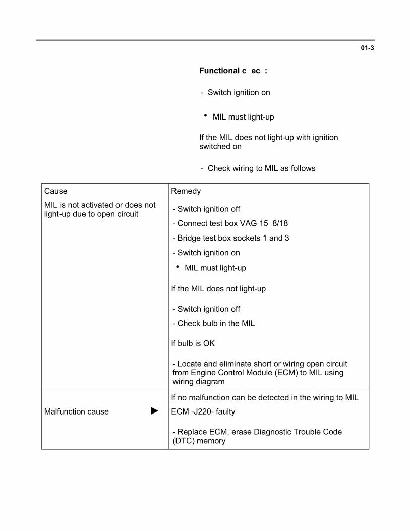
Functional check:
- Switch ignition on:
MIL must light-up.
If the MIL does not light-up with ignition switched on:
- Check wiring to MIL as follows.
Cause: Remedy:
MIL is not activated or does not light-up due to open circuit
If the MIL does not light-up:
If bulb is OK:
- Switch ignition off
- Connect test box VAG 1598/18
- Bridge test box sockets 1 and 3
- Switch ignition on
MIL must light-up
- Switch ignition off
- Check bulb in the MIL
- Locate and eliminate short or wiring open circuit from Engine Control Module (ECM) to MIL using wiring diagram
If no malfunction can be detected in the wiring to MIL:
Malfunction cause: ECM -J220- faulty
- Replace ECM, erase Diagnostic Trouble Code (DTC) memory
Page 3 of 6On Board Diagnostic (OBD)
6/12/2004http://ebahn.bentleypublishers.com/vw/servlet/Display?action=Goto&type=repair&id=VW...

01-4
If the MIL lights-up with ignition switched on, continue check as follows:
- Start engine and run at idle speed.
MIL must go out after a few seconds.
If the MIL does not go out:
- Check DTC memory Page 01-12 .
If no malfunction is stored:
Cause: Remedy:
MIL is permanently activated by short circuit to Ground (GND)
If the specification is not attained:
- Switch ignition off
- Connect test box VAG 1598/18
- Check resistance between test box socket 3 and vehicle Ground (GND), specification: ohms ( )
Short circuit to (GND) in the activation wire from Engine Control Module (ECM) -J220- to MIL
- Locate and eliminate this malfunction using wiring diagram
If the specification ohms ( ) is attained and no short circuit to (GND) can be found:
Malfunction cause: ECM -J220- faulty
- Replace ECM, erase Diagnostic Trouble Code (DTC) memory
Page 4 of 6On Board Diagnostic (OBD)
6/12/2004http://ebahn.bentleypublishers.com/vw/servlet/Display?action=Goto&type=repair&id=VW...

01-5
On Board Diagnostic (OBD) technical data
Equipped with
Diagnostic Trouble Code (DTC) memory
Rapid data transfer
Engine control module identification
Page 01-7 ; VAG 1551 Scan Tool (ST), connecting and selecting Engine Electronics address word 01
Page 5 of 6On Board Diagnostic (OBD)
6/12/2004http://ebahn.bentleypublishers.com/vw/servlet/Display?action=Goto&type=repair&id=VW...

01-6
Engine Control Module (ECM) functions
Note:
The ECM is equipped with various functions. Some functions can be carried out with ignition switched on or with engine running. The following table details the requirements for performing the individual functions.
Function performable with
Ignition switched on
Engine idling
02 Check DTC Memory
Yes Yes
03 Output Diagnostic Test Mode
Yes No
04 Basic Setting Yes1) Yes2)3)
05 Erase DTC Memory
Yes Yes
06 End Output Yes Yes
07 Code Control Module
Yes No
08 Read Measuring Value Block
Yes Yes
1) Must be performed after the following work: replacement of Engine Control Module (ECM), throttle valve control module or engine.
2) Only possible when coolant temperature is above 80 C (176 F). Prior to this, function is blocked.
3) Must be performed when checking idle speed.
Page 6 of 6On Board Diagnostic (OBD)
6/12/2004http://ebahn.bentleypublishers.com/vw/servlet/Display?action=Goto&type=repair&id=VW...

01-7
VAG 1551 Scan Tool (ST), connecting and selecting "Engine Electronics" address word 01
Special tools, testers and auxiliary items
VAG 1551/1552 scan tool with VAG 1551/3 adapter cable
Note:
The VAG 1552 scan tool can be used instead of the VAG 1551 scan tool, however a print-out is not possible.
Test conditions
Fuse 22 OK
Battery voltage at least 11 volts
Ground (GND) connections on engine and transmission OK. (engine GND connection:
Page 24-3 , item 19 )
Work sequence
Depending upon desired function:
- Open cover for Data Link Connector (DLC).
- Connect VAG 1551/1552 scan tool with VAG 1551/3 adapter cable.
- Switch ignition on or start engine Page 01Engine Control Module (ECM) functions table.
Page 1 of 80VAG 1551 Scan Tool (ST), connecting and selecting 'Engine Electronics' address word 01
6/12/2004http://ebahn.bentleypublishers.com/vw/servlet/Display?action=Goto&type=repair&id=VW...

01-8
Note:
If the display does not show as indicated in the work sequence:
VAG 1551 scan tool operating instructions
If due to an input malfunction "Error in communication link" is displayed, disconnect wire from VAG 1551/1552 scan tool, reconnect and repeat work step.
V.A.G - On Board Diagnostic (OBD) HELP
1 - Rapid data transfer
2 - Blink code output
Indicated on display1):
1) Operating modes 1 and 2 are displayed alternately
Operate VAG 1551/1552 scan tool taking into account the information on the display:
- Press -1- button to select "Rapid data transfer" operating mode 1.
- Press buttons -0- and -1- to select "Engine Electronics" address word 01 and press -Q- button to confirm.
037 906 259B MOTRONIC M5 .9 AT V02
Coding 0006 WSC xxxxx
The VAG 1551 scan tool display will show the ECM identification, e.g.:
037 906 259B = Part no. of the ECM (for latest control module version parts catalog)
MOTRONIC M5.9 = Injection and ignition system
AT V02 = Automatic transmission with Motronic system version 02
Page 2 of 80VAG 1551 Scan Tool (ST), connecting and selecting 'Engine Electronics' address word 01
6/12/2004http://ebahn.bentleypublishers.com/vw/servlet/Display?action=Goto&type=repair&id=VW...
01-9
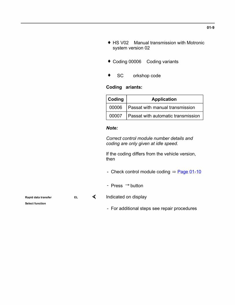
HS V02 = Manual transmission with Motronic system version 02
Coding 00006 = Coding variants
WSC = Workshop code
Coding variants:
Coding Application
00006 Passat with manual transmission
00007 Passat with automatic transmission
Note:
Correct control module number details and coding are only given at idle speed.
If the coding differs from the vehicle version, then:
- Check control module coding Page 01-10 .
- Press button.
Rapid data transfer HELP
Select function XX Indicated on display
- For additional steps see repair procedures.
Page 3 of 80VAG 1551 Scan Tool (ST), connecting and selecting 'Engine Electronics' address word 01
6/12/2004http://ebahn.bentleypublishers.com/vw/servlet/Display?action=Goto&type=repair&id=VW...

01-10
Control module, coding (function 07)
If the appropriate code for the vehicle is not displayed or if the control module has been replaced, the control module must be coded as follows.
Special tools, testers and auxiliary items
VAG 1551/1552 scan tool with VAG 1551/3 adapter cable
Work sequence
- Connect VAG 1551/1552 scan tool and with ignition switched on, select "Engine Electronics" address word 01 and press -Q- button to confirm input Page 01-7 .
Rapid data transfer HELP
Select function XX Indicated on display
- Press buttons -1- and -1- to select "Log-in Procedure" function 11 and press -Q- button to confirm input.
Log-in Procedure HELP
Input code number XXXXX Indicated on display
- Press buttons -0-, -1-, -2-, -8- and -3- to input log-in code 01283 and press -Q- button to confirm input.
Rapid data transfer HELP
Select function XX Indicated on display
- Press buttons -0- and -7- to select "Code Control Module" function 07 and press -Q- button to confirm input.
Page 4 of 80VAG 1551 Scan Tool (ST), connecting and selecting 'Engine Electronics' address word 01
6/12/2004http://ebahn.bentleypublishers.com/vw/servlet/Display?action=Goto&type=repair&id=VW...

01-11
Code Control Module HELP
Input code number XXXXX (0-32000) Indicated on display
- Input appropriate code number for this vehicle and press -Q- button to confirm input.
Coding Application
00006 Passat with manual transmission
00007 Passat with automatic transmission
037 906 259B MOTRONIC M5.9 AT V02
Coding 0006 WSC xxxxx
The VAG 1551 scan tool display will show the control module identification, e.g.:
- Press button.
Rapid data transfer HELP
Select function XX Indicated on display
Note:
The code entered and shown on the display will not be used by the Engine Control Module (ECM) until the ignition has been switched off once. An incorrect coding leads to:
- Press buttons -0- and -6- to select "End Output" function 06 and press -Q- button to confirm input.
Engine running malfunctions
Increased fuel consumption
Increased emissions
Malfunctions stored in Diagnostic Trouble Code (DTC) memory which are not actually present
Reduced transmission life
Page 5 of 80VAG 1551 Scan Tool (ST), connecting and selecting 'Engine Electronics' address word 01
6/12/2004http://ebahn.bentleypublishers.com/vw/servlet/Display?action=Goto&type=repair&id=VW...

01-12
Diagnostic Trouble Code (DTC) memory, checking (function 02)
Special tools, testers and auxiliary items
VAG 1551/1552 scan tool with VAG 1551/3 adapter cable
Work sequence
- Connect VAG 1551/1552 scan tool and select "Engine Electronics" address word 01 Page 01-7 . Engine must be running at idle.
Note:
If engine does not start, operate starter for approx. 6 seconds and then do not switch ignition off.
- Switch printer on with PRINT button (warning lamp in button lights up).
Rapid data transfer HELP
Select function XX Indicated on display
- Press buttons -0- and -2- to select "Check DTC Memory" function 02 and press -Q- button to confirm input.
X DTC recognized The number of malfunctions stored or "No DTC recognized" will be shown on the display.
Note:
If something different is indicated on the display:
VAG 1551 scan tool operating instructions.
Page 6 of 80VAG 1551 Scan Tool (ST), connecting and selecting 'Engine Electronics' address word 01
6/12/2004http://ebahn.bentleypublishers.com/vw/servlet/Display?action=Goto&type=repair&id=VW...

01-13
If one or more malfunctions are stored, the malfunctions stored will be displayed and printed out one after the other.
If no malfunction is stored:
- Press button.
Rapid data transfer HELP
Select function XX Then display will show.
Note:
If a malfunction is present which is not recognized by the On Board Diagnostic (OBD), perform further troubleshooting using the information in:
Electrical Wiring Diagrams, Troubleshooting & Component Locations
- Press buttons -0- and -6- to select "End Output" function 06 and press -Q- button to confirm input.
- Locate and eliminate malfunctions printed out as per Diagnostic Trouble Code (DTC) table Page 01-14 .
- Erase DTC memory Page 01-31 .
Page 7 of 80VAG 1551 Scan Tool (ST), connecting and selecting 'Engine Electronics' address word 01
6/12/2004http://ebahn.bentleypublishers.com/vw/servlet/Display?action=Goto&type=repair&id=VW...

01-14
Diagnostic Trouble Code (DTC) table
Note:
The DTC overview is listed according to SAE or VAG codes.
After repairing malfunctions, DTC memory must be erased ( Page 01-31 ) and the repair verified via the appropriate display group Page 01-35 , Readiness code, creating.
DTC Malfunction text Malfunction elimination
SAE VAG
--- 00524 Knock Sensor 1 -G61
Signal too low
- Check knock sensor and knock control Page 28-25
--- 00532 Supply Voltage (B+)
Signal too high Electrical Wiring Diagrams, Troubleshooting & Component Locations
- Check generator:
--- 00543 RPM upper Limit exceeded - Erase DTC memory Page 01-31
--- 00545 Engine/Trans. Electrical Connection
Electrical Wiring Diagrams, Troubleshooting & Component Locations
- Locate and correct malfunction in wiring to automatic transmission per wiring diagram:
Page 8 of 80VAG 1551 Scan Tool (ST), connecting and selecting 'Engine Electronics' address word 01
6/12/2004http://ebahn.bentleypublishers.com/vw/servlet/Display?action=Goto&type=repair&id=VW...

01-15
DTC Malfunction text Malfunction elimination
SAE VAG
--- 00577 Knock Sensor Control Cyl. 1
Control limit exceeded
- Check knock sensor and knock control Page 28-25
--- 00578 Knock Sensor Control Cyl. 2
Control limit exceeded
- Correct abnormal engine running noises (auxilliary assemblies loose, bracket/bolts sheared)
--- 00579 Knock Sensor Control Cyl. 3
Control limit exceeded
Electrical Wiring Diagrams, Troubleshooting & Component Locations
- Check connectors and wiring per wiring diagram
- Change grade of fuel
--- 00580 Knock Sensor Control Cyl. 4
Control limit exceeded
- Loosen knock sensor and tighten again to 20 Nm (15 ft lb)
--- 00652 Transmission Range Controller
Open/Short circuit to B+
Electrical Wiring Diagrams, Troubleshooting & Component Locations
- Locate and repair faulty wiring to automatic transmission using wiring diagram
Open/Short circuit to Ground
Page 9 of 80VAG 1551 Scan Tool (ST), connecting and selecting 'Engine Electronics' address word 01
6/12/2004http://ebahn.bentleypublishers.com/vw/servlet/Display?action=Goto&type=repair&id=VW...

01-16
DTC Malfunction text Malfunction elimination
SAE VAG
--- 00668 Battery Positive Voltage (B+) Term. 30
signal too high Electrical Wiring Diagrams, Troubleshooting & Component Locations
- Check generator:
Battery Positive Voltage (B+) Term. 30
Signal too low
- Check battery
Battery Positive Voltage (B+) Term. 30
Interrupted Electrical Wiring Diagrams- Troubleshooting & Component Locations
- Check connectors and wiring per wiring diagram
Battery Positive Voltage (B+) Term. 30
Implausible signal
--- 00750 Malfunction Indicator Lamp (MIL)
Faulty Electrical Wiring Diagrams, Troubleshooting & Component Locations
- Check MIL LED
--- 01165 Throttle body control module -J338 - Check throttle valve control module
Page 24-69
--- 01177 Engine Control Module
Faulty
- Replace engine control module Page 24-1 , item 4
Page 10 of 80VAG 1551 Scan Tool (ST), connecting and selecting 'Engine Electronics' address word...
6/12/2004http://ebahn.bentleypublishers.com/vw/servlet/Display?action=Goto&type=repair&id=VW...
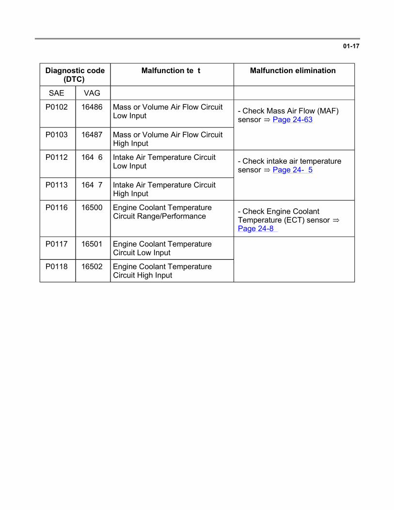
01-17
Diagnostic code (DTC)
Malfunction text Malfunction elimination
SAE VAG
P0102 16486 Mass or Volume Air Flow Circuit Low Input - Check Mass Air Flow (MAF)
sensor Page 24-63
P0103 16487 Mass or Volume Air Flow Circuit High Input
P0112 16496 Intake Air Temperature Circuit Low Input - Check intake air temperature
sensor Page 24-95
P0113 16497 Intake Air Temperature Circuit High Input
P0116 16500 Engine Coolant Temperature Circuit Range/Performance - Check Engine Coolant
Temperature (ECT) sensor Page 24-89
P0117 16501 Engine Coolant Temperature Circuit Low Input
P0118 16502 Engine Coolant Temperature Circuit High Input
Page 11 of 80VAG 1551 Scan Tool (ST), connecting and selecting 'Engine Electronics' address word...
6/12/2004http://ebahn.bentleypublishers.com/vw/servlet/Display?action=Goto&type=repair&id=VW...

01-18
Diagnostic code (DTC)
Malfunction text Malfunction elimination
SAE VAG
P0120 16504 Throttle Position Sensor A Circuit Malfunction - Check throttle valve control module
Page 24-69
- Check MAF sensor Page 24-63
P0121 16505 Throttle Position Sensor A Circuit Range/Performance Problem
P0122 16506 Throttle Position Sensor A Circuit Low Input
P0125 16509 Insufficient Coolant Temperature for Closed Loop Fuel Control
- Check ECT sensor Page 24-89
Repair Manual, 2.0 Liter 4-Cyl. 2V Engine Mechanical, Engine Code(s): ABA m.y. 1995 - 1997, Repair Group 19
- Check thermostat:
P0131 16515 02 Sensor Circuit Low Voltage (Bank 1, Sensor 1) - Check Heated Oxygen Sensor
(HO2S) and Oxygen Sensor (O2S) control (before three way catalytic converter) Page 24-26
- Check O2S aging (before three way catalytic converter) Page 24-57
P0132 16516 02 Sensor Circuit High Voltage (Bank 1, Sensor 1)
P0133 16517 02 Sensor Circuit Slow Response (Bank 1, Sensor 1)
P0134 16518 02 Sensor Circuit No Activity Detected (Bank 1, Sensor 1)
P0135 16519 02 Sensor Heater Circuit Malfunction (Bank 1, Sensor 1)
- Check O2S heating (before three way catalytic converter) Page 24-36
Page 12 of 80VAG 1551 Scan Tool (ST), connecting and selecting 'Engine Electronics' address word...
6/12/2004http://ebahn.bentleypublishers.com/vw/servlet/Display?action=Goto&type=repair&id=VW...

01-19
Diagnostic code (DTC)
Malfunction text Malfunction elimination
SAE VAG
P0137 16521 02 Sensor Circuit Low Voltage (Bank 1, Sensor 2) - Check HO2S 2 and O2S control
(after three way catalytic converter) Page 24-43
P0138 16522 02 Sensor Circuit High Voltage (Bank 1, Sensor 2)
P0140 16524 02 Sensor Circuit No Activity Detected (Bank 1, Sensor 2)
P0141 16525 02 Sensor Heater Circuit Malfunction (Bank 1, Sensor 2)
- Check O2S heating (after three way catalytic converter) Page 24-50
Page 13 of 80VAG 1551 Scan Tool (ST), connecting and selecting 'Engine Electronics' address word...
6/12/2004http://ebahn.bentleypublishers.com/vw/servlet/Display?action=Goto&type=repair&id=VW...

01-20
Diagnostic code (DTC)
Malfunction text
Malfunction elimination
SAE VAG
P0171 16555 System too Lean (Bank 1) - Check intake air system for leaks Page 24-
125
- Check HO2S and O2S control (before three way catalytic converter) Page 24-26
Repair Manual, 2.0 Liter 4-Cyl. 2V Engine Mechanical, Engine Code(s): ABA m.y. 1995 - 1997, Repair Group 26
- Check secondary air injection system Page 01-72 , output Diagnostic Test Mode (DTM) and:
- Check MAF sensor Page 24-63
Repair Manual,2.0 Liter 4-Cyl. 2V Engine Mechanical, Engine Code(s): ABA m.y. 1995 - 1997, Repair Group 20
- Check fuel pump:
- Check fuel injectors Page 01-72 , output Diagnostic Test Mode (DTM) and Page 24-116
Page 14 of 80VAG 1551 Scan Tool (ST), connecting and selecting 'Engine Electronics' address word...
6/12/2004http://ebahn.bentleypublishers.com/vw/servlet/Display?action=Goto&type=repair&id=VW...

01-21
Diagnostic code (DTC)
Malfunction text
Malfunction elimination
SAE VAG
P0172 16556 System too Rich (Bank 1) - Check HO2S and O2S control (before three
way catalytic converter) Page 24-26
- Check fuel pressure regulator Page 24-121
Repair Manual, 2.0 Liter 4-Cyl. 2V Engine Mechanical, Engine Code(s): ABA m.y. 1995 - 1997, Repair Group 26
- Check exhaust system for leaks:
P0300 16684 Random Misfire Detected - Check components of ignition system Page
28-1
- Check misfiring detection Page 28-16
- Check ignition coil Page 28-30
- Check engine speed (RPM) sensor Page 24-100
- Change type of fuel
Page 15 of 80VAG 1551 Scan Tool (ST), connecting and selecting 'Engine Electronics' address word...
6/12/2004http://ebahn.bentleypublishers.com/vw/servlet/Display?action=Goto&type=repair&id=VW...

01-22
Diagnostic code (DTC)
Malfunction text Malfunction elimination
SAE VAG
P0301 16685 Cylinder 1 Misfire Detected - Check fuel injectors Page 01-72 , (output DTM) and Page 24-116
P0302 16686 Cylinder 2 Misfire Detected - Check ignition coil Page 28-30
P0303 16687 Cylinder 3 Misfire Detected - Check ignition coil power output stage Page 28-31
P0304 16688 Cylinder 4 Misfire Detected - Check misfiring detection Page 28-16
P0321 16705 Ign./Distributor Eng.Speed Inp.Circ.
Range/Performance
- Check engine speed (RPM) sensor Page 24-100
P0322 16706 Ign./Distributor Eng.Speed Inp.Circ.
No Signal
P03271) 16711 Knock Sensor 1 Circuit Low Input - Check Knock Sensor (KS) 1 and
knock control Page 28-25
P0341 16725 Camshaft Position Sensor Circuit Range/Performance - Check Camshaft Position (CMP)
sensor Page 28-22
P0411 16795 Sec.Air Inj.Sys. Incorrect Flow Detected
Repair Manual, 2.0 Liter 4-Cyl. 2V Engine Mechanical, Engine Code(s): ABA m.y. 1995 - 1997, Repair Group 26
- Check secondary air injection system Page 01-72 , output Diagnostic Test Mode (DTM) and:
1) MY 97 the SAE Diagnostic Trouble Code (DTC) is not displayed.
Page 16 of 80VAG 1551 Scan Tool (ST), connecting and selecting 'Engine Electronics' address word...
6/12/2004http://ebahn.bentleypublishers.com/vw/servlet/Display?action=Goto&type=repair&id=VW...

01-23
Diagnostic code (DTC)
Malfunction text Malfunction elimination
SAE VAG
P0422 16806 Main Catalyst Efficiency Below Threshold (Bank 1) - Check HO2S and O2S control
(before three way catalytic converter) Page 24-26
- Check O2S aging (before three way catalytic converter) Page 24-57
P0440 16824 Evaporative Emission Control System Malfunction - Check EVAP canister purge
regulator valve Page 01-72 , output Diagnostic Test Mode (DTM)
P0501 16885 Vehicle Speed Sensor Range/Performance - Check vehicle speed sensor signal
Page 24-102
P0506 16890 Idle Control System RPM Lower than Expected - Check fuel pressure regulator and
residual pressure Page 24-121
- Check ignition timing Page 28-14
- Check engine speed (RPM) sensor Page 24-100
- Check battery voltage (B+)
- Check idle speed Page 24-23
P0507 16891 Idle Control System RPM Higher than Expected
P0510 16894 Closed Throttle Position Switch Malfunction - Check throttle valve control module
Page 24-69
P0605 16989 Internal Control Module Read Only Memory (ROM) Error - Replace Engine Control Module
(ECM) Page 24-1 , item 4
Page 17 of 80VAG 1551 Scan Tool (ST), connecting and selecting 'Engine Electronics' address word...
6/12/2004http://ebahn.bentleypublishers.com/vw/servlet/Display?action=Goto&type=repair&id=VW...

01-24
Diagnostic code (DTC)
Malfunction text Malfunction elimination
SAE VAG
P1127 17535 Long Term Fuel Trim mul. (B1) System too Rich
- Check MAF sensor Page 24-63
- Check HO2S and O2S control (before three way catalytic converter) Page 24-26
- Check HO2S 2 and O2S control (after three way catalytic converter) Page 24-43
Repair Manual, 2.0 Liter 4-Cyl. 2V Engine Mechanical, Engine Code(s): ABA m.y. 1995 - 1997, Repair Group 20
- Check fuel pump:
Repair Manual, 2.0 Liter 4-Cyl. 2V Engine Mechanical, Engine Code(s): ABA m.y. 1995 - 1997, Repair Group 26
- Check Secondary Air Injection (AIR) system Page 01-72 , output Diagnostic Test Mode (DTM) and:
- Check fuel injectors Page 01-72 , output Diagnostic Test Mode (DTM) and Page 24-116
Page 18 of 80VAG 1551 Scan Tool (ST), connecting and selecting 'Engine Electronics' address word...
6/12/2004http://ebahn.bentleypublishers.com/vw/servlet/Display?action=Goto&type=repair&id=VW...

01-25
Diagnostic code (DTC)
Malfunction text Malfunction elimination
SAE VAG
P1128 17536 Long Term Fuel Trim mul. (B1) System too Lean
- Check HO2S and O2S control (before three way catalytic converter) Page 24-26
- Check HO2S 2 and O2S control (after three way catalytic converter) Page 24-43
Repair Manual, 2.0 Liter 4-Cyl. 2V Engine Mechanical, Engine Code(s): ABA m.y. 1995 - 1997, Repair Group 20
- Check fuel pump:
- Check fuel injectors Page 01-72 , output Diagnostic Test Mode (DTM) and Page 24-116
- Check EVAP canister purge regulator valve Page 01-72 , output Diagnostic Test Mode (DTM)
Page 19 of 80VAG 1551 Scan Tool (ST), connecting and selecting 'Engine Electronics' address word...
6/12/2004http://ebahn.bentleypublishers.com/vw/servlet/Display?action=Goto&type=repair&id=VW...

01-26
Diagnostic code (DTC)
Malfunction text Malfunction elimination
SAE VAG
P1213 17621 Cyl.1-Fuel Injector Circ. Short to B+ - Check fuel injectors Page 01-72 , output
Diagnostic Test Mode (DTM) and Page 24-116
P1214 17622 Cyl.2-Fuel Injector Circ. Short to B+
P1215 17623 Cyl.3-Fuel Injector Circ. Short to B+
P1216 17624 Cyl.4-Fuel Injector Circ. Short to B+
P1225 17633 Cyl.1-Injector Circ. Short to Ground - Check fuel injectors Page 01-72 , output
Diagnostic Test Mode (DTM) and Page 24-116
P1226 17634 Cyl.2-Injector Circ. Short to Ground
P1227 17635 Cyl.3-Injector Circ. Short to Ground
P1228 17636 Cyl.4-Injector Circ. Short to Ground
P1237 17645 Cyl.1-Injector Circ. Open Circuit - Check fuel injectors Page 01-72 , output
Diagnostic Test Mode (DTM) and Page 24-116
P1238 17646 Cyl.2-Injector Circ. Open Circuit
P1239 17647 Cyl.3-Injector Circ. Open Circuit
P1240 17648 Cyl.4-Injector Circ. Open Circuit
Page 20 of 80VAG 1551 Scan Tool (ST), connecting and selecting 'Engine Electronics' address word...
6/12/2004http://ebahn.bentleypublishers.com/vw/servlet/Display?action=Goto&type=repair&id=VW...

01-27
Diagnostic code (DTC)
Malfunction text Malfunction elimination
SAE VAG
P1300 17708 Misfire detected
Reason: Fuel level too low
- Fill vehicle fuel tank
P1340 17748 Camshaft/Crankshaft Pos.Sens.Signals Out of Sequence
- Check engine speed (RPM) sensor Page 24-100
P1410 17818 Tank Ventilation Valve Short to B+ - Check EVAP canister purge
regulator valve Page 01-72 , output Diagnostic Test Mode (DTM)
P1420 17828 Sec.Air Inj.Control Module Electrical Malfunction
Repair Manual, 2.0 Liter 4-Cyl. 2V Engine Mechanical, Engine Code(s): ABA m.y. 1995 - 1997, Repair Group 26
- Check Secondary Air Injection (AIR) system Page 01-72 , output Diagnostic Test Mode (DTM) and:
P1421 17829 Sec.Air Inj.Valve Circ. Short to Ground
P1422 17830 Sec.Air Inj.Sys.Control Valve Circ. Short to B+
P1425 17833 Tank Vent.Valve Short to Ground - Check EVAP canister purge
regulator valve Page 01-72 , output Diagnostic Test Mode (DTM)
P1426 17834 Tank Vent.Valve Open
Page 21 of 80VAG 1551 Scan Tool (ST), connecting and selecting 'Engine Electronics' address word...
6/12/2004http://ebahn.bentleypublishers.com/vw/servlet/Display?action=Goto&type=repair&id=VW...

01-28
Diagnostic code (DTC)
Malfunction text Malfunction elimination
SAE VAG
P1450 17858 Sec.Air Inj.Sys.Circ. Short to B+
Repair Manual, 2.0 Liter 4-Cyl. 2V Engine Mechanical, Engine Code(s): ABA m.y. 1995 - 1997, Repair Group 26
- Check Secondary Air Injection (AIR) pump relay -J299- Page 01-72 , output Diagnostic Test Mode (DTM) and:
P1451 17859 Sec.Air Inj.Sys.Circ. Short to Ground
P1452 17860 Sec.Air Inj.Sys. Open Circuit
P1500 17908 Fuel Pump Relay Circ. Electrical Malfunction Electrical Wiring Diagrams,
Troubleshooting & Component Locations
- Check fuel pump relay:
P1502 17910 Fuel Pump Relay Circ. Short to B+
Repair Manual, 2.0 Liter 4-Cyl. 2V Engine Mechanical, Engine Code(s): ABA m.y. 1995 - 1997, Repair Group 20
- Check fuel pump:
Page 22 of 80VAG 1551 Scan Tool (ST), connecting and selecting 'Engine Electronics' address word...
6/12/2004http://ebahn.bentleypublishers.com/vw/servlet/Display?action=Goto&type=repair&id=VW...

01-29
Diagnostic code (DTC)
Malfunction text Malfunction elimination
SAE VAG
P1543 17951 Throttle Actuation Potentiometer Signal too Low
- Check throttle valve control module Page 24-69
P1544 17952 Throttle Actuation Potentiometer Signal too High
P1565 17973 Idle Speed Control Throttle Position
Lower limit not attained
- Check throttle valve for damage/soiling
- Check throttle valve control module Page 24-69
P1580 17988 Throttle Actuator (B1) Malfunction
P1582 17990 Idle Adaptation at Limit - Check throttle valve control module Page 24-69
- Check intake air system for leaks Page 24-125
Repair Manual, 2.0 Liter 4-Cyl. 2V Engine Mechanical, Engine Code(s): ABA m.y. 1995 - 1997, Repair Group 26
- Check exhaust system for leaks:
- Check fuel pressure regulator Page 24-121
- Check EVAP canister purge regulator valve Page 01-72 , output Diagnostic Test Mode (DTM)
Page 23 of 80VAG 1551 Scan Tool (ST), connecting and selecting 'Engine Electronics' address word...
6/12/2004http://ebahn.bentleypublishers.com/vw/servlet/Display?action=Goto&type=repair&id=VW...

01-30
Diagnostic code (DTC)
Malfunction text Malfunction elimination
SAE VAG
P1611 18019 MIL Call-up Circ./Transm.Control Module Short to Ground
Electrical Wiring Diagrams, Troubleshooting & Component Locations
- Check wiring between Transmission Control Module (TCM) and ECM:
P1613 18021 MIL Call-up Circ.Open Short to B+
Electrical Wiring Diagrams, Troubleshooting & Component Locations
- Check MIL LED:
P1686 18094 Contr.Unit Error
Programming Error
- Replace control module Page 24-1 , item 4
Page 24 of 80VAG 1551 Scan Tool (ST), connecting and selecting 'Engine Electronics' address word...
6/12/2004http://ebahn.bentleypublishers.com/vw/servlet/Display?action=Goto&type=repair&id=VW...

01-31
Diagnostic Trouble Code (DTC) memory, erasing (function 05)
Special tools, testers and auxiliary items
VAG 1551/1552 scan tool with VAG 1551/3 adapter cable
Test conditions
Malfunctions eliminated
Engine coolant temperature must reach at least 80 C (176 F)
Note:
If DTC memory is erased, the repair must be verified via the appropriate display group Page 01-35 .
- Connect VAG 1551/1552 scan tool and select "Engine Electronics" address word 01 Page 01-7 . Engine must be running at idle.
Rapid data transfer HELP
Select function XX Indicated on display
- Press buttons -0- and -2- to select "Check DTC Memory" function 02 and press -Q- button to confirm input.
Rapid data transfer HELP
Select function XX - Press button until all malfunctions still stored
have appeared and display reads:
- Press buttons -0- and -5- to select "Erase DTC Memory" function 05 and press -Q- button to confirm input.
Page 25 of 80VAG 1551 Scan Tool (ST), connecting and selecting 'Engine Electronics' address word...
6/12/2004http://ebahn.bentleypublishers.com/vw/servlet/Display?action=Goto&type=repair&id=VW...

01-32
Rapid data transfer
DTC memory is erased
Indicated on display
- Press button.
Rapid data transfer HELP
Select function XX Indicated on display
If no malfunction is displayed:
Road test procedure
- Allow engine to idle for at least 1 minute and check DTC memory again.
- Press buttons -0- and -6- to select "End Output" function 06 and press -Q- button to confirm input.
- Road test vehicle for at least 10 minutes.
Engine coolant temperature must reach at least 80 C (176 F)
- Briefly depress accelerator pedal to wide open throttle when engine speed is above 4600 RPM.
- Accelerate from approx. 50 km/h (30 mph), for approx. 4 seconds, using half throttle.
Automatic transmission: Drive range 3
Manual transmission: 4th gear
- Check DTC memory again, no malfunctions should be shown.
- Create readiness code Page 01-35 .
Page 26 of 80VAG 1551 Scan Tool (ST), connecting and selecting 'Engine Electronics' address word...
6/12/2004http://ebahn.bentleypublishers.com/vw/servlet/Display?action=Goto&type=repair&id=VW...

01-33
Readiness code, reading (function 15)
Special tools, testers and auxiliary items
VAG 1551/1552 scan tool with VAG 1551/3 adapter cable
Work sequence
- Connect VAG 1551/1552 scan tool and, with ignition switched on, select "Engine Electronics" address word 01 Page 01-7 .
Rapid data transfer HELP
Select function XX Indicated on display
- Press buttons -1- and -5- to select "Readiness Code" function 15 and press -Q- button to confirm input.
Must appear on display when all diagnosis functions have been successfully completed:
Readiness Code
00000000 - Test complete Indicated on display
- Press button.
- Press buttons -0- and -6- to select "End Output" function 06 and press -Q- button to confirm input.
Readiness Code
01101101 - Test not complete Indicated on display (possible example)
If one of the diagnostic checks has not run through successfully:
- Press button.
Page 27 of 80VAG 1551 Scan Tool (ST), connecting and selecting 'Engine Electronics' address word...
6/12/2004http://ebahn.bentleypublishers.com/vw/servlet/Display?action=Goto&type=repair&id=VW...

01-34
- Create readiness code Page 01-35 .
- Read readiness code Page 01-33 . If DTC memory has been erased, repair must be verified via appropriate display group Page 01-35 , Readiness code, creating.
Relevance of 8-digit number block for readiness code
The readiness code is created only when all display fields show 0
1 2 3 4 5 6 7 8 Diagnostic function
0 Three way catalytic converter
0 Three way catalytic converter heating (not available)
0 Fuel tank venting system
0 Secondary air injection system
0 Air conditioner (no diagnostic capability)
0 Heated oxygen sensor
0 Oxygen sensor heating
0 Exhaust gas recirculation system (not available)
Page 28 of 80VAG 1551 Scan Tool (ST), connecting and selecting 'Engine Electronics' address word...
6/12/2004http://ebahn.bentleypublishers.com/vw/servlet/Display?action=Goto&type=repair&id=VW...

01-35
Readiness code, creating
Special tools, testers and auxiliary items
VAG 1551/1552 scan tool with VAG 1551/3 adapter cable
Note:
During test sequence the ignition must not be switched off.
If the specifications are obtained before the time specified in the table, you can proceed to the next work step.
On vehicles up to m.y. 96 the function bits in the readiness code are set to 0 together, when the last diagnosis has been successfully completed.
On vehicles from m.y. 97 the function bits in the readiness code are set to 0 individually, for each successfully completed diagnosis.
Test sequence
WARNING!
When driving or riding in an airbag-equipped vehicle:
Never hold test equipment in your hands or lap while the vehicle is in motion. Objects between you and the airbag can increase the risk of injury in an accident.
Secure tools or test equipment on passenger side floor where it can be safely read by the second technician.
Page 29 of 80VAG 1551 Scan Tool (ST), connecting and selecting 'Engine Electronics' address word...
6/12/2004http://ebahn.bentleypublishers.com/vw/servlet/Display?action=Goto&type=repair&id=VW...

01-36
Work step: 1
- Connect VAG 1551/1552 scan tool and select "Engine Electronics" address word 01 Page 01-7 .
When doing this, the ignition must be switched on.
Relevance of 8-digit number block in display field 4
1 2 3 4 5 6 7 8 Diagnostic status
1 Diagnostic Trouble Code (DTC) memory
1 = Malfunction in system;0 = No DTCs recognized
1 ERROR bit(specific to display group being viewed)
1 = Malfunction detected;0 = No malfunction detected
1 CYCLE bit
1 = Diagnosis complete;0 = Diagnosis not performed yet
1 ACTIVE bit1 = Diagnosis active;0 = Diagnosis inactive
x Function bit 1)
x Function bit 1)
x Function bit 1)
x Function bit 1)
1) The relevance of the Function Bit varies depending upon the work step.
Page 30 of 80VAG 1551 Scan Tool (ST), connecting and selecting 'Engine Electronics' address word...
6/12/2004http://ebahn.bentleypublishers.com/vw/servlet/Display?action=Goto&type=repair&id=VW...

01-37
Note:
There must not be any malfunctions stored in DTC memory or detected during this diagnostic test.
If the CYCLE bit has a 1, the diagnosis is completed and the test sequence can be implemented.
The specifications for the function bits must only be satisfied during the diagnostic phase (ACTIVE bit = 1).
An "x" shown in the diagnostic status table means the display can show either "0" or "1".
Work step: 2
Rapid data transfer HELP
Select function XX Indicated on display
- Press buttons -0- and -2- to select "Check DTC Memory" function 02 and press -Q- button to confirm input.
X DTC recognized The number of malfunctions stored or "No DTC recognized" will be shown on the display.
- Locate and eliminate malfunctions printed out as per DTC table Page 01-14 .
- Press button.
Page 31 of 80VAG 1551 Scan Tool (ST), connecting and selecting 'Engine Electronics' address word...
6/12/2004http://ebahn.bentleypublishers.com/vw/servlet/Display?action=Goto&type=repair&id=VW...

01-38
Work step: 3
Rapid data transfer HELP
Select function XX Indicated on display
- Press buttons -0- and -5- to select "Erase DTC Memory" function 05 and press -Q- button to confirm input.
Rapid data transfer
DTC Memory is erased
Indicated on display
Work step: 4
Work step: 5
- Press button.
- Start engine and run at idle speed.
Rapid data transfer HELP
Select function XX Indicated on display
- Press buttons -0- and -8- to select "Read Measuring Value Block" function 08 and press -Q- button to confirm input.
Read Measuring Value Block HELP
Input display group number XXX Indicated on display
- Press buttons -1-, -0- and -3- to input display group 103 and press -Q- button to confirm input.
Read Measuring Value Block 103
1 2 3 4
Indicated on display (1-4 = display fields)
- Increase engine speed to 3000-3500 RPM and check specifications after 60 seconds.
Page 32 of 80VAG 1551 Scan Tool (ST), connecting and selecting 'Engine Electronics' address word...
6/12/2004http://ebahn.bentleypublishers.com/vw/servlet/Display?action=Goto&type=repair&id=VW...

01-39
Display fields
1 2 3 4
Display group 103
Display xx.xx ms xxx.x C xxx.x C xxxx xxxx
Indicated Engine load
Engine coolant temperature
Three way catalytic converter
temperature
Diagnosis conditions
Specification --- At least 40 C At least 360 C xx1x xx00
Working range
1.4...2.4 ms
-46.5...141.0 C 0.0...999.9 C x = Not relevant
Relevance of 8 digit number block in display field 4
1 2 3 4 5 6 7 8 Specifications of diagnosis conditions
1 Oxygen Sensor (O2S) control active
0 Diagnosis malfunction free
0 DTC memory malfunction free
- Press key.
Page 33 of 80VAG 1551 Scan Tool (ST), connecting and selecting 'Engine Electronics' address word...
6/12/2004http://ebahn.bentleypublishers.com/vw/servlet/Display?action=Goto&type=repair&id=VW...

01-40
Work step: 6
Diagnosis: Secondary Air Injection (AIR) system
Test conditions
Vehicle stationary, engine at idle
- Press buttons -0- and -4- to select "Basic Setting" function 04 and press -Q- button to confirm input.
Basic Setting HELP
Input display group number XXX Indicated on display
- Press buttons -1-, -6- and -0- to input display group 160 and press -Q- button to confirm input.
System in Basic Setting 160
1 2 3 4
Indicated on display (1-4 = display fields)
- Start engine and run at idle speed and check specifications after 20 seconds.
Page 34 of 80VAG 1551 Scan Tool (ST), connecting and selecting 'Engine Electronics' address word...
6/12/2004http://ebahn.bentleypublishers.com/vw/servlet/Display?action=Goto&type=repair&id=VW...

01-41
Display fields
1 2 3 4
Display group160
Display xxx.x C xx.x % xx.x % xxxx xxxx
Indicated Engine coolant temperature
Secondary air injection valve
open
Secondary air injection pump
running
Diagnosis conditions
Specification At least 60 C At least 0.7% At least 25% xx11 x100
Secondary air injection valve
causes deviations in Oxygen Sensor (O2S) control
Secondary air injection valve
causes deviations in O2S control
x = Not relevant
Working range
-46.5...141.0 C
Relevance of 8 digit number block in display field 4
1 2 3 4 5 6 7 8 Specifications of diagnosis conditions
1 Engine running at idling speed
1 Vehicle stationary
1 CYCLE Bit = Diagnosis completed
0 Diagnosis malfunction free
0 DTC memory malfunction free
- Press button.
Page 35 of 80VAG 1551 Scan Tool (ST), connecting and selecting 'Engine Electronics' address word...
6/12/2004http://ebahn.bentleypublishers.com/vw/servlet/Display?action=Goto&type=repair&id=VW...

01-42
Work step: 7
Rapid data transfer HELP
Select function XX Indicated on display
- Press buttons -0- and -8- to select "Read Measuring Value Block" function 08 and press -Q- button to confirm input.
Read Measuring Value Block HELP
Input display group number XXX Indicated on display
- Press buttons -1-, -0- and -3- to input display group 103 and press -Q- button to confirm input.
Read Measuring Value Block 103
1 2 3 4
Indicated on display (1-4 = display fields)
- Increase engine speed to 2200-3300 RPM and check specifications after 120 seconds.
Page 36 of 80VAG 1551 Scan Tool (ST), connecting and selecting 'Engine Electronics' address word...
6/12/2004http://ebahn.bentleypublishers.com/vw/servlet/Display?action=Goto&type=repair&id=VW...

01-43
Display fields
1 2 3 4
Display group 103
Display xx.xx ms xxx.x C xxx.x C xxxx xxxx
Indicated Engine load
Engine coolant temperature
Three way catalytic converter
temperature
Diagnosis conditions
Specification At least 60 C At least 360 C xx1x xx00
--- --- x = Not relevant
Working range
1.4...2.4 ms
-46.5...141.0 C 0.0...999.9 C
Relevance of 8 digit number block in display field 4
1 2 3 4 5 6 7 8 Specifications of diagnosis conditions
1 Oxygen sensor control active
0 Diagnosis malfunction free
0 DTC memory malfunction free
- Press button.
Page 37 of 80VAG 1551 Scan Tool (ST), connecting and selecting 'Engine Electronics' address word...
6/12/2004http://ebahn.bentleypublishers.com/vw/servlet/Display?action=Goto&type=repair&id=VW...

01-44
Work step: 8
Diagnosis: Oxygen Sensor (O2S) aging (regulating frequency extended)
Rapid data transfer HELP
Select function XX Indicated on display
- Press buttons -0- and -4- to select "Basic Setting" function 04 and press -Q- button to confirm input.
Basic Setting HELP
Input display group number XXX Indicated on display
- Press buttons -1-, -3- and -1- to input display group 131 and press -Q- button to confirm input.
System in Basic Setting 131
1 2 3 4
Indicated on display (1-4 = display fields)
- Run engine at idle speed for at least 5 seconds and check specifications.
Page 38 of 80VAG 1551 Scan Tool (ST), connecting and selecting 'Engine Electronics' address word...
6/12/2004http://ebahn.bentleypublishers.com/vw/servlet/Display?action=Goto&type=repair&id=VW...

01-45
Display fields
1 2 3 4
Display group 131
Display xxxx rpm x.xxx V xxxx ms xxxx xxxx
Indicated Engine speed
Voltage of HO2S after three way
catalytic converter
HO2S aging Diagnosis conditions
Specification 800...880 rpm
0.01...1.00 V fluctuating
-1200...1200 ms xxxx x100
--- HO2S aging: TV displacement by O2S control after three way
catalytic converter
x = Not relevant
Working range
800...6000 rpm
0.01...1.00 V -1200...1200 ms
Relevance of 8 digit number block in display field 4
1 2 3 4 5 6 7 8 Specifications of diagnosis conditions
1 CYCLE Bit = Diagnosis completed
0 Diagnosis malfunction free
0 DTC memory malfunction free
- Press -C- button.
Page 39 of 80VAG 1551 Scan Tool (ST), connecting and selecting 'Engine Electronics' address word...
6/12/2004http://ebahn.bentleypublishers.com/vw/servlet/Display?action=Goto&type=repair&id=VW...

01-46
Work step: 9
Diagnosis: Oxygen Sensor (O2S) adaptation in partial load range
Basic Setting HELP
Input display group number XXX Indicated on display
- Press buttons -1-, -2- and -5- to input display group 125 and press -Q- button to confirm input.
System in Basic Setting 125
1 2 3 4
Indicated on display (1-4 = display fields)
Note:
Avoid deceleration fuel cut-off during this diagnosis, as this causes the three way catalytic converter to store oxygen, and diagnosis will be blocked for at least 10 seconds.
- Test drive with the following special requirements:
Automatic transmission: Drive range 2
Manual transmission: 2nd gear
Engine speed must be kept between 2500-3500 RPM.
- Continue test drive until all specifications are attained.
- Check specifications during test drive (second technician necessary). See airbag warning Page 01-35 .
Page 40 of 80VAG 1551 Scan Tool (ST), connecting and selecting 'Engine Electronics' address word...
6/12/2004http://ebahn.bentleypublishers.com/vw/servlet/Display?action=Goto&type=repair&id=VW...

01-47
Display fields
1 2 3 4
Display group 125
Display xxxx rpm x.x % x.x % xxxx xxxx
Indicated Engine speed O2S adaptation at part load
O2S adaptation at
idle
Diagnosis conditions
Specification 2500...3500 rpm -10...10 % -12.4...12.4 % 01x1 x100
Depending upon driving condition
x = Not relevant
Working range
800...6000 rpm -23...23 % -12.4...12.4 %
Relevance of 8 digit number block in display field 4
1 2 3 4 5 6 7 8 Specifications of diagnosis conditions
0 Reduced correction range active
1 Part load adaptation active
1 O2S control before three way catalytic converter active
1 CYCLE Bit = Diagnosis completed
0 Diagnosis malfunction free
0 DTC memory malfunction free
Page 41 of 80VAG 1551 Scan Tool (ST), connecting and selecting 'Engine Electronics' address word...
6/12/2004http://ebahn.bentleypublishers.com/vw/servlet/Display?action=Goto&type=repair&id=VW...

01-48
Work step: 10
Diagnosis: Oxygen Sensor (O2S) adaptation in idle range
Test conditions
Engine coolant temperature min. 60 C (140 F) ( display group 001, display field 2)
Intake air temperature max. 80 C (176 F) ( display group 003, display field 4)
System in Basic Setting 125
1 2 3 4
Indicated on display (1-4 = display fields)
- Run engine at idle speed and check specifications after 30 seconds.
Page 42 of 80VAG 1551 Scan Tool (ST), connecting and selecting 'Engine Electronics' address word...
6/12/2004http://ebahn.bentleypublishers.com/vw/servlet/Display?action=Goto&type=repair&id=VW...

01-49
Display fields
1 2 3 4
Display group 125
Display xxxx rpm x.x % x.x % xxxx xxxx
Indicated Engine speed
Oxygen sensor adaptation at part
load
Oxygen sensor adaptation at idle
Diagnosis conditions
Specification 800...880 rpm
-23...23 % -12.4...12.4 % 01x1 x100
x = Not relevant
Working range
800...6000 rpm
-23...23 % -12.4...12.4 %
Relevance of 8 digit number block in display field 4
1 2 3 4 5 6 7 8 Specifications of diagnosis conditions
0 Reduced correction range active
1 Part load adaptation active
1 Oxygen sensor control before three way catalytic converter active
1 CYCLE Bit = Diagnosis completed
0 Diagnosis malfunction free
0 DTC memory malfunction free
- Press -C- button.
Page 43 of 80VAG 1551 Scan Tool (ST), connecting and selecting 'Engine Electronics' address word...
6/12/2004http://ebahn.bentleypublishers.com/vw/servlet/Display?action=Goto&type=repair&id=VW...

01-50
Work step: 11
Diagnosis: Oxygen Sensor (O2S) aging (regulating frequency extended)
Test conditions
Vehicle stationary
Basic Setting HELP
Input display group number XXX Indicated on display
- Press buttons -1-, -3- and -0- to input display group 130 and press -Q- button to confirm input.
System in Basic Setting 130
1 2 3 4
Indicated on display (1-4 = display fields)
- Increase engine speed to 2200-2800 RPM for 20 seconds and check specifications.
Page 44 of 80VAG 1551 Scan Tool (ST), connecting and selecting 'Engine Electronics' address word...
6/12/2004http://ebahn.bentleypublishers.com/vw/servlet/Display?action=Goto&type=repair&id=VW...

01-51
Display fields
1 2 3 4
Display group 130
Display xxxx rpm xx s x xxxx xxxx
Indicated Engine speed
Seconds Period counter Diagnosis conditions
Specification 2200...2800 rpm
0...2.8 s 4 1111 x100
Period duration of O2S control before Three
Way Catalytic Converter (TWC)
Heated Oxygen Sensor (HO2S)
periods recognised
Working range
800...6000 rpm
0.00...15.00 s 0...4 ---
Relevance of 8 digit number block in display field 4
1 2 3 4 5 6 7 8 Specifications of diagnosis conditions
1 Oxygen sensor control before TWC active
1 Speed/load range OK.
1 TWC has its minimum temperature
1 O2S heating before TWC diagnosis comp.
1 CYCLE Bit = Diagnosis completed
0 Diagnosis malfunction free
0 DTC memory malfunction free
- Press -C- button.
Page 45 of 80VAG 1551 Scan Tool (ST), connecting and selecting 'Engine Electronics' address word...
6/12/2004http://ebahn.bentleypublishers.com/vw/servlet/Display?action=Goto&type=repair&id=VW...

01-52
Work step: 12
Diagnosis: Three Way Catalytic Converter (TWC)
Basic Setting HELP
Input display group number XXX Indicated on display
- Press buttons -1-, -3- and -6- to input display group 136 and press -Q- button to confirm input.
System in Basic Setting 136
1 2 3 4
Indicated on display (1-4 = display fields)
- Increase engine speed to 2700-3300 RPM and check specifications after 120 seconds.
Page 46 of 80VAG 1551 Scan Tool (ST), connecting and selecting 'Engine Electronics' address word...
6/12/2004http://ebahn.bentleypublishers.com/vw/servlet/Display?action=Goto&type=repair&id=VW...

01-53
Display fields
1 2 3 4
Display group 136
Display xxxx rpm xxx.x C x.xx xxxx xxxx
Indicated Engine speed
Three way catalytic converter temp.
Amplitude ratio
Diagnosis conditions
Specification 2700...3300 rpm
At least 360 C max. 0.3 1111 x100
x = Not relevant
Working range
800...6000 rpm
0.0...999.9 C
Relevance of 8 digit number block in display field 4
1 2 3 4 5 6 7 8 Specifications of diagnosis conditions
1 Oxygen Sensor (O2S) control before Three Way Catalytic Converter (TWC) active
1 TWC has its minimum temperature
1 Load range OK.
1 Heated Oxygen Sensor (HO2S) after TWC operationally ready
1 CYCLE Bit = Diagnosis completed
0 Diagnosis malfunction free
0 DTC memory malfunction free
- Press -C- button.
Page 47 of 80VAG 1551 Scan Tool (ST), connecting and selecting 'Engine Electronics' address word...
6/12/2004http://ebahn.bentleypublishers.com/vw/servlet/Display?action=Goto&type=repair&id=VW...

01-54
Work step: 14
Diagnosis: Fuel tank venting system (EVAP canister purge regulator valve)
Test conditions
Vehicle stationary
Electrical consumers switched off (radiator coolant fan must not run during the check)
Air conditioner switched off
Note:
The engine must be at idle during this diagnosis because the diagnosis will be interrupted.
Basic Setting HELP
Input display group number XXX Indicated on display
- Press buttons -1-, -5- and -0- to input display group 150 and press -Q- button to confirm input.
System in Basic Setting 150
1 2 3 4
Indicated on display (1-4 = display fields)
- Run engine for 30 seconds at idle speed and check specifications.
Page 48 of 80VAG 1551 Scan Tool (ST), connecting and selecting 'Engine Electronics' address word...
6/12/2004http://ebahn.bentleypublishers.com/vw/servlet/Display?action=Goto&type=repair&id=VW...

01-55
Display fields
1 2 3 4
Display group 150
Display xx % x.x % x.xx g/s xxxx xxxx
Indicated Opening degrees
Oxygen Sensor (O2S) control
Idling control Diagnosis conditions
Specification 0...100 % -7.8...-23 or 7.8...23 or at least 0.20 g/s
1110 x100
Minimum opening of
EVAP valve
O2S control deviations during
diagnosis
O2S control deviations during
diagnosis
x = Not relevant
Working range
0...100 % -25...25
Relevance of 8 digit number block in display field 4
1 2 3 4 5 6 7 8 Specifications of diagnosis conditions
1 O2S control before three way catalytic converter active
1 Idling
1 Starting temperature warmer than -5 C
0 Altitude up to max. 2600 m above sea level
1 CYCLE Bit = Diagnosis completed
0 Diagnosis malfunction free
0 DTC memory malfunction free
- Press button.
Page 49 of 80VAG 1551 Scan Tool (ST), connecting and selecting 'Engine Electronics' address word...
6/12/2004http://ebahn.bentleypublishers.com/vw/servlet/Display?action=Goto&type=repair&id=VW...

01-56
Work step: 14
- Read readiness code Page 01-33
- If the readiness code is not OK, perform optional work steps 15 through 21 Page 01-56 .
Work step: 15
Diagnosis: Vehicle Speed Sensor (VSS)
Rapid data transfer HELP
Select function XX Indicated on display
- Press buttons -0- and -4- to select "Basic Setting" function 04 and press -Q- button to confirm input.
Basic Setting HELP
Input display group number XXX Indicated on display
- Press buttons -1-, -8- and -0- to input display group 180 and press -Q- button to confirm input.
System in Basic Setting 180
1 2 3 4
Indicated on display (1-4 = display fields)
- Test drive according to the following special requirements:
Select drive range 2 (automatic) or 2rd gear (manual)
Engine speed above 3200 and 4000 RPM for 10 seconds ...
... then release accelerator pedal for 3 seconds.
After 3 seconds, vehicle speed must still be at least 20 km/h (13 mph) and have been in deceleration fuel cut-off for a minimum of 2 secs.
Page 50 of 80VAG 1551 Scan Tool (ST), connecting and selecting 'Engine Electronics' address word...
6/12/2004http://ebahn.bentleypublishers.com/vw/servlet/Display?action=Goto&type=repair&id=VW...

01-57
- Check specifications during test drive (second technician necessary). See airbag warning Page 01-35 .
Display fields
1 2 3 4
Display group 180
Display xxxx rpm xxx.x C km/h xxxx xxxx
Indicated Engine speed Coolant temperature
Vehicle speed
Diagnosis conditions
Specification 10 seconds between 3200...4000 rpm
At least 80 C 25...50 km/h
x111 x100
x = Not relevant
Working range
800...6000 rpm -46.5...141.0 C
Relevance of 8 digit number block in display field 4
1 2 3 4 5 6 7 8 Specifications of diagnosis conditions
1 Engine speed for this check is OK.
1 Coolant temperature OK.
1 Overrun cut-off is active
1 CYCLE Bit = Diagnosis completed
0 Diagnosis malfunction free
0 DTC memory malfunction free
- Press -C- button.
Page 51 of 80VAG 1551 Scan Tool (ST), connecting and selecting 'Engine Electronics' address word...
6/12/2004http://ebahn.bentleypublishers.com/vw/servlet/Display?action=Goto&type=repair&id=VW...

01-58
Work step: 16
Diagnosis: Knock Sensor (KS)
Test conditions
Vehicle stationary
Basic Setting HELP
Input display group number XXX Indicated on display
- Press buttons -1-, -4- and -5- to input display group 145 and press -Q- button to confirm input.
System in Basic Setting 145
1 2 3 4
Indicated on display (1-4 = display fields)
- Increase engine speed to at least 2500 RPM and check specifications after 15 seconds.
Page 52 of 80VAG 1551 Scan Tool (ST), connecting and selecting 'Engine Electronics' address word...
6/12/2004http://ebahn.bentleypublishers.com/vw/servlet/Display?action=Goto&type=repair&id=VW...

01-59
Display fields
1 2 3 4
Display group 145
Display xxxx rpm x x xxxx xxxx
Indicated Engine speed
Knock Sensor (KS) 1
Wiring open circuit counter
Diagnosis conditions
Specification At least 2500 rpm
max. 7 0 xxxx 1100
Amplification factor of knock sensor signal
Wiring open circuit
diagnosed
x = Not relevant
Working range
800...6000 rpm
Relevance of 8 digit number block in display field 4
1 2 3 4 5 6 7 8 Specifications of diagnosis conditions
1 Knock sensor diagnosis is active
1 CYCLE Bit = Diagnosis completed
0 Diagnosis malfunction free
0 DTC memory malfunction free
- Press Cbutton.
Page 53 of 80VAG 1551 Scan Tool (ST), connecting and selecting 'Engine Electronics' address word...
6/12/2004http://ebahn.bentleypublishers.com/vw/servlet/Display?action=Goto&type=repair&id=VW...

01-60
Work step: 17
Diagnosis: Heated Oxygen Sensor (HO2S) (before three way catalytic converter)
Basic Setting HELP
Input display group number XXX Indicated on display
- Press buttons -1-, -1- and -5- to input display group 115 and press -Q- button to confirm input.
System in Basic Setting 115
1 2 3 4
Indicated on display (1-4 = display fields)
- Increase engine speed to 2200-2800 RPM and check the specifications.
Display fields
1 2 3 4
Display group 115
Display xxx.x C xxx.x C x.xx V xxxx xxxx
Indicated Engine coolant temperature
Three way catalytic
converter temperature
Heated Oxygen Sensor (HO2S) voltage before
three way catalytic converter
Diagnosis conditions
Specification At least 60 C Approx. 360 C Fluctuating 1011 x100
--- --- x = Not relevant
Working range
-46.5...141.0 C 0.0...999.9 C 0...1.0 V
Page 54 of 80VAG 1551 Scan Tool (ST), connecting and selecting 'Engine Electronics' address word...
6/12/2004http://ebahn.bentleypublishers.com/vw/servlet/Display?action=Goto&type=repair&id=VW...

01-61
Relevance of 8 digit number block in display field 4
1 2 3 4 5 6 7 8 Specifications of diagnosis conditions
1 HO2S before Three Way Catalytic Converter (TWC) is switched on
0 HO2S is operationally warm
1 HO2S before TWC is operationally ready
1 Oxygen sensor control before TWC is active
1 CYCLE Bit = Diagnosis completed
0 Diagnosis malfunction free
0 DTC memory malfunction free
- Press key 3 ((V.A.G 1551) or key (V.A.G 1552).
Page 55 of 80VAG 1551 Scan Tool (ST), connecting and selecting 'Engine Electronics' address word...
6/12/2004http://ebahn.bentleypublishers.com/vw/servlet/Display?action=Goto&type=repair&id=VW...

01-62
Work step: 18
Diagnosis: Heated Oxygen Sensor (HO2S) after three way catalytic converter
System in Basic Setting 116
1 2 3 4
Indicated on display (1-4 = display fields)
- Increase engine speed to 2200-2800 RPM and check specifications after 15 seconds.
Display fields
1 2 3 4
Display group 116
Display xxxx ms xxx.x C x.xx V xxxx xxxx
Indicated Switching time delay of Heated Oxygen Sensor
(HO2S) after three way catalytic
converter
Three way catalytic
converter temperature
HO2S voltage after three way
catalytic converter
Diagnosis conditions
Specification Approx. 1200 ms At least 360 C At least 0.6 V 1011 xx 00
--- --- x = Not relevant
Working range
0.0...999.9 C 0...1.0 V
Page 56 of 80VAG 1551 Scan Tool (ST), connecting and selecting 'Engine Electronics' address word...
6/12/2004http://ebahn.bentleypublishers.com/vw/servlet/Display?action=Goto&type=repair&id=VW...

01-63
Relevance of 8 digit number block in display field 4
1 2 3 4 5 6 7 8 Specifications of diagnosis conditions
1 Oxygen sensor heating after Three Way Catalytic Converter (TWC) is switched on
0 HO2S is operationally warm
1 HO2S after TWC operationally ready
1 Oxygen sensor control before TWC is active
1 CYCLE Bit = Diagnosis completed
- Press button.
Page 57 of 80VAG 1551 Scan Tool (ST), connecting and selecting 'Engine Electronics' address word...
6/12/2004http://ebahn.bentleypublishers.com/vw/servlet/Display?action=Goto&type=repair&id=VW...

01-64
Work step: 19
Diagnosis: Oxygen Sensor (O2S) heating (before and after three way catalytic converter)
Basic Setting HELP
Input display group number XXX Indicated on display
- Press buttons -1-, -2- and -0- to input display group 120 and press -Q- button to confirm input.
System in Basic Setting 120
1 2 3 4
Indicated on display (1-4 = display fields)
- Increase engine speed to 2200-2800 RPM and check the specifications.
Page 58 of 80VAG 1551 Scan Tool (ST), connecting and selecting 'Engine Electronics' address word...
6/12/2004http://ebahn.bentleypublishers.com/vw/servlet/Display?action=Goto&type=repair&id=VW...

01-65
Display fields
1 2 3 4
Display group 120
Display xxx.x C xxx s xx.x xxxx xxxx
Indicated TWC temp. Seconds Resistance Diagnosis conditions
Specification At least 360C
Approx. 151 s 5.9...24.2 1111 x100
Time between O2S heating switches on and begin. of
diagnosis
Resistance of O2S heating before three
way catalytic converter
x = Not relevant
Working range
0.0...999.9 C 0.0...500 s 0.0...65.0
Relevance of 8 digit number block in display field 4
1 2 3 4 5 6 7 8 Specifications of diagnosis conditions
1 O2S heating before TWC switched on
1 Heated Oxygen Sensor (HO2S) before TWC vaporization point exceeded
1 HO2S before TWC operationally ready
1 O2S heating beforeTWC operationally ready
1 CYCLE Bit = Diagnosis completed
0 Diagnosis malfunction free
0 DTC memory malfunction free
- Press -3- button ((VAG 1551 scan tool) or button (VAG 1552).
Page 59 of 80VAG 1551 Scan Tool (ST), connecting and selecting 'Engine Electronics' address word...
6/12/2004http://ebahn.bentleypublishers.com/vw/servlet/Display?action=Goto&type=repair&id=VW...

01-66
System in Basic Setting 121
1 2 3 4
Indicated on display (1-4 = display fields)
- Increase engine speed to 2200-2800 RPM and check specifications.
Display fields
1 2 3 4
Display group 121
Display xxx.x C xxx s xx.x xxxx xxxx
Indicated Three way catalytic
converter temperature
Seconds Resistance Diagnosis conditions
Specification At least 360 C Approx. 151 s 5.9...24.2 1111 x100
Time between O2S heating
switches on and beginning of diagnosis
Resistance of O2S heating after three
way catalytic converter
x = Not relevant
Working range
0.0...999.9 C 0.0...500 s 0.0...65.0
Page 60 of 80VAG 1551 Scan Tool (ST), connecting and selecting 'Engine Electronics' address word...
6/12/2004http://ebahn.bentleypublishers.com/vw/servlet/Display?action=Goto&type=repair&id=VW...

01-67
Relevance of 8 digit number block in display field 4
1 2 3 4 5 6 7 8 Specifications of diagnosis conditions
1 O2S heating after TWC switched on
1 O2S after TWC vaporization point exceeded
1 HO2S after TWC operationally ready
1 O2S heating after TWC operationally ready
1 CYCLE Bit = Diagnosis completed
0 Diagnosis malfunction free
0 DTC memory malfunction free
- Press -C- button.
Page 61 of 80VAG 1551 Scan Tool (ST), connecting and selecting 'Engine Electronics' address word...
6/12/2004http://ebahn.bentleypublishers.com/vw/servlet/Display?action=Goto&type=repair&id=VW...

01-68
Work step: 20
Diagnosis: Throttle valve control module
Note:
There are no specifications for this diagnosis. The values in the display fields are typical for this diagnosis. If other values are shown it does not indicate a system malfunction. The diagnostic functions run in the background during the check.
- Press buttons -1-, -4- and -0- to input display group 140 and press -Q- button to confirm input.
System in Basic Setting 140
1 2 3 4
Indicated on display (1-4 = display fields)
- Run engine at idle speed and check specifications.
Display fields
1 2 3 4
Display group 140
Display x.xx ms xx % x.x V xxxx xxxx
Indicated Engine load
Idle actuator position
Throttle valve potentiometer voltage
Diagnosis conditions
Specification 1.4...2.4 ms
65...85 % 3.0...4.0 V ---
- Run engine at idling speed.
- Press -3- button ((VAG 1551) or button (VAG 1552).
Page 62 of 80VAG 1551 Scan Tool (ST), connecting and selecting 'Engine Electronics' address word...
6/12/2004http://ebahn.bentleypublishers.com/vw/servlet/Display?action=Goto&type=repair&id=VW...

01-69
System in Basic Setting 141
1 2 3 4
Indicated on display (1-4 = display fields)
- Run engine at idle speed.
Display fields
1 2 3 4
Display group 141
Display xx % xxx % xxx xxxx xxxx
Indicated Throttle valve actuator
Throttle valve actuator
Throttle valve actuator
Diagnosis conditions
Specification 65...85 % 65...85 % 90...170 ---
Actual position of throttle valve
actuator
Throttle valve actuator
specification
Throttle valve actuator
integrator
- Press -3- button ((VAG 1551 scan tool) or button (VAG 1552 scan tool).
Page 63 of 80VAG 1551 Scan Tool (ST), connecting and selecting 'Engine Electronics' address word...
6/12/2004http://ebahn.bentleypublishers.com/vw/servlet/Display?action=Goto&type=repair&id=VW...

01-70
System in Basic Setting 142
1 2 3 4
Indicated on display (1-4 = display fields)
- Run engine at idle speed.
Display fields
1 2 3 4
Display group 142
Display xx.x % xx.x % xx.x % xxxx xxxx
Indicated Throttle valve actuator
Throttle valve actuator
Throttle valve actuator
Diagnosis conditions
Specification 65...85 % 80...90 % 20...30 % ---
Throttle valve actuator emergency running
cross section
Throttle valve actuator
minimum stop
Throttle valve actuator
maximum stop
- Press button.
Page 64 of 80VAG 1551 Scan Tool (ST), connecting and selecting 'Engine Electronics' address word...
6/12/2004http://ebahn.bentleypublishers.com/vw/servlet/Display?action=Goto&type=repair&id=VW...

01-71
Work step: 21
- Read readiness code Page 01-33 .
- Press buttons -0- and -6- to select "End Output" function 06 and press -Q- button to confirm input.
Page 65 of 80VAG 1551 Scan Tool (ST), connecting and selecting 'Engine Electronics' address word...
6/12/2004http://ebahn.bentleypublishers.com/vw/servlet/Display?action=Goto&type=repair&id=VW...

01-72
Output Diagnostic Test Mode (DTM) (function 03)
The output Diagnostic Test Mode (DTM) actuates the following components in the stated sequence:
1 - Cylinder 1 fuel injector -N30-
2 - Cylinder 2 fuel injector -N31-
3 - Cylinder 3 fuel injector -N32-
4 - Cylinder 4 fuel injector -N33-
5 - Evaporative Emission (EVAP) canister purge regulator valve -N80-
6 - Secondary Air Injection (AIR) solenoid valve -N112-
7 - Secondary Air Injection (AIR) pump relay -J299-
8 - Evaporative Emission (EVAP) canister purge solenoid valve -N115-
Special tools, testers and auxiliary items
VAG 1551/1552 scan tool with VAG 1551/3 adapter cable
VAG 1598/18 test box
Connector test kit VW 1594
VAG 1527B voltage tester
Page 66 of 80VAG 1551 Scan Tool (ST), connecting and selecting 'Engine Electronics' address word...
6/12/2004http://ebahn.bentleypublishers.com/vw/servlet/Display?action=Goto&type=repair&id=VW...

01-73
Test conditions
Throttle Position (TP) sensor -G69- OK
Fuse 18 OK
Test sequence
- Connect VAG 1551/1552 scan tool and with ignition switched on, select "Engine Electronics" address word 01 Page 01-7 .
Rapid data transfer HELP
Select function XX Indicated on display
- Operate VAG 1551/1552 scan tool taking into account information on display.
- Press buttons -0- and -3- to select "Output Diagnostic Test Mode" function 03.
Rapid data transfer Q
03 - Output Diagnostic Test Mode Indicated on display
To activate cylinder 1 fuel injector -N30-:
- Press -Q- button to confirm input.
Output Diagnostic Test Mode (DTM)
Cylinder 1 fuel injector -N30
Indicated on display
Note:
All fuel injectors click extremely quietly!
- Open throttle fully and close again.
Cylinder 1 fuel injector must click.
Page 67 of 80VAG 1551 Scan Tool (ST), connecting and selecting 'Engine Electronics' address word...
6/12/2004http://ebahn.bentleypublishers.com/vw/servlet/Display?action=Goto&type=repair&id=VW...

01-74
To activate fuel injectors for cylinders 2-4, in each case:
- Open throttle fully again and close.
Skipping individual tests:
- Press button.
If one or more fuel injectors do not click:
- Continue output Diagnostic Test Mode (DTM) to the end.
- Switch ignition off.
- Check fuel pump relay.
- Checking fuel injector actuation (resistance and current supply) Page 24-116 , checking fuel injectors.
To activate Evaporative Emission (EVAP) canister purge regulator valve -N80-:
- Press button.
Output Diagnostic Test Mode (DTM)
EVAP canister purge regulator valve -N80-
Indicated on display
The EVAP canister purge regulator valve must click until the next component is activated by pressing the button.
- Disconnect hose off purge regulator valve (from EVAP canister).
- Connect auxiliary hose.
Page 68 of 80VAG 1551 Scan Tool (ST), connecting and selecting 'Engine Electronics' address word...
6/12/2004http://ebahn.bentleypublishers.com/vw/servlet/Display?action=Goto&type=repair&id=VW...

01-75
- During output DTM blow into auxiliary hose (in direction of throttle housing).
Valve must open and close
If the purge regulator valve does not open and close:
If LED flashes:
If LED does not flash:
- Disconnect 2-pin connector from valve and connect VAG 1527B voltage tester with test leads from VW 1594.
LED must flash.
- Replace EVAP canister purge regulator valve.
- Switch ignition off.
- Connect VAG 1598/18 test box to Engine Control Module (ECM) wiring harness (arrow).
- Check wiring between test box and 2-pin connector for open circuit according to wiring diagram.
Terminal 1 and test box socket 31
Resistance: max. 1.5 ohms ( )
Page 69 of 80VAG 1551 Scan Tool (ST), connecting and selecting 'Engine Electronics' address word...
6/12/2004http://ebahn.bentleypublishers.com/vw/servlet/Display?action=Goto&type=repair&id=VW...

01-76
- Check wiring between 2-pin connector terminal 2 and central electrical panel for open circuit according to wiring diagram.
Resistance: max. 1.5 ohms ( )
- Check wiring between ECM connector and 2-pin connector terminal 1 for short circuit to terminal 2 and to vehicle Ground (GND), according to wiring diagram.
Terminal 2 and test box socket 31
Specification: ohms ( )
- Additionally check wiring for short circuit to positive (B+).
Specification: ohms ( )
If no malfunction in wiring is detected:
- Reconnect EVAP canister purge regulator valve connector.
- Replace ECM -J220-.
- Press button.
To activate Secondary Air Injection (AIR) solenoid valve -N112-:
Output Diagnostic Test Mode (DTM)
Secondary AIR solenoid valve-N112
Indicated on display:
- Press key.
Secondary air injection solenoid valve must remain activated until the next component is activated by pressing the key.
Page 70 of 80VAG 1551 Scan Tool (ST), connecting and selecting 'Engine Electronics' address word...
6/12/2004http://ebahn.bentleypublishers.com/vw/servlet/Display?action=Goto&type=repair&id=VW...

01-77
If secondary air injection solenoid valve does not switch:
If LED lights up (voltage supply OK):
If LED does not light up:
- Disconnect 2-pin connector from Secondary Air Injection (AIR) solenoid valve -N112- -2-.
- Connect VAG 1527B voltage tester to 2-pin connector using test leads from VW 1594.
LED must light up
- Replace Secondary Air Injection (AIR) solenoid valve -N112-.
- Switch ignition off.
- Connect VAG 1598/18 test box to ECM wiring harness.
- Check wiring between test box and 2-pin connector terminal 2 for open circuit according to wiring diagram.
Terminal 2 and test box socket 50
Resistance: Max. 1.5 ohms ( )
- Check wire between 2-pin connector terminal 1 and central electrical panel for open circuit according to wiring diagram.
Resistance: Max. 1.5 ohms ( )
Page 71 of 80VAG 1551 Scan Tool (ST), connecting and selecting 'Engine Electronics' address word...
6/12/2004http://ebahn.bentleypublishers.com/vw/servlet/Display?action=Goto&type=repair&id=VW...

01-78
- Check wiring between ECM connector and 2-pin connector terminal 1 for short circuit to terminal 2 and to vehicle Ground (GND), according to wiring diagram.
Terminal 1 and test box socket 50
Specification: ohms ( )
- Additionally, check wiring for short circuit to battery positive (B+).
Specification: ohms ( )
If no malfunction in wiring is detected:
- Reconnect secondary air injection solenoid valve.
- Replace ECM -J220-.
To activate Secondary Air Injection (AIR) pump relay -J299-:
- Press key.
Output Diagnostic Test Mode (DTM)
Secondary air injection pump relay -J299
Indicated on display:
If the secondary air injection pump motor does not run:
The Secondary Air Injection (AIR) pump relay -J299- must activate the Secondary Air Injection pump motor -V101-.
- Disconnect 2-pin connector from Secondary Air Injection (AIR) pump motor -V101-.
Page 72 of 80VAG 1551 Scan Tool (ST), connecting and selecting 'Engine Electronics' address word...
6/12/2004http://ebahn.bentleypublishers.com/vw/servlet/Display?action=Goto&type=repair&id=VW...

01-79
- Connect VAG 1527B voltage tester to 2-pin connector using test leads from VW 1594.
LED must light up.
IF LED lights up (voltage supply OK):
- Replace Secondary Air Injection (AIR) pump motor -V101-.
If LED does not light up:
- Check fuse -3- on secondary air injection pump relay.
Electrical Wiring Diagrams, Troubleshooting & Component Locations
- Connect VAG 1598/18 test box to ECM wiring harness.
- Check wiring between test box socket 49 and Secondary Air Injection (AIR) pump relay -J299for open circuit according to wiring diagram.
Resistance: max. 1.5
- Check Secondary Air Injection (AIR) pump relay -J299-
- Check wiring to Secondary Air Injection (AIR) pump motor -V101- according to wiring diagram.
Page 73 of 80VAG 1551 Scan Tool (ST), connecting and selecting 'Engine Electronics' address word...
6/12/2004http://ebahn.bentleypublishers.com/vw/servlet/Display?action=Goto&type=repair&id=VW...

01-80
- Press key.
Output Diagnostic Test Mode (DTM)
EVAP canister purge solenoid valve-N115
Indicated on display
Disregard display.
- Press key.
Rapid data transfer HELP
Select function XX Indicated on display
Note:
The secondary air injection pump continues to run until 06 is entered for the "End Output" function.
- Press buttons -0- and -6- to select "End Output" function 06 and press -Q- button to confirm input.
- Switch ignition off.
Page 74 of 80VAG 1551 Scan Tool (ST), connecting and selecting 'Engine Electronics' address word...
6/12/2004http://ebahn.bentleypublishers.com/vw/servlet/Display?action=Goto&type=repair&id=VW...

01-81
Measuring value block, reading (function 08)
Note:
To change to another display group proceed as follows:
Display group
VAG 1551 scan tool
VAG 1552 scan tool
Higher Press -3- button
Press button
Lower Press -1- button
Press button
Skip Press -C- button
Press -C- button
Test conditions
Control module in "Read measuring value block" function 08
Vehicle stationary, engine idling
Engine oil temperature min. 80 C (176 F)
Electrical consumers switched off (radiator coolant fan must not run during the check)
Air conditioner switched off
Page 75 of 80VAG 1551 Scan Tool (ST), connecting and selecting 'Engine Electronics' address word...
6/12/2004http://ebahn.bentleypublishers.com/vw/servlet/Display?action=Goto&type=repair&id=VW...

01-82
Display group overview
Display group 000 (decimal displayed value)
Engine running at idle speed, control module in "Read Measuring Value Block"
Display fields Specification Corresponds to
1 2 3 4 5 6 7 8 9 10 Partial load adaptation value for Oxygen Sensor (O2S) control (before three way catalytic converter)
118 - 138 -7 to 7%
Idle adaptation value for O2S control (before TWC)
241 - 255 or
0 - 14
-10 to 10%
O2S control 96 - 160 -5 to 5%
Mass air flow adaptation value at idle
112 - 144 -5 to 5 kg/h
Idle control (idle mass air flow) 112 - 144 -5 to 5 kg/h
Throttle valve angle 0 - 23 0 to 10
Battery voltage 176 - 212 12.0 to 14.0 V
Engine speed 80 - 88 800 to 880 RPM
Engine load 28 - 58 1.4 to 2.4 ms
Engine coolant temperature 170 - 204 80 to 108 C
- If any one specification is not attained Page 01-83 , evaluating display group 000
- For additional steps see repair procedures.
Page 76 of 80VAG 1551 Scan Tool (ST), connecting and selecting 'Engine Electronics' address word...
6/12/2004http://ebahn.bentleypublishers.com/vw/servlet/Display?action=Goto&type=repair&id=VW...
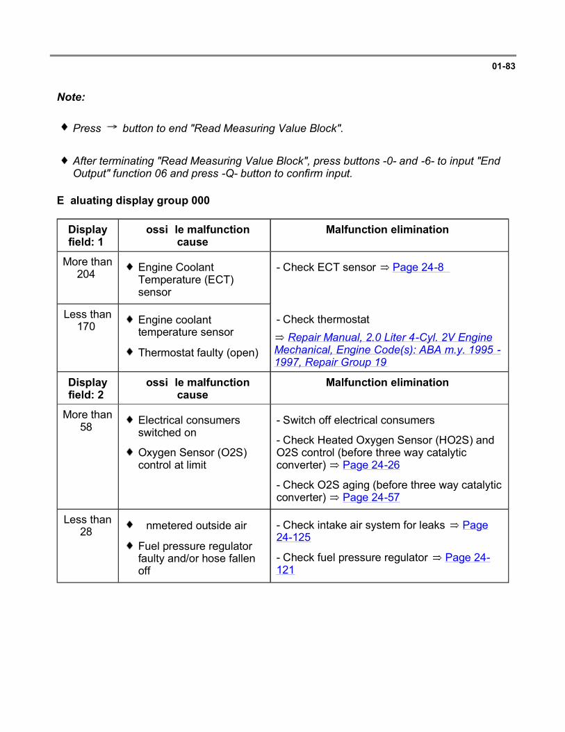
01-83
Note:
Press button to end "Read Measuring Value Block".
After terminating "Read Measuring Value Block", press buttons -0- and -6- to input "End Output" function 06 and press -Q- button to confirm input.
Evaluating display group 000
Display field: 1
Possible malfunction cause
Malfunction elimination
More than 204 Engine Coolant
Temperature (ECT) sensor
- Check ECT sensor Page 24-89
Less than 170 Engine coolant
temperature sensor
Thermostat faulty (open) Repair Manual, 2.0 Liter 4-Cyl. 2V Engine
Mechanical, Engine Code(s): ABA m.y. 1995 - 1997, Repair Group 19
- Check thermostat:
Display field: 2
Possible malfunction cause
Malfunction elimination
More than 58 Electrical consumers
switched on
Oxygen Sensor (O2S) control at limit
- Switch off electrical consumers
- Check Heated Oxygen Sensor (HO2S) and O2S control (before three way catalytic converter) Page 24-26
- Check O2S aging (before three way catalytic converter) Page 24-57
Less than 28 Unmetered outside air
Fuel pressure regulator faulty and/or hose fallen off
- Check intake air system for leaks Page 24-125
- Check fuel pressure regulator Page 24-121
Page 77 of 80VAG 1551 Scan Tool (ST), connecting and selecting 'Engine Electronics' address word...
6/12/2004http://ebahn.bentleypublishers.com/vw/servlet/Display?action=Goto&type=repair&id=VW...
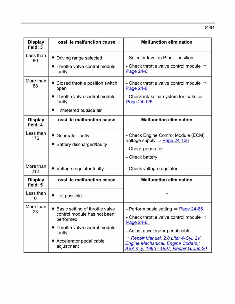
01-84
Display field: 3
Possible malfunction cause Malfunction elimination
Less than 80 Driving range selected
Throttle valve control module faulty
- Selector lever in P or N position
- Check throttle valve control module Page 24-69
More than 88 Closed throttle position switch
open
Throttle valve control module faulty
Unmetered outside air
- Check throttle valve control module Page 24-69
- Check intake air system for leaks Page 24-125
Display field: 4
Possible malfunction cause Malfunction elimination
Less than 176 Generator faulty
Battery discharged/faulty
- Check Engine Control Module (ECM) voltage supply Page 24-106
- Check generator
- Check battery
More than 212 Voltage regulator faulty - Check voltage regulator
Display field: 5
Possible malfunction cause Malfunction elimination
Less than 0 Not possible -
More than 23 Basic setting of throttle valve
control module has not been performed
Throttle valve control module faulty
Accelerator pedal cable adjustment
Repair Manual, 2.0 Liter 4-Cyl. 2V Engine Mechanical, Engine Code(s): ABA m.y. 1995 - 1997, Repair Group 20
- Perform basic setting Page 24-86
- Check throttle valve control module Page 24-69
- Adjust accelerator pedal cable:
Page 78 of 80VAG 1551 Scan Tool (ST), connecting and selecting 'Engine Electronics' address word...
6/12/2004http://ebahn.bentleypublishers.com/vw/servlet/Display?action=Goto&type=repair&id=VW...

01-85
Display field: 6 + 7
Possible malfunction cause
Malfunction elimination
Less than 112 Unmetered air after
throttle valve - Check intake air system for leaks Page 24-125
More than 144 Increased engine load - Switch off consumer
Display field: 8
Possible malfunction cause
Malfunction elimination
Less than 96 Engine too rich, O2S
control weakens mixture
O2S control at limit
Lots of fuel from EVAP canister
Fuel pressure regulator faulty/hose fallen off
- Check HO2S and O2S control (before three way catalytic converter Page 24-26 )
- Check fuel pressure regulator Page 24-121
More than 160 Engine too lean, O2S
control enriches mixture
Unmetered air
Fuel injectors faulty
O2S control at limit
Secondary Air Injection (AIR) system Repair Manual, 2.0 Liter 4-Cyl. 2V Engine
Mechanical, Engine Code(s): ABA m.y. 1995 - 1997, Repair Group 26
- Check HO2S and O2S control (before three way catalytic converter) Page 24-26
- Check intake air system for leaks Page 24-125
- Check fuel injectors Page 24-116
- Check Secondary air injection system Page 01-72 , output Diagnostic Test Mode (DTM) and:
128 Shortage of fuel
O2S control blocked
- Check amount of fuel in tank
- Check HO2S and O2S control (before three way catalytic converter) Page 24-26
Page 79 of 80VAG 1551 Scan Tool (ST), connecting and selecting 'Engine Electronics' address word...
6/12/2004http://ebahn.bentleypublishers.com/vw/servlet/Display?action=Goto&type=repair&id=VW...

01-86
Display field: 9 Possible malfunction cause
Malfunction elimination
Less than 241 or more than 14 Page 24-30 , evaluating display group 025
Display field: 10 Possible malfunction cause
Malfunction elimination
Less than 118 or more than 138 Page 24-30 , evaluating display group 025
Page 80 of 80VAG 1551 Scan Tool (ST), connecting and selecting 'Engine Electronics' address word...
6/12/2004http://ebahn.bentleypublishers.com/vw/servlet/Display?action=Goto&type=repair&id=VW...

01-87
VAG 1551 Scan Tool (ST), connecting and selecting "CARB/OBD II" address word 33
Special tools, testers and auxiliary items
VAG 1551/1552 scan tool with VAG 1551/3 adapter cable
Test conditions
Fuses 15, 18 and 22 OK
Depending on desired function:
Operate VAG 1551/1552 scan tool taking into account the information on the display:
Selectable functions for address word "33 CARB / OBDll"
- Open cover for Data Link Connector (DLC).
- Connect VAG 1551/1552 scan tool with VAG 1551/3 adapter cable.
- Switch ignition on, or start engine.
- Press -1- button to select "Rapid data transfer" operating mode 1.
- Press -3- button twice to select "CARB / OBD II" address word 33.
Page 1 of 17VAG 1551 Scan Tool (ST), connecting and selecting 'CARB/OBD II' address word 33
6/12/2004http://ebahn.bentleypublishers.com/vw/servlet/Display?action=Goto&type=repair&id=VW...

01-88
Rapid data transfer Q
33 - OBD II Display will appear as shown
- Press Q button to confirm input.
OBD II Scan Tool
Select mode 1.. 2.. 3.. 4.. 5.. 6.. 7.. Display will appear as shown
The following modes can be selected:
Note:
When a mode is selected, the control module replies with a 4 on the display in front of the mode selected. Example: mode 2 will be indicated in the display with mode 42.
Mode 1
Current data Page 01-89
Mode 2
Freeze frame data Page 01-98 or Page 01-90
Mode 3
DTC memory Page 01-99
Mode 4
Clear DTC memory Page 01-100
Mode 5
Oxygen sensor signal Page 01-101
Mode 6
Transfer measured values. Measured values that are not being monitoring will be output.
Mode 7
Interrogate DTC memory. Malfunctions which have not switched ON the MIL can be interrogated.
Page 2 of 17VAG 1551 Scan Tool (ST), connecting and selecting 'CARB/OBD II' address word 33
6/12/2004http://ebahn.bentleypublishers.com/vw/servlet/Display?action=Goto&type=repair&id=VW...

01-89
Current data, mode 1
In mode 1 the current diagnostic data can be interrogated. Additionally the readiness code can be displayed (PID1 display field 4).
Breakdown of parameter identification (PID) Page 01-90 diagnostic data.
The On Board Diagnostic (OBD) program can be used to check whether individual parameters correspond to actual engine condition.
- Press -1- button to select mode 1 current data.
Mode 41 PID x Module 10*
diagnostic data
Display will appear as shown
Module 10* or 1A* will be displayed alternately when:
Example: Engine Coolant Temperature is measured at the ECM and ATF at the TCM.
Diagnostic data must be individually interrogated via the button. Press the Print button to obtain a printout.
The MIL is said to be switched ON when the engine is not idling, and only the ignition is switched ON.
Module 10 = Engine Control Module (ECM) -J220-, or
Module 1A = Transmission Control Module (TCM) -J217- have the same parameter identifications (PID)
Page 3 of 17VAG 1551 Scan Tool (ST), connecting and selecting 'CARB/OBD II' address word 33
6/12/2004http://ebahn.bentleypublishers.com/vw/servlet/Display?action=Goto&type=repair&id=VW...

01-90
Diagnostic data
Relevance of figures in 8 digit number block
Mode 41 PID 1 Module 10
00000000 xxxxxxxx xxxxxxxx xxxxxxxx
Display will appear as shown
Display positions 2...8 indicate number of DTCs stored
Display positions Specification
1 2 3 4 5 6 7 8 Number of DTCs stored 0
MIL switched off 1) 0
1) When diagnostic data only is displayed, the specification = 1.
Relevance of figures in 8 digit number block
Mode 41 PID 1 Module 10
xxxxxxxx 00000111 xxxxxxxx xxxxxxxx
Display will appear as shown
Display positions 1 to 5 are not required
Display positions Specification
1 2 3 4 5 6 7 8 Component monitoring 1
Fuel system monitoring 1
Misfire recognition 1
0
Page 4 of 17VAG 1551 Scan Tool (ST), connecting and selecting 'CARB/OBD II' address word 33
6/12/2004http://ebahn.bentleypublishers.com/vw/servlet/Display?action=Goto&type=repair&id=VW...

01-91
Relevance of figures in 8 digit number block
Mode 41 PID 1 Module 10
xxxxxxxx xxxxxxxx 01101101 xxxxxxxx
Display will appear as shown
If specification is 0, the diagnostic capability is not recognized by ECM.
If specification is 1, the diagnostic capability is recognized by ECM.
Display fields Specification
1 2 3 4 5 6 7 8 Three way catalytic converter 1
Three way catalytic converter heating (not available)
0
Fuel tank venting system 1
Secondary air injection (AIR) system 1
A/C (no diagnosiscapability) 0
Heated Oxygen Sensor (HO2S) 1
Oxygen Sensor (O2S) heating 1
Exhaust Gas Recirculation (EGR) system (not available) 0
Page 5 of 17VAG 1551 Scan Tool (ST), connecting and selecting 'CARB/OBD II' address word 33
6/12/2004http://ebahn.bentleypublishers.com/vw/servlet/Display?action=Goto&type=repair&id=VW...

01-92
Mode 41 PID 1 Module 10
xxxxxxxx xxxxxxxx xxxxxxxx 00000000
Display will appear as shown
If the specification is not obtained in display field 4 and a 1 is displayed, then the appropriate diagnostic sequence has not yet been performed. The readiness code must still be created Page 01-35 .
Relevance of figures in 8 digit number block
If specification is 0, the diagnostic program for the readiness code has been completed.
Display fields Specification
1 2 3 4 5 6 7 8 Three way catalytic converter 0
Three way catalytic converter heating (not available)
0
Fuel tank venting system 0
Secondary air injection system 0
A/C (no diagnosis currently) 0
Heated oxygen sensor 0
Oxygen sensor heating 0
Exhaust Gas Recirculation (EGR) system (not available) 0
Page 6 of 17VAG 1551 Scan Tool (ST), connecting and selecting 'CARB/OBD II' address word 33
6/12/2004http://ebahn.bentleypublishers.com/vw/servlet/Display?action=Goto&type=repair&id=VW...

01-93
- Press button to display any additional diagnostic data.
Mode 41 PID 3 Module 10
Fuel System xxxxx1xx xxxxxxxx
PID3: Fuel injection system status
When the 3rd position from the right is 1, the injection status is recognized as available.
- Press button.
Mode 41 PID 4 Module 10
Calculated load value 2 %
PID4: Calculated load value %
Specification at idle approx.: 2%
- Press button.
Mode 41 PID 5 Module 10
Engine Coolant Temp. C
PID5: Engine coolant temperature C
Indicates the current engine coolant temperature
Specification for engine at normal operating temperature: 80 to 105 C (176 to 221 F)
- Press button.
Mode 41 PID 5 Module 1A
Coolant temp. C
PID5: Coolant temperature C
Indicates the current ATF temperature
When the ATF specification is above 140 C (284 F) with engine at normal operating temperature, 80 -105 C (176 -221 F) a DTC will be stored.
Page 7 of 17VAG 1551 Scan Tool (ST), connecting and selecting 'CARB/OBD II' address word 33
6/12/2004http://ebahn.bentleypublishers.com/vw/servlet/Display?action=Goto&type=repair&id=VW...

01-94
- Press button.
Mode 41 PID 6 Module 10
Short Term Fuel Trim Bank 1 x %
PID6: Short Term Fuel Trim, Bank 1 %
The oxygen sensor control integrator in % is displayed here.
- Press button.
Mode 41 PID 7 Module 10
Long Term Fuel Trim Bank 1 x %
PID7: Long Term Fuel Trim, Bank 1 %
The adaptation increases the value in % depending upon altitude.
- Press button.
Mode 41 PID 12 Module 10
Engine speed rpm
PID12: Engine speed (RPM)
The engine speed (RPM) is displayed here.
- Press button.
Mode 41 PID 12 Module 1A
Speed rpm
PID12: Engine speed (RPM)
The input speed (RPM) from transmission is displayed here.
Page 8 of 17VAG 1551 Scan Tool (ST), connecting and selecting 'CARB/OBD II' address word 33
6/12/2004http://ebahn.bentleypublishers.com/vw/servlet/Display?action=Goto&type=repair&id=VW...

01-95
- Press button.
Mode 41 PID 13 Module 1A
Speed x km/h
PID13: Vehicle speed (mph)
Current vehicle speed display
- Press button.
Mode 41 PID 13 Module 10
Speed km/h
PID13: Vehicle speed (mph)
Current vehicle speed display
- Press button.
Mode 41 PID 14 Module 10
Ignition Timing Advance 12
PID14: Ignition angle
Specification at idle: 12 fluctuating.
If the displayed ignition angle is constant and later than 12 , then the cause can be a faulty knock sensor.
- Press button.
Mode 41 PID 15 Module 10
Intake Air Temp. xxx C
PID15: Intake air temperature C
Measured at idle, slightly above ambient temperature
Page 9 of 17VAG 1551 Scan Tool (ST), connecting and selecting 'CARB/OBD II' address word 33
6/12/2004http://ebahn.bentleypublishers.com/vw/servlet/Display?action=Goto&type=repair&id=VW...

01-96
- Press button.
Mode 41 PID 16 Module 10
Air Flow Rate 4.30 g/sec
PID16: Mass air flow g/sec
Measured at idle approx.: 4.3 g/sec.
If the value is below 2.5 g/sec. unmetered (outside) air can be the cause.
- Press button.
Mode 41 PID 17 Module 10
Throttle Valve Position 3 %
PID17: Throttle valve position %
Specification at idle: 2-4%.
A too large or small a value leads to DTC P1582
- Press button.
Mode 41 PID 18 Module 10
Command Secondary Air xxxxx1xx
PID18: Secondary air injection status
When the 3rd position from right is 1, the secondary air injection system is recognized as available.
- Press button.
Mode 41 PID 19 Module 10
Oxygen Sensor Location xxxxxx11
PID19: Location / heated oxygen sensor
When the 1st and the 2nd position from right is 1, the heated oxygen sensors are recognized as available.
Page 10 of 17VAG 1551 Scan Tool (ST), connecting and selecting 'CARB/OBD II' address word 33
6/12/2004http://ebahn.bentleypublishers.com/vw/servlet/Display?action=Goto&type=repair&id=VW...

01-97
- Press button.
Mode 41 PID 20 Module 10
Bank 1 Sensor 1 0.445 V x %
PID20: Heated oxygen sensor 1: 0.445 V x%
The displayed value in volts must fluctuate between 0 and 1.0 volts.
- Press button.
Mode 41 PID 21 Module 10
Bank 1 Sensor 2 0.445 V x %
PID21: Heated oxygen sensor 2: 0.445 V x%
The displayed value in volts must fluctuate between 0 and 1.0 volt, however it must be at a slower rate than the HO2S (before three way catalytic converter).
- Press -C- button to exit mode 1.
Page 11 of 17VAG 1551 Scan Tool (ST), connecting and selecting 'CARB/OBD II' address word 33
6/12/2004http://ebahn.bentleypublishers.com/vw/servlet/Display?action=Goto&type=repair&id=VW...

01-98
Freeze frame data, mode 2
Note:
If a malfunction that illuminates the MIL is detected by the Engine Control Module (ECM) and is then stored, simultaneously, the operating conditions existing at the time the malfunction was stored will also be stored, and can be interrogated via mode 2.
Breakdown of the (PID) identification parameters Page 01-90 diagnostic data.
- Press -2- button to select mode 2 freeze frame data.
Mode 42 0 PID 0 Module 10 *
Freeze Frame Data
Display will appear as shown
Module 10* or 1A* will be activated (alternately):
- Press button.
Module 10 = Engine Control Module (ECM) -J220-
Module 1A = Transmission Control Module (TCM) -J217-
- Press button, and the operating conditions will be printed out as a block, assuming there is a DTC stored in DTC memory.
- Mode 2 can be exited by pressing the -C- button.
Page 12 of 17VAG 1551 Scan Tool (ST), connecting and selecting 'CARB/OBD II' address word 33
6/12/2004http://ebahn.bentleypublishers.com/vw/servlet/Display?action=Goto&type=repair&id=VW...

01-99
DTC memory, mode 3
- Press -3- button to select mode 3 DTC memory.
x Malfunction recognized
Module 10*
MIL off Module 1A*
Display will appear as shown
Module 10* or 1A* will be activated (alternately):
Module 10 = Engine Control Module (ECM) -J220-
Module 1A = Transmission Control Module (TCM) -J217-
MIL OFF / ON = MIL switched OFF or ON
- Press button, any stored DTCs will be displayed in sequence.
P0422 Display will appear as shown (example)
Note:
- Press button.
If two or more DTCs are stored, the cause of the malfunction could be attributed to the second or following malfunction. Interpreting stored DTCs Page 01-14 , DTC table.
After malfunctions have been repaired; clear DTC memory Page 01-100 and create the readiness code again Page 01-35 .
- Press -C- button to exit mode 3.
Page 13 of 17VAG 1551 Scan Tool (ST), connecting and selecting 'CARB/OBD II' address word 33
6/12/2004http://ebahn.bentleypublishers.com/vw/servlet/Display?action=Goto&type=repair&id=VW...

01-100
Clear DTC memory, mode 4
- Start engine and let idle. Press -4- button to select mode 4 clear DTC memory.
Note:
DTC codes (if any are stored) must first be read before they can be cleared. Pressing -4- button will not clear the data in DTC memory immediately. In case of operator error, the control module will respond:
OBD ll Scan Tool
Cleared DTC Memory ? Display will appear as shown
By pressing the -C- button mode 4 will be exited
OBD II Scan Tool
Select mode 1.. 2.. 3.. 4.. 5.. 6.. 7.. Display will appear as shown
By pressing the -Q- button DTC memory will be cleared.
Mode 44 Module 10
DTC Memory is cleared
Display will appear as shown
Note:
When the -Q- button is pressed it can cause the engine to run irregularly until mode 4 is exited.
After repairing malfunctions and clearing DTC memory, the readiness code must be created Page 01-35 . Then the readiness code must be interrogated via mode 41 transfer of diagnostic data
Page 01-90 .
- Press -C- button to exit mode 4.
Page 14 of 17VAG 1551 Scan Tool (ST), connecting and selecting 'CARB/OBD II' address word 33
6/12/2004http://ebahn.bentleypublishers.com/vw/servlet/Display?action=Goto&type=repair&id=VW...
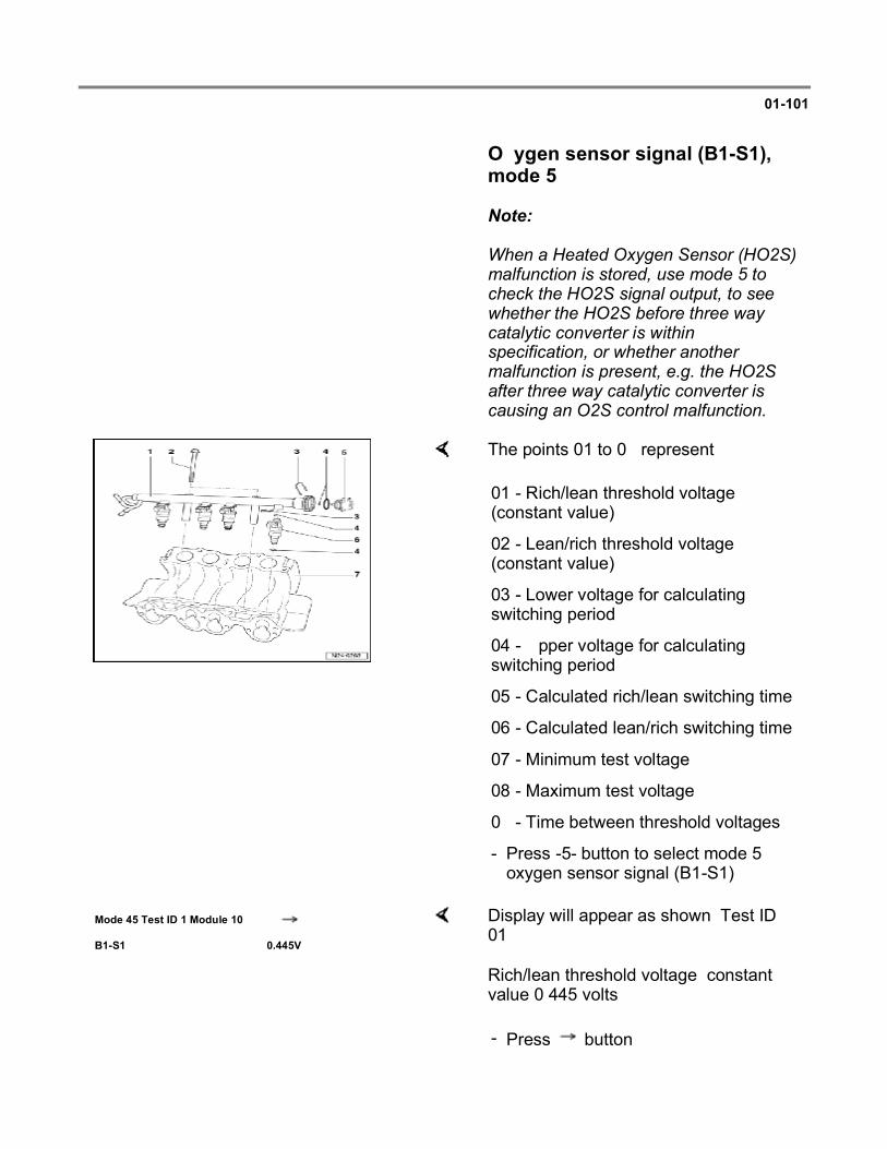
01-101
Oxygen sensor signal (B1-S1), mode 5
Note:
When a Heated Oxygen Sensor (HO2S) malfunction is stored, use mode 5 to check the HO2S signal output, to see whether the HO2S before three way catalytic converter is within specification, or whether another malfunction is present, e.g. the HO2S after three way catalytic converter is causing an O2S control malfunction.
The points 01 to 09 represent:
01 - Rich/lean threshold voltage (constant value)
02 - Lean/rich threshold voltage (constant value)
03 - Lower voltage for calculating switching period
04 - Upper voltage for calculating switching period
05 - Calculated rich/lean switching time
06 - Calculated lean/rich switching time
07 - Minimum test voltage
08 - Maximum test voltage
09 - Time between threshold voltages
- Press -5- button to select mode 5 oxygen sensor signal (B1-S1).
Mode 45 Test ID 1 Module 10
B1-S1 0.445V
Display will appear as shown: Test ID 01
Rich/lean threshold voltage: constant value 0.445 volts
- Press button.
Page 15 of 17VAG 1551 Scan Tool (ST), connecting and selecting 'CARB/OBD II' address word 33
6/12/2004http://ebahn.bentleypublishers.com/vw/servlet/Display?action=Goto&type=repair&id=VW...

01-102
Mode 45 Test ID 2 Module 10
B1-S1 0.445V
Display will appear as shown: Test ID 02
For the following HO2S signals three values are always displayed:
Note:
The displayed Min. and Max. values are constant and do not change. The actual value is displayed as a constant. It will only change when during the test the HO2S supplies a greater or smaller signal.
Lean/rich threshold voltage: constant value 0.445 volts
If constant value is not obtained, the HO2S is faulty
- Press button
1st value = Minimum value
2nd value = Actual value
3rd value = Maximum value
Mode 45 Test ID 7 Module 10
B1-S1 0.148V x.xxV 0.40V
Display will appear as shown: Test ID 07
Minimum test voltage
If the actual value is below 0.148 volts, there is a short circuit to ground.
When the actual value exceeds 0.4 volts, the malfunction could be the HO2S is not at working temperature, sensor heating is faulty, wiring open circuit to HO2S or a short circuit to positive (B+).
Page 16 of 17VAG 1551 Scan Tool (ST), connecting and selecting 'CARB/OBD II' address word 33
6/12/2004http://ebahn.bentleypublishers.com/vw/servlet/Display?action=Goto&type=repair&id=VW...

01-103
- Press button
Mode 45 Test ID 8 Module 10
B1-S1 0.598V x.xxV 1.078V
Display will appear as shown: Test ID 08
Maximum test voltage
If the actual value is above 1.078 volts, there is a short circuit to positive (B+) in the wire to HO2S
If the actual value is below 0.598 volts, the malfunction could be a HO2S not reaching proper operating temperature, faulty O2S heating or an open circuit in the HO2S wiring.
- Press button
Mode 45 Test ID 9 Module 10
B1-S1 0.04s x.xxs 1.20s
Display will appear as shown: Test ID 09
The display shows the time between the threshold voltages
If the actual value is below the minimum time of 0.04 seconds, there is a short circuit
If the actual value exceeds the maximum time of 1.20 seconds, the malfunction could be due to an aged, lazy or contaminated oxygen sensor.
- Press -C- button to exit program sequence
Page 17 of 17VAG 1551 Scan Tool (ST), connecting and selecting 'CARB/OBD II' address word 33
6/12/2004http://ebahn.bentleypublishers.com/vw/servlet/Display?action=Goto&type=repair&id=VW...

24-1
Multiport fuel injection and ignition system Component locations, overview
Repair Manual, 2.0 Liter 4-Cyl. 2V Engine Mechanical, Engine Code(s): ABA m.y. 1995 - 1997, Repair Group 20
1 - Evaporative Emission (EVAP) canister purge regulator valve -N80-
EVAP system
2 - Mass Air Flow (MAF) sensor -G70-
3 - Throttle valve control module -J338-
4 - Engine Control Module
Page 1 of 144Multiport fuel injection and ignition system
6/12/2004http://ebahn.bentleypublishers.com/vw/servlet/Display?action=Goto&type=repair&id=VW...

(ECM) -J220-
5 - Connector
Brown, 4-pin
For Heated Oxygen Sensor (HO2S) 2 -G108-and Oxygen Sensor (O2S) heating (after three way catalytic converter); installation position: Three Way Catalytic Converter (TWC)
Page 2 of 144Multiport fuel injection and ignition system
6/12/2004http://ebahn.bentleypublishers.com/vw/servlet/Display?action=Goto&type=repair&id=VW...

24-2
6 - Connector
Black, 4-pin
For Heated Oxygen Sensor (HO2S) -G39- and Oxygen Sensor (O2S) heating (before three way catalytic converter)
Location: front exhaust pipe
7 - Intake Air Temperature (IAT) sensor -G72-
8 - Ignition coil -N152-
Page 28-3 , item 17
9 -
Speedometer Vehicle Speed Sensor (VSS) -G22-
10 -
Engine Coolant Temperature (ECT) sensor -G62-
Page 3 of 144Multiport fuel injection and ignition system
6/12/2004http://ebahn.bentleypublishers.com/vw/servlet/Display?action=Goto&type=repair&id=VW...

Black, with Engine Coolant Temperature (ECT) sensor -G2-
11 - Center connector
12 - 3-pin connector
For knock sensor
Blue
13 - 3-pin connector
For engine speed sensor
14 - Engine speed (RPM) sensor -G28-
Page 4 of 144Multiport fuel injection and ignition system
6/12/2004http://ebahn.bentleypublishers.com/vw/servlet/Display?action=Goto&type=repair&id=VW...

24-3
Repair Manual, 2.0 Liter 4-Cyl. 2V Engine Mechanical, Engine Code(s): ABA m.y. 1995 - 1997, Repair Group 26
15 - Secondary Air Injection (AIR) pump motor -V101-
16 - Distributor
With Camshaft Position (CMP) sensor -G40- Page 28-3
17 - Fuel injectors
Cylinder 1 -N30-
Cylinder 2 -N31-
Cylinder 3 -N32-
Cylinder 4 -N33-
18 - Knock Sensor (KS) 1 -G61-
Page
28-3 ,
Page 5 of 144Multiport fuel injection and ignition system
6/12/2004http://ebahn.bentleypublishers.com/vw/servlet/Display?action=Goto&type=repair&id=VW...

Repair Manual, 2.0 Liter 4-Cyl. 2V Engine Mechanical, Engine Code(s): ABA m.y. 1995 - 1997, Repair Group 20
item 10
19 - Ground (GND) connection
20 - Fuel pressure regulator
21 -
Temperature regulator Thermal Vacuum Valve (TVV)
For intake air preheating
22 - EVAP canister
Below air cleaner
EVAP system
Page 6 of 144Multiport fuel injection and ignition system
6/12/2004http://ebahn.bentleypublishers.com/vw/servlet/Display?action=Goto&type=repair&id=VW...

24-4
General information
Fuel injection system, servicing
Ignition system, servicing Repair Group 28
Note:
Fuel hoses in engine compartment must be secured with spring type clips. The use of clamp or screw type clips is not permissible.
The control module for the fuel injection and ignition system is equipped with a Diagnostic Trouble Code (DTC) memory. Before carrying out repairs, adjustment work and troubleshooting the DTC memory must be checked and the vacuum connections checked (outside air).
Components marked with an asterisk (*) are checked via the On Board Diagnostic (OBD) program Page 01-12 checking DTC memory.
Components marked with two asterisks (**) are checked via the output Diagnostic Test Mode (DTM) Page 01-72 .
For trouble-free operation of the electrical components, a voltage of at least 11.5 volts is necessary.
Do not use sealants containing silicone. Traces of silicone drawn into the engine are not consumed and will damage the oxygen sensor.
Do not spray anything in the area of the oxygen sensor connectors. To function correctly oxygen sensors require reference air, which they receive via the connector. If contact spray gets into the oxygen sensor via this path it will lead to
Page 7 of 144Multiport fuel injection and ignition system
6/12/2004http://ebahn.bentleypublishers.com/vw/servlet/Display?action=Goto&type=repair&id=VW...

damage/malfunctions.
Page 8 of 144Multiport fuel injection and ignition system
6/12/2004http://ebahn.bentleypublishers.com/vw/servlet/Display?action=Goto&type=repair&id=VW...

24-5
During some checks it can happen that the ECM will recognize and store a malfunction. Therefore after completing all checks and repairs the DTC memory must be checked and if necessary erased Page 01-12 , checking DTC memory.
Safety precautions Page 24-19
Rules for cleanliness Page 24-21
Technical data Page 24-22
Page 9 of 144Multiport fuel injection and ignition system
6/12/2004http://ebahn.bentleypublishers.com/vw/servlet/Display?action=Goto&type=repair&id=VW...

24-6
Fuel injection system, components
Repair Manual, 2.0 Liter 4-Cyl. 2V Engine Mechanical, Engine Code(s): ABA m.y. 1995 - 1997, Repair Group 20
1 - Air Cleaner (ACL)
Disassembling and assembling Page 24-16
2 - Connector
4-pin
Mass Air Flow (MAF) sensor -G70-
3 - Evaporative Emission (EVAP) canister purge regulator valve -N80-*/**
EVAP system
4 - Intake air duct
5 - Positive Crankcase Ventilation
Page 10 of 144Multiport fuel injection and ignition system
6/12/2004http://ebahn.bentleypublishers.com/vw/servlet/Display?action=Goto&type=repair&id=VW...

(PCV) valve
6 - Connector
8-pin
For throttle valve control module -J338-
Page 11 of 144Multiport fuel injection and ignition system
6/12/2004http://ebahn.bentleypublishers.com/vw/servlet/Display?action=Goto&type=repair&id=VW...
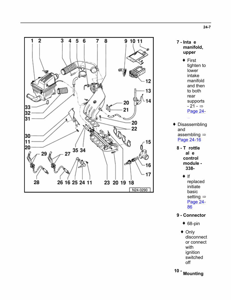
24-7
7 - Intake manifold, upper
First tighten to lower intake manifold and then to both rear supports - 21 - Page 24-9
Disassembling and assembling Page 24-16
8 - Throttle valve control module -J338-*
If replaced initiate basic setting Page 24-86
9 - Connector
68-pin
Only disconnect or connect with ignition switched off
10 - Mounting
Page 12 of 144Multiport fuel injection and ignition system
6/12/2004http://ebahn.bentleypublishers.com/vw/servlet/Display?action=Goto&type=repair&id=VW...

plate
For Engine Control Module (ECM) -J220-
11 - 10 Nm (7 ft lb)
Page 13 of 144Multiport fuel injection and ignition system
6/12/2004http://ebahn.bentleypublishers.com/vw/servlet/Display?action=Goto&type=repair&id=VW...

24-8
12 - Engine Control Module (ECM) -J220-*
Location: in plenum chamber, right side
For fuel injection system, Oxygen Sensor (O2S) control, Evaporative Emission (EVAP) canister purge regulator valve, speed governing via fuel pump relay, idle speed control, ignition and On Board Diagnostic (OBD)
Check ECM coding Page 01-10
If replaced initiate basic setting
Page 14 of 144Multiport fuel injection and ignition system
6/12/2004http://ebahn.bentleypublishers.com/vw/servlet/Display?action=Goto&type=repair&id=VW...

Page 24-86
13 - To brake booster
14 - To A/C
15 - Retaining clip
Check seated securely
16 - O-ring
Replace if damaged
Page 15 of 144Multiport fuel injection and ignition system
6/12/2004http://ebahn.bentleypublishers.com/vw/servlet/Display?action=Goto&type=repair&id=VW...
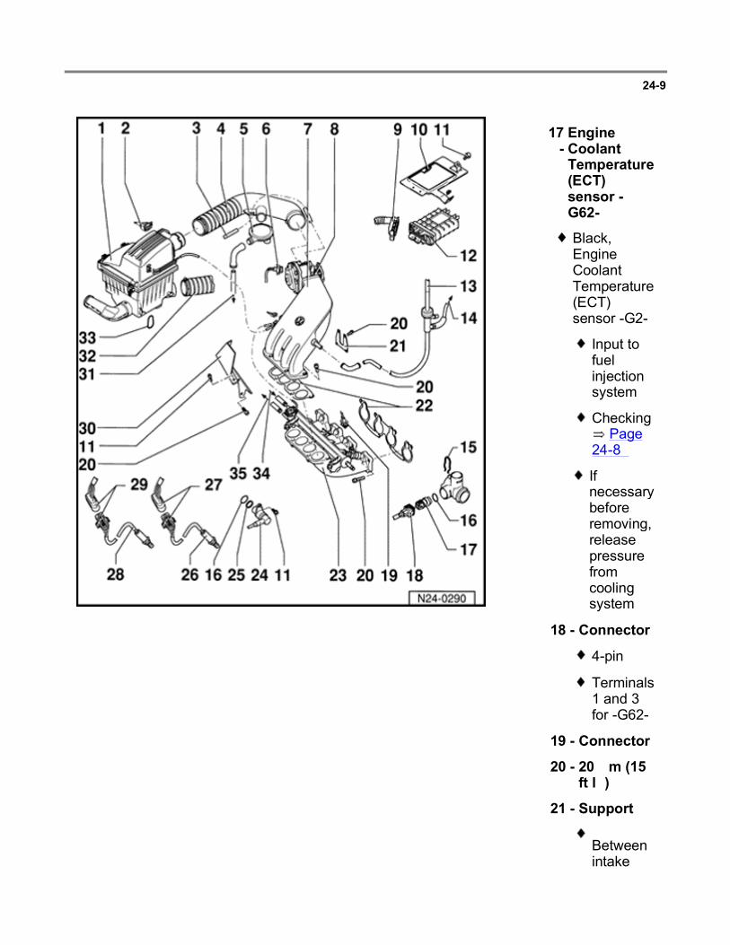
24-9
17 -
Engine Coolant Temperature (ECT) sensor -G62-*
Black, Engine Coolant Temperature (ECT) sensor -G2-
Input to fuel injection system
Checking Page
24-89
If necessary before removing, release pressure from cooling system
18 - Connector
4-pin
Terminals 1 and 3 for -G62-
19 - Connector
20 - 20 Nm (15 ft lb)
21 - Support
Between intake
Page 16 of 144Multiport fuel injection and ignition system
6/12/2004http://ebahn.bentleypublishers.com/vw/servlet/Display?action=Goto&type=repair&id=VW...

manifold upper section and cylinder head
22 - Gasket
Always replace
23 - Intake manifold, lower
Disassembling and assembling Page 24-15
24 - Engine speed (RPM) sensor -G28-*
25 - Spacer ring
Page 17 of 144Multiport fuel injection and ignition system
6/12/2004http://ebahn.bentleypublishers.com/vw/servlet/Display?action=Goto&type=repair&id=VW...

24-10
26 - Heated Oxygen Sensor (HO2S) 2 -G108- *
50 Nm (37 ft lb)
Installation position: Three Way Catalytic Converter (TWC)
Grease only threads with Part No. G 052 112 A3 hot bolt paste (anti-seize compound). Grease must not get into slots of sensor body
Checking HO2S 2 and O2S control Page 24-43
O2S heating voltage supply via fuel pump relay -J17-
Page 18 of 144Multiport fuel injection and ignition system
6/12/2004http://ebahn.bentleypublishers.com/vw/servlet/Display?action=Goto&type=repair&id=VW...

CAUTION!
Part numbers are for reference only. Always check with your Parts Dept. for the latest parts information.
Checking O2S heating
Page 24-50
27 - Connector
Brown, 4-pin
For HO2S 2 -G108- and O2S heating (after three way catalytic converter)
Secured to rear engine mount
Page 19 of 144Multiport fuel injection and ignition system
6/12/2004http://ebahn.bentleypublishers.com/vw/servlet/Display?action=Goto&type=repair&id=VW...

24-11
CAUTION!
28 - Heated Oxygen Sensor (HO2S) -G39-*
50 Nm (37 ft lb)
Installation position: before Three Way Catalytic Converter (TWC)
Grease only threads with Part No. G 052 112 A3 hot bolt paste (anti-seizecompound). Grease must not get into slots of sensor body
Checking HO2S and oxygen sensor control Page 24-26
O2S heating voltage supply via fuel pump relay -J17-
Checking O2S heating Page 24-36
Page 20 of 144Multiport fuel injection and ignition system
6/12/2004http://ebahn.bentleypublishers.com/vw/servlet/Display?action=Goto&type=repair&id=VW...
Part numbers are for reference only. Always check with your Parts Dept. for the latest parts information.
29 - Connector
Black, 4-pin
For HO2S and oxygen sensor heating (before three way catalytic converter)
Secured to rear engine mount
Page 21 of 144Multiport fuel injection and ignition system
6/12/2004http://ebahn.bentleypublishers.com/vw/servlet/Display?action=Goto&type=repair&id=VW...

24-12
Repair Manual, 2.0 Liter 4-Cyl. 2V Engine Mechanical, Engine Code(s): ABA m.y. 1995 - 1997, Repair Group 26
30 - Deflector
31 - To crankcase
32 - Hose
To warm air deflector plate on exhaust manifold
33 - Retaining ring
34 - Supply line
White arrow
Secure with spring-type clips
From fuel delivery unit in fuel tank
35 - Return line
Blue arrow
Secure with spring-
Page 22 of 144Multiport fuel injection and ignition system
6/12/2004http://ebahn.bentleypublishers.com/vw/servlet/Display?action=Goto&type=repair&id=VW...

type clips
To fuel tank
Page 23 of 144Multiport fuel injection and ignition system
6/12/2004http://ebahn.bentleypublishers.com/vw/servlet/Display?action=Goto&type=repair&id=VW...

24-13
Intake manifold, upper, removing and installing
1 - M6: 10 Nm (7 ft lb)
M8: 20 Nm (15 ft lb)
2 - Throttle valve control module -J338-*
Checking Page
24-69
If replaced, "Basic Setting" function 04 must be initiated
Page 24-86
Throttle Position (TP) actuator -V60-
Throttle Position (TP) sensor -G88-
Throttle Position
Page 24 of 144Multiport fuel injection and ignition system
6/12/2004http://ebahn.bentleypublishers.com/vw/servlet/Display?action=Goto&type=repair&id=VW...
Repair Manual, 2.0 Liter 4-Cyl. 2V Engine Mechanical, Engine Code(s): ABA m.y. 1995 - 1997, Repair Group 20
(TP) sensor -G69-
Closed Throttle Position (CTP) switch -F60-
3 - Retainer
4 - Support bracket
For accelerator pedal cable
Adjusting accelerator pedal cable:
Page 25 of 144Multiport fuel injection and ignition system
6/12/2004http://ebahn.bentleypublishers.com/vw/servlet/Display?action=Goto&type=repair&id=VW...

24-14
5 - Intake Air Temperature (IAT) sensor -G72- *
10 Nm (7 ft lb)
Checking Page
24-95
6 - Intake manifold, upper
7 - Gasket
Always replace
Page 26 of 144Multiport fuel injection and ignition system
6/12/2004http://ebahn.bentleypublishers.com/vw/servlet/Display?action=Goto&type=repair&id=VW...

24-15
Intake manifold, lower, removing and installing
1 - Retaining clip
Check securely seated
2 - Strainer
3 - Fuel pressure regulator
Checking Page
24-121
4 - O-ring
Replace if damaged
5 - Fuel Injectors*/**
Cylinder 1 -N30-
Cylinder 2 -N31-
Cylinder 3 -N32-
Cylinder 4 -N33-
Checking Page
24-116
6 - Intake manifold, lower
Page 27 of 144Multiport fuel injection and ignition system
6/12/2004http://ebahn.bentleypublishers.com/vw/servlet/Display?action=Goto&type=repair&id=VW...

7 - 10 Nm (7 ft lb)
8 - Fuel rail
Page 28 of 144Multiport fuel injection and ignition system
6/12/2004http://ebahn.bentleypublishers.com/vw/servlet/Display?action=Goto&type=repair&id=VW...

24-16
Air Cleaner (ACL), removing and installing
1 - Rubber grommet
2 - Air cleaner element
3 - Air cleaner housing, upper
4 - O-ring
Replace if damaged
5 - Mass Air Flow (MAF) sensor -G70-*
Checking Page
24-63
6 - 10 Nm (7 ft lb)
7 - Temperature regulator Thermal Vacuum Valve (TVV)
For intake air preheating
Metal connector pipe or with notch toward
Page 29 of 144Multiport fuel injection and ignition system
6/12/2004http://ebahn.bentleypublishers.com/vw/servlet/Display?action=Goto&type=repair&id=VW...

regulator flap
Intake air preheating, checking
Page 24-127
8 - Gasket
Replace if damaged
Page 30 of 144Multiport fuel injection and ignition system
6/12/2004http://ebahn.bentleypublishers.com/vw/servlet/Display?action=Goto&type=repair&id=VW...

24-17
9 - Mounting plate
10 - To intake hose
11 - Vacuum hose
12 - Vacuum unit
13 - Air cleaner housing, lower
14 - Spacer
Page 31 of 144Multiport fuel injection and ignition system
6/12/2004http://ebahn.bentleypublishers.com/vw/servlet/Display?action=Goto&type=repair&id=VW...

24-18
The diagram applies to Engine Coolant Temperature (ECT) sensor -G62- and Intake Air Temperature (IAT) sensor -G72-.
Scale A shows resistance values for temperature range 0 -50 C (32 -122 F) and scale B shows the values for temperature range 50 -100 C (122 -212 F).
Examples:
Fig. 1 Resistance graph
30 C (86 F) corresponds to a resistance from 1500-2000 ohms (
)
80 C (176 F) corresponds to a resistance from 275-375 ohms ( )
Page 32 of 144Multiport fuel injection and ignition system
6/12/2004http://ebahn.bentleypublishers.com/vw/servlet/Display?action=Goto&type=repair&id=VW...

24-19
Safety precautions
WARNING!
Fuel system is under pressure! Before opening the system place a rag around the connection. Then release pressure by slowly loosening the connection.
Be alert when working on or near the engine. High ignition secondary voltage can cause serious personal injury and damage vehicle components.
DO NOT touch or disconnect ignition system wires when the engine is running or being cranked at starting RPM.
DO NOT operate the starter if the fuel injectors have been removed.
Be sure the ignition is switched OFF, when:
Disconnecting ignition wires
Disconnecting fuel injection system wiring
Connecting or disconnecting test equipment leads
Disconnecting the battery
Washing the engine or engine compartment.
BEFORE cranking the engine at starting RPM (such as for compression testing) disable the ignition and fuel injection systems:
Disconnect the ignition coil power output stage.
Page 33 of 144Multiport fuel injection and ignition system
6/12/2004http://ebahn.bentleypublishers.com/vw/servlet/Display?action=Goto&type=repair&id=VW...

Disconnect harness connectors from all fuel injectors.
After the work is completed, erase DTC memory.
Page 34 of 144Multiport fuel injection and ignition system
6/12/2004http://ebahn.bentleypublishers.com/vw/servlet/Display?action=Goto&type=repair&id=VW...
24-20
CAUTION!
BEFORE disconnecting the battery:
Stop the engine.
Be sure the ignition is switched OFF (also applies when connecting the battery). Failure to do so may damage the Engine Control Module (ECM).
Be sure of the proper radio code (for vehicles equipped with coded anti-theft radio).
Be sure the battery negative (-) cable is disconnected, when:
Working on the electrical system
Resistance (spot) welding or electric arc welding anywhere on the vehicle.
When connecting and disconnecting electrical test equipment (LED voltage tester, multimeter, etc.):
Be sure the ignition is switched OFF.
Use correct adapters from the VW 1594 connector test kit.
For any work affecting the Engine Control Module (ECM):
BEFORE disconnecting the ECM harness connector, switch the ignition OFF and WAIT at least 20 seconds. Failure to do so may damage the ECM.
DO NOT connect any outside voltage source to stimulate an output signal at the ECM.
Page 35 of 144Multiport fuel injection and ignition system
6/12/2004http://ebahn.bentleypublishers.com/vw/servlet/Display?action=Goto&type=repair&id=VW...

24-21
Rules for cleanliness
CAUTION!
Whenever carrying out work on the fuel supply and fuel injection systems, carefully observe the following five rules of cleanliness.
1 - Thoroughly clean fuel system line and hose connections and the surrounding area before disconnecting.
2 - Place removed components on a clean surface and cover. Use plastic sheeting or paper. Do not use fluffy rags that could leave lint!
3 - Carefully cover over or seal any components that have been opened if repairs are not carried out immediately.
4 - Install only clean parts:
Do not remove replacement parts from the packaging until immediately before they are to be installed.
Do not use parts that have been stored without packaging (e.g. in toolboxes, etc.).
5 - When the fuel system is opened:
Avoid working with compressed air whenever possible.
Avoid moving the vehicle if possible.
Page 36 of 144Multiport fuel injection and ignition system
6/12/2004http://ebahn.bentleypublishers.com/vw/servlet/Display?action=Goto&type=repair&id=VW...

24-22
Technical data
Engine code ABA
Idle check 1)
Idle speed RPM 800 to 880 2)
Oxygen sensor control factor
% -5.0 to 5.0 2)3)
Ignition timing 2.0 to 15.0 52)3)
Engine control module (ECM) 4)
Part number Parts catalog
Governed engine speed
RPM 5800 to 6000
1) Observe test conditions Page 24-23
2) Not adjustable
3) Display fluctuates
4) If replaced, initiate "Basic Setting" function 04 Page 24-86
Page 37 of 144Multiport fuel injection and ignition system
6/12/2004http://ebahn.bentleypublishers.com/vw/servlet/Display?action=Goto&type=repair&id=VW...
24-23
Idle speed, checking
Idle speed, ignition timing and CO content not adjustable.
The idle speed is regulated by the throttle valve control module.
The position of the distributor has no influence on ignition timing.
The CO content is held to specification by the oxygen sensor control. Malfunctions in oxygen sensor control will be detected by On Board Diagnostic (OBD) and stored in Diagnostic Trouble Code (DTC) memory.
Special tools, testers and auxiliary items
VAG 1551 scan tool with VAG 1551/3 adapter cable
Test conditions
No malfunctions stored in DTC memory Page 01-12 , checking DTC memory
Engine oil temperature minimum 80 C (176 F)
Electrical consumers switched off (radiator coolant fan must not run during the check)
A/C switched off
Exhaust system must be free of leaks
Page 38 of 144Multiport fuel injection and ignition system
6/12/2004http://ebahn.bentleypublishers.com/vw/servlet/Display?action=Goto&type=repair&id=VW...

24-24
Test sequence
Engine running at idle
- Connect VAG 1551/1552 scan tool and select "Engine Electronics" address word 01 Page 01-7 .
Rapid data transfer HELP
Select function XX Indicated on display
- Press buttons -0- and -4- to select "Basic Setting" function 04 and press -Q- button to confirm input.
Basic Setting HELP
Input display group number XXX Indicated on display
- Press buttons -0-, -0- and -1- to input display group 001 and press -Q- button to confirm input.
System in Basic Setting 1
1 2 3 4
Indicated on display (1-4 Display fields)
Note:
In "Basic Setting" function 04 the Evaporative Emission (EVAP) canister purge regulator valve -N80- is closed.
Do not continue with check until engine temperature exceeds 80 C (176 F) in display field 2.
- Briefly increase engine speed (rev-up) and then allow engine to run at idle speed for 2 minutes.
- Check specifications (display fields 1-4).
Page 39 of 144Multiport fuel injection and ignition system
6/12/2004http://ebahn.bentleypublishers.com/vw/servlet/Display?action=Goto&type=repair&id=VW...

24-25
Display fields
1 2 3 4
Display group 001: Idle test
Display xxxx RPM xxx.x C xx.x% xx.x
Indicated Engine speed Coolant temperature
Oxygen Sensor (O2S) control
Ignition angle
Working range
800 - 6000 RPM - -25.0 to 25.0% 0.0 - 40.0
Specification 800 - 880 RPM 80.0 - 105.0C
Must fluctuate by at least 2% in the
range -5.0 to 5.0%
2.0 - 15.0
If specification is not attained
Page 24-69 : check throttle valve control
module
- If specification is not attained
Page 24-26 : check Heated Oxygen
Sensor (HO2S) and O2S control (before three way catalytic
converter)
If specification is not attained
Page 28-14 : checking
ignition timing
- Press button.
- Press buttons -0- and -6- to select "End Output" function 06 and press -Q- button to confirm input.
- Perform a road test and repeat check.
- Read readiness code Page 01-33 . If DTC memory has been erased, repair must be verified via appropriate display group Page 01-35 , Readiness code, creating.
Page 40 of 144Multiport fuel injection and ignition system
6/12/2004http://ebahn.bentleypublishers.com/vw/servlet/Display?action=Goto&type=repair&id=VW...

24-26
Heated Oxygen Sensor (HO2S) and Oxygen Sensor (O2S) control, checking (before three way catalytic converter)
Special tools, testers and auxiliary items
VAG 1551/1552 scan tool with VAG 1551/3 adapter cable
VAG 1598/18 test box
Multimeter (Fluke 83 or equivalent)
Connector test kit VW 1594
Wiring diagram
Test conditions
Coolant temperature at least 80 C (176 F)
Functional check
Engine running at idle
- Connect VAG 1551/1552 scan tool and select "Engine Electronics" address word 01 Page 01-7 .
Rapid data transfer HELP
Select function XX Indicated on display
- Press buttons -0- and -8- to select "Read Measuring Value Block" function 08 and press -Q- button to confirm input.
Page 41 of 144Multiport fuel injection and ignition system
6/12/2004http://ebahn.bentleypublishers.com/vw/servlet/Display?action=Goto&type=repair&id=VW...

24-27
Read Measuring Value Block HELP
Input display group number XXX Indicated on display
- Press buttons -0-, -2- and -5- to input display group 025 and press -Q- button to confirm input.
Read Measuring Value Block 25
1 2 3 4
Indicated on display (1-4 Display fields)
- Check specifications for O2S control (before three way catalytic converter) in display fields 1-3.
Display fields
1 2 3 4
Display group 025: Oxygen Sensor (O2S) control before Three Way Catalytic Converter (TWC)
Display xx.x% xx.x% xx.x% xxx ms
Indicated O2S control Partial load adaptation
value
Idle adaptation value
O2S control status (before
TWC)
Working range
-25.0 to 25.0% -16.4 to 16.4% -16.4 to 16.4% -
Specification The value must fluctuate at least 2% within range -5.0 to
5.0%
-5.0 to 5.0% can fluctuate
slightly
-5.0 to 5.0% can fluctuate
slightly
Relevance Page 24-32
If specification is not attained Page 24-
28 , continuation
If specification is not attained Page 24-30 , evaluating
display group 025
-
Page 42 of 144Multiport fuel injection and ignition system
6/12/2004http://ebahn.bentleypublishers.com/vw/servlet/Display?action=Goto&type=repair&id=VW...

24-28
Continuation
If the specification in display field 1 is not attained, or the value does not fluctuate at least 2%:
- Perform a test drive to remove possible residue on HO2S and repeat check.
If the the specification in display field 1 is not attained even after a road test, or the value does not fluctuate at least 2%:
- Check O2S heating Page 24-36 .
If the value displayed in display field 1 remains constant:
- Press -C- button.
- Press buttons -1-, -1- and -5- to input display group 115 and press -Q- button to confirm input.
Read Measuring Value Block 115
1 2 3 4
Indicated on display (1-4 Display fields)
- Note HO2S voltage in display field 3.
Page 43 of 144Multiport fuel injection and ignition system
6/12/2004http://ebahn.bentleypublishers.com/vw/servlet/Display?action=Goto&type=repair&id=VW...

24-29
Display fields
1 2 3 4
Display group 115: Heated Oxygen Sensor (HO2S) before Three Way Catalytic Converter (TWC)
Display xxx.x C xxx.x C x.xxx V xxxxxxxx
Indicated Coolant temperature
Exhaust gas temperature (calculated)
HO2S voltage (before TWC)
O2S control status (before
TWC)
Working range
-46.5 to 141.0 C
0.0 - 999.9 C 0.000 - 1.000 V -
Specification 80.0 to 105.0 C
Min.140.0 C The voltage must fluctuate at least 0.3 V at least 30 times per minute in the range
0.000 - 1.000 V
Relevance Page 24-32
- - If specification is not attained Page 24-
31 , evaluating display group 115
-
- Press button.
- Press buttons -0- and -6- to select "End Output" function 06 and press -Q- button to confirm input.
- Switch ignition off.
Page 44 of 144Multiport fuel injection and ignition system
6/12/2004http://ebahn.bentleypublishers.com/vw/servlet/Display?action=Goto&type=repair&id=VW...

24-30
Evaluating display group 025
Display group: 025
Display field: 2 and 3
Possible malfunction cause Malfunction elimination
Adaptation values in range: -5 to -16.4%
Crankcase dilution: when the partial load adaptation value (display field 2) is normal
- Oil change or a fast drive on country roads
Fuel pressure too high - Check fuel pressure regulator Page 24-121
Fuel injector leaking - Check fuel injectors Page 24-116
Oxygen Sensor (O2S) heating - Check O2S heating Page 24-36
Adaptation values in range: 5 to 16.4%
Unmetered air in air intake system or exhaust manifold/front pipe: When the partial load adaptation value (display field 2) is normal
Repair Manual, 2.0 Liter 4-Cyl. 2V Engine Mechanical, Engine Code(s): ABA m.y. 1995 - 1997, Repair Group 26
- Check intake air system for leaks (unmetered air) Page 24-125
- Check exhaust system for leaks
Fuel pressure too low - Check fuel pressure regulator Page 24-121
Check O2S heating - Check O2S heating Page 24-36
Fuel injector not opening or only partly opening
- Check fuel injectors Page 24-116
Adaptation values: constant 0.0%
Oxygen Sensor (O2S) control adaptation not active
- Check whether O2S control adaptation is active Page 24-32
Page 45 of 144Multiport fuel injection and ignition system
6/12/2004http://ebahn.bentleypublishers.com/vw/servlet/Display?action=Goto&type=repair&id=VW...

If O2S control adaptation is not active:
- Check Mass Air Flow (MAF) sensor Page 24-63
Page 46 of 144Multiport fuel injection and ignition system
6/12/2004http://ebahn.bentleypublishers.com/vw/servlet/Display?action=Goto&type=repair&id=VW...

24-31
Evaluating display group 115
Display group: 115
Possible malfunction cause Malfunction elimination
Display field: 3
Approx. 0.435 V Open circuit in wire 4 between Heated Oxygen
Sensor (HO2S) and Engine Control Module (ECM)
- Check basic voltage Page 24-33
Approx. 0.440 V Open circuit in wire 3 between HO2S and ECM
Approx. 1.085 V Short circuit to positive (B+) in wire 4 between
HO2S and ECM - Check HO2S wiring
Page 24-34
Approx. 0.000 V Short circuit to Ground (GND) in wire 4
between HO2S and ECM
Page 47 of 144Multiport fuel injection and ignition system
6/12/2004http://ebahn.bentleypublishers.com/vw/servlet/Display?action=Goto&type=repair&id=VW...

24-32
Relevance of values in 8-digit number block
Relevance when display = 1
x x x x x x x x O2S control status (display group 025)
O2S control status (display group 115)
1 HO2S ready (before TWC) Malfunction in DTC memory
1 HO2S ready (after TWC) Malfunction detected during this diagnosis
1 O2S control active (before TWC)
Diagnosis completed during this drive
1 O2S adaptation active Diagnosis currently active
1 Not relevant O2S control active (before TWC)
1 HO2S voltage initial sign HO2S ready (before TWC)
1 Not relevant Both HO2S cold
1 1 = O2S control regulating frequency rich
0 = O2S control regulating frequency lean
O2S heating on (before TWC)
Page 48 of 144Multiport fuel injection and ignition system
6/12/2004http://ebahn.bentleypublishers.com/vw/servlet/Display?action=Goto&type=repair&id=VW...

24-33
Checking basic voltage
- Separate 4-pin connector (black) -1- to HO2S -G39- (before three way catalytic converter).
If the specification is not attained:
If the specification is attained:
- Connect multimeter with test leads from VW 1594 to measure voltage between terminals 3 and 4 (ECM side of harness connector).
- Start engine and measure the basic voltage.
Specification: 0.40-0.50 volts
- Switch ignition off.
- Check HO2S wiring Page 24-34 .
- Replace HO2S -G39- (before three way catalytic converter).
Page 49 of 144Multiport fuel injection and ignition system
6/12/2004http://ebahn.bentleypublishers.com/vw/servlet/Display?action=Goto&type=repair&id=VW...

24-34
Checking Heated Oxygen Sensor (HO2S) wiring
- Connect VAG 1598/18 test box to ECM wiring harness.
- Separate 4-pin connector -1- (black) to HO2S -G39- (before three way catalytic converter).
Page 50 of 144Multiport fuel injection and ignition system
6/12/2004http://ebahn.bentleypublishers.com/vw/servlet/Display?action=Goto&type=repair&id=VW...

24-35
If no wiring malfunction is detected:
- Check wiring between test box and 4-pin connector for open circuit according to wiring diagram (ECM side of harness connector).
Terminal 3 and test box socket 42
Terminal 4 and test box socket 20
Resistance: maximum 1.5 ohms ( )
- Additionally, check wiring at 4-pin connector for short circuit to one another.
Terminal 4 and test box socket 42
Specification: ohms ( )
- Check shielding for short circuit to HO2S wiring according to wiring diagram.
Terminal 4 and test box socket 56
Terminal 3 and test box socket 56
Specification: ohms ( )
- Replace ECM -J220-.
- Read readiness code Page 01-33 . If DTC memory has been erased, repair must be verified via appropriate display group Page 01-35 , Readiness code, creating.
Page 51 of 144Multiport fuel injection and ignition system
6/12/2004http://ebahn.bentleypublishers.com/vw/servlet/Display?action=Goto&type=repair&id=VW...

24-36
Oxygen Sensor (O2S) heating, checking (before three way catalytic converter)
Special tools, testers and auxiliary items
VAG 1551/1552 scan tool with VAG 1551/3 adapter cable
VAG 1598/18 test box
Multimeter (Fluke 83 or equivalent)
Connector test kit VW 1594
Wiring diagram
Test conditions
Fuse 18 OK
Test sequence
Engine running at idle
- Connect VAG 1551/1552 scan tool and select "Engine Electronics" address word 01 Page 01-7 .
Rapid data transfer HELP
Select function XX Indicated on display
- Press buttons -0- and -8- to select "Read Measuring Value Block" function 08 and press -Q- button to confirm input.
Page 52 of 144Multiport fuel injection and ignition system
6/12/2004http://ebahn.bentleypublishers.com/vw/servlet/Display?action=Goto&type=repair&id=VW...

24-37
Read Measuring Value Block HELP
Input display group number XXX Indicated on display
- Press buttons -1-, -2- and -0- to input display group 120 and press -Q- button to confirm input.
Read Measuring Value Block 120
1 2 3 4
Indicated on display (1-4 Display fields)
- Check the resistance value for oxygen sensor heating before three way catalytic converter (display field 3).
Display fields
1 2 3 4
Display group 120: Oxygen Sensor (O2S) heating before Three Way Catalytic Converter (TWC)
Display xxx.x C xxx.xx sec. xx.x xxxxxxxx
Indicated Exhaust gas temperature
Time to start of diagnosis after
heating on
O2S heating resistance (before
TWC)
Oxygen Sensor (O2S) control status (before
TWC)
Working range
0.0 - 999.9 C
0.00 - 500.00 sec.
0.0 - 65.0 Relevance Page 24-38
Specification - 100.00 - 200.00 sec.
5.9 - 24.2
- - If specification is not attained Page 24-
39 , continuation
-
Page 53 of 144Multiport fuel injection and ignition system
6/12/2004http://ebahn.bentleypublishers.com/vw/servlet/Display?action=Goto&type=repair&id=VW...

24-38
- Press button.
- Press buttons -0- and -6- to select "End Output" function 06 and press -Q- button to confirm input.
- Switch ignition off.
Relevance of values in 8-digit number block
Relevance if display = 1
x x x x x x x x Oxygen sensor control status (display group 120)
1 Malfunction in DTC memory
1 Malfunction detected during this diagnosis
1 Diagnosis completed during this drive
1 Diagnosis currently active
1 O2S heating ready (before TWC)
1 HO2S ready (before TWC)
1 Vapor point exceeded (before TWC)
1 1 = O2S heating (before TWC) on
Alternately 0 and 1 = O2S heating is fluctuating
Page 54 of 144Multiport fuel injection and ignition system
6/12/2004http://ebahn.bentleypublishers.com/vw/servlet/Display?action=Goto&type=repair&id=VW...

24-39
Continuation
- Separate 4-pin connector -1- (black) to HO2S -G39- (before three way catalytic converter).
If the specification is not attained:
- Connect multimeter with test leads from VW 1594 to measure resistance at terminals 1 and 2 on connector to HO2S.
- Check the resistance value.
Specification: 0.0-24.2 ohms ( )
- Replace HO2S -G39- (before three way catalytic converter).
Page 55 of 144Multiport fuel injection and ignition system
6/12/2004http://ebahn.bentleypublishers.com/vw/servlet/Display?action=Goto&type=repair&id=VW...

24-40
If the specification is attained:
- Check relevance table Page 24-38 for value of O2S control status, display group 120, display field 4, 1st position from left.
- Set multimeter to voltage measurement range.
If no voltage is present:
- Connect multimeter using test leads from VW 1594 to measure voltage between terminals 1 and 2 (ECM side of harness connector).
- Measure voltage supply.
When display = 1: specification is 11.0-14.5 volts
When display = alternately 0 and 1: specification is fluctuating between 0.0-12.0 volts
If again no voltage is present:
- Connect multimeter with test leads from VW 1594 to measure voltage between terminal 1 (ECM side of harness connector) and vehicle Ground (GND).
Specification: 11.0-14.5 volts
- Check wiring from terminal 1 to relay panel according to wiring diagram.
Page 56 of 144Multiport fuel injection and ignition system
6/12/2004http://ebahn.bentleypublishers.com/vw/servlet/Display?action=Goto&type=repair&id=VW...
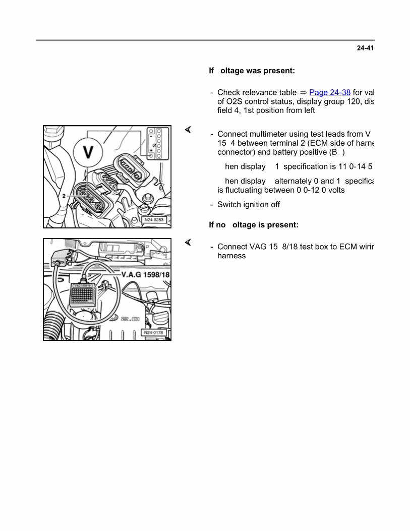
24-41
If voltage was present:
- Check relevance table Page 24-38 for value of O2S control status, display group 120, display field 4, 1st position from left.
If no voltage is present:
- Connect multimeter using test leads from VW 1594 between terminal 2 (ECM side of harness connector) and battery positive (B+).
When display = 1: specification is 11.0-14.5 volts
When display = alternately 0 and 1: specification is fluctuating between 0.0-12.0 volts
- Switch ignition off.
- Connect VAG 1598/18 test box to ECM wiring harness.
Page 57 of 144Multiport fuel injection and ignition system
6/12/2004http://ebahn.bentleypublishers.com/vw/servlet/Display?action=Goto&type=repair&id=VW...

24-42
If no wiring malfunction is detected:
- Check wiring between test box and 4-pin connector for open circuit according to wiring diagram.
Terminal 2 and test box socket 12
Resistance: maximum 1.5 ohms ( )
- Replace Engine Control Module (ECM) -J220-.
- Read readiness code Page 01-33 . If DTC memory has been erased, repair must be verified via appropriate display group Page 01-35 , Readiness code, creating.
Page 58 of 144Multiport fuel injection and ignition system
6/12/2004http://ebahn.bentleypublishers.com/vw/servlet/Display?action=Goto&type=repair&id=VW...

24-43
Heated Oxygen Sensor (HO2S) 2 and Oxygen Sensor (O2S) control, checking (after three way catalytic converter)
Special tools, testers and auxiliary items
VAG 1551/1552 scan tool with VAG 1551/3 adapter cable
VAG 1598/18 test box
Multimeter (Fluke 83 or equivalent)
Connector test kit VW 1594
Wiring diagram
Test conditions
Coolant temperature at least 80 C (176 F)
Functional check
Engine running at idle
- Connect VAG 1551/1552 scan tool and select "Engine Electronics" address word 01 Page 01-7 .
Rapid data transfer HELP
Select function XX Indicated on display
- Press buttons -0- and -8- to select "Read Measuring Value Block" function 08 and press -Q- button to confirm input.
Page 59 of 144Multiport fuel injection and ignition system
6/12/2004http://ebahn.bentleypublishers.com/vw/servlet/Display?action=Goto&type=repair&id=VW...

24-44
Read Measuring Value Block HELP
Input display group number XXX Indicated on display
- Press buttons -1-, -1- and -6- to input display group 116 and press -Q- button to confirm input.
Read Measuring Value Block 116
1 2 3 4
Indicated on display (1-4 Display fields)
- Note HO2S voltage (display field 3).
Display fields
1 2 3 4
Display group 116: Heated Oxygen Sensor (HO2S) 2 after Three Way Catalytic Converter (TWC)
Display xxx ms xxx.x C x.xxx V xxxxxxxx
Indicated Regulating frequency
Exhaust gas temperature (calculated)
HO2S voltage (after TWC)
Oxygen Sensor (O2S) control status (after
TWC)
Working range
- 0.0 - 999.9 C 0.000 - 1.000 V -
Specification - Min.140.0 C 0.000 - 1.000 V (can fluctuate marginally)
Relevance Page 24-45
- - If specification is not attained Page 24-
45 , continuation
-
Page 60 of 144Multiport fuel injection and ignition system
6/12/2004http://ebahn.bentleypublishers.com/vw/servlet/Display?action=Goto&type=repair&id=VW...

24-45
Continuation
- Perform a test drive to remove possible residue from HO2S and repeat check.
If the specification in display field 3 is not attained even after a test drive:
- Check O2S heating Page 24-50 .
- Increase engine speed to above 3000 RPM.
If the value in display field 3 remains constant evaluating display group 116.
Evaluating display group 116
Display group: 116
Display field: 3
Possible malfunction cause Malfunction elimination
Approx. 0.435 V Wiring open circuit in wire 4 between HO2S
and Engine Control Module (ECM) - Check basic voltage
Page 24-47
Approx. 0.440 V Wiring open circuit in wire 3 between HO2S
and ECM
Approx. 1.085 V Short circuit to positive (B+) in wire 4
between HO2S and ECM - Check HO2S wiring Page 24-48
Approx. 0.000 V Short circuit to Ground (GND) in wire 4
between HO2S and ECM
Page 61 of 144Multiport fuel injection and ignition system
6/12/2004http://ebahn.bentleypublishers.com/vw/servlet/Display?action=Goto&type=repair&id=VW...

24-46
Relevance of values in 8-digit number block
Relevance if display = 1
x x x x x x x x O2S control status (display group 116)
1 Malfunction in Diagnostic Trouble Code (DTC) memory
1 Malfunction detected during this diagnosis
1 Diagnosis completed during this drive
1 Diagnosis currently active
1 O2S control active (before TWC)
1 HO2S ready (after TWC)
1 Both Heated Oxygen Sensors (HO2S) cold
1 O2S heating on (after TWC)
Page 62 of 144Multiport fuel injection and ignition system
6/12/2004http://ebahn.bentleypublishers.com/vw/servlet/Display?action=Goto&type=repair&id=VW...

24-47
Checking basic voltage
- Separate 4-pin connector -2- (brown) to HO2S 2 -G108- (after three way catalytic converter).
If the specification is not attained:
If the specification is attained:
- Connect multimeter using test leads from VW 1594 to measure voltage between terminals 3 and 4 (ECM side of harness connector).
- Start engine and measure basic voltage.
Specification: 0.40-0.50 volts
- Switch ignition off.
- Check HO2S wiring Page 24-48
- Replace HO2S 2 -G108- (after three way catalytic converter).
Page 63 of 144Multiport fuel injection and ignition system
6/12/2004http://ebahn.bentleypublishers.com/vw/servlet/Display?action=Goto&type=repair&id=VW...

24-48
Checking Heated Oxygen Sensor (HO2S) wiring
- Connect VAG 1598/18 test box to ECM wiring harness.
- Separate 4-pin connector -2- (brown) to HO2S 2 -G108- (after three way catalytic converter).
Page 64 of 144Multiport fuel injection and ignition system
6/12/2004http://ebahn.bentleypublishers.com/vw/servlet/Display?action=Goto&type=repair&id=VW...

24-49
If no wiring malfunction is detected:
- Check wiring between test box and 4-pin connector to ECM for open circuit according to wiring diagram.
Terminal 3 and test box socket 58
Terminal 4 and test box socket 13
Resistance: maximum 1.5 ohms ( )
- Additionally, check wiring to 4-pin connector for short circuits to one another.
Terminal 4 and test box socket 58
Specification: ohms ( )
- Check shielding for short circuit to HO2S wiring.
Terminal 4 and test box socket 56
Terminal 3 and test box socket 56
Specification: ohms ( )
- Replace Engine Control Module (ECM) -J220-.
- Read readiness code Page 01-33 . If DTC memory has been erased, repair must be verified via appropriate display group Page 01-35 , Readiness code, creating.
Page 65 of 144Multiport fuel injection and ignition system
6/12/2004http://ebahn.bentleypublishers.com/vw/servlet/Display?action=Goto&type=repair&id=VW...
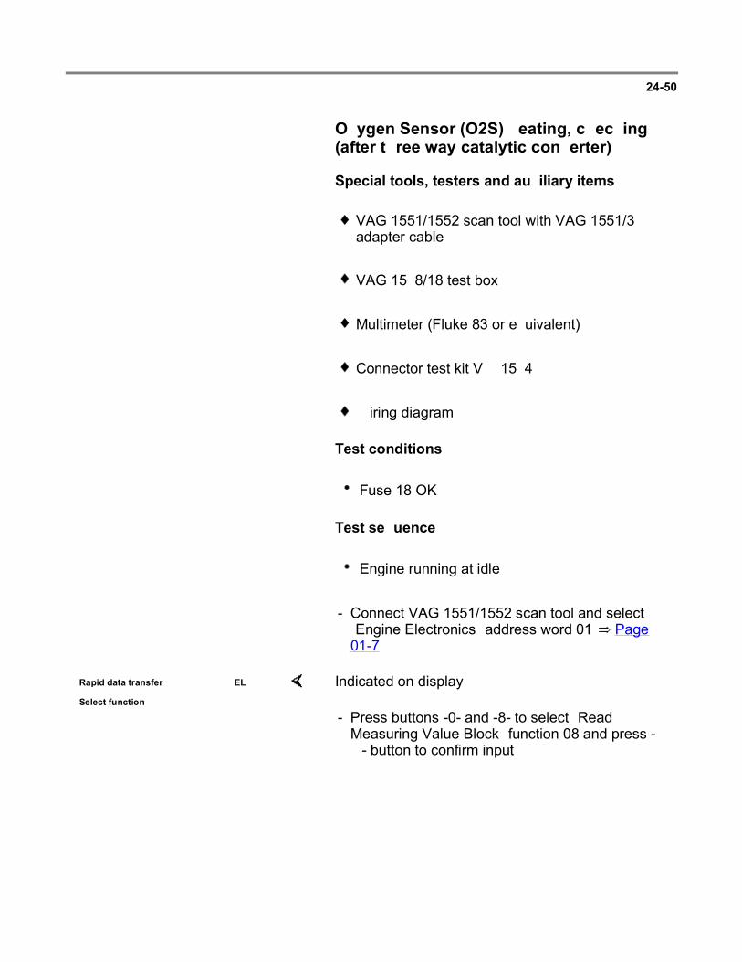
24-50
Oxygen Sensor (O2S) heating, checking (after three way catalytic converter)
Special tools, testers and auxiliary items
VAG 1551/1552 scan tool with VAG 1551/3 adapter cable
VAG 1598/18 test box
Multimeter (Fluke 83 or equivalent)
Connector test kit VW 1594
Wiring diagram
Test conditions
Fuse 18 OK
Test sequence
Engine running at idle
- Connect VAG 1551/1552 scan tool and select "Engine Electronics" address word 01 Page 01-7 .
Rapid data transfer HELP
Select function XX Indicated on display
- Press buttons -0- and -8- to select "Read Measuring Value Block" function 08 and press -Q- button to confirm input.
Page 66 of 144Multiport fuel injection and ignition system
6/12/2004http://ebahn.bentleypublishers.com/vw/servlet/Display?action=Goto&type=repair&id=VW...

24-51
Read Measuring Value Block HELP
Input display group number XXX Indicated on display
- Press buttons -1-, -2- and -1- to input display group 121 and press -Q- button to confirm input.
Read Measuring Value Block 121
1 2 3 4
Indicated on display (1-4 Display fields)
- Check resistance value for O2S heating (after three way catalytic converter) in display field 3:
Display fields
1 2 3 4
Display group 121: Oxygen Sensor (O2S) heating after Three Way Catalytic Converter (TWC)
Display xxx.x C xxx.xx sec. x.x xxxxxxxx
Indicated TWC temperature
Time from heating on to diagnosis
start
O2S heating resistance (after
TWC)
O2S control status (after
TWC)
Working range
0.0 - 999.9 C
Approx.150.00 sec.
0.0 - 65.0 Relevance Page 24-52
Specification - - 5.9 - 24.2
- - If specification is not attained Page 24-
53 , continuation
-
Page 67 of 144Multiport fuel injection and ignition system
6/12/2004http://ebahn.bentleypublishers.com/vw/servlet/Display?action=Goto&type=repair&id=VW...

24-52
- Press button.
- Press buttons -0- and -6- to select "End Output" function 06 and press -Q- button to confirm input.
- Switch ignition off.
Relevance of values in 8-digit number block
Relevance when display = 1
x x x x x x x x O2S control status (display group 121)
1 Malfunction in DTC memory
1 Malfunction detected during this diagnosis
1 Diagnosis completed during this drive
1 Diagnosis currently active
1 O2S heating ready (after TWC)
1 HO2S ready (after TWC)
1 Vapor point exceeded (after TWC)
1 1 = O2S heating on (after TWC)
Alternately 0 and 1 = O2S heating is fluctuating
Page 68 of 144Multiport fuel injection and ignition system
6/12/2004http://ebahn.bentleypublishers.com/vw/servlet/Display?action=Goto&type=repair&id=VW...

24-53
Continuation
- Separate 4-pin connector -2- (brown) to HO2S 2 -G108- (after three way catalytic converter).
If the specification is not attained:
- Connect multimeter with test leads from VW 1594 to measure resistance at terminals 1 and 2 on connector to HO2S 2.
- Measure resistance value.
Specification: 0.00-24.2 ohms ( )
- Replace HO2S 2 -G108- (after three way catalytic converter).
Page 69 of 144Multiport fuel injection and ignition system
6/12/2004http://ebahn.bentleypublishers.com/vw/servlet/Display?action=Goto&type=repair&id=VW...

24-54
If the specification is attained:
- Check relevance table Page 24-52 for value of O2S control status, display group 121, display field 4, 1st position from left.
- Set multimeter to voltage measurement range.
If no voltage is present:
- Connect multimeter with test leads from VW 1594 to measure voltage between terminals 1 and 2 (ECM side of harness connector).
- Measure voltage supply.
When display = 1: specification is 11.0-14.5 volts
When display = alternately 0 and 1: specification is fluctuating between 0.0-12.0 volts
If again no voltage is present:
- Connect multimeter using test leads from VW 1594 to measure voltage between terminal 1 (ECM side) and vehicle Ground (GND).
Specification: 11.0-14.5 volts
- Check wiring from terminal 1 to relay panel according to wiring diagram.
Page 70 of 144Multiport fuel injection and ignition system
6/12/2004http://ebahn.bentleypublishers.com/vw/servlet/Display?action=Goto&type=repair&id=VW...
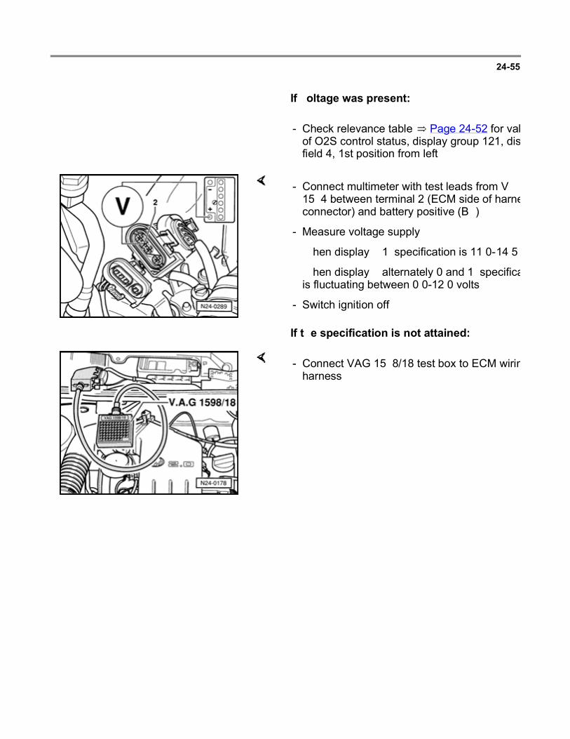
24-55
If voltage was present:
- Check relevance table Page 24-52 for value of O2S control status, display group 121, display field 4, 1st position from left.
If the specification is not attained:
- Connect multimeter with test leads from VW 1594 between terminal 2 (ECM side of harness connector) and battery positive (B+).
- Measure voltage supply.
When display = 1: specification is 11.0-14.5 volts
When display = alternately 0 and 1: specification is fluctuating between 0.0-12.0 volts
- Switch ignition off.
- Connect VAG 1598/18 test box to ECM wiring harness.
Page 71 of 144Multiport fuel injection and ignition system
6/12/2004http://ebahn.bentleypublishers.com/vw/servlet/Display?action=Goto&type=repair&id=VW...

24-56
If no wiring malfunction is detected:
- Check wiring between test box and 4-pin connector for open circuit according to wiring diagram.
Terminal 2 and test box socket 66
Resistance: maximum 1.5 ohms ( )
- Replace Engine Control Module (ECM) -J220-.
- Read readiness code Page 01-33 . If DTC memory has been erased, repair must be verified via appropriate display group Page 01-35 , Readiness code, creating.
Page 72 of 144Multiport fuel injection and ignition system
6/12/2004http://ebahn.bentleypublishers.com/vw/servlet/Display?action=Goto&type=repair&id=VW...

24-57
Oxygen Sensor (O2S) aging, checking (before three way catalytic converter)
Special tools, testers and auxiliary items
VAG 1551/1552 scan tool with VAG 1551/3 adapter cable
Test conditions
Coolant temperature at least 80 C (176 F)
Functional check
Engine running at idle
- Connect VAG 1551/1552 scan tool and select "Engine Electronics" address word 01 Page 01-7 .
Rapid data transfer HELP
Select function XX Indicated on display
- Press buttons -0- and -4- to select "Basic Setting" function 04 and press -Q- button to confirm input.
Basic Setting HELP
Input display group number XXX Indicated on display
- Press buttons -1-, -3- and -0- to input display group 130 and press -Q- button to confirm input.
System in Basic Setting 130
1 2 3 4
Indicated on display (1-4 Display fields)
- Increase engine speed to 2200-2800 RPM and check the specifications for O2S aging (before three way catalytic converter) in display fields 1-4.
Page 73 of 144Multiport fuel injection and ignition system
6/12/2004http://ebahn.bentleypublishers.com/vw/servlet/Display?action=Goto&type=repair&id=VW...

24-58
Note:
During the test, engine RPM must be held for at least 1 minute so that exhaust gas temperature is within specification range. Observe O2S control status in display field 4.
Display fields
1 2 3 4
Display group 130: Oxygen Sensor (O2S) aging (monitoring signal frequency of HO2S)
Display xxxx RPM
xx.xx sec. xxx xxxxxxxx
Indicated Engine speed
HO2S signal frequency (before three way
catalytic converter)
Valid HO2S signal frequency
(counted)
O2S control status
Working range
800 - 6000 RPM
0.00 - 15.00 sec. 0 - 4 -
Specification 2200 - 2800 RPM
0.00 - 2.80 sec. 4 1111x100
- If specification is not attained Page 24-59 , continuation
Relevance Page 24-60
- Press -C- button.
- Press buttons -1-, -3- and -1- to input display group 131 and press -Q- button to confirm input.
System in Basic Setting 131
1 2 3 4
Indicated on display (1-4 Display fields)
- Run engine at idle speed and check specifications.
Page 74 of 144Multiport fuel injection and ignition system
6/12/2004http://ebahn.bentleypublishers.com/vw/servlet/Display?action=Goto&type=repair&id=VW...

24-59
Display fields
1 2 3 4
Display group 131: Oxygen Sensor (O2S) aging (O2S control signal frequency extended)
Display xxxx RPM
xx.xxx V xxx ms xxxxxxxx
Indicated Engine speed
HO2S voltage (after three way catalytic
converter)
Signal frequency extended
O2S control status
Working range
800 - 6000 RPM
0.000 - 1.000 V - -
Specification 2200 - 2800 RPM
0.500 - 0.700 V (can fluctuate marginally)
-1200 to 1200 ms
1111x100
- If specification is not attained Page 24-59 , continuation
Relevance Page 24-60
Continuation
If specification is not attained:
- Perform a road test to free HO2S of possible residues and repeat test.
If the specification is again not attained:
- Replace HO2S -G39- (before three way catalytic converter).
- Read readiness code Page 01-33 . If DTC memory has been erased, repair must be verified via appropriate display group Page 01-35 , Readiness code, creating.
Page 75 of 144Multiport fuel injection and ignition system
6/12/2004http://ebahn.bentleypublishers.com/vw/servlet/Display?action=Goto&type=repair&id=VW...

24-60
Relevance of values in 8-digit number block
Relevance when display = 1
x x x x x x x x O2S control status (display group 130)
O2S control status (display group 131)
1 Malfunction in Diagnostic Trouble Code (DTC) memory
Malfunction in DTC memory
1 Malfunctions detected during this diagnosis
Malfunctions recognized during this diagnosis
1 Diagnosis completed during this drive
Diagnosis completed during this drive
1 Diagnosis currently active Diagnosis currently active
1 Diagnosis O2S heating ready (before TWC)
O2S control active (before TWC)
1 TWC temperature within specified range
O2S control active (after TWC)
1 Engine speed and load within specified range
Engine speed and load within specified range
1 O2S control active (before TWC)
TWC temperature within specified range
Page 76 of 144Multiport fuel injection and ignition system
6/12/2004http://ebahn.bentleypublishers.com/vw/servlet/Display?action=Goto&type=repair&id=VW...

24-61
Engine operation, checking
Note:
Check establishes whether Engine Control Module (ECM) -J220-recognizes the engine operating condition.
Special tools, testers and auxiliary items
VAG 1551/1552 scan tool with VAG 1551/3 adapter cable
Test conditions
Engine oil temperature min. 80 C (176 F)
Test sequence
Engine running at idle
- Connect VAG 1551/1552 scan tool and select "Engine Electronics" address word 01 Page 01-7 .
Rapid data transfer HELP
Select function XX Indicated on display
- Press buttons -0- and -8- to select "Read Measuring Value Block" function 08 and press -Q- button to confirm input.
Read Measuring Value Block HELP
Input display group number XXX Indicated on display
- Press buttons -0-, -0- and -5- for display group number 005 and press -Q- button to confirm input.
Page 77 of 144Multiport fuel injection and ignition system
6/12/2004http://ebahn.bentleypublishers.com/vw/servlet/Display?action=Goto&type=repair&id=VW...

24-62 If the specifications are not attained:
Read Measuring Value Block 5
1 2 3 4
Indicated on display (1-4 Display fields)
- Check whether ECM recognizes operating mode (display field 4).
Display fields
1 2 3 4
Display group 005: General engine data
Display xxx RPM xx.xx ms xxx km/h Idle
Indicated Engine speed
Engine load
Vehicle speed
Operating mode
Working range
800 - 6000 RPM
0.00 - 25.00 ms
- -
Specification 800 - 880 RPM
- 0 km/h Idle = Idle
Partial load = throttle valve slightly open
Enrich. = rev-up above 3000 RPM, then overrun (close throttle valve abruptly)
Full load = only possible when driving
- Check accelerator mechanism for ease of operation.
- Check throttle valve control module Page 24-69
Page 78 of 144Multiport fuel injection and ignition system
6/12/2004http://ebahn.bentleypublishers.com/vw/servlet/Display?action=Goto&type=repair&id=VW...

24-63
Mass Air Flow (MAF) sensor, checking
Special tools, testers and auxiliary items
VAG 1551/1552 scan tool with VAG 1551/3 adapter cable
VAG 1598/18 test box
Multimeter (Fluke 83 or equivalent)
Connector test kit VW 1594
Wiring diagram
Test conditions
Electrical consumers switched off (radiator coolant fan must not run during the check)
A/C switched off
Test sequence
Engine running at idle
- Connect VAG 1551/1552 scan tool and select "Engine Electronics" address word 01 Page 01-7 .
Rapid data transfer HELP
Select function XX Indicated on display
- Press buttons -0- and -8- to select "Read Measuring Value Block" function 08 and press -Q- button to confirm input.
Page 79 of 144Multiport fuel injection and ignition system
6/12/2004http://ebahn.bentleypublishers.com/vw/servlet/Display?action=Goto&type=repair&id=VW...

24-64
Read Measuring Value Block HELP
Input display group number XXX Indicated on display
- Press buttons -0-, -1- and -5- for display group number 015 and press -Q- button to confirm input.
Read Measuring Value Block 15
1 2 3 4
Indicated on display (1-4 Display fields)
- Check the load registration 1 specifications (display fields 2 and 3):
Display fields
1 2 3 4
Display group 015: Load registration 1
Display xxx RPM xx.xx ms xx% xx.x g/s
Indicated Engine speed
Engine load Engine load Mass air flow
Working range
800 - 6000 RPM
0.00 - 25.00 ms 0 - 40% -
Specification 800 - 880 RPM
1.00 - 3.00 ms 10 - 30% 3.0 - 4.0 g/s
- If specification is not attained Page 24-66 , check voltage supply and Page 24-67 , check
wiring
-
Page 80 of 144Multiport fuel injection and ignition system
6/12/2004http://ebahn.bentleypublishers.com/vw/servlet/Display?action=Goto&type=repair&id=VW...

24-65
- Press -C- button.
- Press buttons -0-, -1- and -6- for display group number 016 and press -Q- button to confirm input.
Read Measuring Value Block 16
1 2 3 4
Indicated on display (1-4 Display fields)
- Check load registration specifications 2 (display field 3):
Display fields
1 2 3 4
Display group 016: Load registrations 2
Display xxx RPM
xx.xx ms
xx.xx ms xx.xx ms
Indicated Engine speed
Engine load
Engine load Engine load substitute value
from throttle valve angle
Working range
800 - 6000 RPM
0.00 - 25.00 ms
0 - 25.00 ms 0.00 - 25.00 ms
Specification 800 - 880 RPM
1.00 - 3.00 ms
1.00 - 3.00 ms 1.00 - 3.00 ms
- - If specification is not attained Page 24-66 ,
evaluating display group 016
-
Page 81 of 144Multiport fuel injection and ignition system
6/12/2004http://ebahn.bentleypublishers.com/vw/servlet/Display?action=Goto&type=repair&id=VW...

24-66
Evaluating display group 016
Display group 016
Display field: 3 Possible malfunction cause Malfunction elimination
0.00 ms Wiring open circuit in wire 3 or 4 between Mass Air Flow (MAF) sensor and ECM
- Check voltage supply Page 24-66
Smallest value: 5.30 ms Wiring open circuit in wire 1 or 2 between
MAF sensor and ECM - Check wiring Page 24-67
Checking voltage supply
If no voltage is present:
- Disconnect 4-pin connector from Mass Air Flow (MAF) sensor.
- Connect multimeter with test leads from VW 1594 to measure voltage at terminals1 and 3.
Specification: 9.0-14.5 volts
- Switch ignition off.
- Check wiring according to wiring diagram.
Page 82 of 144Multiport fuel injection and ignition system
6/12/2004http://ebahn.bentleypublishers.com/vw/servlet/Display?action=Goto&type=repair&id=VW...

24-67
Checking wiring
- Switch ignition off.
- Connect VAG 1598/18 test box to ECM wiring harness.
- Check wiring between test box and 4-pin connector for open circuit according to wiring diagram.
Terminal 2 and test box socket 16
Terminal 4 and test box socket 17
Resistance: maximum 1.5 ohms ( )
- Additionally, check 4-pin connector terminals for short circuit to one another.
Terminal 4 and test box socket 16
Specification: ohms ( )
Page 83 of 144Multiport fuel injection and ignition system
6/12/2004http://ebahn.bentleypublishers.com/vw/servlet/Display?action=Goto&type=repair&id=VW...

24-68
- Set multimeter to voltage measurement range.
- Check 4-pin connector terminals for short circuit to battery positive (B+) according to wiring diagram.
Terminal 2 and vehicle Ground (GND)
Terminal 4 and vehicle Ground (GND)
Specification: 0 volts
If no wiring malfunction is detected:
- Replace Mass Air Flow (MAF) sensor -G70-.
- Read readiness code Page 01-33 . If DTC memory has been erased, repair must be verified via appropriate display group Page 01-35 , Readiness code, creating.
Page 84 of 144Multiport fuel injection and ignition system
6/12/2004http://ebahn.bentleypublishers.com/vw/servlet/Display?action=Goto&type=repair&id=VW...

24-69
Throttle valve control module -J338-, checking
Note:
If the Throttle valve control module -J338- is removed and installed or replaced, "Basic Setting" function 04 must be initiated for matching of system components Page 24-86
Special tools, testers and auxiliary items
VAG 1551/1552 scan tool with VAG 1551/3 adapter cable
VAG 1598/18 test box
Multimeter (Fluke 83 or equivalent)
Connector test kit VW 1594
Wiring diagram
Checking voltage supply
- Separate 8-pin connector to Throttle valve control module -J338-.
- Connect multimeter using test leads from VW 1594 to measure voltage at terminals 3 and 7 of connector.
- Switch ignition on.
Specification: 9.0-14.5 volts
Page 85 of 144Multiport fuel injection and ignition system
6/12/2004http://ebahn.bentleypublishers.com/vw/servlet/Display?action=Goto&type=repair&id=VW...

24-70
- Connect multimeter using adapter cables from VW 1594 to measure voltage at terminals 4 and 7 of connector.
Specification: 4.0-6.0 volts
- Switch ignition off.
If the specifications are not attained:
- Connect VAG 1598/18 test box to ECM wiring harness.
- Check wiring between test box and 8-pin connector for open circuit according to wiring diagram.
Terminal 3 and test box socket 10
Terminal 4 and test box socket 41
Terminal 7 and test box socket 33
Resistance: maximum 1.5 ohms ( )
Page 86 of 144Multiport fuel injection and ignition system
6/12/2004http://ebahn.bentleypublishers.com/vw/servlet/Display?action=Goto&type=repair&id=VW...
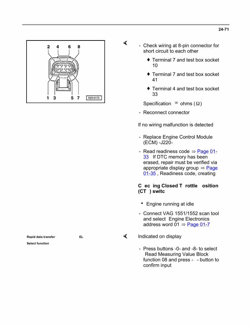
24-71
If no wiring malfunction is detected:
Checking Closed Throttle Position (CTP) switch
- Check wiring at 8-pin connector for short circuit to each other.
Terminal 7 and test box socket 10
Terminal 7 and test box socket 41
Terminal 4 and test box socket 33
Specification: ohms ( )
- Reconnect connector.
- Replace Engine Control Module (ECM) -J220-.
- Read readiness code Page 01-33 . If DTC memory has been erased, repair must be verified via appropriate display group Page 01-35 , Readiness code, creating.
Engine running at idle
- Connect VAG 1551/1552 scan tool and select "Engine Electronics" address word 01 Page 01-7 .
Rapid data transfer HELP
Select function XX Indicated on display
- Press buttons -0- and -8- to select "Read Measuring Value Block" function 08 and press -Q- button to confirm input.
Page 87 of 144Multiport fuel injection and ignition system
6/12/2004http://ebahn.bentleypublishers.com/vw/servlet/Display?action=Goto&type=repair&id=VW...

24-72
Read Measuring Value Block HELP
Input display group number XXX Indicated on display
- Press buttons -0-, -0- and -5- for display group 005 and press -Q- button to confirm input.
Read Measuring Value Block 5
1 2 3 4
Indicated on display (1-4 Display fields)
- Check closed throttle position switch (display field 4).
Display fields
1 2 3 4
Display group 005: General engine data
Display xxx RPM xx.xx ms xxx km/h Text
Indicated Engine speed
Engine load
Vehicle speed
Operating modes
Working range
800 - 6000 RPM
0.00 - 25.00 ms
- -
Specification 800 - 1100 RPM
1.00 - 3.00 ms
0 km/h Throttle valve closed = idling
Throttle valve slightly open = partial load
- - - If specification is not attained Page 24-73 , continuation
Page 88 of 144Multiport fuel injection and ignition system
6/12/2004http://ebahn.bentleypublishers.com/vw/servlet/Display?action=Goto&type=repair&id=VW...

24-73
Continuation
- Switch ignition off.
If the specifications are not attained:
- Connect VAG 1598/18 test box to ECM wiring harness.
- With throttle valve closed connect multimeter to measure resistance at test box sockets 10 and 33.
Specification: maximum 5.0 ohms ()
- Slowly open throttle.
Specification: ohms ( )
- Separate 8-pin connector to Throttle valve control module -J338-.
- Check wiring between test box and 8-pin connector for open circuit according to wiring diagram.
Terminal 3 and test box socket 10
Terminal 7 and test box socket 33
Resistance: maximum 1.5 ohms ( )
Page 89 of 144Multiport fuel injection and ignition system
6/12/2004http://ebahn.bentleypublishers.com/vw/servlet/Display?action=Goto&type=repair&id=VW...

24-74
- Check wiring at 8-pin connector for short circuit between terminal 7 and test box socket 10.
Specification: ohms ( )
- Reconnect connector.
If no wiring malfunction is detected:
- Replace Throttle valve control module -J338-.
- Read readiness code Page 01-33 . If DTC memory has been erased, repair must be verified via appropriate display group Page 01-35 , Readiness code, creating.
Checking Throttle Position (TP) actuator and Throttle Position (TP) sensor
Test conditions
Coolant temperature at least 80 C (176 F)
Test sequence
Engine running at idle
- Connect VAG 1551/1552 scan tool and select "Engine Electronics" address word 01 Page 01-7 .
Rapid data transfer HELP
Select function XX Indicated on display
- Press buttons -0- and -8- to select "Read Measuring Value Block" function 08 and press -Q- button to confirm input.
Page 90 of 144Multiport fuel injection and ignition system
6/12/2004http://ebahn.bentleypublishers.com/vw/servlet/Display?action=Goto&type=repair&id=VW...

24-75
Read Measuring Value Block HELP
Input display group number XXX Indicated on display
- Press buttons -0-, -3- and -7- for display group 037 and press -Q- button to confirm input.
Read Measuring Value Block 37
1 2 3 4
Indicated on display (1-4 Display fields)
- Check specifications for idle control (display field 1-4).
Display fields
1 2 3 4
Display group 037: Idle control
Display xxx RPM
xxx RPM xx.x% xx.x g/s
Indicated Engine speed
Engine speed specification
Idle control Mass air flow
Working range
800 - 6000 RPM
- -16.0 to 16.0% 0.0 - 20.0 g/s
Specification 800 - 880 RPM
840 RPM -4.0 to 4.0% 2.5 - 4.5 g/s
If specification is not attained Page 24-79 ,
continuation
If specification is not attained Page 24-
77 , evaluating display group 037
If specification is not attained Page 24-79 , continuation
Page 91 of 144Multiport fuel injection and ignition system
6/12/2004http://ebahn.bentleypublishers.com/vw/servlet/Display?action=Goto&type=repair&id=VW...

24-76
- Press -C- button.
- Press buttons -0-, -3- and -6- for display group number 036 and press -Q- button to confirm input.
Read Measuring Value Block 36
1 2 3 4
Indicated on display (1-4 Display fields)
- Check specifications for idle control (display field 2 and 3).
Display fields
1 2 3 4
Display group 036: Idle control
Display xx.x x.xx g/s x.xx g/s -
Indicated Throttle valve angle
Mass air flow adaptation value at
idle
Mass air flow adaptation value with driving range
selected
-
Working range
0.0 - 90.0
-1.70 to 1.70 g/s -1.70 to 1.70 g/s -
Specification 3.0 - 7.0
-0.50 to 0.50 g/s -0.40 to 0.40 g/s1) -
- If specification is not attained Page 24-78 , evaluating display group 036
-
1) On vehicles with manual transmission `0' is always displayed.
Page 92 of 144Multiport fuel injection and ignition system
6/12/2004http://ebahn.bentleypublishers.com/vw/servlet/Display?action=Goto&type=repair&id=VW...

24-77
Evaluating display group 037
Display group: 037
Display field: 3 Possible malfunction cause Malfunction elimination
Idle control in range: 4.0 to
16.0% Load increased (electrical consumers switched on)
- Switch off electrical consumers
-4.0 to -16.0% Unmetered air behind throttle valve (also note display group 036, display fields 2 and 3)
Repair Manual, 2.0 Liter 4-Cyl. 2V Engine Mechanical, Engine Code(s): ABA m.y. 1995 - 1997, Repair Group 26
- Check intake air system for leaks (unmetered air) Page 24-125
- Check exhaust system for leaks:
Constant 0.0% 1)
Wiring open circuit - Page 24-79 , continuation
Constant -1.5% 1)
Short circuit to Ground (GND)
1) Value remains constant also during longer idling phase
Page 93 of 144Multiport fuel injection and ignition system
6/12/2004http://ebahn.bentleypublishers.com/vw/servlet/Display?action=Goto&type=repair&id=VW...

24-78
Evaluating display group 036
Display group: 036
Display field: 2 Possible malfunction cause
Malfunction elimination
Mass air flow adaptation
value:
0.50 to 1.70%
Load increased (electrical consumers switched on)
- Switch off electrical consumers
-0.50 to -1.70% Unmetered air behind throttle valve
Repair Manual, 2.0 Liter 4-Cyl. 2V Engine Mechanical, Engine Code(s): ABA m.y. 1995 - 1997, Repair Group 26
- Check intake air system for leaks (unmetered air) Page 24-125
- Check exhaust system for leaks:
Display field: 3 Possible malfunction cause
Malfunction elimination
Mass air flow adaptation
value:
0.40 to 1.70%
Load increased (electrical consumers switched on)
- Switch off electrical consumers
-0.40 to -1.70% Unmetered air behind throttle valve
Repair Manual, 2.0 Liter 4-Cyl. 2V Engine Mechanical, Engine Code(s): ABA m.y. 1995 - 1997, Repair Group 26
- Check intake air system for leaks (unmetered air) Page 24-125
- Check exhaust system for leaks:
Page 94 of 144Multiport fuel injection and ignition system
6/12/2004http://ebahn.bentleypublishers.com/vw/servlet/Display?action=Goto&type=repair&id=VW...

24-79
Continuation
- Switch ignition off.
If the specification is not attained:
- Connect VAG 1598/18 test box to ECM wiring harness.
- Switch ignition on.
- With throttle closed connect multimeter to measure resistance at test box sockets 27 and 53.
Specification: 3-200 ohms ( )
If the specification is not attained:
If the specification is attained:
- Disconnect 8-pin connector from Throttle valve control module -J338-.
- Repeat resistance measurements of throttle valve control module at terminals 1 + 2
Specification: 3-200 ohms ( )
- Replace Throttle valve control module -J338-.
Page 95 of 144Multiport fuel injection and ignition system
6/12/2004http://ebahn.bentleypublishers.com/vw/servlet/Display?action=Goto&type=repair&id=VW...

24-80
- Check wiring between test box and 8-pin connector for open circuit according to wiring diagram.
Terminal 1 and test box socket 27
Terminal 2 and test box socket 53
Terminal 7 and test box socket 33
Terminal 8 and test box socket 62
Resistance: maximum 1.5 ohms ( )
- Check wiring at 8-pin connector for short circuit to each other according to wiring diagram.
Terminal 1 and test box socket 53
Terminal 1 and test box socket 62
Terminal 1 and test box socket 33
Terminal 2 and test box socket 33
Terminal 2 and test box socket 62
Terminal 7 and test box socket 62
Specification: ohms ( )
- Read readiness code Page 01-33 . If DTC memory has been erased, repair must be verified via appropriate display group Page 01-35 , Readiness code, creating.
Page 96 of 144Multiport fuel injection and ignition system
6/12/2004http://ebahn.bentleypublishers.com/vw/servlet/Display?action=Goto&type=repair&id=VW...

24-81
Checking Throttle Position (TP) sensor
- Connect VAG 1551/1552 scan tool and select "Engine Electronics" address word 01 Page 01-7 . Ignition must be switched on but engine not running.
Rapid data transfer HELP
Select function XX Indicated on display
- Press buttons -0- and -8- to select "Read Measuring Value Block" function 08 and press -Q- button to confirm input.
Read Measuring Value Block HELP
Input display group number XXX Indicated on display
- Press buttons -0-, -0- and -3- for display group 003 and press -Q- button to confirm input.
Read Measuring Value Block 3
1 2 3 4
Indicated on display (1-4 Display fields)
- Check TP sensor specification (display field 3).
Page 97 of 144Multiport fuel injection and ignition system
6/12/2004http://ebahn.bentleypublishers.com/vw/servlet/Display?action=Goto&type=repair&id=VW...

24-82
Display fields
1 2 3 4
Display group 003: Load registration 1
Display xxx RPM xx.x g/s
xxx xx.x C
Indicated Engine speed
Mass air flow
Throttle valve angle Intake air temperature
Working range
800 - 6000 RPM
- 0 - 90 -46.5 to 141.0
Specification 0 RPM - 3 - 7 Approx. ambient temperature
- - If specification is not attained Page 24-83 , evaluating
display group 003
-
- Slowly open throttle valve and watch angle display in display field 3.
Value must increase uniformly over complete range.
- Press button.
- Press buttons -0- and -6- to select "End Output" function 06 and press -Q- button to confirm input.
- Switch ignition off.
Page 98 of 144Multiport fuel injection and ignition system
6/12/2004http://ebahn.bentleypublishers.com/vw/servlet/Display?action=Goto&type=repair&id=VW...

24-83
Note:
The displayed value is dependent on the tolerances of the Throttle Position (TP) sensor and does not correspond to the actual opening angle. The maximum permissible displayed value is 90.0 .
If the value does not increase uniformly:
- Replace Throttle valve control module -J338-.
- Read readiness code Page 01-33 . If DTC memory has been erased, repair must be verified via appropriate display group Page 01-35 , Readiness code, creating.
Evaluating display group 003
Display group: 003
Display field: 3 Possible malfunction cause Malfunction elimination
0.0 Wiring open circuit - Check wiring Page 24-84
99.0 Short circuit to Ground (GND)
Page 99 of 144Multiport fuel injection and ignition system
6/12/2004http://ebahn.bentleypublishers.com/vw/servlet/Display?action=Goto&type=repair&id=VW...

24-84
Check wiring
- Connect VAG 1598/18 test box to ECM wiring harness.
- Connect multimeter using test leads from VW 1594 to measure resistance at test box sockets 01 and 40 and check wiring for short circuit to Ground (GND).
Specification: ohms ( )
- Set multimeter to voltage measurement range.
- Switch ignition on.
- Check wiring for short circuit to positive (B+). If necessary, note voltage value.
- Switch ignition off.
Continuation if voltage is present:
If voltage of about 5 volts was present:
- Separate 8-pin connector to Throttle valve control module -J338-.
- Connect multimeter using test leads from VW 1594 to measure resistance at test box sockets 40 and 41 and check for short circuits to each other.
Specification: ohms ( )
Page 100 of 144Multiport fuel injection and ignition system
6/12/2004http://ebahn.bentleypublishers.com/vw/servlet/Display?action=Goto&type=repair&id=VW...

24-85
If the voltage was approx. battery voltage:
- Check wiring at 8-pin connector terminal 5 for short circuit to battery positive (B+) according to wiring diagram.
Continuation if no voltage is present:
- Check wiring between test box and 8-pin connector for open circuit according to wiring diagram.
Terminal 5 and test box socket 40
Resistance: maximum 1.5 ohms ( )
If no wiring malfunction is detected:
- Replace Throttle valve control module -J338-.
- Read readiness code Page 01-33 . If DTC memory has been erased, repair must be verified via appropriate display group Page 01-35 , Readiness code, creating.
Page 101 of 144Multiport fuel injection and ignition system
6/12/2004http://ebahn.bentleypublishers.com/vw/servlet/Display?action=Goto&type=repair&id=VW...

24-86
Basic setting, initiating
Note:
Only initiate "Basic Setting" function 04 when the Throttle valve control module -J338-, the Engine Control Module (ECM) -J220- or the engine has been replaced.
Initiating basic setting matches the ECM to the throttle valve control module with the ignition switched on.
If the basic setting is interrupted by the ECM, it can be, that the throttle valve is not at the mechanical idle stop due to contamination (e.g. coking) or an incorrectly adjusted accelerator cable. In this case the malfunction "Basic setting not performed" will be stored in DTC memory. Thoroughly clean the soiled area in throttle valve control module. The next time the ignition is switched on, basic setting will be automatically performed again.
Special tools, testers and auxiliary items
VAG 1551/1552 scan tool with VAG 1551/3 adapter cable
Test conditions
No malfunctions stored in Diagnostic Trouble Code (DTC) memory Page 01-12 , checking DTC memory
Test sequence
- Connect VAG 1551/1552 scan tool and select "Engine Electronics" address word 01 Page 01-7 . Ignition must be switched on but engine not running.
Page 102 of 144Multiport fuel injection and ignition system
6/12/2004http://ebahn.bentleypublishers.com/vw/servlet/Display?action=Goto&type=repair&id=VW...

24-87
Rapid data transfer HELP
Select function XX Indicated on display
- Press buttons -0- and -4- for the "Basic Setting" function 04 and press -Q- button to confirm input.
Basic Setting HELP
Input display group number XXX Indicated on display
- Press buttons -0-, -9- and -8- for display group 098 and press -Q- button to confirm input.
System in Basic Setting 98
1 2 3 4
Indicated on display (1-4 Display fields)
Note:
After confirming the display group 098 the Throttle Position (TP) actuator will be moved to the min., max. and then into the start position. The control module stores the appropriate throttle valve angle in the permanent memory. The throttle valve will then remain in the start position.
Page 103 of 144Multiport fuel injection and ignition system
6/12/2004http://ebahn.bentleypublishers.com/vw/servlet/Display?action=Goto&type=repair&id=VW...

24-88
- Check specifications (display fields 1-4):
Display fields
1 2 3 4
Display group 098: Basic setting, throttle valve control module
Display x.xxx V x.xxx V Text Text
Indicated Throttle Position (TP)
sensor voltage
Throttle Position (TP)
actuator voltage
Operating mode
Basic setting status
Working range
0.000 - 5.000 V 0.000 - 5.000 V - -
Specification - - Idle ADP. runs
4.000 - 5.000 V 3.000 - 4.000 V Idle ADP. OK.
(ADP. ERROR appears if the basic setting is
not successful)
If specification is not attained Page 24-69 , check throttle valve control module
- Wait at least 30 seconds before ending basic setting by pressing button.
- Press buttons -0- and -6- to select "End Output" function 06 and press -Q- button to confirm input.
Page 104 of 144Multiport fuel injection and ignition system
6/12/2004http://ebahn.bentleypublishers.com/vw/servlet/Display?action=Goto&type=repair&id=VW...
24-89
Engine Coolant Temperature (ECT) sensor -G62-, checking
Special tools, testers and auxiliary items
VAG 1551/1552 scan tool with VAG 1551/3 adapter cable
VAG 1598/18 test box
Multimeter (Fluke 83 or equivalent)
Connector test kit VW 1594
Wiring diagram
Note:
If the engine is warmed to operating temperature with the vehicle stationary, and the time taken to reach operating temperature is too long, it can lead to DTC P0116 or P0125 being stored in DTC memory. In this case, erase DTC memory and bring engine to operating temperature during a test drive.
Test conditions
Engine cold
Test sequence
- Connect VAG 1551/1552 scan tool and select "Engine Electronics" address word 01 Page 01-7 . Ignition must be switched on.
Page 105 of 144Multiport fuel injection and ignition system
6/12/2004http://ebahn.bentleypublishers.com/vw/servlet/Display?action=Goto&type=repair&id=VW...

24-90
Rapid data transfer HELP
Select function XX Indicated on display
- Press buttons -0- and -8- to select "Read Measuring Value Block" function 08 and press -Q- button to confirm input.
Read Measuring Value Block HELP
Input display group number XXX Indicated on display
- Press buttons -0-, -0- and -1- for display group 001 and press -Q- button to confirm input.
Read Measuring Value Block 1
1 2 3 4
Indicated on display (1-4 Display fields)
- Check specification for engine coolant temperature sensor (display field 2).
Page 106 of 144Multiport fuel injection and ignition system
6/12/2004http://ebahn.bentleypublishers.com/vw/servlet/Display?action=Goto&type=repair&id=VW...

24-91
Display fields
1 2 3 4
Display group 001: Idle test
Display xxxx RPM
xxx.x C xx.x% xx.x
Indicated Engine speed
Engine coolant temperature Oxygen Sensor (O2S) control
Ignition angle
Working range
800 - 6000 RPM
-46.5 to 141.0 C -25.0 to 25.0% 0.0 - 50.0
Specification 0 RPM Approx. ambient temperature1)
The value must fluctuate at least 3%
in range -5.0 to 5.0%
2.0 - 15.0
- If specification is not attained Page 24-92 ,
evaluating display group 001
- -
1) If a temperature is displayed which deviates greatly from the ambient temperature of the sensor, check sensor wiring for resistance/open circuit.
Continuation:
- Start engine and run at idle speed.
The temperature value must increase uniformly
If the specification is not attained:
- Replace Engine Coolant Temperature (ECT) sensor -G62-.
Page 107 of 144Multiport fuel injection and ignition system
6/12/2004http://ebahn.bentleypublishers.com/vw/servlet/Display?action=Goto&type=repair&id=VW...

24-92
WARNING!
The cooling system is pressurized when the engine is warm. When opening the expansion tank, wear gloves and other appropriate protection, cover the cap with a cloth, and open carefully to relieve system pressure slowly.
- Press button.
- Press buttons -0- and -6- to select "End Output" function 06 and press -Q- button to confirm input.
- Switch ignition off.
Notes:
Display on VAG 1551 scan tool jumps by 1.5C.
If irregular engine running occurs in certain temperature ranges and the temperature value does not increase without interruption, the temperature signal is temporarily interrupted and the sensor must be replaced.
Evaluating display group 001
Display group: 001
Display field: 2 Possible malfunction cause Malfunction elimination
Approx. -46.6C Wiring open circuit or short circuit to
positive (B+) - Check wiring Page 24-93
Approx. 141.0C Short circuit to Ground (GND)
Page 108 of 144Multiport fuel injection and ignition system
6/12/2004http://ebahn.bentleypublishers.com/vw/servlet/Display?action=Goto&type=repair&id=VW...

24-93
Checking wiring
- Connect VAG 1598/18 test box to ECM wiring harness.
- Disconnect 4-pin connector -1- from ECT sensor -G62- -2-.
Page 109 of 144Multiport fuel injection and ignition system
6/12/2004http://ebahn.bentleypublishers.com/vw/servlet/Display?action=Goto&type=repair&id=VW...

24-94
If no malfunction in wiring is detected:
If the specification is not attained:
- Check wiring between test box and 4-pin connector for open circuit according to wiring diagram.
Terminal 1 and test box socket 33
Terminal 3 and test box socket 14
Resistance: maximum 1.5 ohms ( )
- Check wiring between test box and 4-pin connector terminal 3 for short circuit to terminal 1 or to Ground (GND), according to wiring diagram.
r Terminal 3 and test box socket 33
r Terminal 3 and vehicle Ground (GND)
Specification: ohms ( )
- Additionally, check both wires for short circuit to battery positive (B+). Specification: ohms ( )
- Perform resistance measurement at ECT sensor -G62- terminals 1 and 3, resistance values Page 24-18 , Fig. 1 .
- Replace ECT sensor -G62-.
- Read readiness code Page 01-33 . If DTC memory has been erased, repair must be verified via appropriate display group Page 01-35 , Readiness code, creating.
Page 110 of 144Multiport fuel injection and ignition system
6/12/2004http://ebahn.bentleypublishers.com/vw/servlet/Display?action=Goto&type=repair&id=VW...

24-95
Intake Air Temperature (IAT) sensor -G72-, checking
Special tools, testers and auxiliary items
VAG 1551/1552 scan tool with VAG 1551/3 adapter cable
VAG 1598/18 test box
Multimeter (Fluke 83 or equivalent)
Connector test kit VW 1594
Wiring diagram
Chilling spray (commercially available)
Test sequence
- Connect VAG 1551/1552 scan tool and select "Engine Electronics" address word 01 Page 01-7 . Ignition must be switched on.
Rapid data transfer HELP
Select function XX Indicated on display
- Press buttons -0- and -8- to select "Read Measuring Value Block" function 08 and press -Q- button to confirm input.
Read Measuring Value Block HELP
Input display group number XXX Indicated on display
- Press buttons -0-, -0- and -3- for display group 003 and press -Q- button to confirm input.
Page 111 of 144Multiport fuel injection and ignition system
6/12/2004http://ebahn.bentleypublishers.com/vw/servlet/Display?action=Goto&type=repair&id=VW...
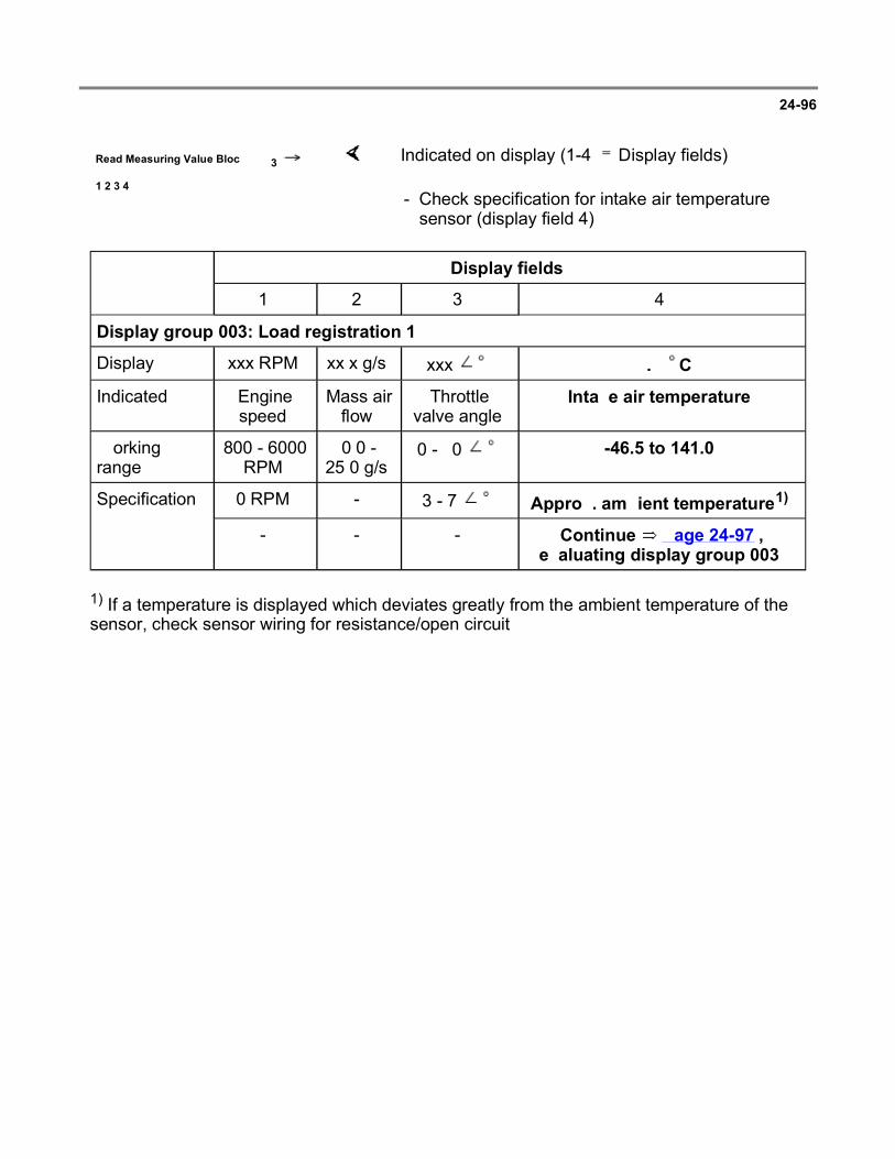
24-96
Read Measuring Value Block 3
1 2 3 4
Indicated on display (1-4 Display fields)
- Check specification for intake air temperature sensor (display field 4).
Display fields
1 2 3 4
Display group 003: Load registration 1
Display xxx RPM xx.x g/s xxx xx.x C
Indicated Engine speed
Mass air flow
Throttle valve angle
Intake air temperature
Working range
800 - 6000 RPM
0.0 - 25.0 g/s
0 - 90 -46.5 to 141.0
Specification 0 RPM - 3 - 7 Approx. ambient temperature1)
- - - Continue Page 24-97 , evaluating display group 003
1) If a temperature is displayed which deviates greatly from the ambient temperature of the sensor, check sensor wiring for resistance/open circuit.
Page 112 of 144Multiport fuel injection and ignition system
6/12/2004http://ebahn.bentleypublishers.com/vw/servlet/Display?action=Goto&type=repair&id=VW...

24-97
Evaluating display group 003
Display group: 003
Display field: 4 Possible malfunction cause Malfunction elimination
-46.5 C Wiring open circuit or short circuit to positive (B+)
- Check wiring Page 24-97
141.0 C Short circuit to Ground (GND)
Approx. ambient temperature Signal periodically
interrupted - Check IAT sensor Page 24-99 , continuation at ambient temperature
Checking wiring
- Switch ignition off.
- Connect VAG 1598/18 test box to ECM wiring harness.
Page 113 of 144Multiport fuel injection and ignition system
6/12/2004http://ebahn.bentleypublishers.com/vw/servlet/Display?action=Goto&type=repair&id=VW...

24-98
If no malfunction in wiring is detected:
- Disconnect 2-pin connector -1- from Intake Air Temperature (IAT) sensor -G72- -2-.
- Check wiring between test box and 2-pin connector for open circuit according to wiring diagram.
Terminal 1 and test box socket 36
Terminal 2 and test box socket 33
Resistance: maximum 1.5 ohms ( )
- Check wiring between test box and 2-pin connector terminal 2 for short circuit to wire terminal 1 or to vehicle Ground (GND), according to wiring diagram.
Terminal 2 and test box socket 36
Terminal 2 and vehicle Ground (GND)
Specification: ohms ( )
- Additionally, check both wires for short circuit to battery positive (B+).
Specification: ohms ( )
- Measure resistance at IAT sensor -G72- terminals 1 and 2, resistance values Page 24-18 , Fig. 1 .
Page 114 of 144Multiport fuel injection and ignition system
6/12/2004http://ebahn.bentleypublishers.com/vw/servlet/Display?action=Goto&type=repair&id=VW...

24-99
If the specification is not attained:
- Replace IAT sensor -G72-.
Continuation of check when display = ambient temperature
If the specification is not attained:
- Remove IAT sensor (harness connector remains connected).
- Read intake air temperature value in display field 4.
- Spray sensor with a commercially available chilling spray and at same time observe temperature value.
Temperature value must decrease.
- Replace IAT sensor -G72-.
- Read readiness code Page 01-33 . If DTC memory has been erased, repair must be verified via appropriate display group Page 01-35 , Readiness code, creating.
Page 115 of 144Multiport fuel injection and ignition system
6/12/2004http://ebahn.bentleypublishers.com/vw/servlet/Display?action=Goto&type=repair&id=VW...

24-100
Engine speed (RPM) sensor -G28-, checking
Special tools, testers and auxiliary items
VAG 1598/18 test box
Multimeter (Fluke 83 or equivalent)
Connector test kit VW 1594
Wiring diagram
Test sequence
- Disconnect 3-pin connector to engine speed sensor -1-.
- Connect VAG 1598/18 test box to ECM wiring harness.
Page 116 of 144Multiport fuel injection and ignition system
6/12/2004http://ebahn.bentleypublishers.com/vw/servlet/Display?action=Goto&type=repair&id=VW...
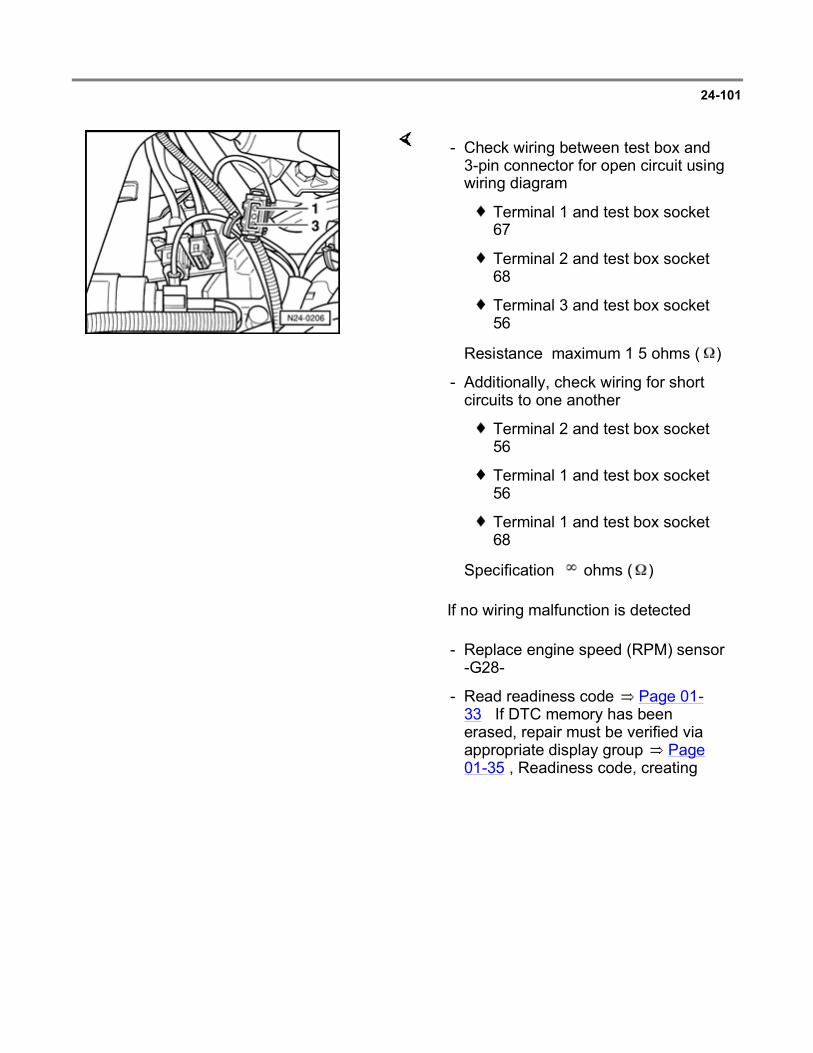
24-101
If no wiring malfunction is detected:
- Check wiring between test box and 3-pin connector for open circuit using wiring diagram.
Terminal 1 and test box socket 67
Terminal 2 and test box socket 68
Terminal 3 and test box socket 56
Resistance: maximum 1.5 ohms ( )
- Additionally, check wiring for short circuits to one another.
Terminal 2 and test box socket 56
Terminal 1 and test box socket 56
Terminal 1 and test box socket 68
Specification: ohms ( )
- Replace engine speed (RPM) sensor -G28-.
- Read readiness code Page 01-33 . If DTC memory has been erased, repair must be verified via appropriate display group Page 01-35 , Readiness code, creating.
Page 117 of 144Multiport fuel injection and ignition system
6/12/2004http://ebahn.bentleypublishers.com/vw/servlet/Display?action=Goto&type=repair&id=VW...

24-102
Speedometer Vehicle Speed Sensor (VSS) -G22- signal, checking
Special tools, testers and auxiliary items
VAG 1551/1552 scan tool with VAG 1551/3 adapter cable
Multimeter (Fluke 83 or equivalent)
Connector test kit VW 1594
Wiring diagram
Test conditions
Speedometer OK, checking:
Repair Manual, Electrical Equipment, Repair Group 90
Note:
To check the speed sensor signal the vehicle must be test driven. To do this a second person is necessary.
Test sequence
Engine running at idle
- Connect VAG 1551/1552 scan tool and select "Engine Electronics" address word 01 Page 01-7 .
Rapid data transfer HELP
Select function XX Indicated on display
- Press buttons -0- and -8- to select "Read Measuring Value Block" function 08 and press -Q- button to confirm input.
Page 118 of 144Multiport fuel injection and ignition system
6/12/2004http://ebahn.bentleypublishers.com/vw/servlet/Display?action=Goto&type=repair&id=VW...
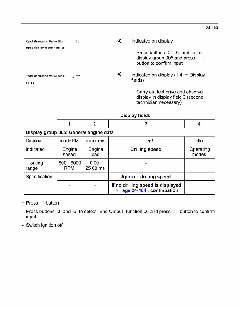
24-103
Read Measuring Value Block HELP
Input display group number XXX Indicated on display
- Press buttons -0-, -0- and -5- for display group 005 and press -Q- button to confirm input.
Read Measuring Value Block 5
1 2 3 4
Indicated on display (1-4 Display fields)
- Carry out test drive and observe display in display field 3 (second technician necessary).
Display fields
1 2 3 4
Display group 005: General engine data
Display xxx RPM xx.xx ms xxx km/h Idle
Indicated Engine speed
Engine load
Driving speed Operating modes
Working range
800 - 6000 RPM
0.00 - 25.00 ms
- -
Specification - - Approx. driving speed -
- - If no driving speed is displayed Page 24-104 , continuation
- Press button.
- Press buttons -0- and -6- to select "End Output" function 06 and press -Q- button to confirm input.
- Switch ignition off.
Page 119 of 144Multiport fuel injection and ignition system
6/12/2004http://ebahn.bentleypublishers.com/vw/servlet/Display?action=Goto&type=repair&id=VW...

24-104
Continuation
If no speed is indicated:
- Disconnect 3-pin connector from vehicle speed sensor -1-.
- Switch ignition on.
If no voltage was present:
- Connect multimeter using test leads from VW 1594 to measure voltage at terminals 1 and 3 of connector.
Specification: 9-14.5 volts
- Switch ignition off.
- Reconnect connector
- Check wiring according to wiring diagram.
Page 120 of 144Multiport fuel injection and ignition system
6/12/2004http://ebahn.bentleypublishers.com/vw/servlet/Display?action=Goto&type=repair&id=VW...

24-105
If voltage was 9-14.5 volts:
If no wiring malfunction is detected and voltage was present between terminals 1 and 3:
- Connect VAG 1598/18 test box to ECM wiring harness.
- Check wiring between central electrical panel and test box socket 65 for open circuit according to wiring diagram.
Resistance: maximum 1.5 ohms ( )
- Connect multimeter using test leads from VW 1594 to measure voltage at sockets 56 and 65.
- Switch ignition on.
- Lift left front wheel and rotate by hand or push vehicle.
Voltage value must fluctuate between 0 and at least 4 volts.
- Replace Speedometer Vehicle Speed Sensor (VSS) -G22-.
- Read readiness code Page 01-33 . If DTC memory has been erased, repair must be verified via appropriate display group Page 01-35 , Readiness code, creating.
Page 121 of 144Multiport fuel injection and ignition system
6/12/2004http://ebahn.bentleypublishers.com/vw/servlet/Display?action=Goto&type=repair&id=VW...

24-106
Engine Control Module (ECM) voltage supply, checking
Special tools, testers and auxiliary items
VAG 1551/1552 scan tool with VAG 1551/3 adapter cable
VAG 1598/18 test box
Multimeter (Fluke 83 or equivalent)
Connector test kit VW 1594
Wiring diagram
Test sequence
- Connect VAG 1551/1552 scan tool and select "Engine Electronics" address word 01 Page 01-7 . Ignition must be switched on.
Rapid data transfer HELP
Select function XX Indicated on display
- Press buttons -0- and -8- to select "Read Measuring Value Block" function 08 and press -Q- button to confirm input.
Read Measuring Value Block HELP
Input display group number XXX Indicated on display
- Press buttons -0-, -0- and -2- for display group 002 and press -Q- button to confirm input.
Page 122 of 144Multiport fuel injection and ignition system
6/12/2004http://ebahn.bentleypublishers.com/vw/servlet/Display?action=Goto&type=repair&id=VW...

24-107
Read Measuring Value Block 2
1 2 3 4
Indicated on display (1-4 Display fields)
- Check battery voltage (display field 3).
Display fields
1 2 3 4
Display group 002: General engine data
Display xxxx RPM
xx.xx ms xx.xxx xxx.x C
Indicated Engine speed
Fuel injection period
Battery voltage Fuel tank ventilation
Working range
800 - 6000 RPM
0.00 - 25.00 ms
0.000 - 16.500 V -
Specification 0 RPM - 12.000 - 14.500 V -
- - If specification is not attained Page 24-108 , evaluating
display group 002
-
- Press button.
- Press buttons -0- and -6- to select "End Output" function 06 and press -Q- button to confirm input.
Page 123 of 144Multiport fuel injection and ignition system
6/12/2004http://ebahn.bentleypublishers.com/vw/servlet/Display?action=Goto&type=repair&id=VW...

24-108
Evaluating display group 002
Display group: 002
Display field: 3 Possible malfunction cause
Malfunction elimination
If no display appears on VAG 1551 Fuse 15 faulty - Replace fuse
Wiring open circuit - Check voltage supply terminal 15 Page 24-109
If the value displayed fluctuates between 12.0 - 14.5 V Loose connection - Check voltage supply
terminal 30 Page 24-109
0.0 - 12.0 V Battery discharged/faulty
Voltage regulator faulty
- Check battery
- Check generator
- Check voltage regulator
14.5 - 16.5 V Generator faulty
Voltage regulator faulty
- Check generator
- Check voltage regulator
Page 124 of 144Multiport fuel injection and ignition system
6/12/2004http://ebahn.bentleypublishers.com/vw/servlet/Display?action=Goto&type=repair&id=VW...

24-109
Checking voltage supply terminal 30
- Switch ignition off.
If the specification is not attained:
Checking voltage supply terminal 15
- Connect VAG 1598/18 test box to ECM wiring harness.
- Connect multimeter using test leads from VW 1594 to measure voltage at sockets 1 and 54:
Specification: 12-14.5 volts
- Check wiring according to wiring diagram.
- Switch ignition off.
If the specification is not attained:
- Connect VAG 1598/18 test box to ECM wiring harness.
- Switch ignition on.
- Connect multimeter using test leads from VW 1594 to measure voltage at sockets 1 and 23:
Specification: 12-14.5 volts
- Check wiring according to wiring diagram.
Page 125 of 144Multiport fuel injection and ignition system
6/12/2004http://ebahn.bentleypublishers.com/vw/servlet/Display?action=Goto&type=repair&id=VW...

24-110
Signal from automatic transmission, checking
Special tools, testers and auxiliary items
VAG 1551/1552 scan tool with VAG 1551/3 adapter cable
VAG 1598/18 test box
Multimeter (Fluke 83 or equivalent)
Connector test kit VW 1594
Wiring diagram
Test sequence
Engine running at idle
- Connect VAG 1551/1552 scan tool and select "Engine Electronics" address word 01 Page 01-7 .
Rapid data transfer HELP
Select function XX Indicated on display
- Press buttons -0- and -8- to select "Read Measuring Value Block" function 08 and press -Q- button to confirm input.
Read Measuring Value Block HELP
Input display group number XXX Indicated on display
- Press buttons -0-, -0- and -8- for display group 008 and press -Q- button to confirm input.
Page 126 of 144Multiport fuel injection and ignition system
6/12/2004http://ebahn.bentleypublishers.com/vw/servlet/Display?action=Goto&type=repair&id=VW...

24-111 Continuation
If the display does not read as described:
Read Measuring Value Block 8
1 2 3 4
Indicated on display (1-4 Display fields)
- Check signals from automatic transmission in display field 2:
Display fields
1 2 3 4
Display group 008: Signals to Engine Control Module (ECM)
Display xxxx RPM Text Text Text
Indicated Engine speed
Driving range status A/C status
A/C compressor status
Working range
800 - 6000 RPM
- - -
Specification 800 - 880 RPM
P and N: NEUTRAL
1, 2, 3 and D: ON
- -
- If specification is not attained Page 24-111 , continuation
- -
- Check wiring between ECM (terminals 07, 11, 18 and 21) and Transmission Control Module (TCM) according to wiring diagram.
Page 127 of 144Multiport fuel injection and ignition system
6/12/2004http://ebahn.bentleypublishers.com/vw/servlet/Display?action=Goto&type=repair&id=VW...
24-112
Signal from A/C compressor, checking
Special tools, testers and auxiliary items
VAG 1551/1552 scan tool with VAG 1551/3 adapter cable
VAG 1598/18 test box
Multimeter (Fluke 83 or equivalent)
Connector test kit VW 1594
Wiring diagram
Check conditions
Function of A/C OK
A/C switched off
Interior of vehicle is at room temperature, above 15 C (59 F)
No malfunctions stored in Diagnostic Trouble Code (DTC) memory Page 01-12 , checking DTC memory
Page 128 of 144Multiport fuel injection and ignition system
6/12/2004http://ebahn.bentleypublishers.com/vw/servlet/Display?action=Goto&type=repair&id=VW...

24-113
Test sequence
Engine running at idle
- Connect VAG 1551/1552 scan tool and select "Engine Electronics" address word 01 Page 01-7 .
Rapid data transfer HELP
Select function XX Indicated on display
- Press buttons -0- and -8- to select "Read Measuring Value Block" function 08 and press -Q- button to confirm input.
Read Measuring Value Block HELP
Input display group number XXX Indicated on display
- Press buttons -0-, -0- and -8- for display group 008 and press -Q- button to confirm input.
Read Measuring Value Block 8
1 2 3 4
Indicated on display (1 - 4 Display fields)
- Switch on A/C (lowest temperature and highest blower speed).
- Check specifications for A/C (display fields 3 and 4)
Page 129 of 144Multiport fuel injection and ignition system
6/12/2004http://ebahn.bentleypublishers.com/vw/servlet/Display?action=Goto&type=repair&id=VW...
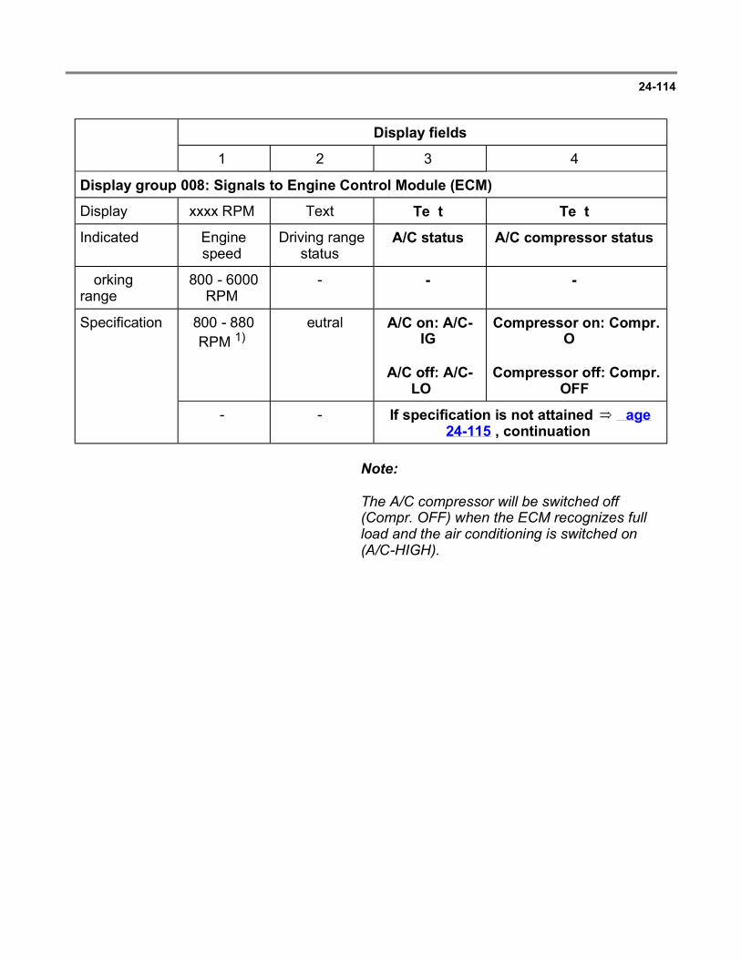
24-114
Display fields
1 2 3 4
Display group 008: Signals to Engine Control Module (ECM)
Display xxxx RPM Text Text Text
Indicated Engine speed
Driving range status
A/C status A/C compressor status
Working range
800 - 6000 RPM
- - -
Specification 800 - 880 RPM 1)
Neutral A/C on: A/C-HIGH
A/C off: A/C-LOW
Compressor on: Compr. ON
Compressor off: Compr. OFF
- - If specification is not attained Page 24-115 , continuation
Note:
The A/C compressor will be switched off (Compr. OFF) when the ECM recognizes full load and the air conditioning is switched on (A/C-HIGH).
Page 130 of 144Multiport fuel injection and ignition system
6/12/2004http://ebahn.bentleypublishers.com/vw/servlet/Display?action=Goto&type=repair&id=VW...

24-115
Continuation
If the display does not indicate as described:
If the specification is not attained:
- Connect VAG 1598/18 test box to ECM wiring harness.
- Check wiring between test box sockets 37 and 39 respectively and A/C for open circuit according to wiring diagram
Resistance: maximum 1.5 ohms ( )
- Check wiring according to wiring diagram.
Page 131 of 144Multiport fuel injection and ignition system
6/12/2004http://ebahn.bentleypublishers.com/vw/servlet/Display?action=Goto&type=repair&id=VW...

24-116
Fuel injectors, checking
Checking activation
Check activation of fuel injectors Page 01-72output Diagnostic Test Mode (DTM).
Special tools, testers and auxiliary items
VAG 1598/18 test box
Multimeter (Fluke 83 or equivalent)
VAG 1527B voltage tester
Connector test kit VW 1594
Wiring diagram
Check conditions
Engine speed sensor OK
Fuel pump relay OK
Test sequence
- Remove intake manifold, upper Page 24-7item 7 .
- Disconnect harness connector -1- from connection -2- and connect VAG 1527B voltage tester with test leads from VW 1594 to terminals of harness connector.
Page 132 of 144Multiport fuel injection and ignition system
6/12/2004http://ebahn.bentleypublishers.com/vw/servlet/Display?action=Goto&type=repair&id=VW...

24-117
- Disconnect harness connectors from fuel injectors 2-4.
- Operate starter and check voltage supply for no. 1 cyl. fuel injector.
LED must flicker
- Repeat check on fuel injectors 2-4.
If the LED does not flicker:
- Switch ignition off.
- Connect VAG 1598/18 test box to ECM wiring harness.
- Check wiring between test box and connector for open circuit according to wiring diagram.
No. 1 cyl. fuel injector: terminal 2 and test box socket 24
No. 2 cyl. fuel injector: terminal 2 and test box socket 25
No. 3 cyl. fuel injector: terminal 2 and test box socket 26
No. 4 cyl. fuel injector: terminal 2 and test box socket 02
Resistance: maximum1.5 ohms ( )
Page 133 of 144Multiport fuel injection and ignition system
6/12/2004http://ebahn.bentleypublishers.com/vw/servlet/Display?action=Goto&type=repair&id=VW...

24-118
- Check wiring between fuel injector connector terminal 1 and relay panel for open circuit according to wiring diagram.
Resistance: maximum 1.5 ohms ( )
- Additionally, check wires for short circuit to one another.
Specification: ohms ( )
Checking resistance of fuel injectors
If the specification is not attained, replace fuel injector(s) as necessary.
- Check resistance of fuel injectors individually
Specification: 15-20 ohms ( )
Page 134 of 144Multiport fuel injection and ignition system
6/12/2004http://ebahn.bentleypublishers.com/vw/servlet/Display?action=Goto&type=repair&id=VW...

24-119
Checking spray pattern and checking for leaks
WARNING!
DO NOT smoke or work near heaters or other fire hazards when working on fuel system.
The fuel system is pressurized! Before loosening hose connections or opening the test connection, wrap a cloth around the connection. Then release pressure by slowly disconnecting the hose/fitting.
Special tools, testers and auxiliary items
Connector test kit VW 1594
VAG 1630 digital potentiometer
VAG 1602 fuel analyzer
Test sequence
- Remove intake manifold, upper Page 24-7item 7 .
- Remove fuel rail complete with fuel injectors Page 24-15 , Item 8 .
- Hold fuel injectors in VAG 1602 fuel analyzer.
Page 135 of 144Multiport fuel injection and ignition system
6/12/2004http://ebahn.bentleypublishers.com/vw/servlet/Display?action=Goto&type=repair&id=VW...

24-120
Note:
When installing the fuel injectors make sure that the O-rings are not damaged.
- Disconnect harness connector from Engine Coolant Temperature (ECT) sensor -G62-.
- Set digital potentiometer VAG 1630 side A to 15 k and using test leads from VW 1594 connect to terminals 1 and 3 of disconnected harness connector.
- Disconnect harness connector from ignition coil.
- Operate starter (second technician required).
Fuel injectors must pulsate and spray in accordance with firing order.
- Switch ignition off and check fuel injectors for leaks.
No more than 2 drops/minute may leak from each fuel injector.
Page 136 of 144Multiport fuel injection and ignition system
6/12/2004http://ebahn.bentleypublishers.com/vw/servlet/Display?action=Goto&type=repair&id=VW...

24-121
Fuel pressure regulator and residual pressure, checking
The fuel pressure regulator controls the fuel pressure dependent upon intake manifold pressure.
Special tools, testers and auxiliary items
VAG 1318 pressure tester
VAG 1318/10 adapter
VAG 1318/11 adapter
VAG 1318/16 adapter
Test conditions
Fuel pump delivery rate OK, checking:
Repair Manual, 2.0 Liter 4-Cyl. 2V Engine Mechanical, Engine Code(s): ABA m.y. 1995 - 1997, Repair Group 20
Page 137 of 144Multiport fuel injection and ignition system
6/12/2004http://ebahn.bentleypublishers.com/vw/servlet/Display?action=Goto&type=repair&id=VW...

24-122
Test sequence
WARNING!
DO NOT smoke or work near heaters or other fire hazards when working on fuel system.
The fuel system is pressurized! Before loosening hose connections or opening the test connection, wrap a cloth around the connection. Then release pressure by slowly disconnecting the hose/fitting.
- Disconnect fuel supply line -1- from fuel rail -and connect using adapter 1318/10 to pressure tester VAG 1318.
- Connect pressure tester VAG 1318 to fuel rail 2- using adapter 1318/11 and 1318/16. Open pressure tester shut-off valve, handle in direction of flow (arrow).
- Start engine and run at idle speed.
- Check fuel pressure.
Specification: approx. 2.5 bar (36.3 psi)
- Disconnect vacuum hose - 1- from connection 2-.
Fuel pressure must rise to approx. 3.0 bar (43 psi).
- Switch ignition off
Page 138 of 144Multiport fuel injection and ignition system
6/12/2004http://ebahn.bentleypublishers.com/vw/servlet/Display?action=Goto&type=repair&id=VW...

24-123
- Check for leaks and residual pressure by watching pressure drop on gauge.
After 10 minutes there must be a residual pressure of at least 2 bar (29 psi).
If the residual pressure drops below 2 bar (29 psi):
- Start engine and run at idle speed.
If the pressure drops again:
Repair Manual, 2.0 Liter 4-Cyl. 2V Engine Mechanical, Engine Code(s): ABA m.y. 1995 - 1997, Repair Group 20
- After pressure has built up switch ignition off and at same time close pressure tester VAG 1318 shut-off valve, handle 90 to direction of flow (arrow).
- Watch pressure drop on gauge.
- Check fuel pump check valve.
Page 139 of 144Multiport fuel injection and ignition system
6/12/2004http://ebahn.bentleypublishers.com/vw/servlet/Display?action=Goto&type=repair&id=VW...

24-124
If the pressure does not drop:
If the pressure does not drop:
If the pressure drops again:
- Open pressure tester VAG 1318 shut-off valve, handle in direction of flow (arrow).
- Start engine and run at idle speed.
- After pressure has built up switch ignition off and at same time clamp-off return line (with blue arrow) on fuel rail.
- Replace fuel pressure regulator.
- Check hose connections, O-rings on fuel rail and fuel injectors for leaks.
- Check pressure gauge for leaks.
Page 140 of 144Multiport fuel injection and ignition system
6/12/2004http://ebahn.bentleypublishers.com/vw/servlet/Display?action=Goto&type=repair&id=VW...

24-125
Intake air system, checking for leaks (outside air)
Checking with engine leak detector spray G 001 800 A1
Special tools, testers and auxiliary items
VAG 1551/1552 scan tool with VAG 1551/3 adapter cable
Engine leak detector spray G 001 800 A1
Note:
The vacuum in the intake system will cause the leak detector spray to be drawn in with the outside air. The leak detector spray reduces the ignitability of the mixture. This leads to a drop in engine speed and to a significant increase of the CO content.
Observe the safety precautions listed on the container.
Test sequence
Engine running at idle
- Connect VAG 1551/1552 scan tool and select "Engine Electronics" address word 01 Page 01-7 .
Rapid data transfer HELP
Select function XX Indicated on display
- Press buttons -0- and -8- to select "Read Measuring Value Block" function 08 and press -Q- button to confirm input.
Page 141 of 144Multiport fuel injection and ignition system
6/12/2004http://ebahn.bentleypublishers.com/vw/servlet/Display?action=Goto&type=repair&id=VW...

24-126
If the engine speed drops or the value displayed for O2S control changes:
Read Measuring Value Block HELP
Input display group number XXX Indicated on display
- Press buttons -0-, -0- and -1- for display group 001 and press -Q- button to confirm input.
Read Measuring Value Block 1
1 2 3 4
Indicated on display (1-4 Display fields)
- Note Oxygen Sensor (O2S) control in display field 3.
Display fields
1 2 3 4
Display group 001: Idle test
Display xxxx RPM xxx.x C xx.x% xx.x
Indicated Engine speed
Engine temperature
O2S control Ignition angle
Working range
800 - 6000 RPM
- -25.0 to 25.0% 0.0 - 40.0
Specification 800 - 880 RPM
- The value must fluctuate at least 2% in range -5.0 to
5.0%
2.0 - 15.0
- Systematically spray parts of intake system with engine leak detector spray.
- Check area of intake system which has been sprayed and eliminate leaks.
Page 142 of 144Multiport fuel injection and ignition system
6/12/2004http://ebahn.bentleypublishers.com/vw/servlet/Display?action=Goto&type=repair&id=VW...
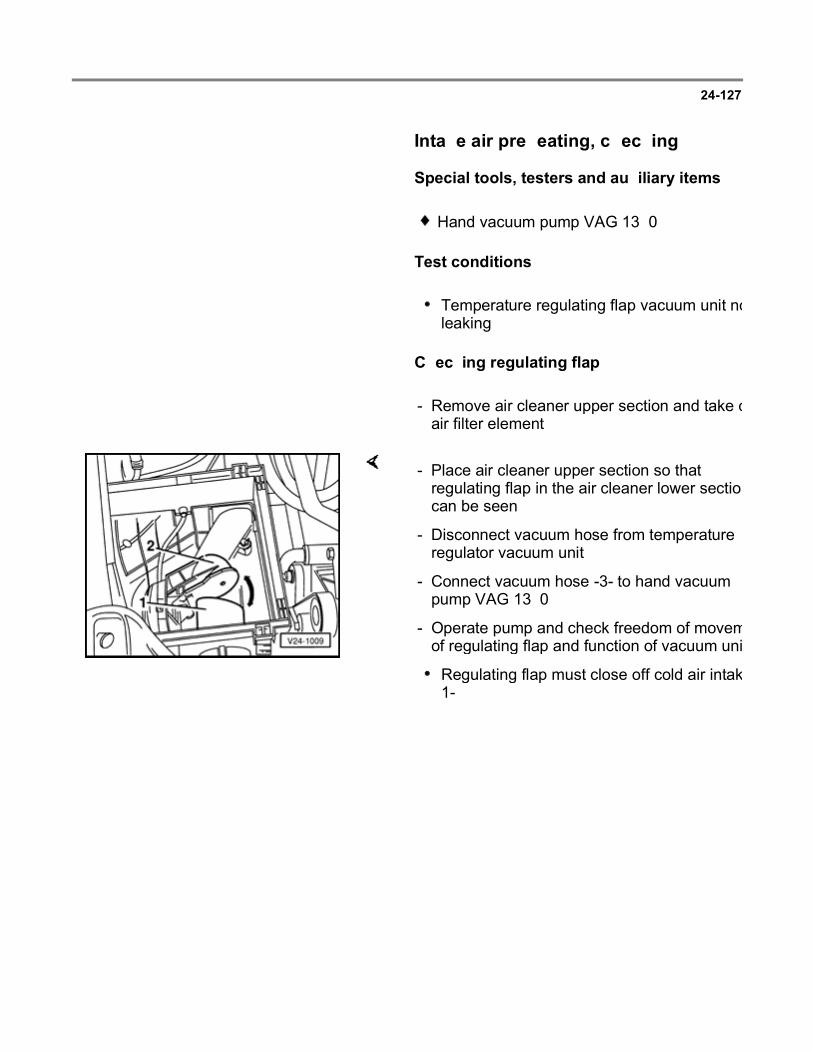
24-127
Intake air preheating, checking
Special tools, testers and auxiliary items
Hand vacuum pump VAG 1390
Test conditions
Temperature regulating flap vacuum unit not leaking
Checking regulating flap
- Remove air cleaner upper section and take out air filter element.
- Place air cleaner upper section so that regulating flap in the air cleaner lower section can be seen.
- Disconnect vacuum hose from temperature regulator vacuum unit.
- Connect vacuum hose -3- to hand vacuum pump VAG 1390.
- Operate pump and check freedom of movement of regulating flap and function of vacuum unit.
Regulating flap must close off cold air intake 1-.
Page 143 of 144Multiport fuel injection and ignition system
6/12/2004http://ebahn.bentleypublishers.com/vw/servlet/Display?action=Goto&type=repair&id=VW...
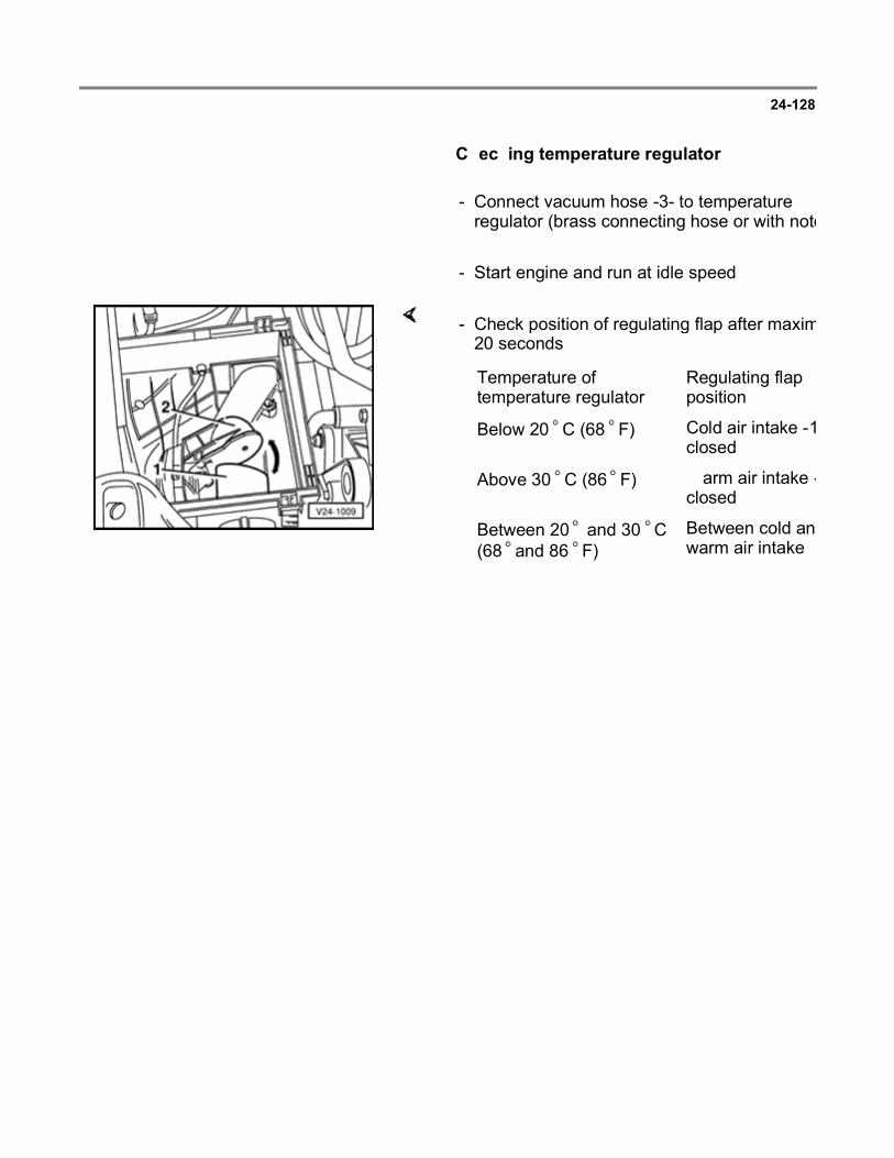
24-128
Checking temperature regulator
- Connect vacuum hose -3- to temperature regulator (brass connecting hose or with notch).
- Start engine and run at idle speed.
- Check position of regulating flap after maximum 20 seconds.
Temperature of temperature regulator
Regulating flap position
Below 20 C (68 F) Cold air intake -1closed
Above 30 C (86 F) Warm air intake -closed
Between 20 and 30 C (68 and 86 F)
Between cold and warm air intake
Page 144 of 144Multiport fuel injection and ignition system
6/12/2004http://ebahn.bentleypublishers.com/vw/servlet/Display?action=Goto&type=repair&id=VW...

28-1
Multiport fuel injection and ignition system
Ignition system components
Note:
Only components which specifically relate to the ignition system are dealt with here. For other components of the fuel injection and ignition system Repair Group 24.
The fuel injection and ignition system Engine Control Module (ECM) is equipped with On Board Diagnostic (OBD).
Components marked with an asterisk (*) are checked via the On Board Diagnostic (OBD) program.
Check Diagnostic Trouble Code (DTC) memory before carrying out repairs and troubleshooting
Page 01-12 .
Safety precautions Page 28-5
Technical data, spark plugs Page 28-7
Page 1 of 37Multiport fuel injection and ignition system
6/12/2004http://ebahn.bentleypublishers.com/vw/servlet/Display?action=Goto&type=repair&id=VW...

28-2
Ignition system, servicing
Note:
Engine Control Module (ECM) -J220-* with connector Page 24-8 , item 12 .
1 - Ignition wires
Check for continuity
2 - Suppressor
0.6-1.4 k
3 - Terminal 1
4 - Terminal 15
5 - Ignition coil power output stage -N157-*
Checking Page
28-31
6 - 10 Nm (7 ft lb)
7 - Ignition coil -N152-
Checking Page
28-30
Page 2 of 37Multiport fuel injection and ignition system
6/12/2004http://ebahn.bentleypublishers.com/vw/servlet/Display?action=Goto&type=repair&id=VW...

8 - Connector
3-pin
9 - Ground (GND) strap
Page 3 of 37Multiport fuel injection and ignition system
6/12/2004http://ebahn.bentleypublishers.com/vw/servlet/Display?action=Goto&type=repair&id=VW...

28-3
10 - Knock Sensor (KS) 1 -G61-*
11 - 20 Nm (15 ft lb)
Tightening torque influences function of knock sensor
12 - Spark plug connector
Use 3277 when disconnecting and connecting
4-6 k
13 - Spark plug
30 Nm (22 ft lb)
Remove and install with 3122B
Type and electrode gap Page 28-7
14 - 25 Nm (18 ft lb)
15 - Clamp
16 - O-ring
Replace
Page 4 of 37Multiport fuel injection and ignition system
6/12/2004http://ebahn.bentleypublishers.com/vw/servlet/Display?action=Goto&type=repair&id=VW...

if damaged
17 - Camshaft Position (CMP) sensor -G40-*
Installing Page
28-8
Checking camshaft position sensor Page 28-22
Page 5 of 37Multiport fuel injection and ignition system
6/12/2004http://ebahn.bentleypublishers.com/vw/servlet/Display?action=Goto&type=repair&id=VW...

28-4
18 - Dust cap
19 - Rotor arm
Marking: R1
0.6-1.4 k
20 - Distributor cap
Check for cracks and signs of tracking
Check contact wear
Clean before installing
Check carbon brush for wear and freedom of movement
21 - Screening cap
Page 6 of 37Multiport fuel injection and ignition system
6/12/2004http://ebahn.bentleypublishers.com/vw/servlet/Display?action=Goto&type=repair&id=VW...

28-5
Safety precautions
WARNING!
Be alert when working on or near the engine. High ignition secondary voltage can cause serious personal injury and damage vehicle components.
DO NOT touch or disconnect ignition system wires when the engine is running or being cranked at starting RPM.
DO NOT operate the starter if the fuel injectors have been removed.
Be sure the ignition is switched OFF, when:
Disconnecting ignition wires
Disconnecting fuel injection system wiring
Connecting or disconnecting test equipment leads
Disconnecting the battery
Washing the engine or engine compartment.
BEFORE cranking the engine at starting RPM (such as for compression testing) disable the ignition and fuel injection systems:
Disconnect the ignition coil power output stage.
Disconnect harness connectors from all fuel injectors.
Page 7 of 37Multiport fuel injection and ignition system
6/12/2004http://ebahn.bentleypublishers.com/vw/servlet/Display?action=Goto&type=repair&id=VW...

After the work is completed, erase Diagnostic Trouble Code (DTC) memory.
Page 8 of 37Multiport fuel injection and ignition system
6/12/2004http://ebahn.bentleypublishers.com/vw/servlet/Display?action=Goto&type=repair&id=VW...

28-6
CAUTION!
BEFORE disconnecting the battery:
Stop the engine.
Be sure the ignition is switched OFF (also applies when connecting the battery). Failure to do so may damage the Engine Control Module (ECM).
Be sure of the proper radio code (for vehicles equipped with coded anti-theft radio).
Be sure the battery negative (-) cable is disconnected, when:
Working on the electrical system
Resistance (spot) welding or electric arc welding anywhere on the vehicle.
When connecting and disconnecting electrical test equipment (LED voltage tester, multimeter, etc.):
Be sure the ignition is switched OFF.
Use correct adapters from the VW 1594 connector test kit.
For any work affecting the Engine Control Module (ECM):
BEFORE disconnecting the ECM harness connector, switch the ignition OFF and WAIT at least 20 seconds. Failure to do so may damage the ECM.
DO NOT connect any outside voltage source to stimulate an output signal at the ECM.
Page 9 of 37Multiport fuel injection and ignition system
6/12/2004http://ebahn.bentleypublishers.com/vw/servlet/Display?action=Goto&type=repair&id=VW...

28-7
Technical data, spark plugs
Engine code ABA
Ignition timing 1)
Checking Page 28-14
Firing order 1-3-4-2
Spark plugs
VW 101 000 044 AA
Manufacturer's designation
FR 8 DS
Electrode gap 0.8 mm (0.032) 2)
Tightening torque 30 Nm (22 ft lb)
1) Not adjustable
2) Gap between Ground (GND) electrode and center electrode insulation
Page 10 of 37Multiport fuel injection and ignition system
6/12/2004http://ebahn.bentleypublishers.com/vw/servlet/Display?action=Goto&type=repair&id=VW...

28-8
Distributor, removing and installing
Special tools, testers and auxiliary items
Pin wrench Matra V159
VAG 1331 torque wrench (5-50 Nm)
Note:
The Engine Control Module (ECM) requires the no. 1 cylinder TDC signal from the camshaft position sensor to orient the fuel injection and knock sensor systems as per firing order.
Checking no. 1 cylinder TDC markings
- Set flywheel -A- or drive plate -B- to TDC no. 1 cylinder.
Page 11 of 37Multiport fuel injection and ignition system
6/12/2004http://ebahn.bentleypublishers.com/vw/servlet/Display?action=Goto&type=repair&id=VW...

28-9
Engine removed
- Set vibration damper (V-belt pulley) to TDC no. 1 cylinder.
Mark on camshaft sprocket must align with arrow on cylinder head cover.
Page 12 of 37Multiport fuel injection and ignition system
6/12/2004http://ebahn.bentleypublishers.com/vw/servlet/Display?action=Goto&type=repair&id=VW...

28-10
Removing and installing distributor
Test conditions
Work sequence
Mark on distributor must align with mark on rotor arm or camshaft position sensor cover.
Crankshaft and camshaft in no. 1 cylinder TDC position
- Remove distributor.
- Before installing distributor align oil pump shaft drive tongue parallel to crankshaft.
Page 13 of 37Multiport fuel injection and ignition system
6/12/2004http://ebahn.bentleypublishers.com/vw/servlet/Display?action=Goto&type=repair&id=VW...

28-11
Note:
When installing, turn rotor arm slightly right of the distributor marking. When inserting, rotor arm will turn back to the marking.
- Install distributor. Pins on distributor must point toward mounting bolt threaded hole (arrow).
If not able to align markings:
Mark on distributor must align with mark on rotor arm or camshaft position sensor cover.
- Tighten distributor mounting bolt.
Tightening torque: 25 Nm (18 ft lb)
- Loosen belt tensioner and take toothed drive belt off camshaft sprocket.
Page 14 of 37Multiport fuel injection and ignition system
6/12/2004http://ebahn.bentleypublishers.com/vw/servlet/Display?action=Goto&type=repair&id=VW...

28-12
- Turn intermediate shaft sprocket with toothed drive belt in direction shown (arrow), until rotor arm aligns with markings for no. 1 cylinder on distributor housing (toothed drive belt slides over crankshaft sprocket).
Note:
For easier installation of the toothed drive belt, loosen belt tensioner lock nut only approx. one thread.
Mark on distributor must align with mark on rotor arm or camshaft position sensor cover.
- Place toothed drive belt on belt tensioner and camshaft sprocket.
Page 15 of 37Multiport fuel injection and ignition system
6/12/2004http://ebahn.bentleypublishers.com/vw/servlet/Display?action=Goto&type=repair&id=VW...

28-13
- To tighten toothed drive belt, turn tensioner with pin wrench (e.g. Matra V159) in direction shown (arrow).
Drive belt is correctly tensioned if it can be turned 90 with thumb and forefinger halfway between camshaft and intermediate shaft sprockets.
- Tighten tensioner lock nut.
Tightening torque: 45 Nm (33 ft lb)
- Rotate crankshaft two full turns and check adjustment.
- Check distributor housing and rotor arm markings.
- Install upper toothed belt protective cover.
- Before installing, clean distributor cap and check for cracks and signs of carbon tracking, replace if necessary.
Page 16 of 37Multiport fuel injection and ignition system
6/12/2004http://ebahn.bentleypublishers.com/vw/servlet/Display?action=Goto&type=repair&id=VW...

28-14
Ignition timing, checking
Special tools, testers and auxiliary items
VAG 1551/1552 scan tool with VAG 1551/3 adapter cable
Test conditions
Electrical consumers switched off (radiator coolant fan must not run during the check)
Air conditioner switched off
Test sequence
- Connect VAG 1551 scan tool ((VAG 1552) and select "Engine Electronics" address word 01 Page 01-7 . Engine must be running at idle speed.
Rapid data transfer HELP
Select function XX Indicated on display
- Press buttons -0- and -8- to select "Read Measuring Value Block" function 08 and press -Q- button to confirm input.
Read Measuring Value Block HELP
Input display group number XXX Indicated on display
- Press buttons -0-, -1- and -0- to input display group 010 and press -Q- button to confirm input.
Read Measuring Value Block 10
1 2 3 4
Indicated on display (1-4 Display fields)
- Check measured values for ignition (display fields 3 and 4).
Page 17 of 37Multiport fuel injection and ignition system
6/12/2004http://ebahn.bentleypublishers.com/vw/servlet/Display?action=Goto&type=repair&id=VW...

28-15
Display fields
1 2 3 4
Display group 010: Ignition 1
Display xxx RPM xx.x ms xx.x xx.x
Indicated Engine speed
Engine load
Ignition angle (mapped value)
Ignition angle
Working range
800 - 6000 RPM
0.0 - 25.0 ms
0.0 - 50.0 BTDC
0.0 - 40.0 BTDC
Specification 800 - 880 RPM
1.5 - 2.5 ms
11.0 - 13.0 BTDC
Max. 2.0 deviation from display field 3
- - Test conditions:
If the specification is not attained Page 24-69 , checking throttle valve control module
Intake manifold temperature max. 50 C (122F)
- Read readiness code Page 01-33 . If DTC memory has been erased, repair must be verified via appropriate display group Page 01-35 , Readiness code, creating.
- Press button.
- Press buttons -0- and -6- to select "End Output" function 06 and press -Q- button to confirm input.
Page 18 of 37Multiport fuel injection and ignition system
6/12/2004http://ebahn.bentleypublishers.com/vw/servlet/Display?action=Goto&type=repair&id=VW...

28-16
Misfire detection, checking
Special tools, testers and auxiliary items
VAG 1551/1552 scan tool with VAG 1551/3 adapter cable
Test sequence
- Connect VAG 1551 scan tool ((VAG 1552) and select "Engine Electronics" address word 01 Page 01-7 . Engine must be running at idle speed.
Rapid data transfer HELP
Select function XX Indicated on display
- Press buttons -0- and -8- to select "Read measuring value block" function 08 and press -Q- button to confirm input.
Read Measuring Value Block HELP
Input display group number XXX Indicated on display
- Press buttons -1-, -1- and -0- to input display group 110 and press -Q- button to confirm input.
Read Measuring Value Block 110
1 2 3 4
Indicated on display (1-4 Display fields)
- Check specifications for misfire detection (display fields 2-4).
Page 19 of 37Multiport fuel injection and ignition system
6/12/2004http://ebahn.bentleypublishers.com/vw/servlet/Display?action=Goto&type=repair&id=VW...

28-17
Display fields
1 2 3 4
Display group 110: Misfire detection 1
Display x.xx ms xxx xxx xxxxxxxx
Indicated Engine load
Misfiring adversely
affecting exhaust gas (total)
Misfiring adversely affecting three way catalytic converter
(total)
Misfiring recognition
status
Working range
0.00 - 25.00 ms
- - -
Specification 1.00 - 3.00 ms
0 0 00000000
- If the specification is not attained Page 28-18 , evaluating display group 110
- Read readiness code Page 01-33 . If DTC memory has been erased, repair must be verified via appropriate display group Page 01-35 , Readiness code, creating.
- Press button.
- Press buttons -0- and -6- for the "End Output" function and press -Q- button to confirm input.
Page 20 of 37Multiport fuel injection and ignition system
6/12/2004http://ebahn.bentleypublishers.com/vw/servlet/Display?action=Goto&type=repair&id=VW...

28-18
Evaluating display group 110
Display group: 110
Display field: 2 + 3
Possible malfunction cause
Malfunction elimination
More than 25 Ignition coil faulty
Ignition wire faulty
Spark plug faulty
- Check ignition coil Page 28-30
- Checking components of ignition system Page 28-1
Fuel injector faulty
Fuel shortage
- Check fuel injectors Page 24-116
- Check quantity of fuel in tank
Page 21 of 37Multiport fuel injection and ignition system
6/12/2004http://ebahn.bentleypublishers.com/vw/servlet/Display?action=Goto&type=repair&id=VW...

28-19
Ignition timing control, checking
Special tools, testers and auxiliary items
VAG 1551/1552 scan tool with VAG 1551/3 adapter cable
Test conditions
Electrical consumers switched off (radiator coolant fan must not run during the check)
Air conditioner switched off
Engine oil temperature at least 80 C (176
F)
Test sequence
- Connect VAG 1551 scan tool ((VAG 1552) and select "Engine Electronics" address word 01 Page 01-7 . Engine must be running at idle speed.
Rapid data transfer HELP
Select function XX Indicated on display
- Press buttons -0- and -8- to select "Read Measuring Value Block" function 08 and press -Q- button to confirm input.
Read Measuring Value Block HELP
Input display group number XXX Indicated on display
- Press buttons -0-, -1- and -0- to input display group 010 and press -Q- button to confirm input.
Page 22 of 37Multiport fuel injection and ignition system
6/12/2004http://ebahn.bentleypublishers.com/vw/servlet/Display?action=Goto&type=repair&id=VW...

28-20
Read Measuring Value Block 10
1 2 3 4
Indicated on display (1-4 Display fields)
- Check measured values for ignition timing control (display fields 1-4).
Display fields
1 2 3 4
Display group 010: Ignition 1
Display xxx RPM xx.x ms xx.x xx.x
Indicated Engine speed
Engine load
Ignition angle (mapped value)
Ignition angle
Working range
800 - 6000 RPM
0.0 - 25.0 ms
0.0 - 40.0 BTDC
0.0 - 40.0 BTDC
Specification 800 - 880 RPM
1.9 - 2.1 ms
11.0 - 13.0 BTDC
Max. 2.0 deviation from display field 3
2480 - 2520 RPM
1.7 - 1.9 ms
23.0 - 25.0 BTDC
Max. 2.0 deviation from display field 3
- - Test condition:
If the specification is not attained Page 28-21 , continuation
Intake manifold temperature max. 50 C (122 F)
Page 23 of 37Multiport fuel injection and ignition system
6/12/2004http://ebahn.bentleypublishers.com/vw/servlet/Display?action=Goto&type=repair&id=VW...

28-21
Continuation
- Check engine operating conditions Page 24-61
- Check throttle valve control module Page 24-69
- Check knock sensor and knock control Page 28-25
If the specification is again not attained:
- Replace Engine Control Module (ECM) -J220- Page 24-8 , item 12 .
- Read readiness code Page 01-33 . If DTC memory has been erased, repair must be verified via appropriate display group Page 01-35 , Readiness code, creating.
Page 24 of 37Multiport fuel injection and ignition system
6/12/2004http://ebahn.bentleypublishers.com/vw/servlet/Display?action=Goto&type=repair&id=VW...

28-22
Camshaft Position (CMP) sensor, checking
Special tools, testers and auxiliary items
VAG 1598/18 test box
Multimeter (Fluke 83 or equivalent)
Connector test kit VW 1594
Wiring diagram
Test sequence
- Disconnect 3-pin connector from camshaft position sensor.
- Connect multimeter using test leads from VW 1594 to measure voltage at terminals 1 and 3 of connector.
- Switch ignition on.
- Measure voltage between terminals 1 and 3.
Specification: 9-14.5 volts
- Switch ignition off.
Page 25 of 37Multiport fuel injection and ignition system
6/12/2004http://ebahn.bentleypublishers.com/vw/servlet/Display?action=Goto&type=repair&id=VW...

28-23
If the specification is not attained:
- Connect VAG 1598/18 test box to Engine Control Module (ECM) wiring harness.
- Check wiring between test box and 3-pin connector for open circuit according to wiring diagram.
Terminal 1 and test box socket 56
Terminal 2 and test box socket 44
Resistance: max. 1.5 ohms ( )
- Check wire between 3-pin connector and relay panel for open circuit using wiring diagram.
Terminal 3 and relay panel
Resistance: max. 1.5 ohms ( )
Page 26 of 37Multiport fuel injection and ignition system
6/12/2004http://ebahn.bentleypublishers.com/vw/servlet/Display?action=Goto&type=repair&id=VW...

28-24
- Additionally check all wires for short circuit to each other.
Terminal 3 and test box socket 44
Terminal 3 and test box socket 56
Terminal 2 and test box socket 56
Specification: ohms ( )
If no wiring malfunction is detected and voltage was present between terminals 1 and 3:
- Replace distributor with camshaft position sensor Page 28-3 , Item 17 .
If no wiring malfunction is detected and no voltage was present between terminals 1 and 3:
- Replace Engine Control Module (ECM) -J220- Page 24-8 , item 12 .
- Read readiness code Page 01-33 . If DTC memory has been erased, repair must be verified via appropriate display group Page 01-35 , Readiness code, creating.
Page 27 of 37Multiport fuel injection and ignition system
6/12/2004http://ebahn.bentleypublishers.com/vw/servlet/Display?action=Goto&type=repair&id=VW...

28-25
Knock Sensor (KS) and knock control, checking
Special tools, testers and auxiliary items
VAG 1551/1552 scan tool with VAG 1551/3 adapter cable
VAG 1598/18 test box
Multimeter (Fluke 83 or equivalent)
Connector test kit VW 1594
Wiring diagram
Test sequence
- Connect VAG 1551 scan tool ((VAG 1552) and select "Engine Electronics" address word 01 Page 01-7 . Engine must be running at idle speed.
Rapid data transfer HELP
Select function XX Indicated on display
- Press buttons -0- and -8- to select "Read Measuring Value Block" function 08 and press -Q- button to confirm input.
Read Measuring Value Block HELP
Input display group number XXX Indicated on display
- Press buttons -0-, -4- and -5- to input display group 045 and press -Q- button to confirm input.
Read Measuring Value Block 45
1 2 3 4
Indicated on display (1-4 Display fields)
Page 28 of 37Multiport fuel injection and ignition system
6/12/2004http://ebahn.bentleypublishers.com/vw/servlet/Display?action=Goto&type=repair&id=VW...

28-26
Note:
The check must be carried out during a test drive as knock control is not active with an engine load exceeding 3 ms.
- Perform test drive and observe specification for knock control on display (second technician necessary).
Display fields
1 2 3 4
Display group 045: Knock control
Display xx.xx xx.xx xx.xx xx.xx
Indicated Ignition angle correction cylinder 1
Ignition angle correction cylinder 2
Ignition angle correction cylinder 3
Ignition angle correction cylinder 4
Working range
0.0 - 15.0 0.0 - 15.0 0.0 - 15.0 0.0 - 15.0
Specification 0.0 - 12.0 0.0 - 12.0 0.0 - 12.0 0.0 - 12.0
If the specification is not attained Page 28-27 , evaluating display group 045
- Read readiness code Page 01-33 . If DTC memory has been erased, repair must be verified via appropriate display group Page 01-35 , Readiness code, creating.
- Press button.
- Press buttons -0- and -6- to select "End Output" function 06 and press -Q- button to confirm input.
Page 29 of 37Multiport fuel injection and ignition system
6/12/2004http://ebahn.bentleypublishers.com/vw/servlet/Display?action=Goto&type=repair&id=VW...

28-27
Evaluating display group 045
Display group: 045
Display fields: 1-4
Possible malfunction cause
Malfunction
elimination
All cylinders more than 12 Knock sensor faulty - Continuation Page 28-28
Connector corroded
Knock sensor incorrectly tightened
- Loosen knock sensor and tighten to 20 Nm (15 ft lb)
Attached components on engine loose
- Tighten attached components
Poor fuel quality - Change fuel type
One cylinder deviates greatly from the others
Connector corroded - Continuation Page 28-28
Engine damage Repair Manual, 2.0 Liter 4-Cyl. 2V
Engine Mechanical, Engine Code(s): ABA m.y. 1995 - 1997, Repair Group 13
- Check compression pressures:
Attached components on engine loose
- Tighten attached components
Page 30 of 37Multiport fuel injection and ignition system
6/12/2004http://ebahn.bentleypublishers.com/vw/servlet/Display?action=Goto&type=repair&id=VW...
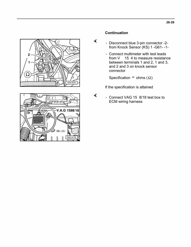
28-28
Continuation
If the specification is attained:
- Disconnect blue 3-pin connector -2- from Knock Sensor (KS) 1 -G61- -1-.
- Connect multimeter with test leads from VW 1594 to measure resistance between terminals 1 and 2, 1 and 3, and 2 and 3 on knock sensor connector.
Specification ohms ( )
- Connect VAG 1598/18 test box to ECM wiring harness.
Page 31 of 37Multiport fuel injection and ignition system
6/12/2004http://ebahn.bentleypublishers.com/vw/servlet/Display?action=Goto&type=repair&id=VW...

28-29
If no wiring malfunction is detected:
If the malfunction is still present (malfunction again in Diagnostic Trouble Code (DTC) memory):
- Check wiring between test box and 3-pin connector for open circuit according to wiring diagram.
Terminal 1 and test box socket 34
Terminal 2 and test box socket 33
Terminal 3 and test box socket 56
Resistance: max. 1.5 ohms ( )
- Additionally check wires for short to one another.
Terminal 3 and test box socket 34
Terminal 3 and test box socket 33
Terminal 2 and test box socket 34
Specification: ohms ( )
- Loosen knock sensor and tighten again to 20 Nm (15 ft lb).
- Replace Knock Sensor (KS) 1 -G61- Page 28-3 , item 10 .
- Read readiness code Page 01-33 . If DTC memory has been erased, repair must be verified via appropriate display group Page 01-35 , Readiness code, creating.
Page 32 of 37Multiport fuel injection and ignition system
6/12/2004http://ebahn.bentleypublishers.com/vw/servlet/Display?action=Goto&type=repair&id=VW...
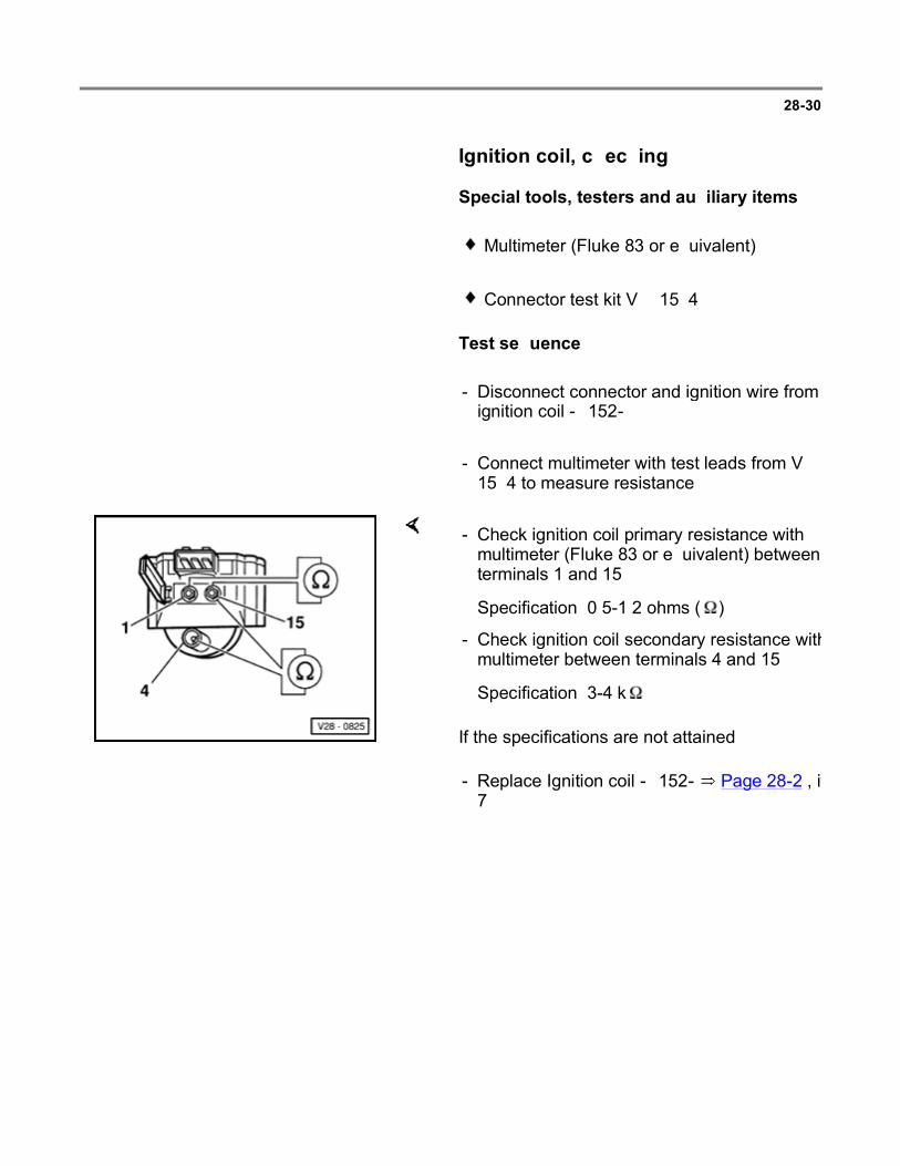
28-30
Ignition coil, checking
Special tools, testers and auxiliary items
Multimeter (Fluke 83 or equivalent)
Connector test kit VW 1594
Test sequence
- Disconnect connector and ignition wire from ignition coil -N152-.
- Connect multimeter with test leads from VW 1594 to measure resistance.
If the specifications are not attained:
- Check ignition coil primary resistance with multimeter (Fluke 83 or equivalent) between terminals 1 and 15.
Specification: 0.5-1.2 ohms ( )
- Check ignition coil secondary resistance with multimeter between terminals 4 and 15.
Specification: 3-4 k
- Replace Ignition coil -N152- Page 28-2 , item 7 .
Page 33 of 37Multiport fuel injection and ignition system
6/12/2004http://ebahn.bentleypublishers.com/vw/servlet/Display?action=Goto&type=repair&id=VW...

28-31
Ignition coil power output stage, checking
Special tools, testers and auxiliary items
VAG 1598/18 test box
Multimeter (Fluke 83 or equivalent)
VAG 1527B voltage tester
Connector test kit VW 1594
Wiring diagram
Checking voltage supply
- Disconnect 3-pin connector from ignition coil.
If the specification is not attained:
- Connect multimeter using test leads from VW 1594 to measure voltage at terminals 1 and 3 of connector.
- Switch ignition on.
- Measure voltage between terminals 1 and 3.
Specification: 9-14.5 volts
- Switch ignition off.
Page 34 of 37Multiport fuel injection and ignition system
6/12/2004http://ebahn.bentleypublishers.com/vw/servlet/Display?action=Goto&type=repair&id=VW...

28-32
- Check wiring between 3-pin connector and relay panel for open circuit using wiring diagram.
Terminal 1 and relay panel
Terminal 3 and relay panel
Resistance: max. 1.5 ohms ( )
If no wiring malfunction is detected and voltage was present between terminals 1 and 3:
- Replace Ignition coil -N152- Page 28-2 , item 7 .
If no wiring malfunction is detected and no voltage was present between terminals 1 and 3:
- Replace Engine Control Module (ECM) -J220Page 24-8 , item 12 .
- Read readiness code Page 01-33 . If DTC memory has been erased, repair must be verified via appropriate display group Page 01-35 , Readiness code, creating.
Checking activation
- Disconnect engine harness center connector Page 24-2 , item 11 .
- Connect VAG 1527B voltage tester with test leads from VW 1594 and adapters VW 1594/15 to terminals 2 and 3 of connector.
Page 35 of 37Multiport fuel injection and ignition system
6/12/2004http://ebahn.bentleypublishers.com/vw/servlet/Display?action=Goto&type=repair&id=VW...

28-33
- Operate starter and check ignition signal from ECM.
LED must flicker
- Switch ignition off.
If the LED does not flicker:
If no wiring malfunction is detected and voltage was present between terminals 1 and 3:
- Connect VAG 1598/18 test box to ECM wiring harness.
- Check wiring between 3-pin connector and test box for open circuit according to wiring diagram.
Terminal 2 and test box socket 8
Resistance: max. 1.5 ohms ( )
- Additionally check the wiring for short circuit to each other.
Terminal 1 and test box socket 8
Terminal 3 and test box socket 8
Specification: ohms ( )
- Replace ECM -J220- Page 24-8 , item 12 .
- Read readiness code Page 01-33 . If DTC memory has been erased, repair must be verified via appropriate display group Page 01-35 , Readiness code, creating.
Page 36 of 37Multiport fuel injection and ignition system
6/12/2004http://ebahn.bentleypublishers.com/vw/servlet/Display?action=Goto&type=repair&id=VW...

28-34
If the voltage supply and activation is OK.:
- Reconnect 3-pin harness connector and ignition wire to ignition coil.
CAUTION!
During the following test do not touch the terminals of the ignition coil or test cables.
- Connect LED voltage tester with test leads to terminals 1 and 15 on ignition coil.
- Operate starter.
LED must flicker
- If necessary, replace ignition coil power output stage.
Page 37 of 37Multiport fuel injection and ignition system
6/12/2004http://ebahn.bentleypublishers.com/vw/servlet/Display?action=Goto&type=repair&id=VW...