Embed Size (px)
Citation preview
Welcome to the growing family of new NISSANowners. This vehicle is delivered to you withconfidence. It was produced using the latesttechniques and strict quality control.
This manual was prepared to help you under-stand the operation and maintenance of yourvehicle so that you may enjoy many miles (kilome-ters) of driving pleasure. Please read through thismanual before operating your vehicle.
A separate Warranty Information Bookletexplains details about the warranties cov-ering your vehicle. The “NISSAN Serviceand Maintenance Guide” explains detailsabout maintaining and servicing your ve-hicle. Additionally, a separate CustomerCare/Lemon Law Booklet (U.S. only) willexplain how to resolve any concerns youmay have with your vehicle, as well asclarify your rights under your state’s lemonlaw.
Your NISSAN dealership knows your vehiclebest. When you require any service or have anyquestions, they will be glad to assist you with theextensive resources available to them.
Before driving your vehicle please read this Own-er’s Manual carefully. This will ensure familiaritywith controls and maintenance requirements, as-sisting you in the safe operation of your vehicle.
WARNING
IMPORTANT SAFETY INFORMATION RE-MINDERS FOR SAFETY!
Follow these important driving rules tohelp ensure a safe and comfortable tripfor you and your passengers!
● NEVER drive under the influence of al-cohol or drugs.
● ALWAYS observe posted speed limitsand never drive too fast for conditions.
● ALWAYS use your seat belts and appro-priate child restraint systems. Pre-teenchildren should be seated in the rearseat.
● ALWAYS provide information about theproper use of vehicle safety features toall occupants of the vehicle.
● ALWAYS review this owner’s manual forimportant safety information.
For descriptions specified for four-wheel drivemodels, a mark is placed at the begin-ning of the applicable sections/items.
As with other vehicles with features foroff-road use, failure to operate four-wheeldrive models correctly may result in loss ofcontrol or an accident. Be sure to read“Driving safety precautions” in the “Start-ing and driving” section of this manual.
ON-PAVEMENT AND OFF-ROAD DRIVING
This vehicle will handle and maneuverdifferently from an ordinary passengercar because it has a higher center ofgravity for off-road use. As with othervehicles with features of this type, fail-ure to operate this vehicle correctly mayresult in loss of control or an accident.
Be sure to read “On-pavement and off-road driving precautions”, and “Avoid-ing collision and rollover”, and “Drivingsafety precautions”, in the “Starting anddriving” section of this manual.
MODIFICATION OF YOUR VEHICLE
This vehicle should not be modified. Modi-fication could affect its performance,safety or durability, and may even violategovernmental regulations. In addition,damage or performance problems result-ing from modifications may not be coveredunder NISSAN warranties.
FOREWORD READ FIRST—THEN DRIVE SAFELY
Z REVIEW COPY—2006 Truck/Frontier (d22)Owners Manual—USA_English (nna)10/14/05—debbie X
This manual includes information for all optionsavailable on this model. Therefore, you may findsome information that does not apply to yourvehicle.
All information, specifications and illustrations inthis manual are those in effect at the time ofprinting. NISSAN reserves the right to changespecifications or design without notice and with-out obligation.
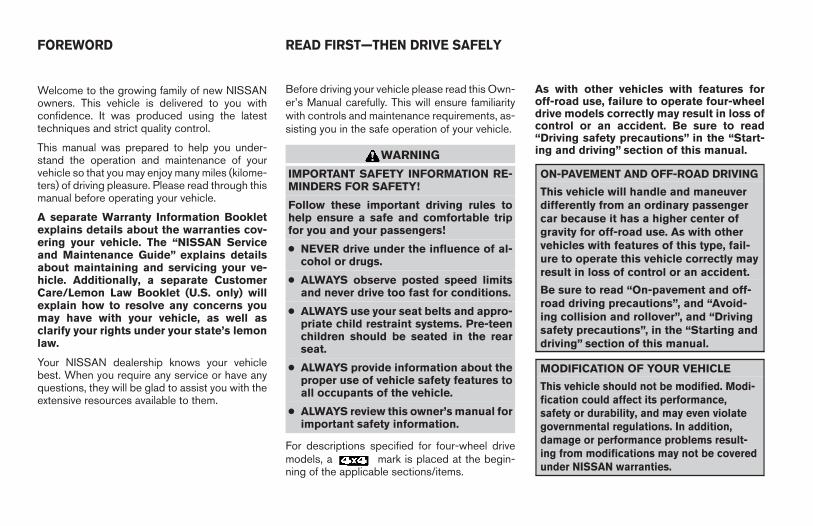
IMPORTANT INFORMATION ABOUTTHIS MANUALYou will see various symbols in this manual. Theyare used in the following ways:
WARNING
This is used to indicate the presence of ahazard that could cause death or seriouspersonal injury. To avoid or reduce therisk, the procedures must be followedprecisely.
CAUTION
This is used to indicate the presence of ahazard that could cause minor or moder-ate personal injury or damage to your ve-hicle. To avoid or reduce the risk, the pro-cedures must be followed carefully.
If you see this symbol, it means “Do not do this”or “Do not let this happen.”
If you see a symbol similar to these in an illustra-tion, it means the arrow points to the front of thevehicle.
Arrows in an illustration that are similar to theseindicate movement or action.
Arrows in an illustration that are similar to thesecall attention to an item in the illustration.
CALIFORNIA PROPOSITION 65WARNING
WARNING
Engine exhaust, some of its constituents,and certain vehicle components containor emit chemicals known to the State ofCalifornia to cause cancer and birth de-fects or other reproductive harm. In addi-tion, certain fluids contained in vehiclesand certain products of component wearcontain or emit chemicals known to theState of California to cause cancer andbirth defects or other reproductive harm.
© 2005 NISSAN NORTH AMERICA, INC.GARDENA, CALIFORNIA
All rights reserved. No part of this Owner’sManual may be reproduced or stored in a retrievalsystem, or transmitted in any form, or by anymeans, electronic, mechanical, photocopying,recording or otherwise, without the prior writtenpermission of Nissan North America, Inc., Gar-dena, California.
APD1005
WHEN READING THE MANUAL
Z REVIEW COPY—2006 Truck/Frontier (d22)Owners Manual—USA_English (nna)10/14/05—debbie X
NISSAN CARES . . .
Both NISSAN and your NISSAN dealer are dedicated to serving all your automotive needs. Your satisfaction with your vehicle and your NISSAN dealer areour primary concerns. Your NISSAN dealer is always available to assist you with all your automobile sales and service needs.
However, if there is something that your NISSANdealer cannot assist you with or you would like toprovide NISSAN directly with comments orquestions, please contact the NISSAN Con-sumer Affairs Department using our toll-freenumber:
For U.S. customers1-800-NISSAN-1(1-800-647-7261)
For Canadian customers1-800-387-0122
The Consumer Affairs Department will ask for thefollowing information:
– Your name, address, and telephone number
– Vehicle identification number (attached to thetop of the instrument panel on the driver’sside)
– Date of purchase
– Current odometer reading
– Your NISSAN dealer’s name
– Your comments or questions
OR
You can write to NISSAN with the information at:
For U.S. customersNissan North America, Inc.Consumer Affairs DepartmentP.O. Box 191Gardena, California 90248-0191
For Canadian customersNissan Canada Inc.5290 Orbitor DriveMississauga, Ontario L4W 4Z5
We appreciate your interest in NISSAN and thank you for buying a quality NISSAN vehicle.
NISSAN CUSTOMER CARE PROGRAM
Z REVIEW COPY—2006 Truck/Frontier (d22)Owners Manual—USA_English (nna)10/14/05—debbie X

Z REVIEW COPY—2006 Truck/Frontier (d22)Owners Manual—USA_English (nna)10/14/05—debbie X
Table ofContents
Illustrated table of contents
Safety—Seats, seat belts and supplemental restraint system
Instruments and controls
Pre-driving checks and adjustments
Heater, air conditioner and audio systems
Starting and driving
In case of emergency
Appearance and care
Maintenance and do-it-yourself
Technical and consumer information
Index
0
1
2
3
4
5
6
7
8
9
10

Z REVIEW COPY—2006 Truck/Frontier (d22)Owners Manual—USA_English (nna)10/14/05—root X
0 Illustrated table of contents
Airbags, seat belts and child restraints . . . . . . . . . . . . . . . 0-2Exterior front . . . . . . . . . . . . . . . . . . . . . . . . . . . . . . . . . . . . . . 0-3Exterior rear. . . . . . . . . . . . . . . . . . . . . . . . . . . . . . . . . . . . . . . 0-4Passenger compartment . . . . . . . . . . . . . . . . . . . . . . . . . . . 0-5
Instrument panel. . . . . . . . . . . . . . . . . . . . . . . . . . . . . . . . . . . 0-6Engine compartment check locations . . . . . . . . . . . . . . . . 0-8Warning/indicator lights . . . . . . . . . . . . . . . . . . . . . . . . . . . 0-10
Z REVIEW COPY—2006 Truck/Frontier (d22)Owners Manual—USA_English (nna)10/14/05—root X
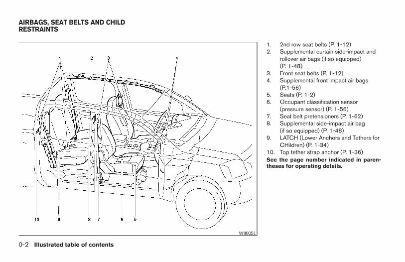
1. 2nd row seat belts (P. 1-12)2. Supplemental curtain side-impact and
rollover air bags (if so equipped)(P. 1-48)
3. Front seat belts (P. 1-12)4. Supplemental front impact air bags
(P.1-56)5. Seats (P. 1-2)6. Occupant classification sensor
(pressure sensor) (P. 1-56)7. Seat belt pretensioners (P. 1-62)8. Supplemental side-impact air bag
(if so equipped) (P. 1-48)9. LATCH (Lower Anchors and Tethers for
CHildren) (P. 1-34)10. Top tether strap anchor (P. 1-36)See the page number indicated in paren-theses for operating details.
WII0051
AIRBAGS, SEAT BELTS AND CHILDRESTRAINTS
0-2 Illustrated table of contents
Z REVIEW COPY—2006 Truck/Frontier (d22)Owners Manual—USA_English (nna)10/14/05—debbie X
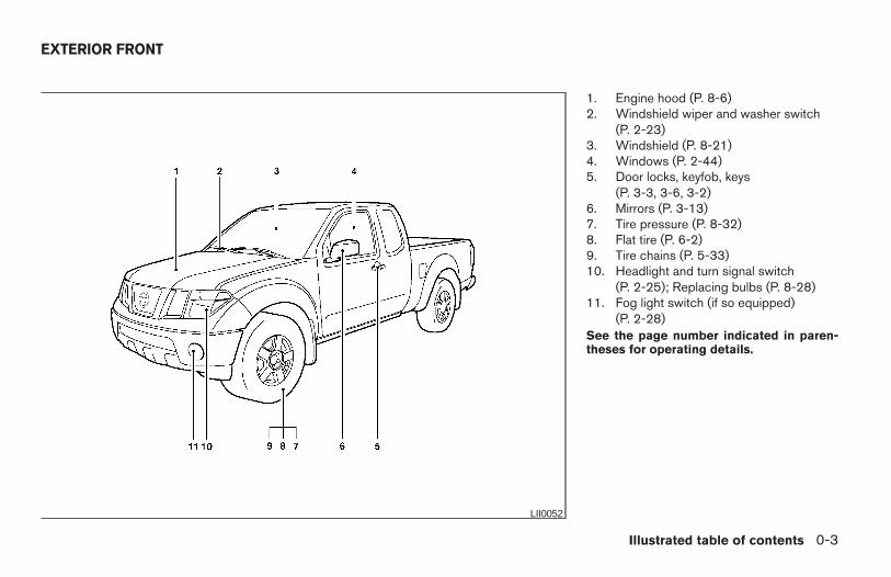
1. Engine hood (P. 8-6)2. Windshield wiper and washer switch
(P. 2-23)3. Windshield (P. 8-21)4. Windows (P. 2-44)5. Door locks, keyfob, keys
(P. 3-3, 3-6, 3-2)6. Mirrors (P. 3-13)7. Tire pressure (P. 8-32)8. Flat tire (P. 6-2)9. Tire chains (P. 5-33)10. Headlight and turn signal switch
(P. 2-25); Replacing bulbs (P. 8-28)11. Fog light switch (if so equipped)
(P. 2-28)See the page number indicated in paren-theses for operating details.
LII0052
EXTERIOR FRONT
Illustrated table of contents 0-3
Z REVIEW COPY—2006 Truck/Frontier (d22)Owners Manual—USA_English (nna)10/14/05—debbie X
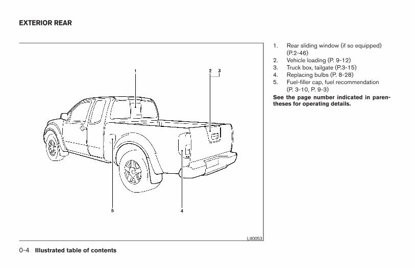
1. Rear sliding window (if so equipped)(P.2-46)
2. Vehicle loading (P. 9-12)3. Truck box, tailgate (P.3-15)4. Replacing bulbs (P. 8-28)5. Fuel-filler cap, fuel recommendation
(P. 3-10, P. 9-3)See the page number indicated in paren-theses for operating details.
LII0053
EXTERIOR REAR
0-4 Illustrated table of contents
Z REVIEW COPY—2006 Truck/Frontier (d22)Owners Manual—USA_English (nna)10/14/05—debbie X
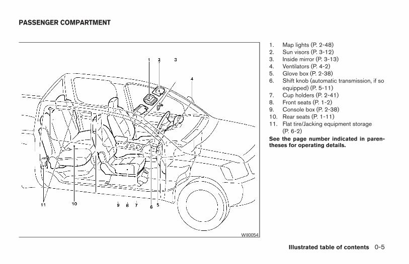
1. Map lights (P. 2-48)2. Sun visors (P. 3-12)3. Inside mirror (P. 3-13)4. Ventilators (P. 4-2)5. Glove box (P. 2-38)6. Shift knob (automatic transmission, if so
equipped) (P. 5-11)7. Cup holders (P. 2-41)8. Front seats (P. 1-2)9. Console box (P. 2-38)10. Rear seats (P. 1-11)11. Flat tire/Jacking equipment storage
(P. 6-2)See the page number indicated in paren-theses for operating details.
WII0054
PASSENGER COMPARTMENT
Illustrated table of contents 0-5
Z REVIEW COPY—2006 Truck/Frontier (d22)Owners Manual—USA_English (nna)10/14/05—debbie X
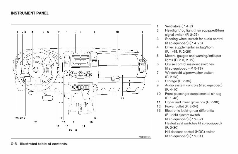
1. Ventilators (P. 4-2)2. Headlight/fog light (if so equipped)/turn
signal switch (P. 2-25)3. Steering wheel switch for audio control
(if so equipped) (P. 4-26)4. Driver supplemental air bag/horn
(P. 1-48, P. 2-29)5. Meters, gauges and warning/indicator
lights (P. 2-3, 2-12)6. Cruise control main/set switches
(if so equipped) (P. 5-18)7. Windshield wiper/washer switch
(P. 2-23)8. Storage (P. 2-35)9. Audio system controls (if so equipped)
(P. 4-10)10. Front passenger supplemental air bag
(P. 1-48)11. Upper and lower glove box (P. 2-38)12. Power outlet (P. 2-34)13. Electronic locking rear differential
(E-Lock) system switch(if so equipped) (P. 2-32)Heated seat switches (if so equipped)(P. 2-30)Hill descent control (HDC) switch(if so equipped) (P. 2-31)WIC0916
INSTRUMENT PANEL
0-6 Illustrated table of contents
Z REVIEW COPY—2006 Truck/Frontier (d22)Owners Manual—USA_English (nna)10/14/05—debbie X
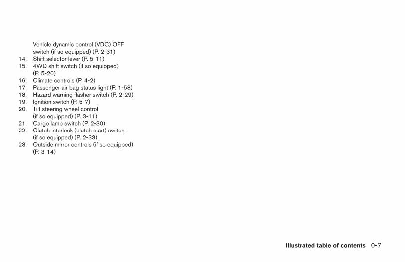
Vehicle dynamic control (VDC) OFFswitch (if so equipped) (P. 2-31)
14. Shift selector lever (P. 5-11)15. 4WD shift switch (if so equipped)
(P. 5-20)16. Climate controls (P. 4-2)17. Passenger air bag status light (P. 1-58)18. Hazard warning flasher switch (P. 2-29)19. Ignition switch (P. 5-7)20. Tilt steering wheel control
(if so equipped) (P. 3-11)21. Cargo lamp switch (P. 2-30)22. Clutch interlock (clutch start) switch
(if so equipped) (P. 2-33)23. Outside mirror controls (if so equipped)
(P. 3-14)
Illustrated table of contents 0-7
Z REVIEW COPY—2006 Truck/Frontier (d22)Owners Manual—USA_English (nna)10/14/05—debbie X
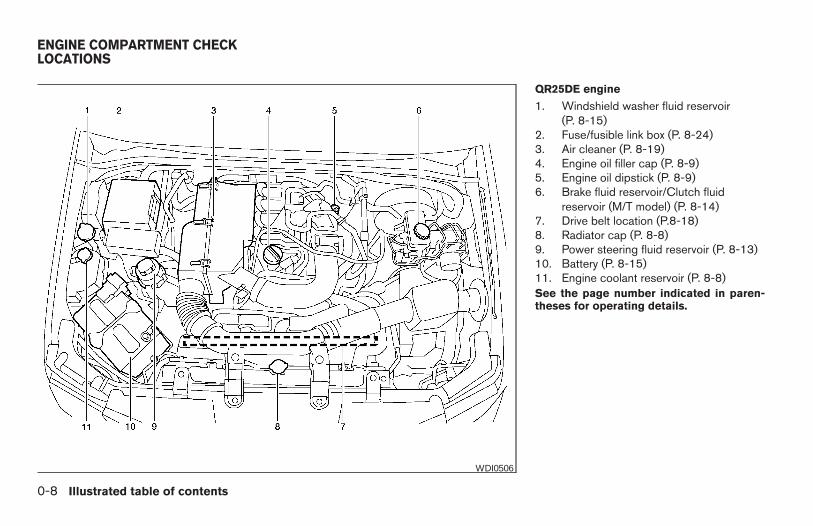
QR25DE engine
1. Windshield washer fluid reservoir(P. 8-15)
2. Fuse/fusible link box (P. 8-24)3. Air cleaner (P. 8-19)4. Engine oil filler cap (P. 8-9)5. Engine oil dipstick (P. 8-9)6. Brake fluid reservoir/Clutch fluid
reservoir (M/T model) (P. 8-14)7. Drive belt location (P.8-18)8. Radiator cap (P. 8-8)9. Power steering fluid reservoir (P. 8-13)10. Battery (P. 8-15)11. Engine coolant reservoir (P. 8-8)See the page number indicated in paren-theses for operating details.
WDI0506
ENGINE COMPARTMENT CHECKLOCATIONS
0-8 Illustrated table of contents
Z REVIEW COPY—2006 Truck/Frontier (d22)Owners Manual—USA_English (nna)10/14/05—debbie X
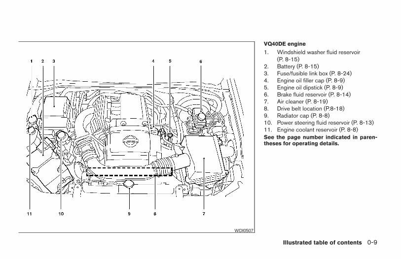
VQ40DE engine
1. Windshield washer fluid reservoir(P. 8-15)
2. Battery (P. 8-15)3. Fuse/fusible link box (P. 8-24)4. Engine oil filler cap (P. 8-9)5. Engine oil dipstick (P. 8-9)6. Brake fluid reservoir (P. 8-14)7. Air cleaner (P. 8-19)8. Drive belt location (P.8-18)9. Radiator cap (P. 8-8)10. Power steering fluid reservoir (P. 8-13)11. Engine coolant reservoir (P. 8-8)See the page number indicated in paren-theses for operating details.
WDI0507
Illustrated table of contents 0-9
Z REVIEW COPY—2006 Truck/Frontier (d22)Owners Manual—USA_English (nna)10/14/05—debbie X
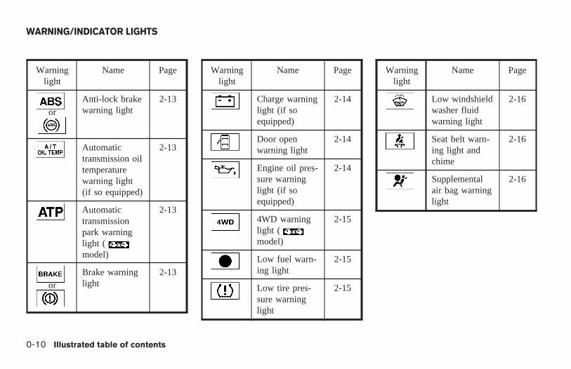
Warninglight
Name Page
or
Anti-lock brakewarning light
2-13
Automatictransmission oiltemperaturewarning light(if so equipped)
2-13
Automatictransmissionpark warninglight (model)
2-13
or
Brake warninglight
2-13
Warninglight
Name Page
Charge warninglight (if soequipped)
2-14
Door openwarning light
2-14
Engine oil pres-sure warninglight (if soequipped)
2-14
4WD warninglight (model)
2-15
Low fuel warn-ing light
2-15
Low tire pres-sure warninglight
2-15
Warninglight
Name Page
Low windshieldwasher fluidwarning light
2-16
Seat belt warn-ing light andchime
2-16
Supplementalair bag warninglight
2-16
WARNING/INDICATOR LIGHTS
0-10 Illustrated table of contents
Z REVIEW COPY—2006 Truck/Frontier (d22)Owners Manual—USA_English (nna)10/14/05—debbie X
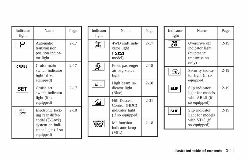
Indicatorlight
Name Page
Automatictransmissionposition indica-tor light
2-17
Cruise mainswitch indicatorlight (if soequipped)
2-17
Cruise setswitch indicatorlight (if soequipped)
2-17
Electronic lock-ing rear differ-ential (E-Lock)system on indi-cator light (if soequipped)
2-18
Indicatorlight
Name Page
4WD shift indi-cator light(model)
2-17
Front passengerair bag statuslight
2-18
High beam in-dicator light(Blue)
2-18
Hill DescentControl (HDC)indicator light(if so equipped)
2-31
Malfunctionindicator lamp(MIL)
2-18
Indicatorlight
Name Page
Overdrive offindicator light(automatictransmissiononly)
2-19
Security indica-tor light (if soequipped)
2-19
Slip indicatorlight for modelswith ABLS (ifso equipped)
2-19
Slip indicatorlight for modelswith VDC (ifso equipped)
2-19
Illustrated table of contents 0-11
Z REVIEW COPY—2006 Truck/Frontier (d22)Owners Manual—USA_English (nna)10/14/05—debbie X
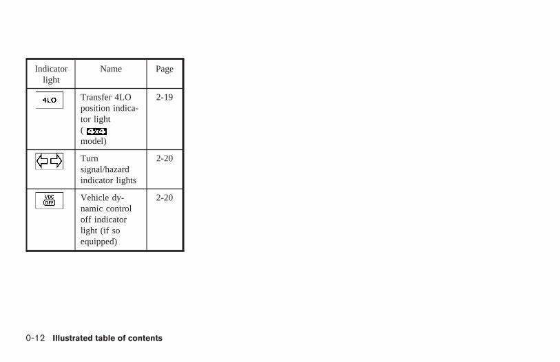
Indicatorlight
Name Page
Transfer 4LOposition indica-tor light(model)
2-19
Turnsignal/hazardindicator lights
2-20
Vehicle dy-namic controloff indicatorlight (if soequipped)
2-20
0-12 Illustrated table of contents
Z REVIEW COPY—2006 Truck/Frontier (d22)Owners Manual—USA_English (nna)10/14/05—debbie X
1 Safety—Seats, seat belts andsupplemental restraint system
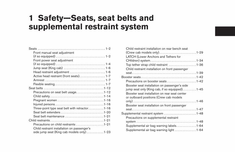
Seats . . . . . . . . . . . . . . . . . . . . . . . . . . . . . . . . . . . . . . . . . . . . 1-2Front manual seat adjustment(if so equipped) . . . . . . . . . . . . . . . . . . . . . . . . . . . . . . . . 1-2Front power seat adjustment(if so equipped) . . . . . . . . . . . . . . . . . . . . . . . . . . . . . . . . 1-4Jump seat (King cab) . . . . . . . . . . . . . . . . . . . . . . . . . . . 1-6Head restraint adjustment . . . . . . . . . . . . . . . . . . . . . . . 1-6Active head restraint (front seats). . . . . . . . . . . . . . . . . 1-7Armrest . . . . . . . . . . . . . . . . . . . . . . . . . . . . . . . . . . . . . . . 1-7Flexible seating. . . . . . . . . . . . . . . . . . . . . . . . . . . . . . . . . 1-7
Seat belts . . . . . . . . . . . . . . . . . . . . . . . . . . . . . . . . . . . . . . .1-12Precautions on seat belt usage. . . . . . . . . . . . . . . . . . 1-12Child safety . . . . . . . . . . . . . . . . . . . . . . . . . . . . . . . . . . .1-14Pregnant women . . . . . . . . . . . . . . . . . . . . . . . . . . . . . .1-16Injured persons. . . . . . . . . . . . . . . . . . . . . . . . . . . . . . . .1-16Three-point type seat belt with retractor . . . . . . . . . . 1-16Seat belt extenders . . . . . . . . . . . . . . . . . . . . . . . . . . . .1-20Seat belt maintenance . . . . . . . . . . . . . . . . . . . . . . . . . 1-21
Child restraints . . . . . . . . . . . . . . . . . . . . . . . . . . . . . . . . . . .1-21Precautions on child restraints . . . . . . . . . . . . . . . . . . 1-21Child restraint installation on passenger’sside jump seat (King cab models only) . . . . . . . . . . . 1-23
Child restraint installation on rear bench seat(Crew cab models only) . . . . . . . . . . . . . . . . . . . . . . . . 1-29LATCH (Lower Anchors and Tethers forCHildren) system . . . . . . . . . . . . . . . . . . . . . . . . . . . . . .1-34Top tether strap child restraint . . . . . . . . . . . . . . . . . . 1-36Child restraint installation on front passengerseat. . . . . . . . . . . . . . . . . . . . . . . . . . . . . . . . . . . . . . . . . .1-39
Booster seats . . . . . . . . . . . . . . . . . . . . . . . . . . . . . . . . . . . .1-42Precautions on booster seats . . . . . . . . . . . . . . . . . . . 1-42Booster seat installation on passenger’s sidejump seat only (King cab, if so equipped). . . . . . . . . 1-45Booster seat installation on rear seat centeror outboard positions (Crew cab modelsonly) . . . . . . . . . . . . . . . . . . . . . . . . . . . . . . . . . . . . . . . . .1-46Booster seat installation on front passengerseat. . . . . . . . . . . . . . . . . . . . . . . . . . . . . . . . . . . . . . . . . .1-47
Supplemental restraint system . . . . . . . . . . . . . . . . . . . . . 1-48Precautions on supplemental restraintsystem . . . . . . . . . . . . . . . . . . . . . . . . . . . . . . . . . . . . . . .1-48Supplemental air bag warning labels . . . . . . . . . . . . . 1-64Supplemental air bag warning light . . . . . . . . . . . . . . 1-64
Z REVIEW COPY—2006 Truck/Frontier (d22)Owners Manual—USA_English (nna)10/14/05—debbie X
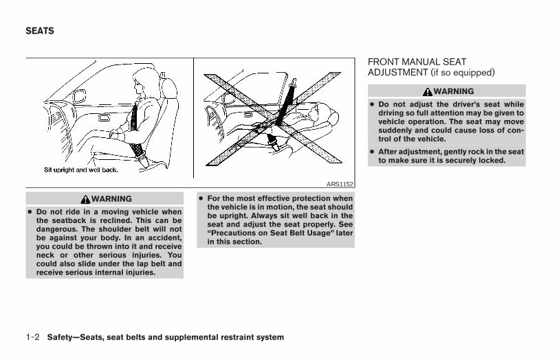
WARNING
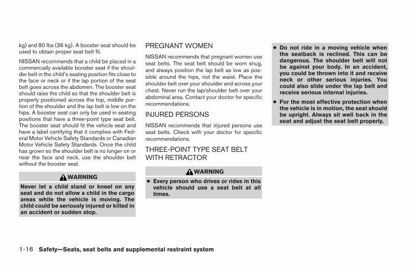
● Do not ride in a moving vehicle whenthe seatback is reclined. This can bedangerous. The shoulder belt will notbe against your body. In an accident,you could be thrown into it and receiveneck or other serious injuries. Youcould also slide under the lap belt andreceive serious internal injuries.
● For the most effective protection whenthe vehicle is in motion, the seat shouldbe upright. Always sit well back in theseat and adjust the seat properly. See“Precautions on Seat Belt Usage” laterin this section.
FRONT MANUAL SEATADJUSTMENT (if so equipped)
WARNING
● Do not adjust the driver’s seat whiledriving so full attention may be given tovehicle operation. The seat may movesuddenly and could cause loss of con-trol of the vehicle.
● After adjustment, gently rock in the seatto make sure it is securely locked.
ARS1152
SEATS
1-2 Safety—Seats, seat belts and supplemental restraint system
Z REVIEW COPY—2006 Truck/Frontier (d22)Owners Manual—USA_English (nna)10/14/05—debbie X
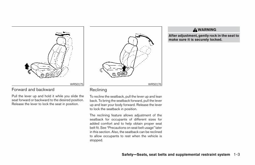
Forward and backwardPull the lever up and hold it while you slide theseat forward or backward to the desired position.Release the lever to lock the seat in position.
Reclining
To recline the seatback, pull the lever up and leanback. To bring the seatback forward, pull the leverup and lean your body forward. Release the leverto lock the seatback in position.
The reclining feature allows adjustment of theseatback for occupants of different sizes foradded comfort and to help obtain proper seatbelt fit. See “Precautions on seat belt usage” laterin this section. Also, the seatback can be reclinedto allow occupants to rest when the vehicle isstopped.
WARNING
After adjustment, gently rock in the seat tomake sure it is securely locked.
WRS0175 WRS0176
Safety—Seats, seat belts and supplemental restraint system 1-3
Z REVIEW COPY—2006 Truck/Frontier (d22)Owners Manual—USA_English (nna)10/14/05—debbie X
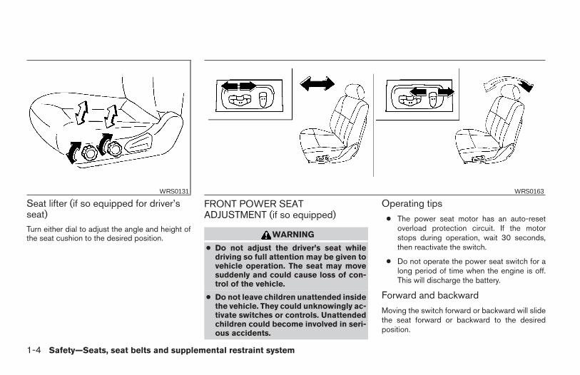
Seat lifter (if so equipped for driver’sseat)Turn either dial to adjust the angle and height ofthe seat cushion to the desired position.
FRONT POWER SEATADJUSTMENT (if so equipped)
WARNING
● Do not adjust the driver’s seat whiledriving so full attention may be given tovehicle operation. The seat may movesuddenly and could cause loss of con-trol of the vehicle.
● Do not leave children unattended insidethe vehicle. They could unknowingly ac-tivate switches or controls. Unattendedchildren could become involved in seri-ous accidents.
Operating tips
● The power seat motor has an auto-resetoverload protection circuit. If the motorstops during operation, wait 30 seconds,then reactivate the switch.
● Do not operate the power seat switch for along period of time when the engine is off.This will discharge the battery.
Forward and backward
Moving the switch forward or backward will slidethe seat forward or backward to the desiredposition.
WRS0131 WRS0163
1-4 Safety—Seats, seat belts and supplemental restraint system
Z REVIEW COPY—2006 Truck/Frontier (d22)Owners Manual—USA_English (nna)10/14/05—debbie X
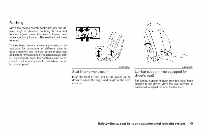
RecliningMove the recline switch backward until the de-sired angle is obtained. To bring the seatbackforward again, move the switch forward andmove your body forward. The seatback will moveforward.
The reclining feature allows adjustment of theseatback for occupants of different sizes foradded comfort and to help obtain proper seatbelt fit (see “Precautions on seat belt usage” laterin this section). Also, the seatback can be re-clined to allow occupants to rest when the ve-hicle is stopped.
Seat lifter (driver’s seat)Push the front or rear end of the switch up ordown to adjust the angle and height of the seatcushion.
Lumbar support (if so equipped fordriver’s seat)The lumbar support feature provides lower backsupport to the driver. Move the lever forward orbackward to adjust the seat lumbar area.
WRS0164 WRS0389
Safety—Seats, seat belts and supplemental restraint system 1-5
Z REVIEW COPY—2006 Truck/Frontier (d22)Owners Manual—USA_English (nna)10/14/05—debbie X
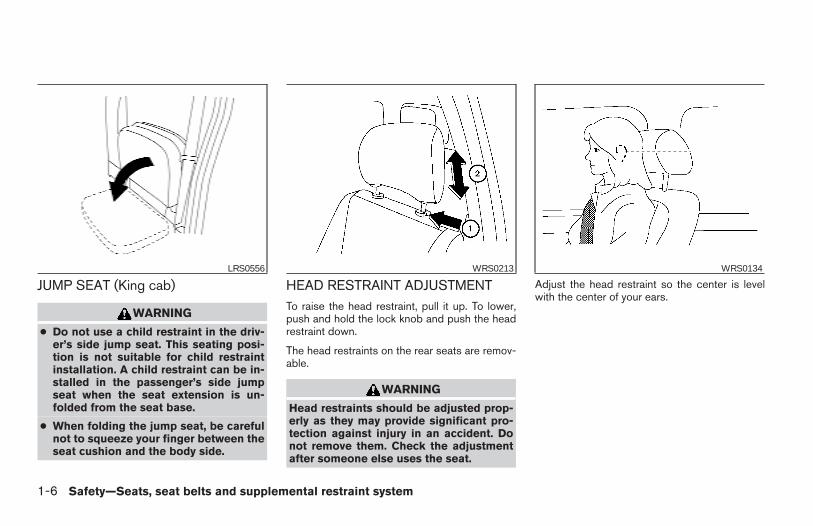
JUMP SEAT (King cab)
WARNING
● Do not use a child restraint in the driv-er’s side jump seat. This seating posi-tion is not suitable for child restraintinstallation. A child restraint can be in-stalled in the passenger’s side jumpseat when the seat extension is un-folded from the seat base.
● When folding the jump seat, be carefulnot to squeeze your finger between theseat cushion and the body side.
HEAD RESTRAINT ADJUSTMENTTo raise the head restraint, pull it up. To lower,push and hold the lock knob and push the headrestraint down.
The head restraints on the rear seats are remov-able.
WARNING
Head restraints should be adjusted prop-erly as they may provide significant pro-tection against injury in an accident. Donot remove them. Check the adjustmentafter someone else uses the seat.
Adjust the head restraint so the center is levelwith the center of your ears.
LRS0556 WRS0213 WRS0134
1-6 Safety—Seats, seat belts and supplemental restraint system
Z REVIEW COPY—2006 Truck/Frontier (d22)Owners Manual—USA_English (nna)10/14/05—debbie X
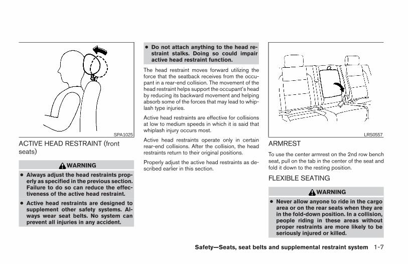
ACTIVE HEAD RESTRAINT (frontseats)
WARNING
● Always adjust the head restraints prop-erly as specified in the previous section.Failure to do so can reduce the effec-tiveness of the active head restraint.
● Active head restraints are designed tosupplement other safety systems. Al-ways wear seat belts. No system canprevent all injuries in any accident.
● Do not attach anything to the head re-straint stalks. Doing so could impairactive head restraint function.
The head restraint moves forward utilizing theforce that the seatback receives from the occu-pant in a rear-end collision. The movement of thehead restraint helps support the occupant’s headby reducing its backward movement and helpingabsorb some of the forces that may lead to whip-lash type injuries.
Active head restraints are effective for collisionsat low to medium speeds in which it is said thatwhiplash injury occurs most.
Active head restraints operate only in certainrear-end collisions. After the collision, the headrestraints return to their original positions.
Properly adjust the active head restraints as de-scribed earlier in this section.
ARMREST
To use the center armrest on the 2nd row benchseat, pull on the tab in the center of the seat andfold it down to the resting position.
FLEXIBLE SEATING
WARNING
● Never allow anyone to ride in the cargoarea or on the rear seats when they arein the fold-down position. In a collision,people riding in these areas withoutproper restraints are more likely to beseriously injured or killed.
SPA1025 LRS0557
Safety—Seats, seat belts and supplemental restraint system 1-7
Z REVIEW COPY—2006 Truck/Frontier (d22)Owners Manual—USA_English (nna)10/14/05—debbie X
● Do not allow people to ride in any areaof your vehicle that is not equipped withseats and seat belts. Be sure everyonein your vehicle is in a seat and using aseat belt properly.
● Do not fold down the rear seats whenoccupants are in the rear seat area orany luggage is on the rear seats.
● Head restraints should be adjustedproperly as they may provide significantprotection against injury in an accident.Always replace and adjust them prop-erly if they have been removed for anyreason.
● If the head restraints are removed forany reason, they should be securelystored to prevent them from causinginjury to passengers or damage to thevehicle in case of sudden braking or anaccident.
● When returning the seatbacks to theupright position, be certain they arecompletely secured in the latched posi-tion. If they are not completely secured,passengers may be injured in an acci-dent or sudden stop.
● Properly secure all cargo to help pre-vent it from sliding or shifting. Do notplace cargo higher than the seatbacks.In a sudden stop or collision, unsecuredcargo could cause personal injury.
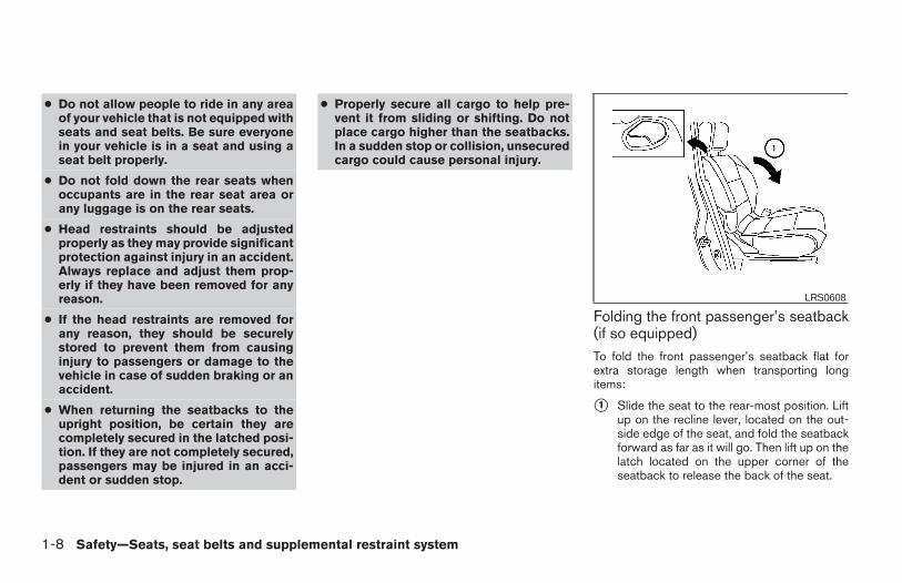
Folding the front passenger’s seatback(if so equipped)To fold the front passenger’s seatback flat forextra storage length when transporting longitems:
s1 Slide the seat to the rear-most position. Liftup on the recline lever, located on the out-side edge of the seat, and fold the seatbackforward as far as it will go. Then lift up on thelatch located on the upper corner of theseatback to release the back of the seat.
LRS0608
1-8 Safety—Seats, seat belts and supplemental restraint system
Z REVIEW COPY—2006 Truck/Frontier (d22)Owners Manual—USA_English (nna)10/14/05—debbie X
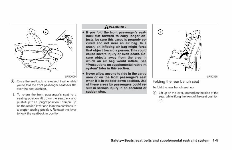
s2 Once the seatback is released it will enableyou to fold the front passenger seatback flatover the seat cushion.
3. To return the front passenger’s seat to aseating position lift up on the seatback andpush it up to an upright position. Then pull upon the recline lever and lean the seatback toa proper seating position. Release the leverto lock the seatback in position.
WARNING
● If you fold the front passenger’s seat-back flat forward to carry longer ob-jects, be sure this cargo is properly se-cured and not near an air bag. In acrash, an inflating air bag might forcethat object toward a person. This couldcause severe injury or even death. Se-cure objects away from the area inwhich an air bag would inflate. See“Precautions on supplemental restraintsystem” later in this section.
● Never allow anyone to ride in the cargoarea or on the front passenger’s seatwhen it is in the fold-down position. Useof these areas by passengers could re-sult in serious injury in an accident orsudden stop.
Folding the rear bench seatTo fold the rear bench seat up:
s1 Lift up on the lever, located on the side of theseat, while lifting the front of the seat cushionup.
LRS0609 LRS0398
Safety—Seats, seat belts and supplemental restraint system 1-9
Z REVIEW COPY—2006 Truck/Frontier (d22)Owners Manual—USA_English (nna)10/14/05—debbie X
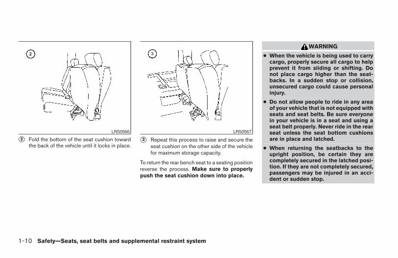
s2 Fold the bottom of the seat cushion towardthe back of the vehicle until it locks in place.
s3 Repeat this process to raise and secure theseat cushion on the other side of the vehiclefor maximum storage capacity.
To return the rear bench seat to a seating positionreverse the process. Make sure to properlypush the seat cushion down into place.
WARNING
● When the vehicle is being used to carrycargo, properly secure all cargo to helpprevent it from sliding or shifting. Donot place cargo higher than the seat-backs. In a sudden stop or collision,unsecured cargo could cause personalinjury.
● Do not allow people to ride in any areaof your vehicle that is not equipped withseats and seat belts. Be sure everyonein your vehicle is in a seat and using aseat belt properly. Never ride in the rearseat unless the seat bottom cushionsare in place and latched.
● When returning the seatbacks to theupright position, be certain they arecompletely secured in the latched posi-tion. If they are not completely secured,passengers may be injured in an acci-dent or sudden stop.
LRS0566 LRS0567
1-10 Safety—Seats, seat belts and supplemental restraint system
Z REVIEW COPY—2006 Truck/Frontier (d22)Owners Manual—USA_English (nna)10/14/05—debbie X
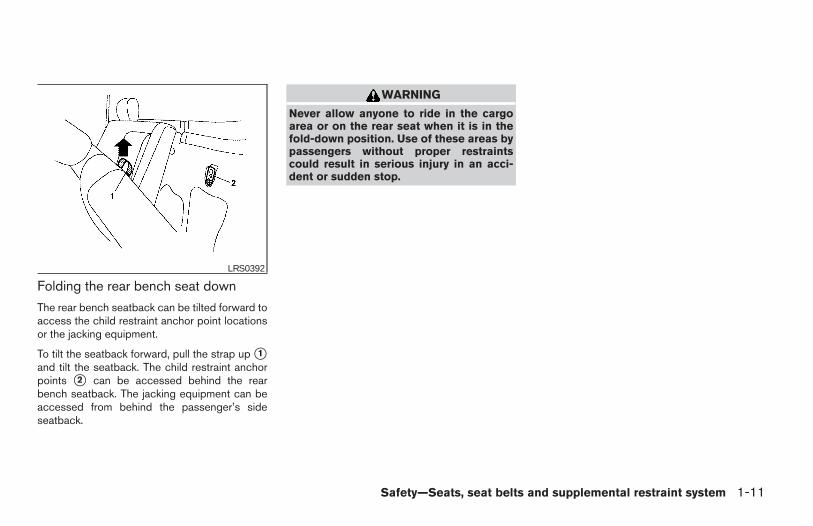
Folding the rear bench seat down
The rear bench seatback can be tilted forward toaccess the child restraint anchor point locationsor the jacking equipment.
To tilt the seatback forward, pull the strap up s1and tilt the seatback. The child restraint anchorpoints s2 can be accessed behind the rearbench seatback. The jacking equipment can beaccessed from behind the passenger’s sideseatback.
WARNING
Never allow anyone to ride in the cargoarea or on the rear seat when it is in thefold-down position. Use of these areas bypassengers without proper restraintscould result in serious injury in an acci-dent or sudden stop.
LRS0392
Safety—Seats, seat belts and supplemental restraint system 1-11
Z REVIEW COPY—2006 Truck/Frontier (d22)Owners Manual—USA_English (nna)10/14/05—debbie X
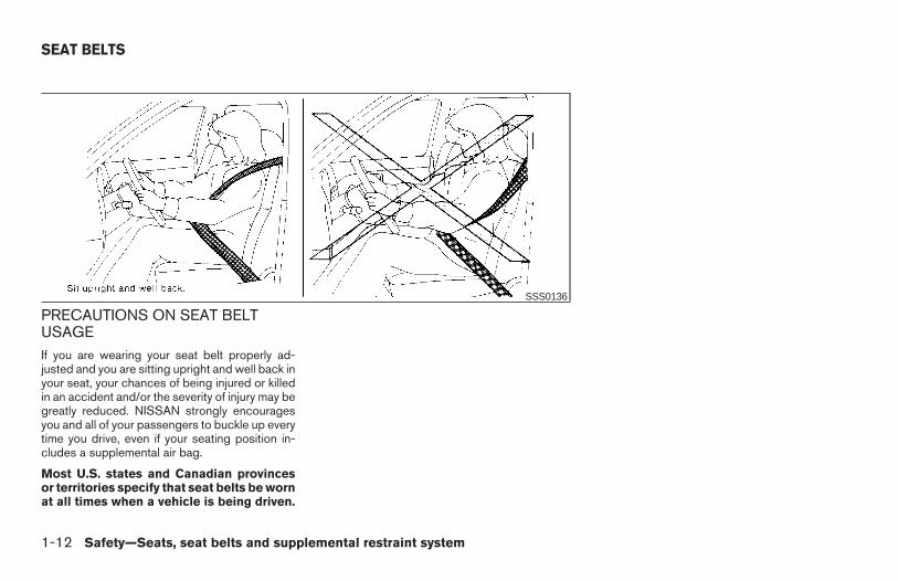
PRECAUTIONS ON SEAT BELTUSAGEIf you are wearing your seat belt properly ad-justed and you are sitting upright and well back inyour seat, your chances of being injured or killedin an accident and/or the severity of injury may begreatly reduced. NISSAN strongly encouragesyou and all of your passengers to buckle up everytime you drive, even if your seating position in-cludes a supplemental air bag.
Most U.S. states and Canadian provincesor territories specify that seat belts be wornat all times when a vehicle is being driven.
SSS0136
SEAT BELTS
1-12 Safety—Seats, seat belts and supplemental restraint system
Z REVIEW COPY—2006 Truck/Frontier (d22)Owners Manual—USA_English (nna)10/14/05—debbie X
WARNING
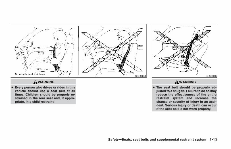
● Every person who drives or rides in thisvehicle should use a seat belt at alltimes. Children should be properly re-strained in the rear seat and, if appro-priate, in a child restraint.
WARNING
● The seat belt should be properly ad-justed to a snug fit. Failure to do so mayreduce the effectiveness of the entirerestraint system and increase thechance or severity of injury in an acci-dent. Serious injury or death can occurif the seat belt is not worn properly.
SSS0134 SSS0016
Safety—Seats, seat belts and supplemental restraint system 1-13
Z REVIEW COPY—2006 Truck/Frontier (d22)Owners Manual—USA_English (nna)10/14/05—debbie X
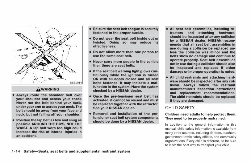
WARNING
● Always route the shoulder belt overyour shoulder and across your chest.Never run the belt behind your back,under your arm or across your neck. Thebelt should be away from your face andneck, but not falling off your shoulder.
● Position the lap belt as low and snug aspossible AROUND THE HIPS, NOT THEWAIST. A lap belt worn too high couldincrease the risk of internal injuries inan accident.
● Be sure the seat belt tongue is securelyfastened to the proper buckle.
● Do not wear the seat belt inside out ortwisted. Doing so may reduce itseffectiveness.
● Do not allow more than one person touse the same seat belt.
● Never carry more people in the vehiclethan there are seat belts.
● If the seat belt warning light glows con-tinuously while the ignition is turnedON with all doors closed and all seatbelts fastened, it may indicate a mal-function in the system. Have the systemchecked by a NISSAN dealer.
● Once the pre-tensioner seat belt hasactivated, it cannot be reused and mustbe replaced together with the retractor.See your NISSAN dealer.
● Removal and installation of the pre-tensioner seat belt system componentsshould be done by a NISSAN dealer.
● All seat belt assemblies, including re-tractors and attaching hardware,should be inspected after any collisionby a NISSAN dealer. NISSAN recom-mends that all seat belt assemblies inuse during a collision be replaced un-less the collision was minor and thebelts show no damage and continue tooperate properly. Seat belt assembliesnot in use during a collision should alsobe inspected and replaced if eitherdamage or improper operation is noted.
● All child restraints and attaching hard-ware should be inspected after any col-lision. Always follow the restraintmanufacturer’s inspection instructionsand replacement recommendations.The child restraints should be replacedif they are damaged.
CHILD SAFETY
Children need adults to help protect them.They need to be properly restrained.
In addition to the general information in thismanual, child safety information is available frommany other sources, including doctors, teachers,government traffic safety offices, and communityorganizations. Every child is different, so be sureto learn the best way to transport your child.
SSS0014
1-14 Safety—Seats, seat belts and supplemental restraint system
Z REVIEW COPY—2006 Truck/Frontier (d22)Owners Manual—USA_English (nna)10/14/05—debbie X
There are three basic types of child restraintsystems:
● Rear facing child restraint
● Front facing child restraint
● Booster seat
The proper restraint depends on the child’s size.Generally, infants up to about 1 year and lessthan 20 pounds (9 kg) should be placed in rearfacing child restraints. Front facing child re-straints are available for children who outgrowrear facing child restraints and are at least oneyear old. Booster seats are used to help positiona vehicle lap/shoulder belt on a child who can nolonger use a front facing child restraint.
WARNING
● Never install a rear facing child restraintin the front passenger’s seat. An inflat-ing supplemental air bag could seri-ously injure or kill your child. A rearfacing child restraint must only be usedin the rear seat.
● Infants and children need special pro-tection. The vehicle’s seat belts may notfit them properly. The shoulder belt maycome too close to the face or neck. Thelap belt may not fit over their small hipbones. In an accident, an improperlyfitting seat belt could cause serious orfatal injury. Always use appropriatechild restraints.
All U.S. states and Canadian provinces or terri-tories require the use of approved child restraintsfor infants and small children. See “Child Re-straints” later in this section.
Also, there are other types of child restraintsavailable for larger children for additional protec-tion.
NISSAN recommends that all pre-teensand children be restrained in the rear seat ifavailable (Crew Cab models). According toaccident statistics, children are safer whenproperly restrained in the rear seat than inthe front seat.
This is especially important because yourvehicle has a supplemental restraint sys-tem (Air bag system) for the front passen-ger. See “Supplemental restraint system”later in this section.
Infants
Infants up to at least 1 year old should be placedin a rear facing child restraint. NISSAN recom-mends that infants be placed in child restraintsthat comply with Federal Motor Vehicle SafetyStandards or Canadian Motor Vehicle SafetyStandards. You should choose a child restraintthat fits your vehicle and always follow the manu-facturer’s instructions for installation and use.
Small ChildrenChildren that are over one year old and weighbetween 20 lbs (9 kg) and 40 lbs (18 kgs) can beplaced in a forward facing child restraint. Refer tothe manufacturer’s instructions for minimum andmaximum weight and height recommendations.NISSAN recommends that small children beplaced in child restraints that comply with FederalMotor Vehicle Safety Standards or Canadian Mo-tor Vehicle Safety Standards. You should choosea child restraint that fits your vehicle and alwaysfollow the manufacturer’s instructions for instal-lation and use.
Larger childrenChildren who are too large for child restraintsshould be seated and restrained by the seat beltswhich are provided. The seat belt may not fitproperly if the child is less than 4 feet 9 inches(142.5 cm) tall and weighs between 40 lbs (18
Safety—Seats, seat belts and supplemental restraint system 1-15
Z REVIEW COPY—2006 Truck/Frontier (d22)Owners Manual—USA_English (nna)10/14/05—debbie X
kg) and 80 lbs (36 kg). A booster seat should beused to obtain proper seat belt fit.
NISSAN recommends that a child be placed in acommercially available booster seat if the shoul-der belt in the child’s seating position fits close tothe face or neck or if the lap portion of the seatbelt goes across the abdomen. The booster seatshould raise the child so that the shoulder belt isproperly positioned across the top, middle por-tion of the shoulder and the lap belt is low on thehips. A booster seat can only be used in seatingpositions that have a three-point type seat belt.The booster seat should fit the vehicle seat andhave a label certifying that it complies with Fed-eral Motor Vehicle Safety Standards or CanadianMotor Vehicle Safety Standards. Once the childhas grown so the shoulder belt is no longer on ornear the face and neck, use the shoulder beltwithout the booster seat.
WARNING
Never let a child stand or kneel on anyseat and do not allow a child in the cargoareas while the vehicle is moving. Thechild could be seriously injured or killed inan accident or sudden stop.
PREGNANT WOMEN
NISSAN recommends that pregnant women useseat belts. The seat belt should be worn snug,and always position the lap belt as low as pos-sible around the hips, not the waist. Place theshoulder belt over your shoulder and across yourchest. Never run the lap/shoulder belt over yourabdominal area. Contact your doctor for specificrecommendations.
INJURED PERSONS
NISSAN recommends that injured persons useseat belts. Check with your doctor for specificrecommendations.
THREE-POINT TYPE SEAT BELTWITH RETRACTOR
WARNING
● Every person who drives or rides in thisvehicle should use a seat belt at alltimes.
● Do not ride in a moving vehicle whenthe seatback is reclined. This can bedangerous. The shoulder belt will notbe against your body. In an accident,you could be thrown into it and receiveneck or other serious injuries. Youcould also slide under the lap belt andreceive serious internal injuries.
● For the most effective protection whenthe vehicle is in motion, the seat shouldbe upright. Always sit well back in theseat and adjust the seat belt properly.
1-16 Safety—Seats, seat belts and supplemental restraint system
Z REVIEW COPY—2006 Truck/Frontier (d22)Owners Manual—USA_English (nna)10/14/05—debbie X
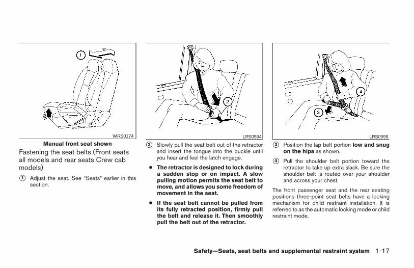
Fastening the seat belts (Front seatsall models and rear seats Crew cabmodels)
s1 Adjust the seat. See “Seats” earlier in thissection.
s2 Slowly pull the seat belt out of the retractorand insert the tongue into the buckle untilyou hear and feel the latch engage.
● The retractor is designed to lock duringa sudden stop or on impact. A slowpulling motion permits the seat belt tomove, and allows you some freedom ofmovement in the seat.
● If the seat belt cannot be pulled fromits fully retracted position, firmly pullthe belt and release it. Then smoothlypull the belt out of the retractor.
s3 Position the lap belt portion low and snugon the hips as shown.
s4 Pull the shoulder belt portion toward theretractor to take up extra slack. Be sure theshoulder belt is routed over your shoulderand across your chest.
The front passenger seat and the rear seatingpositions three-point seat belts have a lockingmechanism for child restraint installation. It isreferred to as the automatic locking mode or childrestraint mode.
Manual front seat shownWRS0174 LRS0594 LRS0595
Safety—Seats, seat belts and supplemental restraint system 1-17
Z REVIEW COPY—2006 Truck/Frontier (d22)Owners Manual—USA_English (nna)10/14/05—debbie X
When the automatic locking mechanism is acti-vated the seat belt cannot be extended again untilthe seat belt tongue is detached from the buckleand fully retracted. Once retracted, the seat beltis in the emergency locking mode. See “Childrestraints” later in this section for more informa-tion.
The automatic locking mode should beused only for child restraint installation.During normal seat belt use by a passen-ger, the locking mode should not be acti-vated. If it is activated it may cause uncom-fortable seat belt tension. It can alsochange the operation of the front passen-ger air bag. See “Front passenger air bagand status light” later in this section.
WARNING
When fastening the seat belts, be certainthat the seatbacks are completely se-cured in the latched position. If they arenot completely secured, passengers maybe injured in an accident or sudden stop.
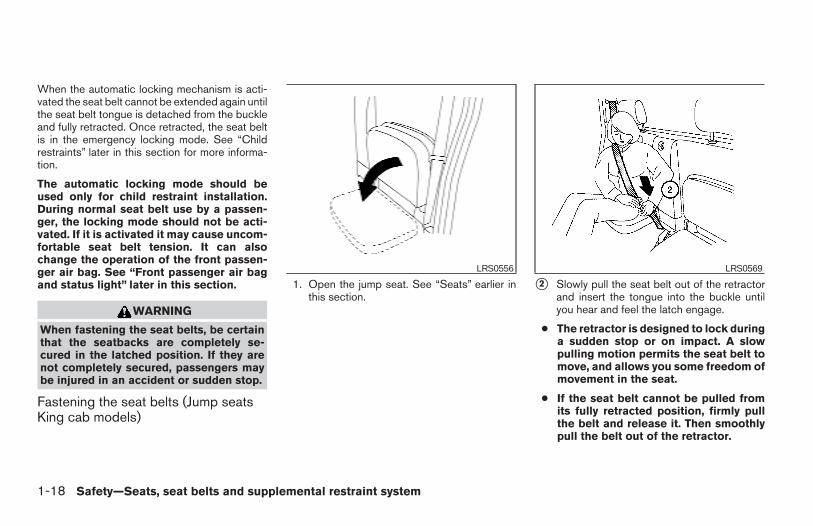
Fastening the seat belts (Jump seatsKing cab models)
1. Open the jump seat. See “Seats” earlier inthis section.
s2 Slowly pull the seat belt out of the retractorand insert the tongue into the buckle untilyou hear and feel the latch engage.
● The retractor is designed to lock duringa sudden stop or on impact. A slowpulling motion permits the seat belt tomove, and allows you some freedom ofmovement in the seat.
● If the seat belt cannot be pulled fromits fully retracted position, firmly pullthe belt and release it. Then smoothlypull the belt out of the retractor.
LRS0556 LRS0569
1-18 Safety—Seats, seat belts and supplemental restraint system
Z REVIEW COPY—2006 Truck/Frontier (d22)Owners Manual—USA_English (nna)10/14/05—debbie X
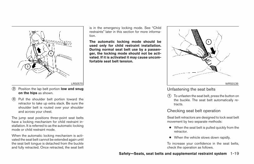
s3 Position the lap belt portion low and snugon the hips as shown.
s4 Pull the shoulder belt portion toward theretractor to take up extra slack. Be sure theshoulder belt is routed over your shoulderand across your chest.
The jump seat positions three-point seat beltshave a locking mechanism for child restraint in-stallation. It is referred to as the automatic lockingmode or child restraint mode.
When the automatic locking mechanism is acti-vated the seat belt cannot be extended again untilthe seat belt tongue is detached from the buckleand fully retracted. Once retracted, the seat belt
is in the emergency locking mode. See “Childrestraints” later in this section for more informa-tion.
The automatic locking mode should beused only for child restraint installation.During normal seat belt use by a passen-ger, the locking mode should not be acti-vated. If it is activated it may cause uncom-fortable seat belt tension.
Unfastening the seat belts
s1 To unfasten the seat belt, press the button onthe buckle. The seat belt automatically re-tracts.
Checking seat belt operation
Seat belt retractors are designed to lock seat beltmovement by two separate methods:
● When the seat belt is pulled quickly from theretractor.
● When the vehicle slows down rapidly.
To increase your confidence in the seat belts,check the operation as follows.
LRS0570 WRS0139
Safety—Seats, seat belts and supplemental restraint system 1-19
Z REVIEW COPY—2006 Truck/Frontier (d22)Owners Manual—USA_English (nna)10/14/05—debbie X
● Grasp the shoulder belt and pull forwardquickly. The retractor should lock and re-strict further belt movement.
If the retractor does not lock during this check orif you have any questions about seat belt opera-tion, see a NISSAN dealer.
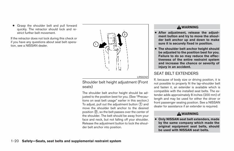
Shoulder belt height adjustment (Frontseats)
The shoulder belt anchor height should be ad-justed to the position best for you. (See “Precau-tions on seat belt usage” earlier in this section.)To adjust, pull out the adjustment button s1 andmove the shoulder belt anchor to the desiredposition s2 , so the belt passes over the center ofthe shoulder. The belt should be away from yourface and neck, but not falling off your shoulder.Release the adjustment button to lock the shoul-der belt anchor into position.
WARNING
● After adjustment, release the adjust-ment button and try to move the shoul-der belt anchor up and down to makesure it is securely fixed in position.
● The shoulder belt anchor height shouldbe adjusted to the position best for you.Failure to do so may reduce the effec-tiveness of the entire restraint systemand increase the chance or severity ofinjury in an accident.
SEAT BELT EXTENDERS
If, because of body size or driving position, it isnot possible to properly fit the lap-shoulder beltand fasten it, an extender is available which iscompatible with the installed seat belts. The ex-tender adds approximately 8 inches (200 mm) oflength and may be used for either the driver orfront passenger seating position. See a NISSANdealer for assistance if an extender is required.
WARNING
● Only NISSAN seat belt extenders, madeby the same company which made theoriginal equipment seat belts, shouldbe used with NISSAN seat belts.
LRS0242
1-20 Safety—Seats, seat belts and supplemental restraint system
Z REVIEW COPY—2006 Truck/Frontier (d22)Owners Manual—USA_English (nna)10/14/05—debbie X
● Adults and children who can use thestandard seat belt should not use anextender. Such unnecessary use couldresult in serious personal injury in theevent of an accident.
● Never use seat belt extenders to installchild restraints. If the child restraint isnot secured properly, the child could beseriously injured in a collision or a sud-den stop.
SEAT BELT MAINTENANCE
● To clean the seat belt webbing, apply amild soap solution or any solution recom-mended for cleaning upholstery or carpet.Then wipe with a cloth and allow the seatbelts to dry in the shade. Do not allow the seatbelts to retract until they are completely dry.
● If dirt builds up in the shoulder beltguide of the seat belt anchors, the seatbelts may retract slowly. Wipe the shoulderbelt guide with a clean, dry cloth.
● Periodically check to see that the seatbelt and the metal components, such asbuckles, tongues, retractors, flexible wiresand anchors, work properly. If loose parts,deterioration, cuts or other damage on thewebbing is found, the entire seat belt as-sembly should be replaced.
PRECAUTIONS ON CHILDRESTRAINTS
WARNING
● Infants and small children should al-ways be placed in an appropriate childrestraint while riding in the vehicle.Failure to use a child restraint can re-sult in serious injury or death.
WARNING
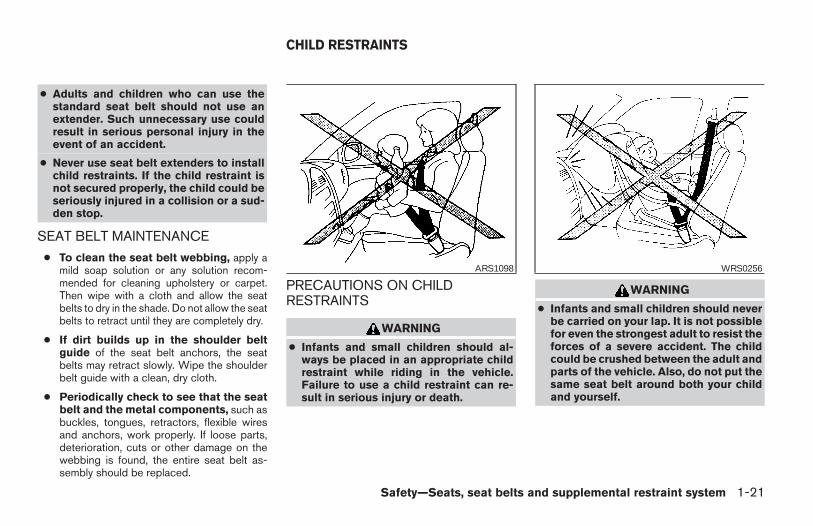
● Infants and small children should neverbe carried on your lap. It is not possiblefor even the strongest adult to resist theforces of a severe accident. The childcould be crushed between the adult andparts of the vehicle. Also, do not put thesame seat belt around both your childand yourself.
ARS1098 WRS0256
CHILD RESTRAINTS
Safety—Seats, seat belts and supplemental restraint system 1-21
Z REVIEW COPY—2006 Truck/Frontier (d22)Owners Manual—USA_English (nna)10/14/05—debbie X
● Even with the NISSAN Advanced AirBag System, never install a rear-facingchild restraint in the front seat. An in-flating supplemental front air bag couldseriously injure or kill your child. A rear-facing child restraint must only be usedin the rear seat.
● NISSAN recommends that the child re-straint be installed in the rear seat. Ac-cording to accident statistics, childrenare safer when properly restrained inthe rear seat than in the front seat.
● An improperly installed child restraintcould lead to serious injury or death inan accident.
In general, child restraints are designed to beinstalled with the lap portion of a lap/shoulderbelt. In addition, Crew Cab models are equippedwith a universal child restraint lower anchor sys-tem, referred to as the LATCH (Lower Anchorsand Tethers for CHildren) system. Some childrestraints include two rigid or webbing-mountedattachments that can be connected to theselower anchors. For details, see the “LATCH(Lower Anchors and Tethers for CHildren) sys-tem” later in this section.
Child restraints for infants and small children ofvarious sizes are offered by several manufactur-
ers. When selecting any child restraint, keep thefollowing points in mind:
● Choose only a restraint with a label certifyingthat it complies with Federal Motor VehicleSafety Standard 213 or Canadian MotorVehicle Safety Standard 213.
● Check the child restraint in your vehicle to besure it is compatible with the vehicle’s seatand seat belt system.
● If the child restraint is compatible with yourvehicle, place your child in the child restraintand check the various adjustments to besure the child restraint is compatible withyour child. Choose a child restraint that isdesigned for your child’s height and weight.Always follow all recommended procedures.
All U.S. states and Canadian provinces orterritories require that infants and smallchildren be restrained in an approved childrestraint at all times while the vehicle isbeing operated.
WARNING
● Improper use of a child restraint canincrease the risk or severity of injury forboth the child and other occupants ofthe vehicle.
● Follow all of the child restraint manu-facturer’s instructions for installationand use. When purchasing a child re-straint, be sure to select one which willfit your child and vehicle. It may not bepossible to properly install some typesof child restraints in your vehicle.
● If the child restraint is not anchoredproperly, the risk of a child being in-jured in a collision or a sudden stopgreatly increases.
● Adjustable seatbacks should be posi-tioned to fit the child restraint, but asupright as possible.
● After attaching the child restraint, test itbefore you place the child in it. Push itfrom side to side. Try to tug it forwardand check to see if the belt holds therestraint in place. The child restraintshould not move more than 1 inch (25mm). If the restraint is not secure,tighten the belt as necessary, or put therestraint in another seat and test itagain. You may need to try a differentchild restraint. Not all child restraints fitin all types of vehicles.
1-22 Safety—Seats, seat belts and supplemental restraint system
Z REVIEW COPY—2006 Truck/Frontier (d22)Owners Manual—USA_English (nna)10/14/05—debbie X
● If you must install a front facing childrestraint in the front seat, see “Childrestraint installation on front passengerseat” later in this section.
● When your child restraint is not in use,keep it secured with a seat belt to pre-vent it from being thrown around incase of a sudden stop or accident.
CAUTION
Remember that a child restraint left in aclosed vehicle can become very hot.Check the seating surface and bucklesbefore placing your child in the childrestraint.
CHILD RESTRAINT INSTALLATIONON PASSENGER’S SIDE JUMPSEAT (King cab models only)
WARNING
● The three-point seat belt in your vehicleis equipped with an automatic lockingmode retractor which must be usedwhen installing a child restraint.
● Failure to use the retractor’s lockingmode will result in the child restraintnot being properly secured. The re-straint could tip over or otherwise beunsecured and cause injury to the childin a sudden stop or collision.
WARNING
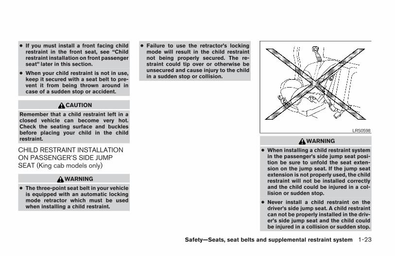
● When installing a child restraint systemin the passenger’s side jump seat posi-tion be sure to unfold the seat exten-sion on the jump seat. If the jump seatextension is not properly used, the childrestraint will not be installed correctlyand the child could be injured in a col-lision or sudden stop.
● Never install a child restraint on thedriver’s side jump seat. A child restraintcan not be properly installed in the driv-er’s side jump seat and the child couldbe injured in a collision or sudden stop.
LRS0598
Safety—Seats, seat belts and supplemental restraint system 1-23
Z REVIEW COPY—2006 Truck/Frontier (d22)Owners Manual—USA_English (nna)10/14/05—debbie X
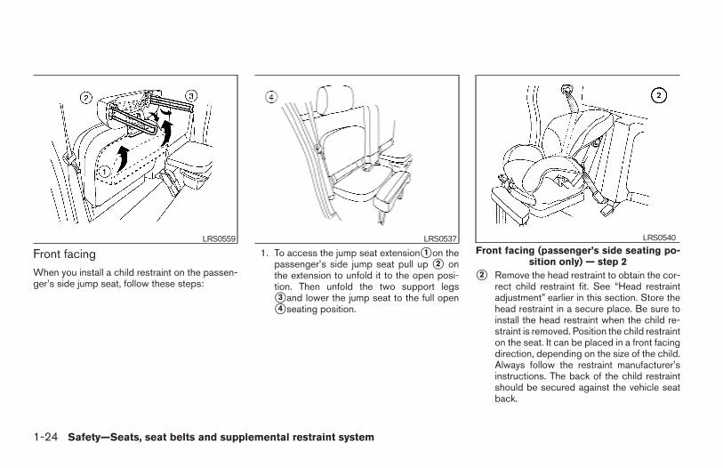
Front facingWhen you install a child restraint on the passen-ger’s side jump seat, follow these steps:
1. To access the jump seat extensions1 on thepassenger’s side jump seat pull up s2 onthe extension to unfold it to the open posi-tion. Then unfold the two support legss3 and lower the jump seat to the full opens4 seating position.
s2 Remove the head restraint to obtain the cor-rect child restraint fit. See “Head restraintadjustment” earlier in this section. Store thehead restraint in a secure place. Be sure toinstall the head restraint when the child re-straint is removed. Position the child restrainton the seat. It can be placed in a front facingdirection, depending on the size of the child.Always follow the restraint manufacturer’sinstructions. The back of the child restraintshould be secured against the vehicle seatback.
LRS0559 LRS0537Front facing (passenger’s side seating po-
sition only) — step 2
LRS0540
1-24 Safety—Seats, seat belts and supplemental restraint system
Z REVIEW COPY—2006 Truck/Frontier (d22)Owners Manual—USA_English (nna)10/14/05—debbie X
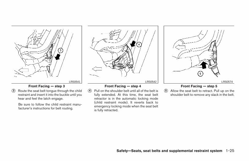
s3 Route the seat belt tongue through the childrestraint and insert it into the buckle until youhear and feel the latch engage.
Be sure to follow the child restraint manu-facturer’s instructions for belt routing.
s4 Pull on the shoulder belt until all of the belt isfully extended. At this time, the seat beltretractor is in the automatic locking mode(child restraint mode). It reverts back toemergency locking mode when the seat beltis fully retracted.
s5 Allow the seat belt to retract. Pull up on theshoulder belt to remove any slack in the belt.
Front Facing — step 3LRS0541
Front Facing — step 4LRS0542
Front Facing — step 5LRS0574
Safety—Seats, seat belts and supplemental restraint system 1-25
Z REVIEW COPY—2006 Truck/Frontier (d22)Owners Manual—USA_English (nna)10/14/05—debbie X
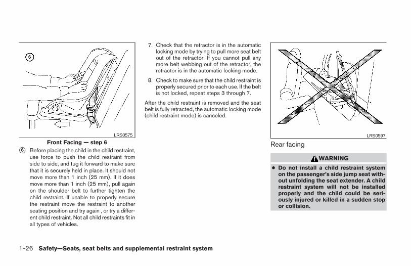
s6 Before placing the child in the child restraint,use force to push the child restraint fromside to side, and tug it forward to make surethat it is securely held in place. It should notmove more than 1 inch (25 mm). If it doesmove more than 1 inch (25 mm), pull againon the shoulder belt to further tighten thechild restraint. If unable to properly securethe restraint move the restraint to anotherseating position and try again , or try a differ-ent child restraint. Not all child restraints fit inall types of vehicles.
7. Check that the retractor is in the automaticlocking mode by trying to pull more seat beltout of the retractor. If you cannot pull anymore belt webbing out of the retractor, theretractor is in the automatic locking mode.
8. Check to make sure that the child restraint isproperly secured prior to each use. If the beltis not locked, repeat steps 3 through 7.
After the child restraint is removed and the seatbelt is fully retracted, the automatic locking mode(child restraint mode) is canceled.
Rear facing
WARNING
● Do not install a child restraint systemon the passenger’s side jump seat with-out unfolding the seat extender. A childrestraint system will not be installedproperly and the child could be seri-ously injured or killed in a sudden stopor collision.
Front Facing — step 6LRS0575 LRS0597
1-26 Safety—Seats, seat belts and supplemental restraint system
Z REVIEW COPY—2006 Truck/Frontier (d22)Owners Manual—USA_English (nna)10/14/05—debbie X
WARNING
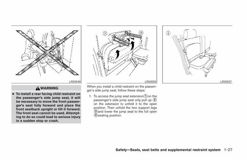
● To install a rear facing child restraint onthe passenger’s side jump seat, it willbe necessary to move the front passen-ger’s seat fully forward and place thefront seatback upright or tilt it forward.The front seat cannot be used. Attempt-ing to do so could lead to serious injuryin a sudden stop or crash.
When you install a child restraint on the passen-ger’s side jump seat, follow these steps:
1. To access the jump seat extensions1 on thepassenger’s side jump seat only pull up s2on the extension to unfold it to the openposition. Then unfold the two support legss3 and lower the jump seat to the full opens4 seating position.
LRS0549 LRS0559 LRS0537
Safety—Seats, seat belts and supplemental restraint system 1-27
Z REVIEW COPY—2006 Truck/Frontier (d22)Owners Manual—USA_English (nna)10/14/05—debbie X
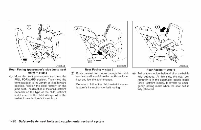
s2 Move the front passenger’s seat into theFULL FORWARD position. Then move thefront seatback to the upright or tilted forwardposition. Position the child restraint on thejump seat. The direction of the child restraintdepends on the type of the child restraintand the size of the child. Always follow therestraint manufacturer’s instructions.
s3 Route the seat belt tongue through the childrestraint and insert it into the buckle until youhear and feel the latch engage.
Be sure to follow the child restraint manu-facturer’s instructions for belt routing.
s4 Pull on the shoulder belt until all of the belt isfully extended. At this time, the seat beltretractor is in the automatic locking mode(child restraint mode). It reverts to emer-gency locking mode when the seat belt isfully retracted.
Rear Facing (passenger’s side jump seatonly) — step 2
LRS0544
Rear Facing — step 3LRS0545
Rear Facing — step 4LRS0546
1-28 Safety—Seats, seat belts and supplemental restraint system
Z REVIEW COPY—2006 Truck/Frontier (d22)Owners Manual—USA_English (nna)10/14/05—debbie X
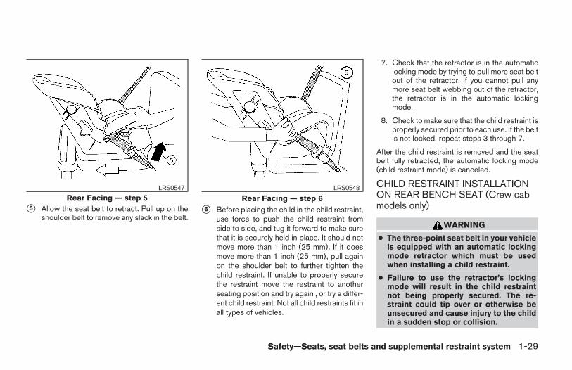
s5 Allow the seat belt to retract. Pull up on theshoulder belt to remove any slack in the belt.
s6 Before placing the child in the child restraint,use force to push the child restraint fromside to side, and tug it forward to make surethat it is securely held in place. It should notmove more than 1 inch (25 mm). If it doesmove more than 1 inch (25 mm), pull againon the shoulder belt to further tighten thechild restraint. If unable to properly securethe restraint move the restraint to anotherseating position and try again , or try a differ-ent child restraint. Not all child restraints fit inall types of vehicles.
7. Check that the retractor is in the automaticlocking mode by trying to pull more seat beltout of the retractor. If you cannot pull anymore seat belt webbing out of the retractor,the retractor is in the automatic lockingmode.
8. Check to make sure that the child restraint isproperly secured prior to each use. If the beltis not locked, repeat steps 3 through 7.
After the child restraint is removed and the seatbelt fully retracted, the automatic locking mode(child restraint mode) is canceled.
CHILD RESTRAINT INSTALLATIONON REAR BENCH SEAT (Crew cabmodels only)
WARNING
● The three-point seat belt in your vehicleis equipped with an automatic lockingmode retractor which must be usedwhen installing a child restraint.
● Failure to use the retractor’s lockingmode will result in the child restraintnot being properly secured. The re-straint could tip over or otherwise beunsecured and cause injury to the childin a sudden stop or collision.
Rear Facing — step 5LRS0547
Rear Facing — step 6LRS0548
Safety—Seats, seat belts and supplemental restraint system 1-29
Z REVIEW COPY—2006 Truck/Frontier (d22)Owners Manual—USA_English (nna)10/14/05—debbie X
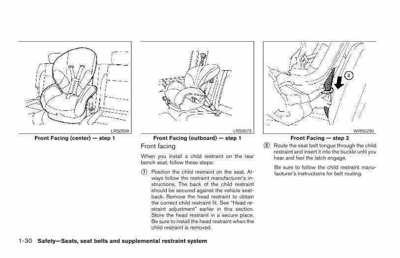
Front facingWhen you install a child restraint on the rearbench seat, follow these steps:
s1 Position the child restraint on the seat. Al-ways follow the restraint manufacturer’s in-structions. The back of the child restraintshould be secured against the vehicle seat-back. Remove the head restraint to obtainthe correct child restraint fit. See “Head re-straint adjustment” earlier in this section.Store the head restraint in a secure place.Be sure to install the head restraint when thechild restraint is removed.
s2 Route the seat belt tongue through the childrestraint and insert it into the buckle until youhear and feel the latch engage.
Be sure to follow the child restraint manu-facturer’s instructions for belt routing.
Front Facing (center) — step 1LRS0599
Front Facing (outboard) — step 1LRS0573
Front Facing — step 2WRS0250
1-30 Safety—Seats, seat belts and supplemental restraint system
Z REVIEW COPY—2006 Truck/Frontier (d22)Owners Manual—USA_English (nna)10/14/05—debbie X
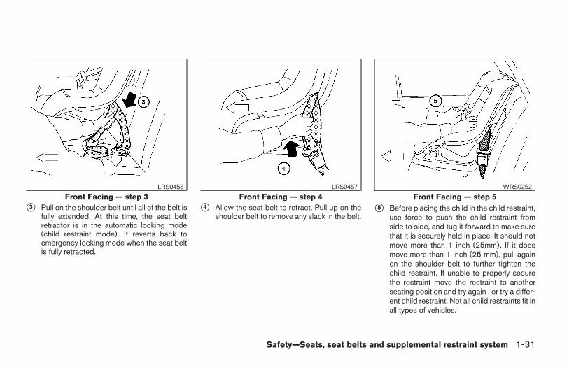
s3 Pull on the shoulder belt until all of the belt isfully extended. At this time, the seat beltretractor is in the automatic locking mode(child restraint mode). It reverts back toemergency locking mode when the seat beltis fully retracted.
s4 Allow the seat belt to retract. Pull up on theshoulder belt to remove any slack in the belt.
s5 Before placing the child in the child restraint,use force to push the child restraint fromside to side, and tug it forward to make surethat it is securely held in place. It should notmove more than 1 inch (25mm). If it doesmove more than 1 inch (25 mm), pull againon the shoulder belt to further tighten thechild restraint. If unable to properly securethe restraint move the restraint to anotherseating position and try again , or try a differ-ent child restraint. Not all child restraints fit inall types of vehicles.
Front Facing — step 3LRS0458
Front Facing — step 4LRS0457
Front Facing — step 5WRS0252
Safety—Seats, seat belts and supplemental restraint system 1-31
Z REVIEW COPY—2006 Truck/Frontier (d22)Owners Manual—USA_English (nna)10/14/05—debbie X
6. Check that the retractor is in the automaticlocking mode by trying to pull more seat beltout of the retractor. If you cannot pull anymore belt webbing out of the retractor, theretractor is in the automatic locking mode.
7. Check to make sure that the child restraint isproperly secured prior to each use. If the beltis not locked, repeat steps 3 through 6.
After the child restraint is removed and the seatbelt is fully retracted, the automatic locking mode(child restraint mode) is canceled.
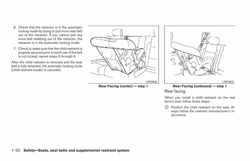
Rear facingWhen you install a child restraint on the rearbench seat, follow these steps:
s1 Position the child restraint on the seat. Al-ways follow the restraint manufacturer’s in-structions.
Rear Facing (center) — step 1LRS0600
Rear Facing (outboard) — step 1LRS0403
1-32 Safety—Seats, seat belts and supplemental restraint system
Z REVIEW COPY—2006 Truck/Frontier (d22)Owners Manual—USA_English (nna)10/14/05—debbie X
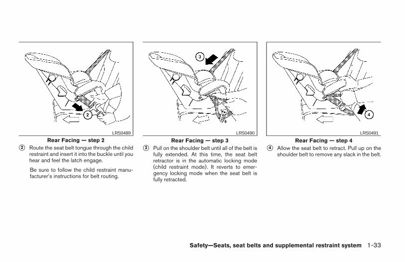
s2 Route the seat belt tongue through the childrestraint and insert it into the buckle until youhear and feel the latch engage.
Be sure to follow the child restraint manu-facturer’s instructions for belt routing.
s3 Pull on the shoulder belt until all of the belt isfully extended. At this time, the seat beltretractor is in the automatic locking mode(child restraint mode). It reverts to emer-gency locking mode when the seat belt isfully retracted.
s4 Allow the seat belt to retract. Pull up on theshoulder belt to remove any slack in the belt.
Rear Facing — step 2LRS0489
Rear Facing — step 3LRS0490
Rear Facing — step 4LRS0491
Safety—Seats, seat belts and supplemental restraint system 1-33
Z REVIEW COPY—2006 Truck/Frontier (d22)Owners Manual—USA_English (nna)10/14/05—debbie X
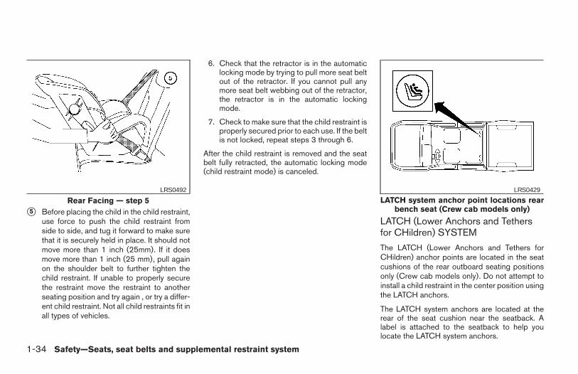
s5 Before placing the child in the child restraint,use force to push the child restraint fromside to side, and tug it forward to make surethat it is securely held in place. It should notmove more than 1 inch (25mm). If it doesmove more than 1 inch (25 mm), pull againon the shoulder belt to further tighten thechild restraint. If unable to properly securethe restraint move the restraint to anotherseating position and try again , or try a differ-ent child restraint. Not all child restraints fit inall types of vehicles.
6. Check that the retractor is in the automaticlocking mode by trying to pull more seat beltout of the retractor. If you cannot pull anymore seat belt webbing out of the retractor,the retractor is in the automatic lockingmode.
7. Check to make sure that the child restraint isproperly secured prior to each use. If the beltis not locked, repeat steps 3 through 6.
After the child restraint is removed and the seatbelt fully retracted, the automatic locking mode(child restraint mode) is canceled.
LATCH (Lower Anchors and Tethersfor CHildren) SYSTEM
The LATCH (Lower Anchors and Tethers forCHildren) anchor points are located in the seatcushions of the rear outboard seating positionsonly (Crew cab models only). Do not attempt toinstall a child restraint in the center position usingthe LATCH anchors.
The LATCH system anchors are located at therear of the seat cushion near the seatback. Alabel is attached to the seatback to help youlocate the LATCH system anchors.
Rear Facing — step 5LRS0492
LATCH system anchor point locations rearbench seat (Crew cab models only)
LRS0429
1-34 Safety—Seats, seat belts and supplemental restraint system
Z REVIEW COPY—2006 Truck/Frontier (d22)Owners Manual—USA_English (nna)10/14/05—debbie X
WARNING
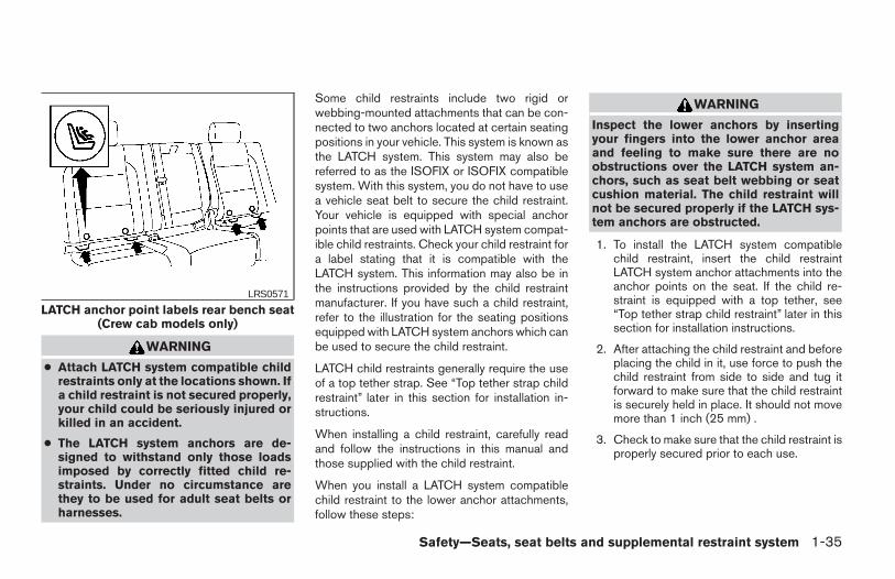
● Attach LATCH system compatible childrestraints only at the locations shown. Ifa child restraint is not secured properly,your child could be seriously injured orkilled in an accident.
● The LATCH system anchors are de-signed to withstand only those loadsimposed by correctly fitted child re-straints. Under no circumstance arethey to be used for adult seat belts orharnesses.
Some child restraints include two rigid orwebbing-mounted attachments that can be con-nected to two anchors located at certain seatingpositions in your vehicle. This system is known asthe LATCH system. This system may also bereferred to as the ISOFIX or ISOFIX compatiblesystem. With this system, you do not have to usea vehicle seat belt to secure the child restraint.Your vehicle is equipped with special anchorpoints that are used with LATCH system compat-ible child restraints. Check your child restraint fora label stating that it is compatible with theLATCH system. This information may also be inthe instructions provided by the child restraintmanufacturer. If you have such a child restraint,refer to the illustration for the seating positionsequipped with LATCH system anchors which canbe used to secure the child restraint.
LATCH child restraints generally require the useof a top tether strap. See “Top tether strap childrestraint” later in this section for installation in-structions.
When installing a child restraint, carefully readand follow the instructions in this manual andthose supplied with the child restraint.
When you install a LATCH system compatiblechild restraint to the lower anchor attachments,follow these steps:
WARNING
Inspect the lower anchors by insertingyour fingers into the lower anchor areaand feeling to make sure there are noobstructions over the LATCH system an-chors, such as seat belt webbing or seatcushion material. The child restraint willnot be secured properly if the LATCH sys-tem anchors are obstructed.
1. To install the LATCH system compatiblechild restraint, insert the child restraintLATCH system anchor attachments into theanchor points on the seat. If the child re-straint is equipped with a top tether, see“Top tether strap child restraint” later in thissection for installation instructions.
2. After attaching the child restraint and beforeplacing the child in it, use force to push thechild restraint from side to side and tug itforward to make sure that the child restraintis securely held in place. It should not movemore than 1 inch (25 mm) .
3. Check to make sure that the child restraint isproperly secured prior to each use.
LATCH anchor point labels rear bench seat(Crew cab models only)
LRS0571
Safety—Seats, seat belts and supplemental restraint system 1-35
Z REVIEW COPY—2006 Truck/Frontier (d22)Owners Manual—USA_English (nna)10/14/05—debbie X
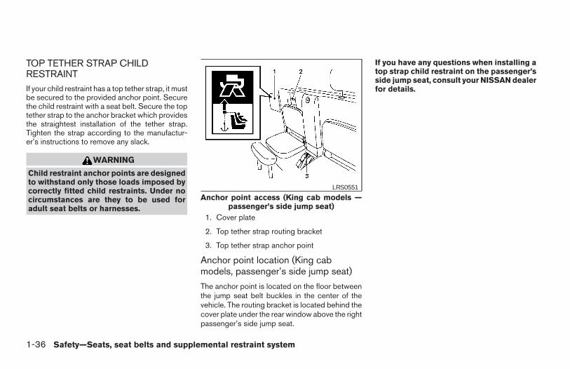
TOP TETHER STRAP CHILDRESTRAINTIf your child restraint has a top tether strap, it mustbe secured to the provided anchor point. Securethe child restraint with a seat belt. Secure the toptether strap to the anchor bracket which providesthe straightest installation of the tether strap.Tighten the strap according to the manufactur-er’s instructions to remove any slack.
WARNING
Child restraint anchor points are designedto withstand only those loads imposed bycorrectly fitted child restraints. Under nocircumstances are they to be used foradult seat belts or harnesses.
1. Cover plate
2. Top tether strap routing bracket
3. Top tether strap anchor point
Anchor point location (King cabmodels, passenger’s side jump seat)
The anchor point is located on the floor betweenthe jump seat belt buckles in the center of thevehicle. The routing bracket is located behind thecover plate under the rear window above the rightpassenger’s side jump seat.
If you have any questions when installing atop strap child restraint on the passenger’sside jump seat, consult your NISSAN dealerfor details.
Anchor point access (King cab models —passenger’s side jump seat)
LRS0551
1-36 Safety—Seats, seat belts and supplemental restraint system
Z REVIEW COPY—2006 Truck/Frontier (d22)Owners Manual—USA_English (nna)10/14/05—debbie X
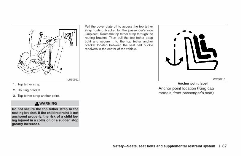
1. Top tether strap
2. Routing bracket
3. Top tether strap anchor point.
WARNING
Do not secure the top tether strap to therouting bracket. If the child restraint is notanchored properly, the risk of a child be-ing injured in a collision or a sudden stopgreatly increases.
Pull the cover plate off to access the top tetherstrap routing bracket for the passenger’s sidejump seat. Route the top tether strap through therouting bracket. Then pull the top tether straptight and secure it to the top tether anchorbracket located between the seat belt bucklereceivers in the center of the vehicle.
Anchor point location (King cabmodels, front passenger’s seat)
LRS0561Anchor point label
WRS0210
Safety—Seats, seat belts and supplemental restraint system 1-37
Z REVIEW COPY—2006 Truck/Frontier (d22)Owners Manual—USA_English (nna)10/14/05—debbie X
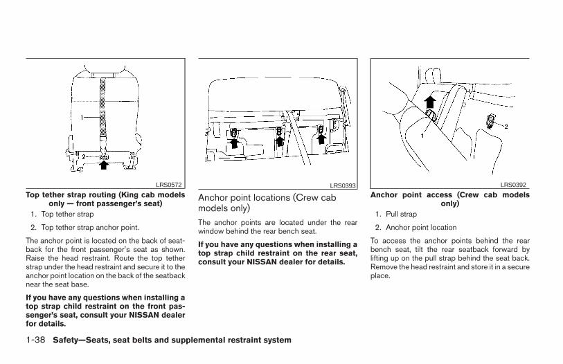
1. Top tether strap
2. Top tether strap anchor point.
The anchor point is located on the back of seat-back for the front passenger’s seat as shown.Raise the head restraint. Route the top tetherstrap under the head restraint and secure it to theanchor point location on the back of the seatbacknear the seat base.
If you have any questions when installing atop strap child restraint on the front pas-senger’s seat, consult your NISSAN dealerfor details.
Anchor point locations (Crew cabmodels only)The anchor points are located under the rearwindow behind the rear bench seat.
If you have any questions when installing atop strap child restraint on the rear seat,consult your NISSAN dealer for details.
1. Pull strap
2. Anchor point location
To access the anchor points behind the rearbench seat, tilt the rear seatback forward bylifting up on the pull strap behind the seat back.Remove the head restraint and store it in a secureplace.
Top tether strap routing (King cab modelsonly — front passenger’s seat)
LRS0572 LRS0393Anchor point access (Crew cab models
only)
LRS0392
1-38 Safety—Seats, seat belts and supplemental restraint system
Z REVIEW COPY—2006 Truck/Frontier (d22)Owners Manual—USA_English (nna)10/14/05—debbie X
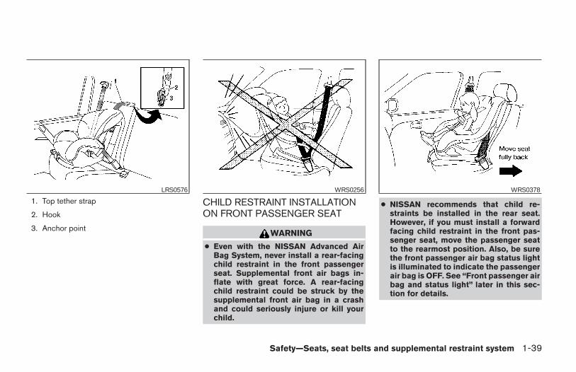
1. Top tether strap
2. Hook
3. Anchor point
CHILD RESTRAINT INSTALLATIONON FRONT PASSENGER SEAT
WARNING
● Even with the NISSAN Advanced AirBag System, never install a rear-facingchild restraint in the front passengerseat. Supplemental front air bags in-flate with great force. A rear-facingchild restraint could be struck by thesupplemental front air bag in a crashand could seriously injure or kill yourchild.
● NISSAN recommends that child re-straints be installed in the rear seat.However, if you must install a forwardfacing child restraint in the front pas-senger seat, move the passenger seatto the rearmost position. Also, be surethe front passenger air bag status lightis illuminated to indicate the passengerair bag is OFF. See “Front passenger airbag and status light” later in this sec-tion for details.
LRS0576 WRS0256 WRS0378
Safety—Seats, seat belts and supplemental restraint system 1-39
Z REVIEW COPY—2006 Truck/Frontier (d22)Owners Manual—USA_English (nna)10/14/05—debbie X
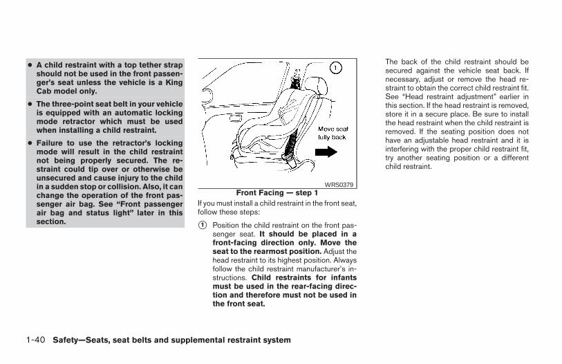
● A child restraint with a top tether strapshould not be used in the front passen-ger’s seat unless the vehicle is a KingCab model only.
● The three-point seat belt in your vehicleis equipped with an automatic lockingmode retractor which must be usedwhen installing a child restraint.
● Failure to use the retractor’s lockingmode will result in the child restraintnot being properly secured. The re-straint could tip over or otherwise beunsecured and cause injury to the childin a sudden stop or collision. Also, it canchange the operation of the front pas-senger air bag. See “Front passengerair bag and status light” later in thissection.
If you must install a child restraint in the front seat,follow these steps:
s1 Position the child restraint on the front pas-senger seat. It should be placed in afront-facing direction only. Move theseat to the rearmost position. Adjust thehead restraint to its highest position. Alwaysfollow the child restraint manufacturer’s in-structions. Child restraints for infantsmust be used in the rear-facing direc-tion and therefore must not be used inthe front seat.
The back of the child restraint should besecured against the vehicle seat back. Ifnecessary, adjust or remove the head re-straint to obtain the correct child restraint fit.See “Head restraint adjustment” earlier inthis section. If the head restraint is removed,store it in a secure place. Be sure to installthe head restraint when the child restraint isremoved. If the seating position does nothave an adjustable head restraint and it isinterfering with the proper child restraint fit,try another seating position or a differentchild restraint.
Front Facing — step 1WRS0379
1-40 Safety—Seats, seat belts and supplemental restraint system
Z REVIEW COPY—2006 Truck/Frontier (d22)Owners Manual—USA_English (nna)10/14/05—debbie X
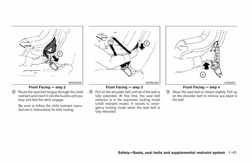
s2 Route the seat belt tongue through the childrestraint and insert it into the buckle until youhear and feel the latch engage.
Be sure to follow the child restraint manu-facturer’s instructions for belt routing.
s3 Pull on the shoulder belt until all of the belt isfully extended. At this time, the seat beltretractor is in the automatic locking mode(child restraint mode). It reverts to emer-gency locking mode when the seat belt isfully retracted.
s4 Allow the seat belt to retract slightly. Pull upon the shoulder belt to remove any slack inthe belt.
Front Facing — step 2WRS0159
Front Facing — step 3WRS0160
Front Facing — step 4LRS0457
Safety—Seats, seat belts and supplemental restraint system 1-41
Z REVIEW COPY—2006 Truck/Frontier (d22)Owners Manual—USA_English (nna)10/14/05—debbie X
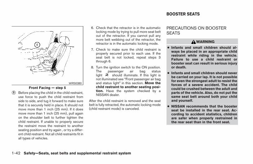
s5 Before placing the child in the child restraint,use force to push the child restraint fromside to side, and tug it forward to make surethat it is securely held in place. It should notmove more than 1 inch (25 mm). If it doesmove more than 1 inch (25 mm), pull againon the shoulder belt to further tighten thechild restraint. If unable to properly securethe restraint move the restraint to anotherseating position and try again , or try a differ-ent child restraint. Not all child restraints fit inall types of vehicles.
6. Check that the retractor is in the automaticlocking mode by trying to pull more seat beltout of the retractor. If you cannot pull anymore belt webbing out of the retractor, theretractor is in the automatic locking mode.
7. Check to make sure the child restraint isproperly secured prior to each use. If theseat belt is not locked, repeat steps 3through 6.
8. Turn the ignition switch to the ON position.The passenger air bag statuslight should illuminate. If this light isnot illuminated see “Front passenger air bagand status light” in this section. Move thechild restraint to another seating posi-tion. Have the system checked by aNISSAN dealer.
After the child restraint is removed and the seatbelt is fully retracted, the automatic locking mode(child restraint mode) is canceled.
PRECAUTIONS ON BOOSTERSEATS
WARNING
● Infants and small children should al-ways be placed in an appropriate childrestraint while riding in the vehicle.Failure to use a child restraint orbooster seat can result in serious injuryor death.
● Infants and small children should neverbe carried on your lap. It is not possiblefor even the strongest adult to resist theforces of a severe accident. The childcould be crushed between the adult andparts of the vehicle. Also, do not put thesame seat belt around both your childand yourself.
● NISSAN recommends that the boosterseat be installed in the rear seat. Ac-cording to accident statistics, childrenare safer when properly restrained inthe rear seat than in the front seat.
Front Facing — step 5WRS0380
BOOSTER SEATS
1-42 Safety—Seats, seat belts and supplemental restraint system
Z REVIEW COPY—2006 Truck/Frontier (d22)Owners Manual—USA_English (nna)10/14/05—debbie X
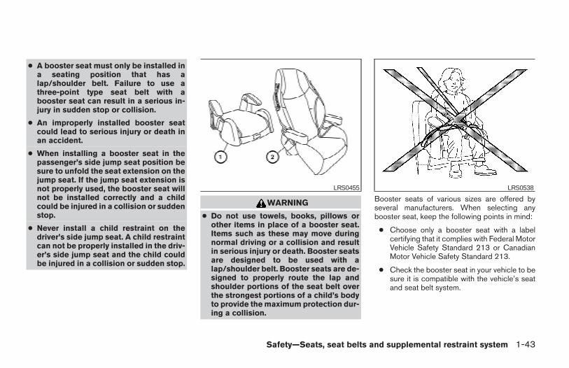
● A booster seat must only be installed ina seating position that has alap/shoulder belt. Failure to use athree-point type seat belt with abooster seat can result in a serious in-jury in sudden stop or collision.
● An improperly installed booster seatcould lead to serious injury or death inan accident.
● When installing a booster seat in thepassenger’s side jump seat position besure to unfold the seat extension on thejump seat. If the jump seat extension isnot properly used, the booster seat willnot be installed correctly and a childcould be injured in a collision or suddenstop.
● Never install a child restraint on thedriver’s side jump seat. A child restraintcan not be properly installed in the driv-er’s side jump seat and the child couldbe injured in a collision or sudden stop.
WARNING
● Do not use towels, books, pillows orother items in place of a booster seat.Items such as these may move duringnormal driving or a collision and resultin serious injury or death. Booster seatsare designed to be used with alap/shoulder belt. Booster seats are de-signed to properly route the lap andshoulder portions of the seat belt overthe strongest portions of a child’s bodyto provide the maximum protection dur-ing a collision.
Booster seats of various sizes are offered byseveral manufacturers. When selecting anybooster seat, keep the following points in mind:
● Choose only a booster seat with a labelcertifying that it complies with Federal MotorVehicle Safety Standard 213 or CanadianMotor Vehicle Safety Standard 213.
● Check the booster seat in your vehicle to besure it is compatible with the vehicle’s seatand seat belt system.
LRS0455 LRS0538
Safety—Seats, seat belts and supplemental restraint system 1-43
Z REVIEW COPY—2006 Truck/Frontier (d22)Owners Manual—USA_English (nna)10/14/05—debbie X
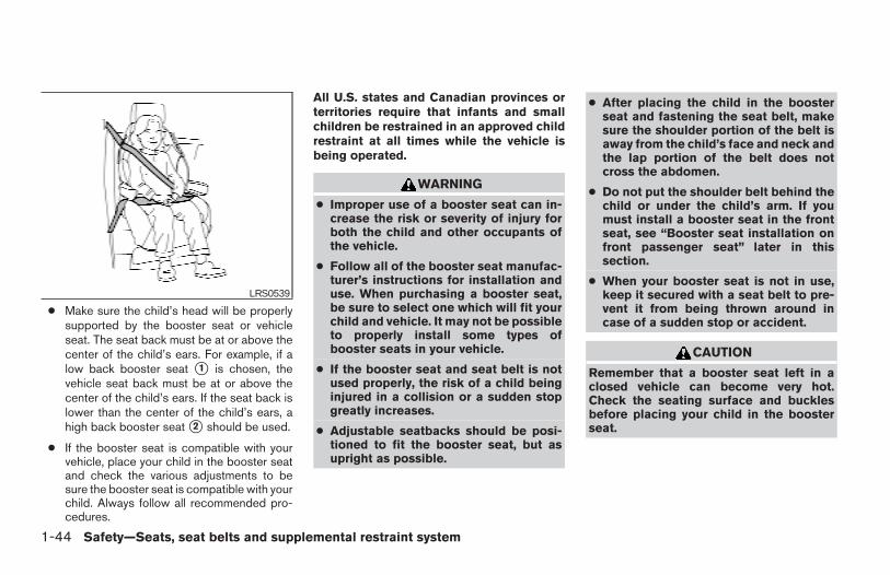
● Make sure the child’s head will be properlysupported by the booster seat or vehicleseat. The seat back must be at or above thecenter of the child’s ears. For example, if alow back booster seat s1 is chosen, thevehicle seat back must be at or above thecenter of the child’s ears. If the seat back islower than the center of the child’s ears, ahigh back booster seat s2 should be used.
● If the booster seat is compatible with yourvehicle, place your child in the booster seatand check the various adjustments to besure the booster seat is compatible with yourchild. Always follow all recommended pro-cedures.
All U.S. states and Canadian provinces orterritories require that infants and smallchildren be restrained in an approved childrestraint at all times while the vehicle isbeing operated.
WARNING
● Improper use of a booster seat can in-crease the risk or severity of injury forboth the child and other occupants ofthe vehicle.
● Follow all of the booster seat manufac-turer’s instructions for installation anduse. When purchasing a booster seat,be sure to select one which will fit yourchild and vehicle. It may not be possibleto properly install some types ofbooster seats in your vehicle.
● If the booster seat and seat belt is notused properly, the risk of a child beinginjured in a collision or a sudden stopgreatly increases.
● Adjustable seatbacks should be posi-tioned to fit the booster seat, but asupright as possible.
● After placing the child in the boosterseat and fastening the seat belt, makesure the shoulder portion of the belt isaway from the child’s face and neck andthe lap portion of the belt does notcross the abdomen.
● Do not put the shoulder belt behind thechild or under the child’s arm. If youmust install a booster seat in the frontseat, see “Booster seat installation onfront passenger seat” later in thissection.
● When your booster seat is not in use,keep it secured with a seat belt to pre-vent it from being thrown around incase of a sudden stop or accident.
CAUTION
Remember that a booster seat left in aclosed vehicle can become very hot.Check the seating surface and bucklesbefore placing your child in the boosterseat.
LRS0539
1-44 Safety—Seats, seat belts and supplemental restraint system
Z REVIEW COPY—2006 Truck/Frontier (d22)Owners Manual—USA_English (nna)10/14/05—debbie X
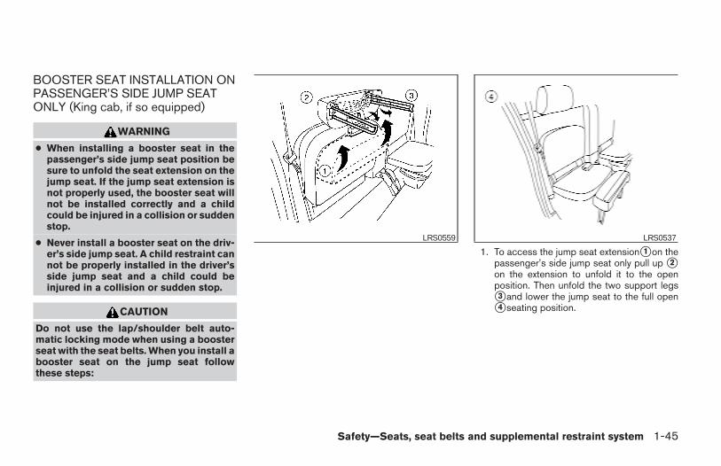
BOOSTER SEAT INSTALLATION ONPASSENGER’S SIDE JUMP SEATONLY (King cab, if so equipped)
WARNING
● When installing a booster seat in thepassenger’s side jump seat position besure to unfold the seat extension on thejump seat. If the jump seat extension isnot properly used, the booster seat willnot be installed correctly and a childcould be injured in a collision or suddenstop.
● Never install a booster seat on the driv-er’s side jump seat. A child restraint cannot be properly installed in the driver’sside jump seat and a child could beinjured in a collision or sudden stop.
CAUTION
Do not use the lap/shoulder belt auto-matic locking mode when using a boosterseat with the seat belts. When you install abooster seat on the jump seat followthese steps:
1. To access the jump seat extensions1 on thepassenger’s side jump seat only pull up s2on the extension to unfold it to the openposition. Then unfold the two support legss3 and lower the jump seat to the full opens4 seating position.
LRS0559 LRS0537
Safety—Seats, seat belts and supplemental restraint system 1-45
Z REVIEW COPY—2006 Truck/Frontier (d22)Owners Manual—USA_English (nna)10/14/05—debbie X
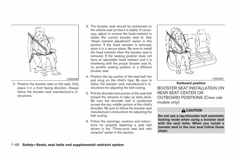
2. Position the booster seat on the seat. Onlyplace it in a front facing direction. Alwaysfollow the booster seat manufacturer’s in-structions.
3. The booster seat should be positioned onthe vehicle seat so that it is stable. If neces-sary, adjust or remove the head restraint toobtain the correct booster seat fit. See“Head restraint adjustment” earlier in thissection. If the head restraint is removed,store it in a secure place. Be sure to installthe head restraint when the booster seat isremoved. If the seating position does nothave an adjustable head restraint and it isinterfering with the proper booster seat fit,try another seating position or a differentbooster seat.
4. Position the lap portion of the seat belt lowand snug on the child’s hips. Be sure tofollow the booster seat manufacturer’s in-structions for adjusting the belt routing.
5. Pull the shoulder belt portion of the seat belttoward the retractor to take up extra slack.Be sure the shoulder belt is positionedacross the top, middle portion of the child’sshoulder. Be sure to follow the booster seatmanufacturer’s instructions for adjusting thebelt routing.
6. Follow the warnings, cautions and instruc-tions for properly fastening a seat beltshown in the “Three-point seat belt withretractor” earlier in this section.
BOOSTER SEAT INSTALLATION ONREAR SEAT CENTER OROUTBOARD POSITIONS (Crew cabmodels only)
CAUTION
Do not use a lap/shoulder belt automaticlocking mode when using a booster seatwith the seat belts. When you install abooster seat in the rear seat follow thesesteps:
LRS0539
Outboard positionLRS0563
1-46 Safety—Seats, seat belts and supplemental restraint system
Z REVIEW COPY—2006 Truck/Frontier (d22)Owners Manual—USA_English (nna)10/14/05—debbie X
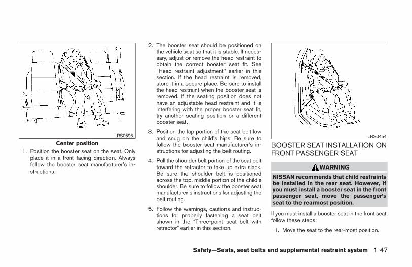
1. Position the booster seat on the seat. Onlyplace it in a front facing direction. Alwaysfollow the booster seat manufacturer’s in-structions.
2. The booster seat should be positioned onthe vehicle seat so that it is stable. If neces-sary, adjust or remove the head restraint toobtain the correct booster seat fit. See“Head restraint adjustment” earlier in thissection. If the head restraint is removed,store it in a secure place. Be sure to installthe head restraint when the booster seat isremoved. If the seating position does nothave an adjustable head restraint and it isinterfering with the proper booster seat fit,try another seating position or a differentbooster seat.
3. Position the lap portion of the seat belt lowand snug on the child’s hips. Be sure tofollow the booster seat manufacturer’s in-structions for adjusting the belt routing.
4. Pull the shoulder belt portion of the seat belttoward the retractor to take up extra slack.Be sure the shoulder belt is positionedacross the top, middle portion of the child’sshoulder. Be sure to follow the booster seatmanufacturer’s instructions for adjusting thebelt routing.
5. Follow the warnings, cautions and instruc-tions for properly fastening a seat beltshown in the “Three-point seat belt withretractor” earlier in this section.
BOOSTER SEAT INSTALLATION ONFRONT PASSENGER SEAT
WARNING
NISSAN recommends that child restraintsbe installed in the rear seat. However, ifyou must install a booster seat in the frontpassenger seat, move the passenger’sseat to the rearmost position.
If you must install a booster seat in the front seat,follow these steps:
1. Move the seat to the rear-most position.
Center positionLRS0596 LRS0454
Safety—Seats, seat belts and supplemental restraint system 1-47
Z REVIEW COPY—2006 Truck/Frontier (d22)Owners Manual—USA_English (nna)10/14/05—debbie X
2. Position the booster seat on the seat. Onlyplace it in a front facing direction. Alwaysfollow the booster seat manufacturer’s in-structions.
3. The booster seat should be positioned onthe vehicle seat so that it is stable. If neces-sary, adjust or remove the head restraint toobtain the correct booster seat fit. See“Head restraint adjustment” earlier in thissection. If the head restraint is removed,store it in a secure place. Be sure to installthe head restraint when the booster seat isremoved. If the seating position does nothave an adjustable head restraint and it isinterfering with the proper booster seat fit,try another seating position or a differentbooster seat.
4. Position the lap portion of the seat belt lowand snug on the child’s hips. Be sure tofollow the booster seat manufacturer’s in-structions for adjusting the belt routing.
5. Pull the shoulder belt portion of the seat belttoward the retractor to take up extra slack.Be sure the shoulder belt is positionedacross the top, middle portion of the child’sshoulder. Be sure to follow the booster seatmanufacturer’s instructions for adjusting thebelt routing.
6. Follow the warnings, cautions and instruc-tions for properly fastening a seat beltshown in the “Three-point seat belt withretractor” earlier in this section.
7. When the ignition switch is turned to the ONposition, the passenger air bag statuslight may or may not be illuminated,depending on the size of the child and thetype of booster seat being used. See “Frontpassenger air bag and status light” later inthis section.
PRECAUTIONS ONSUPPLEMENTAL RESTRAINTSYSTEM
This Supplemental Restraint System (SRS) sec-tion contains important information concerningthe driver and passenger supplemental front airbags (NISSAN Advanced Air Bag System),supplemental side air bags, curtain side-impactand rollover air bags and pre-tensioner seat belts.
Supplemental front impact air bag system:The NISSAN Advanced Air Bag System can helpcushion the impact force to the head and chest ofthe driver and front passenger in certain frontalcollisions.
Supplemental side-impact air bag system(if so equipped): This system can help cushionthe impact force to the chest area of the driverand front passenger in certain side impact colli-sions. The front seat side-impact supplementalside air bags are designed to inflate on the sidewhere the vehicle is impacted.
Supplemental curtain side-impact and roll-over air bag system (if so equipped): Thissystem can help cushion the impact force to thehead of occupants in front and rear outboardseating positions in certain side impact or rollovercollisions. In a side impact, the curtain air bagsare designed to inflate on the side where the
SUPPLEMENTAL RESTRAINTSYSTEM
1-48 Safety—Seats, seat belts and supplemental restraint system
Z REVIEW COPY—2006 Truck/Frontier (d22)Owners Manual—USA_English (nna)10/14/05—debbie X
vehicle is impacted. In a rollover both curtain airbags are designed to inflate and remain inflatedfor a short time.
These supplemental restraint systems are de-signed to supplement the crash protection pro-vided by the seat belts and are not a substitutefor them. Seat belts should always be correctlyworn and the occupant seated a suitable dis-tance away from the steering wheel, instrumentpanel and door finishers. See “Seat belts” earlierin this section for instructions and precautions onseat belt usage.
The supplemental air bags operate onlywhen the ignition switch is in the ON orSTART position.
After turning the ignition key to the ONposition, the supplemental air bag warninglight illuminates. The supplemental air bagwarning light will turn off after about 7seconds if the system is operational.
WARNING
● The supplemental front air bags ordi-narily will not inflate in the event of aside impact, rear impact, rollover, orlower severity frontal collision. Alwayswear your seat belts to help reduce therisk or severity of injury in various kindsof accidents.
● The front passenger air bag will notinflate if the passenger air bag statuslight is lit or if the front passenger seatis unoccupied. See “Front passenger airbag and status light” later in thissection.
WRS0031
Safety—Seats, seat belts and supplemental restraint system 1-49
Z REVIEW COPY—2006 Truck/Frontier (d22)Owners Manual—USA_English (nna)10/14/05—debbie X
● The seat belts and the supplementalfront air bags are most effective whenyou are sitting well back and upright inthe seat. The front air bags inflate withgreat force. Even with the NISSAN Ad-vanced Air Bag System, if you are unre-strained, leaning forward, sitting side-ways or out of position in any way, youare at greater risk of injury or death in acrash. You may also receive serious orfatal injuries from the supplementalfront air bag if you are up against itwhen it inflates. Always sit back againstthe seatback and as far away as practi-cal from the steering wheel or instru-ment panel. Always use the seat belts.
● The driver and front passenger seat beltbuckles are equipped with sensors thatdetect if the seat belts are fastened. Theadvanced air bag system monitors theseverity of a collision and seat belt us-age then inflates the air bags. Failure toproperly wear seat belts can increasethe risk or severity of injury in anaccident.
● The front passenger seat is equippedwith an occupant classification sensor(pressure sensor) that turns the frontpassenger air bag OFF under someconditions. This sensor is only used inthis seat. Failure to be properly seatedand wearing the seat belt can increasethe risk or severity of injury in an acci-dent. See “Front Passenger air bag andstatus light” later in this section.
● Keep hands on the outside of the steer-ing wheel. Placing them inside thesteering wheel rim could increase therisk that they are injured when thesupplemental front air bag inflates.
1-50 Safety—Seats, seat belts and supplemental restraint system
Z REVIEW COPY—2006 Truck/Frontier (d22)Owners Manual—USA_English (nna)10/14/05—debbie X
WARNING
● Never let children ride unrestrained orextend their hands or face out of thewindow. Do not attempt to hold them inyour lap or arms. Some examples ofdangerous riding positions are shownin the illustrations.
ARS1133 ARS1041
Safety—Seats, seat belts and supplemental restraint system 1-51
Z REVIEW COPY—2006 Truck/Frontier (d22)Owners Manual—USA_English (nna)10/14/05—debbie X
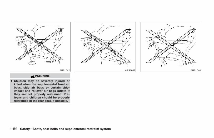
WARNING
● Children may be severely injured orkilled when the supplemental front airbags, side air bags or curtain side-impact and rollover air bags inflate ifthey are not properly restrained. Pre-teens and children should be properlyrestrained in the rear seat, if possible.
ARS1042 ARS1043 ARS1044
1-52 Safety—Seats, seat belts and supplemental restraint system
Z REVIEW COPY—2006 Truck/Frontier (d22)Owners Manual—USA_English (nna)10/14/05—debbie X
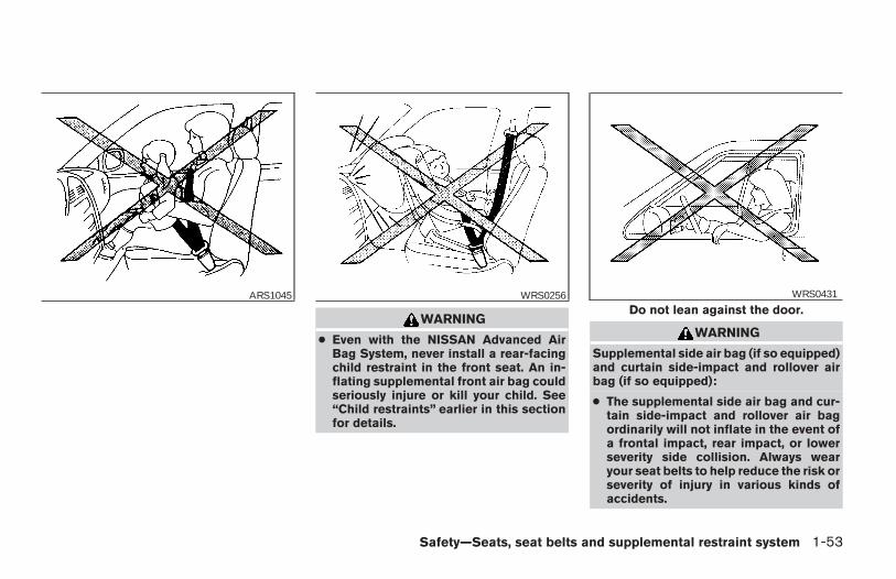
WARNING
● Even with the NISSAN Advanced AirBag System, never install a rear-facingchild restraint in the front seat. An in-flating supplemental front air bag couldseriously injure or kill your child. See“Child restraints” earlier in this sectionfor details.
WARNING
Supplemental side air bag (if so equipped)and curtain side-impact and rollover airbag (if so equipped):
● The supplemental side air bag and cur-tain side-impact and rollover air bagordinarily will not inflate in the event ofa frontal impact, rear impact, or lowerseverity side collision. Always wearyour seat belts to help reduce the risk orseverity of injury in various kinds ofaccidents.
ARS1045 WRS0256Do not lean against the door.
WRS0431
Safety—Seats, seat belts and supplemental restraint system 1-53
Z REVIEW COPY—2006 Truck/Frontier (d22)Owners Manual—USA_English (nna)10/14/05—debbie X
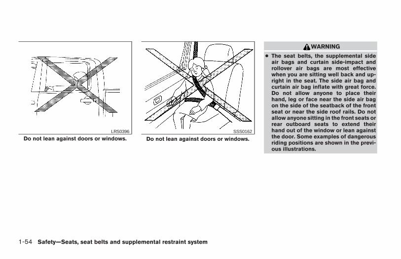
WARNING
● The seat belts, the supplemental sideair bags and curtain side-impact androllover air bags are most effectivewhen you are sitting well back and up-right in the seat. The side air bag andcurtain air bag inflate with great force.Do not allow anyone to place theirhand, leg or face near the side air bagon the side of the seatback of the frontseat or near the side roof rails. Do notallow anyone sitting in the front seats orrear outboard seats to extend theirhand out of the window or lean againstthe door. Some examples of dangerousriding positions are shown in the previ-ous illustrations.
Do not lean against doors or windows.LRS0396
Do not lean against doors or windows.SSS0162
1-54 Safety—Seats, seat belts and supplemental restraint system
Z REVIEW COPY—2006 Truck/Frontier (d22)Owners Manual—USA_English (nna)10/14/05—debbie X
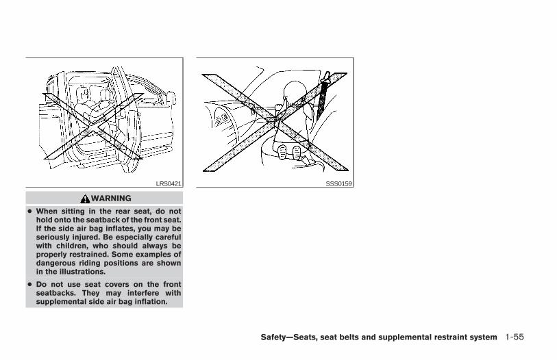
WARNING
● When sitting in the rear seat, do nothold onto the seatback of the front seat.If the side air bag inflates, you may beseriously injured. Be especially carefulwith children, who should always beproperly restrained. Some examples ofdangerous riding positions are shownin the illustrations.
● Do not use seat covers on the frontseatbacks. They may interfere withsupplemental side air bag inflation.
LRS0421 SSS0159
Safety—Seats, seat belts and supplemental restraint system 1-55
Z REVIEW COPY—2006 Truck/Frontier (d22)Owners Manual—USA_English (nna)10/14/05—debbie X
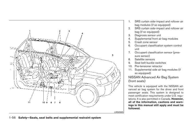
1. SRS curtain side-impact and rollover airbag modules (if so equipped)
2. SRS curtain side-impact and rollover airbag (if so equipped)
3. Diagnosis sensor unit4. Supplemental front air bag modules5. Crash zone sensor6. Occupant classification system control
unit7. Occupant classification sensor (pres-
sure sensor)8. Satellite sensors9. Seat belt buckle switches10. Pre-tensioner retractor11. Supplemental side air bag modules (if
so equipped)
NISSAN Advanced Air Bag System(front seats)
This vehicle is equipped with the NISSAN ad-vanced air bag system for the driver and frontpassenger seats. This system is designed tomeet certification requirements under U.S. regu-lations. It is also permitted in Canada. However,all of the information, cautions and warn-ings in this manual still apply and must befollowed.
LRS0565
1-56 Safety—Seats, seat belts and supplemental restraint system
Z REVIEW COPY—2006 Truck/Frontier (d22)Owners Manual—USA_English (nna)10/14/05—debbie X
The driver supplemental front air bag is located inthe center of the steering wheel. The passengersupplemental front air bag is mounted in thedashboard above the glove box. The supplemen-tal front air bags are designed to inflate in higherseverity frontal collisions, although they may in-flate if the forces in another type of collision aresimilar to those of a higher severity frontal impact.They may not inflate in certain frontal collisions.Vehicle damage (or lack of it) is not always anindication of proper supplemental front air bagsystem operation.
The NISSAN advanced air bag system has dualstage inflators. It also monitors information fromthe crash zone sensor, the diagnosis sensor unit,seat belt buckle sensors, occupant classificationsensor (pressure sensor) and passenger seatbelt tension sensor. Inflator operation is based onthe severity of a collision and seat belt usage forthe driver. For the front passenger, it additionallymonitors the weight of an occupant or object onthe seat and seat belt tension. Based on informa-tion from the sensors, only one front air bag mayinflate in a crash, depending on the crash severityand whether the front occupants are belted orunbelted. Additionally, the front passenger airbag may be automatically turned OFF undersome conditions, depending on the weight de-tected on the passenger seat and how the seatbelt is used. If the front passenger air bag is OFF,
the passenger air bag status light will be illumi-nated (if the seat is unoccupied, the light will notbe illuminated, but the air bag will be off). See“Front passenger air bag and status light” later inthis section for further details. One front air baginflating does not indicate improper performanceof the system.
If you have any questions about your air bagsystem, please contact NISSAN or your NISSANdealer. If you are considering modification of yourvehicle due to a disability, you may also contactNISSAN. Contact information is contained in thefront of this Owner’s Manual.
When a supplemental front air bag inflates, afairly loud noise may be heard, followed by therelease of smoke. This smoke is not harmful anddoes not indicate a fire. Care should be taken tonot inhale it, as it may cause irritation and chok-ing. Those with a history of a breathing conditionshould get fresh air promptly.
Supplemental front air bags, along with the use ofseat belts, help to cushion the impact force onthe face and chest of the front occupants. Theycan help save lives and reduce serious injuries.However, an inflating front air bag may causefacial abrasions or other injuries. Front air bagsdo not provide restraint to the lower body.
Even with NISSAN advanced air bags, seat beltsshould be correctly worn and the driver and pas-
senger seated upright as far as practical awayfrom the steering wheel or instrument panel. Thesupplemental front air bags inflate quickly in orderto help protect the front occupants. Because ofthis, the force of the front air bag inflating canincrease the risk of injury if the occupant is tooclose to, or is against, the front air bag moduleduring inflation.
The front air bags deflate quickly after a collision.
The supplemental front air bags operateonly when the ignition switch is in the ONor START position.
After turning the ignition key to the ONposition, the supplemental air bag warninglight illuminates. The supplemental air bagwarning light will turn off after about 7seconds if the system is operational.
Safety—Seats, seat belts and supplemental restraint system 1-57
Z REVIEW COPY—2006 Truck/Frontier (d22)Owners Manual—USA_English (nna)10/14/05—debbie X
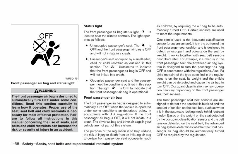
Front passenger air bag and status light
WARNING
The front passenger air bag is designed toautomatically turn OFF under some con-ditions. Read this section carefully tolearn how it operates. Proper use of theseat, seat belt and child restraints is nec-essary for most effective protection. Fail-ure to follow all instructions in thismanual concerning the use of seats, seatbelts and child restraints can increase therisk or severity of injury in an accident.
Status light
The front passenger air bag status light islocated near the climate controls. The light oper-ates as follows:
● Unoccupied passenger’s seat: The isOFF and the front passenger air bag is OFFand will not inflate in a crash.
● Passenger’s seat occupied by a small adult,child or child restraint as outlined in thissection: The illuminates to indicatethat the front passenger air bag is OFF andwill not inflate in a crash.
● Occupied passenger seat and the passen-ger meet the conditions outlined in this sec-tion: The light is OFF to indicate thatthe front passenger air bag is operational.
Front passenger air bag
The front passenger air bag is designed to auto-matically turn OFF when the vehicle is operatedunder some conditions as described below inaccordance with U.S. regulations. If the frontpassenger air bag is OFF, it will not inflate in acrash. The driver air bag and other air bags in yourvehicle are not part of this system.
The purpose of the regulation is to help reducethe risk of injury or death from an inflating air bagto certain front passenger seat occupants, such
as children, by requiring the air bag to be auto-matically turned OFF. Certain sensors are usedto meet the requirements.
One sensor used is the occupant classificationsensor (pressure sensor). It is in the bottom of thefront passenger seat cushion and is designed todetect an occupant and objects on the seat byweight. It works together with seat belt sensorsdescribed later. For example, if a child is in thefront passenger seat, the advanced air bag sys-tem is designed to turn the passenger air bagOFF in accordance with the regulations. Also, if achild restraint of the type specified in the regula-tions is on the seat, its weight and the child’sweight can be detected and cause the air bag toturn OFF. Occupant classification sensor opera-tion can vary depending on the front passengerseat belt sensors.
The front passenger seat belt sensors are de-signed to detect if the seat belt is buckled and theamount of tension on the seat belt, such as whenit is in the automatic locking mode (child restraintmode). Based on the weight on the seat detectedby the occupant classification sensor and the belttension detected on the seat belt, the advancedair bag system determines whether the front pas-senger air bag should be automatically turnedOFF as required by the regulations.
WRS0475
1-58 Safety—Seats, seat belts and supplemental restraint system
Z REVIEW COPY—2006 Truck/Frontier (d22)Owners Manual—USA_English (nna)10/14/05—debbie X
Front passenger seat adult occupants who areproperly seated and using the seat belt as out-lined in this manual should not cause the passen-ger air bag to be automatically turned OFF. Forsmall adults it may be turned OFF, however if theoccupant takes his/her weight off the seat cush-ion (for example, by not sitting upright, by sittingon an edge of the seat, or by otherwise being outof position), this could cause the sensor to turnthe air bag OFF. In addition, if the occupantimproperly uses the seat belt in the automaticlocking mode (child restraint mode), this couldcause the air bag to be turned OFF. Always besure to be seated and wearing the seat beltproperly for the most effective protection by theseat belt and supplemental air bag.
NISSAN recommends that pre-teens and chil-dren be properly restrained in a rear seat.NISSAN also recommends that appropriate childrestraints and booster seats be properly installedin a rear seat. If this is not possible, the occupantclassification sensor and seat belt sensors aredesigned to operate as described above to turnthe front passenger air bag OFF for specifiedchild restraints as required by the regulations.Failing to properly secure child restraints and touse the automatic locking mode (child restraintmode) may allow the restraint to tip or move in anaccident or sudden stop. This can also result inthe passenger air bag inflating in a crash instead
of being OFF. See “Child restraints” earlier in thissection for proper use and installation.
If the front passenger seat is not occupied thepassenger air bag is designed not to inflate in acrash. However, heavy objects placed on theseat could result in air bag inflation, because ofthe object’s weight detected by the occupantclassification sensor. Other conditions could alsoresult in air bag inflation, such as if a child isstanding on the seat, or if two children are on theseat, contrary to the instructions in this manual.Always be sure that you and all vehicle occupantsare seated and restrained properly.
Using the passenger air bag status light, you canmonitor when the front passenger air bag is au-tomatically turned OFF with the seat occupied.The light will not illuminate when the front pas-senger seat is unoccupied.
If an adult occupant is in the seat but the passen-ger air bag status light is illuminated (indicatingthat the air bag is OFF), it could be that theperson is a small adult, or is not sitting on the seatproperly or not using the seat belt properly.
If a child restraint must be used in the front seat,the passenger air bag status light may or may notbe illuminated, depending on the size of the childand the type of child restraint being used. If thepassenger air bag status light is not illuminated(indicating that the air bag might inflate in a
crash), it could be that the child restraint or seatbelt is not being used properly. In rare cases, thepassenger air bag status light will not illuminateeven though the air bag is OFF.
If such situations happen, properly position andrestrain the occupant or child restraint. Other-wise reposition the occupant or child restraint ina rear seat. If you have any questions aboutwhether your passenger air bag is working asdesigned, your NISSAN dealer can confirm that itis working properly by using a special tool.
The air bag system and passenger air bag statuslight will take a few seconds to register a changein the passenger seat status. For example, if alarge adult who is sitting in the front passengerseat exits the vehicle, the passenger air bagstatus light will go from OFF to ON for a fewseconds and then to OFF. This is normal systemoperation and does not indicate a malfunction.
If a malfunction occurs in the front passenger airbag system, the supplemental air bag warninglight , located in the meter and gauges areain the center of the instrument panel, will blink.Have the system checked by a NISSAN dealer.
Safety—Seats, seat belts and supplemental restraint system 1-59
Z REVIEW COPY—2006 Truck/Frontier (d22)Owners Manual—USA_English (nna)10/14/05—debbie X
Other supplemental front air bag precau-tions
WARNING
● Do not place any objects on the steer-ing wheel pad or on the instrumentpanel. Also, do not place any objectsbetween any occupant and the steeringwheel or instrument panel. Such ob-jects may become dangerous projec-tiles and cause injury if the supplemen-tal front air bag inflates.
● Immediately after inflation, severalfront air bag system components will behot. Do not touch them; you may se-verely burn yourself.
● No unauthorized changes should bemade to any components or wiring ofthe supplemental air bag system. This isto prevent accidental inflation of thesupplemental air bag or damage to thesupplemental air bag system.
● Do not make unauthorized changes toyour vehicle’s electrical system, sus-pension system or front end structure.This could affect proper operation ofthe supplemental front air bag system.
● Tampering with the supplemental frontair bag system may result in seriouspersonal injury. Tampering includeschanges to the steering wheel and theinstrument panel assembly by placingmaterial over the steering wheel padand above the instrument panel or byinstalling additional trim materialaround the air bag system.
● Modifying or tampering with the frontpassenger seat may result in seriouspersonal injury. For example, do notchange the front seats by placing mate-rial on the seat cushion or by installingadditional trim material, such as seatcovers, on the seat that are not specifi-cally designed to assure proper air bagoperation. Additionally, do not stow anyobjects under the front passenger seator the seat cushion and seatback. Suchobjects may interfere with the properoperation of the occupant classifica-tion sensor (pressure sensor).
● No unauthorized changes should bemade to any components or wiring ofthe seat belt system. This may affect thesupplemental front air bag system.Tampering with the seat belt systemmay result in serious personal injury.
● Work on and around the supplementalfront air bag system should be done bya NISSAN dealer. Installation of electri-cal equipment should also be done by aNISSAN dealer. The Supplemental Re-straint System (SRS) wiring should notbe modified or disconnected. Unautho-rized electrical test equipment andprobing devices should not be used onthe air bag system.
● A cracked windshield should be re-placed immediately by a qualified re-pair facility. A cracked windshield couldaffect the function of the supplementalair bag system.
● The SRS wiring harness connectors areyellow and orange for easyidentification.
When selling your vehicle, we request that youinform the buyer about the supplemental front airbag system and guide the buyer to the appropri-ate sections in this Owner’s Manual.
1-60 Safety—Seats, seat belts and supplemental restraint system
Z REVIEW COPY—2006 Truck/Frontier (d22)Owners Manual—USA_English (nna)10/14/05—debbie X
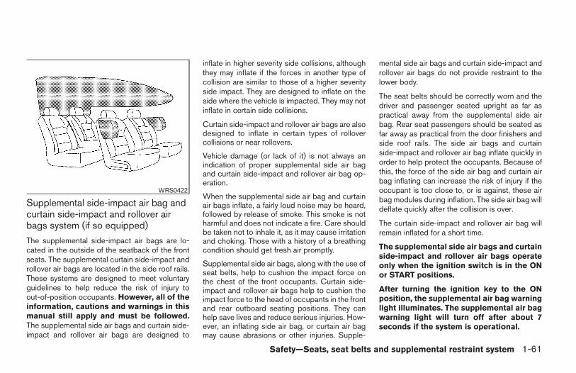
Supplemental side-impact air bag andcurtain side-impact and rollover airbags system (if so equipped)
The supplemental side-impact air bags are lo-cated in the outside of the seatback of the frontseats. The supplemental curtain side-impact androllover air bags are located in the side roof rails.These systems are designed to meet voluntaryguidelines to help reduce the risk of injury toout-of-position occupants. However, all of theinformation, cautions and warnings in thismanual still apply and must be followed.The supplemental side air bags and curtain side-impact and rollover air bags are designed to
inflate in higher severity side collisions, althoughthey may inflate if the forces in another type ofcollision are similar to those of a higher severityside impact. They are designed to inflate on theside where the vehicle is impacted. They may notinflate in certain side collisions.
Curtain side-impact and rollover air bags are alsodesigned to inflate in certain types of rollovercollisions or near rollovers.
Vehicle damage (or lack of it) is not always anindication of proper supplemental side air bagand curtain side-impact and rollover air bag op-eration.
When the supplemental side air bag and curtainair bags inflate, a fairly loud noise may be heard,followed by release of smoke. This smoke is notharmful and does not indicate a fire. Care shouldbe taken not to inhale it, as it may cause irritationand choking. Those with a history of a breathingcondition should get fresh air promptly.
Supplemental side air bags, along with the use ofseat belts, help to cushion the impact force onthe chest of the front occupants. Curtain side-impact and rollover air bags help to cushion theimpact force to the head of occupants in the frontand rear outboard seating positions. They canhelp save lives and reduce serious injuries. How-ever, an inflating side air bag, or curtain air bagmay cause abrasions or other injuries. Supple-
mental side air bags and curtain side-impact androllover air bags do not provide restraint to thelower body.
The seat belts should be correctly worn and thedriver and passenger seated upright as far aspractical away from the supplemental side airbag. Rear seat passengers should be seated asfar away as practical from the door finishers andside roof rails. The side air bags and curtainside-impact and rollover air bag inflate quickly inorder to help protect the occupants. Because ofthis, the force of the side air bag and curtain airbag inflating can increase the risk of injury if theoccupant is too close to, or is against, these airbag modules during inflation. The side air bag willdeflate quickly after the collision is over.
The curtain side-impact and rollover air bag willremain inflated for a short time.
The supplemental side air bags and curtainside-impact and rollover air bags operateonly when the ignition switch is in the ONor START positions.
After turning the ignition key to the ONposition, the supplemental air bag warninglight illuminates. The supplemental air bagwarning light will turn off after about 7seconds if the system is operational.
WRS0422
Safety—Seats, seat belts and supplemental restraint system 1-61
Z REVIEW COPY—2006 Truck/Frontier (d22)Owners Manual—USA_English (nna)10/14/05—debbie X
WARNING
● Do not place any objects near the seat-back of the front seats. Also, do notplace any objects (an umbrella, bag,etc.) between the front door finisherand the front seat. Such objects maybecome dangerous projectiles andcause injury if the supplemental side airbag inflates.
● Right after inflation, several side air bagand curtain side-impact and rollover airbag system components will be hot. Donot touch them; you may severely burnyourself.
● No unauthorized changes should bemade to any components or wiring ofthe side air bag and curtain air bagsystem. This is to prevent accidentalinflation of the side air bag and curtainair bag or damage to the side air bagand curtain air bag system.
● Do not make unauthorized changes toyour vehicle’s electrical system, sus-pension system or side panel. Thiscould affect proper operation of thesupplemental curtain air bag system.
● Tampering with the supplemental sideair bag system may result in seriouspersonal injury. For example, do notchange the front seats by placing mate-rial near the seatbacks or by installingadditional trim material, such as seatcovers, around the side air bag.
● Work around and on the curtain air bagsystem should be done by a NISSANdealer. Installation of electrical equip-ment should also be done by a NISSANdealer. The SRS wiring harnesses*should not be modified or discon-nected. Unauthorized electrical testequipment and probing devices shouldnot be used on the side air bag or cur-tain air bag system.
* The SRS wiring harness or connectors areyellow or orange for easy identification.
When selling your vehicle, we request that youinform the buyer about the supplemental side airbag and curtain air bag system and guide thebuyer to the appropriate sections in this Owner’sManual.
Pre-tensioner seat belt system (Frontseats)
WARNING
● The pre-tensioner seat belt cannot bereused after activation. It must be re-placed together with the retractor andbuckle as a unit.
● If the vehicle becomes involved in afrontal collision but the pre-tensioner isnot activated, be sure to have the pre-tensioner system checked and, if nec-essary, replaced by your NISSANdealer.
● No unauthorized changes should bemade to any components or wiring ofthe pre-tensioner seat belt system. Thisis to prevent accidental activation ofthe pre-tensioner seat belt or damageto the pre-tensioner seat belt operation.Tampering with the pre-tensioner seatbelt system may result in serious per-sonal injury.
1-62 Safety—Seats, seat belts and supplemental restraint system
Z REVIEW COPY—2006 Truck/Frontier (d22)Owners Manual—USA_English (nna)10/14/05—debbie X
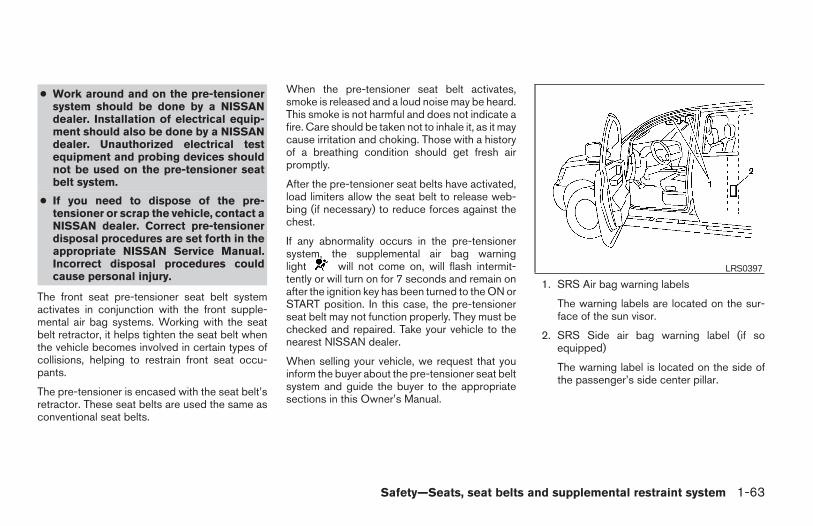
● Work around and on the pre-tensionersystem should be done by a NISSANdealer. Installation of electrical equip-ment should also be done by a NISSANdealer. Unauthorized electrical testequipment and probing devices shouldnot be used on the pre-tensioner seatbelt system.
● If you need to dispose of the pre-tensioner or scrap the vehicle, contact aNISSAN dealer. Correct pre-tensionerdisposal procedures are set forth in theappropriate NISSAN Service Manual.Incorrect disposal procedures couldcause personal injury.
The front seat pre-tensioner seat belt systemactivates in conjunction with the front supple-mental air bag systems. Working with the seatbelt retractor, it helps tighten the seat belt whenthe vehicle becomes involved in certain types ofcollisions, helping to restrain front seat occu-pants.
The pre-tensioner is encased with the seat belt’sretractor. These seat belts are used the same asconventional seat belts.
When the pre-tensioner seat belt activates,smoke is released and a loud noise may be heard.This smoke is not harmful and does not indicate afire. Care should be taken not to inhale it, as it maycause irritation and choking. Those with a historyof a breathing condition should get fresh airpromptly.
After the pre-tensioner seat belts have activated,load limiters allow the seat belt to release web-bing (if necessary) to reduce forces against thechest.
If any abnormality occurs in the pre-tensionersystem, the supplemental air bag warninglight will not come on, will flash intermit-tently or will turn on for 7 seconds and remain onafter the ignition key has been turned to the ON orSTART position. In this case, the pre-tensionerseat belt may not function properly. They must bechecked and repaired. Take your vehicle to thenearest NISSAN dealer.
When selling your vehicle, we request that youinform the buyer about the pre-tensioner seat beltsystem and guide the buyer to the appropriatesections in this Owner’s Manual.
1. SRS Air bag warning labels
The warning labels are located on the sur-face of the sun visor.
2. SRS Side air bag warning label (if soequipped)
The warning label is located on the side ofthe passenger’s side center pillar.
LRS0397
Safety—Seats, seat belts and supplemental restraint system 1-63
Z REVIEW COPY—2006 Truck/Frontier (d22)Owners Manual—USA_English (nna)10/14/05—debbie X
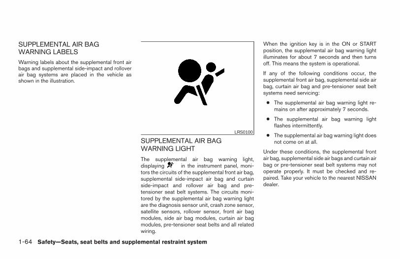
SUPPLEMENTAL AIR BAGWARNING LABELSWarning labels about the supplemental front airbags and supplemental side-impact and rolloverair bag systems are placed in the vehicle asshown in the illustration.
SUPPLEMENTAL AIR BAGWARNING LIGHT
The supplemental air bag warning light,displaying in the instrument panel, moni-tors the circuits of the supplemental front air bag,supplemental side-impact air bag and curtainside-impact and rollover air bag and pre-tensioner seat belt systems. The circuits moni-tored by the supplemental air bag warning lightare the diagnosis sensor unit, crash zone sensor,satellite sensors, rollover sensor, front air bagmodules, side air bag modules, curtain air bagmodules, pre-tensioner seat belts and all relatedwiring.
When the ignition key is in the ON or STARTposition, the supplemental air bag warning lightilluminates for about 7 seconds and then turnsoff. This means the system is operational.
If any of the following conditions occur, thesupplemental front air bag, supplemental side airbag, curtain air bag and pre-tensioner seat beltsystems need servicing:
● The supplemental air bag warning light re-mains on after approximately 7 seconds.
● The supplemental air bag warning lightflashes intermittently.
● The supplemental air bag warning light doesnot come on at all.
Under these conditions, the supplemental frontair bag, supplemental side air bags and curtain airbag or pre-tensioner seat belt systems may notoperate properly. It must be checked and re-paired. Take your vehicle to the nearest NISSANdealer.
LRS0100
1-64 Safety—Seats, seat belts and supplemental restraint system
Z REVIEW COPY—2006 Truck/Frontier (d22)Owners Manual—USA_English (nna)10/14/05—debbie X
WARNING
If the supplemental air bag warning lightis on, it could mean that the supplementalfront air bag, supplemental side air bag,curtain air bag systems and/or pre-tensioner seat belt systems will not oper-ate in an accident. To help avoid injury toyourself or others, have your vehiclechecked by a NISSAN dealer as soon aspossible.
Repair and replacement procedure
The supplemental front air bags, supplementalside air bags, curtain air bags and pre-tensionerseat belts are designed to inflate on a one-time-only basis. As a reminder, unless it is damaged,the supplemental air bag warning light remainsilluminated after inflation has occurred. Repairand replacement of these supplemental air bagsystems should be done only by a NISSANdealer.
When maintenance work is required on the ve-hicle, the supplemental front air bags, supple-mental side air bags, curtain air bags, pre-tensioner seat belts and related parts should bepointed out to the person performing the mainte-nance. The ignition key should always be in theLOCK position when working under the hood orinside the vehicle.
WARNING
● Once a supplemental front air bag,supplemental side air bag or curtain airbag has inflated, the air bag module willnot function again and must be re-placed. Additionally, if any of thesupplemental front air bags inflate, theactivated pre-tensioner seat belts mustalso be replaced. The air bag moduleand pre-tensioner seat belt systemshould be replaced by a NISSAN dealer.The air bag module and pre-tensionerseat belt system cannot be repaired.
● The supplemental front air bag, side airbag and curtain air bag systems, andthe pre-tensioner seat belt systemshould be inspected by a NISSANdealer if there is any damage to thefront end or side portion of the vehicle.
● If you need to dispose of the supple-mental air bag, pre-tensioner seat beltsystem or scrap the vehicle, contact aNISSAN dealer. Correct supplementalair bag and pre-tensioner seat belt sys-tem disposal procedures are set forth inthe appropriate NISSAN ServiceManual. Incorrect disposal procedurescould cause personal injury.
Safety—Seats, seat belts and supplemental restraint system 1-65
Z REVIEW COPY—2006 Truck/Frontier (d22)Owners Manual—USA_English (nna)10/14/05—debbie X
2 Instruments and controls
Instrument panel. . . . . . . . . . . . . . . . . . . . . . . . . . . . . . . . . . . 2-2Meters and gauges . . . . . . . . . . . . . . . . . . . . . . . . . . . . . . . . 2-3
Speedometer and odometer . . . . . . . . . . . . . . . . . . . . . 2-4Trip computer (if so equipped) . . . . . . . . . . . . . . . . . . . 2-5Tachometer . . . . . . . . . . . . . . . . . . . . . . . . . . . . . . . . . . . . 2-6Engine coolant temperature gauge . . . . . . . . . . . . . . . 2-6Fuel gauge . . . . . . . . . . . . . . . . . . . . . . . . . . . . . . . . . . . . 2-7Engine oil pressure gauge (if so equipped) . . . . . . . . 2-8Voltmeter (if so equipped) . . . . . . . . . . . . . . . . . . . . . . . 2-8
Compass and outside temperature display(if so equipped) . . . . . . . . . . . . . . . . . . . . . . . . . . . . . . . . . . . 2-9
Outside temperature display . . . . . . . . . . . . . . . . . . . . . 2-9Compass display . . . . . . . . . . . . . . . . . . . . . . . . . . . . . .2-10
Warning/indicator lights and audible reminders . . . . . . 2-12Checking bulbs . . . . . . . . . . . . . . . . . . . . . . . . . . . . . . .2-12Warning lights . . . . . . . . . . . . . . . . . . . . . . . . . . . . . . . .2-13Indicator lights . . . . . . . . . . . . . . . . . . . . . . . . . . . . . . . .2-17Audible reminders . . . . . . . . . . . . . . . . . . . . . . . . . . . . .2-21
Security systems (if so equipped) . . . . . . . . . . . . . . . . . . 2-21Vehicle security system (if so equipped) . . . . . . . . . . 2-21NISSAN vehicle immobilizer system(if so equipped) . . . . . . . . . . . . . . . . . . . . . . . . . . . . . . .2-22
Windshield wiper and washer switch . . . . . . . . . . . . . . . 2-23
Switch operation . . . . . . . . . . . . . . . . . . . . . . . . . . . . . .2-23Rear window and outside mirror defroster switch(if so equipped) . . . . . . . . . . . . . . . . . . . . . . . . . . . . . . . . . .2-24Headlight and turn signal switch. . . . . . . . . . . . . . . . . . . . 2-25
Headlight control switch. . . . . . . . . . . . . . . . . . . . . . . . 2-25Daytime running light system (Canada only) . . . . . . 2-27Instrument brightness control . . . . . . . . . . . . . . . . . . . 2-28Turn signal switch . . . . . . . . . . . . . . . . . . . . . . . . . . . . .2-28Fog light switch (if so equipped) . . . . . . . . . . . . . . . . 2-28
Hazard warning flasher switch . . . . . . . . . . . . . . . . . . . . . 2-29Horn . . . . . . . . . . . . . . . . . . . . . . . . . . . . . . . . . . . . . . . . . . . .2-29Cargo lamp switch . . . . . . . . . . . . . . . . . . . . . . . . . . . . . . .2-30Heated seat (if so equipped). . . . . . . . . . . . . . . . . . . . . . . 2-30Vehicle dynamic control (VDC) off switch(if so equipped) . . . . . . . . . . . . . . . . . . . . . . . . . . . . . . . . . .2-31Hill descent control (HDC) switch (if so equipped) . . . 2-31Electronic locking rear differential (E-Lock) systemswitch (if so equipped) . . . . . . . . . . . . . . . . . . . . . . . . . . . .2-32Clutch interlock (clutch start) switch(if so equipped) . . . . . . . . . . . . . . . . . . . . . . . . . . . . . . . . . .2-33Power outlet . . . . . . . . . . . . . . . . . . . . . . . . . . . . . . . . . . . . .2-34Storage . . . . . . . . . . . . . . . . . . . . . . . . . . . . . . . . . . . . . . . . .2-35
Storage trays . . . . . . . . . . . . . . . . . . . . . . . . . . . . . . . . .2-35
Z REVIEW COPY—2006 Truck/Frontier (d22)Owners Manual—USA_English (nna)10/14/05—debbie X
Under-seat storage bins. . . . . . . . . . . . . . . . . . . . . . . . 2-36Console box . . . . . . . . . . . . . . . . . . . . . . . . . . . . . . . . . .2-38Glove box . . . . . . . . . . . . . . . . . . . . . . . . . . . . . . . . . . . .2-38Sunglasses holder (if so equipped) . . . . . . . . . . . . . . 2-38Map pockets . . . . . . . . . . . . . . . . . . . . . . . . . . . . . . . . . .2-39Seat pockets (if so equipped) . . . . . . . . . . . . . . . . . . . 2-40Cup holders . . . . . . . . . . . . . . . . . . . . . . . . . . . . . . . . . .2-41Roof rack (if so equipped) . . . . . . . . . . . . . . . . . . . . . . 2-43
Windows . . . . . . . . . . . . . . . . . . . . . . . . . . . . . . . . . . . . . . . .2-44Power windows (if so equipped) . . . . . . . . . . . . . . . . 2-44Manual windows . . . . . . . . . . . . . . . . . . . . . . . . . . . . . .2-46Rear sliding window (if so equipped) . . . . . . . . . . . . 2-46
Sunroof (if so equipped). . . . . . . . . . . . . . . . . . . . . . . . . . . 2-47Automatic sunroof . . . . . . . . . . . . . . . . . . . . . . . . . . . . .2-47
Interior lights . . . . . . . . . . . . . . . . . . . . . . . . . . . . . . . . . . . . .2-48Personal lights (if so equipped) . . . . . . . . . . . . . . . . . . . . 2-50Map lights (if so equipped) . . . . . . . . . . . . . . . . . . . . . . . . 2-50HomeLinkT universal transceiver (if so equipped). . . . . 2-50
Programming HomeLinkT. . . . . . . . . . . . . . . . . . . . . . . 2-51Programming HomeLinkT for Canadiancustomers . . . . . . . . . . . . . . . . . . . . . . . . . . . . . . . . . . . .2-52Operating the HomeLinkT universaltransceiver. . . . . . . . . . . . . . . . . . . . . . . . . . . . . . . . . . . .2-52Programming trouble-diagnosis . . . . . . . . . . . . . . . . . 2-53Clearing the programmed information . . . . . . . . . . . . 2-53Reprogramming a single HomeLinkT button . . . . . . 2-53If your vehicle is stolen . . . . . . . . . . . . . . . . . . . . . . . . . 2-53
Z REVIEW COPY—2006 Truck/Frontier (d22)Owners Manual—USA_English (nna)10/14/05—debbie X
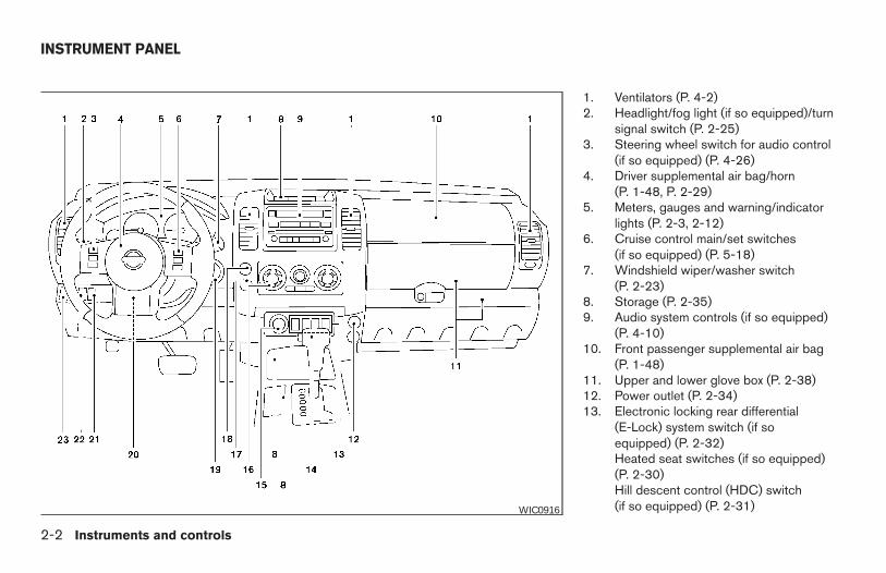
1. Ventilators (P. 4-2)2. Headlight/fog light (if so equipped)/turn
signal switch (P. 2-25)3. Steering wheel switch for audio control
(if so equipped) (P. 4-26)4. Driver supplemental air bag/horn
(P. 1-48, P. 2-29)5. Meters, gauges and warning/indicator
lights (P. 2-3, 2-12)6. Cruise control main/set switches
(if so equipped) (P. 5-18)7. Windshield wiper/washer switch
(P. 2-23)8. Storage (P. 2-35)9. Audio system controls (if so equipped)
(P. 4-10)10. Front passenger supplemental air bag
(P. 1-48)11. Upper and lower glove box (P. 2-38)12. Power outlet (P. 2-34)13. Electronic locking rear differential
(E-Lock) system switch (if soequipped) (P. 2-32)Heated seat switches (if so equipped)(P. 2-30)Hill descent control (HDC) switch(if so equipped) (P. 2-31)WIC0916
INSTRUMENT PANEL
2-2 Instruments and controls
Z REVIEW COPY—2006 Truck/Frontier (d22)Owners Manual—USA_English (nna)10/14/05—debbie X
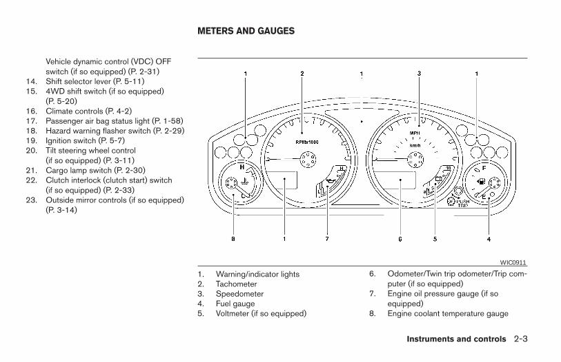
Vehicle dynamic control (VDC) OFFswitch (if so equipped) (P. 2-31)
14. Shift selector lever (P. 5-11)15. 4WD shift switch (if so equipped)
(P. 5-20)16. Climate controls (P. 4-2)17. Passenger air bag status light (P. 1-58)18. Hazard warning flasher switch (P. 2-29)19. Ignition switch (P. 5-7)20. Tilt steering wheel control
(if so equipped) (P. 3-11)21. Cargo lamp switch (P. 2-30)22. Clutch interlock (clutch start) switch
(if so equipped) (P. 2-33)23. Outside mirror controls (if so equipped)
(P. 3-14)
1. Warning/indicator lights2. Tachometer3. Speedometer4. Fuel gauge5. Voltmeter (if so equipped)
6. Odometer/Twin trip odometer/Trip com-puter (if so equipped)
7. Engine oil pressure gauge (if soequipped)
8. Engine coolant temperature gauge
WIC0911
METERS AND GAUGES
Instruments and controls 2-3
Z REVIEW COPY—2006 Truck/Frontier (d22)Owners Manual—USA_English (nna)10/14/05—debbie X
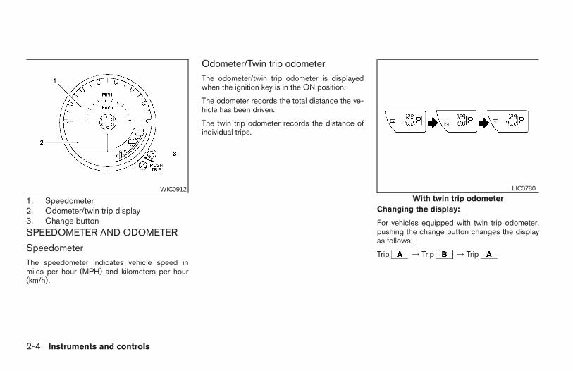
1. Speedometer2. Odometer/twin trip display3. Change buttonSPEEDOMETER AND ODOMETER
SpeedometerThe speedometer indicates vehicle speed inmiles per hour (MPH) and kilometers per hour(km/h).
Odometer/Twin trip odometerThe odometer/twin trip odometer is displayedwhen the ignition key is in the ON position.
The odometer records the total distance the ve-hicle has been driven.
The twin trip odometer records the distance ofindividual trips.
Changing the display:
For vehicles equipped with twin trip odometer,pushing the change button changes the displayas follows:
Trip → Trip → Trip
WIC0912With twin trip odometer
LIC0780
2-4 Instruments and controls
Z REVIEW COPY—2006 Truck/Frontier (d22)Owners Manual—USA_English (nna)10/14/05—debbie X
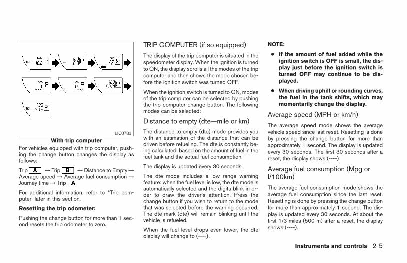
For vehicles equipped with trip computer, push-ing the change button changes the display asfollows:
Trip → Trip → Distance to Empty →Average speed → Average fuel consumption →Journey time → Trip
For additional information, refer to “Trip com-puter” later in this section.
Resetting the trip odometer:
Pushing the change button for more than 1 sec-ond resets the trip odometer to zero.
TRIP COMPUTER (if so equipped)
The display of the trip computer is situated in thespeedometer display. When the ignition is turnedto ON, the display scrolls all the modes of the tripcomputer and then shows the mode chosen be-fore the ignition switch was turned OFF.
When the ignition switch is turned to ON, modesof the trip computer can be selected by pushingthe trip computer change button. The followingmodes can be selected:
Distance to empty (dte—mile or km)The distance to empty (dte) mode provides youwith an estimation of the distance that can bedriven before refueling. The dte is constantly be-ing calculated, based on the amount of fuel in thefuel tank and the actual fuel consumption.
The display is updated every 30 seconds.
The dte mode includes a low range warningfeature: when the fuel level is low, the dte mode isautomatically selected and the digits blink in or-der to draw the driver’s attention. Press thechange button if you wish to return to the modethat was selected before the warning occurred.The dte mark (dte) will remain blinking until thevehicle is refueled.
When the fuel level drops even lower, the dtedisplay will change to (----).
NOTE:
● If the amount of fuel added while theignition switch is OFF is small, the dis-play just before the ignition switch isturned OFF may continue to be dis-played.
● When driving uphill or rounding curves,the fuel in the tank shifts, which maymomentarily change the display.
Average speed (MPH or km/h)
The average speed mode shows the averagevehicle speed since last reset. Resetting is doneby pressing the change button for more thanapproximately 1 second. The display is updatedevery 30 seconds. The first 30 seconds after areset, the display shows (----).
Average fuel consumption (Mpg orl/100km)
The average fuel consumption mode shows theaverage fuel consumption since the last reset.Resetting is done by pressing the change buttonfor more than approximately 1 second. The dis-play is updated every 30 seconds. At about thefirst 1/3 miles (500 m) after a reset, the displayshows (----).
With trip computerLIC0781
Instruments and controls 2-5
Z REVIEW COPY—2006 Truck/Frontier (d22)Owners Manual—USA_English (nna)10/14/05—debbie X
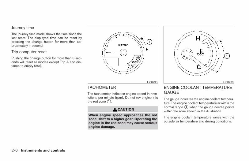
Journey timeThe journey time mode shows the time since thelast reset. The displayed time can be reset bypressing the change button for more than ap-proximately 1 second.
Trip computer resetPushing the change button for more than 3 sec-onds will reset all modes except Trip A and dis-tance to empty (dte).
TACHOMETERThe tachometer indicates engine speed in revo-lutions per minute (rpm). Do not rev engine intothe red zone s1 .
CAUTION
When engine speed approaches the redzone, shift to a higher gear. Operating theengine in the red zone may cause seriousengine damage.
ENGINE COOLANT TEMPERATUREGAUGE
The gauge indicates the engine coolant tempera-ture. The engine coolant temperature is within thenormal range s1 when the gauge needle pointswithin the zone shown in the illustration.
The engine coolant temperature varies with theoutside air temperature and driving conditions.
LIC0738 LIC0739
2-6 Instruments and controls
Z REVIEW COPY—2006 Truck/Frontier (d22)Owners Manual—USA_English (nna)10/14/05—debbie X
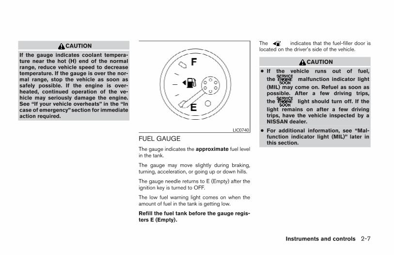
CAUTION
If the gauge indicates coolant tempera-ture near the hot (H) end of the normalrange, reduce vehicle speed to decreasetemperature. If the gauge is over the nor-mal range, stop the vehicle as soon assafely possible. If the engine is over-heated, continued operation of the ve-hicle may seriously damage the engine.See “If your vehicle overheats” in the “Incase of emergency”section for immediateaction required.
FUEL GAUGE
The gauge indicates the approximate fuel levelin the tank.
The gauge may move slightly during braking,turning, acceleration, or going up or down hills.
The gauge needle returns to E (Empty) after theignition key is turned to OFF.
The low fuel warning light comes on when theamount of fuel in the tank is getting low.
Refill the fuel tank before the gauge regis-ters E (Empty).
The indicates that the fuel-filler door islocated on the driver’s side of the vehicle.
CAUTION
● If the vehicle runs out of fuel,
the malfunction indicator light
(MIL) may come on. Refuel as soon aspossible. After a few driving trips,
the light should turn off. If the
light remains on after a few drivingtrips, have the vehicle inspected by aNISSAN dealer.
● For additional information, see “Mal-function indicator light (MIL)” later inthis section.
LIC0740
Instruments and controls 2-7
Z REVIEW COPY—2006 Truck/Frontier (d22)Owners Manual—USA_English (nna)10/14/05—debbie X
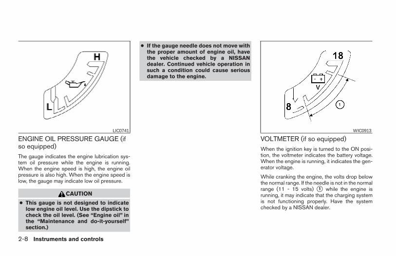
ENGINE OIL PRESSURE GAUGE (ifso equipped)The gauge indicates the engine lubrication sys-tem oil pressure while the engine is running.When the engine speed is high, the engine oilpressure is also high. When the engine speed islow, the gauge may indicate low oil pressure.
CAUTION
● This gauge is not designed to indicatelow engine oil level. Use the dipstick tocheck the oil level. (See “Engine oil” inthe “Maintenance and do-it-yourself”section.)
● If the gauge needle does not move withthe proper amount of engine oil, havethe vehicle checked by a NISSANdealer. Continued vehicle operation insuch a condition could cause seriousdamage to the engine.
VOLTMETER (if so equipped)When the ignition key is turned to the ON posi-tion, the voltmeter indicates the battery voltage.When the engine is running, it indicates the gen-erator voltage.
While cranking the engine, the volts drop belowthe normal range. If the needle is not in the normalrange (11 - 15 volts) s1 while the engine isrunning, it may indicate that the charging systemis not functioning properly. Have the systemchecked by a NISSAN dealer.
LIC0741 WIC0913
2-8 Instruments and controls
Z REVIEW COPY—2006 Truck/Frontier (d22)Owners Manual—USA_English (nna)10/14/05—debbie X
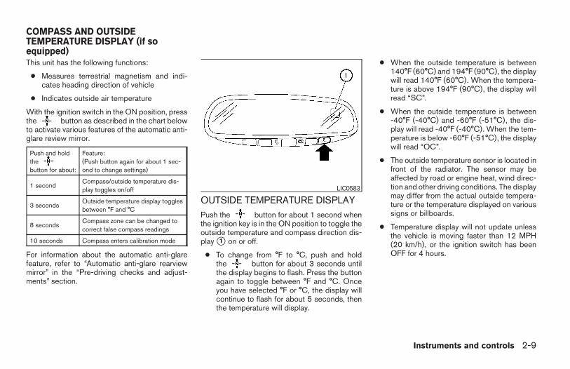
This unit has the following functions:
● Measures terrestrial magnetism and indi-cates heading direction of vehicle
● Indicates outside air temperature
With the ignition switch in the ON position, pressthe button as described in the chart belowto activate various features of the automatic anti-glare review mirror.
Push and holdthebutton for about:
Feature:(Push button again for about 1 sec-ond to change settings)
1 secondCompass/outside temperature dis-play toggles on/off
3 secondsOutside temperature display togglesbetween °F and °C
8 secondsCompass zone can be changed tocorrect false compass readings
10 seconds Compass enters calibration mode
For information about the automatic anti-glarefeature, refer to “Automatic anti-glare rearviewmirror” in the “Pre-driving checks and adjust-ments” section.
OUTSIDE TEMPERATURE DISPLAYPush the button for about 1 second whenthe ignition key is in the ON position to toggle theoutside temperature and compass direction dis-play s1 on or off.
● To change from °F to °C, push and holdthe button for about 3 seconds untilthe display begins to flash. Press the buttonagain to toggle between °F and °C. Onceyou have selected °F or °C, the display willcontinue to flash for about 5 seconds, thenthe temperature will display.
● When the outside temperature is between140°F (60°C) and 194°F (90°C), the displaywill read 140°F (60°C). When the tempera-ture is above 194°F (90°C), the display willread “SC”.
● When the outside temperature is between-40°F (-40°C) and -60°F (-51°C), the dis-play will read -40°F (-40°C). When the tem-perature is below -60°F (-51°C), the displaywill read “OC”.
● The outside temperature sensor is located infront of the radiator. The sensor may beaffected by road or engine heat, wind direc-tion and other driving conditions. The displaymay differ from the actual outside tempera-ture or the temperature displayed on varioussigns or billboards.
● Temperature display will not update unlessthe vehicle is moving faster than 12 MPH(20 km/h), or the ignition switch has beenOFF for 4 hours.
LIC0583
COMPASS AND OUTSIDETEMPERATURE DISPLAY (if soequipped)
Instruments and controls 2-9
Z REVIEW COPY—2006 Truck/Frontier (d22)Owners Manual—USA_English (nna)10/26/05—tbrooks X
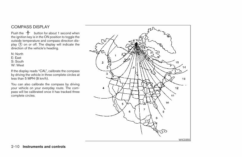
COMPASS DISPLAYPush the button for about 1 second whenthe ignition key is in the ON position to toggle theoutside temperature and compass direction dis-play s1 on or off. The display will indicate thedirection of the vehicle’s heading.
N: NorthE: EastS: SouthW: West
If the display reads “CAL”, calibrate the compassby driving the vehicle in three complete circles atless than 5 MPH (8 km/h).
You can also calibrate the compass by drivingyour vehicle on your everyday route. The com-pass will be calibrated once it has tracked threecomplete circles.
WIC0355
2-10 Instruments and controls
Z REVIEW COPY—2006 Truck/Frontier (d22)Owners Manual—USA_English (nna)10/14/05—debbie X
Zone variation change procedure
The difference between magnetic north and geo-graphical north is known as variance. In someareas, this difference can sometimes be greatenough to cause false compass readings. Followthese instructions to set the variance for yourparticular location if this happens:
1. Press and hold the button for about 8seconds. The current zone number will ap-pear in the display. Release the button.
2. Find your current location on the zone map.Refer to the illustration.
3. Press the button repeatedly to togglethrough the zone numbers until the desirednumber appears in the display. Once youhave selected a zone number, the displaywill show a compass direction within a fewseconds.
Inaccurate compass direction
The compass display is equipped with automaticcorrection function. If the correct direction is notshown, follow this procedure.
1. With the display turned on, press and holdthe button for about 10 seconds. The“CAL” icon in the compass display will illu-minate.
2. Calibrate the compass by driving the vehiclein three complete circles at a maximumspeed of 5 MPH (8 km/h).
3. After completing the circles, the displayshould return to normal.
● If the compass deviates from the correctindication soon after repeated adjustment,have the compass checked at an authorizeddealer.
● The compass may not indicate the correctcompass point in tunnels or while driving upor down a steep hill. (The compass returnsto the correct compass point when the ve-hicle moves to an area where the geomag-netism is stabilized.)
● If a magnet is located in or near the overheadconsole in the front of the vehicle or thevehicle is driven where the terrestrial mag-netism is disturbed, the compass displaymay not indicate the correct direction.
CAUTION
● Do not install a ski rack, antenna, etc.,which are attached to the vehicle bymeans of a magnet. They affect the op-eration of the compass.
● When cleaning the mirror, use a papertowel or similar material dampenedwith glass cleaner. Do not spray glasscleaner directly on the mirror as it maycause the liquid cleaner to enter themirror housing.
Instruments and controls 2-11
Z REVIEW COPY—2006 Truck/Frontier (d22)Owners Manual—USA_English (nna)10/14/05—debbie X
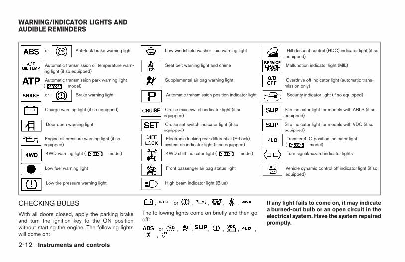
or Anti-lock brake warning light Low windshield washer fluid warning light Hill descent control (HDC) indicator light (if soequipped)
Automatic transmission oil temperature warn-ing light (if so equipped)
Seat belt warning light and chime Malfunction indicator light (MIL)
Automatic transmission park warning light( model)
Supplemental air bag warning light Overdrive off indicator light (automatic trans-mission only)
or Brake warning light Automatic transmission position indicator light Security indicator light (if so equipped)
Charge warning light (if so equipped) Cruise main switch indicator light (if soequipped)
Slip indicator light for models with ABLS (if soequipped)
Door open warning light Cruise set switch indicator light (if soequipped)
Slip indicator light for models with VDC (if soequipped)
Engine oil pressure warning light (if soequipped)
Electronic locking rear differential (E-Lock)system on indicator light (if so equipped)
Transfer 4LO position indicator light( model)
4WD warning light ( model) 4WD shift indicator light ( model) Turn signal/hazard indicator lights
Low fuel warning light Front passenger air bag status light Vehicle dynamic control off indicator light (if soequipped)
Low tire pressure warning light High beam indicator light (Blue)
CHECKING BULBS
With all doors closed, apply the parking brakeand turn the ignition key to the ON positionwithout starting the engine. The following lightswill come on:
, or , , , ,
The following lights come on briefly and then gooff:
or , , , , , ,,
If any light fails to come on, it may indicatea burned-out bulb or an open circuit in theelectrical system. Have the system repairedpromptly.
WARNING/INDICATOR LIGHTS ANDAUDIBLE REMINDERS
2-12 Instruments and controls
Z REVIEW COPY—2006 Truck/Frontier (d22)Owners Manual—USA_English (nna)10/14/05—debbie X
WARNING LIGHTSor Anti-lock brake
warning light
If the light comes on while the engine is running,it may indicate the anti-lock brake system is notfunctioning properly. Have the system checkedby a NISSAN dealer.
If an abnormality occurs in the system, the anti-lock function ceases, but the regular brakingsystem continues to operate.
If the light comes on while you are driving,contact a NISSAN dealer for repair.
The ABS system will be disabled and the ABSlight will illuminate when the electronic lockingrear differential (E-Lock) system switch (if soequipped) is turned on and the E-Lock system isengaged. If the E-Lock system disengages or theswitch is turned off, the ABS system will beenabled and the ABS light will turn off.
Automatic transmission oiltemperature warning light (ifso equipped)
This light comes on when the automatic transmis-sion oil temperature is too high. If the light comeson while driving, reduce the vehicle speed assoon as safely possible until the light turns off.
CAUTION
Continued vehicle operation when the A/Toil temperature warning light is on maydamage the automatic transmission.
Automatic transmission parkwarning light ( model)
WARNING
● If the ATP light is ON, this indicates thatthe automatic transmission P (Park) po-sition will not function and the transfercase is in neutral.
● When parking, always make sure thatthe 4WD shift indicator light illuminatesand the parking brake is set. Failure toengage the transfer position in 2WD, 4Hor 4LO could result in the vehicle mov-ing unexpectedly, resulting in seriouspersonal injury or property damage.
● Shift the 4WD switch into the 2WD, 4Hor 4LO position again to turn off the ATPwarning light when the automatic trans-mission selector lever is in the P posi-tion and the ATP warning light is ON.(Before shifting the 4WD switch into the4LO position, move the automatictransmission selector lever into the Nposition once, shift the selector leverinto P again and make sure the ATPwarning light is OFF.)
This light indicates that the automatic transmis-sion parking function is not engaged. If the trans-fer control is not secured in any drive positionwhile the automatic transmission selector lever isin the P (Park) position, the transmission willdisengage and the drive wheels will not lock.
or Brake warning light
This light functions for both the parking brake andthe foot brake systems.
Parking brake indicator
When the ignition key is in the ON position, thelight comes on when the parking brake is applied.
Instruments and controls 2-13
Z REVIEW COPY—2006 Truck/Frontier (d22)Owners Manual—USA_English (nna)10/14/05—debbie X
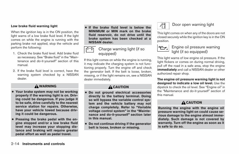
Low brake fluid warning light
When the ignition key is in the ON position, thelight warns of a low brake fluid level. If the lightcomes on while the engine is running with theparking brake not applied, stop the vehicle andperform the following:
1. Check the brake fluid level. Add brake fluidas necessary. See “Brake fluid” in the “Main-tenance and do-it-yourself” section of thismanual.
2. If the brake fluid level is correct, have thewarning system checked by a NISSANdealer.
WARNING
● Your brake system may not be workingproperly if the warning light is on. Driv-ing could be dangerous. If you judge itto be safe, drive carefully to the nearestservice station for repairs. Otherwise,have your vehicle towed because driv-ing it could be dangerous.
● Pressing the brake pedal with the en-gine stopped and/or a low brake fluidlevel may increase your stopping dis-tance and braking will require greaterpedal effort as well as pedal travel.
● If the brake fluid level is below theMINIMUM or MIN mark on the brakefluid reservoir, do not drive until thebrake system has been checked at aNISSAN dealer.
Charge warning light (if soequipped)
If this light comes on while the engine is running,it may indicate the charging system is not func-tioning properly. Turn the engine off and checkthe generator belt. If the belt is loose, broken,missing, or if the light remains on, see a NISSANdealer immediately.
CAUTION
● Do not ground electrical accessoriesdirectly to the battery terminal. Doingso will bypass the variable control sys-tem and the vehicle battery may notcharge completely. Refer to “Variablevoltage control system” in the “Mainte-nance and do-it-yourself” section laterin this manual.
● Do not continue driving if the generatorbelt is loose, broken or missing.
Door open warning light
This light comes on when any of the doors are notclosed securely while the ignition key is in the ONposition.
Engine oil pressure warninglight (if so equipped)
This light warns of low engine oil pressure. If thelight flickers or comes on during normal driving,pull off the road in a safe area, stop the engineimmediately and call a NISSAN dealer or otherauthorized repair shop.
The engine oil pressure warning light is notdesigned to indicate a low oil level. Use thedipstick to check the oil level. See “Engine oil” inthe “Maintenance and do-it-yourself” section ofthis manual.
CAUTION
Running the engine with the engine oilpressure warning light on could cause se-rious damage to the engine almost imme-diately. Such damage is not covered bywarranty. Turn off the engine as soon as itis safe to do so.
2-14 Instruments and controls
Z REVIEW COPY—2006 Truck/Frontier (d22)Owners Manual—USA_English (nna)10/14/05—debbie X
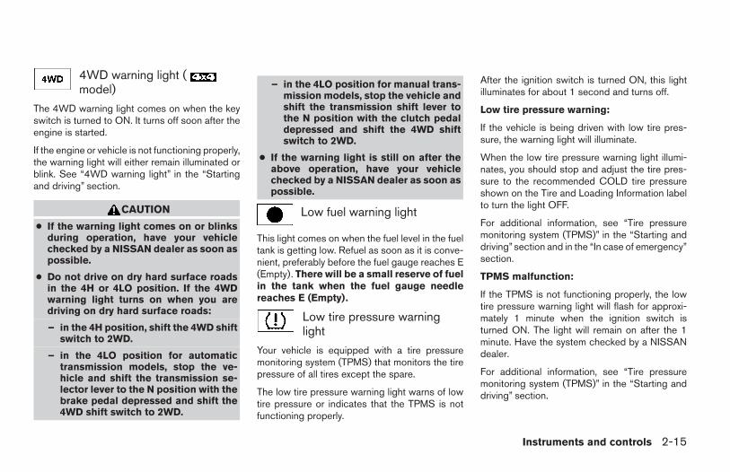
4WD warning light (model)
The 4WD warning light comes on when the keyswitch is turned to ON. It turns off soon after theengine is started.
If the engine or vehicle is not functioning properly,the warning light will either remain illuminated orblink. See “4WD warning light” in the “Startingand driving” section.
CAUTION
● If the warning light comes on or blinksduring operation, have your vehiclechecked by a NISSAN dealer as soon aspossible.
● Do not drive on dry hard surface roadsin the 4H or 4LO position. If the 4WDwarning light turns on when you aredriving on dry hard surface roads:
– in the 4H position, shift the 4WD shiftswitch to 2WD.
– in the 4LO position for automatictransmission models, stop the ve-hicle and shift the transmission se-lector lever to the N position with thebrake pedal depressed and shift the4WD shift switch to 2WD.
– in the 4LO position for manual trans-mission models, stop the vehicle andshift the transmission shift lever tothe N position with the clutch pedaldepressed and shift the 4WD shiftswitch to 2WD.
● If the warning light is still on after theabove operation, have your vehiclechecked by a NISSAN dealer as soon aspossible.
Low fuel warning light
This light comes on when the fuel level in the fueltank is getting low. Refuel as soon as it is conve-nient, preferably before the fuel gauge reaches E(Empty). There will be a small reserve of fuelin the tank when the fuel gauge needlereaches E (Empty).
Low tire pressure warninglight
Your vehicle is equipped with a tire pressuremonitoring system (TPMS) that monitors the tirepressure of all tires except the spare.
The low tire pressure warning light warns of lowtire pressure or indicates that the TPMS is notfunctioning properly.
After the ignition switch is turned ON, this lightilluminates for about 1 second and turns off.
Low tire pressure warning:
If the vehicle is being driven with low tire pres-sure, the warning light will illuminate.
When the low tire pressure warning light illumi-nates, you should stop and adjust the tire pres-sure to the recommended COLD tire pressureshown on the Tire and Loading Information labelto turn the light OFF.
For additional information, see “Tire pressuremonitoring system (TPMS)” in the “Starting anddriving”section and in the “In case of emergency”section.
TPMS malfunction:
If the TPMS is not functioning properly, the lowtire pressure warning light will flash for approxi-mately 1 minute when the ignition switch isturned ON. The light will remain on after the 1minute. Have the system checked by a NISSANdealer.
For additional information, see “Tire pressuremonitoring system (TPMS)” in the “Starting anddriving” section.
Instruments and controls 2-15
Z REVIEW COPY—2006 Truck/Frontier (d22)Owners Manual—USA_English (nna)10/14/05—debbie X
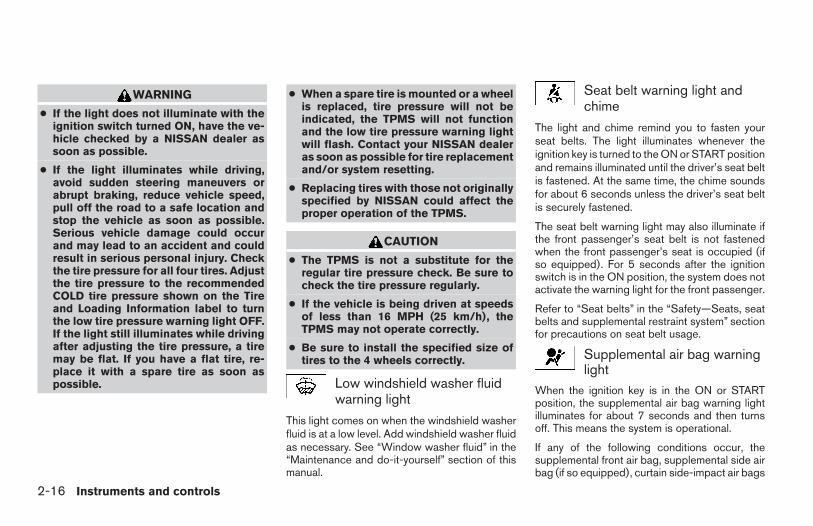
WARNING
● If the light does not illuminate with theignition switch turned ON, have the ve-hicle checked by a NISSAN dealer assoon as possible.
● If the light illuminates while driving,avoid sudden steering maneuvers orabrupt braking, reduce vehicle speed,pull off the road to a safe location andstop the vehicle as soon as possible.Serious vehicle damage could occurand may lead to an accident and couldresult in serious personal injury. Checkthe tire pressure for all four tires. Adjustthe tire pressure to the recommendedCOLD tire pressure shown on the Tireand Loading Information label to turnthe low tire pressure warning light OFF.If the light still illuminates while drivingafter adjusting the tire pressure, a tiremay be flat. If you have a flat tire, re-place it with a spare tire as soon aspossible.
● When a spare tire is mounted or a wheelis replaced, tire pressure will not beindicated, the TPMS will not functionand the low tire pressure warning lightwill flash. Contact your NISSAN dealeras soon as possible for tire replacementand/or system resetting.
● Replacing tires with those not originallyspecified by NISSAN could affect theproper operation of the TPMS.
CAUTION
● The TPMS is not a substitute for theregular tire pressure check. Be sure tocheck the tire pressure regularly.
● If the vehicle is being driven at speedsof less than 16 MPH (25 km/h), theTPMS may not operate correctly.
● Be sure to install the specified size oftires to the 4 wheels correctly.
Low windshield washer fluidwarning light
This light comes on when the windshield washerfluid is at a low level. Add windshield washer fluidas necessary. See “Window washer fluid” in the“Maintenance and do-it-yourself” section of thismanual.
Seat belt warning light andchime
The light and chime remind you to fasten yourseat belts. The light illuminates whenever theignition key is turned to the ON or START positionand remains illuminated until the driver’s seat beltis fastened. At the same time, the chime soundsfor about 6 seconds unless the driver’s seat beltis securely fastened.
The seat belt warning light may also illuminate ifthe front passenger’s seat belt is not fastenedwhen the front passenger’s seat is occupied (ifso equipped). For 5 seconds after the ignitionswitch is in the ON position, the system does notactivate the warning light for the front passenger.
Refer to “Seat belts” in the “Safety—Seats, seatbelts and supplemental restraint system” sectionfor precautions on seat belt usage.
Supplemental air bag warninglight
When the ignition key is in the ON or STARTposition, the supplemental air bag warning lightilluminates for about 7 seconds and then turnsoff. This means the system is operational.
If any of the following conditions occur, thesupplemental front air bag, supplemental side airbag (if so equipped), curtain side-impact air bags
2-16 Instruments and controls
Z REVIEW COPY—2006 Truck/Frontier (d22)Owners Manual—USA_English (nna)10/14/05—debbie X
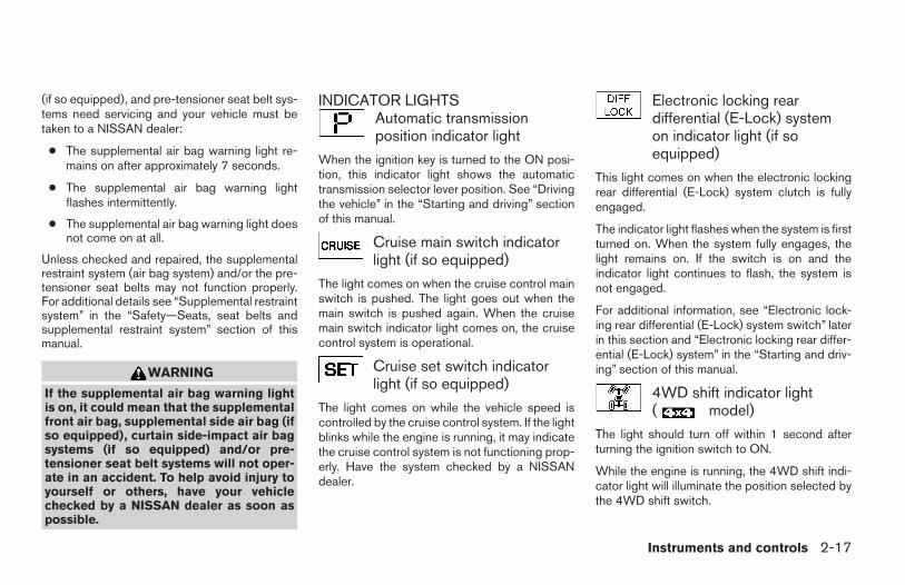
(if so equipped), and pre-tensioner seat belt sys-tems need servicing and your vehicle must betaken to a NISSAN dealer:
● The supplemental air bag warning light re-mains on after approximately 7 seconds.
● The supplemental air bag warning lightflashes intermittently.
● The supplemental air bag warning light doesnot come on at all.
Unless checked and repaired, the supplementalrestraint system (air bag system) and/or the pre-tensioner seat belts may not function properly.For additional details see “Supplemental restraintsystem” in the “Safety—Seats, seat belts andsupplemental restraint system” section of thismanual.
WARNING
If the supplemental air bag warning lightis on, it could mean that the supplementalfront air bag, supplemental side air bag (ifso equipped), curtain side-impact air bagsystems (if so equipped) and/or pre-tensioner seat belt systems will not oper-ate in an accident. To help avoid injury toyourself or others, have your vehiclechecked by a NISSAN dealer as soon aspossible.
INDICATOR LIGHTSAutomatic transmissionposition indicator light
When the ignition key is turned to the ON posi-tion, this indicator light shows the automatictransmission selector lever position. See “Drivingthe vehicle” in the “Starting and driving” sectionof this manual.
Cruise main switch indicatorlight (if so equipped)
The light comes on when the cruise control mainswitch is pushed. The light goes out when themain switch is pushed again. When the cruisemain switch indicator light comes on, the cruisecontrol system is operational.
Cruise set switch indicatorlight (if so equipped)
The light comes on while the vehicle speed iscontrolled by the cruise control system. If the lightblinks while the engine is running, it may indicatethe cruise control system is not functioning prop-erly. Have the system checked by a NISSANdealer.
Electronic locking reardifferential (E-Lock) systemon indicator light (if soequipped)
This light comes on when the electronic lockingrear differential (E-Lock) system clutch is fullyengaged.
The indicator light flashes when the system is firstturned on. When the system fully engages, thelight remains on. If the switch is on and theindicator light continues to flash, the system isnot engaged.
For additional information, see “Electronic lock-ing rear differential (E-Lock) system switch” laterin this section and “Electronic locking rear differ-ential (E-Lock) system” in the “Starting and driv-ing” section of this manual.
4WD shift indicator light( model)
The light should turn off within 1 second afterturning the ignition switch to ON.
While the engine is running, the 4WD shift indi-cator light will illuminate the position selected bythe 4WD shift switch.
Instruments and controls 2-17
Z REVIEW COPY—2006 Truck/Frontier (d22)Owners Manual—USA_English (nna)10/14/05—debbie X
The 4WD shift indicator light may blinkwhile shifting from one drive mode to theother.
Front passenger air bagstatus light
The front passenger air bag status light ( )will be lit and the passenger front air bag will beOFF depending on how the front passenger seatis being used.
For front passenger air bag status light operation,see “Front passenger air bag and status light” inthe “Safety — Seats, seat belts and supplementalrestraint system” section of this manual.
High beam indicator light(Blue)
This blue light comes on when the headlight highbeams are on and goes out when the low beamsare selected.
The high beam indicator light also comes onwhen the passing signal is activated.
Hill descent control (HDC)system on indicator light (if soequipped)
When the ignition switch is turned ON, this lightcomes on briefly and then turns off.
The light comes on when the hill descent controlsystem is activated.
If the HDC switch is on and the indicator lightblinks, the system is not engaged.
If the indicator light does not come on or blinkwhen the hill descent switch is on, the systemmay not be functioning properly. Have the systemchecked by a NISSAN dealer.
For additional information, see “Hill descent con-trol (HDC) switch” later in this section and “Hilldescent control (HDC) system” in the “Startingand driving” section of this manual.
Malfunction indicator light(MIL)
If this indicator light comes on steady or blinkswhile the engine is running, it may indicate apotential emission control malfunction.
The malfunction indicator light may also come onsteady if the fuel-filler cap is loose or missing, or ifthe vehicle runs out of fuel. Check to make surethe fuel-filler cap is installed and closed tightly,and that the vehicle has at least 3 gallons (11.4liters) of fuel in the fuel tank.
After a few driving trips, the light shouldturn off if no other potential emission controlsystem malfunction exists.
If this indicator light comes on steady for 20seconds and then blinks for 10 seconds whenthe engine is not running, it indicates that thevehicle is not ready for an emission control sys-tem inspection/maintenance test. See “Readi-ness for inspection/maintenance (I/M) test” in the“Technical and consumer information” section ofthis manual.
Operation
The malfunction indicator light will come on inone of two ways:
● Malfunction indicator light on steady — Anemission control system malfunction hasbeen detected. Check the fuel-filler cap. Ifthe fuel-filler cap is loose or missing, tightenor install the cap and continue to drive thevehicle. The light should turn off aftera few driving trips. If the light does notturn off after a few driving trips, have thevehicle inspected by a NISSAN dealer. Youdo not need to have your vehicle towed tothe dealer.
● Malfunction indicator light blinking — An en-gine misfire has been detected which maydamage the emission control system. To re-duce or avoid emission control system dam-age:
2-18 Instruments and controls
Z REVIEW COPY—2006 Truck/Frontier (d22)Owners Manual—USA_English (nna)10/14/05—debbie X
– do not drive at speeds above 45 MPH(72 km/h).
– avoid hard acceleration or deceleration.
– avoid steep uphill grades.
– if possible, reduce the amount of cargobeing hauled or towed.
The malfunction indicator light may stop blinkingand come on steady. Have the vehicle inspectedby a NISSAN dealer. You do not need to haveyour vehicle towed to the dealer.
CAUTION
Continued vehicle operation without hav-ing the emission control system checkedand repaired as necessary could lead topoor driveability, reduced fuel economy,and possible damage to the emission con-trol system.
Overdrive off indicator light(automatic transmissionmodels only)
This light comes on when the overdrive functionis OFF.
The automatic transmission overdrive function iscontrolled by the overdrive switch.
See “Driving the vehicle” in the “Starting anddriving” section of this manual.
Security indicator light (if soequipped)
This light blinks whenever the ignition switch is inthe LOCK, OFF or ACC position. This functionindicates the security system equipped on thevehicle is operational.
For additional information, see “Security sys-tems” later in this section.
Slip indicator light for modelswith ABLS (if so equipped)
This indicator light comes on if the active brakelimited slip is activated. If activated, the systemwill apply braking to the slipping drive wheel(s),giving the non-slipping wheel(s) more traction.
Slip indicator light for modelswith VDC (if so equipped)
This indicator light will blink when the tractioncontrol system is limiting wheel spin. Slipperyroad conditions may exist if the slip indicatorblinks on. If this happens, adjust your drivingaccordingly.
The slip indicator light also comes on when youturn the ignition key to the ON position. The lightwill turn off after about 2 seconds if the system is
operational. If the light does not come on or doesnot go off, have the traction control systemchecked by a NISSAN dealer.
If the battery is removed or discharged, the trac-tion control system is disabled and the slip indi-cator light will not turn off after 2 seconds whenthe ignition switch is turned to the ON position.To reset the system, you must perform the resetprocedure. Refer to “Vehicle dynamic control(VDC) system” in the “Starting and driving” sec-tion of this manual.
If the light does not go off after performing thereset procedure, have the traction control systemchecked by a NISSAN dealer.
Transfer 4LO positionindicator light ( model)
The light should turn off within 1 second afterturning the ignition switch to ON.
This light comes on when the 4WD shift switch isset in the 4LO position with the ignition key in theON position.
The transfer case may be damaged if you shift theswitch while driving.
Make sure the transfer 4LO position indicatorlight turns on when you shift the 4WD shift switchto 4LO.
Instruments and controls 2-19
Z REVIEW COPY—2006 Truck/Frontier (d22)Owners Manual—USA_English (nna)10/17/05—debbie X
The indicator light may blink while shiftingfrom one drive mode to the other.
The 4LO indicator light must stop blinking andremain illuminated or turn off before shifting thetransmission into gear. If the transmission selec-tor lever is shifted from the N position to any othergear when the 4LO indicator light is blinking, thevehicle may move unexpectedly.
When you shift between 4H and 4LO, follow theinstructions below:
● For automatic transmission models, stop thevehicle and shift the transmission selectorlever to the N position with the brake pedaldepressed, then depress and turn the 4WDshift switch to 4LO or 4H.
● For manual transmission models, stop thevehicle and shift the transmission selectorlever to the N position with the clutch pedaldepressed, then depress and turn the 4WDshift switch to 4LO or 4H.
You cannot move the transfer 4WD shift switchbetween 4H and 4LO unless you stop the vehicleand shift the transmission selector lever to the Nposition with the brake pedal (AT models) orclutch pedal (MT models) depressed.
Turn signal/hazard indicatorlights
The appropriate light flashes when the turn signalswitch is activated.
Both lights flash when the hazard switch is turnedon.
Vehicle dynamic control offindicator light (if so equipped)
This indicator light comes on when the vehicledynamic control off switch is pushed to OFF, thetransfer case is in the 4LO position (model), or when the vehicle dynamic control sys-tem is not functioning properly. This indicates thevehicle dynamic control system is not operating.
Push the vehicle dynamic control off switch againor restart the engine and the system will operatenormally. See “Vehicle dynamic control (VDC)system” in the “Starting and driving” section ofthis manual.
The vehicle dynamic control light also comes onwhen you turn the ignition key to the ON position.The light will turn off after about 2 seconds if thesystem is operational. If the light stays on orcomes on along with the SLIP indicator lightwhile you are driving, have the vehicle dynamiccontrol system checked by a NISSAN dealer.
If the battery is removed or discharged, the ve-hicle dynamic control system is disabled and theVDC indicator light will not turn off after 2 sec-onds when the ignition switch is turned to the ONposition. To reset the system, you must performthe reset procedure. Refer to “Vehicle dynamiccontrol (VDC) system” in the “Starting and driv-ing” section of this manual.
If the light does not go off after performing thereset procedure, have the traction control systemchecked by a NISSAN dealer.
While the vehicle dynamic control system is op-erating, you might feel slight vibration or hear thesystem working when starting the vehicle or ac-celerating, but this is normal.
The VDC system will be disabled and the VDClight will illuminate when the electronic lockingrear differential (E-lock) system switch (if soequipped) is turned on and the E-lock system isengaged. If the E-lock system disengages or theswitch is turned off, the VDC system will beenabled and the VDC light will turn off.
2-20 Instruments and controls
Z REVIEW COPY—2006 Truck/Frontier (d22)Owners Manual—USA_English (nna)10/17/05—debbie X
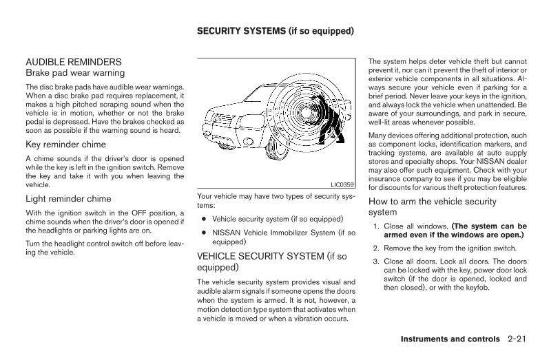
AUDIBLE REMINDERSBrake pad wear warningThe disc brake pads have audible wear warnings.When a disc brake pad requires replacement, itmakes a high pitched scraping sound when thevehicle is in motion, whether or not the brakepedal is depressed. Have the brakes checked assoon as possible if the warning sound is heard.
Key reminder chimeA chime sounds if the driver’s door is openedwhile the key is left in the ignition switch. Removethe key and take it with you when leaving thevehicle.
Light reminder chimeWith the ignition switch in the OFF position, achime sounds when the driver’s door is opened ifthe headlights or parking lights are on.
Turn the headlight control switch off before leav-ing the vehicle.
Your vehicle may have two types of security sys-tems:
● Vehicle security system (if so equipped)
● NISSAN Vehicle Immobilizer System (if soequipped)
VEHICLE SECURITY SYSTEM (if soequipped)
The vehicle security system provides visual andaudible alarm signals if someone opens the doorswhen the system is armed. It is not, however, amotion detection type system that activates whena vehicle is moved or when a vibration occurs.
The system helps deter vehicle theft but cannotprevent it, nor can it prevent the theft of interior orexterior vehicle components in all situations. Al-ways secure your vehicle even if parking for abrief period. Never leave your keys in the ignition,and always lock the vehicle when unattended. Beaware of your surroundings, and park in secure,well-lit areas whenever possible.
Many devices offering additional protection, suchas component locks, identification markers, andtracking systems, are available at auto supplystores and specialty shops. Your NISSAN dealermay also offer such equipment. Check with yourinsurance company to see if you may be eligiblefor discounts for various theft protection features.
How to arm the vehicle securitysystem
1. Close all windows. (The system can bearmed even if the windows are open.)
2. Remove the key from the ignition switch.
3. Close all doors. Lock all doors. The doorscan be locked with the key, power door lockswitch (if the door is opened, locked andthen closed), or with the keyfob.
LIC0359
SECURITY SYSTEMS (if so equipped)
Instruments and controls 2-21
Z REVIEW COPY—2006 Truck/Frontier (d22)Owners Manual—USA_English (nna)10/17/05—debbie X
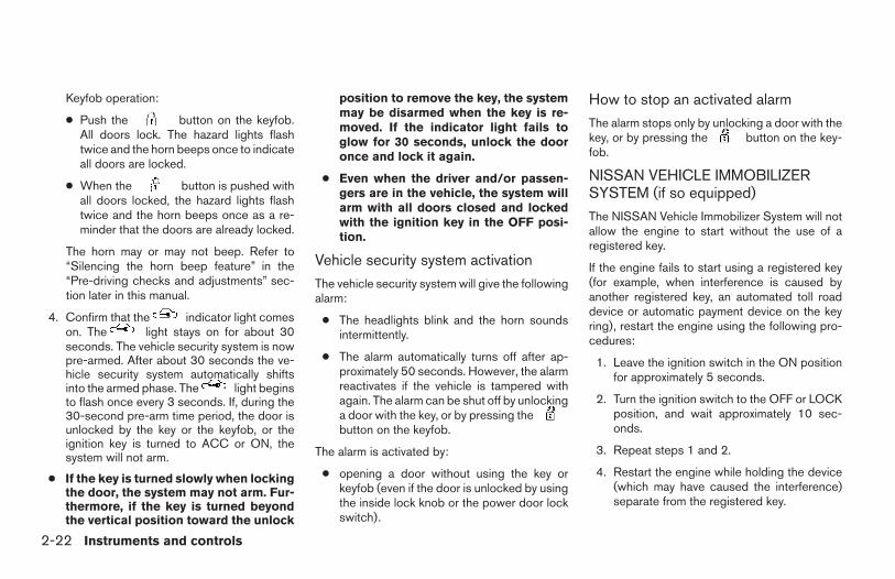
Keyfob operation:
● Push the button on the keyfob.All doors lock. The hazard lights flashtwice and the horn beeps once to indicateall doors are locked.
● When the button is pushed withall doors locked, the hazard lights flashtwice and the horn beeps once as a re-minder that the doors are already locked.
The horn may or may not beep. Refer to“Silencing the horn beep feature” in the“Pre-driving checks and adjustments” sec-tion later in this manual.
4. Confirm that the indicator light comeson. The light stays on for about 30seconds. The vehicle security system is nowpre-armed. After about 30 seconds the ve-hicle security system automatically shiftsinto the armed phase. The light beginsto flash once every 3 seconds. If, during the30-second pre-arm time period, the door isunlocked by the key or the keyfob, or theignition key is turned to ACC or ON, thesystem will not arm.
● If the key is turned slowly when lockingthe door, the system may not arm. Fur-thermore, if the key is turned beyondthe vertical position toward the unlock
position to remove the key, the systemmay be disarmed when the key is re-moved. If the indicator light fails toglow for 30 seconds, unlock the dooronce and lock it again.
● Even when the driver and/or passen-gers are in the vehicle, the system willarm with all doors closed and lockedwith the ignition key in the OFF posi-tion.
Vehicle security system activation
The vehicle security system will give the followingalarm:
● The headlights blink and the horn soundsintermittently.
● The alarm automatically turns off after ap-proximately 50 seconds. However, the alarmreactivates if the vehicle is tampered withagain. The alarm can be shut off by unlockinga door with the key, or by pressing thebutton on the keyfob.
The alarm is activated by:
● opening a door without using the key orkeyfob (even if the door is unlocked by usingthe inside lock knob or the power door lockswitch).
How to stop an activated alarm
The alarm stops only by unlocking a door with thekey, or by pressing the button on the key-fob.
NISSAN VEHICLE IMMOBILIZERSYSTEM (if so equipped)
The NISSAN Vehicle Immobilizer System will notallow the engine to start without the use of aregistered key.
If the engine fails to start using a registered key(for example, when interference is caused byanother registered key, an automated toll roaddevice or automatic payment device on the keyring), restart the engine using the following pro-cedures:
1. Leave the ignition switch in the ON positionfor approximately 5 seconds.
2. Turn the ignition switch to the OFF or LOCKposition, and wait approximately 10 sec-onds.
3. Repeat steps 1 and 2.
4. Restart the engine while holding the device(which may have caused the interference)separate from the registered key.
2-22 Instruments and controls
Z REVIEW COPY—2006 Truck/Frontier (d22)Owners Manual—USA_English (nna)10/17/05—debbie X
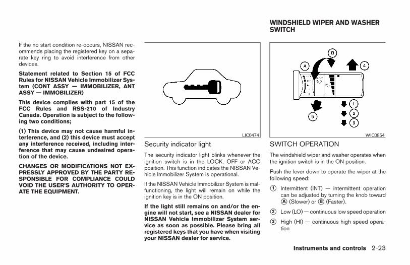
If the no start condition re-occurs, NISSAN rec-ommends placing the registered key on a sepa-rate key ring to avoid interference from otherdevices.
Statement related to Section 15 of FCCRules for NISSAN Vehicle Immobilizer Sys-tem (CONT ASSY — IMMOBILIZER, ANTASSY — IMMOBILIZER)
This device complies with part 15 of theFCC Rules and RSS-210 of IndustryCanada. Operation is subject to the follow-ing two conditions;
(1) This device may not cause harmful in-terference, and (2) this device must acceptany interference received, including inter-ference that may cause undesired opera-tion of the device.
CHANGES OR MODIFICATIONS NOT EX-PRESSLY APPROVED BY THE PARTY RE-SPONSIBLE FOR COMPLIANCE COULDVOID THE USER’S AUTHORITY TO OPER-ATE THE EQUIPMENT.
Security indicator light
The security indicator light blinks whenever theignition switch is in the LOCK, OFF or ACCposition. This function indicates the NISSAN Ve-hicle Immobilizer System is operational.
If the NISSAN Vehicle Immobilizer System is mal-functioning, the light will remain on while theignition key is in the ON position.
If the light still remains on and/or the en-gine will not start, see a NISSAN dealer forNISSAN Vehicle Immobilizer System ser-vice as soon as possible. Please bring allregistered keys that you have when visitingyour NISSAN dealer for service.
SWITCH OPERATION
The windshield wiper and washer operates whenthe ignition switch is in the ON position.
Push the lever down to operate the wiper at thefollowing speed:
s1 Intermittent (INT) — intermittent operationcan be adjusted by turning the knob towardsA (Slower) or sB (Faster).
s2 Low (LO) — continuous low speed operation
s3 High (HI) — continuous high speed opera-tion
LIC0474 WIC0854
WINDSHIELD WIPER AND WASHERSWITCH
Instruments and controls 2-23
Z REVIEW COPY—2006 Truck/Frontier (d22)Owners Manual—USA_English (nna)10/17/05—debbie X
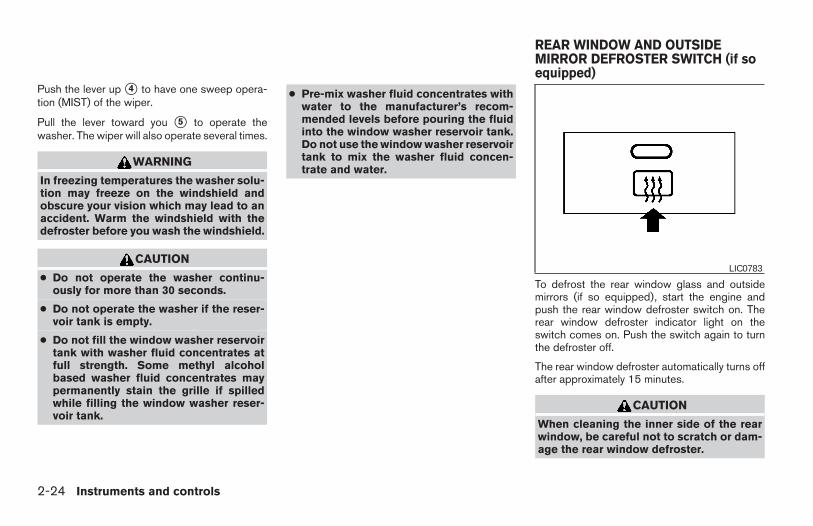
Push the lever up s4 to have one sweep opera-tion (MIST) of the wiper.
Pull the lever toward you s5 to operate thewasher. The wiper will also operate several times.
WARNING
In freezing temperatures the washer solu-tion may freeze on the windshield andobscure your vision which may lead to anaccident. Warm the windshield with thedefroster before you wash the windshield.
CAUTION
● Do not operate the washer continu-ously for more than 30 seconds.
● Do not operate the washer if the reser-voir tank is empty.
● Do not fill the window washer reservoirtank with washer fluid concentrates atfull strength. Some methyl alcoholbased washer fluid concentrates maypermanently stain the grille if spilledwhile filling the window washer reser-voir tank.
● Pre-mix washer fluid concentrates withwater to the manufacturer’s recom-mended levels before pouring the fluidinto the window washer reservoir tank.Do not use the window washer reservoirtank to mix the washer fluid concen-trate and water.
To defrost the rear window glass and outsidemirrors (if so equipped), start the engine andpush the rear window defroster switch on. Therear window defroster indicator light on theswitch comes on. Push the switch again to turnthe defroster off.
The rear window defroster automatically turns offafter approximately 15 minutes.
CAUTION
When cleaning the inner side of the rearwindow, be careful not to scratch or dam-age the rear window defroster.
LIC0783
REAR WINDOW AND OUTSIDEMIRROR DEFROSTER SWITCH (if soequipped)
2-24 Instruments and controls
Z REVIEW COPY—2006 Truck/Frontier (d22)Owners Manual—USA_English (nna)10/17/05—debbie X
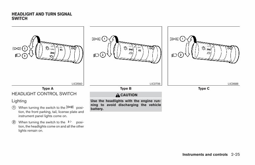
HEADLIGHT CONTROL SWITCH
Lighting
s1 When turning the switch to the posi-tion, the front parking, tail, license plate andinstrument panel lights come on.
s2 When turning the switch to the posi-tion, the headlights come on and all the otherlights remain on.
CAUTION
Use the headlights with the engine run-ning to avoid discharging the vehiclebattery.
Type ALIC0560
Type BLIC0706
Type CLIC0688
HEADLIGHT AND TURN SIGNALSWITCH
Instruments and controls 2-25
Z REVIEW COPY—2006 Truck/Frontier (d22)Owners Manual—USA_English (nna)10/17/05—debbie X
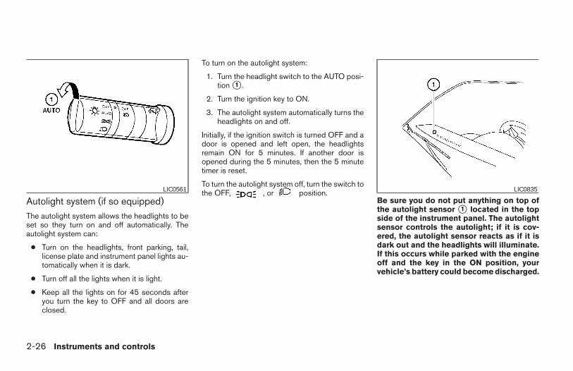
Autolight system (if so equipped)The autolight system allows the headlights to beset so they turn on and off automatically. Theautolight system can:
● Turn on the headlights, front parking, tail,license plate and instrument panel lights au-tomatically when it is dark.
● Turn off all the lights when it is light.
● Keep all the lights on for 45 seconds afteryou turn the key to OFF and all doors areclosed.
To turn on the autolight system:
1. Turn the headlight switch to the AUTO posi-tion s1 .
2. Turn the ignition key to ON.
3. The autolight system automatically turns theheadlights on and off.
Initially, if the ignition switch is turned OFF and adoor is opened and left open, the headlightsremain ON for 5 minutes. If another door isopened during the 5 minutes, then the 5 minutetimer is reset.
To turn the autolight system off, turn the switch tothe OFF, , or position.
Be sure you do not put anything on top ofthe autolight sensor s1 located in the topside of the instrument panel. The autolightsensor controls the autolight; if it is cov-ered, the autolight sensor reacts as if it isdark out and the headlights will illuminate.If this occurs while parked with the engineoff and the key in the ON position, yourvehicle’s battery could become discharged.
LIC0561 LIC0835
2-26 Instruments and controls
Z REVIEW COPY—2006 Truck/Frontier (d22)Owners Manual—USA_English (nna)10/17/05—debbie X
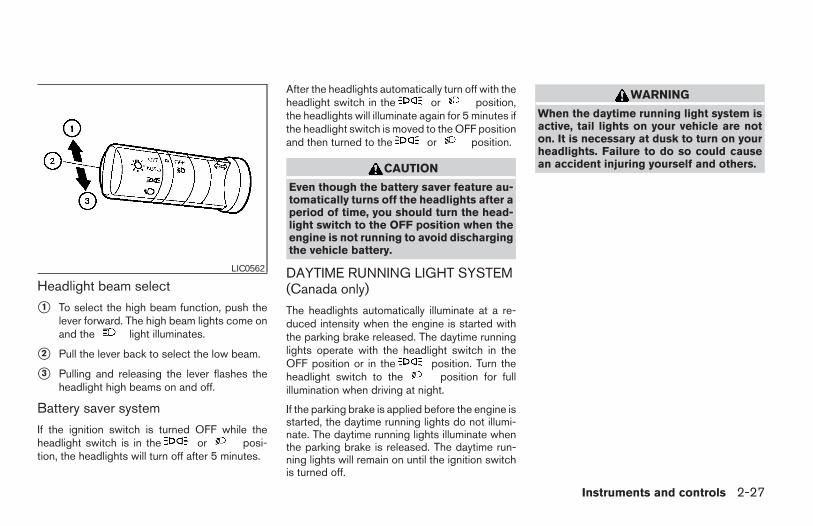
Headlight beam select
s1 To select the high beam function, push thelever forward. The high beam lights come onand the light illuminates.
s2 Pull the lever back to select the low beam.
s3 Pulling and releasing the lever flashes theheadlight high beams on and off.
Battery saver system
If the ignition switch is turned OFF while theheadlight switch is in the or posi-tion, the headlights will turn off after 5 minutes.
After the headlights automatically turn off with theheadlight switch in the or position,the headlights will illuminate again for 5 minutes ifthe headlight switch is moved to the OFF positionand then turned to the or position.
CAUTION
Even though the battery saver feature au-tomatically turns off the headlights after aperiod of time, you should turn the head-light switch to the OFF position when theengine is not running to avoid dischargingthe vehicle battery.
DAYTIME RUNNING LIGHT SYSTEM(Canada only)
The headlights automatically illuminate at a re-duced intensity when the engine is started withthe parking brake released. The daytime runninglights operate with the headlight switch in theOFF position or in the position. Turn theheadlight switch to the position for fullillumination when driving at night.
If the parking brake is applied before the engine isstarted, the daytime running lights do not illumi-nate. The daytime running lights illuminate whenthe parking brake is released. The daytime run-ning lights will remain on until the ignition switchis turned off.
WARNING
When the daytime running light system isactive, tail lights on your vehicle are noton. It is necessary at dusk to turn on yourheadlights. Failure to do so could causean accident injuring yourself and others.
LIC0562
Instruments and controls 2-27
Z REVIEW COPY—2006 Truck/Frontier (d22)Owners Manual—USA_English (nna)10/17/05—debbie X
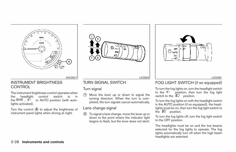
INSTRUMENT BRIGHTNESSCONTROLThe instrument brightness control operates whenthe headlight control switch is inthe , or AUTO position (with auto-lights activated).
Turn the control sA to adjust the brightness ofinstrument panel lights when driving at night.
TURN SIGNAL SWITCH
Turn signal
s1 Move the lever up or down to signal theturning direction. When the turn is com-pleted, the turn signals cancel automatically.
Lane change signal
s2 To signal a lane change, move the lever up ordown to the point where the indicator lightbegins to flash, but the lever does not latch.
FOG LIGHT SWITCH (if so equipped)To turn the fog lights on, turn the headlight switchto the position, then turn the fog lightswitch to the position.
To turn the fog lights on with the headlight switchin the AUTO position (if so equipped), the head-lights must be on, then turn the fog light switch tothe position.
To turn the fog lights off, turn the fog light switchto the OFF position.
The headlights must be on and the low beamsselected for the fog lights to operate. The foglights automatically turn off when the high beamheadlights are selected.
WIC0917 LIC0563 LIC0393
2-28 Instruments and controls
Z REVIEW COPY—2006 Truck/Frontier (d22)Owners Manual—USA_English (nna)10/17/05—debbie X
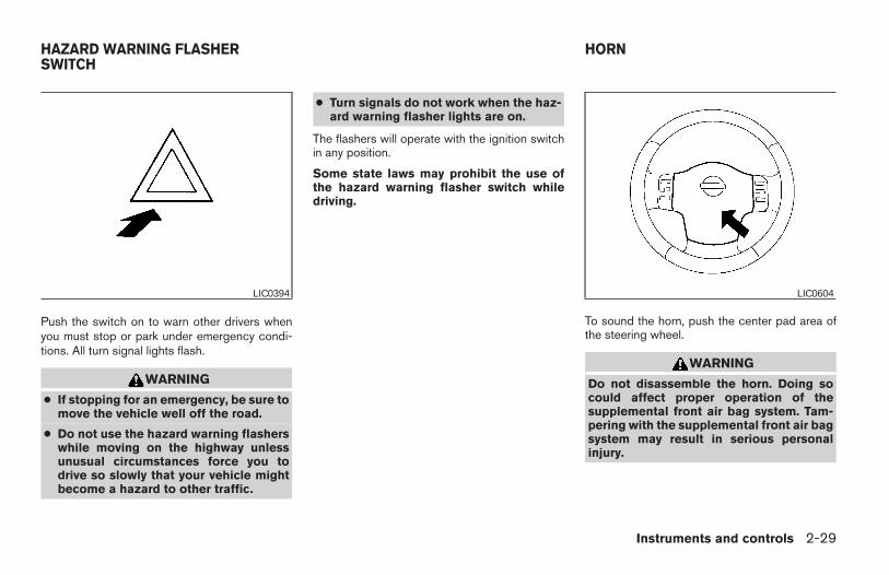
Push the switch on to warn other drivers whenyou must stop or park under emergency condi-tions. All turn signal lights flash.
WARNING
● If stopping for an emergency, be sure tomove the vehicle well off the road.
● Do not use the hazard warning flasherswhile moving on the highway unlessunusual circumstances force you todrive so slowly that your vehicle mightbecome a hazard to other traffic.
● Turn signals do not work when the haz-ard warning flasher lights are on.
The flashers will operate with the ignition switchin any position.
Some state laws may prohibit the use ofthe hazard warning flasher switch whiledriving.
To sound the horn, push the center pad area ofthe steering wheel.
WARNING
Do not disassemble the horn. Doing socould affect proper operation of thesupplemental front air bag system. Tam-pering with the supplemental front air bagsystem may result in serious personalinjury.
LIC0394 LIC0604
HAZARD WARNING FLASHERSWITCH
HORN
Instruments and controls 2-29
Z REVIEW COPY—2006 Truck/Frontier (d22)Owners Manual—USA_English (nna)10/17/05—debbie X
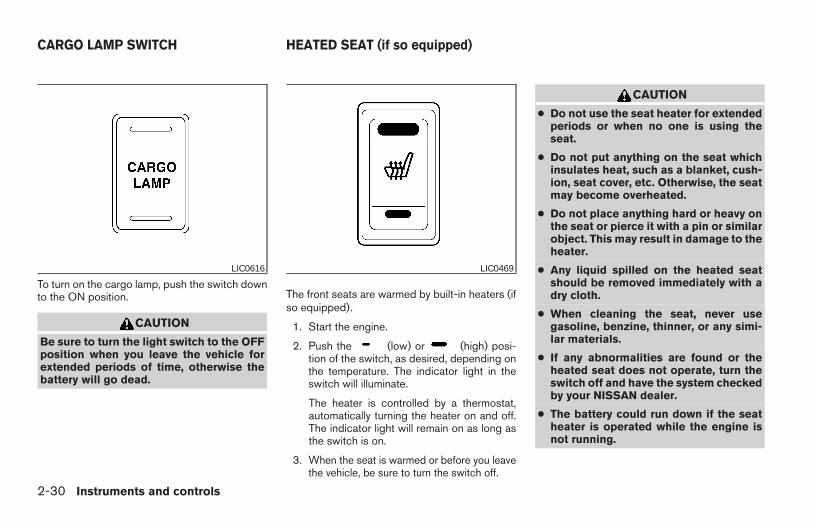
To turn on the cargo lamp, push the switch downto the ON position.
CAUTION
Be sure to turn the light switch to the OFFposition when you leave the vehicle forextended periods of time, otherwise thebattery will go dead.
The front seats are warmed by built-in heaters (ifso equipped).
1. Start the engine.
2. Push the (low) or (high) posi-tion of the switch, as desired, depending onthe temperature. The indicator light in theswitch will illuminate.
The heater is controlled by a thermostat,automatically turning the heater on and off.The indicator light will remain on as long asthe switch is on.
3. When the seat is warmed or before you leavethe vehicle, be sure to turn the switch off.
CAUTION
● Do not use the seat heater for extendedperiods or when no one is using theseat.
● Do not put anything on the seat whichinsulates heat, such as a blanket, cush-ion, seat cover, etc. Otherwise, the seatmay become overheated.
● Do not place anything hard or heavy onthe seat or pierce it with a pin or similarobject. This may result in damage to theheater.
● Any liquid spilled on the heated seatshould be removed immediately with adry cloth.
● When cleaning the seat, never usegasoline, benzine, thinner, or any simi-lar materials.
● If any abnormalities are found or theheated seat does not operate, turn theswitch off and have the system checkedby your NISSAN dealer.
● The battery could run down if the seatheater is operated while the engine isnot running.
LIC0616 LIC0469
CARGO LAMP SWITCH HEATED SEAT (if so equipped)
2-30 Instruments and controls
Z REVIEW COPY—2006 Truck/Frontier (d22)Owners Manual—USA_English (nna)10/17/05—debbie X
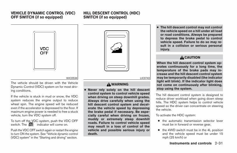
The vehicle should be driven with the VehicleDynamic Control (VDC) system on for most driv-ing conditions.
If the vehicle is stuck in mud or snow, the VDCsystem reduces the engine output to reducewheel spin. The engine speed will be reducedeven if the accelerator is depressed to the floor. Ifmaximum engine power is needed to free a stuckvehicle, turn the VDC system off.
To turn off the VDC system, push the VDC OFFswitch. The indicator will come on.
Push the VDC OFF switch again or restart the engineto turn ON the system. See “Vehicle dynamic control(VDC) system” in the “Starting and driving” section.
WARNING
● Never rely solely on the hill descentcontrol system to control vehicle speedwhen driving on steep downhill grades.Always drive carefully when using thehill descent control system and decel-erate the vehicle speed by depressingthe brake pedal if necessary. Be espe-cially careful when driving on frozen,muddy or extremely steep downhillroads. Failure to control vehicle speedmay result in a loss of control of thevehicle and possible serious injury ordeath.
● The hill descent control may not controlthe vehicle speed on a hill under all loador road conditions. Always be preparedto depress the brake pedal to controlvehicle speed. Failure to do so may re-sult in a collision or serious personalinjury.
CAUTION
When the hill descent control system op-erates continuously for a long time, thetemperature of the brake pads may in-crease and the hill descent control systemmay be temporarily disabled (the indicatorlight will blink). If the indicator light doesnot come on continuously after blinking,stop using the system.
The hill descent control system is designed toreduce driver workload when going down steephills. The HDC system helps to control vehiclespeed so the driver can concentrate on steeringthe vehicle.
To activate the HDC system:
● the automatic transmission selector levermust be in forward or reverse gear,
● the 4WD switch must be in the 4L positionand the vehicle speed must be under 15mph (25 km/h) or
WIC0534 LIC0743
VEHICLE DYNAMIC CONTROL (VDC)OFF SWITCH (if so equipped)
HILL DESCENT CONTROL (HDC)SWITCH (if so equipped)
Instruments and controls 2-31
Z REVIEW COPY—2006 Truck/Frontier (d22)Owners Manual—USA_English (nna)10/17/05—debbie X
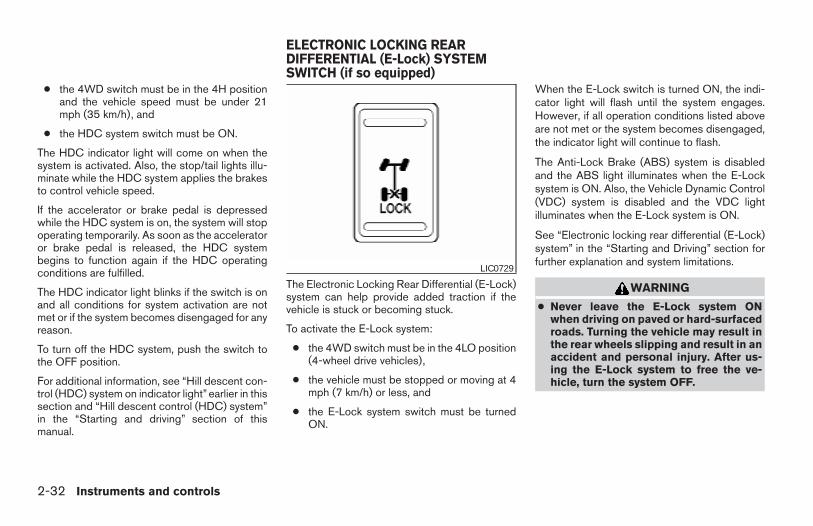
● the 4WD switch must be in the 4H positionand the vehicle speed must be under 21mph (35 km/h), and
● the HDC system switch must be ON.
The HDC indicator light will come on when thesystem is activated. Also, the stop/tail lights illu-minate while the HDC system applies the brakesto control vehicle speed.
If the accelerator or brake pedal is depressedwhile the HDC system is on, the system will stopoperating temporarily. As soon as the acceleratoror brake pedal is released, the HDC systembegins to function again if the HDC operatingconditions are fulfilled.
The HDC indicator light blinks if the switch is onand all conditions for system activation are notmet or if the system becomes disengaged for anyreason.
To turn off the HDC system, push the switch tothe OFF position.
For additional information, see “Hill descent con-trol (HDC) system on indicator light” earlier in thissection and “Hill descent control (HDC) system”in the “Starting and driving” section of thismanual.
The Electronic Locking Rear Differential (E-Lock)system can help provide added traction if thevehicle is stuck or becoming stuck.
To activate the E-Lock system:
● the 4WD switch must be in the 4LO position(4-wheel drive vehicles),
● the vehicle must be stopped or moving at 4mph (7 km/h) or less, and
● the E-Lock system switch must be turnedON.
When the E-Lock switch is turned ON, the indi-cator light will flash until the system engages.However, if all operation conditions listed aboveare not met or the system becomes disengaged,the indicator light will continue to flash.
The Anti-Lock Brake (ABS) system is disabledand the ABS light illuminates when the E-Locksystem is ON. Also, the Vehicle Dynamic Control(VDC) system is disabled and the VDC lightilluminates when the E-Lock system is ON.
See “Electronic locking rear differential (E-Lock)system” in the “Starting and Driving” section forfurther explanation and system limitations.
WARNING
● Never leave the E-Lock system ONwhen driving on paved or hard-surfacedroads. Turning the vehicle may result inthe rear wheels slipping and result in anaccident and personal injury. After us-ing the E-Lock system to free the ve-hicle, turn the system OFF.
LIC0729
ELECTRONIC LOCKING REARDIFFERENTIAL (E-Lock) SYSTEMSWITCH (if so equipped)
2-32 Instruments and controls
Z REVIEW COPY—2006 Truck/Frontier (d22)Owners Manual—USA_English (nna)10/17/05—debbie X
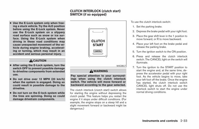
● Use the E-Lock system only when free-ing a stuck vehicle. Try the 4LO positionbefore using the E-Lock system. Neveruse the E-Lock system on a slipperyroad surface such as snow or ice sur-face. Using the E-Lock system whendriving in these road conditions maycause unexpected movement of the ve-hicle during engine braking, accelerat-ing or turning, which may result in anaccident and serious personal injury.
CAUTION
● After using the E-Lock system, turn theswitch OFF to prevent possible damageto driveline components from extendeduse.
● Do not drive over 12 MPH (20 km/h)when the system is engaged. Doing socould result in possible damage to thedriveline.
● Do not turn on the E-lock system whilethe tires are spinning. Doing so coulddamage drivetrain components.
WARNING
Pay special attention to your surround-ings when using the clutch interlockswitch. The vehicle will move forward orbackward according to the gear selected.
The clutch interlock (clutch start) switch allowsfor starting the engine without depressing theclutch pedal. This feature helps you restart theengine if it stops under difficult conditions. (Forexample, the engine stops on a steep hill and aslight movement forward or backward might bedangerous.)
To use the clutch interlock switch:
1. Set the parking brake.
2. Depress the brake pedal with your right foot.
3. Place the gear shift lever in the 1 position tomove forward, or R to move backward.
4. Place your left foot on the brake pedal andrelease the parking brake.
5. Turn the ignition switch to the ON position.
6. Press and release the clutch interlockswitch. The CANCEL light on the switch willilluminate.
7. Turn the ignition to the START position tostart the engine and, at the same time, de-press the accelerator pedal with your rightfoot. As the vehicle begins to move, takeyour left foot off the brake. Once the enginehas started, the clutch interlock switchCANCEL light shuts off. Do not use theinterlock switch to start the engine undernormal driving conditions.
WIC0817
CLUTCH INTERLOCK (clutch start)SWITCH (if so equipped)
Instruments and controls 2-33
Z REVIEW COPY—2006 Truck/Frontier (d22)Owners Manual—USA_English (nna)10/17/05—debbie X
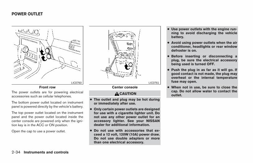
The power outlets are for powering electricalaccessories such as cellular telephones.
The bottom power outlet located on instrumentpanel is powered directly by the vehicle’s battery.
The top power outlet located on the instrumentpanel and the power outlet located inside thecenter console are powered only when the igni-tion key is in the ACC or ON position.
Open the cap to use a power outlet.
CAUTION
● The outlet and plug may be hot duringor immediately after use.
● Only certain power outlets are designedfor use with a cigarette lighter unit. Donot use any other power outlet for anaccessory lighter. See your NISSANdealer for additional information.
● Do not use with accessories that ex-ceed a 12 volt, 120W (10A) power draw.Do not use double adapters or morethan one electrical accessory.
● Use power outlets with the engine run-ning to avoid discharging the vehiclebattery.
● Avoid using power outlets when the airconditioner, headlights or rear windowdefroster is on.
● Before inserting or disconnecting aplug, be sure the electrical accessorybeing used is turned OFF.
● Push the plug in as far as it will go. Ifgood contact is not made, the plug mayoverheat or the internal temperaturefuse may open.
● When not in use, be sure to close thecap. Do not allow water to contact theoutlet.
Front rowLIC0760
Center consoleLIC0761
POWER OUTLET
2-34 Instruments and controls
Z REVIEW COPY—2006 Truck/Frontier (d22)Owners Manual—USA_English (nna)10/17/05—debbie X
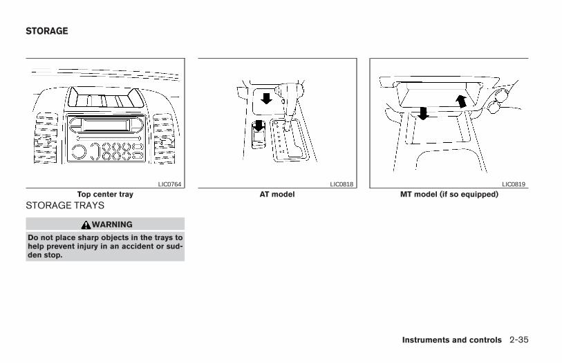
STORAGE TRAYS
WARNING
Do not place sharp objects in the trays tohelp prevent injury in an accident or sud-den stop.
Top center trayLIC0764
AT modelLIC0818
MT model (if so equipped)LIC0819
STORAGE
Instruments and controls 2-35
Z REVIEW COPY—2006 Truck/Frontier (d22)Owners Manual—USA_English (nna)10/17/05—debbie X
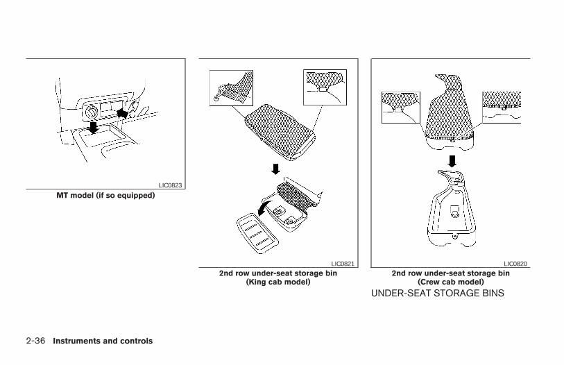
UNDER-SEAT STORAGE BINS
MT model (if so equipped)LIC0823
2nd row under-seat storage bin(King cab model)
LIC0821
2nd row under-seat storage bin(Crew cab model)
LIC0820
2-36 Instruments and controls
Z REVIEW COPY—2006 Truck/Frontier (d22)Owners Manual—USA_English (nna)10/17/05—debbie X
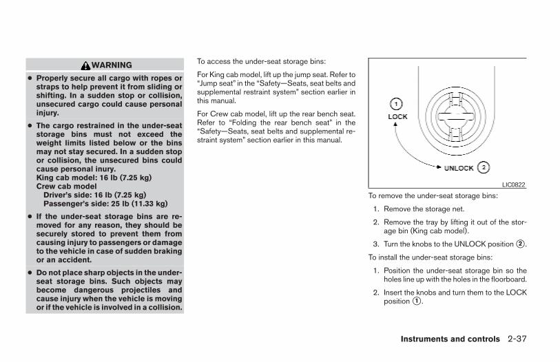
WARNING
● Properly secure all cargo with ropes orstraps to help prevent it from sliding orshifting. In a sudden stop or collision,unsecured cargo could cause personalinjury.
● The cargo restrained in the under-seatstorage bins must not exceed theweight limits listed below or the binsmay not stay secured. In a sudden stopor collision, the unsecured bins couldcause personal inury.King cab model: 16 lb (7.25 kg)Crew cab model
Driver’s side: 16 lb (7.25 kg)Passenger’s side: 25 lb (11.33 kg)
● If the under-seat storage bins are re-moved for any reason, they should besecurely stored to prevent them fromcausing injury to passengers or damageto the vehicle in case of sudden brakingor an accident.
● Do not place sharp objects in the under-seat storage bins. Such objects maybecome dangerous projectiles andcause injury when the vehicle is movingor if the vehicle is involved in a collision.
To access the under-seat storage bins:
For King cab model, lift up the jump seat. Refer to“Jump seat” in the “Safety—Seats, seat belts andsupplemental restraint system” section earlier inthis manual.
For Crew cab model, lift up the rear bench seat.Refer to “Folding the rear bench seat” in the“Safety—Seats, seat belts and supplemental re-straint system” section earlier in this manual.
To remove the under-seat storage bins:
1. Remove the storage net.
2. Remove the tray by lifting it out of the stor-age bin (King cab model).
3. Turn the knobs to the UNLOCK position s2 .
To install the under-seat storage bins:
1. Position the under-seat storage bin so theholes line up with the holes in the floorboard.
2. Insert the knobs and turn them to the LOCKposition s1 .
LIC0822
Instruments and controls 2-37
Z REVIEW COPY—2006 Truck/Frontier (d22)Owners Manual—USA_English (nna)10/17/05—debbie X
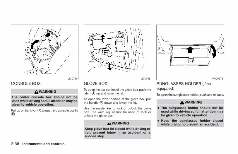
CONSOLE BOX
WARNING
The center console box should not beused while driving so full attention may begiven to vehicle operation.
Pull up on the lever s1 to open the console box lids2 .
GLOVE BOXTo open the top portion of the glove box, push thelatch sA up and raise the lid.
To open the lower portion of the glove box, pullthe handle sB down and lower the lid.
Use the master key to lock or unlock the glovebox. The valet key cannot be used to lock orunlock the glove box.
WARNING
Keep glove box lid closed while driving tohelp prevent injury in an accident or asudden stop.
SUNGLASSES HOLDER (if soequipped)
To open the sunglasses holder, push and release.
WARNING
● The sunglasses holder should not beused while driving so full attention maybe given to vehicle operation.
● Keep the sunglasses holder closedwhile driving to prevent an accident.
LIC0766 LIC0768 WIC0673
2-38 Instruments and controls
Z REVIEW COPY—2006 Truck/Frontier (d22)Owners Manual—USA_English (nna)10/17/05—debbie X
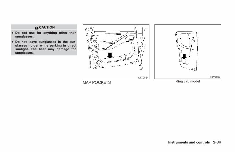
CAUTION
● Do not use for anything other thansunglasses.
● Do not leave sunglasses in the sun-glasses holder while parking in directsunlight. The heat may damage thesunglasses.
MAP POCKETSWIC0824
King cab modelLIC0826
Instruments and controls 2-39
Z REVIEW COPY—2006 Truck/Frontier (d22)Owners Manual—USA_English (nna)10/17/05—debbie X
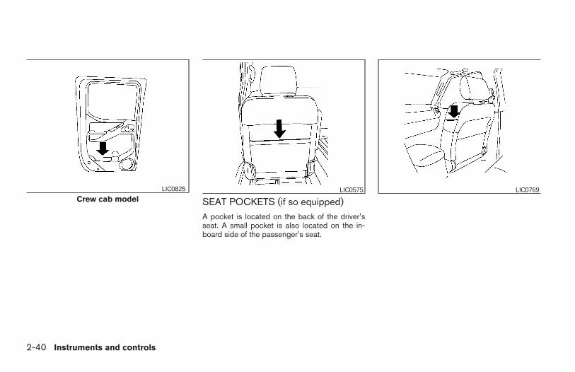
SEAT POCKETS (if so equipped)A pocket is located on the back of the driver’sseat. A small pocket is also located on the in-board side of the passenger’s seat.
Crew cab modelLIC0825 LIC0575 LIC0769
2-40 Instruments and controls
Z REVIEW COPY—2006 Truck/Frontier (d22)Owners Manual—USA_English (nna)10/17/05—debbie X
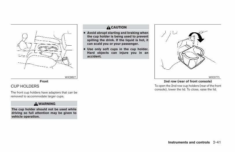
CUP HOLDERS
The front cup holders have adapters that can beremoved to accommodate larger cups.
WARNING
The cup holder should not be used whiledriving so full attention may be given tovehicle operation.
CAUTION
● Avoid abrupt starting and braking whenthe cup holder is being used to preventspilling the drink. If the liquid is hot, itcan scald you or your passenger.
● Use only soft cups in the cup holder.Hard objects can injure you in anaccident.
To open the 2nd row cup holders (rear of the frontconsole), lower the lid. To close, raise the lid.
FrontWIC0827
2nd row (rear of front console)WIC0771
Instruments and controls 2-41
Z REVIEW COPY—2006 Truck/Frontier (d22)Owners Manual—USA_English (nna)10/17/05—debbie X
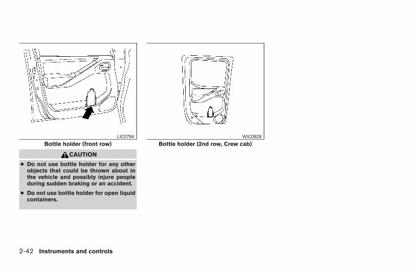
CAUTION
● Do not use bottle holder for any otherobjects that could be thrown about inthe vehicle and possibly injure peopleduring sudden braking or an accident.
● Do not use bottle holder for open liquidcontainers.
Bottle holder (front row)LIC0784
Bottle holder (2nd row, Crew cab)WIC0828
2-42 Instruments and controls
Z REVIEW COPY—2006 Truck/Frontier (d22)Owners Manual—USA_English (nna)10/17/05—debbie X
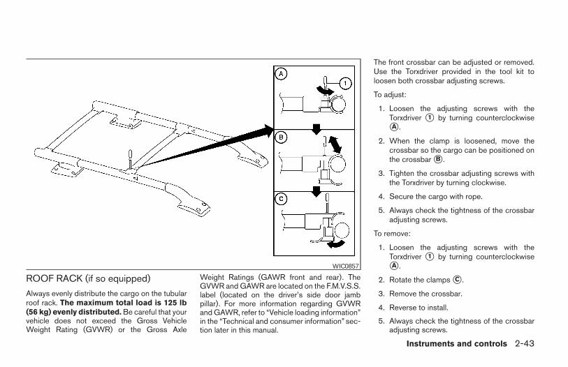
ROOF RACK (if so equipped)
Always evenly distribute the cargo on the tubularroof rack. The maximum total load is 125 lb(56 kg) evenly distributed. Be careful that yourvehicle does not exceed the Gross VehicleWeight Rating (GVWR) or the Gross Axle
Weight Ratings (GAWR front and rear). TheGVWR and GAWR are located on the F.M.V.S.S.label (located on the driver’s side door jambpillar). For more information regarding GVWRand GAWR, refer to “Vehicle loading information”in the “Technical and consumer information” sec-tion later in this manual.
The front crossbar can be adjusted or removed.Use the Torxdriver provided in the tool kit toloosen both crossbar adjusting screws.
To adjust:
1. Loosen the adjusting screws with theTorxdriver s1 by turning counterclockwisesA .
2. When the clamp is loosened, move thecrossbar so the cargo can be positioned onthe crossbar sB .
3. Tighten the crossbar adjusting screws withthe Torxdriver by turning clockwise.
4. Secure the cargo with rope.
5. Always check the tightness of the crossbaradjusting screws.
To remove:
1. Loosen the adjusting screws with theTorxdriver s1 by turning counterclockwisesA .
2. Rotate the clamps sC .
3. Remove the crossbar.
4. Reverse to install.
5. Always check the tightness of the crossbaradjusting screws.
WIC0857
Instruments and controls 2-43
Z REVIEW COPY—2006 Truck/Frontier (d22)Owners Manual—USA_English (nna)10/17/05—debbie X
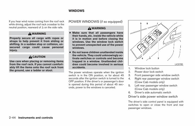
If you hear wind noise coming from the roof rackwhile driving, adjust the roof rack crossbar to theneutral position, rearward of D on the side rails.
WARNING
Properly secure all cargo with ropes orstraps to help prevent it from sliding orshifting. In a sudden stop or collision, un-secured cargo could cause personalinjury.
CAUTION
Use care when placing or removing itemsfrom the roof rack. If you cannot comfort-ably lift the items onto the roof rack fromthe ground, use a ladder or stool.
POWER WINDOWS (if so equipped)
WARNING
● Make sure that all passengers havetheir hands, etc. inside the vehicle whileit is in motion and before closing thewindows. Use the window lock switchto prevent unexpected use of the powerwindows.
● Do not leave children unattended insidethe vehicle. They could unknowingly ac-tivate switches or controls and becometrapped in a window. Unattended chil-dren could become involved in seriousaccidents.
The power windows operate when the ignitionswitch is in the ON position, or for about 45seconds after the ignition switch is turned to theOFF position. If the driver’s or passenger’s dooris opened during this period of about 45 sec-onds, power to the windows is canceled.
1. Window lock button2. Power door lock switch3. Front passenger side window switch4. Right rear passenger window switch
(Crew Cab models only)5. Left rear passenger window switch
(Crew Cab models only)6. Driver’s side automatic switch
Driver’s side power window switch
The driver’s side control panel is equipped withswitches to open or close the front and rearpassenger windows.
LIC0785
WINDOWS
2-44 Instruments and controls
Z REVIEW COPY—2006 Truck/Frontier (d22)Owners Manual—USA_English (nna)10/17/05—debbie X
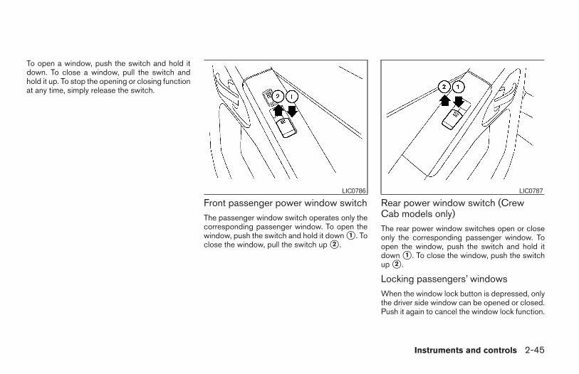
To open a window, push the switch and hold itdown. To close a window, pull the switch andhold it up. To stop the opening or closing functionat any time, simply release the switch.
Front passenger power window switchThe passenger window switch operates only thecorresponding passenger window. To open thewindow, push the switch and hold it down s1 . Toclose the window, pull the switch up s2 .
Rear power window switch (CrewCab models only)The rear power window switches open or closeonly the corresponding passenger window. Toopen the window, push the switch and hold itdown s1 . To close the window, push the switchup s2 .
Locking passengers’ windowsWhen the window lock button is depressed, onlythe driver side window can be opened or closed.Push it again to cancel the window lock function.
LIC0786 LIC0787
Instruments and controls 2-45
Z REVIEW COPY—2006 Truck/Frontier (d22)Owners Manual—USA_English (nna)10/17/05—debbie X
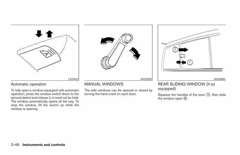
Automatic operationTo fully open a window equipped with automaticoperation, press the window switch down to thesecond detent and release it; it need not be held.The window automatically opens all the way. Tostop the window, lift the switch up while thewindow is opening.
MANUAL WINDOWSThe side windows can be opened or closed byturning the hand crank on each door.
REAR SLIDING WINDOW (if soequipped)Squeeze the handles of the lever s1 , then slidethe window open s2 .
LIC0410 WIC0263 WIC0856
2-46 Instruments and controls
Z REVIEW COPY—2006 Truck/Frontier (d22)Owners Manual—USA_English (nna)10/17/05—debbie X
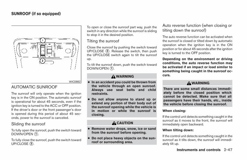
AUTOMATIC SUNROOF
The sunroof will only operate when the ignitionkey is in the ON position. The automatic sunroofis operational for about 45 seconds, even if theignition key is turned to the ACC or OFF position.If the driver’s door or the front passenger’s dooris opened during this period of about 45 sec-onds, power to the sunroof is canceled.
Sliding the sunroofTo fully open the sunroof, push the switch towardDOWN/OPEN s1 .
To fully close the sunroof, push the switch towardUP/CLOSE s2 .
To open or close the sunroof part way, push theswitch in any direction while the sunroof is slidingto stop it in the desired position.
Tilting the sunroofClose the sunroof by pushing the switch towardUP/CLOSE s2 . Release the switch, then pushthe UP/CLOSE switch again to tilt the sunroofup.
To tilt the sunroof down, push the switch towardDOWN/OPEN s1 .
WARNING
● In an accident you could be thrown fromthe vehicle through an open sunroof.Always use seat belts and childrestraints.
● Do not allow anyone to stand up orextend any portion of their body out ofthe sunroof opening while the vehicle isin motion or while the sunroof isclosing.
CAUTION
● Remove water drops, snow, ice or sandfrom the sunroof before opening.
● Do not place heavy objects on the sun-roof or surrounding area.
Auto reverse function (when closing ortilting down the sunroof)
The auto reverse function can be activated whenthe sunroof is closed or tilted down by automaticoperation when the ignition key is in the ONposition or for about 45 seconds after the ignitionkey is turned to the OFF position.
Depending on the environment or drivingconditions, the auto reverse function maybe activated if an impact or load similar tosomething being caught in the sunroof oc-curs.
WARNING
There are some small distances immedi-ately before the closed position whichcannot be detected. Make sure that allpassengers have their hands, etc., insidethe vehicle before closing the sunroof.
When closing:
If the control unit detects something caught in thesunroof as it moves to the front, the sunroof willimmediately open backward.
When tilting down:
If the control unit detects something caught in thesunroof as it tilts down, the sunroof will immedi-ately tilt up.
WIC0882
SUNROOF (if so equipped)
Instruments and controls 2-47
Z REVIEW COPY—2006 Truck/Frontier (d22)Owners Manual—USA_English (nna)10/17/05—debbie X
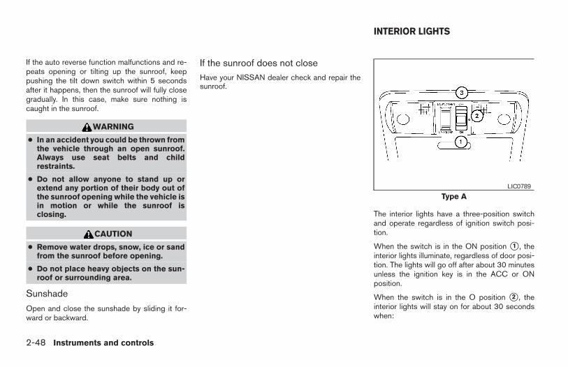
If the auto reverse function malfunctions and re-peats opening or tilting up the sunroof, keeppushing the tilt down switch within 5 secondsafter it happens, then the sunroof will fully closegradually. In this case, make sure nothing iscaught in the sunroof.
WARNING
● In an accident you could be thrown fromthe vehicle through an open sunroof.Always use seat belts and childrestraints.
● Do not allow anyone to stand up orextend any portion of their body out ofthe sunroof opening while the vehicle isin motion or while the sunroof isclosing.
CAUTION
● Remove water drops, snow, ice or sandfrom the sunroof before opening.
● Do not place heavy objects on the sun-roof or surrounding area.
Sunshade
Open and close the sunshade by sliding it for-ward or backward.
If the sunroof does not closeHave your NISSAN dealer check and repair thesunroof.
The interior lights have a three-position switchand operate regardless of ignition switch posi-tion.
When the switch is in the ON position s1 , theinterior lights illuminate, regardless of door posi-tion. The lights will go off after about 30 minutesunless the ignition key is in the ACC or ONposition.
When the switch is in the O position s2 , theinterior lights will stay on for about 30 secondswhen:
Type ALIC0789
INTERIOR LIGHTS
2-48 Instruments and controls
Z REVIEW COPY—2006 Truck/Frontier (d22)Owners Manual—USA_English (nna)10/17/05—debbie X
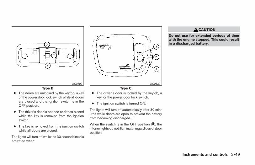
● The doors are unlocked by the keyfob, a keyor the power door lock switch while all doorsare closed and the ignition switch is in theOFF position.
● The driver’s door is opened and then closedwhile the key is removed from the ignitionswitch.
● The key is removed from the ignition switchwhile all doors are closed.
The lights will turn off while the 30 second timer isactivated when:
● The driver’s door is locked by the keyfob, akey, or the power door lock switch.
● The ignition switch is turned ON.
The lights will turn off automatically after 30 min-utes while doors are open to prevent the batteryfrom becoming discharged.
When the switch is in the OFF position s3 , theinterior lights do not illuminate, regardless of doorposition.
CAUTION
Do not use for extended periods of timewith the engine stopped. This could resultin a discharged battery.
Type BLIC0792
Type CLIC0630
Instruments and controls 2-49
Z REVIEW COPY—2006 Truck/Frontier (d22)Owners Manual—USA_English (nna)10/17/05—debbie X
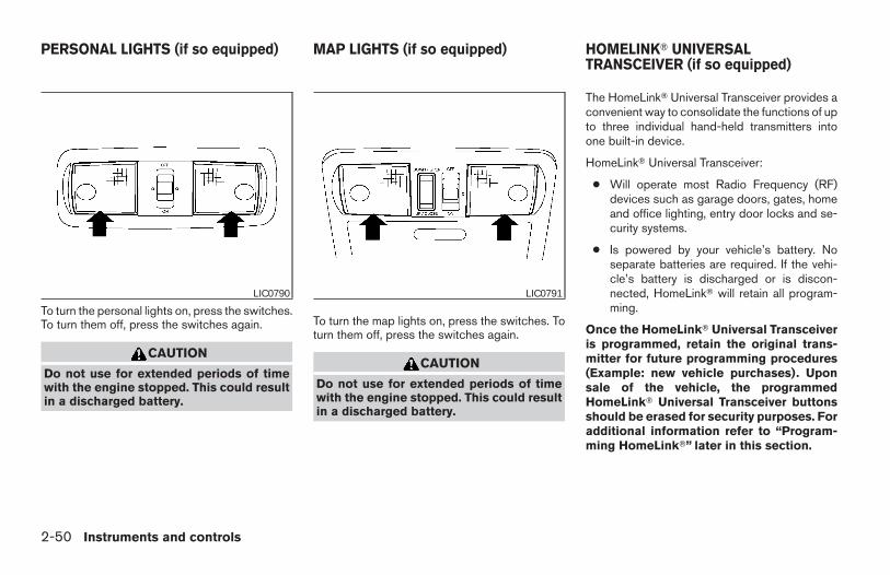
To turn the personal lights on, press the switches.To turn them off, press the switches again.
CAUTION
Do not use for extended periods of timewith the engine stopped. This could resultin a discharged battery.
To turn the map lights on, press the switches. Toturn them off, press the switches again.
CAUTION
Do not use for extended periods of timewith the engine stopped. This could resultin a discharged battery.
The HomeLinkT Universal Transceiver provides aconvenient way to consolidate the functions of upto three individual hand-held transmitters intoone built-in device.
HomeLinkT Universal Transceiver:
● Will operate most Radio Frequency (RF)devices such as garage doors, gates, homeand office lighting, entry door locks and se-curity systems.
● Is powered by your vehicle’s battery. Noseparate batteries are required. If the vehi-cle’s battery is discharged or is discon-nected, HomeLinkT will retain all program-ming.
Once the HomeLinkT Universal Transceiveris programmed, retain the original trans-mitter for future programming procedures(Example: new vehicle purchases). Uponsale of the vehicle, the programmedHomeLinkT Universal Transceiver buttonsshould be erased for security purposes. Foradditional information refer to “Program-ming HomeLinkT” later in this section.
LIC0790 LIC0791
PERSONAL LIGHTS (if so equipped) MAP LIGHTS (if so equipped) HOMELINKT UNIVERSALTRANSCEIVER (if so equipped)
2-50 Instruments and controls
Z REVIEW COPY—2006 Truck/Frontier (d22)Owners Manual—USA_English (nna)10/17/05—debbie X
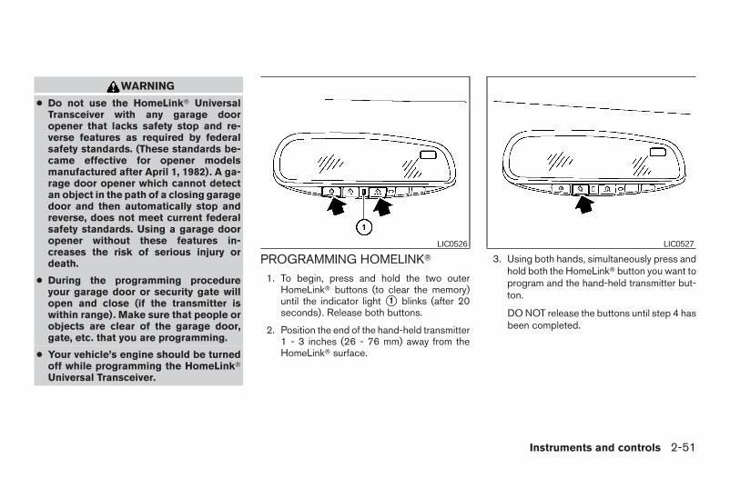
WARNING
● Do not use the HomeLinkT UniversalTransceiver with any garage dooropener that lacks safety stop and re-verse features as required by federalsafety standards. (These standards be-came effective for opener modelsmanufactured after April 1, 1982). A ga-rage door opener which cannot detectan object in the path of a closing garagedoor and then automatically stop andreverse, does not meet current federalsafety standards. Using a garage dooropener without these features in-creases the risk of serious injury ordeath.
● During the programming procedureyour garage door or security gate willopen and close (if the transmitter iswithin range). Make sure that people orobjects are clear of the garage door,gate, etc. that you are programming.
● Your vehicle’s engine should be turnedoff while programming the HomeLinkTUniversal Transceiver.
PROGRAMMING HOMELINKT
1. To begin, press and hold the two outerHomeLinkT buttons (to clear the memory)until the indicator light s1 blinks (after 20seconds). Release both buttons.
2. Position the end of the hand-held transmitter1 - 3 inches (26 - 76 mm) away from theHomeLinkT surface.
3. Using both hands, simultaneously press andhold both the HomeLinkT button you want toprogram and the hand-held transmitter but-ton.
DO NOT release the buttons until step 4 hasbeen completed.
LIC0526 LIC0527
Instruments and controls 2-51
Z REVIEW COPY—2006 Truck/Frontier (d22)Owners Manual—USA_English (nna)10/17/05—debbie X
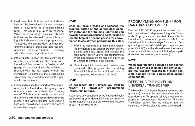
4. Hold down both buttons until the indicatorlight on the HomeLinkT flashes, changingfrom a “slow blink” to a “rapidly flashingblink”. This could take up to 90 seconds.When the indicator light flashes rapidly, bothbuttons may be released. The rapidly flash-ing light indicates successful programming.To activate the garage door or other pro-grammed device, press and hold the pro-grammed HomeLinkT button — releasingwhen the device begins to activate.
5. If the indicator light on the HomeLinkT blinksrapidly for 2 seconds and then turns solid,HomeLinkT has picked up a “rolling code”garage door opener signal. You will need toproceed with the next steps to train theHomeLinkT to complete the programmingwhich may require a ladder and another per-son for convenience.
6. Press and release the “smart” or “learn” pro-gram button located on the garage dooropener’s motor to activate the “trainingmode”. This button is usually located nearthe antenna wire that hangs down from themotor. If the wire originates from under alight lens, you will need to remove the lens toaccess the program button.
NOTE:
Once you have pressed and released theprogram button on the garage door open-er’s motor and the “training light” is lit, youhave 30 seconds in which to perform step 7.Use the help of a second person for conve-nience to assist when performing this step.
7. Within 30 seconds of pressing and releas-ing the garage door opener program button,quickly and firmly press and release theHomeLinkT button you’ve just programmed.Press and release the HomeLinkT button upto 3 times to complete the training.
8. Your HomeLinkT button should now be pro-grammed. (To program the remainingHomeLinkT buttons for additional door orgate openers, follow steps 2-8 only.)
NOTE:
Do not repeat step 1 unless you want to“clear” all previously programmedHomeLinkT buttons.
If you have any questions or are having difficultyprogramming your HomeLinkT buttons, refer tothe HomeLinkT web site at: www.homelink.comor call 1-800-355-3515.
PROGRAMMING HOMELINKT FORCANADIAN CUSTOMERSPrior to 1992, D.O.C. regulations required hand-held transmitters to stop transmitting after 2 sec-onds. To program your hand-held transmitter toHomeLinkT, continue to press and hold theHomeLinkT button (note steps 2 - 4 under “Pro-gramming HomeLinkT”) while you press and re-press (“cycle”) your hand-held transmitters every2 seconds until the indicator light flashes rapidly(indicating successful programming).
NOTE:
When programming a garage door opener,etc., it is advised to unplug the device dur-ing the “cycling” process to prevent pos-sible damage to the garage door openercomponents.
OPERATING THE HOMELINKTUNIVERSAL TRANSCEIVERThe HomeLinkT Universal Transceiver (once pro-grammed) may now be used to activate the ga-rage door, etc. To operate, simply press the ap-propriate programmed HomeLinkT UniversalTransceiver button. The red indicator light willilluminate while the signal is being transmitted.
2-52 Instruments and controls
Z REVIEW COPY—2006 Truck/Frontier (d22)Owners Manual—USA_English (nna)10/17/05—debbie X
PROGRAMMING TROUBLE-DIAGNOSISIf the HomeLinkT does not quickly learn the hand-held transmitter information:
● replace the hand-held transmitter batterieswith new batteries.
● position the hand-held transmitter with itsbattery area facing away from theHomeLinkT surface.
● press and hold both the HomeLinkT andhand-held transmitter buttons without inter-ruption.
● position the hand-held transmitter 1 - 3inches (26 - 76 mm) away from theHomeLinkT surface. Hold the transmitter inthat position for up to 15 seconds. IfHomeLinkT is not programmed within thattime, try holding the transmitter in anotherposition – keeping the indicator light in viewat all times.
If you continue to have programming difficulties,please contact the NISSAN Consumer AffairsDepartment. The phone numbers are located inthe Foreword of this manual.
CLEARING THE PROGRAMMEDINFORMATION
Individual buttons cannot be cleared. However,to clear all programming, press and hold the twooutside buttons and release when the indicatorlight begins to flash (approximately 20 seconds).
REPROGRAMMING A SINGLEHOMELINKT BUTTONTo reprogram a HomeLinkT Universal Transceiverbutton, complete the following.
1. Press and hold the desired HomeLinkT but-ton. Do not release the button until step 4has been completed.
2. When the indicator light begins to flashslowly (after 20 seconds), position thehand-held transmitter 1 - 3 inches (26 - 76mm) away from the HomeLinkT surface.
3. Press and hold the hand-held transmitterbutton.
4. The HomeLinkT indicator light will flash, firstslowly and then rapidly. When the indicator lightbegins to flash rapidly, release both buttons.
The HomeLinkT Universal Transceiver button hasnow been reprogrammed. The new device can beactivated by pushing the HomeLinkT button thatwas just programmed. This procedure will not affectany other programmed HomeLinkT buttons.
IF YOUR VEHICLE IS STOLENIf your vehicle is stolen, you should change thecodes of any non-rolling code device that hasbeen programmed into HomeLinkT. Consult theOwner’s Manual of each device or call the manu-facturer or dealer of those devices for additionalinformation.
When your vehicle is recovered, you willneed to reprogram the HomeLinkT Univer-sal Transceiver with your new transmitterinformation.
FCC Notice:
This device complies with FCC rules part15. Operation is subject to the followingtwo conditions: (1) This device may notcause harmful interference and (2) This de-vice must accept any interference that maybe received, including interference thatmay cause undesired operation.
This transmitter has been tested and com-plies with FCC and DOC/MDC rules.Changes or modifications not expressly ap-proved by the party responsible for compli-ance could void the user’s authority to op-erate the equipment.
DOC: ISTC 1763K1313
FCC I.D. CV2V67690
Instruments and controls 2-53
Z REVIEW COPY—2006 Truck/Frontier (d22)Owners Manual—USA_English (nna)10/17/05—debbie X

2-54 Instruments and controls
MEMO
3 Pre-driving checks and adjustments
Keys . . . . . . . . . . . . . . . . . . . . . . . . . . . . . . . . . . . . . . . . . . . . . 3-2Nissan vehicle immobilizer system keys(if so equipped) . . . . . . . . . . . . . . . . . . . . . . . . . . . . . . . . 3-2
Doors . . . . . . . . . . . . . . . . . . . . . . . . . . . . . . . . . . . . . . . . . . . . 3-3Locking with key. . . . . . . . . . . . . . . . . . . . . . . . . . . . . . . . 3-3Locking with inside lock knob . . . . . . . . . . . . . . . . . . . . 3-4Locking with power door lock switch(if so equipped) . . . . . . . . . . . . . . . . . . . . . . . . . . . . . . . . 3-4Rear doors (King Cab models) . . . . . . . . . . . . . . . . . . . 3-5Child safety rear door lock(Crew Cab models only) . . . . . . . . . . . . . . . . . . . . . . . . 3-6
Remote keyless entry system (if so equipped). . . . . . . . . 3-6How to use remote keyless entry system . . . . . . . . . . 3-7
Hood . . . . . . . . . . . . . . . . . . . . . . . . . . . . . . . . . . . . . . . . . . . . 3-9
Fuel-filler door . . . . . . . . . . . . . . . . . . . . . . . . . . . . . . . . . . .3-10Fuel-filler cap . . . . . . . . . . . . . . . . . . . . . . . . . . . . . . . . .3-10
Steering wheel . . . . . . . . . . . . . . . . . . . . . . . . . . . . . . . . . . .3-11Tilt operation (if so equipped) . . . . . . . . . . . . . . . . . . . 3-11
Sun visors . . . . . . . . . . . . . . . . . . . . . . . . . . . . . . . . . . . . . . .3-12Vanity mirrors . . . . . . . . . . . . . . . . . . . . . . . . . . . . . . . . .3-12
Mirrors . . . . . . . . . . . . . . . . . . . . . . . . . . . . . . . . . . . . . . . . . .3-13Rearview mirror (if so equipped). . . . . . . . . . . . . . . . . 3-13Automatic anti-glare rearview mirror(if so equipped) . . . . . . . . . . . . . . . . . . . . . . . . . . . . . . .3-13Outside mirrors . . . . . . . . . . . . . . . . . . . . . . . . . . . . . . .3-14
Truck box . . . . . . . . . . . . . . . . . . . . . . . . . . . . . . . . . . . . . . . .3-15Tailgate. . . . . . . . . . . . . . . . . . . . . . . . . . . . . . . . . . . . . . .3-15Tie down hooks (if so equipped) . . . . . . . . . . . . . . . . 3-17
Z REVIEW COPY—2006 Truck/Frontier (d22)Owners Manual—USA_English (nna)10/17/05—debbie X
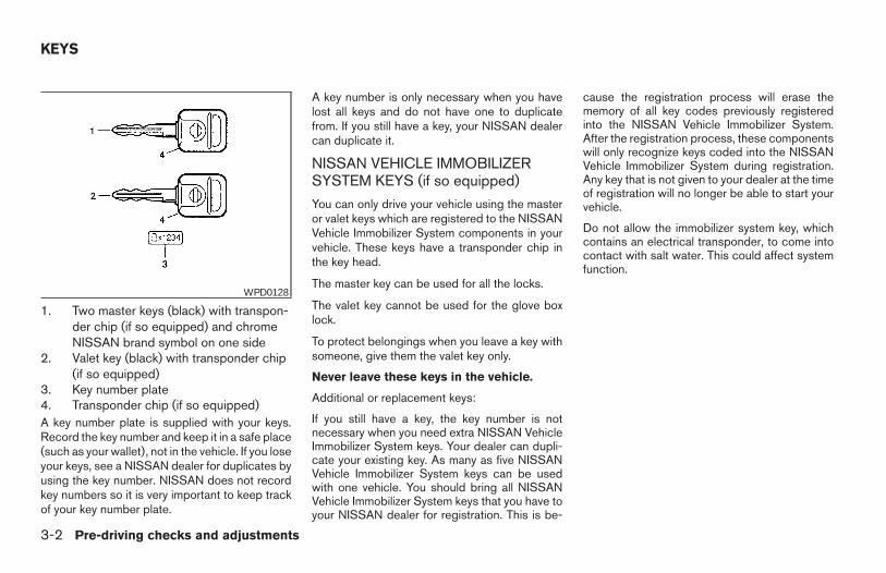
1. Two master keys (black) with transpon-der chip (if so equipped) and chromeNISSAN brand symbol on one side
2. Valet key (black) with transponder chip(if so equipped)
3. Key number plate4. Transponder chip (if so equipped)A key number plate is supplied with your keys.Record the key number and keep it in a safe place(such as your wallet), not in the vehicle. If you loseyour keys, see a NISSAN dealer for duplicates byusing the key number. NISSAN does not recordkey numbers so it is very important to keep trackof your key number plate.
A key number is only necessary when you havelost all keys and do not have one to duplicatefrom. If you still have a key, your NISSAN dealercan duplicate it.
NISSAN VEHICLE IMMOBILIZERSYSTEM KEYS (if so equipped)
You can only drive your vehicle using the masteror valet keys which are registered to the NISSANVehicle Immobilizer System components in yourvehicle. These keys have a transponder chip inthe key head.
The master key can be used for all the locks.
The valet key cannot be used for the glove boxlock.
To protect belongings when you leave a key withsomeone, give them the valet key only.
Never leave these keys in the vehicle.
Additional or replacement keys:
If you still have a key, the key number is notnecessary when you need extra NISSAN VehicleImmobilizer System keys. Your dealer can dupli-cate your existing key. As many as five NISSANVehicle Immobilizer System keys can be usedwith one vehicle. You should bring all NISSANVehicle Immobilizer System keys that you have toyour NISSAN dealer for registration. This is be-
cause the registration process will erase thememory of all key codes previously registeredinto the NISSAN Vehicle Immobilizer System.After the registration process, these componentswill only recognize keys coded into the NISSANVehicle Immobilizer System during registration.Any key that is not given to your dealer at the timeof registration will no longer be able to start yourvehicle.
Do not allow the immobilizer system key, whichcontains an electrical transponder, to come intocontact with salt water. This could affect systemfunction.
WPD0128
KEYS
3-2 Pre-driving checks and adjustments
Z REVIEW COPY—2006 Truck/Frontier (d22)Owners Manual—USA_English (nna)10/17/05—debbie X
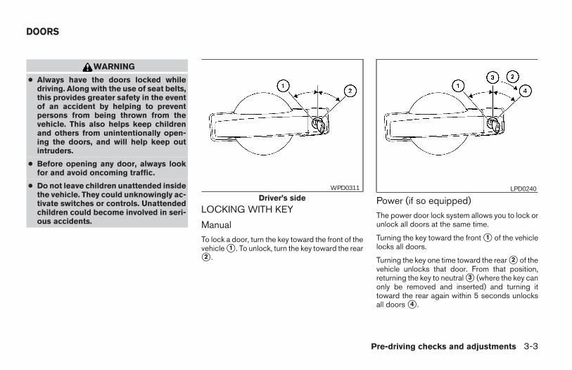
WARNING
● Always have the doors locked whiledriving. Along with the use of seat belts,this provides greater safety in the eventof an accident by helping to preventpersons from being thrown from thevehicle. This also helps keep childrenand others from unintentionally open-ing the doors, and will help keep outintruders.
● Before opening any door, always lookfor and avoid oncoming traffic.
● Do not leave children unattended insidethe vehicle. They could unknowingly ac-tivate switches or controls. Unattendedchildren could become involved in seri-ous accidents.
LOCKING WITH KEY
ManualTo lock a door, turn the key toward the front of thevehicle s1 . To unlock, turn the key toward the rears2 .
Power (if so equipped)The power door lock system allows you to lock orunlock all doors at the same time.
Turning the key toward the front s1 of the vehiclelocks all doors.
Turning the key one time toward the rear s2 of thevehicle unlocks that door. From that position,returning the key to neutral s3 (where the key canonly be removed and inserted) and turning ittoward the rear again within 5 seconds unlocksall doors s4 .
Driver’s sideWPD0311 LPD0240
DOORS
Pre-driving checks and adjustments 3-3
Z REVIEW COPY—2006 Truck/Frontier (d22)Owners Manual—USA_English (nna)10/17/05—debbie X
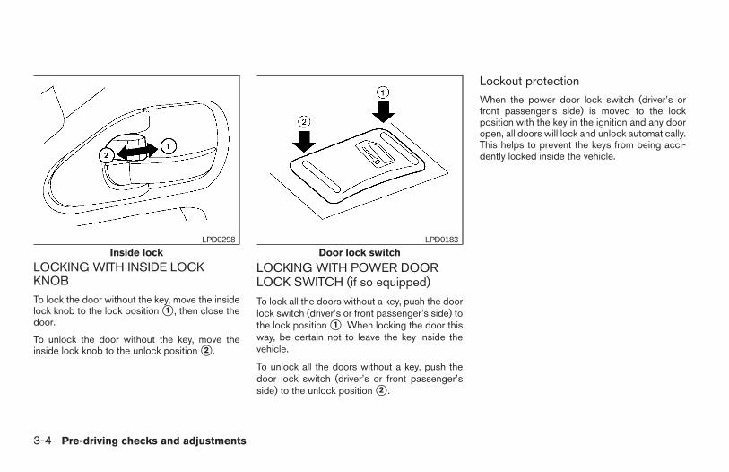
LOCKING WITH INSIDE LOCKKNOBTo lock the door without the key, move the insidelock knob to the lock position s1 , then close thedoor.
To unlock the door without the key, move theinside lock knob to the unlock position s2 .
LOCKING WITH POWER DOORLOCK SWITCH (if so equipped)
To lock all the doors without a key, push the doorlock switch (driver’s or front passenger’s side) tothe lock position s1 . When locking the door thisway, be certain not to leave the key inside thevehicle.
To unlock all the doors without a key, push thedoor lock switch (driver’s or front passenger’sside) to the unlock position s2 .
Lockout protectionWhen the power door lock switch (driver’s orfront passenger’s side) is moved to the lockposition with the key in the ignition and any dooropen, all doors will lock and unlock automatically.This helps to prevent the keys from being acci-dently locked inside the vehicle.
Inside lockLPD0298
Door lock switchLPD0183
3-4 Pre-driving checks and adjustments
Z REVIEW COPY—2006 Truck/Frontier (d22)Owners Manual—USA_English (nna)10/17/05—debbie X
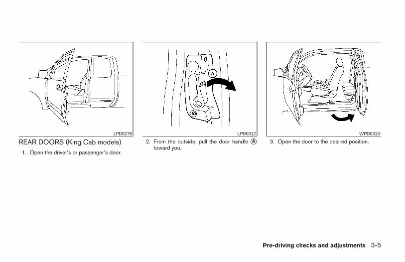
REAR DOORS (King Cab models)1. Open the driver’s or passenger’s door.
2. From the outside, pull the door handle sAtoward you.
3. Open the door to the desired position.LPD0278 LPD0312 WPD0313
Pre-driving checks and adjustments 3-5
Z REVIEW COPY—2006 Truck/Frontier (d22)Owners Manual—USA_English (nna)10/17/05—debbie X
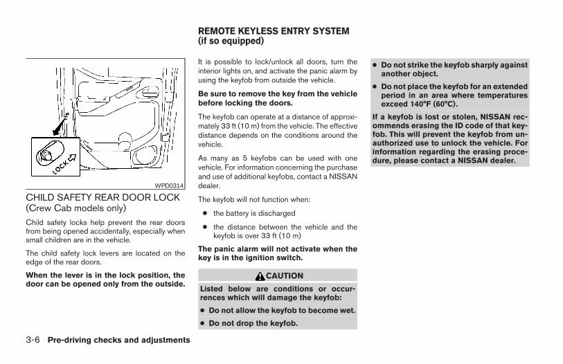
CHILD SAFETY REAR DOOR LOCK(Crew Cab models only)Child safety locks help prevent the rear doorsfrom being opened accidentally, especially whensmall children are in the vehicle.
The child safety lock levers are located on theedge of the rear doors.
When the lever is in the lock position, thedoor can be opened only from the outside.
It is possible to lock/unlock all doors, turn theinterior lights on, and activate the panic alarm byusing the keyfob from outside the vehicle.
Be sure to remove the key from the vehiclebefore locking the doors.
The keyfob can operate at a distance of approxi-mately 33 ft (10 m) from the vehicle. The effectivedistance depends on the conditions around thevehicle.
As many as 5 keyfobs can be used with onevehicle. For information concerning the purchaseand use of additional keyfobs, contact a NISSANdealer.
The keyfob will not function when:
● the battery is discharged
● the distance between the vehicle and thekeyfob is over 33 ft (10 m)
The panic alarm will not activate when thekey is in the ignition switch.
CAUTION
Listed below are conditions or occur-rences which will damage the keyfob:
● Do not allow the keyfob to become wet.
● Do not drop the keyfob.
● Do not strike the keyfob sharply againstanother object.
● Do not place the keyfob for an extendedperiod in an area where temperaturesexceed 140°F (60°C).
If a keyfob is lost or stolen, NISSAN rec-ommends erasing the ID code of that key-fob. This will prevent the keyfob from un-authorized use to unlock the vehicle. Forinformation regarding the erasing proce-dure, please contact a NISSAN dealer.
WPD0314
REMOTE KEYLESS ENTRY SYSTEM(if so equipped)
3-6 Pre-driving checks and adjustments
Z REVIEW COPY—2006 Truck/Frontier (d22)Owners Manual—USA_English (nna)10/17/05—debbie X
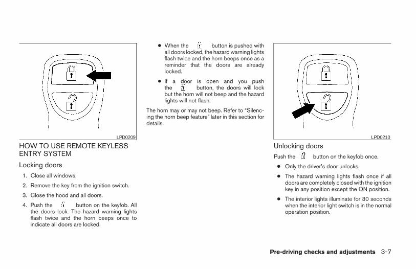
HOW TO USE REMOTE KEYLESSENTRY SYSTEM
Locking doors1. Close all windows.
2. Remove the key from the ignition switch.
3. Close the hood and all doors.
4. Push the button on the keyfob. Allthe doors lock. The hazard warning lightsflash twice and the horn beeps once toindicate all doors are locked.
● When the button is pushed withall doors locked, the hazard warning lightsflash twice and the horn beeps once as areminder that the doors are alreadylocked.
● If a door is open and you pushthe button, the doors will lockbut the horn will not beep and the hazardlights will not flash.
The horn may or may not beep. Refer to “Silenc-ing the horn beep feature” later in this section fordetails.
Unlocking doorsPush the button on the keyfob once.
● Only the driver’s door unlocks.
● The hazard warning lights flash once if alldoors are completely closed with the ignitionkey in any position except the ON position.
● The interior lights illuminate for 30 secondswhen the interior light switch is in the normaloperation position.
LPD0209 LPD0210
Pre-driving checks and adjustments 3-7
Z REVIEW COPY—2006 Truck/Frontier (d22)Owners Manual—USA_English (nna)10/17/05—debbie X
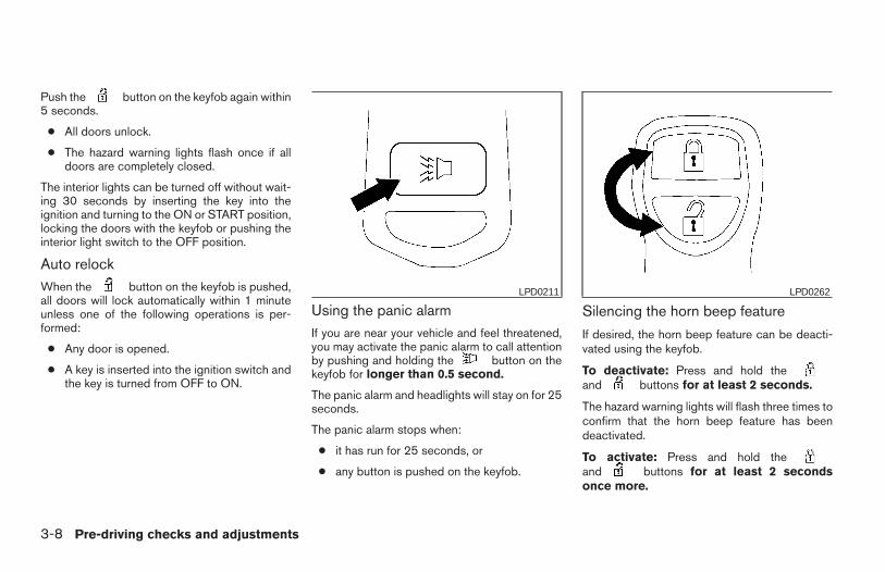
Push the button on the keyfob again within5 seconds.
● All doors unlock.
● The hazard warning lights flash once if alldoors are completely closed.
The interior lights can be turned off without wait-ing 30 seconds by inserting the key into theignition and turning to the ON or START position,locking the doors with the keyfob or pushing theinterior light switch to the OFF position.
Auto relockWhen the button on the keyfob is pushed,all doors will lock automatically within 1 minuteunless one of the following operations is per-formed:
● Any door is opened.
● A key is inserted into the ignition switch andthe key is turned from OFF to ON.
Using the panic alarmIf you are near your vehicle and feel threatened,you may activate the panic alarm to call attentionby pushing and holding the button on thekeyfob for longer than 0.5 second.
The panic alarm and headlights will stay on for 25seconds.
The panic alarm stops when:
● it has run for 25 seconds, or
● any button is pushed on the keyfob.
Silencing the horn beep feature
If desired, the horn beep feature can be deacti-vated using the keyfob.
To deactivate: Press and hold theand buttons for at least 2 seconds.
The hazard warning lights will flash three times toconfirm that the horn beep feature has beendeactivated.
To activate: Press and hold theand buttons for at least 2 secondsonce more.
LPD0211 LPD0262
3-8 Pre-driving checks and adjustments
Z REVIEW COPY—2006 Truck/Frontier (d22)Owners Manual—USA_English (nna)10/17/05—debbie X
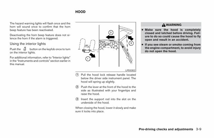
The hazard warning lights will flash once and thehorn will sound once to confirm that the hornbeep feature has been reactivated.
Deactivating the horn beep feature does not si-lence the horn if the alarm is triggered.
Using the interior lightsPush the button on the keyfob once to turnon the interior lights.
For additional information, refer to “Interior lights”in the “Instruments and controls”section earlier inthis manual.
s1 Pull the hood lock release handle locatedbelow the driver side instrument panel. Thehood will spring up slightly.
s2 Push the lever at the front of the hood to theside as illustrated with your fingertips andraise the hood.
s3 Insert the support rod into the slot on theunderside of the hood.
When closing the hood, lower it slowly and makesure it locks into place.
WARNING
● Make sure the hood is completelyclosed and latched before driving. Fail-ure to do so could cause the hood to flyopen and result in an accident.
● If you see steam or smoke coming fromthe engine compartment, to avoid injurydo not open the hood.
LPD0302
HOOD
Pre-driving checks and adjustments 3-9
Z REVIEW COPY—2006 Truck/Frontier (d22)Owners Manual—USA_English (nna)10/17/05—debbie X
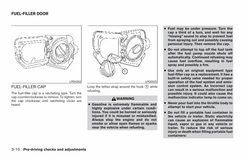
FUEL-FILLER CAPThe fuel-filler cap is a ratcheting type. Turn thecap counterclockwise to remove. To tighten, turnthe cap clockwise until ratcheting clicks areheard.
Loop the tether strap around the hook s1 whilerefueling.
WARNING
● Gasoline is extremely flammable andhighly explosive under certain condi-tions. You could be burned or seriouslyinjured if it is misused or mishandled.Always stop the engine and do notsmoke or allow open flames or sparksnear the vehicle when refueling.
● Fuel may be under pressure. Turn thecap a third of a turn, and wait for any“hissing” sound to stop to prevent fuelfrom spraying out and possibly causingpersonal injury. Then remove the cap.
● Do not attempt to top off the fuel tankafter the fuel pump nozzle shuts offautomatically. Continued refueling maycause fuel overflow, resulting in fuelspray and possibly a fire.
● Use only an original equipment typefuel-filler cap as a replacement. It has abuilt-in safety valve needed for properoperation of the fuel system and emis-sion control system. An incorrect capcan result in a serious malfunction andpossible injury. It could also cause themalfunction indicator lamp to come on.
● Never pour fuel into the throttle body toattempt to start your vehicle.
● Do not fill a portable fuel container inthe vehicle or trailer. Static electricitycan cause an explosion of flammableliquid, vapor or gas in any vehicle ortrailer. To reduce the risk of seriousinjury or death when filling portable fuelcontainers:
LPD0263 LPD0325
FUEL-FILLER DOOR
3-10 Pre-driving checks and adjustments
Z REVIEW COPY—2006 Truck/Frontier (d22)Owners Manual—USA_English (nna)10/17/05—debbie X
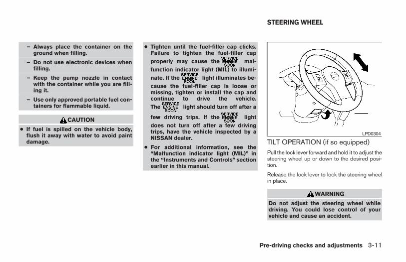
– Always place the container on theground when filling.
– Do not use electronic devices whenfilling.
– Keep the pump nozzle in contactwith the container while you are fill-ing it.
– Use only approved portable fuel con-tainers for flammable liquid.
CAUTION
● If fuel is spilled on the vehicle body,flush it away with water to avoid paintdamage.
● Tighten until the fuel-filler cap clicks.Failure to tighten the fuel-filler cap
properly may cause the mal-
function indicator light (MIL) to illumi-
nate. If the light illuminates be-
cause the fuel-filler cap is loose ormissing, tighten or install the cap andcontinue to drive the vehicle.
The light should turn off after a
few driving trips. If the light
does not turn off after a few drivingtrips, have the vehicle inspected by aNISSAN dealer.
● For additional information, see the“Malfunction indicator light (MIL)” inthe “Instruments and Controls” sectionearlier in this manual.
TILT OPERATION (if so equipped)Pull the lock lever forward and hold it to adjust thesteering wheel up or down to the desired posi-tion.
Release the lock lever to lock the steering wheelin place.
WARNING
Do not adjust the steering wheel whiledriving. You could lose control of yourvehicle and cause an accident.
LPD0304
STEERING WHEEL
Pre-driving checks and adjustments 3-11
Z REVIEW COPY—2006 Truck/Frontier (d22)Owners Manual—USA_English (nna)10/17/05—debbie X
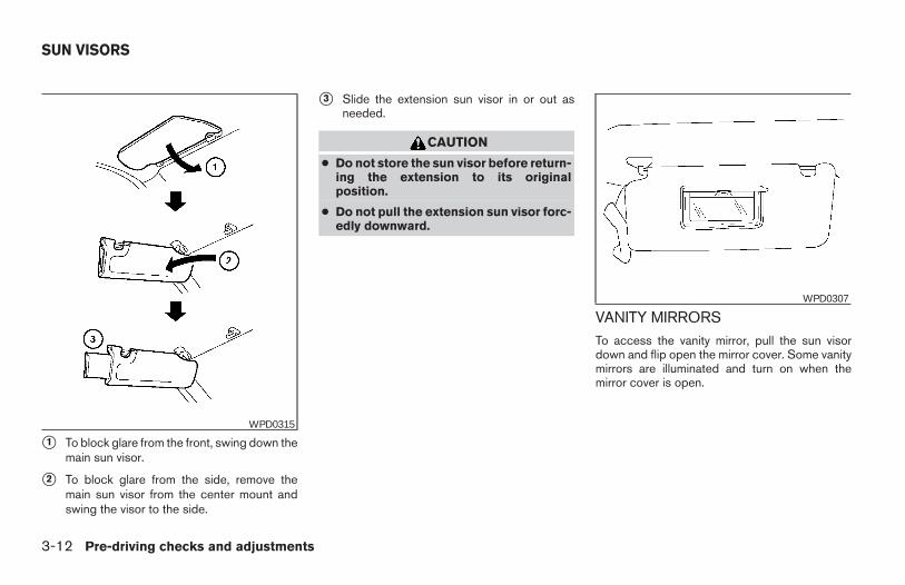
s1 To block glare from the front, swing down themain sun visor.
s2 To block glare from the side, remove themain sun visor from the center mount andswing the visor to the side.
s3 Slide the extension sun visor in or out asneeded.
CAUTION
● Do not store the sun visor before return-ing the extension to its originalposition.
● Do not pull the extension sun visor forc-edly downward.
VANITY MIRRORSTo access the vanity mirror, pull the sun visordown and flip open the mirror cover. Some vanitymirrors are illuminated and turn on when themirror cover is open.
WPD0315
WPD0307
SUN VISORS
3-12 Pre-driving checks and adjustments
Z REVIEW COPY—2006 Truck/Frontier (d22)Owners Manual—USA_English (nna)10/17/05—debbie X
REARVIEW MIRROR (if so equipped)The night position s1 reduces glare from theheadlights of vehicles behind you at night.
Use the day position s2 when driving in daylighthours.
WARNING
Use the night position only when neces-sary, because it reduces rear view clarity.
AUTOMATIC ANTI-GLAREREARVIEW MIRROR (if so equipped)The inside mirror is designed so that it automati-cally dims according to the intensity of the head-lights of the vehicle following you. The automaticanti-glare feature operates only when the ignitionswitch is in the ON position.
The indicator light s1 will illuminate when theautomatic anti-glare feature is operating.
To turn off the automatic anti-glare feature, pressthe button. The indicator light will turn off.
To turn on the automatic anti-glare feature, pressthe button again. The indicator light willturn on.
For information on HomeLinkT Universal Trans-ceiver operation, see “HomeLinkT UniversalTransceiver” in the “Instrument and controls” sec-tion of this manual.
For information on the compass and outside tem-perature display, see “Compass and outsidetemperature display” in the “Instrument and con-trols” section of this manual.
NOTE:
Do not hang any objects over the sensorss2 or apply glass cleaner to the sensors.Doing so will reduce the sensitivity of thesensors, resulting in improper operation.
WPD0126 WPD0333
MIRRORS
Pre-driving checks and adjustments 3-13
Z REVIEW COPY—2006 Truck/Frontier (d22)Owners Manual—USA_English (nna)10/17/05—debbie X
OUTSIDE MIRRORS
WARNING
● Objects viewed in the outside mirror onthe passenger side are closer than theyappear. Be careful when moving to theright. Using only this mirror could causean accident. Use the inside mirror orglance over your shoulder to properlyjudge distances to other objects.
● Do not adjust the mirrors while driving.You could lose control of your vehicleand cause an accident.
Electric control type (if so equipped)The outside mirror remote control will operateonly when the ignition switch is in the ACC or ONposition.
Move the small switch s1 to select the right or leftmirror. Adjust each mirror to the desired positionusing the large switch s2 .
Manual control typeThe outside mirror can be moved in any directionfor a better rear view.
Heated mirrors (if so equipped)Some outside mirrors can be heated to defrost,defog, or de-ice for improved visibility. For addi-tional information, see “Rear window and outsidemirror defroster switch” in the “Instrument andcontrols” section of this manual.
LPD0237 WPD0170
3-14 Pre-driving checks and adjustments
Z REVIEW COPY—2006 Truck/Frontier (d22)Owners Manual—USA_English (nna)10/17/05—debbie X
Foldable outside mirrorsPull the outside mirror toward the door to fold it.
TAILGATE
Opening the tailgate
Pull the tailgate handle upward and lower thetailgate. The support cables hold the tailgateopen.
When closing the tailgate, make sure the latchesare securely locked.
Do not drive the vehicle with the tailgatedown, unless equipped with NISSAN’s BedExtender (accessory) or equivalent in theextended position.
For proper truck box loading see “Vehicle loadinginformation” in the “Technical and consumer in-formation” section of this manual.
WARNING
● It is extremely dangerous to ride in acargo area inside a vehicle. In a colli-sion, people riding in these areas aremore likely to be seriously injured orkilled.
● Do not allow people to ride in any areaof your vehicle that is not equipped withseats and seat belts.
● Be sure everyone in your vehicle is in aseat and using a seat belt properly.
LPD0259 LPD0270
TRUCK BOX
Pre-driving checks and adjustments 3-15
Z REVIEW COPY—2006 Truck/Frontier (d22)Owners Manual—USA_English (nna)10/17/05—debbie X
Removing the tailgate
1. Release the tailgate support cables.
CAUTION
● The tailgate is heavy. Two peopleshould remove or install it. Be carefulnot to drop it during removal.
● After releasing the support cables, donot let the tailgate rest on the bumper.
2. Hold the tailgate at a 45 degree angle.
3. Pull the tailgate out from the right side hinge.
4. Slide the tailgate out of the left side hinge.
Installing the tailgate1. Insert the tailgate into the left side hinge.
2. Hold the tailgate at a 45 degree angle andinsert into the right side hinge.
3. Continue to hold the tailgate at a 45 degreeangle and attach the tailgate support cables.
4. Close the tailgate securely.
Locking the tailgateTo lock the tailgate, turn the key toward the pas-senger side of the vehicle s1 . To unlock, turn thekey toward the driver side s2 .
Both the master key and the valet key can beused to lock and unlock the tailgate.
LPD0271 LPD0272
3-16 Pre-driving checks and adjustments
Z REVIEW COPY—2006 Truck/Frontier (d22)Owners Manual—USA_English (nna)10/17/05—debbie X
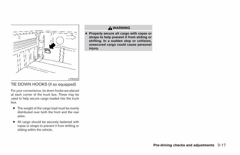
TIE DOWN HOOKS (if so equipped)
For your convenience, tie down hooks are placedat each corner of the truck box. These may beused to help secure cargo loaded into the truckbox.
● The weight of the cargo load must be evenlydistributed over both the front and the rearaxles.
● All cargo should be securely fastened withropes or straps to prevent it from shifting orsliding within the vehicle.
WARNING
● Properly secure all cargo with ropes orstraps to help prevent it from sliding orshifting. In a sudden stop or collision,unsecured cargo could cause personalinjury.
LTI0102
Pre-driving checks and adjustments 3-17
Z REVIEW COPY—2006 Truck/Frontier (d22)Owners Manual—USA_English (nna)10/17/05—debbie X

3-18 Pre-driving checks and adjustments
MEMO
4 Heater, air conditioner and audiosystems
Ventilators . . . . . . . . . . . . . . . . . . . . . . . . . . . . . . . . . . . . . . . . 4-2Heater and air conditioner (manual) . . . . . . . . . . . . . . . . . . 4-2
Controls . . . . . . . . . . . . . . . . . . . . . . . . . . . . . . . . . . . . . . . 4-3Heater operation . . . . . . . . . . . . . . . . . . . . . . . . . . . . . . . 4-4Air conditioner operation (if so equipped) . . . . . . . . . 4-5Air flow charts. . . . . . . . . . . . . . . . . . . . . . . . . . . . . . . . . . 4-6
Servicing air conditioner. . . . . . . . . . . . . . . . . . . . . . . . . . . . 4-9Audio system . . . . . . . . . . . . . . . . . . . . . . . . . . . . . . . . . . . .4-10
Radio . . . . . . . . . . . . . . . . . . . . . . . . . . . . . . . . . . . . . . . .4-10FM radio reception . . . . . . . . . . . . . . . . . . . . . . . . . . . .4-10AM radio reception . . . . . . . . . . . . . . . . . . . . . . . . . . . .4-10
Satellite radio reception (if so equipped) . . . . . . . . . 4-10Audio operation precautions . . . . . . . . . . . . . . . . . . . . 4-11FM-AM radio with compact disc (CD) player(if so equipped) . . . . . . . . . . . . . . . . . . . . . . . . . . . . . . .4-16FM-AM-SAT radio with compact disc (CD)changer . . . . . . . . . . . . . . . . . . . . . . . . . . . . . . . . . . . . . .4-20CD care and cleaning . . . . . . . . . . . . . . . . . . . . . . . . . . 4-25Steering wheel switch for audio control(if so equipped) . . . . . . . . . . . . . . . . . . . . . . . . . . . . . . .4-26Antenna . . . . . . . . . . . . . . . . . . . . . . . . . . . . . . . . . . . . . .4-26
Car phone or CB radio . . . . . . . . . . . . . . . . . . . . . . . . . . . .4-27
Z REVIEW COPY—2006 Truck/Frontier (d22)Owners Manual—USA_English (nna)10/17/05—debbie X
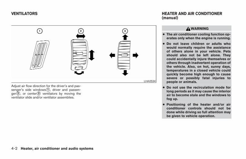
Adjust air flow direction for the driver’s and pas-senger’s side windowss1 , driver and passen-gers2 , or centers3 ventilators by moving theventilator slide and/or ventilator assemblies.
WARNING
● The air conditioner cooling function op-erates only when the engine is running.
● Do not leave children or adults whowould normally require the assistanceof others alone in your vehicle. Petsshould also not be left alone. Theycould accidentally injure themselves orothers through inadvertent operation ofthe vehicle. Also, on hot, sunny days,temperatures in a closed vehicle couldquickly become high enough to causesevere or possibly fatal injuries topeople or animals.
● Do not use the recirculation mode forlong periods as it may cause the interiorair to become stale and the windows tofog up.
● Positioning of the heater and/or airconditioner controls should not bedone while driving so full attention maybe given to vehicle operation.
LHA0534
VENTILATORS HEATER AND AIR CONDITIONER(manual)
4-2 Heater, air conditioner and audio systems
Z REVIEW COPY—2006 Truck/Frontier (d22)Owners Manual—USA_English (nna)10/17/05—debbie X
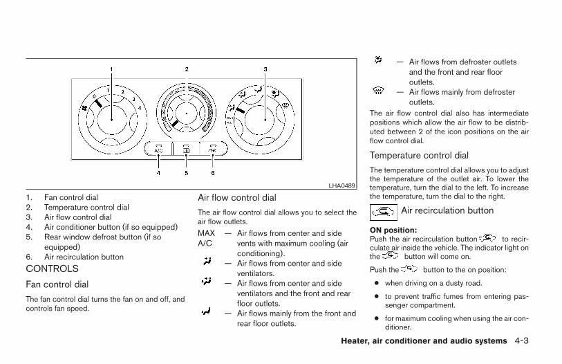
1. Fan control dial2. Temperature control dial3. Air flow control dial4. Air conditioner button (if so equipped)5. Rear window defrost button (if so
equipped)6. Air recirculation button
CONTROLS
Fan control dial
The fan control dial turns the fan on and off, andcontrols fan speed.
Air flow control dial
The air flow control dial allows you to select theair flow outlets.
MAXA/C
— Air flows from center and sidevents with maximum cooling (airconditioning).
— Air flows from center and sideventilators.
— Air flows from center and sideventilators and the front and rearfloor outlets.
— Air flows mainly from the front andrear floor outlets.
— Air flows from defroster outletsand the front and rear flooroutlets.
— Air flows mainly from defrosteroutlets.
The air flow control dial also has intermediatepositions which allow the air flow to be distrib-uted between 2 of the icon positions on the airflow control dial.
Temperature control dial
The temperature control dial allows you to adjustthe temperature of the outlet air. To lower thetemperature, turn the dial to the left. To increasethe temperature, turn the dial to the right.
Air recirculation button
ON position:Push the air recirculation button to recir-culate air inside the vehicle. The indicator light onthe button will come on.
Push the button to the on position:
● when driving on a dusty road.
● to prevent traffic fumes from entering pas-senger compartment.
● for maximum cooling when using the air con-ditioner.
LHA0489
Heater, air conditioner and audio systems 4-3
Z REVIEW COPY—2006 Truck/Frontier (d22)Owners Manual—USA_English (nna)10/17/05—debbie X
OFF position:Push the air recirculation button again toturn air recirculation off. The indicator light onthe button will turn off. Outside air is drawninto the passenger compartment and distributedthrough the selected outlet.
Use the off position for normal heater or air con-ditioner operation.
Air conditioner button (if soequipped)
The button is provided only on vehicles equippedwith an air conditioner.
Start the engine, turn the fan control dial to thedesired (1 - 4) position and push thebutton to turn on the air conditioner. The indicatorlight comes on when the air conditioner is oper-ating. To turn off the air conditioner, pushthe button again.
The air conditioner cooling function oper-ates only when the engine is running.
Rear window defroster switchFor more information about the rear window de-froster switch, see “Rear window and outsidemirror (if so equipped) defroster switch” in the“Instruments and controls”section of this manual.
HEATER OPERATIONHeating
This mode is used to direct heated air to the footoutlets. Some air also flows from the defrostoutlets.
1. Push the button to the OFF positionfor normal heating. The indicator light onthe button will go off.
2. Turn the air flow control dial to theposition.
3. Turn the fan control dial to the desired posi-tion.
4. Turn the temperature control dial to the de-sired position between the middle and thehot position.
VentilationThis mode directs outside air to the side andcenter ventilators.
1. Push the button to the OFF position.The indicator light on the button willgo off.
2. Turn the air flow control dial to theposition.
3. Turn the fan control dial to the desired posi-tion.
4. Turn the temperature control dial to the de-sired position.
Defrosting or defogging
This mode directs the air to the defrost outlets todefrost/defog the windows.
1. Turn the air flow control dial to theposition.
2. Turn the fan control dial to the desired posi-tion.
3. Turn the temperature control dial to the de-sired position between the middle and thehot position.
● To quickly remove ice or fog from the win-dows, turn the fan control dial to 4 and thetemperature control lever to the full HOTposition.
● When the position is selected, the airconditioner automatically turns on (however,the indicator light will not illuminate) if theoutside temperature is more than 36°F(2°C). The air conditioning system will con-tinue to operate until the fan control dial isturned to OFF or the vehicle is shut off, evenif the air flow control dial is turned to aposition other than the position. Thisdehumidifies the air which helps defog thewindshield. The mode automatically
4-4 Heater, air conditioner and audio systems
Z REVIEW COPY—2006 Truck/Frontier (d22)Owners Manual—USA_English (nna)10/17/05—debbie X
turns off, allowing outside air to be drawninto the passenger compartment to furtherimprove the defogging performance.
Bi-level heating
This mode directs cooler air from the side andcenter vents and warmer air from the floor outlets.When the temperature control dial is moved tothe full hot or full cool position, the air betweenthe vents and the floor outlets is the same tem-perature.
1. Push the button to the off position.
2. Turn the air flow control dial to theposition.
3. Turn the fan control dial to the desired posi-tion.
4. Turn the temperature control dial to the de-sired position.
Heating and defogging
This mode heats the interior and defogs the wind-shield.
1. Turn the air flow control dial to theposition.
2. Turn the fan control dial to the desired posi-tion.
3. Turn the temperature control dial to the de-sired position between the middle and thehot position.
● When the position is selected, the airconditioner automatically turns on (however,the indicator light on the button willnot come on) if the outside temperature ismore than 36°F (2°C). If in defrost mode formore than one minute, the air conditioningsystem will continue to operate until the fancontrol dial is turned to OFF or the vehicle isshut off, even if the air flow control dial isturned to a position other than theposition. This dehumidifies the air whichhelps defog the windshield. Themode automatically turns off, allowing out-side air to be drawn into the passengercompartment to further improve the defog-ging performance.
Operating tipsClear snow and ice from the wiper bladesand air inlet in front of the windshield. Thisimproves heater operation.
AIR CONDITIONER OPERATION (ifso equipped)
Start the engine, turn the fan control dial to thedesired (1 - 4) position, and push in thebutton to activate the air conditioner. When theair conditioner is on, cooling and dehumidifyingfunctions are added to the heater operation.
The air conditioner cooling function oper-ates only when the engine is running.
Cooling
This mode is used to cool and dehumidify the air.
1. Push the button to the off position.
2. Turn the air flow control dial to theposition.
3. Turn the fan control dial to the desired posi-tion.
4. Push the button. The indicator lightcomes on.
5. Turn the temperature control dial to the de-sired position.
● For quick cooling when the outside tem-perature is high, push the button tothe on position (indicator light on). Be sureto return the button to the off positionfor normal cooling.
Heater, air conditioner and audio systems 4-5
Z REVIEW COPY—2006 Truck/Frontier (d22)Owners Manual—USA_English (nna)10/17/05—debbie X
Dehumidified heatingThis mode is used to heat and dehumidify the air.
1. Push the button to the off position.
2. Turn the air flow control dial to theposition.
3. Turn the fan control dial to the desired posi-tion.
4. Push the button. The indicator lightcomes on.
5. Turn the temperature control dial to the de-sired position.
Dehumidified defoggingThis mode is used to defog the windows anddehumidify the air.
1. Turn the air flow control dial to theposition.
2. Turn the fan control dial to the desired posi-tion.
3. Push the button. The indicator lightcomes on.
When the , or positions in betweenare selected, the air conditioner automaticallyturns on (however, the indicator light will notilluminate) if the outside temperature is more than36°F (2°C). The air conditioning system will con-tinue to operate until the fan control dial is turnedto OFF or the vehicle is shut off, even if the air flowcontrol dial is turned to a position other thanthe position. This dehumidifies the airwhich helps defog the windshield. Themode automatically turns off, allowing outside airto be drawn into the passenger compartment tofurther improve the defogging performance.
4. Turn the temperature control dial to the de-sired position.
Operating tips● Keep the windows and sunroof (if so
equipped) closed while the air conditioner isin operation.
● After parking in the sun, drive for 2 or 3minutes with the windows open to vent hotair from the passenger compartment. Then,close the windows. This allows the air con-ditioner to cool the interior more quickly.
● The air conditioning system should beoperated for approximately 10 minutesat least once a month. This helps pre-vent damage to the system due to lackof lubrication.
● If the engine coolant temperaturegauge indicates engine coolant tem-perature over the normal range, turnthe air conditioner off. See “If yourvehicle overheats” in the “In case ofemergency” section of this manual.
AIR FLOW CHARTSThe following charts show the button and dialpositions for MAXIMUM AND QUICK heating,cooling or defrosting. For additional informationon heating and cooling see “Heater and air con-ditioner” in this section”. The air recirculation( ) button should always be in the OFFposition for heating and defrosting.
4-6 Heater, air conditioner and audio systems
Z REVIEW COPY—2006 Truck/Frontier (d22)Owners Manual—USA_English (nna)10/17/05—debbie X
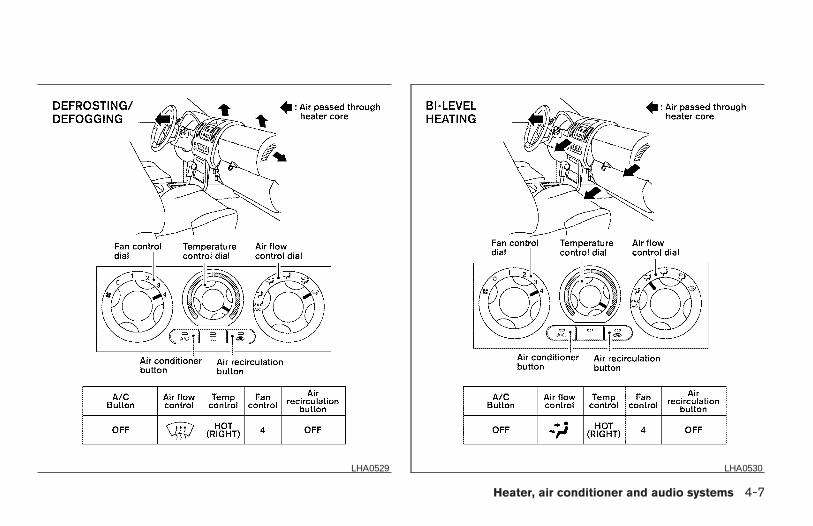
LHA0529 LHA0530
Heater, air conditioner and audio systems 4-7
Z REVIEW COPY—2006 Truck/Frontier (d22)Owners Manual—USA_English (nna)10/17/05—debbie X
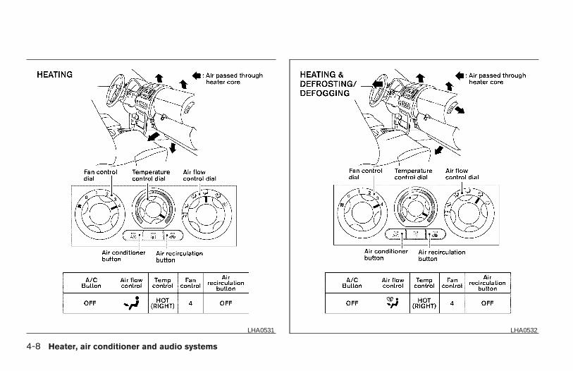
LHA0531 LHA0532
4-8 Heater, air conditioner and audio systems
Z REVIEW COPY—2006 Truck/Frontier (d22)Owners Manual—USA_English (nna)10/17/05—debbie X
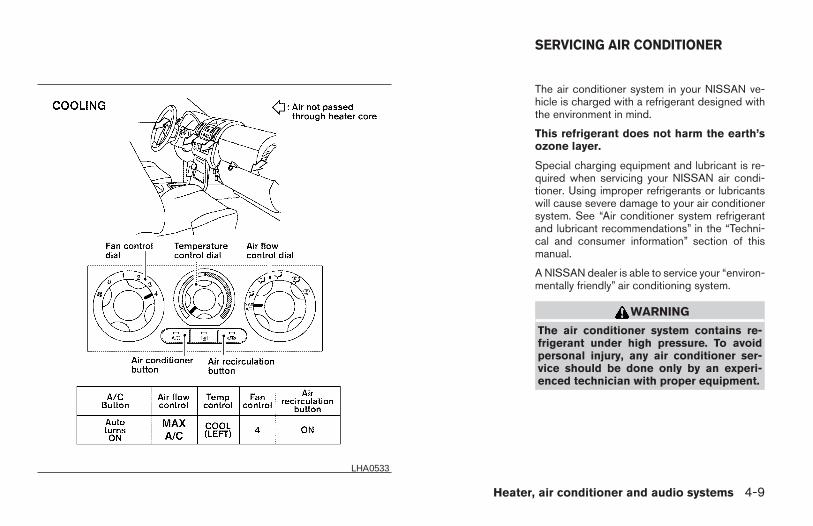
The air conditioner system in your NISSAN ve-hicle is charged with a refrigerant designed withthe environment in mind.
This refrigerant does not harm the earth’sozone layer.
Special charging equipment and lubricant is re-quired when servicing your NISSAN air condi-tioner. Using improper refrigerants or lubricantswill cause severe damage to your air conditionersystem. See “Air conditioner system refrigerantand lubricant recommendations” in the “Techni-cal and consumer information” section of thismanual.
A NISSAN dealer is able to service your “environ-mentally friendly” air conditioning system.
WARNING
The air conditioner system contains re-frigerant under high pressure. To avoidpersonal injury, any air conditioner ser-vice should be done only by an experi-enced technician with proper equipment.
LHA0533
SERVICING AIR CONDITIONER
Heater, air conditioner and audio systems 4-9
Z REVIEW COPY—2006 Truck/Frontier (d22)Owners Manual—USA_English (nna)10/17/05—debbie X
RADIO
Turn the ignition key to the ACC or ON positionand press the PWR (power)/VOL (volume) knobto turn the radio on. If you listen to the radio withthe engine not running, the key should be turnedto the ACC position.
Radio reception is affected by station signalstrength, distance from radio transmitter, build-ings, bridges, mountains and other external influ-ences. Intermittent changes in reception qualitynormally are caused by these external influences.
Using a cellular phone in or near the ve-hicle may influence radio reception quality.
Radio reception
Your NISSAN radio system is equipped withstate-of-the-art electronic circuits to enhance ra-dio reception. These circuits are designed toextend reception range, and to enhance the qual-ity of that reception.
However there are some general characteristicsof both FM and AM radio signals that can affectradio reception quality in a moving vehicle, evenwhen the finest equipment is used. These char-acteristics are completely normal in a given re-ception area, and do not indicate any malfunctionin your NISSAN radio system.
Reception conditions will constantly change be-cause of vehicle movement. Buildings, terrain,signal distance and interference from other ve-hicles can work against ideal reception. De-scribed below are some of the factors that canaffect your radio reception.
FM RADIO RECEPTION
Range: FM range is normally limited to 25 – 30miles (40 – 48 km), with monaural (single chan-nel) FM having slightly more range than stereoFM. External influences may sometimes interferewith FM station reception even if the FM station iswithin 25 miles (40 km). The strength of the FMsignal is directly related to the distance betweenthe transmitter and receiver. FM signals follow aline-of-sight path, exhibiting many of the samecharacteristics as light. For example they willreflect off objects.
Fade and drift: As your vehicle moves away froma station transmitter, the signals will tend to fadeand/or drift.
Static and flutter: During signal interference frombuildings, large hills or due to antenna position(usually in conjunction with increased distancefrom the station transmitter) static or flutter canbe heard. This can be reduced by adjusting thetreble control to reduce treble response.
Multipath reception: Because of the reflectivecharacteristics of FM signals, direct and reflectedsignals reach the receiver at the same time. Thesignals may cancel each other, resulting in mo-mentary flutter or loss of sound.
AM RADIO RECEPTION
AM signals, because of their low frequency, canbend around objects and skip along the ground.In addition, the signals can be bounced off theionosphere and bent back to earth. Because ofthese characteristics, AM signals are also sub-ject to interference as they travel from transmitterto receiver.
Fading: Occurs while the vehicle is passingthrough freeway underpasses or in areas withmany tall buildings. It can also occur for severalseconds during ionospheric turbulence even inareas where no obstacles exist.
Static: Caused by thunderstorms, electricalpower lines, electric signs and even traffic lights.
SATELLITE RADIO RECEPTION (if soequipped)
When the satellite radio is first installed or thebattery has been replaced, the satellite radio maynot work properly. This is not a malfunction. Waitmore than 10 minutes with satellite radio ON and
AUDIO SYSTEM
4-10 Heater, air conditioner and audio systems
Z REVIEW COPY—2006 Truck/Frontier (d22)Owners Manual—USA_English (nna)10/17/05—debbie X
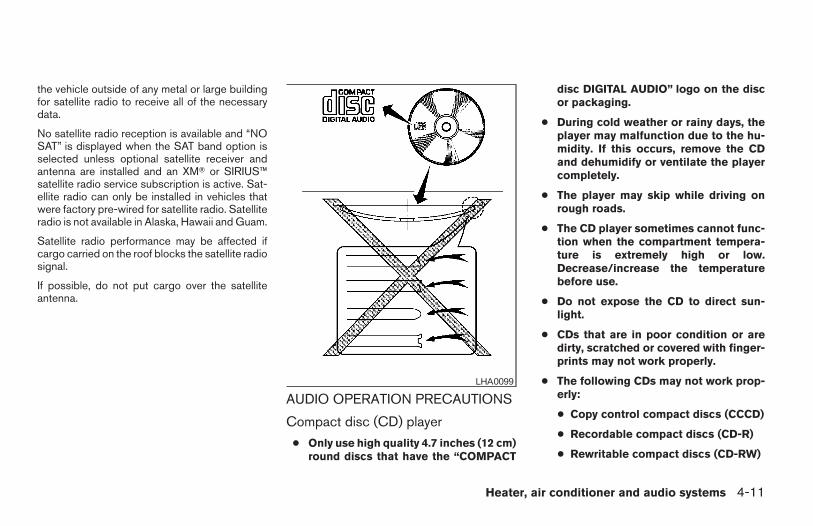
the vehicle outside of any metal or large buildingfor satellite radio to receive all of the necessarydata.
No satellite radio reception is available and “NOSAT” is displayed when the SAT band option isselected unless optional satellite receiver andantenna are installed and an XMT or SIRIUS™satellite radio service subscription is active. Sat-ellite radio can only be installed in vehicles thatwere factory pre-wired for satellite radio. Satelliteradio is not available in Alaska, Hawaii and Guam.
Satellite radio performance may be affected ifcargo carried on the roof blocks the satellite radiosignal.
If possible, do not put cargo over the satelliteantenna.
AUDIO OPERATION PRECAUTIONS
Compact disc (CD) player
● Only use high quality 4.7 inches (12 cm)round discs that have the “COMPACT
disc DIGITAL AUDIO” logo on the discor packaging.
● During cold weather or rainy days, theplayer may malfunction due to the hu-midity. If this occurs, remove the CDand dehumidify or ventilate the playercompletely.
● The player may skip while driving onrough roads.
● The CD player sometimes cannot func-tion when the compartment tempera-ture is extremely high or low.Decrease/increase the temperaturebefore use.
● Do not expose the CD to direct sun-light.
● CDs that are in poor condition or aredirty, scratched or covered with finger-prints may not work properly.
● The following CDs may not work prop-erly:
● Copy control compact discs (CCCD)
● Recordable compact discs (CD-R)
● Rewritable compact discs (CD-RW)
LHA0099
Heater, air conditioner and audio systems 4-11
Z REVIEW COPY—2006 Truck/Frontier (d22)Owners Manual—USA_English (nna)10/17/05—debbie X
● Do not use the following CDs as theymay cause the CD player to malfunc-tion:
● 3.1 in (8 cm) discs with an adapter
● CDs that are not round
● CDs with a paper label
● CDs that are warped, scratched, orhave abnormal edges
● This audio system can only play pre-recorded CDs. It has no capability torecord or burn CDs.
● If the CD cannot be played, one of thefollowing messages will be displayed.
CHECK DISC:
● Confirm that the CD is inserted cor-rectly (the label side is facing up, etc.).
● Confirm that the CD is not bent orwarped and it is free of scratches.
PUSH EJECT:
This is an error due to excessive tem-perature inside the player. Remove theCD by pushing the EJECT button. Aftera short time, reinsert the CD. The CDcan be played when the temperature ofthe player returns to normal.
UNPLAYABLE:
The file is unplayable in this audio sys-tem (only MP3 CD).
Compact Disc with MP3Terms:
● MP3 — MP3 is short for Moving PicturesExperts Group Audio Layer 3. MP3 is themost well-known compressed digital audiofile format. This format allows for near “CDquality” sound, but at a fraction of the size ofnormal audio files. MP3 conversion of anaudio track from CD-ROM can reduce thefile size by approximately a 10:1 ratio withvirtually no perceptible loss in quality. MP3compression removes the redundant andirrelevant parts of a sound signal that thehuman ear doesn’t hear.
● Bit rate — Bit rate denotes the number ofbits per second used by a digital music file.The size and quality of a compressed digitalaudio file is determined by the bit rate usedwhen encoding the file.
● Sampling frequency — Sampling frequencyis the rate at which the samples of a signalare converted from analog to digital (A/Dconversion) per second.
● ID3 tag — The ID3 tag is the part of theencoded MP3 file that contains informationabout the digital music file such as song title,artist, album title, encoding bit rate, tracktime duration, etc. ID3 tag information isdisplayed on the Album/Artist/Track title lineon the display.
4-12 Heater, air conditioner and audio systems
Z REVIEW COPY—2006 Truck/Frontier (d22)Owners Manual—USA_English (nna)10/17/05—debbie X
Playback order:
Playback order of the CD with compressed files(MP3) is as illustrated above.
● The names of folders not containing MP3files are not shown in the display.
● If there is a file in the top level of the disc,“ROOT” is displayed.
● The playback order is the order in which thefiles were written by the writing software.Therefore, the files might not play in thedesired order.
WHA0543
Heater, air conditioner and audio systems 4-13
Z REVIEW COPY—2006 Truck/Frontier (d22)Owners Manual—USA_English (nna)10/17/05—debbie X
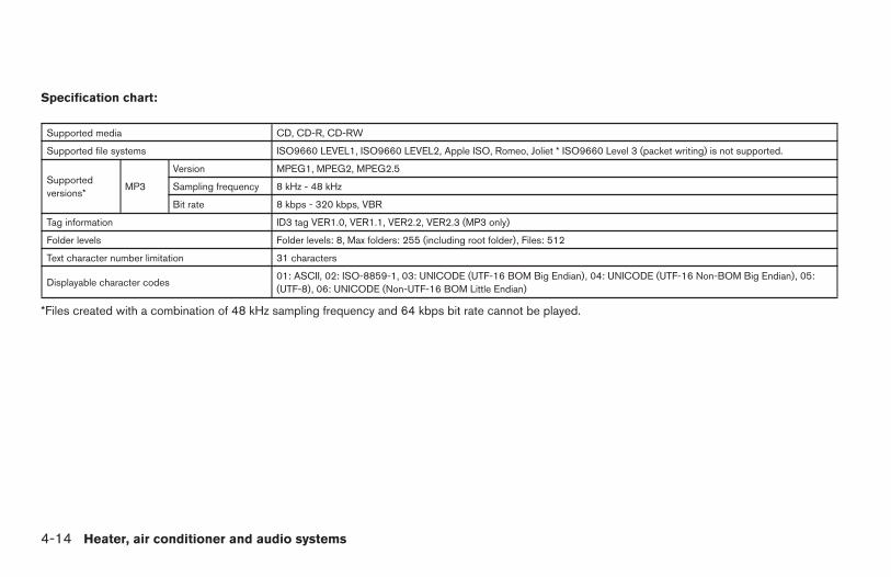
Specification chart:
Supported media CD, CD-R, CD-RW
Supported file systems ISO9660 LEVEL1, ISO9660 LEVEL2, Apple ISO, Romeo, Joliet * ISO9660 Level 3 (packet writing) is not supported.
Supportedversions*
MP3
Version MPEG1, MPEG2, MPEG2.5
Sampling frequency 8 kHz - 48 kHz
Bit rate 8 kbps - 320 kbps, VBR
Tag information ID3 tag VER1.0, VER1.1, VER2.2, VER2.3 (MP3 only)
Folder levels Folder levels: 8, Max folders: 255 (including root folder), Files: 512
Text character number limitation 31 characters
Displayable character codes01: ASCII, 02: ISO-8859-1, 03: UNICODE (UTF-16 BOM Big Endian), 04: UNICODE (UTF-16 Non-BOM Big Endian), 05:(UTF-8), 06: UNICODE (Non-UTF-16 BOM Little Endian)
*Files created with a combination of 48 kHz sampling frequency and 64 kbps bit rate cannot be played.
4-14 Heater, air conditioner and audio systems
Z REVIEW COPY—2006 Truck/Frontier (d22)Owners Manual—USA_English (nna)10/17/05—debbie X
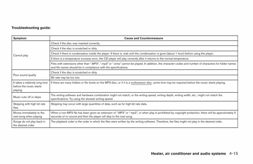
Troubleshooting guide:
Symptom Cause and Countermeasure
Cannot play
Check if the disc was inserted correctly.
Check if the disc is scratched or dirty.
Check if there is condensation inside the player. If there is, wait until the condensation is gone (about 1 hour) before using the player.
If there is a temperature increase error, the CD player will play correctly after it returns to the normal temperature.
Files with extensions other than “.MP3”, “.mp3” or “.wma” cannot be played. In addition, the character codes and number of characters for folder namesand file names should be in compliance with the specifications.
Poor sound qualityCheck if the disc is scratched or dirty.
Bit rate may be too low.
It takes a relatively long timebefore the music startsplaying.
If there are many folders or file levels on the MP3 disc, or if it is a multisession disc, some time may be required before the music starts playing.
Music cuts off or skipsThe writing software and hardware combination might not match, or the writing speed, writing depth, writing width, etc., might not match thespecifications. Try using the slowest writing speed.
Skipping with high bit ratefiles
Skipping may occur with large quantities of data, such as for high bit rate data.
Moves immediately to thenext song when playing
When a non-MP3 file has been given an extension of “.MP3” or “.mp3”, or when play is prohibited by copyright protection, there will be approximately 5seconds of no sound and then the player will skip to the next song.
Songs do not play back inthe desired order
The playback order is the order in which the files were written by the writing software. Therefore, the files might not play in the desired order.
Heater, air conditioner and audio systems 4-15
Z REVIEW COPY—2006 Truck/Frontier (d22)Owners Manual—USA_English (nna)10/17/05—debbie X
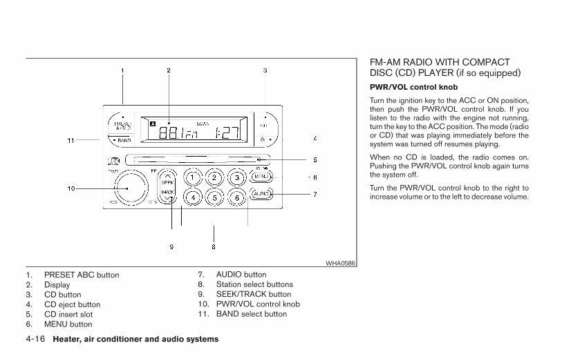
1. PRESET ABC button2. Display3. CD button4. CD eject button5. CD insert slot6. MENU button
7. AUDIO button8. Station select buttons9. SEEK/TRACK button10. PWR/VOL control knob11. BAND select button
FM-AM RADIO WITH COMPACTDISC (CD) PLAYER (if so equipped)PWR/VOL control knob
Turn the ignition key to the ACC or ON position,then push the PWR/VOL control knob. If youlisten to the radio with the engine not running,turn the key to the ACC position. The mode (radioor CD) that was playing immediately before thesystem was turned off resumes playing.
When no CD is loaded, the radio comes on.Pushing the PWR/VOL control knob again turnsthe system off.
Turn the PWR/VOL control knob to the right toincrease volume or to the left to decrease volume.
WHA0586
4-16 Heater, air conditioner and audio systems
Z REVIEW COPY—2006 Truck/Frontier (d22)Owners Manual—USA_English (nna)10/17/05—debbie X
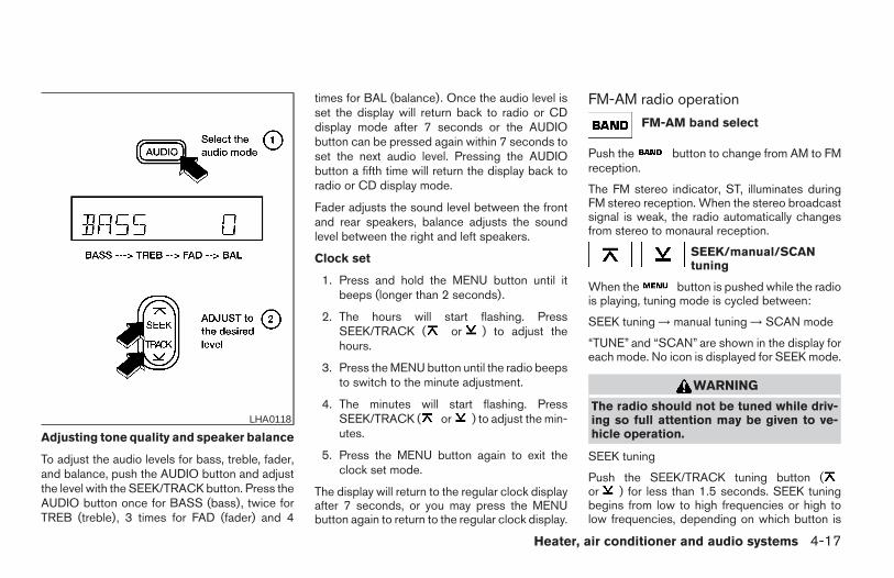
Adjusting tone quality and speaker balance
To adjust the audio levels for bass, treble, fader,and balance, push the AUDIO button and adjustthe level with the SEEK/TRACK button. Press theAUDIO button once for BASS (bass), twice forTREB (treble), 3 times for FAD (fader) and 4
times for BAL (balance). Once the audio level isset the display will return back to radio or CDdisplay mode after 7 seconds or the AUDIObutton can be pressed again within 7 seconds toset the next audio level. Pressing the AUDIObutton a fifth time will return the display back toradio or CD display mode.
Fader adjusts the sound level between the frontand rear speakers, balance adjusts the soundlevel between the right and left speakers.
Clock set
1. Press and hold the MENU button until itbeeps (longer than 2 seconds).
2. The hours will start flashing. PressSEEK/TRACK ( or ) to adjust thehours.
3. Press the MENU button until the radio beepsto switch to the minute adjustment.
4. The minutes will start flashing. PressSEEK/TRACK ( or ) to adjust the min-utes.
5. Press the MENU button again to exit theclock set mode.
The display will return to the regular clock displayafter 7 seconds, or you may press the MENUbutton again to return to the regular clock display.
FM-AM radio operation
FM-AM band select
Push the button to change from AM to FMreception.
The FM stereo indicator, ST, illuminates duringFM stereo reception. When the stereo broadcastsignal is weak, the radio automatically changesfrom stereo to monaural reception.
SEEK/manual/SCANtuning
When the button is pushed while the radiois playing, tuning mode is cycled between:
SEEK tuning → manual tuning → SCAN mode
“TUNE” and “SCAN” are shown in the display foreach mode. No icon is displayed for SEEK mode.
WARNING
The radio should not be tuned while driv-ing so full attention may be given to ve-hicle operation.
SEEK tuning
Push the SEEK/TRACK tuning button (or ) for less than 1.5 seconds. SEEK tuningbegins from low to high frequencies or high tolow frequencies, depending on which button is
LHA0118
Heater, air conditioner and audio systems 4-17
Z REVIEW COPY—2006 Truck/Frontier (d22)Owners Manual—USA_English (nna)10/17/05—debbie X
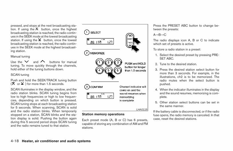
pressed, and stops at the next broadcasting sta-tion. If using the button, once the highestbroadcasting station is reached, the radio contin-ues in the SEEK mode at the lowest broadcastingstation. If using the button, once the lowestbroadcasting station is reached, the radio contin-ues in the SEEK mode at the highest broadcast-ing station.
Manual tuning
Use the and buttons for manualtuning. To move quickly through the channels,hold either of the tuning buttons down.
SCAN tuning
Push and hold the SEEK/TRACK tuning button( or ) for more than 1.5 seconds.
SCAN illuminates in the display window, and theradio station blinks. SCAN tuning begins fromlow to high frequencies or high to low frequen-cies, depending on which button is pressed.SCAN tuning stops at each broadcasting stationfor 5 seconds. When scanning, SCAN is solidand the radio station blinks. When temporarilystopped on a station, SCAN blinks and the sta-tion display is solid. Pushing the button againduring this 5 second period stops SCAN tuningand the radio remains tuned to that station.
Station memory operations
Each preset mode (A, B or C) has 6 presets,capable of storing any combination of AM and FMstations.
Press the PRESET ABC button to change be-tween the presets:
A→B→C
The radio displays icon A, B or C to indicatewhich set of presets is active.
To store a radio station in a preset:
1. Select the desired preset by pressing PRE-SET ABC.
2. Tune to the desired station.
3. Press the desired station select button formore than 3 seconds. For example, in theillustrations, ch2 is to be memorized. Theradio mutes when the select button ispushed.
4. When the indicator illuminates in the displayand the sound resumes, memorizing is com-plete.
5. Other station select buttons can be set inthe same manner.
If the battery cable is disconnected, or if the radiofuse opens, the radio memory is canceled. In thatcase, reset the desired stations.
LHA0119
4-18 Heater, air conditioner and audio systems
Z REVIEW COPY—2006 Truck/Frontier (d22)Owners Manual—USA_English (nna)10/17/05—debbie X
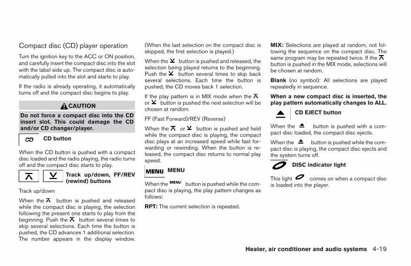
Compact disc (CD) player operation
Turn the ignition key to the ACC or ON position,and carefully insert the compact disc into the slotwith the label side up. The compact disc is auto-matically pulled into the slot and starts to play.
If the radio is already operating, it automaticallyturns off and the compact disc begins to play.
CAUTION
Do not force a compact disc into the CDinsert slot. This could damage the CDand/or CD changer/player.
CD button
When the CD button is pushed with a compactdisc loaded and the radio playing, the radio turnsoff and the compact disc starts to play.
Track up/down, FF/REV(rewind) buttons
Track up/down
When the button is pushed and releasedwhile the compact disc is playing, the selectionfollowing the present one starts to play from thebeginning. Push the button several times toskip several selections. Each time the button ispushed, the CD advances 1 additional selection.The number appears in the display window.
(When the last selection on the compact disc isskipped, the first selection is played.)
When the button is pushed and released, theselection being played returns to the beginning.Push the button several times to skip backseveral selections. Each time the button ispushed, the CD moves back 1 selection.
If the play pattern is in MIX mode when theor button is pushed the next selection will bechosen at random.
FF (Fast Forward)/REV (Reverse)
When the or button is pushed and heldwhile the compact disc is playing, the compactdisc plays at an increased speed while fast for-warding or rewinding. When the button is re-leased, the compact disc returns to normal playspeed.
MENU
When the button is pushed while the com-pact disc is playing, the play pattern changes asfollows:
RPT: The current selection is repeated.
MIX: Selections are played at random, not fol-lowing the sequence on the compact disc. Thesame program may be repeated twice. If thebutton is pushed in the MIX mode, selections willbe chosen at random.
Blank (no symbol): All selections are playedrepeatedly in sequence.
When a new compact disc is inserted, theplay pattern automatically changes to ALL.
CD EJECT button
When the button is pushed with a com-pact disc loaded, the compact disc ejects.
When the button is pushed while the com-pact disc is playing, the compact disc ejects andthe system turns off.
DISC indicator light
This light comes on when a compact discis loaded into the player.
Heater, air conditioner and audio systems 4-19
Z REVIEW COPY—2006 Truck/Frontier (d22)Owners Manual—USA_English (nna)10/17/05—debbie X
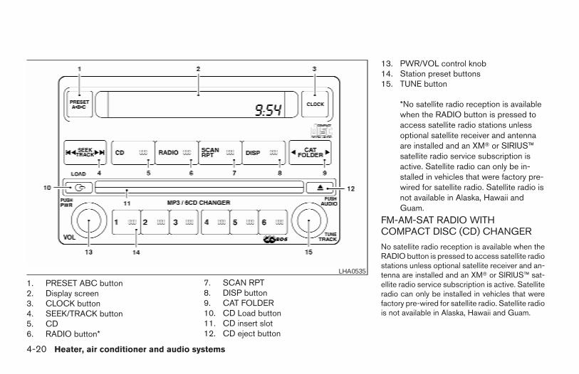
1. PRESET ABC button2. Display screen3. CLOCK button4. SEEK/TRACK button5. CD6. RADIO button*
7. SCAN RPT8. DISP button9. CAT FOLDER10. CD Load button11. CD insert slot12. CD eject button
13. PWR/VOL control knob14. Station preset buttons15. TUNE button
*No satellite radio reception is availablewhen the RADIO button is pressed toaccess satellite radio stations unlessoptional satellite receiver and antennaare installed and an XMT or SIRIUS™satellite radio service subscription isactive. Satellite radio can only be in-stalled in vehicles that were factory pre-wired for satellite radio. Satellite radio isnot available in Alaska, Hawaii andGuam.
FM-AM-SAT RADIO WITHCOMPACT DISC (CD) CHANGER
No satellite radio reception is available when theRADIO button is pressed to access satellite radiostations unless optional satellite receiver and an-tenna are installed and an XMT or SIRIUS™ sat-ellite radio service subscription is active. Satelliteradio can only be installed in vehicles that werefactory pre-wired for satellite radio. Satellite radiois not available in Alaska, Hawaii and Guam.
LHA0535
4-20 Heater, air conditioner and audio systems
Z REVIEW COPY—2006 Truck/Frontier (d22)Owners Manual—USA_English (nna)10/17/05—debbie X
Audio main operation
POWER/VOLUME control:
Turn the ignition key to ACC or ON, and thenpush the POWER/VOLUME control knob whilethe system is off to call up the mode (radio or CD)which was playing immediately before the systemwas turned off.
To turn the system off, press thePOWER/VOLUME control knob.
Turn the POWER/VOLUME control knob to ad-just the volume.
This vehicle may be equipped with speed sensi-tive control volume (SSV) for audio. The audiovolume changes as the driving speed changes.
AUDIO knob (BASS, MIDRANGE, TREBLE,FADE, BALANCE and SSV if so equipped):
Press the AUDIO knob to change the mode asfollows:
BASS → MID → TREBLE → FADE → BALANCE→ SSV (if so equipped)
To adjust Bass, Mid (Midrange), Treble, Fade andBalance, press the AUDIO knob until the desiredmode appears in the display. Turn the Tuningknob to adjust Bass and Treble to the desiredlevel. You can also use the Tuning knob to adjustFader and Balance modes. Fader adjusts the
sound level between the front and rear speakersand Balance adjusts the sound between the rightand left speakers.
To change the SSV mode to OFF, LOW, MID orHIGH, turn the Tuning knob to the right or left.
Once you have adjusted the sound quality to thedesired level, press the AUDIO knob repeatedlyuntil the radio or CD display reappears. Other-wise, the radio or CD display will automaticallyreappear after about 10 seconds.
Clock set
1. Press the CLOCK button until it beeps(>1.5 seconds).
2. The hours will start flashing. Press CATFOLDER ( or ) or SEEK TRACK( or ) to adjust the hours.
3. Press the CLOCK button again to switch tothe minute adjustment.
4. Press CAT FOLDER ( or ) orSEEK-TRACK ( or ) to adjustthe minutes.
5. Press the CLOCK button again to exit theclock set mode.
The display will return to the regular clock displayafter 7 seconds, or you may press the CLOCKbutton again to return to the regular clock display.
DISP (display) button:
This DISP (display) button will show text aboutMP3, SAT or CD information in the audio display.
CD display mode
To change the text displayed while playing a CDwith text, press the DISP button. The DISP buttonwill allow you to scroll through CD text as follows:Disc title ←→ Track title.
To change the default display mode press theAUDIO knob repeatedly until DISPLAY MODEappears on the display, then rotate the knob toselect the following display modes: Disc title ←→Track title ←→ Track number.
Once the display mode is selected press theAUDIO knob again to store the setting. If theAUDIO knob is not pressed within 8 seconds thedisplay will refresh with the last selected displaymode setting.
● Track title mode displays the title of the se-lected CD track.
● Disk title mode displays the title of the CDbeing played.
● Track number mode displays the numberselected disc and the track that is currentlybeing played on the disk.
Heater, air conditioner and audio systems 4-21
Z REVIEW COPY—2006 Truck/Frontier (d22)Owners Manual—USA_English (nna)10/17/05—debbie X
MP3 display mode
To change the text displayed when listening to anMP3 with MP3 text (when CD with text is beingused), press the DISP button. The DISP buttonwill scroll through the CD text as follows: Disctitle ←→ Track title ←→ Folder title.
To change the default display mode press theAUDIO knob repeatedly until DISPLAY MODEappears on the display, then rotate the knob toselect the following display modes: Folder num-ber ←→ Track title ←→ Folder title ←→ Disc title←→ Disc number.
Once a display mode is selected press the AU-DIO knob again to store the setting.
● Folder number mode displays the foldernumber and the file number of the foldercurrently being played.
● Disc number mode displays the number se-lected disc and the track that is currentlybeing played.
● Track title mode displays the ID3 track title ofthe MP3 file.
● Disc title mode displays the ID3 disc title ofthe MP3 file.
● Folder title mode displays the folder namegiven to the MP3 folder.
Display satellite radio display mode (if soequipped)
To change the text displayed when listening tosatellite radio (if so equipped) press the DISPbutton. The DISP button will scroll through thebroadcasted information as follows: Name ←→Title ←→ Current display mode.
To change the default display mode push thetune knob to display mode and rotate the knob toselect the following display modes: Channelnumber ←→ Channel name ←→ Name ←→Title. Once the display mode is selected pressthe tune knob again to store the setting. If thetuning knob is not pressed after 8 seconds thedisplay will refresh with the last selected displaymode setting.
● Channel number mode displays the channelnumber of the selected satellite radio sta-tion.
● Channel name mode displays the channelname of the selected satellite radio station.
● Name mode displays the name of the artist,host or weather condition of the selectedsatellite radio station.
● Title mode displays the song title, showname, or temperature of the selected satel-lite radio station.
FM/AM/SAT radio operation
FM/AM/SAT band select:
Pushing the RADIO button will change the bandas follows:
AM ←→ FM or SAT (Satellite, if so equipped)
When the RADIO button is pushed while theignition switch is in the ACC or ON position, theradio will come on at the station last played.
The last station played will also come on whenthe POWER/VOLUME control knob is de-pressed to ON.
No satellite radio reception is available when theRADIO button is pressed to access satellite radiostations unless optional satellite receiver and an-tenna are installed and an XMT or SIRIUS™ sat-ellite radio service subscription is active. Satelliteradio can only be installed in vehicles that werefactory pre-wired for satellite radio. Satellite radiois not available in Alaska, Hawaii and Guam. Ifsatellite radio is not operational then the RADIObutton is used to toggle between AM and FMbands.
If a compact disc is playing when the RADIObutton is pushed, the compact disc will automati-cally be turned off and the last radio stationplayed will come on.
4-22 Heater, air conditioner and audio systems
Z REVIEW COPY—2006 Truck/Frontier (d22)Owners Manual—USA_English (nna)10/17/05—debbie X
The FM stereo indicator ST will glow during FMstereo reception. When the stereo broadcastsignal is weak, the radio will automatically changefrom stereo to monaural reception.
CAT FOLDER (Tuning):
WARNING
The radio should not be tuned while driv-ing so full attention may be given to ve-hicle operation.
To manually tune the radio, push the CATFOLDER tune button ( or ) or turnthe tuning knob to right or left.
To move quickly through the channels, hold eitherthe or button down for more than1.5 seconds.
SEEK tuning:
Push the SEEK/TRACK button ( or )for less than 1.5 seconds to tune from high to lowor low to high frequencies and stop at the nextbroadcasting station.
To seek quickly through the channels, press andhold the SEEK/TRACK button for more than 1.5seconds. When the button is released the radiowill seek to the next broadcasting station.
SCAN RPT tuning:
Push the SCAN RPT button for more than 1.5seconds to stop at each broadcasting station(AM, FM or SAT if so equipped) for 5 seconds.Pushing the button again during this 5 secondperiod will stop SCAN tuning and the radio willremain tuned to that station. If the SCAN RPTbutton is not pushed within 5 seconds, SCANtuning moves to the next station.
PRESET A-B-C (Station memory opera-tions):
18 stations can be set for the FM, AM and SAT(Satellite-if so equipped) radio to the A, B and Cpreset button in any combination of FM, AM orSAT stations.
1. Choose preset channel A, B or C using thepreset select button.
2. Select the desired FM, AM or SAT stationband.
3. Tune to the desired station using manual,SEEK or SCAN tuning. Push and hold any ofthe desired station memory buttons (1 – 6)until a beep sound is heard.
4. The channel indicator will then come on andthe sound will resume. Memorizing is nowcomplete.
5. Other buttons can be set in the same man-ner.
If the battery cable is disconnected, or if the fuseopens, the radio memory will be canceled. In thatcase, reset the desired stations.
Radio data system (RDS):
RDS stands for Radio Data System, and is a datainformation service transmitted by some radiostations on the FM band (not AM band). Cur-rently, most RDS stations are in large cities, butmany stations are now considering broadcastingRDS data.
RDS can display:
● Station call sign, such as “WHFR 98.3”.
● Station name, such as “The Groove”.
If the station broadcasts RDS information, theRDS icon is displayed.
Compact disc (CD) changer operation
CAUTION
● Do not force a compact disc into the CDinsert slot. This could damage the CDand/or CD changer/player.
Heater, air conditioner and audio systems 4-23
Z REVIEW COPY—2006 Truck/Frontier (d22)Owners Manual—USA_English (nna)10/17/05—debbie X
● Trying to load a CD with the CD doorclosed could damage the CD and/or CDchanger.
Turn the ignition key to the ACC or ON positionand insert the compact disc into the slot with thelabel side facing up. The compact disc will beguided automatically into the slot and start play-ing. To insert the disc, first push the LOAD button.
If the radio is already operating, it will automati-cally turn off and the compact disc will play.
If the system has been turned off while the com-pact disc was playing, pushing thePOWER/VOLUME control knob will start thecompact disc.
Do not use 3.1 in (8 cm) diameter compact discsin the CD changer.
LOAD button:
To insert a CD in the CD changer, push the loadbutton for less than 1.5 seconds. Selectthe loading slot by pushing the CD insert selectbutton (1 – 6), then insert the CD.
To insert 6 CDs to the CD changer, push the loadbutton for more than 1.5 seconds.
The slot numbers (1 – 6) will illuminate on thedisplay when CDs are loaded into the changer.
CD button:
When the CD button is pushed with the systemoff and the compact disc loaded, the system willturn on and the compact disc will start to play.
When the CD button is pushed with the compactdisc loaded with the radio playing, the radio willautomatically be turned off and the compact discwill start to play.
SEEK/TRACK:
When the button is pushed for less than 1.5seconds while a compact disc is playing, thetrack being played returns to its beginning. Pushseveral times to skip back through tracks. Thecompact disc will go back the number of timesthe button is pushed.
When the button is pushed for less than 1.5seconds while the compact disc is playing, thenext track will start to play from its beginning.Push several times to skip through tracks. Thecompact disc will advance the number of timesthe button is pushed. (When the last track on thecompact disc is skipped through, the first trackwill be played.)
When the or button is pushed formore than 1.5 seconds while a CD is playing, theCD plays at an increased speed while fast for-warding or rewinding through the existing track
being played. When the button is released theCD returns to normal play speed.
CAT FOLDER:
While playing an MP3, push the CAT FOLDERbutton ( or ) to scan backward orforward through available folders.
CD select buttons:
To play another CD that has been loaded, push aCD select button (1 – 6).
SCAN/RPT:
When the SCAN/RPT play button is pushedwhile the compact disc is played, the play patterncan be changed as follows:
ALL DISC RPT → 1 DISC RPT→ 1 TRACK RPT→ ALL DISC RDM → 1 DISC RDM → ALL DISCRPT
ALL DISC RPT: All discs loaded will be repeated.1 DISC RPT: The disc that is currently playing willbe repeated.1 TRACK RPT: The track that is currently playingwill be repeatedALL DISC RDM: Tracks from all discs will beplayed randomly1 DISC RDM: Tracks from the disc that is cur-rently playing will be played randomly
4-24 Heater, air conditioner and audio systems
Z REVIEW COPY—2006 Truck/Frontier (d22)Owners Manual—USA_English (nna)10/17/05—debbie X
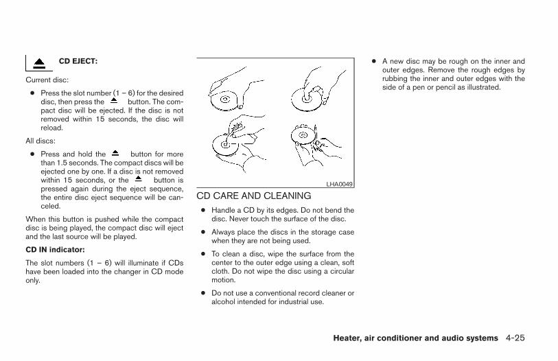
CD EJECT:
Current disc:
● Press the slot number (1 – 6) for the desireddisc, then press the button. The com-pact disc will be ejected. If the disc is notremoved within 15 seconds, the disc willreload.
All discs:
● Press and hold the button for morethan 1.5 seconds. The compact discs will beejected one by one. If a disc is not removedwithin 15 seconds, or the button ispressed again during the eject sequence,the entire disc eject sequence will be can-celed.
When this button is pushed while the compactdisc is being played, the compact disc will ejectand the last source will be played.
CD IN indicator:
The slot numbers (1 – 6) will illuminate if CDshave been loaded into the changer in CD modeonly.
CD CARE AND CLEANING● Handle a CD by its edges. Do not bend the
disc. Never touch the surface of the disc.
● Always place the discs in the storage casewhen they are not being used.
● To clean a disc, wipe the surface from thecenter to the outer edge using a clean, softcloth. Do not wipe the disc using a circularmotion.
● Do not use a conventional record cleaner oralcohol intended for industrial use.
● A new disc may be rough on the inner andouter edges. Remove the rough edges byrubbing the inner and outer edges with theside of a pen or pencil as illustrated.
LHA0049
Heater, air conditioner and audio systems 4-25
Z REVIEW COPY—2006 Truck/Frontier (d22)Owners Manual—USA_English (nna)10/17/05—debbie X
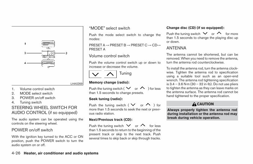
1. Volume control switch2. MODE select switch3. POWER on/off switch4. Tuning switch
STEERING WHEEL SWITCH FORAUDIO CONTROL (if so equipped)
The audio system can be operated using thecontrols on the steering wheel.
POWER on/off switch
With the ignition key turned to the ACC or ONposition, push the POWER switch to turn theaudio system on or off.
“MODE” select switch
Push the mode select switch to change themodes:
PRESET A → PRESET B → PRESET C → CD→PRESET A
Volume control switch
Push the volume control switch up or down toincrease or decrease the volume.
Tuning
Memory change (radio):
Push the tuning switch ( or ) for lessthan 1.5 seconds to change presets.
Seek tuning (radio):
Push the tuning switch ( or ) formore than 1.5 seconds to seek the next or previ-ous radio station.
Next/Previous track (CD):
Push the tuning switch or for lessthan 1.5 seconds to return to the beginning of thepresent track or skip to the next track. Pushseveral times to skip back or skip through tracks.
Change disc (CD) (if so equipped):
Push the tuning switch or for morethan 1.5 seconds to change the playing disc upor down.
ANTENNAThe antenna cannot be shortened, but can beremoved. When you need to remove the antenna,turn the antenna rod counterclockwise.
To install the antenna rod, turn the antenna clock-wise. Tighten the antenna rod to specificationusing a suitable tool such as an open-endwrench. The antenna rod tightening specificationis 3.4 – 3.6 N·m (30 – 32 in-lb). Do not use pliersto tighten the antenna as they can leave marks onthe antenna surface. The antenna rod cannot behand tightened to the proper specification.
CAUTION
Always properly tighten the antenna rodduring installation or the antenna rod maybreak during vehicle operation.
LHA0269
4-26 Heater, air conditioner and audio systems
Z REVIEW COPY—2006 Truck/Frontier (d22)Owners Manual—USA_English (nna)10/17/05—debbie X
When installing a CB, ham radio or car phone inyour NISSAN, be sure to observe the followingcautions, otherwise the new equipment may ad-versely affect the engine control system andother electronic parts.
WARNING
● A cellular telephone should not be usedwhile driving so full attention may begiven to vehicle operation. Some juris-dictions prohibit the use of cellular tele-phones while driving.
● If you must make a call while your ve-hicle is in motion, the hands free cellu-lar phone operational mode (if soequipped) is highly recommended. Ex-ercise extreme caution at all times sofull attention may be given to vehicleoperation.
● If a conversation in a moving vehiclerequires you to take notes, pull off theroad to a safe location and stop yourvehicle before doing so.
CAUTION
● Keep the antenna as far away as pos-sible from the electronic controlmodules.
● Keep the antenna wire more than 8 in(20 cm) away from the electronic con-trol system harnesses. Do not route theantenna wire next to any harness.
● Adjust the antenna standing-wave ratioas recommended by the manufacturer.
● Connect the ground wire from the CBradio chassis to the body.
● For details, consult a NISSAN dealer.
● Do not ground electrical accessoriesdirectly to the battery terminal. Doingso, will bypass the variable voltage con-trol system and the vehicle battery maynot charge completely. Refer to “Vari-able voltage control system” in the“Maintenance and do-it-yourself” sec-tion later in this manual.
● Use electrical accessories with the en-gine running to avoid discharging thevehicle battery.
CAR PHONE OR CB RADIO
Heater, air conditioner and audio systems 4-27
Z REVIEW COPY—2006 Truck/Frontier (d22)Owners Manual—USA_English (nna)10/17/05—debbie X
4-28 Heater, air conditioner and audio systems
MEMO
5 Starting and driving
Precautions when starting and driving. . . . . . . . . . . . . . . . 5-2Exhaust gas (carbon monoxide) . . . . . . . . . . . . . . . . . . 5-2Three-way catalyst. . . . . . . . . . . . . . . . . . . . . . . . . . . . . . 5-2Tire pressure monitoring system (TPMS) . . . . . . . . . . 5-3On-pavement and off-road drivingprecautions . . . . . . . . . . . . . . . . . . . . . . . . . . . . . . . . . . . . 5-5Avoiding collision and rollover . . . . . . . . . . . . . . . . . . . . 5-5Drinking alcohol/drugs and driving. . . . . . . . . . . . . . . . 5-5Driving safety precautions . . . . . . . . . . . . . . . . . . . . . . . 5-6
Ignition switch. . . . . . . . . . . . . . . . . . . . . . . . . . . . . . . . . . . . . 5-7Automatic transmission. . . . . . . . . . . . . . . . . . . . . . . . . . 5-7Manual transmission . . . . . . . . . . . . . . . . . . . . . . . . . . . . 5-8Key positions . . . . . . . . . . . . . . . . . . . . . . . . . . . . . . . . . . 5-9Nissan vehicle immobilizer system . . . . . . . . . . . . . . . . 5-9
Before starting the engine . . . . . . . . . . . . . . . . . . . . . . . . . . 5-9Starting the engine . . . . . . . . . . . . . . . . . . . . . . . . . . . . . . .5-10Driving the vehicle . . . . . . . . . . . . . . . . . . . . . . . . . . . . . . . .5-11
Automatic transmission. . . . . . . . . . . . . . . . . . . . . . . . . 5-11Manual transmission . . . . . . . . . . . . . . . . . . . . . . . . . . . 5-14
Parking brake . . . . . . . . . . . . . . . . . . . . . . . . . . . . . . . . . . . .5-17Cruise control (if so equipped) . . . . . . . . . . . . . . . . . . . . . 5-18
Precautions on cruise control . . . . . . . . . . . . . . . . . . . 5-18Cruise control operations. . . . . . . . . . . . . . . . . . . . . . . 5-18
Break-in schedule . . . . . . . . . . . . . . . . . . . . . . . . . . . . . . . .5-19
Increasing fuel economy. . . . . . . . . . . . . . . . . . . . . . . . . . . 5-20Using four wheel drive (4WD) . . . . . . . . . . . . . 5-20
Transfer case shifting procedures . . . . . . . . . . . . . . . 5-20Electronic locking rear differential (E-Lock) system(if so equipped) . . . . . . . . . . . . . . . . . . . . . . . . . . . . . . . . . .5-25Parking/parking on hills. . . . . . . . . . . . . . . . . . . . . . . . . . . .5-27Power steering . . . . . . . . . . . . . . . . . . . . . . . . . . . . . . . . . . .5-28Brake system . . . . . . . . . . . . . . . . . . . . . . . . . . . . . . . . . . . .5-28
Brake precautions . . . . . . . . . . . . . . . . . . . . . . . . . . . . .5-28Anti-lock brake system (ABS) . . . . . . . . . . . . . . . . . . . 5-29
Active brake limited slip (ABLS) system(if so equipped) . . . . . . . . . . . . . . . . . . . . . . . . . . . . . . . . . .5-30Vehicle dynamic control (VDC) system(if so equipped) . . . . . . . . . . . . . . . . . . . . . . . . . . . . . . . . . .5-30Hill descent control (HDC) system (if so equipped). . . 5-32Hill start assist (HSA) system (if so equipped) . . . . . . . 5-32Cold weather driving . . . . . . . . . . . . . . . . . . . . . . . . . . . . . .5-33
Freeing a frozen door lock . . . . . . . . . . . . . . . . . . . . . . 5-33Anti-freeze. . . . . . . . . . . . . . . . . . . . . . . . . . . . . . . . . . . .5-33Battery . . . . . . . . . . . . . . . . . . . . . . . . . . . . . . . . . . . . . . .5-33Draining of coolant water . . . . . . . . . . . . . . . . . . . . . . . 5-33Tire equipment . . . . . . . . . . . . . . . . . . . . . . . . . . . . . . . .5-33Special winter equipment. . . . . . . . . . . . . . . . . . . . . . . 5-34Driving on snow or ice . . . . . . . . . . . . . . . . . . . . . . . . . 5-34Engine block heater (if so equipped) . . . . . . . . . . . . . 5-34
Z REVIEW COPY—2006 Truck/Frontier (d22)Owners Manual—USA_English (nna)10/17/05—debbie X
WARNING
● Do not leave children or adults whowould normally require the assistanceof others alone in your vehicle. Petsshould also not be left alone. Theycould accidentally injure themselves orothers through inadvertent operation ofthe vehicle. Also, on hot, sunny days,temperatures in a closed vehicle couldquickly become high enough to causesevere or possibly fatal injuries topeople or animals.
● Properly secure all cargo with ropes orstraps to help prevent it from sliding orshifting. Do not place cargo higher thanthe seatbacks. In a sudden stop or col-lision, unsecured cargo could causepersonal injury.
EXHAUST GAS (carbon monoxide)
WARNING
● Do not breathe exhaust gases; theycontain colorless and odorless carbonmonoxide. Carbon monoxide is danger-ous. It can cause unconsciousness ordeath.
● If you suspect that exhaust fumes areentering the vehicle, drive with all win-dows fully open, and have the vehicleinspected immediately.
● Do not run the engine in closed spacessuch as a garage.
● Do not park the vehicle with the enginerunning for any extended length of time.
● Keep the lift gate and rear windowsclosed while driving, otherwise exhaustgases could be drawn into the passen-ger compartment. If you must drive withthe lift gate or rear windows open, fol-low these precautions:
1. Open all the windows.
2. Set the air recirculation but-ton (if so equipped) to off and the fancontrol dial to 4 (high) to circulatethe air.
● If electrical wiring or other cable con-nections must pass to a trailer throughthe seal on the lift gate or the body,follow the manufacturer’s recommen-dation to prevent carbon monoxide en-try into the vehicle.
● The exhaust system and body should beinspected by a qualified mechanicwhenever:
a. The vehicle is raised for service.
b. You suspect that exhaust fumes areentering into the passengercompartment.
c. You notice a change in the sound ofthe exhaust system.
d. You have had an accident involvingdamage to the exhaust system, un-derbody, or rear of the vehicle.
THREE-WAY CATALYST
The three-way catalyst is an emission controldevice installed in the exhaust system. Exhaustgases in the three-way catalyst are burned athigh temperatures to help reduce pollutants.
WARNING
● The exhaust gas and the exhaust sys-tem are very hot. Keep people, animalsor flammable materials away from theexhaust system components.
PRECAUTIONS WHEN STARTINGAND DRIVING
5-2 Starting and driving
Z REVIEW COPY—2006 Truck/Frontier (d22)Owners Manual—USA_English (nna)10/17/05—debbie X
● Do not stop or park the vehicle overflammable materials such as dry grass,waste paper or rags. They may igniteand cause a fire.
CAUTION
● Do not use leaded gasoline. Depositsfrom leaded gasoline will seriously re-duce the three-way catalyst’s ability tohelp reduce exhaust pollutants.
● Keep your engine tuned up. Malfunc-tions in the ignition, fuel injection, orelectrical systems can cause overrichfuel flow into the three-way catalyst,causing it to overheat. Do not keep driv-ing if the engine misfires, or if notice-able loss of performance or other un-usual operating conditions aredetected. Have the vehicle inspectedpromptly by a NISSAN dealer.
● Avoid driving with an extremely low fuellevel. Running out of fuel could causethe engine to misfire, damaging thethree-way catalyst.
● Do not race the engine while warming itup.
● Do not push or tow your vehicle to startthe engine.
TIRE PRESSURE MONITORINGSYSTEM (TPMS)
Each tire, including the spare (if provided),should be checked monthly when cold and in-flated to the inflation pressure recommended bythe vehicle manufacturer on the vehicle placardor tire inflation pressure label. (If your vehicle hastires of a different size than the size indicated onthe vehicle placard or tire inflation pressure label,you should determine the proper tire inflationpressure for those tires.)
As an added safety feature, your vehicle has beenequipped with a Tire Pressure Monitoring System(TPMS) that illuminates a low tire pressure telltalewhen one or more of your tires is significantlyunderinflated. Accordingly, when the low tirepressure telltale illuminates, you should stop andcheck your tires as soon as possible, and inflatethem to the proper pressure. Driving on a signifi-cantly underinflated tire causes the tire to over-heat and can lead to tire failure. Underinflationalso reduces fuel efficiency and tire tread life, andmay affect the vehicle’s handling and stoppingability.
Please note that the TPMS is not a substitute forproper tire maintenance, and it is the driver’sresponsibility to maintain correct tire pressure,
even if underinflation has not reached the level totrigger illumination of the TPMS low tire pressuretelltale.
Your vehicle has also been equipped with aTPMS malfunction indicator to indicate when thesystem is not operating properly. The TPMS mal-function indicator is combined with the low tirepressure telltale. When the system detects amalfunction, the telltale will flash for approxi-mately one minute and then remain continuouslyilluminated. This sequence will continue uponsubsequent vehicle start-ups as long as the mal-function exists. When the malfunction indicator isilluminated, the system may not be able to detector signal low tire pressure as intended. TPMSmalfunctions may occur for a variety of reasons,including the installation of replacement or alter-nate tires or wheels on the vehicle that preventthe TPMS from functioning properly. Alwayscheck the TPMS malfunction telltale after replac-ing one or more tires or wheels on your vehicle toensure that the replacement or alternate tires andwheels allow the TPMS to continue to functionproperly.
Additional information:
● The TPMS does not monitor the tire pres-sure of the spare tire.
Starting and driving 5-3
Z REVIEW COPY—2006 Truck/Frontier (d22)Owners Manual—USA_English (nna)10/17/05—debbie X
● The TPMS will activate only when the vehicleis driven at speeds above 16 MPH (25km/h). Also, this system may not detect asudden drop in tire pressure (for example aflat tire while driving).
● Tire pressure rises and falls depending onthe heat caused by the vehicle’s operationand the outside temperature. Low outsidetemperature can lower the temperature ofthe air inside the tire which can cause alower tire inflation pressure. This may causethe low tire pressure warning light to illumi-nate. If the warning light illuminates in lowambient temperature, check the tire pres-sure for all four tires.
● You can also check the pressure of all tires(except the spare tire) on the display screen.The order of the tire pressure figures dis-played on the screen does not correspondwith the actual order of the tire position. See“Tire pressure information” in the “Displayscreen, heater, air conditioner and audiosystems” section.
For additional information, see “Low tire pressurewarning light” in the “Instruments and controls”section, “Tire pressure monitoring system(TPMS)” in the “In case of emergency” section.
WARNING
● If the low tire pressure warning lightilluminates while driving, avoid suddensteering maneuvers or abrupt braking,reduce vehicle speed, pull off the roadto a safe location and stop the vehicleas soon as possible. Serious vehicledamage could occur and may lead to anaccident and could result in seriouspersonal injury. Check the tire pressurefor all four tires. Adjust the tire pressureto the recommended COLD tire pres-sure shown on the Tire and LoadingInformation label to turn the low tirepressure warning light OFF. If you havea flat tire, replace it with a spare tire assoon as possible. (See “Flat tire” in the“In case of emergency” section forchanging a flat tire.)
● When a spare tire is mounted or a wheelis replaced, tire pressure will not beindicated, the TPMS will not functionand the low tire pressure warning lightwill flash. Contact your NISSAN dealeras soon as possible for tire replacementand/or system resetting.
● Replacing tires with those not originallyspecified by NISSAN could affect theproper operation of the TPMS.
● Do not inject any tire liquid or aerosoltire sealant into the tires, as this maycause a malfunction of the tire pressuresensors.
CAUTION
Do not place metalized film or any metalparts (antenna, etc.) on the windows. Thismay cause poor reception of the signalsfrom the tire pressure sensors, and theTPMS will not function properly.
FCC Notice:
Changes or modifications not expressly ap-proved by the party responsible for compli-ance could void the user’s authority to op-erate the equipment.
This device complies with Part 15 of theFCC Rules and RSS-210 of IndustryCanada.
Operation is subject to the following twoconditions: (1) This device may not causeharmful interface, and (2) this device mustaccept any interference received, includinginterference that may cause undesired op-eration of the device.
5-4 Starting and driving
Z REVIEW COPY—2006 Truck/Frontier (d22)Owners Manual—USA_English (nna)10/17/05—debbie X
ON-PAVEMENT AND OFF-ROADDRIVING PRECAUTIONSUtility vehicles have a significantly higherrollover rate than other types of vehicles.
They have higher ground clearance than passen-ger cars to make them capable of performing in avariety of on-pavement and off-road applications.This gives them a higher center of gravity thanordinary cars. An advantage of higher groundclearance is a better view of the road, allowingyou to anticipate problems. However, they are notdesigned for cornering at the same speeds asconventional two-wheel drive vehicles any morethan low-slung sports cars are designed to per-form satisfactorily under off-road conditions. If atall possible, avoid sharp turns at high speeds. Aswith other vehicles of this type, failure to operatethis vehicle correctly may result in loss of controlor vehicle rollover. In a rollover crash, an unbeltedperson is significantly more likely to die than aperson wearing a seat belt.
Be sure to read the driving safety precautionslater in this section.
AVOIDING COLLISION ANDROLLOVER
WARNING
Failure to operate this vehicle in a safeand prudent manner may result in loss ofcontrol or an accident.
Be alert and drive defensively at all times. Obeyall traffic regulations. Avoid excessive speed,high speed cornering, or sudden steering ma-neuvers, because these driving practices couldcause you to lose control of your vehicle. As withany vehicle, loss of control could result in acollision with other vehicles or objects, orcause the vehicle to roll over, particularly ifthe loss of control causes the vehicle toslide sideways. Be attentive at all times, andavoid driving when tired. Never drive when underthe influence of alcohol or drugs (including pre-scription or over-the-counter drugs which maycause drowsiness). Always wear your seat belt asoutlined in the “Safety – Seats, seat belts andsupplemental restraint system” section of thismanual, and also instruct your passengers to do so.
Seat belts help reduce the risk of injury in collisionsand rollovers. In a rollover crash, an unbeltedor improperly belted person is significantlymore likely to be injured or killed than aperson properly wearing a seat belt.
DRINKING ALCOHOL/DRUGS ANDDRIVING
WARNING
Never drive under the influence of alcoholor drugs. Alcohol in the bloodstream re-duces coordination, delays reaction timeand impairs judgement. Driving afterdrinking alcohol increases the likelihoodof being involved in an accident injuringyourself and others. Additionally, if youare injured in an accident, alcohol canincrease the severity of the injury.
NISSAN is committed to safe driving. However,you must choose not to drive under the influenceof alcohol. Every year thousands of people areinjured or killed in alcohol-related accidents. Al-though the local laws vary on what is consideredto be legally intoxicated, the fact is that alcoholaffects all people differently and most peopleunderestimate the effects of alcohol.
Remember, drinking and driving don’t mix! Andthat is true for drugs, too (over-the-counter, pre-scription, and illegal drugs). Don’t drive if yourability to operate your vehicle is impaired by alco-hol, drugs, or some other physical condition.
Starting and driving 5-5
Z REVIEW COPY—2006 Truck/Frontier (d22)Owners Manual—USA_English (nna)10/17/05—debbie X
DRIVING SAFETY PRECAUTIONS
Your NISSAN is designed for both normal andoff-road use. However, avoid driving in deep wa-ter or mud as your NISSAN is mainly designed forleisure use, unlike a conventional off-road ve-hicle.
Remember that two-wheel drive models are lesscapable than four-wheel drive models for roughroad driving and extrication when stuck in deepsnow or mud, or the like.
Please observe the following precautions:
WARNING
● Drive carefully when off the road andavoid dangerous areas. Every personwho drives or rides in this vehicleshould be seated with their seat beltfastened. This will keep you and yourpassengers in position when drivingover rough terrain.
● Do not drive across steep slopes. In-stead drive either straight up or straightdown the slopes. Off-road vehicles cantip over sideways much more easilythan they can forward or backward.
● Many hills are too steep for any vehicle.If you drive up them, you may stall. Ifyou drive down them, you may not beable to control your speed. If you driveacross them, you may roll over.
● Do not shift gears while driving ondownhill grades as this could causeloss of control of the vehicle.
● Stay alert when driving to the top of ahill. At the top there could be a drop-offor other hazard that could cause anaccident.
● If your engine stalls or you cannot makeit to the top of a steep hill, never at-tempt to turn around. Your vehiclecould tip or roll over. Always backstraight down in R (Reverse) gear. Neverback down in N (Neutral) or with theclutch depressed (manual transmissionvehicles), using only the brake, as thiscould cause loss of control.
● Heavy braking going down a hill couldcause your brakes to overheat and fade,resulting in loss of control and an acci-dent. Apply brakes lightly and use a lowgear to control your speed. Use the HillDescent Control feature (if soequipped).
● Unsecured cargo can be thrown aroundwhen driving over rough terrain. Prop-erly secure all cargo so it will not bethrown forward and cause injury to youor your passengers.
● To avoid raising the center of gravityexcessively, do not exceed the ratedcapacity of the roof rack (if soequipped) and evenly distribute theload. Secure heavy loads in the cargoarea as far forward and as low as pos-sible. Do not equip the vehicle with tireslarger than specified in this manual.This could cause your vehicle to rollover.
● Do not grip the inside or spokes of thesteering wheel when driving off-road.The steering wheel could move sud-denly and injure your hands. Insteaddrive with your fingers and thumbs onthe outside of the rim.
● Before operating the vehicle, ensurethat the driver and all passengers havetheir seat belts fastened.
● Always drive with the floor mats inplace as the floor may become hot.
5-6 Starting and driving
Z REVIEW COPY—2006 Truck/Frontier (d22)Owners Manual—USA_English (nna)10/17/05—debbie X
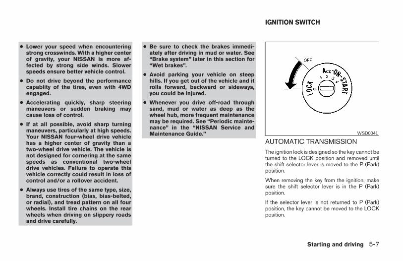
● Lower your speed when encounteringstrong crosswinds. With a higher centerof gravity, your NISSAN is more af-fected by strong side winds. Slowerspeeds ensure better vehicle control.
● Do not drive beyond the performancecapablity of the tires, even with 4WDengaged.
● Accelerating quickly, sharp steeringmaneuvers or sudden braking maycause loss of control.
● If at all possible, avoid sharp turningmaneuvers, particularly at high speeds.Your NISSAN four-wheel drive vehiclehas a higher center of gravity than atwo-wheel drive vehicle. The vehicle isnot designed for cornering at the samespeeds as conventional two-wheeldrive vehicles. Failure to operate thisvehicle correctly could result in loss ofcontrol and/or a rollover accident.
● Always use tires of the same type, size,brand, construction (bias, bias-belted,or radial), and tread pattern on all fourwheels. Install tire chains on the rearwheels when driving on slippery roadsand drive carefully.
● Be sure to check the brakes immedi-ately after driving in mud or water. See“Brake system” later in this section for“Wet brakes”.
● Avoid parking your vehicle on steephills. If you get out of the vehicle and itrolls forward, backward or sideways,you could be injured.
● Whenever you drive off-road throughsand, mud or water as deep as thewheel hub, more frequent maintenancemay be required. See “Periodic mainte-nance” in the “NISSAN Service andMaintenance Guide.”
AUTOMATIC TRANSMISSIONThe ignition lock is designed so the key cannot beturned to the LOCK position and removed untilthe shift selector lever is moved to the P (Park)position.
When removing the key from the ignition, makesure the shift selector lever is in the P (Park)position.
If the selector lever is not returned to P (Park)position, the key cannot be moved to the LOCKposition.
WSD0041
IGNITION SWITCH
Starting and driving 5-7
Z REVIEW COPY—2006 Truck/Frontier (d22)Owners Manual—USA_English (nna)10/17/05—debbie X
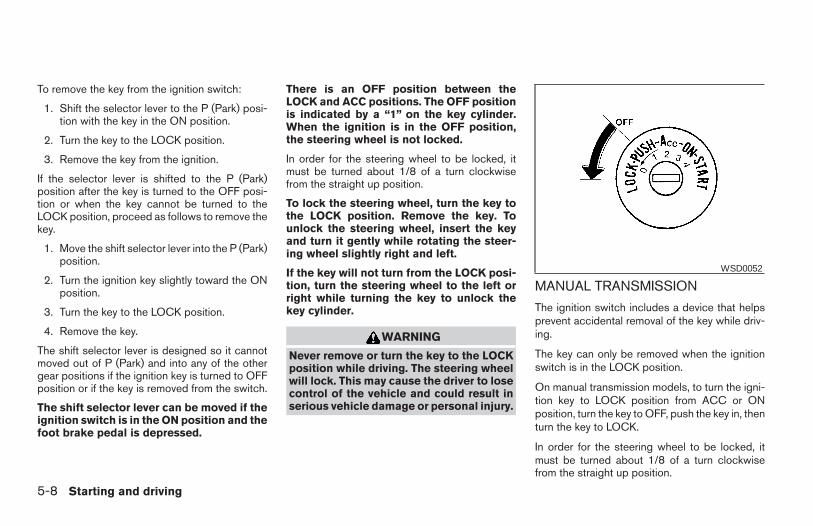
To remove the key from the ignition switch:
1. Shift the selector lever to the P (Park) posi-tion with the key in the ON position.
2. Turn the key to the LOCK position.
3. Remove the key from the ignition.
If the selector lever is shifted to the P (Park)position after the key is turned to the OFF posi-tion or when the key cannot be turned to theLOCK position, proceed as follows to remove thekey.
1. Move the shift selector lever into the P (Park)position.
2. Turn the ignition key slightly toward the ONposition.
3. Turn the key to the LOCK position.
4. Remove the key.
The shift selector lever is designed so it cannotmoved out of P (Park) and into any of the othergear positions if the ignition key is turned to OFFposition or if the key is removed from the switch.
The shift selector lever can be moved if theignition switch is in the ON position and thefoot brake pedal is depressed.
There is an OFF position between theLOCK and ACC positions. The OFF positionis indicated by a “1” on the key cylinder.When the ignition is in the OFF position,the steering wheel is not locked.
In order for the steering wheel to be locked, itmust be turned about 1/8 of a turn clockwisefrom the straight up position.
To lock the steering wheel, turn the key tothe LOCK position. Remove the key. Tounlock the steering wheel, insert the keyand turn it gently while rotating the steer-ing wheel slightly right and left.
If the key will not turn from the LOCK posi-tion, turn the steering wheel to the left orright while turning the key to unlock thekey cylinder.
WARNING
Never remove or turn the key to the LOCKposition while driving. The steering wheelwill lock. This may cause the driver to losecontrol of the vehicle and could result inserious vehicle damage or personal injury.
MANUAL TRANSMISSION
The ignition switch includes a device that helpsprevent accidental removal of the key while driv-ing.
The key can only be removed when the ignitionswitch is in the LOCK position.
On manual transmission models, to turn the igni-tion key to LOCK position from ACC or ONposition, turn the key to OFF, push the key in, thenturn the key to LOCK.
In order for the steering wheel to be locked, itmust be turned about 1/8 of a turn clockwisefrom the straight up position.
WSD0052
5-8 Starting and driving
Z REVIEW COPY—2006 Truck/Frontier (d22)Owners Manual—USA_English (nna)10/17/05—debbie X
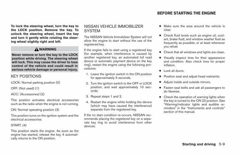
To lock the steering wheel, turn the key tothe LOCK position. Remove the key. Tounlock the steering wheel, insert the keyand turn it gently while rotating the steer-ing wheel slightly right and left.
WARNING
Never remove or turn the key to the LOCKposition while driving. The steering wheelwill lock. This may cause the driver to losecontrol of the vehicle and could result inserious vehicle damage or personal injury.
KEY POSITIONS
LOCK: Normal parking position (0)
OFF: (Not used) (1)
ACC: (Accessories) (2)
This position activates electrical accessoriessuch as the radio when the engine is not running.
ON: Normal operating position (3)
This position turns on the ignition system and theelectrical accessories.
START: (4)
This position starts the engine. As soon as theengine has started, release the key. It automati-cally returns to the ON position.
NISSAN VEHICLE IMMOBILIZERSYSTEMThe NISSAN Vehicle Immobilizer System will notallow the engine to start without the use of theregistered key.
If the engine fails to start using a registered key(for example, when interference is caused byanother registered key, an automated toll roaddevice or automatic payment device on the keyring), restart the engine using the following pro-cedures:
1. Leave the ignition switch in the ON positionfor approximately 5 seconds.
2. Turn the ignition switch to the OFF or LOCKposition, and wait approximately 10 sec-onds.
3. Repeat steps 1 and 2.
4. Restart the engine while holding the device(which may have caused the interference)separate from the registered key.
If the no start condition re-occurs, NISSAN rec-ommends placing the registered key on a sepa-rate key ring to avoid interference from otherdevices.
● Make sure the area around the vehicle isclear.
● Check fluid levels such as engine oil, cool-ant, brake fluid, and window washer fluid asfrequently as possible, or at least wheneveryou refuel.
● Check that all windows and lights are clean.
● Visually inspect tires for their appearanceand condition. Also check tires for properinflation.
● Lock all doors.
● Position seat and adjust head restraints.
● Adjust inside and outside mirrors.
● Fasten seat belts and ask all passengers todo likewise.
● Check the operation of warning lights whenthe key is turned to the ON (3) position. See“Warning/indicator lights and audible re-minders” in the “Instruments and controls”section of this manual.
BEFORE STARTING THE ENGINE
Starting and driving 5-9
Z REVIEW COPY—2006 Truck/Frontier (d22)Owners Manual—USA_English (nna)10/17/05—debbie X
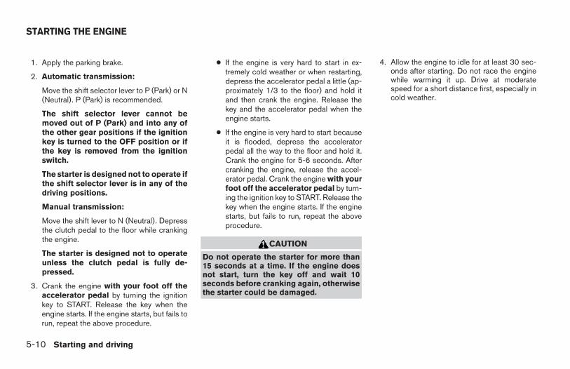
1. Apply the parking brake.
2. Automatic transmission:
Move the shift selector lever to P (Park) or N(Neutral). P (Park) is recommended.
The shift selector lever cannot bemoved out of P (Park) and into any ofthe other gear positions if the ignitionkey is turned to the OFF position or ifthe key is removed from the ignitionswitch.
The starter is designed not to operate ifthe shift selector lever is in any of thedriving positions.
Manual transmission:
Move the shift lever to N (Neutral). Depressthe clutch pedal to the floor while crankingthe engine.
The starter is designed not to operateunless the clutch pedal is fully de-pressed.
3. Crank the engine with your foot off theaccelerator pedal by turning the ignitionkey to START. Release the key when theengine starts. If the engine starts, but fails torun, repeat the above procedure.
● If the engine is very hard to start in ex-tremely cold weather or when restarting,depress the accelerator pedal a little (ap-proximately 1/3 to the floor) and hold itand then crank the engine. Release thekey and the accelerator pedal when theengine starts.
● If the engine is very hard to start becauseit is flooded, depress the acceleratorpedal all the way to the floor and hold it.Crank the engine for 5-6 seconds. Aftercranking the engine, release the accel-erator pedal. Crank the engine with yourfoot off the accelerator pedal by turn-ing the ignition key to START. Release thekey when the engine starts. If the enginestarts, but fails to run, repeat the aboveprocedure.
CAUTION
Do not operate the starter for more than15 seconds at a time. If the engine doesnot start, turn the key off and wait 10seconds before cranking again, otherwisethe starter could be damaged.
4. Allow the engine to idle for at least 30 sec-onds after starting. Do not race the enginewhile warming it up. Drive at moderatespeed for a short distance first, especially incold weather.
STARTING THE ENGINE
5-10 Starting and driving
Z REVIEW COPY—2006 Truck/Frontier (d22)Owners Manual—USA_English (nna)10/17/05—debbie X
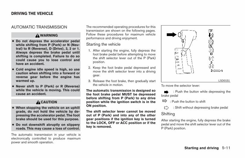
AUTOMATIC TRANSMISSION
WARNING
● Do not depress the accelerator pedalwhile shifting from P (Park) or N (Neu-tral) to R (Reverse), D (Drive), 3, 2 or 1.Always depress the brake pedal untilshifting is completed. Failure to do socould cause you to lose control andhave an accident.
● Cold engine idle speed is high, so usecaution when shifting into a forward orreverse gear before the engine haswarmed up.
● Never shift to P (Park) or R (Reverse)while the vehicle is moving. This couldcause an accident.
CAUTION
● When stopping the vehicle on an uphillgrade, do not hold the vehicle by de-pressing the accelerator pedal. The footbrake should be used for this purpose.
● Do not downshift abruptly on slipperyroads. This may cause a loss of control.
The automatic transmission in your vehicle iselectronically controlled to produce maximumpower and smooth operation.
The recommended operating procedures for thistransmission are shown on the following pages.Follow these procedures for maximum vehicleperformance and driving enjoyment.
Starting the vehicle1. After starting the engine, fully depress the
foot brake pedal before attempting to movethe shift selector lever out of the P (Park)position.
2. Keep the foot brake pedal depressed andmove the shift selector lever into a drivinggear.
3. Release the foot brake, then gradually startthe vehicle in motion.
The automatic transmission is designed sothe foot brake pedal MUST be depressedbefore shifting from P (Park) to any driveposition while the ignition switch is in theON position.
The shift selector lever cannot be movedout of P (Park) and into any of the othergear positions if the ignition key is turnedto the LOCK, OFF or ACC position or if thekey is removed.
To move the selector lever:
: Push the button while depressing thebrake pedal
: Push the button to shift
: Shift without depressing brake pedal
Shifting
After starting the engine, fully depress the brakepedal and move the shift selector lever out of theP (Park) position.
LSD0151
DRIVING THE VEHICLE
Starting and driving 5-11
Z REVIEW COPY—2006 Truck/Frontier (d22)Owners Manual—USA_English (nna)10/17/05—debbie X
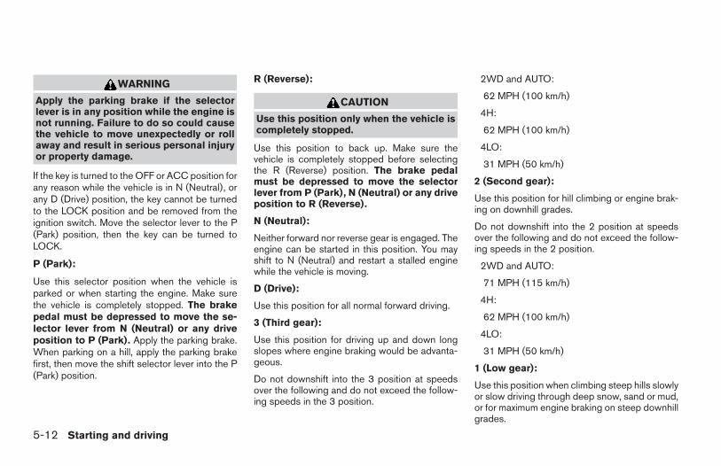
WARNING
Apply the parking brake if the selectorlever is in any position while the engine isnot running. Failure to do so could causethe vehicle to move unexpectedly or rollaway and result in serious personal injuryor property damage.
If the key is turned to the OFF or ACC position forany reason while the vehicle is in N (Neutral), orany D (Drive) position, the key cannot be turnedto the LOCK position and be removed from theignition switch. Move the selector lever to the P(Park) position, then the key can be turned toLOCK.
P (Park):
Use this selector position when the vehicle isparked or when starting the engine. Make surethe vehicle is completely stopped. The brakepedal must be depressed to move the se-lector lever from N (Neutral) or any driveposition to P (Park). Apply the parking brake.When parking on a hill, apply the parking brakefirst, then move the shift selector lever into the P(Park) position.
R (Reverse):
CAUTION
Use this position only when the vehicle iscompletely stopped.
Use this position to back up. Make sure thevehicle is completely stopped before selectingthe R (Reverse) position. The brake pedalmust be depressed to move the selectorlever from P (Park), N (Neutral) or any driveposition to R (Reverse).
N (Neutral):
Neither forward nor reverse gear is engaged. Theengine can be started in this position. You mayshift to N (Neutral) and restart a stalled enginewhile the vehicle is moving.
D (Drive):
Use this position for all normal forward driving.
3 (Third gear):
Use this position for driving up and down longslopes where engine braking would be advanta-geous.
Do not downshift into the 3 position at speedsover the following and do not exceed the follow-ing speeds in the 3 position.
2WD and AUTO:
62 MPH (100 km/h)
4H:
62 MPH (100 km/h)
4LO:
31 MPH (50 km/h)
2 (Second gear):
Use this position for hill climbing or engine brak-ing on downhill grades.
Do not downshift into the 2 position at speedsover the following and do not exceed the follow-ing speeds in the 2 position.
2WD and AUTO:
71 MPH (115 km/h)
4H:
62 MPH (100 km/h)
4LO:
31 MPH (50 km/h)
1 (Low gear):
Use this position when climbing steep hills slowlyor slow driving through deep snow, sand or mud,or for maximum engine braking on steep downhillgrades.
5-12 Starting and driving
Z REVIEW COPY—2006 Truck/Frontier (d22)Owners Manual—USA_English (nna)10/17/05—debbie X
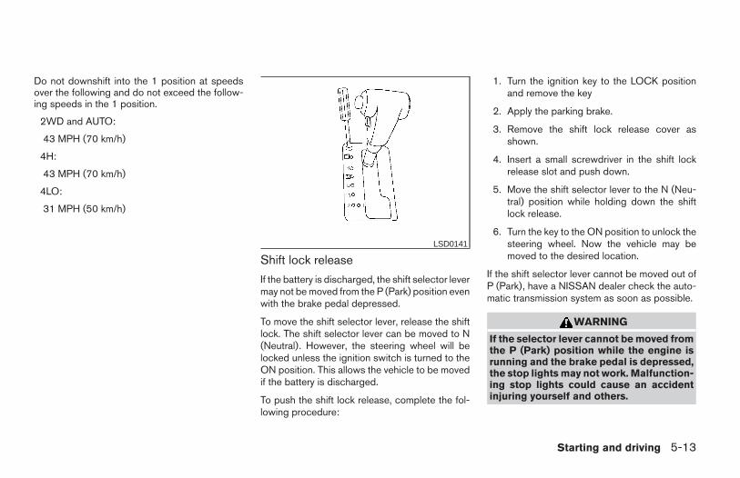
Do not downshift into the 1 position at speedsover the following and do not exceed the follow-ing speeds in the 1 position.
2WD and AUTO:
43 MPH (70 km/h)
4H:
43 MPH (70 km/h)
4LO:
31 MPH (50 km/h)
Shift lock release
If the battery is discharged, the shift selector levermay not be moved from the P (Park) position evenwith the brake pedal depressed.
To move the shift selector lever, release the shiftlock. The shift selector lever can be moved to N(Neutral). However, the steering wheel will belocked unless the ignition switch is turned to theON position. This allows the vehicle to be movedif the battery is discharged.
To push the shift lock release, complete the fol-lowing procedure:
1. Turn the ignition key to the LOCK positionand remove the key
2. Apply the parking brake.
3. Remove the shift lock release cover asshown.
4. Insert a small screwdriver in the shift lockrelease slot and push down.
5. Move the shift selector lever to the N (Neu-tral) position while holding down the shiftlock release.
6. Turn the key to the ON position to unlock thesteering wheel. Now the vehicle may bemoved to the desired location.
If the shift selector lever cannot be moved out ofP (Park), have a NISSAN dealer check the auto-matic transmission system as soon as possible.
WARNING
If the selector lever cannot be moved fromthe P (Park) position while the engine isrunning and the brake pedal is depressed,the stop lights may not work. Malfunction-ing stop lights could cause an accidentinjuring yourself and others.
LSD0141
Starting and driving 5-13
Z REVIEW COPY—2006 Truck/Frontier (d22)Owners Manual—USA_English (nna)10/17/05—debbie X
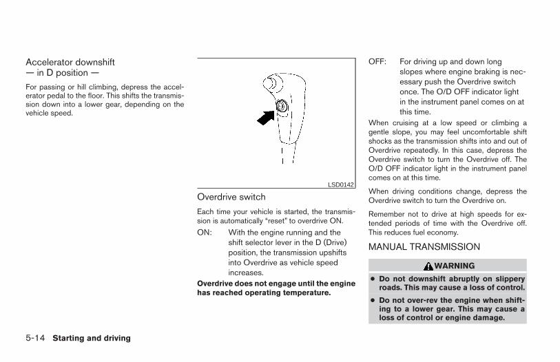
Accelerator downshift— in D position —For passing or hill climbing, depress the accel-erator pedal to the floor. This shifts the transmis-sion down into a lower gear, depending on thevehicle speed.
Overdrive switch
Each time your vehicle is started, the transmis-sion is automatically “reset” to overdrive ON.
ON: With the engine running and theshift selector lever in the D (Drive)position, the transmission upshiftsinto Overdrive as vehicle speedincreases.
Overdrive does not engage until the enginehas reached operating temperature.
OFF: For driving up and down longslopes where engine braking is nec-essary push the Overdrive switchonce. The O/D OFF indicator lightin the instrument panel comes on atthis time.
When cruising at a low speed or climbing agentle slope, you may feel uncomfortable shiftshocks as the transmission shifts into and out ofOverdrive repeatedly. In this case, depress theOverdrive switch to turn the Overdrive off. TheO/D OFF indicator light in the instrument panelcomes on at this time.
When driving conditions change, depress theOverdrive switch to turn the Overdrive on.
Remember not to drive at high speeds for ex-tended periods of time with the Overdrive off.This reduces fuel economy.
MANUAL TRANSMISSION
WARNING
● Do not downshift abruptly on slipperyroads. This may cause a loss of control.
● Do not over-rev the engine when shift-ing to a lower gear. This may cause aloss of control or engine damage.
LSD0142
5-14 Starting and driving
Z REVIEW COPY—2006 Truck/Frontier (d22)Owners Manual—USA_English (nna)10/17/05—debbie X
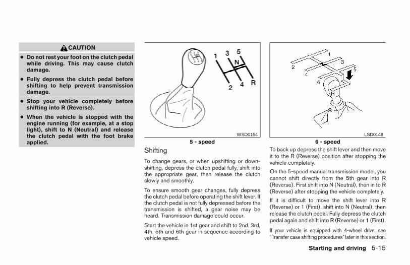
CAUTION
● Do not rest your foot on the clutch pedalwhile driving. This may cause clutchdamage.
● Fully depress the clutch pedal beforeshifting to help prevent transmissiondamage.
● Stop your vehicle completely beforeshifting into R (Reverse).
● When the vehicle is stopped with theengine running (for example, at a stoplight), shift to N (Neutral) and releasethe clutch pedal with the foot brakeapplied.
Shifting
To change gears, or when upshifting or down-shifting, depress the clutch pedal fully, shift intothe appropriate gear, then release the clutchslowly and smoothly.
To ensure smooth gear changes, fully depressthe clutch pedal before operating the shift lever. Ifthe clutch pedal is not fully depressed before thetransmission is shifted, a gear noise may beheard. Transmission damage could occur.
Start the vehicle in 1st gear and shift to 2nd, 3rd,4th, 5th and 6th gear in sequence according tovehicle speed.
To back up depress the shift lever and then moveit to the R (Reverse) position after stopping thevehicle completely.
On the 5-speed manual transmission model, youcannot shift directly from the 5th gear into R(Reverse). First shift into N (Neutral), then in to R(Reverse) after stopping the vehicle completely.
If it is difficult to move the shift lever into R(Reverse) or 1 (First), shift into N (Neutral), thenrelease the clutch pedal. Fully depress the clutchpedal again and shift into R (Reverse) or 1 (First).
If your vehicle is equipped with 4-wheel drive, see“Transfer case shifting procedures” later in this section.
5 - speedWSD0154
6 - speedLSD0148
Starting and driving 5-15
Z REVIEW COPY—2006 Truck/Frontier (d22)Owners Manual—USA_English (nna)10/17/05—debbie X
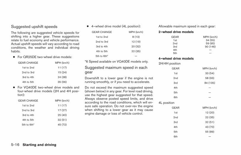
Suggested upshift speedsThe following are suggested vehicle speeds forshifting into a higher gear. These suggestionsrelate to fuel economy and vehicle performance.Actual upshift speeds will vary according to roadconditions, the weather and individual drivinghabits.
● For QR25DE two-wheel drive models:
GEAR CHANGE MPH (km/h)
1st to 2nd 11 (17)
2nd to 3rd 15 (24)
3rd to 4th 24 (38)
4th to 5th 35 (56)
● For VQ40DE two-wheel drive models andfour-wheel drive models (2H and 4H posi-tion):
GEAR CHANGE MPH (km/h)
1st to 2nd 11 (17)
2nd to 3rd 17 (27)
3rd to 4th 25 (40)
4th to 5th 32 (51)
5th to 6th* 45 (72)
● 4–wheel drive model (4L position):
GEAR CHANGE MPH (km/h)
1st to 2nd 8 (13)
2nd to 3rd 12 (19)
3rd to 4th 20 (32)
4th to 5th 22 (35)
5th to 6th* —
*6 Speed available on VQ40DE models only.
Suggested maximum speed in eachgearDownshift to a lower gear if the engine is notrunning smoothly, or if you need to accelerate.
Do not exceed the maximum suggested speed(shown below) in any gear. For level road driving,use the highest gear suggested for that speed.Always observe posted speed limits, and driveaccording to the road conditions, which will en-sure safe operation. Do not over-rev the enginewhen shifting to a lower gear as it may causeengine damage or loss of vehicle control.
Allowable maximum speed in each gear:
2–wheel drive models
GEAR MPH (km/h)1st 34 (55)2nd 59 (95)3rd 90 (146)4th —5th —
4–wheel drive models
2H/4H positionGEAR MPH (km/h)
1st 33 (54)
2nd 58 (93)
3rd 84 (135)
4th —
5th —
6th —
4L positionGEAR MPH (km/h)
1st 12 (20)
2nd 22 (35)
3rd 32 (51)
4th 43 (70)
5th 55 (89)
6th —
5-16 Starting and driving
Z REVIEW COPY—2006 Truck/Frontier (d22)Owners Manual—USA_English (nna)10/17/05—debbie X
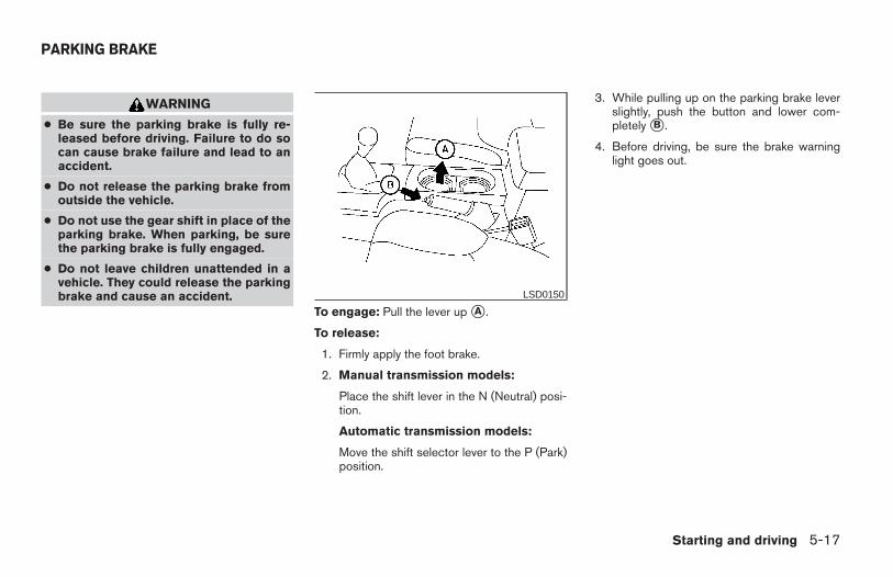
WARNING
● Be sure the parking brake is fully re-leased before driving. Failure to do socan cause brake failure and lead to anaccident.
● Do not release the parking brake fromoutside the vehicle.
● Do not use the gear shift in place of theparking brake. When parking, be surethe parking brake is fully engaged.
● Do not leave children unattended in avehicle. They could release the parkingbrake and cause an accident.
To engage: Pull the lever up sA .
To release:
1. Firmly apply the foot brake.
2. Manual transmission models:
Place the shift lever in the N (Neutral) posi-tion.
Automatic transmission models:
Move the shift selector lever to the P (Park)position.
3. While pulling up on the parking brake leverslightly, push the button and lower com-pletely sB .
4. Before driving, be sure the brake warninglight goes out.
LSD0150
PARKING BRAKE
Starting and driving 5-17
Z REVIEW COPY—2006 Truck/Frontier (d22)Owners Manual—USA_English (nna)10/17/05—debbie X
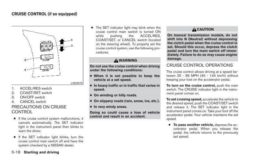
1. ACCEL/RES switch2. COAST/SET switch3. ON/OFF switch4. CANCEL switch
PRECAUTIONS ON CRUISECONTROL
● If the cruise control system malfunctions, itcancels automatically. The SET indicatorlight in the instrument panel then blinks towarn the driver.
● If the SET indicator light blinks, turn thecruise control main switch off and have thesystem checked by a NISSAN dealer.
● The SET indicator light may blink when thecruise control main switch is turned ONwhile pushing the ACCEL/RES,COAST/SET, or CANCEL switch (locatedon the steering wheel). To properly set thecruise control system, use the following pro-cedures.
WARNING
Do not use the cruise control when drivingunder the following conditions:
● When it is not possible to keep thevehicle at a set speed.
● In heavy traffic or in traffic that varies inspeed.
● On winding or hilly roads.
● On slippery roads (rain, snow, ice, etc.).
● In very windy areas.
Doing so could cause a loss of vehiclecontrol and result in an accident.
CAUTION
On manual transmission models, do notshift into N (Neutral) without depressingthe clutch pedal when the cruise control isset. Should this occur, depress the clutchpedal and turn the main switch off imme-diately. Failure to do so may cause enginedamage.
CRUISE CONTROL OPERATIONSThe cruise control allows driving at a speed be-tween 25 - 89 MPH (40 - 144 km/h) withoutkeeping your foot on the accelerator pedal.
To turn on the cruise control, push the mainswitch. The CRUISE indicator light in the instru-ment panel comes on.
To set cruising speed, accelerate the vehicle tothe desired speed, push the COAST/SET switchand release it. The SET indicator light in theinstrument panel comes on. Take your foot off theaccelerator pedal. Your vehicle maintains the setspeed.
● To pass another vehicle, depress the ac-celerator pedal. When you release thepedal, the vehicle returns to the previouslyset speed.
LSD0075
CRUISE CONTROL (if so equipped)
5-18 Starting and driving
Z REVIEW COPY—2006 Truck/Frontier (d22)Owners Manual—USA_English (nna)10/17/05—debbie X
● The vehicle may not maintain the set speedwhen going up or down steep hills. If thishappens, drive without the cruise control.
To cancel the preset speed, use one of thefollowing three methods.
● Push the CANCEL button; the SET indicatorlight in the instrument panel goes out.
● Tap the brake pedal; the SET indicator lightgoes out.
● Turn the main switch off. Both the CRUISEindicator light and SET indicator light in theinstrument panel go out.
The cruise control is automatically canceled andthe SET light in the instrument panel goes out if:
● you depress the brake or clutch pedal whilepushing the ACCEL/RES or COAST/SETswitch. The preset speed is deleted frommemory.
● the vehicle slows down more than 8 MPH(13 km/h) below the set speed.
● you depress the clutch pedal (manual trans-mission), or move the shift selector lever to N(Neutral) (automatic transmission).
To reset at a faster cruising speed, use oneof the following three methods.
● Depress the accelerator pedal. When thevehicle attains the desired speed, push andrelease the COAST/SET switch.
● Push and hold the ACCEL/RES switch.When the vehicle attains the speed you de-sire, release the switch.
● Push and release the ACCEL/RES switch.Each time you do this, the set speed in-creases by about 1 MPH (1.6 km/h).
To reset at a slower cruising speed, use oneof the following three methods.
● Lightly tap the brake pedal. When the ve-hicle attains the desired speed, push theCOAST/SET switch and release it.
● Push and hold the COAST/SET switch. Re-lease the switch when the vehicle slows tothe desired speed.
● Push and release the COAST/SET switch.Each time you do this, the set speed de-creases by about 1 MPH (1.6 km/h).
To resume the preset speed, push and re-lease the ACCEL/RES switch. The vehicle re-turns to the last set cruising speed when thevehicle speed is over 25 MPH (40 km/h).
CAUTION
During the first 1,200 miles (2,000 km),follow these recommendations to obtainmaximum engine performance and en-sure the future reliability and economy ofyour new vehicle. Failure to follow theserecommendations may result in short-ened engine life and reduced engineperformance.
● Avoid driving for long periods at constantspeed, either fast or slow, and do not run theengine over 4,000 rpm.
● Do not accelerate at full throttle in any gear.
● Avoid quick starts.
● Avoid hard braking as much as possible.
● Do not tow a trailer for the first 500 miles(800 km). Your engine, axle or other partscould be damaged.
BREAK-IN SCHEDULE
Starting and driving 5-19
Z REVIEW COPY—2006 Truck/Frontier (d22)Owners Manual—USA_English (nna)10/17/05—debbie X
● Accelerate slowly and smoothly. Maintaincruising speeds with a constant acceleratorposition.
● Drive at moderate speeds on the highway. Driv-ing at high speed lowers fuel economy.
● Avoid unnecessary stopping and braking.Maintain a safe distance behind other vehicles.
● Use a proper gear range which suits roadconditions. On level roads, shift into highgear as soon as possible.
● Avoid unnecessary engine idling.
● Keep your engine tuned up.
● Follow the recommended periodic mainte-nance schedule.
● Keep the tires inflated to the correct pres-sure. Low tire pressure increases tire wearand lowers fuel economy.
● Keep the front wheels in correct alignment.Improper alignment increases tire wear andlowers fuel economy.
● Air conditioner operation lowers fuel economy.Use the air conditioner only when necessary.
● When cruising at highway speeds, it is moreeconomical to use the air conditioner andleave the windows closed to reduce drag.
● Use 4H or 4L position only whennecessary. Four-wheel drive operation low-ers fuel economy.
CAUTION
● Do not drive the vehicle in the 4H or 4LOposition on dry hard surface roads. Driv-ing on dry, hard surfaces in 4H or 4LOmay cause unnecessary noise, tire wearand increased fuel consumption.
If the 4WD warning light turns on whenyou are driving on dry hard surfaceroads:
– in the 4H position, shift the 4WD shiftswitch to 2WD.
– in the 4LO position for automatictransmission vehicles, stop the ve-hicle and shift the transmission se-lector to the N position with thebrake pedal depressed and shift the4WD shift switch to 2WD.
– in the 4LO position for manual trans-mission vehicles, stop the vehicleand shift the transmission shift leverto the N position with the clutchpedal depressed and shift the 4WDshift switch to 2WD.
● If the warning light is still on after theabove operation, have your vehiclechecked by a NISSAN dealer as soon aspossible.
TRANSFER CASE SHIFTINGPROCEDURESThe part time 4WD system provides 3 positions(2WD, 4H and 4LO), so you can select thedesired drive mode according to the driving con-ditions.
2WD or 4WD shift procedure:
INCREASING FUEL ECONOMY USING FOUR WHEEL DRIVE(4WD)
5-20 Starting and driving
Z REVIEW COPY—2006 Truck/Frontier (d22)Owners Manual—USA_English (nna)10/17/05—debbie X
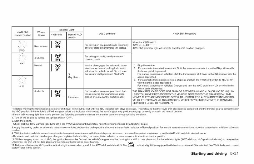
4WD ShiftSwitch Position
WheelsDriven
Indicator Light
Use Conditions 4WD Shift Procedure4WD shift Transfer 4LOposition
2WD
Rear wheels For driving on dry, paved roads (Economydrive) or state dynamometer I/M testing
Move the 4WD switch.2WD <—> 4H4WD shift indicator light will indicate transfer shift position engaged.
4H
4 wheels For driving on rocky, sandy or snow-covered roads
Neutral
*1May blink
Neutral disengages the automatic trans-mission mechanical parking lock, whichwill allow the vehicle to roll. Do not leavethe transfer shift position in Neutral.*2
1. Stop the vehicle.2. For automatic transmission vehicles: Shift the transmission selector to the (N) position with
the brake pedal depressed.For manual transmission vehicles: Shift the transmission shift lever to the (N) position with theclutch depressed.
3. For automatic transmission vehicles: Depress and turn the 4WD shift switch to 4LO or 4Hwith the brake pedal depressed.For manual transmission vehicles: Depress and turn the 4WD switch to 4LO or 4H with theclutch pedal depressed.
THE TRANSFER CASE DOES NOT ENGAGE BETWEEN 4H AND 4LO (OR 4LO TO 4H) UN-LESS YOU HAVE FIRST STOPPED THE VEHICLE, DEPRESSED THE BRAKE PEDAL ANDMOVED THE TRANSMISSION SELECTOR TO NEUTRAL FOR AUTOMATIC TRANSMISSIONVEHICLES. FOR MANUAL TRANSMISSION VEHICLES YOU MUST MOVE THE TRANSMIS-SION SHIFT LEVER TO NEUTRAL. *3
4LO
4 wheels
Illuminated
For use when maximum power and trac-tion is required (for example: on steepgrades or rocky, sandy, muddy roads)
*1: Before moving the transmission selector or shift lever from neutral, wait until the 4LO indicator light stays on steady. This indicates that the 4WD shift procedure is completed and the transfer gear is correctly set inthe 4LO position. If the vehicle is shifted into gear before the indicator is on steady, the transfer gear may grind, not engage correctly or stay in the neutral position.- If the 4WD warning light illuminates, perform the following procedure to return the transfer case to correct operating condition.1. Turn off the engine by turning the ignition switch 9OFF9.2. Start the engine.- Check that the 4WD warning light turns off. If the 4WD warning light illuminates, have the system checked by a NISSAN dealer.3. Apply the parking brake, for automatic transmission vehicles, depress the brake pedal and move the transmission selector to Neutral position. For manual transmission vehicles, move the transmission shift lever to Neutralposition.4. With the brake pedal depressed on automatic transmission vehicles or with the clutch pedal depressed on manual transmission vehicles, move the 4WD shift switch to desired mode.- Be sure to wait until the transfer gear change completes before shifting the transmission selector or transmission shift lever from Neutral position.*2: While changing in and out of 4LO, the ignition key must be ON and the vehicle’s engine must be running for a shift to take place and for the indicator lights (4WD shift and 4LO position indicator) to be operable.Otherwise, the shift will not take place and no indicator lights will be on or flashing.*3: Make sure the transfer 4LO position indicator light turns on when you shift the 4WD shift switch to 4LO. The indicator light (if so equipped) will also turn on when 4LO is selected. See “Vehicle dynamic controlsystem” later in this section.
Starting and driving 5-21
Z REVIEW COPY—2006 Truck/Frontier (d22)Owners Manual—USA_English (nna)10/17/05—debbie X
The transfer case 4WD shift switch is used toselect either 2WD or 4WD depending on thedriving conditions. There are three types of drivemodes available, 2WD, 4H and 4LO.
The 4WD shift switch electronically controls thetransfer case operation. Rotate the switch tomove between each mode, 2WD, 4H and 4LO.
To change into or out of 4LO, the vehicleMUST be stationary, shift the transmissionselector or transmission shift lever to Neu-tral (N), and for automatic transmissionvehicles depress the brake pedal or formanual transmission vehicles depress theclutch pedal. The switch must be de-pressed and turned when changing into orout of 4LO.
WARNING
● When parking, apply the parking brakebefore stopping the engine and makesure that the 4WD shift indicator light ison and the ATP warning light goes off.Otherwise, the vehicle could unexpect-edly move even if the automatic trans-mission is in the P position.
● The 4LO indicator light must stop blink-ing and remain illuminated or turn offbefore shifting the transmission intogear. If the transmission selector ortransmission shift lever is shifted fromthe (N) position to any other gear whenthe 4LO indicator light is blinking, thevehicle may move unexpectedly.
CAUTION
● Never shift the 4WD shift switch be-tween 4LO and 4H while driving.
● The 4H position provides greater trac-tion. Avoid excessive speed, as it willcause increased fuel consumption andhigher oil temperatures, and coulddamage drivetrain components.Speeds over 62.5 MPH (100 km/h) in 4His not recommended.
● The 4LO position provides maximumpower and traction. Avoid raising ve-hicle speed excessively, as the maxi-mum speed is approximately 31 MPH(50 km/h).
● When driving straight, shift the 4WDshift switch to the 2WD or 4H position.Do not move the 4WD shift switch whenmaking a turn or reversing.
● Do not shift the 4WD shift switch (be-tween 2WD and 4H) while driving onsteep downhill grades. Use the enginebrake and low automatic transmissiongears (D1 or D2) or manual transmis-sion (1st gear or 2nd gear) for enginebraking.
● Do not operate the 4WD shift switch(between 2WD and 4H) with the rearwheels spinning.
● Do not drive on dry hard surface roadsin the 4H or 4LO position. Driving on dryhard surfaces in 4H or 4LO may causeunnecessary noise and tire wear.NISSAN recommends driving in the2WD position under these conditions.
● The 4WD transfer case may not beshifted between 4H and 4LO at low am-bient temperatures and the transfer4LO position indicator light may blinkeven when the 4WD shift switch isshifted. After driving for a while you canchange the 4WD transfer case between4H and 4LO.
When driving on rough roads,
● Set the 4WD shift switch to 4H or 4LO.
● Drive carefully according to the road surfaceconditions.
5-22 Starting and driving
Z REVIEW COPY—2006 Truck/Frontier (d22)Owners Manual—USA_English (nna)10/17/05—debbie X
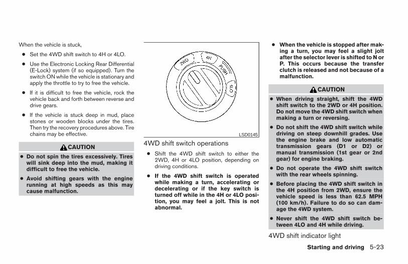
When the vehicle is stuck,
● Set the 4WD shift switch to 4H or 4LO.
● Use the Electronic Locking Rear Differential(E-Lock) system (if so equipped). Turn theswitch ON while the vehicle is stationary andapply the throttle to try to free the vehicle.
● If it is difficult to free the vehicle, rock thevehicle back and forth between reverse anddrive gears.
● If the vehicle is stuck deep in mud, placestones or wooden blocks under the tires.Then try the recovery procedures above. Tirechains may be effective.
CAUTION
● Do not spin the tires excessively. Tireswill sink deep into the mud, making itdifficult to free the vehicle.
● Avoid shifting gears with the enginerunning at high speeds as this maycause malfunction.
4WD shift switch operations● Shift the 4WD shift switch to either the
2WD, 4H or 4LO position, depending ondriving conditions.
● If the 4WD shift switch is operatedwhile making a turn, accelerating ordecelerating or if the key switch isturned off while in the 4H or 4LO posi-tion, you may feel a jolt. This is notabnormal.
● When the vehicle is stopped after mak-ing a turn, you may feel a slight joltafter the selector lever is shifted to N orP. This occurs because the transferclutch is released and not because of amalfunction.
CAUTION
● When driving straight, shift the 4WDshift switch to the 2WD or 4H position.Do not move the 4WD shift switch whenmaking a turn or reversing.
● Do not shift the 4WD shift switch whiledriving on steep downhill grades. Usethe engine brake and low automatictransmission gears (D1 or D2) ormanual transmission (1st gear or 2ndgear) for engine braking.
● Do not operate the 4WD shift switchwith the rear wheels spinning.
● Before placing the 4WD shift switch inthe 4H position from 2WD, ensure thevehicle speed is less than 62.5 MPH(100 km/h). Failure to do so can dam-age the 4WD system.
● Never shift the 4WD shift switch be-tween 4LO and 4H while driving.
4WD shift indicator light
LSD0145
Starting and driving 5-23
Z REVIEW COPY—2006 Truck/Frontier (d22)Owners Manual—USA_English (nna)10/17/05—debbie X
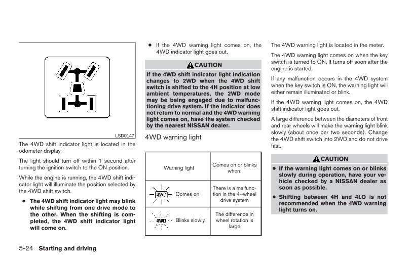
The 4WD shift indicator light is located in theodometer display.
The light should turn off within 1 second afterturning the ignition switch to the ON position.
While the engine is running, the 4WD shift indi-cator light will illuminate the position selected bythe 4WD shift switch.
● The 4WD shift indicator light may blinkwhile shifting from one drive mode tothe other. When the shifting is com-pleted, the 4WD shift indicator lightwill come on.
● If the 4WD warning light comes on, the4WD indicator light goes out.
CAUTION
If the 4WD shift indicator light indicationchanges to 2WD when the 4WD shiftswitch is shifted to the 4H position at lowambient temperatures, the 2WD modemay be being engaged due to malfunc-tioning drive system. If the indicator doesnot return to normal and the 4WD warninglight comes on, have the system checkedby the nearest NISSAN dealer.
4WD warning light
Warning light Comes on or blinkswhen:
Comes onThere is a malfunc-tion in the 4–wheel
drive system
Blinks slowlyThe difference inwheel rotation is
large
The 4WD warning light is located in the meter.
The 4WD warning light comes on when the keyswitch is turned to ON. It turns off soon after theengine is started.
If any malfunction occurs in the 4WD systemwhen the key switch is ON, the warning light willeither remain illuminated or blink.
If the 4WD warning light comes on, the 4WDshift indicator light goes out.
A large difference between the diameters of frontand rear wheels will make the warning light blinkslowly (about once per two seconds). Changethe 4WD shift switch into 2WD and do not drivefast.
CAUTION
● If the warning light comes on or blinksslowly during operation, have your ve-hicle checked by a NISSAN dealer assoon as possible.
● Shifting between 4H and 4LO is notrecommended when the 4WD warninglight turns on.
LSD0147
5-24 Starting and driving
Z REVIEW COPY—2006 Truck/Frontier (d22)Owners Manual—USA_English (nna)10/17/05—debbie X
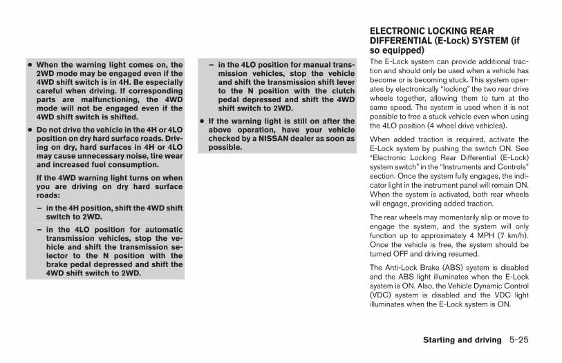
● When the warning light comes on, the2WD mode may be engaged even if the4WD shift switch is in 4H. Be especiallycareful when driving. If correspondingparts are malfunctioning, the 4WDmode will not be engaged even if the4WD shift switch is shifted.
● Do not drive the vehicle in the 4H or 4LOposition on dry hard surface roads. Driv-ing on dry, hard surfaces in 4H or 4LOmay cause unnecessary noise, tire wearand increased fuel consumption.
If the 4WD warning light turns on whenyou are driving on dry hard surfaceroads:
– in the 4H position, shift the 4WD shiftswitch to 2WD.
– in the 4LO position for automatictransmission vehicles, stop the ve-hicle and shift the transmission se-lector to the N position with thebrake pedal depressed and shift the4WD shift switch to 2WD.
– in the 4LO position for manual trans-mission vehicles, stop the vehicleand shift the transmission shift leverto the N position with the clutchpedal depressed and shift the 4WDshift switch to 2WD.
● If the warning light is still on after theabove operation, have your vehiclechecked by a NISSAN dealer as soon aspossible.
The E-Lock system can provide additional trac-tion and should only be used when a vehicle hasbecome or is becoming stuck. This system oper-ates by electronically “locking” the two rear drivewheels together, allowing them to turn at thesame speed. The system is used when it is notpossible to free a stuck vehicle even when usingthe 4LO position (4 wheel drive vehicles).
When added traction is required, activate theE-Lock system by pushing the switch ON. See“Electronic Locking Rear Differential (E-Lock)system switch” in the “Instruments and Controls”section. Once the system fully engages, the indi-cator light in the instrument panel will remain ON.When the system is activated, both rear wheelswill engage, providing added traction.
The rear wheels may momentarily slip or move toengage the system, and the system will onlyfunction up to approximately 4 MPH (7 km/h).Once the vehicle is free, the system should beturned OFF and driving resumed.
The Anti-Lock Brake (ABS) system is disabledand the ABS light illuminates when the E-Locksystem is ON. Also, the Vehicle Dynamic Control(VDC) system is disabled and the VDC lightilluminates when the E-Lock system is ON.
ELECTRONIC LOCKING REARDIFFERENTIAL (E-Lock) SYSTEM (ifso equipped)
Starting and driving 5-25
Z REVIEW COPY—2006 Truck/Frontier (d22)Owners Manual—USA_English (nna)10/17/05—debbie X
WARNING
● Never leave the E-Lock system ONwhen driving on paved or hard-surfacedroads. Turning the vehicle may result inthe rear wheels slipping and result in anaccident and personal injury. After us-ing the E-Lock system to free the ve-hicle, turn the system OFF.
● Use the E-Lock system only when free-ing a stuck vehicle. Try the 4LO positionbefore using the E-Lock system. Neveruse the E-Lock system on a slipperyroad surface such as snow or ice sur-face. Using the E-Lock system whendriving in these road conditions maycause unexpected movement of the ve-hicle during engine braking, accelerat-ing or turning, which may result in anaccident and serious personal injury.
CAUTION
● After using the E-Lock system, turn theswitch OFF to prevent possible damageto driveline components from extendeduse.
● Do not drive the vehicle at speeds fasterthan 12 mph (20 km/h) when the systemis engaged. Doing so could damagedrivetrain components.
● Do not turn on the E-lock system whilethe tires are spinning. Doing so coulddamage drivetrain components.
5-26 Starting and driving
Z REVIEW COPY—2006 Truck/Frontier (d22)Owners Manual—USA_English (nna)10/17/05—debbie X
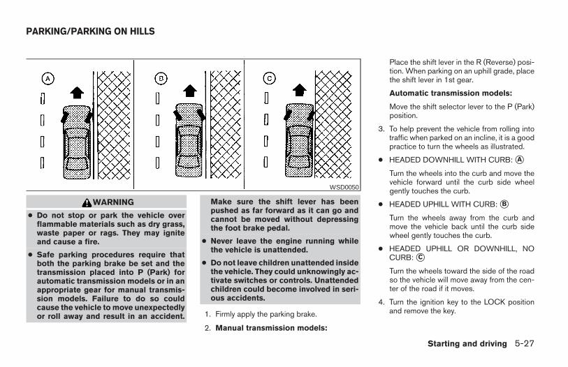
WARNING
● Do not stop or park the vehicle overflammable materials such as dry grass,waste paper or rags. They may igniteand cause a fire.
● Safe parking procedures require thatboth the parking brake be set and thetransmission placed into P (Park) forautomatic transmission models or in anappropriate gear for manual transmis-sion models. Failure to do so couldcause the vehicle to move unexpectedlyor roll away and result in an accident.
Make sure the shift lever has beenpushed as far forward as it can go andcannot be moved without depressingthe foot brake pedal.
● Never leave the engine running whilethe vehicle is unattended.
● Do not leave children unattended insidethe vehicle. They could unknowingly ac-tivate switches or controls. Unattendedchildren could become involved in seri-ous accidents.
1. Firmly apply the parking brake.
2. Manual transmission models:
Place the shift lever in the R (Reverse) posi-tion. When parking on an uphill grade, placethe shift lever in 1st gear.
Automatic transmission models:
Move the shift selector lever to the P (Park)position.
3. To help prevent the vehicle from rolling intotraffic when parked on an incline, it is a goodpractice to turn the wheels as illustrated.
● HEADED DOWNHILL WITH CURB: sA
Turn the wheels into the curb and move thevehicle forward until the curb side wheelgently touches the curb.
● HEADED UPHILL WITH CURB: sB
Turn the wheels away from the curb andmove the vehicle back until the curb sidewheel gently touches the curb.
● HEADED UPHILL OR DOWNHILL, NOCURB: sC
Turn the wheels toward the side of the roadso the vehicle will move away from the cen-ter of the road if it moves.
4. Turn the ignition key to the LOCK positionand remove the key.
WSD0050
PARKING/PARKING ON HILLS
Starting and driving 5-27
Z REVIEW COPY—2006 Truck/Frontier (d22)Owners Manual—USA_English (nna)10/17/05—debbie X
The power assisted steering uses a hydraulicpump, driven by the engine, to assist steering.
If the engine stops or the drive belt breaks, youwill still have control of the vehicle. However,much greater steering effort is needed, especiallyin sharp turns and at low speeds.
WARNING
If the engine is not running or is turned offwhile driving, the power assist for thesteering will not work. Steering will bemuch harder to operate.
The brake system has two separate hydrauliccircuits. If one circuit malfunctions, you will stillhave braking at two wheels.
BRAKE PRECAUTIONS
Vacuum assisted brakes
The brake booster aids braking by using enginevacuum. If the engine stops, you can stop thevehicle by depressing the brake pedal. However,greater foot pressure on the brake pedal will berequired to stop the vehicle and stopping dis-tance will be longer.
Using the brakes
Avoid resting your foot on the brake pedal whiledriving. This will overheat the brakes, wear out thebrakes and pads faster, and reduce gas mileage.
To help reduce brake wear and to prevent thebrakes from overheating, reduce speed anddownshift to a lower gear before going down aslope or long grade. Overheated brakes mayreduce braking performance and could result inloss of vehicle control.
WARNING
● While driving on a slippery surface, becareful when braking, accelerating ordownshifting. Abrupt braking or accel-erating could cause the wheels to skidand result in an accident.
● If the engine is not running or is turnedoff while driving, the power assist forthe brakes will not work. Braking will beharder.
Wet brakes
When the vehicle is washed or driven throughwater, the brakes may get wet. As a result, yourbraking distance will be longer and the vehiclemay pull to one side during braking.
To dry the brakes, drive the vehicle at a safespeed while lightly pressing the brake pedal toheat up the brakes. Do this until the brakes returnto normal. Avoid driving the vehicle at highspeeds until the brakes function correctly.
Parking brake break-in
Break-in the parking brake shoes whenever thestopping effect of the parking brake is weakenedor whenever the parking brake shoes and/ordrum/rotors are replaced, in order to assure thebest brake performance.
POWER STEERING BRAKE SYSTEM
5-28 Starting and driving
Z REVIEW COPY—2006 Truck/Frontier (d22)Owners Manual—USA_English (nna)10/17/05—debbie X
This procedure is described in the vehicle servicemanual and can be performed by a NISSANdealer.
ANTI-LOCK BRAKE SYSTEM (ABS)
The anti-lock brake system controls the brakes sothe wheels do not lock when braking abruptly orwhen braking on slippery surfaces. The systemdetects the rotation speed at each wheel andvaries the brake fluid pressure to prevent eachwheel from locking and sliding. By preventingwheel lockup, the system helps the driver main-tain steering control and helps to minimize swerv-ing and spinning on slippery surfaces.
Using the systemDepress the brake pedal and hold it down.
WARNING
Do not pump the brake pedal. Doing somay result in increased stoppingdistances.
Normal operationThe anti-lock brake system does not operate atspeeds below 3 - 6 MPH (5 - 10 km/h). (Thespeeds vary according to road conditions.)
When driving, the anti-lock brake system con-trols the wheels so they will not lock when brak-
ing abruptly or when braking on a slippery road.Thus, difficult steering and swerving of the ve-hicle due to locked wheels is minimized. Thesystem detects the wheel rotation rate and elec-tronically controls the pressure applied to eachbrake. Slight vibration on the brake pedal accom-panied by noise usually occurs while the ABSsystem is operating. Such vibration and noiseencountered during abrupt braking is not a prob-lem, but indicates that the system is functioningproperly. However, the pulsation may indicatethat road conditions are hazardous and extra careis required while driving.
Self-test feature
The anti-lock brake system consists of electronicsensors and hydraulic solenoids controlled by acomputer. The computer has a built-in diagnosticfeature that tests the system each time you startthe engine and move the vehicle at a low speed inforward or reverse. When the self-test occurs,you may hear a “clunk” noise and/or feel a pulsa-tion in the brake pedal. This is normal and is notan indication of any malfunction. If the computersenses any malfunction, it switches the anti-lockbrake system off and turns on the ABS brakewarning light on the instrument panel. The brakesystem then operates normally, but without anti-lock assistance.
If the light comes on during the self-test or whiledriving, take the vehicle to a NISSAN dealer forrepair.
WARNING
● The anti-lock brake system is a sophis-ticated device, but it cannot prevent ac-cidents resulting from careless or dan-gerous driving techniques. It can helpmaintain vehicle control during brakingon slippery surfaces, but remember thatthe stopping distance on slippery sur-faces will be longer than on normalsurfaces even with the anti-lock brakesystem. Stopping distances may alsobe longer on rough, gravel or snow cov-ered roads, or if you are using tirechains. Tire type and condition may alsoaffect braking effectiveness. Alwaysmaintain a safe distance from the ve-hicle in front of you. Ultimately, the re-sponsibility for safety of self and othersrests in the hands of the driver.
● Tire type and condition of tires may alsoaffect braking effectiveness.
● When replacing tires, install the speci-fied size of tires on all four wheels.
Starting and driving 5-29
Z REVIEW COPY—2006 Truck/Frontier (d22)Owners Manual—USA_English (nna)10/17/05—debbie X
● When installing a spare tire, make sureit is the proper size and type as speci-fied on the tire placard. For tire placardlocation information, refer to “Tire plac-ard” in the “Technical and consumerinformation” section of this manual.
● Refer to “Wheels and tires” in the“Maintenance and do-it-yourself” sec-tion of this manual.
● ABLS is a form of traction control usingsensors from the Anti-lock Brake System(ABS) to transfer power from a slipping drivewheel to a wheel with more traction. TheABLS system applies braking to the slippingwheel, which helps redirect power to an-other wheel.
● On 4WD models the ABLS system operatesin both 4H and 4LO modes. On 2WD ve-hicles, the ABLS system operates on thedrive axle only.
● The ABLS system is always ON unless thesystem detects brake pad overheating. Ifhigh brake pad temperature is detected, itwill turn OFF, but normal brake function willcontinue. ABLS will function even when theVDC system (if so equipped) is turned OFF.
WARNING
The ABLS system provides increased trac-tion, but will not prevent accidents due toabrupt steering operation or by carelessdriving or dangerous driving practices.Reduce vehicle speed and be especiallycareful when driving and cornering onslippery surfaces, and always drivecarefully.
When accelerating or driving on slippery sur-faces, the tires may spin or slide. With the VehicleDynamic Control (VDC) system, sensors detectthese movements and control the braking andengine output to help improve vehicle stability.
● When the vehicle dynamic control (VDC)system is operating, the SLIP indicator in theinstrument panel blinks.
● If the 4WD transfer case is shifted into 4LOthe indicator light will come on andthe VDC system will be turned off. See“Transfer case shifting procedures” earlier inthis section.
● If the SLIP indicator blinks, the road condi-tions are slippery. Be sure to adjust yourspeed and driving to these conditions. See“Slip indicator light”, and “Vehicle dynamiccontrol (VDC) off indicator light” in the “In-struments and controls” section.
If the battery is removed or discharged, the trac-tion control system may be disabled and theSLIP and indicator lights will not turn offafter 2 seconds when the ignition switch is turnedto the ON position. Perform the following proce-dure to reset the system:
● Start the engine and set the steering wheelin the straight forward position.
ACTIVE BRAKE LIMITED SLIP (ABLS)SYSTEM (if so equipped)
VEHICLE DYNAMIC CONTROL (VDC)SYSTEM (if so equipped)
5-30 Starting and driving
Z REVIEW COPY—2006 Truck/Frontier (d22)Owners Manual—USA_English (nna)10/17/05—debbie X
● Drive the vehicle at speeds above 10 mph(15 km/h) for at least 10 minutes.
● The VDC OFF indicator light should go offindicating the traction control system is op-erational.
● If you interrupt the reset procedure by turn-ing the ignition off, you will need to restartthe reset procedure.
If after driving the vehicle for more than 10 min-utes and the SLIP and lights remain illumi-nated in the instrument panel, have the vehicledynamic control system checked by a NISSANdealer.
If the vehicle is operated with the vehicle dynamiccontrol system off using the VDC OFF switch,most VDC functions will be turned off. The VDCsystem will still try to transfer power from a slip-ping drive wheel to one with more traction whenthe VDC system switch is OFF. The Slip indicatorwill flash if wheel spin is detected. The ABS willstill operate with the VDC system off.
When the VDC system is operating, you may feela pulsation in the brake pedal and hear a noise orvibration from under the hood. This is normal andindicates that the VDC system is working prop-erly.
The computer has a built in diagnostic featurethat tests the system each time you start theengine and move the vehicle forward or in reverseat a slow speed. When the self-test occurs, youmay hear a clunk noise and/or feel a pulsation inthe brake pedal. This is normal and is not anindication of a malfunction.
WARNING
● The vehicle dynamic control system isdesigned to help improve driving stabil-ity but does not prevent accidents dueto abrupt steering operation at highspeeds or by careless or dangerousdriving techniques. Reduce vehiclespeed and be especially careful whendriving and cornering on slippery sur-faces and always drive carefully.
● If brake related parts such as brakepads, rotors and calipers are not stan-dard equipment or are extremely dete-riorated, the vehicle dynamic controlsystem may not operate properly andthe vehicle dynamic control off indica-tor light may come on.
● Do not modify the vehicle’s suspension. Ifsuspension parts such as shock absorb-ers, struts, springs, stabilizer bars andbushings are not NISSAN approved foryour vehicle or are extremely deterioratedthe vehicle dynamic control system maynot operate properly. This could adverselyaffect vehicle handling performance, andthe VDC OFF indicator light may come on.
● When driving on extremely inclined sur-faces such as higher banked corners,the vehicle dynamic control system maynot operate properly and the VDC OFFindicator light may come on. Do notdrive on these types of roads.
● When driving on an unstable surfacesuch as a turntable, ferry, elevator orramp, the vehicle dynamic control offindicator light may illuminate. This isnot a malfunction. Restart the engineafter driving onto a stable surface
● If wheels or tires other than the recom-mended ones are used, the vehicle dy-namic control system may not operateproperly and the vehicle dynamic con-trol off indicator light may come on.
● The vehicle dynamic control system isnot a substitute for winter tires or tirechains on a snow covered road.
Starting and driving 5-31
Z REVIEW COPY—2006 Truck/Frontier (d22)Owners Manual—USA_English (nna)10/17/05—debbie X
WARNING
● Never rely solely on the hill descentcontrol system to control vehicle speedwhen driving on steep down hill grades.Always drive carefully and attentivelywhen using the hill descent control sys-tem and decelerate the vehicle speedby depressing the brake pedal if neces-sary. Be especially careful when drivingon frozen, muddy or an extremely steepdownhill roads. Failure to control ve-hicle speed may result in a loss of con-trol of the vehicle and possible seriousinjury or death.
● The hill descent control may not controlthe vehicle speed on a hill under all loador road conditions. Always be preparedto depress the brake pedal to controlvehicle speed. Failure to do so may re-sult in a collision or serious personalinjury.
The hill descent control system helps maintainvehicle speed when driving under 15-21 mph(25-35 km/h) on steeper downhill grades. HDCis useful when engine braking alone in 4H or 4Lcannot control vehicle speed. HDC applies thevehicle brakes to control vehicle speed allowing
the driver to concentrate on steering while reduc-ing the burden of brake and accelerator opera-tion.
● When additional braking is required onsteep downhill roads activate the HDC sys-tem by pushing the switch ON, see “Hilldescent control (HDC) switch” in the “In-struments and controls” section.
● Once the system is activated the indicatorlight will remain on in the instrument panel,see “Hill descent control (HDC) system onindicator light” in the “Instruments and con-trols” section.
If the accelerator or brake pedal is depressedwhile the HDC system is on, the system will stopoperating temporarily. As soon as the acceleratoror brake pedal is released, the HDC systembegins to function again if the HDC operatingconditions are fulfilled.
For the best results, when descending steepdownhill grades, the HDC switch should be ONand the selector lever in 2 (Second gear) or 1(Low gear) for engine braking.
WARNING
● Never rely solely on the hill start assistsystem to prevent the vehicle from mov-ing backward on a hill. Always drivecarefully and attentively. Depress thebrake pedal when the vehicle isstopped on a steep hill. Be especiallycareful when stopped on a hill on frozenor muddy roads. Failure to prevent thevehicle from rolling backwards may re-sult in a loss of control of the vehicleand possible serious injury or death.
● The hill start assist system is not de-signed to hold the vehicle at a standstillon a hill. Depress the brake pedal whenthe vehicle is stopped on a steep hill.Failure to do so may cause the vehicleto roll backwards and may result in acollision or serious personal injury.
● The hill start assist may not prevent thevehicle from rolling backwards on a hillunder all load or road conditions. Al-ways be prepared to depress the brakepedal to prevent the vehicle from rollingbackwards. Failure to do so may resultin a collision or serious personal injury.
HILL DESCENT CONTROL (HDC)SYSTEM (if so equipped)
HILL START ASSIST (HSA) SYSTEM(if so equipped)
5-32 Starting and driving
Z REVIEW COPY—2006 Truck/Frontier (d22)Owners Manual—USA_English (nna)10/17/05—debbie X
The hill start assist system automatically keepsthe brakes applied to help prevent the vehiclefrom rolling backwards in the time it takes thedriver to release the brake pedal and apply theaccelerator when the vehicle is stopped on a hill.
Hill start assist will operate automatically underthe following conditions:
● The selector lever is shifted to a forward orreverse gear.
● The vehicle is stopped completely on a hillby applying the brake.
The maximum holding time is 2 seconds. After 2seconds the vehicle will begin to roll back and hillstart assist will stop operating completely.
Hill start assist will not operate when the selectorlever is shifted to N or P or on a flat and level road.
FREEING A FROZEN DOOR LOCKTo prevent a door lock from freezing, apply de-icer through the key hole. If the lock becomesfrozen, heat the key before inserting it into the keyhole or use the remote keyless entry keyfob (if soequipped).
ANTI-FREEZEIn the winter when it is anticipated that the tem-perature will drop below 32°F (0°C), check theanti-freeze to assure proper winter protection.For details, see “Engine cooling system” in the“Maintenance and do-it-yourself” section of thismanual.
BATTERYIf the battery is not fully charged during extremelycold weather conditions, the battery fluid mayfreeze and damage the battery. To maintain maxi-mum efficiency, the battery should be checkedregularly. For details, see “Battery” in the “Main-tenance and do-it-yourself” section of thismanual.
DRAINING OF COOLANT WATER
If the vehicle is to be left outside without anti-freeze, drain the cooling system, including theengine block. Refill before operating the vehicle.For details, see “Changing engine coolant” in the“Maintenance and do-it-yourself” section of thismanual.
TIRE EQUIPMENT
1. SUMMER tires have a tread designed toprovide superior performance on dry pave-ment. However, the performance of thesetires will be substantially reduced in snowyand icy conditions. If you operate your ve-hicle on snowy or icy roads, NISSAN recom-mends the use of MUD & SNOW or ALLSEASON TIRES on all four wheels. Pleaseconsult a NISSAN dealer for the tire type,size, speed rating and availability informa-tion.
2. For additional traction on icy roads, studdedtires may be used. However, some U.S.states and Canadian provinces prohibit theiruse. Check local, state and provincial lawsbefore installing studded tires.
Skid and traction capabilities of studdedsnow tires on wet or dry surfaces may bepoorer than that of non-studded snow tires.
COLD WEATHER DRIVING
Starting and driving 5-33
Z REVIEW COPY—2006 Truck/Frontier (d22)Owners Manual—USA_English (nna)10/17/05—debbie X
3. Tire chains may be used.
Use of tire chains may be prohibited accordingto location. Check the local laws before install-ing tire chains. When installing tire chains,make sure they are the proper size for the tireson your vehicle and are installed according tothe chain manufacturer’s suggestions. Useonly SAE Class “S” chains. Class “S”chains are used on vehicles with restricted tireto vehicle clearance. Vehicles that can useClass “S” chains are designed to meet theminimum clearances between the tire and theclosest vehicle suspension or body compo-nent required to accommodate the use of awinter traction device (tire chains or cables).The minimum clearances are determined us-ing the factory equipped tire size. Other typesmay damage your vehicle. Use chain tension-ers when recommended by the tire chainmanufacturer to ensure a tight fit. Loose endlinks of the tire chain must be secured orremoved to prevent the possibility of whippingaction damage to the fenders or underbody. Ifpossible, avoid fully loading your vehicle whenusing tire chains. In addition, drive at a re-duced speed. Otherwise, your vehicle may bedamaged and/or vehicle handling and perfor-mance may be adversely affected.
Never install tire chains on spare tires. Donot use tire chains on dry roads.
SPECIAL WINTER EQUIPMENT
It is recommended that the following items becarried in the vehicle during winter:
● A scraper and stiff-bristled brush to removeice and snow from the windows and wiperblades.
● A sturdy, flat board to be placed under thejack to give it firm support.
● A shovel to dig the vehicle out of snowdrifts.
● Extra window washer fluid to refill the reser-voir tank.
DRIVING ON SNOW OR ICE
WARNING
● Wet ice (32°F, 0°C and freezing rain),very cold snow or ice can be slick andvery hard to drive on. The vehicle willhave much less traction or “grip” underthese conditions. Try to avoid driving onwet ice until the road is salted orsanded.
● Whatever the condition, drive with cau-tion. Accelerate and slow down withcare. If accelerating or downshifting toofast, the drive wheels will lose evenmore traction.
● Allow more stopping distance underthese conditions. Braking should bestarted sooner than on dry pavement.
● Allow greater following distances onslippery roads.
● Watch for slippery spots (glare ice).These may appear on an otherwise clearroad in shaded areas. If a patch of ice isseen ahead, brake before reaching it. Trynot to brake while on the ice, and avoidany sudden steering maneuvers.
● Do not use the cruise control on slip-pery roads.
● Snow can trap dangerous exhaustgases under your vehicle. Keep snowclear of the exhaust pipe and fromaround your vehicle.
ENGINE BLOCK HEATER (if soequipped)An engine block heater to assist in extreme coldtemperature starting is available through aNISSAN dealer.
WARNING
Do not use your heater with an ungroundedelectrical system or two-pronged (cheater)adapters. You can be injured by an electricalshock if you use an ungrounded connection.
5-34 Starting and driving
Z REVIEW COPY—2006 Truck/Frontier (d22)Owners Manual—USA_English (nna)10/17/05—debbie X
6 In case of emergency
First aid kit (if so equipped) . . . . . . . . . . . . . . . . . . . . . . . . . 6-2Flat tire . . . . . . . . . . . . . . . . . . . . . . . . . . . . . . . . . . . . . . . . . . . 6-2
Tire pressure monitoring system. . . . . . . . . . . . . . . . . . 6-2Changing a flat tire . . . . . . . . . . . . . . . . . . . . . . . . . . . . . 6-3
Jump starting . . . . . . . . . . . . . . . . . . . . . . . . . . . . . . . . . . . . . 6-8
Push starting. . . . . . . . . . . . . . . . . . . . . . . . . . . . . . . . . . . . .6-10If your vehicle overheats . . . . . . . . . . . . . . . . . . . . . . . . . . . 6-10Towing your vehicle . . . . . . . . . . . . . . . . . . . . . . . . . . . . . . .6-11
Towing recommended by NISSAN . . . . . . . . . . . . . . 6-12Vehicle recovery (freeing a stuck vehicle) . . . . . . . . . 6-14
Z REVIEW COPY—2006 Truck/Frontier (d22)Owners Manual—USA_English (nna)10/17/05—debbie X
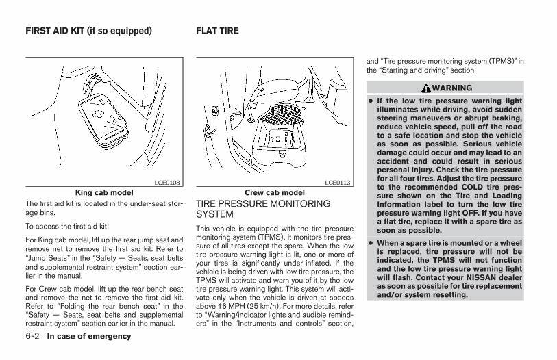
The first aid kit is located in the under-seat stor-age bins.
To access the first aid kit:
For King cab model, lift up the rear jump seat andremove net to remove the first aid kit. Refer to“Jump Seats” in the “Safety — Seats, seat beltsand supplemental restraint system” section ear-lier in the manual.
For Crew cab model, lift up the rear bench seatand remove the net to remove the first aid kit.Refer to “Folding the rear bench seat” in the“Safety — Seats, seat belts and supplementalrestraint system” section earlier in the manual.
TIRE PRESSURE MONITORINGSYSTEMThis vehicle is equipped with the tire pressuremonitoring system (TPMS). It monitors tire pres-sure of all tires except the spare. When the lowtire pressure warning light is lit, one or more ofyour tires is significantly under-inflated. If thevehicle is being driven with low tire pressure, theTPMS will activate and warn you of it by the lowtire pressure warning light. This system will acti-vate only when the vehicle is driven at speedsabove 16 MPH (25 km/h). For more details, referto “Warning/indicator lights and audible remind-ers” in the “Instruments and controls” section,
and “Tire pressure monitoring system (TPMS)” inthe “Starting and driving” section.
WARNING
● If the low tire pressure warning lightilluminates while driving, avoid suddensteering maneuvers or abrupt braking,reduce vehicle speed, pull off the roadto a safe location and stop the vehicleas soon as possible. Serious vehicledamage could occur and may lead to anaccident and could result in seriouspersonal injury. Check the tire pressurefor all four tires. Adjust the tire pressureto the recommended COLD tire pres-sure shown on the Tire and LoadingInformation label to turn the low tirepressure warning light OFF. If you havea flat tire, replace it with a spare tire assoon as possible.
● When a spare tire is mounted or a wheelis replaced, tire pressure will not beindicated, the TPMS will not functionand the low tire pressure warning lightwill flash. Contact your NISSAN dealeras soon as possible for tire replacementand/or system resetting.
King cab modelLCE0108
Crew cab modelLCE0113
FIRST AID KIT (if so equipped) FLAT TIRE
6-2 In case of emergency
Z REVIEW COPY—2006 Truck/Frontier (d22)Owners Manual—USA_English (nna)10/17/05—debbie X
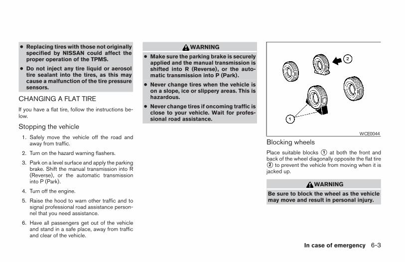
● Replacing tires with those not originallyspecified by NISSAN could affect theproper operation of the TPMS.
● Do not inject any tire liquid or aerosoltire sealant into the tires, as this maycause a malfunction of the tire pressuresensors.
CHANGING A FLAT TIRE
If you have a flat tire, follow the instructions be-low.
Stopping the vehicle
1. Safely move the vehicle off the road andaway from traffic.
2. Turn on the hazard warning flashers.
3. Park on a level surface and apply the parkingbrake. Shift the manual transmission into R(Reverse), or the automatic transmissioninto P (Park).
4. Turn off the engine.
5. Raise the hood to warn other traffic and tosignal professional road assistance person-nel that you need assistance.
6. Have all passengers get out of the vehicleand stand in a safe place, away from trafficand clear of the vehicle.
WARNING
● Make sure the parking brake is securelyapplied and the manual transmission isshifted into R (Reverse), or the auto-matic transmission into P (Park).
● Never change tires when the vehicle ison a slope, ice or slippery areas. This ishazardous.
● Never change tires if oncoming traffic isclose to your vehicle. Wait for profes-sional road assistance.
Blocking wheelsPlace suitable blocks s1 at both the front andback of the wheel diagonally opposite the flat tires2 to prevent the vehicle from moving when it isjacked up.
WARNING
Be sure to block the wheel as the vehiclemay move and result in personal injury.
WCE0044
In case of emergency 6-3
Z REVIEW COPY—2006 Truck/Frontier (d22)Owners Manual—USA_English (nna)10/17/05—debbie X
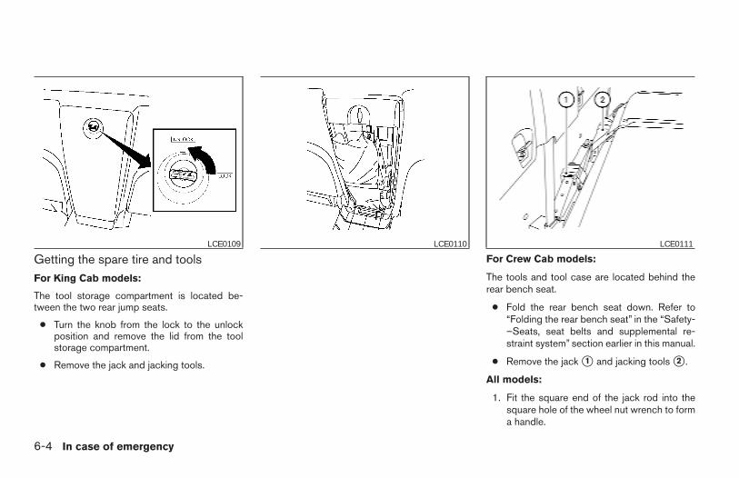
Getting the spare tire and toolsFor King Cab models:
The tool storage compartment is located be-tween the two rear jump seats.
● Turn the knob from the lock to the unlockposition and remove the lid from the toolstorage compartment.
● Remove the jack and jacking tools.
For Crew Cab models:
The tools and tool case are located behind therear bench seat.
● Fold the rear bench seat down. Refer to“Folding the rear bench seat” in the “Safety-–Seats, seat belts and supplemental re-straint system” section earlier in this manual.
● Remove the jack s1 and jacking tools s2 .
All models:
1. Fit the square end of the jack rod into thesquare hole of the wheel nut wrench to forma handle.
LCE0109 LCE0110 LCE0111
6-4 In case of emergency
Z REVIEW COPY—2006 Truck/Frontier (d22)Owners Manual—USA_English (nna)10/17/05—debbie X
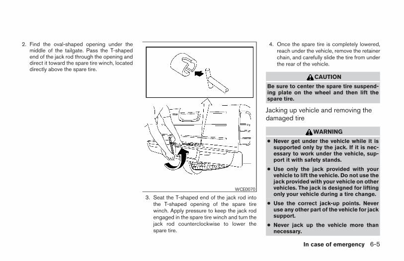
2. Find the oval-shaped opening under themiddle of the tailgate. Pass the T-shapedend of the jack rod through the opening anddirect it toward the spare tire winch, locateddirectly above the spare tire.
3. Seat the T-shaped end of the jack rod intothe T-shaped opening of the spare tirewinch. Apply pressure to keep the jack rodengaged in the spare tire winch and turn thejack rod counterclockwise to lower thespare tire.
4. Once the spare tire is completely lowered,reach under the vehicle, remove the retainerchain, and carefully slide the tire from underthe rear of the vehicle.
CAUTION
Be sure to center the spare tire suspend-ing plate on the wheel and then lift thespare tire.
Jacking up vehicle and removing thedamaged tire
WARNING
● Never get under the vehicle while it issupported only by the jack. If it is nec-essary to work under the vehicle, sup-port it with safety stands.
● Use only the jack provided with yourvehicle to lift the vehicle. Do not use thejack provided with your vehicle on othervehicles. The jack is designed for liftingonly your vehicle during a tire change.
● Use the correct jack-up points. Neveruse any other part of the vehicle for jacksupport.
● Never jack up the vehicle more thannecessary.
WCE0070
In case of emergency 6-5
Z REVIEW COPY—2006 Truck/Frontier (d22)Owners Manual—USA_English (nna)10/17/05—debbie X
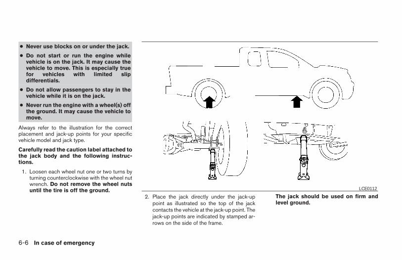
● Never use blocks on or under the jack.
● Do not start or run the engine whilevehicle is on the jack. It may cause thevehicle to move. This is especially truefor vehicles with limited slipdifferentials.
● Do not allow passengers to stay in thevehicle while it is on the jack.
● Never run the engine with a wheel(s) offthe ground. It may cause the vehicle tomove.
Always refer to the illustration for the correctplacement and jack-up points for your specificvehicle model and jack type.
Carefully read the caution label attached tothe jack body and the following instruc-tions.
1. Loosen each wheel nut one or two turns byturning counterclockwise with the wheel nutwrench. Do not remove the wheel nutsuntil the tire is off the ground.
2. Place the jack directly under the jack-uppoint as illustrated so the top of the jackcontacts the vehicle at the jack-up point. Thejack-up points are indicated by stamped ar-rows on the side of the frame.
The jack should be used on firm andlevel ground.
LCE0112
6-6 In case of emergency
Z REVIEW COPY—2006 Truck/Frontier (d22)Owners Manual—USA_English (nna)10/17/05—debbie X
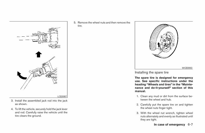
3. Install the assembled jack rod into the jackas shown.
4. To lift the vehicle, securely hold the jack leverand rod. Carefully raise the vehicle until thetire clears the ground.
5. Remove the wheel nuts and then remove thetire.
Installing the spare tire
The spare tire is designed for emergencyuse. See specific instructions under theheading “Wheels and tires” in the “Mainte-nance and do-it-yourself” section of thismanual.
1. Clean any mud or dirt from the surface be-tween the wheel and hub.
2. Carefully put the spare tire on and tightenthe wheel nuts finger tight.
3. With the wheel nut wrench, tighten wheelnuts alternately and evenly as illustrated untilthey are tight.
LCE0087
WCE0063
In case of emergency 6-7
Z REVIEW COPY—2006 Truck/Frontier (d22)Owners Manual—USA_English (nna)10/17/05—debbie X
4. Lower the vehicle slowly until the tiretouches the ground. Then, with the wheelnut wrench, tighten the wheel nuts securelyin the sequence illustrated. Lower the ve-hicle completely.
WARNING
● Incorrect wheel nuts or improperlytightened wheel nuts can cause thewheel to become loose or come off.This could cause an accident.
● Do not use oil or grease on the wheelstuds or nuts. This could cause the nutsto become loose.
Retighten the wheel nuts after the vehiclehas been driven for 600 miles (1,000 km)(also in cases of a flat tire, etc.). As soon aspossible, tighten the wheel nuts to thespecified torque with a torque wrench.
Wheel nut tightening torque:
98 ft-lb (133 N·m)
The wheel nuts must be kept tightened tospecification at all times. It is recom-mended that wheel nuts be tightened tospecifications at each lubrication interval.
Adjust tire pressure to the COLD pressure.
COLD pressure: After vehicle has beenparked for three hours or more or drivenless than 1 mile (1.6 km).
COLD tire pressures are shown on the Tireand Loading Information label affixed tothe driver side center pillar.
5. Securely store the flat tire and jacking equip-ment in the vehicle.
WARNING
● Always make sure that the spare tireand jacking equipment are properly se-cured after use. Such items can becomedangerous projectiles in an accident orsudden stop.
● The spare tire is designed for emer-gency use. See specific instructions un-der the heading “Wheels and tires” inthe “Maintenance and do-it-yourself”section of this manual.
To start your engine with a booster battery, theinstructions and precautions below must be fol-lowed.
WARNING
● If done incorrectly, jump starting canlead to a battery explosion, resulting insevere injury or death. It could alsodamage your vehicle.
● Explosive hydrogen gas is alwayspresent in the vicinity of the battery.Keep all sparks and flames away fromthe battery.
● Do not allow battery fluid to come intocontact with eyes, skin, clothing orpainted surfaces. Battery fluid is a cor-rosive sulfuric acid solution which cancause severe burns. If the fluid shouldcome into contact with anything, imme-diately flush the contacted area withwater.
● Keep battery out of the reach ofchildren.
● The booster battery must be rated at 12volts. Use of an improperly rated batterycan damage your vehicle.
JUMP STARTING
6-8 In case of emergency
Z REVIEW COPY—2006 Truck/Frontier (d22)Owners Manual—USA_English (nna)10/17/05—debbie X
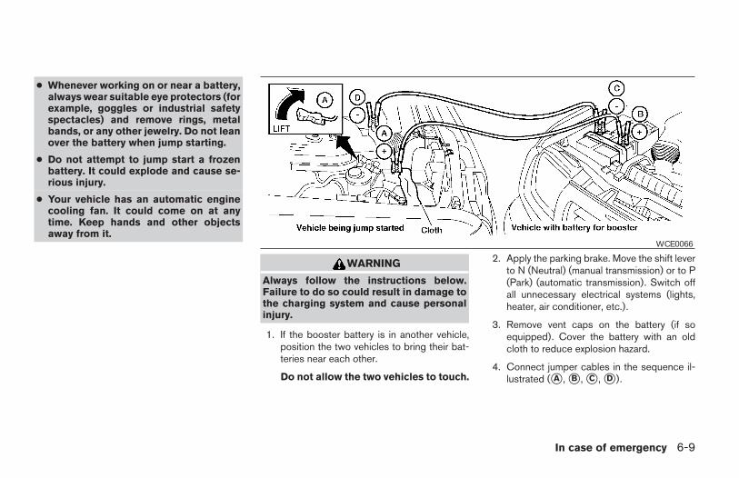
● Whenever working on or near a battery,always wear suitable eye protectors (forexample, goggles or industrial safetyspectacles) and remove rings, metalbands, or any other jewelry. Do not leanover the battery when jump starting.
● Do not attempt to jump start a frozenbattery. It could explode and cause se-rious injury.
● Your vehicle has an automatic enginecooling fan. It could come on at anytime. Keep hands and other objectsaway from it.
WARNING
Always follow the instructions below.Failure to do so could result in damage tothe charging system and cause personalinjury.
1. If the booster battery is in another vehicle,position the two vehicles to bring their bat-teries near each other.
Do not allow the two vehicles to touch.
2. Apply the parking brake. Move the shift leverto N (Neutral) (manual transmission) or to P(Park) (automatic transmission). Switch offall unnecessary electrical systems (lights,heater, air conditioner, etc.).
3. Remove vent caps on the battery (if soequipped). Cover the battery with an oldcloth to reduce explosion hazard.
4. Connect jumper cables in the sequence il-lustrated (sA , sB , sC , sD ).
WCE0066
In case of emergency 6-9
Z REVIEW COPY—2006 Truck/Frontier (d22)Owners Manual—USA_English (nna)10/17/05—debbie X
CAUTION
● Always connect positive (1) to positive(1) and negative (2) to body ground (forexample, strut mounting bolt, enginelift bracket, etc.) — not to the battery.
● Make sure the jumper cables do nottouch moving parts in the engine com-partment and that the cable clamps donot contact any other metal.
5. Start the engine of the booster vehicle andlet it run for a few minutes.
6. Keep the engine speed of the booster ve-hicle at about 2,000 rpm, and start the en-gine of the vehicle being jump started.
CAUTION
Do not keep the starter motor engaged formore than 10 seconds. If the engine doesnot start right away, turn the key off andwait 3 to 4 seconds before trying again.
7. After starting the engine, carefully disconnectthe negative cable and then the positive cable.
8. Replace the vent caps (if so equipped). Besure to dispose of the cloth used to coverthe vent holes as it may be contaminatedwith corrosive acid.
CAUTION
● Automatic transmission models cannotbe push-started or tow-started. At-tempting to do so may cause transmis-sion damage.
● Three-way catalyst equipped modelsshould not be started by pushing. Thethree-way catalyst may be damaged.
● Never try to start the vehicle by towingit. When the engine starts, the forwardsurge could cause the vehicle to collidewith the tow vehicle.
WARNING
● Do not continue to drive if your vehicleoverheats. Doing so could cause enginedamage or a vehicle fire.
● To avoid the danger of being scalded,never remove the radiator or coolantreservoir cap while the engine is stillhot. When the radiator or coolant reser-voir cap is removed, pressurized hotwater will spurt out, possibly causingserious injury.
● Do not open the hood if steam is com-ing out.
If your vehicle is overheating (indicated by anextremely high temperature gauge reading andthe illumination of the engine oil pressure/enginecoolant temperature high indicator light), or if youfeel a lack of engine power, detect abnormalnoise, etc. take the following steps.
1. Move the vehicle safely off the road, applythe parking brake and move the shift lever toP (Park).
Do not stop the engine.
2. Turn off the air conditioner. Open all thewindows, move the heater or air conditionertemperature control to maximum hot and fancontrol to high speed.
PUSH STARTING IF YOUR VEHICLE OVERHEATS
6-10 In case of emergency
Z REVIEW COPY—2006 Truck/Frontier (d22)Owners Manual—USA_English (nna)10/17/05—debbie X
3. Get out of the vehicle. Look and listen forsteam or coolant escaping from the radiatorbefore opening the hood. (If steam or cool-ant is escaping, turn off the engine.) Do notopen the hood further until no steam orcoolant can be seen.
4. Open the engine hood.
WARNING
If steam or water is coming from the en-gine, stand clear to prevent gettingburned.
5. Visually check drive belts for damage orlooseness. Also check if the cooling fan isrunning. The radiator hoses and radiatorshould not leak water. If coolant is leaking,the water pump belt is missing or loose, orthe cooling fan does not run, stop the en-gine.
WARNING
Be careful not to allow your hands, hair,jewelry or clothing to come into contactwith, or get caught in, engine belts or theengine cooling fan. The engine coolingfan can start at any time when the coolanttemperature is high.
6. After the engine cools down, check the cool-ant level in the engine coolant reservoir tankwith the engine running. Add coolant to theengine coolant reservoir tank if necessary.Have your vehicle repaired at a NISSANdealer.
When towing your vehicle, all State (Provincial inCanada) and local regulations for towing must befollowed. Incorrect towing equipment could dam-age your vehicle. Towing instructions are avail-able from a NISSAN dealer. Local service opera-tors are generally familiar with the applicable lawsand procedures for towing. To assure propertowing and to prevent accidental damage to yourvehicle, NISSAN recommends having a serviceoperator tow your vehicle. It is advisable to havethe service operator carefully read the followingprecautions:
WARNING
● Never ride in a vehicle that is beingtowed.
● Never get under your vehicle after it hasbeen lifted by a tow truck.
CAUTION
● When towing, make sure that the trans-mission, axles, steering system andpowertrain are in working condition. Ifany unit is damaged, dollies must beused.
● Always attach safety chains beforetowing.
TOWING YOUR VEHICLE
In case of emergency 6-11
Z REVIEW COPY—2006 Truck/Frontier (d22)Owners Manual—USA_English (nna)10/17/05—debbie X
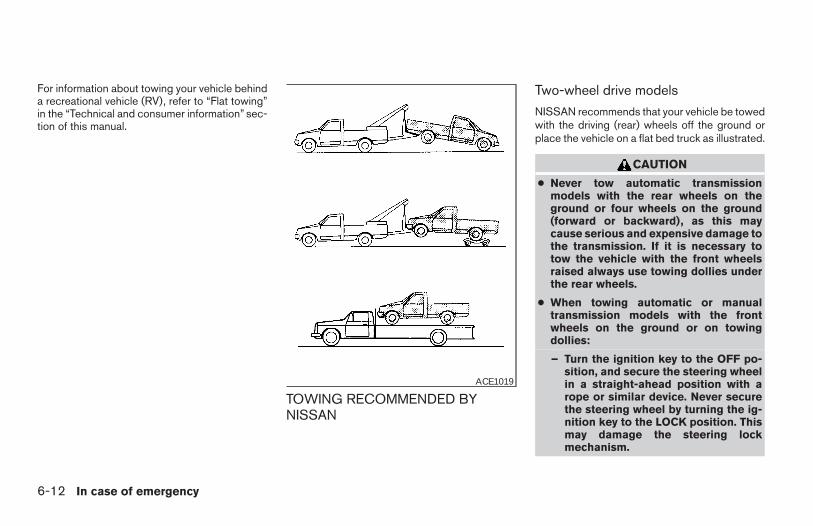
For information about towing your vehicle behinda recreational vehicle (RV), refer to “Flat towing”in the “Technical and consumer information” sec-tion of this manual.
TOWING RECOMMENDED BYNISSAN
Two-wheel drive models
NISSAN recommends that your vehicle be towedwith the driving (rear) wheels off the ground orplace the vehicle on a flat bed truck as illustrated.
CAUTION
● Never tow automatic transmissionmodels with the rear wheels on theground or four wheels on the ground(forward or backward), as this maycause serious and expensive damage tothe transmission. If it is necessary totow the vehicle with the front wheelsraised always use towing dollies underthe rear wheels.
● When towing automatic or manualtransmission models with the frontwheels on the ground or on towingdollies:
– Turn the ignition key to the OFF po-sition, and secure the steering wheelin a straight-ahead position with arope or similar device. Never securethe steering wheel by turning the ig-nition key to the LOCK position. Thismay damage the steering lockmechanism.
ACE1019
6-12 In case of emergency
Z REVIEW COPY—2006 Truck/Frontier (d22)Owners Manual—USA_English (nna)10/17/05—debbie X
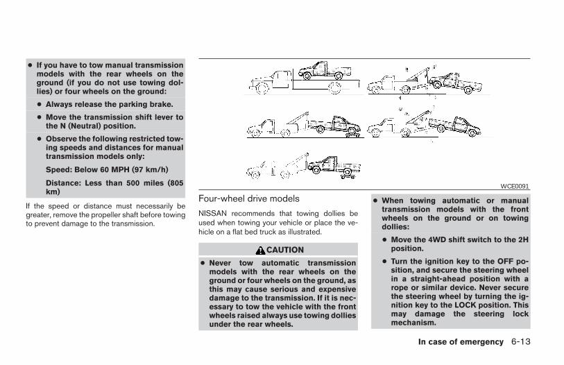
● If you have to tow manual transmissionmodels with the rear wheels on theground (if you do not use towing dol-lies) or four wheels on the ground:
● Always release the parking brake.
● Move the transmission shift lever tothe N (Neutral) position.
● Observe the following restricted tow-ing speeds and distances for manualtransmission models only:
Speed: Below 60 MPH (97 km/h)
Distance: Less than 500 miles (805km)
If the speed or distance must necessarily begreater, remove the propeller shaft before towingto prevent damage to the transmission.
Four-wheel drive models
NISSAN recommends that towing dollies beused when towing your vehicle or place the ve-hicle on a flat bed truck as illustrated.
CAUTION
● Never tow automatic transmissionmodels with the rear wheels on theground or four wheels on the ground, asthis may cause serious and expensivedamage to the transmission. If it is nec-essary to tow the vehicle with the frontwheels raised always use towing dolliesunder the rear wheels.
● When towing automatic or manualtransmission models with the frontwheels on the ground or on towingdollies:
● Move the 4WD shift switch to the 2Hposition.
● Turn the ignition key to the OFF po-sition, and secure the steering wheelin a straight-ahead position with arope or similar device. Never securethe steering wheel by turning the ig-nition key to the LOCK position. Thismay damage the steering lockmechanism.
WCE0091
In case of emergency 6-13
Z REVIEW COPY—2006 Truck/Frontier (d22)Owners Manual—USA_English (nna)10/17/05—debbie X
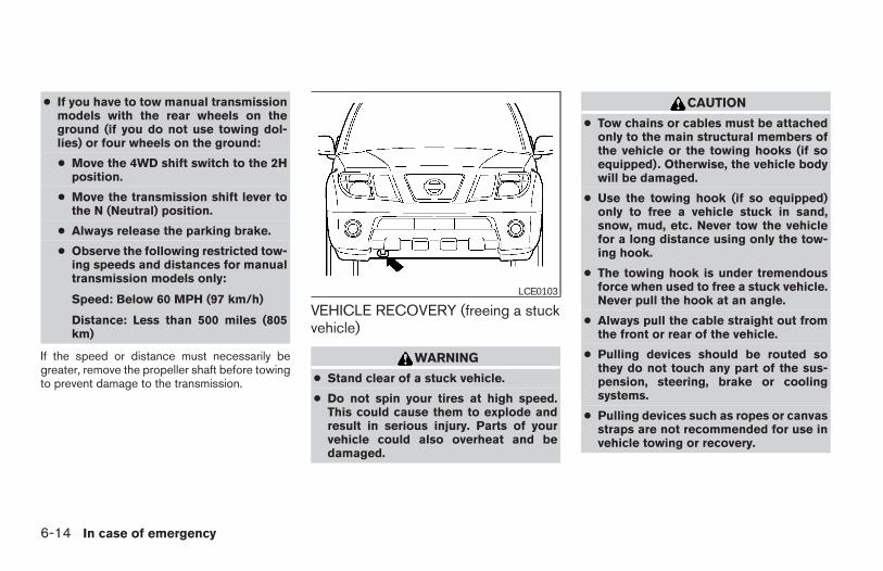
● If you have to tow manual transmissionmodels with the rear wheels on theground (if you do not use towing dol-lies) or four wheels on the ground:
● Move the 4WD shift switch to the 2Hposition.
● Move the transmission shift lever tothe N (Neutral) position.
● Always release the parking brake.
● Observe the following restricted tow-ing speeds and distances for manualtransmission models only:
Speed: Below 60 MPH (97 km/h)
Distance: Less than 500 miles (805km)
If the speed or distance must necessarily begreater, remove the propeller shaft before towingto prevent damage to the transmission.
VEHICLE RECOVERY (freeing a stuckvehicle)
WARNING
● Stand clear of a stuck vehicle.
● Do not spin your tires at high speed.This could cause them to explode andresult in serious injury. Parts of yourvehicle could also overheat and bedamaged.
CAUTION
● Tow chains or cables must be attachedonly to the main structural members ofthe vehicle or the towing hooks (if soequipped). Otherwise, the vehicle bodywill be damaged.
● Use the towing hook (if so equipped)only to free a vehicle stuck in sand,snow, mud, etc. Never tow the vehiclefor a long distance using only the tow-ing hook.
● The towing hook is under tremendousforce when used to free a stuck vehicle.Never pull the hook at an angle.
● Always pull the cable straight out fromthe front or rear of the vehicle.
● Pulling devices should be routed sothey do not touch any part of the sus-pension, steering, brake or coolingsystems.
● Pulling devices such as ropes or canvasstraps are not recommended for use invehicle towing or recovery.
LCE0103
6-14 In case of emergency
Z REVIEW COPY—2006 Truck/Frontier (d22)Owners Manual—USA_English (nna)10/17/05—debbie X
If your vehicle is stuck in sand, snow, mud, etc.,use the following procedure:
1. Turn off the Vehicle Dynamic Control System(if so equipped).
2. Make sure the area in front and behind thevehicle is clear of obstructions.
3. Turn the steering wheel right and left to clearan area around the front tires.
4. Slowly rock the vehicle forward and back-ward.
● Shift back and forth between R (Reverse)and D (Drive).
● Apply the accelerator as little as possibleto maintain the rocking motion.
● Release the accelerator pedal beforeshifting between R and D.
● Do not spin the tires above 35 mph (55km/h).
5. If the vehicle can not be freed after a fewtries, contact a professional towing serviceto remove the vehicle.
In case of emergency 6-15
Z REVIEW COPY—2006 Truck/Frontier (d22)Owners Manual—USA_English (nna)10/17/05—debbie X

6-16 In case of emergency
MEMO
7 Appearance and care
Cleaning exterior . . . . . . . . . . . . . . . . . . . . . . . . . . . . . . . . . . 7-2Washing . . . . . . . . . . . . . . . . . . . . . . . . . . . . . . . . . . . . . . 7-2Waxing . . . . . . . . . . . . . . . . . . . . . . . . . . . . . . . . . . . . . . . . 7-2Removing spots . . . . . . . . . . . . . . . . . . . . . . . . . . . . . . . . 7-2Underbody . . . . . . . . . . . . . . . . . . . . . . . . . . . . . . . . . . . . 7-3Glass . . . . . . . . . . . . . . . . . . . . . . . . . . . . . . . . . . . . . . . . . 7-3Aluminum alloy wheels . . . . . . . . . . . . . . . . . . . . . . . . . . 7-3Chrome parts . . . . . . . . . . . . . . . . . . . . . . . . . . . . . . . . . . 7-3Tire dressings . . . . . . . . . . . . . . . . . . . . . . . . . . . . . . . . . . 7-3
Cleaning interior. . . . . . . . . . . . . . . . . . . . . . . . . . . . . . . . . . . 7-4Floor mats . . . . . . . . . . . . . . . . . . . . . . . . . . . . . . . . . . . . . 7-4Seat belts . . . . . . . . . . . . . . . . . . . . . . . . . . . . . . . . . . . . . 7-5
Corrosion protection . . . . . . . . . . . . . . . . . . . . . . . . . . . . . . . 7-5Most common factors contributing to vehiclecorrosion . . . . . . . . . . . . . . . . . . . . . . . . . . . . . . . . . . . . . . 7-5Environmental factors influence the rate ofcorrosion . . . . . . . . . . . . . . . . . . . . . . . . . . . . . . . . . . . . . . 7-5To protect your vehicle from corrosion . . . . . . . . . . . . 7-5
Z REVIEW COPY—2006 Truck/Frontier (d22)Owners Manual—USA_English (nna)10/17/05—debbie X
In order to maintain the appearance of your ve-hicle, it is important to take proper care of it.
To protect the paint surfaces, please wash yourvehicle as soon as you can:
● after a rainfall to prevent possible damagefrom acid rain.
● after driving on coastal roads.
● when contaminants such as soot, bird drop-pings, tree sap, metal particles or bugs geton the paint surface.
● when dust or mud builds up on the surface.
Whenever possible, store or park your vehicleinside a garage or in a covered area.
When it is necessary to park outside, park in ashady area or protect the vehicle with a bodycover.
Be careful not to scratch the paint surfacewhen putting on or removing the bodycover.
WASHINGWash dirt off with a wet sponge and plenty ofwater. Clean the vehicle thoroughly using a mildsoap, a special vehicle soap or general purposedishwashing liquid mixed with clean, lukewarm(never hot) water.
CAUTION
● Do not wash the vehicle with stronghousehold soap, strong chemical deter-gents, gasoline or solvents.
● Do not wash the vehicle in direct sun-light or while the vehicle body is hot, asthe surface may become water-spotted.
● Avoid using tight-napped or roughcloths, such as washing mitts. Caremust be taken when removingcaked-on dirt or other foreign sub-stances so the paint surface is notscratched or damaged.
Rinse the vehicle thoroughly with plenty of cleanwater.
Inside flanges, seams and folds on the doors,hatches and hood are particularly vulnerable tothe effects of road salt. Therefore, these areasmust be cleaned regularly. Take care that thedrain holes in the lower edge of the door areopen. Spray water under the body and in thewheel wells to loosen the dirt and wash awayroad salt.
A damp chamois can be used to dry the vehicle toavoid water spots.
WAXINGRegular waxing protects the paint surface andhelps retain new vehicle appearance. Polishing isrecommended to remove built-up wax residueand to avoid a weathered appearance beforere-applying wax.
A NISSAN dealer can assist you in choosing theproper product.
● Wax your vehicle only after a thorough wash-ing. Follow the instructions supplied with thewax.
● Do not use a wax containing any abrasives,cutting compounds or cleaners that maydamage the vehicle finish.
Machine compounding or aggressive polishingon a base coat/clear coat paint finish may dull thefinish or leave swirl marks.
REMOVING SPOTSRemove tar and oil spots, industrial dust, insects,and tree sap as quickly as possible from thesurface of the paint to avoid lasting damage orstaining. Special cleaning products are availableat a NISSAN dealer or any automotive accessorystore.
CLEANING EXTERIOR
7-2 Appearance and care
Z REVIEW COPY—2006 Truck/Frontier (d22)Owners Manual—USA_English (nna)10/17/05—debbie X
UNDERBODYIn areas where road salt is used in winter, it isnecessary to clean the underbody regularly inorder to prevent dirt and salt from building up andcausing the acceleration of corrosion on the un-derbody and suspension. Before the winter pe-riod and again in the spring, the underseal mustbe checked and, if necessary, retreated.
GLASSUse glass cleaner to remove smoke and dust filmfrom the glass surfaces. It is normal for glass tobecome coated with a film after the vehicle isparked in the hot sun. Glass cleaner and a softcloth will easily remove this film.
CAUTION
When cleaning the inside of the windows,do not use sharp-edged tools, abrasivecleaners or chlorine-based disinfectantcleaners. They could damage the electri-cal conductors, radio antenna elements orrear window defroster elements.
ALUMINUM ALLOY WHEELSWash the wheels regularly, especially during win-ter months in areas where road salt is used. If notremoved, road salt can discolor the wheels.
CHROME PARTSClean all chrome parts regularly with a non-abrasive chrome polish to maintain the finish.
TIRE DRESSINGSNISSAN does not recommend the use of tiredressings. Tire manufacturers apply a coating tothe tires to help reduce discoloration of the rub-ber. If a tire dressing is applied to the tires, it mayreact with the coating and form a compound. Thiscompound may come off the tire while driving andstain the vehicle paint.
If you choose to use a tire dressing, take thefollowing precautions:
● Use a water-based tire dressing. The coat-ing on the tire dissolves more easily with anoil-based tire dressing.
● Apply a light coat of tire dressing to helpprevent it from entering the tiretread/grooves (where it would be difficult toremove).
● Wipe off excess tire dressing using a drytowel. Make sure the tire dressing is com-pletely removed from the tire tread/grooves.
● Allow the tire dressing to dry as recom-mended by tire dressing manufacturer.
Appearance and care 7-3
Z REVIEW COPY—2006 Truck/Frontier (d22)Owners Manual—USA_English (nna)10/17/05—debbie X
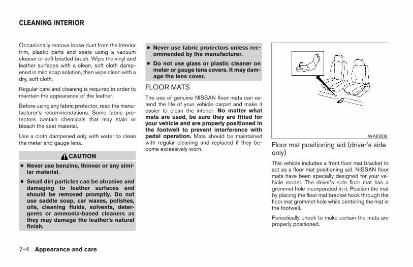
Occasionally remove loose dust from the interiortrim, plastic parts and seats using a vacuumcleaner or soft bristled brush. Wipe the vinyl andleather surfaces with a clean, soft cloth damp-ened in mild soap solution, then wipe clean with adry, soft cloth.
Regular care and cleaning is required in order tomaintain the appearance of the leather.
Before using any fabric protector, read the manu-facturer’s recommendations. Some fabric pro-tectors contain chemicals that may stain orbleach the seat material.
Use a cloth dampened only with water to cleanthe meter and gauge lens.
CAUTION
● Never use benzine, thinner or any simi-lar material.
● Small dirt particles can be abrasive anddamaging to leather surfaces andshould be removed promptly. Do notuse saddle soap, car waxes, polishes,oils, cleaning fluids, solvents, deter-gents or ammonia-based cleaners asthey may damage the leather’s naturalfinish.
● Never use fabric protectors unless rec-ommended by the manufacturer.
● Do not use glass or plastic cleaner onmeter or gauge lens covers. It may dam-age the lens cover.
FLOOR MATSThe use of genuine NISSAN floor mats can ex-tend the life of your vehicle carpet and make iteasier to clean the interior. No matter whatmats are used, be sure they are fitted foryour vehicle and are properly positioned inthe footwell to prevent interference withpedal operation. Mats should be maintainedwith regular cleaning and replaced if they be-come excessively worn.
Floor mat positioning aid (driver’s sideonly)This vehicle includes a front floor mat bracket toact as a floor mat positioning aid. NISSAN floormats have been specially designed for your ve-hicle model. The driver’s side floor mat has agrommet hole incorporated in it. Position the matby placing the floor mat bracket hook through thefloor mat grommet hole while centering the mat inthe footwell.
Periodically check to make certain the mats areproperly positioned.
WAI0006
CLEANING INTERIOR
7-4 Appearance and care
Z REVIEW COPY—2006 Truck/Frontier (d22)Owners Manual—USA_English (nna)10/17/05—debbie X
SEAT BELTSThe seat belts can be cleaned by wiping themwith a sponge dampened in a mild soap solution.Allow the belts to dry completely in the shadebefore using them. See “Seat belt maintenance”in the “Safety – Seats, seat belts and supplemen-tal restraint system” section of this manual.
WARNING
Do not allow wet seat belts to roll up in theretractor. NEVER use bleach, dye orchemical solvents to clean the seat belts,since these materials may severelyweaken the seat belt webbing.
MOST COMMON FACTORSCONTRIBUTING TO VEHICLECORROSION
● The accumulation of moisture-retaining dirtand debris in body panel sections, cavities,and other areas.
● Damage to paint and other protective coat-ings caused by gravel and stone chips orminor traffic accidents.
ENVIRONMENTAL FACTORSINFLUENCE THE RATE OFCORROSION
Moisture
Accumulation of sand, dirt and water on the ve-hicle body underside can accelerate corrosion.Wet floor coverings will not dry completely insidethe vehicle, and should be removed for drying toavoid floor panel corrosion.
Relative humidity
Corrosion will be accelerated in areas of highrelative humidity, especially those areas wherethe temperatures stay above freezing and whereatmospheric pollution exists and road salt isused.
TemperatureHigh temperatures accelerate the rate of corro-sion to those parts which are not well ventilated.
Air pollutionIndustrial pollution, the presence of salt in the airin coastal areas, or heavy road salt use acceler-ates the corrosion process. Road salt also accel-erates the disintegration of paint surfaces.
TO PROTECT YOUR VEHICLEFROM CORROSION
● Wash and wax your vehicle often to keep thevehicle clean.
● Always check for minor damage to the paintand repair it as soon as possible.
● Keep drain holes at the bottom of the doorsopen to avoid water accumulation.
● Check the underbody for accumulation ofsand, dirt or salt. If present, wash with wateras soon as possible.
CORROSION PROTECTION
Appearance and care 7-5
Z REVIEW COPY—2006 Truck/Frontier (d22)Owners Manual—USA_English (nna)10/17/05—debbie X
CAUTION
● NEVER remove dirt, sand or other de-bris from the passenger compartmentby washing it out with a hose. Removedirt with a vacuum cleaner or broom.
● Never allow water or other liquids tocome in contact with electronic compo-nents inside the vehicle as this maydamage them.
Chemicals used for road surface de-icing areextremely corrosive. They accelerate corrosionand deterioration of underbody componentssuch as the exhaust system, fuel and brake lines,brake cables, floor pan and fenders.
In winter, the underbody must be cleanedperiodically.
For additional protection against rust and corro-sion, which may be required in some areas, con-sult a NISSAN dealer.
7-6 Appearance and care
Z REVIEW COPY—2006 Truck/Frontier (d22)Owners Manual—USA_English (nna)10/17/05—debbie X
8 Maintenance and do-it-yourself
Maintenance requirements. . . . . . . . . . . . . . . . . . . . . . . . . . 8-2General maintenance . . . . . . . . . . . . . . . . . . . . . . . . . . . . . . 8-2
Explanation of general maintenance items . . . . . . . . . 8-2Maintenance precautions . . . . . . . . . . . . . . . . . . . . . . . . . . . 8-5Engine compartment check locations . . . . . . . . . . . . . . . . 8-6Engine cooling system . . . . . . . . . . . . . . . . . . . . . . . . . . . . . 8-8
Checking engine coolant level . . . . . . . . . . . . . . . . . . . 8-8Changing engine coolant . . . . . . . . . . . . . . . . . . . . . . . . 8-9
Engine oil. . . . . . . . . . . . . . . . . . . . . . . . . . . . . . . . . . . . . . . . . 8-9Checking engine oil level . . . . . . . . . . . . . . . . . . . . . . . . 8-9Changing engine oil . . . . . . . . . . . . . . . . . . . . . . . . . . . 8-10Changing engine oil filter . . . . . . . . . . . . . . . . . . . . . . . 8-12
5-speed automatic transmission fluid . . . . . . . . . . . . . . . 8-13Power steering fluid. . . . . . . . . . . . . . . . . . . . . . . . . . . . . . .8-13Brake and clutch fluid . . . . . . . . . . . . . . . . . . . . . . . . . . . . .8-14
Brake fluid . . . . . . . . . . . . . . . . . . . . . . . . . . . . . . . . . . . .8-14Clutch fluid . . . . . . . . . . . . . . . . . . . . . . . . . . . . . . . . . . .8-14
Window washer fluid . . . . . . . . . . . . . . . . . . . . . . . . . . . . .8-15Window washer fluid reservoir . . . . . . . . . . . . . . . . . . 8-15
Battery . . . . . . . . . . . . . . . . . . . . . . . . . . . . . . . . . . . . . . . . . .8-15Jump starting . . . . . . . . . . . . . . . . . . . . . . . . . . . . . . . . .8-17
Variable Voltage Control System . . . . . . . . . . . . . . . . . . . 8-17Drive belts . . . . . . . . . . . . . . . . . . . . . . . . . . . . . . . . . . . . . . .8-18
Spark plugs. . . . . . . . . . . . . . . . . . . . . . . . . . . . . . . . . . . . . .8-19Replacing spark plugs . . . . . . . . . . . . . . . . . . . . . . . . . 8-19
Air cleaner . . . . . . . . . . . . . . . . . . . . . . . . . . . . . . . . . . . . . . .8-19In-cabin microfilter . . . . . . . . . . . . . . . . . . . . . . . . . . . . .8-20
Windshield wiper blades . . . . . . . . . . . . . . . . . . . . . . . . . . 8-21Cleaning . . . . . . . . . . . . . . . . . . . . . . . . . . . . . . . . . . . . .8-21Replacing . . . . . . . . . . . . . . . . . . . . . . . . . . . . . . . . . . . .8-22
Parking brake and brake pedal . . . . . . . . . . . . . . . . . . . . . 8-23Checking parking brake . . . . . . . . . . . . . . . . . . . . . . . . 8-23Checking brake pedal. . . . . . . . . . . . . . . . . . . . . . . . . . 8-23Brake booster . . . . . . . . . . . . . . . . . . . . . . . . . . . . . . . . .8-24
Fuses . . . . . . . . . . . . . . . . . . . . . . . . . . . . . . . . . . . . . . . . . . .8-24Engine compartment . . . . . . . . . . . . . . . . . . . . . . . . . . . 8-25Passenger compartment . . . . . . . . . . . . . . . . . . . . . . . 8-26
Keyfob battery replacement . . . . . . . . . . . . . . . . . . . . . . . . 8-27Lights . . . . . . . . . . . . . . . . . . . . . . . . . . . . . . . . . . . . . . . . . . .8-28
Headlights . . . . . . . . . . . . . . . . . . . . . . . . . . . . . . . . . . . .8-28Exterior and interior lights. . . . . . . . . . . . . . . . . . . . . . . 8-29
Wheels and tires . . . . . . . . . . . . . . . . . . . . . . . . . . . . . . . . .8-32Tire pressure. . . . . . . . . . . . . . . . . . . . . . . . . . . . . . . . . .8-32Tire labeling. . . . . . . . . . . . . . . . . . . . . . . . . . . . . . . . . . .8-36Types of tires. . . . . . . . . . . . . . . . . . . . . . . . . . . . . . . . . .8-39Tire chains. . . . . . . . . . . . . . . . . . . . . . . . . . . . . . . . . . . .8-40Changing wheels and tires . . . . . . . . . . . . . . . . . . . . . 8-40
Z REVIEW COPY—2006 Truck/Frontier (d22)Owners Manual—USA_English (nna)10/17/05—debbie X
Your new NISSAN has been designed to haveminimum maintenance requirements with longerservice intervals to save you both time andmoney. However, some day-to-day and regularmaintenance is essential to maintain your NIS-SAN’s good mechanical condition, as well as itsemission and engine performance.
It is the owner’s responsibility to make sure thatthe scheduled maintenance, as well as generalmaintenance, is performed.
As the vehicle owner, you are the only one whocan ensure that your vehicle receives propermaintenance. You are a vital link in the mainte-nance chain.
Scheduled maintenance
For your convenience, both required and optionalscheduled maintenance items are described andlisted in your “NISSAN Service and MaintenanceGuide.” You must refer to that guide to ensurethat necessary maintenance is performed on yourNISSAN at regular intervals.
General maintenance
General maintenance includes those items whichshould be checked during normal day-to-day op-eration. They are essential for proper vehicle op-eration. It is your responsibility to perform thesemaintenance procedures regularly as prescribed.
Performing general maintenance checks requiresminimal mechanical skill and only a few generalautomotive tools.
These checks or inspections can be done by you,a qualified technician, or, if you prefer, a NISSANdealer.
Where to go for service
If maintenance service is required or your vehicleappears to malfunction, have the systemschecked and corrected by a NISSAN dealer.
NISSAN technicians are well-trained specialistswho are kept up-to-date with the latest serviceinformation through technical bulletins, servicetips, and in-dealership training programs. Theyare completely qualified to work on NISSAN ve-hicles before they work on your vehicle, ratherthan after they have worked on it.
You can be confident that a NISSAN dealer’sservice department performs the best job to meetthe maintenance requirements on your vehicle —in a reliable and economic way.
During the normal day-to-day operation of thevehicle, general maintenance should be per-formed regularly as prescribed in this section. Ifyou detect any unusual sounds, vibrations orsmells, be sure to check for the cause or have aNISSAN dealer do it promptly. In addition, youshould notify a NISSAN dealer if you think thatrepairs are required.
When performing any checks or maintenancework, closely observe the “Maintenance precau-tions” later in this section.
EXPLANATION OF GENERALMAINTENANCE ITEMS
Additional information on the followingitems with “*” is found later in this section.
Outside the vehicle
The maintenance items listed here should beperformed from time to time, unless otherwisespecified.
Doors and engine hood Check that the doorsand engine hood operate properly. Also ensurethat all latches lock securely. Lubricate hinges,latches, latch pins, rollers and links as necessary.Make sure that the secondary latch keeps thehood from opening when the primary latch isreleased.
MAINTENANCE REQUIREMENTS GENERAL MAINTENANCE
8-2 Maintenance and do-it-yourself
Z REVIEW COPY—2006 Truck/Frontier (d22)Owners Manual—USA_English (nna)10/17/05—debbie X
When driving in areas using road salt or othercorrosive materials, check lubrication frequently.
Lights* Clean the headlights on a regular basis.Make sure that the headlights, stop lights, taillights, turn signal lights, and other lights are alloperating properly and installed securely. Alsocheck headlight aim.
Road wheel nuts* When checking the tires,make sure no wheel nuts are missing, and checkfor any loose wheel nuts. Tighten if necessary.
Tire rotation* Tires should be rotated every7,500 miles (12,000 km).
Tires* Check the pressure with a gauge oftenand always prior to long distance trips. If neces-sary, adjust the pressure in all tires, including thespare, to the pressure specified. Check carefullyfor damage, cuts or excessive wear.
Wheel alignment and balance If the vehicleshould pull to either side while driving on astraight and level road, or if you detect uneven orabnormal tire wear, there may be a need for wheelalignment. If the steering wheel or seat vibrates atnormal highway speeds, wheel balancing may beneeded.
● For additional information regarding tires,refer to “Important Tire Safety Information”(US) or “Tire Safety Information” (Canada) inthe Warranty Information Booklet .
Windshield Clean the windshield on a regularbasis. Check the windshield at least every sixmonths for cracks or other damage. Have a dam-aged windshield repaired by a qualified repairfacility.
Windshield wiper blades* Check for cracks orwear if they do not wipe properly.
Inside the vehicle
The maintenance items listed here should bechecked on a regular basis, such as when per-forming periodic maintenance, cleaning the ve-hicle, etc.
Additional information on the followingitems with an “*” is found later in this sec-tion.
Accelerator pedal Check the pedal for smoothoperation and make sure the pedal does not bindor require uneven effort. Keep the floor mat awayfrom the pedal.
Automatic transmission P (Park) positionmechanism On a fairly steep hill check that yourvehicle is held securely with the selector lever inthe P (Park) position without applying any brakes.
Brake pedal and booster* Check the pedal forsmooth operation and make sure it has the properdistance under it when depressed fully. Check
the brake booster function. Be certain to keep thefloor mat away from the pedal.
Brakes Check that the brakes do not pull thevehicle to one side when applied.
Parking brake* Check that the lever/pedal hasthe proper travel and confirm that your vehicle isheld securely on a fairly steep hill with only theparking brake applied.
Seats Check seat position controls such as seatadjusters, seatback recliner, etc. to ensure theyoperate smoothly and all latches lock securely inevery position. Check that the head restraintsmove up and down smoothly and the locks (if soequipped) hold securely in all latched positions.
Seat belts Check that all parts of the seat beltsystem (for example, buckles, anchors, adjustersand retractors) operate properly and smoothly,and are installed securely. Check the belt web-bing for cuts, fraying, wear or damage.
Steering wheel Check for changes in the steer-ing system, such as excessive freeplay, hardsteering or strange noises.
Warning lights and chimes Make sure allwarning lights and chimes are operating properly.
Windshield wiper and washer* Check thatthe wipers and washer operate properly and thatthe wipers do not streak.
Maintenance and do-it-yourself 8-3
Z REVIEW COPY—2006 Truck/Frontier (d22)Owners Manual—USA_English (nna)10/17/05—debbie X
Windshield defroster Check that the aircomes out of the defroster outlets properly and insufficient quantity when operating the heater orair conditioner.
Under the hood and vehicleThe maintenance items listed here should bechecked periodically (for example, each time youcheck the engine oil or refuel).
Battery* Check the fluid level in each cell. Itshould be between the MAX and MIN lines. Ve-hicles operated in high temperatures or undersevere conditions require frequent checks of thebattery fluid level.
Brake fluid levels* Make sure that the brakefluid level is between the MIN and MAX lines onthe reservoir.
Engine coolant level* Check the coolant levelwhen the engine is cold.
Engine drive belts* Make sure the drive beltsare not frayed, worn, cracked or oily.
Engine oil level* Check the level after parkingthe vehicle on a level surface with the engine off.Wait more than 10 minutes for the oil to drainback into the oil pan.
Exhaust system Make sure there are no loosesupports, cracks or holes. If the sound of theexhaust seems unusual or there is a smell of
exhaust fumes, immediately have the exhaustsystem inspected by a NISSAN dealer. See thecarbon monoxide warning in the “Starting anddriving” section of this manual.
Fluid leaks Check under the vehicle for fuel, oil,water or other fluid leaks after the vehicle hasbeen parked for a while. Water dripping from theair conditioner after use is normal. If you shouldnotice any leaks or if gasoline fumes are evident,check for the cause and have it corrected imme-diately.
Power steering fluid level* and lines Checkthe level when the fluid is cold, with the engineoff. Check the lines for proper attachment, leaks,cracks, etc.
Radiator and hoses Check the front of theradiator and clean off any dirt, insects, leaves,etc., that may have accumulated. Make sure thehoses have no cracks, deformation, rot or looseconnections.
Underbody The underbody is frequently ex-posed to corrosive substances such as thoseused on icy roads or to control dust. It is veryimportant to remove these substances from theunderbody, otherwise rust may form on the floorpan, frame, fuel lines and exhaust system. At theend of winter, the underbody should be thor-oughly flushed with plain water, in those areas
where mud and dirt may have accumulated. Seethe “Appearance and care” section of thismanual.
Windshield washer fluid* Check that there isadequate fluid in the reservoir.
8-4 Maintenance and do-it-yourself
Z REVIEW COPY—2006 Truck/Frontier (d22)Owners Manual—USA_English (nna)10/17/05—debbie X
When performing any inspection or maintenancework on your vehicle, always take care to preventserious accidental injury to yourself or damage tothe vehicle. The following are general precau-tions which should be closely observed.
WARNING
● Park the vehicle on a level surface, ap-ply the parking brake securely andblock the wheels to prevent the vehiclefrom moving. Move the shift selectorlever to P (Park).
● Be sure the ignition key is in the OFF orLOCK position when performing anyparts replacement or repairs.
● Never leave the engine or automatictransmission related component har-nesses disconnected while the ignitionswitch is in the ON position.
● Never connect or disconnect the batteryor any transistorized component whilethe ignition switch is in the ON position.
● Your vehicle is equipped with an auto-matic engine cooling fan. It may come onat any time without warning, even if theignition key is in the OFF position and theengine is not running. To avoid injury,always disconnect the negative batterycable before working near the fan.
● If you must work with the engine run-ning, keep your hands, clothing, hairand tools away from moving fans, beltsand any other moving parts.
● It is advisable to secure or remove anyloose clothing and remove any jewelry,such as rings, watches, etc. beforeworking on your vehicle.
● Always wear eye protection wheneveryou work on your vehicle.
● If you must run the engine in an en-closed space such as a garage, be surethere is proper ventilation for exhaustgases to escape.
● Never get under the vehicle while it issupported only by a jack. If it is neces-sary to work under the vehicle, supportit with safety stands.
● Keep smoking materials, flame andsparks away from the fuel tank andbattery.
● On gasoline engine models with themultiport fuel injection (MFI) system,the fuel filter or fuel lines should beserviced by a NISSAN dealer becausethe fuel lines are under high pressureeven when the engine is off.
CAUTION
● Do not work under the hood while theengine is hot. Turn the engine off andwait until it cools down.
● Avoid contact with used engine oil andcoolant. Improperly disposed engineoil, engine coolant and/or other vehiclefluids can damage the environment. Al-ways conform to local regulations fordisposal of vehicle fluid.
This “Maintenance and do-it-yourself” sectiongives instructions regarding only those itemswhich are relatively easy for an owner to perform.
A genuine NISSAN service manual is also avail-able. See “Owner’s Manual/Service Manual or-der information” in the “Technical and consumerinformation” section of this manual.
You should be aware that incomplete or improperservicing may result in operating difficulties orexcessive emissions, and could affect warrantycoverage. If in doubt about any servicing,have it done by a NISSAN dealer.
MAINTENANCE PRECAUTIONS
Maintenance and do-it-yourself 8-5
Z REVIEW COPY—2006 Truck/Frontier (d22)Owners Manual—USA_English (nna)10/17/05—debbie X
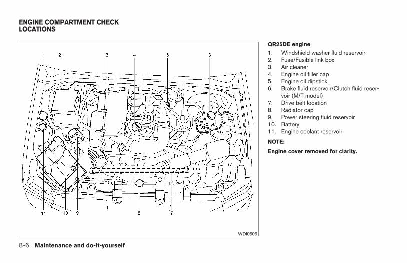
QR25DE engine
1. Windshield washer fluid reservoir2. Fuse/Fusible link box3. Air cleaner4. Engine oil filler cap5. Engine oil dipstick6. Brake fluid reservoir/Clutch fluid reser-
voir (M/T model)7. Drive belt location8. Radiator cap9. Power steering fluid reservoir10. Battery11. Engine coolant reservoir
NOTE:
Engine cover removed for clarity.
WDI0506
ENGINE COMPARTMENT CHECKLOCATIONS
8-6 Maintenance and do-it-yourself
Z REVIEW COPY—2006 Truck/Frontier (d22)Owners Manual—USA_English (nna)10/17/05—debbie X
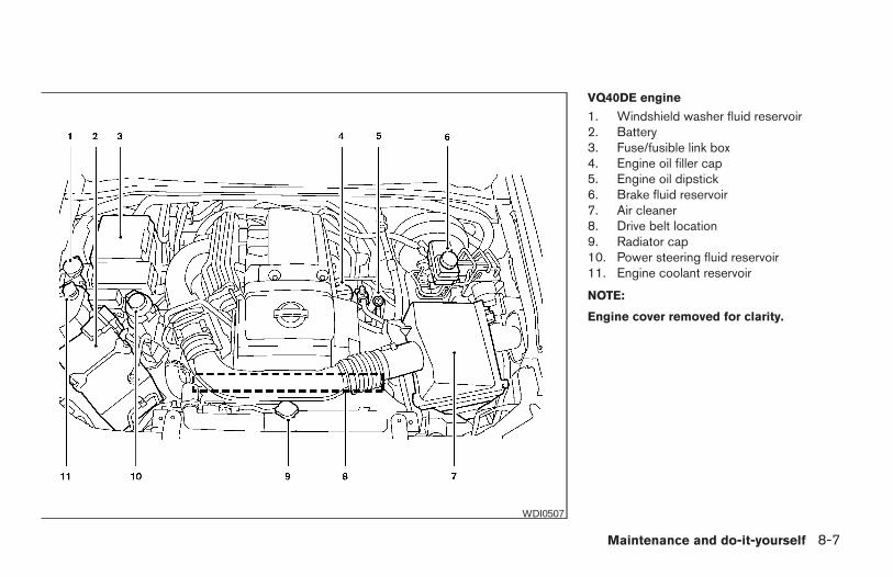
VQ40DE engine
1. Windshield washer fluid reservoir2. Battery3. Fuse/fusible link box4. Engine oil filler cap5. Engine oil dipstick6. Brake fluid reservoir7. Air cleaner8. Drive belt location9. Radiator cap10. Power steering fluid reservoir11. Engine coolant reservoir
NOTE:
Engine cover removed for clarity.
WDI0507
Maintenance and do-it-yourself 8-7
Z REVIEW COPY—2006 Truck/Frontier (d22)Owners Manual—USA_English (nna)10/17/05—debbie X
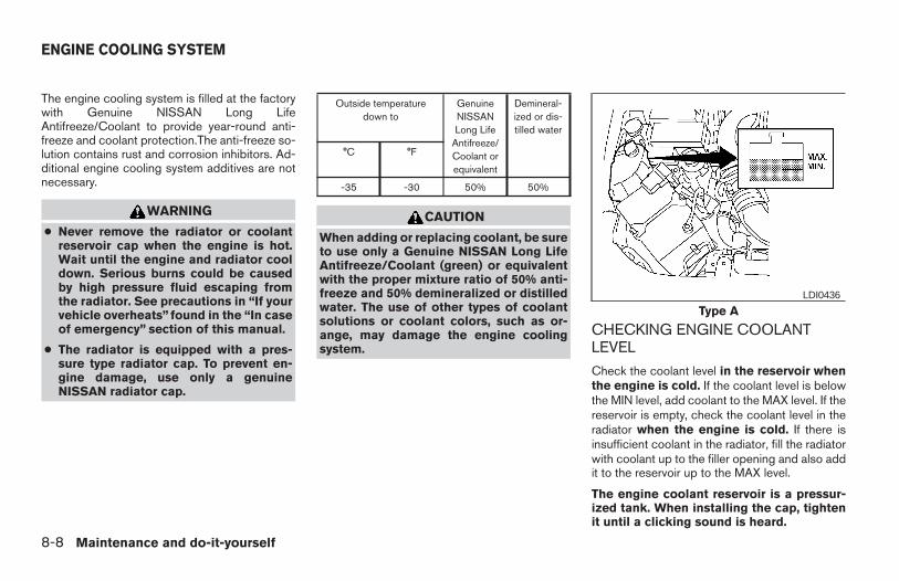
The engine cooling system is filled at the factorywith Genuine NISSAN Long LifeAntifreeze/Coolant to provide year-round anti-freeze and coolant protection.The anti-freeze so-lution contains rust and corrosion inhibitors. Ad-ditional engine cooling system additives are notnecessary.
WARNING
● Never remove the radiator or coolantreservoir cap when the engine is hot.Wait until the engine and radiator cooldown. Serious burns could be causedby high pressure fluid escaping fromthe radiator. See precautions in “If yourvehicle overheats” found in the “In caseof emergency” section of this manual.
● The radiator is equipped with a pres-sure type radiator cap. To prevent en-gine damage, use only a genuineNISSAN radiator cap.
Outside temperaturedown to
GenuineNISSANLong Life
Antifreeze/Coolant orequivalent
Demineral-ized or dis-tilled water
°C °F
-35 -30 50% 50%
CAUTION
When adding or replacing coolant, be sureto use only a Genuine NISSAN Long LifeAntifreeze/Coolant (green) or equivalentwith the proper mixture ratio of 50% anti-freeze and 50% demineralized or distilledwater. The use of other types of coolantsolutions or coolant colors, such as or-ange, may damage the engine coolingsystem.
CHECKING ENGINE COOLANTLEVEL
Check the coolant level in the reservoir whenthe engine is cold. If the coolant level is belowthe MIN level, add coolant to the MAX level. If thereservoir is empty, check the coolant level in theradiator when the engine is cold. If there isinsufficient coolant in the radiator, fill the radiatorwith coolant up to the filler opening and also addit to the reservoir up to the MAX level.
The engine coolant reservoir is a pressur-ized tank. When installing the cap, tightenit until a clicking sound is heard.
Type ALDI0436
ENGINE COOLING SYSTEM
8-8 Maintenance and do-it-yourself
Z REVIEW COPY—2006 Truck/Frontier (d22)Owners Manual—USA_English (nna)10/17/05—debbie X
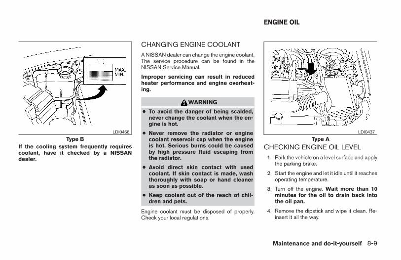
If the cooling system frequently requirescoolant, have it checked by a NISSANdealer.
CHANGING ENGINE COOLANTA NISSAN dealer can change the engine coolant.The service procedure can be found in theNISSAN Service Manual.
Improper servicing can result in reducedheater performance and engine overheat-ing.
WARNING
● To avoid the danger of being scalded,never change the coolant when the en-gine is hot.
● Never remove the radiator or enginecoolant reservoir cap when the engineis hot. Serious burns could be causedby high pressure fluid escaping fromthe radiator.
● Avoid direct skin contact with usedcoolant. If skin contact is made, washthoroughly with soap or hand cleaneras soon as possible.
● Keep coolant out of the reach of chil-dren and pets.
Engine coolant must be disposed of properly.Check your local regulations.
CHECKING ENGINE OIL LEVEL1. Park the vehicle on a level surface and apply
the parking brake.
2. Start the engine and let it idle until it reachesoperating temperature.
3. Turn off the engine. Wait more than 10minutes for the oil to drain back intothe oil pan.
4. Remove the dipstick and wipe it clean. Re-insert it all the way.
Type BLDI0466
Type ALDI0437
ENGINE OIL
Maintenance and do-it-yourself 8-9
Z REVIEW COPY—2006 Truck/Frontier (d22)Owners Manual—USA_English (nna)10/17/05—debbie X
5. Remove the dipstick again and check the oillevel. It should be between the H (High) andL (Low) marks sB . This is the normal oper-ating oil level range. If the oil level is belowthe L (Low) mark sA , remove the oil filler capand pour recommended oil through theopening. Do not overfill sC .
6. Recheck oil level with the dipstick.
It is normal to add some oil between oilmaintenance intervals or during thebreak-in period, depending on the severityof operating conditions.
CAUTION
Oil level should be checked regularly. Op-erating the engine with an insufficientamount of oil can damage the engine, andsuch damage is not covered by warranty.
CHANGING ENGINE OIL
1. Park the vehicle on a level surface and applythe parking brake.
2. Start the engine and let it idle until it reachesoperating temperature, then turn it off.
3. Remove the oil filler cap sA by turning itcounterclockwise.
4. Place a large drain pan under the drain plug.
5. Remove the drain plug sB with a wrench byturning it counterclockwise and completelydrain the oil.
Type BLDI0467 LDI0371
VQ40DEWDI0500
8-10 Maintenance and do-it-yourself
Z REVIEW COPY—2006 Truck/Frontier (d22)Owners Manual—USA_English (nna)10/17/05—debbie X
If the oil filter is to be changed, remove andreplace it at this time. See “Changing engineoil filter” later in this section.
WARNING
● Prolonged and repeated contact withused engine oil may cause skin cancer.
● Try to avoid direct skin contact withused oil. If skin contact is made, washthoroughly with soap or hand cleaneras soon as possible.
● Keep used engine oil out of reach ofchildren.
CAUTION
Be careful not to burn yourself. The engineoil may be hot.
● Waste oil must be disposed of prop-erly.
● Check your local regulations.
6. Clean and reinstall the drain plug and a newwasher. Securely tighten the drain plug witha wrench. Do not use excessive force.
Drain plug tightening torque:22 - 29 ft-lb (29 - 39 N·m)
7. Refill engine with recommended oil throughthe oil filler opening, then install the oil fillercap securely.
See “Capacities and recommendedfuel/lubricants” in the “Technical and con-sumer information” section of this manual fordrain and refill capacity.
The drain and refill capacity depends on theoil temperature and drain time. Use thesespecifications for reference only. Always usethe dipstick to determine when the properamount of oil is in the engine.
8. Start the engine. Check for leakage aroundthe drain plug and oil filter. Correct as re-quired.
9. Turn the engine off and wait more than 10minutes. Check the oil level with the dipstick.Add engine oil if necessary.
QR25DEWDI0501
Maintenance and do-it-yourself 8-11
Z REVIEW COPY—2006 Truck/Frontier (d22)Owners Manual—USA_English (nna)10/17/05—debbie X
CHANGING ENGINE OIL FILTER
1. Park the vehicle on a level surface and applythe parking brake.
2. Turn the engine off.
3. Place a large drain pan under the oil filter.
4. Unscrew the plate covering the oil filter ex-posing the filter. (For VQ40DE engine only)
5. Loosen the oil filter sA with an oil filterwrench by turning it counterclockwise. Thenremove the oil filter by turning it by hand.
CAUTION
Be careful not to burn yourself. The engineoil may be hot.
6. Wipe the engine oil filter sealing surface witha clean rag.
Be sure to remove any old gasket materialremaining on the sealing surface of the en-gine.
7. Coat the gasket on the new filter with cleanengine oil.
8. Screw on the oil filter until a slight resistanceis felt, then tighten an additional 2/3 turn.
9. Start the engine and check for leakagearound the oil filter. Correct as required.
10. Turn the engine off and wait more than 10minutes. Check the oil level. Add engine oil ifnecessary.
VQ40DEWDI0502
QR25DEWDI0503
8-12 Maintenance and do-it-yourself
Z REVIEW COPY—2006 Truck/Frontier (d22)Owners Manual—USA_English (nna)10/17/05—debbie X
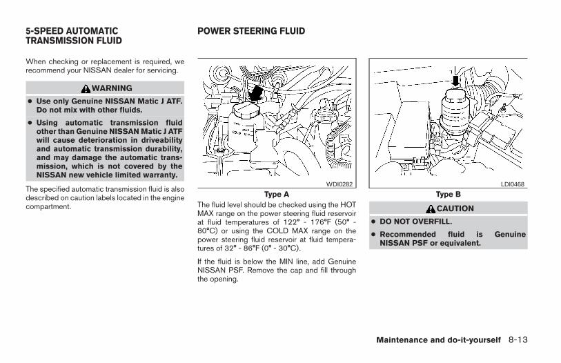
When checking or replacement is required, werecommend your NISSAN dealer for servicing.
WARNING
● Use only Genuine NISSAN Matic J ATF.Do not mix with other fluids.
● Using automatic transmission fluidother than Genuine NISSAN Matic J ATFwill cause deterioration in driveabilityand automatic transmission durability,and may damage the automatic trans-mission, which is not covered by theNISSAN new vehicle limited warranty.
The specified automatic transmission fluid is alsodescribed on caution labels located in the enginecompartment. The fluid level should be checked using the HOT
MAX range on the power steering fluid reservoirat fluid temperatures of 122° - 176°F (50° -80°C) or using the COLD MAX range on thepower steering fluid reservoir at fluid tempera-tures of 32° - 86°F (0° - 30°C).
If the fluid is below the MIN line, add GenuineNISSAN PSF. Remove the cap and fill throughthe opening.
CAUTION
● DO NOT OVERFILL.
● Recommended fluid is GenuineNISSAN PSF or equivalent.
Type AWDI0282
Type BLDI0468
5-SPEED AUTOMATICTRANSMISSION FLUID
POWER STEERING FLUID
Maintenance and do-it-yourself 8-13
Z REVIEW COPY—2006 Truck/Frontier (d22)Owners Manual—USA_English (nna)10/17/05—debbie X
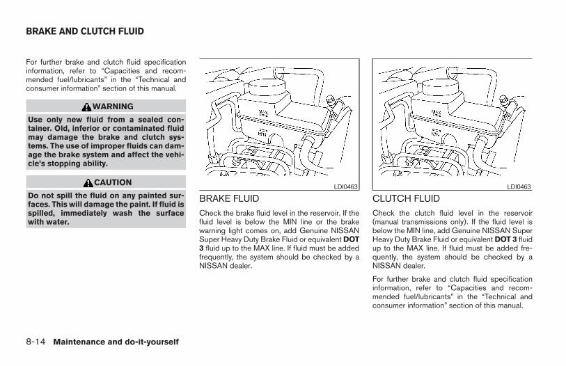
For further brake and clutch fluid specificationinformation, refer to “Capacities and recom-mended fuel/lubricants” in the “Technical andconsumer information” section of this manual.
WARNING
Use only new fluid from a sealed con-tainer. Old, inferior or contaminated fluidmay damage the brake and clutch sys-tems. The use of improper fluids can dam-age the brake system and affect the vehi-cle’s stopping ability.
CAUTION
Do not spill the fluid on any painted sur-faces. This will damage the paint. If fluid isspilled, immediately wash the surfacewith water.
BRAKE FLUIDCheck the brake fluid level in the reservoir. If thefluid level is below the MIN line or the brakewarning light comes on, add Genuine NISSANSuper Heavy Duty Brake Fluid or equivalent DOT3 fluid up to the MAX line. If fluid must be addedfrequently, the system should be checked by aNISSAN dealer.
CLUTCH FLUIDCheck the clutch fluid level in the reservoir(manual transmissions only). If the fluid level isbelow the MIN line, add Genuine NISSAN SuperHeavy Duty Brake Fluid or equivalent DOT 3 fluidup to the MAX line. If fluid must be added fre-quently, the system should be checked by aNISSAN dealer.
For further brake and clutch fluid specificationinformation, refer to “Capacities and recom-mended fuel/lubricants” in the “Technical andconsumer information” section of this manual.
LDI0463 LDI0463
BRAKE AND CLUTCH FLUID
8-14 Maintenance and do-it-yourself
Z REVIEW COPY—2006 Truck/Frontier (d22)Owners Manual—USA_English (nna)10/17/05—debbie X
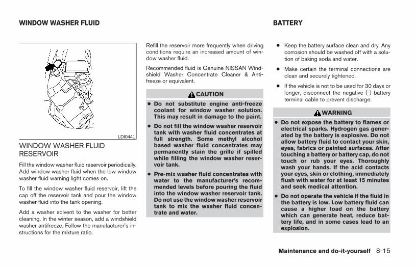
WINDOW WASHER FLUIDRESERVOIR
Fill the window washer fluid reservoir periodically.Add window washer fluid when the low windowwasher fluid warning light comes on.
To fill the window washer fluid reservoir, lift thecap off the reservoir tank and pour the windowwasher fluid into the tank opening.
Add a washer solvent to the washer for bettercleaning. In the winter season, add a windshieldwasher antifreeze. Follow the manufacturer’s in-structions for the mixture ratio.
Refill the reservoir more frequently when drivingconditions require an increased amount of win-dow washer fluid.
Recommended fluid is Genuine NISSAN Wind-shield Washer Concentrate Cleaner & Anti-freeze or equivalent.
CAUTION
● Do not substitute engine anti-freezecoolant for window washer solution.This may result in damage to the paint.
● Do not fill the window washer reservoirtank with washer fluid concentrates atfull strength. Some methyl alcoholbased washer fluid concentrates maypermanently stain the grille if spilledwhile filling the window washer reser-voir tank.
● Pre-mix washer fluid concentrates withwater to the manufacturer’s recom-mended levels before pouring the fluidinto the window washer reservoir tank.Do not use the window washer reservoirtank to mix the washer fluid concen-trate and water.
● Keep the battery surface clean and dry. Anycorrosion should be washed off with a solu-tion of baking soda and water.
● Make certain the terminal connections areclean and securely tightened.
● If the vehicle is not to be used for 30 days orlonger, disconnect the negative (-) batteryterminal cable to prevent discharge.
WARNING
● Do not expose the battery to flames orelectrical sparks. Hydrogen gas gener-ated by the battery is explosive. Do notallow battery fluid to contact your skin,eyes, fabrics or painted surfaces. Aftertouching a battery or battery cap, do nottouch or rub your eyes. Thoroughlywash your hands. If the acid contactsyour eyes, skin or clothing, immediatelyflush with water for at least 15 minutesand seek medical attention.
● Do not operate the vehicle if the fluid inthe battery is low. Low battery fluid cancause a higher load on the batterywhich can generate heat, reduce bat-tery life, and in some cases lead to anexplosion.
LDI0441
WINDOW WASHER FLUID BATTERY
Maintenance and do-it-yourself 8-15
Z REVIEW COPY—2006 Truck/Frontier (d22)Owners Manual—USA_English (nna)10/17/05—debbie X
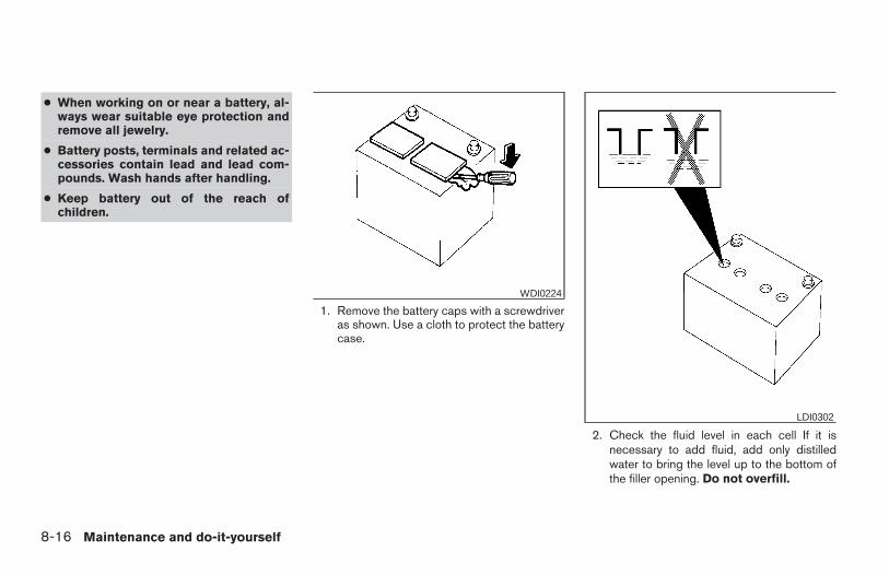
● When working on or near a battery, al-ways wear suitable eye protection andremove all jewelry.
● Battery posts, terminals and related ac-cessories contain lead and lead com-pounds. Wash hands after handling.
● Keep battery out of the reach ofchildren.
1. Remove the battery caps with a screwdriveras shown. Use a cloth to protect the batterycase.
2. Check the fluid level in each cell If it isnecessary to add fluid, add only distilledwater to bring the level up to the bottom ofthe filler opening. Do not overfill.
WDI0224
LDI0302
8-16 Maintenance and do-it-yourself
Z REVIEW COPY—2006 Truck/Frontier (d22)Owners Manual—USA_English (nna)10/17/05—debbie X
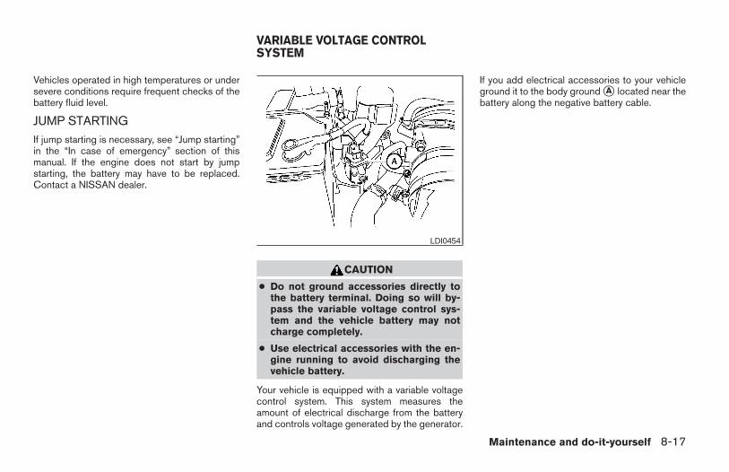
Vehicles operated in high temperatures or undersevere conditions require frequent checks of thebattery fluid level.
JUMP STARTINGIf jump starting is necessary, see “Jump starting”in the “In case of emergency” section of thismanual. If the engine does not start by jumpstarting, the battery may have to be replaced.Contact a NISSAN dealer.
CAUTION
● Do not ground accessories directly tothe battery terminal. Doing so will by-pass the variable voltage control sys-tem and the vehicle battery may notcharge completely.
● Use electrical accessories with the en-gine running to avoid discharging thevehicle battery.
Your vehicle is equipped with a variable voltagecontrol system. This system measures theamount of electrical discharge from the batteryand controls voltage generated by the generator.
If you add electrical accessories to your vehicleground it to the body ground sA located near thebattery along the negative battery cable.
LDI0454
VARIABLE VOLTAGE CONTROLSYSTEM
Maintenance and do-it-yourself 8-17
Z REVIEW COPY—2006 Truck/Frontier (d22)Owners Manual—USA_English (nna)10/17/05—debbie X
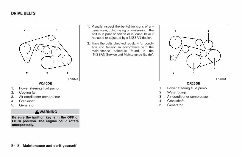
1. Power steering fluid pump2. Cooling fan3. Air conditioner compressor4. Crankshaft5. Generator
WARNING
Be sure the ignition key is in the OFF orLOCK position. The engine could rotateunexpectedly.
1. Visually inspect the belt(s) for signs of un-usual wear, cuts, fraying or looseness. If thebelt is in poor condition or is loose, have itreplaced or adjusted by a NISSAN dealer.
2. Have the belts checked regularly for condi-tion and tension in accordance with themaintenance schedule found in the“NISSAN Service and Maintenance Guide”.
1 Power steering fluid pump2 Water pump3 Air conditioner compressor4 Crankshaft5 Generator
VQ40DELDI0449
QR25DELDI0461
DRIVE BELTS
8-18 Maintenance and do-it-yourself
Z REVIEW COPY—2006 Truck/Frontier (d22)Owners Manual—USA_English (nna)10/17/05—debbie X
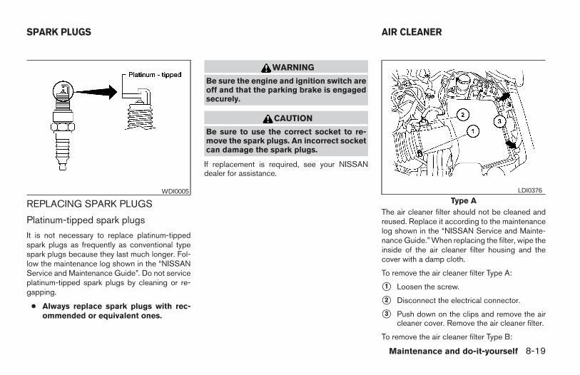
REPLACING SPARK PLUGS
Platinum-tipped spark plugs
It is not necessary to replace platinum-tippedspark plugs as frequently as conventional typespark plugs because they last much longer. Fol-low the maintenance log shown in the “NISSANService and Maintenance Guide”. Do not serviceplatinum-tipped spark plugs by cleaning or re-gapping.
● Always replace spark plugs with rec-ommended or equivalent ones.
WARNING
Be sure the engine and ignition switch areoff and that the parking brake is engagedsecurely.
CAUTION
Be sure to use the correct socket to re-move the spark plugs. An incorrect socketcan damage the spark plugs.
If replacement is required, see your NISSANdealer for assistance.
The air cleaner filter should not be cleaned andreused. Replace it according to the maintenancelog shown in the “NISSAN Service and Mainte-nance Guide.” When replacing the filter, wipe theinside of the air cleaner filter housing and thecover with a damp cloth.
To remove the air cleaner filter Type A:
s1 Loosen the screw.
s2 Disconnect the electrical connector.
s3 Push down on the clips and remove the aircleaner cover. Remove the air cleaner filter.
To remove the air cleaner filter Type B:
WDI0005Type A
LDI0376
SPARK PLUGS AIR CLEANER
Maintenance and do-it-yourself 8-19
Z REVIEW COPY—2006 Truck/Frontier (d22)Owners Manual—USA_English (nna)10/17/05—debbie X
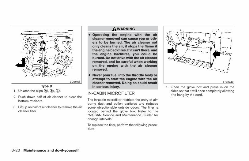
1. Unlatch the clips sA , sB , sC .
2. Push down half of air cleaner to clear thebottom retainers.
3. Lift up on half of air cleaner to remove the aircleaner filter
WARNING
● Operating the engine with the aircleaner removed can cause you or oth-ers to be burned. The air cleaner notonly cleans the air, it stops the flame ifthe engine backfires. If it isn’t there, andthe engine backfires, you could beburned. Do not drive with the air cleanerremoved, and be careful when workingon the engine with the air cleanerremoved.
● Never pour fuel into the throttle body orattempt to start the engine with the aircleaner removed. Doing so could resultin serious injury.
IN-CABIN MICROFILTERThe in-cabin microfilter restricts the entry of air-borne dust and pollen particles and reducessome objectionable outside odors. The filter islocated behind the glove box. Refer to the“NISSAN Service and Maintenance Guide” forchange intervals.
To replace the filter, perform the following proce-dure:
1. Open the glove box and press in on thesides so that it will open completely allowingit to hang by the cord.
Type BLDI0465 LDI0442
8-20 Maintenance and do-it-yourself
Z REVIEW COPY—2006 Truck/Frontier (d22)Owners Manual—USA_English (nna)10/17/05—debbie X
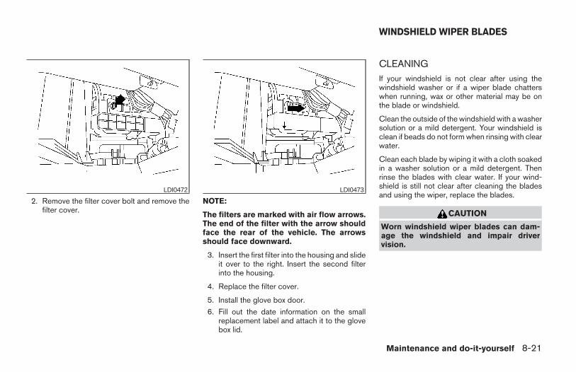
2. Remove the filter cover bolt and remove thefilter cover.
NOTE:
The filters are marked with air flow arrows.The end of the filter with the arrow shouldface the rear of the vehicle. The arrowsshould face downward.
3. Insert the first filter into the housing and slideit over to the right. Insert the second filterinto the housing.
4. Replace the filter cover.
5. Install the glove box door.
6. Fill out the date information on the smallreplacement label and attach it to the glovebox lid.
CLEANINGIf your windshield is not clear after using thewindshield washer or if a wiper blade chatterswhen running, wax or other material may be onthe blade or windshield.
Clean the outside of the windshield with a washersolution or a mild detergent. Your windshield isclean if beads do not form when rinsing with clearwater.
Clean each blade by wiping it with a cloth soakedin a washer solution or a mild detergent. Thenrinse the blades with clear water. If your wind-shield is still not clear after cleaning the bladesand using the wiper, replace the blades.
CAUTION
Worn windshield wiper blades can dam-age the windshield and impair drivervision.
LDI0472 LDI0473
WINDSHIELD WIPER BLADES
Maintenance and do-it-yourself 8-21
Z REVIEW COPY—2006 Truck/Frontier (d22)Owners Manual—USA_English (nna)10/17/05—debbie X
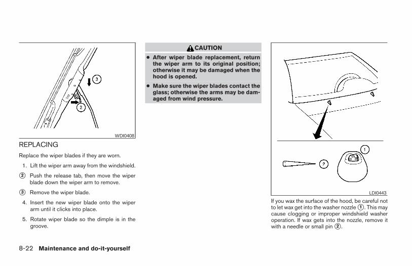
REPLACING
Replace the wiper blades if they are worn.
1. Lift the wiper arm away from the windshield.
s2 Push the release tab, then move the wiperblade down the wiper arm to remove.
s3 Remove the wiper blade.
4. Insert the new wiper blade onto the wiperarm until it clicks into place.
5. Rotate wiper blade so the dimple is in thegroove.
CAUTION
● After wiper blade replacement, returnthe wiper arm to its original position;otherwise it may be damaged when thehood is opened.
● Make sure the wiper blades contact theglass; otherwise the arms may be dam-aged from wind pressure.
If you wax the surface of the hood, be careful notto let wax get into the washer nozzle s1 . This maycause clogging or improper windshield washeroperation. If wax gets into the nozzle, remove itwith a needle or small pin s2 .
WDI0408
LDI0443
8-22 Maintenance and do-it-yourself
Z REVIEW COPY—2006 Truck/Frontier (d22)Owners Manual—USA_English (nna)10/17/05—debbie X
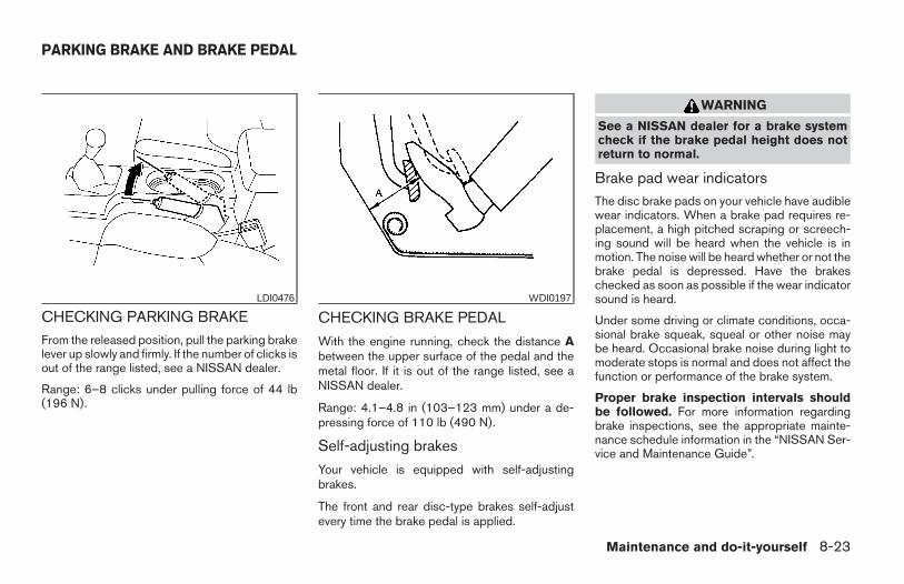
CHECKING PARKING BRAKEFrom the released position, pull the parking brakelever up slowly and firmly. If the number of clicks isout of the range listed, see a NISSAN dealer.
Range: 6–8 clicks under pulling force of 44 lb(196 N).
CHECKING BRAKE PEDAL
With the engine running, check the distance Abetween the upper surface of the pedal and themetal floor. If it is out of the range listed, see aNISSAN dealer.
Range: 4.1–4.8 in (103–123 mm) under a de-pressing force of 110 lb (490 N).
Self-adjusting brakes
Your vehicle is equipped with self-adjustingbrakes.
The front and rear disc-type brakes self-adjustevery time the brake pedal is applied.
WARNING
See a NISSAN dealer for a brake systemcheck if the brake pedal height does notreturn to normal.
Brake pad wear indicatorsThe disc brake pads on your vehicle have audiblewear indicators. When a brake pad requires re-placement, a high pitched scraping or screech-ing sound will be heard when the vehicle is inmotion. The noise will be heard whether or not thebrake pedal is depressed. Have the brakeschecked as soon as possible if the wear indicatorsound is heard.
Under some driving or climate conditions, occa-sional brake squeak, squeal or other noise maybe heard. Occasional brake noise during light tomoderate stops is normal and does not affect thefunction or performance of the brake system.
Proper brake inspection intervals shouldbe followed. For more information regardingbrake inspections, see the appropriate mainte-nance schedule information in the “NISSAN Ser-vice and Maintenance Guide”.
LDI0476 WDI0197
PARKING BRAKE AND BRAKE PEDAL
Maintenance and do-it-yourself 8-23
Z REVIEW COPY—2006 Truck/Frontier (d22)Owners Manual—USA_English (nna)10/17/05—debbie X
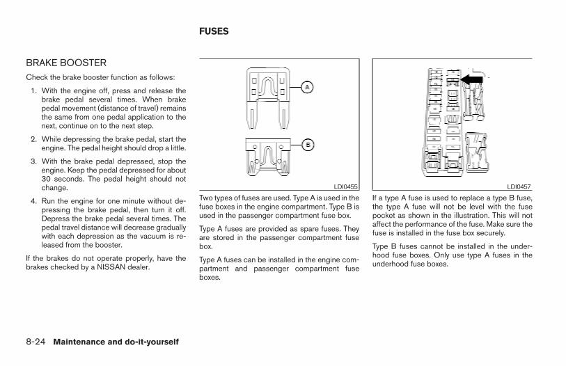
BRAKE BOOSTERCheck the brake booster function as follows:
1. With the engine off, press and release thebrake pedal several times. When brakepedal movement (distance of travel) remainsthe same from one pedal application to thenext, continue on to the next step.
2. While depressing the brake pedal, start theengine. The pedal height should drop a little.
3. With the brake pedal depressed, stop theengine. Keep the pedal depressed for about30 seconds. The pedal height should notchange.
4. Run the engine for one minute without de-pressing the brake pedal, then turn it off.Depress the brake pedal several times. Thepedal travel distance will decrease graduallywith each depression as the vacuum is re-leased from the booster.
If the brakes do not operate properly, have thebrakes checked by a NISSAN dealer.
Two types of fuses are used. Type A is used in thefuse boxes in the engine compartment. Type B isused in the passenger compartment fuse box.
Type A fuses are provided as spare fuses. Theyare stored in the passenger compartment fusebox.
Type A fuses can be installed in the engine com-partment and passenger compartment fuseboxes.
If a type A fuse is used to replace a type B fuse,the type A fuse will not be level with the fusepocket as shown in the illustration. This will notaffect the performance of the fuse. Make sure thefuse is installed in the fuse box securely.
Type B fuses cannot be installed in the under-hood fuse boxes. Only use type A fuses in theunderhood fuse boxes.
LDI0455 LDI0457
FUSES
8-24 Maintenance and do-it-yourself
Z REVIEW COPY—2006 Truck/Frontier (d22)Owners Manual—USA_English (nna)10/17/05—debbie X
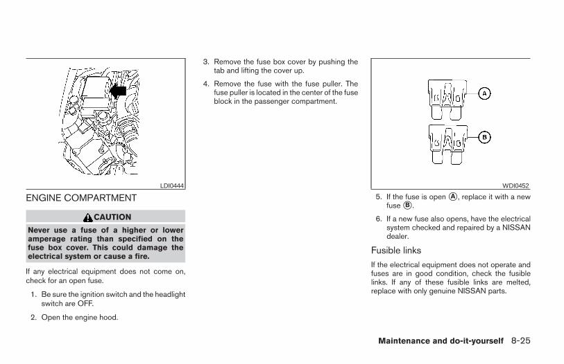
ENGINE COMPARTMENT
CAUTION
Never use a fuse of a higher or loweramperage rating than specified on thefuse box cover. This could damage theelectrical system or cause a fire.
If any electrical equipment does not come on,check for an open fuse.
1. Be sure the ignition switch and the headlightswitch are OFF.
2. Open the engine hood.
3. Remove the fuse box cover by pushing thetab and lifting the cover up.
4. Remove the fuse with the fuse puller. Thefuse puller is located in the center of the fuseblock in the passenger compartment.
5. If the fuse is open sA , replace it with a newfuse sB .
6. If a new fuse also opens, have the electricalsystem checked and repaired by a NISSANdealer.
Fusible linksIf the electrical equipment does not operate andfuses are in good condition, check the fusiblelinks. If any of these fusible links are melted,replace with only genuine NISSAN parts.
LDI0444 WDI0452
Maintenance and do-it-yourself 8-25
Z REVIEW COPY—2006 Truck/Frontier (d22)Owners Manual—USA_English (nna)10/17/05—debbie X
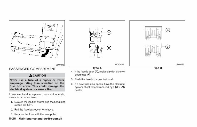
PASSENGER COMPARTMENT
CAUTION
Never use a fuse of a higher or loweramperage rating than specified on thefuse box cover. This could damage theelectrical system or cause a fire.
If any electrical equipment does not operate,check for an open fuse.
1. Be sure the ignition switch and the headlightswitch are OFF.
2. Pull the fuse box cover to remove.
3. Remove the fuse with the fuse puller.
4. If the fuse is open sA , replace it with a knowngood fuse sB .
5. Push the fuse box cover to install.
6. If a new fuse also opens, have the electricalsystem checked and repaired by a NISSANdealer.
LDI0445Type A
WDI0452
Type BLDI0456
8-26 Maintenance and do-it-yourself
Z REVIEW COPY—2006 Truck/Frontier (d22)Owners Manual—USA_English (nna)10/17/05—debbie X
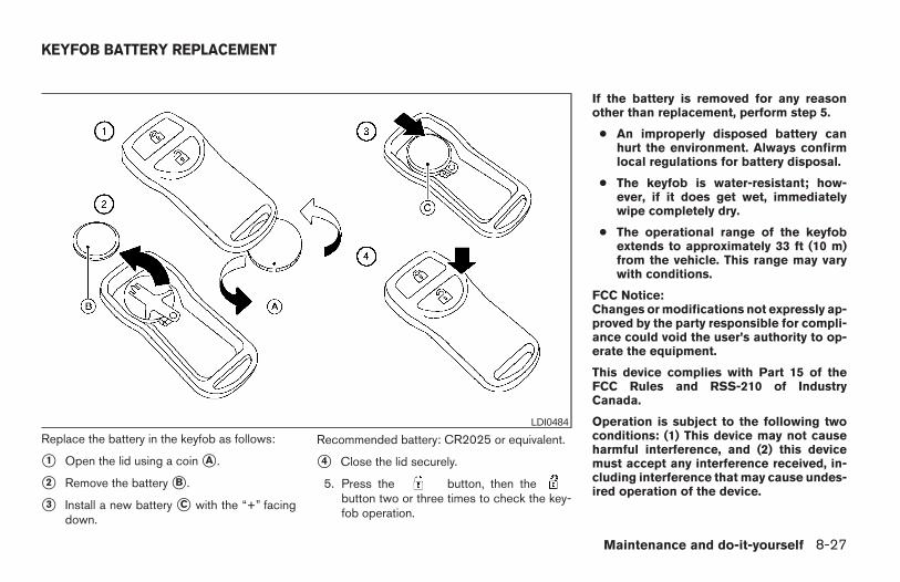
Replace the battery in the keyfob as follows:
s1 Open the lid using a coin sA .
s2 Remove the battery sB .
s3 Install a new battery sC with the “+” facingdown.
Recommended battery: CR2025 or equivalent.
s4 Close the lid securely.
5. Press the button, then thebutton two or three times to check the key-fob operation.
If the battery is removed for any reasonother than replacement, perform step 5.
● An improperly disposed battery canhurt the environment. Always confirmlocal regulations for battery disposal.
● The keyfob is water-resistant; how-ever, if it does get wet, immediatelywipe completely dry.
● The operational range of the keyfobextends to approximately 33 ft (10 m)from the vehicle. This range may varywith conditions.
FCC Notice:Changes or modifications not expressly ap-proved by the party responsible for compli-ance could void the user’s authority to op-erate the equipment.
This device complies with Part 15 of theFCC Rules and RSS-210 of IndustryCanada.
Operation is subject to the following twoconditions: (1) This device may not causeharmful interference, and (2) this devicemust accept any interference received, in-cluding interference that may cause undes-ired operation of the device.
LDI0484
KEYFOB BATTERY REPLACEMENT
Maintenance and do-it-yourself 8-27
Z REVIEW COPY—2006 Truck/Frontier (d22)Owners Manual—USA_English (nna)10/17/05—debbie X
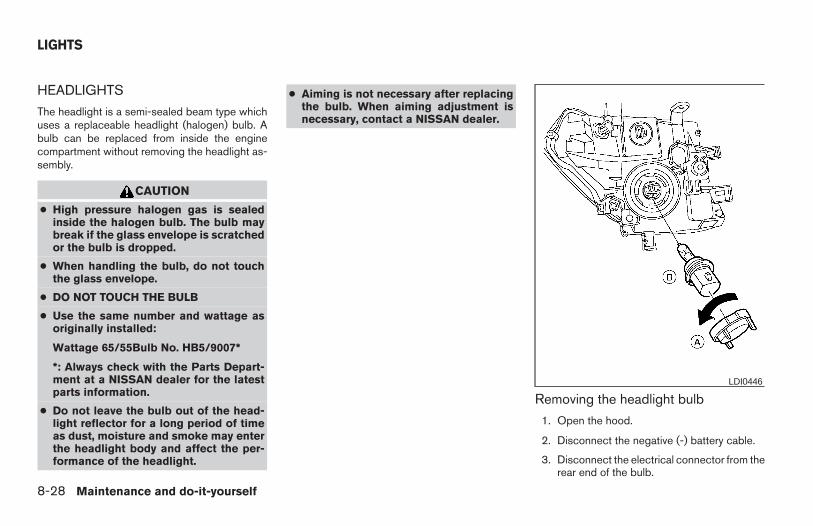
HEADLIGHTS
The headlight is a semi-sealed beam type whichuses a replaceable headlight (halogen) bulb. Abulb can be replaced from inside the enginecompartment without removing the headlight as-sembly.
CAUTION
● High pressure halogen gas is sealedinside the halogen bulb. The bulb maybreak if the glass envelope is scratchedor the bulb is dropped.
● When handling the bulb, do not touchthe glass envelope.
● DO NOT TOUCH THE BULB
● Use the same number and wattage asoriginally installed:
Wattage 65/55Bulb No. HB5/9007*
*: Always check with the Parts Depart-ment at a NISSAN dealer for the latestparts information.
● Do not leave the bulb out of the head-light reflector for a long period of timeas dust, moisture and smoke may enterthe headlight body and affect the per-formance of the headlight.
● Aiming is not necessary after replacingthe bulb. When aiming adjustment isnecessary, contact a NISSAN dealer.
Removing the headlight bulb
1. Open the hood.
2. Disconnect the negative (-) battery cable.
3. Disconnect the electrical connector from therear end of the bulb.
LDI0446
LIGHTS
8-28 Maintenance and do-it-yourself
Z REVIEW COPY—2006 Truck/Frontier (d22)Owners Manual—USA_English (nna)10/17/05—debbie X
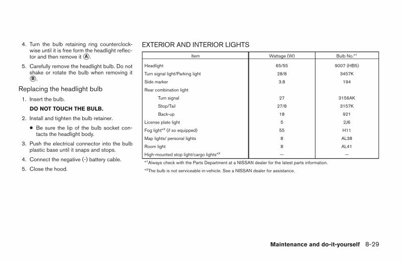
4. Turn the bulb retaining ring counterclock-wise until it is free form the headlight reflec-tor and then remove it sA .
5. Carefully remove the headlight bulb. Do notshake or rotate the bulb when removing itsB .
Replacing the headlight bulb1. Insert the bulb.
DO NOT TOUCH THE BULB.
2. Install and tighten the bulb retainer.
● Be sure the lip of the bulb socket con-tacts the headlight body.
3. Push the electrical connector into the bulbplastic base until it snaps and stops.
4. Connect the negative (-) battery cable.
5. Close the hood.
EXTERIOR AND INTERIOR LIGHTS
Item Wattage (W) Bulb No.*1
Headlight 65/55 9007 (HB5)
Turn signal light/Parking light 28/8 3457K
Side marker 3.8 194
Rear combination light
Turn signal 27 3156AK
Stop/Tail 27/8 3157K
Back-up 18 921
License plate light 5 2J6
Fog light*2 (if so equipped) 55 H11
Map lights/ personal lights 8 AL38
Room light 8 AL41
High-mounted stop light/cargo lights*2 — —
*1Always check with the Parts Department at a NISSAN dealer for the latest parts information.
*2The bulb is not serviceable in-vehicle. See a NISSAN dealer for assistance.
Maintenance and do-it-yourself 8-29
Z REVIEW COPY—2006 Truck/Frontier (d22)Owners Manual—USA_English (nna)10/17/05—debbie X
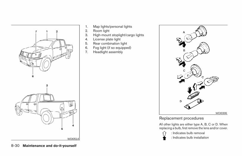
1. Map lights/personal lights2. Room light3. High-mount stoplight/cargo lights4. License plate light5. Rear combination light6. Fog light (if so equipped)7. Headlight assembly
Replacement proceduresAll other lights are either type A, B, C or D. Whenreplacing a bulb, first remove the lens and/or cover.
: Indicates bulb removal: Indicates bulb installationWDI0514
WDI0306
8-30 Maintenance and do-it-yourself
Z REVIEW COPY—2006 Truck/Frontier (d22)Owners Manual—USA_English (nna)10/26/05—tbrooks X
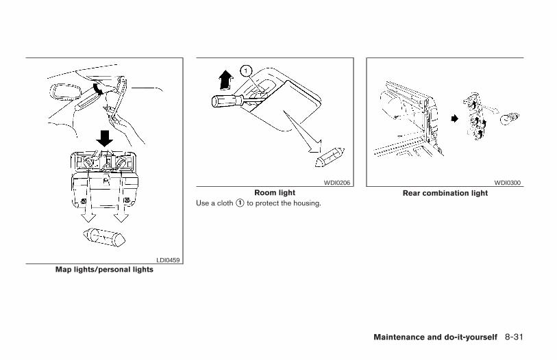
Use a cloth s1 to protect the housing.
Map lights/personal lightsLDI0459
Room lightWDI0206
Rear combination lightWDI0300
Maintenance and do-it-yourself 8-31
Z REVIEW COPY—2006 Truck/Frontier (d22)Owners Manual—USA_English (nna)10/17/05—debbie X
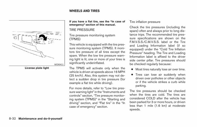
If you have a flat tire, see the “In case ofemergency” section of this manual.
TIRE PRESSURE
Tire pressure monitoring system(TPMS)
This vehicle is equipped with the tire pres-sure monitoring system (TPMS). It moni-tors tire pressure of all tires except thespare. When the low tire pressure warn-ing light is lit, one or more of your tires issignificantly underinflated.
The TPMS will activate only when thevehicle is driven at speeds above 16 MPH(25 km/h). Also, this system may not de-tect a sudden drop in tire pressure (forexample a flat tire while driving).
For more details, refer to “Low tire pres-sure warning light” in the “Instruments andcontrols” section, “Tire pressure monitor-ing system (TPMS)” in the “Starting anddriving” section, and “Flat tire” in the “Incase of emergency” section.
Tire inflation pressure
Check the tire pressures (including thespare) often and always prior to long dis-tance trips. The recommended tire pres-sure specifications are shown on theF.M.V.S.S./C.M.V.S.S. label or the Tireand Loading Information label (if soequipped) under the 9Cold Tire InflationPressure9 heading. The Tire and LoadingInformation label is affixed to the driverside center pillar. Tire pressures shouldbe checked regularly because:
● Most tires naturally lose air over time.
● Tires can lose air suddenly whendriven over potholes or other objectsor if the vehicle strikes a curb whileparking.
The tire pressures should be checkedwhen the tires are cold. The tires areconsidered COLD after the vehicle hasbeen parked for 3 or more hours, or drivenless than 1 mile (1.6 km) at moderatespeeds.
License plate lightWDI0411
WHEELS AND TIRES
8-32 Maintenance and do-it-yourself
Z REVIEW COPY—2006 Truck/Frontier (d22)Owners Manual—USA_English (nna)10/17/05—debbie X
Incorrect tire pressure, including un-der inflation, may adversely affecttire life and vehicle handling.
WARNING
● Improperly inflated tires can failsuddenly and cause an accident.
● The Gross Vehicle Weight Rating(GVWR) is located on theF.M.V.S.S./C.M.V.S.S. label. Thevehicle weight capacity is indi-cated on the Tire and LoadingInformation label (if soequipped). Do not load your ve-hicle beyond this capacity. Over-loading your vehicle may result inreduced tire life, unsafe operat-ing conditions due to prematuretire failure, or unfavorable han-dling characteristics and couldalso lead to a serious accident.Loading beyond the specified ca-pacity may also result in failure ofother vehicle components.
● Before taking a long trip, orwhenever you heavily load yourvehicle, use a tire pressure gaugeto ensure that the tire pressuresare at the specified level.
● Do not drive your vehicle over 85MPH (137 km/h) unless it isequipped with high speed ratedtires. Driving faster than 85 MPH(137 km/h) may result in tire fail-ure, loss of control and possibleinjury.
● For additional information re-garding tires, refer to “ImportantTire Safety Information” (US) or“Tire Safety Information”(Canada) in the Warranty Infor-mation Booklet.
Maintenance and do-it-yourself 8-33
Z REVIEW COPY—2006 Truck/Frontier (d22)Owners Manual—USA_English (nna)10/17/05—debbie X
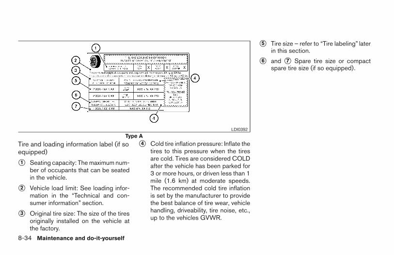
Tire and loading information label (if soequipped)
s1 Seating capacity: The maximum num-ber of occupants that can be seatedin the vehicle.
s2 Vehicle load limit: See loading infor-mation in the “Technical and con-sumer information” section.
s3 Original tire size: The size of the tiresoriginally installed on the vehicle atthe factory.
s4 Cold tire inflation pressure: Inflate thetires to this pressure when the tiresare cold. Tires are considered COLDafter the vehicle has been parked for3 or more hours, or driven less than 1mile (1.6 km) at moderate speeds.The recommended cold tire inflationis set by the manufacturer to providethe best balance of tire wear, vehiclehandling, driveability, tire noise, etc.,up to the vehicles GVWR.
s5 Tire size – refer to “Tire labeling” laterin this section.
s6 and s7 Spare tire size or compactspare tire size (if so equipped).
Type ALDI0392
8-34 Maintenance and do-it-yourself
Z REVIEW COPY—2006 Truck/Frontier (d22)Owners Manual—USA_English (nna)10/17/05—debbie X
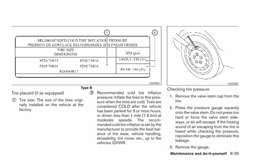
Tire placard (if so equipped)
s1 Tire size: The size of the tires origi-nally installed on the vehicle at thefactory.
s2 Recommended cold tire inflationpressure: Inflate the tires to this pres-sure when the tires are cold. Tires areconsidered COLD after the vehiclehas been parked for 3 or more hours,or driven less than 1 mile (1.6 km) atmoderate speeds. The recom-mended cold tire inflation is set by themanufacturer to provide the best bal-ance of tire wear, vehicle handling,driveability, tire noise, etc., up to thevehicles GVWR.
Checking tire pressure
1. Remove the valve stem cap from thetire.
2. Press the pressure gauge squarelyonto the valve stem. Do not press toohard or force the valve stem side-ways, or air will escape. If the hissingsound of air escaping from the tire isheard while checking the pressure,reposition the gauge to eliminate thisleakage.
3. Remove the gauge.
Type BLDI0462 LDI0393
Maintenance and do-it-yourself 8-35
Z REVIEW COPY—2006 Truck/Frontier (d22)Owners Manual—USA_English (nna)10/17/05—debbie X
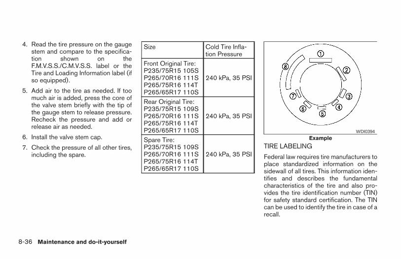
4. Read the tire pressure on the gaugestem and compare to the specifica-tion shown on theF.M.V.S.S./C.M.V.S.S. label or theTire and Loading Information label (ifso equipped).
5. Add air to the tire as needed. If toomuch air is added, press the core ofthe valve stem briefly with the tip ofthe gauge stem to release pressure.Recheck the pressure and add orrelease air as needed.
6. Install the valve stem cap.
7. Check the pressure of all other tires,including the spare.
Size Cold Tire Infla-tion Pressure
Front Original Tire:P235/75R15 105SP265/70R16 111SP265/75R16 114TP265/65R17 110S
240 kPa, 35 PSI
Rear Original Tire:P235/75R15 109SP265/70R16 111SP265/75R16 114TP265/65R17 110S
240 kPa, 35 PSI
Spare Tire:P235/75R15 109SP265/70R16 111SP265/75R16 114TP265/65R17 110S
240 kPa, 35 PSITIRE LABELING
Federal law requires tire manufacturers toplace standardized information on thesidewall of all tires. This information iden-tifies and describes the fundamentalcharacteristics of the tire and also pro-vides the tire identification number (TIN)for safety standard certification. The TINcan be used to identify the tire in case of arecall.
ExampleWDI0394
8-36 Maintenance and do-it-yourself
Z REVIEW COPY—2006 Truck/Frontier (d22)Owners Manual—USA_English (nna)10/17/05—debbie X
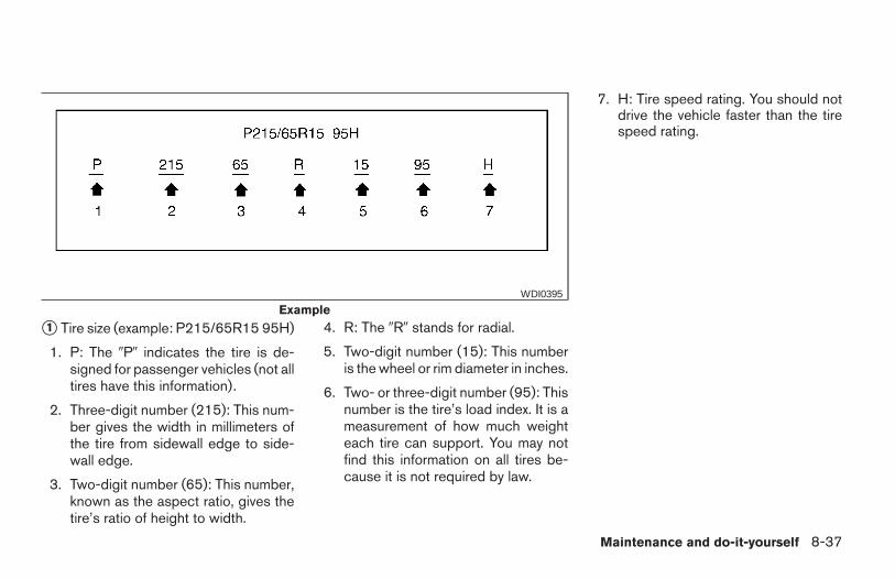
s1 Tire size (example: P215/65R15 95H)
1. P: The 9P9 indicates the tire is de-signed for passenger vehicles (not alltires have this information).
2. Three-digit number (215): This num-ber gives the width in millimeters ofthe tire from sidewall edge to side-wall edge.
3. Two-digit number (65): This number,known as the aspect ratio, gives thetire’s ratio of height to width.
4. R: The 9R9 stands for radial.
5. Two-digit number (15): This numberis the wheel or rim diameter in inches.
6. Two- or three-digit number (95): Thisnumber is the tire’s load index. It is ameasurement of how much weighteach tire can support. You may notfind this information on all tires be-cause it is not required by law.
7. H: Tire speed rating. You should notdrive the vehicle faster than the tirespeed rating.
ExampleWDI0395
Maintenance and do-it-yourself 8-37
Z REVIEW COPY—2006 Truck/Frontier (d22)Owners Manual—USA_English (nna)10/17/05—debbie X
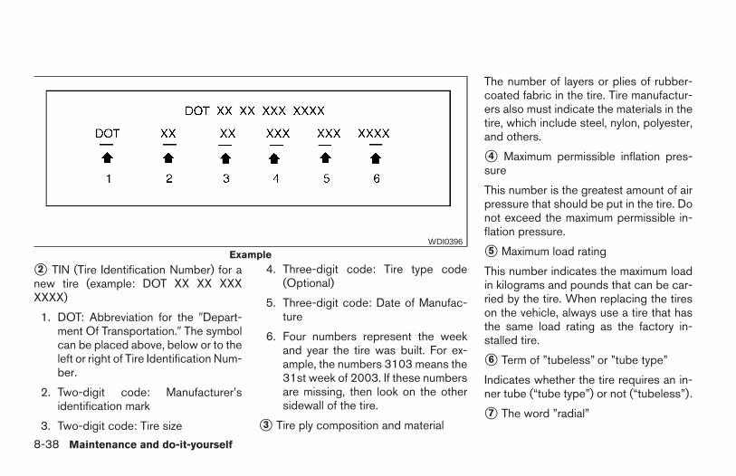
s2 TIN (Tire Identification Number) for anew tire (example: DOT XX XX XXXXXXX)
1. DOT: Abbreviation for the 9Depart-ment Of Transportation.9 The symbolcan be placed above, below or to theleft or right of Tire Identification Num-ber.
2. Two-digit code: Manufacturer’sidentification mark
3. Two-digit code: Tire size
4. Three-digit code: Tire type code(Optional)
5. Three-digit code: Date of Manufac-ture
6. Four numbers represent the weekand year the tire was built. For ex-ample, the numbers 3103 means the31st week of 2003. If these numbersare missing, then look on the othersidewall of the tire.
s3 Tire ply composition and material
The number of layers or plies of rubber-coated fabric in the tire. Tire manufactur-ers also must indicate the materials in thetire, which include steel, nylon, polyester,and others.
s4 Maximum permissible inflation pres-sure
This number is the greatest amount of airpressure that should be put in the tire. Donot exceed the maximum permissible in-flation pressure.
s5 Maximum load rating
This number indicates the maximum loadin kilograms and pounds that can be car-ried by the tire. When replacing the tireson the vehicle, always use a tire that hasthe same load rating as the factory in-stalled tire.
s6 Term of ”tubeless” or ”tube type”
Indicates whether the tire requires an in-ner tube (“tube type”) or not (“tubeless”).
s7 The word ”radial”
ExampleWDI0396
8-38 Maintenance and do-it-yourself
Z REVIEW COPY—2006 Truck/Frontier (d22)Owners Manual—USA_English (nna)10/17/05—debbie X
The word 9radial9 is shown if the tire hasradial structure.
s8 Manufacturer or brand name
Manufacturer or brand name is shown.
Other Tire-related Terminology
In addition to the many terms that aredefined throughout this section, IntendedOutboard Sidewall is (1) the sidewall thatcontains a whitewall, bears white letteringor bears manufacturer, brand, and/ormodel name molding that is higher ordeeper than the same molding on theother sidewall of the tire, or (2) the out-ward facing sidewall of an asymmetricaltire that has a particular side that mustalways face outward when mounted on avehicle.
TYPES OF TIRES
WARNING
● When changing or replacing tires, besure all four tires are of the same type(i.e., Summer, All Season or Snow) andconstruction. A NISSAN dealer may beable to help you with information abouttire type, size, speed rating andavailability.
● Replacement tires may have a lowerspeed rating than the factory equippedtires, and may not match the potentialmaximum vehicle speed. Never exceedthe maximum speed rating of the tire.
● For additional information regardingtires, refer to “Important Tire Safety In-formation” (US) or “Tire Safety Informa-tion” (Canada) in the Warranty Informa-tion Booklet.
All season tires
NISSAN specifies All Season tires on some mod-els to provide good performance all year, includ-ing snowy and icy road conditions. All Seasontires are identified by ALL SEASON and/or M&Son the tire sidewall. Snow tires have better snowtraction than All Season tires and may be moreappropriate in some areas.
Summer tires
NISSAN specifies summer tires on some modelsto provide superior performance on dry roads.Summer tire performance is substantially re-duced in snow and ice. Summer tires do not havethe tire traction rating “M&S” on the tire sidewall.
If you plan to operate your vehicle in snowy or icyconditions, NISSAN recommends the use ofSNOW tires or ALL SEASON tires on all fourwheels.
Snow tiresIf snow tires are needed, it is necessary to selecttires equivalent in size and load rating to theoriginal equipment tires. If you do not, it canadversely affect the safety and handling of yourvehicle.
Generally, snow tires have lower speed ratingsthan factory equipped tires and may not matchthe potential maximum vehicle speed. Never ex-ceed the maximum speed rating of the tire.
If you install snow tires, they must be the samesize, brand, construction and tread pattern on allfour wheels.
For additional traction on icy roads, studded tiresmay be used. However, some U.S. states andCanadian provinces prohibit their use. Checklocal, state and provincial laws before installing
Maintenance and do-it-yourself 8-39
Z REVIEW COPY—2006 Truck/Frontier (d22)Owners Manual—USA_English (nna)10/17/05—debbie X
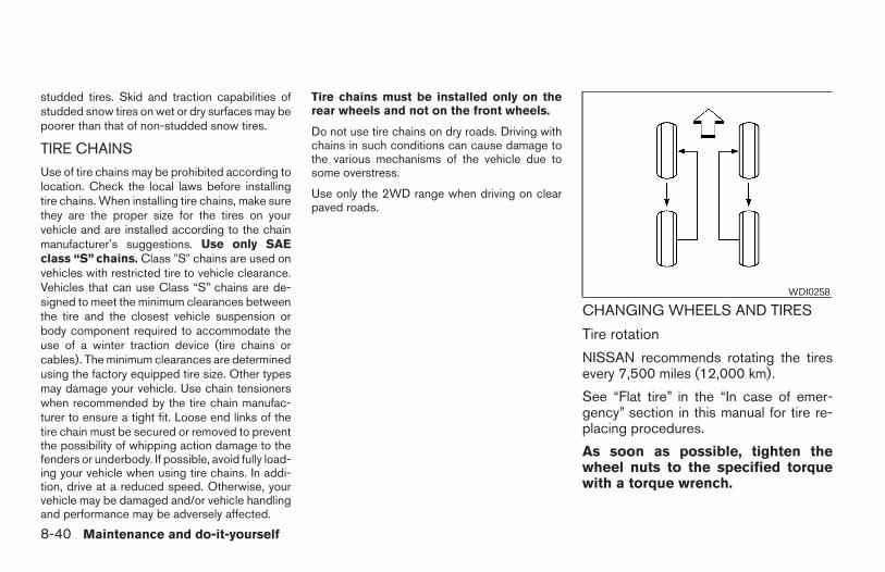
studded tires. Skid and traction capabilities ofstudded snow tires on wet or dry surfaces may bepoorer than that of non-studded snow tires.
TIRE CHAINS
Use of tire chains may be prohibited according tolocation. Check the local laws before installingtire chains. When installing tire chains, make surethey are the proper size for the tires on yourvehicle and are installed according to the chainmanufacturer’s suggestions. Use only SAEclass “S” chains. Class 9S9 chains are used onvehicles with restricted tire to vehicle clearance.Vehicles that can use Class “S” chains are de-signed to meet the minimum clearances betweenthe tire and the closest vehicle suspension orbody component required to accommodate theuse of a winter traction device (tire chains orcables). The minimum clearances are determinedusing the factory equipped tire size. Other typesmay damage your vehicle. Use chain tensionerswhen recommended by the tire chain manufac-turer to ensure a tight fit. Loose end links of thetire chain must be secured or removed to preventthe possibility of whipping action damage to thefenders or underbody. If possible, avoid fully load-ing your vehicle when using tire chains. In addi-tion, drive at a reduced speed. Otherwise, yourvehicle may be damaged and/or vehicle handlingand performance may be adversely affected.
Tire chains must be installed only on therear wheels and not on the front wheels.
Do not use tire chains on dry roads. Driving withchains in such conditions can cause damage tothe various mechanisms of the vehicle due tosome overstress.
Use only the 2WD range when driving on clearpaved roads.
CHANGING WHEELS AND TIRES
Tire rotation
NISSAN recommends rotating the tiresevery 7,500 miles (12,000 km).
See “Flat tire” in the “In case of emer-gency” section in this manual for tire re-placing procedures.
As soon as possible, tighten thewheel nuts to the specified torquewith a torque wrench.
WDI0258
8-40 Maintenance and do-it-yourself
Z REVIEW COPY—2006 Truck/Frontier (d22)Owners Manual—USA_English (nna)10/17/05—debbie X
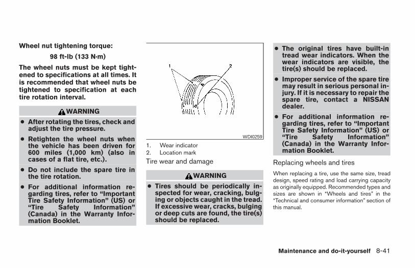
Wheel nut tightening torque:
98 ft-lb (133 N·m)
The wheel nuts must be kept tight-ened to specifications at all times. Itis recommended that wheel nuts betightened to specification at eachtire rotation interval.
WARNING
● After rotating the tires, check andadjust the tire pressure.
● Retighten the wheel nuts whenthe vehicle has been driven for600 miles (1,000 km) (also incases of a flat tire, etc.).
● Do not include the spare tire inthe tire rotation.
● For additional information re-garding tires, refer to “ImportantTire Safety Information” (US) or“Tire Safety Information”(Canada) in the Warranty Infor-mation Booklet.
1. Wear indicator2. Location mark
Tire wear and damage
WARNING
● Tires should be periodically in-spected for wear, cracking, bulg-ing or objects caught in the tread.If excessive wear, cracks, bulgingor deep cuts are found, the tire(s)should be replaced.
● The original tires have built-intread wear indicators. When thewear indicators are visible, thetire(s) should be replaced.
● Improper service of the spare tiremay result in serious personal in-jury. If it is necessary to repair thespare tire, contact a NISSANdealer.
● For additional information re-garding tires, refer to “ImportantTire Safety Information” (US) or“Tire Safety Information”(Canada) in the Warranty Infor-mation Booklet.
Replacing wheels and tires
When replacing a tire, use the same size, treaddesign, speed rating and load carrying capacityas originally equipped. Recommended types andsizes are shown in “Wheels and tires” in the“Technical and consumer information” section ofthis manual.
WDI0259
Maintenance and do-it-yourself 8-41
Z REVIEW COPY—2006 Truck/Frontier (d22)Owners Manual—USA_English (nna)10/17/05—debbie X
WARNING
● The use of tires other than those recom-mended or the mixed use of tires ofdifferent brands, construction (bias,bias-belted or radial), or tread patternscan adversely affect the ride, braking,handling, ground clearance, body-to-tire clearance, tire chain clearance,speedometer calibration, headlight aimand bumper height. Some of these ef-fects may lead to accidents and couldresult in serious personal injury.
● If the wheels are changed for any rea-son, always replace with wheels whichhave the same off-set dimension.Wheels of a different off-set couldcause premature tire wear, degrade ve-hicle handling characteristics and/orinterference with the brakediscs/drums. Such interference canlead to decreased braking efficiencyand/or early brake pad/shoe wear. Re-fer to “Wheels and tires” in the “Techni-cal and consumer information” sectionof this manual for wheel off-setdimensions.
● When a spare tire is mounted or a wheelis replaced, tire pressure will not beindicated, the TPMS will not functionand the low tire pressure warning lightwill flash. Contact your NISSAN dealeras soon as possible for tire replacementand/or system resetting.
● Replacing tires with those not originallyspecified by NISSAN could affect theproper operation of the TPMS.
● Do not install a deformed wheel or tireeven if it has been repaired. Suchwheels or tires could have structuraldamage and could fail without warning.
● The use of retread tires is notrecommended.
● For additional information regardingtires, refer to “Important Tire Safety In-formation” (US) or “Tire Safety Informa-tion” (Canada) in the Warranty Informa-tion Booklet.
Four-wheel drive models
CAUTION
Always use tires of the same type, size,brand, construction (bias, bias-belted orradial), and tread pattern on all fourwheels. Failure to do so may result in acircumference difference between tireson the front and rear axles which willcause excessive tire wear and may dam-age the transmission, transfer case anddifferential gears.
If excessive tire wear is found, it is recommendedthat all four tires be replaced with tires of thesame size, brand, construction and tread pattern.The tire pressure and wheel alignment shouldalso be checked and corrected as necessary.Contact a NISSAN dealer.
Wheel balance
Unbalanced wheels may affect vehicle handlingand tire life. Even with regular use, wheels can getout of balance. Therefore, they should be bal-anced as required.
Wheel balance service should be per-formed with the wheels off the vehicle.Spin balancing the wheels on the vehiclecould lead to mechanical damage.
8-42 Maintenance and do-it-yourself
Z REVIEW COPY—2006 Truck/Frontier (d22)Owners Manual—USA_English (nna)10/17/05—debbie X
● For additional information regardingtires, refer to “Important Tire SafetyInformation” (US) or “Tire Safety Infor-mation” (Canada) in the Warranty In-formation Booklet .
Care of wheels● Wash the wheels when washing the vehicle
to maintain their appearance.
● Clean the inner side of the wheels when thewheel is changed or the underside of thevehicle is washed.
● Do not use abrasive cleaners when washingthe wheels.
● Inspect wheel rims regularly for dents orcorrosion. Such damage may cause loss ofpressure or poor seal at the tire bead.
● NISSAN recommends waxing the roadwheels to protect against road salt in areaswhere it is used during winter.
Maintenance and do-it-yourself 8-43
Z REVIEW COPY—2006 Truck/Frontier (d22)Owners Manual—USA_English (nna)10/17/05—debbie X

8-44 Maintenance and do-it-yourself
MEMO
9 Technical and consumer information
Capacities and recommended fuel/lubricants . . . . . . . . . 9-2Fuel recommendation . . . . . . . . . . . . . . . . . . . . . . . . . . . 9-3Engine oil and oil filter recommendation . . . . . . . . . . . 9-5Recommended SAE viscosity number . . . . . . . . . . . . 9-6Air conditioner system refrigerant and oilrecommendations . . . . . . . . . . . . . . . . . . . . . . . . . . . . . . 9-6
Specifications. . . . . . . . . . . . . . . . . . . . . . . . . . . . . . . . . . . . . 9-7Engine . . . . . . . . . . . . . . . . . . . . . . . . . . . . . . . . . . . . . . . . 9-7Wheels and tires . . . . . . . . . . . . . . . . . . . . . . . . . . . . . . . 9-8Dimensions and weights . . . . . . . . . . . . . . . . . . . . . . . . 9-8
When traveling or registering your vehicle inanother country . . . . . . . . . . . . . . . . . . . . . . . . . . . . . . . . . . . 9-9Vehicle identification . . . . . . . . . . . . . . . . . . . . . . . . . . . . . . . 9-9
Vehicle identification number (VIN) plate . . . . . . . . . . 9-9Vehicle identification number (chassis number) . . . . . . . 9-9Engine serial number. . . . . . . . . . . . . . . . . . . . . . . . . . . 9-10F.M.V.S.S./C.M.V.S.S. certification label . . . . . . . . . . 9-10Emission control information label . . . . . . . . . . . . . . . 9-11Tire and loading information label. . . . . . . . . . . . . . . . 9-11Air conditioner specification label. . . . . . . . . . . . . . . . 9-11
Installing front license plate . . . . . . . . . . . . . . . . . . . . . . . . 9-12Vehicle loading information . . . . . . . . . . . . . . . . . . . . . . . . 9-12
Terms . . . . . . . . . . . . . . . . . . . . . . . . . . . . . . . . . . . . . . . .9-12
Vehicle load capacity . . . . . . . . . . . . . . . . . . . . . . . . . . 9-13Securing the load. . . . . . . . . . . . . . . . . . . . . . . . . . . . . .9-15Utili-track™ channel system (if so equipped) . . . . . . 9-16Loading tips . . . . . . . . . . . . . . . . . . . . . . . . . . . . . . . . . .9-21
Truck-camper loading information . . . . . . . . . . . . . . . . . . 9-22Crew Cab Models . . . . . . . . . . . . . . . . . . . . . . . . . . . . .9-22King Cab models . . . . . . . . . . . . . . . . . . . . . . . . . . . . . .9-22Special Body vehicles. . . . . . . . . . . . . . . . . . . . . . . . . . 9-22Location for center of gravity . . . . . . . . . . . . . . . . . . . . 9-22Vehicle load weight capacity . . . . . . . . . . . . . . . . . . . . 9-23Measurement of weights . . . . . . . . . . . . . . . . . . . . . . . 9-25
Towing a trailer . . . . . . . . . . . . . . . . . . . . . . . . . . . . . . . . . . .9-25Maximum load limits . . . . . . . . . . . . . . . . . . . . . . . . . . . 9-25Towing load/specification. . . . . . . . . . . . . . . . . . . . . . . 9-29Towing safety . . . . . . . . . . . . . . . . . . . . . . . . . . . . . . . . .9-30Flat towing. . . . . . . . . . . . . . . . . . . . . . . . . . . . . . . . . . . .9-35
Uniform tire quality grading . . . . . . . . . . . . . . . . . . . . . . . . 9-36Emission control system warranty . . . . . . . . . . . . . . . . . . 9-37Reporting safety defects (US only) . . . . . . . . . . . . . . . . . 9-37Readiness for inspection/maintenance (I/M) test . . . . . 9-38Event data recorders. . . . . . . . . . . . . . . . . . . . . . . . . . . . . .9-39Owner’s Manual/Service Manual order information . . . 9-39
In the event of a collision . . . . . . . . . . . . . . . . . . . . . . . 9-39
Z REVIEW COPY—2006 Truck/Frontier (d22)Owners Manual—USA_English (nna)10/17/05—debbie X
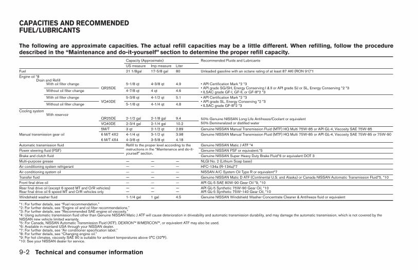
The following are approximate capacities. The actual refill capacities may be a little different. When refilling, follow the proceduredescribed in the “Maintenance and do-it-yourself” section to determine the proper refill capacity.
Capacity (Approximate) Recommended Fluids and LubricantsUS measure Imp measure Liter
Fuel 21 1/8gal 17-5/8 gal 80 Unleaded gasoline with an octane rating of at least 87 AKI (RON 91)*1Engine oil *8
Drain and RefillWith oil filter change
QR25DE5-1/8 qt 4-3/8 qt 4.9 • API Certification Mark *2 *3
• API grade SG/SH, Energy Conserving I & II or API grade SJ or SL, Energy Conserving *2 *3• ILSAC grade GF-I, GF-II, or GF-III*2 *3Without oil filter change 4-7/8 qt 4 qt 4.6
With oil filter changeVQ40DE
5-3/8 qt 4-1/2 qt 5.1 • API Certification Mark *2 *3• API grade SL, Energy Conserving *2 *3• ILSAC grade GF-III*2 *3Without oil filter change 5-1/8 qt 4-1/4 qt 4.8
Cooling systemWith reservoir
QR25DE 2-1/2 gal 2-1/8 gal 9.4 50% Genuine NISSAN Long Life Antifreeze/Coolant or equivalent50% Demineralized or distilled waterVQ40DE 2-3/4 gal 2-1/4 gal 10.2
Manual transmission gear oil5M/T 3 qt 2-1/2 qt 2.89 Genuine NISSAN Manual Transmission Fluid (MTF) HQ Multi 75W-85 or API GL-4, Viscosity SAE 75W-856 M/T 4X2 4-1/4 qt 3-1/2 qt 3.98 Genuine NISSAN Manual Transmission Fluid (MTF) HQ Multi 75W-85 or API GL-4, Viscosity SAE 75W-85 or 75W-906 M/T 4X4 4-3/8 qt 3-5/8 qt 4.18
Automatic transmission fluid Refill to the proper level according to theinstructions in the “Maintenance and do-it-yourself” section.
Genuine NISSAN Matic J ATF *4Power steering fluid (PSF) Genuine NISSAN PSF or equivalent.*5Brake and clutch fluid Genuine NISSAN Super Heavy Duty Brake Fluid*6 or equivalent DOT 3Multi-purpose grease — — — NLGI No. 2 (Lithium Soap base)Air conditioning system refrigerant — — — HFC-134a (R-134a)*7Air conditioning system oil — — — NISSAN A/C System Oil Type R or equivalent*7Transfer fluid — — — Genuine NISSAN Matic D ATF (Continental U.S. and Alaska) or Canada NISSAN Automatic Transmission Fluid*5, *10Front final drive oil — — — API GL-5 SAE 80W-90 Gear Oil *9, *10Rear final drive oil (except 6 speed MT and O/R vehicles) — — — API GL-5 Synthetic 75W-90 Gear Oil, *10Rear final drive oil 6 speed MT and O/R vehicles only — — — API GL-5 Synthetic 75W-140 Gear Oil, *10Windshield washer fluid 1-1/4 gal 1 gal 4.5 Genuine NISSAN Windshield Washer Concentrate Cleaner & Antifreeze fluid or equivalent
*1: For further details, see “Fuel recommendation.”*2: For further details, see “Engine oil and oil filter recommendations.”*3: For further details, see “Recommended SAE engine oil viscosity.”*4: Using automatic transmission fluid other than Genuine NISSAN Matic J ATF will cause deterioration in driveability and automatic transmission durability, and may damage the automatic transmission, which is not covered by theNISSAN new vehicle limited warranty.*5: For Canada, NISSAN Automatic Transmission Fluid (ATF), DEXRON™ III/MERCON™, or equivalent ATF may also be used.*6: Available in mainland USA through your NISSAN dealer.*7: For further details, see “Air conditioner specification label.”*8: For further details, see “Changing engine oil.”*9: For hot climates, viscosity SAE 90 is suitable for ambient temperatures above 0°C (32°F).*10: See your NISSAN dealer for service.
CAPACITIES AND RECOMMENDEDFUEL/LUBRICANTS
9-2 Technical and consumer information
Z REVIEW COPY—2006 Truck/Frontier (d22)Owners Manual—USA_English (nna)10/17/05—debbie X
FUEL RECOMMENDATION
For 2.5L engine.
Use unleaded regular gasoline with an octanerating of at least 87 AKI (Anti-Knock Index) num-ber (Research octane number 91).
For 4.0L engine.
Use unleaded regular gasoline with an octanerating of at least 87 AKI (Anti-Knock Index) num-ber (Research octane number 91).
For improved vehicle performance, NISSAN rec-ommends the use of unleaded premium gasolinewith an octane rating of at least 91 AKI number(Research octane number 96).
CAUTION
● Using a fuel other than that specifiedcould adversely affect the emissioncontrol system, and may also affect thewarranty coverage.
● Under no circumstances should aleaded gasoline be used, because thiswill damage the three-way catalyst.
● Do not use E-85 fuel in your vehicle.Your vehicle is not designed to run onE-85 fuel. Using E-85 fuel can damagethe fuel system components and is notcovered by the NISSAN vehicle limitedwarranty.
Gasoline specifications
NISSAN recommends using gasoline that meetsthe World-Wide Fuel Charter specificationswhere it is available. Many of the automobilemanufacturers developed this specification toimprove emission system and vehicle perfor-mance. Ask your service station manager if thegasoline meets the World-Wide Fuel Charterspecifications.
Reformulated gasolineSome fuel suppliers are now producing reformu-lated gasolines. These gasolines are speciallydesigned to reduce vehicle emissions. NISSANsupports efforts towards cleaner air and sug-gests that you use reformulated gasoline whenavailable.
Gasoline containing oxygenatesSome fuel suppliers sell gasoline containing oxy-genates such as ethanol, MTBE and methanolwith or without advertising their presence.NISSAN does not recommend the use of fuels of
which the oxygenate content and the fuel com-patibility for your NISSAN cannot be readily de-termined. If in doubt, ask your service stationmanager.
If you use oxygenate-blend gasoline, please takethe following precautions as the usage of suchfuels may cause vehicle performance problemsand/or fuel system damage.
● The fuel should be unleaded and havean octane rating no lower than thatrecommended for unleaded gasoline.
● If an oxygenate-blend other than metha-nol blend is used, it should contain nomore than 10% oxygenate. (MTBE may,however, be added up to 15%.)
● If a methanol blend is used, it shouldcontain no more than 5% methanol(methyl alcohol, wood alcohol). Itshould also contain a suitable amountof appropriate cosolvents and corro-sion inhibitors. If not properly formu-lated with appropriate cosolvents andcorrosion inhibitors, such methanolblends may cause fuel system damageand/or vehicle performance problems.At this time, sufficient data is not avail-able to ensure that all methanol blendsare suitable for use in NISSAN ve-hicles.
Technical and consumer information 9-3
Z REVIEW COPY—2006 Truck/Frontier (d22)Owners Manual—USA_English (nna)10/17/05—debbie X
If any driveability problems such as engine stall-ing and difficult hot-starting are experienced afterusing oxygenate-blend fuels, immediatelychange to a non-oxygenate fuel or a fuel with alow blend of MTBE.
Take care not to spill gasoline during refu-eling. Gasoline containing oxygenates cancause paint damage.
E–85 fuel
E-85 fuel is a mixture of approximately 85% fuelethanol and 15% unleaded gasoline. E-85 canonly be used in a Flexible Fuel Vehicle (FFV). Donot use E-85 in your vehicle. U.S. governmentregulations require fuel ethanol dispensingpumps to be identified by a small, square, orangeand black label with the common abbreviation orthe appropriate percentage for that region.
Aftermarket fuel additives
NISSAN does not recommend the use of anyaftermarket fuel additives (for example, fuel injec-tor cleaner, octane booster, intake valve depositremovers, etc.) which are sold commercially.Many of these additives intended for gum, varnishor deposit removal may contain active solvents orsimilar ingredients that can be harmful to the fuelsystem and engine.
Octane rating tips
Using unleaded gasoline with an octanerating lower than recommended can causepersistent, heavy “spark knock.” (“Sparkknock” is a metallic rapping noise.) If se-vere, this can lead to engine damage. If youdetect a persistent heavy spark knock evenwhen using gasoline of the stated octanerating, or if you hear steady spark knockwhile holding a steady speed on levelroads, have a NISSAN dealer correct thecondition. Failure to correct the conditionis misuse of the vehicle, for which NISSANis not responsible.
Incorrect ignition timing may result in sparkknock, after-run and/or overheating, which maycause excessive fuel consumption or enginedamage. If any of the above symptoms are en-countered, have your vehicle checked at aNISSAN dealer.
However, now and then you may noticelight spark knock for a short time whileaccelerating or driving up hills. This is not acause for concern, because you get thegreatest fuel benefit when there is lightspark knock for a short time under heavyengine load.
CAUTION
● Your vehicle is not designed to run onE-85 fuel. Using E-85 fuel in a vehiclenot specifically designed for E-85 fuelcan damage fuel system componentsand is not covered by the NISSAN newvehicle limited warranty.
● E-85 is a mixture of approximately 85%fuel ethanol and 15% unleadedgasoline.
● U.S. government regulations requireethanol dispensing pumps to be identi-fied by a small, square, orange andblack label with the common abbrevia-tion or the appropriate percentage forthat region.
9-4 Technical and consumer information
Z REVIEW COPY—2006 Truck/Frontier (d22)Owners Manual—USA_English (nna)10/17/05—debbie X
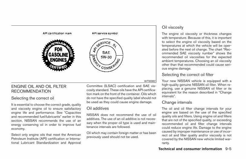
ENGINE OIL AND OIL FILTERRECOMMENDATION
Selecting the correct oil
It is essential to choose the correct grade, qualityand viscosity engine oil to ensure satisfactoryengine life and performance. See 9Capacitiesand recommended fuel/lubricants9 earlier in thissection. NISSAN recommends the use of anenergy conserving oil in order to improve fueleconomy.
Select only engine oils that meet the AmericanPetroleum Institute (API) certification or Interna-tional Lubricant Standardization and Approval
Committee (ILSAC) certification and SAE vis-cosity standard. These oils have the API certifica-tion mark on the front of the container. Oils whichdo not have the specified quality label should notbe used as they could cause engine damage.
Oil additives
NISSAN does not recommend the use of oiladditives. The use of an oil additive is not neces-sary when the proper oil type is used and main-tenance intervals are followed.
Oil which may contain foreign matter or has beenpreviously used should not be used.
Oil viscosity
The engine oil viscosity or thickness changeswith temperature. Because of this, it is importantto select the engine oil viscosity based on thetemperatures at which the vehicle will be oper-ated before the next oil change. The chart “Rec-ommended SAE viscosity number” shows therecommended oil viscosities for the expectedambient temperatures. Choosing an oil viscosityother than that recommended could cause seri-ous engine damage.
Selecting the correct oil filterYour new NISSAN vehicle is equipped with ahigh-quality genuine NISSAN oil filter. When re-placing, use a genuine NISSAN oil filter or itsequivalent for the reason described in “Changeintervals”.
Change intervalsThe oil and oil filter change intervals for yourengine are based on the use of the specifiedquality oils and filters. Using engine oil and filtersthat are not of the specified quality, or exceedingrecommended oil and filter change intervalscould reduce engine life. Damage to the enginecaused by improper maintenance or use of incor-rect oil and filter quality and/or viscosity is notcovered by the NISSAN new vehicle limited war-ranty.
WTI0082
Technical and consumer information 9-5
Z REVIEW COPY—2006 Truck/Frontier (d22)Owners Manual—USA_English (nna)10/17/05—debbie X
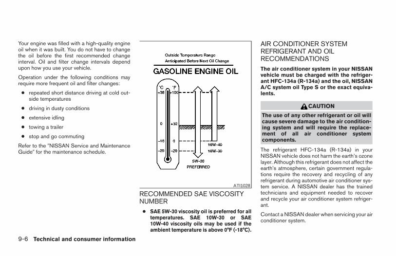
Your engine was filled with a high-quality engineoil when it was built. You do not have to changethe oil before the first recommended changeinterval. Oil and filter change intervals dependupon how you use your vehicle.
Operation under the following conditions mayrequire more frequent oil and filter changes:
● repeated short distance driving at cold out-side temperatures
● driving in dusty conditions
● extensive idling
● towing a trailer
● stop and go commuting
Refer to the 9NISSAN Service and MaintenanceGuide9 for the maintenance schedule.
RECOMMENDED SAE VISCOSITYNUMBER
● SAE 5W-30 viscosity oil is preferred for alltemperatures. SAE 10W-30 or SAE10W-40 viscosity oils may be used if theambient temperature is above 0°F (-18°C).
AIR CONDITIONER SYSTEMREFRIGERANT AND OILRECOMMENDATIONSThe air conditioner system in your NISSANvehicle must be charged with the refriger-ant HFC-134a (R-134a) and the oil, NISSANA/C system oil Type S or the exact equiva-lents.
CAUTION
The use of any other refrigerant or oil willcause severe damage to the air condition-ing system and will require the replace-ment of all air conditioner systemcomponents.
The refrigerant HFC-134a (R-134a) in yourNISSAN vehicle does not harm the earth’s ozonelayer. Although this refrigerant does not affect theearth’s atmosphere, certain government regula-tions require the recovery and recycling of anyrefrigerant during automotive air conditioner sys-tem service. A NISSAN dealer has the trainedtechnicians and equipment needed to recoverand recycle your air conditioner system refriger-ant.
Contact a NISSAN dealer when servicing your airconditioner system.
ATI1028
9-6 Technical and consumer information
Z REVIEW COPY—2006 Truck/Frontier (d22)Owners Manual—USA_English (nna)10/17/05—debbie X
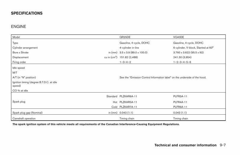
ENGINE
Model QR25DE VQ40DE
Type Gasoline, 4-cycle, DOHC Gasoline, 4-cycle, DOHC
Cylinder arrangement 4-cylinder in-line 6-cylinder, V-block, Slanted at 60°
Bore x Stroke in (mm) 3.5 x 3.9 (89.0 x 100.0) 3.760 x 3.622 (95.5 x 92)
Displacement cu in (cm3) 151.82 (2,488) 241.30 (3,954)
Firing order 1–3–4–2 1–2–3–4–5–6
Idle speed
M/T
A/T (in “N” position) See the “Emission Control Information label” on the underside of the hood.
Ignition timing (degree B.T.D.C. at idlespeed)
CO % at idle
Spark plug
Standard PLZKAR6A-11 PLFR5A-11
Hot PLZKAR5A-11 PLFR4A-11
Cold PLZKAR7A-11 PLFR6A-11
Spark plug gap (Nominal) in (mm) 0.043 (1.1) 0.043 (1.1)
Camshaft operation Timing chain Timing chain
The spark ignition system of this vehicle meets all requirements of the Canadian Interference-Causing Equipment Regulations.
SPECIFICATIONS
Technical and consumer information 9-7
Z REVIEW COPY—2006 Truck/Frontier (d22)Owners Manual—USA_English (nna)10/17/05—debbie X
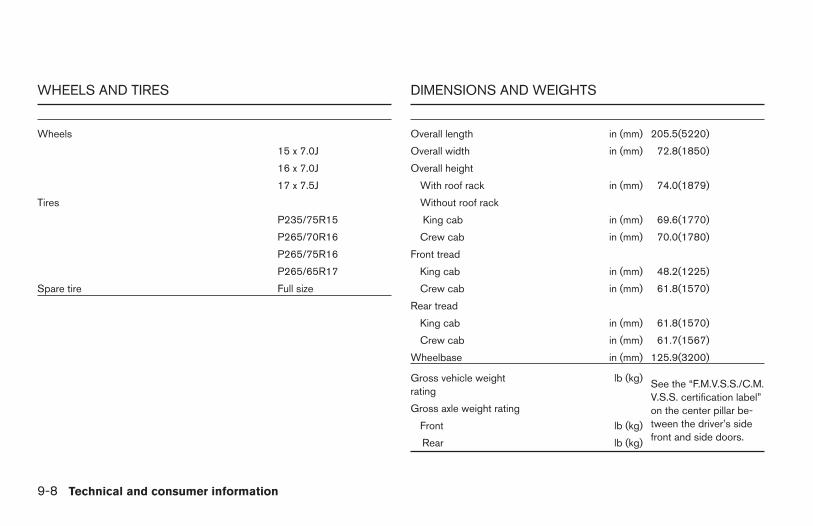
WHEELS AND TIRES
Wheels
15 x 7.0J
16 x 7.0J
17 x 7.5J
Tires
P235/75R15
P265/70R16
P265/75R16
P265/65R17
Spare tire Full size
DIMENSIONS AND WEIGHTS
Overall length in (mm) 205.5(5220)
Overall width in (mm) 72.8(1850)
Overall height
With roof rack in (mm) 74.0(1879)
Without roof rack
King cab in (mm) 69.6(1770)
Crew cab in (mm) 70.0(1780)
Front tread
King cab in (mm) 48.2(1225)
Crew cab in (mm) 61.8(1570)
Rear tread
King cab in (mm) 61.8(1570)
Crew cab in (mm) 61.7(1567)
Wheelbase in (mm) 125.9(3200)
Gross vehicle weightrating
lb (kg) See the “F.M.V.S.S./C.M.V.S.S. certification label”on the center pillar be-tween the driver’s sidefront and side doors.
Gross axle weight rating
Front lb (kg)
Rear lb (kg)
9-8 Technical and consumer information
Z REVIEW COPY—2006 Truck/Frontier (d22)Owners Manual—USA_English (nna)10/17/05—debbie X
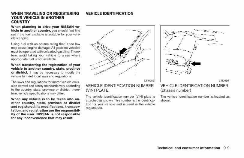
When planning to drive your NISSAN ve-hicle in another country, you should first findout if the fuel available is suitable for your vehi-cle’s engine.
Using fuel with an octane rating that is too lowmay cause engine damage. All gasoline vehiclesmust be operated with unleaded gasoline. There-fore, avoid taking your vehicle to areas whereappropriate fuel is not available.
When transferring the registration of yourvehicle to another country, state, provinceor district, it may be necessary to modify thevehicle to meet local laws and regulations.
The laws and regulations for motor vehicle emis-sion control and safety standards vary accordingto the country, state, province or district; there-fore, vehicle specifications may differ.
When any vehicle is to be taken into an-other country, state, province or districtand registered, its modifications, transpor-tation, and registration are the responsibil-ity of the user. NISSAN is not responsiblefor any inconvenience that may result.
VEHICLE IDENTIFICATION NUMBER(VIN) PLATEThe vehicle identification number (VIN) plate isattached as shown. This number is the identifica-tion for your vehicle and is used in the vehicleregistration.
VEHICLE IDENTIFICATION NUMBER(chassis number)The vehicle identification number is located asshown.
LTI0085 LTI0086
WHEN TRAVELING OR REGISTERINGYOUR VEHICLE IN ANOTHERCOUNTRY
VEHICLE IDENTIFICATION
Technical and consumer information 9-9
Z REVIEW COPY—2006 Truck/Frontier (d22)Owners Manual—USA_English (nna)10/17/05—debbie X
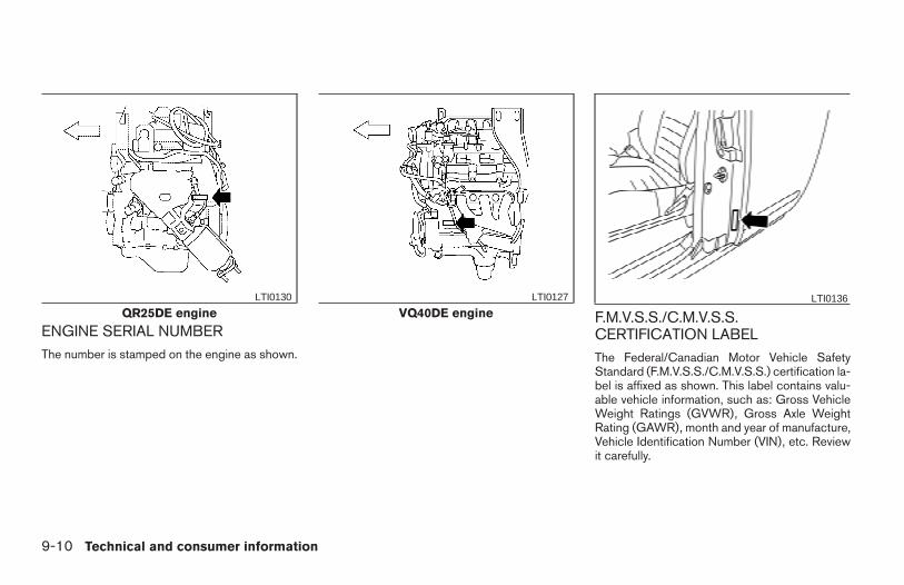
ENGINE SERIAL NUMBERThe number is stamped on the engine as shown.
F.M.V.S.S./C.M.V.S.S.CERTIFICATION LABELThe Federal/Canadian Motor Vehicle SafetyStandard (F.M.V.S.S./C.M.V.S.S.) certification la-bel is affixed as shown. This label contains valu-able vehicle information, such as: Gross VehicleWeight Ratings (GVWR), Gross Axle WeightRating (GAWR), month and year of manufacture,Vehicle Identification Number (VIN), etc. Reviewit carefully.
QR25DE engineLTI0130
VQ40DE engineLTI0127 LTI0136
9-10 Technical and consumer information
Z REVIEW COPY—2006 Truck/Frontier (d22)Owners Manual—USA_English (nna)10/17/05—debbie X
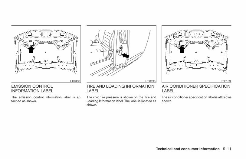
EMISSION CONTROLINFORMATION LABELThe emission control information label is at-tached as shown.
TIRE AND LOADING INFORMATIONLABELThe cold tire pressure is shown on the Tire andLoading Information label. The label is located asshown.
AIR CONDITIONER SPECIFICATIONLABELThe air conditioner specification label is affixed asshown.
LTI0133 LTI0135 LTI0133
Technical and consumer information 9-11
Z REVIEW COPY—2006 Truck/Frontier (d22)Owners Manual—USA_English (nna)10/17/05—debbie X
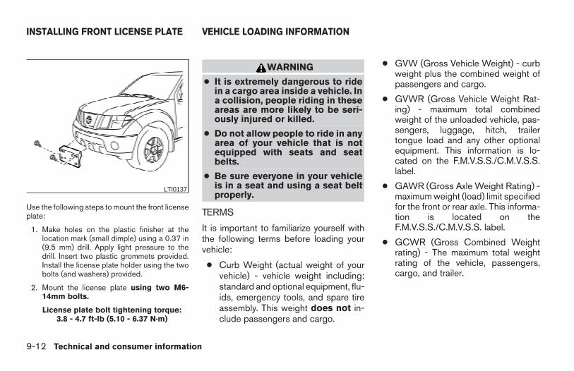
Use the following steps to mount the front licenseplate:
1. Make holes on the plastic finisher at thelocation mark (small dimple) using a 0.37 in(9.5 mm) drill. Apply light pressure to thedrill. Insert two plastic grommets provided.Install the license plate holder using the twobolts (and washers) provided.
2. Mount the license plate using two M6-14mm bolts.
License plate bolt tightening torque:3.8 - 4.7 ft-lb (5.10 - 6.37 N·m)
WARNING
● It is extremely dangerous to ridein a cargo area inside a vehicle. Ina collision, people riding in theseareas are more likely to be seri-ously injured or killed.
● Do not allow people to ride in anyarea of your vehicle that is notequipped with seats and seatbelts.
● Be sure everyone in your vehicleis in a seat and using a seat beltproperly.
TERMS
It is important to familiarize yourself withthe following terms before loading yourvehicle:
● Curb Weight (actual weight of yourvehicle) - vehicle weight including:standard and optional equipment, flu-ids, emergency tools, and spare tireassembly. This weight does not in-clude passengers and cargo.
● GVW (Gross Vehicle Weight) - curbweight plus the combined weight ofpassengers and cargo.
● GVWR (Gross Vehicle Weight Rat-ing) - maximum total combinedweight of the unloaded vehicle, pas-sengers, luggage, hitch, trailertongue load and any other optionalequipment. This information is lo-cated on the F.M.V.S.S./C.M.V.S.S.label.
● GAWR (Gross Axle Weight Rating) -maximum weight (load) limit specifiedfor the front or rear axle. This informa-tion is located on theF.M.V.S.S./C.M.V.S.S. label.
● GCWR (Gross Combined Weightrating) - The maximum total weightrating of the vehicle, passengers,cargo, and trailer.
LTI0137
INSTALLING FRONT LICENSE PLATE VEHICLE LOADING INFORMATION
9-12 Technical and consumer information
Z REVIEW COPY—2006 Truck/Frontier (d22)Owners Manual—USA_English (nna)10/17/05—debbie X
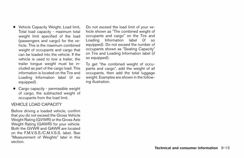
● Vehicle Capacity Weight, Load limit,Total load capacity - maximum totalweight limit specified of the load(passengers and cargo) for the ve-hicle. This is the maximum combinedweight of occupants and cargo thatcan be loaded into the vehicle. If thevehicle is used to tow a trailer, thetrailer tongue weight must be in-cluded as part of the cargo load. Thisinformation is located on the Tire andLoading Information label (if soequipped).
● Cargo capacity - permissible weightof cargo, the subtracted weight ofoccupants from the load limit.
VEHICLE LOAD CAPACITY
Before driving a loaded vehicle, confirmthat you do not exceed the Gross VehicleWeight Rating (GVWR) or the Gross AxleWeight Rating (GAWR) for your vehicle.Both the GVWR and GAWR are locatedon the F.M.V.S.S./C.M.V.S.S. label. See9Measurement of Weights9 later in thissection.
Do not exceed the load limit of your ve-hicle shown as 9The combined weight ofoccupants and cargo9 on the Tire andLoading Information label (if soequipped). Do not exceed the number ofoccupants shown as 9Seating Capacity9on Tire and Loading Information label (ifso equipped).
To get 9the combined weight of occu-pants and cargo9, add the weight of alloccupants, then add the total luggageweight. Examples are shown in the follow-ing illustration.
Technical and consumer information 9-13
Z REVIEW COPY—2006 Truck/Frontier (d22)Owners Manual—USA_English (nna)10/17/05—debbie X
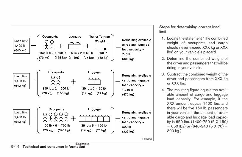
Steps for determining correct loadlimit
1. Locate the statement “The combinedweight of occupants and cargoshould never exceed XXX kg or XXXlbs” on your vehicle’s placard.
2. Determine the combined weight ofthe driver and passengers that will beriding in your vehicle.
3. Subtract the combined weight of thedriver and passengers from XXX kgor XXX lbs.
4. The resulting figure equals the avail-able amount of cargo and luggageload capacity. For example, if theXXX amount equals 1400 lbs. andthere will be five 150 lb. passengersin your vehicle, the amount of avail-able cargo and luggage load capac-ity is 650 lbs. (1400-750 (5 X 150)= 650 lbs) or (640-340 (5 X 70) =300 kg.)
ExampleLTI0152
9-14 Technical and consumer information
Z REVIEW COPY—2006 Truck/Frontier (d22)Owners Manual—USA_English (nna)10/17/05—debbie X
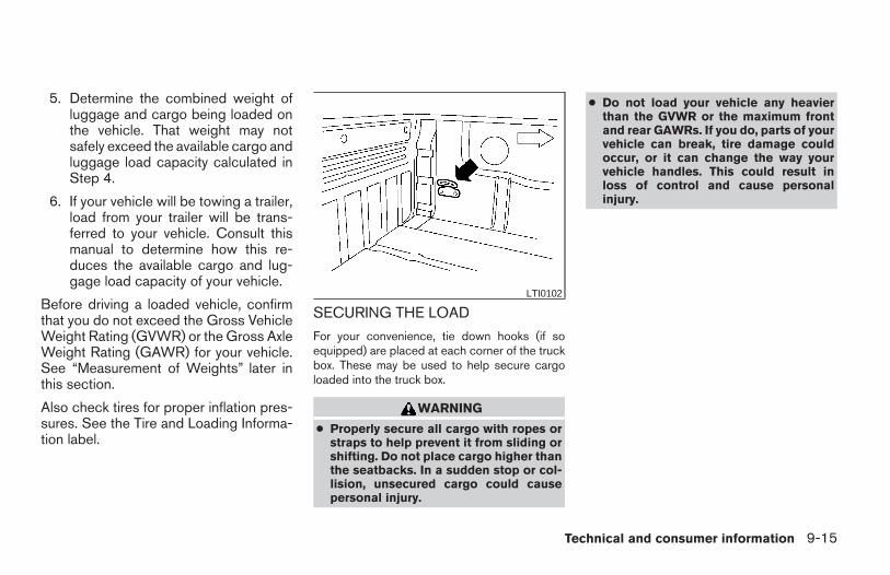
5. Determine the combined weight ofluggage and cargo being loaded onthe vehicle. That weight may notsafely exceed the available cargo andluggage load capacity calculated inStep 4.
6. If your vehicle will be towing a trailer,load from your trailer will be trans-ferred to your vehicle. Consult thismanual to determine how this re-duces the available cargo and lug-gage load capacity of your vehicle.
Before driving a loaded vehicle, confirmthat you do not exceed the Gross VehicleWeight Rating (GVWR) or the Gross AxleWeight Rating (GAWR) for your vehicle.See “Measurement of Weights” later inthis section.
Also check tires for proper inflation pres-sures. See the Tire and Loading Informa-tion label.
SECURING THE LOAD
For your convenience, tie down hooks (if soequipped) are placed at each corner of the truckbox. These may be used to help secure cargoloaded into the truck box.
WARNING
● Properly secure all cargo with ropes orstraps to help prevent it from sliding orshifting. Do not place cargo higher thanthe seatbacks. In a sudden stop or col-lision, unsecured cargo could causepersonal injury.
● Do not load your vehicle any heavierthan the GVWR or the maximum frontand rear GAWRs. If you do, parts of yourvehicle can break, tire damage couldoccur, or it can change the way yourvehicle handles. This could result inloss of control and cause personalinjury.
LTI0102
Technical and consumer information 9-15
Z REVIEW COPY—2006 Truck/Frontier (d22)Owners Manual—USA_English (nna)10/26/05—tbrooks X
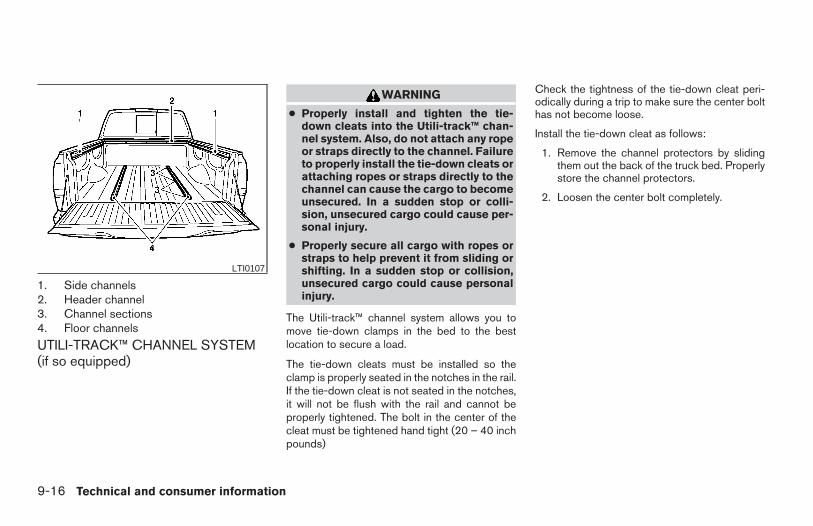
1. Side channels2. Header channel3. Channel sections4. Floor channels
UTILI-TRACK™ CHANNEL SYSTEM(if so equipped)
WARNING
● Properly install and tighten the tie-down cleats into the Utili-track™ chan-nel system. Also, do not attach any ropeor straps directly to the channel. Failureto properly install the tie-down cleats orattaching ropes or straps directly to thechannel can cause the cargo to becomeunsecured. In a sudden stop or colli-sion, unsecured cargo could cause per-sonal injury.
● Properly secure all cargo with ropes orstraps to help prevent it from sliding orshifting. In a sudden stop or collision,unsecured cargo could cause personalinjury.
The Utili-track™ channel system allows you tomove tie-down clamps in the bed to the bestlocation to secure a load.
The tie-down cleats must be installed so theclamp is properly seated in the notches in the rail.If the tie-down cleat is not seated in the notches,it will not be flush with the rail and cannot beproperly tightened. The bolt in the center of thecleat must be tightened hand tight (20 – 40 inchpounds)
Check the tightness of the tie-down cleat peri-odically during a trip to make sure the center bolthas not become loose.
Install the tie-down cleat as follows:
1. Remove the channel protectors by slidingthem out the back of the truck bed. Properlystore the channel protectors.
2. Loosen the center bolt completely.
LTI0107
9-16 Technical and consumer information
Z REVIEW COPY—2006 Truck/Frontier (d22)Owners Manual—USA_English (nna)10/17/05—debbie X
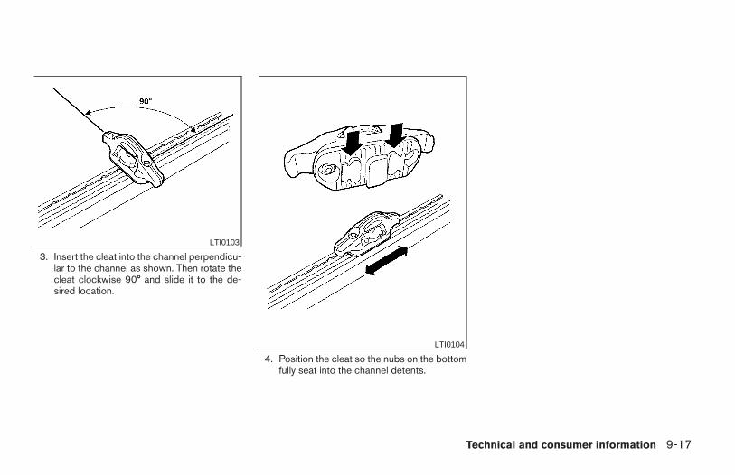
3. Insert the cleat into the channel perpendicu-lar to the channel as shown. Then rotate thecleat clockwise 90° and slide it to the de-sired location.
4. Position the cleat so the nubs on the bottomfully seat into the channel detents.
LTI0103
LTI0104
Technical and consumer information 9-17
Z REVIEW COPY—2006 Truck/Frontier (d22)Owners Manual—USA_English (nna)10/17/05—debbie X
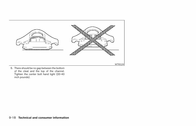
5. There should be no gap between the bottomof the cleat and the top of the channel.Tighten the center bolt hand tight (20-40inch pounds).
WTI0124
9-18 Technical and consumer information
Z REVIEW COPY—2006 Truck/Frontier (d22)Owners Manual—USA_English (nna)10/17/05—debbie X
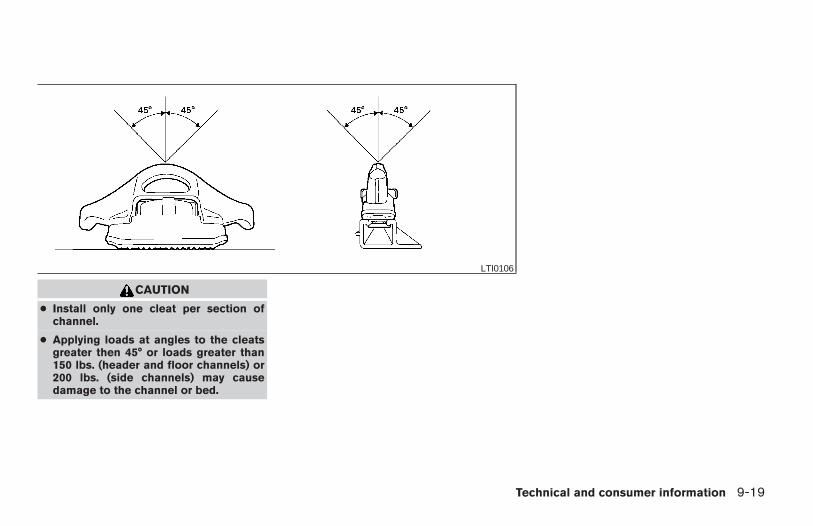
CAUTION
● Install only one cleat per section ofchannel.
● Applying loads at angles to the cleatsgreater then 45° or loads greater than150 lbs. (header and floor channels) or200 lbs. (side channels) may causedamage to the channel or bed.
LTI0106
Technical and consumer information 9-19
Z REVIEW COPY—2006 Truck/Frontier (d22)Owners Manual—USA_English (nna)10/17/05—debbie X
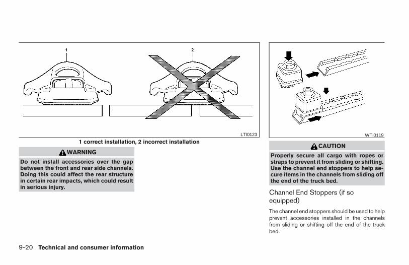
WARNING
Do not install accessories over the gapbetween the front and rear side channels.Doing this could affect the rear structurein certain rear impacts, which could resultin serious injury.
CAUTION
Properly secure all cargo with ropes orstraps to prevent it from sliding or shifting.Use the channel end stoppers to help se-cure items in the channels from sliding offthe end of the truck bed.
Channel End Stoppers (if soequipped)
The channel end stoppers should be used to helpprevent accessories installed in the channelsfrom sliding or shifting off the end of the truckbed.
1 correct installation, 2 incorrect installationLTI0123 WTI0119
9-20 Technical and consumer information
Z REVIEW COPY—2006 Truck/Frontier (d22)Owners Manual—USA_English (nna)10/17/05—debbie X
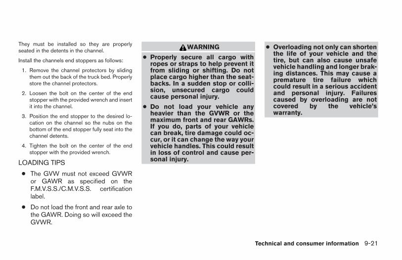
They must be installed so they are properlyseated in the detents in the channel.
Install the channels end stoppers as follows:
1. Remove the channel protectors by slidingthem out the back of the truck bed. Properlystore the channel protectors.
2. Loosen the bolt on the center of the endstopper with the provided wrench and insertit into the channel.
3. Position the end stopper to the desired lo-cation on the channel so the nubs on thebottom of the end stopper fully seat into thechannel detents.
4. Tighten the bolt on the center of the endstopper with the provided wrench.
LOADING TIPS
● The GVW must not exceed GVWRor GAWR as specified on theF.M.V.S.S./C.M.V.S.S. certificationlabel.
● Do not load the front and rear axle tothe GAWR. Doing so will exceed theGVWR.
WARNING
● Properly secure all cargo withropes or straps to help prevent itfrom sliding or shifting. Do notplace cargo higher than the seat-backs. In a sudden stop or colli-sion, unsecured cargo couldcause personal injury.
● Do not load your vehicle anyheavier than the GVWR or themaximum front and rear GAWRs.If you do, parts of your vehiclecan break, tire damage could oc-cur, or it can change the way yourvehicle handles. This could resultin loss of control and cause per-sonal injury.
● Overloading not only can shortenthe life of your vehicle and thetire, but can also cause unsafevehicle handling and longer brak-ing distances. This may cause apremature tire failure whichcould result in a serious accidentand personal injury. Failurescaused by overloading are notcovered by the vehicle’swarranty.
Technical and consumer information 9-21
Z REVIEW COPY—2006 Truck/Frontier (d22)Owners Manual—USA_English (nna)10/17/05—debbie X
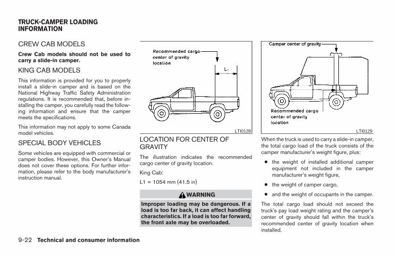
CREW CAB MODELSCrew Cab models should not be used tocarry a slide-in camper.
KING CAB MODELSThis information is provided for you to properlyinstall a slide-in camper and is based on theNational Highway Traffic Safety Administrationregulations. It is recommended that, before in-stalling the camper, you carefully read the follow-ing information and ensure that the campermeets the specifications.
This information may not apply to some Canadamodel vehicles.
SPECIAL BODY VEHICLESSome vehicles are equipped with commercial orcamper bodies. However, this Owner’s Manualdoes not cover these options. For further infor-mation, please refer to the body manufacturer’sinstruction manual.
LOCATION FOR CENTER OFGRAVITYThe illustration indicates the recommendedcargo center of gravity location.
King Cab:
L1 = 1054 mm (41.5 in)
WARNING
Improper loading may be dangerous. If aload is too far back, it can affect handlingcharacteristics. If a load is too far forward,the front axle may be overloaded.
When the truck is used to carry a slide-in camper,the total cargo load of the truck consists of thecamper manufacturer’s weight figure, plus:
● the weight of installed additional camperequipment not included in the campermanufacturer’s weight figure,
● the weight of camper cargo,
● and the weight of occupants in the camper.
The total cargo load should not exceed thetruck’s pay load weight rating and the camper’scenter of gravity should fall within the truck’srecommended center of gravity location wheninstalled.
LTI0128 LTI0129
TRUCK-CAMPER LOADINGINFORMATION
9-22 Technical and consumer information
Z REVIEW COPY—2006 Truck/Frontier (d22)Owners Manual—USA_English (nna)10/17/05—debbie X
WARNING
Overloading or improper loading can ad-versely affect vehicle handling, brakingand performance and may lead toaccidents.
VEHICLE LOAD WEIGHT CAPACITY
The vehicle load weight capacity shown on fol-lowing charts indicate the maximum total weightof passengers, optional equipment (air condition-ing, trailer hitch, etc) and cargo that your vehicleis designed to carry.
Before driving a loaded vehicle, confirm that youdo not exceed the Gross Vehicle Weight Rating(GVWR) or the Gross Axle Weight Rating(GAWR) for your vehicle. See ’’Vehicle LoadingInformation’’ earlier in this section for details.
Also check tires for proper inflation pressures.See the tire placard.
Technical and consumer information 9-23
Z REVIEW COPY—2006 Truck/Frontier (d22)Owners Manual—USA_English (nna)10/17/05—debbie X
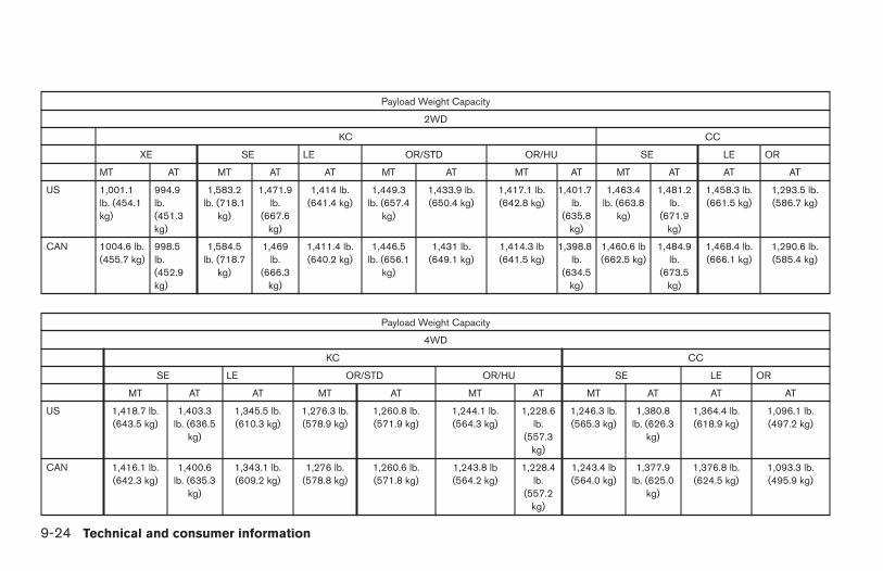
Payload Weight Capacity
2WD
KC CC
XE SE LE OR/STD OR/HU SE LE OR
MT AT MT AT AT MT AT MT AT MT AT AT AT
US 1,001.1lb. (454.1kg)
994.9lb.(451.3kg)
1,583.2lb. (718.1
kg)
1,471.9lb.
(667.6kg)
1,414 lb.(641.4 kg)
1,449.3lb. (657.4
kg)
1,433.9 lb.(650.4 kg)
1,417.1 lb.(642.8 kg)
1,401.7lb.
(635.8kg)
1,463.4lb. (663.8
kg)
1,481.2lb.
(671.9kg)
1,458.3 lb.(661.5 kg)
1,293.5 lb.(586.7 kg)
CAN 1004.6 lb.(455.7 kg)
998.5lb.(452.9kg)
1,584.5lb. (718.7
kg)
1,469lb.
(666.3kg)
1,411.4 lb.(640.2 kg)
1,446.5lb. (656.1
kg)
1,431 lb.(649.1 kg)
1,414.3 lb(641.5 kg)
1,398.8lb.
(634.5kg)
1,460.6 lb(662.5 kg)
1,484.9lb.
(673.5kg)
1,468.4 lb.(666.1 kg)
1,290.6 lb.(585.4 kg)
Payload Weight Capacity
4WD
KC CC
SE LE OR/STD OR/HU SE LE OR
MT AT AT MT AT MT AT MT AT AT AT
US 1,418.7 lb.(643.5 kg)
1,403.3lb. (636.5
kg)
1,345.5 lb.(610.3 kg)
1,276.3 lb.(578.9 kg)
1,260.8 lb.(571.9 kg)
1,244.1 lb.(564.3 kg)
1,228.6lb.
(557.3kg)
1,246.3 lb.(565.3 kg)
1,380.8lb. (626.3
kg)
1,364.4 lb.(618.9 kg)
1,096.1 lb.(497.2 kg)
CAN 1,416.1 lb.(642.3 kg)
1,400.6lb. (635.3
kg)
1,343.1 lb.(609.2 kg)
1,276 lb.(578.8 kg)
1,260.6 lb.(571.8 kg)
1,243.8 lb(564.2 kg)
1,228.4lb.
(557.2kg)
1,243.4 lb(564.0 kg)
1,377.9lb. (625.0
kg)
1,376.8 lb.(624.5 kg)
1,093.3 lb.(495.9 kg)
9-24 Technical and consumer information
Z REVIEW COPY—2006 Truck/Frontier (d22)Owners Manual—USA_English (nna)10/17/05—debbie X
MEASUREMENT OF WEIGHTS
Secure loose items to prevent weightshifts that could affect the balance of yourvehicle. When the vehicle is loaded, driveto a scale and weigh the front and the rearwheels separately to determine axleloads. Individual axle loads should not ex-ceed either of the gross axle weight rat-ings (GAWR). The total of the axle loadsshould not exceed the gross vehicleweight rating (GVWR). These ratings aregiven on the vehicle certification label. Ifweight ratings are exceeded, move or re-move items to bring all weights below theratings.
WARNING
Overloading or improper loading of atrailer and its cargo can adversely affectvehicle handling, braking and perfor-mance and may lead to accidents.
CAUTION
● Do not tow a trailer or haul a heavy loadfor the first 500 miles (800 km). Yourengine, axle or other parts could bedamaged.
● For the first 500 miles (800 km) that youtow a trailer, do not drive over 50 mph(80 km/h) and do not make starts at fullthrottle. This helps the engine and otherparts of your vehicle wear in at theheavier loads.
Your new vehicle was designed to be used pri-marily to carry passengers and cargo. Rememberthat towing a trailer places additional loads onyour vehicle’s engine, drive train, steering, brak-ing and other systems.
A NISSAN Towing Guide (U.S. only) is availableon the website at www.nissanusa.com. Thisguide includes information on trailer towing ca-pability and the special equipment required forproper towing.
MAXIMUM LOAD LIMITSMaximum trailer loadsNever allow the total trailer load to exceed thevalue specified in the “TowingLoad/Specification” chart found later in this sec-tion. The total trailer load equals trailer weightplus its cargo weight.
● When towing a trailer load of 3,500 lbs.(1587 kg) or more, trailers with a brakesystem MUST be used.
The maximum GCWR (Gross Combined WeightRating) should not exceed the value specified inthe following “Towing Load/Specification” chart.
TOWING A TRAILER
Technical and consumer information 9-25
Z REVIEW COPY—2006 Truck/Frontier (d22)Owners Manual—USA_English (nna)10/17/05—debbie X
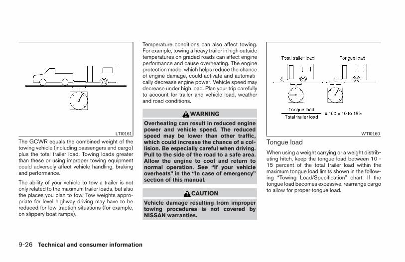
The GCWR equals the combined weight of thetowing vehicle (including passengers and cargo)plus the total trailer load. Towing loads greaterthan these or using improper towing equipmentcould adversely affect vehicle handling, brakingand performance.
The ability of your vehicle to tow a trailer is notonly related to the maximum trailer loads, but alsothe places you plan to tow. Tow weights appro-priate for level highway driving may have to bereduced for low traction situations (for example,on slippery boat ramps).
Temperature conditions can also affect towing.For example, towing a heavy trailer in high outsidetemperatures on graded roads can affect engineperformance and cause overheating. The engineprotection mode, which helps reduce the chanceof engine damage, could activate and automati-cally decrease engine power. Vehicle speed maydecrease under high load. Plan your trip carefullyto account for trailer and vehicle load, weatherand road conditions.
WARNING
Overheating can result in reduced enginepower and vehicle speed. The reducedspeed may be lower than other traffic,which could increase the chance of a col-lision. Be especially careful when driving.Pull to the side of the road to a safe area.Allow the engine to cool and return tonormal operation. See “If your vehicleoverheats” in the “In case of emergency”section of this manual.
CAUTION
Vehicle damage resulting from impropertowing procedures is not covered byNISSAN warranties.
Tongue loadWhen using a weight carrying or a weight distrib-uting hitch, keep the tongue load between 10 -15 percent of the total trailer load within themaximum tongue load limits shown in the follow-ing “Towing Load/Specification” chart. If thetongue load becomes excessive, rearrange cargoto allow for proper tongue load.
LTI0161 WTI0160
9-26 Technical and consumer information
Z REVIEW COPY—2006 Truck/Frontier (d22)Owners Manual—USA_English (nna)10/17/05—debbie X
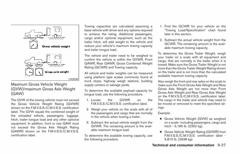
Maximum Gross Vehicle Weight(GVW)/maximum Gross Axle Weight(GAW)
The GVW of the towing vehicle must not exceedthe Gross Vehicle Weight Rating (GVWR)shown on the F.M.V.S.S./C.M.V.S.S. certificationlabel. The GVW equals the combined weight ofthe unloaded vehicle, passengers, luggage,hitch, trailer tongue load and any other optionalequipment. In addition, front or rear GAW mustnot exceed the Gross Axle Weight Rating(GAWR) shown on the F.M.V.S.S./C.M.V.S.S.certification label.
Towing capacities are calculated assuming abase vehicle with driver and any options requiredto achieve the rating. Additional passengers,cargo and/or optional equipment, such as thetrailer hitch, will add weight to the vehicle andreduce your vehicle’s maximum towing capacityand trailer tongue load.
The vehicle and trailer need to be weighed toconfirm the vehicle is within the GVWR, FrontGAWR, Rear GAWR, Gross Combined WeightRating (GCWR) and Towing capacity.
All vehicle and trailer weights can be measuredusing platform type scales commonly found attruck stops, highway weigh stations, buildingsupply centers or salvage yards.
To determine the available payload capacity fortongue load, use the following procedure.
1. Locate the GVWR on theF.M.V.S.S./C.M.V.S.S. certification label.
2. Weigh your vehicle on the scale with all ofthe passengers and cargo that are normallyin the vehicle when towing a trailer.
3. Subtract the actual vehicle weight from theGVWR. The remaining amount is the avail-able maximum tongue load.
To determine the available towing capacity, usethe following procedure.
1. Find the GCWR for your vehicle on the9Towing Load/Specification9 chart foundlater in this section.
2. Subtract the actual vehicle weight from theGCWR. The remaining amount is the avail-able maximum towing capacity.
To determine the Gross Trailer Weight, weighyour trailer on a scale with all equipment andcargo, that are normally in the trailer when it istowed. Make sure the Gross Trailer Weight is notmore than the Gross Trailer Weight Rating shownon the trailer and is not more than the calculatedavailable maximum towing capacity.
Also weigh the front and rear axles on the scale tomake sure the Front Gross Axle Weight and RearGross Axle Weight are not more than FrontGross Axle Weight and Rear Gross Axle Weighton the F.M.V.S.S./C.M.V.S.S. certification label.The cargo in the trailer and vehicle may need tobe moved or removed to meet the specified rat-ings.
Example:
● Gross Vehicle Weight (GVW) as weighedon a scale- including passengers, cargo andhitch - 5,185 lb. (2352 kg).
● Gross Vehicle Weight Rating (GVWR) fromF.M.V.S.S./C.M.V.S.S. certification label -5,815 lb. (2638 kg).
CA0036
Technical and consumer information 9-27
Z REVIEW COPY—2006 Truck/Frontier (d22)Owners Manual—USA_English (nna)10/26/05—tbrooks X
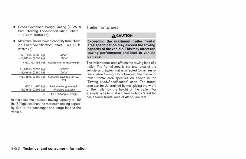
● Gross Combined Weight Rating (GCWR)from “Towing Load/Specification9 chart -11,133 lb. (5050 kg).
● Maximum Trailer towing capacity from “Tow-ing Load/Specification9 chart - 6,100 lb.(2767 kg).
5,815 lb. (2638 kg) GVWR– 5,185 lb. (2352 kg) GVW
= 630 lb. (286 kg) Available for tongue weight
11,133 lb. (5050 kg) GCWR– 5,185 lb. (2352 kg) GVW
= 5,948 lb. (2698 kg) Capacity available for tow-ing
630 lb. (286 kg) Available tongue weight/ 5,948 lb. (2698 kg) Available capacity
= 10.6 % tongue weight
In this case, the available towing capacity is 152lb. (69 kg) less than the maximum towing capac-ity due to the passenger and cargo load in thevehicle.
Trailer frontal area
CAUTION
Exceeding the maximum trailer frontalarea specification may exceed the towingcapacity of the vehicle. This may affect thetowing performance and lead to vehicledamage.
The trailer frontal area affects the towing load of atrailer. The frontal area is the total area of thevehicle and trailer that is affected by air resis-tance while towing. Do not exceed the maximumtrailer frontal area specification shown in the9Towing Load/Specification” chart. The frontalarea can be determined by multiplying the widthof the trailer by the height of the trailer. Forexample, a trailer that is 8 feet wide by 6 feet tallhas a trailer frontal area of 48 square feet.
9-28 Technical and consumer information
Z REVIEW COPY—2006 Truck/Frontier (d22)Owners Manual—USA_English (nna)10/17/05—debbie X
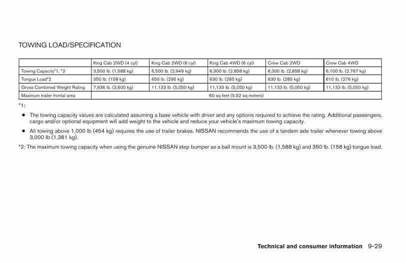
TOWING LOAD/SPECIFICATION
King Cab 2WD (4 cyl) King Cab 2WD (6 cyl) King Cab 4WD (6 cyl) Crew Cab 2WD Crew Cab 4WD
Towing Capacity*1, *2 3,500 lb. (1,588 kg) 6,500 lb. (2,949 kg) 6,300 lb. (2,858 kg) 6,300 lb. (2,858 kg) 6,100 lb. (2,767 kg)
Tongue Load*2 350 lb. (158 kg) 650 lb. (295 kg) 630 lb. (285 kg) 630 lb. (285 kg) 610 lb. (276 kg)
Gross Combined Weight Rating 7,936 lb. (3,600 kg) 11,133 lb. (5,050 kg) 11,133 lb. (5,050 kg) 11,133 lb. (5,050 kg) 11,133 lb. (5,050 kg)
Maximum trailer frontal area 60 sq feet (5.52 sq meters)
*1:
● The towing capacity values are calculated assuming a base vehicle with driver and any options required to achieve the rating. Additional passengers,cargo and/or optional equipment will add weight to the vehicle and reduce your vehicle’s maximum towing capacity.
● All towing above 1,000 lb (454 kg) requires the use of trailer brakes. NISSAN recommends the use of a tandem axle trailer whenever towing above3,000 lb (1,361 kg).
*2: The maximum towing capacity when using the genuine NISSAN step bumper as a ball mount is 3,500 lb. (1,588 kg) and 350 lb. (158 kg) tongue load.
Technical and consumer information 9-29
Z REVIEW COPY—2006 Truck/Frontier (d22)Owners Manual—USA_English (nna)10/17/05—debbie X
TOWING SAFETYTrailer hitch
Your vehicle may be equipped with an optionaltrailer tow package. The trailer tow package in-cludes a receiver-type frame mounted hitch. Thishitch is rated for the maximum towing capacity ofthis vehicle when the proper towing equipment isused. Choose a proper ball mount and hitch ballthat is rated for the trailer to be towed. GenuineNissan ball mounts and hitch balls are availablefrom your NISSAN dealer.
If your vehicle is not equipped with the optionaltrailer tow package, check the towing capacity ofyour bumper hitch or receiver-type framemounted hitch. Choose a proper hitch for yourvehicle and trailer. A genuine Nissan trailer hitchis available from your NISSAN dealer. Make surethe trailer hitch is securely attached to the vehicleto help avoid personal injury or property damagedue to sway caused by crosswinds, rough roadsurfaces or passing trucks.
WARNING
Trailer hitch components have specificweight ratings. Your vehicle may be ca-pable of towing a trailer heavier than theweight rating of the hitch components.Never exceed the weight rating of thehitch components. Doing so can causeserious personal injury or propertydamage.
Hitch ballChoose a hitch ball of the proper size and weightrating for your trailer:
● The required hitch ball size is stamped onmost trailer couplers. Most hitch balls alsohave the size printed on the top of the ball.
● Choose the proper class hitch ball based onthe trailer weight.
● The diameter of the threaded shank of thehitch ball must be matched to the ball mounthole diameter. The hitch ball shank shouldbe no more than 1/16” smaller than the holein the ball mount.
● The threaded shank of the hitch ball must belong enough to be properly secured to theball mount. There should be at least 2threads showing beyond the lock washerand nut.
Ball mountThe hitch ball is attached to the ball mount andthe ball mount is inserted into the hitch receiver.Choose a proper class ball mount based on thetrailer weight. Additionally, the ball mount shouldbe chosen to keep the trailer tongue level with theground.
9-30 Technical and consumer information
Z REVIEW COPY—2006 Truck/Frontier (d22)Owners Manual—USA_English (nna)10/17/05—debbie X
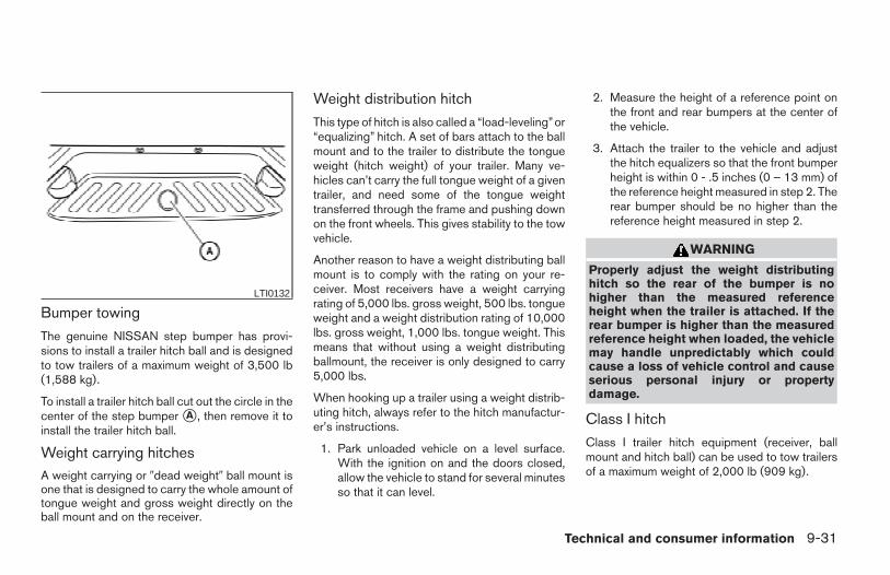
Bumper towing
The genuine NISSAN step bumper has provi-sions to install a trailer hitch ball and is designedto tow trailers of a maximum weight of 3,500 lb(1,588 kg).
To install a trailer hitch ball cut out the circle in thecenter of the step bumper sA , then remove it toinstall the trailer hitch ball.
Weight carrying hitchesA weight carrying or 9dead weight9 ball mount isone that is designed to carry the whole amount oftongue weight and gross weight directly on theball mount and on the receiver.
Weight distribution hitch
This type of hitch is also called a “load-leveling”or“equalizing” hitch. A set of bars attach to the ballmount and to the trailer to distribute the tongueweight (hitch weight) of your trailer. Many ve-hicles can’t carry the full tongue weight of a giventrailer, and need some of the tongue weighttransferred through the frame and pushing downon the front wheels. This gives stability to the towvehicle.
Another reason to have a weight distributing ballmount is to comply with the rating on your re-ceiver. Most receivers have a weight carryingrating of 5,000 lbs. gross weight, 500 lbs. tongueweight and a weight distribution rating of 10,000lbs. gross weight, 1,000 lbs. tongue weight. Thismeans that without using a weight distributingballmount, the receiver is only designed to carry5,000 lbs.
When hooking up a trailer using a weight distrib-uting hitch, always refer to the hitch manufactur-er’s instructions.
1. Park unloaded vehicle on a level surface.With the ignition on and the doors closed,allow the vehicle to stand for several minutesso that it can level.
2. Measure the height of a reference point onthe front and rear bumpers at the center ofthe vehicle.
3. Attach the trailer to the vehicle and adjustthe hitch equalizers so that the front bumperheight is within 0 - .5 inches (0 – 13 mm) ofthe reference height measured in step 2. Therear bumper should be no higher than thereference height measured in step 2.
WARNING
Properly adjust the weight distributinghitch so the rear of the bumper is nohigher than the measured referenceheight when the trailer is attached. If therear bumper is higher than the measuredreference height when loaded, the vehiclemay handle unpredictably which couldcause a loss of vehicle control and causeserious personal injury or propertydamage.
Class I hitch
Class I trailer hitch equipment (receiver, ballmount and hitch ball) can be used to tow trailersof a maximum weight of 2,000 lb (909 kg).
LTI0132
Technical and consumer information 9-31
Z REVIEW COPY—2006 Truck/Frontier (d22)Owners Manual—USA_English (nna)10/17/05—debbie X
Class II hitch
Class II trailer hitch equipment (receiver, ballmount and hitch ball) can be used to tow trailersof a maximum weight of 3,500 lb (1,510 kg).
The genuine NISSAN step bumper is considereda Class II ball mount.
Class III hitch
Class III trailer hitch equipment (receiver, ballmount and hitch ball) can be used to tow trailersof a maximum weight of 5,000 lb (2,272 kg).
Class IV hitch
Class IV trailer hitch equipment (receiver, ballmount and hitch ball) can be used to tow trailersof a maximum weight of 10,000 lb (4,545 kg). Aweight distributing hitch should be used to towtrailers that weigh over 5,000 lb (2,272 kg).
Your vehicle may be equipped with Class IVtrailer hitch equipment that has a 10,000 lb(4,545 kg) maximum weight rating, but your ve-hicle is only capable of towing the maximumtrailer weights shown in the “TowingLoad/Specification” chart earlier in this section.
CAUTION
● Special hitches which include frame re-inforcements are required for towingabove 2,000 lb (907 kg). Suitable genu-ine NISSAN hitches, ball mounts andhitch balls for pickup trucks and sportutility vehicles are available at aNISSAN dealer.
● The hitch should not be attached to oraffect the operation of the impact-absorbing bumper.
● Do not use axle-mounted hitches.
● Do not modify the vehicle exhaust sys-tem, brake system, etc. to install atrailer hitch.
● To reduce the possibility of additionaldamage if your vehicle is struck fromthe rear, where practical, remove thehitch and/or receiver when not in use.
● Regularly check that all trailer hitchmounting bolts are securely mounted.
● When towing with the hitch ballmounted to the rear bumper, do notmake sharp turns. The trailer may con-tact the bumper and cause damage tothe bumper or trailer.
Tire pressures
● When towing a trailer, inflate the ve-hicle tires to the recommended coldtire pressure indicated on the Tireand Loading Information label.
● Trailer tire condition, size, load ratingand proper inflation pressure shouldbe in accordance with the trailer andtire manufacturer’s specifications.
Safety chains
Always use suitable safety chains between yourvehicle and the trailer. The safety chains shouldbe crossed and should be attached to the hitch,not to the vehicle bumper or axle. The safetychains can be attached to the bumper if the hitchball is mounted to the bumper. Be sure to leaveenough slack in the chains to permit turningcorners.
9-32 Technical and consumer information
Z REVIEW COPY—2006 Truck/Frontier (d22)Owners Manual—USA_English (nna)10/26/05—tbrooks X
Trailer lights
CAUTION
When splicing into the vehicle electricalsystem, a commercially available power-type module/converter must be used toprovide power for all trailer lighting. Thisunit uses the vehicle battery as a directpower source for all trailer lights whileusing the vehicle tail light, stoplight andturn signal circuits as a signal source. Themodule/converter must draw no morethat 15 milliamps from the stop and taillamp circuits. Using a module/converterthat exceeds these power requirementsmay damage the vehicle’s electrical sys-tem. See a reputable trailer dealer to ob-tain the proper equipment and to have itinstalled.
Trailer lights should comply with federal and/orlocal regulations. For assistance in hooking uptrailer lights, contact a NISSAN dealer or repu-table trailer dealer. Vehicles equipped with theoptional trailer tow package are equipped with a7-pin trailer harness connector. If your trailer isequipped with a flat 4-pin connector, an adapterwill be needed to connect the trailer lights to thevehicle. Adapters are available at NISSAN deal-ers as well as auto parts stores and hitch retail-ers.
Trailer brakes
If your trailer is equipped with a braking system,make sure it conforms to federal and/or localregulations and that it is properly installed.
WARNING
Never connect a trailer brake system di-rectly to the vehicle brake system.
Pre-towing tips
● Be certain your vehicle maintains a levelposition when a loaded and/or unloadedtrailer is hitched. Do not drive the vehicle if ithas an abnormal nose-up or nose-downcondition; check for improper tongue load,overload, worn suspension or other possiblecauses of either condition.
● Always secure items in the trailer to preventload shift while driving.
● Keep the cargo load as low as possible inthe trailer to keep the trailer center of gravitylow.
● Load the trailer so approximately 60% of thetrailer load is in the front half and 40% is inthe back half. Also make sure the load isbalanced side to side.
● Check your hitch, trailer tire pressure, ve-hicle tire pressure, trailer light operation, andtrailer wheel lug nuts every time you attach atrailer to the vehicle.
● Be certain your rearview mirrors conform toall federal, state or local regulations. If not,install any mirrors required for towing beforedriving the vehicle.
● Determine the overall height of the vehicleand trailer so the required clearance isknown.
Trailer towing tips
In order to gain skill and an understanding of thevehicle’s behavior, you should practice turning,stopping and backing up in an area which is freefrom traffic. Steering stability and braking perfor-mance will be somewhat different than undernormal driving conditions.
● Always secure items in the trailer to preventload shift while driving.
● Lock the trailer hitch coupler with a pin orlock to prevent the coupler from inadvert-ently becoming unlatched.
● Avoid abrupt starts, acceleration or stops.
● Avoid sharp turns or lane changes.
Technical and consumer information 9-33
Z REVIEW COPY—2006 Truck/Frontier (d22)Owners Manual—USA_English (nna)10/17/05—debbie X
● Always drive your vehicle at a moderatespeed.
● When backing up, hold the bottom of thesteering wheel with one hand. Move yourhand in the direction in which you want thetrailer to go. Make small corrections andback up slowly. If possible, have someoneguide you when you are backing up.
Always block the wheels on both vehicle andtrailer when parking. Parking on a slope is notrecommended; however, if you must do so:
CAUTION
If you move the shift selector lever to the P(Park) position before blocking thewheels and applying the parking brake,transmission damage could occur.
1. Apply and hold the brake pedal.
2. Have someone place blocks on the down hillside of the vehicle and trailer wheels.
3. After the wheel blocks are in place, slowlyrelease the brake pedal until the blocks ab-sorb the vehicle load.
4. Apply the parking brake.
5. Shift the transmission into P (Park).
6. Make sure the indicator light (if soequipped) indicates the transfer case is in4H, 4L, or 2H and that the ATP light is off. Ifthe indicator light is flashing, or theATP light is ON, make sure the transmissionis in P (Park) (AT) and turn the 4WD switchto 2WD or 4H. See 9Automatic transmissionpark warning light9 in the 9Instruments andcontrols9 section and 9Using four wheeldrive9 in the 9Starting and driving9 section.
7. Turn off the engine.
To drive away:
1. Start the vehicle.
2. Apply and hold the brake pedal.
3. Shift the transmission into gear.
4. Release the parking brake.
5. Drive slowly until the vehicle and trailer areclear from the blocks.
6. Apply and hold the brake pedal.
7. Have someone retrieve and store the blocks.
● When going down a hill, shift into a lowergear and use the engine braking effect.When going up a long grade, downshift thetransmission to a lower gear and reducespeed to reduce chances of engine over-loading and/or overheating. However, for
long steep grades, do not stay in 1st gearwhen driving above 35 MPH (56 km/h) or2nd gear when driving above 58 MPH (93km/h).
● If the engine coolant rises to an extremelyhigh temperature when the air conditionersystem is on, turn off the air conditioner.Coolant heat can be additionally vented byopening the windows, switching the fancontrol to high and setting the temperaturecontrol to the HOT position.
● Trailer towing requires more fuel than normalcircumstances.
● Avoid towing a trailer for your vehicle’s first500 miles (805 km).
● For the first 500 miles (805 km) that you dotow, do not drive over 50 MPH (80 km/h).
● Have your vehicle serviced more often thanat intervals specified in the recommendedMaintenance Schedule in the “NISSAN Ser-vice and Maintenance Guide”.
● When making a turn, your trailer wheels willbe closer to the inside of the turn than yourvehicle wheels. To compensate for this,make a larger than normal turning radiusduring the turn.
9-34 Technical and consumer information
Z REVIEW COPY—2006 Truck/Frontier (d22)Owners Manual—USA_English (nna)10/17/05—debbie X
● Crosswinds and rough roads will adverselyaffect vehicle/trailer handling, possibly caus-ing vehicle sway. When being passed bylarger vehicles, be prepared for possiblechanges in crosswinds that could affect ve-hicle handling.
Do the following if the trailer begins to sway:
1. Take your foot off the accelerator pedal toallow the vehicle to coast and steer asstraight ahead as the road conditions allow.This combination will help stabilize the vehicle- Do not correct trailer sway by steering orapplying the brakes.
2. When the trailer sway stops, gently apply thebrakes and pull to the side of the road in asafe area.
3. Try to rearrange the trailer load so it is bal-anced as described earlier in this section.
● Be careful when passing other vehicles.Passing while towing a trailer requires con-siderably more distance than normal pass-ing. Remember, the length of the trailer mustalso pass the other vehicle before you cansafely change lanes.
● Down shift the transmission to a lower gearfor engine braking when driving down steepor long hills. This will help slow the vehiclewithout applying the brakes.
● To maintain engine braking efficiency andelectrical charging performance, do not useoverdrive.
● Avoid holding the brake pedal down too longor too frequently. This could cause thebrakes to overheat, resulting in reducedbraking efficiency.
● Increase your following distance to allow forgreater stopping distances while towing atrailer. Anticipate stops and brake gradually
● Do not use cruise control while towing atrailer.
● Some states or provinces have specific regu-lations and speed limits for vehicles that aretowing trailers. Obey the local speed limits.
● Check your hitch, trailer wiring harness con-nections, and trailer wheel lug nuts after 50miles (80 km) of travel and at every break.
● When stopped in traffic for long periods oftime in hot weather, put the vehicle in the P(Park) position.
● When launching a boat, don’t allow the wa-ter level to go over the exhaust tail pipe orrear bumper.
● Make sure you disconnect the trailer lightsbefore backing the trailer into the water orthe trailer lights may burn out.
When towing a trailer, final drive gear oilshould be replaced and transmissionoil/fluid should be changed more fre-quently. For additional information, see the“Maintenance and do-it-yourself” sectionearlier in this manual.
FLAT TOWING
Towing your vehicle with all four wheels on theground is sometimes called flat towing. Thismethod is sometimes used when towing a vehiclebehind a recreational vehicle, such as a motorhome.
CAUTION
● Failure to follow these guidelines canresult in severe transmission damage.
● Whenever flat towing your vehicle, al-ways tow forward, never backward.
● DO NOT tow any automatic transmis-sion vehicle with all four wheels on theground (flat towing). Doing so WILLDAMAGE internal transmission partsdue to lack of transmission lubrication.
● For emergency towing procedures referto “Towing recommended by NISSAN”in the “In case of emergency” section ofthis manual.
Technical and consumer information 9-35
Z REVIEW COPY—2006 Truck/Frontier (d22)Owners Manual—USA_English (nna)10/17/05—debbie X
Automatic TransmissionTo tow a vehicle equipped with an automatictransmission, an appropriate vehicle dolly MUSTbe placed under the towed vehicle’s drivewheels. Always follow the dolly manufacturer’srecommendations when using their product.
Manual Transmission● Always tow with the manual transmission in
Neutral.
● On four-wheel drive vehicles, place thetransfer case in the 2H range. Failure to doso will cause the powertrain to bind up.
● After towing 500 miles (805 km), start andidle the engine with the transmission in Neu-tral for two minutes. Failure to idle the engineafter every 500 miles (805 km) of towingmay cause damage to internal transmissionparts.
DOT (Department of Transportation) QualityGrades: All passenger car tires must conform tofederal safety requirements in addition to thesegrades.
Quality grades can be found where applicable onthe tire sidewall between tread shoulder andmaximum section width. For example:
Treadwear 200 Traction AA Temperature A
Treadwear
The treadwear grade is a comparative ratingbased on the wear rate of the tire when testedunder controlled conditions on a specified gov-ernment test course. For example, a tire graded150 would wear one and one-half (1 1/2) timesas well on the government course as a tire graded100. The relative performance of tires dependsupon the actual conditions of their use, however,and may depart significantly from the norm due tovariations in driving habits, service practices anddifferences in road characteristics and climate.
Traction AA, A, B and C
The traction grades, from highest to lowest, areAA, A, B, and C. Those grades represent thetire’s ability to stop on wet pavement as mea-sured under controlled conditions on specifiedgovernment test surfaces of asphalt and con-crete. A tire marked C may have poor tractionperformance.
WARNING
The traction grade assigned to this tire isbased on straight-ahead braking tractiontests, and does not include acceleration,cornering, hydroplaning, or peak tractioncharacteristics.
Temperature A, B and C
The temperature grades are A (the highest), B,and C, representing the tire’s resistance to thegeneration of heat, and its ability to dissipate heatwhen tested under controlled conditions on aspecified indoor laboratory test wheel. Sustainedhigh temperature can cause the material of thetire to degenerate and reduce tire life, and exces-sive temperature can lead to sudden tire failure.The grade C corresponds to a level of perfor-mance which all passenger car tires must meetunder the Federal Motor Safety Standard No.109. Grades B and A represent higher levels ofperformance on the laboratory test wheel thanthe minimum required by law.
UNIFORM TIRE QUALITY GRADING
9-36 Technical and consumer information
Z REVIEW COPY—2006 Truck/Frontier (d22)Owners Manual—USA_English (nna)10/17/05—debbie X
WARNING
The temperature grade for this tire is es-tablished for a tire that is properly inflatedand not overloaded. Excessive speed,under-inflation, or excessive loading, ei-ther separately or in combination, cancause heat build-up and possible tirefailure.
Your NISSAN vehicle is covered by the followingemission warranties:
For USA
1. Emission Defects Warranty
2. Emissions Performance Warranty
Details of these warranties may be found withother vehicle warranties in your Warranty Infor-mation Booklet which comes with your NISSANvehicle. If you did not receive a Warranty Informa-tion Booklet, or it is lost, you may obtain a re-placement by writing to:
● Nissan North America, Inc.Consumer Affairs DepartmentP.O. Box 191Gardena, CA 90248-0191
For Canada
Emission Control System Warranty
Details of these warranties may be found withother vehicle warranties in your Warranty Infor-mation Booklet which comes with your NISSANvehicle. If you did not receive a Warranty Informa-tion Booklet, or it is lost, you may obtain a re-placement by writing to:
● Nissan Canada Inc.5290 Orbitor DriveMississauga, Ontario, L4W 4Z5
If you believe that your vehicle has a de-fect which could cause a crash or couldcause injury or death, you should immedi-ately inform the National Highway TrafficSafety Administration (NHTSA) in addi-tion to notifying NISSAN.
If NHTSA receives similar complaints, itmay open an investigation, and if it findsthat a safety defect exists in a group ofvehicles, it may order a recall and remedycampaign. However, NHTSA cannot be-come involved in individual problems be-tween you, your dealer, or NISSAN.
To contact NHTSA, you may call the Ve-hicle Safety Hotline toll-free at 1-888-327-4236 (TTY: 1-800-424-9153); goto http://www.safercar.gov ; or write to:Administrator, NHTSA, 400 SeventhStreet, SW., Washington, D.C. 20590.You can also obtain other informationabout motor vehicle safety fromhttp://www.safercar.gov .
You may notify NISSAN by contacting ourConsumer Affairs Department, toll-free, at1-800-NISSAN-1.
EMISSION CONTROL SYSTEMWARRANTY
REPORTING SAFETY DEFECTS (USonly)
Technical and consumer information 9-37
Z REVIEW COPY—2006 Truck/Frontier (d22)Owners Manual—USA_English (nna)10/17/05—debbie X
Due to legal requirements in some states andCanadian Provinces, your vehicle may be re-quired to be in what is called the “ready condi-tion” for an Inspection/Maintenance (I/M) test ofthe emission control system.
The vehicle is set to the “ready condition” when itis driven through certain driving patterns. Usually,the ready condition can be obtained by ordinaryusage of the vehicle.
If a powertrain system component is repaired orthe battery is disconnected, the vehicle may bereset to a “not ready” condition. Before taking theI/M test, check the vehicle’sinspection/maintenance test readiness condi-tion. Turn the ignition switch ON without startingthe engine. If the Malfunction Indicator Light(MIL) comes on steady for 20 seconds and thenblinks for 10 seconds , the I/M test condition is9not ready9. If the MIL does not blink after 20seconds, the I/M test condition is 9ready.9 If theMIL indicates the vehicle is in a 9not ready9 con-dition, drive the vehicle through the followingpattern to set the vehicle to the ready condition. Ifyou cannot or do not want to perform the drivingpattern, a NISSAN dealer can conduct it for you.
WARNING
Always drive the vehicle in a safe andprudent manner according to traffic con-ditions and obey all traffic laws.
1. Start the engine when the engine coolanttemperature gauge needle points to C. Al-low the engine to idle until the gauge needlepoints between the C and H (normal oper-ating temperature).
2. Accelerate the vehicle to 55 MPH (88km/h), then quickly release the acceleratorpedal completely and keep it released for atleast 10 seconds.
3. Quickly depress the accelerator pedal for amoment, then drive the vehicle at a speed of53 - 60 MPH (86 - 96 km/h) for at least 9minutes.
4. Stop the vehicle.
5. Accelerate the vehicle to 35 MPH (55 km/h)and maintain the speed for 20 seconds.
6. Repeat steps 4 through 5 at least 10 times.
7. Accelerate the vehicle to 55 MPH (88 km/h)and maintain the speed for at least 3 min-utes.
8. Stop the vehicle. Place the transmission se-lector lever in the P (Park) or N (Neutral)position.
9. Turn the engine off.
10. Repeat steps 1 - 8 at least one more time.
If steps 1 through 7 are interrupted, repeat thepreceding step. Any safe driving mode is accept-able between steps. Do not stop the engine untilstep 7 is completed.
READINESS FOR INSPECTION/MAINTENANCE (I/M) TEST
9-38 Technical and consumer information
Z REVIEW COPY—2006 Truck/Frontier (d22)Owners Manual—USA_English (nna)10/17/05—debbie X
Your vehicle is equipped with a variety of comput-ers that monitor and control a number of systemsto optimize performance and help service techni-cians with diagnosis and repair. Depending onthe equipment on your vehicle, some of the com-puters monitor emission control systems, brakingsystems, engine systems, transmission systems,tire pressure systems, and airbag systems. Somedata about vehicle operation may be stored in thecomputers for use during servicing. Other datamay be stored if a crash event occurs. For ex-ample, air bag readiness, air bag performance,and seat belt use by the driver or passenger maybe recorded, depending on vehicle equipment.These types of systems are sometimes calledEvent Data Recorders.
Special equipment can be used to access theelectronic data that may be stored in the vehicle’scomputers (sounds are not recorded). NISSANand NISSAN dealers have equipment to accesssome of this data; others may also have thisequipment. The data may be retrieved duringroutine vehicle servicing or for special research. Itmight also be accessed with the consent of thevehicle owner or lessee, in response to a requestby law enforcement, or as otherwise required orpermitted by law.
A genuine NISSAN Service Manual is the bestsource of service and repair information for yourvehicle. Filled with wiring diagrams, illustrationsand step-by-step diagnostic and adjustment pro-cedures, this manual is the same one used by thefactory-trained technicians working at NISSANdealerships. Also available are genuine NISSANOwner’s Manuals, and genuine NISSAN Serviceand Owner’s Manuals for older NISSAN models.
For USA
For current pricing and availability of genuineNISSAN Service Manuals for the 2000 modelyear and later contact:
Tweddle Litho Company1-800-450-9491www.nissan-techinfo.com
For current pricing and availability of genuineNISSAN Service Manuals for the 1999 modelyear and prior, see a NISSAN dealer, or contact:
Resolve Corporation20770 Westwood RoadStrongsville, OH 441361-800-247-5321
For current pricing and availability of genuineNISSAN Owner’s Manuals for this model yearand prior, see a NISSAN dealer, or contact:
Resolve Corporation20770 Westwood RoadStrongsville, OH 441361-800-247-5321
For Canada
To purchase a copy of a genuine NISSAN Ser-vice Manual or Owner’s Manual please contactyour nearest NISSAN dealer. For the phone num-ber and location of a NISSAN dealer in your areacall the NISSAN Information Center at 1-800-387-0122 and a bilingual NISSAN representa-tive will assist you.
Also available are genuine NISSAN Service andOwner’s Manuals for older NISSAN models.
IN THE EVENT OF A COLLISION
Unfortunately, accidents do occur. In this unlikelyevent, there is some important information youshould know.
Many insurance companies routinely authorizethe use of non-genuine collision parts in order tocut costs, among other reasons.
EVENT DATA RECORDERS OWNER’S MANUAL/SERVICEMANUAL ORDER INFORMATION
Technical and consumer information 9-39
Z REVIEW COPY—2006 Truck/Frontier (d22)Owners Manual—USA_English (nna)10/17/05—debbie X
Insist on the use of genuine NISSANcollision parts!If you want your vehicle to be restored using partsmade to NISSAN’s original exacting specifica-tions – if you want to help it to last and hold itsresale value, the solution is simple. Tell yourinsurance agent and your repair shop toonly use Genuine NISSAN Collision Parts.NISSAN does not warrant non-NISSAN parts,nor does NISSAN’s warranty apply to damagecaused by a non-genuine part.
Using Genuine NISSAN Parts can help protectyour personal safety, preserve your warranty pro-tection and maintain the resale value of yourvehicle. And if your vehicle was leased, usingGenuine NISSAN Parts may prevent or limit un-necessary excess wear and tear expenses at theend of your lease.
NISSAN designs its hoods with crumple zones tominimize the risk that the hood will penetrate thewindshield of your vehicle in an accident. Non-genuine (imitation) parts may not provide suchbuilt-in safeguards. Also, non-genuine parts of-ten show premature wear, rust and corrosion.
Why should you take a chance?In over 40 states, the law says you must beadvised if non-genuine parts are used to repairyour vehicle. And some states have enacted lawsthat restrict insurance companies from authoriz-ing the use of non-genuine collision parts duringthe new vehicle warranty. These laws help pro-tect you, so you can take action to protect your-self.
It’s your right!If you should need further information visit us at:www.nissanusa.com.
9-40 Technical and consumer information
Z REVIEW COPY—2006 Truck/Frontier (d22)Owners Manual—USA_English (nna)10/17/05—debbie X

10 Index
4WD warning light . . . . . . . . . . . . . . .2-15
A
Active brake limited slip (ABLS) system(if so equipped) . . . . . . . . . . . . . . . . .5-30Active head restraint . . . . . . . . . . . . . . .1-7Air bag(See supplemental restraint system) . . . . .1-48Air bag system
Front (See supplemental front impactair bag system) . . . . . . . . . . . . . . .1-56
Air bag warning labels . . . . . . . . . . . . .1-64Air bag warning light . . . . . . . . . . .1-64, 2-16Air cleaner housing filter . . . . . . . . . . . .8-19Air conditioner
Air conditioner operation. . . . . . . . . . .4-5Air conditioner service . . . . . . . . . . . .4-9Air conditioner specification label . . . . .9-11Air conditioner system refrigerant and oilrecommendations . . . . . . . . . . . . . .9-6Heater and air conditioner controls . . . . .4-2Servicing air conditioner . . . . . . . . . . .4-9
Air flow charts . . . . . . . . . . . . . . . . . .4-6Alarm system(See vehicle security system) . . . . . . . . .2-21Anchor point locations . . . . . . . . . . . . .1-38Antenna . . . . . . . . . . . . . . . . . . . . .4-26Anti-lock brake system (ABS) . . . . . . . . .5-29Anti-lock brake warning light . . . . . . . . . .2-13Audible reminders. . . . . . . . . . . . . . . .2-21
Audio system . . . . . . . . . . . . . . . . . .4-10Compact Disc (CD) changer . . . . . . .4-23Compact disc (CD) player . . . . . . . . .4-19FM-AM radio with compact disc (CD)player . . . . . . . . . . . . . . . . .4-16, 4-20Radio . . . . . . . . . . . . . . . . . . . .4-10Steering wheel audio control switch. . . .4-26
Autolight switch . . . . . . . . . . . . . . . . .2-26Automatic
Automatic power window switch . . . . .2-46Automatic transmission position indicatorlight . . . . . . . . . . . . . . . . . . . . .2-17Driving with automatic transmission . . . .5-11Transmission selector lever lockrelease . . . . . . . . . . . . . . . . . . . .5-13
Automatic anti-glare inside mirror . . . . . . .3-13
B
Battery . . . . . . . . . . . . . . . . . . . . . .8-15Charge warning light . . . . . . . . . . . .2-14
Before starting the engine . . . . . . . . . . . .5-9Belts (See drive belts) . . . . . . . . . . . . .8-18Booster seats . . . . . . . . . . . . . . . . . .1-42Brake
Anti-lock brake system (ABS) . . . . . . .5-29Brake booster . . . . . . . . . . . . . . . .8-24Brake fluid . . . . . . . . . . . . . . . . . .8-14Brake light (See stop light) . . . . . . . . .8-29Brake pedal . . . . . . . . . . . . . . . . .8-23Brake system . . . . . . . . . . . . . . . .5-28
Brake warning light . . . . . . . . . . . . .2-13Brake wear indicators . . . . . . . .2-21, 8-23Parking brake check . . . . . . . . . . . .8-23Parking brake operation . . . . . . . . . .5-17Self-adjusting brakes . . . . . . . . . . . .8-23
Break-in schedule. . . . . . . . . . . . . . . .5-19Brightness control
Instrument panel . . . . . . . . . . . . . .2-28Bulb check/instrument panel. . . . . . . . . .2-12Bulb replacement . . . . . . . . . . . . . . . .8-29
C
Capacities and recommendedfuel/lubricants. . . . . . . . . . . . . . . . . . .9-2Car phone or CB radio . . . . . . . . . . . . .4-27Cargo light switch . . . . . . . . . . . . . . .2-30Cargo (See vehicle loading information) . . .9-12CD care and cleaning . . . . . . . . . . . . .4-25CD changer (See audio system). . . . . . . .4-23CD player (See audio system) . . . . . . . . .4-19Child restraint with top tether strap . . . . . .1-36Child restraints . . . . . . .1-14, 1-15, 1-21, 1-34
Precautions on child restraints . . .1-21, 1-42Top tether strap anchor point locations . .1-38
Child safety rear door lock . . . . . . . . . . . .3-6Chimes, audible reminders . . . . . . . . . . .2-21Cleaning exterior and interior . . . . . . . . . .7-2Clock . . . . . . . . . . . . . . . . . . . . . .4-17Clutch
Clutch fluid . . . . . . . . . . . . . . . . .8-14
Z REVIEW COPY—2006 Truck/Frontier (d22)Owners Manual—USA_English (nna)10/17/05—debbie X
Clutch interlock (clutch start) switch . . . . .2-33C.M.V.S.S. certification label . . . . . . . . . .9-10Cold weather driving . . . . . . . . . . . . . .5-33Compact disc (CD) player . . . . . . . . . . .4-19Compass display . . . . . . . . . . . . . . . . .2-9Console box . . . . . . . . . . . . . . . . . . .2-38Controls
Audio controls (steering wheel) . . . . . .4-26Heater and air conditioner controls . . . . .4-2
CoolantCapacities and recommendedfuel/lubricants. . . . . . . . . . . . . . . . .9-2Changing engine coolant . . . . . . . . . .8-9Checking engine coolant level. . . . . . . .8-8Engine coolant temperature gauge . . . . .2-6
Corrosion protection . . . . . . . . . . . . . . .7-5Cruise control . . . . . . . . . . . . . . . . . .5-18Cup holders . . . . . . . . . . . . . . . . . . .2-41Curtain side-impact and rollover air bag . . .1-61
D
Daytime running light system(Canada only) . . . . . . . . . . . . . . . . . .2-27Defroster switch
Rear window and outside mirror defrosterswitch . . . . . . . . . . . . . . . . . . . .2-24
Dimensions and weights . . . . . . . . . . . . .9-8Dimmer switch for instrument panel . . . . . .2-28Door locks . . . . . . . . . . . . . . . . . . . .3-3Door open warning light . . . . . . . . . . . .2-14Drive belts . . . . . . . . . . . . . . . . . . . .8-18Driving
Cold weather driving . . . . . . . . . . . .5-33Driving with automatic transmission . . . .5-11
Driving with manual transmission . . . . .5-14Precautions when starting and driving . . .5-2
E
Economy - fuel . . . . . . . . . . . . . . . . .5-20Electronic locking rear differential (E-Lock)system . . . . . . . . . . . . . . . . . . . . . .5-25Electronic locking rear differential (E-Lock)system switch . . . . . . . . . . . . . . . . . .2-32Emission control information label . . . . . . .9-11Emission control system warranty . . . . . . .9-37Engine
Before starting the engine . . . . . . . . . .5-9Capacities and recommendedfuel/lubricants. . . . . . . . . . . . . . . . .9-2Changing engine coolant . . . . . . . . . .8-9Changing engine oil . . . . . . . . . . . .8-10Changing engine oil filter . . . . . . . . . .8-12Checking engine coolant level. . . . . . . .8-8Checking engine oil level . . . . . . . . . .8-9Engine compartment check locations. . . .8-8Engine coolant temperature gauge . . . . .2-6Engine cooling system . . . . . . . . . . . .8-8Engine oil . . . . . . . . . . . . . . . . . . .8-9Engine oil and oil filter recommendation . .9-5Engine oil pressure warning light . . . . .2-14Engine oil viscosity . . . . . . . . . . . . . .9-5Engine serial number . . . . . . . . . . . .9-10Engine specifications. . . . . . . . . . . . .9-7Starting the engine . . . . . . . . . . . . .5-10
Engine oil pressure gauge . . . . . . . . . . . .2-8Event data recorders . . . . . . . . . . . . . .9-39Exhaust gas (Carbon monoxide) . . . . . . . .5-2
F
First aid kit . . . . . . . . . . . . . . . . . . . .6-2Flashers(See hazard warning flasher switch). . . . . .2-29Flat tire . . . . . . . . . . . . . . . . . . . . . .6-2Floor mat positioning aid . . . . . . . . . . . . .7-4Fluid
Brake fluid . . . . . . . . . . . . . . . . . .8-14Capacities and recommendedfuel/lubricants. . . . . . . . . . . . . . . . .9-2Clutch fluid . . . . . . . . . . . . . . . . .8-14Engine coolant . . . . . . . . . . . . . . . .8-8Engine oil . . . . . . . . . . . . . . . . . . .8-9Power steering fluid. . . . . . . . . . . . .8-13Window washer fluid . . . . . . . . . . . .8-15
F.M.V.S.S. certification label . . . . . . . . . .9-10Fog light switch . . . . . . . . . . . . . . . . .2-28Front air bag system(See supplemental restraint system) . . . . .1-56Front seats . . . . . . . . . . . . . . . . . . . .1-2Fuel
Capacities and recommendedfuel/lubricants. . . . . . . . . . . . . . . . .9-2Fuel economy . . . . . . . . . . . . . . . .5-20Fuel gauge . . . . . . . . . . . . . . . . . .2-7Fuel octane rating . . . . . . . . . . . . . .9-4Fuel recommendation . . . . . . . . . . . .9-3Fuel-filler cap . . . . . . . . . . . . . . . .3-10Fuel-filler door and cap . . . . . . . . . . .3-10Fuel-filler lid . . . . . . . . . . . . . . . . .3-10
Fuses . . . . . . . . . . . . . . . . . . . . . .8-24Fusible links . . . . . . . . . . . . . . . . . . .8-25
10-2
Z REVIEW COPY—2006 Truck/Frontier (d22)Owners Manual—USA_English (nna)10/17/05—debbie X
G
Garage door opener, HomeLinkT UniversalTransceiver . . . . . . . . . . . . . . . . . . .2-50Gas cap . . . . . . . . . . . . . . . . .3-10, 3-10Gauge
Engine coolant temperature gauge . . . . .2-6Engine oil pressure gauge . . . . . . . . . .2-8Fuel gauge . . . . . . . . . . . . . . . . . .2-7Odometer . . . . . . . . . . . . . . . . . . .2-4Speedometer . . . . . . . . . . . . . . . . .2-4Tachometer . . . . . . . . . . . . . . . . . .2-6Trip computer . . . . . . . . . . . . . . . . .2-5Trip odometer . . . . . . . . . . . . . . . . .2-4Voltmeter . . . . . . . . . . . . . . . . . . .2-8
General maintenance . . . . . . . . . . . . . .8-2Glove box . . . . . . . . . . . . . . . . . . . .2-38
H
Hazard warning flasher switch . . . . . . . . .2-29Head restraints . . . . . . . . . . . . . . . . . .1-6
Active head restraint . . . . . . . . . . . . .1-7Headlight and turn signal switch. . . . . . . .2-25Headlight control switch . . . . . . . . . . . .2-25Headlights . . . . . . . . . . . . . . . . . . . .8-28Heated seats . . . . . . . . . . . . . . . . . .2-30Heater
Heater and air conditioner controls . . . . .4-2Heater operation . . . . . . . . . . . . . . .4-4
Hill descent control (HDC) switch. . . . . . .2-31Hill descent control (HDC) system . . . . . .5-32Hill start assist (HSA) system . . . . . . . . .5-32HomeLinkT Universal Transceiver . . . . . . .2-50
Hood release . . . . . . . . . . . . . . . . . . .3-9Horn . . . . . . . . . . . . . . . . . . . . . . .2-29
I
Ignition switch . . . . . . . . . . . . . . . . . .5-7Immobilizer system . . . . . . . . . .2-22, 3-2, 5-9Important vehicle information label. . . . . . .9-10In-cabin microfilter . . . . . . . . . . . . . . .8-20Increasing fuel economy . . . . . . . . . . . .5-20Indicator lights and audible reminders(See warning/indicator lights and audiblereminders) . . . . . . . . . . . . . . . . . . . .2-12Inside automatic anti-glare mirror . . . . . . .3-13Inside mirror . . . . . . . . . . . . . . . . . . .3-13Instrument brightness control . . . . . . . . .2-28Instrument panel . . . . . . . . . . . . . .0-6, 2-2Instrument panel dimmer switch . . . . . . . .2-28Interior light . . . . . . . . . . . . . . . . . . .2-48ISOFIX child restraints . . . . . . . . . . . . .1-34
J
Jump seat . . . . . . . . . . . . . . . . . . . . .1-6Jump starting . . . . . . . . . . . . . . . . . . .6-8
K
Key . . . . . . . . . . . . . . . . . . . . . . . .3-2Keyfob battery replacement . . . . . . . . . .8-27Keyless entry system(See remote keyless entry system) . . . . . . .3-6
L
LabelsAir conditioner specification label . . . . .9-11C.M.V.S.S. certification label . . . . . . . .9-10Emission control information label . . . . .9-11Engine serial number . . . . . . . . . . . .9-10F.M.V.S.S. certification label . . . . . . . .9-10Vehicle identification number (VIN) plate . .9-9Warning labels (for SRS). . . . . . . . . .1-64
LATCH (Lower Anchors and Tethersfor CHildren) System . . . . . . . . . . . . . .1-34License plate
Installing the license plate . . . . . . . . .9-12Light
Air bag warning light . . . . . . . . .1-64, 2-16Brake light (See stop light) . . . . . . . . .8-29Bulb check/instrument panel. . . . . . . .2-12Bulb replacement . . . . . . . . . . . . . .8-29Charge warning light . . . . . . . . . . . .2-14Fog light switch . . . . . . . . . . . . . . .2-28Headlight and turn signal switch. . . . . .2-25Headlight control switch . . . . . . . . . .2-25Headlights . . . . . . . . . . . . . . . . . .8-28Interior light . . . . . . . . . . . . . . . . .2-48Light bulbs. . . . . . . . . . . . . . . . . .8-28Low tire pressure warning light . . . . . .2-15Low washer fluid warning light . . . . . . .2-16Passenger air bag and status light. . . . .1-58Personal lights . . . . . . . . . . . . . . .2-50Security indicator light . . . . . . . . . . .2-19Warning/indicator lights and audiblereminders . . . . . . . . . . . . . . . . . .2-12
LightsMap lights . . . . . . . . . . . . . . . . . .2-50
10-3
Z REVIEW COPY—2006 Truck/Frontier (d22)Owners Manual—USA_English (nna)10/17/05—debbie X
LockChild safety rear door lock . . . . . . . . . .3-6Door locks . . . . . . . . . . . . . . . . . .3-3Power door locks . . . . . . . . . . . . . . .3-4
Low fuel warning light . . . . . . . . . . . . .2-15Low tire pressure warning light . . . . . . . .2-15Low washer fluid warning light . . . . . . . . .2-16Luggage rack (see roof rack) . . . . . . . . .2-43Luggage (See vehicle loading information) . .9-12
M
MaintenanceGeneral maintenance . . . . . . . . . . . .8-2Inside the vehicle . . . . . . . . . . . . . . .8-3Maintenance precautions . . . . . . . . . .8-5Outside the vehicle. . . . . . . . . . . . . .8-2Seat belt maintenance . . . . . . . . . . .1-21Under the hood and vehicle . . . . . . . . .8-4
Malfunction indicator light . . . . . . . . . . .2-18Manual front seat adjustment . . . . . . . . . .1-2Manual windows . . . . . . . . . . . . . . . .2-46Map lights . . . . . . . . . . . . . . . . . . . .2-50Map pocket . . . . . . . . . . . . . . . . . . .2-39Meters and gauges. . . . . . . . . . . . . . . .2-3
Instrument brightness control . . . . . . .2-28Mirror
Automatic anti-glare inside mirror . . . . .3-13Inside mirror . . . . . . . . . . . . . . . . .3-13Outside mirrors . . . . . . . . . . . . . . .3-14Vanity mirror . . . . . . . . . . . . . . . . .3-12
Multi-remote control system(See remote keyless entry system) . . . . . . .3-6
N
NISSAN vehicle immobilizersystem . . . . . . . . . . . . . . . .2-22, 3-2, 5-9
O
Octane rating (See fuel octane rating) . . . . .9-4Odometer . . . . . . . . . . . . . . . . . . . . .2-4Oil
Capacities and recommendedfuel/lubricants. . . . . . . . . . . . . . . . .9-2Changing engine oil . . . . . . . . . . . .8-10Changing engine oil filter . . . . . . . . . .8-12Checking engine oil level . . . . . . . . . .8-9Engine oil . . . . . . . . . . . . . . . . . . .8-9Engine oil and oil filter recommendation . .9-5Engine oil viscosity . . . . . . . . . . . . . .9-5
Outside mirrors . . . . . . . . . . . . . . . . .3-14Overdrive switch . . . . . . . . . . . . . . . .5-14Overheat
If your vehicle overheats . . . . . . . . . .6-10Owner’s manual order form . . . . . . . . . .9-39Owner’s manual/service manual orderinformation. . . . . . . . . . . . . . . . . . . .9-39
P
ParkingParking brake check . . . . . . . . . . . .8-23Parking brake operation . . . . . . . . . .5-17Parking/parking on hills . . . . . . . . . . .5-27
Personal lights . . . . . . . . . . . . . . . . .2-50
PowerFront seat adjustment . . . . . . . . . . . .1-4Power door locks . . . . . . . . . . . . . . .3-4Power outlet . . . . . . . . . . . . . . . . .2-34Power steering fluid. . . . . . . . . . . . .8-13Power steering system . . . . . . . . . . .5-28Power windows . . . . . . . . . . . . . . .2-44Rear power windows . . . . . . . . . . . .2-45
PrecautionsMaintenance precautions . . . . . . . . . .8-5On-pavement and off-road drivingprecautions . . . . . . . . . . . . . . . . . .5-5Precautions on child restraints . . .1-21, 1-42Precautions on seat belt usage . . . . . .1-12Precautions on supplemental restraintsystem . . . . . . . . . . . . . . . . . . . .1-48Precautions when starting and driving . . .5-2
Pre-tensioner seat belt system. . . . . . . . .1-62Push starting . . . . . . . . . . . . . . . . . .6-10
R
RadioCar phone or CB radio . . . . . . . . . . .4-27Compact Disc (CD) changer . . . . . . .4-23FM-AM radio with compact disc (CD)player . . . . . . . . . . . . . . . . .4-16, 4-20Steering wheel audio control switch. . . .4-26
Readiness for inspection maintenance (I/M)test . . . . . . . . . . . . . . . . . . . . . . . .9-38Rear power windows . . . . . . . . . . . . . .2-45Rear sliding window . . . . . . . . . . . . . .2-46Rear window and outside mirror defrosterswitch . . . . . . . . . . . . . . . . . . . . . .2-24
10-4
Z REVIEW COPY—2006 Truck/Frontier (d22)Owners Manual—USA_English (nna)10/17/05—debbie X
RecordersEvent data . . . . . . . . . . . . . . . . . .9-39
Refrigerant recommendation . . . . . . . . . .9-6Registering your vehicle in another country. . .9-9Remote keyless entry system . . . . . . . . . .3-6Reporting safety defects (US only) . . . . . .9-37Roof rack . . . . . . . . . . . . . . . . . . . .2-43
S
SafetyChild safety rear door lock . . . . . . . . . .3-6Child seat belts . . . . . . . . . . .1-21, 1-42Reporting safety defects (US only) . . . .9-37
SeatJump seat . . . . . . . . . . . . . . . . . . .1-6
Seat adjustmentFront manual seat adjustment . . . . . . . .1-2Front power seat adjustment . . . . . . . .1-4
Seat beltChild safety . . . . . . . . . . . . . . . . .1-14Infants and small children . . . . . . . . .1-15Injured Person. . . . . . . . . . . . . . . .1-16Larger children . . . . . . . . . . . . . . .1-15Precautions on seat belt usage . . . . . .1-12Pregnant women . . . . . . . . . . . . . .1-16Pre-tensioner seat belt system. . . . . . .1-62Seat belt extenders . . . . . . . . . . . . .1-20Seat belt maintenance . . . . . . . . . . .1-21Seat belts . . . . . . . . . . . . . . . . . .1-12Shoulder belt height adjustment . . . . . .1-20Three-point type with retractor. . . . . . .1-16
Seat belt warning light . . . . . . . . . . . . .2-16Seatback pockets. . . . . . . . . . . . . . . .2-40
SeatsAdjustment . . . . . . . . . . . . . . . . . .1-2Front seats . . . . . . . . . . . . . . . . . .1-2Heated seats . . . . . . . . . . . . . . . .2-30Manual front seat adjustment . . . . . . . .1-2
Security indicator light . . . . . . . . . . . . .2-19Security system (NISSAN vehicle immobilizersystem), engine start. . . . . . . . .2-22, 3-2, 5-9Self-adjusting brakes . . . . . . . . . . . . . .8-23Service manual order form . . . . . . . . . . .9-39Servicing air conditioner . . . . . . . . . . . . .4-9Shift lock release . . . . . . . . . . . . . . . .5-13Shifting
Automatic transmission. . . . . . . . . . .5-11Manual transmission . . . . . . . . . . . .5-15
Shoulder belt height adjustment . . . . . . . .1-20Side air bag system (See supplemental side airbag, curtain and rollover air bag systems). . .1-61Spark plug replacement . . . . . . . . . . . .8-19Speedometer . . . . . . . . . . . . . . . . . . .2-4SRS warning label . . . . . . . . . . . . . . .1-64Starting
Before starting the engine . . . . . . . . . .5-9Jump starting . . . . . . . . . . . . . . . . .6-8Precautions when starting and driving . . .5-2Push starting . . . . . . . . . . . . . . . .6-10Starting the engine . . . . . . . . . . . . .5-10
SteeringPower steering fluid. . . . . . . . . . . . .8-13Power steering system . . . . . . . . . . .5-28Tilting steering wheel . . . . . . . . . . . .3-11
Steering wheel audio control switch. . . . . .4-26Stop light . . . . . . . . . . . . . . . . . . . .8-29Storage . . . . . . . . . . . . . . . . . . . . .2-35Storage tray . . . . . . . . . . . . . . .2-35, 2-36
Sun visors . . . . . . . . . . . . . . . . . . . .3-12Sunglasses case . . . . . . . . . . . . . . . .2-38Sunroof . . . . . . . . . . . . . . . . . . . . .2-47Supplemental air bag warning labels . . . . .1-64Supplemental air bag warning light . . .1-64, 2-16Supplemental front impact air bag system . .1-56Supplemental restraint system
Information and warning labels. . . . . . .1-64Precautions on supplemental restraintsystem . . . . . . . . . . . . . . . . . . . .1-48
Supplemental restraint system(Supplemental air bag system). . . . . . . . .1-48Switch
Autolight switch . . . . . . . . . . . . . . .2-26Automatic power window switch . . . . .2-46Clutch interlock (clutch start) switch . . .2-33Electronic locking rear differential (E-Lock)system switch . . . . . . . . . . . . . . . .2-32Fog light switch . . . . . . . . . . . . . . .2-28Hazard warning flasher switch . . . . . . .2-29Headlight and turn signal switch. . . . . .2-25Headlight control switch . . . . . . . . . .2-25Hill descent control (HDC) switch. . . . .2-31Ignition switch . . . . . . . . . . . . . . . .5-7Overdrive switch . . . . . . . . . . . . . .5-14Power door lock switch . . . . . . . . . . .3-4Rear window and outside mirror defrosterswitch . . . . . . . . . . . . . . . . . . . .2-24Turn signal switch . . . . . . . . . . . . . .2-28Vehicle dynamic control (VDC) offswitch . . . . . . . . . . . . . . . . . . . .2-31Windshield wiper and washer switch . . .2-23
10-5
Z REVIEW COPY—2006 Truck/Frontier (d22)Owners Manual—USA_English (nna)10/17/05—debbie X
T
Tachometer . . . . . . . . . . . . . . . . . . . .2-6Tailgate latch . . . . . . . . . . . . . . . . . .3-15Temperature gauge
Engine coolant temperature gauge . . . . .2-6Theft (NISSAN vehicle immobilizer system),engine start . . . . . . . . . . . . . .2-22, 3-2, 5-9Three-way catalyst . . . . . . . . . . . . . . . .5-2Tie down hooks . . . . . . . . . . . . . . . . .3-17Tilting steering wheel . . . . . . . . . . . . . .3-11Tire
Flat tire . . . . . . . . . . . . . . . . . . . .6-2Spare tire . . . . . . . . . . . . . . . . . . .6-4Tire chains . . . . . . . . . . . . . . . . . .8-40Tire placard . . . . . . . . . . . . . . . . .9-11Tire pressure . . . . . . . . . . . . . . . .8-32Tire rotation . . . . . . . . . . . . . . . . .8-40Tires of 4-wheel drive. . . . . . . . . . . .8-42Types of tires . . . . . . . . . . . . . . . .8-39Uniform tire quality grading. . . . . . . . .9-36Wheels and tires . . . . . . . . . . . . . .8-32Wheel/tire size . . . . . . . . . . . . . . . .9-8
Tire pressureLow tire pressure warning light . . . . . .2-15
Tire pressure monitoring system . . . . . . . .5-3Top tether strap child restraint . . . . . . . . .1-36Towing
2-wheel drive models. . . . . . . . . . . .6-124-wheel drive models. . . . . . . . . . . .6-13Flat towing. . . . . . . . . . . . . . . . . .9-35Tow truck towing . . . . . . . . . . . . . .6-11Towing load/specification . . . . . . . . .9-29Trailer towing . . . . . . . . . . . . . . . .9-25
TransceiverHomeLinkT Universal Transceiver . . . . .2-50
TransmissionDriving with automatic transmission . . . .5-11Driving with manual transmission . . . . .5-14Selector lever lock release . . . . . . . . .5-13
Travel (See registering your vehicle in anothercountry) . . . . . . . . . . . . . . . . . . . . . .9-9Trip computer . . . . . . . . . . . . . . . . . . .2-5Trip odometer . . . . . . . . . . . . . . . . . . .2-4Truck - camper loading . . . . . . . . . . . . .9-22Turn signal switch . . . . . . . . . . . . . . . .2-28
U
Uniform tire quality grading. . . . . . . . . . .9-36
V
Vanity mirror . . . . . . . . . . . . . . . . . . .3-12Vehicle dimensions and weights . . . . . . . .9-8Vehicle dynamic control (VDC) off switch. . .2-31Vehicle dynamic control (VDC) system . . . .5-30Vehicle identification . . . . . . . . . . . . . . .9-9Vehicle identification number (VIN)(Chassis number). . . . . . . . . . . . . . . . .9-9Vehicle identification number (VIN) plate . . . .9-9Vehicle loading information. . . . . . . . . . .9-12Vehicle recovery . . . . . . . . . . . . . .6-14, 7-2Vehicle security system. . . . . . . . . . . . .2-21Vehicle security system (NISSAN vehicleimmobilizer system), engine start . .2-22, 3-2, 5-9
Ventilators . . . . . . . . . . . . . . . . . . . . .4-2Visors . . . . . . . . . . . . . . . . . . . . . .3-12Voltmeter . . . . . . . . . . . . . . . . . . . . .2-8
W
Warning4WD warning light . . . . . . . . . . . . .2-15Air bag warning light . . . . . . . . .1-64, 2-16Anti-lock brake warning light . . . . . . . .2-13Battery charge warning light . . . . . . . .2-14Brake warning light . . . . . . . . . . . . .2-13Door open warning light . . . . . . . . . .2-14Engine oil pressure warning light . . . . .2-14Hazard warning flasher switch . . . . . . .2-29Low fuel warning light . . . . . . . . . . .2-15Low tire pressure warning light . . . . . .2-15Low washer fluid warning light . . . . . . .2-16Passenger air bag and status light. . . . .1-58Seat belt warning light . . . . . . . . . . .2-15Vehicle security system. . . . . . . . . . .2-21Warning labels (for SRS). . . . . . . . . .1-64Warning/indicator lights and audiblereminders . . . . . . . . . . . . . . . . . .2-12
Warning lights. . . . . . . . . . . . . . . . . .2-12Washer switch
Windshield wiper and washer switch . . .2-23Weights (See dimensions and weights) . . . .9-8Wheels and tires . . . . . . . . . . . . . . . .8-32Wheel/tire size . . . . . . . . . . . . . . . . . .9-8When traveling or registering your vehicle inanother country . . . . . . . . . . . . . . . . . .9-9Window washer fluid . . . . . . . . . . . . . .8-15
10-6
Z REVIEW COPY—2006 Truck/Frontier (d22)Owners Manual—USA_English (nna)10/17/05—debbie X
WindowsLocking passengers’ windows . . . . . . .2-45Manual windows . . . . . . . . . . . . . .2-46Power windows . . . . . . . . . . . . . . .2-44Rear power windows . . . . . . . . . . . .2-45Rear sliding window . . . . . . . . . . . .2-46
Windshield wiper and washer switch . . . . .2-23Wiper
Windshield wiper and washer switch . . .2-23Wiper blades . . . . . . . . . . . . . . . .8-21
10-7
Z REVIEW COPY—2006 Truck/Frontier (d22)Owners Manual—USA_English (nna)10/17/05—debbie X

MEMO

MEMO

MEMO
RECOMMENDED FUEL:
For 2.5L engine.
Use unleaded regular gasoline with an octanerating of at least 87 AKI (Anti-Knock Index) num-ber (Research octane number 91).
For 4.0L engine.
Use unleaded regular gasoline with an octanerating of at least 87 AKI (Anti-Knock Index) num-ber (Research octane number 91).
For improved vehicle performance, NISSAN rec-ommends the use of unleaded premium gasolinewith an octane rating of at least 91 AKI number(Research octane number 96).
CAUTION
● Using a fuel other than that specifiedcould adversely affect the emissioncontrol system, and may also affect thewarranty coverage.
● Under no circumstances should aleaded gasoline be used, because thiswill damage the three-way catalyst.
● Do not use E-85 fuel in your vehicle.Your vehicle is not designed to run onE-85 fuel. Using E-85 fuel can damagethe fuel system components and is notcovered by the NISSAN vehicle limitedwarranty.
For additional information, see “Capacities andrecommended fuel/lubricants in the “Technicaland consumer information” section.
RECOMMENDED ENGINE OIL:
QR25DE Engine
● API Certification Mark
● API grade SG/SH Energy Conserving I & IIor API grade SJ or SL Energy Conserving
● ILSAC grade GF-I, GF-II or GF-III
● 5W-30 Viscosity preferred
See “Engine oil and oil filter recommendation” inthe “Technical and consumer information” sec-tion of this manual.
VQ40DE Engine
● API Certification Mark
● API grade SL, Energy Conserving
● ILSAC grade GF-III
● 5W-30 Viscosity preferred
See “Engine oil and oil filter recommendation” inthe “Technical and consumer information” sec-tion of this manual.
TIRE COLD PRESSURE:See Tire and Loading Information label.
RECOMMENDED NEW VEHICLEBREAK-IN PROCEDURE:During the first 1,200 miles (2,000 km) of vehicleuse, follow the recommendations outlined in the“BREAK-IN SCHEDULE” information found inthe “Starting and driving” section of this manual.Follow these recommendations for the future re-liability and economy of your new vehicle. Failureto follow these recommendations may result invehicle damage or shortened engine life.
GAS STATION INFORMATION
Z REVIEW COPY—2006 Truck/Frontier (d22)Owners Manual—USA_English (nna)10/17/05—debbie X
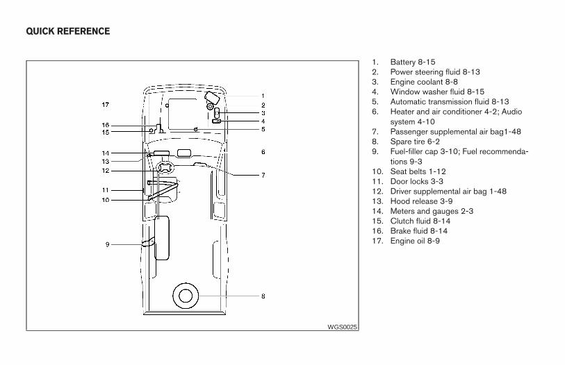
1. Battery 8-152. Power steering fluid 8-133. Engine coolant 8-84. Window washer fluid 8-155. Automatic transmission fluid 8-136. Heater and air conditioner 4-2; Audio
system 4-107. Passenger supplemental air bag1-488. Spare tire 6-29. Fuel-filler cap 3-10; Fuel recommenda-
tions 9-310. Seat belts 1-1211. Door locks 3-312. Driver supplemental air bag 1-4813. Hood release 3-914. Meters and gauges 2-315. Clutch fluid 8-1416. Brake fluid 8-1417. Engine oil 8-9
WGS0025
QUICK REFERENCE
Z REVIEW COPY—2006 Truck/Frontier (d22)Owners Manual—USA_English (nna)10/17/05—debbie X

![[NISSAN] Manual de Taller Nissan D22 Frontier](https://img.pdfslide.net/doc/110x75/577c79661a28abe05492900c/nissan-manual-de-taller-nissan-d22-frontier.jpg)