Embed Size (px)
Citation preview
Presented by
Ameya P. Nijasure
RECOGNITION OF NEED
MODELING
(CAD)
TESING
(PROTOTYPE & CAE)
MANUFACTURING
FEEDBACK
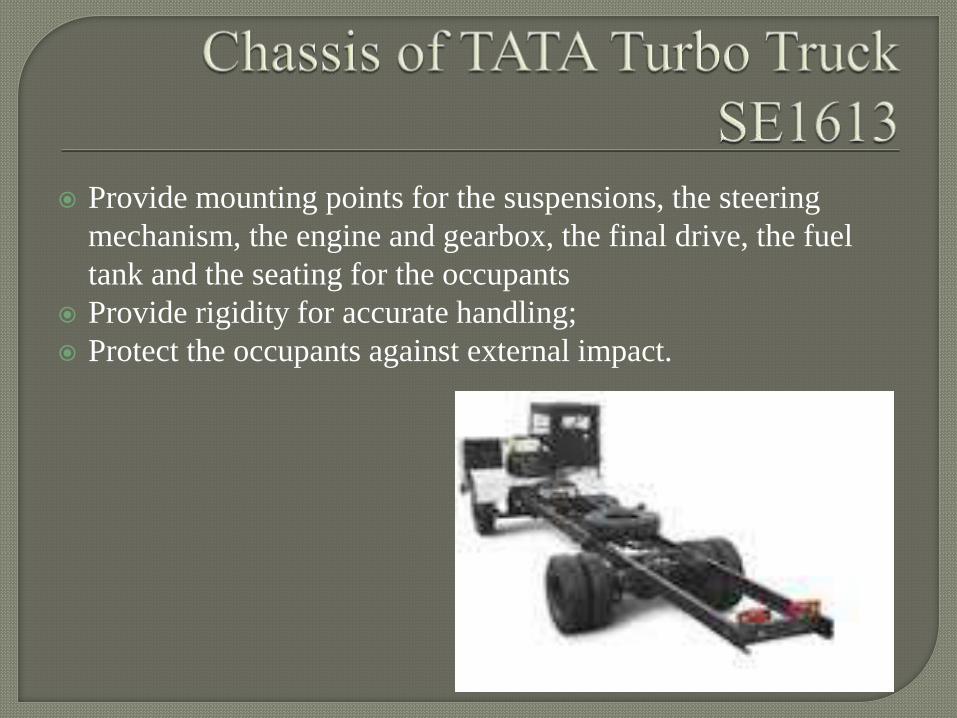
Provide mounting points for the suspensions, the steering
mechanism, the engine and gearbox, the final drive, the fuel
tank and the seating for the occupants
Provide rigidity for accurate handling;
Protect the occupants against external impact.
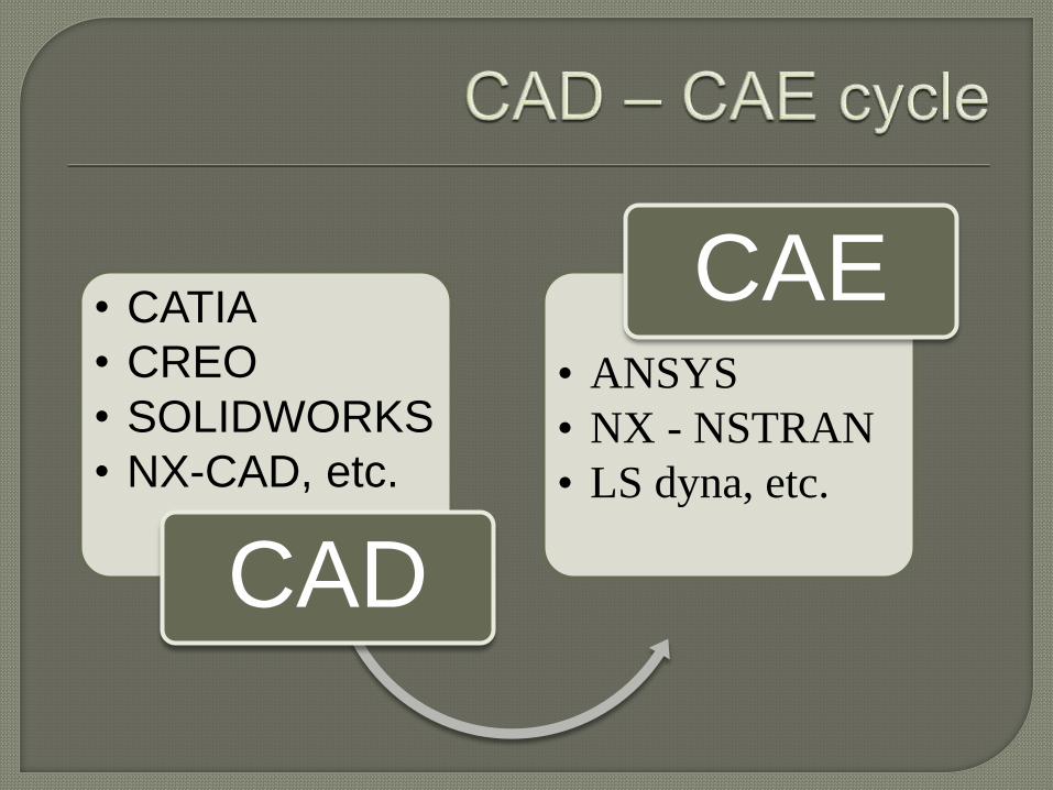
• CATIA
• CREO
• SOLIDWORKS
• NX-CAD, etc.
CAD
• ANSYS
• NX - NSTRAN
• LS dyna, etc.
CAE
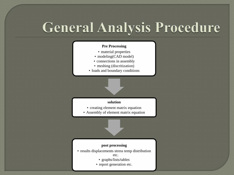
Pre Processing
• material properties
• modeling(CAD model)
• connections in assembly
• meshing (discritization)
• loads and boundary conditions
solution
• creating element matrix equation
• Assembly of element matrix equation
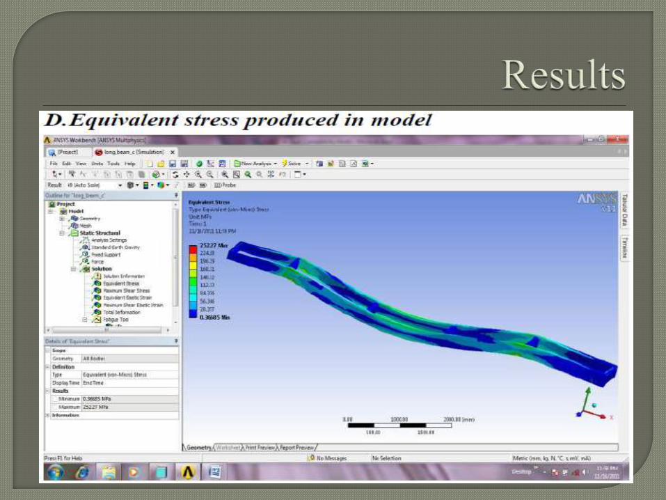
post processing
• results displacements stress temp distribution etc.
• graphs/lists/tables
• report generation etc.
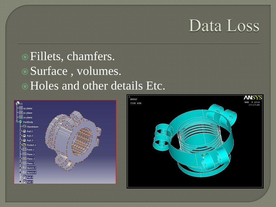
Fillets, chamfers.
Surface , volumes.
Holes and other details Etc.
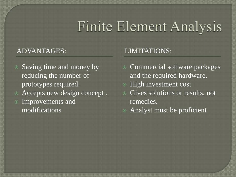
ADVANTAGES: LIMITATIONS:
Saving time and money by
reducing the number of
prototypes required.
Accepts new design concept .
Improvements and
modifications
Commercial software packages
and the required hardware.
High investment cost
Gives solutions or results, not
remedies.
Analyst must be proficient
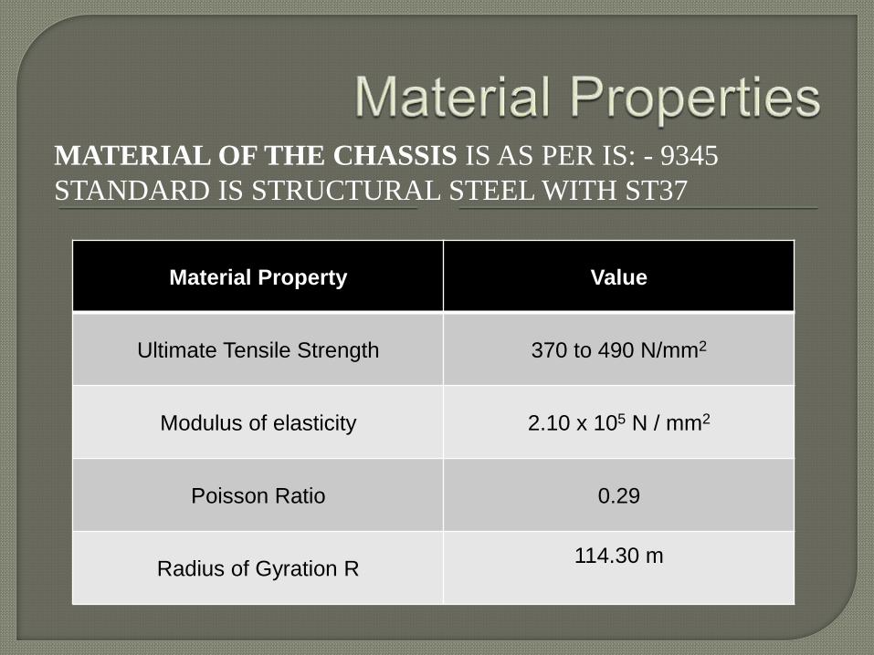
MATERIAL OF THE CHASSIS IS AS PER IS: - 9345
STANDARD IS STRUCTURAL STEEL WITH ST37
Material Property Value
Ultimate Tensile Strength 370 to 490 N/mm2
Modulus of elasticity 2.10 x 10⁵ N / mm2
Poisson Ratio 0.29
Radius of Gyration R 114.30 m
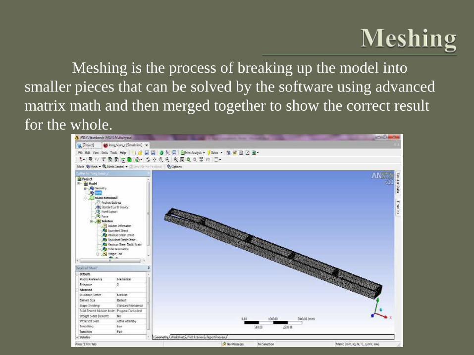
Meshing is the process of breaking up the model into
smaller pieces that can be solved by the software using advanced
matrix math and then merged together to show the correct result
for the whole.
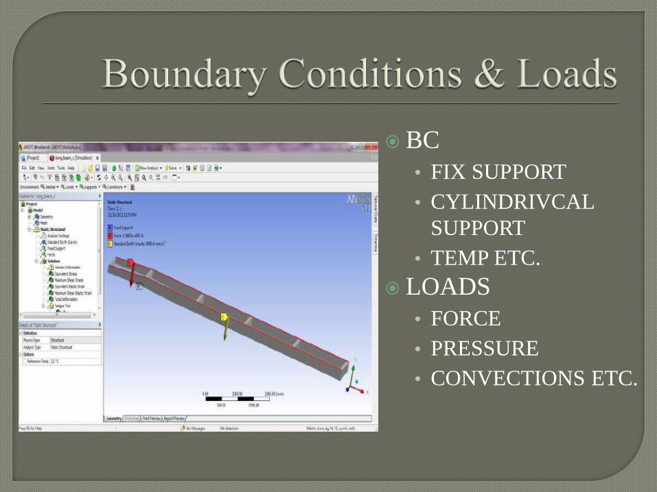
BC
• FIX SUPPORT
• CYLINDRIVCAL
SUPPORT
• TEMP ETC.
LOADS
• FORCE
• PRESSURE
• CONVECTIONS ETC.