Embed Size (px)
DESCRIPTION
JP701 supports all 9 tst modes of the latest J-1979 OBD2 test specs and used for Reads Engine, Transmission, ABS & Airbag Systems for major Japanese vehicles.
Citation preview
www.vtoolshop.com
VTOOLSHOPTel:+86-0755-27823977
1. Safety Precautions and Warnings.....................................1 2. General Information .........................................................2
2.1 On-Board Diagnostics ..............................................2 2.2 Diagnostic Trouble Codes (DTC’s) .........................2 2.3 Location of the Data Link Connector (DLC) ..........3 2.4 OBD II/EOBD Readiness Monitors.........................4 2.5 OBDII/EOBD Monitor Readiness Status................5 2.6 OBD II/EOBD Definitions .......................................6
3. Using the Scan tool ............................................................8 3.1 Tool Description .......................................................8 3.2 Specifications..........................................................10 3.3 Accessories..............................................................10 3.4 Navigation Characters ...........................................10 3.5 Power ......................................................................11 3.6 Obtaining Login Password ....................................11 3.7 Product Setup.........................................................13 3.8 Tool Information ....................................................21 3.9 Battery Replacement..............................................22 3.10 Vehicle Coverage....................................................22 3.11 Product Troubleshooting .......................................22
4. Review Data.....................................................................23 5. Diagnostics.......................................................................29
5.1 OBDII/EOBD Diagnostics .....................................29 5.2 Pre-OBDII Vehicle Diagnostics .............................55
6. Updating and Printing ....................................................67 7. Warranty and Service .....................................................68
7.1 Limited One Year Warranty .................................68 7.2 Service Procedures .................................................68
Web:http://www.vtoolshop.com
Autel Maxiscan JP701 Scanner Use Manual
www.vtoolshop.com
VTOOLSHOPTel:+86-0755-27823977
Web:http://www.vtoolshop.com
1
1. Safety Precautions and Warnings To prevent personal injury or damage to vehicles and/or the scan tool, read this instruction manual first and observe the following safety precautions at a minimum whenever working on a vehicle:
l Always perform automotive testing in a safe environment. l Wear safety eye protection that meets ANSI standards. l Keep clothing, hair, hands, tools, test equipment, etc. away from
all moving or hot engine parts. l Operate the vehicle in a well ventilated work area: Exhaust gases
are poisonous. l Put blocks in front of the drive wheels and never leave the vehicle
unattended while running tests. l Use extreme caution when working around the ignition coil,
distributor cap, ignition wires and spark plugs. These components create hazardous voltages when the engine is running.
l Put the transmission in PARK (for automatic transmission) or NEUTRAL (for manual transmission) and make sure the parking brake is engaged.
l Keep a fire extinguisher suitable for gasoline/chemical/electrical fires nearby.
l Don’t connect or disconnect any test equipment while the ignition is on or the engine is running.
l Keep the scan tool dry, clean, free from oil/water or grease. Use a mild detergent on a clean cloth to clean the outside of the scan tool, when necessary.
www.vtoolshop.com
VTOOLSHOPTel:+86-0755-27823977
Web:http://www.vtoolshop.com
2
2. General Information 2.1 On-Board Diagnostics
The first generation of On-Board Diagnostics (called OBD I) was developed by the California Air Resources Board (CARB) and implemented in 1988 to monitor some of the emission control components on vehicles. As technology evolved and the desire to improve the On-Board Diagnostic system increased, a new generation of On-Board Diagnostic system was developed. This second generation of On-Board Diagnostic regulations is called "OBD II". The European version of OBDII is commonly referred to as EOBD and has protocols developed for the European vehicle market. The OBD II system is designed to monitor emission control systems and key engine components by performing either continuous or periodic tests of specific components and vehicle conditions. When a problem is detected, the OBD II system turns on a warning lamp (MIL) on the vehicle instrument panel to alert the driver typically by the phrase of “Check Engine” or “Service Engine Soon”. The system will also store important information about the detected malfunction so that a technician can accurately find and fix the problem. Here below follow three pieces of such valuable information: 1) Whether the Malfunction Indicator Light (MIL) is
commanded 'on' or 'off'; 2) Which, if any, Diagnostic Trouble Codes (DTC’s) are stored; 3) Readiness Monitor status.
2.2 Diagnostic Trouble Codes (DTC’s) EOBD/OBD II Diagnostic Trouble Codes are codes that are stored by the on-board computer diagnostic system in response to a problem found in the vehicle. These codes identify a particular problem area and are intended to provide you with a guide as to where a fault might be occurring within a vehicle. OBD II/EOBD Diagnostic Trouble Codes consist of a five-digit alphanumeric code. The first character, a letter, identifies which control system sets the code. The other four characters, all numbers, provide additional information on where the
www.vtoolshop.com
VTOOLSHOPTel:+86-0755-27823977
Web:http://www.vtoolshop.com
3
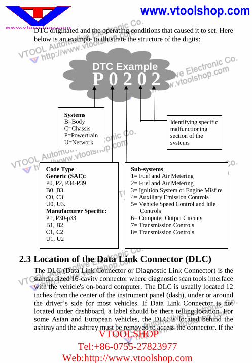
DTC originated and the operating conditions that caused it to set. Here below is an example to illustrate the structure of the digits:
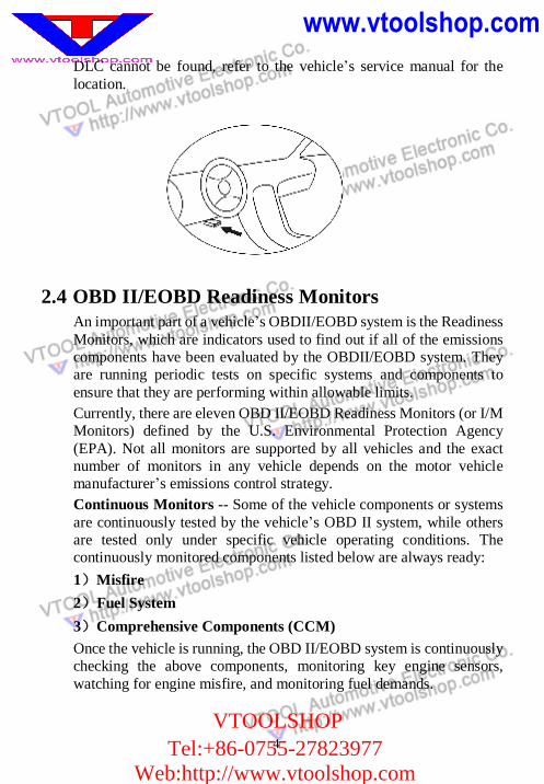
2.3 Location of the Data Link Connector (DLC) The DLC (Data Link Connector or Diagnostic Link Connector) is the standardized 16-cavity connector where diagnostic scan tools interface with the vehicle's on-board computer. The DLC is usually located 12 inches from the center of the instrument panel (dash), under or around the driver’s side for most vehicles. If Data Link Connector is not located under dashboard, a label should be there telling location. For some Asian and European vehicles, the DLC is located behind the ashtray and the ashtray must be removed to access the connector. If the
Identifying specific malfunctioning section of the systems
Systems B=Body C=Chassis P=Powertrain U=Network
Code Type Generic (SAE): P0, P2, P34-P39 B0, B3 C0, C3 U0, U3. Manufacturer Specific: P1, P30-p33 B1, B2 C1, C2 U1, U2
Sub-systems 1= Fuel and Air Metering 2= Fuel and Air Metering 3= Ignition System or Engine Misfire 4= Auxiliary Emission Controls 5= Vehicle Speed Control and Idle
Controls 6= Computer Output Circuits 7= Transmission Controls 8= Transmission Controls
DTC Example P 0 2 0 2
www.vtoolshop.com
VTOOLSHOPTel:+86-0755-27823977
Web:http://www.vtoolshop.com
4
DLC cannot be found, refer to the vehicle’s service manual for the location.
2.4 OBD II/EOBD Readiness Monitors An important part of a vehicle’s OBDII/EOBD system is the Readiness Monitors, which are indicators used to find out if all of the emissions components have been evaluated by the OBDII/EOBD system. They are running periodic tests on specific systems and components to ensure that they are performing within allowable limits. Currently, there are eleven OBD II/EOBD Readiness Monitors (or I/M Monitors) defined by the U.S. Environmental Protection Agency (EPA). Not all monitors are supported by all vehicles and the exact number of monitors in any vehicle depends on the motor vehicle manufacturer’s emissions control strategy. Continuous Monitors -- Some of the vehicle components or systems are continuously tested by the vehicle’s OBD II system, while others are tested only under specific vehicle operating conditions. The continuously monitored components listed below are always ready: 1)Misfire 2)Fuel System 3)Comprehensive Components (CCM) Once the vehicle is running, the OBD II/EOBD system is continuously checking the above components, monitoring key engine sensors, watching for engine misfire, and monitoring fuel demands.
5
Non-Continuous Monitors -- Unlike the continuous monitors, many emissions and engine system components require the vehicle to be operated under specific conditions before the monitor is ready. These monitors are termed non-continuous monitors and are listed below:
1) EGR System 2) O2 Sensors 3) Catalyst 4) Evaporative System 5) O2 Sensor Heater 6) Secondary air 7) Heated Catalyst 8) A/C system
2.5 OBDII/EOBD Monitor Readiness Status OBD II systems must indicate whether or not the vehicle’s PCM’s monitor system has completed testing on each component. Components that have been tested will be reported as “Ready”, or “Complete”, meaning they have been tested by the OBD II system. The purpose of recording readiness status is to allow inspectors to determine if the vehicle’s OBD II system has tested all the components and/or systems. The powertrain control module (PCM) sets a monitor to “Ready” or “Complete” after an appropriate drive cycle has been performed. The drive cycle that enables a monitor and sets readiness codes to “Ready” varies for each individual monitor. Once a monitor is set as “Ready” or “Complete”, it will remain in this state. A number of factors, including erasing of diagnostic trouble codes (DTC’s) with a scan tool or a disconnected battery, can result in Readiness Monitors being set to “Not Ready”. Since the three continuous monitors are constantly evaluating, they will be reported as “Ready” all of the time. If testing of a particular supported non-continuous monitor has not been completed, the monitor status will be reported as “Not Complete” or “Not Ready.” In order for the OBD monitor system to become ready, the vehicle should be driven under a variety of normal operating conditions. These operating conditions may include a mix of highway driving and stop
6
and go, city type driving, and at least one overnight-off period. For specific information on getting your vehicle’s OBD monitor system ready, please consult your vehicle owner’s manual.
2.6 OBD II/EOBD Definitions Powertrain Control Module (PCM) -- EOBD terminology for the on-board computer that controls engine and drives train. Malfunction Indicator Light (MIL) -- Malfunction Indicator Light (Service Engine Soon, Check Engine) is a term used for the light on the instrument panel. It is to alert the driver and/or the repair technician that there is a problem with one or more of vehicle's systems and may cause emissions to exceed federal standards. If the MIL illuminates with a steady light, it indicates that a problem has been detected and the vehicle should be serviced as soon as possible. Under certain conditions, the dashboard light will blink or flash. This indicates a severe problem and flashing is intended to discourage vehicle operation. The vehicle onboard diagnostic system can not turn the MIL off until necessary repairs are completed or the condition no longer exists. DTC -- Diagnostic Trouble Codes (DTC) that identify which section of the emission control system has malfunctioned. Enabling Criteria -- Also termed Enabling Conditions. They are the vehicle-specific events or conditions that must occur within the engine before the various monitors will set, or run. Some monitors require the vehicle to follow a prescribed “drive cycle” routine as part of the enabling criteria. Drive cycles vary among vehicles and for each monitor in any particular vehicle. EOBD Drive Cycle -- A specific mode of vehicle operation that provides conditions required to set all the readiness monitors applicable to the vehicle to the “ready” condition. The purpose of completing an EOBD drive cycle is to force the vehicle to run its onboard diagnostics. Some form of a drive cycle needs to be performed after DTC’s have been erased from the PCM’s memory or after the battery has been disconnected. Running through a vehicle’s complete drive cycle will “set” the readiness monitors so that future faults can be detected. Drive cycles vary depending on the vehicle and the monitor
www.vtoolshop.com
VTOOLSHOPTel:+86-0755-27823977
Web:http://www.vtoolshop.com
7
that needs to be reset. For vehicle specific drive cycle, consult the vehicle’s Owner’s Manual. Freeze Frame Data -- When an emission-related fault occurs, the EOBD system not only sets a code but also records a snapshot of the vehicle operating parameters to help in identifying the problem. This set of values is referred to as Freeze Frame Data and may include important engine parameters such as engine RPM, vehicle speed, air flow, engine load, fuel pressure, fuel trim value, engine coolant temperature, ignition timing advance, or closed loop status.
www.vtoolshop.com
VTOOLSHOPTel:+86-0755-27823977
Web:http://www.vtoolshop.com
8
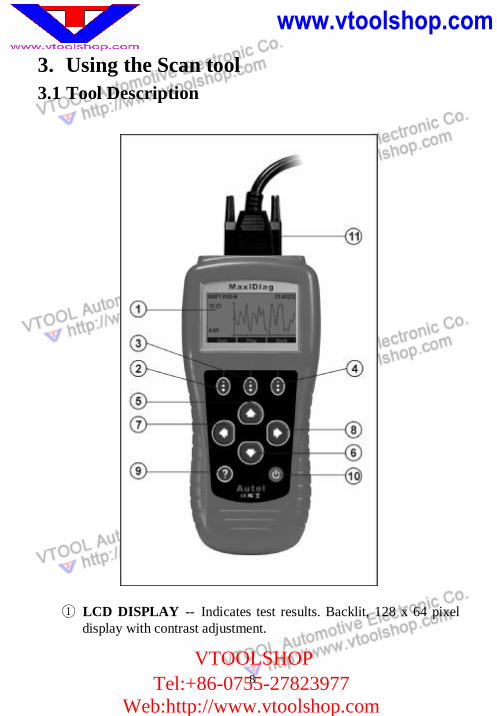
3. Using the Scan tool 3.1 Tool Description
① LCD DISPLAY -- Indicates test results. Backlit, 128 x 64 pixel display with contrast adjustment.
9
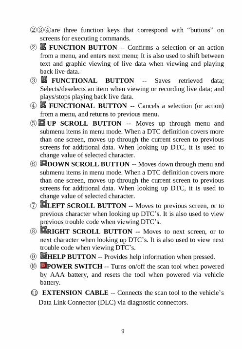
②③④are three function keys that correspond with “buttons” on screens for executing commands.
② FUNCTION BUTTON -- Confirms a selection or an action from a menu, and enters next menu; It is also used to shift between text and graphic viewing of live data when viewing and playing back live data.
③ FUNCTIONAL BUTTON -- Saves retrieved data; Selects/deselects an item when viewing or recording live data; and plays/stops playing back live data.
④ FUNCTIONAL BUTTON -- Cancels a selection (or action) from a menu, and returns to previous menu.
⑤ UP SCROLL BUTTON -- Moves up through menu and submenu items in menu mode. When a DTC definition covers more than one screen, moves up through the current screen to previous screens for additional data. When looking up DTC, it is used to change value of selected character.
⑥ DOWN SCROLL BUTTON -- Moves down through menu and submenu items in menu mode. When a DTC definition covers more than one screen, moves up through the current screen to previous screens for additional data. When looking up DTC, it is used to change value of selected character.
⑦ LEFT SCROLL BUTTON -- Moves to previous screen, or to previous character when looking up DTC’s. It is also used to view previous trouble code when viewing DTC’s.
⑧ RIGHT SCROLL BUTTON -- Moves to next screen, or to next character when looking up DTC’s. It is also used to view next trouble code when viewing DTC’s.
⑨ HELP BUTTON -- Provides help information when pressed. ⑩ POWER SWITCH -- Turns on/off the scan tool when powered
by AAA battery, and resets the tool when powered via vehicle battery.
○11 EXTENSION CABLE -- Connects the scan tool to the vehicle’s Data Link Connector (DLC) via diagnostic connectors.
10
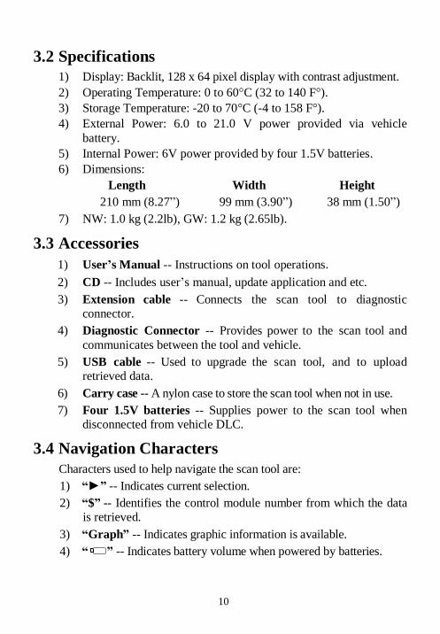
3.2 Specifications 1) Display: Backlit, 128 x 64 pixel display with contrast adjustment. 2) Operating Temperature: 0 to 60°C (32 to 140 F°). 3) Storage Temperature: -20 to 70°C (-4 to 158 F°). 4) External Power: 6.0 to 21.0 V power provided via vehicle
battery. 5) Internal Power: 6V power provided by four 1.5V batteries. 6) Dimensions: Length Width Height
210 mm (8.27”) 99 mm (3.90”) 38 mm (1.50”) 7) NW: 1.0 kg (2.2lb), GW: 1.2 kg (2.65lb).
3.3 Accessories 1) User’s Manual -- Instructions on tool operations. 2) CD -- Includes user’s manual, update application and etc. 3) Extension cable -- Connects the scan tool to diagnostic
connector. 4) Diagnostic Connector -- Provides power to the scan tool and
communicates between the tool and vehicle. 5) USB cable -- Used to upgrade the scan tool, and to upload
retrieved data. 6) Carry case -- A nylon case to store the scan tool when not in use. 7) Four 1.5V batteries -- Supplies power to the scan tool when
disconnected from vehicle DLC.
3.4 Navigation Characters Characters used to help navigate the scan tool are: 1) “►” -- Indicates current selection. 2) “$” -- Identifies the control module number from which the data
is retrieved. 3) “Graph” -- Indicates graphic information is available. 4) “ ” -- Indicates battery volume when powered by batteries.
11
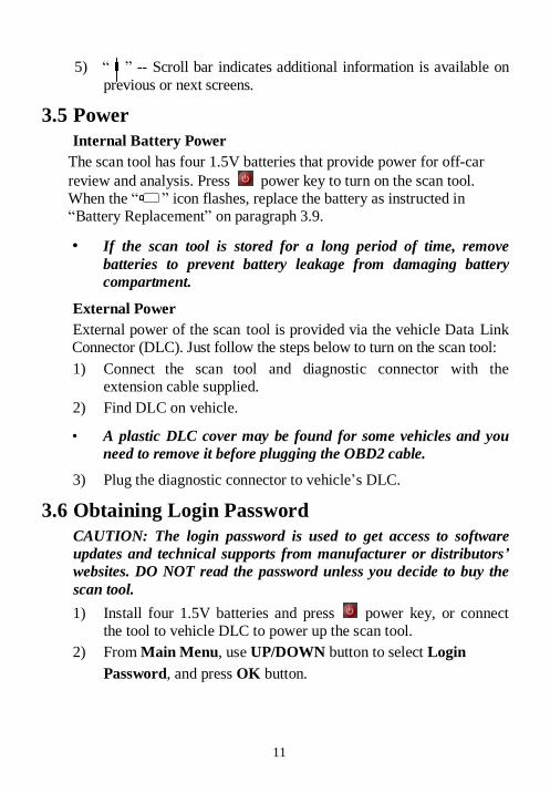
5) “ ” -- Scroll bar indicates additional information is available on previous or next screens.
3.5 Power Internal Battery Power
The scan tool has four 1.5V batteries that provide power for off-car review and analysis. Press power key to turn on the scan tool. When the “ ” icon flashes, replace the battery as instructed in “Battery Replacement” on paragraph 3.9.
• If the scan tool is stored for a long period of time, remove batteries to prevent battery leakage from damaging battery compartment.
External Power External power of the scan tool is provided via the vehicle Data Link Connector (DLC). Just follow the steps below to turn on the scan tool: 1) Connect the scan tool and diagnostic connector with the
extension cable supplied. 2) Find DLC on vehicle.
• A plastic DLC cover may be found for some vehicles and you need to remove it before plugging the OBD2 cable.
3) Plug the diagnostic connector to vehicle’s DLC.
3.6 Obtaining Login Password CAUTION: The login password is used to get access to software updates and technical supports from manufacturer or distributors’ websites. DO NOT read the password unless you decide to buy the scan tool. 1) Install four 1.5V batteries and press power key, or connect
the tool to vehicle DLC to power up the scan tool. 2) From Main Menu, use UP/DOWN button to select Login Password, and press OK button.
www.vtoolshop.com
VTOOLSHOPTel:+86-0755-27823977
Web:http://www.vtoolshop.com
12
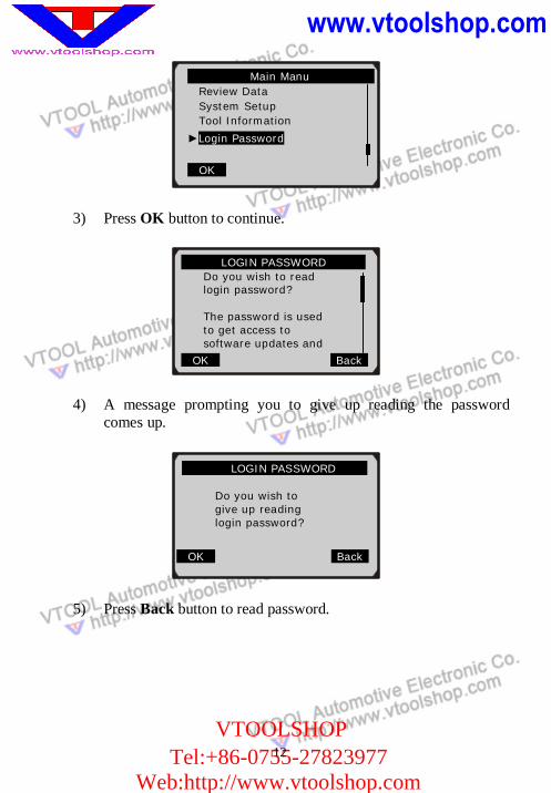
3) Press OK button to continue.
4) A message prompting you to give up reading the password comes up.
5) Press Back button to read password.
………….LOGIN PASSWORD…… ….. Do you wish to read login password?
The password is used to get access to software updates and
OK Back
…………….LOGIN PASSWORD……….
Do you wish to give up reading login password?
OK Back
…………. Main Manu … … ….. Review Data System Setup Tool Information
►Login Password
OK
13
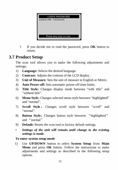
l If you decide not to read the password, press OK button to return.
3.7 Product Setup The scan tool allows you to make the following adjustments and settings: 1) Language: Selects the desired language. 2) Contrast: Adjusts the contrast of the LCD display. 3) Unit of Measure: Sets the unit of measure to English or Metric. 4) Auto Power-off: Sets automatic power-off time limits. 5) Title Style: Changes display mode between “with title” and
“without title”. 6) Menu Style:Changes selected menu style between “highlighted”
and “normal”. 7) Scroll Style: Changes scroll style between “scroll” and
“normal”. 8) Button Style:Changes button style between “highlighted”
and “normal” 9) Default: Resets the scan tool to factory default settings. • Settings of the unit will remain until change to the existing
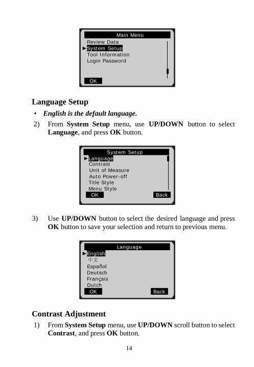
settings is made. To enter system setup mode 1) Use UP/DOWN button to select System Setup from Main
Menu and press OK button. Follow the instructions to make adjustments and settings as described in the following setup options.
………….LOGIN PASSWORD… … ….. LOGIN PW: XXXXXXX
Press any key to con.
14
Language Setup • English is the default language. 2) From System Setup menu, use UP/DOWN button to select
Language, and press OK button.
3) Use UP/DOWN button to select the desired language and press OK button to save your selection and return to previous menu.
Contrast Adjustment 1) From System Setup menu, use UP/DOWN scroll button to select
Contrast, and press OK button.
……… ……… …Language…… ……. …. ►English 中文
Español Deutsch Français
Dutch OK Back
……………… . .Main Menu……… …….. Review Data
►System Setup Tool Information Login Password
OK
………… .System Setup……………. . ►Language Contrast
Unit of Measure Auto Power-off Title Style Menu Style
OK Back
www.vtoolshop.com
VTOOLSHOPTel:+86-0755-27823977
Web:http://www.vtoolshop.com
15
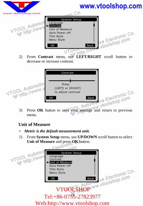
2) From Contrast menu, use LEFT/RIGHT scroll button to decrease or increase contrast.
3) Press OK button to save your settings and return to previous menu.
Unit of Measure • Metric is the default measurement unit. 1) From System Setup menu, use UP/DOWN scroll button to select
Unit of Measure and press OK button.
…………… .System Setup…… ……... Language ►Contrast
Unit of Measure Auto Power-off Title Style Menu Style
OK Back
……… .Contrast……… …
Press [LEFT] or [RIGHT] to adjust contrast
OK Back
…………… ..System Setup…… … ……. Language
Contrast ►Unit of Measure
Auto Power-off Title Style Menu Style
OK Back
16
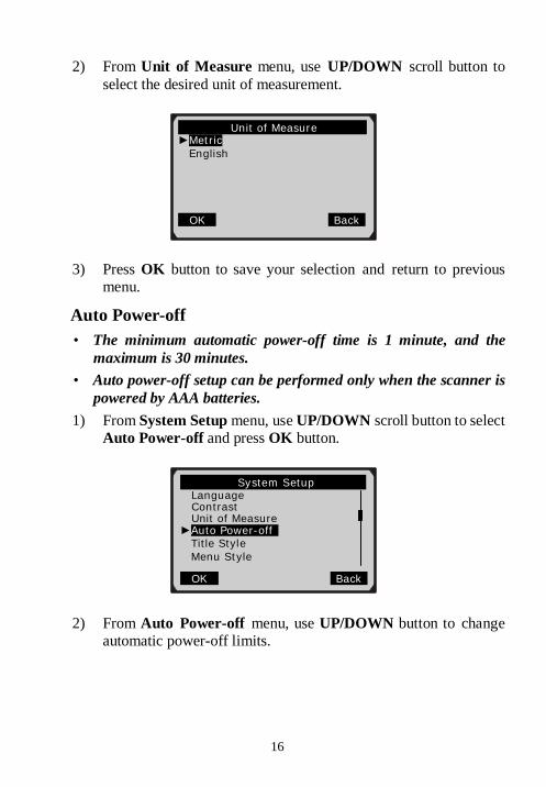
2) From Unit of Measure menu, use UP/DOWN scroll button to select the desired unit of measurement.
3) Press OK button to save your selection and return to previous menu.
Auto Power-off • The minimum automatic power-off time is 1 minute, and the
maximum is 30 minutes. • Auto power-off setup can be performed only when the scanner is
powered by AAA batteries. 1) From System Setup menu, use UP/DOWN scroll button to select
Auto Power-off and press OK button.
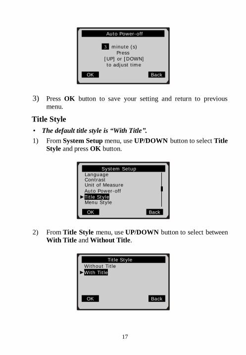
2) From Auto Power-off menu, use UP/DOWN button to change automatic power-off limits.
……………..Unit of Measure ….… ►Metric
English
OK Back
………… ……System Setup……… .. Language Contrast Unit of Measure ►Auto Power-off
Title Style Menu Style
OK Back
17
3) Press OK button to save your setting and return to previous menu.
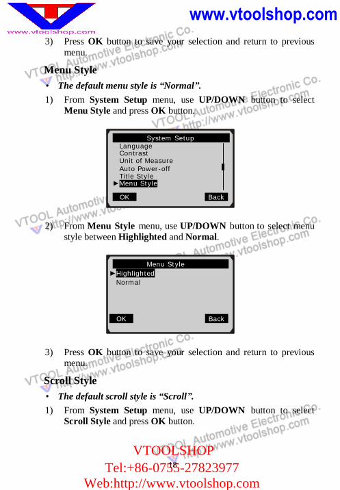
Title Style • The default title style is “With Title”. 1) From System Setup menu, use UP/DOWN button to select Title
Style and press OK button.
2) From Title Style menu, use UP/DOWN button to select between With Title and Without Title.
……… Auto Power-off …
3 minute (s) Press [UP] or [DOWN] to adjust time
OK Back
…………… …Title Style……… …… .. Without Title
►With Title OK Back
…………..System Setup…… …… …. . Language Contrast Unit of Measure Auto Power-off ►Title Style Menu Style
OK Back
www.vtoolshop.com
VTOOLSHOPTel:+86-0755-27823977
Web:http://www.vtoolshop.com
18
3) Press OK button to save your selection and return to previous menu.
Menu Style • The default menu style is “Normal”. 1) From System Setup menu, use UP/DOWN button to select
Menu Style and press OK button.
2) From Menu Style menu, use UP/DOWN button to select menu style between Highlighted and Normal.
3) Press OK button to save your selection and return to previous menu.
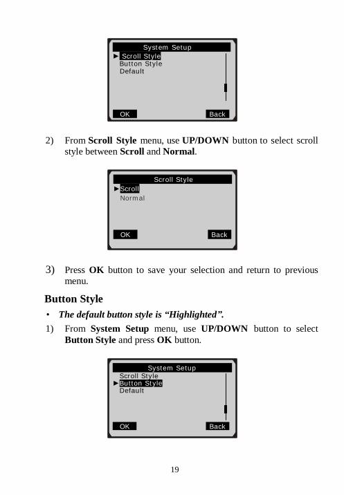
Scroll Style • The default scroll style is “Scroll”. 1) From System Setup menu, use UP/DOWN button to select
Scroll Style and press OK button.
………… . Menu Style………… …… … ►Highlighted
Normal OK Back
……… System Setup …… Language Contrast Unit of Measure Auto Power-off Title Style
►Menu Style
OK Back
19
2) From Scroll Style menu, use UP/DOWN button to select scroll style between Scroll and Normal.
3) Press OK button to save your selection and return to previous menu.
Button Style • The default button style is “Highlighted”. 1) From System Setup menu, use UP/DOWN button to select
Button Style and press OK button.
……………… Scroll Style…… ……….… ►Scroll
Normal OK Back
…………… System Setup………… ……. ► Scroll Style Button Style
Default
OK Back
…………… System Setup……… …….. Scroll Style
►Button Style Default
OK Back
www.vtoolshop.com
VTOOLSHOPTel:+86-0755-27823977
Web:http://www.vtoolshop.com
20
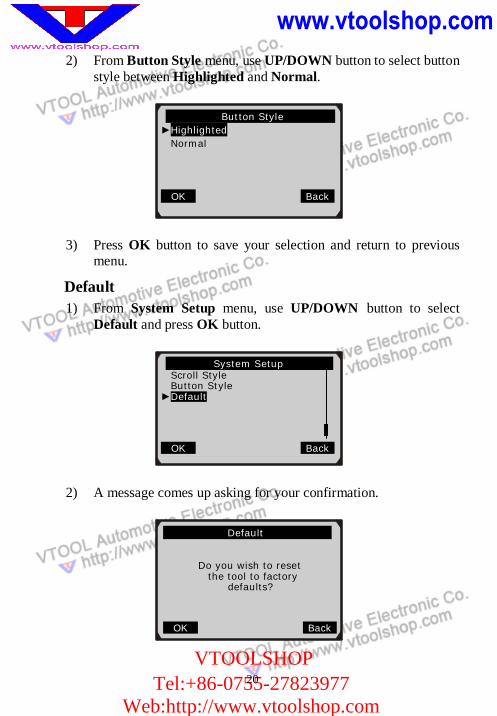
2) From Button Style menu, use UP/DOWN button to select button style between Highlighted and Normal.
3) Press OK button to save your selection and return to previous menu.
Default 1) From System Setup menu, use UP/DOWN button to select
Default and press OK button.
2) A message comes up asking for your confirmation.
……………… .Button Style……… … …. ►Highlighted
Normal OK Back
……………. System Setup……… ….. Scroll Style Button Style
►Default
OK Back
…………… .Default… Do you wish to reset the tool to factory defaults?
OK Back
21
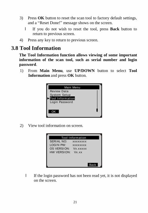
3) Press OK button to reset the scan tool to factory default settings, and a “Reset Done!” message shows on the screen. l If you do not wish to reset the tool, press Back button to
return to previous screen. 4) Press any key to return to previous screen.
3.8 Tool Information The Tool Information function allows viewing of some important information of the scan tool, such as serial number and login password. 1) From Main Menu, use UP/DOWN button to select Tool
Information and press OK button.
2) View tool information on screen.
l If the login password has not been read yet, it is not displayed on the screen.
…… Tool Information … SERIAL NO: xxxxxxxx LOGIN PW: xxxxxxxx OS VERSION: Vx.xxxxx HW VERSION: Vx.xx
Back
…… … …. Main Menu… …………… Review Data System Setup ►Tool Information Login Password
OK
www.vtoolshop.com
VTOOLSHOPTel:+86-0755-27823977
Web:http://www.vtoolshop.com
22
3.9 Battery Replacement The scan tool requires four AAA batteries to operate when disconnected from the vehicle. When the “ ” icon flashes, replace batteries as per instructed below: 1) Locate the battery cover on the back of the scan tool. 2) Remove the battery cover screw and slide the battery cover off. 3) Remove discharged batteries and install 4 new AAA batteries. 4) Reinstall battery cover by sliding battery cover on and installing
screw.
3.10 Vehicle Coverage The MaxiDiag series professional scan tool includes 4 professional scan tools: JP701, EU702, US703 and FR704. They are not only able to work with global OBDII/EOBD compliant vehicles but also able to diagnose non-OBDII compliant vehicles. They are specially designed to read and clear trouble codes, and to retrieve ECU information of engine, automatic transmission, ABS and airbag systems for Japanese, European, American and French vehicles. For most pre-OBDII vehicles, they do not have standard 16-pin OBDII DLC (Data Link Connector). You need to have proper diagnostic connectors to diagnose them.
3.11 Product Troubleshooting Vehicle Linking Error A communication error occurs if the scan tool fails to communicate with the vehicle’s ECU (Electronic Control Unit). You need to do the following to check up: ü Verify that the ignition is ON. ü Check if the scan tool’s diagnostic connector is securely
connected to the vehicle’s DLC. ü Turn the ignition off and wait for about 10 seconds. Turn the
ignition back to on and continue the testing. ü Verify the control module is not defective.
www.vtoolshop.com
VTOOLSHOPTel:+86-0755-27823977
Web:http://www.vtoolshop.com
23
Operating Error If the scan tool freezes, then an exception occurs or the vehicle’s ECU (Electronic Control Unit) is too slow to respond to requests. You need to do the following to reset the tool: ü Press and hold POWER button for at least 2 seconds to reset the
scan tool. ü Turn the ignition off and wait for about 10 seconds. Turn the
ignition back to on and continue the testing.
Scan Tool doesn’t power up If the scan tool won’t power up or operates incorrectly in any other way, you need to do the following to check up: ü Check if the scan tool’s diagnostic connector is securely connected
to the vehicle’s DLC. ü Check if the DLC pins are bent or broken. Clean the DLC pins if
necessary. ü Check vehicle battery to make sure it is still good with at least 8.0
volts.
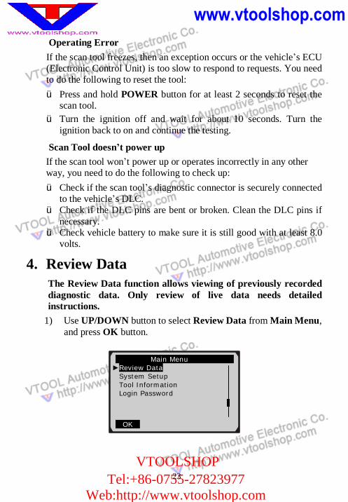
4. Review Data The Review Data function allows viewing of previously recorded diagnostic data. Only review of live data needs detailed instructions.
1) Use UP/DOWN button to select Review Data from Main Menu, and press OK button.
Main Menu ►Review Data
System Setup Tool Information Login Password
OK
www.vtoolshop.com
VTOOLSHOPTel:+86-0755-27823977
Web:http://www.vtoolshop.com
24
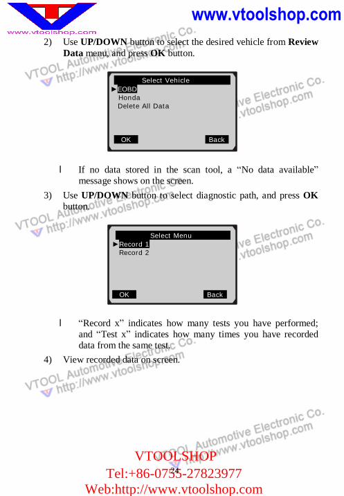
2) Use UP/DOWN button to select the desired vehicle from Review Data menu, and press OK button.
l If no data stored in the scan tool, a “No data available” message shows on the screen.
3) Use UP/DOWN button to select diagnostic path, and press OK button.
l “Record x” indicates how many tests you have performed; and “Test x” indicates how many times you have recorded data from the same test.
4) View recorded data on screen.
Select Vehicle . ►EOBD Honda Delete All Data
OK Back
Select Menu ►Record 1
Record 2
OK Back
25
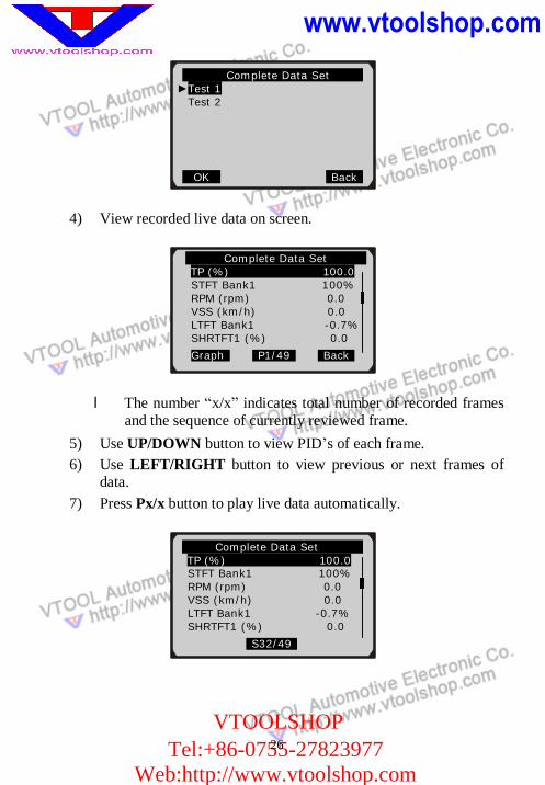
Reviewing Live Data 1) To review live data, use UP/DOWN scroll button to select
diagnostic path till Live Data is located, and press OK button.
2) Use UP/DOWN scroll button to select Complete Data Set or Custom Data Set, when necessary, and press OK button.
3) Use UP/DOWN scroll button to select a test, and press OK button.
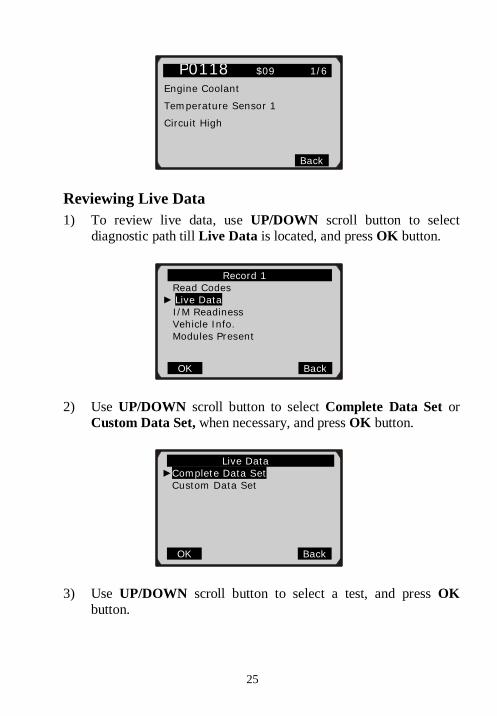
P0118 $09 1/6 Engine Coolant
Temperature Sensor 1
Circuit High
Back
Record 1 Read Codes
► Live Data I/M Readiness
Vehicle Info. Modules Present
OK Back
Live Data ►Complete Data Set Custom Data Set
OK Back
www.vtoolshop.com
VTOOLSHOPTel:+86-0755-27823977
Web:http://www.vtoolshop.com
26
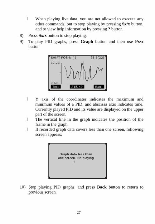
4) View recorded live data on screen.
l The number “x/x” indicates total number of recorded frames and the sequence of currently reviewed frame.
5) Use UP/DOWN button to view PID’s of each frame. 6) Use LEFT/RIGHT button to view previous or next frames of
data. 7) Press Px/x button to play live data automatically.
Complete Data Set ►Test 1
Test 2
OK Back
Complete Data Set TP (%) 100.0 STFT Bank1 100% RPM (rpm) 0.0 VSS (km/h) 0.0 LTFT Bank1 -0.7% SHRTFT1 (%) 0.0
Graph P1/49 Back
Complete Data Set TP (%) 100.0 STFT Bank1 100% RPM (rpm) 0.0 VSS (km/h) 0.0 LTFT Bank1 -0.7% SHRTFT1 (%) 0.0
S32/49
27
l When playing live data, you are not allowed to execute any other commands, but to stop playing by pressing Sx/x button, and to view help information by pressing ? button
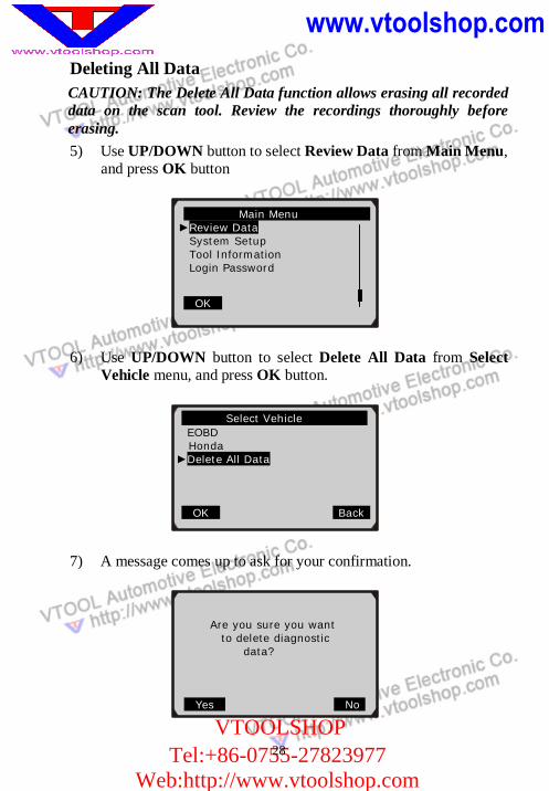
8) Press Sx/x button to stop playing. 9) To play PID graphs, press Graph button and then use Px/x
button
l Y axis of the coordinates indicates the maximum and minimum values of a PID, and abscissa axis indicates time. Currently played PID and its value are displayed on the upper part of the screen.
l The vertical line in the graph indicates the position of the frame in the graph.
l If recorded graph data covers less than one screen, following screen appears:
10) Stop playing PID graphs, and press Back button to return to previous screen.
Graph data less than one screen. No playing !
SHIFT POS-N ( ) 25.7(22)
32.23
0.69 Text S15/49 Back
www.vtoolshop.com
VTOOLSHOPTel:+86-0755-27823977
Web:http://www.vtoolshop.com
28
Deleting All Data CAUTION: The Delete All Data function allows erasing all recorded data on the scan tool. Review the recordings thoroughly before erasing. 5) Use UP/DOWN button to select Review Data from Main Menu,
and press OK button
6) Use UP/DOWN button to select Delete All Data from Select Vehicle menu, and press OK button.
7) A message comes up to ask for your confirmation.
Main Menu ►Review Data
System Setup Tool Information Login Password
OK
Select Vehicle . EOBD
Honda ►Delete All Data
OK Back
Are you sure you want to delete diagnostic
data? Yes No
29
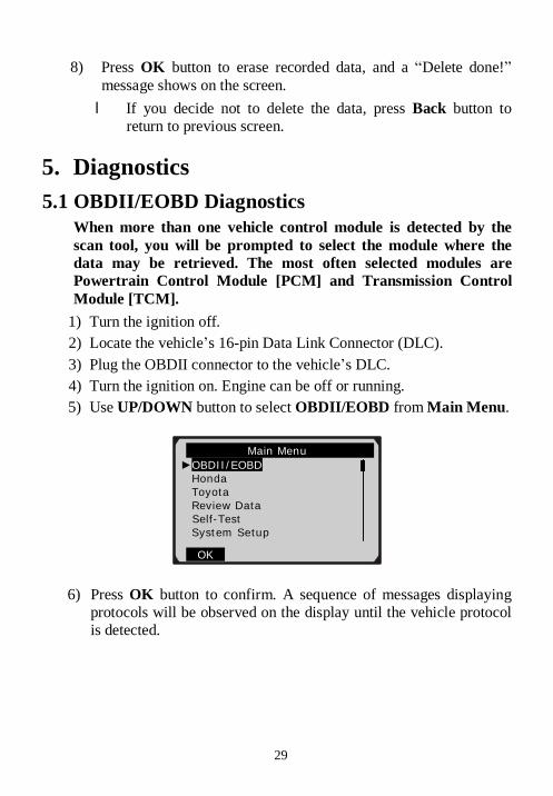
8) Press OK button to erase recorded data, and a “Delete done!” message shows on the screen. l If you decide not to delete the data, press Back button to
return to previous screen.
5. Diagnostics 5.1 OBDII/EOBD Diagnostics
When more than one vehicle control module is detected by the scan tool, you will be prompted to select the module where the data may be retrieved. The most often selected modules are Powertrain Control Module [PCM] and Transmission Control Module [TCM].
1) Turn the ignition off. 2) Locate the vehicle’s 16-pin Data Link Connector (DLC). 3) Plug the OBDII connector to the vehicle’s DLC. 4) Turn the ignition on. Engine can be off or running. 5) Use UP/DOWN button to select OBDII/EOBD from Main Menu.
6) Press OK button to confirm. A sequence of messages displaying protocols will be observed on the display until the vehicle protocol is detected.
Main Menu ►OBDII/EOBD
Honda Toyota Review Data
Self-Test System Setup
OK
www.vtoolshop.com
VTOOLSHOPTel:+86-0755-27823977
Web:http://www.vtoolshop.com
30
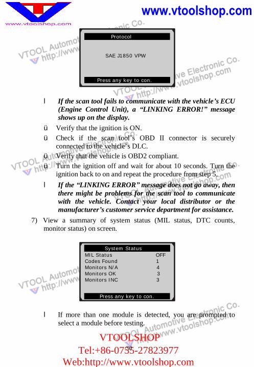
l If the scan tool fails to communicate with the vehicle’s ECU (Engine Control Unit), a “LINKING ERROR!” message shows up on the display.
ü Verify that the ignition is ON. ü Check if the scan tool’s OBD II connector is securely
connected to the vehicle’s DLC. ü Verify that the vehicle is OBD2 compliant. ü Turn the ignition off and wait for about 10 seconds. Turn the
ignition back to on and repeat the procedure from step 5. l If the “LINKING ERROR” message does not go away, then
there might be problems for the scan tool to communicate with the vehicle. Contact your local distributor or the manufacturer’s customer service department for assistance.
7) View a summary of system status (MIL status, DTC counts, monitor status) on screen.
l If more than one module is detected, you are prompted to select a module before testing.
System Status MIL Status OFF Codes Found 1 Monitors N/A 4 Monitors OK 3 Monitors INC 3
Press any key to con.
..Protocol
SAE J1850 VPW
Press any key to con.
www.vtoolshop.com
VTOOLSHOPTel:+86-0755-27823977
Web:http://www.vtoolshop.com
31
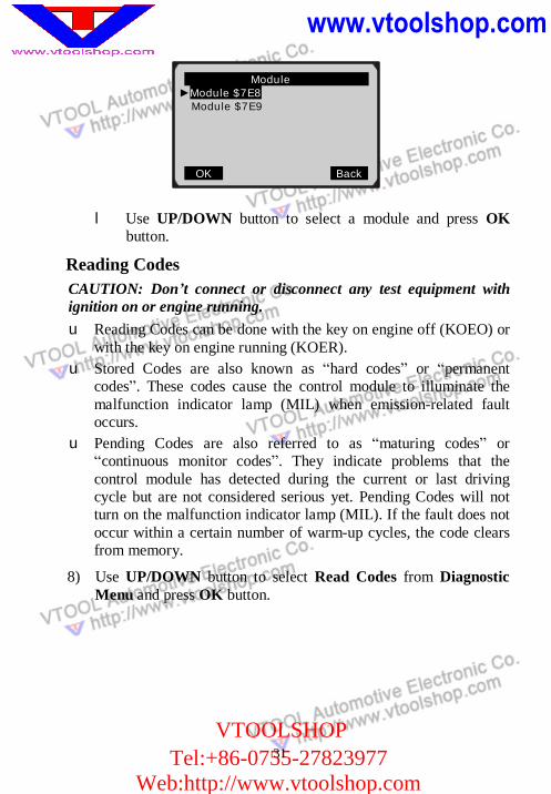
l Use UP/DOWN button to select a module and press OK button.
Reading Codes CAUTION: Don’t connect or disconnect any test equipment with ignition on or engine running. u Reading Codes can be done with the key on engine off (KOEO) or
with the key on engine running (KOER). u Stored Codes are also known as “hard codes” or “permanent
codes”. These codes cause the control module to illuminate the malfunction indicator lamp (MIL) when emission-related fault occurs.
u Pending Codes are also referred to as “maturing codes” or “continuous monitor codes”. They indicate problems that the control module has detected during the current or last driving cycle but are not considered serious yet. Pending Codes will not turn on the malfunction indicator lamp (MIL). If the fault does not occur within a certain number of warm-up cycles, the code clears from memory.
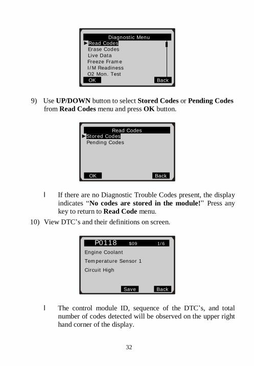
8) Use UP/DOWN button to select Read Codes from Diagnostic Menu and press OK button.
Module ... ►Module $7E8
Module $7E9
OK Back
32
9) Use UP/DOWN button to select Stored Codes or Pending Codes from Read Codes menu and press OK button.
l If there are no Diagnostic Trouble Codes present, the display indicates “No codes are stored in the module!” Press any key to return to Read Code menu.
10) View DTC’s and their definitions on screen.
l The control module ID, sequence of the DTC’s, and total number of codes detected will be observed on the upper right hand corner of the display.
. Diagnostic Menu ... ►Read Codes
Erase Codes Live Data Freeze Frame I/M Readiness O2 Mon. Test
OK Back
Read Codes ►Stored Codes
Pending Codes
OK Back
P0118 $09 1/6 Engine Coolant
Temperature Sensor 1
Circuit High
Save Back
33
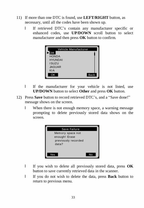
11) If more than one DTC is found, use LEFT/RIGHT button, as necessary, until all the codes have been shown up. l If retrieved DTC’s contain any manufacturer specific or
enhanced codes, use UP/DOWN scroll button to select manufacturer and then press OK button to confirm.
l If the manufacturer for your vehicle is not listed, use UP/DOWN button to select Other and press OK button.
12) Press Save button to record retrieved DTC’s, and a “Save done!” message shows on the screen. l When there is not enough memory space, a warning message
prompting to delete previously stored data shows on the screen.
l If you wish to delete all previously stored data, press OK button to save currently retrieved data in the scanner.
l If you do not wish to delete the data, press Back button to return to previous menu.
. Vehicle Manufacturer ►GM
HONDA HYUNDAI ISUZU JAGUAR KIA
OK Back
Save Failure Memory space not enough! Erase previously recorded data?
Yes No
www.vtoolshop.com
VTOOLSHOPTel:+86-0755-27823977
Web:http://www.vtoolshop.com
34
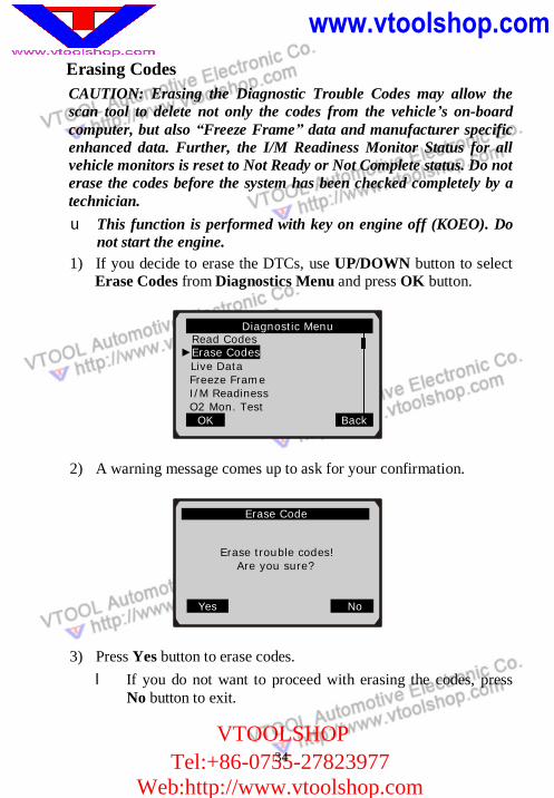
Erasing Codes CAUTION: Erasing the Diagnostic Trouble Codes may allow the scan tool to delete not only the codes from the vehicle’s on-board computer, but also “Freeze Frame” data and manufacturer specific enhanced data. Further, the I/M Readiness Monitor Status for all vehicle monitors is reset to Not Ready or Not Complete status. Do not erase the codes before the system has been checked completely by a technician. u This function is performed with key on engine off (KOEO). Do
not start the engine. 1) If you decide to erase the DTCs, use UP/DOWN button to select
Erase Codes from Diagnostics Menu and press OK button.
2) A warning message comes up to ask for your confirmation.
3) Press Yes button to erase codes. l If you do not want to proceed with erasing the codes, press
No button to exit.
.. Erase Code Erase trouble codes!
Are you sure?
Yes No
Diagnostic Menu Read Codes
►Erase Codes Live Data Freeze Frame I/M Readiness O2 Mon. Test OK Back
35
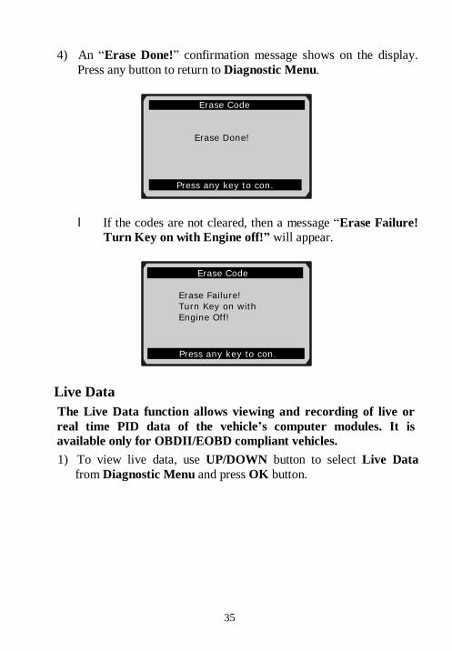
4) An “Erase Done!” confirmation message shows on the display. Press any button to return to Diagnostic Menu.
l If the codes are not cleared, then a message “Erase Failure! Turn Key on with Engine off!” will appear.
Live Data The Live Data function allows viewing and recording of live or real time PID data of the vehicle’s computer modules. It is available only for OBDII/EOBD compliant vehicles. 1) To view live data, use UP/DOWN button to select Live Data
from Diagnostic Menu and press OK button.
Erase Code
Erase Done!
Press any key to con.
Erase Code Erase Failure! Turn Key on with Engine Off!
Press any key to con.
www.vtoolshop.com
VTOOLSHOPTel:+86-0755-27823977
Web:http://www.vtoolshop.com
36
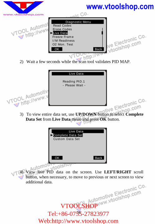
2) Wait a few seconds while the scan tool validates PID MAP.
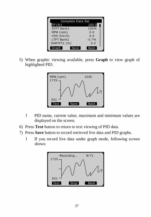
3) To view entire data set, use UP/DOWN button to select Complete Data Set from Live Data menu and press OK button.
4) View live PID data on the screen. Use LEFT/RIGHT scroll button, when necessary, to move to previous or next screen to view additional data.
Live Data
Reading PID.1 - Please Wait -
Live Data ►Complete Data Set Custom Data Set
OK Back
Diagnostic Menu Read Codes
Erase Codes ►Live Data
Freeze Frame I/M Readiness O2 Mon. Test
OK Back
37
5) When graphic viewing available, press Graph to view graph of highlighted PID.
l PID name, current value, maximum and minimum values are displayed on the screen.
6) Press Text button to return to text viewing of PID data. 7) Press Save button to record retrieved live data and PID graphs. l If you record live data under graph mode, following screen
shows:
Complete Data Set TP (%) 100.0 STFT Bank1 100% RPM (rpm) 0.0 VSS (km/h) 0.0 LTFT Bank1 -0.7% SHRTFT1 (%) 0.0
Graph Save Back
RPM (rpm) 1035 1725
931 Text Save Back
Recording… 8/71 1725
931
.Text Stop Back
www.vtoolshop.com
VTOOLSHOPTel:+86-0755-27823977
Web:http://www.vtoolshop.com
38
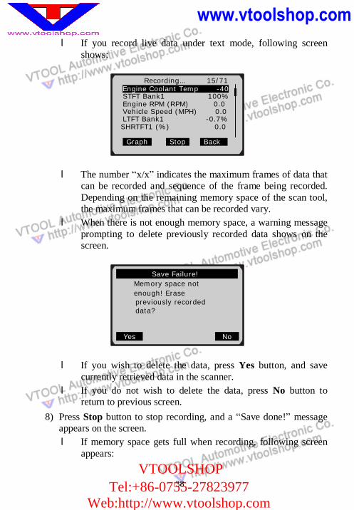
l If you record live data under text mode, following screen shows:
l The number “x/x” indicates the maximum frames of data that can be recorded and sequence of the frame being recorded. Depending on the remaining memory space of the scan tool, the maximum frames that can be recorded vary.
l When there is not enough memory space, a warning message prompting to delete previously recorded data shows on the screen.
l If you wish to delete the data, press Yes button, and save currently retrieved data in the scanner.
l If you do not wish to delete the data, press No button to return to previous screen.
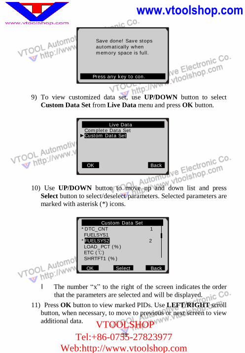
8) Press Stop button to stop recording, and a “Save done!” message appears on the screen. l If memory space gets full when recording, following screen
appears:
Recording… 15/71 Engine Coolant Temp -40 STFT Bank1 100% Engine RPM (RPM) 0.0 Vehicle Speed (MPH) 0.0 LTFT Bank1 -0.7% SHRTFT1 (%) 0.0 Graph Stop Back
Save Failure! Memory space not enough! Erase previously recorded data?
Yes No
www.vtoolshop.com
VTOOLSHOPTel:+86-0755-27823977
Web:http://www.vtoolshop.com
39
9) To view customized data set, use UP/DOWN button to select Custom Data Set from Live Data menu and press OK button.
10) Use UP/DOWN button to move up and down list and press Select button to select/deselect parameters. Selected parameters are marked with asterisk (*) icons.
l The number “x” to the right of the screen indicates the order that the parameters are selected and will be displayed.
11) Press OK button to view marked PIDs. Use LEFT/RIGHT scroll button, when necessary, to move to previous or next screen to view additional data.
Custom Data Set *DTC_CNT 1 FUELSYS1 *FUELSYS2 2 LOAD_PCT (%)
ETC (℃) SHRTFT1 (%)
OK Select Back
Save done! Save stops automatically when memory space is full.
Press any key to con.
Live Data Complete Data Set
►Custom Data Set
OK Back
40
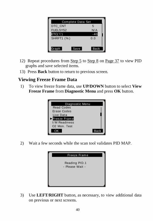
12) Repeat procedures from Step 5 to Step 8 on Page 37 to view PID graphs and save selected items.
13) Press Back button to return to previous screen.
Viewing Freeze Frame Data 1) To view freeze frame data, use UP/DOWN button to select View
Freeze Frame from Diagnostic Menu and press OK button.
2) Wait a few seconds while the scan tool validates PID MAP.
3) Use LEFT/RIGHT button, as necessary, to view additional data on previous or next screens.
Freeze Frame
Reading PID.1 - Please Wait -
Complete Data Set DTC_CNT 5 FUELSYS2 N/A ETC(℃) -40 SHRFT1 (%) 0.0
Graph Save Back
Diagnostic Menu Read Codes
Erase Codes Live Data
►Freeze Frame I/M Readiness O2 Mon. Test
OK Back
www.vtoolshop.com
VTOOLSHOPTel:+86-0755-27823977
Web:http://www.vtoolshop.com 41
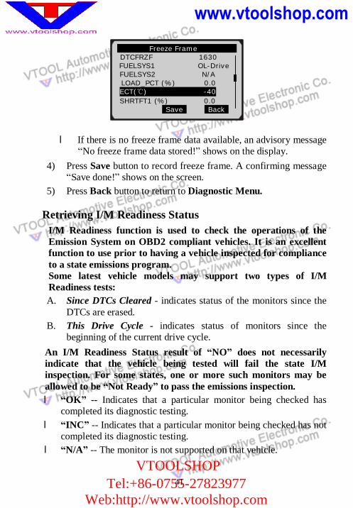
l If there is no freeze frame data available, an advisory message “No freeze frame data stored!” shows on the display.
4) Press Save button to record freeze frame. A confirming message “Save done!” shows on the screen.
5) Press Back button to return to Diagnostic Menu.
Retrieving I/M Readiness Status I/M Readiness function is used to check the operations of the Emission System on OBD2 compliant vehicles. It is an excellent function to use prior to having a vehicle inspected for compliance to a state emissions program. Some latest vehicle models may support two types of I/M Readiness tests: A. Since DTCs Cleared - indicates status of the monitors since the
DTCs are erased. B. This Drive Cycle - indicates status of monitors since the
beginning of the current drive cycle. An I/M Readiness Status result of “NO” does not necessarily indicate that the vehicle being tested will fail the state I/M inspection. For some states, one or more such monitors may be allowed to be “Not Ready” to pass the emissions inspection. l “OK” -- Indicates that a particular monitor being checked has
completed its diagnostic testing. l “INC” -- Indicates that a particular monitor being checked has not
completed its diagnostic testing. l “N/A” -- The monitor is not supported on that vehicle.
Freeze Frame DTCFRZF 1630
FUELSYS1 OL-Drive FUELSYS2 N/A
LOAD_PCT (%) 0.0 ECT(℃) -40 SHRTFT1 (%) 0.0
Save Back
www.vtoolshop.com
VTOOLSHOPTel:+86-0755-27823977
Web:http://www.vtoolshop.com
42
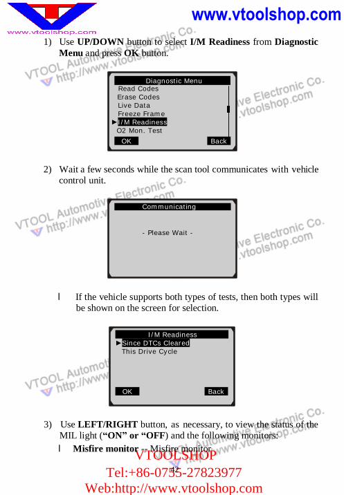
1) Use UP/DOWN button to select I/M Readiness from Diagnostic Menu and press OK button.
2) Wait a few seconds while the scan tool communicates with vehicle control unit.
l If the vehicle supports both types of tests, then both types will be shown on the screen for selection.
3) Use LEFT/RIGHT button, as necessary, to view the status of the MIL light (“ON” or “OFF) and the following monitors: l Misfire monitor -- Misfire monitor
.. I/M Readiness ►Since DTCs Cleared
This Drive Cycle
OK Back
Communicating
- Please Wait -
Diagnostic Menu Read Codes
Erase Codes Live Data Freeze Frame
►I/M Readiness O2 Mon. Test
OK Back
43
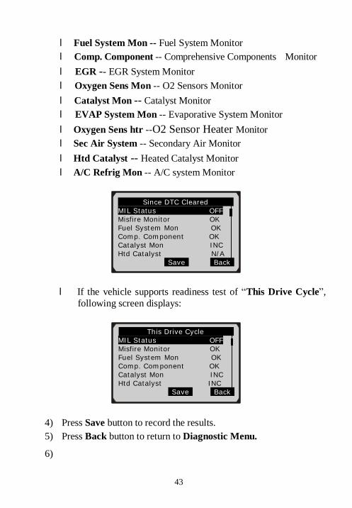
l Fuel System Mon -- Fuel System Monitor l Comp. Component -- Comprehensive Components Monitor l EGR -- EGR System Monitor l Oxygen Sens Mon -- O2 Sensors Monitor l Catalyst Mon -- Catalyst Monitor l EVAP System Mon -- Evaporative System Monitor l Oxygen Sens htr --O2 Sensor Heater Monitor l Sec Air System -- Secondary Air Monitor l Htd Catalyst -- Heated Catalyst Monitor l A/C Refrig Mon -- A/C system Monitor
l If the vehicle supports readiness test of “This Drive Cycle”, following screen displays:
4) Press Save button to record the results. 5) Press Back button to return to Diagnostic Menu.
6)
Since DTC Cleared MIL Status OFF Misfire Monitor OK Fuel System Mon OK Comp. Component OK Catalyst Mon INC Htd Catalyst N/A
Save Back
This Drive Cycle …. MIL Status OFF Misfire Monitor OK Fuel System Mon OK Comp. Component OK Catalyst Mon INC Htd Catalyst INC
Save Back
44
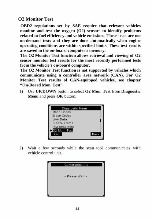
O2 Monitor Test OBD2 regulations set by SAE require that relevant vehicles monitor and test the oxygen (O2) sensors to identify problems related to fuel efficiency and vehicle emissions. These tests are not on-demand tests and they are done automatically when engine operating conditions are within specified limits. These test results are saved in the on-board computer's memory. The O2 Monitor Test function allows retrieval and viewing of O2 sensor monitor test results for the most recently performed tests from the vehicle's on-board computer. The O2 Monitor Test function is not supported by vehicles which communicate using a controller area network (CAN). For O2 Monitor Test results of CAN-equipped vehicles, see chapter “On-Board Mon. Test”. 1) Use UP/DOWN button to select O2 Mon. Test from Diagnostic
Menu and press OK button.
2) Wait a few seconds while the scan tool communicates with vehicle control unit.
Diagnostic Menu Read Codes
Erase Codes Live Data Freeze Frame I/M Readiness
►O2 Mon. Test OK Back
Communicating
- Please Wait -
45
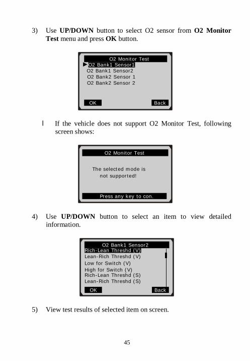
3) Use UP/DOWN button to select O2 sensor from O2 Monitor Test menu and press OK button.
l If the vehicle does not support O2 Monitor Test, following screen shows:
4) Use UP/DOWN button to select an item to view detailed information.
5) View test results of selected item on screen.
O2 Monitor Test ►O2 Bank1 Sensor1
O2 Bank1 Sensor2 O2 Bank2 Sensor 1 O2 Bank2 Sensor 2
OK Back
O2 Bank1 Sensor2 Rich-Lean Threshd (V) Lean-Rich Threshd (V) Low for Switch (V) High for Switch (V)
Rich-Lean Threshd (S) Lean-Rich Threshd (S)
OK Back
…………….O2 Monitor Test……
The selected mode is
not supported!
Press any key to con.
www.vtoolshop.com
VTOOLSHOPTel:+86-0755-27823977
Web:http://www.vtoolshop.com
46
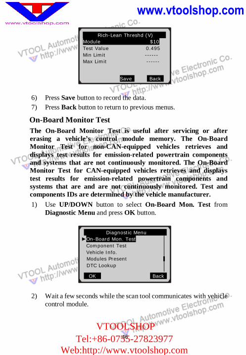
6) Press Save button to record the data. 7) Press Back button to return to previous menus.
On-Board Monitor Test The On-Board Monitor Test is useful after servicing or after erasing a vehicle’s control module memory. The On-Board Monitor Test for non-CAN-equipped vehicles retrieves and displays test results for emission-related powertrain components and systems that are not continuously monitored. The On-Board Monitor Test for CAN-equipped vehicles retrieves and displays test results for emission-related powertrain components and systems that are and are not continuously monitored. Test and components IDs are determined by the vehicle manufacturer. 1) Use UP/DOWN button to select On-Board Mon. Test from
Diagnostic Menu and press OK button.
2) Wait a few seconds while the scan tool communicates with vehicle control module.
Diagnostic Menu ►On-Board Mon. Test
Component Test Vehicle Info. Modules Present DTC Lookup
OK Back
Rich-Lean Threshd (V) Module $10 Test Value 0.495 Min Limit ------ Max Limit ------
Save Back
www.vtoolshop.com
VTOOLSHOPTel:+86-0755-27823977
Web:http://www.vtoolshop.com
47
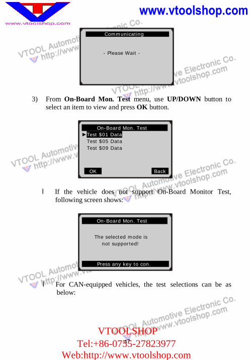
3) From On-Board Mon. Test menu, use UP/DOWN button to select an item to view and press OK button.
l If the vehicle does not support On-Board Monitor Test, following screen shows:
l For CAN-equipped vehicles, the test selections can be as below:
On-Board Mon. Test ►Test $01 Data Test $05 Data Test $09 Data
OK Back
.. Communicating
- Please Wait -
…… .On-Board Mon. Test…………..
The selected mode is
not supported!
Press any key to con.
www.vtoolshop.com
VTOOLSHOPTel:+86-0755-27823977
Web:http://www.vtoolshop.com
48
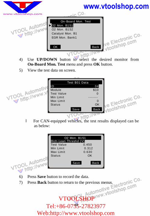
4) Use UP/DOWN button to select the desired monitor from On-Board Mon. Test menu and press OK button.
5) View the test data on screen.
l For CAN-equipped vehicles, the test results displayed can be as below:
6) Press Save button to record the data. 7) Press Back button to return to the previous menus.
On-Board Mon. Test ►O2 Mon. B1S1 O2 Mon. B1S2 Catalyst Mon. B1 EGR Mon. Bank1
OK Back
Test $01 Data ID 04 Module $10 Test Value 0
Min Limit ------- Max Limit 0 Status OK
Save Back
O2 Mon. B1S1 Rich-Lean Threshd (V)
Test Value 0.450 Min Limit 0.312 Max Limit 0.630 Status OK
Save Back
49
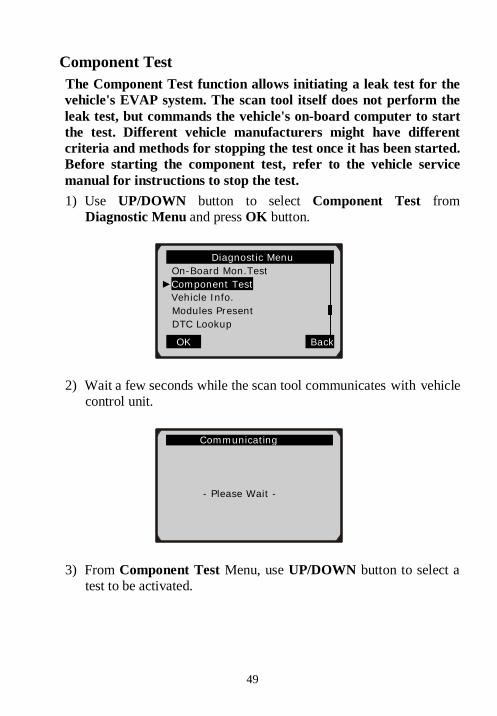
Component Test The Component Test function allows initiating a leak test for the vehicle's EVAP system. The scan tool itself does not perform the leak test, but commands the vehicle's on-board computer to start the test. Different vehicle manufacturers might have different criteria and methods for stopping the test once it has been started. Before starting the component test, refer to the vehicle service manual for instructions to stop the test. 1) Use UP/DOWN button to select Component Test from
Diagnostic Menu and press OK button.
2) Wait a few seconds while the scan tool communicates with vehicle control unit.
3) From Component Test Menu, use UP/DOWN button to select a test to be activated.
Diagnostic Menu On-Board Mon.Test ►Component Test
Vehicle Info. Modules Present DTC Lookup
OK Back
. Communicating
- Please Wait -
www.vtoolshop.com
VTOOLSHOPTel:+86-0755-27823977
Web:http://www.vtoolshop.com
50
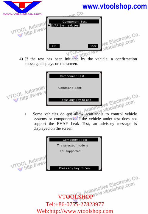
4) If the test has been initiated by the vehicle, a confirmation message displays on the screen.
l Some vehicles do not allow scan tools to control vehicle systems or components. If the vehicle under test does not support the EVAP Leak Test, an advisory message is displayed on the screen.
Component Test ►EVAP Sys. leak test
OK Back.
Component Test
Command Sent!
Press any key to con.
Component Test
The selected mode is
not supported!
Press any key to con.
51
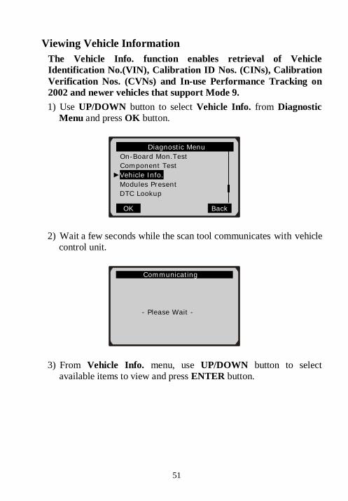
Viewing Vehicle Information The Vehicle Info. function enables retrieval of Vehicle Identification No.(VIN), Calibration ID Nos. (CINs), Calibration Verification Nos. (CVNs) and In-use Performance Tracking on 2002 and newer vehicles that support Mode 9. 1) Use UP/DOWN button to select Vehicle Info. from Diagnostic
Menu and press OK button.
2) Wait a few seconds while the scan tool communicates with vehicle control unit.
3) From Vehicle Info. menu, use UP/DOWN button to select available items to view and press ENTER button.
Diagnostic Menu On-Board Mon.Test Component Test ►Vehicle Info.
Modules Present DTC Lookup
OK Back
. Communicating
- Please Wait -
www.vtoolshop.com
VTOOLSHOPTel:+86-0755-27823977
Web:http://www.vtoolshop.com 52
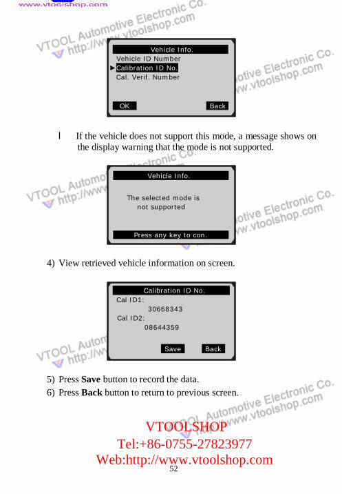
l If the vehicle does not support this mode, a message shows on the display warning that the mode is not supported.
4) View retrieved vehicle information on screen.
5) Press Save button to record the data. 6) Press Back button to return to previous screen.
Vehicle Info. Vehicle ID Number ►Calibration ID No.
Cal. Verif. Number
OK Back.
Calibration ID No. Cal ID1: 30668343 Cal ID2: 08644359
Save Back
Vehicle Info.
The selected mode is
not supported
Press any key to con.
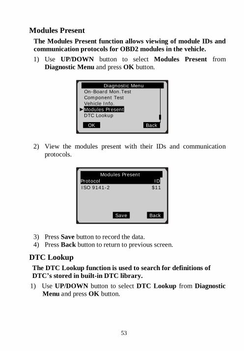
53
Modules Present The Modules Present function allows viewing of module IDs and communication protocols for OBD2 modules in the vehicle. 1) Use UP/DOWN button to select Modules Present from
Diagnostic Menu and press OK button.
2) View the modules present with their IDs and communication protocols.
3) Press Save button to record the data. 4) Press Back button to return to previous screen.
DTC Lookup The DTC Lookup function is used to search for definitions of DTC’s stored in built-in DTC library.
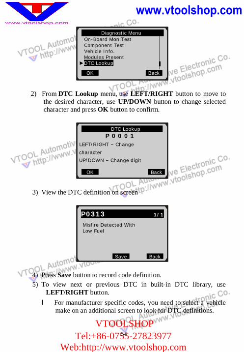
1) Use UP/DOWN button to select DTC Lookup from Diagnostic Menu and press OK button.
Modules Present Protocol ID ISO 9141-2 $11
Save Back
Diagnostic Menu On-Board Mon.Test Component Test Vehicle Info. ►Modules Present
DTC Lookup
OK Back
www.vtoolshop.com
VTOOLSHOPTel:+86-0755-27823977
Web:http://www.vtoolshop.com
54
2) From DTC Lookup menu, use LEFT/RIGHT button to move to the desired character, use UP/DOWN button to change selected character and press OK button to confirm.
3) View the DTC definition on screen
4) Press Save button to record code definition. 5) To view next or previous DTC in built-in DTC library, use
LEFT/RIGHT button. l For manufacturer specific codes, you need to select a vehicle
make on an additional screen to look for DTC definitions.
DTC Lookup P 0 0 0 1
LEFT/RIGHT – Change
character
UP/DOWN – Change digit
OK Back
Diagnostic Menu On-Board Mon.Test Component Test Vehicle Info.
Modules Present ►DTC Lookup
OK Back
P0313 1/1 Misfire Detected With Low Fuel
Save Back
55
l If definition could not be found (SAE or Manufacturer Specific), the scan tool displays “Please refer to vehicle service manual!”
6) To enter another DTC, press Back button to return to previous screen.
7) To exit to Diagnostic Menu, press Back button.
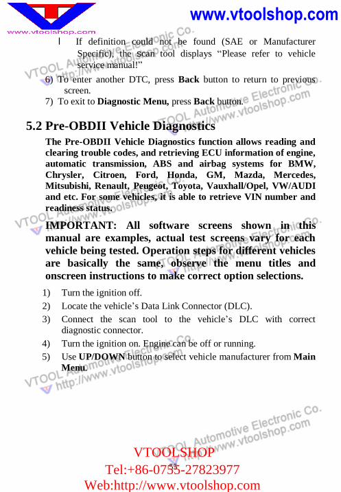
5.2 Pre-OBDII Vehicle Diagnostics The Pre-OBDII Vehicle Diagnostics function allows reading and clearing trouble codes, and retrieving ECU information of engine, automatic transmission, ABS and airbag systems for BMW, Chrysler, Citroen, Ford, Honda, GM, Mazda, Mercedes, Mitsubishi, Renault, Peugeot, Toyota, Vauxhall/Opel, VW/AUDI and etc. For some vehicles, it is able to retrieve VIN number and readiness status.
IMPORTANT: All software screens shown in this manual are examples, actual test screens vary for each vehicle being tested. Operation steps for different vehicles are basically the same, observe the menu titles and onscreen instructions to make correct option selections.
1) Turn the ignition off. 2) Locate the vehicle’s Data Link Connector (DLC). 3) Connect the scan tool to the vehicle’s DLC with correct
diagnostic connector. 4) Turn the ignition on. Engine can be off or running. 5) Use UP/DOWN button to select vehicle manufacturer from Main
Menu.
www.vtoolshop.com
VTOOLSHOPTel:+86-0755-27823977
Web:http://www.vtoolshop.com
56
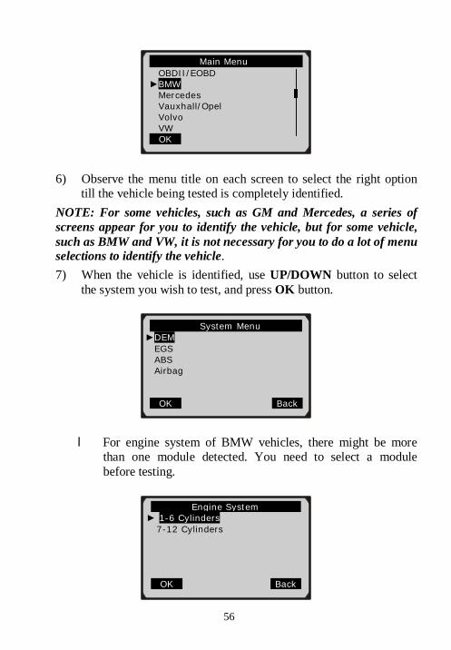
6) Observe the menu title on each screen to select the right option till the vehicle being tested is completely identified.
NOTE: For some vehicles, such as GM and Mercedes, a series of screens appear for you to identify the vehicle, but for some vehicle, such as BMW and VW, it is not necessary for you to do a lot of menu selections to identify the vehicle. 7) When the vehicle is identified, use UP/DOWN button to select
the system you wish to test, and press OK button.
l For engine system of BMW vehicles, there might be more than one module detected. You need to select a module before testing.
Main Menu OBDII/EOBD
►BMW Mercedes Vauxhall/Opel Volvo VW
OK
System Menu ►DEM
EGS ABS Airbag
OK Back
Engine System ... ► 1-6 Cylinders
7-12 Cylinders
OK Back
57
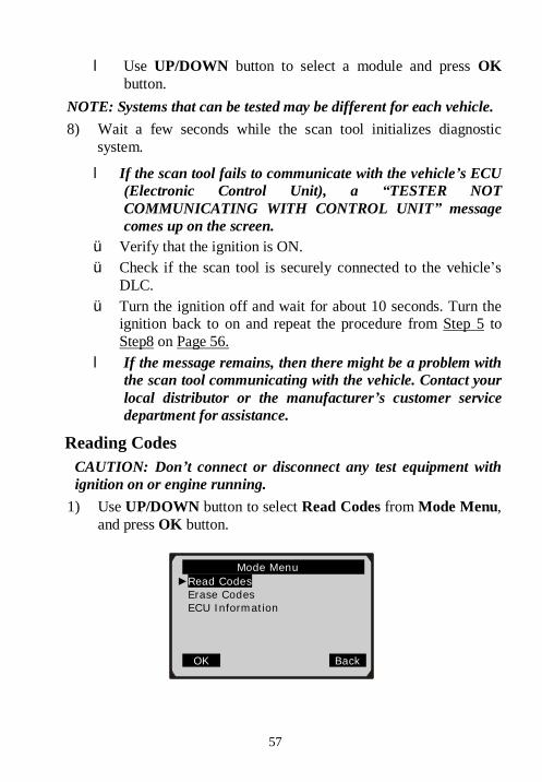
l Use UP/DOWN button to select a module and press OK button.
NOTE: Systems that can be tested may be different for each vehicle. 8) Wait a few seconds while the scan tool initializes diagnostic
system.
l If the scan tool fails to communicate with the vehicle’s ECU (Electronic Control Unit), a “TESTER NOT COMMUNICATING WITH CONTROL UNIT” message comes up on the screen.
ü Verify that the ignition is ON. ü Check if the scan tool is securely connected to the vehicle’s
DLC. ü Turn the ignition off and wait for about 10 seconds. Turn the
ignition back to on and repeat the procedure from Step 5 to Step8 on Page 56.
l If the message remains, then there might be a problem with the scan tool communicating with the vehicle. Contact your local distributor or the manufacturer’s customer service department for assistance.
Reading Codes CAUTION: Don’t connect or disconnect any test equipment with ignition on or engine running.
1) Use UP/DOWN button to select Read Codes from Mode Menu, and press OK button.
Mode Menu ►Read Codes
Erase Codes ECU Information
OK Back
58
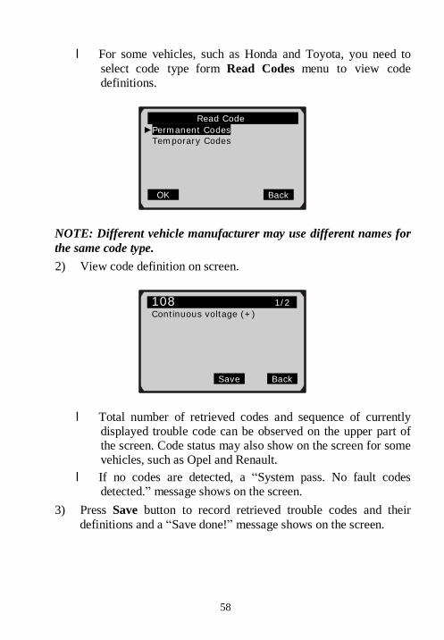
l For some vehicles, such as Honda and Toyota, you need to select code type form Read Codes menu to view code definitions.
NOTE: Different vehicle manufacturer may use different names for the same code type. 2) View code definition on screen.
l Total number of retrieved codes and sequence of currently displayed trouble code can be observed on the upper part of the screen. Code status may also show on the screen for some vehicles, such as Opel and Renault.
l If no codes are detected, a “System pass. No fault codes detected.” message shows on the screen.
3) Press Save button to record retrieved trouble codes and their definitions and a “Save done!” message shows on the screen.
Read Code ►Permanent Codes
Temporary Codes
OK Back
108 1/2 Continuous voltage (+)
Save Back
www.vtoolshop.com
VTOOLSHOPTel:+86-0755-27823977
Web:http://www.vtoolshop.com
59
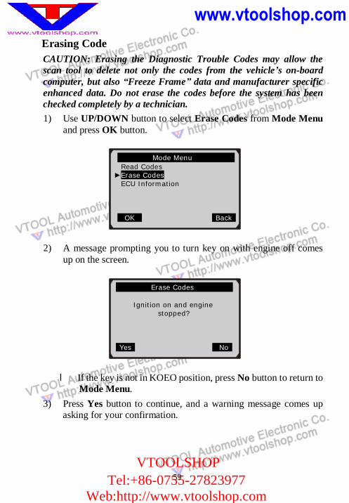
Erasing Code CAUTION: Erasing the Diagnostic Trouble Codes may allow the scan tool to delete not only the codes from the vehicle’s on-board computer, but also “Freeze Frame” data and manufacturer specific enhanced data. Do not erase the codes before the system has been checked completely by a technician. 1) Use UP/DOWN button to select Erase Codes from Mode Menu
and press OK button.
2) A message prompting you to turn key on with engine off comes up on the screen.
l If the key is not in KOEO position, press No button to return to Mode Menu.
3) Press Yes button to continue, and a warning message comes up asking for your confirmation.
Mode Menu Read Codes
►Erase Codes ECU Information
OK Back
Erase Codes
Ignition on and engine stopped?
Yes No
60
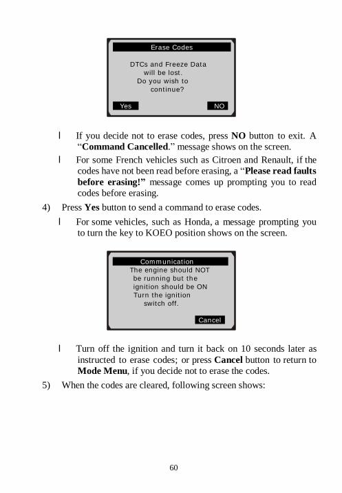
l If you decide not to erase codes, press NO button to exit. A “Command Cancelled.” message shows on the screen.
l For some French vehicles such as Citroen and Renault, if the codes have not been read before erasing, a “Please read faults before erasing!” message comes up prompting you to read codes before erasing.
4) Press Yes button to send a command to erase codes. l For some vehicles, such as Honda, a message prompting you
to turn the key to KOEO position shows on the screen.
l Turn off the ignition and turn it back on 10 seconds later as instructed to erase codes; or press Cancel button to return to Mode Menu, if you decide not to erase the codes.
5) When the codes are cleared, following screen shows:
Erase Codes
DTCs and Freeze Data will be lost.
Do you wish to continue?
Yes NO
Communication The engine should NOT be running but the ignition should be ON
Turn the ignition switch off.
Cancel
www.vtoolshop.com
VTOOLSHOPTel:+86-0755-27823977
Web:http://www.vtoolshop.com
61
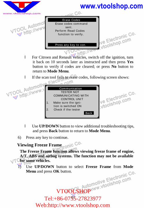
l For Citroen and Renault vehicles, switch off the ignition, turn it back on 10 seconds later as instructed and then press Yes button to verify if codes are cleared; or press No button to return to Mode Menu.
l If the scan tool fails to erase codes, following screen shows:
l Use UP/DOWN button to view additional troubleshooting tips, and press Back button to return to Mode Menu.
6) Press any key to continue.
Viewing Freeze Frame The Freeze Frame function allows viewing freeze frame of engine, A/T, ABS and airbag systems. The function may not be available for some vehicles.
1) Use UP/DOWN button to select Freeze Frame from Mode Menu and press OK button.
Communication TESTER NOT
COMMUNICATING WITH CONTROL UNIT 1. Make sure the igni-
tion is switched ON 2. Check if the tester Back
Erase Codes Erase codes command
sent. Perform Read Codes
function to verify.
Press any key to con.
62
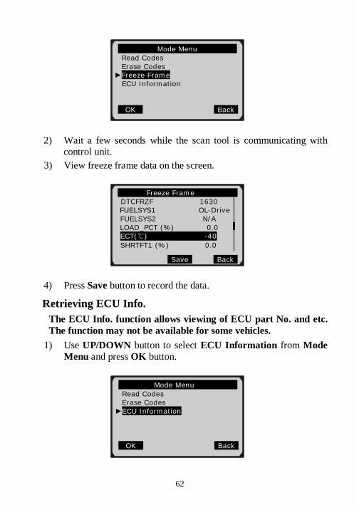
2) Wait a few seconds while the scan tool is communicating with control unit.
3) View freeze frame data on the screen.
4) Press Save button to record the data. Retrieving ECU Info.
The ECU Info. function allows viewing of ECU part No. and etc. The function may not be available for some vehicles.
1) Use UP/DOWN button to select ECU Information from Mode Menu and press OK button.
Mode Menu Read Codes Erase Codes
►Freeze Frame ECU Information
OK Back
Freeze Frame DTCFRZF 1630
FUELSYS1 OL-Drive FUELSYS2 N/A
LOAD_PCT (%) 0.0 ECT(℃) -40 SHRTFT1 (%) 0.0
Save Back
Mode Menu Read Codes Erase Codes
►ECU Information
OK Back
www.vtoolshop.com
VTOOLSHOPTel:+86-0755-27823977
Web:http://www.vtoolshop.com
63
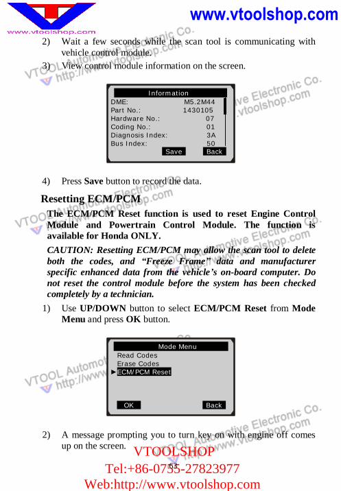
2) Wait a few seconds while the scan tool is communicating with vehicle control module.
3) View control module information on the screen.
4) Press Save button to record the data. Resetting ECM/PCM
The ECM/PCM Reset function is used to reset Engine Control Module and Powertrain Control Module. The function is available for Honda ONLY. CAUTION: Resetting ECM/PCM may allow the scan tool to delete both the codes, and “Freeze Frame” data and manufacturer specific enhanced data from the vehicle’s on-board computer. Do not reset the control module before the system has been checked completely by a technician.
1) Use UP/DOWN button to select ECM/PCM Reset from Mode Menu and press OK button.
2) A message prompting you to turn key on with engine off comes up on the screen.
Mode Menu Read Codes Erase Codes
►ECM/PCM Reset OK Back
Information DME: M5.2M44 Part No.: 1430105 Hardware No.: 07 Coding No.: 01 Diagnosis Index: 3A Bus Index: 50
Save Back
www.vtoolshop.com
VTOOLSHOPTel:+86-0755-27823977
Web:http://www.vtoolshop.com
64
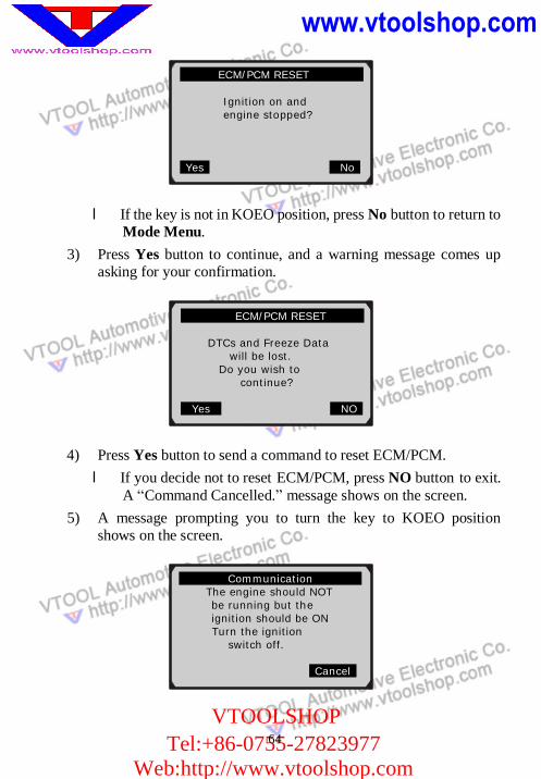
l If the key is not in KOEO position, press No button to return to Mode Menu.
3) Press Yes button to continue, and a warning message comes up asking for your confirmation.
4) Press Yes button to send a command to reset ECM/PCM. l If you decide not to reset ECM/PCM, press NO button to exit.
A “Command Cancelled.” message shows on the screen. 5) A message prompting you to turn the key to KOEO position
shows on the screen.
ECM/PCM RESET
DTCs and Freeze Data will be lost.
Do you wish to continue?
Yes NO
ECM/PCM RESET Ignition on and engine stopped?
Yes No
Communication The engine should NOT be running but the ignition should be ON
Turn the ignition switch off.
Cancel
www.vtoolshop.com
VTOOLSHOPTel:+86-0755-27823977
Web:http://www.vtoolshop.com
65
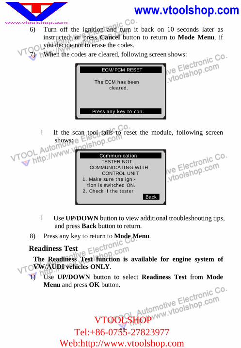
6) Turn off the ignition and turn it back on 10 seconds later as instructed; or press Cancel button to return to Mode Menu, if you decide not to erase the codes.
7) When the codes are cleared, following screen shows:
l If the scan tool fails to reset the module, following screen shows:
l Use UP/DOWN button to view additional troubleshooting tips, and press Back button to return.
8) Press any key to return to Mode Menu.
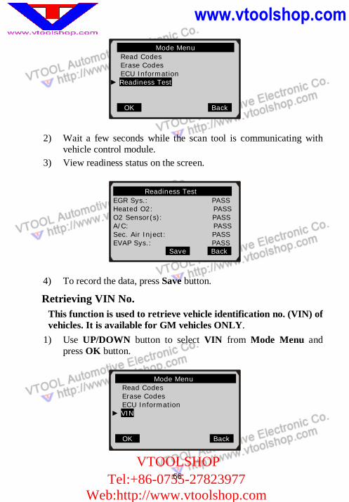
Readiness Test The Readiness Test function is available for engine system of VW/AUDI vehicles ONLY.
1) Use UP/DOWN button to select Readiness Test from Mode Menu and press OK button.
Communication TESTER NOT
COMMUNICATING WITH CONTROL UNIT
1. Make sure the igni- tion is switched ON.
2. Check if the tester Back
ECM/PCM RESET
The ECM has been cleared.
Press any key to con.
www.vtoolshop.com
VTOOLSHOPTel:+86-0755-27823977
Web:http://www.vtoolshop.com
66
2) Wait a few seconds while the scan tool is communicating with vehicle control module.
3) View readiness status on the screen.
4) To record the data, press Save button.
Retrieving VIN No. This function is used to retrieve vehicle identification no. (VIN) of vehicles. It is available for GM vehicles ONLY.
1) Use UP/DOWN button to select VIN from Mode Menu and press OK button.
Mode Menu Read Codes Erase Codes ECU Information
► Readiness Test
OK Back
Readiness Test EGR Sys.: PASS Heated O2: PASS O2 Sensor(s): PASS A/C: PASS Sec. Air Inject: PASS EVAP Sys.: PASS
Save Back
Mode Menu Read Codes Erase Codes ECU Information
► VIN
OK Back
www.vtoolshop.com
VTOOLSHOPTel:+86-0755-27823977
Web:http://www.vtoolshop.com
67
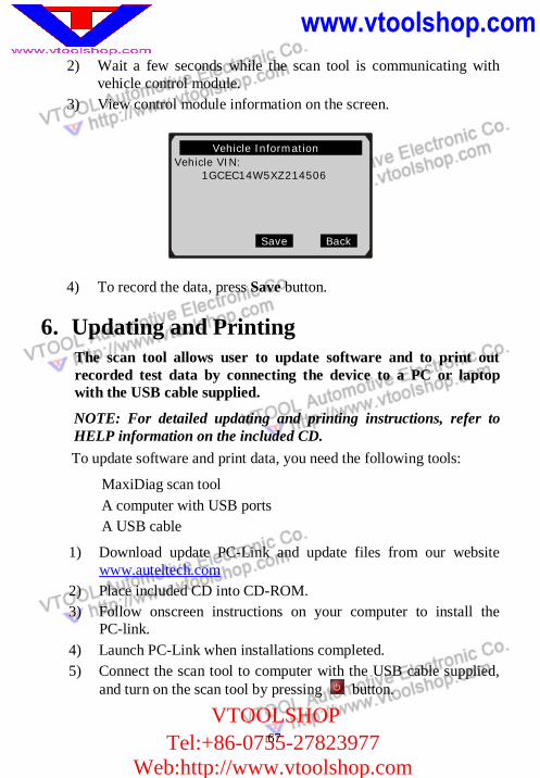
2) Wait a few seconds while the scan tool is communicating with vehicle control module.
3) View control module information on the screen.
4) To record the data, press Save button.
6. Updating and Printing The scan tool allows user to update software and to print out recorded test data by connecting the device to a PC or laptop with the USB cable supplied.
NOTE: For detailed updating and printing instructions, refer to HELP information on the included CD. To update software and print data, you need the following tools:
MaxiDiag scan tool A computer with USB ports A USB cable
1) Download update PC-Link and update files from our website www.auteltech.com
2) Place included CD into CD-ROM. 3) Follow onscreen instructions on your computer to install the
PC-link. 4) Launch PC-Link when installations completed. 5) Connect the scan tool to computer with the USB cable supplied,
and turn on the scan tool by pressing button.
Vehicle Information Vehicle VIN: 1GCEC14W5XZ214506
Save Back
www.vtoolshop.com
VTOOLSHOPTel:+86-0755-27823977
Web:http://www.vtoolshop.com
68
7. Warranty and Service 7.1 Limited One Year Warranty
Autel warrants to its customers that this product will be free from all defects in materials and workmanship for a period of one (1) year from the date of the original purchase, subject to the following terms and conditions: 1) The sole responsibility of Autel under the Warranty is limsited to
either the repair or, at the option of Autel, replacement of the code reader at no charge with Proof of Purchase. The sales receipt may be used for this purpose.
2) This warranty does not apply to damages caused by improper use, accident, flood, lightning, or if the product was altered or repaired by anyone other than the Manufacturer’s Service Center.
3) Autel shall not be liable for any incidental or consequential damages arising from the use, misuse, or mounting of the code reader.
4) All information in this manual is based on the latest information available at the time of publication and no warranty can be made for its accuracy or completeness. Autel reserves the right to make changes at any time without notice.
7.2 Service Procedures If you have any questions, please contact your local store, distributor or visit our website at If it becomes necessary to return the scan tool for repair, contact your local distributor for more information.
Web:http://www.vtoolshop.com