Embed Size (px)
Citation preview
an Alent plc Company
Preform Product
Elimination of Wave Exactalloy T&R Preforms
Highly Confidential and Privileged Information of Alpha an Alent plc Company
Introduction of “Elimination of Wave”
• The desire to reduce cost and improve reliability in assembly for our customers continues to drive Alpha’s marketplace today. Transitioning mixed technology or traditional wave applications to SMT or what we like to call the “elimination of wave” is a value proposition demonstrating both cost, reliability, and environmental benefits.
• The most common methodology to accomplish a transition from wave to surface mount technology is known as pin-in-paste or P-i-P. Pin-in-Paste provides manufacturers with a high-yield process that simultaneously reflows solder for surface mount and through hole components - without the need for wave soldering. By eliminating that step of the assembly process altogether, pin-in-paste not only saves time, reduces production costs, and increases throughput, but also enhances solder reliability while reducing dross in the manufacturing environment
• Once a PiP application has been identified, there are a number of challenges that can arise which can be overcome by using Alpha T&R preforms with PiP. In this presentation, we will focus on those applications. Upon completion, you will have the ability to assess your mixed technology process quickly and determine if it is a candidate for elimination of wave using Alpha Exactalloy Tape and Reel (T&R) preforms. Let’s get started!
Highly Confidential and Privileged Information of Alpha an Alent plc Company
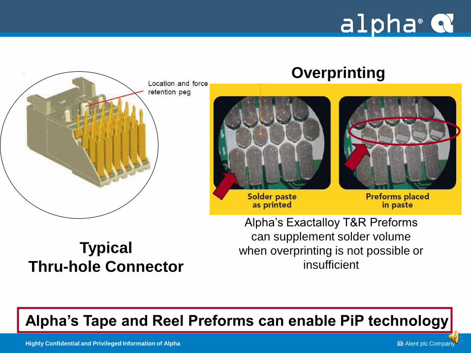
Alpha’s Tape and Reel Preforms can enable PiP technology
Overprinting
Typical
Thru-hole Connector
Alpha’s Exactalloy T&R Preforms
can supplement solder volume
when overprinting is not possible or
insufficient
Highly Confidential and Privileged Information of Alpha an Alent plc Company
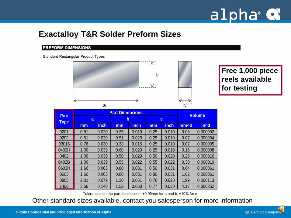
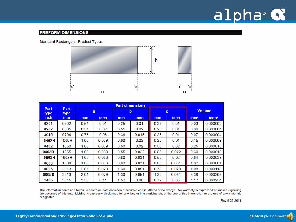
Exactalloy T&R Solder Preform Sizes
0.020
mm inch mm inch mm inch mm^3 in^3
0201 0.51 0.020 0.25 0.010 0.25 0.010 0.03 0.000002
0202 0.51 0.020 0.51 0.020 0.25 0.010 0.07 0.000004
03015 0.76 0.030 0.38 0.015 0.25 0.010 0.07 0.000005
0402H 1.00 0.039 0.60 0.020 0.25 0.010 0.15 0.000008
0402 1.00 0.039 0.50 0.020 0.50 0.020 0.25 0.000016
0402B 1.00 0.039 0.55 0.022 0.55 0.022 0.30 0.000019
0603H 1.60 0.063 0.80 0.031 0.50 0.031 0.64 0.000061
0603 1.60 0.063 0.80 0.031 0.80 0.031 1.02 0.000061
0805 2.01 0.079 1.30 0.051 0.76 0.028 1.99 0.000113
1406 3.56 0.140 1.52 0.060 0.77 0.030 4.17 0.000252
VolumePart
Type
Part Dimensions
a b c
Free 1,000 piece
reels available
for testing
Other standard sizes available, contact you salesperson for more information
Highly Confidential and Privileged Information of Alpha an Alent plc Company
No
tem
pera
ture
dif
fere
nti
al
= n
o t
herm
al
sh
ock
2150C
(>2350C)
>2300C
(>2450C)
Sn/Pb Soldering
(Pb-Free Soldering)
1100C
Tem
pera
ture
dif
fere
nti
al
cre
ate
s t
herm
al
sh
ock
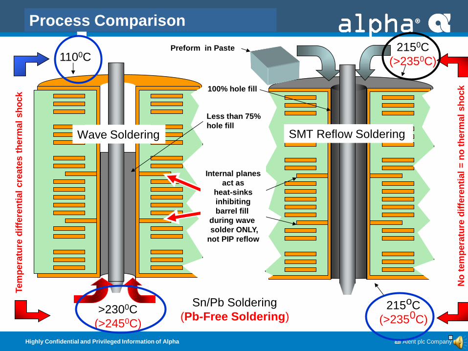
Internal planes
act as
heat-sinks
inhibiting
barrel fill
during wave
solder ONLY,
not PIP reflow
215oC
(>2350C)
Preform in Paste
Process Comparison
Wave Soldering
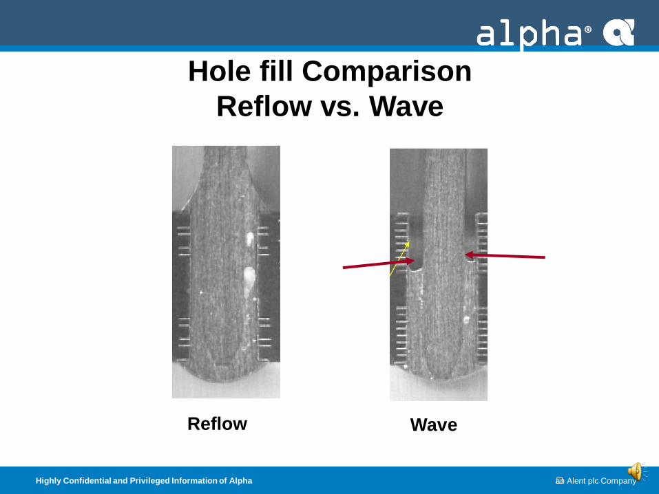
Less than 75%
hole fill
100% hole fill
SMT Reflow Soldering
Highly Confidential and Privileged Information of Alpha an Alent plc Company
Reflow Wave
Hole fill Comparison
Reflow vs. Wave
Highly Confidential and Privileged Information of Alpha an Alent plc Company
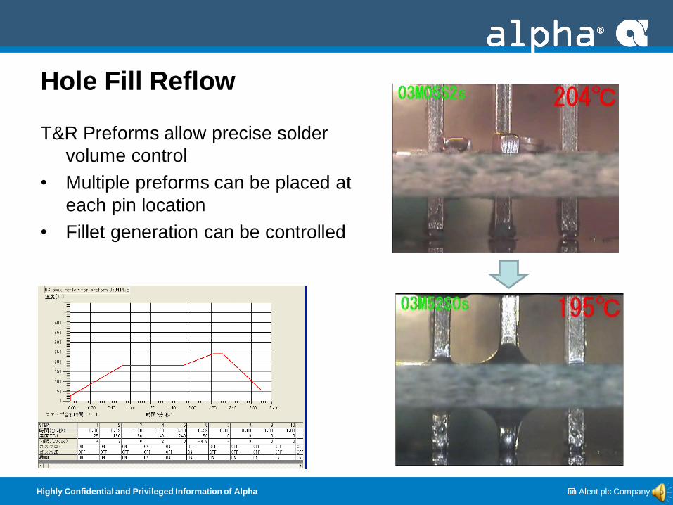
Hole Fill Reflow
T&R Preforms allow precise solder
volume control
• Multiple preforms can be placed at
each pin location
• Fillet generation can be controlled
Highly Confidential and Privileged Information of Alpha an Alent plc Company
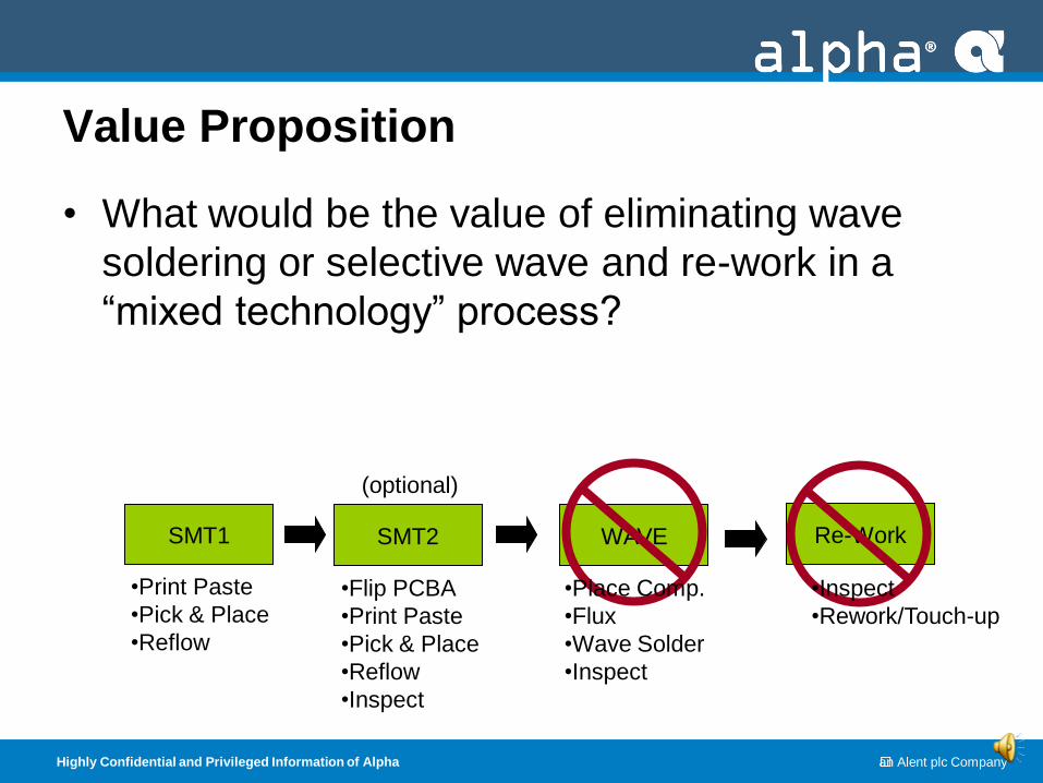
Value Proposition
• What would be the value of eliminating wave
soldering or selective wave and re-work in a
“mixed technology” process?
SMT1 SMT2 WAVE Re-Work
•Print Paste
•Pick & Place
•Reflow
•Flip PCBA
•Print Paste
•Pick & Place
•Reflow
•Inspect
•Place Comp.
•Flux
•Wave Solder
•Inspect
•Inspect
•Rework/Touch-up
(optional)
Highly Confidential and Privileged Information of Alpha an Alent plc Company
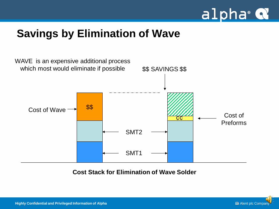
Savings by Elimination of Wave
$$
SMT1
SMT2
Cost of Wave Cost of
Preforms
$$ SAVINGS $$
Cost Stack for Elimination of Wave Solder
WAVE is an expensive additional process
which most would eliminate if possible
¢¢
Highly Confidential and Privileged Information of Alpha an Alent plc Company
Implementing
Paste-plus-Preform
to Eliminate Wave
Highly Confidential and Privileged Information of Alpha an Alent plc Company
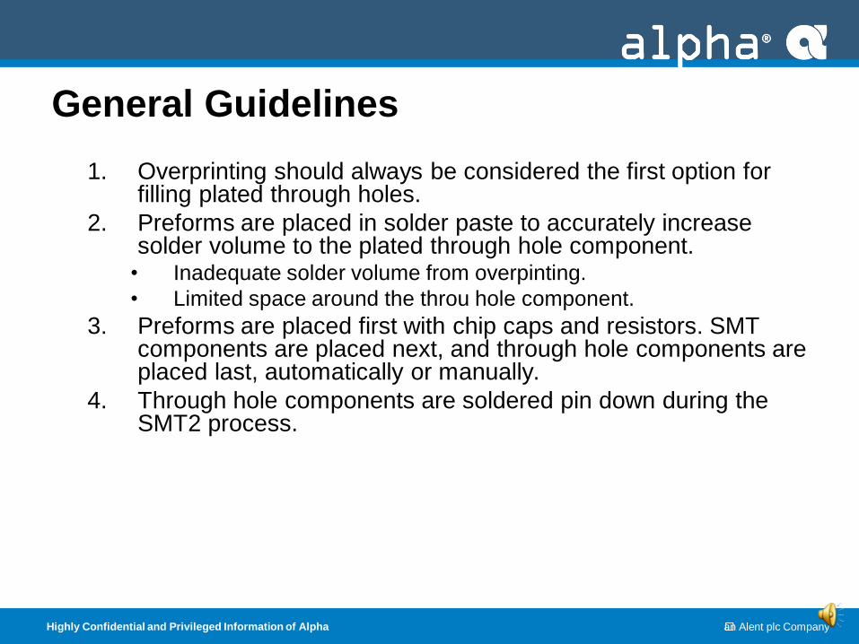
General Guidelines
1. Overprinting should always be considered the first option for filling plated through holes.
2. Preforms are placed in solder paste to accurately increase solder volume to the plated through hole component.
• Inadequate solder volume from overpinting.
• Limited space around the throu hole component.
3. Preforms are placed first with chip caps and resistors. SMT components are placed next, and through hole components are placed last, automatically or manually.
4. Through hole components are soldered pin down during the SMT2 process.
Highly Confidential and Privileged Information of Alpha an Alent plc Company
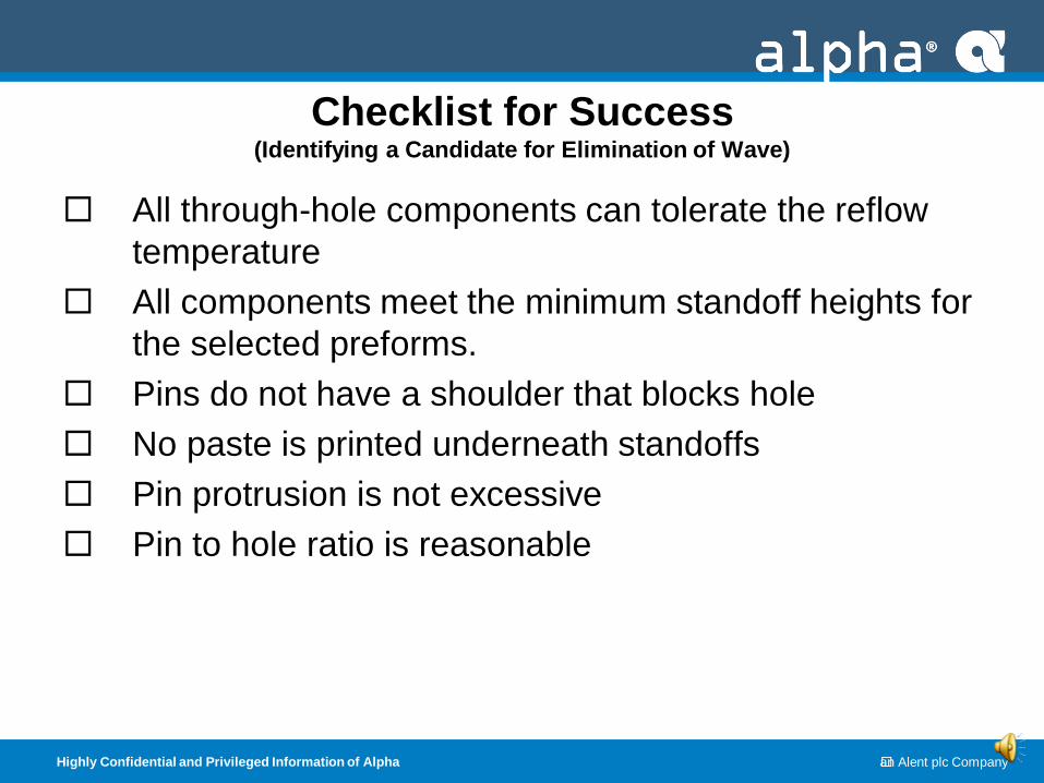
Checklist for Success (Identifying a Candidate for Elimination of Wave)
All through-hole components can tolerate the reflow
temperature
All components meet the minimum standoff heights for
the selected preforms.
Pins do not have a shoulder that blocks hole
No paste is printed underneath standoffs
Pin protrusion is not excessive
Pin to hole ratio is reasonable
Highly Confidential and Privileged Information of Alpha an Alent plc Company
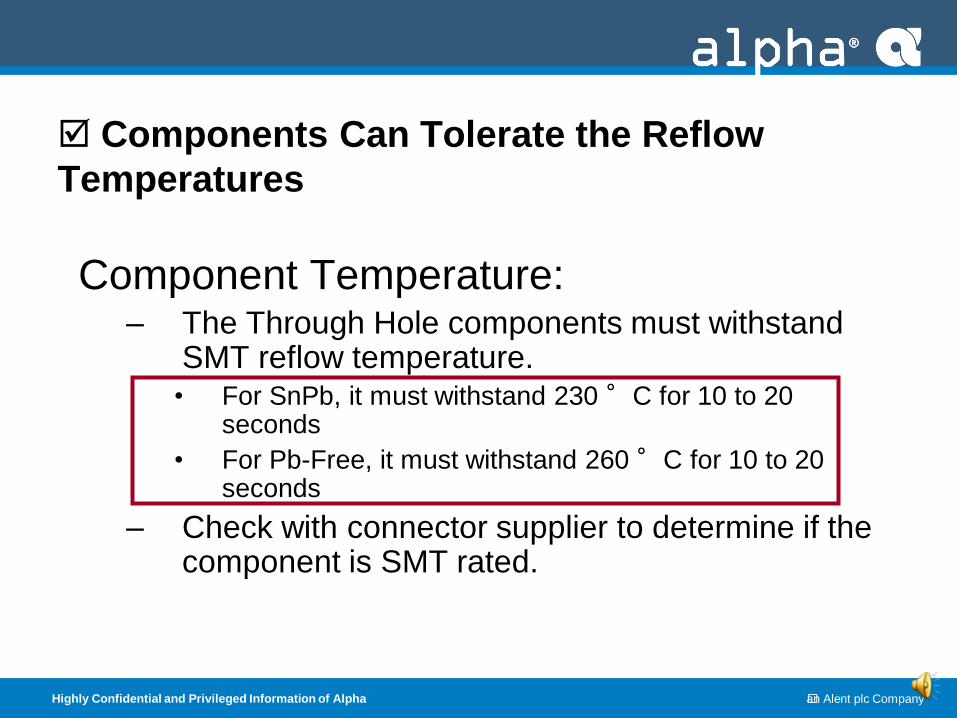
Components Can Tolerate the Reflow
Temperatures
Component Temperature: – The Through Hole components must withstand
SMT reflow temperature. • For SnPb, it must withstand 230 °C for 10 to 20
seconds
• For Pb-Free, it must withstand 260 °C for 10 to 20 seconds
– Check with connector supplier to determine if the component is SMT rated.
Highly Confidential and Privileged Information of Alpha an Alent plc Company
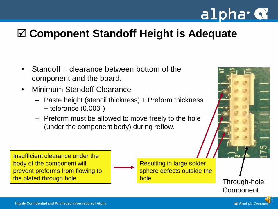
Component Standoff Height is Adequate
• Standoff = clearance between bottom of the
component and the board.
• Minimum Standoff Clearance
– Paste height (stencil thickness) + Preform thickness
+ tolerance (0.003”)
– Preform must be allowed to move freely to the hole
(under the component body) during reflow.
Insufficient clearance under the
body of the component will
prevent preforms from flowing to
the plated through hole.
Resulting in large solder
sphere defects outside the
hole Through-hole
Component
Highly Confidential and Privileged Information of Alpha an Alent plc Company
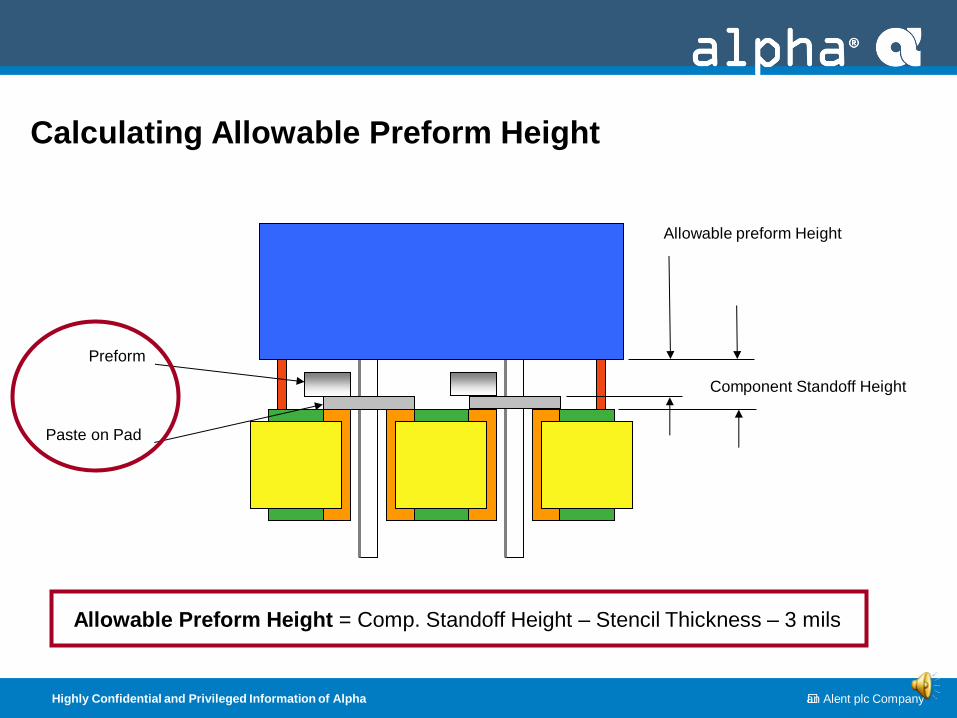
Calculating Allowable Preform Height
Allowable Preform Height = Comp. Standoff Height – Stencil Thickness – 3 mils
Component Standoff Height
Allowable preform Height
Paste on Pad
Preform
Highly Confidential and Privileged Information of Alpha an Alent plc Company
Highly Confidential and Privileged Information of Alpha an Alent plc Company
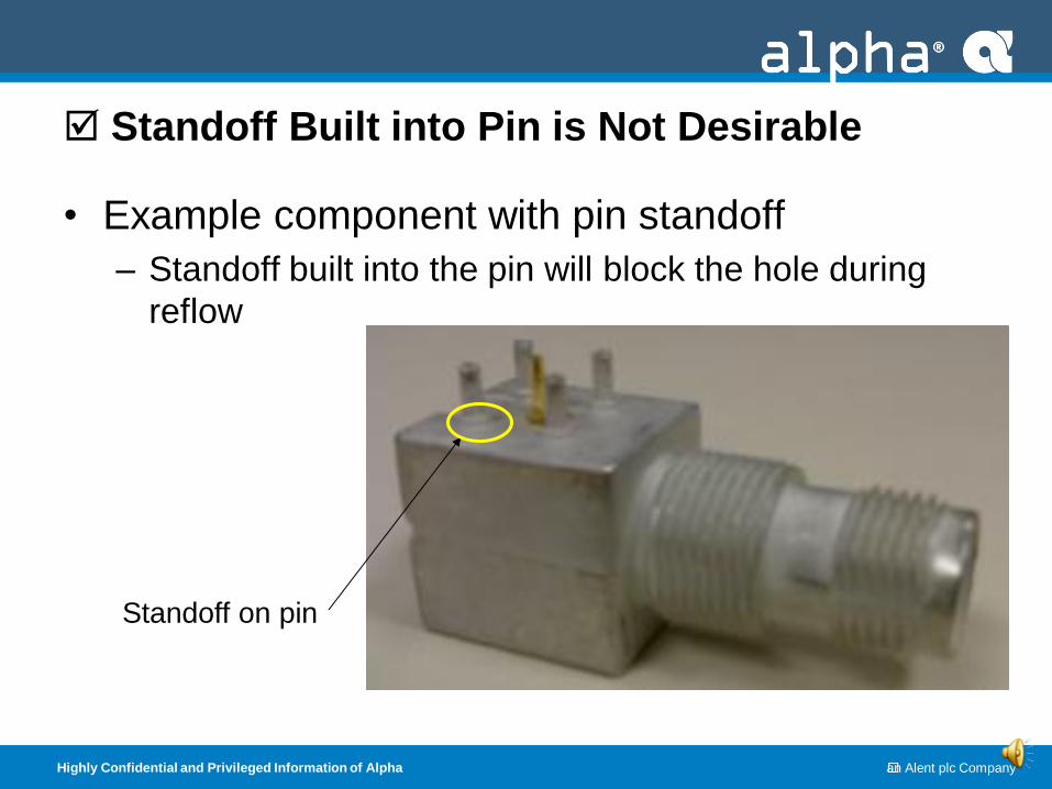
Standoff Built into Pin is Not Desirable
• Example component with pin standoff
– Standoff built into the pin will block the hole during
reflow
Standoff on pin
Highly Confidential and Privileged Information of Alpha an Alent plc Company
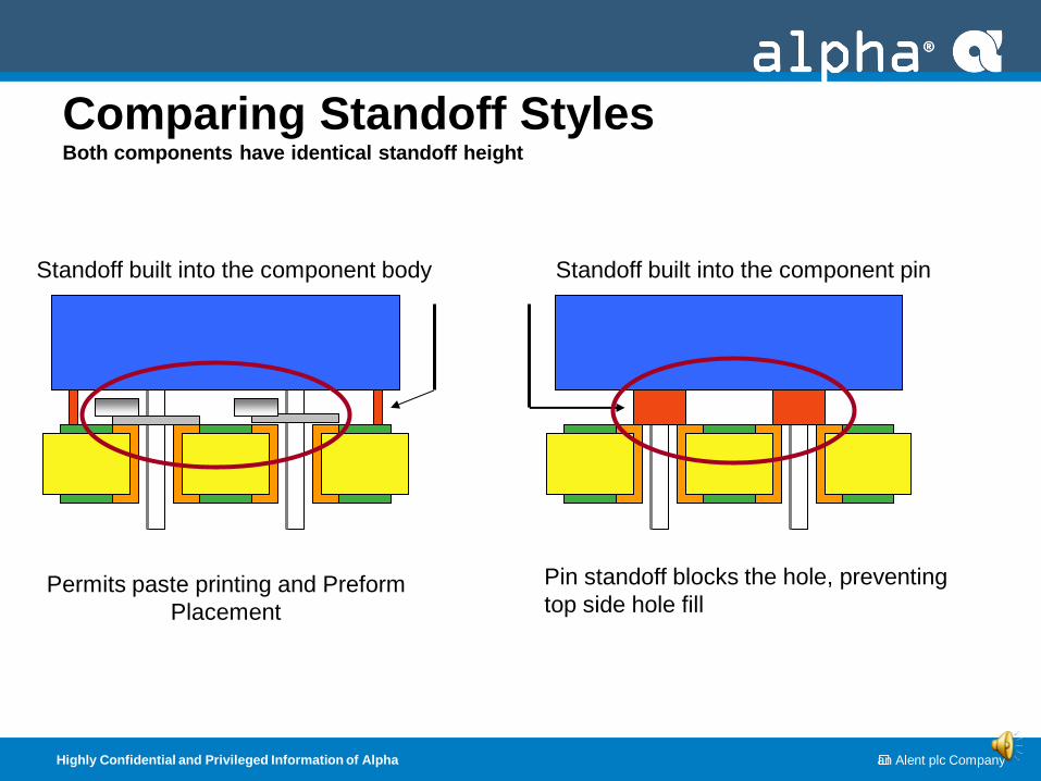
Comparing Standoff Styles Both components have identical standoff height
Permits paste printing and Preform
Placement
Pin standoff blocks the hole, preventing
top side hole fill
Standoff built into the component body Standoff built into the component pin
Highly Confidential and Privileged Information of Alpha an Alent plc Company
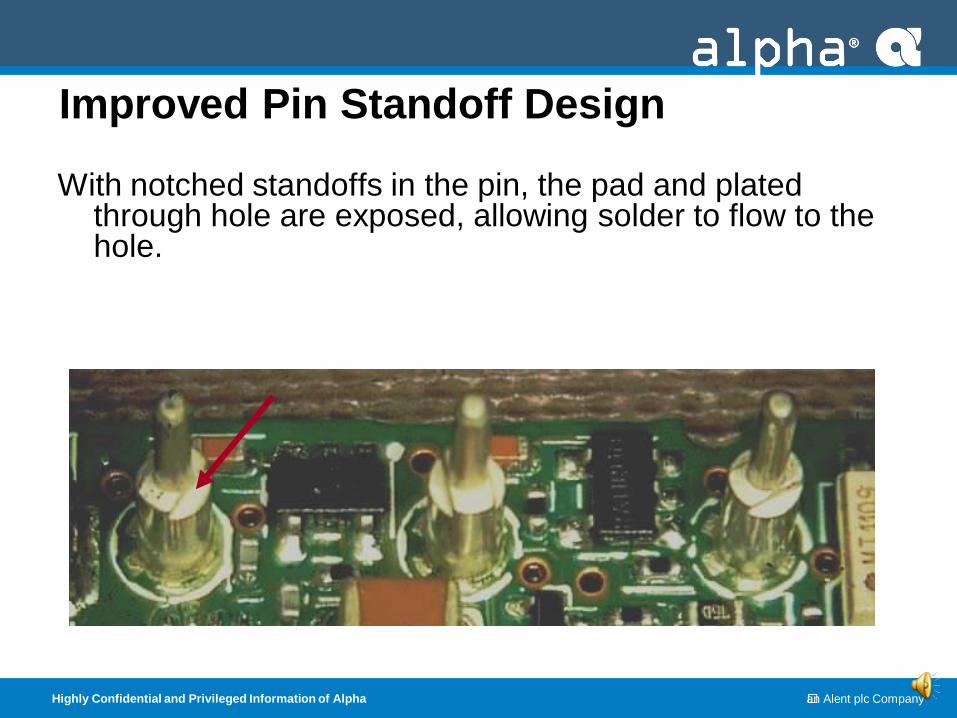
Improved Pin Standoff Design
With notched standoffs in the pin, the pad and plated through hole are exposed, allowing solder to flow to the hole.
Highly Confidential and Privileged Information of Alpha an Alent plc Company
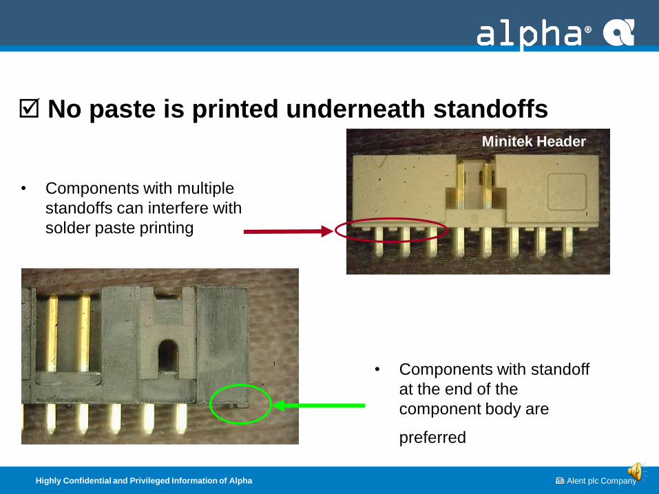
No paste is printed underneath standoffs
• Components with multiple
standoffs can interfere with
solder paste printing
• Components with standoff
at the end of the
component body are
preferred
Minitek Header
Highly Confidential and Privileged Information of Alpha an Alent plc Company
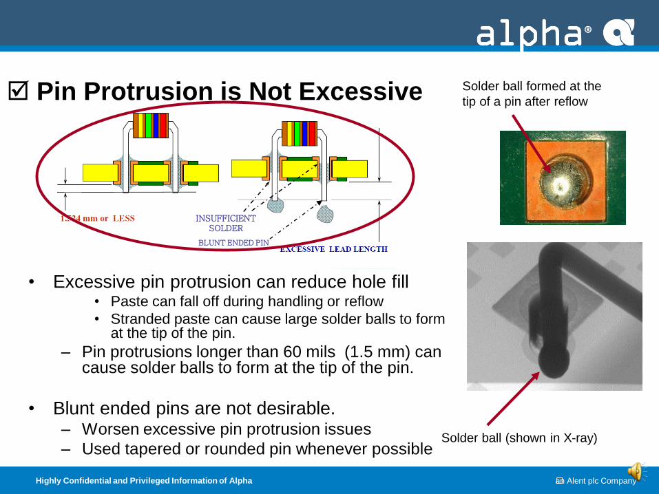
Pin Protrusion is Not Excessive
• Excessive pin protrusion can reduce hole fill • Paste can fall off during handling or reflow
• Stranded paste can cause large solder balls to form at the tip of the pin.
– Pin protrusions longer than 60 mils (1.5 mm) can cause solder balls to form at the tip of the pin.
• Blunt ended pins are not desirable. – Worsen excessive pin protrusion issues
– Used tapered or rounded pin whenever possible
Solder ball formed at the
tip of a pin after reflow
Solder ball (shown in X-ray)
BLUNT ENDED PIN
INSUFFICIENT SOLDER
Highly Confidential and Privileged Information of Alpha an Alent plc Company
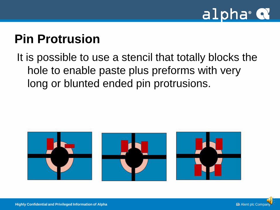
Pin Protrusion
It is possible to use a stencil that totally blocks the
hole to enable paste plus preforms with very
long or blunted ended pin protrusions.
Highly Confidential and Privileged Information of Alpha an Alent plc Company
Pin to Hole Ratio Acceptable
• A wide variety of pin to hole ratios can be
reflow soldered using paste plus preforms
• Pin to Hole Ratios: – Minimum Pin to Hole Ratio: Pin + 15 mils (0.38 mm).
• Going lower will create problems of solder flow and
placement issues.
– Maximum Pin to Hole Ratio: Pin + 40 mils (1 mm)
• Exceeding this value may create voids or gaps in
barrel.
Highly Confidential and Privileged Information of Alpha an Alent plc Company
Checklist for Success
Summary
Components can tolerate the reflow temperature
All components have a minimum standoff height
Pins do not have a shoulder that blocks hole
No paste is printed underneath standoffs
Pin protrusion is not excessive
Pin to hole ratio is reasonable
** If you can confirm all the items in the checklist, you surely have an excellent candidate for a preform application.
Highly Confidential and Privileged Information of Alpha an Alent plc Company
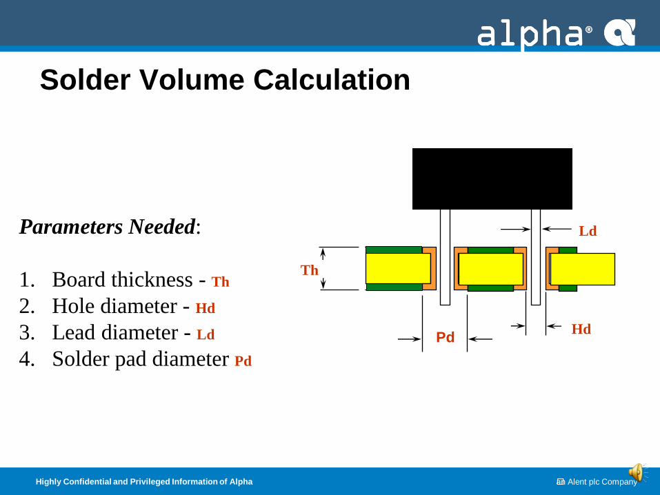
Parameters Needed:
1. Board thickness - Th
2. Hole diameter - Hd
3. Lead diameter - Ld
4. Solder pad diameter Pd
Th
Ld
Hd
Solder Volume Calculation
Pd
Highly Confidential and Privileged Information of Alpha an Alent plc Company
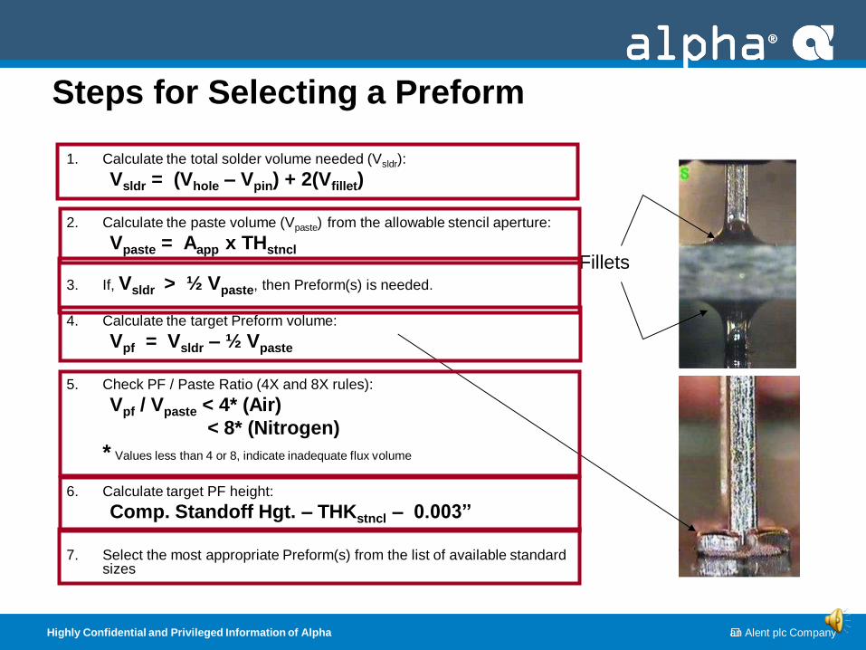
Steps for Selecting a Preform
1. Calculate the total solder volume needed (Vsldr):
Vsldr = (Vhole – Vpin) + 2(Vfillet)
2. Calculate the paste volume (Vpaste) from the allowable stencil aperture:
Vpaste = Aapp x THstncl
3. If, Vsldr > ½ Vpaste, then Preform(s) is needed.
4. Calculate the target Preform volume:
Vpf = Vsldr – ½ Vpaste
5. Check PF / Paste Ratio (4X and 8X rules):
Vpf / Vpaste < 4* (Air)
< 8* (Nitrogen)
* Values less than 4 or 8, indicate inadequate flux volume
6. Calculate target PF height:
Comp. Standoff Hgt. – THKstncl – 0.003”
7. Select the most appropriate Preform(s) from the list of available standard
sizes
Fillets
Highly Confidential and Privileged Information of Alpha an Alent plc Company
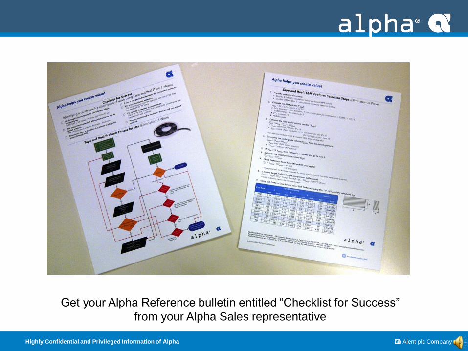
Get your Alpha Reference bulletin entitled “Checklist for Success”
from your Alpha Sales representative
Highly Confidential and Privileged Information of Alpha an Alent plc Company
28
Summary • Alpha Tape and Reel Preforms can be used to aid in the
Elimination of Wave in a mixed technology process.
• Tape and Reel Preforms are an economical alternative to increasing solder volume when overprinting solder paste is not adequate.
• There are a wide variety of Alpha T&R preform sizes to address most every through hole application.
• The implementation of Alpha T&R Preforms into an existing SMT process is not complicated.
• Alpha T&R preforms are a more reliable solution then overprinting:
– Very little flux residue
– 100% hole fill is routinely achieved
– A large overprint can be reduced or eliminated
– Random solder balls can be significantly reduced.
• Not all Wave applications can benefit from preform in paste techniques. Use the Checklist for Success tool to help you decide.