Embed Size (px)
Citation preview
IMPORTANT SAFETY NOTICE
Appropriate service methods and proper repair procedure are essential for the safe, reliable operation of all motor vehicles as well as the personal safety of the individual doing the work. This Manual provides general directions for accomplishing service and repair work with tested, effective techniques. Following them will help assure reliability. There are numerous variations in procedures, techniques, tools and parts for servicing vehicles, as well as in the skill of the individual doing the work. This Manual cannot possibly anticipate all such variations and provide advice or cautions as to each. Accordingly, anyone who departs from the instructions provided in this Manual must first establish that he compromises neither his personal safety nor the vehicle integrity by his choice of methods, tools or parts.
NOTES, CAUTIONS, AND WARNINGS
As you read through the procedures, you will come across NOTES, CAUTIONS, and WARNINGS. Each one is there for a specific purpose. NOTES give you added information that will help you to complete a particular procedure. CAUTIONS are given to prevent you from making an error that could damage the vehicle. WARNINGS remind you to be especially careful in those areas where carelessness can cause personal injury. The following list contains some general WARNING that you should follow when you work on a vehicle.
Always wear safety glasses for eye protection.
Use safety stands whenever a procedure requires you to be under the vehicle with the vehicle jacked up.
Be sure that the ignition switch is always in the OFF position, unless otherwise required by the procedure.
Set the parking brake when working on the vehicle. It should be in REVERSE (engine OFF) or NEUTRAL
(engine ON) unless instructed otherwise for a specific operation. Place wood blocks (4”X4” or larger) to the front and rear surfaces of the tires to provide further restraint from inadvertent vehicle movement.
Operate the engine only in a well-ventilated area to avoid the danger of carbon monoxide.
Keep yourself and your clothing away from the moving parts, when the engine is running, especially the fan
and drive belts. To prevent serious burns, avoid contact with hot metal parts such as the radiator, exhaust manifold tail pipe,
catalytic converter and muffler. Do not smoke while working on the vehicle.
To avoid injury, always remove rings, watches, loose hanging jewelry, and loose clothing before beginning
to work on a vehicle. Tie long hair securely behind the head. Keep hands and other objects clear of the radiator fan blades, Electric cooling fans can start to operate at any
time by an increase in under hood temperatures, even though the ignition is in the OFF position. Therefore, care should be taken to ensure that the electric cooling fan is completely disconnected when working under the hood.
Disconnect the negative battery ground cable before using any electric welding equipment.
Contents
Section Page
1 INTRODUCTION AND DESCRIPTION1-1. Introduction ……………………………………………………………………….1-10. Description………………………………………………………………………
1-11-1
2 T5 WC & STD ON-VEHICLE SERVICE AND TROUBLESHOOTING2-1. Maintenance……………..………………………………………………………..2-7. Troubleshooting…………………………………………………………………..2-10. Transmission Removal… ………………………………………………………2-21. Transmission Installation ………………………………………………………..
2-12-12-42-7
3 T5 WC DISASSEMBLY3-1. General Information ……………………………………………………………...3-6. T5 HD Transmission Disassembly Procedures ………………………………
3-13-1
4 T5 STD DISASSEMBLY4-1. General Information ……………………………………………………………...4-6. T5 STD Transmission Disassembly Procedures ……………………………..
4-14-1
5 T5 WC & STD CLEANING, INSPECTION, REPAIR OR REPLACEMENT5-1. Cleaning …………………………………………………………………………..5-5. Inspection …………………………………………………………………………5-10. Repair or Replacement ………………………………………………………….
5-15-85-16
6 T5 WC ASSEMBLY6-1. General Information ……………………………………………………………...6-4. T5 HD Transmission Assembly Procedures …………………………………..
6-16-1
7 T5 STD ASSEMBLY7-1 General Information ……………………………………………………………...7-4. T5 STD Transmission Assembly Procedures ………………………………...
7-17-1
Section 1Introduction and Description
1-1. INTRODUCTION1-2. PURPOSE. This manual containsmaintenance, service and parts information for theT5 Five-Speed Manual Transmission manufacturedby TREMEC (TRANSMISIONES Y EQUIPOSMECANICOS S.A DE C.V.) Av. 5 de febrero No.2115, Querétaro,Qro. México.
1-3. SCOPE. As you will see in the Table ofContents, this manual provides information formaintenance, troubleshooting, disassembly,cleaning, inspection, repair or replacement, andassembly of the transmission.
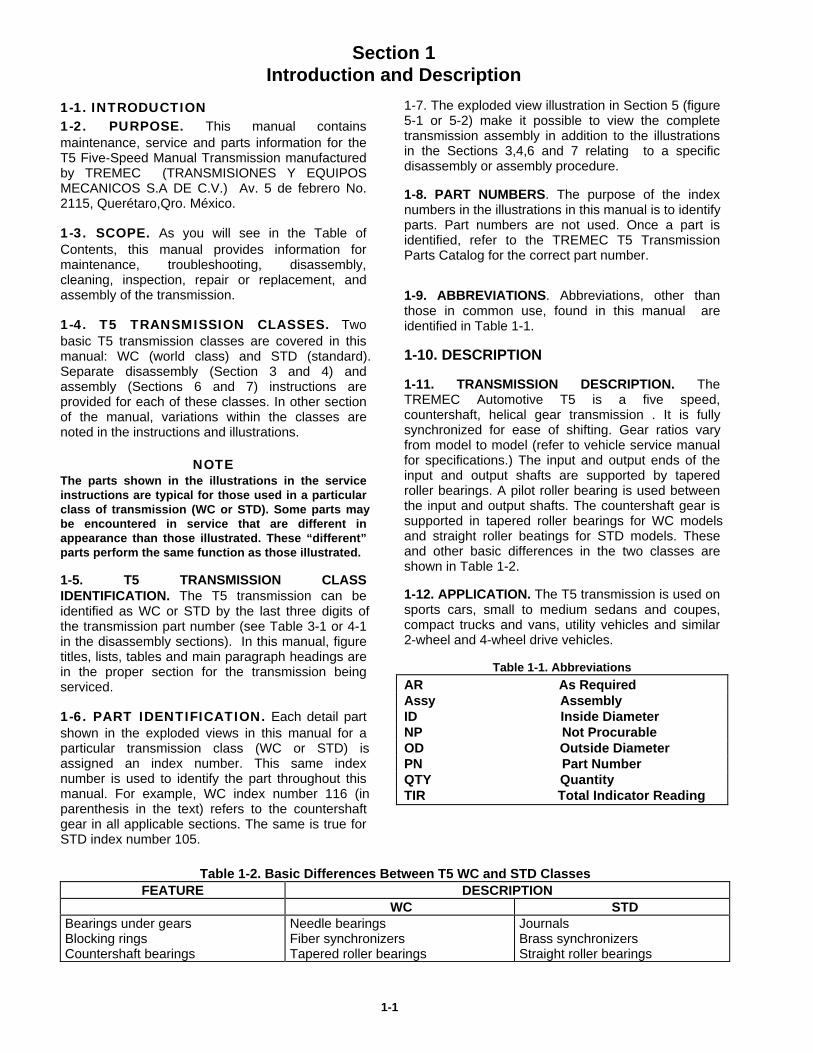
1-4. T5 TRANSMISSION CLASSES. Twobasic T5 transmission classes are covered in thismanual: WC (world class) and STD (standard).Separate disassembly (Section 3 and 4) andassembly (Sections 6 and 7) instructions areprovided for each of these classes. In other sectionof the manual, variations within the classes arenoted in the instructions and illustrations.
NOTEThe parts shown in the illustrations in the serviceinstructions are typical for those used in a particularclass of transmission (WC or STD). Some parts maybe encountered in service that are different inappearance than those illustrated. These “different”parts perform the same function as those illustrated.
1-5. T5 TRANSMISSION CLASSIDENTIFICATION. The T5 transmission can beidentified as WC or STD by the last three digits ofthe transmission part number (see Table 3-1 or 4-1in the disassembly sections). In this manual, figuretitles, lists, tables and main paragraph headings arein the proper section for the transmission beingserviced.
1-6. PART IDENTIFICATION. Each detail partshown in the exploded views in this manual for aparticular transmission class (WC or STD) isassigned an index number. This same indexnumber is used to identify the part throughout thismanual. For example, WC index number 116 (inparenthesis in the text) refers to the countershaftgear in all applicable sections. The same is true forSTD index number 105.
1-7. The exploded view illustration in Section 5 (figure5-1 or 5-2) make it possible to view the completetransmission assembly in addition to the illustrationsin the Sections 3,4,6 and 7 relating to a specificdisassembly or assembly procedure.
1-8. PART NUMBERS. The purpose of the indexnumbers in the illustrations in this manual is to identifyparts. Part numbers are not used. Once a part isidentified, refer to the TREMEC T5 TransmissionParts Catalog for the correct part number.
1-9. ABBREVIATIONS. Abbreviations, other thanthose in common use, found in this manual areidentified in Table 1-1.
1-10. DESCRIPTION
1-11. TRANSMISSION DESCRIPTION. TheTREMEC Automotive T5 is a five speed,countershaft, helical gear transmission . It is fullysynchronized for ease of shifting. Gear ratios varyfrom model to model (refer to vehicle service manualfor specifications.) The input and output ends of theinput and output shafts are supported by taperedroller bearings. A pilot roller bearing is used betweenthe input and output shafts. The countershaft gear issupported in tapered roller bearings for WC modelsand straight roller beatings for STD models. Theseand other basic differences in the two classes areshown in Table 1-2.
1-12. APPLICATION. The T5 transmission is used onsports cars, small to medium sedans and coupes,compact trucks and vans, utility vehicles and similar2-wheel and 4-wheel drive vehicles.
Table 1-1. Abbreviations
AR As RequiredAssy AssemblyID Inside DiameterNP Not ProcurableOD Outside DiameterPN Part NumberQTY QuantityTIR Total Indicator Reading
Table 1-2. Basic Differences Between T5 WC and STD ClassesFEATURE DESCRIPTION
WC STDBearings under gearsBlocking ringsCountershaft bearings
Needle bearingsFiber synchronizersTapered roller bearings
JournalsBrass synchronizersStraight roller bearings
1-1
Section 2T5 WC & STD On- Vehicle Service and Troubleshooting
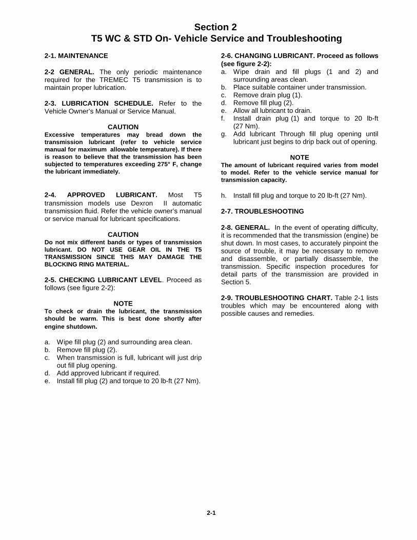
2-1. MAINTENANCE
2-2 GENERAL. The only periodic maintenancerequired for the TREMEC T5 transmission is tomaintain proper lubrication.
2-3. LUBRICATION SCHEDULE. Refer to theVehicle Owner’s Manual or Service Manual.
CAUTIONExcessive temperatures may bread down thetransmission lubricant (refer to vehicle servicemanual for maximum allowable temperature). If thereis reason to believe that the transmission has beensubjected to temperatures exceeding 275° F, changethe lubricant immediately.
2-4. APPROVED LUBRICANT. Most T5transmission models use Dexron II automatictransmission fluid. Refer the vehicle owner’s manualor service manual for lubricant specifications.
CAUTIONDo not mix different bands or types of transmissionlubricant. DO NOT USE GEAR OIL IN THE T5TRANSMISSION SINCE THIS MAY DAMAGE THEBLOCKING RING MATERIAL.
2-5. CHECKING LUBRICANT LEVEL. Proceed asfollows (see figure 2-2):
NOTETo check or drain the lubricant, the transmissionshould be warm. This is best done shortly afterengine shutdown.
a. Wipe fill plug (2) and surrounding area clean.b. Remove fill plug (2).c. When transmission is full, lubricant will just drip
out fill plug opening.d. Add approved lubricant if required.e. Install fill plug (2) and torque to 20 lb-ft (27 Nm).
2-6. CHANGING LUBRICANT. Proceed as follows(see figure 2-2):a. Wipe drain and fill plugs (1 and 2) and
surrounding areas clean.b. Place suitable container under transmission.c. Remove drain plug (1).d. Remove fill plug (2).e. Allow all lubricant to drain.f. Install drain plug (1) and torque to 20 lb-ft
(27 Nm).g. Add lubricant Through fill plug opening until
lubricant just begins to drip back out of opening.
NOTE The amount of lubricant required varies from modelto model. Refer to the vehicle service manual fortransmission capacity. h. Install fill plug and torque to 20 lb-ft (27 Nm).
2-7. TROUBLESHOOTING
2-8. GENERAL. In the event of operating difficulty,it is recommended that the transmission (engine) beshut down. In most cases, to accurately pinpoint thesource of trouble, it may be necessary to removeand disassemble, or partially disassemble, thetransmission. Specific inspection procedures fordetail parts of the transmission are provided inSection 5.
2-9. TROUBLESHOOTING CHART. Table 2-1 liststroubles which may be encountered along withpossible causes and remedies.
2-1
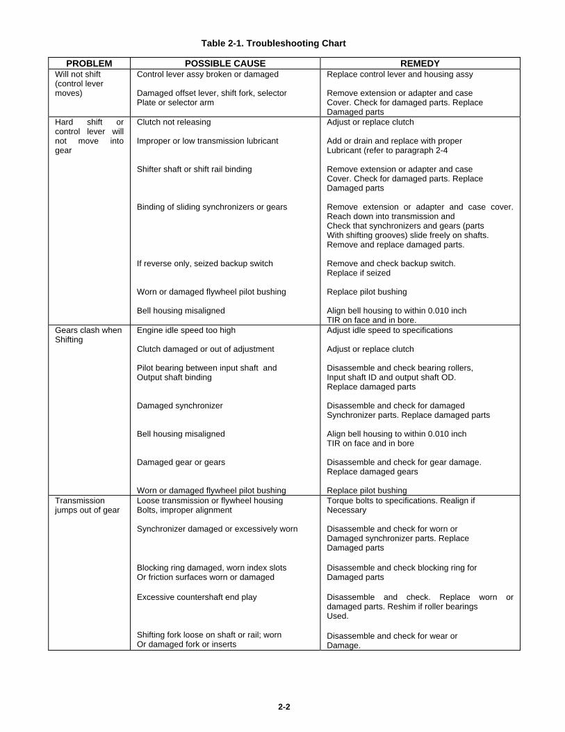
Table 2-1. Troubleshooting Chart
PROBLEM POSSIBLE CAUSE REMEDYWill not shift(control levermoves)
Control lever assy broken or damaged
Damaged offset lever, shift fork, selectorPlate or selector arm
Replace control lever and housing assy
Remove extension or adapter and caseCover. Check for damaged parts. ReplaceDamaged parts
Hard shift orcontrol lever willnot move intogear
Clutch not releasing
Improper or low transmission lubricant
Shifter shaft or shift rail binding
Binding of sliding synchronizers or gears
If reverse only, seized backup switch
Worn or damaged flywheel pilot bushing
Bell housing misaligned
Adjust or replace clutch
Add or drain and replace with properLubricant (refer to paragraph 2-4
Remove extension or adapter and caseCover. Check for damaged parts. ReplaceDamaged parts
Remove extension or adapter and case cover.Reach down into transmission andCheck that synchronizers and gears (partsWith shifting grooves) slide freely on shafts.Remove and replace damaged parts.
Remove and check backup switch.Replace if seized
Replace pilot bushing
Align bell housing to within 0.010 inchTIR on face and in bore.
Gears clash whenShifting
Engine idle speed too high
Clutch damaged or out of adjustment
Pilot bearing between input shaft andOutput shaft binding
Damaged synchronizer
Bell housing misaligned
Damaged gear or gears
Worn or damaged flywheel pilot bushing
Adjust idle speed to specifications
Adjust or replace clutch
Disassemble and check bearing rollers,Input shaft ID and output shaft OD.Replace damaged parts
Disassemble and check for damagedSynchronizer parts. Replace damaged parts
Align bell housing to within 0.010 inchTIR on face and in bore
Disassemble and check for gear damage.Replace damaged gears
Replace pilot bushingTransmissionjumps out of gear
Loose transmission or flywheel housingBolts, improper alignment
Synchronizer damaged or excessively worn
Blocking ring damaged, worn index slotsOr friction surfaces worn or damaged
Excessive countershaft end play
Shifting fork loose on shaft or rail; wornOr damaged fork or inserts
Torque bolts to specifications. Realign ifNecessary
Disassemble and check for worn orDamaged synchronizer parts. ReplaceDamaged parts
Disassemble and check blocking ring forDamaged parts
Disassemble and check. Replace worn ordamaged parts. Reshim if roller bearingsUsed.
Disassemble and check for wear orDamage.
2-2
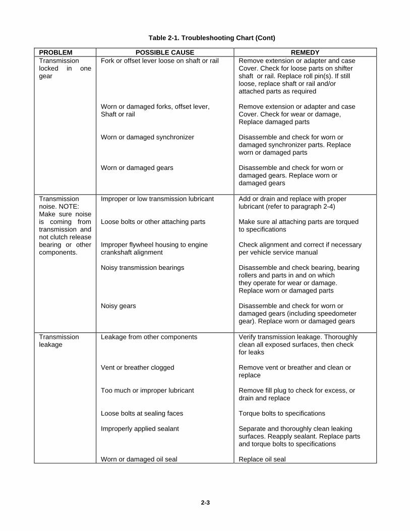
Table 2-1. Troubleshooting Chart (Cont)
PROBLEM POSSIBLE CAUSE REMEDYTransmissionlocked in onegear
Fork or offset lever loose on shaft or rail
Worn or damaged forks, offset lever,Shaft or rail
Worn or damaged synchronizer
Worn or damaged gears
Remove extension or adapter and caseCover. Check for loose parts on shiftershaft or rail. Replace roll pin(s). If stillloose, replace shaft or rail and/orattached parts as required
Remove extension or adapter and caseCover. Check for wear or damage,Replace damaged parts
Disassemble and check for worn ordamaged synchronizer parts. Replaceworn or damaged parts
Disassemble and check for worn ordamaged gears. Replace worn ordamaged gears
Transmissionnoise. NOTE:Make sure noiseis coming fromtransmission andnot clutch releasebearing or othercomponents.
Improper or low transmission lubricant
Loose bolts or other attaching parts
Improper flywheel housing to enginecrankshaft alignment
Noisy transmission bearings
Noisy gears
Add or drain and replace with properlubricant (refer to paragraph 2-4)
Make sure al attaching parts are torquedto specifications
Check alignment and correct if necessaryper vehicle service manual
Disassemble and check bearing, bearingrollers and parts in and on whichthey operate for wear or damage.Replace worn or damaged parts
Disassemble and check for worn ordamaged gears (including speedometergear). Replace worn or damaged gears
Transmissionleakage
Leakage from other components
Vent or breather clogged
Too much or improper lubricant
Loose bolts at sealing faces
Improperly applied sealant
Worn or damaged oil seal
Verify transmission leakage. Thoroughlyclean all exposed surfaces, then checkfor leaks
Remove vent or breather and clean orreplace
Remove fill plug to check for excess, ordrain and replace
Torque bolts to specifications
Separate and thoroughly clean leakingsurfaces. Reapply sealant. Replace partsand torque bolts to specifications
Replace oil seal
2-3
2-10. TRANSMISSION REMOVAL
2-11. GENERAL. The following paragraphs provideprocedures for removing the T5 transmission. For 4-wheeldrive vehicles, instructions are also given for removing thetransfer case. If the vehicle is not equipped with 4-wheeldrive, disregard paragraph 2-18 and references to thetransfer case in the other paragraphs
2-12. OTHER COMPONENTS. Before or duringtransmission removal, it may be necessary to remove ordisconnect other components. This is required to provideaccess to or clearance for the transmission ( and transfercase, if used ). Since these components vary widely fromvehicle to vehicle, specific instruction are not provided in thismanual. Refer to the vehicle service manual. Suchcomponents may include:a. Console or similar cover.b. Parking brake lever and controls.c. Wiring and/or vacuum harness.d. Exhaust system components.e. Clutch components.f. A skid plate or protective covers on the underside of the
vehicle.
1.13 SUPPORTING TRANSMISSION ( OR TRANSFERCASE, IF USED) Before removing any parts which attach orsupport the transmission(and transfer case, if used), supportthe transmission on a suitable jack or stand. The jack orstand must be capable of supporting and holding thetransmission independently. Also the jack or stand shall becapable or lowering, raising and moving the transmissionlaterally.
2-14. PROCEDURES WITH VEHICLE ON FLOOR. Beforeraising the vehicle, proceed as follows:a. Position vehicle over suitable hoist.
WARNINGWhen using a drive-on lift, be sure to properly chock thewheels to prevent the vehicle from rolling off.
b. Disconnect negative battery terminal.c. Shift vehicle into neutral and release parking brake. On
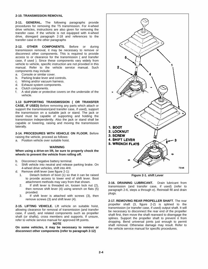
4-wheel drive vehicles, shift into 4HI.d. Remove shift lever (see figure 2-1):
1. Detach bottom of boot (1) so that it can be raisedto provide access to lower end of shift lever. Bootattachment methods may vary from that shown.
2. If shift lever is threaded on, loosen lock nut (2),then remove shift lever (4) using wrench on flats (5)provided.
3. If shift lever is attached with screws (3), thenremove screws (3) and shift lever (4).
2-15. LIFTING VEHICLE. Lift vehicle on suitable hoist,allowing clearance for removal of transmission (and transfercase, if used), and related components such as propellershaft (or shafts), cross members and supports. If unsure,refer to vehicle service manual for approved lift points.
NOTEOn some vehicles, it may be necessary to remove ordisconnect other components (refer to paragraph 2-12)
Figure 2-1. shift Lever
2-16. DRAINING LUBRICANT. Drain lubricant fromtransmission (and transfer case, if used) (refer toparagraph 2-6, steps a through e). Reinstall fill and drainplugs.
2-17. REMOVING REAR PROPELLER SHAFT. The rearpropeller shaft (3, figure 2-2) is splined to thetransmission (or transfer case, if used) output shaft. It willbe necessary to disconnect the rear end of the propellershaft first, then move the shaft rearward to disengage thesplines. Support the propeller shaft to prevent it fromdropping. Bend universal joints just enough to permitshaft removal. Otherwise damage may result. Refer tothe vehicle service manual for specific procedures.
2-4
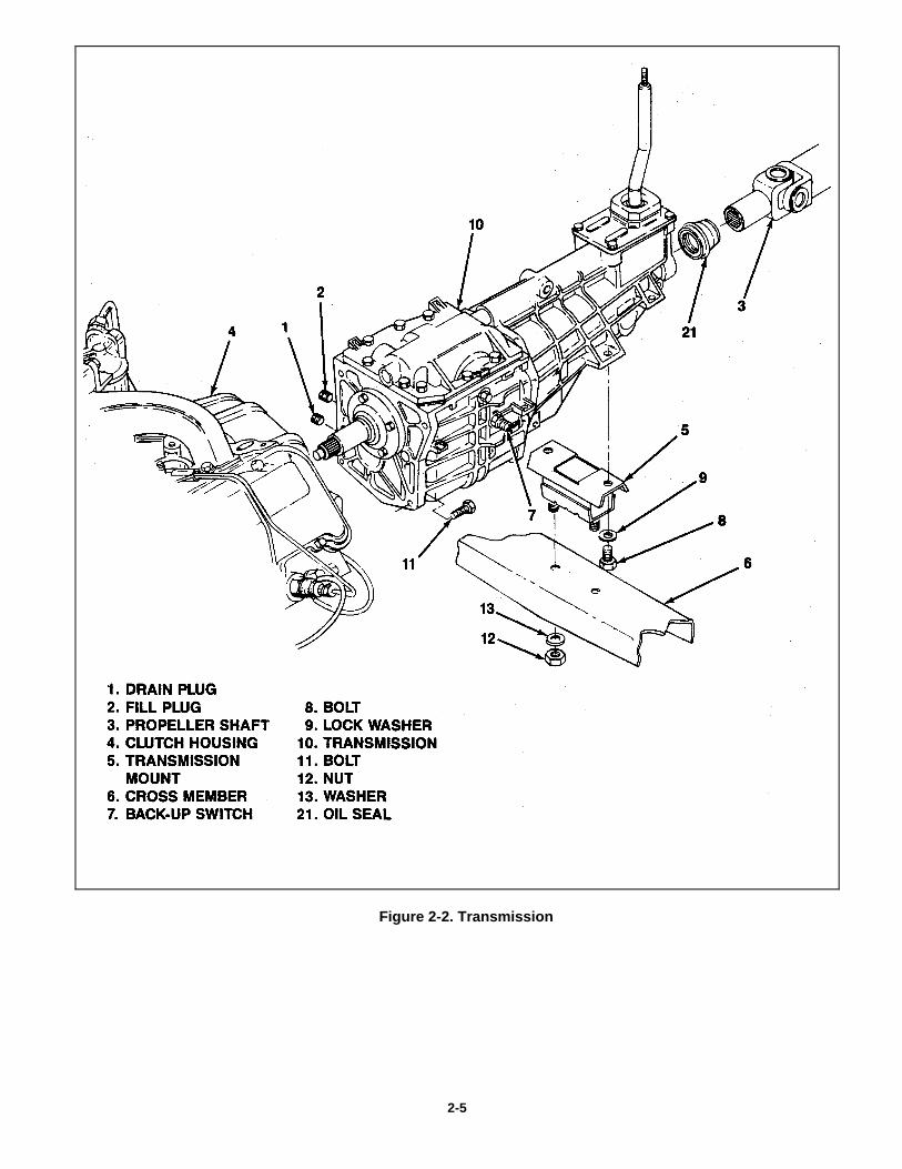
Figure 2-2. Transmission
2-5
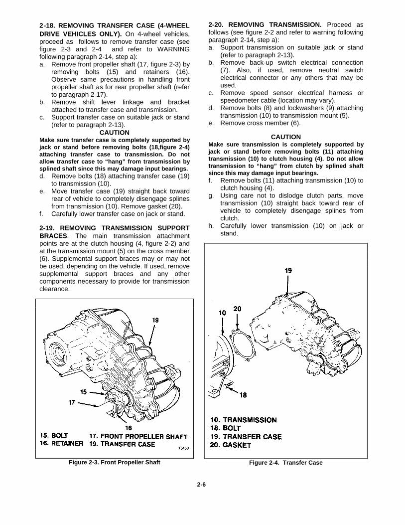
2-18. REMOVING TRANSFER CASE (4-WHEELDRIVE VEHICLES ONLY). On 4-wheel vehicles,proceed as follows to remove transfer case (seefigure 2-3 and 2-4 and refer to WARNINGfollowing paragraph 2-14, step a):a. Remove front propeller shaft (17, figure 2-3) by
removing bolts (15) and retainers (16).Observe same precautions in handling frontpropeller shaft as for rear propeller shaft (referto paragraph 2-17).
b. Remove shift lever linkage and bracketattached to transfer case and transmission.
c. Support transfer case on suitable jack or stand(refer to paragraph 2-13).
CAUTION Make sure transfer case is completely supported byjack or stand before removing bolts (18,figure 2-4)attaching transfer case to transmission. Do notallow transfer case to “hang” from transmission bysplined shaft since this may damage input bearings.d. Remove bolts (18) attaching transfer case (19)
to transmission (10).e. Move transfer case (19) straight back toward
rear of vehicle to completely disengage splinesfrom transmission (10). Remove gasket (20).
f. Carefully lower transfer case on jack or stand.
2-19. REMOVING TRANSMISSION SUPPORTBRACES. The main transmission attachmentpoints are at the clutch housing (4, figure 2-2) andat the transmission mount (5) on the cross member(6). Supplemental support braces may or may notbe used, depending on the vehicle. If used, removesupplemental support braces and any othercomponents necessary to provide for transmissionclearance.
Figure 2-3. Front Propeller Shaft
2-20. REMOVING TRANSMISSION. Proceed asfollows (see figure 2-2 and refer to warning followingparagraph 2-14, step a):a. Support transmission on suitable jack or stand
(refer to paragraph 2-13).b. Remove back-up switch electrical connection
(7). Also, if used, remove neutral switchelectrical connector or any others that may beused.
c. Remove speed sensor electrical harness orspeedometer cable (location may vary).
d. Remove bolts (8) and lockwashers (9) attachingtransmission (10) to transmission mount (5).
e. Remove cross member (6).
CAUTION Make sure transmission is completely supported byjack or stand before removing bolts (11) attachingtransmission (10) to clutch housing (4). Do not allowtransmission to “hang” from clutch by splined shaftsince this may damage input bearings.f. Remove bolts (11) attaching transmission (10) to
clutch housing (4).g. Using care not to dislodge clutch parts, move
transmission (10) straight back toward rear ofvehicle to completely disengage splines fromclutch.
h. Carefully lower transmission (10) on jack orstand.
Figure 2-4. Transfer Case
2-6
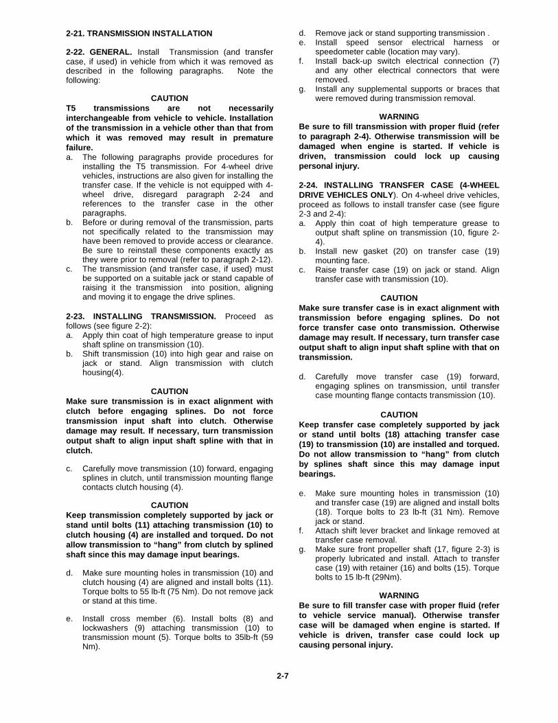
2-21. TRANSMISSION INSTALLATION
2-22. GENERAL. Install Transmission (and transfercase, if used) in vehicle from which it was removed asdescribed in the following paragraphs. Note thefollowing:
CAUTIONT5 transmissions are not necessarilyinterchangeable from vehicle to vehicle. Installationof the transmission in a vehicle other than that fromwhich it was removed may result in prematurefailure.a. The following paragraphs provide procedures for
installing the T5 transmission. For 4-wheel drivevehicles, instructions are also given for installing thetransfer case. If the vehicle is not equipped with 4-wheel drive, disregard paragraph 2-24 andreferences to the transfer case in the otherparagraphs.
b. Before or during removal of the transmission, partsnot specifically related to the transmission mayhave been removed to provide access or clearance.Be sure to reinstall these components exactly asthey were prior to removal (refer to paragraph 2-12).
c. The transmission (and transfer case, if used) mustbe supported on a suitable jack or stand capable ofraising it the transmission into position, aligningand moving it to engage the drive splines.
2-23. INSTALLING TRANSMISSION. Proceed asfollows (see figure 2-2):a. Apply thin coat of high temperature grease to input
shaft spline on transmission (10).b. Shift transmission (10) into high gear and raise on
jack or stand. Align transmission with clutchhousing(4).
CAUTIONMake sure transmission is in exact alignment withclutch before engaging splines. Do not forcetransmission input shaft into clutch. Otherwisedamage may result. If necessary, turn transmissionoutput shaft to align input shaft spline with that inclutch.
c. Carefully move transmission (10) forward, engagingsplines in clutch, until transmission mounting flangecontacts clutch housing (4).
CAUTIONKeep transmission completely supported by jack orstand until bolts (11) attaching transmission (10) toclutch housing (4) are installed and torqued. Do notallow transmission to “hang” from clutch by splinedshaft since this may damage input bearings.
d. Make sure mounting holes in transmission (10) andclutch housing (4) are aligned and install bolts (11).Torque bolts to 55 lb-ft (75 Nm). Do not remove jackor stand at this time.
e. Install cross member (6). Install bolts (8) and
lockwashers (9) attaching transmission (10) totransmission mount (5). Torque bolts to 35lb-ft (59Nm).
d. Remove jack or stand supporting transmission .e. Install speed sensor electrical harness or
speedometer cable (location may vary).f. Install back-up switch electrical connection (7)
and any other electrical connectors that wereremoved.
g. Install any supplemental supports or braces thatwere removed during transmission removal.
WARNINGBe sure to fill transmission with proper fluid (referto paragraph 2-4). Otherwise transmission will bedamaged when engine is started. If vehicle isdriven, transmission could lock up causingpersonal injury.
2-24. INSTALLING TRANSFER CASE (4-WHEELDRIVE VEHICLES ONLY). On 4-wheel drive vehicles,proceed as follows to install transfer case (see figure2-3 and 2-4):a. Apply thin coat of high temperature grease to
output shaft spline on transmission (10, figure 2-4).
b. Install new gasket (20) on transfer case (19)mounting face.
c. Raise transfer case (19) on jack or stand. Aligntransfer case with transmission (10).
CAUTION
Make sure transfer case is in exact alignment withtransmission before engaging splines. Do notforce transfer case onto transmission. Otherwisedamage may result. If necessary, turn transfer caseoutput shaft to align input shaft spline with that ontransmission. d. Carefully move transfer case (19) forward,
engaging splines on transmission, until transfercase mounting flange contacts transmission (10).
CAUTION
Keep transfer case completely supported by jackor stand until bolts (18) attaching transfer case(19) to transmission (10) are installed and torqued.Do not allow transmission to “hang” from clutchby splines shaft since this may damage inputbearings. e. Make sure mounting holes in transmission (10)
and transfer case (19) are aligned and install bolts(18). Torque bolts to 23 lb-ft (31 Nm). Removejack or stand.
f. Attach shift lever bracket and linkage removed attransfer case removal.
g. Make sure front propeller shaft (17, figure 2-3) isproperly lubricated and install. Attach to transfercase (19) with retainer (16) and bolts (15). Torquebolts to 15 lb-ft (29Nm).
WARNINGBe sure to fill transfer case with proper fluid (referto vehicle service manual). Otherwise transfercase will be damaged when engine is started. Ifvehicle is driven, transfer case could lock upcausing personal injury.
2-7
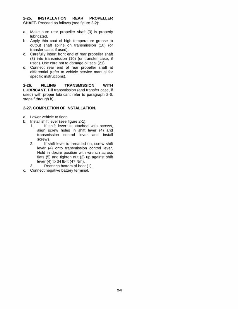
2-25. INSTALLATION REAR PROPELLERSHAFT. Proceed as follows (see figure 2-2):
a. Make sure rear propeller shaft (3) is properlylubricated.
b. Apply thin coat of high temperature grease tooutput shaft spline on transmission (10) (ortransfer case, if used).
c. Carefully insert front end of rear propeller shaft(3) into transmission (10) (or transfer case, ifused). Use care not to damage oil seal (21).
d. Connect rear end of rear propeller shaft atdifferential (refer to vehicle service manual forspecific instructions).
2-26. FILLING TRANSMISSION WITHLUBRICANT. Fill transmission (and transfer case, ifused) with proper lubricant refer to paragraph 2-6,steps f through h).
2-27. COMPLETION OF INSTALLATION.
a. Lower vehicle to floor.b. Install shift lever (see figure 2-1):
1. If shift lever is attached with screws,align screw holes in shift lever (4) andtransmission control lever and installscrews.
2. If shift lever is threaded on, screw shiftlever (4) onto transmission control lever.Hold in desire position with wrench acrossflats (5) and tighten nut (2) up against shiftlever (4) to 34 lb-ft (47 Nm).
3. Reattach bottom of boot (1).c. Connect negative battery terminal.
2-8
Section 3T5 WC Disassembly
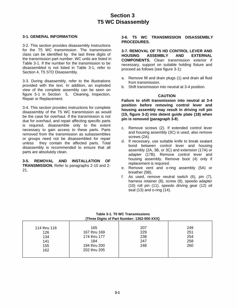
3-1. GENERAL INFORMATION
3-2. This section provides disassembly instructionsfor the T5 WC transmission. The transmissionclass can be identified by the last three digits ofthe transmission part number. WC units are listed inTable 3-1. If the number for the transmission to bedisassembled is not listed in Table 3-1, refer toSection 4, T5 STD Disassembly.
3-3. During disassembly, refer to the illustrationsprovided with the text. In addition, an explodedview of the complete assembly can be seen onfigure 5-1 in Section 5, Cleaning, Inspection,Repair or Replacement.
3-4. This section provides instructions for completedisassembly of the T5 WC transmission as wouldbe the case for overhaul. If the transmission is notdue for overhaul, and repair affecting specific partsis required, disassemble only to the extentnecessary to gain access to these parts. Partsremoved from the transmission as subassembliesor groups need not be disassembled for repairunless they contain the affected parts. Totaldisassembly is recommended to ensure that allparts are absolutely clean.
3-5. REMOVAL AND INSTALLATION OFTRANSMISSION. Refer to paragraphs 2-10 and 2-21.
3-6. T5 WC TRANSMISSION DISASSEMBLYPROCEDURES.
3-7. REMOVAL OF T5 HD CONTROL LEVER ANDHOUSING ASSEMBLY AND EXTERNALCOMPONENTS. Clean transmission exterior ifnecessary, support on suitable holding fixture andproceed as follows (see figure 3-1):
a. Remove fill and drain plugs (1) and drain all fluidfrom transmission.
b. Shift transmission into neutral at 3-4 position.
CAUTION Failure to shift transmission into neutral at 3-4position before removing control lever andhousing assembly may result in driving roll pin(15, figure 3-2) into detent guide plate (18) whenpin is removed (paragraph 3-8). c. Remove screws (2). If extended control lever
and housing assembly (3C) is used, also removescrews (2A).
d. If necessary, use suitable knife to break sealantbond between control lever and housingassembly (2A, 3B, or 3C) and extension (17A) oradapter (17B). Remove control lever andhousing assembly. Remove boot (4) only ifreplacement is required.
e. Remove vent and o-ring assembly (5A) orbreather (5B).
f. As used, remove neutral switch (6), pin (7),harness retainer (8), screw (9), speedo adapter(10) roll pin (11), speedo driving gear (12) oilseal (13) and o-ring (14).
Table 3-1. T5 WC Transmissions(Three Digits of Part Number: 1352-000-XXX)
114 thru 116126134141155162
165167 thru 169174 thru 177
184194 thru 200202 thru 205
207229238247248
249251254258260
3-1
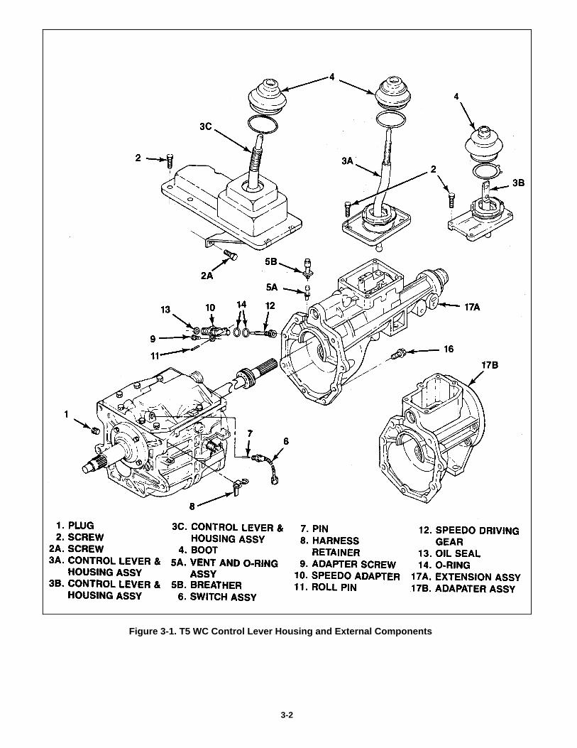
Figure 3-1. T5 WC Control Lever Housing and External Components
3-2
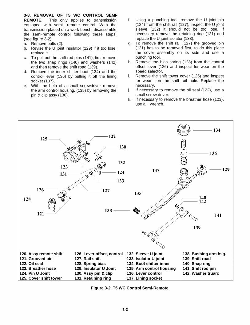
3-8. REMOVAL OF T5 WC CONTROL SEMI-REMOTE. This only applies to transmissión equipped with semi- remote control. With the transmissión placed on a work bench, disassemble the semi-remote control following these steps: (see figure 3-2) a. Remove bolts (2). b. Revise the U joint insulator (129) if it too lose,
replace it. c. To pull out the shift rod pins (141), first remove
the two snap rings (140) and washers (142) and then remove the shift road (139).
d. Remove the inner shifter boot (134) and the control lever (136) by pulling it off the lining socket (137),
e. With the help of a small screwdriver remove the arm control housing. (135) by removing the pin & clip assy (130).
f. Using a punching tool, remove the U joint pin
(124) from the shift rail (127), inspect the U joint sleeve (132) it should not be too lose. If necessary remove the retaining ring (131) and replace the U joint isolator (133).
g. To remove the shift rail (127) the grooved pin (121) has to be removed first, to do this place the cover assembly on its side and use a punching tool.
h. Remove the bias spring (128) from the control offset lever (126) and inspect for wear on the speed selector.
i. Remove the shift tower cover (125) and inspect for wear on the shift rail hole. Replace the necessary.
j. If necessary to remove the oil seal (122), use a small screw driver.
k. If necessary to remove the breather hose (123), use a wrench.
120. Assy remote shift 126. Lever offset, control 132. Sleeve U joint 138. Bushing arm hsg. 121. Grooved pin 127. Rail shift 133. Isolator U joint 139. Shift road 122. Oil seal 128. Spring bias 134. Boot shifter inner 140. Snap ring 123. Breather hose 129. Insulator U Joint 135. Arm control housing 141. Shift rod pin 124. Pin U Joint 130. Assy pin & clip 136. Lever control 142. Washer truarc 125. Cover shift tower 131. Retaining ring 137. Lining socket
Figure 3-2. T5 WC Control Semi-Remote
3-3
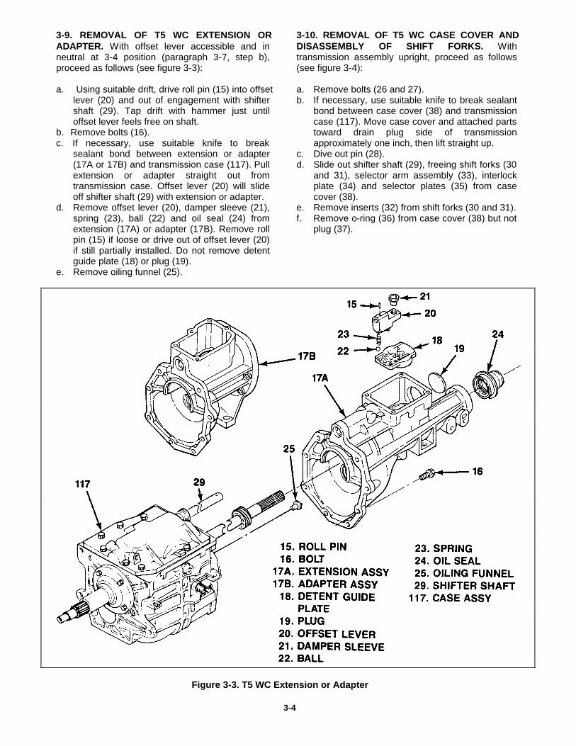
3-9. REMOVAL OF T5 WC EXTENSION OR ADAPTER. With offset lever accessible and in neutral at 3-4 position (paragraph 3-7, step b), proceed as follows (see figure 3-3): a. Using suitable drift, drive roll pin (15) into offset
lever (20) and out of engagement with shifter shaft (29). Tap drift with hammer just until offset lever feels free on shaft.
b. Remove bolts (16). c. If necessary, use suitable knife to break
sealant bond between extension or adapter (17A or 17B) and transmission case (117). Pull extension or adapter straight out from transmission case. Offset lever (20) will slide off shifter shaft (29) with extension or adapter.
d. Remove offset lever (20), damper sleeve (21), spring (23), ball (22) and oil seal (24) from extension (17A) or adapter (17B). Remove roll pin (15) if loose or drive out of offset lever (20) if still partially installed. Do not remove detent guide plate (18) or plug (19).
e. Remove oiling funnel (25).
3-10. REMOVAL OF T5 WC CASE COVER AND DISASSEMBLY OF SHIFT FORKS. With transmission assembly upright, proceed as follows (see figure 3-4): a. Remove bolts (26 and 27). b. If necessary, use suitable knife to break sealant
bond between case cover (38) and transmission case (117). Move case cover and attached parts toward drain plug side of transmission approximately one inch, then lift straight up.
c. Dive out pin (28). d. Slide out shifter shaft (29), freeing shift forks (30
and 31), selector arm assembly (33), interlock plate (34) and selector plates (35) from case cover (38).
e. Remove inserts (32) from shift forks (30 and 31). f. Remove o-ring (36) from case cover (38) but not
plug (37).
Figure 3-3. T5 WC Extension or Adapter
3-4
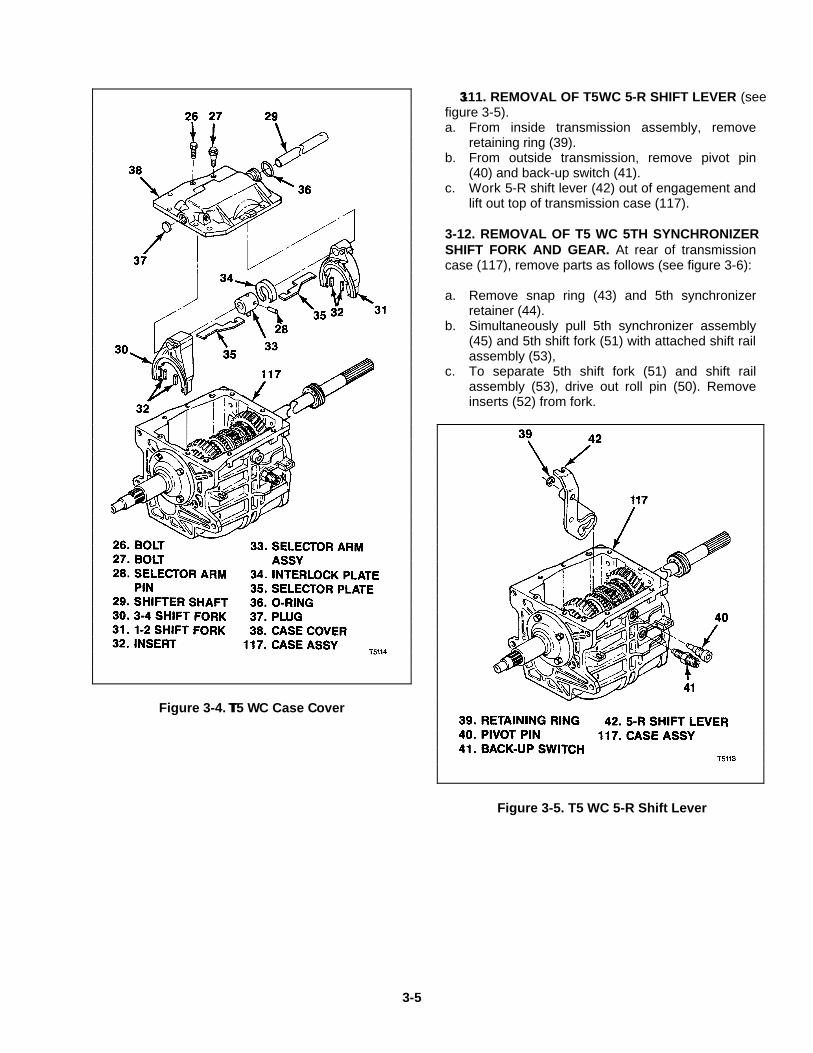
Figure 3-4. TT5 W C Case C over
3-111. REMOVAL OF T5 WC 5-R SHIFT LEVER (see figure 3-5). a. From inside transmission assembly, remove
retaining ring (39). b. From outside transmission, remove pivot pin
(40) and back-up switch (41). c. Work 5-R shift lever (42) out of engagement and
lift out top of transmission case (117). 3-12. REMOVAL OF T5 WC 5TH SYNCHRONIZER SHIFT FORK AND GEAR. At rear of transmission case (117), remove parts as follows (see figure 3-6): a. Remove snap ring (43) and 5th synchronizer
retainer (44). b. Simultaneously pull 5th synchronizer assembly
(45) and 5th shift fork (51) with attached shift rail assembly (53),
c. To separate 5th shift fork (51) and shift rail assembly (53), drive out roll pin (50). Remove inserts (52) from fork.
Figure 3-5. T5 WC 5-R Shift Lever
3-5
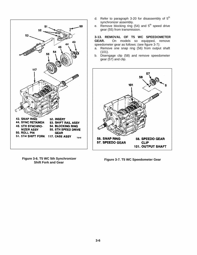
Figure 3-6. T5 WC 5th Synchronizer Shift Fork and Gear
d. Refer to paragraph 3-20 for disassembly of 5th
synchronizer assembly. e. Remove blocking ring (54) and 5th speed drive
gear (55) from transmission. 3-13. REMOVAL OF T5 WC SPEEDOMETER GEAR. On models so equipped, remove speedometer gear as follows: (see figure 3-7): a. Remove one snap ring (56) from output shaft
(101). b. Disengage clip (58) and remove speedometer
gear (57) and clip.
Figure 3-7. T5 WC Speedometer Gear
3-6
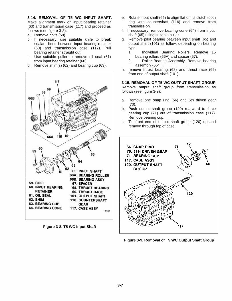
3-14. REMOVAL OF T5 WC INPUT SHAFT. Make alignment mark on input bearing retainer (60) and transmission case (117) and proceed as follows (see figure 3-8): a. Remove bolts (59). b. If necessary, use suitable knife to break
sealant bond between input bearing retainer (60) and transmission case (117). Pull bearing retainer straight out.
c. Use suitable puller to remove oil seal (61) from input bearing retainer (60).
d. Remove shim(s) (62) and bearing cup (63).
Figure 3-8. T5 WC Input Shaft
e. Rotate input shaft (65) to align flat on its clutch tooth
ring with countershaft (116) and remove from transmission.
f. If necessary, remove bearing cone (64) from input shaft (65) using suitable puller.
g. Remove pilot bearing between input shaft (65) and output shaft (101) as follow, depending on bearing type: 1. Individual Bearing Rollers. Remove 15
bearing rollers (66A) and spacer (67). 2. Roller Bearing Assembly. Remove bearing
assembly (66ª ). h. remove thrust bearing (68) and thrust race (69)
from end of output shaft (101). 3-15. REMOVAL OF T5 WC OUTPUT SHAFT GROUP. Remove output shaft group from transmission as follows (see figure 3-9): a. Remove one snap ring (56) and 5th driven gear
(70). b. Push output shaft group (120) rearward to force
bearing cup (71) out of transmission case (117). Remove bearing cup.
c. Tilt front end of output shaft group (120) up and remove through top of case.
Figure 3-9. Removal of T5 WC Output Shaft Group
3-7
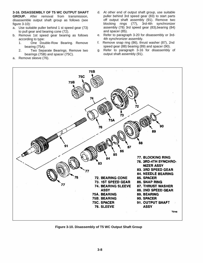
3-16. DISASSEMBLY OF T5 WC OUTPUT SHAFT GROUP. After removal from transmission, disassemble output shaft group as follows (see figure 3-10): a. Use suitable puller behind 1 st speed gear (73)
to pull gear and bearing cone (72). b. Remove 1st speed gear bearing as follows
according to type: 1. One Double-Row Bearing. Remove
bearing (75A). 2. Two Separate Bearings. Remove two
bearings (75B) and spacer (75C). a. Remove sleeve (76).
d. At other end of output shaft group, use suitable puller behind 3rd speed gear (83) to start parts off output shaft assembly (91). Remove two blocking rings (77), 3rd-4th synchronizer assembly (78) 3rd speed gear (83),bearing (84) and spacer (85).
e. Refer to paragraph 3-20 for disassembly or 3rd-4th synchronizer assembly.
f. Remove snap ring (86), thrust washer (87), 2nd speed gear (88) bearing (89) and spacer (90).
g. Refer to paragraph 3-16 for disassembly of output shaft assembly (91).
Figure 3-10. Disassembly of T5 WC Output Shaft Group
3-8
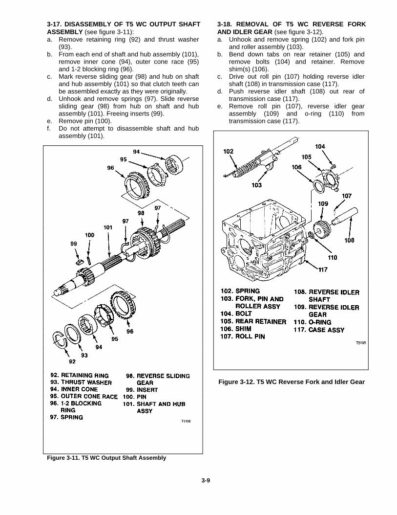
3-17. DISASSEMBLY OF T5 WC OUTPUT SHAFT ASSEMBLY (see figure 3-11): a. Remove retaining ring (92) and thrust washer
(93). b. From each end of shaft and hub assembly (101),
remove inner cone (94), outer cone race (95) and 1-2 blocking ring (96).
c. Mark reverse sliding gear (98) and hub on shaft and hub assembly (101) so that clutch teeth can be assembled exactly as they were originally.
d. Unhook and remove springs (97). Slide reverse sliding gear (98) from hub on shaft and hub assembly (101). Freeing inserts (99).
e. Remove pin (100). f. Do not attempt to disassemble shaft and hub
assembly (101).
Figure 3-11. T5 WC Output Shaft Assembly
3-18. REMOVAL OF T5 WC REVERSE FORK AND IDLER GEAR (see figure 3-12). a. Unhook and remove spring (102) and fork pin
and roller assembly (103). b. Bend down tabs on rear retainer (105) and
remove bolts (104) and retainer. Remove shim(s) (106).
c. Drive out roll pin (107) holding reverse idler shaft (108) in transmission case (117).
d. Push reverse idler shaft (108) out rear of transmission case (117).
e. Remove roll pin (107), reverse idler gear assembly (109) and o-ring (110) from transmission case (117).
Figure 3-12. T5 WC Reverse Fork and Idler Gear
3-9
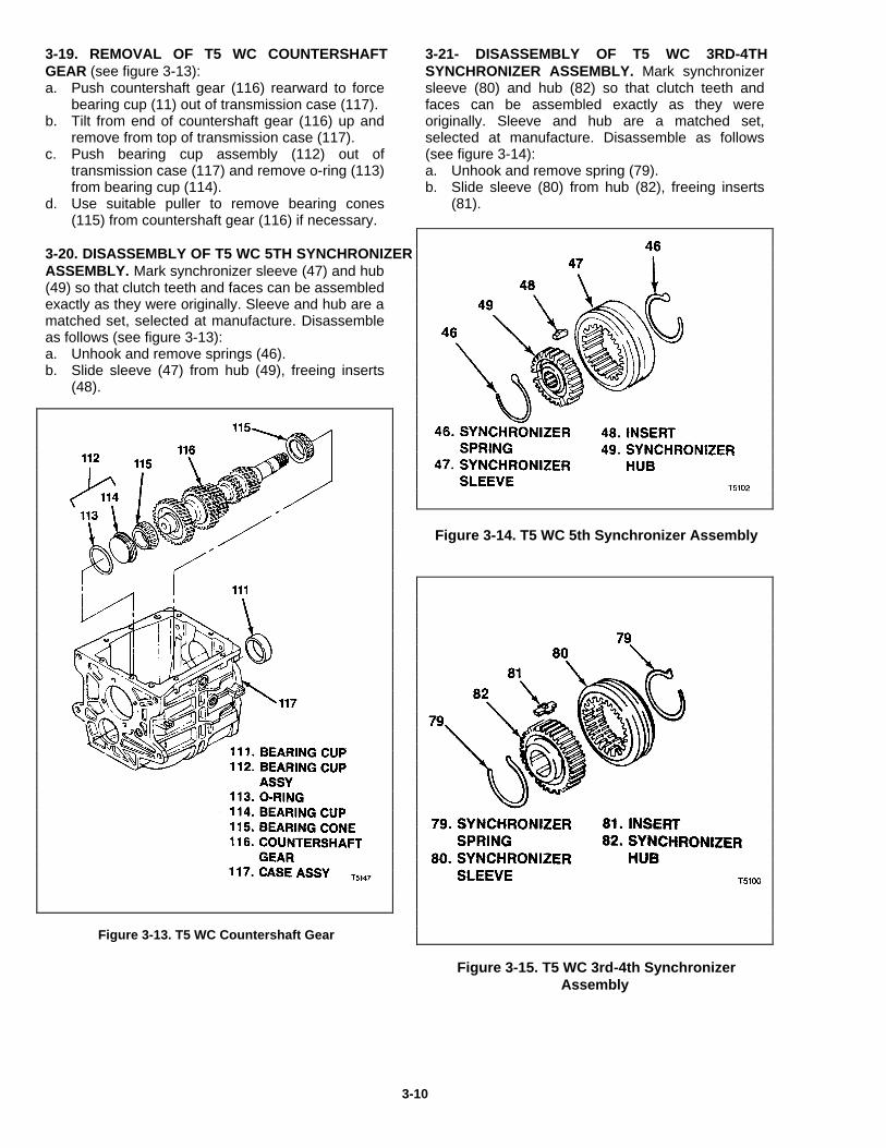
3-19. REMOVAL OF T5 WC COUNTERSHAFT GEAR (see figure 3-13): a. Push countershaft gear (116) rearward to force
bearing cup (11) out of transmission case (117). b. Tilt from end of countershaft gear (116) up and
remove from top of transmission case (117). c. Push bearing cup assembly (112) out of
transmission case (117) and remove o-ring (113) from bearing cup (114).
d. Use suitable puller to remove bearing cones (115) from countershaft gear (116) if necessary.
3-20. DISASSEMBLY OF T5 WC 5TH SYNCHRONIZER ASSEMBLY. Mark synchronizer sleeve (47) and hub (49) so that clutch teeth and faces can be assembled exactly as they were originally. Sleeve and hub are a matched set, selected at manufacture. Disassemble as follows (see figure 3-13): a. Unhook and remove springs (46). b. Slide sleeve (47) from hub (49), freeing inserts
(48).
Figure 3-13. T5 WC Countershaft Gear
3-21- DISASSEMBLY OF T5 WC 3RD-4TH SYNCHRONIZER ASSEMBLY. Mark synchronizer sleeve (80) and hub (82) so that clutch teeth and faces can be assembled exactly as they were originally. Sleeve and hub are a matched set, selected at manufacture. Disassemble as follows (see figure 3-14): a. Unhook and remove spring (79). b. Slide sleeve (80) from hub (82), freeing inserts
(81).
Figure 3-14. T5 WC 5th Synchronizer Assembly
Figure 3-15. T5 WC 3rd-4th Synchronizer Assembly
3-10

Section 4T5 STD Disassembly
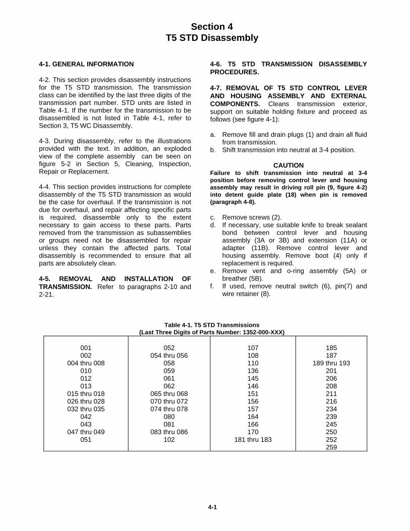
4-1. GENERAL INFORMATION
4-2. This section provides disassembly instructionsfor the T5 STD transmission. The transmissionclass can be identified by the last three digits of thetransmission part number. STD units are listed inTable 4-1. If the number for the transmission to bedisassembled is not listed in Table 4-1, refer toSection 3, T5 WC Disassembly.
4-3. During disassembly, refer to the illustrationsprovided with the text. In addition, an explodedview of the complete assembly can be seen onfigure 5-2 in Section 5, Cleaning, Inspection,Repair or Replacement.
4-4. This section provides instructions for completedisassembly of the T5 STD transmission as wouldbe the case for overhaul. If the transmission is notdue for overhaul, and repair affecting specific partsis required, disassemble only to the extentnecessary to gain access to these parts. Partsremoved from the transmission as subassembliesor groups need not be disassembled for repairunless they contain the affected parts. Totaldisassembly is recommended to ensure that allparts are absolutely clean.
4-5. REMOVAL AND INSTALLATION OFTRANSMISSION. Refer to paragraphs 2-10 and2-21.
4-6. T5 STD TRANSMISSION DISASSEMBLYPROCEDURES.
4-7. REMOVAL OF T5 STD CONTROL LEVERAND HOUSING ASSEMBLY AND EXTERNALCOMPONENTS. Cleans transmission exterior,support on suitable holding fixture and proceed asfollows (see figure 4-1):
a. Remove fill and drain plugs (1) and drain all fluidfrom transmission.
b. Shift transmission into neutral at 3-4 position.
CAUTION Failure to shift transmission into neutral at 3-4position before removing control lever and housingassembly may result in driving roll pin (9, figure 4-2)into detent guide plate (18) when pin is removed(paragraph 4-8). c. Remove screws (2).d. If necessary, use suitable knife to break sealant
bond between control lever and housingassembly (3A or 3B) and extension (11A) oradapter (11B). Remove control lever andhousing assembly. Remove boot (4) only ifreplacement is required.
e. Remove vent and o-ring assembly (5A) orbreather (5B).
f. If used, remove neutral switch (6), pin(7) andwire retainer (8).
Table 4-1. T5 STD Transmissions(Last Three Digits of Parts Number: 1352-000-XXX)
001002
004 thru 008010012013
015 thru 018026 thru 028032 thru 035
042043
047 thru 049051
052054 thru 056
058059061062
065 thru 068070 thru 072074 thru 078
080081
083 thru 086102
107108110136145146151156157164166170
181 thru 183
185187
189 thru 193201206208211216234239245250252259
4-1
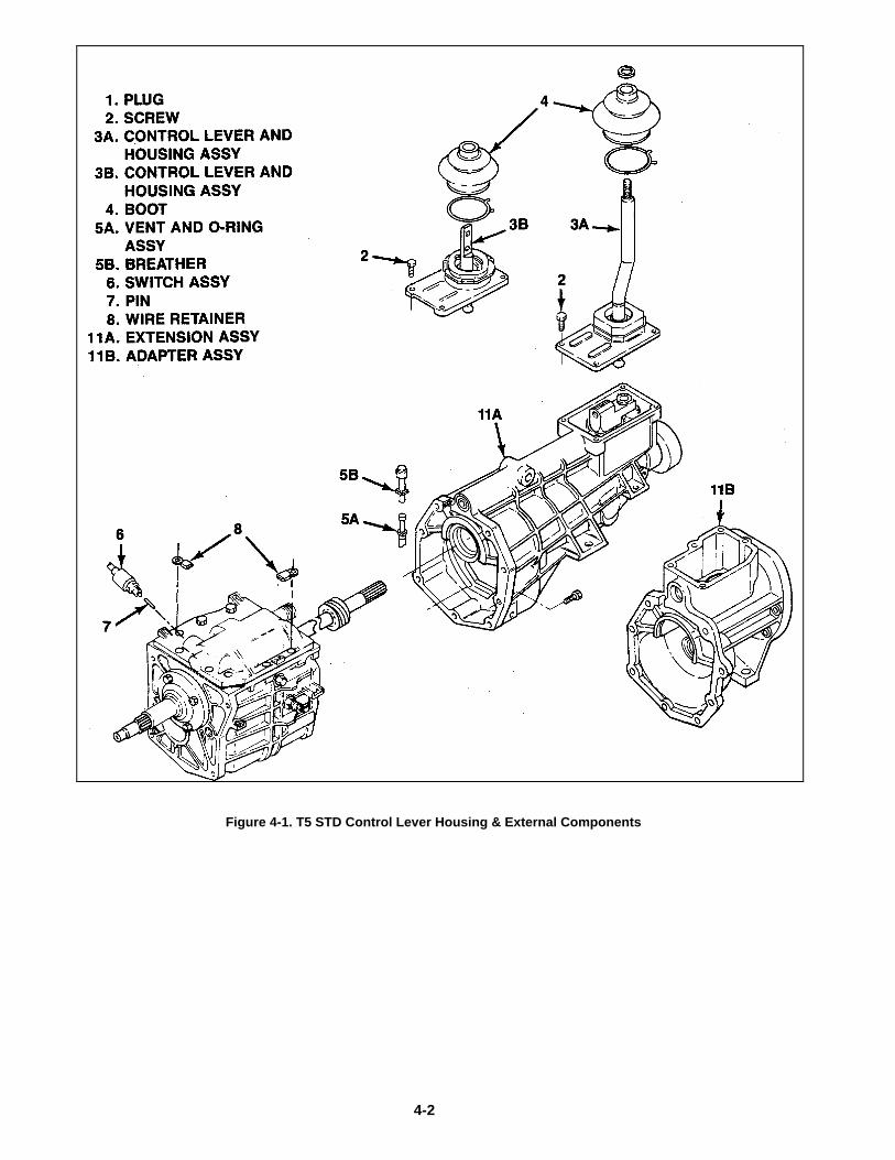
Figure 4-1. T5 STD Control Lever Housing & External Components
4-2
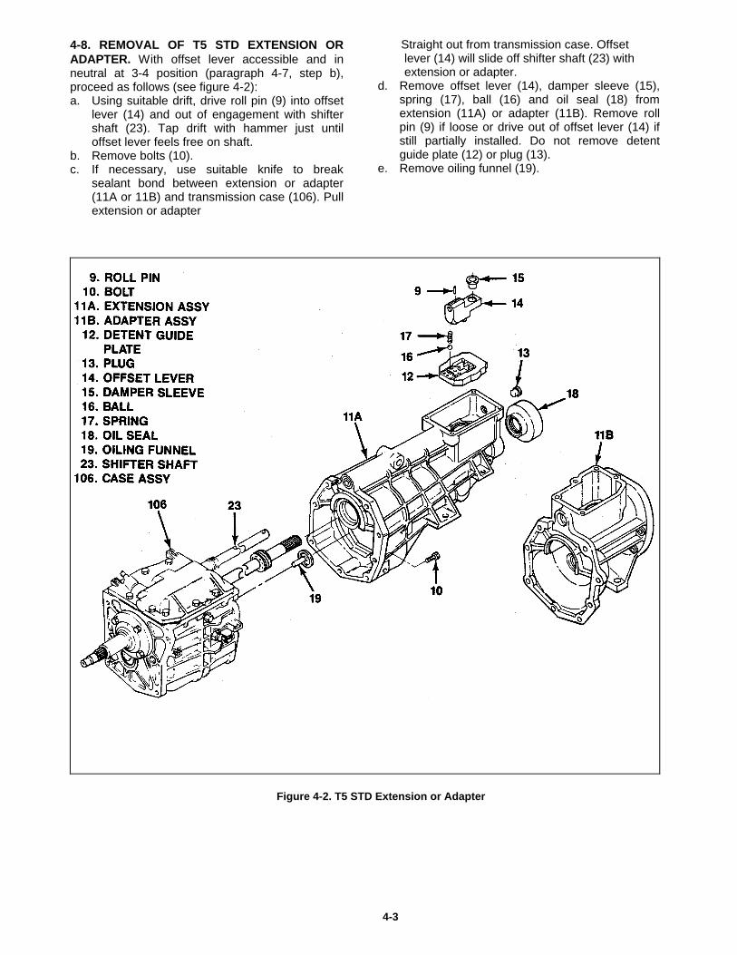
4-8. REMOVAL OF T5 STD EXTENSION ORADAPTER. With offset lever accessible and inneutral at 3-4 position (paragraph 4-7, step b),proceed as follows (see figure 4-2):a. Using suitable drift, drive roll pin (9) into offset
lever (14) and out of engagement with shiftershaft (23). Tap drift with hammer just untiloffset lever feels free on shaft.
b. Remove bolts (10).c. If necessary, use suitable knife to break
sealant bond between extension or adapter(11A or 11B) and transmission case (106). Pullextension or adapter
Straight out from transmission case. Offset lever (14) will slide off shifter shaft (23) with extension or adapter.d. Remove offset lever (14), damper sleeve (15),
spring (17), ball (16) and oil seal (18) fromextension (11A) or adapter (11B). Remove rollpin (9) if loose or drive out of offset lever (14) ifstill partially installed. Do not remove detentguide plate (12) or plug (13).
e. Remove oiling funnel (19).
Figure 4-2. T5 STD Extension or Adapter
4-3
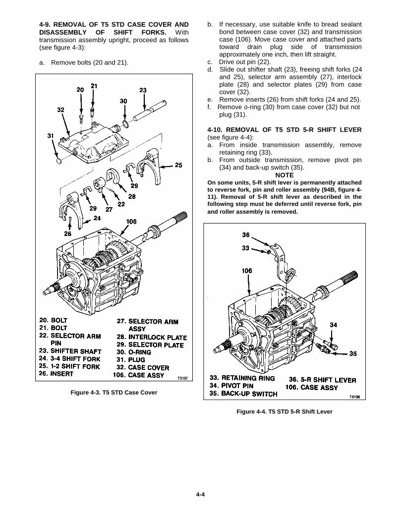
4-9. REMOVAL OF T5 STD CASE COVER ANDDISASSEMBLY OF SHIFT FORKS. Withtransmission assembly upright, proceed as follows(see figure 4-3):
a. Remove bolts (20 and 21).
Figure 4-3. T5 STD Case Cover
b. If necessary, use suitable knife to bread sealantbond between case cover (32) and transmissioncase (106). Move case cover and attached partstoward drain plug side of transmissionapproximately one inch, then lift straight.
c. Drive out pin (22).d. Slide out shifter shaft (23), freeing shift forks (24
and 25), selector arm assembly (27), interlockplate (28) and selector plates (29) from casecover (32).
e. Remove inserts (26) from shift forks (24 and 25).f. Remove o-ring (30) from case cover (32) but not
plug (31).
4-10. REMOVAL OF T5 STD 5-R SHIFT LEVER(see figure 4-4):a. From inside transmission assembly, remove
retaining ring (33).b. From outside transmission, remove pivot pin
(34) and back-up switch (35).NOTE
On some units, 5-R shift lever is permanently attachedto reverse fork, pin and roller assembly (94B, figure 4-11). Removal of 5-R shift lever as described in thefollowing step must be deferred until reverse fork, pinand roller assembly is removed.
Figure 4-4. T5 STD 5-R Shift Lever
4-4
c. Work 5-R shift lever (36) out of engagement andlift out top of transmission case (106).
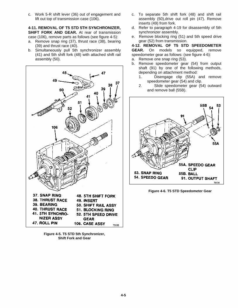
4-11. REMOVAL OF T5 STD 5TH SYNCHRONIZER,SHIFT FORK AND GEAR. At rear of transmissioncase (106), remove parts as follows (see figure 4-5):a. Remove snap ring (37), thrust race (38), bearing
(39) and thrust race (40).b. Simultaneously pull 5th synchronizer assembly
(41) and 5th shift fork (48) with attached shift railassembly (50).
Figure 4-5. T5 STD 5th Synchronizer,Shift Fork and Gear
c. To separate 5th shift fork (48) and shift railassembly (50),drive out roll pin (47). Removeinserts (49) from fork.
d. Refer to paragraph 4-19 for disassembly of 5thsynchronizer assembly.
e. Remove blocking ring (51) and 5th speed drivegear (52) from transmission.
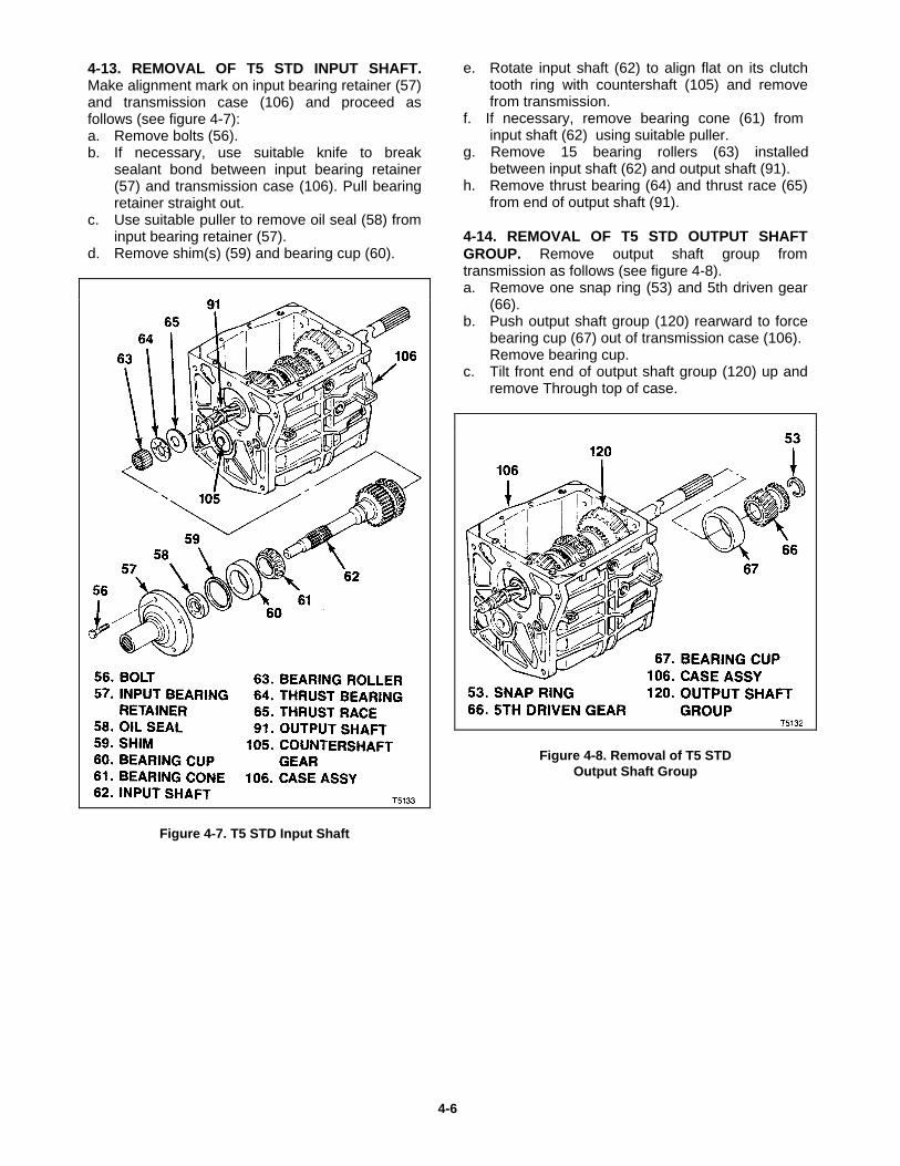
4-12. REMOVAL OF T5 STD SPEEDOMETERGEAR. On models so equipped, removespeedometer gear as follows: (see figure 4-6):a. Remove one snap ring (53).b. Remove speedometer gear (54) from output
shaft (91) by one of the following methods,depending on attachment method:1. Disengage clip (55A) and remove
speedometer gear (54) and clip.2. Slide speedometer gear (54) outward
and remove ball (55B).
Figure 4-6. T5 STD Speedometer Gear
4-5
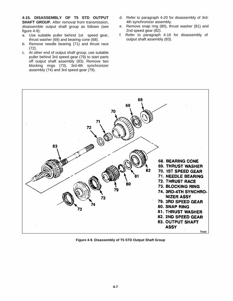
4-13. REMOVAL OF T5 STD INPUT SHAFT.Make alignment mark on input bearing retainer (57)and transmission case (106) and proceed asfollows (see figure 4-7):a. Remove bolts (56).b. If necessary, use suitable knife to break
sealant bond between input bearing retainer(57) and transmission case (106). Pull bearingretainer straight out.
c. Use suitable puller to remove oil seal (58) frominput bearing retainer (57).
d. Remove shim(s) (59) and bearing cup (60).
Figure 4-7. T5 STD Input Shaft
e. Rotate input shaft (62) to align flat on its clutchtooth ring with countershaft (105) and removefrom transmission.
f. If necessary, remove bearing cone (61) frominput shaft (62) using suitable puller.
g. Remove 15 bearing rollers (63) installedbetween input shaft (62) and output shaft (91).
h. Remove thrust bearing (64) and thrust race (65)from end of output shaft (91).
4-14. REMOVAL OF T5 STD OUTPUT SHAFTGROUP. Remove output shaft group fromtransmission as follows (see figure 4-8).a. Remove one snap ring (53) and 5th driven gear
(66).b. Push output shaft group (120) rearward to force
bearing cup (67) out of transmission case (106). Remove bearing cup.
c. Tilt front end of output shaft group (120) up andremove Through top of case.
Figure 4-8. Removal of T5 STDOutput Shaft Group
4-6
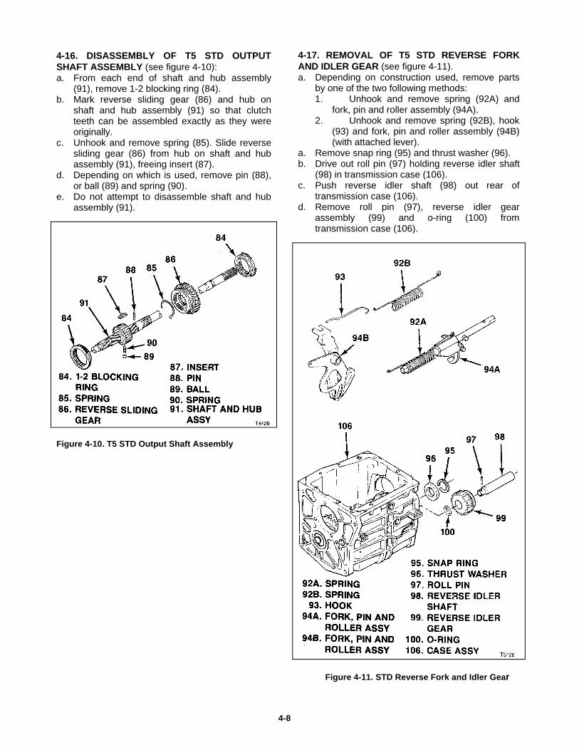
4-15. DISASSEMBLY OF T5 STD OUTPUTSHAFT GROUP. After removal from transmission,disassemble output shaft group as follows (seefigure 4-9):a. Use suitable puller behind 1st speed gear,
thrust washer (69) and bearing cone (68).b. Remove needle bearing (71) and thrust race
(72).c. At other end of output shaft group, use suitable
puller behind 3rd speed gear (79) to start partsoff output shaft assembly (83). Remove twoblocking rings (73), 3rd-4th synchronizerassembly (74) and 3rd speed gear (79).
d. Refer to paragraph 4-20 for disassembly of 3rd-4th synchronizer assembly.
e. Remove snap ring (80), thrust washer (81) and2nd speed gear (82).
f. Refer to paragraph 4-16 for disassembly ofoutput shaft assembly (83).
Figure 4-9. Disassembly of T5 STD Output Shaft Group
4-7
4-16. DISASSEMBLY OF T5 STD OUTPUTSHAFT ASSEMBLY (see figure 4-10):a. From each end of shaft and hub assembly
(91), remove 1-2 blocking ring (84).b. Mark reverse sliding gear (86) and hub on
shaft and hub assembly (91) so that clutchteeth can be assembled exactly as they wereoriginally.
c. Unhook and remove spring (85). Slide reversesliding gear (86) from hub on shaft and hubassembly (91), freeing insert (87).
d. Depending on which is used, remove pin (88),or ball (89) and spring (90).
e. Do not attempt to disassemble shaft and hubassembly (91).
Figure 4-10. T5 STD Output Shaft Assembly
4-17. REMOVAL OF T5 STD REVERSE FORKAND IDLER GEAR (see figure 4-11).a. Depending on construction used, remove parts
by one of the two following methods:1. Unhook and remove spring (92A) and
fork, pin and roller assembly (94A).2. Unhook and remove spring (92B), hook
(93) and fork, pin and roller assembly (94B)(with attached lever).
a. Remove snap ring (95) and thrust washer (96).b. Drive out roll pin (97) holding reverse idler shaft
(98) in transmission case (106).c. Push reverse idler shaft (98) out rear of
transmission case (106).d. Remove roll pin (97), reverse idler gear
assembly (99) and o-ring (100) fromtransmission case (106).
Figure 4-11. STD Reverse Fork and Idler Gear
4-8
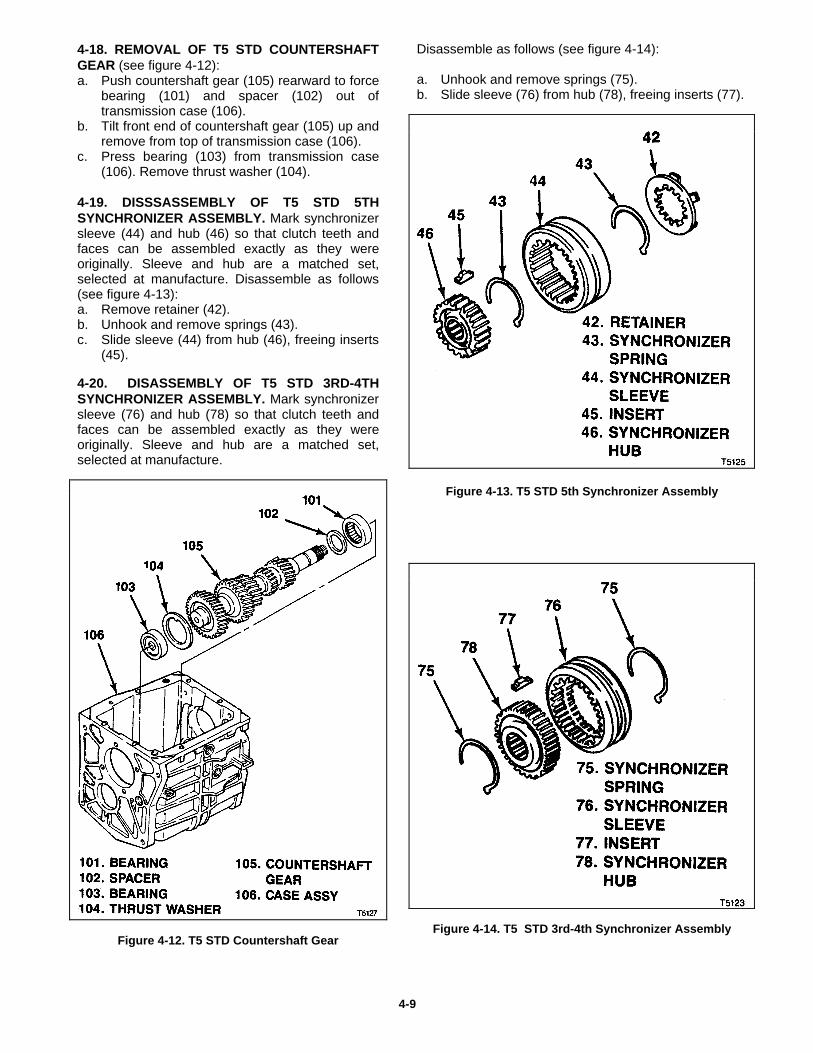
4-18. REMOVAL OF T5 STD COUNTERSHAFTGEAR (see figure 4-12):a. Push countershaft gear (105) rearward to force
bearing (101) and spacer (102) out oftransmission case (106).
b. Tilt front end of countershaft gear (105) up andremove from top of transmission case (106).
c. Press bearing (103) from transmission case(106). Remove thrust washer (104).
4-19. DISSSASSEMBLY OF T5 STD 5THSYNCHRONIZER ASSEMBLY. Mark synchronizersleeve (44) and hub (46) so that clutch teeth andfaces can be assembled exactly as they wereoriginally. Sleeve and hub are a matched set,selected at manufacture. Disassemble as follows(see figure 4-13):a. Remove retainer (42).b. Unhook and remove springs (43).c. Slide sleeve (44) from hub (46), freeing inserts
(45).
4-20. DISASSEMBLY OF T5 STD 3RD-4THSYNCHRONIZER ASSEMBLY. Mark synchronizersleeve (76) and hub (78) so that clutch teeth andfaces can be assembled exactly as they wereoriginally. Sleeve and hub are a matched set,selected at manufacture.
Figure 4-12. T5 STD Countershaft Gear
Disassemble as follows (see figure 4-14):
a. Unhook and remove springs (75).b. Slide sleeve (76) from hub (78), freeing inserts (77).
Figure 4-13. T5 STD 5th Synchronizer Assembly
Figure 4-14. T5 STD 3rd-4th Synchronizer Assembly
4-9

Section 5T5 WC & STD Cleaning, Inspection, Repair or Replacement
5-1. CLEANING
NOTEPrior cleaning transmission case, check magnetcemented in case bottom for presence of metalparticles. Larger, granular or irregular shapedparticles indicate chipping or similar damage.Smaller, powder-like particles indicate uneven orexcessive wear. If metal particles are detected, beon the lookout for damage or wear when inspectingrotating parts and those with which they mate.
5-2. GENERAL CLEANING PROCEDURE.Carefully scrape parts to remove old sealant usingcare not to damage metal surfaces. Wash parts incleaning solvent to remove old lubricant and dirtdeposits. Use a bristle brush to remove caked-ondeposits. Parts that cannon be cleaned by brushingmay be scraped but use care not to damage metalsurfaces.
5-3. DRYING CLEANED PARTS. Dry parts withlow pressure (20 psi max) compressed air. Wipingparts dry could leave lint deposits. Holt bearings toprevent them from spinning when drying.
5-4. LUBRICATING BEARINGS. Immediately aftercleaning, lubricate anti-friction bearings listed belowwith transmission lubricant (refer to paragraph 2-4).Rotating or spinning dry, unlubricated bearings couldresult in damage. Cover lubricated bearing to protectfrom dust.
a. T5 WC Anti-Friction Bearings ( see figure 5-1):
Bearing cone (64). Bearing rollers (66A) or bearing assy (66B) Thrust bearing (68) Bearing cone (72) Bearing (75A) or bearing (75B) Needle bearing (84) 2nd speed bearing (89) Bearing cones (115)
b. T5 STD Anti-Friction Bearing ( see figure 5-2):
Bearing (39)Bearing cone (61)Bearing rollers (63)Thrust bearing (64)Bearing cone (68)Needle bearing (71)Bearing (101)Bearing(103)
5-1
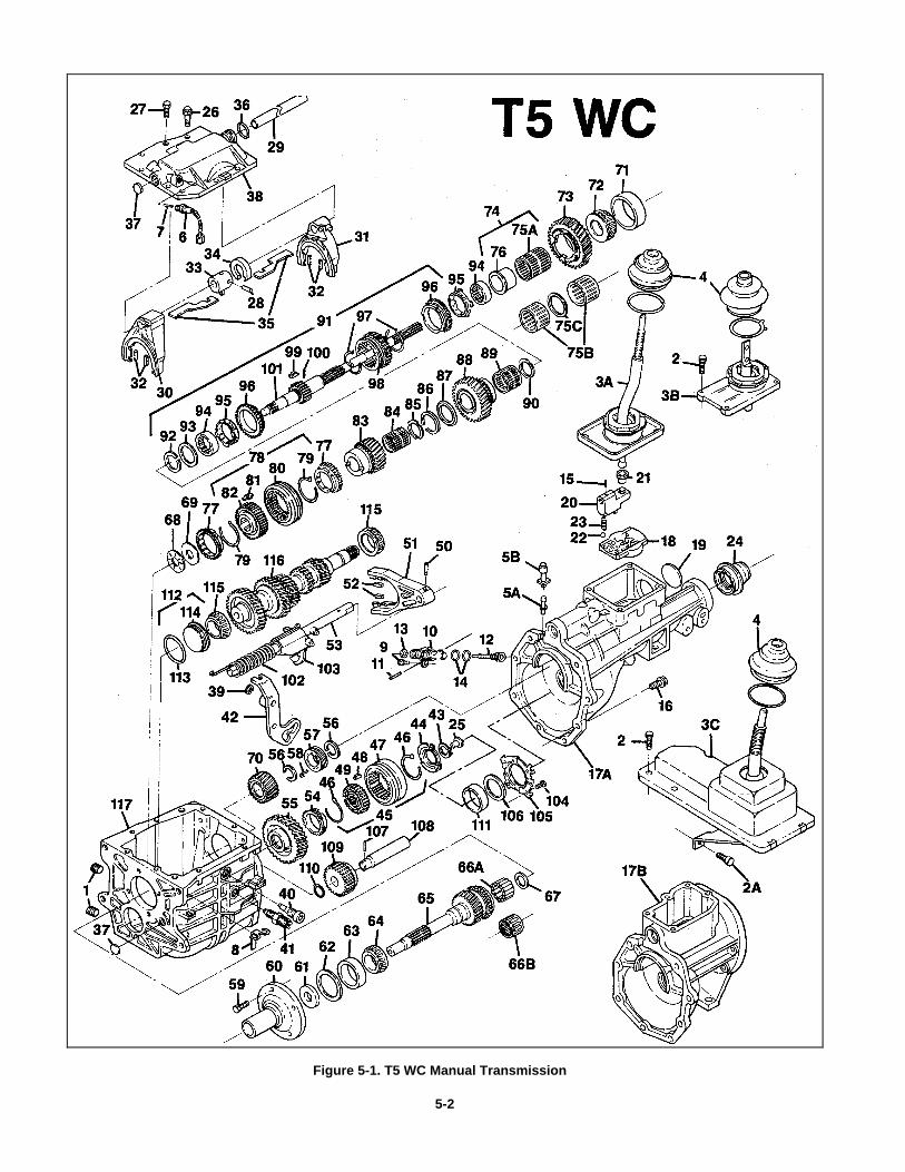
Figure 5-1. T5 WC Manual Transmission
5-2
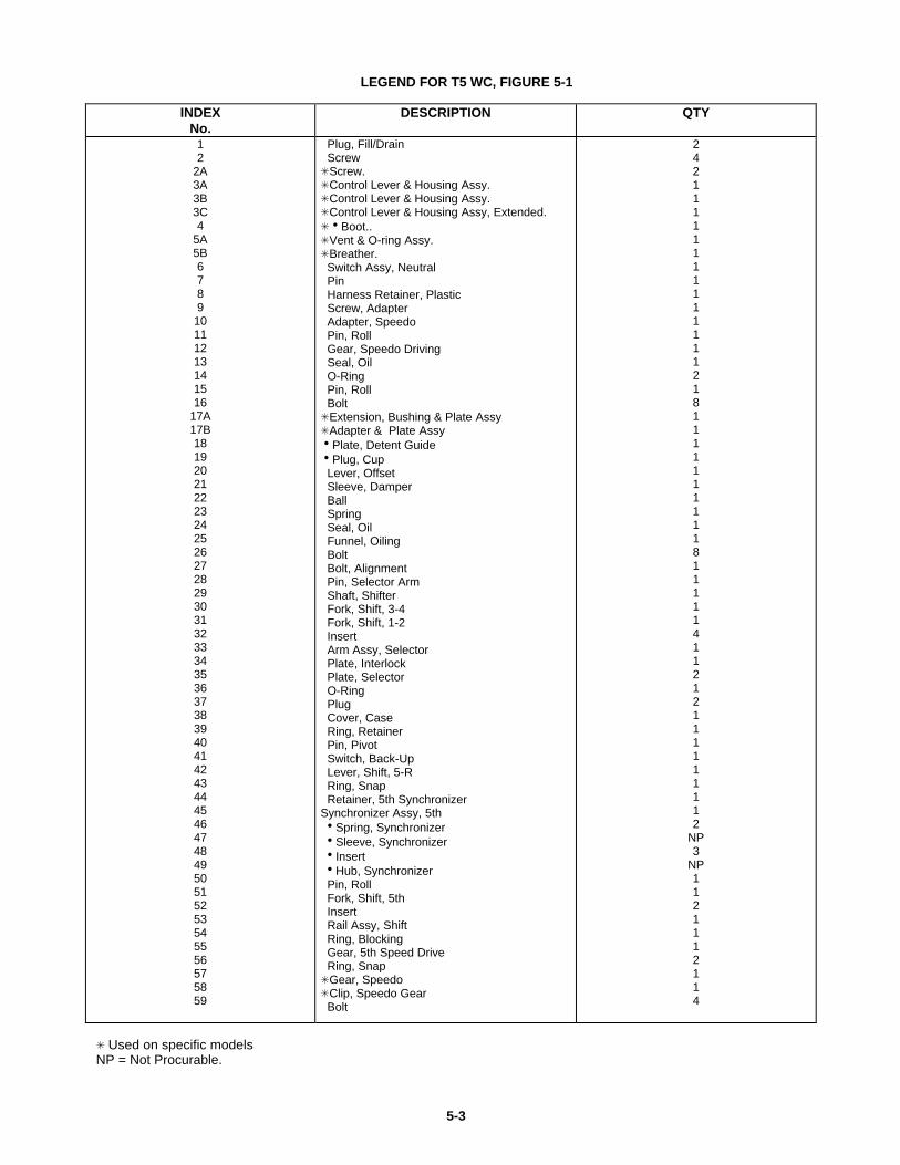
LEGEND FOR T5 WC, FIGURE 5-1
INDEXNo.
DESCRIPTION QTY
12
2A3A3B3C4
5A5B6789
10111213141516
17A17B181920212223242526272829303132333435363738394041424344454647484950515253545556575859
Plug, Fill/Drain ScrewSScrew.SControl Lever & Housing Assy.SControl Lever & Housing Assy.SControl Lever & Housing Assy, Extended.ShBoot..SVent & O-ring Assy.SBreather. Switch Assy, Neutral Pin Harness Retainer, Plastic Screw, Adapter Adapter, Speedo Pin, Roll Gear, Speedo Driving Seal, Oil O-Ring Pin, Roll BoltSExtension, Bushing & Plate AssySAdapter & Plate AssyhPlate, Detent GuidehPlug, Cup Lever, Offset Sleeve, Damper Ball Spring Seal, Oil Funnel, Oiling Bolt Bolt, Alignment Pin, Selector Arm Shaft, Shifter Fork, Shift, 3-4 Fork, Shift, 1-2 Insert Arm Assy, Selector Plate, Interlock Plate, Selector O-Ring Plug Cover, Case Ring, Retainer Pin, Pivot Switch, Back-Up Lever, Shift, 5-R Ring, Snap Retainer, 5th SynchronizerSynchronizer Assy, 5th hSpring, Synchronizer hSleeve, Synchronizer hInsert hHub, Synchronizer Pin, Roll Fork, Shift, 5th Insert Rail Assy, Shift Ring, Blocking Gear, 5th Speed Drive Ring, SnapSGear, SpeedoSClip, Speedo Gear Bolt
242111111111111112181111111111811111411212111111112
NP3
NP1121112114
S Used on specific modelsNP = Not Procurable.
5-3
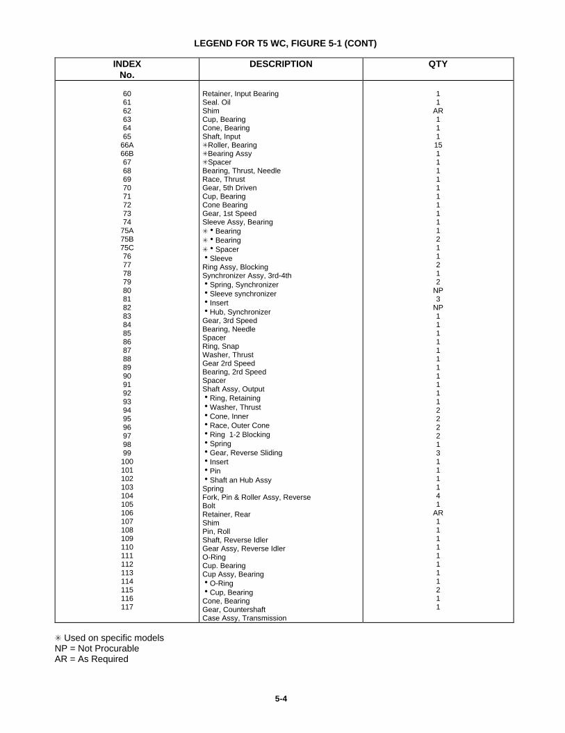
LEGEND FOR T5 WC, FIGURE 5-1 (CONT)
INDEXNo.
DESCRIPTION QTY
606162636465
66A66B6768697071727374
75A75B75C767778798081828384858687888990919293949596979899100101102103104105106107108109110111112113114115116117
Retainer, Input BearingSeal. OilShimCup, BearingCone, BearingShaft, InputSRoller, BearingSBearing AssySSpacerBearing, Thrust, NeedleRace, ThrustGear, 5th DrivenCup, BearingCone BearingGear, 1st SpeedSleeve Assy, BearingShBearingShBearingShSpacerhSleeveRing Assy, BlockingSynchronizer Assy, 3rd-4thhSpring, SynchronizerhSleeve synchronizerhInserthHub, SynchronizerGear, 3rd SpeedBearing, NeedleSpacerRing, SnapWasher, ThrustGear 2rd SpeedBearing, 2rd SpeedSpacerShaft Assy, OutputhRing, RetaininghWasher, ThrusthCone, InnerhRace, Outer ConehRing 1-2 BlockinghSpringhGear, Reverse SlidinghInserthPinhShaft an Hub AssySpringFork, Pin & Roller Assy, ReverseBoltRetainer, RearShimPin, RollShaft, Reverse IdlerGear Assy, Reverse IdlerO-RingCup. BearingCup Assy, BearinghO-RinghCup, BearingCone, BearingGear, CountershaftCase Assy, Transmission
11
AR111151111111111211212
NP3
NP11111111111222213111141
AR11111111211
S Used on specific models NP = Not Procurable AR = As Required
5-4
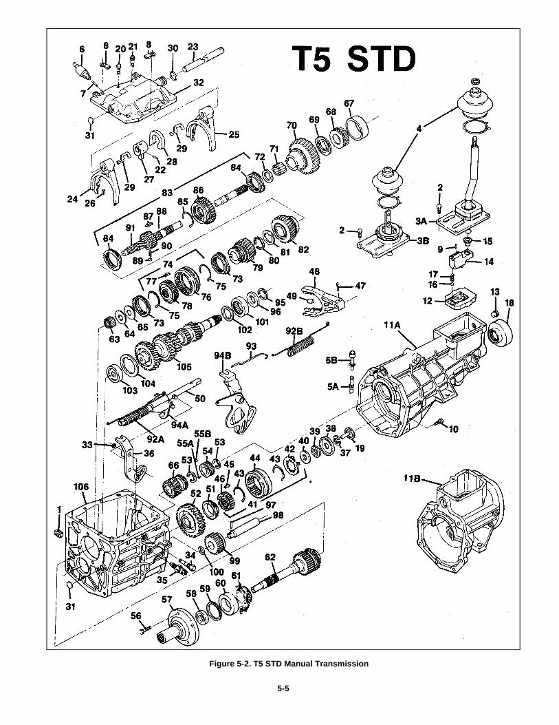
Figure 5-2. T5 STD Manual Transmission
5-5
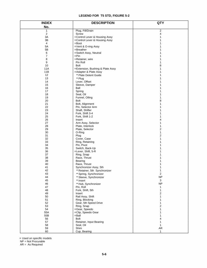
LEGEND FOR T5 STD, FIGURE 5-2
INDEXNo.
DESCRIPTION QTY
1 Plug, Fill/Drain 22 Screw 4
3A SControl Lever & Housing Assy 13B SControl Lever & Housing Assy 14 SBoot 1
5A SVent & O-ring Assy 15B SBreather 16 SSwitch Assy, Neutral 17 SPin 18 SRetainer, wire 19 Pin Roll 1
10 Bolt 811A SExtension, Bushing & Plate Assy 111B SAdapter & Plate Assy 112 hPlate Detent Guide 113 hPlug 114 Lever, Offset 115 Sleeve, Damper 116 Ball 117 Spring 118 Seal, Oil 119 Funnel, Oiling 120 Bolt 821 Bolt, Alignment 122 Pin, Selector Arm 123 Shaft, Shifter 124 Fork, Shift 3-4 125 Fork, Shift 1-2 126 Insert 427 Arm Assy, Selector 128 Plate, Interlock 129 Plate, Selector 230 O-Ring 131 Plug 232 Cover, Case 133 Ring, Retaining 134 Pin, Pivot 135 Switch, Back-Up 136 SLever, Shift, 5-R 137 Ring, Snap 138 Race, Thrust 139 Bearing 140 Race, Thrust 141 Synchronizer Assy, 5th 142 hRetainer, 5th Synchronizer 143 hSpring, Synchronizer 244 hSleeve, Synchronizer NP45 hInsert 346 hHub, Synchronizer NP47 Pin, Roll 148 Fork, Shift, 5th 149 Insert 250 Rail Assy, Shift 151 Ring, Blocking 152 Gear, 5th Speed Drive 153 Ring, Snap 254 SGear, Speedo 1
55A SClip, Speedo Gear 155B SBall 156 Bolt 457 Retainer, Input Bearing 158 Seal, Oil 159 Shim AR60 Cup, Bearing 1
S Used on specific models NP = Not Procurable AR = As Required
5-6
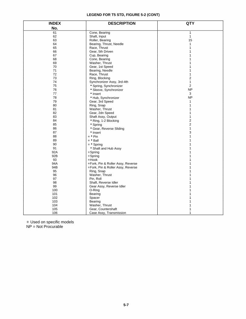
LEGEND FOR T5 STD, FIGURE 5-2 (CONT)
INDEXNo.
DESCRIPTION QTY
61 Cone, Bearing 162 Shaft, Input 163 Roller, Bearing 1564 Bearing, Thrust, Needle 165 Race, Thrust 166 Gear, 5th Driven 167 Cup, Bearing 168 Cone, Bearing 169 Washer, Thrust 170 Gear, 1st Speed 171 Bearing, Needle 172 Race, Thrust 173 Ring, Blocking 274 Synchronizer Assy, 3rd-4th 175 hSpring, Synchronizer 276 hSleeve, Synchronizer NP77 hInsert 378 hHub, Synchronizer NP79 Gear, 3rd Speed 180 Ring, Snap 181 Washer, Thrust 182 Gear, 2dn Speed 183 Shaft Assy, Output 184 hRing, 1-2 Blocking 285 hSpring 286 hGear, Reverse Sliding 187 hInsert 388 ShPin 189 ShBall 190 ShSpring 191 hShaft and Hub Assy 1
92A SSpring 192B SSpring 193 SHook 1
94A SFork, Pin & Roller Assy, Reverse 194B SFork, Pin & Roller Assy, Reverse 195 Ring, Snap 196 Washer, Thrust 197 Pin, Roll 198 Shaft, Reverse Idler 199 Gear Assy, Reverse Idler 1100 O-Ring 1101 Bearing 1102 Spacer 1103 Bearing 1104 Washer, Thrust 1105 Gear, Countershaft 1106 Case Assy, Transmission 1
S Used on specific modelsNP = Not Procurable
5-7
5-5. INSPECTION
5-6. GENERAL INSPECTION PROCEDURES.Visually inspect all parts except o-rings and oilseals, which should be replaced with new parts, orparts in kit if service kit is used. Inspect for damageor excessive or uneven wear. Reject parts withdamage or wear that would affect serviceability ofthe part. Inspection terms used in this section areas follows.
Burr: Local rise of material forming protrudingsharp edge.
Chip: An area from which a small fragment hasbeen broken of or cut.
Crack: Surface break of line nature indicatingpartial or complete separation of material.
Excessive wear: Heavy or obvious wear beyondexpectations considering condition of operation.
Indentation: displacement of material caused bylocalized heavy contact.
Galling: Breakdown (or build-up) of metal surfacedue to excessive friction between parts. Particles ofthe softer material are torn loose and welded to theharder material.
Nick: Local break or notch. Usually displacementof material rather than loss.
Scoring: Tear or break in metal surface fromcontact under pressure. May show discolorationfrom heat produced by friction.
Step wear: Heavy wear that produces a step thatcan be seen or felt between adjacent contact andnoncontact surfaces.
Uneven wear: Condition of localizer, unevenlydistributed wear. Includes hollows, shiny spots,uneven polish and other visual indications.
5-7. SPECIFIC INSPECTION PROCEDURES.Inspect parts in accordance with Table 5-1 (T5 WC)or 5-2 (T5 STD) and as specified in the followingparagraphs. Index numbers used in Table 5-1 and5-2 are those assigned to exploded view figures 5-1 (T5 WC) and 5-2 (T5 STD).
5-8. GEAR OR CLUTCH TEETH INSPECTION.When specified in Table 5-1 or 5-2, inspect gear orclutch teeth as follows:
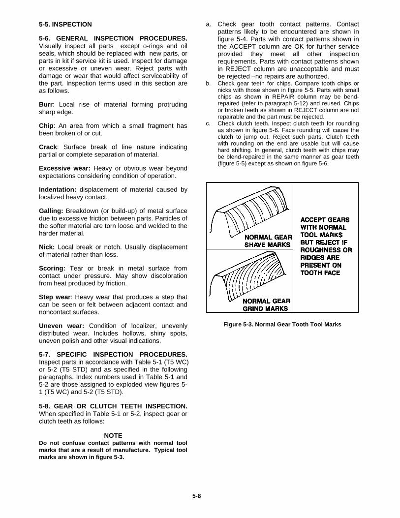
NOTEDo not confuse contact patterns with normal toolmarks that are a result of manufacture. Typical toolmarks are shown in figure 5-3.
a. Check gear tooth contact patterns. Contactpatterns likely to be encountered are shown infigure 5-4. Parts with contact patterns shown inthe ACCEPT column are OK for further serviceprovided they meet all other inspectionrequirements. Parts with contact patterns shownin REJECT column are unacceptable and mustbe rejected –no repairs are authorized.
b. Check gear teeth for chips. Compare tooth chips ornicks with those shown in figure 5-5. Parts with smallchips as shown in REPAIR column may be bend-repaired (refer to paragraph 5-12) and reused. Chipsor broken teeth as shown in REJECT column are notrepairable and the part must be rejected.
c. Check clutch teeth. Inspect clutch teeth for roundingas shown in figure 5-6. Face rounding will cause theclutch to jump out. Reject such parts. Clutch teethwith rounding on the end are usable but will causehard shifting. In general, clutch teeth with chips maybe blend-repaired in the same manner as gear teeth(figure 5-5) except as shown on figure 5-6.
Figure 5-3. Normal Gear Tooth Tool Marks
5-8
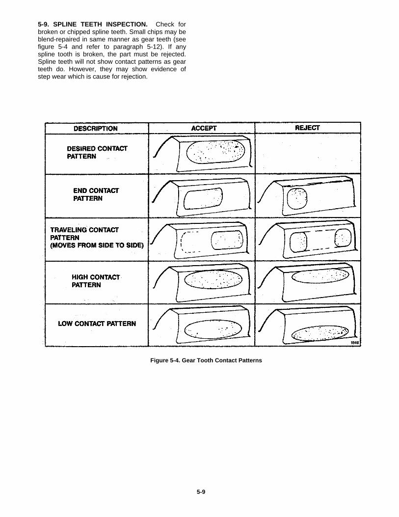
5-9. SPLINE TEETH INSPECTION. Check forbroken or chipped spline teeth. Small chips may beblend-repaired in same manner as gear teeth (seefigure 5-4 and refer to paragraph 5-12). If anyspline tooth is broken, the part must be rejected.Spline teeth will not show contact patterns as gearteeth do. However, they may show evidence ofstep wear which is cause for rejection.
Figure 5-4. Gear Tooth Contact Patterns
5-9
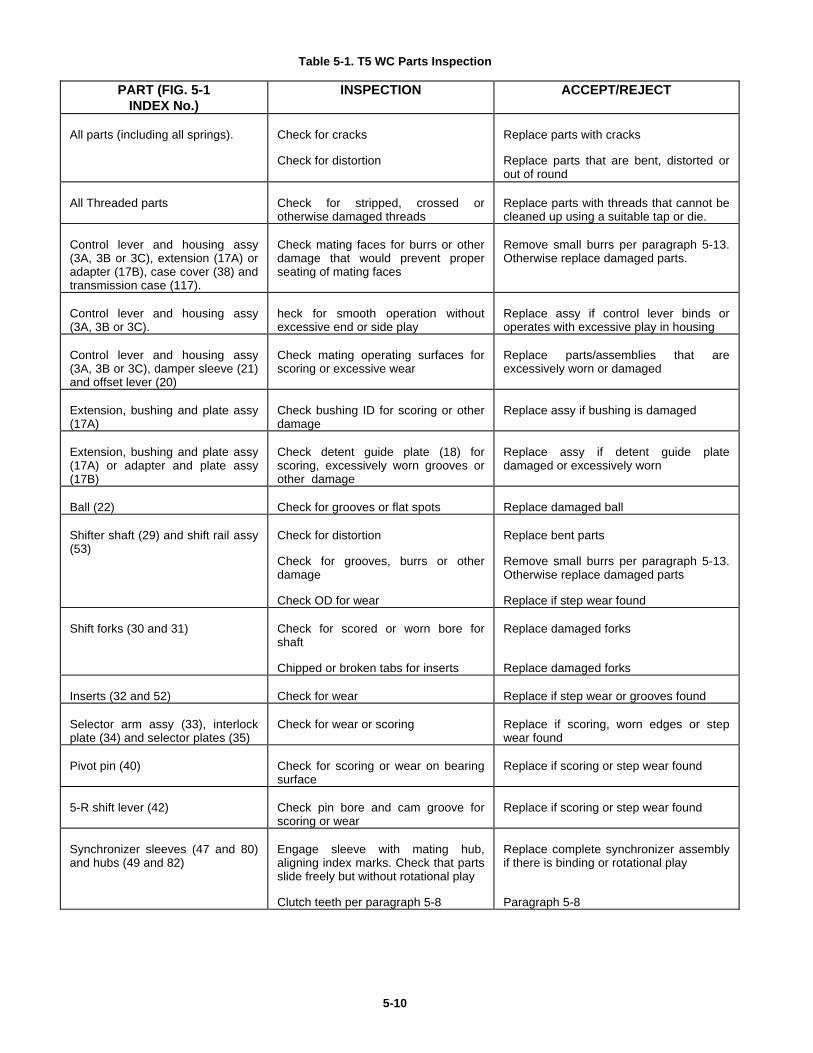
Table 5-1. T5 WC Parts Inspection
PART (FIG. 5-1INDEX No.)
INSPECTION ACCEPT/REJECT
All parts (including all springs). Check for cracks
Check for distortion
Replace parts with cracks
Replace parts that are bent, distorted orout of round
All Threaded parts Check for stripped, crossed orotherwise damaged threads
Replace parts with threads that cannot becleaned up using a suitable tap or die.
Control lever and housing assy(3A, 3B or 3C), extension (17A) oradapter (17B), case cover (38) andtransmission case (117).
Check mating faces for burrs or otherdamage that would prevent properseating of mating faces
Remove small burrs per paragraph 5-13.Otherwise replace damaged parts.
Control lever and housing assy(3A, 3B or 3C).
heck for smooth operation withoutexcessive end or side play
Replace assy if control lever binds oroperates with excessive play in housing
Control lever and housing assy(3A, 3B or 3C), damper sleeve (21)and offset lever (20)
Check mating operating surfaces forscoring or excessive wear
Replace parts/assemblies that areexcessively worn or damaged
Extension, bushing and plate assy(17A)
Check bushing ID for scoring or otherdamage
Replace assy if bushing is damaged
Extension, bushing and plate assy(17A) or adapter and plate assy(17B)
Check detent guide plate (18) forscoring, excessively worn grooves orother damage
Replace assy if detent guide platedamaged or excessively worn
Ball (22) Check for grooves or flat spots Replace damaged ball
Shifter shaft (29) and shift rail assy(53)
Check for distortion
Check for grooves, burrs or otherdamage
Check OD for wear
Replace bent parts
Remove small burrs per paragraph 5-13.Otherwise replace damaged parts
Replace if step wear found
Shift forks (30 and 31) Check for scored or worn bore forshaft
Chipped or broken tabs for inserts
Replace damaged forks
Replace damaged forks
Inserts (32 and 52) Check for wear Replace if step wear or grooves found
Selector arm assy (33), interlockplate (34) and selector plates (35)
Check for wear or scoring Replace if scoring, worn edges or stepwear found
Pivot pin (40) Check for scoring or wear on bearingsurface
Replace if scoring or step wear found
5-R shift lever (42) Check pin bore and cam groove forscoring or wear
Replace if scoring or step wear found
Synchronizer sleeves (47 and 80)and hubs (49 and 82)
Engage sleeve with mating hub,aligning index marks. Check that partsslide freely but without rotational play
Clutch teeth per paragraph 5-8
Replace complete synchronizer assemblyif there is binding or rotational play
Paragraph 5-8
5-10
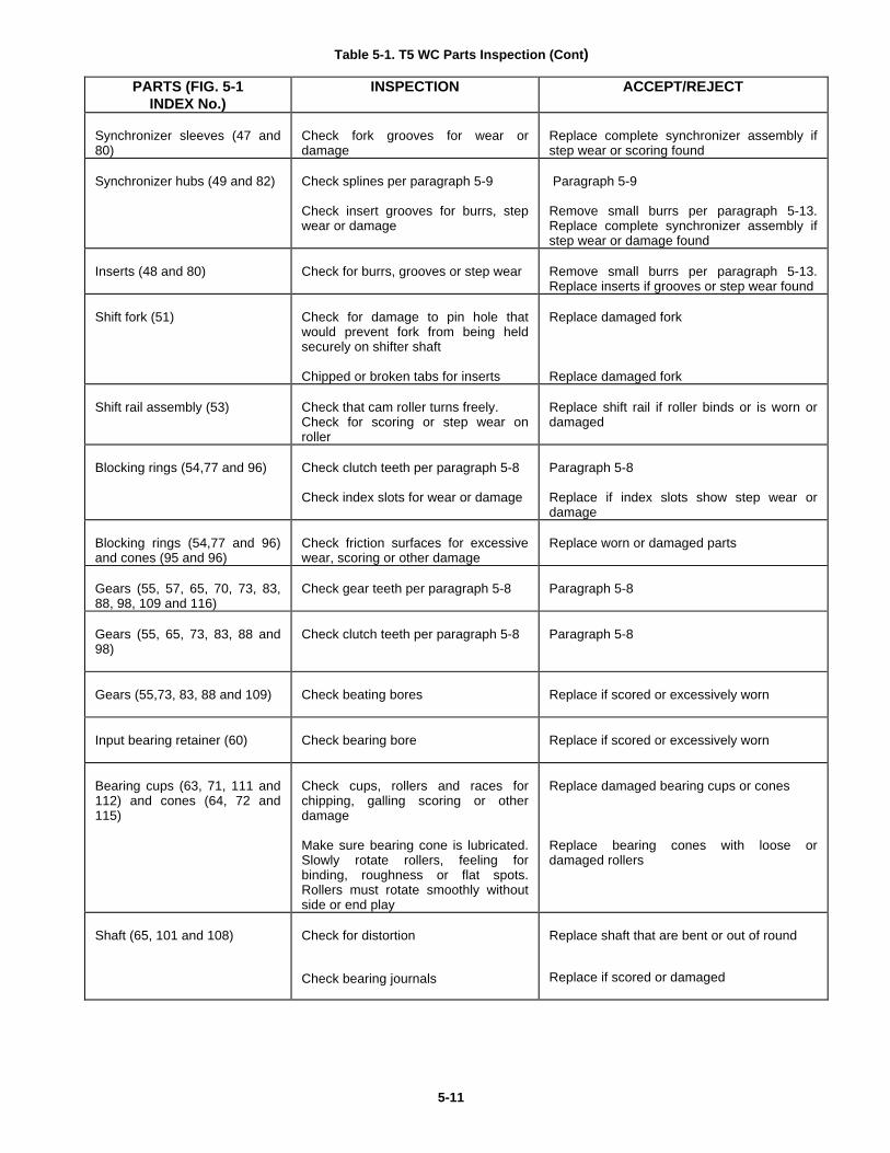
Table 5-1. T5 WC Parts Inspection (Cont)
PARTS (FIG. 5-1INDEX No.)
INSPECTION ACCEPT/REJECT
Synchronizer sleeves (47 and80)
Check fork grooves for wear ordamage
Replace complete synchronizer assembly ifstep wear or scoring found
Synchronizer hubs (49 and 82) Check splines per paragraph 5-9
Check insert grooves for burrs, stepwear or damage
Paragraph 5-9
Remove small burrs per paragraph 5-13.Replace complete synchronizer assembly ifstep wear or damage found
Inserts (48 and 80) Check for burrs, grooves or step wear Remove small burrs per paragraph 5-13.Replace inserts if grooves or step wear found
Shift fork (51) Check for damage to pin hole thatwould prevent fork from being heldsecurely on shifter shaft
Chipped or broken tabs for inserts
Replace damaged fork
Replace damaged fork
Shift rail assembly (53) Check that cam roller turns freely.Check for scoring or step wear onroller
Replace shift rail if roller binds or is worn ordamaged
Blocking rings (54,77 and 96) Check clutch teeth per paragraph 5-8
Check index slots for wear or damage
Paragraph 5-8
Replace if index slots show step wear ordamage
Blocking rings (54,77 and 96)and cones (95 and 96)
Check friction surfaces for excessivewear, scoring or other damage
Replace worn or damaged parts
Gears (55, 57, 65, 70, 73, 83,88, 98, 109 and 116)
Check gear teeth per paragraph 5-8 Paragraph 5-8
Gears (55, 65, 73, 83, 88 and98)
Check clutch teeth per paragraph 5-8 Paragraph 5-8
Gears (55,73, 83, 88 and 109) Check beating bores Replace if scored or excessively worn
Input bearing retainer (60) Check bearing bore Replace if scored or excessively worn
Bearing cups (63, 71, 111 and112) and cones (64, 72 and115)
Check cups, rollers and races forchipping, galling scoring or otherdamage
Make sure bearing cone is lubricated.Slowly rotate rollers, feeling forbinding, roughness or flat spots.Rollers must rotate smoothly withoutside or end play
Replace damaged bearing cups or cones
Replace bearing cones with loose ordamaged rollers
Shaft (65, 101 and 108) Check for distortion
Check bearing journals
Replace shaft that are bent or out of round
Replace if scored or damaged
5-11
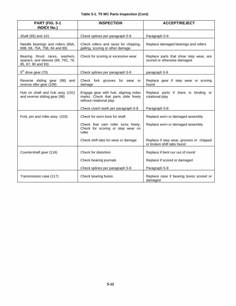
Table 5-1. T5 WC Parts Inspection (Cont)
PART (FIG. 5-1INDEX No.)
INSPECTION ACCEPT/REJECT
Shaft (65) and 101 Check splines per paragraph 5-9 Paragraph 5-9
Needle bearings and rollers (66A,66B, 68, 75A, 75B, 84 and 89)
Check rollers and races for chipping,galling, scoring or other damage
Replace damaged bearings and rollers
Bearing thrust races, washers,spacers, and sleeves (69, 75C, 76,85, 87, 90 and 93)
Check for scoring or excessive wear Replace parts that show step wear, arescored or otherwise damaged
5th drive gear (70) Check splines per paragraph 5-9 paragraph 5-9
Reverse sliding gear (98) andreverse idler gear (109)
Check fork grooves for wear ordamage
Replace gear if step wear or scoringfound
Hub on shaft and hub assy (101)and reverse sliding gear (98)
Engage gear with hub, aligning indexmarks. Check that parts slide freelywithout rotational play
Check clutch teeth per paragraph 5-8
Replace parts if there is binding orrotational play
Paragraph 5-8
Fork, pin and roller assy (103) Check for worn bore for shaft
Check that cam roller turns freely.Check for scoring or step wear onroller
Check shift tabs for wear or damage
Replace worn or damaged assembly
Replace worn or damaged assembly
Replace if step wear, grooves or chippedor broken shift tabs found
Countershaft gear (116) Check for distortion
Check bearing journals
Check splines per paragraph 5-9
Replace if bent our out of round
Replace if scored or damaged
Paragraph 5-9
Transmission case (117) Check bearing bores Replace case if bearing bores scored ordamaged
5-12
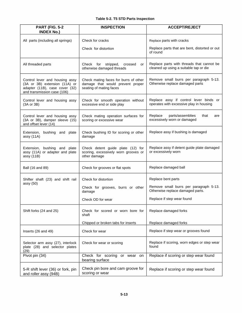
Table 5-2. T5 STD Parts Inspection
PART (FIG. 5-2INDEX No.)
INSPECTION ACCEPT/REJECT
All parts (including all springs) Check for cracks
Check for distortion
Replace parts with cracks
Replace parts that are bent, distorted or outof round
All threaded parts Check for stripped, crossed orotherwise damaged threads
Replace parts with threads that cannot becleaned up using a suitable tap or die
Control lever and housing assy(3A or 3B) extension (11A) oradapter (11B), case cover (32)and transmission case (106)
Check mating faces for burrs of otherdamage that would prevent properseating of mating faces
Remove small burrs per paragraph 5-13.Otherwise replace damaged parts
Control lever and housing assy(3A or 3B)
Check for smooth operation withoutexcessive end or side play
Replace assy if control lever binds oroperates with excessive play in housing
Control lever and housing assy(3A or 3B), damper sleeve (15)and offset lever (14)
Check mating operation surfaces forscoring or excessive wear
Replace parts/assemblies that areexcessively worn or damaged
Extension, bushing and plateassy (11A)
Check bushing ID for scoring or otherdamage
Replace assy if bushing is damaged
Extension, bushing and plateassy (11A) or adapter and plateassy (11B)
Check detent guide plate (12) forscoring, excessively worn grooves orother damage
Replace assy if detent guide plate damagedor excessively worn
Ball (16 and 89) Check for grooves or flat spots Replace damaged ball
Shifter shaft (23) and shift railassy (50)
Check for distortion
Check for grooves, burrs or otherdamage
Check OD for wear
Replace bent parts
Remove small burrs per paragraph 5-13.Otherwise replace damaged parts.
Replace if step wear found
Shift forks (24 and 25) Check for scored or worn bore forshaft
Chipped or broken tabs for inserts
Replace damaged forks
Replace damaged forks
Inserts (26 and 49) Check for wear Replace if step wear or grooves found
Selector arm assy (27), interlockplate (28) and selector plates(29)
Check for wear or scoring Replace if scoring, worn edges or step wearfound
Pivot pin (34) Check for scoring or wear onbearing surface
Replace if scoring or step wear found
5-R shift lever (36) or fork, pinand roller assy (94B)
Check pin bore and cam groove forscoring or wear
Replace if scoring or step wear found
5-13
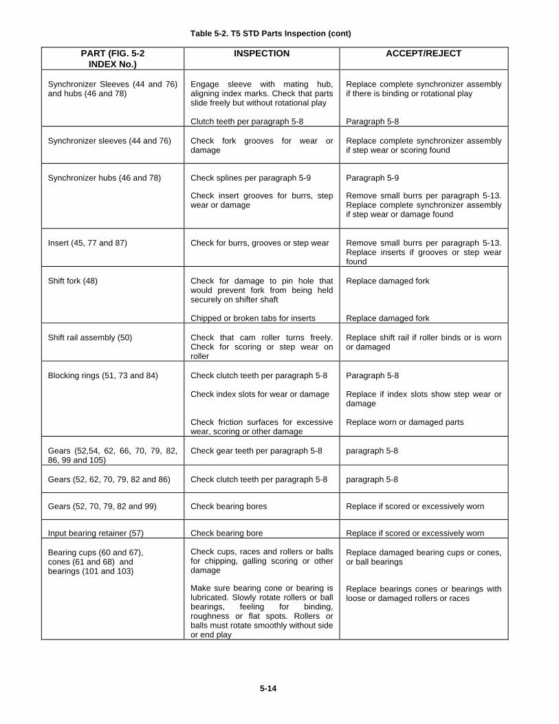
Table 5-2. T5 STD Parts Inspection (cont)
PART (FIG. 5-2INDEX No.)
INSPECTION ACCEPT/REJECT
Synchronizer Sleeves (44 and 76)and hubs (46 and 78)
Engage sleeve with mating hub,aligning index marks. Check that partsslide freely but without rotational play
Clutch teeth per paragraph 5-8
Replace complete synchronizer assemblyif there is binding or rotational play
Paragraph 5-8
Synchronizer sleeves (44 and 76) Check fork grooves for wear ordamage
Replace complete synchronizer assemblyif step wear or scoring found
Synchronizer hubs (46 and 78) Check splines per paragraph 5-9
Check insert grooves for burrs, stepwear or damage
Paragraph 5-9
Remove small burrs per paragraph 5-13.Replace complete synchronizer assemblyif step wear or damage found
Insert (45, 77 and 87) Check for burrs, grooves or step wear Remove small burrs per paragraph 5-13.Replace inserts if grooves or step wearfound
Shift fork (48) Check for damage to pin hole thatwould prevent fork from being heldsecurely on shifter shaft
Chipped or broken tabs for inserts
Replace damaged fork
Replace damaged fork
Shift rail assembly (50) Check that cam roller turns freely.Check for scoring or step wear onroller
Replace shift rail if roller binds or is wornor damaged
Blocking rings (51, 73 and 84) Check clutch teeth per paragraph 5-8
Check index slots for wear or damage
Check friction surfaces for excessivewear, scoring or other damage
Paragraph 5-8
Replace if index slots show step wear ordamage
Replace worn or damaged parts
Gears (52,54, 62, 66, 70, 79, 82,86, 99 and 105)
Check gear teeth per paragraph 5-8 paragraph 5-8
Gears (52, 62, 70, 79, 82 and 86) Check clutch teeth per paragraph 5-8 paragraph 5-8
Gears (52, 70, 79, 82 and 99) Check bearing bores Replace if scored or excessively worn
Input bearing retainer (57) Check bearing bore Replace if scored or excessively worn
Bearing cups (60 and 67),cones (61 and 68) andbearings (101 and 103)
Check cups, races and rollers or ballsfor chipping, galling scoring or otherdamage
Make sure bearing cone or bearing islubricated. Slowly rotate rollers or ballbearings, feeling for binding,roughness or flat spots. Rollers orballs must rotate smoothly without sideor end play
Replace damaged bearing cups or cones,or ball bearings
Replace bearings cones or bearings withloose or damaged rollers or races
5-14
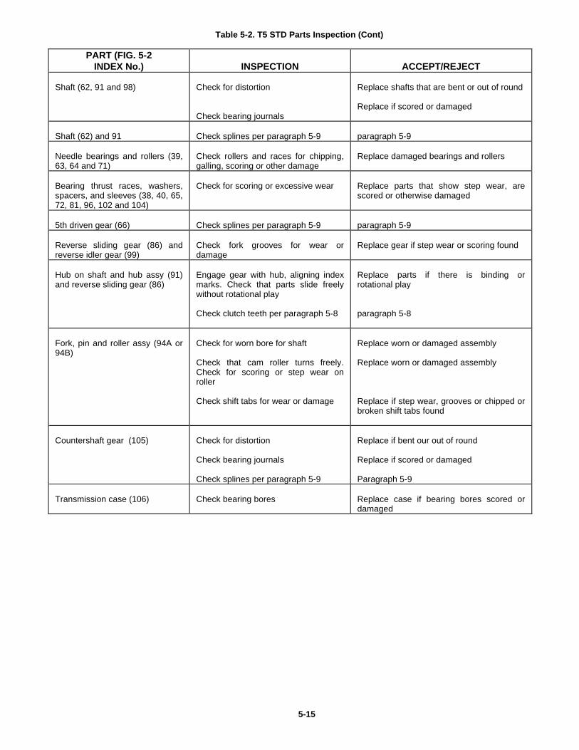
Table 5-2. T5 STD Parts Inspection (Cont)
PART (FIG. 5-2INDEX No.) INSPECTION ACCEPT/REJECT
Shaft (62, 91 and 98) Check for distortion
Check bearing journals
Replace shafts that are bent or out of round
Replace if scored or damaged
Shaft (62) and 91 Check splines per paragraph 5-9 paragraph 5-9
Needle bearings and rollers (39,63, 64 and 71)
Check rollers and races for chipping,galling, scoring or other damage
Replace damaged bearings and rollers
Bearing thrust races, washers,spacers, and sleeves (38, 40, 65,72, 81, 96, 102 and 104)
Check for scoring or excessive wear Replace parts that show step wear, arescored or otherwise damaged
5th driven gear (66) Check splines per paragraph 5-9 paragraph 5-9
Reverse sliding gear (86) andreverse idler gear (99)
Check fork grooves for wear ordamage
Replace gear if step wear or scoring found
Hub on shaft and hub assy (91)and reverse sliding gear (86)
Engage gear with hub, aligning indexmarks. Check that parts slide freelywithout rotational play
Check clutch teeth per paragraph 5-8
Replace parts if there is binding orrotational play
paragraph 5-8
Fork, pin and roller assy (94A or94B)
Check for worn bore for shaft
Check that cam roller turns freely.Check for scoring or step wear onroller
Check shift tabs for wear or damage
Replace worn or damaged assembly
Replace worn or damaged assembly
Replace if step wear, grooves or chipped orbroken shift tabs found
Countershaft gear (105) Check for distortion
Check bearing journals
Check splines per paragraph 5-9
Replace if bent our out of round
Replace if scored or damaged
Paragraph 5-9
Transmission case (106) Check bearing bores Replace case if bearing bores scored ordamaged
5-15
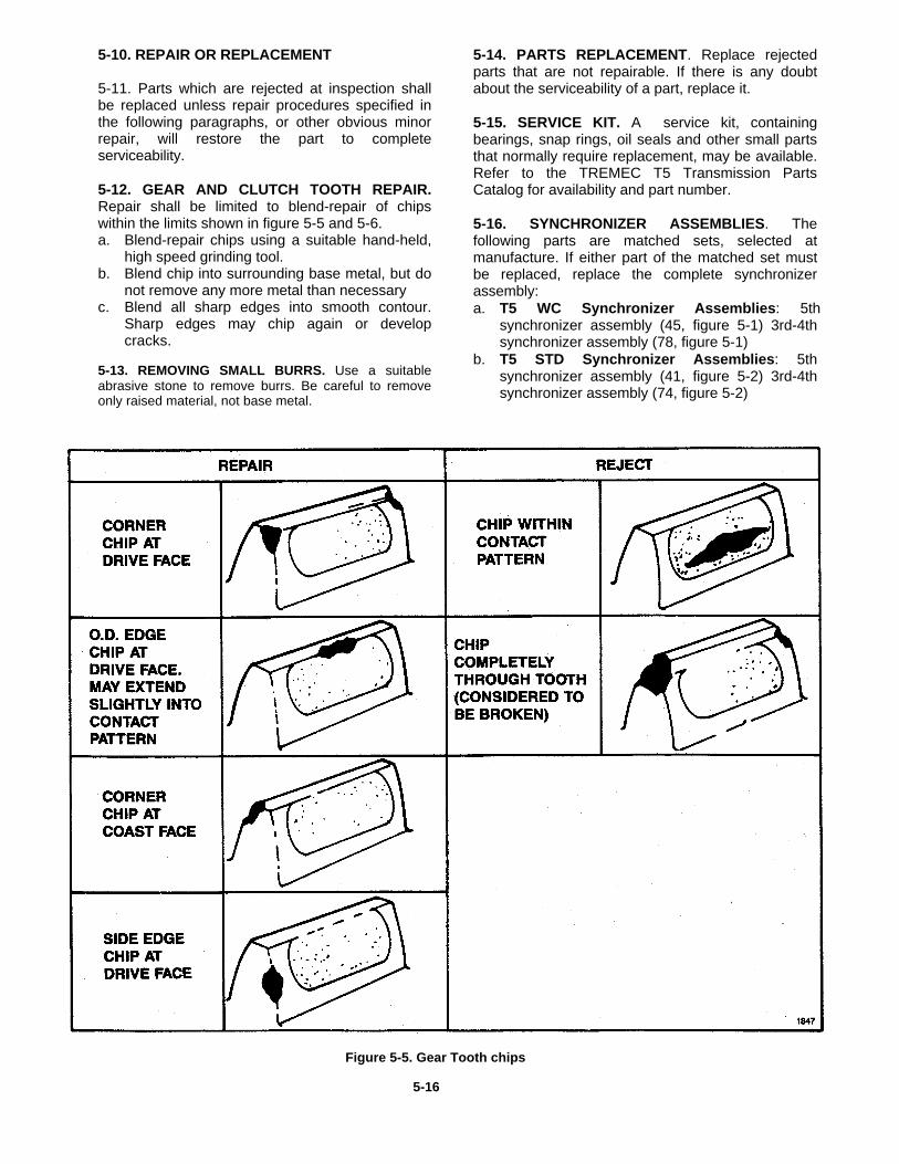
5-10. REPAIR OR REPLACEMENT
5-11. Parts which are rejected at inspection shallbe replaced unless repair procedures specified inthe following paragraphs, or other obvious minorrepair, will restore the part to completeserviceability.
5-12. GEAR AND CLUTCH TOOTH REPAIR.Repair shall be limited to blend-repair of chipswithin the limits shown in figure 5-5 and 5-6.a. Blend-repair chips using a suitable hand-held,
high speed grinding tool.b. Blend chip into surrounding base metal, but do
not remove any more metal than necessaryc. Blend all sharp edges into smooth contour.
Sharp edges may chip again or developcracks.
5-13. REMOVING SMALL BURRS. Use a suitableabrasive stone to remove burrs. Be careful to removeonly raised material, not base metal.
5-14. PARTS REPLACEMENT. Replace rejectedparts that are not repairable. If there is any doubtabout the serviceability of a part, replace it.
5-15. SERVICE KIT. A service kit, containingbearings, snap rings, oil seals and other small partsthat normally require replacement, may be available.Refer to the TREMEC T5 Transmission PartsCatalog for availability and part number.
5-16. SYNCHRONIZER ASSEMBLIES. Thefollowing parts are matched sets, selected atmanufacture. If either part of the matched set mustbe replaced, replace the complete synchronizerassembly:a. T5 WC Synchronizer Assemblies: 5th
synchronizer assembly (45, figure 5-1) 3rd-4thsynchronizer assembly (78, figure 5-1)
b. T5 STD Synchronizer Assemblies: 5thsynchronizer assembly (41, figure 5-2) 3rd-4thsynchronizer assembly (74, figure 5-2)
Figure 5-5. Gear Tooth chips
5-16
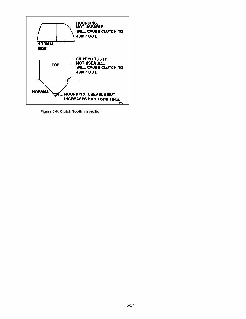
Figure 5-6. Clutch Tooth Inspection
5-17

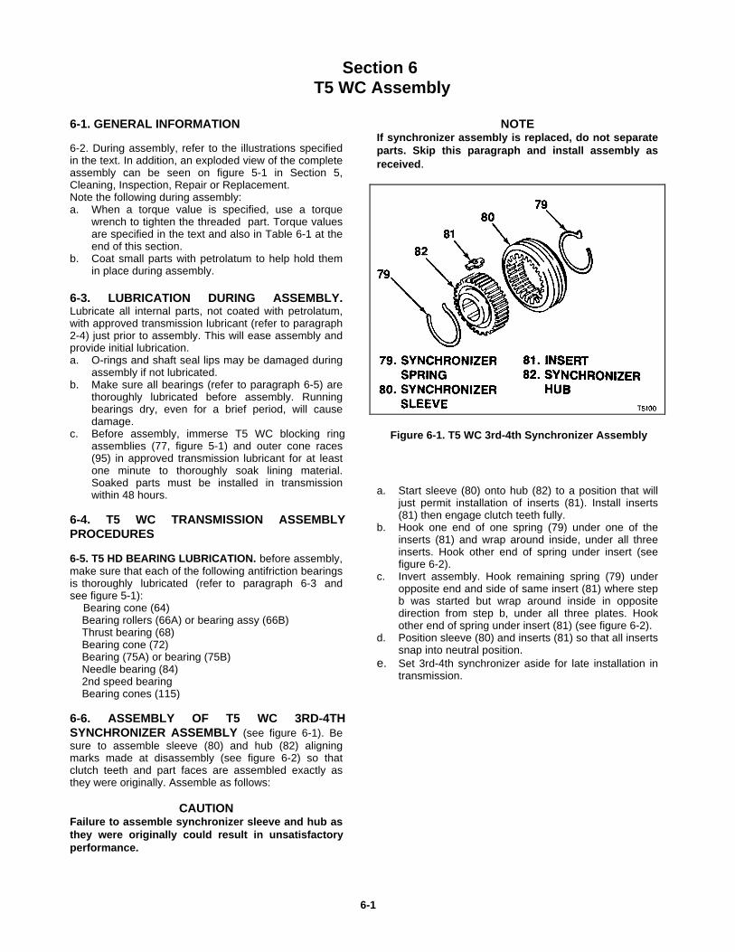
Section 6T5 WC Assembly
6-1. GENERAL INFORMATION
6-2. During assembly, refer to the illustrations specifiedin the text. In addition, an exploded view of the completeassembly can be seen on figure 5-1 in Section 5,Cleaning, Inspection, Repair or Replacement.Note the following during assembly:a. When a torque value is specified, use a torque
wrench to tighten the threaded part. Torque valuesare specified in the text and also in Table 6-1 at theend of this section.
b. Coat small parts with petrolatum to help hold themin place during assembly.
6-3. LUBRICATION DURING ASSEMBLY.Lubricate all internal parts, not coated with petrolatum,with approved transmission lubricant (refer to paragraph2-4) just prior to assembly. This will ease assembly andprovide initial lubrication.a. O-rings and shaft seal lips may be damaged during
assembly if not lubricated.b. Make sure all bearings (refer to paragraph 6-5) are
thoroughly lubricated before assembly. Runningbearings dry, even for a brief period, will causedamage.
c. Before assembly, immerse T5 WC blocking ringassemblies (77, figure 5-1) and outer cone races(95) in approved transmission lubricant for at leastone minute to thoroughly soak lining material.Soaked parts must be installed in transmissionwithin 48 hours.
6-4. T5 WC TRANSMISSION ASSEMBLYPROCEDURES
6-5. T5 HD BEARING LUBRICATION. before assembly,make sure that each of the following antifriction bearingsis thoroughly lubricated (refer to paragraph 6-3 andsee figure 5-1): Bearing cone (64) Bearing rollers (66A) or bearing assy (66B) Thrust bearing (68) Bearing cone (72) Bearing (75A) or bearing (75B) Needle bearing (84) 2nd speed bearing Bearing cones (115)
6-6. ASSEMBLY OF T5 WC 3RD-4THSYNCHRONIZER ASSEMBLY (see figure 6-1). Besure to assemble sleeve (80) and hub (82) aligningmarks made at disassembly (see figure 6-2) so thatclutch teeth and part faces are assembled exactly asthey were originally. Assemble as follows:
CAUTIONFailure to assemble synchronizer sleeve and hub asthey were originally could result in unsatisfactoryperformance.
NOTEIf synchronizer assembly is replaced, do not separateparts. Skip this paragraph and install assembly asreceived.
Figure 6-1. T5 WC 3rd-4th Synchronizer Assembly
a. Start sleeve (80) onto hub (82) to a position that willjust permit installation of inserts (81). Install inserts(81) then engage clutch teeth fully.
b. Hook one end of one spring (79) under one of theinserts (81) and wrap around inside, under all threeinserts. Hook other end of spring under insert (seefigure 6-2).
c. Invert assembly. Hook remaining spring (79) underopposite end and side of same insert (81) where stepb was started but wrap around inside in oppositedirection from step b, under all three plates. Hookother end of spring under insert (81) (see figure 6-2).
d. Position sleeve (80) and inserts (81) so that all insertssnap into neutral position.
e. Set 3rd-4th synchronizer aside for late installation intransmission.
6-1
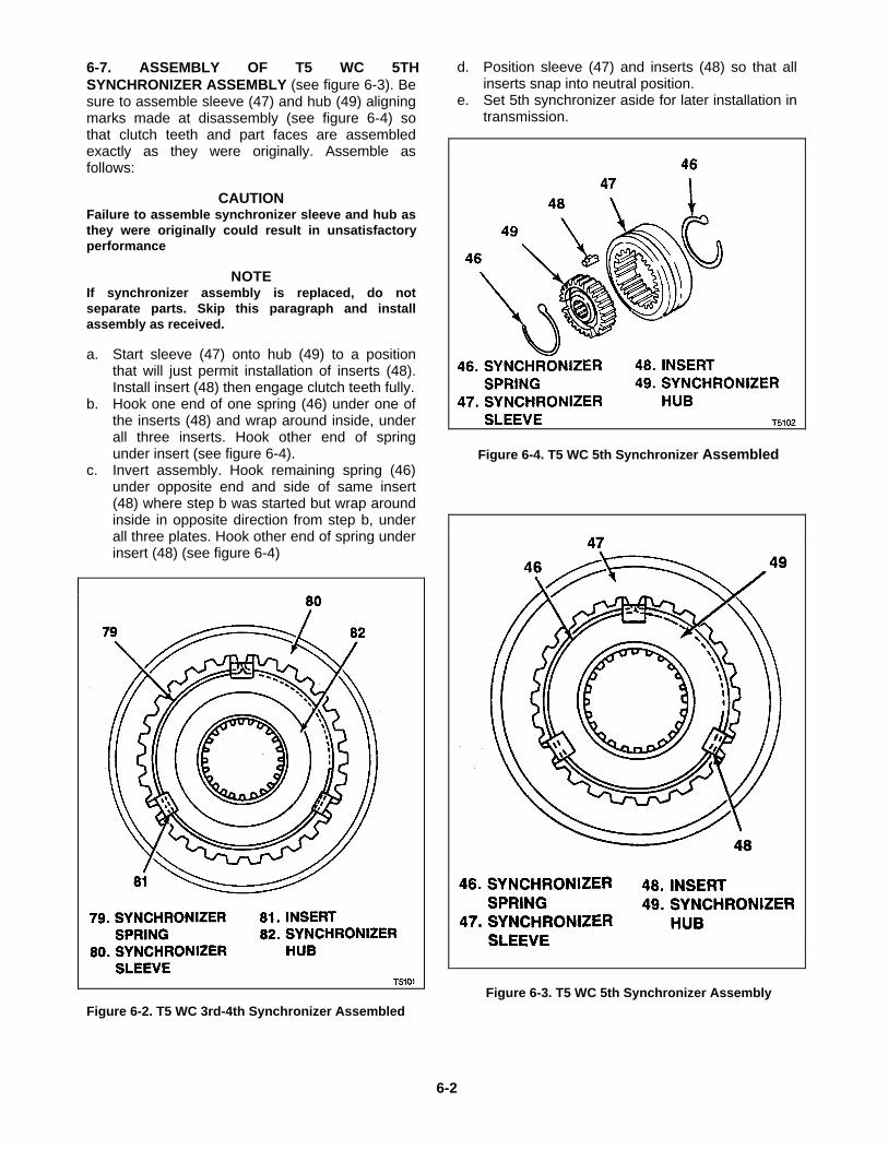
6-7. ASSEMBLY OF T5 WC 5THSYNCHRONIZER ASSEMBLY (see figure 6-3). Besure to assemble sleeve (47) and hub (49) aligningmarks made at disassembly (see figure 6-4) sothat clutch teeth and part faces are assembledexactly as they were originally. Assemble asfollows:
CAUTIONFailure to assemble synchronizer sleeve and hub asthey were originally could result in unsatisfactoryperformance
NOTEIf synchronizer assembly is replaced, do notseparate parts. Skip this paragraph and installassembly as received.
a. Start sleeve (47) onto hub (49) to a positionthat will just permit installation of inserts (48).Install insert (48) then engage clutch teeth fully.
b. Hook one end of one spring (46) under one ofthe inserts (48) and wrap around inside, underall three inserts. Hook other end of springunder insert (see figure 6-4).
c. Invert assembly. Hook remaining spring (46)under opposite end and side of same insert(48) where step b was started but wrap aroundinside in opposite direction from step b, underall three plates. Hook other end of spring underinsert (48) (see figure 6-4)
Figure 6-2. T5 WC 3rd-4th Synchronizer Assembled
d. Position sleeve (47) and inserts (48) so that allinserts snap into neutral position.
e. Set 5th synchronizer aside for later installation intransmission.
Figure 6-4. T5 WC 5th Synchronizer Assembled
Figure 6-3. T5 WC 5th Synchronizer Assembly
6-2
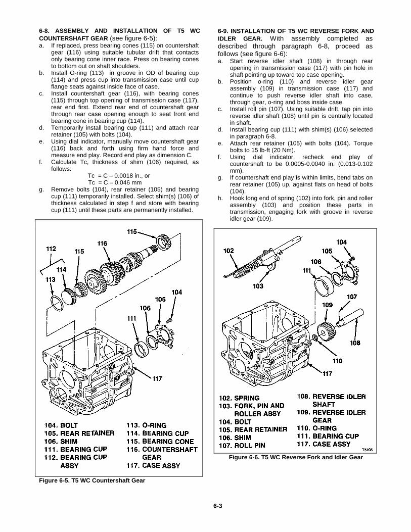
6-8. ASSEMBLY AND INSTALLATION OF T5 WCCOUNTERSHAFT GEAR (see figure 6-5):a. If replaced, press bearing cones (115) on countershaft
gear (116) using suitable tubular drift that contactsonly bearing cone inner race. Press on bearing conesto bottom out on shaft shoulders.
b. Install O-ring (113) in groove in OD of bearing cup(114) and press cup into transmission case until cupflange seats against inside face of case.
c. Install countershaft gear (116), with bearing cones(115) through top opening of transmission case (117),rear end first. Extend rear end of countershaft gearthrough rear case opening enough to seat front endbearing cone in bearing cup (114).
d. Temporarily install bearing cup (111) and attach rearretainer (105) with bolts (104).
e. Using dial indicator, manually move countershaft gear(116) back and forth using firm hand force andmeasure end play. Record end play as dimension C.
f. Calculate Tc, thickness of shim (106) required, asfollows:
Tc = C – 0.0018 in., or Tc = C – 0.046 mmg. Remove bolts (104), rear retainer (105) and bearing
cup (111) temporarily installed. Select shim(s) (106) ofthickness calculated in step f and store with bearingcup (111) until these parts are permanently installed.
Figure 6-5. T5 WC Countershaft Gear
6-9. INSTALLATION OF T5 WC REVERSE FORK ANDIDLER GEAR. With assembly completed asdescribed through paragraph 6-8, proceed asfollows (see figure 6-6):a. Start reverse idler shaft (108) in through rear
opening in transmission case (117) with pin hole inshaft pointing up toward top case opening.
b. Position o-ring (110) and reverse idler gearassembly (109) in transmission case (117) andcontinue to push reverse idler shaft into case,through gear, o-ring and boss inside case.
c. Install roll pin (107). Using suitable drift, tap pin intoreverse idler shaft (108) until pin is centrally locatedin shaft.
d. Install bearing cup (111) with shim(s) (106) selectedin paragraph 6-8.
e. Attach rear retainer (105) with bolts (104). Torquebolts to 15 lb-ft (20 Nm).
f. Using dial indicator, recheck end play ofcountershaft to be 0.0005-0.0040 in. (0.013-0.102mm).
g. If countershaft end play is within limits, bend tabs onrear retainer (105) up, against flats on head of bolts(104).
h. Hook long end of spring (102) into fork, pin and rollerassembly (103) and position these parts intransmission, engaging fork with groove in reverseidler gear (109).
Figure 6-6. T5 WC Reverse Fork and Idler Gear
6-3
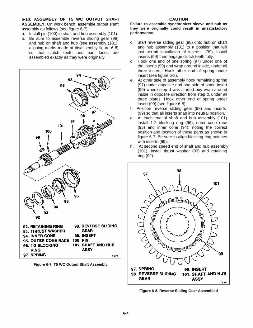
6-10. ASSEMBLY OF T5 WC OUTPUT SHAFTASSEMBLY. On work bench, assemble output shaftassembly as follows (see figure 6-7):a. Install pin (100) in shaft and hub assembly (101).b. Be sure to assemble reverse sliding gear (98)
and hub on shaft and hub (see assembly (101),aligning marks made at disassembly figure 6-8)so that clutch teeth and part faces areassembled exactly as they were originally.
Figure 6-7. T5 WC Output Shaft Assembly
CAUTION Failure to assemble synchronizer sleeve and hub asthey were originally could result in unsatisfactoryperformance. c. Start reverse sliding gear (98) onto hub on shaft
and hub assembly (101) to a position that willjust permit installation of inserts (99). Installinserts (99) then engage clutch teeth fully.
d. Hook one end of one spring (97) under one ofthe inserts (99) and wrap around inside, under allthree inserts. Hook other end of spring underinsert (see figure 6-8).
e. At other side of assembly hook remaining spring(97) under opposite end and side of same insert(99) where step d was started buy wrap aroundinside in opposite direction from step d, under allthree plates. Hook other end of spring underinsert (99) (see figure 6-8).
f. Position reverse sliding gear (98) and inserts(99) so that all inserts snap into neutral position.
g. At each end of shaft and hub assembly (101)install 1-2 blocking ring (96), outer cone race(95) and inner cone (94), noting the correctposition and location of these parts as shown infigure 6-7. Be sure to align blocking ring notcheswith inserts (99).
h. At second speed end of shaft and hub assembly(101), install thrust washer (93) and retainingring (92).
Figure 6-8. Reverse Sliding Gear Assembled
6-4
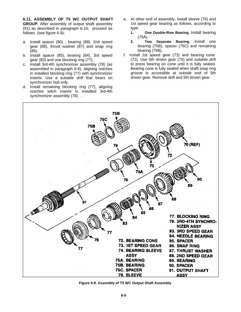
6.11. ASSEMBLY OF T5 WC OUTPUT SHAFTGROUP. After assembly of output shaft assembly(91) as described in paragraph 6-10, proceed asfollows (see figure 6-9):
a. Install spacer (90) , bearing (89), 2nd speedgear (88), thrust washer (87) and snap ring(86).
b. Install spacer (85), bearing (84), 3rd speedgear (83) and one blocking ring (77).
c. Install 3rd-4th synchronizer assembly (78) (asassembled in paragraph 6-6), aligning notchesin installed blocking ring (77) with synchronizerinserts. Use a suitable drift that bears onsynchronizer hub only.
d. Install remaining blocking ring (77), aligningnotches witch inserts in installed 3rd-4thsynchronizer assembly (78) .
e. At other end of assembly, install sleeve (76) and1st speed gear bearing as follows, according totype:1. One Double-Row Bearing. Install bearing
(75A).2. Two Separate Bearing. Install one
bearing (75B), spacer (75C) and remainingbearing (75B).
f. Install 1st speed gear (73) and bearing cone(72). Use 5th driven gear (70) and suitable driftto press bearing on cone until it is fully seated.Bearing cone is fully seated when shaft snap ringgroove is accessible at outside end of 5thdriven gear. Remove drift and 5th driven gear.
Figure 6-9. Assembly of T5 WC Output Shaft Assembly
6-5
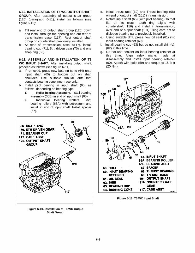
6-12. INSTALLATION OF T5 WC OUTPUT SHAFTGROUP. After assembly of output shaft group(120) (paragraph 6-11), install as follows (seefigure 6-10):
a. Tilt rear end of output shaft group (120) downand install through top opening and out rear oftransmission case (117). Rest output shaftgroup on countershaft previously installed.
b. At rear of transmission case 8117), installbearing cup (71), 5th, driven gear (70) and onesnap ring (56).
6-13. ASSEMBLY AND INSTALLATION OF T5WC INPUT SHAFT. After installing output shaft,proceed as follows (see figure 6-11):a. If removed, press new bearing cone (64) onto
input shaft (65) to bottom out on shaftshoulder. Use suitable tubular drift thatcontacts bearing cone inner race only.
b. Install pilot bearing in input shaft (65) asfollows, depending on bearing type:1. Roller bearing Assembly. Install bearing
assembly (66B) in end of input shaft (65).2. Individual Bearing Rollers. Coat
bearing rollers (66A) with petrolatum andinstall in end of input shaft. Install spacer(67).
Figure 6-10. Installation of T5 WC OutputShaft Group
c. Install thrust race (69) and Thrust bearing (68)on end of output shaft (101) in transmission.
d. Rotate input shaft (65) (with pilot bearing) so thatflat on its clutch tooth ring aligns withcountershaft (116) and install in transmission,over end of output shaft (101) using care not todislodge bearing parts previously installed.
e. Using suitable drift, press new oil seal (61) intoinput bearing retainer (60).
f. Install bearing cup (63) but do not install shim(s)(62) at this time.
g. Do not use sealant on input bearing retainer atthis time. Align index marks made atdisassembly and install input bearing retainer(60). Attach with bolts (59) and torque to 15 lb-ft(20 Nm).
Figure 6-11. T5 WC Input Shaft
6-6
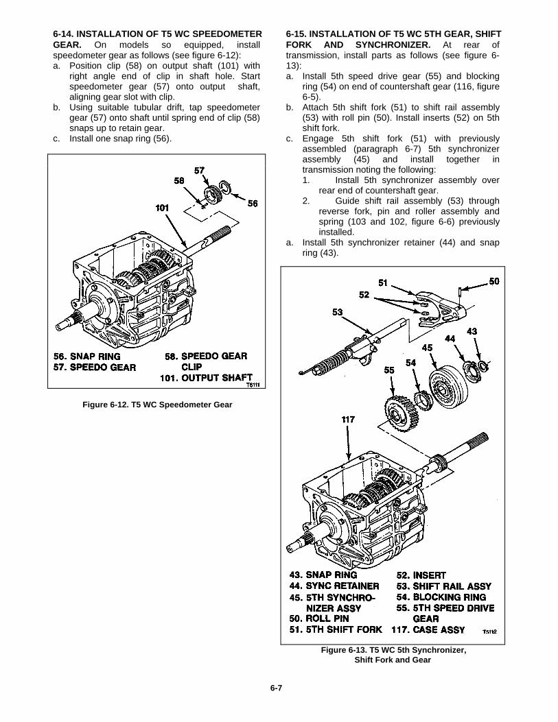
6-14. INSTALLATION OF T5 WC SPEEDOMETERGEAR. On models so equipped, installspeedometer gear as follows (see figure 6-12):a. Position clip (58) on output shaft (101) with
right angle end of clip in shaft hole. Startspeedometer gear (57) onto output shaft,aligning gear slot with clip.
b. Using suitable tubular drift, tap speedometergear (57) onto shaft until spring end of clip (58)snaps up to retain gear.
c. Install one snap ring (56).
Figure 6-12. T5 WC Speedometer Gear
6-15. INSTALLATION OF T5 WC 5TH GEAR, SHIFTFORK AND SYNCHRONIZER. At rear oftransmission, install parts as follows (see figure 6-13):a. Install 5th speed drive gear (55) and blocking
ring (54) on end of countershaft gear (116, figure6-5).
b. Attach 5th shift fork (51) to shift rail assembly(53) with roll pin (50). Install inserts (52) on 5thshift fork.
c. Engage 5th shift fork (51) with previouslyassembled (paragraph 6-7) 5th synchronizerassembly (45) and install together intransmission noting the following:1. Install 5th synchronizer assembly over
rear end of countershaft gear.2. Guide shift rail assembly (53) through
reverse fork, pin and roller assembly andspring (103 and 102, figure 6-6) previouslyinstalled.
a. Install 5th synchronizer retainer (44) and snapring (43).
Figure 6-13. T5 WC 5th Synchronizer,Shift Fork and Gear
6-7
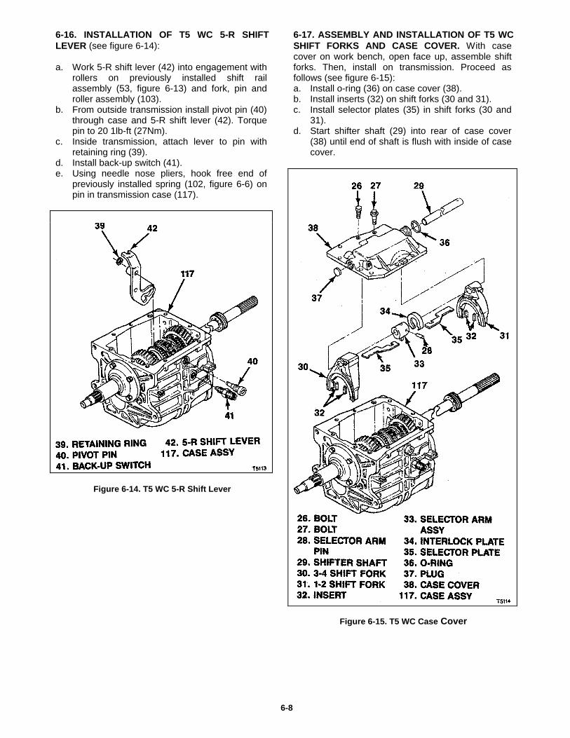
6-16. INSTALLATION OF T5 WC 5-R SHIFTLEVER (see figure 6-14):
a. Work 5-R shift lever (42) into engagement withrollers on previously installed shift railassembly (53, figure 6-13) and fork, pin androller assembly (103).
b. From outside transmission install pivot pin (40)through case and 5-R shift lever (42). Torquepin to 20 1lb-ft (27Nm).
c. Inside transmission, attach lever to pin withretaining ring (39).
d. Install back-up switch (41).e. Using needle nose pliers, hook free end of
previously installed spring (102, figure 6-6) onpin in transmission case (117).
Figure 6-14. T5 WC 5-R Shift Lever
6-17. ASSEMBLY AND INSTALLATION OF T5 WCSHIFT FORKS AND CASE COVER. With casecover on work bench, open face up, assemble shiftforks. Then, install on transmission. Proceed asfollows (see figure 6-15):a. Install o-ring (36) on case cover (38).b. Install inserts (32) on shift forks (30 and 31).c. Install selector plates (35) in shift forks (30 and
31).d. Start shifter shaft (29) into rear of case cover
(38) until end of shaft is flush with inside of casecover.
Figure 6-15. T5 WC Case Cover
6-8
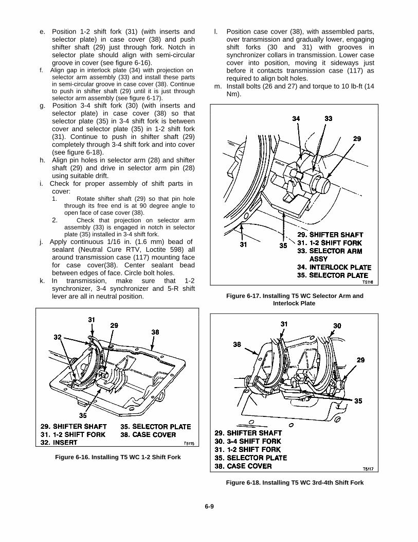
e. Position 1-2 shift fork (31) (with inserts andselector plate) in case cover (38) and pushshifter shaft (29) just through fork. Notch inselector plate should align with semi-circulargroove in cover (see figure 6-16).
f. Align gap in interlock plate (34) with projection onselector arm assembly (33) and install these partsin semi-circular groove in case cover (38). Continueto push in shifter shaft (29) until it is just throughselector arm assembly (see figure 6-17).
g. Position 3-4 shift fork (30) (with inserts andselector plate) in case cover (38) so thatselector plate (35) in 3-4 shift fork is betweencover and selector plate (35) in 1-2 shift fork(31). Continue to push in shifter shaft (29)completely through 3-4 shift fork and into cover(see figure 6-18).
h. Align pin holes in selector arm (28) and shiftershaft (29) and drive in selector arm pin (28)using suitable drift.
i. Check for proper assembly of shift parts incover:1. Rotate shifter shaft (29) so that pin hole
through its free end is at 90 degree angle toopen face of case cover (38).
2. Check that projection on selector armassembly (33) is engaged in notch in selectorplate (35) installed in 3-4 shift fork.
j. Apply continuous 1/16 in. (1.6 mm) bead ofsealant (Neutral Cure RTV, Loctite 598) allaround transmission case (117) mounting facefor case cover(38). Center sealant beadbetween edges of face. Circle bolt holes.
k. In transmission, make sure that 1-2synchronizer, 3-4 synchronizer and 5-R shiftlever are all in neutral position.
Figure 6-16. Installing T5 WC 1-2 Shift Fork
l. Position case cover (38), with assembled parts,over transmission and gradually lower, engagingshift forks (30 and 31) with grooves insynchronizer collars in transmission. Lower casecover into position, moving it sideways justbefore it contacts transmission case (117) asrequired to align bolt holes.
m. Install bolts (26 and 27) and torque to 10 lb-ft (14Nm).
Figure 6-17. Installing T5 WC Selector Arm andInterlock Plate
Figure 6-18. Installing T5 WC 3rd-4th Shift Fork
6-9
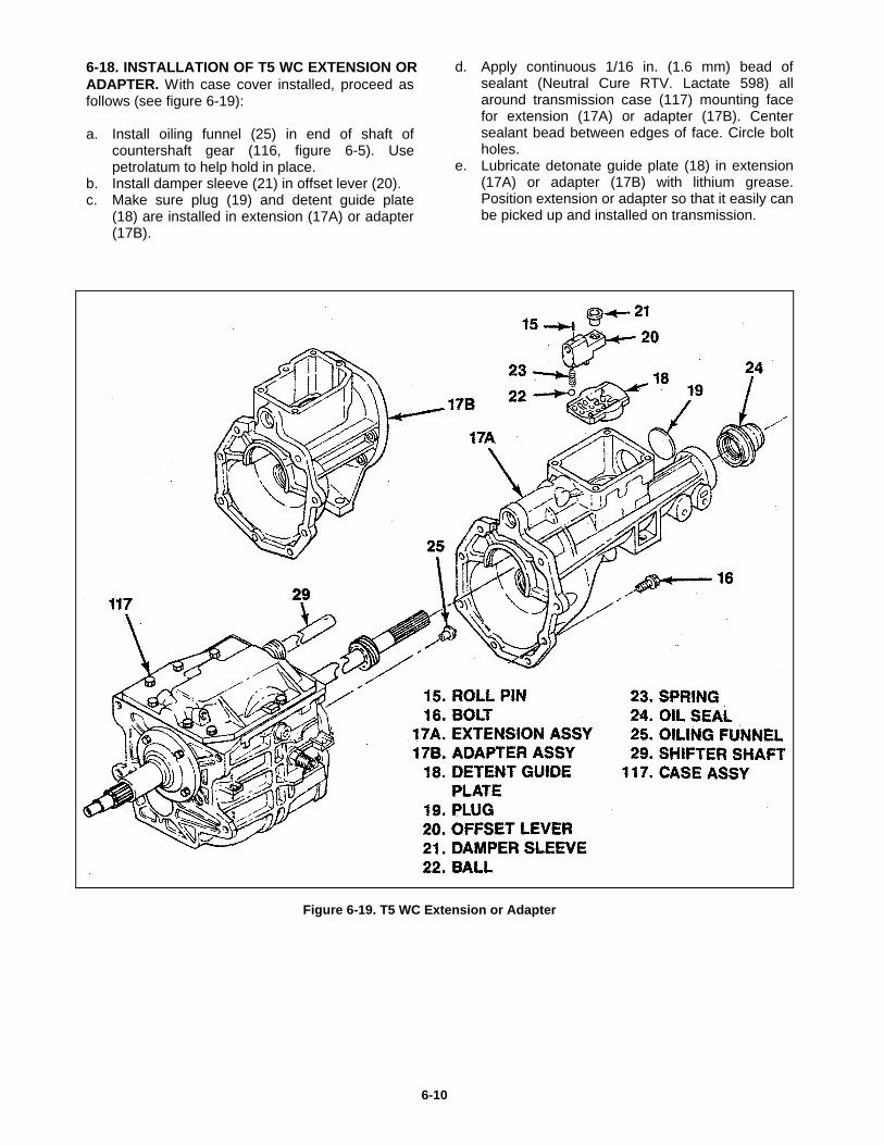
6-18. INSTALLATION OF T5 WC EXTENSION ORADAPTER. With case cover installed, proceed asfollows (see figure 6-19):
a. Install oiling funnel (25) in end of shaft ofcountershaft gear (116, figure 6-5). Usepetrolatum to help hold in place.
b. Install damper sleeve (21) in offset lever (20).c. Make sure plug (19) and detent guide plate
(18) are installed in extension (17A) or adapter(17B).
d. Apply continuous 1/16 in. (1.6 mm) bead ofsealant (Neutral Cure RTV. Lactate 598) allaround transmission case (117) mounting facefor extension (17A) or adapter (17B). Centersealant bead between edges of face. Circle boltholes.
e. Lubricate detonate guide plate (18) in extension(17A) or adapter (17B) with lithium grease.Position extension or adapter so that it easily canbe picked up and installed on transmission.
Figure 6-19. T5 WC Extension or Adapter
6-10
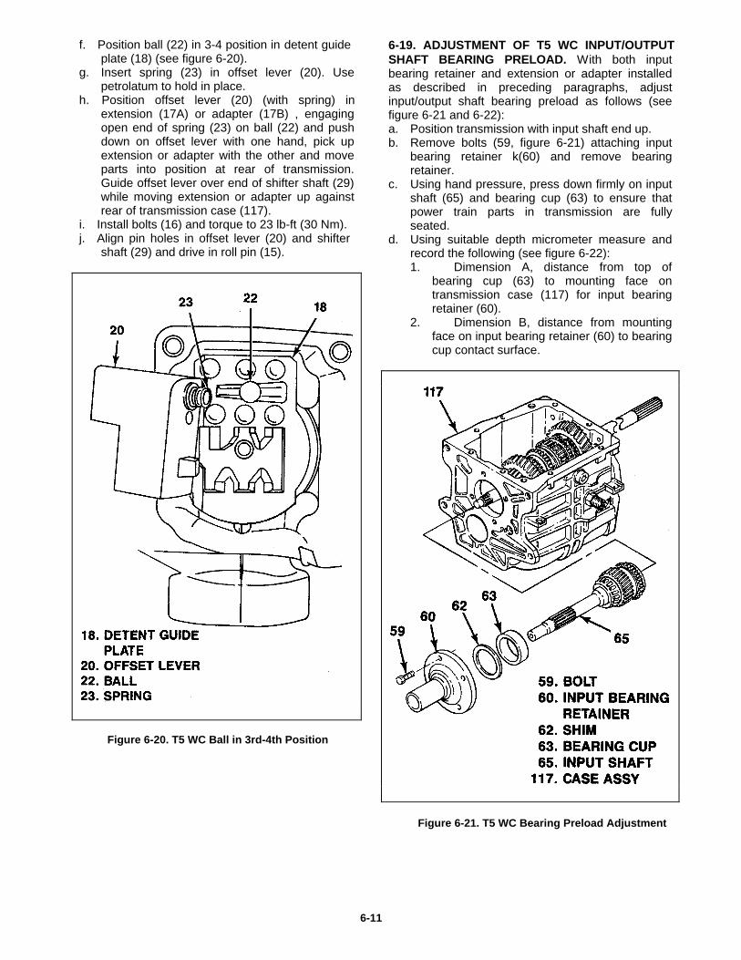
f. Position ball (22) in 3-4 position in detent guideplate (18) (see figure 6-20).
g. Insert spring (23) in offset lever (20). Usepetrolatum to hold in place.
h. Position offset lever (20) (with spring) inextension (17A) or adapter (17B) , engagingopen end of spring (23) on ball (22) and pushdown on offset lever with one hand, pick upextension or adapter with the other and moveparts into position at rear of transmission.Guide offset lever over end of shifter shaft (29)while moving extension or adapter up againstrear of transmission case (117).
i. Install bolts (16) and torque to 23 lb-ft (30 Nm).j. Align pin holes in offset lever (20) and shifter
shaft (29) and drive in roll pin (15).
Figure 6-20. T5 WC Ball in 3rd-4th Position
6-19. ADJUSTMENT OF T5 WC INPUT/OUTPUTSHAFT BEARING PRELOAD. With both inputbearing retainer and extension or adapter installedas described in preceding paragraphs, adjustinput/output shaft bearing preload as follows (seefigure 6-21 and 6-22):a. Position transmission with input shaft end up.b. Remove bolts (59, figure 6-21) attaching input
bearing retainer k(60) and remove bearingretainer.
c. Using hand pressure, press down firmly on inputshaft (65) and bearing cup (63) to ensure thatpower train parts in transmission are fullyseated.
d. Using suitable depth micrometer measure andrecord the following (see figure 6-22):1. Dimension A, distance from top of
bearing cup (63) to mounting face ontransmission case (117) for input bearingretainer (60).
2. Dimension B, distance from mountingface on input bearing retainer (60) to bearingcup contact surface.
Figure 6-21. T5 WC Bearing Preload Adjustment
6-11
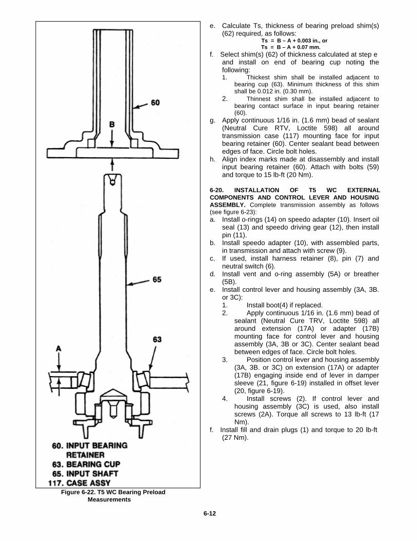
e. Calculate Ts, thickness of bearing preload shim(s)(62) required, as follows:
Ts = B – A + 0.003 in., or Ts = B – A + 0.07 mm. f. Select shim(s) (62) of thickness calculated at step e
and install on end of bearing cup noting thefollowing:1. Thickest shim shall be installed adjacent to
bearing cup (63). Minimum thickness of this shimshall be 0.012 in. (0.30 mm).
2. Thinnest shim shall be installed adjacent tobearing contact surface in input bearing retainer(60).
g. Apply continuous 1/16 in. (1.6 mm) bead of sealant(Neutral Cure RTV, Loctite 598) all aroundtransmission case (117) mounting face for inputbearing retainer (60). Center sealant bead betweenedges of face. Circle bolt holes.
h. Align index marks made at disassembly and installinput bearing retainer (60). Attach with bolts (59)and torque to 15 lb-ft (20 Nm).
6-20. INSTALLATION OF T5 WC EXTERNALCOMPONENTS AND CONTROL LEVER AND HOUSINGASSEMBLY. Complete transmission assembly as follows(see figure 6-23):a. Install o-rings (14) on speedo adapter (10). Insert oil
seal (13) and speedo driving gear (12), then installpin (11).
b. Install speedo adapter (10), with assembled parts,in transmission and attach with screw (9).
c. If used, install harness retainer (8), pin (7) andneutral switch (6).
d. Install vent and o-ring assembly (5A) or breather(5B).
e. Install control lever and housing assembly (3A, 3B.or 3C):1. Install boot(4) if replaced.2. Apply continuous 1/16 in. (1.6 mm) bead of
sealant (Neutral Cure TRV, Loctite 598) allaround extension (17A) or adapter (17B)mounting face for control lever and housingassembly (3A, 3B or 3C). Center sealant beadbetween edges of face. Circle bolt holes.
3. Position control lever and housing assembly(3A, 3B. or 3C) on extension (17A) or adapter(17B) engaging inside end of lever in dampersleeve (21, figure 6-19) installed in offset lever(20, figure 6-19).
4. Install screws (2). If control lever andhousing assembly (3C) is used, also installscrews (2A). Torque all screws to 13 lb-ft (17Nm).
f. Install fill and drain plugs (1) and torque to 20 lb-ft(27 Nm).
Figure 6-22. T5 WC Bearing Preload Measurements
6-12
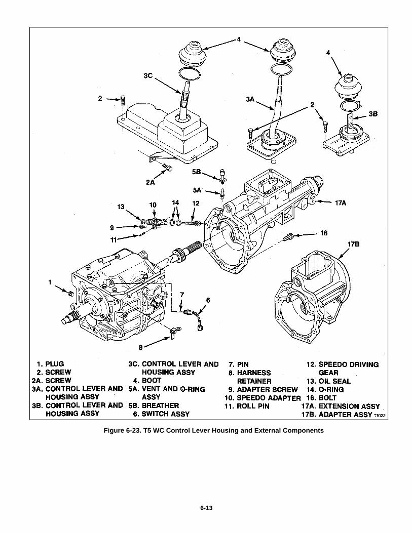
Figure 6-23. T5 WC Control Lever Housing and External Components
6-13
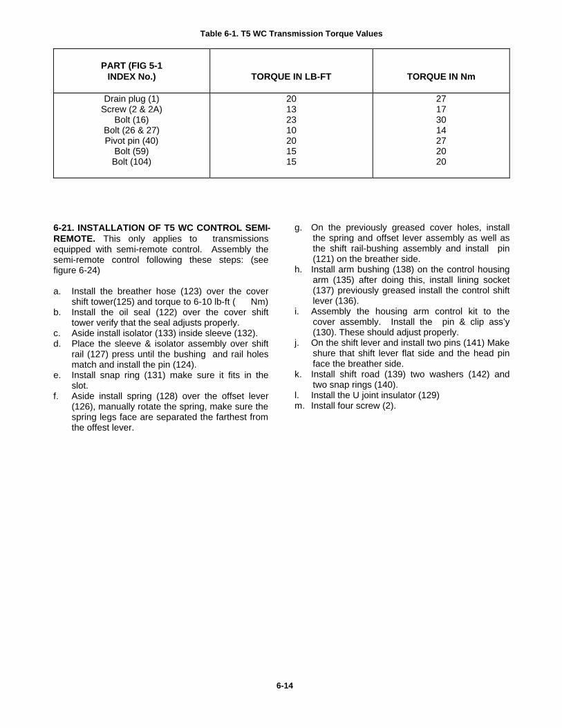
Table 6-1. T5 WC Transmission Torque Values
PART (FIG 5-1
INDEX No.)
TORQUE IN LB-FT
TORQUE IN Nm
Drain plug (1) Screw (2 & 2A)
Bolt (16) Bolt (26 & 27) Pivot pin (40)
Bolt (59) Bolt (104)
20 13 23 10 20 15 15
27 17 30 14 27 20 20
6-21. INSTALLATION OF T5 WC CONTROL SEMI-REMOTE. This only applies to transmissions equipped with semi-remote control. Assembly the semi-remote control following these steps: (see figure 6-24) a. Install the breather hose (123) over the cover
shift tower(125) and torque to 6-10 lb-ft ( Nm) b. Install the oil seal (122) over the cover shift
tower verify that the seal adjusts properly. c. Aside install isolator (133) inside sleeve (132). d. Place the sleeve & isolator assembly over shift
rail (127) press until the bushing and rail holes match and install the pin (124).
e. Install snap ring (131) make sure it fits in the slot.
f. Aside install spring (128) over the offset lever (126), manually rotate the spring, make sure the spring legs face are separated the farthest from the offest lever.
g. On the previously greased cover holes, install the spring and offset lever assembly as well as the shift rail-bushing assembly and install pin (121) on the breather side.
h. Install arm bushing (138) on the control housing arm (135) after doing this, install lining socket (137) previously greased install the control shift lever (136).
i. Assembly the housing arm control kit to the cover assembly. Install the pin & clip ass’y (130). These should adjust properly.
j. On the shift lever and install two pins (141) Make shure that shift lever flat side and the head pin face the breather side.
k. Install shift road (139) two washers (142) and two snap rings (140).
l. Install the U joint insulator (129) m. Install four screw (2).
6-14
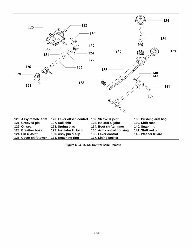
120. Assy remote shift 126. Lever offset, control 132. Sleeve U joint 138. Bushing arm hsg. 121. Grooved pin 127. Rail shift 133. Isolator U joint 139. Shift road 122. Oil seal 128. Spring bias 134. Boot shifter inner 140. Snap ring 123. Breather hose 129. Insulator U Joint 135. Arm control housing 141. Shift rod pin 124. Pin U Joint 130. Assy pin & clip 136. Lever control 142. Washer truarc 125. Cover shift tower 131. Retaining ring 137. Lining socket
Figure 6-24. T5 WC Control Semi-Remote 6-15
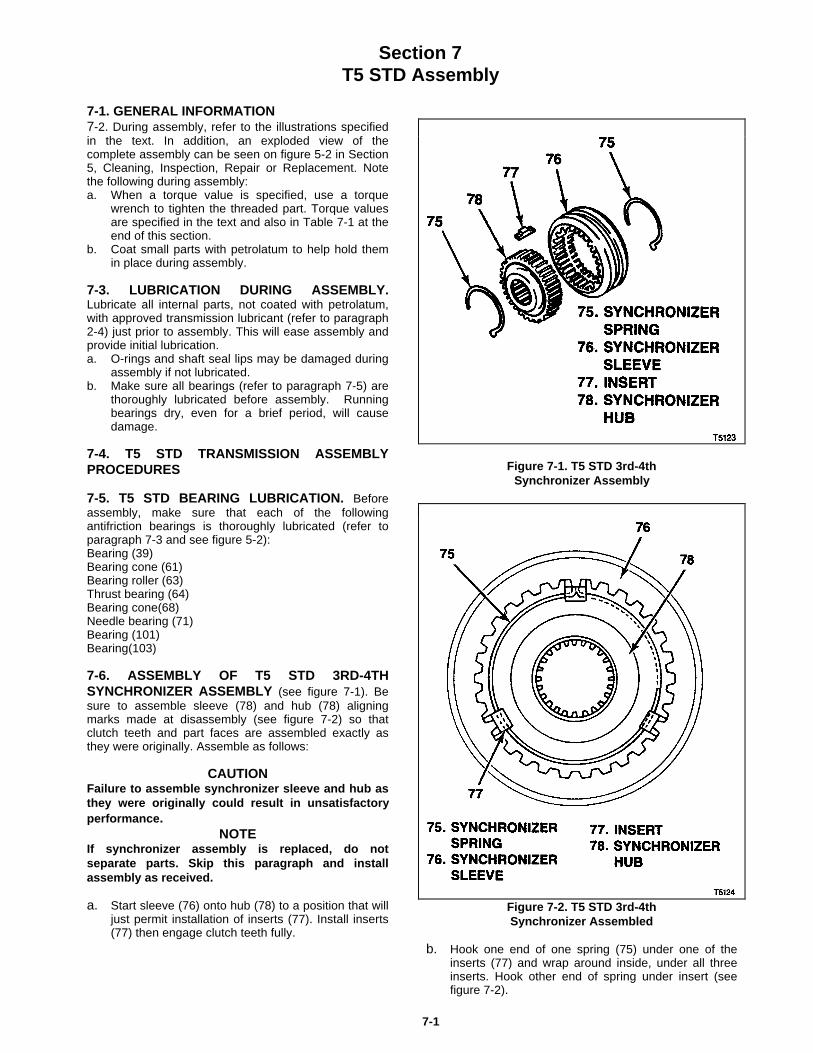
Section 7T5 STD Assembly
7-1. GENERAL INFORMATION7-2. During assembly, refer to the illustrations specifiedin the text. In addition, an exploded view of thecomplete assembly can be seen on figure 5-2 in Section5, Cleaning, Inspection, Repair or Replacement. Notethe following during assembly:a. When a torque value is specified, use a torque
wrench to tighten the threaded part. Torque valuesare specified in the text and also in Table 7-1 at theend of this section.
b. Coat small parts with petrolatum to help hold themin place during assembly.
7-3. LUBRICATION DURING ASSEMBLY.Lubricate all internal parts, not coated with petrolatum,with approved transmission lubricant (refer to paragraph2-4) just prior to assembly. This will ease assembly andprovide initial lubrication.a. O-rings and shaft seal lips may be damaged during
assembly if not lubricated.b. Make sure all bearings (refer to paragraph 7-5) are
thoroughly lubricated before assembly. Runningbearings dry, even for a brief period, will causedamage.
7-4. T5 STD TRANSMISSION ASSEMBLYPROCEDURES
7-5. T5 STD BEARING LUBRICATION. Beforeassembly, make sure that each of the followingantifriction bearings is thoroughly lubricated (refer toparagraph 7-3 and see figure 5-2):Bearing (39)Bearing cone (61)Bearing roller (63)Thrust bearing (64)Bearing cone(68)Needle bearing (71)Bearing (101)Bearing(103)
7-6. ASSEMBLY OF T5 STD 3RD-4THSYNCHRONIZER ASSEMBLY (see figure 7-1). Besure to assemble sleeve (78) and hub (78) aligningmarks made at disassembly (see figure 7-2) so thatclutch teeth and part faces are assembled exactly asthey were originally. Assemble as follows:
CAUTIONFailure to assemble synchronizer sleeve and hub asthey were originally could result in unsatisfactoryperformance.
NOTEIf synchronizer assembly is replaced, do notseparate parts. Skip this paragraph and installassembly as received.
a. Start sleeve (76) onto hub (78) to a position that willjust permit installation of inserts (77). Install inserts(77) then engage clutch teeth fully.
Figure 7-1. T5 STD 3rd-4thSynchronizer Assembly
Figure 7-2. T5 STD 3rd-4thSynchronizer Assembled
b. Hook one end of one spring (75) under one of theinserts (77) and wrap around inside, under all threeinserts. Hook other end of spring under insert (seefigure 7-2).
7-1
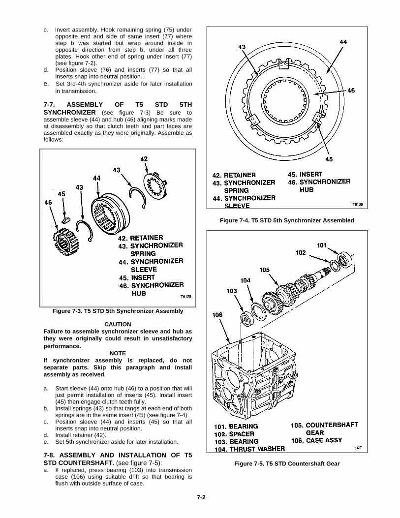
c. Invert assembly. Hook remaining spring (75) underopposite end and side of same insert (77) wherestep b was started but wrap around inside inopposite direction from step b, under all threeplates. Hook other end of spring under insert (77)(see figure 7-2).
d. Position sleeve (76) and inserts (77) so that allinserts snap into neutral position..
e. Set 3rd-4th synchronizer aside for later installationin transmission.
7-7. ASSEMBLY OF T5 STD 5THSYNCHRONIZER (see figure 7-3) Be sure toassemble sleeve (44) and hub (46) aligning marks madeat disassembly so that clutch teeth and part faces areassembled exactly as they were originally. Assemble asfollows:
Figure 7-3. T5 STD 5th Synchronizer Assembly
CAUTIONFailure to assemble synchronizer sleeve and hub asthey were originally could result in unsatisfactoryperformance.
NOTEIf synchronizer assembly is replaced, do notseparate parts. Skip this paragraph and installassembly as received.
a. Start sleeve (44) onto hub (46) to a position that willjust permit installation of inserts (45). Install insert(45) then engage clutch teeth fully.
b. Install springs (43) so that tangs at each end of bothsprings are in the same insert (45) (see figure 7-4).
c. Position sleeve (44) and inserts (45) so that allinserts snap into neutral position.
d. Install retainer (42).e. Set 5th synchronizer aside for later installation.
7-8. ASSEMBLY AND INSTALLATION OF T5STD COUNTERSHAFT. (see figure 7-5):a. If replaced, press bearing (103) into transmission
case (106) using suitable drift so that bearing isflush with outside surface of case.
Figure 7-4. T5 STD 5th Synchronizer Assembled
Figure 7-5. T5 STD Countershaft Gear
7-2
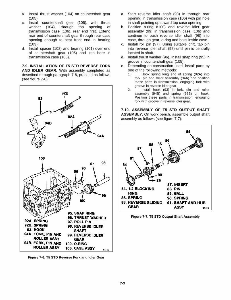
b. Install thrust washer (104) on countershaft gear(105).
c. Install countershaft gear (105), with thrustwasher (104), through top opening oftransmission case (106), rear end first. Extendrear end of countershaft gear through rear caseopening enough to seat front end in bearing(103).
d. Install spacer (102) and bearing (101) over endof countershaft gear (105) and into bore intransmission case (106).
7-9. INSTALLATION OF T5 STD REVERSE FORKAND IDLER GEAR. With assembly completed asdescribed through paragraph 7-8, proceed as follows(see figure 7-6):
Figure 7-6. T5 STD Reverse Fork and Idler Gear
a. Start reverse idler shaft (98) in through rearopening in transmission case (106) with pin holein shaft pointing up toward top case opening.
b. Position o-ring 8100) and reverse idler gearassembly (99) in transmission case (106) andcontinue to push reverse idler shaft (98) intocase, through gear, o-ring and boss inside case.
c. Install roll pin (97). Using suitable drift, tap pininto reverse idler shaft (98) until pin is centrallylocated in shaft.
d. Install thrust washer (96). Install snap ring (95) ingroove in countershaft gear (105).
e. Depending on construction used, install parts byone of the following methods:1. Hook spring long end of spring (92A) into
fork, pin and roller assembly (94A) and positionthese parts in transmission, engaging fork withgroove in reverse idler gear.
2. Install hook (93) in fork, pin and rollerassembly (94B) and spring (92B) on hook.Position these parts in transmission, engagingfork with groove in reverse idler gear.
7-10. ASSEMBLY OF T5 STD OUTPUT SHAFTASSEMBLY. On work bench, assemble output shaftassembly as follows (see figure 7-7):
Figure 7-7. T5 STD Output Shaft Assembly
7-3
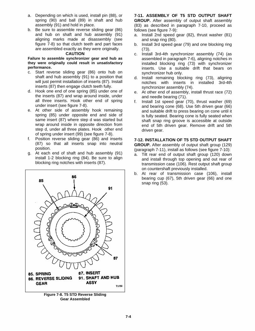
a. Depending on which is used, install pin (88), orspring (90) and ball (89) in shaft and hubassembly (91) and hold in place.
b. Be sure to assemble reverse sliding gear (86)and hub on shaft and hub assembly (91)aligning marks made at disassembly (seefigure 7-8) so that clutch teeth and part facesare assembled exactly as they were originally.
CAUTION Failure to assemble synchronizer gear and hub asthey were originally could result in unsatisfactoryperformance.c. Start reverse sliding gear (86) onto hub on
shaft and hub assembly (91) to a position thatwill just permit installation of inserts (87). Installinserts (87) then engage clutch teeth fully.
d. Hook one end of one spring (85) under one ofthe inserts (87) and wrap around inside, underall three inserts. Hook other end of springunder insert (see figure 7-8).
e. At other side of assembly hook remainingspring (85) under opposite end and side ofsame insert (87) where step d was started butwrap around inside in opposite direction fromstep d, under all three plates. Hook other endof spring under insert (99) (see figure 7-8).
f. Position reverse sliding gear (86) and inserts(87) so that all inserts snap into neutralposition.
g. At each end of shaft and hub assembly (91)install 1-2 blocking ring (84). Be sure to alignblocking ring notches with inserts (87).
Figure 7-8. T5 STD Reverse SlidingGear Assembled
7-11. ASSEMBLY OF T5 STD OUTPUT SHAFTGROUP. After assembly of output shaft assembly(83) as described in paragraph 7-10, proceed asfollows (see figure 7-9):a. Install 2nd speed gear (82), thrust washer (81)
and snap ring (80).b. Install 3rd speed gear (79) and one blocking ring
(73).c. Install 3rd-4th synchronizer assembly (74) (as
assembled in paragraph 7-6), aligning notches ininstalled blocking ring (73) with synchronizerinserts. Use a suitable drift that bears onsynchronizer hub only.
d. Install remaining blocking ring (73), aligningnotches with inserts in installed 3rd-4thsynchronizer assembly (74).
e. At other end of assembly, install thrust race (72)and needle bearing (71).
f. Install 1st speed gear (70), thrust washer (69)and bearing cone (68). Use 5th driven gear (66)and suitable drift to press bearing on cone until itis fully seated. Bearing cone is fully seated whenshaft snap ring groove is accessible at outsideend of 5th driven gear. Remove drift and 5thdriven gear.
7-12. INSTALLATION OF T5 STD OUTPUT SHAFTGROUP. After assembly of output shaft group (129)(paragraph 7-11), install as follows (see figure 7-10):a. Tilt rear end of output shaft group (120) down
and install through top opening and out rear oftransmission case (106). Rest output shaft groupon countershaft previously installed.
b. At rear of transmission case (106), installbearing cup (67), 5th driven gear (66) and onesnap ring (53).
7-4
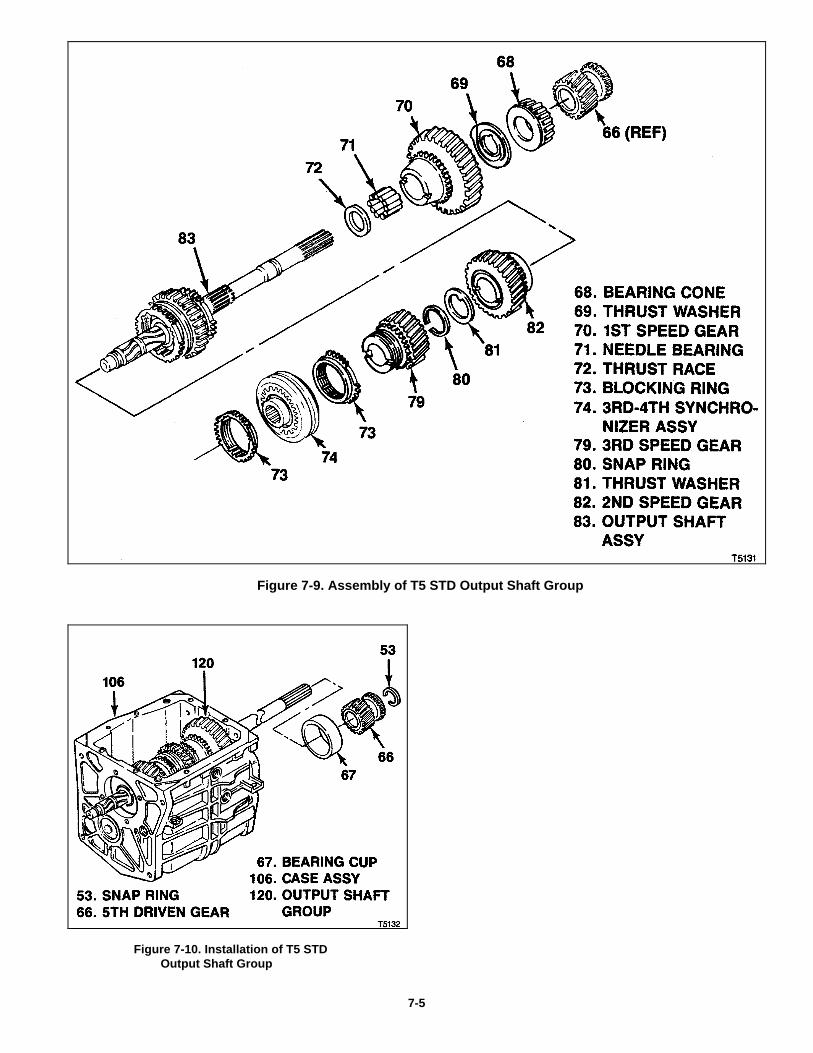
Figure 7-9. Assembly of T5 STD Output Shaft Group
Figure 7-10. Installation of T5 STD Output Shaft Group
7-5
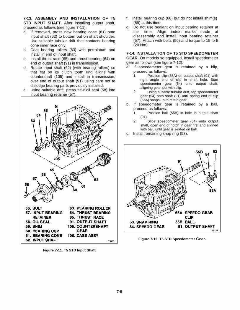
7-13. ASSEMBLY AND INSTALLATION OF T5STD INPUT SHAFT. After installing output shaft,proceed as follows (see figure 7-11):a. If removed, press new bearing cone (61) onto
input shaft (62) to bottom out on shaft shoulder.Use suitable tubular drift that contacts bearingcone inner race only.
b. Coat bearing rollers (63) with petrolatum andinstall in end of input shaft.
c. Install thrust race (65) and thrust bearing (64) onend of output shaft (91) in transmission.
d. Rotate input shaft (62) (with bearing rollers) sothat flat on its clutch tooth ring aligns withcountershaft (105) and install in transmission,over end of output shaft (91) using care not todislodge bearing parts previously installed.
e. Using suitable drift, press new oil seal (58) intoinput bearing retainer (57).
Figure 7-11. T5 STD Input Shaft
f. Install bearing cup (60) but do not install shim(s)(59) at this time.
g. Do not use sealant on input bearing retainer atthis time. Align index marks made atdisassembly and install input bearing retainer(57). Attach with bolts (56) and torque to 15 lb-ft(20 Nm).
7-14. INSTALLATION OF T5 STD SPEEDOMETERGEAR. On models so equipped, install speedometergear as follows (see figure 7-12):a. If speedometer gear is retained by a blip,
proceed as follows:1. Position clip (55A) on output shaft (91) with
right angle end of clip in shaft hole. Startspeedometer gear (54) onto output shaft,aligning gear slot with clip.
2. Using suitable tubular drift, tap speedometergear (54) onto shaft (91) until spring end of clip(55A) snaps up to retain gear.
b. If speedometer gear is retained by a ball,proceed as follows:1. Position ball (55B) in hole in output shaft
(91).2. Slide speedometer gear (54) onto output
shaft, open end of notch in gear first and alignedwith ball, until gear is seated on ball.
c. Install remaining snap ring (53).
Figure 7-12. T5 STD Speedometer Gear.
7-6
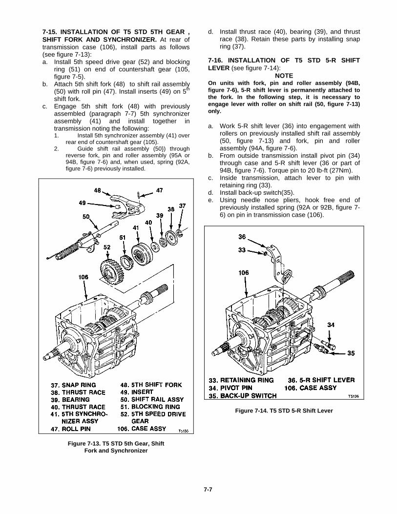
7-15. INSTALLATION OF T5 STD 5TH GEAR ,SHIFT FORK AND SYNCHRONIZER. At rear oftransmission case (106), install parts as follows(see figure 7-13):a. Install 5th speed drive gear (52) and blocking
ring (51) on end of countershaft gear (105,figure 7-5).
b. Attach 5th shift fork (48) to shift rail assembly(50) with roll pin (47). Install inserts (49) on 5th
shift fork.c. Engage 5th shift fork (48) with previously
assembled (paragraph 7-7) 5th synchronizerassembly (41) and install together intransmission noting the following:1. Install 5th synchronizer assembly (41) over
rear end of countershaft gear (105).2. Guide shift rail assembly (50}) through
reverse fork, pin and roller assembly (95A or94B, figure 7-6) and, when used, spring (92A,figure 7-6) previously installed.
Figure 7-13. T5 STD 5th Gear, ShiftFork and Synchronizer
d. Install thrust race (40), bearing (39), and thrustrace (38). Retain these parts by installing snapring (37).
7-16. INSTALLATION OF T5 STD 5-R SHIFTLEVER (see figure 7-14):
NOTEOn units with fork, pin and roller assembly (94B,figure 7-6), 5-R shift lever is permanently attached tothe fork. In the following step, it is necessary toengage lever with roller on shift rail (50, figure 7-13)only.
a. Work 5-R shift lever (36) into engagement withrollers on previously installed shift rail assembly(50, figure 7-13) and fork, pin and rollerassembly (94A, figure 7-6).
b. From outside transmission install pivot pin (34)through case and 5-R shift lever (36 or part of94B, figure 7-6). Torque pin to 20 lb-ft (27Nm).
c. Inside transmission, attach lever to pin withretaining ring (33).
d. Install back-up switch(35).e. Using needle nose pliers, hook free end of
previously installed spring (92A or 92B, figure 7-6) on pin in transmission case (106).
Figure 7-14. T5 STD 5-R Shift Lever
7-7
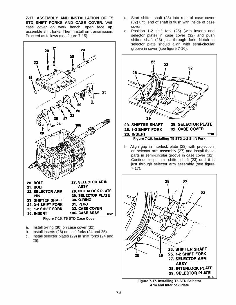
7-17. ASSEMBLY AND INSTALLATION OF T5STD SHIFT FORKS AND CASE COVER. Withcase cover on work bench, open face up,assemble shift forks. Then, install on transmission.Proceed as follows (see figure 7-15):
Figure 7-15. T5 STD Case Cover
a. Install o-ring (30) on case cover (32).b. Install inserts (26) on shift forks (24 and 25).c. Install selector plates (29) in shift forks (24 and
25).
d. Start shifter shaft (23) into rear of case cover(32) until end of shaft is flush with inside of casecover.
e. Position 1-2 shift fork (25) (with inserts andselector plate) in case cover (32) and pushshifter shaft (23) just through fork. Notch inselector plate should align with semi-circulargroove in cover (see figure 7-16).
Figure 7-16. Installing T5 STD 1-2 Shift Fork
f. Align gap in interlock plate (28) with projectionon selector arm assembly (27) and install theseparts in semi-circular groove in case cover (32).Continue to push in shifter shaft (23) until it isjust through selector arm assembly (see figure7-17).
Figure 7-17. Installing T5 STD SelectorArm and Interlock Plate
7-8
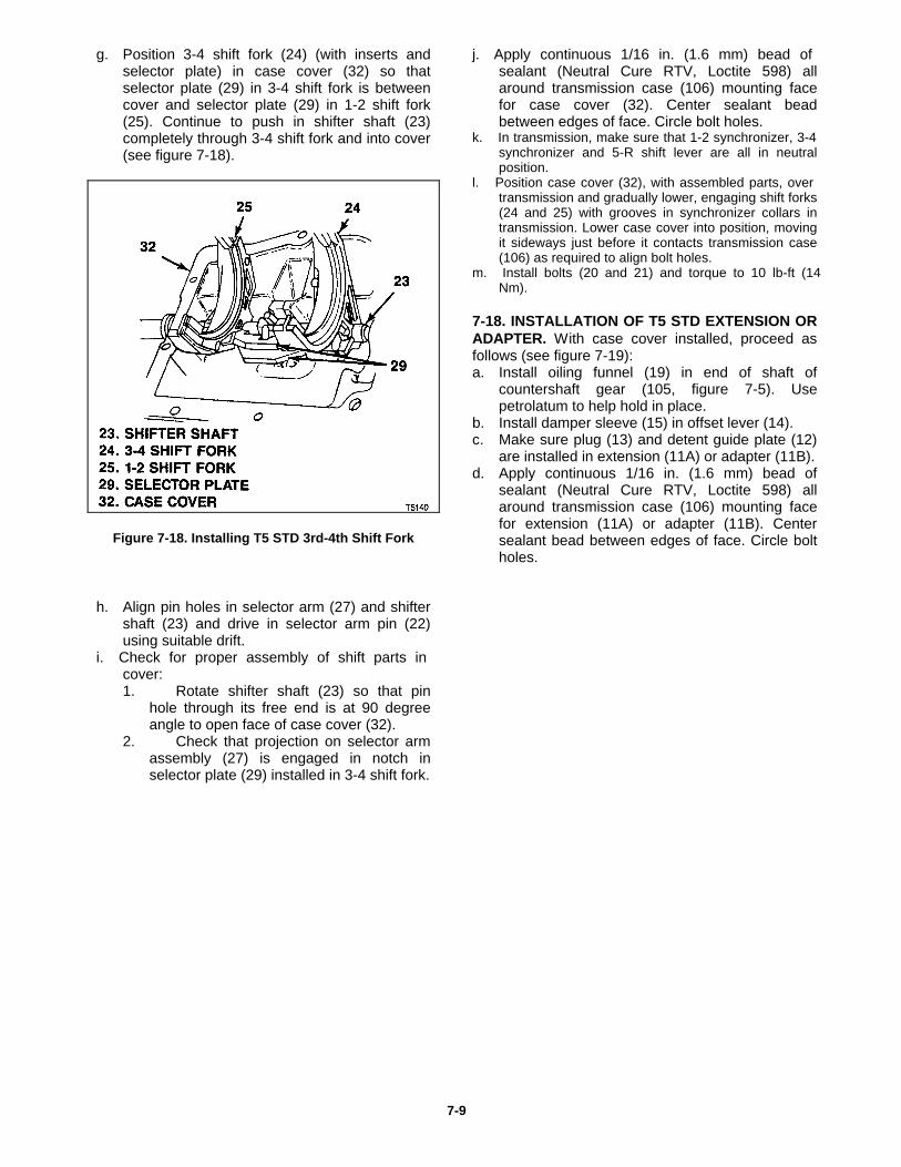
g. Position 3-4 shift fork (24) (with inserts andselector plate) in case cover (32) so thatselector plate (29) in 3-4 shift fork is betweencover and selector plate (29) in 1-2 shift fork(25). Continue to push in shifter shaft (23)completely through 3-4 shift fork and into cover(see figure 7-18).
Figure 7-18. Installing T5 STD 3rd-4th Shift Fork
h. Align pin holes in selector arm (27) and shifter
shaft (23) and drive in selector arm pin (22)using suitable drift.
i. Check for proper assembly of shift parts incover:1. Rotate shifter shaft (23) so that pin
hole through its free end is at 90 degreeangle to open face of case cover (32).
2. Check that projection on selector armassembly (27) is engaged in notch inselector plate (29) installed in 3-4 shift fork.
j. Apply continuous 1/16 in. (1.6 mm) bead ofsealant (Neutral Cure RTV, Loctite 598) allaround transmission case (106) mounting facefor case cover (32). Center sealant beadbetween edges of face. Circle bolt holes.
k. In transmission, make sure that 1-2 synchronizer, 3-4synchronizer and 5-R shift lever are all in neutralposition.
l. Position case cover (32), with assembled parts, overtransmission and gradually lower, engaging shift forks(24 and 25) with grooves in synchronizer collars intransmission. Lower case cover into position, movingit sideways just before it contacts transmission case(106) as required to align bolt holes.
m. Install bolts (20 and 21) and torque to 10 lb-ft (14Nm).
7-18. INSTALLATION OF T5 STD EXTENSION ORADAPTER. With case cover installed, proceed asfollows (see figure 7-19):a. Install oiling funnel (19) in end of shaft of
countershaft gear (105, figure 7-5). Usepetrolatum to help hold in place.
b. Install damper sleeve (15) in offset lever (14).c. Make sure plug (13) and detent guide plate (12)
are installed in extension (11A) or adapter (11B).d. Apply continuous 1/16 in. (1.6 mm) bead of
sealant (Neutral Cure RTV, Loctite 598) allaround transmission case (106) mounting facefor extension (11A) or adapter (11B). Centersealant bead between edges of face. Circle boltholes.
7-9
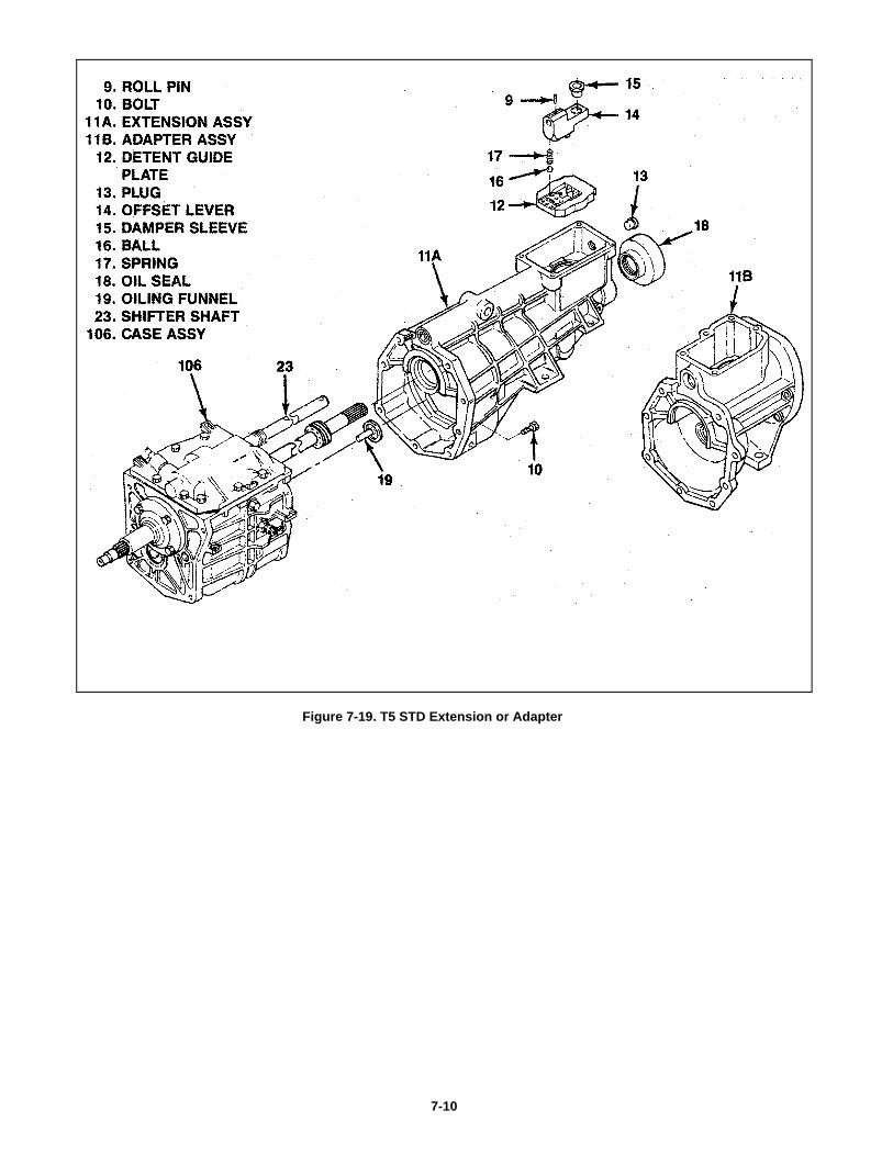
Figure 7-19. T5 STD Extension or Adapter
7-10
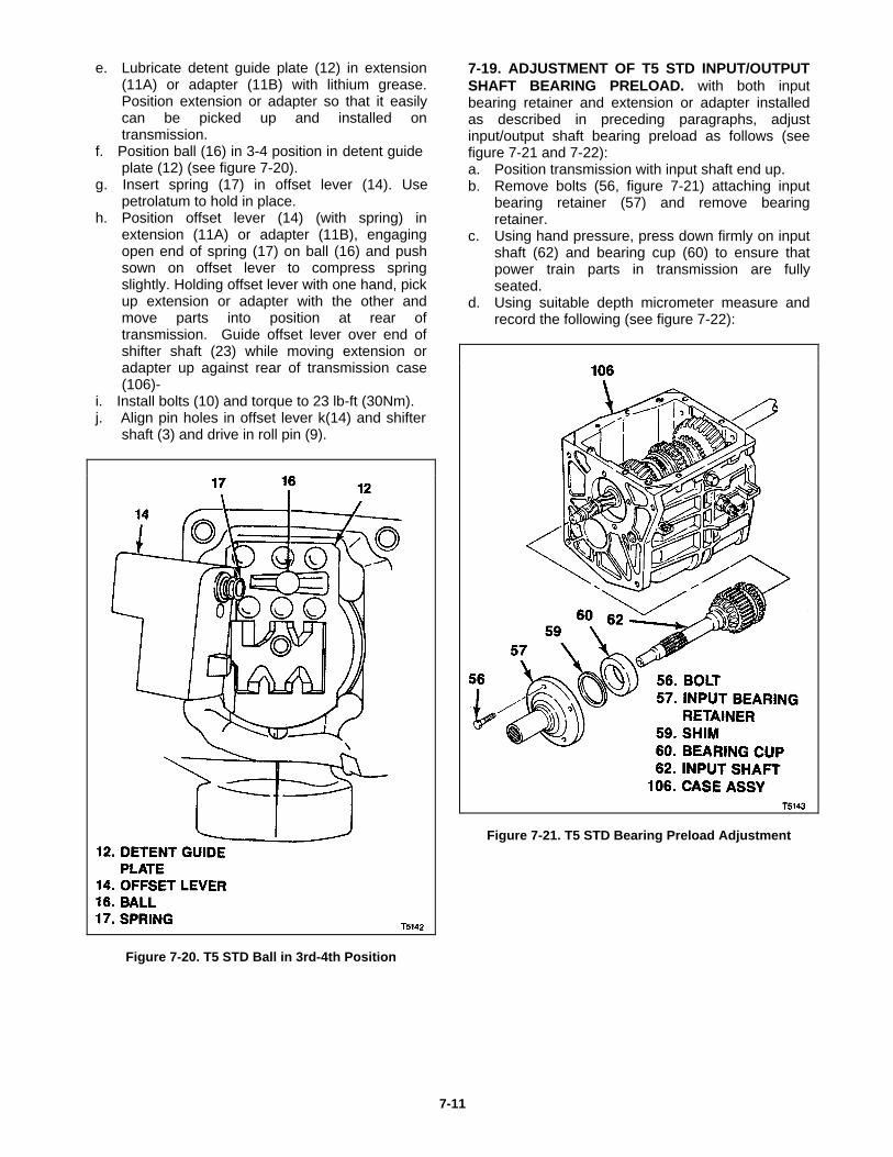
e. Lubricate detent guide plate (12) in extension(11A) or adapter (11B) with lithium grease.Position extension or adapter so that it easilycan be picked up and installed ontransmission.
f. Position ball (16) in 3-4 position in detent guideplate (12) (see figure 7-20).
g. Insert spring (17) in offset lever (14). Usepetrolatum to hold in place.
h. Position offset lever (14) (with spring) inextension (11A) or adapter (11B), engagingopen end of spring (17) on ball (16) and pushsown on offset lever to compress springslightly. Holding offset lever with one hand, pickup extension or adapter with the other andmove parts into position at rear oftransmission. Guide offset lever over end ofshifter shaft (23) while moving extension oradapter up against rear of transmission case(106)-
i. Install bolts (10) and torque to 23 lb-ft (30Nm).j. Align pin holes in offset lever k(14) and shifter
shaft (3) and drive in roll pin (9).
Figure 7-20. T5 STD Ball in 3rd-4th Position
7-19. ADJUSTMENT OF T5 STD INPUT/OUTPUTSHAFT BEARING PRELOAD. with both inputbearing retainer and extension or adapter installedas described in preceding paragraphs, adjustinput/output shaft bearing preload as follows (seefigure 7-21 and 7-22):a. Position transmission with input shaft end up.b. Remove bolts (56, figure 7-21) attaching input
bearing retainer (57) and remove bearingretainer.
c. Using hand pressure, press down firmly on inputshaft (62) and bearing cup (60) to ensure thatpower train parts in transmission are fullyseated.
d. Using suitable depth micrometer measure andrecord the following (see figure 7-22):
Figure 7-21. T5 STD Bearing Preload Adjustment
7-11
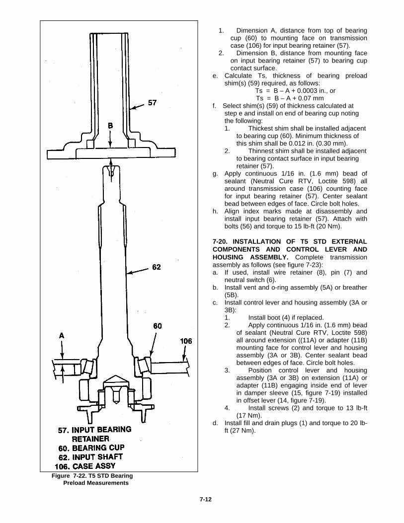
1. Dimension A, distance from top of bearingcup (60) to mounting face on transmissioncase (106) for input bearing retainer (57).
2. Dimension B, distance from mounting faceon input bearing retainer (57) to bearing cupcontact surface.
e. Calculate Ts, thickness of bearing preloadshim(s) (59) required, as follows:
Ts = B – A + 0.0003 in., or Ts = B – A + 0.07 mm
f. Select shim(s) (59) of thickness calculated atstep e and install on end of bearing cup notingthe following:1. Thickest shim shall be installed adjacent
to bearing cup (60). Minimum thickness ofthis shim shall be 0.012 in. (0.30 mm).
2. Thinnest shim shall be installed adjacentto bearing contact surface in input bearingretainer (57).
g. Apply continuous 1/16 in. (1.6 mm) bead ofsealant (Neutral Cure RTV, Loctite 598) allaround transmission case (106) counting facefor input bearing retainer (57). Center sealantbead between edges of face. Circle bolt holes.
h. Align index marks made at disassembly andinstall input bearing retainer (57). Attach withbolts (56) and torque to 15 lb-ft (20 Nm).
7-20. INSTALLATION OF T5 STD EXTERNALCOMPONENTS AND CONTROL LEVER ANDHOUSING ASSEMBLY. Complete transmissionassembly as follows (see figure 7-23):a. If used, install wire retainer (8), pin (7) and
neutral switch (6).b. Install vent and o-ring assembly (5A) or breather
(5B).c. Install control lever and housing assembly (3A or
3B):1. Install boot (4) if replaced.2. Apply continuous 1/16 in. (1.6 mm) bead
of sealant (Neutral Cure RTV, Loctite 598)all around extension ((11A) or adapter (11B)mounting face for control lever and housingassembly (3A or 3B). Center sealant beadbetween edges of face. Circle bolt holes.
3. Position control lever and housingassembly (3A or 3B) on extension (11A) oradapter (11B) engaging inside end of leverin damper sleeve (15, figure 7-19) installedin offset lever (14, figure 7-19).
4. Install screws (2) and torque to 13 lb-ft(17 Nm).
d. Install fill and drain plugs (1) and torque to 20 lb-ft (27 Nm).
Figure 7-22. T5 STD Bearing Preload Measurements
7-12
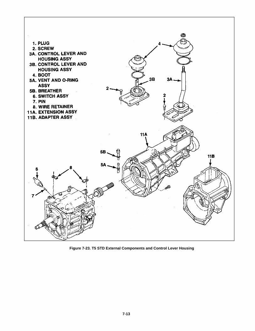
Figure 7-23. T5 STD External Components and Control Lever Housing
7-13
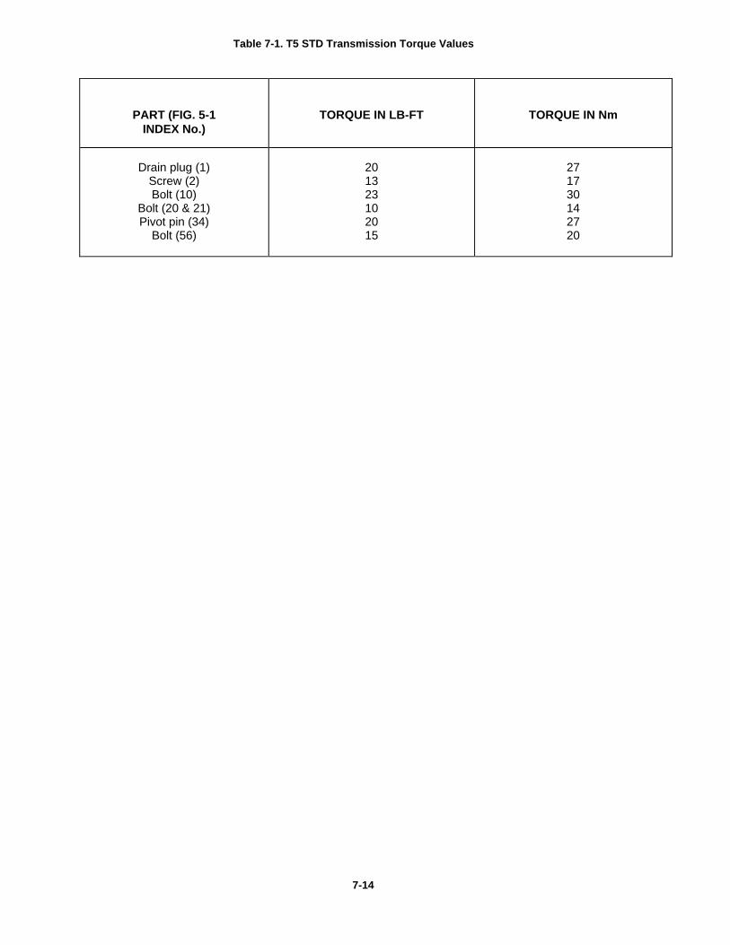
Table 7-1. T5 STD Transmission Torque Values
PART (FIG. 5-1INDEX No.)
TORQUE IN LB-FT TORQUE IN Nm
Drain plug (1)Screw (2)Bolt (10)
Bolt (20 & 21)Pivot pin (34)
Bolt (56)
201323102015
271730142720
7-14


![Kipor KDE2200,3500,5000,6500,6700E,X,T,TA Service Manual[1]](https://img.pdfslide.net/doc/110x75/55cf9c6d550346d033a9ccf9/kipor-kde22003500500065006700extta-service-manual1.jpg)