Embed Size (px)
DESCRIPTION
Solar photovoltaic system characteristics depends on environmental factors, therefore a maximum power point tracking MPPT technique is needed to keep the working point of the system as close as possible to the MPP. In this paper we present a PV generator composed by four PV panel Kaneka GSA211 (60Watt) placed in series, and a neural network model developed by the authors. The aim of this study focuses on the application of the artificial neural networks to extract the maximum power point of a photovoltaic generator that feeds a motor-pump group unit through a PWM inverter installed in the laboratory. The output of the ANN is the optimal voltage Vopt which is compared to the PV generator voltage Vpv, then passed through an integrator to extract the stator frequency fs that are given to the PWM control of the DC-AC inverter to find out the sinusoidal reference voltage and the sampled wave. The training of the ANN is done with Levenberg Marquardt algorithm and the whole technique is being simulated and studied using MATLAB software [24]. KEYWORDS: .
Citation preview
International Journal of Advances in Engineering & Technology, Nov. 2012.
©IJAET ISSN: 2231-1963
130 Vol. 5, Issue 1, pp. 130-140
A MAXIMUM POWER POINT TRACKING METHOD BASED ON
ARTIFICIAL NEURAL NETWORK FOR A PV SYSTEM
Abdessamia Elgharbi1, Dhafer Mezghani
1, Abdelkader Mami
2
1 Laboratory of Analyse and Control of Systems, Department of Electric Engineering
National School of Engineering of Tunis, PB 37, Le Belvedere, Tunis1002, Tunisia.
2Department of Physics, Faculty of Sciences of Tunis, Electronic Laboratory, 2092 El
Manar, Tunis, Tunisia.
ABSTRACT
Solar photovoltaic system characteristics depends on environmental factors, therefore a maximum power point
tracking MPPT technique is needed to keep the working point of the system as close as possible to the MPP. In
this paper we present a PV generator composed by four PV panel Kaneka GSA211 (60Watt) placed in series,
and a neural network model developed by the authors. The aim of this study focuses on the application of the
artificial neural networks to extract the maximum power point of a photovoltaic generator that feeds a motor-
pump group unit through a PWM inverter installed in the laboratory. The output of the ANN is the optimal
voltage Vopt which is compared to the PV generator voltage Vpv, then passed through an integrator to extract the
stator frequency fs that are given to the PWM control of the DC-AC inverter to find out the sinusoidal reference
voltage and the sampled wave. The training of the ANN is done with Levenberg Marquardt algorithm and the
whole technique is being simulated and studied using MATLAB software [24].
KEYWORDS: MPPT, Artificial Neural Network, LM algorithm, PV system, MATLAB Simulink.
I. INTRODUCTION
The production of energy is a challenge of great importance for the coming years. Indeed, the energy
needs of the people are rising. Furthermore, developing countries will need more energy to complete
their development. Today, much of the world's energy is supplied from fossil sources. Consumption
of these sources leads to emissions of greenhouse gases followed by an increase in pollution.
Moreover, the additional danger is that excessive consumption of natural resource reserves reduces
this type of energy in a dangerous way for future generations.
Unlike fossil fuels, renewable energy such as solar, wind, hydropower and biomass are unlimited and
reduce emission of greenhouse gases. Renewable energies include a number of technology clusters by
source of energy valued and useful energy obtained. The studied photovoltaic structure is composed
by a photovoltaic generator, a DC / AC inverter and a motor-pump unit connected with a storage tank.
By applying the technique of maximum power point tracking, the efficiency of the system rises
whatever is the irradiation and the temperature of the environment. Several different MPPT
techniques have been proposed in the literature [1-2], several papers tackle the problem concerning
the search of the optimal operation point by using Hill-climbing algorithms [1-3-4-5], fuzzy logic or
digital signal processing.
The uses of neural network in the industrial electronics have been increased, and have a large
perspective in intelligent control area that is evident by the publications in the literature. Considering
International Journal of Advances in Engineering & Technology, Nov. 2012.
©IJAET ISSN: 2231-1963
131 Vol. 5, Issue 1, pp. 130-140
the immense potentiality of neural networks in future, their applications in industrial electronics area
are yet in the stage of infancy [6].
In a first part, after a brief modelling of the PV module, we present the model and the simulations of
the I-V and P-V characteristics with different levels of illuminations and temperatures. In a second
part, an artificial neural network is presented then trained with LM algorithm and the back
propagation method to extract the optimal voltage Vopt of the same PV module. The simulations are
carried out to verify the proposed ANN method in the section IV. Finally, concluding and remarks are
given in section VI.
II. PHOTOVOLTAIC MODULE MODELLING
Photovoltaic conversion is produced by subjecting the solar cell to sunlight. The received energy
causes chaotic movement of the electrons within the material, the current collection is done by the
metal contacts (electrodes). If these electrodes are connected to an external circuit, a direct current
flows.
In this PV generator, a number of solar cells are assembled to form a photovoltaic module, the link
between these modules in parallel rise the direct current value and its link in series rise the direct
voltage value. Thus, the group of linked PV modules according to desired values of both the current
and the voltage forms the PV generator. The PV array characteristics presents three important points,
the short circuit current, the open circuit voltage and the optimum power delivered by the PV module
to an optimum load when the PV modules operate at their maximum power point. Our model of PV
module consisting 4 cells Kaneka GSA211 (60Watt) in series which has been evaluated using
MATLAB environment.
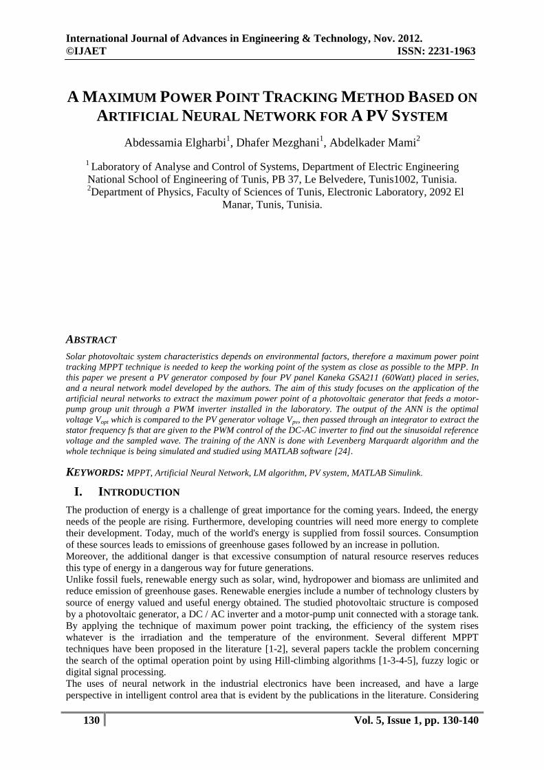
The PV generator behaviour is equivalent to a current source shunted by a junction diode, if we
neglect the physical phenomena of PV cell such as contact resistance, the current lost by photocell
sides as well as the age of cells [7-8-9].
Figure 1. Electrical schema of PV module
The relationship between the output voltage Vpv and the load current Ipv can be expressed as:
(1)
Where;
Ec: solar illumination in W/m2
Ecref: the reference illumination (1000W/m2)
T: the ambient temperature in °C
Tref: the reference ambient temperature (25°C)
Tp : the surface temperature of the PV generator (°C ou °K)
Icc : the total short-circuit current for the state reference in A
Kisc : the short-circuit -temperature current coefficient (Kisc = 0.0017 A/°C)
Is : the opposite total current of the PV generator in A
in : the ideality factor of the PV field
K : the Boltzman constant (K=1.38.10-23 j /°K)
q : the electron charge (q=1.6.10-19 C)
International Journal of Advances in Engineering & Technology, Nov. 2012.
©IJAET ISSN: 2231-1963
132 Vol. 5, Issue 1, pp. 130-140
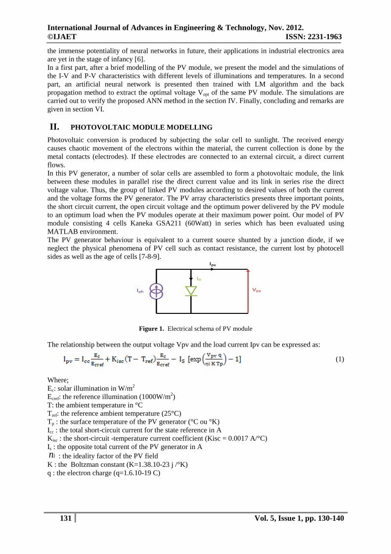
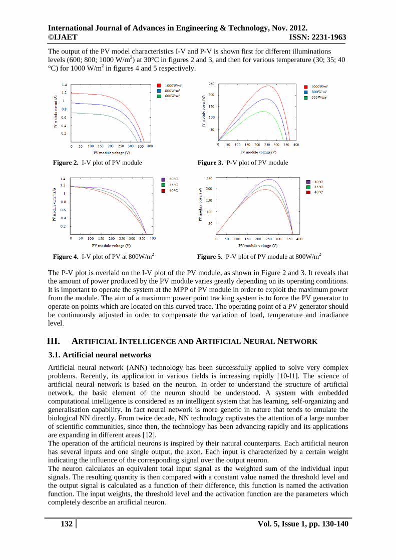
The output of the PV model characteristics I-V and P-V is shown first for different illuminations
levels (600; 800; 1000 W/m2) at 30°C in figures 2 and 3, and then for various temperature (30; 35; 40
°C) for 1000 W/m2 in figures 4 and 5 respectively.
Figure 2. I-V plot of PV module Figure 3. P-V plot of PV module
Figure 4. I-V plot of PV at 800W/m2
Figure 5. P-V plot of PV module at 800W/m2
The P-V plot is overlaid on the I-V plot of the PV module, as shown in Figure 2 and 3. It reveals that
the amount of power produced by the PV module varies greatly depending on its operating conditions.
It is important to operate the system at the MPP of PV module in order to exploit the maximum power
from the module. The aim of a maximum power point tracking system is to force the PV generator to
operate on points which are located on this curved trace. The operating point of a PV generator should
be continuously adjusted in order to compensate the variation of load, temperature and irradiance
level.
III. ARTIFICIAL INTELLIGENCE AND ARTIFICIAL NEURAL NETWORK
3.1. Artificial neural networks
Artificial neural network (ANN) technology has been successfully applied to solve very complex
problems. Recently, its application in various fields is increasing rapidly [10-l1]. The science of
artificial neural network is based on the neuron. In order to understand the structure of artificial
network, the basic element of the neuron should be understood. A system with embedded
computational intelligence is considered as an intelligent system that has learning, self-organizing and
generalisation capability. In fact neural network is more genetic in nature that tends to emulate the
biological NN directly. From twice decade, NN technology captivates the attention of a large number
of scientific communities, since then, the technology has been advancing rapidly and its applications
are expanding in different areas [12].
The operation of the artificial neurons is inspired by their natural counterparts. Each artificial neuron
has several inputs and one single output, the axon. Each input is characterized by a certain weight
indicating the influence of the corresponding signal over the output neuron.
The neuron calculates an equivalent total input signal as the weighted sum of the individual input
signals. The resulting quantity is then compared with a constant value named the threshold level and
the output signal is calculated as a function of their difference, this function is named the activation
function. The input weights, the threshold level and the activation function are the parameters which
completely describe an artificial neuron.
International Journal of Advances in Engineering & Technology, Nov. 2012.
©IJAET ISSN: 2231-1963
133 Vol. 5, Issue 1, pp. 130-140
Over the last few years, more sophisticated types of neurons and activation functions assembled in
algorithms have been introduced in order to solve different sorts of practical problems. In particular,
Quasi-Newton Levenberg Marquardt method has useful for many control system and system
identification applications [13].
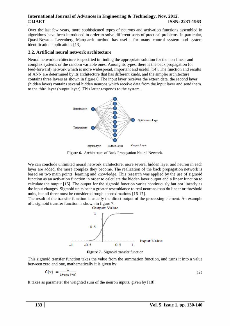
3.2. Artificial neural network architecture
Neural network architecture is specified in finding the appropriate solution for the non-linear and
complex systems or the random variable ones. Among its types, there is the back propagation (or
feed-forward) network which is more widespread, important and useful [14]. The function and results
of ANN are determined by its architecture that has different kinds, and the simpler architecture
contains three layers as shown in figure 6. The input layer receives the extern data, the second layer
(hidden layer) contains several hidden neurons which receive data from the input layer and send them
to the third layer (output layer). This latter responds to the system.
Figure 6. Architecture of Back Propagation Neural Network.
We can conclude unlimited neural network architecture, more several hidden layer and neuron in each
layer are added; the more complex they become. The realization of the back propagation network is
based on two main points: learning and knowledge. This research was applied by the use of sigmoid
function as an activation function in order to calculate the hidden layer output and a linear function to
calculate the output [15]. The output for the sigmoid function varies continuously but not linearly as
the input changes. Sigmoid units bear a greater resemblance to real neurons than do linear or threshold
units, but all three must be considered rough approximations [16-17].
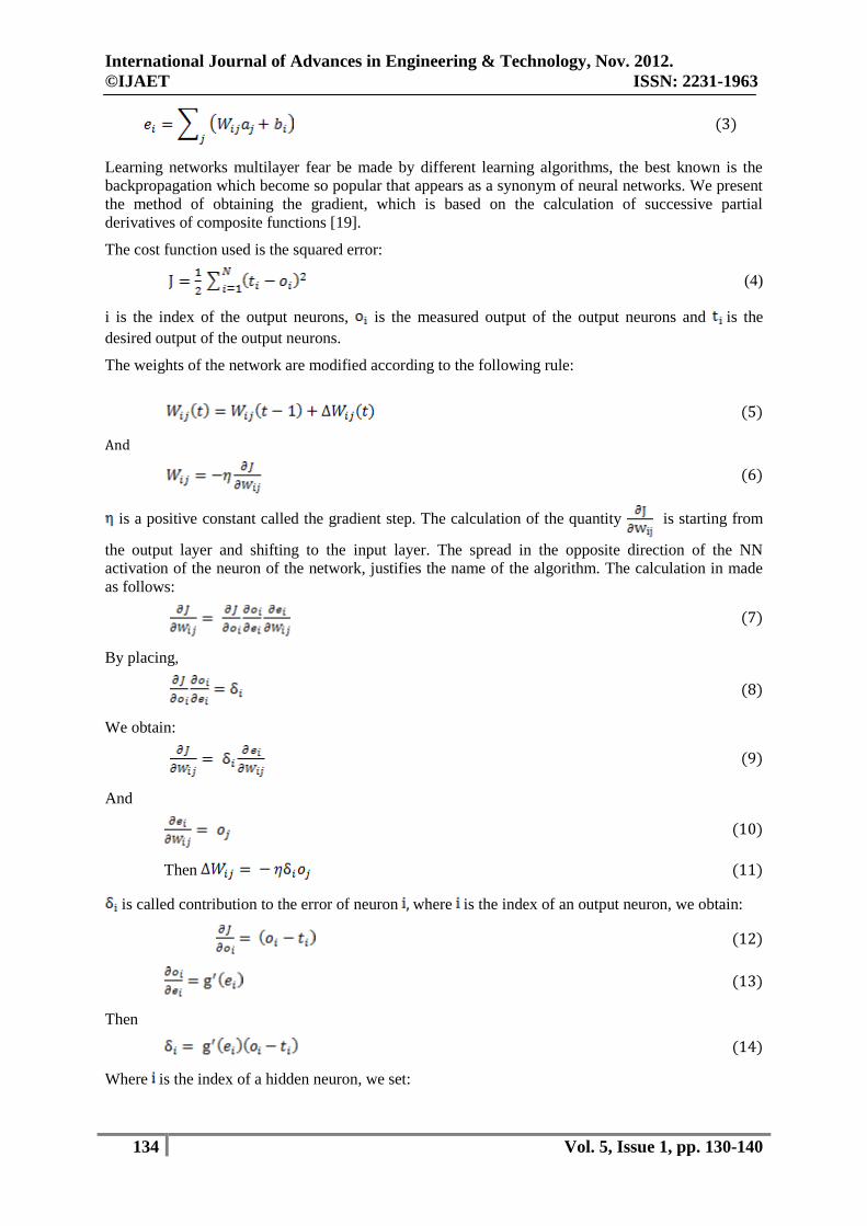
The result of the transfer function is usually the direct output of the processing element. An example
of a sigmoid transfer function is shown in figure 7.
Figure 7. Sigmoid transfer function.
This sigmoid transfer function takes the value from the summation function, and turns it into a value
between zero and one, mathematically it is given by:
(2)
It takes as parameter the weighted sum of the neuron inputs, given by [18]:
International Journal of Advances in Engineering & Technology, Nov. 2012.
©IJAET ISSN: 2231-1963
134 Vol. 5, Issue 1, pp. 130-140
(3)
Learning networks multilayer fear be made by different learning algorithms, the best known is the
backpropagation which become so popular that appears as a synonym of neural networks. We present
the method of obtaining the gradient, which is based on the calculation of successive partial
derivatives of composite functions [19].
The cost function used is the squared error:
(4)
i is the index of the output neurons, is the measured output of the output neurons and is the
desired output of the output neurons.
The weights of the network are modified according to the following rule:
(5)
And
(6)
is a positive constant called the gradient step. The calculation of the quantity is starting from
the output layer and shifting to the input layer. The spread in the opposite direction of the NN
activation of the neuron of the network, justifies the name of the algorithm. The calculation in made
as follows:
(7)
By placing,
(8)
We obtain:
(9)
And
(10)
Then (11)
is called contribution to the error of neuron , where is the index of an output neuron, we obtain:
(12)
(13)
Then
(14)
Where is the index of a hidden neuron, we set:
International Journal of Advances in Engineering & Technology, Nov. 2012.
©IJAET ISSN: 2231-1963
135 Vol. 5, Issue 1, pp. 130-140
(15)
is the index of all neurons in which the neuron sends connexion. The calculation results are:
(16)
Then
(17)
The neural network used here has two input layers (illumination and temperature), hidden layer with
10 neurons. The hidden layer contains tan-sigmoid functions and the output layer (the optimal
voltage) contains a linear function. This neural network will be trained by a back propagation method
and the Levenberg Marquardt algorithm.
The LM algorithm is the second order method which implements an iterative approximation of the
hessian matrix (or its inverse) and which consists in modifying the weights by the following formula:
(18)
(19)
H: the hessian matrix with general term
(20)
The LM algorithm is equivalent to the application of the simple gradient rule with a step of 1/𝜇i.
The LM algorithm shows a faster convergence and a better accuracy than other algorithms. Although
the LM algorithms needs an important memory space in training stage, this method is preferred to be
utilised.
3.3. Artificial neural network training
Artificial neural network have memory, which corresponds to the weights in the neurons. The weights
and biases of the network are adjusted by the learning rate in order to move the network output closer
to the targets. The 'newff' function allows a user to specify the number of layers, the number of
neurons in the hidden layer and the activation function used as described below. After training, the
network weights are set by the back-propagation learning rule. The number of epochs for this example
is set to 100 and the learning rate is 0.02. During training, the input vector will be passed through the
neural network and the weights will be adjusted 100 times. The learning rate of the network is also set
[22-23].
The following Matlab code creates a feed forward network:
net = newff(pr,tr,[10,1],{'tansig','purelin'},'trainlm','learngdm','msereg');
net.trainparam.epoch=100;
net.trainparam.Ir=0.02;
net= train(net,pr,tr); gensim(net);
IV. ARTIFICIAL NEURAL NETWORK APPROACH OF MAXIMUM POWER
POINT TRACKING
4.1. Neural network MPPT Photovoltaic power generation requires so much larger initial cost compared to other power
generation sources that it is imperative to extract as much available solar energy as possible from the
PV array. Maximum power output of the PV array changes when solar irradiation, temperature, and/or
load levels vary. Control is therefore, needed for the PV generator to always keep track of the
maximum power point. By controlling the switching scheme of the inverters connected to the PVs the
MPP of the PV array can always be tracked [20-21].
International Journal of Advances in Engineering & Technology, Nov. 2012.
©IJAET ISSN: 2231-1963
136 Vol. 5, Issue 1, pp. 130-140
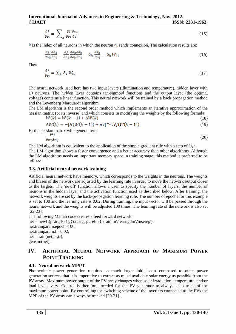
Nonlinear I-V characteristics of a PV module match very well to a neural network application. The
block diagram of the proposed MPPT scheme is shown in the figure 8. In this scheme ANN is used to
find out optimal voltage which is compared with the PV generator voltage.
The error is given to the integrator controller. The output of the integrator controller is the stator
frequency fs that are given to the PWM control of the DC-AC inverter to find out the sinusoidal
reference voltage and the sampled wave.
Figure 8. Proposed MPPT scheme.
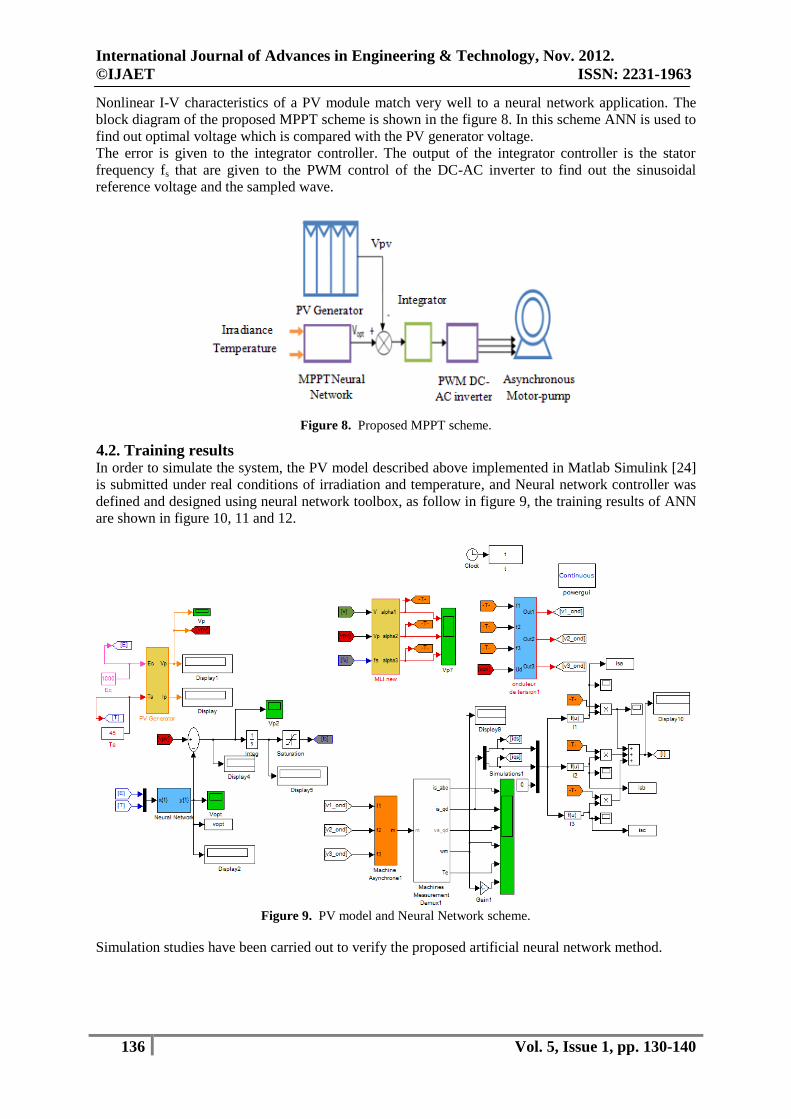
4.2. Training results In order to simulate the system, the PV model described above implemented in Matlab Simulink [24]
is submitted under real conditions of irradiation and temperature, and Neural network controller was
defined and designed using neural network toolbox, as follow in figure 9, the training results of ANN
are shown in figure 10, 11 and 12.
Figure 9. PV model and Neural Network scheme.
Simulation studies have been carried out to verify the proposed artificial neural network method.
International Journal of Advances in Engineering & Technology, Nov. 2012.
©IJAET ISSN: 2231-1963
137 Vol. 5, Issue 1, pp. 130-140
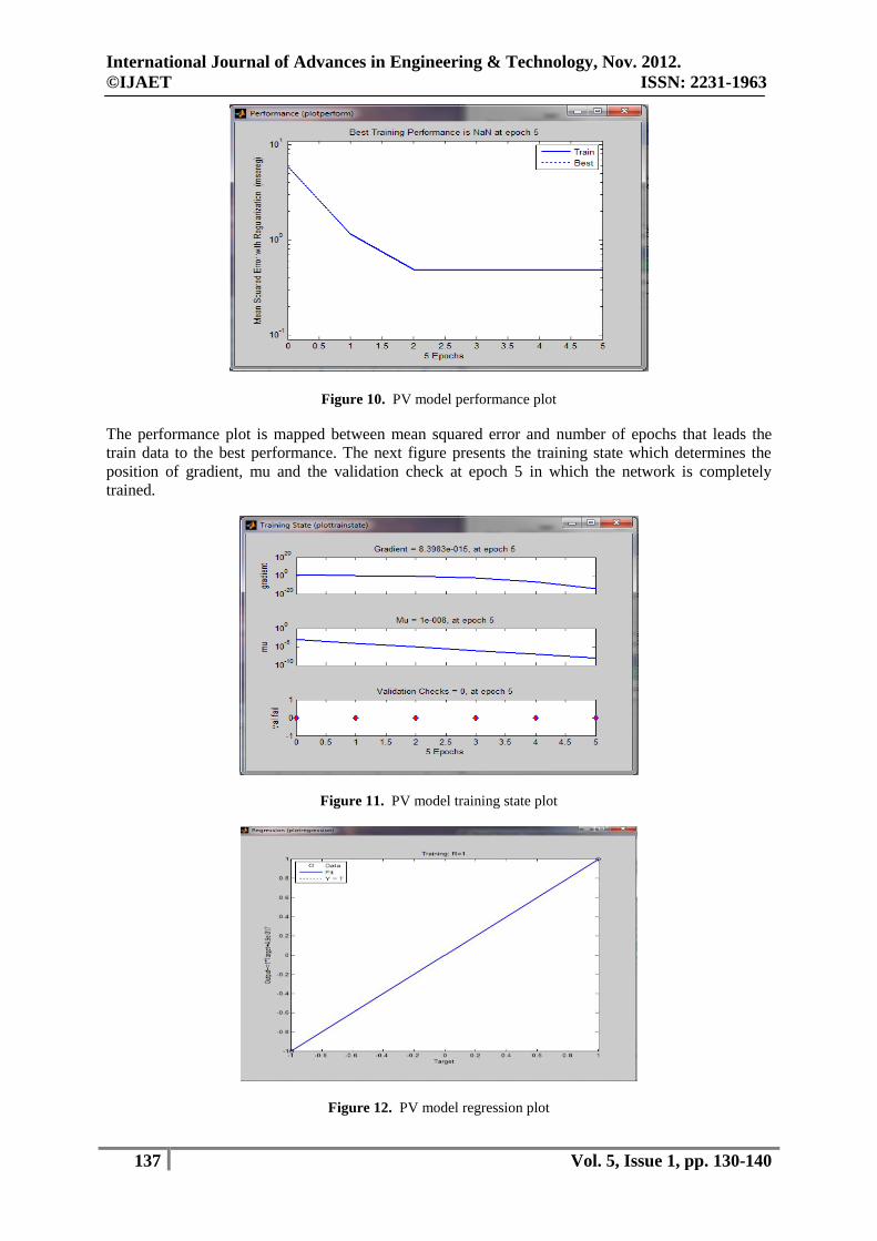
Figure 10. PV model performance plot
The performance plot is mapped between mean squared error and number of epochs that leads the
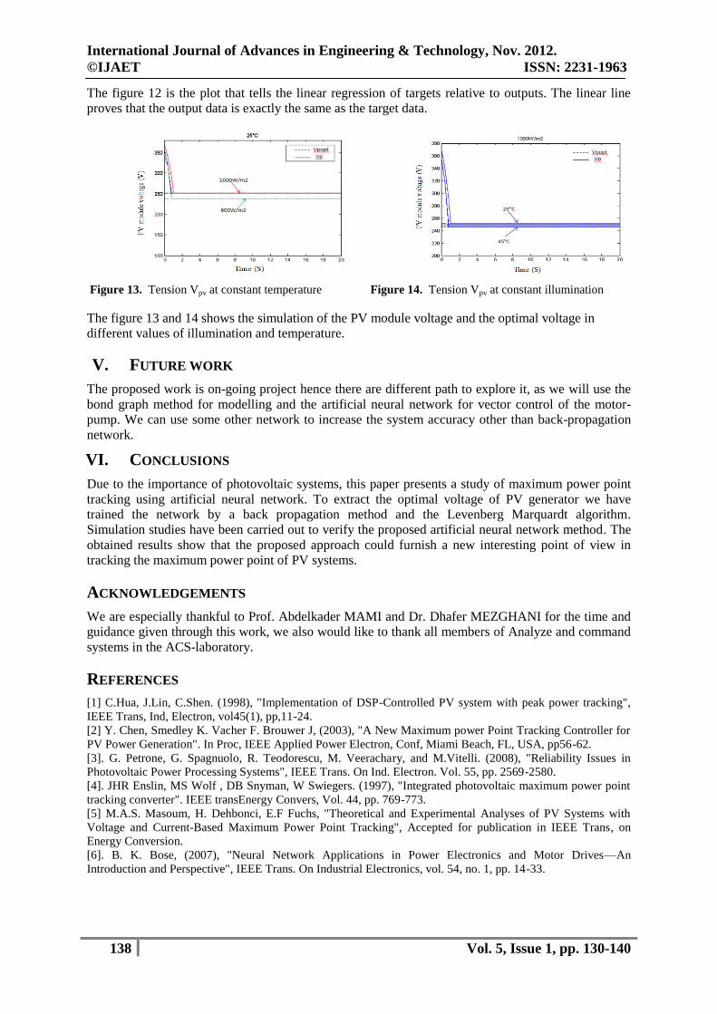
train data to the best performance. The next figure presents the training state which determines the
position of gradient, mu and the validation check at epoch 5 in which the network is completely
trained.
Figure 11. PV model training state plot
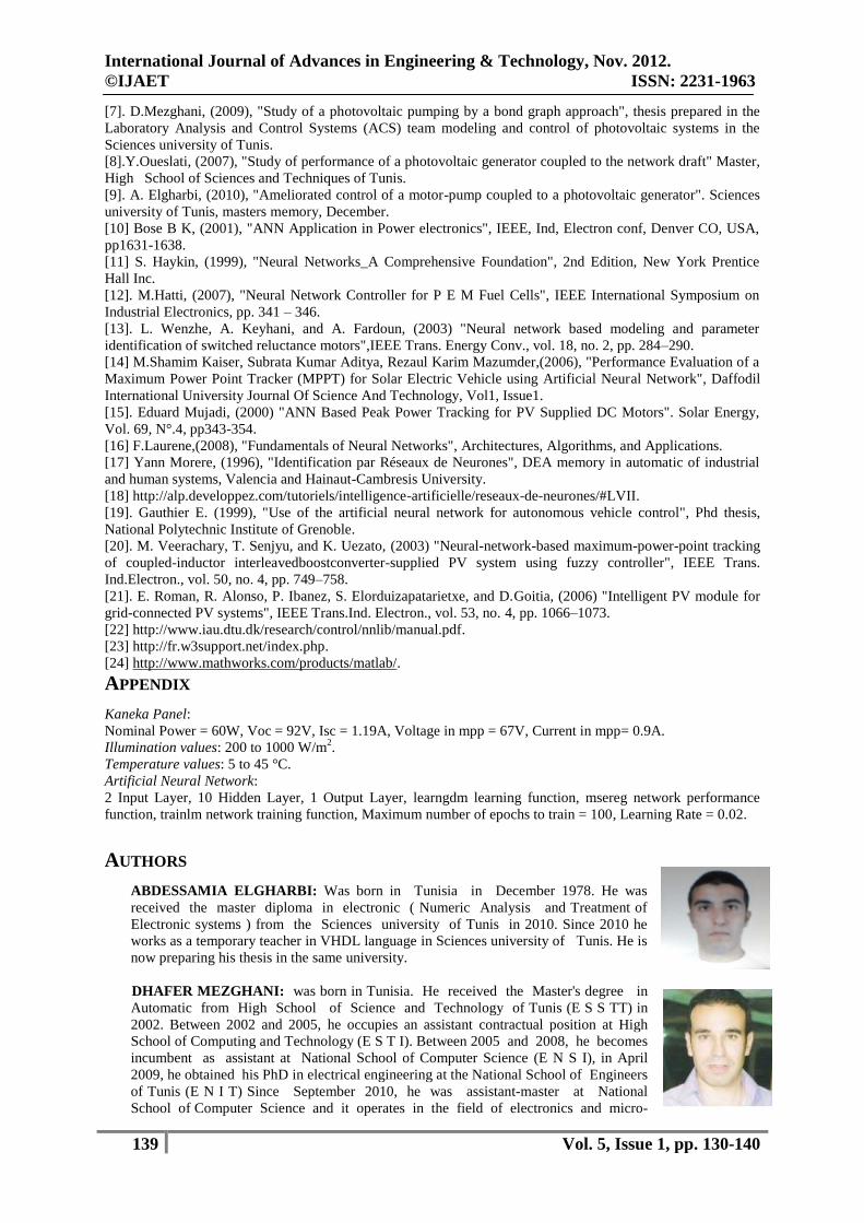
Figure 12. PV model regression plot
International Journal of Advances in Engineering & Technology, Nov. 2012.
©IJAET ISSN: 2231-1963
138 Vol. 5, Issue 1, pp. 130-140
The figure 12 is the plot that tells the linear regression of targets relative to outputs. The linear line
proves that the output data is exactly the same as the target data.
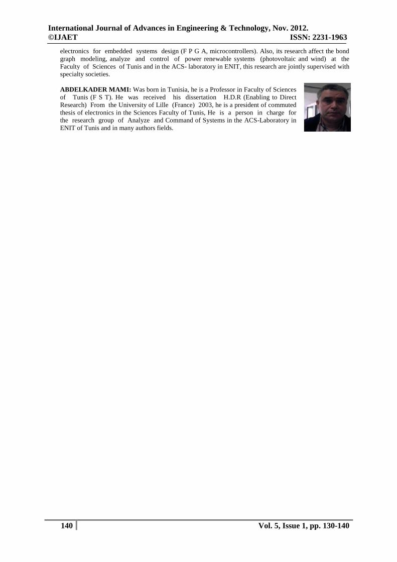
Figure 13. Tension Vpv at constant temperature Figure 14. Tension Vpv at constant illumination
The figure 13 and 14 shows the simulation of the PV module voltage and the optimal voltage in
different values of illumination and temperature.
V. FUTURE WORK
The proposed work is on-going project hence there are different path to explore it, as we will use the
bond graph method for modelling and the artificial neural network for vector control of the motor-
pump. We can use some other network to increase the system accuracy other than back-propagation
network.
VI. CONCLUSIONS
Due to the importance of photovoltaic systems, this paper presents a study of maximum power point
tracking using artificial neural network. To extract the optimal voltage of PV generator we have
trained the network by a back propagation method and the Levenberg Marquardt algorithm.
Simulation studies have been carried out to verify the proposed artificial neural network method. The
obtained results show that the proposed approach could furnish a new interesting point of view in
tracking the maximum power point of PV systems.
ACKNOWLEDGEMENTS
We are especially thankful to Prof. Abdelkader MAMI and Dr. Dhafer MEZGHANI for the time and
guidance given through this work, we also would like to thank all members of Analyze and command
systems in the ACS-laboratory.
REFERENCES
[1] C.Hua, J.Lin, C.Shen. (1998), "Implementation of DSP-Controlled PV system with peak power tracking",
IEEE Trans, Ind, Electron, vol45(1), pp,11-24.
[2] Y. Chen, Smedley K. Vacher F. Brouwer J, (2003), "A New Maximum power Point Tracking Controller for
PV Power Generation". In Proc, IEEE Applied Power Electron, Conf, Miami Beach, FL, USA, pp56-62.
[3]. G. Petrone, G. Spagnuolo, R. Teodorescu, M. Veerachary, and M.Vitelli. (2008), "Reliability Issues in
Photovoltaic Power Processing Systems", IEEE Trans. On Ind. Electron. Vol. 55, pp. 2569-2580.
[4]. JHR Enslin, MS Wolf , DB Snyman, W Swiegers. (1997), "Integrated photovoltaic maximum power point
tracking converter". IEEE transEnergy Convers, Vol. 44, pp. 769-773.
[5] M.A.S. Masoum, H. Dehbonci, E.F Fuchs, "Theoretical and Experimental Analyses of PV Systems with
Voltage and Current-Based Maximum Power Point Tracking", Accepted for publication in IEEE Trans, on
Energy Conversion.
[6]. B. K. Bose, (2007), "Neural Network Applications in Power Electronics and Motor Drives—An
Introduction and Perspective", IEEE Trans. On Industrial Electronics, vol. 54, no. 1, pp. 14-33.
International Journal of Advances in Engineering & Technology, Nov. 2012.
©IJAET ISSN: 2231-1963
139 Vol. 5, Issue 1, pp. 130-140
[7]. D.Mezghani, (2009), "Study of a photovoltaic pumping by a bond graph approach", thesis prepared in the
Laboratory Analysis and Control Systems (ACS) team modeling and control of photovoltaic systems in the
Sciences university of Tunis.
[8].Y.Oueslati, (2007), "Study of performance of a photovoltaic generator coupled to the network draft" Master,
High School of Sciences and Techniques of Tunis.
[9]. A. Elgharbi, (2010), "Ameliorated control of a motor-pump coupled to a photovoltaic generator". Sciences
university of Tunis, masters memory, December.
[10] Bose B K, (2001), "ANN Application in Power electronics", IEEE, Ind, Electron conf, Denver CO, USA,
pp1631-1638.
[11] S. Haykin, (1999), "Neural Networks_A Comprehensive Foundation", 2nd Edition, New York Prentice
Hall Inc.
[12]. M.Hatti, (2007), "Neural Network Controller for P E M Fuel Cells", IEEE International Symposium on
Industrial Electronics, pp. 341 – 346.
[13]. L. Wenzhe, A. Keyhani, and A. Fardoun, (2003) "Neural network based modeling and parameter
identification of switched reluctance motors",IEEE Trans. Energy Conv., vol. 18, no. 2, pp. 284–290.
[14] M.Shamim Kaiser, Subrata Kumar Aditya, Rezaul Karim Mazumder,(2006), "Performance Evaluation of a
Maximum Power Point Tracker (MPPT) for Solar Electric Vehicle using Artificial Neural Network", Daffodil
International University Journal Of Science And Technology, Vol1, Issue1.
[15]. Eduard Mujadi, (2000) "ANN Based Peak Power Tracking for PV Supplied DC Motors". Solar Energy,
Vol. 69, N°.4, pp343-354.
[16] F.Laurene,(2008), "Fundamentals of Neural Networks", Architectures, Algorithms, and Applications.
[17] Yann Morere, (1996), "Identification par Réseaux de Neurones", DEA memory in automatic of industrial
and human systems, Valencia and Hainaut-Cambresis University.
[18] http://alp.developpez.com/tutoriels/intelligence-artificielle/reseaux-de-neurones/#LVII.
[19]. Gauthier E. (1999), "Use of the artificial neural network for autonomous vehicle control", Phd thesis,
National Polytechnic Institute of Grenoble.
[20]. M. Veerachary, T. Senjyu, and K. Uezato, (2003) "Neural-network-based maximum-power-point tracking
of coupled-inductor interleavedboostconverter-supplied PV system using fuzzy controller", IEEE Trans.
Ind.Electron., vol. 50, no. 4, pp. 749–758.
[21]. E. Roman, R. Alonso, P. Ibanez, S. Elorduizapatarietxe, and D.Goitia, (2006) "Intelligent PV module for
grid-connected PV systems", IEEE Trans.Ind. Electron., vol. 53, no. 4, pp. 1066–1073.
[22] http://www.iau.dtu.dk/research/control/nnlib/manual.pdf.
[23] http://fr.w3support.net/index.php.
[24] http://www.mathworks.com/products/matlab/.
APPENDIX
Kaneka Panel:
Nominal Power = 60W, Voc = 92V, Isc = 1.19A, Voltage in mpp = 67V, Current in mpp= 0.9A.
Illumination values: 200 to 1000 W/m2.
Temperature values: 5 to 45 °C. Artificial Neural Network:
2 Input Layer, 10 Hidden Layer, 1 Output Layer, learngdm learning function, msereg network performance
function, trainlm network training function, Maximum number of epochs to train = 100, Learning Rate = 0.02.
AUTHORS
ABDESSAMIA ELGHARBI: Was born in Tunisia in December 1978. He was
received the master diploma in electronic ( Numeric Analysis and Treatment of
Electronic systems ) from the Sciences university of Tunis in 2010. Since 2010 he
works as a temporary teacher in VHDL language in Sciences university of Tunis. He is
now preparing his thesis in the same university.
DHAFER MEZGHANI: was born in Tunisia. He received the Master's degree in
Automatic from High School of Science and Technology of Tunis (E S S TT) in
2002. Between 2002 and 2005, he occupies an assistant contractual position at High
School of Computing and Technology (E S T I). Between 2005 and 2008, he becomes
incumbent as assistant at National School of Computer Science (E N S I), in April
2009, he obtained his PhD in electrical engineering at the National School of Engineers
of Tunis (E N I T) Since September 2010, he was assistant-master at National
School of Computer Science and it operates in the field of electronics and micro-
International Journal of Advances in Engineering & Technology, Nov. 2012.
©IJAET ISSN: 2231-1963
140 Vol. 5, Issue 1, pp. 130-140
electronics for embedded systems design (F P G A, microcontrollers). Also, its research affect the bond
graph modeling, analyze and control of power renewable systems (photovoltaic and wind) at the
Faculty of Sciences of Tunis and in the ACS- laboratory in ENIT, this research are jointly supervised with
specialty societies.
ABDELKADER MAMI: Was born in Tunisia, he is a Professor in Faculty of Sciences
of Tunis (F S T). He was received his dissertation H.D.R (Enabling to Direct
Research) From the University of Lille (France) 2003, he is a president of commuted
thesis of electronics in the Sciences Faculty of Tunis, He is a person in charge for
the research group of Analyze and Command of Systems in the ACS-Laboratory in
ENIT of Tunis and in many authors fields.