Embed Size (px)
Citation preview
DESIGN AND APPLICATION
CORRUGATED PANELSystem Technology for Facades
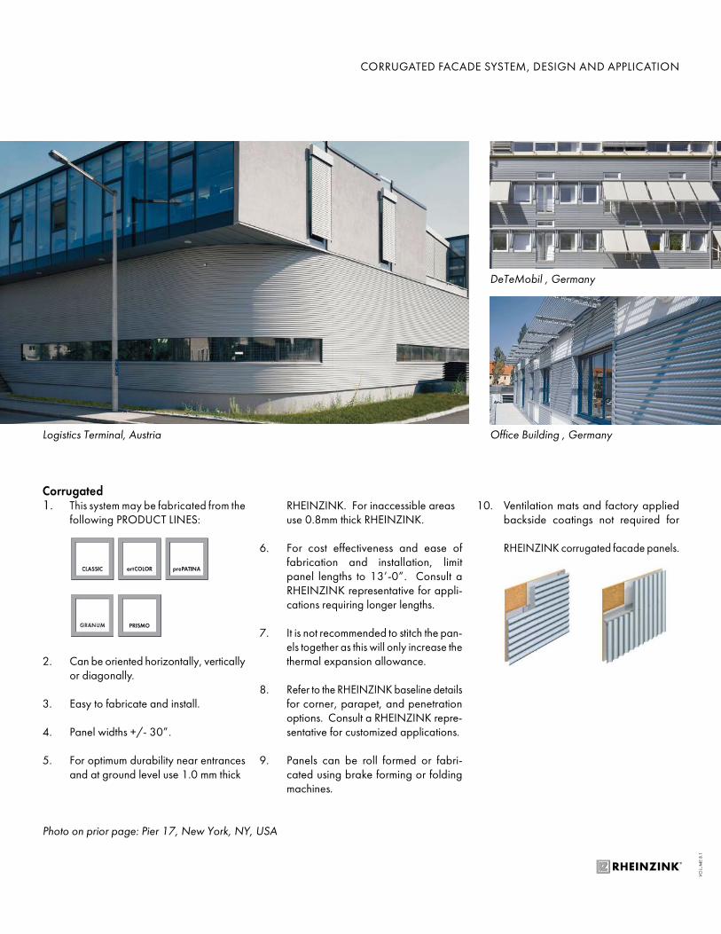
Corrugated1. This system may be fabricated from the
following PRODUCT LINES:
2. Can be oriented horizontally, vertically or diagonally.
3. Easy to fabricate and install.
4. Panel widths +/- 30”.
5. For optimum durability near entrances and at ground level use 1.0 mm thick
RHEINZINK. For inaccessible areas use 0.8mm thick RHEINZINK.
6. For cost effectiveness and ease of fabrication and installation, limit panel lengths to 13’-0”. Consult a RHEINZINK representative for appli-cations requiring longer lengths.
7. It is not recommended to stitch the pan-els together as this will only increase the thermal expansion allowance.
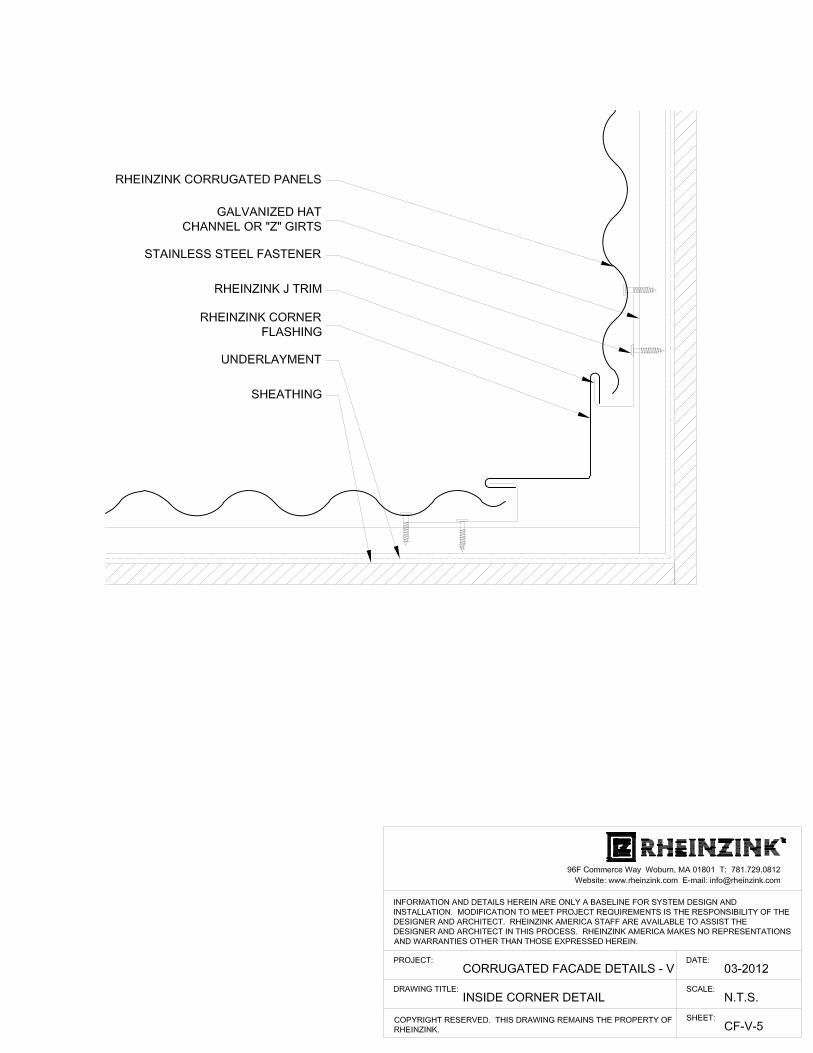
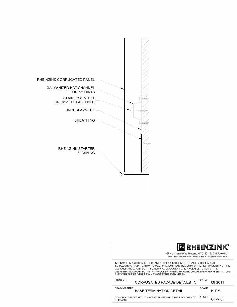
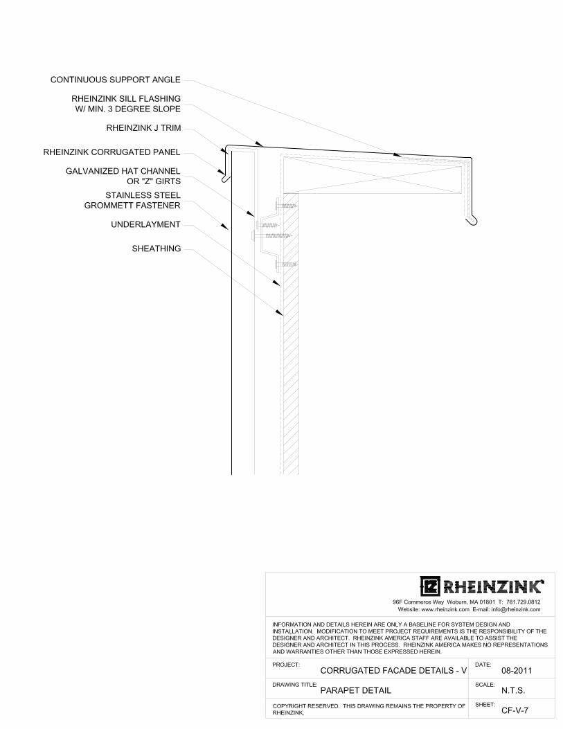
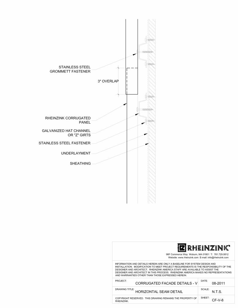
8. Refer to the RHEINZINK baseline details for corner, parapet, and penetration options. Consult a RHEINZINK repre-sentative for customized applications.
9. Panels can be roll formed or fabri-cated using brake forming or folding machines.
10. Ventilation mats and factory applied backside coatings not required for
RHEINZINK corrugated facade panels.
CORRUGATED FACADE SYSTEM, DESIGN AND APPLICATION
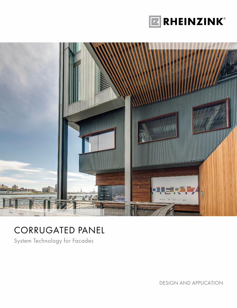
Photo on prior page: Pier 17, New York, NY, USA
DeTeMobil , Germany
Logistics Terminal, Austria Office Building , Germany
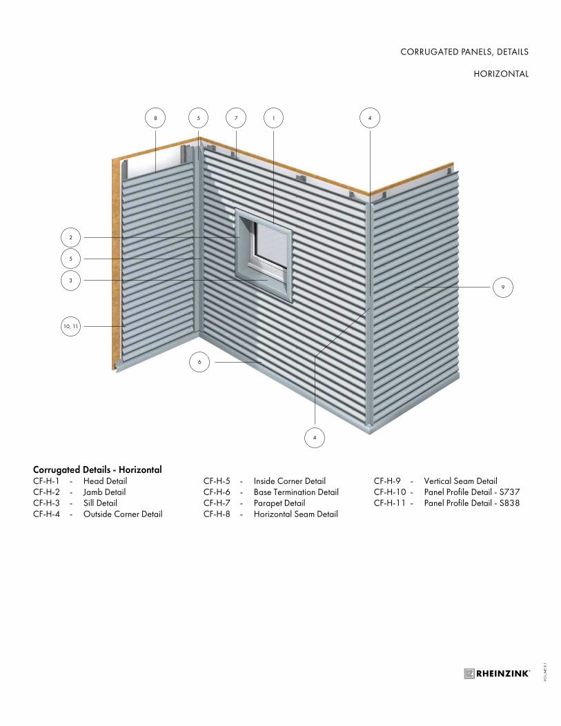
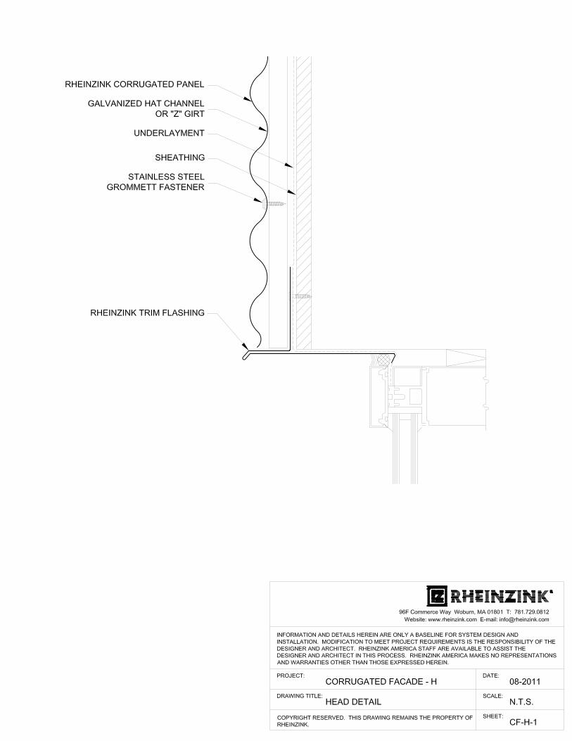
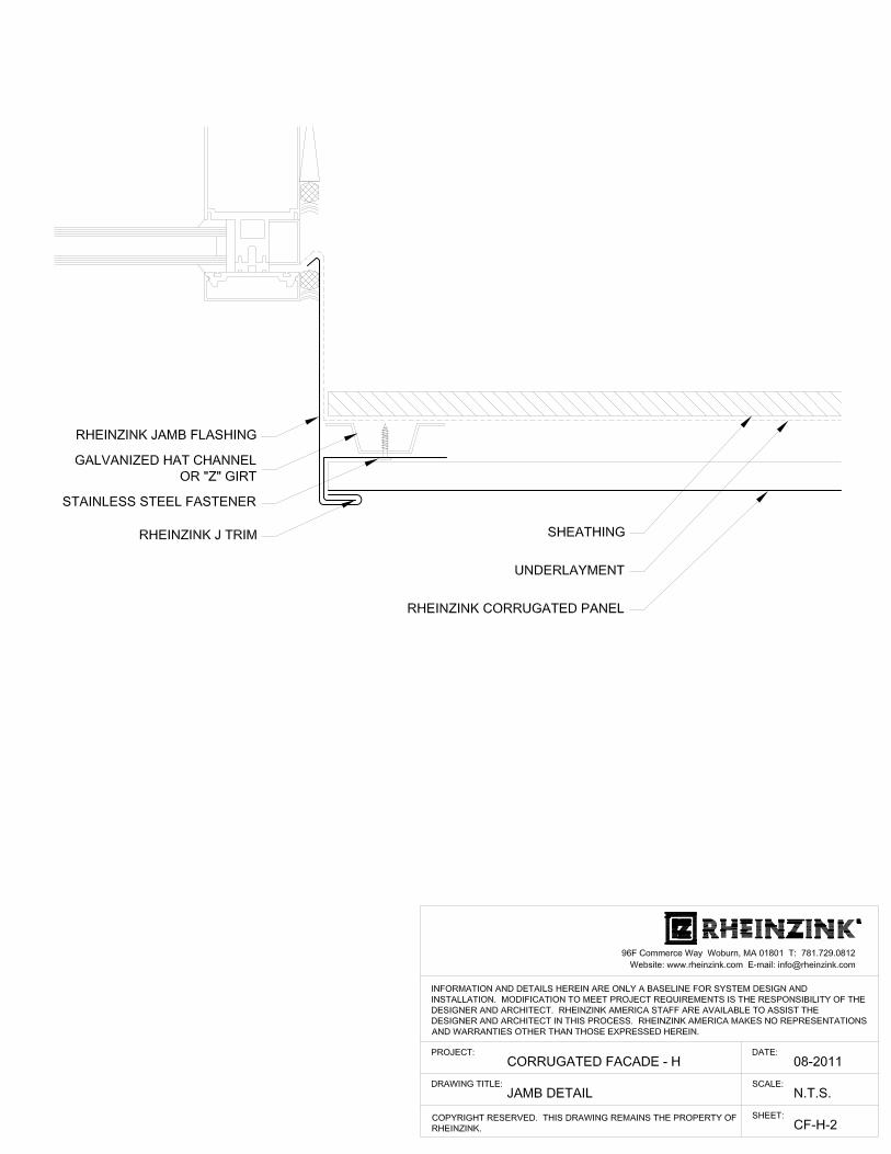
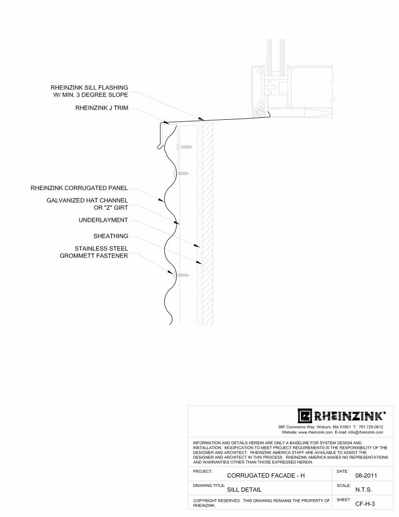
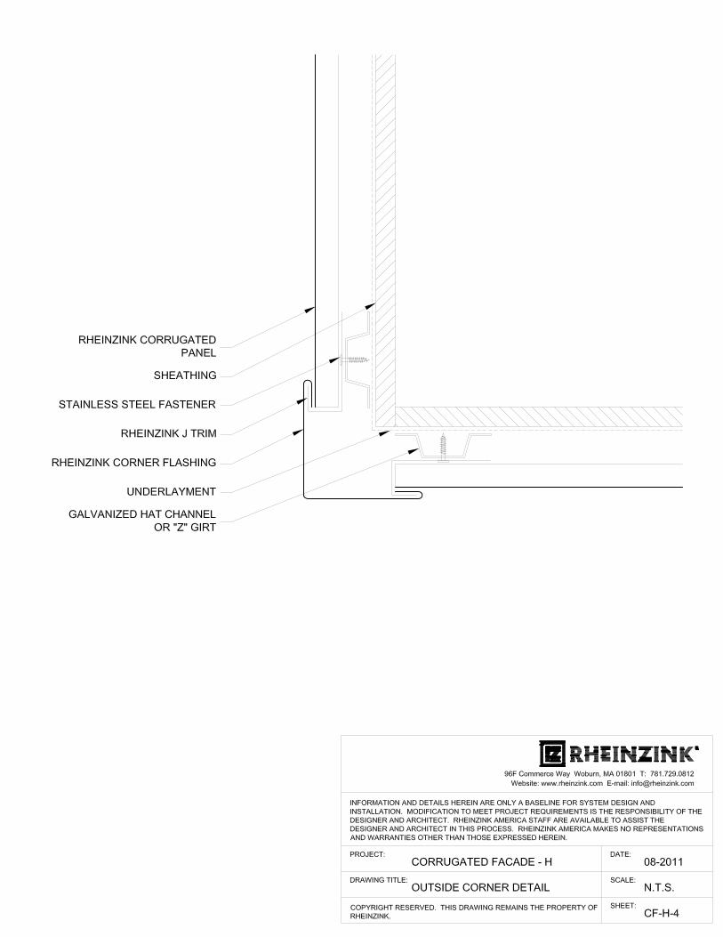
Corrugated Details - HorizontalCF-H-1 - Head DetailCF-H-2 - Jamb Detail CF-H-3 - Sill Detail CF-H-4 - Outside Corner Detail
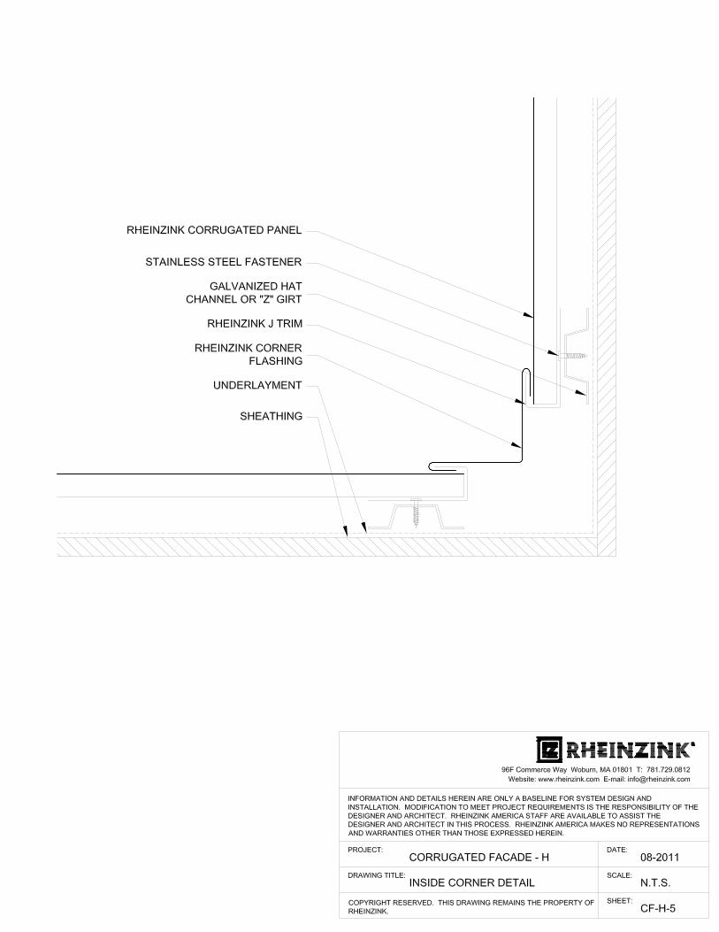
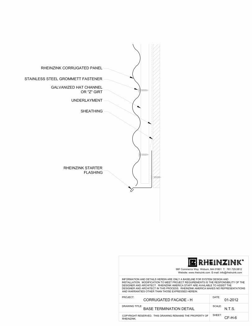
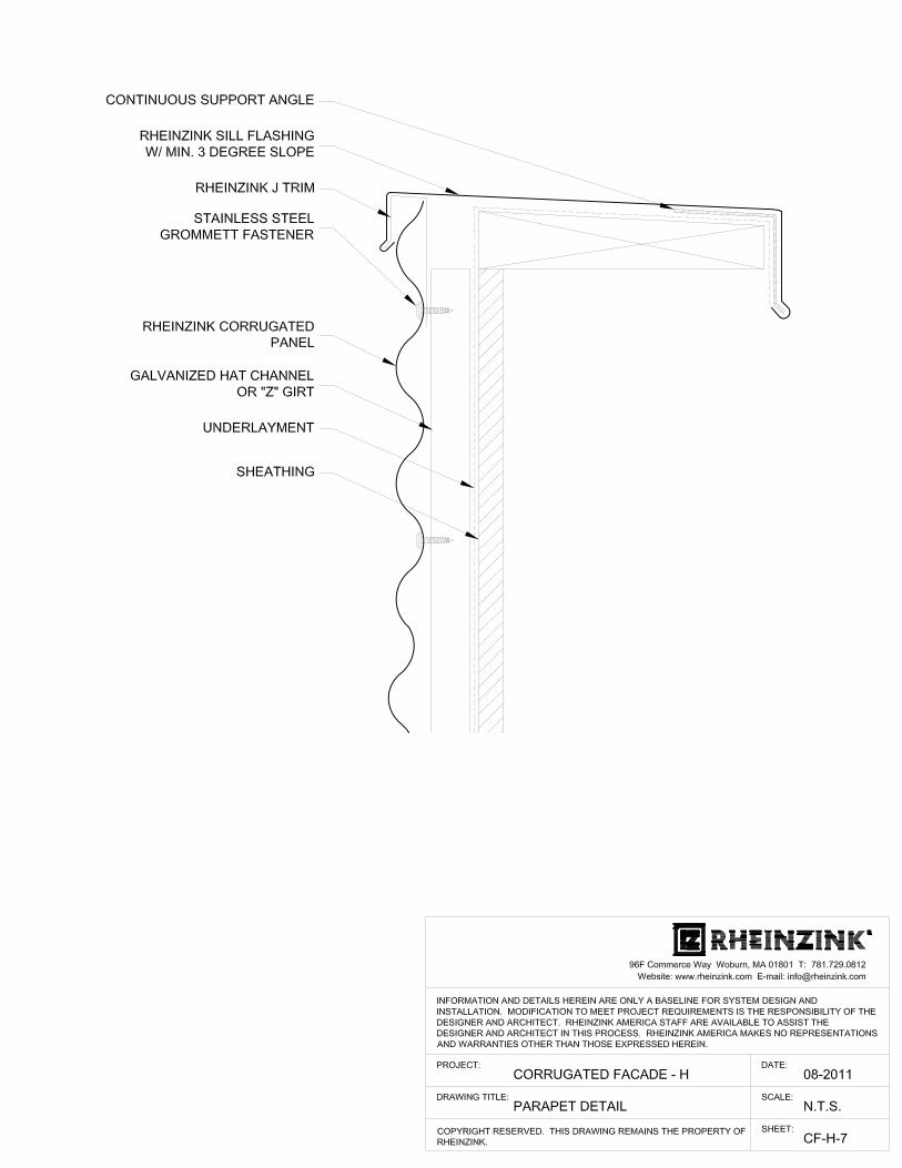
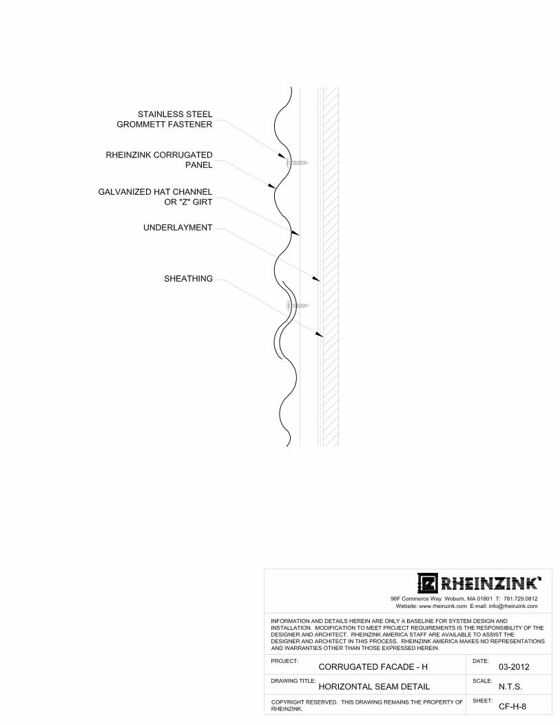
CF-H-5 - Inside Corner DetailCF-H-6 - Base Termination Detail CF-H-7 - Parapet Detail CF-H-8 - Horizontal Seam Detail
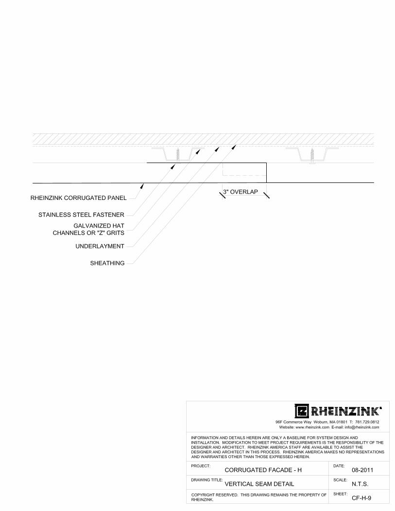
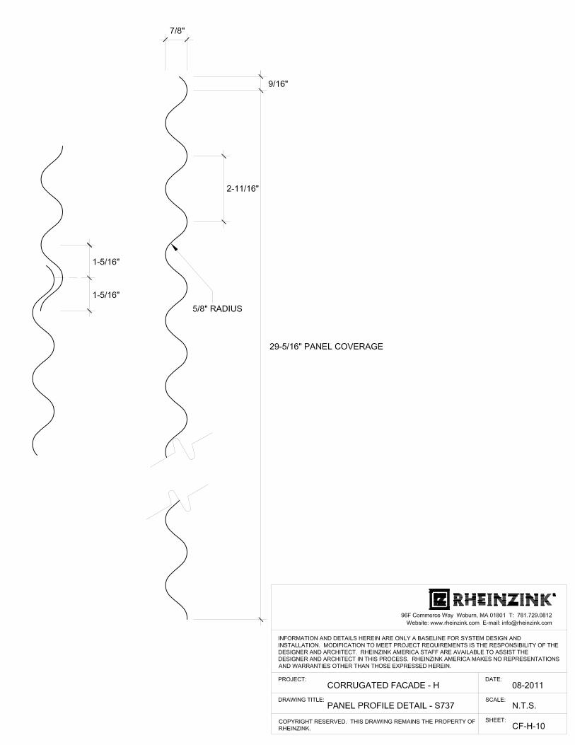
CF-H-9 - Vertical Seam Detail CF-H-10 - Panel Profile Detail - S737CF-H-11 - Panel Profile Detail - S838
6
4
48 1
2
5
3
10, 11
CORRUGATED PANELS, DETAILS
7
9
5
HORIZONTAL
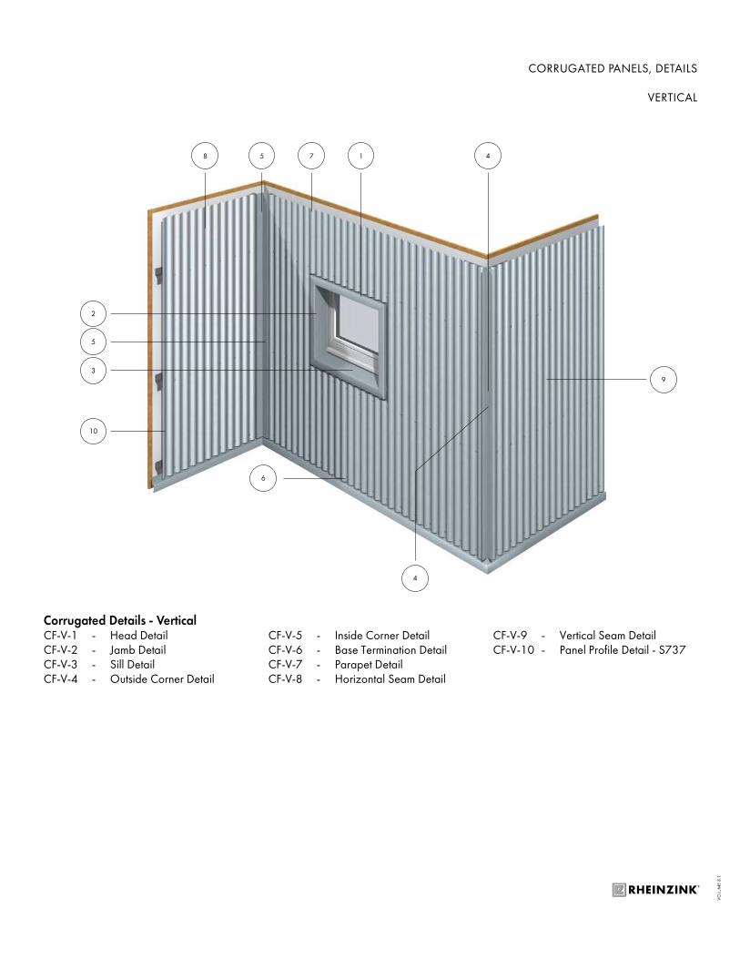
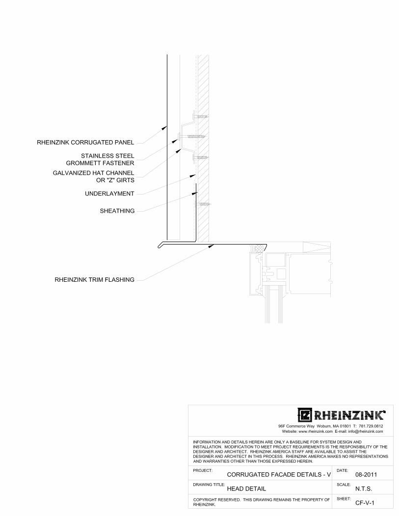
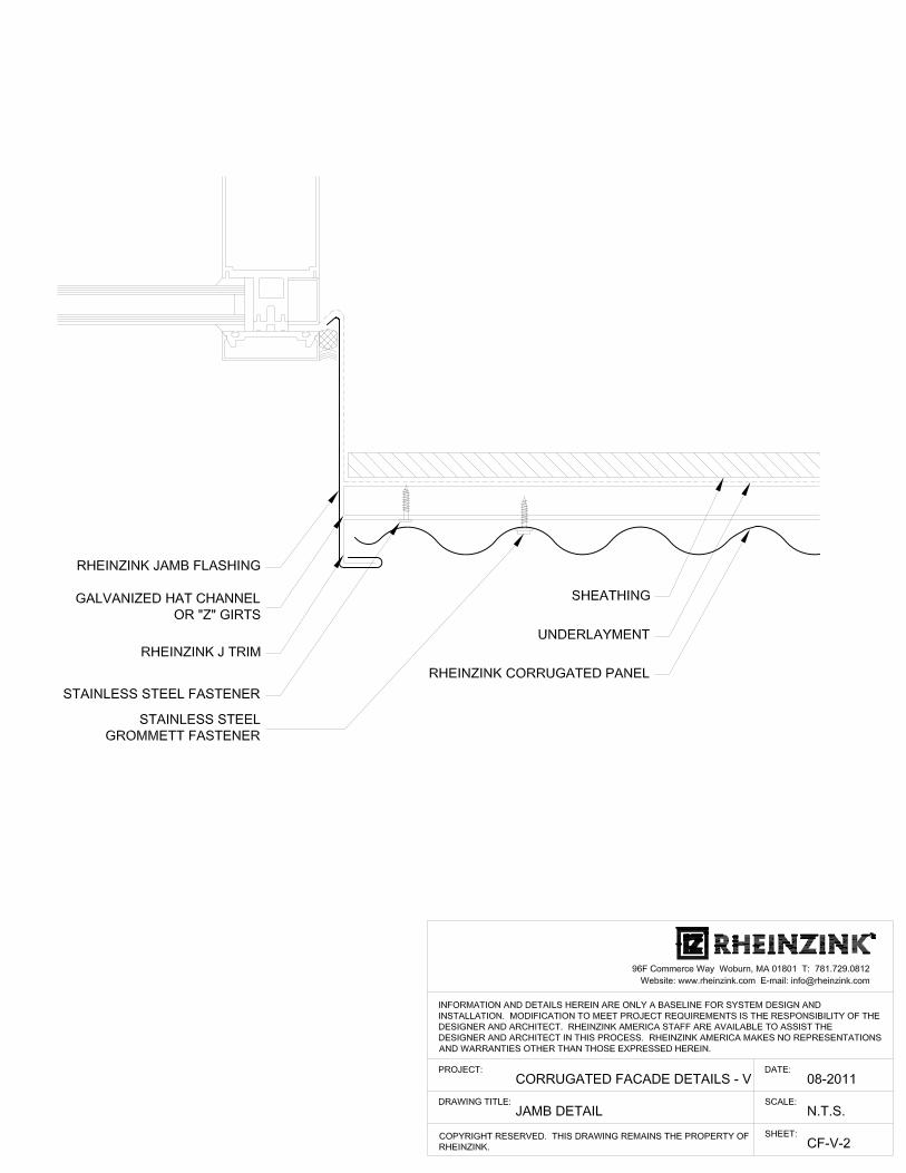
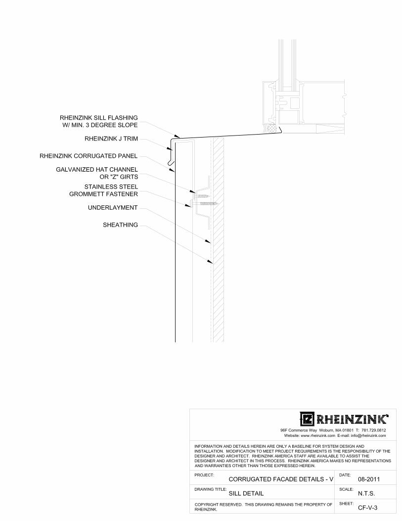
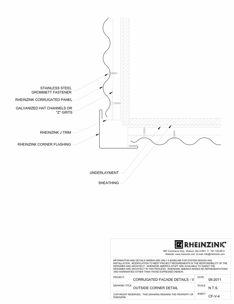
Corrugated Details - VerticalCF-V-1 - Head DetailCF-V-2 - Jamb Detail CF-V-3 - Sill Detail CF-V-4 - Outside Corner Detail
CF-V-5 - Inside Corner DetailCF-V-6 - Base Termination Detail CF-V-7 - Parapet Detail CF-V-8 - Horizontal Seam Detail
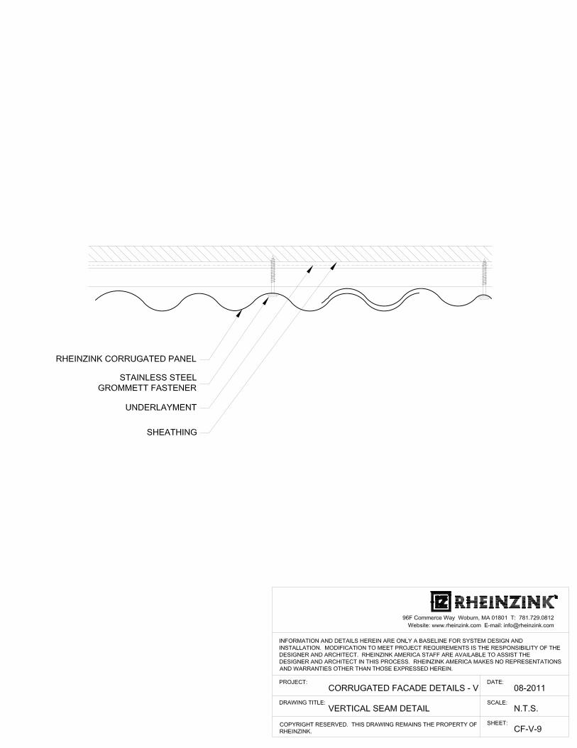
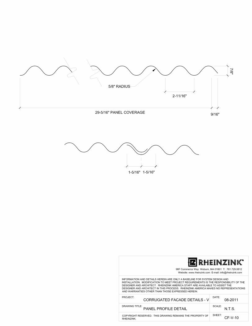
CF-V-9 - Vertical Seam Detail CF-V-10 - Panel Profile Detail - S737
6
4
48 1
2
5
3
10
CORRUGATED PANELS, DETAILS
7
9
5
VERTICAL
CORRUGATED METAL WALL PANELS Section 07 42 13 February 13, 2021 Page 1 of 8
SECTION 07 42 13 - CORRUGATED METAL WALL PANELS PART 1 – GENERAL
1.01 RELATED DOCUMENTS
A. All of the Contract Documents, including General and Supplementary Conditions and Division 1 Specification Sections, apply to the work of this Section.
B. Examine all Drawings and all other Sections of the Specifications for requirements therein affecting
the work of this Section. C. Coordinate work with that of all other trades affecting or affected by work of this Section.
Cooperate with such trades to assure the steady progress of all work under the Contract. 1.02 DESCRIPTION OF WORK
A. The Work of this Section shall include, but not be limited to, the following: 1. Custom fabricated, mechanically attached, [RHEINZINK-CLASSIC bright rolled,
RHEINZINK-prePATINA blue-grey, RHEINZINK-prePATINA graphite-grey, RHEINZINK-GRANUM skygrey, RHEINZINK-GRANUM basalte, RHEINZINK-artCOLOR various colors and RHEINZINK PRISMO various colors] zinc alloy [reveal and shiplap panels] [vertical or horizontal] as indicated on the Drawings, with all required accessories for a weatherproof installation.
2. [Zinc gutters and downspouts] as indicated on the Drawings. 3. Zinc coping and wall trim as indicated on the Drawings 4. Penetrations [doors, windows, louvers, etc…] in the wall assembly as indicated on the
Drawings.
B. Related Sections: 1. Section 05400 – Cold Formed Metal Framing 2. Section 06100 – Rough Carpentry 3. Section 07210 – Building Insulation 4. Section 07265 – Air and Vapor Barrier Membrane 5. Section 07610 – Sheet Metal Roofing 6. Section 07500 – Membrane Roofing 7. Section 07620 – Sheet Metal Flashing and Trim 8. Section 07720 – Roof Accessories 9. Section 07920 – Joint Sealants
1.03 REFERENCES
A. ASTM B69-16 (or latest edition) – Architectural Rolled Zinc - Types 1 and 2 – Standard Specification for rolled zinc.
B. RHEINZINK Division 7 Binder: latest edition.
C. RHEINZINK Material and Processing Guidlines: latest edition
D. SMACNA – Architectural Sheet Metal Manual; latest edition; Chapter 7 as a minimum standard or
these specification and details where they exceed. E. Names of the applicable building codes or other authorities having jurisdiction:
______________________________________________________
CORRUGATED METAL WALL PANELS Section 07 42 13 February 13, 2021 Page 2 of 8
F. As all documents are intended to be complementary, in the event of contradiction in the references, the RHEINZINK Division 7 Binder; latest edition will govern.
1.04 SUBMITTALS
A. Provide product data for zinc wall panels, including manufacturer’s product specifications, standard details, and installation instructions.
B. Material Samples: submit [RHEINZINK-CLASSIC bright rolled, RHEINZINK-prePATINA blue-grey, RHEINZINK-prePATINA graphite-grey, RHEINZINK-GRANUM skygrey, RHEINZINK-GRANUM basalte, RHEINZINK-artCOLOR - various colors and RHEINZINK-PRISMO – various colors] (Note artCOLOR and PRISMO are premium colors and special order) color samples of each material that is to be exposed in the finished work. As required by architect, also provide two fabricated panel samples to demonstrate connection.
C. Shop Drawings: show layouts of panels on all wall elevations, details at panel terminations, edge
conditions, joints, corners, panel profiles, supports, anchorages, trim, flashings, closures, and special details. Provide actual dimensions to the greatest extent possible for all plan and detail conditions.
1. Details for shop fabricated sheet metal components, including seams and dimensions. 2. Details for joining and securing sheet metal components, including layout and number of
required fasteners, clips and other attachments. Include pattern of seams and spacing of fasteners.
3. Details of termination points and assemblies, including fixed points. 4. Details of expansion joints, including showing direction of expansion and contraction. 5. Details of window and door penetrations at head, jamb and sill conditions. 6. Details of parapets. 7. Details of special conditions, integrating mechanical, electrical and plumbing conditions. 8. Details of connections to adjoining work
D. [Engineering Calculations: As required by Architect, Installer to provide wind load (positive and
negative pressure) calculations based on substrate [exterior sheathing, galvanized steel sub-framing] information provided by the Contractor. Calculations to utilize fastener pullout data and known panel physical properties to provide “estimated” design performance. Submit written certification showing calculations prepared and stamped by a Professional Structural Engineer licensed and registered in the project state.]
1.05 QUALITY ASSURANCE
A. Fabricator/Installer Qualifications: The fabricator and installer of the wall panel system shall be trained by the zinc material manufacturer [and system fabricator]. Installer shall submit list of three (3) successful “natural metal” project installations of similar complexity and scope.
B. Source: Provide panels, which are the product of one manufacturer. Provide secondary materials,
which are acceptable to the zinc manufacturer. Award installation of zinc wall panels, including weather-barrier underlayment to a single firm for undivided responsibility.
C. Comply with RHEINZINK Division 7 Binder; latest edition and SMACNA -Architectural Sheet Metal Manual; latest edition for flashings and sheet metal work.
D. Field Measurements: Prior to fabrication of panel systems, verify drawing dimensions by taking
field measurements of structure or substrates to receive panel systems.
CORRUGATED METAL WALL PANELS Section 07 42 13 February 13, 2021 Page 3 of 8
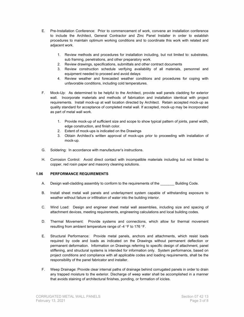
E. Pre-Installation Conference: Prior to commencement of work, convene an installation conference to include the Architect, General Contractor and Zinc Panel Installer in order to establish procedures to maintain optimum working conditions and to coordinate this work with related and adjacent work.
1. Review methods and procedures for installation including, but not limited to: substrates,
sub framing, penetrations, and other preparatory work. 2. Review drawings, specifications, submittals and other contract documents 3. Review construction schedule verifying availability of all materials, personnel and
equipment needed to proceed and avoid delays 4. Review weather and forecasted weather conditions and procedures for coping with
unfavorable conditions, including cold temperatures.
F. Mock-Up: As determined to be helpful to the Architect, provide wall panels cladding for exterior wall. Incorporate materials and methods of fabrication and installation identical with project requirements. Install mock-up at wall location directed by Architect. Retain accepted mock-up as quality standard for acceptance of completed metal wall. If accepted, mock-up may be incorporated as part of metal wall work.
1. Provide mock-up of sufficient size and scope to show typical pattern of joints, panel width,
edge construction, and finish color. 2. Extent of mock-ups is indicated on the Drawings 3. Obtain Architect’s written approval of mock-ups prior to proceeding with installation of
mock-up.
G. Soldering: In accordance with manufacturer’s instructions. H. Corrosion Control: Avoid direct contact with incompatible materials including but not limited to
copper, red rosin paper and masonry cleaning solutions.
1.06 PERFORMANCE REQUIREMENTS
A. Design wall-cladding assembly to conform to the requirements of the _______ Building Code. B. Install sheet metal wall panels and underlayment system capable of withstanding exposure to
weather without failure or infiltration of water into the building interior. C. Wind Load: Design and engineer sheet metal wall assemblies, including size and spacing of
attachment devices, meeting requirements, engineering calculations and local building codes. D. Thermal Movement: Provide systems and connections, which allow for thermal movement
resulting from ambient temperature range of -4 °F to 176 °F. E. Structural Performance: Provide metal panels, anchors and attachments, which resist loads
required by code and loads as indicated on the Drawings without permanent deflection or permanent deformation. Information on Drawings referring to specific design of attachment, panel stiffening, and structural systems is intended for information only. System performance, based on project conditions and compliance with all applicable codes and loading requirements, shall be the responsibility of the panel fabricator and installer.
F. Weep Drainage: Provide clear internal paths of drainage behind corrugated panels in order to drain
any trapped moisture to the exterior. Discharge of weep water shall be accomplished in a manner that avoids staining of architectural finishes, ponding, or formation of icicles.
CORRUGATED METAL WALL PANELS Section 07 42 13 February 13, 2021 Page 4 of 8
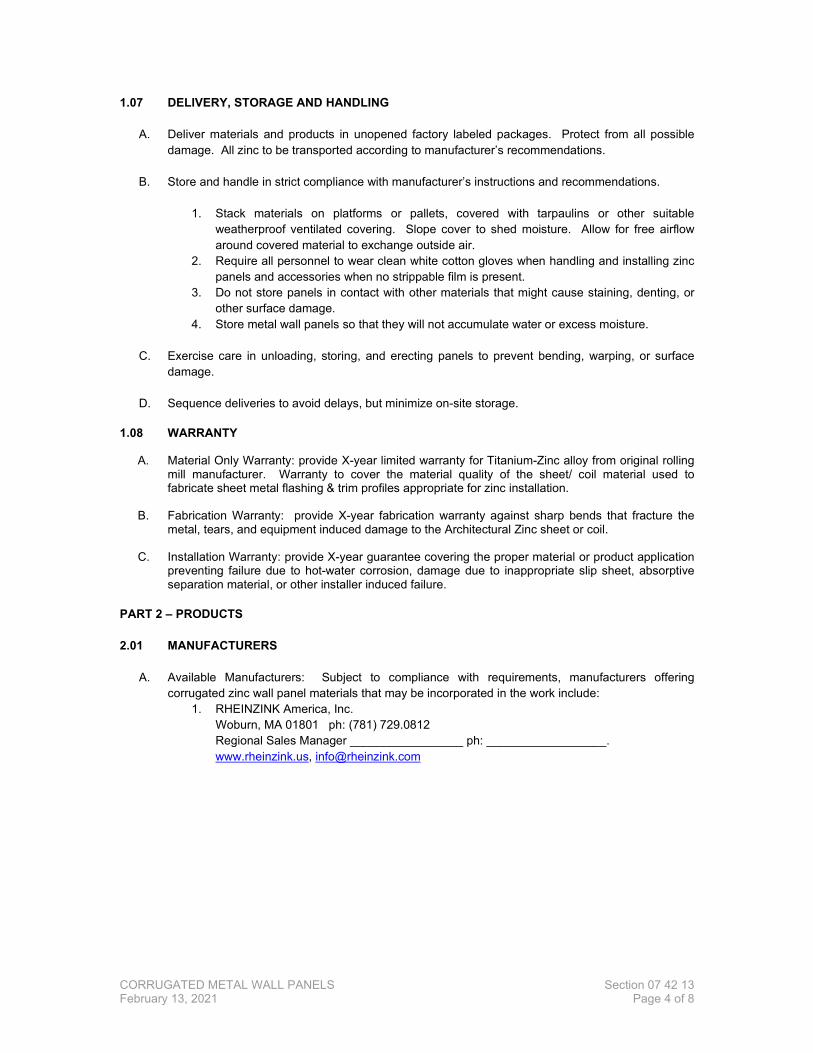
1.07 DELIVERY, STORAGE AND HANDLING
A. Deliver materials and products in unopened factory labeled packages. Protect from all possible damage. All zinc to be transported according to manufacturer’s recommendations.
B. Store and handle in strict compliance with manufacturer’s instructions and recommendations.
1. Stack materials on platforms or pallets, covered with tarpaulins or other suitable
weatherproof ventilated covering. Slope cover to shed moisture. Allow for free airflow around covered material to exchange outside air.
2. Require all personnel to wear clean white cotton gloves when handling and installing zinc panels and accessories when no strippable film is present.
3. Do not store panels in contact with other materials that might cause staining, denting, or other surface damage.
4. Store metal wall panels so that they will not accumulate water or excess moisture.
C. Exercise care in unloading, storing, and erecting panels to prevent bending, warping, or surface damage.
D. Sequence deliveries to avoid delays, but minimize on-site storage.
1.08 WARRANTY
A. Material Only Warranty: provide X-year limited warranty for Titanium-Zinc alloy from original rolling
mill manufacturer. Warranty to cover the material quality of the sheet/ coil material used to fabricate sheet metal flashing & trim profiles appropriate for zinc installation.
B. Fabrication Warranty: provide X-year fabrication warranty against sharp bends that fracture the metal, tears, and equipment induced damage to the Architectural Zinc sheet or coil.
C. Installation Warranty: provide X-year guarantee covering the proper material or product application
preventing failure due to hot-water corrosion, damage due to inappropriate slip sheet, absorptive separation material, or other installer induced failure.
PART 2 – PRODUCTS 2.01 MANUFACTURERS
A. Available Manufacturers: Subject to compliance with requirements, manufacturers offering corrugated zinc wall panel materials that may be incorporated in the work include:
1. RHEINZINK America, Inc. Woburn, MA 01801 ph: (781) 729.0812
Regional Sales Manager _________________ ph: __________________. www.rheinzink.us, [email protected]
CORRUGATED METAL WALL PANELS Section 07 42 13 February 13, 2021 Page 5 of 8
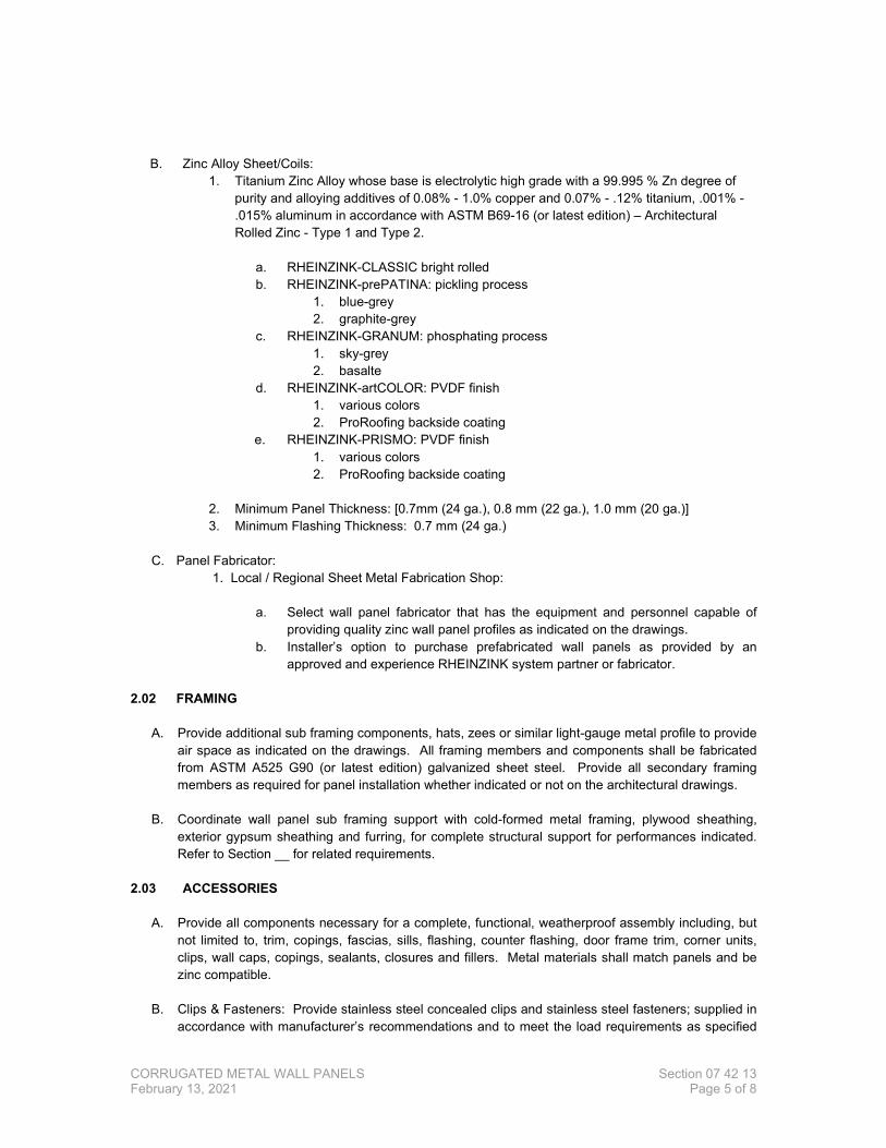
B. Zinc Alloy Sheet/Coils: 1. Titanium Zinc Alloy whose base is electrolytic high grade with a 99.995 % Zn degree of
purity and alloying additives of 0.08% - 1.0% copper and 0.07% - .12% titanium, .001% - .015% aluminum in accordance with ASTM B69-16 (or latest edition) – Architectural Rolled Zinc - Type 1 and Type 2.
a. RHEINZINK-CLASSIC bright rolled b. RHEINZINK-prePATINA: pickling process
1. blue-grey 2. graphite-grey
c. RHEINZINK-GRANUM: phosphating process 1. sky-grey 2. basalte
d. RHEINZINK-artCOLOR: PVDF finish 1. various colors 2. ProRoofing backside coating
e. RHEINZINK-PRISMO: PVDF finish 1. various colors 2. ProRoofing backside coating
2. Minimum Panel Thickness: [0.7mm (24 ga.), 0.8 mm (22 ga.), 1.0 mm (20 ga.)] 3. Minimum Flashing Thickness: 0.7 mm (24 ga.)
C. Panel Fabricator:
1. Local / Regional Sheet Metal Fabrication Shop:
a. Select wall panel fabricator that has the equipment and personnel capable of providing quality zinc wall panel profiles as indicated on the drawings.
b. Installer’s option to purchase prefabricated wall panels as provided by an approved and experience RHEINZINK system partner or fabricator.
2.02 FRAMING
A. Provide additional sub framing components, hats, zees or similar light-gauge metal profile to provide air space as indicated on the drawings. All framing members and components shall be fabricated from ASTM A525 G90 (or latest edition) galvanized sheet steel. Provide all secondary framing members as required for panel installation whether indicated or not on the architectural drawings.
B. Coordinate wall panel sub framing support with cold-formed metal framing, plywood sheathing,
exterior gypsum sheathing and furring, for complete structural support for performances indicated. Refer to Section __ for related requirements.
2.03 ACCESSORIES
A. Provide all components necessary for a complete, functional, weatherproof assembly including, but
not limited to, trim, copings, fascias, sills, flashing, counter flashing, door frame trim, corner units, clips, wall caps, copings, sealants, closures and fillers. Metal materials shall match panels and be zinc compatible.
B. Clips & Fasteners: Provide stainless steel concealed clips and stainless steel fasteners; supplied in
accordance with manufacturer’s recommendations and to meet the load requirements as specified
CORRUGATED METAL WALL PANELS Section 07 42 13 February 13, 2021 Page 6 of 8
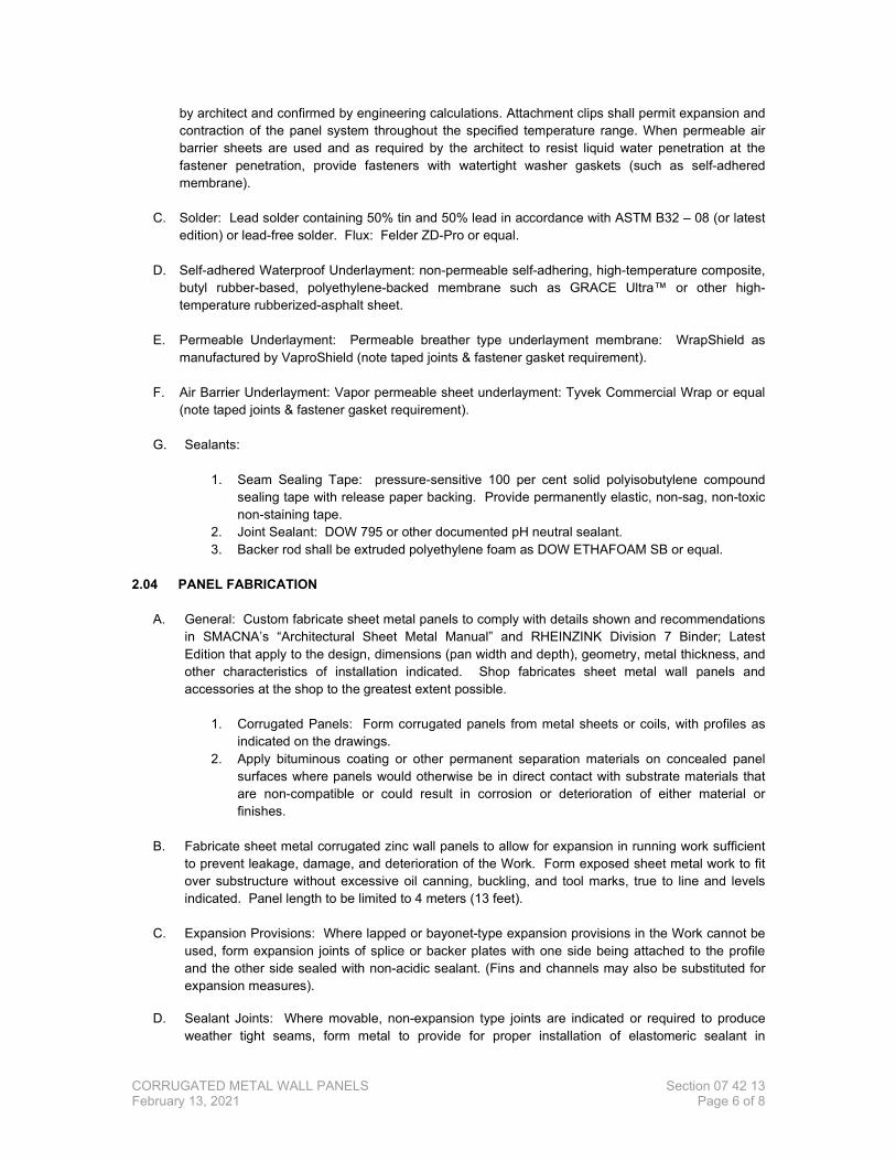
by architect and confirmed by engineering calculations. Attachment clips shall permit expansion and contraction of the panel system throughout the specified temperature range. When permeable air barrier sheets are used and as required by the architect to resist liquid water penetration at the fastener penetration, provide fasteners with watertight washer gaskets (such as self-adhered membrane).
C. Solder: Lead solder containing 50% tin and 50% lead in accordance with ASTM B32 – 08 (or latest
edition) or lead-free solder. Flux: Felder ZD-Pro or equal.
D. Self-adhered Waterproof Underlayment: non-permeable self-adhering, high-temperature composite, butyl rubber-based, polyethylene-backed membrane such as GRACE Ultra™ or other high-temperature rubberized-asphalt sheet.
E. Permeable Underlayment: Permeable breather type underlayment membrane: WrapShield as
manufactured by VaproShield (note taped joints & fastener gasket requirement).
F. Air Barrier Underlayment: Vapor permeable sheet underlayment: Tyvek Commercial Wrap or equal (note taped joints & fastener gasket requirement).
G. Sealants:
1. Seam Sealing Tape: pressure-sensitive 100 per cent solid polyisobutylene compound sealing tape with release paper backing. Provide permanently elastic, non-sag, non-toxic non-staining tape.
2. Joint Sealant: DOW 795 or other documented pH neutral sealant. 3. Backer rod shall be extruded polyethylene foam as DOW ETHAFOAM SB or equal.
2.04 PANEL FABRICATION
A. General: Custom fabricate sheet metal panels to comply with details shown and recommendations in SMACNA’s “Architectural Sheet Metal Manual” and RHEINZINK Division 7 Binder; Latest Edition that apply to the design, dimensions (pan width and depth), geometry, metal thickness, and other characteristics of installation indicated. Shop fabricates sheet metal wall panels and accessories at the shop to the greatest extent possible.
1. Corrugated Panels: Form corrugated panels from metal sheets or coils, with profiles as
indicated on the drawings. 2. Apply bituminous coating or other permanent separation materials on concealed panel
surfaces where panels would otherwise be in direct contact with substrate materials that are non-compatible or could result in corrosion or deterioration of either material or finishes.
B. Fabricate sheet metal corrugated zinc wall panels to allow for expansion in running work sufficient
to prevent leakage, damage, and deterioration of the Work. Form exposed sheet metal work to fit over substructure without excessive oil canning, buckling, and tool marks, true to line and levels indicated. Panel length to be limited to 4 meters (13 feet).
C. Expansion Provisions: Where lapped or bayonet-type expansion provisions in the Work cannot be used, form expansion joints of splice or backer plates with one side being attached to the profile and the other side sealed with non-acidic sealant. (Fins and channels may also be substituted for expansion measures).
D. Sealant Joints: Where movable, non-expansion type joints are indicated or required to produce weather tight seams, form metal to provide for proper installation of elastomeric sealant in
CORRUGATED METAL WALL PANELS Section 07 42 13 February 13, 2021 Page 7 of 8
compliance with SMACNA standards. In general, panel joints are intended to be dry, sealant-free, to facilitate air movement and drying behind the wall panels.
PART 3 – EXECUTION 3.01 INSPECTION
A. Contractor shall inspect all surfaces, areas and other contingent construction in or to which his work is to be installed and insure himself that they are in proper condition to receive the work to be performed under this Section.
B. Verify that sheathing surfaces are sound, dry, properly secured and that provision has been made
for flashings, anchorage, and all other interface items attaching to or penetrating through the Work of this Section.
C. The Contractor shall notify the Architect in writing, before any work is installed, of any condition
requiring correction. Failure to make such a report shall be construed as acceptance of the existing conditions and the responsibility to provide an acceptable installation.
3.02 PREPARATION
A. Verify field dimensions before fabrication. Notify Architect of any discrepancies between field measurements and dimensions indicated in Construction Documents.
B. Place [air barrier, permeable underlayment, waterproof] membrane on substrate surfaces to
receive metal panels; comply with manufacturer’s instructions.
1. Coordinate installation of underlayment with metal cladding, flashing, trim and coping to provide a weatherproof, secure and non-corrosive installation.
2. For underlayment end and side laps, see underlayment manufacturers instructions for proper attachment, seaming and termination recommendations.
C. For breather-type permeable /air barrier membranes, consult the architect for strategies preventing
infiltration through fastener holes by applying sealant to backside of attachment.
3.03 INSTALLATION
A. Manufacturer’s Recommendations: Except as otherwise shown or specified, comply with recommendations and instructions of manufacturer of corrugated zinc panel being fabricated and installed.
1. Do not install in inclement weather 2. Do not install over a damp substrate 3. If covering of corrugated zinc panels is required, provide free airflow around the zinc
material in accordance with manufacturer’s requirement to prevent white rust.
B. Install work to be truly straight and square or conform to curvilinear geometry indicated on drawings. 1. Fabricate and install work with lines and corners of exposed units true and accurate. 2. Form exposed faces free o f buckles, excessive waves, and avoidable tool marks
considering temper and reflectivity of metal. 3. Shim and align panel units within installed tolerance of ¼ inch in 20’ –0” 4. All seams shall be of uniform appearance, dimensions and straight and level with
minimum exposure of solder and sealant.
CORRUGATED METAL WALL PANELS Section 07 42 13 February 13, 2021 Page 8 of 8
5. Except as otherwise shown, fold back sheet metal to form a hem on concealed side of exposed edges.
6. Form all seams to be weatherproof, leaving room for expansion and contraction with specified and required tolerances.
7. Comply with RHEINZINK Division 7 Binder; latest edition and SMACNA -Architectural Sheet Metal Manual; latest edition for flashings and sheet metal work.
C. Conceal fasteners and expansion provision where possible in exposed non-corrugated zinc work, and locate so as to minimize possibility of leakage. Cover and seal fasteners and anchors as required for a tight installation.
D. Provide work as indicated on approved shop drawings
1. Form and fabricate panels, vent strips, cleats, edge treatments, integral flashings, and
other components of metal wall cladding to profiles, patterns, and drainage arrangements shown and as required for water shedding construction. Ensure that all shop and field fabricated bends have an acceptable “rounded” or radius bend. NO SHARP BREAKS
E. Separate non-compatible materials with a rubberized asphalt underlayment.
F. Install work to meet specified performance requirements.
G Provide a minimum of ¾” of uninterrupted ventilation at backside of corrugated panels, regardless of panel corrugation orientations. Provide base, sill, head, and parapet conditions that allow for entrance and exit of ventilation air.
3.04 CLEANING AND PROTECTION
A. Remove protective film (if any) from exposed surfaces of metal panels promptly upon installation (or prior if film covers any concealed seam areas) with care to avoid damage to finish.
B. Follow Manufacturer’s Cleaning Instructions. C. Ensure that cleaning by other trades working in proximity to zinc installation is in accordance with
the recommendations of the zinc manufacturer. D. Damaged units: Replace panels and other components of the work that have been damaged or
have deteriorated beyond successful repair by means of finish touch-up or similar minor repair.
E. Follow manufacturer’s recommended storage and handling instructions.
3.05 CLEAN-UP
A. During the progress of the work, keep premises clear of debris resulting from this operation and remove surplus and waste materials from the site as soon as possible.
B. Upon completion of the work, Contractor shall remove from the site all equipment and materials
used on the work as well as any debris resulting from the operations.
-END OF SECTION-