Embed Size (px)
Citation preview
~ Computer Graphics, Volume 23, Number 3, July 1989
HARDWARE ACCELERATION for WINDOW SYSTEMS
Desi Rhoden Chris Wilcox
Hewlett-Packard Company Graphics Technology Division Fort Collins, Colorado, 80525
ABSTRACT
Graphics pipelines are quickly evolving to support multi- tasking workstations. The driving force behind this evolution is the window system, which must provide high performance graphics within multiple windows, while maintaining inter- activity. The virtual graphics system presented by [7] provides a clean solution to the problem of context switching graphics hardware between processes, but does not solve all the problems associated with sharing graphics pipelines.
The primary difficulty in context switching a graphics ac- celerator is the pipeline latency encountered during a pipeline flush. This latency removes the responsiveness and interactivity of the graphics system. As primitives become more complex and pipelines become longer, pipeline latency grows. Hardware solutions are described which further ac- celerate the window system by eliminating the need for pipeline flushing and resynchronization. An overview of the entire system is presented, highlighting the hardware mechanisms which contribute to window acceleration.
CR Category: 1.3.1 [Computer Graphics]: Hardware Ar- chitecture - Raster Display Devices.
1. INTRODUCTION
Workstations communicate with their users through an in- terface that allows the user to create and manipula te windows. The primary function of a window system is to provide the user with simultaneous access to multiple processes on the workstation. Each process provides an in- terface to the user through its own area on the display. The result is increased productivity since the user can manage more than one task at a time. An emerging standard for window systems is the X window system [4] developed at MIT. The implementation described in this paper is based on X windows, but the discussion is applicable to any win- dow system.
Permission to copy without fee all or part of this material is granted provided that the copies are not made or distributed for direct commercial advantage, the ACM copyright notice and the title of the publication and its date appear, and notice is given that copying is by permission of the Association for Computing Machinery:; To copy otherwise, or to republish, requires a fee and/or specific permission.
Each process associated with a window views the workstation resources as if it were the sole owner. This means that resour- ces such as the processing unit, memory, peripherals, and graphics hardware must be shared between these processes in a manner which prevents conflicts. Efficient methods for transparent sharing between processes already exist for con- v e n t i o n a l c o m p u t i n g resources ; good examples are time-sliced processors and virtual memory systems.
Similar schemes allow processes to share graphics hardware such as framebuffers and graphics accelerators. The goal of our system is to provide a virtual graphics device to each process requesting graphics [7]. Actual implementation of virtual graphics requires extensive hardware support within the graphics system. Many of the difficulties that exist with virtual implementations are a result of the pipeline architec- ture common to most graphics devices. Sharing the graphics accelerator has traditionally required pipeline flushing and resynchronizat ion to maintain the illusion of a virtual device. Unfortunately, these operations are costly and can impact user interactivity, especially when multiple windows are active and context swapping occurs between the host and graphics device. The problem is similar to a virtual memory system thrashing when a majority of CPU time is spent swap- ping pages. To further compound the problem, the current trend of our graphics pipelines is towards higher level, more complex primitives. The complexity of these primitives re- quires more processing time in the pipeline, which increases the penalty for a pipeline flush. Our systems currently sup- port spline primitives that can require several seconds to render, and pipelines can typically contain hundreds of these primitives. Considering the trends toward more complex primitives and longer pipelines, it is clear that alternatives to pipeline flushing are necessary for good system perfor- mance. Allowing the window system to freeze while rendering proceeds can no longer be considered a viable op- tion. Software solutions exist for many of these problems, but are not fast enough. To provide interactivity for a sig- nificant number of windows requires hardware solutions, especially when those windows require the graphics ac- celerator.
©1989 ACM-O-89791-312-4/89/O07/O061 $0o.75
61
' ~Lq~SIGGRAPH '89, Boston, 31 July-4 August, 1989
The goal of the hardware described in this paper is to create a graphics device that can be shared between multiple win- dows in an efficient manner. Graphics operations within a window should not unduly influence the performance of graphics inside of other windows. To achieve this goal for an unlimited number of windows would require an uncon- strained amount of hardware. Since hardware is costly, our solution is to provide acceleration for a reasonable number of windows with a limited amount of resources. The system described in this paper is currently under development. However, many of these features have already been imple- mented in currently available systems. Each feature will be discussed in detail in the following sections. The key hardware resources provided to accelerate the window sys- tem are listed below:
1. MULTIPLE GRAPHICS CONTEXTS. 2. PIPELINE SYNCHRONIZATION. 3. PIPELINE BYPASS AND VALVE. 4. PIPELINE MARKER CIRCUITRY. 5. W I N D O W RELATIVE RENDERING. 6. W I N D O W BLOCK MOVER. 7. W I N D O W B U R S T TRANSFER. 8. W I N D O W COMPARE CIRCUITRY. 9. W I N D O W CLIPPING PLANES. 10. W I N D O W DISPLAY MODE PLANES. 11. W I N D O W OVERLAY PLANES. 12. W I N D O W OFFSCREEN PLANES. 13. MULTIPLE H A R D W A R E DISPLAY MODES. 14. MULTIPLE H A R D W A R E COLOR MAPS. 15. H A R D W A R E CURSOR SUPPORT
Tho ideal graphics hardware would provide a separate resource for each window, obviously not a practical solution. Instead, enough resources for a reasonable number of win- dows are added to the system, and these resources are shared in the most efficient manner possible. Window support is integrated into the pipeline at the correct location to mini- mize in te rac t ion o f the window sys tem software with graphics rendering. Quick access to window control cir- cuitry is required to allow fast switching, providing the appearance of an unlimited resource. In the sections that follow, the major blocks of our graphics accelerator are presented, with the accompanying modifications for window support.
2 HARDWARE SUPPORT
2.1 System Overview
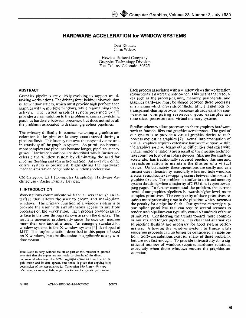
Support for window acceleration exists in all functional areas of the graphics hardware. Figure 1 shows the graphics ac- celerator with window support added. The placement of the window support circuitry within the pipeline is especially significant.
A majority of the window support circuitry is placed after the rendering hardware and before the framebuffer. This is the logical location for the window relative and window com- pare operations, described in a later section. Both of these operations help eliminate the need for pipeline flushing. Another important component is the pipeline bypass, which provides the window system with direct access to various components of the system, including the frarnebuffer.
2.2 Transform Processor
The t ransform processor is the core of the accelerated graphics system. On our workstations, the transform proces- sor block is i m p l e m e n t e d with parallel f loat ing point processors. The transform processors perform many tasks, including graphics context management, matrix transforma- tion calculations, spline tessellation, and lighting model computations. The transform processors also control vector and polygon rendering hardware, implemented with VLSI components as described in [5].
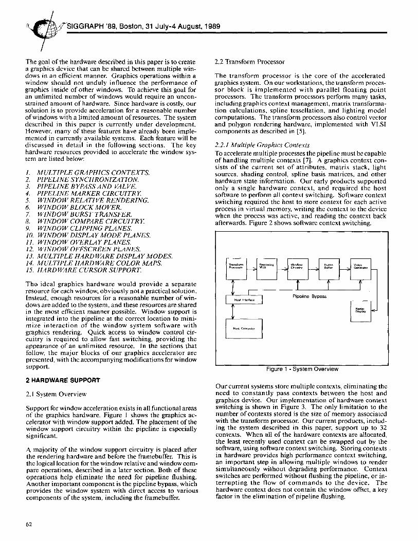
2.2.1 Multiple Graphics Contexts To accelerate multiple processes the pipeline must be capable of handling multiple contexts [7]. A graphics context con- sists o f the current set o f attributes, matr ix stack, light sources, shading control, spline basis matrices, and other hardware state information. Our early products supported only a single hardware context , and required the host software to perform all context switching. Software context switching required the host to store context for each active process in virtual memory, writing the context to the device when the process was active, and reading the context back afterwards. Figure 2 shows software context switching.
Trantf~rm|
Host Computer
Figure 1 - System Overview
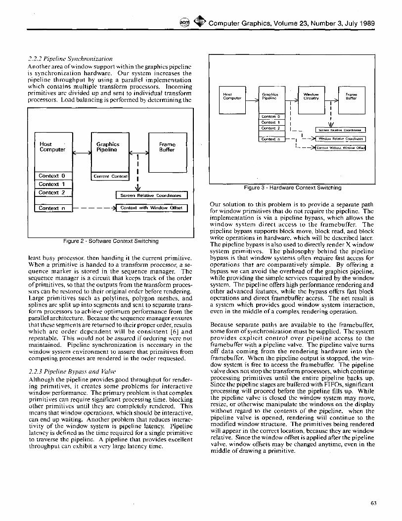
Our current systems store multiple contexts, eliminating the need to constant ly pass contexts between the host and graphics device. Our implementat ion of hardware context switching is shown in Figure 3. The only limitation to the number of contexts stored is the size of memory associated with the transform processor. Our current products, includ- ing the system described in this paper, support up to 32 contexts. When all of the hardware contexts are allocated, the least recently used context can be swapped out by the software, using software context switching. Storing contexts in hardware provides high performance context switching, an important step in allowing multiple windows to render simultaneously without degrading performance. Context switches are performed without flushing the pipeline, or in- t e r rup t ing the flow of c o m m a n d s to the device. The hardware context does not contain the window offset, a key factor in the elimination of pipeline flushing.
62
~ C o m p u t e r G r a p h i c s , V o l u m e 23, N u m b e r 3, J u l y 1989
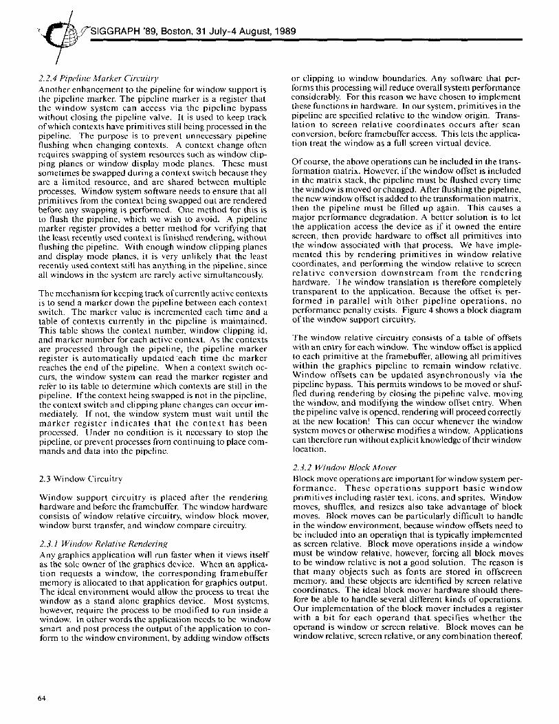
2.2.2 Pipeline Synchronization Another area of window support within the graphics pipeline is synchronization hardware. Our system increases the pipeline throughput by using a parallel implementa t ion which contains multiple transform processors. Incoming primitives are divided up and sent to individual transform processors. Load balancing is performed by determining the
Host Computer
Context 0
Context 1 Context 2
Context n
J Graphics Pipeline
Currerlt Conlext
Frame Buffer
I
I Screen Relative Coordinates I
--~ Contexl with W i n d o w Offset I
Figure 2 - Software Context Switching
least busy processor, then handing it the current primitive. When a primitive is handed to a transform processor, a se- quence marker is stored in the sequence manager. The sequence manager is a circuit that keeps track of the order of primitives, so that the outputs from the transform proces- sors can be restored to their original order before rendering. Large primitives such as polylines, polygon meshes, and splines are split up into segments and sent to separate trans- form processors to achieve opt imum performance from the parallel architecture. Because the sequence manager ensures that these segments are returned to their proper order, results which are order dependen t will be consis tent [6] and repeatable. This would not be assured if ordering were not maintained. Pipeline synchronization is necessary in the window system environment to assure that primitives from competing processes are rendered in the order requested.
2.2.3 Pipeline Bypass and Valve Although the pipeline provides good throughput for render- ing primitives, it creates some problems for interactive window performance. The primary problem is that complex primitives can require significant processing time, blocking other primitives until they are completely rendered. This means that window operations, which should be interactive, can end up waiting. Another problem that reduces interac- tivity of the window system is pipeline latency. Pipeline latency is defined as the time required for a single primitive to traverse the pipeline. A pipeline that provides excellent throughput can exhibit a very large latency time.
Host Computer Graphics ~ Window ~ Frame Pipe|ine Circuitry Buffer
Context 1 I I~ Context 2 I__ __ I .Ser¢~.e~n nelalive Coordinates I
co.,ext o - - I C _ ~ ~°~ .. . . . . . ,.o coo,~ ..... I I i_ __ __~ Conlr~x:l Wilhout W~.dow O('[set~
Figure 3 - Hardware Context Switching
Our solution to this problem is to provide a separate path for window primitives that do not require the pipeline. The implementation is v ia a pipeline bypass, which allows the window system direct access to the framebuffer . The pipeline bypass supports block move, block read, and block write operations in hardware, which will be described later. The pipeline bypass is also used to directly render X window system primitives. T h e philosophy behind the pipeline bypass is that window systems often require fast access for operations that are comparatively simple. By offering a bypass we can avoid the overhead of the graphics pipeline, while providing the simple services required by the window system. The pipeline offers high performance rendering and other advanced features, while the bypass offers fast block operations and direct framebuffer access. The net result is a system which provides good window system interaction, even in the middle of a complex rendering operation.
Because separate paths are available to the framebuffer, some form of synchronization must be supplied. The system prov ides expl ic i t con t ro l over p ipe l ine access to the framebuffer with a pipeline valve. The pipeline valve turns off data coming f rom the rendering hardware into the framebuffer. When the pipeline output is stopped, the win- dow system is free to access the framebuffer. The pipeline valve does not stop the transform processors, which continue processing primitives until the entire pipeline backs up. Since the pipeline stages are buffered with FIFOs, significant processing will proceed before the pipeline fills up. While the pipeline valve is closed the window system may move, resize, or otherwise manipulate the windows on the display without regard to the contents of the pipeline, when the pipeline valve is opened, rendering will continue to the modified window structure. The primitives being rendered will appear in the correct location, because they are window relative. Since the window offset is applied after the pipeline valve, window offsets may be changed anytime, even in the middle of drawing a primitive.
63
"L,,I~~SIGG RA PH '89, Boston, 31 July-4 August, 1989
2.2.4 Pipeline Marker Circuitry Another enhancement to the pipeline for window support is the pipeline marker. The pipeline marker is a register that the window system can access via the pipeline bypass without closing the pipeline valve. It is used to keep track of which contexts have primitives still being processed in the pipeline. The purpose is to prevent unnecessary pipeline flushing when changing contexts. A context change often requires swapping of system resources such as window clip- ping planes or window display mode planes. These must sometimes be swapped during a context switch because they are a limited resource, and are shared between multiple processes. Window system software needs to ensure that all primitives from the context being swapped out are rendered before any swapping is performed. One method for this is to flush the pipeline, which we wish to avoid. A pipeline marker register provides a better method for verifying that the least recently used context is finished rendering, without flushing the pipeline. With enough window clipping planes and display mode planes, it is very unlikely that the least recently used context still has anything in the pipeline, since all windows in the system are rarely active simultaneously.
The mechanism for keeping track of currently active contexts is to send a marker down the pipeline between each context switch. The marker value is incremented each time and a table of contexts currently in the pipeline is maintained. This table shows the context number, window clipping id, and marker number for each active context. As the contexts are processed through the pipeline, the pipeline marker register is automatically updated 'each time the marker reaches the end of the pipeline. When a context switch oc- curs, the window system can read the marker register and refer to its table to determine which contexts are still in the pipeline. If the context being swapped is not in the pipeline, the context switch and clipping plane changes can occur im- mediately. If not, the window system must wait until the marker register indica tes that the contex t has been processed. Under no condition is it necessary to stop the pipeline, or prevent processes from continuing to place com- mands and data into the pipeline.
2.3 Window Circuitry
Window support circuitry is placed after the rendering hardware and before the framebuffer. The window hardware consists of window relative circuitry, window block mover, window burst transfer, and window compare circuitry.
2.3. I Window Relative Rendering Any graphics application will run faster when it views itself as the sole owner of the graphics device. When an applica- tion requests a window, the corresponding framebuffer memory is allocated to that application for graphics output. The ideal environment would allow the process to treat the window as a stand alone graphics device. Most systems, however, require the process to be modified to run inside a window. In other words the application needs to be window smart and post process the output of the application to con- form to the window environment, by adding window offsets
or clipping to window boundaries. Any software that per- forms this processing will reduce overall system performance considerably. For this reason we have chosen to implement these functions in hardware. In our system, primitives in the pipeline are specified relative to the window origin. Trans- lation to screen relative coordinates occurs after scan conversion, before framebuffer access. This lets the applica- tion treat the window as a full screen virtual device.
Of course, the above operations can be included in the trans- formation matrix. However, if the window offset is included in the matrix stack, the pipeline must be flushed every time the window is moved or changed. After flushing the pipeline, the new window offset is added to the transformation matrix, then the pipeline must be filled up again. This causes a major performance degradation. A better solution is to let the application access the device as if it owned the entire screen, then provide hardware to offset all primitives into the window associated with that process. We have imple- mented this by rendering primitives in window relative coordinates, and performing the window relative to screen relat ive conver s ion downs t r eam from the render ing hardware. The window translation is therefore completely transparent to the application. Because the offset is per- formed in parallel with bther pipeline operat ions, no performance penalty exists. Figure 4 shows a block diagram of the window support circuitry,
The window relative circuitry consists of a table of offsets with an entry for each window. The window offset is applied to each primitive at the framebuffer, allowing all primitives within the graphics pipeline to remain window relative. Window offsets can be updated asynchronously via the pipeline bypass. This permits windows to be moved or shuf- fled during rendering by closing the pipeline valve, moving the window, and modifying the window offset entry. When the pipeline valve is opened, rendering will proceed correctly at the new location! This can occur whenever the window system moves or otherwise modifies a window. Applications can therefore run without explicit knowledge of their window location.
2.3.2 Window Block Mover Block move operations are important for window system per- fo rmance . These o p e r a t i o n s s u p p o r t basic window primitives including raster text, icons, and sprites. Window moves, shuffles, and resizes also take advantage of block moves. Block moves can be particularly difficult to handle in the window environment, because window offsets need to be included into an operation that is typically implemented as screen relative. Block move operations inside a window must be window relative, however, forcing all block moves to be window relative is not a good solution. The reason is that many objects such as fonts are stored in offscreen memory, and these objects are identified by screen relative coordinates. The ideal block mover hardware should there- fore be able to handle several different kinds of operations. Our implementation of the block mover includes a register with a bit for each operand that. specifies whether the operand is window or screen relative. Block moves can be window relative, screen relative, or any combination thereof.
64
~ Computer Graphics, Volume 23, Number 3, July 1989
This is useful because it allows the window system to move objects stored offscreen into a window, without explicitly calculating the offset for the destination. Instead, our win- dow relative hardware supplies the window offset for operands that are window relative. To initiate a block move on our system, the driver simply writes the source and des- t i na t i on addresses , b lock width and height , and a replacement rule.
Figure 4 - Window Support Hardware
For efficiency, the hardware handles mixed window and screen relative requests on the fly, and does not require the application to make decisions about the coordinate system used by the various operands. This meets our objective of avoiding extra processing by the window system on top of "the application. The mechanism for deciding which requests are window relative and which are screen relative is simple. If an object is offscreen, it is assumed to be screen relative. If an object is displayed, it is assumed to be window relative. These are defaults which can be overridden by explicit com- mands to the block mover.
2.3.3 Window Burst Transfer Another feature for window performance is the ability to move large amounts o f pixel data to and from system memory. Special hardware to speed up operations like block read and write increase the performance of many window operations. With acceleration, screen redraw, save bitmap, and restore bitmap operations occur very quickly, reducing the need to optimize fonts and bitmaps into offscreen memory.
The actual mechanics of how the burst transfers work are very similar to block moves. The driver just writes registers with a destination address, block width and height, and re- placement rule, followed by a stream of data. The burst transfer hardware takes care of getting the data to the right place on the display in the same window relative format as other operations. An additional offset is also included to allow for transfer of data that is not aligned in system memory without performance loss. Block write data is therefore not required to be aligned. The burst transfer hardware supports bit per pixel, byte per pixel, and full pixel
writes. The burst transferhardware available on our current systems is fast enough to support real time animation using images stored in system memory. Future systems will allow burst transfers in both directions, to speed up block reads and writes inside a window.
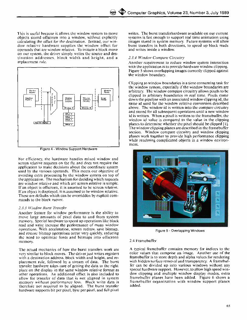
2.3.4 Window Compare Circuitry Another requirement to reduce window system interaction with the application is to provide hardware window clipping. Figure 5 shows overlapping images correctly clipped against the window boundary.
Clipping to window boundaries is a time consuming task for the window system, especially if the window boundaries are arbitrary. The window compare circuitry allows pixels to be clipped to arbitrary boundaries in real time. Pixels come down the pipeline with an associated window clipping id, the same id used for the window relative conversion described above. The window id is written into the compare circuitry and stored for all subsequent operations until a new window id is written. When a pixel is written to the framebuffer, the window id value is compared to the value in the clipping planes to determine whether the pixel should be clipped [1]. The window clipping planes are described in the framebuffer section. Window compare circuitry and window clipping planes work together to provide high performance clipping while rendering complicated objects in a window environ- ment.
Figure 5 - Overlapping Windows
2.4 Framebuffer
A typical framebuffer contains memory for indices to the color values that comprise an image. Another use of the framebuffer is to store depth and alpha values for rendering with hidden surface removal and transparency. A framebuf- fer can be divided up into various windows without any special hardware support. However, to allow high speed win- dow clipping and multiple window display modes, extra framebuffer planes have been added. Figure 6 shows a framebuffer organization with window support planes added.
65
' , S,GGRAPH '89, Boston, 31 J u l y - 4 Augus t , 1989
2.4.1 Window Clipping Planes Window clipping planes contain an id number for the win- dow that currently controls each pixei. When primitives are drawn, the window circuitry compares the window id of the pixei in the framebuffer to the window id of the pixel cur- rently being drawn. If the values match, the primitive lies inside the window, and the pixel is drawn. If the values are different, the primitive must be clipped, so the pixel is dis- carded [1]. Four window clipping planes provide up to sixteen independent windows, although one value must usually be reserved as a keep out value.
Window Circuitry
~ Depth B,Jf~ex • 4 Clippings ID,S Video
Generator
Figure 6 - Framebuffer Organization
2.4.2 Window Display Mode Planes Window display mode planes work in a similar fashion [7]. The framebuffer values for each pixel are sent in a stream to the video circuitry. At the same time the window display id is also sent. A display processor checks all values simul- taneously and reformats the framebuffer data according to the display mode for each pixel. This method allows one window to display from 8 planes, another from 24 planes, another in 12:12 double buffer mode, and so on. Windows which are rendering us ing double buffering can swap buffers asynchronously, a necessity to allow independent processes to render smoothly. Four window display mode planes pro- vide up to sixteen independent display modes. The color map for each window is also chosen based on the display id. Display modes and color lookup tables are discussed in the section on the video generator.
2.4.3 Window Overlay Planes Another resource that is useful for a window system is over- lay planes. These are framebuffer planes that are merged into the display in front of the image planes, allowing win- dows to coexist with rendered images. Since the actual contents of the framebuffer image planes are not destroyed by overlay data, our system allows rendering to image win- dows occluded by overlay windows.
2.4.4 Window Offscreen Planes Offscreen memory is also a valuable resource for window systems. Since many windows use predominantly raster text, raster fonts can be stored in an area of the framebuffer that is not displayed. The advantage is that characters from these fonts can be block moved into the window, a framebuffer to framebuffer copy, faster than they can be written from the host, a system memory to framebuffer copy. The importance of offscreen memory for font storage is reduced if accelera- tion is available for the system memory to framebuffer path. Our current systems display 1280 by 1024 pixels out of the 2048 by 1024 framebuffer, which provides an offscreen area of 768 by 1024 pixels.
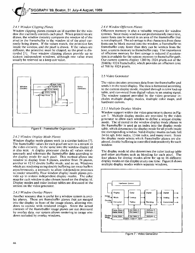
2.5 Video Generator
The video circuitry processes data from the framebuffer and sends it to the raster display. The data is formatted according to the current display mode, mapped through a color lookup table, and converted from digital values to an analog signal. The window support provided by the video generator in- cludes multiple display modes, multiple color maps, and hardware cursors.
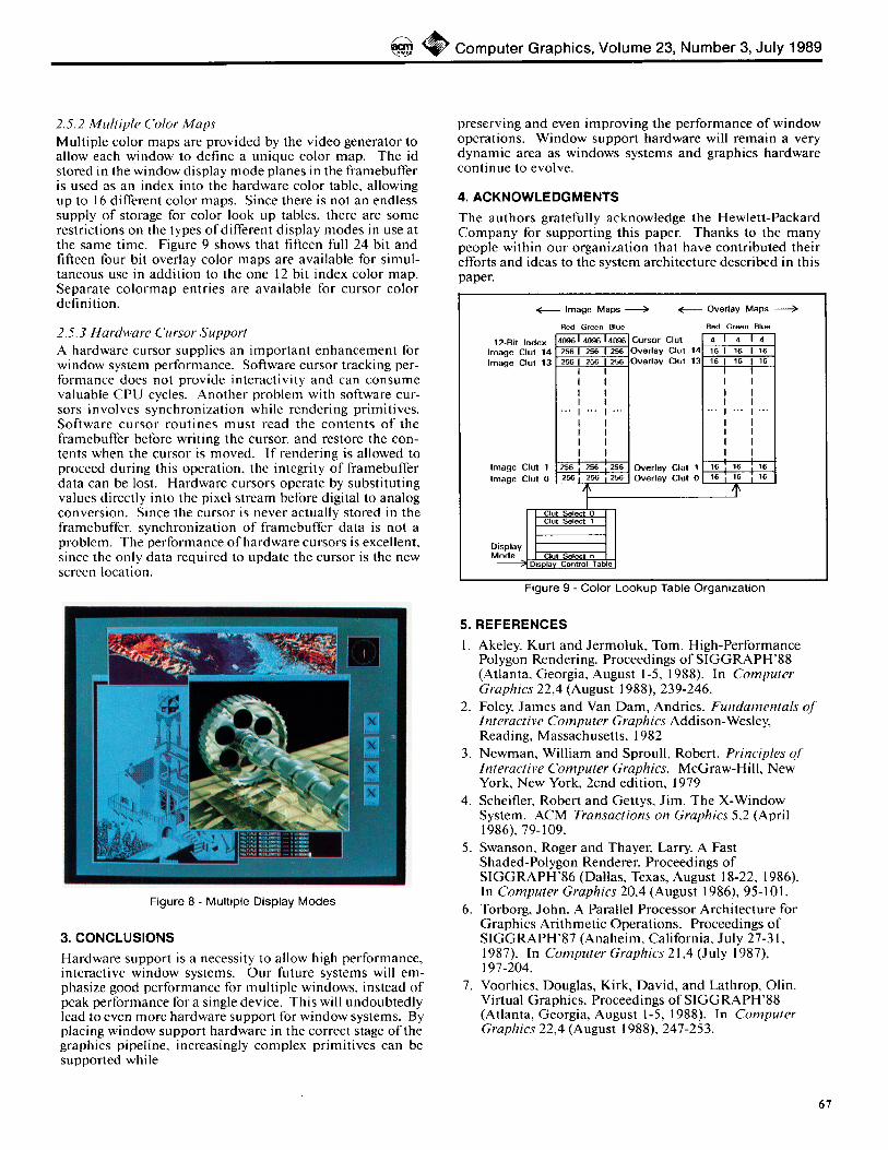
2.5.1 Multiple Display Modes Window support within the video generator is shown in Fig- ure 7. Multiple display modes are provided by the video generator to allow each window to define a unique display mode. The id stored in the window display mode planes in the framebuffer is used as an index into the display mode table, which determines the display mode for all pixels inside the corresponding window. Valid display modes include full 24-bit rgb, 8-bit index, 12-bit index, and many more. Since the display mode selects which framebuffer planes are dis- played, double buffering is controlled independently for each window.
The display mode id also determines the color lookup table and other attributes such as blending for each pixel. The four planes for display modes allow for up to 16 different display modes on the display at any one time. Figure 8 shows multiple display modes within separate windows.
l Hardware Cursor
; Lookl
/1
I
Dis ta bode 1
ModeDisplay ~ Display Control Table
Figure 7 - Video Generator
66
@ C o m p u t e r G r a p h i c s , V o l u m e 23, N u m b e r 3, J u l y 1 9 8 9
2.5.2 Multiple Color Maps Multiple color maps are provided by the video generator to allow each window to define a unique color map. The id stored in the window display mode planes in the framebuffer is used as an index into the hardware color table, allowing up to 16 different color maps. Since there is not an endless supply of storage for color look up tables, there are some restrictions on the types of different display modes in use at the same time. Figure 9 shows that fifteen full 24 bit and fifteen four bit overlay color maps are available for simul- taneous use in addition to the one 12 bit index color map. Separate colormap entries are available for cursor color definition.
2,5.3 Hardware Cursor Support A hardware cursor supplies an important enhancement for window system performance. Software cursor tracking per- formance does not provide interactivity and can consume valuable CPU cycles. Another problem with software cur- sors involves synchronization while rendering primitives. Software cursor routines must read the contents of the framebuffer before writing the cursor, and restore the con- tents when the cursor is moved. If rendering is allowed to proceed during this operation, the integrity of framebuffer data can be lost. Hardware cursors operate by substituting values directly into the pixel stream before digital to analog conversion. Since the cursor is never actually stored in the framebuffer, synchronization of framebuffer data is not a problem. The performance of hardware cursors is excellent, since the only data required to update the cursor is the new screen location.
Figure 8 - Multiple Display Modes
3. CONCLUSIONS
Hardware support is a necessity to allow high performance, interactive window systems. Our future systems will em- phasize good performance for multiple windows, instead of peak performance for a single device. This will undoubtedly lead to even more hardware support for window systems. By placing window support hardware in the correct stage of the graphics pipeline, increasingly complex primitives can be supported while
preserving and even improving the performance of window operations. Window support hardware will remain a very dynamic area as windows systems and graphics hardware continue to evolve.
4. ACKNOWLEDGMENTS
The authors gratefully acknowledge the Hewlett-Packard Company for supporting this paper. Thanks to the many people within our organization that have contributed their efforts and ideas to the system architecture described in this paper.
< Overlay Maps
RBd Green Blue
12-Bit Index 4 4 4 Image Clut 14 Image Clut 13
Image Maps > <
Red Green Blue 4096 I 4096 14096 Cursor elut 256 256 1 256 Overlay Clut 14 256 256 256 Overlay Clut 13
16 16 16 16 16 16
Image Clut 1 ] 2'56 ; 256 ; 256 I Overlay Clut 1 1,6 16 16 Imego CI.t O I ~" i 256 i 256 1 Overlay Clut 0 1,6 16 16
t ] Clut Select 0 I I
Display I Clut Select 1 1
Mode _1 Clut Select n ] Display Contro Tabe
Figure 9 - Color Lookup Table Organization
5. REFERENCES
1. Akeley, Kurt and Jermotuk, Tom. High-Performance Polygon Rendering. Proceedings of SIGGRAPH'88 (Atlanta, Georgia, August 1-5, 1988). In Computer Graphics 22,4 (August 1988), 239-246.
2. Foley, James and Van Dam, Andries. Fundamentals of Interactive Computer Graphics Addison-Wesley, Reading, Massachusetts, 1982
3. Newman, William and Sproull, Robert. Principles of Interactive Computer Graphics. McGraw-Hill, New York, New York, 2cnd edition, 1979
4. Scheifler, Robert and Gettys, Jim. The X-Window System. ACM Transactions on Graphics 5,2 (April 1986), 79-109.
5. Swanson, Roger and Thayer, Larry. A Fast Shaded-Polygon Renderer. Proceedings of SIGGRAPH'86 (Dallas, Texas, August 18-22, 1986). In Computer Graphics 20,4 (August 1986), 95-101.
6. Torborg, John. A Parallel Processor Architecture for Graphics Arithmetic Operations. Proceedings of SIGGRAPH'87 (Anaheim, California, July 27-3 l, 1987). In Computer Graphics 21,4 (July 1987), 197-204.
7. Voorhies, Douglas, Kirk, David, and Lathrop, Olin. Virtual Graphics. Proceedings of SIGGRAPH'88 (Atlanta, Georgia, August 1-5, 1988). In Computer Graphics 22,4 (August 1988), 247-253.
67