Embed Size (px)
Citation preview
Contents
PA-09 Data Sheet
2345678
Specifications DimensionsSpeed/Current vs Load Connectors & Feedback Mounting Brackets Internal Components Internal Descriptions
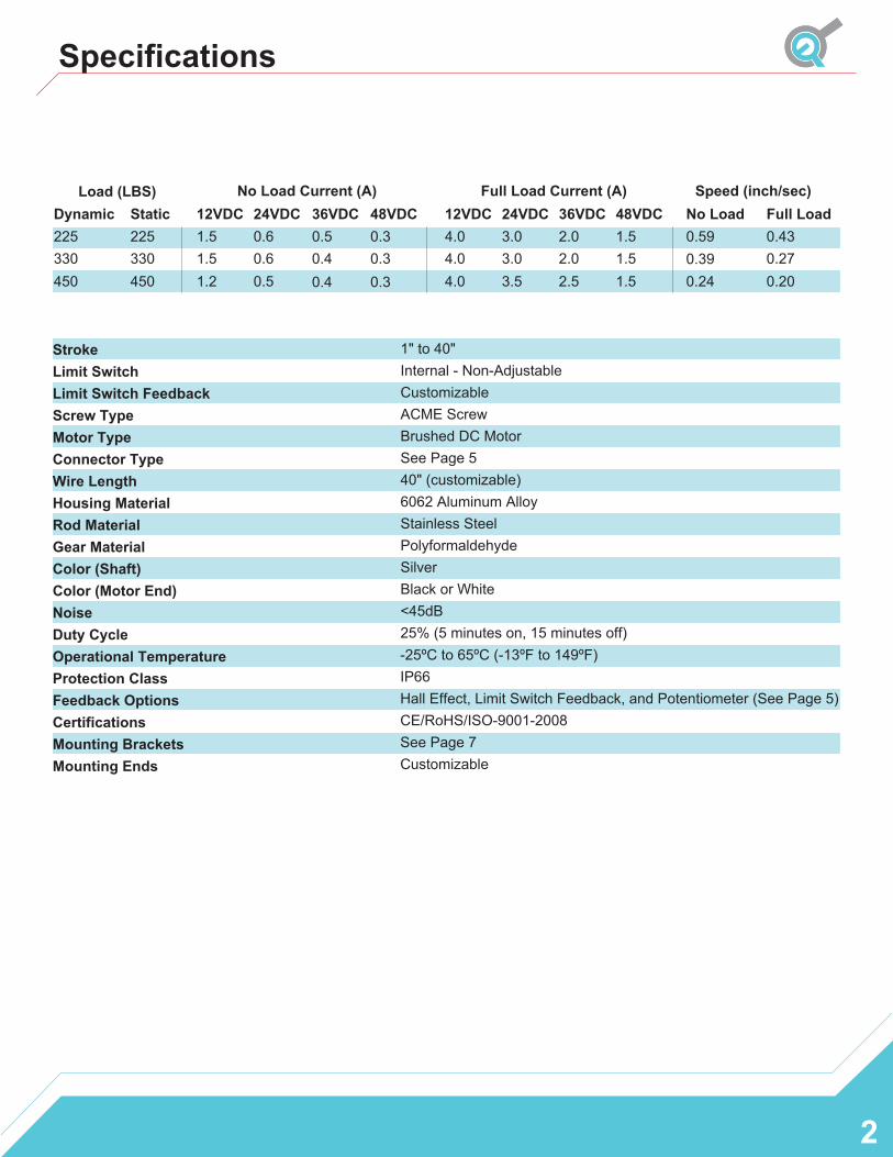
Specifications
2
0.430.270.20
0.59 0.39 0.24
1.5 0.62250.6330 1.5
1.2 0.5450
225330450
Dynamic Static0.30.30.4
0.5 4.0 3.03.04.0
4.0 3.5
1.51.51.52.5
2.02.0
1" to 40"Internal - Non-Adjustable CustomizableACME ScrewBrushed DC MotorSee Page 540" (customizable)6062 Aluminum AlloyStainless Steel PolyformaldehydeSilverBlack or White<45dB25% (5 minutes on, 15 minutes off)-25ºC to 65ºC (-13ºF to 149ºF)IP66Hall Effect, Limit Switch Feedback, and Potentiometer (See Page 5)CE/RoHS/ISO-9001-2008See Page 7Customizable
StrokeLimit Switch Limit Switch Feedback Screw TypeMotor TypeConnector TypeWire LengthHousing MaterialRod MaterialGear MaterialColor (Shaft)Color (Motor End) NoiseDuty CycleOperational Temperature Protection Class Feedback Options Certifications Mounting Brackets Mounting Ends
Full LoadLoad (LBS) Speed (inch/sec)
No LoadNo Load Current (A)
12VDC 24VDC 36VDC 48VDC
0.30.4
Full Load Current (A)12VDC 24VDC 36VDC 48VDC
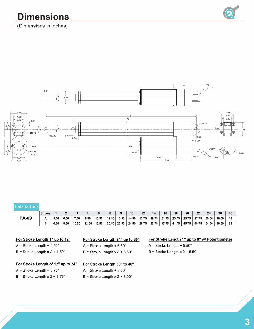
PA-09Stroke 1 3 4 9 12 16
5.50 6.50 7.50 8.50 10.50 12.50 13.50 14.50 17.75 19.75 21.75 23.756.50 8.50 10.50 12.50 16.50 20.50 22.50 24.50 29.75 33.75 37.75 41.75
Dimensions
Hole to Hole2 6 8 20
25.75 27.7545.75 49.75
2430.50 36.5054.50 66.50
AB
404888
10 14 18 22 30
3
3.32
Ø0.74
R0.901.24
0.721.02
1.68
0.75
0.90
0.42
0.74
Ø0.32
AB
0.360.94
3.625.20
Ø0.32
0.80
1.38
0.420.82
1.22
0.80
0.24
1.30
1.38
R0.90
Ø0.50
1.68
Ø0.94
1.800.80
1.85
0.440.25
1.61
0.62
For Stroke Length 1" up to 12" A = Stroke Length + 4.50"
B = Stroke Length x 2 + 4.50"
For Stroke Length of 12" up to 24" A = Stroke Length + 5.75"
B = Stroke Length x 2 + 5.75"
For Stroke Length 24" up to 30" A = Stroke Length + 6.50" B = Stroke Length x 2 + 6.50"
For Stroke Length 30" to 40" A = Stroke Length + 8.00" B = Stroke Length x 2 + 8.00"
(Dimensions in inches)
For Stroke Length 1" up to 8" w/ Potentiometer A = Stroke Length + 5.50"
B = Stroke Length x 2 + 5.50"
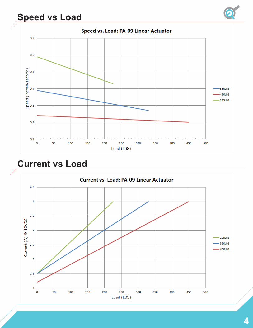
Speed vs Load
Current vs Load
4
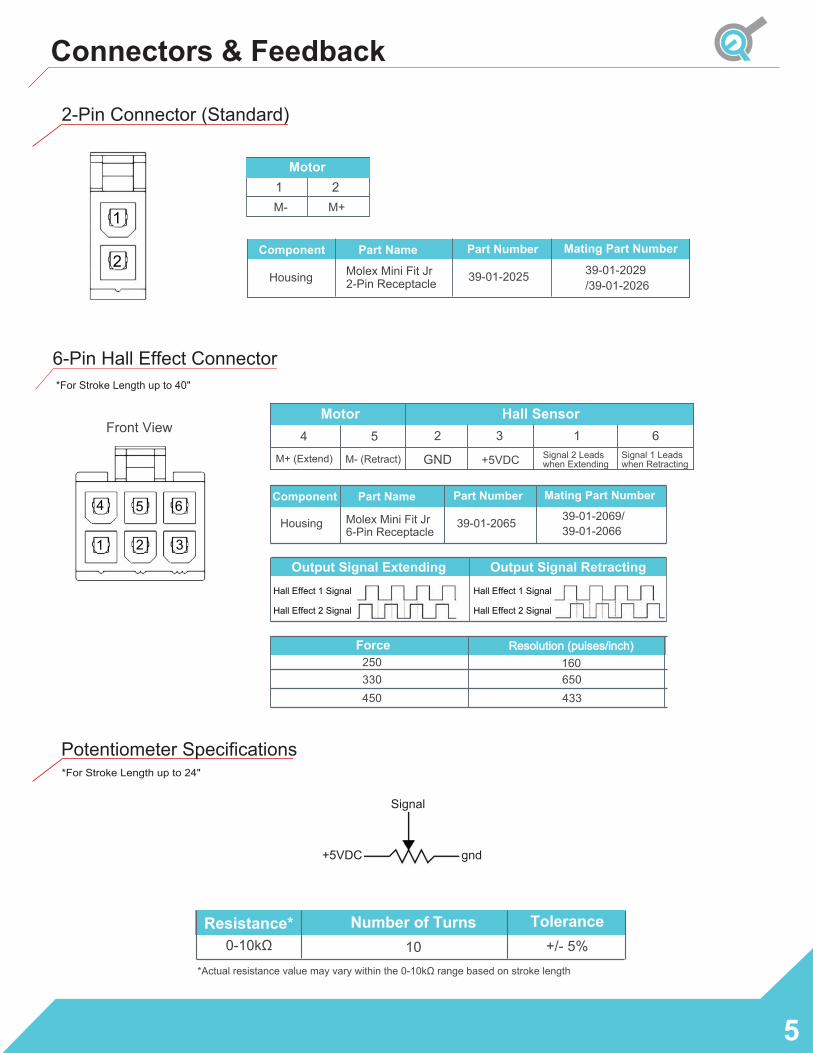
Connectors & Feedback
5
Force
330
Resolution (pulses/inch) 160650433450
250
1
2
2-Pin Connector (Standard)
Part Number Mating Part NumberComponent
Housing
Part NameMolex Mini Fit Jr 2-Pin Receptacle 39-01-2025 39-01-2029
/39-01-2026
4 5 6
321
6-Pin Hall Effect Connector
Front View
Housing
Output Signal Extending Output Signal RetractingHall Effect 1 Signal
Hall Effect 2 Signal
Hall Effect 1 Signal
Hall Effect 2 Signal
Part Name
Molex Mini Fit Jr 6-Pin Receptacle
Part Number
39-01-2065
Mating Part Number
39-01-2069/39-01-2066
Component
*For Stroke Length up to 40"
4 5
M+ (Extend) M- (Retract)
2
+5VDC
6Signal 1 Leadswhen Retracting
Motor Hall Sensor
GND Signal 2 Leadswhen Extending
13
1 2M- M+
Motor
Resistance*0-10kΩ
Tolerance +/- 5%
Number of Turns 10
Signal
+5VDC gnd
*Actual resistance value may vary within the 0-10kΩ range based on stroke length
Potentiometer Specifications *For Stroke Length up to 24"
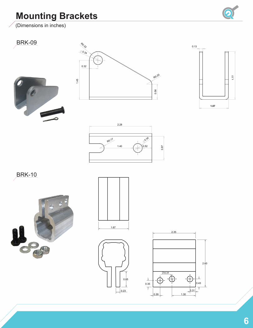
Mounting Brackets
6
BRK-09
(Dimensions in inches)
0.34
R0.32
0.32
1.4
5
0.56
R0.20
1.77
0.13
1.07
2.28
0.87
0.34
R0.17
1.40 0.52
0.23
0.85
2.60
2.35
0.39 0.31
1.30
0.43 0.35
0.31
1.67
BRK-10
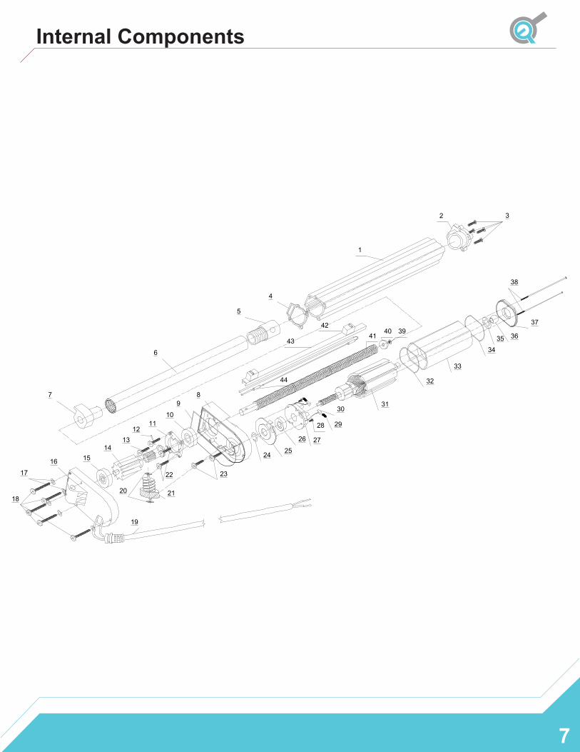
Internal Components
7
1
2 3
4
5
6
7 89
1011
1213
141516
17
18
19
20 21
22 23
24 25
26 27
28 29
3031
32
33
3435 36
37
38
394041
43
44
42
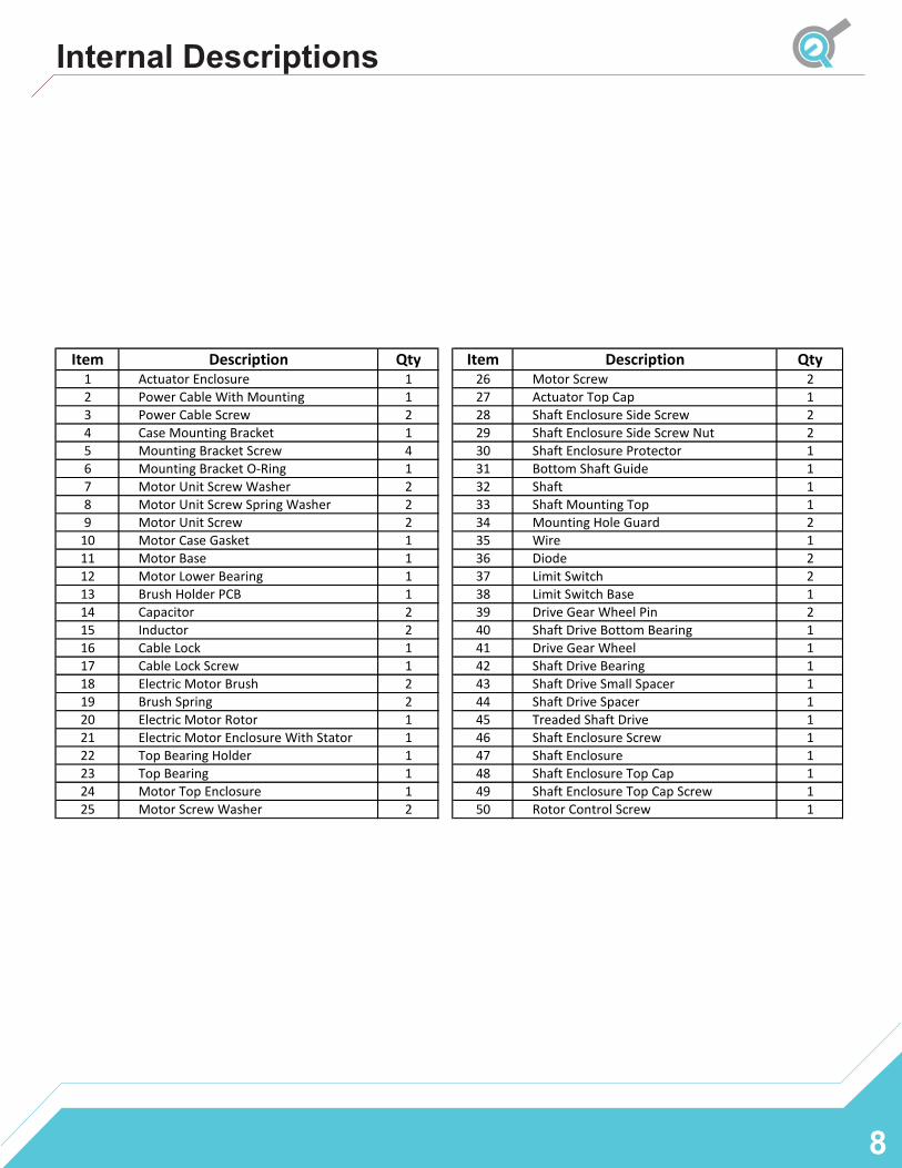
Item Description Qty Item Description Qty1 Actuator Enclosure 1 26 Motor Screw 22 Power Cable With Mounting 1 27 Actuator Top Cap 13 Power Cable Screw 2 28 Shaft Enclosure Side Screw 24 Case Mounting Bracket 1 29 Shaft Enclosure Side Screw Nut 25 Mounting Bracket Screw 4 30 Shaft Enclosure Protector 16 Mounting Bracket O-Ring 1 31 Bottom Shaft Guide 17 Motor Unit Screw Washer 2 32 Shaft 18 Motor Unit Screw Spring Washer 2 33 Shaft Mounting Top 19 Motor Unit Screw 2 34 Mounting Hole Guard 2
10 Motor Case Gasket 1 35 Wire 111 Motor Base 1 36 Diode 212 Motor Lower Bearing 1 37 Limit Switch 213 Brush Holder PCB 1 38 Limit Switch Base 114 Capacitor 2 39 Drive Gear Wheel Pin 215 Inductor 2 40 Shaft Drive Bottom Bearing 116 Cable Lock 1 41 Drive Gear Wheel 117 Cable Lock Screw 1 42 Shaft Drive Bearing 118 Electric Motor Brush 2 43 Shaft Drive Small Spacer 119 Brush Spring 2 44 Shaft Drive Spacer 120 Electric Motor Rotor 1 45 Treaded Shaft Drive 121 Electric Motor Enclosure With Stator 1 46 Shaft Enclosure Screw 122 Top Bearing Holder 1 47 Shaft Enclosure 123 Top Bearing 1 48 Shaft Enclosure Top Cap 124 Motor Top Enclosure 1 49 Shaft Enclosure Top Cap Screw 125 Motor Screw Washer 2 50 Rotor Control Screw 1
Internal Descriptions
8