Embed Size (px)
Citation preview

Insert Class Title as per Title Page
IPD – Integrating my project design with others … Let’s come together right now!Speaker: Natalia Khaldi IBE Consulting Engineers
MP4150Class will focus on common problems and the difficulties design teams face in collaborating with design built contractors or general contractors. Touch on Preconstruction administration: quantities of take offs from the designer’s model in Revit MEP and AutoCAD MEP. We will also review lessons learned and show examples of successful coordination between Architects, MEP designers, design-build contractors, sub-contractors and a general contractors.)
Learning Objectives
At the end of this class, you will be able to:
Control and manage linked objects displays in Revit
Have a better understanding of multiplatform workflow
Import/Export from Revit MEP, AutoCAD MEP, and other AutoCAD based applications more efficiently
Extracting and Reporting data from Revit MEP and AutoCAD MEP
Will be more efficient in Navisworks Collision Detection and Reporting
About the Speaker
Natalia Khaldi Natalia is currently a 3D Modelling Manager for IBE Consulting Engineers and previously worked for Arup North Americas LTD where she pioneered 3D design drafting. Natalia holds a B.S. in Mechanical Engineering from Polytechnic University Minsk, Belarus. She has been an active user of AutoCAD® since release 10 and AutoCAD MEP (Building Systems) since 2000. She has been using AutoCAD MEP on variety of projects such as laboratories, hospitals and office buildings. Natalia has been involved in developing and implementing CAD Standards for AutoCAD, AutoCAD MEP and AutoCAD Revit® MEP. She has been providing technical support, training, and content development for AutoCAD MEP users for different disciplines and offices.
7
Insert Class Title as per Title Page
IPD – Integrating my project design with others … Let’s come together right now!
Any design process in the modern world is a collaborative process. All Construction Documents and As Build packages include a 3D model for many different reasons... Integrated project delivery includes collaborative effort on creating one master model where all parties work together on meeting the scheduled deadlines. 2D paper drawing with wet stamp and signature are still part of the deliverable package for most agencies. The differentiation here is that the 2D drawings are being created from the data rich 3D Models. The utilization of intelligent data from the 3D model simplifies many of the processes for the members of the design/build team. These include but are not limited to quantities take-offs and constructability. With the current rate of change and evolution in the Integrated Project Delivery, it is feasible to assume that in the near future all design and build documents will exist in only digital format. Frequency of data exchange between involved parties has been increasing exponentially. In some cases all parties are working in a real time model exchange - on the same model or off the same server. Optimizing the process of data exchange plays a key role in the success and profitability of any project for all the members of the design team with no exceptions. There is no magic tool that can do all the design, simulations, production of shop drawings, navigation of various platforms, and optimization of communication within the design team without sacrificing productivity of team members.
In this class I would like to go over some well knows and maybe overlooked tools to streamline the Integration of the design.
7
Insert Class Title as per Title Page
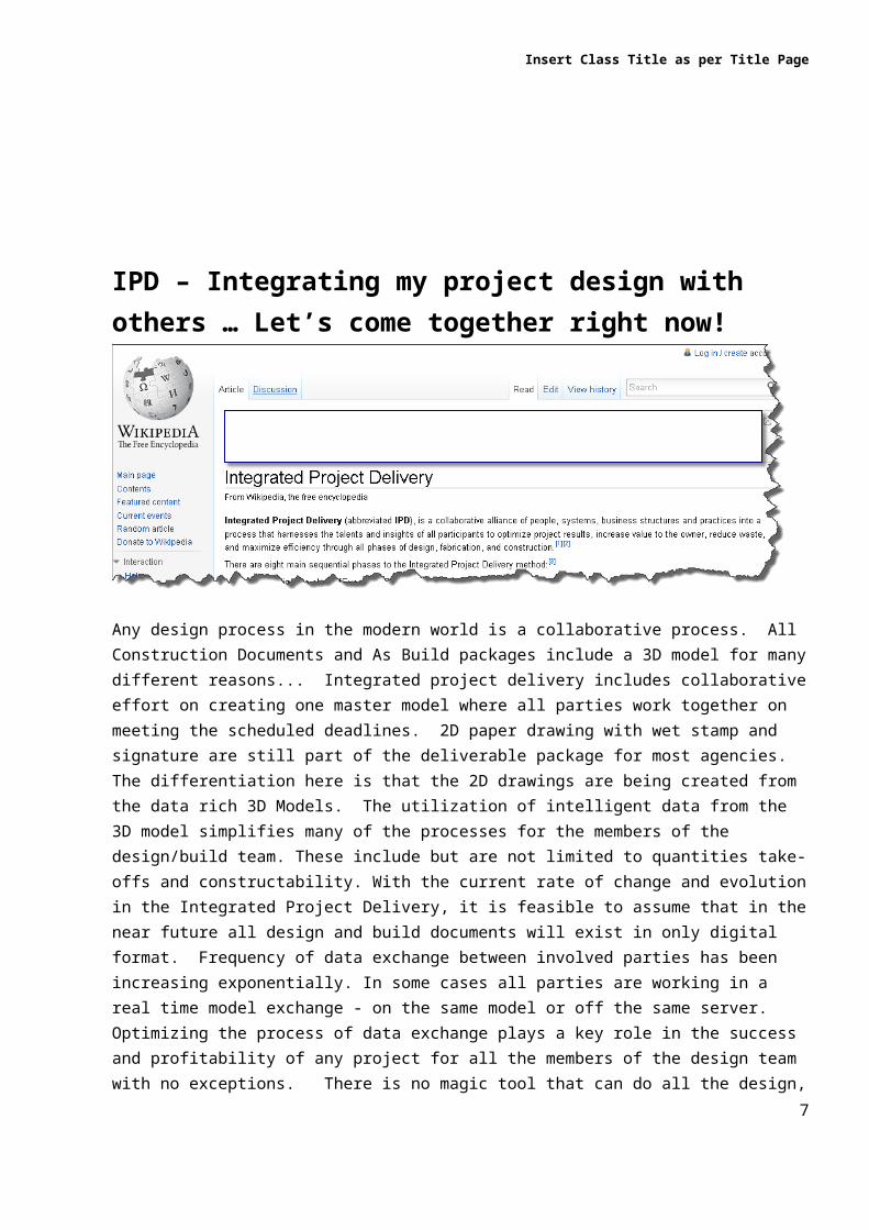
A
Before you start any project there are a few things you must address to resolve misunderstandings, and streamline the process of data/models exchange.
Project Directory Data
Project Execution plan.
Project execution plan is a very valuable tool for BIM managers and the rest of the design team. The Plan is a road map to tasks and responsibilities, contact information, important dates and goals of the project. The Project execution plan can be downloaded from the Autodesk website or can be developed in house based on your firm’s standards.
Level of Development (LOD)
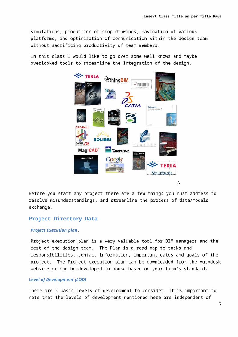
There are 5 basic levels of development to consider. It is important to note that the levels of development mentioned here are independent of project types. These are simply guide lines to how detailed the model is at different stage of the project. These levels help define consistent expectations throughout the building lifecycle from planning through design and construction. There are five defined standard LOD per the AIA E202 document. LOD 100 - 200 have a reference to the traditional 2D project delivery method while levels 300 and 500 are specific to the BIM process. Exchanging your firms LOD document with other members of the design team at the beginning of the project will give every member of the team a clear picture of what to expect from the models. Every company should have a document describing how detailed there models are and when the development is happening. LOD is usually submitted to the client or architect, or by the architect to the client at the beginning of the project. The document could be very informative and let you plan your strategy knowing what to expect from the model.
7
Insert Class Title as per Title Page
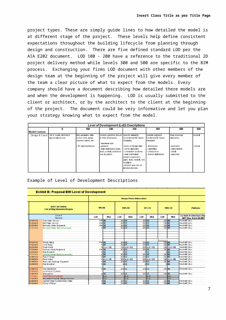
Example of Level of Development Descriptions
The Template of the document can be obtained from AIA website.
File Exchange Format. File exchange format and frequency of file exchange should be documented and agreed on by all parties. For some it might be a little more work than others. In our office the most preferable formats are: DWG, IFC, DXF, NWD,NWC, RVT.
Coordinates (To share or not to share)Only Revit Projects will always benefit from using shared coordinates. It should be noted that if any member of the design team is using AutoCAD I would recommend to use Project internal coordinates for any Revit related exports. If coordination is done using Navisworks, models exported from Revit and Cad will not align. Furthermore, all Revit models exported to AutoCAD and then to Revit will lose their inherent inelegance. By using project coordinates you simplify model assembly. If a project requires weekly model exchange, it will save the team lot of time.
7
Insert Class Title as per Title Page
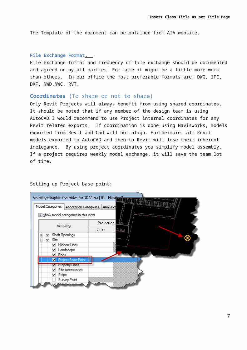
Setting up Project base point:
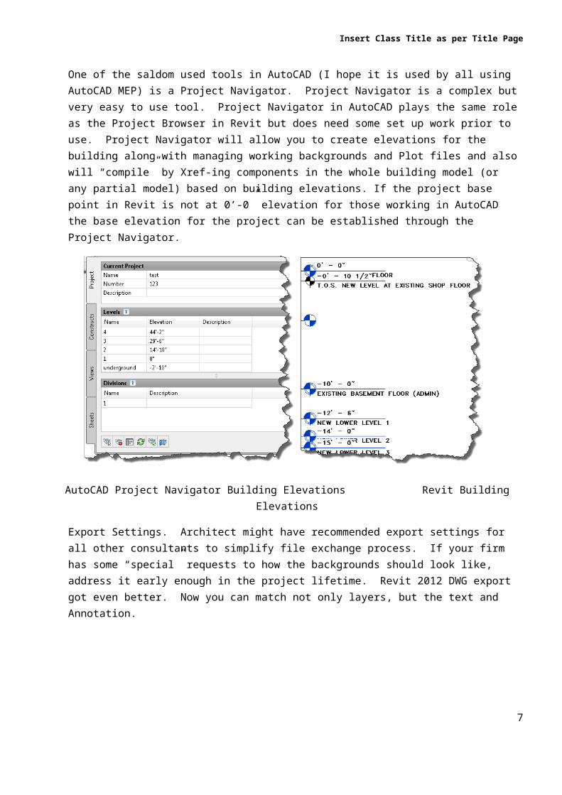
One of the saldom used tools in AutoCAD (I hope it is used by all using AutoCAD MEP) is a Project Navigator. Project Navigator is a complex but very easy to use tool. Project Navigator in AutoCAD plays the same role as the Project Browser in Revit but does need some set up work prior to use. Project Navigator will allow you to create elevations for the building along with managing working backgrounds and Plot files and also will “compile” by Xref-ing components in the whole building model (or any partial model) based on building elevations. If the project base point in Revit is not at 0’-0” elevation for those working in AutoCAD the base elevation for the project can be established through the Project Navigator.
AutoCAD Project Navigator Building Elevations Revit Building Elevations
7
Insert Class Title as per Title Page
Export Settings. Architect might have recommended export settings for all other consultants to simplify file exchange process. If your firm has some “special” requests to how the backgrounds should look like, address it early enough in the project lifetime. Revit 2012 DWG export got even better. Now you can match not only layers, but the text and Annotation.
In Revit 2012 you can have different export settings for different clients. you can use overrides for layers and you can “translate” linetype, text, and dimensions into AutoCAD formats.
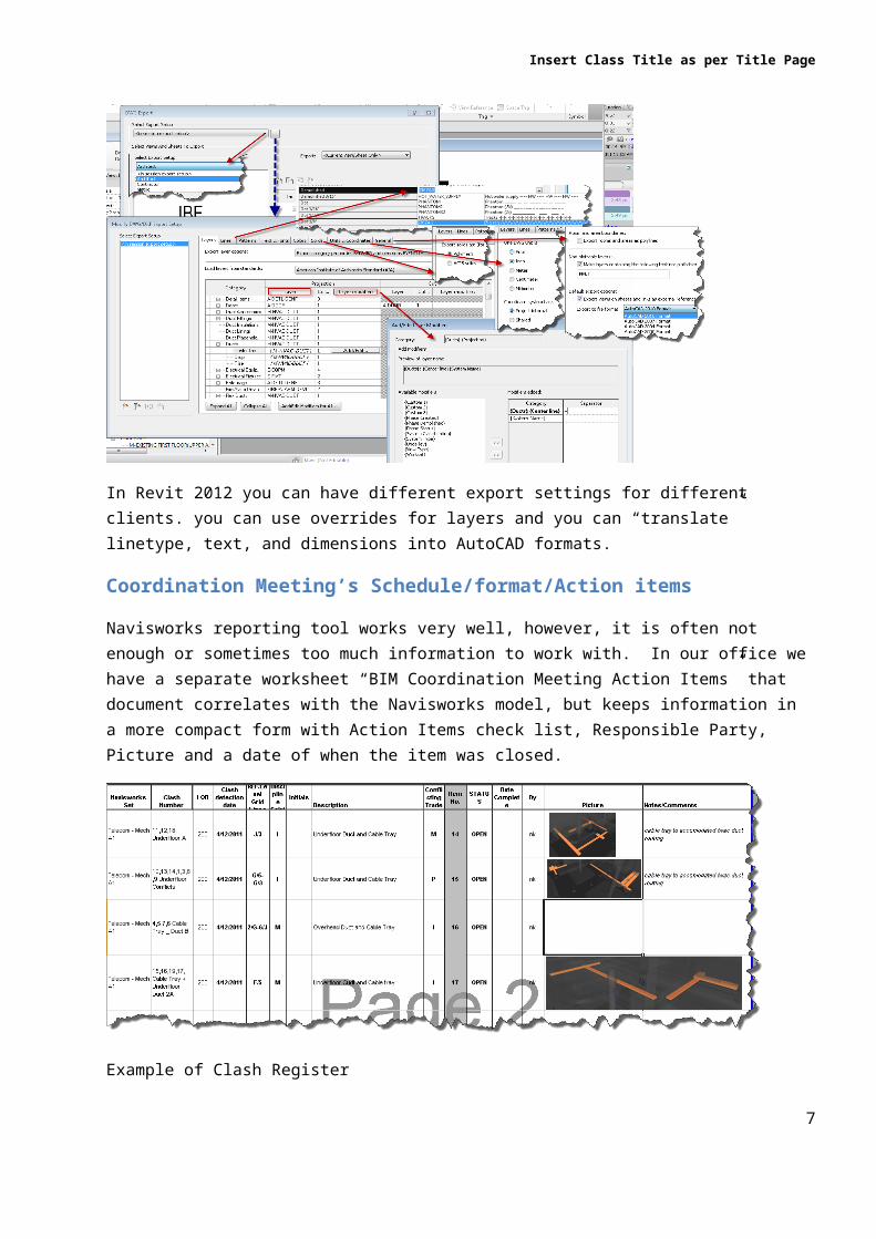
Coordination Meeting’s Schedule/format/Action items
Navisworks reporting tool works very well, however, it is often not enough or sometimes too much information to work with. In our office we have a separate worksheet “BIM Coordination Meeting Action Items” that document correlates with the Navisworks model, but keeps information in a more compact form with Action Items check list, Responsible Party, Picture and a date of when the item was closed.
Example of Clash Register
7
Insert Class Title as per Title Page
Model Elements/Views (Revit)
If at any given point, two or more team players are going to exchange models and thus reuse each other’s design elements (walls, mechanical equipment, lights, views) I would strongly recommend to re-use(change) instead of delete/redraw tactic. If a wall is removed, all objects that are face based will disappear from the consultant’s model, but if a wall is modified the objects that are wall based will remain in the model.
Level
If a level is removed from the model, all elements associated with that level will disappear. If linked view visibility graphics are used in the view and it does not exist you might end up having a completely different view displaying on the background. If a room has been deleted from the model and new room has been placed, the Space defined within that room will disappear from MEP model and will need to be recreated. Reuse/Modify – do delete/redraw.
Project Sub Division-ingAs many of us have noticed, most Autodesk applications have become very slow in handling large files. Therefore, it is a good idea to plan on how you can dissect the project into smaller files. This will alleviate the reduction in productivity due to large sluggish models. Revit servers or virtual workstations can also be a solution to this issue; however, for smaller firms this might not be economically feasible. Working in AutoCAD MEP and using the project navigator feature will force you to work on a floor by floor basis; however, you can always split floors into smaller portions. Also, not having nested references will improve application’s performance. It is recommended to have all Xrefs Overlay as opposed to Attached.
In Revit you can set up multiple models; one per trade. If it is not the best for an integrated workflow to split the model into levels but it might be another alternative. Another option could be to divide the building into upper and lower levels or to Core and Shell. In any case scenario you can always have all disciplines together or in separate linked models it is all just matter of workflow. At the end of the day all models get linked into each other as an Overlay to avoid using nested links and all elements can be tagged (connection to linked elements is still not supported in Revit but it is supported in AutoCAD MEP)
If you are linking AutoCAD drawings into a Revit model, you can do it two ways. The first option is to directly link dwg’s into your Revit model. The second option is to create a separate Revit model where you link all dwg files creating one big model. As a subset of the second option you can also create a few smaller models and selectively link the dwg files to these. By linking the overall model into your model will have a little more flexibility with the visibility controls of the elements in the view. See more details information in case study.
All Sub Division-ing shall be thought through based of what all members of the team workflow and agreed on upon beginning of the project.
CAD 3D Grid. I have developed a “typical” 3D grid that I can modify and use on all of my projects to use in Navisworks. A 3D grid will help you navigate through the model and identify locations of potential conflicts. A 3D grid may be shared by all.
7
Insert Class Title as per Title Page
Case Study.
Project size: 180,000 Sq.Ft Multi Use Building
Platforms Used: AutoCAD MEP, CadDuct, CadPipe, Revit, Tekla, Navisworks
Deliverables:
As Build Revit Model(s) By General Contractor to the Client
Roles:
Architect 100%CD+AsBuild Revit Model to General Contractor
IBE 50% CD MEP to Architect
IBE 100%CD E to Architect
Subs 3D shop drawings to General Contractor
File Exchange Formats:
DWG, RVT, NWD(C) - weekly
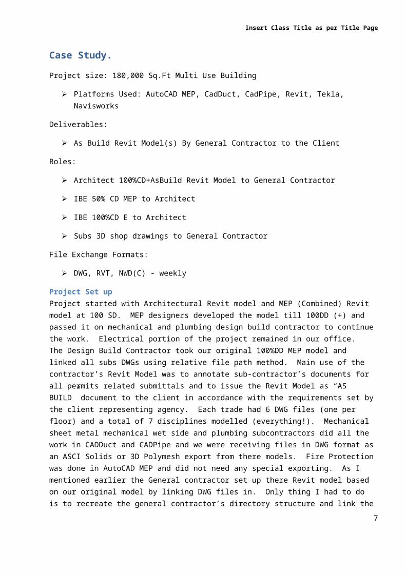
Project Set upProject started with Architectural Revit model and MEP (Combined) Revit model at 100 SD. MEP designers developed the model till 100DD (+) and passed it on mechanical and plumbing design build contractor to continue the work. Electrical portion of the project remained in our office. The Design Build Contractor took our original 100%DD MEP model and linked all subs DWGs using relative file path method. Main use of the contractor’s Revit Model was to annotate sub-contractor’s documents for all permits related submittals and to issue the Revit Model as “AS BUILD” document to the client in accordance with the requirements set by the client representing agency. Each trade had 6 DWG files (one per floor) and a total of 7 disciplines modelled (everything!). Mechanical sheet metal mechanical wet side and plumbing subcontractors did all the work in CADDuct and CADPipe and we were receiving files in DWG format as an ASCI Solids or 3D Polymesh export from there models. Fire Protection was done in AutoCAD MEP and did not need any special exporting. As I mentioned earlier the General contractor set up there Revit model based on our original model by linking DWG files in. Only thing I had to do is to recreate the general contractor’s directory structure and link the contractor’s “mixed” model into my Electrical Model. I did the same to create a structural Revit Model using exported DWG format files from Tekla. Contractor’s model did not link at the same location as my project was (Shared Coordinates were used in original model set up and was still used by the Architect). This is when I had to use 3d object (no lines are visible in 3d View in Revit) to “align” models I used common edge in the floor slab in Architectural model to align both models together. My weekly background updates consisted only placing the updated files into right location and post my exported files in DWG, NWC formats plus up to date a Revit Model. What I had to do on weekly basis is only download updated files and override my references.
7

Insert Class Title as per Title Page
Project Setup Matrix
I stated earlier that to optimize Revit performance it is highly recommended not to link references with links attached. In this case it worked much better for me because contractor’s DWG files were cuet small and if contractor changed anything in there Revit model I would not have to chase it – it will be automaticaly updated. Also, it was easier to control when the DWG were loaded. I would unload the model prior exiting the model and reload it only when I needed it. This alone saved a lot of time for the team. When project got into final stages and models got very big and some of the levels were signed off I also was able to control what is loading into contractors model via File Managenet by simply remnaming references I did not need to load. In conclusion, I was loosing time on some operations when I had to to reload the contractors model but I did save time on Open/Close which seemed totake much longer then just to reload the reference after model is open
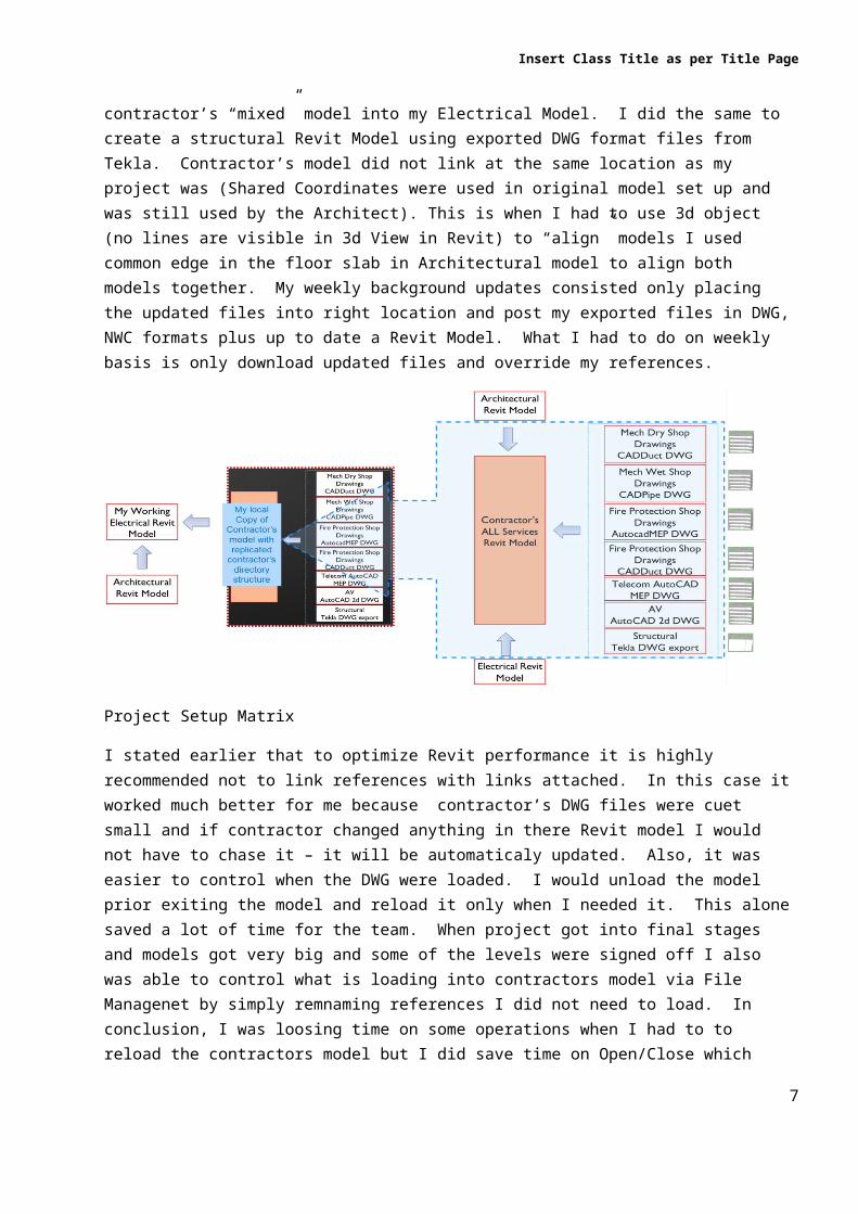
Lesson Learned* CADDuct Duct and some CADPipe objects would not display when they are an external reference in a DWG file linked into Revit.
DWG Visibility control in Revit. Smaller models are faster to load. It appears that lots of smaller links are faster to load then one big link. The benefit of linking Revit Model with DWGs linked into your Revit model is that as a default DWGs are not displaying in any view and all settings are “staying” with you Revit Model. Please note, all color overrides shall be done in the DWG, Revit has not override control over DWG elements. Only control you might have in Revit is to turn elements off and on
7
Insert Class Title as per Title Page
.
You can always use View Template to transfer settings from one view to other views any time you updated the visibility graphics. I always set up Working Views, where everything is shown and the Documentation Views where I have all unnecessary information turned off on Plot/Sheet Views.
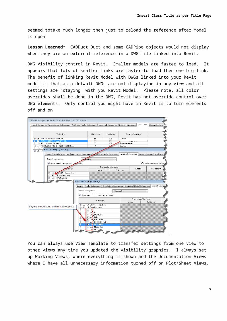
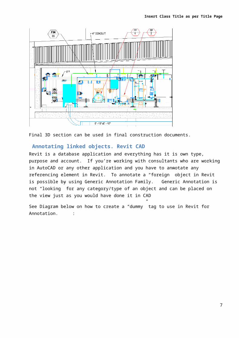
DocumentationAnother challenge working with linked DWG is that Revit will not know how to extend the view because it “sees” DWG as ONE big object and if you cut the section linked dwg objects will display unreadable. I found a work around for this issue. I used 3D view as my section view and now in 2012 you can also place all your annotation in the locked 3D view.
First, create a section and then create a 3D view and Orient the View to the section. (Refer to Virtual portion of the class for presentation)
7
Insert Class Title as per Title Page
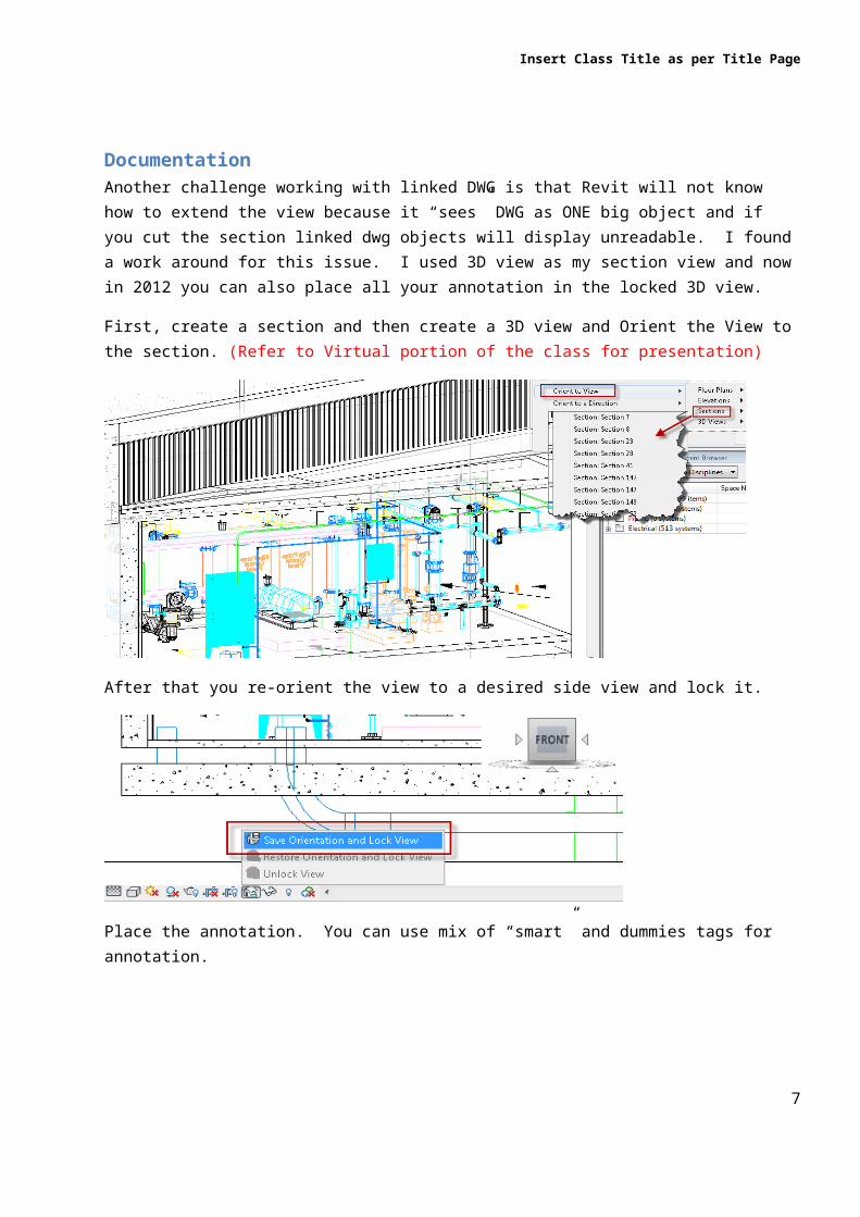
After that you re-orient the view to a desired side view and lock it.
Place the annotation. You can use mix of “smart” and dummies tags for annotation.
Final 3D section can be used in final construction documents.
7
Insert Class Title as per Title Page
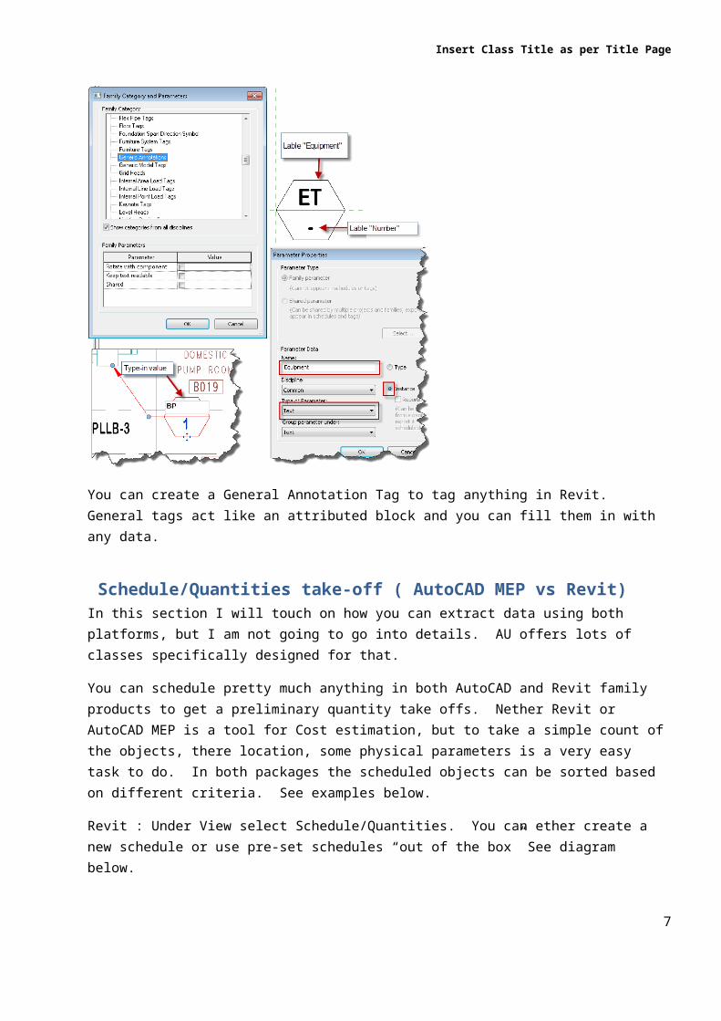
Annotating linked objects. Revit CADRevit is a database application and everything has it is own type, purpose and account. If you’re working with consultants who are working in AutoCAD or any other application and you have to annotate any referencing element in Revit. To annotate a “foreign” object in Revit is possible by using Generic Annotation Family. Generic Annotation is not “looking” for any category/type of an object and can be placed on the view just as you would have done it in CAD
See Diagram below on how to create a “dummy” tag to use in Revit for Annotation. :
You can create a General Annotation Tag to tag anything in Revit. General tags act like an attributed block and you can fill them in with any data.
Schedule/Quantities take-off ( AutoCAD MEP vs Revit)In this section I will touch on how you can extract data using both platforms, but I am not going to go into details. AU offers lots of classes specifically designed for that.
You can schedule pretty much anything in both AutoCAD and Revit family products to get a preliminary quantity take offs. Nether Revit or AutoCAD MEP is a tool for Cost estimation, but to take a simple count of the objects, there location, some physical parameters is a very easy task to do. In both packages the scheduled objects can be sorted based on different criteria. See examples below.
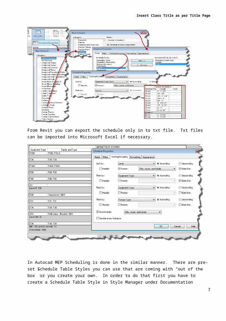
Revit : Under View select Schedule/Quantities. You can ether create a new schedule or use pre-set schedules “out of the box” See diagram below.
7
Insert Class Title as per Title Page
From Revit you can export the schedule only in to txt file. Txt files can be imported into Microsoft Excel if necessary.
In Autocad MEP Scheduling is done in the similar manner. There are pre-set Schedule Table Styles you can use that are coming with “out of the box” or you create your own. In order to do that first you have to create a Schedule Table Style in Style Manager under Documentation
7
Insert Class Title as per Title Page
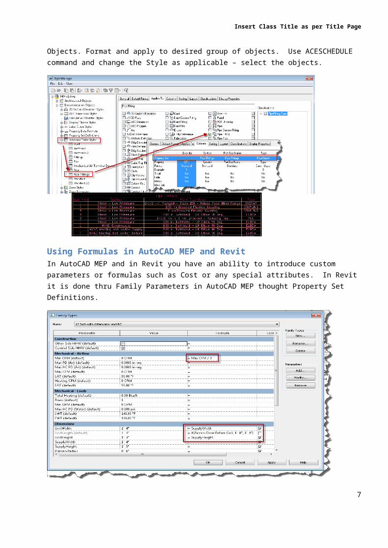
Objects. Format and apply to desired group of objects. Use ACESCHEDULE command and change the Style as applicable – select the objects.
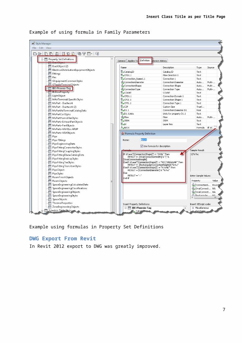
Using Formulas in AutoCAD MEP and RevitIn AutoCAD MEP and in Revit you have an ability to introduce custom parameters or formulas such as Cost or any special attributes. In Revit it is done thru Family Parameters in AutoCAD MEP thought Property Set Definitions.
Example of using formula in Family Parameters
7
Insert Class Title as per Title Page
Example using formulas in Property Set Definitions
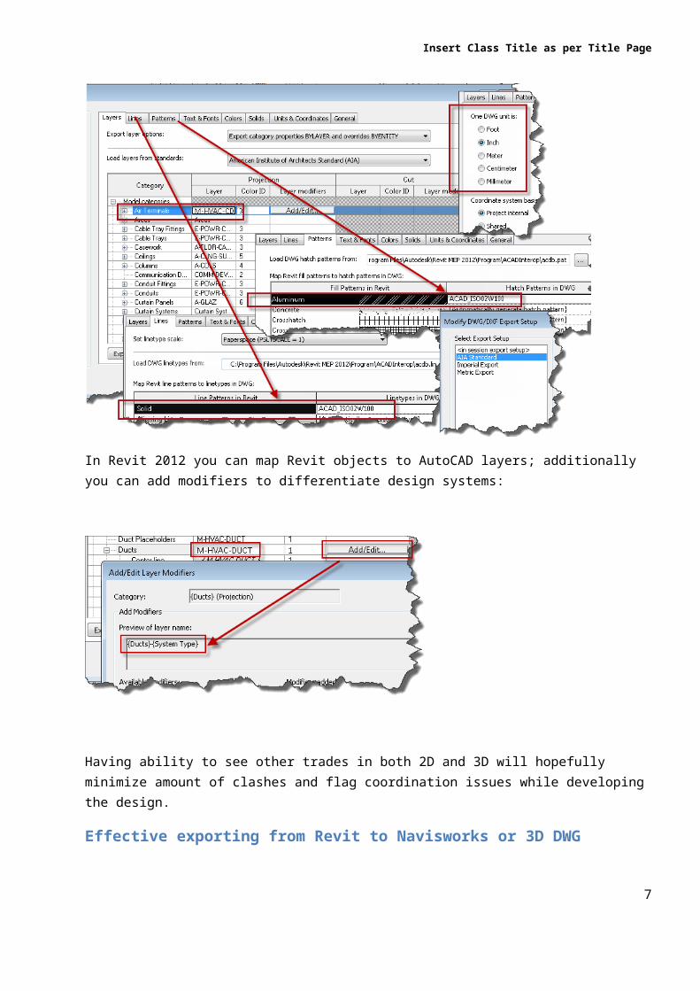
DWG Export From Revit In Revit 2012 export to DWG was greatly improved.
7
Insert Class Title as per Title Page
In Revit 2012 you can map Revit objects to AutoCAD layers; additionally you can add modifiers to differentiate design systems:
Having ability to see other trades in both 2D and 3D will hopefully minimize amount of clashes and flag coordination issues while developing the design.
Effective exporting from Revit to Navisworks or 3D DWG
To effectively export form Revit, you can pre-set export views. The views can be floor/discipline based or floor/sub-discipline based; or overall model of some elements. As an example, I set up views for one floor HVAC Dry side, HVAC Pipes, Lights, Diffusers, Mechanical Equipment, Cable Trays and so on. In Navisworks I can set up clashes for one floor to clash Diffusers with Light
7
Insert Class Title as per Title Page
Fixtures, or I can clash Diffusers+HVAC Dry+HVAC Pipes with Cable Tray. You can use the views to export to both Navisworks and 3D DWG. Please note top and bottom limits of the Section Box should be floor finish to floor finish
You can also use Navisworks to break the model into even smaller groups for clash test such a Ducts, Pipes Walls.
Refer to Virtual portion of the class for presentation
In Navisworks try to use Search Sets instead of file vs. file for clash detection. Search Sets are group of elements qualifying a certain criteria.
7
Insert Class Title as per Title Page
Example creating a search sets.
7
Insert Class Title as per Title Page
You can group element involved in the clash.
Example using Search Sets for Clash
Example: Grouping Clashes involving the same element
Now your model is set up and you are ready to work
Tips on Effective Clash DetectionPrepare for the clash detection meeting. Otherwise before you know it you will lose your audience as they will be looking at the same thing over and over again.
Break the clashes into sizable groups.
Group the clashes involving the same element.
Create Clash Sets to re-run clashes after updating your components.
Keep log of clashes for the meeting as “must resolve”.
Use grid lines (possible to move up/down).
Create multiple files for clash detection – per floor – no need to deal with sectioning.
For big projects plan on how to partition them.
Re-use already set up views to export to Navisworks.
7