Embed Size (px)
Citation preview
PSU HelpichairA project by Tony Muilenburg, Dawson Green, & Luis Santiago
Instructor: Marek PerkowskiFinal Project SummaryRobotics - ECE 478/578
Fall term 2014
Table of Contents1 – Project Summary....................................................................................................................................................2
1.1 – Prior Work.......................................................................................................................................................2
1.2 – Initial design....................................................................................................................................................2
1.3 – Status of Desired Objectives at Project Conclusion.........................................................................................3
1.4 – Future improvements for the helpiarm..........................................................................................................3
2 – Implemented Hardware.........................................................................................................................................4
2.1 – Electric Wheelchair System.............................................................................................................................4
2.2 – Helpiarm Feeding System...............................................................................................................................4
2.2.1 – Z-Axis Pulley System................................................................................................................................5
2.2.2 – X- & Y-axis Track Motors..........................................................................................................................5
2.2.3 – Spoon Servo Control................................................................................................................................6
2.2.4 – Torque Calculations.................................................................................................................................6
3 – Arduino Firmware for Servo Control – Design and Usage......................................................................................7
4 – Computer Vision Software – Design and Usage.....................................................................................................7
4.1 – Computer vision pseudo code........................................................................................................................9
5 – User Control Software – Design and Usage..........................................................................................................10
5.1 – General Object Flowchart.............................................................................................................................10
5.1.1 – definitions.h...........................................................................................................................................10
5.1.2 – HelpiUI...................................................................................................................................................10
5.1.3 – PortManager.........................................................................................................................................11
5.1.4 – FuzzyCalc...............................................................................................................................................11
6 – Fuzzy Logic...........................................................................................................................................................12
7 – Kinematics............................................................................................................................................................13
8 – Timeline of Project Development and Challenges Encountered..........................................................................13
8.1 – Construction of the Helpiarm........................................................................................................................14
8.2 – Software Controls.........................................................................................................................................14
8.3 – Vision Software.............................................................................................................................................15
9 – Final Remarks and Future Work...........................................................................................................................15
Appendix A – Links to project Materials.....................................................................................................................16
Appendix B – Team Member Contributions...............................................................................................................16
Appendix C – Threshold values used for the objects tracked.....................................................................................18
Appendix D – Hardware technical information..........................................................................................................19
Appendix E – Cost......................................................................................................................................................19
1 | P a g e
Appendix F – Wheelchair Movement Control............................................................................................................20
1 – Project SummaryThe evolution of assistive technologies for medical patients and less abled individuals is a critical area of research due to its opportunity to significantly improve the quality of life of the end users of these products. The Helpichair project is intended to continue development on a previous student’s design of robotics-based solutions to the complex tasks of tactile manipulation and autonomous wheelchair navigation. Currently, development on the Helpichair is focused on designing, implementing and powering an OpenCV backed computer vision system (dubbed “Helpivision”) to control a custom designed Cartesian arm rig (dubbed the “Helpiarm”) to spoon-feed the current chair’s occupant. Additional groundwork has been laid to use the Helpivision to assist with automated wheelchair navigation, but this feature was not prioritized for completion by the end of this term. The following sections provide a record for the development process behind the hardware on this device.
1.1 – Prior WorkThe Helpichair was initially based upon a design that used a Rhino Robotics XR-3 Rhino Robotic Arm to assist a wheelchair bound individual with manipulating the environment around them. This arm was intended to be mounted onto a surplus manual wheelchair obtained by Dr. Marek Perkowski for use in projects by his students. While the Rhino arm offered numerous degrees of freedom to the designers, it suffered from two key drawbacks: massive weight and a lack of absolute precision. Additionally, previous teams’ attempts to mount it to the side of this chair ran into numerous problems. Furthermore, the arm had no method of reporting how far it was extended in any of its degrees of freedom. While prior teams had put a significant amount of work into this direction of development, it was determined that a new approach would be necessary in order to achieve our project goal of feeding a wheelchair occupant with robotic assistance.
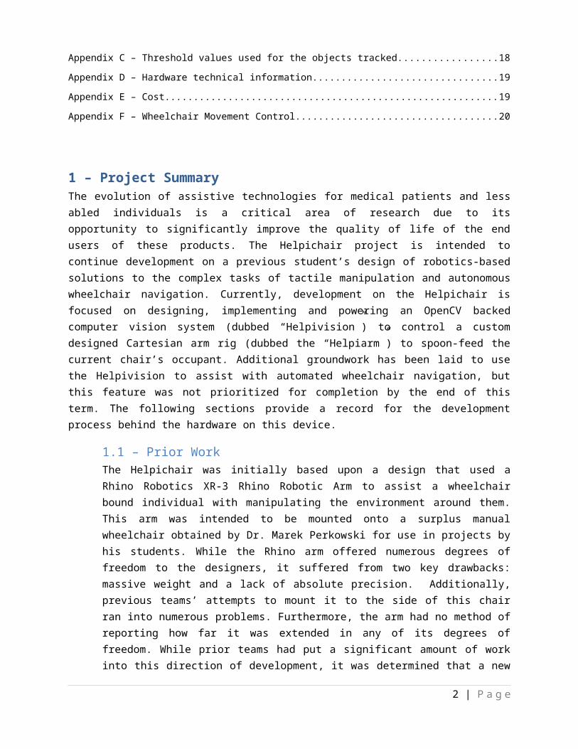
1.2 – Initial designUtilizing work done by previous teams as a starting point, we have designed and implemented a brand new robotic feeding arm system. The main areas of improvement were made possible by finding a more capable wheelchair and designing a replacement for the Rhino arm. Regarding the wheelchair, the general shape and design of the existing chair meant that fittings for mounting attachments would be difficult to design and implement. Issues observed with the Rhino arm were detailed above. Fortunately, Dr. Douglas Hall was able to donate a superior electric wheelchair that he had available from previous student projects. The fact that the new unit has an onboard battery meant that all necessary attachments could tap into this power supply and free us from having to design an additional power supply. To address patient
2 | P a g e
Figure 1: Cartesian Arm Concept
feeding, it was also determined that we would attempt to implement a Cartesian arm as opposed to a more human inspired appendage. While a humanoid arm would offer greater flexibility in overall applications, the Cartesian system offered greatly simplified kinematic computations. Lastly, monitoring of the arm’s position would be handled by a simple AI processing data from a webcam and an OpenCV program. The initial concept design (not including the cameras is shown in Figure 1.
1.3 – Status of Desired Objectives at Project ConclusionWe were able to realize the majority of our design goals by the end of the term. Below is the status of the project’s goals by the project’s due date:
1) Construction of Cartesian Helpiarm.................................................................COMPLETED2) Integration of Helpiarm with Wheelchair........................................................COMPLETED3) Implementation of Controllers for all Servos and Motors...............................COMPLETED4) OpenCV Target Identification System..............................................................COMPLETED5) Camera Vision System.....................................................................................COMPLETED6) Graphical User Interface Control System
a. Interface for Controllers and Vision System..............................................COMPLETEDb. Self-Diagnostic and Motor Test.................................................................COMPLETEDc. Manual Control of All Axes of Motion.......................................................COMPLETEDd. Automated Patient Feeding System..........................................................COMPLETEDe. Fuzzy Logic Motion Control System...........................................................COMPLETED
7) Kinematic diagram and calculations................................................................COMPLETED8) 3D drawing.......................................................................................................COMPLETED
1.4 – Future improvements for the helpiarmMany large and small improvements were considered as the project progressed. Some initial research, proof of concept, and even design was completed each of these ideas. Below is a list of items that could be added, along with a rough estimate of the amount of time that would be required:
1) Compare the fuzzy motor control to that of an IGA learned flow .........................15 hours2) Add dynamic color and light calibration to the OpenCV program.........................10 hours3) Add a second camera to track y axis movement rather than just move 6”.............5 hours4) Build a solid removable tray..................................................................................10 hours5) Work with an actual disabled person, tune the arm for use................................30+ hours6) Mount camera(s) so they move with the chair......................................................10 hours7) Merge the vision and GUI code into one app, create and installer package..........15 hours8) Build a more stable arm.........................................................................................20 hours9) Add speech recognition, synthesis commands to control all motors.....................30 hours10) Track head, real lips, and a spoon that is not bright green ...................................30 hours11) Enable wheelchair movement (wheel control) .....................................................20 hours12) Wheelchair navigation using Kinect ....................................................................40+ hours13) Add another motor so that the arm can be rotated out of the way .....................10 hours14) Improve the casing, controller access, and wiring ................................................10 hours
3 | P a g e
2 – Implemented HardwareThe Helpichair system is made up of numerous sub-components. The wheelchair itself was leftover from a previous project and donated by Dr. Douglas Hall. The Helpiarm was constructed over the course of the term from an assortment of parts, most of which were obtained from either the robotics lab or Home Depot™. A more detailed description of each is provided below.
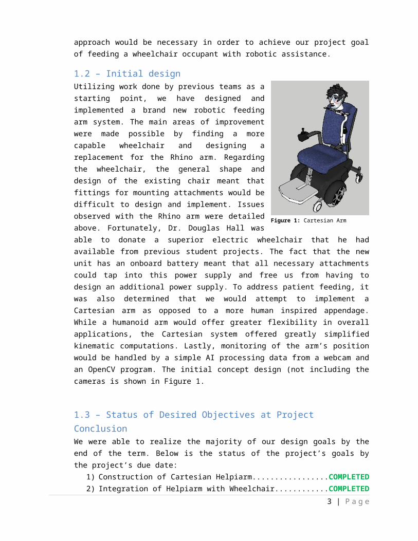
2.1 – Electric Wheelchair SystemWe used a Pride Mobility Jazzy 1121 Powered Wheelchair (figure 2). It is powered by two 12-volt, 35 Ah Werker Deep Cycle Batteries. The Helpiarm is mounted on the left side of the wheelchair, while the controller unit on the right side has been disassembled to analyze the control signals needed for the computer vision assisted driving described in section 2.3. One of the goals for the end of the term was to have the motor controllers and vision system connected to the wheelchair’s onboard battery for fully self-contained power. We accomplish this by connecting the Arduino and the motor controller to directly to one of the two 12V batteries and also connected a 7805 voltage regulator to provide up to 1 Amp at 5 V power for all 3 servos.
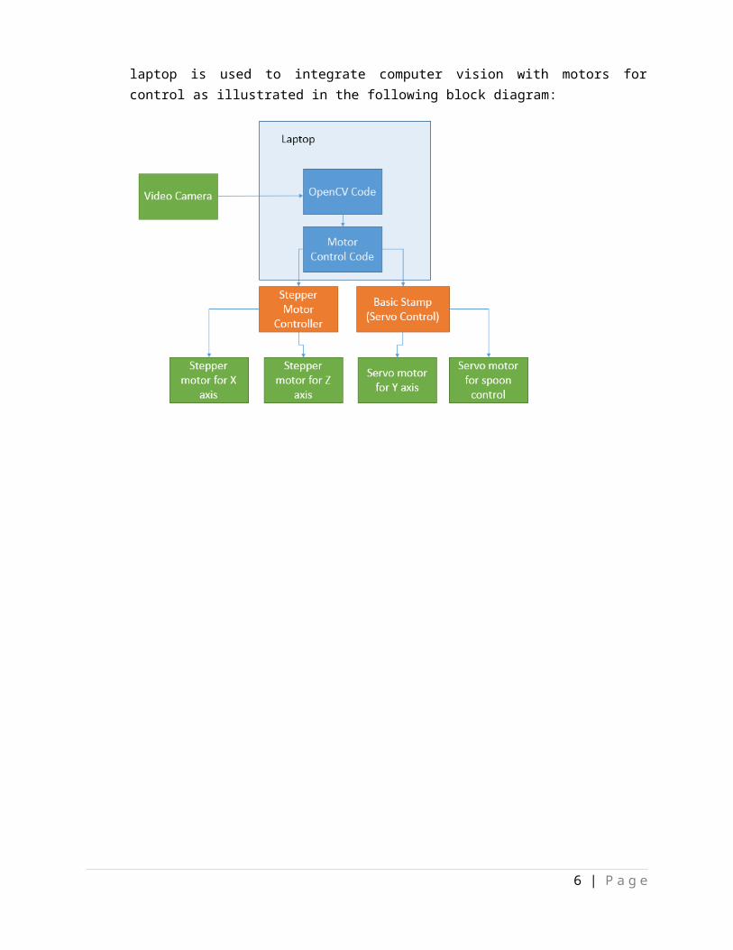
2.2 – Helpiarm Feeding SystemThe Helpiarm is a system assembled from available parts and driven by a set of stepper motors and servo controllers. The unit is mounted on the left side of the wheelchair and is attached the chair by repurposing the socket for the chair’s left arm brace. A laptop is used to integrate computer vision with motors for control as illustrated in the following block diagram:
4 | P a g e
Figure 2: Jazzy 1121 Wheelchair
5 | P a g e
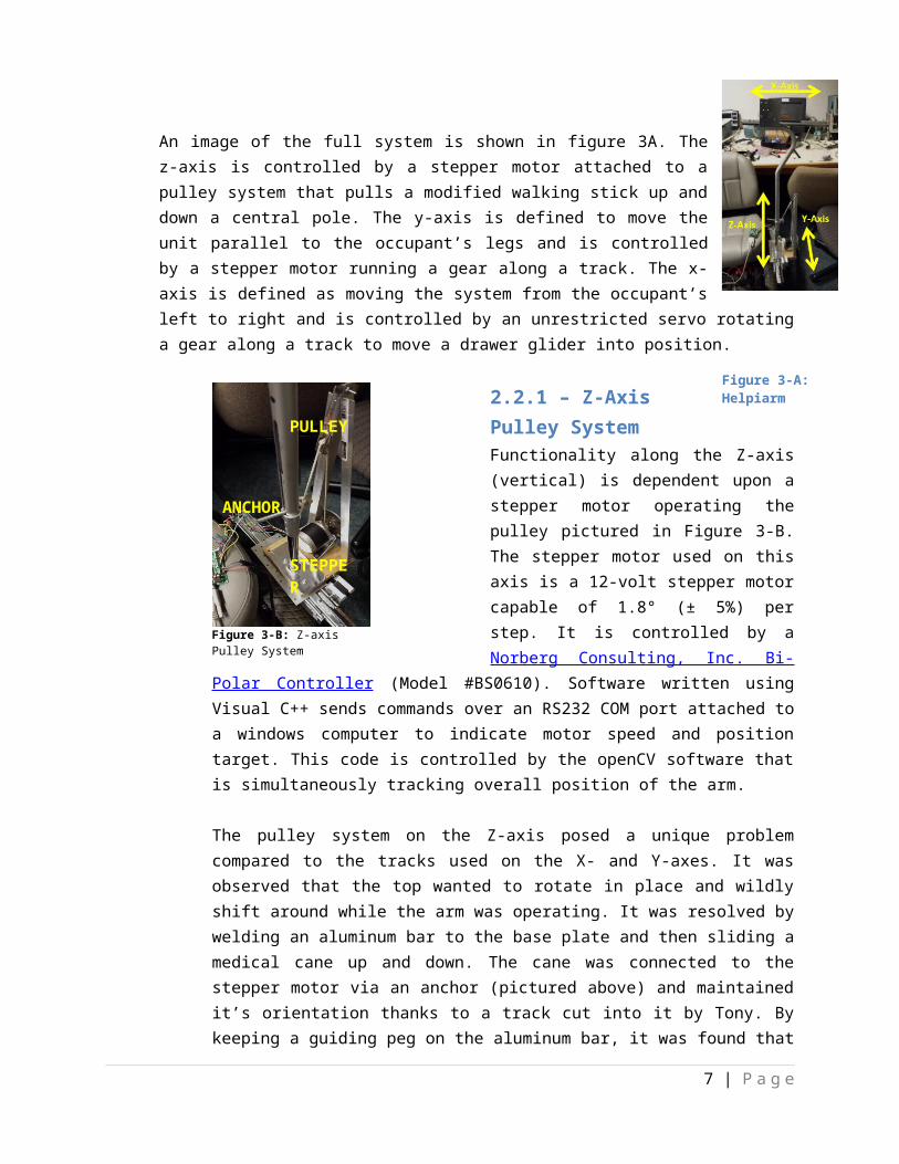
An image of the full system is shown in figure 3A. The z-axis is controlled by a stepper motor attached to a pulley system that pulls a modified walking stick up and down a central pole. The y-axis is defined to move the unit parallel to the occupant’s legs and is controlled by a stepper motor running a gear along a track. The x-axis is defined as moving the system from the occupant’s left to right and is controlled by an unrestricted servo rotating a gear along a track to move a drawer glider into position.
2.2.1 – Z-Axis Pulley SystemFunctionality along the Z-axis (vertical) is dependent upon a stepper motor operating the pulley pictured in Figure 3-B. The stepper motor used on this axis is a 12-volt stepper motor capable of 1.8° (± 5%) per step. It is controlled by a Norberg Consulting, Inc. Bi-Polar Controller (Model #BS0610). Software written using Visual C++ sends commands over an RS232 COM port attached to a windows computer to indicate motor speed
and position target. This code is controlled by the openCV software that is simultaneously tracking overall position of the arm.
The pulley system on the Z-axis posed a unique problem compared to the tracks used on the X- and Y-axes. It was observed that the top wanted to rotate in place and wildly shift around while the arm was operating. It was resolved by welding an aluminum bar to the base plate and then sliding a medical cane up and down. The cane was connected to the stepper motor via an anchor (pictured above) and maintained it’s orientation thanks to a track cut into it by Tony. By keeping a guiding peg on the aluminum bar, it was found that smooth motion could be achieved if the anchor was very carefully aligned. While this solution works, it could be improved by using readily available linear actuators that are more costly, but slide more easily.
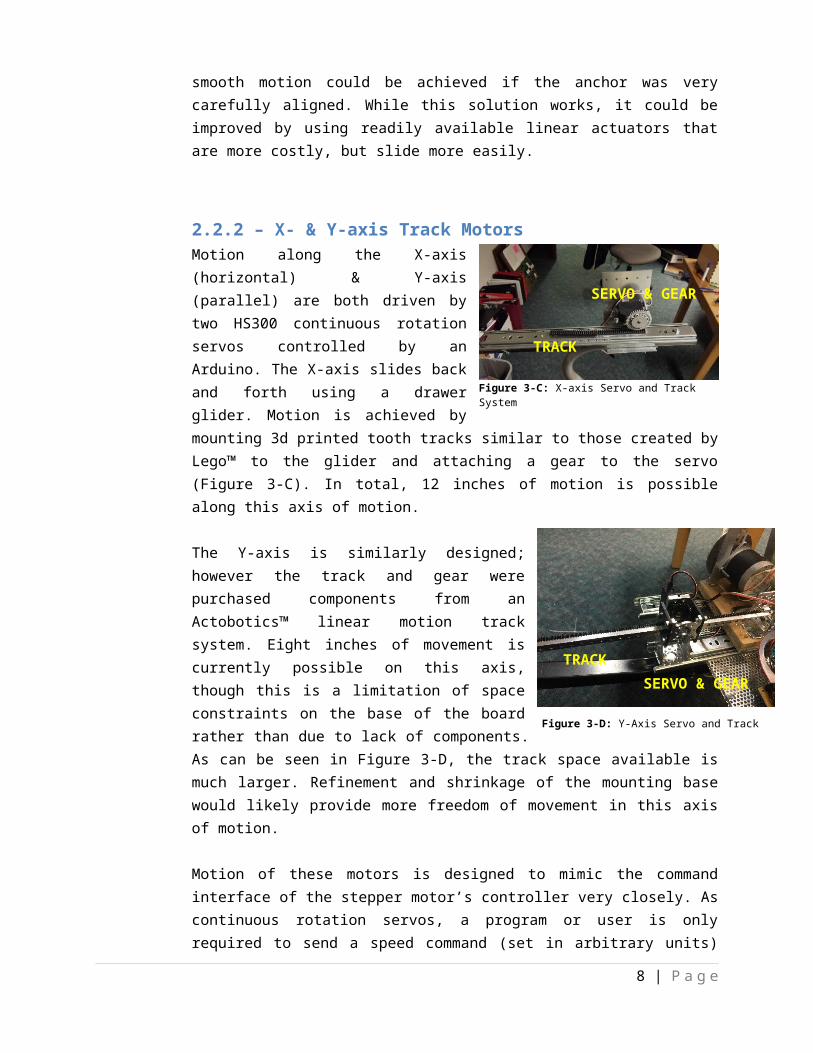
2.2.2 – X- & Y-axis Track MotorsMotion along the X-axis (horizontal) & Y-axis (parallel) are both driven by two HS300 continuous rotation servos controlled by an Arduino. The X-axis slides back and forth using a drawer glider. Motion is achieved by
6 | P a g e
Figure 3-B: Z-axis Pulley System
STEPPER
ANCHOR
PULLEY
TRACK
SERVO & GEAR
Figure 3-C: X-axis Servo and Track System
Figure 3-A: Helpiarm
mounting 3d printed tooth tracks similar to those created by Lego™ to the glider and attaching a gear to the servo (Figure 3-C). In total, 12 inches of motion is possible along this axis of motion.
The Y-axis is similarly designed; however the track and gear were purchased components from an Actobotics™ linear motion track system. Eight inches of movement is currently possible on this axis, though this is a limitation of space constraints on the base of the board rather than due to lack of components. As can be seen in Figure 3-D, the track space available is much larger. Refinement and shrinkage of the mounting base would likely provide more freedom of movement in this axis of motion.
Motion of these motors is designed to mimic the command interface of the stepper motor’s controller very closely. As continuous rotation servos, a program or user is only required to send a speed command (set in arbitrary units) that causes the motor to turn. Once told to start turning, the motor will continue to spin until it loses power or is told to stop. The main system is not required to continuously spam commands to the motor in order to achieve a desired effect and motion is much more fluid in space. Stop pins are used to ensure the gears never leave the tracks.
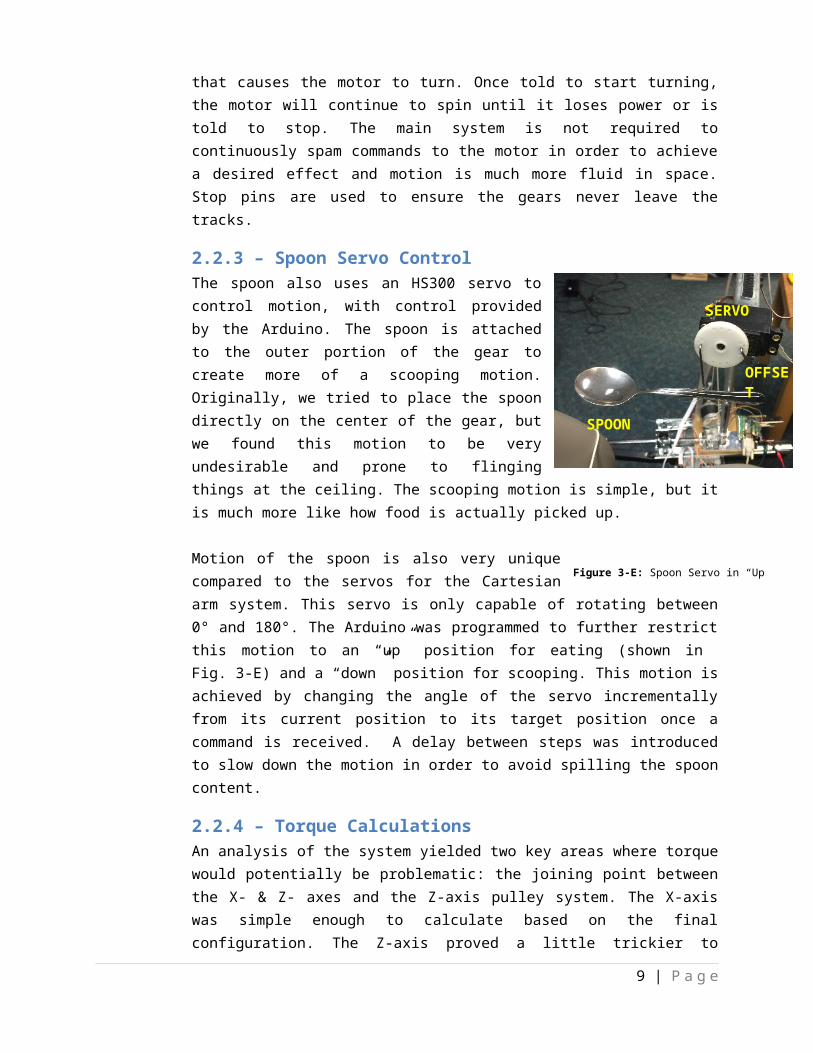
2.2.3 – Spoon Servo ControlThe spoon also uses an HS300 servo to control motion, with control provided by the Arduino. The spoon is attached to the outer portion of the gear to create more of a scooping motion. Originally, we tried to place the spoon directly on the center of the gear, but we found this motion to be very undesirable and prone to flinging things at the ceiling. The scooping motion is simple, but it is much more like how food is actually picked up.
Motion of the spoon is also very unique compared to the servos for the Cartesian arm system. This servo is only capable of rotating between 0° and 180°. The Arduino was programmed to further restrict this motion to an “up” position for eating (shown in Fig. 3-E) and a “down” position for scooping. This motion is achieved by changing the angle of the servo incrementally from its current position to its target position once a command is received. A delay between steps was introduced to slow down the motion in order to avoid spilling the spoon content.
7 | P a g e
Figure 3-D: Y-Axis Servo and Track System
SERVO & GEAR
TRACK
Figure 3-E: Spoon Servo in “Up” Position
SERVO
SPOON
OFFSET
2.2.4 – Torque CalculationsAn analysis of the system yielded two key areas where torque would potentially be problematic: the joining point between the X- & Z- axes and the Z-axis pulley system. The X-axis was simple enough to calculate based on the final configuration. The Z-axis proved a little trickier to analyze as we realized that the torque would change depending on how much of the rope was wrapped around the stepper motor. Therefore, we have calculated only the minimum and maximum torques below.
3 – Arduino Firmware for Servo Control – Design and UsageWe wanted all the computations be handled by the computer and the motors to be controlled by a separate system. The Fuzzy control described in section 5.1.4 sends commands to control the speed of the servos. Using the serial port, the control program sends data to the Arduino using the format of a letter followed by a number (i.e. x100). The Arduino then monitors the serial port for data and once data is present will read the first character (letter) and using a switch stamen will compare if matches the value assigned to one of the servos, if it does it will extract the number that follows and send that instruction to the appropriate servo. Below is a small portion of code that describes this behavior.
while(true) { // Loop and check if serial buffer has something if (Serial.available() > 0) { // read first byte on serial and store it int inByte = Serial.read(); // Check if it is one the defined cases switch (inByte) { case 'x': // Valid case, wait for an int and store it in pos pos = Serial.parseInt(); // provides feedback for debug if needed #ifndef Silent Serial.print("Servo X="); Serial.println(pos); #endif /* Silent */ //Sends instruction to servo xservo.write(pos); break; } }}
8 | P a g e
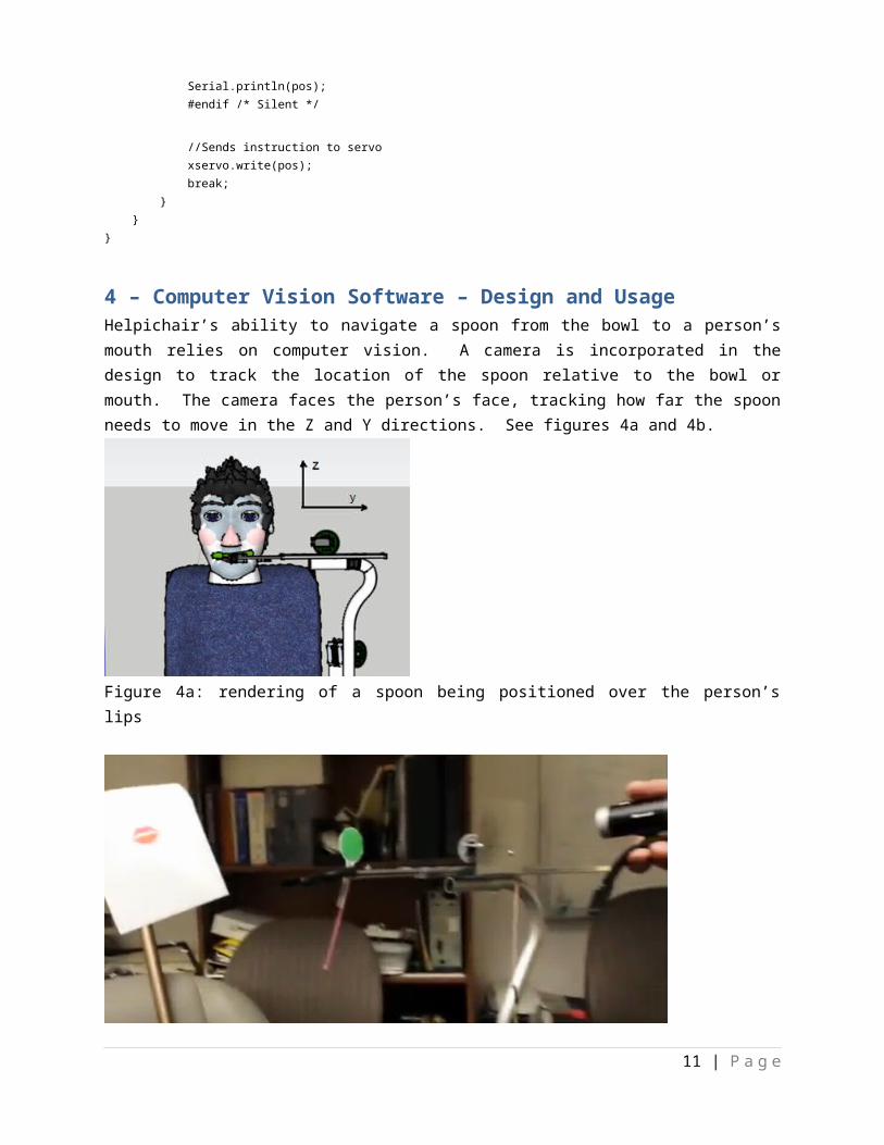
4 – Computer Vision Software – Design and UsageHelpichair’s ability to navigate a spoon from the bowl to a person’s mouth relies on computer vision. A camera is incorporated in the design to track the location of the spoon relative to the bowl or mouth. The camera faces the person’s face, tracking how far the spoon needs to move in the Z and Y directions. See figures 4a and 4b.
Figure 4a: rendering of a spoon being positioned over the person’s lips
Figure 4b: initial tracking using simple red lips and a green spoon
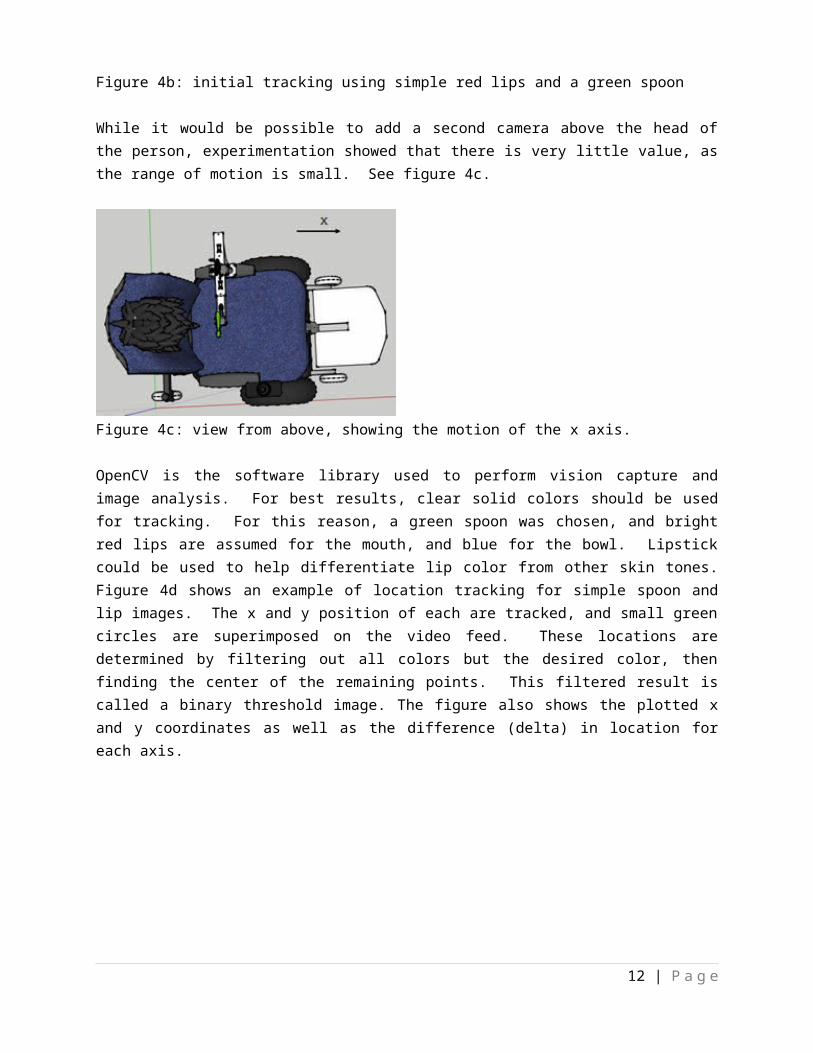
While it would be possible to add a second camera above the head of the person, experimentation showed that there is very little value, as the range of motion is small. See figure 4c.
9 | P a g e
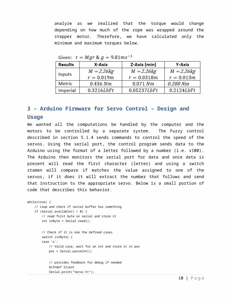
Figure 4c: view from above, showing the motion of the x axis.
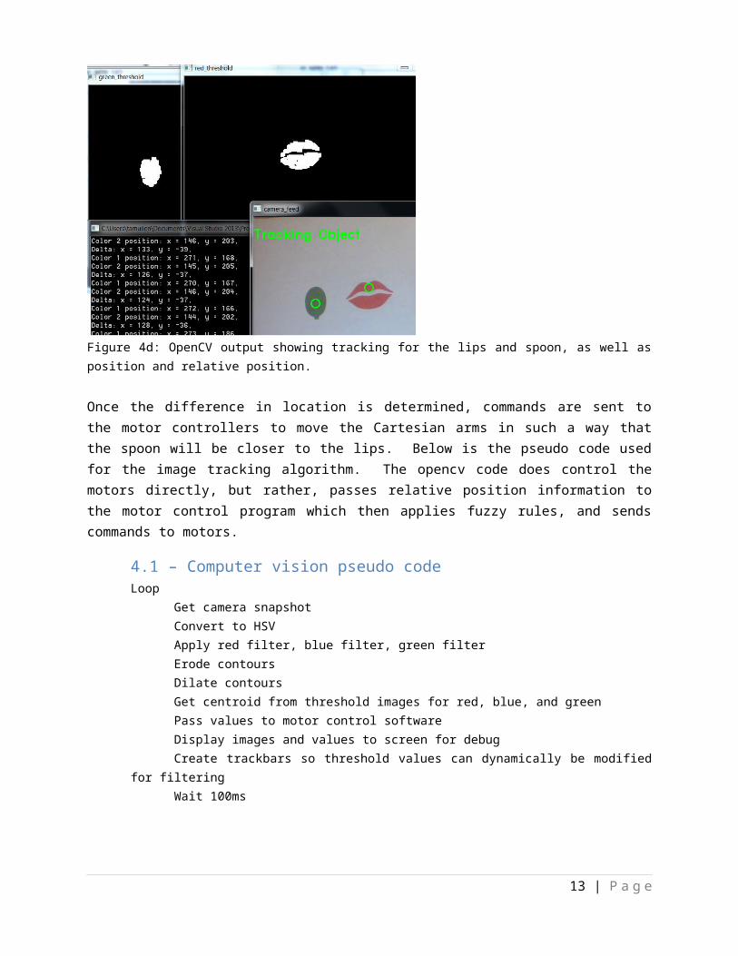
OpenCV is the software library used to perform vision capture and image analysis. For best results, clear solid colors should be used for tracking. For this reason, a green spoon was chosen, and bright red lips are assumed for the mouth, and blue for the bowl. Lipstick could be used to help differentiate lip color from other skin tones. Figure 4d shows an example of location tracking for simple spoon and lip images. The x and y position of each are tracked, and small green circles are superimposed on the video feed. These locations are determined by filtering out all colors but the desired color, then finding the center of the remaining points. This filtered result is called a binary threshold image. The figure also shows the plotted x and y coordinates as well as the difference (delta) in location for each axis.
Figure 4d: OpenCV output showing tracking for the lips and spoon, as well as position and relative position.
Once the difference in location is determined, commands are sent to the motor controllers to move the Cartesian arms in such a way that the spoon will be closer to the lips. Below is the pseudo code used for the image tracking algorithm. The opencv code does control the motors directly, but rather, passes relative position information to the motor control program which then applies fuzzy rules, and sends commands to motors.
10 | P a g e
4.1 – Computer vision pseudo codeLoop
Get camera snapshotConvert to HSVApply red filter, blue filter, green filterErode contoursDilate contoursGet centroid from threshold images for red, blue, and greenPass values to motor control softwareDisplay images and values to screen for debugCreate trackbars so threshold values can dynamically be modified for filteringWait 100ms
5 – User Control Software – Design and UsageThe greatest difficulty in designing a user interface system for this project was a lack of background in toolsets that would allow for an intuitive system. It was determined that we should target a Windows system due to the better documentation of OpenCV on that OS. It was also agreed upon that development would be done with Microsoft Visual Studio C++ (2013 edition, v120). This required a lot of ramp up to use on the GUI side as C++ is not normally supposed to handle asynchronous events or garbage collection. Many tasks that seemed to make sense in C++ had to be altered in subtle fashions in order to make them work in Microsoft’s ecosystem. Some of these challenges are described below.
5.1 – General Object FlowchartOne advantage of C++ is the ability to inject object-oriented programming practices into the design process. One advantage of Visual C++ is that these objects are now capable of being managed by a garbage collector. In order to permit faster development and more reliable interfacing, the system was divided into multiple distinct objects. Most of the action takes place on the primary GUI object, but additional defined objects are still very critical to the overall success of the implementation.
5.1.1 – definitions.hWhile not an actual object, this file is critical to understanding how the system works overall. All included system header files are defined in this file, and this file is also included in all files used by the program (the “#pragma once” is recognized by the compiler to prevent redundant inclusion at compile time). Additionally, almost all the terms, IDs and resources used by this program are listed as a #define directive. Major changes to the system will inevitably require adjustments to this file.
5.1.2 – HelpiUIThis is the primary interface object. This object defines all UI screens, maintains ownership of the helper objects and analyzes the data from the OpenCV vision system. Most of the work is done by splitting off managed threads to permit the GUI to remain responsive. The self-test and automated feeding motion are both given their own
11 | P a g e
dedicated threads to run. A Boolean flag is used to signal if those threads need to abort early. One of the key difficulties in working with threads in this way is not only ensuring that all behaviors are thread safe, but also that the managed threads are created in a way that plays nicely with the garbage collector. Further, any modifications to the GUI by the threads requires special signaling and deferred actions, which is very counter-intuitive when compared to a normal C++ program.
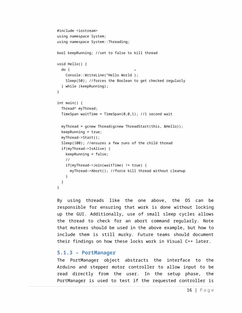
To create and use a thread in Visual C++, the following code can be used as a guideline:
12 | P a g e
#include <iostream>using namespace System;using namespace System::Threading;
bool keepRunning; //set to false to kill thread
void Hello() { do { Console::WriteLine(“Hello World”); Sleep(50); //forces the Boolean to get checked regularly } while (keepRunning);}
int main() { Thread^ myThread; TimeSpan waitTime = TimeSpan(0,0,1); //1 second wait myThread = gcnew Thread(gcnew ThreadStart(this, &Hello)); keepRunning = true; myThread->Start(); Sleep(100); //ensures a few runs of the child thread if(myThread->IsAlive) { keepRunning = false; // if(myThread->Join(waitTime) != true) { myThread->Abort(); //force kill thread without cleanup } }}
By using threads like the one above, the OS can be responsible for ensuring that work is done without locking up the GUI. Additionally, use of small sleep cycles allows the thread to check for an abort command regularly. Note that mutexes should be used in the above example, but how to include them is still murky. Future teams should document their findings on how these locks work in Visual C++ later.
5.1.3 – PortManagerThe PortManager object abstracts the interface to the Arduino and stepper motor controller to allow input to be read directly from the user. In the setup phase, the PortManager is used to test if the requested controller is present, then report back results. Then, when actually manipulating the arm, the manager takes in arbitrary speeds and converts them to values that are actually meaningful to either the servo or stepper motor. This abstraction is key to the modularity of the system as a whole.
5.1.4 – FuzzyCalcThis object manages the conversion of OpenCV distance data to speed calculations for the servo and stepper motor. Four regions are defined: stop, slow, medium, and fast speeds. Medium is the most complicated, as it is defined by partial membership in the
13 | P a g e
slow and fast groups. There is no partial membership space between stop and slow. The system is designed to permit maximum flexibility for a user by making all major defining variables public. This was done to provide opportunity for a genetic algorithm to design an optimal set of thresholds for movement speeds, but this testing was not able to be completed before the end of the term. It is strongly urged that future group take up this testing in order to better calibrate the Helpiarm.
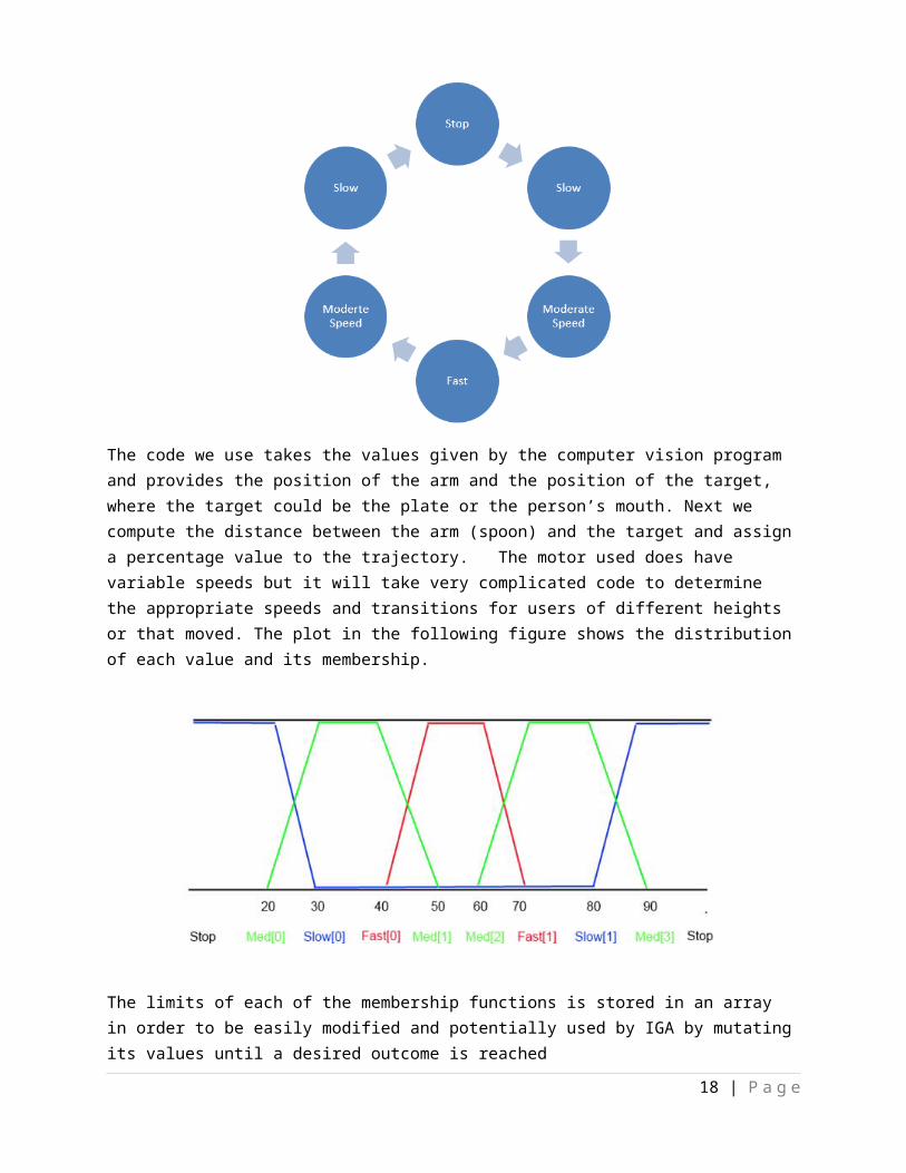
6 – Fuzzy LogicCurrently computer vision software determines the movement and direction taken. Motors and servos operated with binary logic is not ideal because the on and off instructions are not sufficient to provide a smooth operation. Feeding and navigation should have a smooth movement not only for comfort but also for safety. Additional code added to the computer vision using fuzzy logic is added. The behavior described in in the following figure is used to model the code behavior. Modeled by human like actions when eating get the food and stop for an instant to fill the spoon then slowly increase speed gradually until you reach are close to the mouth. When the food is near the mouth a similar process begins where you slow down until you reach the mouth.
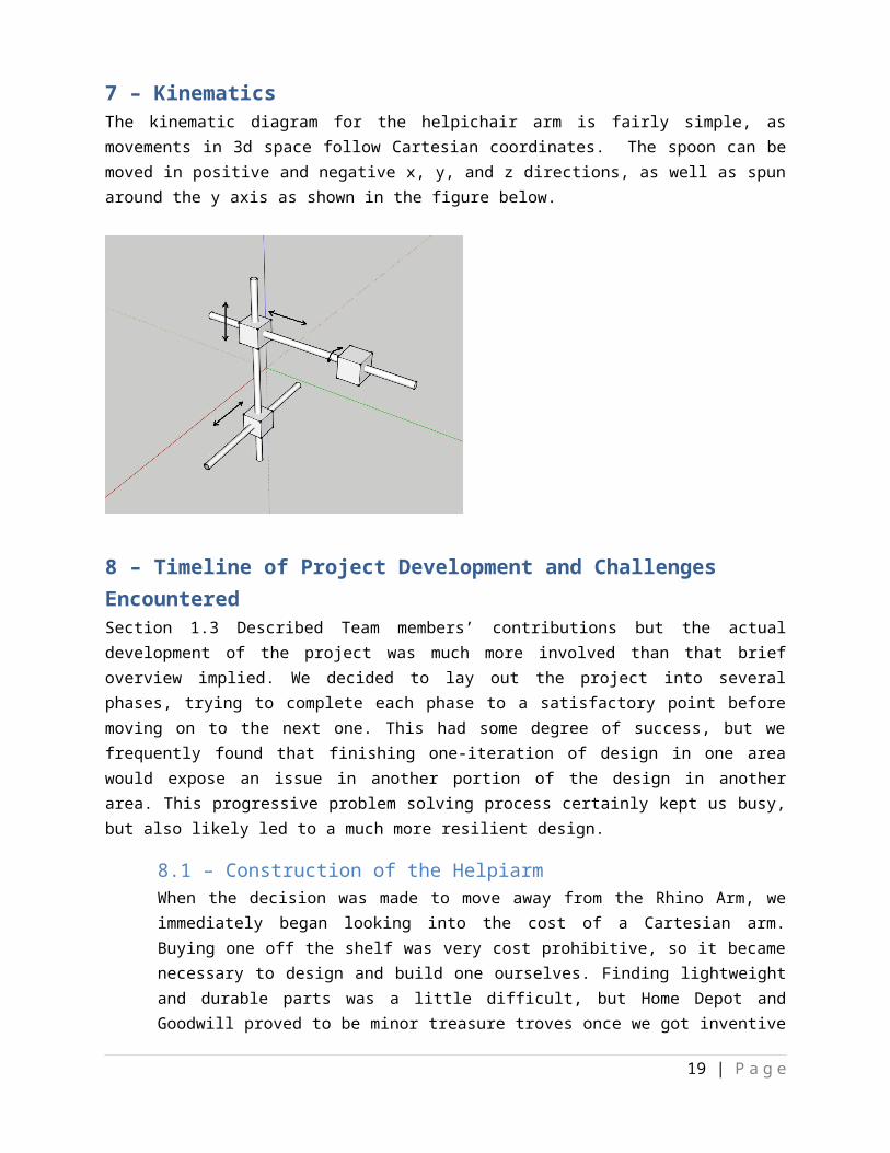
The code we use takes the values given by the computer vision program and provides the position of the arm and the position of the target, where the target could be the plate or the person’s mouth. Next we compute the distance between the arm (spoon) and the target and assign a percentage value to the trajectory. The motor used does have variable speeds but it will take very complicated code to determine the appropriate speeds and transitions for users of different heights or that moved. The plot in the following figure shows the distribution of each value and its membership.
14 | P a g e
The limits of each of the membership functions is stored in an array in order to be easily modified and potentially used by IGA by mutating its values until a desired outcome is reached
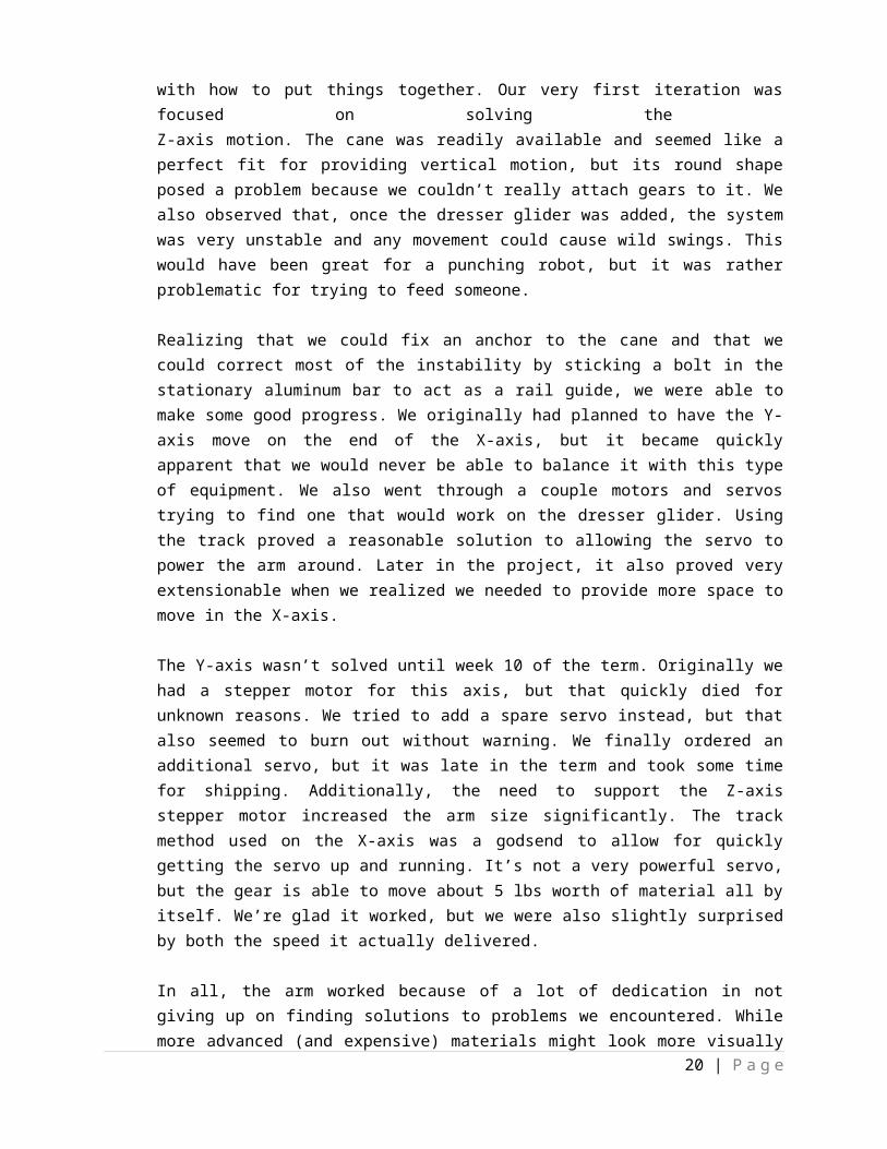
7 – KinematicsThe kinematic diagram for the helpichair arm is fairly simple, as movements in 3d space follow Cartesian coordinates. The spoon can be moved in positive and negative x, y, and z directions, as well as spun around the y axis as shown in the figure below.
8 – Timeline of Project Development and Challenges EncounteredSection 1.3 Described Team members’ contributions but the actual development of the project was much more involved than that brief overview implied. We decided to lay out the project into several phases, trying to complete each phase to a satisfactory point before moving on to the next one. This had some degree of success, but we frequently found that finishing one-iteration of design in one area would expose an issue in another portion of the design in another area. This progressive problem solving process certainly kept us busy, but also likely led to a much more resilient design.
15 | P a g e
8.1 – Construction of the HelpiarmWhen the decision was made to move away from the Rhino Arm, we immediately began looking into the cost of a Cartesian arm. Buying one off the shelf was very cost prohibitive, so it became necessary to design and build one ourselves. Finding lightweight and durable parts was a little difficult, but Home Depot and Goodwill proved to be minor treasure troves once we got inventive with how to put things together. Our very first iteration was focused on solving the Z-axis motion. The cane was readily available and seemed like a perfect fit for providing vertical motion, but its round shape posed a problem because we couldn’t really attach gears to it. We also observed that, once the dresser glider was added, the system was very unstable and any movement could cause wild swings. This would have been great for a punching robot, but it was rather problematic for trying to feed someone.
Realizing that we could fix an anchor to the cane and that we could correct most of the instability by sticking a bolt in the stationary aluminum bar to act as a rail guide, we were able to make some good progress. We originally had planned to have the Y-axis move on the end of the X-axis, but it became quickly apparent that we would never be able to balance it with this type of equipment. We also went through a couple motors and servos trying to find one that would work on the dresser glider. Using the track proved a reasonable solution to allowing the servo to power the arm around. Later in the project, it also proved very extensionable when we realized we needed to provide more space to move in the X-axis.
The Y-axis wasn’t solved until week 10 of the term. Originally we had a stepper motor for this axis, but that quickly died for unknown reasons. We tried to add a spare servo instead, but that also seemed to burn out without warning. We finally ordered an additional servo, but it was late in the term and took some time for shipping. Additionally, the need to support the Z-axis stepper motor increased the arm size significantly. The track method used on the X-axis was a godsend to allow for quickly getting the servo up and running. It’s not a very powerful servo, but the gear is able to move about 5 lbs worth of material all by itself. We’re glad it worked, but we were also slightly surprised by both the speed it actually delivered.
In all, the arm worked because of a lot of dedication in not giving up on finding solutions to problems we encountered. While more advanced (and expensive) materials might look more visually impressive, the fact remains that we were able to successfully design and build a robotic arm with equipment most people would find in their garage. We’re pretty proud of that.
8.2 – Software ControlsThe software was designed modularly so that the vision software would be separate from the user controls & motion logic. OpenCV quickly proved to be complicated enough on its own to require dedicated training of one team member, and our evolving requirements made the user interface software develop in capability over time. Work on software didn’t start until about week 3, and was limited to trying to replicate the ability to send commends over RS232 com ports. It was then upgraded to provide a reliable way to identify which ports were to be used. Once commands were successfully being sent, the manual control system was designed to
16 | P a g e
provide clear feedback of what needed fine tuning at the hardware level. The self-test was added and this version, capable of autonomous (though non-analytical) control was demoed to the class.
The software also drove some design decisions on how to control the servos. Originally, the servos were controlled via a BASIC stamp and moved in step increments. However, this caused a significant difference in how the system could communicate commands to the arm, so it was decided to implement an Arduino system that could control the servos similarly to how the stepper motor was controlled. At this point, the arm was now cleanly moving around in free space, but it still relied on a human to tell it what to do. In order to provide communication with the OpenCV software, a significant chunk of time was devoted to figuring out how to implement multithreaded software in Visual C++. This took about 2 weeks to iron out, but eventually it was able to establish a clear link to the OpenCV data, even though that code was being developed independently.
Final implementation of the feeding motion was actually fairly quick to develop after the previous trials. The reliable abstraction of how to interface with each servo/motor also permitted a fairly unified code structure to control desired motions. Debugging ended up proving the most complicated issue, particularly as there was occasionally some miscommunication on who was trying to fix which problem. Still, it eventually came together to provide the polished, documented approach that we desired.
8.3 – Vision SoftwareThe vision software was developed over the course of the entire term. Setting up Visual Studio and learning the OpenCV toolset was a significant part of Tony’s responsibilities for the term. Developing demos to present to the class proved a good learning tool, and allowed an iterative approach to determining what could be done, and then identifying what we wanted to do. We ended up trying five different cameras before we settled on a high definition Microsoft web camera with auto focus. Installing a second HD camera caused the drivers to glitch, but the issue was resolved before the end of the term.
Once the camera was reliably being controlled, then it was only necessary to provide the logic to gather data from it and write it to a location on the computer system. We did find out that lighting could produce very significant issues due to our approach of targeting colors. Identifying objects (like mouth/eyes/face) would have been more realistic, but leave this to another group to incorporate later. Presently, the camera has to be calibrated to each room it is used in, and must also be recalibrated if a different camera is used. Figuring out a robust way around this limitation would be an excellent project for future work.
9 – Final Remarks and Future WorkUltimately, this project was a great learning experience. While each of us on the team has worked with hardware and software before, combining them in this fashion was a real eye opener to how badly
17 | P a g e
things could go wrong and how great things were when they went right. We heartily encourage further development of this project, as there are many ways it could be refined or improved. Section 1.4 includes a list of additional improvements that could be made to the existing system.
We encourage future teams to be creative in picking up where we are leaving off with this project. A key element of our success here is that we were always striving to simply do what works (keep it simple). We wish the best of luck to the next team to upgrade this system and hope that you tackle this with zeal and energy.
Appendix A – Links to project MaterialsGoogle Drive with Code & Documentationhttps://drive.google.com/folderview?id=0B5K2cz_Vb8p1UHc0bUhMQnA4Sms&usp=sharing
Project Website with Video & OpenCV Tutorialshttp://smartwheelchair.themuilenburgs.com/
OpenCV for Windows Downloadhttp://sourceforge.net/projects/opencvlibrary/files/opencv-win/2.4.9/
Visual Studio 2013 MSDN for Visual C++http://msdn.microsoft.com/en-us/library/60k1461a.aspx
Arduino IDE, setup instructionshttp://arduino.cc/en/Main/Software
Appendix B – Team Member ContributionsThis project was only possible by significant collaboration amongst team members. Below is a list of how each team member contributed to each completed objective.
18 | P a g e
19 | P a g e
Appendix C – Threshold values used for the objects trackedBelow are the threshold values used for the objects tracked on the helpichair. Red is the color used for the lips, the spoon is tracked using green, and the bowl is tracked with blue.
Red
Green
Blue
20 | P a g e
Appendix D – Hardware technical informationWe quickly realized that robotics parts are expensive, so we mainly focused on having a working prototype that future students can use as a foundation, apply their ideas and concepts to improve it. Our biggest obstacle was to find materials that were light and strong at a reasonable price. We finally built it with materials from Home Depot and Goodwill put together in a creative way. Since most of the parts were not designed to work together, our next obstacle was the integration of the ideas. We made 4 inch Lego tracks we found from thingiverse.com and printed at the PDU EPL (Electronics Prototyping Lab) using their 3D printer. We built the design with light parts and careful thinking, considering the degrees of freedom. Consideration of where to place our motors allowed us to use inexpensive servos. Controlling speed is challenge with servos, but our strategic placement allowed us to obtain reasonable speed to move the arm.
D.2 Power managementAll components used on the Helpichair work on either 5V or 12V, since the wheelchair has two 12V batteries we decided that instead of adding more batteries or connecting to the wall, we were going to use them to power up the controllers. The 12 v devices are connected directly to the battery and the servos are powered by a 7805 regulator also connected to the battery.
D.3 Time considerationArm construction took many hours with multiple iterations. If we had to do this again it would probably take less than 4 hours to duplicate out work. The change can be mainly credited to the fact that now we know the measurements that work. No more measure twice cut once only to have it not work.
Appendix E – CostWhile many of the items were found at thrift and surplus stores, it would be more expensive to procure them new, or on short notice. Below is a table of the cost of some of the items:
Product Qty CostArduino 1 $20.0011.935 inch Aluminum Beam (2 pack) 1 $7.99 32P Beam Gear Rack 1 $5.99 Beam Attachment Block B (4 pack 2 $4.99 eaAttachment Blocks 1 $9.9990 Degree Quad Hub Mount B 1 $4.9932 Tooth, 32 Pitch Servo Gear 1 $4.92Drawer Glider 2 $12.99Cane (Goodwill) 1 $5.00Size #8 Screws and nuts 3 $1.20 eaTony’s Motor ??????Tony’s Motor Controller ?????
*Many small parts were available in the robotics lab
21 | P a g e
Appendix F – Wheelchair Movement ControlWhile we did not enable wheelchair movement in our code, we demonstrated that we can move the wheelchair by interfacing with the joystick. The four joystick wires were cut, and spliced so that signals can be intercepted and overridden. Below is a table of values needed to make the wheelchair move forward, stop, go in reverse, or move left and right:
Wire Color VoltageStopped Forward Reverse Left Right
Red 12 12 12 12 12Yellow 6 7 5 5.67 6.24Blue 6 6 6 4.78 7Green 6 6 6 6 6
22 | P a g e