Embed Size (px)
Citation preview
Design Computing
03. Autodesk Revit & BIM Features
3/19/2015Digital Design I | HOM3034 | Spring 2015 | Every Thursday 2:00 p.m. – 5:50 pm
Jin Kook Lee, Ph.D. 02-2220-2645 | [email protected] Professor, Space & Design IT Lab.Department of Interior Architecture Design, Hanyang University
+
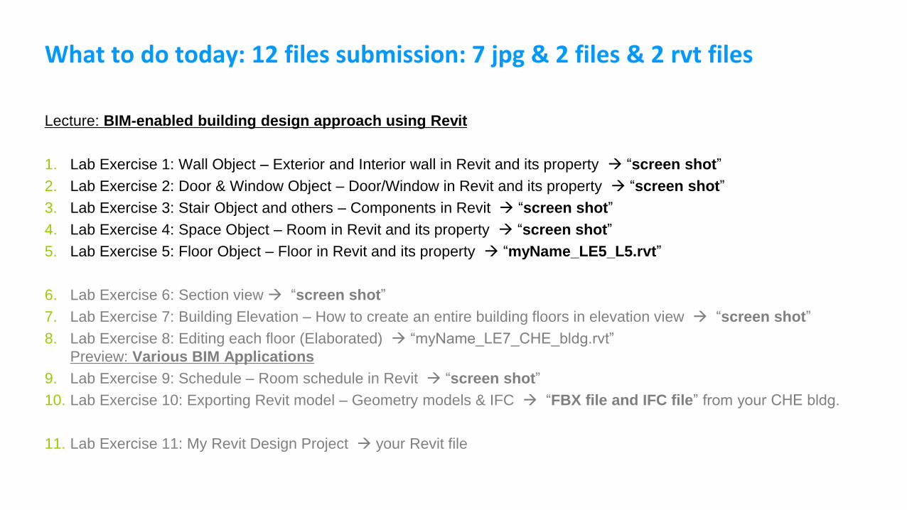
What to do today: 12 files submission: 7 jpg & 2 files & 2 rvt files
Lecture: BIM-enabled building design approach using Revit
1. Lab Exercise 1: Wall Object – Exterior and Interior wall in Revit and its property “screen shot”
2. Lab Exercise 2: Door & Window Object – Door/Window in Revit and its property “screen shot”
3. Lab Exercise 3: Stair Object and others – Components in Revit “screen shot”
4. Lab Exercise 4: Space Object – Room in Revit and its property “screen shot”
5. Lab Exercise 5: Floor Object – Floor in Revit and its property “myName_LE5_L5.rvt”
6. Lab Exercise 6: Section view “screen shot”
7. Lab Exercise 7: Building Elevation – How to create an entire building floors in elevation view “screen shot”
8. Lab Exercise 8: Editing each floor (Elaborated) “myName_LE7_CHE_bldg.rvt”
Preview: Various BIM Applications
9. Lab Exercise 9: Schedule – Room schedule in Revit “screen shot”
10. Lab Exercise 10: Exporting Revit model – Geometry models & IFC “FBX file and IFC file” from your CHE bldg.
11. Lab Exercise 11: My Revit Design Project your Revit file

Review: Building Information Modeling Approach
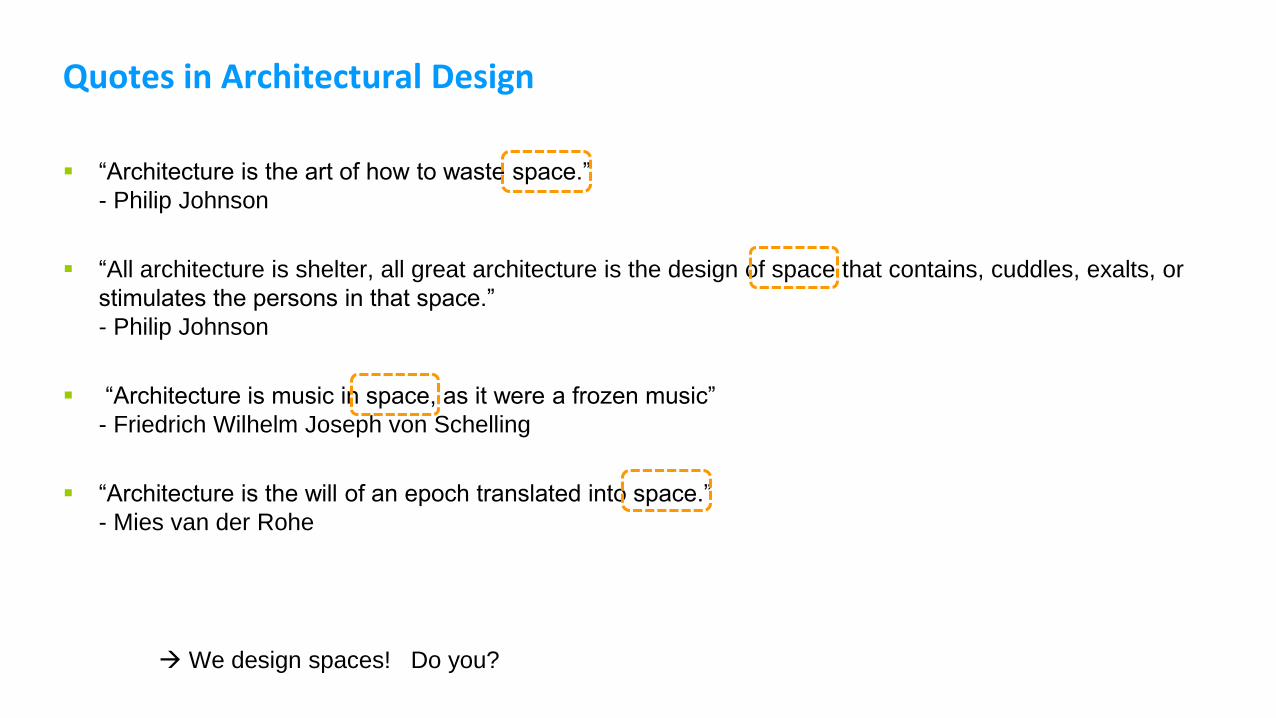
Quotes in Architectural Design
“Architecture is the art of how to waste space.”
- Philip Johnson
“All architecture is shelter, all great architecture is the design of space that contains, cuddles, exalts, or
stimulates the persons in that space.”
- Philip Johnson
“Architecture is music in space, as it were a frozen music”
- Friedrich Wilhelm Joseph von Schelling
“Architecture is the will of an epoch translated into space.”
- Mies van der Rohe
We design spaces! Do you?
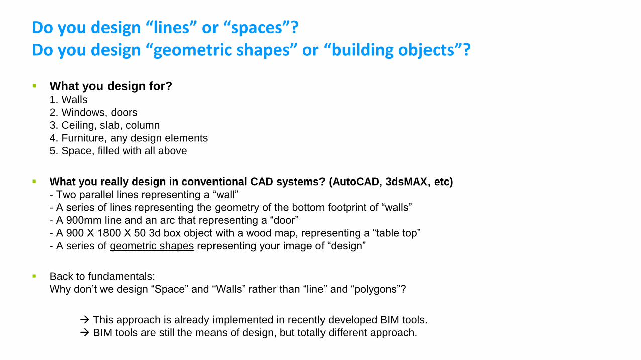
Do you design “lines” or “spaces”?Do you design “geometric shapes” or “building objects”?
What you design for?1. Walls
2. Windows, doors
3. Ceiling, slab, column
4. Furniture, any design elements
5. Space, filled with all above
What you really design in conventional CAD systems? (AutoCAD, 3dsMAX, etc)
- Two parallel lines representing a “wall”
- A series of lines representing the geometry of the bottom footprint of “walls”
- A 900mm line and an arc that representing a “door”
- A 900 X 1800 X 50 3d box object with a wood map, representing a “table top”
- A series of geometric shapes representing your image of “design”
Back to fundamentals:
Why don’t we design “Space” and “Walls” rather than “line” and “polygons”?
This approach is already implemented in recently developed BIM tools.
BIM tools are still the means of design, but totally different approach.
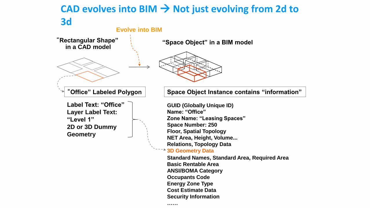
CAD evolves into BIM Not just evolving from 2d to 3d
GUID (Globally Unique ID)
Name: “Office”
Zone Name: “Leasing Spaces”
Space Number: 250
Floor, Spatial Topology
NET Area, Height, Volume...
Relations, Topology Data
3D Geometry Data
Space Object Instance contains “information”
“Rectangular Shape” in a CAD model
“Space Object” in a BIM model
“Office” Labeled Polygon
Label Text: “Office”
Layer Label Text:
“Level 1”
2D or 3D Dummy
Geometry
Evolve into BIM
Standard Names, Standard Area, Required Area
Basic Rentable Area
ANSI/BOMA Category
Occupants Code
Energy Zone Type
Cost Estimate Data
Security Information
……
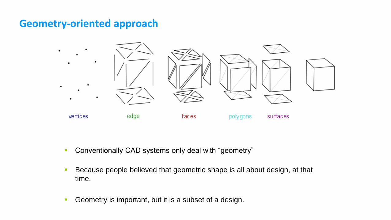
Geometry-oriented approach
Conventionally CAD systems only deal with “geometry”
Because people believed that geometric shape is all about design, at that
time.
Geometry is important, but it is a subset of a design.
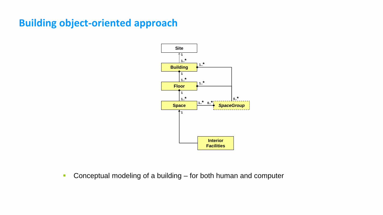
Building object-oriented approach
Conceptual modeling of a building – for both human and computer
Building
Space
Floor
SpaceGroup
1..*
1
0..*
1..*
1
1
Site
1..*
1
1..*
1..*
1..*
0..*
Interior
Facilities
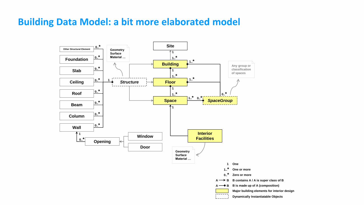
Building Data Model: a bit more elaborated model
Building
Space
Floor
SpaceGroup
1..*
1
Any group or
classification
of spaces
0..*
1..*
1
1
Other Structural ElementSite
Structure
Slab
Foundation
Roof
Beam
Ceiling
Column
Wall
Opening
Window
1..*
1
0..*
0..*
0..*
0..*
0..*
0..*
0..*
1
1
0..*
Geometry
Surface
Material …
0..*
1..*
1..*
1..*
0..*
1
1..*
0..*
One
One or more
Zero or more
B contains A / A is super class of B
B is made up of A (composition)
A B
A B
Major building elements for interior design
Dynamically Instantiatable Objects
Interior
Facilities
Geometry
Surface
Material …
Door
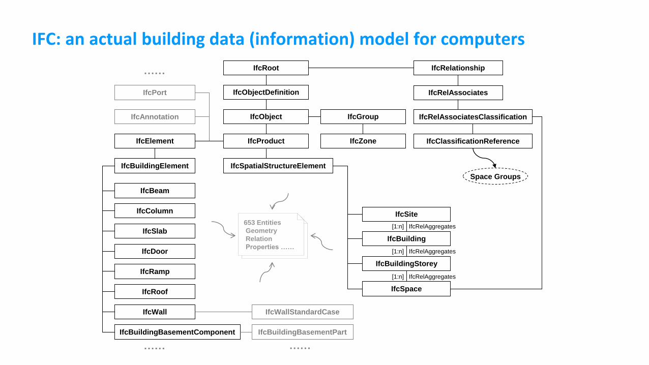
IFC: an actual building data (information) model for computers
IfcSpace
IfcBuildingStorey
[1:n] IfcRelAggregates
IfcBuilding
IfcSite
[1:n] IfcRelAggregates
[1:n] IfcRelAggregates
IfcSpatialStructureElement
IfcObject
IfcProduct
IfcRoot
IfcObjectDefinition
IfcElement
IfcBuildingElement
IfcBeam
IfcColumn
IfcSlab
IfcDoor
IfcRamp
IfcRoof
IfcWall
IfcBuildingBasementComponent
IfcAnnotation
IfcPort
IfcWallStandardCase
……
……
IfcBuildingBasementPart
……
IfcRelationship
IfcRelAssociates
IfcRelAssociatesClassification
IfcClassificationReference
Space Groups
653 Entities
Geometry
Relation
Properties ……
IfcGroup
IfcZone
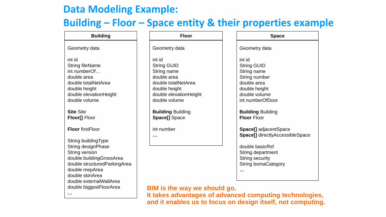
Data Modeling Example:Building – Floor – Space entity & their properties example
Space
Geometry data
int id
String GUID
String name
String number
double area
double height
double volume
int numberOfDoor
Building Building
Floor Floor
Space[] adjacentSpace
Space[] directlyAccessibleSpace
double basicRsf
String department
String security
String bomaCategory
…
Building
Geometry data
int id
String fileName
int numberOf…
double area
double totalNetArea
double height
double elevationHeight
double volume
Site Site
Floor[] Floor
Floor firstFloor
String buildingType
String designPhase
String version
double buildingGrossArea
double structuredParkingArea
double mepArea
double skinArea
double externalWallArea
double biggestFloorArea
…
Floor
Geometry data
int id
String GUID
String name
double area
double totalNetArea
double height
double elevationHeight
double volume
Building Building
Space[] Space
int number
…
BIM is the way we should go.It takes advantages of advanced computing technologies,and it enables us to focus on design itself, not computing.

Solid Modeling in Revit
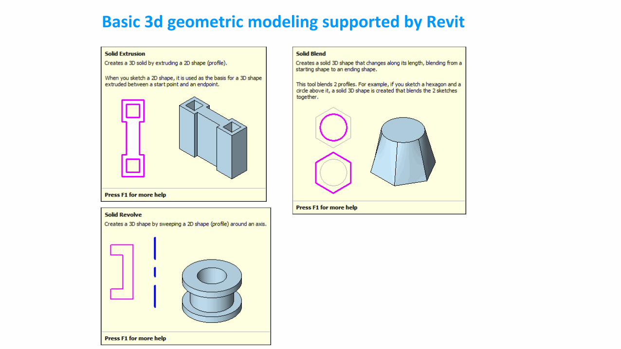
Basic 3d geometric modeling supported by Revit
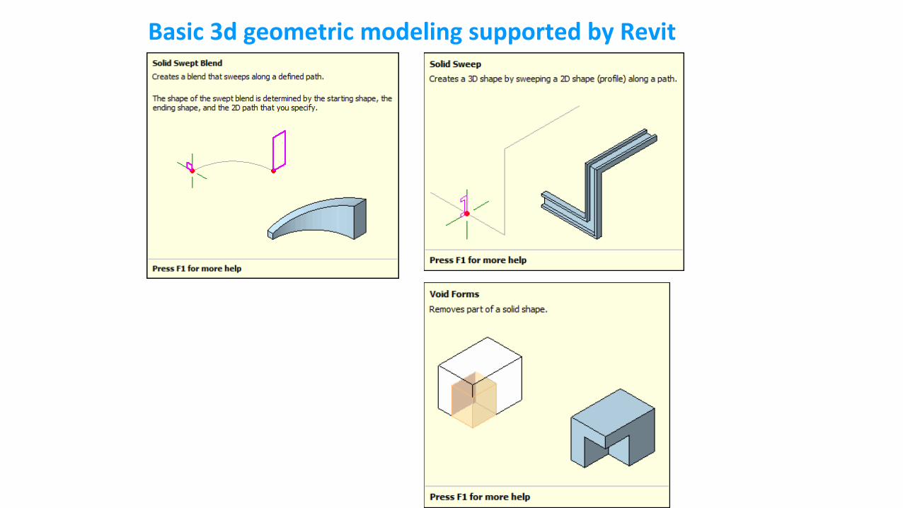
Basic 3d geometric modeling supported by Revit
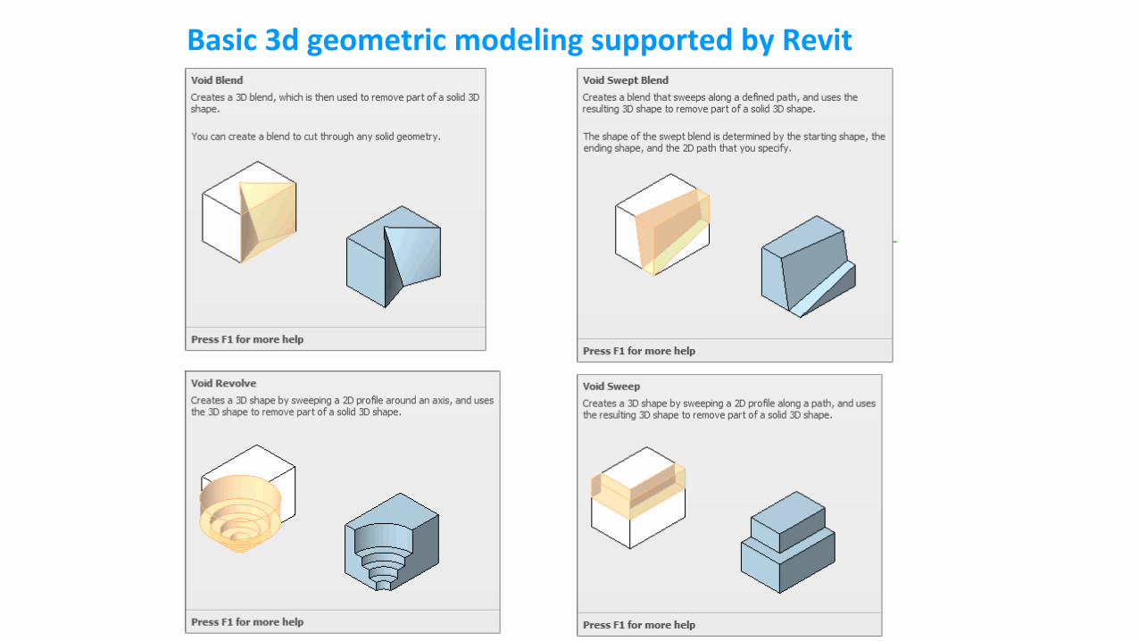
Basic 3d geometric modeling supported by Revit
Autodesk HomeStyler.com
- A web-based parametric modeling tool (& Mobile-based)
- Login using Google Account, and design your room
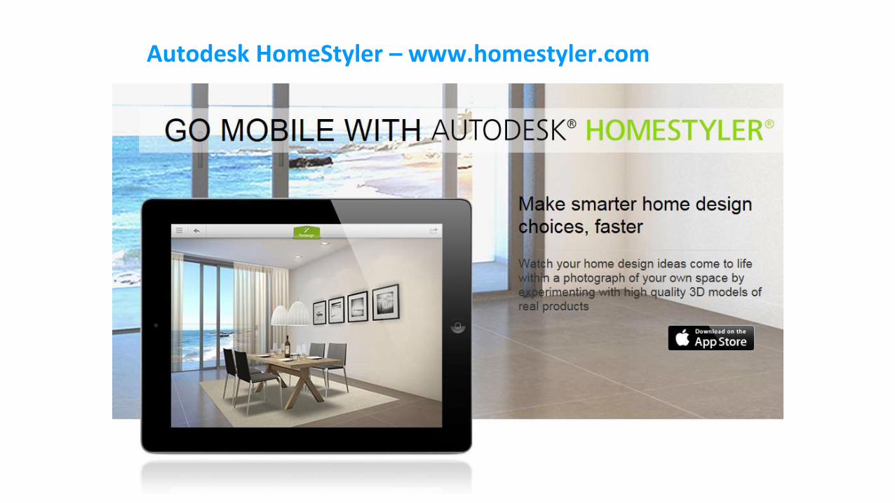
Autodesk HomeStyler – www.homestyler.com
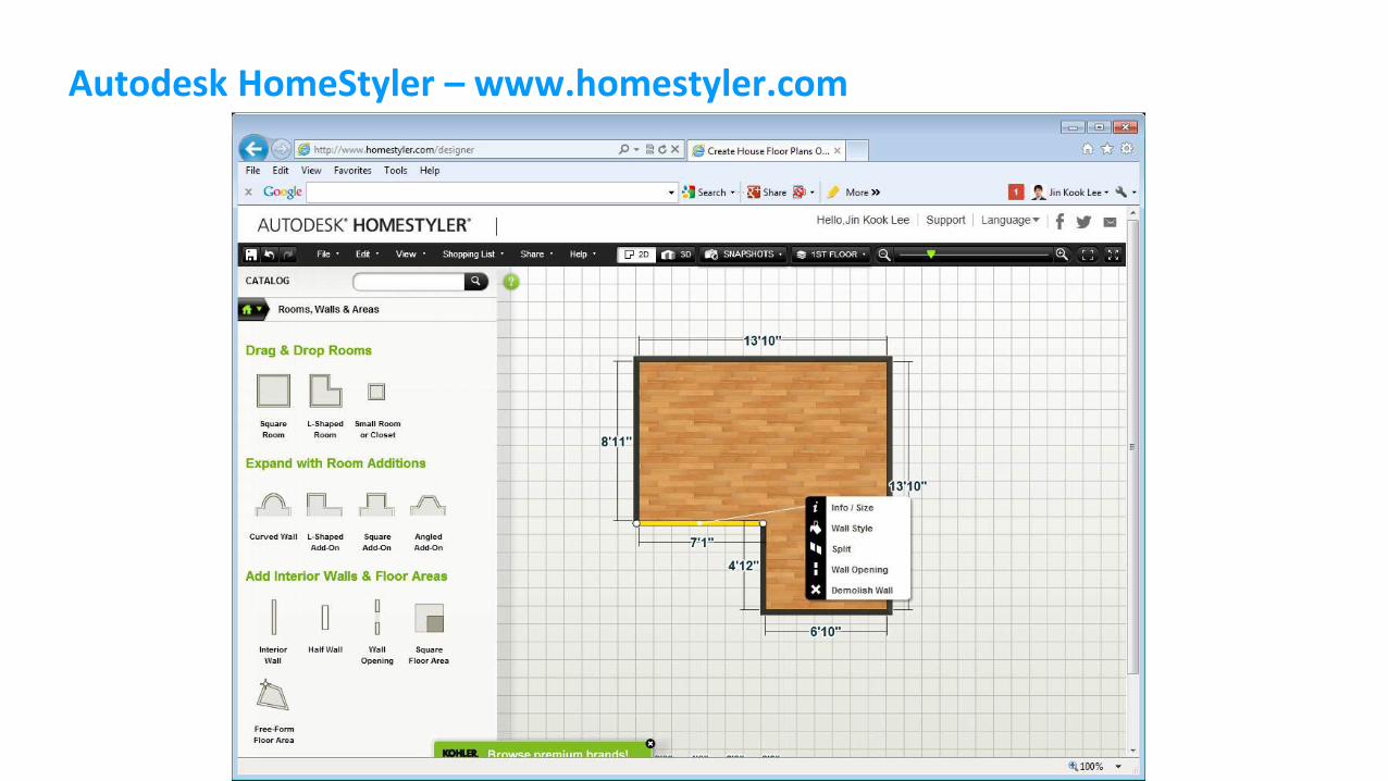
Autodesk HomeStyler – www.homestyler.com
CAD vs. BIM
- Export your design in .DWG, and .RVT in HomeStyler.com
- Comparison between .DWG file and .RVT
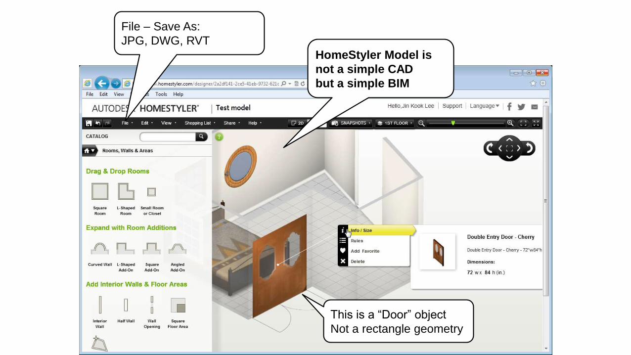
HomeStyler Model is
not a simple CAD
but a simple BIM
This is a “Door” object
Not a rectangle geometry
File – Save As:
JPG, DWG, RVT
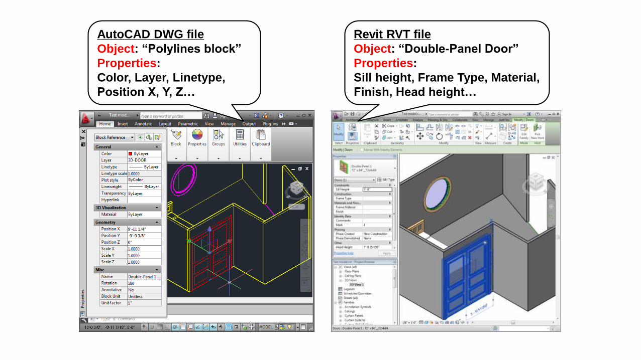
AutoCAD DWG file
Object: “Polylines block”
Properties:
Color, Layer, Linetype,
Position X, Y, Z…
Revit RVT file
Object: “Double-Panel Door”
Properties:
Sill height, Frame Type, Material,
Finish, Head height…
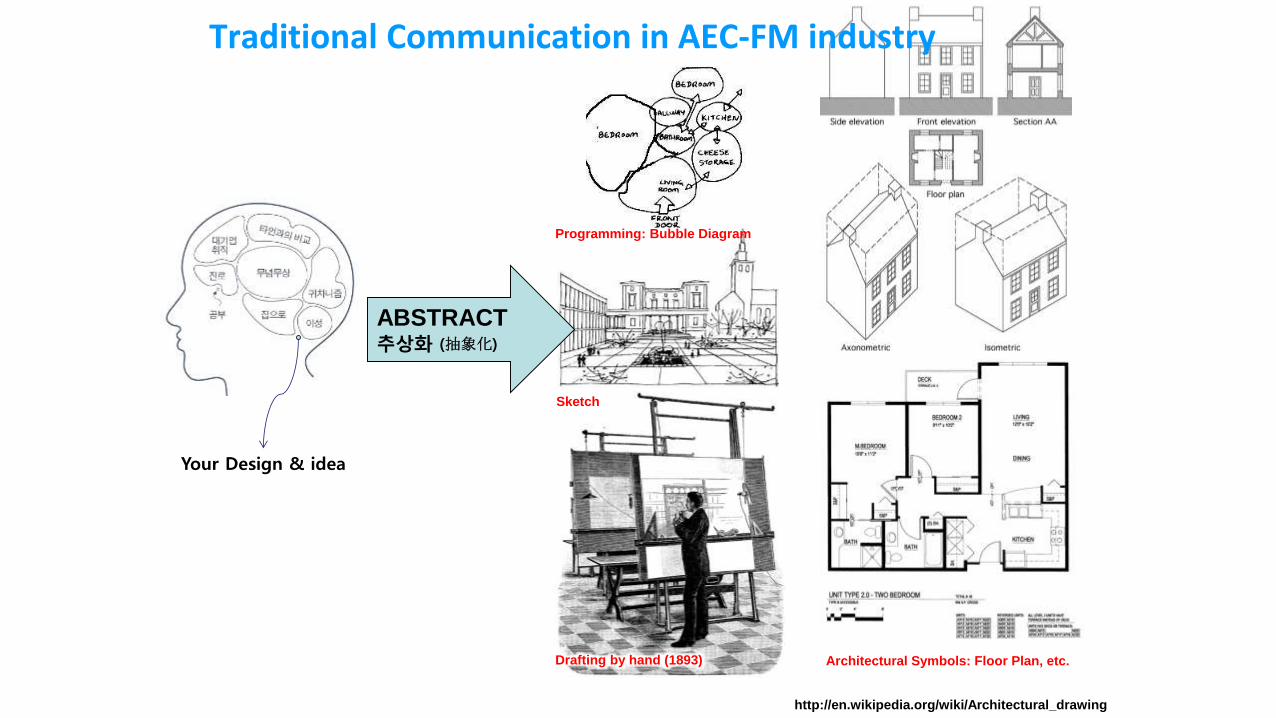
Your Design & idea
http://en.wikipedia.org/wiki/Architectural_drawing
ABSTRACT추상화 (抽象化)
Programming: Bubble Diagram
Sketch
Drafting by hand (1893) Architectural Symbols: Floor Plan, etc.
Traditional Communication in AEC-FM industry
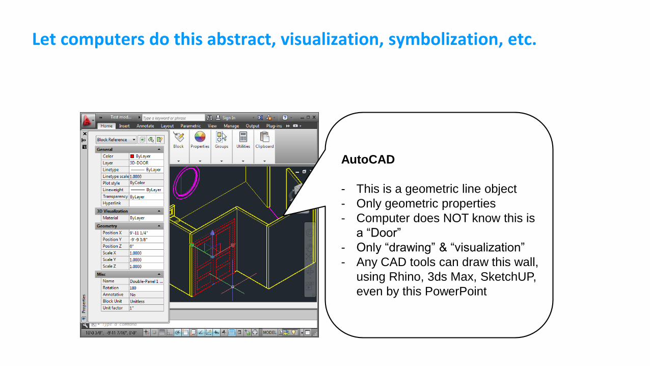
Let computers do this abstract, visualization, symbolization, etc.
AutoCAD
- This is a geometric line object
- Only geometric properties
- Computer does NOT know this is
a “Door”
- Only “drawing” & “visualization”
- Any CAD tools can draw this wall,
using Rhino, 3ds Max, SketchUP,
even by this PowerPoint
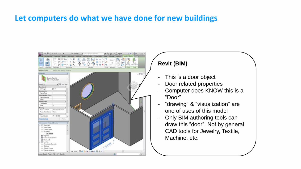
Let computers do what we have done for new buildings
Revit (BIM)
- This is a door object
- Door related properties
- Computer does KNOW this is a
“Door”
- “drawing” & “visualization” are
one of uses of this model
- Only BIM authoring tools can
draw this “door”. Not by general
CAD tools for Jewelry, Textile,
Machine, etc.
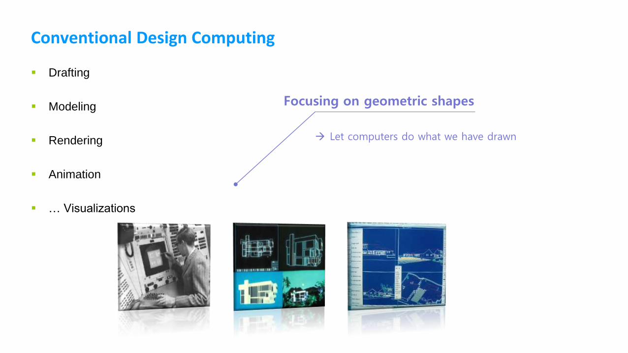
Conventional Design Computing
Drafting
Modeling
Rendering
Animation
… Visualizations
Focusing on geometric shapes
Let computers do what we have drawn
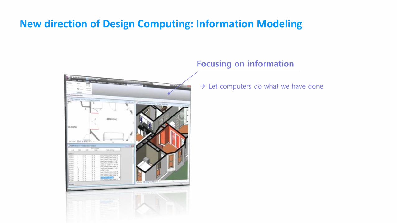
New direction of Design Computing: Information Modeling
Focusing on information
Let computers do what we have done
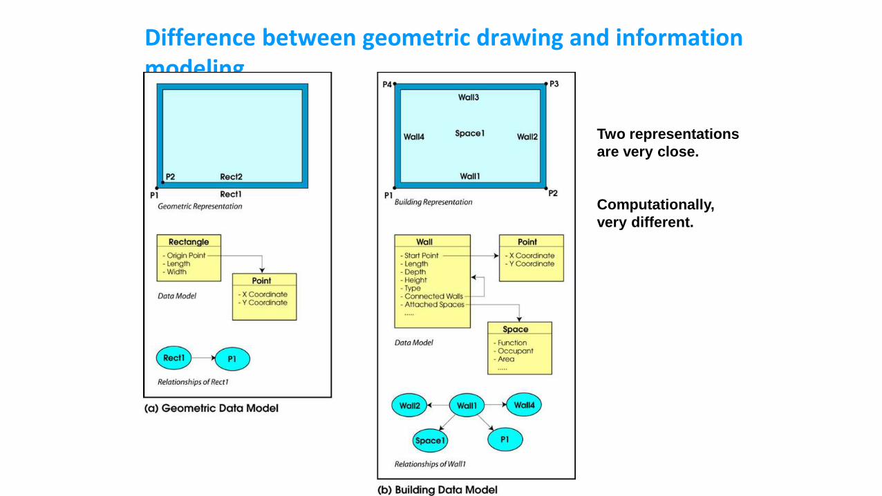
Difference between geometric drawing and information modeling
Two representations
are very close.
Computationally,
very different.
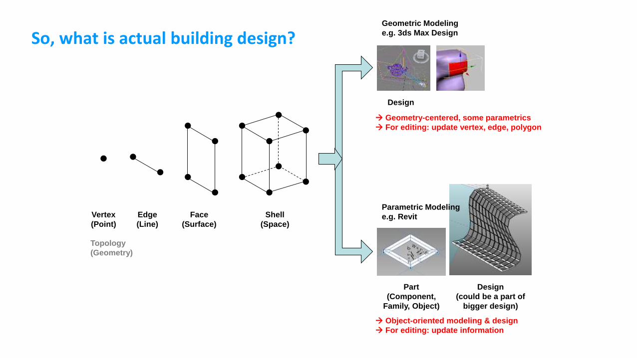
So, what is actual building design?
Vertex
(Point)
Edge
(Line)
Face
(Surface)
Shell
(Space)
Geometric Modeling
e.g. 3ds Max Design
Design
Parametric Modeling
e.g. Revit
Part
(Component,
Family, Object)
Design
(could be a part of
bigger design)
Geometry-centered, some parametrics
For editing: update vertex, edge, polygon
Object-oriented modeling & design
For editing: update information
Topology
(Geometry)
Parametric Modeling in Revit
Parametric & Feature-based Modeling
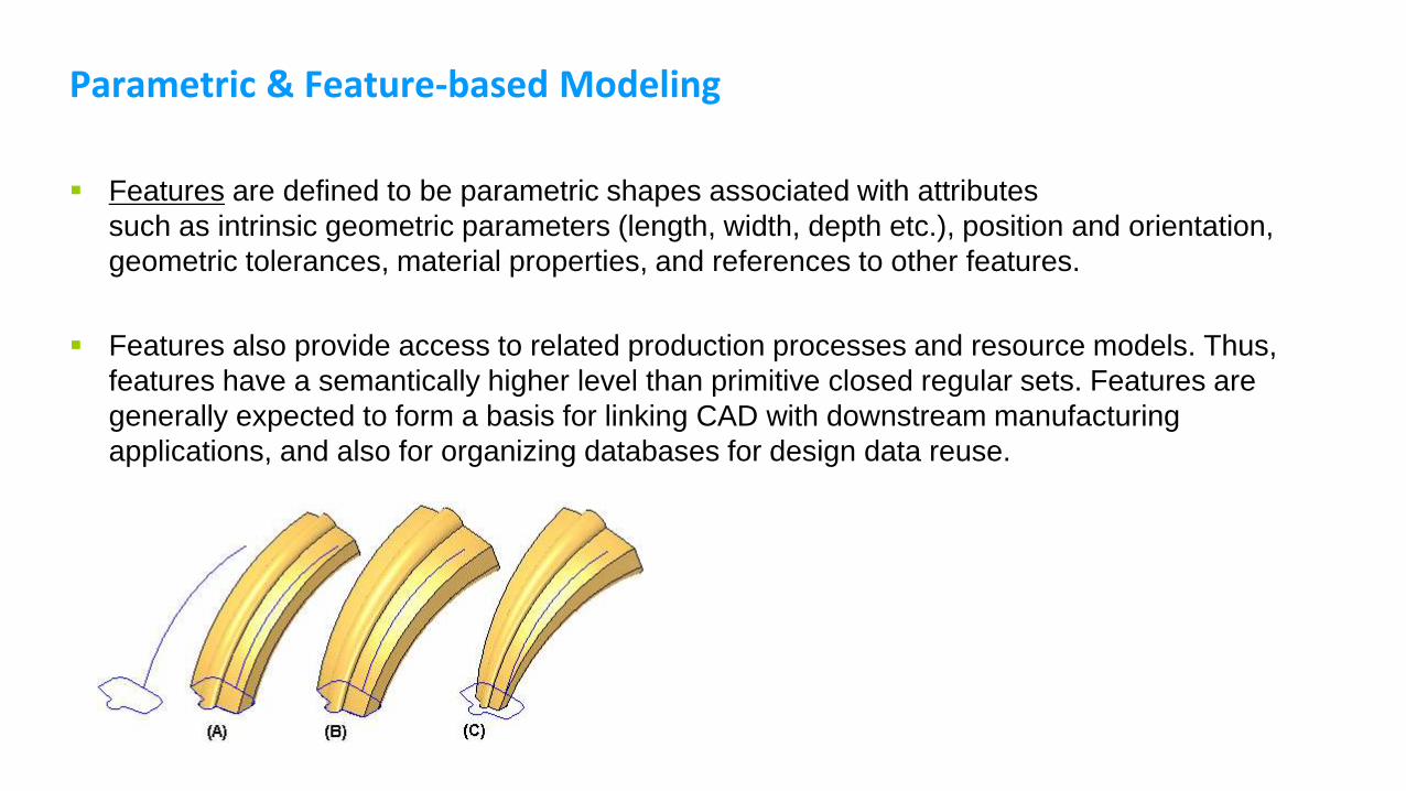
Features are defined to be parametric shapes associated with attributes
such as intrinsic geometric parameters (length, width, depth etc.), position and orientation,
geometric tolerances, material properties, and references to other features.
Features also provide access to related production processes and resource models. Thus,
features have a semantically higher level than primitive closed regular sets. Features are
generally expected to form a basis for linking CAD with downstream manufacturing
applications, and also for organizing databases for design data reuse.
Parametric Modeling
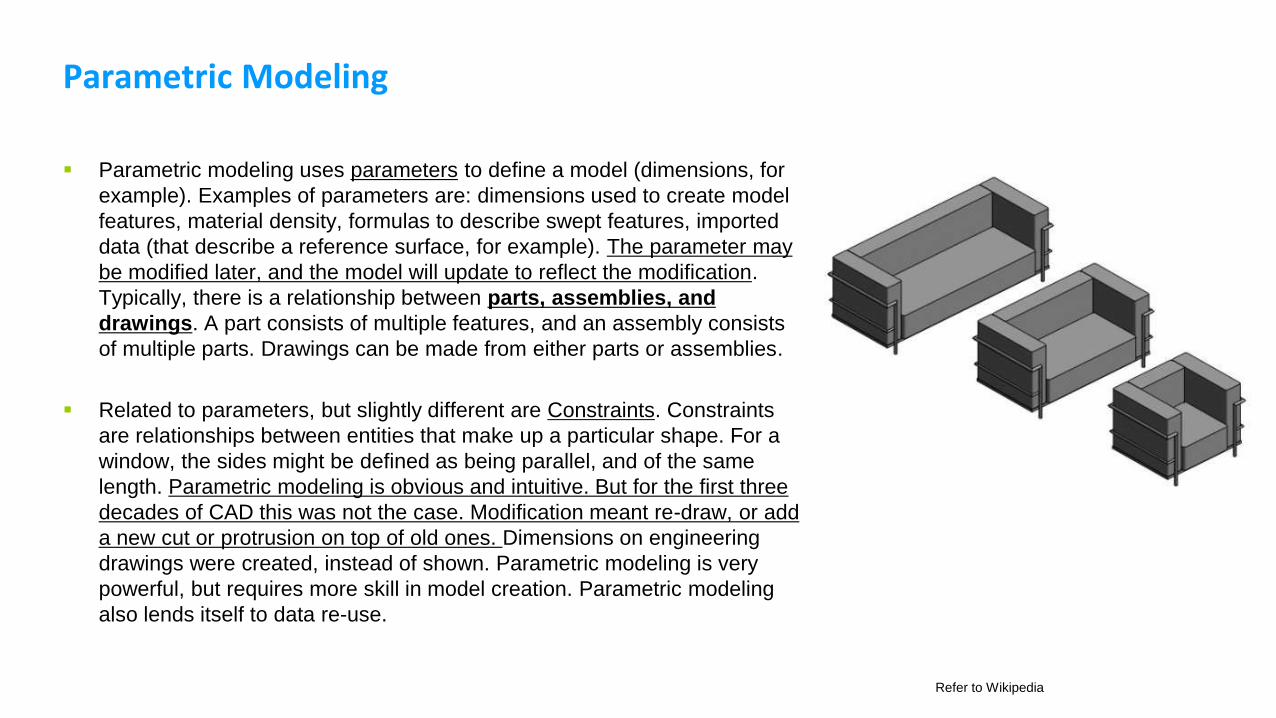
Parametric modeling uses parameters to define a model (dimensions, for
example). Examples of parameters are: dimensions used to create model
features, material density, formulas to describe swept features, imported
data (that describe a reference surface, for example). The parameter may
be modified later, and the model will update to reflect the modification.
Typically, there is a relationship between parts, assemblies, and
drawings. A part consists of multiple features, and an assembly consists
of multiple parts. Drawings can be made from either parts or assemblies.
Related to parameters, but slightly different are Constraints. Constraints
are relationships between entities that make up a particular shape. For a
window, the sides might be defined as being parallel, and of the same
length. Parametric modeling is obvious and intuitive. But for the first three
decades of CAD this was not the case. Modification meant re-draw, or add
a new cut or protrusion on top of old ones. Dimensions on engineering
drawings were created, instead of shown. Parametric modeling is very
powerful, but requires more skill in model creation. Parametric modeling
also lends itself to data re-use.
Refer to Wikipedia
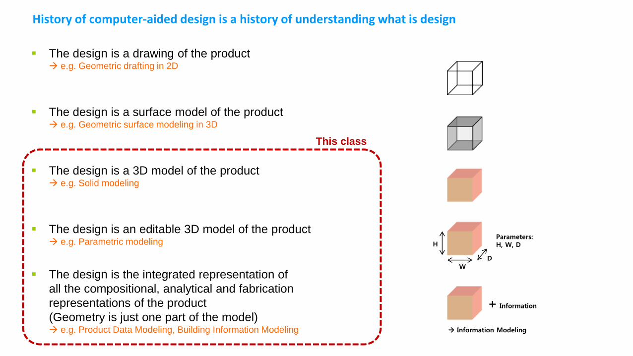
History of computer-aided design is a history of understanding what is design
The design is a drawing of the product e.g. Geometric drafting in 2D
The design is a surface model of the product e.g. Geometric surface modeling in 3D
The design is a 3D model of the product e.g. Solid modeling
The design is an editable 3D model of the product e.g. Parametric modeling
The design is the integrated representation of
all the compositional, analytical and fabrication
representations of the product
(Geometry is just one part of the model) e.g. Product Data Modeling, Building Information Modeling
H
W
D
Parameters:H, W, D
+ Information
Information Modeling
This class
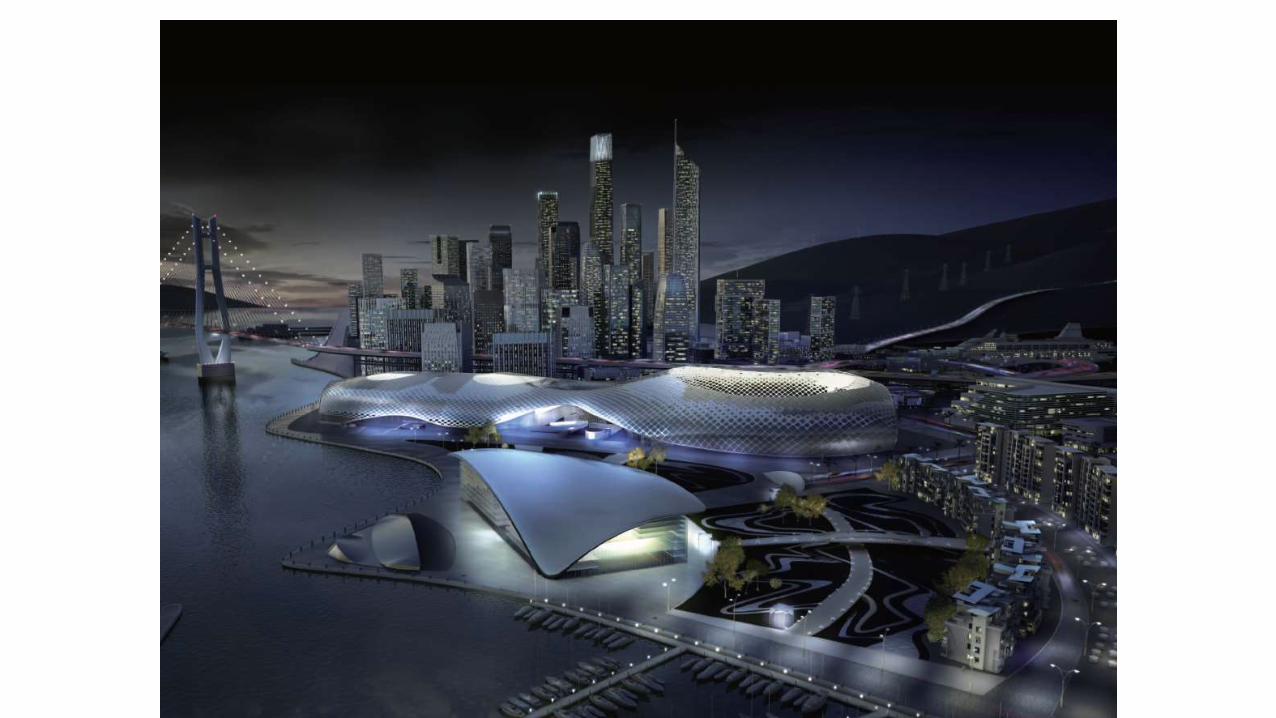
Non-uniform Design of Buildings
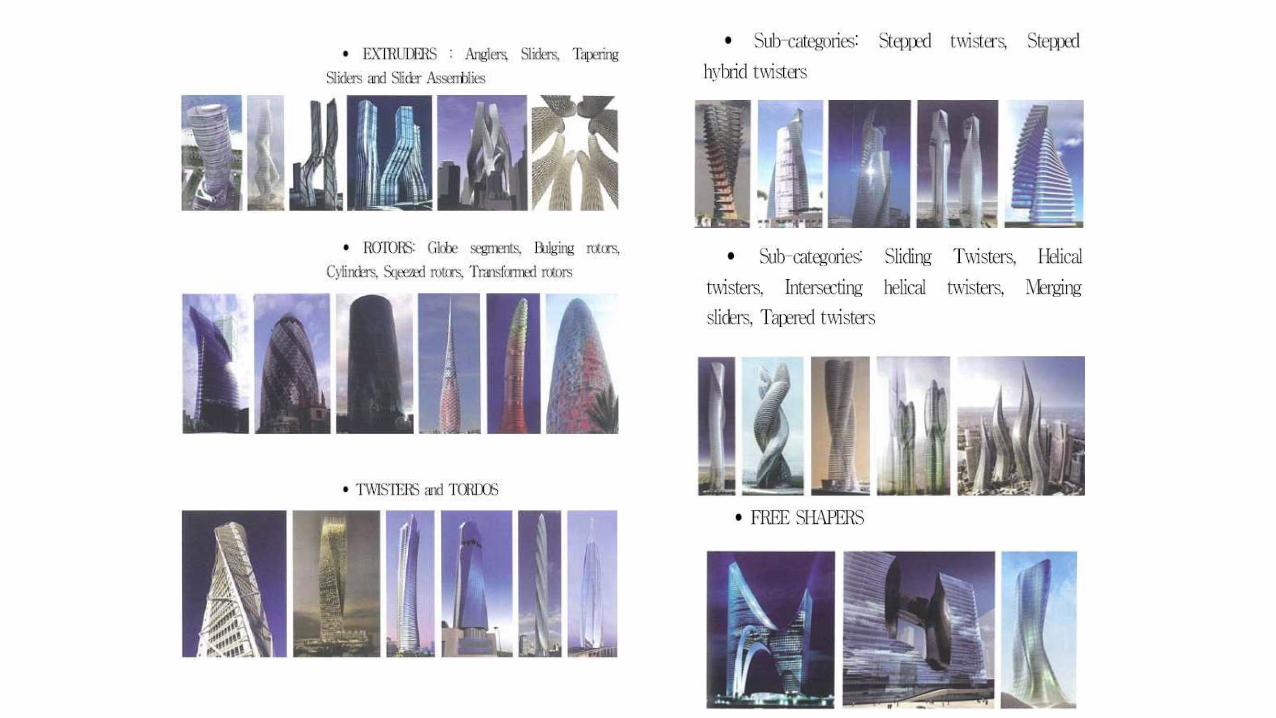
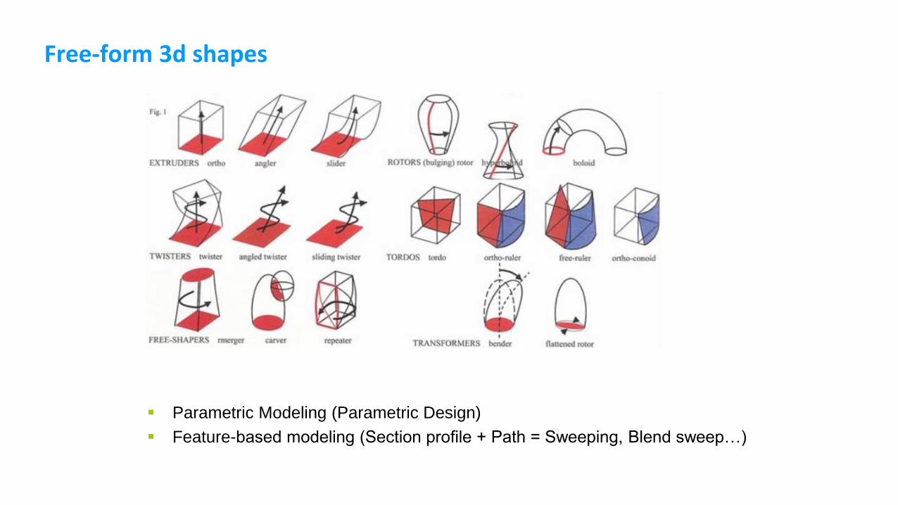
Free-form 3d shapes
Parametric Modeling (Parametric Design)
Feature-based modeling (Section profile + Path = Sweeping, Blend sweep…)
Non-uniform Design, Parametric Design, and BIM
Inevitable trend in recent AEC-FM industry

Case Study: Gansam Architects and Partners
신사동 페이토빌딩, 해군안보전시관, 프라자호텔 리모델링
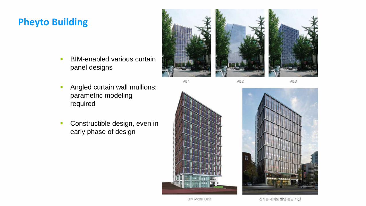
Pheyto Building
BIM-enabled various curtain
panel designs
Angled curtain wall mullions:
parametric modeling
required
Constructible design, even in
early phase of design
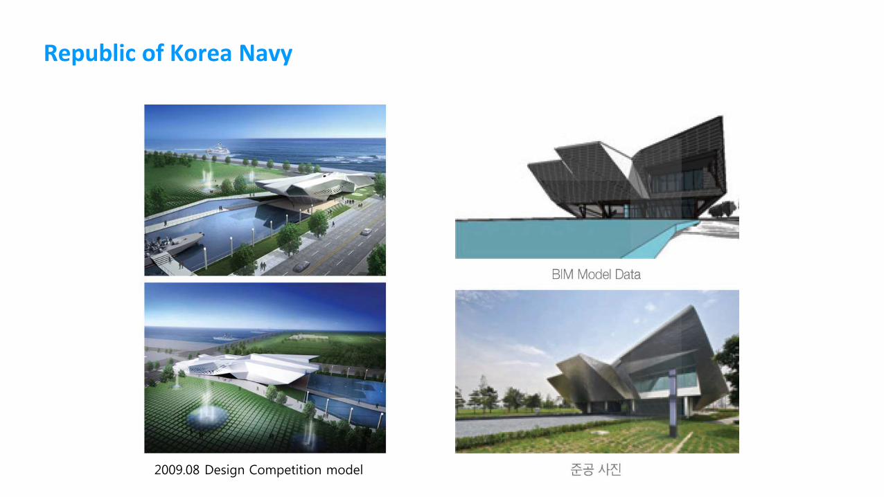
Republic of Korea Navy
2009.08 Design Competition model
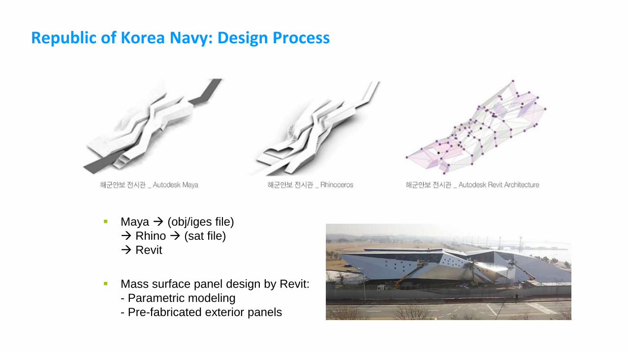
Republic of Korea Navy: Design Process
Maya (obj/iges file)
Rhino (sat file)
Revit
Mass surface panel design by Revit:
- Parametric modeling
- Pre-fabricated exterior panels
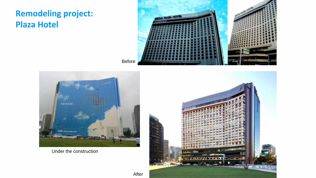
Remodeling project:Plaza Hotel
Before
After
Under the construction
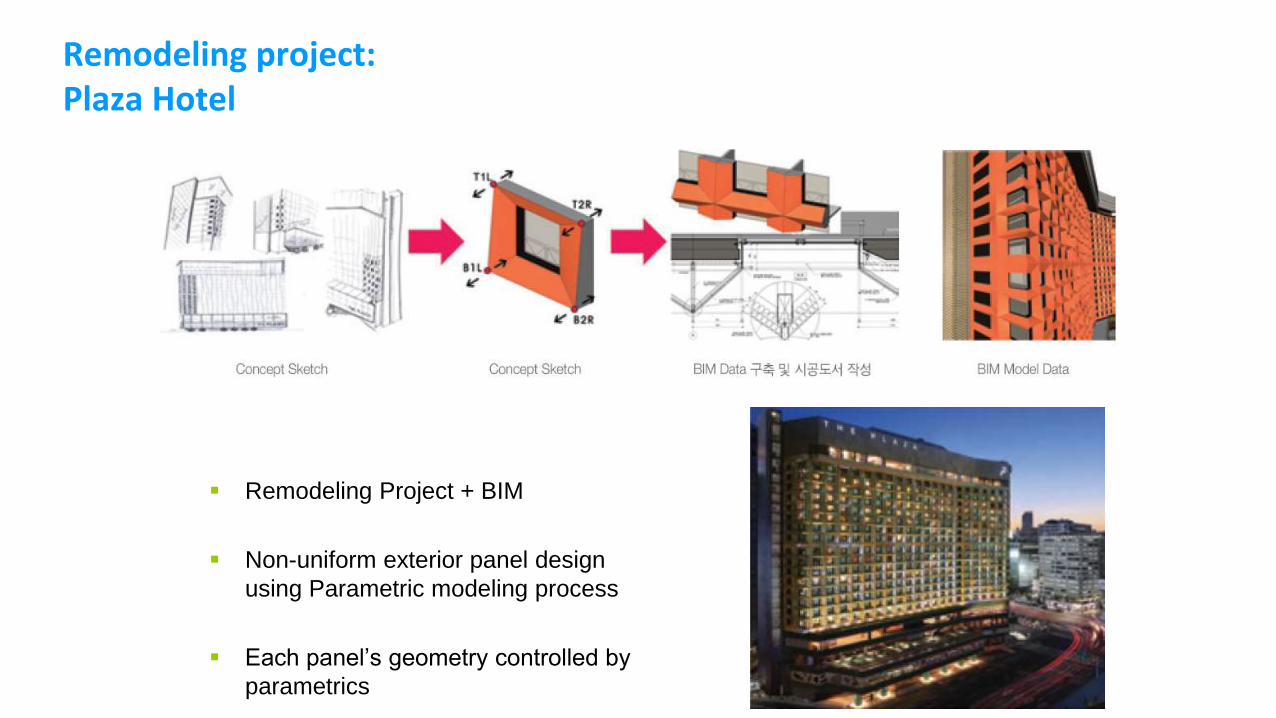
Remodeling project:Plaza Hotel
Remodeling Project + BIM
Non-uniform exterior panel design
using Parametric modeling process
Each panel’s geometry controlled by
parametrics
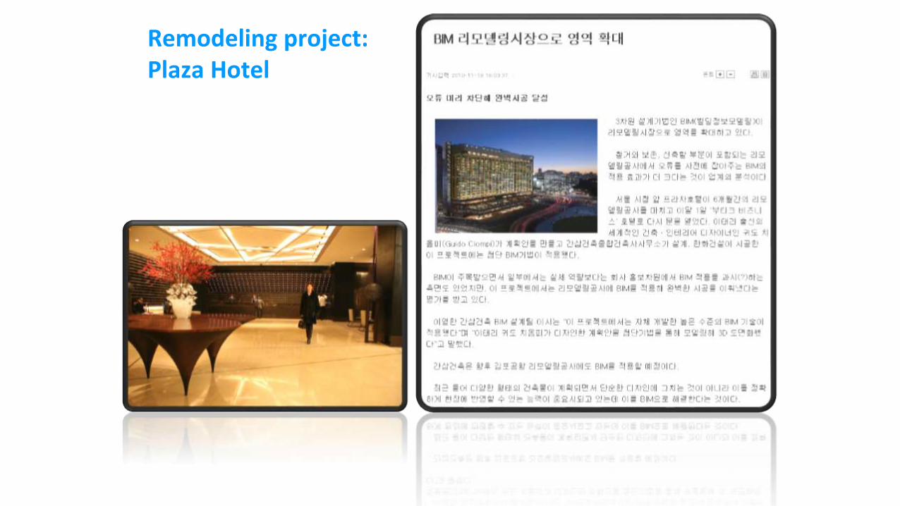
Remodeling project:Plaza Hotel

An early Pilot Project using BIM
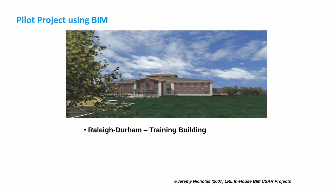
Pilot Project using BIM
Jeremy Nicholas (2007) LRL In-House BIM USAR Projects
• Raleigh-Durham – Training Building
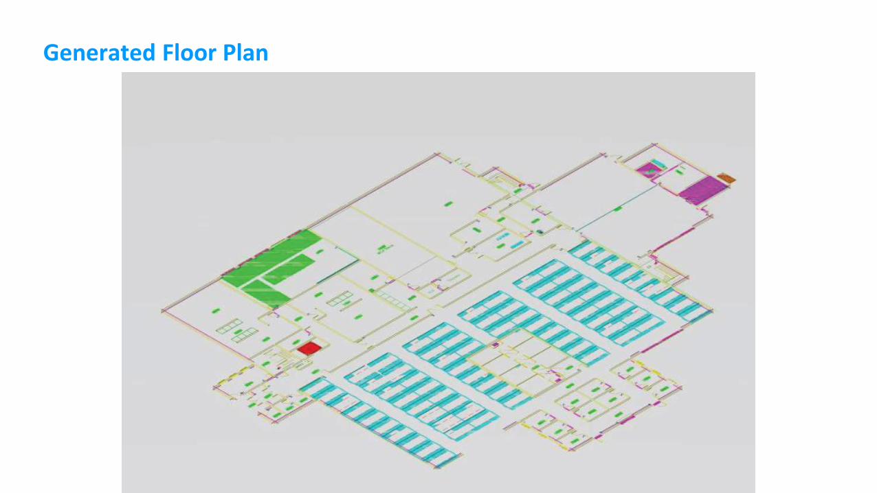
Generated Floor Plan
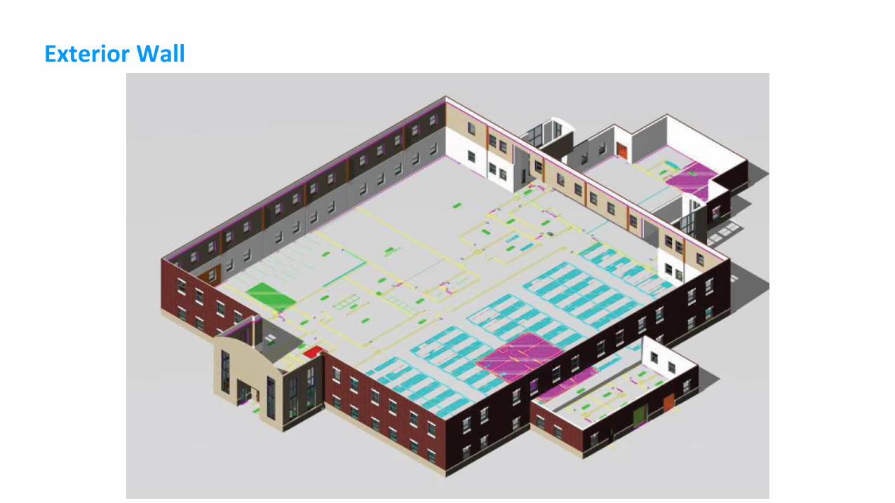
Exterior Wall
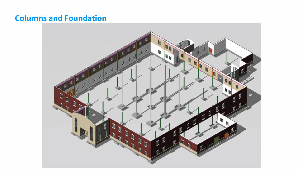
Columns and Foundation
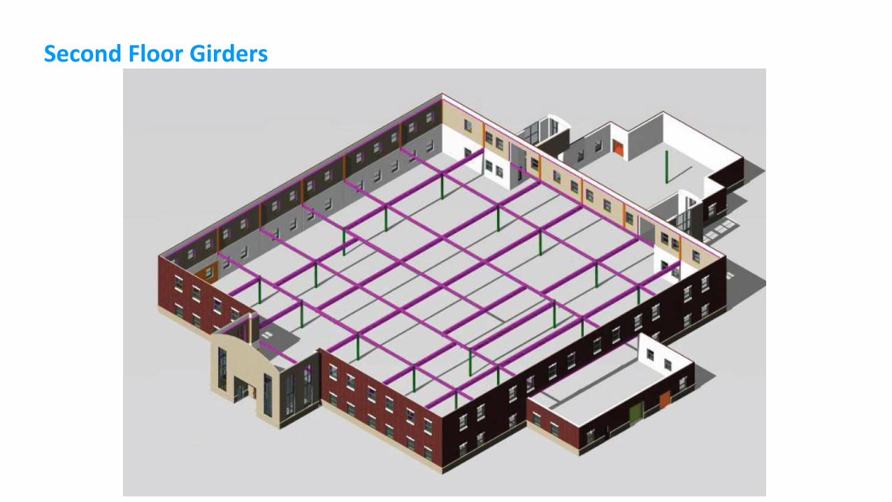
Second Floor Girders
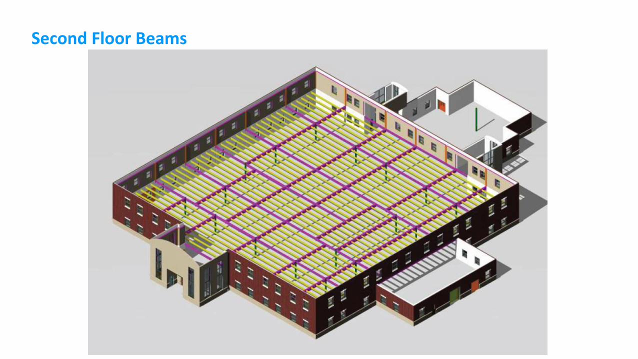
Second Floor Beams
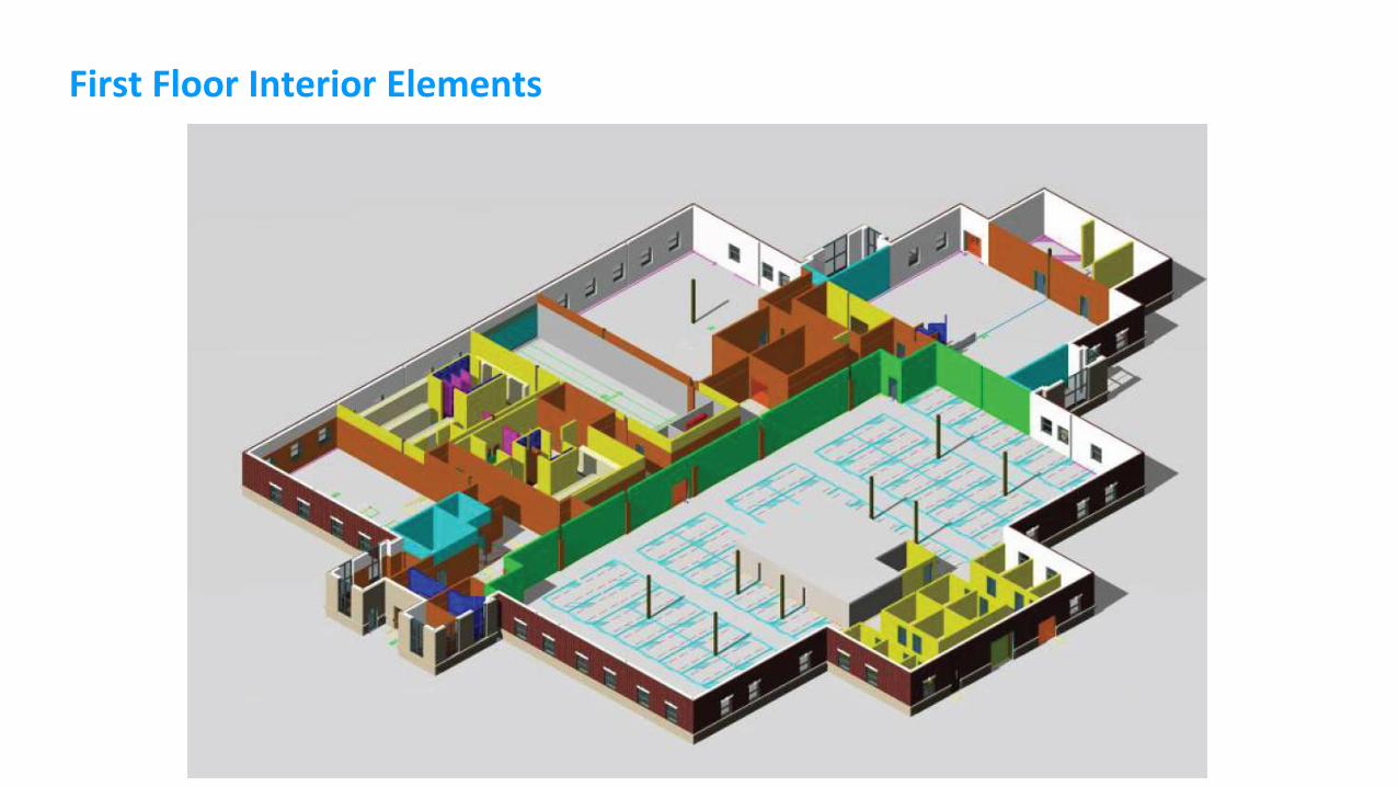
First Floor Interior Elements
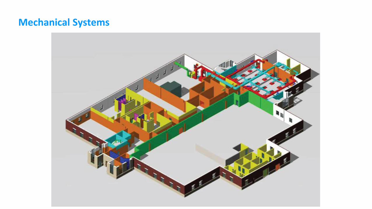
Mechanical Systems
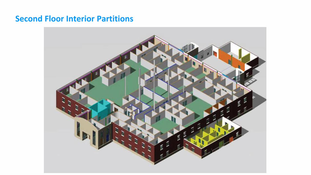
Second Floor Interior Partitions
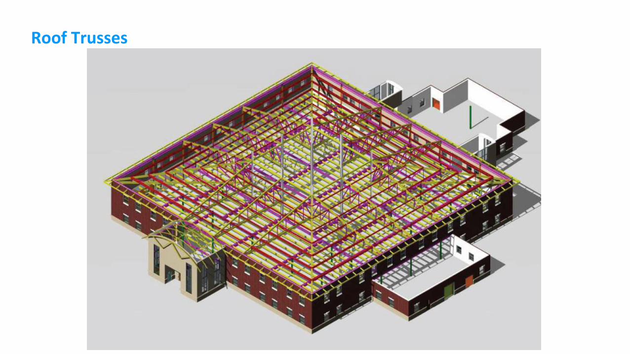
Roof Trusses
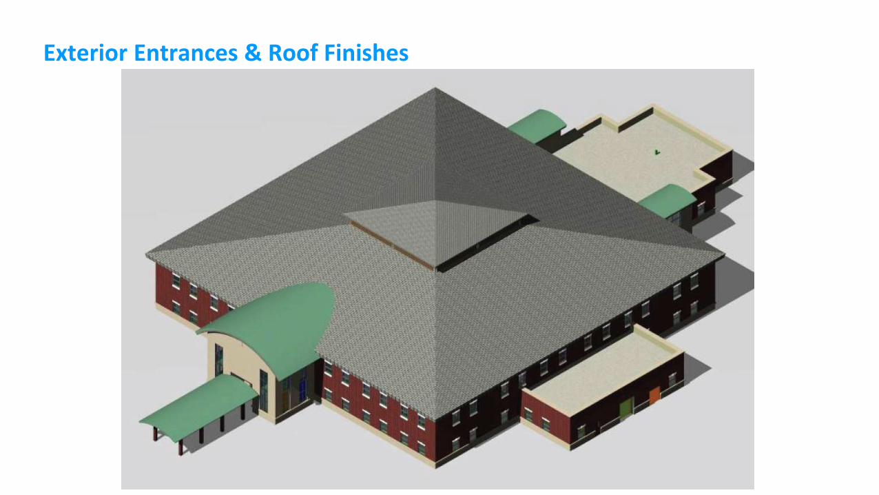
Exterior Entrances & Roof Finishes

Review: Autodesk Revit, its BIM Approaches
and its Use Scenarios for Interiors
Autodesk Revit 2014, as of 2014 (2015 will be released soon)
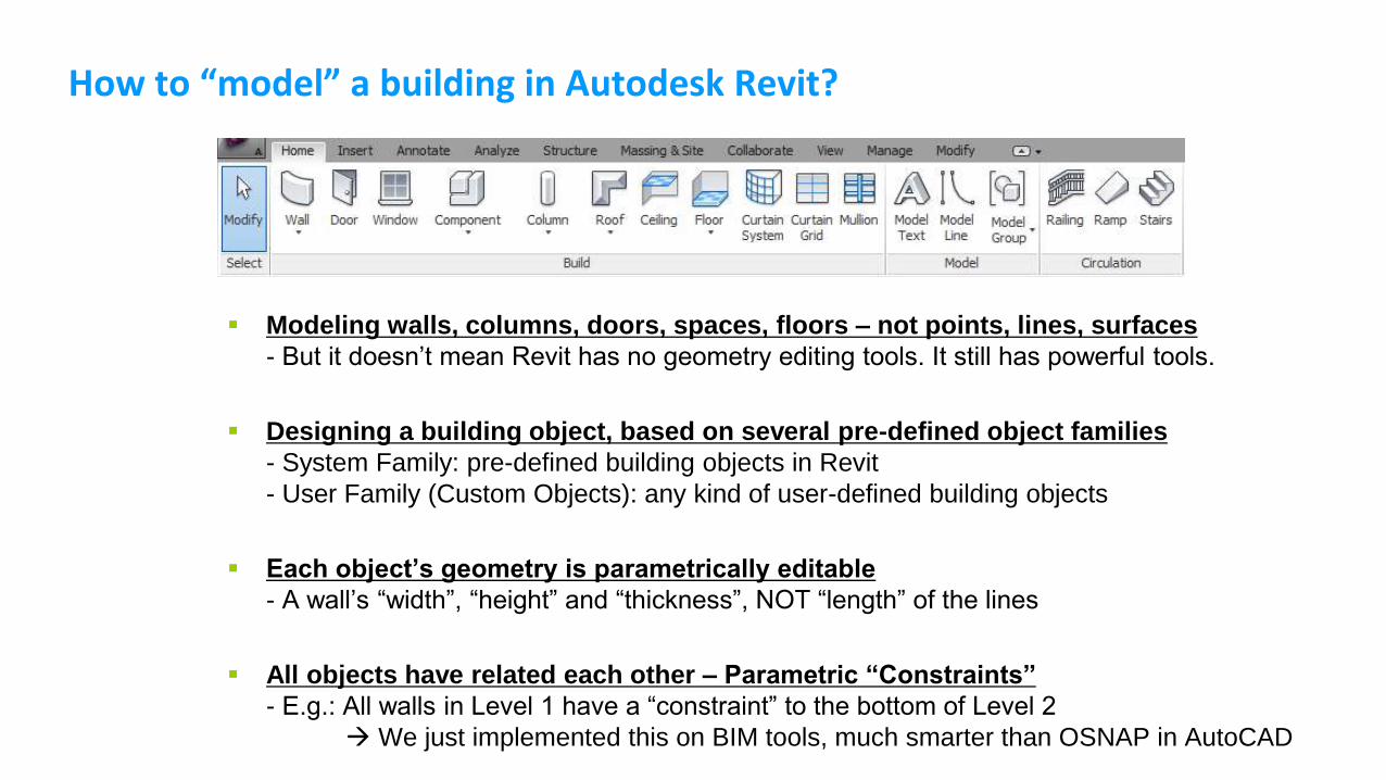
How to “model” a building in Autodesk Revit?
Modeling walls, columns, doors, spaces, floors – not points, lines, surfaces
- But it doesn’t mean Revit has no geometry editing tools. It still has powerful tools.
Designing a building object, based on several pre-defined object families
- System Family: pre-defined building objects in Revit
- User Family (Custom Objects): any kind of user-defined building objects
Each object’s geometry is parametrically editable
- A wall’s “width”, “height” and “thickness”, NOT “length” of the lines
All objects have related each other – Parametric “Constraints”
- E.g.: All walls in Level 1 have a “constraint” to the bottom of Level 2
We just implemented this on BIM tools, much smarter than OSNAP in AutoCAD
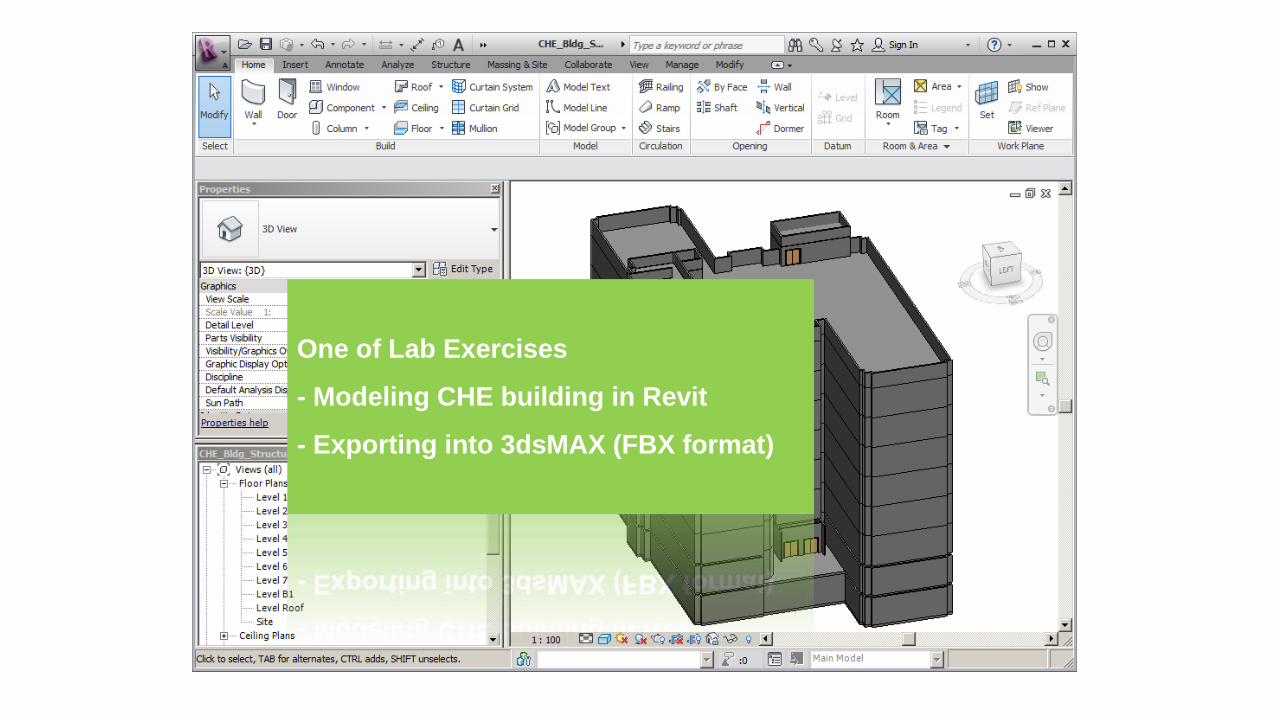
One of Lab Exercises
- Modeling CHE building in Revit
- Exporting into 3dsMAX (FBX format)
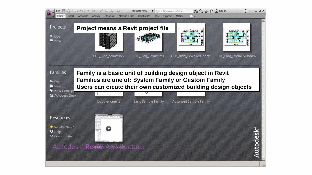
Project means a Revit project file
Family is a basic unit of building design object in Revit
Families are one of: System Family or Custom Family
Users can create their own customized building design objects
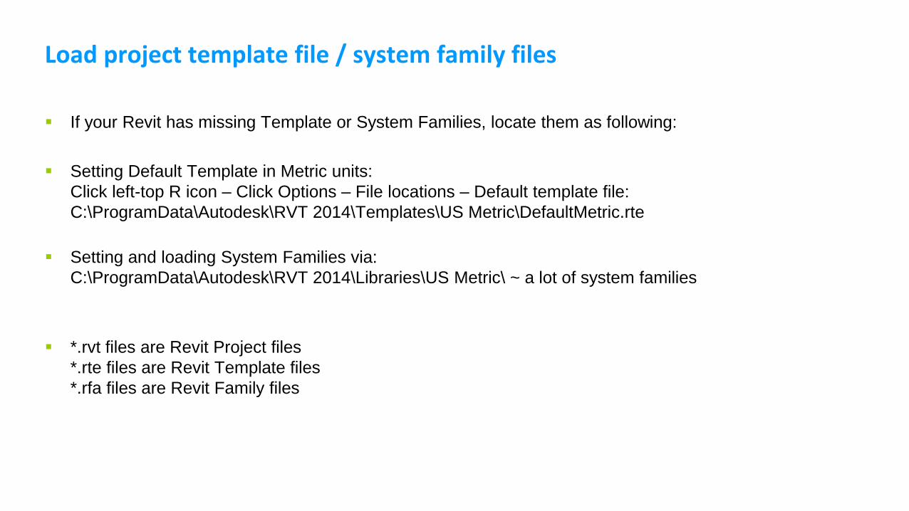
Load project template file / system family files
If your Revit has missing Template or System Families, locate them as following:
Setting Default Template in Metric units:
Click left-top R icon – Click Options – File locations – Default template file:
C:\ProgramData\Autodesk\RVT 2014\Templates\US Metric\DefaultMetric.rte
Setting and loading System Families via:
C:\ProgramData\Autodesk\RVT 2014\Libraries\US Metric\ ~ a lot of system families
*.rvt files are Revit Project files
*.rte files are Revit Template files
*.rfa files are Revit Family files
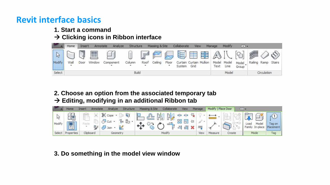
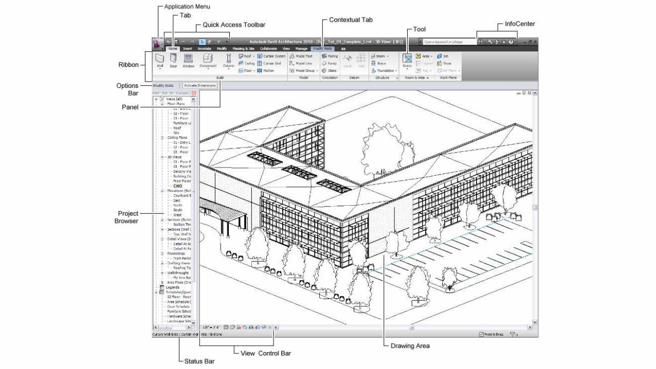
Revit interface basics1. Start a command
Clicking icons in Ribbon interface
2. Choose an option from the associated temporary tab
Editing, modifying in an additional Ribbon tab
3. Do something in the model view window
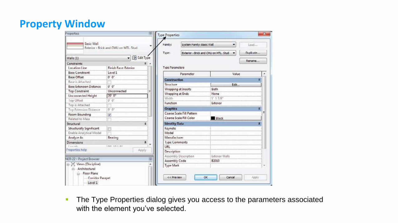
Property Window
The Type Properties dialog gives you access to the parameters associated
with the element you’ve selected.
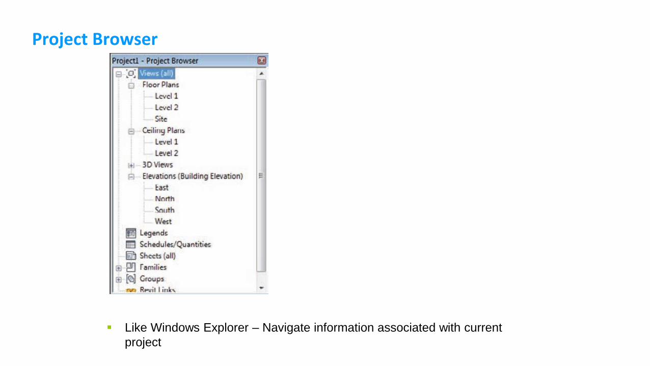
Project Browser
Like Windows Explorer – Navigate information associated with current
project
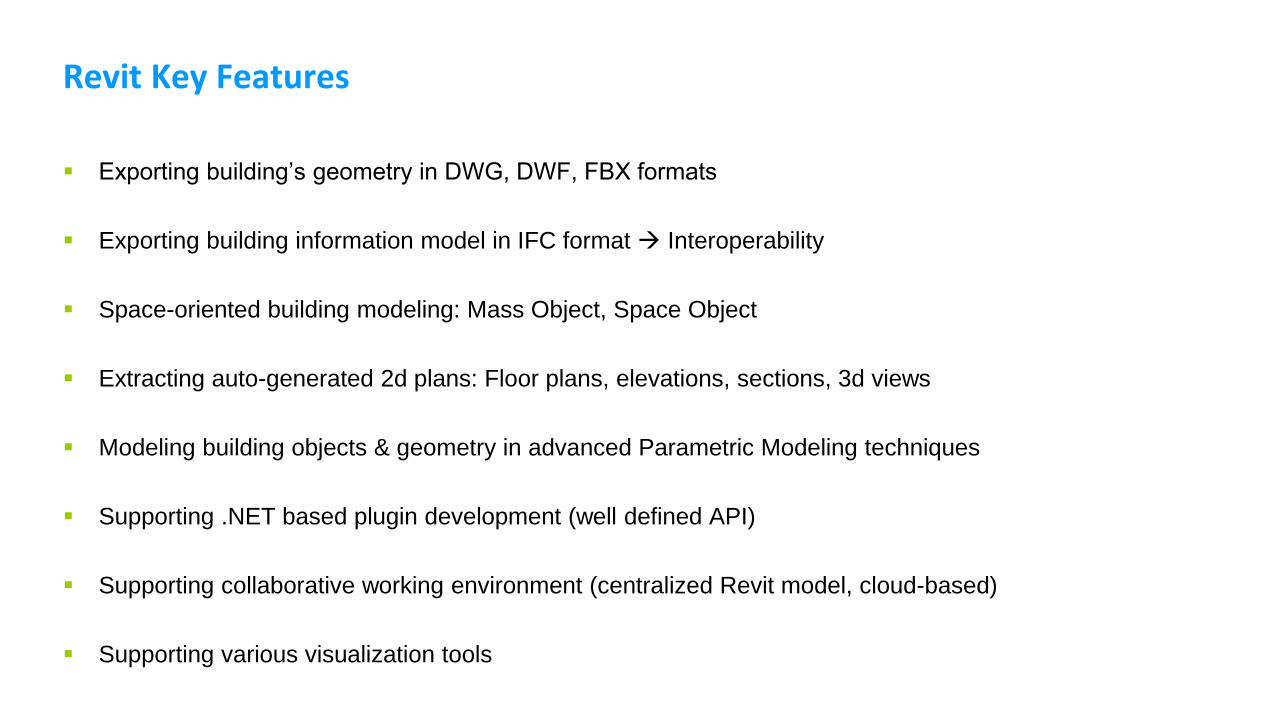
Revit Key Features
Exporting building’s geometry in DWG, DWF, FBX formats
Exporting building information model in IFC format Interoperability
Space-oriented building modeling: Mass Object, Space Object
Extracting auto-generated 2d plans: Floor plans, elevations, sections, 3d views
Modeling building objects & geometry in advanced Parametric Modeling techniques
Supporting .NET based plugin development (well defined API)
Supporting collaborative working environment (centralized Revit model, cloud-based)
Supporting various visualization tools
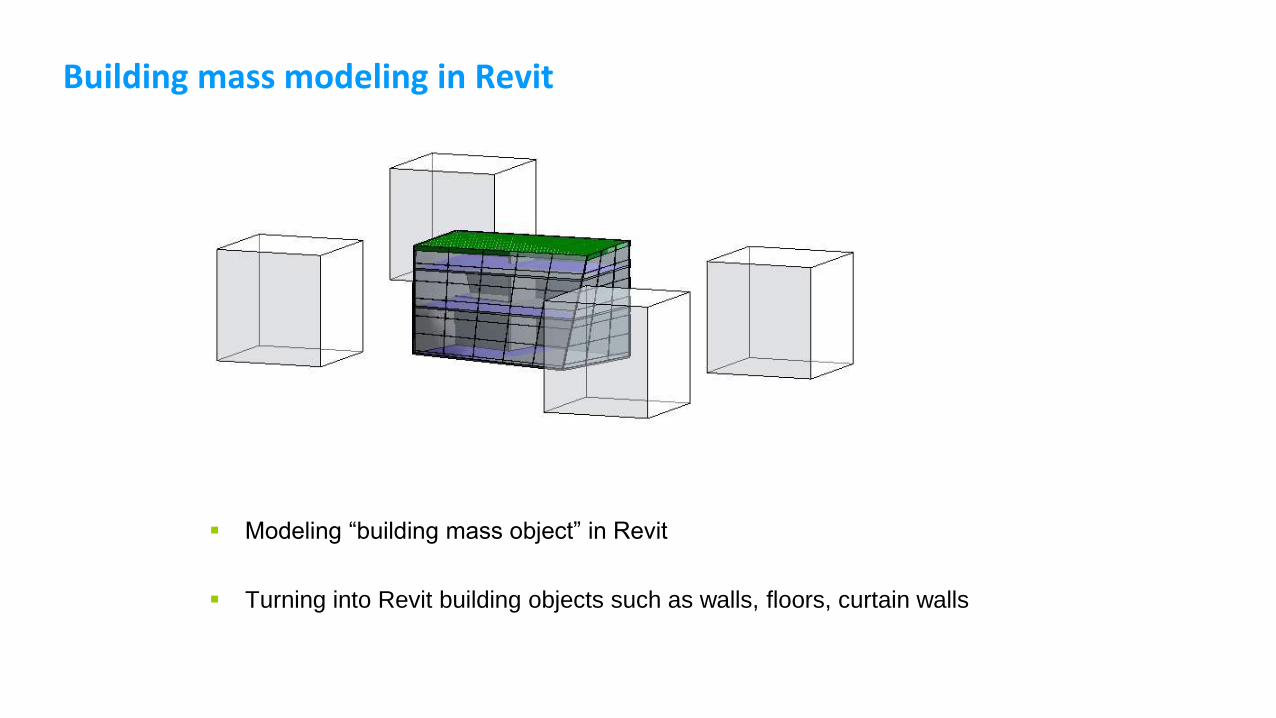
Building mass modeling in Revit
Modeling “building mass object” in Revit
Turning into Revit building objects such as walls, floors, curtain walls
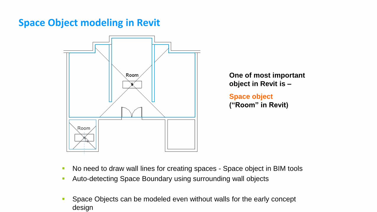
Space Object modeling in Revit
No need to draw wall lines for creating spaces - Space object in BIM tools
Auto-detecting Space Boundary using surrounding wall objects
Space Objects can be modeled even without walls for the early concept
design
One of most important
object in Revit is –
Space object
(“Room” in Revit)
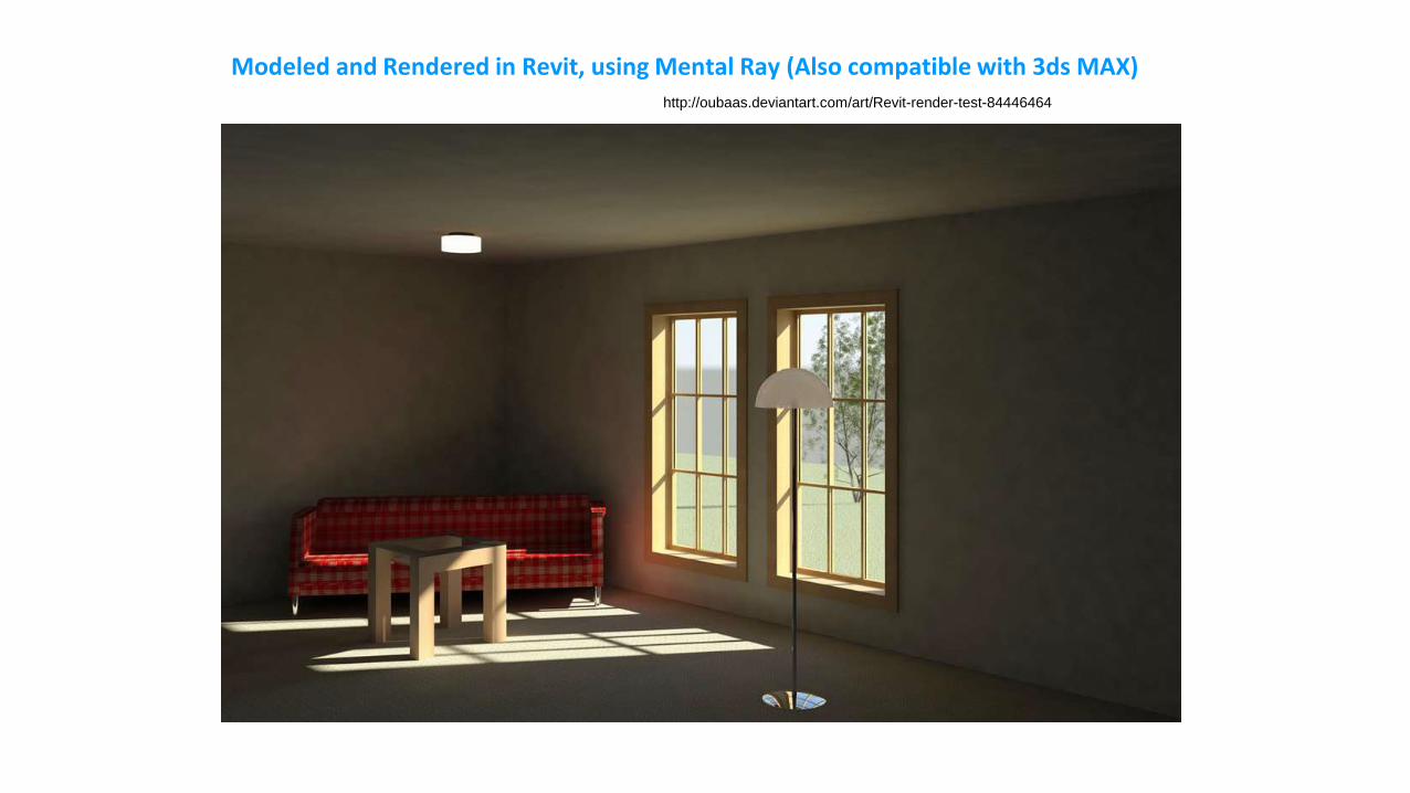
Modeled and Rendered in Revit, using Mental Ray (Also compatible with 3ds MAX)http://oubaas.deviantart.com/art/Revit-render-test-84446464
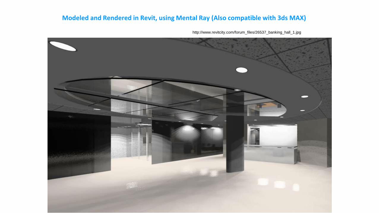
http://www.revitcity.com/forum_files/26537_banking_hall_1.jpg
Modeled and Rendered in Revit, using Mental Ray (Also compatible with 3ds MAX)
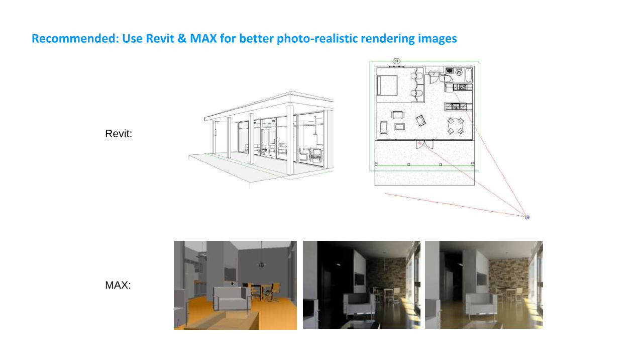
Recommended: Use Revit & MAX for better photo-realistic rendering images
Revit:
MAX:
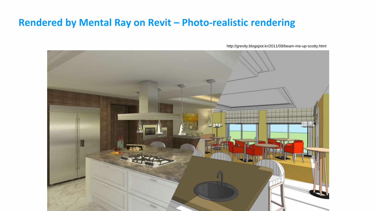
Rendered by Mental Ray on Revit – Photo-realistic rendering
http://grevity.blogspot.kr/2011/09/beam-me-up-scotty.html
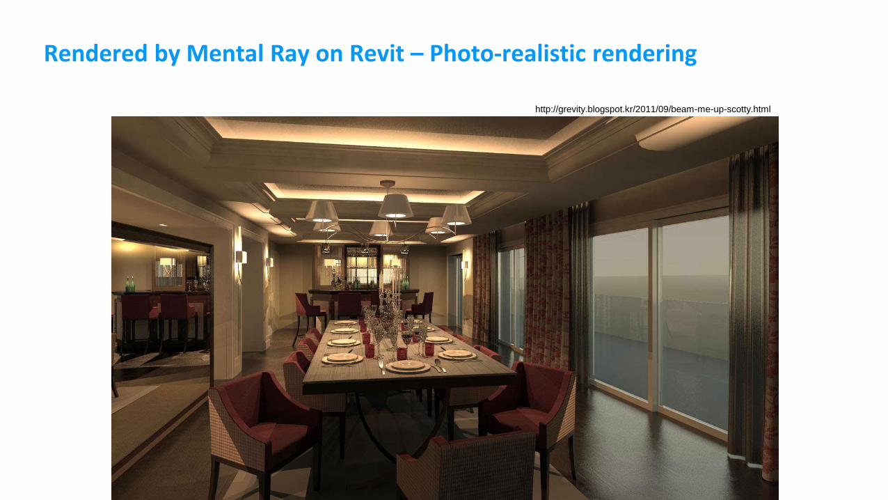
Rendered by Mental Ray on Revit – Photo-realistic rendering
http://grevity.blogspot.kr/2011/09/beam-me-up-scotty.html
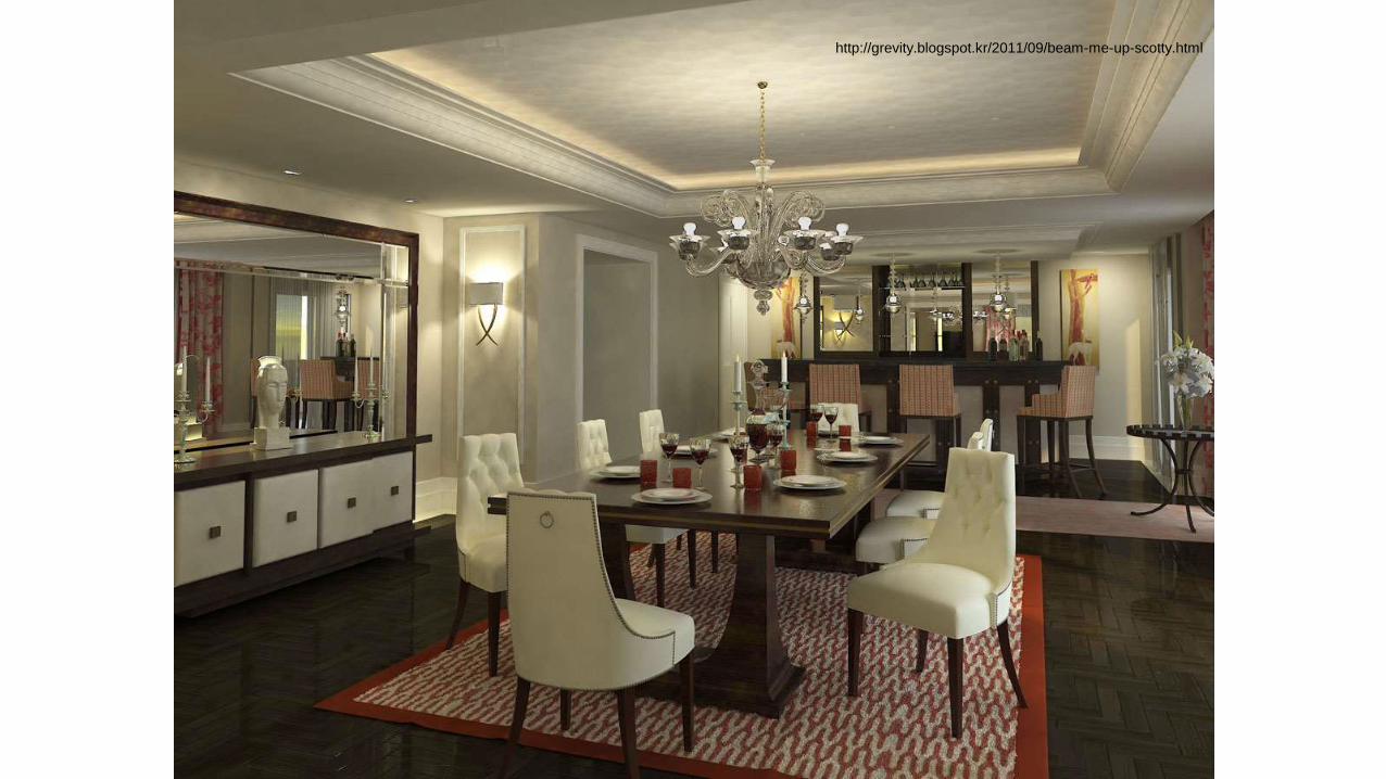
http://grevity.blogspot.kr/2011/09/beam-me-up-scotty.html

Next Class
Revit & BIM
Lab Exercises: - Modeling and Rendering by Autodesk Revit