Embed Size (px)
Citation preview
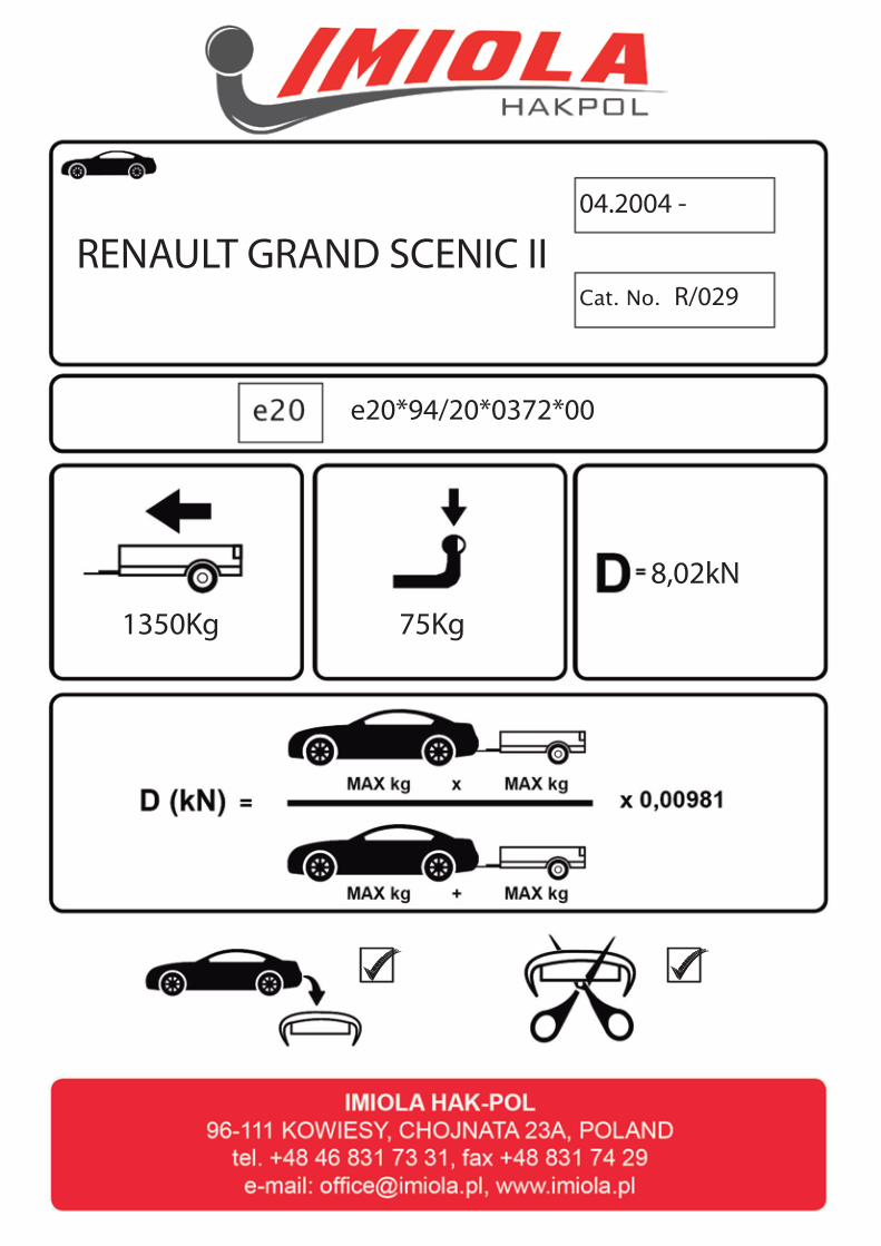
Cat. No.
1350Kg 75Kg
RENAULT GRAND SCENIC II04.2004 -
R/029
8,02kN
e20*94/20*0372*00
���
����
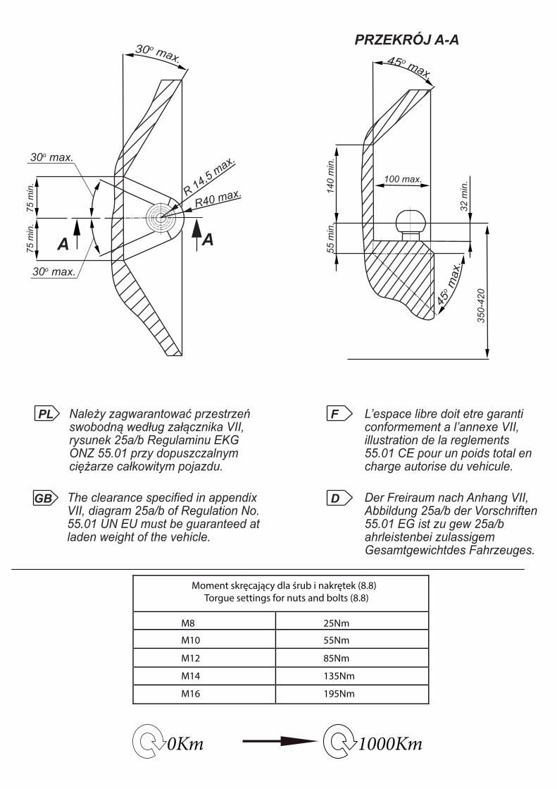
0Km 1000Km
Moment skręcający dla śrub i nakrętek (8.8) Torgue settings for nuts and bolts (8.8)
M8
M10
M12
M14
M16
25Nm
55Nm
85Nm
135Nm
195Nm
R 14,5 max.
30o max.
30o max.
R40 max.
75 m
in.
75 m
in.
AA
100 max.
140
min
.
PRZEKRÓJ A-A
55 m
in.
32 m
in.
350-
420
PL Należy zagwarantować przestrzeńswobodną według załącznika VII,rysunek 25a/b Regulaminu EKGONZ 55.01 przy dopuszczalnym ciężarze całkowitym pojazdu.
L’espace libre doit etre garanticonformement a l’annexe VII,illustration de la reglements 55.01 CE pour un poids total en charge autorise du vehicule.
The clearance specified in appendix VII, diagram 25a/b of Regulation No.55.01 UN EU must be guaranteed atladen weight of the vehicle.
Der Freiraum nach Anhang VII, Abbildung 25a/b der Vorschriften 55.01 EG ist zu gew 25a/b ahrleistenbei zulassigem Gesamtgewichtdes Fahrzeuges.
GB
F
D
x1
x1
x1
x1
x1
x1
x1
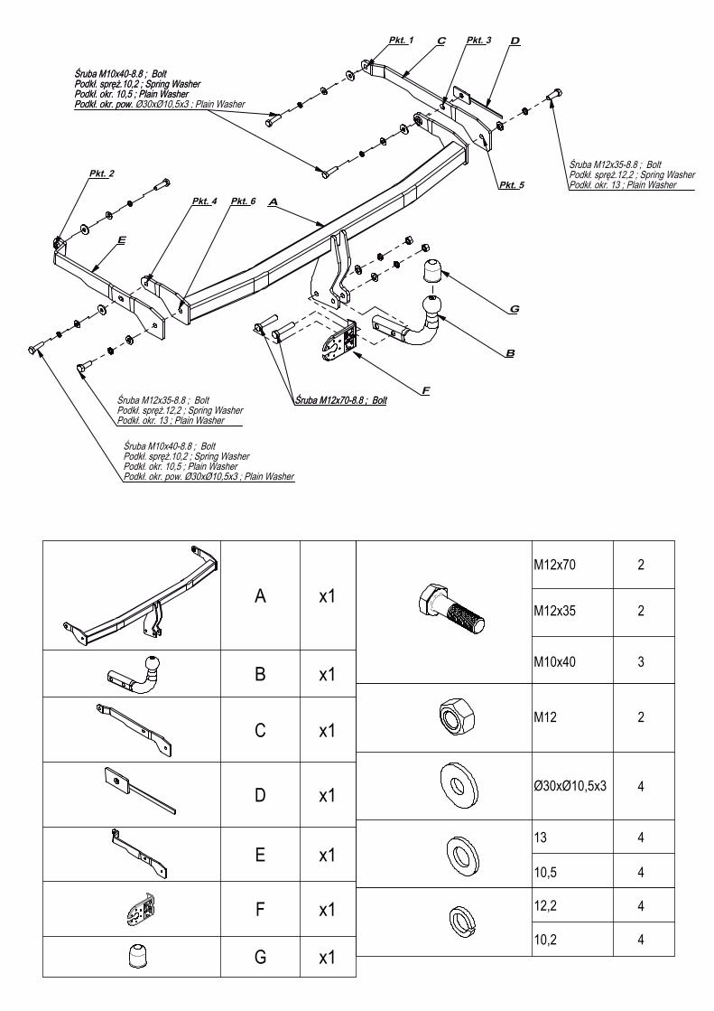
M12 2
Ø30xØ10,5x3 4
13 4
12,2 4
10,2 4
M12x70 2
M12x35 2
M10x40 3
10,5 4
A
B
C D
E
Pkt. 1
Pkt. 2
Pkt. 3
Pkt. 4
Pkt. 5
Pkt. 6
Śruba M12x35-8.8 ; BoltPodkł. spręż.12,2 ; Spring WasherPodkł. okr. 13 ; Plain Washer
Śruba M12x70-8.8 ; BoltŚruba M12x35-8.8 ; BoltPodkł. spręż.12,2 ; Spring WasherPodkł. okr. 13 ; Plain Washer
Śruba M10x40-8.8 ; BoltPodkł. spręż.10,2 ; Spring WasherPodkł. okr. 10,5 ; Plain WasherPodkł. okr. pow. Ø30xØ10,5x3 ; Plain Washer
Śruba M10x40-8.8 ; BoltPodkł. spręż.10,2 ; Spring WasherPodkł. okr. 10,5 ; Plain WasherPodkł. okr. pow. Ø30xØ10,5x3 ; Plain Washer
Śruba M10x40-8.8 ; BoltPodkł. spręż.10,2 ; Spring WasherPodkł. okr. 10,5 ; Plain WasherPodkł. okr. pow.
Śruba M12x70-8.8 ; BoltF
G
Nr ka
talog
owy
R/0
29M
arka
od 1
0.20
03R
enau
lt S
ceni
c II
96-1
11 K
owie
sy, C
hojn
ata
23 A
tel.
+48
46 8
31 7
3 31
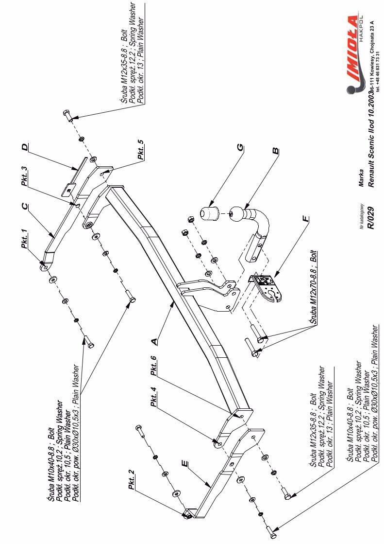
A
B
CD
E
Pkt
. 1
Pkt
. 2
Pkt
. 3
Pkt
. 4
Pkt
. 5
Pkt
. 6
Śrub
a M12
x35-
8.8 ;
Bolt
Podk
ł. spr
ęż.12
,2 ; S
pring
Was
her
Podk
ł. okr.
13 ; P
lain W
ashe
r
Śrub
a M12
x70-
8.8 ;
Bolt
Śrub
a M12
x35-
8.8 ;
Bolt
Podk
ł. spr
ęż.12
,2 ; S
pring
Was
her
Podk
ł. okr.
13 ; P
lain W
ashe
r
Śrub
a M10
x40-
8.8 ;
Bolt
Podk
ł. spr
ęż.10
,2 ; S
pring
Was
her
Podk
ł. okr.
10,5
; Plai
n Was
her
Podk
ł. okr.
pow.
Ø30
xØ10
,5x3 ;
Plai
n Was
her
Śrub
a M10
x40-
8.8 ;
Bolt
Podk
ł. spr
ęż.10
,2 ; S
pring
Was
her
Podk
ł. okr.
10,5
; Plai
n Was
her
Podk
ł. okr.
pow.
Ø30
xØ10
,5x3 ;
Plai
n Was
her
Śrub
a M10
x40-
8.8 ;
Bolt
Podk
ł. spr
ęż.10
,2 ; S
pring
Was
her
Podk
ł. okr.
10,5
; Plai
n Was
her
Podk
ł. okr.
pow.
Śrub
a M12
x70-
8.8 ;
Bolt
F
G
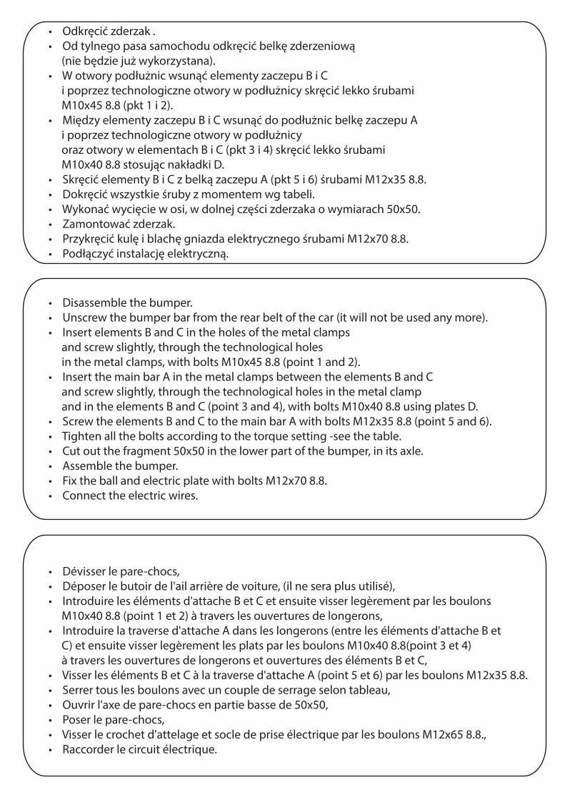
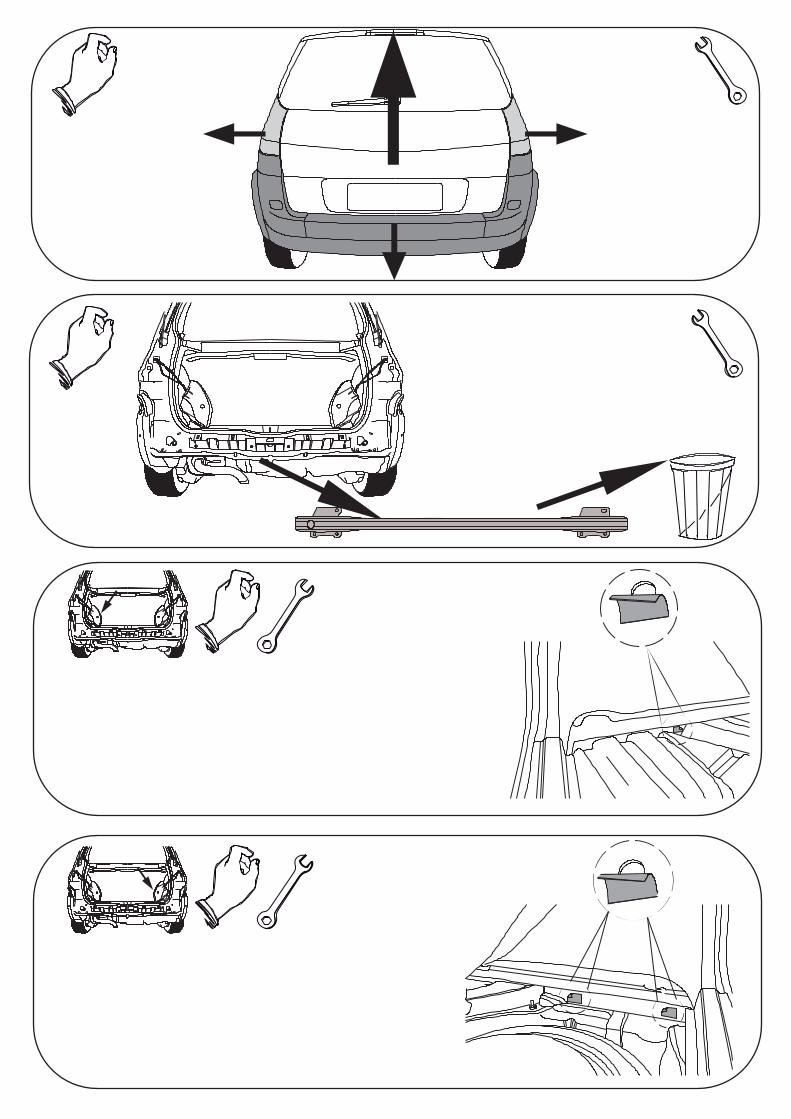
• Odkręcić zderzak .• Od tylnego pasa samochodu odkręcić belkę zderzeniową (nie będzie już wykorzystana).• W otwory podłużnic wsunąć elementy zaczepu B i C i poprzez technologiczne otwory w podłużnicy skręcić lekko śrubami M10x45 8.8 (pkt 1 i 2).• Między elementy zaczepu B i C wsunąć do podłużnic belkę zaczepu A i poprzez technologiczne otwory w podłużnicy oraz otwory w elementach B i C (pkt 3 i 4) skręcić lekko śrubami M10x40 8.8 stosując nakładki D.• Skręcić elementy B i C z belką zaczepu A (pkt 5 i 6) śrubami M12x35 8.8.• Dokręcić wszystkie śruby z momentem wg tabeli.• Wykonać wycięcie w osi, w dolnej części zderzaka o wymiarach 50x50.• Zamontować zderzak.• Przykręcić kulę i blachę gniazda elektrycznego śrubami M12x70 8.8.• Podłączyć instalację elektryczną.
• Disassemble the bumper.• Unscrew the bumper bar from the rear belt of the car (it will not be used any more).• Insert elements B and C in the holes of the metal clamps and screw slightly, through the technological holes in the metal clamps, with bolts M10x45 8.8 (point 1 and 2).• Insert the main bar A in the metal clamps between the elements B and C and screw slightly, through the technological holes in the metal clamp and in the elements B and C (point 3 and 4), with bolts M10x40 8.8 using plates D.• Screw the elements B and C to the main bar A with bolts M12x35 8.8 (point 5 and 6).• Tighten all the bolts according to the torque setting -see the table.• Cut out the fragment 50x50 in the lower part of the bumper, in its axle.• Assemble the bumper.• Fix the ball and electric plate with bolts M12x70 8.8.• Connect the electric wires.
• Dévisser le pare-chocs,• Déposer le butoir de l'ail arrière de voiture, (il ne sera plus utilisé),• Introduire les éléments d'attache B et C et ensuite visser legèrement par les boulons M10x40 8.8 (point 1 et 2) à travers les ouvertures de longerons,• Introduire la traverse d'attache A dans les longerons (entre les éléments d'attache B et C) et ensuite visser legèrement les plats par les boulons M10x40 8.8(point 3 et 4) à travers les ouvertures de longerons et ouvertures des éléments B et C,• Visser les éléments B et C à la traverse d'attache A (point 5 et 6) par les boulons M12x35 8.8.• Serrer tous les boulons avec un couple de serrage selon tableau,• Ouvrir l'axe de pare-chocs en partie basse de 50x50,• Poser le pare-chocs,• Visser le crochet d'attelage et socle de prise électrique par les boulons M12x65 8.8.,• Raccorder le circuit électrique.
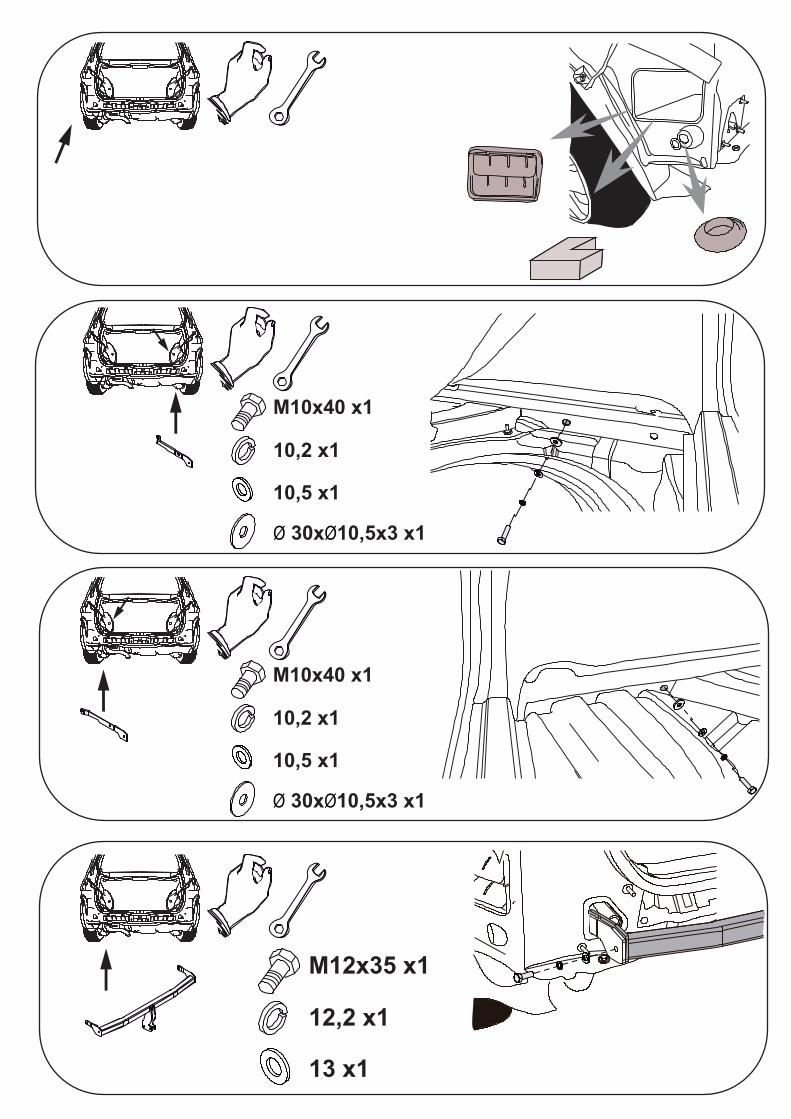
M10x40 x1
10,2 x1
10,5 x1
Ø 30xØ10,5x3 x1
M10x40 x1
10,2 x1
10,5 x1
Ø 30xØ10,5x3 x1
M12x35 x1
12,2 x1
13 x1
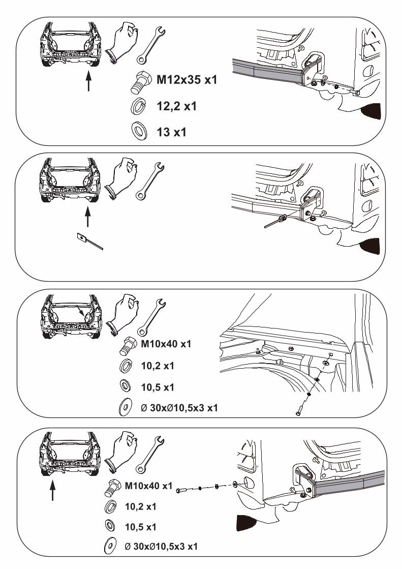
M10x40 x1
10,2 x1
10,5 x1
Ø 30xØ10,5x3 x1
M12x35 x1
12,2 x1
13 x1
M10x40 x1
10,2 x1
10,5 x1
Ø 30xØ10,5x3 x1
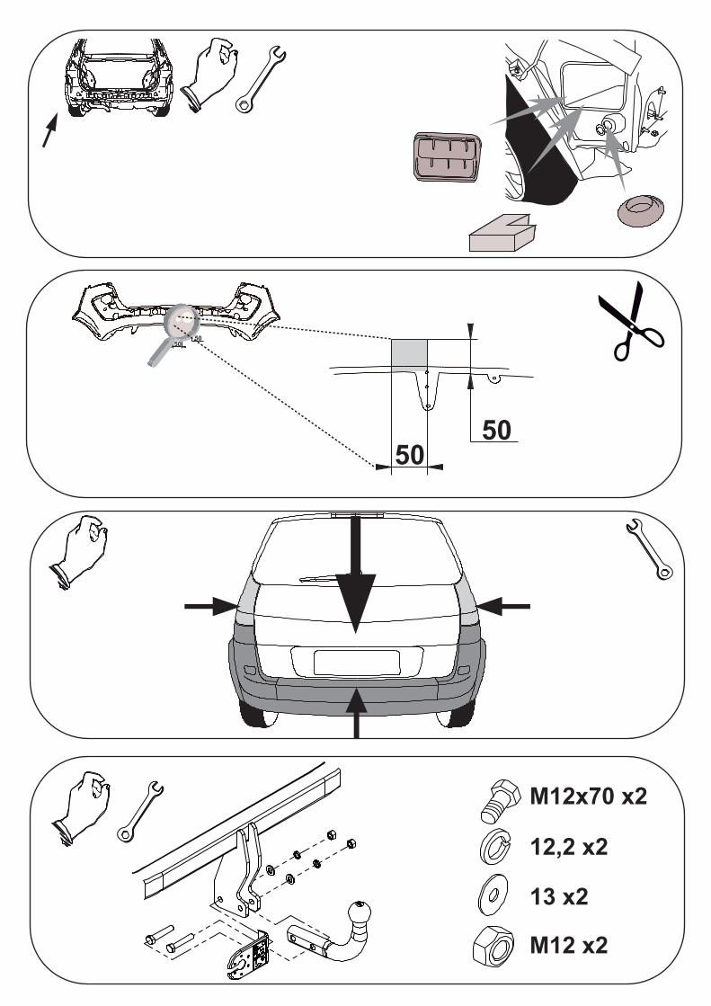
5050
5050
M12x70 x2
12,2 x2
13 x2
M12 x2