Embed Size (px)
Citation preview
MAHATMA GANDHI MISSION’S
JAWAHARLAL NEHRU ENGINEERING COLLEGE,
AURANGABAD. (M.S.)
DEPARTMENT OF CIVIL ENGINEERING
TRANSPORTATION ENGG
LAB MANUAL
Prepared By Approved By
Prof. S.V.Ighare Dr. S. B. Shinde
Lab Incharge H.O.D. Civil

Vision of Civil Department
The department of Civil Engineering strives to produce qualified engineers, researchers and
professionals to serve the society with sustainable development.
Mission of Civil Department
To provide quality education and prepare competitive graduates for successful career in Civil
Engineering.
To develop research opportunities that creates competent professionals who are trained in the
design and development of environment friendly Civil Engineering system.
Program Educational Objectives
I. Graduates of Civil Engineering Program will be prepared to take the challenges in the field
of Civil Engineering.
II. To provide Graduates with a sound Knowledge in mathematical, scientific and Civil
Engineering fundamentals required to solve engineering problems and also to pursue higher
studies.
III. To train students with good scientific and engineering breadth in
Construction industry & many field of Civil Engineering.
IV. To build the confidence of students leading to professional and ethical integrity, effective
communication skill, leadership, so that they can apply engineering knowledge for
betterment of society.
V. To provide a good competitive learning environment so that graduates of Civil Engineering
will be ready to meet the needs of Indian and multinational construction industries.
Program specific outcomes
The students are able to demonstrate:
1. The knowledge of planning and designing of the system components for building planning,
transportation, water resources, estimating, costing and scheduling the construction processes.
2. The fundamental knowledge of analysis and design of various structures with an understanding
of associated safety, quality and economy.
3. The knowledge of field data collection and material characterization to provide constructive and
creative engineering solutions that reflect social and environmental sensitivities.
‘TRANSPORTATION ENGG’ EXPERIMENTS
CLASS: - Third Year Civil Engineering
CONTENTS Page No.
PART – A: Introduction 3
PART – B: Tests on soil
1. CBR Test 7
PART – C: Tests on Aggregates
2. Aggregate Impact Test 11
3. Abrasion Test 15
4. Aggregate Crushing Value Test 19
5. Specific Gravity and Water Absorption Test 22
6. Shape Tests 25
PART – D: Tests on Bituminous Materials
7. Penetration Test 32
8. Ductility and Elastic Recovery Test 35
9. Softening Point Test 38
10. Viscosity Test 41
11. Marshall Stability Test 44

JNEC CIVIL/TRE/SVI/2016 Page 2
PART – A: Introduction
1. Laboratory Tests on Subgrade Soil
Soil is a principle material for the construction fill or embankment and Subgrade of highways soil is also
used in other pavement layers such as sub base and base course. The pavement layers are laid over the
prepared soil Subgrade which provides support to the pavement. The design and the performance of the
pavement, particularly the flexible pavement, depend on a great extent on the type of Subgrade soil and its
properties including the support or stability value.
In view of the wide diversity in soil type, it is desirable to classify the Subgrade soil into groups
possessing similar properties. Many methods have been in use for this purpose. Soils are normally
classified on the basis of simple laboratory test such as grain size analysis and consistency tests.
Soil compaction is an important phenomenon in highway construction. Compaction of earth embankments
result in reduction in future settlement. Compacted soil fill and Subgrade improve the load supporting
ability of pavement, which in turn results in decreased pavement thickness requirement. The laboratory
compaction test results are useful in specifying the optimum moisture content at which a soil should be
compacted and the dry density that should be aimed at the construction site. The in-situ density of
prepared Subgrade as well as other pavement layer is determined by a field density test to check the
compaction achieved and as a field control test for compaction.
Table: List of Laboratory tests on Soil
Sr. No. Tests Apparatus Desired Properties
1 Grain size analysis I.S. Sieves Particle size determination
2 Consistency limit Casagrande apparatus Consistency of soil
3 Shear test of soil Shear test apparatus Shear strength
4 California Bearing ratio C.B.R. apparatus Strength of soil

JNEC CIVIL/TRE/SVI/2016 Page 3
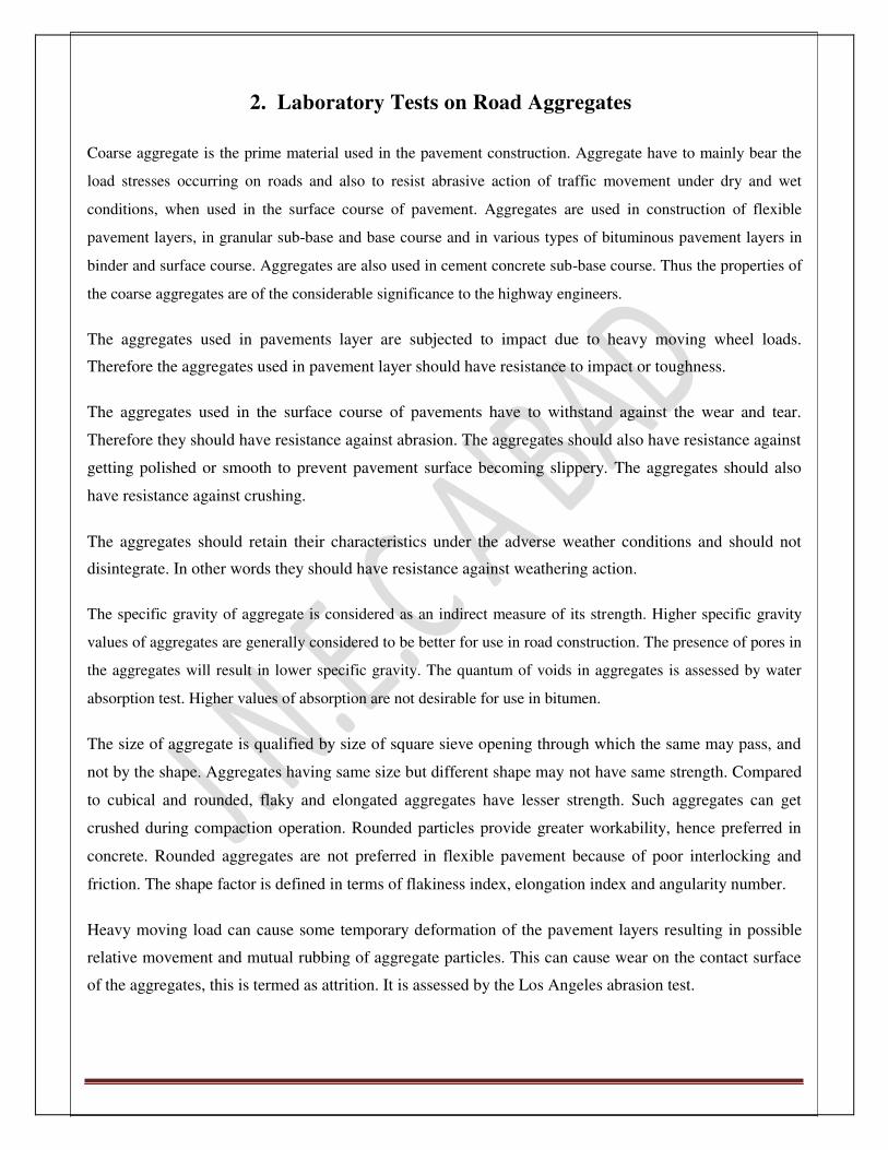
2. Laboratory Tests on Road Aggregates Coarse aggregate is the prime material used in the pavement construction. Aggregate have to mainly bear the
load stresses occurring on roads and also to resist abrasive action of traffic movement under dry and wet
conditions, when used in the surface course of pavement. Aggregates are used in construction of flexible
pavement layers, in granular sub-base and base course and in various types of bituminous pavement layers in
binder and surface course. Aggregates are also used in cement concrete sub-base course. Thus the properties of
the coarse aggregates are of the considerable significance to the highway engineers.
The aggregates used in pavements layer are subjected to impact due to heavy moving wheel loads.
Therefore the aggregates used in pavement layer should have resistance to impact or toughness.
The aggregates used in the surface course of pavements have to withstand against the wear and tear.
Therefore they should have resistance against abrasion. The aggregates should also have resistance against
getting polished or smooth to prevent pavement surface becoming slippery. The aggregates should also
have resistance against crushing.
The aggregates should retain their characteristics under the adverse weather conditions and should not
disintegrate. In other words they should have resistance against weathering action.
The specific gravity of aggregate is considered as an indirect measure of its strength. Higher specific gravity
values of aggregates are generally considered to be better for use in road construction. The presence of pores in
the aggregates will result in lower specific gravity. The quantum of voids in aggregates is assessed by water
absorption test. Higher values of absorption are not desirable for use in bitumen.
The size of aggregate is qualified by size of square sieve opening through which the same may pass, and
not by the shape. Aggregates having same size but different shape may not have same strength. Compared
to cubical and rounded, flaky and elongated aggregates have lesser strength. Such aggregates can get
crushed during compaction operation. Rounded particles provide greater workability, hence preferred in
concrete. Rounded aggregates are not preferred in flexible pavement because of poor interlocking and
friction. The shape factor is defined in terms of flakiness index, elongation index and angularity number.
Heavy moving load can cause some temporary deformation of the pavement layers resulting in possible
relative movement and mutual rubbing of aggregate particles. This can cause wear on the contact surface
of the aggregates, this is termed as attrition. It is assessed by the Los Angeles abrasion test.

JNEC CIVIL/TRE/SVI/2016 Page 4
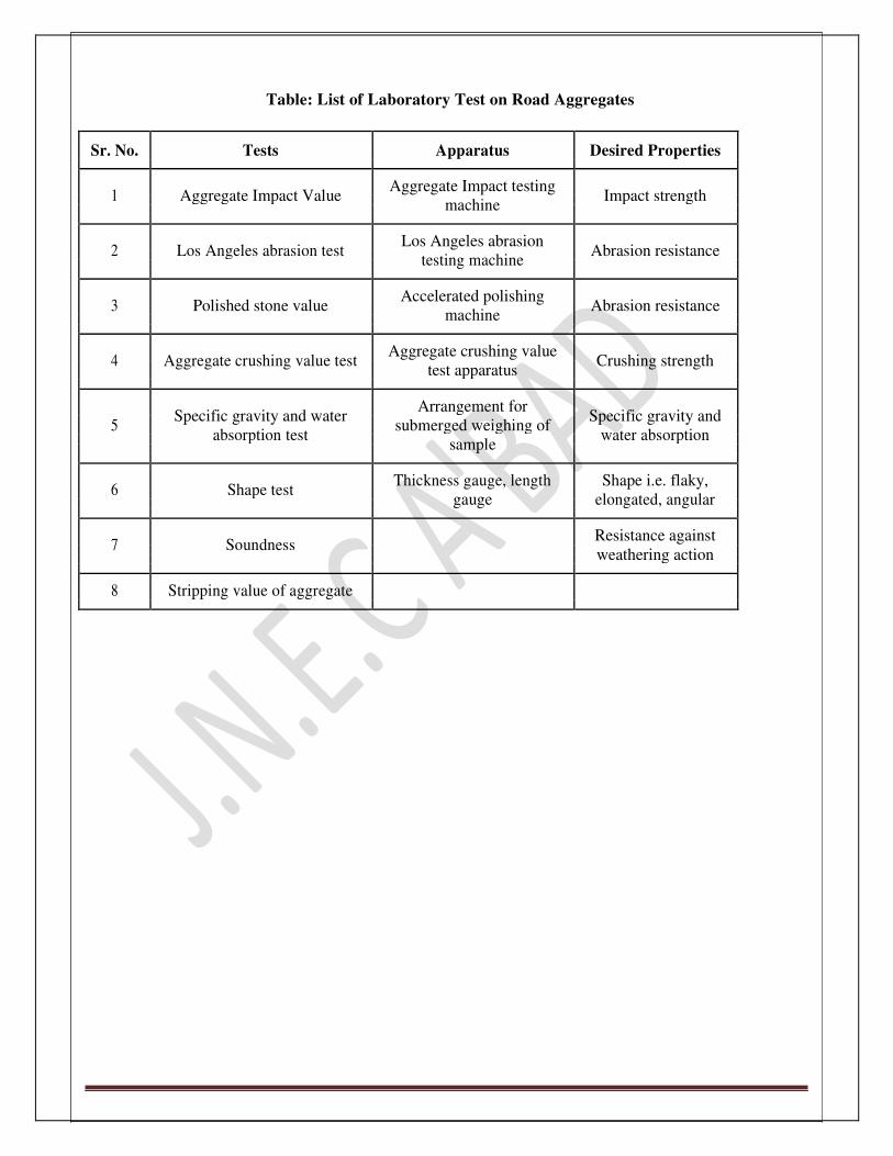
Table: List of Laboratory Test on Road Aggregates
Sr. No. Tests Apparatus Desired Properties
1 Aggregate Impact Value Aggregate Impact testing
Impact strength
machine
2 Los Angeles abrasion test Los Angeles abrasion
Abrasion resistance
testing machine
3 Polished stone value Accelerated polishing
Abrasion resistance
machine
4 Aggregate crushing value test Aggregate crushing value
Crushing strength
test apparatus
Specific gravity and water
Arrangement for Specific gravity and
5 submerged weighing of
absorption test water absorption
sample
6 Shape test Thickness gauge, length Shape i.e. flaky,
gauge elongated, angular
7 Soundness Resistance against
weathering action
8 Stripping value of aggregate

JNEC CIVIL/TRE/SVI/2016 Page 5
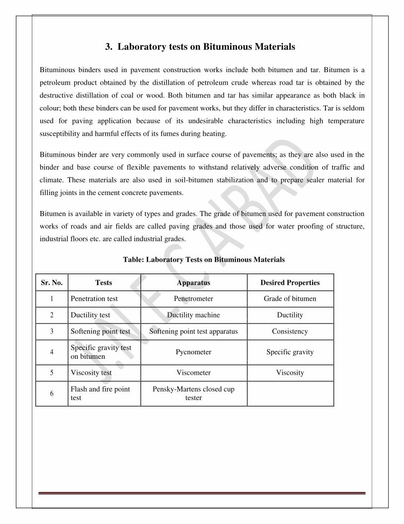
3. Laboratory tests on Bituminous Materials
Bituminous binders used in pavement construction works include both bitumen and tar. Bitumen is a
petroleum product obtained by the distillation of petroleum crude whereas road tar is obtained by the
destructive distillation of coal or wood. Both bitumen and tar has similar appearance as both black in
colour; both these binders can be used for pavement works, but they differ in characteristics. Tar is seldom
used for paving application because of its undesirable characteristics including high temperature
susceptibility and harmful effects of its fumes during heating.
Bituminous binder are very commonly used in surface course of pavements; as they are also used in the
binder and base course of flexible pavements to withstand relatively adverse condition of traffic and
climate. These materials are also used in soil-bitumen stabilization and to prepare sealer material for
filling joints in the cement concrete pavements.
Bitumen is available in variety of types and grades. The grade of bitumen used for pavement construction
works of roads and air fields are called paving grades and those used for water proofing of structure,
industrial floors etc. are called industrial grades.
Table: Laboratory Tests on Bituminous Materials
Sr. No. Tests Apparatus Desired Properties
1 Penetration test Penetrometer Grade of bitumen
2 Ductility test Ductility machine Ductility
3 Softening point test Softening point test apparatus Consistency
4 Specific gravity test
Pycnometer Specific gravity
on bitumen
5 Viscosity test Viscometer Viscosity
6 Flash and fire point Pensky-Martens closed cup
test tester

JNEC CIVIL/TRE/SVI/2016 Page 6
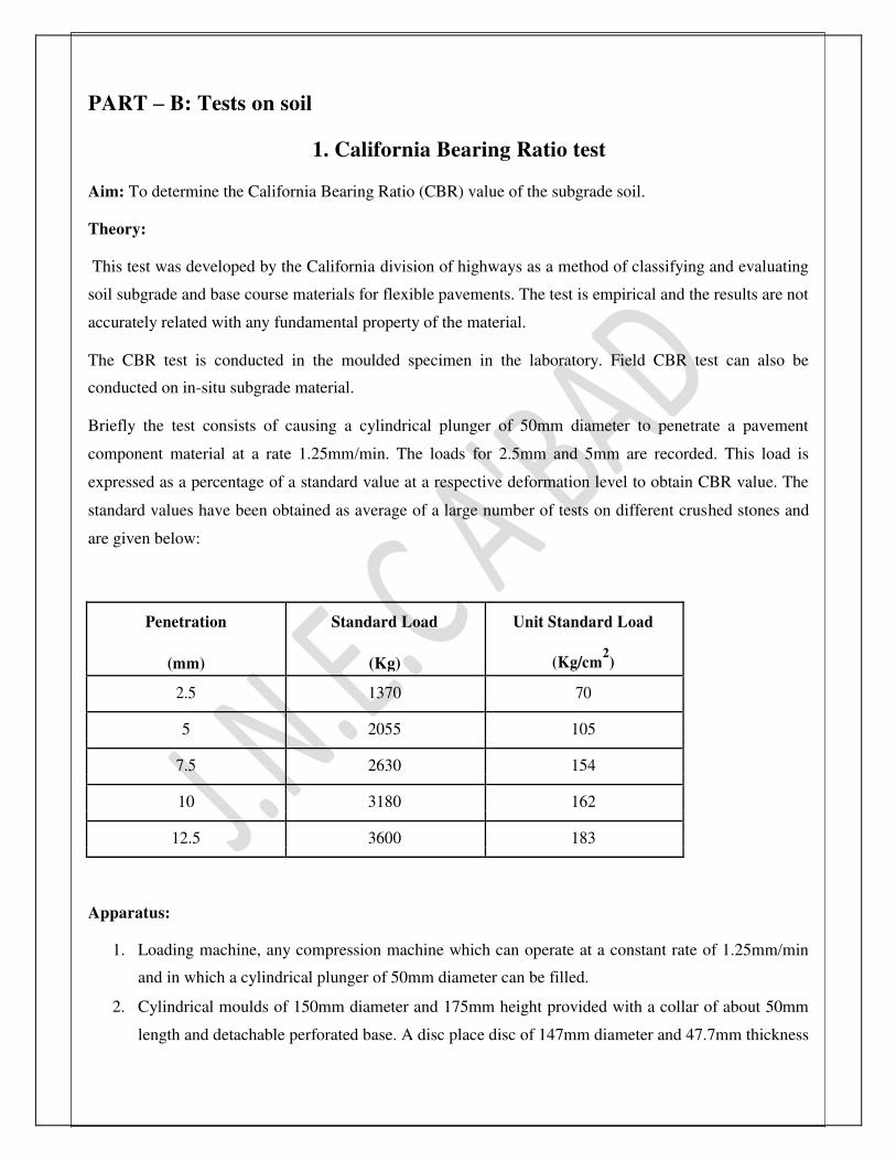
PART – B: Tests on soil
1. California Bearing Ratio test
Aim: To determine the California Bearing Ratio (CBR) value of the subgrade soil. Theory: This test was developed by the California division of highways as a method of classifying and evaluating
soil subgrade and base course materials for flexible pavements. The test is empirical and the results are not
accurately related with any fundamental property of the material.
The CBR test is conducted in the moulded specimen in the laboratory. Field CBR test can also be
conducted on in-situ subgrade material.
Briefly the test consists of causing a cylindrical plunger of 50mm diameter to penetrate a pavement
component material at a rate 1.25mm/min. The loads for 2.5mm and 5mm are recorded. This load is
expressed as a percentage of a standard value at a respective deformation level to obtain CBR value. The
standard values have been obtained as average of a large number of tests on different crushed stones and
are given below:
Penetration Standard Load Unit Standard Load
(mm) (Kg) (Kg/cm2)
2.5 1370 70
5 2055 105
7.5 2630 154
10 3180 162
12.5 3600 183
Apparatus:
1. Loading machine, any compression machine which can operate at a constant rate of 1.25mm/min
and in which a cylindrical plunger of 50mm diameter can be filled.
2. Cylindrical moulds of 150mm diameter and 175mm height provided with a collar of about 50mm
length and detachable perforated base. A disc place disc of 147mm diameter and 47.7mm thickness

is used to obtain a specimen of exactly 127.3mm height.
JNEC CIVIL/TRE/SVI/2016 Page 7
3. Compression hammer- Compaction is done as suggested by ISI for light and heavy compaction.
Compaction No. of Layers Weight of
Fall (cm) No. of Blows
Hammer (kg)
1. Light 3 2.6 31 56
2. Heavy 5 4.89 45 56
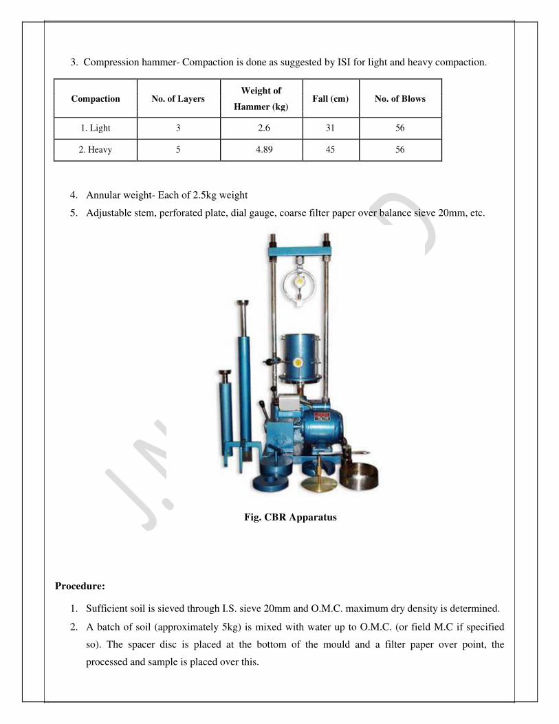
4. Annular weight- Each of 2.5kg weight
5. Adjustable stem, perforated plate, dial gauge, coarse filter paper over balance sieve 20mm, etc.
Fig. CBR Apparatus Procedure:
1. Sufficient soil is sieved through I.S. sieve 20mm and O.M.C. maximum dry density is determined.
2. A batch of soil (approximately 5kg) is mixed with water up to O.M.C. (or field M.C if specified
so). The spacer disc is placed at the bottom of the mould and a filter paper over point, the
processed and sample is placed over this.

JNEC CIVIL/TRE/SVI/2016 Page 8
3. The soil is compacted with 56blows per layer in three equal layers. The collar is removed and the
excess soil at the top of the mould is struck off using a straight edge. Such three CBR test specimen
are prepared.
4. From each mould soil samples are collected for M.C. determinations.
5. The sample contained in the mould excluding base plate and spacer disc is weighed. The filler
paper is now placed on base plate and the mould is turned upside down so that the top sample is
now placed in the water tank for soaking. A filter paper is placed over the sample top along with
the perforated plate with adjustable stem. Over this a surcharge weight of 2.5kg or 5kg placed in
order to simulate the effect of the overlying pavement weight soaking is done for 4days. The initial
and final readings of the dial gauge are taken to measure expansion.
6. The sample is allowed to drain off water in a vertical position for 15minutes. The sample along
with the moulded is again weighed to calculate the percentage of water absorbed.
7. The surcharge weight is again provided and the assembly with the base plate is placed in the
compression machine. The plunger is brought in contact with the top surface of the sample. A
seating load of 4kg is applied; the dial gauge is attached and is set to zero. The load is applied
smoothly at the rate at 1.25mm/min. Load readings are recorded at 0.5, 1.0, 1.5, 2.0, 2.5, 3.0, 4.0,
5.0, 7.5, 10 and 12.5mm. The load is released and the mould is removed from the loading machine.
A soil sample from the top 3cm layer is collected and weighed from M.C. determination, the
California state highway Department correlating the CBR value and the flexible pavement
thickness requirement. IRC also adopted a CBR design chart for tentative use in India. The chart
gives the depth of construction of Highway pavement component for various CBR values and for
different traffic volume.
Observations:
1. Type of material: Soil.
2. Compacting M.C.:
3. Dry Density: Maximum Dry Density.
4. Condition of test specimen: Soaked / Unsoaked.
5. M.C.: a) At top 3cm, after soaking.
b) Average after Soaking.
6. Period of Soaking: 3 to 4days.

JNEC CIVIL/TRE/SVI/2016 Page 9
Calculations: Final Dial Reading – Initial Dial Reading
E. R = 0.01 × Initial Height of Specimen in mm
For each penetration level, the unit pressure is obtained. The load penetration curve for each specimen is
then plotted on natural scale. If the curve is uniform the CBR values at 2.5mm and 5.0mm are obtained. If
the curve becomes reverse one, a tangent at the steepest point of the curve is drawn. This line is extended
until it intersects the base axis which represents the correct zero penetration. The values at the corrected
penetration at 2.5mm and 5.0mm are read out CBR values are then calculated. Generally the value at
2.5mm is higher than that at 5.0mm. However higher CBR value obtained at 5.0mm then the test is
repeated to verify this.
Result:
The CBR values for different penetration are as follows:
1. 2.5mm penetration-
2. 5.0mm penetration- Conclusion: CBR value for 5.0mm penetration is more than the 2.5mm penetration. Hence the test should be repeated.
If on repetition 5.0mm test value of CBR is more once again, then 5.0mm penetration value should be
taken for design. Application of test: Based on extensive test data collected, empirical design chart were developed by the California State
Highway department, correlating the CBR value and flexible pavement thickness requirement. Later on
similar design curve were developed by other states in USA and other organisations in several countries.
IRC has established the guidelines for the design of flexible pavements based on CBR value (IRC: 37 –
2001) and the method is being followed for the design of flexible pavements for all the roads in India. For
village roads separate design specifications and charts are made available by IRC.

JNEC CIVIL/TRE/SVI/2016 Page 10
PART – C: Tests on Aggregates
2. Aggregate Impact Test
(IS: 2386 – Part 4)
Object: To determine the resistance of aggregates to sudden shock of impact. Theory: Toughness is the property of a material to resist impact. Due to traffic loads, the road aggregates are
subjected to the impact and there is possibility of stones breaking into smaller pieces. The road aggregates
should therefore be tough enough to resist fracture under impact. A test designed to evaluate the toughness
of road stones that is the resistance of the stones to fracture under repeated impacts is called as aggregate
impact test.
The aggregate impact value indicates a relative measure of the resistance of aggregate to a sudden shock
and differs from its resistance to a slow compressive load.
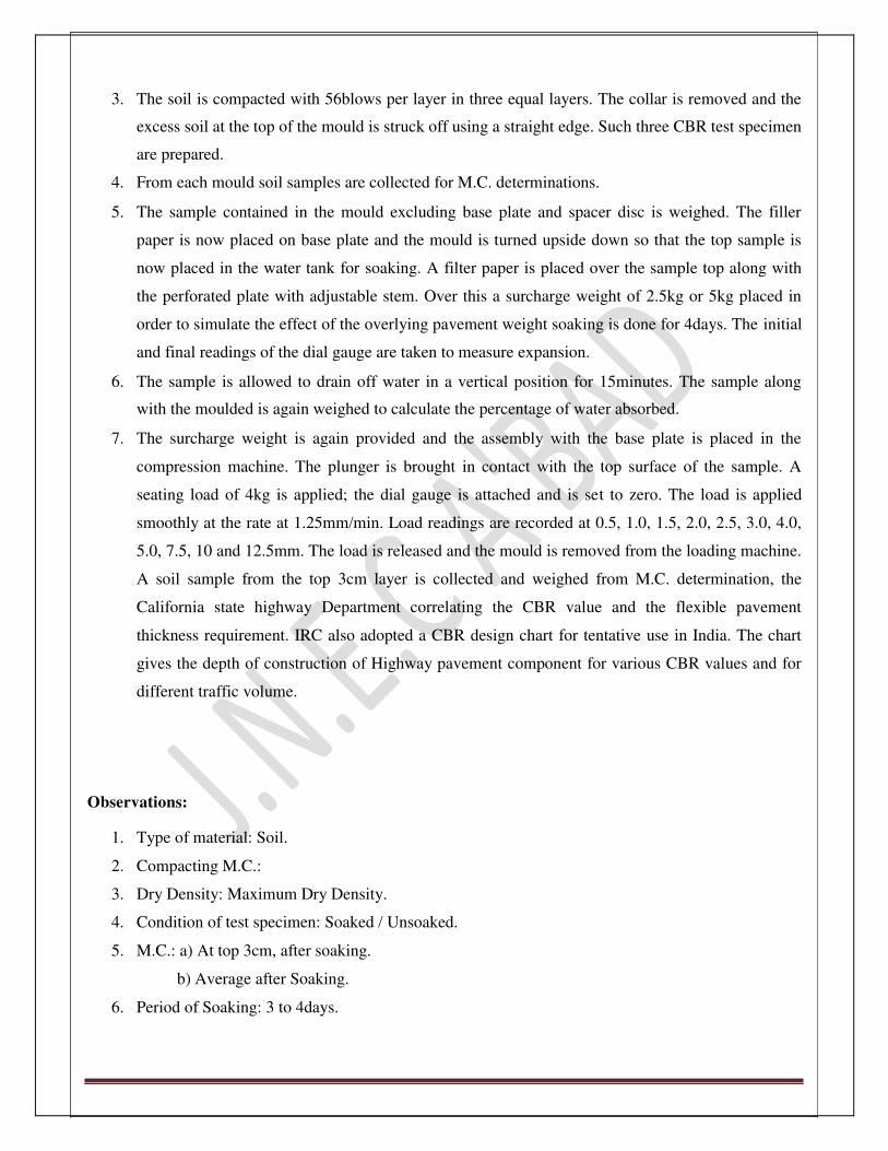
Apparatus:
1. Impact test machine with cup and hammer 13.5 to 14 kg, with lifting and lowering arrangement
2. A cylindrical measure having internal diameter 75 mm and depth 50 mm, for measuring aggregates
3. I.S. sieves 12.5 mm, 10 mm and 2.36 mm
4. Tamping rod of circular section, 10 mm in diameter and 230 mm in length, rounded at one end
5. Weighing machine accurate upto 1gram
6. Thermostatically controlled oven, capable of maintaining temperature between 100 oC and 110
oC
Fig. Aggregate impact testing machine

JNEC CIVIL/TRE/SVI/2016 Page 11
Procedure:
1. The test sample consist of aggregates passing through 12.5 mm and retained on 10 mm sieve and
dried in an oven for 4 hours at a temperature 100 oC to 110
oC and cooled.
2. The test aggregates are filled up to about 1/3rd
full in the cylindrical measure and tamped 25 times
with rounded tamping rod. Further quantity of aggregates is then added up to about 2/3rd
full in the
cylinder and 25 strokes of tamping rod are given. The measure is now filled with the aggregates to
overflow, tamped 25 times and the surplus aggregates are struck off using the tamping rod as
straight edge. The net weight of aggregate in the measure is determined to the nearest gram and
this weight of the aggregate is used for carrying out duplicate test on the same materials.
3. The impact machines are adjusted so that hammer guide columns are vertical.
4. The cylindrical cup of diameter 102 mm and depth 50 mm is fixed firmly on the base plate of the
machine and the whole of the test sample placed in it and compacted by tamping with 25 strokes.
5. The hammer is raised until its lower face is 380 mm above the upper surface of the aggregate in the
cup and allowed to fall freely over the aggregate. The sample is subjected to a total of 15 such
blows, each being delivered at an interval of not less than 1second.
6. The crushed aggregate is then sieved through I.S. sieve 2.36 mm and fraction passing is weighed
accurate to 0.1 gram.
7. Three tests are made on fresh aggregates.
8. The ratio of the weight of fines formed to the total weight of the sample in each test is calculated
and expressed as percentage to the first decimal place. The average of the 3 results is reported as
aggregate impact value to the nearest whole number.

JNEC CIVIL/TRE/SVI/2016 Page 12
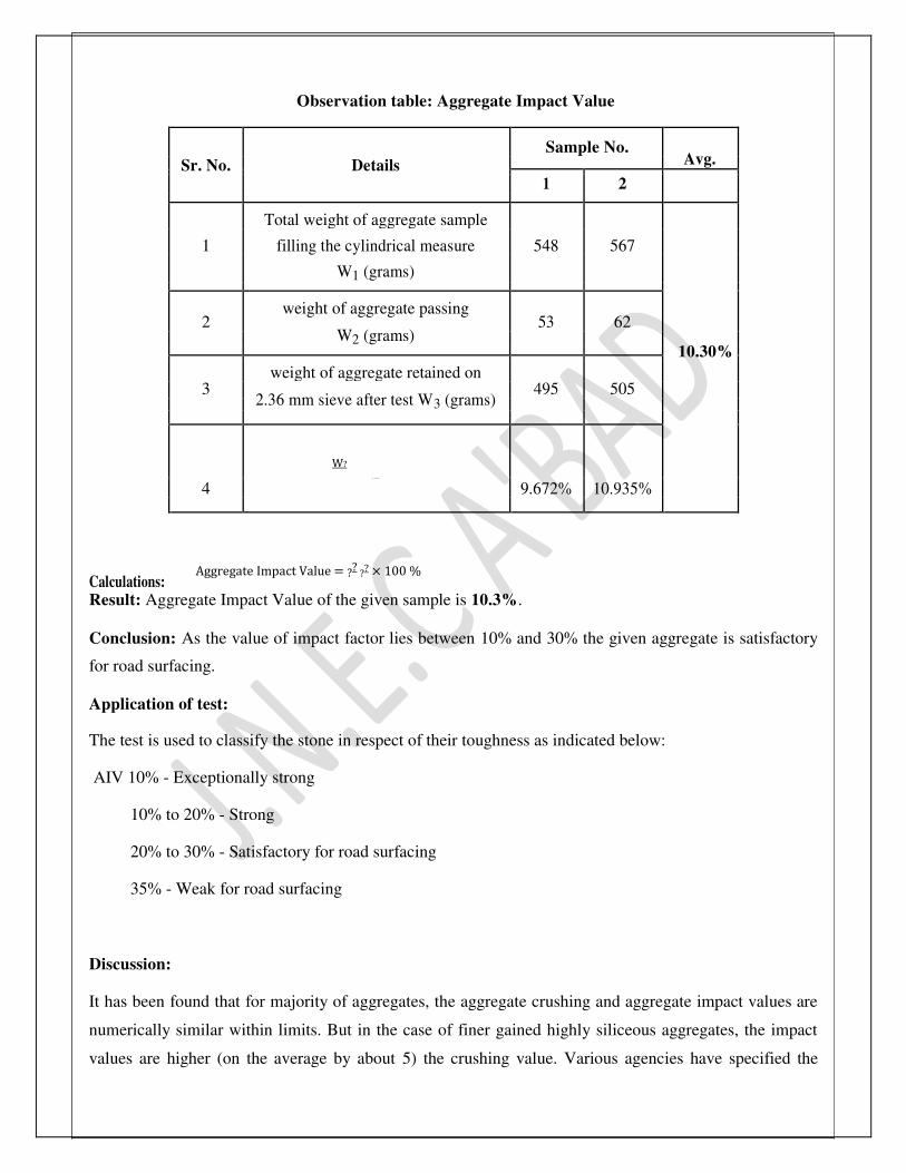
Observation table: Aggregate Impact Value
Sr. No. Details
Sample No. Avg.
1 2
Total weight of aggregate sample
1 filling the cylindrical measure 548 567
W1 (grams)
2
weight of aggregate passing 53 62
W2 (grams)
10.30%
3 weight of aggregate retained on
495 505
2.36 mm sieve after test W3 (grams)
W?
4 W? X 100 %
9.672% 10.935%
Calculations:
Aggregate Impact Value = ?? ?? × 100 %
Result: Aggregate Impact Value of the given sample is 10.3%. Conclusion: As the value of impact factor lies between 10% and 30% the given aggregate is satisfactory
for road surfacing.
Application of test: The test is used to classify the stone in respect of their toughness as indicated below: AIV 10% - Exceptionally strong
10% to 20% - Strong
20% to 30% - Satisfactory for road surfacing
35% - Weak for road surfacing
Discussion: It has been found that for majority of aggregates, the aggregate crushing and aggregate impact values are
numerically similar within limits. But in the case of finer gained highly siliceous aggregates, the impact
values are higher (on the average by about 5) the crushing value. Various agencies have specified the

maximum permissible aggregate impact values for the different types of pavements. JNEC CIVIL/TRE/SVI/2016 Page 13
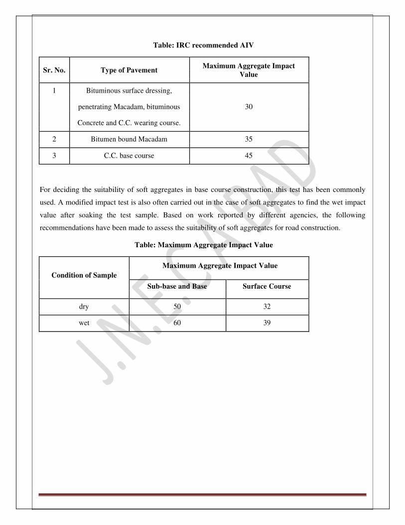
Table: IRC recommended AIV
Sr. No. Type of Pavement Maximum Aggregate Impact
Value
1 Bituminous surface dressing,
penetrating Macadam, bituminous 30
Concrete and C.C. wearing course.
2 Bitumen bound Macadam 35
3 C.C. base course 45
For deciding the suitability of soft aggregates in base course construction, this test has been commonly
used. A modified impact test is also often carried out in the case of soft aggregates to find the wet impact
value after soaking the test sample. Based on work reported by different agencies, the following
recommendations have been made to assess the suitability of soft aggregates for road construction.
Table: Maximum Aggregate Impact Value
Maximum Aggregate Impact Value
Condition of Sample
Sub-base and Base Surface Course
dry 50 32
wet 60 39

JNEC CIVIL/TRE/SVI/2016 Page 14
3. Abrasion Test
Object: To determine the wearing resistance/ hardness of the aggregates Theory: The road stones used in surface course of pavements are subjected to wearing action at the top surface,
due to vehicular traffic. Resistance to wear is an essential property for road aggregates, especially when
used in wearing course. Thus road stone should be hard enough to resist the abrasion due to the traffic.
When fast moving traffic fitted with the pneumatic tyres on the wheel, move on the road, the soil particles
present between the road surface and tyres causes abrasion of the road surface. Steel wheels of animal
drawn vehicles which rub against the stones can cause considerable abrasion of the stones on the road
surface. In order to test the suitability of road stones to resist the abrading action due to traffic, different
types of abrasion tests are carried out in laboratory.
Abrasion test on aggregates is generally carried out by any of the following methods:
i) Los Angeles Abrasion Test
ii) Deval Abrasion Test iii) Dorry Abrasion Test
The Los Angeles test is commonly adopted as the values of aggregates have bees correlated with
pavement performance studies. The BIS has suggested that Los Angeles method should be preferred over
other methods. The IRC and MORTH have specified only Los Angeles test.
The principle of the test is to find percentage wear due to relative rubbing action between the aggregates
and steel balls used as abrasive charge. It is observed that the test is reliable for evaluating the suitability
of coarse aggregates in pavement as both abrasion and impact occur during the test similar to the field
conditions. This test has also been standardize by ASTM, AASHTO and BIS.

JNEC CIVIL/TRE/SVI/2016 Page 15
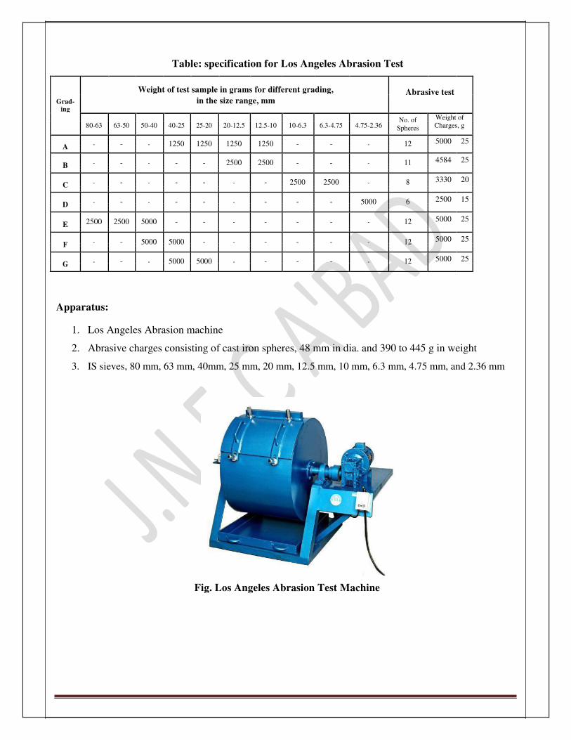
Table: specification for Los Angeles Abrasion Test
Weight of test sample in grams for different grading, Abrasive test
in the size range, mm
Grad-
ing
80-63 63-50 50-40 40-25 25-20 20-12.5 12.5-10 10-6.3 6.3-4.75 4.75-2.36 No. of Weight of
Charges, g
Spheres
A - - - 1250 1250 1250 1250 - - - 12 5000 25
B - - - - - 2500 2500 - - - 11 4584 25
C - - - - - - - 2500 2500 - 8 3330 20
D - - - - - - - - - 5000 6 2500 15
E 2500 2500 5000 - - - - - - - 12 5000 25
F - - 5000 5000 - - - - - - 12 5000 25
G - - - 5000 5000 - - - - - 12 5000 25
Apparatus:
1. Los Angeles Abrasion machine
2. Abrasive charges consisting of cast iron spheres, 48 mm in dia. and 390 to 445 g in weight
3. IS sieves, 80 mm, 63 mm, 40mm, 25 mm, 20 mm, 12.5 mm, 10 mm, 6.3 mm, 4.75 mm, and 2.36 mm
Fig. Los Angeles Abrasion Test Machine

JNEC CIVIL/TRE/SVI/2016 Page 16
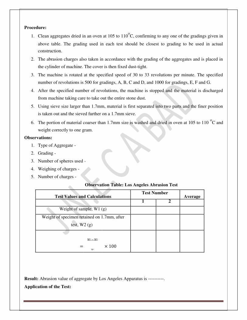
Procedure:
1. Clean aggregates dried in an oven at 105 to 110oC, confirming to any one of the gradings given in
above table. The grading used in each test should be closest to grading to be used in actual
construction.
2. The abrasion charges also taken in accordance with the grading of the aggregates and is placed in
the cylinder of machine. The cover is then fixed dust-tight.
3. The machine is rotated at the specified speed of 30 to 33 revolutions per minute. The specified
number of revolutions is 500 for gradings, A, B, C and D, and 1000 for gradings, E, F and G.
4. After the specified number of revolutions, the machine is stopped and the material is discharged
from machine taking care to take out the entire stone dust.
5. Using sieve size larger than 1.7mm, material is first separated into two parts and the finer position
is taken out and the sieved further on a 1.7mm sieve.
6. The portion of material coarser than 1.7mm size is washed and dried in oven at 105 to 110 oC and
weight correctly to one gram. Observations:
1. Type of Aggregate -
2. Grading -
3. Number of spheres used -
4. Weighing of charges -
5. Number of charges -
Observation Table: Los Angeles Abrasion Test
Test Values and Calculations Test Number
Average
1 2
Weight of sample, W1 (g)
Weight of specimen retained on 1.7mm, after
test, W2 (g)
=
W? − W?
× 100
W?
Result: Abrasion value of aggregate by Los Angeles Apparatus is ----------. Application of the Test:

JNEC CIVIL/TRE/SVI/2016 Page 17
Los Angeles Abrasion test is very commonly used to evaluate the quality of aggregate for use in pavement
construction, especially to decide the hardness. The test may be considered as one in which resistance to
both abrasion and impact of aggregate maybe obtained simultaneously, due to the presence of abrasive
charge. Also the test condition is considered more representative of field conditions.
The maximum allowable Los Angeles Abrasion Value as per the specifications for road and bridge works,
by the MORTH, Government of India for different types of pavement are given below.
Table: Maximum allowable values of Los Angeles
Abrasion Test for pavement layers
Sr. Types of pavement layers
Los Angeles Abrasion
No.
Value, max %
i) WBM Sub-base, WBM, WMM and CRM base
course
1 ii) Bituminous Macadam base/ binder course 40
iii) Bituminous penetration Macadam, Built up spray
grout base course
2 i) Dense Graded Bituminous Macadam Binder course
35
ii) Cement Concrete Pavement
i) Bituminous Carpet Surface course
3 ii) Bituminous Surface dressing, single or two coat
40
iii) Close Graded Bituminous Surface/ Mixed seal
surfacing
4 Bituminous Concrete surface course 30

JNEC CIVIL/TRE/SVI/2016 Page 18
4. Aggregate Crushing Value Test
(IS: 2386 - Part 4)
Object: To determine the resistance to crushing or crushing value for the aggregate sample. Theory: The important mechanical properties of stone aggregates for use in construction of road pavements are;
i) Satisfactory resistance to crushing under the roller during construction and under heavy wheel loads
on the pavements during its service life.
ii) Adequate resistance to impact under traffic movements on the pavement. iii) Adequate resistance to abrasion and getting smooth or polished under traffic movements when used
in the surface course of pavements.
The strength of coarse aggregates under gradually applied load is called as aggregate crushing strength or
aggregate crushing value. A low aggregate crushing value indicates high resistance to getting crushed
under the specified load.
Aggregates used in the all construction are assessed for their strength property by aggregate crushing test.
The test provides a relative measure of resistance to crushing under gradually applied compressive load.
To achieve a high quality payment, aggregate crushing value should be preferred.
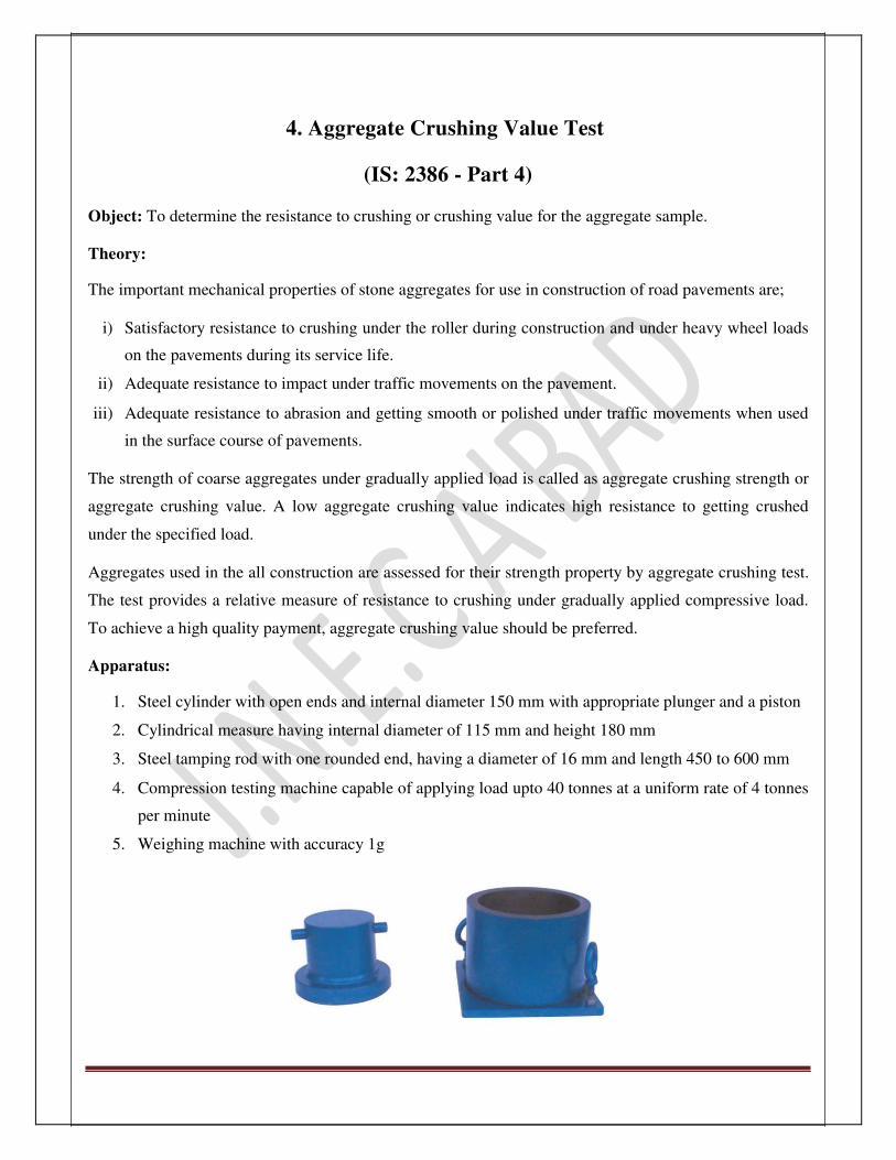
Apparatus:
1. Steel cylinder with open ends and internal diameter 150 mm with appropriate plunger and a piston
2. Cylindrical measure having internal diameter of 115 mm and height 180 mm
3. Steel tamping rod with one rounded end, having a diameter of 16 mm and length 450 to 600 mm
4. Compression testing machine capable of applying load upto 40 tonnes at a uniform rate of 4 tonnes
per minute
5. Weighing machine with accuracy 1g

JNEC CIVIL/TRE/SVI/2016 Page 19
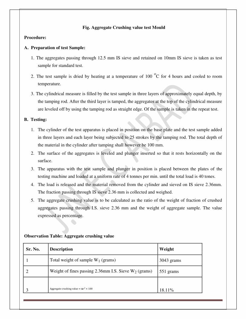
Fig. Aggregate Crushing value test Mould Procedure: A. Preparation of test Sample:
1. The aggregates passing through 12.5 mm IS sieve and retained on 10mm IS sieve is taken as test
sample for standard test.
2. The test sample is dried by heating at a temperature of 100 oC for 4 hours and cooled to room
temperature.
3. The cylindrical measure is filled by the test sample in three layers of approximately equal depth, by
the tamping rod. After the third layer is tamped, the aggregates at the top of the cylindrical measure
are leveled off by using the tamping rod as straight edge. Of the sample is taken in the repeat test.
B. Testing:
1. The cylinder of the test apparatus is placed in position on the base plate and the test sample added
in three layers and each layer being subjected to 25 strokes by the tamping rod. The total depth of
the material in the cylinder after tamping shall however be 100 mm.
2. The surface of the aggregates is leveled and plunger inserted so that it rests horizontally on the
surface.
3. The apparatus with the test sample and plunger in position is placed between the plates of the
testing machine and loaded at a uniform rate of 4 tonnes per min. until the total load is 40 tones.
4. The load is released and the material removed from the cylinder and sieved on IS sieve 2.36mm.
The fraction passing through IS sieve 2.36 mm is collected and weighed.
5. The aggregate crushing value is to be calculated as the ratio of the weight of fraction of crushed
aggregates passing through I.S. sieve 2.36 mm and the weight of aggregate sample. The value
expressed as percentage.
Observation Table: Aggregate crushing value
Sr. No. Description Weight
1 Total weight of sample W1 (grams) 3043 grams
2 Weight of fines passing 2.36mm I.S. Sieve W2 (grams) 551 grams
3 Aggregate crushing value = W?? × 100 18.11%

JNEC CIVIL/TRE/SVI/2016 Page 20
Calculations: Aggregate Crushing value = ? ? × 100 % ? ?
Result: Aggregates crushing value = 18.11% Conclusion: IRC specifies that the crushing value of course aggregate used for C.C. payment should not exceed 30%,
as the crushing value of given sample is 18.11% it can safely be used for concrete pavement. Application of the test: The aggregate crushing value is an indirect measure of crushing strength of aggregates. Low aggregate
crushing values indicate strong aggregates, as the crushed fraction is low. Thus the test can be used to
assess the suitability of aggregates with reference to the crushing strength for various types of pavement
components. Stresses at the base and sub-base course are low, aggregate with less crushing strength or
higher crushing value maybe used at the lower layers of pavement.
IRC and BIS has specified that the aggregate crushing value of the coarse aggregates to be used for cement
concrete pavement surface should not exceed 30%. Aggregate crushing value upto 45% is permissible for the
aggregates to be used for cement concrete other than for wearing surfaces. However, aggregate crushing value
have not been specified by the IRC or MORTH for coarse aggregate to be used in flexible pavement.
JNEC CIVIL/TRE/SVI/2016 Page 21
5. Specific Gravity and Water Absorption test
(IS: 2386 – Part 1) Object: To determine the specific gravity and water absorption for the road aggregates. Theory: The specific gravity is a relative heaviness of a material with respect to distilled water. It can be defined
as, the ratio of weight of a given volume of aggregate to the weight of equal volume of distilled water.
Specific gravity of aggregates considered to be a measure of strength of the material. Stones having low
specific gravity are generally weaker than those with higher specific gravity.
Water absorption gives an idea of strength of rock. Stones having more water absorption are generally
considered unsuitable unless they are found to be acceptable based on strength, impact and hardness test.
Apparatus:
1. Weighing machine of about 5 kg capacity with arrangement of weighing sample container when
suspended in water
2. Wire basket or perforated container
3. Water container
4. Trays, water absorbent cloth etc.
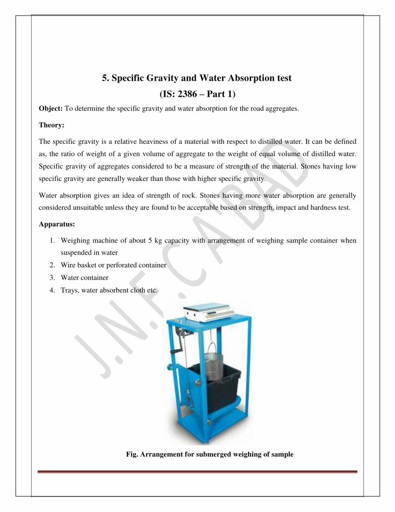
Fig. Arrangement for submerged weighing of sample

JNEC CIVIL/TRE/SVI/2016 Page 22
Procedure:
1. About 2 kg of aggregate sample is washed thoroughly to remove fines, drained and then placed in
the wire basket and immersed in distilled water at a temperature between 22 oC to 32
oC.
2. The entrapped air is removed and the basket and the aggregates are left completely immersed in
water for 24 hours.
3. The basket and the sample are then weighed while suspended in water.
4. The basket and the aggregates are removed from the water and allowed to drain for a few minute
after which the aggregates are transferred to one of the tray absorbent cloths. The empty basket is
then immersed in water, jolted and weighed.
5. The aggregates are surface dried with a cloth and weighed.
6. The aggregates are then dried in the oven for 24 hours at a temperature 105 oC to 110
oC, then
cooled and weighed. The test is repeated.
Observation table:
Sr. No. Details Observations
1 Weight of Saturated aggregate and basket in
3304
water W1 (grams)
2 Weight of basket in water W2 (grams) 1988
3 Weight of saturated surface dry aggregate in air
1988
W3 (grams)
Weight of oven dried aggregate in air W4
4 (grams) 1965
5 Specific Gravity = W? − (W? − W? )
2.92
?
6
Apparent Specific Gravity = ? ? ? (? ? ? ? ? )
3.03
? ?
7 Water Absorption = (? ? ? ?? ??
)×? ? ? 1.17%
Results:
1) True specific gravity = 2.92

2) Apparent Specific gravity = 3.03
JNEC CIVIL/TRE/SVI/2016 Page 23
3) Water absorption = 1.17% Conclusion: The range of the values for the aggregates used in road construction is 2.5 to 3; hence the specific gravity
of the given aggregates is acceptable.
Since the permissible value of water absorption being 2%; given aggregates are suitable for the bituminous
Macadam base course, dense bituminous Macadam binder course and bituminous concrete surface course.
Application of test Data: The specific gravity of the aggregates normally used for the road construction ranges from about 2.50 to
3.00 with an average value of 2.58. Though high specific gravity of an aggregate is considered as an
indication of high strength, it is not possible to judge the suitability of sample without finding the
mechanical properties such as aggregate crushing, impact and abrasion values.
Water absorption of an aggregate is accepted as measure of its porosity. But sometimes this value is even
considered as a measure of its resistance to frost action. Water absorption values ranges from 0.1% to
0.2% for course aggregates used in road surface course. Indian Road Congress (IRC) and Ministry Of
Road Transportation and highways (MORTH) have specified the maximum water absorption values as 1%
for the aggregates used in bituminous surface dressing. As per MORTH specification, the maximum
permissible water absorption value is 2% for the aggregates used in bituminous Macadam base course,
dense bituminous Macadam binder course and bituminous concrete surface course. If the water absorption
of aggregates used in wet mix Macadam base course exceeds 2%, soundness test should be carried out to
check the durability. However the course aggregates with water absorption up to 4% have been
successfully used in granular base course of road pavement.

JNEC CIVIL/TRE/SVI/2016 Page 24
6. Shape Test
(IS: 2386 – Part 1)
Object: Determination of Flakiness Index, Elongation Index and Angularity Number of the given sample
of aggregates. Theory: The particle shape of aggregate is determined by the percentage of flaky, elongated particle contained in
weight; in case of gravel it is determined by its angularity number for base course and construction of
bituminous and cements concrete. The presence of flaky and elongated particle is considered undesirable
as they may cause inherent weakness with possibility of breaking down under heavy loads. Rounded
aggregates are preferred in cement concrete road construction as the workability of concrete improves.
Angular shape of particle is desirable for granular base course due to increased stability derived from the
better interlocking. Thus evaluation of shape of particle with reference to flakiness, elongation and
angularity is necessary.

JNEC CIVIL/TRE/SVI/2016 Page 25
A. Determination of Flakiness Index
Definition: The Flakiness Index of aggregate is the percent by weight of the particles whose least
dimension (thickness) is less than 0.6 times their mean dimension. The test is not applicable to sizes
smaller than 6.3mm.
Apparatus:
1. Standard thickness gauge
2. Weighing machine accurate upto 1gram
3. I.S. Sieves- 63, 50, 40, 31.5, 25, 20, 16, 12.5, 10 and 6.3 mm
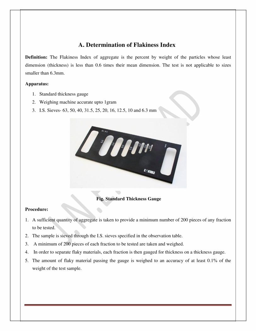
Fig. Standard Thickness Gauge Procedure: 1. A sufficient quantity of aggregate is taken to provide a minimum number of 200 pieces of any fraction
to be tested. 2. The sample is sieved through the I.S. sieves specified in the observation table. 3. A minimum of 200 pieces of each fraction to be tested are taken and weighed. 4. In order to separate flaky materials, each fraction is then gauged for thickness on a thickness gauge. 5. The amount of flaky material passing the gauge is weighed to an accuracy of at least 0.1% of the
weight of the test sample.

JNEC CIVIL/TRE/SVI/2016 Page 26
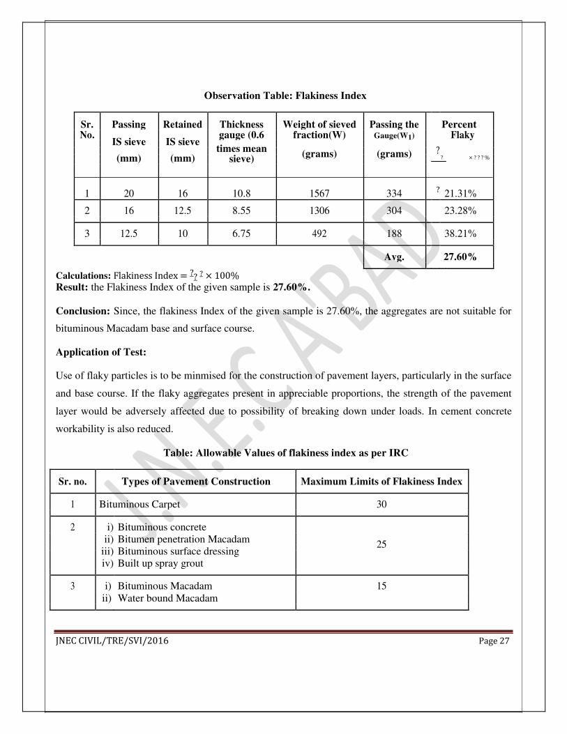
Observation Table: Flakiness Index
Sr. Passing Retained Thickness Weight of sieved Passing the
?
Percent
No. IS sieve IS sieve
gauge (0.6 fraction(W) Gauge(W1) Flaky
times mean
? × ? ? ? %
(mm) (mm) (grams) (grams)
sieve)
1 20 16 10.8 1567 334 ? 21.31%
2 16 12.5 8.55 1306 304 23.28%
3 12.5 10 6.75 492 188 38.21%
Avg. 27.60%
Calculations: Flakiness Index = ?? ? × 100% Result: the Flakiness Index of the given sample is 27.60%.
Conclusion: Since, the flakiness Index of the given sample is 27.60%, the aggregates are not suitable for
bituminous Macadam base and surface course.
Application of Test:
Use of flaky particles is to be minmised for the construction of pavement layers, particularly in the surface
and base course. If the flaky aggregates present in appreciable proportions, the strength of the pavement
layer would be adversely affected due to possibility of breaking down under loads. In cement concrete
workability is also reduced.
Table: Allowable Values of flakiness index as per IRC
Sr. no. Types of Pavement Construction Maximum Limits of Flakiness Index
1 Bituminous Carpet 30
2 i) Bituminous concrete
ii) Bitumen penetration Macadam 25
iii) Bituminous surface dressing
iv) Built up spray grout
3 i) Bituminous Macadam 15
ii) Water bound Macadam
JNEC CIVIL/TRE/SVI/2016 Page 27
B. Determination of Elongation Index
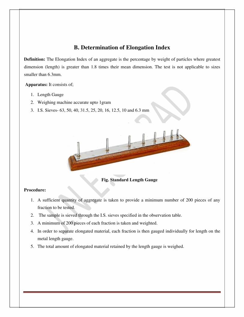
Definition: The Elongation Index of an aggregate is the percentage by weight of particles where greatest
dimension (length) is greater than 1.8 times their mean dimension. The test is not applicable to sizes
smaller than 6.3mm. Apparatus: It consists of;
1. Length Gauge
2. Weighing machine accurate upto 1gram
3. I.S. Sieves- 63, 50, 40, 31.5, 25, 20, 16, 12.5, 10 and 6.3 mm
Fig. Standard Length Gauge Procedure:
1. A sufficient quantity of aggregate is taken to provide a minimum number of 200 pieces of any
fraction to be tested.
2. The sample is sieved through the I.S. sieves specified in the observation table.
3. A minimum of 200 pieces of each fraction is taken and weighted.
4. In order to separate elongated material, each fraction is then gauged individually for length on the
metal length gauge.
5. The total amount of elongated material retained by the length gauge is weighed.

JNEC CIVIL/TRE/SVI/2016 Page 28
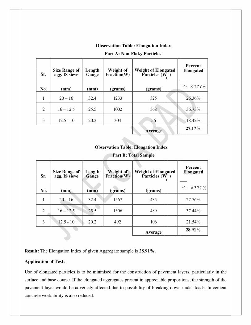
Observation Table: Elongation Index
Part A: Non-Flaky Particles
Size Range of Length Weight of Weight of Elongated
Percent
Sr. Elongated
agg. IS sieve Gauge Fraction(W) Particles (W )
?? ? × ? ? ? %
No. (mm) (mm) (grams) (grams)
1
1 20 – 16 32.4 1233 325 26.36%
2 16 – 12.5 25.5 1002 368 36.73%
3 12.5 - 10 20.2 304 56 18.42%
Average
27.17%
Observation Table: Elongation Index
Part B: Total Sample
Size Range of Length Weight of Weight of Elongated
Percent
Elongated
Sr. agg. IS sieve Gauge Fraction(W) Particles (W )
?? ? × ? ? ? %
No. (mm) (mm) (grams) (grams)
1
1 20 – 16 32.4 1567 435 27.76%
2 16 – 12.5 25.5 1306 489 37.44%
3 12.5 - 10 20.2 492 106 21.54%
Average
28.91%
Result: The Elongation Index of given Aggregate sample is 28.91%. Application of Test: Use of elongated particles is to be minmised for the construction of pavement layers, particularly in the
surface and base course. If the elongated aggregates present in appreciable proportions, the strength of the
pavement layer would be adversely affected due to possibility of breaking down under loads. In cement
concrete workability is also reduced.

JNEC CIVIL/TRE/SVI/2016 Page 29
C. Determination of Angularity Number
Theory: Angularity can be defined as, “the absence of sphericity or rounding of an aggregate.” It is important
because it affects the ease of handling a mixture of aggregate and binder or the workability of a mix. The
determination of angularity number of an aggregate is an essentially a laboratory method intended for
comparing the properties of different aggregates for mix design purpose and for deciding their gradation
requirement.
The degree of packing of particles of single sized aggregates, depend on the shape and angularity of the
aggregates. If a number of single sized spherical particles are packed together in the densest form, the total
volume of solids will be 67% and the volume of voids 33% of the total volume. However if the shape of
the particles of the same size deviates from the spherical shape to the irregular or angular shape, when
they are densely packed the volume of solids decreases resulting in increase in the volume of voids. Hence
angularity of single sized aggregate can be estimated from the properties of the voids in a sample of
aggregate compacted in a particular manner.
The angularity number of an aggregate of a given size range can be defined as, “the amount by which the percentage voids exceed 33% being compacted in a prescribed manner.”
Apparatus:
1. A metal cylinder closed at one end, 3 litres capacity
2. A tamping rod of circular cross section, 16 mm in diameter and 60 cm in length, rounded at one edge
3. A weighing machine accurate up to 1 g Procedure:
1. Take a cylinder of 3 litres capacity and weigh it empty (W1).
2. Fill the cylinder completely with the water and take weight (W2).
3. Empty the cylinder and dry it.
4. Fill the cylinder one third with aggregates; blow it 100 times by the tamping rod, at the rate of 2
blows per second. Tamping is to be done by freely dropping the tamping rod, vertically from 5cm
height.
5. Fill the cylinder one third for the second and third layer, tamp it as described earlier.
6. The third layer should contain only aggregates required to just fill up the cylinder level before
tamping.

JNEC CIVIL/TRE/SVI/2016 Page 30
7. After tamping the third layer; fill the cylinder to overflow and struck of the aggregates by using
tamping rod as a straight edge.
8. Add individual pieces of aggregates in to the surface by gently rolling the tamping rod across the upper
edge of the cylinder. Care must be taken that, no downward force applied on the tamping rod.
9. Weigh the aggregates with cylinder (W3).
Observations:
1. Empty weight of cylinder (W1) = 2600 g.
2. Weight of water with cylinder (W2) = 4986 g.
3. Weight of water with aggregates (W3) = 7030 g.
4. Specific Gravity of aggregates (G) = 2.92.
Calculations: – (? ? ? ? )×? ? ?
Angularity number = 67
? .(? ? ? ? ? )
= 67 (? ? ? ? ? ? ? ? ? )×? ? ?
−? .? ? ×(? ? ? ? ? ? ? ? ? )
= 3.41
Result: The Angularity Number of given sample is 3.41. Conclusion: the Angularity number of given sample is between 0 and 11; hence it is suitable in pavement
construction.
Application of Test: The angularity number of aggregates generally ranges from zero for the highly rounded gravel to 11 for
freshly crushed aggregates. Higher the angularity number less workable is the mix. In cement concrete
mix, rounded aggregates maybe preferred because of better workability, lesser specific surface area and
higher strength for particular cement content. But in the flexible pavement construction, such as
bituminous mix, water bound Macadam etc. angular aggregates preferred because of higher stability due
to better interlocking and friction.

JNEC CIVIL/TRE/SVI/2016 Page 31
PART – D: Tests on Bituminous Materials
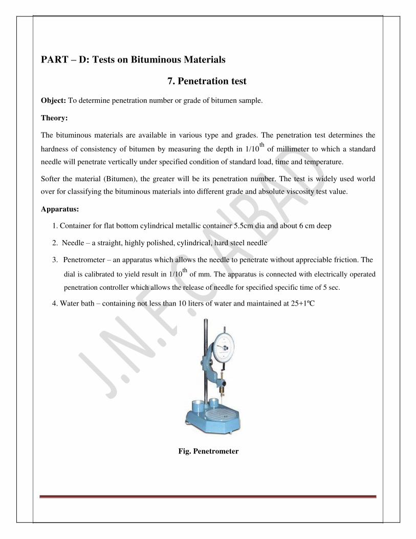
7. Penetration test
Object: To determine penetration number or grade of bitumen sample. Theory: The bituminous materials are available in various type and grades. The penetration test determines the
hardness of consistency of bitumen by measuring the depth in 1/10th
of millimeter to which a standard
needle will penetrate vertically under specified condition of standard load, time and temperature. Softer the material (Bitumen), the greater will be its penetration number. The test is widely used world
over for classifying the bituminous materials into different grade and absolute viscosity test value.
Apparatus:
1. Container for flat bottom cylindrical metallic container 5.5cm dia and about 6 cm deep
2. Needle – a straight, highly polished, cylindrical, hard steel needle
3. Penetrometer – an apparatus which allows the needle to penetrate without appreciable friction. The
dial is calibrated to yield result in 1/10th
of mm. The apparatus is connected with electrically operated
penetration controller which allows the release of needle for specified specific time of 5 sec.
4. Water bath – containing not less than 10 liters of water and maintained at 25+1ºC
Fig. Penetrometer

JNEC CIVIL/TRE/SVI/2016 Page 32
Procedure:
1. The bitumen sample is softened, at pouring temperature between 75 ºC and 100 ºC Above the
approximate softening temperature. It is properly stirred to make it homogeneous and free from air
bubble and water.
2. The sample material is then poured into the container to a depth at least 1.5 cm more than expect
penetration.
3. The sample containers are cooled in atmosphere for one heat and placed at temperature controlled
water bath at a temperature of 25 ºC for a period of 1 hour.
4. The sample container is placed in transfer tray with water from the water bath and is kept under the
needle of the Penetrometer.
5. The additional weight is kept in the shaft so that the total weight of the assembly of needle, shaft
and additional weight is 100g.
6. The needle is arranged to make contact with the sample surface and zero reading of the
Penetrometer dial is taken.
7. The needle is release for 5 seconds by switching on the penetrometer controller and the final dial
reading is taken.
8. At least three measurements are made on this sample by testing at a distance of not less than 1cm
apart. After each test needle is disengaged and wiped with benzene (or kerosene) and dried
carefully, the sample container is also transferred in the water bath before next testing is done so as
to maintain a constant temperature of 25 ºC.
9. The test is repeated with sample in the other container.
10. The depth of penetration is reported in 1/10th
of mm. The mean value of three consistent
measurements reported as the penetration value. Observations:
1. Pouring temperature : 100 º C
2. Period of cooling ……………..min.
3. Room temperature…………….º C
4. Period of cooling in water bath 30 min.
5. Actual test temperature………..º C

JNEC CIVIL/TRE/SVI/2016 Page 33
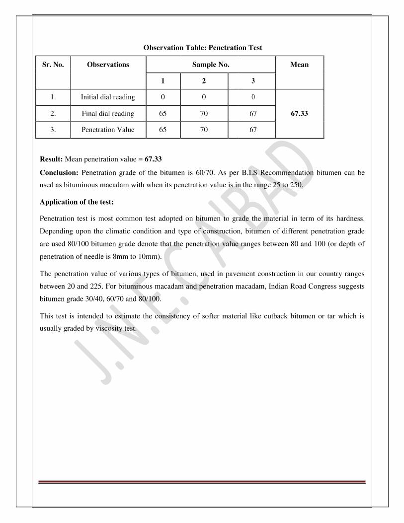
Observation Table: Penetration Test
Sr. No. Observations Sample No. Mean
1 2 3
1. Initial dial reading 0 0 0
2. Final dial reading 65 70 67 67.33
3. Penetration Value 65 70 67
Result: Mean penetration value = 67.33
Conclusion: Penetration grade of the bitumen is 60/70. As per B.I.S Recommendation bitumen can be
used as bituminous macadam with when its penetration value is in the range 25 to 250.
Application of the test:
Penetration test is most common test adopted on bitumen to grade the material in term of its hardness.
Depending upon the climatic condition and type of construction, bitumen of different penetration grade
are used 80/100 bitumen grade denote that the penetration value ranges between 80 and 100 (or depth of
penetration of needle is 8mm to 10mm).
The penetration value of various types of bitumen, used in pavement construction in our country ranges
between 20 and 225. For bituminous macadam and penetration macadam, Indian Road Congress suggests
bitumen grade 30/40, 60/70 and 80/100.
This test is intended to estimate the consistency of softer material like cutback bitumen or tar which is
usually graded by viscosity test.

JNEC CIVIL/TRE/SVI/2016 Page 34
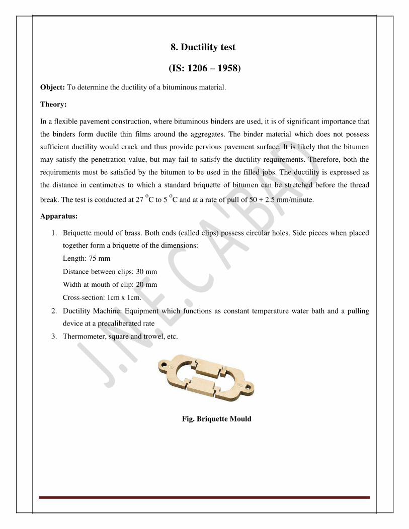
8. Ductility test
(IS: 1206 – 1958)
Object: To determine the ductility of a bituminous material. Theory: In a flexible pavement construction, where bituminous binders are used, it is of significant importance that
the binders form ductile thin films around the aggregates. The binder material which does not possess
sufficient ductility would crack and thus provide pervious pavement surface. It is likely that the bitumen
may satisfy the penetration value, but may fail to satisfy the ductility requirements. Therefore, both the
requirements must be satisfied by the bitumen to be used in the filled jobs. The ductility is expressed as
the distance in centimetres to which a standard briquette of bitumen can be stretched before the thread
break. The test is conducted at 27 oC to 5
oC and at a rate of pull of 50 + 2.5 mm/minute.
Apparatus:
1. Briquette mould of brass. Both ends (called clips) possess circular holes. Side pieces when placed
together form a briquette of the dimensions:
Length: 75 mm
Distance between clips: 30 mm
Width at mouth of clip: 20 mm
Cross-section: 1cm x 1cm.
2. Ductility Machine: Equipment which functions as constant temperature water bath and a pulling
device at a precaliberated rate
3. Thermometer, square and trowel, etc.
Fig. Briquette Mould

JNEC CIVIL/TRE/SVI/2016 Page 35
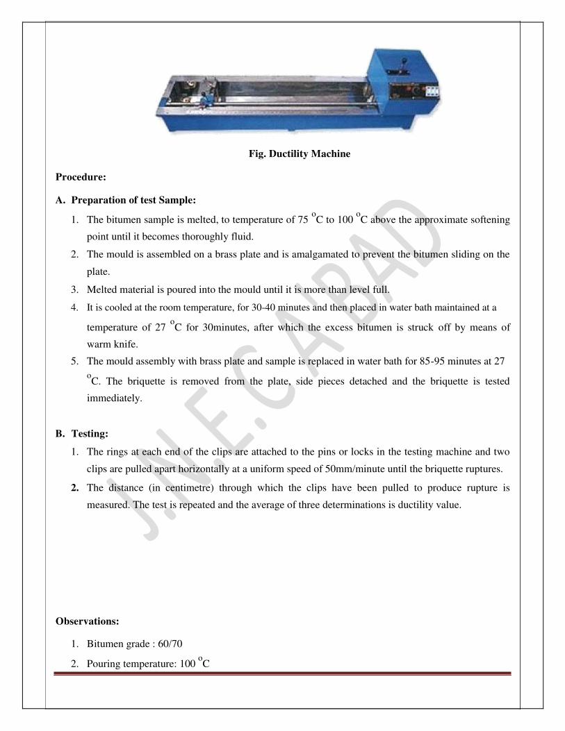
Fig. Ductility Machine Procedure: A. Preparation of test Sample:
1. The bitumen sample is melted, to temperature of 75 oC to 100
oC above the approximate softening
point until it becomes thoroughly fluid.
2. The mould is assembled on a brass plate and is amalgamated to prevent the bitumen sliding on the
plate.
3. Melted material is poured into the mould until it is more than level full.
4. It is cooled at the room temperature, for 30-40 minutes and then placed in water bath maintained at a
temperature of 27 oC for 30minutes, after which the excess bitumen is struck off by means of
warm knife.
5. The mould assembly with brass plate and sample is replaced in water bath for 85-95 minutes at 27
oC. The briquette is removed from the plate, side pieces detached and the briquette is tested
immediately.
B. Testing:
1. The rings at each end of the clips are attached to the pins or locks in the testing machine and two
clips are pulled apart horizontally at a uniform speed of 50mm/minute until the briquette ruptures.
2. The distance (in centimetre) through which the clips have been pulled to produce rupture is
measured. The test is repeated and the average of three determinations is ductility value.
Observations:
1. Bitumen grade : 60/70
2. Pouring temperature: 100 oC

JNEC CIVIL/TRE/SVI/2016 Page 36
3. Test temperature :
4. Period of cooling :
a. In air: 30 minutes.
b. In water bath before trimming: minutes.
c. In water bath after trimming: 30 minutes.
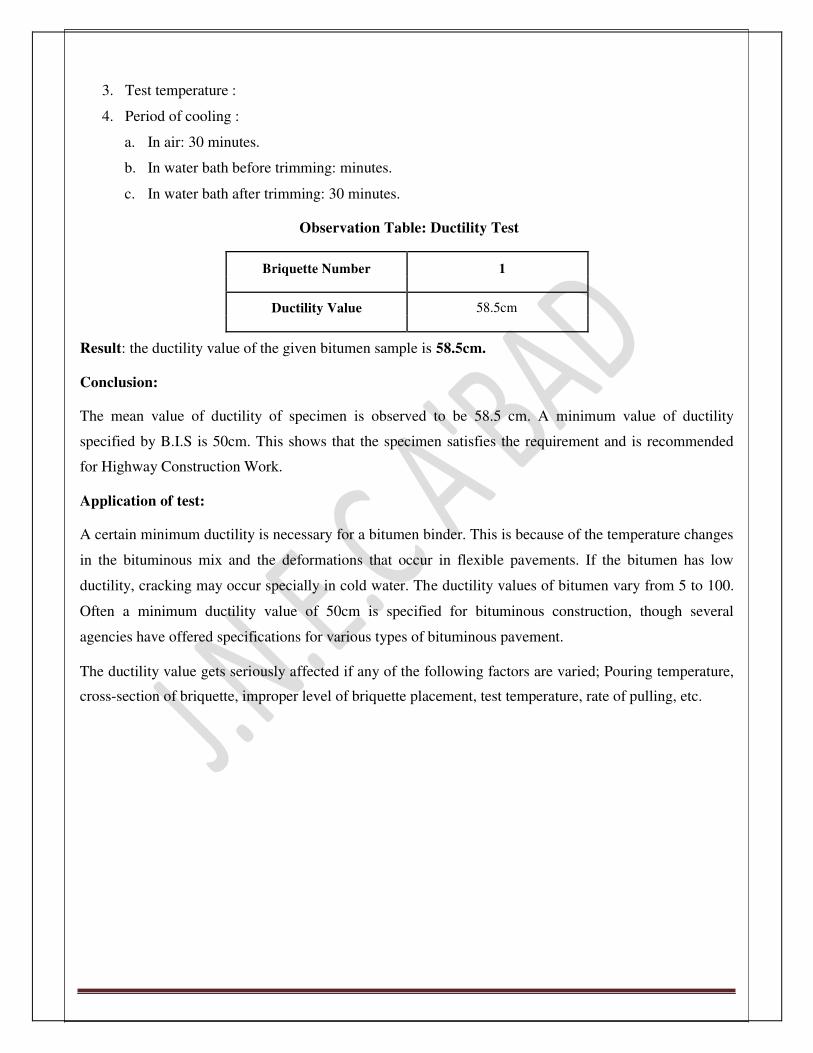
Observation Table: Ductility Test
Briquette Number 1
Ductility Value 58.5cm
Result: the ductility value of the given bitumen sample is 58.5cm. Conclusion: The mean value of ductility of specimen is observed to be 58.5 cm. A minimum value of ductility
specified by B.I.S is 50cm. This shows that the specimen satisfies the requirement and is recommended
for Highway Construction Work.
Application of test: A certain minimum ductility is necessary for a bitumen binder. This is because of the temperature changes
in the bituminous mix and the deformations that occur in flexible pavements. If the bitumen has low
ductility, cracking may occur specially in cold water. The ductility values of bitumen vary from 5 to 100.
Often a minimum ductility value of 50cm is specified for bituminous construction, though several
agencies have offered specifications for various types of bituminous pavement.
The ductility value gets seriously affected if any of the following factors are varied; Pouring temperature,
cross-section of briquette, improper level of briquette placement, test temperature, rate of pulling, etc.

JNEC CIVIL/TRE/SVI/2016 Page 37
9. Softening Point Test
(I.S.:1205-1958)
Object: To determine the softening point of bitumen sample by ring and ball apparatus. Theory: Bitumen does not suddenly change from solid to liquid state, but at the temperature, increases, it gradually
becomes softer until it flows readily. All semisolid state bitumen grades need sufficient fluidity for they
are used for application with the aggregate mix. For this purpose bitumen is sometimes cutback with a
solvent like kerosene. The common procedure however is to liquefy the bitumen by heating. The softening
point is the temperature at which the substance attains particular degree of softening under specified
conditions of test. For bitumen, it is determined by using ring and ball apparatus and the test procedure are
standardized by B.I.S.
Apparatus:
The ring and ball apparatus consisting of: 1. Steel balls: 2 in number each of dia.9.5mm and weight, 2.5+0.05 gm 2. Brass rings-2 in number with following dimensions-
Depth: 6.4 mm
Inside diameter at bottom: 15.9 mm
Inside diameter at top: 17.5 mm
Outside: 20.6 mm
Each brass ring is accompanied with brass ball guide 3. Metallic support with two horizontal plates and distance of 25mm between the bottom of the rings and
top surface for the bottom plate 4. Bath and stir-heat resistant glass container and mechanically (electrically operated) stir 5. Thermometer

JNEC CIVIL/TRE/SVI/2016 Page 38
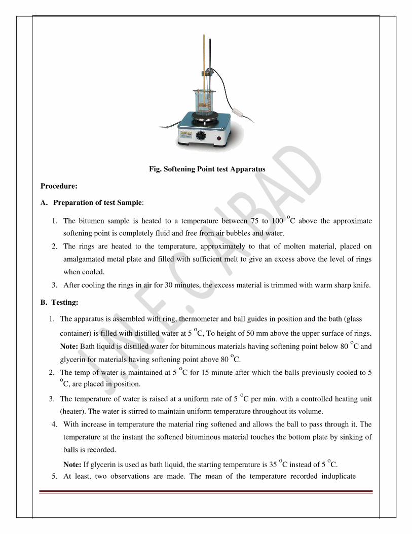
Fig. Softening Point test Apparatus Procedure: A. Preparation of test Sample:
1. The bitumen sample is heated to a temperature between 75 to 100 oC above the approximate
softening point is completely fluid and free from air bubbles and water.
2. The rings are heated to the temperature, approximately to that of molten material, placed on
amalgamated metal plate and filled with sufficient melt to give an excess above the level of rings
when cooled.
3. After cooling the rings in air for 30 minutes, the excess material is trimmed with warm sharp knife.
B. Testing:
1. The apparatus is assembled with ring, thermometer and ball guides in position and the bath (glass
container) is filled with distilled water at 5 oC, To height of 50 mm above the upper surface of rings.
Note: Bath liquid is distilled water for bituminous materials having softening point below 80 oC and
glycerin for materials having softening point above 80 oC.
2. The temp of water is maintained at 5 oC for 15 minute after which the balls previously cooled to 5
oC, are placed in position.
3. The temperature of water is raised at a uniform rate of 5 oC per min. with a controlled heating unit
(heater). The water is stirred to maintain uniform temperature throughout its volume.
4. With increase in temperature the material ring softened and allows the ball to pass through it. The
temperature at the instant the softened bituminous material touches the bottom plate by sinking of
balls is recorded.
Note: If glycerin is used as bath liquid, the starting temperature is 35 oC instead of 5
oC.
5. At least, two observations are made. The mean of the temperature recorded induplicate

JNEC CIVIL/TRE/SVI/2016 Page 39
determinations in reported to the nearest 0.5 oC, as softening point of sample.
Observations:
1. Bitumen grade : 60/70
2. Approximate softening point :
3. Liquid used in bath : water
4. Period of air cooling :…………minute.
5. Period of cooling in bath :………..minute.
Observation Table: Softening Point Test
Observation
Sr. No. Details
Ball A Ball B
1 Temperature (
oC) at which the
60 oC 60
oC
sample touches the bottom plate
2 Softening point. 60 oC 60
oC
Result: Mean value of softening point = 60 oC
Conclusion: The Softening point of the tested bitumen, not lie between the permissible range given by the B.I.S i.e.
33 to 50 oC. Hence the given bitumen cannot be used for pavement construction.
Applications of Test: Softening point is essential the temperature at which the bituminous binders have an equal viscosity. The
softening point of tar is therefore related to the equiviscous temperature (EVT). The softening point found
by the ring and ball apparatus is approximately 20 oC lower than the EVT.
The softening point, thus gives an idea of tempt at which the bituminous material attains a certain
viscosity. Bitumen with softening point may be preferred in warmer place. IS specifies the softening point
of 35 oC to 50
oC. For bitumen grades used in our country. Softening point is also used to specify hard
bitumen and pitches.

JNEC CIVIL/TRE/SVI/2016 Page 40
10. Viscosity test
(IS 1206-1958)
Object: To determine the viscosity of bitumen or tar. Theory: Viscosity is the property of a fluid by virtue of which it resists flow due to internal friction and is defined
as inverse of fluidity. The degree of fluidity at the application temperature greatly influences the strength
characteristics of paving mix. High or low fluidity at mixing and compaction has been observed to result
in lower stability values. There is on optimum value of fluidity or viscosity for mixing and compacting for
each aggregate gradation of the mix and bitumen grade. At low viscosity the bituminous binder simply
lubricates the aggregate binding section. Similarly, high viscosity also resists the compacting efforts and
resulting mix is heterogeneous in character exhibiting low stability value. A method by which viscosity of
liquid binder like cut back bitumen, emulsion and liquid tar is measured by determining the time taken by
50cc of the material to flow from a cup through specified orifice at given temperature.
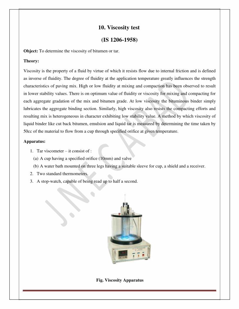
Apparatus:
1. Tar viscometer – it consist of :
(a) A cup having a specified orifice (10mm) and valve
(b) A water bath mounted on three legs having a suitable sleeve for cup, a shield and a receiver.
2. Two standard thermometers.
3. A stop-watch, capable of being read up to half a second.
Fig. Viscosity Apparatus

JNEC CIVIL/TRE/SVI/2016 Page 41
Procedure:
1. The tar cup is properly leveled and water in the bath is heated to the temperature specified for the test
and is maintained with +1 ºC of the specified temperature throughout the test by continuous stirring.
2. The tar cup orifice is cleaned with suitable solvent (kerosene) and dried.
3. The bituminous material is warmed to 20 ºC above the temperature specified for the stirred and
allowed to cool to a temperature slightly above the test temp.
4. A 28 ml. mineral oil or 1% by weight solution of soap is poured into a graduated receiver (flask)
and the receiver is placed under the orifice. The thermometer (one in the cup and another in water
bath) are then placed in position.
5. When the sample material reaches the test temperature within +1 ºC and is maintained for 5min,
the ball value is opened.
6. The stopwatch is started when the receiving flask records 25 ml.
7. The time in second is recorded for flow up to a mark of 75 ml. (i.e.50ml of test sample) to flow
through the orifice.
8. Duplicate observations are taken on a fresh sample and the viscosity of the bitumen tar is reported
in terms of the average time in second taken by 50 ml. of sample to flow out at the specified test
temperature.
Observations:
1. Material :
2. Grade :
3. Specified test temp. :
4. Size of orifice :……….. mm
5. Actual test temp. : ……… oC
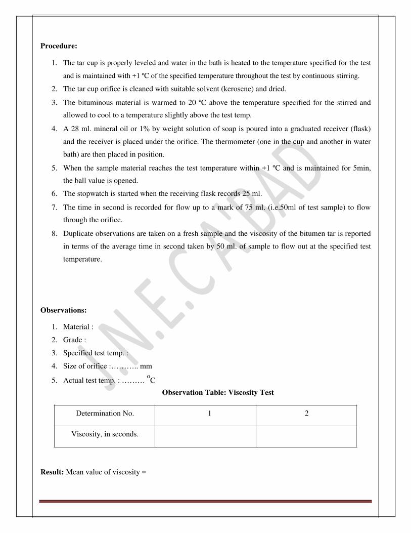
Observation Table: Viscosity Test
Determination No. 1 2
Viscosity, in seconds. Result: Mean value of viscosity =

JNEC CIVIL/TRE/SVI/2016 Page 42
Application of the test: Orifice viscosity test given an indirect measure of tar and cutbacks in seconds. Higher the time more
viscous is the binder material. The standard orifice viscometer test results are useful to classify the grade
of tar and cutbacks. The working range of tar viscometer for 10mm orifice is 10 to 140 seconds. For
cutbacks bitumen, the orifice size specified is 4mm for lower grades and 10mm for higher grades with
higher viscosity.

JNEC CIVIL/TRE/SVI/2016 Page 43
11.Marshall Stability Test Introduction: The top layer of a flexible pavement, particularly the surface course has to withstand high stress
conditions and wear and tear due to traffic loads. In addition the surface course is exposed to adverse
climatic factors including temperature variations; water etc. therefore properly designed high quality hot
bituminous mixes are laid on the surface course of flexible pavements so as to sustain heavy traffic loads,
wear and tear and high speed vehicles movements requiring good surface texture to provide adequate skid
resistance in wet condition. The high quality bituminous mixes consist of well graded hard aggregates and
suitable bituminous binder of correct proportion. The bituminous mixture is prepared in a hot mix plant
using the mineral aggregates and binder in appropriate proportion as per the mix design, at suitable mixing
temperature.
It is necessary to design the bituminous mixes so as to withstand the repeated stresses and resultant
fatigue; the mix should also posses adequate resistance to low temperature cracking, moisture induced
damage and resistance to permanent deformation during hot weather caused by climatic variations. The
workability of the mix should be adequate at the mixing, laying and compacting temperatures. The
properties of bituminous mixes, depends on the gradation of properties of aggregates and also the type and
percentage of bituminous binder used in the mix. Therefore it is desirable that a well designed bituminous
mix when properly paved and compacted should be able to fulfill the above requirement.
Different methods are available for testing the compacted specimen of bituminous mixes in the laboratory.
These include Marshall Stability Test, Hveen Stabilometer Test, Hubbard Field Test and unconfined
Compression Test. Marshall Stability Test (developed by Bruce Marshall in U.S.A.) is being generally
followed in India.
Marshall Stability test is conducted on compacted cylindrical specimen of bituminous mix of diameter
101.6 mm thickness 63.5 mm. the load is applied perpendicular to the axis of cylindrical specimen through
a testing head consisting of pair of cylindrical segments, at a constant rate of deformation of 51 mm per
minute at the standard test temperature of 60 oC.
‘Marshall Stability’ of the bituminous mix specimen is defined as, a maximum load carried in kg at the
standard test temperature of 60 oC when load is applied under specified test conditions.
‘Flow Value’ is the total deformation of Marshall Test specimen at the maximum load, expressed in mm
units.

JNEC CIVIL/TRE/SVI/2016 Page 44
Marshall Stability value of a compacted specimen of bituminous mix indicate its resistance to deformation
under applied incremental load and the flow value indicates the extent of deformation it undergoes due to
loading or its flexibility .
Apparatus:
1. Compaction mould of cylindrical shape of diameter 101.6 mm and height 75 mm, a collar
extension and base plate
2. Compaction hammer with a flat circular plate of diameter 98.4 mm and weight 4.5 kg having a lift
and release arrangement of a height 457 mm
3. Testing head consisting of upper and lower cylindrical segments of test head with an inside radius
of curvature of 51 mm
4. Testing machine consisting a motorized loading unit provided with a gear system to lift the base
plate upward at the specified rate
5. Deformation measuring dial gauge having least count of 0.01 mm
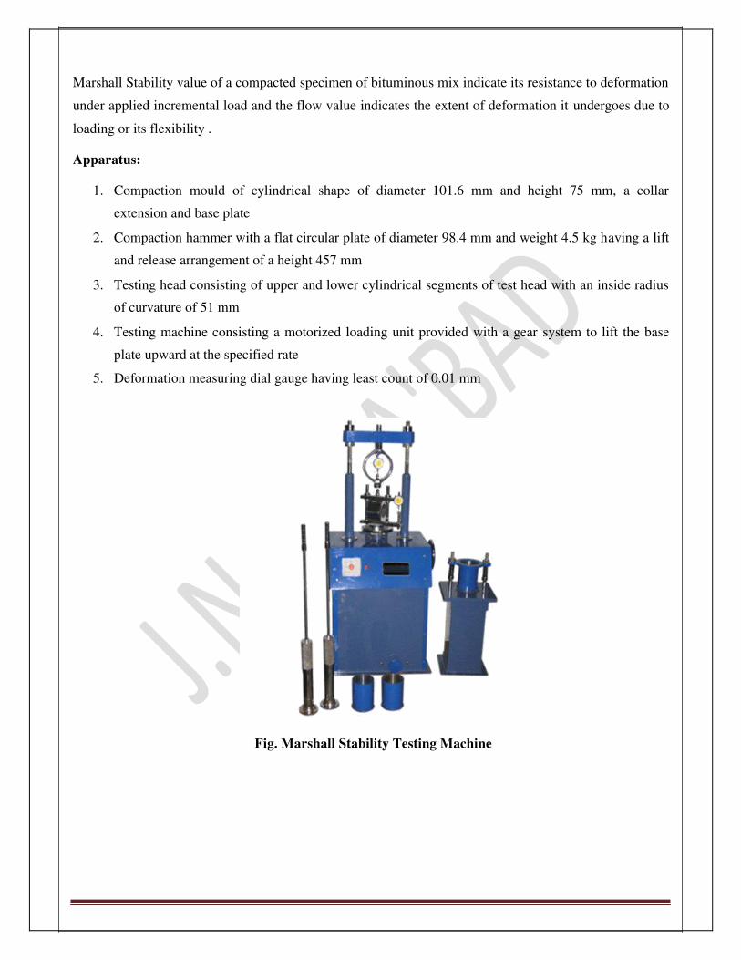
Fig. Marshall Stability Testing Machine

JNEC CIVIL/TRE/SVI/2016 Page 45
Procedure: A) Preparation of Test Specimen:
1. Coarse aggregates, fine aggregates and filler material are proportioned and mixed to obtain final
gradation of the mixture within the specified range for the desired type of bituminous mix. Max
permissible size of aggregate is 25 mm. Type and grading of aggregates and content of bituminous
binder shall be as per the relevant standard specifications. For example, the specifications for the
bituminous concrete pavement surface course as per MORTH are given below.
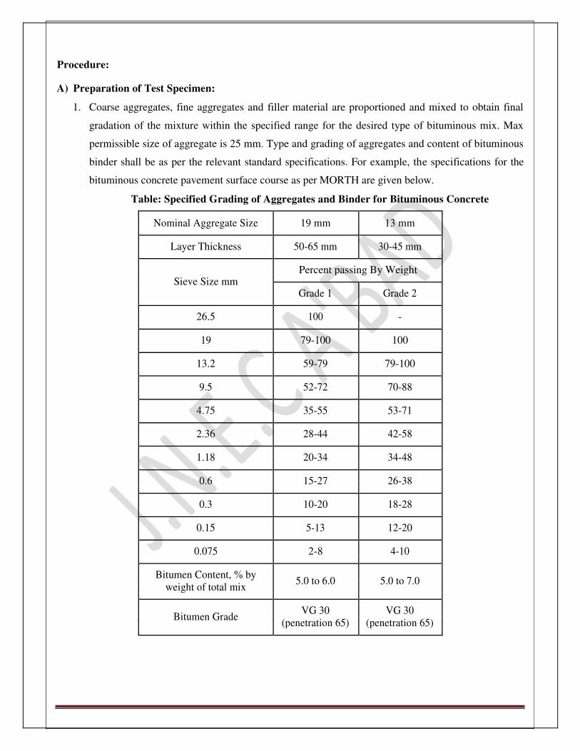
Table: Specified Grading of Aggregates and Binder for Bituminous Concrete
Nominal Aggregate Size 19 mm 13 mm
Layer Thickness 50-65 mm 30-45 mm
Sieve Size mm Percent passing By Weight
Grade 1 Grade 2
26.5 100 -
19 79-100 100
13.2 59-79 79-100
9.5 52-72 70-88
4.75 35-55 53-71
2.36 28-44 42-58
1.18 20-34 34-48
0.6 15-27 26-38
0.3 10-20 18-28
0.15 5-13 12-20
0.075 2-8 4-10
Bitumen Content, % by 5.0 to 6.0 5.0 to 7.0
weight of total mix
Bitumen Grade VG 30 VG 30
(penetration 65) (penetration 65)

JNEC CIVIL/TRE/SVI/2016 Page 46
2. The aggregates and filler are mixed together in desired proportion to fulfill the design requirements
and the specified gradation. The required quantity of mineral aggregate mix is weighed and taken
so as to produce a compacted bituminous mix specimen of thickness 63.5 mm.
3. 1200 g of aggregates and filler mix is taken, weighed correctly and heated to a temperature of 175 oC to 190
oC (not exceeding above the mixing temperature). The compaction assembly and
rammer are cleaned and kept pre-heated at temperature of 95 oC to 150
oC.
4. Bituminous binder is heated to a temperature of 120 oC to 165
oC. The required quantity of
bitumen is calculated. The weighed quantity of aggregate is added to the heated aggregates and the
mixture is thoroughly mixed at the specified temperature.
5. After mixing thoroughly such that the surface of aggregates are uniformly and fully coated with the
binder, bituminous mix maybe allowed to slightly cool down to recommended compacting
temperature.
6. Mix is placed in the pre-heated mould and it should be compacted by the rammer at the specified
temperature, by applying 75 blows on either ends. After compaction, the specimen with mould is
allowed to cool down to the room temperature. B) Determination of Weight and Volume of specimen: The specimen is weighed in air and average diameter and thickness of the cylindrical specimen is
obtained. The volume of specimen can also be determined by finding the weights of specimen in air and
its apparent weight by suspending it in water. The main objective is to determine the density or specific
gravity of the compacted bituminous mix specimen.
C) Determination of Marshall Stability:
1. The specimen to ±be tested are kept immersed in the water in a thermostatically controlled water bath maintained at 60 1 oC for 30 to 40 min.
2. Specimen is taken out from the water bath and placed in the Marshall Test head. The test head with
the specimen is placed in position in the loading machine and the base plate of the loading machine
is raised using the hand gear until the top of the test head is contact with the bottom of the proving
ring or load cell.
3. Deformation measuring dial gauge is placed in position and adjusted to zero.
4. Load is applied at the constant deformation rate of 51 mm per minute. Maximum load reading and
the corresponding deformation dial readings are noted.
5. Maximum load value expressed in kg is recorded as the ‘Marshall Stability’ value of the specimen.
Vertical deformation of the test specimen corresponding to the maximum load, expressed in 0.25
mm units is recorded as the ‘flow value’. Density and Void Analysis:
JNEC CIVIL/TRE/SVI/2016 Page 47
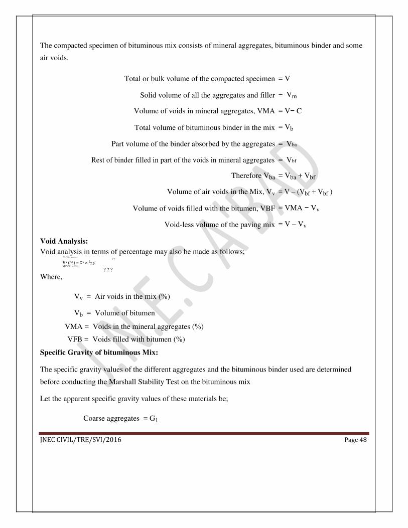
The compacted specimen of bituminous mix consists of mineral aggregates, bituminous binder and some
air voids.
Total or bulk volume of the compacted specimen = V
Solid volume of all the aggregates and filler = Vm
Volume of voids in mineral aggregates, VMA = V− C
Total volume of bituminous binder in the mix = Vb
Part volume of the binder absorbed by the aggregates = Vba
Rest of binder filled in part of the voids in mineral aggregates = Vbf
Therefore Vba = Vba + Vbf
Volume of air voids in the Mix, Vv = V – (Vbf + Vbf )
Volume of voids filled with the bitumen, VBF = VMA − Vv
Void-less volume of the paving mix = V – Vv Void Analysis: Void analysis in terms of percentage may also be made as follows;
VV? (%) = ? ? ? (? ? ? ? ? ) ? ?
V? (%) = G? × ?? ?? VBF (%) = ? ? ? ? ?
? ? ? Where,
Vv = Air voids in the mix (%)
Vb = Volume of bitumen
VMA = Voids in the mineral aggregates (%)
VFB = Voids filled with bitumen (%) Specific Gravity of bituminous Mix: The specific gravity values of the different aggregates and the bituminous binder used are determined
before conducting the Marshall Stability Test on the bituminous mix Let the apparent specific gravity values of these materials be;
Coarse aggregates = G1
JNEC CIVIL/TRE/SVI/2016 Page 48
Fine aggregates = G2
Filler = G3
Bituminous binder = G4 Theoretical specific gravity value100 of the bituminous mix specimen, G
t is given by;
? ? = ?? ?? + ?? ?? + ?? ?? + ?? ?? Where;
W1 = percent by weight of coarse aggregate in total mix
W2 = percent by weight of fine aggregate
W3 = percent by weight of filler
W4 = percent by weight of bituminous binder
Observation Table: Marshall Stability Test
Bitumen Height Wright (gram) Bulk
Sample content of
density Vv Vb VMA VFB
No. sample
In
(%) In air Gb
(mm) water
1
2 X1
3
Average
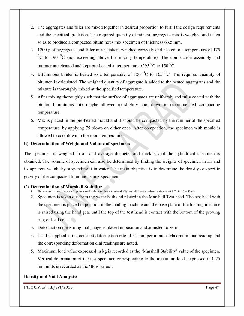
Determination of Optimum Bitumen Content:
Graphs are plotted with bitumen content on X-Axis and (i) density (ii) Marshall Stability (iii) flow value
(iv) air voids (v) VMA on Y-Axis
JNEC CIVIL/TRE/SVI/2016 Page 49
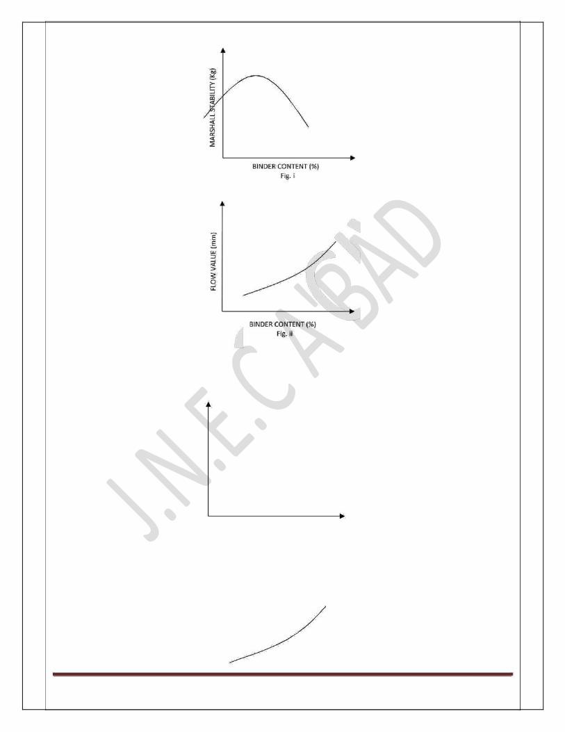

JNEC CIVIL/TRE/SVI/2016 Page 50 BINDER CONTENT
(%) Fig. ii