Embed Size (px)
DESCRIPTION
078-0300-01F ISI Protocol Spec V3
Citation preview
ISI Protocol SpecificationVersion 3
0 7 8 - 0 3 0 0 - 0 1 F

Echelon, LONWORKS, Neuron, LonMaker, LONMARK, 3120, 3150, and the Echelon logo are trademarks of Echelon Corporation registered in the United States and other countries. 3170 is a trademark of Echelon Corporation.
Other brand and product names are trademarks or registered trademarks of their respective holders. Neuron Chips and other OEM Products were not designed for use in equipment or systems which involve danger to human health or safety or a risk of property damage and Echelon assumes no responsibility or liability for use of the Neuron Chips in such applications.
Parts manufactured by vendors other than Echelon and referenced in this document have been described for illustrative purposes only, and may not have been tested by Echelon. It is the responsibility of the customer to determine the suitability of these parts for each application.
ECHELON MAKES AND YOU RECEIVE NO WARRANTIES OR CONDITIONS, EXPRESS, IMPLIED, STATUTORY OR IN ANY COMMUNICATION WITH YOU, AND ECHELON SPECIFICALLY DISCLAIMS ANY IMPLIED WARRANTY OF MERCHANTABILITY OR FITNESS FOR A PARTICULAR PURPOSE.
No part of this publication may be reproduced, stored in a retrieval system, or transmitted, in any form or by any means, electronic, mechanical, photocopying, recording, or otherwise, without the prior written permission of Echelon Corporation.
Printed in the United States of America. Copyright © 2005, 2007 Echelon Corporation.
Echelon Corporation www.echelon.com
ISI Protocol Specification 1
Introduction
This specification describes the Interoperable Self-Installation (ISI) protocol, which is a protocol used to create networks of control devices without requiring the use of an installation tool. This specification refers to version 3.01 of Echelon’s ISI libraries.
2 ISI Protocol Specification
The ISI protocol is an application-layer protocol that allows installation of devices and connection management without the use of a separate network management tool such as the LonMaker® Integration Tool. The ISI protocol can be used with small networks with up to 200 devices. The ISI protocol supports transitioning an ISI installed network to a managed network where a network management tool assumes responsibility for network configuration of all devices in the network. A network management tool provides additional flexibility, enables more complex connections and configuration, and supports larger networks. The ISI protocol simplifies installation by eliminating the need for a separate tool for simple networks.
The ISI protocol supports the following:
• Flexibility—by leveraging LONMARK® profiles and types, many types of devices are supported. For example, the ISI protocol can be used for appliances, lamps, light switches, thermostats, air conditioners, furnaces, occupancy sensors, security sensors, pool pump controllers, sun blinds, jalousies, and water heaters.
• Isolation—different networks can be logically isolated, even if their devices are within earshot of each other, such as devices in neighboring apartments or houses.
• Anarchy—devices may come and go without any special precaution. For example, many devices may be turned off when new devices are added to a network, and a device can even be moved to a different network—including one that is within earshot.
• Robustness—installation continues to work, even during periods of temporary network communication outage.
• Ease-of-Use—managing an ISI network is simple. A few button presses are all that is needed.
• Growth—networks may grow beyond the limits of the ISI protocol. The ISI protocol supports easy transitioning of a network from being self-installed to managed, where a network management tool and server take over management of the network configuration of all the devices in the network. The ISI protocol uses network configuration algorithms that are fully compatible with common network management tools and servers. This enables the network management tools and servers to fully recover all network configuration information, including device addresses and network variable connections.
The ISI protocol performs three key functions—domain acquisition, network address assignment, and connection management. Domain acquisition ensures that devices in a network can interoperate with each other, but will not interfere with devices in a neighboring network. Network address assignment ensures that every device in a network has a unique logical address, which is important to support transitioning to a managed network. Connection management allows devices in a network to exchange data. The ISI protocol operates on top of the ANSI/CEA-709.1 (also known as ISO/CEN EN14908-1) Control Network Protocol, which is a protocol designed to support the needs of control applications spanning a range of industries and requirements. It is a complete 7-layer communications protocol with each layer optimized to the needs of control applications. The 7 layers follow the reference model for open systems interconnections (OSI) developed by the International Standard Organization (ISO).
ISI Protocol Specification 3
This document describes the ISI protocol. It covers the typical ISI network architecture, the procedures that take place in an ISI installed network, and the messages that are defined by the ISI protocol.
The ISI protocol is licensed by Echelon subject to RAND1 terms (or RAND-Z2 for use with Echelon transceivers for the LONMARK TP/FT-10 and PL-20 channels, subject to additional terms outlined in the Echelon OEM License Agreement, Revision J or newer, or an amendment to a prior version of the Echelon OEM License Agreement that includes rights to the ISI protocol)). The RAND-Z terms provide a royalty-free license for use of the ISI protocol with an Echelon FT 3120®/FT 3150®/PL 3120/PL 3150/PL 3170™ Smart Transceiver or an Echelon FTT-10A/LPT-11/PLT-22 Transceiver used in conjunction with a Neuron® Chip. The OEM License Agreement specifies additional requirements for RAND-Z terms for use of the ISI protocol in devices sold into the home market. An implementation of the ISI protocol is available from Echelon. For more details, see the ISI Programmer’s Guide. To use the ISI libraries in products designed for use in a home environment, you must also have a Digital Home Alliance Agreement in effect with Echelon.
1 “RAND terms” mean the commercially reasonable and non-discriminatory terms and conditions upon which an intellectual property license is granted; these terms may include a reasonable royalty or reasonable fee. 2 “RAND-Z terms” mean the commercially reasonable and non-discriminatory terms and conditions upon which an intellectual property license is granted; these terms do not include a royalty or other fee.
4 ISI Protocol Specification
Table of Contents Introduction.............................................................................................................. 1
Table of Contents ................................................................................................. 4 ISI Network Architecture ........................................................................................ 7
Network Topology and Limits ............................................................................. 8 Where ISI Fits ...................................................................................................... 9 How the ISI Protocol Works ................................................................................ 9
Fire-and-Forget.............................................................................................. 9 Periodic Broadcasting of Data .................................................................... 10 Domain Configuration................................................................................. 11
Interoperable Data............................................................................................. 12 Addressing .......................................................................................................... 13
Subnet and Node ID .................................................................................... 14 Groups .......................................................................................................... 14 Network Variable Selectors ........................................................................ 14 Network Variable Tables ............................................................................ 15 Implicit and Explicit Addressing................................................................ 15
Connection Model............................................................................................... 15 Selector Mapping......................................................................................... 18 Compound Connection Example Walk-Through ....................................... 19 Multiple Network Variable Mapping ......................................................... 22 Accepting Partial Connections.................................................................... 23
Connection Management................................................................................... 24 Manual Enrollment ..................................................................................... 25 Automatic Enrollment................................................................................. 27 Controlled Enrollment ................................................................................ 27
Self-Installation Procedures .................................................................................. 29 Domain Acquisition............................................................................................ 30 Network Address Assignment........................................................................... 31 Network Address Verification........................................................................... 32 Device Discovery ................................................................................................ 32 Connection Enrollment...................................................................................... 32 Connection Verification ..................................................................................... 35 Connection Discovery......................................................................................... 37 Connection Removal .......................................................................................... 37 Instance Identification....................................................................................... 38 Deinstallation..................................................................................................... 38
Message Profiles..................................................................................................... 39 Periodic Messages .............................................................................................. 40 Normal and Extended Message Structures...................................................... 42 Timing and Bandwidth Control ........................................................................ 43 ISI Constants...................................................................................................... 45
ISI Group IDs and Usage Categories ......................................................... 45 ISI Message Codes....................................................................................... 46 Controlled Enrollment Request Codes....................................................... 46
ISI Message Structures ..................................................................................... 47 ISI Message Header .................................................................................... 47 Connection Management Messages ........................................................... 48
ISI Protocol Specification 5
DRUM 0x00 - Domain Resource Usage ..................................................... 49 DRUMEX 0x01 - Extended DRUM ............................................................ 49 CSMO 0x02 - Open Enrollment.................................................................. 50 CSMOEX 0x03 - Extended CSMO.............................................................. 52 CSMA 0x04 - Automatic Enrollment ......................................................... 55 CSMAEX 0x05 - Extended CSMA .............................................................. 55 CSMR 0x06 - Automatic Enrollment Reminder ........................................ 56 CSMREX 0x07 - Extended CSMR .............................................................. 56 DIDRQ 0x08 - Domain ID Request ............................................................ 56 DIDRM 0x09 - Domain ID Response.......................................................... 56 DIDCF 0x0A - Domain ID Confirmation ................................................... 58 TIMG 0x0B - Timing Guidance .................................................................. 58 CSMX 0x0C - Enrollment Cancellation ..................................................... 59 CSMC 0x0D - Enrollment Confirmation.................................................... 59 CSME 0x0E - Enrollment Acceptance........................................................ 59 CSMD 0x0F - Connection Deletion Request .............................................. 59 CSMI 0x10 - Connection Status Information ............................................ 59 CTRQ 0x11 - Control Request .................................................................... 60 CTRP 0x12 - Control Response................................................................... 60 RDCT 0x13 - Connection Table Read Request .......................................... 61 RDCS 0x14 - Connection Table Read Success ........................................... 61 RDCF 0x15 - Connection Table Read Failure ........................................... 61

6 ISI Protocol Specification
ISI Protocol Specification 7
1
ISI Network Architecture
This chapter describes the ISI network architecture, and the use of ANSI/CEA-709.1 (ISO/CEN EN14908-1) services within an ISI network.
8 ISI Protocol Specification
Network Topology and Limits There are two types of ISI networks—ISI-S for simple and standalone ISI networks, and ISI-DA for self-installed networks that support more devices than ISI-S, more complex topologies, and unique domain IDs. An ISI-DA network must include one or more domain address server (DAS) devices, and all the devices in an ISI-DA network must be ISI-DA compatible. The DAS devices are present to help manage the ISI-DA network. Multiple domain address servers can be used with a single network for increased reach or redundancy. Multiple domain address servers act independently, but the first DAS determines the domain ID to be used. The protocol implemented by the domain address servers is called the ISI-DAS protocol. The domain address servers do not take on the full roll of network management servers. Instead, they are only used to coordinate assignment of unique domain IDs and to maintain an estimate of network size to optimize use of available channel bandwidth.
ISI networks support up to 32 devices for ISI-S networks and up to 200 devices for ISI-DA networks. ISI networks will not immediately stop functioning if these limits are exceeded. Increasing the number of devices over the supported limits increases the network bandwidth consumed for administrative ISI messages, possibly preventing regular network operation due to an increased collision rate. The supported channel types for the ISI protocol are PL-20 power line and TP/FT-10 free topology twisted pair. ISI-S networks are limited to a single channel segmented with physical layer repeaters according to the standard channel properties (i.e. none for PL-20 channels, or multiple for TP/FT-10 channels) provided there is never more than one physical layer repeater between any two points of communication. In other words, you can have one N-way repeater, much in the way of an N-port Ethernet hub. A physical layer repeater is similar to a hub (signal booster without filtering logic). ISI-DA networks can have one or two channels. ISI-DA networks with two channels must include a router configured as a repeater. Each channel must meet the same requirements as a channel for ISI-S without the DAS described above. The router must be preconfigured to be compatible with ISI networks, or otherwise capable of joining an ISI network. If a domain address server is used in a two-channel network with a PL-20 and TP/FT-10 channel, it should be located on the PL-20 channel. One of the functions of the domain address server is to determine the slowest channel of the network that it is located on. If a domain address server is located on the PL-20 channel, it will start up with knowledge of the slowest channel. If it is located on the TP/FT-10 channel, it will have to learn of the existence of the PL-20 channel by discovering one of the PL-20 devices. This may take some time. Conversely, if the domain address server is located on the TP/FT-10 channel and all PL-20 devices are removed from the network, the domain address server should be reset to relearn the network topology.
ISI does not support redundant routers, and the user is responsible for avoiding looping topologies. The network topologies described in this section will not cause looping topologies.
ISI Protocol Specification 9
Where ISI Fits The main advantage of using ISI installation over installation with a network management tool is that eliminates the need for trained installation personal or specialized tools. In an ISI network, there is no central management device that if lost will cause the loss of network configuration information. There is no central database to manage and maintain. And there is no need for someone with an engineering background or specific tools to install the network. The ISI protocol is suitable for small networks with simple network topologies. Example applications in a small building or home network include monitoring and control for appliances, HVAC systems, lights, remote A/V equipment, and security devices. New devices can be added at any time to extend an existing system. The ISI protocol supports network growth. If a network grows beyond the device maximum of 32 for simple ISI-S networks, a domain address server may be added to the network to support up to 200 devices if all the devices are ISI-DA compatible. If the network grows beyond that limit, or if the complexity of the network application starts exceeding what can be reasonably managed using the ISI protocol, the ISI network can be upgraded to a managed network, and standard network management tools such as the LonMaker Integration Tool may be used to further improve and expand the system.
To join an ISI network, each participating device must implement parts of the ISI protocol. Support for the ISI protocol requires at least 3 Kbytes of application memory. While this is not typically a problem on devices supporting external memory, single-chip solutions will be more constrained. ISI installed devices need periodic communication for the maintenance of the self-installed network. The ISI protocol limits this management traffic to only one packet every five seconds, on average, for networks that include a power line channel, reducing the bandwidth available to applications by that small amount.
Self-installed networks have limited knowledge of the actual topology and network variable connection layout. Generic parameters are used when determining transport properties. If you use a network management tool to create a network with the same network variable connections as a self-installed network, the managed network will typically result in a more economic use of device and network resources, and in a more optimized device and network configuration.
How the ISI Protocol Works
Fire-and-Forget Network address assignment and connection management both require allocation of network resources. In the case of network address assignment, the network resources that must be allocated are subnet and node IDs. In the case of connection management, the network resources that must be allocated are network variable selectors. In a managed network, a network management server allocates network resources and ensures there are no conflicts. In an ISI network, there is no central network management server, so each device must allocate its own network resources and automatically resolve any conflicts that may occur due to duplicate resource assignment.
10 ISI Protocol Specification
The ISI protocol uses a patent-pending fire-and-forget algorithm for the allocation and maintenance of unique network addresses. The fire-and-forget algorithm eliminates delays when configuring the network, eliminates the need for a centralized server, and ensures correct ISI operation even at times of partial network outage or unavailability of many installed devices.
When an ISI device needs a new network address such as a device or connection address, the ISI code in the device randomly selects an address and periodically broadcasts its selection to all the other devices in the network. This is the “fire” part of fire-and-forget. When a device does this, it does not wait for a response. It assumes that its chosen address is unique and continues to use it. This is the “forget” part of fire-and-forget. All ISI devices monitor these periodic broadcasts. If a device receives a message that indicates there is an address conflict, the receiving device takes defensive action and changes its own configuration to eliminate the conflict. This eliminates the need for the sending device to wait for a response—which is important because some of the potential receiving devices may be switched off for long periods of time, and may not detect the conflict until they are switched back on some time after the initial address assignment. ISI devices maintain an estimate of the network size that is used to throttle these periodic broadcasts, such that the broadcasts do not produce more network traffic than is shown below.
Networks are assumed to be in a constant state of flux. Devices may be added and removed from the network, units may be powered on and off, or partial transient network outages may occur at any time. Thanks to the periodic notifications, the fire-and-forget algorithm ensures that each device handles a new situation as it becomes aware of relevant changes.
The ISI protocol uses fire-and-forget address assignment for assigning ANSI/CEA-709.1 (ISO/CEN EN14908-1) subnet IDs, node IDs, and network variable selectors.
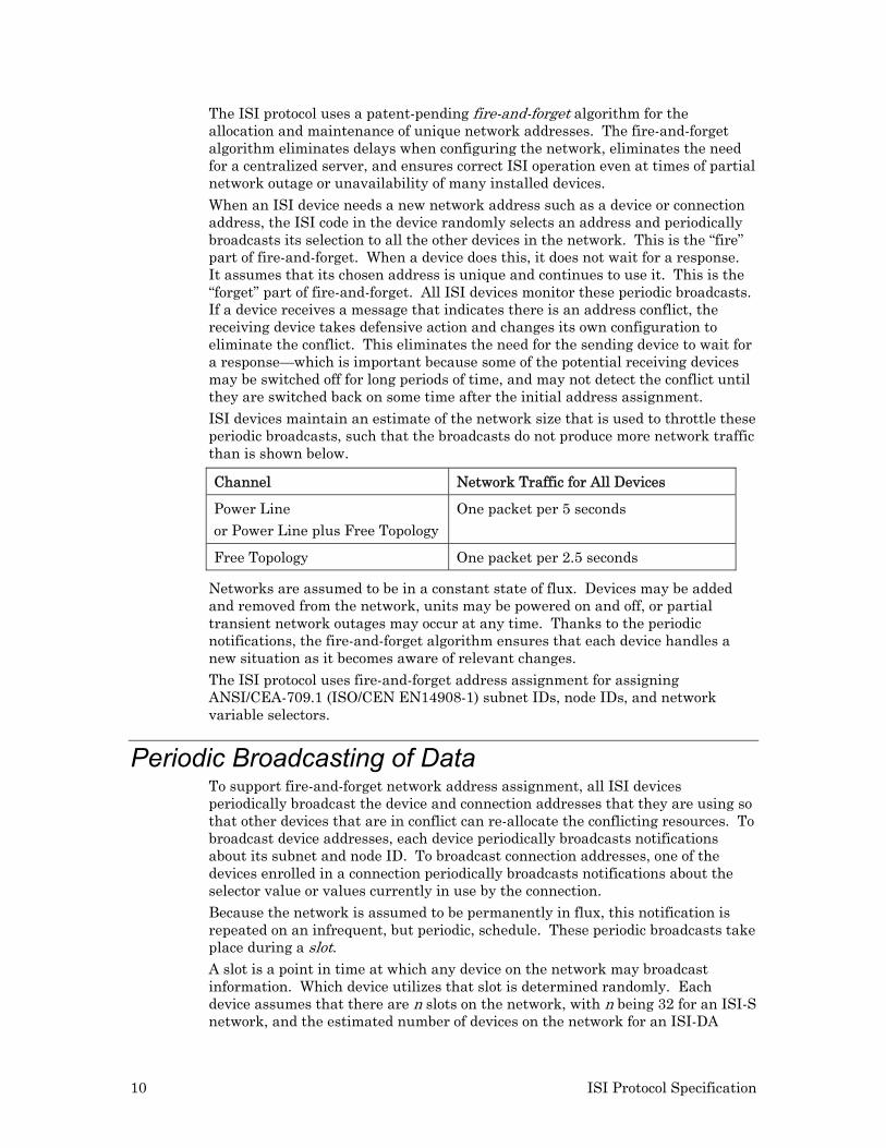
Periodic Broadcasting of Data To support fire-and-forget network address assignment, all ISI devices periodically broadcast the device and connection addresses that they are using so that other devices that are in conflict can re-allocate the conflicting resources. To broadcast device addresses, each device periodically broadcasts notifications about its subnet and node ID. To broadcast connection addresses, one of the devices enrolled in a connection periodically broadcasts notifications about the selector value or values currently in use by the connection. Because the network is assumed to be permanently in flux, this notification is repeated on an infrequent, but periodic, schedule. These periodic broadcasts take place during a slot. A slot is a point in time at which any device on the network may broadcast information. Which device utilizes that slot is determined randomly. Each device assumes that there are n slots on the network, with n being 32 for an ISI-S network, and the estimated number of devices on the network for an ISI-DA
Channel Network Traffic for All Devices
Power Line or Power Line plus Free Topology
One packet per 5 seconds
Free Topology One packet per 2.5 seconds
ISI Protocol Specification 11
network with a domain address server (DAS). The DAS provides the estimated count of devices in the network, or the number 8, whichever is highest.
The time Tslot between two adjacent slots is a property of the topology of the ISI network. Tslot is 5 seconds for networks that exclusively use a free topology channel, and 10 seconds for those containing a power line channel. The slot width ensures that periodic broadcast messages needed for the maintenance of the ISI network consume no more than 1.5% of the available bandwidth on average, and under typical conditions. The period (Tperiod) until the slot returns to the first device is determined by the number n; Tperiod = n * Tslot. For example, with a Tslot of 10 seconds and each periodic broadcast being sent with 2 packets (one initial packet, followed by one repeat), the schedule meets the requirement of 1 packet in 5 seconds on average. ISI-S networks, which assume 32 devices, normally operate at Tperiod = 32 * Tslot = 320s = 5 minutes 20 seconds on networks containing a power line channel, and at twice that rate in exclusive free topology networks. Whenever a slot is due for a particular device, the device broadcasts the next message from its broadcast queue. The broadcast queue contains at least one of the following: a message informing of the device’s subnet and node ID (DRUM), a message for each connection where the device is host of the connection (CSMI), a reminder message for each automatic connection where the device is host of the connection (CSMR), and optional network variable heartbeat messages. Several other ISI messages may also enter the periodic broadcast queue, and devices may include application-specific messages in the queue. Even though normal slot use cycles through all candidate messages in a round-robin fashion, the domain resource usage message DRUM must be sent at least every eighth slot; Tdrum ≥ 8 * Tslot. Spreading is applied to all outgoing messages that are sent in a slot: each device monitors all messages that are sent its chosen broadcast slot. If a device that is ready to send an ISI message determines an interval of less than Tspread has passed since the previous message, the sending device broadcasts the scheduled message regardless, and relies on the ANSI/CEA-709.1 layer 1 and 2 processing to handle transient traffic demand or possible collisions. The sending device then chooses a different slot for the next broadcast of a similar nature. The detection interval Tspread is a function of the network topology; 1.5 seconds is allocated on ISI networks containing a power line channel, and approximately 1 second on those making exclusive use of a free topology channel. This method aims at statistically even distribution of these periodic messages. In addition to those messages that are required for ISI operation (DRUM, TIMG, CSMI, CSMR, etc), the ISI protocol also supports the propagation of network variable heartbeat messages in the same slot. This allows for network variable heartbeats to be sent at an optimal rate for the network size, since self-installed networks cannot rely on configuration tools for adjustment of heartbeat intervals.
Domain Configuration Devices in an ISI network must join two domains, a primary and a secondary. The primary domain is the application domain, and is used for all application communication and for ISI connection-related messages. The initial primary domain is fixed for all ISI devices that are not domain address servers, and is assigned by the domain address server for devices installed in ISI-DA networks. For devices that are not domain address servers, the initial domain must be a 3-byte domain ID with a value of 0x49, 0x53, 0x49 (the ASCII codes for “ISI”). The
12 ISI Protocol Specification
domain ID for a domain address server is a 6-byte ID that is initially derived from the Neuron ID of one of the devices in the network—typically from the first domain address server in the network. Use of a unique domain assigned by a domain address server can prevent inadvertent communication between devices in different networks when those devices are within earshot of each other. This can happen, for example, in a power line network where devices in neighboring homes may be within earshot of each other.
The secondary domain is the ISI administrative domain. The secondary domain is fixed for all ISI devices. The standard fixed value is the zero-length domain with the clone domain attribute set. The clone domain attribute allows devices to receive messages that originate from a device with the same subnet/node ID as the receiver. Devices without the clone domain attribute automatically reject packets originating from their own address—this is typically desirable except when it is necessary to find duplicate addresses. The clone domain attribute on the secondary domain allows ISI devices to detect and repair duplicate addresses. Use of a common secondary domain allows multiple ISI networks to coexist on the same, shared, media. All ISI networks on the same shared media scale correctly as a function of the total number of ISI devices using that media, independent from the primary domain ID in use.
Interoperable Data A device application may be divided into one or more functional blocks. A functional block is a portion of a device’s application that performs a task by receiving configuration and operational data inputs, processing the data, and sending operational data outputs. A functional block may receive inputs from the network, hardware attached to the device, and from other functional blocks on the device. A functional block may send outputs to the network, to hardware attached to the device, and to other functional blocks on the device. The device application typically implements a functional block for each function on the device to which other devices should communicate, or that requires configuration for particular application behavior. Each functional block must be defined by a functional profile. Functional profiles are templates for functional blocks, and each functional block is an implementation of a functional profile. The network inputs and outputs of a functional block, if any, are provided by network variables and configuration properties. A network variable is an operational data input or output for a functional block. A configuration property is a data value used for configuring or documenting the behavior of one or more network variables, one or more functional blocks, or the entire device. Configuration properties used to configure or document an entire device are either associated with the entire device or associated with a special type of functional block called the Node Object functional block. Network tools use the Node Object functional block to test and manage the other functional blocks on a device. The Node Object functional block may also be used to enable or disable self-installation, to manage time, to report alarms, and to transfer data logs. Network variables are used to share data between devices. Every network variable has a direction, type, and length. The network variable direction can be either input or output, depending on whether the network variable is used to receive or send data. The network variable type determines the encoding and format of the data. LONMARK International publishes standard network variable definitions called Standard Network Variable Types, or SNVTs. Device
ISI Protocol Specification 13
manufacturers may also create custom network variable types, called user network variable types, or UNVTs.
Network variables of identical type and length but opposite directions can be connected to allow devices to share information. A single network variable may be connected to multiple network variables of the same type but opposite direction. A single network variable output connected to multiple inputs is called a fan-out connection. A single network variable input that receives inputs from multiple network variable outputs is called a fan-in connection. The application program in a device is not required to know from where input network variable values come nor to where output network variable values go. When the application program has a changed value for an output network variable, it simply passes the new value to the device firmware. Through a process called enrollment (for self-installed networks) or binding (for managed networks) the device firmware is configured to know the logical address of the other device or devices in the network that are expecting that network variable’s values. It assembles and sends the appropriate packets to these devices. Similarly, when the device firmware receives an updated value for an input network variable required by its application program, it passes the data to the application program. The enrollment or binding process thus creates logical connections between an output network variable in one device and an input network variable in another device or group of devices. Connections may be thought of as virtual wires. The enrollment or binding process may configure a network variable to appear as multiple identical network variables on the network. The additional virtual network variables created by this process are called aliases. Aliases are transparent to the device applications—an alias update to an input network variable appears identical to a network variable update to the primary network variable; an update to an output network variable with aliases is automatically sent to the primary network variable and all its aliases. ISI supports up to 254 network variables and 254 aliases on a single device. Devices may implement more than 254 network variables and 254 aliases, but only those with index 0 through 253 can be used with ISI connections. When the same device is used within a managed network, a maximum of 4096 network variables and 4096 aliases may be used on a single device.
Addressing ANSI/CEA-709.1 (ISO/CEN EN14908-1) devices typically communicate using network variables. A network variable update is sent on the network in a packet that contains a network variable value and addressing information that is used to identify the device or devices to send the update to, and to identify the network variables on those devices to receive the update. The addressing information is contained in two components—a layer-3 address that identifies the device or devices to receive the update, and a layer-6 address called the network variable selector that identifies the network variables on the receiving devices to receive the update. The layer-3 address may identify a single device, a group of devices, or all devices in the network.
14 ISI Protocol Specification
Subnet and Node ID A subnet and node ID is a pair of layer-3 identifiers that provide a unique address for each device in a network. For ISI networks, the subnet ID is a value between 64 and 127 for TP/FT-10 devices and between 128 and 191 for PL-20 devices. Multiple devices can share the same subnet. Subnets are used in managed networks for efficient routing; allocating subnet identifiers as a function of the local transceiver type allows a self-installed ISI network to be prepared for upgrading into a managed network in the future. The node ID is a value between 2 and 125. The combination of the subnet ID and node ID for a device must be unique for every device in a network. Subnet and node IDs are assigned using the fire-and-forget protocol and the protocol maintains the uniqueness of the subnet/node ID value pairs.
Groups A group is a logical collection of devices within a domain. Each group is identified by a layer-3 address called a group ID. The group ID is an identifier with a value between 0 and 255, which are split between 128 standard IDs (0 – 127) and 128 manufacturer-defined IDs (128 – 255). Each ISI standard group ID describes a device usage category. Devices are designed to recognize a certain set of group IDs, and might join up to 15 different groups at any time. For example, a washing machine appliance could belong to a manufacturer-specific group by default, but be designed to recognize standard groups for appliances, gateways, and controllers. The standard IDs and categories are defined in ISI Group IDs and Usage Categories. In an ISI network, network variables are typically sent using group addressing. Since network variables are typically sent using group addressing, devices that belong to the same group, but do not belong to the same connection, might receive the network variable update message. This is typically benign, since the network variable selector will have a unique value, and network variable updates that relate to a selector value unknown to the receiving device are dropped.
If a device is a member of multiple groups, one of the groups must be identified as the primary group. A device may belong to up to 15 groups. The maximum number of concurrent groups is defined by the address table size, which is determined by the device application.
Network Variable Selectors A network variable selector is the layer-6 address for a network variable. The network variable selector is an identifier that is included with every network variable update that is used to associate the network variable with a network variable within the receiving application. The network variable selector is a 14-bit identifier with a value between 0 and 3FFF hex, for a maximum of 16384 selector values. Selector values 0 to 2FFF hex are available for bound network variables. This provides a total of 12288 network variable selectors for bound network variables. Selector values 3000 to 3FFF hex are reserved for unbound network variables, with the selector value equal to 3FFF hex minus the network variable index.
Selectors are assigned using the fire-and-forget protocol. The protocol maintains the uniqueness of the selectors.
ISI Protocol Specification 15
Network Variable Tables Every ANSI/CEA-709.1 device maintains two tables that are used to associate a network variable selector contained in a network variable update message with a network variable on the device. These tables are also used to determine which selector or selectors to use when the application sends a network variable update. The first table is called the network variable configuration table. This table contains a single network variable selector per network variable on the device. The selector contained in this table is called the primary network variable selector. The second table is called the alias table. This table contains a variable number of selectors for each network variable on the device. The alias table is used as a pool of selectors, where any number of selectors may be assigned to each of the network variables on the device, up to the number of entries available in the alias table. Each entry in the alias table is called an alias. The ISI prototocol supports aliases, but does not require them. Device manufacturers can choose to include support for aliases in the device, at the expense of some memory and for the benefit of being able to support more flexibible connection schemes. Aliases are also supported by network management tools, allowing these tools to support more types of connections in managed networks.
Implicit and Explicit Addressing Every ANSI/CEA-709.1 device maintains an address table that is used as a pool of layer-3 addresses for sending messages, and is also used by the ANSI/CEA-709.1 protocol implementation to qualify incoming group-addressed messages. When an application writes to a network variable, the ANSI/CEA-709.1 protocol implementation looks up the network variable’s selector and address table entry to use in the network variable configuration table. It then sends the update to the address in the specified entry in the address table. This process is called implicit addressing, because the device application never has to deal with any of the addressing information. Implicit addressing reduces application code size and complexity, but limits the number of distinct network addresses that can be used by the application to the number of entries in the address table. Applications can bypass the address table by using explicit addressing. With explicit addressing, the application explicitly identifies the destination layer-6 and layer-3 addresses for a network variable update. Controllers may use this capability to send a network variable update to an individual device without needing to establish a connection first, and without requiring an address table entry.
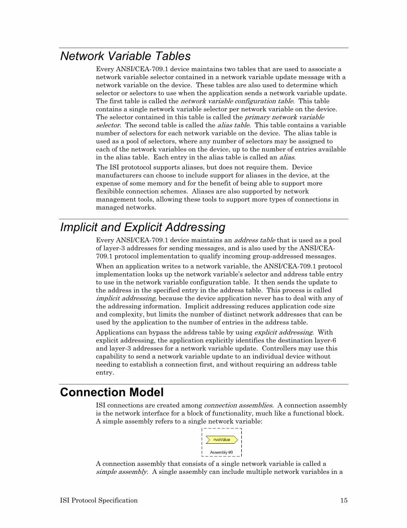
Connection Model ISI connections are created among connection assemblies. A connection assembly is the network interface for a block of functionality, much like a functional block. A simple assembly refers to a single network variable:
A connection assembly that consists of a single network variable is called a simple assembly. A single assembly can include multiple network variables in a
16 ISI Protocol Specification
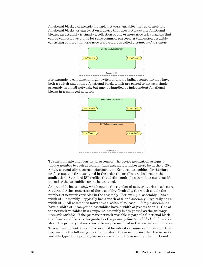
functional block, can include multiple network variables that span multiple functional blocks, or can exist on a device that does not have any functional blocks; an assembly is simply a collection of one or more network variables that can be connected as a unit for some common purpose. A connection assembly consisting of more than one network variable is called a compound assembly:
For example, a combination light-switch and lamp ballast controller may have both a switch and a lamp functional block, which are paired to act as a single assembly in an ISI network, but may be handled as independent functional blocks in a managed network:
To communicate and identify an assembly, the device application assigns a unique number to each assembly. This assembly number must be in the 0–254 range, sequentially assigned, starting at 0. Required assemblies for standard profiles must be first, assigned in the order the profiles are declared in the application. Standard ISI profiles that define multiple assemblies must specify the order the assemblies are to be assigned.
An assembly has a width, which equals the number of network variable selectors required for the connection of the assembly. Typically, the width equals the number of network variables in the assembly. For example, assembly 0 has a width of 1, assembly 1 typically has a width of 2, and assembly 2 typically has a width of 4. All assemblies must have a width of at least 1. Simple assemblies have a width of 1; compound assemblies have a width of greater than 1. One of the network variables in a compound assembly is designated as the primary network variable. If the primary network variable is part of a functional block, that functional block is designated as the primary functional block. Information about the primary network variable may be included in the connection invitation. To open enrollment, the connection host broadcasts a connection invitation that may include the following information about the assembly on offer: the network variable type of the primary network variable in the assembly, the functional
ISI Protocol Specification 17
profile number of the primary functional profile in the assembly, and the connection width. The connection invitation is sent using an ISI message called the open enrollment message (CSMO). Other devices on the network receive the invitation and interpret the offered assembly to decide whether they could join the new connection.
In the case of assembly 0, the CSMO may just specify a width of 1 and the network variable type. This is a case similar to the one employed by a generic switch device where: the switch offers a SNVT_switch network variable that is not tied to a specific functional profile. Devices that receive this CSMO message decide whether or not to join this connection based on the CSMO data (for example, a SNVT_switch network variable is on offer), and knowledge of the local application (for example, the local application itself implements a SNVT_switch network variable).
Assembly 1 demonstrates a more specialized example. In this example, a switch offers the assembly, and the assembly is described as an implementation of SFPTclosedLoopSensor with a width of 2 and the implementation of SNVT_xxx as SNVT_switch. The ISI protocol defines how selector values are mapped to the individual network variables offered. Accepting devices may include devices implementing SFPTclosedLoopActuator with SNVT_xxx as SNVT_switch, but are not limited to these. Any device that understands the data that is being offered (SFPTclosedLoopSensor implementing SNVT_switch) may join this connection. Since the invitation includes no more than one functional profile number, a compound assembly is typically limited to a single functional block on each device. To include multiple functional blocks in an assembly, a variant may be specified. A variant is an identifier that customizes the information specified in the connection invitation. Variants may be defined for any device category and/or any functional profile/member number pair. For example, a variant can be specified with the SFPTclosedLoopSensor functional block offered in assembly 2 above to specify that the SFPTclosedLoopActuator functional block is included in the assembly. A value of zero specifies that a variant is not specified. Variant values 1 – 127 are standard variant values specified by this specification and by ISI profiles published by LONMARK International. Variant values 128 – 254 are available for use by manufacturer-specific connections. The open enrollment message (CSMO) includes fields for the manufacturer ID, scope at which the types are defined, and a variant field. For standard connections, the manufacturer ID and scope are both set to zero. The variant field, too, is typically set to zero.
A manufacturer-specific connection is one where the CSMO message can only be interpreted with manufacturer-specific knowledge. A manufacturer-specific connection may use any scope, but must set the manufacturer ID field to a non-zero, valid manufacturer ID. The manufacturer ID identifies a LONWORKS® device manufacturer. Manufacturers who are members of LONMARK International have a standard manufacturer ID. These are listed at www.lonmark.org/spid. Manufacturers who are not members of LONMARK International can request a free manufacturer ID by filling out a simple form at www.lonmark.org/mid.
With manufacturer-specific compound connections, the variety of connection models supported with the CSMO message is virtually unlimited. The ISI protocol is limited to connections with a width of no more than 63.
18 ISI Protocol Specification
Each assembly on a device has a unique number that is assigned by the application. Each network variable on a device may be assigned to an assembly.
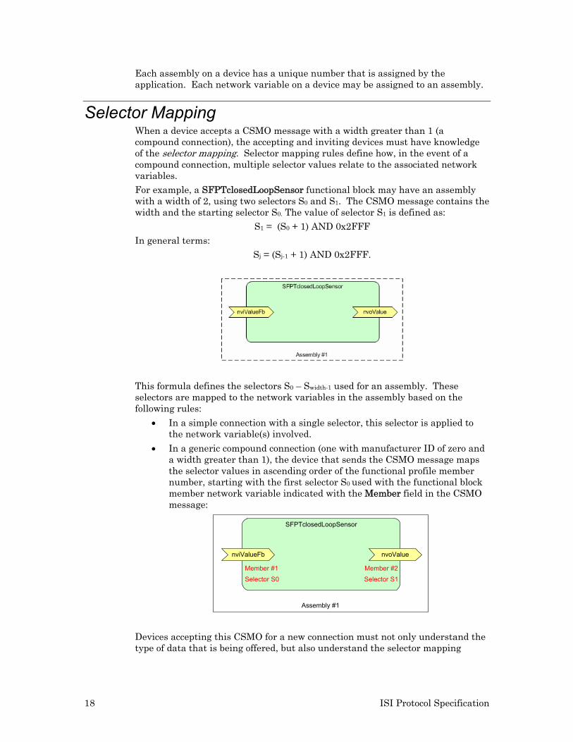
Selector Mapping When a device accepts a CSMO message with a width greater than 1 (a compound connection), the accepting and inviting devices must have knowledge of the selector mapping. Selector mapping rules define how, in the event of a compound connection, multiple selector values relate to the associated network variables. For example, a SFPTclosedLoopSensor functional block may have an assembly with a width of 2, using two selectors S0 and S1. The CSMO message contains the width and the starting selector S0. The value of selector S1 is defined as:
S1 = (S0 + 1) AND 0x2FFF In general terms:
Sj = (Sj-1 + 1) AND 0x2FFF.
This formula defines the selectors S0 – Swidth-1 used for an assembly. These selectors are mapped to the network variables in the assembly based on the following rules:
• In a simple connection with a single selector, this selector is applied to the network variable(s) involved.
• In a generic compound connection (one with manufacturer ID of zero and a width greater than 1), the device that sends the CSMO message maps the selector values in ascending order of the functional profile member number, starting with the first selector S0 used with the functional block member network variable indicated with the Member field in the CSMO message:
Assembly #1
SFPTclosedLoopSensor
nviValueFb nvoValue
Member #1 Member #2Selector S1Selector S0
Devices accepting this CSMO for a new connection must not only understand the type of data that is being offered, but also understand the selector mapping
ISI Protocol Specification 19
applied on the inviting device. Devices then have to associate local network variables with the selector values such that a meaningful connection is created.
For example, if the accepting device implements a SFPTclosedLoopActuator functional block with the same network variable type, it can map selector S0 to its local output network variable and selector S1 to its local input network variable.
A variant value may be used to identify alternate mappings.
Compound Connection Example Walk-Through Following is a walk-through a reasonably complex connection example. These examples are available as part of the Mini EVK Evaluation Kit.
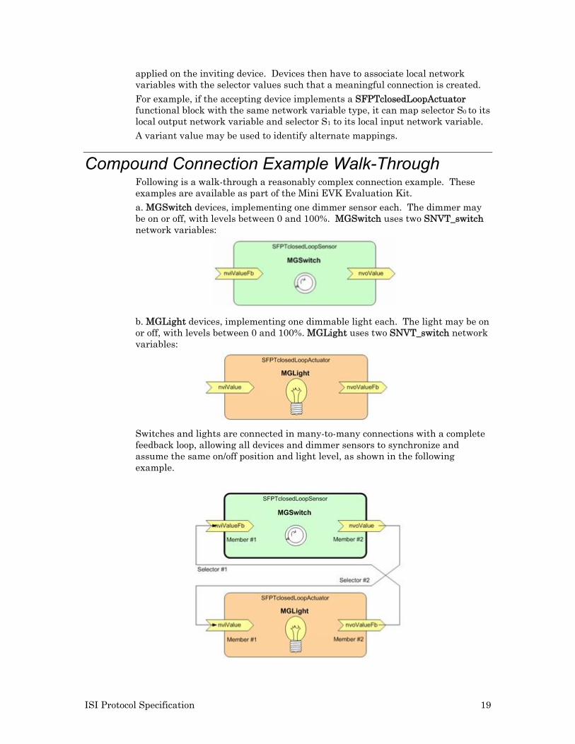
a. MGSwitch devices, implementing one dimmer sensor each. The dimmer may be on or off, with levels between 0 and 100%. MGSwitch uses two SNVT_switch network variables:
b. MGLight devices, implementing one dimmable light each. The light may be on or off, with levels between 0 and 100%. MGLight uses two SNVT_switch network variables:
Switches and lights are connected in many-to-many connections with a complete feedback loop, allowing all devices and dimmer sensors to synchronize and assume the same on/off position and light level, as shown in the following example.
20 ISI Protocol Specification
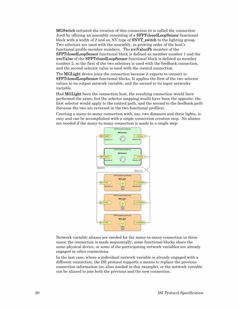
MGSwitch initiated the creation of this connection (it is called the connection host) by offering an assembly consisting of a SFPTclosedLoopSensor functional block with a width of 2 and an NV type of SNVT_switch to the lighting group. Two selectors are used with the assembly, in growing order of the host’s functional profile member numbers. The nviValueFb member of the SFPTclosedLoopSensor functional block is defined as member number 1 and the nvoValue of the SFPTclosedLoopSensor functional block is defined as member number 2, so the first of the two selectors is used with the feedback connection, and the second selector value is used with the control connection. The MGLight device joins the connection because it expects to connect to SFPTclosedLoopSensor functional blocks. It applies the first of the two selector values to its output network variable, and the second to its input networks variable.
Had MGLight been the connection host, the resulting connection would have performed the same, but the selector mapping would have been the opposite: the first selector would apply to the control path, and the second to the feedback path (because the two are reversed in the two functional profiles). Creating a many-to-many connection with, say, two dimmers and three lights, is easy and can be accomplished with a single connection creation step. No aliases are needed if the many-to-many connection is made in a single step:
Network variable aliases are needed for the many-to-many connection in three cases: the connection is made sequentially, some functional blocks share the same physical device, or some of the participating network variables are already engaged in other connections.
In the last case, where a individual network variable is already engaged with a different connection, the ISI protocol supports a means to replace the previous connection information (no alias needed in this example), or the network variable can be aliased to join both the previous and the new connection.
ISI Protocol Specification 21
In the second case, which is the case of a single device implementing two switches, the connection cannot be made in a single step. The ISI protocol can only apply a single assembly at a time per device, even if a given device may provide multiple applicable assemblies. In order to establish the resulting many-to-many connection, a multi-step procedure must be used.
The same multi-step procedure is also used to extend an existing connection. ISI connections may be extended by adding an additional aliased connection. The resulting user-experience is that of an extended connection, although the ANSI/CEA 709.1 mapping is that of an aliased, separate, connection.
22 ISI Protocol Specification
EXAMPLE
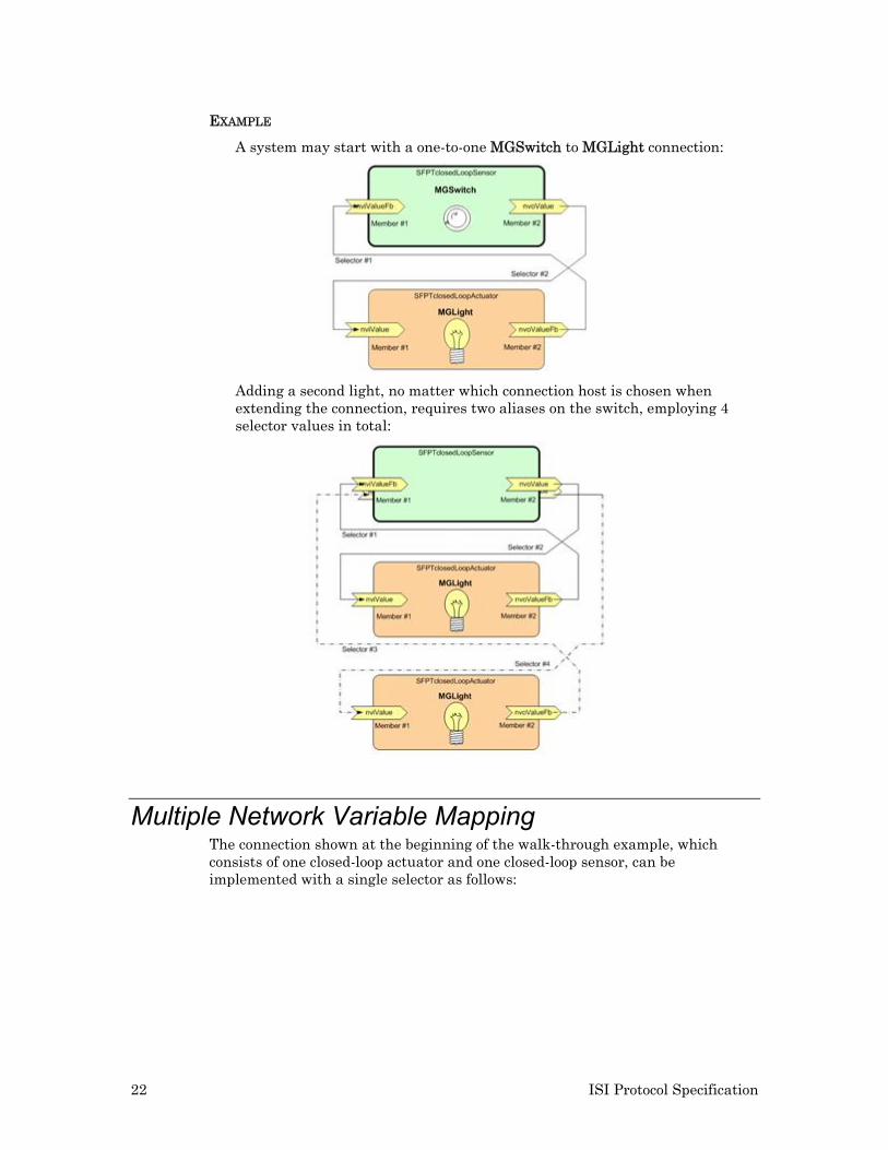
A system may start with a one-to-one MGSwitch to MGLight connection:
Adding a second light, no matter which connection host is chosen when extending the connection, requires two aliases on the switch, employing 4 selector values in total:
Multiple Network Variable Mapping The connection shown at the beginning of the walk-through example, which consists of one closed-loop actuator and one closed-loop sensor, can be implemented with a single selector as follows:
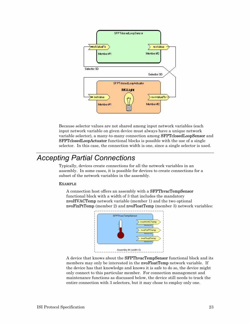
ISI Protocol Specification 23
Because selector values are not shared among input network variables (each input network variable on given device must always have a unique network variable selector), a many-to-many connection among SFPTclosedLoopSensor and SFPTclosedLoopActuator functional blocks is possible with the use of a single selector. In this case, the connection width is one, since a single selector is used.
Accepting Partial Connections Typically, devices create connections for all the network variables in an assembly. In some cases, it is possible for devices to create connections for a subset of the network variables in the assembly.
EXAMPLE
A connection host offers an assembly with a SFPThvacTempSensor functional block with a width of 3 that includes the mandatory nvoHVACTemp network variable (member 1) and the two optional nvoFixPtTemp (member 2) and nvoFloatTemp (member 3) network variables:
A device that knows about the SFPThvacTempSensor functional block and its members may only be interested in the nvoFloatTemp network variable. If the device has that knowledge and knows it is safe to do so, the device might only connect to this particular member. For connection management and maintenance functions as discussed below, the device still needs to track the entire connection with 3 selectors, but it may chose to employ only one.
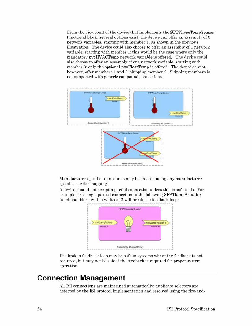
24 ISI Protocol Specification
From the viewpoint of the device that implements the SFTPhvacTempSensor functional block, several options exist: the device can offer an assembly of 3 network variables, starting with member 1, as shown in the previous illustration. The device could also choose to offer an assembly of 1 network variable, starting with member 1: this would be the case where only the mandatory nvoHVACTemp network variable is offered. The device could also choose to offer an assembly of one network variable, starting with member 3: only the optional nvoFloatTemp is offered. The device cannot, however, offer members 1 and 3, skipping member 2. Skipping members is not supported with generic compound connections.
Manufacturer-specific connections may be created using any manufacturer-specific selector mapping. A device should not accept a partial connection unless this is safe to do. For example, creating a partial connection to the following SFPTlampActuator functional block with a width of 2 will break the feedback loop:
The broken feedback loop may be safe in systems where the feedback is not required, but may not be safe if the feedback is required for proper system operation.
Connection Management All ISI connections are maintained automatically: duplicate selectors are detected by the ISI protocol implementation and resolved using the fire-and-
ISI Protocol Specification 25
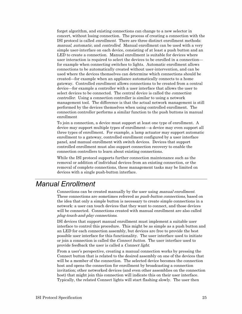
forget algorithm, and existing connections can change to a new selector in concert, without losing connection. The process of creating a connection with the ISI protocol is called enrollment. There are three distinct enrollment methods: manual, automatic, and controlled. Manual enrollment can be used with a very simple user-interface on each device, consisting of at least a push button and an LED to create a connection. Manual enrollment is suitable for devices where user interaction is required to select the devices to be enrolled in a connection—for example when connecting switches to lights. Automatic enrollment allows connections to be automatically created without user-intervention, and can be used where the devices themselves can determine which connections should be created—for example when an appliance automatically connects to a home gateway. Controlled enrollment allows connections to be created from a central device—for example a controller with a user interface that allows the user to select devices to be connected. The central device is called the connection controller. Using a connection controller is similar to using a network management tool. The difference is that the actual network management is still performed by the devices themselves when using controlled enrollment. The connection controller performs a similar function to the push buttons in manual enrollment
To join a connection, a device must support at least one type of enrollment. A device may support multiple types of enrollment—a device may even support all three types of enrollment. For example, a lamp actuator may support automatic enrollment to a gateway, controlled enrollment configured by a user interface panel, and manual enrollment with switch devices. Devices that support controlled enrollment must also support connection recovery to enable the connection controllers to learn about existing connections.
While the ISI protocol supports further connection maintenance such as the removal or addition of individual devices from an existing connection, or the removal of complete connections, these management tasks may be limited on devices with a single push-button interface.
Manual Enrollment Connections can be created manually by the user using manual enrollment. These connections are sometimes referred as push-button connections, based on the idea that only a simple button is necessary to create simple connections in a network: a user can touch devices that they want to connect, and those devices will be connected. Connections created with manual enrollment are also called plug-touch-and-play connections.
ISI devices that support manual enrollment must implement a suitable user interface to control this procedure. This might be as simple as a push button and an LED for each connection assembly, but devices are free to provide the best possible user interface for this functionality. The user interface used to initiate or join a connection is called the Connect button. The user interface used to provide feedback the user is called a Connect light. From a user’s perspective, creating a manual connection works by pressing the Connect button that is related to the desired assembly on one of the devices that will be a member of the connection. The selected device becomes the connection host and opens the connection for enrollment by broadcasting a connection invitation; other networked devices (and even other assemblies on the connection host) that might join this connection will indicate this on their user interface. Typically, the related Connect lights will start flashing slowly. The user then
26 ISI Protocol Specification
chooses each assembly that ought to participate in the new connection and identifies each assembly by pressing the related Connect button. The related Connect light will now be solid on, reflecting the fact that the assembly is ready to join the connection. The Connect light on the connection host will also change to solid on, indicating that at least one connection member has been identified. Finally, the user returns to the connection host and confirms the connection by pressing its Connect button once more. This implements the connection on the connection host and all devices that the user has identified. All related Connect lights will flash briefly to indicate the completion, be turned off, and the connection is operational.
The open enrollment times out if the connection is not confirmed by pressing the Connect button on the connection host a second time in time Tacq. Only one assembly for each device may join a connection at one time; if multiple assemblies implemented on the same device need to join the same connection, the enrollment procedure must be repeated.
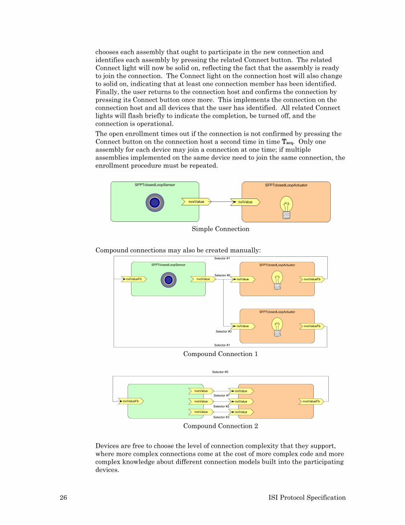
SFPTclosedLoopActuator
nviValue
SFPTclosedLoopSensor
nvoValue
Simple Connection
Compound connections may also be created manually:
SFPTclosedLoopSensor
nviValueFb nvoValue
SFPTclosedLoopActuator
nviValue nvoValueFb
SFPTclosedLoopActuator
nviValue nvoValueFb
Selector #0
Selector #0
Selector #1
Selector #1
Compound Connection 1
nviValueFb nvoValue nviValue nvoValueFb
nvoValue nviValue
nvoValue nviValue
Selector #0
Selector #3
Selector #2
Selector #1
Compound Connection 2
Devices are free to choose the level of connection complexity that they support, where more complex connections come at the cost of more complex code and more complex knowledge about different connection models built into the participating devices.
ISI Protocol Specification 27
Automatic Enrollment Connections can be created automatically with no user intervention using automatic enrollment. This allows for complete plug-and-play operation of a set of devices. For example, a general-purpose home gateway device may automatically create connections from its time output network variable to all the time input network variables on all devices in the network, and may automatically create connections from all alarm output network variables from all devices of the network to its own alarm input network variable. Automatic enrollment occurs using messages that are automatically issued by the connection host (the home gateway, for example). These messages are re-sent periodically, allowing newly added devices to join the existing automatic connection (the time and alarm reporting connections in the example). Automatic connections offer an assembly in a similar way as manual connections, and maintenance of automatic connections is largely identical to maintaining manually initiated connections. Receiving devices can determine if the connection invitation is for automatic or manual/controlled enrollment, and can use this information when determining whether or not to join the connection. To avoid a peak traffic demand at power-up, devices implementing automatic connections are required to do so no sooner than Tauto after power-up, which includes a randomized initial wait-time after reset.
Controlled Enrollment Connections can be created by a user interacting with a connection controller device using controlled enrollment. The connection controller may be a simple user interface panel or other controller. The user initiates enrollment by interacting with the connection controller. The connection controller in turn sends requests to the devices to be enrolled. This takes the place of the user pressing Connect buttons on the devices. However, the operations performed by the devices hosting and joining the connection are the same operations that are performed during manual enrollment. The only difference is that the procedure is initiated by the connection controller instead of local push buttons. To send a request to a device, the connection controller sends a control request (CTRQ) message to the device. The CTRQ message contains a controlled enrollment request code and a parameter for the device to respond to. If the destination devices supports controlled enrollment, it responds with a control response (CTRP) message to indicate whether the requested operation is supported or not. If the destination device does not support controlled enrollment, it will not send any response. The request codes are defined in Controlled Enrollment Request Codes. The request is always sent on the primary domain, using Neuron ID addressing. Using the primary domain is required so that the response can reach the

28 ISI Protocol Specification
connection controller. Using Neuron ID addressing allows for simpler device tracking. Because the response only contains the source subnet and node ID, the Neuron ID is included in the CTRQ message. This allows the controller device to correlate responses to devices without tracking subnet/node IDs.
ISI Protocol Specification 29
2
Self-Installation Procedures
This chapter describes the procedures defined by the ISI protocol.
30 ISI Protocol Specification
Domain Acquisition Devices in an ISI network must join two domains, a primary and a secondary. The primary domain is the application domain, and is used for all application communication and for ISI connection-related messages. The primary domain for a device that is not a domain address server is initially a 3-byte domain ID with a value of 73, 83, 73 (0x49, 0x53, 0x49—the ASCII codes for “ISI’). The domain ID for devices installed in an ISI-DA network is a 6-byte ID that is initially derived from the Neuron ID of one of the devices in the network—typically the first domain address server in the network. There are four methods to assign a primary domain to an ISI device:
1. The domain may be fixed and assigned by the device application. All ISI devices support this method since an initial application domain must be assigned prior to acquiring a domain using one of the other methods. This enables all ISI devices to be used in an ISI-S network. The standard default domain ID used by ISI devices is a 3-byte long domain ID with decimal values 73, 83, 73 (0x49, 0x53, 0x49—the ASCII codes for “ISI”).
2. A device that supports domain acquisition or a domain address server (DAS) can acquire a unique domain address from another DAS. If a DAS is not available, domain acquisition will fail and the ISI engine will continue to use the default domain. Devices that support domain acquisition also support multiple, redundant, domain address servers. Domain address acquisition is initiated by the user and controlled by the DAS and the device acquiring the domain ID. This method allows the device acquiring the domain ID to make intelligent decisions about retries, preventing enrollment during the domain acquisition. It also allows the device acquiring the domain ID to increase automatic enrollment performance following the completion of domain acquisition.
3. A domain address server can assign a domain to a device without a request from the device. This minimizes the code required in the device, and can be used with any ISI device. This procedure is called fetching a device.
4. A domain address server can fetch the domain from any of the devices in a network and assign it to itself. This keeps multiple domain address servers in a network synchronized with each other, or allows a replacement domain address server to join an existing ISI network. This procedure is called fetching a domain.
For the second method, the domain acquisition procedure is used by a device that supports domain acquisition to obtain a domain ID for a network. A domain address server (DAS) only assigns a domain ID when it is in device acquisition mode. This mode must be manually enabled by a user and will only last for a limited time Tacq — the purpose being to minimize the possibility of acquiring a neighbor’s device. If a domain address server is requested to serve a domain address, but has not yet itself been assigned a domain, it will use its Neuron ID as the domain ID, or it may fetch the Neuron ID from another device in the network using the fetch domain procedure. A replacement domain address server can obtain the primary domain ID from any of the presently installed devices on the network using the fetch domain procedure. The following domain acquisition procedure is used to assign a domain ID to a device joining an ISI-DA network using domain acquisition:
ISI Protocol Specification 31
1. The user starts domain acquisition mode on the DAS by pressing the Connect button on the DAS (or by another user interface on the DAS). The DAS automatically terminates device acquisition mode after Tacq, unless re-triggered.
2. The user presses the Connect button on the new device to be added to the domain. The device broadcasts a domain ID request (DIDRQ) message on the secondary domain. The DIDRQ message contains the sender’s Neuron ID.
3. The DAS that is currently in device acquisition mode responds with a domain ID response (DIDRM) message. The DAS uses Neuron ID addressing to target the requesting device alone, therefore reducing the risk of accidentally providing a domain ID to the incorrect device.
4. The new device receives the DIDRM response message and indicates receipt of this message by executing its Wink function. The Wink function is a standard option for ANSI/CEA 709.1 devices, resulting in some suitable, benign, visual or audible feedback. For example, a device might flash all its LEDs for 5 seconds.
5. The user confirms that the correct device has executed its Wink function to the DAS by pressing the Connect button on the DAS again (or by another user interface on the DAS). This restarts the DAS device acquisition mode timer (Tacq), and causes a domain ID confirmation message (DIDCF) to be sent to the device. Like with DIDRM, the DAS uses Neuron ID addressing to target the requesting device alone, therefore reducing the risk of accidentally providing a domain ID to the incorrect device.
6. If more then one response is received containing different domain IDs, the device discards them all, and aborts the domain address acquisition procedure.
7. If the device receives a confirmation message that matches the initial domain ID response message, the device configures its primary domain accordingly and exits registration mode.
8. If the device receives a confirmation message (DIDCF) that does not match the initial response (DIDRM), the device indicates failure and aborts registration mode. It will continue to operate using the most recent primary domain ID. The registration procedure may be restarted with step 1.
9. If a device fails to receive an initial response (DIDRM) within Trm from the issue of the request (DIDRQ), or fails to receive a confirmation (DIDCF) within Tcf from the receipt of the DIDRM response, the device waits 5 * Trm and re-enters the registration procedure by re-sending a domain ID request (DIDRQ) message, as described in step 2.
10. If the whole procedure is repeated 20 times without success, the device aborts registration mode. It will continue to operate using the most recent primary domain ID. The registration procedure may be restarted with step 1.
Network Address Assignment A subnet and node ID is a pair of layer-3 identifiers that provide a unique address for each device in a network. For ISI devices, the subnet ID is a value between 64 and 127 for TP/FT-10 devices and between 128 and 191 for PL-20 devices. The node ID is a value between 2 and 125. The network address assignment procedure automatically assigns a subnet and node ID to a device when it is installed for the first time. It is performed on initial power-on reset for all ISI devices, and may be repeated once the domain acquisition procedure has
32 ISI Protocol Specification
been completed when joining an ISI-DA network. Subnet and node IDs are assigned using the fire-and-forget algorithm as follows:
1. The device randomly chooses a subnet ID from the value range defined in the previous paragraph and sets its subnet ID in the primary domain.
2. The device randomly chooses a node ID from the value range defined in the previous paragraph and sets its node ID in the primary domain.
3. The device immediately broadcasts a domain resource usage message (DRUM), using the secondary domain.
Any device receiving a DRUM with a duplicate subnet/node ID and the same primary domain ID reconfigures its subnet/node ID using the standard registration procedure (but ensuring that the duplicate address is not assigned again).
Network Address Verification The network address verification procedure verifies that a device’s network address is valid. The network address verification procedure is used periodically, but is especially important when a device that has a network address is powered off and then is later powered back on. While the device is powered off, it is possible for a duplicate address to be assigned. To detect address conflicts, all devices periodically resend the DRUM at the Tdrum interval (see Timing and Bandwidth Control for details). As with the initial allocation, any device receiving a DRUM with a different Neuron ID, the same primary domain ID, and duplicate subnet/node ID reconfigures itself using the standard network address assignment procedure.
Device Discovery The device discovery procedure enables any device to learn the network address and program types for all devices in a network. This procedure is typically only used by gateways and controllers. Since all devices periodically send a device resource usage message (DRUM), any device on the network can learn about every other active device on the network that is within network listening range by monitoring DRUMs. This is useful for controllers that must control many other devices or that must monitor data from many other devices. Such controllers may monitor DRUMs and build a device table containing details of all the devices with which the controller must interact. Details may include the device’s network address and any other detail provided with the DRUM. This table may be constructed and maintained by the controller application or self-installation firmware. Any device constructing such a device table must continuously monitor DRUMs and update the table with new devices, devices with changed addresses, and deleted devices. To detect deleted devices, the device application must monitor the time of update for each device-table entry and detect stale entries that no longer have corresponding DRUMs.
Connection Enrollment The connection enrollment procedure creates network variable connections among the devices in a network. This procedure may be invoked once the network address assignment procedure has been completed, and subsequently at any time. Connections may be created using automatic, controlled, or manual enrollment. For controlled or manual enrollment, user intervention is required to
ISI Protocol Specification 33
identify devices or assemblies to be connected. Controlled enrollment is initiated by a centralized tool such as a controller or user interface panel. This centralized tool is called the connection controller. Manual enrollment is initiated from the devices to be connected, typically with a push button called the Connect button. For automatic enrollment, connections are automatically created and no user intervention is required. The type of enrollment depends on the application. For example, appliances typically use automatic enrollment, lighting and security devices installed by electricians or professional installers typically use controlled enrollment, and lighting and security devices installed by end-users typically use manual enrollment. When using automatic enrollment, no user intervention is required to create connections. When using controlled or manual enrollment, the user chooses the device that becomes the connection host.
A connection is created during an open enrollment period that is initiated by a user for controlled or manual enrollment or by an application for automatic enrollment.
Multiple connections may be created during the open enrollment period. For example, a home gateway device may offer automatic enrollment for many of its inputs and outputs.
Most connections are created using repeated group connections. There are two exceptions:
• Polling input network variables use request/response messaging.
• Acknowledged service is supported, but requires the use of subnet/node ID addressed unicast messages. Devices initiating acknowledged network variable updates must track subnet/node ID allocation similar to the mechanisms described under Device Discovery.
Connections can be simple connections requiring a single selector or they can be compound connections that require multiple selector values. The first selector is always allocated randomly, but subsequent selectors are allocated sequentially following this first selector as described in Network Variable Selectors. Manufacturer-specific compound connections are free to use any manufacturer-specific scheme to map the width selector values to the network variables involved. Generic compound connections, however, must always use the standard selector mapping scheme described in Network Variable Selectors.
The enrollment procedure is as follows: 1. For manual enrollment, the user identifies a connection assembly to be
enrolled in a new connection. This is typically done by the user pressing a Connect button on the device to be connected. For controlled enrollment, the user identifies connection assemblies to be enrolled in a new connection. This is done by the user interacting with a user interface on the connection controller. The connection controller then instructs the participating devices accordingly; the remainder of the controlled enrollment procedure is much like the manual enrollment procedure, with one of the devices appointed by the controller to become the connection host. For automatic enrollment, the connection host and connection members automatically identify the connection assembly to be enrolled in a new connection. The enrollment procedure must be repeated once per connection to be created on each connection host, and it must be repeated once per connection assembly to be added on each participating device. Devices that support multiple connection assemblies must provide device-specific methods to allow the user to determine which connection is to be made or re-made. In the simplest case,
34 ISI Protocol Specification
this could mean pressing a single Connect button once for the first connection, twice for the second one, etc. Alternatively, there may be a single Connect button per assembly, for example, one button per switch. More sophisticated devices, such as room temperature controllers with multiple buttons and an LCD display, for example, might provide a different and easier-to-use method for multi-connection management.
2. The connection host randomly chooses an NV selector between 0 and 12287. Even though the NV selector is selected randomly by the connection host, once selected it must be used by all network variables that will enroll in the same connection. For a compound connection, the host randomly chooses a selector S between 0 and 12287, and assumes the remaining number of selectors to be sequentially following the starting selector: Sj = (Sj-1 + 1) AND 0x2FFF When choosing the selector values, the connection host ensures local uniqueness—that is, the connection host will choose a new selector or selector range such that no conflict occurs with any bound selector on the same device.
3. The connection host assigns a unique connection ID. The connection ID uniquely identifies a connection and is used to repair network variable selector conflicts. It must be unique for all connections in the network. To ensure uniqueness, the connection ID combines the Neuron ID of the connection host with a connection serial number assigned by the connection host.
4. For manual and controlled enrollment, the connection host sends a connection invitation by broadcasting an open enrollment message (CSMO) to the primary domain, signaling an open enrollment period. The connection host periodically repeats this message until the connection is confirmed or cancelled by the user, or cancelled automatically as a timeout at the Tenroll interval. The CSMO message is repeated each Tcsmo interval. For automatic enrollment, the connection sends an automatic connection invitation message (CSMA), and repeats this invitation periodically by broadcasting automatic connection invitation reminders (CSMR). CSMA and CSMR messages share a message format with CSMO messages, but use a different ISI message code.3
5. Receiving devices determine whether or not they will provisionally approve the connection invitation based on the information provided with the CSMO message. In the manual enrollment scenario, devices indicate provisionally approved members for the connection by providing some feedback to the user such as flashing an LED. When a device receives an open enrollment message (CSMO), it initially only provisionally approves, but does not yet join, the connection. To provisionally approve a connection means to confirm that this is an acceptable, possible, connection for the device to participate in. This includes the acceptance of the data offered (as described in the CSMO message), and the confirmation that sufficient device resources appear to be available (alias table space, connection table space, etc).
3 Unless specifically noted, CSMO, CSMA, and CSMR messages behave identically—the remainder of this section refers to a CSMO message type as the common term for CSMO, CSMA, and CSMR message types.
ISI Protocol Specification 35
In the controlled or automatic enrollment scenarios, devices are not required to indicate eligible assemblies to the user, as no local user intervention is required.
6. Any device provisionally approving the connection may add one or more network variables to the connection. This is called accepting the connection invitation. The user or device application identifies network variables to be enrolled in the connection. For manual enrollment this is typically done by the user pressing a Connect button on the device to be connected. For controlled enrollment, this is typically done by the user interacting with the connection controller and the connection controller then sending a connection request (CTRQ) to the device. For automatic enrollment, this is done automatically by rules and algorithms defined in the device’s application. As devices are selected and accept the connection invitation, they send an enrollment acceptance message (CSME) and will typically provide visual or audible feedback to the user to signal the acceptance of the connection invitation.
A device that accepts a connection invitation by sending a CSME message starts to resend the CSME message periodically at Tcsme intervals, until the connection attempt either times out, is cancelled, or the connection is confirmed and implemented.
7. If the connection was initiated manually, the user must manually close the enrollment on the connection host, for example by pressing the same Connect button on the connection host that was used to start the connection. If the connection was initiated with controlled enrollment, the connection controller closes the enrollment on the connection host. To close the enrollment, the connection host implements the connection by broadcasting a connection confirmation message (CSMC) to the primary domain, signaling a closed enrollment period. Upon receiving this message, any selected devices use the network variable selector(s) and group ID to join the connection, and associate the connection ID with the connection. The connection host may only close the enrollment if at least one enrollment acceptance message (CSME) has been received. Automatic enrollment closes implicitly and immediately; no CSMC or CSME messages are required in the automatic enrollment case.
8. If the enrollment is not closed within T4 (5 * Tenroll), the connection host will cancel the enrollment. The connection host will also cancel the enrollment if an open enrollment message is received from another device within the domain. To cancel the enrollment, the connection host broadcasts an enrollment cancellation message (CSMX) to the primary domain, signaling a cancelled enrollment period. Cancellation does not apply to automatic enrollment. Automatic enrollment cannot be cancelled, but connections made through automatic enrollment may be removed just like other connections.
9. If a device has accepted a connection invitation but does not receive manual or automatic confirmation or cancellation, the device discards the invitation after T4.
Connection Verification The connection verification procedure automatically verifies and maintains network variable connections. All connection hosts periodically resend the connection status information message (CSMI) for each connection that they host
36 ISI Protocol Specification
on their primary domain. The CSMIs are sent one at a time for each connection, cycling through the connections on each update. As a result, if a device is host of 5 simple connections, the update interval for all connections will be 5 * Tperiod. Other message types may also use the periodically scheduled Tperiod intervals, increasing this update interval. See Timing and Bandwidth Usage Control for details about scheduling of periodic messages. Connection hosts hosting compound connections also send out CSMIs. The CSMI for a compound connection specifies a starting selector value S0 and a count 0 – 3 to indicate the number of subsequent selector values also governed by this CSMI. A compound connection with a total width of 6 selectors requires 2 CSMIs, one for the selector set S0 – S3 (CSMI count 3) and one for the set S4 – S5 (CSMI count 1). Since all related CSMIs must use the same connection ID (because they relate to the same connection), receivers must be able to distinguish between a selector update, and a CSMI for a different selector slice. To enable this, the CSMI also contains an Offset field, which indicates the N-th slice within the selectors belonging to this connection. In the above example, the first CSMI has an offset of zero, the second one an offset of one. Any device receiving a CSMI with count 0 and offset 0 (a simple connection) does the following for all connections of which the device is currently a member:
• Any device receiving a connection status message with a duplicate NV selector and different connection ID reconfigures itself by assigning a new selector that is a function of the old selector and connection ID. The function is the sum of the old selector plus each of the bytes of the connection ID, masked by 0x2FFF.
• Any device receiving a connection status message with a different selector and duplicate connection ID reconfigures itself by assigning the new selector. The new selector is the one provided with the CSMI.
Any device receiving a CSMI with count greater than 0 or offset greater than 0 (a compound connection or part of a compound connection) does the following for all connections of which the device is currently a member:
• Any device receiving a connection status message with a duplicate NV selector and different connection ID, where the duplicate selector relates to any of the selector values governed by the CSMI, reconfigures itself by assigning new selectors that are a function of the old selectors and connection ID. It does so for all selectors governed by the CSMI. The first replacement selector in the affected range is the sum of the old selector plus each of the bytes of the connection ID, masked by 0x2FFF. The remaining selectors in the CSMI range follow sequentially, also masked by 0x2FFF.
• Any device receiving a connection status message with a different start NV selector and duplicate connection ID reconfigures itself by assigning the new starting selector, and all other selectors in the set follow sequentially. The new starting selector is the one provided with the CSMI.
Devices that are connection hosts for automatic connections may also monitor DIDRQ messages. At a time Tcsmr after the last DIDRQ message seen (where each DIDRQ re-triggers the Tcsmr timer), the device propagates a CSMR message for each automatic connection for which the device acts as a connection host. This accelerates discovery of the automatic connections by the new device that just joined the network (i.e., the device that issued the DIDRQ message). The CSMR message data equals that of the CSMO message. A device receiving a
ISI Protocol Specification 37
CSMR message that refers to an existing connection on the device discards the message. A device receiving a CSMR where the message relates to an automatic connection that the device is prepared to join automatically joins that connection in one step (there is no confirmation CSMC or cancellation CSMX message following CSMR). This simple mechanism allows for new devices to be added to the network and to automatically join existing connections as needed, with minimum network burden.
Connection Discovery A self-installed network may include one or more connection controllers. Connection controllers orchestrate connection enrollment, as described under Controlled Enrollment. Additionally, connection controllers can also be used to manage existing connections by removing or extending existing connections. A connection controller normally accumulates the information required for optional maintenance throughout its lifetime. This information may be lost, or a new connection controller may be installed into or added to an existing, self-installed, network. The connection discovery procedure allows the connection controller to recover the current connection status of each device in the network. This is typically done by a device that also performs controlled enrollment on devices in the network. The controlling device sends a read connection table request (RDCT) message to each device that it wishes to query. The RDCT message includes a connection table index. If the member and host fields in the message are set to 0xFF, then the device returns a read connection table success (RDCS) response with the connection information for that device’s connection table index. If the index does not exist, then it responds with a read connection table failure (RDCF) response. Devices may optionally support filtering by host and member assembly numbers. This reduces the number of messages required to find a specific entry. If the host or member field is different from 0xFF, and the device supports filtering, the index provided acts as a starting index. The first matching connection table entry is returned, if any. If both host and member filter are set to a value different from 0xFF, then connection table entries matching either the host or the member assembly number are returned, if any. If the host or member field is different from 0xFF and the device does not support filtering, the connection table entry indicated by the index specified in the RDCT message is returned.
Connection Removal The connection removal procedure removes a network variable connection among devices in a network. As with the initial connection enrollment, connections may be removed using automatic, controlled, or manual connection removal. Once initiated, any device may broadcast a connection deletion request message (CSMD) to the primary domain, signaling a deleted connection. This causes all enrolled devices to delete the NV selector and group ID (if not in use by another connection) from their network configuration and connection table.
Devices are not required to support connection removal. They may instead only support deinstallation, which removes the device from all connections. Further, devices are free to support means of removal of local connection information only (the local device would leave the connection without
38 ISI Protocol Specification
propagating a CSMD message), or to support removal of the entire connection, or both.
Connection hosts, however, cannot delete the connection locally without deleting the connection on the network. When a connection is removed from a connection host, the host must issue CSMD connection deletion messages for all connections the related assembly was engaged with.
Instance Identification The instance identification procedure enables the user to perform an action on a device upon request by a controller. As described in the discovery procedure, a controller can create a device table of all devices in a network, or a subset of the devices based on program ID. By using explicitly constructed network variable updates or polls, the controller application can individually access any device and network variable in the network. In this case, the controller may still join the connections using the standard connection enrollment procedure. This allows the controller application to use the network variable selector acquired during the connection enrollment procedure. For a network variable update or poll, the controller application uses the assigned selector with the subnet and node ID from the device table.
Deinstallation The deinstallation procedure enables the user to perform an action on a device to remove all configuration data. The configuration data includes the domain, network address, and network variable connections. Support for this procedure is required. It is used when a device is moved to a new network, or when a device is accidentally acquired by the wrong domain address server. The procedure is also used by devices that do not provide connection removal, since it then provides the only means to remove the device from a connection. Self-installed devices must support a manual mechanism for this, even without a network connection. For example, a self-installed device may initiate deinstallation when the user presses and holds the Connect button for 10 seconds. To complete the deinstallation procedure, the device application clears the configuration data and resets itself. When a device joins a new primary domain using the domain acquisition procedure, it may automatically deinstall all current configuration data. This requires reinstallation of the entire network in the event of changing the primary domain ID by using domain acquisition, but allows moving of individual devices into different networks (domain IDs) with little precaution. A DAS with a device table can change the primary domain by selecting a new domain ID, and fetching all devices in the old domain. To move a device to a new network, reset it to the factory default prior to physically installing it in the new network.
ISI Protocol Specification 39
3
Message Profiles
This chapter describes the ISI protocol message structures. It also gives details on the timing of how the messages are sent.
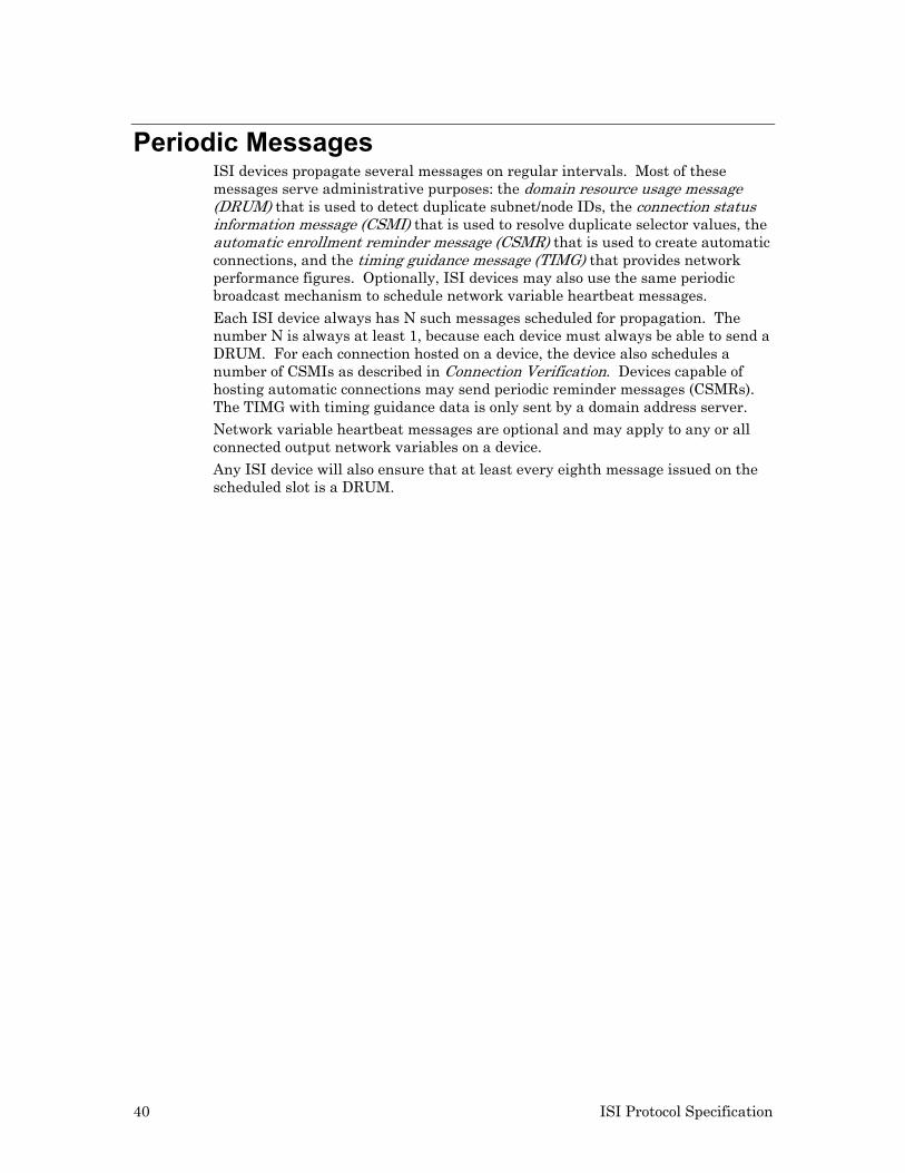
40 ISI Protocol Specification
Periodic Messages ISI devices propagate several messages on regular intervals. Most of these messages serve administrative purposes: the domain resource usage message (DRUM) that is used to detect duplicate subnet/node IDs, the connection status information message (CSMI) that is used to resolve duplicate selector values, the automatic enrollment reminder message (CSMR) that is used to create automatic connections, and the timing guidance message (TIMG) that provides network performance figures. Optionally, ISI devices may also use the same periodic broadcast mechanism to schedule network variable heartbeat messages.
Each ISI device always has N such messages scheduled for propagation. The number N is always at least 1, because each device must always be able to send a DRUM. For each connection hosted on a device, the device also schedules a number of CSMIs as described in Connection Verification. Devices capable of hosting automatic connections may send periodic reminder messages (CSMRs). The TIMG with timing guidance data is only sent by a domain address server. Network variable heartbeat messages are optional and may apply to any or all connected output network variables on a device.
Any ISI device will also ensure that at least every eighth message issued on the scheduled slot is a DRUM.
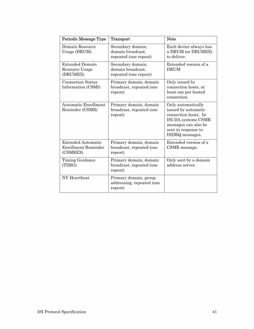
ISI Protocol Specification 41
Periodic Message Type Transport Note
Domain Resource Usage (DRUM)
Secondary domain, domain broadcast, repeated (one repeat)
Each device always has a DRUM (or DRUMEX) to deliver.
Extended Domain Resource Usage (DRUMEX)
Secondary domain, domain broadcast, repeated (one repeat)
Extended version of a DRUM
Connection Status Information (CSMI)
Primary domain, domain broadcast, repeated (one repeat)
Only issued by connection hosts, at least one per hosted connection.
Automatic Enrollment Reminder (CSMR)
Primary domain, domain broadcast, repeated (one repeat)
Only automatically issued by automatic connection hosts. In ISI-DA systems CSMR messages can also be sent in response to DIDRQ messages.
Extended Automatic Enrollment Reminder (CSMREX)
Primary domain, domain broadcast, repeated (one repeat)
Extended version of a CSMR message.
Timing Guidance (TIMG)
Primary domain, domain broadcast, repeated (one repeat)
Only sent by a domain address server.
NV Heartbeat Primary domain, group addressing, repeated (one repeat)
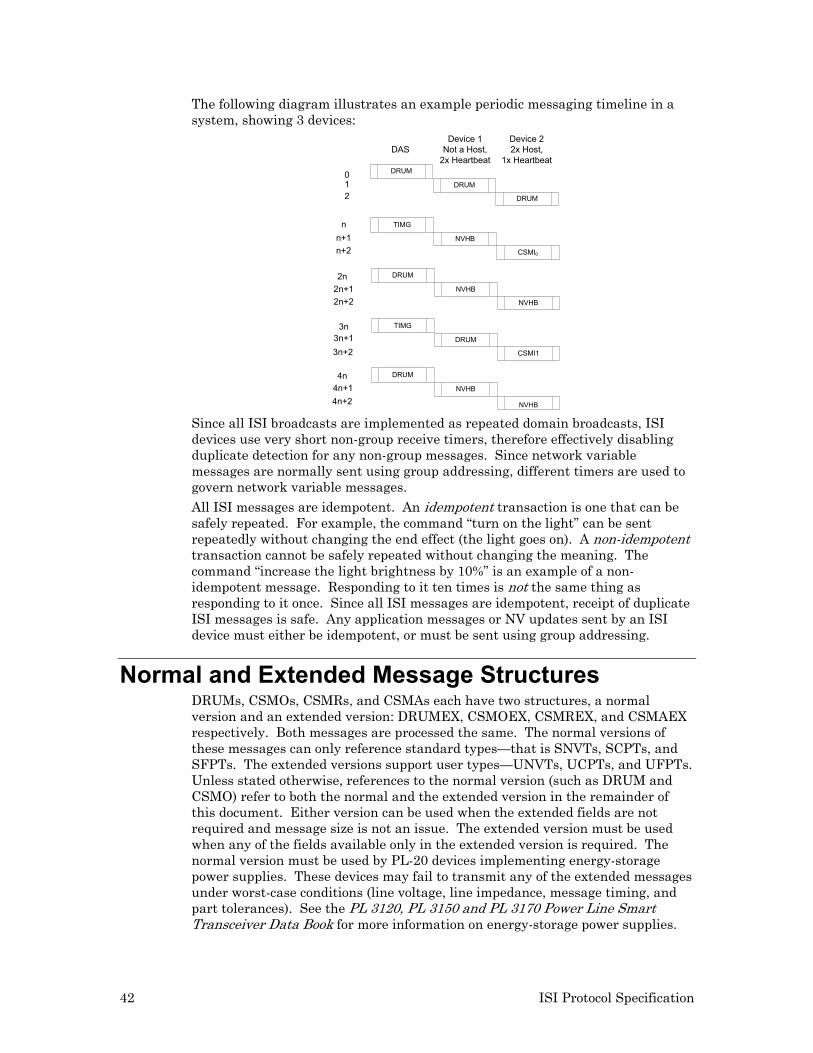
42 ISI Protocol Specification
The following diagram illustrates an example periodic messaging timeline in a system, showing 3 devices:
DRUM
DRUM
DRUM
TIMG
NVHB
CSMI0
DRUM
NVHB
NVHB
TIMG
DRUM
CSMI1
DASDevice 1
Not a Host,2x Heartbeat
DRUM
NVHB
NVHB
Device 22x Host,
1x Heartbeat
nn+1n+2
012
2n+12n+2
2n
3n3n+13n+2
4n4n+14n+2
Since all ISI broadcasts are implemented as repeated domain broadcasts, ISI devices use very short non-group receive timers, therefore effectively disabling duplicate detection for any non-group messages. Since network variable messages are normally sent using group addressing, different timers are used to govern network variable messages. All ISI messages are idempotent. An idempotent transaction is one that can be safely repeated. For example, the command “turn on the light” can be sent repeatedly without changing the end effect (the light goes on). A non-idempotent transaction cannot be safely repeated without changing the meaning. The command “increase the light brightness by 10%” is an example of a non-idempotent message. Responding to it ten times is not the same thing as responding to it once. Since all ISI messages are idempotent, receipt of duplicate ISI messages is safe. Any application messages or NV updates sent by an ISI device must either be idempotent, or must be sent using group addressing.
Normal and Extended Message Structures DRUMs, CSMOs, CSMRs, and CSMAs each have two structures, a normal version and an extended version: DRUMEX, CSMOEX, CSMREX, and CSMAEX respectively. Both messages are processed the same. The normal versions of these messages can only reference standard types—that is SNVTs, SCPTs, and SFPTs. The extended versions support user types—UNVTs, UCPTs, and UFPTs. Unless stated otherwise, references to the normal version (such as DRUM and CSMO) refer to both the normal and the extended version in the remainder of this document. Either version can be used when the extended fields are not required and message size is not an issue. The extended version must be used when any of the fields available only in the extended version is required. The normal version must be used by PL-20 devices implementing energy-storage power supplies. These devices may fail to transmit any of the extended messages under worst-case conditions (line voltage, line impedance, message timing, and part tolerances). See the PL 3120, PL 3150 and PL 3170 Power Line Smart Transceiver Data Book for more information on energy-storage power supplies.
ISI Protocol Specification 43
Timing and Bandwidth Control Each device must calculate numbers for various timers, such as timeout periods, heartbeat intervals for repeatedly resent messages such as DRUMs and CSMIs, or network transport properties such as ANSI/CEA-709.1 (ISO/CEN EN14908-1) receive-timer values. In an ISI-DA network, the domain address server periodically provides updated timing-guidance data with TIMG messages to assist all devices in the network with calculation of these timers. Since support for TIMG messages is optional, only devices that support TIMG messages can be installed in an ISI-DA network.
In an ISI-S network that does not contain a domain address server, all devices assume a device count of 32 and a single channel. These devices derive the transport parameters from their local transceiver type. Any ISI device can be installed in an ISI-S network. Timing-guidance data contains two figures: an encoded value for approximate worst-case single-trip propagation delay between any two devices on the network, and the device count estimate. The encoding for the propagation delay is the channel type identifier, as used with the standard-format program ID. The domain address server advises on the slowest channel type observed in the network, allowing all devices to adjust to this performance expectation as the common denominator throughout the system.
The domain address server establishes the propagation delay figure based on its local transceiver type in a single-segment network. In a multi-segment network, the domain address server monitors DRUMs from all devices and chooses the least performing channel to derive propagation delay guidance. The domain address server provides a device count estimate. This figure is not necessarily the exact number of active devices at the time, but it should be a reasonable approximation. The approximation should err on the side of overestimating rather than underestimating. The domain address server assumes a minimum of 8 devices, itself included. The domain address controller broadcasts timing guidance data in a TIMG message regularly, alternating with its own DRUM, scheduled at intervals governed by the periodic broadcast scheduler. Each device broadcasts messages regularly, one each D * Tslot seconds, where D is the estimated device count. Several messages share this scheme: DRUM, TIMG, CSMI, CSMR, and network variable heartbeat messages all enter a propagation queue, and the message at the head of this queue will be sent each D seconds. The queue will never be empty, as it always contains at least one DRUM. Each device ensures that at least every eighth message is a DRUM. Each device ensures a minimum interval of D* Tslot between each repeated DRUM or CSMI, therefore evenly distributing all maintenance messages that are sent from this device. To support even distribution of all maintenance messages (DRUM, TIMG, CSMI, CSMR, and network variable heartbeat messages) in the entire network, and to avoid peak bandwidth demand therefore, devices implement a spreading technique: whenever a device is ready to propagate one of its regularly scheduled messages but has received one such message from another device within Tspread, the device completes the necessary broadcast and re-allocates the broadcasting slot.
ANSI/CEA-709.1 (ISO/CEN EN14908-1) receive timers are derived from the channel type identifier in the timing guidance data. The ANSI/CEA 709.1
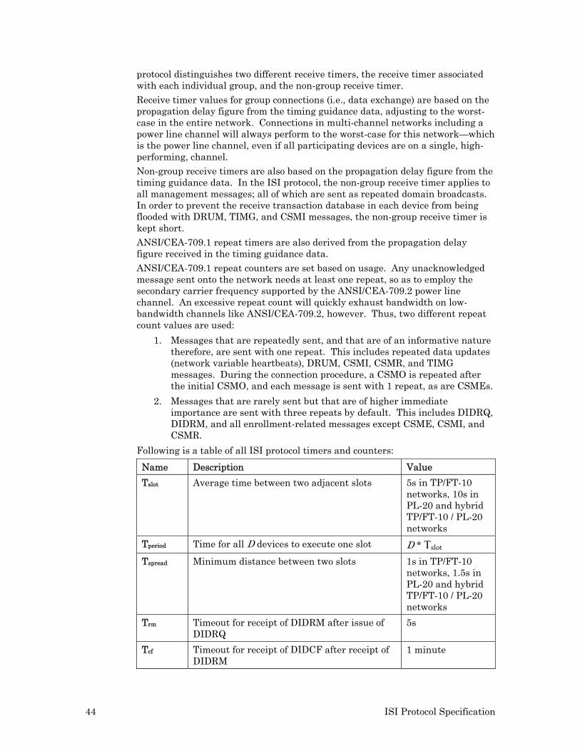
44 ISI Protocol Specification
protocol distinguishes two different receive timers, the receive timer associated with each individual group, and the non-group receive timer.
Receive timer values for group connections (i.e., data exchange) are based on the propagation delay figure from the timing guidance data, adjusting to the worst-case in the entire network. Connections in multi-channel networks including a power line channel will always perform to the worst-case for this network—which is the power line channel, even if all participating devices are on a single, high-performing, channel. Non-group receive timers are also based on the propagation delay figure from the timing guidance data. In the ISI protocol, the non-group receive timer applies to all management messages; all of which are sent as repeated domain broadcasts. In order to prevent the receive transaction database in each device from being flooded with DRUM, TIMG, and CSMI messages, the non-group receive timer is kept short. ANSI/CEA-709.1 repeat timers are also derived from the propagation delay figure received in the timing guidance data.
ANSI/CEA-709.1 repeat counters are set based on usage. Any unacknowledged message sent onto the network needs at least one repeat, so as to employ the secondary carrier frequency supported by the ANSI/CEA-709.2 power line channel. An excessive repeat count will quickly exhaust bandwidth on low-bandwidth channels like ANSI/CEA-709.2, however. Thus, two different repeat count values are used:
1. Messages that are repeatedly sent, and that are of an informative nature therefore, are sent with one repeat. This includes repeated data updates (network variable heartbeats), DRUM, CSMI, CSMR, and TIMG messages. During the connection procedure, a CSMO is repeated after the initial CSMO, and each message is sent with 1 repeat, as are CSMEs.
2. Messages that are rarely sent but that are of higher immediate importance are sent with three repeats by default. This includes DIDRQ, DIDRM, and all enrollment-related messages except CSME, CSMI, and CSMR.
Following is a table of all ISI protocol timers and counters:
Name Description Value
Tslot Average time between two adjacent slots 5s in TP/FT-10 networks, 10s in PL-20 and hybrid TP/FT-10 / PL-20 networks
Tperiod Time for all D devices to execute one slot D * Tslot Tspread Minimum distance between two slots 1s in TP/FT-10
networks, 1.5s in PL-20 and hybrid TP/FT-10 / PL-20 networks
Trm Timeout for receipt of DIDRM after issue of DIDRQ
5s
Tcf Timeout for receipt of DIDCF after receipt of DIDRM
1 minute
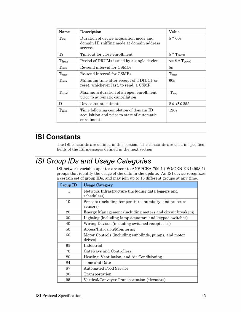
ISI Protocol Specification 45
Name Description Value
Tacq Duration of device acquisition mode and domain ID sniffing mode at domain address servers
5 * 60s
T4 Timeout for close enrollment 5 * Tenroll
Tdrum Period of DRUMs issued by a single device <= 8 * Tperiod
Tcsmo Re-send interval for CSMOs 5s
Tcsme Re-send interval for CSMEs Tcsmo
Tcsmr Minimum time after receipt of a DIDCF or reset, whichever last, to send, a CSMR
60s
Tenroll Maximum duration of an open enrollment prior to automatic cancellation
Tacq
D Device count estimate 8 ≤ D ≤ 255
Tauto Time following completion of domain ID acquisition and prior to start of automatic enrollment
120s
ISI Constants The ISI constants are defined in this section. The constants are used in specified fields of the ISI messages defined in the next section.
ISI Group IDs and Usage Categories ISI network variable updates are sent to ANSI/CEA-709.1 (ISO/CEN EN14908-1) groups that identify the usage of the data in the update. An ISI device recognizes a certain set of group IDs, and may join up to 15 different groups at any time.
Group ID Usage Category
1 Network Infrastructure (including data loggers and schedulers)
10 Sensors (including temperature, humidity, and pressure sensors)
20 Energy Management (including meters and circuit breakers) 30 Lighting (including lamp actuators and keypad switches) 40 Wiring Devices (including switched receptacles) 50 Access/Intrusion/Monitoring 60 Motor Controls (including sunblinds, pumps, and motor
drives) 65 Industrial 70 Gateways and Controllers 80 Heating, Ventilation, and Air Conditioning 84 Time and Date 87 Automated Food Service 90 Transportation 95 Vertical/Conveyer Transportation (elevators)
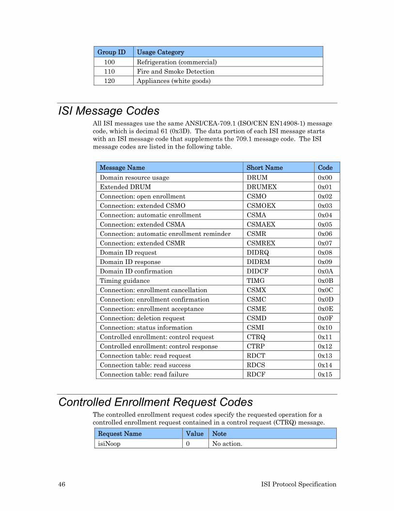
46 ISI Protocol Specification
Group ID Usage Category
100 Refrigeration (commercial) 110 Fire and Smoke Detection 120 Appliances (white goods)
ISI Message Codes All ISI messages use the same ANSI/CEA-709.1 (ISO/CEN EN14908-1) message code, which is decimal 61 (0x3D). The data portion of each ISI message starts with an ISI message code that supplements the 709.1 message code. The ISI message codes are listed in the following table.
Message Name Short Name Code
Domain resource usage DRUM 0x00 Extended DRUM DRUMEX 0x01 Connection: open enrollment CSMO 0x02 Connection: extended CSMO CSMOEX 0x03 Connection: automatic enrollment CSMA 0x04 Connection: extended CSMA CSMAEX 0x05 Connection: automatic enrollment reminder CSMR 0x06 Connection: extended CSMR CSMREX 0x07 Domain ID request DIDRQ 0x08 Domain ID response DIDRM 0x09 Domain ID confirmation DIDCF 0x0A Timing guidance TIMG 0x0B Connection: enrollment cancellation CSMX 0x0C Connection: enrollment confirmation CSMC 0x0D Connection: enrollment acceptance CSME 0x0E Connection: deletion request CSMD 0x0F Connection: status information CSMI 0x10 Controlled enrollment: control request CTRQ 0x11 Controlled enrollment: control response CTRP 0x12 Connection table: read request RDCT 0x13 Connection table: read success RDCS 0x14 Connection table: read failure RDCF 0x15
Controlled Enrollment Request Codes The controlled enrollment request codes specify the requested operation for a controlled enrollment request contained in a control request (CTRQ) message.
Request Name Value Note
isiNoop 0 No action.
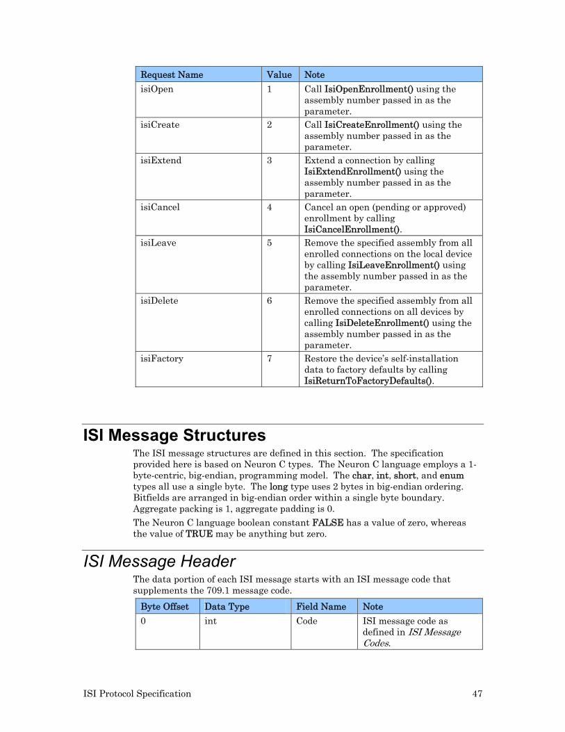
ISI Protocol Specification 47
Request Name Value Note
isiOpen 1 Call IsiOpenEnrollment() using the assembly number passed in as the parameter.
isiCreate 2 Call IsiCreateEnrollment() using the assembly number passed in as the parameter.
isiExtend 3 Extend a connection by calling IsiExtendEnrollment() using the assembly number passed in as the parameter.
isiCancel 4 Cancel an open (pending or approved) enrollment by calling IsiCancelEnrollment().
isiLeave 5 Remove the specified assembly from all enrolled connections on the local device by calling IsiLeaveEnrollment() using the assembly number passed in as the parameter.
isiDelete 6 Remove the specified assembly from all enrolled connections on all devices by calling IsiDeleteEnrollment() using the assembly number passed in as the parameter.
isiFactory 7 Restore the device’s self-installation data to factory defaults by calling IsiReturnToFactoryDefaults().
ISI Message Structures The ISI message structures are defined in this section. The specification provided here is based on Neuron C types. The Neuron C language employs a 1-byte-centric, big-endian, programming model. The char, int, short, and enum types all use a single byte. The long type uses 2 bytes in big-endian ordering. Bitfields are arranged in big-endian order within a single byte boundary. Aggregate packing is 1, aggregate padding is 0.
The Neuron C language boolean constant FALSE has a value of zero, whereas the value of TRUE may be anything but zero.
ISI Message Header The data portion of each ISI message starts with an ISI message code that supplements the 709.1 message code.
Byte Offset Data Type Field Name Note
0 int Code ISI message code as defined in ISI Message Codes.
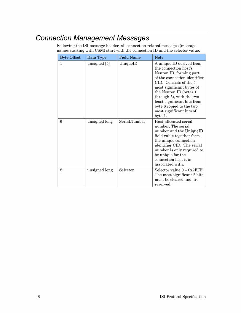
48 ISI Protocol Specification
Connection Management Messages Following the ISI message header, all connection-related messages (message names starting with CSM) start with the connection ID and the selector value:
Byte Offset Data Type Field Name Note
1 unsigned [5] UniqueID A unique ID derived from the connection host’s Neuron ID, forming part of the connection identifier CID. Consists of the 5 most significant bytes of the Neuron ID (bytes 1 through 5), with the two least significant bits from byte 6 copied to the two most significant bits of byte 1.
6 unsigned long SerialNumber Host-allocated serial number. The serial number and the UniqueID field value together form the unique connection identifier CID. The serial number is only required to be unique for the connection host it is associated with.
8 unsigned long Selector Selector value 0 – 0x2FFF. The most significant 2 bits must be cleared and are reserved.
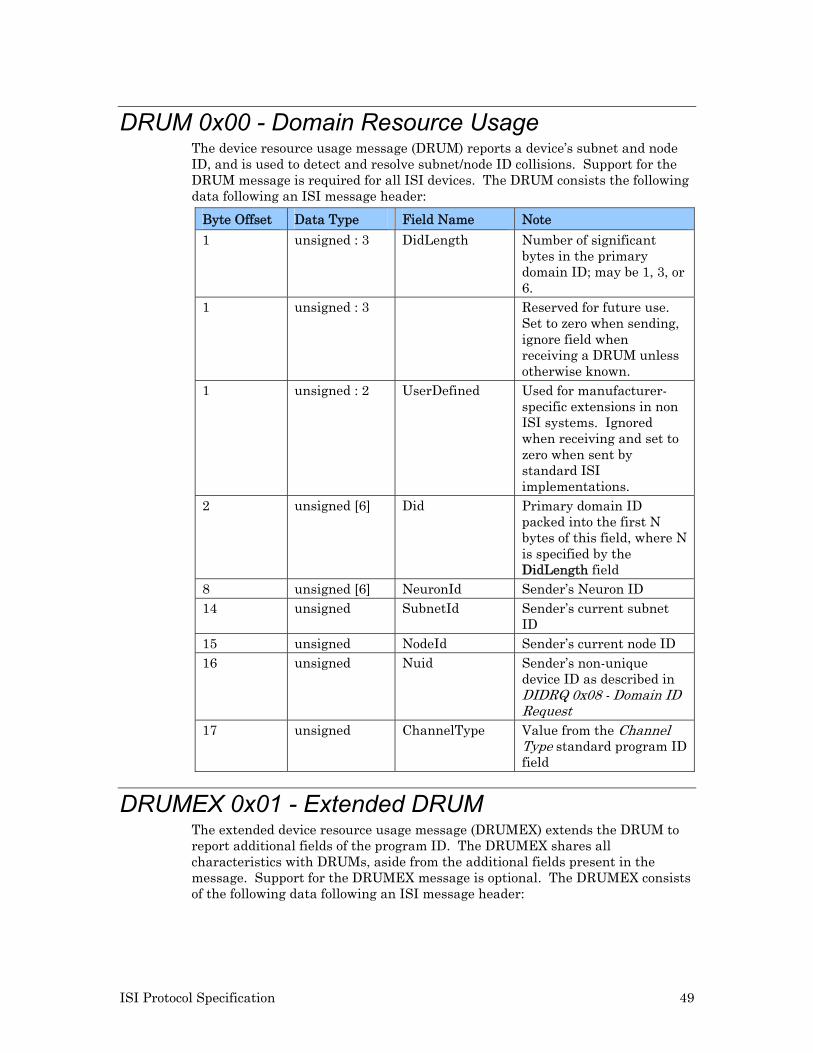
ISI Protocol Specification 49
DRUM 0x00 - Domain Resource Usage The device resource usage message (DRUM) reports a device’s subnet and node ID, and is used to detect and resolve subnet/node ID collisions. Support for the DRUM message is required for all ISI devices. The DRUM consists the following data following an ISI message header:
Byte Offset Data Type Field Name Note
1 unsigned : 3 DidLength Number of significant bytes in the primary domain ID; may be 1, 3, or 6.
1 unsigned : 3 Reserved for future use. Set to zero when sending, ignore field when receiving a DRUM unless otherwise known.
1 unsigned : 2 UserDefined Used for manufacturer-specific extensions in non ISI systems. Ignored when receiving and set to zero when sent by standard ISI implementations.
2 unsigned [6] Did Primary domain ID packed into the first N bytes of this field, where N is specified by the DidLength field
8 unsigned [6] NeuronId Sender’s Neuron ID 14 unsigned SubnetId Sender’s current subnet
ID 15 unsigned NodeId Sender’s current node ID 16 unsigned Nuid Sender’s non-unique
device ID as described in DIDRQ 0x08 - Domain ID Request
17 unsigned ChannelType Value from the Channel Type standard program ID field
DRUMEX 0x01 - Extended DRUM The extended device resource usage message (DRUMEX) extends the DRUM to report additional fields of the program ID. The DRUMEX shares all characteristics with DRUMs, aside from the additional fields present in the message. Support for the DRUMEX message is optional. The DRUMEX consists of the following data following an ISI message header:
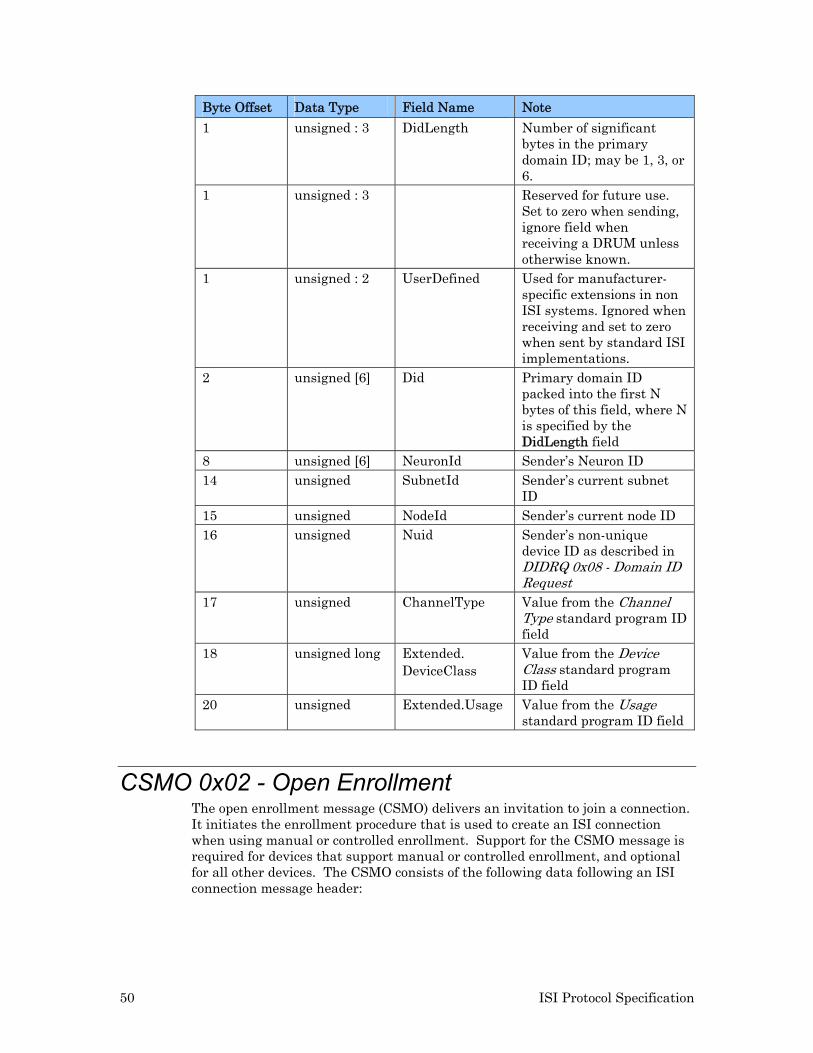
50 ISI Protocol Specification
Byte Offset Data Type Field Name Note
1 unsigned : 3 DidLength Number of significant bytes in the primary domain ID; may be 1, 3, or 6.
1 unsigned : 3 Reserved for future use. Set to zero when sending, ignore field when receiving a DRUM unless otherwise known.
1 unsigned : 2 UserDefined Used for manufacturer-specific extensions in non ISI systems. Ignored when receiving and set to zero when sent by standard ISI implementations.
2 unsigned [6] Did Primary domain ID packed into the first N bytes of this field, where N is specified by the DidLength field
8 unsigned [6] NeuronId Sender’s Neuron ID 14 unsigned SubnetId Sender’s current subnet
ID 15 unsigned NodeId Sender’s current node ID 16 unsigned Nuid Sender’s non-unique
device ID as described in DIDRQ 0x08 - Domain ID Request
17 unsigned ChannelType Value from the Channel Type standard program ID field
18 unsigned long Extended. DeviceClass
Value from the Device Class standard program ID field
20 unsigned Extended.Usage Value from the Usage standard program ID field
CSMO 0x02 - Open Enrollment The open enrollment message (CSMO) delivers an invitation to join a connection. It initiates the enrollment procedure that is used to create an ISI connection when using manual or controlled enrollment. Support for the CSMO message is required for devices that support manual or controlled enrollment, and optional for all other devices. The CSMO consists of the following data following an ISI connection message header:
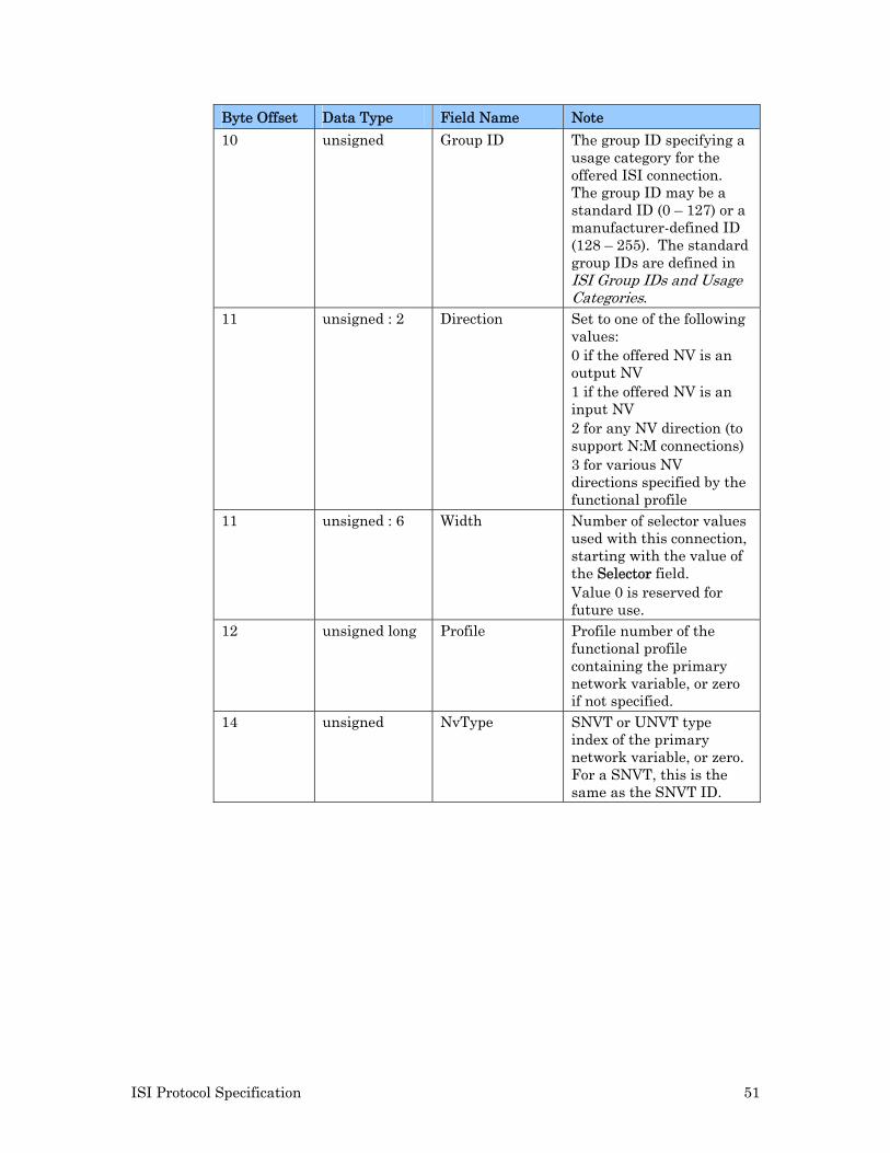
ISI Protocol Specification 51
Byte Offset Data Type Field Name Note
10 unsigned Group ID The group ID specifying a usage category for the offered ISI connection. The group ID may be a standard ID (0 – 127) or a manufacturer-defined ID (128 – 255). The standard group IDs are defined in ISI Group IDs and Usage Categories.
11 unsigned : 2 Direction Set to one of the following values: 0 if the offered NV is an output NV 1 if the offered NV is an input NV 2 for any NV direction (to support N:M connections) 3 for various NV directions specified by the functional profile
11 unsigned : 6 Width Number of selector values used with this connection, starting with the value of the Selector field. Value 0 is reserved for future use.
12 unsigned long Profile Profile number of the functional profile containing the primary network variable, or zero if not specified.
14 unsigned NvType SNVT or UNVT type index of the primary network variable, or zero. For a SNVT, this is the same as the SNVT ID.
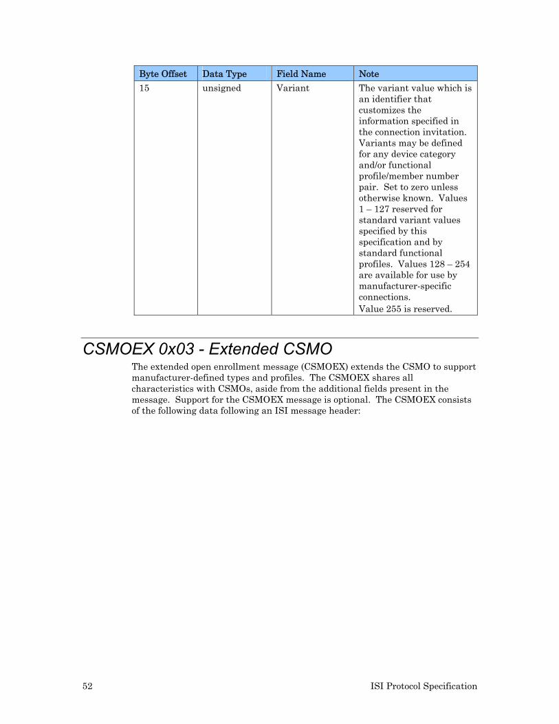
52 ISI Protocol Specification
Byte Offset Data Type Field Name Note
15 unsigned Variant The variant value which is an identifier that customizes the information specified in the connection invitation. Variants may be defined for any device category and/or functional profile/member number pair. Set to zero unless otherwise known. Values 1 – 127 reserved for standard variant values specified by this specification and by standard functional profiles. Values 128 – 254 are available for use by manufacturer-specific connections. Value 255 is reserved.
CSMOEX 0x03 - Extended CSMO The extended open enrollment message (CSMOEX) extends the CSMO to support manufacturer-defined types and profiles. The CSMOEX shares all characteristics with CSMOs, aside from the additional fields present in the message. Support for the CSMOEX message is optional. The CSMOEX consists of the following data following an ISI message header:
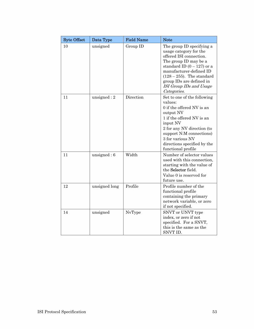
ISI Protocol Specification 53
Byte Offset Data Type Field Name Note
10 unsigned Group ID The group ID specifying a usage category for the offered ISI connection. The group ID may be a standard ID (0 – 127) or a manufacturer-defined ID (128 – 255). The standard group IDs are defined in ISI Group IDs and Usage Categories.
11 unsigned : 2 Direction Set to one of the following values: 0 if the offered NV is an output NV 1 if the offered NV is an input NV 2 for any NV direction (to support N:M connections) 3 for various NV directions specified by the functional profile
11 unsigned : 6 Width Number of selector values used with this connection, starting with the value of the Selector field. Value 0 is reserved for future use.
12 unsigned long Profile Profile number of the functional profile containing the primary network variable, or zero if not specified.
14 unsigned NvType SNVT or UNVT type index, or zero if not specified. For a SNVT, this is the same as the SNVT ID.
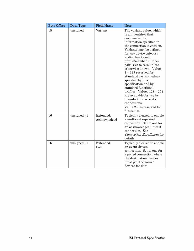
54 ISI Protocol Specification
Byte Offset Data Type Field Name Note
15 unsigned Variant The variant value, which is an identifier that customizes the information specified in the connection invitation. Variants may be defined for any device category and/or functional profile/member number pair. Set to zero unless otherwise known. Values 1 – 127 reserved for standard variant values specified by this specification and by standard functional profiles. Values 128 – 254 are available for use by manufacturer-specific connections. Value 255 is reserved for future use.
16 unsigned : 1 Extended. Acknowledged
Typically cleared to enable a multicast repeated connection. Set to one for an acknowledged unicast connection. See Connection Enrollment for details.
16 unsigned : 1 Extended. Poll
Typically cleared to enable an event-driven connection. Set to one for a polled connection where the destination devices must poll the source devices for data.
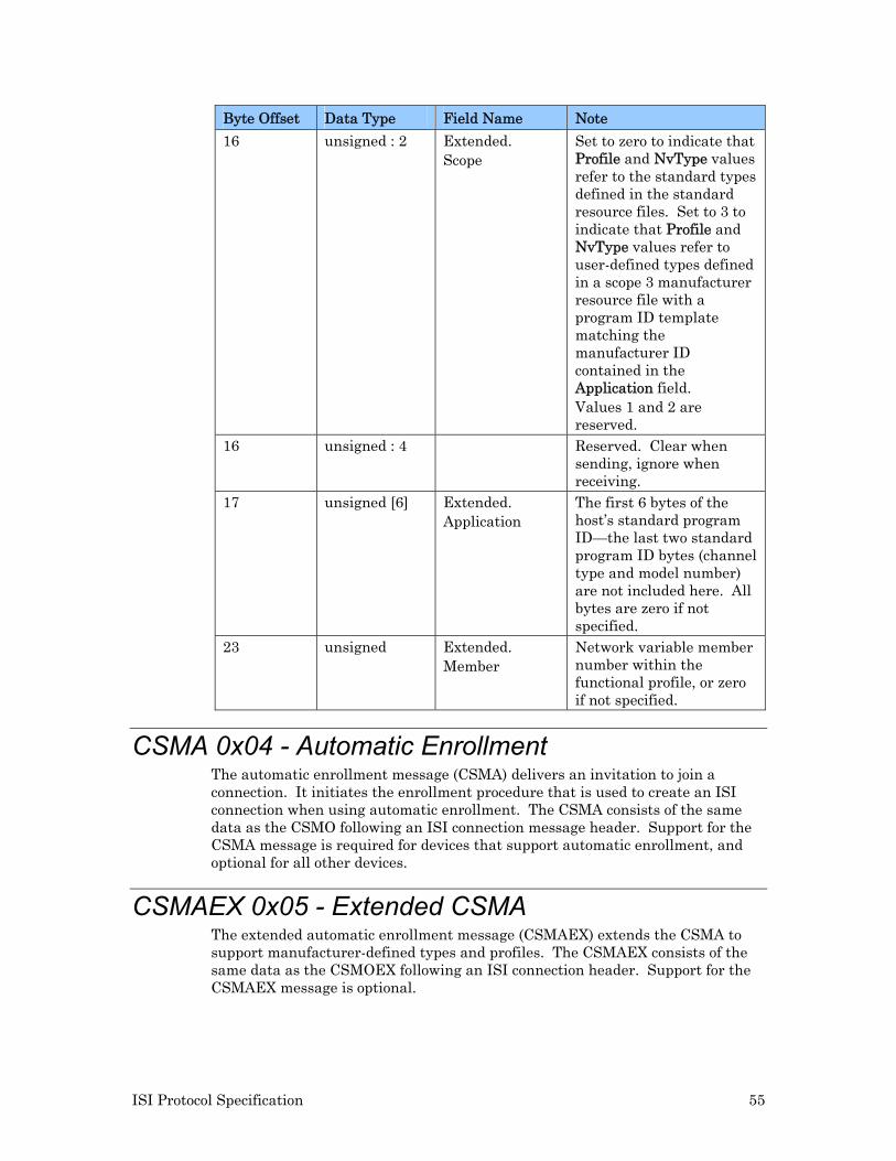
ISI Protocol Specification 55
Byte Offset Data Type Field Name Note
16 unsigned : 2 Extended. Scope
Set to zero to indicate that Profile and NvType values refer to the standard types defined in the standard resource files. Set to 3 to indicate that Profile and NvType values refer to user-defined types defined in a scope 3 manufacturer resource file with a program ID template matching the manufacturer ID contained in the Application field. Values 1 and 2 are reserved.
16 unsigned : 4 Reserved. Clear when sending, ignore when receiving.
17 unsigned [6] Extended. Application
The first 6 bytes of the host’s standard program ID—the last two standard program ID bytes (channel type and model number) are not included here. All bytes are zero if not specified.
23 unsigned Extended. Member
Network variable member number within the functional profile, or zero if not specified.
CSMA 0x04 - Automatic Enrollment The automatic enrollment message (CSMA) delivers an invitation to join a connection. It initiates the enrollment procedure that is used to create an ISI connection when using automatic enrollment. The CSMA consists of the same data as the CSMO following an ISI connection message header. Support for the CSMA message is required for devices that support automatic enrollment, and optional for all other devices.
CSMAEX 0x05 - Extended CSMA The extended automatic enrollment message (CSMAEX) extends the CSMA to support manufacturer-defined types and profiles. The CSMAEX consists of the same data as the CSMOEX following an ISI connection header. Support for the CSMAEX message is optional.
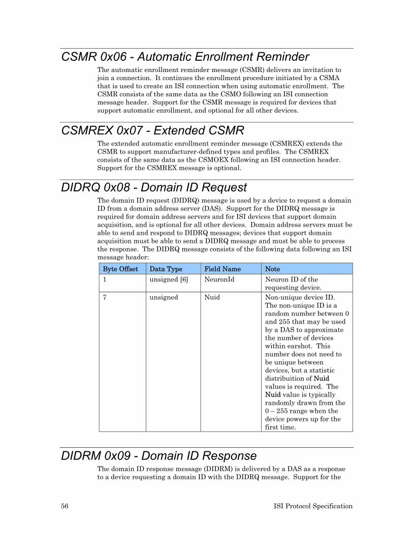
56 ISI Protocol Specification
CSMR 0x06 - Automatic Enrollment Reminder The automatic enrollment reminder message (CSMR) delivers an invitation to join a connection. It continues the enrollment procedure initiated by a CSMA that is used to create an ISI connection when using automatic enrollment. The CSMR consists of the same data as the CSMO following an ISI connection message header. Support for the CSMR message is required for devices that support automatic enrollment, and optional for all other devices.
CSMREX 0x07 - Extended CSMR The extended automatic enrollment reminder message (CSMREX) extends the CSMR to support manufacturer-defined types and profiles. The CSMREX consists of the same data as the CSMOEX following an ISI connection header. Support for the CSMREX message is optional.
DIDRQ 0x08 - Domain ID Request The domain ID request (DIDRQ) message is used by a device to request a domain ID from a domain address server (DAS). Support for the DIDRQ message is required for domain address servers and for ISI devices that support domain acquisition, and is optional for all other devices. Domain address servers must be able to send and respond to DIDRQ messages; devices that support domain acquisition must be able to send a DIDRQ message and must be able to process the response. The DIDRQ message consists of the following data following an ISI message header:
Byte Offset Data Type Field Name Note
1 unsigned [6] NeuronId Neuron ID of the requesting device.
7 unsigned Nuid Non-unique device ID. The non-unique ID is a random number between 0 and 255 that may be used by a DAS to approximate the number of devices within earshot. This number does not need to be unique between devices, but a statistic distribuition of Nuid values is required. The Nuid value is typically randomly drawn from the 0 – 255 range when the device powers up for the first time.
DIDRM 0x09 - Domain ID Response The domain ID response message (DIDRM) is delivered by a DAS as a response to a device requesting a domain ID with the DIDRQ message. Support for the
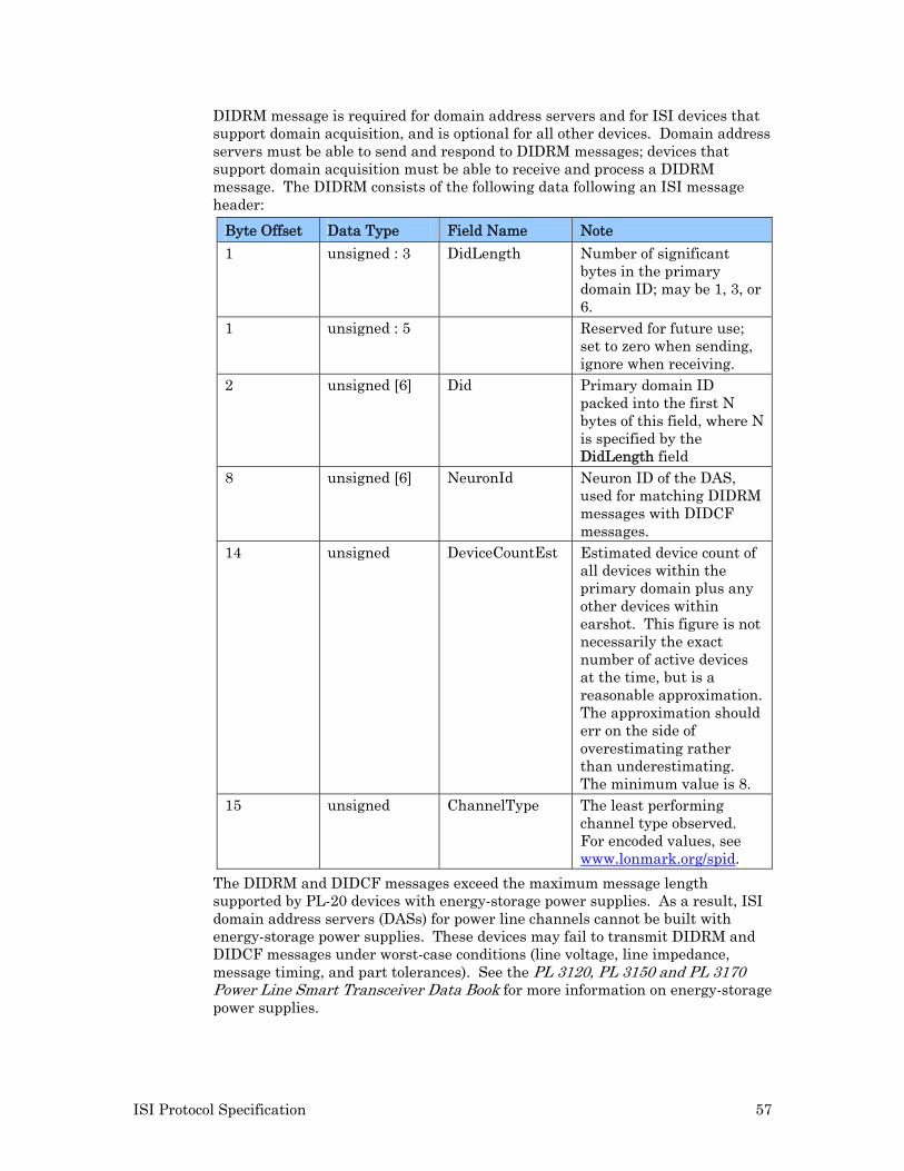
ISI Protocol Specification 57
DIDRM message is required for domain address servers and for ISI devices that support domain acquisition, and is optional for all other devices. Domain address servers must be able to send and respond to DIDRM messages; devices that support domain acquisition must be able to receive and process a DIDRM message. The DIDRM consists of the following data following an ISI message header:
Byte Offset Data Type Field Name Note
1 unsigned : 3 DidLength Number of significant bytes in the primary domain ID; may be 1, 3, or 6.
1 unsigned : 5 Reserved for future use; set to zero when sending, ignore when receiving.
2 unsigned [6] Did Primary domain ID packed into the first N bytes of this field, where N is specified by the DidLength field
8 unsigned [6] NeuronId Neuron ID of the DAS, used for matching DIDRM messages with DIDCF messages.
14 unsigned DeviceCountEst Estimated device count of all devices within the primary domain plus any other devices within earshot. This figure is not necessarily the exact number of active devices at the time, but is a reasonable approximation. The approximation should err on the side of overestimating rather than underestimating. The minimum value is 8.
15 unsigned ChannelType The least performing channel type observed. For encoded values, see www.lonmark.org/spid.
The DIDRM and DIDCF messages exceed the maximum message length supported by PL-20 devices with energy-storage power supplies. As a result, ISI domain address servers (DASs) for power line channels cannot be built with energy-storage power supplies. These devices may fail to transmit DIDRM and DIDCF messages under worst-case conditions (line voltage, line impedance, message timing, and part tolerances). See the PL 3120, PL 3150 and PL 3170 Power Line Smart Transceiver Data Book for more information on energy-storage power supplies.
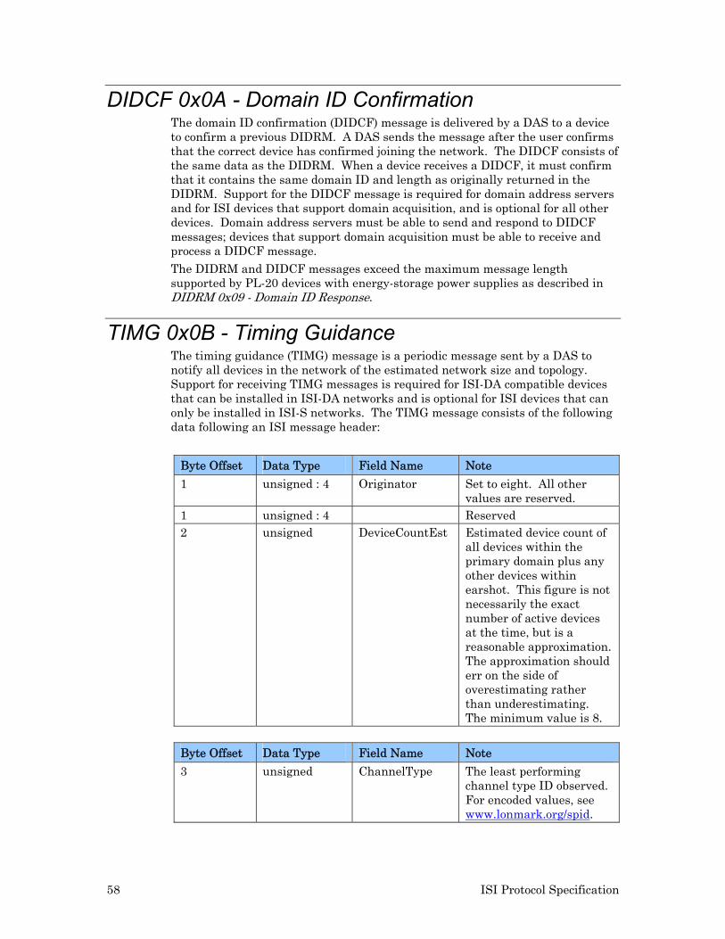
58 ISI Protocol Specification
DIDCF 0x0A - Domain ID Confirmation The domain ID confirmation (DIDCF) message is delivered by a DAS to a device to confirm a previous DIDRM. A DAS sends the message after the user confirms that the correct device has confirmed joining the network. The DIDCF consists of the same data as the DIDRM. When a device receives a DIDCF, it must confirm that it contains the same domain ID and length as originally returned in the DIDRM. Support for the DIDCF message is required for domain address servers and for ISI devices that support domain acquisition, and is optional for all other devices. Domain address servers must be able to send and respond to DIDCF messages; devices that support domain acquisition must be able to receive and process a DIDCF message.
The DIDRM and DIDCF messages exceed the maximum message length supported by PL-20 devices with energy-storage power supplies as described in DIDRM 0x09 - Domain ID Response.
TIMG 0x0B - Timing Guidance The timing guidance (TIMG) message is a periodic message sent by a DAS to notify all devices in the network of the estimated network size and topology. Support for receiving TIMG messages is required for ISI-DA compatible devices that can be installed in ISI-DA networks and is optional for ISI devices that can only be installed in ISI-S networks. The TIMG message consists of the following data following an ISI message header:
Byte Offset Data Type Field Name Note
1 unsigned : 4 Originator Set to eight. All other values are reserved.
1 unsigned : 4 Reserved 2 unsigned DeviceCountEst Estimated device count of
all devices within the primary domain plus any other devices within earshot. This figure is not necessarily the exact number of active devices at the time, but is a reasonable approximation. The approximation should err on the side of overestimating rather than underestimating. The minimum value is 8.
Byte Offset Data Type Field Name Note
3 unsigned ChannelType The least performing channel type ID observed. For encoded values, see www.lonmark.org/spid.
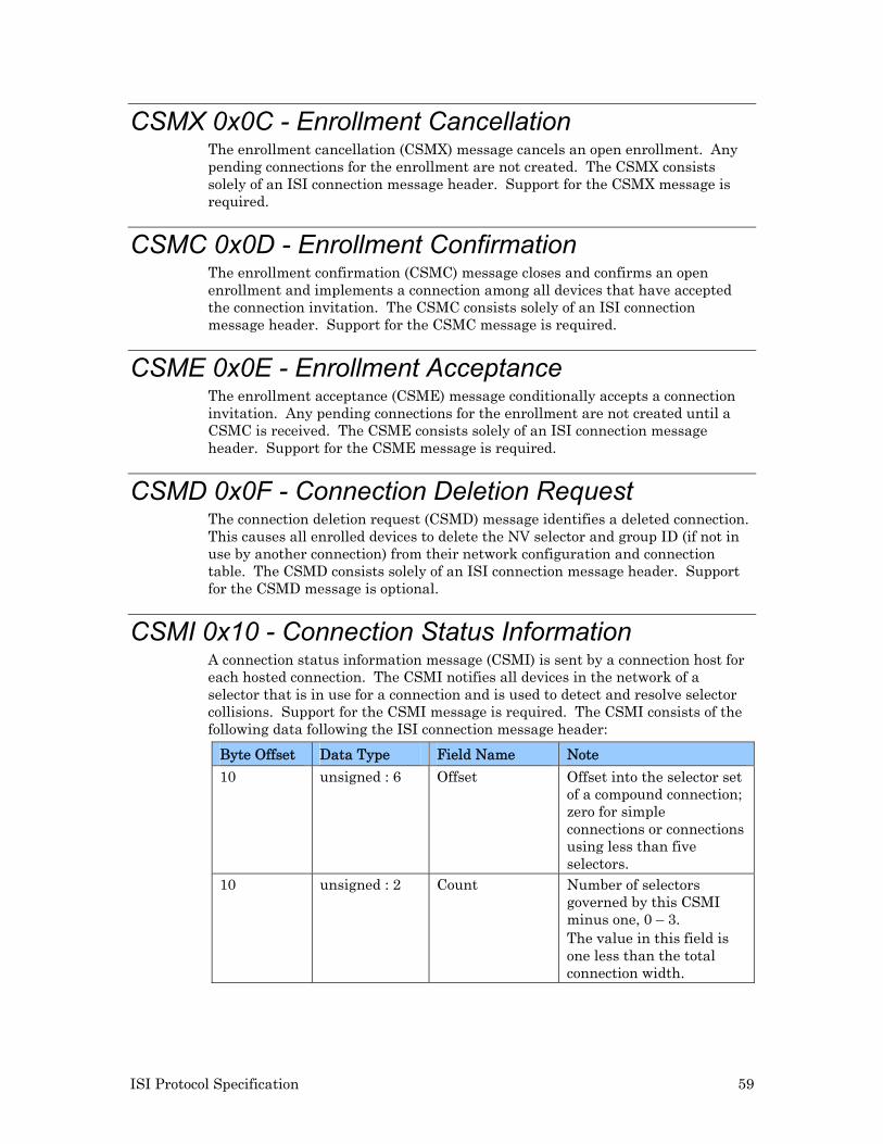
ISI Protocol Specification 59
CSMX 0x0C - Enrollment Cancellation The enrollment cancellation (CSMX) message cancels an open enrollment. Any pending connections for the enrollment are not created. The CSMX consists solely of an ISI connection message header. Support for the CSMX message is required.
CSMC 0x0D - Enrollment Confirmation The enrollment confirmation (CSMC) message closes and confirms an open enrollment and implements a connection among all devices that have accepted the connection invitation. The CSMC consists solely of an ISI connection message header. Support for the CSMC message is required.
CSME 0x0E - Enrollment Acceptance The enrollment acceptance (CSME) message conditionally accepts a connection invitation. Any pending connections for the enrollment are not created until a CSMC is received. The CSME consists solely of an ISI connection message header. Support for the CSME message is required.
CSMD 0x0F - Connection Deletion Request The connection deletion request (CSMD) message identifies a deleted connection. This causes all enrolled devices to delete the NV selector and group ID (if not in use by another connection) from their network configuration and connection table. The CSMD consists solely of an ISI connection message header. Support for the CSMD message is optional.
CSMI 0x10 - Connection Status Information A connection status information message (CSMI) is sent by a connection host for each hosted connection. The CSMI notifies all devices in the network of a selector that is in use for a connection and is used to detect and resolve selector collisions. Support for the CSMI message is required. The CSMI consists of the following data following the ISI connection message header:
Byte Offset Data Type Field Name Note
10 unsigned : 6 Offset Offset into the selector set of a compound connection; zero for simple connections or connections using less than five selectors.
10 unsigned : 2 Count Number of selectors governed by this CSMI minus one, 0 – 3. The value in this field is one less than the total connection width.
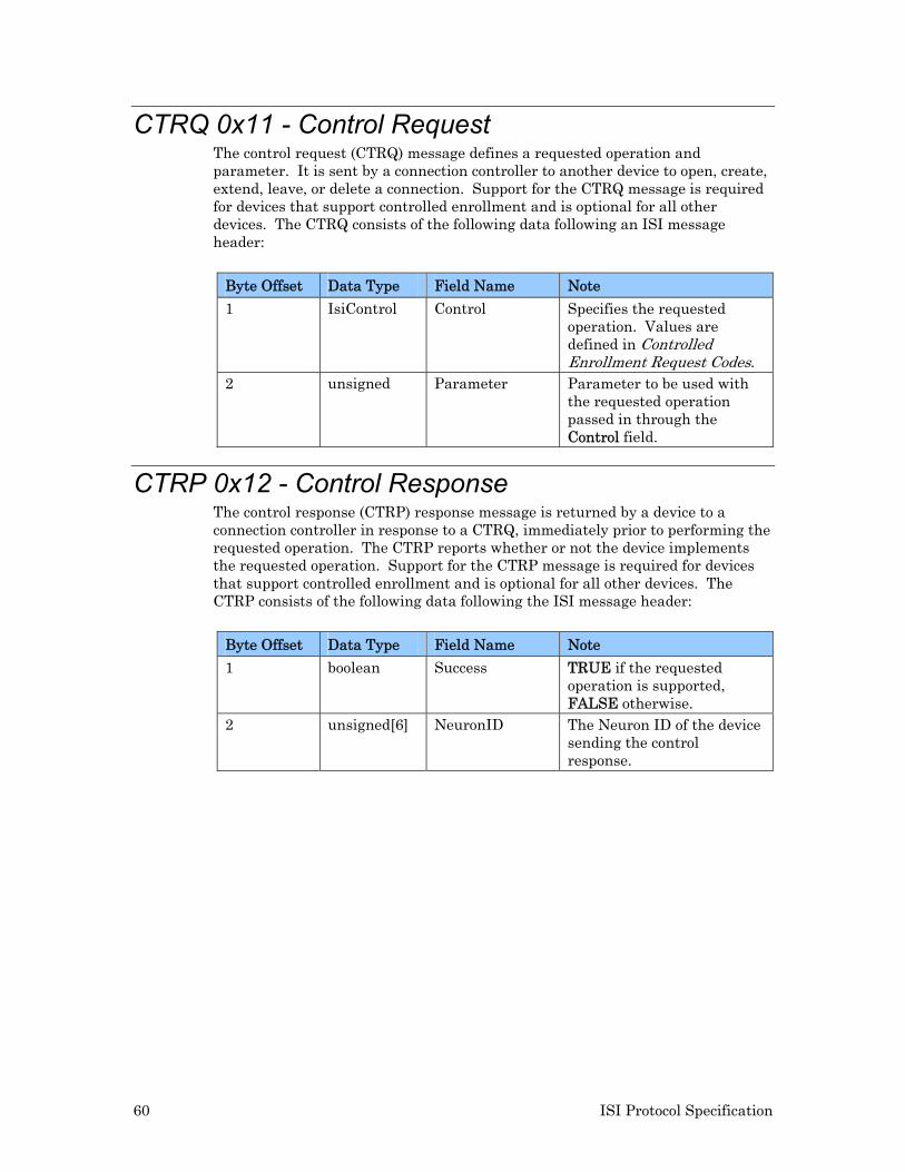
60 ISI Protocol Specification
CTRQ 0x11 - Control Request The control request (CTRQ) message defines a requested operation and parameter. It is sent by a connection controller to another device to open, create, extend, leave, or delete a connection. Support for the CTRQ message is required for devices that support controlled enrollment and is optional for all other devices. The CTRQ consists of the following data following an ISI message header:
Byte Offset Data Type Field Name Note
1 IsiControl Control Specifies the requested operation. Values are defined in Controlled Enrollment Request Codes.
2 unsigned Parameter Parameter to be used with the requested operation passed in through the Control field.
CTRP 0x12 - Control Response The control response (CTRP) response message is returned by a device to a connection controller in response to a CTRQ, immediately prior to performing the requested operation. The CTRP reports whether or not the device implements the requested operation. Support for the CTRP message is required for devices that support controlled enrollment and is optional for all other devices. The CTRP consists of the following data following the ISI message header:
Byte Offset Data Type Field Name Note
1 boolean Success TRUE if the requested operation is supported, FALSE otherwise.
2 unsigned[6] NeuronID The Neuron ID of the device sending the control response.
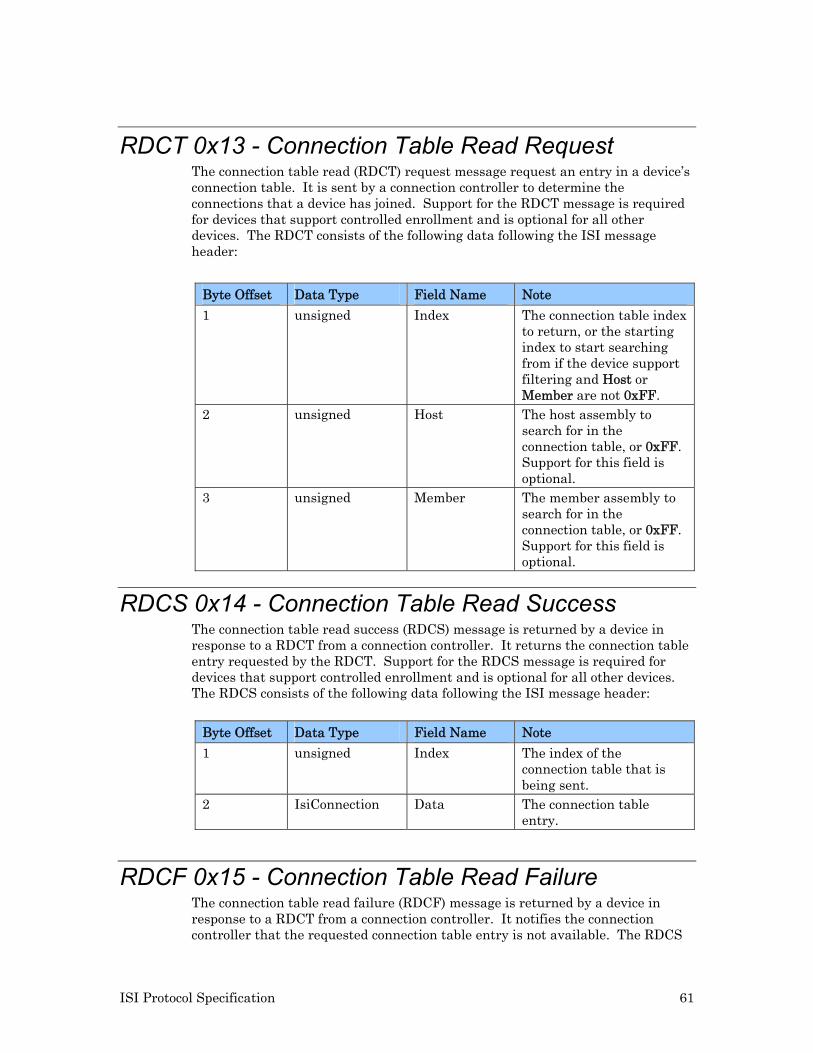
ISI Protocol Specification 61
RDCT 0x13 - Connection Table Read Request The connection table read (RDCT) request message request an entry in a device’s connection table. It is sent by a connection controller to determine the connections that a device has joined. Support for the RDCT message is required for devices that support controlled enrollment and is optional for all other devices. The RDCT consists of the following data following the ISI message header:
Byte Offset Data Type Field Name Note
1 unsigned Index The connection table index to return, or the starting index to start searching from if the device support filtering and Host or Member are not 0xFF.
2 unsigned Host The host assembly to search for in the connection table, or 0xFF. Support for this field is optional.
3 unsigned Member The member assembly to search for in the connection table, or 0xFF. Support for this field is optional.
RDCS 0x14 - Connection Table Read Success The connection table read success (RDCS) message is returned by a device in response to a RDCT from a connection controller. It returns the connection table entry requested by the RDCT. Support for the RDCS message is required for devices that support controlled enrollment and is optional for all other devices. The RDCS consists of the following data following the ISI message header:
Byte Offset Data Type Field Name Note
1 unsigned Index The index of the connection table that is being sent.
2 IsiConnection Data The connection table entry.
RDCF 0x15 - Connection Table Read Failure The connection table read failure (RDCF) message is returned by a device in response to a RDCT from a connection controller. It notifies the connection controller that the requested connection table entry is not available. The RDCS

62 ISI Protocol Specification
consists solely of an ISI message header. Support for the RDCF message is required for devices that support controlled enrollment and is optional for all other devices.

www.echelon.com