Embed Size (px)
Citation preview
�������������� ����������� ������ ������������ ��
������������������������������� �
Page 1 / 41 10.12.2008/ re
������������������������
�������������������������������� !
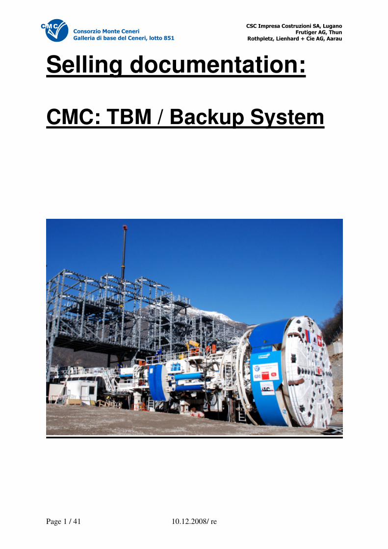
Selling documentation: CMC: TBM / Backup System
�������������� ����������� ������ ������������ ��
������������������������������� �
Page 2 / 41 10.12.2008/ re
������������������������
�������������������������������� !
1 Performance Specifications ............................................................................................................ 3 2 Cutterhead D = 9.7 meters ............................................................................................................. 4
2.1 Cutterhead description ........................................................................................................... 4 2.2 Available Cutter Inventory ...................................................................................................... 5
3 TBM: Robbins 253-309................................................................................................................... 5 3.1 Dimensions / Technical Specifications................................................................................... 5 3.2 TBM Operation ....................................................................................................................... 7 3.3 Revised Parts of TBM ............................................................................................................ 9 3.4 History of TBM........................................................................................................................ 9
4 Backup System for a Diameter of 9.73 Meters............................................................................... 9 4.1 Towing System..................................................................................................................... 11 4.2 Conveyor Belt Installation .................................................................................................... 12
4.2.1 Preface ........................................................................................................................ 12 4.2.2 Machine Belt ................................................................................................................ 12 4.2.3 Backup System Belt .................................................................................................... 13 4.2.4 Attachment Mounting Station for Tunnel Belt.............................................................. 13 4.2.5 Pillar Slewing Crane .................................................................................................... 14 4.2.6 Discharge belt.............................................................................................................. 14 4.2.7 Coarse Grit Precipitation ............................................................................................. 15
4.3 Securing / Rockbolting ......................................................................................................... 16 4.3.1 Rockbolting System L1................................................................................................ 18 4.3.2 Rockbolting Carriages ................................................................................................. 19 4.3.3 Rockbolting System L2................................................................................................ 19 4.3.4 Probe Drilling System.................................................................................................. 19 4.3.5 Logging of Probe Drilling ............................................................................................. 19 4.3.6 Ring Beam Erector ...................................................................................................... 19
4.4 Shotcrete Carriage ............................................................................................................... 19 4.4.1 Shotcrete Robot........................................................................................................... 20 4.4.2 Suprema ...................................................................................................................... 21 4.4.3 Secatol......................................................................................................................... 22
5 Cranes for Flow of Material........................................................................................................... 22 5.1 Monorail below TBM ............................................................................................................ 23 5.2 Crane on TBM...................................................................................................................... 24 5.3 Crane TBM-BS..................................................................................................................... 25 5.4 Surface Carrier BS1 ............................................................................................................. 25 5.5 Suspended platform (BS2)................................................................................................... 26 5.6 Monorail Overhead Crane (BS2).......................................................................................... 27
6 Ventilation System ........................................................................................................................ 28 6.1 Preface ................................................................................................................................. 28 6.2 Secondary Ventilator AL 12-550 .......................................................................................... 28 6.3 Dry-type Dedusting System HTKS 1/1000........................................................................... 29 6.4 Wet-type Deduster HCN 400/1 ............................................................................................ 30
7 Electrical Installations ................................................................................................................... 31 7.1 Electrical Main Data and Functions...................................................................................... 31 7.2 TBM and NL Schematics ..................................................................................................... 32 7.3 Frequency Converter ........................................................................................................... 34 7.4 Cutterhead Drive .................................................................................................................. 36
7.4.1 Cutterhead Motors....................................................................................................... 36 7.4.2 Cutterhead Planetary Gearbox.................................................................................... 37
7.5 High Voltage Cable Drum .................................................................................................... 37 7.6 Transformers ........................................................................................................................ 38 7.7 Emergency Lighting ............................................................................................................. 38 7.8 Default Lighting .................................................................................................................... 38 7.9 Emergency Backup Generator............................................................................................. 39
8 Miscellaneous ............................................................................................................................... 39 8.1 Rescue Container ................................................................................................................ 39 8.2 Duct Storage Unit ................................................................................................................. 39 8.3 Industrial Water Installation.................................................................................................. 40 8.4 Compressed Air.................................................................................................................... 41 8.5 Replacement Parts............................................................................................................... 41
�������������� ����������� ������ ������������ ��
������������������������������� �
Page 3 / 41 10.12.2008/ re
������������������������
�������������������������������� !
1 Performance Specifications The TBM Robbins TBM 253-309 was fully revised under close surveillance of Robbins prior to its operation (2300 meters) by the consortium CMC.
Power consumption of cutterhead: 3000 kW Power consumption of backup system: approx. 1650kW
Rotation speed: 0-4.6 rpm, field weakening capability: up to 8.3 rpm Torque: approx. 6275 kNm at 0-4.6 rpm approx. 3490 kNm at 8.3 rpm
Thrust force max.:* 20.6 MN Stroke: 1.87 m Electrical motors: 10 x 300 kW
Built in: 2003 Revised in: 2007 Cutterhead diameter 9.7 meters built by Robbins in 2007.
Equipped with 59 disc cutters 4 pcs. center cutters: 17“ 55 pcs. face and und caliber cutters: 19“
The ROWA backup system (BS) built in 2007 was designed and built specifically for the CMC operation with an excavation diameter of 9.7 meters and a tunnel length of 2300 meters:
Curve radius: approx. 1000 meters (enveloping circle of 8.4 meters)
Working area L1: rockbolts, ring beams, mash, shotcrete, probe drillings Working area L2: rockbolts, shotcrete, probe drillings Ventilation: blowing fresh air to TBM Air duct diameter on BS: 1200 mm Logistics in: by truck Logistics out: conveyor belt 800 mm Average daily advance (unsecured excavation): 27 meters by 18 hrs./day Max. technical daily advance (BS): 54 meters by 18 hrs./day Max. advance per hour: 2.25 meters Max. capacity of conveyor belt Installation for excavated material: 800 to/h
Coarse grit precipitation: 250 by 250 by 300 mm
�������������� ����������� ������ ������������ ��
������������������������������� �
Page 4 / 41 10.12.2008/ re
������������������������
�������������������������������� !
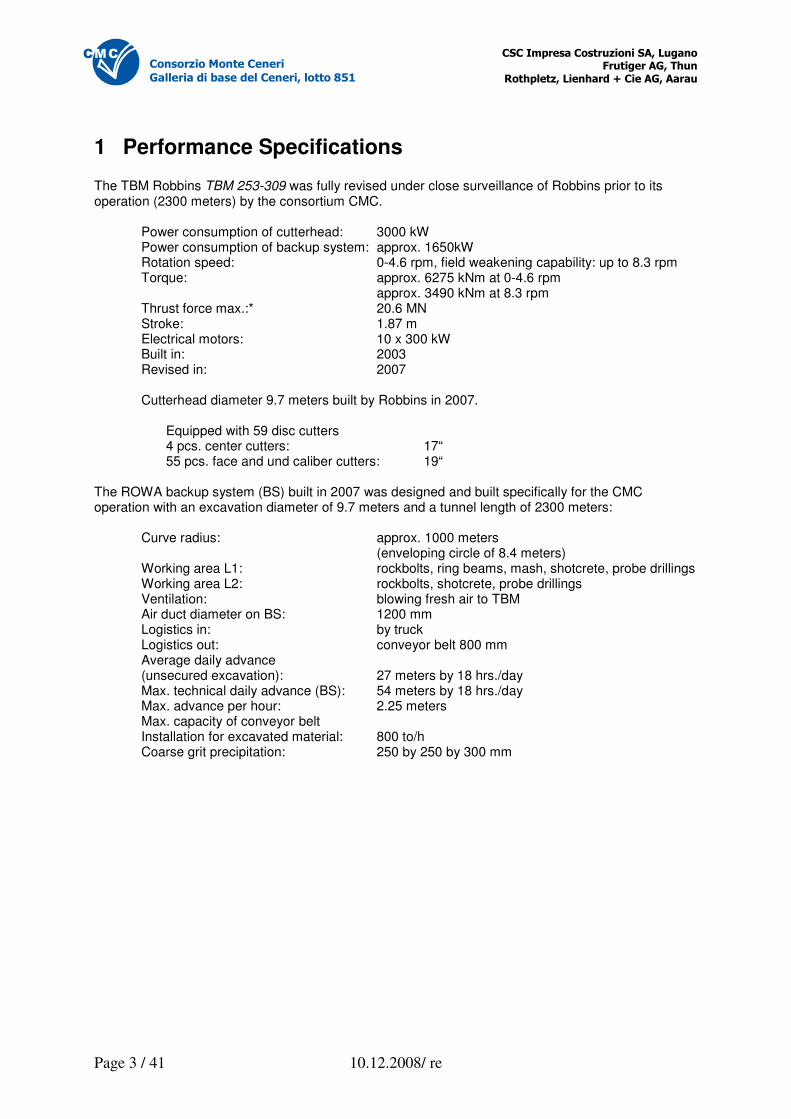
2 Cutterhead D = 9.7 meters
2.1 Cutterhead description Diameter: 9.73 meters Equipped with 57 disc cutters: 4 center cutters: 17“ 53 face and caliber cutters: 19“
�������������� ����������� ������ ������������ ��
������������������������������� �
Page 5 / 41 10.12.2008/ re
������������������������
�������������������������������� !
2.2 Available Cutter Inventory The available cutter material consists of the following components:
- ½ set(s) of used cutters (Robbins) - 25 pcs. 19“ single disc cutters Palmieri (new)
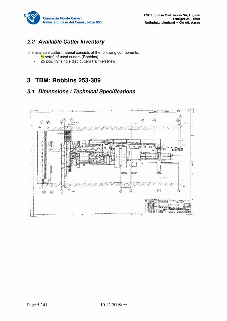
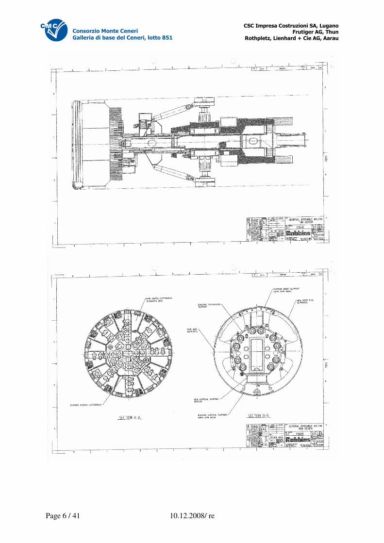
3 TBM: Robbins 253-309
3.1 Dimensions / Technical Specifications
�������������� ����������� ������ ������������ ��
������������������������������� �
Page 6 / 41 10.12.2008/ re
������������������������
�������������������������������� !
�������������� ����������� ������ ������������ ��
������������������������������� �
Page 7 / 41 10.12.2008/ re
������������������������
�������������������������������� !
Technical Specifications Cutterhead drive configuration: revolution-controlled electrical motors, gearbox power consumption: 3000 kW rotation speed: max. 8.3 rpm torque: 3490 kNm at 8.3 rpm 6275 kNm at 4.62 rpm max. thrust force*: 20.6 MN (2100 to) stroke: 1.87 m electrical motors: 10 x 300 kW Contact force: 18.6 MN (1900 to) Hydraulic system, max. pressure: 345 bar (feed cylinders: 285 bar) Capacity of hydraulic system: 150 kW (400 V) Transformers of cutterhead drive: 2x2000 kVA (16/0.69kV) Transformers of backup and hydraulics: 1x1000 kVA (16/0.4 kV) Auxiliary drives and backup: 400/230 V 50 Hz Spoil ridding capacity: 18.4 m3/h Belt speed: 122 m /min. Engine voltage: 3 x 690 V, 3-phase Lighting system: 220 V, 50 Hz Electrical control: 24 V Weight of TBM: approx. 800 to *At normal operation
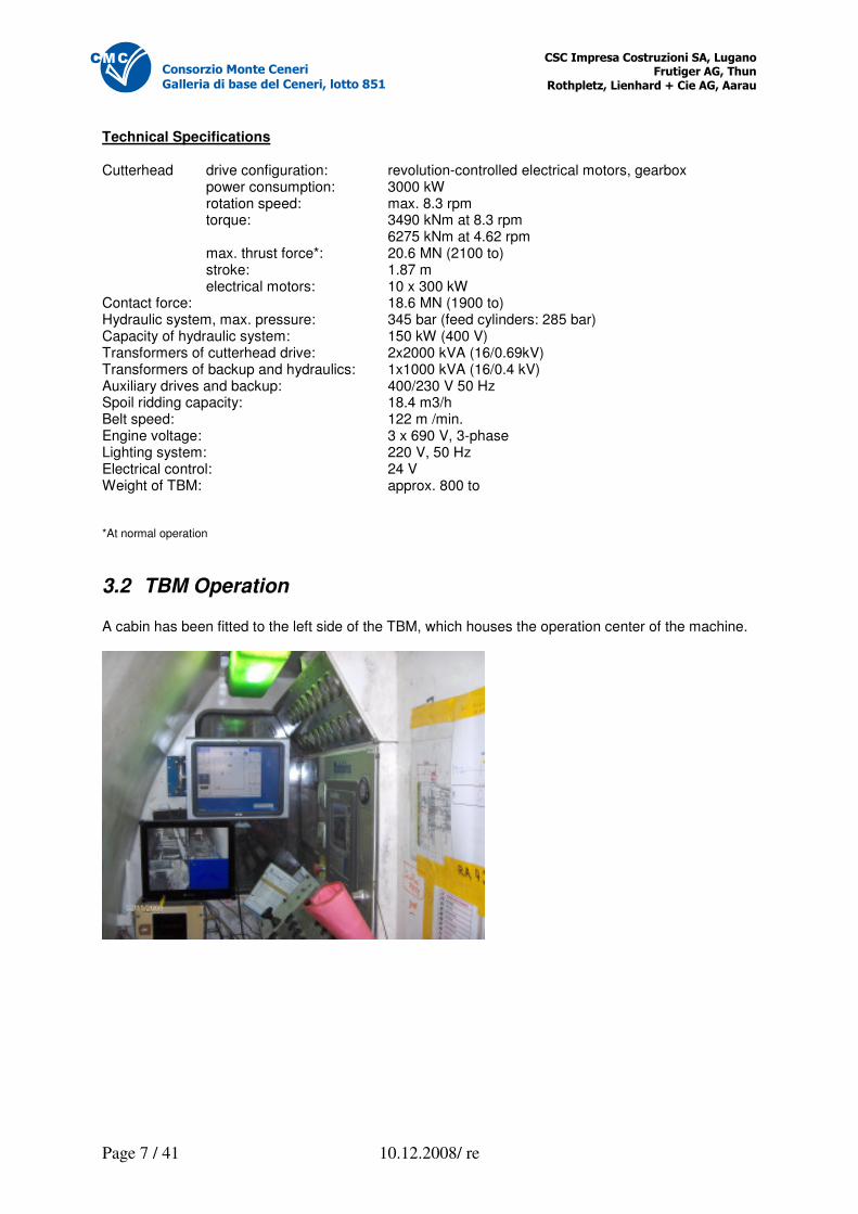
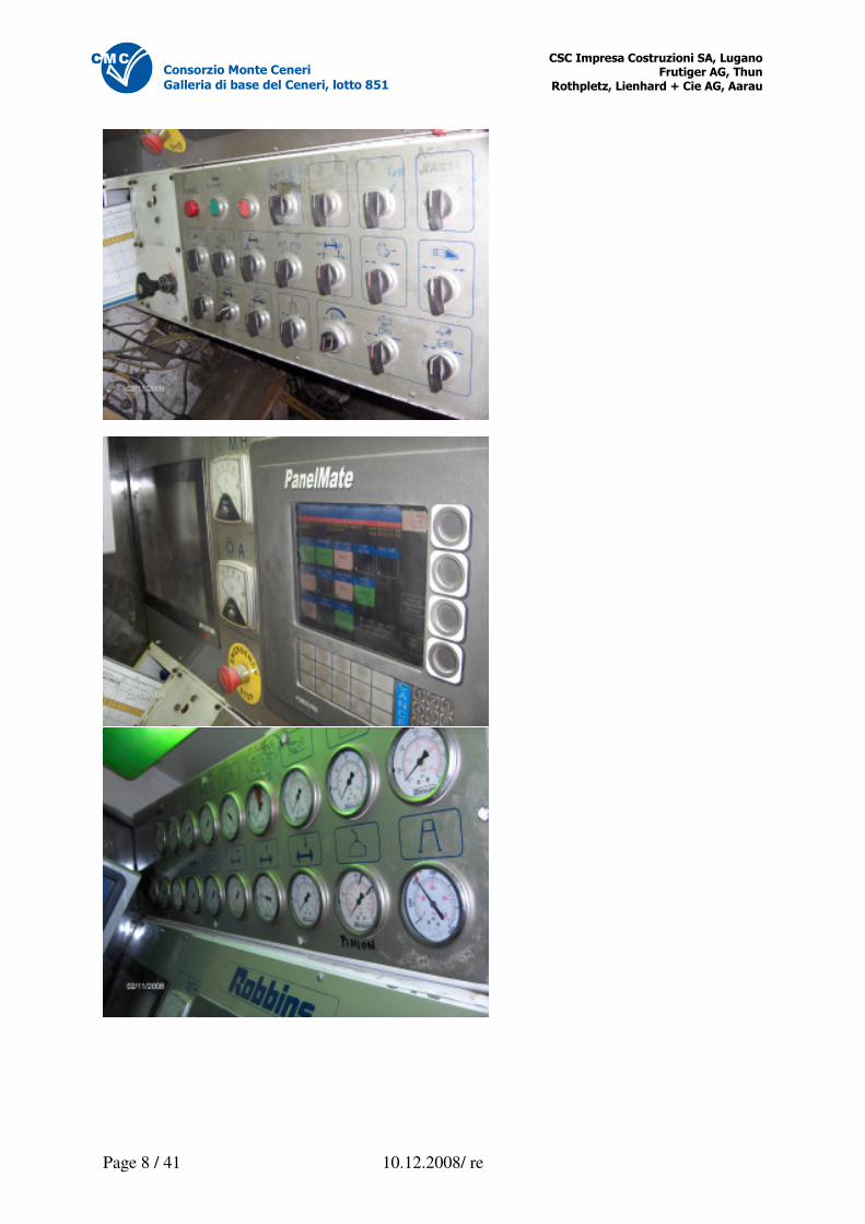
3.2 TBM Operation A cabin has been fitted to the left side of the TBM, which houses the operation center of the machine.
�������������� ����������� ������ ������������ ��
������������������������������� �
Page 8 / 41 10.12.2008/ re
������������������������
�������������������������������� !
�������������� ����������� ������ ������������ ��
������������������������������� �
Page 9 / 41 10.12.2008/ re
������������������������
�������������������������������� !
3.3 Revised Parts of TBM The TBM was revised in 2007 under supervision of Robbins. Amongst others the following components were revised by according specialists, respectively checked thoroughly: Electrical motors: Robbins USA Planetary gearbox: Robbins USA Gripper cylinders: checked by Robbins Europe Conveyer belt: revised by Robbins Europe Hydraulic system: revised by Robbins USA Main bearings/kelly: checked by SKF Italy via Robbins Adjustment of gripper plate: retrofitted by Robbins Adjustment primary tension: retrofitted Robbins
3.4 History of TBM Operations to date: Karahnjukar Iceland (Impregilo) 2003 14.6 km with D = 7.63 m Switzerland, Sigirino TI March 2008 – Oct. 2008 2.3 km with D = 9.7 m Operating hours meter reading to date: 6315 h
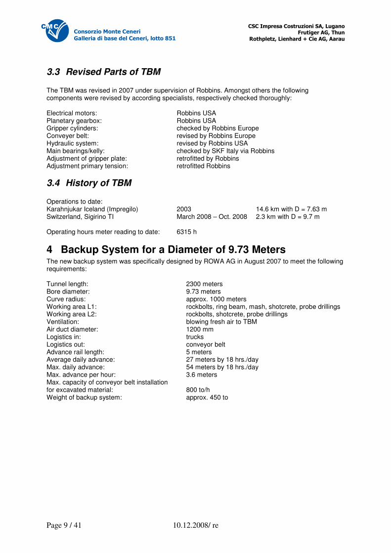
4 Backup System for a Diameter of 9.73 Meters The new backup system was specifically designed by ROWA AG in August 2007 to meet the following requirements: Tunnel length: 2300 meters Bore diameter: 9.73 meters Curve radius: approx. 1000 meters Working area L1: rockbolts, ring beam, mash, shotcrete, probe drillings Working area L2: rockbolts, shotcrete, probe drillings Ventilation: blowing fresh air to TBM Air duct diameter: 1200 mm Logistics in: trucks Logistics out: conveyor belt Advance rail length: 5 meters Average daily advance: 27 meters by 18 hrs./day Max. daily advance: 54 meters by 18 hrs./day Max. advance per hour: 3.6 meters Max. capacity of conveyor belt installation for excavated material: 800 to/h Weight of backup system: approx. 450 to
�������������� ����������� ������ ������������ ��
������������������������������� �
Page 10 / 41 10.12.2008/ re
������������������������
�������������������������������� !
�������������� ����������� ������ ������������ ��
������������������������������� �
Page 11 / 41 10.12.2008/ re
������������������������
�������������������������������� !
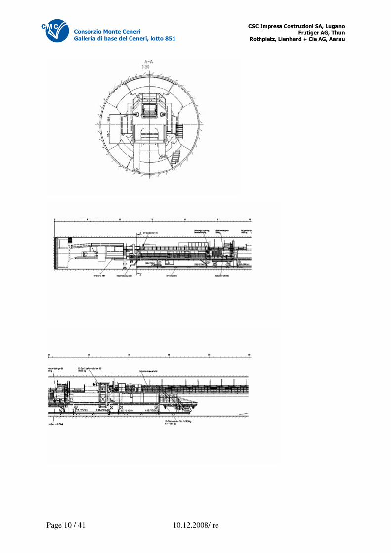
4.1 Towing System The towing system consists of towing brackets and the according towing cylinders, which are fitted to the rear end of the TBM. The towing system secures the towing connection between TBM and the backup system. The hydraulic cylinders move the BS forward after each stroke of the TBM. To prevent the towing along of the backup system during cutting advance of the TBM, the towing cylinders are set to a pressure-less state. Technical specifications Towing force: approx. ??? to
�������������� ����������� ������ ������������ ��
������������������������������� �
Page 12 / 41 10.12.2008/ re
������������������������
�������������������������������� !
4.2 Conveyor Belt Installation
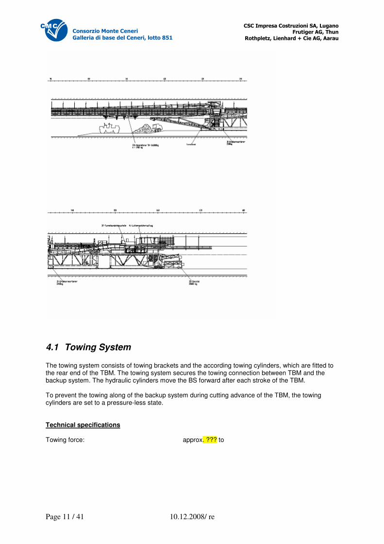
4.2.1 Preface The conveyor belt installation consists of the machine belt of the TBM, the belt of the backup system (full length of BS), the discharge belt and the attachment mounting station of the tunnel belt. In order reduce the development of dust, the attachment mounting stations “machine belt to BS belt” and “BS belt to tunnel belt” are equipped with spraying nozzles. The belts are partly monitored by the TBM operator via cameras.
4.2.2 Machine Belt The machine belt takes the excavation cuttings on from the cutterhead and passes them on to the BS belt. It runs within the TBM. Technical Specifications Belt length: approx. 26 m Belt width: 1000 mm Power output: 5.5 kW (hydraulic drive) Max. conveyor capacity: 18.4 m3/min. Weight: 2.5 to Speed: 122 m/min.
�������������� ����������� ������ ������������ ��
������������������������������� �
Page 13 / 41 10.12.2008/ re
������������������������
�������������������������������� !
4.2.3 Backup System Belt The excavation material is being transported from the machine belt on the BS belt to the coarse grit precipitation on the BS3. The hand-over point between machine and BS belts are monitored via video camera. The backup system belt is designed to handle grit sizes up to 250 x 250 x 300 mm off the machine belt. 90% of the cuttings mustn’t exceed a size of 150 x 150 x 150 mm. Spray nozzles (water) after the deflector of the coarse grit precipitator. Spray nozzles (water) only at hand-over points. Technical Specifications Belt length: 100 m Belt width: 1000 mm Belt type: Metaltrans M630 ITA V 8S+3 Belt speed: 2.0 m/sec. Max. conveyor capacity: 800 to/h Drive: bevel gear drive block SK9082.1, 55 kW, 400 V Tensioning device: Lifting/tensioning cylinders, 2000 mm, with hydraulic unit Belt monitoring: by sensor
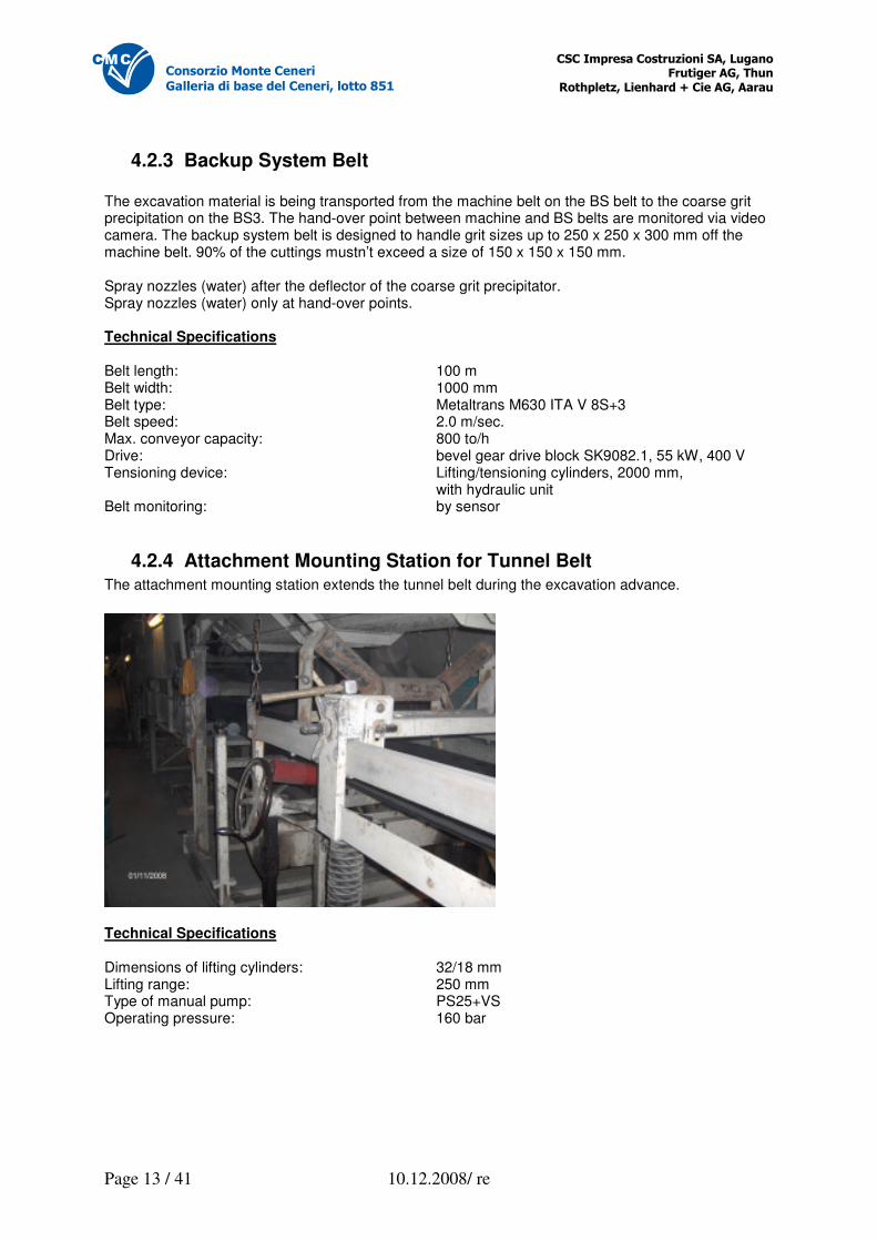
4.2.4 Attachment Mounting Station for Tunnel Belt The attachment mounting station extends the tunnel belt during the excavation advance.
Technical Specifications Dimensions of lifting cylinders: 32/18 mm Lifting range: 250 mm Type of manual pump: PS25+VS Operating pressure: 160 bar
�������������� ����������� ������ ������������ ��
������������������������������� �
Page 14 / 41 10.12.2008/ re
������������������������
�������������������������������� !
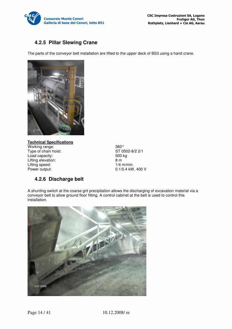
4.2.5 Pillar Slewing Crane The parts of the conveyor belt installation are lifted to the upper deck of BS3 using a hand crane.
Technical Specifications Working range: 360° Type of chain hoist: ST 0502-8/2 2/1 Load capacity: 500 kg Lifting elevation: 8 m Lifting speed: 1/4 m/min. Power output: 0.1/0.4 kW, 400 V
4.2.6 Discharge belt
A shunting switch at the coarse grit precipitation allows the discharging of excavation material via a conveyor belt to allow ground floor fitting. A control cabinet at the belt is used to control this installation.
�������������� ����������� ������ ������������ ��
������������������������������� �
Page 15 / 41 10.12.2008/ re
������������������������
�������������������������������� !
Technical Specifications Belt length: 17 m Belt width: 800 mm Belt type: EP500/3 5:3 VT Conveyor capacity: max. 600 to/h Belt speed: 2.6 m/sec. Drive: Block SK 9042.1 Power consumption: 15 kW, 400 V
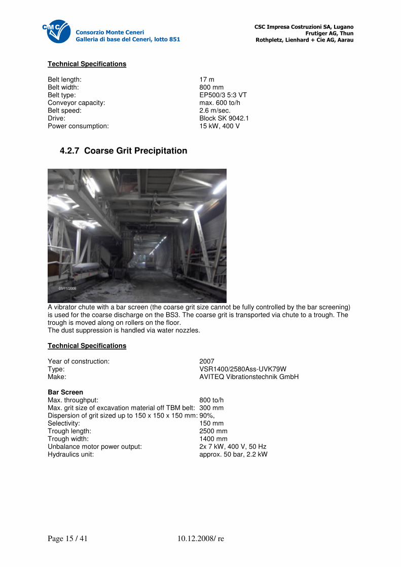
4.2.7 Coarse Grit Precipitation
A vibrator chute with a bar screen (the coarse grit size cannot be fully controlled by the bar screening) is used for the coarse discharge on the BS3. The coarse grit is transported via chute to a trough. The trough is moved along on rollers on the floor. The dust suppression is handled via water nozzles. Technical Specifications Year of construction: 2007 Type: VSR1400/2580Ass-UVK79W Make: AVITEQ Vibrationstechnik GmbH Bar Screen Max. throughput: 800 to/h Max. grit size of excavation material off TBM belt: 300 mm Dispersion of grit sized up to 150 x 150 x 150 mm: 90%, Selectivity: 150 mm Trough length: 2500 mm Trough width: 1400 mm Unbalance motor power output: 2x 7 kW, 400 V, 50 Hz Hydraulics unit: approx. 50 bar, 2.2 kW
�������������� ����������� ������ ������������ ��
������������������������������� �
Page 16 / 41 10.12.2008/ re
������������������������
�������������������������������� !
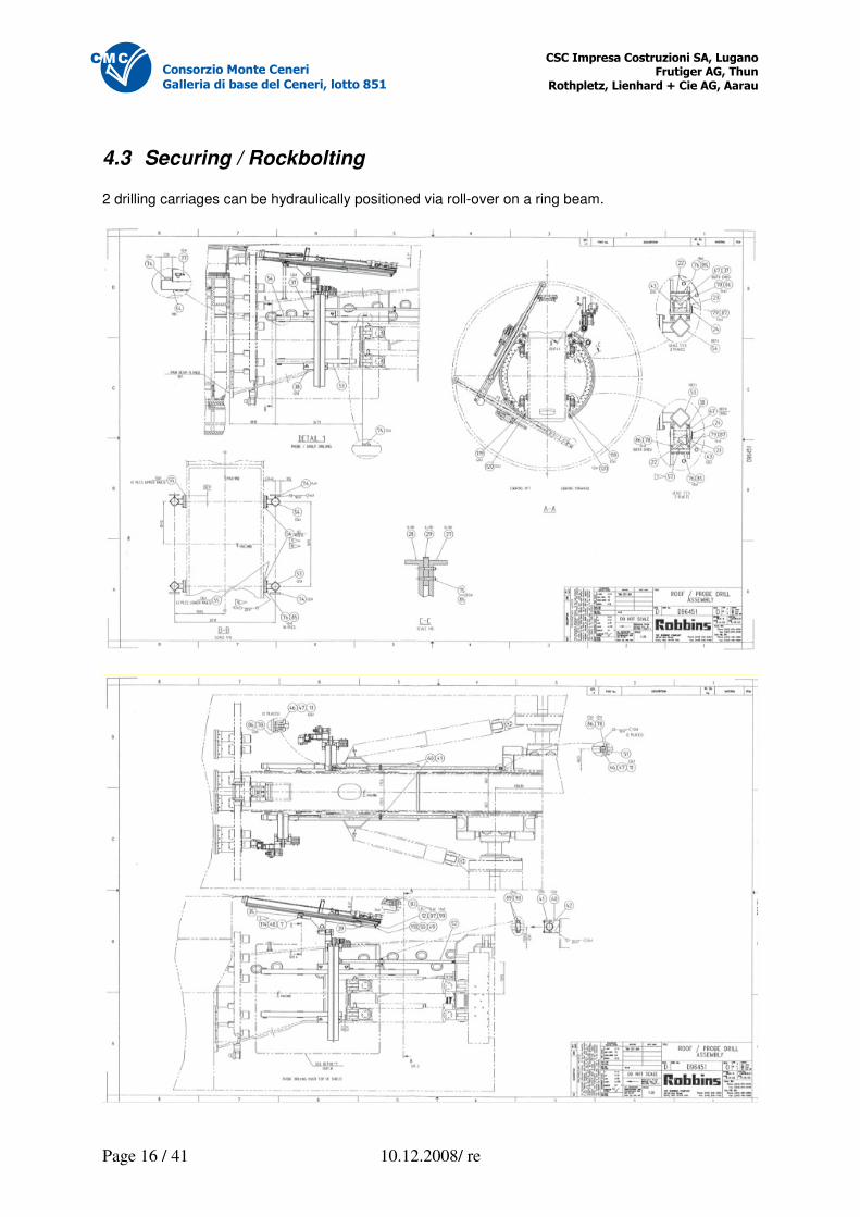
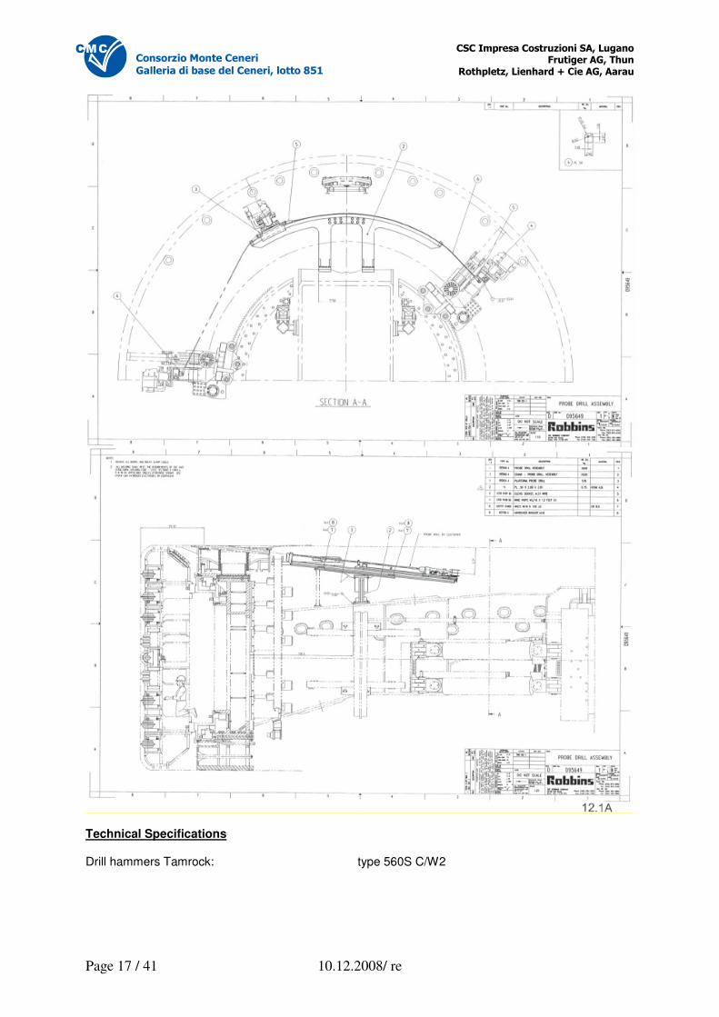
4.3 Securing / Rockbolting 2 drilling carriages can be hydraulically positioned via roll-over on a ring beam.
�������������� ����������� ������ ������������ ��
������������������������������� �
Page 17 / 41 10.12.2008/ re
������������������������
�������������������������������� !
Technical Specifications Drill hammers Tamrock: type 560S C/W2
�������������� ����������� ������ ������������ ��
������������������������������� �
Page 18 / 41 10.12.2008/ re
������������������������
�������������������������������� !
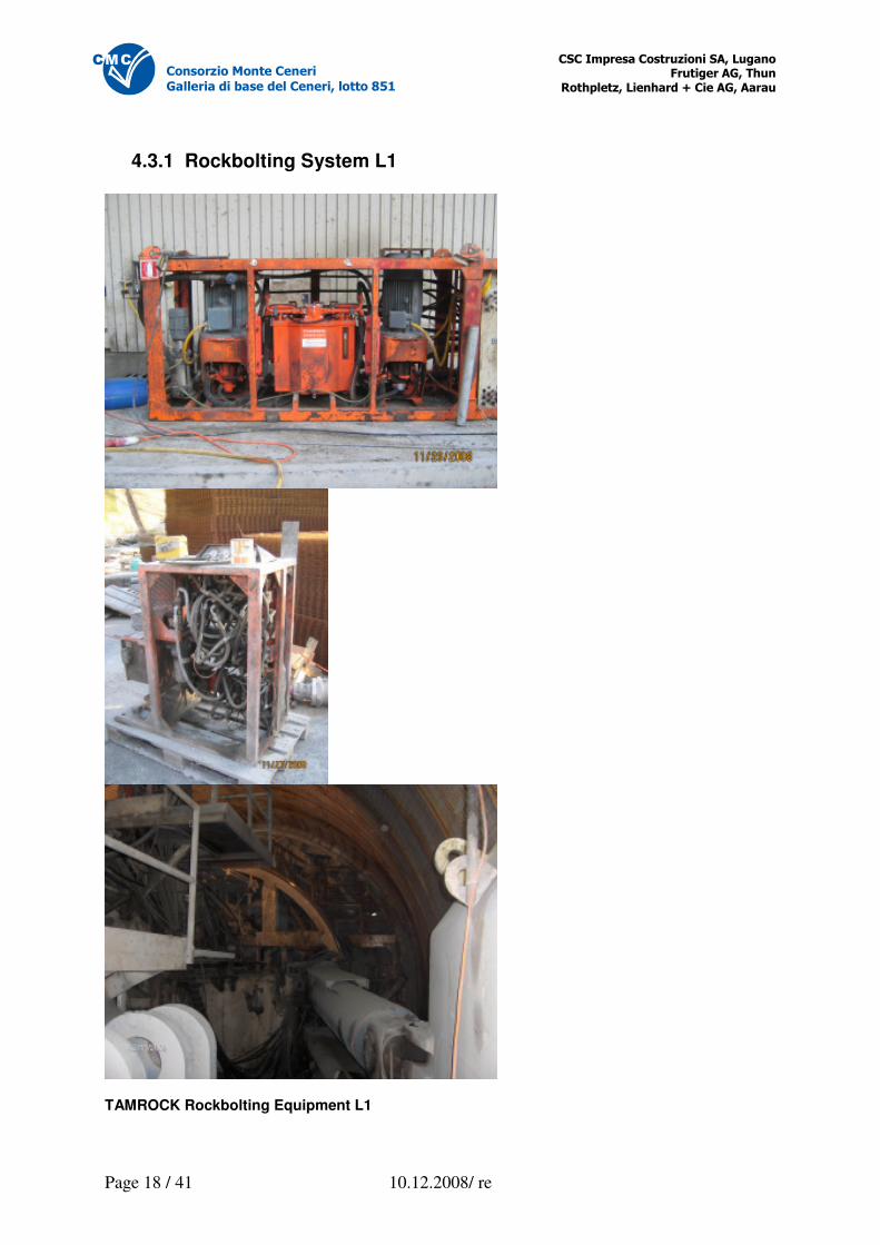
4.3.1 Rockbolting System L1
TAMROCK Rockbolting Equipment L1
�������������� ����������� ������ ������������ ��
������������������������������� �
Page 19 / 41 10.12.2008/ re
������������������������
�������������������������������� !
Equipment per side (left/right): 1 pc. drill hammer Tamrock 560S C/W2 1 pc. radio remote control unit
4.3.2 Rockbolting Carriages Both carriages are attached to a ring beam, which allows securing along a 360° radius.
4.3.3 Rockbolting System L2 System anchoring (adhesion) is executed by a Tamrock Commando, which is mounted on coach 3 of the BS. It is equipped with openings, in order to allow rockbolting along an approximately 230° radius in the overhead area.
4.3.4 Probe Drilling System The drilling equipment in L1 can also be used to perform forward investigation probe drillings. The kinematics of this assembly is designed to allow drilling in a flat angle above the cutterhead.
4.3.5 Logging of Probe Drilling To allow electronic logging of excavation data, the hydraulic supplies of the following functions are equipped with electronic pressure gauges: blow pressure, rotation pressure, advance pressure, rinse pressure and advance oil flow. All data can be further processes on a PC.
4.3.6 Ring Beam Erector
A ring beam erector is mounted in front of the L1 which allows exact positioning of ring beams in a 360° radius.
4.4 Shotcrete Carriage A spray robot allows shotcrete application in L2. Longitudinal mobility of extruder lance: 2 m Longitudinal mobility of carriage: 4 m Longitudinal spraying area: 6 m Max. radial spraying area: 220°
�������������� ����������� ������ ������������ ��
������������������������������� �
Page 20 / 41 10.12.2008/ re
������������������������
�������������������������������� !
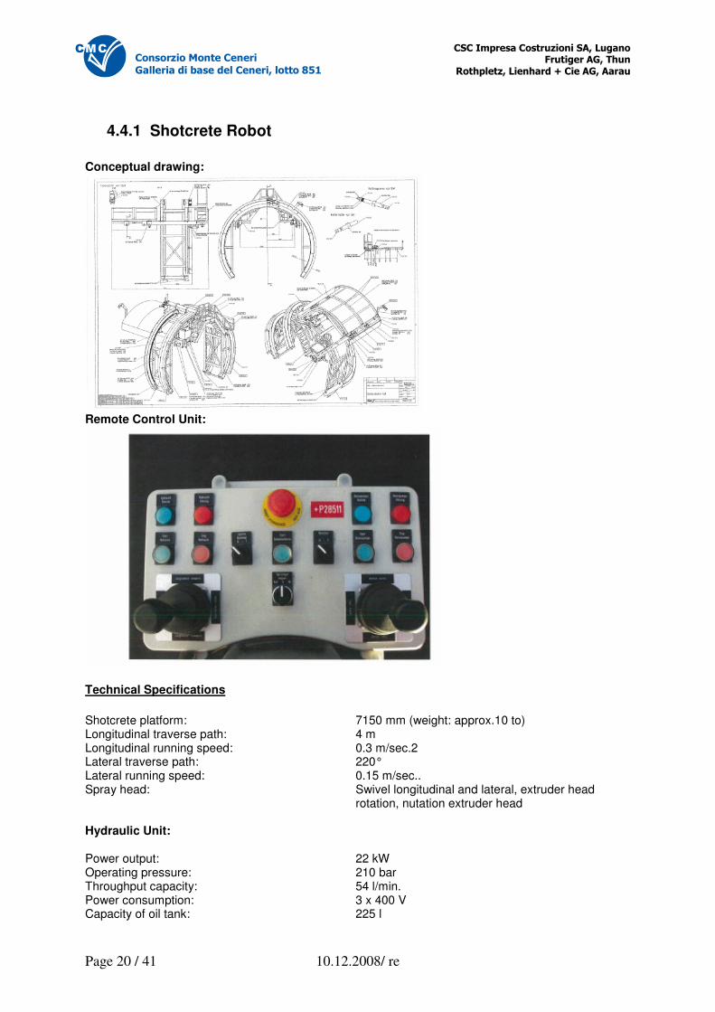
4.4.1 Shotcrete Robot
Conceptual drawing:
Remote Control Unit:
Technical Specifications
Shotcrete platform: 7150 mm (weight: approx.10 to) Longitudinal traverse path: 4 m Longitudinal running speed: 0.3 m/sec.2 Lateral traverse path: 220° Lateral running speed: 0.15 m/sec.. Spray head: Swivel longitudinal and lateral, extruder head rotation, nutation extruder head Hydraulic Unit: Power output: 22 kW Operating pressure: 210 bar Throughput capacity: 54 l/min. Power consumption: 3 x 400 V Capacity of oil tank: 225 l
�������������� ����������� ������ ������������ ��
������������������������������� �
Page 21 / 41 10.12.2008/ re
������������������������
�������������������������������� !
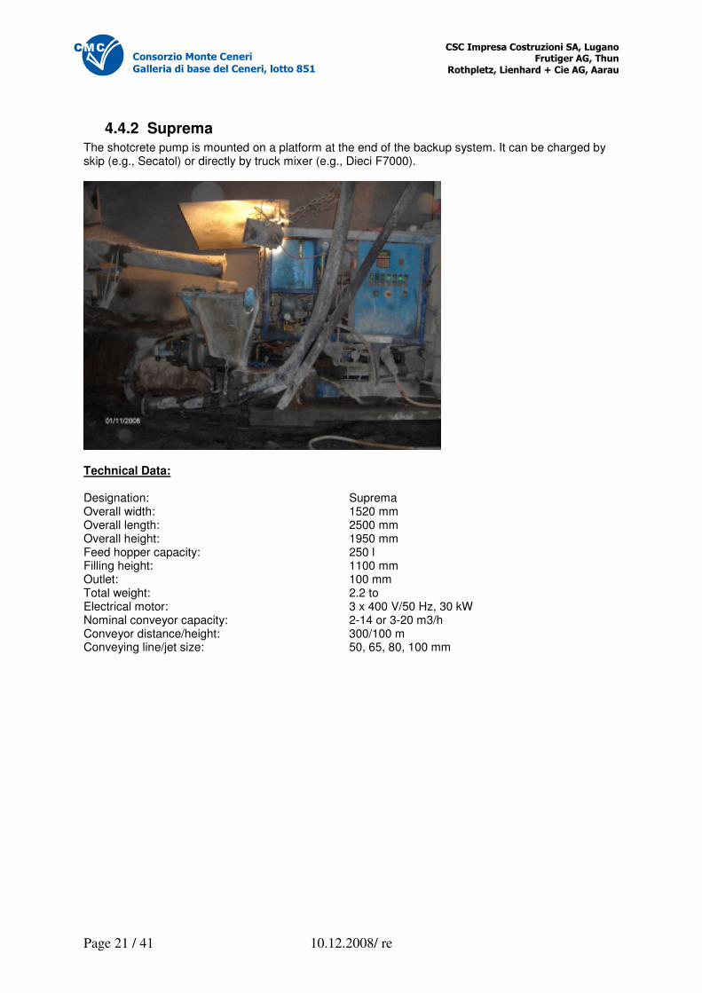
4.4.2 Suprema The shotcrete pump is mounted on a platform at the end of the backup system. It can be charged by skip (e.g., Secatol) or directly by truck mixer (e.g., Dieci F7000).
Technical Data: Designation: Suprema Overall width: 1520 mm Overall length: 2500 mm Overall height: 1950 mm Feed hopper capacity: 250 l Filling height: 1100 mm Outlet: 100 mm Total weight: 2.2 to Electrical motor: 3 x 400 V/50 Hz, 30 kW Nominal conveyor capacity: 2-14 or 3-20 m3/h Conveyor distance/height: 300/100 m Conveying line/jet size: 50, 65, 80, 100 mm
�������������� ����������� ������ ������������ ��
������������������������������� �
Page 22 / 41 10.12.2008/ re
������������������������
�������������������������������� !
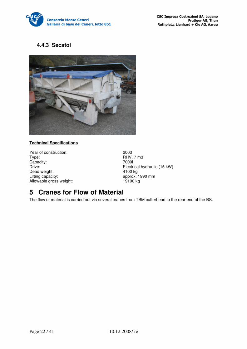
4.4.3 Secatol
Technical Specifications Year of construction: 2003 Type: RHV, 7 m3 Capacity: 7000l Drive: Electrical hydraulic (15 kW) Dead weight. 4100 kg Lifting capacity: approx. 1990 mm Allowable gross weight: 19100 kg
5 Cranes for Flow of Material The flow of material is carried out via several cranes from TBM cutterhead to the rear end of the BS.
�������������� ����������� ������ ������������ ��
������������������������������� �
Page 23 / 41 10.12.2008/ re
������������������������
�������������������������������� !
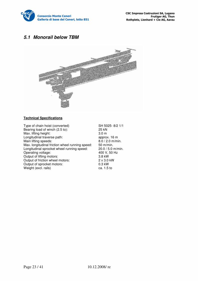
5.1 Monorail below TBM
Technical Specifications Type of chain hoist (converted) SH 5025- 8/2 1/1 Bearing load of winch (2.5 to): 25 kN Max. lifting height: 3.0 m Longitudinal traverse path: approx. 16 m Main lifting speeds: 8.0 / 2.0 m/min. Max. longitudinal friction wheel running speed: 50 m/min. Longitudinal sprocket wheel running speed: 20.0 / 5.0 m/min. Operating voltage: 400 V, 50 Hz Output of lifting motors: 3.8 kW Output of friction wheel motors: 2 x 3.0 kW Output of sprocket motors: 0.3 kW Weight (excl. rails) ca. 1.5 to
�������������� ����������� ������ ������������ ��
������������������������������� �
Page 24 / 41 10.12.2008/ re
������������������������
�������������������������������� !
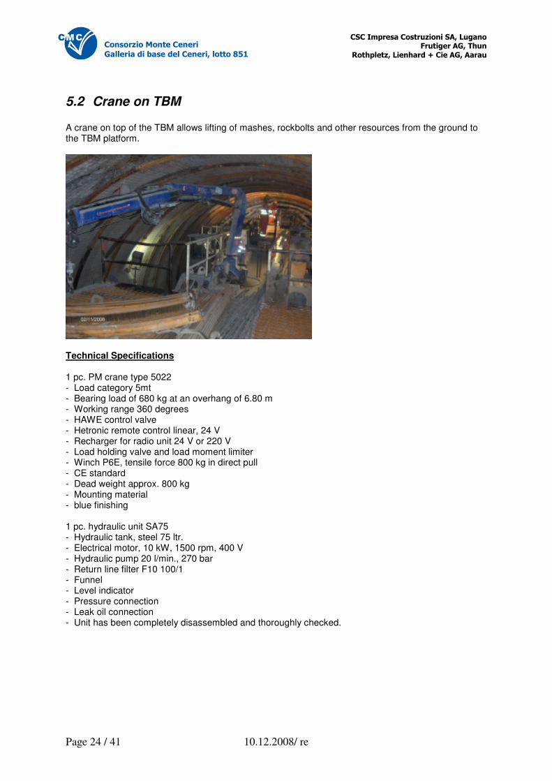
5.2 Crane on TBM A crane on top of the TBM allows lifting of mashes, rockbolts and other resources from the ground to the TBM platform.
Technical Specifications 1 pc. PM crane type 5022 - Load category 5mt - Bearing load of 680 kg at an overhang of 6.80 m - Working range 360 degrees - HAWE control valve - Hetronic remote control linear, 24 V - Recharger for radio unit 24 V or 220 V - Load holding valve and load moment limiter - Winch P6E, tensile force 800 kg in direct pull - CE standard - Dead weight approx. 800 kg - Mounting material - blue finishing 1 pc. hydraulic unit SA75 - Hydraulic tank, steel 75 ltr. - Electrical motor, 10 kW, 1500 rpm, 400 V - Hydraulic pump 20 l/min., 270 bar - Return line filter F10 100/1 - Funnel - Level indicator - Pressure connection - Leak oil connection - Unit has been completely disassembled and thoroughly checked.
�������������� ����������� ������ ������������ ��
������������������������������� �
Page 25 / 41 10.12.2008/ re
������������������������
�������������������������������� !
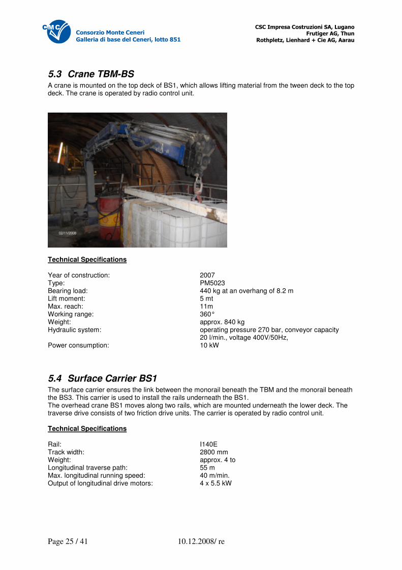
5.3 Crane TBM-BS A crane is mounted on the top deck of BS1, which allows lifting material from the tween deck to the top deck. The crane is operated by radio control unit.
Technical Specifications Year of construction: 2007 Type: PM5023 Bearing load: 440 kg at an overhang of 8.2 m Lift moment: 5 mt Max. reach: 11m Working range: 360° Weight: approx. 840 kg Hydraulic system: operating pressure 270 bar, conveyor capacity 20 l/min., voltage 400V/50Hz, Power consumption: 10 kW
5.4 Surface Carrier BS1 The surface carrier ensures the link between the monorail beneath the TBM and the monorail beneath the BS3. This carrier is used to install the rails underneath the BS1. The overhead crane BS1 moves along two rails, which are mounted underneath the lower deck. The traverse drive consists of two friction drive units. The carrier is operated by radio control unit. Technical Specifications Rail: I140E Track width: 2800 mm Weight: approx. 4 to Longitudinal traverse path: 55 m Max. longitudinal running speed: 40 m/min. Output of longitudinal drive motors: 4 x 5.5 kW
�������������� ����������� ������ ������������ ��
������������������������������� �
Page 26 / 41 10.12.2008/ re
������������������������
�������������������������������� !
Lifting Units 1 + 2: Bearing load per chain hoist: 3200 kg Lifting height: 3 m Lifting speed: 4 and 1 m/min. Output of lifting motors: 2 x 2.44/0.61 kW Lateral Carriage: Lateral traverse path: 1.8 m Max. lateral running speed: 12 m/min. Output of lateral drive motors: 2 x 0.25 kW Handover Crane: Type of electric chain hoist: GCHO1000/2NF Bearing load: 1600 kg Lifting height: 3 m Lifting speed: 4 and 1 m/min. Output lifting motors: 2 x 2.44/0.61 kW Auxiliary Rail Cranes: Type of electric chain hoist: GCHO1000/1NF Bearing load: 1000 kg Lifting height: 3 m Lifting speed: 8 and 2 m/min. Output lifting motors: 2 x 1.45/0.36 kW
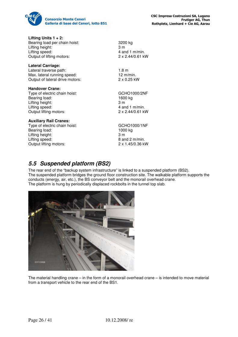
5.5 Suspended platform (BS2) The rear end of the “backup system infrastructure” is linked to a suspended platform (BS2). The suspended platform bridges the ground floor construction site. The walkable platform supports the conducts (energy, air, etc.), the BS conveyor belt and the monorail overhead crane. The platform is hung by periodically displaced rockbolts in the tunnel top slab.
The material handling crane – in the form of a monorail overhead crane – is intended to move material from a transport vehicle to the rear end of the BS1.
�������������� ����������� ������ ������������ ��
������������������������������� �
Page 27 / 41 10.12.2008/ re
������������������������
�������������������������������� !
Technical Specifications „BS2“ Suspended platform Platfrom segments: 18 pcs. System length of platform segments: 3 m Suspension rail incl. chain and shackles: 2 x 20 pcs. Rail length: 3 m Distance between the two rows of rockbolts: 4.700 m Bearing load of rockbolts nominal: 35 kN Test load of rockbolts: 70 kN
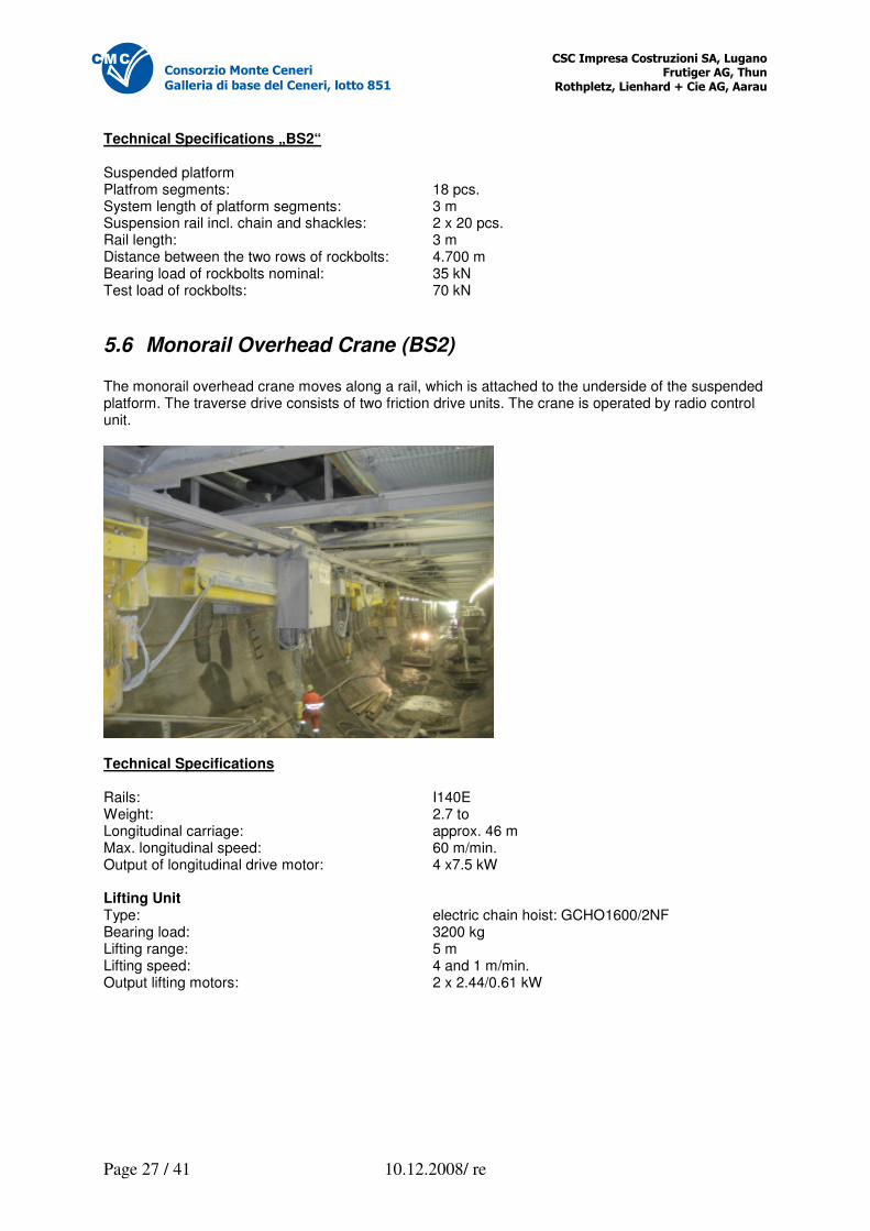
5.6 Monorail Overhead Crane (BS2) The monorail overhead crane moves along a rail, which is attached to the underside of the suspended platform. The traverse drive consists of two friction drive units. The crane is operated by radio control unit.
Technical Specifications Rails: I140E Weight: 2.7 to Longitudinal carriage: approx. 46 m Max. longitudinal speed: 60 m/min. Output of longitudinal drive motor: 4 x7.5 kW Lifting Unit Type: electric chain hoist: GCHO1600/2NF Bearing load: 3200 kg Lifting range: 5 m Lifting speed: 4 and 1 m/min. Output lifting motors: 2 x 2.44/0.61 kW
�������������� ����������� ������ ������������ ��
������������������������������� �
Page 28 / 41 10.12.2008/ re
������������������������
�������������������������������� !
5.3 Backup System for Supply and Disposal (BS3) The backup system “supply and disposal” (BS) consists of the tailing portal carriages 5 and 6. These portal carriages are supported by skids and rails. The following functions are integrated in these carriages: - Coarse grit extrusion: A grader extrudes the course grit. The course grit (approx. 150 – 300 mm) is
separated and deposed in a trough. The trough moves along with the BS3 (resp. is pulled along the ground floor) and is exchanged by truck.
- A shunting switch below the normal-sized grit separator allows the diversion of the excavation material to a truck below the installation (e.g., if the tunnel belt is out of order or to acquire filling material to be used at the ground floor construction site.)
- A deposition point for the tunnel belt. - An installation point for the tunnel belt. A raised platform with stairway access on the upper deck can
be used by the customer to mount an extension installation for the tunnel belt. A crane is used to move parts of the installation to and from the platform. The max. tolerable tension on the tail pulley installed by the customer is 54 kN.
- Units (pumps, reservoirs, etc.) of the water installation for industrial and mountain water are not included in this submission. Space is provided at the rear of the BS to mount the hose drums of the water supply to the backup system installation.
- A medium voltage cable drum is mounted on one of the tailing carriages. The emergency power supply of the duct storage unit is used for electrical power during the coiling up of the cables
- A material-handling crane is used to exchange the duct storage units. - A cooling unit of the tunnel air ventilation (Which was never installed, because it wasn’t required). - An emergency power supply unit to supply above pumps, cable drums and emergency lighting. - Secondary ventilation
6 Ventilation System
6.1 Preface The tunnel airduct has a diameter of 2200 mm. The main ventilation unit is located at the tunnel entrance. The fresh air is conducted via the airduct to the duct storage unit with diffuser, then to the secondary ventilator with sound absorber and finally via the secondary air duct to the TBM.
6.2 Secondary Ventilator AL 12-550 Technical Specifications Type: AL12-550 Diameter: 1200 mm Installation length: 1350 mm Nominal rotation speed: 1500 rpm Nominal output: 55kW Weight: approx. 1050 kg Sound absorber type: SDS12 Secondary airduct: flat airducts D1400 and D1200 (approx. 110 m) Startup: via soft starter
�������������� ����������� ������ ������������ ��
������������������������������� �
Page 29 / 41 10.12.2008/ re
������������������������
�������������������������������� !
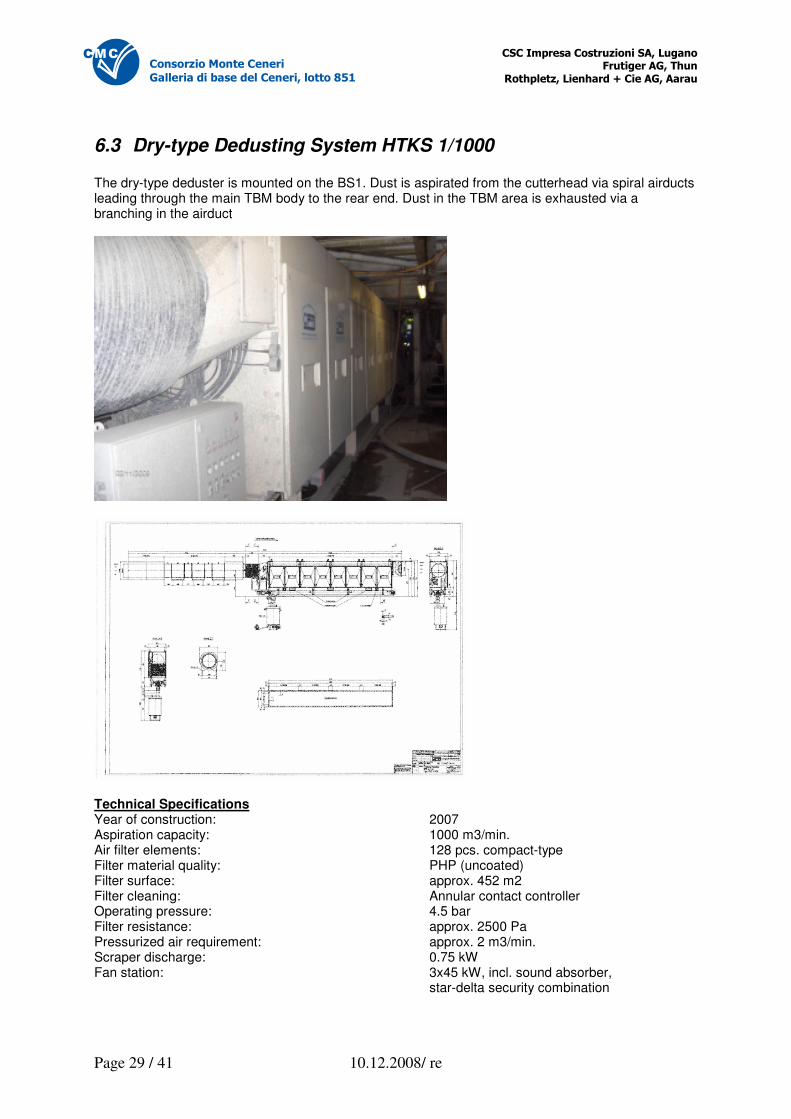
6.3 Dry-type Dedusting System HTKS 1/1000 The dry-type deduster is mounted on the BS1. Dust is aspirated from the cutterhead via spiral airducts leading through the main TBM body to the rear end. Dust in the TBM area is exhausted via a branching in the airduct
Technical Specifications Year of construction: 2007 Aspiration capacity: 1000 m3/min. Air filter elements: 128 pcs. compact-type Filter material quality: PHP (uncoated) Filter surface: approx. 452 m2 Filter cleaning: Annular contact controller Operating pressure: 4.5 bar Filter resistance: approx. 2500 Pa Pressurized air requirement: approx. 2 m3/min. Scraper discharge: 0.75 kW Fan station: 3x45 kW, incl. sound absorber, star-delta security combination
�������������� ����������� ������ ������������ ��
������������������������������� �
Page 30 / 41 10.12.2008/ re
������������������������
�������������������������������� !
Wet discharge device for blended volumes: approx. 200 l Electric circuits for: Control of all discharge units Filter purification Control of starting and stopping sequences of all units
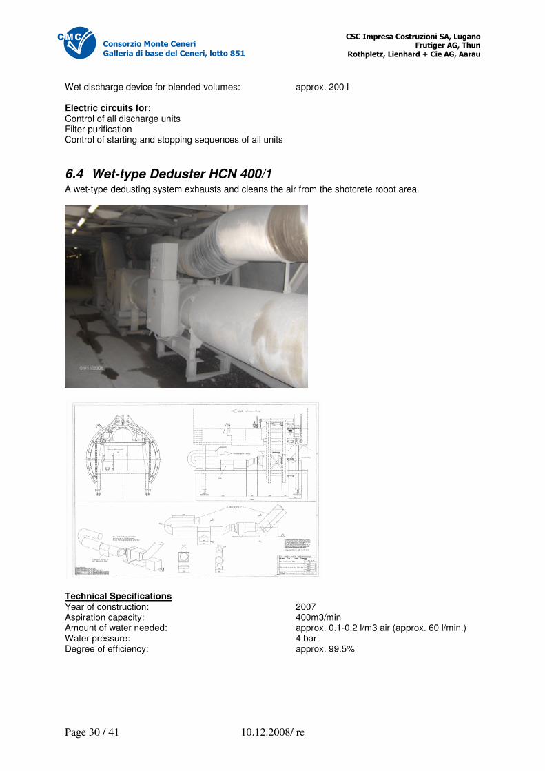
6.4 Wet-type Deduster HCN 400/1 A wet-type dedusting system exhausts and cleans the air from the shotcrete robot area.
Technical Specifications Year of construction: 2007 Aspiration capacity: 400m3/min Amount of water needed: approx. 0.1-0.2 l/m3 air (approx. 60 l/min.) Water pressure: 4 bar Degree of efficiency: approx. 99.5%
�������������� ����������� ������ ������������ ��
������������������������������� �
Page 31 / 41 10.12.2008/ re
������������������������
�������������������������������� !
Ventilator station with axial blower: Stream volume: 360 m3/min. Pressing: 300 Pa at 360 m3/min. Drive output: 2x15 kW Propeller diameter: 600 mm Rotation speed: 3000 rpm Voltage: 400 V, 50 Hz Incl. control unit
7 Electrical Installations
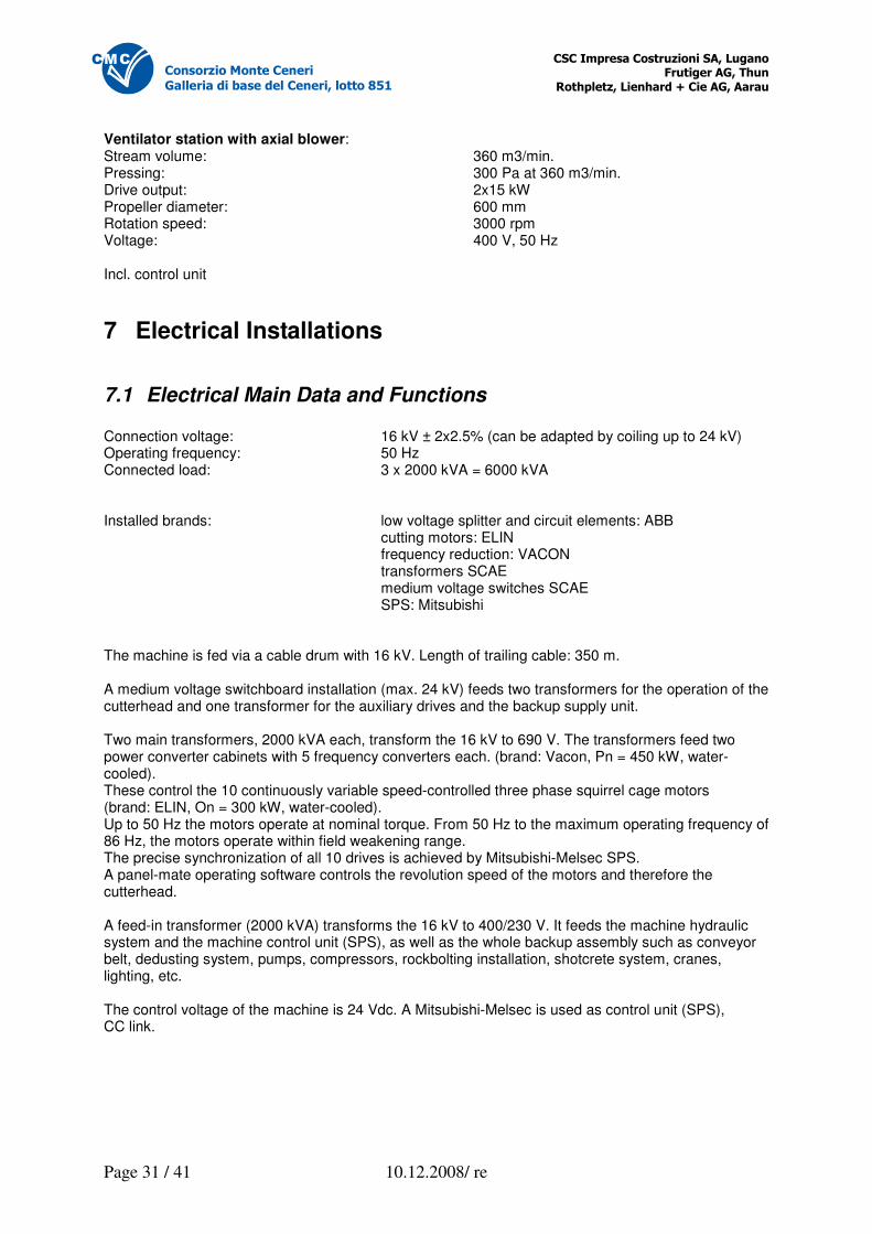
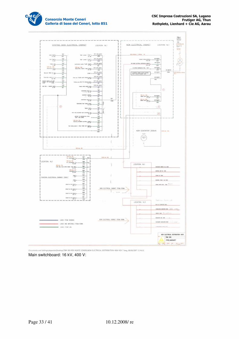
7.1 Electrical Main Data and Functions Connection voltage: 16 kV ± 2x2.5% (can be adapted by coiling up to 24 kV) Operating frequency: 50 Hz Connected load: 3 x 2000 kVA = 6000 kVA Installed brands: low voltage splitter and circuit elements: ABB cutting motors: ELIN frequency reduction: VACON transformers SCAE medium voltage switches SCAE SPS: Mitsubishi The machine is fed via a cable drum with 16 kV. Length of trailing cable: 350 m. A medium voltage switchboard installation (max. 24 kV) feeds two transformers for the operation of the cutterhead and one transformer for the auxiliary drives and the backup supply unit. Two main transformers, 2000 kVA each, transform the 16 kV to 690 V. The transformers feed two power converter cabinets with 5 frequency converters each. (brand: Vacon, Pn = 450 kW, water-cooled). These control the 10 continuously variable speed-controlled three phase squirrel cage motors (brand: ELIN, On = 300 kW, water-cooled). Up to 50 Hz the motors operate at nominal torque. From 50 Hz to the maximum operating frequency of 86 Hz, the motors operate within field weakening range. The precise synchronization of all 10 drives is achieved by Mitsubishi-Melsec SPS. A panel-mate operating software controls the revolution speed of the motors and therefore the cutterhead. A feed-in transformer (2000 kVA) transforms the 16 kV to 400/230 V. It feeds the machine hydraulic system and the machine control unit (SPS), as well as the whole backup assembly such as conveyor belt, dedusting system, pumps, compressors, rockbolting installation, shotcrete system, cranes, lighting, etc. The control voltage of the machine is 24 Vdc. A Mitsubishi-Melsec is used as control unit (SPS), CC link.
�������������� ����������� ������ ������������ ��
������������������������������� �
Page 32 / 41 10.12.2008/ re
������������������������
�������������������������������� !
7.2 TBM and NL Schematics
�������������� ����������� ������ ������������ ��
������������������������������� �
Page 33 / 41 10.12.2008/ re
������������������������
�������������������������������� !
Main switchboard: 16 kV, 400 V:
�������������� ����������� ������ ������������ ��
������������������������������� �
Page 34 / 41 10.12.2008/ re
������������������������
�������������������������������� !
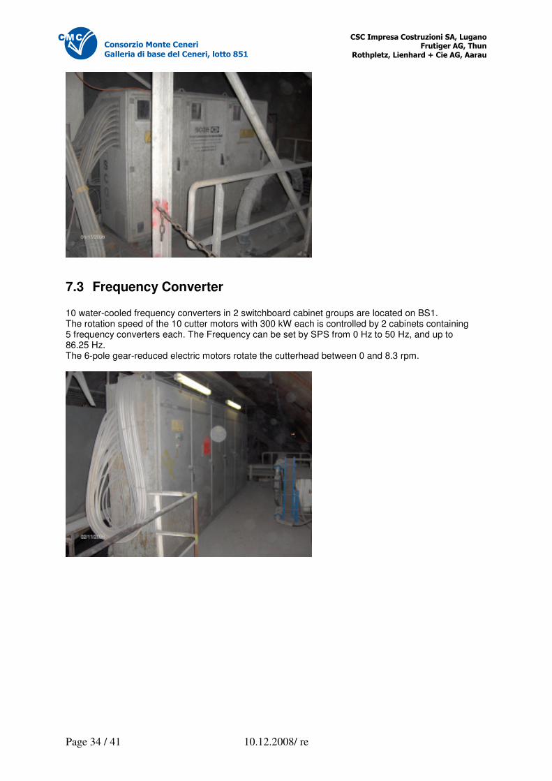
7.3 Frequency Converter 10 water-cooled frequency converters in 2 switchboard cabinet groups are located on BS1. The rotation speed of the 10 cutter motors with 300 kW each is controlled by 2 cabinets containing 5 frequency converters each. The Frequency can be set by SPS from 0 Hz to 50 Hz, and up to 86.25 Hz. The 6-pole gear-reduced electric motors rotate the cutterhead between 0 and 8.3 rpm.
�������������� ����������� ������ ������������ ��
������������������������������� �
Page 35 / 41 10.12.2008/ re
������������������������
�������������������������������� !
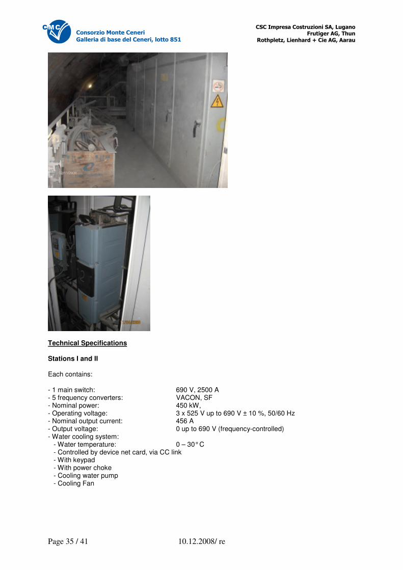
Technical Specifications Stations I and II Each contains: - 1 main switch: 690 V, 2500 A - 5 frequency converters: VACON, SF - Nominal power: 450 kW, - Operating voltage: 3 x 525 V up to 690 V ± 10 %, 50/60 Hz - Nominal output current: 456 A - Output voltage: 0 up to 690 V (frequency-controlled) - Water cooling system: - Water temperature: 0 – 30° C - Controlled by device net card, via CC link - With keypad - With power choke - Cooling water pump - Cooling Fan
�������������� ����������� ������ ������������ ��
������������������������������� �
Page 36 / 41 10.12.2008/ re
������������������������
�������������������������������� !
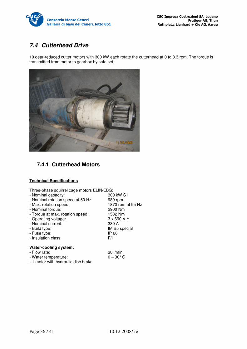
7.4 Cutterhead Drive 10 gear-reduced cutter motors with 300 kW each rotate the cutterhead at 0 to 8.3 rpm. The torque is transmitted from motor to gearbox by safe set.
7.4.1 Cutterhead Motors Technical Specifications Three-phase squirrel cage motors ELIN/EBG: - Nominal capacity: 300 kW S1 - Nominal rotation speed at 50 Hz: 989 rpm. - Max. rotation speed: 1870 rpm at 95 Hz - Nominal torque: 2900 Nm - Torque at max. rotation speed: 1532 Nm - Operating voltage: 3 x 690 V Y - Nominal current: 330 A - Build type: IM B5 special - Fuse type: IP 66 - Insulation class: F/H Water-cooling system: - Flow rate: 30 l/min. - Water temperature: 0 – 30° C - 1 motor with hydraulic disc brake
�������������� ����������� ������ ������������ ��
������������������������������� �
Page 37 / 41 10.12.2008/ re
������������������������
�������������������������������� !
7.4.2 Cutterhead Planetary Gearbox Gearboxes 1 to 10: - Planetary gearbox: Lohman & Stolterfüht - Nominal capacity: 315 kW - Input torque: 1671 Nm - Output torque: 31057 Nm - Max. coupling torque: 5100 Nm - Input rotation speed: 1800 rpm - Output rotation speed: 96.9 rpm - Transmission: 1 by 18.571 Water cooling system: - Flow rate: 20 l/min. - Water temperature 0 – 30° C
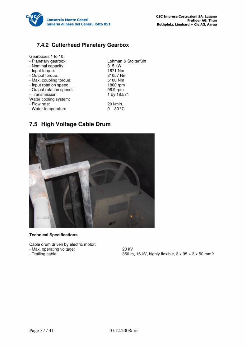
7.5 High Voltage Cable Drum
Technical Specifications Cable drum driven by electric motor: - Max. operating voltage: 20 kV - Trailing cable: 350 m, 16 kV, highly flexible, 3 x 95 + 3 x 50 mm2
�������������� ����������� ������ ������������ ��
������������������������������� �
Page 38 / 41 10.12.2008/ re
������������������������
�������������������������������� !
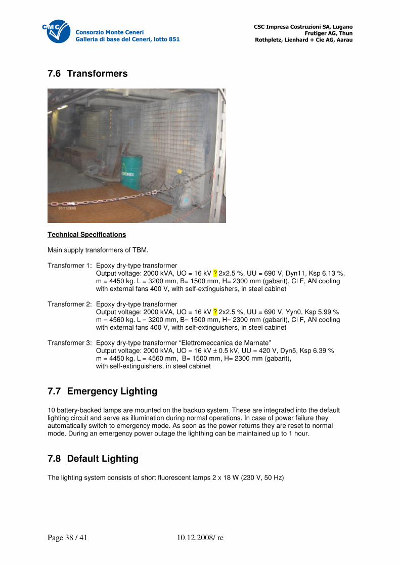
7.6 Transformers
Technical Specifications Main supply transformers of TBM. Transformer 1: Epoxy dry-type transformer Output voltage: 2000 kVA, UO = 16 kV ? 2x2.5 %, UU = 690 V, Dyn11, Ksp 6.13 %, m = 4450 kg. L = 3200 mm, B= 1500 mm, H= 2300 mm (gabarit), Cl F, AN cooling with external fans 400 V, with self-extinguishers, in steel cabinet Transformer 2: Epoxy dry-type transformer Output voltage: 2000 kVA, UO = 16 kV ? 2x2.5 %, UU = 690 V, Yyn0, Ksp 5.99 % m = 4560 kg. L = 3200 mm, B= 1500 mm, H= 2300 mm (gabarit), Cl F, AN cooling with external fans 400 V, with self-extinguishers, in steel cabinet Transformer 3: Epoxy dry-type transformer “Elettromeccanica de Marnate” Output voltage: 2000 kVA, UO = 16 kV ± 0.5 kV, UU = 420 V, Dyn5, Ksp 6.39 % m = 4450 kg. L = 4560 mm, B= 1500 mm, H= 2300 mm (gabarit), with self-extinguishers, in steel cabinet
7.7 Emergency Lighting 10 battery-backed lamps are mounted on the backup system. These are integrated into the default lighting circuit and serve as illumination during normal operations. In case of power failure they automatically switch to emergency mode. As soon as the power returns they are reset to normal mode. During an emergency power outage the lighthing can be maintained up to 1 hour.
7.8 Default Lighting The lighting system consists of short fluorescent lamps 2 x 18 W (230 V, 50 Hz)
�������������� ����������� ������ ������������ ��
������������������������������� �
Page 39 / 41 10.12.2008/ re
������������������������
�������������������������������� !
7.9 Emergency Backup Generator An emergency power installation for the supply of the pumps and lighting is mounted on BS3. Technical Specifications Year of construction: 2007 Type: GEPK275HE Nominal capacity: 275 kVA
Effective power cosγ 0,8: 225 kW Continuous power: 250 kVA
Continuous effective power cosγ 0,8: 200 kW Nominal voltage: 400/230 V Frequency: 50 Hz Rotation speed: 1500 G/1
8 Miscellaneous
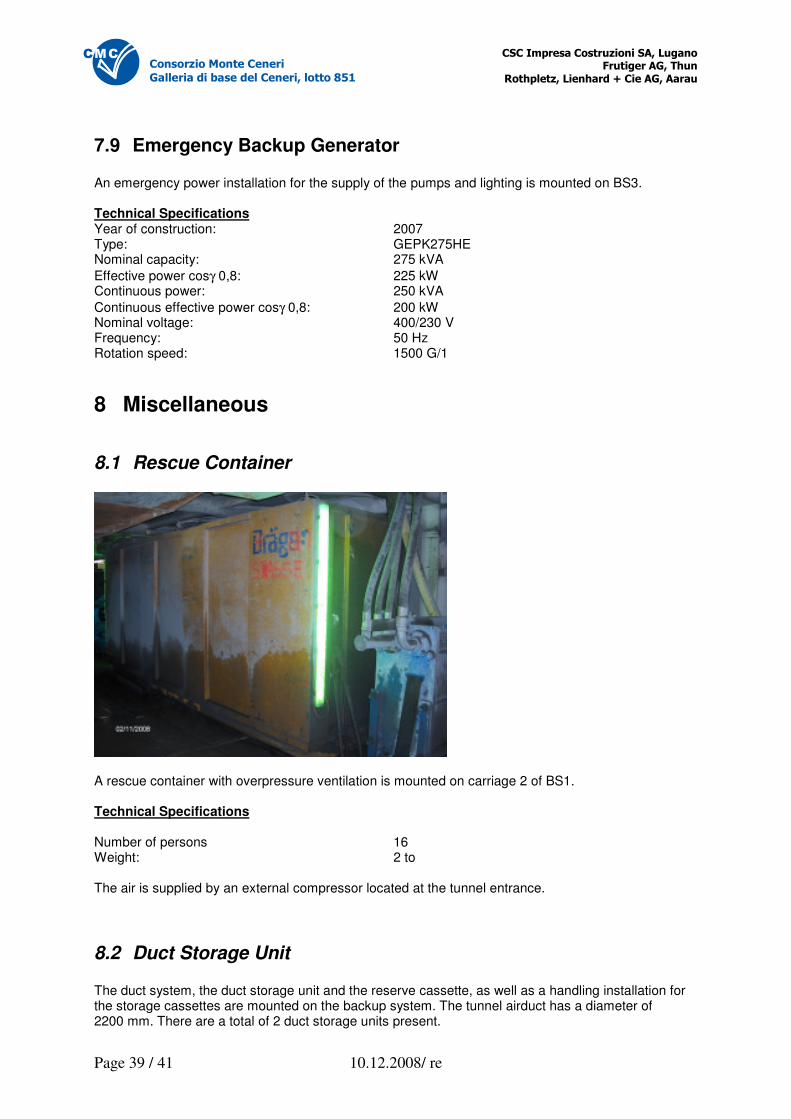
8.1 Rescue Container
A rescue container with overpressure ventilation is mounted on carriage 2 of BS1. Technical Specifications Number of persons 16 Weight: 2 to The air is supplied by an external compressor located at the tunnel entrance.
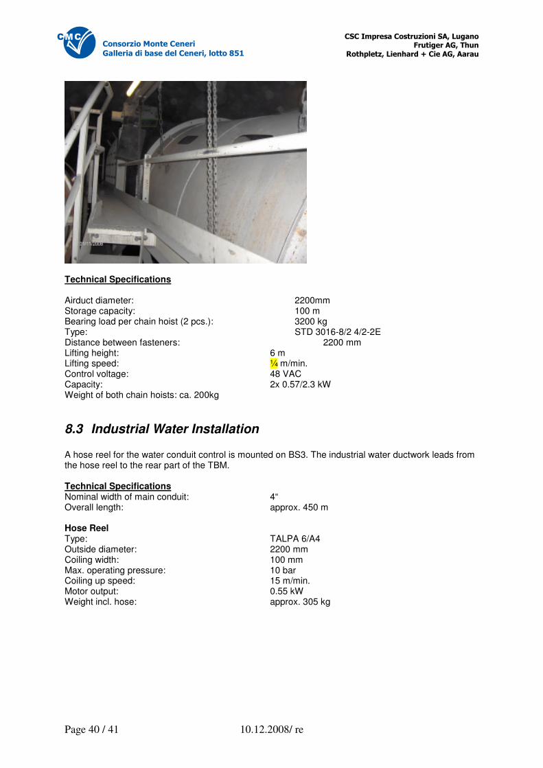
8.2 Duct Storage Unit The duct system, the duct storage unit and the reserve cassette, as well as a handling installation for the storage cassettes are mounted on the backup system. The tunnel airduct has a diameter of 2200 mm. There are a total of 2 duct storage units present.
�������������� ����������� ������ ������������ ��
������������������������������� �
Page 40 / 41 10.12.2008/ re
������������������������
�������������������������������� !
Technical Specifications Airduct diameter: 2200mm Storage capacity: 100 m Bearing load per chain hoist (2 pcs.): 3200 kg Type: STD 3016-8/2 4/2-2E Distance between fasteners: 2200 mm Lifting height: 6 m Lifting speed: ¼ m/min. Control voltage: 48 VAC Capacity: 2x 0.57/2.3 kW Weight of both chain hoists: ca. 200kg
8.3 Industrial Water Installation A hose reel for the water conduit control is mounted on BS3. The industrial water ductwork leads from the hose reel to the rear part of the TBM. Technical Specifications Nominal width of main conduit: 4“ Overall length: approx. 450 m Hose Reel Type: TALPA 6/A4 Outside diameter: 2200 mm Coiling width: 100 mm Max. operating pressure: 10 bar Coiling up speed: 15 m/min. Motor output: 0.55 kW Weight incl. hose: approx. 305 kg
�������������� ����������� ������ ������������ ��
������������������������������� �
Page 41 / 41 10.12.2008/ re
������������������������
�������������������������������� !
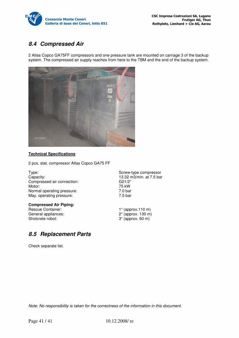
8.4 Compressed Air 2 Atlas Copco GA75FF compressors and one pressure tank are mounted on carriage 3 of the backup system. The compressed air supply reaches from here to the TBM and the end of the backup system.
Technical Specifications 2 pcs. stat. compressor Atlas Copco GA75 FF Type: Screw-type compressor Capacity: 13.32 m3/min. at 7.5 bar Compressed air connection: G21/2“ Motor: 75 kW Normal operating pressure: 7.0 bar May. operating pressure: 7.5 bar Compressed Air Piping: Rescue Container: 1“ (approx.110 m) General appliances: 2“ (approx. 130 m) Shotcrete robot: 3“ (approx. 60 m)
8.5 Replacement Parts Check separate list. Note: No responsibility is taken for the correctness of the information in this document.

![TBM 렌탈솔루션 - cafe24mrrental.cafe24.com/tbm/tbmrs_service_introduction.pdf · 01. TBM 렌탈솔루션소개 [이미지출처: 효성에프엠에스뉴스레터(2019.01.28)]](https://img.pdfslide.net/doc/110x75/5ece13d36c14a753b559968e/tbm-eoefe-01-tbm-eoefeoeeoe-eoe-ee20190128.jpg)