Embed Size (px)
DESCRIPTION
specs
Citation preview
PREPARED FOR DEPARTMENT OF THE
AIR FORCE
BY
GOMEZ GIMENEZ CAYETANO C/ GONZALEZ GORDON 3
JEREZ DE LA FRONTERA, 11407 CADIZ, SPAIN
TECHNICAL PROVISIONS & SPECIFICATIONS FOR:
PROJECT QUUG 09-1017
RPR UTILITY MANHOLE COVERS
FINAL SUBMITTAL Prepared and approved by: ________________________________________________ Name: Cayetano Gómez Giménez, Date: August 13 2010 Ingeniero Industrial, Colegiado No. 1022 Colegio Oficial de Ingenieros Industriales de Andalucía Occidental
PROJECT QUUG 09-1017
LIST OF SPECIFICATIONS
DIVISION 1 GENERAL REQUIREMENTS
01000 Scope of Work, Drawings and Special Conditions 01011 General Conditions
DIVISION 2 SITE WORK
02220 Demolitions 02315 Excavation and Fill
DIVISION 3 CONCRETE
03300 Cast In-Place Concrete DIVISION 5 METALS
05500 Metal Fabrications, Manhole Covers
PROJECT QUUG 09-1017
Section 01000 - Page 1 of 4
SECTION 01000
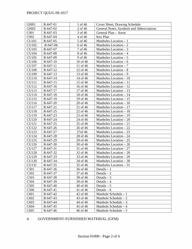
SCOPE OF WORK, DRAWINGS AND SPECIAL CONDITIONS 1. SCOPE OF WORK This project provides for work to fix deficiencies found in existing manholes and manhole covers at Moron Air Base. The works consist, but are not limited to, the replacement and repairs of broken utility manholes, handhole covers and valve boxes protections.. The repairs will apply to the following systems: potable water, irrigation, sewer, electrical, oil separators and grease traps. There is a wide variety of repairs that range from cover seal changing and cleaning to the manhole cover replacement and reconstruction. All conditions are described in drawings, specifications and schedules. All manholes, handholes and valve boxes are identified with a numbering reference in drawings. A recent picture of each one is provided. The Contractor is to provide an identified picture of every manhole / handhole / valve box repaired with the same numbering system as an as-built requirement. This work provides for a Base Bid, BB, and two Additive Items, ADD1 and ADD2. The Base Bid (BB) includes the replacement and anchoring of broken manhole covers which represent major safety risks and the repair of miscellaneous special items (SP). Additive Item 1 (ADD1) includes the repair of the rest of manholes and manhole covers. Additive Item 2 (ADD2) includes the installation of new covers to valve boxes. 2. PERFORMANCE PERIOD The performance period proposed for the execution of this project, 240 calendar days, is for information purposes only and includes average inclement weather days. 3. DRAWINGS See following drawing schedule DRAWING
NO. SHEET NO. SHEET TITLE
PROJECT QUUG 09-1017
Section 01000 - Page 2 of 4
GI001 R-647-01 1 of 46 Cover Sheet, Drawing Schedule GI002 R-647-02 2 of 46 General Notes, Symbols and Abbreviations C001 R-647-03 3 of 46 General Plan – Areas C002 R-647-04 4 of 46 Key Plan CU101 R-647-05 5 of 46 Manholes Location – 1 CU102 R-647-06 6 of 46 Manholes Location – 2 CU103 R-647-07 7 of 46 Manholes Location – 3 CU104 R-647-08 8 of 46 Manholes Location – 4 CU105 R-647-09 9 of 46 Manholes Location – 5 CU106 R-647-10 10 of 46 Manholes Location – 6 CU107 R-647-11 11 of 46 Manholes Location – 7 CU108 R-647-12 12 of 46 Manholes Location – 8 CU109 R-647-13 13 of 46 Manholes Location – 9 CU110 R-647-14 14 of 46 Manholes Location – 10 CU111 R-647-15 15 of 46 Manholes Location – 11 CU112 R-647-16 16 of 46 Manholes Location – 12 CU113 R-647-17 17 of 46 Manholes Location – 13 CU114 R-647-18 18 of 46 Manholes Location – 14 CU115 R-647-19 19 of 46 Manholes Location – 15 CU116 R-647-20 20 of 46 Manholes Location – 16 CU117 R-647-21 21 of 46 Manholes Location – 17 CU118 R-647-25 22 of 46 Manholes Location – 18 CU119 R-647-23 23 of 46 Manholes Location – 19 CU120 R-647-24 24 of 46 Manholes Location – 20 CU121 R-647-25 25 of 46 Manholes Location – 21 CU122 R-647-26 26 of 46 Manholes Location – 22 CU123 R-647-27 27of 46 Manholes Location – 23 CU124 R-647-28 28 of 46 Manholes Location – 24 CU125 R-647-29 29 of 46 Manholes Location – 25 CU126 R-647-30 30 of 46 Manholes Location – 26 CU127 R-647-31 31 of 46 Manholes Location – 27 CU128 R-647-32 32 of 46 Manholes Location – 28 CU129 R-647-33 33 of 46 Manholes Location – 29 CU130 R-647-34 34 of 46 Manholes Location – 30 CU131 R-647-35 35 of 46 Manholes Location – 31 C501 R-647-36 36 of 46 Details – 1 C502 R-647-37 37 of 46 Details – 2 C503 R-647-38 38 of 46 Details – 3 C504 R-647-39 39 of 46 Details – 4 C505 R-647-40 40 of 46 Details – 5 C506 R-647-41 41 of 46 Details – 6 C601 R-647-42 42 of 46 Manhole Schedule – 1 C602 R-647-43 43 of 46 Manhole Schedule – 2 C603 R-647-44 44 of 46 Manhole Schedule – 3 C604 R-647-45 45 of 46 Manhole Schedule – 4 C605 R-647-46 46 of 46 Manhole Schedule – 5 4. GOVERNMENT-FURNISHED MATERIAL (GFM)
PROJECT QUUG 09-1017
Section 01000 - Page 3 of 4
Not Applicable 5. EQUIPMENT, CONTROLS, AND MATERIAL OF THE UNITED STATES OF AMERICA Not Applicable 6. CERTIFICATION OF CLASSIFICATION Bidders and/or their subcontractors must hold an updated Certificate of Classification issued by the "Registro Oficial de Contratistas de Obras del Estado" of the "Ministerio de Economía y Hacienda" covering the following groups, subgroups, and categories. Group Subgroup Category C 2,4 C 7. SPECIAL REQUIREMENTS
7.1 Shut-off Valves of Hydrant System The Contractor shall request an inspection of the shut-off valves of the hydrant and irrigation systems mainly on which new protection covers have to be installed, just before the beginning of the work. The inspection shall be conducted by the maintenance department of Civil Engineering in the presence of the Contractor. The purpose of the inspection is checking of the operation of shut-off valves of the hydrant and irrigation system to determine the conditions of the valves and act accordingly. The CE workshops shall fix shut off valves found defective. 7.2 Stockpiling Area for Contractor Material and Contractor Offices The Contracting Officer representative shall coordinate with the Base Chief of Operations and Maintenance the exact location for Contractor offices and stockpiling.
7.3 Escorts
Escorts shall be provided for Base access by the Contractor for personnel, subcontractors or material suppliers. During the construction period Contractor shall provide their escorts with training, transportation, cell phones, permits, etc. Escorts shall be in possession of a valid driving license and if required, flight driving permit.
PROJECT QUUG 09-1017
Section 01000 - Page 4 of 4
7.3.1 Escort Responsibility
a. Maintaining visual and voice contact with escorted personnel and vehicle at
all times. b. Ensuring visitor has base access pass attached to outer garment in a visible location, and that vehicle passes are visible from the dashboard. c. Ensuring that escorted personnel do not abandon the work site and that they remain with the escort when moving from one part of the base to another. d. Ensuring that the escorted persons and equipment leave the base and surrender the base access paperwork with the security guard at the gate. e. Ensuring that escorted personnel fully understand these requirements. f. Ensuring that the instructions from base personnel as well as the vouching authority are followed. g. Maintaining visual and radio contact with control tower at all times. The Government shall provide two radios at least to the Contractor. The Contractor shall return the radios after the completion of the work. Construction Management shall establish the location where the Contractor has to recharge the battery of the radios. h. Ensuring that Airfield Management Operations Office is informed every day when the Contractor is going to access the work site and when the Contractor has left the work site.
*** END OF SECTION ***
PROJECT QUUG 09-1017
01011 - 1
SECTION 01011
GENERAL CONDITIONS 1. GENERAL: The work consists of furnishing all labor, materials, plant, transportation, equipment, and services to complete the project described in Section 01000, Scope of Work, Drawings and Special Conditions, in accordance with the drawings and specifications, complete and ready for use by means of a firm fixed price construction contract. Measurements given in the drawings and specifications are given for reference use only. It is the Contractor’s responsibility to verify any and all of said measurements. 2. GENERAL DESCRIPTION: The work consists in, but is not limited to, executing the line items indicated in the scope of work. All line items indicated in the scope of work do not limit or reduce the Contractor’s responsibility to perform all work as required by the project in order to provide a complete and operable facility. 3. LOCATION: The work is located in Morón Air Base, Spain, as shown on the contract drawings. 4. DRAWINGS ACCOMPANYING SPECIFICATION: The drawings accompanying this specification are a part thereof. Drawings are the property of the Government, and shall not be used for any purpose other than that contemplated by the specification. The drawings included in this specification are similar to A1. 5. WARRANTY: For this contract the Contractor shall provide a two year standard commercial warranty associated with all scope of work items including materials and workmanship. The warranty should cover all defects noticed and reported to the Contractor within two years after acceptance of the project. The Contractor shall repair or replace defective materials at the Contractor's expense within a reasonable time, and as approved by the Contracting Officer 6. BASE ACCESS: 6.1 Permits or Authorizations: The Contractor shall obtain all permits or authorizations to access Morón Air Base. Once the works have finalized, the Contractor will return the permits or authorizations. 6.2 Delays and Interruptions: Contractors are advised that due to security reasons, during the access/egress process of personnel and materials from the Morón Air Base delays are liable to occur. Additionally, the Contractor shall immediately interrupt work when required to do so if security warning/alarm situations occur.
PROJECT QUUG 09-1017
01011 - 2
7. WORK CLEARANCE REQUEST: The Contractor shall request AF Form 103 “BCE Work Clearance Request” in order to obtain all the information pertaining to the current status of general utilities. Requests shall be processed through the Contracting Officer or authorized representative, minimum of 7 duty days beforehand. The Contractor shall not perform any excavation works under any circumstances without an approved Work Clearance Request at the work site (hard copy). Work Clearance Request will only be processed once all materials and documentation necessary to commence work have been submitted and approved. The Contractor shall be held responsible for any damage caused to general utilities indicated on the AF Form 103 and related drawings and shall be repaired at no additional cost to the Government of the United States. 8. BASE UTILITIES: 8.1 Use of Base Utilities: Base utilities are available to the Contactor at no additional expense to the Contractor. The following utilities shall be available from the existing Base utility connections in reasonable quantities: a. Electricity 120/208 volts, 60 Hz. b. Non-potable water. Connection requests shall indicate the type of utility service required, type of connection and disconnection, utility service use and maximum duration. All connection and disconnection works for Base utilities shall be programmed during normal Base personnel operating hours. It shall be the Contractor’s responsibility to effect the connections and disconnections and shall reimburse costs incurred in the connection, disconnection, conversion, transportation of Base utility services to the work site, including providing the mechanisms that avoid water from flowing back into the system (backflow preventers) and furnishing and installing the necessary transformers. The Contractor shall not activate or alter any control device of the system of the utility services, including water, sewage and electricity. Control devices will be Government operated. The Contractor shall notify the Contracting Officer or authorized representative 5 duty days prior to any connection, disconnection or manipulation of the control system of the utility services required. Temporary overhead connections to utility services are prohibited. All systems shall be restored to their original condition prior to satisfying final contractual payments. 8.2 Base Utility Outages: Utility outage requests shall indicate the type of outage to be performed, the scope of work and the maximum duration. All utility outages shall be programmed during normal Base personnel operating hours. The Contractor shall not activate or alter any control device of the system of the utility services, including water, sewage and electricity. Control devices will be Government operated. The Contractor shall notify the Contracting Officer or authorized representative 5 duty days prior to any connection, disconnection or manipulation of the control system of the utility services required. Temporary
PROJECT QUUG 09-1017
01011 - 3
overhead connections to utility services are prohibited. All systems shall be restored to their original condition prior to satisfying final contractual payments. 9. HOT WORK: The Contractor shall submit for approval a written request to the Contracting Officer or authorized representative 5 days prior to any welding, oxyacetylene or plasma cutting work. Said request shall indicate welding procedures and fire prevention measures. All welding work performed during the project shall be carried out by qualified welders only. The copies of the welding certificates, issued by an approved agency, shall be kept in the construction inspector’s files. 10. VEHICULAR TRAFFIC, MACHINERY AND EQUIPMENT: 10.1 Traffic Control: All works which require vehicular or pedestrian traffic disruptions on the Base shall require an approved transit control plan. Said plan shall be approved at least 7 days prior to carrying out said disruption. Said plan shall include the date, duration, proposed alternative routes, signs, barriers, cones and/or flagmen. The Contractor shall establish alternate procedures should unforeseen circumstances take place. The responsibility of furnishing, erecting, maintaining and removing all signs, barriers, cones and flags shall be solely the Contractor’s. Once the work is completed, the Contractor shall remove the signaling elements such as barriers, cones and/or flags. 10.2 Access Routes: The Contractor shall submit a plan for the access routes which shall be approved by the Contracting Officer or authorized representative. 10.3 Trucks: Trucks loaded with loose material (air borne dust, construction debris or other objects that could fall from them), shall be duly covered. Said covers, such as tarps, shall be fastened over the load prior to accessing the adjacent roads. 11. PROGRESS SCHEDULE: (See solicitation/Contract FAR clause 52.236-15, Schedules for Construction Contracts, Apr 1984). The Contractor shall, within five days after the work commences on the contract or another period of time determined by the Contracting Officer, prepare and submit to the Contracting Officer for approval four copies of a practicable schedule showing the order in which the Contractor proposes to perform the work, and the dates on which the Contractor contemplates starting and completing the several salient features of the work (including acquiring materials, plant, and equipment). The schedule shall be in the form of a progress chart of suitable scale to indicate appropriately the percentage of work scheduled for completion by any given date during the period. If the Contractor fails to submit a schedule within the time prescribed, the Contracting Officer may withhold approval of progress payments until the Contractor submits the required schedule. 12. MOBILITY PLAN: The Contractor shall submit a mobility plan to the Contracting Officer or authorized representative for approval. Said plan shall propose the location and
PROJECT QUUG 09-1017
01011 - 4
surface of the work site, offices and material staging and storage areas. The Contractor shall submit the plan 5 duty days prior to commencing work. The Contractor shall include in the mobility plan the proposed system to supply the required utility services required at each site. 12.1 Construction Site Fencing: Construction sites, offices, latrines, material staging and storage areas shall be fenced in by means of a two meter high fence to include gates and locks, unless otherwise approved the Government of the United States. The type of fencing, height and color shall be specified in accordance with the Contracting Officer or authorized representative’s criteria. Fences shall be screened with green opaque screening material to prevent visibility inside the fenced area. Fencing shall be completely secured at top and bottom to prevent access. Fences and screens shall be adequately staked and/or anchored to prevent blowing over during high wind conditions. The Contractor shall include in the Mobilization Plan photos, catalogs or samples of the screening material. The Contractor shall not install the fencing or screening materials until approval, in writing, has been granted from the Contracting Officer or authorized representative. The responsibility of providing, erecting, maintaining and removing the fencing shall be solely the Contractor’s. The Contractor shall replace or repair, within the following 24 hours or as determined by the Contracting Officer or authorized representative, all fence or screening sections which have been damaged or deteriorated. Once the works have been finalized, the Contractor shall remove the fencing. 12.2 Offices: Temporary prefabricated buildings required for administrative reasons (office space, conference room and break room) shall be in good conditions. Temporary prefabricated buildings requiring paint, repairs or are in bad conditions shall not be allowed at the site. Said temporary prefabricated buildings shall include on the outside a plaque, 0.5 x 0.5 meters maximum dimensions, indicating the name of the company and telephone number (s) of the person (s) designated as POC for the Contractor 24 hours a day. Once the works are finalized, the Contractor shall remove the temporary prefabricated buildings. 12.3 Latrines: Prefabricated temporary buildings required as latrines for personnel shall be in good conditions. The prefabricated temporary buildings requiring paint, repairs or are in bad conditions shall not be allowed on the work site. These facilities shall be kept in perfect using conditions and sanitized, shall be treated for insects and shall be emptied once a week and cleaned with a detergent suitable for sanitary use. The frequency of emptying and cleaning shall be adjusted according to needs. The facilities shall be located no less than 50 meters from the existing buildings on Base if they cannot be located near a sewage manhole. Once the works have been completed, the Contractor shall remove the temporary facilities and shall leave the area clean and sanitized. 12.4 Parking: The Contractor, their employees and subcontractors shall park all vehicles, including heavy machinery, equipment or vehicles, in areas where they do not pose an obstruction in the corresponding work site. All possible efforts must be made so that the
PROJECT QUUG 09-1017
01011 - 5
vehicles are not parked in an area where they will be clearly visible from the outside. 12.5 Material Storage: Storage containers will be in good conditions. The storage of materials at the work site shall be at the Contractor’s own risk. The use of private security guards at the work site shall require Spanish Air Force Security Forces approval. The Contractor shall not use the work site to store material previously approved by the Contracting Officer or authorized representative. Once the works have finished, the Contractor shall remove the excess stored material. 12.6 NOT USED. 13. QUALITY CONTROL PLAN: The Contractor shall submit comprehensive Quality Control Plan 5 duty days prior to commencing work. The plan shall contain at minimum the following: 1. Names and Qualifications for any proposed Quality Control Manager or
Inspectors. 2. Develop an Organization Chart that identifies the Reporting Responsibility the
Quality Control Inspectors, Quality Control Manager and the Project Manager. 3. Inspection Procedures. This should include types and frequencies of inspections
and procedures for failed or unsatisfactory inspections. 4. Inspection Reporting. Submit recommended forms for all types of planned
inspections with the Quality Control Plan for approval. 5 Identify all necessary inspections and submit a schedule with the frequency of
inspections. 6 Copies of all performed inspection reporting forms, including Specific (HVAC,
Plumbing, framing, Electrical, HVAC etc.,) are to be submitted to the Contracting Officer within 24 hrs. after performing each inspection.
7. List of planned ‘Hold Inspection Points’ with the estimated dates from the construction schedule.
8. Request for Information (RFI) Submit the proposed RFI Form and RFI Log Form to be used. This will be used to submit and track any RFI’s during construction.
9. Material Testing: Submit the name and qualifications for any Testing Agency or Laboratory planned for testing. All testing reports shall be submitted in a timely manner for review and approval. Should any test report fail, follow-on work is not to proceed until after the failure has been corrected. It is the responsibility of the QC Manager to ensure that all reports have been reviewed and the necessary action taken to resolve any failed testing.
10 A daily report of all actions performed during the contract period is required to
be documented on a daily basis
PROJECT QUUG 09-1017
01011 - 6
a. The following should be included in the report, but is not all-inclusive. 1) The date of the inspection. 2) Comment on the weather conditions. 3) Inspection of equipment and materials and when received at the job-
site. 4) Names of visitors to the site during the day. 5) Inspection of any deficiencies discovered during the day and
corrective action taken. 6) Inspection and acceptance of subcontractor materials and
workmanship. 7) Work being performed during the day and notation of inspection and
acceptance. 8) Any field changes made by Civil Engineer inspector or deviations
from original plans or specifications. These daily reports are to be kept on the job-site and available for review at all times. 13.1 Acceptance of the Construction Quality Control (QC) Plan: Acceptance of the QC Plan is required prior to the start of construction. The Contracting Officer reserves the right to require changes in the QC Plan and operations as necessary, including removal of personnel, to ensure the specified quality of work. 13.2 The contractor is expected to know and adhere to the contract specifications and drawings. The Government inspector will conduct regular inspections to confirm compliance with the drawings & specifications. 13.3 Tests to be performed by the contractor are to be in accordance with the specifications and will be evaluated by the government inspector. 13.4 Maintenance of records required by the contract and specifications are the responsibility of the contractor. 13.5 Final inspection and acceptance will be conducted jointly with the inspector and a representative from the contracting office. All punch list items must be completed before final acceptance of the project. 14. WORK DAY: 14.1 Normal Work Hours: The Contractor shall perform all work during normal working hours unless a special authorization is issued by the Contracting Office representative to deviate
PROJECT QUUG 09-1017
01011 - 7
from said work schedule. Normal working hours shall be from 0800 to 1700, from Monday to Friday, with the exception of holidays. 14.2 Work Outside Normal Hours: If the Contractor wishes to work outside the normal hours of operation, Saturdays, Sundays, or holidays, he shall submit an application to the Contracting Officer. The Contractor shall submit the request 5 duty days ahead of time as minimum. 15. CONSERVATION AND MAINTENANCE: 15.1 Conservation and Maintenance of the Existing Facilities: The contractor shall conserve and protect all existing facilities at the work site or adjacent to it which shall not to be removed or affected by the work required under this contract. The Contractor shall restore, at no additional cost to the Government of the United States of America, the facility affected during the execution of works to its original condition, before final acceptance of the project. 15.2 Conservation and Maintenance of the Existing Vegetation: The Contractor shall conserve and protect the existing vegetation (trees, shrubs, grass) on or adjacent to the work site, which shall not to be removed and which do not interfere with the work required under this contract. The contractor shall only remove trees or shrubs when specifically indicated in the drawings and specifications and shall avoid damaging the rest of vegetation. If any limbs or branches of trees are broken during contract performance due to the careless operation of equipment or the carelessness of the workmen, the contractor shall trim those limbs or branches with a clean cut and paint the cut with a tree-pruning compound. The contractor shall cut the grass or vegetation in the work site so that it does not exceed 10 cm in height. The Contractor shall restore, at no additional cost to the Government of the United States of America to their original state all areas disturbed during construction to their original condition before final acceptance of works under this project. 16. CLEANING AND MAINTENANCE: 16.1 Housekeeping and Site Cleanup: The Contractor shall dispose of accumulated debris, waste materials and rubbish and shall keep the site in order. All rubbish and waste materials shall be removed daily and shall be placed in contractor furnished containers and shall be removed on a daily basis to an authorized dump off-Base as the project progresses. Contractors shall ensure all light weight debris at the construction site is properly secured in waste receptacles so that it does not blow to another area or onto the airfield. Once the works are finished, the Contractor shall remove the containers. 16.2 Cleaning and Maintenance of Access Routes: The Contractor shall be solely responsible for any material dumped/spilled by trucks, vehicles and machinery or equipment on the access routes. Said material shall be immediately removed by the Contractor. The Contractor
PROJECT QUUG 09-1017
01011 - 8
shall be responsible for assuring that all access routes shall be kept clean and clear at all times. No amount of debris whatsoever will be tolerated on the access routes 16.3 Waste and Construction Debris: The Contractor, once the project has been completed, shall submit a report to the Chief of Construction Management with the estimated amounts or waste and construction debris managed during the execution of the project. 17. HAZARDOUS MATERIAL: Before transporting any type of hazardous material, the Contractor shall contact the Chief of Construction Management to coordinate handling and storage. The Contractor shall be responsible for complying with all applicable environmental rules and regulations concerning handling, transportation and storage of materials and/or dangerous waste. 18. NOISE CONTROL: The Contractor shall comply with all applicable municipal and state regulations and all bylaws and norms pertaining to noise control, applicable on or off Base. 19. SPECIFICATIONS AND DRAWINGS FOR CONSTRUCTION: (See Solicitation/Contract FAR clause 52.236-21, Specifications and Drawings for Construction, Feb 1997). 19.1 Maintenance and Updating of As-Built Drawings and Specifications: The Contractor shall keep two sets of specifications and prints, regular size, on the site which shall show neatly and clearly marked in red all approved & not approved variations between the actual construction and the contract documents. The As-Built drawings shall be kept up-to-date at the work site at all times during the contract. 19.2 Availability and Review of As-Built Drawings: As-Builts shall be available for inspection by the Contracting Officer or his authorized representative. Upon completion of work, a complete set of As-Built drawings shall be submitted to the Contracting Officer for final review. A hard copy of the As-Built drawings will be submitted marked in red and signed by project inspection. The Contracting Officer shall provide comments and/or approval within the following two weeks from the submittal. 19.3 Submittal of As-Builts: After final review and once the As-Built drawings have been approved, the Contractor shall have two weeks to submit a complete set of As-Builts and a CD with Updated AutoCAD files, Version 2010, of said drawings. The name of the drawing files on the CD shall correspond to the drawing numbers of the hard copies. The CD shall be labeled as follows: - Project Name and Number. - Date. - Contract Number.
PROJECT QUUG 09-1017
01011 - 9
- Contractor Name. 20. CONTRACTOR GENERAL GUIDELINES FOR AS-BUILT SPATIAL DATA COLLECTION & SUBMITTAL: 20.1 The contractor is responsible for accurately collecting all spatial data* features as-built and as-installed. The required positional accuracy is +/- 2 cm. 20.2 The contractor is responsible for delivering the spatial data in a scalable vector format such as DXF, AutoCAD DWG, ESRI shapefile or ESRI Geodatabase. 20.3 The contractor shall identify the classification, type, size, location, ID number, and any other necessary attributes, as specified by the Government, for all features. 20.4 The contractor is responsible for delivering the spatial data in a logical layering system according to the current version of Spatial Data Standard for Facilities Infrastructure and Environment (SDSFIE). The layers and associated definitions are listed in Appendix A. SDSFIE Feature Summary Listing. 20.5 The contractor is responsible for delivering the spatial data in the Universal Transverse Mercator (UTM) coordinate system Zone 30 North, World Geodetic System 1984 (WGS84) datum. 20.6 The contractor will coordinate with the installation GeoBase Office to determine the current version being used for all software, data and data standards. The Government will provide the contractor with data and information concerning all necessary and pertinent functions and principal features of the identified project including the installation's latest digital planimetric data. 20.7 Deliverables include, but are not limited to:
• Site plans. • Topographic surveys or studies. • Boundary or Cadastral surveys. • Utility (water, sewer, power, storm, etc.) designs, plans, surveys and studies. • Pavement, Grading, or Excavation plans. • Soil/Geology studies or surveys. • Environmental assessments, surveys, studies, or plans. • Historical or Archaeological surveys, studies, or plans.
All data deliverables shall include a schedule and shall be in a digital (electronic information) format and shall be delivered on CD-ROM or DVD-ROM. The media must have
PROJECT QUUG 09-1017
01011 - 10
an external label listing the contractor's contact information, a short description of the contents, and a sequence number if there are multiple volumes. 20.7.1 A transmittal sheet in both hardcopy and digital format (a *.dbf, *.xls, or ASCII comma-delimited format) must accompany the media containing the information included on the external labels, total number of volumes being delivered, and a list of file names and file descriptions on each volume. The transmittal sheet must also include instructions for reading, restoring, or transferring the files from the media, and certification that all delivery media is free of known computer viruses - including the name(s) of the virus scanning software and the date the virus scan was performed. 20.7.2 The following procedures must be performed before CADD data is placed on the delivery media: 1. Include all files, both graphic and non-graphic, required for the project.
Ensure all files are in the same directory, and that references to those files do not include device or directory specifications.
2. Ensure all reference (external reference) files are attached and without
device or directory (path) specifications. 3. Remove all extraneous graphics and text outside the project border area, and
set the active parameters to a standard setting (or the setting contained in the seed or prototype file).
4. Include any standards sheets (abbreviations, symbols libraries, font
libraries, color tables, pen tables, plot configuration files, user command files, etc.) necessary for a complete project.
20.7.3 The following procedures must be performed before GIS data is placed on the delivery media: 1. Shapefile data shall include, as a minimum, the following files: the *.shp,
the *.shx, the *.dbf, the *.prj and the *.xml or other metadata file. 2. Geodatabase data shall be returned in a Personal Geodatabase format
compatible with the version of ArcGIS presently used by the GeoBase Office. All concomitant tables, domains, metadata, etc. shall be included in the Geodatabase.
PROJECT QUUG 09-1017
01011 - 11
3. Any ArcGIS Map Documents (i.e. *.mxd files) delivered shall be accompanied by all referenced data files, both spatial and tabular; and any associated images or other objects in the layout.
*Spatial data, also known as geospatial data or geographic information, means any data with a direct or indirect reference to a specific location or geographical area. 21 SITE INVESTIGATION AND CONDITIONS AFFECTING WORK: The Contractor acknowledges that it has taken steps reasonably necessary to ascertain the nature and location of the work, and that it has investigated and satisfied itself as to the general and local conditions which can affect the work or its cost, including but not limited to… see Solicitation/Contract FAR clause 52.236-3, Site Investigation and Conditions Affecting the Work, Apr 1984. 22. PERMITS AND RESPONSIBILITIES: The Contractor shall, without additional expense to the Government, be responsible for obtaining any necessary licenses and permits, and for complying with any Federal, State, and municipal laws, codes and regulations applicable to the performance of the work. The Contractor shall also be responsible for all damages to persons or property that occurs as a result of the Contractor’s fault or negligence. The Contractor shall also be responsible for all materials delivered and work performed until completion and acceptance of the entire work, except for any completed unit of work which may have been accepted under the contract. (See Solicitation/Contract FAR clause 52.236-7, Permits and responsibilities, Nov 1991) 23. CONTRACTOR AND SUBCONTRACTOR PERSONNEL: 23.1 Superintendent: The Contractor shall directly superintend the work or assign and have on the worksite a competent superintendent who is satisfactory to the Contracting Officer and has authority to act for the Contractor. The superintendent must be able to effectively answer technical questions related to the project and effectively manage the work. 23.2 English Speaking Representative: 23.2.1 At all times during the execution of any work, the Contractor shall have a representative present on site capable of explaining the work operations and receiving instructions in English. The Contracting Officer or authorized representative shall have the right to determine, without appeal of such decision, whether the proposed representative has the linguistic capability or not, in which case, said representative shall be replaced immediately by another previously approved by the Contracting Officer or his authorized representative. 23.3 Personnel Listing: The Contractor shall submit a list of key personnel and subcontractor personnel to include position, personal addresses and phone number for emergency
PROJECT QUUG 09-1017
01011 - 12
contact purposes. As changes occur and additional information becomes available, the Contractor shall correct the information contained in the previously submitted lists. 23.4 Personnel Transit On-Base: Personnel working on the Base shall keep to the work site and shall transit using the approved access routes. The personnel shall keep off restricted areas unless the pertinent authorization is issued. 24. PUBLIC RELEASE OF INFORMATION: The public release of information o photographs concerning any aspect of the materials or services related to this bid, purchase order or other documents resulting thereof without prior written approval from the Contracting Officer. 25. SAFETY PROGRAM: 25.1 Safety Plan: Prior to commencement of work, the Contractor shall submit a Safety Plan to the Contracting Officer in writing. The safety plan shall be subject to approval by the Contracting Officer or his authorized representative. The work site Safety Plan shall identify safety and health risks of the workers and shall propose the necessary preventive measures for each unavoidable risk in order to protect the physical integrity of the workers and minimize material damage to the facility. Fire prevention measures shall be indicated for those works which involve a fire risk. The Contractor shall provide fire extinguishers for hazardous works in which fire or a fire risk is involved. Avoidable risks shall be eliminated. Preventive measures shall be preferably collective in nature. Those risks for which, technically, collective preventive measures do not apply shall allow the use of Personal Protection Equipment. The Contractor shall list the contents of the First Aid Kit in the Safety Plan. 25.2 Standard Regulations: The contractor shall execute the Safety Plan in accordance with the corresponding State, Autonomous Community, Province and Municipal legislation. The program shall include, but not be limited to, the following: - “Occupational Safety and Health as of 1970, Public Law 91-596, 91 Congress,
S.2193, 29 December 1970. - "Public Law Amendment 91-596, 101-552, 3101, 5 November 1990. - “Ley 31/95, 8 November, Risk Prevention”. Royal Decree 1316/1989, 27 October, relative to protection for workers exposed
to noise risks during the execution of work. Royal Decree 363/1995, 10 March, Regulation for notification of new substances
and classification, container and labeling of hazardous substances.
PROJECT QUUG 09-1017
01011 - 13
Royal Decree 485/97 14 April, on work site warning signs. Royal Decree 486/97, 14 April, work sites. Royal Decree 487/97, 14 April, handling heavy loads. Royal Decree 488/97, 14 April, screens. Royal Decree 664/97, 12 May, biological agents. Royal Decree 665/97, 12 May, cancerous agents. Royal Decree 773/97, 30 May, Individual Protective Equipment. Royal Decree 1215/97, 18 July, work equipment. Royal Decree 1627/97, 24 October, Occupational Safety and Health regulations
regarding construction works. Royal Decree 1942/1997, 5 November, Regulation on the installation of
protection against fires. Royal Decree 396/2006, 31 March, regulation relative to working with Risk of
Asbestos. 25.3 Base Regulations: The Contractor, his employees and subcontractors shall become familiar with and comply with all Base rules and regulations including fire, traffic and security regulations. 25.4 Excavations and Hazardous Areas: Excavations and all areas considered hazardous by the Government of the United States of America shall be protected by suitable barriers, lights and beacons (flags, cones, boards). Warning lights (portable lamps IP-44 minimum) or safety signal lights shall be installed by the Contractor. The Contractor shall pay for any damage resulting from his own negligence. The responsibility of supplying, erecting, maintaining and removing all barriers, lights, beacons, warning lights and safety lights shall be solely the Contractor’s. Once the works have finalized, the Contractor shall remove all signaling elements such as barriers, lights and beacons. 25.5 Burning and Explosives: Burning practices and use of explosives without prior written authorization from the Government of the Unites States of America is prohibited. 26. ASBESTOS: The use of asbestos containing materials is prohibited.
PROJECT QUUG 09-1017
01011 - 14
27. CELL PHONE AND RADIO TRANSMITTER RESTRICTIONS: Under no circumstances shall radio transmitters or cell phones be used without prior approval from the Government of the United States of America. 28. WEATHER PROTECTION: The Contractor shall take the necessary precautions to protect the work site, facilities, equipment and materials from weather, to include those furnished by the Government or Government Property. It shall be the Contractor’s responsibility to be aware of weather forecasts and to take the necessary protective measures. Prior to commencing any work, the Contractor shall have at the site the material (tarpaulins, etc.) or necessary equipment to protect the site, facilities, equipment and materials exposed to rain, wind, or other natural events. Required tarpaulins shall not be light plastic, the thickness shall be enough as to assure that the weight of accumulated water does not exceed the resistance of the tarpaulin, thus tearing it. The Contractor shall be responsible for damage caused due to lack of protection against the weather. 29. MATERIAL AND/OR EQUIPMENT SUBMITTALS: 29.1 Submittals Required: The Contractor shall submit the documentation or samples indicated in the Form “Schedule of Material Submittals” for each material or equipment. 29.2 Submittal Procedure: The Contractor shall attach AF Form 3000 “Material Approval Submittal” to the documentation or sample of material or equipment submitted. The Contractor shall fill in all the necessary fields of AF Form 3000. The Contractor shall turn in AF Form 3000 and the documentation or sample of the material or equipment to the Contracting Officer within the time frame indicated in the document “Schedule of Material Submittals” for approval prior to commencement of any type of work. The Contracting Officer shall return the AF Form 3000 indicating if said submittal has been approved or not. If the Contracting Officer has not approved the submittal, the Contractor shall provide a new submittal. 29.3 AF Form 3000: The Contractor shall create said form. 30. MATERIALS AND/OR EQUIPMENT: 30.1 Material and/or Equipment Purchase Order: Once the Contractor has received approval from the Contracting Officer for the submittal, the Contractor shall proceed with the purchase order for the approved equipment or material. 30.2 Delay in the Delivery of Materials and/or Equipment: Delays in the delivery of materials and/or equipment shall not justify an extension in the performance period of the contract.
PROJECT QUUG 09-1017
01011 - 15
31. COMMENCEMENT OF WORK: Once all the required materials and/or equipment are available for use, the Contractor shall proceed to commence the works. If the Contractor wishes to commence works without all materials and/or equipment on site, he shall request authorization from the Contracting Officer.
*** END OF SECTION ***
PROJECT QUUG 09-1017
Section 02220 - Page 1 of 4
SECTION 02220
DEMOLITIONS PART 1 GENERAL 1.1 REFERENCES The publications listed below form a part of this specification to the extent referenced. The publications are referred to in the text by the basic designation only.
CONSEJO DE LA UNION EUROPEA DECISION DEL CONSEJO 2003/32/CE ((2003) December 19, Criteria and Procedures
for the Admission of Residues in Landfills in accordance with article 16 and annex II of Directiva 1999/31/CE
DIRECTIVA 1999/31/CE (1999) April 19, relative to Waste Dumping DEL CONSEJO
MINISTERIO DE LA PRESIDENCIA REAL DECRETO 105/2008 (2008) February 1, for the Regulation of
Production and Management of Construction and Demolition Residues
REAL DECRETO 1627/1997 (1997) October 24, in which Minimum Safety
Dispositions in Construction works are established
DECRETO 604/2006 (2006) May 29, Modifications to R.D.
1627/1997. REAL DECRETO 773/1997 (1997) May 30, in which Minimum Health and
Safety Dispositions relative to the Use of Personal Protective Equipment by the Workers are established
MINISTERIO DE MEDIO AMBIENTE
ORDEN MAM/304/2002 (2002) February 8, in which the Evaluation and
Disposal Operations of Residues and the European Residues Listing are published (BOE no. 43, February 19 2002; correction of errors BOE no. 61, March 12 2002)
PROJECT QUUG 09-1017
Section 02220 - Page 2 of 4
1.2 GENERAL REQUIREMENTS The small demolition works of this project shall fulfill the requirements established in Real Decreto 105/2008, of February 1, for the Regulation of Production and Management of Construction and Demolition Residues. The Contractor shall fulfill all requirements to Demolition Contractors as applicable in that Regulation. Do not begin demolition until authorization is received from the Contracting Officer. Remove rubbish and debris from the station as soon as a truck load can be completed; do not allow accumulations at the job site. The work includes demolition, removal and transportation off Base of rubbish and debris generated during the demolition and excavation works. Materials that cannot be removed daily shall be stored in areas specified by the Contracting Officer. In the interest of occupational safety and health, the work shall be performed in accordance with the Safety Plan and all applicable codes referenced. 1.3 SUBMITTALS Name of Authorized Waste Management Company in compliance with RD 105/2008. 1.4 REGULATORY AND TRANSPORTATION REQUIREMENTS Transportation of any material off Base shall fulfill the requirements of the Consejería de Medio Ambiente de la Junta de Andalucía. Comply with national and regional transportation and disposal regulations, particularly Real Decreto 105/2008 for the Regulation of Production and Management of Construction and Demolition Residues. Orden MAM/304/2002 shall be fulfilled as it may affect this activity. 1.5 DUST AND DEBRIS CONTROL Prevent the spread of dust and debris to occupied portions of the base and on the vicinity of airfield pavements, and avoid the creation of a nuisance or hazard in the surrounding area. 1.6 PROTECTION
1.6.1 Traffic Control Signs
Where pedestrian and driver safety is endangered in the area of removal work, use traffic barricades with flashing lights. Notify the Contracting Officer prior to beginning such work. 1.6.2 Existing Work Before beginning any demolition work, the Contractor shall survey the site and examine the drawings and specifications to determine the extent of the work. The Contractor shall coordinate the work of this section with all other work.
PROJECT QUUG 09-1017
Section 02220 - Page 3 of 4
1.6.3 Facilities Protect electrical and mechanical services and utilities in the neighboring areas close to the job site around each manhole or structure being repaired. 1.6.4 Protection of Personnel While work is going on, the Contractor shall consider the need to provide individual protection according to applicable regulation listed in 23.2 of Specification Section 01011. In case individual protections are required, it will have to be included in the Safety Plan.
1.7 BURNING The use of burning at the project site for the disposal of refuse and debris or any other purposes shall not be permitted. 1.8 FOREIGN OBJECT DAMAGE (FOD) Aircraft and aircraft engines are subject to FOD from debris and waste material lying on airfield pavements. Remove all such materials that may appear on the proximity of operational aircraft pavements due to the Contractor's operations. PART 2 PRODUCTS Not used. PART 3 EXECUTION 3.1 GENERAL Demolition works affect manholes, edges of manholes and miscellaneous. Demolitions shall normally be executed by hand due to the small relevance of demolition works. In case of need, demolition equipment can also be used. Care shall be taken to prevent damage to any structure or utility. Repairs, in the event of damage, shall be the responsibility of the Contractor. 3.2 FILLING Holes, recessed excavated ground areas and indicated openings shall be filled and compacted when required following specifications and drawing indications.
PROJECT QUUG 09-1017
Section 02220 - Page 4 of 4
3.3 DISPOSITON OF MATERIAL
3.3.1 Transportation Guidance Transportation of all materials, soil removed and construction debris, shall be in accordance with local regulations and the “Consejería de Medio Ambiente de la Junta de Andalucía”.
3.4 CLEANUP Earth, debris and dirt shall be removed. All materials shall be removed and transported in a manner that prevents spillage on streets or adjacent areas. Local regulations regarding hauling and disposal shall apply.
3.4.1 Debris and Rubbish Debris shall be removed and transported in a manner that prevents spillage on streets or adjacent areas and off Base public roads. Local regulations regarding hauling and disposal shall apply. The Contractor shall be responsible of cleaning and sweeping roads or paved areas which may have debris spillage caused by the works.
*** END OF SECTION***
PROJECT QUUG 09-1017
Section 02315 – Page 1 of 3
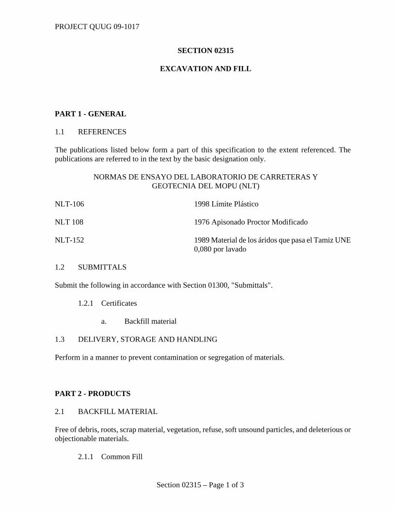
SECTION 02315 EXCAVATION AND FILL PART 1 - GENERAL 1.1 REFERENCES The publications listed below form a part of this specification to the extent referenced. The publications are referred to in the text by the basic designation only. NORMAS DE ENSAYO DEL LABORATORIO DE CARRETERAS Y GEOTECNIA DEL MOPU (NLT) NLT-106 1998 Límite Plástico NLT 108 1976 Apisonado Proctor Modificado NLT-152 1989 Material de los áridos que pasa el Tamiz UNE
0,080 por lavado 1.2 SUBMITTALS Submit the following in accordance with Section 01300, "Submittals". 1.2.1 Certificates
a. Backfill material 1.3 DELIVERY, STORAGE AND HANDLING Perform in a manner to prevent contamination or segregation of materials. PART 2 - PRODUCTS 2.1 BACKFILL MATERIAL Free of debris, roots, scrap material, vegetation, refuse, soft unsound particles, and deleterious or objectionable materials.
2.1.1 Common Fill
PROJECT QUUG 09-1017
Section 02315 – Page 2 of 3
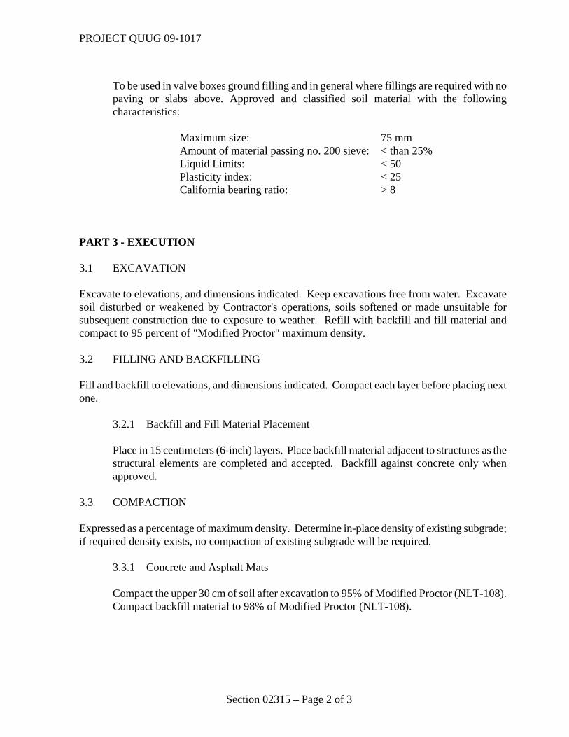
To be used in valve boxes ground filling and in general where fillings are required with no paving or slabs above. Approved and classified soil material with the following characteristics:
Maximum size: 75 mm Amount of material passing no. 200 sieve: < than 25% Liquid Limits: < 50 Plasticity index: < 25 California bearing ratio: > 8 PART 3 - EXECUTION 3.1 EXCAVATION Excavate to elevations, and dimensions indicated. Keep excavations free from water. Excavate soil disturbed or weakened by Contractor's operations, soils softened or made unsuitable for subsequent construction due to exposure to weather. Refill with backfill and fill material and compact to 95 percent of "Modified Proctor" maximum density. 3.2 FILLING AND BACKFILLING Fill and backfill to elevations, and dimensions indicated. Compact each layer before placing next one. 3.2.1 Backfill and Fill Material Placement
Place in 15 centimeters (6-inch) layers. Place backfill material adjacent to structures as the structural elements are completed and accepted. Backfill against concrete only when approved.
3.3 COMPACTION Expressed as a percentage of maximum density. Determine in-place density of existing subgrade; if required density exists, no compaction of existing subgrade will be required. 3.3.1 Concrete and Asphalt Mats
Compact the upper 30 cm of soil after excavation to 95% of Modified Proctor (NLT-108). Compact backfill material to 98% of Modified Proctor (NLT-108).
PROJECT QUUG 09-1017
Section 02315 – Page 3 of 3
3.4 FINISH OPERATIONS 3.4.1 Protection of Surfaces: Protect newly graded areas from traffic, erosion, and
settlements that may occur. Repair or reestablish damaged grades, elevations, or slopes. 3.5 DISPOSITION OF SURPLUS MATERIAL Remove from the Base surplus or other soil material not suitable for filling or backfilling and brush, refuse, and roots. 3.6 FIELD QUALITY CONTROL The areas to be filled and backfilled are small ad would not justify in general standard tests. In all cases, filling and compaction will be executed around manholes. The Contractor will provide good sound construction work: it will be left to the discretion of the Contracting Officer to request the Contractor to re-excavate, fill and compact again with new filling material if the job performed does not appear properly executed to him or his representative person. *** END OF SECTION ***
PROJECT QUUG 09 – 1017
Section 03300 - Page 1 of 6
SECTION 03300
CAST IN PLACE CONCRETE PART 1 GENERAL 1.1 REFERENCES The publications listed below form a part of this specification to the extent referenced. The publications are referred to in the text by the basic designation only.
MINISTERIO DE FOMENTO RC – 08 (2008) RD 956/2008 Instrucción para la
Recepción de Cementos EHE 08 (2008) Instrucción de Hormigón Estructural
AENOR – NORMAS UNE UNE-41107 (1961) Productos Prefabricados, Elásticos y de
Baja Dilatación Transversal para el Relleno de Juntas de Expansión en Pavimentos de Hormigón
UNE-EN 12350-1 (2006) Ensayos de Hormigón. Toma de Muestras
de Hormigón Fresco UNE-EN 12504-1 (2001) Ensayos de hormigón en estructuras. Parte
I: testigos. Extracción, examen y ensayo a compresión.
UNE-EN 12390-3 (2003) Ensayos de hormigón endurecido. Parte 3:
Determinación de la resistencia a compresión de probetas.
UNE-EN 12350-2 (2006) Ensayos de Hormigón. Parte 2: Ensayo de
asentamiento UNE-104233/1M (2002) Impermeabilización. Materiales
Bituminosos y Bituminosos Modificados. Materiales Bituminosos de Sellado para Juntas de Hormigón
PROJECT QUUG 09 – 1017
Section 03300 - Page 2 of 6
UNE EN 1340 (2004; ERR 2007) Bordillos prefabricados de hormigón. Especificación y métodos de ensayo
UNE 36811 (1998 IN) Barras corrugadas de acero para
armaduras de hormigón armado. Códigos de identificación del fabricante
UNE 36092 (1996; ERR 1997) mallas electrosoldadas para
armaduras de hormigón armado. 1.2 DEFINITIONS
a. "Cementitious material" as used herein shall include all portland cement, pozzolan, fly ash, ground iron blast-furnace slag.
b. "Exposed to public view" means situated so that it can be seen from eye level from a public location after completion of the building. A public location is accessible to persons not responsible for operation or maintenance of the building.
1.3 SUBMITTALS Submit the following:
1.3.1 Product Data Curing materials Reinforcing steel Admixtures Submit a complete list of materials including type, brand and applicable reference specifications. 1.3.2 Test Reports
Compressive strength tests 1.4 MODIFICATION OF REFERENCES Accomplish work in accordance with EHE 08 except as modified herein. Interpret reference to the "Director de Obra," to mean the Contracting Officer.
PROJECT QUUG 09 – 1017
Section 03300 - Page 3 of 6
1.5 DELIVERY STORAGE AND HANDLING Do not deliver concrete until forms, reinforcement, embedded items, and chamfer strips are in place and ready for concrete placement. EHE 08 is applicable for job site storage of materials. Protect materials from contaminants such as grease, oil, and dirt. Ensure materials can be accurately identified after bundles are broken and tags removed. 1.5.1 Reinforcement
Store reinforcement of different sizes and shapes in separate piles or racks raised above the ground. Protect from contaminants such as grease, oil, and dirt. Ensure bar sizes can be accurately identified after bundles are broken and tags removed.
1.6 QUALITY ASSURANCE 1.6.1 Test Reports 1.6.1.1 Concrete Mix Design
Submit copies of laboratory test reports showing that the mixes have been successfully tested to produce concrete with the properties specified and that mixes will be suitable for the job conditions. Test reports shall be submitted along with the concrete mix design. Obtain approval before concrete placement.
PART 2 PRODUCTS 2.1 MATERIALS FOR FORMS Provide wood, plywood, or steel. Use plywood or steel forms where a smooth form finish is required. Lumber shall be square edged or tongue-and-groove boards, free of raised grain, knotholes, or other surface defects. Steel form surfaces shall not contain irregularities, dents, or sags. 2.2 FORM TIES AND ACCESSORIES Form ties and accessories shall not reduce the effective cover of the reinforcement.
PROJECT QUUG 09 – 1017
Section 03300 - Page 4 of 6
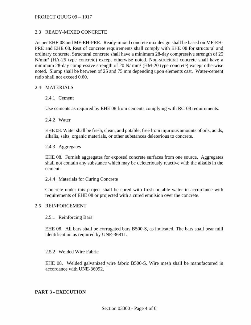
2.3 READY-MIXED CONCRETE As per EHE 08 and MF-EH-PRE. Ready-mixed concrete mix design shall be based on MF-EH-PRE and EHE 08. Rest of concrete requirements shall comply with EHE 08 for structural and ordinary concrete. Structural concrete shall have a minimum 28-day compressive strength of 25 N/mm² (HA-25 type concrete) except otherwise noted. Non-structural concrete shall have a minimum 28-day compressive strength of 20 N/ mm² (HM-20 type concrete) except otherwise noted. Slump shall be between of 25 and 75 mm depending upon elements cast. Water-cement ratio shall not exceed 0.60. 2.4 MATERIALS 2.4.1 Cement Use cements as required by EHE 08 from cements complying with RC-08 requirements. 2.4.2 Water
EHE 08. Water shall be fresh, clean, and potable; free from injurious amounts of oils, acids, alkalis, salts, organic materials, or other substances deleterious to concrete.
2.4.3 Aggregates
EHE 08. Furnish aggregates for exposed concrete surfaces from one source. Aggregates shall not contain any substance which may be deleteriously reactive with the alkalis in the cement.
2.4.4 Materials for Curing Concrete
Concrete under this project shall be cured with fresh potable water in accordance with requirements of EHE 08 or projected with a cured emulsion over the concrete.
2.5 REINFORCEMENT 2.5.1 Reinforcing Bars
EHE 08. All bars shall be corrugated bars B500-S, as indicated. The bars shall bear mill identification as required by UNE-36811.
2.5.2 Welded Wire Fabric EHE 08. Welded galvanized wire fabric B500-S. Wire mesh shall be manufactured in accordance with UNE-36092.
PART 3 - EXECUTION
PROJECT QUUG 09 – 1017
Section 03300 - Page 5 of 6
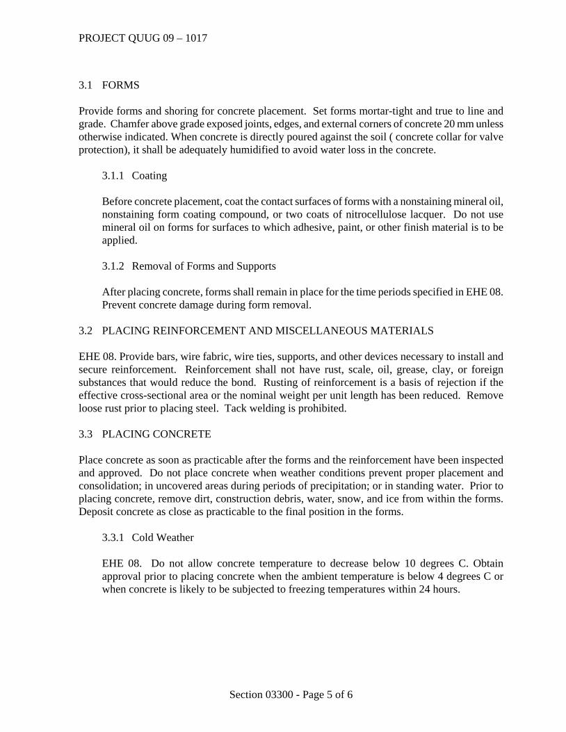
3.1 FORMS Provide forms and shoring for concrete placement. Set forms mortar-tight and true to line and grade. Chamfer above grade exposed joints, edges, and external corners of concrete 20 mm unless otherwise indicated. When concrete is directly poured against the soil ( concrete collar for valve protection), it shall be adequately humidified to avoid water loss in the concrete. 3.1.1 Coating
Before concrete placement, coat the contact surfaces of forms with a nonstaining mineral oil, nonstaining form coating compound, or two coats of nitrocellulose lacquer. Do not use mineral oil on forms for surfaces to which adhesive, paint, or other finish material is to be applied.
3.1.2 Removal of Forms and Supports
After placing concrete, forms shall remain in place for the time periods specified in EHE 08. Prevent concrete damage during form removal.
3.2 PLACING REINFORCEMENT AND MISCELLANEOUS MATERIALS EHE 08. Provide bars, wire fabric, wire ties, supports, and other devices necessary to install and secure reinforcement. Reinforcement shall not have rust, scale, oil, grease, clay, or foreign substances that would reduce the bond. Rusting of reinforcement is a basis of rejection if the effective cross-sectional area or the nominal weight per unit length has been reduced. Remove loose rust prior to placing steel. Tack welding is prohibited. 3.3 PLACING CONCRETE Place concrete as soon as practicable after the forms and the reinforcement have been inspected and approved. Do not place concrete when weather conditions prevent proper placement and consolidation; in uncovered areas during periods of precipitation; or in standing water. Prior to placing concrete, remove dirt, construction debris, water, snow, and ice from within the forms. Deposit concrete as close as practicable to the final position in the forms. 3.3.1 Cold Weather
EHE 08. Do not allow concrete temperature to decrease below 10 degrees C. Obtain approval prior to placing concrete when the ambient temperature is below 4 degrees C or when concrete is likely to be subjected to freezing temperatures within 24 hours.
PROJECT QUUG 09 – 1017
Section 03300 - Page 6 of 6
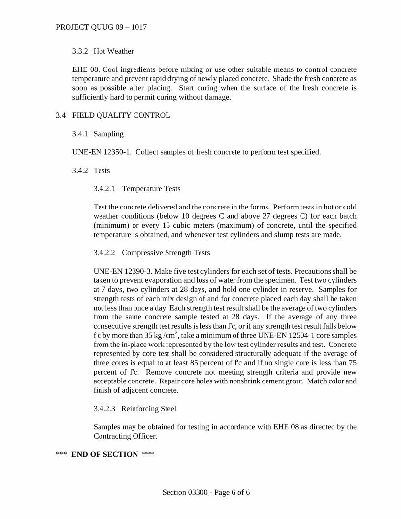
3.3.2 Hot Weather
EHE 08. Cool ingredients before mixing or use other suitable means to control concrete temperature and prevent rapid drying of newly placed concrete. Shade the fresh concrete as soon as possible after placing. Start curing when the surface of the fresh concrete is sufficiently hard to permit curing without damage.
3.4 FIELD QUALITY CONTROL 3.4.1 Sampling UNE-EN 12350-1. Collect samples of fresh concrete to perform test specified. 3.4.2 Tests 3.4.2.1 Temperature Tests
Test the concrete delivered and the concrete in the forms. Perform tests in hot or cold weather conditions (below 10 degrees C and above 27 degrees C) for each batch (minimum) or every 15 cubic meters (maximum) of concrete, until the specified temperature is obtained, and whenever test cylinders and slump tests are made.
3.4.2.2 Compressive Strength Tests
UNE-EN 12390-3. Make five test cylinders for each set of tests. Precautions shall be taken to prevent evaporation and loss of water from the specimen. Test two cylinders at 7 days, two cylinders at 28 days, and hold one cylinder in reserve. Samples for strength tests of each mix design of and for concrete placed each day shall be taken not less than once a day. Each strength test result shall be the average of two cylinders from the same concrete sample tested at 28 days. If the average of any three consecutive strength test results is less than f'c, or if any strength test result falls below f'c by more than 35 kg /cm2, take a minimum of three UNE-EN 12504-1 core samples from the in-place work represented by the low test cylinder results and test. Concrete represented by core test shall be considered structurally adequate if the average of three cores is equal to at least 85 percent of f'c and if no single core is less than 75 percent of f'c. Remove concrete not meeting strength criteria and provide new acceptable concrete. Repair core holes with nonshrink cement grout. Match color and finish of adjacent concrete.
3.4.2.3 Reinforcing Steel Samples may be obtained for testing in accordance with EHE 08 as directed by the Contracting Officer.
*** END OF SECTION ***
PROJECT 09-1017
Section 05500 - Page 1 of 8
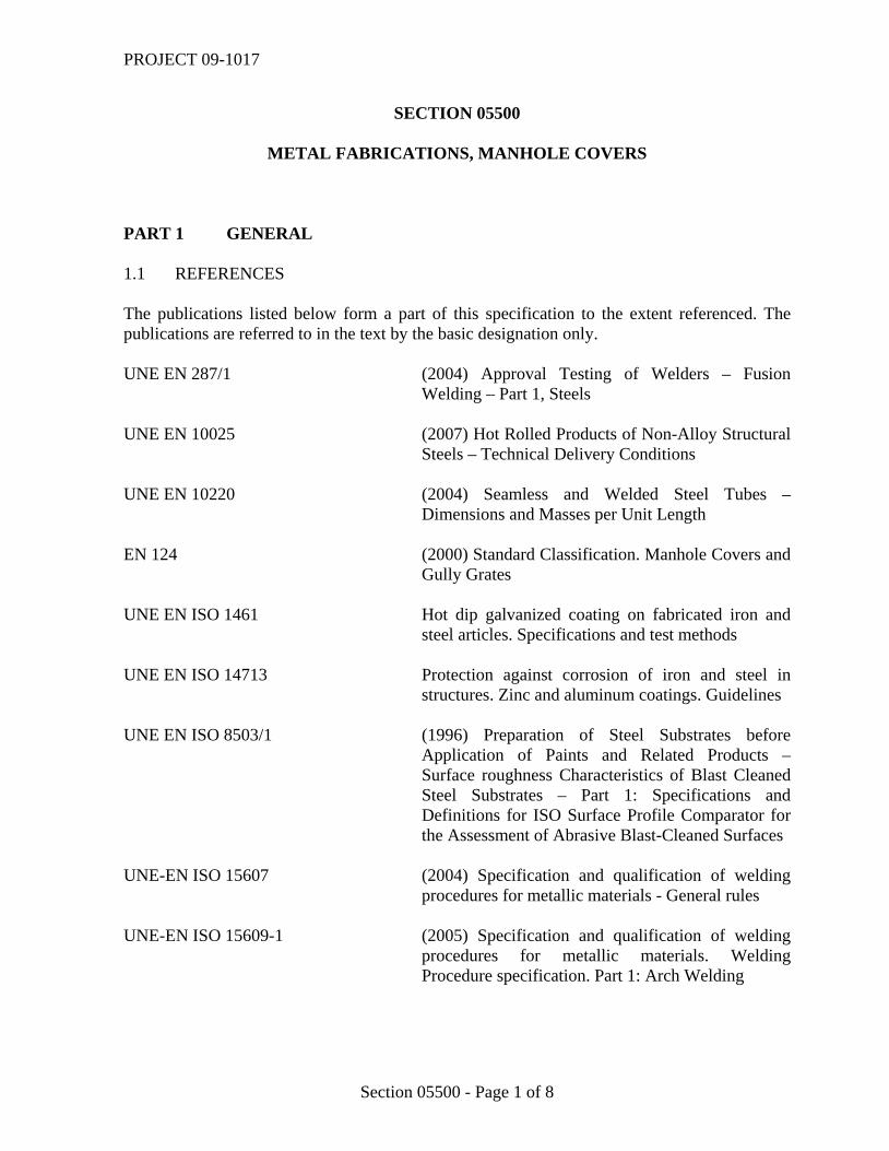
SECTION 05500
METAL FABRICATIONS, MANHOLE COVERS PART 1 GENERAL 1.1 REFERENCES The publications listed below form a part of this specification to the extent referenced. The publications are referred to in the text by the basic designation only. UNE EN 287/1 (2004) Approval Testing of Welders – Fusion
Welding – Part 1, Steels UNE EN 10025 (2007) Hot Rolled Products of Non-Alloy Structural
Steels – Technical Delivery Conditions UNE EN 10220 (2004) Seamless and Welded Steel Tubes –
Dimensions and Masses per Unit Length EN 124 (2000) Standard Classification. Manhole Covers and
Gully Grates UNE EN ISO 1461 Hot dip galvanized coating on fabricated iron and
steel articles. Specifications and test methods UNE EN ISO 14713 Protection against corrosion of iron and steel in
structures. Zinc and aluminum coatings. Guidelines UNE EN ISO 8503/1 (1996) Preparation of Steel Substrates before
Application of Paints and Related Products – Surface roughness Characteristics of Blast Cleaned Steel Substrates – Part 1: Specifications and Definitions for ISO Surface Profile Comparator for the Assessment of Abrasive Blast-Cleaned Surfaces
UNE-EN ISO 15607 (2004) Specification and qualification of welding
procedures for metallic materials - General rules UNE-EN ISO 15609-1 (2005) Specification and qualification of welding
procedures for metallic materials. Welding Procedure specification. Part 1: Arch Welding
PROJECT 09-1017
Section 05500 - Page 2 of 8
UNE-EN ISO 15614-1 (2005) Specification and qualification of welding procedures for metallic materials. Welding procedure test. Part 1: Arch and gas welding of steels and arc welding of nickel and nickel alloys
UNE EN 288/4 (1993) Specification and Qualification of welding
procedures for metallic materials – Part 4: welding procedure tests for the arc welding of aluminium and its alloys
UNE-EN ISO 15610 (2004) Specification and qualification of welding
procedures for metallic materials – qualification based on tested welding consumables.
UNE-EN ISO 15611 (2004) Specification and qualification of welding
procedures for metallic materials – qualification based on previous welding experience
UNE-EN ISO 15612 (2005) Specification and qualification of welding
procedures for metallic materials – qualification by adoption of a standard welding procedure
DIN 2440 Medium-weight threaded steel tubes 1.2 SUBMITTALS Submit the following: a. Shop Drawings Display board – Confined space warning Valve box installation drawing Galvanized steel covers and frames b. Product Data Structural Carbon Steel profiles Structural Tubing Round sewer manhole frames and covers for sewer manholes Square and rectangular frames and covers for electrical, water and sewer services Valve box frame and cover cast iron assembly Finish mortar compound Manhole seals Anchoring grouts, concrete repair compounds Hinges Multi-adherent primer paint Polyurethane finish paint Locks / latches for galvanized steel covers
PROJECT 09-1017
Section 05500 - Page 3 of 8
c. Samples Valve box cover PVC plastic pressure pipe Manhole / handhole cover of each type Locks / latches for galvanized steel covers Samples may be installed in the work, provided each sample is clearly identified and its location recorded. 1.3 QUALIFICATION OF WELDERS Qualify welders in accordance with UNE EN 287/1. Use procedures, materials, and equipment of the type required for the work. 1.4 DELIVERY, STORAGE, AND PROTECTION Protect from corrosion, deformation, and other types of damage. Store items in an enclosed area free from contact with soil and weather. Remove and replace damaged items with new items. PART 2 PRODUCTS 2.1 MATERIALS
2.1.1 Display Boards – Confined Spaces Manufactured 1 mm sheet metal steel with welded frame as shown in drawings. Hot dip galvanized primer and two coats of finish white paint. Size as shown. Warning sign, stating: “DANGER – PERMIT REQUIRED - CONFINED SPACE, DO NOT ENTER” “PELIGRO – SE REQUIERE PERMISO DE ACCESO – ESPACIO CONFINADO, NO ENTRAR” Words shall be painted in black color. 2.1.2 Structural Carbon Steel Profiles UNE EN 10025. 2.1.3 Structural Tubing
UNE EN 10220 Group 1
PROJECT 09-1017
Section 05500 - Page 4 of 8
2.1.4 Round Sewer Manhole Frames and Covers
EN 124 – Class D400 Intense Traffic – ductile cast iron. All manhole covers shall be the same type regardless of location. Round frame. Minimum is 88 kg of combines weight (both frame and cover), and minimum weight for the cover is 55 kg. Opening size 610 mm; manhole cover opening at 130º with closure blocking at 90º. It will be provided with locking device. Elastomeric seal. Frames and covers shall be ductile cast iron. Cast iron frames and covers shall be as indicated and shall be of type suitable for the application, circular, without vent holes. The words “sanitario” and “sewer” shall be cast into covers so that it is plainly visible. 2.1.5 Square and rectangular frames and Covers. Manholes and Handholes for Electrical, Water and Sewer Services EN 124 Class C250. Will be provided with locking device kit. Minimum weights for reference:
FRAME OPENING HEIGHT WEIGHT (Kg) 450x450 300x300 56 25 500x500 360x360 87 29,70 550x550 400x400 56 33 620x620 500x500 50 38 650x650 500x500 56 45 750x750 600x600 56 61
For the specific application of Electrical handholes serving electrical lighting poles (not any other application) covers Class B125 with locking device kits (acerrojamiento) can be used. The words “Electrical”, “Sanitario” & “Sewer” (both) and “Agua” & “Water” (both) shall be cast into covers so that it is plainly visible. Should the cover need to be installed on a road or paved area with traffic, frame and covers shall be Class D400. 2.1.6 Valve Box Frame and Cast Iron Assemblies “Registro para Acometida Hidraúlico y Realzable” Class 250 equipped to insert in PVC pipes including standard tight rubber seal. PVC PIPE DIAMETER
TOTAL WEIGHT (KG)
COVER WEIGHT (KG)
CLEAR OPENING (MM)
DN 250 16 KG 4 KG 181 MM DN 300 26 KG 6 KG 225 MM DN 400 30.6 KG 10 KG 305 MM Material: ductile cast iron EN 124.
PROJECT 09-1017
Section 05500 - Page 5 of 8
Valve box register shall be as manufactured by Saint-Gobain PAM España SA or equal approved. Existing valve box assembly shall fit inside the body of this register. The words “Agua” & “Water” (both) shall be cast into covers so that it is plainly visible. The piece of PVC pipe to fix to the support will be PN 10 (for 10 kg/cm2 pressure). 2.1.7 Finish Mortar Compound Repair mortar, monocomponent, based in cementitius material, synthetic resins and reinforcing fibres. To be used for all manhole mortar finish repairs and border regeneration on concrete and brick manhole walls. Authorised material, following manufacturer recommendations SIKA Monotop 612, 618 or 620. Similar products with manufacturer technical data and recommendation of the manufacturer for the specific application in this project can be submitted for approval. 2.1.8 Manhole Seals New seals to substitute existing ones, shall be of the same manufacturer as existing round manhole covers. If they are not available, the Contractor shall install adequate seals to fit existing frame seal grooves. The seals shall be made of composite material (PE/PP) or elastomeric. In any case, they shall be made of the most durable material available at the cover manufacturer, when exposed to weather and specific local working conditions. A statement of best durability available for the seal model shall have to be certified in the submittal by the manhole cover manufacturer. 2.1.9 Anchoring Grouts, Concrete Repair Compounds Use monocomponent mortar grout, compensated shrink, cementitius base composition. Adequate to anchor metallic elements to concrete and brick structures. It will have to be used in this project for the anchorage of manhole frames to their supporting structure as recommended by the manhole cover manufacturer and grout manufacturer. The Contractor shall use the most adequate product as recommended by the grout manufacturer for the specific application. Authorised products can be (following manufacturers recommendations) Sika Grout, Sika Grout 218, Sika Grout 295 or Sika Grout Construction. Similar products from other manufacturers can also be submitted for approval with technical characteristics and manufacturers certification of suitability for the application.
PROJECT 09-1017
Section 05500 - Page 6 of 8
2.2 FABRICATION FINISHES
2.2.1 Galvanizing Hot-dip galvanized items specified to be zinc-coated/galvanized, after fabrication. Galvanizing: UNE EN ISO 1461 and UNE EN ISO 14713. Coating thickness of 50 microns. Design ambient C3. 2.2.2 Galvanize Galvanize all new manhole steel covers and frames, anchor bolts, grating fasteners, washers, and parts or devices necessary for proper installation, unless indicated otherwise. The Contractor shall take into account potential deformations that might be produced during the galvanizing process and will ensure that elements to be galvanized are rigid enough to prevent deformations. If it happens after the first galvanizing samples, the design will be modified, including material thickness if needed, to prevent deformations. 2.2.3 Repair of Zinc-Coated Surfaces Repair damaged surfaces with galvanizing repair method and paint as approved by Contracting Officer. Clean areas to be repaired and remove slag from welds. 2.2.4 Shop Cleaning and Painting
2.2.4.1 Surface Preparation Blast clean surfaces in accordance with UNE EN ISO 8503/1. Wash cleaned surfaces which become contaminated with rust, dirt, oil, grease, or other contaminants with solvents until thoroughly clean. Steel to be embedded in concrete shall be free of dirt and grease. In all cases, the steel shall have to be primed and painted previously. 2.2.4.2 Pre-treatment, Priming and Painting Apply pre-treatment, primer, and paint in accordance with manufacturer's printed instructions. Prime with thick multi-adherent primer coat, adequate for application on galvanized steel. Priming thickness shall be 30 microns minimum of dry film; if not achieved apply two coats. Tint additional prime coat with a small amount of tinting pigment. Apply two coats of finish polyurethane paint adequate for exterior ambient. Total prime and finish coat dry film thickness shall be no less than 80 microns.
2.5 GUARD POSTS (BOLLARDS) Provide 150 mm galvanized DIN 2440 steel pipe. Anchor posts in concrete as indicated and fill solidly with concrete with minimum compressive strength of HM 20.
PROJECT 09-1017
Section 05500 - Page 7 of 8
PART 3 EXECUTION 3.1 INSTALLATION Install items at locations indicated, according to manufacturer's instructions. Items listed below require specific procedures. 3.2 ANCHORAGE, FASTENINGS, AND CONNECTIONS Provide anchorage where necessary for fastening miscellaneous metal items securely in place. Anchorage grout shall be used following manufacturer recommendations to fix all manhole anchors in place. Concrete and brick wall anchoring areas shall, in all cases, be saturated with water before grout application. The anchor shall also be free of dirt, grease or rust and will be blasted and / or painted after cleaning. 3.3 BUILT-IN WORK Form for anchorage metal work built-in with concrete or masonry, or provide with suitable anchoring devices as indicated or as required. Furnish metal work in ample time for securing in place as the work progresses. 3.4 WELDING Perform welding, welding inspection, and corrective welding, in accordance with UNE-EN ISO 15607, UNE-EN ISO 15609-1, UNE-EN ISO 15614-1, UNE EN 288/4, UNE-EN ISO 15610, UNE-EN ISO 15611 and UNE-EN ISO 15612. Use continuous welds on all exposed connections. Grind visible welds smooth on the finished installation. 3.5 FINISHES
3.5.1 Environmental Conditions Do not clean or paint surface when damp or exposed to foggy or rainy Weather, when metallic surface temperature is below 7 degrees C or over 35 degrees C, unless approved by the Contracting Officer.
PROJECT 09-1017
Section 05500 - Page 8 of 8
3.5.2 Finish Mortar Compound Application Repairs on brickwall bodies and concrete bodies shall be done using concrete repair compound as specified in paragraph 2.1.7 of this specification. All manhole borders and exposed body walls shall be finished using “Finish Mortar Compound” as specified. The application of the products shall be done following the manufacturer recommendations. Special care shall be given to the fact that in most cases, the areas on which mortars have to be applied shall have to be “water saturated”: this is a task frequently ignored. Not doing it properly affects very negatively the final results. The use of ordinary mortar with cement and sand will be limited to those cases where the reconstruction of a brickwall body has to be made. Even in these cases, the finish mortar, border and anchoring will be executed with monocomponent compounds as specified in paragraphs 2.1.7 and 2.1.9 of this specification
*** END OF SECTION ***