Embed Size (px)
Citation preview
SCUBA TANK
SECTION 9
S9 - 1NAS120v, Section 9, August 2009Copyright© 2009 MSC.Software Corporation
SCUBA TANK
● Topics covered in this section● Axisymmetric modeling techniques ● Importing Geometry● Mesh Density Control● Perform quality checks on stress results● Create and manipulate viewports
SCUBA TANK
S9 - 2NAS120v, Section 9, August 2009Copyright© 2009 MSC.Software Corporation
SCUBA TANK
● Problem Description● Scuba tanks are designed to withstand cyclic pressurization and
depressurization loads. They must also survive loads induced during transportation and actual service. You are asked to analyze a new scuba tank design.
● Analysis Objectives
S9 - 3NAS120v, Section 9, August 2009Copyright© 2009 MSC.Software Corporation
● Analysis Objectives● Determine stresses in the scuba tank under an internal pressure of
3000 psi. The maximum stress must be below the yield point of the tank material.
SCUBA TANK
● Getting started on the scuba tank analysis● The scuba tank is a thick shell structure. We expect the state of
stress to be 3 dimensional in the tank shell. Solid elements should be used.
● Solid element models tend to get large and take a lot of CPU time to solve. This is especially true for non-linear or transient analysis. It is often advisable to simplify the model in order to speed up the
S9 - 4NAS120v, Section 9, August 2009Copyright© 2009 MSC.Software Corporation
often advisable to simplify the model in order to speed up the analysis process.
● Several ways to simplify finite element models are presented next.
SCUBA TANK
● Simplifying Finite Element Models● Finite element models can be simplified by using a 2D (planar)
representation of a 3D model. There are three ways to do this:● Plane Stress● Plane Strain● Axisymmetric
Finite element models can also be simplified by taking advantage of
S9 - 5NAS120v, Section 9, August 2009Copyright© 2009 MSC.Software Corporation
● Finite element models can also be simplified by taking advantage of symmetry. There are two primary types of symmetry - reflective symmetry and cyclic symmetry. Symmetry techniques will be presented in detail in the advanced course.
SCUBA TANK
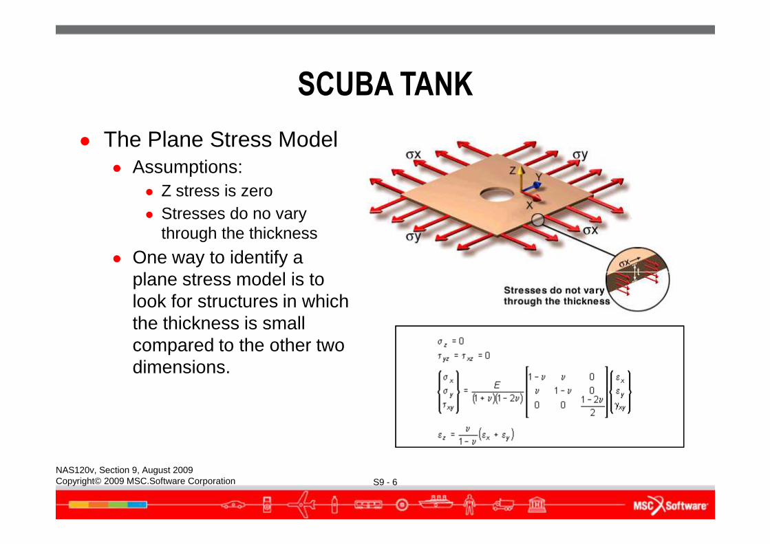
● The Plane Stress Model● Assumptions:
● Z stress is zero● Stresses do no vary
through the thickness
● One way to identify a plane stress model is to
S9 - 6NAS120v, Section 9, August 2009Copyright© 2009 MSC.Software Corporation
plane stress model is to look for structures in which the thickness is small compared to the other two dimensions.
SCUBA TANK
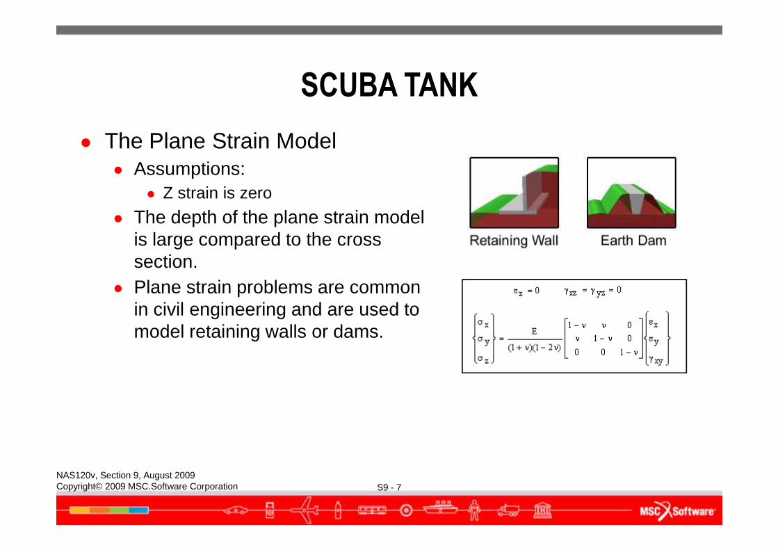
● The Plane Strain Model● Assumptions:
● Z strain is zero
● The depth of the plane strain model is large compared to the cross section.
S9 - 7NAS120v, Section 9, August 2009Copyright© 2009 MSC.Software Corporation
● Plane strain problems are common in civil engineering and are used to model retaining walls or dams.
SCUBA TANK
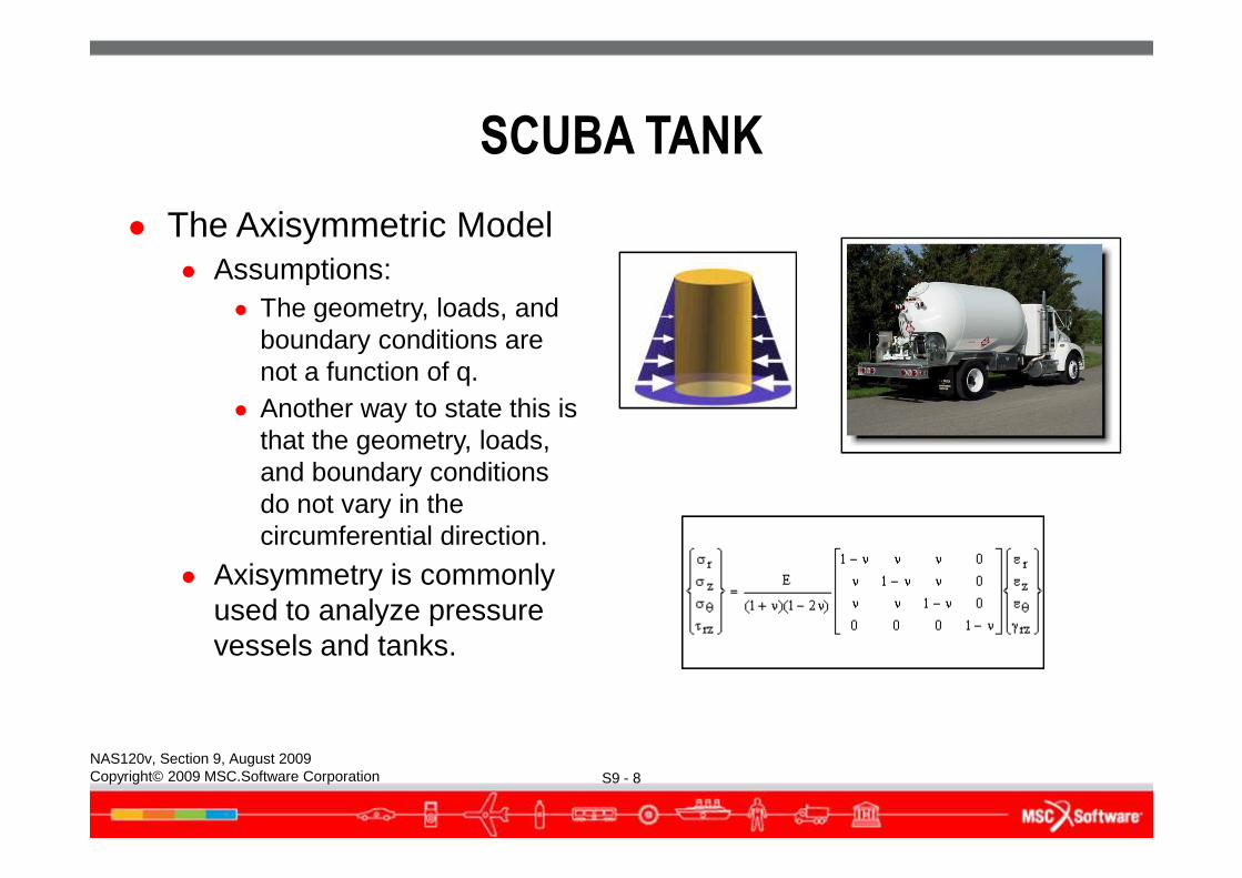
● The Axisymmetric Model● Assumptions:
● The geometry, loads, and boundary conditions are not a function of q.
● Another way to state this is that the geometry, loads,
S9 - 8NAS120v, Section 9, August 2009Copyright© 2009 MSC.Software Corporation
that the geometry, loads, and boundary conditions do not vary in the circumferential direction.
● Axisymmetry is commonly used to analyze pressure vessels and tanks.
SCUBA TANK
● Simplification of the scuba tank model● Since the scuba tank is axisymmetric and the pressure load is
axisymmetric, we can simplify the problem using axisymmetry. We will solve this problem using two different axisymmetric methods:
● Build a sector of the tank using 3D solid elements● Build the tank cross section using 2D solid elements
S9 - 9NAS120v, Section 9, August 2009Copyright© 2009 MSC.Software Corporation
SCUBA TANK
● Creating the geometry for the tank● A geometry file for the scuba tank generated by a CAD package is
available so there is no need to re-create the geometry.● Use File/Import to import the geometry file directly into PATRAN.
S9 - 10NAS120v, Section 9, August 2009Copyright© 2009 MSC.Software Corporation
SCUBA TANK
S9 - 11NAS120v, Section 9, August 2009Copyright© 2009 MSC.Software Corporation
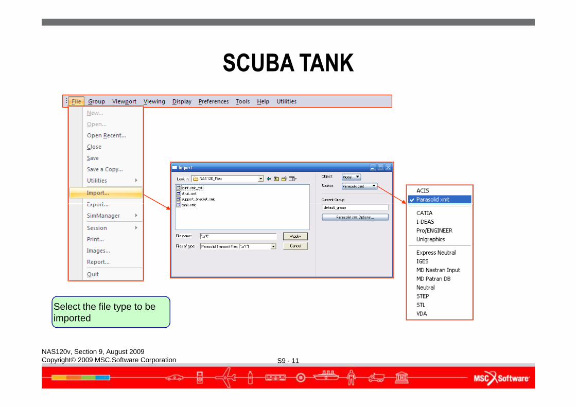
Select the file type to be imported
SCUBA TANK
● Models created by the following CAD packages can be imported into PATRAN:● CATIA● Unigraphics● Pro/ENGINEER● EUCLID 3
S9 - 12NAS120v, Section 9, August 2009Copyright© 2009 MSC.Software Corporation
● EUCLID 3● I-DEAS
SCUBA TANK
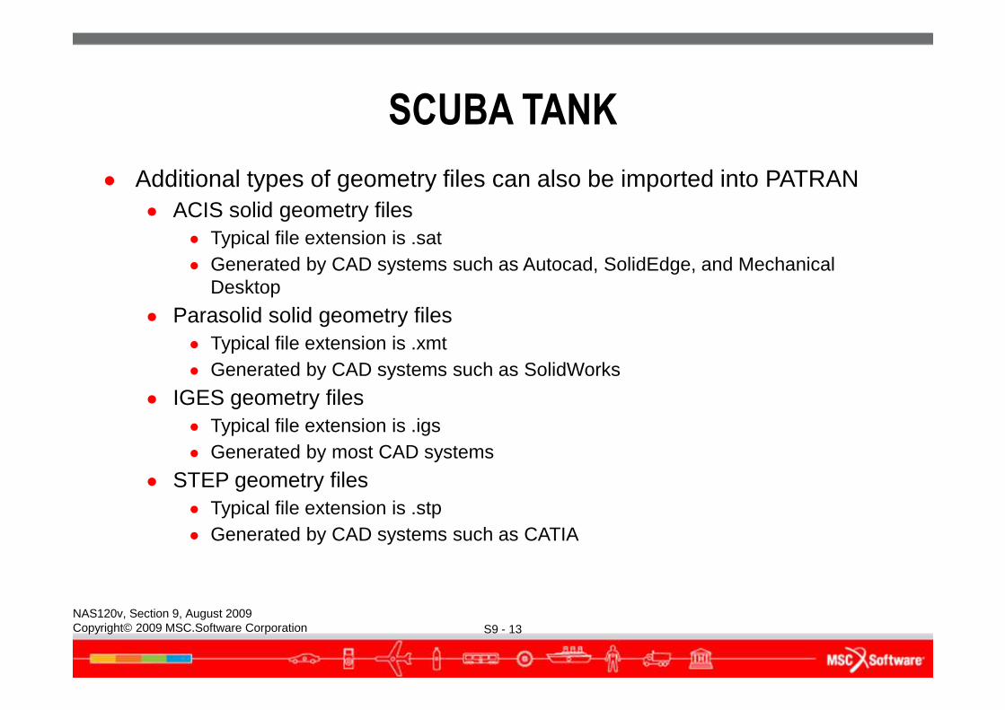
● Additional types of geometry files can also be imported into PATRAN● ACIS solid geometry files
● Typical file extension is .sat● Generated by CAD systems such as Autocad, SolidEdge, and Mechanical
Desktop
● Parasolid solid geometry files● Typical file extension is .xmt
S9 - 13NAS120v, Section 9, August 2009Copyright© 2009 MSC.Software Corporation
● Generated by CAD systems such as SolidWorks
● IGES geometry files● Typical file extension is .igs● Generated by most CAD systems
● STEP geometry files● Typical file extension is .stp● Generated by CAD systems such as CATIA
SCUBA TANK
● The scuba tank geometry file we have is a parasolid solid geometry model. Let’s import this file into PATRAN.
S9 - 14NAS120v, Section 9, August 2009Copyright© 2009 MSC.Software Corporation
SCUBA TANK
S9 - 15NAS120v, Section 9, August 2009Copyright© 2009 MSC.Software Corporation
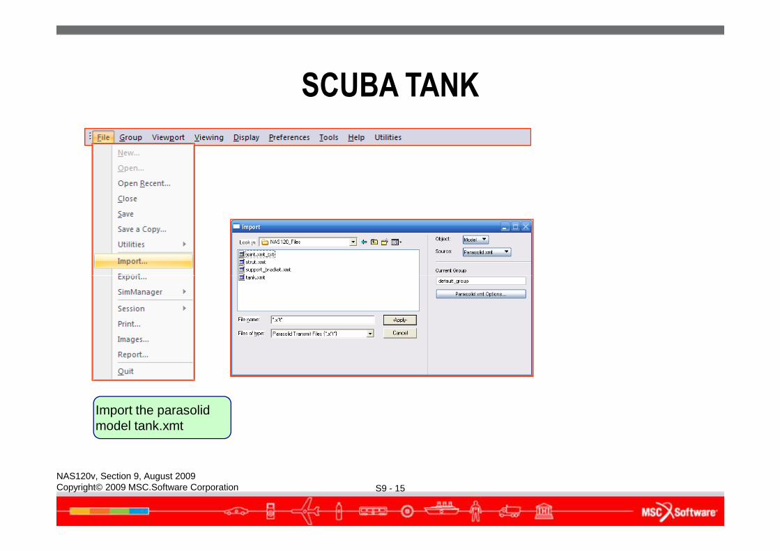
Import the parasolid model tank.xmt
SCUBA TANK
S9 - 16NAS120v, Section 9, August 2009Copyright© 2009 MSC.Software Corporation
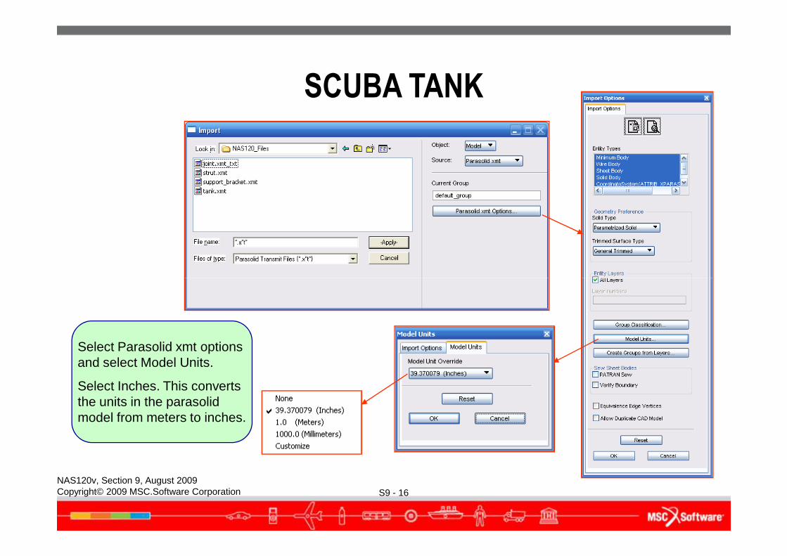
Select Parasolid xmt options and select Model Units.
Select Inches. This converts the units in the parasolid model from meters to inches.
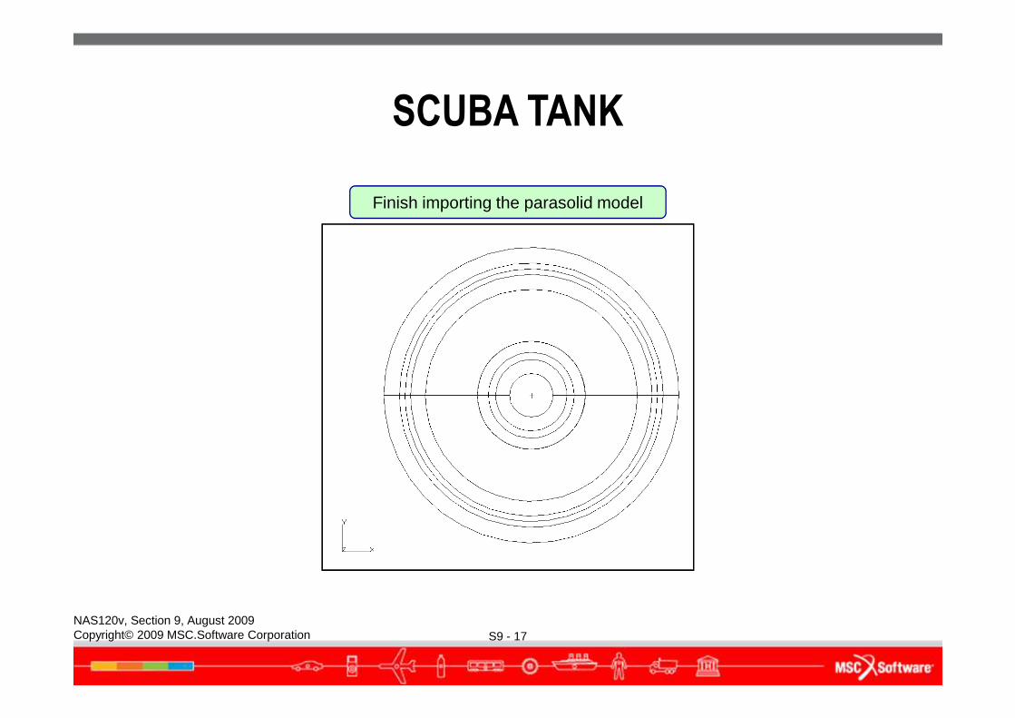
Finish importing the parasolid model
SCUBA TANK
S9 - 17NAS120v, Section 9, August 2009Copyright© 2009 MSC.Software Corporation
SCUBA TANK
S9 - 18NAS120v, Section 9, August 2009Copyright© 2009 MSC.Software Corporation
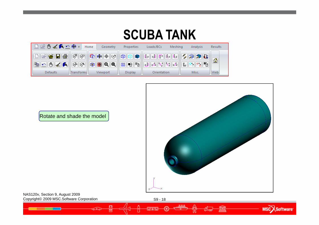
Rotate and shade the model
SCUBA TANK
S9 - 19NAS120v, Section 9, August 2009Copyright© 2009 MSC.Software Corporation
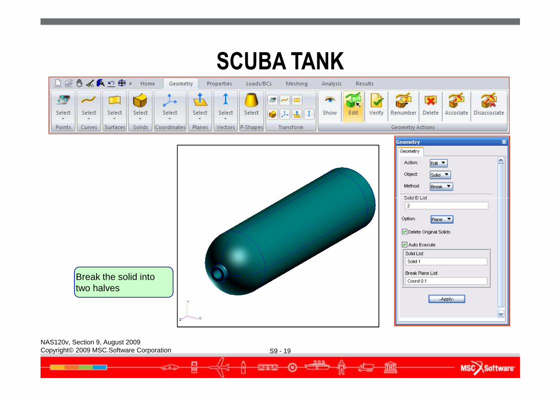
Break the solid into two halves
SCUBA TANK
S9 - 20NAS120v, Section 9, August 2009Copyright© 2009 MSC.Software Corporation
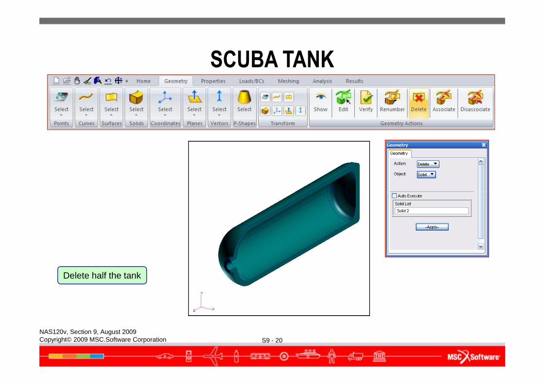
Delete half the tank
SCUBA TANK
S9 - 21NAS120v, Section 9, August 2009Copyright© 2009 MSC.Software Corporation
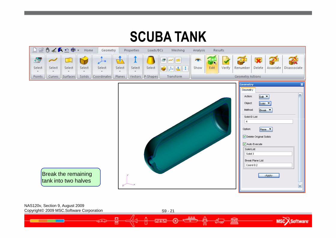
Break the remaining tank into two halves
SCUBA TANK
S9 - 22NAS120v, Section 9, August 2009Copyright© 2009 MSC.Software Corporation
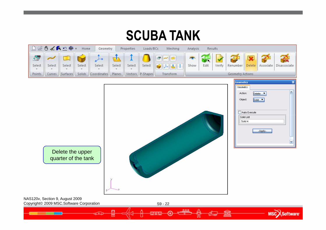
Delete the upper quarter of the tank
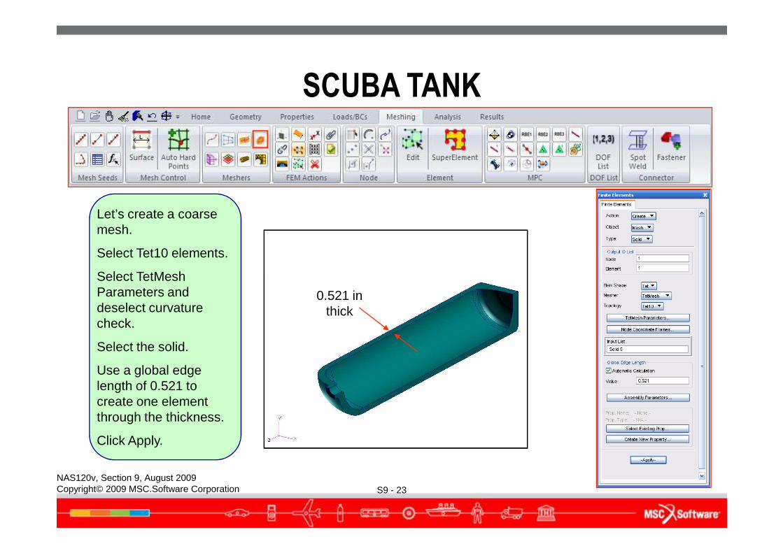
Let’s create a coarse mesh.
Select Tet10 elements.
Select TetMesh
SCUBA TANK
S9 - 23NAS120v, Section 9, August 2009Copyright© 2009 MSC.Software Corporation
Select TetMesh Parameters and deselect curvature check.
Select the solid.
Use a global edge length of 0.521 to create one element through the thickness.
Click Apply.
0.521 in thick
SCUBA TANK
S9 - 24NAS120v, Section 9, August 2009Copyright© 2009 MSC.Software Corporation
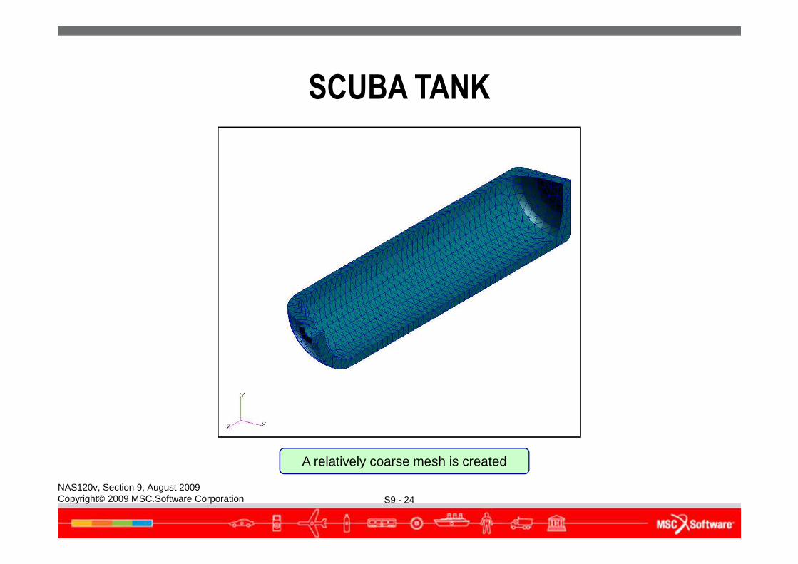
A relatively coarse mesh is created
SCUBA TANK
● Create Boundary Conditions● Since the scuba tank is axisymmetric, we need to create a cylindrical
coordinate system to define the symmetry boundary conditions.
S9 - 25NAS120v, Section 9, August 2009Copyright© 2009 MSC.Software Corporation
SCUBA TANK
S9 - 26NAS120v, Section 9, August 2009Copyright© 2009 MSC.Software Corporation
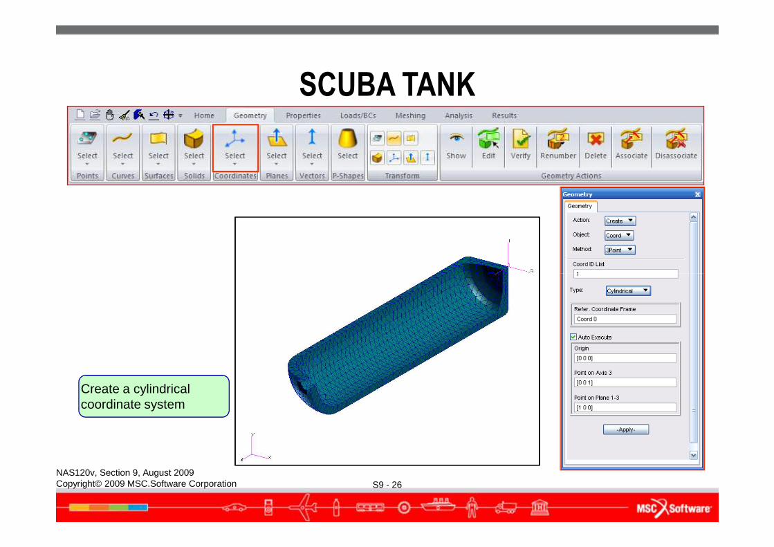
Create a cylindrical coordinate system
SCUBA TANK
S9 - 27NAS120v, Section 9, August 2009Copyright© 2009 MSC.Software Corporation
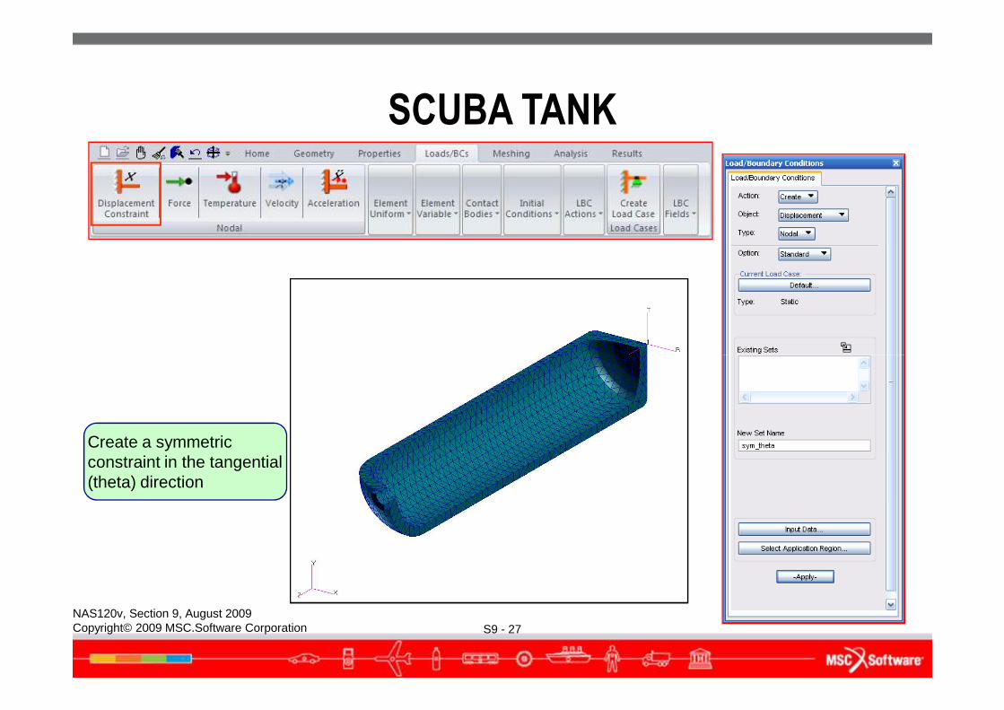
Create a symmetric constraint in the tangential (theta) direction
SCUBA TANK
S9 - 28NAS120v, Section 9, August 2009Copyright© 2009 MSC.Software Corporation
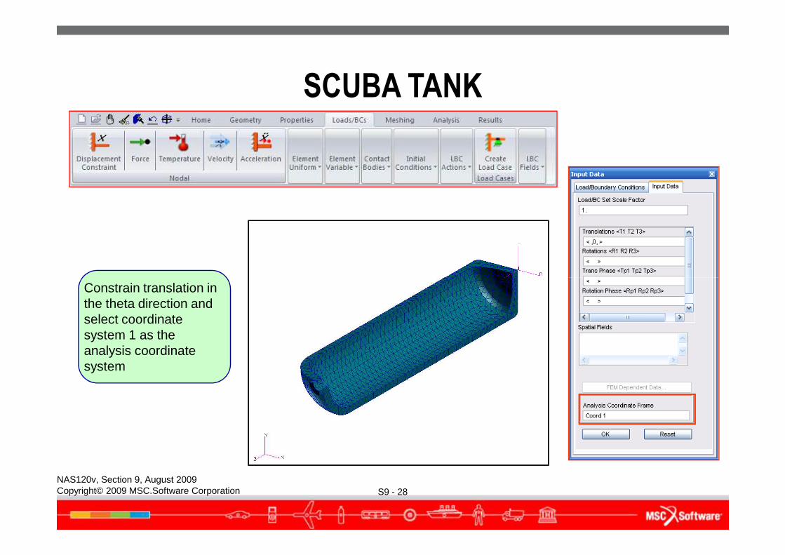
Constrain translation in the theta direction and select coordinate system 1 as the analysis coordinate system
SCUBA TANK
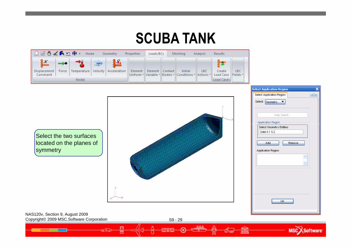
S9 - 29NAS120v, Section 9, August 2009Copyright© 2009 MSC.Software Corporation
Select the two surfaces located on the planes of symmetry
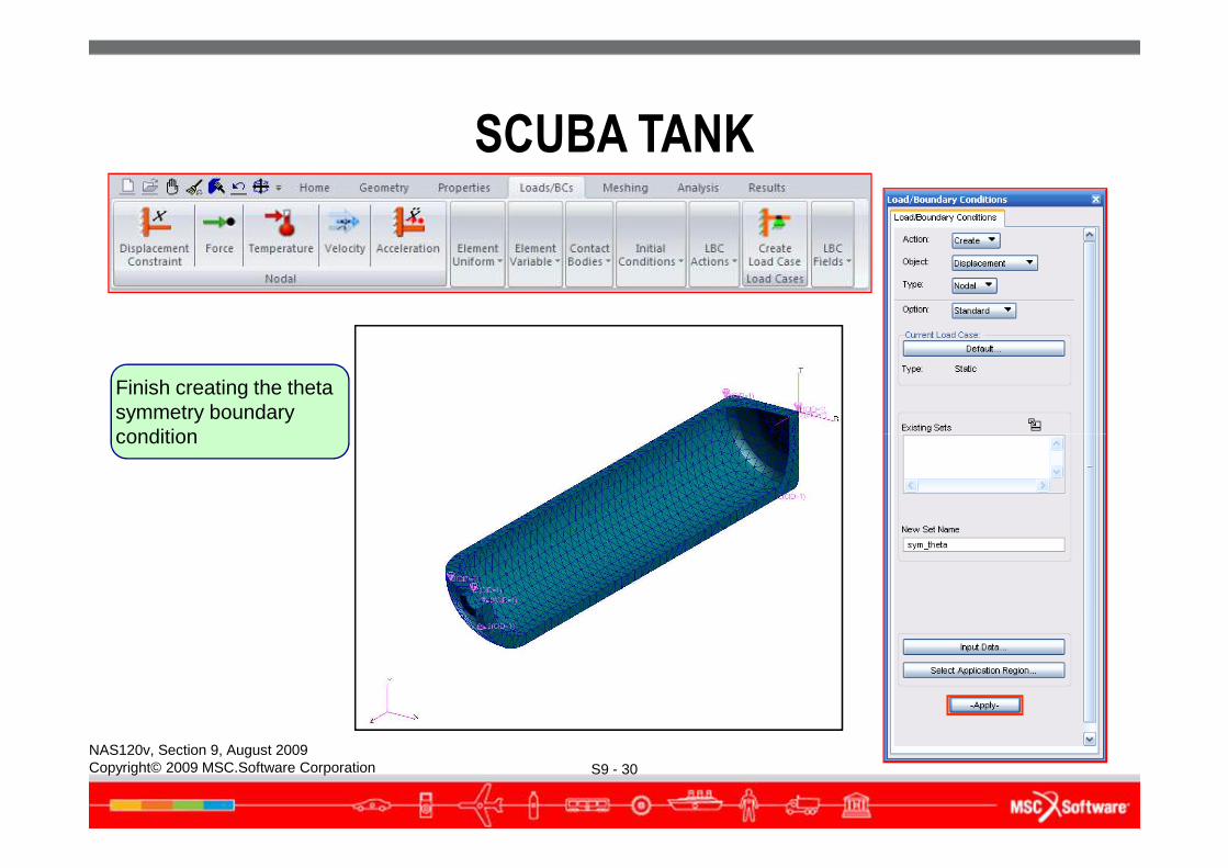
Finish creating the theta symmetry boundary condition
SCUBA TANK
S9 - 30NAS120v, Section 9, August 2009Copyright© 2009 MSC.Software Corporation
condition
SCUBA TANK
S9 - 31NAS120v, Section 9, August 2009Copyright© 2009 MSC.Software Corporation
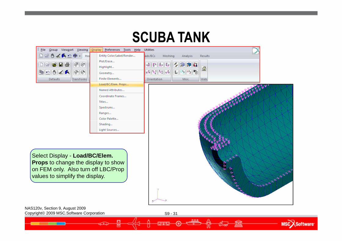
Select Display - Load/BC/Elem. Props to change the display to show on FEM only. Also turn off LBC/Prop values to simplify the display.
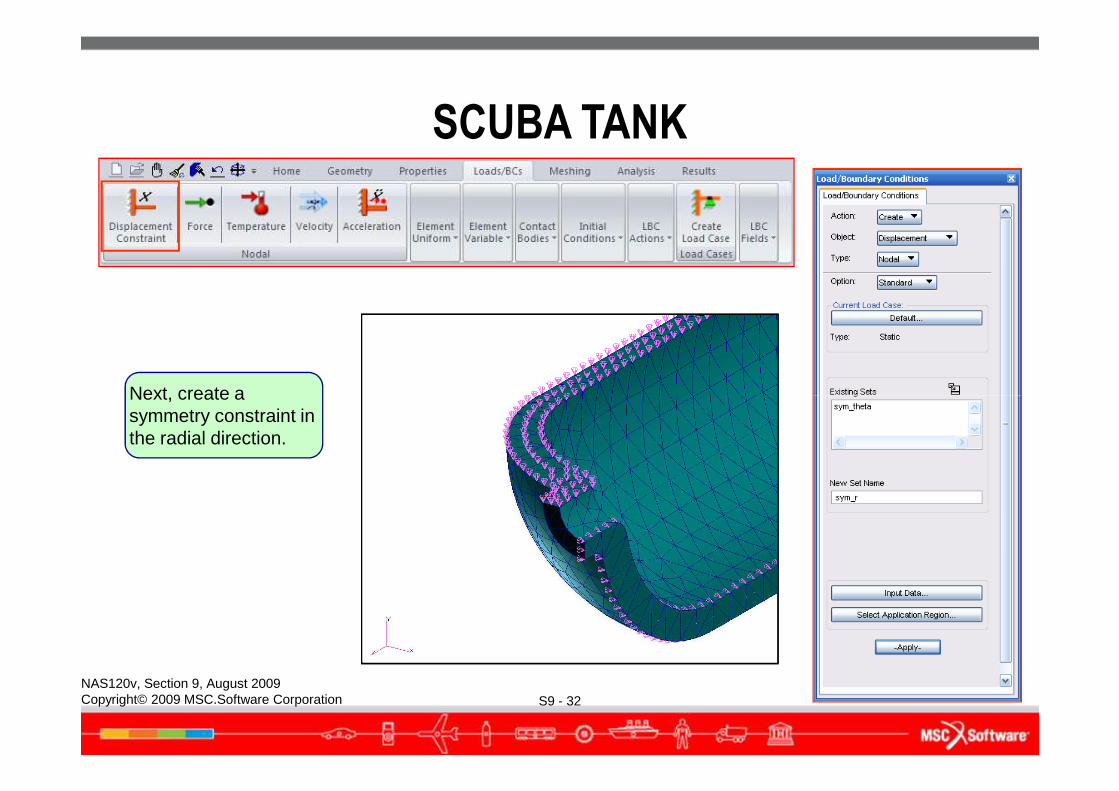
Next, create a
SCUBA TANK
S9 - 32NAS120v, Section 9, August 2009Copyright© 2009 MSC.Software Corporation
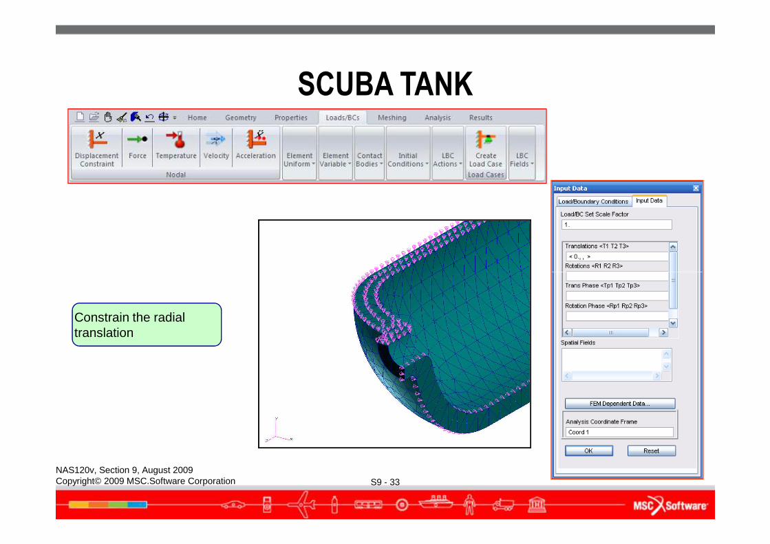
Next, create a symmetry constraint in the radial direction.
SCUBA TANK
S9 - 33NAS120v, Section 9, August 2009Copyright© 2009 MSC.Software Corporation
Constrain the radial translation
SCUBA TANK
S9 - 34NAS120v, Section 9, August 2009Copyright© 2009 MSC.Software Corporation
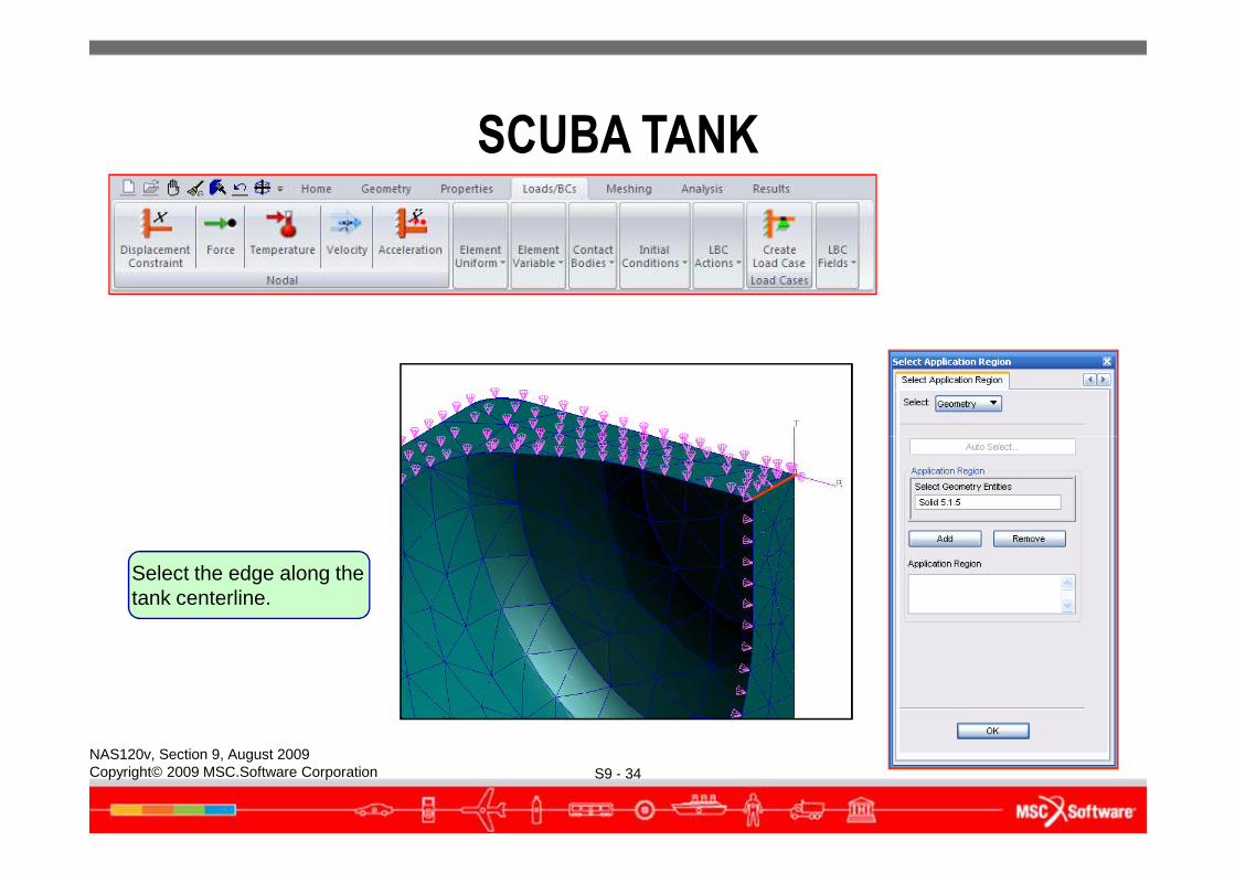
Select the edge along the tank centerline.
SCUBA TANK
S9 - 35NAS120v, Section 9, August 2009Copyright© 2009 MSC.Software Corporation
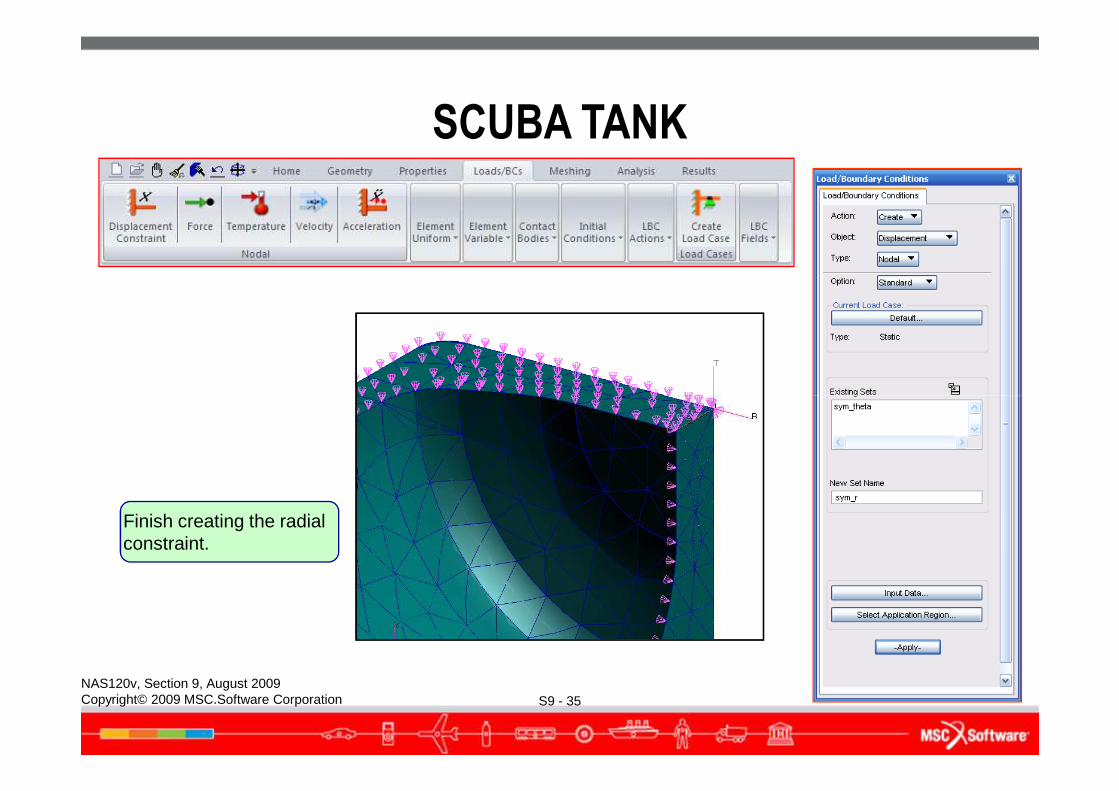
Finish creating the radial constraint.
SCUBA TANK
S9 - 36NAS120v, Section 9, August 2009Copyright© 2009 MSC.Software Corporation
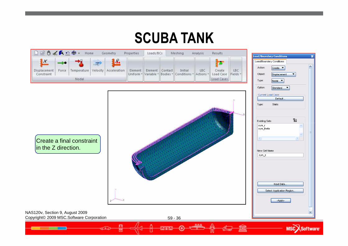
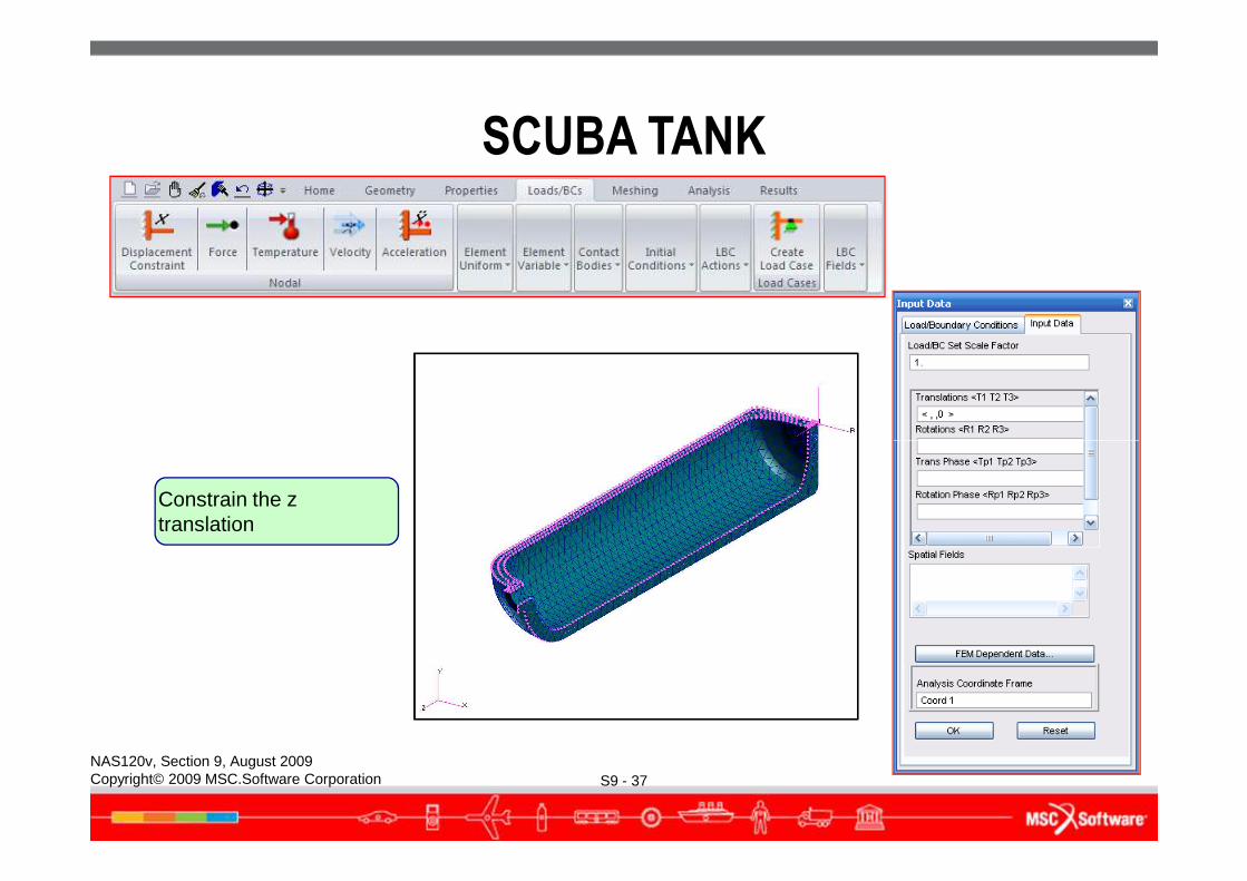
Create a final constraint in the Z direction.
SCUBA TANK
S9 - 37NAS120v, Section 9, August 2009Copyright© 2009 MSC.Software Corporation
Constrain the z translation
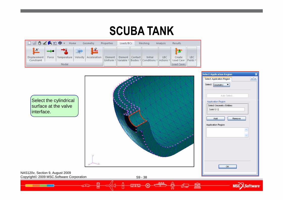
Select the cylindrical
SCUBA TANK
S9 - 38NAS120v, Section 9, August 2009Copyright© 2009 MSC.Software Corporation
Select the cylindrical surface at the valve interface.
SCUBA TANK
S9 - 39NAS120v, Section 9, August 2009Copyright© 2009 MSC.Software Corporation
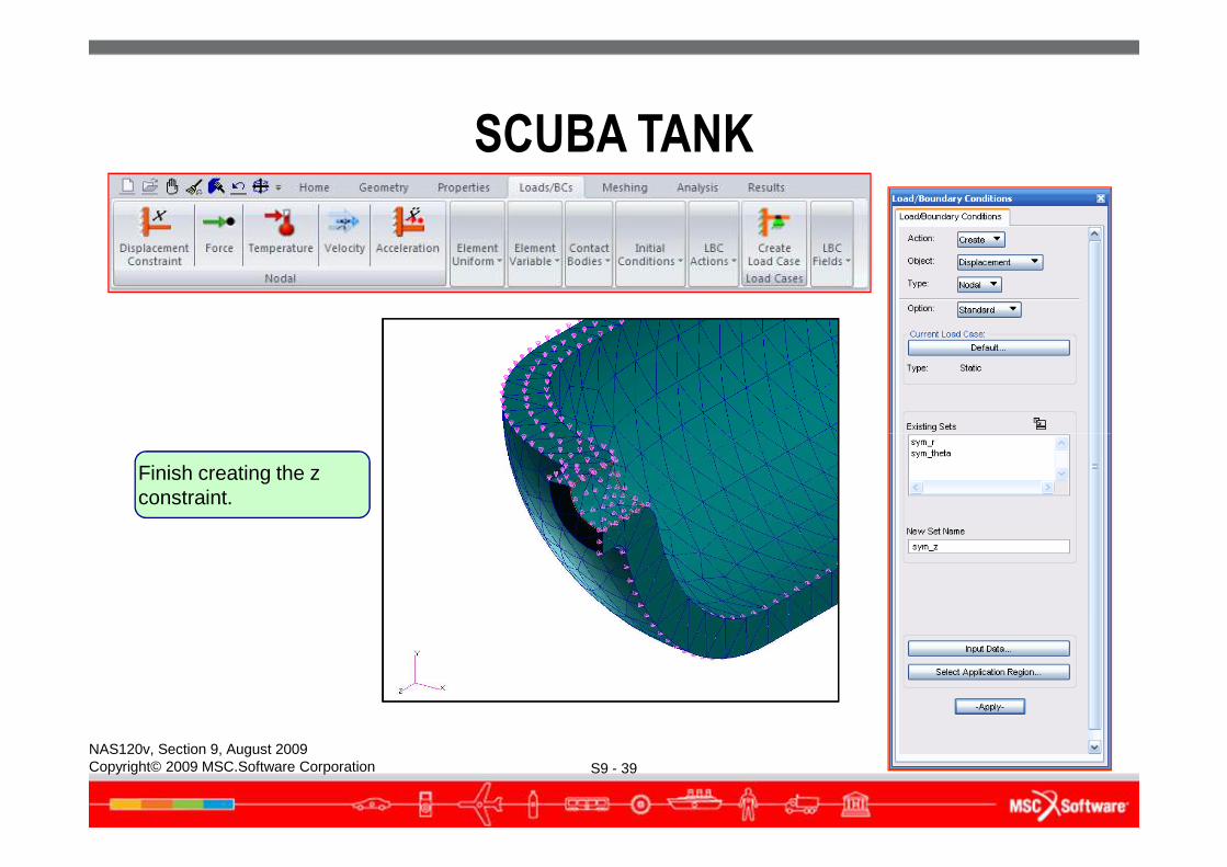
Finish creating the z constraint.
SCUBA TANK
S9 - 40NAS120v, Section 9, August 2009Copyright© 2009 MSC.Software Corporation
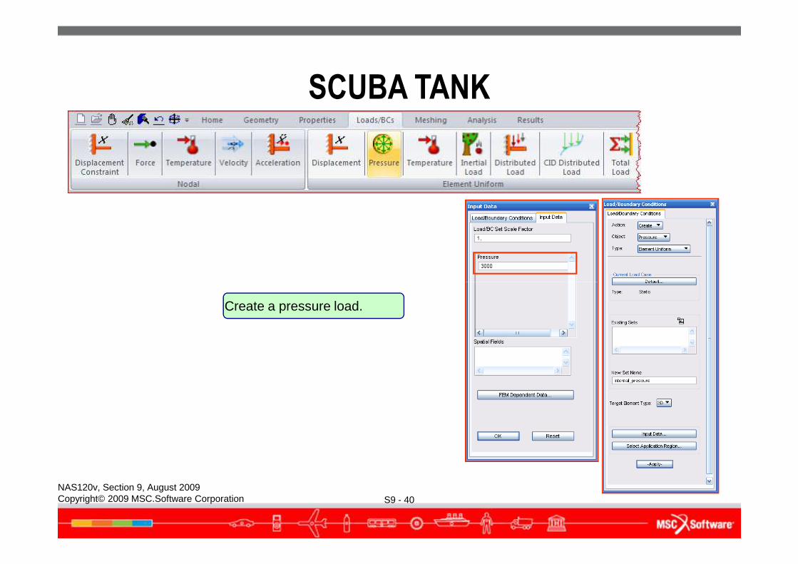
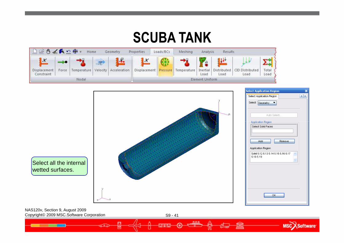
Create a pressure load.
SCUBA TANK
S9 - 41NAS120v, Section 9, August 2009Copyright© 2009 MSC.Software Corporation
Select all the internal wetted surfaces.
SCUBA TANK
S9 - 42NAS120v, Section 9, August 2009Copyright© 2009 MSC.Software Corporation
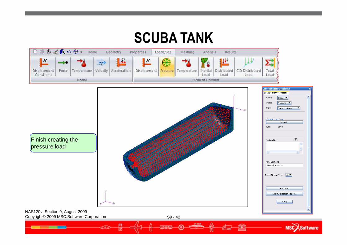
Finish creating the pressure load
SCUBA TANK
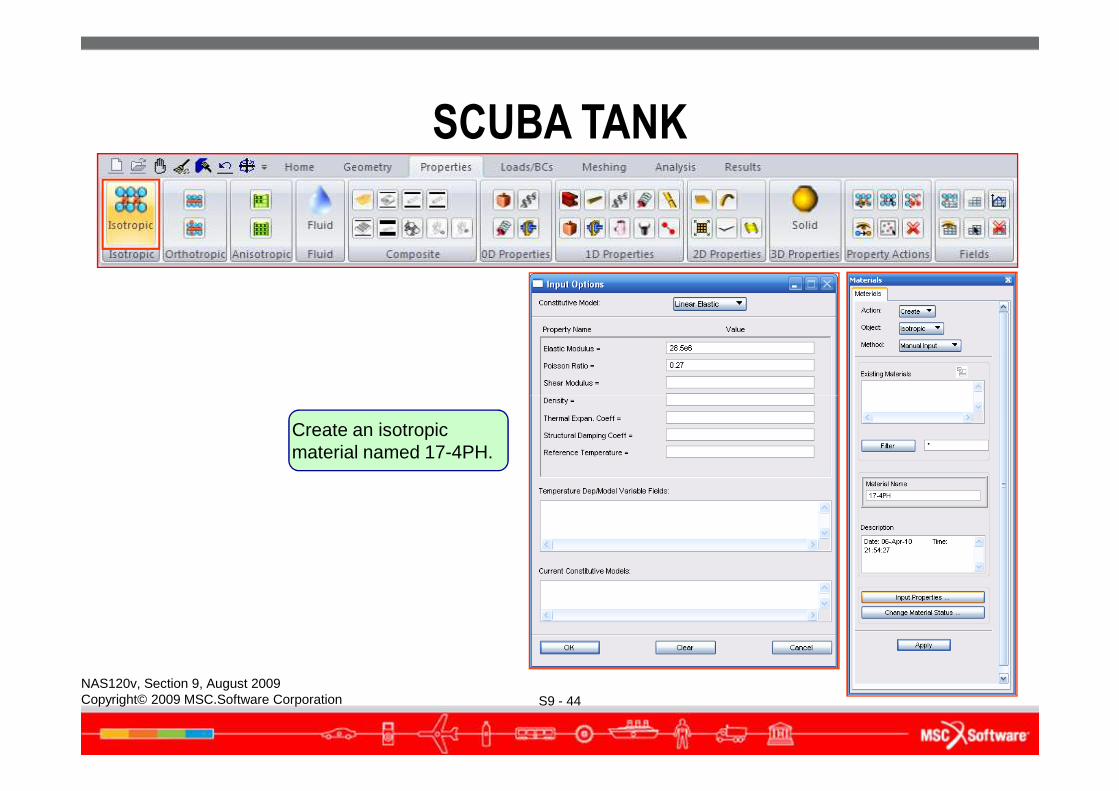
● Create the scuba tank material properties● The tank is made from 17-4 PH stainless steel forging, heat treated
to the H1025 condition.● E = 28.5 x 10⁶ psi● ν = 0.27● Ultimate strength = 155 ksi
Yield strength = 145 ksi
S9 - 43NAS120v, Section 9, August 2009Copyright© 2009 MSC.Software Corporation
● Yield strength = 145 ksi
SCUBA TANK
S9 - 44NAS120v, Section 9, August 2009Copyright© 2009 MSC.Software Corporation
Create an isotropic material named 17-4PH.
SCUBA TANK
S9 - 45NAS120v, Section 9, August 2009Copyright© 2009 MSC.Software Corporation
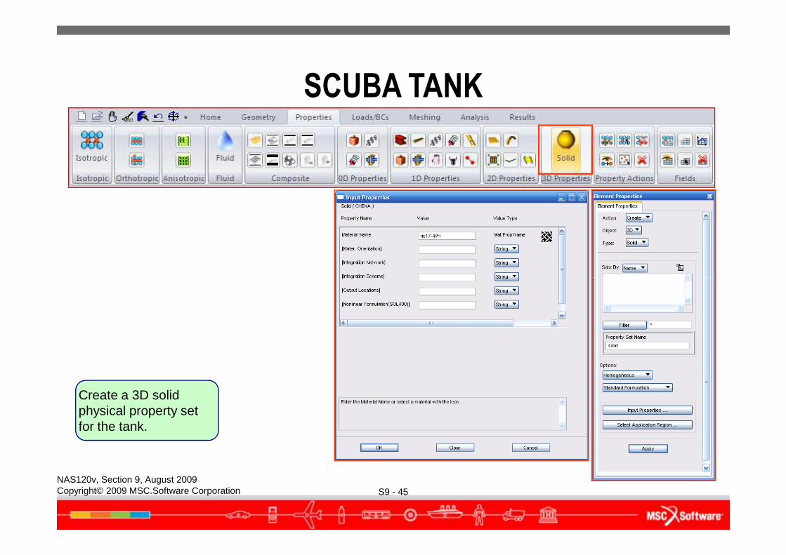
Create a 3D solid physical property set for the tank.
SCUBA TANK
S9 - 46NAS120v, Section 9, August 2009Copyright© 2009 MSC.Software Corporation
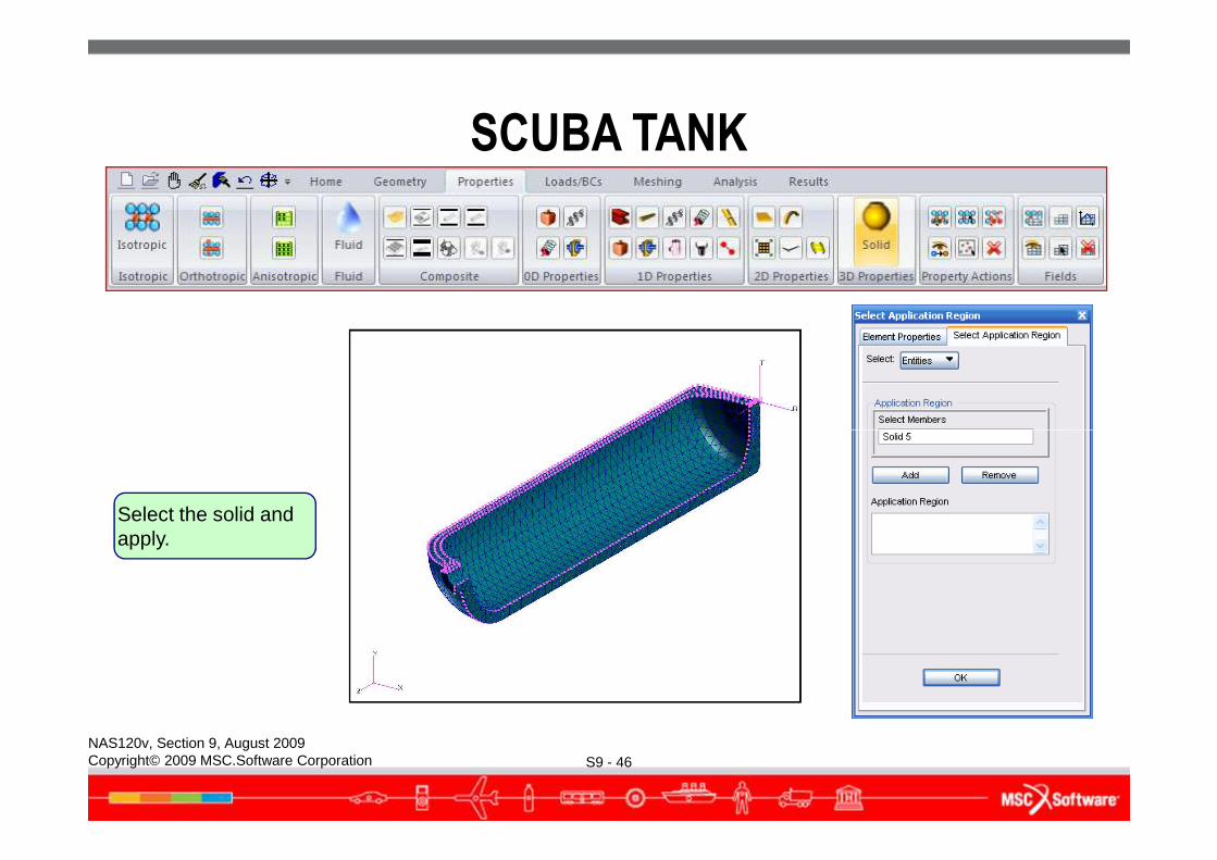
Select the solid and apply.
SCUBA TANK
S9 - 47NAS120v, Section 9, August 2009Copyright© 2009 MSC.Software Corporation
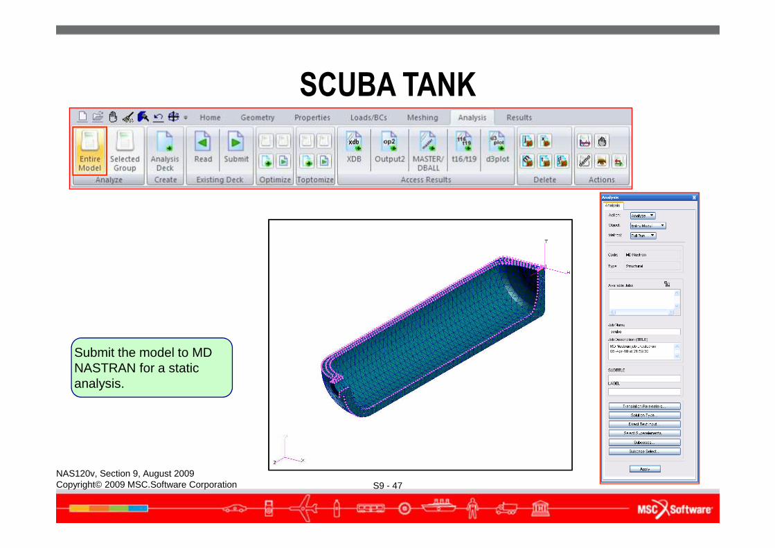
Submit the model to MD NASTRAN for a static analysis.
SCUBA TANK
S9 - 48NAS120v, Section 9, August 2009Copyright© 2009 MSC.Software Corporation
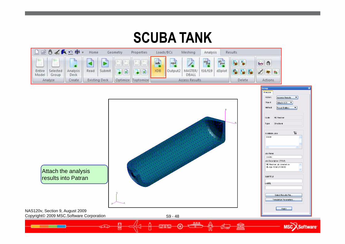
Attach the analysis results into Patran
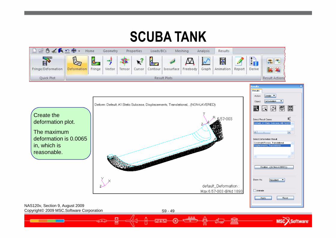
Create the deformation plot.
SCUBA TANK
S9 - 49NAS120v, Section 9, August 2009Copyright© 2009 MSC.Software Corporation
deformation plot.
The maximum deformation is 0.0065 in, which is reasonable.
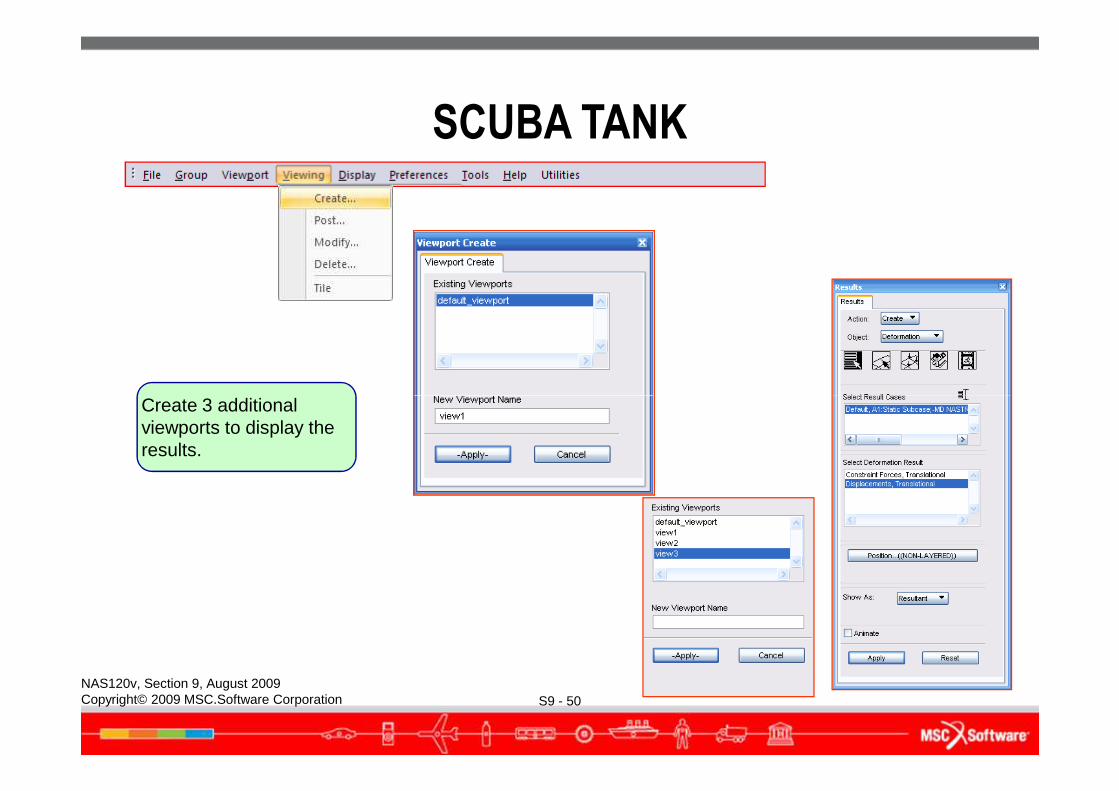
Create 3 additional
SCUBA TANK
S9 - 50NAS120v, Section 9, August 2009Copyright© 2009 MSC.Software Corporation
Create 3 additional viewports to display the results.
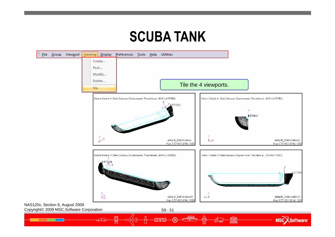
Tile the 4 viewports.
SCUBA TANK
S9 - 51NAS120v, Section 9, August 2009Copyright© 2009 MSC.Software Corporation
SCUBA TANK
● Next, let’s plot the stresses● By default, the solid element stresses are computed in the basic
coordinate system.● For the scuba tank, we are interested in the radial, hoop, and axial
stresses which are defined in a cylindrical system. We need to transform the stresses from the basic coordinate system to the cylindrical coordinate system no. 1.
S9 - 52NAS120v, Section 9, August 2009Copyright© 2009 MSC.Software Corporation
cylindrical coordinate system no. 1.
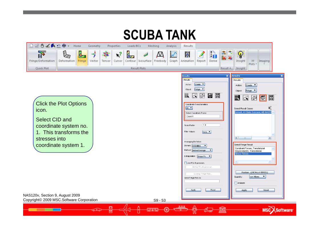
Click the Plot Options icon.
SCUBA TANK
S9 - 53NAS120v, Section 9, August 2009Copyright© 2009 MSC.Software Corporation
Select CID and coordinate system no. 1. This transforms the stresses into coordinate system 1.
SCUBA TANK
S9 - 54NAS120v, Section 9, August 2009Copyright© 2009 MSC.Software Corporation
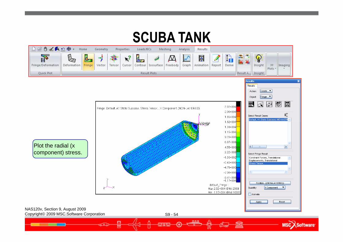
Plot the radial (x component) stress.
SCUBA TANK
S9 - 55NAS120v, Section 9, August 2009Copyright© 2009 MSC.Software Corporation
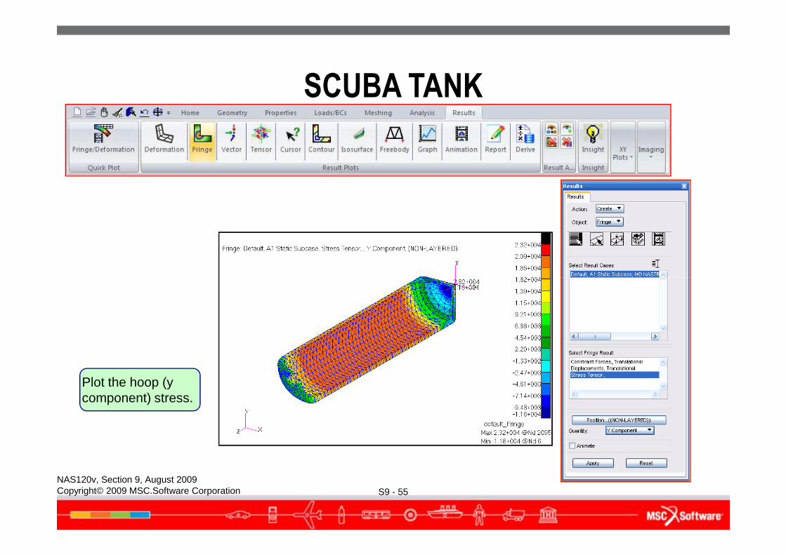
Plot the hoop (y component) stress.
SCUBA TANK
S9 - 56NAS120v, Section 9, August 2009Copyright© 2009 MSC.Software Corporation
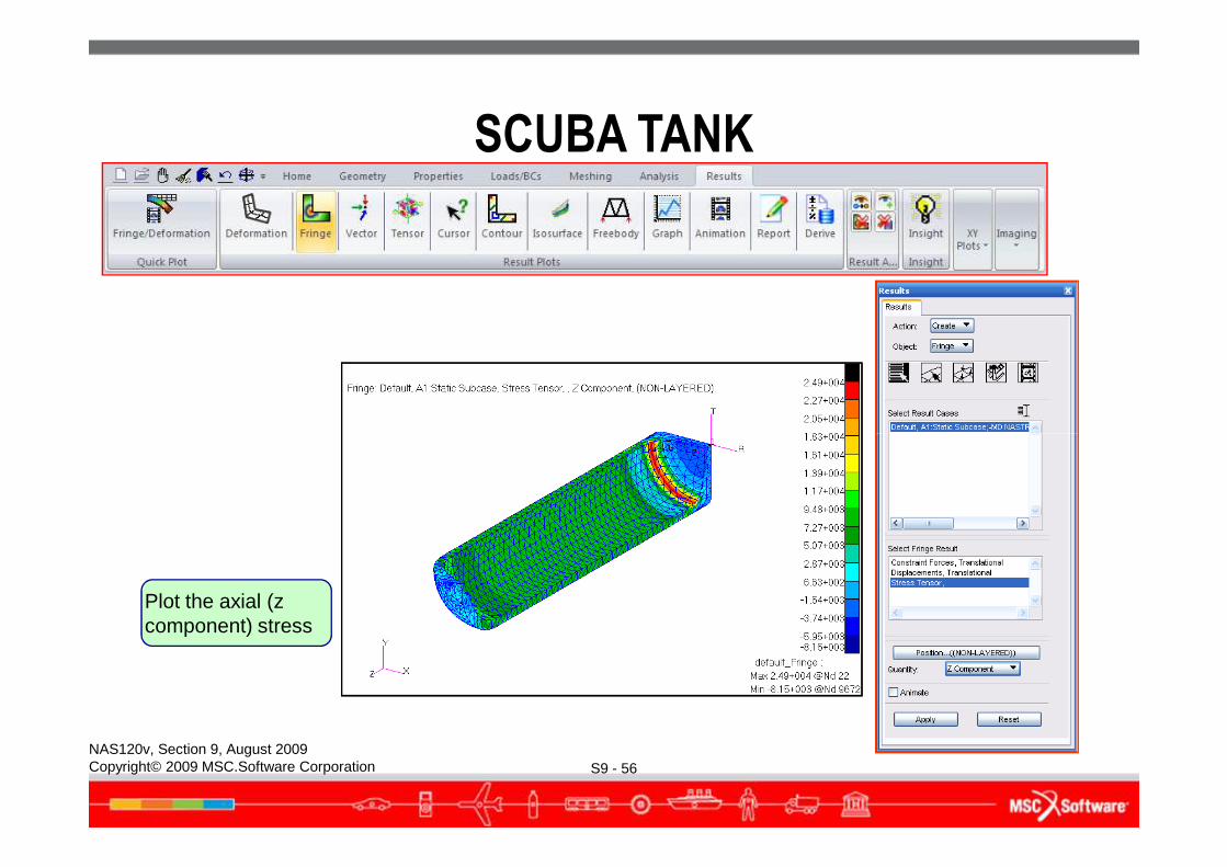
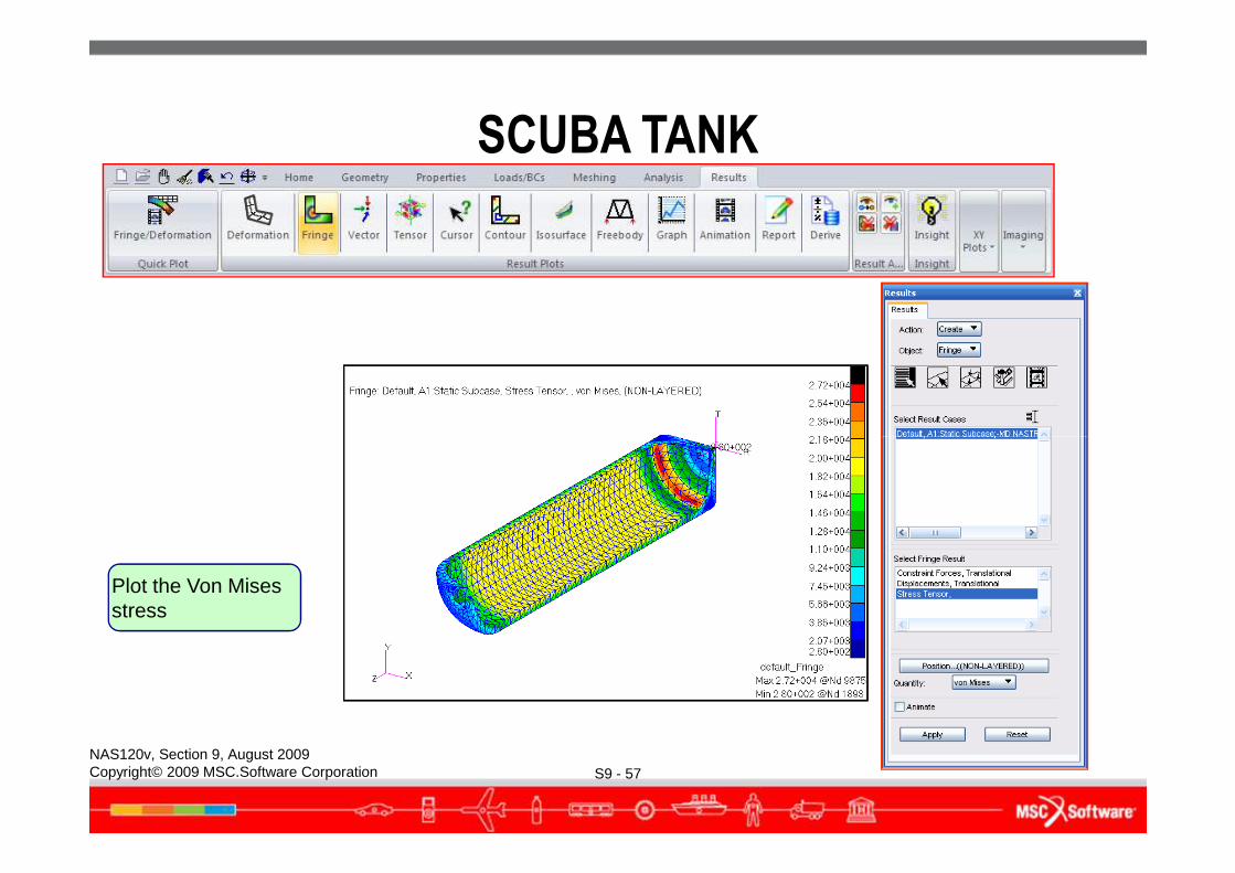
Plot the axial (z component) stress
SCUBA TANK
S9 - 57NAS120v, Section 9, August 2009Copyright© 2009 MSC.Software Corporation
Plot the Von Mises stress
Zoom in to the
SCUBA TANK
S9 - 58NAS120v, Section 9, August 2009Copyright© 2009 MSC.Software Corporation
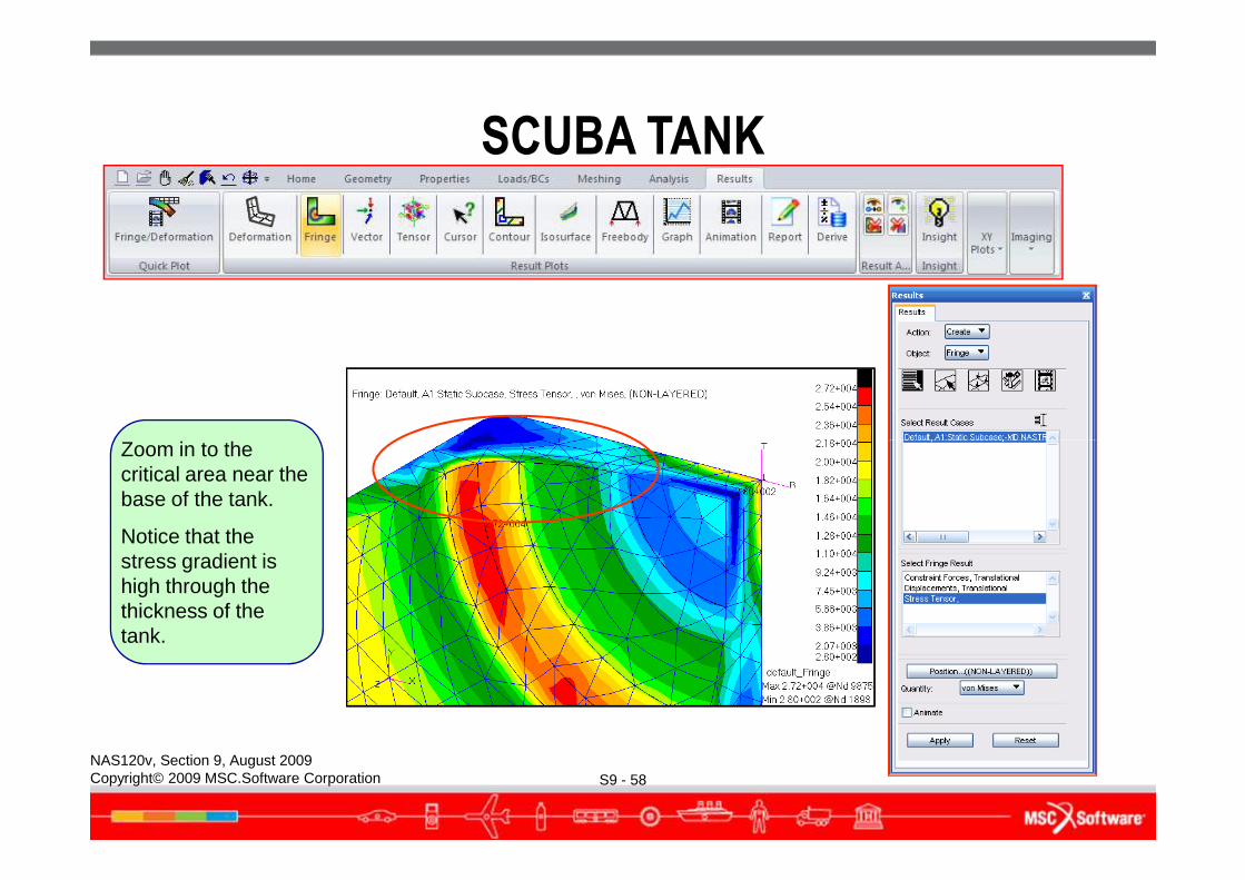
Zoom in to the critical area near the base of the tank.
Notice that the stress gradient is high through the thickness of the tank.
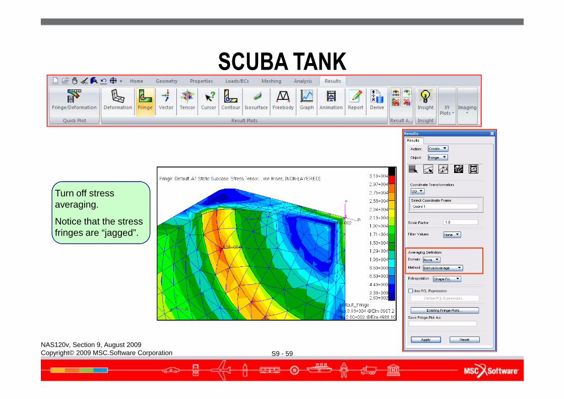
Turn off stress averaging.
SCUBA TANK
S9 - 59NAS120v, Section 9, August 2009Copyright© 2009 MSC.Software Corporation
averaging.
Notice that the stress fringes are “jagged”.
Plot the stress jumps
SCUBA TANK
S9 - 60NAS120v, Section 9, August 2009Copyright© 2009 MSC.Software Corporation
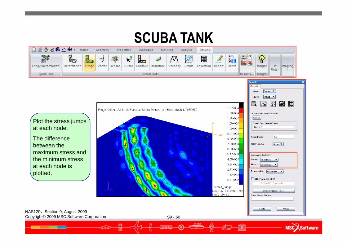
Plot the stress jumps at each node.
The difference between the maximum stress and the minimum stress at each node is plotted.
SCUBA TANK
● Scuba tank coarse-mesh model analysis summary:● The maximum Von Mises stress is 31,800 psi at the base of the tank
near the fillet radius.● The stress gradient through the tank wall thickness is high. It ranges
from 31,800 psi on the inside wall to about 5,000 psi on the outside wall. This stress gradient is captured by a single tet10 element through the thickness.
S9 - 61NAS120v, Section 9, August 2009Copyright© 2009 MSC.Software Corporation
through the thickness.● The un-averaged stress fringe plot is jagged, an indication that the
mesh is too coarse.● The stress difference plot shows a maximum stress jump of 13,700
psi. This suggests that the mesh is too coarse in this area.
● This first scuba tank model was relatively coarse. It helped us identify the critical area in the tank. We will now create a second model with a finer mesh in the critical area.
Create a new database
SCUBA TANK
S9 - 62NAS120v, Section 9, August 2009Copyright© 2009 MSC.Software Corporation
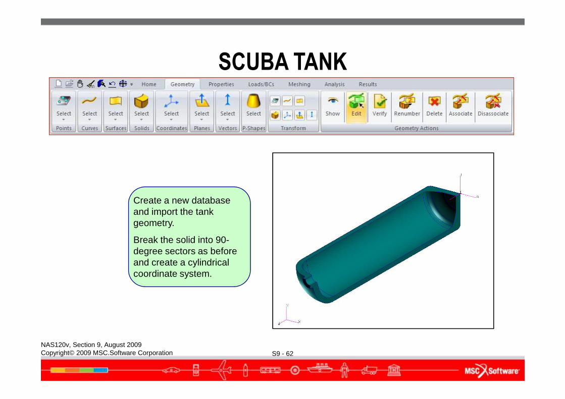
Create a new database and import the tank geometry.
Break the solid into 90-degree sectors as before and create a cylindrical coordinate system.
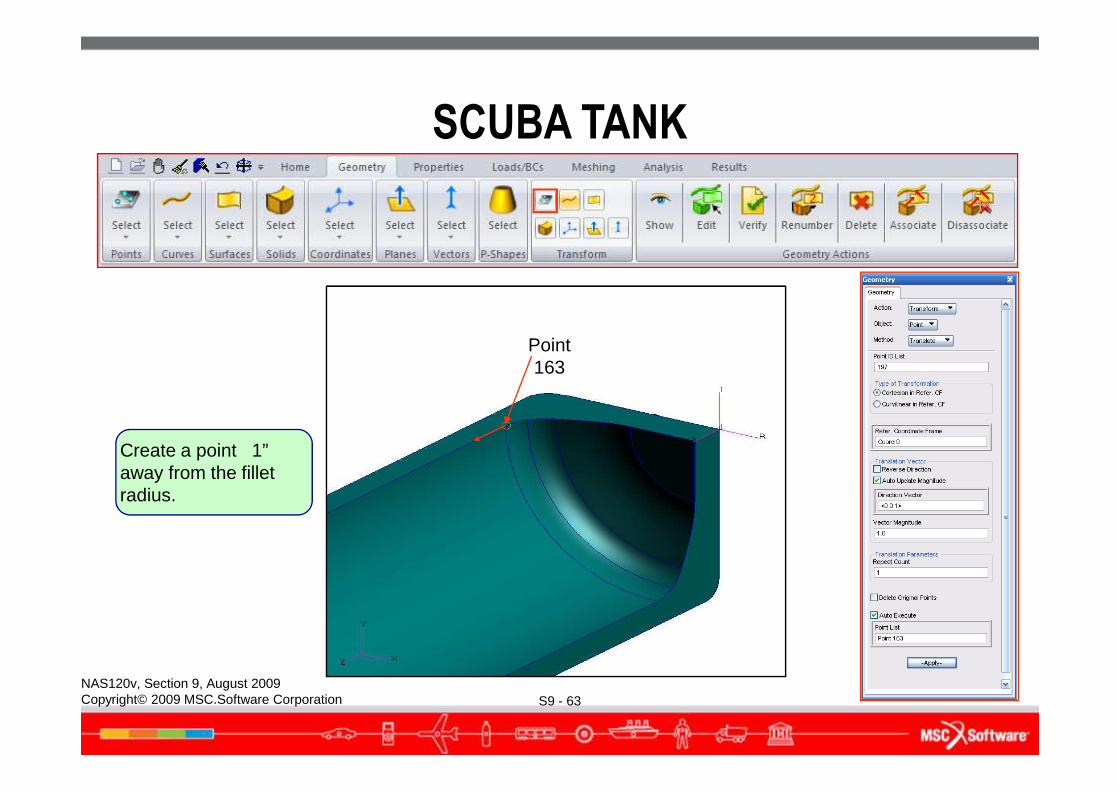
Point 163
SCUBA TANK
S9 - 63NAS120v, Section 9, August 2009Copyright© 2009 MSC.Software Corporation
Create a point 1” away from the fillet radius.
SCUBA TANK
S9 - 64NAS120v, Section 9, August 2009Copyright© 2009 MSC.Software Corporation
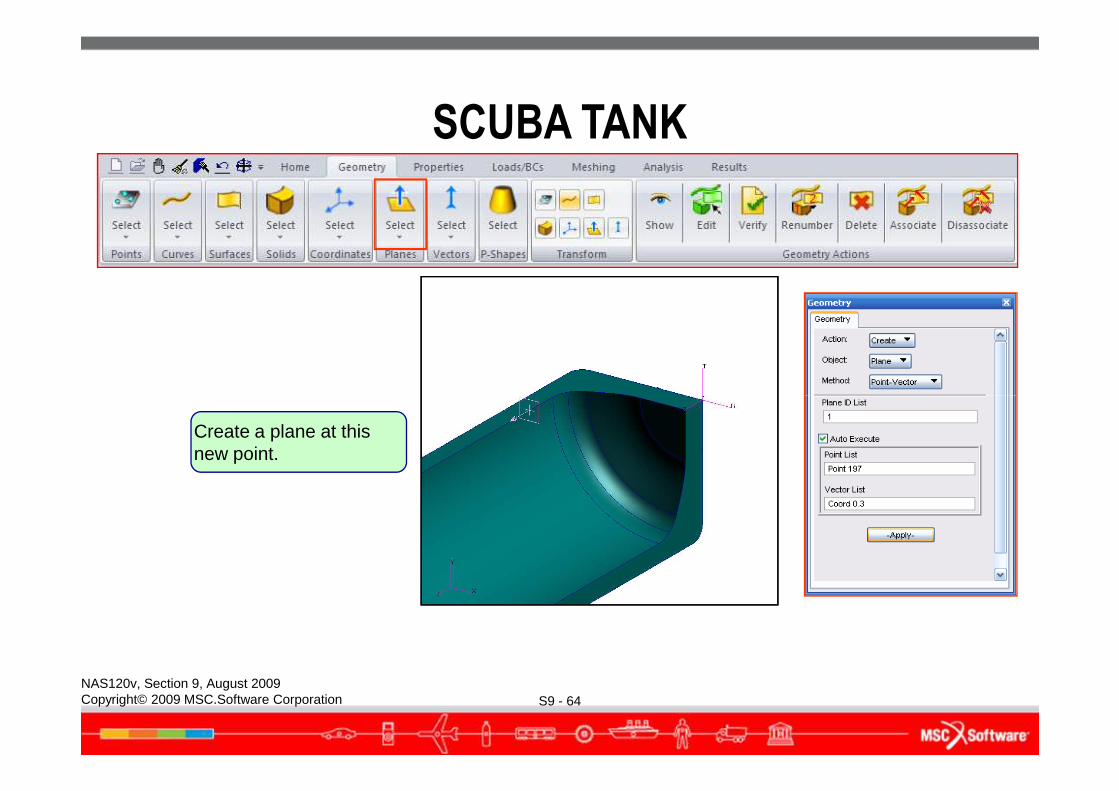
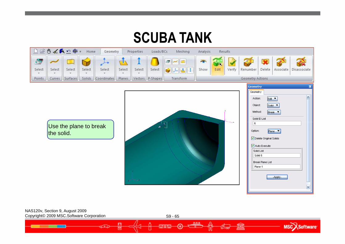
Create a plane at this new point.
SCUBA TANK
S9 - 65NAS120v, Section 9, August 2009Copyright© 2009 MSC.Software Corporation
Use the plane to break the solid.
SCUBA TANK
S9 - 66NAS120v, Section 9, August 2009Copyright© 2009 MSC.Software Corporation
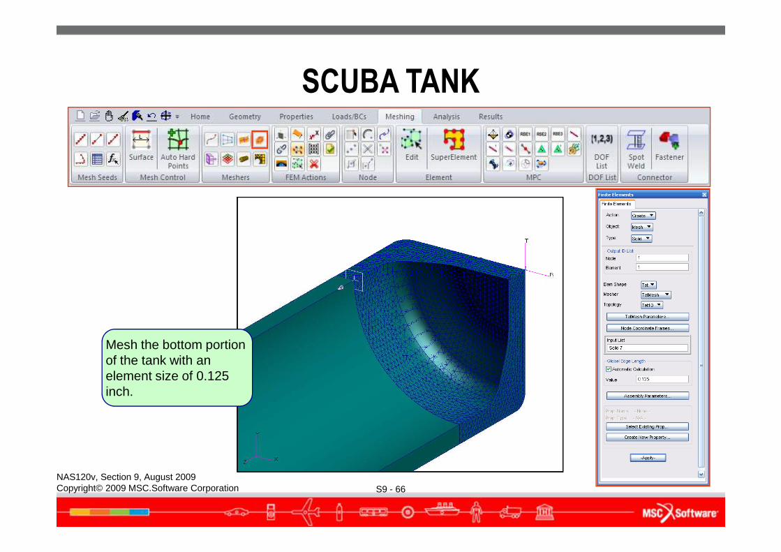
Mesh the bottom portion of the tank with an element size of 0.125 inch.
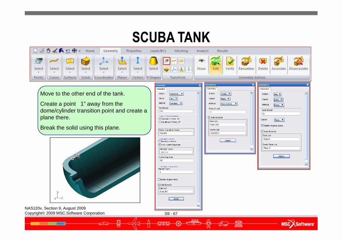
Move to the other end of the tank.
Create a point 1” away from the dome/cylinder transition point and create a plane there.
SCUBA TANK
S9 - 67NAS120v, Section 9, August 2009Copyright© 2009 MSC.Software Corporation
plane there.
Break the solid using this plane.
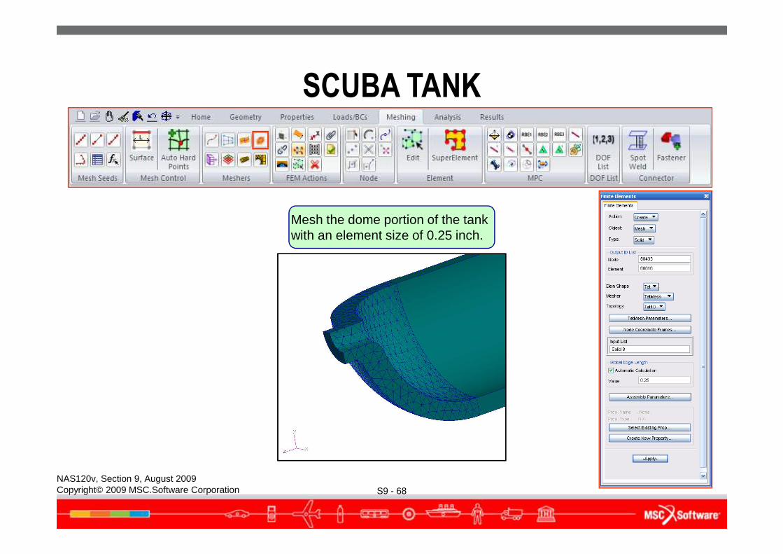
Mesh the dome portion of the tank with an element size of 0.25 inch.
SCUBA TANK
S9 - 68NAS120v, Section 9, August 2009Copyright© 2009 MSC.Software Corporation
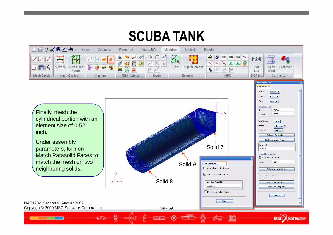
Finally, mesh the cylindrical portion with an
SCUBA TANK
S9 - 69NAS120v, Section 9, August 2009Copyright© 2009 MSC.Software Corporation
Solid 9
Solid 7
Solid 8
cylindrical portion with an element size of 0.521 inch.
Under assembly parameters, turn on Match Parasolid Faces to match the mesh on two neighboring solids.
SCUBA TANK
S9 - 70NAS120v, Section 9, August 2009Copyright© 2009 MSC.Software Corporation
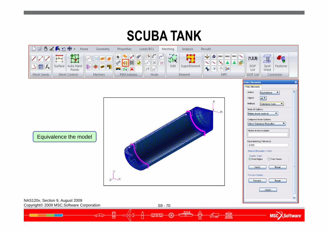
Equivalence the model
SCUBA TANK
S9 - 71NAS120v, Section 9, August 2009Copyright© 2009 MSC.Software Corporation
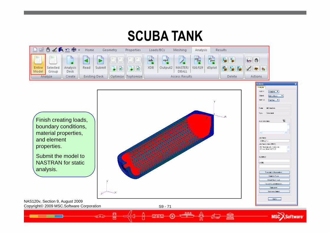
Finish creating loads, boundary conditions, material properties, and element properties.
Submit the model to NASTRAN for static analysis.
SCUBA TANK
S9 - 72NAS120v, Section 9, August 2009Copyright© 2009 MSC.Software Corporation
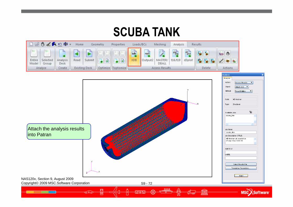
Attach the analysis results into Patran
Create the
SCUBA TANK
S9 - 73NAS120v, Section 9, August 2009Copyright© 2009 MSC.Software Corporation
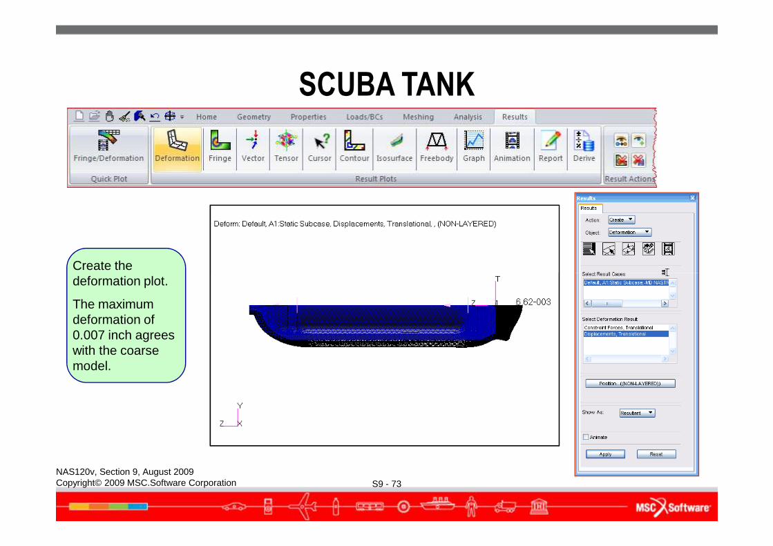
deformation plot.
The maximum deformation of 0.007 inch agrees with the coarse model.
SCUBA TANK
S9 - 74NAS120v, Section 9, August 2009Copyright© 2009 MSC.Software Corporation
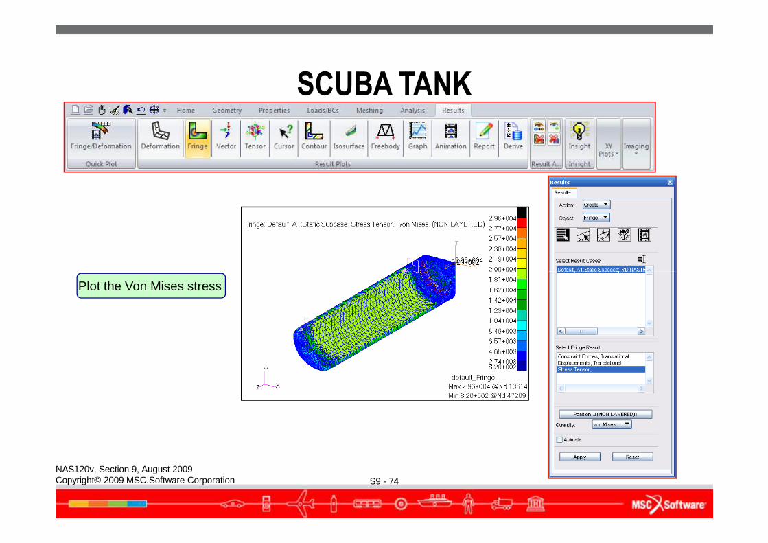
Plot the Von Mises stress
Zoom into the critical
SCUBA TANK
S9 - 75NAS120v, Section 9, August 2009Copyright© 2009 MSC.Software Corporation
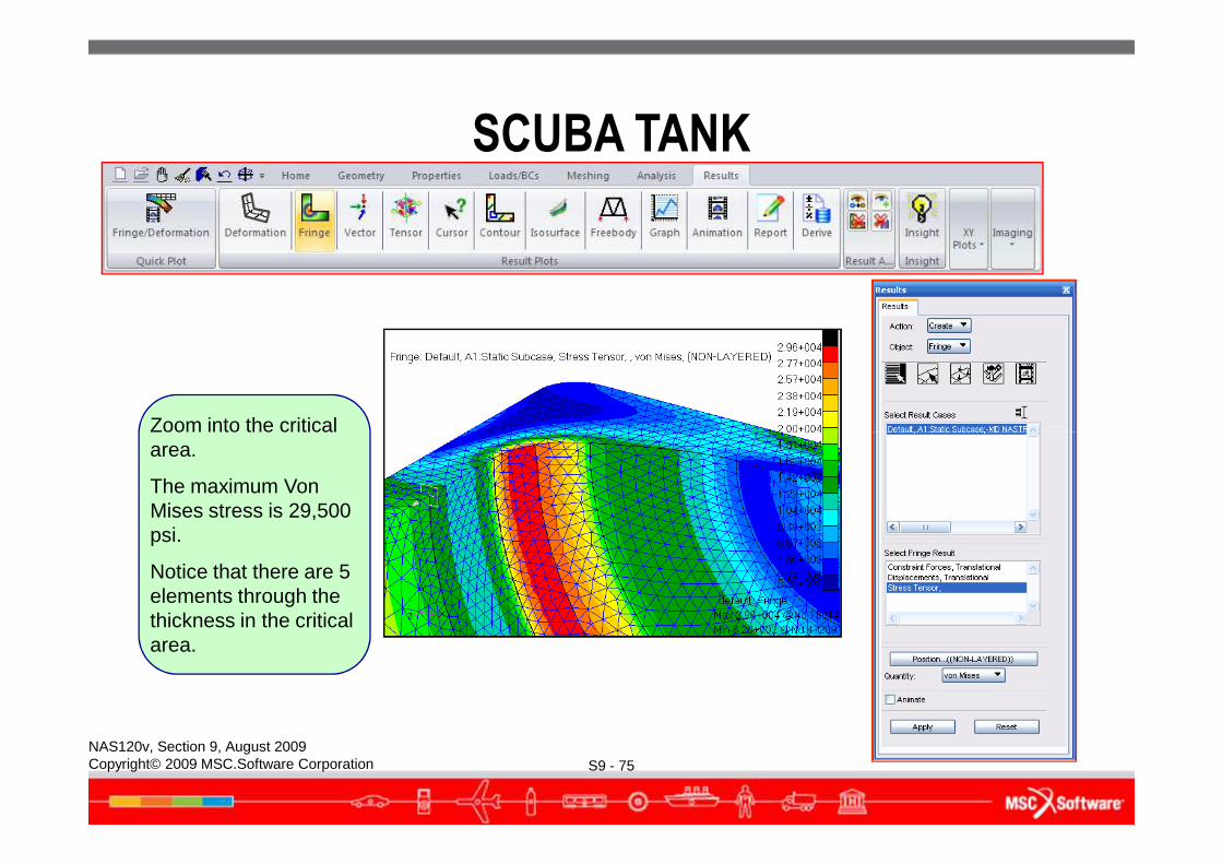
Zoom into the critical area.
The maximum Von Mises stress is 29,500 psi.
Notice that there are 5 elements through the thickness in the critical area.
Turn off stress averaging.
SCUBA TANK
S9 - 76NAS120v, Section 9, August 2009Copyright© 2009 MSC.Software Corporation
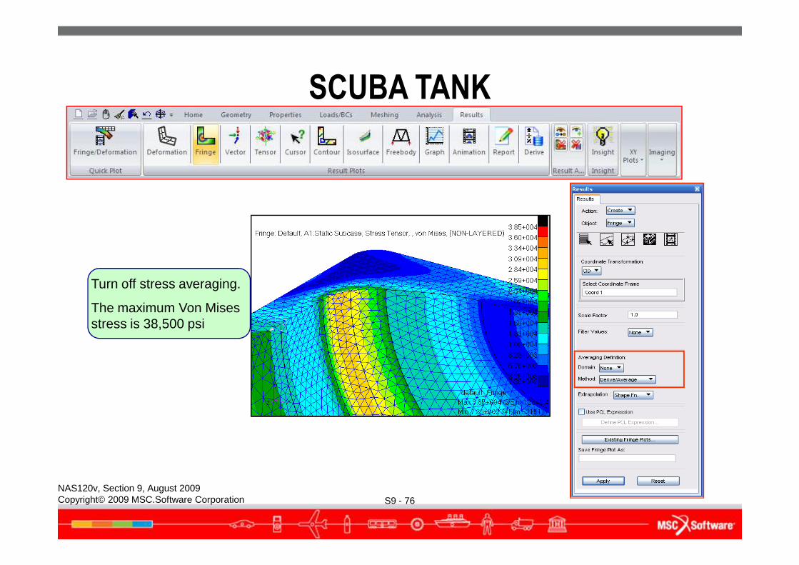
Turn off stress averaging.
The maximum Von Mises stress is 38,500 psi
SCUBA TANK
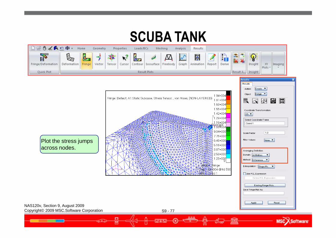
S9 - 77NAS120v, Section 9, August 2009Copyright© 2009 MSC.Software Corporation
Plot the stress jumps across nodes.
SCUBA TANK
● Scuba tank fine-mesh model analysis summary:● The maximum Von Mises stress is 30,300 psi at the base of the tank
near the fillet radius.● There are 5 elements through the thickness in this critical area. The
stress gradient is represented reasonably well through the thickness.● The un-averaged stress fringe plot is relatively smooth, indicating
S9 - 78NAS120v, Section 9, August 2009Copyright© 2009 MSC.Software Corporation
that the re-meshing effort paid off.● The stress difference plot shows a maximum stress jump of 4300
psi. Is further mesh refinement necessary?● A total of 98,830 nodes and 66,504 elements were used to model
this problem.
● Let’s analyze the tank again using 2D axisymmetric elements.
SCUBA TANK
● Using 2D Axisymmetric Elements● This converts a 3D problem into a planar problem by using 2D
elements.● Only half of the tank cross section is modeled.● Geometry, boundary condition, and loads must all be axisymmetric.● A much finer mesh can be used to solve this problem.
S9 - 79NAS120v, Section 9, August 2009Copyright© 2009 MSC.Software Corporation
● A much finer mesh can be used to solve this problem.
SCUBA TANK
S9 - 80NAS120v, Section 9, August 2009Copyright© 2009 MSC.Software Corporation
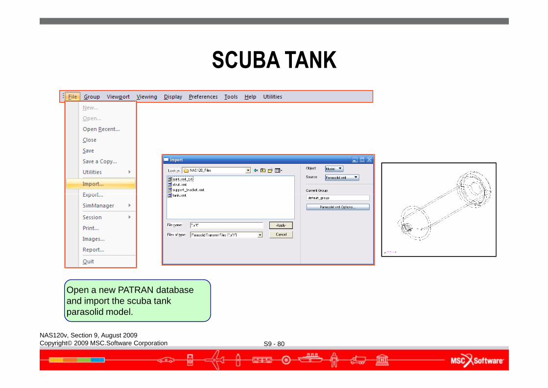
Open a new PATRAN database and import the scuba tank parasolid model.
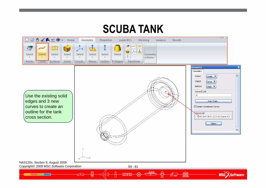
Use the existing solid
SCUBA TANK
S9 - 81NAS120v, Section 9, August 2009Copyright© 2009 MSC.Software Corporation
Use the existing solid edges and 3 new curves to create an outline for the tank cross section.
SCUBA TANK
S9 - 82NAS120v, Section 9, August 2009Copyright© 2009 MSC.Software Corporation
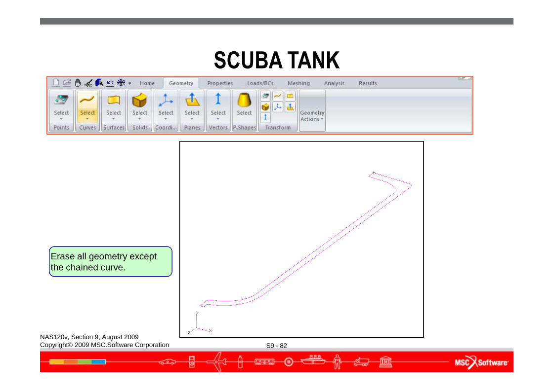
Erase all geometry except the chained curve.
SCUBA TANK
S9 - 83NAS120v, Section 9, August 2009Copyright© 2009 MSC.Software Corporation
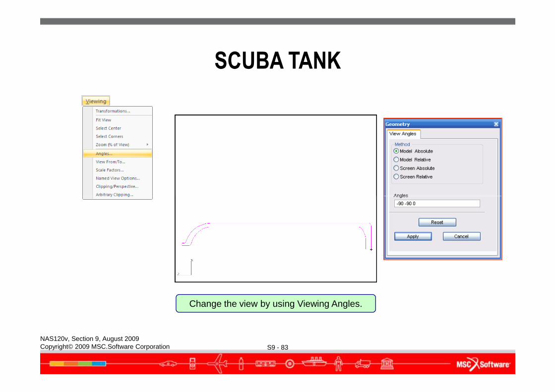
Change the view by using Viewing Angles.
SCUBA TANK
S9 - 84NAS120v, Section 9, August 2009Copyright© 2009 MSC.Software Corporation
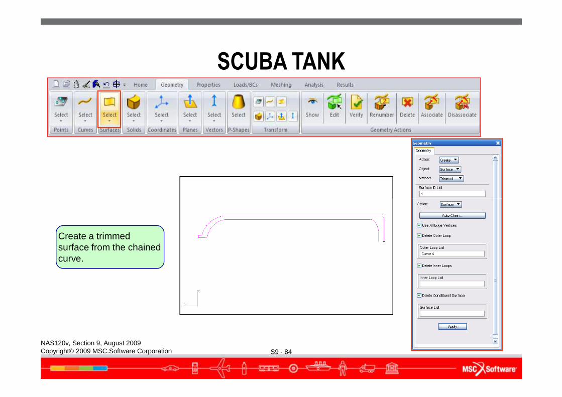
Create a trimmed surface from the chained curve.
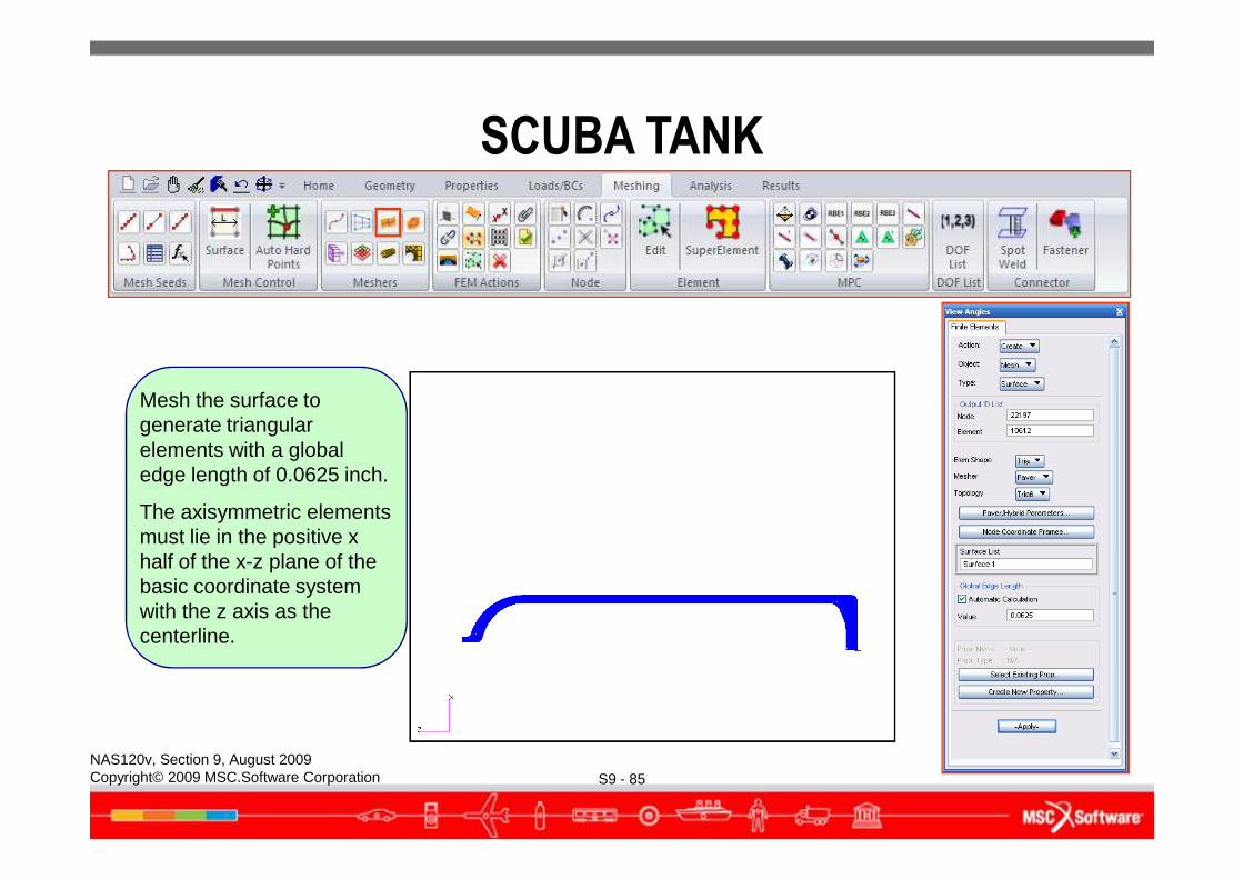
Mesh the surface to generate triangular elements with a global
SCUBA TANK
S9 - 85NAS120v, Section 9, August 2009Copyright© 2009 MSC.Software Corporation
elements with a global edge length of 0.0625 inch.
The axisymmetric elements must lie in the positive x half of the x-z plane of the basic coordinate system with the z axis as the centerline.
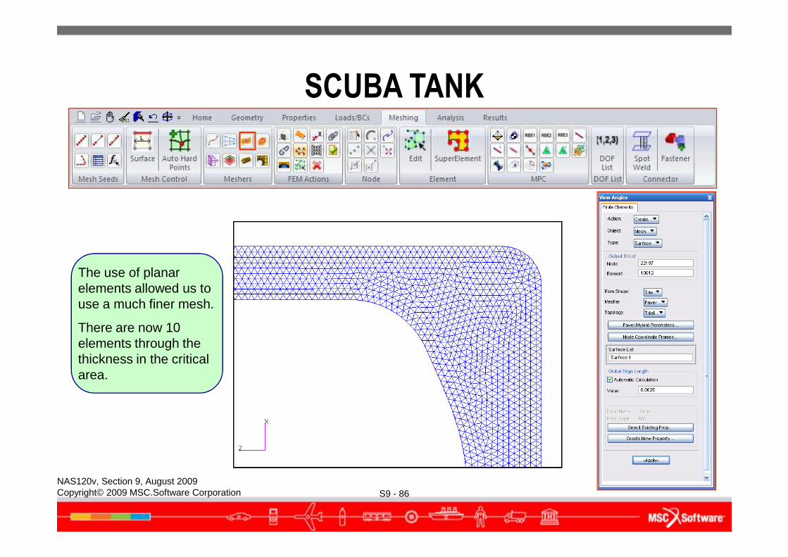
The use of planar
SCUBA TANK
S9 - 86NAS120v, Section 9, August 2009Copyright© 2009 MSC.Software Corporation
The use of planar elements allowed us to use a much finer mesh.
There are now 10 elements through the thickness in the critical area.
SCUBA TANK
S9 - 87NAS120v, Section 9, August 2009Copyright© 2009 MSC.Software Corporation
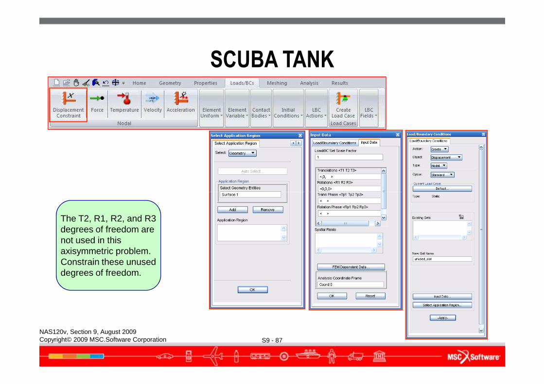
The T2, R1, R2, and R3 degrees of freedom are not used in this axisymmetric problem. Constrain these unused degrees of freedom.
SCUBA TANK
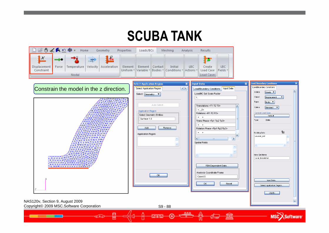
Constrain the model in the z direction.
S9 - 88NAS120v, Section 9, August 2009Copyright© 2009 MSC.Software Corporation
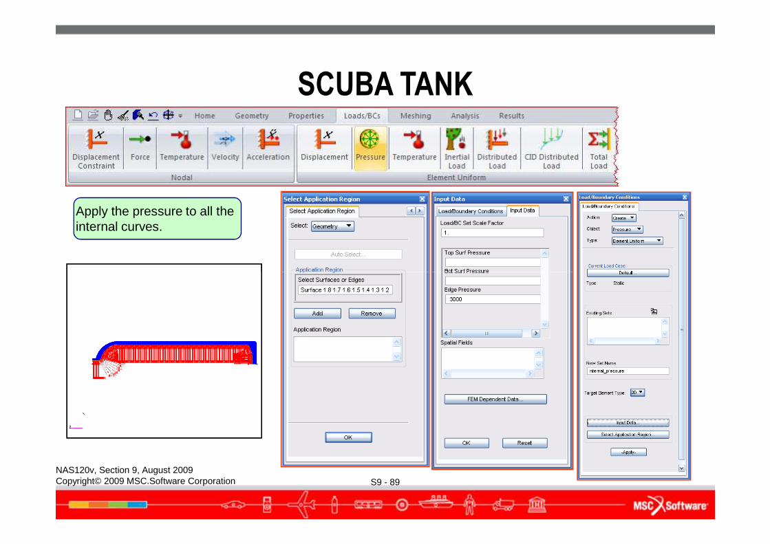
Apply the pressure to all the internal curves.
SCUBA TANK
S9 - 89NAS120v, Section 9, August 2009Copyright© 2009 MSC.Software Corporation

SCUBA TANK
S9 - 90NAS120v, Section 9, August 2009Copyright© 2009 MSC.Software Corporation
Create an isotropic material named 17-4PH.
SCUBA TANK
S9 - 91NAS120v, Section 9, August 2009Copyright© 2009 MSC.Software Corporation
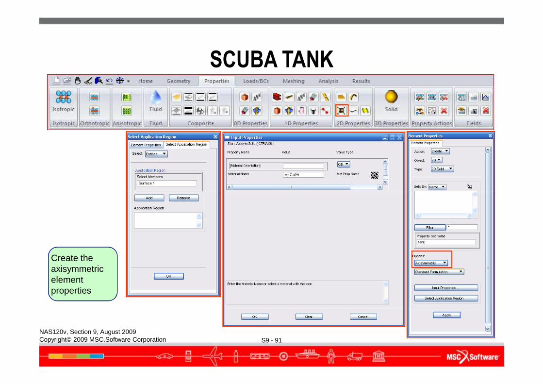
Create the axisymmetric element properties
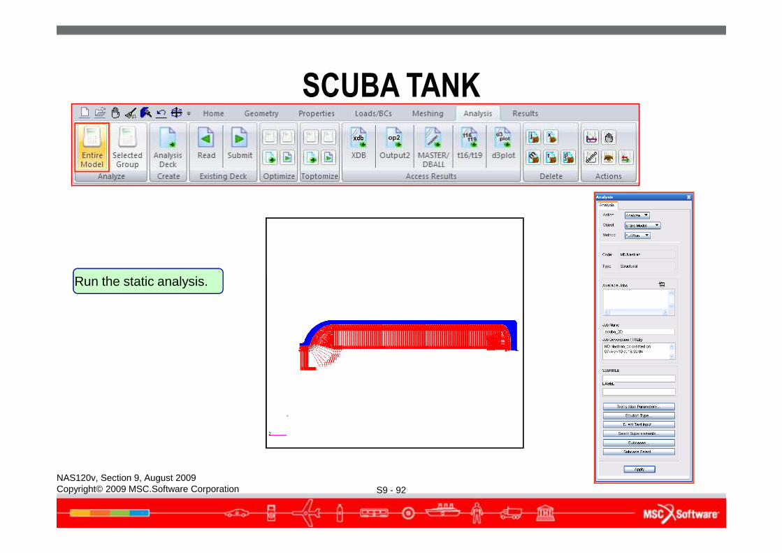
Run the static analysis.
SCUBA TANK
S9 - 92NAS120v, Section 9, August 2009Copyright© 2009 MSC.Software Corporation
Run the static analysis.
Attach the analysis
SCUBA TANK
S9 - 93NAS120v, Section 9, August 2009Copyright© 2009 MSC.Software Corporation
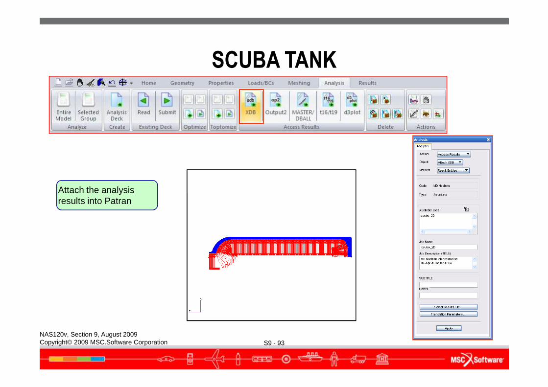
Attach the analysis results into Patran
SCUBA TANK
S9 - 94NAS120v, Section 9, August 2009Copyright© 2009 MSC.Software Corporation
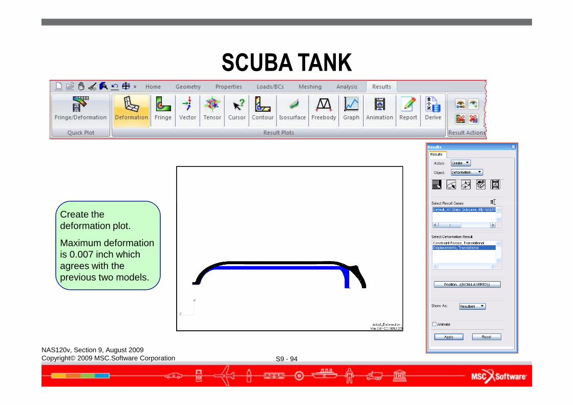
Create the deformation plot.
Maximum deformation is 0.007 inch which agrees with the previous two models.
SCUBA TANK
S9 - 95NAS120v, Section 9, August 2009Copyright© 2009 MSC.Software Corporation
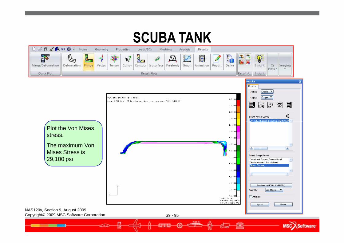
Plot the Von Mises stress.
The maximum Von Mises Stress is 29,100 psi
SCUBA TANK
S9 - 96NAS120v, Section 9, August 2009Copyright© 2009 MSC.Software Corporation
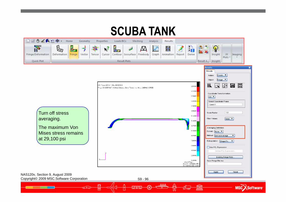
Turn off stress averaging.
The maximum Von Mises stress remains at 29,100 psi
Zoom in on the critical
SCUBA TANK
S9 - 97NAS120v, Section 9, August 2009Copyright© 2009 MSC.Software Corporation
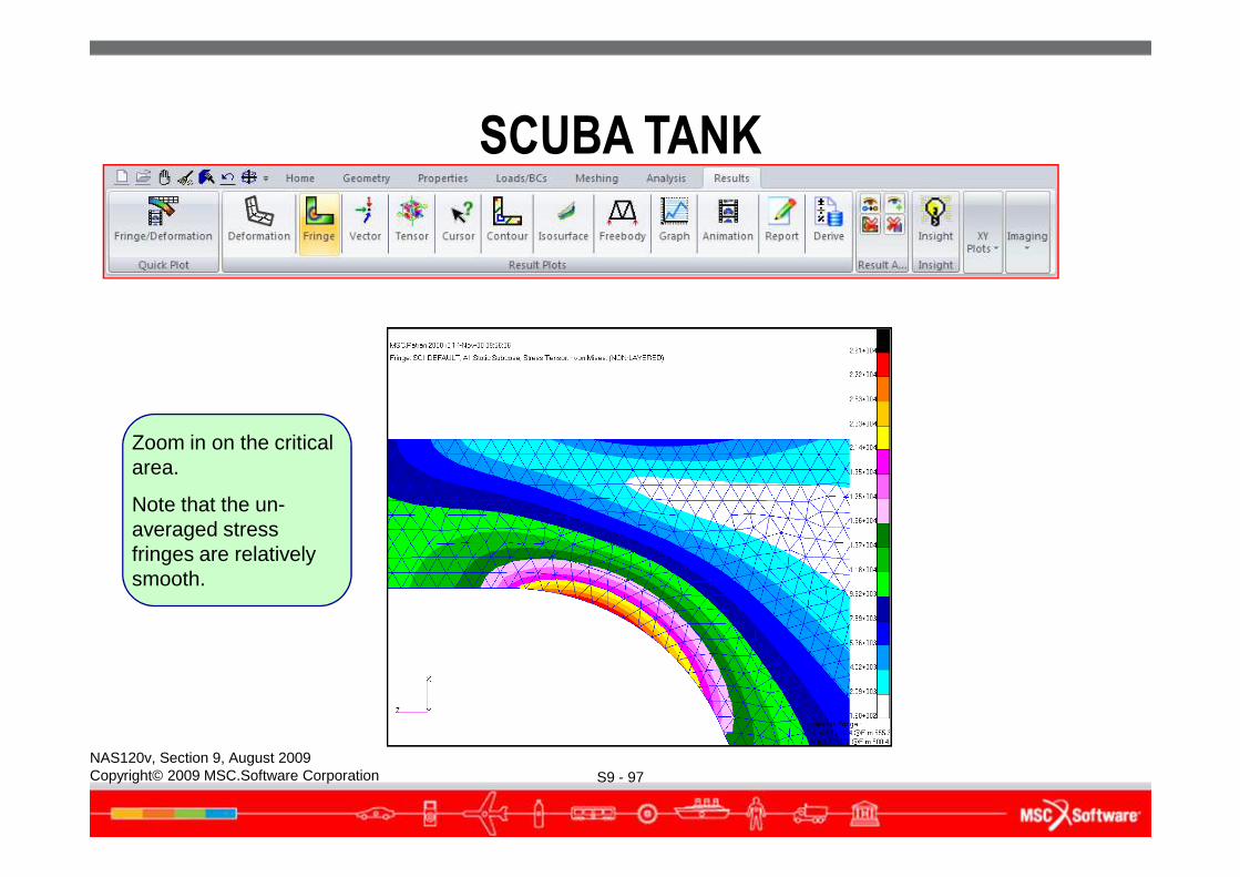
Zoom in on the critical area.
Note that the un-averaged stress fringes are relatively smooth.
SCUBA TANK
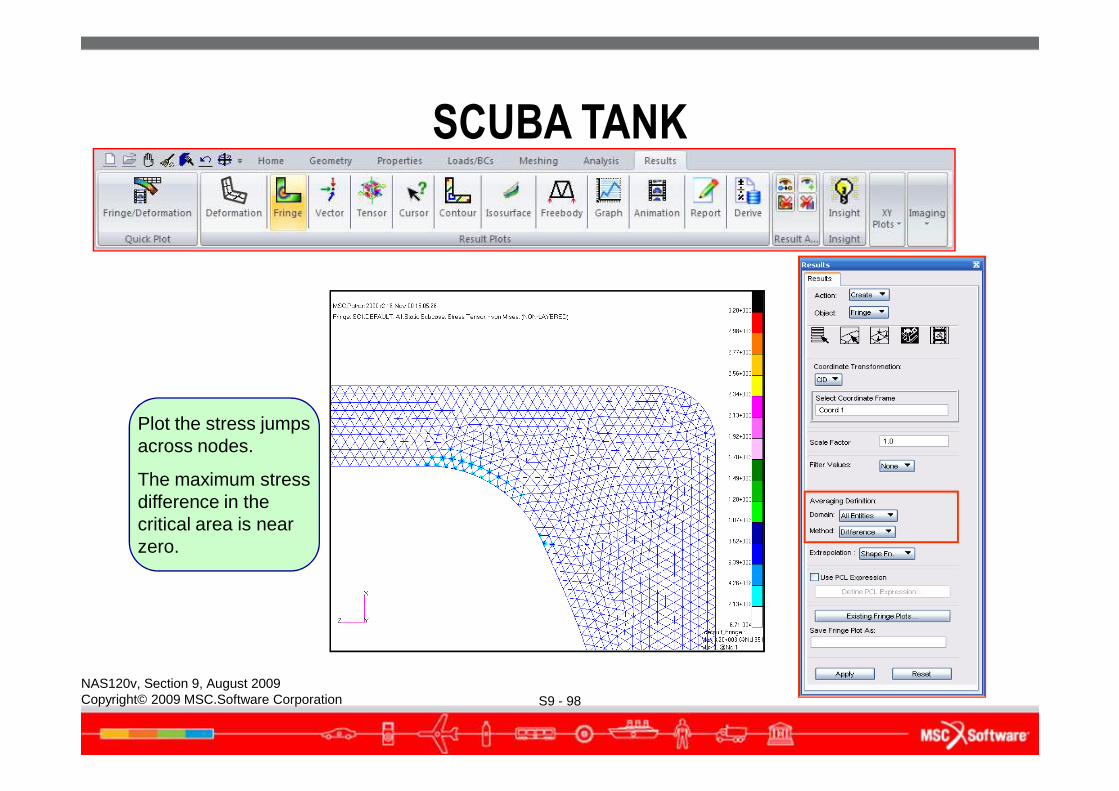
S9 - 98NAS120v, Section 9, August 2009Copyright© 2009 MSC.Software Corporation
Plot the stress jumps across nodes.
The maximum stress difference in the critical area is near zero.
SCUBA TANK
● Scuba tank 2D axisymmetric analysis summary● The maximum Von Mises stress is 29,100 psi at the base of the tank
near the fillet radius.● There are 10 elements through the thickness in this critical area.
The stress gradient is represented reasonably well through the thickness.
S9 - 99NAS120v, Section 9, August 2009Copyright© 2009 MSC.Software Corporation
● The un-averaged stress fringe plot is very smooth, indicating that the mesh density is adequate.
● The stress difference plot shows near zero values.● Using a 2D representation of the scuba tank, we were able to create
a smaller model with a finer mesh compared to the 3D model.
EXERCISE
● Perform Workshop 9 “Support Bracket” in your exercise workbook.
● Optional:● Analyze the Scuba Tank covered in this section.
S9 - 100NAS120v, Section 9, August 2009Copyright© 2009 MSC.Software Corporation