Embed Size (px)
Citation preview
1 - 1
Automation products, PLCs, I/O systems, operator panels and touch screens, SCADA software
1
Micro Programmable Logic Controllers Mitsubishi Alpha 2 series 1 - 2Hitachi EH Micro series 1 - 6Modular Programmable Logic Controllers Hitachi EH-150 series 1 - 10Micro and modular PLC accessory selection guide 1 - 15Fieldbus I/O systems for industrial automation applications Overview 1 - 16750 Series 1 - 21857 Series JUMPFLEX Transducers 1 - 26750 Series Intrinsically safe system 1 - 28750 Series PROFIsafe system 1 - 29750 Series Vibration monitoring 1 - 30751 Series AS-i Fieldbus system 1 - 31Programming and diagnostic software 1 - 33750 Series Starter kits 1 - 34753 Series Quick connect 1 - 35Fieldbus I/O systems for long distance, lighting and irrigation control systems Overview 1 - 38Ordering details 1 - 42Operator panels and touch screens SC 207 1 - 48Overview 1 - 49Text based operator panels 1 - 50Graphics operator panels 1 - 51Graphics touch screens 1 - 52Communications cables 1 - 54VTWIN Configuration software 1 - 55Dimensions and cut-outs 1 - 56Visualisation and reporting software - Adroit Overview - World class 32-bit SCADA/HMI software 1 - 59Ordering details 1 - 66Switch mode power supplies 1 - 68
FFFFFFFFIIIIEEEEEEEEELLLLLDDDDDDDDDBBBBBBBUUUUUUUSSSSSSSSSSS STEMSIII///////////OOOOO SSSSYYYYYYYYYYYSSSSSSSSSTTTTTTTTTTTTTTEEEEEEMMMMMSSSSSSSSSSSSS
MMICCRRO PLCSMMICCRRO PLCS MODULAARR PPLLCCS
FFIELLDDBBUSS II//OO SSYYSSTTEEMMSS
3XWPRUHFRQWUROLQ\RXUKDQGVL \\\\\\\\\\\\\\\\\\\\\\RXURXURXU KDKDKDDKDDKDKDKDKKKDDDDQGVQGVGQGQGQGQGQGGQGVVQGVQGVQGVQGVQGVQQQGGQGV
OPEERRAATTOORR PPAANNEELLSS AANNDD TOUCHH SSCCRREEEENNSS
SWITCHH SSWW MMOODE POWER SUUPPPPLIES
1 - 2
1
For further information please contact Sales 1300 NHP NHP or visit nhp.com.au GST not included
Easier programming The graphical user interface of the AL-PCSWIN-E package makes programming the Alpha series very easy. On the left and right you have graphical representations of the inputs and outputs, with the pre-programmed function blocks between them (timers, counters, real-time clocks etc.). You just use the mouse to ‘draw’ graphical connections (circuits) between the inputs, function blocks and outputs to define the program logic. Using this simple approach you can create programs with up to 200 function blocks (Alpha 2), and each function block can be reused as many times as necessary within the same program. Program simulationThis feature is particularly useful, enabling you to simulate your program without an Alpha controller connected to your PC.The AL-PCSWIN-E simulation module displays a realistic representation of the controller program. You can activate inputs by clicking with the mouse and the status of the function blocks and program execution are then displayed graphically on your screen.Monitoring functionsThe AL-PCSWIN-E “Monitor” function enables you to connect an Alpha controller to your computer and monitor actual program execution on your computer screen. In this mode the current status of the I/Os and function blocks are displayed on the screen during program execution.Process visualisationAL-PCSWIN-E also comes with a simple process visualisation system called ‘System Sketch’. It is displayed in a separate window into which you can copy and configure graphical elements from your program (inputs, outputs, function blocks etc.) or from another Windows application. Once you have set up the System Sketch window you can use it to perform a graphical simulation and monitoring of your program without using the programming interface. Among other things this can make setting up, installing and maintaining your application much simpler.Modem communicationsThe Alpha is capable of connection to both GSM and land line modems. Through a GSM modem SMS text messages can be sent to multiple mobile phones from the Alpha whenever an event takes place that requires attention. SMS text messages can be sent to the Alpha from mobile phones to remotely control the outputs. Messages sent to the Alpha are accepted only from “known” mobile phone numbers and a return message is sent to confirm that the requested action has occurred.
Full-featured calendar and clockThe Alpha family has a calendar and clock function with automatic summer/winter time switching. Each Alpha2 controller program can process up to 1,200 clock/calendar-activated on/off switching commands.
Mitsubishi programmable logic controllerAlpha 2 series
OUT4OUT2 OUT3OUT1
AL2-10MR-D
OK
ESC
+
-
1 2 3 4 5 6DC INPUT
-+ (B)(A)
POWER24V DC
RELAY OUTPUT
8290
71.2
2- 4.2 Ø
RELAYOUTPUT
(B) 1 2 3 4 5 6 7 8DC INPUT
+
24V DC
OUT1 OUT2 OUT3 OUT4
OK
ESC
+
-
80M1 LISTEDIND. CONT.EQ.
MADE IN JAPANMITSUBISHI ELECTRIC CORPORATION L U
CU
SR
AL2-14MR-D
POWER
- (A)
OUT5 OUT6
124.6
90
112.6
82
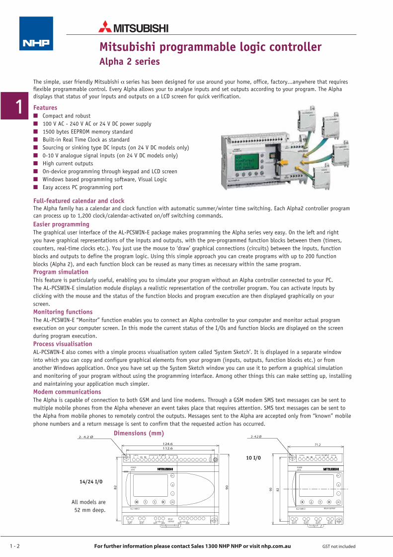
2- 4.2 ØDimensions (mm)
14/24 I/O
10 I/O
All models are 52 mm deep.
FeaturesQ Compact and robustQ 100 V AC - 240 V AC or 24 V DC power supplyQ 1500 bytes EEPROM memory standardQ Built-in Real Time Clock as standardQ Sourcing or sinking type DC inputs (on 24 V DC models only)Q 0-10 V analogue signal inputs (on 24 V DC models only)Q High current outputs Q On-device programming through keypad and LCD screenQ Windows based programming software, Visual LogicQ Easy access PC programming port
The simple, user friendly Mitsubishi _series has been designed for use around your home, office, factory...anywhere that requires flexible programmable control. Every Alpha allows your to analyse inputs and set outputs according to your program. The Alpha displays that status of your inputs and outputs on a LCD screen for quick verification.
1 - 3
1
For further information please contact Sales 1300 NHP NHP or visit nhp.com.au GST not included
Mitsubishi programmable logic controllerAlpha 2 series
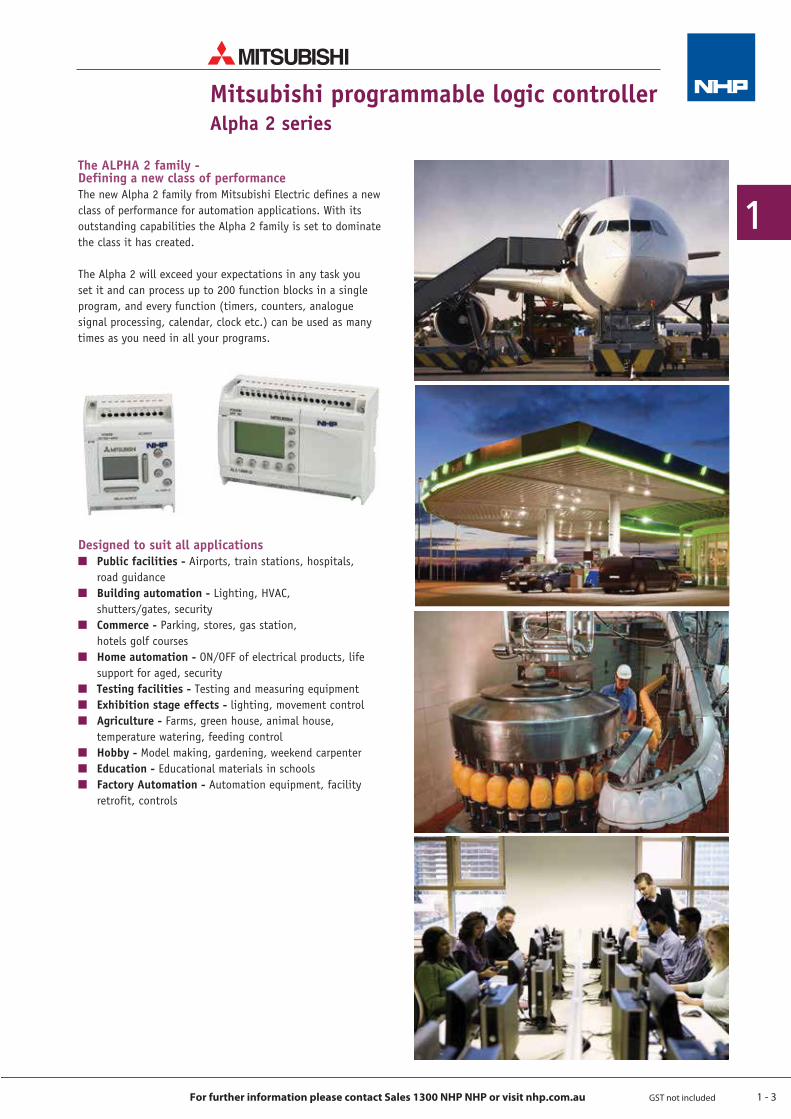
The ALPHA 2 family - Defining a new class of performanceThe new Alpha 2 family from Mitsubishi Electric defines a new class of performance for automation applications. With its outstanding capabilities the Alpha 2 family is set to dominate the class it has created.
The Alpha 2 will exceed your expectations in any task you set it and can process up to 200 function blocks in a single program, and every function (timers, counters, analogue signal processing, calendar, clock etc.) can be used as many times as you need in all your programs.
Designed to suit all applicationsQ Public facilities - Airports, train stations, hospitals, road guidanceQ Building automation - Lighting, HVAC, shutters/gates, securityQ Commerce - Parking, stores, gas station, hotels golf coursesQ Home automation - ON/OFF of electrical products, life support for aged, securityQ Testing facilities - Testing and measuring equipmentQ Exhibition stage effects - lighting, movement controlQ Agriculture - Farms, green house, animal house, temperature watering, feeding controlQ Hobby - Model making, gardening, weekend carpenterQ Education - Educational materials in schoolsQ Factory Automation - Automation equipment, facility retrofit, controls
1 - 4
1
For further information please contact Sales 1300 NHP NHP or visit nhp.com.au GST not included
AccessoriesDescription Cat. No. Price $Programming/Comms cable, PLC to PC, or PLC to L/line Modem (9 pin D)
USB to Serial converter (RS 232)
Alpha DVD which includes AL-PCSWINE programming software, manuals, sample code, laboratory notes and quick start guides
Transducer, PT100 RTD, 2 channel, 3-wire, -50 °C to +200 °C range
Transducer, Thermocouple, 2 channel, K-Type, -50 °C to +450 °C range
Memory Module, EEPROM to copy and transfer user memory
GSM Modem with antenna, 12 - 24 V DC
NEXTG Modem with antenna, 12 - 24 V DC
Modem cable, PLC to Modem, (9 pin D)
External Power supply 24 V DC, 3.5 A power supply
External Power supply 24 V DC, 5 A power supply
Mitsubishi programmable logic controllerAlpha 2 series
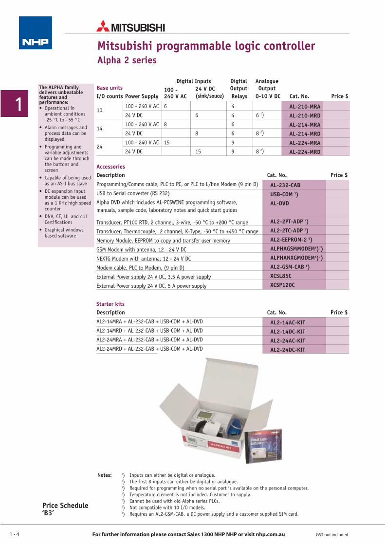
AL-210-MRAAL-210-MRDAL-214-MRAAL-214-MRDAL-224-MRAAL-224-MRD
Base unitsI/O counts
100 - 240 V AC
24 V DC
100 - 240 V AC
24 V DC
100 - 240 V AC
24 V DC
Cat. No. Price $Power Supply
6
8
15
100 - 240 V AC
6
8
15
24 V DC (sink/souce)
10
14
24
4
4
6
6
9
9
Relays
6 1)
8 2)
8 2)
0-10 V DC
Digital Inputs Digital Output
Analogue Output
AL-232-CABUSB-COM 3)AL-DVD
AL2-2PT-ADP 4)AL2-2TC-ADP 4)AL2-EEPROM-2 5)ALPHAGSMMODEM6)7)ALPHANXGMODEM6)7)AL2-GSM-CAB 6)XCSL85C XCSP120C
The ALPHA family delivers unbeatable features and performance:• Operational in
ambient conditions -25 °C to +55 °C
• Alarm messages and process data can be displayed
• Programming and variable adjustments can be made through the buttons and screen
• Capable of being used as an AS-I bus slave
• DC expansion input module can be used as a 1 KHz high speed counter
• DNV, CE, UL and cUL Certifications
• Graphical windows based software
Starter kitsDescription Cat. No. Price $AL2-14MRA + AL-232-CAB + USB-COM + AL-DVD
AL2-14MRD + AL-232-CAB + USB-COM + AL-DVD
AL2-24MRA + AL-232-CAB + USB-COM + AL-DVD
AL2-24MRD + AL-232-CAB + USB-COM + AL-DVD
AL2-14AC-KITAL2-14DC-KITAL2-24AC-KITAL2-24DC-KIT
Notes: 1) Inputs can either be digital or analogue. 2) The first 8 inputs can either be digital or analogue. 3) Required for programming when no serial port is available on the personal computer. 4) Temperature element is not included. Customer to supply. 5) Cannot be used with old Alpha series PLCs. 6) Not compatible with 10 I/O models. 7) Requires an AL2-GSM-CAB, a DC power supply and a customer supplied SIM card.
+ USB-COM + AL-DVD AL
Price Schedule ‘B3’
1 - 5
1
For further information please contact Sales 1300 NHP NHP or visit nhp.com.au GST not included
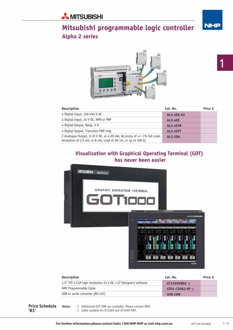
Description Cat. No. Price $4 Digital Input, 100-240 V AC
4 Digital Input, 24 V DC, NPN or PNP
4 Digital Output, Relay, 2 A
4 Digital Output, Transistor PNP only2 Analogue Output, 0-10 V DC, or 4-20 mA, Accuracy of +/- 1% full scale, resolution of 2.5 mV, or 8 mA, Load of 5K-1m, or up to 500 Ω
Mitsubishi programmable logic controllerAlpha 2 series
AL2-4EX-A2AL2-4EXAL2-4EYRAL2-4EYTAL2-2DA
Description Cat. No. Price $4.5” STF 3 CLR high resolution 24 V DC + GT Designer3 software
HMI Programmable Cable
USB to serial converter (RS-232)
GT1030HBD2 1)
GT01-C30R2-6P 2)
USB-COM
Visualisation with Graphical Operating Terminal (GOT) has never been easier
Price Schedule ‘B3’
Notes: 1) Additional GOT HMI are available. Please contact NHP. 2) Cable suitable for GT1020 and GT1030 HMI.
1 - 6
1
For further information please contact Sales 1300 NHP NHP or visit nhp.com.au GST not included
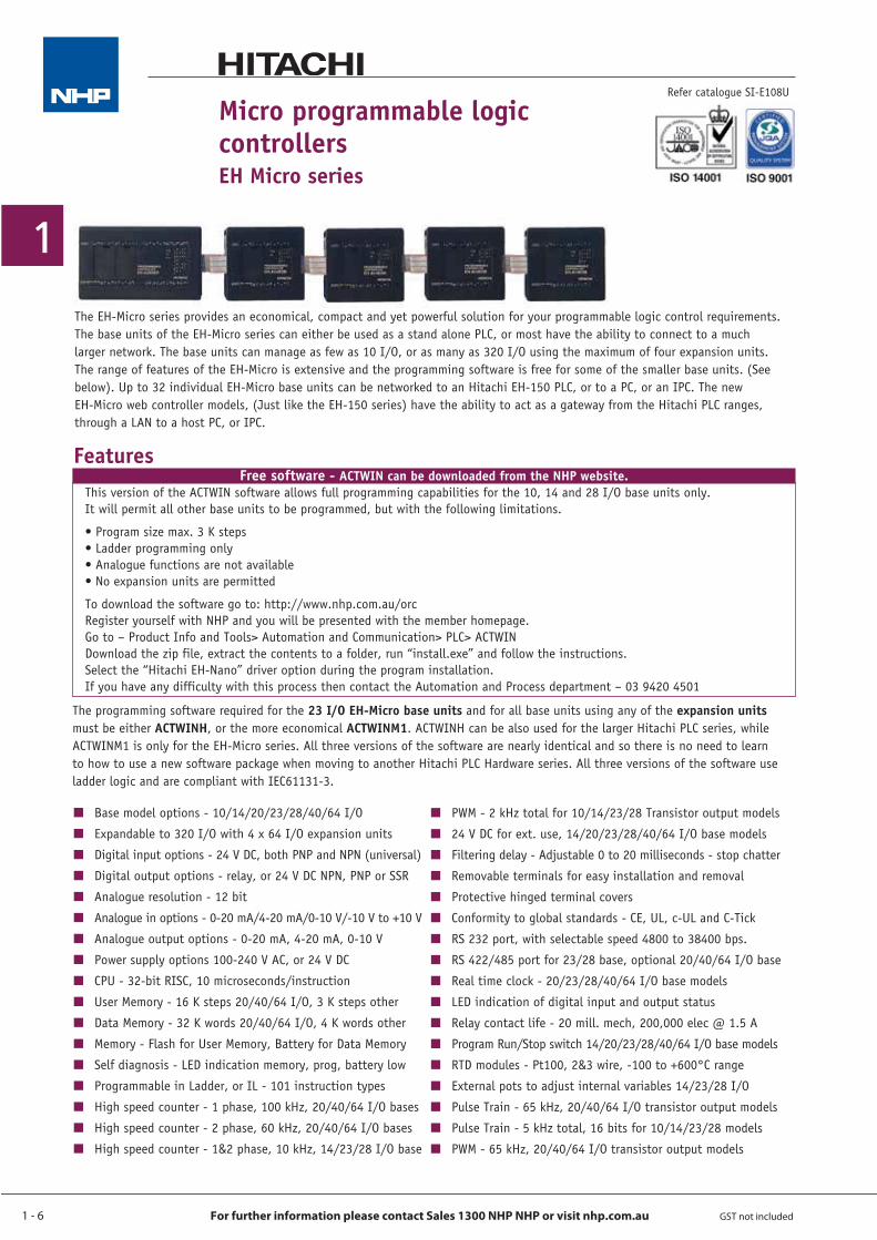
Micro programmable logic controllersEH Micro series
Q Base model options - 10/14/20/23/28/40/64 I/O
Q Expandable to 320 I/O with 4 x 64 I/O expansion units
Q Digital input options - 24 V DC, both PNP and NPN (universal)
Q Digital output options - relay, or 24 V DC NPN, PNP or SSR
Q Analogue resolution - 12 bit
Q Analogue in options - 0-20 mA/4-20 mA/0-10 V/-10 V to +10 V
Q Analogue output options - 0-20 mA, 4-20 mA, 0-10 V
Q Power supply options 100-240 V AC, or 24 V DC
Q CPU - 32-bit RISC, 10 microseconds/instruction
Q User Memory - 16 K steps 20/40/64 I/O, 3 K steps other
Q Data Memory - 32 K words 20/40/64 I/O, 4 K words other
Q Memory - Flash for User Memory, Battery for Data Memory
Q Self diagnosis - LED indication memory, prog, battery low
Q Programmable in Ladder, or IL - 101 instruction types
Q High speed counter - 1 phase, 100 kHz, 20/40/64 I/O bases
Q High speed counter - 2 phase, 60 kHz, 20/40/64 I/O bases
Q High speed counter - 1&2 phase, 10 kHz, 14/23/28 I/O base
Q PWM - 2 kHz total for 10/14/23/28 Transistor output models
Q 24 V DC for ext. use, 14/20/23/28/40/64 I/O base models
Q Filtering delay - Adjustable 0 to 20 milliseconds - stop chatter
Q Removable terminals for easy installation and removal
Q Protective hinged terminal covers
Q Conformity to global standards - CE, UL, c-UL and C-Tick
Q RS 232 port, with selectable speed 4800 to 38400 bps.
Q RS 422/485 port for 23/28 base, optional 20/40/64 I/O base
Q Real time clock - 20/23/28/40/64 I/O base models
Q LED indication of digital input and output status
Q Relay contact life - 20 mill. mech, 200,000 elec @ 1.5 A
Q Program Run/Stop switch 14/20/23/28/40/64 I/O base models
Q RTD modules - Pt100, 2&3 wire, -100 to +600°C range
Q External pots to adjust internal variables 14/23/28 I/O
Q Pulse Train - 65 kHz, 20/40/64 I/O transistor output models
Q Pulse Train - 5 kHz total, 16 bits for 10/14/23/28 models
Q PWM - 65 kHz, 20/40/64 I/O transistor output models
Refer catalogue SI-E108U
Features
The EH-Micro series provides an economical, compact and yet powerful solution for your programmable logic control requirements. The base units of the EH-Micro series can either be used as a stand alone PLC, or most have the ability to connect to a much larger network. The base units can manage as few as 10 I/O, or as many as 320 I/O using the maximum of four expansion units. The range of features of the EH-Micro is extensive and the programming software is free for some of the smaller base units. (See below). Up to 32 individual EH-Micro base units can be networked to an Hitachi EH-150 PLC, or to a PC, or an IPC. The new EH-Micro web controller models, (Just like the EH-150 series) have the ability to act as a gateway from the Hitachi PLC ranges, through a LAN to a host PC, or IPC.
Free software - ACTWIN can be downloaded from the NHP website. This version of the ACTWIN software allows full programming capabilities for the 10, 14 and 28 I/O base units only. It will permit all other base units to be programmed, but with the following limitations.
• Program size max. 3 K steps • Ladder programming only • Analogue functions are not available • No expansion units are permitted
To download the software go to: http://www.nhp.com.au/orc Register yourself with NHP and you will be presented with the member homepage. Go to – Product Info and Tools> Automation and Communication> PLC> ACTWIN Download the zip file, extract the contents to a folder, run “install.exe” and follow the instructions. Select the “Hitachi EH-Nano” driver option during the program installation. If you have any difficulty with this process then contact the Automation and Process department – 03 9420 4501
The programming software required for the 23 I/O EH-Micro base units and for all base units using any of the expansion units must be either ACTWINH, or the more economical ACTWINM1. ACTWINH can be also used for the larger Hitachi PLC series, while ACTWINM1 is only for the EH-Micro series. All three versions of the software are nearly identical and so there is no need to learn to how to use a new software package when moving to another Hitachi PLC Hardware series. All three versions of the software use ladder logic and are compliant with IEC61131-3.
1 - 7
1
For further information please contact Sales 1300 NHP NHP or visit nhp.com.au GST not included
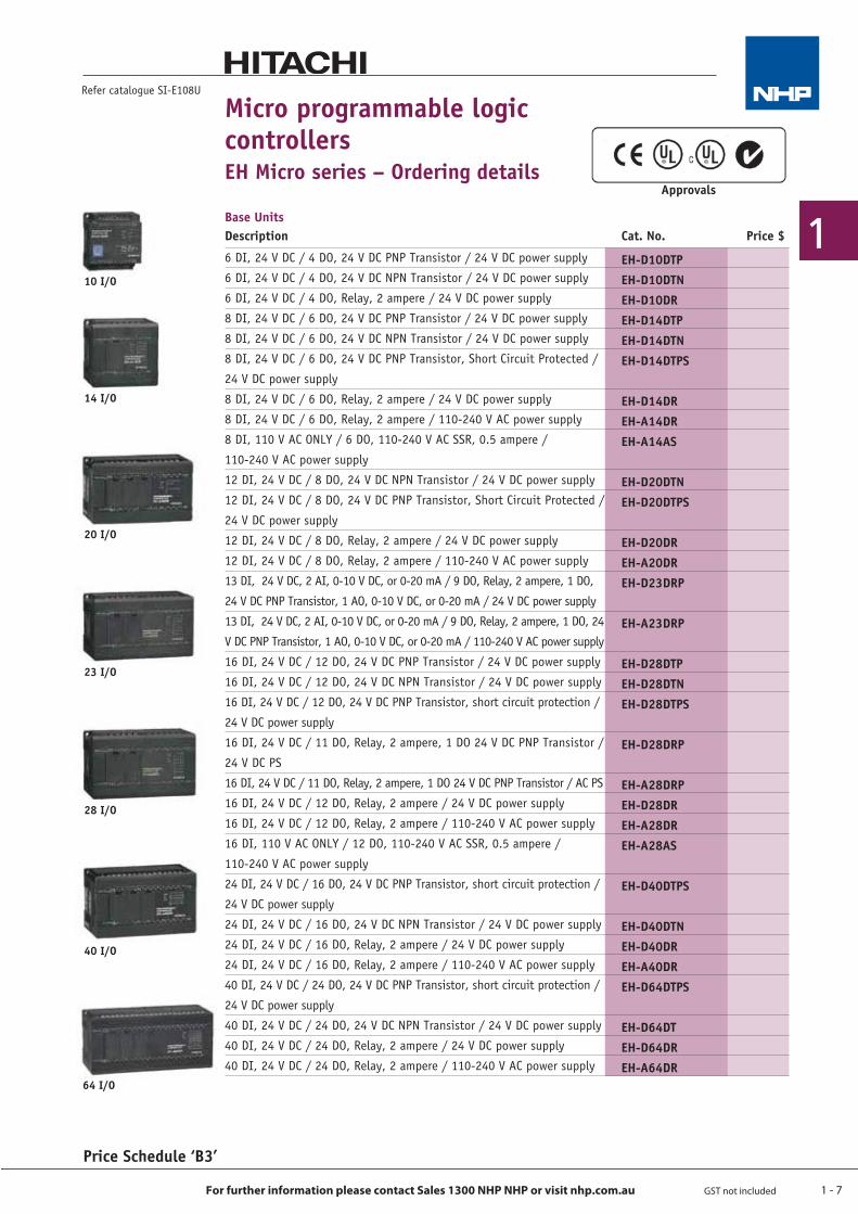
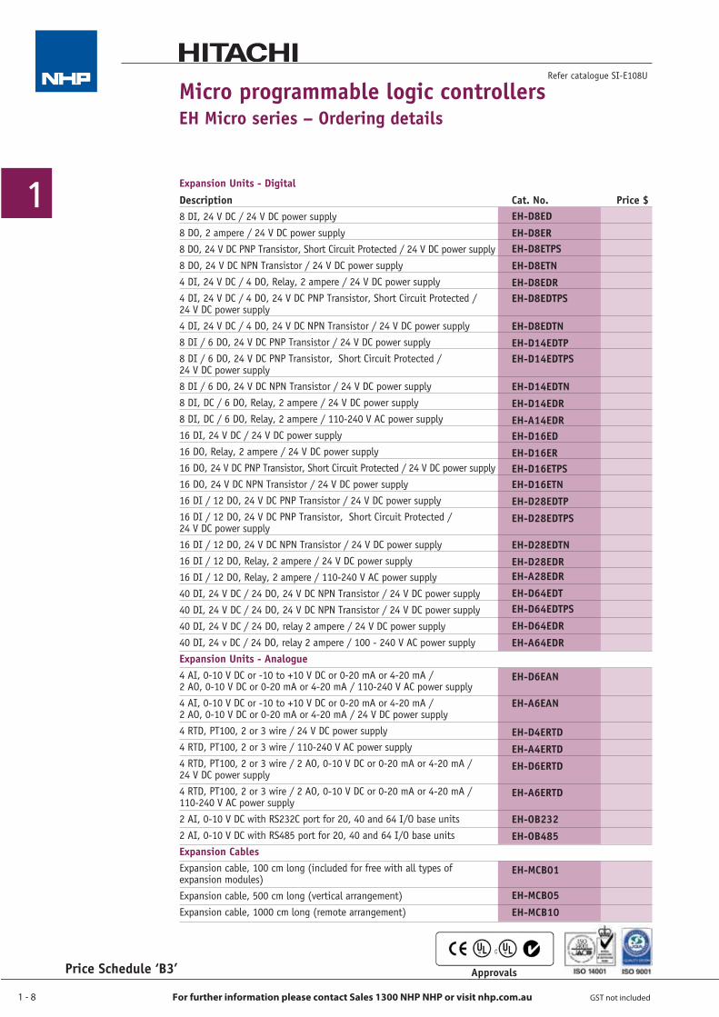
Micro programmable logic controllersEH Micro series – Ordering details
Price Schedule ‘B3’
Refer catalogue SI-E108U
10 I/O
14 I/O
20 I/O
23 I/O
28 I/O
40 I/O
64 I/O
Approvals
6 DI, 24 V DC / 4 DO, 24 V DC PNP Transistor / 24 V DC power supply
6 DI, 24 V DC / 4 DO, 24 V DC NPN Transistor / 24 V DC power supply
6 DI, 24 V DC / 4 DO, Relay, 2 ampere / 24 V DC power supply
8 DI, 24 V DC / 6 DO, 24 V DC PNP Transistor / 24 V DC power supply
8 DI, 24 V DC / 6 DO, 24 V DC NPN Transistor / 24 V DC power supply
8 DI, 24 V DC / 6 DO, 24 V DC PNP Transistor, Short Circuit Protected /
24 V DC power supply
8 DI, 24 V DC / 6 DO, Relay, 2 ampere / 24 V DC power supply
8 DI, 24 V DC / 6 DO, Relay, 2 ampere / 110-240 V AC power supply
8 DI, 110 V AC ONLY / 6 DO, 110-240 V AC SSR, 0.5 ampere /
110-240 V AC power supply
12 DI, 24 V DC / 8 DO, 24 V DC NPN Transistor / 24 V DC power supply
12 DI, 24 V DC / 8 DO, 24 V DC PNP Transistor, Short Circuit Protected /
24 V DC power supply
12 DI, 24 V DC / 8 DO, Relay, 2 ampere / 24 V DC power supply
12 DI, 24 V DC / 8 DO, Relay, 2 ampere / 110-240 V AC power supply
13 DI, 24 V DC, 2 AI, 0-10 V DC, or 0-20 mA / 9 DO, Relay, 2 ampere, 1 DO,
24 V DC PNP Transistor, 1 AO, 0-10 V DC, or 0-20 mA / 24 V DC power supply
13 DI, 24 V DC, 2 AI, 0-10 V DC, or 0-20 mA / 9 DO, Relay, 2 ampere, 1 DO, 24
V DC PNP Transistor, 1 AO, 0-10 V DC, or 0-20 mA / 110-240 V AC power supply
16 DI, 24 V DC / 12 DO, 24 V DC PNP Transistor / 24 V DC power supply
16 DI, 24 V DC / 12 DO, 24 V DC NPN Transistor / 24 V DC power supply
16 DI, 24 V DC / 12 DO, 24 V DC PNP Transistor, short circuit protection /
24 V DC power supply
16 DI, 24 V DC / 11 DO, Relay, 2 ampere, 1 DO 24 V DC PNP Transistor /
24 V DC PS
16 DI, 24 V DC / 11 DO, Relay, 2 ampere, 1 DO 24 V DC PNP Transistor / AC PS
16 DI, 24 V DC / 12 DO, Relay, 2 ampere / 24 V DC power supply
16 DI, 24 V DC / 12 DO, Relay, 2 ampere / 110-240 V AC power supply
16 DI, 110 V AC ONLY / 12 DO, 110-240 V AC SSR, 0.5 ampere /
110-240 V AC power supply
24 DI, 24 V DC / 16 DO, 24 V DC PNP Transistor, short circuit protection /
24 V DC power supply
24 DI, 24 V DC / 16 DO, 24 V DC NPN Transistor / 24 V DC power supply
24 DI, 24 V DC / 16 DO, Relay, 2 ampere / 24 V DC power supply
24 DI, 24 V DC / 16 DO, Relay, 2 ampere / 110-240 V AC power supply
40 DI, 24 V DC / 24 DO, 24 V DC PNP Transistor, short circuit protection /
24 V DC power supply
40 DI, 24 V DC / 24 DO, 24 V DC NPN Transistor / 24 V DC power supply
40 DI, 24 V DC / 24 DO, Relay, 2 ampere / 24 V DC power supply
40 DI, 24 V DC / 24 DO, Relay, 2 ampere / 110-240 V AC power supply
EH-D10DTPEH-D10DTNEH-D10DREH-D14DTPEH-D14DTNEH-D14DTPS
EH-D14DREH-A14DREH-A14AS
EH-D20DTNEH-D20DTPS
EH-D20DREH-A20DREH-D23DRP
EH-A23DRP
EH-D28DTPEH-D28DTNEH-D28DTPS
EH-D28DRP
EH-A28DRPEH-D28DREH-A28DREH-A28AS
EH-D40DTPS
EH-D40DTNEH-D40DREH-A40DREH-D64DTPS
EH-D64DTEH-D64DREH-A64DR
Base UnitsDescription Cat. No. Price $
1 - 8
1
For further information please contact Sales 1300 NHP NHP or visit nhp.com.au GST not included
Price Schedule ‘B3’
Micro programmable logic controllersEH Micro series – Ordering details
Refer catalogue SI-E108U
Expansion Units - DigitalDescription Cat. No. Price $8 DI, 24 V DC / 24 V DC power supply8 DO, 2 ampere / 24 V DC power supply8 DO, 24 V DC PNP Transistor, Short Circuit Protected / 24 V DC power supply8 DO, 24 V DC NPN Transistor / 24 V DC power supply4 DI, 24 V DC / 4 DO, Relay, 2 ampere / 24 V DC power supply4 DI, 24 V DC / 4 DO, 24 V DC PNP Transistor, Short Circuit Protected / 24 V DC power supply4 DI, 24 V DC / 4 DO, 24 V DC NPN Transistor / 24 V DC power supply8 DI / 6 DO, 24 V DC PNP Transistor / 24 V DC power supply8 DI / 6 DO, 24 V DC PNP Transistor, Short Circuit Protected / 24 V DC power supply8 DI / 6 DO, 24 V DC NPN Transistor / 24 V DC power supply8 DI, DC / 6 DO, Relay, 2 ampere / 24 V DC power supply8 DI, DC / 6 DO, Relay, 2 ampere / 110-240 V AC power supply16 DI, 24 V DC / 24 V DC power supply16 DO, Relay, 2 ampere / 24 V DC power supply16 DO, 24 V DC PNP Transistor, Short Circuit Protected / 24 V DC power supply16 DO, 24 V DC NPN Transistor / 24 V DC power supply16 DI / 12 DO, 24 V DC PNP Transistor / 24 V DC power supply16 DI / 12 DO, 24 V DC PNP Transistor, Short Circuit Protected / 24 V DC power supply16 DI / 12 DO, 24 V DC NPN Transistor / 24 V DC power supply16 DI / 12 DO, Relay, 2 ampere / 24 V DC power supply16 DI / 12 DO, Relay, 2 ampere / 110-240 V AC power supply40 DI, 24 V DC / 24 DO, 24 V DC NPN Transistor / 24 V DC power supply40 DI, 24 V DC / 24 DO, 24 V DC NPN Transistor / 24 V DC power supply40 DI, 24 V DC / 24 DO, relay 2 ampere / 24 V DC power supply40 DI, 24 v DC / 24 DO, relay 2 ampere / 100 - 240 V AC power supplyExpansion Units - Analogue4 AI, 0-10 V DC or -10 to +10 V DC or 0-20 mA or 4-20 mA / 2 AO, 0-10 V DC or 0-20 mA or 4-20 mA / 110-240 V AC power supply 4 AI, 0-10 V DC or -10 to +10 V DC or 0-20 mA or 4-20 mA / 2 AO, 0-10 V DC or 0-20 mA or 4-20 mA / 24 V DC power supply 4 RTD, PT100, 2 or 3 wire / 24 V DC power supply4 RTD, PT100, 2 or 3 wire / 110-240 V AC power supply4 RTD, PT100, 2 or 3 wire / 2 AO, 0-10 V DC or 0-20 mA or 4-20 mA / 24 V DC power supply 4 RTD, PT100, 2 or 3 wire / 2 AO, 0-10 V DC or 0-20 mA or 4-20 mA / 110-240 V AC power supply 2 AI, 0-10 V DC with RS232C port for 20, 40 and 64 I/O base units2 AI, 0-10 V DC with RS485 port for 20, 40 and 64 I/O base unitsExpansion CablesExpansion cable, 100 cm long (included for free with all types of expansion modules)Expansion cable, 500 cm long (vertical arrangement)Expansion cable, 1000 cm long (remote arrangement)
EH-D8EDEH-D8EREH-D8ETPSEH-D8ETNEH-D8EDREH-D8EDTPS
EH-D8EDTNEH-D14EDTPEH-D14EDTPS
EH-D14EDTNEH-D14EDREH-A14EDREH-D16EDEH-D16EREH-D16ETPSEH-D16ETNEH-D28EDTPEH-D28EDTPS
EH-D28EDTNEH-D28EDREH-A28EDREH-D64EDTEH-D64EDTPSEH-D64EDREH-A64EDR
EH-D6EAN
EH-A6EAN
EH-D4ERTDEH-A4ERTDEH-D6ERTD
EH-A6ERTD
EH-OB232EH-OB485
EH-MCB01
EH-MCB05EH-MCB10
Approvals
1 - 9
1
For further information please contact Sales 1300 NHP NHP or visit nhp.com.au GST not included
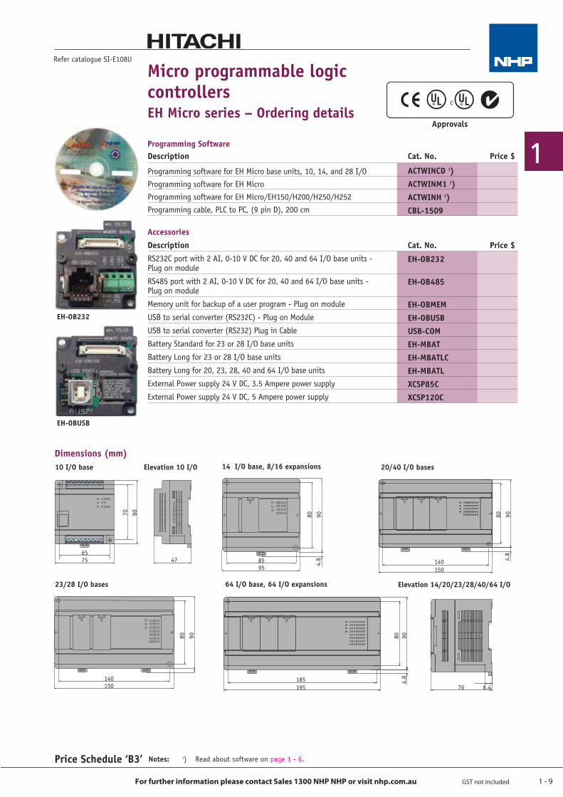
AccessoriesDescription Cat. No. Price $RS232C port with 2 AI, 0-10 V DC for 20, 40 and 64 I/O base units - Plug on module
RS485 port with 2 AI, 0-10 V DC for 20, 40 and 64 I/O base units - Plug on module
Memory unit for backup of a user program - Plug on module
USB to serial converter (RS232C) - Plug on Module
USB to serial converter (RS232) Plug in Cable
Battery Standard for 23 or 28 I/O base units
Battery Long for 23 or 28 I/O base units
Battery Long for 20, 23, 28, 40 and 64 I/O base units
External Power supply 24 V DC, 3.5 Ampere power supply
External Power supply 24 V DC, 5 Ampere power supply
Programming SoftwareDescription Cat. No. Price $
Programming software for EH Micro base units, 10, 14, and 28 I/OProgramming software for EH Micro Programming software for EH Micro/EH150/H200/H250/H252Programming cable, PLC to PC, (9 pin D), 200 cm
ACTWINCD 1)ACTWINM1 1)ACTWINH 1)CBL-1509
Refer catalogue SI-E108U
Price Schedule ‘B3’
Micro programmable logic controllersEH Micro series – Ordering details
EH-OB232
EH-OB485
EH-OBMEMEH-OBUSBUSB-COMEH-MBATEH-MBATLCEH-MBATLXCSP85CXCSP120C
EH-OBUSB
EH-OB232
Notes: 1) Read about software on page 1 - 6.
14-point type, 8/16-point expansion unit 20/40-point type
64-point type23/28-point type
10-point type
70 80 80 90 80 90
80 9080 90
6575 47 85
95140150
76 8.4185195
140150
4.8 4.
8
4.8
Dimensions (mm)
76 8.4
10 I/O base
23/28 I/O bases 64 I/O base, 64 I/O expansions
Elevation 10 I/O 14 I/O base, 8/16 expansions
Elevation 14/20/23/28/40/64 I/O
20/40 I/O bases
Approvals
1 - 10
1
For further information please contact Sales 1300 NHP NHP or visit nhp.com.au GST not included
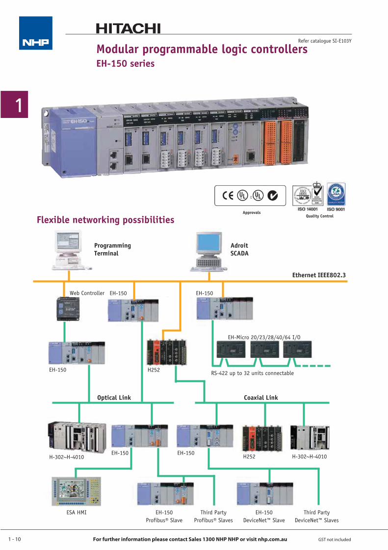
Modular programmable logic controllersEH-150 series
Refer catalogue SI-E103Y
Flexible networking possibilitiesApprovals
Quality Control
ProgrammingTerminal
AdroitSCADA
Ethernet IEEE802.3
Optical Link Coaxial Link
Web Controller EH-150 EH-150
H252EH-150 RS-422 up to 32 units connectable
EH-Micro 20/23/28/40/64 I/O
EH-150 EH-150 H252 H-302~H-4010H-302~H-4010
ESA HMI Third PartyDeviceNet™ Slaves
EH-150DeviceNet™ Slave
Third PartyProfibus® Slaves
EH-150Profibus® Slave
1 - 11
1
For further information please contact Sales 1300 NHP NHP or visit nhp.com.au GST not included
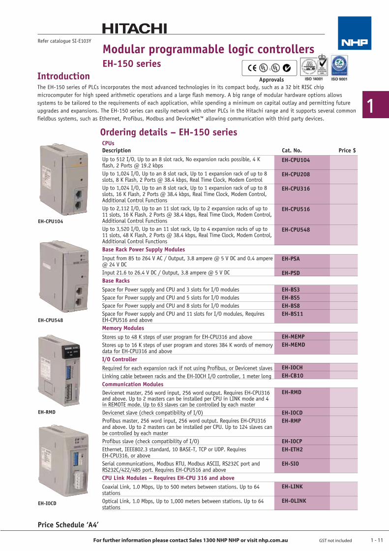
CPUsDescription Cat. No. Price $Up to 512 I/O, Up to an 8 slot rack, No expansion racks possible, 4 K flash, 2 Ports @ 19.2 kbpsUp to 1,024 I/O, Up to an 8 slot rack, Up to 1 expansion rack of up to 8 slots, 8 K Flash, 2 Ports @ 38.4 kbps, Real Time Clock, Modem ControlUp to 1,024 I/O, Up to an 8 slot rack, Up to 1 expansion rack of up to 8 slots, 16 K Flash, 2 Ports @ 38.4 kbps, Real Time Clock, Modem Control, Additional Control FunctionsUp to 2,112 I/O, Up to an 11 slot rack, Up to 2 expansion racks of up to 11 slots, 16 K Flash, 2 Ports @ 38.4 kbps, Real Time Clock, Modem Control, Additional Control FunctionsUp to 3,520 I/O, Up to an 11 slot rack, Up to 4 expansion racks of up to 11 slots, 48 K Flash, 2 Ports @ 38.4 kbps, Real Time Clock, Modem Control, Additional Control FunctionsBase Rack Power Supply ModulesInput from 85 to 264 V AC / Output, 3.8 ampere @ 5 V DC and 0.4 ampere @ 24 V DCInput 21.6 to 26.4 V DC / Output, 3.8 ampere @ 5 V DCBase RacksSpace for Power supply and CPU and 3 slots for I/O modulesSpace for Power supply and CPU and 5 slots for I/O modulesSpace for Power supply and CPU and 8 slots for I/O modulesSpace for Power supply and CPU and 11 slots for I/O modules, Requires EH-CPU516 and aboveMemory ModulesStores up to 48 K steps of user program for EH-CPU316 and aboveStores up to 16 K steps of user program and stores 384 K words of memory data for EH-CPU316 and above I/O ControllerRequired for each expansion rack if not using Profibus, or Devicenet slavesLinking cable between racks and the EH-IOCH I/O controller, 1 meter longCommunication ModulesDevicenet master, 256 word input, 256 word output. Requires EH-CPU316 and above. Up to 2 masters can be installed per CPU in LINK mode and 4 in REMOTE mode. Up to 63 slaves can be controlled by each masterDevicenet slave (check compatibility of I/O)Profibus master, 256 word input, 256 word output. Requires EH-CPU316 and above. Up to 2 masters can be installed per CPU. Up to 124 slaves can be controlled by each master Profibus slave (check compatibility of I/O)Ethernet, IEEE802.3 standard, 10 BASE-T, TCP or UDP. Requires EH-CPU316, or aboveSerial communications, Modbus RTU, Modbus ASCII, RS232C port and RS232C/422/485 port. Requires EH-CPU516 and aboveCPU Link Modules – Requires EH-CPU 316 and aboveCoaxial Link, 1.0 Mbps, Up to 500 meters between stations. Up to 64 stationsOptical Link, 1.0 Mbps, Up to 1,000 meters between stations. Up to 64 stations
Price Schedule ‘A4’
Refer catalogue SI-E103Y
EH-I0CD
EH-CPU104
IntroductionThe EH-150 series of PLCs incorporates the most advanced technologies in its compact body, such as a 32 bit RISC chip microcomputer for high speed arithmetic operations and a large flash memory. A big range of modular hardware options allows systems to be tailored to the requirements of each application, while spending a minimum on capital outlay and permitting future upgrades and expansions. The EH-150 series can easily network with other PLCs in the Hitachi range and it supports several common fieldbus systems, such as Ethernet, Profibus, Modbus and DeviceNet™ allowing communication with third party devices.
Modular programmable logic controllersEH-150 series
Ordering details – EH-150 series
EH-CPU548
EH-RMD
Approvals
EH-CPU104
EH-CPU208
EH-CPU316
EH-CPU516
EH-CPU548
EH-PSA
EH-PSD
EH-BS3EH-BS5EH-BS8EH-BS11
EH-MEMPEH-MEMD
EH-IOCHEH-CB10
EH-RMD
EH-IOCDEH-RMP
EH-IOCPEH-ETH2
EH-SIO
EH-LINK
EH-OLINK
1 - 12
1
For further information please contact Sales 1300 NHP NHP or visit nhp.com.au GST not included
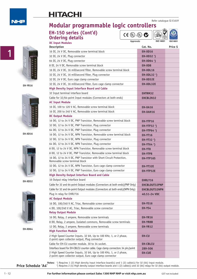
DC Input ModulesDescription Cat. No. Price $16 DI, 24 V DC, Removable screw terminal block
32 DI, 24 V DC, Plug connector
64 DI, 24 V DC, Plug connector
8 DI, 24 V DC, Removable screw terminal block
16 DI, 24 V DC, 16 millisecond filter, Removable screw terminal block
32 DI, 24 V DC, 16 millisecond filter, Plug connector
32 DI, 24 V DC, Euro cage clamp connector
32 DI, 24 V DC, 16 millisecond filter, Euro cage clamp connectorHigh Density Input Interface Board and Cable32 Input terminal interface board
Cable for 32/64-point Input modules (Connectors at both ends)AC Input Module16 DI, 100 to 120 V AC, Removable screw terminal block
16 DI, 200 to 240 V AC, Removable screw terminal blockDC Output Module16 DO, 12 to 24 V DC, PNP Transistor, Removable screw terminal block
32 DO, 12 to 24 V DC, PNP Transistor, Plug connector
64 DO, 12 to 24 V DC, PNP Transistor, Plug connector
16 DO, 12 to 24 V DC, NPN Transistor, Removable screw terminal block
32 DO, 12 to 24 V DC, NPN Transistor, Plug connector
64 DO, 12 to 24 V DC, NPN Transistor, Plug connector
8 DO, 12 to 24 V DC, NPN Transistor, Removable screw terminal block
8 DO, 12 to 24 V DC, PNP Transistor, Removable screw terminal block
16 DO, 12 to 24 V DC, PNP Transistor with Short Circuit Protection, Removable screw terminal block
32 DO, 12 to 24 V DC, NPN Transistor, Euro cage clamp connector
32 DO, 12 to 24 V DC, PNP Transistor, Euro cage clamp connector
High Density Output Interface Board and Cable16 Output relay interface board
Cable for 32 and 64-point Output modules (Connectors at both ends)(PNP Only)
Cable for 32 and 64-point Output modules (Connectors at both ends)(NPN Only)
Plug in relay for EHRLY16
AC Output Module
16 DO, 100/240 V AC, Triac, Removable screw connector
4 DO, 100/240 V AC, Triac, Removable screw connectorRelay Output Module
16 DO, Relay, 2 ampere, Removable screw terminals
8 DO, Relay, 2 ampere, Isolated commons, Removable screw terminals
12 DO, Relay, 2 ampere, Removable screw terminals High Function Module
2 High Speed Counter Inputs, 32 bit, Up to 100 KHz, 1, or 2 phase, 2-point open collector output, Plug connector
Cable for EH-CU counter module. 30 to 34 socket.Interface board for EH-CBLCU counter cable. Cage clamp connectors 34 pin/point2 High Speed Counter Inputs, 32 bit, Up to 100 KHz, 1, or 2 phase, 2-point open collector output, Euro cage clamp connector
EH-XD16EH-XD32 1)EH-XD64 1)EH-XD8EH-XDL16EH-XDL32 1)EH-XD32EEH-XDL32E EHTRM32EHCBLIN32 EH-XA16EH-XAH16 EH-YTP16EH-YTP32 2)EH-YTP64 2)EH-YT16EH-YT32 2)EH-YT64 2)EH-YT8EH-YTP8EH-YTP16S
EH-YT32EEH-YTP32E
EHRLY16EHCBLOUT32PNPEHCBLOUT32NPN40.51-24 VDC EH-YS16EH-YS4 EH-YR16EH-YR8BEH-YR12
EH-CU
EH-CBLCU289-506EH-CUE
Price Schedule ‘A4’
Refer catalogue SI-E103Y
Modular programmable logic controllersEH-150 series (Cont’d)Ordering details
Notes: 1) Requires 1 (2) High density input interface board(s) and 1 (2) cable(s) for 32 (64) input module. 2) Requires 2 (4) High density output interface boards and 1 (2) cable(s) and 32 (64) relays for 32 (64) output module.
EH-YR16
EH-XD32
EH-XD64
EH-XD16
Approvals
1 - 13
1
For further information please contact Sales 1300 NHP NHP or visit nhp.com.au GST not included
Modular programmable logic controllersEH-150 series (Cont’d)
Price Schedule ‘A4’
Refer catalogue SI-E103Y
Ordering details
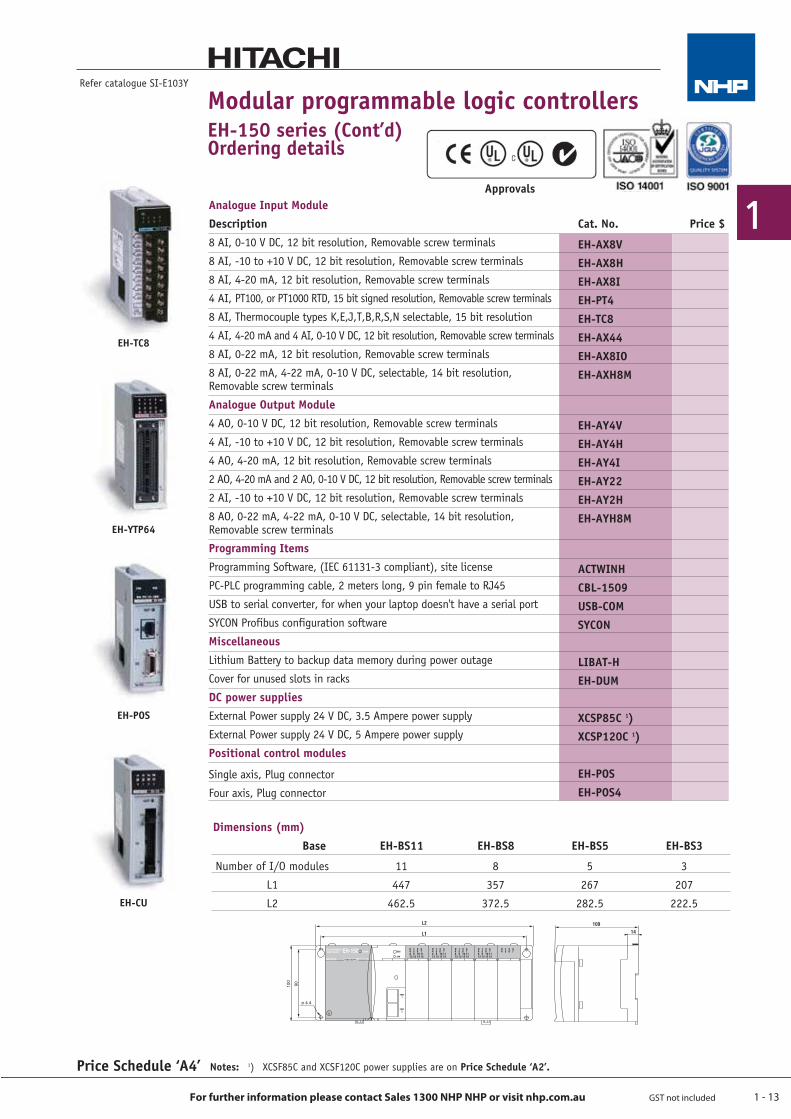
Number of I/O modules
L1
L2
11
447
462.5
BaseDimensions (mm)
EH-BS11
8
357
372.5
EH-BS8
5
267
282.5
EH-BS5
3
207
222.5
EH-BS3
Notes: 1) XCSF85C and XCSF120C power supplies are on Price Schedule ‘A2’.
EH-TC8
EH-YTP64
EH-POS
EH-CU
ApprovalsAnalogue Input ModuleDescription Cat. No. Price $8 AI, 0-10 V DC, 12 bit resolution, Removable screw terminals
8 AI, -10 to +10 V DC, 12 bit resolution, Removable screw terminals
8 AI, 4-20 mA, 12 bit resolution, Removable screw terminals
4 AI, PT100, or PT1000 RTD, 15 bit signed resolution, Removable screw terminals
8 AI, Thermocouple types K,E,J,T,B,R,S,N selectable, 15 bit resolution
4 AI, 4-20 mA and 4 AI, 0-10 V DC, 12 bit resolution, Removable screw terminals
8 AI, 0-22 mA, 12 bit resolution, Removable screw terminals
8 AI, 0-22 mA, 4-22 mA, 0-10 V DC, selectable, 14 bit resolution, Removable screw terminals
Analogue Output Module4 AO, 0-10 V DC, 12 bit resolution, Removable screw terminals
4 AI, -10 to +10 V DC, 12 bit resolution, Removable screw terminals
4 AO, 4-20 mA, 12 bit resolution, Removable screw terminals
2 AO, 4-20 mA and 2 AO, 0-10 V DC, 12 bit resolution, Removable screw terminals
2 AI, -10 to +10 V DC, 12 bit resolution, Removable screw terminals
8 AO, 0-22 mA, 4-22 mA, 0-10 V DC, selectable, 14 bit resolution, Removable screw terminals
Programming ItemsProgramming Software, (IEC 61131-3 compliant), site license
PC-PLC programming cable, 2 meters long, 9 pin female to RJ45
USB to serial converter, for when your laptop doesn't have a serial port
SYCON Profibus configuration software
MiscellaneousLithium Battery to backup data memory during power outage
Cover for unused slots in racks
DC power suppliesExternal Power supply 24 V DC, 3.5 Ampere power supply
External Power supply 24 V DC, 5 Ampere power supply
Positional control modules
Single axis, Plug connector
Four axis, Plug connector
EH-AX8VEH-AX8HEH-AX8IEH-PT4EH-TC8EH-AX44EH-AX8IOEH-AXH8M
EH-AY4VEH-AY4HEH-AY4IEH-AY22EH-AY2HEH-AYH8M
ACTWINHCBL-1509USB-COMSYCON LIBAT-HEH-DUM XCSP85C 1)XCSP120C 1)
EH-POSEH-POS4
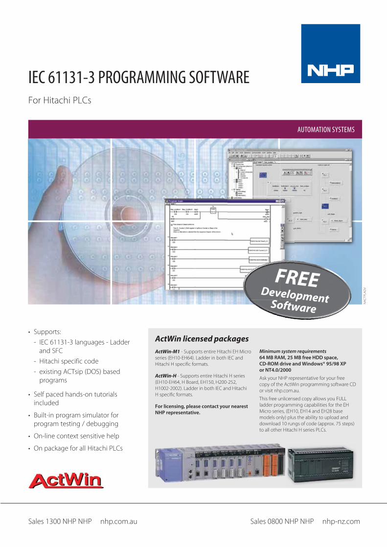
IEC 61131-3 PROGRAMMING SOFTWARE
AUTOMATION SYSTEMS
FREEDevelopmentSoftware
ActWin licensed packagesActWin-M1
ActWin-H
For licensing, please contact your nearest NHP representative.
Minimum system requirements 64 MB RAM, 25 MB free HDD space, CD-ROM drive and Windows® 95/98 XP or NT4.0/2000
1 - 15
1
For further information please contact Sales 1300 NHP NHP or visit nhp.com.au GST not included
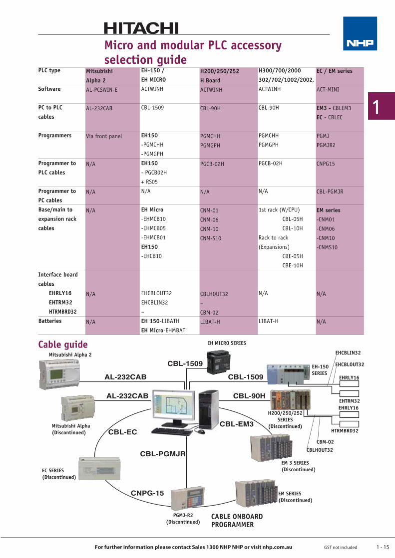
Micro and modular PLC accessory selection guide
EH-150 / EH MICROACTWINH
CBL-1509
EH150-PGMCHH
-PGMGPH
EH150- PGCB02H
+ RS05
N/A
EH Micro-EHMCB10
-EHMCB05
-EHMCB01
EH150-EHCB10
EHCBLOUT32
EHCBLIN32
–
EH 150-LIBATH
EH Micro-EHMBAT
PLC type
Software
PC to PLCcables
Programmers
Programmer to PLC cables
Programmer toPC cablesBase/main to expansion rack cables
Interface board cables EHRLY16 EHTRM32 HTRMBRD32Batteries
EC / EM series
ACT-MINI
EM3 - CBLEM3
EC - CBLEC
PGMJ
PGMJR2
CNPG15
CBL-PGMJR
EM series-CNM01
-CNM06
-CNM10
-CNMS10
N/A
N/A
MitsubishiAlpha 2AL-PCSWIN-E
AL-232CAB
Via front panel
N/A
N/A
N/A
N/A
N/A
H200/250/252 H BoardACTWINH
CBL-90H
PGMCHH
PGMGPH
PGCB-02H
N/A
CNM-01
CNM-06
CNM-10
CNM-S10
CBLHOUT32
–
CBM-02
LIBAT-H
H300/700/2000302/702/1002/2002, ACTWINH
CBL-90H
PGMCHH
PGMGPH
PGCB-02H
N/A
1st rack (W/CPU)
CBL-05H
CBL-10H
Rack to rack
(Expansions)
CBE-05H
CBE-10H
N/A
LIBAT-H
Cable guide
EC SERIES(Discontinued)
Mitsubishi Alpha 2
Mitsubishi Alpha(Discontinued)
H200/250/252 SERIES
(Discontinued)
EM SERIES(Discontinued)
PGMJ-R2(Discontinued)
CABLE ONBOARD PROGRAMMER
EH MICRO SERIES
EH-150SERIES
EHCBLOUT32
EHCBLIN32
CBLHOUT32CBM-02
EHRLY16
EHTRM32EHRLY16
HTRMBRD32
EM 3 SERIES(Discontinued)
CBL-1509
AL-232CAB CBL-1509
AL-232CAB CBL-90H
CBL-EM3CBL-EC
CNPG-15
CBL-PGMJR
1 - 16
1
For further information please contact Sales 1300 NHP NHP or visit nhp.com.au GST not included
Optimum design of a Fieldbus node
The following requirements must be met in order to design an economic fieldbus node:
Q best possible modularity – 1, 2, 4 or 8 channel for standard I/Os – single channel for special functions
Q combination of digital and analogue I/Os including various voltage, power and instrumentation signal requirements within a node
Q sensors and actuators may be wired independently of the fieldbus Q fast coupling to the chosen fieldbus Q quick and clear marking facilityQ easy handling with few additional accessoriesQ fast and easy wiring with high operational reliabilityQ RS 232/RS 485 communication modules, user configurable and easy to use
WAGO I/O-SystemFieldbus independent BUS terminal block
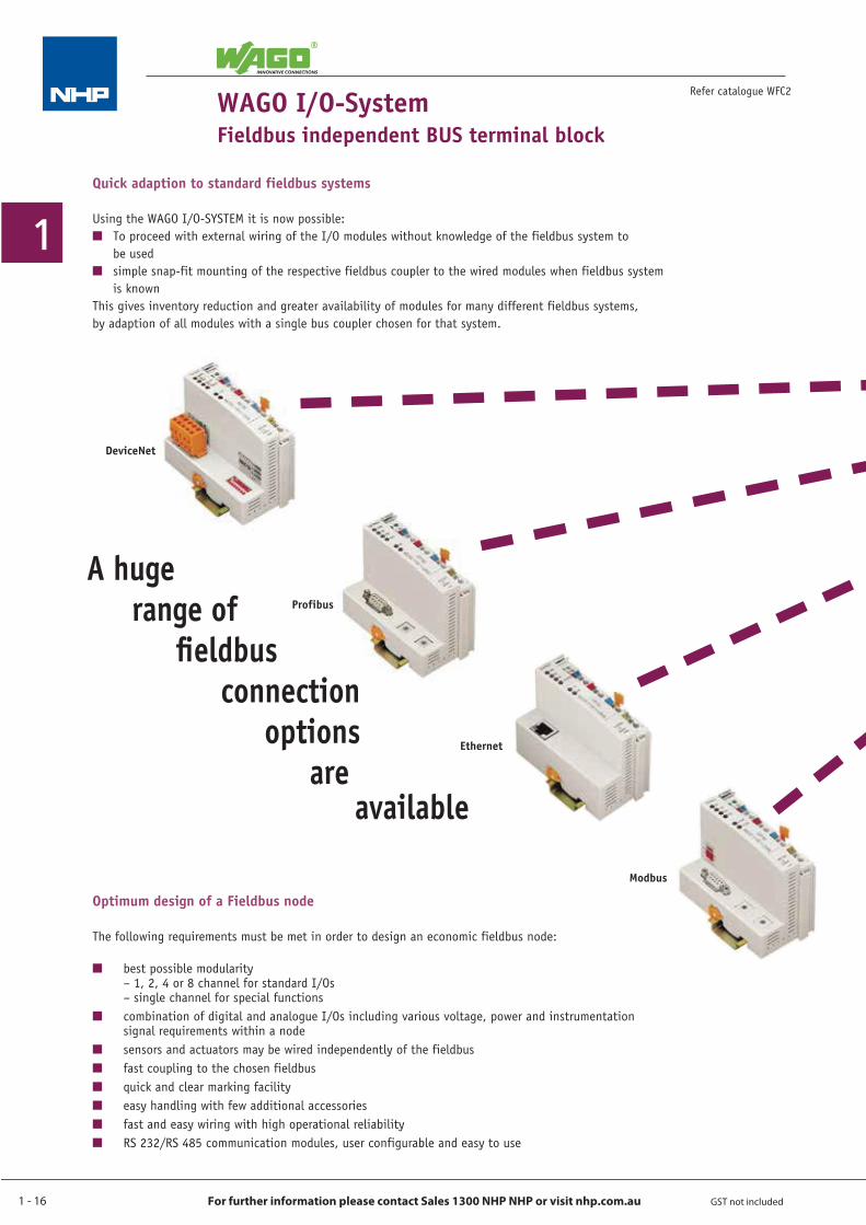
Quick adaption to standard fieldbus systems
Using the WAGO I/O-SYSTEM it is now possible:Q To proceed with external wiring of the I/O modules without knowledge of the fieldbus system to be usedQ simple snap-fit mounting of the respective fieldbus coupler to the wired modules when fieldbus system is known This gives inventory reduction and greater availability of modules for many different fieldbus systems,by adaption of all modules with a single bus coupler chosen for that system.
Refer catalogue WFC2
DeviceNet
Profibus
Ethernet
Modbus
A hugerange of
fieldbusconnection
optionsare
available
1 - 17
1
For further information please contact Sales 1300 NHP NHP or visit nhp.com.au GST not included
WAGO I/O-SystemFieldbus independent BUS terminal block
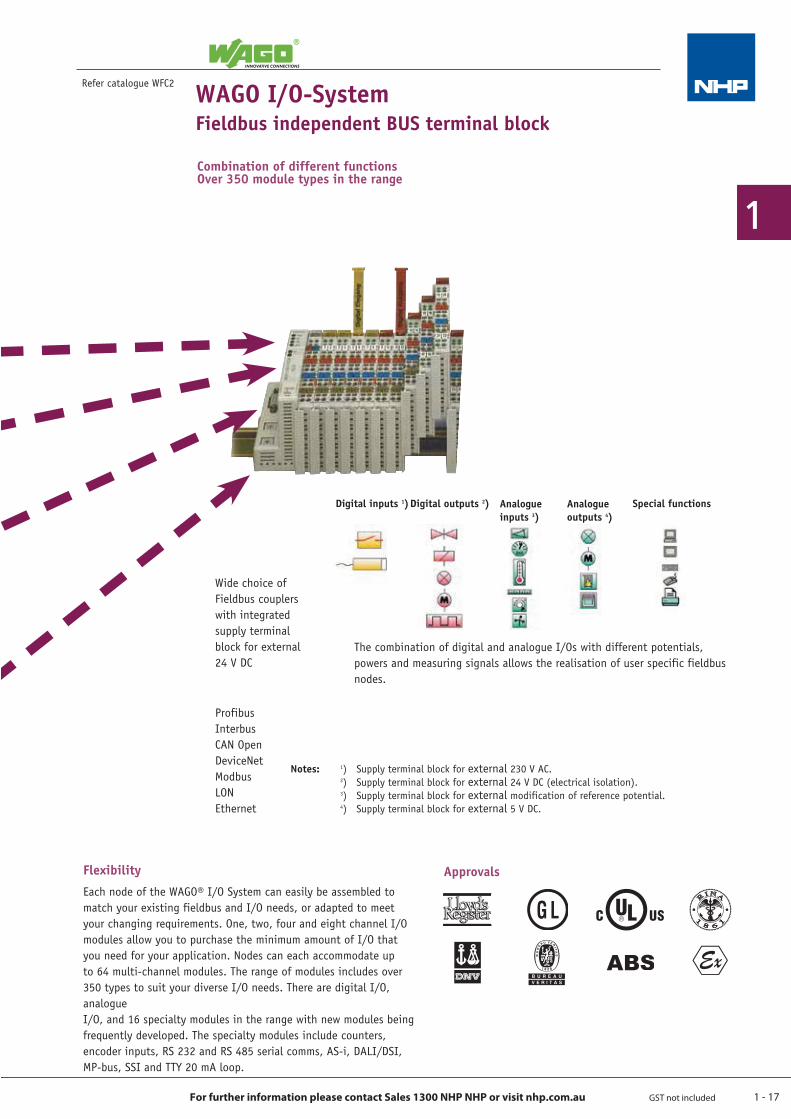
Combination of different functionsOver 350 module types in the range
The combination of digital and analogue I/Os with different potentials, powers and measuring signals allows the realisation of user specific fieldbus nodes.
Wide choice of Fieldbus couplers with integrated supply terminal block for external 24 V DC
Digital inputs 1)Digital outputs 2) Analogue inputs 3)
Analogue outputs 4)
Special functions
Notes: 1) Supply terminal block for external 230 V AC. 2) Supply terminal block for external 24 V DC (electrical isolation). 3) Supply terminal block for external modification of reference potential. 4) Supply terminal block for external 5 V DC.
ProfibusInterbus CAN OpenDeviceNetModbusLONEthernet
Refer catalogue WFC2
Each node of the WAGO® I/O System can easily be assembled to match your existing fieldbus and I/O needs, or adapted to meet your changing requirements. One, two, four and eight channel I/O modules allow you to purchase the minimum amount of I/O that you need for your application. Nodes can each accommodate up to 64 multi-channel modules. The range of modules includes over 350 types to suit your diverse I/O needs. There are digital I/O, analogueI/O, and 16 specialty modules in the range with new modules being frequently developed. The specialty modules include counters, encoder inputs, RS 232 and RS 485 serial comms, AS-i, DALI/DSI, MP-bus, SSI and TTY 20 mA loop.
Flexibility Approvals
1 - 18
1
For further information please contact Sales 1300 NHP NHP or visit nhp.com.au GST not included
Refer catalogue WFC2
WAGO I/O-System – 750 SeriesThe BUS terminal blockThe universal basic module
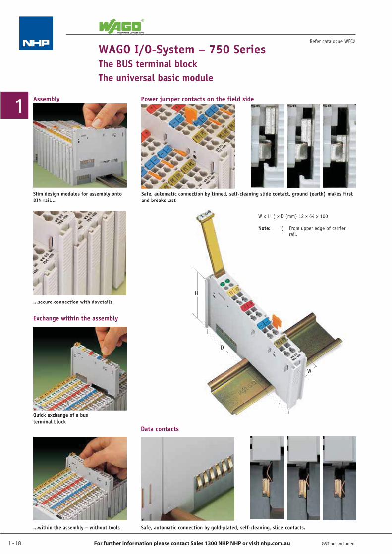
Assembly Power jumper contacts on the field side
Slim design modules for assembly onto DIN rail...
...secure connection with dovetails
Quick exchange of a bus terminal block
...within the assembly – without tools Safe, automatic connection by gold-plated, self-cleaning, slide contacts.
Safe, automatic connection by tinned, self-cleaning slide contact, ground (earth) makes first and breaks last
W x H 1) x D (mm) 12 x 64 x 100
Note: 1) From upper edge of carrier rail.
H
W
D
Exchange within the assembly
Data contacts
1 - 19
1
For further information please contact Sales 1300 NHP NHP or visit nhp.com.au GST not included
WAGO I/O-System – 750 SeriesThe BUS terminal block
The universal basic module
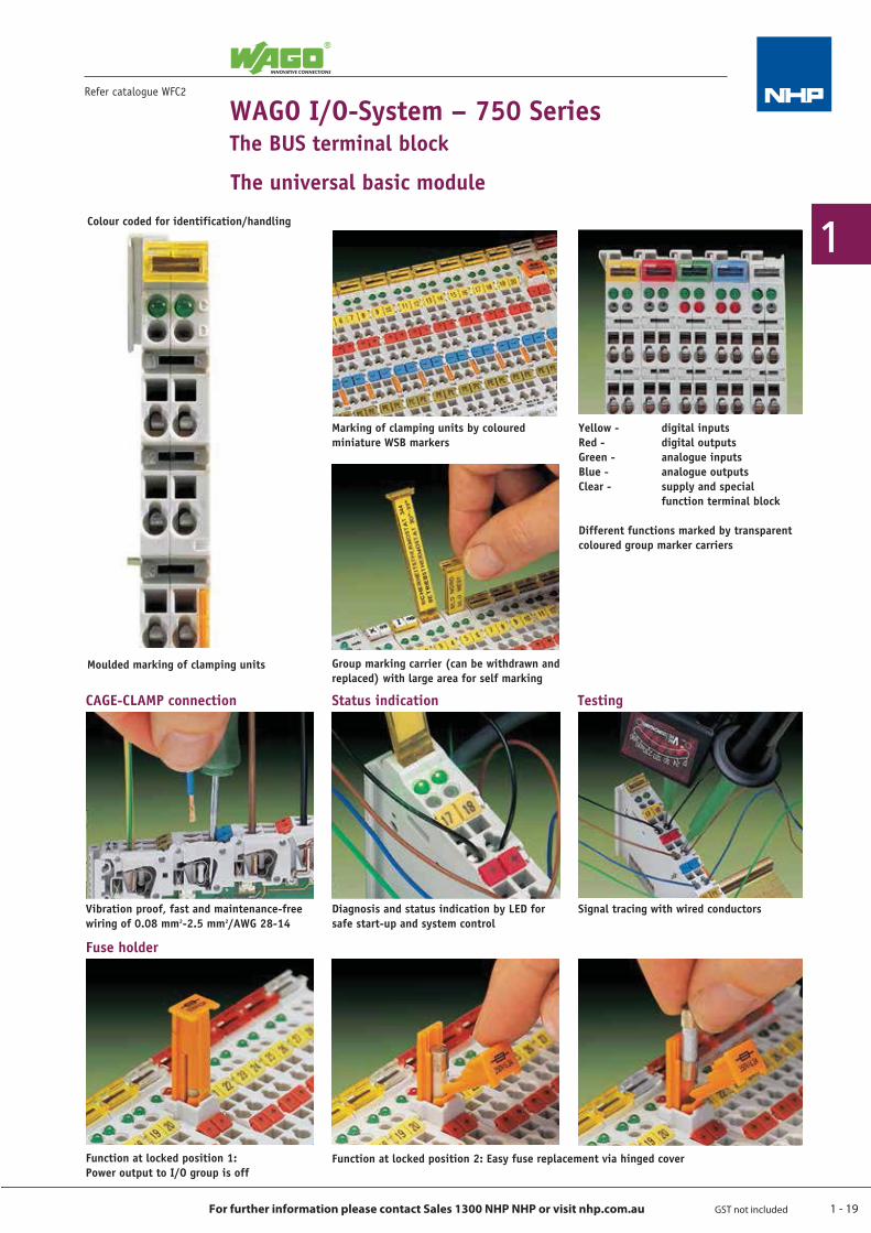
Marking of clamping units by coloured miniature WSB markers
Yellow - digital inputsRed - digital outputsGreen - analogue inputsBlue - analogue outputsClear - supply and special function terminal block
Different functions marked by transparent coloured group marker carriers
Group marking carrier (can be withdrawn and replaced) with large area for self marking
Vibration proof, fast and maintenance-free wiring of 0.08 mm2-2.5 mm2/AWG 28-14
Function at locked position 1:Power output to I/O group is off
Function at locked position 2: Easy fuse replacement via hinged cover
Diagnosis and status indication by LED for safe start-up and system control
Signal tracing with wired conductors
Colour coded for identification/handling
Moulded marking of clamping units
CAGE-CLAMP connection Status indication Testing
Fuse holder
Refer catalogue WFC2
1 - 20
1
For further information please contact Sales 1300 NHP NHP or visit nhp.com.au GST not included
WAGO I/O-SystemFieldbus independent BUS terminal block
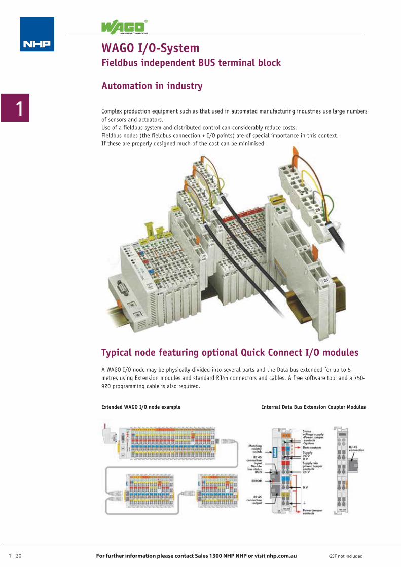
Automation in industry
Complex production equipment such as that used in automated manufacturing industries use large numbers of sensors and actuators.Use of a fieldbus system and distributed control can considerably reduce costs.Fieldbus nodes (the fieldbus connection + I/O points) are of special importance in this context. If these are properly designed much of the cost can be minimised.
Typical node featuring optional Quick Connect I/O modulesA WAGO I/O node may be physically divided into several parts and the Data bus extended for up to 5 metres using Extension modules and standard RJ45 connectors and cables. A free software tool and a 750-920 programming cable is also required.
Extended WAGO I/O node example Internal Data Bus Extension Coupler Modules
1 - 21
1
For further information please contact Sales 1300 NHP NHP or visit nhp.com.au GST not included
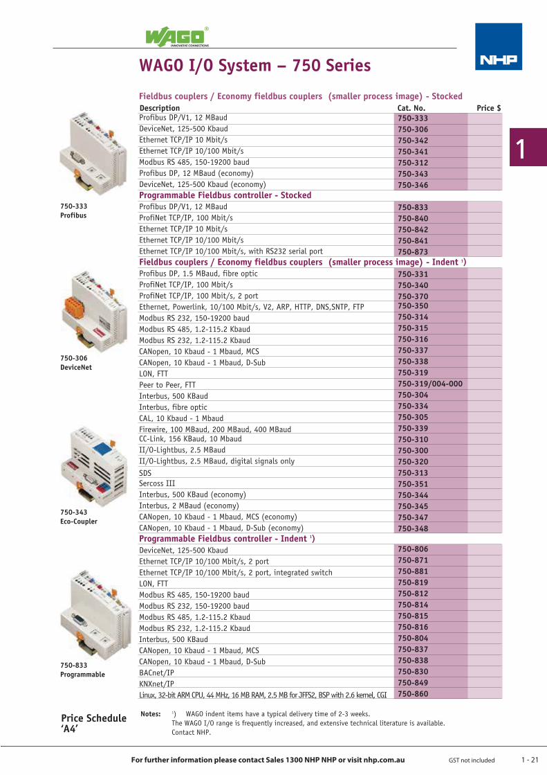
Profibus DP/V1, 12 MBaudDeviceNet, 125-500 KbaudEthernet TCP/IP 10 Mbit/sEthernet TCP/IP 10/100 Mbit/sModbus RS 485, 150-19200 baudProfibus DP, 12 MBaud (economy)DeviceNet, 125-500 Kbaud (economy)Programmable Fieldbus controller - StockedProfibus DP/V1, 12 MBaudProfiNet TCP/IP, 100 Mbit/sEthernet TCP/IP 10 Mbit/sEthernet TCP/IP 10/100 Mbit/sEthernet TCP/IP 10/100 Mbit/s, with RS232 serial portFieldbus couplers / Economy fieldbus couplers (smaller process image) - Indent 1)Profibus DP, 1.5 MBaud, fibre opticProfiNet TCP/IP, 100 Mbit/sProfiNet TCP/IP, 100 Mbit/s, 2 portEthernet, Powerlink, 10/100 Mbit/s, V2, ARP, HTTP, DNS,SNTP, FTPModbus RS 232, 150-19200 baudModbus RS 485, 1.2-115.2 KbaudModbus RS 232, 1.2-115.2 KbaudCANopen, 10 Kbaud - 1 Mbaud, MCSCANopen, 10 Kbaud - 1 Mbaud, D-SubLON, FTTPeer to Peer, FTTInterbus, 500 KBaudInterbus, fibre opticCAL, 10 Kbaud - 1 MbaudFirewire, 100 MBaud, 200 MBaud, 400 MBaudCC-Link, 156 KBaud, 10 MbaudII/O-Lightbus, 2.5 MBaudII/O-Lightbus, 2.5 MBaud, digital signals onlySDSSercoss IIIInterbus, 500 KBaud (economy)Interbus, 2 MBaud (economy)CANopen, 10 Kbaud - 1 Mbaud, MCS (economy)CANopen, 10 Kbaud - 1 Mbaud, D-Sub (economy)Programmable Fieldbus controller - Indent 1)DeviceNet, 125-500 KbaudEthernet TCP/IP 10/100 Mbit/s, 2 portEthernet TCP/IP 10/100 Mbit/s, 2 port, integrated switchLON, FTTModbus RS 485, 150-19200 baudModbus RS 232, 150-19200 baudModbus RS 485, 1.2-115.2 KbaudModbus RS 232, 1.2-115.2 KbaudInterbus, 500 KBaudCANopen, 10 Kbaud - 1 Mbaud, MCSCANopen, 10 Kbaud - 1 Mbaud, D-SubBACnet/IPKNXnet/IPLinux, 32-bit ARM CPU, 44 MHz, 16 MB RAM, 2.5 MB for JFFS2, BSP with 2.6 kernel, CGI
750-333750-306750-342750-341750-312750-343750-346
750-833750-840750-842750-841750-873
750-331750-340750-370750-350750-314750-315750-316750-337750-338750-319750-319/004-000750-304750-334750-305750-339750-310750-300750-320750-313750-351750-344750-345750-347750-348
750-806750-871750-881750-819750-812750-814750-815750-816750-804750-837750-838750-830750-849750-860
Fieldbus couplers / Economy fieldbus couplers (smaller process image) - Stocked
750-343Eco-Coupler
750-306DeviceNet
750-333Profibus
WAGO I/O System – 750 Series
750-833Programmable
Price Schedule ‘A4’
Notes: 1) WAGO indent items have a typical delivery time of 2-3 weeks. The WAGO I/O range is frequently increased, and extensive technical literature is available. Contact NHP.
Description Cat. No. Price $
1 - 22
1
For further information please contact Sales 1300 NHP NHP or visit nhp.com.au GST not included
Notes: 1) WAGO indent items have a typical delivery time of 2-3 weeks. The WAGO I/O range is frequently increased, and extensive technical literature is available. Contact NHP.
Refer catalogue WFC2
Price Schedule ‘A4’
750-400
750-430
750-424
750-530
750-523
WAGO I/O System – 750 Series
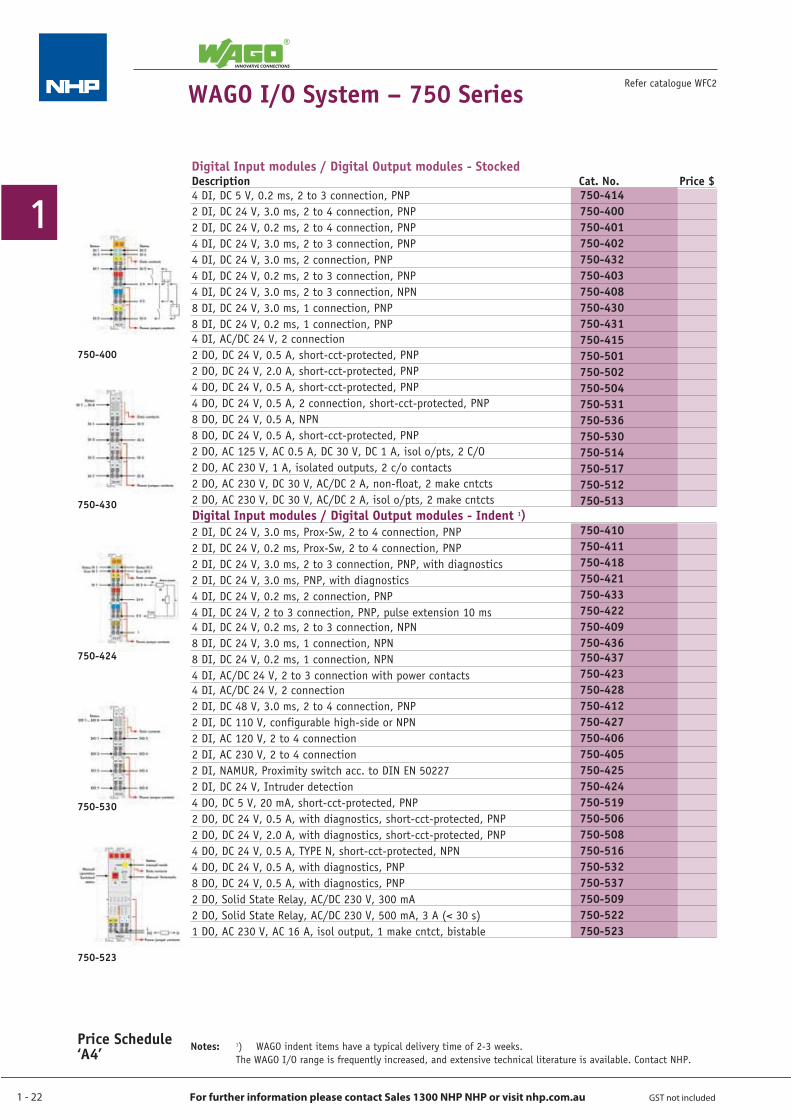
4 DI, DC 5 V, 0.2 ms, 2 to 3 connection, PNP2 DI, DC 24 V, 3.0 ms, 2 to 4 connection, PNP2 DI, DC 24 V, 0.2 ms, 2 to 4 connection, PNP4 DI, DC 24 V, 3.0 ms, 2 to 3 connection, PNP4 DI, DC 24 V, 3.0 ms, 2 connection, PNP4 DI, DC 24 V, 0.2 ms, 2 to 3 connection, PNP4 DI, DC 24 V, 3.0 ms, 2 to 3 connection, NPN8 DI, DC 24 V, 3.0 ms, 1 connection, PNP8 DI, DC 24 V, 0.2 ms, 1 connection, PNP4 DI, AC/DC 24 V, 2 connection2 DO, DC 24 V, 0.5 A, short-cct-protected, PNP2 DO, DC 24 V, 2.0 A, short-cct-protected, PNP4 DO, DC 24 V, 0.5 A, short-cct-protected, PNP4 DO, DC 24 V, 0.5 A, 2 connection, short-cct-protected, PNP8 DO, DC 24 V, 0.5 A, NPN8 DO, DC 24 V, 0.5 A, short-cct-protected, PNP2 DO, AC 125 V, AC 0.5 A, DC 30 V, DC 1 A, isol o/pts, 2 C/O2 DO, AC 230 V, 1 A, isolated outputs, 2 c/o contacts2 DO, AC 230 V, DC 30 V, AC/DC 2 A, non-float, 2 make cntcts2 DO, AC 230 V, DC 30 V, AC/DC 2 A, isol o/pts, 2 make cntctsDigital Input modules / Digital Output modules - Indent 1)2 DI, DC 24 V, 3.0 ms, Prox-Sw, 2 to 4 connection, PNP2 DI, DC 24 V, 0.2 ms, Prox-Sw, 2 to 4 connection, PNP2 DI, DC 24 V, 3.0 ms, 2 to 3 connection, PNP, with diagnostics2 DI, DC 24 V, 3.0 ms, PNP, with diagnostics4 DI, DC 24 V, 0.2 ms, 2 connection, PNP4 DI, DC 24 V, 2 to 3 connection, PNP, pulse extension 10 ms4 DI, DC 24 V, 0.2 ms, 2 to 3 connection, NPN8 DI, DC 24 V, 3.0 ms, 1 connection, NPN8 DI, DC 24 V, 0.2 ms, 1 connection, NPN4 DI, AC/DC 24 V, 2 to 3 connection with power contacts4 DI, AC/DC 24 V, 2 connection2 DI, DC 48 V, 3.0 ms, 2 to 4 connection, PNP2 DI, DC 110 V, configurable high-side or NPN2 DI, AC 120 V, 2 to 4 connection2 DI, AC 230 V, 2 to 4 connection2 DI, NAMUR, Proximity switch acc. to DIN EN 502272 DI, DC 24 V, Intruder detection4 DO, DC 5 V, 20 mA, short-cct-protected, PNP2 DO, DC 24 V, 0.5 A, with diagnostics, short-cct-protected, PNP2 DO, DC 24 V, 2.0 A, with diagnostics, short-cct-protected, PNP4 DO, DC 24 V, 0.5 A, TYPE N, short-cct-protected, NPN4 DO, DC 24 V, 0.5 A, with diagnostics, PNP8 DO, DC 24 V, 0.5 A, with diagnostics, PNP2 DO, Solid State Relay, AC/DC 230 V, 300 mA2 DO, Solid State Relay, AC/DC 230 V, 500 mA, 3 A (< 30 s)1 DO, AC 230 V, AC 16 A, isol output, 1 make cntct, bistable
750-414750-400750-401750-402750-432750-403750-408750-430750-431750-415750-501750-502750-504750-531750-536750-530750-514750-517750-512750-513
750-410750-411750-418750-421750-433750-422750-409750-436750-437750-423750-428750-412750-427750-406750-405750-425750-424750-519750-506750-508750-516750-532750-537750-509750-522750-523
Digital Input modules / Digital Output modules - StockedDescription Cat. No. Price $
1 - 23
1
For further information please contact Sales 1300 NHP NHP or visit nhp.com.au GST not included
Price Schedule ‘A4’
Refer catalogue WFC2 WAGO I/O System – 750 Series
750-452
750-457
750-491
750-557
Notes: 1) WAGO indent items have a typical delivery time of 2-3 weeks. The WAGO I/O range is frequently increased, and extensive technical literature is available. Contact NHP.
750-493
Analogue Input / Analogue Output modules - Stocked
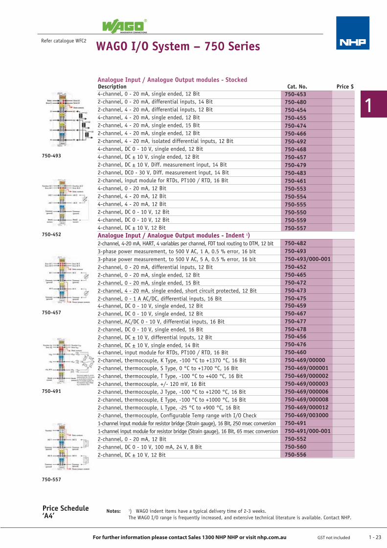
4-channel, 0 - 20 mA, single ended, 12 Bit2-channel, 0 - 20 mA, differential inputs, 14 Bit2-channel, 4 - 20 mA, differential inputs, 12 Bit4-channel, 4 - 20 mA, single ended, 12 Bit2-channel, 4 - 20 mA, single ended, 15 Bit2-channel, 4 - 20 mA, single ended, 12 Bit2-channel, 4 - 20 mA, isolated differential inputs, 12 Bit4-channel, DC 0 - 10 V, single ended, 12 Bit4-channel, DC ± 10 V, single ended, 12 Bit2-channel, DC ± 10 V, Diff. measurement input, 14 Bit2-channel, DC0 - 30 V, Diff. measurement input, 14 Bit2-channel, input module for RTDs, PT100 / RTD, 16 Bit4-channel, 0 - 20 mA, 12 Bit2-channel, 4 - 20 mA, 12 Bit4-channel, 4 - 20 mA, 12 Bit2-channel, DC 0 - 10 V, 12 Bit4-channel, DC 0 - 10 V, 12 Bit4-channel, DC ± 10 V, 12 BitAnalogue Input / Analogue Output modules - Indent 1)2-channel, 4-20 mA, HART, 4 variables per channel, FDT tool routing to DTM, 12 bit3-phase power measurement, to 500 V AC, 1 A, 0.5 % error, 16 bit3-phase power measurement, to 500 V AC, 5 A, 0.5 % error, 16 bit2-channel, 0 - 20 mA, differential inputs, 12 Bit2-channel, 0 - 20 mA, single ended, 12 Bit2-channel, 0 - 20 mA, single ended, 15 Bit2-channel, 4 - 20 mA, single ended, short circuit protected, 12 Bit2-channel, 0 - 1 A AC/DC, differential inputs, 16 Bit4-channel, DC 0 - 10 V, single ended, 12 Bit2-channel, DC 0 - 10 V, single ended, 12 Bit2-channel, AC/DC 0 - 10 V, differential inputs, 16 Bit2-channel, DC 0 - 10 V, single ended, 16 Bit2-channel, DC ± 10 V, differential inputs, 12 Bit2-channel, DC ± 10 V, single ended, 14 Bit4-channel, input module for RTDs, PT100 / RTD, 16 Bit2-channel, thermocouple, K Type, -100 °C to +1370 °C, 16 Bit2-channel, thermocouple, S Type, 0 °C to +1700 °C, 16 Bit2-channel, thermocouple, T Type, -100 °C to +400 °C, 16 Bit2-channel, thermocouple, +/- 120 mV, 16 Bit2-channel, thermocouple, J Type, -100 °C to +1200 °C, 16 Bit2-channel, thermocouple, E Type, -100 °C to +1000 °C, 16 Bit2-channel, thermocouple, L Type, -25 °C to +900 °C, 16 Bit2-channel, thermocouple, Configurable Temp range with I/O Check1-channel input module for resistor bridge (Strain gauge), 16 Bit, 250 msec conversion1-channel input module for resistor bridge (Strain gauge), 16 Bit, 65 msec conversion2-channel, 0 - 20 mA, 12 Bit2-channel, DC 0 - 10 V, 100 mA, 24 V, 8 Bit2-channel, DC ± 10 V, 12 Bit
750-453750-480750-454750-455750-474750-466750-492750-468750-457750-479750-483750-461750-553750-554750-555750-550750-559750-557
750-482750-493750-493/000-001750-452750-465750-472750-473750-475750-459750-467750-477750-478750-456750-476750-460750-469/00000750-469/000001750-469/000002750-469/000003750-469/000006750-469/000008750-469/000012750-469/003000750-491750-491/000-001750-552750-560750-556
Description Cat. No. Price $
1 - 24
1
For further information please contact Sales 1300 NHP NHP or visit nhp.com.au GST not included
Refer catalogue WFC2
Price Schedule ‘A4’
WAGO I/O System – 750 Series
750-404
Vibration Module750-645
Vibration Sensor750-925
Notes: 1) WAGO indent items have a typical delivery time of 2-3 weeks. The WAGO I/O range is frequently increased, and extensive technical literature is available. Contact NHP.
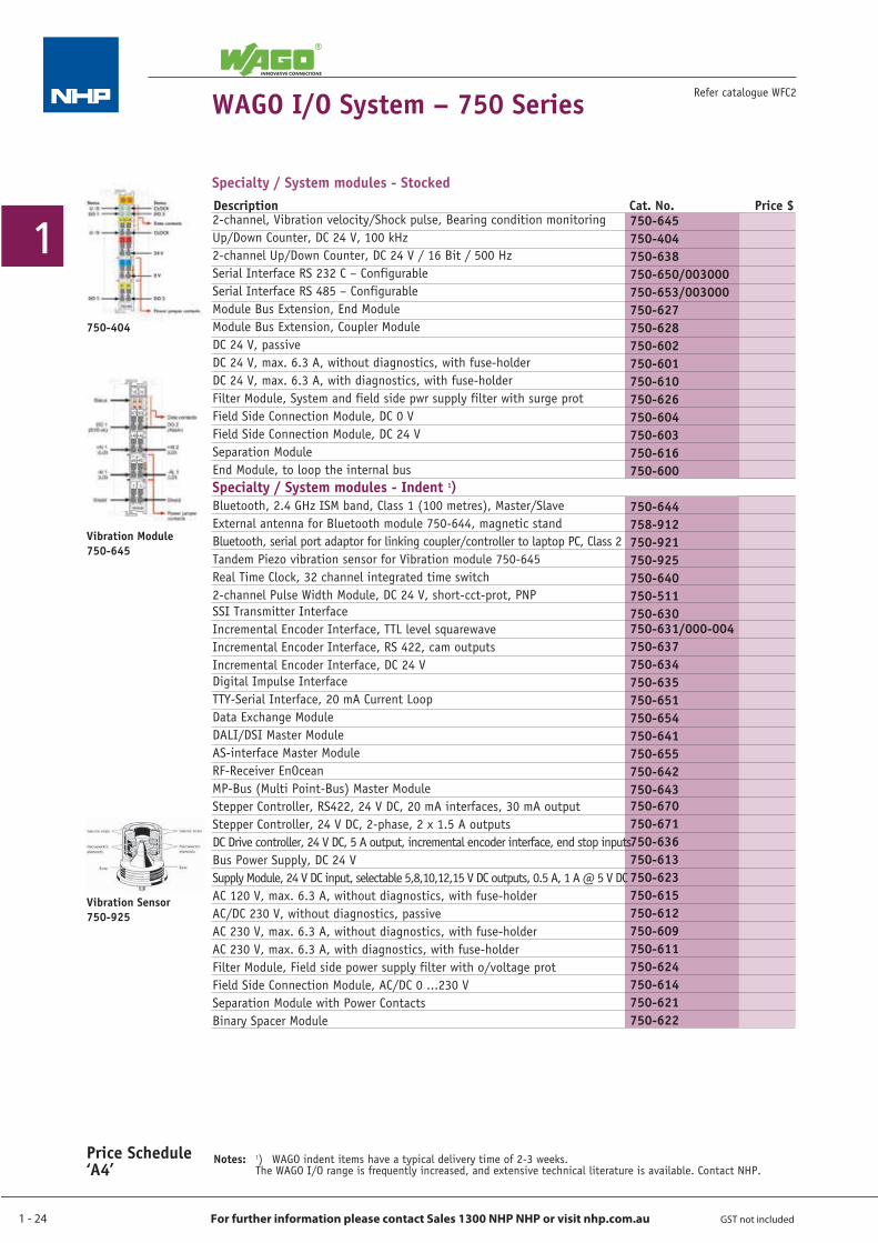
2-channel, Vibration velocity/Shock pulse, Bearing condition monitoringUp/Down Counter, DC 24 V, 100 kHz2-channel Up/Down Counter, DC 24 V / 16 Bit / 500 HzSerial Interface RS 232 C – ConfigurableSerial Interface RS 485 – ConfigurableModule Bus Extension, End ModuleModule Bus Extension, Coupler ModuleDC 24 V, passiveDC 24 V, max. 6.3 A, without diagnostics, with fuse-holderDC 24 V, max. 6.3 A, with diagnostics, with fuse-holderFilter Module, System and field side pwr supply filter with surge protField Side Connection Module, DC 0 VField Side Connection Module, DC 24 VSeparation ModuleEnd Module, to loop the internal busSpecialty / System modules - Indent 1)Bluetooth, 2.4 GHz ISM band, Class 1 (100 metres), Master/SlaveExternal antenna for Bluetooth module 750-644, magnetic standBluetooth, serial port adaptor for linking coupler/controller to laptop PC, Class 2Tandem Piezo vibration sensor for Vibration module 750-645Real Time Clock, 32 channel integrated time switch2-channel Pulse Width Module, DC 24 V, short-cct-prot, PNPSSI Transmitter InterfaceIncremental Encoder Interface, TTL level squarewaveIncremental Encoder Interface, RS 422, cam outputsIncremental Encoder Interface, DC 24 VDigital Impulse InterfaceTTY-Serial Interface, 20 mA Current LoopData Exchange ModuleDALI/DSI Master ModuleAS-interface Master ModuleRF-Receiver EnOceanMP-Bus (Multi Point-Bus) Master ModuleStepper Controller, RS422, 24 V DC, 20 mA interfaces, 30 mA outputStepper Controller, 24 V DC, 2-phase, 2 x 1.5 A outputsDC Drive controller, 24 V DC, 5 A output, incremental encoder interface, end stop inputsBus Power Supply, DC 24 VSupply Module, 24 V DC input, selectable 5,8,10,12,15 V DC outputs, 0.5 A, 1 A @ 5 V DCAC 120 V, max. 6.3 A, without diagnostics, with fuse-holderAC/DC 230 V, without diagnostics, passiveAC 230 V, max. 6.3 A, without diagnostics, with fuse-holderAC 230 V, max. 6.3 A, with diagnostics, with fuse-holderFilter Module, Field side power supply filter with o/voltage protField Side Connection Module, AC/DC 0 ...230 VSeparation Module with Power ContactsBinary Spacer Module
Specialty / System modules - Stocked
750-645750-404750-638750-650/003000750-653/003000750-627750-628750-602750-601750-610750-626750-604750-603750-616750-600
750-644758-912750-921750-925750-640750-511750-630750-631/000-004750-637750-634750-635750-651750-654750-641750-655750-642750-643750-670750-671750-636750-613750-623750-615750-612750-609750-611750-624750-614750-621750-622
Description Cat. No. Price $
1 - 25
1
For further information please contact Sales 1300 NHP NHP or visit nhp.com.au GST not included
Refer catalogue WFC2
Price Schedule ‘A4’
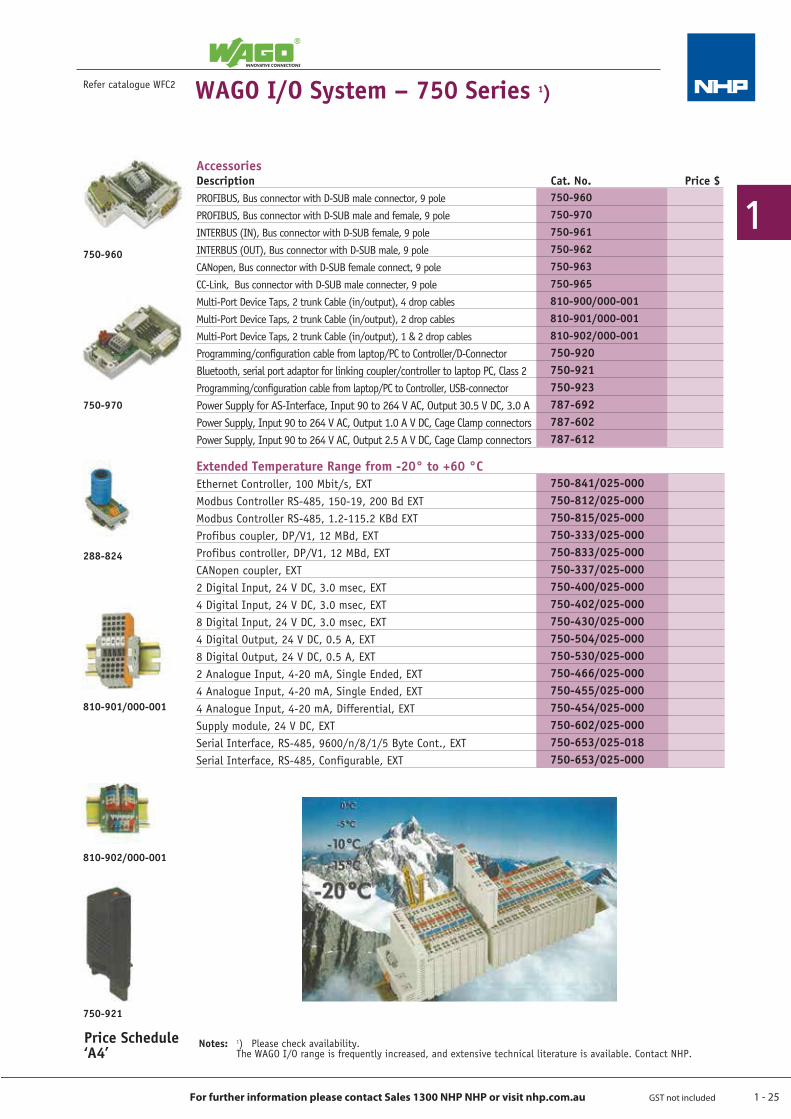
AccessoriesDescription Cat. No. Price $PROFIBUS, Bus connector with D-SUB male connector, 9 polePROFIBUS, Bus connector with D-SUB male and female, 9 poleINTERBUS (IN), Bus connector with D-SUB female, 9 poleINTERBUS (OUT), Bus connector with D-SUB male, 9 poleCANopen, Bus connector with D-SUB female connect, 9 poleCC-Link, Bus connector with D-SUB male connecter, 9 poleMulti-Port Device Taps, 2 trunk Cable (in/output), 4 drop cablesMulti-Port Device Taps, 2 trunk Cable (in/output), 2 drop cablesMulti-Port Device Taps, 2 trunk Cable (in/output), 1 & 2 drop cablesProgramming/configuration cable from laptop/PC to Controller/D-ConnectorBluetooth, serial port adaptor for linking coupler/controller to laptop PC, Class 2 Programming/configuration cable from laptop/PC to Controller, USB-connectorPower Supply for AS-Interface, Input 90 to 264 V AC, Output 30.5 V DC, 3.0 APower Supply, Input 90 to 264 V AC, Output 1.0 A V DC, Cage Clamp connectorsPower Supply, Input 90 to 264 V AC, Output 2.5 A V DC, Cage Clamp connectors
Extended Temperature Range from -20° to +60 °CEthernet Controller, 100 Mbit/s, EXTModbus Controller RS-485, 150-19, 200 Bd EXTModbus Controller RS-485, 1.2-115.2 KBd EXTProfibus coupler, DP/V1, 12 MBd, EXTProfibus controller, DP/V1, 12 MBd, EXTCANopen coupler, EXT2 Digital Input, 24 V DC, 3.0 msec, EXT4 Digital Input, 24 V DC, 3.0 msec, EXT8 Digital Input, 24 V DC, 3.0 msec, EXT4 Digital Output, 24 V DC, 0.5 A, EXT8 Digital Output, 24 V DC, 0.5 A, EXT2 Analogue Input, 4-20 mA, Single Ended, EXT4 Analogue Input, 4-20 mA, Single Ended, EXT4 Analogue Input, 4-20 mA, Differential, EXTSupply module, 24 V DC, EXTSerial Interface, RS-485, 9600/n/8/1/5 Byte Cont., EXTSerial Interface, RS-485, Configurable, EXT
750-960750-970750-961750-962750-963750-965810-900/000-001810-901/000-001810-902/000-001750-920750-921750-923787-692787-602787-612
750-841/025-000750-812/025-000750-815/025-000750-333/025-000750-833/025-000750-337/025-000750-400/025-000750-402/025-000750-430/025-000750-504/025-000750-530/025-000750-466/025-000750-455/025-000750-454/025-000750-602/025-000750-653/025-018750-653/025-000
WAGO I/O System – 750 Series 1)
Notes: 1) Please check availability. The WAGO I/O range is frequently increased, and extensive technical literature is available. Contact NHP.
750-960
750-970
288-824
810-901/000-001
810-902/000-001
750-921
1 - 26
1
For further information please contact Sales 1300 NHP NHP or visit nhp.com.au GST not included
WAGO I/O System – 857 SeriesJUMPFLEX Transducers
Refer catalogue WFC2
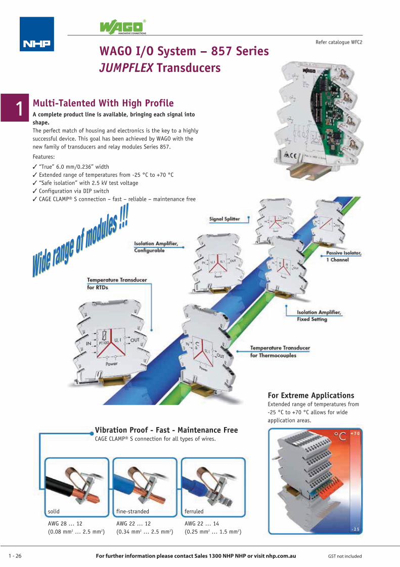
Multi-Talented With High ProfileA complete product line is available, bringing each signal into shape.The perfect match of housing and electronics is the key to a highly successful device. This goal has been achieved by WAGO with the new family of transducers and relay modules Series 857.
Features:
“True” 6.0 mm/0.236” width Extended range of temperatures from -25 °C to +70 °C “Safe isolation” with 2.5 kV test voltage Configuration via DIP switch CAGE CLAMP® S connection – fast – reliable – maintenance free
solid
AWG 28 … 12 (0.08 mm2 … 2.5 mm2)
ferruled
AWG 22 … 14 (0.25 mm2 … 1.5 mm2)
fine-stranded
AWG 22 … 12 (0.34 mm2 … 2.5 mm2)
Vibration Proof - Fast - Maintenance FreeCAGE CLAMP® S connection for all types of wires.
For Extreme ApplicationsExtended range of temperatures from -25 °C to +70 °C allows for wide application areas.
1 - 27
1
For further information please contact Sales 1300 NHP NHP or visit nhp.com.au GST not included
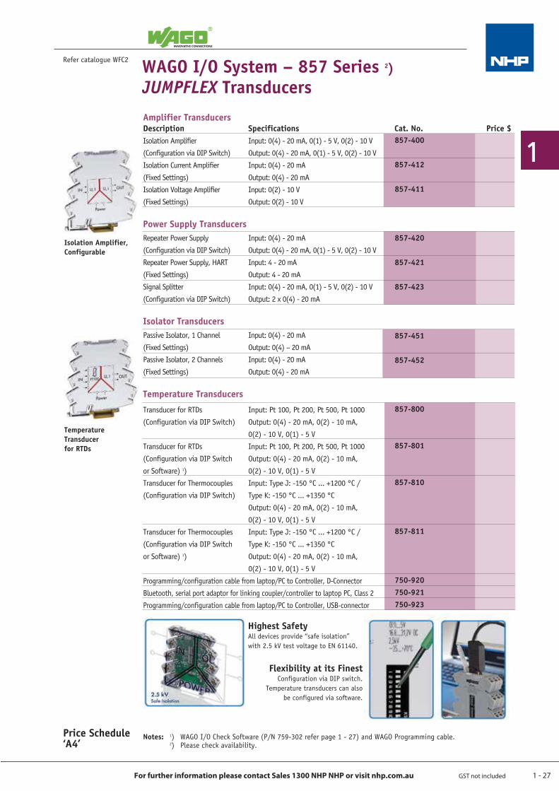
Description Specifications Cat. No. Price $Isolation Amplifier Input: 0(4) - 20 mA, 0(1) - 5 V, 0(2) - 10 V(Configuration via DIP Switch) Output: 0(4) - 20 mA, 0(1) - 5 V, 0(2) - 10 VIsolation Current Amplifier Input: 0(4) - 20 mA(Fixed Settings) Output: 0(4) - 20 mAIsolation Voltage Amplifier Input: 0(2) - 10 V(Fixed Settings) Output: 0(2) - 10 V
Power Supply TransducersRepeater Power Supply Input: 0(4) - 20 mA(Configuration via DIP Switch) Output: 0(4) - 20 mA, 0(1) - 5 V, 0(2) - 10 VRepeater Power Supply, HART Input: 4 - 20 mA(Fixed Settings) Output: 4 - 20 mASignal Splitter Input: 0(4) - 20 mA, 0(1) - 5 V, 0(2) - 10 V(Configuration via DIP Switch) Output: 2 x 0(4) - 20 mA
Isolator TransducersPassive Isolator, 1 Channel Input: 0(4) - 20 mA(Fixed Settings) Output: 0(4) – 20 mAPassive Isolator, 2 Channels Input: 0(4) - 20 mA(Fixed Settings) Output: 0(4) - 20 mA
Temperature Transducers
Transducer for RTDs Input: Pt 100, Pt 200, Pt 500, Pt 1000(Configuration via DIP Switch) Output: 0(4) - 20 mA, 0(2) - 10 mA,
0(2) - 10 V, 0(1) - 5 VTransducer for RTDs Input: Pt 100, Pt 200, Pt 500, Pt 1000(Configuration via DIP Switch Output: 0(4) - 20 mA, 0(2) - 10 mA, or Software) 1) 0(2) - 10 V, 0(1) - 5 V Transducer for Thermocouples Input: Type J: -150 °C ... +1200 °C / (Configuration via DIP Switch) Type K: -150 °C ... +1350 °C Output: 0(4) - 20 mA, 0(2) - 10 mA, 0(2) - 10 V, 0(1) - 5 VTransducer for Thermocouples Input: Type J: -150 °C ... +1200 °C / (Configuration via DIP Switch Type K: -150 °C ... +1350 °C or Software) 1) Output: 0(4) - 20 mA, 0(2) - 10 mA, 0(2) - 10 V, 0(1) - 5 VProgramming/configuration cable from laptop/PC to Controller, D-ConnectorBluetooth, serial port adaptor for linking coupler/controller to laptop PC, Class 2Programming/configuration cable from laptop/PC to Controller, USB-connector
WAGO I/O System – 857 Series 2) JUMPFLEX Transducers
Refer catalogue WFC2
Price Schedule ‘A4’
Highest SafetyAll devices provide “safe isolation” with 2.5 kV test voltage to EN 61140.
Flexibility at its FinestConfiguration via DIP switch.
Temperature transducers can also be configured via software.
Isolation Amplifier, Configurable
Temperature Transducer for RTDs
Amplifier Transducers
857-400
857-412
857-411
857-420
857-421
857-423
857-451
857-452
857-800
857-801
857-810
857-811
750-920750-921750-923
Notes: 1) WAGO I/O Check Software (P/N 759-302 refer page 1 - 27) and WAGO Programming cable. 2) Please check availability.
1 - 28
1
For further information please contact Sales 1300 NHP NHP or visit nhp.com.au GST not included
Price Schedule ‘A4’
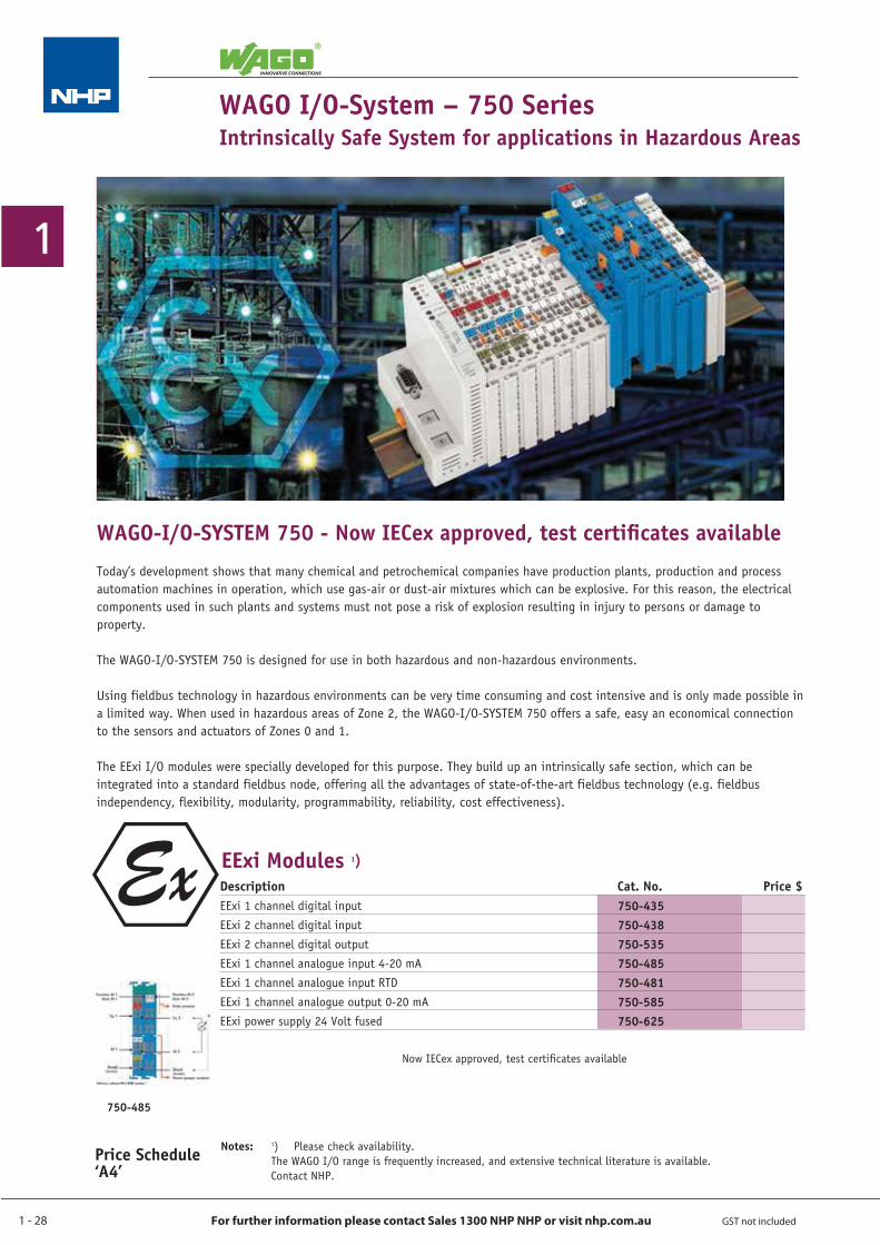
Description Cat. No. Price $EExi 1 channel digital inputEExi 2 channel digital inputEExi 2 channel digital outputEExi 1 channel analogue input 4-20 mAEExi 1 channel analogue input RTDEExi 1 channel analogue output 0-20 mAEExi power supply 24 Volt fused
750-435750-438750-535750-485750-481750-585750-625
WAGO I/O-System – 750 Series Intrinsically Safe System for applications in Hazardous Areas
EExi Modules 1)
Notes: 1) Please check availability. The WAGO I/O range is frequently increased, and extensive technical literature is available. Contact NHP.
WAGO-I/O-SYSTEM 750 - Now IECex approved, test certificates availableToday’s development shows that many chemical and petrochemical companies have production plants, production and process automation machines in operation, which use gas-air or dust-air mixtures which can be explosive. For this reason, the electrical components used in such plants and systems must not pose a risk of explosion resulting in injury to persons or damage to property.
The WAGO-I/O-SYSTEM 750 is designed for use in both hazardous and non-hazardous environments.
Using fieldbus technology in hazardous environments can be very time consuming and cost intensive and is only made possible in a limited way. When used in hazardous areas of Zone 2, the WAGO-I/O-SYSTEM 750 offers a safe, easy an economical connection to the sensors and actuators of Zones 0 and 1.
The EExi I/O modules were specially developed for this purpose. They build up an intrinsically safe section, which can be integrated into a standard fieldbus node, offering all the advantages of state-of-the-art fieldbus technology (e.g. fieldbus independency, flexibility, modularity, programmability, reliability, cost effectiveness).
750-485
Now IECex approved, test certificates available
1 - 29
1
For further information please contact Sales 1300 NHP NHP or visit nhp.com.au GST not included
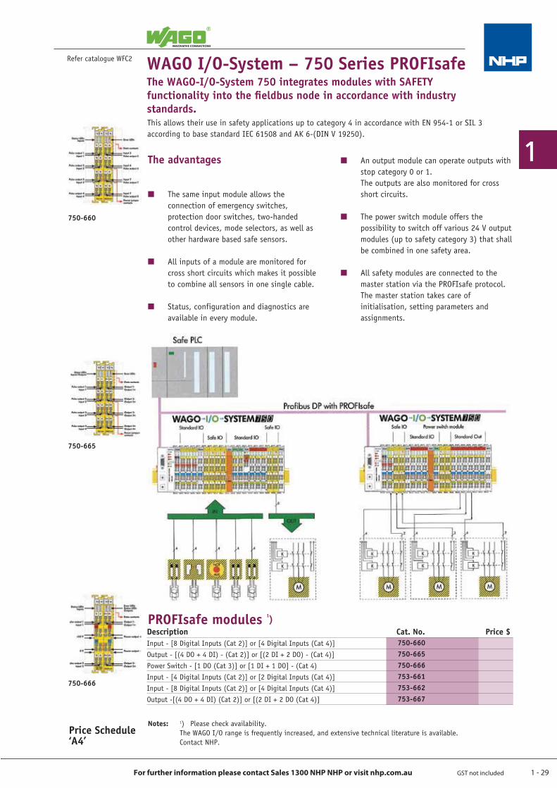
Description Cat. No. Price $Input - [8 Digital Inputs (Cat 2)] or [4 Digital Inputs (Cat 4)]Output - [(4 DO + 4 DI) - (Cat 2)] or [(2 DI + 2 DO) - (Cat 4)]Power Switch - [1 DO (Cat 3)] or [1 DI + 1 DO] - (Cat 4)Input - [4 Digital Inputs (Cat 2)] or [2 Digital Inputs (Cat 4)]Input - [8 Digital Inputs (Cat 2)] or [4 Digital Inputs (Cat 4)]Output -[(4 DO + 4 DI) (Cat 2)] or [(2 DI + 2 DO (Cat 4)]
WAGO I/O-System – 750 Series PROFIsafeThe WAGO-I/O-System 750 integrates modules with SAFETY functionality into the fieldbus node in accordance with industry standards.
Price Schedule ‘A4’
Notes: 1) Please check availability. The WAGO I/O range is frequently increased, and extensive technical literature is available. Contact NHP.
Refer catalogue WFC2
750-660750-665750-666753-661753-662753-667
PROFIsafe modules 1)
The advantages
Q The same input module allows the connection of emergency switches, protection door switches, two-handed control devices, mode selectors, as well as other hardware based safe sensors.
Q All inputs of a module are monitored for cross short circuits which makes it possible to combine all sensors in one single cable.
Q Status, configuration and diagnostics are available in every module.
Q An output module can operate outputs with stop category 0 or 1. The outputs are also monitored for cross short circuits.
Q The power switch module offers the possibility to switch off various 24 V output modules (up to safety category 3) that shall be combined in one safety area.
Q All safety modules are connected to the master station via the PROFIsafe protocol. The master station takes care of initialisation, setting parameters and assignments.
This allows their use in safety applications up to category 4 in accordance with EN 954-1 or SIL 3 according to base standard IEC 61508 and AK 6-(DIN V 19250).
750-660
750-665
750-666
1 - 30
1
For further information please contact Sales 1300 NHP NHP or visit nhp.com.au GST not included
Price Schedule ‘A4’
WAGO I/O-System – 750 Series
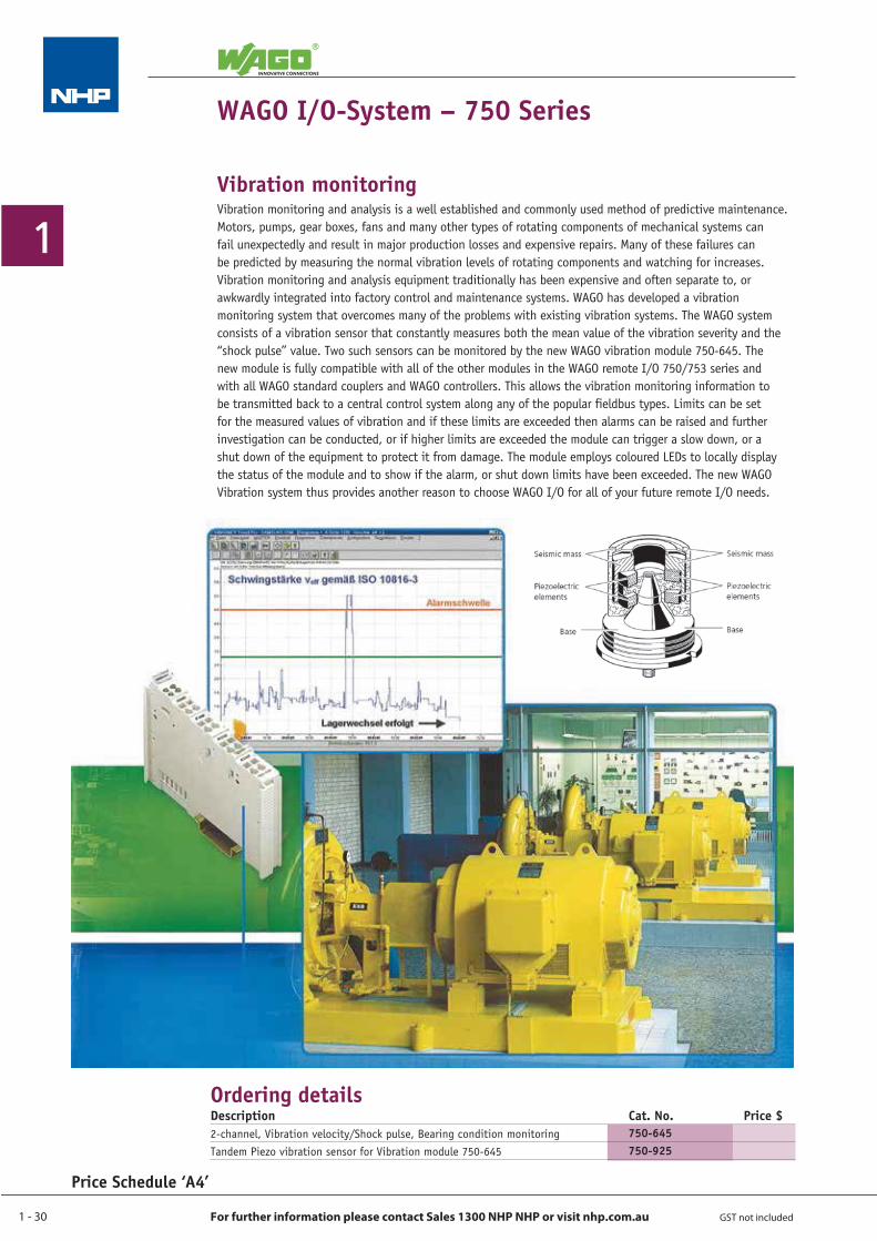
Vibration monitoringVibration monitoring and analysis is a well established and commonly used method of predictive maintenance. Motors, pumps, gear boxes, fans and many other types of rotating components of mechanical systems can fail unexpectedly and result in major production losses and expensive repairs. Many of these failures can be predicted by measuring the normal vibration levels of rotating components and watching for increases. Vibration monitoring and analysis equipment traditionally has been expensive and often separate to, or awkwardly integrated into factory control and maintenance systems. WAGO has developed a vibration monitoring system that overcomes many of the problems with existing vibration systems. The WAGO system consists of a vibration sensor that constantly measures both the mean value of the vibration severity and the “shock pulse” value. Two such sensors can be monitored by the new WAGO vibration module 750-645. The new module is fully compatible with all of the other modules in the WAGO remote I/O 750/753 series and with all WAGO standard couplers and WAGO controllers. This allows the vibration monitoring information to be transmitted back to a central control system along any of the popular fieldbus types. Limits can be set for the measured values of vibration and if these limits are exceeded then alarms can be raised and further investigation can be conducted, or if higher limits are exceeded the module can trigger a slow down, or a shut down of the equipment to protect it from damage. The module employs coloured LEDs to locally display the status of the module and to show if the alarm, or shut down limits have been exceeded. The new WAGO Vibration system thus provides another reason to choose WAGO I/O for all of your future remote I/O needs.
Ordering detailsDescription Cat. No. Price $2-channel, Vibration velocity/Shock pulse, Bearing condition monitoringTandem Piezo vibration sensor for Vibration module 750-645
750-645750-925
1 - 31
1
For further information please contact Sales 1300 NHP NHP or visit nhp.com.au GST not included
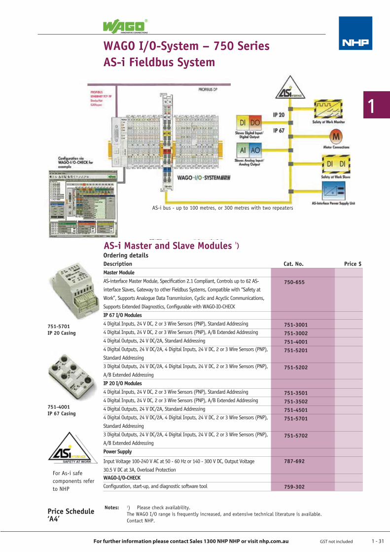
Description Cat. No. Price $Master ModuleAS-interface Master Module, Specification 2.1 Compliant, Controls up to 62 AS-interface Slaves, Gateway to other Fieldbus Systems, Compatible with “Safety atWork”, Supports Analogue Data Transmission, Cyclic and Acyclic Communications,Supports Extended Diagnostics, Configurable with WAGO-IO-CHECKIP 67 I/O Modules4 Digital Inputs, 24 V DC, 2 or 3 Wire Sensors (PNP), Standard Addressing4 Digital Inputs, 24 V DC, 2 or 3 Wire Sensors (PNP), A/B Extended Addressing4 Digital Outputs, 24 V DC/2A, Standard Addressing4 Digital Outputs, 24 V DC/2A, 4 Digital Inputs, 24 V DC, 2 or 3 Wire Sensors (PNP),Standard Addressing3 Digital Outputs, 24 V DC/2A, 4 Digital Inputs, 24 V DC, 2 or 3 Wire Sensors (PNP),A/B Extended AddressingIP 20 I/O Modules4 Digital Inputs, 24 V DC, 2 or 3 Wire Sensors (PNP), Standard Addressing4 Digital Inputs, 24 V DC, 2 or 3 Wire Sensors (PNP), A/B Extended Addressing4 Digital Outputs, 24 V DC/2A, Standard Addressing4 Digital Outputs, 24 V DC/2A, 4 Digital Inputs, 24 V DC, 2 or 3 Wire Sensors (PNP),Standard Addressing3 Digital Outputs, 24 V DC/2A, 4 Digital Inputs, 24 V DC, 2 or 3 Wire Sensors (PNP),A/B Extended AddressingPower Supply
Input Voltage 100-240 V AC at 50 - 60 Hz or 140 - 300 V DC, Output Voltage30.5 V DC at 3A, Overload ProtectionWAGO-I/O-CHECKConfiguration, start-up, and diagnostic software tool
WAGO I/O-System – 750 SeriesAS-i Fieldbus System
Notes: 1) Please check availability. The WAGO I/O range is frequently increased, and extensive technical literature is available. Contact NHP.
751-5701IP 20 Casing
751-4001IP 67 Casing
Price Schedule ‘A4’
For As-i safe components refer to NHP
750-655
751-3001751-3002751-4001751-5201
751-5202
751-3501751-3502751-4501751-5701
751-5702
787-692
759-302
AS-i Master and Slave Modules 1)Ordering details
AS-i bus - up to 100 metres, or 300 metres with two repeaters

0800 NHP NHP nhp-nz.com1300 NHP NHP nhp.com.au
As an integrated group that spans across six key business areas, the unique and complete NHP package rests on a strong team of staff that pride itself on a shared set of core company values.
Make NHP part of your business.
Think Quality Service. Think NHP.
THINK QUALITY SERVICE. THINK NHP.NHP is shaped by a team of over 850 quality staff dedicated to providing ‘what you want, when, where and how you want it’.
1 - 33
1
For further information please contact Sales 1300 NHP NHP or visit nhp.com.au GST not included
Refer catalogue WFC2
Price Schedule ‘A4’
WAGO I/O-SystemProgramming and diagnostic software
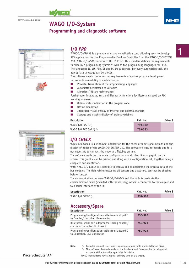
I/O PROWAGO-I/O-PRO 32 is a programming and visualisation tool, allowing users to develop SPS applications for the Programmable Fieldbus Controller from the WAGO-I/O-SYSTEMS 750. WAGO-I/O-PRO conforms to IEC 61131-3. This standard defines the requirements fulfilled by a programming system as well as five programming languages for PLCs. The languages IL, LD, FBD, ST and FC are supported. For every automation task, the appropriate language can be chosen.The software meets the increasing requirements of control program development, for example re-usability or modularisation.Q Powerful translation of the programming languagesQ Automatic declaration of variablesQ Librarian / library maintenanceFurthermore, integrated test and diagnostic functions facilitate and speed up PLC working processes.Q Online status indication in the program codeQ Offline simulationQ Integrated visual display of internal and external markersQ Storage and graphic display of project variables
I/O CHECKWAGO-I/O-CHECK is a WindowsTM application for the check of inputs and outputs and the display of nodes of the WAGO-I/O-SYSTEM 750. The software is easy to handle and it is not necessary to connect the node to a fieldbus system.The software reads out the node configuration and displays it as a graphic on the screen. This graphic can be printed out along with a configuration list, together being a complete documentation.With WAGO-I/O-CHECK it is possible to display and to determine the process data of the bus modules. The field wiring including all sensors and actuators, can thus be checked before startup.The communication between WAGO-I/O-CHECK and the node is made via the communication cable (included with the delivery) which is connected to the coupler and to a serial interface of the PC.
Note: 1) Includes: manual (electronic), communications cable and installation disks. 2) The software choice depends on the hardware and firmware that is being used. Ask your NHP automation specialist for advice. WAGO indent items have a typical delivery time of 2-3 weeks.
Accessory/Spare
759-332759-333
Description Cat. No.
WAGO I/O PRO 1) 2)
WAGO I/O PRO CAA 1) 2)
Price $
759-302WAGO I/O CHECK 1)
Description Cat. No. Price $
750-920
750-921
750-923
Programming/configuration cable from laptop/PC to Coupler/controller, D-connector
Bluetooth, serial port adaptor for linking coupler/ controller to laptop PC, Class 2
Programming/configuration cable from laptop/PC to Controller, USB-connector
Description Cat. No. Price $
1 - 34
1
For further information please contact Sales 1300 NHP NHP or visit nhp.com.au GST not included
Price Schedule ‘A4’
WAGO I/O-System – 750 Series Starter Kits 1)
Refer catalogue WFC2
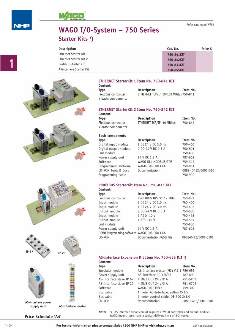
ETHERNET StarterKit 1 Item No. 750-841 KITContent:Type Description Item No.Fieldbus controller ETHERNET TCP/IP 10/100 MBit/s 750-841+ basic components
ETHERNET StarterKit 2 Item No. 750-842 KITContent:Type Description Item No.Fieldbus controller ETHERNET TCP/IP 10 MBit/s 750-842+ basic components
Basic componentsType Description Item No.Digital input module 2 DI 24 V DC 3.0 ms 750-400Digital output module 2 DO 24 V DC 0.5 A 750-501End module 750-600Power supply unit 24 V DC 1.3 A 787-602Software WAGO DLL MODBUS/TCP 759-312Programming software WAGO-I/O-PRO CAA 759-911CD-ROM Tools & Docs Documentation 0888- 0412/0001-010Programming cable 750-920
PROFIBUS StarterKit Item No. 750-833 KITContent:Type Description Item No.Fieldbus controller PROFIBUS DP/ V1 12 MBd 750-833Input module 2 DI 24 V DC 3.0 ms 750-400Input module 4 DI 24 V DC 3.0 ms 750-402Output module 8 DO 24 V DC 0.5 A 750-530Input module 2 AI 0 -10 V 750-478Output module 4 AO 0-10 V 750-559End module 750-600Power supply unit 24 V DC 1,3 A 787-602DEMO Programming software WAGO-I/O-PRO CAACD-ROM Documentation/GSD file 0888-0412/0001-0101
AS-Interface Expansion Kit Item No. 750-655 KIT 1)Content:Type Description Item No.Specialty module AS-Interface master (M3) V.2.1 750-655Power supply unit AS-Interface 30.1 V/3A 787-692AS-Interface slave IP 67 4 IN/3 OUT 24 V/2 A 751-5202AS-Interface slave IP 20 4 IN/3 OUT 24 V/2 A 751-5702Software WAGO-I/O-CHECK 759-302Bus cable 1 meter AS-Interface, yellow 2x1.5Bus cable 1 meter control cable, OB 500 2x1.0CD-ROM Documentation 0888-0412/0001-0101
IP 67 IP 20
AS-interface power supply unit AS-interface master
Note: 1) AS interface expansion kit requires a WAGO controller and an end module. WAGO indent items have a typical delivery t ime of 2-3 weeks.
Description Cat. No. Price $Ethernet Starter Kit 1Ethernet Starter Kit 2Profibus Starter KitASinterface Starter Kit
750-841KIT750-842KIT750-833KIT750-655KIT
1 - 35
1
For further information please contact Sales 1300 NHP NHP or visit nhp.com.au GST not included
Refer catalogue WFC2
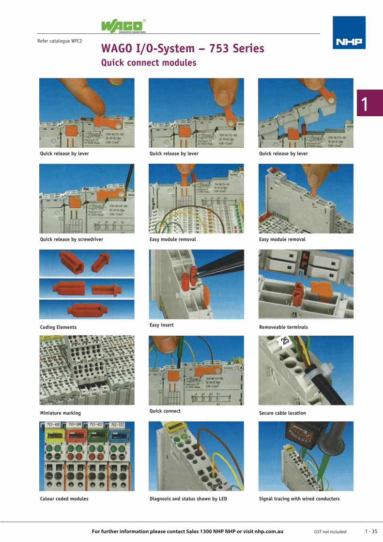
WAGO I/O-System – 753 SeriesQuick connect modules
Quick release by lever
Quick connect Secure cable locationMiniature marking
Coding Elements
Signal tracing with wired conductorsDiagnosis and status shown by LED
Removeable terminalsEasy insert
Quick release by lever Quick release by lever
Quick release by screwdriver Easy module removal
Colour coded modules
Easy module removal
1 - 36
1
For further information please contact Sales 1300 NHP NHP or visit nhp.com.au GST not included
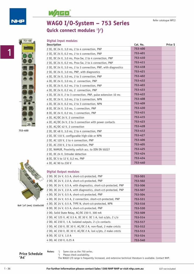
Refer catalogue WFC2WAGO I/O-System – 753 SeriesQuick connect modules 1)2)
Notes: 1) Same size as the 750 series. 2) Please check availability. The WAGO I/O range is frequently increased, and extensive technical literature is available. Contact NHP.
753-400
BxH 1) xT (mm) 12x65x100
Digital Input modules Description Cat. No. Price $2 DI, DC 24 V, 3.0 ms, 2 to 4 connection, PNP
2 DI, DC 24 V, 0.2 ms, 2 to 4 connection, PNP
2 DI, DC 24 V, 3.0 ms, Prox-Sw, 2 to 4 connection, PNP
2 DI, DC 24 V, 0.2 ms, Prox-Sw, 2 to 4 connection, PNP
2 DI, DC 24 V, 3.0 ms, 2 to 3 connection, PNP, with diagnostics
2 DI, DC 24 V, 3.0 ms, PNP, with diagnostics
4 DI, DC 24 V, 3.0 ms, 2 to 3 connection, PNP
4 DI, DC 24 V, 3.0 ms, 2 connection, PNP
4 DI, DC 24 V, 0.2 ms, 2 to 3 connection, PNP
4 DI, DC 24 V, 0.2 ms, 2 connection, PNP
4 DI, DC 24 V, 2 to 3 connection, PNP, pulse extension 10 ms
4 DI, DC 24 V, 3.0 ms, 2 to 3 connection, NPN
4 DI, DC 24 V, 0.2 ms, 2 to 3 connection, NPN
8 DI, DC 24 V, 3.0 ms, 1 connection, PNP
8 DI, DC 24 V, 0.2 ms, 1 connection, PNP
4 DI, AC/DC 24 V, 2 connection
4 DI, AC/DC 24 V, 2 to 3 connection with power contacts
4 DI, AC/DC 42 V, 2 connection
2 DI, DC 48 V, 3.0 ms, 2 to 4 connection, PNP
2 DI, DC 110 V, configurable high-side or NPN
2 DI, AC 120 V, 2 to 4 connection, PNP
2 DI, AC 230 V, 2 to 4 connection, PNP
2 DI, NAMUR, Proximity switch acc. to DIN EN 50227
2 DI, DC 24 V, Intruder detection
8 DI, DC 5 to 12 V, 0,2 ms, PNP
4 DI, AC 90 to 230 V
Digital Output modules 2 DO, DC 24 V, 0.5 A, short-cct-protected, PNP
2 DO, DC 24 V, 2.0 A, short-cct-protected, PNP
2 DO, DC 24 V, 0.5 A, with diagnostics, short-cct-protected, PNP
2 DO, DC 24 V, 2.0 A, with diagnostics, short-cct-protected, PNP
4 DO, DC 24 V, 0.5 A, short-cct-protected, PNP
4 DO, DC 24 V, 0.5 A, 2 connection, short-cct-protected, PNP
4 DO, DC 24 V, 0.5 A, TYPE N, short-cct-protected, NPN
8 DO, DC 24 V, 0.5 A, short-cct-protected, PNP
2 DO, Solid State Relay, AC/DC 230 V, 300 mA
2 DO, AC 125 V, AC 0.5 A, DC 30 V, DC 1 A, isol o/pts, 2 c/o
2 DO, AC 230 V, 1 A, isolated outputs, 2 c/o contacts
2 DO, AC 230 V, DC 30 V, AC/DC 2 A, non-float, 2 make cntcts
2 DO, AC 230 V, DC 30 V, AC/DC 2 A, isol o/pts, 2 make cntcts
8 DO, DC 12 V, 1.0 A
4 DO, AC 230 V, 0.25 A
753-400753-401753-410753-411753-418753-421753-402753-432753-403753-433753-422753-408753-409753-430753-431753-415753-423753-428753-412753-427753-406753-405753-425753-424753-434753-440
753-501753-502753-506753-507753-504753-531753-516753-530753-509753-514753-517753-512753-513753-534753-540
Price Schedule ‘A4’

1 - 37
1
For further information please contact Sales 1300 NHP NHP or visit nhp.com.au GST not included
Description Cat. No. Price $2-channel, 0 - 20 mA, Diff.
4-channel, 0 - 20 mA, single ended
2-channel, 0 - 20 mA, single ended
2-channel, 0 - 20 mA, single ended, 16 Bit
2-channel, 0 - 20 mA, Differential inputs
2-channel, 4 - 20 mA, Diff.
4-channel, 4 - 20 mA, single ended
2-channel, 4 - 20 mA, single ended, 16 Bit
2-channel, 4 - 20 mA, single ended
2-channel, 4 - 20 mA, Isolated differential inputs
2-channel, 0 - 1 A AC/DC, Diff.
4-channel, DC 0 - 10 V, single ended
2-channel, DC 0 - 10 V, single ended
2-channel, DC 4 - 20 mA, single ended
2-channel, AC/DC 0 - 10 V, Diff.
2-channel, DC 0 - 10 V, single ended
2-channel, DC ± 10 V, Diff.
4-channel, DC ± 10 V, single ended
2-channel, DC ± 10 V, Diff. measurement input
2-channel, DC ± 10 V, single ended
2-channel, DC 0 - 30 V, Diff. measurement input
2-channel, input module for RTDs, PT100 / RTD
2-channel, t/cpls, open-cct, K type
2-channel, 4-20 mA, HART, up to 4 variables per channel, 12 bit
Analogue Output modules2-channel, 0 - 20 mA
2-channel, 4 - 20 mA
2-channel, DC 0 - 10 V
4-channel, DC 0 - 10 V
2-channel, DC ± 10 V
4-channel, DC ± 10 V
Speciality modulesUp/Down counter, DC 24 V, 100 kHz
2-channel Up/Down counter, DC 24 V / 16 Bit / 500 Hz
Digital impulse interface
Serial interface RS 232 C
Serial interface RS 485
KNX/TP1, KNX/EIB
System modulesField Side connection module, DC 0 V
Field Side connection module, DC 24 V
Field Side connection module, AC/DC 0 ...230 V
Connector (required for all 753 Series modules)
AccessoriesCoding element Series 753
Refer catalogue WFC2
Price Schedule ‘A4’
753-400
BxH 1)xT (mm) 12x65x100
WAGO I/O-System – 753 SeriesQuick connect modules 2)
Notes: 1) Same size as the 750 series. 2) Please check availability. The WAGO I/O range is frequently increased, and extensive technical literature is available. Contact NHP.
Analogue Input modules
753-452753-453753-465753-472753-480753-454753-455753-474753-466753-492753-475753-459753-467753-466753-477753-478753-456753-457753-479753-476753-483753-461753-469753-482
753-552753-554753-550753-559753-556753-557
753-404753-638753-635753-650753-653753-646
753-604753-603753-614753-110
753-150
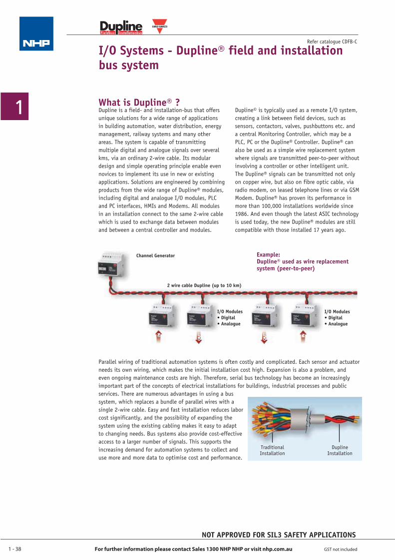
1 - 38
1
For further information please contact Sales 1300 NHP NHP or visit nhp.com.au GST not included
I/O Systems - Dupline® field and installation bus system
Refer catalogue CDFB-C
Fieldbus Installationbus
®
Dupline is a field- and installation-bus that offers unique solutions for a wide range of applications in building automation, water distribution, energy management, railway systems and many other areas. The system is capable of transmitting multiple digital and analogue signals over several kms, via an ordinary 2-wire cable. Its modular design and simple operating principle enable even novices to implement its use in new or existing applications. Solutions are engineered by combining products from the wide range of Dupline® modules, including digital and analogue I/O modules, PLC and PC interfaces, HMIs and Modems. All modules in an installation connect to the same 2-wire cable which is used to exchange data between modules and between a central controller and modules.
Dupline© is typically used as a remote I/O system, creating a link between field devices, such as sensors, contactors, valves, pushbuttons etc. and a central Monitoring Controller, which may be a PLC, PC or the Dupline® Controller. Dupline® can also be used as a simple wire replacement system where signals are transmitted peer-to-peer without involving a controller or other intelligent unit. The Dupline® signals can be transmitted not only on copper wire, but also on fibre optic cable, via radio modem, on leased telephone lines or via GSM Modem. Dupline® has proven its performance in more than 100,000 installations worldwide since 1986. And even though the latest ASIC technology is used today, the new Dupline® modules are still compatible with those installed 17 years ago.
Parallel wiring of traditional automation systems is often costly and complicated. Each sensor and actuator needs its own wiring, which makes the initial installation cost high. Expansion is also a problem, and even ongoing maintenance costs are high. Therefore, serial bus technology has become an increasingly important part of the concepts of electrical installations for buildings, industrial processes and public services. There are numerous advantages in using a bus system, which replaces a bundle of parallel wires with a single 2-wire cable. Easy and fast installation reduces labor cost significantly, and the possibility of expanding the system using the existing cabling makes it easy to adapt to changing needs. Bus systems also provide cost-effective access to a larger number of signals. This supports the increasing demand for automation systems to collect and use more and more data to optimise cost and performance.
Traditional Installation
Dupline Installation
What is Dupline® ?
Example:Dupline® used as wire replacement system (peer-to-peer)
2 wire cable Dupline (up to 10 km)
I/O Modules • Digital • Analogue
I/O Modules • Digital • Analogue
Channel Generator
NOT APPROVED FOR SIL3 SAFETY APPLICATIONS
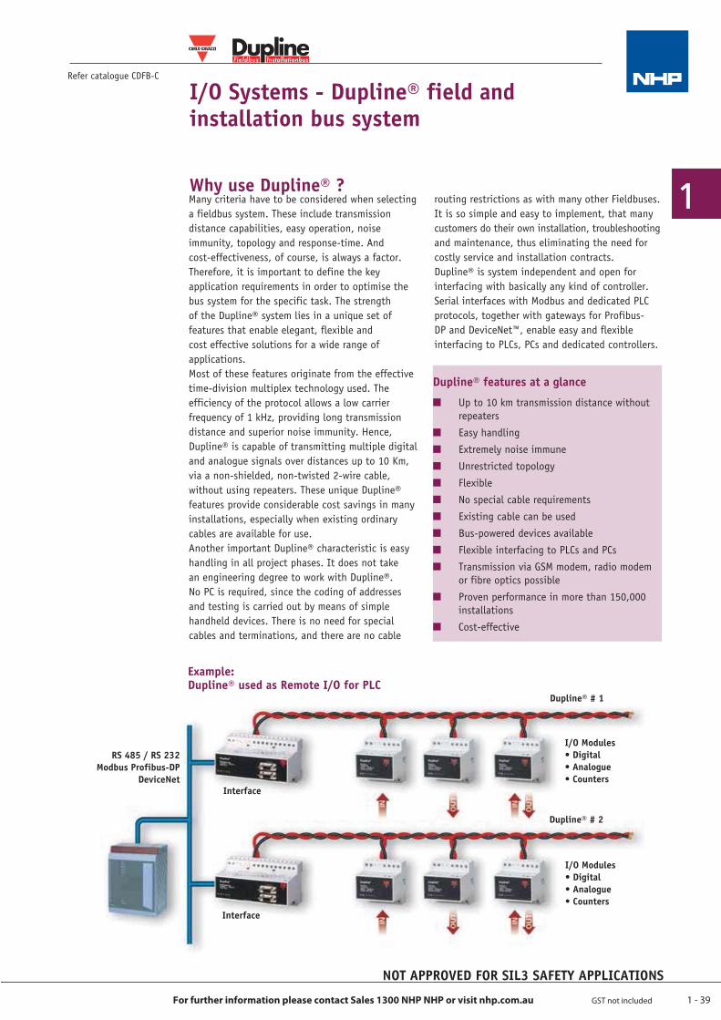
1 - 39
1
For further information please contact Sales 1300 NHP NHP or visit nhp.com.au GST not included
I/O Systems - Dupline® field and installation bus system
Refer catalogue CDFB-C
Fieldbus Installationbus
®
Many criteria have to be considered when selecting a fieldbus system. These include transmission distance capabilities, easy operation, noise immunity, topology and response-time. And cost-effectiveness, of course, is always a factor. Therefore, it is important to define the key application requirements in order to optimise the bus system for the specific task. The strength of the Dupline® system lies in a unique set of features that enable elegant, flexible and cost effective solutions for a wide range of applications.Most of these features originate from the effective time-division multiplex technology used. The efficiency of the protocol allows a low carrier frequency of 1 kHz, providing long transmission distance and superior noise immunity. Hence, Dupline® is capable of transmitting multiple digital and analogue signals over distances up to 10 Km, via a non-shielded, non-twisted 2-wire cable, without using repeaters. These unique Dupline® features provide considerable cost savings in many installations, especially when existing ordinary cables are available for use. Another important Dupline® characteristic is easy handling in all project phases. It does not take an engineering degree to work with Dupline®. No PC is required, since the coding of addresses and testing is carried out by means of simple handheld devices. There is no need for special cables and terminations, and there are no cable
routing restrictions as with many other Fieldbuses. It is so simple and easy to implement, that many customers do their own installation, troubleshooting and maintenance, thus eliminating the need for costly service and installation contracts.Dupline® is system independent and open for interfacing with basically any kind of controller.Serial interfaces with Modbus and dedicated PLC protocols, together with gateways for Profibus-DP and DeviceNet™, enable easy and flexible interfacing to PLCs, PCs and dedicated controllers.
Dupline® features at a glance
Q Up to 10 km transmission distance without repeaters
Q Easy handlingQ Extremely noise immuneQ Unrestricted topologyQ FlexibleQ No special cable requirementsQ Existing cable can be usedQ Bus-powered devices availableQ Flexible interfacing to PLCs and PCsQ Transmission via GSM modem, radio modem
or fibre optics possibleQ Proven performance in more than 150,000
installationsQ Cost-effective
Example:Dupline® used as Remote I/O for PLC
RS 485 / RS 232Modbus Profibus-DP
DeviceNet
Dupline® # 1
I/O Modules • Digital • Analogue • Counters
Dupline® # 2
I/O Modules • Digital • Analogue • Counters
Interface
Interface
Why use Dupline® ?
NOT APPROVED FOR SIL3 SAFETY APPLICATIONS
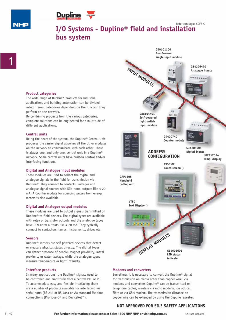
1 - 40
1
For further information please contact Sales 1300 NHP NHP or visit nhp.com.au GST not included
G50101106Bus-Poweredsingle input module
INPUT MODULES
DISPLAY M
ODULES
G34296470Analogue inputs
G88104401Self-powered light switch input module
G4420740Counter module
G34205501Digital inputs
GAP1605Handheld coding unit
ADDRESSCONFIGURATION
VT565WTouch screen 1)
VT50Text Display 1)
G54606606LED status indicator
G82452574Temp. display
I/O Systems - Dupline® field and installation bus system
Refer catalogue CDFB-C
Product categoriesThe wide range of Dupline® products for industrial applications and building automation can be divided into different categories depending on the function they perform on the network.By combining products from the various categories, complete solutions can be engineered for a multitude of different applications.
Central unitsBeing the heart of the system, the Dupline® Central Unit produces the carrier signal allowing all the other modules on the network to communicate with each other. There is always one, and only one, central unit in a Dupline® network. Some central units have built-in control and/or interfacing functions.
Digital and Analogue input modulesThese modules are used to collect the digital and analogue signals in the field for transmission via Dupline®. They connect to contacts, voltages and analogue signal sources with DIN-norm outputs like 4-20 mA. A Counter module for counting pulses from energy meters is also available.
Digital and Analogue output modulesThese modules are used to output signals transmitted on Dupline® to field devices. The digital types are available with relay or transistor outputs and the analogue types have DIN-norm outputs like 4-20 mA. They typically connect to contactors, lamps, instruments, drives etc.
SensorsDupline® sensors are self-powered devices that detect or measure physical states directly. The digital types can detect presence of people, magnet proximity, metal proximity or water leakage, while the analogue types measure temperature or light intensity.
Interface productsIn many applications, the Dupline® signals need to be controlled and monitored from a central PLC or PC. To accommodate easy and flexible interfacing there are a number of products available for interfacing via serial ports (RS 232 or RS 485) or via standard Fieldbus connections (Profibus-DP and DeviceNet™).
Modems and convertersSometimes it is necessary to convert the Dupline® signal for transmission on media other than copper wire. Via modems and converters Dupline® can be transmitted on telephone cables, wireless via radio modems, on optical fibre or via GSM modem. The transmission distance on copper wire can be extended by using the Dupline repeater.
NOT APPROVED FOR SIL3 SAFETY APPLICATIONS
Fieldbus Installationbus
®
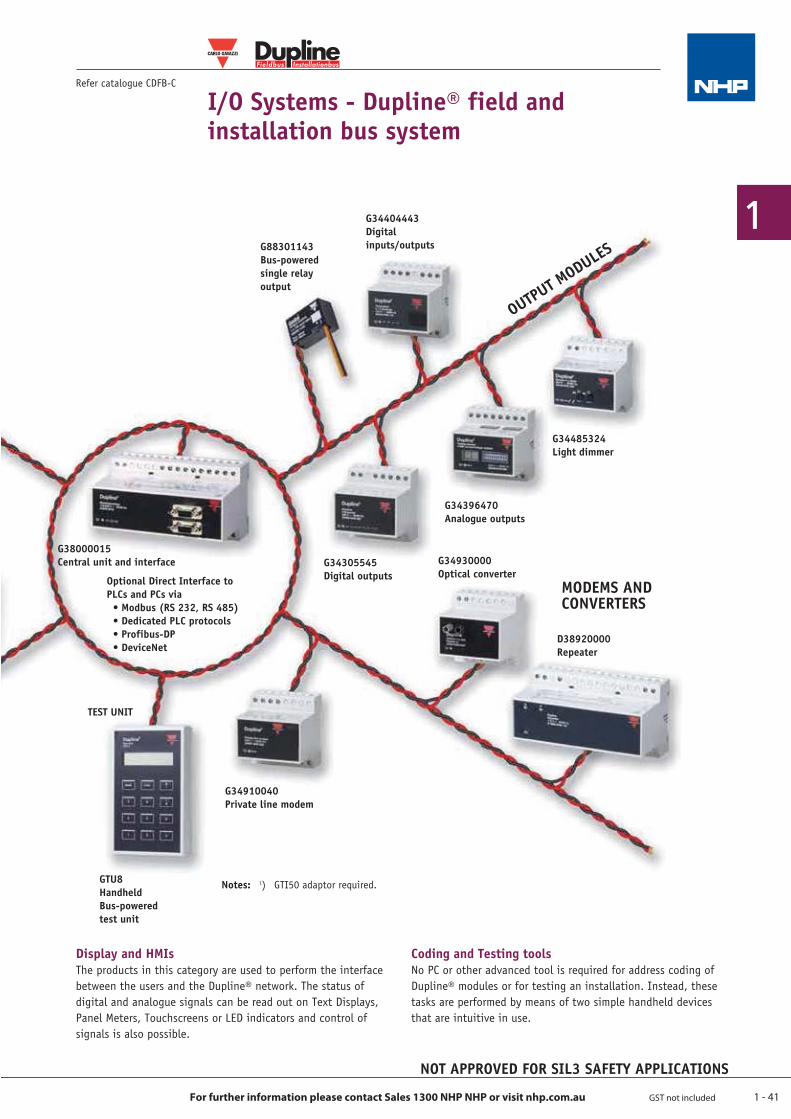
1 - 41
1
For further information please contact Sales 1300 NHP NHP or visit nhp.com.au GST not included
Optional Direct Interface to PLCs and PCs via • Modbus (RS 232, RS 485) • Dedicated PLC protocols • Profibus-DP • DeviceNet
OUTPUT M
ODULESG88301143Bus-powered single relay output
G34404443Digital inputs/outputs
G34485324Light dimmer
G34396470Analogue outputs
G38000015Central unit and interface G34305545
Digital outputsG34930000Optical converter
G34910040Private line modem
MODEMS ANDCONVERTERS
TEST UNIT
D38920000Repeater
GTU8Handheld Bus-powered test unit
I/O Systems - Dupline® field and installation bus system
Refer catalogue CDFB-C
Display and HMIsThe products in this category are used to perform the interface between the users and the Dupline® network. The status of digital and analogue signals can be read out on Text Displays, Panel Meters, Touchscreens or LED indicators and control of signals is also possible.
Coding and Testing toolsNo PC or other advanced tool is required for address coding of Dupline® modules or for testing an installation. Instead, these tasks are performed by means of two simple handheld devices that are intuitive in use.
NOT APPROVED FOR SIL3 SAFETY APPLICATIONS
Fieldbus Installationbus
®
Notes: 1) GTI50 adaptor required.
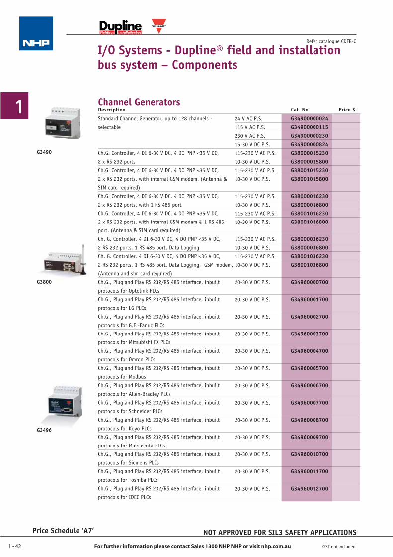
1 - 42
1
For further information please contact Sales 1300 NHP NHP or visit nhp.com.au GST not included
Price Schedule ‘A7’
I/O Systems - Dupline® field and installation bus system – Components
Refer catalogue CDFB-C
Channel Generators
G3490
G3800
G3496
NOT APPROVED FOR SIL3 SAFETY APPLICATIONS
Fieldbus Installationbus
®
24 V AC P.S.115 V AC P.S.230 V AC P.S.15-30 V DC P.S.115-230 V AC P.S.10-30 V DC P.S.115-230 V AC P.S.10-30 V DC P.S.
115-230 V AC P.S.10-30 V DC P.S.115-230 V AC P.S.10-30 V DC P.S.
115-230 V AC P.S.10-30 V DC P.S.115-230 V AC P.S.10-30 V DC P.S.
20-30 V DC P.S.
20-30 V DC P.S.
20-30 V DC P.S.
20-30 V DC P.S.
20-30 V DC P.S.
20-30 V DC P.S.
20-30 V DC P.S.
20-30 V DC P.S.
20-30 V DC P.S.
20-30 V DC P.S.
20-30 V DC P.S.
20-30 V DC P.S.
20-30 V DC P.S.
Standard Channel Generator, up to 128 channels - selectable
Ch.G. Controller, 4 DI 6-30 V DC, 4 DO PNP <35 V DC, 2 x RS 232 portsCh.G. Controller, 4 DI 6-30 V DC, 4 DO PNP <35 V DC, 2 x RS 232 ports, with internal GSM modem. (Antenna & SIM card required)Ch.G. Controller, 4 DI 6-30 V DC, 4 DO PNP <35 V DC, 2 x RS 232 ports, with 1 RS 485 portCh.G. Controller, 4 DI 6-30 V DC, 4 DO PNP <35 V DC, 2 x RS 232 ports, with internal GSM modem & 1 RS 485 port. (Antenna & SIM card required)Ch. G. Controller, 4 DI 6-30 V DC, 4 DO PNP <35 V DC, 2 RS 232 ports, 1 RS 485 port, Data LoggingCh. G. Controller, 4 DI 6-30 V DC, 4 DO PNP <35 V DC, 2 RS 232 ports, 1 RS 485 port, Data Logging, GSM modem, (Antenna and sim card required)Ch.G., Plug and Play RS 232/RS 485 interface, inbuilt protocols for Optolink PLCsCh.G., Plug and Play RS 232/RS 485 interface, inbuilt protocols for LG PLCsCh.G., Plug and Play RS 232/RS 485 interface, inbuilt protocols for G.E.-Fanuc PLCsCh.G., Plug and Play RS 232/RS 485 interface, inbuilt protocols for Mitsubishi FX PLCsCh.G., Plug and Play RS 232/RS 485 interface, inbuilt protocols for Omron PLCsCh.G., Plug and Play RS 232/RS 485 interface, inbuilt protocols for ModbusCh.G., Plug and Play RS 232/RS 485 interface, inbuilt protocols for Allen-Bradley PLCsCh.G., Plug and Play RS 232/RS 485 interface, inbuilt protocols for Schneider PLCsCh.G., Plug and Play RS 232/RS 485 interface, inbuilt protocols for Koyo PLCsCh.G., Plug and Play RS 232/RS 485 interface, inbuilt protocols for Matsushita PLCsCh.G., Plug and Play RS 232/RS 485 interface, inbuilt protocols for Siemens PLCsCh.G., Plug and Play RS 232/RS 485 interface, inbuilt protocols for Toshiba PLCsCh.G., Plug and Play RS 232/RS 485 interface, inbuilt protocols for IDEC PLCs
Description Cat. No. Price $
G34900000024G34900000115G34900000230G34900000824G38000015230G38000015800G38001015230G38001015800
G38000016230G38000016800G38001016230G38001016800
G38000036230G38000036800G38001036230G38001036800
G34960000700
G34960001700
G34960002700
G34960003700
G34960004700
G34960005700
G34960006700
G34960007700
G34960008700
G34960009700
G34960010700
G34960011700
G34960012700
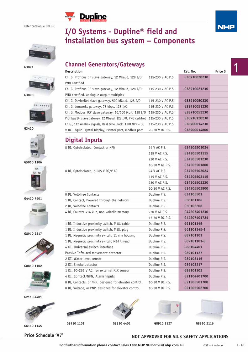
1 - 43
1
For further information please contact Sales 1300 NHP NHP or visit nhp.com.au GST not included
G3891
G3890
G3420
G5010 1106
G4420 7401
G8910 2217
I/O Systems - Dupline® field and installation bus system – Components
Refer catalogue CDFB-C
Price Schedule ‘A7’
G6110 1145G8910 1101 G8810 4401 G8910 1127 G8910 2116
G8810 1102
G2110 4401
NOT APPROVED FOR SIL3 SAFETY APPLICATIONS
Fieldbus Installationbus
®
Description Cat. No. Price $
Ch. G. Profibus DP slave gateway, 12 Mbaud, 128 I/O, 115-230 V AC P.S.
PNO certified
Ch. G. Profibus DP slave gateway, 12 Mbaud, 128 I/O, 115-230 V AC P.S.
PNO certified, analogue output multiplex
Ch. G. DeviceNet slave gateway, 500 kBaud, 128 I/O 115-230 V AC P.S.
Ch. G. Lonworks gateway, 78 kbps, 128 I/O 115-230 V AC P.S.
Ch. G. Modbus TCP slave gateway, 10/100 Mbit, 128 I/O 115-230 V AC P.S.
Profibus DP slave gateway, 12 Mbaud, 128 I/O, PNO certified 115-230 V AC P.S.
Ch.G., 112 Analink signals, Real time Clock, 1 DO NPN < 35 115-230 V AC P.S.
V DC, Liquid Crystal Display, Printer port, Modbus port 20-30 V DC P.S.
Digital Inputs8 DI, Optoisolated, Contact or NPN 24 V AC P.S.
115 V AC P.S.
230 V AC P.S.
10-30 V AC P.S.
8 DI, Optoisolated, 6-265 V DC/V AC 24 V AC P.S.
115 V AC P.S.
230 V AC P.S.
10-30 V AC P.S.
8 DI, Volt-free Contacts Dupline P.S.
1 DI, Contact, Powered through the network Dupline P.S.
2 DI, Volt-free Contacts Dupline P.S.
4 DI, Counter <14 kHz, non-volatile memory 230 V AC P.S.
15-30 V DC P.S.
1 DI, Inductive proximity switch, M18, cable Dupline P.S.
1 DI, Inductive proximity switch, M18, plug Dupline P.S.
1 DI, Magnetic proximity switch, 11 mm housing Dupline P.S.
1 DI, Magnetic proximity switch, M14 thread Dupline P.S.
4 DI, Universal switch interface Dupline P.S.
Passive Infra-red movement detector Dupline P.S.
2 DI, Water level sensor Dupline P.S.
2 DI, Smoke detector Dupline P.S.
1 DI, 90-265 V AC, for external PIR sensor Dupline P.S.
4 DI, Contact/NPN, Alarm inputs Dupline P.S.
8 DI, Contacts, or NPN, designed for elevator control 10-30 V DC P.S.
8 DI, Voltage, or PNP, designed for elevator control 10-30 V DC P.S.
Channel Generators/Gateways
G38910020230
G38910021230
G38910050230
G38910051230
G38910052230
G38910120230
G38900014230
G38900014800
G34205501024
G34205501115
G34205501230
G34205501800
G34205502024
G34205502115
G34205502230
G34205502800
G34105501
G50101106
G50102206
G44207401230
G44207401724
G61101145
G61101145-1
G89101101
G89101101-G
G88104401
G89101127
G89102116
G89102217
G88101102
G21104401700
G21205501700
G21205502700
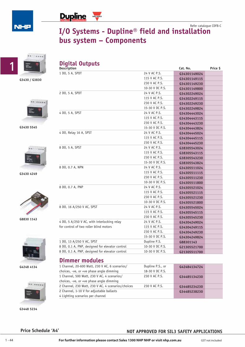
1 - 44
1
For further information please contact Sales 1300 NHP NHP or visit nhp.com.au GST not included
Price Schedule ‘A4’
I/O Systems - Dupline® field and installation bus system – Components
Refer catalogue CDFB-C
Digital Outputs
G3430 / G3830
G3430 5545
G3430 4249
G8830 1143
G4248 4134
G3448 5234
NOT APPROVED FOR SIL3 SAFETY APPLICATIONS
Fieldbus Installationbus
®
Description Cat. No. Price $1 DO, 5 A, SPDT 24 V AC P.S. 115 V AC P.S. 230 V AC P.S. 10-30 V DC P.S.2 DO, 5 A, SPDT 24 V AC P.S. 115 V AC P.S. 230 V AC P.S. 15-30 V DC P.S.4 DO, 5 A, SPST 24 V AC P.S. 115 V AC P.S. 230 V AC P.S. 15-30 V DC P.S.4 DO, Relay 16 A, SPST 24 V AC P.S. 115 V AC P.S. 230 V AC P.S.8 DO, 5 A, SPST 24 V AC P.S. 115 V AC P.S. 230 V AC P.S. 15-30 V DC P.S.8 DO, 0.7 A, NPN 24 V AC P.S. 115 V AC P.S. 230 V AC P.S. 10-30 V DC P.S.8 DO, 0.7 A, PNP 24 V AC P.S. 115 V AC P.S. 230 V AC P.S. 10-30 V DC P.S.8 DO, 16 A/250 V AC, SPST 24 V AC P.S. 115 V AC P.S. 230 V AC P.S.4 DO, 5 A/250 V AC, with interlocking relay 24 V AC P.S.for control of two roller blind motors 115 V AC P.S. 230 V AC P.S. 15-30 V DC P.S.1 DO, 13 A/250 V AC, SPST Dupline P.S.8 DO, 0.1 A, PNP, designed for elevator control 10-30 V DC P.S.8 DO, 0.1 A, PNP, designed for elevator control 10-30 V DC P.S.
Dimmer modules1 Channel, 20-600 Watt, 230 V AC, 6 scenarios/ Dupline P.S., orchoices, -ve, or +ve phase angle dimming 18-30 V DC P.S.1 Channel, 500 Watt, 230 V AC, 4 scenarios/ 230 V AC P.S.choices, -ve, or +ve phase angle dimming 2 Channel, 230 Watt, 230 V AC, 4 scenarios/choices 230 V AC P.S.2 Channel, 1-10 V for adjustable ballasts4 Lighting scenarios per channel
G34301149024G34301149115G34301149230G34301149800G34302249024G34302249115G34302249230G34302249824G34304443024G34304443115G34304443230G34304443824G34304445024G34304445115G34304445230G38305543024G38305543115G38305543230G38305543824G34305511024G34305511115G34305511230G34305511800G34305521024G34305521115G34305521230G34305521800G34305545024G34305545115G34305545230G34304249024 G34304249115 G34304249230 G34304249824 G88301143G21305521700G21305511700
G42484134724
G34485134230
G34485234230G34485238230
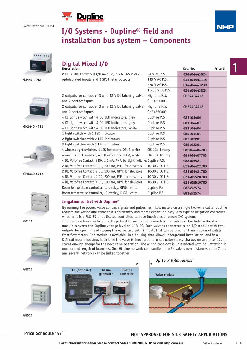
1 - 45
1
For further information please contact Sales 1300 NHP NHP or visit nhp.com.au GST not included
Refer catalogue CDFB-C
Price Schedule ‘A7’
Fieldbus Installationbus
®
I/O Systems - Dupline® field and installation bus system – Components
Irrigation control with Dupline®By running the power, valve control signals and pulses from flow meters on a single two-wire cable, Dupline reduces the wiring and cable cost significantly and makes expansion easy. Any type of irrigation controller, whether it is a PLC, PC or dedicated controller, can use Dupline as a remote I/O system.In order to achieve sufficient voltage level to switch the 3-wire latching valves in the field, a Booster module converts the Dupline voltage level to 28 V DC. Each valve is connected to an I/O-module with two outputs for opening and closing the valve, and with 2 inputs that can be used for transmission of pulses from flow meters. The module is available in a housing that allows underground installation, and in a DIN-rail mount housing. Each time the valve is fired, a built-in capacitor slowly charges up and after 10s it stores enough energy for the next valve operation. The wiring topology is unrestricted with no limitation in number and length of branches. One Hi-Line network can handle up to 64 valves over distances up to 7 km, and several networks can be linked together.
Digital Mixed I/O
G3440 4443
GH3440 4412
GH6440 4412
G8210
G8510
G8110
Up to 7 Kilometres!
PLC (optional) Channel generator Valve module
Hi-Line converter
NOT APPROVED FOR SIL3 SAFETY APPLICATIONS
Description Cat. No. Price $2 DI, 2 DO, Combined I/O module, 2 x 6-265 V AC/DC 24 V AC P.S.optoisolated inputs and 2 SPST relay outputs 115 V AC P.S. 230 V AC P.S. 15-30 V DC P.S.2 outputs for control of 3 wire 12 V DC latching valve Highline P.S.and 2 contact inputs GH348500002 outputs for control of 3 wire 12 V DC latching valve Highline P.S.and 2 contact inputs GH348500004 DI light switch with 4 DO LED indicators, grey Dupline P.S.4 DI light switch with 4 DO LED indicators, grey Dupline P.S.4 DI light switch with 4 DO LED indicators, white Dupline P.S.1 light switch with 1 LED indicator Dupline P.S.2 light switches with 2 LED indicators Dupline P.S.3 light switches with 3 LED indicators Dupline P.S.4 wireless light switches, 4 LED indicators, OPUS, white CR2023 Battery4 wireless light switches, 4 LED indicators, FUGA, white CR2023 Battery4 DI, Volt-free Contact, 4 DO, 1.5 mA, PNP, for light switches Dupline P.S.2 DI, Volt-free Contact, 2 DO, 200 mA, PNP, for elevators 10-30 V DC P.S.2 DI, Volt-free Contact, 2 DO, 200 mA, NPN, for elevators 10-30 V DC P.S.4 DI, Volt-free Contact, 4 DO, 200 mA, PNP, for elevators 10-30 V DC P.S.4 DI, Volt-free Contact, 4 DO, 200 mA, NPN, for elevators 10-30 V DC P.S.Room temperature controller, LC display, OPUS, white Dupline P.S.Room temperature controller, LC display, FUGA, white Dupline P.S.
G34404443024G34404443115G34404443230G34404443824GH34404412
GH64404412
G81104406G81104407G82104406G85101101G85102201G85103301G82864406703G81864407703G88405521G21404422700G21404421700G21405520700G21405510700G82452574G81452574
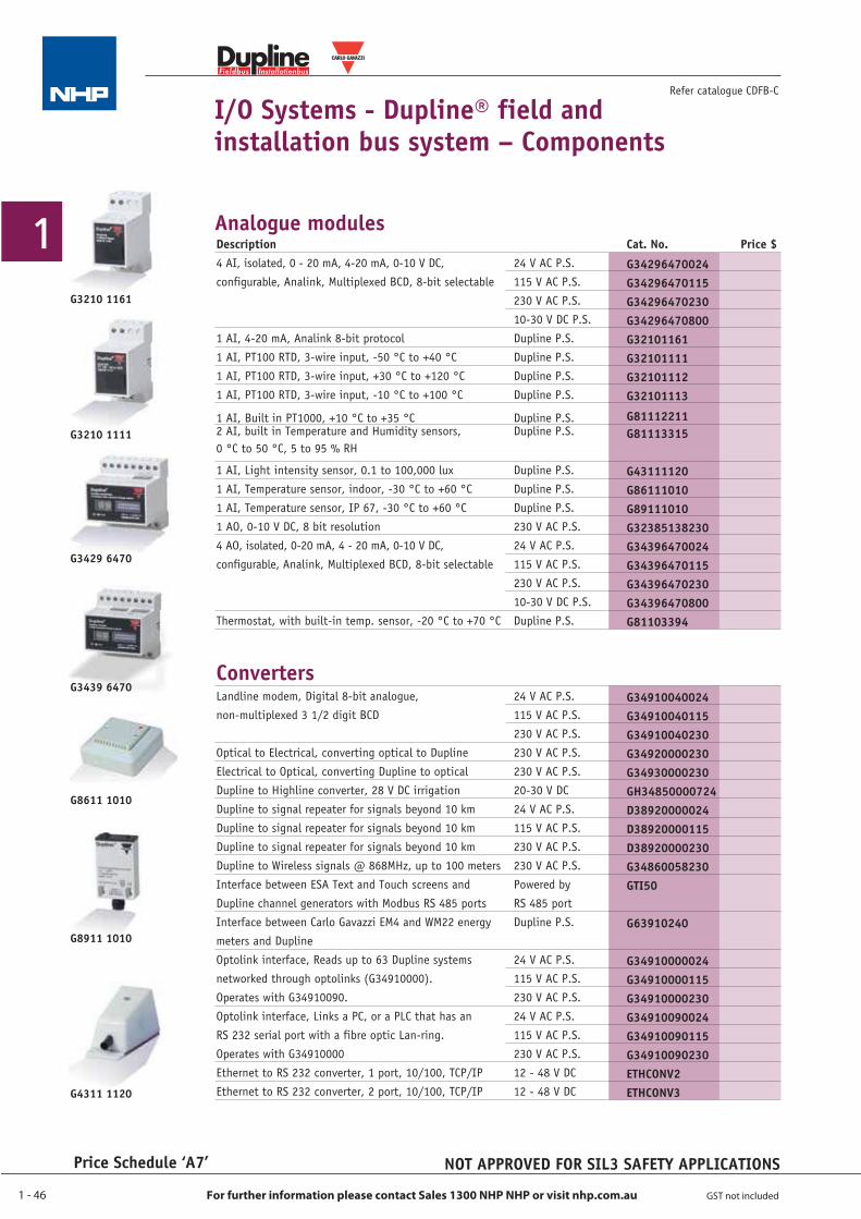
1 - 46
1
For further information please contact Sales 1300 NHP NHP or visit nhp.com.au GST not included
Description Cat. No. Price $4 AI, isolated, 0 - 20 mA, 4-20 mA, 0-10 V DC, 24 V AC P.S.configurable, Analink, Multiplexed BCD, 8-bit selectable 115 V AC P.S. 230 V AC P.S. 10-30 V DC P.S.1 AI, 4-20 mA, Analink 8-bit protocol Dupline P.S.1 AI, PT100 RTD, 3-wire input, -50 °C to +40 °C Dupline P.S.1 AI, PT100 RTD, 3-wire input, +30 °C to +120 °C Dupline P.S.1 AI, PT100 RTD, 3-wire input, -10 °C to +100 °C Dupline P.S.
1 AI, Built in PT1000, +10 °C to +35 °C Dupline P.S.2 AI, built in Temperature and Humidity sensors, Dupline P.S.0 °C to 50 °C, 5 to 95 % RH
1 AI, Light intensity sensor, 0.1 to 100,000 lux Dupline P.S.1 AI, Temperature sensor, indoor, -30 °C to +60 °C Dupline P.S.1 AI, Temperature sensor, IP 67, -30 °C to +60 °C Dupline P.S.1 AO, 0-10 V DC, 8 bit resolution 230 V AC P.S.4 AO, isolated, 0-20 mA, 4 - 20 mA, 0-10 V DC, 24 V AC P.S.configurable, Analink, Multiplexed BCD, 8-bit selectable 115 V AC P.S. 230 V AC P.S. 10-30 V DC P.S.Thermostat, with built-in temp. sensor, -20 °C to +70 °C Dupline P.S.
ConvertersLandline modem, Digital 8-bit analogue, 24 V AC P.S.non-multiplexed 3 1/2 digit BCD 115 V AC P.S. 230 V AC P.S.Optical to Electrical, converting optical to Dupline 230 V AC P.S.Electrical to Optical, converting Dupline to optical 230 V AC P.S.Dupline to Highline converter, 28 V DC irrigation 20-30 V DCDupline to signal repeater for signals beyond 10 km 24 V AC P.S.Dupline to signal repeater for signals beyond 10 km 115 V AC P.S.Dupline to signal repeater for signals beyond 10 km 230 V AC P.S.Dupline to Wireless signals @ 868MHz, up to 100 meters 230 V AC P.S.Interface between ESA Text and Touch screens and Powered byDupline channel generators with Modbus RS 485 ports RS 485 portInterface between Carlo Gavazzi EM4 and WM22 energy Dupline P.S.meters and Dupline Optolink interface, Reads up to 63 Dupline systems 24 V AC P.S. networked through optolinks (G34910000). 115 V AC P.S. Operates with G34910090. 230 V AC P.S. Optolink interface, Links a PC, or a PLC that has an 24 V AC P.S. RS 232 serial port with a fibre optic Lan-ring. 115 V AC P.S. Operates with G34910000 230 V AC P.S.Ethernet to RS 232 converter, 1 port, 10/100, TCP/IP 12 - 48 V DCEthernet to RS 232 converter, 2 port, 10/100, TCP/IP 12 - 48 V DC
Price Schedule ‘A7’
Refer catalogue CDFB-C
Fieldbus Installationbus
®
G3210 1111
I/O Systems - Dupline® field and installation bus system – Components
Analogue modules
G3429 6470
G3210 1161
G4311 1120
G8611 1010
G8911 1010
G3439 6470
NOT APPROVED FOR SIL3 SAFETY APPLICATIONS
G34910040024G34910040115G34910040230G34920000230G34930000230GH34850000724D38920000024D38920000115D38920000230G34860058230GTI50
G63910240
G34910000024G34910000115G34910000230G34910090024G34910090115G34910090230ETHCONV2ETHCONV3
G34296470024G34296470115G34296470230G34296470800G32101161G32101111G32101112G32101113
G81112211G81113315
G43111120G86111010G89111010G32385138230G34396470024G34396470115G34396470230G34396470800G81103394
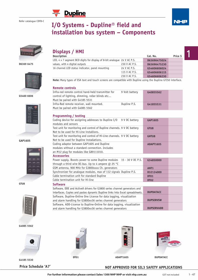
1 - 47
1
For further information please contact Sales 1300 NHP NHP or visit nhp.com.au GST not included
I/O Systems - Dupline® field and installation bus system – Components
Refer catalogue CDFB-C
Price Schedule ‘A7’
Displays / HMI
GTU8
D6369 6475
G5460 6606
G4185 5530DUPDATACC
GAP1605
NOT APPROVED FOR SIL3 SAFETY APPLICATIONS
Fieldbus Installationbus
®
ADAPT1605DT01
G4085 5562
Description Cat. No. Price $LED, 4 x 7 segment BCD digits for display of 8-bit analogue 24 V AC P.S.values, with 4 digital outputs 230 V AC P.S.16 channel LED status indicator, panel mounting 24 V AC P.S. 115 V AC P.S. 230 V AC P.S.Note: Many types of ESA text and touch screens are compatible with Dupline using the Dupline GTI50 interface.
Remote controlsInfra-red remote control hand-held transmitter for 9 Volt batterycontrol of lighting, dimming, roller blinds etc... Must be paired with G4185 5531 Infra-Red remote receiver, wall mounted. Dupline P.S.Must be paired with G4085 5562
Programming / testingCoding device for assigning addresses to Dupline I/O 9 V DC batterymodules and sensorsTest unit for monitoring and control of Dupline channels. 9 V DC batteryNot to be used for Hi-Line installions. Test unit for monitoring and control of Hi-Line channels. 9 V DC batteryNot to be used for Dupline installations. Coding adaptor between GAP1605 and Dupline modules without a standard connection. Includes an M12 plug for modules like G89111010. Accessories Power supply, Boosts power to some Dupline modules 15 - 30 V DC P.S. through a third wire DC-bus. Up to 4 ampere @ 25 °CGSM antenna, 900 MHz for G3800xxxx Ch. generators Synchronizer for analogue modules, max of 112 signals Dupline P.S.Cable termination unit for standard Dupline Cable termination unit for Hi-line
Software Software, DDE and ActiveX drivers for G3800 series channel generators and interfaces. Copies and pastes dynamic Dupline links into Excel spreadsheets.Software, Dupline-Online One License for data logging, visualization and alarm handling for G3800xx36 series channel generatorsSoftware, ADD-License to Dupline-Online for data logging, visualization and alarm handling for G3800xx36 series channel generators
D63696475024D63696475230G54606606024G54606606115G54606606230
G40855562
G41855531
GAP1605
GTU8
GHTU8
ADAPT1605
G34850000
ANT1D32124000DT01DT02 DUPDATACC
DUPSERVSW
DUPSERVADD
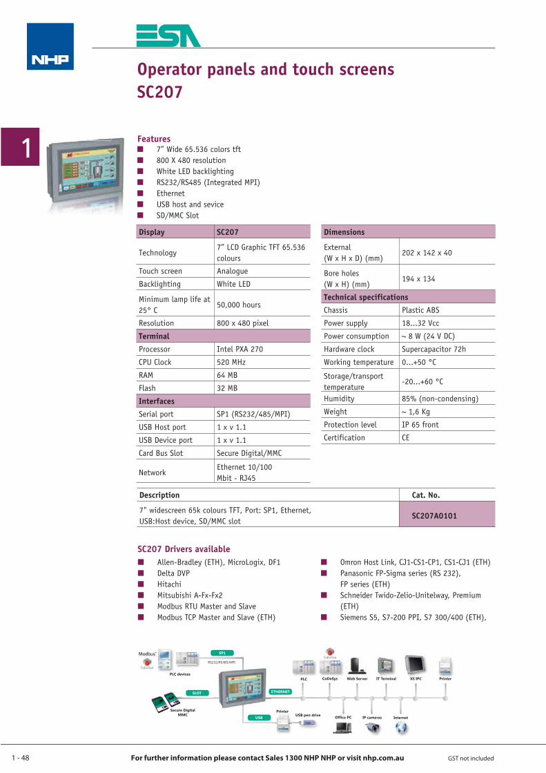
1 - 48
1
For further information please contact Sales 1300 NHP NHP or visit nhp.com.au GST not included
Operator panels and touch screensSC207
Q Allen-Bradley (ETH), MicroLogix, DF1Q Delta DVPQ HitachiQ Mitsubishi A-Fx-Fx2Q Modbus RTU Master and SlaveQ Modbus TCP Master and Slave (ETH)
Q Omron Host Link, CJ1-CS1-CP1, CS1-CJ1 (ETH)Q Panasonic FP-Sigma series (RS 232),
FP series (ETH)Q Schneider Twido-Zelio-Unitelway, Premium
(ETH)Q Siemens S5, S7-200 PPI, S7 300/400 (ETH),
Q 7” Wide 65.536 colors tftQ 800 X 480 resolutionQ White LED backlightingQ RS232/RS485 (Integrated MPI)Q EthernetQ USB host and seviceQ SD/MMC Slot
Features
SC207 Drivers available
Display SC207
Technology 7” LCD Graphic TFT 65.536 colours
Touch screen Analogue
Backlighting White LED
Minimum lamp life at 25° C
50,000 hours
Resolution 800 x 480 pixel
TerminalProcessor Intel PXA 270
CPU Clock 520 MHz
RAM 64 MB
Flash 32 MB
InterfacesSerial port SP1 (RS232/485/MPI)
USB Host port 1 x v 1.1
USB Device port 1 x v 1.1
Card Bus Slot Secure Digital/MMC
Network Ethernet 10/100 Mbit - RJ45
Dimensions
External (W x H x D) (mm)
202 x 142 x 40
Bore holes (W x H) (mm)
194 x 134
Technical specificationsChassis Plastic ABS
Power supply 18...32 Vcc
Power consumption ~ 8 W (24 V DC)
Hardware clock Supercapacitor 72h
Working temperature 0...+50 °C
Storage/transport temperature
-20...+60 °C
Humidity 85% (non-condensing)
Weight ~ 1,6 Kg
Protection level IP 65 front
Certification CE
Description Cat. No.
7" widescreen 65k colours TFT, Port: SP1, Ethernet, USB:Host device, SD/MMC slot
SC207A0101
3XWPRUHFRQWUROLQ\RXUKDQGV3XWPRUHFRQWURO LQ \RXU\RXU\RXU\RXUU\RXU\RXU\RXU\RXU\RXU\\\\\\\\\\\ KDQKDDKDDDDQKDQKDQKDQKDQKDQDQDQDDDQKDQKDQDQKDKDQKDQKDQKDQK GVGVGVGGVVVVVGGGGGVGV
565603,
6/27
6HFXUH'LJLWDO00&
63
3ULQWHU86%SHQGULYH
86%
(7+(51(7
3/& &R'H6\V :HE6HUYHU ,77HUPLQDO ;6,3& 3ULQWHU
2IÀFH3& ,3FDPHUDV ,QWHUQHW
3/&GHYLFHV
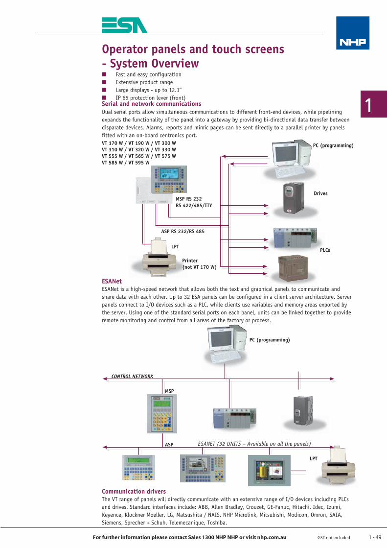
1 - 49
1
For further information please contact Sales 1300 NHP NHP or visit nhp.com.au GST not included
Operator panels and touch screens - System Overview
Dual serial ports allow simultaneous communications to different front-end devices, while pipelining expands the functionality of the panel into a gateway by providing bi-directional data transfer between disparate devices. Alarms, reports and mimic pages can be sent directly to a parallel printer by panels fitted with an on-board centronics port.
Q Fast and easy configurationQ Extensive product rangeQ Large displays - up to 12.1”Q IP 65 protection lever (front)Serial and network communications
ESANetESANet is a high-speed network that allows both the text and graphical panels to communicate and share data with each other. Up to 32 ESA panels can be configured in a client server archi tecture. Server panels connect to I/O devices such as a PLC, while clients use variables and memory areas exported by the server. Using one of the standard serial ports on each panel, units can be linked together to provide remote monitoring and control from all areas of the factory or process.
Communication driversThe VT range of panels will directly communicate with an extensive range of I/O devices including PLCs and drives. Standard interfaces include: ABB, Allen Bradley, Crouzet, GE-Fanuc, Hitachi, Idec, Izumi, Keyence, Klockner Moeller, LG, Matsushita / NAIS, NHP Microlink, Mitsubishi, Modicon, Omron, SAIA, Siemens, Sprecher + Schuh, Telemecanique, Toshiba.
PC (programming)
MSP
ASP
CONTROL NETWORK
ESANET (32 UNITS – Available on all the panels)
LPT
PC (programming)
Drives
ASP RS 232/RS 485
LPT
VT 170 W / VT 190 W / VT 300 W VT 310 W / VT 320 W / VT 330 W VT 555 W / VT 565 W / VT 575 W VT 585 W / VT 595 W
PLCs
MSP RS 232 RS 422/485/TTY
Printer (not VT 170 W)
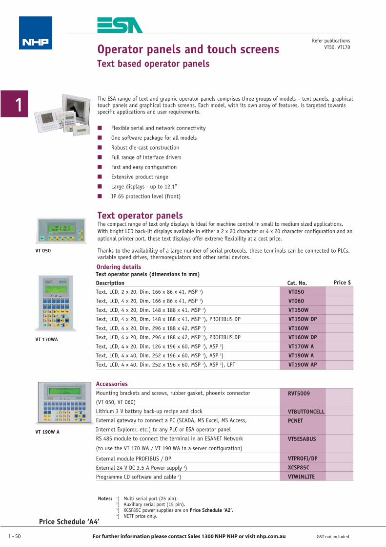
1 - 50
1
For further information please contact Sales 1300 NHP NHP or visit nhp.com.au GST not included
Refer publications VT50, VT170
Notes: 1) Multi serial port (25 pin). 2) Auxiliary serial port (15 pin). 3) XCSF85C power supplies are on Price Schedule ‘A2’. 4) NETT price only.
Operator panels and touch screensText based operator panels
The ESA range of text and graphic operator panels comprises three groups of models – text panels, graphical touch panels and graphical touch screens. Each model, with its own array of features, is targeted towards specific applications and user requirements.
Q Flexible serial and network connectivity
Q One software package for all models
Q Robust die-cast construction
Q Full range of interface drivers
Q Fast and easy configuration
Q Extensive product range
Q Large displays - up to 12.1”
Q IP 65 protection level (front)
Text operator panelsThe compact range of text only displays is ideal for machine control in small to medium sized applications. With bright LCD back-lit displays available in either a 2 x 20 character or 4 x 20 character configuration and an optional printer port, these text displays offer extreme flexibility at a cost price.
Thanks to the availability of a large number of serial protocols, these terminals can be connected to PLCs, variable speed drives, thermoregulators and other serial devices.
Text operator panels (dimensions in mm)Ordering details
RVT5009
VTBUTTONCELLPCNET
VT5ESABUS
VTPROFI/DPXCSP85CVTWINLITE
AccessoriesMounting brackets and screws, rubber gasket, phoenix connector
(VT 050, VT 060)
Lithium 3 V battery back-up recipe and clock
External gateway to connect a PC (SCADA, MS Excel, MS Access,
Internet Explorer, etc.) to any PLC or ESA operator panel
RS 485 module to connect the terminal in an ESANET Network
(to use the VT 170 WA / VT 190 WA in a server configuration)
External module PROFIBUS / DP
External 24 V DC 3.5 A Power supply 3)
Programme CD software and cable 4)
VT 170WA
VT 190W A
VT050VT060VT150WVT150W DPVT160WVT160W DPVT170W AVT190W AVT190W AP
Cat. No.DescriptionText, LCD, 2 x 20, Dim. 166 x 86 x 41, MSP 1)
Text, LCD, 4 x 20, Dim. 166 x 86 x 41, MSP 1)
Text, LCD, 4 x 20, Dim. 148 x 188 x 41, MSP 1)
Text, LCD, 4 x 20, Dim. 148 x 188 x 41, MSP 1), PROFIBUS DP
Text, LCD, 4 x 20, Dim. 296 x 188 x 42, MSP 1)
Text, LCD, 4 x 20, Dim. 296 x 188 x 42, MSP 1), PROFIBUS DP
Text, LCD, 4 x 20, Dim. 126 x 196 x 60, MSP 1), ASP 2)
Text, LCD, 4 x 40, Dim. 252 x 196 x 60, MSP 1), ASP 2)
Text, LCD, 4 x 40, Dim. 252 x 196 x 60, MSP 1), ASP 2), LPT
Price $
VT 050
Price Schedule ‘A4’
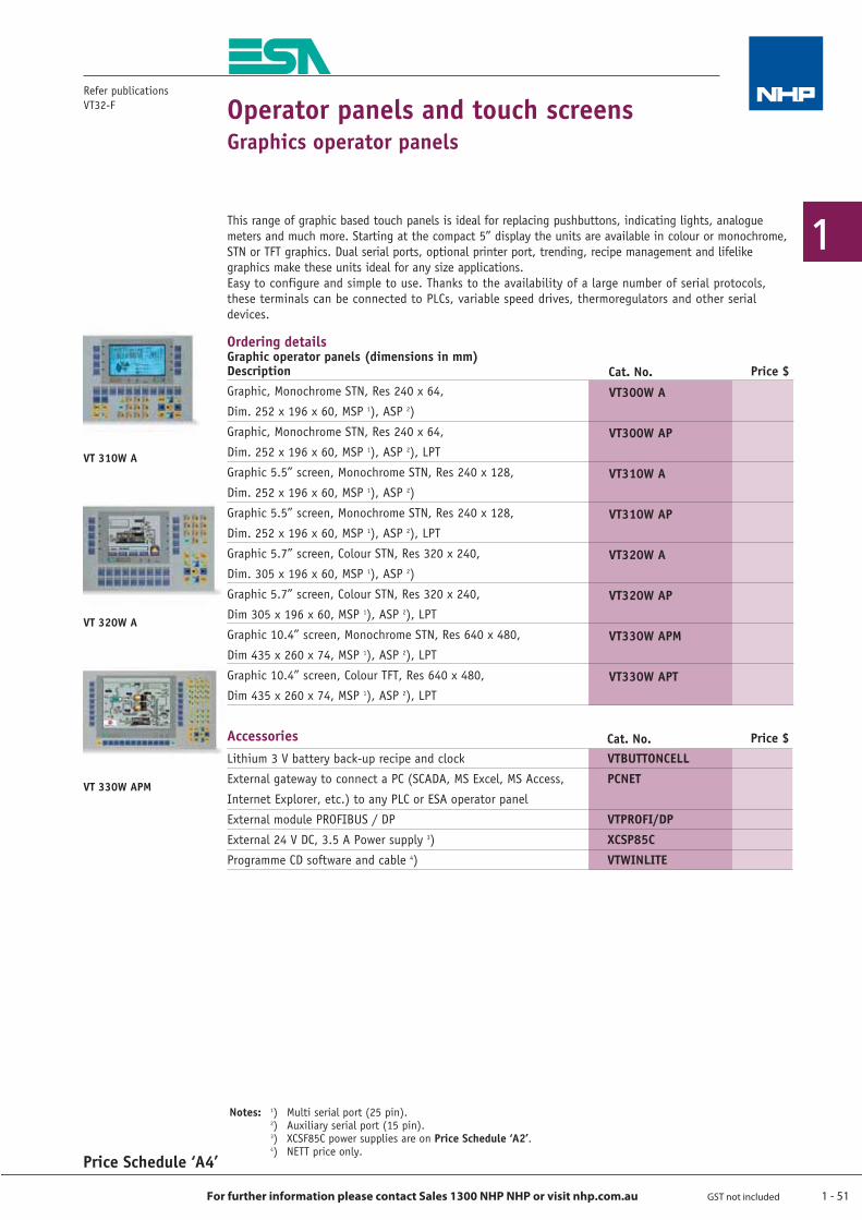
1 - 51
1
For further information please contact Sales 1300 NHP NHP or visit nhp.com.au GST not included
Refer publications VT32-F Operator panels and touch screens
Graphics operator panels
This range of graphic based touch panels is ideal for replacing pushbuttons, indicating lights, analogue meters and much more. Starting at the compact 5” display the units are available in colour or monochrome, STN or TFT graphics. Dual serial ports, optional printer port, trending, recipe management and lifelike graphics make these units ideal for any size applications.Easy to configure and simple to use. Thanks to the availability of a large number of serial protocols, these terminals can be connected to PLCs, variable speed drives, thermoregulators and other serial devices.
Ordering details Graphic operator panels (dimensions in mm)
VT 310W A
VT 320W A
VT 330W APM
VTBUTTONCELLPCNET
VTPROFI/DPXCSP85CVTWINLITE
AccessoriesLithium 3 V battery back-up recipe and clock
External gateway to connect a PC (SCADA, MS Excel, MS Access,
Internet Explorer, etc.) to any PLC or ESA operator panel
External module PROFIBUS / DP
External 24 V DC, 3.5 A Power supply 3)
Programme CD software and cable 4)
Cat. No. Price $
Price Schedule ‘A4’
Notes: 1) Multi serial port (25 pin). 2) Auxiliary serial port (15 pin). 3) XCSF85C power supplies are on Price Schedule ‘A2’. 4) NETT price only.
VT300W A
VT300W AP
VT310W A
VT310W AP
VT320W A
VT320W AP
VT330W APM
VT330W APT
Cat. No.Graphic, Monochrome STN, Res 240 x 64,
Dim. 252 x 196 x 60, MSP 1), ASP 2)
Graphic, Monochrome STN, Res 240 x 64,
Dim. 252 x 196 x 60, MSP 1), ASP 2), LPT
Graphic 5.5” screen, Monochrome STN, Res 240 x 128,
Dim. 252 x 196 x 60, MSP 1), ASP 2)
Graphic 5.5” screen, Monochrome STN, Res 240 x 128,
Dim. 252 x 196 x 60, MSP 1), ASP 2), LPT
Graphic 5.7” screen, Colour STN, Res 320 x 240,
Dim. 305 x 196 x 60, MSP 1), ASP 2)
Graphic 5.7” screen, Colour STN, Res 320 x 240,
Dim 305 x 196 x 60, MSP 1), ASP 2), LPT
Graphic 10.4” screen, Monochrome STN, Res 640 x 480,
Dim 435 x 260 x 74, MSP 1), ASP 2), LPT
Graphic 10.4” screen, Colour TFT, Res 640 x 480,
Dim 435 x 260 x 74, MSP 1), ASP 2), LPT
Description Price $
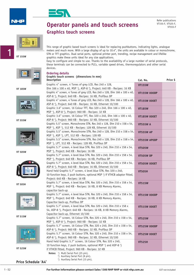
1 - 52
1
For further information please contact Sales 1300 NHP NHP or visit nhp.com.au GST not included
VT 555W
This range of graphic based touch screens is ideal for replacing pushbuttons, indicating lights, analogue meters and much more. With a large display of up to 10.4”, the units are available in colour or monochrome, STN or TFT graphics. Dual serial ports, optional printer port, trending, recipe management and lifelike graphics make these units ideal for any size applications.Easy to configure and simple to use. Thanks to the availability of a large number of serial protocols, these terminals can be connected to PLCs, variable speed drives, thermoregulators and other serial devices.
Ordering details Graphic touch screens (dimensions in mm)
VT 505W
VT 155W
VT 505H
Operator panels and touch screensGraphics touch screens
VT 525W
VT 515W
Price Schedule ‘A4’
Refer publications VT155-F, VT525-F,
VT555-F
Notes: 1) Multi Serial Port (25 pin). 2) Auxiliary Serial Port (8 pin). 3) Auxiliary Serial Port (15 pin).
VT 185W
Graphic 4" screen, 4 Tones of grey LCD, Res 240 x 128, Dim 166 x 100 x 40, MSP 1), ASP-8 2), Project: 640 KB - Recipes: 16 KBGraphic 4" screen, 4 Tones of grey LCD, Res 240 x 128, Dim 166 x 100 x 40, ASP-8 2), Project: 640 KB - Recipes: 16 KB, Profibus DPGraphic 4" screen, 4 Tones of grey LCD, Res 240 x 128, Dim 166 x 100 x 40, ASP-8 2), Project: 640 KB - Recipes: 16 KB, Ethernet 10/100Graphic 3.6" screen, 16 Colour TFT, Res 320 x 240, Dim 166 x 100 x 40, MSP 1), ASP-8 2), Project: 960 KB - Recipes: 32 KBGraphic 3.6" screen, 16 Colour TFT, Res 320 x 240, Dim 166 x 100 x 40, ASP-8 2), Project: 960 KB - Recipes: 32 KB, Ethernet 10/100Graphic 5.5" screen, Monochrome STN, Res 240 x 128, Dim 210 x 158 x 54, MSP 1), ASP 3), 512 KB - Recipes: 128 KB, Ethernet 10/100Graphic 5.5" screen, Monochrome STN, Res 240 x 128, Dim 210 x 158 x 54, MSP 1), ASP 3), LPT, 512 KB - Recipes: 128 KBGraphic 5.5" screen, Monochrome STN, Res 240 x 128, Dim 210 x 158 x 54, MSP 1), LPT, 512 KB - Recipes: 128 KB, Profibus DPGraphic 5.7" screen, 4 level blue STN, Res 320 x 240, Dim 210 x 158 x 54, MSP 1), Project: 640 KB - Recipes: 16 KBGraphic 5.7" screen, 4 level blue STN, Res 320 x 240, Dim 210 x 158 x 54, MSP 1), Project: 640 KB - Recipes: 16 KB, Profibus DPGraphic 5.7" screen, 4 level blue STN, Res 320 x 240, Dim 210 x 158 x 54, ASP-8 2), Project: 640 KB - Recipes: 16 KB, Ethernet 10/100Hand held Graphic 5.7" screen, 4 level blue STN, Res 320 x 240, 10 function keys, 2 push buttons, optional MSP 1) if VTHCB adaptor fitted, Project: 640 KB - Recipes: 16 KBGraphic 5.7" screen, 4 level blue STN, Res 320 x 240, Dim 210 x 158 x 54, MSP 1), Project: 640 KB - Recipes: 16 KB, 8 KB Memory Alarms, capacitor back-upGraphic 5.7" screen, 4 level blue STN, Res 320 x 240, Dim 210 x 158 x 54, MSP 1), Project: 640 KB - Recipes: 16 KB, 8 KB Memory Alarms, Capacitor back-up, Profibus DPGraphic 5.7" screen, 4 level blue STN, Res 320 x 240, Dim 210 x 158 x 54, ASP-8 2), Project: 640 KB - Recipes: 16 KB, 8 KB Memory Alarms, Capacitor back-up, Ethernet 10/100Graphic 5.7" screen, 16 Colour STN, Res 320 x 240, Dim 210 x 158 x 54, MSP 1), ASP-8 2), Project: 960 KB - Recipes: 32 KBGraphic 5.7" screen, 16 Colour STN, Res 320 x 240, Dim 210 x 158 x 54, ASP-8 2), Project: 960 KB - Recipes: 32 KB, Profibus DPGraphic 5.7" screen, 16 Colour STN, Res 320 x 240, Dim 210 x 158 x 54, ASP-8 2), Project: 960 KB - Recipes: 32 KB, Ethernet 10/100Hand held Graphic 5.7" screen, 16 Colour STN, Res 320 x 240, 10 function keys, 2 push buttons, optional MSP 1) and ASP-8 2) if VTHCB fitted, Project: 960 KB - Recipes: 32 KB
VT155W
VT155W 000DP
VT155W 000ET
VT185W
VT185W 000ET
VT555W A
VT555W AP
VT555W AP0DP
VT505W
VT505W DP
VT505W 000ET
VT505H
VT515W
VT515W 000DP
VT515W 000ET
VT525W
VT525W 000DP
VT525W 000ET
VT525H
Cat. No.Description Price $
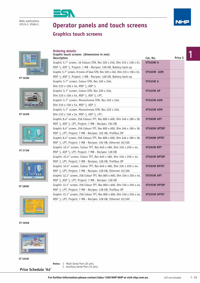
1 - 53
1
For further information please contact Sales 1300 NHP NHP or visit nhp.com.au GST not included
Refer publications VT575-F, VT595-F,
VT 560W
VT 565W
VT 575W
VT 580W
VT 585W
VT 595W
Ordering details Graphic touch screens (dimensions in mm)
Operator panels and touch screensGraphics touch screens
VT560W A
VT560W A0M
VT565W A
VT565W AP
VT565W A0M
VT565W APM
VT580W APT
VT580W 0PTDP
VT580W 0PTET
VT585W BPT
VT585W BPTDP
VT585W BPTET
VT595W APT
VT595W 0PTDP
VT595W 0PTET
Cat. No.Graphic 5.7" screen, 16 Colours STN, Res 320 x 240, Dim 210 x 158 x 61,
MSP 1), ASP 2), Project: 1 MB - Recipes: 128 KB, Battery back-up
Graphic 5.7" screen, 8 tones of blue STN, Res 320 x 240, Dim 210 x 158 x 61,
MSP 1), ASP 2), Project: 1 MB - Recipes: 128 KB, Battery back-up
Graphic 5.7" screen, Colour STN, Res 320 x 240,
Dim 210 x 158 x 54, MSP 1), ASP 2)
Graphic 5.7" screen, Colour STN, Res 320 x 240,
Dim 210 x 158 x 54, MSP 1), ASP 2), LPT,
Graphic 5.7" screen, Monochrome STN, Res 320 x 240,
Dim 210 x 158 x 54, MSP 1), ASP 2)
Graphic 5.7" screen, Monochrome STN, Res 320 x 240,
Dim 210 x 158 x 54, MSP 1), ASP 2), LPT,
Graphic 8.4" screen, 256 Colours TFT, Res 800 x 600, Dim 246 x 189 x 38,
MSP 1), ASP 2), LPT, Project: 7 MB - Recipes: 192 KB
Graphic 8.4" screen, 256 Colours TFT, Res 800 x 600, Dim 246 x 189 x 38,
MSP 1), LPT, Project: 7 MB - Recipes: 192 KB, Profibus DP
Graphic 8.4" screen, 256 Colours TFT, Res 800 x 600, Dim 246 x 189 x 38,
MSP 1), LPT, Project: 7 MB - Recipes: 192 KB, Ethernet 10/100
Graphic 10.4" screen, Colour TFT, Res 640 x 480, Dim 336 x 256 x 44,
MSP 1), ASP 2), LPT, Project: 7 MB - Recipes: 128 KB
Graphic 10.4" screen, Colour TFT, Res 640 x 480, Dim 336 x 256 x 44,
MSP 1), LPT, Project: 7 MB - Recipes: 128 KB, Profibus DP
Graphic 10.4" screen, Colour TFT, Res 640 x 480, Dim 336 x 256 x 44,
MSP 1), LPT, Project: 7 MB - Recipes: 128 KB, Ethernet 10/100
Graphic 12.1" screen, 256 Colour TFT, Res 800 x 600, Dim 336 x 256 x 44,
MSP 1), ASP 2), LPT, Project: 7 MB - Recipes: 128 KB
Graphic 12.1" screen, 256 Colour TFT, Res 800 x 600, Dim 336 x 256 x 44,
MSP 1), LPT, Project: 7 MB - Recipes: 128 KB, Profibus DP
Graphic 12.1" screen, 256 Colour TFT, Res 800 x 600, Dim 336 x 256 x 44,
MSP 1), LPT, Project: 7 MB - Recipes: 128 KB, Ethernet 10/100
Description Price $
Price Schedule ‘A4’
Notes: 1) Multi Serial Port (25 pin). 2) Auxiliary Serial Port (15 pin).
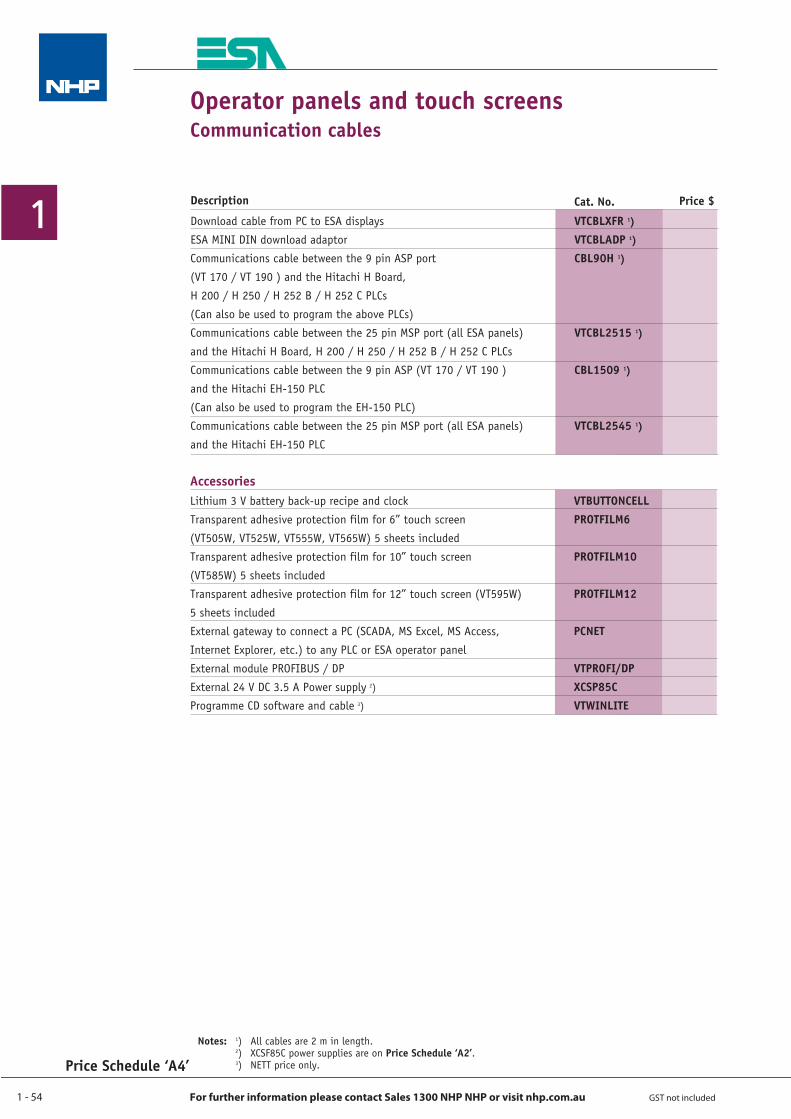
1 - 54
1
For further information please contact Sales 1300 NHP NHP or visit nhp.com.au GST not included
AccessoriesVTBUTTONCELLPROTFILM6
PROTFILM10
PROTFILM12
PCNET
VTPROFI/DPXCSP85CVTWINLITE
Lithium 3 V battery back-up recipe and clock
Transparent adhesive protection film for 6” touch screen
(VT505W, VT525W, VT555W, VT565W) 5 sheets included
Transparent adhesive protection film for 10” touch screen
(VT585W) 5 sheets included
Transparent adhesive protection film for 12” touch screen (VT595W)
5 sheets included
External gateway to connect a PC (SCADA, MS Excel, MS Access,
Internet Explorer, etc.) to any PLC or ESA operator panel
External module PROFIBUS / DP
External 24 V DC 3.5 A Power supply 2)
Programme CD software and cable 3)
Notes: 1) All cables are 2 m in length. 2) XCSF85C power supplies are on Price Schedule ‘A2’. 3) NETT price only.
Operator panels and touch screensCommunication cables
Price Schedule ‘A4’
Download cable from PC to ESA displays
ESA MINI DIN download adaptor
Communications cable between the 9 pin ASP port
(VT 170 / VT 190 ) and the Hitachi H Board,
H 200 / H 250 / H 252 B / H 252 C PLCs
(Can also be used to program the above PLCs)
Communications cable between the 25 pin MSP port (all ESA panels)
and the Hitachi H Board, H 200 / H 250 / H 252 B / H 252 C PLCs
Communications cable between the 9 pin ASP (VT 170 / VT 190 )
and the Hitachi EH-150 PLC
(Can also be used to program the EH-150 PLC)
Communications cable between the 25 pin MSP port (all ESA panels)
and the Hitachi EH-150 PLC
VTCBLXFR 1)
VTCBLADP 1)
CBL90H 1)
VTCBL2515 1)
CBL1509 1)
VTCBL2545 1)
Description Cat. No. Price $
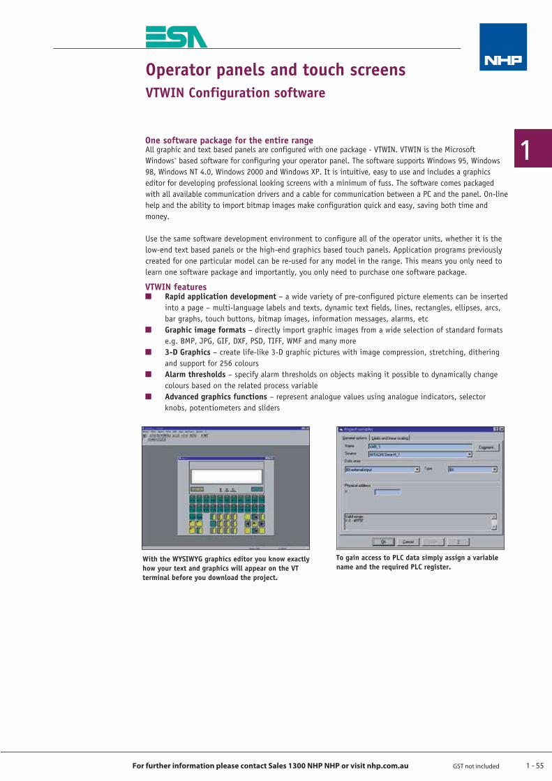
1 - 55
1
For further information please contact Sales 1300 NHP NHP or visit nhp.com.au GST not included
Operator panels and touch screensVTWIN Configuration software
One software package for the entire rangeAll graphic and text based panels are configured with one package - VTWIN. VTWIN is the Microsoft Windows® based software for configuring your operator panel. The software supports Windows 95, Windows 98, Windows NT 4.0, Windows 2000 and Windows XP. It is intuitive, easy to use and includes a graphics editor for developing professional looking screens with a minimum of fuss. The software comes packaged with all available communication drivers and a cable for communication between a PC and the panel. On-line help and the ability to import bitmap images make configuration quick and easy, saving both time and money.
Use the same software development environment to configure all of the operator units, whether it is the low-end text based panels or the high-end graphics based touch panels. Application programs previously created for one particular model can be re-used for any model in the range. This means you only need to learn one software package and importantly, you only need to purchase one software package.
VTWIN featuresQ Rapid application development – a wide variety of pre-configured picture elements can be inserted
into a page – multi-language labels and texts, dynamic text fields, lines, rectangles, ellipses, arcs, bar graphs, touch buttons, bitmap images, information messages, alarms, etc
Q Graphic image formats – directly import graphic images from a wide selection of standard formats e.g. BMP, JPG, GIF, DXF, PSD, TIFF, WMF and many more
Q 3-D Graphics – create life-like 3-D graphic pictures with image compression, stretching, dithering and support for 256 colours
Q Alarm thresholds – specify alarm thresholds on objects making it possible to dynamically change colours based on the related process variable
Q Advanced graphics functions – represent analogue values using analogue indicators, selector knobs, potentiometers and sliders
With the WYSIWYG graphics editor you know exactly how your text and graphics will appear on the VT terminal before you download the project.
To gain access to PLC data simply assign a variable name and the required PLC register.
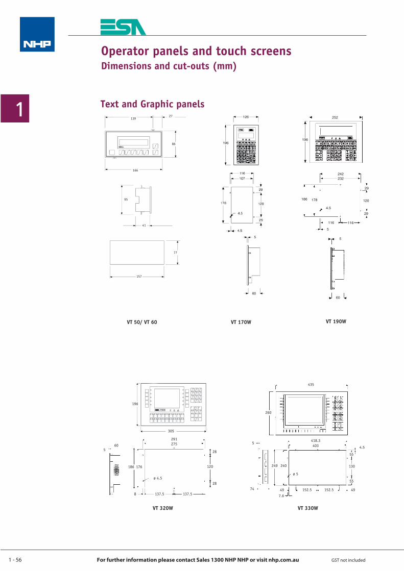
1 - 56
1
For further information please contact Sales 1300 NHP NHP or visit nhp.com.au GST not included
Operator panels and touch screensDimensions and cut-outs (mm)
Text and Graphic panels
305
196
560
291275
120
28
28
176186
8 137.5 137.5
ø 4.5
VT 320W
13927
86
166
95
41
77
157
VT 50/ VT 60 VT 190W
435
260
5
74
418.3403
240 130249
4.5
49 49
ø 5
7.6152.5 152.5
55
55
VT 330W
VT 170W
252
196
5
60
242232
29
120178
29
116116
5
186
4.5
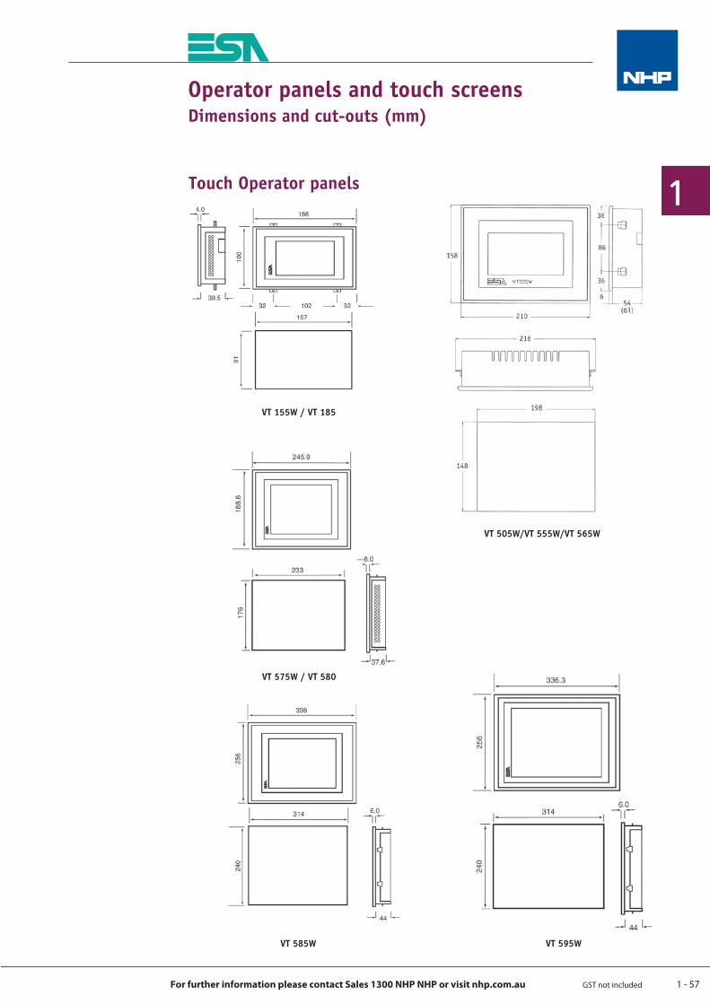
1 - 57
1
For further information please contact Sales 1300 NHP NHP or visit nhp.com.au GST not included
Operator panels and touch screensDimensions and cut-outs (mm)
VT 505W/VT 555W/VT 565W
VT 155W / VT 185
VT 595W
VT 575W / VT 580
VT 585W
Touch Operator panels
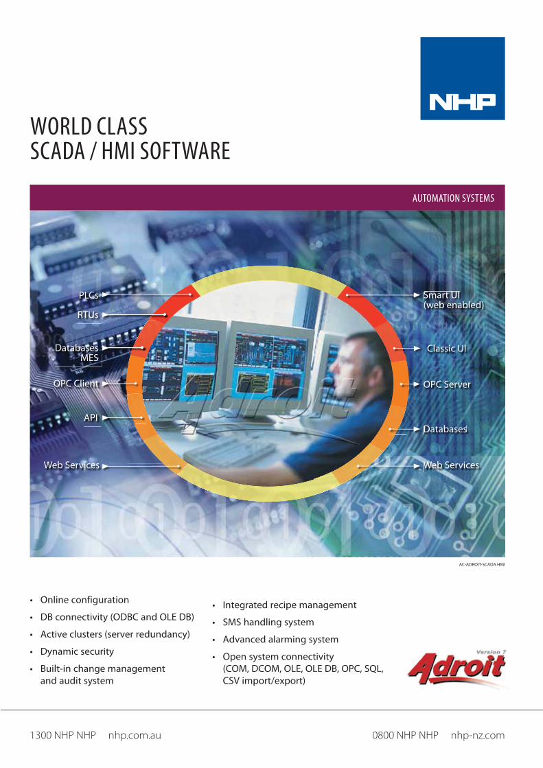
AC-ADROIT-SCADA HMI
WORLD CLASS SCADA / HMI SOFTWARE
0800 NHP NHP nhp-nz.com1300 NHP NHP nhp.com.au
AUTOMATION SYSTEMS
PLCs Smart UI (web enabled)
Classic UI
RTUs
DatabasesMES
OPC Client
API
OPC Server
Databases
Web ServicesWeb Services
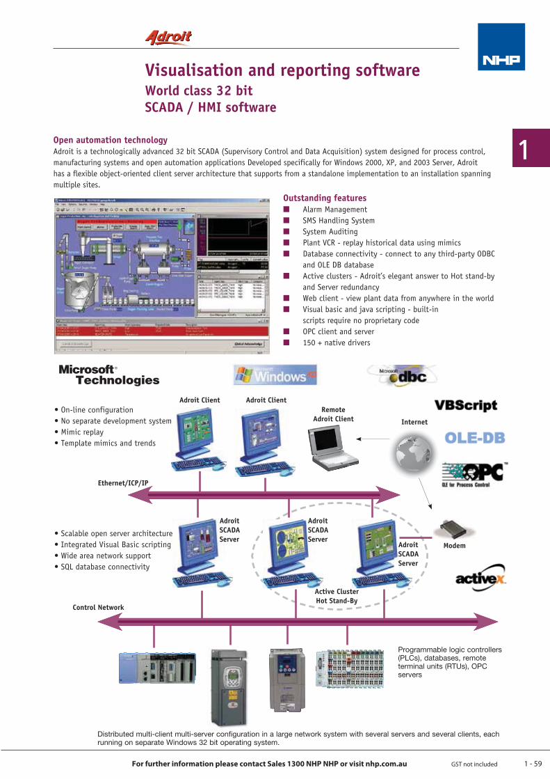
1 - 59
1
For further information please contact Sales 1300 NHP NHP or visit nhp.com.au GST not included
Visualisation and reporting softwareWorld class 32 bitSCADA / HMI software
Open automation technologyAdroit is a technologically advanced 32 bit SCADA (Supervisory Control and Data Acquisition) system designed for process control, manufacturing systems and open automation applications Developed specifically for Windows 2000, XP, and 2003 Server, Adroit has a flexible object-oriented client server architecture that supports from a standalone implementation to an installation spanning multiple sites.
Adroit Client Adroit Client
Ethernet/ICP/IP
Control Network
Active ClusterHot Stand-By
AdroitSCADAServer
AdroitSCADAServer
AdroitSCADAServer
Modem
Internet
RemoteAdroit Client
Distributed multi-client multi-server configuration in a large network system with several servers and several clients, each running on separate Windows 32 bit operating system.
Programmable logic controllers (PLCs), databases, remote terminal units (RTUs), OPC servers
• On-line configuration• No separate development system• Mimic replay• Template mimics and trends
• Scalable open server architecture• Integrated Visual Basic scripting• Wide area network support• SQL database connectivity
Microsoft®
Technologies
Outstanding featuresQ Alarm ManagementQ SMS Handling SystemQ System AuditingQ Plant VCR - replay historical data using mimicsQ Database connectivity - connect to any third-party ODBC
and OLE DB databaseQ Active clusters - Adroit’s elegant answer to Hot stand-by
and Server redundancyQ Web client - view plant data from anywhere in the worldQ Visual basic and java scripting - built-in
scripts require no proprietary codeQ OPC client and serverQ 150 + native drivers
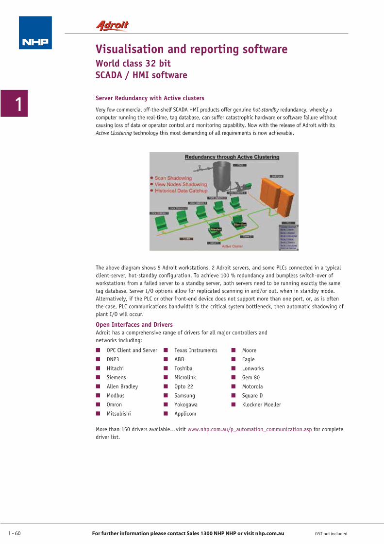
1 - 60
1
For further information please contact Sales 1300 NHP NHP or visit nhp.com.au GST not included
Visualisation and reporting softwareWorld class 32 bitSCADA / HMI software
Server Redundancy with Active clusters
Very few commercial off-the-shelf SCADA HMI products offer genuine hot-standby redundancy, whereby a computer running the real-time, tag database, can suffer catastrophic hardware or software failure without causing loss of data or operator control and monitoring capability. Now with the release of Adroit with its Active Clustering technology this most demanding of all requirements is now achievable.
The above diagram shows 5 Adroit workstations, 2 Adroit servers, and some PLCs connected in a typical client-server, hot-standby configuration. To achieve 100 % redundancy and bumpless switch-over of workstations from a failed server to a standby server, both servers need to be running exactly the same tag database. Server I/O options allow for replicated scanning in and/or out, when in standby mode. Alternatively, if the PLC or other front-end device does not support more than one port, or, as is often the case, PLC communications bandwidth is the critical system bottleneck, then automatic shadowing of plant I/O will occur.
Open Interfaces and DriversAdroit has a comprehensive range of drivers for all major controllers and networks including:
More than 150 drivers available…visit www.nhp.com.au/p_automation_communication.asp for complete driver list.
Q OPC Client and Server
Q DNP3
Q Hitachi
Q Siemens
Q Allen Bradley
Q Modbus
Q Omron
Q Mitsubishi
Q Texas Instruments
Q ABB
Q Toshiba
Q Microlink
Q Opto 22
Q Samsung
Q Yokogawa
Q Applicom
Q Moore
Q Eagle
Q Lonworks
Q Gem 80
Q Motorola
Q Square D
Q Klockner Moeller
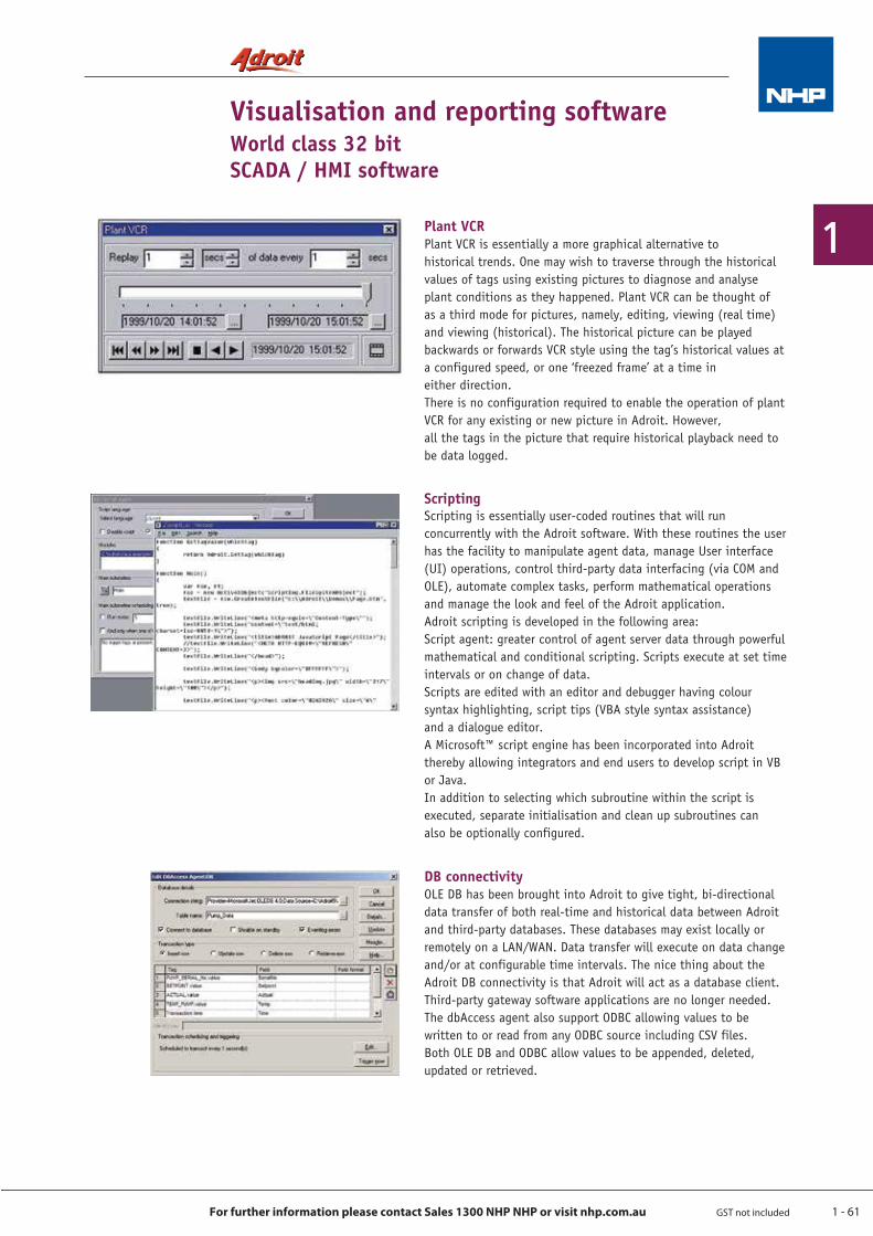
1 - 61
1
For further information please contact Sales 1300 NHP NHP or visit nhp.com.au GST not included
Visualisation and reporting softwareWorld class 32 bitSCADA / HMI software
DB connectivityOLE DB has been brought into Adroit to give tight, bi-directional data transfer of both real-time and historical data between Adroit and third-party databases. These databases may exist locally or remotely on a LAN/WAN. Data transfer will execute on data change and/or at configurable time intervals. The nice thing about the Adroit DB connectivity is that Adroit will act as a database client. Third-party gateway software applications are no longer needed.The dbAccess agent also support ODBC allowing values to be written to or read from any ODBC source including CSV files.Both OLE DB and ODBC allow values to be appended, deleted, updated or retrieved.
ScriptingScripting is essentially user-coded routines that will run concurrently with the Adroit software. With these routines the user has the facility to manipulate agent data, manage User interface (UI) operations, control third-party data interfacing (via COM and OLE), automate complex tasks, perform mathematical operations and manage the look and feel of the Adroit application.Adroit scripting is developed in the following area: Script agent: greater control of agent server data through powerful mathematical and conditional scripting. Scripts execute at set time intervals or on change of data.Scripts are edited with an editor and debugger having colour syntax highlighting, script tips (VBA style syntax assistance) and a dialogue editor. A Microsoft™ script engine has been incorporated into Adroit thereby allowing integrators and end users to develop script in VB or Java. In addition to selecting which subroutine within the script is executed, separate initialisation and clean up subroutines can also be optionally configured.
Plant VCRPlant VCR is essentially a more graphical alternative to historical trends. One may wish to traverse through the historical values of tags using existing pictures to diagnose and analyse plant conditions as they happened. Plant VCR can be thought of as a third mode for pictures, namely, editing, viewing (real time) and viewing (historical). The historical picture can be played backwards or forwards VCR style using the tag’s historical values at a configured speed, or one ‘freezed frame’ at a time in either direction. There is no configuration required to enable the operation of plant VCR for any existing or new picture in Adroit. However, all the tags in the picture that require historical playback need to be data logged.
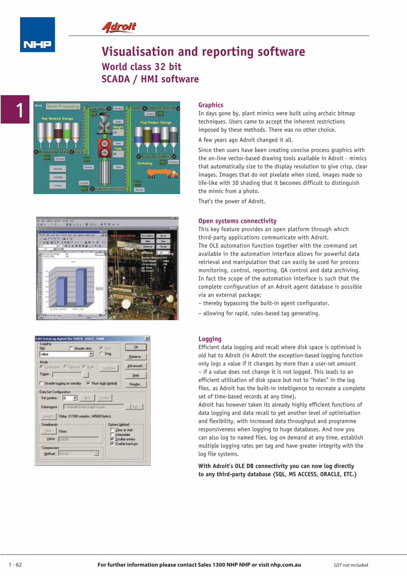
1 - 62
1
For further information please contact Sales 1300 NHP NHP or visit nhp.com.au GST not included
Visualisation and reporting softwareWorld class 32 bitSCADA / HMI software
This key feature provides an open platform through which third-party applications communicate with Adroit.The OLE automation function together with the command set available in the automation interface allows for powerful data retrieval and manipulation that can easily be used for process monitoring, control, reporting, QA control and data archiving. In fact the scope of the automation interface is such that the complete configuration of an Adroit agent database is possible via an external package;– thereby bypassing the built-in agent configurator,
– allowing for rapid, rules-based tag generating.
Open systems connectivity
In days gone by, plant mimics were built using archaic bitmap techniques. Users came to accept the inherent restrictions imposed by these methods. There was no other choice.
A few years ago Adroit changed it all.
Since then users have been creating concise process graphics with the on-line vector-based drawing tools available in Adroit - mimics that automatically size to the display resolution to give crisp, clear images. Images that do not pixelate when sized, images made so life-like with 3D shading that it becomes difficult to distinguish the mimic from a photo.
That’s the power of Adroit.
Graphics
Efficient data logging and recall where disk space is optimised is old hat to Adroit (in Adroit the exception-based logging function only logs a value if it changes by more than a user-set amount – if a value does not change it is not logged. This leads to an efficient utilisation of disk space but not to “holes” in the log files, as Adroit has the built-in intelligence to recreate a complete set of time-based records at any time).Adroit has however taken its already highly efficient functions of data logging and data recall to yet another level of optimisation and flexibility, with increased data throughput and programme responsiveness when logging to huge databases. And now you can also log to named files, log on demand at any time, establish multiple logging rates per tag and have greater integrity with the log file systems.
With Adroit’s OLE DB connectivity you can now log directly to any third-party database (SQL, MS ACCESS, ORACLE, ETC.)
Logging
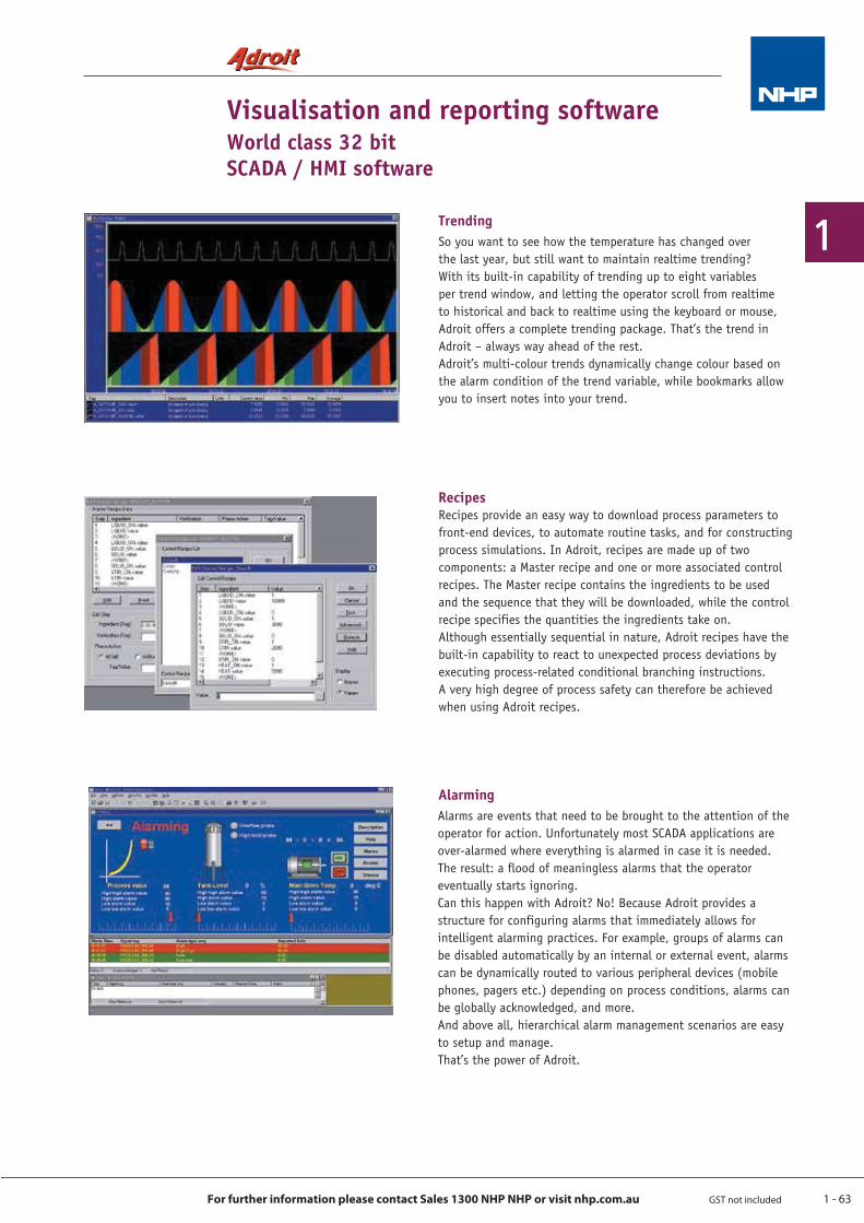
1 - 63
1
For further information please contact Sales 1300 NHP NHP or visit nhp.com.au GST not included
Visualisation and reporting softwareWorld class 32 bitSCADA / HMI software
So you want to see how the temperature has changed over the last year, but still want to maintain realtime trending? With its built-in capability of trending up to eight variables per trend window, and letting the operator scroll from realtime to historical and back to realtime using the keyboard or mouse, Adroit offers a complete trending package. That’s the trend in Adroit – always way ahead of the rest.Adroit’s multi-colour trends dynamically change colour based on the alarm condition of the trend variable, while bookmarks allow you to insert notes into your trend.
Trending
Recipes provide an easy way to download process parameters to front-end devices, to automate routine tasks, and for constructing process simulations. In Adroit, recipes are made up of two components: a Master recipe and one or more associated control recipes. The Master recipe contains the ingredients to be used and the sequence that they will be downloaded, while the control recipe specifies the quantities the ingredients take on.Although essentially sequential in nature, Adroit recipes have the built-in capability to react to unexpected process deviations by executing process-related conditional branching instructions.A very high degree of process safety can therefore be achieved when using Adroit recipes.
Recipes
Alarms are events that need to be brought to the attention of the operator for action. Unfortunately most SCADA applications are over-alarmed where everything is alarmed in case it is needed.The result: a flood of meaningless alarms that the operator eventually starts ignoring.Can this happen with Adroit? No! Because Adroit provides a structure for configuring alarms that immediately allows for intelligent alarming practices. For example, groups of alarms can be disabled automatically by an internal or external event, alarms can be dynamically routed to various peripheral devices (mobile phones, pagers etc.) depending on process conditions, alarms can be globally acknowledged, and more.And above all, hierarchical alarm management scenarios are easy to setup and manage.That’s the power of Adroit.
Alarming
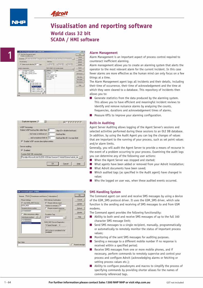
1 - 64
1
For further information please contact Sales 1300 NHP NHP or visit nhp.com.au GST not included
Visualisation and reporting software World class 32 bitSCADA / HMI software
Alarm ManagementAlarm Management is an important aspect of process control required to counteract inefficient alarming.Alarm management allows you to create an alarming system that alerts the operator to the most relevant alarm for the current incident. In this case fewer alarms are more effective as the human mind can only focus on a few things at a time.The Alarm Management agent logs all incidents and their details, including their time of occurrence, their time of acknowledgement and the time at which they were cleared to a database. This repository of incidents then allows you to:Q Generate statistics from the data produced by the alarming system. This allows you to have efficient and meaningful incident reviews to identify and remove nuisance alarms by analysing the counts, frequencies, durations and acknowledgement times of alarms.
Q Measure KPIs to improve your alarming configuration.
SMS Handling SystemThe Command agent can send and receive SMS messages by using a device of the GSM_SMS protocol driver. It uses the GSM_SMS driver, which sole function is the sending and receiving of SMS messages to and from GSM modems. The Command agent provides the following functionality:Q Ability to both send and receive SMS messages of up to the full 160 character SMS message limit;Q Send SMS messages to a single recipient, manually, programmatically or automatically to remotely monitor the status of important process values;Q Monitoring of the sent SMS messages for auditing purposes. Q Sending a message to a different mobile number if no response is received within a specified period;Q Receive SMS messages from one or more mobile phones, and if necessary, perform commands to remotely supervise and control your process and configure Adroit (acknowledging alarms or fetching or setting process values etc.);Q Ability to configure pseudonyms and macros to simplify the process of specifying commands by providing shorter aliases for the names of commonly referenced tags.
Built-in AuditingAgent Server Auditing allows logging of the Agent Server’s sessions and selected activities performed during these sessions to an OLE DB database. In addition, by using the Audit Agent you can log the changes of values that are important to the running of your process, such as set point values and/or alarm limits.Generally, you will audit the Agent Server to provide a means of recourse in the event of a problem occurring to your process. Examining the audit logs you can determine any of the following user actions:Q When the Agent Server was stopped and started;Q What agents have been added or removed from your Adroit installation;Q What Adroit documents have been saved;Q Which audited tags (as specified in the Audit agent) have changed in value;Q Who the logged on user was, when these audited events occurred.
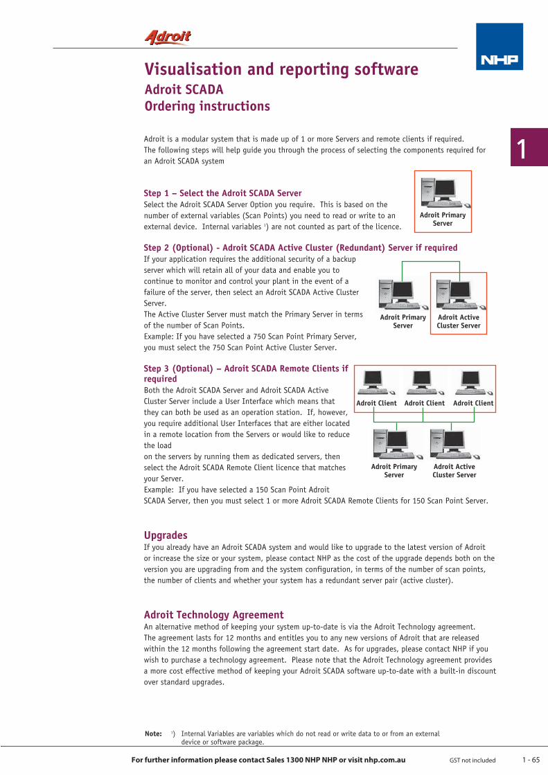
1 - 65
1
For further information please contact Sales 1300 NHP NHP or visit nhp.com.au GST not included
Adroit is a modular system that is made up of 1 or more Servers and remote clients if required. The following steps will help guide you through the process of selecting the components required for an Adroit SCADA system
Step 1 – Select the Adroit SCADA ServerSelect the Adroit SCADA Server Option you require. This is based on the number of external variables (Scan Points) you need to read or write to an external device. Internal variables 1) are not counted as part of the licence.
Step 2 (Optional) - Adroit SCADA Active Cluster (Redundant) Server if requiredIf your application requires the additional security of a backup server which will retain all of your data and enable you to continue to monitor and control your plant in the event of a failure of the server, then select an Adroit SCADA Active Cluster Server. The Active Cluster Server must match the Primary Server in terms of the number of Scan Points. Example: If you have selected a 750 Scan Point Primary Server, you must select the 750 Scan Point Active Cluster Server.
Step 3 (Optional) – Adroit SCADA Remote Clients if requiredBoth the Adroit SCADA Server and Adroit SCADA Active Cluster Server include a User Interface which means that they can both be used as an operation station. If, however, you require additional User Interfaces that are either located in a remote location from the Servers or would like to reduce the load on the servers by running them as dedicated servers, then select the Adroit SCADA Remote Client licence that matches your Server. Example: If you have selected a 150 Scan Point Adroit SCADA Server, then you must select 1 or more Adroit SCADA Remote Clients for 150 Scan Point Server.
UpgradesIf you already have an Adroit SCADA system and would like to upgrade to the latest version of Adroit or increase the size or your system, please contact NHP as the cost of the upgrade depends both on the version you are upgrading from and the system configuration, in terms of the number of scan points, the number of clients and whether your system has a redundant server pair (active cluster).
Adroit Technology AgreementAn alternative method of keeping your system up-to-date is via the Adroit Technology agreement. The agreement lasts for 12 months and entitles you to any new versions of Adroit that are released within the 12 months following the agreement start date. As for upgrades, please contact NHP if you wish to purchase a technology agreement. Please note that the Adroit Technology agreement provides a more cost effective method of keeping your Adroit SCADA software up-to-date with a built-in discount over standard upgrades.
Visualisation and reporting softwareAdroit SCADAOrdering instructions
Note: 1) Internal Variables are variables which do not read or write data to or from an external device or software package.
Adroit Primary Server
Adroit Active Cluster Server
Adroit Primary Server
Adroit ClientAdroit Client Adroit Client
Adroit Primary Server
Adroit Active Cluster Server
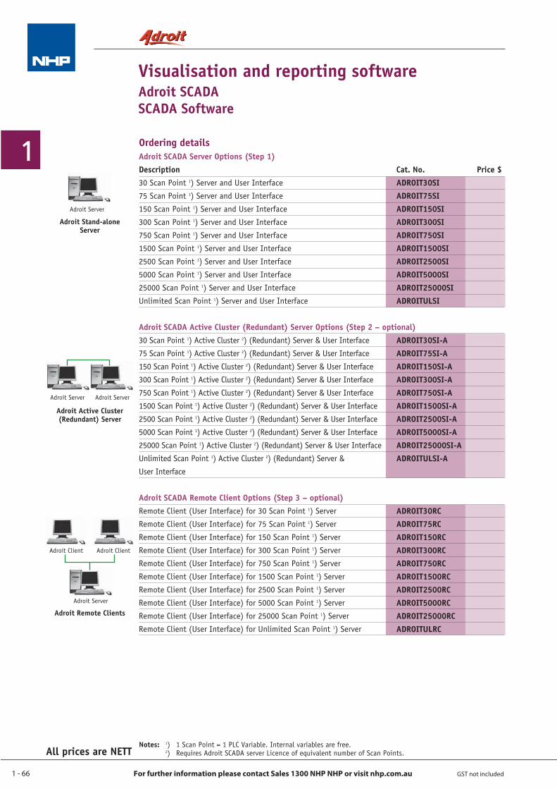
1 - 66
1
For further information please contact Sales 1300 NHP NHP or visit nhp.com.au GST not included
All prices are NETT
Visualisation and reporting softwareAdroit SCADASCADA Software
Ordering details
Notes: 1) 1 Scan Point = 1 PLC Variable. Internal variables are free. 2) Requires Adroit SCADA server Licence of equivalent number of Scan Points.
Adroit SCADA Server Options (Step 1)Description Cat. No. Price $30 Scan Point 1) Server and User Interface
75 Scan Point 1) Server and User Interface
150 Scan Point 1) Server and User Interface
300 Scan Point 1) Server and User Interface
750 Scan Point 1) Server and User Interface
1500 Scan Point 1) Server and User Interface
2500 Scan Point 1) Server and User Interface
5000 Scan Point 1) Server and User Interface
25000 Scan Point 1) Server and User Interface
Unlimited Scan Point 1) Server and User Interface
Adroit SCADA Active Cluster (Redundant) Server Options (Step 2 – optional)30 Scan Point 1) Active Cluster 2) (Redundant) Server & User Interface
75 Scan Point 1) Active Cluster 2) (Redundant) Server & User Interface
150 Scan Point 1) Active Cluster 2) (Redundant) Server & User Interface
300 Scan Point 1) Active Cluster 2) (Redundant) Server & User Interface
750 Scan Point 1) Active Cluster 2) (Redundant) Server & User Interface
1500 Scan Point 1) Active Cluster 2) (Redundant) Server & User Interface
2500 Scan Point 1) Active Cluster 2) (Redundant) Server & User Interface
5000 Scan Point 1) Active Cluster 2) (Redundant) Server & User Interface
25000 Scan Point 1) Active Cluster 2) (Redundant) Server & User Interface
Unlimited Scan Point 1) Active Cluster 2) (Redundant) Server &
User Interface
Adroit SCADA Remote Client Options (Step 3 – optional)Remote Client (User Interface) for 30 Scan Point 1) Server
Remote Client (User Interface) for 75 Scan Point 1) Server
Remote Client (User Interface) for 150 Scan Point 1) Server
Remote Client (User Interface) for 300 Scan Point 1) Server
Remote Client (User Interface) for 750 Scan Point 1) Server
Remote Client (User Interface) for 1500 Scan Point 1) Server
Remote Client (User Interface) for 2500 Scan Point 1) Server
Remote Client (User Interface) for 5000 Scan Point 1) Server
Remote Client (User Interface) for 25000 Scan Point 1) Server
Remote Client (User Interface) for Unlimited Scan Point 1) Server
ADROIT30SIADROIT75SIADROIT150SIADROIT300SIADROIT750SIADROIT1500SIADROIT2500SIADROIT5000SIADROIT25000SIADROITULSI
ADROIT30SI-AADROIT75SI-AADROIT150SI-AADROIT300SI-AADROIT750SI-AADROIT1500SI-AADROIT2500SI-AADROIT5000SI-AADROIT25000SI-AADROITULSI-A
ADROIT30RCADROIT75RCADROIT150RCADROIT300RCADROIT750RCADROIT1500RCADROIT2500RCADROIT5000RCADROIT25000RCADROITULRC
Adroit ServerAdroit Server
Adroit Active Cluster (Redundant) Server
Adroit Server
Adroit Stand-alone Server
Adroit Server
Adroit Remote Clients
Adroit ClientAdroit Client
1 - 67
1
For further information please contact Sales 1300 NHP NHP or visit nhp.com.au GST not included
All prices are NETT
Visualisation and reporting softwareAdroit SCADASCADA Software
Ordering details Adroit Upgrades and Maintenance AgreementsDescription Adroit UpgradeThe cost to upgrade from a previous version of Adroit depends both on the version number you are upgrading from and the system configuration in terms of the number of scan points, the number of clients and whether your system has a redundant server pair (cluster).Please contact NHP for a quote on Adroit Upgrades.
Adroit Technology AgreementThe Technology Agreement is a 12 month contract which entitles you to all Adroit upgrades and premium support for the period of the contract. The cost of the Technology Agreement depends both on the version number you have and the system configuration in terms of the number of scan points, the number of clients and whether your system has a redundant server pair (cluster).Please contact NHP for pricing on Adroit Technology Agreements.
Notes: 1 Scan Point = 1 PLC Variable. Internal variables are free. Other variants including redundant servers (Clusters) available. Please contact NHP for more information.
Price $
Price $
Training
Adroit configuration Level I - 2 day course. This course is targeted at new Adroit users, configurators, technicians and engineers. The course sets the foundation for the next level course and provides delegates with the tools to implement and configure small projects. All commonly used features are covered in appropriate detail. The pre-requisite for attending this course is an understanding of SCADA and an operational knowledge of Microsoft Windows 95/98. Operational experience of Microsoft Windows 2000 / XP is an advantage.
Adroit configuration Level II - 2 day course. This course is targeted at Adroit users, configurators, technicians and engineers who have successfully implemented at least one project. The concepts and principals presented in the Level I course are covered in depth, while additional features are introduced and explained. The pre-requisite for attending this course is the Level I configuration course as well as project experience.
Contact NHP for further information.
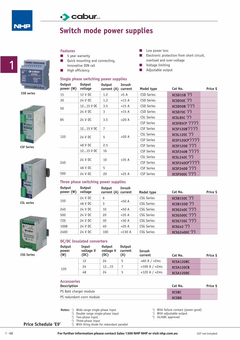
1 - 68
1
For further information please contact Sales 1300 NHP NHP or visit nhp.com.au GST not included
Price Schedule ‘E9’
Switch mode power supplies
FeaturesQ 5 year warrantyQ Quick mounting and connecting,
innovative DIN railQ High efficiency
Q Low power lossQ Electronic protection from short circuit,
overload and over-voltageQ Voltage limitingQ Adjustable output
Notes: 1) Wide range single-phase input 2) Double range single-phase input 3) Two-phase input 4) Three-phase input 5) With Oring diode for redundant parallel
6) With failure contact (power good) 7) With adjustable output 8) UL508C approved
XCSD15B 1)8)
XCSD30C 1)8)
XCSD50B 1)7)8)
XCSD70C 1)8)
XCSL85C 1)8)
XCSF85CP 1)5)6)8)
XCSF120B1)6)7)8)
XCSL120C 1)8)
XCSF120CP1)5)6)8)
XCSF120D 1)6)8)
XCSF240B 2)6)7)8)
XCSL240C 2)8)
XCSF240CP2)5)6)8)
XCSF240D 2)6)8)
XCSF500C 2)6)8)
Single phase switching power supplies
15
30
50
85
120
240
500
Cat No. Price $Output power (W)
Output voltage
12 V DC
24 V DC
12...15 V DC
24 V DC
24 V DC
12...15 V DC
24 V DC
48 V DC
12...15 V DC
24 V DC
48 V DC
24 V DC
Output current (A)
Inrush current Model type
CSD Series
CSD Series
CSD Series
CSD Series
CSL Series
CSF Series
CSF Series
CSL Series
CSF Series
CSF Series
CSF Series
CSL Series
CSF Series
CSF Series
CSF Series
1.2
1.2
3.5
3
3.5
7
5
2.5
16
10
5
20
<5 A
<13 A
<15 A
<15 A
<20 A
<20 A
<35 A
<25 A
XCSBCXCSBD
AccessoriesCat No. Price $Description
PS Batt charger module
PS redundant conn module
CSD series
CSF Series
CSL series
CSG Series
XCSB150C 3)8)
XCSB150D 3)8)
XCSG240C 4)6)8)
XCSG500C 4)6)8)
XCSG720C 4)6)8)
XCSG42 4)8)
XCSG2400C 4)8)
Three phase switching power supplies
150
240
500
720
1008
2400
Cat No. Price $Output power (W)
Output voltage
24 V DC
48 V DC
24 V DC
24 V DC
24 V DC
24 V DC
24 V DC
Output current (A)
Inrush current Model type
CSG Series
CSG Series
CSG Series
CSG Series
CSG Series
CSG Series
CSG Series
<50 A
<50 A
<35 A
<30 A
<20 A
<130 A
6
3
10
20
30
40
100
XCSA120BCXCSA120CBXCSA120DC
Cat No. Price $
Input voltage V (DC)
12
24
48
Output voltage V (DC)
24
12...15
24
Output current (A)
5
7
5
Inrush current <60 A / <2ms
<100 A / <2ms
<120 A / <2ms120
Output power (W)
DC/DC Insulated converters

1. Download
In order to scan one of the QR Codes you need to download a QR Code reader app to your smartphone. Try simply searching ‘QR Code’ in your app store.
2. Scan
Open your QR Code reader app and point the device’s camera at the relevant QR code.
3. View
Once scanned the QR Code will automatically open the relevant location.
HO
W TO
ACTIVATE YOU
R QR CO
DES
WWEBQR CODE
With NHP’s Price Lists available for download online, you can now access product information anytime, anywhere!
Scan the QR code below or go to www.nhp.com.au to download the latest NHP catalogues and price lists.
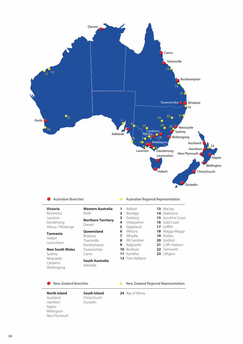
34
VictoriaRichmondLavertonDandenongAlbury / Wodonga
TasmaniaHobartLaunceston
New South WalesSydneyNewcastleCanberraWollongong
Western AustraliaPerth
Northern TerritoryDarwin
QueenslandBrisbaneTownsvilleRockhamptonToowoombaCairns
South AustraliaAdelaide
1 Ballarat2 Bendigo 3 Geelong4 Shepparton5 Gippsland 6 Mildura7 Whyalla8 Mt Gambier9 Kalgoorlie10 Bunbury11 Karratha12 Port Hedland
13 Mackay14 Gladstone15 Sunshine Coast16 Gold Coast17 Griffith18 Wagga Wagga19 Dubbo20 Gosford21 Coffs Harbour22 Tamworth23 Lithgow
North IslandAucklandHamiltonNapierWellington New Plymouth
South IslandChristchurch Dunedin
24 Bay of Plenty
Cairns
Townsville
Rockhampton
Brisbane
NewcastleSydney
Wollongong
Auckland
Hamilton
LauncestonDandenongLaverton
12
3 5
67
13
14
15
16
17
18
19
20
2122
23
24
8
9
10
11 12
Adelaide
NHP Branch OfficesNHP Resident Sales Staff
Perth
Darwin
Melbourne
AlburyCanberra
Hobart
Napier
Wellington
Christchurch
Dunedin
Toowoomba
4
New Plymouth
Australian Branches
New Zealand Branches
Australian Regional Representation
New Zealand Regional Representation

NHP Electrical Engineering Products Pty LtdA.B.N. 84 004 304 812
NPLISTDC © Copyright NHP 2013
AUSTRALIAnhp.com.au
SALES 1300 NHP NHP
VICTORIAMelbourne 43-67 River Street Richmond VIC 3121 Tel +61 3 9429 2999
Laverton 104-106 William Angliss Drive Laverton North VIC 3026 Tel +61 3 9368 2901
Albury / Wodonga 847 Ramsden Drive Albury NSW 2640 Tel +61 2 6049 0600 Dandenong 40-42 Cyber Loop Dandenong South VIC 3175 Tel +61 3 8773 6400
TASMANIA
Hobart Unit 2 65 Albert Street Moonah TAS 7009 Tel +61 3 6228 9575 Launceston Unit 3 13-17 Merino Street Kings Meadows TAS 7249 Tel +61 3 6345 2600
NEW SOUTH WALESSydney 30-34 Day Street North Silverwater NSW 2128 Tel +61 2 9748 3444
Newcastle 575 Maitland Road Mayfield West NSW 2304 Tel +61 2 4960 2220 Wollongong 34 Industrial Road Unanderra NSW 2526 Tel +61 2 4272 5763
ACT
Canberra Unit 1 187 Gladstone Street Fyshwick ACT 2609 Tel +61 2 6280 9888
WESTERN AUSTRALIA
Perth 38 Belmont Ave Rivervale WA 6103 Tel +61 8 9277 1777
NORTHERN TERRITORYDarwin 3 Steele Street Winnellie NT 0820 Tel +61 8 8947 2666
QUEENSLANDBrisbane 16 Riverview Place Murarrie QLD 4172 Tel +61 7 3909 4999 Townsville 5 Leyland Street Garbutt QLD 4814 Tel +61 7 4779 0700 Rockhampton 1 Lawson Street Parkhurst QLD 4702 Tel +61 7 4927 2277 Toowoomba Cnr Carroll Street and Struan Court QLD 4350 Tel +61 7 4634 4799 Cairns Unit 2 1 Bramp Close Portsmith QLD 4870 Tel +61 7 4035 6888
SOUTH AUSTRALIA
Adelaide 36-38 Croydon Road Keswick SA 5035 Tel +61 8 8297 9055
NEW ZEALANDnhp-nz.com
SALES 0800 NHP NHP
PO Box 62-009 Sylvia Park Auckland 1644 New Zealand
Auckland 118a Carbine Road Mt Wellington 1060 Tel +64 9 276 1967
Hamilton 78 Rostrevor Street Hamilton 3204 Tel +64 7 849 0257 Napier 126 Taradale Road Onekawa 4110 Tel +64 6 843 6928 New Plymouth 2 Dean Place Waiwhakaiho 4312 Tel 0800 NHP NHP Wellington 52 Victoria Street Lower Hutt 5010 Tel +64 4 570 0634 Christchurch 27 Iversen Terrace Waltham 8011 Tel +64 3 377 4407 Dunedin 30 Fox Street South Dunedin 9012 Tel 0800 NHP NHP