Embed Size (px)
Citation preview
1 OFFICIAL
Expert Panel on Monju Decommissioning6th March 2018
Steve BeckittChief Nuclear Officer
DSRL
OFFICIAL2
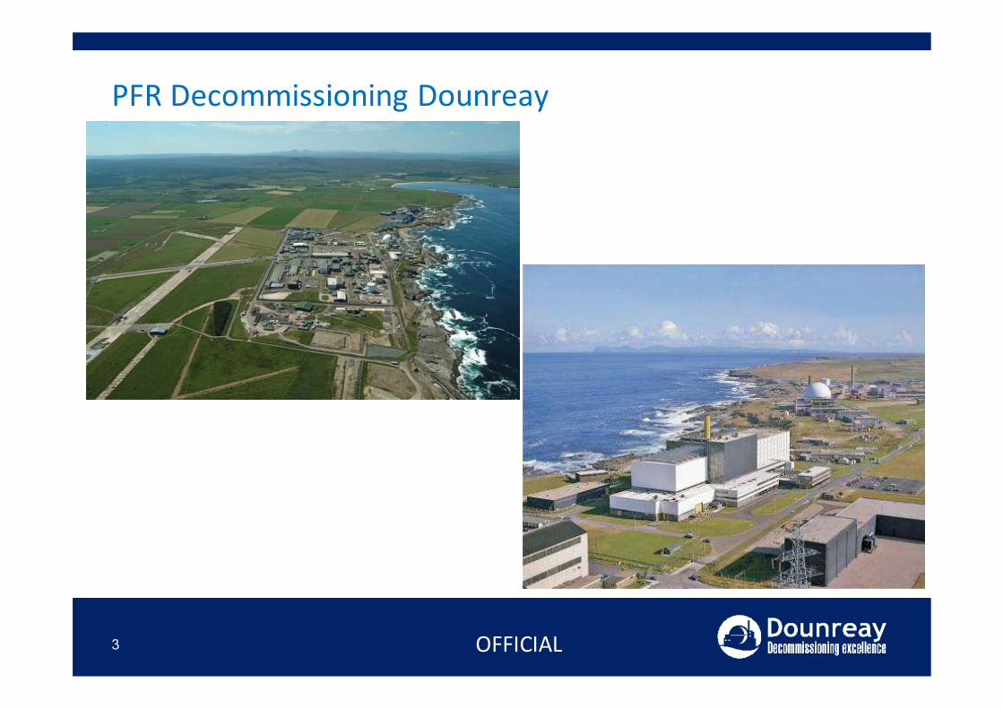
PFR Decommissioning Dounreay
3 OFFICIAL
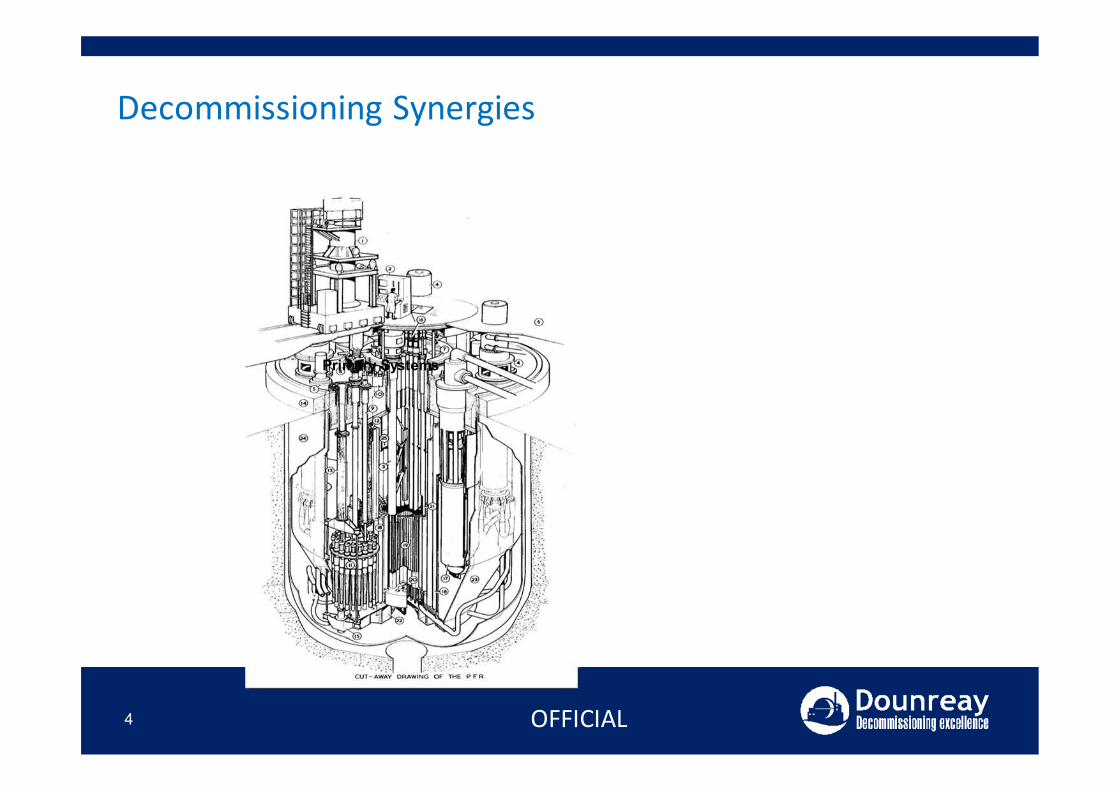
Decommissioning Synergies
4 OFFICIAL
Primary Systems
Decommissioning Synergies
5 OFFICIAL
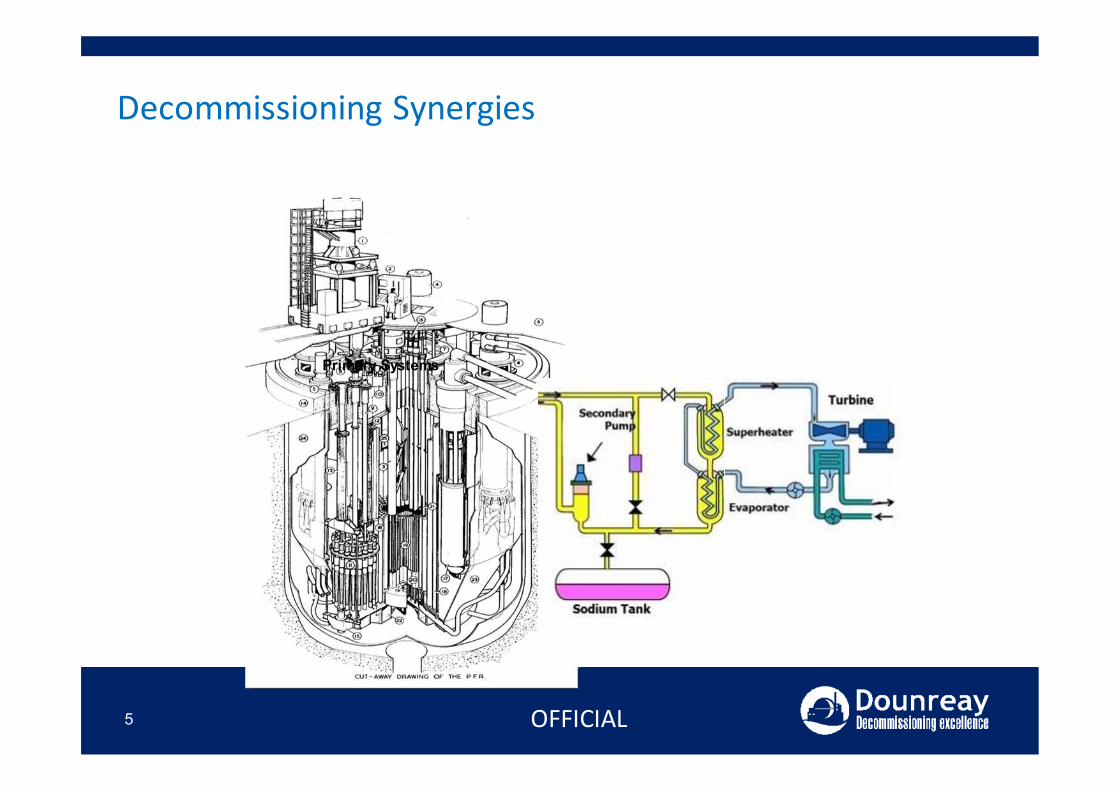
Primary Systems
Decommissioning Synergies
6 OFFICIAL
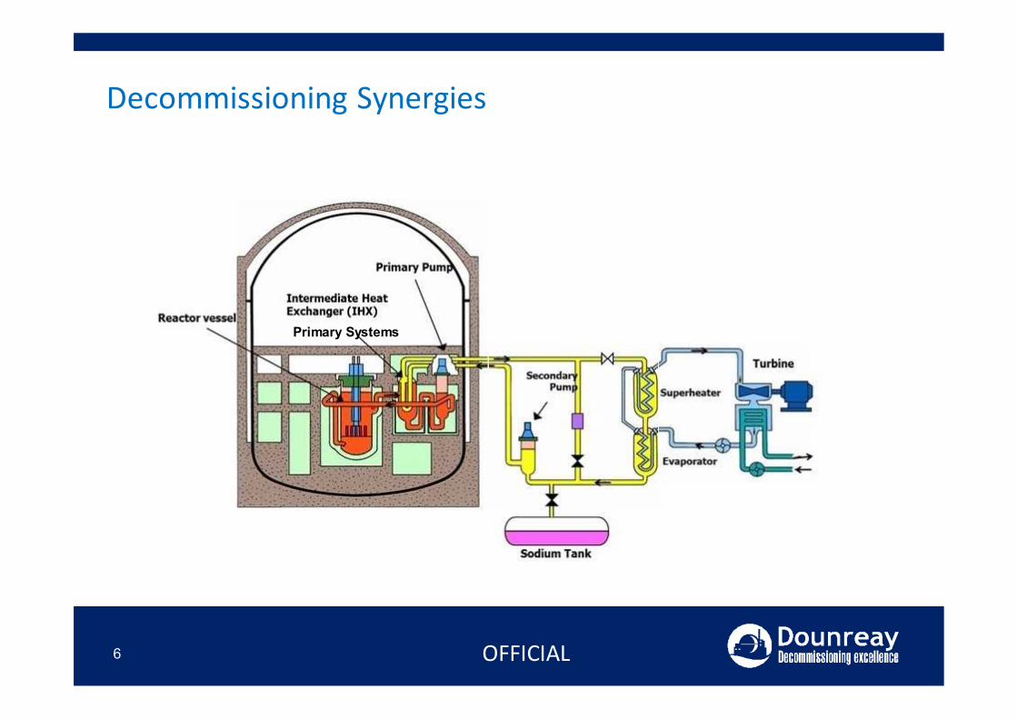
Primary Systems
Decommissioning Synergies
7 OFFICIAL
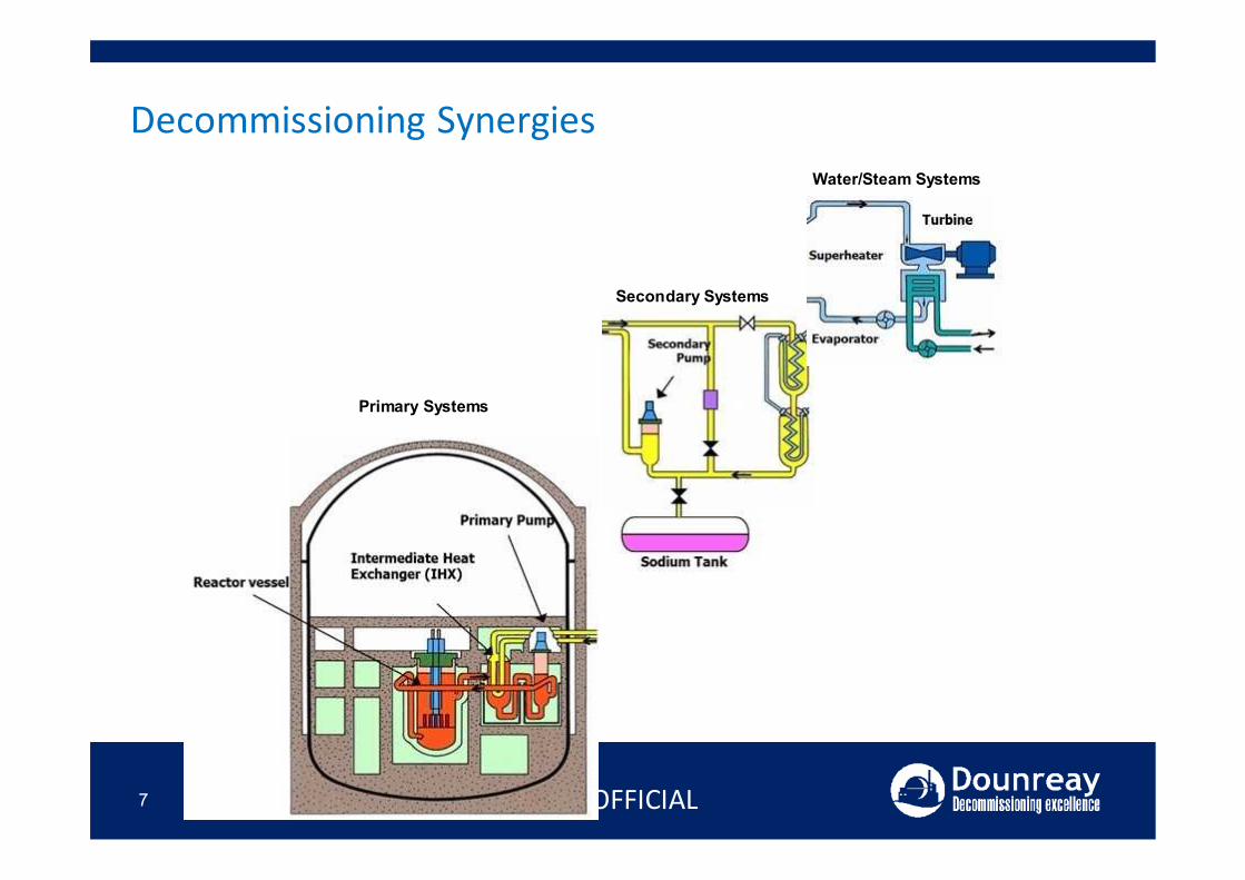
Primary Systems
Secondary Systems
Water/Steam Systems
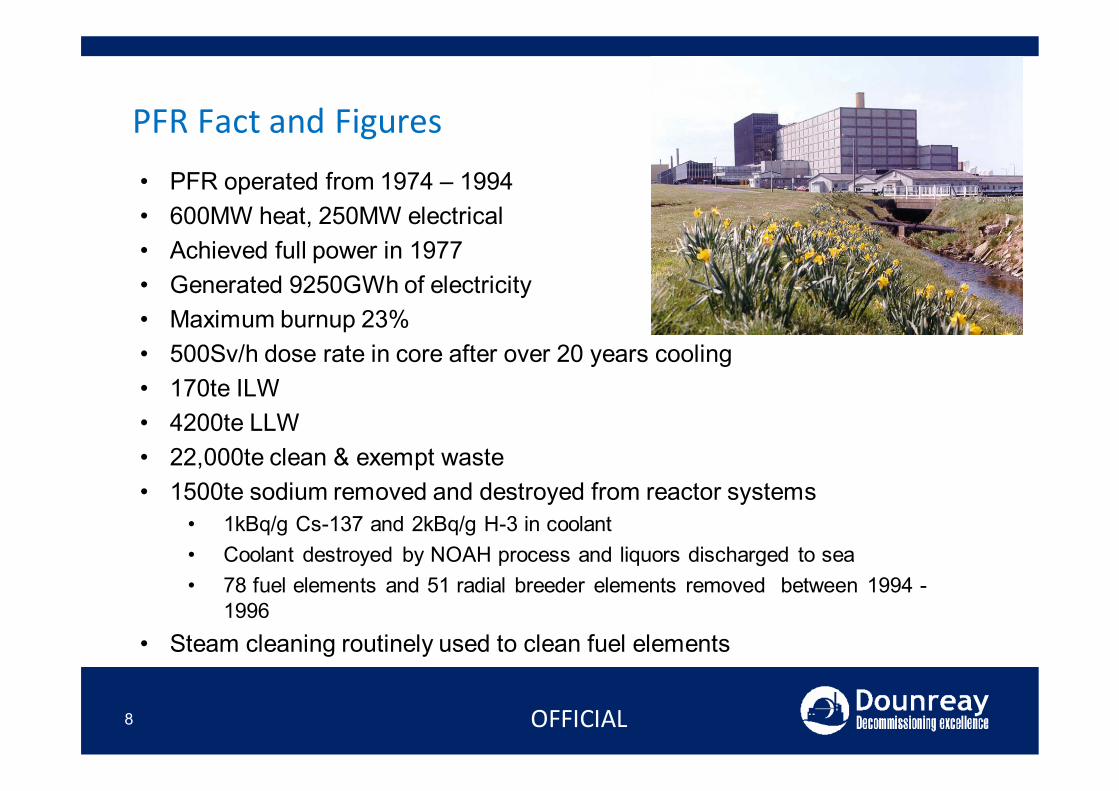
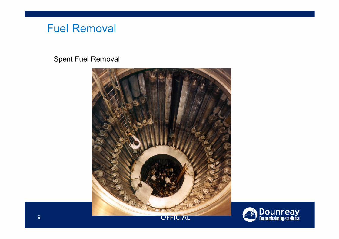
PFR Fact and Figures• PFR operated from 1974 – 1994• 600MW heat, 250MW electrical• Achieved full power in 1977• Generated 9250GWh of electricity• Maximum burnup 23%• 500Sv/h dose rate in core after over 20 years cooling • 170te ILW• 4200te LLW• 22,000te clean & exempt waste • 1500te sodium removed and destroyed from reactor systems
• 1kBq/g Cs-137 and 2kBq/g H-3 in coolant• Coolant destroyed by NOAH process and liquors discharged to sea • 78 fuel elements and 51 radial breeder elements removed between 1994 -
1996• Steam cleaning routinely used to clean fuel elements
8 OFFICIAL
9 OFFICIAL
Fuel Removal
Spent Fuel Removal
10 OFFICIAL
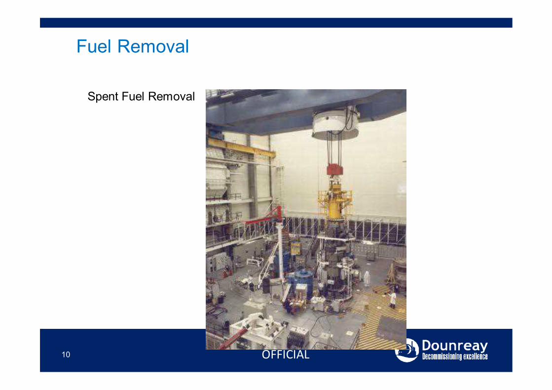
Fuel Removal
Spent Fuel Removal
11 OFFICIAL
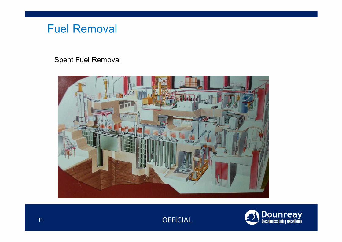
Fuel Removal
Spent Fuel Removal
12 OFFICIAL
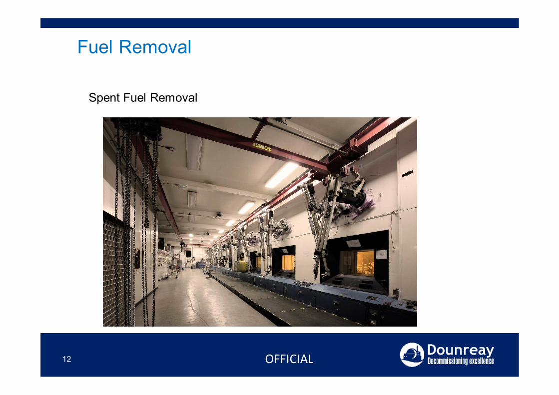
Fuel Removal
Spent Fuel Removal
13
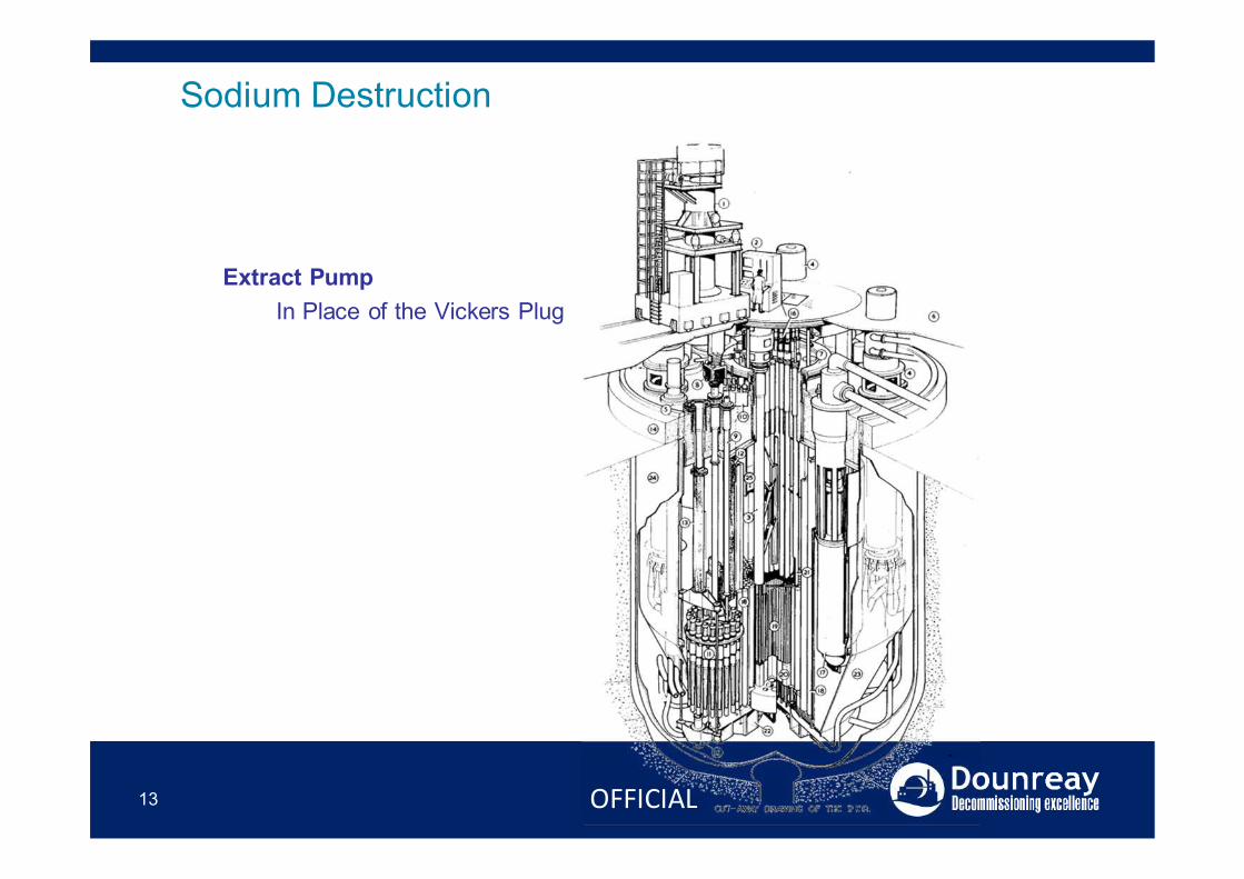
Sodium Destruction
Extract PumpIn Place of the Vickers Plug
OFFICIAL
14
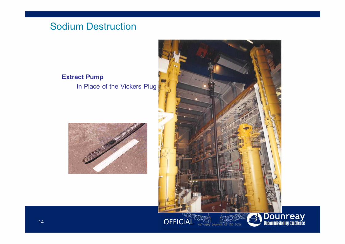
Sodium Destruction
Extract PumpIn Place of the Vickers Plug
OFFICIAL

15
Sodium Destruction
Extract PumpIn Place of the Vickers Plug
OFFICIAL
16
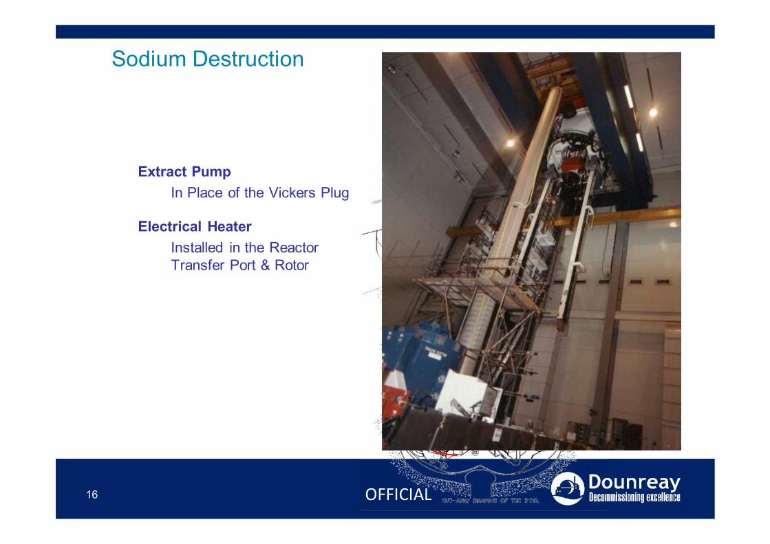
Sodium Destruction
Extract PumpIn Place of the Vickers Plug
Electrical HeaterInstalled in the Reactor Transfer Port & Rotor
OFFICIAL
17
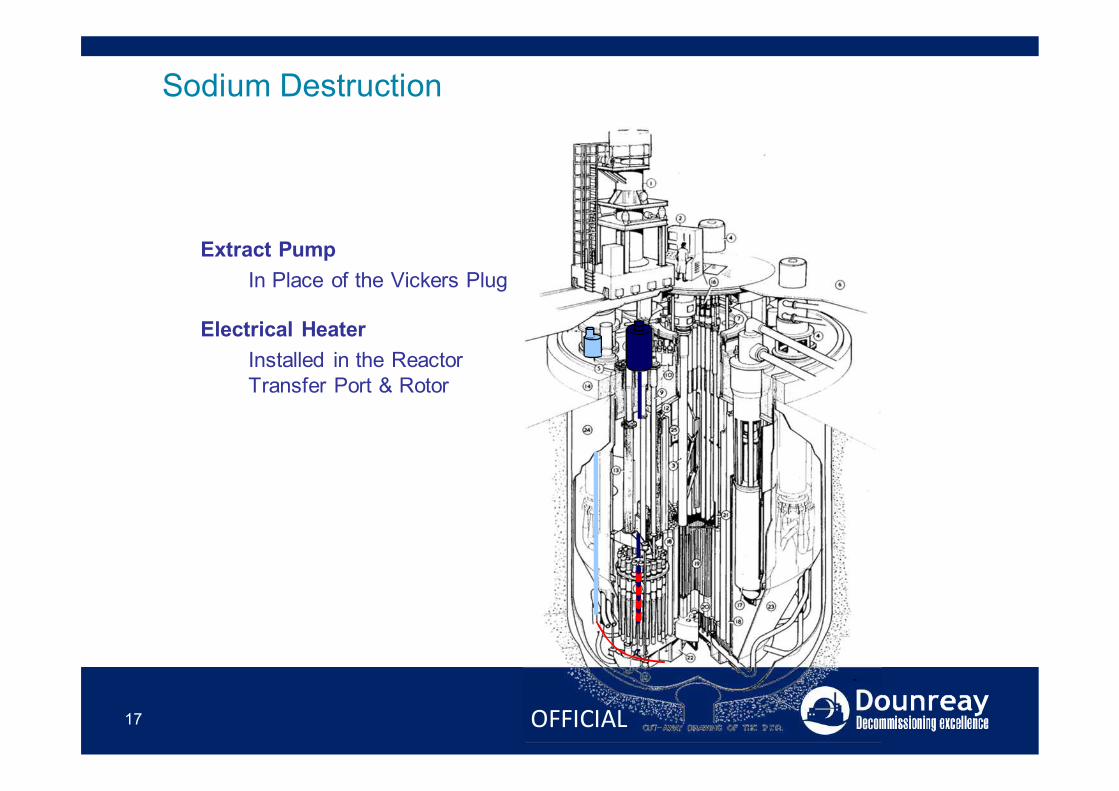
Sodium Destruction
Extract PumpIn Place of the Vickers Plug
Electrical HeaterInstalled in the Reactor Transfer Port & Rotor
OFFICIAL
18
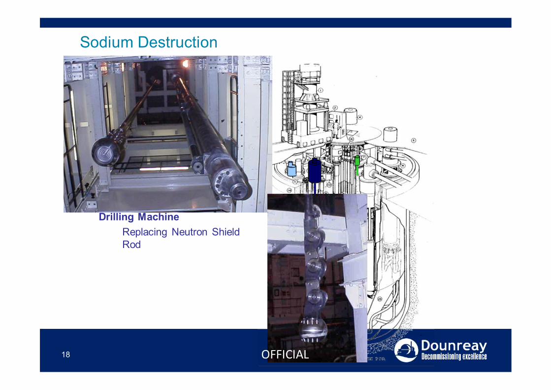
Sodium Destruction
Extract PumpIn Place of the Vickers Plug
Electrical HeaterInstalled in the Reactor Transfer Port & Rotor
Drilling MachineReplacing Neutron Shield Rod
OFFICIAL
19
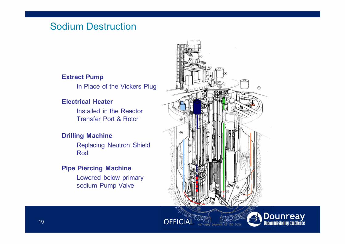
Sodium Destruction
Extract PumpIn Place of the Vickers Plug
Electrical HeaterInstalled in the Reactor Transfer Port & Rotor
Drilling MachineReplacing Neutron Shield Rod
Pipe Piercing MachineLowered below primary sodium Pump Valve
OFFICIAL
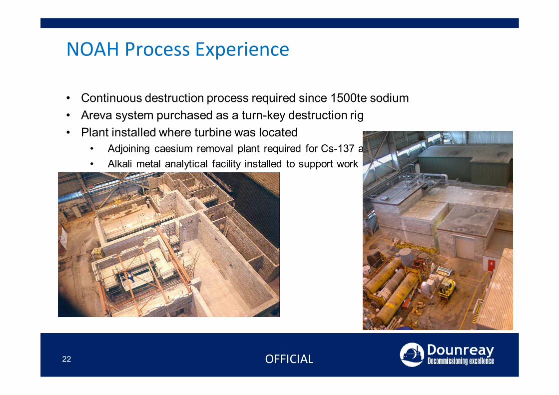
NOAH Process Experience
• Continuous destruction process required since 1500te sodium• Areva system purchased as a turn-key destruction rig• Plant installed where turbine was located
• Adjoining caesium removal plant required for Cs-137 abatement• Alkali metal analytical facility installed to support work
20 OFFICIAL
NOAH Process Experience
• Continuous destruction process required since 1500te sodium• Areva system purchased as a turn-key destruction rig• Plant installed where turbine was located
• Adjoining caesium removal plant required for Cs-137 abatement• Alkali metal analytical facility installed to support work
21 OFFICIAL
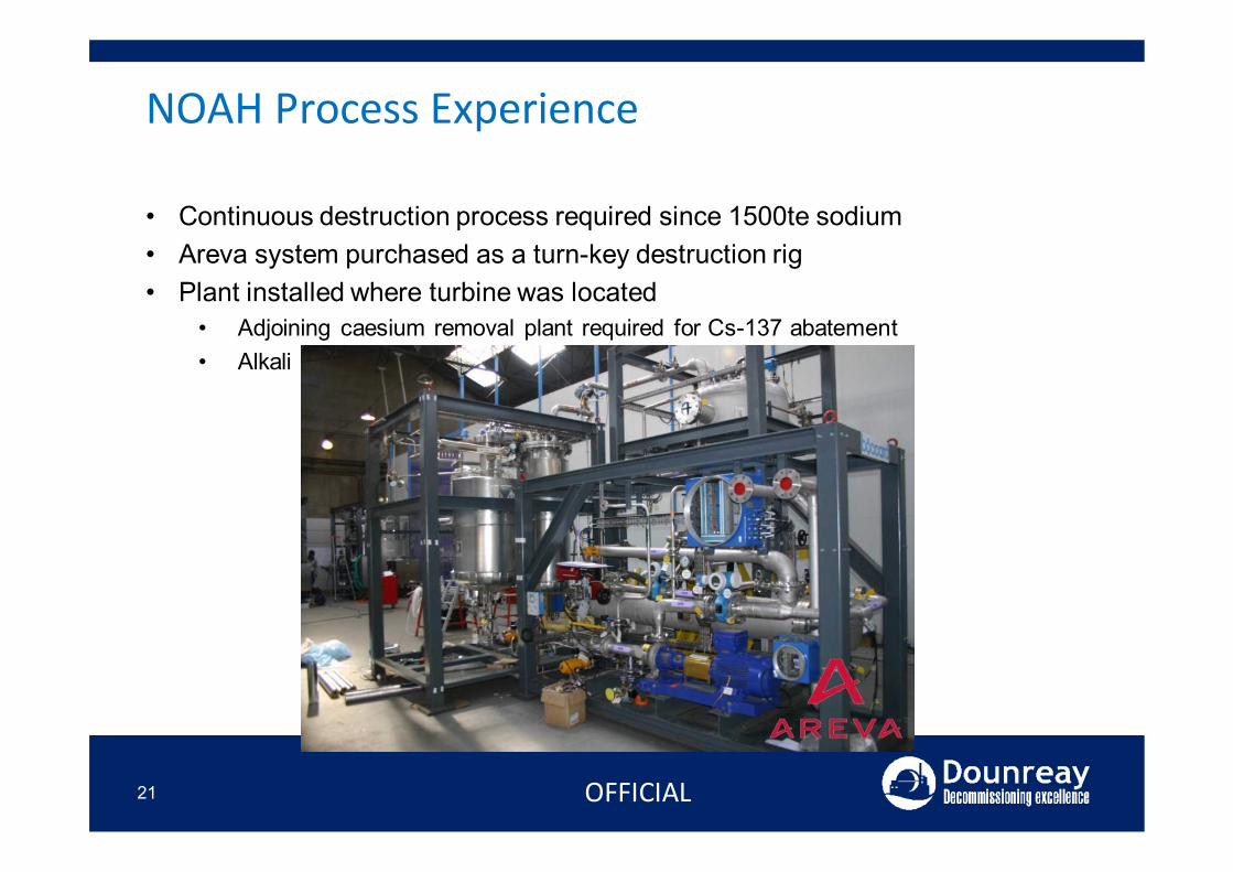
NOAH Process Experience
• Continuous destruction process required since 1500te sodium• Areva system purchased as a turn-key destruction rig• Plant installed where turbine was located
• Adjoining caesium removal plant required for Cs-137 abatement• Alkali metal analytical facility installed to support work
22 OFFICIAL
NOAH Process Experience
23
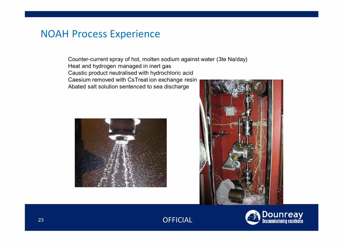
Basic processCounter-current spray of hot, molten sodium against water (3te Na/day)Heat and hydrogen managed in inert gasCaustic product neutralised with hydrochloric acidCaesium removed with CsTreat ion exchange resinAbated salt solution sentenced to sea discharge
OFFICIAL
NOAH Process Experience
24
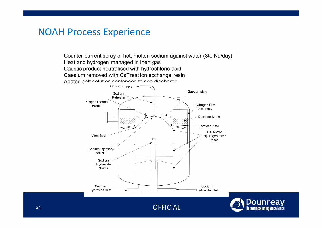
Basic processCounter-current spray of hot, molten sodium against water (3te Na/day)Heat and hydrogen managed in inert gasCaustic product neutralised with hydrochloric acidCaesium removed with CsTreat ion exchange resinAbated salt solution sentenced to sea discharge
OFFICIAL
NOAH Process Experience
25
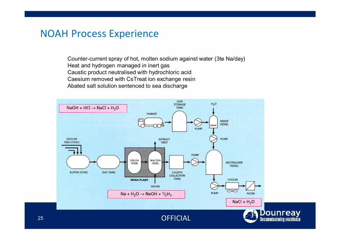
Basic processCounter-current spray of hot, molten sodium against water (3te Na/day)Heat and hydrogen managed in inert gasCaustic product neutralised with hydrochloric acidCaesium removed with CsTreat ion exchange resinAbated salt solution sentenced to sea discharge
OFFICIAL
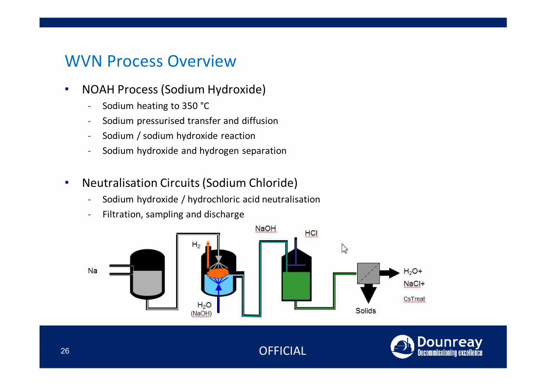
WVN Process Overview• NOAH Process (Sodium Hydroxide)
- Sodium heating to 350 °C - Sodium pressurised transfer and diffusion- Sodium / sodium hydroxide reaction- Sodium hydroxide and hydrogen separation
• Neutralisation Circuits (Sodium Chloride)- Sodium hydroxide / hydrochloric acid neutralisation- Filtration, sampling and discharge
26 OFFICIAL
History of WVN at Dounreay
27
NOAH Process (Sodium Hydroxide)• Laboratory work on WVN process had demonstrated that:• WVN process would be suitable for sodium frosts.• WVN process does not necessarily react sodium deposits in inaccessible
areas.• When treating sodium pools WVN process can lead to:
• Periods of vigorous reaction• Pressure transients • Temperature transients
• Work required to:• Scale-up the process• Demonstrate applicability on real plant• Quantify pressure and temperature transients during WVN treatment of
sodium pools
OFFICIAL
Timeline for Sodium Destruction Work
28
Off-Site - complete• Small quantity of sodium (5 kg)• through to• Large quantity of sodium (1000 kg)
Sodium tank farm - complete• Large tanks (no internal geometry)• Clean sodium (tritiated)• Sodium quantity 100 kg to 300 kg.
Secondary sodium circuits - complete• Large diameter pipework• Complex geometry.• Clean sodium (tritiated)• Sodium quantity 100 kg to 200 kg.
Dirty Dump Tanks -complete• Large tanks (no internal geometry)• Clean sodium (tritiated)• Sodium quantity 2 tonnes - 8 tonnes.
Primary Vessel - pending• Very large vessel.• Complex internal geometry.• Contaminated sodium.• Sodium quantity estimated at 15 tonnes
OFFICIAL
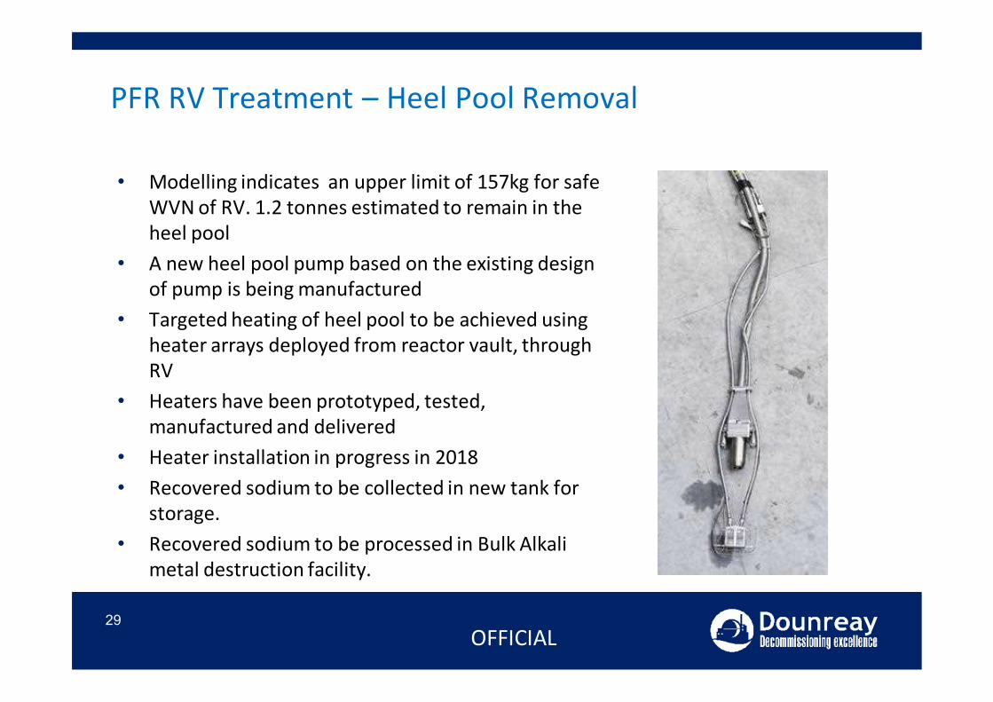
• Modelling indicates an upper limit of 157kg for safe WVN of RV. 1.2 tonnes estimated to remain in the heel pool
• A new heel pool pump based on the existing design of pump is being manufactured
• Targeted heating of heel pool to be achieved using heater arrays deployed from reactor vault, through RV
• Heaters have been prototyped, tested, manufactured and delivered
• Heater installation in progress in 2018• Recovered sodium to be collected in new tank for
storage.• Recovered sodium to be processed in Bulk Alkali
metal destruction facility.
PFR RV Treatment – Heel Pool Removal
29OFFICIAL
30
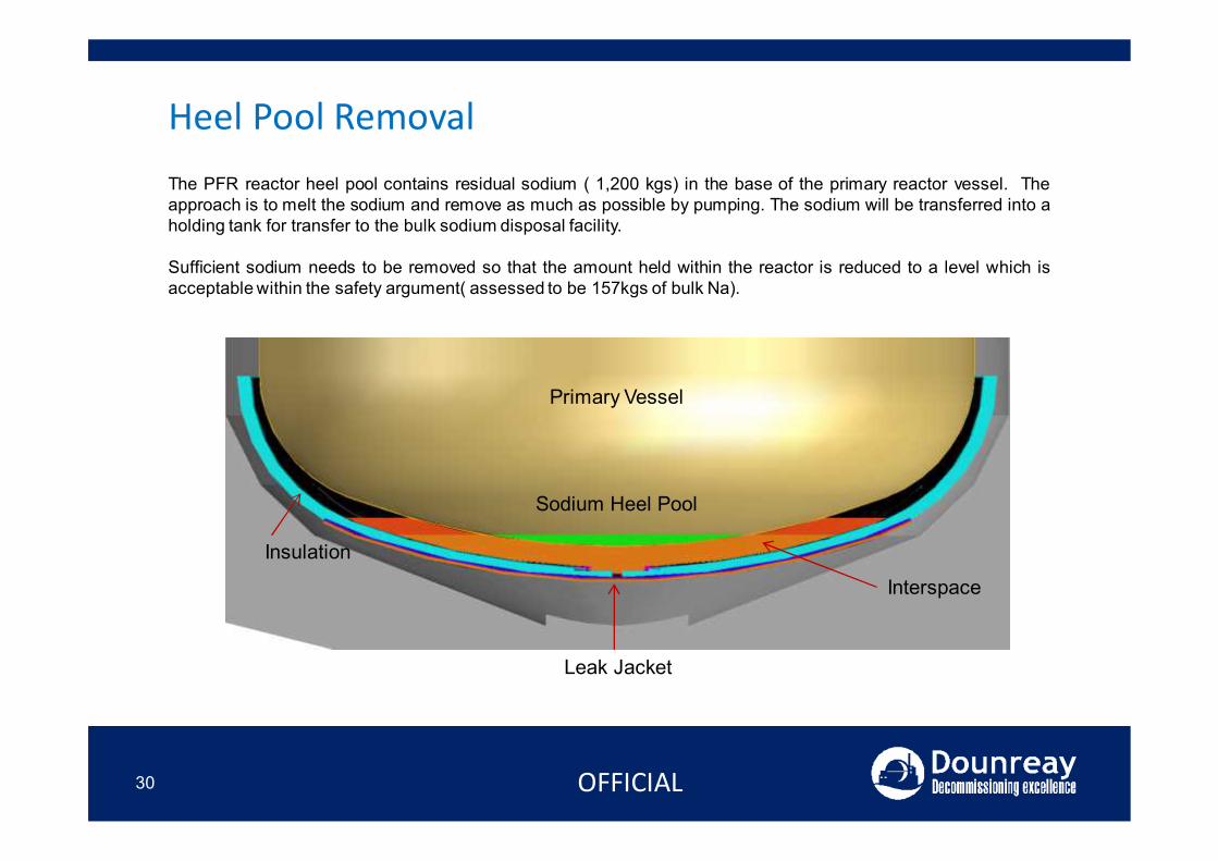
Heel Pool Removal
Primary Vessel
Sodium Heel Pool
Insulation
Interspace
Leak Jacket
The PFR reactor heel pool contains residual sodium ( 1,200 kgs) in the base of the primary reactor vessel. Theapproach is to melt the sodium and remove as much as possible by pumping. The sodium will be transferred into aholding tank for transfer to the bulk sodium disposal facility.
Sufficient sodium needs to be removed so that the amount held within the reactor is reduced to a level which isacceptable within the safety argument( assessed to be 157kgs of bulk Na).
OFFICIAL
Phase 1.1: Heel Pool Removal
31
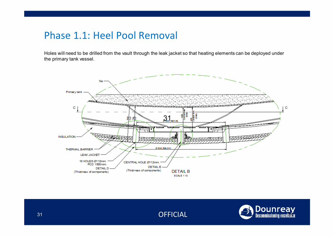
Holes will need to be drilled from the vault through the leak jacket so that heating elements can be deployed under the primary tank vessel.
OFFICIAL
31
31
Phase 1.1: Heel Pool Removal
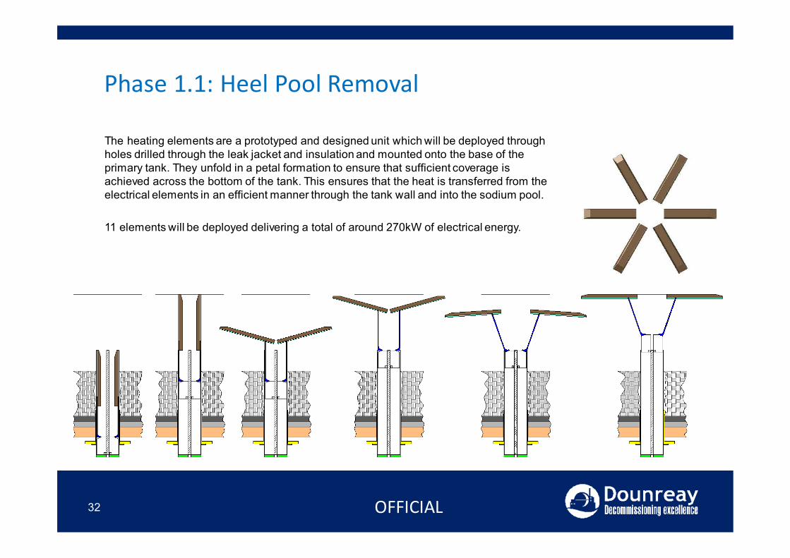
The heating elements are a prototyped and designed unit which will be deployed through holes drilled through the leak jacket and insulation and mounted onto the base of the primary tank. They unfold in a petal formation to ensure that sufficient coverage is achieved across the bottom of the tank. This ensures that the heat is transferred from the electrical elements in an efficient manner through the tank wall and into the sodium pool.
11 elements will be deployed delivering a total of around 270kW of electrical energy.
OFFICIAL32
Current PFR Position
33 OFFICIAL
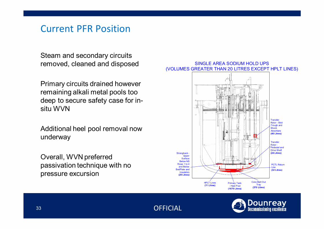
Primary Tank- Heel Pool
(1679 Litres)
Strongback -Upper
SurfaceBelow NS
Rows 1 to 4and Below
BedPlate andInsulation
(29 Litres)
Core Melt OutTray
(370 Litres)
HPLT Lines(11 Litres)
PCTL ReturnLine(32 Litres)
TransferRotor -Pedestal andDrive Shaft(24 Litres)
TransferRotor - SkidTrough andShockAbsorbers(46 Litres)
SINGLE AREA SODIUM HOLD UPS(VOLUMES GREATER THAN 20 LITRES EXCEPT HPLT LINES)
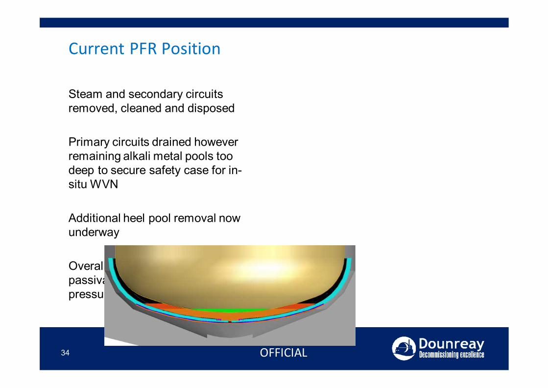
Steam and secondary circuits removed, cleaned and disposed
Primary circuits drained however remaining alkali metal pools too deep to secure safety case for in-situ WVN
Additional heel pool removal now underway
Overall, WVN preferred passivation technique with no pressure excursion
Current PFR Position
34 OFFICIAL
Steam and secondary circuits removed, cleaned and disposed
Primary circuits drained however remaining alkali metal pools too deep to secure safety case for in-situ WVN
Additional heel pool removal now underway
Overall, WVN preferred passivation technique with no pressure excursion

Current PFR Position
35 OFFICIAL
Steam and secondary circuits removed, cleaned and disposed
Primary circuits drained however remaining alkali metal pools too deep to secure safety case for in-situ WVN
Additional heel pool removal now underway
Overall, WVN preferred passivation technique with no pressure excursion
Current PFR Position
36 OFFICIAL
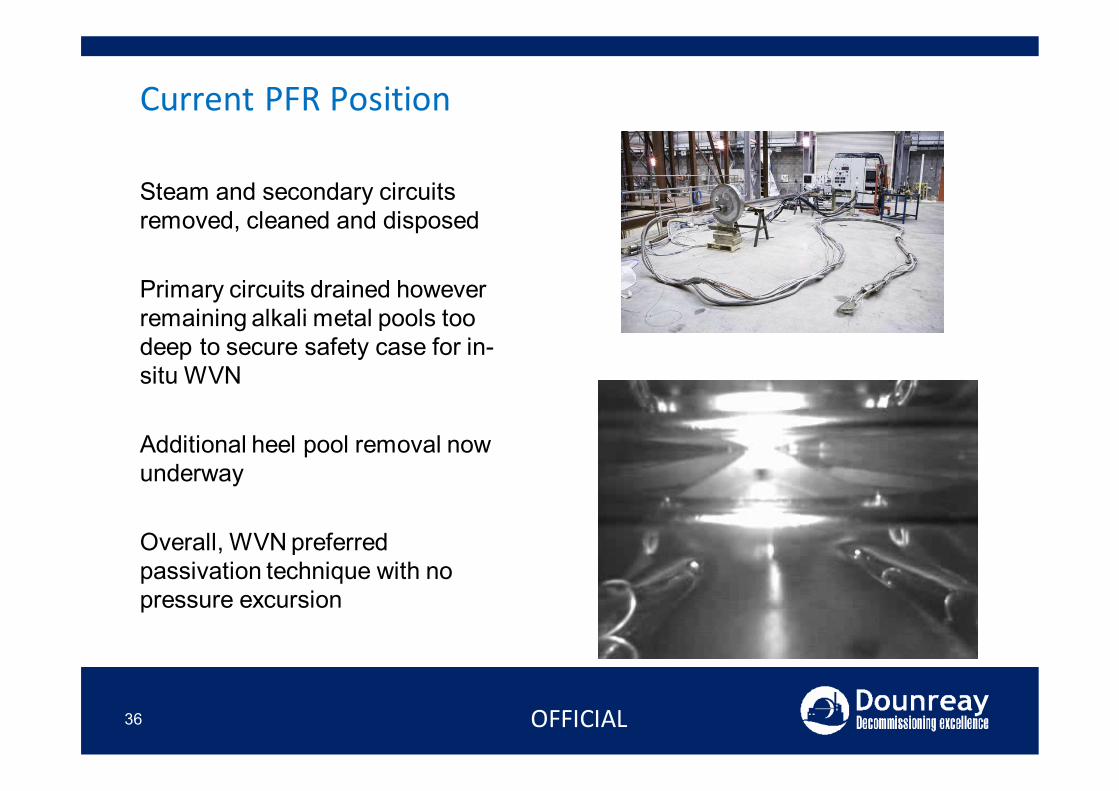
Steam and secondary circuits removed, cleaned and disposed
Primary circuits drained however remaining alkali metal pools too deep to secure safety case for in-situ WVN
Additional heel pool removal now underway
Overall, WVN preferred passivation technique with no pressure excursion
Preferred Sodium Destruction Techniques
37
NOAH Process (Sodium Hydroxide)1 Water Vapour Nitrogen (WVN)
• Deployed following Bulk removal (Reactor Vessel, Secondary Circuits, IFC & Tank Farm)• Highly effective thin films• Some hold-ups in capillaries, blank ends etc.
2 Superheated Steam (SHS)• Deployed for bulk sodium destruction in a new facility.
3 Conventional Steam• Used within the Decontamination Vessel
• Cleaning of sodium logged components in Mortuaries• Secondary cleaning of suspect components fro ILWSRF
4 Others• Fester process
– Return of systems to air after WVN
OFFICIAL
PFR Challenges
38
NOAH Process (Sodium Hydroxide)• Destroy remaining sodium:
• Remove heel pool from reactor vessel• Treat residual sodium in reactor vessel• Treat residual sodium in remaining systems
• Dismantle reactor vessel• Design and construct supporting facilities (ILWSRF, tooling and flasking)• Remove and package the vessel and contents (ILW, tritiated LLW, LLW)
• Dismantle remaining systems and structures• PCTL , AGB, Reactor Building Systems and Tank Farm• IFC (after fuel removal by Fuels Directorate)
• Process Remaining Bulk Sodium• Design and Construct Bulk Sodium Destruction Facility• Process Bulk Sodium
• Demolish structures to foundation plinth
OFFICIAL
Remote Camera Inspection - DFR
39
NOAH Process (Sodium Hydroxide)
OFFICIAL
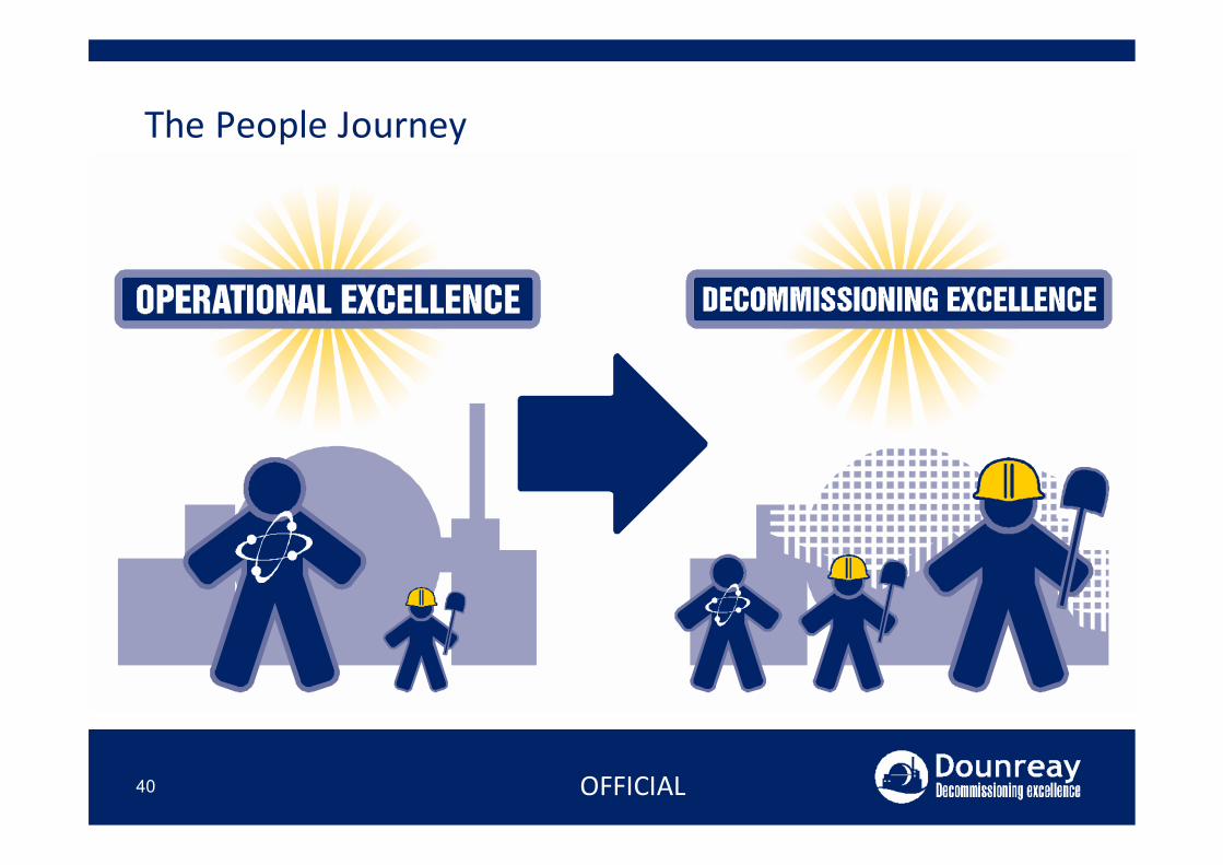
The People Journey
40
NOAH Process (Sodium Hydroxide)
OFFICIAL
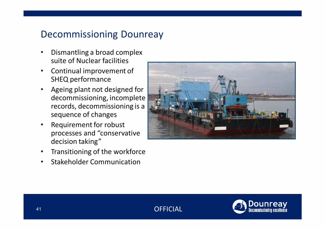
Decommissioning Dounreay• Dismantling a broad complex
suite of Nuclear facilities• Continual improvement of
SHEQ performance• Ageing plant not designed for
decommissioning, incomplete records, decommissioning is a sequence of changes
• Requirement for robust processes and “conservative decision taking”
• Transitioning of the workforce• Stakeholder Communication
41 OFFICIAL
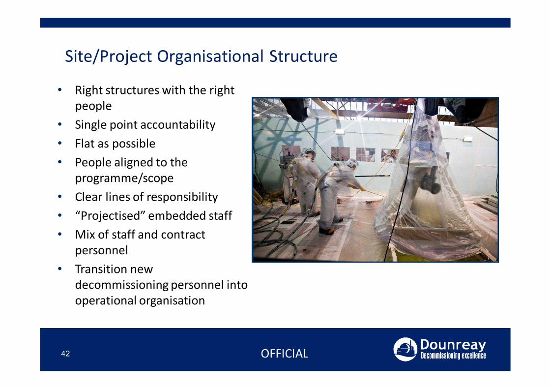
Site/Project Organisational Structure
42
• Right structures with the right people
• Single point accountability• Flat as possible• People aligned to the
programme/scope• Clear lines of responsibility• “Projectised” embedded staff• Mix of staff and contract
personnel• Transition new
decommissioning personnel into operational organisation
OFFICIAL
Questions?
43 OFFICIAL


![Modeling and Simulation of Nonisothermal Plug Flow Reactor ...point, 64.7°C, methyl acetate boiling point 57.1°C) [4]. The feed will enter a plug flow reactor (PFR) where variables](https://img.pdfslide.net/doc/110x75/61105c861bc3db584136b290/modeling-and-simulation-of-nonisothermal-plug-flow-reactor-point-647c-methyl.jpg)