Embed Size (px)
Citation preview

Congratulations on your wise decision to purchasethe Mamiya RB 67 Professional SD (Pro-SD)
The RB67 Pro-SD is the latest addition to the long-selling RB67 Series
which was first released in 1970. Due to its innovative 6x7cm revolving back
format, the RB67 has been highly recognized throughout the world as thegenesis of the medium format cameras.
Specifically, the camera features an expanded interval lens mount diameter
(from 54mm to 61mm, i.e. the same as that of the RZ67), thereby enablinga wider variety of new, high performance lenses, such as the APO series
to be used. The newly developed extra bright, ultra low dispersion glassof the APO series lenses and shift lens have gone a long way to improvingsystem configuration.
With a wide spectrum of accessories, photographic excellence is assured
in a multitude of applications from commercial to portraiture.
Perusing this manual before attempting to use the Pro-SD will minimize the
possibility of malfunctions.
I
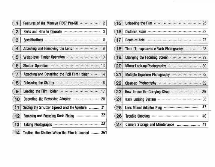
6_fI _2 pa* and How ,o *pep@ ............................. 3 / @yj m*w SC& ........................................... 27 j
($3 1 Smifiwons ............................................ 8 / (17 / Deoth_of_field ............................................ 27 /
($0 Operating fie Revolving Adapter ...................... 20 (24 ~~~ hhng system ................................... 36
~~leHiog_the Shutter Speed and lhe Aperlure ......... 21 (-25 Lens Mount Adapter Ring .............................. 37
Ming am) Fmmm bob Fixing ................... 22 (26 Tmble Shooting ........................................ 40
(13 1 Taking Photographs ..................................... 23 (271 Camera Storage and Maintenance .................... 41
fi4/ Testing theShulterWhentheFilmisi.oaded ....... 261
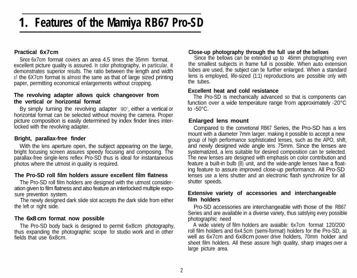
1. Features of the Mamiya RB67 Pro-SD
Practical 6x7cmSince 6x7cm format covers an area 4.5 times the 35mm format.
excellent picture quality is assured. In color photography, in particular, itdemonstrates superior results. The ratio between the length and widthof the 6X7cm format is almost the same as that of large sized printingpaper, permitting economical enlargements without cropping.
The revolving adapter allows quick changeover fromthe vertical or horizontal format
By simply turning the revolving adapter gOa, either a vertical orhorizontal format can be selected without moving the camera. Properpicture composition is easily determined by index finder lines inter-locked with the revolving adapter.
Bright, parallax-free finderWith the lens aperture open, the subject appearing on the large,
bright focusing screen assures speedy focusing and composing. Theparallax-free single-lens reflex Pro-SD thus is ideal for instantaneousphotos where the utmost in quality is required.
The Pro-SD roll film holders assure excellent film flatnessThe Pro-SD roll film holders are designed with the utmost consider-
ation given to film flatness and also feature an interlocked multiple expo-sure prevention system.
The newly designed dark slide slot accepts the dark slide from eitherthe left or right side.
The 6x8 cm format now possibleThe Pro-SD body back is designed to permit 6x8cm photography,
thus expanding the photographic scope for studio work and in otherfields that use 6x8cm.
Close-up photography through the full use of the bellowsSince the bellows can be extended up to 46mm photographing even
the smallest subjects in frame full is possible. When auto extensiontubes are used, the subject can be further enlarged. When a standardlens is employed, life-sized (1:1) reproductions are possible only withthe tubes.
Excellent heat and cold resistanceThe Pro-SD is mechanically advanced so that is components can
function over a wide temperature range from approximately -20°Cto -50°C.
Enlarged lens mountCompared to the convetional RB67 Series, the Pro-SD has a lens
mount with a diameter 7mm larger. making it possible to accept a newgroup of high performance sophisticated lenses, such as the APO, shift,and newly designed wide angle lens 75mm. Since the lenses aresystematized, a lens suitable for desired composition can be selected.The new lenses are designed with emphasis on color contribution andfeature a built-in bulb (B) unit, and the wide-angle lenses have a float-ing feature to assure improved close-up performance. All Pro-SDlenses use a lens shutter and an electronic flash synchronize for allshutter speeds.
Extensive variety of accessories and interchangeablefilm holders
Pro-SD accessories are interchangeable with those of the RB67Series and are available in a diverse variety, thus satisfying every possiblephotographic need
A wide variety of film holders are avaialble: 6x7cm format 120/200roll film holders and 6x4.5cm (semi-format) holders for the Pro-SD, aswell as 6x7cm and 6x8cm power drive holders, 70mm holder andsheet film holders. All these assure high quality, sharp images over alarge picture area.
2
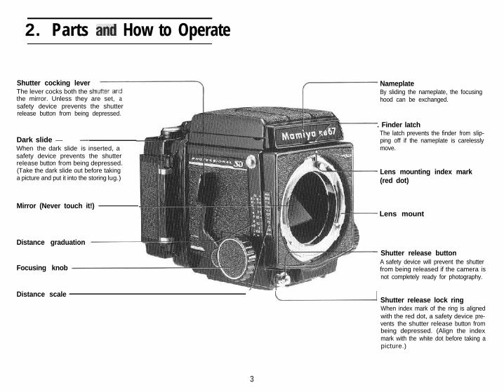
2. Parts andand How to Operate
Shutter cocking leverThe lever cocks both the shthe mirror. Unless they are set, asafety device prevents the shutterrelease button from being depressed.
Dark slide - -When the dark slide is inserted, asafety device prevents the shutterrelease button from being depressed.(Take the dark slide out before takinga picture and put it into the storing lug.)
Mirror (Never touch it!)
Distance graduation
Focusing knob
NameplateBy sliding the nameplate, the focusinghood can be exchanged.
. Finder latchThe latch prevents the finder from slip-ping off if the nameplate is carelesslymove.
Lens mounting index mark(red dot)
Lens mount
Shutter release buttonA safety device will prevent the shutterfrom being released if the camera isnot completely ready for photography.
Distance scaleL Shutter release lock ring
When index mark of the ring is alignedwith the red dot, a safety device pre-vents the shutter release button frombeing depressed. (Align the indexmark with the white dot before taking apicture.)
3
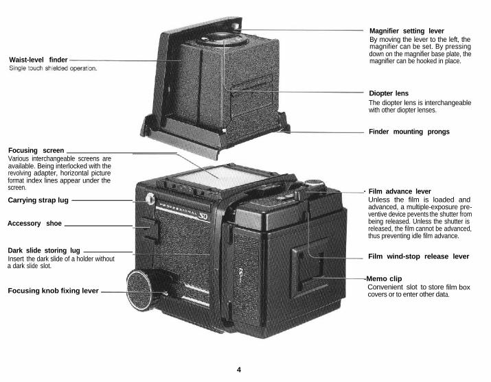
Waist-level finder
Focusing screenVarious interchangeable screens areavailable. Being interlocked with therevolving adapter, horizontal pictureformat index lines appear under thescreen.
Carrying strap lug
Accessory shoe
Dark slide storing lugInsert the dark slide of a holder withouta dark slide slot.
Focusing knob fixing lever -
Magnifier setting leverBy moving the lever to the left, themagnifier can be set. By pressingdown on the magnifier base plate, themagnifier can be hooked in place.
Diopter lensThe diopter lens is interchangeablewith other diopter lenses.
Finder mounting prongs
- Film advance leverUnless the film is loaded andadvanced, a multiple-exposure pre-ventive device pevents the shutter frombeing released. Unless the shutter isreleased, the film cannot be advanced,thus preventing idle film advance.
Film wind-stop release lever
-Memo clipConvenient slot to storecovers or to enter other dat
film boxa.
4
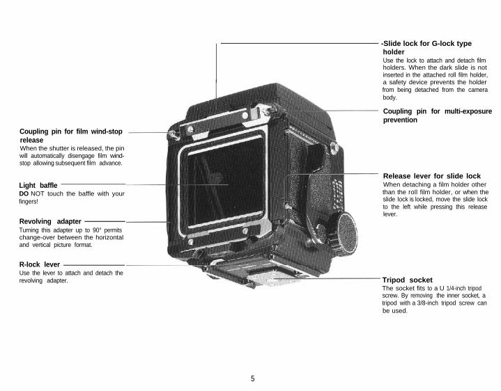
Coupling pin for film wind-stopreleaseWhen the shutter is released, the pinwill automatically disengage film wind-stop allowing subsequent film advance.
Light baffleDO NOT touch the baffle with yourfingers!
Revolving adapterTurning this adapter up to 90° permitschange-over between the horizontaland vertical picture format.
R-lock leverUse the lever to attach and detach therevolving adapter.
-Slide lock for G-lock typeholderUse the lock to attach and detach filmholders. When the dark slide is notinserted in the attached roll film holder,a safety device prevents the holderfrom being detached from the camerabody.
Coupling pin for multi-exposureprevention
Release lever for slide lockWhen detaching a film holder otherthan the roll film holder, or when theslide lock is locked, move the slide lockto the left while pressing this releaselever.
Tripod socketThe socket fits to a U 1/4-inch tripodscrew. By removing the inner socket, atripod with a 3/8-inch tripod screw canbe used.
5
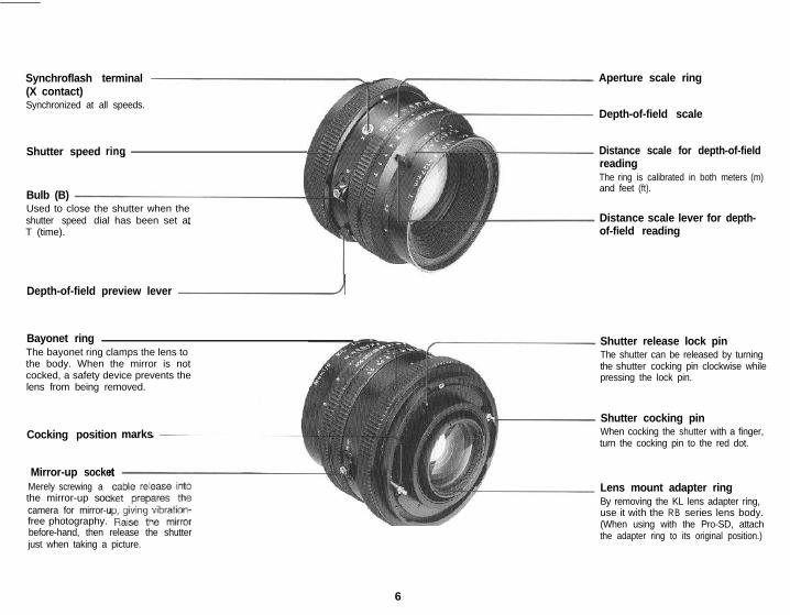
Synchroflash terminal(X contact)Synchronized at all speeds.
Shutter speed ring
Bulb (B)Used to close the shutter when theshutter speed dial has been set atT (time).
Depth-of-field preview lever d
Bayonet ringThe bayonet ring clamps the lens tothe body. When the mirror is notcocked, a safety device prevents thelens from being removed.
Cocking position marks
Mirror-up socketMerely screwing athe mirror-up soccamera for mirror-ufree photography.before-hand, then release the shutterjust when taking a picture.
6
Aperture scale ring
Depth-of-field scale
Distance scale for depth-of-fieldreadingThe ring is calibrated in both meters (m)and feet (ft).
Distance scale lever for depth-of-field reading
Shutter release lock pinThe shutter can be released by turningthe shutter cocking pin clockwise whilepressing the lock pin.
Shutter cocking pinWhen cocking the shutter with a finger,turn the cocking pin to the red dot.
Lens mount adapter ringBy removing the KL lens adapter ring,use it with the RB series lens body.(When using with the Pro-SD, attachthe adapter ring to its original position.)
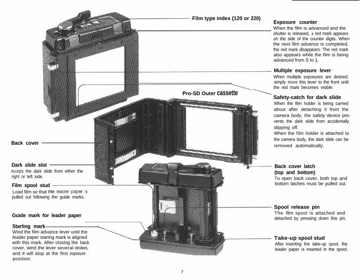
Film type index (120 or 220)
Pro-SD Outer cassette
Back cover
Dark slide slotAccepts the dark slide from either theright or left side.
Film spool studLoad film so that thpulled out following the guide marks.
Guide mark for leader paper___________________
Starting markWind the film advance lever until theleader paper staring mark is alignedwith this mark. After closing the backcover, wind the lever several strokes,and it will stop at the first exposure
Exposure counterWhen the film is advanced and theshutter is released, a red mark appearson the side of the counter digits. Whenthe next film advance is completed,the red mark disappears. The red markalso appears while the film is beingadvanced from S to 1.
Multiple exposure leverWhen multiple exposures are desired,simply move this lever to the front untilthe red mark becomes visible.
Safety-catch for dark slideWhen the film holder is being carriedabout after detaching it from thecamera body, the safety device pre-vents the dark slide from accidentallyslipping off.When the film holder is attached tothe camera body, the dark slide can beremoved automatically.
Back cover latch(top and bottom)To open back cover, both top andbottom latches must be pulled out.
Spool release pinThe film spool is attached anddetached by pressing down this pin.
Take-up spool studAfter inserting the take-up spool, theleader paper is inserted in the spool.
position.
7
l Camera Body
Type:6x7cm lens-shutter single-lens reflexcamera: corresponding the 6x8cm format.
Lens mount:With safety lock ring.
Viewfinder:Horizontal format index mark interlocks withrevolution of revolving adapter (Vertical for-mat based on fixing index line on focusingscreen) 96% of the field of view visible.
Waist-level finder:Single-action opening and closing, withmounting lock.Interchangeable.Finder magnification is 3x. Interchangeable,diopter lens.
Focusing screen:With fresnel lens. Interchangeable. (7 types)
Revolving adapterFull 90° revolving rotary system; verticalhorizontal format indicator interlockingmechanism.By R-lock interchangeable system withPolaroid pack film holder, etc.By G-lock revolving adapter system, G-lock-type film holders are attachable.
Focusing:Bellows extension system with rack andpinions.Maximum extension 46mm. With focusingknob fixing device.
Shutter and mirror cocking:Single-action (75°) cocking by lever on theside of the body.
Additional features:Accessory shoe is provided.Shutter release button can be locked toprevent releasing the shutter accidentally.
l Standard Lenses:
Lens:Mamiya KL 127mm f/3.5L with lens hood
Composition:6 elements in 4 groups
Angle of view:38°
Filter screw diameter:77mm
Aperture:Full automatic diaphragm (with depth-of-field preview lever). f/3.5 to 32 (with click-stops for aperture settings).
Shutter:Seiko #1 shutter1 to 1/400 second and T (Time)
Flash synchronization:X contact
Other features:Mirror-up photography. Bulb (B) feature.
l Pro-SD 120 Roll Film Holder
Film used:120 roll film 10 exposures; 6x7cm formatActual negative size: 56x69.5mm
Film advance:One-stroke film advance lever (After winding70° can be wound in several short, definitestrokes).Automatic multiple-exposure prevention.Film wind-stop automatic release.Multiple exposures are also an option.
Film counter:Automatic reset; red index mark disappearsupon completion of film windingFeatures dark slide dislocation prevention,storing lug and memo clip.
l Dimensions:
(Camera body with roll film holder)Height: 144mmWidth: 104mmLength: 233mm (with 127mm f/3.5 lens)
l Weight:
Camera body . . . . . . . . . . . . . . . . . . . . . . . . . . . . 1050gRevolving adapter .~....,.,....,.................... 200gWaist-level finder . . . . . . . . . . . .._................... 185gPro-SD roll film holder . . . .._...._......_._....... 475gKL 127mm f/3.5L lens .._...._......_._...._.. 780gTotal weight . . . . . . . . 2690g
8
4 . Attaching and Removing the Lens
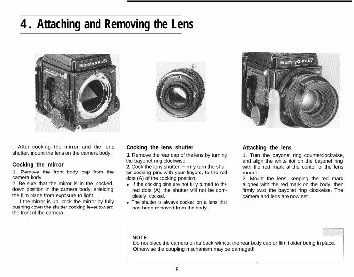
After cocking the mirror and the lensshutter, mount the lens on the camera body.
Cocking the mirror1. Remove the front body cap from thecamera body.2. Be sure that the mirror is in the cocked,down position in the camera body, shieldingthe film plane from exposure to light.
If the mirror is up, cock the mirror by fullypushing down the shutter cocking lever towardthe front of the camera.
Cocking the lens shutter1. Remove the rear cap of the lens by turningthe bayonet ring clockwise.2. Cock the lens shutter. Firmly turn the shut-ter cocking pins with your fingers, to the reddots (A) of the cocking position,l If the cocking pins are not fully turned to the
red dots (A), the shutter will not be com-pletely cocked.
l The shutter is always cocked on a lens thathas been removed from the body.
Attaching the lens1. Turn the bayonet ring counterclockwise,and align the white dot on the bayonet ringwith the red mark at the center of the lensmount.2. Mount the lens, keeping the red markaligned with the red mark on the body; thenfirmly twist the bayonet ring clockwise. Thecamera and lens are now set.
NOTE:Do not place the camera on its back without the rear body cap or film holder being in place.Otherwise the coupling mechanism may be damaged!
.
9
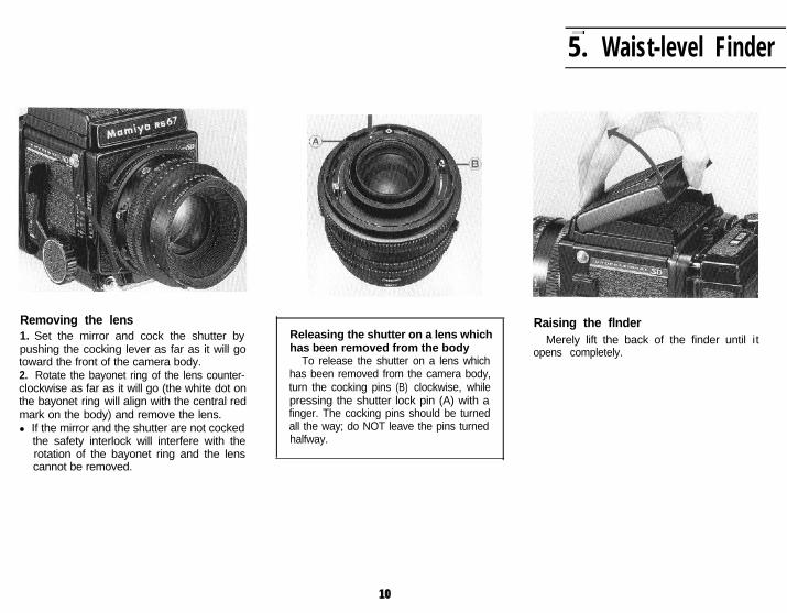
Removing the lens1. Set the mirror and cock the shutter bypushing the cocking lever as far as it will gotoward the front of the camera body.2. Rotate the bayonet ring of the lens counter-clockwise as far as it will go (the white dot onthe bayonet ring will align with the central redmark on the body) and remove the lens.l If the mirror and the shutter are not cocked
the safety interlock will interfere with therotation of the bayonet ring and the lenscannot be removed.
..,
5. Waist-level Finder
Releasing the shutter on a lens whichhas been removed from the body
To release the shutter on a lens whichhas been removed from the camera body,turn the cocking pins (B) clockwise, whilepressing the shutter lock pin (A) with afinger. The cocking pins should be turnedall the way; do NOT leave the pins turnedhalfway.
Raising the flnderMerely lift the back of the finder until it
opens completely.
1010
Operation
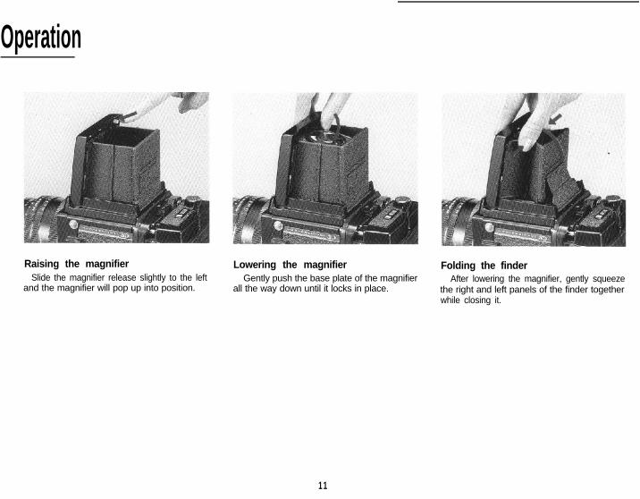
Raising the magnifier Lowering the magnifierSlide the magnifier release slightly to the left Gently push the base plate of the magnifier
and the magnifier will pop up into position. all the way down until it locks in place.
Folding the finderAfter lowering the magnifier, gently squeeze
the right and left panels of the finder togetherwhile closing it.
11
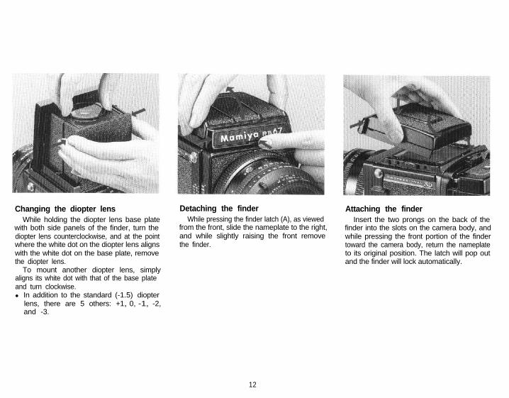
Changing the diopter lensWhile holding the diopter lens base plate
with both side panels of the finder, turn thediopter lens counterclockwise, and at the pointwhere the white dot on the diopter lens alignswith the white dot on the base plate, removethe diopter lens.
To mount another diopter lens, simplyaligns its white dot with that of the base plateand turn clockwise.l In addition to the standard (-1.5) diopter
lens, there are 5 others: +1, 0, -1, -2,and -3.
Detaching the finderWhile pressing the finder latch (A), as viewed
from the front, slide the nameplate to the right,and while slightly raising the front removethe finder.
Attaching the finderInsert the two prongs on the back of the
finder into the slots on the camera body, andwhile pressing the front portion of the findertoward the camera body, return the nameplateto its original position. The latch will pop outand the finder will lock automatically.
12
,:6. Shutter Operation
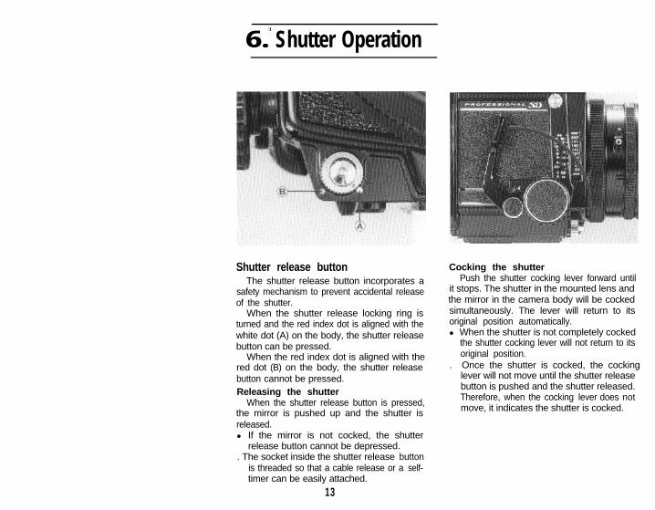
Shutter release buttonThe shutter release button incorporates a
safety mechanism to prevent accidental releaseof the shutter.
When the shutter release locking ring isturned and the red index dot is aligned with thewhite dot (A) on the body, the shutter releasebutton can be pressed.
When the red index dot is aligned with thered dot (B) on the body, the shutter releasebutton cannot be pressed.Releasing the shutter
When the shutter release button is pressed,the mirror is pushed up and the shutter isreleased.l If the mirror is not cocked, the shutter
release button cannot be depressed.. The socket inside the shutter release button
is threaded so that a cable release or a self-timer can be easily attached.
13
Cocking the shutterPush the shutter cocking lever forward until
it stops. The shutter in the mounted lens andthe mirror in the camera body will be cockedsimultaneously. The lever will return to itsoriginal position automatically.l When the shutter is not completely cocked
the shutter cocking lever will not return to itsoriginal position.
. Once the shutter is cocked, the cockinglever will not move until the shutter releasebutton is pushed and the shutter released.Therefore, when the cocking lever does notmove, it indicates the shutter is cocked.
7. Attaching and Detaching the Roll Film Holder
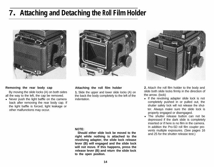
Removing the rear body capBy moving the slide locks (A) on both sides
all the way to the left, the cap be removed.l Never push the light baffle on the camera
back after removing the rear body cap. Ifthe light baffle is forced, light leakage orother malfunctions may occur.
Attaching the roll film holder1. Slide the upper and lower slide locks (A) onthe back the body completely to the left of theindentation.
NOTE:Should either slide lock be moved to the
right while nothing is attached to therevolving adapter, the slide lock releaselever (B) will engaged and the slide lockwill not move. If this happens, press therelease lever (B) and return the slide lockto the open position.
14
2. Attach the roll film holder to the body andslide both slide locks firmly in the direction ofthe arrow. (lock)l If the revolving adapter slide lock is not
completely pushed in or pulled out, theshutter safety lock will not release the shut-ter. Always make sure the slide lock isproperly engaged or disengaged.
l The shutter release button can not bedepressed if the dark slide is completelyinserted or if here is no film in the camera.In addition the Pro-SD roll film coupler pre-vents multiple exposures. (See pages 16and 25 for the shutter release test.)
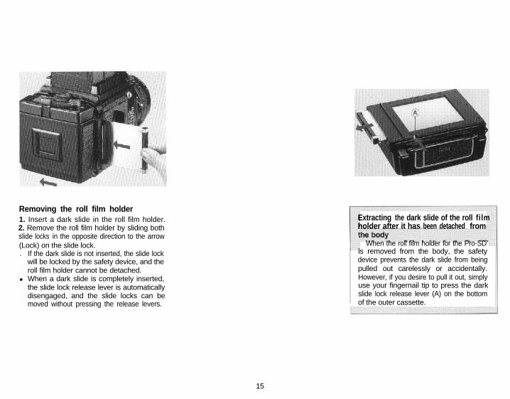
Removing the roll film holder1. Insert a dark slide in the roll film holder.2. Remove the roll film holder by sliding bothslide locks in the opposite direction to the arrow(Lock) on the slide lock.. If the dark slide is not inserted, the slide lock
will be locked by the safety device, and theroll film holder cannot be detached.
l When a dark slide is completely inserted,the slide lock release lever is automaticallydisengaged, and the slide locks can bemoved without pressing the release levers.
Extracting the dark slide of the roll filmholder after it has been detached from
When the roll film holder for the Pro-SDis removed from the body, the safetydevice prevents the dark slide from beingpulled out carelessly or accidentally.However, if you desire to pull it out, simplyuse your fingernail tip to press the darkslide lock release lever (A) on the bottomof the outer cassette.
15
8. Releasing the Shutter
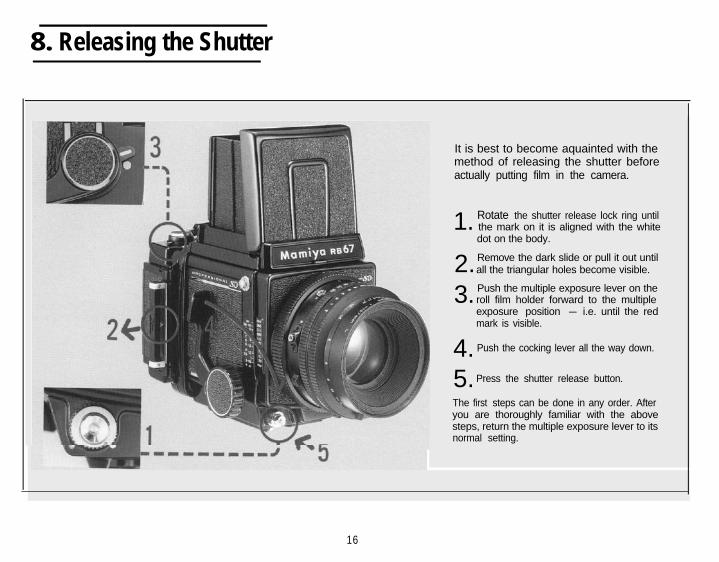
It is best to become aquainted with themethod of releasing the shutter beforeactually putting film in the camera.
1. Rotate the shutter release lock ring until the mark on it is aligned with the whitedot on the body.
2.Remove the dark slide or pull it out untilall the triangular holes become visible.
3. Push the multiple exposure lever on the roll film holder forward to the multiple
exposure position - i.e. until the redmark is visible.
4. Push the cocking lever all the way down.
5.Press the shutter release button.
The first steps can be done in any order. Afteryou are thoroughly familiar with the abovesteps, return the multiple exposure lever to itsnormal setting.
16
9. Loading the Film Holder
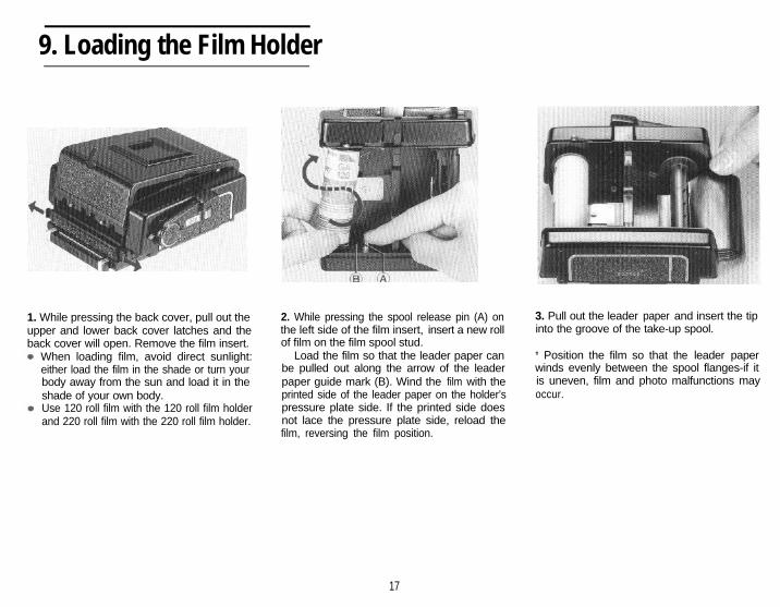
1. While pressing the back cover, pull out theupper and lower back cover latches and theback cover will open. Remove the film insert.
When loading film, avoid direct sunlight:either load the film in the shade or turn yourbody away from the sun and load it in theshade of your own body.Use 120 roll film with the 120 roll film holderand 220 roll film with the 220 roll film holder.
2. While pressing the spool release pin (A) onthe left side of the film insert, insert a new rollof film on the film spool stud.
Load the film so that the leader paper canbe pulled out along the arrow of the leaderpaper guide mark (B). Wind the film with theprinted side of the leader paper on the holder’spressure plate side. If the printed side doesnot lace the pressure plate side, reload thefilm, reversing the film position.
3. Pull out the leader paper and insert the tipinto the groove of the take-up spool.
* Position the film so that the leader paperwinds evenly between the spool flanges-if itis uneven, film and photo malfunctions mayoccur.
17
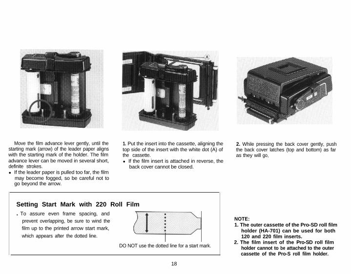
Move the film advance lever gently, until thestarting mark (arrow) of the leader paper alignswith the starting mark of the holder. The filmadvance lever can be moved in several short,definite strokes.l If the leader paper is pulled too far, the film
may become fogged, so be careful not togo beyond the arrow.
1. Put the insert into the cassette, aligning thetop side of the insert with the white dot (A) ofthe cassette.l If the film insert is attached in reverse, the
back cover cannot be closed.
Setting Start Mark with 220 Roll Film. To assure even frame spacing, and
prevent overlapping, be sure to wind thefilm up to the printed arrow start mark,
which appears after the dotted line.
ifi>
DO NOT use the dotted line for a start mark.
18
2. While pressing the back cover gently, pushthe back cover latches (top and bottom) as faras they will go,
NOTE:1. The outer cassette of the Pro-SD roll film
holder (HA-701) can be used for both120 and 220 film inserts.
2. The film insert of the Pro-SD roll filmholder cannot to be attached to the outercassette of the Pro-S roll film holder.

Exposure Counter
Film winding for first exposureWhen the film is completely advanced, the
numeral ‘1’ will appear in the exposurecounter and the red film-advance warning willdisappear indicating that the holder is readyfor photography.l The shutter cannot be released unless the
film from S (start) to 1 has been completelyadvanced with the cocking lever.
1919
1 0. Operating the Revolving Adapter
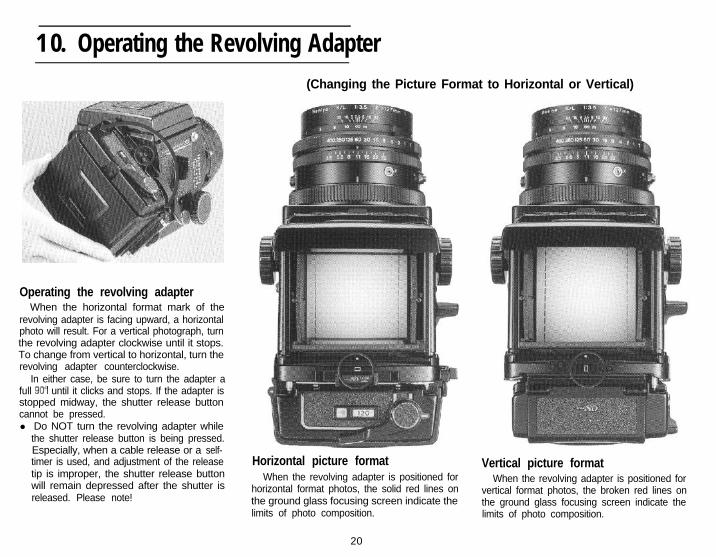
Operating the revolving adapterWhen the horizontal format mark of the
revolving adapter is facing upward, a horizontalphoto will result. For a vertical photograph, turnthe revolving adapter clockwise until it stops.To change from vertical to horizontal, turn therevolving adapter counterclockwise.
In either case, be sure to turn the adapter afull until it clicks and stops. If the adapter isstopped midway, the shutter release buttoncannot be pressed.l Do NOT turn the revolving adapter while
the shutter release button is being pressed.Especially, when a cable release or a self-timer is used, and adjustment of the releasetip is improper, the shutter release buttonwill remain depressed after the shutter isreleased. Please note!
(Changing the Picture Format to Horizontal or Vertical)
Horizontal picture formatWhen the revolving adapter is positioned for
horizontal format photos, the solid red lines onthe ground glass focusing screen indicate thelimits of photo composition.
20
Vertical picture formatWhen the revolving adapter is positioned for
vertical format photos, the broken red lines onthe ground glass focusing screen indicate thelimits of photo composition.
1 1 Setting the Shutter Speed and the Apertur
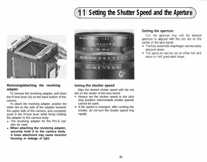
Removing/attaching the revolvingadapter
To remove the revolving adapter, pull downthe R-lock lever (A) on the back bottom of thecamera.
To attach the revolving adapter, position thewhite dot on the side of the adapter towardsthe upper side of the camera, and completlypush in the R-lock lever while firmly holdingthe adapter to the camera body.l The revolving adapter for the Pro-S can
also be used.l When attaching the revolving adapter,
securely hold it to the camera body.A loose attachment may cause incorrectfocusing or leakage of light.
Setting the shutter speedAlign the desired shutter speed with the red
dot on the center of the lens barrel..
.
Always set the shutter speed to the clickstop position: intermediate shutter speedscannot be used.If the speed is changed, after cocking theshutter, do not turn the shutter speed ringrapidly.
21
12. Focusing and Focusing Knob Fixing
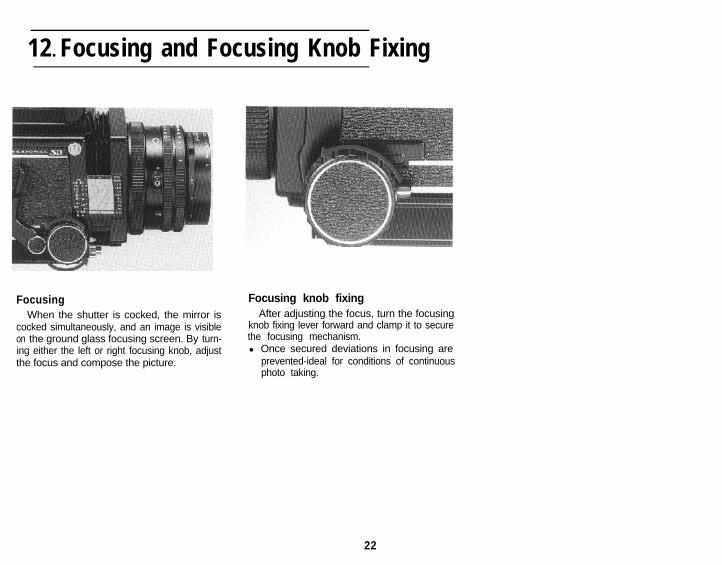
FocusingWhen the shutter is cocked, the mirror is
cocked simultaneously, and an image is visibleon the ground glass focusing screen. By turn-ing either the left or right focusing knob, adjustthe focus and compose the picture.
Focusing knob fixingAfter adjusting the focus, turn the focusing
knob fixing lever forward and clamp it to securethe focusing mechanism.l Once secured deviations in focusing are
prevented-ideal for conditions of continuousphoto taking.
22
1 3. Taking Photographs
first.
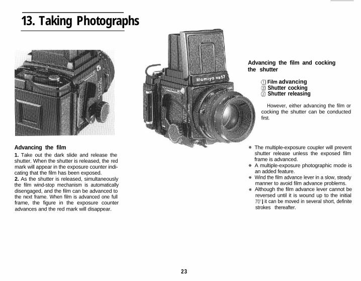
Advancing the film1. Take out the dark slide and release theshutter. When the shutter is released, the redmark will appear in the exposure counter indi-cating that the film has been exposed.2. As the shutter is released, simultaneouslythe film wind-stop mechanism is automaticallydisengaged, and the film can be advanced tothe next frame. When film is advanced one fullframe, the figure in the exposure counteradvances and the red mark will disappear.
Advancing the film and cockingthe shutter
@ Film advancing@ Shutter cocking@ Shutter releasing
However, either advancing the film orcocking the shutter can be conducted
The multiple-exposure coupler will preventshutter release unless the exposed filmframe is advanced.A multiple-exposure photographic mode isan added feature.Wind the film advance lever in a slow, steadymanner to avoid film advance problems.Although the film advance lever cannot bereversed until it is wound up to the initial70’, it can be moved in several short, definitestrokes thereafter.
23
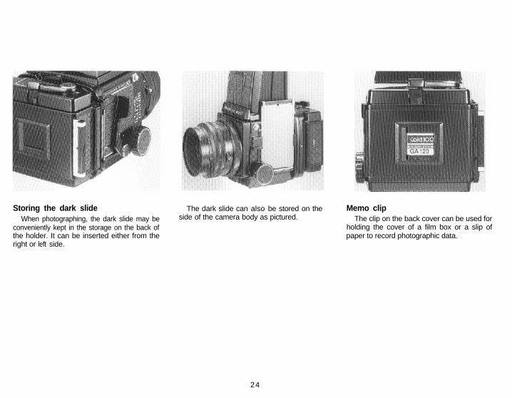
Storing the dark slideWhen photographing, the dark slide may be
conveniently kept in the storage on the back ofthe holder. It can be inserted either from theright or left side.
The dark slide can also be stored on theside of the camera body as pictured.
Memo clipThe clip on the back cover can be used for
holding the cover of a film box or a slip ofpaper to record photographic data.
24
14. Testing the Shutter When the Film is Loaded
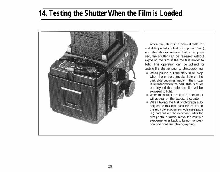
When the shutter is cocked with thedarkslide partially pulled out (approx. 5mm)and the shutter release button is pres-sed, the shutter can be released withoutexposing the film in the roll film holder tolight. This operation can be utilized fortesting the shutter prior to photographing.
When pulling out the dark slide, stopwhen the entire triangular hole on thedark slide becomes visible. If the shutteris released when the dark slide is pulledout beyond that hole, the film will beexposed to light.When the shutter is released, a red markwill appear on the exposure counter.When taking the first photograph sub-sequent to this test, cock the shutter inthe multiple exposure mode (see page32), and pull out the dark slide. After thefirst photo is taken, move the multipleexposure lever back to its normal posi-tion and continue photographing.
25
15. Unloading the Film
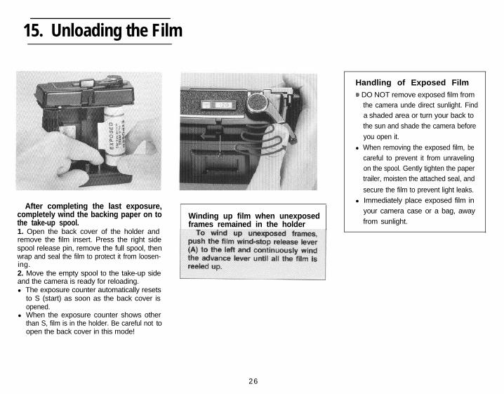
After completing the last exposure,completely wind the backing paper on tothe take-up spool.1. Open the back cover of the holder andremove the film insert. Press the right sidespool release pin, remove the full spool, thenwrap and seal the film to protect it from loosen-ing.2. Move the empty spool to the take-up sideand the camera is ready for reloading.l The exposure counter automatically resets
to S (start) as soon as the back cover isopened.
l When the exposure counter shows otherthan S, film is in the holder. Be careful not toopen the back cover in this mode!
Winding up film when unexposedframes remained in the holder
Handling of Exposed Film0 DO NOT remove exposed film from
the camera unde direct sunlight. Finda shaded area or turn your back tothe sun and shade the camera before
you open it.
l When removing the exposed film, becareful to prevent it from unravelingon the spool. Gently tighten the papertrailer, moisten the attached seal, and
secure the film to prevent light leaks.l Immediately place exposed film in
your camera case or a bag, awayfrom sunlight.
26
.
16. Distance Scale 17. Depth-of-field
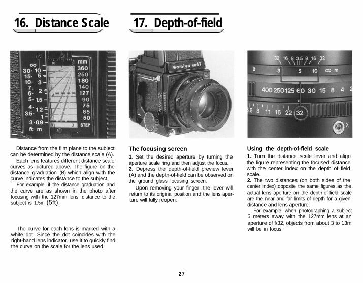
Distance from the film plane to the subjectcan be determined by the distance scale (A).
Each lens features different distance scalecurves as pictured above. The figure on thedistance graduation (B) which align with thecurve indicates the distance to the subject.
For example, if the distance graduation andthe curve are as shown in the photo afterfocusing with the 127mm lens, distance to thesubject is 1.5m (5ft).
The focusing screen1. Set the desired aperture by turning theaperture scale ring and then adjust the focus.2. Depress the depth-of-field preview lever(A) and the depth-of-field can be observed onthe ground glass focusing screen.
Upon removing your finger, the lever willreturn to its original position and the lens aper-ture will fully reopen.
The curve for each lens is marked with awhite dot. Since the dot coincides with theright-hand lens indicator, use it to quickly findthe curve on the scale for the lens used.
Using the depth-of-field scale1. Turn the distance scale lever and alignthe figure representing the focused distancewith the center index on the depth of fieldscale.2. The two distances (on both sides of thecenter index) opposite the same figures as theactual lens aperture on the depth-of-field scaleare the near and far limits of depth for a givendistance and lens aperture.
For example, when photographing a subject5 meters away with the 127mm lens at anaperture of f/32, objects from about 3 to 13mwill be in focus.
27
18. Time (T) exposures, Flash Photography
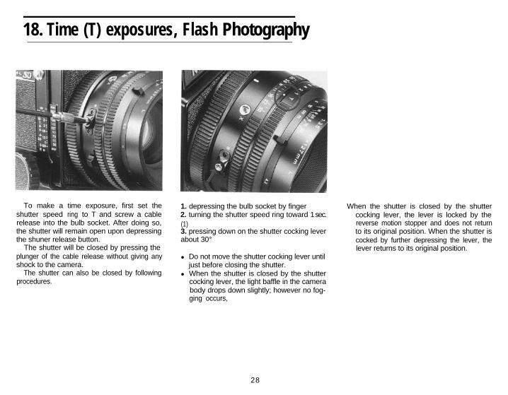
To make a time exposure, first set theshutter speed ring to T and screw a cablerelease into the bulb socket. After doing so,the shutter will remain open upon depressingthe shuner release button.
The shutter will be closed by pressing theplunger of the cable release without giving anyshock to the camera.
The shutter can also be closed by followingprocedures.
1. depressing the bulb socket by finger2. turning the shutter speed ring toward 1 sec.
When the shutter is closed by the shutter
(1)cocking lever, the lever is locked by the
3. pressing down on the shutter cocking leverreverse motion stopper and does not return
about 30°to its original position. When the shutter iscocked by further depressing the lever, the
l Do not move the shutter cocking lever untiljust before closing the shutter.
l When the shutter is closed by the shuttercocking lever, the light baffle in the camerabody drops down slightly; however no fog-ging occurs,
lever returns to its original position.
28

Flash photographyConnect the cord of the flash unit to the
synchroflash terminal (X contact).. The flash unit synchronizes at all shutter
speeds.
Determining the apertureThe aperture setting for flash photography
is determined by dividing the guide number ofthe flash unit by the subject distance.
For example, when photographed withIS0100 in m.
Changing the Focusing Screen)
Attaching and detachingFirst remove the waist-level finder, then while
holding both sides take out the focusing screen.To attach it, hold each side and insert the
focusing screen into the top of the camera bodyand press down lightly.NOTE:
When the focusing screen has beendetached, do not touch the picture format redrod indicator on the side of the camera body.
Seven types of interchangeable focusingscreens are available to meet various photo-graphic applications.l The focusing screen is made of acrylic
resin, and since its surface is soft and sus-ceptible to damage, be carefully so as tonot get fingerprints or other foreign matteron it.
When dust is wiped off with a cloth or lenspaper, static electricity attracts more dust.So, use a blower brush to remove dust.
(Guide number) 40(Subject distance) 5 (m)
= (Correct aperture setting) 8
29
20. Mirror Lock-up Photography
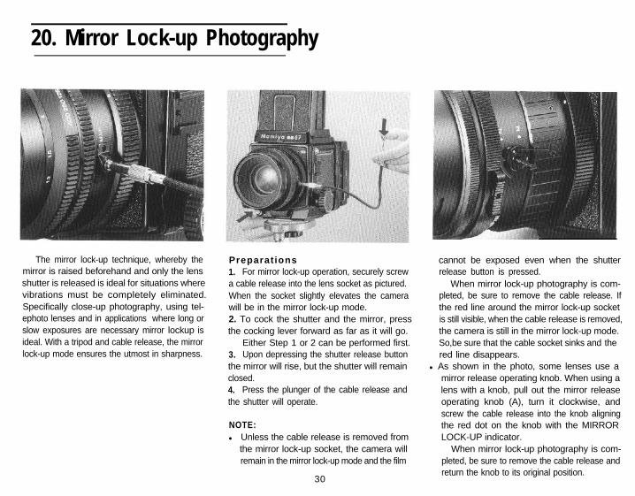
The mirror lock-up technique, whereby themirror is raised beforehand and only the lensshutter is released is ideal for situations wherevibrations must be completely eliminated.Specifically close-up photography, using tel-ephoto lenses and in applications where long orslow exposures are necessary mirror lockup isideal. With a tripod and cable release, the mirrorlock-up mode ensures the utmost in sharpness.
Preparat ions1. For mirror lock-up operation, securely screwa cable release into the lens socket as pictured.When the socket slightly elevates the camerawill be in the mirror lock-up mode.2. To cock the shutter and the mirror, pressthe cocking lever forward as far as it will go.
Either Step 1 or 2 can be performed first.3. Upon depressing the shutter release buttonthe mirror will rise, but the shutter will remainclosed.4. Press the plunger of the cable release andthe shutter will operate.
NOTE:l Unless the cable release is removed from
the mirror lock-up socket, the camera willremain in the mirror lock-up mode and the film
30
cannot be exposed even when the shutterrelease button is pressed.
When mirror lock-up photography is com-pleted, be sure to remove the cable release. Ifthe red line around the mirror lock-up socketis still visible, when the cable release is removed,the camera is still in the mirror lock-up mode.So,be sure that the cable socket sinks and thered line disappears.
l As shown in the photo, some lenses use amirror release operating knob. When using alens with a knob, pull out the mirror releaseoperating knob (A), turn it clockwise, andscrew the cable release into the knob aligningthe red dot on the knob with the MIRRORLOCK-UP indicator.
When mirror lock-up photography is com-pleted, be sure to remove the cable release andreturn the knob to its original position.
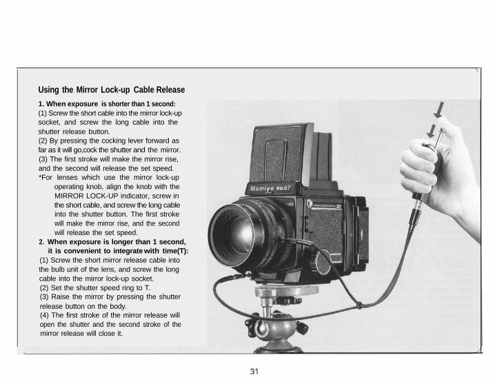
Using the Mirror Lock-up Cable Release
1. When exposure is shorter than 1 second:(1) Screw the short cable into the mirror lock-upsocket, and screw the long cable into theshutter release button.(2) By pressing the cocking lever forward asfar as it will go,cock the shutter and the mirror.(3) The first stroke will make the mirror rise,and the second will release the set speed.*For lenses which use the mirror lock-up
operating knob, align the knob with theMIRROR LOCK-UP indicator, screw inthe short cable, and screw the long cableinto the shutter button. The first strokewill make the mirror rise, and the secondwill release the set speed.
2. When exposure is longer than 1 second,it is convenient to integrate with time(T):
(1) Screw the short mirror release cable intothe bulb unit of the lens, and screw the longcable into the mirror lock-up socket.(2) Set the shutter speed ring to T.(3) Raise the mirror by pressing the shutterrelease button on the body.(4) The first stroke of the mirror release willopen the shutter and the second stroke of themirror release will close it.
21 Multiple Exposure Photography 22 Close-up Photography
Exposure compensation for close-upphotography
When the bellows of the camera isextended for close-up photography, and dis-tance between the lens and the film planeincreases, image brightness on the film planedecreases, thus requiring an increase in expo-sure. To adjust the exposure, refer to theexposure compensation scale on the camerabody.
When a finder with built-in exposure meter(i.e. PD Prism Finder or PD Magnifying Hood)is used, exposure compensation is unneces-sary, since TTL metering takes place.
When making exposure compensation,refer to the exposure compensation scale onthe camera body.
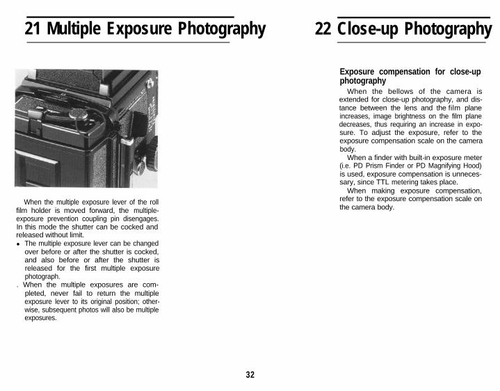
When the multiple exposure lever of the rollfilm holder is moved forward, the multiple-exposure prevention coupling pin disengages.In this mode the shutter can be cocked andreleased without limit.l The multiple exposure lever can be changed
over before or after the shutter is cocked,and also before or after the shutter isreleased for the first multiple exposurephotograph.
. When the multiple exposures are com-pleted, never fail to return the multipleexposure lever to its original position; other-wise, subsequent photos will also be multipleexposures.
32
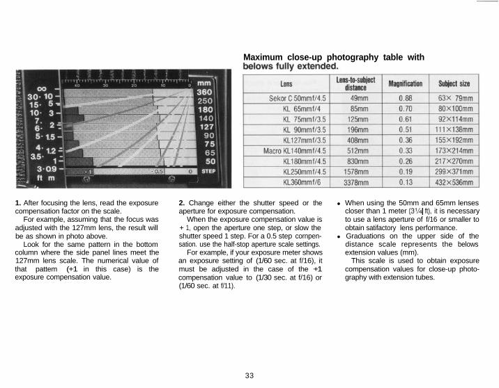
Maximum close-up photography table with
1. After focusing the lens, read the exposurecompensation factor on the scale.
For example, assuming that the focus wasadjusted with the 127mm lens, the result willbe as shown in photo above.
Look for the same pattern in the bottomcolumn where the side panel lines meet the127mm lens scale. The numerical value ofthat pattem (+1 in this case) is theexposure compensation value.
2. Change either the shutter speed or theaperture for exposure compensation.
When the exposure compensation value is+ 1, open the aperture one step, or slow theshutter speed 1 step. For a 0.5 step cornpen-sation. use the half-stop aperture scale settings.
For example, if your exposure meter showsan exposure setting of (1/60 sec. at f/16), itmust be adjusted in the case of the +1compensation value to (1/30 sec. at f/16) or(1/60 sec. at f/11).
l When using the 50mm and 65mm lensescloser than 1 meter (3% ft), it is necessaryto use a lens aperture of f/16 or smaller toobtain satifactory lens performance.
l Graduations on the upper side of thedistance scale represents the belowsextension values (mm).
This scale is used to obtain exposurecompensation values for close-up photo-graphy with extension tubes.
33
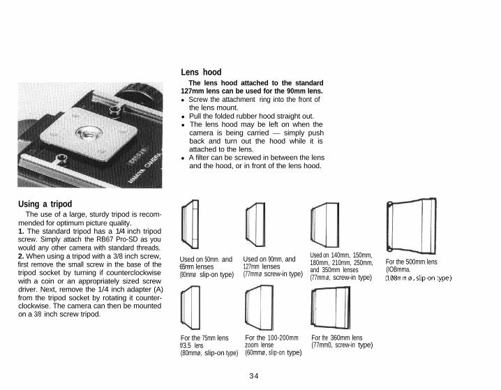
Lens hoodThe lens hood attached to the standard
127mm lens can be used for the 90mm lens.l Screw the attachment ring into the front of
the lens mount.l Pull the folded rubber hood straight out.l The lens hood may be left on when the
camera is being carried - simply pushback and turn out the hood while it isattached to the lens.
l A filter can be screwed in between the lensand the hood, or in front of the lens hood.
Using a tripodThe use of a large, sturdy tripod is recom-
mended for optimum picture quality.1. The standard tripod has a 1/4 inch tripodscrew. Simply attach the RB67 Pro-SD as youwould any other camera with standard threads.2. When using a tripod with a 3/8 inch screw,first remove the small screw in the base of thetripod socket by turning if counterclockwisewith a coin or an appropriately sized screwdriver. Next, remove the 1/4 inch adapter (A)from the tripod socket by rotating it counter-clockwise. The camera can then be mountedon a 3/8 inch screw tripod.
ulUsed on 50mm. and Used on 90mm, and65mm lenses 127mm lenses(80mmø slip-on type) (77mmø screw-in type)
Q %3Used on 140mm, 150mm,180mm, 210mm, 250mm, For the 500mm lensand 350mm lenses (IOBmma. (77mm ø, screw-in type)
Q aFor the 75mm lens For the 100-200mmf/3.5 lens zoom lense(80mmø, slip-on type) (60mmø, slip-on type)
For the 360mm lens(77mm0, screw-in type)
34
23 How to use the Carrying Strap
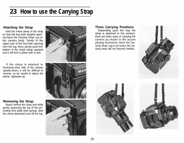
Attaching the StrapHold the metal clamp of the strap
so that the key-hole shaped open-ing faces the Carrying Strap Lug onthe camera body. Gently fit theupper part of the key-hole openingover the lug. Next, gently push thebottom of the metal clamp upwardsand it will lock in place with a click.
If the clamp is attached toAccessory-shoe side of the cameraupside-down, it will be difficult toremove, so be careful to attach theclamp rightside-up.
Removing the StrapReach behind the strap and while
gently squeezing the top of the pro-truding front plate (leaf spring), slidethe clamp downward and off the lug.
Three Carrying PositionsDepending upon the way the
strap is attached to the camera,there are three ways of carrying thecamera as shown in the accompanying illustrations Since the Car-rying Strap Lug is not rotary, the car-rying strap will not become twisted.
“‘. b
2 4 Back Locking System
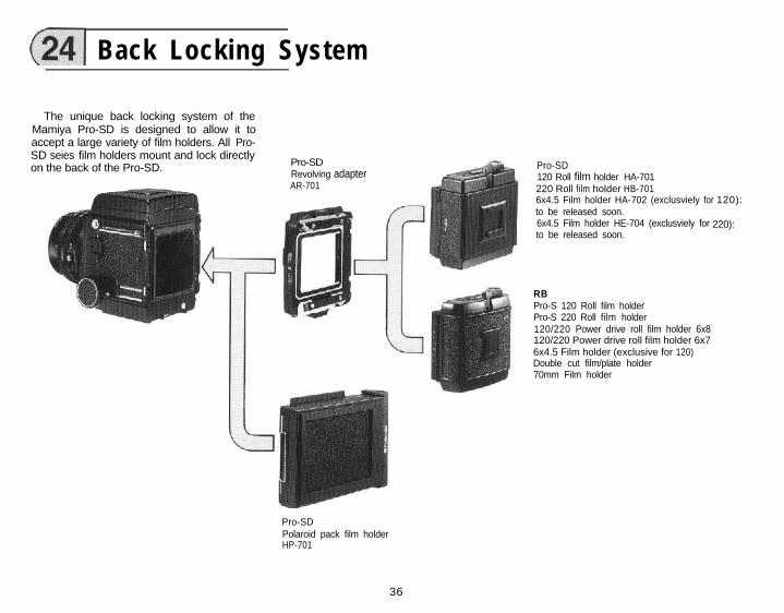
The unique back locking system of theMamiya Pro-SD is designed to allow it toaccept a large variety of film holders. All Pro-SD seies film holders mount and lock directlyon the back of the Pro-SD. Pro-SD
Revolving adapterAR-701
Pro-SD120 Roll film holder HA-701220 Roll film holder HB-7016x4.5 Film holder HA-702 (exclusviely forto be released soon.6x4.5 Film holder HE-704 (exclusviely forto be released soon.
RBPro-S 120 Roll film holderPro-S 220 Roll film holder120/220 Power drive roll film holder 6x8120/220 Power drive roll film holder 6x76x4.5 Film holder (exclusive for 120)Double cut film/plate holder70mm Film holder
120):
220):
Pro-SDPolaroid pack film holderHP-701
36

25 Lens Mount Adapter Ring
When using Mamiya Sekor C interchange-able lenses with the RB67 Pro-SD, the lensmount adapter ring must be used. It should beattached to the rear lens mount. (When usingMamiya KL lenses with the RB Pro-S andRB67. remove the lens mount adapter ring.). The lens mount adapter ring comes with
Sekor C lenses.For KL lenses it is attached to the rear lensmount.
. Both the 75mm shift and APO 500mm lensesare L lenses.
l Make sure to securely tighten the lensmount adapter ring onto the lens mount.
I Sekor C KL L
RB67 Pro-SDThe lens mount
adapter ring shouldbe attached.
RB67 Pro-SThe lens mount
adapter ring shouldbe detached.
37
Mamiya RB67 Pro-SD Operation Diagram
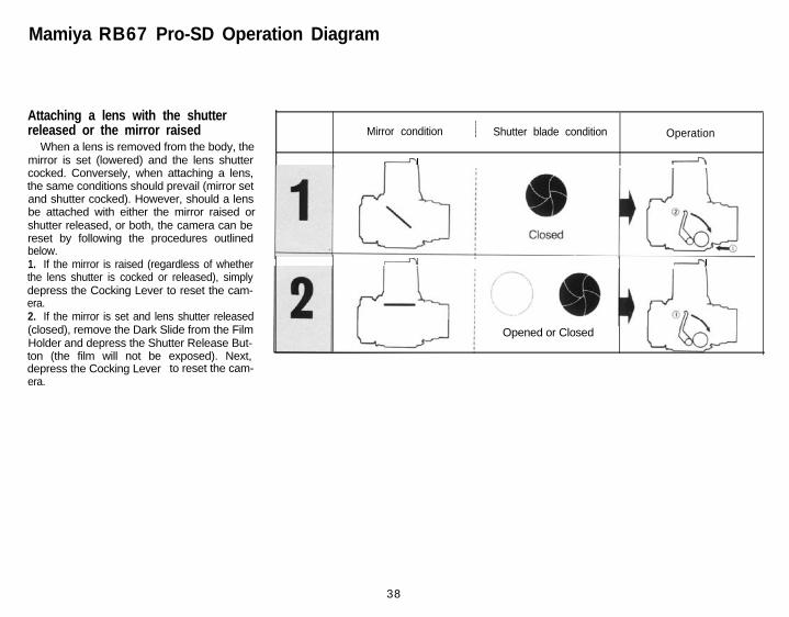
Attaching a lens with the shutterreleased or the mirror raised
When a lens is removed from the body, themirror is set (lowered) and the lens shuttercocked. Conversely, when attaching a lens,the same conditions should prevail (mirror setand shutter cocked). However, should a lensbe attached with either the mirror raised orshutter released, or both, the camera can bereset by following the procedures outlinedbelow.1. If the mirror is raised (regardless of whetherthe lens shutter is cocked or released), simplydepress the Cocking Lever to reset the cam-era.2. If the mirror is set and lens shutter released(closed), remove the Dark Slide from the FilmHolder and depress the Shutter Release But-ton (the film will not be exposed). Next,depress the Cocking Lever to reset the cam-era.
Mirror condition / Shutter blade condition Operation
- 4
I I - I -
Opened or Closed
38
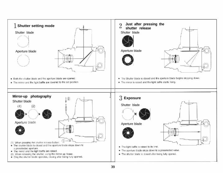
1 Shutter setting mode
Shutter blade
/--\I1-j
Aperture blade
Mirror-up photographyShutter blade
1
2 Just after pressing theshutter release
Shutter blade
&b
Aperture blade
0
3 Exposure
Shutter blade/-\i :
1)‘L/ m
Aperture blade
39

26 Trouble Shooting
Various safety interlocking device are incor-porated in the Mamiya RB67 Pro-SD to elimi-
4. After the shutter was released during ordi-nary exposure (not during multiple expo-
nate careless operational mistakes. When the sures), did you advance the film?shutter is not released, or when the lens or the 5. Was the dark slide pulled out?roll film holder cannot be removed, do not Pull out the dark slide.hastily conclude that this indicates a cameramalfunction. Check the following conditions:
6. Is the revolving adapter turned to the clickstop postion?
the numbers in parentheses indicate the pagenumber in the Instruction Manual that coverrelevant malfucntions.
Turn the adapter until it stops with a click.(p. 20)7. Has the slide lock on the revolving adapterstopped halfway?
Move the slide lock until it stops. (p.4)
Shutter release button cannot be depressed
1. Is the shutter release button locked?Turn the shutter release lock ring coun-
terclockwise and align it with the white dot.(p.13)2. Is the mirror set?
Set the mirror by pressing the shutter cock-ing lever down.3. Is the roll film holder loaded with film andhas the film and has the film been advanced tothe first exposure?
Lens cannot be removedTo remove, press the shutter cocking lever
down. Set the mirror and the shutter. (p.10)
When mounting the film holder, won’tthe slide lock move?
While pressing the side lock release lever,move the slide lock to the left. (p. 14)
Can’t the roll film holder be removed?After inserting the dark slide, the slide lock
should operate.
40
71 Camera Storage and Maintenance
l If the camera is not to be used for a longtime, remove the film.
. Do not store the camera at temperatureexceeding 40°C or below -10°C. Alsoavoid storing in a damp or a sea air environ-ment.
. As your camera is a precision instrument,avoid exposing it to vibrations or severeshocks. When handholding your camera,always exercise extreme caution so that itis not dropped or hit against something.
. Prolonged disuse does not lengthen cam-era life, but shortens it. So, when storing itfor a long time, periodically take the cam-era out and release the shutter severaltimes to keep it in good condition.
When using the RB67 Pro-SD for specialimportant photos for on location photography,weddings, overseas trips and or other importantphotography, be sure to take some trial photosand check all functions.
It is advisable to put your camera in forperiodic check-ups (at intervals of one to twoyears) to thus ensuring the best photography atoptimum performance.
Cleaningl Never touch the surface of the mirror! If it
needs cleaning, use a blower brush or lenspaper to gently remove dust particles.Please note the surface should never betouched!
. Do not touch the lens surface. If a finger-print gets on the surface, first remove thedust particles with a blower brush. Thengently wipe the fingerprint off with a lenscleaning paper with a drop of lens cleaneron it: finaly, gently wipe dry with drylens paper.
Periodic CheckPeriodically check the camera to make sure
it is in working order. This is especially impor-tant before beginning a photographic sessionor assignment. Check the battery, flash syn-chronization, mirror and shutter operation,diaphgram funcitioning and film advance. Alsocheck any accessories you plan to use.
For a general overhaul, cleaning, or minorrepair, take the camera to your nearest au-thorized Mamiya Service Center or see yourcamera shop for advice.
41