Embed Size (px)
Citation preview
Ultra light Helicopter AK1-3 14/10/04 Tech Specs Rev 1.2
TABLE OF CONTENTS
1. GENERAL PROVISIONS 1.1. HELICOPTER REQUIREMENTS 1.2. HELICOPTER CERTIFICATION 1.3. MATERIALS AND PRODUCTION TECHNIQUE 1.4. SUPERVISION AND TESTING METHODS 1.5. HELICOPTER PROOFING 1.6. STENCILLING AND INSCRIPTIONS ON THE HELICOPTER 2. A BRIEF DESCRIPTION OF THE HELICOPTER 2.1 CONSTRUCTIONS AND LAYOUT DIAGRAM 2.2. HELICOPTER TYPE AND DESIGNATION 2.3. ENGINE TYPE AND QUANTITY 2.4. DEVELOPER AND MODEL 2.5. CREW PERSONNEL AND HELICOPTER’S TRANSPORTING CAPABILITIES 2.6. OUTER COATING 3. MAIN FEATURES 3.1. ESTIMATED WEIGHTS З.2. REGULATION CURVES 3.3. CENTERING CHARACTERISTICS 3.4. FLIGHT CHARACTERISTICS 3.5. GEOMETRICAL DIMENSIONS 3.6. ENGINE INFORMATION 3.7. GEOMETRICAL ADJECTIVES OF THE ROTORS 3.8. ALTITUDE RANGES, OPERATING TEMPERATURE RANGES, AND
WEATHER CONDITIONS 3.9. LIFETIME 4. BRIEF DESCRIPTION OF THE HELICOPTER’S CONSTRUCTION 4.1. GENERAL PROVISIONS 4.2. MATERIALS USED 4.3. FRAMEWORK 4.4. COCKPIT 4.5. TAIL BOOM 4.6. UNDERCARRIAGE 4.7. ROTOR 4.8. ANTI-TORQUE ROTOR 5. PROPULSION AND TRANSMISSION 5.1. GENERAL INFORMATON 5.2. ENGINE 5.3. TRANSMISSION 5.4. NOISE LEVEL 6. CONTROLLING SYSTEM
Ultra light Helicopter AK1-3 14/10/04 Tech Specs Rev 1.2
6.1. GENERAL PROVISIONS 6.2. WOBBLE PLATE 6.3. CONTROLS 7. POWER-SUPPLY SYSTEM 7.1. GENERAL PROVISIONS 7.2. 12V AND 27V DIRECT-CURRENT SYSTEM 7.3. 36V THREE-PHASE ALTERNATE CURRENT SYSTEM 8 FUEL SYSTEM 8.1. GENERAL PROVISIONS 9. HEATING AND EVAPORATION SYSTEM 9.1. GENERAL CHARACTERISTICS 10. GENERAL PROCESS TECHNOLOGY CHARACTERISTICS
Ultra light Helicopter AK1-3 14/10/04 Tech Specs Rev 1.2
GENERAL PROVISIONS
1.1.HELICOPTER REQUIREMENTS
The AK1-3 helicopter complies with the requirements of AP 27 Normal Category Rotary Wing Flight Suitability Norms, which comply with the FAA flight suitability standards for civil aircraft (FAR-27).
1.2. HELICOPTER CERTIFICATION
AK1-3 helicopter is registered for certification with the State Aircraft Department of Ukraine. АК1-3 complies with the requirements of the certification basis for the helicopter
developed according to: - AP-27 normal category flight suitability norms;
- noise abatement requirements as laid down in Chapter 3 of Appendix 16 of the International Civil Aircraft Convention (Chicago 1944), volume 1, Aviation Noise, 3rd edition 1933; and the requirements of Part 3 of Aviation Rules (AP-36).
1.3. MATERIALS AND PRODUCTION TECHNIQUE
In producing the helicopter, the materials and techniques applied comply with the existing aviation standards and other reference documents.
1.4. SUPERVISION AND TESTING METHODS
The supervision and testing during manufacturing are carried out according to the existing reference documents.
1.5. HELICOPTER PROOFING
The helicopter's inner and outer surface proofing is carried out according to the existing reference documents.
1.6. STENCILLING AND INSCRIPTIONS ON THE HELICOPTER All inscriptions on the helicopter’s outer surface, stenciling and inscriptions in the cockpit
and on the controls are in Russian. Under the customer’s wishes, stenciling and inscriptions can be done in a foreign language.
Ultra light Helicopter AK1-3 14/10/04 Tech Specs Rev 1.2
A BRIEF DESCRIPTION OF THE HELICOPTER
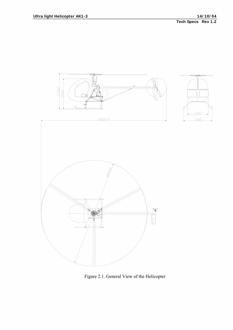
2.1 CONSTRUCTIONS AND LAY-OUT DIAGRAM 2.1.1. The AK1-3 helicopter (Fig. 2.1) is a fabricated structure with a 3-bladed rotor and a
2-bladed anti-torque rotor. 2.2. HELICOPTER TYPE AND DESIGNATION 2.2.1. The helicopter falls into the normal category of light aircraft, and is designated to
fulfill the following tasks: - Patrolling (power lines, canals, pipelines, highways, hard-to-reach border regions); - Agriculture (pollination, spraying, sowing, animal watch); - Forest and wild animal protection; - Advertising; - Searching; - Aerial inspection (aerial photography, geological and fishing exploration); - Flying lessons for both military and civilian students; - Participation in aviation sports competitions.
2.3 ENGINE TYPE AND QUANTITY 2.3.1. The helicopter uses one piston liquid-cooled engine produced by the Japanese
Subaru, EJ-25 model, which is installed behind the cockpit. 2.4. DEVELOPER AND MODEL 2.4.1 The developer is Аэрокоптер Ltd., Ukraine. Model: AK1-3 helicopter. 2.5. CREW PERSONNEL AND HELICOPTER’S TRANSPORTING CAPABILITIES 2.5.1. Depending on its mission, the helicopter crew may include one or two persons:
- A pilot; - An observer (operator, trainee).
2.5.2. The helicopter is capable of transporting one passenger. 2.6 OUTER COATING
Coating and proofing of the helicopter’s outer surfaces, engine, and components are carried out according to the existing norms and guarantee successful exploitation under different climatic conditions.
Ultra light Helicopter AK1-3 14/10/04 Tech Specs Rev 1.2
Figure 2.1. General View of the Helicopter
Ultra light Helicopter AK1-3 14/10/04 Tech Specs Rev 1.2
MAIN FEATURES 3.1. ESTIMATED WEIGHTS 3.1.1. Maximum takeoff weight 650 kg 3.1.2. Maximum weight of loaded helicopter without fuel 590 kg 3.1.3. Maximum payload weight (including pilot and fuel) 270 kg 3.1.5. Empty helicopter weight 380 kg 3.1.6. Helicopter equipment weight, including: - crew parachutes (2) 20 kg
- crew (2 persons) 160 kg - protective helmets (2) 2.3 kg - engine oil 3 kg - unusable fuel 0,5 kg
З.2. REGULATION CURVES
Table 3.1
REGULATING DATA
Deflection # Item Deflecting
direction degrees mm Note
1. Slope angle of rotor axis Forward Left
Right
0 0 0
-- --
2. Angle of rotor pitch min
max
0
14° --
Crosshead traverse 24±1mm
3. Slope angles of wobble plate and control rod traverses that correspond to them
Forward Backward
Right Left
5°±20′ 4°±20′ 4°±20′ 4°±20′
130 110 110 110
--
4. Angle of incidence of anti-torque rotor a) with right pedal stopped b) with both pedals in neutral c) with left pedal stopped
--
+20°±20′
+5°±20′ -10°±20′
-- --
5. Deflection of pedals from neutral -- --
60±2 --
Ultra light Helicopter AK1-3 14/10/04 Tech Specs Rev 1.2
6. Control rod labor not more than 3 kg.
--
-- --
7. Foot pedals labor with anti-torque rotor attached not more than 7 kg.
--
-- --
Labor measurements are taken in the middle part of rods and footboards with TNV
8. Labor for the Lead/Gas shift, with normal shifting from one extreme position to the other taking no less than 20 seconds, not more than 5 kg.
-- -- --
> +15°.
3.3. CENTERING CHARACTERISTICS 3.3.1 Centering capacity during takeoff, flight, and landing: - noseheaviness, before the rotor axis 38 mm
- bowheaviness, behind the rotor axis 59 mm 3.3.2. Longitudinal centering for an empty helicopter 173mm 3.4. FLIGHT CHARACTERISTICS 3.4.1. Maximum ground airspeed 186 km/h 3.4.2. Ground cruising airspeed 160 km/h 3.4.3. Rotation speed around vertical axis during hovering < 45 degrees/s 3.4.4. Static ceiling for hovering 1500 m 3.4.5. Maximum ground climbing capacity 8 m/s 3.4.6. Minimal vertical descent rate while floating in autorotation regime at VDesc=90 km/h 7,4 m/s 3.4.7. Flight duration at Н=0 - 500 m with 5 % necessary fuel supply 3 hrs 3.4.8. Practical ground range ability with 5 % necessary fuel supply 450 km 3.4.9. Maximum exploitation load range +0.5…+2.5
Ultra light Helicopter AK1-3 14/10/04 Tech Specs Rev 1.2
3.5. GEOMETRICAL DIMENSIONS 3.5.1. Tail unit Keel area 0.267 m2
Stabilizer area 0.15 m2
3.5.2. Cockpit Internal dimensions: - length 1.5 m
- width 1.4 m - height 1.2 m Entrance door 0.95х1 m 3.5.3. Undercarriage - length 1.8 m
- distance between skids 1.6 m 3.6. ENGINE INFORMATION 3.6.1. Engine quantity, type, and marking: one horizontal piston four-cylinder four-act liquid-cooled engine Subaru EJ-25. 3.6.2. General characteristics of Subaru EJ-25: Engine working volume 2500 cm3
Engine power 165 horsepower (121 kW)
Engine dry weight 110 kg Overall dimensions of the engine: - length 0.8 m
- height 0.7 m - width 0.5 m 3.6.3. Subaru EJ-25 operating limitations: Continuous working time in regime - unlimited 3.6.4. Engine mounting units: - three shock-absorbing pads, of which two are
on the engine mounting, and one near the flywheel. 3.7. GEOMETRICAL ADJECTIVES OF THE ROTORS 3.7.1. Geometrical adjectives of the rotor - rotor diameter 6.84 m - blade number 3 - carrier blade chord 0.17 m - blade profile NACA 63012/63015 - outline blade shape rectangular - peripheral velocity of blade tip 205 m/s - duty factor 0.0475 3.7.2. Geometrical adjectives of the anti-torque rotor
- rotor diameter 1.28 m - blade number 2
Ultra light Helicopter AK1-3 14/10/04 Tech Specs Rev 1.2
- carrier blade chord 0.115 mm - blade profile NACA 63012 - peripheral velocity of blade tip 186.3 m/s - duty factor 0.1144 3.8. ALTITUDE RANGES, OPERATING TEMPERATURE RANGES, AND
WEATHER CONDITIONS
3.8.1. Temperature range: –30…+30°С 3.8.2. Altitude range (limited by the absence of oxygen equipment) 0…3000 m 3.8.3. The helicopter is designated for use under normal weather conditions in daylight
according to visual flight rules in any latitudes. 3.9. LIFETIME The overall technical lifetime (design life) of the helicopter is 2,000 flight hours.
The passing of design life is warranted by revisions and checkups that are included in regular technical service.
Ultra light Helicopter AK1-3 14/10/04 Tech Specs Rev 1.2
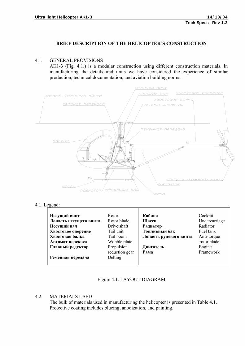
BRIEF DESCRIPTION OF THE HELICOPTER’S CONSTRUCTION 4.1. GENERAL PROVISIONS АК1-3 (Fig. 4.1.) is a modular construction using different construction materials. In
manufacturing the details and units we have considered the experience of similar production, technical documentation, and aviation building norms.
4.1. Legend:
Несущий винт Rotor Лопасть несущего винта Rotor blade Несущий вал Drive shaft Хвостовое оперение Tail unit Хвостовая балка Tail boom Автомат перекоса Wobble plate Главный редуктор Propulsion reduction gear Ременная передача Belting
Кабина Cockpit Шасси Undercarriage Радиатор Radiator Топливный бак Fuel tank Лопасть рулевого винта Anti-torque rotor blade Двигатель Engine Рама Framework
Figure 4.1. LAYOUT DIAGRAM
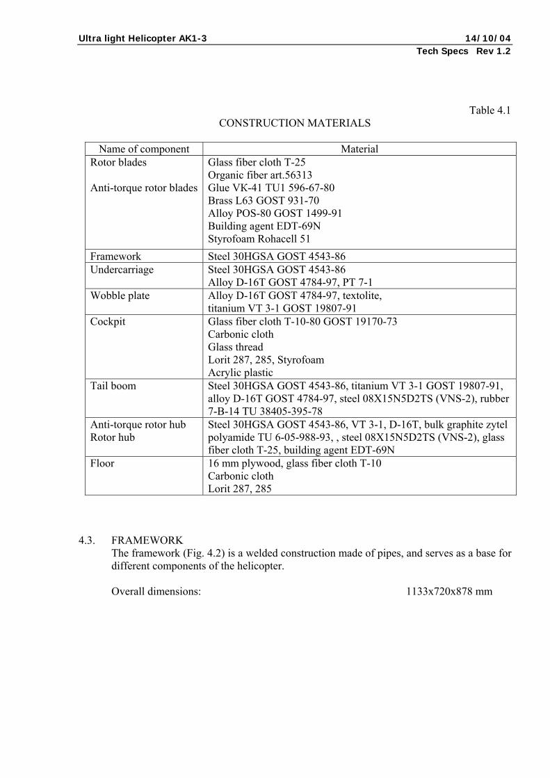
4.2. MATERIALS USED The bulk of materials used in manufacturing the helicopter is presented in Table 4.1. Protective coating includes blueing, anodization, and painting.
Ultra light Helicopter AK1-3 14/10/04 Tech Specs Rev 1.2
Table 4.1
CONSTRUCTION MATERIALS
Name of component Material Rotor blades Anti-torque rotor blades
Glass fiber cloth Т-25 Organic fiber art.56313 Glue VК-41 TU1 596-67-80 Brass L63 GOST 931-70 Alloy POS-80 GOST 1499-91 Building agent EDT-69N Styrofoam Rohacell 51
Framework Steel 30HGSA GOST 4543-86 Undercarriage Steel 30HGSA GOST 4543-86
Alloy D-16Т GOST 4784-97, PТ 7-1 Wobble plate Alloy D-16Т GOST 4784-97, textolite,
titanium VТ 3-1 GOST 19807-91 Cockpit Glass fiber cloth Т-10-80 GOST 19170-73
Carbonic cloth Glass thread Lorit 287, 285, Styrofoam Acrylic plastic
Tail boom Steel 30HGSA GOST 4543-86, titanium VТ 3-1 GOST 19807-91, alloy D-16Т GOST 4784-97, steel 08Х15N5D2ТS (VNS-2), rubber 7-В-14 ТU 38405-395-78
Anti-torque rotor hub Rotor hub
Steel 30HGSA GOST 4543-86, VТ 3-1, D-16Т, bulk graphite zytel polyamide ТU 6-05-988-93, , steel 08Х15N5D2ТS (VNS-2), glass fiber cloth Т-25, building agent EDT-69N
Floor 16 mm plywood, glass fiber cloth Т-10 Carbonic cloth Lorit 287, 285
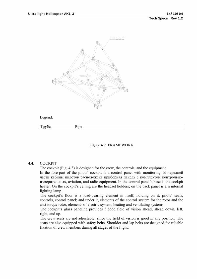
4.3. FRAMEWORK
The framework (Fig. 4.2) is a welded construction made of pipes, and serves as a base for different components of the helicopter. Overall dimensions: 1133х720х878 mm
Ultra light Helicopter AK1-3 14/10/04 Tech Specs Rev 1.2
Legend: Труба Pipe
Figure 4.2. FRAMEWORK
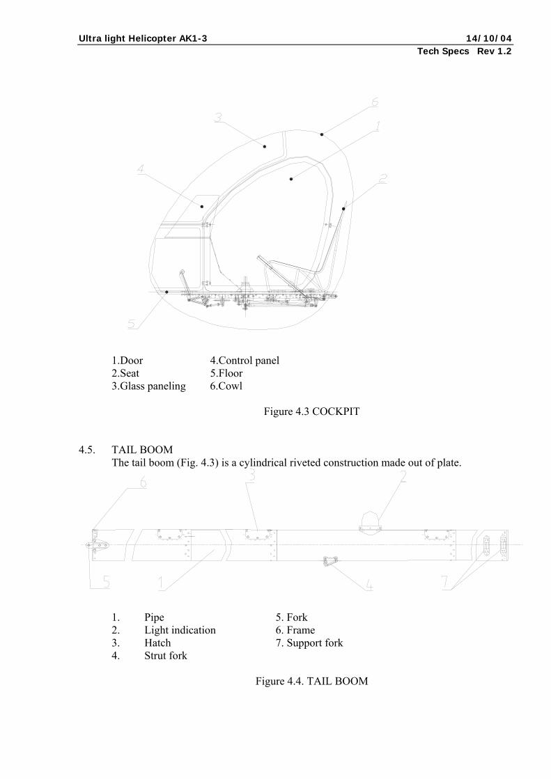
4.4. COCKPIT The cockpit (Fig. 4.3) is designed for the crew, the controls, and the equipment. In the fore-part of the pilots’ cockpit is a control panel with monitoring, В передней части кабины пилотов расположена приборная панель с комплектом контрольно-измерительных, aviation, and radio equipment. In the control panel’s base is the cockpit heater. On the cockpit’s ceiling are the headset holders; on the back panel is a n internal lighting lamp. The cockpit’s floor is a load-bearing element in itself, holding on it: pilots’ seats, controls, control panel; and under it, elements of the control system for the rotor and the anti-torque rotor, elements of electric system, heating and ventilating systems. The cockpit’s glass paneling provides f good field of vision ahead, ahead down, left, right, and up. The crew seats are not adjustable, since the field of vision is good in any position. The seats are also equipped with safety belts. Shoulder and lap belts are designed for reliable fixation of crew members during all stages of the flight.
Ultra light Helicopter AK1-3 14/10/04 Tech Specs Rev 1.2
1.Door 4.Control panel 2.Seat 5.Floor 3.Glass paneling 6.Cowl
Figure 4.3 COCKPIT
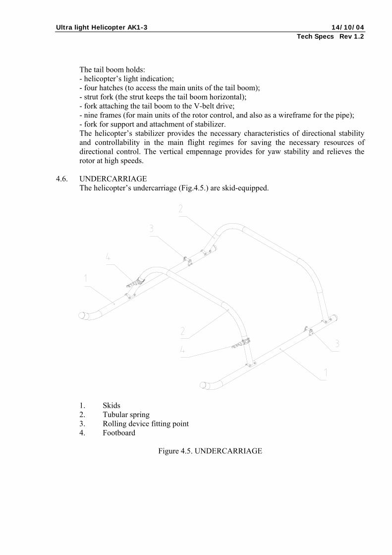
4.5. TAIL BOOM The tail boom (Fig. 4.3) is a cylindrical riveted construction made out of plate.
1. Pipe 5. Fork 2. Light indication 6. Frame 3. Hatch 7. Support fork 4. Strut fork
Figure 4.4. TAIL BOOM
Ultra light Helicopter AK1-3 14/10/04 Tech Specs Rev 1.2
The tail boom holds: - helicopter’s light indication; - four hatches (to access the main units of the tail boom); - strut fork (the strut keeps the tail boom horizontal); - fork attaching the tail boom to the V-belt drive; - nine frames (for main units of the rotor control, and also as a wireframe for the pipe); - fork for support and attachment of stabilizer. The helicopter’s stabilizer provides the necessary characteristics of directional stability and controllability in the main flight regimes for saving the necessary resources of directional control. The vertical empennage provides for yaw stability and relieves the rotor at high speeds.
4.6. UNDERCARRIAGE The helicopter’s undercarriage (Fig.4.5.) are skid-equipped.
1. Skids 2. Tubular spring 3. Rolling device fitting point 4. Footboard
Figure 4.5. UNDERCARRIAGE
Ultra light Helicopter AK1-3 14/10/04 Tech Specs Rev 1.2
The skids are made of jointless pipes. For softening the impact during incorrect landing, the helicopter is equipped with springs made of bent pipes. The skids are equipped with holders for the detachable rolling device for land transportation of the helicopter within airports or hangars.
To make getting into the cockpit more comfortable, the footboards are attached to the fore springs.
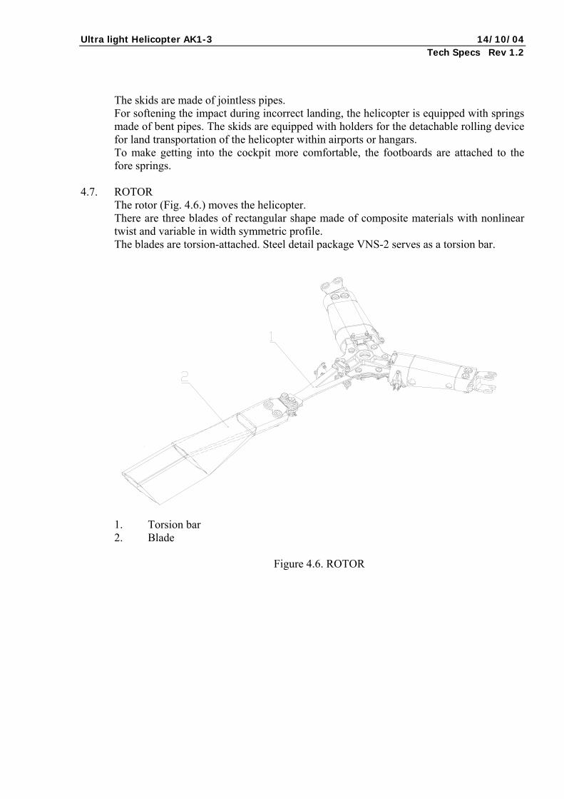
4.7. ROTOR
The rotor (Fig. 4.6.) moves the helicopter. There are three blades of rectangular shape made of composite materials with nonlinear twist and variable in width symmetric profile. The blades are torsion-attached. Steel detail package VNS-2 serves as a torsion bar.
1. Torsion bar 2. Blade
Figure 4.6. ROTOR
Ultra light Helicopter AK1-3 14/10/04 Tech Specs Rev 1.2
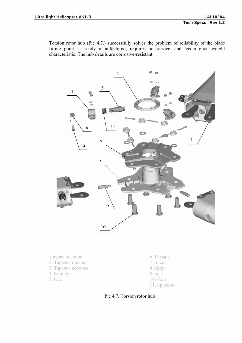
Torsion rotor hub (Pic 4.7.) successfully solves the problem of reliability of the blade fitting point, is easily manufactured, requires no service, and has a good weight characteristic. The hub details are corrosive-resistant.
3
2
10
7
54
6
9
118
1
1.рукав в сборе 6. Штырь 2. Тарелка нижняя 7. диск 3. Тарелка верхняя 8.сфера 4. Корпус 9. ось 5. Ось 10. болт
11. пружина
Pic 4.7. Torsion rotor hub
Ultra light Helicopter AK1-3 14/10/04 Tech Specs Rev 1.2
1
6
12 5 2
11
9
3
410
13
7
8
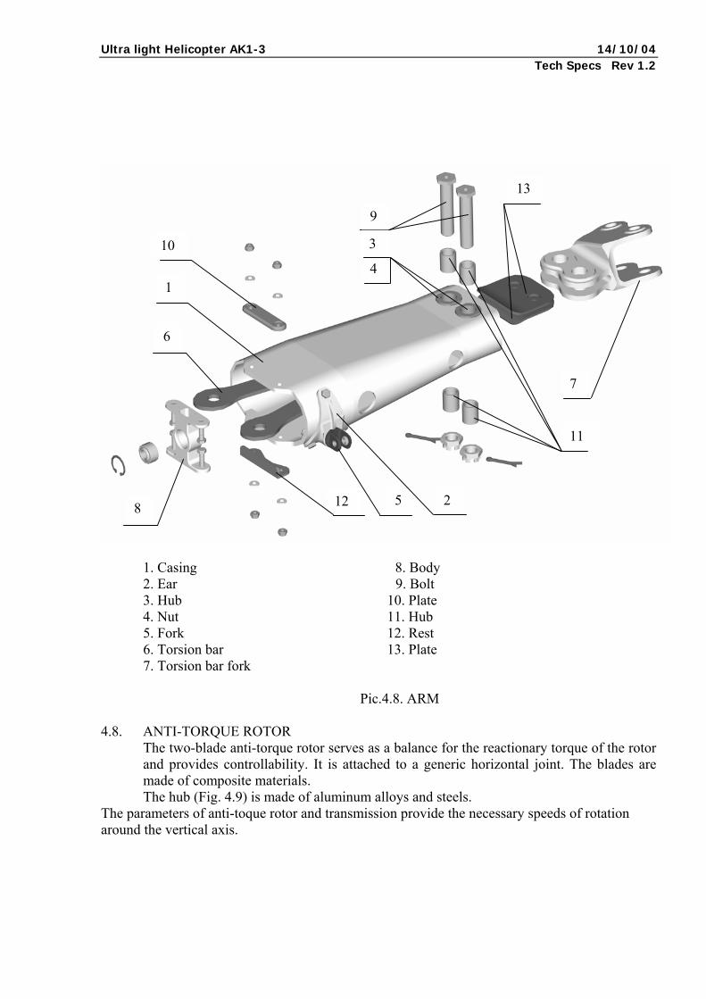
1. Casing 8. Body 2. Ear 9. Bolt 3. Hub 10. Plate 4. Nut 11. Hub 5. Fork 12. Rest 6. Torsion bar 13. Plate 7. Torsion bar fork
Pic.4.8. ARM 4.8. ANTI-TORQUE ROTOR
The two-blade anti-torque rotor serves as a balance for the reactionary torque of the rotor and provides controllability. It is attached to a generic horizontal joint. The blades are made of composite materials. The hub (Fig. 4.9) is made of aluminum alloys and steels.
The parameters of anti-toque rotor and transmission provide the necessary speeds of rotation around the vertical axis.
Ultra light Helicopter AK1-3 14/10/04 Tech Specs Rev 1.2
1
12 3
2
2
4
4
8
8
7
10 9 5
6
11 11
12
10
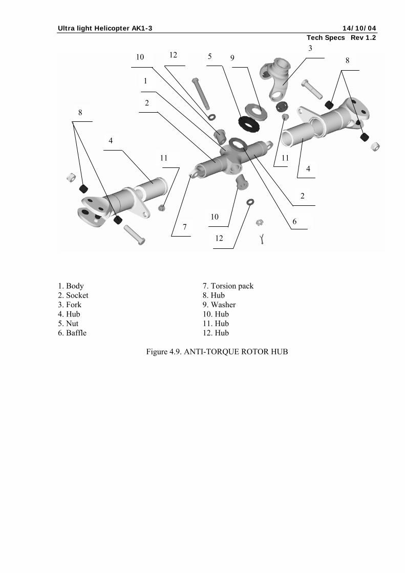
1. Body 7. Torsion pack 2. Socket 8. Hub 3. Fork 9. Washer 4. Hub 10. Hub 5. Nut 11. Hub 6. Baffle 12. Hub
Figure 4.9. ANTI-TORQUE ROTOR HUB
Ultra light Helicopter AK1-3 14/10/04 Tech Specs Rev 1.2
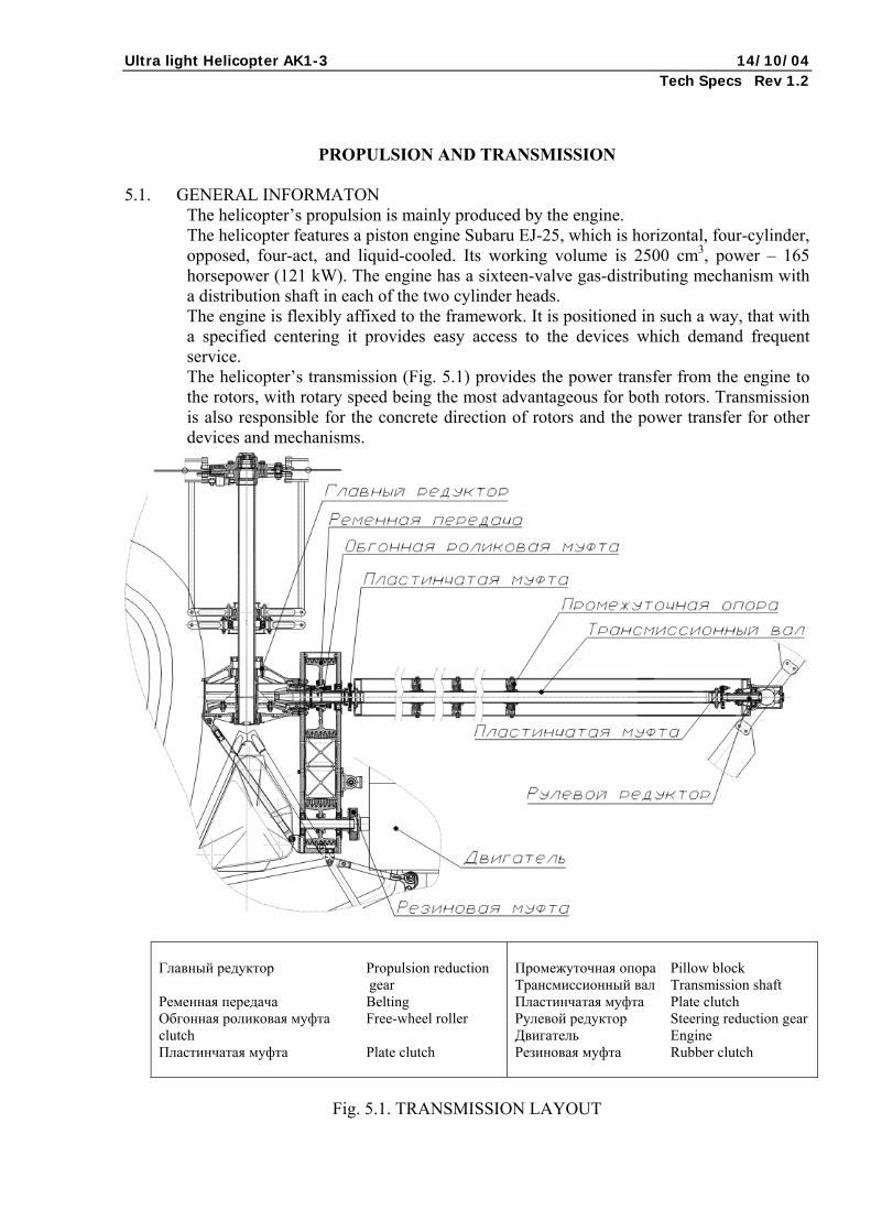
PROPULSION AND TRANSMISSION 5.1. GENERAL INFORMATON
The helicopter’s propulsion is mainly produced by the engine. The helicopter features a piston engine Subaru EJ-25, which is horizontal, four-cylinder, opposed, four-act, and liquid-cooled. Its working volume is 2500 cm3, power – 165 horsepower (121 kW). The engine has a sixteen-valve gas-distributing mechanism with a distribution shaft in each of the two cylinder heads. The engine is flexibly affixed to the framework. It is positioned in such a way, that with a specified centering it provides easy access to the devices which demand frequent service. The helicopter’s transmission (Fig. 5.1) provides the power transfer from the engine to the rotors, with rotary speed being the most advantageous for both rotors. Transmission is also responsible for the concrete direction of rotors and the power transfer for other devices and mechanisms.
Главный редуктор Propulsion reduction gear Ременная передача Belting Обгонная роликовая муфта Free-wheel roller clutch Пластинчатая муфта Plate clutch
Промежуточная опора Pillow block Трансмиссионный вал Transmission shaft Пластинчатая муфта Plate clutch Рулевой редуктор Steering reduction gear Двигатель Engine Резиновая муфта Rubber clutch
Fig. 5.1. TRANSMISSION LAYOUT
Ultra light Helicopter AK1-3 14/10/04 Tech Specs Rev 1.2
5.2. ENGINE
5.2.1. The engine’s design philosophy: - pyramidal combustors with spark-plug in the center and four valves (2 exhaust, 2 admission ones) for one cylinder; - valve-levers are equipped with gap hydro-compensators; - distribution shafts (in the left and right heads) are activated by one cogged belt, which also activates the cooling system pump situated in the left engine half-block. The cogged belt’s tension is regulated automatically; - the supporting crankshaft is positioned in the five main-bearings; - the cylinder block is made of aluminum alloy through pressure die casting and is equipped with dry cast-iron liners mounted into the floor of the block.
5.2.2. Cooling system. The propulsion cooling system is liquid-based. The cooling system radiator is situated in the lower part of the frame and forcibly cooled by the airflow created by two electric fans with step-by-step activation, mounted on the fan baffle above the radiator. For air supply from the approach flow, there is a fresh-air intake.
5.2.3. Engine starting system The engine starting system is regular. The engine is equipped with an electric starter, a starter relay, and a starter button. The engine is started from a storage battery with the capacity of 60 Å/hr. The storage battery is charged by a 12 V 70 Å generator, whicj includes a voltage control box and an electronic rectifier.
5.3. TRANSMISSION
5.3.1. The belting is responsible for power transfer through the flexible rubber clutch and
the free-wheel roller clutch from the engine to the reduction gear drive shaft. The belt is a V-belt. There are seven belts.
5.3.2. The propulsion reduction gear is single, transmitting the rotational moment from the engine to the rotor shaft. The transmission is conical, with a circular cog. The propulsion reduction gear has one entrance. The power is transmitted from the engine through the belting and the free-wheel clutch to the control shaft and the rotor shaft. The control shaft, through the flexible plate clutch, transfers the power to the transmission shaft, mounted on three pillow blocks. The transmission shaft, through the plate clutch, transfers the tension to the steering reduction gear. The reduction gear uses bubbling oiling. The oil is filled through the filler neck, which is closed with a breather lid. Oil level monitoring is done with the help of the level indicator. To control the oil temperature, there is an oil-temperature sensor in the propulsion reduction gear, with indication appearing on the pilot’s control panel.
Ultra light Helicopter AK1-3 14/10/04 Tech Specs Rev 1.2
5.3.3. The steering reduction gear is designated for rotating the anti-torque rotor. It has a 90° transmission. It has two conical cog-wheels with circular cogs, which are mounted on the frictionless bearings. The reduction gear case is made of aluminum alloy, and is attached to the tail boom’s mainframe. The anti-torque rotor collective pitch control system is mounted on the takeoff shaft of the steering reduction gear.
5.3.4. The anti-torque axis shaft transmits power from the propulsion reduction gear to the steering reduction gear. The shaft consists of a pipe with plate clutches mounted on one end. It has three fulcrums, which include closed frictionless bearings in rubber casings. The units’ mounting is done with the help of frames positioned in the tail boom.
5.4. NOISE LEVEL
The noise level produced by the helicopter is in compliance with the ICAO and environmental norms. Appendix 16 of the International Civil Aircraft Convention, Aviation Noise, vol. 1, chapter 3.
Ultra light Helicopter AK1-3 14/10/04 Tech Specs Rev 1.2
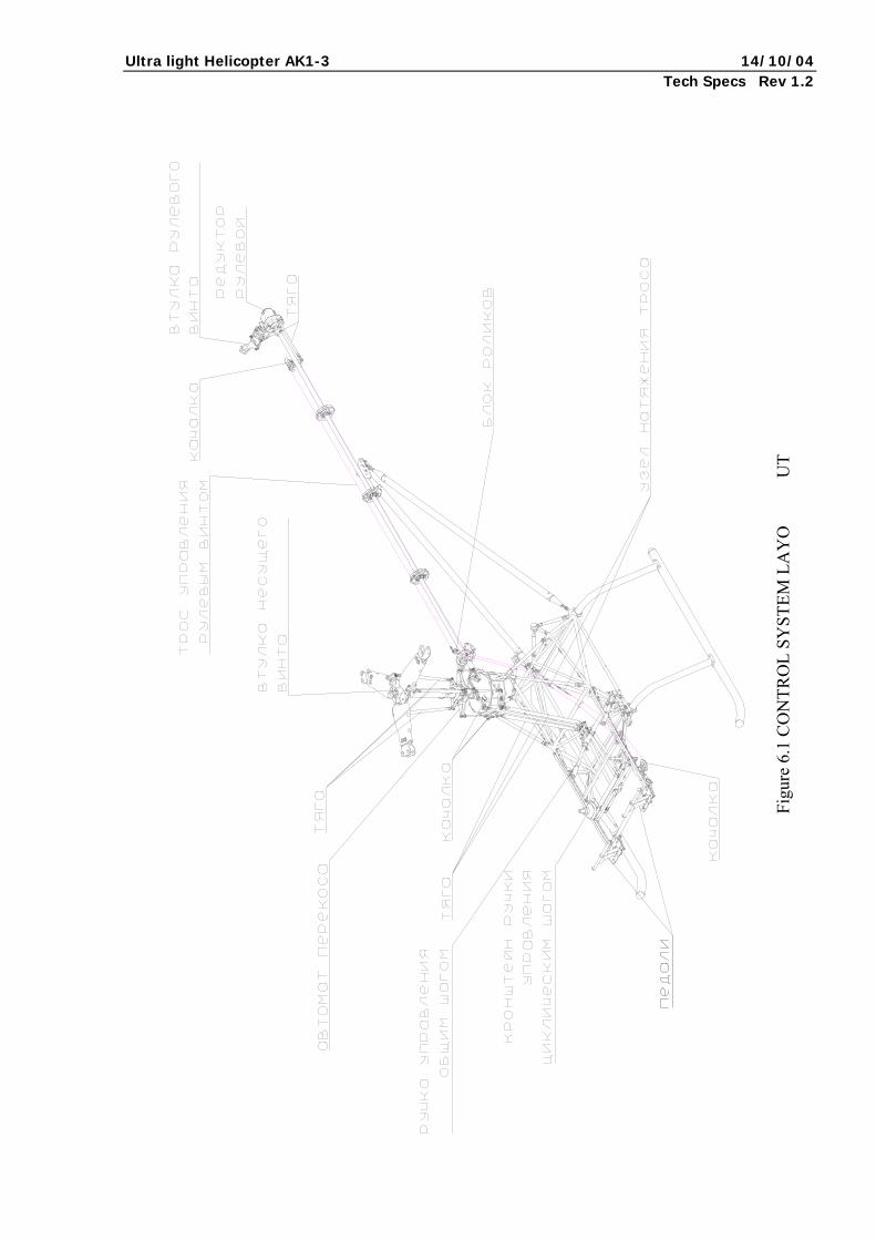
CONTROLLING SYSTEM 6.1. GENERAL PROVISIONS
To change the helicopter’s flight configuration and counteract external disturbance, the helicopter uses an unassisted control system, with the help of which the pilot, operating the rotor and the anti-torque rotor, provides the helicopter’s necessary position. The control system is mechanical (Fig. 6.1). The control linkages are rigid in the circular and collective pitch channels, and mixed in the itinerary channel.
6.2. WOBBLE PLATE The wobble plate is the most responsible device in the controlling system. The wobble plate is a mechanism which provides simultaneous angle of pitch change for all blades and circular pitch change depending on the blades’ azimuthal location. Moving the wobble plate along the rotor’s rotational axis, with the control levers turning the blades to the same value, makes the blades’ angle of pitch change. Tilting the wobble plate relative to the rotor’s rotational axis does the blades’ circular pitch change. Rotating a tilted plate leads to displacement of the rotor thrusts, which connect the plate with the blade control levers, making the plates rotate relative to their longitudinal axes, which changes the azimuth pitch. The wobble plate consists of rotating and nonrotating movable rings. It is mounted to the rotor shaft with a spherical joint, which slides along the shaft.
6.3. CONTROLS The controls are situated in the cockpit and are divided into the main and auxiliary ones. The main controls include the circular pitch knob, the rotor collective pitch lever, and the airway control pedal. The auxiliary controls include the cockpit heater door control knobs. The engine power correction twist-knob is mounted on the rotor collective pitch lever. The change in collective pitch automatically changes the throttle plate position, which means the engine power correction twist-knob does not have to be used in flight.
Ultra light Helicopter AK1-3 14/10/04 Tech Specs Rev 1.2
Figu
re 6
.1 C
ON
TRO
L SY
STEM
LA
YO
U
T
Ultra light Helicopter AK1-3 14/10/04 Tech Specs Rev 1.2
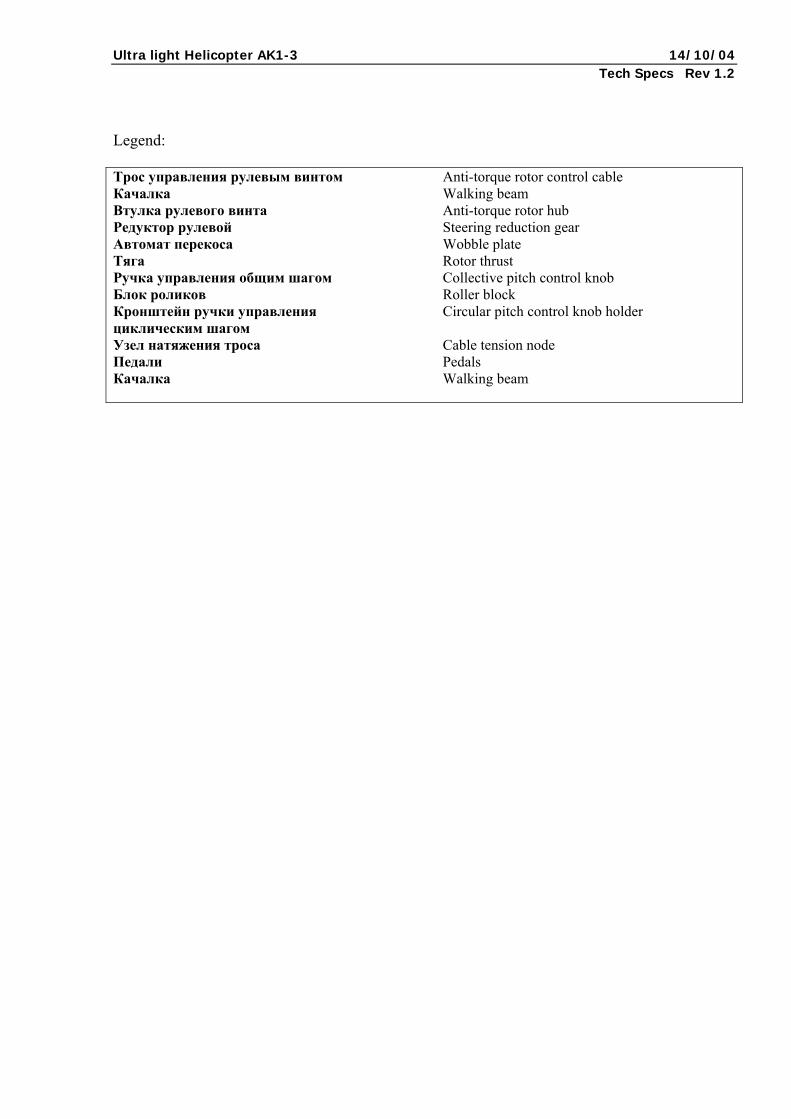
Legend: Трос управления рулевым винтом Anti-torque rotor control cable Качалка Walking beam Втулка рулевого винта Anti-torque rotor hub Редуктор рулевой Steering reduction gear Автомат перекоса Wobble plate Тяга Rotor thrust Ручка управления общим шагом Collective pitch control knob Блок роликов Roller block Кронштейн ручки управления Circular pitch control knob holder циклическим шагом Узел натяжения троса Cable tension node Педали Pedals Качалка Walking beam
Ultra light Helicopter AK1-3 14/10/04 Tech Specs Rev 1.2
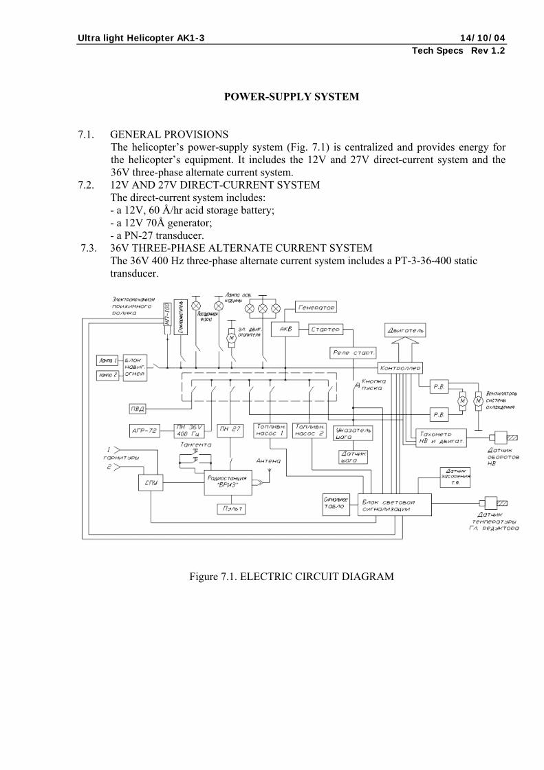
POWER-SUPPLY SYSTEM 7.1. GENERAL PROVISIONS
The helicopter’s power-supply system (Fig. 7.1) is centralized and provides energy for the helicopter’s equipment. It includes the 12V and 27V direct-current system and the 36V three-phase alternate current system.
7.2. 12V AND 27V DIRECT-CURRENT SYSTEM The direct-current system includes: - a 12V, 60 Å/hr acid storage battery; - a 12V 70Å generator; - a PN-27 transducer.
7.3. 36V THREE-PHASE ALTERNATE CURRENT SYSTEM The 36V 400 Hz three-phase alternate current system includes a PT-3-36-400 static transducer.
Figure 7.1. ELECTRIC CIRCUIT DIAGRAM
Ultra light Helicopter AK1-3 14/10/04 Tech Specs Rev 1.2
Legend: Электромеханизм прижимного ролика Clamping roller electric mechanism Стеклоочиститель Screen wiper Лампа освещения кабины Cockpit lighting lamp Электрический двигатель отопителя Heater electric engine Генератор Generator Стартер Starter Реле старт Start relay Двигатель Engine Лампа Lamp Блок навигационных огней Navigation lights block Контроллер Control unit Кнопка пуска Start button Вентиляторы системы охлаждения Cooling system fans Топливный насос Fuel pump Указатель шага Pitch indicator Тахометр НВ и двигателя Anti-torque rotor and engine tachometer Датчик оборотов НВ ATR rotation sensor Гарнитуры Headsets Тангента Flap Антенна Aerial Датчик шага Pitch sensor Датчик засорения Blockage sensor Радиостанция «Бриз» Breeze radio station Пульт Control panel Сигнальное табло Annunciation panel Блок световой сигнализации Annunciation unit Датчик температуры главного редуктора Propulsion reduction gear temperature sensor
Ultra light Helicopter AK1-3 14/10/04 Tech Specs Rev 1.2
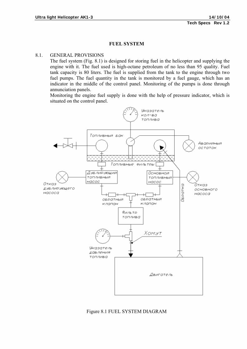
FUEL SYSTEM 8.1. GENERAL PROVISIONS
The fuel system (Fig. 8.1) is designed for storing fuel in the helicopter and supplying the engine with it. The fuel used is high-octane petroleum of no less than 95 quality. Fuel tank capacity is 80 liters. The fuel is supplied from the tank to the engine through two fuel pumps. The fuel quantity in the tank is monitored by a fuel gauge, which has an indicator in the middle of the control panel. Monitoring of the pumps is done through annunciation panels. Monitoring the engine fuel supply is done with the help of pressure indicator, which is situated on the control panel.
Figure 8.1 FUEL SYSTEM DIAGRAM
Ultra light Helicopter AK1-3 14/10/04 Tech Specs Rev 1.2
Legend: Указатель количества топлива Fuel quantity indicator Топливный бак Fuel tank Аварийный остаток Emergency resource Топливные фильтры Fuel filters Отказ дублирующего насоса Backup pump failure Дублирующий топливный насос Backup fuel pump Основной топливный насос Main fuel pump Отказ основного насоса Main pump failure Обратный клапан Check valve Обратка Feedback Фильтр топлива Fuel filter Хомут Clamp Указатель давления топлива Fuel pressure indicator Двигатель Engine
Ultra light Helicopter AK1-3 14/10/04 Tech Specs Rev 1.2
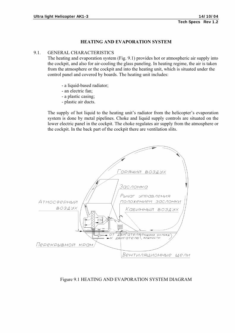
HEATING AND EVAPORATION SYSTEM 9.1. GENERAL CHARACTERISTICS
The heating and evaporation system (Fig. 9.1) provides hot or atmospheric air supply into the cockpit, and also for air-cooling the glass paneling. In heating regime, the air is taken from the atmosphere or the cockpit and into the heating unit, which is situated under the control panel and covered by boards. The heating unit includes:
- a liquid-based radiator; - an electric fan; - a plastic casing; - plastic air ducts.
The supply of hot liquid to the heating unit’s radiator from the helicopter’s evaporation system is done by metal pipelines. Choke and liquid supply controls are situated on the lower electric panel in the cockpit. The choke regulates air supply from the atmosphere or the cockpit. In the back part of the cockpit there are ventilation slits.
Figure 9.1 HEATING AND EVAPORATION SYSTEM DIAGRAM
Ultra light Helicopter AK1-3 14/10/04 Tech Specs Rev 1.2
Legend: Горячий воздух Hot air Заслонка Choke Атмосферный воздух Atmospheric air Рычаг управления положением заслонки Choke control lever Кабинный воздух Cockpit air Подача охлаждённой жидкости от двигателя/к двигателю Cool liquid supply to/from the engine Перекрывной кран Shutoff valve Вентиляционные щели Ventilation slits
Ultra light Helicopter AK1-3 14/10/04 Tech Specs Rev 1.2
GENERAL PROCESS TECHNOLOGY CHARACTERISTICS
10.1. Process technology development is basic in preparing the AK1-3 helicopter for
production. In developing process technology the source information was considered: design drawings of details, technical precision requirements, surface roughness parameter, and other quality requirements, such as yield. Technological processes were developed with regard to their regulation. This includes estimate and norm-setting in completing the work process; estimating the work category; estimating the material consumption norm.
10.1.1. Technological processes in part cutting Before developing the technological processes for part cutting, each specific part’s construction and function in a unit (mechanism) was examined, and manufacturability analyses were carried out. Design drawings of details contain all the data necessary for full understanding of the detail’s manufacture and control, and comply with the existing standards.
10.1.2. Technological processes in part assembly The technological processes of part assembly were based on assembly drawings, inspection specifications, and reference materials. The assembly diagrams based on assembly drawings make the work process easier. There are subassembly diagrams for the elements which are dismounted unsorted and are parts of the article. And the parts dismounted separately are directly a part of the general assembly. The technological processes of part cutting and assembly are presented as flow-sheets and operational sheets.