Embed Size (px)
Citation preview
Section A REV. 0/04-03-03
IntroductionPg. 1
Lancair International Inc., Represented by Neico Aviation Inc., Copyright © 2000 , Redmond, OR 97756
IV-P
Propjet
Lancair Propjet Supplement
1. Introduction
2. Parts List
3. Construction Procedure
A. FIREWALL RETROFIT INSTALLATION
B. ENGINE MOUNT INSTALLATION
C. ENGINE INSTALLATION
D. COWLING INSTALLATION
E. BELLY TANK INSTALLATION
F. NOSE WHEEL ASSEMBLY
G. NOSE GEAR DOORS
H. FIREWALL LAYOUT
I. OIL COOLER
J. AIR INTAKE PLENUMS
K. ENGINE CONTROLS - THROTTLE QUADRANT - INSTRUMENT PANELS
L. FUEL SYSTEMS
M. RUDDER CONTROLS
N. BATTERY INSTALLATION
O. PRESSURIZATION SYSTEM
1. INTRODUCTION
The Lancair PropJet supplement is supplied with the Lancair IV-P manual. The basic airframe of the
two aircraft is the same. The main differences are firewall forward and the belly tank used on the PropJet.
Chapters 1 through 11 are the same for both aircraft. Follow Chapter 12 except the instructions relating to
the firewall. Follow chapter 13 through 22 with the exception of section I of Chapter 15. Refer to section M
of this supplement for the rudder pedal installation. There are some slight differences in Chapter 23 which
will be pointed out in this supplement. Follow chapters 24 through 26. The fuel system in chapter 27 is also
slightly different and differences will also be pointed out in this supplement. Follow chapters 28, 29, and 30.
Omit the firewall forward chapter 31. The wiring chapter, chapter 32 is slightly different. Please consult
with Lancair Avionics. Follow chapter 33.
Note that the supplement shows the retrofit installation in section A. The retrofit only applies to kits with the
retrofit option. All regular propjet firewalls already have the PropJet firewall installed.
A. RECOMMENDED BACKGROUND INFORMATION
This manual provides detailed step-by-step instructions for assembling the Lancair Prop Jet Kit.
Hands on experience with fiberglass construction techniques and various hand tools is assumed. If you
do not have that background knowledge, the study of other, more basic texts will be necessary.
Suggested references are given on the following pages.
EAAWhittman Airfield
Oshkosh, WI 54903-3065920- 426-4800www.eaa.org
W A R N I N GIF DURING CONSTRUCTION YOU HAVE ANY QUESTION OR DOUBT ABOUTA CONSTRUCTION PROCEDURE, DO NOT CONTINUE UNTIL YOU HAVEOBTAINED THE NECESSARY INFORMATION OR SKILL. IF YOU ARE NOTKNOWLEDGEABLE IN FIBERGLASS OR OTHER REQUIRED CONSTRUC-TION TECHNIQUES OR TOOLS, OBTAIN THAT KNOWLEDGE BEFORE START-ING CONSTRUCTION.
NO CHANGE TO THE AIRCRAFT DESIGN OR SPECIFIED CONSTRUCTIONPROCEDURES IS PERMITTED. SUCH CHANGES MAY ADVERSELY EFFECTTHE AIRCRAFT'S STRUCTURAL INTEGRITY OR AIRWORTHINESS.
FAILURE TO FOLLOW THIS WARNING AND OTHERS FOUND THROUGH-OUT THIS MANUAL COULD RESULT IN COMPONENT FAILURE AND LOSSOF AIRCRAFT CONTROL CAUSING SERIOUS INJURY OR DEATH.
Note:
(*) Parts Optional - available through Kit Components Inc.
(**) Parts not included with Propjet Kit - supplied with retro fit option
Introduction
Section A REV. 0/04-03-03
IntroductionPg. 2
Lancair International Inc., Represented by Neico Aviation Inc., Copyright © 2000 , Redmond, OR 97756
IV-P
Propjet
COMPOSITE MATERIALS PRACTICE KIT: This kit contains various materials with which to practice and
develop your fiberglass construction technique. It also contains a copy of Burt Rutan's Moldless
Composite Sandwich Homebuilt Aircraft Construction book described below. This kit is recom-
mended for all newcomers to fiberglass construction and is a good refresher for others.
MOLDLESS COMPOSITE SANDWICH HOMEBUILT AIRCRAFT CONSTRUCTION: by Burt Rutan.
Though the hot wire shaping technique covered by this book is not used on the Lancair, this book has a
great deal of other excellent, basic fiberglass construction information. Highly recommended.
BUILDING RUTAN COMPOSITES: This is a video tape by Burt Rutan. Although it covers some techniques
not used on the Lancair, it shows you how the experts handle fiberglass construction. Highly recom-
mended.
COMPOSITE CONSTRUCTION FOR HOMEBUILT AIRCRAFT: by Jack Lambie. This book is an
additional source of useful construction information and goes into the theory of aircraft design as well.
Jack's Chapter 9, Safety in Working With Composite Construction, is particularly worth reading. This
book would be a useful addition to the above.
KITPLANE CONSTRUCTION: by Ron Wenttaja. This is a resourceful book with information on metal,
wood, and composites.
The above publications, practice kit and video tape are available from:
Aircraft Spruce and Specialty Company
225 Airport Circle
Corona, CA 91720
Toll free order line (877) 477-7823
Customer sevice (800) 861-3192
Fax (909) 372-0555
Email: [email protected]
The following recommended books largely describe aspects of aircraft construction other than working
with fiberglass:
FIREWALL FORWARD: by Tony Bingelis is packed with vital info about engine installation. You'll need
this when you're getting ready to install the engine.
THE SPORTPLANE BUILDER: by Tony Bingelis has a lot of useful information on aircraft construction in
general such as electrical systems, instrumentation and fuel systems. The chapter entitled :You and the
FAA" gives important information on the procedures that you will need to follow during construction in
order to get your homebuilt's airworthiness certificate.
These two books can be obtained from: EAA Aviation Foundation
Whittman Airfield
Oshkosh, WI 59403-3065
Phone: 1-920-426-4800
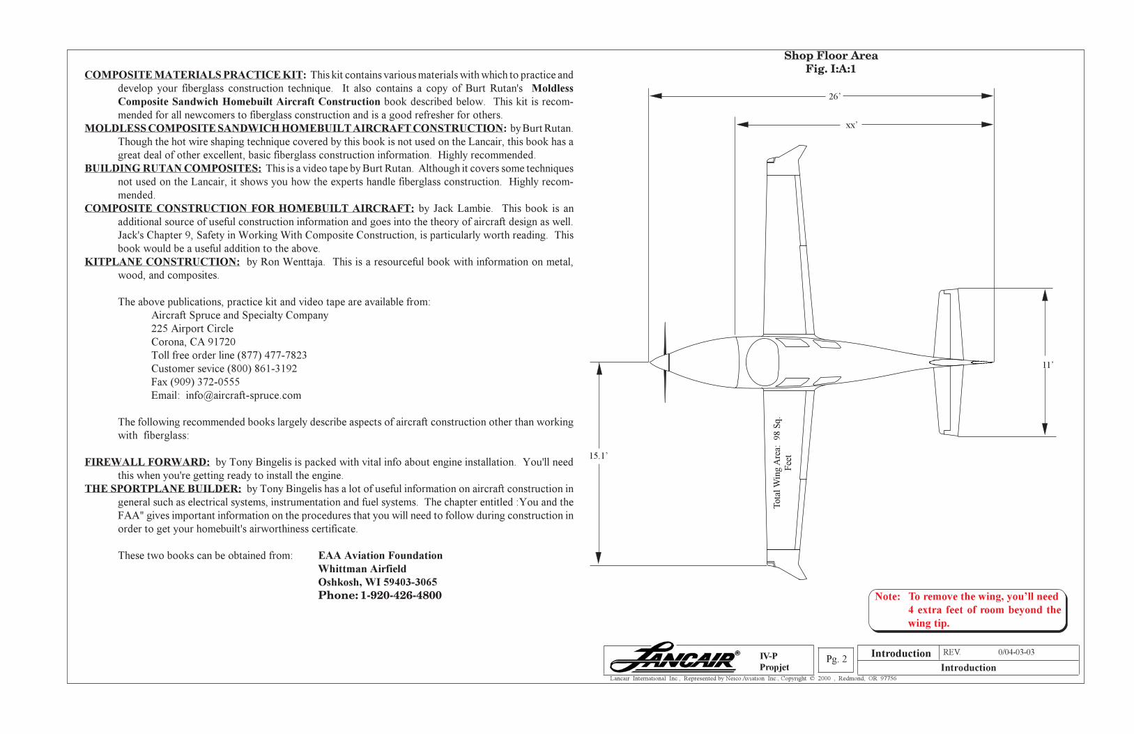
Shop Floor AreaFig. I:A:1
Introduction
26’
15.1’
Tota
l W
ing A
rea:
98 S
q.
Fee
t
xx’
11’
Note: To remove the wing, you’ll need
4 extra feet of room beyond the
wing tip.
Section A REV. 0/04-03-03
IntroductionPg. 3
Lancair International Inc., Represented by Neico Aviation Inc., Copyright © 2000 , Redmond, OR 97756
IV-P
Propjet
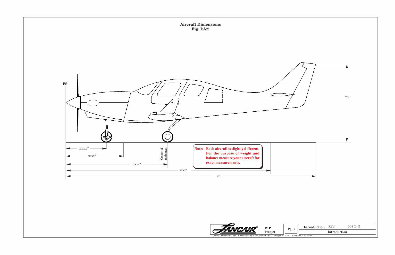
Aircraft DimensionsFig. I:A:2
Introduction
Cen
ter
of
mai
n g
ear
Tra
ilin
g e
dge
of
the
rudder
xxxx"
xxxx"
26’
Fir
ewal
l
joggle
xxxx"
FS 0
xxxx” Note: Each aircraft is slightly different.
For the purpose of weight and
balance measure your aircraft for
exact measurements.
7’8”
Section A REV. 0/04-03-03
IntroductionPg. 4
Lancair International Inc., Represented by Neico Aviation Inc., Copyright © 2000 , Redmond, OR 97756
IV-P
Propjet
of the opening page of each chapter that is affected. A new "table of revisions" page will accompany any
revision made to a chapter.
Each chapter should be read through entirely and understood before beginning the work it describes. The
equipment and supplies called for in each chapter should be on hand and ready for use.
C. SETTING UP YOUR SHOP
Your work area should be well lit, clean and uncluttered, and have at least one large table to cut on and
work with the fiberglass. Since parts will be placed on the floor occasionally, oil, grease and dirt must
be removed from the floor to prevent contamination of the parts.
If work is to be done when the outside temperature is less than 70°F, a heat source may be necessary.
Working with adhesive or fiberglass resin at lower temperatures, wetting the fiberglass out becomes
difficult.
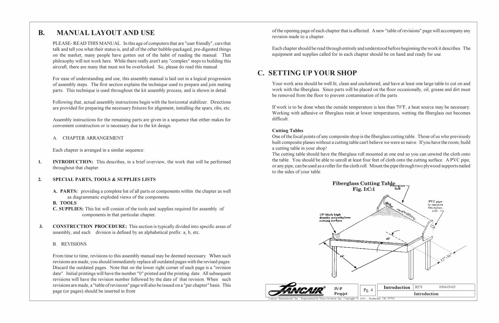
Cutting Tables
One of the focal points of any composite shop is the fiberglass cutting table. Those of us who previously
built composite planes without a cutting table can't believe we were so naive. If you have the room, build
a cutting table in your shop!
The cutting table should have the fiberglass roll mounted at one end so you can unwind the cloth onto
the table. You should be able to unroll at least four feet of cloth onto the cutting surface. A PVC pipe,
or any pipe, can be used as a roller for the cloth roll. Mount the pipe through two plywood supports nailed
to the sides of your table.
Fiberglass Cutting TableFig. I:C:1
B. MANUAL LAYOUT AND USE
PLEASE- READ THIS MANUAL. In this age of computers that are "user friendly", cars that
talk and tell you what their status is, and all of the other bubble-packaged, pre-digested things
on the market, many people have gotten out of the habit of reading the manual. That
philosophy will not work here. While there really aren't any "complex" steps to building this
aircraft, there are many that must not be overlooked. So, please do read this manual.
For ease of understanding and use, this assembly manual is laid out in a logical progression
of assembly steps. The first section explains the technique used to prepare and join mating
parts. This technique is used throughout the kit assembly process, and is shown in detail.
Following that, actual assembly instructions begin with the horizontal stabilizer. Directions
are provided for preparing the necessary fixtures for alignment, installing the spars, ribs, etc.
Assembly instructions for the remaining parts are given in a sequence that either makes for
convenient construction or is necessary due to the kit design.
A. CHAPTER ARRANGEMENT
Each chapter is arranged in a similar sequence:
1. INTRODUCTION: This describes, in a brief overview, the work that will be performed
throughout that chapter.
2. SPECIAL PARTS, TOOLS & SUPPLIES LISTS
A. PARTS: providing a complete list of all parts or components within the chapter as well
as diagrammatic exploded views of the components.
B. TOOLS
C. SUPPLIES: This list will consist of the tools and supplies required for assembly of
components in that particular chapter.
3. CONSTRUCTION PROCEDURE: This section is typically divided into specific areas of
assembly, and each division is defined by an alphabetical prefix: a, b, etc.
B. REVISIONS
From time to time, revisions to this assembly manual may be deemed necessary. When such
revisions are made, you should immediately replace all outdated pages with the revised pages.
Discard the outdated pages. Note that on the lower right corner of each page is a "revision
date". Initial printings will have the number "0" printed and the printing date. All subsequent
revisions will have the revision number followed by the date of that revision. When such
revisions are made, a "table of revisions" page will also be issued on a "per chapter" basis. This
page (or pages) should be inserted in front
12"-36"
Introduction
Section A REV. 0/04-03-03
IntroductionPg. 5
Lancair International Inc., Represented by Neico Aviation Inc., Copyright © 2000 , Redmond, OR 97756
IV-P
Propjet
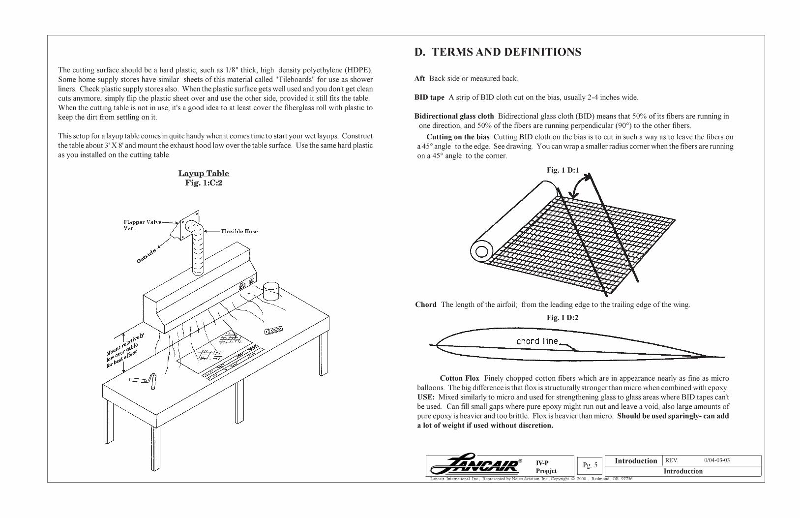
The cutting surface should be a hard plastic, such as 1/8" thick, high density polyethylene (HDPE).
Some home supply stores have similar sheets of this material called "Tileboards" for use as shower
liners. Check plastic supply stores also. When the plastic surface gets well used and you don't get clean
cuts anymore, simply flip the plastic sheet over and use the other side, provided it still fits the table.
When the cutting table is not in use, it's a good idea to at least cover the fiberglass roll with plastic to
keep the dirt from settling on it.
This setup for a layup table comes in quite handy when it comes time to start your wet layups. Construct
the table about 3' X 8' and mount the exhaust hood low over the table surface. Use the same hard plastic
as you installed on the cutting table.
Layup TableFig. 1:C:2
D. TERMS AND DEFINITIONS
Aft Back side or measured back.
BID tape A strip of BID cloth cut on the bias, usually 2-4 inches wide.
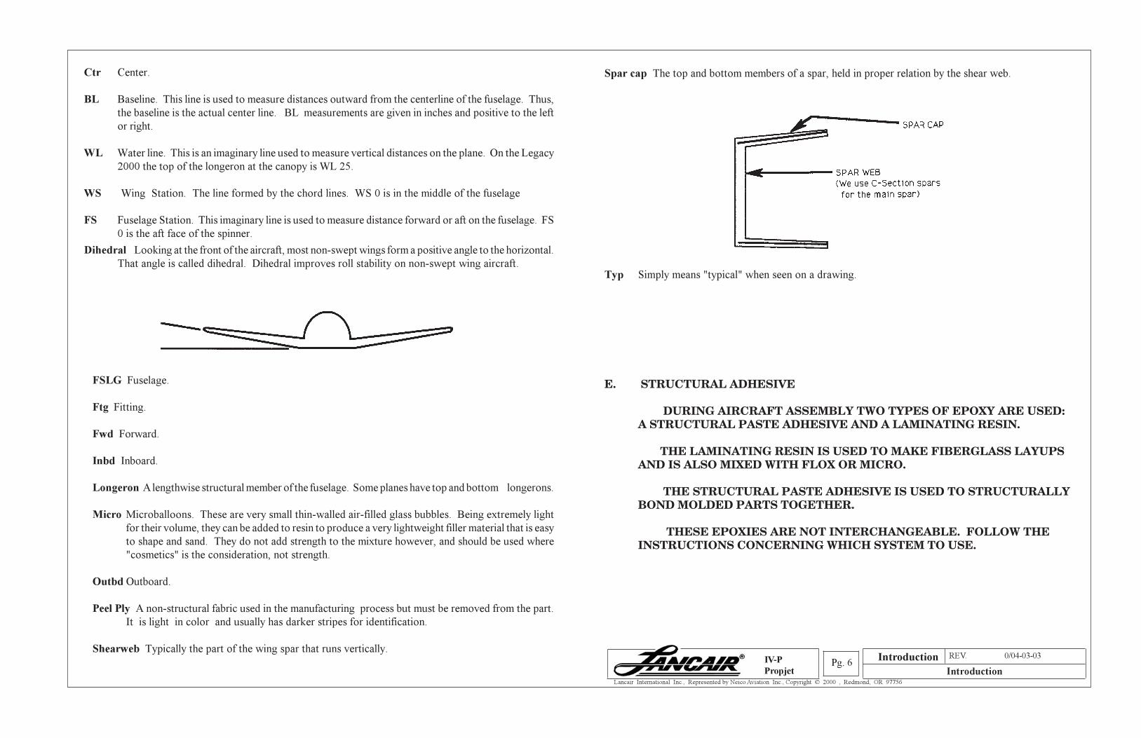
Bidirectional glass cloth Bidirectional glass cloth (BID) means that 50% of its fibers are running in
one direction, and 50% of the fibers are running perpendicular (90°) to the other fibers.
Cutting on the bias Cutting BID cloth on the bias is to cut in such a way as to leave the fibers on
a 45° angle to the edge. See drawing. You can wrap a smaller radius corner when the fibers are running
on a 45° angle to the corner.
Chord The length of the airfoil; from the leading edge to the trailing edge of the wing.
Cotton Flox Finely chopped cotton fibers which are in appearance nearly as fine as micro
balloons. The big difference is that flox is structurally stronger than micro when combined with epoxy.
USE: Mixed similarly to micro and used for strengthening glass to glass areas where BID tapes can't
be used. Can fill small gaps where pure epoxy might run out and leave a void, also large amounts of
pure epoxy is heavier and too brittle. Flox is heavier than micro. Should be used sparingly- can add
a lot of weight if used without discretion.
Fig. 1 D:1
Fig. I D:2
Introduction
Section A REV. 0/04-03-03
IntroductionPg. 6
Lancair International Inc., Represented by Neico Aviation Inc., Copyright © 2000 , Redmond, OR 97756
IV-P
Propjet
Ctr Center.
BL Baseline. This line is used to measure distances outward from the centerline of the fuselage. Thus,
the baseline is the actual center line. BL measurements are given in inches and positive to the left
or right.
WL Water line. This is an imaginary line used to measure vertical distances on the plane. On the Legacy
2000 the top of the longeron at the canopy is WL 25.
WS Wing Station. The line formed by the chord lines. WS 0 is in the middle of the fuselage
FS Fuselage Station. This imaginary line is used to measure distance forward or aft on the fuselage. FS
0 is the aft face of the spinner.
Dihedral Looking at the front of the aircraft, most non-swept wings form a positive angle to the horizontal.
That angle is called dihedral. Dihedral improves roll stability on non-swept wing aircraft.
FSLG Fuselage.
Ftg Fitting.
Fwd Forward.
Inbd Inboard.
Longeron A lengthwise structural member of the fuselage. Some planes have top and bottom longerons.
Micro Microballoons. These are very small thin-walled air-filled glass bubbles. Being extremely light
for their volume, they can be added to resin to produce a very lightweight filler material that is easy
to shape and sand. They do not add strength to the mixture however, and should be used where
"cosmetics" is the consideration, not strength.
Outbd Outboard.
Peel Ply A non-structural fabric used in the manufacturing process but must be removed from the part.
It is light in color and usually has darker stripes for identification.
Shearweb Typically the part of the wing spar that runs vertically.
Spar cap The top and bottom members of a spar, held in proper relation by the shear web.
Typ Simply means "typical" when seen on a drawing.
E. STRUCTURAL ADHESIVE
DURING AIRCRAFT ASSEMBLY TWO TYPES OF EPOXY ARE USED:A STRUCTURAL PASTE ADHESIVE AND A LAMINATING RESIN.
THE LAMINATING RESIN IS USED TO MAKE FIBERGLASS LAYUPSAND IS ALSO MIXED WITH FLOX OR MICRO.
THE STRUCTURAL PASTE ADHESIVE IS USED TO STRUCTURALLYBOND MOLDED PARTS TOGETHER.
THESE EPOXIES ARE NOT INTERCHANGEABLE. FOLLOW THEINSTRUCTIONS CONCERNING WHICH SYSTEM TO USE.
Introduction
Section A REV. 0/04-03-03
IntroductionPg. 7
Lancair International Inc., Represented by Neico Aviation Inc., Copyright © 2000 , Redmond, OR 97756
IV-P
Propjet
SAMPLE ILLUSTRATIONS, OTHER SYSTEMS MAY BE SUPPLIED ASSTANDARD WITH YOUR AIRFRAME KIT. SEE ABOVE WARNING.
NOTE: Most epoxies have a manufacturer's recommended shelf life of typically one year. In
some cases this is quite conservative. However, the manufacturers recommendations should
obviously be followed.
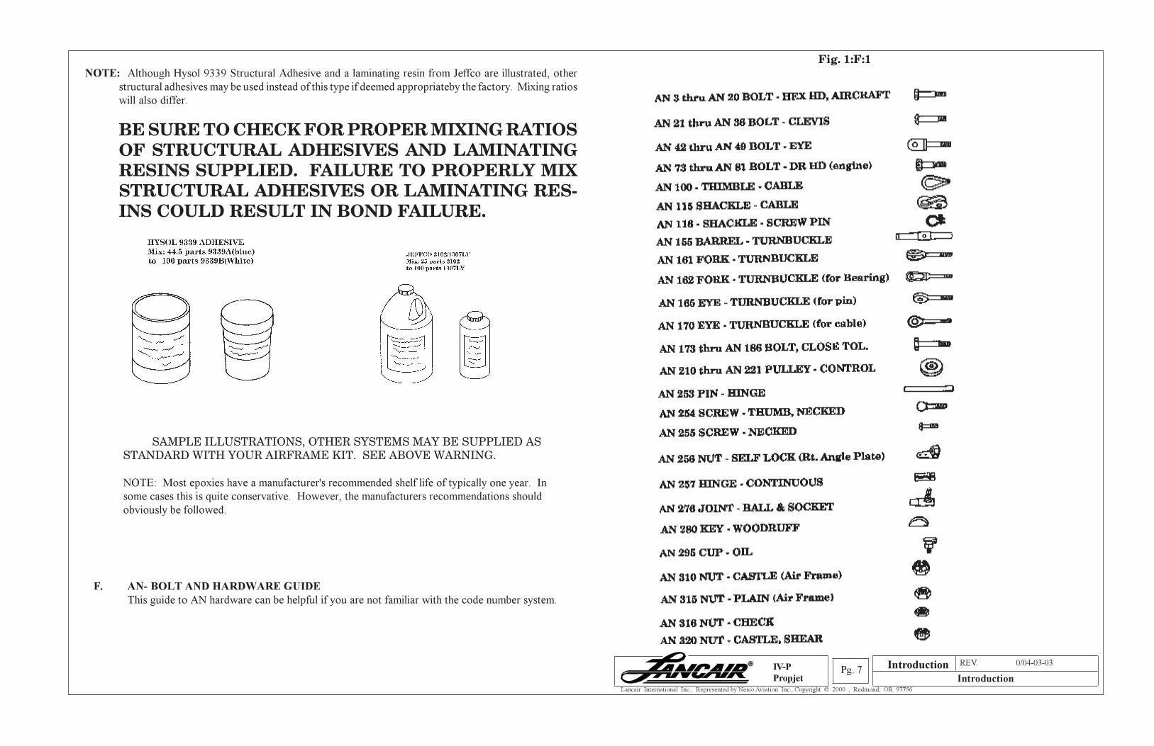
F. AN- BOLT AND HARDWARE GUIDE
This guide to AN hardware can be helpful if you are not familiar with the code number system.
Fig. 1:F:1NOTE: Although Hysol 9339 Structural Adhesive and a laminating resin from Jeffco are illustrated, other
structural adhesives may be used instead of this type if deemed appropriateby the factory. Mixing ratios
will also differ.
BE SURE TO CHECK FOR PROPER MIXING RATIOSOF STRUCTURAL ADHESIVES AND LAMINATINGRESINS SUPPLIED. FAILURE TO PROPERLY MIXSTRUCTURAL ADHESIVES OR LAMINATING RES-INS COULD RESULT IN BOND FAILURE.
Introduction

Section A REV. 0/04-03-03
IntroductionPg. 8
Lancair International Inc., Represented by Neico Aviation Inc., Copyright © 2000 , Redmond, OR 97756
IV-P
Propjet
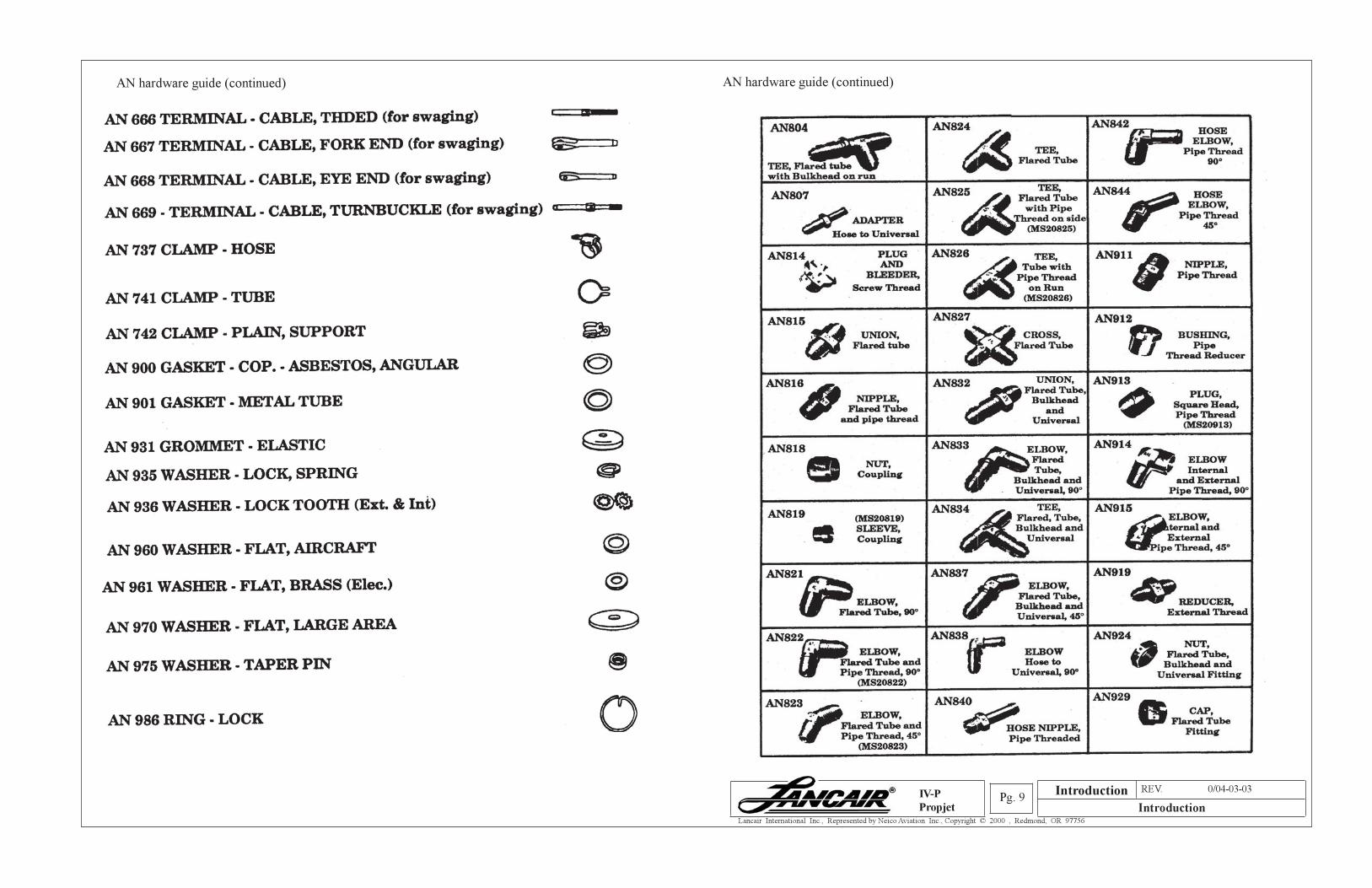
AN hardware guide (continued) AN hardware guide (continued)
Introduction
Section A REV. 0/04-03-03
IntroductionPg. 9
Lancair International Inc., Represented by Neico Aviation Inc., Copyright © 2000 , Redmond, OR 97756
IV-P
Propjet
AN hardware guide (continued) AN hardware guide (continued)
Introduction
Section A REV. 0/04-03-03
IntroductionPg. 10
Lancair International Inc., Represented by Neico Aviation Inc., Copyright © 2000 , Redmond, OR 97756
IV-P
Propjet
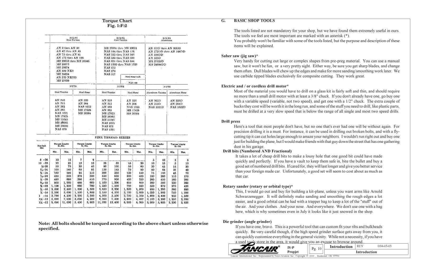
Torque ChartFig. 1:F:2
Note: All bolts should be torqued according to the above chart unless otherwisespecified.
G. BASIC SHOP TOOLS
The tools listed are not mandatory for your shop, but we have found them extremely useful in ours.
The tools we feel are most important are marked with an asterisk (*).
You probably won't be familiar with some of the tools listed, but the purpose and description of these
items will be explained.
Saber saw (jig saw)*
Very handy for cutting out large or complex shapes from pre-preg material. You can use a manual
saw, but it won't be fun, or a very pretty sight. Either way, be sure you get sharp blades, and change
them often. Dull blades will chew up the edges and make for more sanding/smoothing work later. We
use carbide tipped blades exclusively for composite cutting. They work great.
Electric and / or cordless drill motor*
Most of the material you would have to drill on a glass kit is fairly soft and thin, and should require
no more than a small drill motor with at least a 3/8" chuck. If you don't already have one, go buy one
with a variable speed (variable, not two speed), and get one with a 1/2" chuck. The extra couple of
bucks they cost will be worth it in the long run, and some of the stuff you need to drill, like plastic parts,
must be drilled at a very slow speed that is below the range of all single and most two speed drills.
Drill press
Here's a tool that most people don't have, but no one that's ever had one will be without again. For
precision drilling it is a must. For instance, it can be used in drilling out broken bolts, and with a fly-
cutting tip it can cut holes large enough to amaze your neighbors. I wouldn't run right out and buy one
just for building the plane, but I would make friends with that guy down the street that has one gathering
dust in his garage.Drill bits (Numbered AND Fractional)
It takes a lot of cheap drill bits to make a lousy hole that one good bit could have made
quickly and perfectly. If you have a vault to keep them safe in, bite the bullet and buy a
good set of numbered drill bits. If cared for, they will last longer and give you better service
than your foreign made car. Unfortunately, a good set will seem to cost about as much as
that car.
Rotary sander (rotary or orbital type)*
This, I would go out and buy for building a kit-plane, unless you want arms like Arnold
Schwarzenegger. It will definitely make sanding and smoothing the rough edges a lot
easier, and a good orbital can be had with a trapper bag to keep a lot of the "stuff" out of
the air. And your clothes. And your nose. And everywhere. We don't use one with a bag
here, which is why sometimes even in July it looks like it just snowed in the shop.
Die grinder (angle grinder)
If you have one, bravo. This is a powerful tool that can custom fit your ribs and bulkheads
quickly. Be very careful though, if the high speed grinder surface gets away from you, it
can quickly customize everything in the general vicinity. While not a necessity, if you have
a used tools store in the area, it would give you an excuse to browse around.Introduction
Section A REV. 0/04-03-03
IntroductionPg. 11
Lancair International Inc., Represented by Neico Aviation Inc., Copyright © 2000 , Redmond, OR 97756
IV-P
Propjet
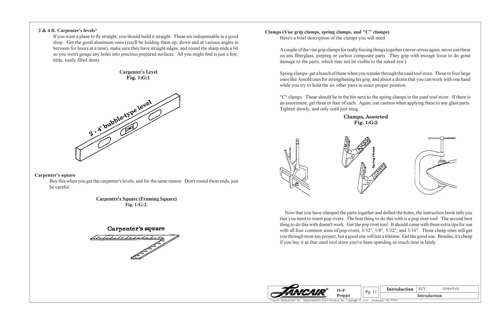
2 & 4 ft. Carpenter's levels*
If you want a plane to fly straight, you should build it straight. These are indispensable in a good
shop. Get the good aluminum ones (you'll be holding them up, down and at various angles in
between for hours at a time), make sure they have straight edges, and round the sharp ends a bit
so you won't gouge any holes into precious prepared surfaces. All you might find is just a few,
little, easily filled dents.
Carpenter's Level
Fig. 1:G:1
Carpenter's square
Buy this when you get the carpenter's levels, and for the same reason. Don't round these ends, just
be careful.
Carpenter's Square (Framing Square)
Fig. 1:G:2.
Clamps (Vise grip clamps, spring clamps, and "C" clamps)
Here's a brief description of the clamps you will need.
A couple of the vise grip clamps for really forcing things together (never-stress again, never use these
on any fiberglass, prepreg or carbon composite parts. They grip with enough force to do great
damage to the parts, which may not be visible to the naked eye.)
Spring clamps- get a bunch of these when you wander through the used tool store. Three or four large
ones like Arnold uses for strengthening his grip, and about a dozen that you can work with one hand
while you try to hold the six other parts in exact proper position.
"C" clamps. These should be in the bin next to the spring clamps in the used tool store. If there is
an assortment, get three or four of each. Again, use caution when applying these to any glass parts.
Tighten slowly, and only until just snug.
Clamps, AssortedFig. 1:G:3
Now that you have clamped the parts together and drilled the holes, the instruction book tells you
that you need to insert pop rivets. The best thing to do this with is a pop rivet tool. The second best
thing to do this with doesn't work. Get the pop rivet tool. It should come with three extra tips for use
with all four common sizes of pop rivets, 3/32", 1/8", 5/32", and 3/16". Three cheap ones will get
you through most any project, but a good one will last a lifetime. Get the good one. Besides, it's cheap
if you buy it at that used tool store you've been spending so much time in lately.
Introduction
Section A REV. 0/04-03-03
IntroductionPg. 12
Lancair International Inc., Represented by Neico Aviation Inc., Copyright © 2000 , Redmond, OR 97756
IV-P
Propjet
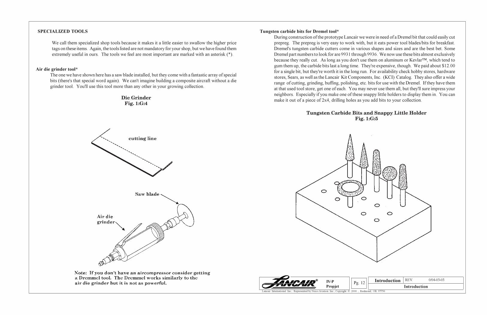
Air die grinder tool*
The one we have shown here has a saw blade installed, but they come with a fantastic array of special
bits (there's that special word again). We can't imagine building a composite aircraft without a die
grinder tool. You'll use this tool more than any other in your growing collection.
Die GrinderFig. 1:G:4
SPECIALIZED TOOLS
We call them specialized shop tools because it makes it a little easier to swallow the higher price
tags on these items. Again, the tools listed are not mandatory for your shop, but we have found them
extremely useful in ours. The tools we feel are most important are marked with an asterisk (*).
Tungsten carbide bits for Dremel tool*
During construction of the prototype Lancair we were in need of a Dremel bit that could easily cut
prepreg. The prepreg is very easy to work with, but it eats power tool blades/bits for breakfast.
Dremel's tungsten carbide cutters come in various shapes and sizes and are the best bet. Some
Dremel part numbers to look for are 9931 through 9936. We now use these bits almost exclusively
because they really cut. As long as you don't use them on aluminum or Kevlar™, which tend to
gum them up, the carbide bits last a long time. They're expensive, though. We paid about $12.00
for a single bit, but they're worth it in the long run. For availability check hobby stores, hardware
stores, Sears, as well as the Lancair Kit Components, Inc. (KCI) Catalog. They also offer a wide
range of cutting, grinding, buffing, polishing, etc. bits for use with the Dremel. If they have them
at that used tool store, get one of each. You may never use them all, but they'll sure impress your
neighbors. Especially if you make one of these snappy little holders to display them in. You can
make it out of a piece of 2x4, drilling holes as you add bits to your collection.
Tungsten Carbide Bits and Snappy Little HolderFig. 1:G:5
Introduction
Section A REV. 0/04-03-03
IntroductionPg. 13
Lancair International Inc., Represented by Neico Aviation Inc., Copyright © 2000 , Redmond, OR 97756
IV-P
Propjet
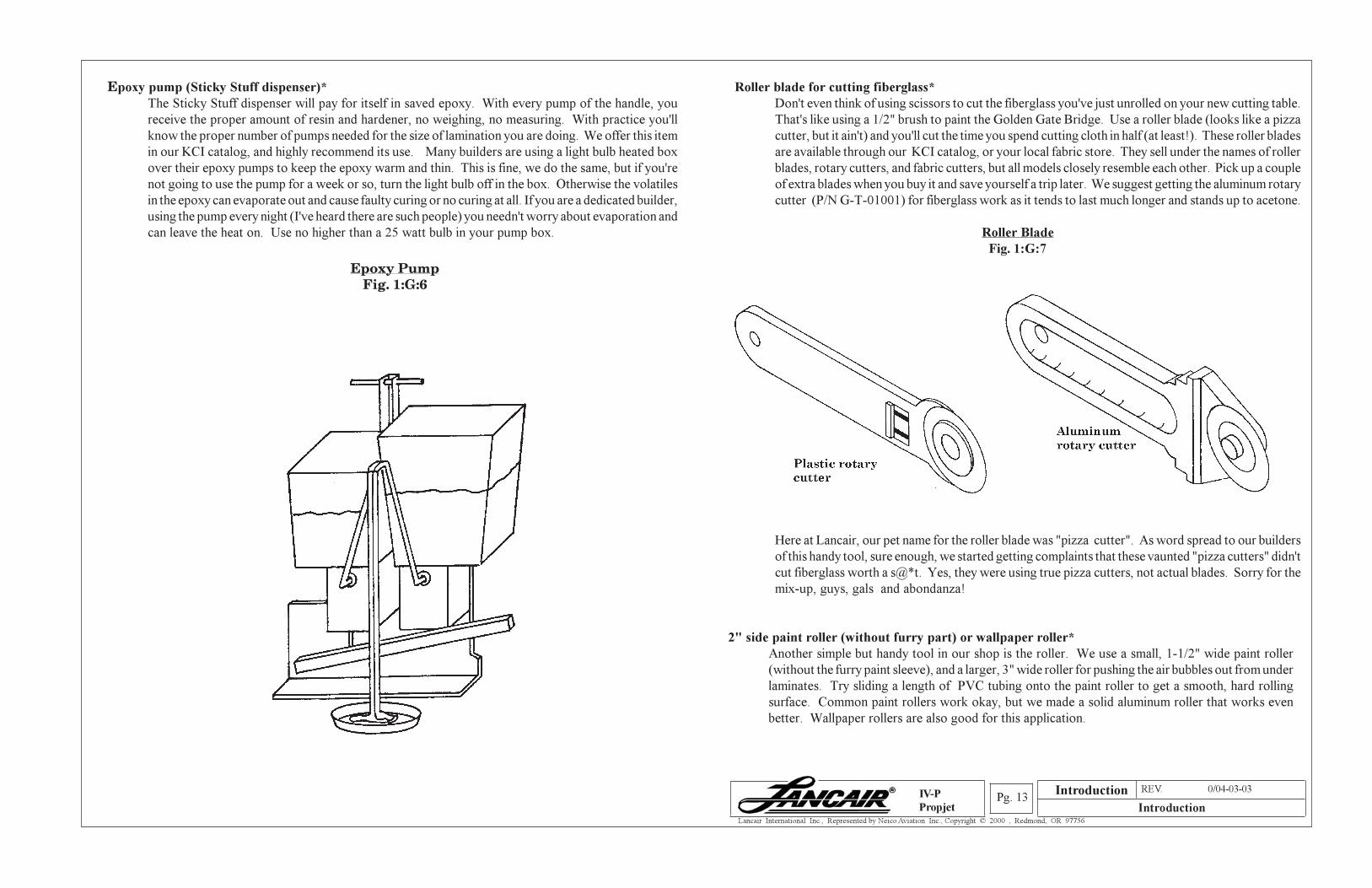
Epoxy pump (Sticky Stuff dispenser)*
The Sticky Stuff dispenser will pay for itself in saved epoxy. With every pump of the handle, you
receive the proper amount of resin and hardener, no weighing, no measuring. With practice you'll
know the proper number of pumps needed for the size of lamination you are doing. We offer this item
in our KCI catalog, and highly recommend its use. Many builders are using a light bulb heated box
over their epoxy pumps to keep the epoxy warm and thin. This is fine, we do the same, but if you're
not going to use the pump for a week or so, turn the light bulb off in the box. Otherwise the volatiles
in the epoxy can evaporate out and cause faulty curing or no curing at all. If you are a dedicated builder,
using the pump every night (I've heard there are such people) you needn't worry about evaporation and
can leave the heat on. Use no higher than a 25 watt bulb in your pump box.
Epoxy PumpFig. 1:G:6
Roller blade for cutting fiberglass*
Don't even think of using scissors to cut the fiberglass you've just unrolled on your new cutting table.
That's like using a 1/2" brush to paint the Golden Gate Bridge. Use a roller blade (looks like a pizza
cutter, but it ain't) and you'll cut the time you spend cutting cloth in half (at least!). These roller blades
are available through our KCI catalog, or your local fabric store. They sell under the names of roller
blades, rotary cutters, and fabric cutters, but all models closely resemble each other. Pick up a couple
of extra blades when you buy it and save yourself a trip later. We suggest getting the aluminum rotary
cutter (P/N G-T-01001) for fiberglass work as it tends to last much longer and stands up to acetone.
Roller Blade
Fig. 1:G:7
Here at Lancair, our pet name for the roller blade was "pizza cutter". As word spread to our builders
of this handy tool, sure enough, we started getting complaints that these vaunted "pizza cutters" didn't
cut fiberglass worth a s@*t. Yes, they were using true pizza cutters, not actual blades. Sorry for the
mix-up, guys, gals and abondanza!
2" side paint roller (without furry part) or wallpaper roller*
Another simple but handy tool in our shop is the roller. We use a small, 1-1/2" wide paint roller
(without the furry paint sleeve), and a larger, 3" wide roller for pushing the air bubbles out from under
laminates. Try sliding a length of PVC tubing onto the paint roller to get a smooth, hard rolling
surface. Common paint rollers work okay, but we made a solid aluminum roller that works even
better. Wallpaper rollers are also good for this application.
Introduction
Section A REV. 0/04-03-03
IntroductionPg. 14
Lancair International Inc., Represented by Neico Aviation Inc., Copyright © 2000 , Redmond, OR 97756
IV-P
Propjet
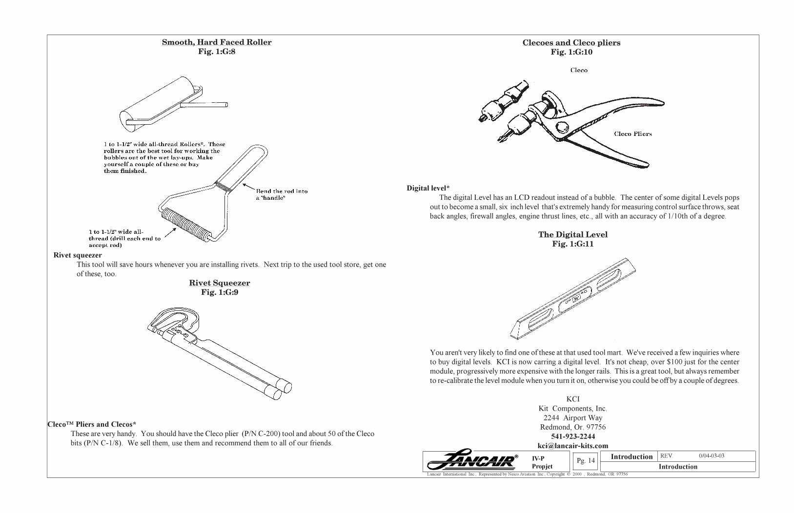
Smooth, Hard Faced RollerFig. 1:G:8
Rivet squeezer
This tool will save hours whenever you are installing rivets. Next trip to the used tool store, get one
of these, too.
Rivet SqueezerFig. 1:G:9
Clecoes and Cleco pliersFig. 1:G:10
Digital level*
The digital Level has an LCD readout instead of a bubble. The center of some digital Levels pops
out to become a small, six inch level that's extremely handy for measuring control surface throws, seat
back angles, firewall angles, engine thrust lines, etc., all with an accuracy of 1/10th of a degree.
The Digital LevelFig. 1:G:11
You aren't very likely to find one of these at that used tool mart. We've received a few inquiries where
to buy digital levels. KCI is now carring a digital level. It's not cheap, over $100 just for the center
module, progressively more expensive with the longer rails. This is a great tool, but always remember
to re-calibrate the level module when you turn it on, otherwise you could be off by a couple of degrees.
KCI
Kit Components, Inc.
2244 Airport Way
Redmond, Or. 97756
541-923-2244
Cleco™ Pliers and Clecos*
These are very handy. You should have the Cleco plier (P/N C-200) tool and about 50 of the Cleco
bits (P/N C-1/8). We sell them, use them and recommend them to all of our friends.
Introduction
Section A REV. 0/04-03-03
IntroductionPg. 15
Lancair International Inc., Represented by Neico Aviation Inc., Copyright © 2000 , Redmond, OR 97756
IV-P
Propjet
Tubing bender
This will be at the used tool store, where you should be on a first name basis with the owner by now.
Tell him you just need one for 1/4" tubing. It should be in the bin right next to the 37° Flaring tool.
37° flaring tool
Keep this with your tube bender. You won't need it often, but when you do nothing else will work.
Don't use automotive type flaring tools- they have a different flaring angle.
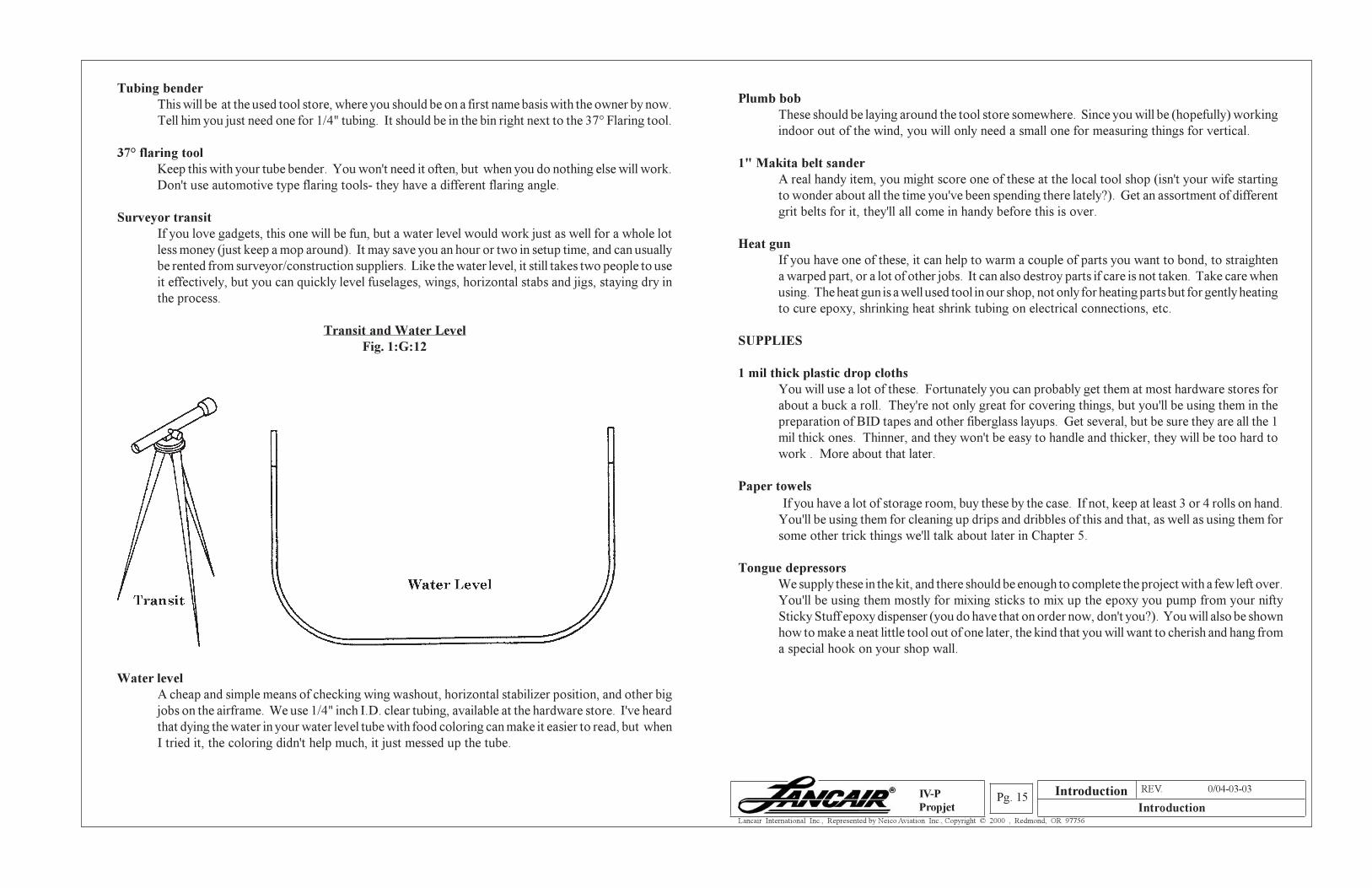
Surveyor transit
If you love gadgets, this one will be fun, but a water level would work just as well for a whole lot
less money (just keep a mop around). It may save you an hour or two in setup time, and can usually
be rented from surveyor/construction suppliers. Like the water level, it still takes two people to use
it effectively, but you can quickly level fuselages, wings, horizontal stabs and jigs, staying dry in
the process.
Transit and Water Level
Fig. 1:G:12
Water level
A cheap and simple means of checking wing washout, horizontal stabilizer position, and other big
jobs on the airframe. We use 1/4" inch I.D. clear tubing, available at the hardware store. I've heard
that dying the water in your water level tube with food coloring can make it easier to read, but when
I tried it, the coloring didn't help much, it just messed up the tube.
Plumb bob
These should be laying around the tool store somewhere. Since you will be (hopefully) working
indoor out of the wind, you will only need a small one for measuring things for vertical.
1" Makita belt sander
A real handy item, you might score one of these at the local tool shop (isn't your wife starting
to wonder about all the time you've been spending there lately?). Get an assortment of different
grit belts for it, they'll all come in handy before this is over.
Heat gun
If you have one of these, it can help to warm a couple of parts you want to bond, to straighten
a warped part, or a lot of other jobs. It can also destroy parts if care is not taken. Take care when
using. The heat gun is a well used tool in our shop, not only for heating parts but for gently heating
to cure epoxy, shrinking heat shrink tubing on electrical connections, etc.
SUPPLIES
1 mil thick plastic drop cloths
You will use a lot of these. Fortunately you can probably get them at most hardware stores for
about a buck a roll. They're not only great for covering things, but you'll be using them in the
preparation of BID tapes and other fiberglass layups. Get several, but be sure they are all the 1
mil thick ones. Thinner, and they won't be easy to handle and thicker, they will be too hard to
work . More about that later.
Paper towels
If you have a lot of storage room, buy these by the case. If not, keep at least 3 or 4 rolls on hand.
You'll be using them for cleaning up drips and dribbles of this and that, as well as using them for
some other trick things we'll talk about later in Chapter 5.
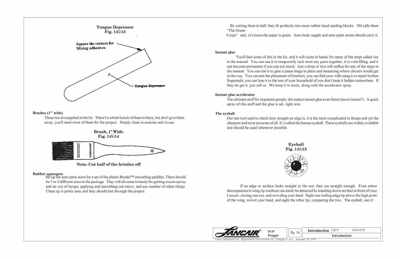
Tongue depressors
We supply these in the kit, and there should be enough to complete the project with a few left over.
You'll be using them mostly for mixing sticks to mix up the epoxy you pump from your nifty
Sticky Stuff epoxy dispenser (you do have that on order now, don't you?). You will also be shown
how to make a neat little tool out of one later, the kind that you will want to cherish and hang from
a special hook on your shop wall.
Introduction
Section A REV. 0/04-03-03
IntroductionPg. 16
Lancair International Inc., Represented by Neico Aviation Inc., Copyright © 2000 , Redmond, OR 97756
IV-P
Propjet
Brushes (1" wide)
These too are supplied in the kit. There's a whole bunch of them in there, but don't give them
away, you'll need most of them for the project. Simply clean in acetone and re-use.
Brush, 1" WideFig. 1:G:14
Note: Cut half of the bristles off
Rubber squeegees Hit up the auto parts store for a set of the plastic Bondo™ smoothing paddles. There should
be 3 or 4 different sizes in the package. They will all come in handy for getting excess epoxy
and air out of layups, applying and smoothing out micro, and any number of other things.
Clean up is pretty easy and they should last through the project.
By cutting them in half, they fit perfectly into most rubber hand sanding blocks. 3M calls them
"The Green
Corps" and, of course,the paper is green. Auto body supply and auto paint stores should carry it.
Instant glue
You'll find some of this in the kit, and it will come in handy for many of the steps called out
in the manual. You can use it to temporarily tack most any parts together, it is void-filling, and it
can become permanent if you use too much. Just a drop or two will suffice for any of the steps in
the manual. You can use it to glue a piano hinge in place and measuring where clecoes would get
in the way. You can test the placement of brackets, you can find your wife using it to repair broken
fingernails, you can lose it to the rest of your household of you don't keep it hidden somewhere. If
they do get it, just call us. We keep it in stock, along with the accelerator spray.
Instant glue accelerator
The ultimate stuff for impatient people, this makes instant glue even faster (more instant?). A quick
spray of this stuff and the glue is set, right now.
The eyeball
Our last tool used to check how straight an edge is, it is the most complicated in design and yet the
cheapest and most accurate of all. It’s called the human eyeball. These eyeballs are widely available
and should be used whenever possible.
EyeballFig. 1:G:15
If an edge or surface looks straight to the eye, they are straight enough. Even minor
discrepancies in wing tip washout can easily be detected by kneeling down ten feet in front of your
Lancair, closing one eye, and swiveling your head. Sight one trailing edge tip above the high point
of the wing, swivel your head, and sight the other tip, comparing the two. The eyeball, use it!
Tongue DepressorFig. 1:G:13
Introduction
Section A REV. 0/04-03-03
IntroductionPg. 17
Lancair International Inc., Represented by Neico Aviation Inc., Copyright © 2000 , Redmond, OR 97756
IV-P
Propjet
I. PROCEDURE
Cleaning, care, and handling of parts
1. Cleaning Parts
You will find instructions calling for the use of cleaning agents throughout this manual. We have
found that Methylene Chloride (MC) cleaner is very good in its ability to remove impurities from
surfaces. As with all cleaners, be sure to read and follow the safety directions. Acetone is a good
cleaner but Methylene Chloride (MC) is superior. MEK should not be used.
2. Storage of Premolded Parts
The manner in which your pre-molded parts are stored is very important. Care and thought
should be exercised when laying pre-molded parts away for some future use which could be
months away. Try to store these parts in a position that won't produce any distorting forces (i.e.,
store them supported in a position as close to the actual use orientation as possible).
Unlike fiberglass composite parts, the carbon fiber parts are much stiffer and less prone to
distortion, however it is still highly recommended that great care be exercised when storing these
valuable components. Also, all composite parts should be kept away from direct sunlight for
any extended periods of time. An afternoon or a day is perhaps okay. However a week, for
example, in direct sunlight would not be acceptable.
3. Honeycomb Prepreg Panels
The prepreg honeycomb panels are available in two types: 3/8" core + 2 BID per side and 1/4"
core + 1 BID per side. All BID ply schedules must remain the same when using prepreg panels
(i.e., if a part calls for 6 BID on one side and 2 BID on the other side, the 2 BID honeycomb panel
will require 4 additional BID on the first side). Also, all attachment BID schedules must remain
the same (i.e., if plans call for a 6 BID attachment, then 6 plies (wet layup) must be used.)
Typically 1" contact on each surface unless otherwise noted is sufficient.
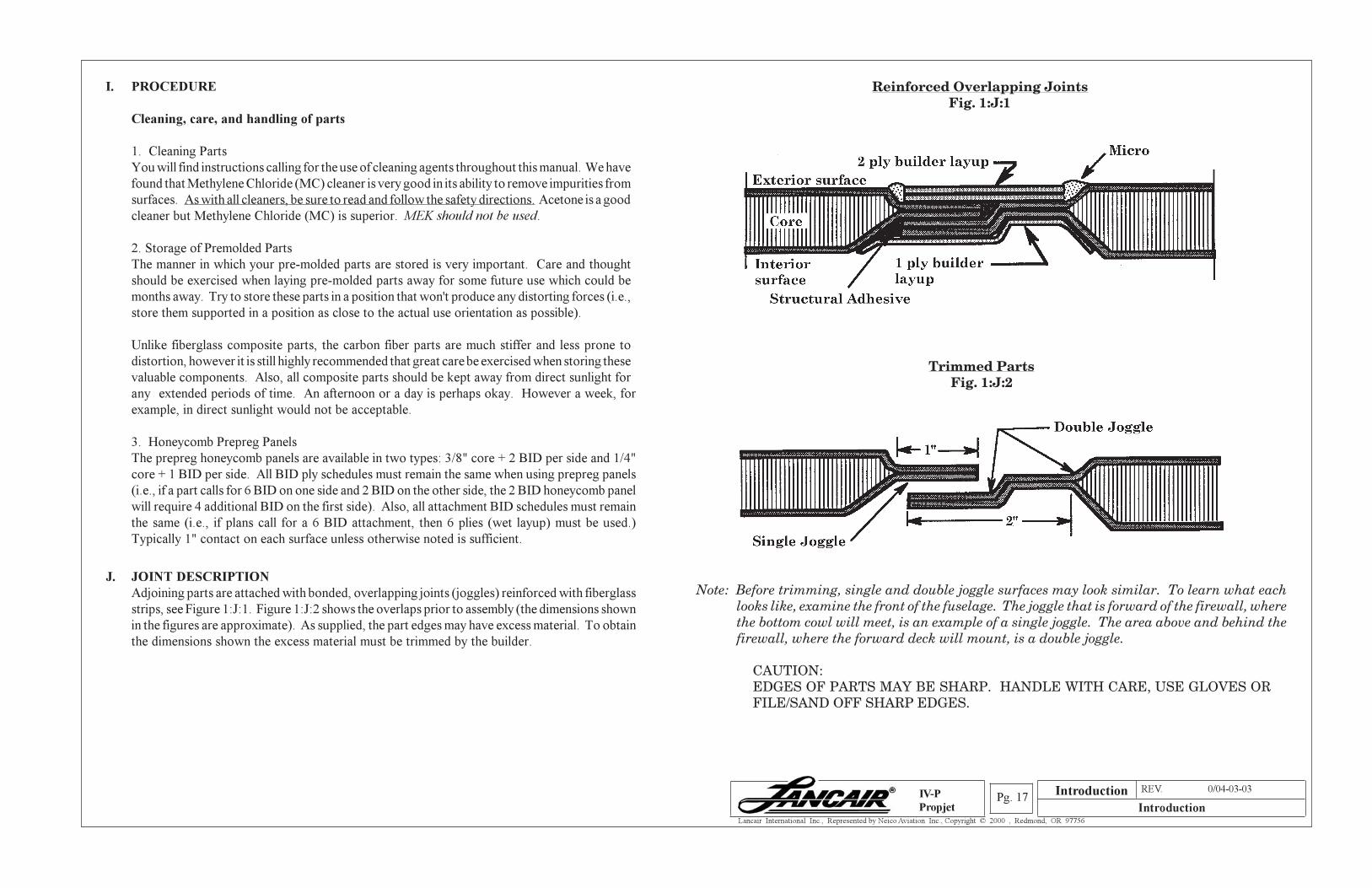
J. JOINT DESCRIPTION
Adjoining parts are attached with bonded, overlapping joints (joggles) reinforced with fiberglass
strips, see Figure 1:J:1. Figure 1:J:2 shows the overlaps prior to assembly (the dimensions shown
in the figures are approximate). As supplied, the part edges may have excess material. To obtain
the dimensions shown the excess material must be trimmed by the builder.
Reinforced Overlapping JointsFig. 1:J:1
Trimmed PartsFig. 1:J:2
Note: Before trimming, single and double joggle surfaces may look similar. To learn what eachlooks like, examine the front of the fuselage. The joggle that is forward of the firewall, wherethe bottom cowl will meet, is an example of a single joggle. The area above and behind thefirewall, where the forward deck will mount, is a double joggle.
CAUTION:EDGES OF PARTS MAY BE SHARP. HANDLE WITH CARE, USE GLOVES ORFILE/SAND OFF SHARP EDGES.
Introduction
Section A REV. 0/04-03-03
IntroductionPg. 18
Lancair International Inc., Represented by Neico Aviation Inc., Copyright © 2000 , Redmond, OR 97756
IV-P
Propjet
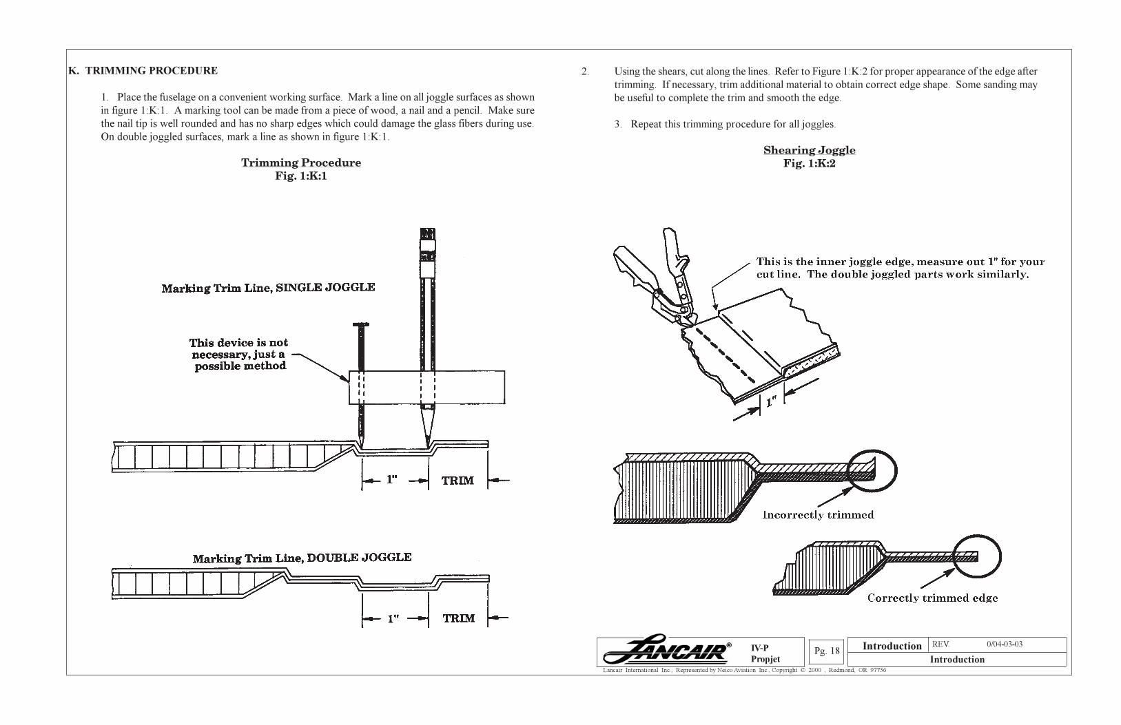
K. TRIMMING PROCEDURE
1. Place the fuselage on a convenient working surface. Mark a line on all joggle surfaces as shown
in figure 1:K:1. A marking tool can be made from a piece of wood, a nail and a pencil. Make sure
the nail tip is well rounded and has no sharp edges which could damage the glass fibers during use.
On double joggled surfaces, mark a line as shown in figure 1:K:1.
Trimming ProcedureFig. 1:K:1
2. Using the shears, cut along the lines. Refer to Figure 1:K:2 for proper appearance of the edge after
trimming. If necessary, trim additional material to obtain correct edge shape. Some sanding may
be useful to complete the trim and smooth the edge.
3. Repeat this trimming procedure for all joggles.
Shearing JoggleFig. 1:K:2
Introduction
Section A REV. 0/04-03-03
IntroductionPg. 19
Lancair International Inc., Represented by Neico Aviation Inc., Copyright © 2000 , Redmond, OR 97756
IV-P
Propjet
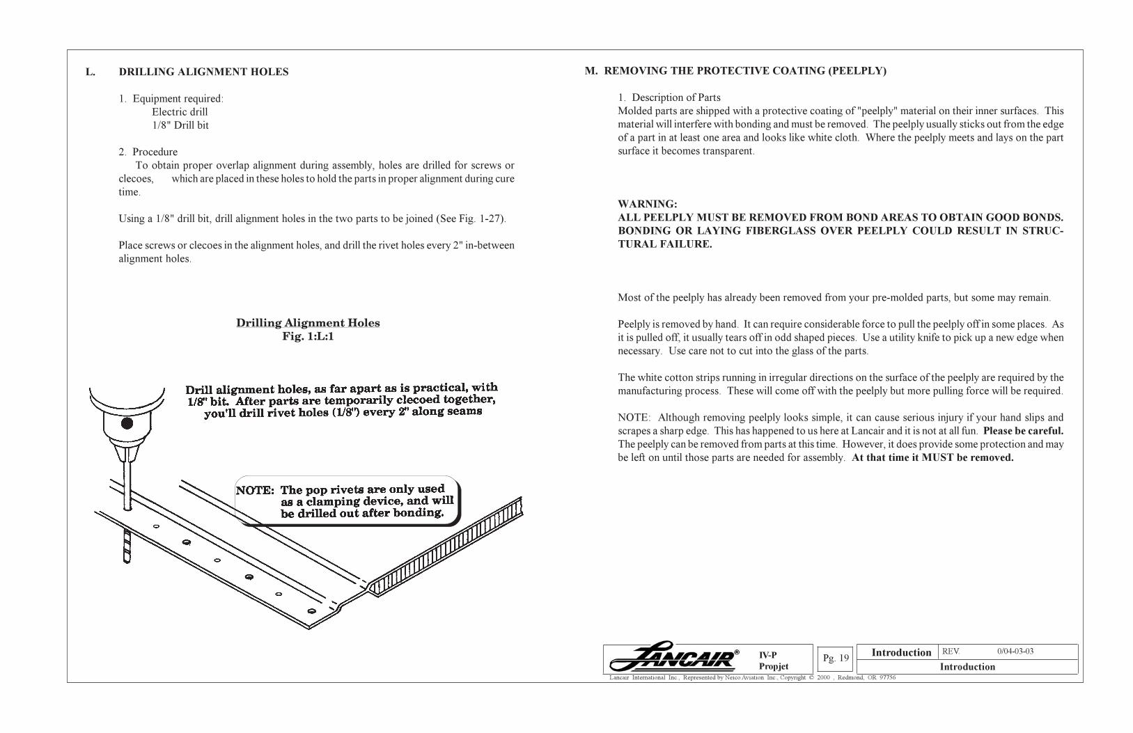
L. DRILLING ALIGNMENT HOLES
1. Equipment required:
Electric drill
1/8" Drill bit
2. Procedure
To obtain proper overlap alignment during assembly, holes are drilled for screws or
clecoes, which are placed in these holes to hold the parts in proper alignment during cure
time.
Using a 1/8" drill bit, drill alignment holes in the two parts to be joined (See Fig. 1-27).
Place screws or clecoes in the alignment holes, and drill the rivet holes every 2" in-between
alignment holes.
Drilling Alignment HolesFig. 1:L:1
M. REMOVING THE PROTECTIVE COATING (PEELPLY)
1. Description of Parts
Molded parts are shipped with a protective coating of "peelply" material on their inner surfaces. This
material will interfere with bonding and must be removed. The peelply usually sticks out from the edge
of a part in at least one area and looks like white cloth. Where the peelply meets and lays on the part
surface it becomes transparent.
WARNING:
ALL PEELPLY MUST BE REMOVED FROM BOND AREAS TO OBTAIN GOOD BONDS.
BONDING OR LAYING FIBERGLASS OVER PEELPLY COULD RESULT IN STRUC-
TURAL FAILURE.
Most of the peelply has already been removed from your pre-molded parts, but some may remain.
Peelply is removed by hand. It can require considerable force to pull the peelply off in some places. As
it is pulled off, it usually tears off in odd shaped pieces. Use a utility knife to pick up a new edge when
necessary. Use care not to cut into the glass of the parts.
The white cotton strips running in irregular directions on the surface of the peelply are required by the
manufacturing process. These will come off with the peelply but more pulling force will be required.
NOTE: Although removing peelply looks simple, it can cause serious injury if your hand slips and
scrapes a sharp edge. This has happened to us here at Lancair and it is not at all fun. Please be careful.
The peelply can be removed from parts at this time. However, it does provide some protection and may
be left on until those parts are needed for assembly. At that time it MUST be removed.
Introduction
Section A REV. 0/04-03-03
IntroductionPg. 20
Lancair International Inc., Represented by Neico Aviation Inc., Copyright © 2000 , Redmond, OR 97756
IV-P
Propjet
It takes practice to drill a close tolerance hole in aluminum and fiberglass. We're not all precision machinists here
at the shop, but through trial and error we've come up with some drill combinations that work well for various
size screws and rivets.
First a note about tolerances. When a bolt is holding a bracket tight against a bulkhead, rib, firewall etc., you
needn't drill a .001" tolerance hole, because the bolt's clamping action will keep the bracket from wearing the bolt
hole larger. This applies to rod end bearings and bellcrank bearings that are mounted tight with elastic locknuts.
In this case, the slop in the bearings are not dependent on the tolerance of the holes.
Here is a list of drills we commonly use for various bolts and rivets:
-AN 426 rivets are .097" diameter, use #40 drill.
-1/8" rivets are .125" diameter, use 1/8" or #30 (.1285") drills.
-#6 screws are .137", drill a sloppy #29 (.136) hole or a tight #28 (.1405").
-#8 screws are .161", #20 (.161") and #21 (.159") both work well.
-3/16" (AN3) bolts can use, in addition to the obvious 3/16" drill, a #13 hole with reaming to get a tight fit, (See
above section when and where this is necessary). A #12 hole is sometimes too sloppy but can be used for
unimportant, quick and dirty holes.
-1/4" (AN4) bolts use 1/4" drill, of course. Also handy are lettered drills, like "E" (.250") or D (.246") with a
reamer.
When drilling, creep up on your final drill size. If you want a tight AN4 hole and simply use a 1/4" drill first, the
hole will be loose and usually triangular shaped. Try drilling a 3/16" hole first, then 7/32", then 1/4". The extra
one minute spent changing drills is well worth it, especially if you're drilling a hole that needs a tight tolerance
(See above).
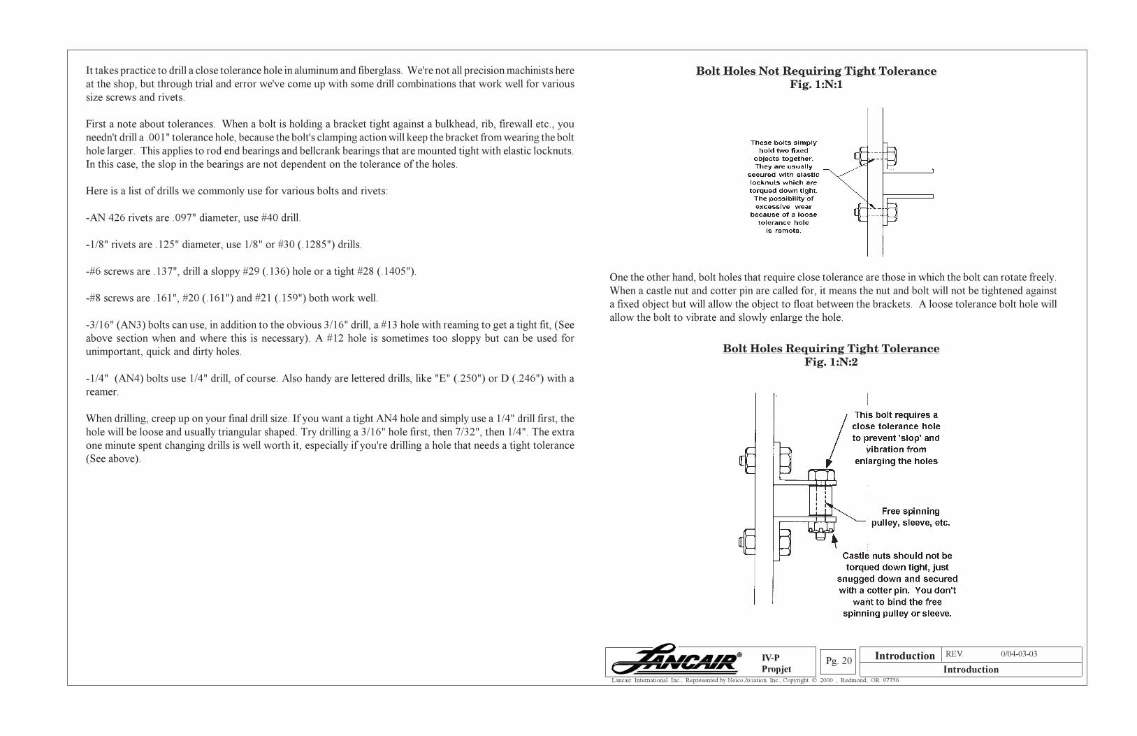
Bolt Holes Not Requiring Tight ToleranceFig. 1:N:1
One the other hand, bolt holes that require close tolerance are those in which the bolt can rotate freely.
When a castle nut and cotter pin are called for, it means the nut and bolt will not be tightened against
a fixed object but will allow the object to float between the brackets. A loose tolerance bolt hole will
allow the bolt to vibrate and slowly enlarge the hole.
Bolt Holes Requiring Tight ToleranceFig. 1:N:2
Introduction
Section A REV. 0/04-03-03
IntroductionPg. 21
Lancair International Inc., Represented by Neico Aviation Inc., Copyright © 2000 , Redmond, OR 97756
IV-P
Propjet
O. FASTENING PARTS TOGETHER
1. When parts are to be fastened together using epoxy or structural adhesive, they must be held tightly
in position until the bonding material has set. Several methods are available, but pop rivets remain
the best way to be sure of a proper bond. Typically, the bonding sequence is:
The parts are prepared for bonding-
a. peelply is removed
b. Joggled surfaces are trimmed
c. Alignment holes are drilled
d. Sheet metal screws or clecoes* (Fig. 1:O:1.) are installed into these holes to hold the parts in
alignment while holes are drilled about every 2" from pop rivets.
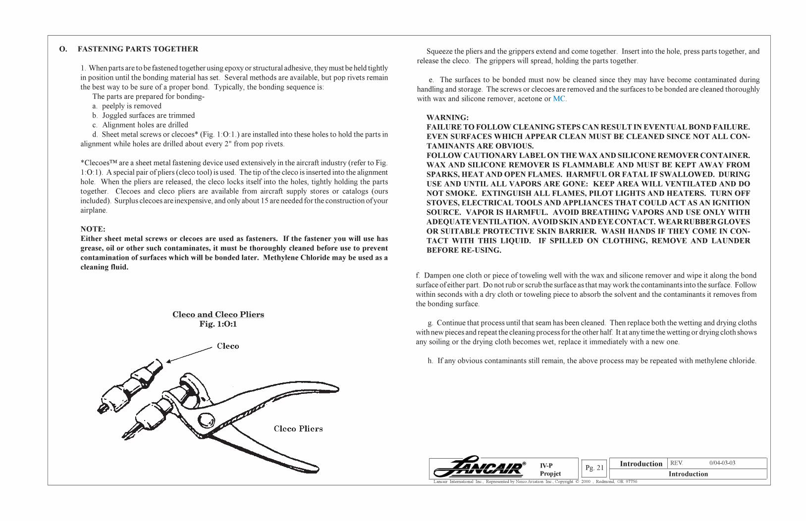
*Clecoes™ are a sheet metal fastening device used extensively in the aircraft industry (refer to Fig.
1:O:1). A special pair of pliers (cleco tool) is used. The tip of the cleco is inserted into the alignment
hole. When the pliers are released, the cleco locks itself into the holes, tightly holding the parts
together. Clecoes and cleco pliers are available from aircraft supply stores or catalogs (ours
included). Surplus clecoes are inexpensive, and only about 15 are needed for the construction of your
airplane.
NOTE:
Either sheet metal screws or clecoes are used as fasteners. If the fastener you will use has
grease, oil or other such contaminates, it must be thoroughly cleaned before use to prevent
contamination of surfaces which will be bonded later. Methylene Chloride may be used as a
cleaning fluid.
Cleco and Cleco PliersFig. 1:O:1
Squeeze the pliers and the grippers extend and come together. Insert into the hole, press parts together, and
release the cleco. The grippers will spread, holding the parts together.
e. The surfaces to be bonded must now be cleaned since they may have become contaminated during
handling and storage. The screws or clecoes are removed and the surfaces to be bonded are cleaned thoroughly
with wax and silicone remover, acetone or MC.
WARNING:
FAILURE TO FOLLOW CLEANING STEPS CAN RESULT IN EVENTUAL BOND FAILURE.
EVEN SURFACES WHICH APPEAR CLEAN MUST BE CLEANED SINCE NOT ALL CON-
TAMINANTS ARE OBVIOUS.
FOLLOW CAUTIONARY LABEL ON THE WAX AND SILICONE REMOVER CONTAINER.
WAX AND SILICONE REMOVER IS FLAMMABLE AND MUST BE KEPT AWAY FROM
SPARKS, HEAT AND OPEN FLAMES. HARMFUL OR FATAL IF SWALLOWED. DURING
USE AND UNTIL ALL VAPORS ARE GONE: KEEP AREA WILL VENTILATED AND DO
NOT SMOKE. EXTINGUISH ALL FLAMES, PILOT LIGHTS AND HEATERS. TURN OFF
STOVES, ELECTRICAL TOOLS AND APPLIANCES THAT COULD ACT AS AN IGNITION
SOURCE. VAPOR IS HARMFUL. AVOID BREATHING VAPORS AND USE ONLY WITH
ADEQUATE VENTILATION. AVOID SKIN AND EYE CONTACT. WEAR RUBBER GLOVES
OR SUITABLE PROTECTIVE SKIN BARRIER. WASH HANDS IF THEY COME IN CON-
TACT WITH THIS LIQUID. IF SPILLED ON CLOTHING, REMOVE AND LAUNDER
BEFORE RE-USING.
f. Dampen one cloth or piece of toweling well with the wax and silicone remover and wipe it along the bond
surface of either part. Do not rub or scrub the surface as that may work the contaminants into the surface. Follow
within seconds with a dry cloth or toweling piece to absorb the solvent and the contaminants it removes from
the bonding surface.
g. Continue that process until that seam has been cleaned. Then replace both the wetting and drying cloths
with new pieces and repeat the cleaning process for the other half. It at any time the wetting or drying cloth shows
any soiling or the drying cloth becomes wet, replace it immediately with a new one.
h. If any obvious contaminants still remain, the above process may be repeated with methylene chloride.
Introduction
Section A REV. 0/04-03-03
IntroductionPg. 22
Lancair International Inc., Represented by Neico Aviation Inc., Copyright © 2000 , Redmond, OR 97756
IV-P
Propjet
WARNING:FOLLOW CAUTIONARY LABELS ON THE METHYLENE CHLORIDE CON-
TAINER. METHYLENE CHLORIDE IS A VOLATILE SOLVENT. CAUSESIRRITATION OF THE EYES, SKIN AND RESPIRATORY TRACT. PRO-LONGED BREATHING OF VAPOR CAN CAUSE LOSS OF CONSCIOUS-NESS. DO NOT GET IN EYES, ON SKIN, OR CLOTHING. DO NOT TAKEINTERNALLY. AVOID BREATHING OF VAPORS. WHEN HANDLINGWEAR CHEMICAL SPLASH GOGGLES, PROTECTIVE CLOTHING ANDSOLVENT RESISTANT GLOVES. WASH THOROUGHLY AFTER HAN-DLING. USE ADEQUATE VENTILATION IN WORK AREA.
i. After the seam is cleaned, repeat the cleaning process for the other part.
j. Using clean #80 grit abrasive paper roughen all cleaned surfaces lightly until the surface shows
a fine white powder. Remove the powder with a clean cloth or clean brush.
k. The bonding material (epoxy, epoxy/flox, epoxy/micro or structural adhesive) is prepared and
applied to one or both surfaces to be bonded.
WARNINGTHE CONTAINERS USED TO MIX THE ADHESIVE MUST NOT BE WAXCOATED. THE WAX COATING COULD CONTAMINATE THE ADHESIVEAND REDUCE THE BOND STRENGTH. LIKEWISE, THE MIXING CON-TAINER MUST BE FREE OF DIRT, GREASE, OIL OR OTHER SIMILARCONTAMINANTS.
WARNINGREAD THE CAUTIONARY LABEL ON THE EPOXY CANS. THIS EPOXY IS
EXTREMELY IRRITATING TO THE EYES AND CAN CAUSE PERMANENTEYE DAMAGE. MAY ALSO CAUSE SKIN IRRITATION OR SENSITIZA-TION REACTION IN CERTAIN INDIVIDUALS. PREVENT EYE AND SKINCONTACT WITH EPOXY MATERIALS. AVOID BREATHING VAPORS.USE ONLY IN WELL VENTILATED AREA. AVOID INHALATION OR EYECONTACT WITH DUST FROM GRINDING OR SANDING OF CURED EP-OXY. REMOVE CONTAMINATED CLOTHING AND LAUNDER BEFORERE-USE.
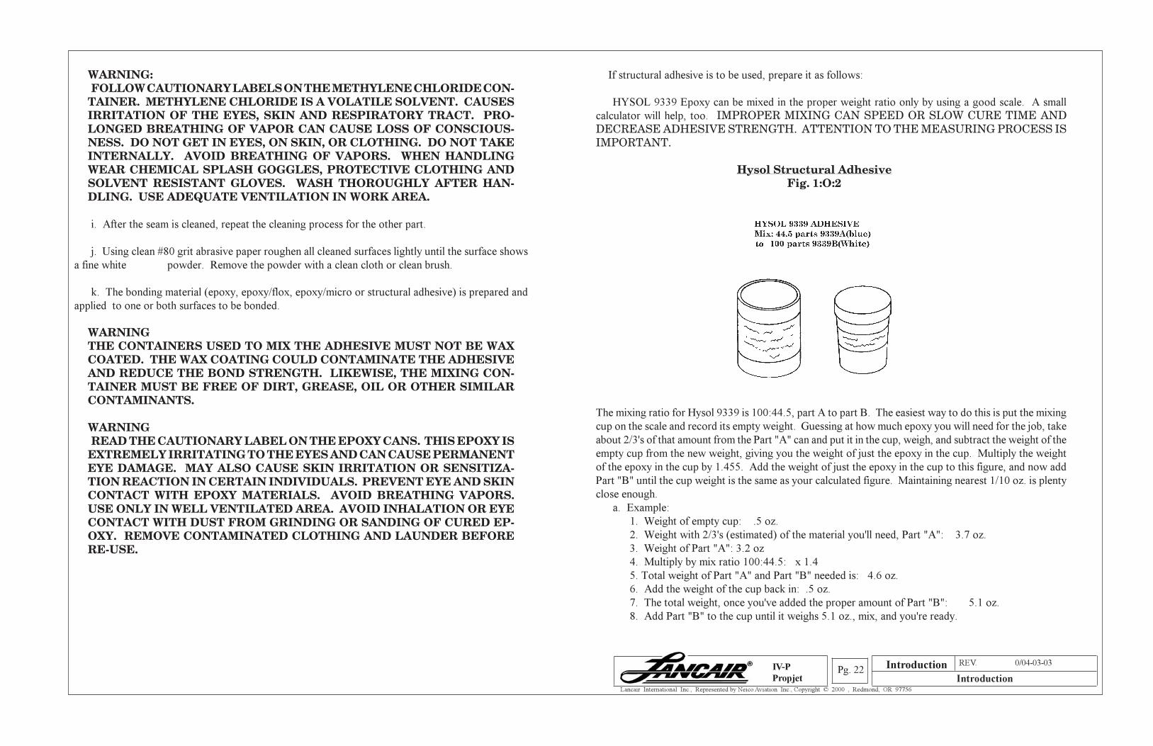
If structural adhesive is to be used, prepare it as follows:
HYSOL 9339 Epoxy can be mixed in the proper weight ratio only by using a good scale. A small
calculator will help, too. IMPROPER MIXING CAN SPEED OR SLOW CURE TIME ANDDECREASE ADHESIVE STRENGTH. ATTENTION TO THE MEASURING PROCESS ISIMPORTANT.
Hysol Structural AdhesiveFig. 1:O:2
The mixing ratio for Hysol 9339 is 100:44.5, part A to part B. The easiest way to do this is put the mixing
cup on the scale and record its empty weight. Guessing at how much epoxy you will need for the job, take
about 2/3's of that amount from the Part "A" can and put it in the cup, weigh, and subtract the weight of the
empty cup from the new weight, giving you the weight of just the epoxy in the cup. Multiply the weight
of the epoxy in the cup by 1.455. Add the weight of just the epoxy in the cup to this figure, and now add
Part "B" until the cup weight is the same as your calculated figure. Maintaining nearest 1/10 oz. is plenty
close enough.
a. Example:
1. Weight of empty cup: .5 oz.
2. Weight with 2/3's (estimated) of the material you'll need, Part "A": 3.7 oz.
3. Weight of Part "A": 3.2 oz
4. Multiply by mix ratio 100:44.5: x 1.4
5. Total weight of Part "A" and Part "B" needed is: 4.6 oz.
6. Add the weight of the cup back in: .5 oz.
7. The total weight, once you've added the proper amount of Part "B": 5.1 oz.
8. Add Part "B" to the cup until it weighs 5.1 oz., mix, and you're ready.
Introduction
Section A REV. 0/04-03-03
IntroductionPg. 23
Lancair International Inc., Represented by Neico Aviation Inc., Copyright © 2000 , Redmond, OR 97756
IV-P
Propjet
b. Mix the Hysol 9339 epoxy adhesive components as follows:
1. Read all the instructions and information on the epoxy cans. Temperature of the adhesive
ingredients and the surrounding room temperature must be 60°F or more.
2. The 9339 adhesive has a working life of 2 hours at 77°F. However, at higher
temperatures or with a larger batch this working life will be less. Therefore, before mixing
adhesive, all necessary equipment should be ready.
3. For the same reason, it is better to mix too much adhesive than too little. If you run out
and must mix a second batch, the first batch may have already begun to thicken making it
difficult to compress the seam properly and possibly reducing bond strength when cured.
Another reason for mixing more than you need- If you have a little left over, leave it in the corner
of the cup with the mixing stick in it. Because cure time varies with temperature, by leaving
a little in the cup and leaving the cup near the part you have epoxied, the cup can now be used
as your test for curing. Wait at least 24 hours after joining parts. Then, before touching parts,
try to move the stick around in the epoxy in the cup. If you can move it at all, your parts have
not cured. Wait another 24 hours and repeat. Handling parts before cure is complete can reduce
the bond strength, and should be avoided.
The epoxy cure time depends on the temperature during cure time. Because of the fire hazards
involved with most heaters, it is not recommended to have a heater operating in the room that
could cause a fire. However, getting the room nice and warm before applying adhesive, so the
parts and air temperature is above 77°F, will help shorten cure times, but remember it will also
shorten the pot life/working time of the adhesive.
(a) Estimate the amount of adhesive that you will need for the first seam and
measure a sufficient amount of Part "A" and "B" to make that amount.
(b) Using a mixing stick, thoroughly mix the two parts for at least two minutes. Mix
longer for larger batches. Occasionally scrape unmixed material from the sides
of the cup. Uniform blue-gray color will result.
(c) Apply the structural adhesive as follows (the following assumes the seams have
been cleaned and sanded as previously described. If not, do so at this time).
(1) Beginning with the seam of the first part you have chosen to start on, with a wood spatula, spread
an even layer of adhesive on the overlap surface of the part. Repeat the adhesive application
process on the overlap surface of the other part.
(2) Overlap the two adhesive coated surfaces and align the holes in the surfaces. Insert a screw or
cleco into a hole at each end of the part, or every foot along the part if it is longer than 18". Starting
at either end, insert rivets into the predrilled holes and form the heads (backup washers are
normally not necessary).
(d) Remove the fasteners and place rivets into those holes.
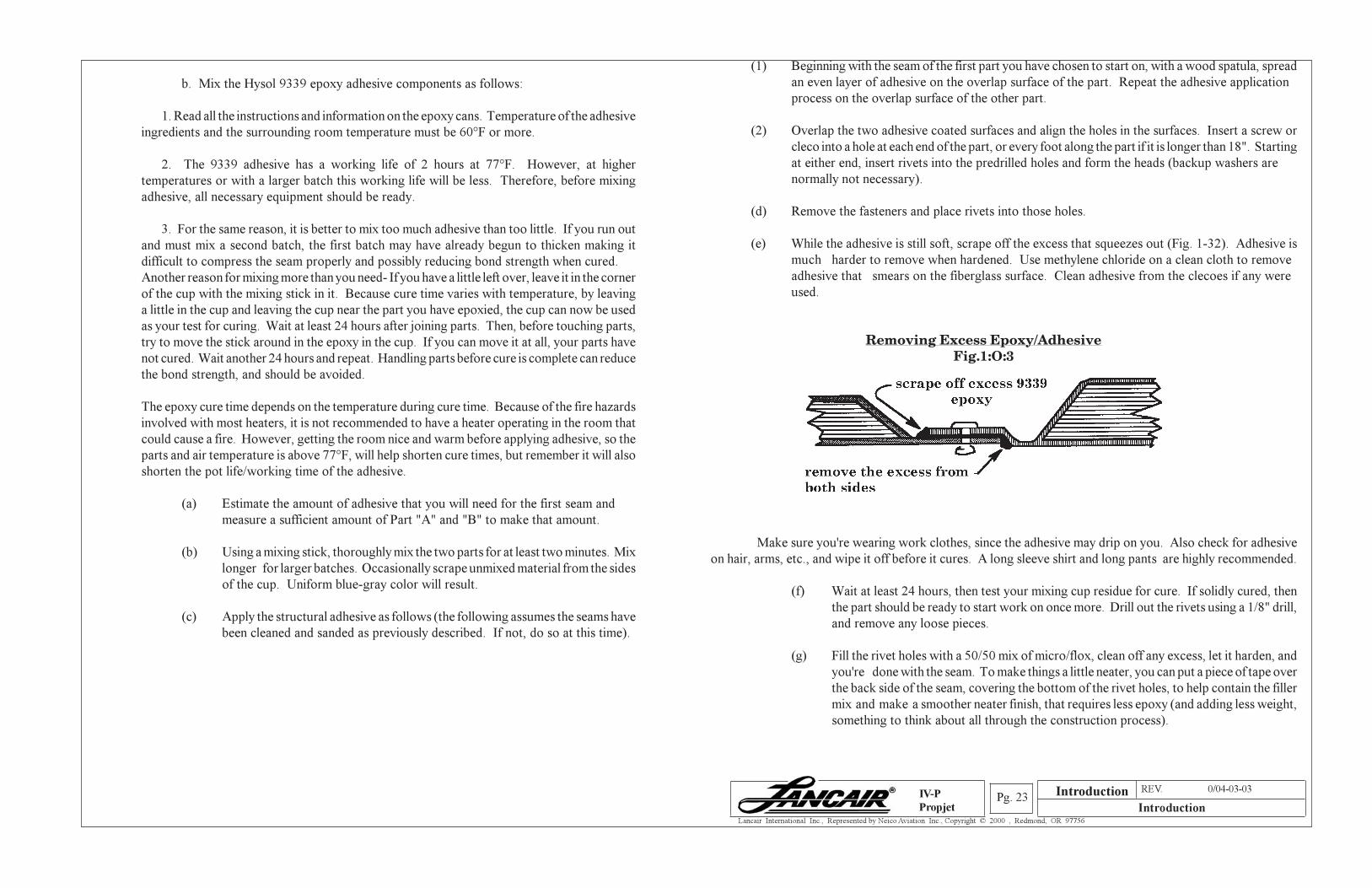
(e) While the adhesive is still soft, scrape off the excess that squeezes out (Fig. 1-32). Adhesive is
much harder to remove when hardened. Use methylene chloride on a clean cloth to remove
adhesive that smears on the fiberglass surface. Clean adhesive from the clecoes if any were
used.
Removing Excess Epoxy/AdhesiveFig.1:O:3
Make sure you're wearing work clothes, since the adhesive may drip on you. Also check for adhesive
on hair, arms, etc., and wipe it off before it cures. A long sleeve shirt and long pants are highly recommended.
(f) Wait at least 24 hours, then test your mixing cup residue for cure. If solidly cured, then
the part should be ready to start work on once more. Drill out the rivets using a 1/8" drill,
and remove any loose pieces.
(g) Fill the rivet holes with a 50/50 mix of micro/flox, clean off any excess, let it harden, and
you're done with the seam. To make things a little neater, you can put a piece of tape over
the back side of the seam, covering the bottom of the rivet holes, to help contain the filler
mix and make a smoother neater finish, that requires less epoxy (and adding less weight,
something to think about all through the construction process).
Introduction
Section A REV. 0/04-03-03
IntroductionPg. 24
Lancair International Inc., Represented by Neico Aviation Inc., Copyright © 2000 , Redmond, OR 97756
IV-P
Propjet
3. Epoxy
(a) Mixing epoxy: As with the structural adhesive, you can use a scale for measuring the proper
amount of laminating resin and hardener. There are also some good measuring pumps on the market
that will probably pay for themselves (about $265) since you'll waste less epoxy with them, and have
less chance of spills or improper mixes. We offer one in our catalog that has performed well here in our
own shop for years now.
Typically, you will be using from 1 to 6 ounces at a time.
If you prefer to use a scale instead of a dispenser, you can measure the two parts as you did for the Hysol,
except use 1.44 instead of 1.445.
Another way is (Jeffco resin system used here for example purposes only. Use the appropriate ratios
for your supplied system of resins.)
(1) Place your empty cup on the scale.
(2) Record the weight of the empty cup.
(3) Estimate amount of epoxy you will need.
(4) Add .25 oz of hardener (yellowish) to cup for each 1-1/4 oz you'll
need.
(5) Pour 1 oz of resin (clear) into cup for each .25 oz of hardener and
mix thoroughly.
(a) Working time can be as short as ten minutes if it is hot, so be sure everything
is in place and ready to go before you begin mixing.
(b) As with the Hysol, the surfaces must be totally free of oil, grease or other
contaminants, and slightly roughened. Fasten with pop rivets, let harden,
remove fasteners & fill holes.
NOTE: USE CARE TO MIX YOUR RESINS AND ADHESIVES ACCORDINGTO THE MANUFACTURER'S INSTRUCTIONS FOR THE PARTICULARSYSTEM YOU ARE USING. THEY ARE ALL DIFFERENT. AN IMPROPERMIX RATIO COULD RESULT IN IMPROPER BONDING - OR NO BONDINGAT ALL.
BE CAREFUL TO PAY ATTENTION TO THE MANUFACTURER'S INSTRUCTIONS!!!
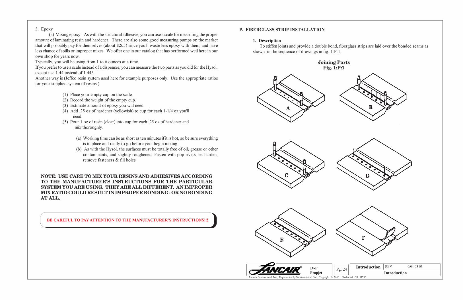
P. FIBERGLASS STRIP INSTALLATION
1. Description
To stiffen joints and provide a double bond, fiberglass strips are laid over the bonded seams as
shown in the sequence of drawings in fig. 1:P:1.
Joining PartsFig. 1:P:1
Introduction
Section A REV. 0/04-03-03
IntroductionPg. 25
Lancair International Inc., Represented by Neico Aviation Inc., Copyright © 2000 , Redmond, OR 97756
IV-P
Propjet
a. Fig. 1:P:1A shows the two pieces to be joined. After the adhesive has been place along
the inside of both pieces to be joined, the two clecoes were installed to hold the parts in
alignment.
b. Fig. 1:P:1B shows pop rivets set into the other holes drilled 1" apart for the length of the
seam.
c. Figure 1:P:1C shows the pop rivets after being compressed.
d. In figure 1:P:1D, the two clecoes have been removed and replaced with pop rivets
awaiting compression.
e. Figure 1:P:1E displays the two parts, waiting patiently for the adhesive to cure.
Preparing Seam For BID TapeFig. 1:P:2
f. After the adhesive has cured, the pop rivets are drilled out, the holes filled with a 50/50
mix of flox and micro (see Fig. 1:P:2) and, without a need to wait for that to cure, a bid
strip is being laid into place over the top of the joggles.
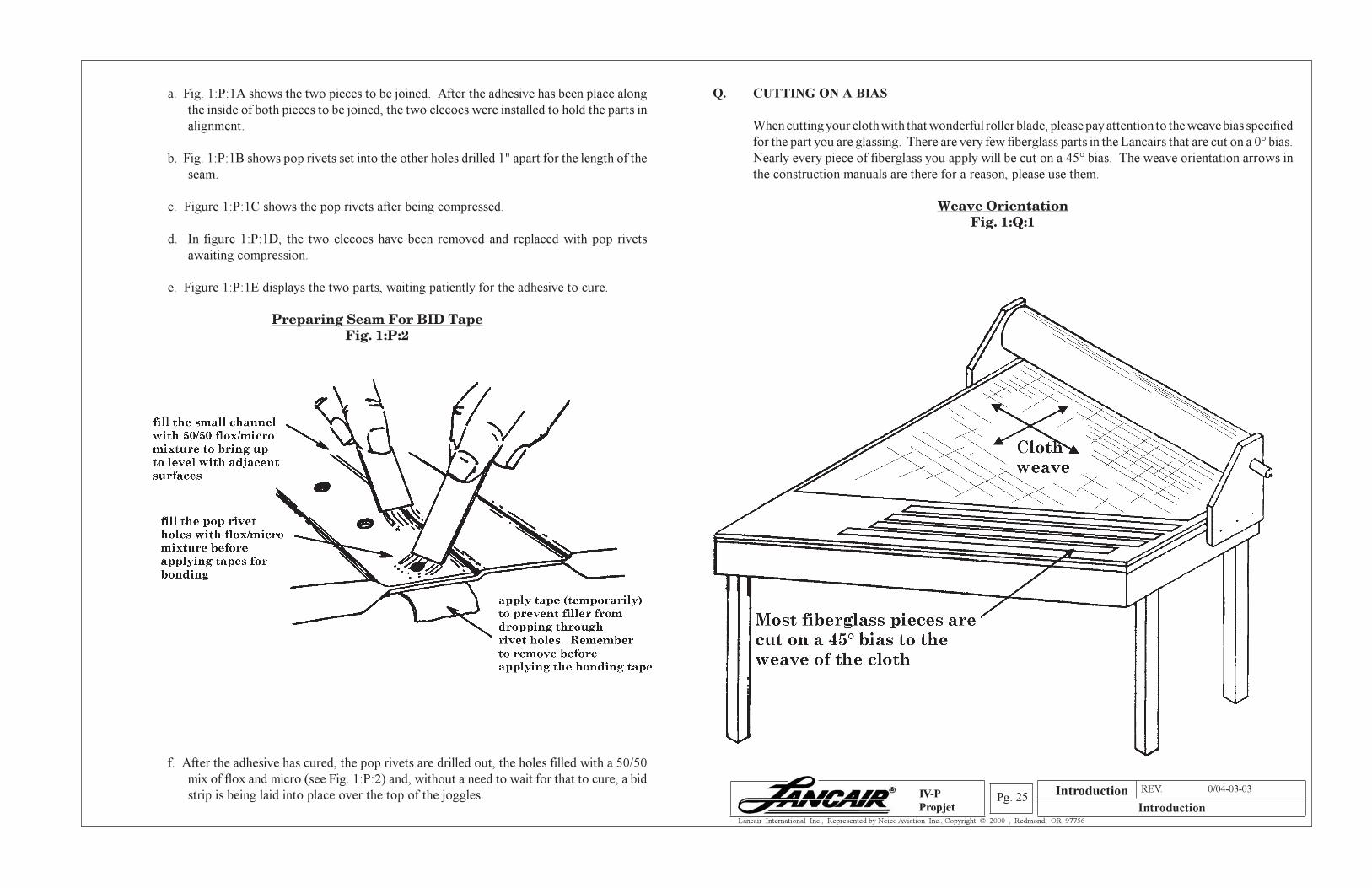
Q. CUTTING ON A BIAS
When cutting your cloth with that wonderful roller blade, please pay attention to the weave bias specified
for the part you are glassing. There are very few fiberglass parts in the Lancairs that are cut on a 0° bias.
Nearly every piece of fiberglass you apply will be cut on a 45° bias. The weave orientation arrows in
the construction manuals are there for a reason, please use them.
Weave OrientationFig. 1:Q:1
Introduction
Section A REV. 0/04-03-03
IntroductionPg. 26
Lancair International Inc., Represented by Neico Aviation Inc., Copyright © 2000 , Redmond, OR 97756
IV-P
Propjet
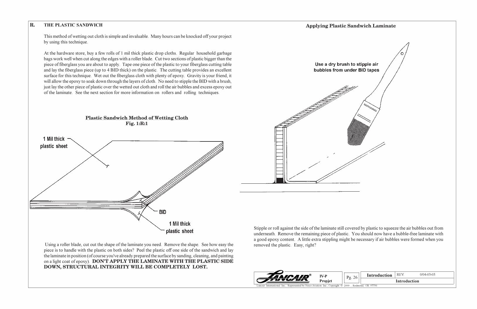
Stipple or roll against the side of the laminate still covered by plastic to squeeze the air bubbles out from
underneath. Remove the remaining piece of plastic. You should now have a bubble-free laminate with
a good epoxy content. A little extra stippling might be necessary if air bubbles were formed when you
removed the plastic. Easy, right?
R. THE PLASTIC SANDWICH
This method of wetting out cloth is simple and invaluable. Many hours can be knocked off your project
by using this technique.
At the hardware store, buy a few rolls of 1 mil thick plastic drop cloths. Regular household garbage
bags work well when cut along the edges with a roller blade. Cut two sections of plastic bigger than the
piece of fiberglass you are about to apply. Tape one piece of the plastic to your fiberglass cutting table
and lay the fiberglass piece (up to 4 BID thick) on the plastic. The cutting table provides an excellent
surface for this technique. Wet out the fiberglass cloth with plenty of epoxy. Gravity is your friend, it
will allow the epoxy to soak down through the layers of cloth. No need to stipple the BID with a brush,
just lay the other piece of plastic over the wetted out cloth and roll the air bubbles and excess epoxy out
of the laminate. See the next section for more information on rollers and rolling techniques.
Plastic Sandwich Method of Wetting ClothFig. 1:R:1
Using a roller blade, cut out the shape of the laminate you need. Remove the shape. See how easy the
piece is to handle with the plastic on both sides? Peel the plastic off one side of the sandwich and lay
the laminate in position (of course you've already prepared the surface by sanding, cleaning, and painting
on a light coat of epoxy). DON'T APPLY THE LAMINATE WITH THE PLASTIC SIDEDOWN, STRUCTURAL INTEGRITY WILL BE COMPLETELY LOST.
Applying Plastic Sandwich Laminate
Introduction
Section A REV. 0/04-03-03
IntroductionPg. 27
Lancair International Inc., Represented by Neico Aviation Inc., Copyright © 2000 , Redmond, OR 97756
IV-P
Propjet
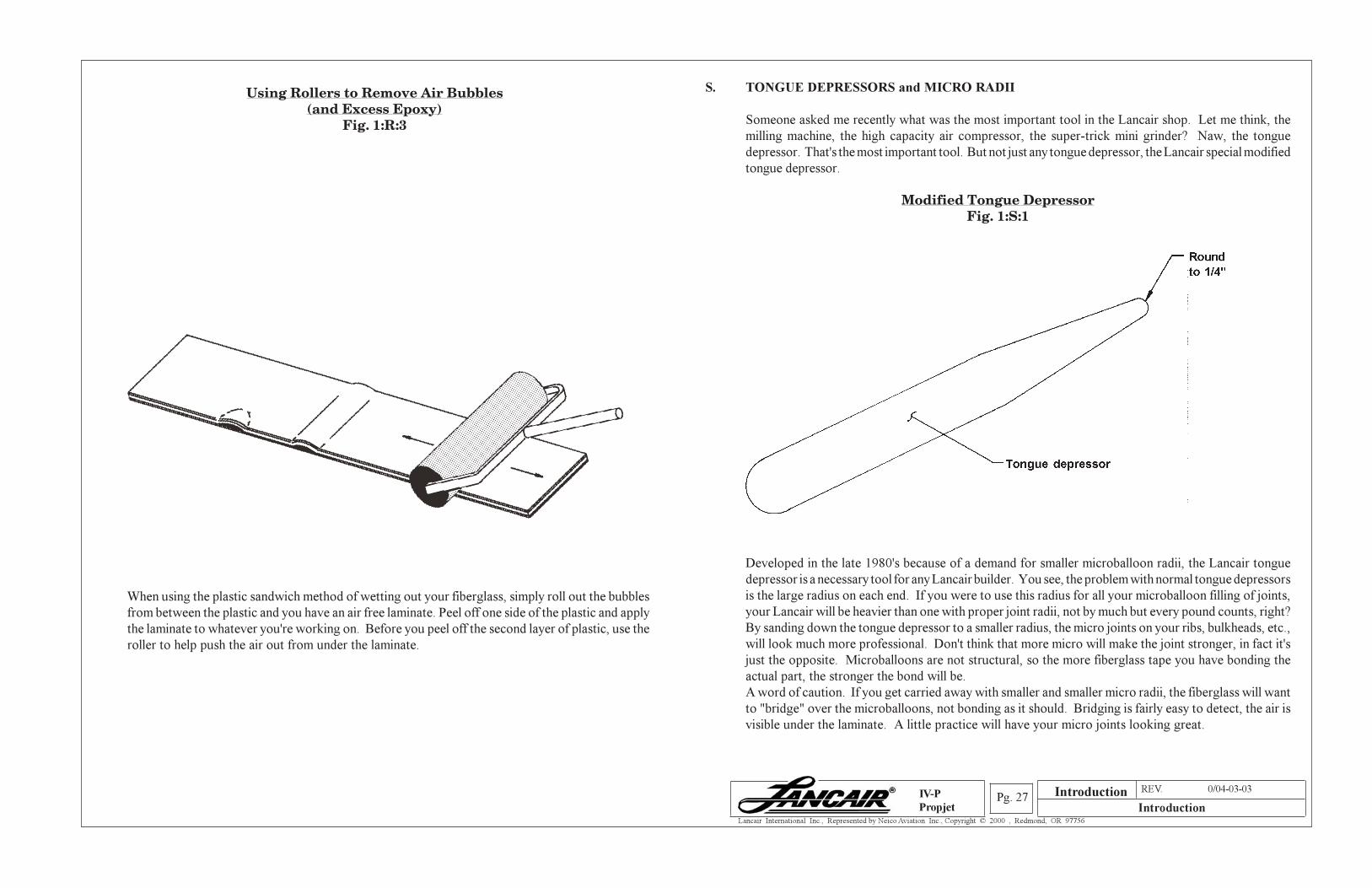
Using Rollers to Remove Air Bubbles(and Excess Epoxy)
Fig. 1:R:3
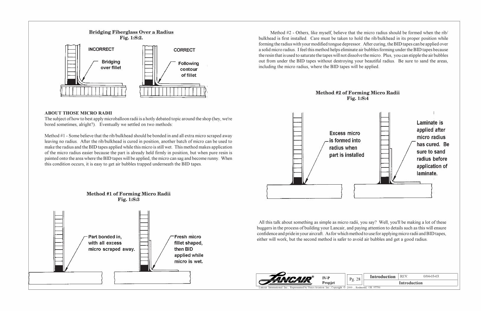
S. TONGUE DEPRESSORS and MICRO RADII
Someone asked me recently what was the most important tool in the Lancair shop. Let me think, the
milling machine, the high capacity air compressor, the super-trick mini grinder? Naw, the tongue
depressor. That's the most important tool. But not just any tongue depressor, the Lancair special modified
tongue depressor.
Modified Tongue DepressorFig. 1:S:1
Developed in the late 1980's because of a demand for smaller microballoon radii, the Lancair tongue
depressor is a necessary tool for any Lancair builder. You see, the problem with normal tongue depressors
is the large radius on each end. If you were to use this radius for all your microballoon filling of joints,
your Lancair will be heavier than one with proper joint radii, not by much but every pound counts, right?
By sanding down the tongue depressor to a smaller radius, the micro joints on your ribs, bulkheads, etc.,
will look much more professional. Don't think that more micro will make the joint stronger, in fact it's
just the opposite. Microballoons are not structural, so the more fiberglass tape you have bonding the
actual part, the stronger the bond will be.
A word of caution. If you get carried away with smaller and smaller micro radii, the fiberglass will want
to "bridge" over the microballoons, not bonding as it should. Bridging is fairly easy to detect, the air is
visible under the laminate. A little practice will have your micro joints looking great.
When using the plastic sandwich method of wetting out your fiberglass, simply roll out the bubbles
from between the plastic and you have an air free laminate. Peel off one side of the plastic and apply
the laminate to whatever you're working on. Before you peel off the second layer of plastic, use the
roller to help push the air out from under the laminate.
Introduction
Section A REV. 0/04-03-03
IntroductionPg. 28
Lancair International Inc., Represented by Neico Aviation Inc., Copyright © 2000 , Redmond, OR 97756
IV-P
Propjet
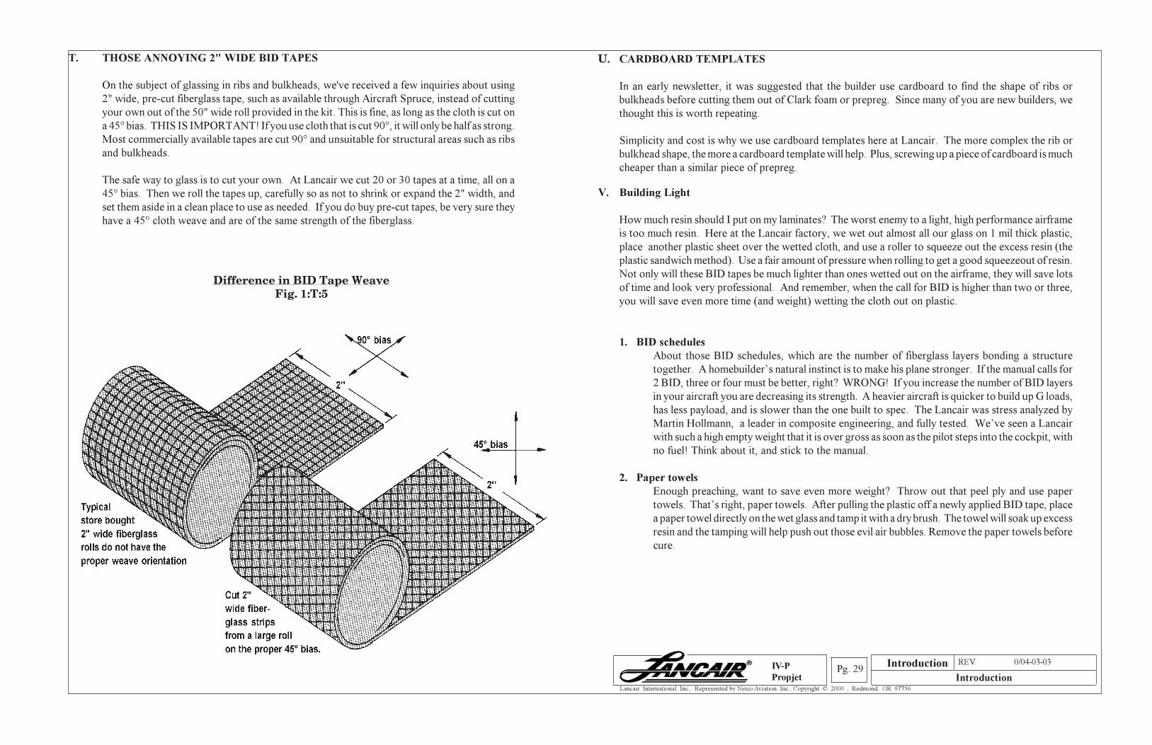
ABOUT THOSE MICRO RADII
The subject of how to best apply microballoon radii is a hotly debated topic around the shop (hey, we're
bored sometimes, alright?). Eventually we settled on two methods:
Method #1 - Some believe that the rib/bulkhead should be bonded in and all extra micro scraped away
leaving no radius. After the rib/bulkhead is cured in position, another batch of micro can be used to
make the radius and the BID tapes applied while this micro is still wet. This method makes application
of the micro radius easier because the part is already held firmly in position, but when pure resin is
painted onto the area where the BID tapes will be applied, the micro can sag and become runny. When
this condition occurs, it is easy to get air bubbles trapped underneath the BID tapes.
Method #1 of Forming Micro RadiiFig. 1:S:3
Bridging Fiberglass Over a RadiusFig. 1:S:2.
Method #2 - Others, like myself, believe that the micro radius should be formed when the rib/
bulkhead is first installed. Care must be taken to hold the rib/bulkhead in its proper position while
forming the radius with your modified tongue depressor. After curing, the BID tapes can be applied over
a solid micro radius. I feel this method helps eliminate air bubbles forming under the BID tapes because
the resin that is used to saturate the tapes will not dissolve the micro. Plus, you can stipple the air bubbles
out from under the BID tapes without destroying your beautiful radius. Be sure to sand the areas,
including the micro radius, where the BID tapes will be applied.
Method #2 of Forming Micro RadiiFig. 1:S:4
All this talk about something as simple as micro radii, you say? Well, you'll be making a lot of these
buggers in the process of building your Lancair, and paying attention to details such as this will ensure
confidence and pride in your aircraft. As for which method to use for applying micro radii and BID tapes,
either will work, but the second method is safer to avoid air bubbles and get a good radius.
Introduction
Section A REV. 0/04-03-03
IntroductionPg. 29
Lancair International Inc., Represented by Neico Aviation Inc., Copyright © 2000 , Redmond, OR 97756
IV-P
Propjet
T. THOSE ANNOYING 2" WIDE BID TAPES
On the subject of glassing in ribs and bulkheads, we've received a few inquiries about using
2" wide, pre-cut fiberglass tape, such as available through Aircraft Spruce, instead of cutting
your own out of the 50" wide roll provided in the kit. This is fine, as long as the cloth is cut on
a 45° bias. THIS IS IMPORTANT! If you use cloth that is cut 90°, it will only be half as strong.
Most commercially available tapes are cut 90° and unsuitable for structural areas such as ribs
and bulkheads.
The safe way to glass is to cut your own. At Lancair we cut 20 or 30 tapes at a time, all on a
45° bias. Then we roll the tapes up, carefully so as not to shrink or expand the 2" width, and
set them aside in a clean place to use as needed. If you do buy pre-cut tapes, be very sure they
have a 45° cloth weave and are of the same strength of the fiberglass.
Difference in BID Tape WeaveFig. 1:T:5
U. CARDBOARD TEMPLATES
In an early newsletter, it was suggested that the builder use cardboard to find the shape of ribs or
bulkheads before cutting them out of Clark foam or prepreg. Since many of you are new builders, we
thought this is worth repeating.
Simplicity and cost is why we use cardboard templates here at Lancair. The more complex the rib or
bulkhead shape, the more a cardboard template will help. Plus, screwing up a piece of cardboard is much
cheaper than a similar piece of prepreg.
V. Building Light
How much resin should I put on my laminates? The worst enemy to a light, high performance airframe
is too much resin. Here at the Lancair factory, we wet out almost all our glass on 1 mil thick plastic,
place another plastic sheet over the wetted cloth, and use a roller to squeeze out the excess resin (the
plastic sandwich method). Use a fair amount of pressure when rolling to get a good squeezeout of resin.
Not only will these BID tapes be much lighter than ones wetted out on the airframe, they will save lots
of time and look very professional. And remember, when the call for BID is higher than two or three,
you will save even more time (and weight) wetting the cloth out on plastic.
1. BID schedules
About those BID schedules, which are the number of fiberglass layers bonding a structure
together. A homebuilder’s natural instinct is to make his plane stronger. If the manual calls for
2 BID, three or four must be better, right? WRONG! If you increase the number of BID layers
in your aircraft you are decreasing its strength. A heavier aircraft is quicker to build up G loads,
has less payload, and is slower than the one built to spec. The Lancair was stress analyzed by
Martin Hollmann, a leader in composite engineering, and fully tested. We’ve seen a Lancair
with such a high empty weight that it is over gross as soon as the pilot steps into the cockpit, with
no fuel! Think about it, and stick to the manual.
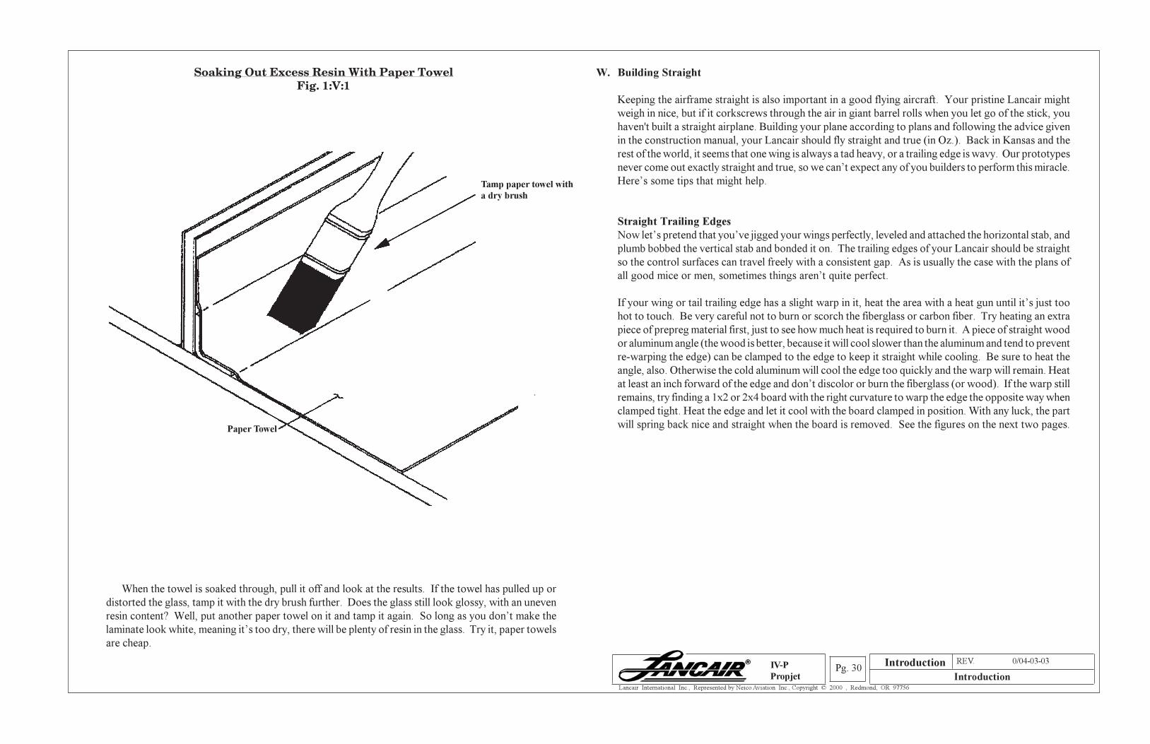
2. Paper towels
Enough preaching, want to save even more weight? Throw out that peel ply and use paper
towels. That’s right, paper towels. After pulling the plastic off a newly applied BID tape, place
a paper towel directly on the wet glass and tamp it with a dry brush. The towel will soak up excess
resin and the tamping will help push out those evil air bubbles. Remove the paper towels before
cure.
Introduction
Section A REV. 0/04-03-03
IntroductionPg. 30
Lancair International Inc., Represented by Neico Aviation Inc., Copyright © 2000 , Redmond, OR 97756
IV-P
Propjet
Soaking Out Excess Resin With Paper TowelFig. 1:V:1
When the towel is soaked through, pull it off and look at the results. If the towel has pulled up or
distorted the glass, tamp it with the dry brush further. Does the glass still look glossy, with an uneven
resin content? Well, put another paper towel on it and tamp it again. So long as you don’t make the
laminate look white, meaning it’s too dry, there will be plenty of resin in the glass. Try it, paper towels
are cheap.
W. Building Straight
Keeping the airframe straight is also important in a good flying aircraft. Your pristine Lancair might
weigh in nice, but if it corkscrews through the air in giant barrel rolls when you let go of the stick, you
haven't built a straight airplane. Building your plane according to plans and following the advice given
in the construction manual, your Lancair should fly straight and true (in Oz.). Back in Kansas and the
rest of the world, it seems that one wing is always a tad heavy, or a trailing edge is wavy. Our prototypes
never come out exactly straight and true, so we can’t expect any of you builders to perform this miracle.
Here’s some tips that might help.
Straight Trailing Edges
Now let’s pretend that you’ve jigged your wings perfectly, leveled and attached the horizontal stab, and
plumb bobbed the vertical stab and bonded it on. The trailing edges of your Lancair should be straight
so the control surfaces can travel freely with a consistent gap. As is usually the case with the plans of
all good mice or men, sometimes things aren’t quite perfect.
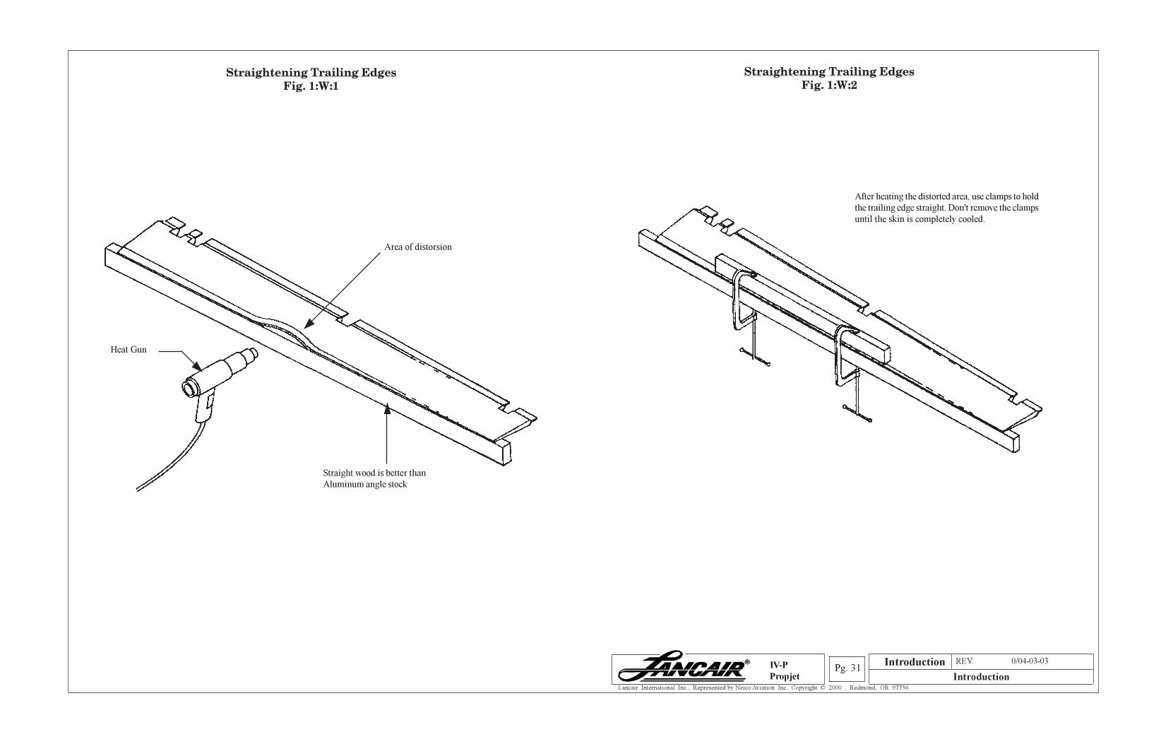
If your wing or tail trailing edge has a slight warp in it, heat the area with a heat gun until it’s just too
hot to touch. Be very careful not to burn or scorch the fiberglass or carbon fiber. Try heating an extra
piece of prepreg material first, just to see how much heat is required to burn it. A piece of straight wood
or aluminum angle (the wood is better, because it will cool slower than the aluminum and tend to prevent
re-warping the edge) can be clamped to the edge to keep it straight while cooling. Be sure to heat the
angle, also. Otherwise the cold aluminum will cool the edge too quickly and the warp will remain. Heat
at least an inch forward of the edge and don’t discolor or burn the fiberglass (or wood). If the warp still
remains, try finding a 1x2 or 2x4 board with the right curvature to warp the edge the opposite way when
clamped tight. Heat the edge and let it cool with the board clamped in position. With any luck, the part
will spring back nice and straight when the board is removed. See the figures on the next two pages.
Tamp paper towel with
a dry brush
Paper Towel
Introduction
Section A REV. 0/04-03-03
IntroductionPg. 31
Lancair International Inc., Represented by Neico Aviation Inc., Copyright © 2000 , Redmond, OR 97756
IV-P
Propjet
Straightening Trailing EdgesFig. 1:W:1
Straightening Trailing EdgesFig. 1:W:2
Area of distorsion
Straight wood is better than
Aluminum angle stock
Heat Gun
After heating the distorted area, use clamps to hold
the trailing edge straight. Don't remove the clamps
until the skin is completely cooled.
Introduction
Section A REV. 0/04-03-03
IntroductionPg. 32
Lancair International Inc., Represented by Neico Aviation Inc., Copyright © 2000 , Redmond, OR 97756
IV-P
Propjet
X. CONTROL SYSTEMS
Pushrod Tips
a. After cutting the pushrod tube to length, don’t immediately rivet the rod end in position. It is better
to test the pushrod in the system (flap, aileron, elevator) by temporarily securing the rod ends to the
pushrod with instant glue. Use only a few drops of glue to secure the rod end or the bond may become
more than temporary. Don’t cover the rod end with glue then slide it into the pushrod, the bond
would be impossible to break free. Once you determine the tube is the proper length, you can break
the rod ends free, clean them up, and rivet them in place.
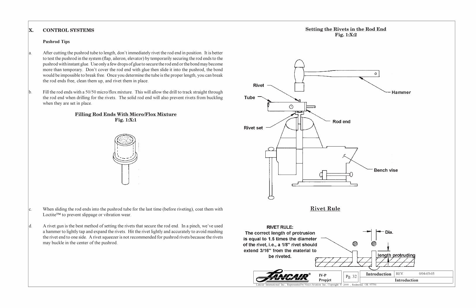
b. Fill the rod ends with a 50/50 micro/flox mixture. This will allow the drill to track straight through
the rod end when drilling for the rivets. The solid rod end will also prevent rivets from buckling
when they are set in place.
Filling Rod Ends With Micro/Flox MixtureFig. 1:X:1
c. When sliding the rod ends into the pushrod tube for the last time (before riveting), coat them with
Loctite™ to prevent slippage or vibration wear.
d. A rivet gun is the best method of setting the rivets that secure the rod end. In a pinch, we’ve used
a hammer to lightly tap and expand the rivets. Hit the rivet lightly and accurately to avoid mashing
the rivet end to one side. A rivet squeezer is not recommended for pushrod rivets because the rivets
may buckle in the center of the pushrod.
Setting the Rivets in the Rod EndFig. 1:X:2
Introduction
Section A REV. 0/04-03-03
IntroductionPg. 33
Lancair International Inc., Represented by Neico Aviation Inc., Copyright © 2000 , Redmond, OR 97756
IV-P
Propjet
1. Painting pushrods
At Lancair we usually spray paint our pushrods with one coat of Zinc Chromate and one coat
of color. Hardware store spray cans are fine for the color coat and you can choose from all
kinds of nifty colors.
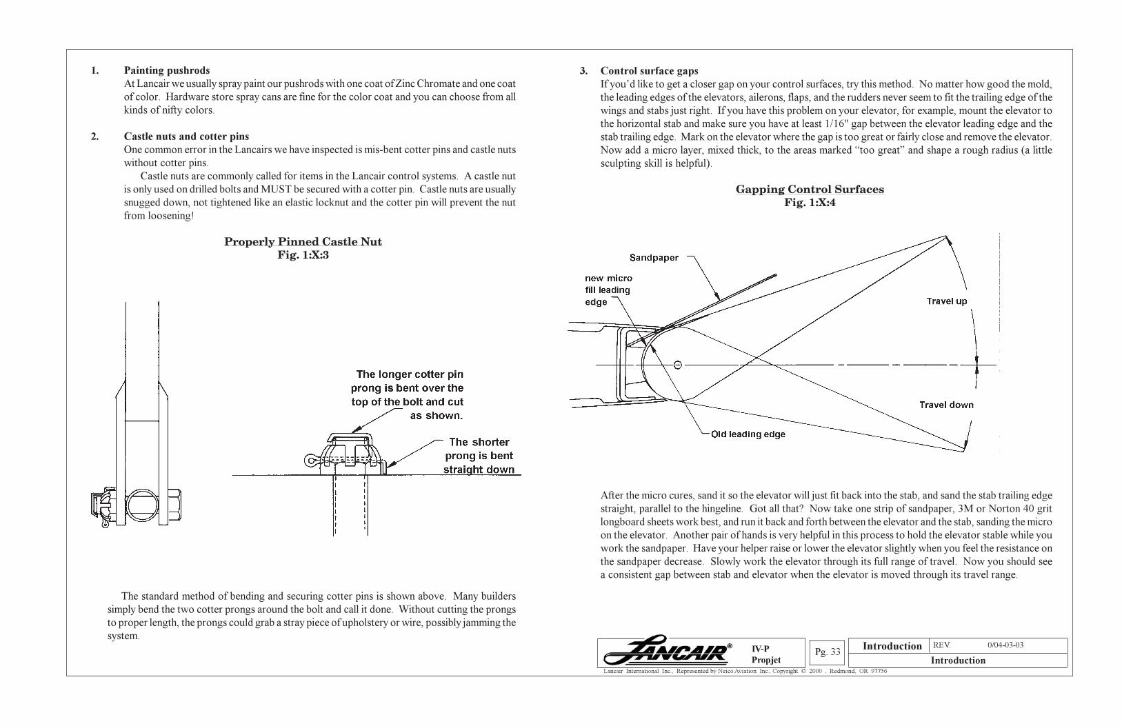
2. Castle nuts and cotter pins
One common error in the Lancairs we have inspected is mis-bent cotter pins and castle nuts
without cotter pins.
Castle nuts are commonly called for items in the Lancair control systems. A castle nut
is only used on drilled bolts and MUST be secured with a cotter pin. Castle nuts are usually
snugged down, not tightened like an elastic locknut and the cotter pin will prevent the nut
from loosening!
Properly Pinned Castle NutFig. 1:X:3
The standard method of bending and securing cotter pins is shown above. Many builders
simply bend the two cotter prongs around the bolt and call it done. Without cutting the prongs
to proper length, the prongs could grab a stray piece of upholstery or wire, possibly jamming the
system.
3. Control surface gaps
If you’d like to get a closer gap on your control surfaces, try this method. No matter how good the mold,
the leading edges of the elevators, ailerons, flaps, and the rudders never seem to fit the trailing edge of the
wings and stabs just right. If you have this problem on your elevator, for example, mount the elevator to
the horizontal stab and make sure you have at least 1/16" gap between the elevator leading edge and the
stab trailing edge. Mark on the elevator where the gap is too great or fairly close and remove the elevator.
Now add a micro layer, mixed thick, to the areas marked “too great” and shape a rough radius (a little
sculpting skill is helpful).
Gapping Control SurfacesFig. 1:X:4
After the micro cures, sand it so the elevator will just fit back into the stab, and sand the stab trailing edge
straight, parallel to the hingeline. Got all that? Now take one strip of sandpaper, 3M or Norton 40 grit
longboard sheets work best, and run it back and forth between the elevator and the stab, sanding the micro
on the elevator. Another pair of hands is very helpful in this process to hold the elevator stable while you
work the sandpaper. Have your helper raise or lower the elevator slightly when you feel the resistance on
the sandpaper decrease. Slowly work the elevator through its full range of travel. Now you should see
a consistent gap between stab and elevator when the elevator is moved through its travel range.
Introduction
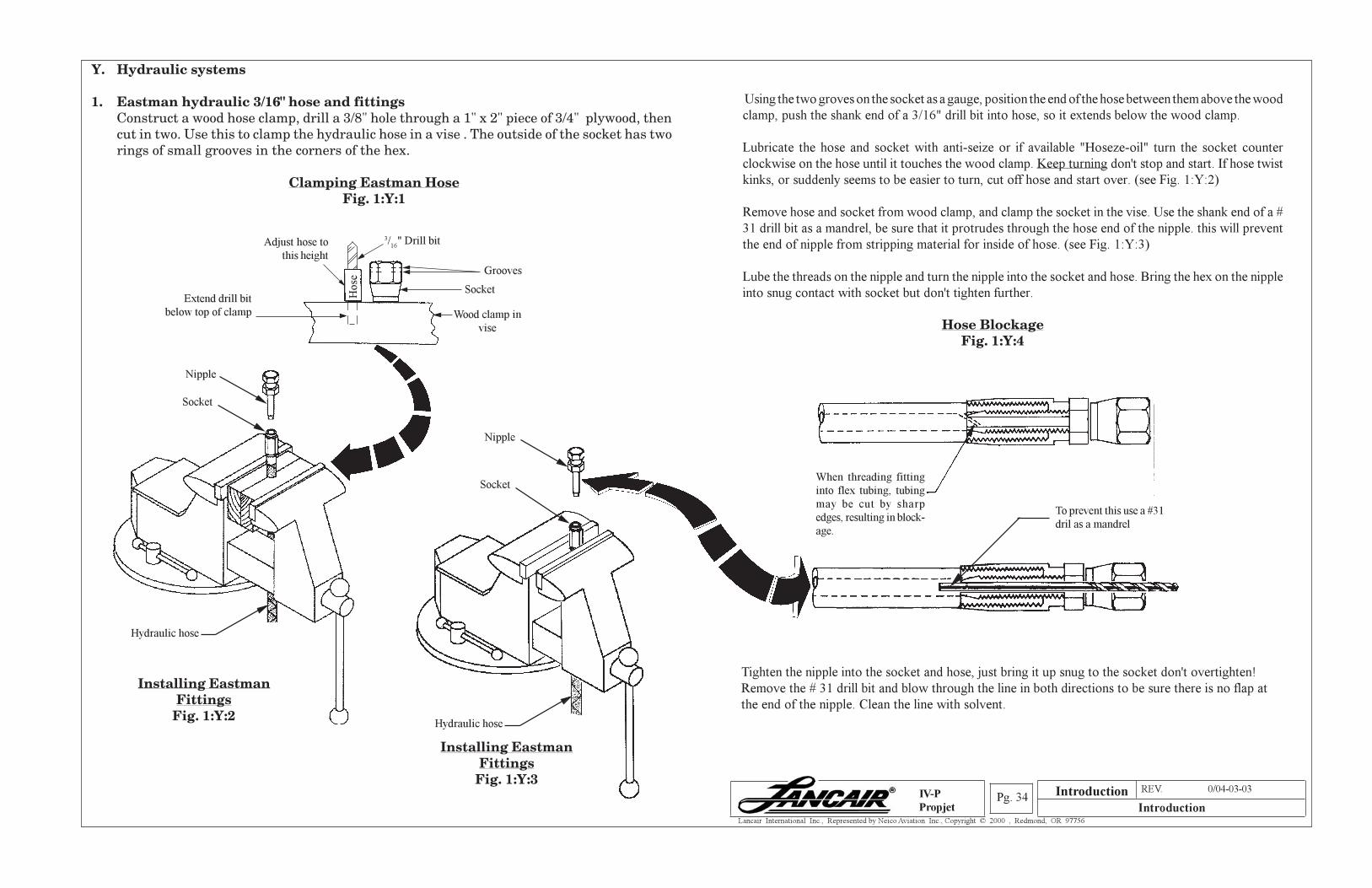
Section A REV. 0/04-03-03
IntroductionPg. 34
Lancair International Inc., Represented by Neico Aviation Inc., Copyright © 2000 , Redmond, OR 97756
IV-P
Propjet
Y. Hydraulic systems
1. Eastman hydraulic 3/16" hose and fittingsConstruct a wood hose clamp, drill a 3/8" hole through a 1" x 2" piece of 3/4" plywood, thencut in two. Use this to clamp the hydraulic hose in a vise . The outside of the socket has tworings of small grooves in the corners of the hex.
Clamping Eastman HoseFig. 1:Y:1
Using the two groves on the socket as a gauge, position the end of the hose between them above the wood
clamp, push the shank end of a 3/16" drill bit into hose, so it extends below the wood clamp.
Lubricate the hose and socket with anti-seize or if available "Hoseze-oil" turn the socket counter
clockwise on the hose until it touches the wood clamp. Keep turning don't stop and start. If hose twist
kinks, or suddenly seems to be easier to turn, cut off hose and start over. (see Fig. 1:Y:2)
Remove hose and socket from wood clamp, and clamp the socket in the vise. Use the shank end of a #
31 drill bit as a mandrel, be sure that it protrudes through the hose end of the nipple. this will prevent
the end of nipple from stripping material for inside of hose. (see Fig. 1:Y:3)
Lube the threads on the nipple and turn the nipple into the socket and hose. Bring the hex on the nipple
into snug contact with socket but don't tighten further.
Hose BlockageFig. 1:Y:4
Tighten the nipple into the socket and hose, just bring it up snug to the socket don't overtighten!
Remove the # 31 drill bit and blow through the line in both directions to be sure there is no flap at
the end of the nipple. Clean the line with solvent.
Adjust hose to
this height
Wood clamp in
vise
Hose
Grooves
Extend drill bit
below top of clamp
3/16
" Drill bit
Socket
When threading fitting
into flex tubing, tubing
may be cut by sharp
edges, resulting in block-
age.
To prevent this use a #31
dril as a mandrel
Installing EastmanFittings
Fig. 1:Y:2
Nipple
Socket
Hydraulic hose
Nipple
Socket
Hydraulic hose
Installing EastmanFittings
Fig. 1:Y:3Introduction
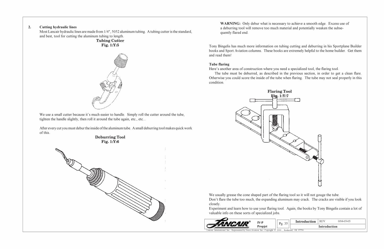
Section A REV. 0/04-03-03
IntroductionPg. 35
Lancair International Inc., Represented by Neico Aviation Inc., Copyright © 2000 , Redmond, OR 97756
IV-P
Propjet
2. Cutting hydraulic lines
Most Lancair hydraulic lines are made from 1/4", 5052 aluminum tubing. A tubing cutter is the standard,
and best, tool for cutting the aluminum tubing to length.
Tubing CutterFig. 1:Y:5
WARNING: Only debur what is necessary to achieve a smooth edge. Excess use of
a deburring tool will remove too much material and potentially weaken the subse-
quently flared end.
Tony Bingelis has much more information on tubing cutting and deburring in his Sportplane Builder
books and Sport Aviation columns. These books are extremely helpful to the home builder. Get them
and read them!
Tube flaring
Here’s another area of construction where you need a specialized tool, the flaring tool.
The tube must be deburred, as described in the previous section, in order to get a clean flare.
Otherwise you could score the inside of the tube when flaring. The tube may not seal properly in this
condition.
Flaring ToolFig. 1:Y:7
We use a small cutter because it’s much easier to handle. Simply roll the cutter around the tube,
tighten the handle slightly, then roll it around the tube again, etc., etc...
After every cut you must debur the inside of the aluminum tube. A small deburring tool makes quick work
of this.
Deburring ToolFig. 1:Y:6
We usually grease the cone shaped part of the flaring tool so it will not gouge the tube.
Don’t flare the tube too much, the expanding aluminum may crack. The cracks are visible if you look
closely.
Experiment and learn how to use your flaring tool. Again, the books by Tony Bingelis contain a lot of
valuable info on these sorts of specialized jobs.
Introduction
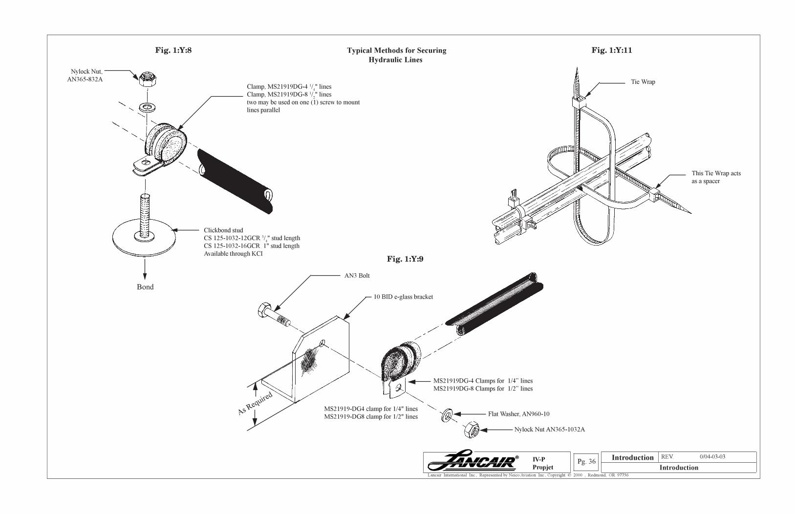
Section A REV. 0/04-03-03
IntroductionPg. 36
Lancair International Inc., Represented by Neico Aviation Inc., Copyright © 2000 , Redmond, OR 97756
IV-P
Propjet
Typical Methods for Securing
Hydraulic Lines
MS21919DG-4 Clamps for 1/4” lines
MS21919DG-8 Clamps for 1/2” lines
10 BID e-glass bracket
AN3 Bolt
As Req
uired
Tie Wrap
This Tie Wrap acts
as a spacer
Clickbond stud
CS 125-1032-12GCR 3/4" stud length
CS 125-1032-16GCR 1" stud length
Available through KCI
Clamp, MS21919DG-4 1/4" lines
Clamp, MS21919DG-8 1/2" lines
two may be used on one (1) screw to mount
lines parallel
Fig. 1:Y:8
Fig. 1:Y:9
Fig. 1:Y:11
Flat Washer, AN960-10
Nylock Nut AN365-1032A
MS21919-DG4 clamp for 1/4" lines
MS21919-DG8 clamp for 1/2" lines
Nylock Nut,
AN365-832A
Bond
Introduction
Section A REV. 0/04-03-03
IntroductionPg. 37
Lancair International Inc., Represented by Neico Aviation Inc., Copyright © 2000 , Redmond, OR 97756
IV-P
Propjet
Z. PAINTING
In the last year, the Lancair shop has prepared and painted Lancair prototypes. In the process, we’ve
learned a few basic painting tips and rules you may find interesting, or even helpful.
Painting is a disgusting, dirty, tedious, boring, stressful, sometimes toxic process that you will do once
and swear never to attempt again. Lock up all your weapons because with one slip of the spray gun, one
little mistake, you might feel like ending it all. Bet you can’t wait to get started on your paint job now,
huh?
Seriously though, if you take your time and don’t try to produce a flying Mona Lisa, a good looking paint
job is fairly easy to produce. Here’s the basic flow chart that we follow for preparation and painting of
our Lancairs.
1. Clean all surfaces
2. Sand all surfaces with 80 grit
3. Prime with featherfill
4. Sand with 100 grit
5. Paint with normal primer
6. Sand down to 220 grit
7. Fill pinholes
8. Prime with normal primer
9. Sand down to 360 grit
10. Clean for color coat
11. Paint your favorite color!
Now let’s get more detailed, step by step:
Step 1. Before the initial sanding of your surfaces, and before each primer and color coat, you MUST clean the
area to remove any contaminants that would affect the paint. We use DuPont Prep-Sol cleaner for this
purpose.
Step 2. After you’ve Prep-Soled your bare fiberglass or carbon fiber surface, scuff up the surface with 80 grit so
the primer can bond properly. We use a dual action (DA) sander to make short work of this step.
Step 3. Clean your surfaces with Prep-Sol again in preparation for the first primer coat. We use the polyester
based Featherfill primer as a first coat. It may sound strange, but we actually apply the Featherfill with
a paint brush. We find brushing on the first coat of primer fills the pinholes much better than spraying
does. Don’t worry about making this first coat pretty, most all of it will be sanded off anyway.
Step 4. The goal of the Featherfill was to fill the weave of the material and the scattered pinholes. Now you
can sand most of the Featherfill away with 100 grit. Use a longboard sanding block or one of the sanding
blocks that use 1/2 sheet of sandpaper. If there are low spots in the surface, here is where you’ll start
to see them.
Step 5. Blow off the surface with an air nozzle and clean with Prep-Sol. This next coat of primer should be the
same brand as your color paint. Be sure of compatibility! We’ve found a few really good primers. The
WLS system is a great primer, we used it on the Lancair IV prototype, but the white WLS paint we
applied over it isn’t sticking worth a darn, especially on the leading edges (We just tell people that the
paint tends to burn off during reentry into the earth’s atmosphere). We just tried the Superflite primer
on the 320 and we’re very happy with it’s application and sanding properties. Whatever brand you use,
spray on a good, thick coat.
Step 6. Sand the primer smooth with 180 grit. We usually wet sand at this point, the sandpaper is much more
efficient when wet. This is where many builders start to run into trouble. They begin to paint on coat
after coat of primer, only to sand off each coat they apply. They complain about the huge amount of
time required to get a good finish on their planes. Well of course it takes a long time if you sand off
every bit of primer you put on. They might as well use watercolors, it’d come off real quick when wet
sanding. Anyway, you don’t have to sand all the way through the primer coat you just applied. Sand
until it’s smooth and that’s all. On the bottom of your plane, you may not want to apply any more primer
if this coat has sanded smooth without sanding through. In this case, simply switch to 320 grit and finish
it off, ready for the color coat.
Step 7. This is the best time to look for pinholes in your surfaces. Use the air nozzle to blow the dust off the
smoothly sanded surface and out of the pinholes. We use Evercoat polyester glazing putty to fill
pinholes, chips, and other boo boos. The lacquer glazing putties tend to shrink too much with age, as
does Bondo. Use a putty knife, or squeegee, to force the putty into the pinholes. Lightly re-sand the
pinhole-covered areas after filling.
Step 8. Now clean all your surfaces and spray on what should be your last coat of primer. Use the same brand
of primer as the previous coat. Use your judgement to decide if you need a thinner or thicker primer
coat (usually this last coat is applied thinner). This primer coat should look pretty good, very evenly
applied and few, if any, sandpaper scratches visible.
Introduction
Section A REV. 0/04-03-03
IntroductionPg. 38
Lancair International Inc., Represented by Neico Aviation Inc., Copyright © 2000 , Redmond, OR 97756
IV-P
Propjet
Step 9. Wet sand this last coat of primer with 360 grit. Some builders would cringe at this, saying that the last
primer coats should be sanded down to at least 400 grit. We’ve found that 400 grit sands the surface just
a bit too smooth, the paint doesn’t have anything to grab onto. The last grit we used on the Lancair 320
repaint job was 320 grit (easy to remember, 320 on a 320) and the gray color coat did not show any scratch
marks.
Step 10. This is it! Blow off and clean all your surfaces thoroughly with Prep-Sol. Fill any remaining, pesky
pinholes now or forever hold your peace. Use a tack rag, available at all automotive paint stores, to remove
the dust and dirt from the surfaces. Congratulations, you’re ready to paint.
Step 11. The best advice we can give you about painting the color coat on your aircraft is DON’T, at least not
if you don’t have the proper facility, tools and training. We convinced ourselves here at Lancair that
spraying the color coat on during the early dawn or dusk hours, with the pavement wetted down and no
wind, would produce a lovely finish suitable for framing. It just doesn’t work that way. Shooting the
primer coats on in your back yard with a lousy spray gun is one thing, but getting a dust free, no runs, color
coat is another. Seriously consider taking your plane to a paint shop. The Lancairs are perfectly suited
for this because you can take the wings off and roll them anywhere. Having a professional shoot the color
coat is not as expensive as you think IF you do all the preparation yourself. All the painter will have to
do is shoot the color.
If you absolutely must spray the color on yourself, seek advice and assistance from a painter who could
probably tell you ten times more than we could about painting.
Again, we’re not saying this is the best, or even a standard process for finishing your Lancair, but it works
for us. Sure, some of the parts may need an extra coat of primer, some edges may have to be puttied up
and reprimed, but these are part of the joys of building your own plane, aren’t they?
Introduction
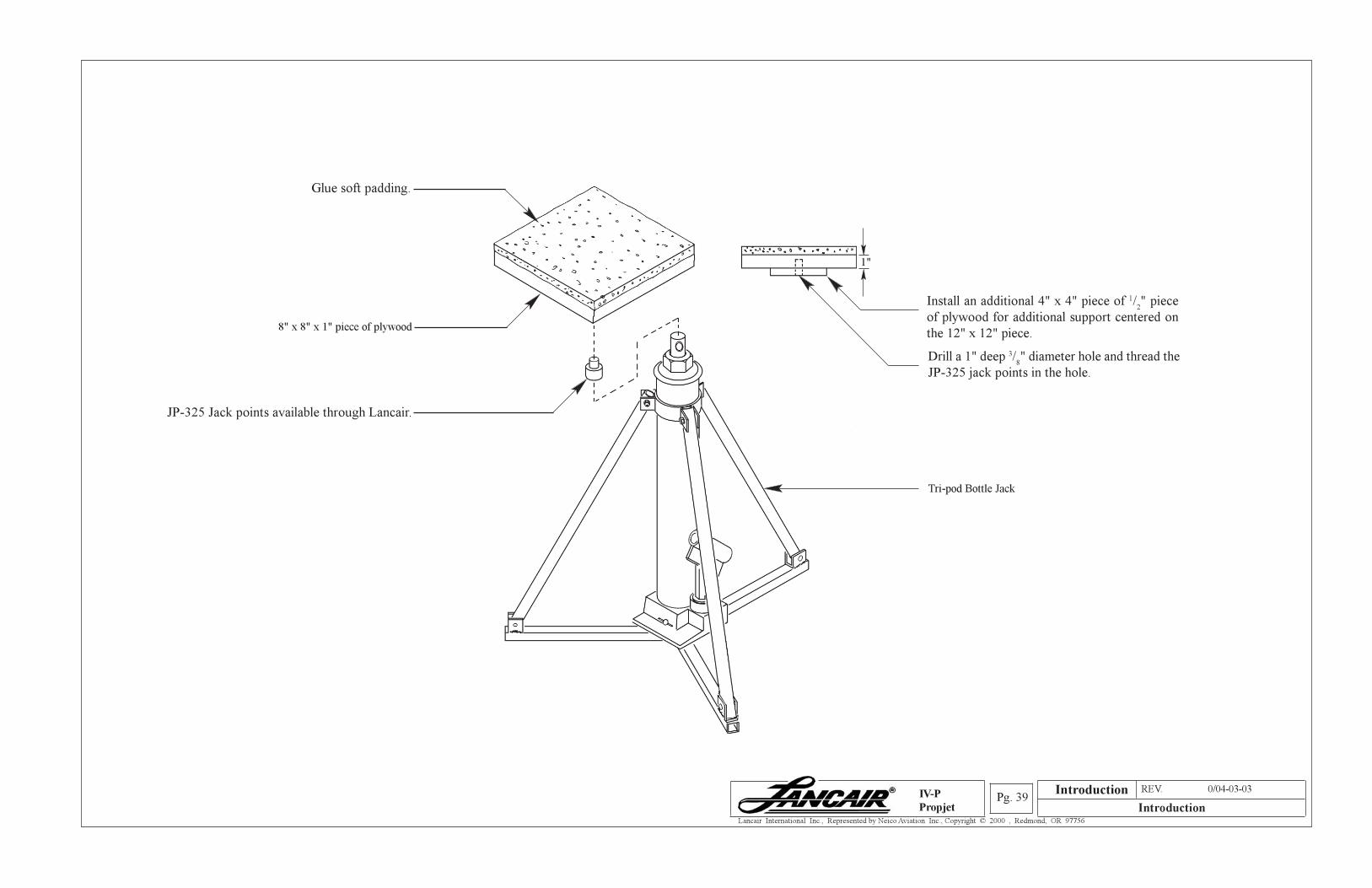
Section A REV. 0/04-03-03
IntroductionPg. 39
Lancair International Inc., Represented by Neico Aviation Inc., Copyright © 2000 , Redmond, OR 97756
IV-P
Propjet
Glue soft padding.
8" x 8" x 1" piece of plywood
1"
Install an additional 4" x 4" piece of 1/2" piece
of plywood for additional support centered on
the 12" x 12" piece.
Drill a 1" deep 3/8" diameter hole and thread the
JP-325 jack points in the hole.
Tri-pod Bottle Jack
JP-325 Jack points available through Lancair.
Introduction
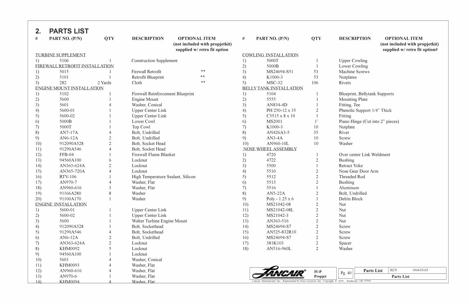
Parts List REV. 0/04-03-03
Parts ListPg. 40
Lancair International Inc., Represented by Neico Aviation Inc., Copyright © 2000 , Redmond, OR 97756
IV-P
Propjet
2. PARTS LIST
# PART NO. (P/N) QTY DESCRIPTION OPTIONAL ITEM
(not included with propjetkit)
supplied w/ retro fit option
TURBINE SUPPLEMENT
1) 5106 1 Construction Supplement
FIREWALL RETROFIT INSTALLATION
1) 5015 1 Firewall Retrofit **
2) 5101 1 Retrofit Blueprint **
3) 282 2 Yards Cloth **
ENGINE MOUNT INSTALLATION
1) 5102 1 Firewall Reinforcement Blueprint
2) 5600 1 Engine Mount
3) 5601 4 Washer, Conical
4) 5600-01 1 Upper Center Link
5) 5600-02 1 Upper Center Link
6) 5000B 1 Lower Cowl
7) 5000T 1 Top Cowl
8) AN7-17A 4 Bolt, Undrilled
9) AN6-12A 2 Bolt, Undrilled
10) 912090A528 2 Bolt, Socket Head
11) 91290A546 4 Bolt, Socket Head
12) FFB-04 1 Firewall Flame Blanket
13) 94560A100 6 Locknut
14) AN363-624A 2 Locknut
15) AN365-720A 4 Locknut
16) RTV-106 1 High Temperature Sealant, Silicon
17) AN970-7 4 Washer, Flat
18) AN960-616 3 Washer, Flat
19) 91166A280 8 Washer
20) 91100A170 1 Washer
ENGINE INSTALLATION
1) 5600-01 1 Upper Center Link
2) 5600-02 1 Upper Center Link
3) 5600 1 Walter Turbine Engine Mount
4) 912090A528 1 Bolt, Sockethead
5) 91290A546 4 Bolt, Sockethead
6) AN6-12A 2 Bolt, Undrilled
7) AN363-624A 2 Locknut
8) KHM0092 5 Locknut
9) 94560A100 1 Locknut
10) 5601 4 Washer, Conical
11) KHM0093 4 Washer, Flat
12) AN960-616 4 Washer, Flat
13) AN970-6 1 Washer, Flat
14) KHM0094 4 Washer, Flat
# PART NO. (P/N) QTY DESCRIPTION OPTIONAL ITEM
(not included with propjetkit)
supplied w/ retro fit option#
COWLING INSTALLATION
1) 5000T 1 Upper Cowling
2) 5000B 1 Lower Cowling
3) MS24694-S51 53 Machine Screws
4) K1000-3 53 Nutplates
5) MSC-32 106 Rivets
BELLY TANK INSTALLATION
1) 5104 1 Blueprint, Bellytank Supports
2) 5555 1 Mounting Plate
3) AN834-4D 1 Fitting, Tee
4) PH 250-12 x 35 2 Phenolic Support 1/4” Thick
5) C5515 x 8 x 10 1 Fitting
6) MS2001 1’ Piano Hinge (Cut into 2” pieces)
7) K1000-3 10 Nutplate
8) AN426A3-5 35 Rivet
9) AN3-4A 10 Screw
10) AN960-10L 10 Washer
NOSE WHEEL ASSEMBLY
1) 4720 1 Over center Link Weldment
2) 4722 2 Bushing
3) 5500 1 Retract Yoke
4) 5510 2 Nose Gear Door Arm
5) 5512 2 Threaded Rod
6) 5513 2 Bushing
7) 5516 1 Aluminum
8) AN5-22A 2 Bolt, Undrilled
9) Poly - 1.25 x 6 1 Delrin Block
10) MS21042-08 2 Nut
11) MS21042-08L 2 Nut
12) MS21042-3 2 Nut
13) AN363-516 2 Nut
14) MS24694-S7 2 Screw
15) AN525-832R10 2 Screw
16) MS24694-S7 2 Screw
17) 381K103 2 Spacer
18) AN516-960L 2 Washer
Parts List
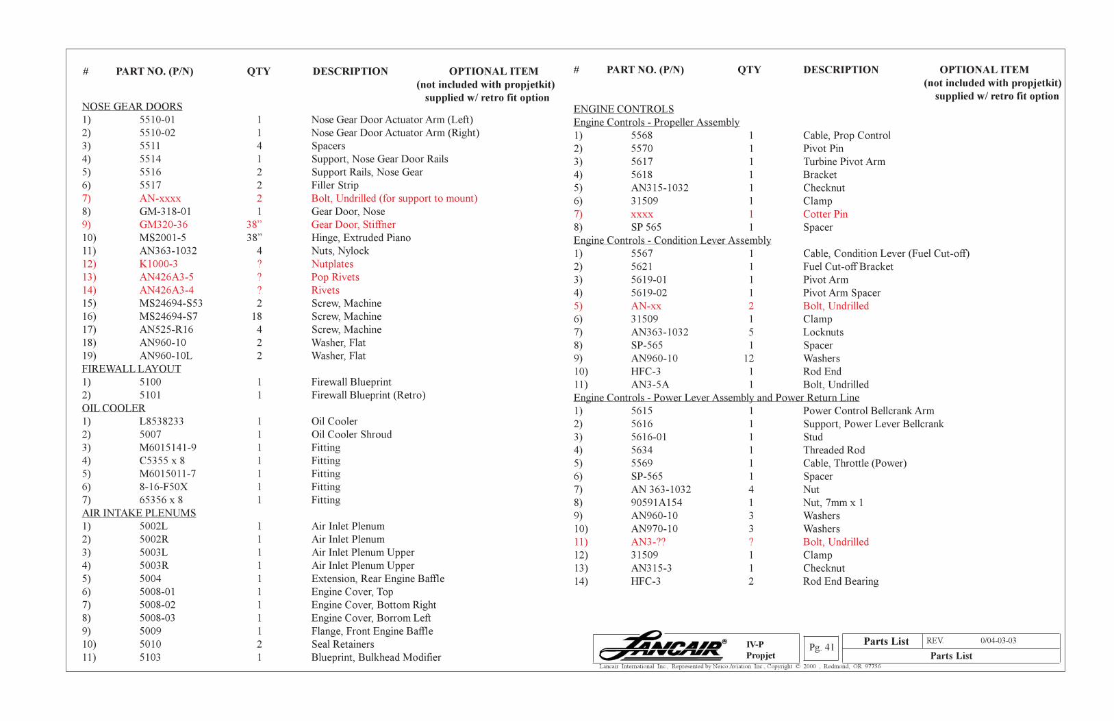
Parts List REV. 0/04-03-03
Parts ListPg. 41
Lancair International Inc., Represented by Neico Aviation Inc., Copyright © 2000 , Redmond, OR 97756
IV-P
Propjet
# PART NO. (P/N) QTY DESCRIPTION OPTIONAL ITEM
(not included with propjetkit)
supplied w/ retro fit option
# PART NO. (P/N) QTY DESCRIPTION OPTIONAL ITEM
(not included with propjetkit)
supplied w/ retro fit option
ENGINE CONTROLS
Engine Controls - Propeller Assembly
1) 5568 1 Cable, Prop Control
2) 5570 1 Pivot Pin
3) 5617 1 Turbine Pivot Arm
4) 5618 1 Bracket
5) AN315-1032 1 Checknut
6) 31509 1 Clamp
7) xxxx 1 Cotter Pin
8) SP 565 1 Spacer
Engine Controls - Condition Lever Assembly
1) 5567 1 Cable, Condition Lever (Fuel Cut-off)
2) 5621 1 Fuel Cut-off Bracket
3) 5619-01 1 Pivot Arm
4) 5619-02 1 Pivot Arm Spacer
5) AN-xx 2 Bolt, Undrilled
6) 31509 1 Clamp
7) AN363-1032 5 Locknuts
8) SP-565 1 Spacer
9) AN960-10 12 Washers
10) HFC-3 1 Rod End
11) AN3-5A 1 Bolt, Undrilled
Engine Controls - Power Lever Assembly and Power Return Line
1) 5615 1 Power Control Bellcrank Arm
2) 5616 1 Support, Power Lever Bellcrank
3) 5616-01 1 Stud
4) 5634 1 Threaded Rod
5) 5569 1 Cable, Throttle (Power)
6) SP-565 1 Spacer
7) AN 363-1032 4 Nut
8) 90591A154 1 Nut, 7mm x 1
9) AN960-10 3 Washers
10) AN970-10 3 Washers
11) AN3-?? ? Bolt, Undrilled
12) 31509 1 Clamp
13) AN315-3 1 Checknut
14) HFC-3 2 Rod End Bearing
NOSE GEAR DOORS
1) 5510-01 1 Nose Gear Door Actuator Arm (Left)
2) 5510-02 1 Nose Gear Door Actuator Arm (Right)
3) 5511 4 Spacers
4) 5514 1 Support, Nose Gear Door Rails
5) 5516 2 Support Rails, Nose Gear
6) 5517 2 Filler Strip
7) AN-xxxx 2 Bolt, Undrilled (for support to mount)
8) GM-318-01 1 Gear Door, Nose
9) GM320-36 38” Gear Door, Stiffner
10) MS2001-5 38” Hinge, Extruded Piano
11) AN363-1032 4 Nuts, Nylock
12) K1000-3 ? Nutplates
13) AN426A3-5 ? Pop Rivets
14) AN426A3-4 ? Rivets
15) MS24694-S53 2 Screw, Machine
16) MS24694-S7 18 Screw, Machine
17) AN525-R16 4 Screw, Machine
18) AN960-10 2 Washer, Flat
19) AN960-10L 2 Washer, Flat
FIREWALL LAYOUT
1) 5100 1 Firewall Blueprint
2) 5101 1 Firewall Blueprint (Retro)
OIL COOLER
1) L8538233 1 Oil Cooler
2) 5007 1 Oil Cooler Shroud
3) M6015141-9 1 Fitting
4) C5355 x 8 1 Fitting
5) M6015011-7 1 Fitting
6) 8-16-F50X 1 Fitting
7) 65356 x 8 1 Fitting
AIR INTAKE PLENUMS
1) 5002L 1 Air Inlet Plenum
2) 5002R 1 Air Inlet Plenum
3) 5003L 1 Air Inlet Plenum Upper
4) 5003R 1 Air Inlet Plenum Upper
5) 5004 1 Extension, Rear Engine Baffle
6) 5008-01 1 Engine Cover, Top
7) 5008-02 1 Engine Cover, Bottom Right
8) 5008-03 1 Engine Cover, Borrom Left
9) 5009 1 Flange, Front Engine Baffle
10) 5010 2 Seal Retainers
11) 5103 1 Blueprint, Bulkhead Modifier
Parts List
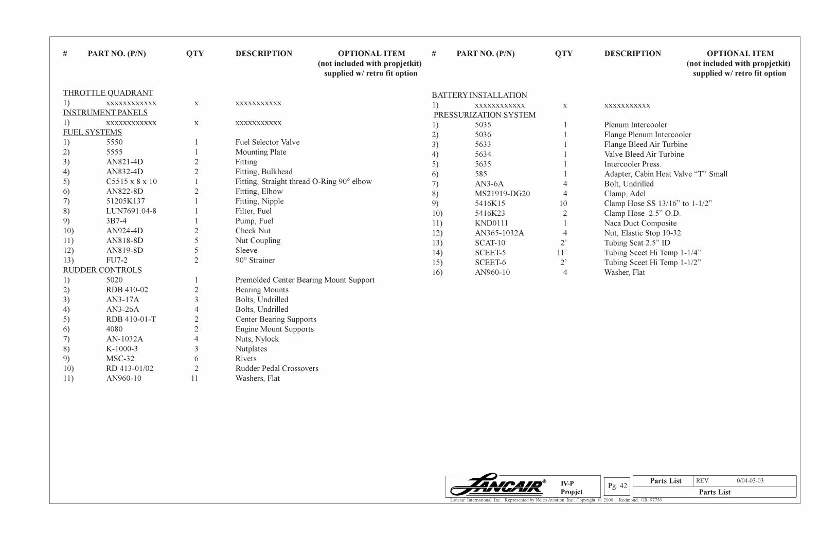
Parts List REV. 0/04-03-03
Parts ListPg. 42
Lancair International Inc., Represented by Neico Aviation Inc., Copyright © 2000 , Redmond, OR 97756
IV-P
Propjet
# PART NO. (P/N) QTY DESCRIPTION OPTIONAL ITEM
(not included with propjetkit)
supplied w/ retro fit option
THROTTLE QUADRANT
1) xxxxxxxxxxxx x xxxxxxxxxxx
INSTRUMENT PANELS
1) xxxxxxxxxxxx x xxxxxxxxxxx
FUEL SYSTEMS
1) 5550 1 Fuel Selector Valve
2) 5555 1 Mounting Plate
3) AN821-4D 2 Fitting
4) AN832-4D 2 Fitting, Bulkhead
5) C5515 x 8 x 10 1 Fitting, Straight thread O-Ring 90° elbow
6) AN822-8D 2 Fitting, Elbow
7) 51205K137 1 Fitting, Nipple
8) LUN7691.04-8 1 Filter, Fuel
9) 3B7-4 1 Pump, Fuel
10) AN924-4D 2 Check Nut
11) AN818-8D 5 Nut Coupling
12) AN819-8D 5 Sleeve
13) FU7-2 2 90° Strainer
RUDDER CONTROLS
1) 5020 1 Premolded Center Bearing Mount Support
2) RDB 410-02 2 Bearing Mounts
3) AN3-17A 3 Bolts, Undrilled
4) AN3-26A 4 Bolts, Undrilled
5) RDB 410-01-T 2 Center Bearing Supports
6) 4080 2 Engine Mount Supports
7) AN-1032A 4 Nuts, Nylock
8) K-1000-3 3 Nutplates
9) MSC-32 6 Rivets
10) RD 413-01/02 2 Rudder Pedal Crossovers
11) AN960-10 11 Washers, Flat
BATTERY INSTALLATION
1) xxxxxxxxxxxx x xxxxxxxxxxx
PRESSURIZATION SYSTEM
1) 5035 1 Plenum Intercooler
2) 5036 1 Flange Plenum Intercooler
3) 5633 1 Flange Bleed Air Turbine
4) 5634 1 Valve Bleed Air Turbine
5) 5635 1 Intercooler Press.
6) 585 1 Adapter, Cabin Heat Valve “T” Small
7) AN3-6A 4 Bolt, Undrilled
8) MS21919-DG20 4 Clamp, Adel
9) 5416K15 10 Clamp Hose SS 13/16” to 1-1/2”
10) 5416K23 2 Clamp Hose 2.5” O.D.
11) KND0111 1 Naca Duct Composite
12) AN365-1032A 4 Nut, Elastic Stop 10-32
13) SCAT-10 2’ Tubing Scat 2.5” ID
14) SCEET-5 11’ Tubing Sceet Hi Temp 1-1/4”
15) SCEET-6 2’ Tubing Sceet Hi Temp 1-1/2”
16) AN960-10 4 Washer, Flat
# PART NO. (P/N) QTY DESCRIPTION OPTIONAL ITEM
(not included with propjetkit)
supplied w/ retro fit option
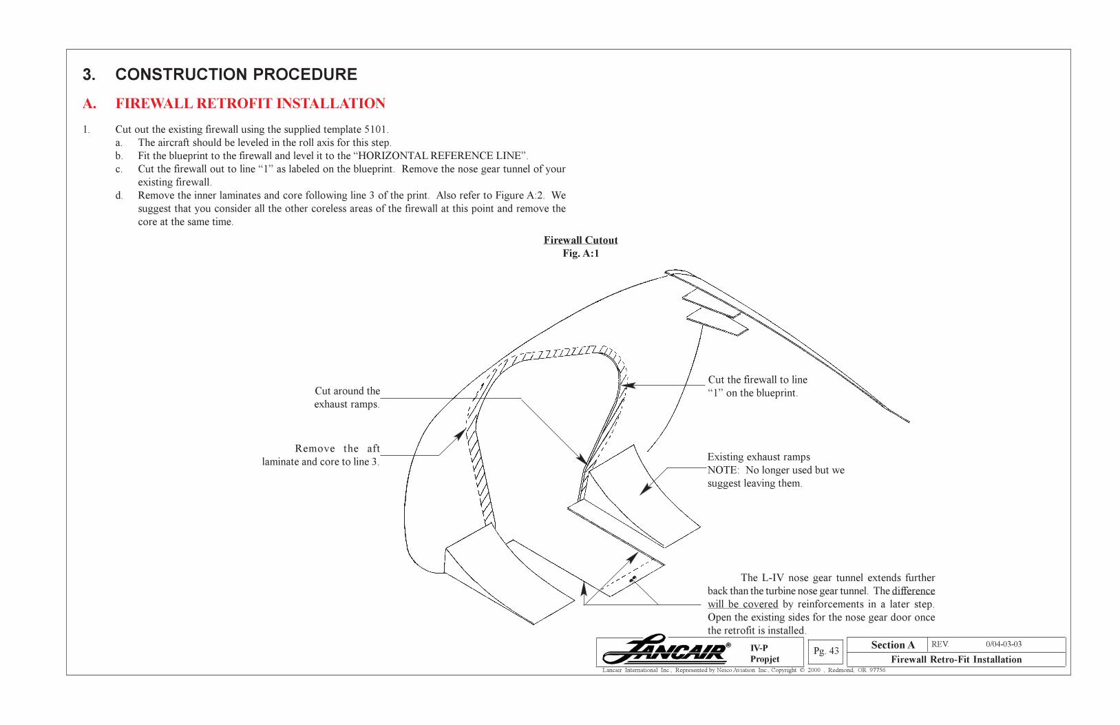
Section A REV. 0/04-03-03
Firewall Retro-Fit InstallationPg. 43
Lancair International Inc., Represented by Neico Aviation Inc., Copyright © 2000 , Redmond, OR 97756
IV-P
Propjet
3. CONSTRUCTION PROCEDURE
A. FIREWALL RETROFIT INSTALLATION
1. Cut out the existing firewall using the supplied template 5101.
a. The aircraft should be leveled in the roll axis for this step.
b. Fit the blueprint to the firewall and level it to the “HORIZONTAL REFERENCE LINE”.
c. Cut the firewall out to line “1” as labeled on the blueprint. Remove the nose gear tunnel of your
existing firewall.
d. Remove the inner laminates and core following line 3 of the print. Also refer to Figure A:2. We
suggest that you consider all the other coreless areas of the firewall at this point and remove the
core at the same time.
Firewall Cutout
Fig. A:1
Remove the aft
laminate and core to line 3.
Cut around the
exhaust ramps.
Cut the firewall to line
“1” on the blueprint.
Existing exhaust ramps
NOTE: No longer used but we
suggest leaving them.
The L-IV nose gear tunnel extends further
back than the turbine nose gear tunnel. The difference
will be covered by reinforcements in a later step.
Open the existing sides for the nose gear door once
the retrofit is installed.
Section A
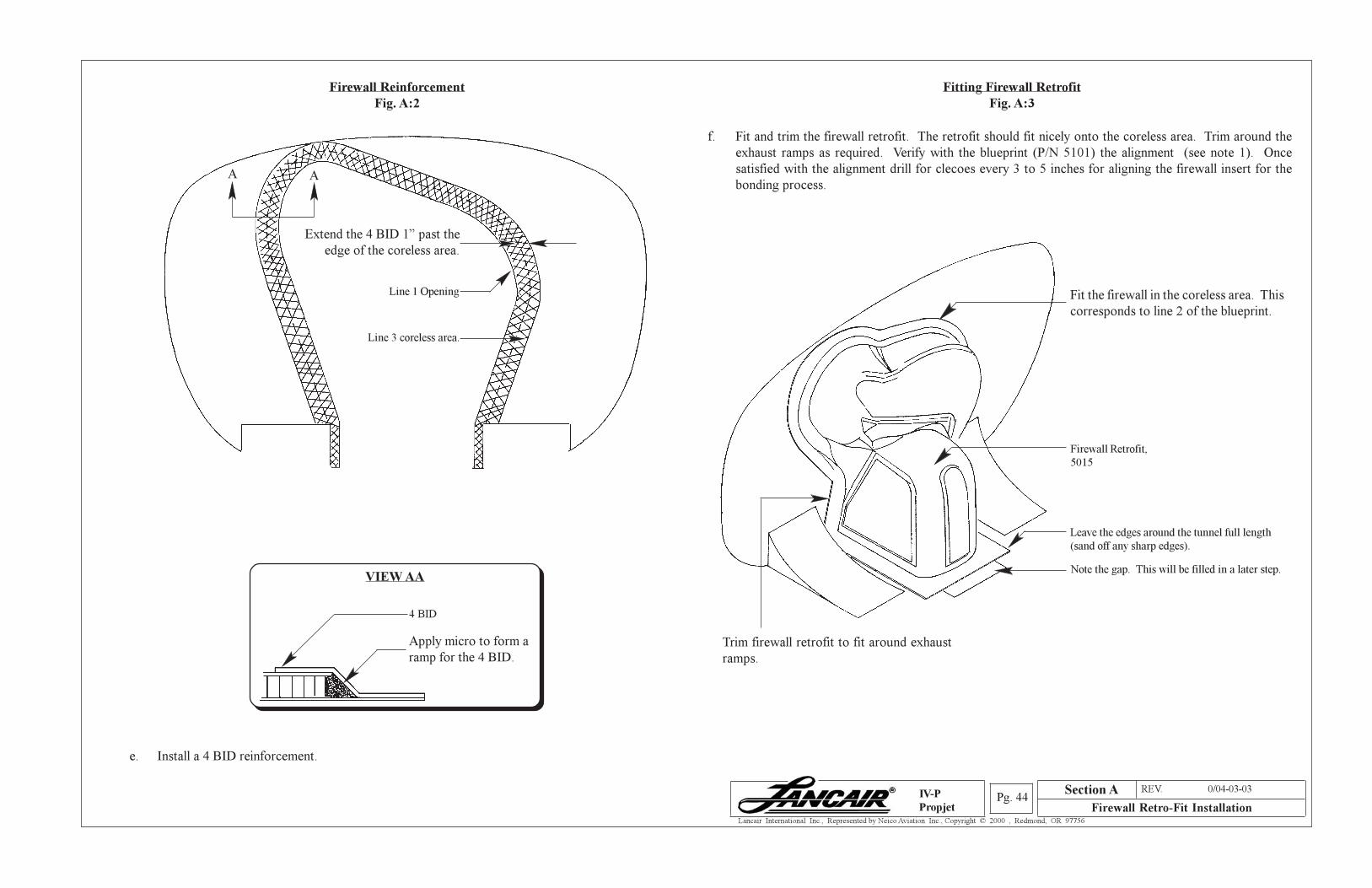
Section A REV. 0/04-03-03
Firewall Retro-Fit InstallationPg. 44
Lancair International Inc., Represented by Neico Aviation Inc., Copyright © 2000 , Redmond, OR 97756
IV-P
Propjet
Firewall Reinforcement
Fig. A:2
Fitting Firewall Retrofit
Fig. A:3
Extend the 4 BID 1” past the
edge of the coreless area.
Line 1 Opening
Line 3 coreless area.
e. Install a 4 BID reinforcement.
f. Fit and trim the firewall retrofit. The retrofit should fit nicely onto the coreless area. Trim around the
exhaust ramps as required. Verify with the blueprint (P/N 5101) the alignment (see note 1). Once
satisfied with the alignment drill for clecoes every 3 to 5 inches for aligning the firewall insert for the
bonding process.
Fit the firewall in the coreless area. This
corresponds to line 2 of the blueprint.
Firewall Retrofit,
5015
Leave the edges around the tunnel full length
(sand off any sharp edges).
Note the gap. This will be filled in a later step.
Trim firewall retrofit to fit around exhaust
ramps.
VIEW AA
4 BID
Apply micro to form a
ramp for the 4 BID.
A A
Section A
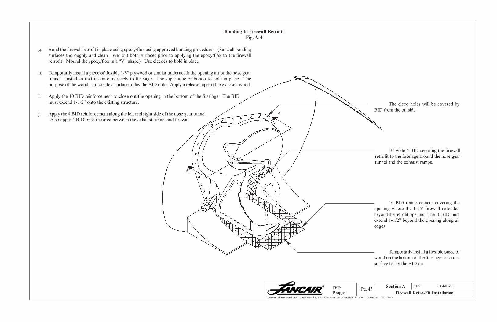
Section A REV. 0/04-03-03
Firewall Retro-Fit InstallationPg. 45
Lancair International Inc., Represented by Neico Aviation Inc., Copyright © 2000 , Redmond, OR 97756
IV-P
Propjet
Bonding In Firewall Retrofit
Fig. A:4
g. Bond the firewall retrofit in place using epoxy/flox using approved bonding procedures. (Sand all bonding
surfaces thoroughly and clean. Wet out both surfaces prior to applying the epoxy/flox to the firewall
retrofit. Mound the epoxy/flox in a “V” shape). Use clecoes to hold in place.
h. Temporarily install a piece of flexible 1/8” plywood or similar underneath the opening aft of the nose gear
tunnel. Install so that it contours nicely to fuselage. Use super glue or bondo to hold in place. The
purpose of the wood is to create a surface to lay the BID onto. Apply a release tape to the exposed wood.
i. Apply the 10 BID reinforcement to close out the opening in the bottom of the fuselage. The BID
must extend 1-1/2” onto the existing structure.
j. Apply the 4 BID reinforcement along the left and right side of the nose gear tunnel.
Also apply 4 BID onto the area between the exhaust tunnel and firewall.
The cleco holes will be covered by
BID from the outside.
3” wide 4 BID securing the firewall
retrofit to the fuselage around the nose gear
tunnel and the exhaust ramps.
10 BID reinforcement covering the
opening where the L-IV firewall extended
beyond the retrofit opening. The 10 BID must
extend 1-1/2” beyond the opening along all
edges.
Temporarily install a flexible piece of
wood on the bottom of the fuselage to form a
surface to lay the BID on.
A
A
Section A
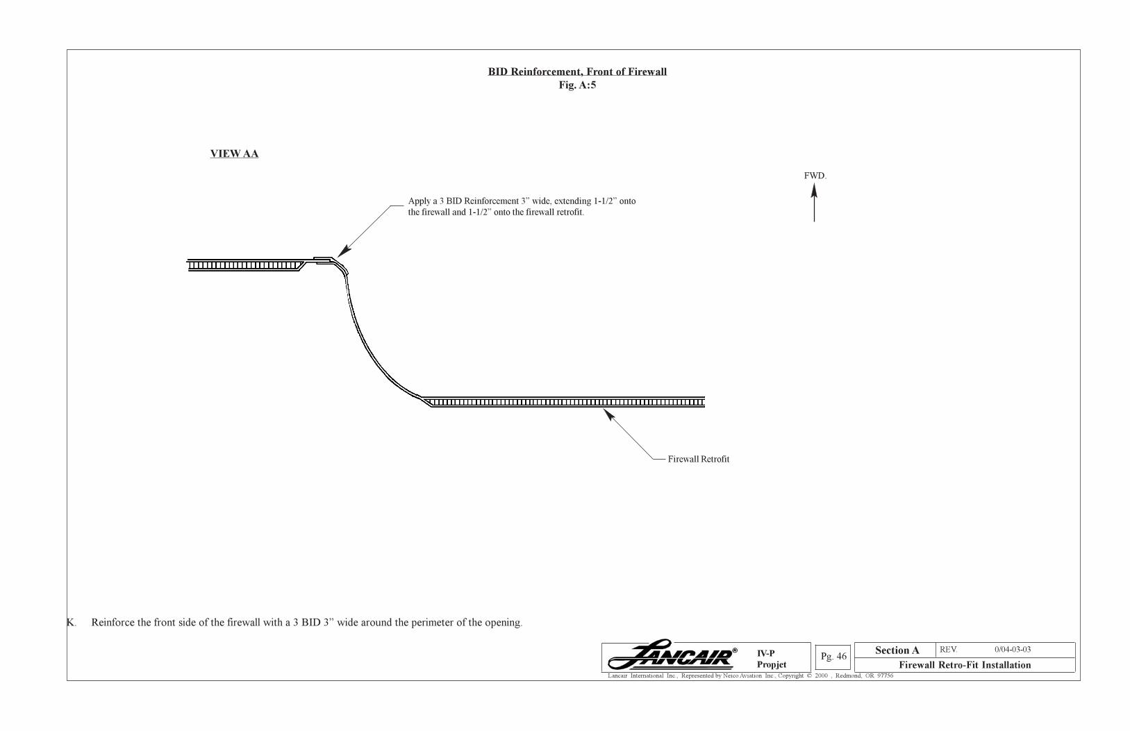
Section A REV. 0/04-03-03
Firewall Retro-Fit InstallationPg. 46
Lancair International Inc., Represented by Neico Aviation Inc., Copyright © 2000 , Redmond, OR 97756
IV-P
Propjet
BID Reinforcement, Front of Firewall
Fig. A:5
VIEW AA
Apply a 3 BID Reinforcement 3” wide, extending 1-1/2” onto
the firewall and 1-1/2” onto the firewall retrofit.
K. Reinforce the front side of the firewall with a 3 BID 3” wide around the perimeter of the opening.
FWD.
Firewall Retrofit
Section A
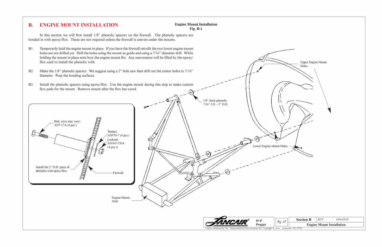
Section A REV. 0/04-03-03
Engine Mount InstallationPg. 47
Lancair International Inc., Represented by Neico Aviation Inc., Copyright © 2000 , Redmond, OR 97756
IV-P
Propjet
Engine Mount Installation
Fig. B:1B. ENGINE MOUNT INSTALLATION
In this section we will first install 1/8” phenolic spacers on the firewall. The phenolic spacers are
bonded in with epoxy/flox. These are not required unless the firewall is uneven under the mounts.
B1. Temporarily hold the engine mount in place. If you have the firewall retrofit the two lower engine mount
holes are not drilled yet. Drill the holes using the mount as guide and using a 7/16” diameter drill. While
holding the mount in place note how the engine mount fits. Any unevenness will be filled by the epoxy/
flox used to install the phenolic with.
B2. Make the 1/8” phenolic spacers. We suggest using a 2” hole saw then drill out the center holes to 7/16”
diameter. Prep the bonding surfaces.
B3. Install the phenolic spacers using epoxy/flox. Use the engine mount during this step to make custom
flox pads for the mount. Remove mount after the flox has cured.
Upper Engine Mount
Holes.
Lower Engine Mount Holes.
1/8” thick phenolic
7/16” I.D. - 2” O.D.
Engine Mount,
5600
Firewall
Washer,
AN970-7 (4 pcs.)
Locknut,
AN365-720A
(4 pcs.))
Bolt, (size may vary)
AN7-17A (4 pcs.)
Install the 2” O.D. piece of
phenolic with epoxy/flox.
Section B
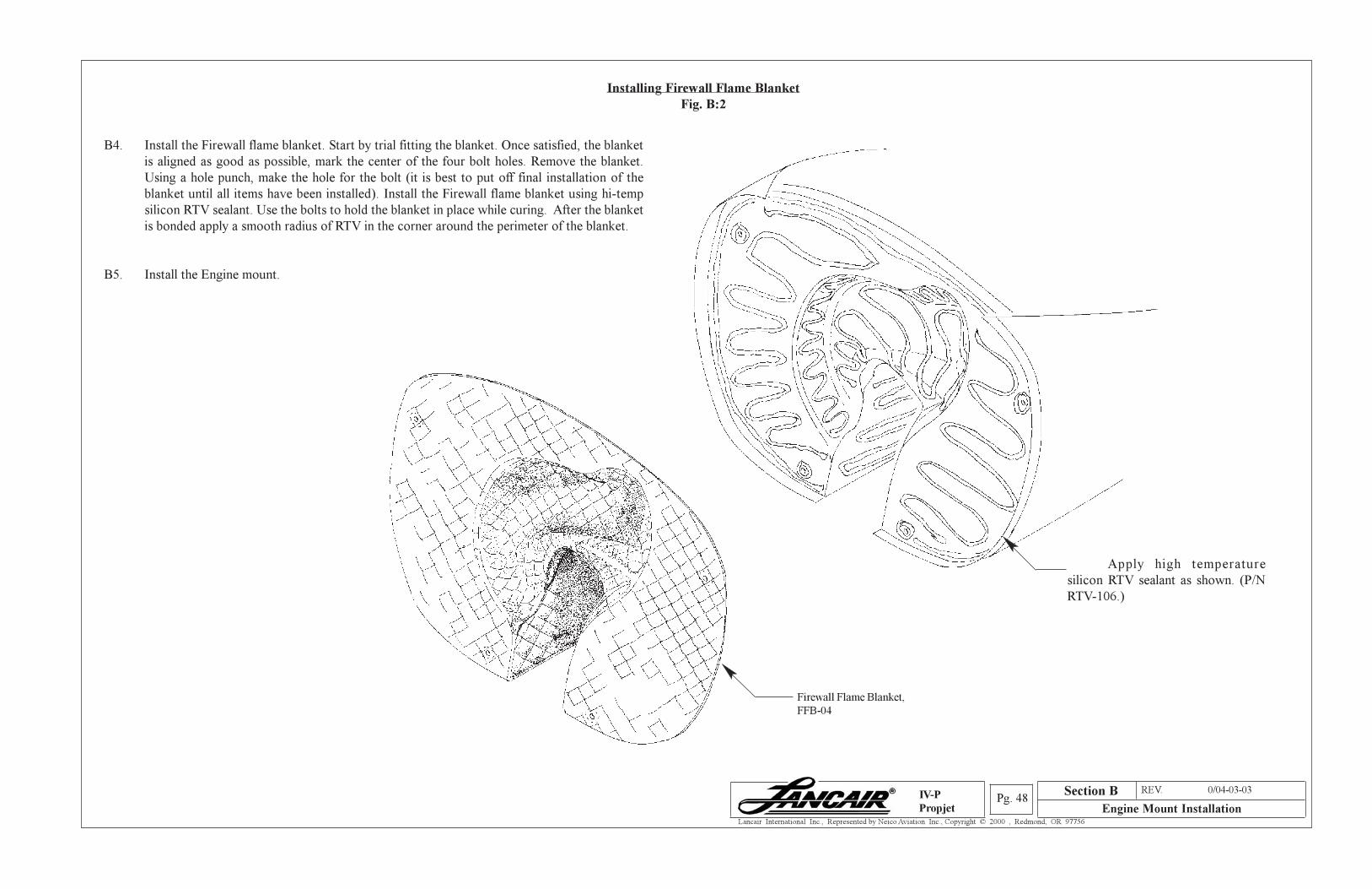
Section A REV. 0/04-03-03
Engine Mount InstallationPg. 48
Lancair International Inc., Represented by Neico Aviation Inc., Copyright © 2000 , Redmond, OR 97756
IV-P
Propjet
B4. Install the Firewall flame blanket. Start by trial fitting the blanket. Once satisfied, the blanket
is aligned as good as possible, mark the center of the four bolt holes. Remove the blanket.
Using a hole punch, make the hole for the bolt (it is best to put off final installation of the
blanket until all items have been installed). Install the Firewall flame blanket using hi-temp
silicon RTV sealant. Use the bolts to hold the blanket in place while curing. After the blanket
is bonded apply a smooth radius of RTV in the corner around the perimeter of the blanket.
B5. Install the Engine mount.
Installing Firewall Flame Blanket
Fig. B:2
Section B
Apply high temperature
silicon RTV sealant as shown. (P/N
RTV-106.)
Firewall Flame Blanket,
FFB-04
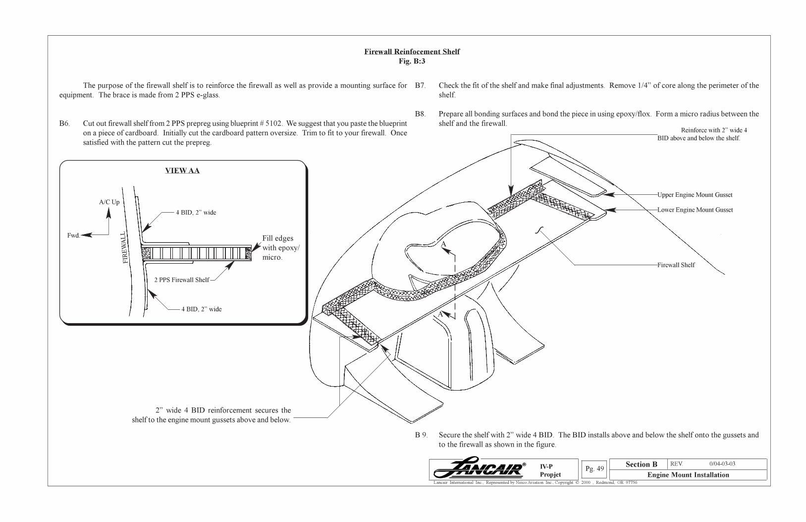
Section A REV. 0/04-03-03
Engine Mount InstallationPg. 49
Lancair International Inc., Represented by Neico Aviation Inc., Copyright © 2000 , Redmond, OR 97756
IV-P
Propjet
The purpose of the firewall shelf is to reinforce the firewall as well as provide a mounting surface for
equipment. The brace is made from 2 PPS e-glass.
B6. Cut out firewall shelf from 2 PPS prepreg using blueprint # 5102. We suggest that you paste the blueprint
on a piece of cardboard. Initially cut the cardboard pattern oversize. Trim to fit to your firewall. Once
satisfied with the pattern cut the prepreg.
Firewall Reinfocement Shelf
Fig. B:3
B7. Check the fit of the shelf and make final adjustments. Remove 1/4” of core along the perimeter of the
shelf.
B8. Prepare all bonding surfaces and bond the piece in using epoxy/flox. Form a micro radius between the
shelf and the firewall.
A/C Up
Fwd.
VIEW AA
4 BID, 2” wide
4 BID, 2” wide
2 PPS Firewall Shelf
Fill edges
with epoxy/
micro.
A
A
Reinforce with 2” wide 4
BID above and below the shelf.
B 9. Secure the shelf with 2” wide 4 BID. The BID installs above and below the shelf onto the gussets and
to the firewall as shown in the figure.
Upper Engine Mount Gusset
Lower Engine Mount Gusset
~
Firewall Shelf
2” wide 4 BID reinforcement secures the
shelf to the engine mount gussets above and below.
FIR
EW
AL
L
Section B
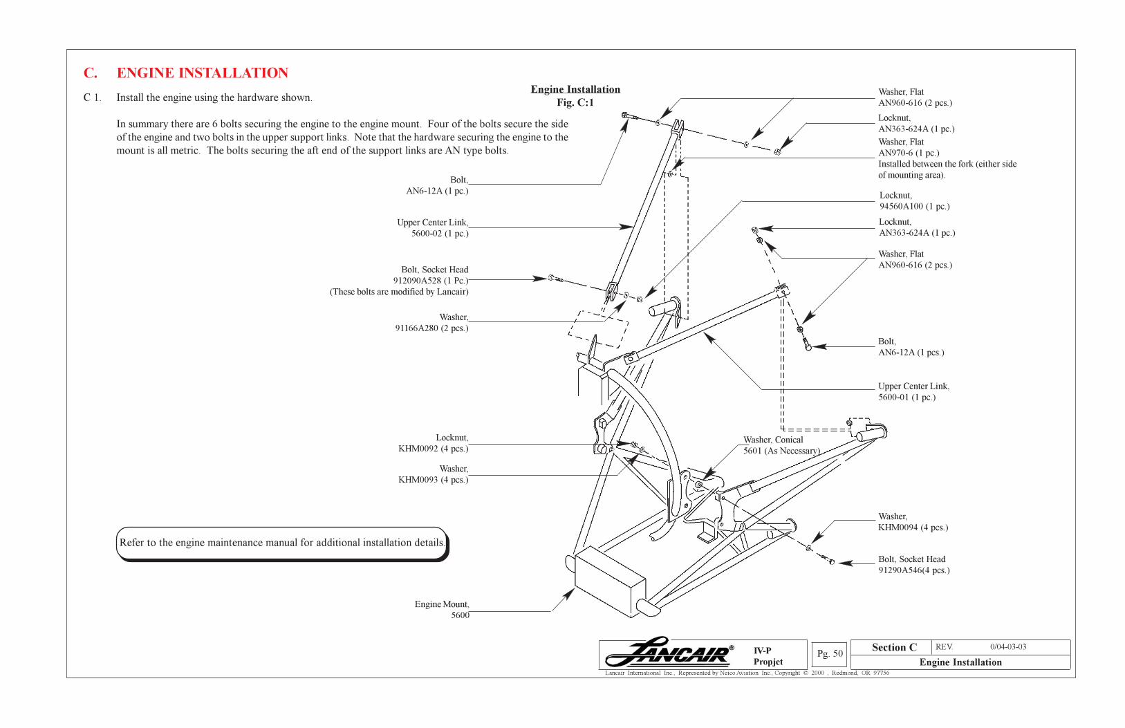
Section A REV. 0/04-03-03
Engine InstallationPg. 50
Lancair International Inc., Represented by Neico Aviation Inc., Copyright © 2000 , Redmond, OR 97756
IV-P
Propjet
Washer, Flat
AN970-6 (1 pc.)
Installed between the fork (either side
of mounting area).Bolt,
AN6-12A (1 pc.)
Bolt, Socket Head
91290A546(4 pcs.)
Washer,
KHM0094 (4 pcs.)
Washer,
KHM0093 (4 pcs.)
Engine Mount,
5600
Engine Installation
Fig. C:1C 1. Install the engine using the hardware shown.
In summary there are 6 bolts securing the engine to the engine mount. Four of the bolts secure the side
of the engine and two bolts in the upper support links. Note that the hardware securing the engine to the
mount is all metric. The bolts securing the aft end of the support links are AN type bolts.
C. ENGINE INSTALLATION
Refer to the engine maintenance manual for additional installation details.
Washer, Flat
AN960-616 (2 pcs.)
Washer,
91166A280 (2 pcs.)
Washer, Flat
AN960-616 (2 pcs.)
Locknut,
AN363-624A (1 pc.)
Upper Center Link,
5600-02 (1 pc.)
Bolt, Socket Head
912090A528 (1 Pc.)
(These bolts are modified by Lancair)
Washer, Conical
5601 (As Necessary)
Locknut,
KHM0092 (4 pcs.)
Locknut,
94560A100 (1 pc.)
Upper Center Link,
5600-01 (1 pc.)
Bolt,
AN6-12A (1 pcs.)
Locknut,
AN363-624A (1 pc.)
Section C
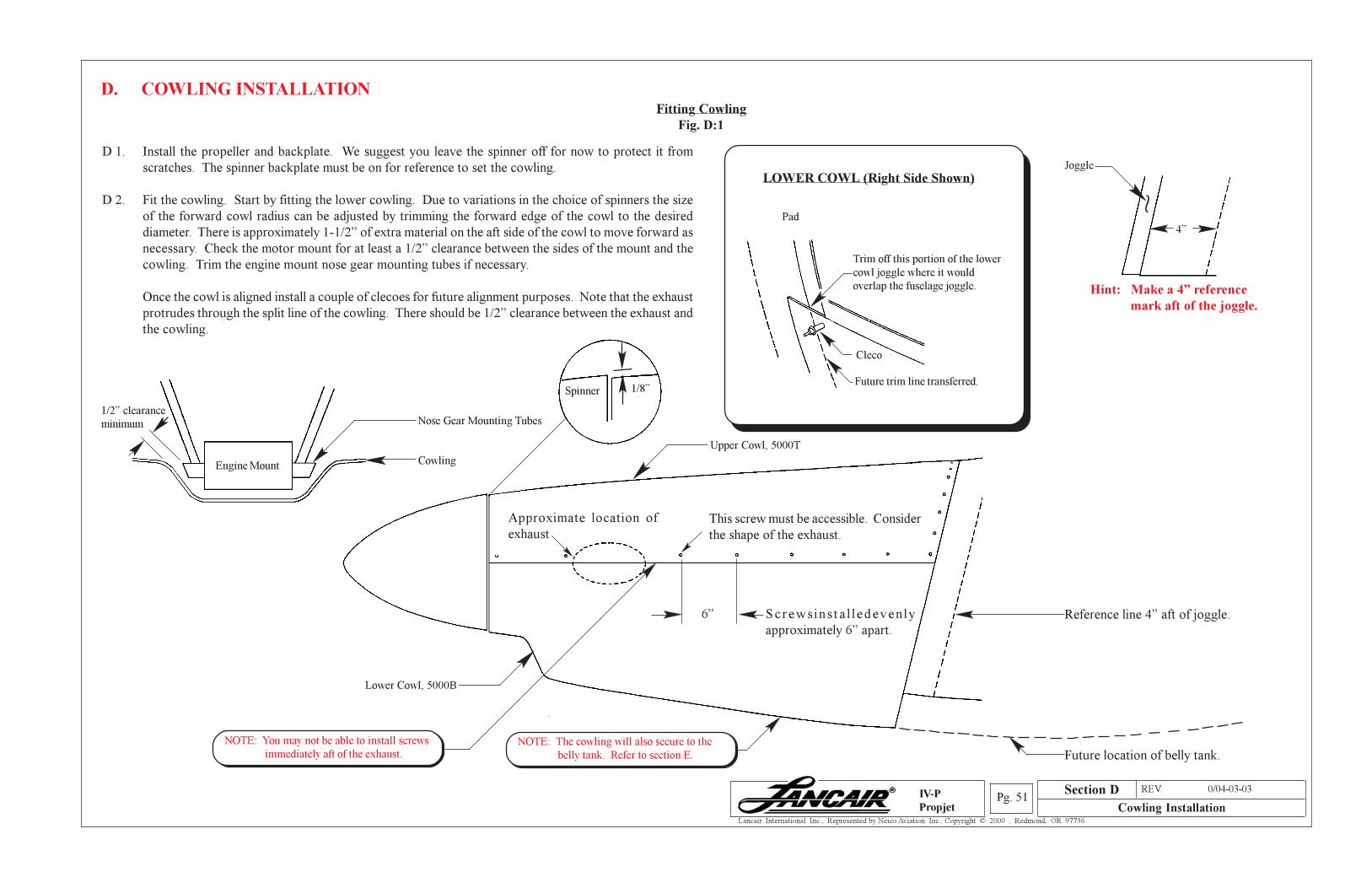
Section A REV. 0/04-03-03
Cowling InstallationPg. 51
Lancair International Inc., Represented by Neico Aviation Inc., Copyright © 2000 , Redmond, OR 97756
IV-P
Propjet
Reference line 4” aft of joggle.Sc rews in s t a l l edeven ly
approximately 6” apart.
Future location of belly tank.
Fitting Cowling
Fig. D:1
D 1. Install the propeller and backplate. We suggest you leave the spinner off for now to protect it from
scratches. The spinner backplate must be on for reference to set the cowling.
D 2. Fit the cowling. Start by fitting the lower cowling. Due to variations in the choice of spinners the size
of the forward cowl radius can be adjusted by trimming the forward edge of the cowl to the desired
diameter. There is approximately 1-1/2” of extra material on the aft side of the cowl to move forward as
necessary. Check the motor mount for at least a 1/2” clearance between the sides of the mount and the
cowling. Trim the engine mount nose gear mounting tubes if necessary.
Once the cowl is aligned install a couple of clecoes for future alignment purposes. Note that the exhaust
protrudes through the split line of the cowling. There should be 1/2” clearance between the exhaust and
the cowling.
D. COWLING INSTALLATION
Hint: Make a 4” reference
mark aft of the joggle.
4”
Approximate location of
exhaust
1/8”
LOWER COWL (Right Side Shown)
Pad
Trim off this portion of the lower
cowl joggle where it would
overlap the fuselage joggle.
Cleco
Future trim line transferred.Spinner
6”
NOTE: The cowling will also secure to the
belly tank. Refer to section E.
NOTE: You may not be able to install screws
immediately aft of the exhaust.
Lower Cowl, 5000B
Upper Cowl, 5000T
~
Joggle
Section D
Engine Mount Cowling
Nose Gear Mounting Tubes1/2” clearance
minimum
This screw must be accessible. Consider
the shape of the exhaust.
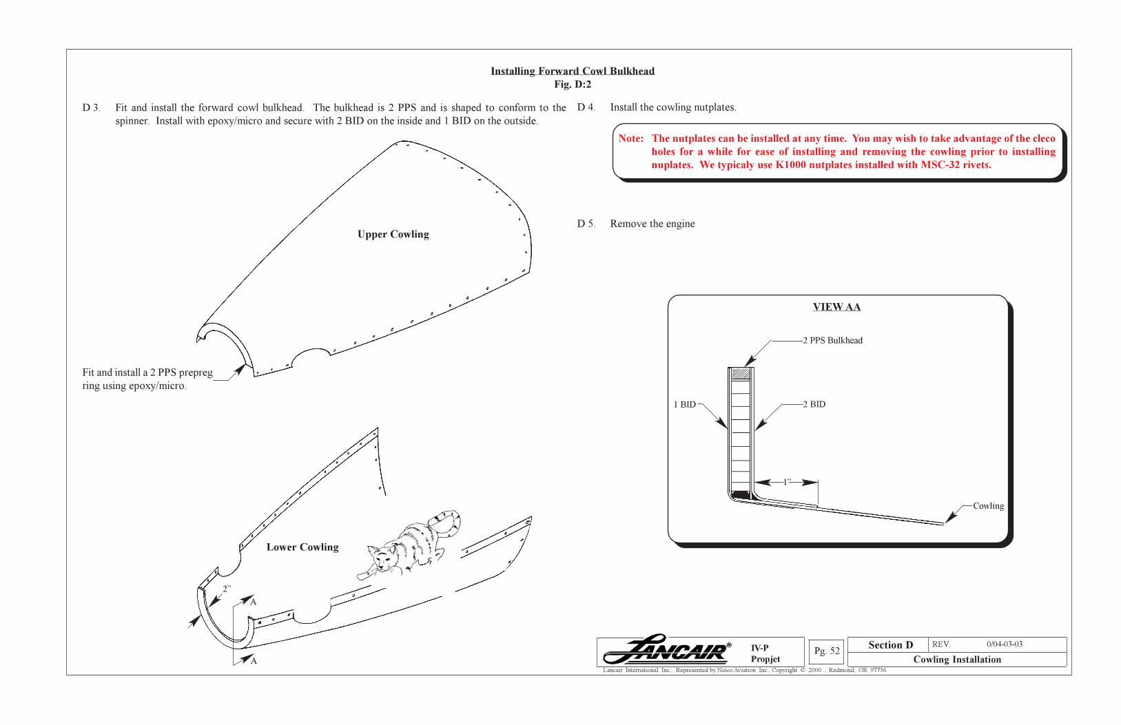
Section A REV. 0/04-03-03
Cowling InstallationPg. 52
Lancair International Inc., Represented by Neico Aviation Inc., Copyright © 2000 , Redmond, OR 97756
IV-P
Propjet
Installing Forward Cowl Bulkhead
Fig. D:2
D 4. Install the cowling nutplates.
D 5. Remove the engine
Note: The nutplates can be installed at any time. You may wish to take advantage of the cleco
holes for a while for ease of installing and removing the cowling prior to installing
nuplates. We typicaly use K1000 nutplates installed with MSC-32 rivets.
VIEW AA
2 PPS Bulkhead
1 BID 2 BID
Cowling
1”
Section D
D 3. Fit and install the forward cowl bulkhead. The bulkhead is 2 PPS and is shaped to conform to the
spinner. Install with epoxy/micro and secure with 2 BID on the inside and 1 BID on the outside.
Fit and install a 2 PPS prepreg
ring using epoxy/micro.
Upper Cowling
2”
A
A
Lower Cowling
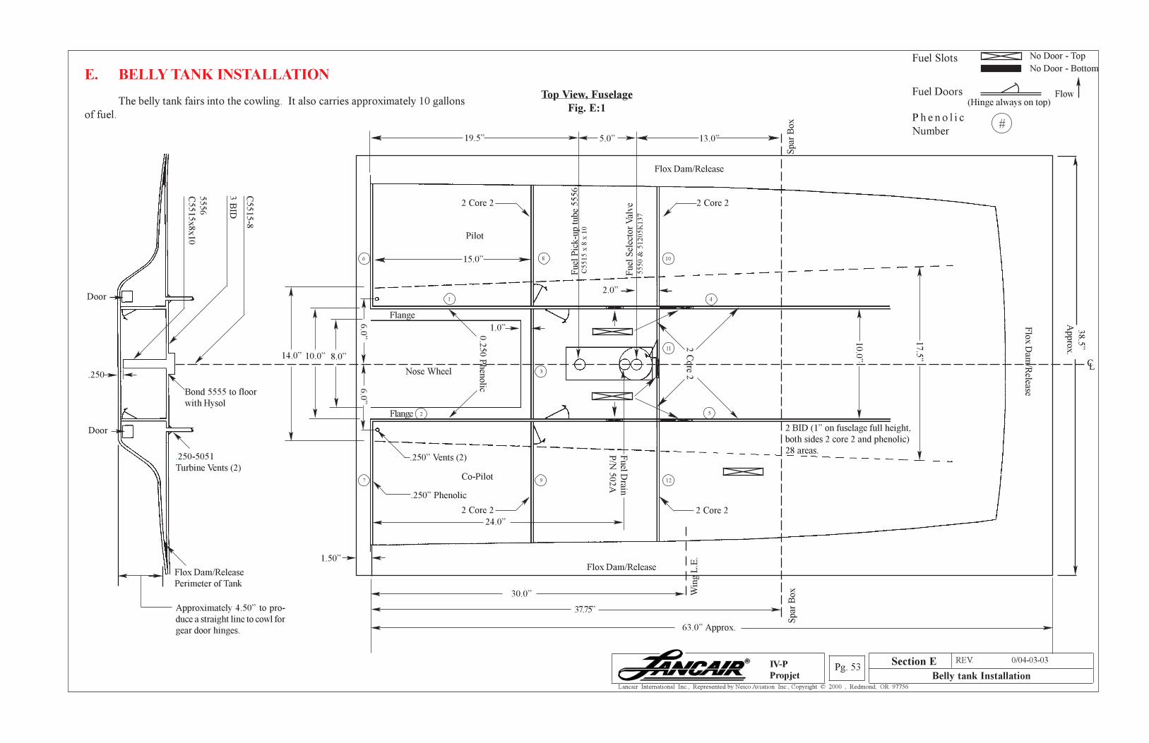
Section A REV. 0/04-03-03
Belly tank InstallationPg. 53
Lancair International Inc., Represented by Neico Aviation Inc., Copyright © 2000 , Redmond, OR 97756
IV-P
Propjet
E. BELLY TANK INSTALLATION
The belly tank fairs into the cowling. It also carries approximately 10 gallons
of fuel.
Top View, Fuselage
Fig. E:1
.250-5051
Turbine Vents (2)
Flox Dam/Release
Perimeter of Tank
Bond 5555 to floor
with Hysol
Door
Door
Approximately 4.50” to pro-
duce a straight line to cowl for
gear door hinges.
3 B
ID
C5515-8
6.0
”6.0
”
8.0”
Nose Wheel
0.2
50 P
hen
olic
1.0”
.250” Vents (2)
.250” Phenolic
Fuel D
rain
P/N
502A
24.0”
2.0”
Fuel
Sel
ecto
r V
alv
e5
55
0 &
51
20
5K
13
7
Fuel
Pic
k-u
p t
ube
5556
C5
51
5 x
8 x
10
Flox Dam/Release
Co-Pilot
Pilot
Flox Dam/Release
2 C
ore 2
2 BID (1” on fuselage full height,
both sides 2 core 2 and phenolic)
28 areas.
10.0
”
Flo
x D
am/R
elease
19.5” 5.0”
.250
14.0” 10.0”
17.5
”
38.5
”
Appro
x.
13.0”
Fuel Slots
Fuel Doors
No Door - Top
No Door - Bottom
Flow(Hinge always on top)
P h e n o l i c
Number#
Spar
Box
15.0”
30.0”
37.75”
63.0” Approx.
Spar
BoxW
ing L
.E.
CL
Flange
Section E
2 Core 2
2 Core 2 2 Core 2
5556
C5515x8x10
6
1
8
4
2 Core 2
10
1.50”
7 9 12
5
3
2Flange
11
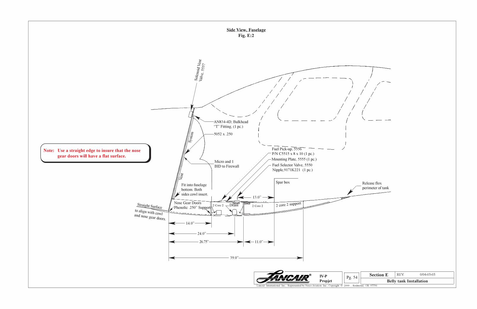
Section A REV. 0/04-03-03
Belly tank InstallationPg. 54
Lancair International Inc., Represented by Neico Aviation Inc., Copyright © 2000 , Redmond, OR 97756
IV-P
Propjet
Side View, Fuselage
Fig. E:2
14.0”
24.0”
26.75”
39.0”
11.0”
Spar box
Drain
Mounting Plate, 5555 (1 pc.)
Fit into fuselage
bottom. Both
sides cowl insert.
AN834-4D, Bulkhead
“T” Fitting, (1 pc.)
13.0”
Release flox
perimeter of tank
to align with cowland nose gear doors.
2 core 2 support
Sole
noid
Ven
tV
alve,
5557
Straight Surface
Ven
t
Sys
tem
Micro and 1
BID to Firewall
~
5052 x .250
Fuel Pick-up, 5556
P/N C5515 x 8 x 10 (1 pc.)
Fuel Selector Valve, 5550
Nipple,9171K221 (1 pc.)
Nose Gear Doors
Phenolic .250” Support2 Core 2 2 Core 2
Section E
Note: Use a straight edge to insure that the nose
gear doors will have a flat surface.
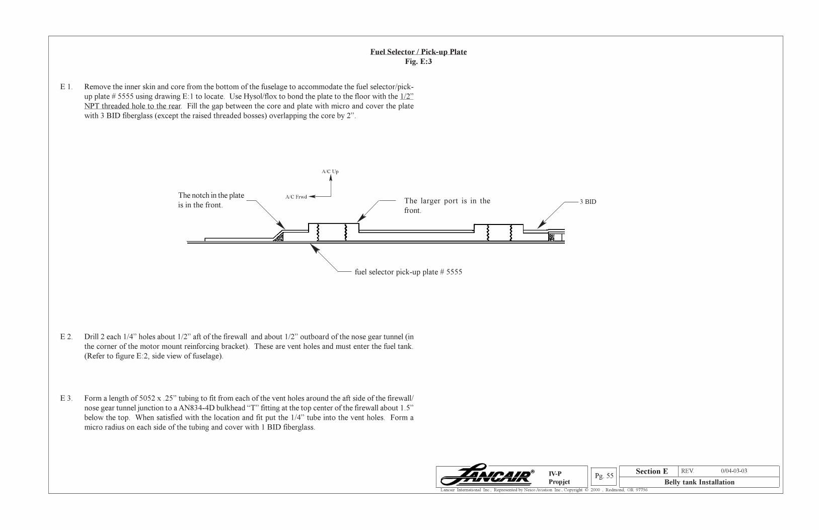
Section A REV. 0/04-03-03
Belly tank InstallationPg. 55
Lancair International Inc., Represented by Neico Aviation Inc., Copyright © 2000 , Redmond, OR 97756
IV-P
Propjet
Fuel Selector / Pick-up Plate
Fig. E:3
E 1. Remove the inner skin and core from the bottom of the fuselage to accommodate the fuel selector/pick-
up plate # 5555 using drawing E:1 to locate. Use Hysol/flox to bond the plate to the floor with the 1/2”
NPT threaded hole to the rear. Fill the gap between the core and plate with micro and cover the plate
with 3 BID fiberglass (except the raised threaded bosses) overlapping the core by 2”.
E 2. Drill 2 each 1/4” holes about 1/2” aft of the firewall and about 1/2” outboard of the nose gear tunnel (in
the corner of the motor mount reinforcing bracket). These are vent holes and must enter the fuel tank.
(Refer to figure E:2, side view of fuselage).
E 3. Form a length of 5052 x .25” tubing to fit from each of the vent holes around the aft side of the firewall/
nose gear tunnel junction to a AN834-4D bulkhead “T” fitting at the top center of the firewall about 1.5”
below the top. When satisfied with the location and fit put the 1/4” tube into the vent holes. Form a
micro radius on each side of the tubing and cover with 1 BID fiberglass.
3 BIDThe larger port is in the
front.
The notch in the plate
is in the front.
fuel selector pick-up plate # 5555
Section E
A/C Up
A/C Frwd
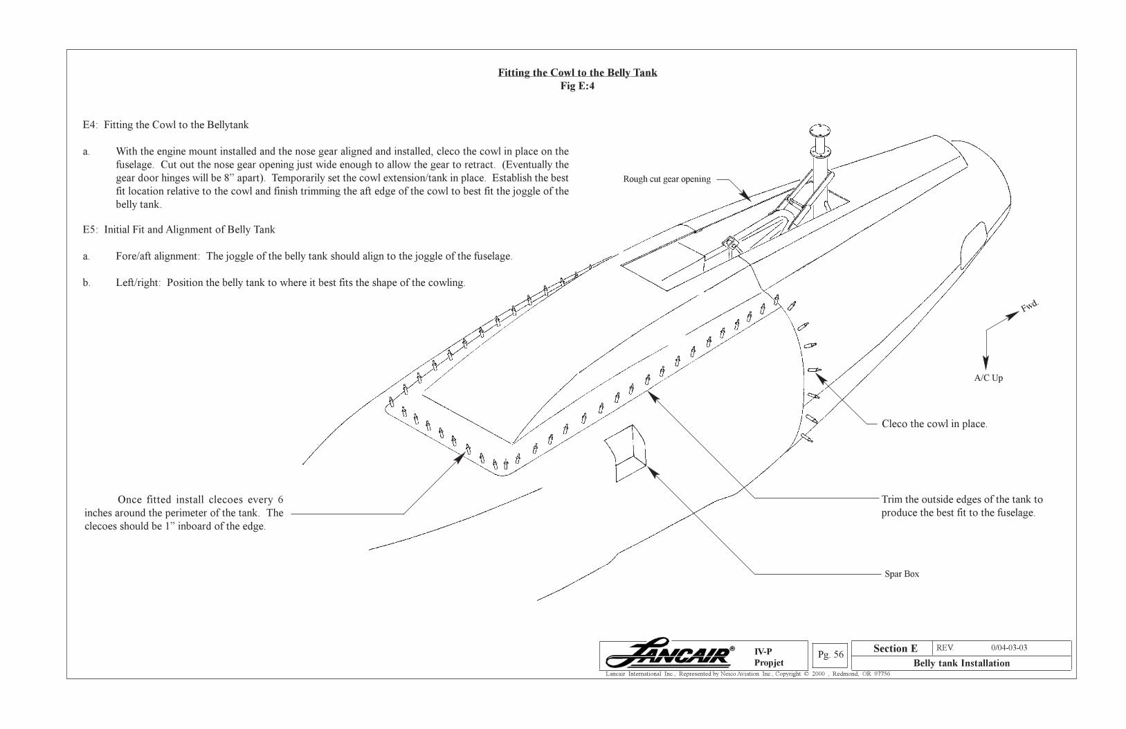
Section A REV. 0/04-03-03
Belly tank InstallationPg. 56
Lancair International Inc., Represented by Neico Aviation Inc., Copyright © 2000 , Redmond, OR 97756
IV-P
Propjet
Fitting the Cowl to the Belly Tank
Fig E:4
E4: Fitting the Cowl to the Bellytank
a. With the engine mount installed and the nose gear aligned and installed, cleco the cowl in place on the
fuselage. Cut out the nose gear opening just wide enough to allow the gear to retract. (Eventually the
gear door hinges will be 8” apart). Temporarily set the cowl extension/tank in place. Establish the best
fit location relative to the cowl and finish trimming the aft edge of the cowl to best fit the joggle of the
belly tank.
E5: Initial Fit and Alignment of Belly Tank
a. Fore/aft alignment: The joggle of the belly tank should align to the joggle of the fuselage.
b. Left/right: Position the belly tank to where it best fits the shape of the cowling.
Rough cut gear opening
Trim the outside edges of the tank to
produce the best fit to the fuselage.
Cleco the cowl in place.
Spar Box
Once fitted install clecoes every 6
inches around the perimeter of the tank. The
clecoes should be 1” inboard of the edge.
A/C Up
Fwd.
Section E
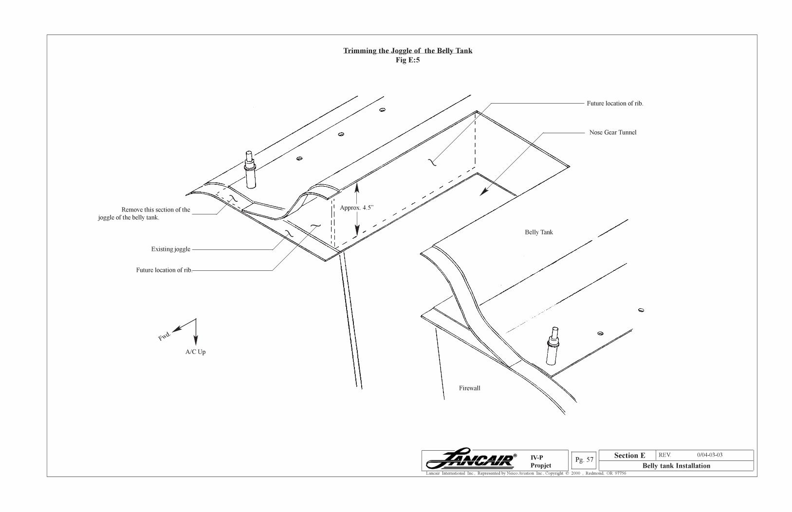
Section A REV. 0/04-03-03
Belly tank InstallationPg. 57
Lancair International Inc., Represented by Neico Aviation Inc., Copyright © 2000 , Redmond, OR 97756
IV-P
Propjet
Trimming the Joggle of the Belly Tank
Fig E:5
Remove this section of the
joggle of the belly tank.
Existing joggle
Future location of rib.
Belly Tank
Nose Gear Tunnel
~
~
~
~
Firewall
A/C Up
Fwd.
Section E
Approx. 4.5”
Future location of rib.
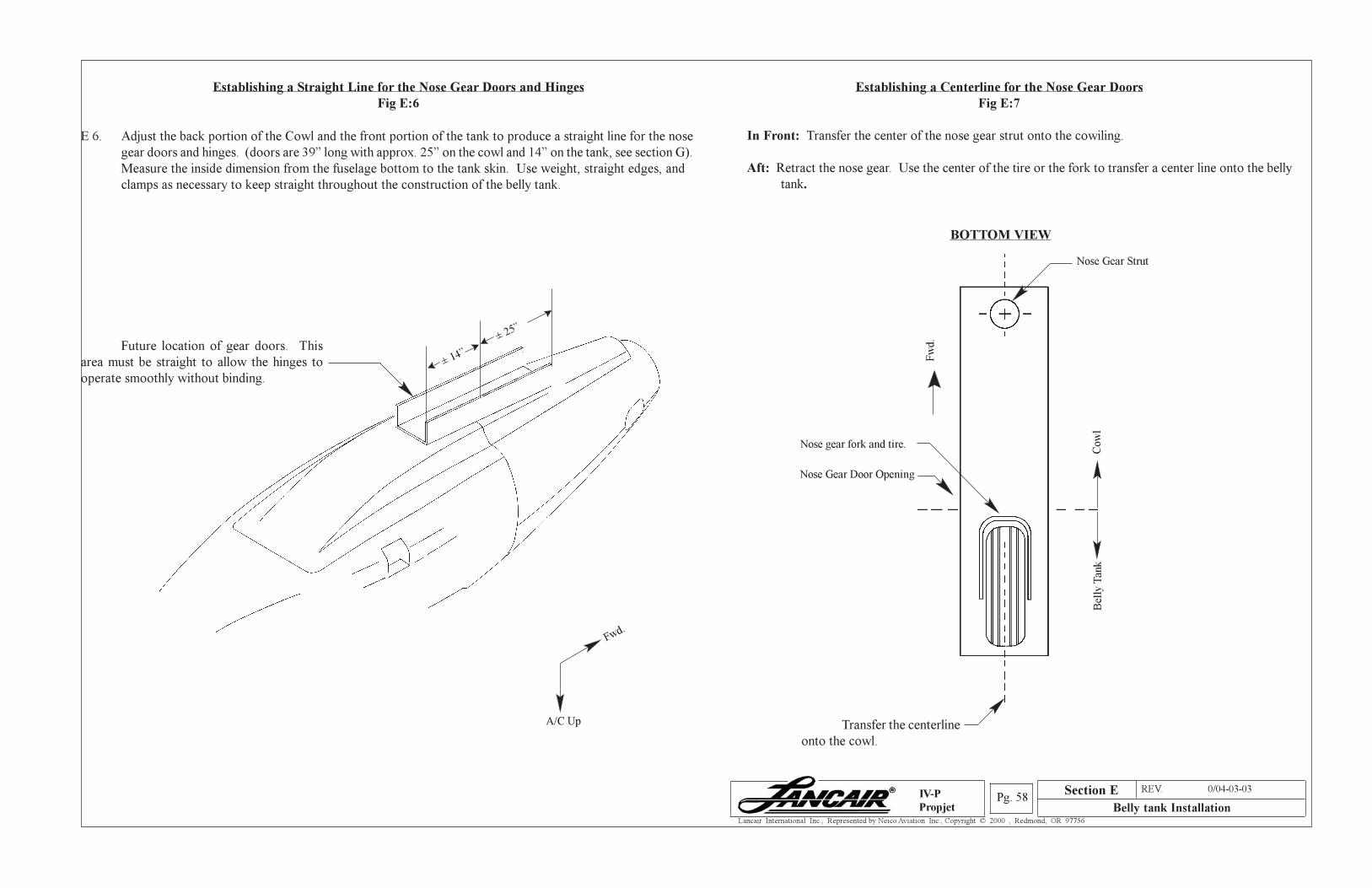
Section A REV. 0/04-03-03
Belly tank InstallationPg. 58
Lancair International Inc., Represented by Neico Aviation Inc., Copyright © 2000 , Redmond, OR 97756
IV-P
Propjet
Establishing a Straight Line for the Nose Gear Doors and Hinges
Fig E:6
E 6. Adjust the back portion of the Cowl and the front portion of the tank to produce a straight line for the nose
gear doors and hinges. (doors are 39” long with approx. 25” on the cowl and 14” on the tank, see section G).
Measure the inside dimension from the fuselage bottom to the tank skin. Use weight, straight edges, and
clamps as necessary to keep straight throughout the construction of the belly tank.
BOTTOM VIEW
Establishing a Centerline for the Nose Gear Doors
Fig E:7
In Front: Transfer the center of the nose gear strut onto the cowiling.
Aft: Retract the nose gear. Use the center of the tire or the fork to transfer a center line onto the belly
tank.
A/C Up
Fwd.
Future location of gear doors. This
area must be straight to allow the hinges to
operate smoothly without binding.
± 25”
± 14”
Transfer the centerline
onto the cowl.
Fw
d.
Nose Gear Strut
Cow
lB
elly
Tan
k
Nose Gear Door Opening
Nose gear fork and tire.
Section E
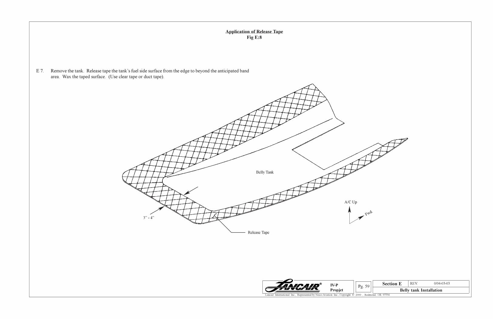
Section A REV. 0/04-03-03
Belly tank InstallationPg. 59
Lancair International Inc., Represented by Neico Aviation Inc., Copyright © 2000 , Redmond, OR 97756
IV-P
Propjet
Application of Release Tape
Fig E:8
E 7. Remove the tank. Release tape the tank’s fuel side surface from the edge to beyond the anticipated band
area. Wax the taped surface. (Use clear tape or duct tape).
Belly Tank
Release Tape
~
3” - 4”
A/C Up
Fwd.
Section E
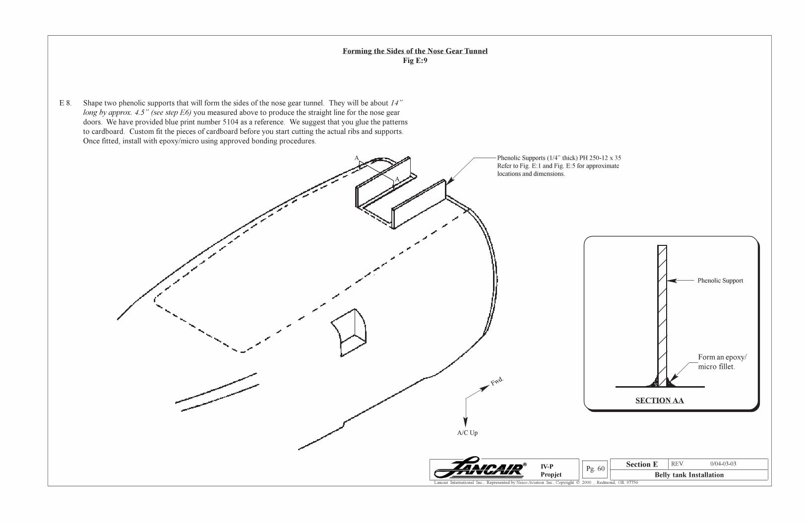
Section A REV. 0/04-03-03
Belly tank InstallationPg. 60
Lancair International Inc., Represented by Neico Aviation Inc., Copyright © 2000 , Redmond, OR 97756
IV-P
Propjet
Forming the Sides of the Nose Gear Tunnel
Fig E:9
E 8. Shape two phenolic supports that will form the sides of the nose gear tunnel. They will be about 14”
long by approx. 4.5” (see step E6) you measured above to produce the straight line for the nose gear
doors. We have provided blue print number 5104 as a reference. We suggest that you glue the patterns
to cardboard. Custom fit the pieces of cardboard before you start cutting the actual ribs and supports.
Once fitted, install with epoxy/micro using approved bonding procedures.
Phenolic Supports (1/4” thick) PH 250-12 x 35
Refer to Fig. E:1 and Fig. E:5 for approximate
locations and dimensions.
A/C Up
Fwd.
A
A
SECTION AA
Phenolic Support
Form an epoxy/
micro fillet.
Section E
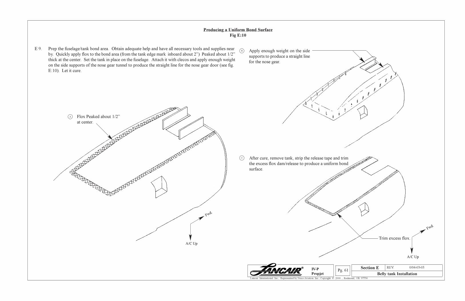
Section A REV. 0/04-03-03
Belly tank InstallationPg. 61
Lancair International Inc., Represented by Neico Aviation Inc., Copyright © 2000 , Redmond, OR 97756
IV-P
Propjet
Producing a Uniform Bond Surface
Fig E:10
E 9. Prep the fuselage/tank bond area. Obtain adequate help and have all necessary tools and supplies near
by. Quickly apply flox to the bond area (from the tank edge mark inboard about 2”) Peaked about 1/2”
thick at the center. Set the tank in place on the fuselage. Attach it with clecos and apply enough weight
on the side supports of the nose gear tunnel to produce the straight line for the nose gear door (see fig.
E:10). Let it cure.
Trim excess flox.A/C Up
Fwd.
A/C Up
Fwd.
After cure, remove tank, strip the release tape and trim
the excess flox dam/release to produce a uniform bond
surface.
C.
Apply enough weight on the side
supports to produce a straight line
for the nose gear.
B.
Flox Peaked about 1/2”
at center.
A.
Section E
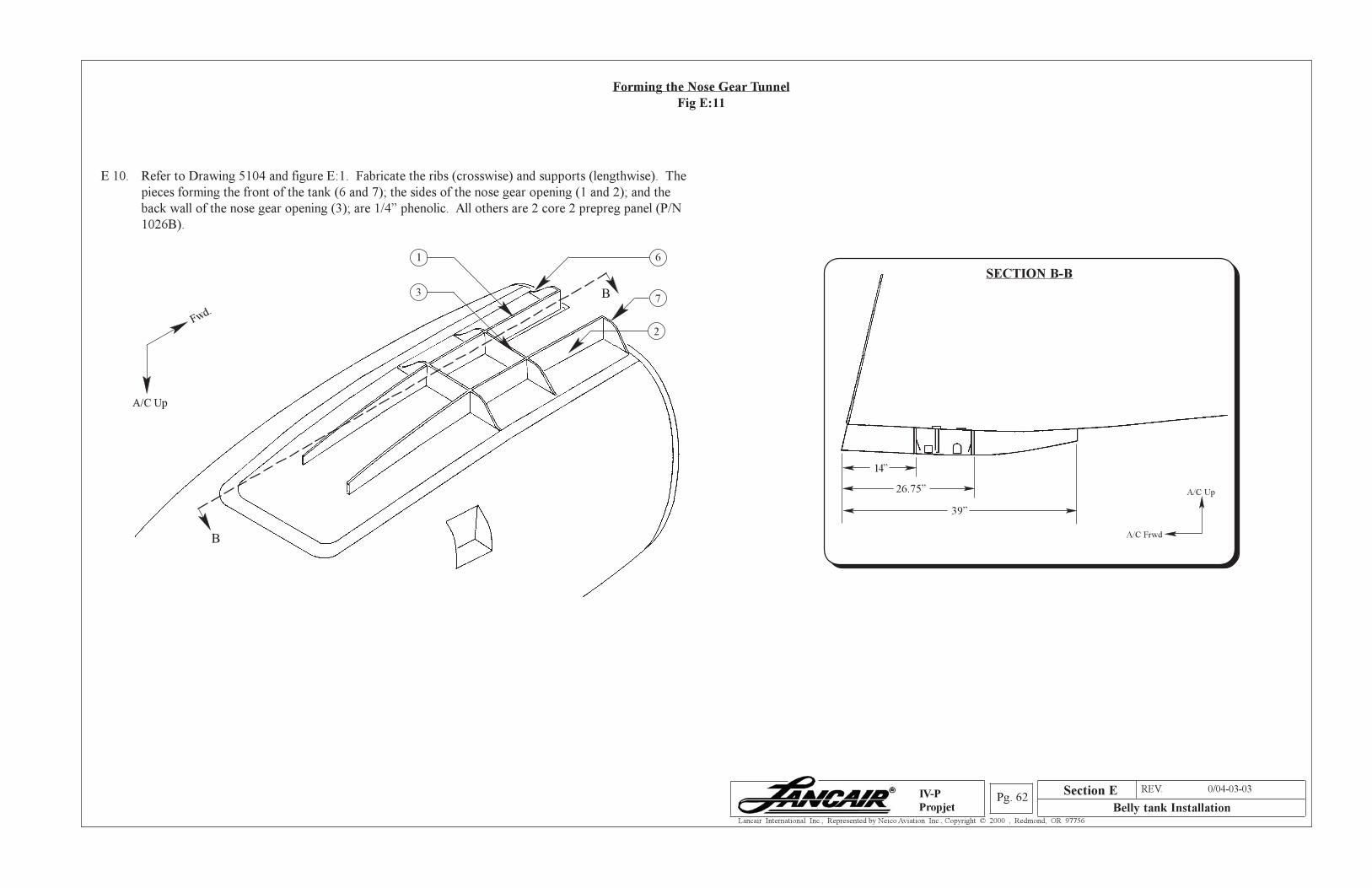
Section A REV. 0/04-03-03
Belly tank InstallationPg. 62
Lancair International Inc., Represented by Neico Aviation Inc., Copyright © 2000 , Redmond, OR 97756
IV-P
Propjet
Forming the Nose Gear Tunnel
Fig E:11
E 10. Refer to Drawing 5104 and figure E:1. Fabricate the ribs (crosswise) and supports (lengthwise). The
pieces forming the front of the tank (6 and 7); the sides of the nose gear opening (1 and 2); and the
back wall of the nose gear opening (3); are 1/4” phenolic. All others are 2 core 2 prepreg panel (P/N
1026B).
B
B
6
7
2
1
3
A/C Up
Fwd.
14”
SECTION B-B
26.75”
39”
A/C Up
A/C Frwd
Section E
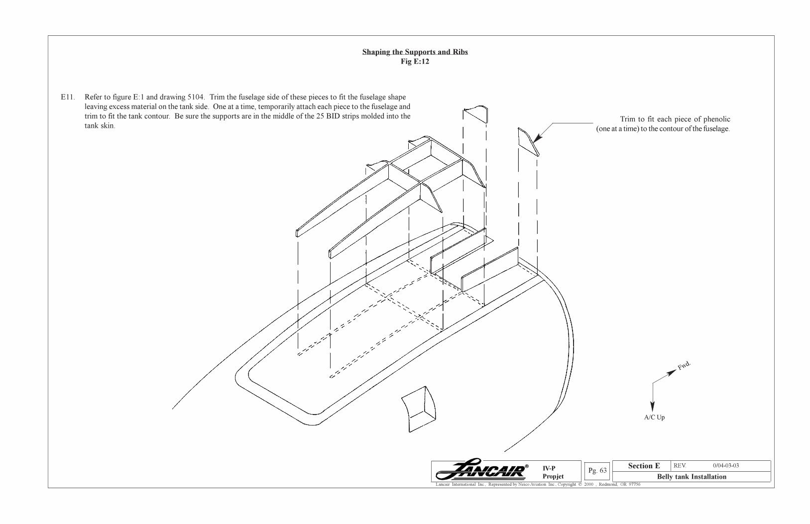
Section A REV. 0/04-03-03
Belly tank InstallationPg. 63
Lancair International Inc., Represented by Neico Aviation Inc., Copyright © 2000 , Redmond, OR 97756
IV-P
Propjet
Shaping the Supports and Ribs
Fig E:12
E11. Refer to figure E:1 and drawing 5104. Trim the fuselage side of these pieces to fit the fuselage shape
leaving excess material on the tank side. One at a time, temporarily attach each piece to the fuselage and
trim to fit the tank contour. Be sure the supports are in the middle of the 25 BID strips molded into the
tank skin.Trim to fit each piece of phenolic
(one at a time) to the contour of the fuselage.
A/C Up
Fwd.
Section E
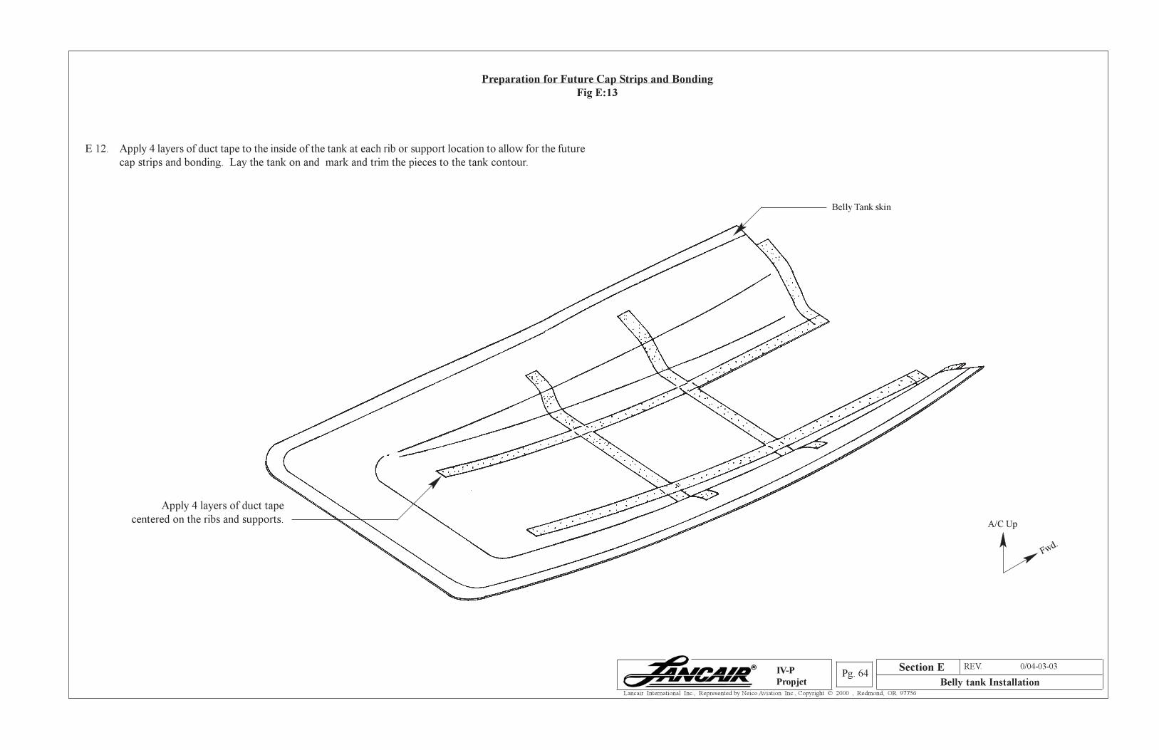
Section A REV. 0/04-03-03
Belly tank InstallationPg. 64
Lancair International Inc., Represented by Neico Aviation Inc., Copyright © 2000 , Redmond, OR 97756
IV-P
Propjet
Preparation for Future Cap Strips and Bonding
Fig E:13
E 12. Apply 4 layers of duct tape to the inside of the tank at each rib or support location to allow for the future
cap strips and bonding. Lay the tank on and mark and trim the pieces to the tank contour.
Belly Tank skin
Apply 4 layers of duct tape
centered on the ribs and supports. A/C Up
Fwd.
Section E
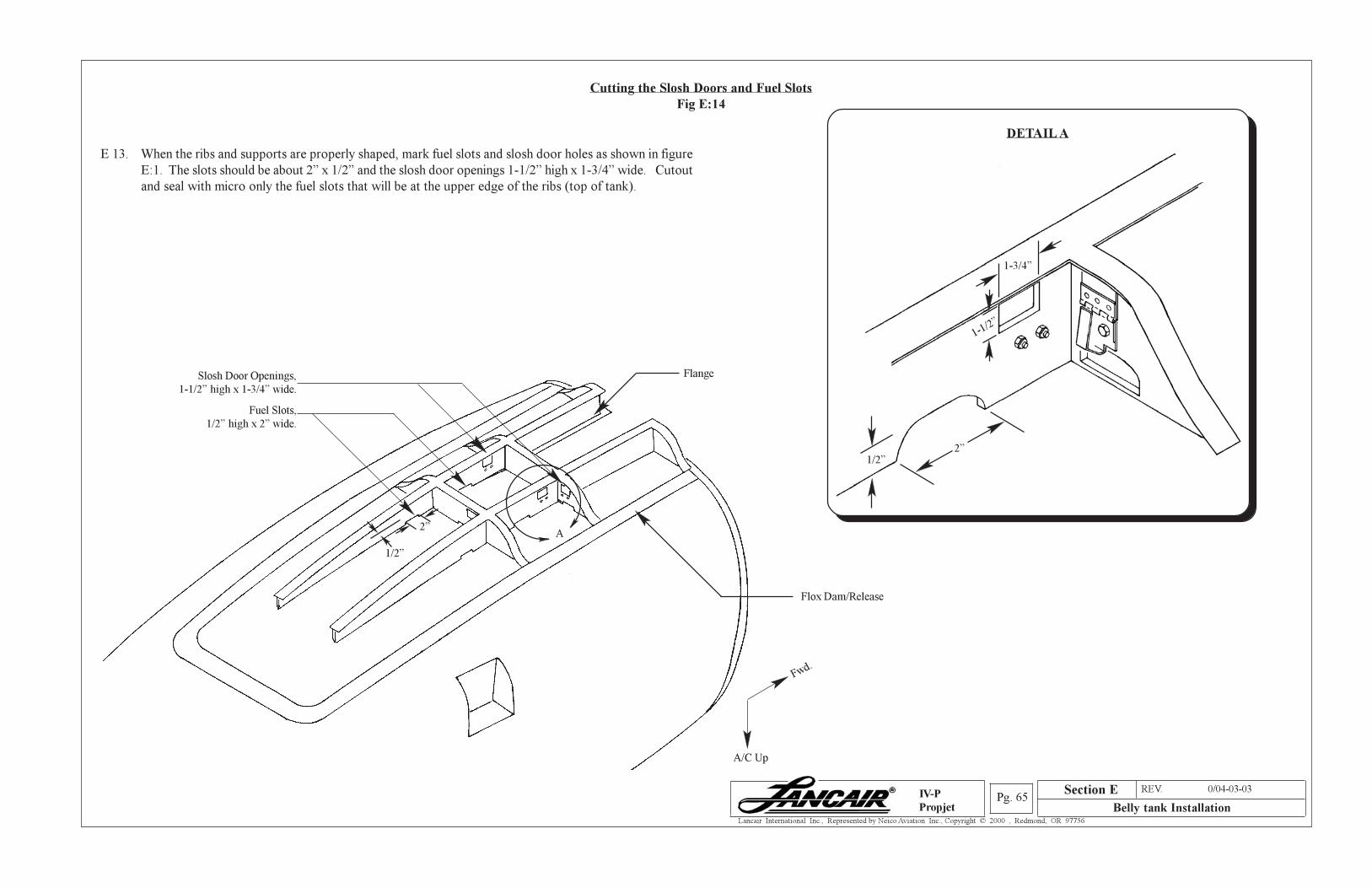
Section A REV. 0/04-03-03
Belly tank InstallationPg. 65
Lancair International Inc., Represented by Neico Aviation Inc., Copyright © 2000 , Redmond, OR 97756
IV-P
Propjet
Cutting the Slosh Doors and Fuel Slots
Fig E:14
E 13. When the ribs and supports are properly shaped, mark fuel slots and slosh door holes as shown in figure
E:1. The slots should be about 2” x 1/2” and the slosh door openings 1-1/2” high x 1-3/4” wide. Cutout
and seal with micro only the fuel slots that will be at the upper edge of the ribs (top of tank).
Slosh Door Openings,
1-1/2” high x 1-3/4” wide.
Flange
Flox Dam/Release
DETAIL A
2”
1/2”
2”1/2”
1-1/2”
1-3/4”
A
Fuel Slots,
1/2” high x 2” wide.
A/C Up
Fwd.
Section E
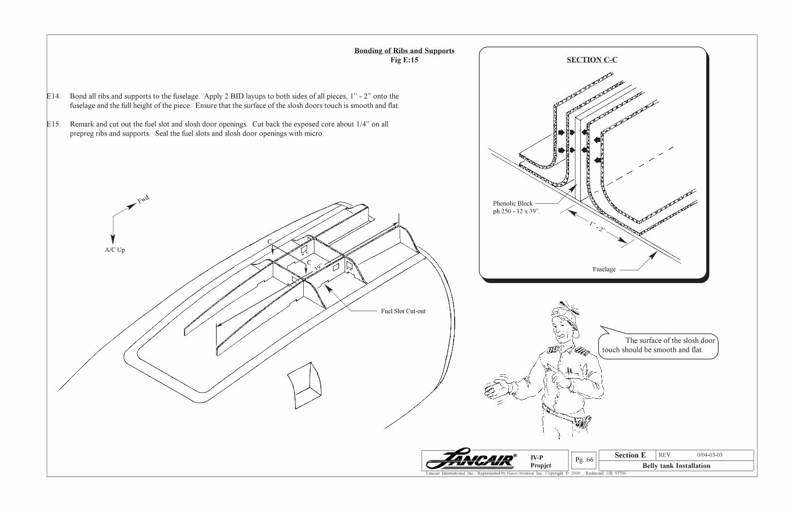
Section A REV. 0/04-03-03
Belly tank InstallationPg. 66
Lancair International Inc., Represented by Neico Aviation Inc., Copyright © 2000 , Redmond, OR 97756
IV-P
Propjet
39”
Bonding of Ribs and Supports
Fig E:15
E14. Bond all ribs and supports to the fuselage. Apply 2 BID layups to both sides of all pieces, 1” - 2” onto the
fuselage and the full height of the piece. Ensure that the surface of the slosh doors touch is smooth and flat.
E15. Remark and cut out the fuel slot and slosh door openings. Cut back the exposed core about 1/4” on all
prepreg ribs and supports. Seal the fuel slots and slosh door openings with micro.
Fuel Slot Cut-out
A/C Up
Fwd.
C
C
Section E
SECTION C-C
Phenolic Block
ph.250 - 12 x 39”.
Fuselage
1” - 2”
The surface of the slosh door
touch should be smooth and flat.
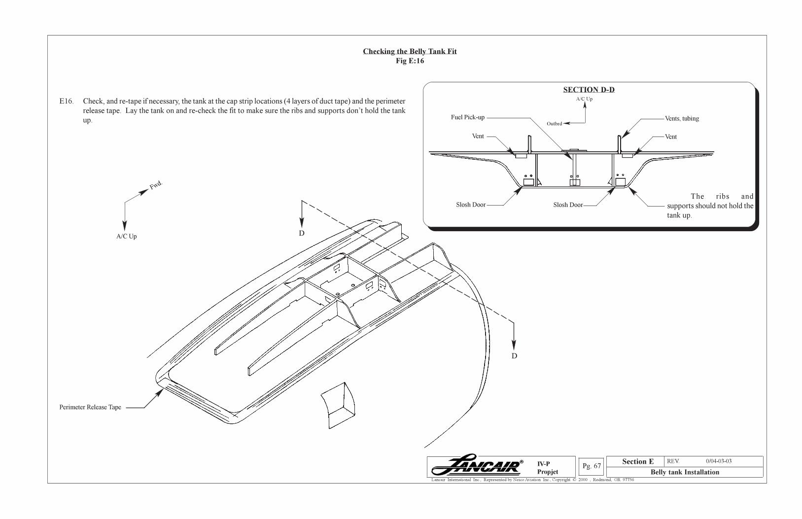
Section A REV. 0/04-03-03
Belly tank InstallationPg. 67
Lancair International Inc., Represented by Neico Aviation Inc., Copyright © 2000 , Redmond, OR 97756
IV-P
Propjet
Checking the Belly Tank Fit
Fig E:16
E16. Check, and re-tape if necessary, the tank at the cap strip locations (4 layers of duct tape) and the perimeter
release tape. Lay the tank on and re-check the fit to make sure the ribs and supports don’t hold the tank
up.
Perimeter Release Tape
Vent
Vents, tubing
Vent
The ribs and
supports should not hold the
tank up.
Fuel Pick-up
D
D
SECTION D-D
Slosh Door Slosh Door
A/C Up
Fwd.
A/C Up
Outbrd
Section E
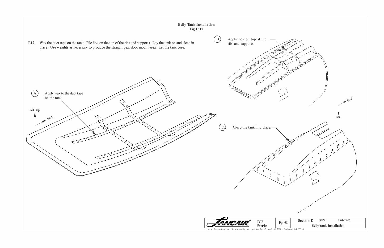
Section A REV. 0/04-03-03
Belly tank InstallationPg. 68
Lancair International Inc., Represented by Neico Aviation Inc., Copyright © 2000 , Redmond, OR 97756
IV-P
Propjet
Belly Tank Installation
Fig E:17
E17. Wax the duct tape on the tank. Pile flox on the top of the ribs and supports. Lay the tank on and cleco in
place. Use weights as necessary to produce the straight gear door mount area. Let the tank cure.
A. Apply wax to the duct tape
on the tank.
C. Cleco the tank into place.
B. Apply flox on top at the
ribs and supports.
A/C
Fwd.
A/C Up
Fwd.
Section E
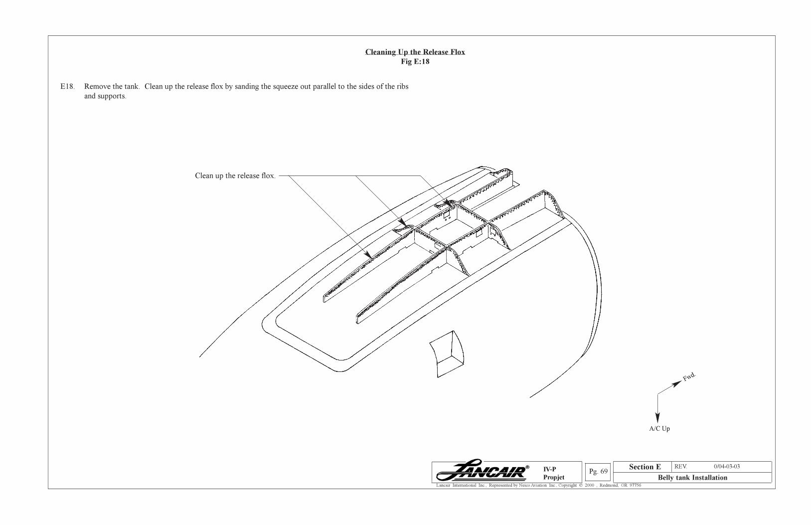
Section A REV. 0/04-03-03
Belly tank InstallationPg. 69
Lancair International Inc., Represented by Neico Aviation Inc., Copyright © 2000 , Redmond, OR 97756
IV-P
Propjet
Cleaning Up the Release Flox
Fig E:18
E18. Remove the tank. Clean up the release flox by sanding the squeeze out parallel to the sides of the ribs
and supports.
Clean up the release flox.
A/C Up
Fwd.
Section E
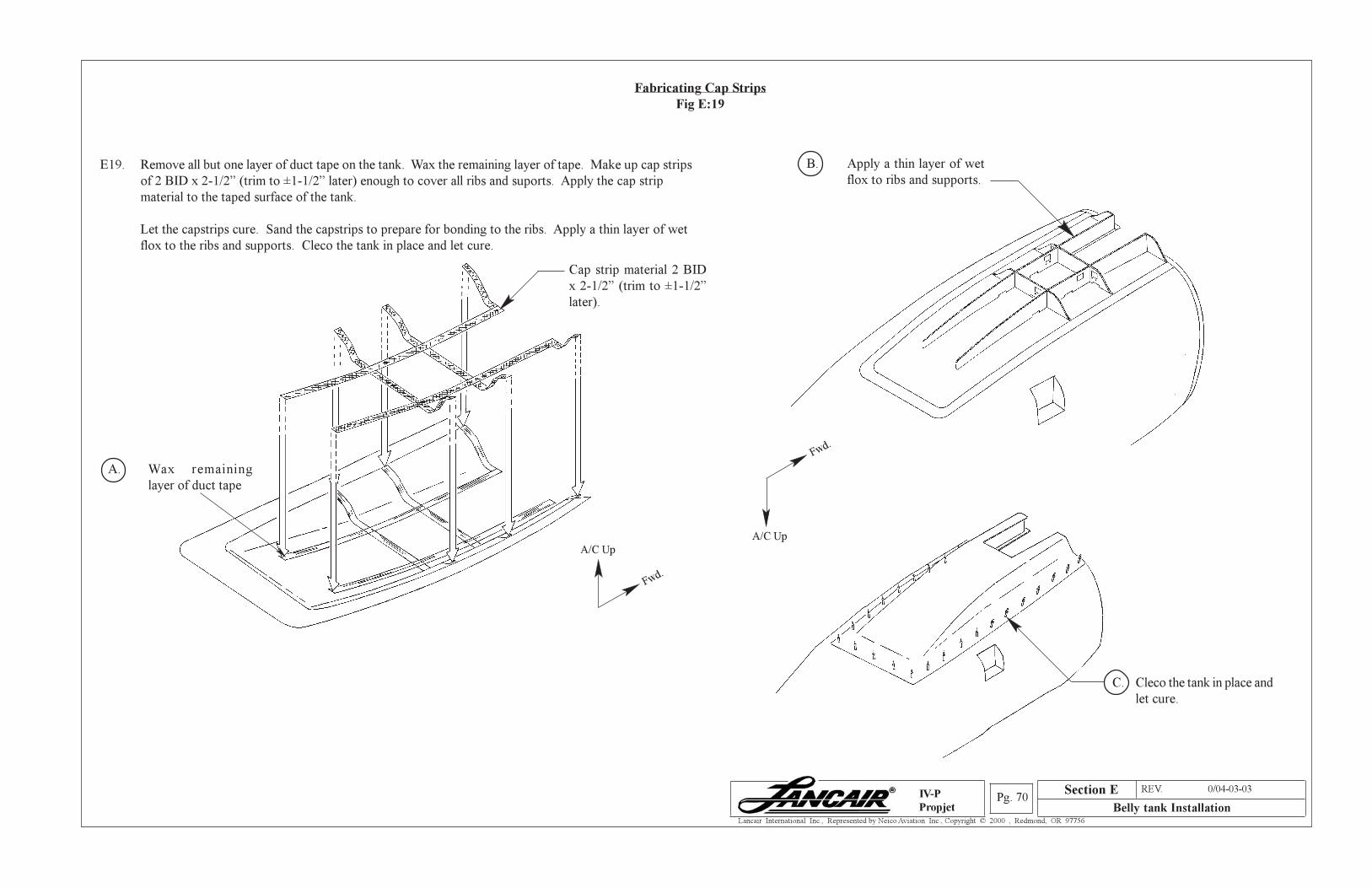
Section A REV. 0/04-03-03
Belly tank InstallationPg. 70
Lancair International Inc., Represented by Neico Aviation Inc., Copyright © 2000 , Redmond, OR 97756
IV-P
Propjet
Fabricating Cap Strips
Fig E:19
E19. Remove all but one layer of duct tape on the tank. Wax the remaining layer of tape. Make up cap strips
of 2 BID x 2-1/2” (trim to ±1-1/2” later) enough to cover all ribs and suports. Apply the cap strip
material to the taped surface of the tank.
Let the capstrips cure. Sand the capstrips to prepare for bonding to the ribs. Apply a thin layer of wet
flox to the ribs and supports. Cleco the tank in place and let cure.
B. Apply a thin layer of wet
flox to ribs and supports.
A/C Up
Fwd.
Cap strip material 2 BID
x 2-1/2” (trim to ±1-1/2”
later).
C. Cleco the tank in place and
let cure.
A/C Up
Fwd.
Section E
A. Wax remaining
layer of duct tape
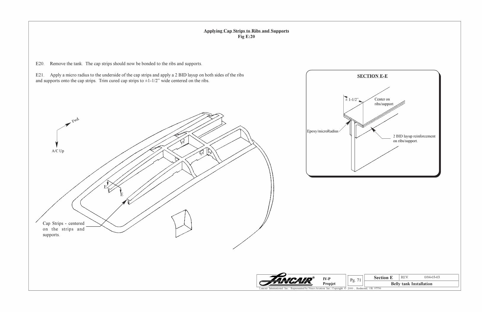
Section A REV. 0/04-03-03
Belly tank InstallationPg. 71
Lancair International Inc., Represented by Neico Aviation Inc., Copyright © 2000 , Redmond, OR 97756
IV-P
Propjet
Applying Cap Strips to Ribs and Supports
Fig E:20
E20. Remove the tank. The cap strips should now be bonded to the ribs and supports.
E21. Apply a micro radius to the underside of the cap strips and apply a 2 BID layup on both sides of the ribs
and supports onto the cap strips. Trim cured cap strips to ±1-1/2” wide centered on the ribs.
Cap Strips - centered
on the strips and
supports.
Epoxy/microRadius
2 BID layup reinforcement
on ribs/support.
Center on
ribs/support
SECTION E-E
E
E
± 1-1/2”
A/C Up
Fwd.
Section E
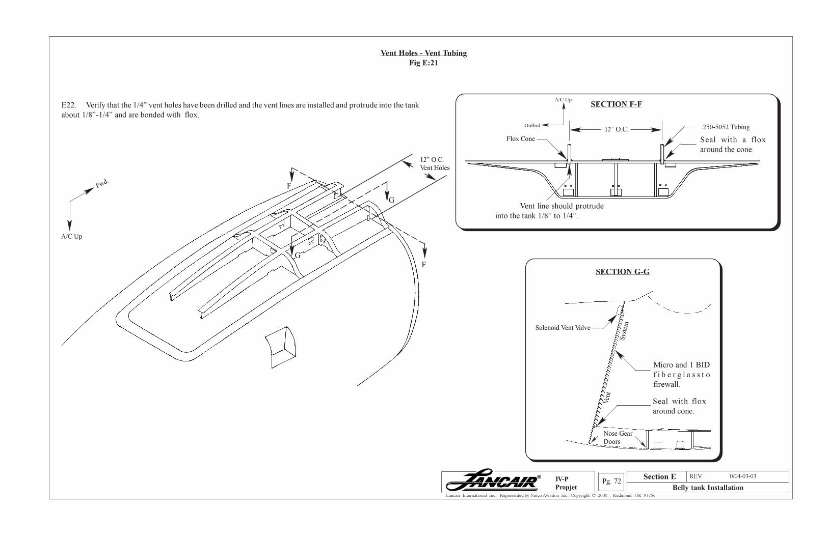
Section A REV. 0/04-03-03
Belly tank InstallationPg. 72
Lancair International Inc., Represented by Neico Aviation Inc., Copyright © 2000 , Redmond, OR 97756
IV-P
Propjet
Vent Holes - Vent Tubing
Fig E:21
E22. Verify that the 1/4” vent holes have been drilled and the vent lines are installed and protrude into the tank
about 1/8”-1/4” and are bonded with flox.
12” O.C.
Vent Holes
F
F
G
G
A/C Up
Fwd.
Vent line should protrude
into the tank 1/8” to 1/4”.
SECTION F-F
.250-5052 Tubing
Seal with a flox
around the cone.
Flox Cone
12” O.C.
Ven
t
Sys
tem
Micro and 1 BID
f i b e r g l a s s t o
firewall.
Seal with flox
around cone.
SECTION G-G
Nose Gear
Doors
Solenoid Vent Valve
A/C Up
Outbrd
Section E
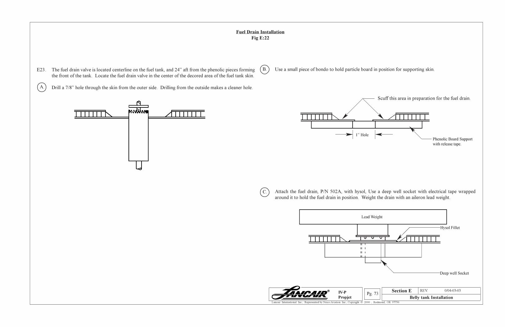
Section A REV. 0/04-03-03
Belly tank InstallationPg. 73
Lancair International Inc., Represented by Neico Aviation Inc., Copyright © 2000 , Redmond, OR 97756
IV-P
Propjet
Fuel Drain Installation
Fig E:22
E23. The fuel drain valve is located centerline on the fuel tank, and 24” aft from the phenolic pieces forming
the front of the tank. Locate the fuel drain valve in the center of the decored area of the fuel tank skin.
Drill a 7/8” hole through the skin from the outer side. Drilling from the outside makes a cleaner hole.
Use a small piece of bondo to hold particle board in position for supporting skin.
Scuff this area in preparation for the fuel drain.
Phenolic Board Support
with release tape.
Attach the fuel drain, P/N 502A, with hysol, Use a deep well socket with electrical tape wrapped
around it to hold the fuel drain in position. Weight the drain with an aileron lead weight.
Lead Weight
Hysol Fillet
Deep well Socket
7/8” hole saw
1” Hole
Section E
A.
B.
C.
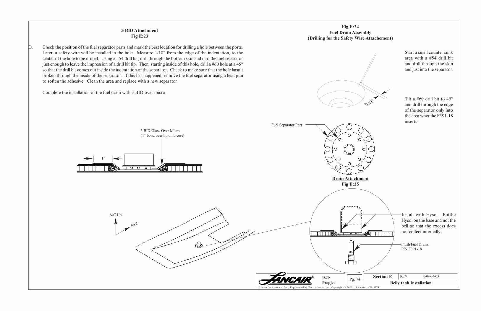
Section A REV. 0/04-03-03
Belly tank InstallationPg. 74
Lancair International Inc., Represented by Neico Aviation Inc., Copyright © 2000 , Redmond, OR 97756
IV-P
Propjet
Fig E:24
Fuel Drain Assembly
(Drilling for the Safety Wire Attachement)
D. Check the position of the fuel separator parts and mark the best location for drilling a hole between the ports.
Later, a safety wire will be installed in the hole. Measure 1/10” from the edge of the indentation, to the
center of the hole to be drilled. Using a #54 drill bit, drill through the bottom skin and into the fuel separator
just enough to leave the impression of a drill bit tip. Then, starting inside of this hole, drill a #60 hole at a 45°
so that the drill bit comes out inside the indentation of the separator. Check to make sure that the hole hasn’t
broken through the inside of the separator. If this has happened, remove the fuel separator using a heat gun
to soften the adhesive. Clean the area and replace with a new separator.
Complete the installation of the fuel drain with 3 BID over micro.
3 BID Attachment
Fig E:23
3 BID Glass Over Micro
(1” bond overlap onto core)
Drain Attachment
Fig E:25
1”
A/C Up
Fwd.
Fuel Separator Port
Start a small counter sunk
area with a #54 drill bit
and drill through the skin
and just into the separator.
Tilt a #60 drill bit to 45°
and drill through the edge
of the separator only into
the area wher the F391-18
inserts
Install with Hysol. Putthe
Hysol on the base and not the
bell so that the excess does
not collect internally.
Flush Fuel Drain.
P/N F391-18
Section E
0.13"
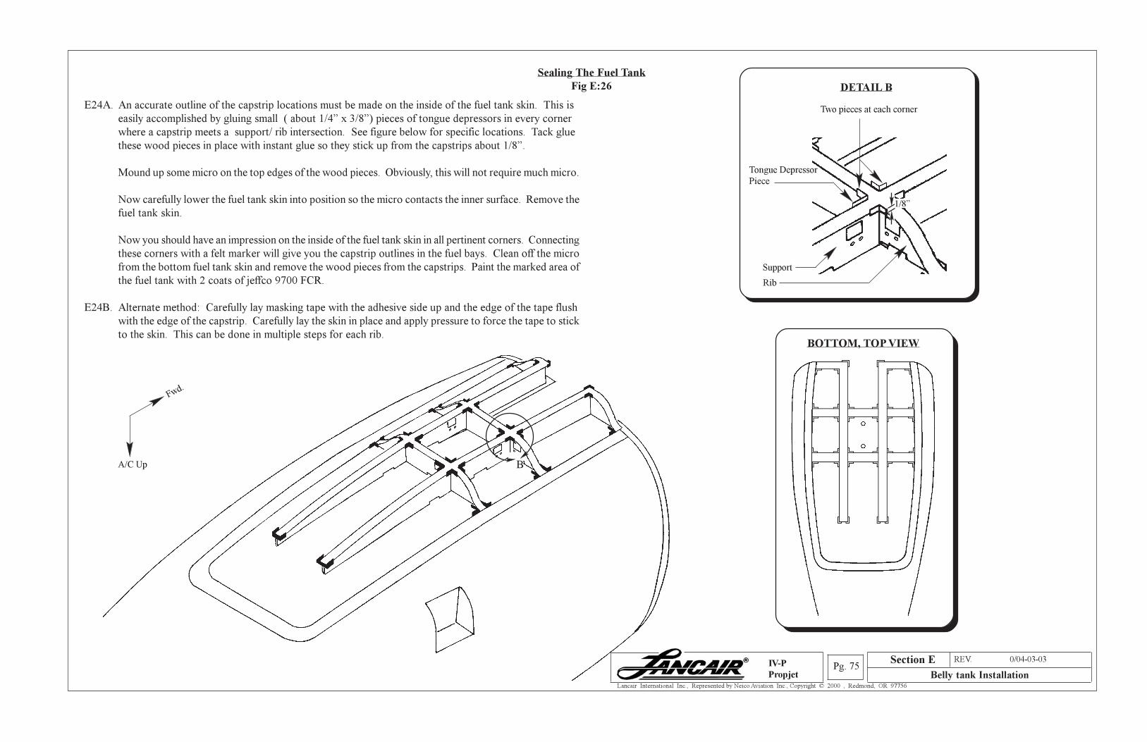
Section A REV. 0/04-03-03
Belly tank InstallationPg. 75
Lancair International Inc., Represented by Neico Aviation Inc., Copyright © 2000 , Redmond, OR 97756
IV-P
Propjet
Sealing The Fuel Tank
Fig E:26
E24A. An accurate outline of the capstrip locations must be made on the inside of the fuel tank skin. This is
easily accomplished by gluing small ( about 1/4” x 3/8”) pieces of tongue depressors in every corner
where a capstrip meets a support/ rib intersection. See figure below for specific locations. Tack glue
these wood pieces in place with instant glue so they stick up from the capstrips about 1/8”.
Mound up some micro on the top edges of the wood pieces. Obviously, this will not require much micro.
Now carefully lower the fuel tank skin into position so the micro contacts the inner surface. Remove the
fuel tank skin.
Now you should have an impression on the inside of the fuel tank skin in all pertinent corners. Connecting
these corners with a felt marker will give you the capstrip outlines in the fuel bays. Clean off the micro
from the bottom fuel tank skin and remove the wood pieces from the capstrips. Paint the marked area of
the fuel tank with 2 coats of jeffco 9700 FCR.
E24B. Alternate method: Carefully lay masking tape with the adhesive side up and the edge of the tape flush
with the edge of the capstrip. Carefully lay the skin in place and apply pressure to force the tape to stick
to the skin. This can be done in multiple steps for each rib.
A/C Up
Fwd.
Section E
B
Two pieces at each corner
Tongue Depressor
Piece
Support
Rib
DETAIL B
1/8”
BOTTOM, TOP VIEW
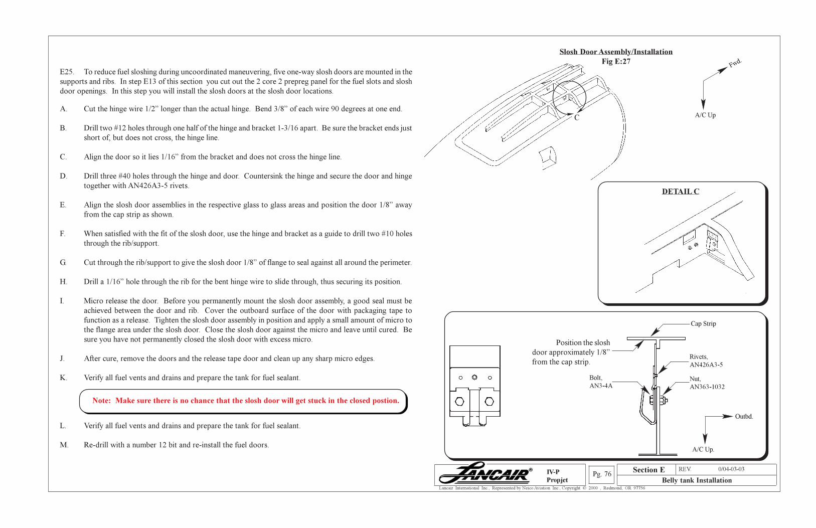
Section A REV. 0/04-03-03
Belly tank InstallationPg. 76
Lancair International Inc., Represented by Neico Aviation Inc., Copyright © 2000 , Redmond, OR 97756
IV-P
Propjet
Slosh Door Assembly/Installation
Fig E:27
Position the slosh
door approximately 1/8”
from the cap strip.
Cap Strip
Bolt,
AN3-4A
Rivets,
AN426A3-5
Nut,
AN363-1032
Outbd.
A/C Up.
E25. To reduce fuel sloshing during uncoordinated maneuvering, five one-way slosh doors are mounted in the
supports and ribs. In step E13 of this section you cut out the 2 core 2 prepreg panel for the fuel slots and slosh
door openings. In this step you will install the slosh doors at the slosh door locations.
A. Cut the hinge wire 1/2” longer than the actual hinge. Bend 3/8” of each wire 90 degrees at one end.
B. Drill two #12 holes through one half of the hinge and bracket 1-3/16 apart. Be sure the bracket ends just
short of, but does not cross, the hinge line.
C. Align the door so it lies 1/16” from the bracket and does not cross the hinge line.
D. Drill three #40 holes through the hinge and door. Countersink the hinge and secure the door and hinge
together with AN426A3-5 rivets.
E. Align the slosh door assemblies in the respective glass to glass areas and position the door 1/8” away
from the cap strip as shown.
F. When satisfied with the fit of the slosh door, use the hinge and bracket as a guide to drill two #10 holes
through the rib/support.
G. Cut through the rib/support to give the slosh door 1/8” of flange to seal against all around the perimeter.
H. Drill a 1/16” hole through the rib for the bent hinge wire to slide through, thus securing its position.
I. Micro release the door. Before you permanently mount the slosh door assembly, a good seal must be
achieved between the door and rib. Cover the outboard surface of the door with packaging tape to
function as a release. Tighten the slosh door assembly in position and apply a small amount of micro to
the flange area under the slosh door. Close the slosh door against the micro and leave until cured. Be
sure you have not permanently closed the slosh door with excess micro.
J. After cure, remove the doors and the release tape door and clean up any sharp micro edges.
K. Verify all fuel vents and drains and prepare the tank for fuel sealant.
L. Verify all fuel vents and drains and prepare the tank for fuel sealant.
M. Re-drill with a number 12 bit and re-install the fuel doors.
A/C Up
Fwd.
C
DETAIL C
Section E
Note: Make sure there is no chance that the slosh door will get stuck in the closed postion.
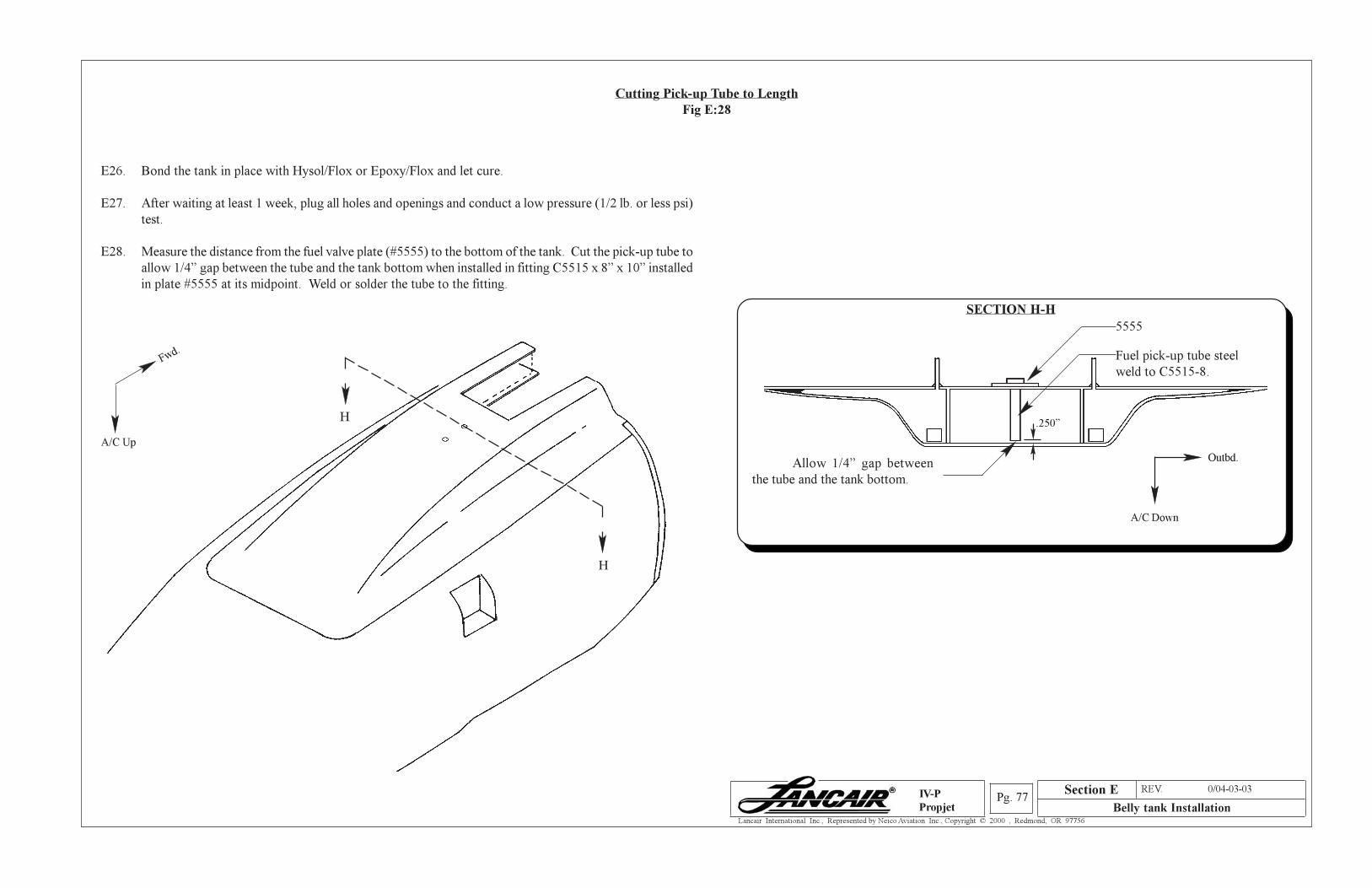
Section A REV. 0/04-03-03
Belly tank InstallationPg. 77
Lancair International Inc., Represented by Neico Aviation Inc., Copyright © 2000 , Redmond, OR 97756
IV-P
Propjet
E26. Bond the tank in place with Hysol/Flox or Epoxy/Flox and let cure.
E27. After waiting at least 1 week, plug all holes and openings and conduct a low pressure (1/2 lb. or less psi)
test.
E28. Measure the distance from the fuel valve plate (#5555) to the bottom of the tank. Cut the pick-up tube to
allow 1/4” gap between the tube and the tank bottom when installed in fitting C5515 x 8” x 10” installed
in plate #5555 at its midpoint. Weld or solder the tube to the fitting.
Cutting Pick-up Tube to Length
Fig E:28
H
H
A/C Up
Fwd.
Allow 1/4” gap between
the tube and the tank bottom.
Fuel pick-up tube steel
weld to C5515-8.
SECTION H-H
Outbd.
A/C Down
.250”
Section E
5555
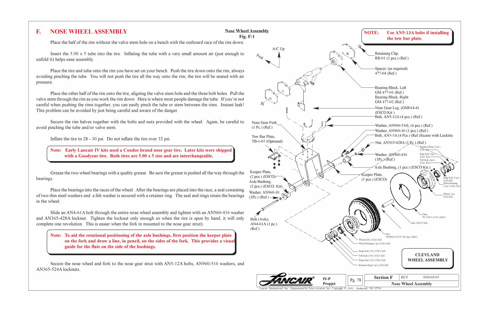
Section A REV. 0/04-03-03
Nose Wheel AssemblyPg. 78
Lancair International Inc., Represented by Neico Aviation Inc., Copyright © 2000 , Redmond, OR 97756
IV-P
Propjet
Place the half of the rim without the valve stem hole on a bench with the outboard race of the rim down.
Insert the 5.00 x 5 tube into the tire. Inflating the tube with a very small amount air (just enough to
unfold it) helps ease assembly.
Place the tire and tube onto the rim you have set on your bench. Push the tire down onto the rim, always
avoiding pinching the tube. You will not push the tire all the way onto the rim, the tire will be seated with air
pressure.
Place the other half of the rim onto the tire, aligning the valve stem hole and the three bolt holes. Pull the
valve stem through the rim as you work the rim down. Here is where most people damage the tube. If you’re not
careful when pushing the rims together, you can easily pinch the tube or stem between the rims. Instant leak!
This problem can be avoided by just being careful and aware of the danger.
Secure the rim halves together with the bolts and nuts provided with the wheel. Again, be careful to
avoid pinching the tube and/or valve stem.
Inflate the tire to 28 - 30 psi. Do not inflate the tire over 32 psi.
Note: Early Lancair IV kits used a Condor brand nose gear tire. Later kits were shipped
with a Goodyear tire. Both tires are 5.00 x 5 size and are interchangeable.
Grease the two wheel bearings with a quality grease. Be sure the grease is pushed all the way through the
bearings.
Place the bearings into the races of the wheel. After the bearings are placed into the race, a seal consisting
of two thin steel washers and a felt washer is secured with a retainer ring. The seal and rings retain the bearings
in the wheel.
Slide an AN4-61A bolt through the entire nose wheel assembly and tighten with an AN960-416 washer
and AN365-428A locknut. Tighten the locknut only enough so when the tire is spun by hand, it will only
complete one revolution. This is easier when the fork in mounted to the nose gear strut).
Note: To aid the rotational positioning of the axle bushings, first position the keeper plate
on the fork and draw a line, in pencil, on the sides of the fork. This provides a visual
guide for the flats on the side of the bushings.
Secure the nose wheel and fork to the nose gear strut with AN5-12A bolts, AN960-516 washers, and
AN365-524A locknuts.
F. NOSE WHEEL ASSEMBLY Nose Wheel Assembly
Fig. F:1
Spacer, (as required)
477-04 (Ref.)
Retaining Clip,
RR-01 (2 pcs.) (Ref.)
Bearing Block, Left
GM 477-01 (Ref.)
Bearing Block, Right
GM 477-02 (Ref.)
Tow Bar Plate,
TB-1-03 (Optional)
Retainer Ring (1 pc.) (Clev.Kit)
Ring Seal (1 Pc.) (Clev. Kit)
Felt Seal (1 Pc.) (Clev. Kit)
Ring Seal (1 Pc.) (Clev. Kit)
Wheel Bearing (1 pc.) (Clev. Kit)
Wheel (1Pc.) (Clev. Kit)
Tube,
TU-5.00-5 (1 Pc.) (Ref.)
Ring SealFelt Seal
CLEVLAND
WHEEL ASSEMBLY
Bolt, AN5-12A (4 pcs.) (Ref.)
Washer, AN960-516L (4 pcs.) (Ref.)
Nose Gear Leg, (GM014-4)
(ESCO Kit )
NOTE: Use AN5-13A bolts if installing
the tow bar plate.
Washer, AN960-10 (1 pcs.) (Ref.)
Bolt, AN3-3A (4 Pcs.) (Ref.)Secure with Locktite
Bolt (Axle),
AN4-61A (1 pc.)
(Ref.)
Washer, AN960-10
(1Pc.) (Ref.)
Wheel
Bearing (1 pc.)
Washer, AN960-416
(1Pc.) (Ref.)
Tire,
TR500x5 GY FC III (1pc.) (Ref.)
Keeper Plate,
(2 pcs.) (ESCO)
Axle Bushing,
(2 pcs.) (ESCO. Kit)
Retainer Ring, (1 pc.)
(Clev. Kit)
Axle, (ESCO Kit)
A/C Up
Fwd.
Nut, AN365-428A (1 Pc.) (Ref.)
Wheel, 1 pc.
(Clev.Kit)
Ring Seal, (1 pc.)
(Clev.Kit)
Wheel Bearing,
(1 pc.) (Clev. Kit.)
Ring Seal, (1pc.)
(Clev. Kit)
Felt Seal, (1pc.)
(Clev. Kit)
Nose Gear Fork,
(1 Pc.) (Ref.)
Axle Bushing, (1 pcs.) (ESCO Kit.)
Keeper Plate,
(1 pcs.) (ESCO)
Section F
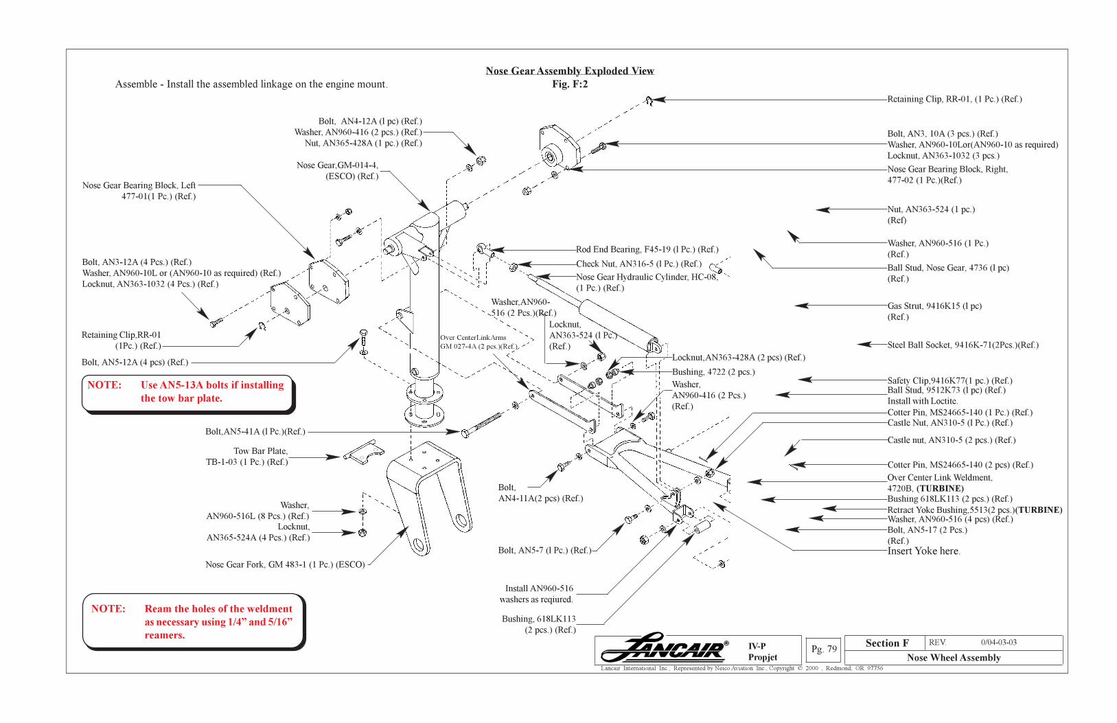
Section A REV. 0/04-03-03
Nose Wheel AssemblyPg. 79
Lancair International Inc., Represented by Neico Aviation Inc., Copyright © 2000 , Redmond, OR 97756
IV-P
Propjet
Locknut,
AN363-524 (l Pc.)
(Ref.)
Nose Gear Assembly Exploded View
Fig. F:2
Over CenterLinkArms
GM 027-4A (2 pcs.)(Ref.)
Nose Gear,GM-014-4,
(ESCO) (Ref.)Nose Gear Bearing Block, Left
477-01(1 Pc.) (Ref.)
Retaining Clip, RR-01, (1 Pc.) (Ref.)
Bolt, AN4-12A (l pc) (Ref.)
Washer, AN960-416 (2 pcs.) (Ref.)
Nut, AN365-428A (1 pc.) (Ref.)
Nose Gear Hydraulic Cylinder, HC-08,
(1 Pc.) (Ref.)
Check Nut, AN316-5 (l Pc.) (Ref.)
Bolt, AN5-7 (l Pc.) (Ref.)
Over Center Link Weldment,
4720B, (TURBINE)
Bolt,AN5-41A (l Pc.)(Ref.)
Bolt,
AN4-11A(2 pcs) (Ref.)
Washer,
AN960-416 (2 Pcs.)
(Ref.)
Bolt, AN5-17 (2 Pcs.)
(Ref.)
Washer,AN960-
516 (2 Pcs.)(Ref.)
Install AN960-516
washers as reqiured.
Castle nut, AN310-5 (2 pcs.) (Ref.)
Cotter Pin, MS24665-140 (1 Pc.) (Ref.)Castle Nut, AN310-5 (l Pc.) (Ref.)
Washer, AN960-516 (4 pcs) (Ref.)
Ball Stud, 9512K73 (l pc) (Ref.)
Install with Loctite.
Steel Ball Socket, 9416K-71(2Pcs.)(Ref.)
Gas Strut, 9416K15 (l pc)
(Ref.)
Safety Clip,9416K77(1 pc.) (Ref.)
Locknut,
AN365-524A (4 Pcs.) (Ref.)
Nose Gear Fork, GM 483-1 (1 Pc.) (ESCO)
Tow Bar Plate,
TB-1-03 (1 Pc.) (Ref.)
Ball Stud, Nose Gear, 4736 (l pc)
(Ref.)
Bolt, AN5-12A (4 pcs) (Ref.)
Rod End Bearing, F45-19 (l Pc.) (Ref.)
Nose Gear Bearing Block, Right,
477-02 (1 Pc.)(Ref.)
Insert Yoke here.
Assemble - Install the assembled linkage on the engine mount.
Retaining Clip,RR-01
(1Pc.) (Ref.)
Bolt, AN3-12A (4 Pcs.) (Ref.)
Washer, AN960-10L or (AN960-10 as required) (Ref.)
Locknut, AN363-1032 (4 Pcs.) (Ref.)
Retract Yoke Bushing,5513(2 pcs.)(TURBINE)
Bushing, 618LK113
(2 pcs.) (Ref.)
Washer, AN960-516 (1 Pc.)
(Ref.)
Nut, AN363-524 (1 pc.)
(Ref)
Cotter Pin, MS24665-140 (2 pcs) (Ref.)
Bolt, AN3, 10A (3 pcs.) (Ref.)
Washer, AN960-10Lor(AN960-10 as required)
Locknut, AN363-1032 (3 pcs.)
Bushing 618LK113 (2 pcs.) (Ref.)
NOTE: Ream the holes of the weldment
as necessary using 1/4” and 5/16”
reamers.
NOTE: Use AN5-13A bolts if installing
the tow bar plate.
Section F
Locknut,AN363-428A (2 pcs) (Ref.)
Bushing, 4722 (2 pcs.)
Washer,
AN960-516L (8 Pcs.) (Ref.)
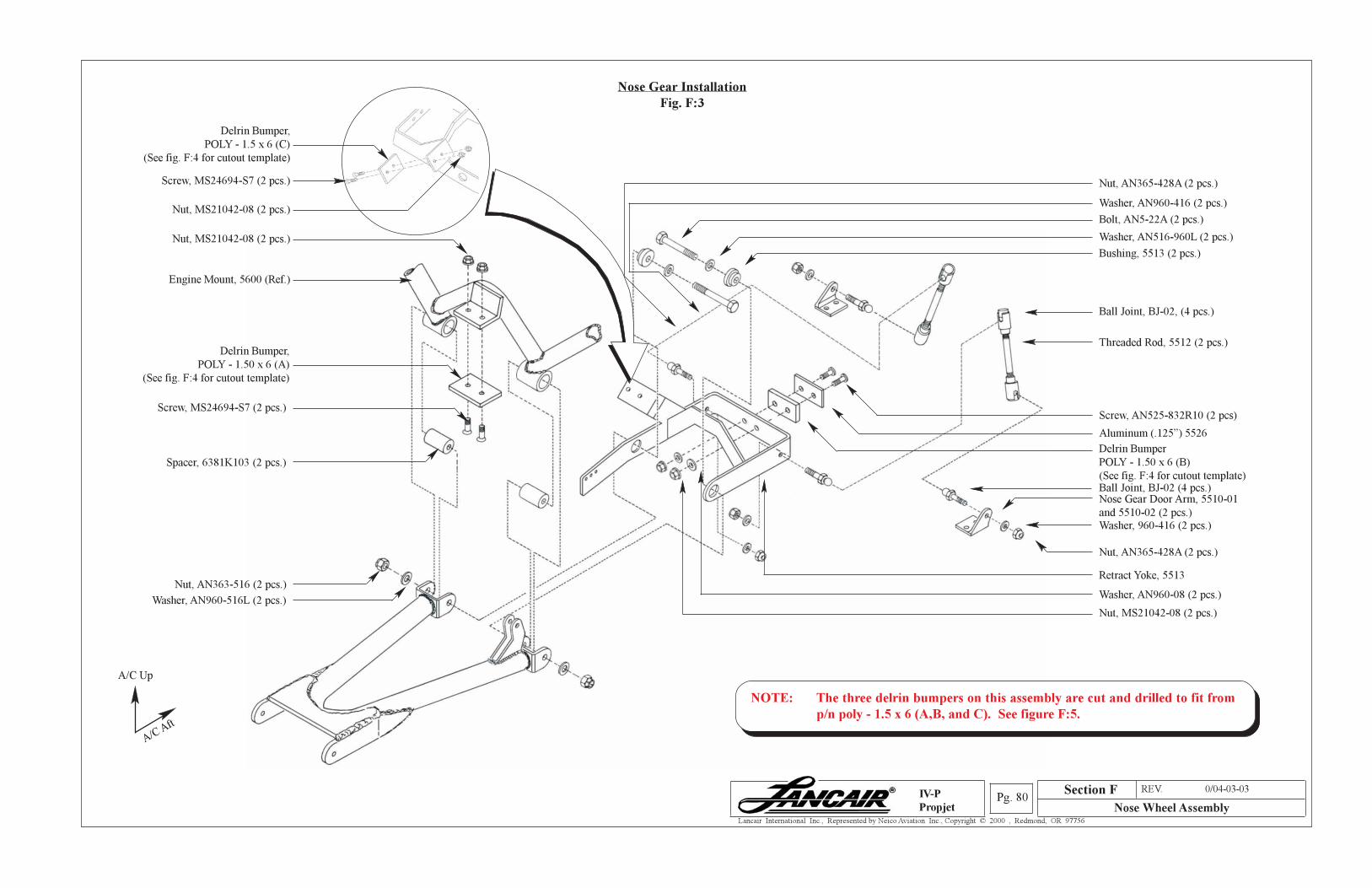
Section A REV. 0/04-03-03
Nose Wheel AssemblyPg. 80
Lancair International Inc., Represented by Neico Aviation Inc., Copyright © 2000 , Redmond, OR 97756
IV-P
Propjet
Nose Gear Door Arm, 5510-01
and 5510-02 (2 pcs.)
Section F
Nose Gear Installation
Fig. F:3
Washer, AN516-960L (2 pcs.)
Spacer, 6381K103 (2 pcs.)
Retract Yoke, 5513
Screw, MS24694-S7 (2 pcs.)
Screw, MS24694-S7 (2 pcs.)
Nut, MS21042-08 (2 pcs.)
Screw, AN525-832R10 (2 pcs)
Aluminum (.125”) 5526
Delrin Bumper
POLY - 1.50 x 6 (B)
(See fig. F:4 for cutout template)
Ball Joint, BJ-02, (4 pcs.)
Threaded Rod, 5512 (2 pcs.)
Washer, AN960-08 (2 pcs.)
Nut, MS21042-08 (2 pcs.)Washer, AN960-516L (2 pcs.)
Bushing, 5513 (2 pcs.)
Ball Joint, BJ-02 (4 pcs.)
Nut, AN363-516 (2 pcs.)
Washer, 960-416 (2 pcs.)
Nut, AN365-428A (2 pcs.)
Bolt, AN5-22A (2 pcs.)
Washer, AN960-416 (2 pcs.)Nut, MS21042-08 (2 pcs.)
Nut, AN365-428A (2 pcs.)
Engine Mount, 5600 (Ref.)
Delrin Bumper,
POLY - 1.50 x 6 (A)
(See fig. F:4 for cutout template)
A/C Aft
A/C Up
Delrin Bumper,
POLY - 1.5 x 6 (C)
(See fig. F:4 for cutout template)
NOTE: The three delrin bumpers on this assembly are cut and drilled to fit from
p/n poly - 1.5 x 6 (A,B, and C). See figure F:5.
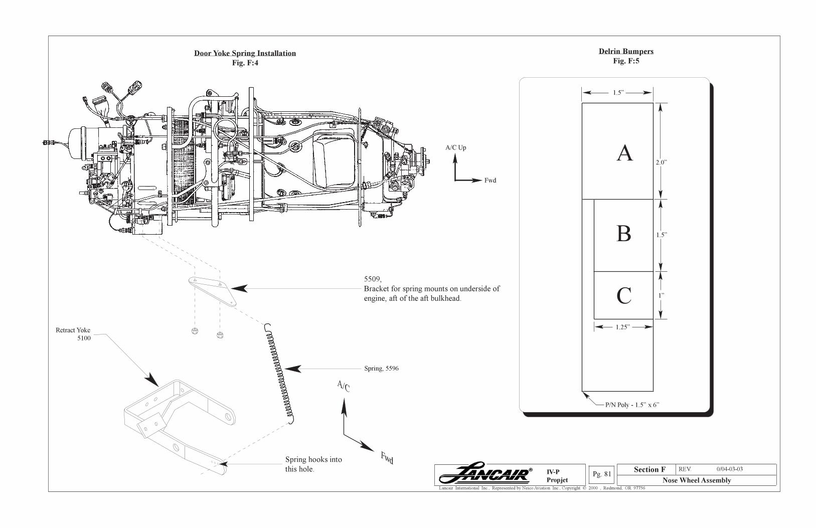
Section A REV. 0/04-03-03
Nose Wheel AssemblyPg. 81
Lancair International Inc., Represented by Neico Aviation Inc., Copyright © 2000 , Redmond, OR 97756
IV-P
Propjet
1.25”
1”
1.5”
A
B
C
Delrin Bumpers
Fig. F:5
P/N Poly - 1.5” x 6”
Door Yoke Spring Installation
Fig. F:4
2.0”
1.5”
Section F
Spring hooks into
this hole.
Spring, 5596
Retract Yoke
5100
5509,
Bracket for spring mounts on underside of
engine, aft of the aft bulkhead.
A/C
Fwd
A/C Up
Fwd
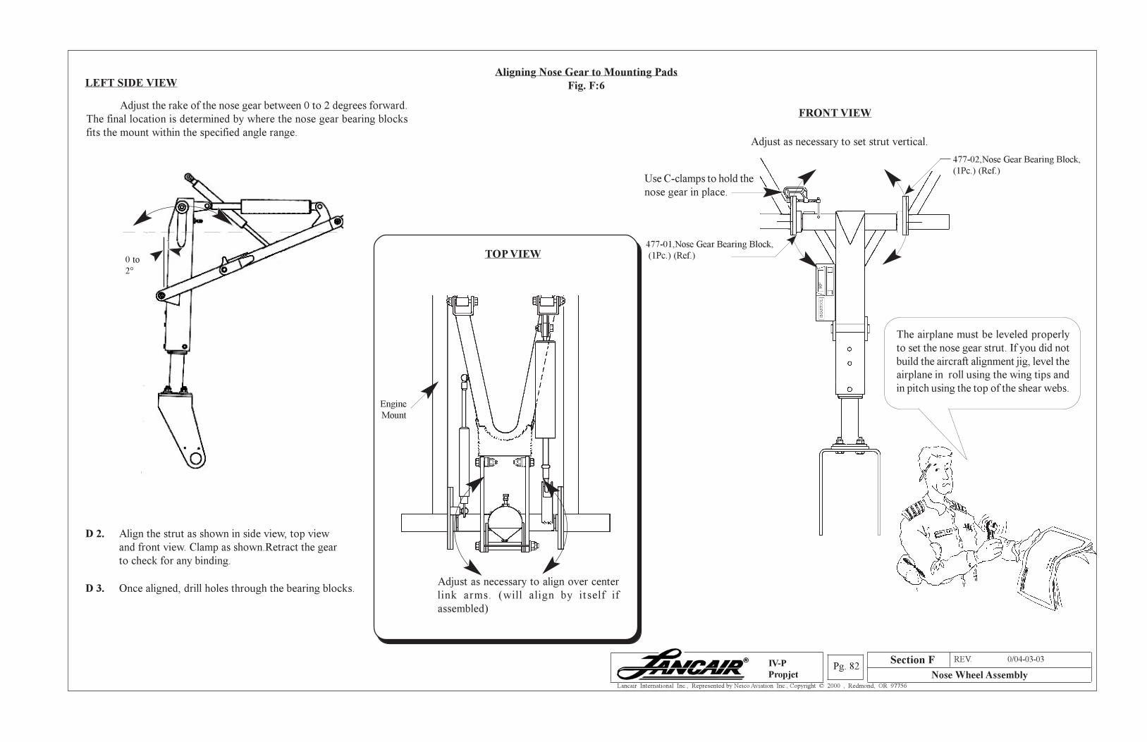
Section A REV. 0/04-03-03
Nose Wheel AssemblyPg. 82
Lancair International Inc., Represented by Neico Aviation Inc., Copyright © 2000 , Redmond, OR 97756
IV-P
Propjet
Aligning Nose Gear to Mounting Pads
Fig. F:6
D 3. Once aligned, drill holes through the bearing blocks.
D 2. Align the strut as shown in side view, top view
and front view. Clamp as shown.Retract the gear
to check for any binding.
The airplane must be leveled properly
to set the nose gear strut. If you did not
build the aircraft alignment jig, level the
airplane in roll using the wing tips and
in pitch using the top of the shear webs.
Use C-clamps to hold the
nose gear in place.
Adjust as necessary to set strut vertical.
SMARTOOL
90O
FRONT VIEWAdjust the rake of the nose gear between 0 to 2 degrees forward.
The final location is determined by where the nose gear bearing blocks
fits the mount within the specified angle range.
LEFT SIDE VIEW
477-02,Nose Gear Bearing Block,
(1Pc.) (Ref.)
0 to
2°
477-01,Nose Gear Bearing Block,
(1Pc.) (Ref.)
Engine
Mount
TOP VIEW
Section F
Adjust as necessary to align over center
link arms. (will align by itself if
assembled)
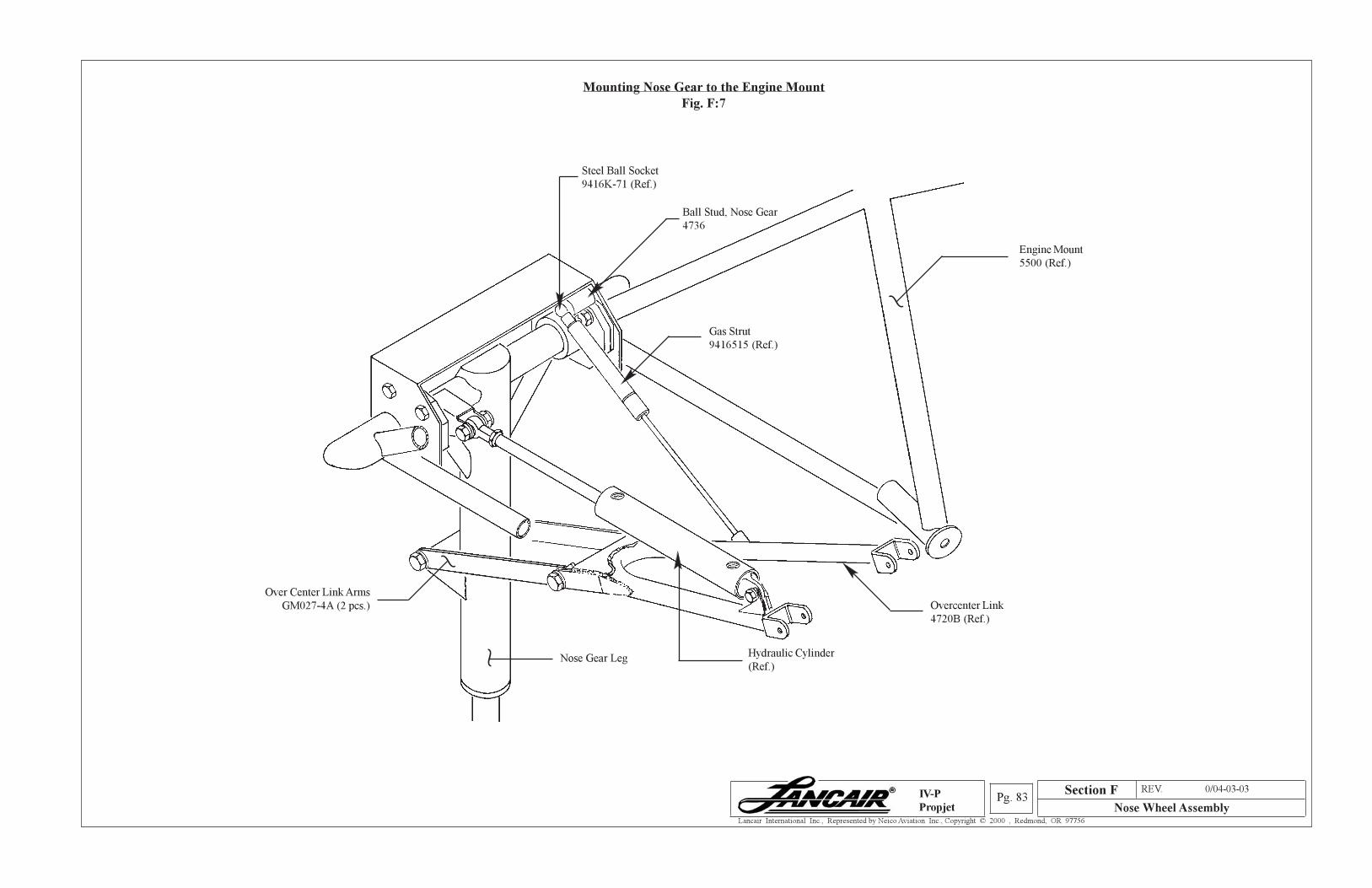
Section A REV. 0/04-03-03
Nose Wheel AssemblyPg. 83
Lancair International Inc., Represented by Neico Aviation Inc., Copyright © 2000 , Redmond, OR 97756
IV-P
Propjet
Mounting Nose Gear to the Engine Mount
Fig. F:7
Section F
Ball Stud, Nose Gear
4736
Steel Ball Socket
9416K-71 (Ref.)
Engine Mount
5500 (Ref.)
Hydraulic Cylinder
(Ref.)Nose Gear Leg
Over Center Link Arms
GM027-4A (2 pcs.)
~
~
~
Gas Strut
9416515 (Ref.)
Overcenter Link
4720B (Ref.)
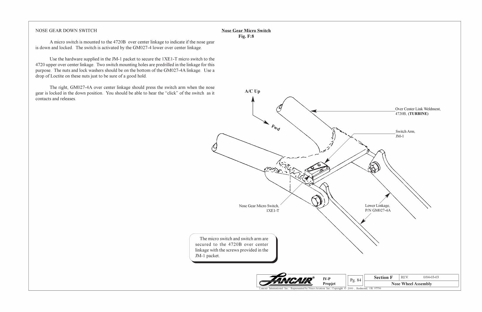
Section A REV. 0/04-03-03
Nose Wheel AssemblyPg. 84
Lancair International Inc., Represented by Neico Aviation Inc., Copyright © 2000 , Redmond, OR 97756
IV-P
Propjet
Nose Gear Micro Switch
Fig. F:8
NOSE GEAR DOWN SWITCH
A micro switch is mounted to the 4720B over center linkage to indicate if the nose gear
is down and locked. The switch is activated by the GM027-4 lower over center linkage.
Use the hardware supplied in the JM-1 packet to secure the 1XE1-T micro switch to the
4720 upper over center linkage. Two switch mounting holes are predrilled in the linkage for this
purpose. The nuts and lock washers should be on the bottom of the GM027-4A linkage. Use a
drop of Loctite on these nuts just to be sure of a good hold.
The right, GM027-4A over center linkage should press the switch arm when the nose
gear is locked in the down position. You should be able to hear the “click” of the switch as it
contacts and releases.
Over Center Link Weldment,
4720B, (TURBINE)
Switch Arm,
JM-1
Nose Gear Micro Switch,
1XE1-T
Lower Linkage,
P/N GM027-4A
A/C Up
Fwd
Section F
The micro switch and switch arm are
secured to the 4720B over center
linkage with the screws provided in the
JM-1 packet.
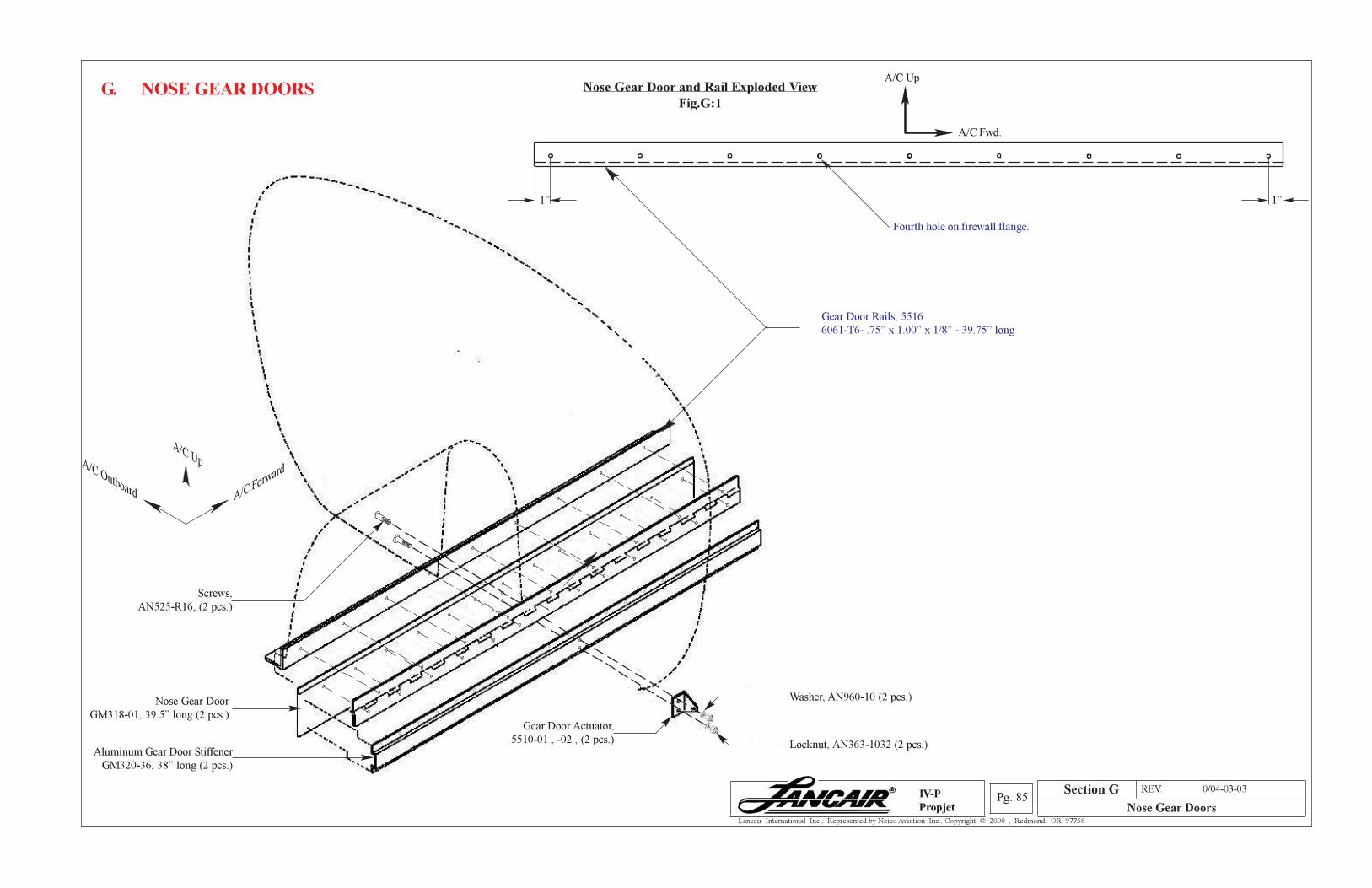
Section A REV. 0/04-03-03
Nose Gear DoorsPg. 85
Lancair International Inc., Represented by Neico Aviation Inc., Copyright © 2000 , Redmond, OR 97756
IV-P
Propjet
G. NOSE GEAR DOORS Nose Gear Door and Rail Exploded View
Fig.G:1
Section G
Nose Gear Door
GM318-01, 39.5” long (2 pcs.)
Aluminum Gear Door Stiffener
GM320-36, 38” long (2 pcs.)
Gear Door Rails, 5516
6061-T6- .75” x 1.00” x 1/8” - 39.75” long
Locknut, AN363-1032 (2 pcs.)
Washer, AN960-10 (2 pcs.)
1” 1”
Fourth hole on firewall flange.
A/C Fwd.
A/C Up
Gear Door Actuator,
5510-01 , -02 , (2 pcs.)
Screws,
AN525-R16, (2 pcs.)
A/C Forward
A/C UpA/C Outboard
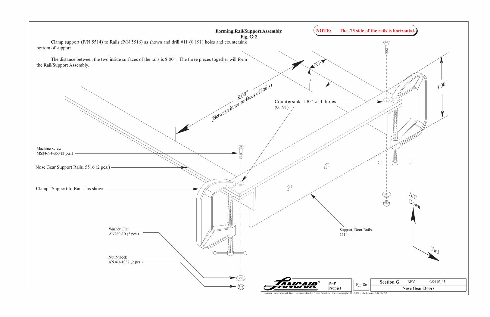
Section A REV. 0/04-03-03
Nose Gear DoorsPg. 86
Lancair International Inc., Represented by Neico Aviation Inc., Copyright © 2000 , Redmond, OR 97756
IV-P
Propjet
8.00"
Machine Screw
MS24694-S53 (2 pcs.)
Nut Nylock
AN363-1032 (2 pcs.)
Washer, Flat
AN960-10 (2 pcs.)Support, Door Rails,
5514
(Between
inner surfa
ces of R
ails)
Countersink 100° #11 holes
(0.191)
Forming Rail/Support Assembly
Fig. G:2Clamp support (P/N 5514) to Rails (P/N 5516) as shown and drill #11 (0.191) holes and countersink
bottom of support.
The distance between the two inside surfaces of the rails is 8.00". The three pieces together will form
the Rail/Support Assembly.
Section G
A/CDown
Fwd
3.00"
Clamp “Support to Rails” as shown
Nose Gear Support Rails, 5516 (2 pcs.)
NOTE: The .75 side of the rails is horizontal.
1"
.75”
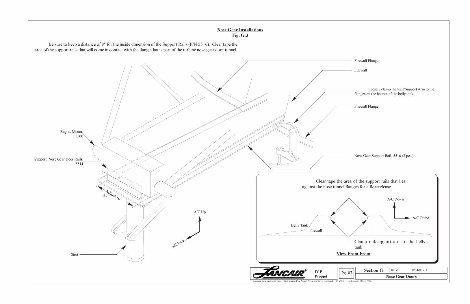
Section A REV. 0/04-03-03
Nose Gear DoorsPg. 87
Lancair International Inc., Represented by Neico Aviation Inc., Copyright © 2000 , Redmond, OR 97756
IV-P
Propjet
Section G
Nose Gear Installations
Fig. G:3
Be sure to keep a distance of 8" for the inside dimension of the Support Rails (P/N 5516). Clear tape the
area of the support rails that will come in contact with the flange that is part of the turbine nose gear door tunnel.
Engine Mount,
5500
Firewall Flange
Firewall Flange
Firewall
Nose Gear Support Rail, 5516 (2 pcs.)
Adjust to8".
Strut
Loosely clamp the Rail/Support Arm to the
flanges on the bottom of the belly tank.
Clear tape the area of the support rails that lies
against the nose tunnel flanges for a flox/release.
Firewall
View From Front
A/C Up
A/C Fwd.Clamp rail/support arm to the belly
tank.
Belly Tank
Support, Nose Gear Door Rails,
5514
A/C Outbd.
A/C Down
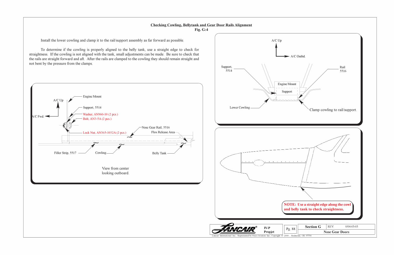
Section A REV. 0/04-03-03
Nose Gear DoorsPg. 88
Lancair International Inc., Represented by Neico Aviation Inc., Copyright © 2000 , Redmond, OR 97756
IV-P
Propjet
Section G
Checking Cowling, Bellytank and Gear Door Rails Alignment
Fig. G:4
Install the lower cowling and clamp it to the rail/support assembly as far forward as possible.
To determine if the cowling is properly aligned to the belly tank, use a straight edge to check for
straightness. If the cowling is not aligned with the tank, small adjustments can be made. Be sure to check that
the rails are straight forward and aft. After the rails are clamped to the cowling they should remain straight and
not bent by the pressure from the clamps.
NOTE: Use a straight edge along the
cowl and belly tank to check straightness.
NOTE: Use a straight edge along the cowl
and belly tank to check straightness.
Support,
5514
Support
Lower Cowling
Rail
5516
Clamp cowling to rail/support.
Engine Mount
A/C Up
A/C Outbd.
Engine Mount
A/C Fwd.
Support, 5514
View from center
looking outboard.
A/C Up
Cowling
~
Filler Strip, 5517
~
Belly Tank
~
Flox Release Area
Bolt, AN3-5A (2 pcs.)
Lock Nut, AN365-1032A (2 pcs.)
Nose Gear Rail, 5516
~
Washer, AN960-10 (2 pcs.)
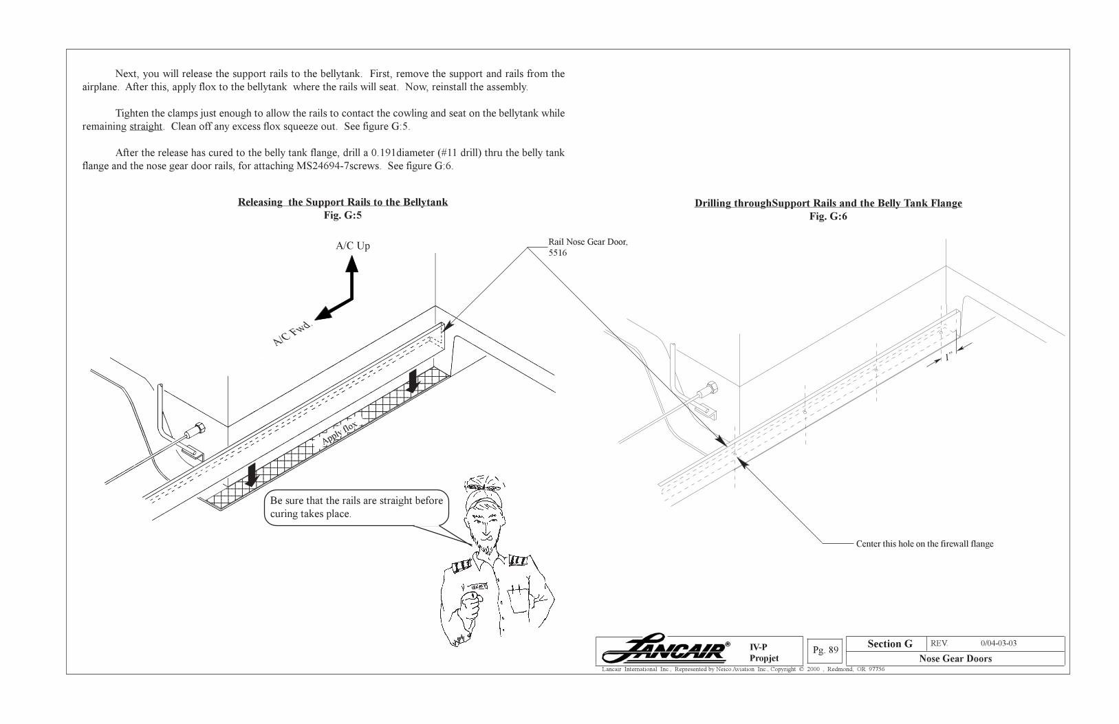
Section A REV. 0/04-03-03
Nose Gear DoorsPg. 89
Lancair International Inc., Represented by Neico Aviation Inc., Copyright © 2000 , Redmond, OR 97756
IV-P
Propjet
Section G
Releasing the Support Rails to the Bellytank
Fig. G:5
Next, you will release the support rails to the bellytank. First, remove the support and rails from the
airplane. After this, apply flox to the bellytank where the rails will seat. Now, reinstall the assembly.
Tighten the clamps just enough to allow the rails to contact the cowling and seat on the bellytank while
remaining straight. Clean off any excess flox squeeze out. See figure G:5.
After the release has cured to the belly tank flange, drill a 0.191diameter (#11 drill) thru the belly tank
flange and the nose gear door rails, for attaching MS24694-7screws. See figure G:6.
123456789012345678901234567890121231234567890123456789012345678901212312345678901234567890123456789012123123456789012345678901234567890121231234567890123456789012345678901212312345678901234567890123456789012123123456789012345678901234567890121231234567890123456789012345678901212312345678901234567890123456789012123123456789012345678901234567890121231234567890123456789012345678901212312345678901234567890123456789012123123456789012345678901234567890121231234567890123456789012345678901212312345678901234567890123456789012123123456789012345678901234567890121231234567890123456789012345678901212312345678901234567890123456789012123123456789012345678901234567890121231234567890123456789012345678901212312345678901234567890123456789012123
Apply flox
A/C Up
A/C Fwd.
Be sure that the rails are straight before
curing takes place.
Drilling throughSupport Rails and the Belly Tank Flange
Fig. G:6
Rail Nose Gear Door,
5516
Center this hole on the firewall flange
1”
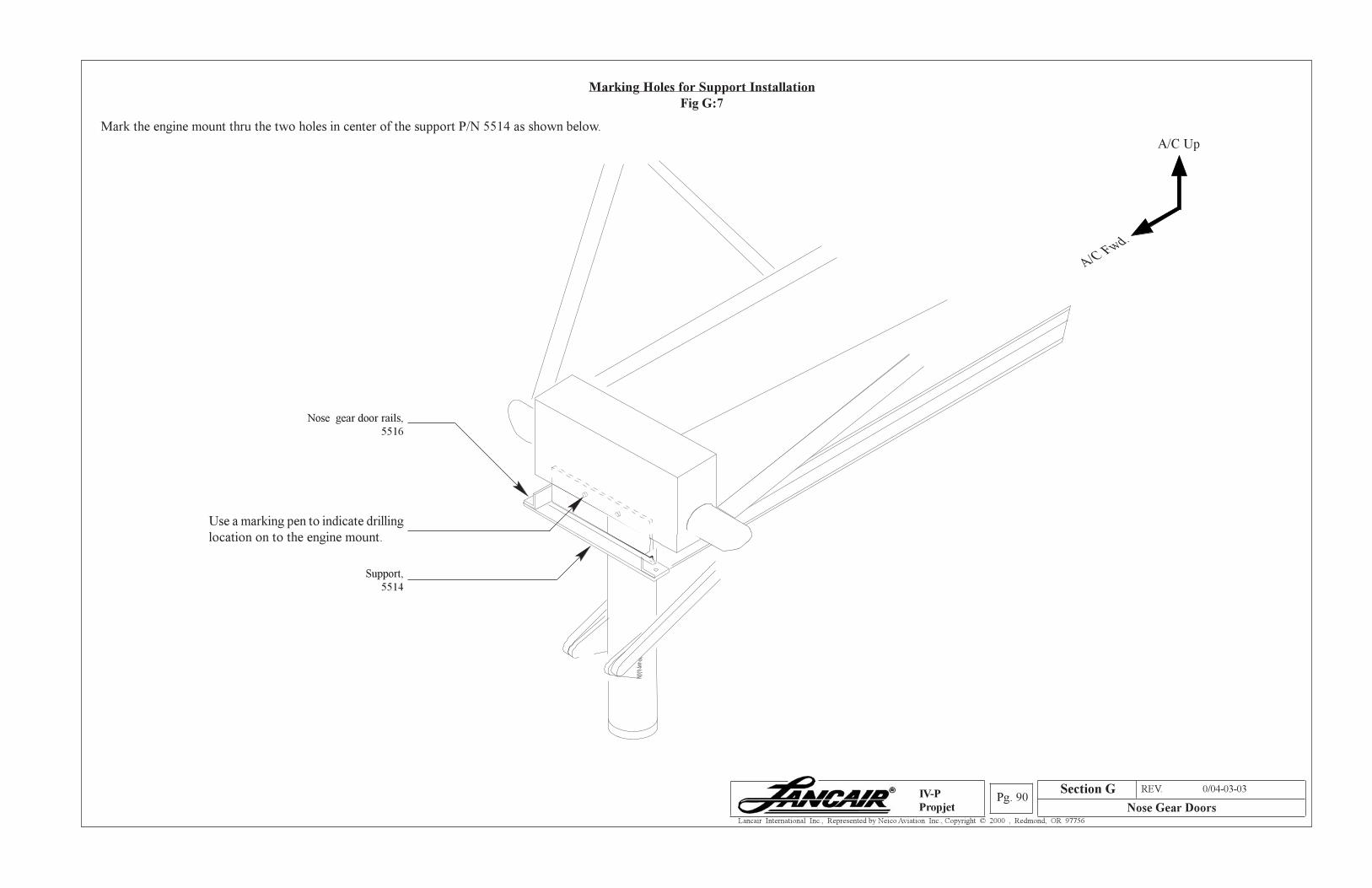
Section A REV. 0/04-03-03
Nose Gear DoorsPg. 90
Lancair International Inc., Represented by Neico Aviation Inc., Copyright © 2000 , Redmond, OR 97756
IV-P
Propjet
Section G
Marking Holes for Support Installation
Fig G:7
Mark the engine mount thru the two holes in center of the support P/N 5514 as shown below.
A/C Up
A/C Fwd.
Use a marking pen to indicate drilling
location on to the engine mount.
Nose gear door rails,
5516
Support,
5514
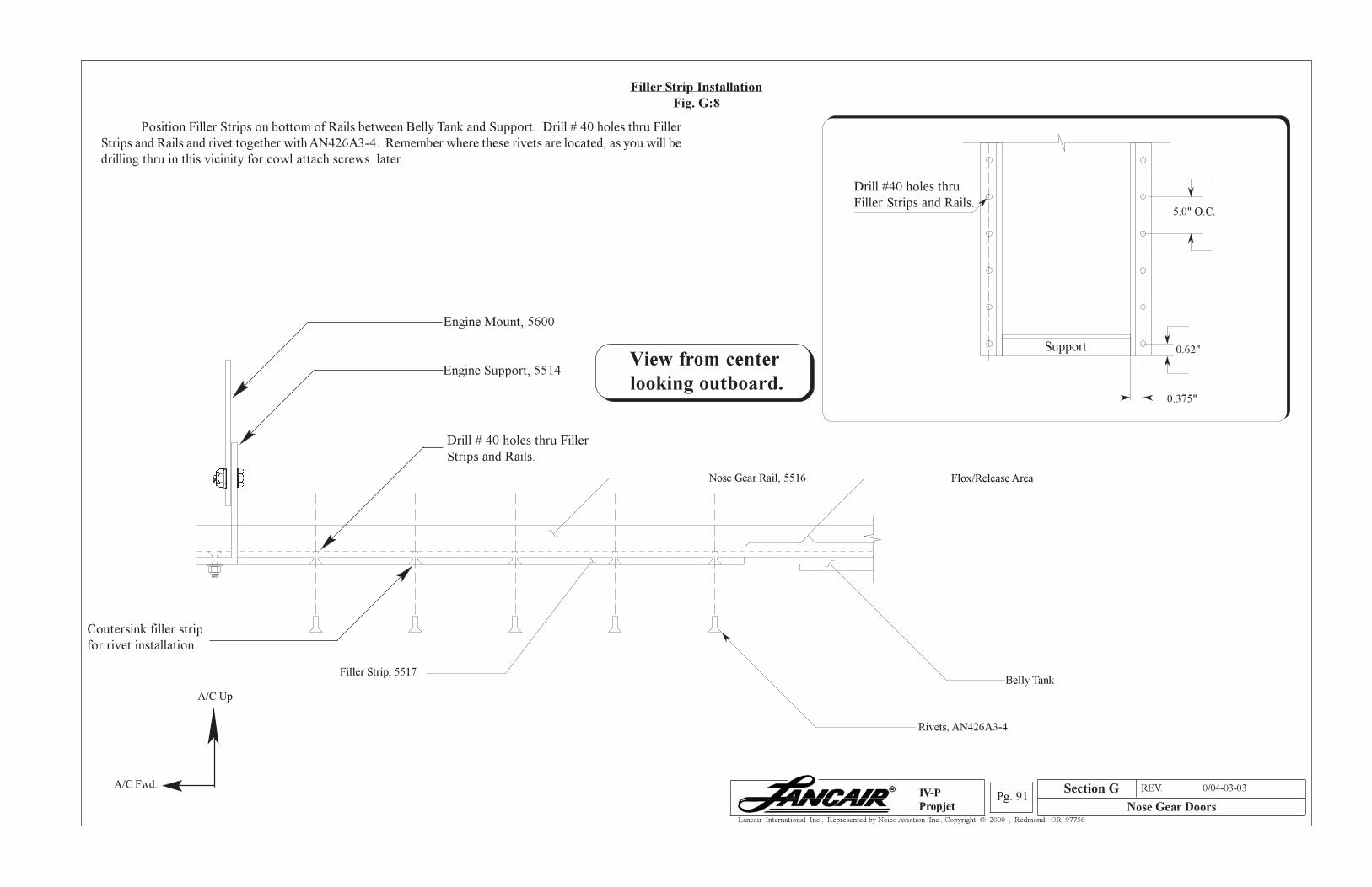
Section A REV. 0/04-03-03
Nose Gear DoorsPg. 91
Lancair International Inc., Represented by Neico Aviation Inc., Copyright © 2000 , Redmond, OR 97756
IV-P
Propjet
Section G
Filler Strip Installation
Fig. G:8
View from center
looking outboard.
A/C Fwd.
A/C Up
Position Filler Strips on bottom of Rails between Belly Tank and Support. Drill # 40 holes thru Filler
Strips and Rails and rivet together with AN426A3-4. Remember where these rivets are located, as you will be
drilling thru in this vicinity for cowl attach screws later.
Support
Drill #40 holes thru
Filler Strips and Rails.5.0" O.C.
0.62"
0.375"
Rivets, AN426A3-4
Belly TankFiller Strip, 5517
Drill # 40 holes thru Filler
Strips and Rails.
Engine Mount, 5600
Engine Support, 5514
Flox/Release AreaNose Gear Rail, 5516
Coutersink filler strip
for rivet installation
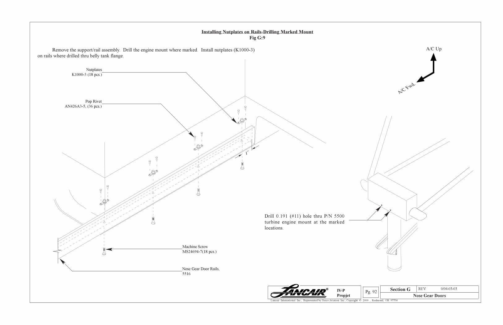
Section A REV. 0/04-03-03
Nose Gear DoorsPg. 92
Lancair International Inc., Represented by Neico Aviation Inc., Copyright © 2000 , Redmond, OR 97756
IV-P
Propjet
Section G
Installing Nutplates on Rails-Drilling Marked Mount
Fig G:9
Remove the support/rail assembly. Drill the engine mount where marked. Install nutplates (K1000-3)
on rails where drilled thru belly tank flange.
Drill 0.191 (#11) hole thru P/N 5500
turbine engine mount at the marked
locations.
Pop Rivet
AN426A3-5, (36 pcs.)
A/C Up
A/C Fwd.
x
x
Nutplates
K1000-3 (18 pcs.)
1”
Nose Gear Door Rails,
5516
Machine Screw
MS24694-7(18 pcs.)
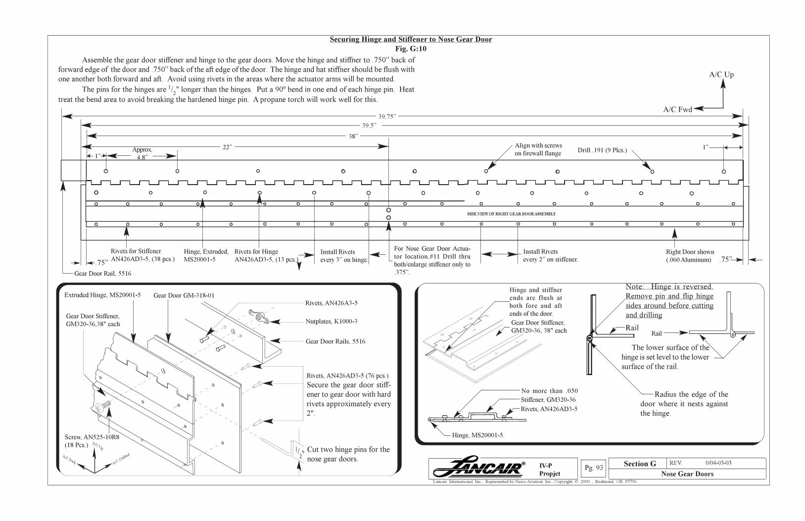
Section A REV. 0/04-03-03
Nose Gear DoorsPg. 93
Lancair International Inc., Represented by Neico Aviation Inc., Copyright © 2000 , Redmond, OR 97756
IV-P
Propjet
Securing Hinge and Stiffener to Nose Gear Door
Fig. G:10
Rivets, AN426A3-5
Nutplates, K1000-3
Gear Door Rails, 5516
Rivets, AN426AD3-5 (76 pcs.)
Secure the gear door stiff-
ener to gear door with hard
rivets approximately every
2".
Cut two hinge pins for the
nose gear doors.
Gear Door GM-318-01Extruded Hinge, MS20001-5
Gear Door Stiffener,
GM320-36,38" each
Screw, AN525-10R8
(18 Pcs.)
Gear Door Stiffener,
GM320-36, 38" each
Hinge and stiffner
ends are flush at
both fore and aft
ends of the door.
Stiffener, GM320-36
Hinge, MS20001-5.
No more than .050
Rivets, AN426AD3-5
Assemble the gear door stiffener and hinge to the gear doors. Move the hinge and stiffner to .750” back of
forward edge of the door and .750” back of the aft edge of the door. The hinge and hat stiffner should be flush with
one another both forward and aft. Avoid using rivets in the areas where the actuator arms will be mounted.
The pins for the hinges are 1/2" longer than the hinges. Put a 90º bend in one end of each hinge pin. Heat
treat the bend area to avoid breaking the hardened hinge pin. A propane torch will work well for this.
A/C Up
A/C Fwd
Gear Door Rail, 5516
A/C Up
A/C Fwd A/C O
utbrd
Radius the edge of the
door where it nests against
the hinge.
Rail
Section G
SIDE VIEW OF RIGHT GEAR DOOR ASSEMBLY
.75”
Right Door shown
(.060 Aluminum) .75”Rivets for Hinge
AN426AD3-5, (13 pcs.)
Install Rivets
every 2” on stiffener.
39.75”
39.5”
38”
22”
Rivets for Stiffener
AN426AD3-5, (38 pcs.)Hinge, Extruded,
MS20001-5
Install Rivets
every 3” on hinge.
For Nose Gear Door Actua-
tor location,#11 Drill thru
both/enlarge stiffener only to
.375”.
Align with screws
on firewall flange
The lower surface of the
hinge is set level to the lower
surface of the rail.
Rail
Note: Hinge is reversed.
Remove pin and flip hinge
sides around before cutting
and drilling
1”Approx.
4.8”1”Drill .191 (9 Plcs.)
1/2"
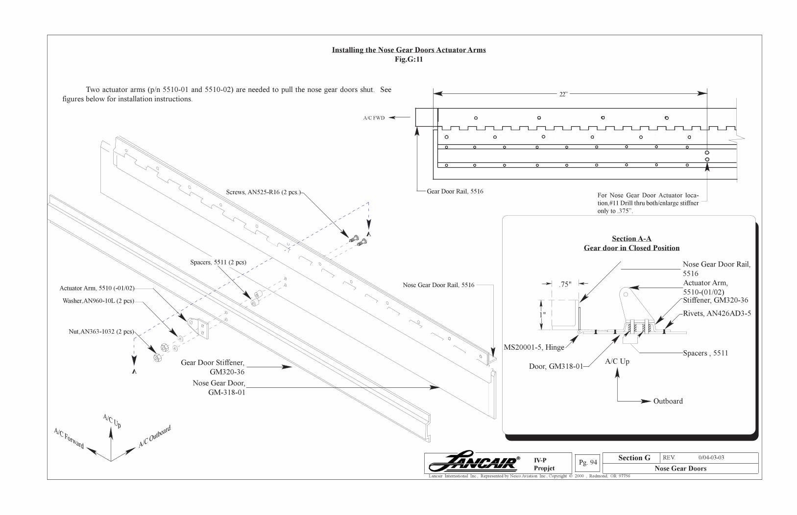
Section A REV. 0/04-03-03
Nose Gear DoorsPg. 94
Lancair International Inc., Represented by Neico Aviation Inc., Copyright © 2000 , Redmond, OR 97756
IV-P
Propjet
Section G
Installing the Nose Gear Doors Actuator Arms
Fig.G:11
Two actuator arms (p/n 5510-01 and 5510-02) are needed to pull the nose gear doors shut. See
figures below for installation instructions.
Gear Door Rail, 5516
22”
For Nose Gear Door Actuator loca-
tion,#11 Drill thru both/enlarge stiffner
only to .375”.
Nose Gear Door,
GM-318-01
Spacers, 5511 (2 pcs)
Actuator Arm, 5510 (-01/02)
Gear Door Stiffener,
GM320-36
Nose Gear Door Rail, 5516
Door, GM318-01
MS20001-5, Hinge
11111
1212121212
1212121212
1212121212
.75"
1"
Spacers , 5511A/C Up
Outboard
Actuator Arm,
5510-(01/02)Stiffener, GM320-36
Rivets, AN426AD3-5
Nose Gear Door Rail,
5516
ASection A-A
Gear door in Closed Position
A/C FWD
A
Washer,AN960-10L (2 pcs)
Nut,AN363-1032 (2 pcs)
Screws, AN525-R16 (2 pcs.)
A/C Outboard
A/C UpA/C Forward
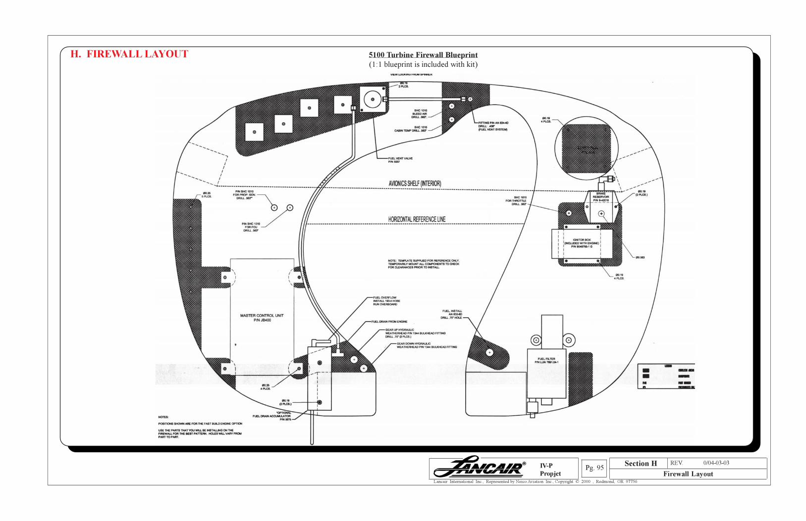
Section A REV. 0/04-03-03
Firewall LayoutPg. 95
Lancair International Inc., Represented by Neico Aviation Inc., Copyright © 2000 , Redmond, OR 97756
IV-P
Propjet
5100 Turbine Firewall Blueprint
(1:1 blueprint is included with kit)
H. FIREWALL LAYOUT
Section H
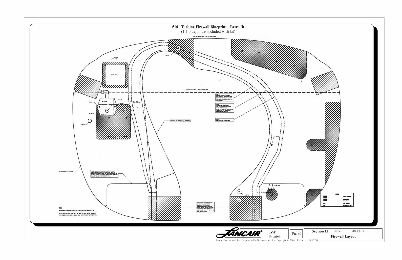
Section A REV. 0/04-03-03
Firewall LayoutPg. 96
Lancair International Inc., Represented by Neico Aviation Inc., Copyright © 2000 , Redmond, OR 97756
IV-P
Propjet
5101 Turbine Firewall Blueprint - Retro fit
(1:1 blueprint is included with kit)
Section H
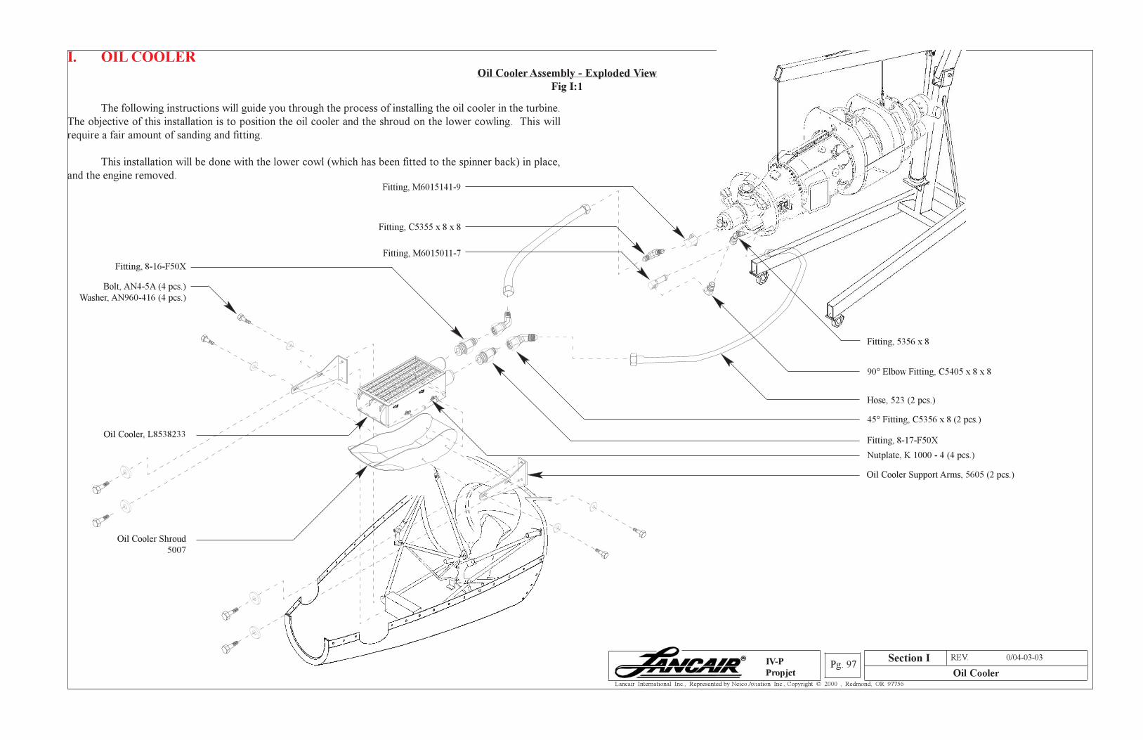
Section A REV. 0/04-03-03
Oil CoolerPg. 97
Lancair International Inc., Represented by Neico Aviation Inc., Copyright © 2000 , Redmond, OR 97756
IV-P
Propjet
Section I
I. OIL COOLER
Oil Cooler Assembly - Exploded View
Fig I:1
The following instructions will guide you through the process of installing the oil cooler in the turbine.
The objective of this installation is to position the oil cooler and the shroud on the lower cowling. This will
require a fair amount of sanding and fitting.
This installation will be done with the lower cowl (which has been fitted to the spinner back) in place,
and the engine removed.
Fitting, 5356 x 8
90° Elbow Fitting, C5405 x 8 x 8
Hose, 523 (2 pcs.)
Fitting, M6015141-9
Fitting, C5355 x 8 x 8
Fitting, M6015011-7
45° Fitting, C5356 x 8 (2 pcs.)
Fitting, 8-17-F50X
Fitting, 8-16-F50X
Bolt, AN4-5A (4 pcs.)
Washer, AN960-416 (4 pcs.)
Nutplate, K 1000 - 4 (4 pcs.)
Oil Cooler, L8538233
Oil Cooler Shroud
5007
Oil Cooler Support Arms, 5605 (2 pcs.)
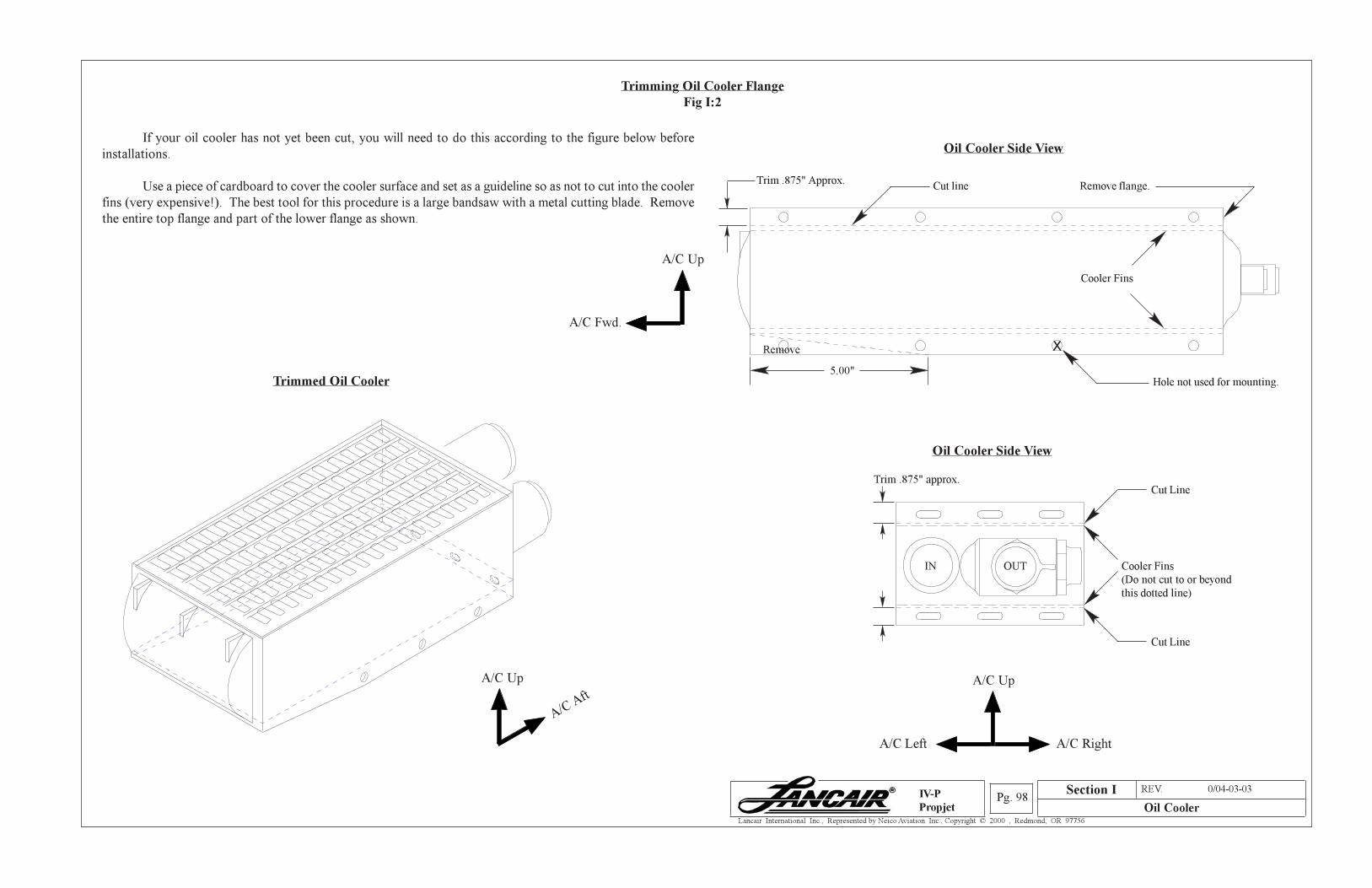
Section A REV. 0/04-03-03
Oil CoolerPg. 98
Lancair International Inc., Represented by Neico Aviation Inc., Copyright © 2000 , Redmond, OR 97756
IV-P
Propjet
Section I
Trimming Oil Cooler Flange
Fig I:2
If your oil cooler has not yet been cut, you will need to do this according to the figure below before
installations.
Use a piece of cardboard to cover the cooler surface and set as a guideline so as not to cut into the cooler
fins (very expensive!). The best tool for this procedure is a large bandsaw with a metal cutting blade. Remove
the entire top flange and part of the lower flange as shown.
Oil Cooler Side View
Trim .875" Approx.Cut line Remove flange.
Trimmed Oil Cooler
Cooler Fins
5.00"
X
Hole not used for mounting.
Oil Cooler Side View
Remove
Cooler Fins
(Do not cut to or beyond
this dotted line)
Cut Line
Cut Line
OUTIN
Trim .875" approx.
A/C Up
A/C A
ft
A/C Up
A/C Fwd.
A/C Up
A/C Left
A/C Right
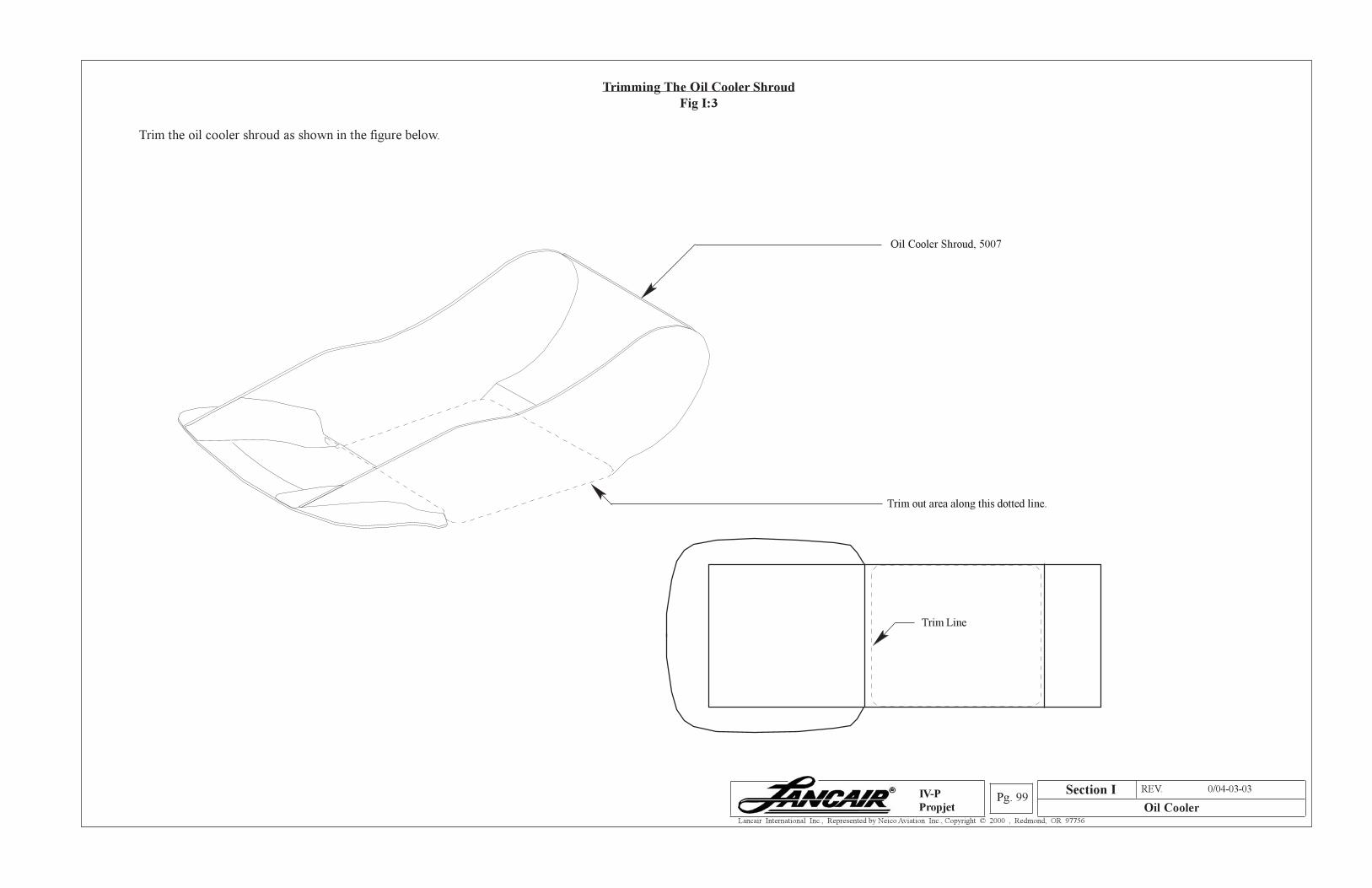
Section A REV. 0/04-03-03
Oil CoolerPg. 99
Lancair International Inc., Represented by Neico Aviation Inc., Copyright © 2000 , Redmond, OR 97756
IV-P
Propjet
Trimming The Oil Cooler Shroud
Fig I:3
Trim the oil cooler shroud as shown in the figure below.
Oil Cooler Shroud, 5007
Trim Line
Trim out area along this dotted line.
Section I
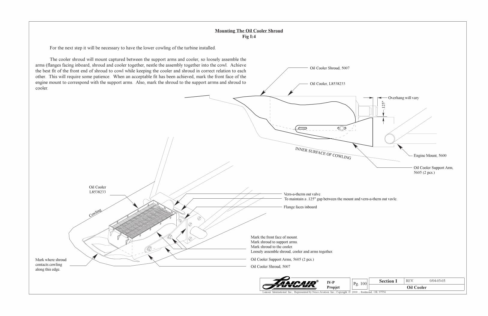
Section A REV. 0/04-03-03
Oil CoolerPg. 100
Lancair International Inc., Represented by Neico Aviation Inc., Copyright © 2000 , Redmond, OR 97756
IV-P
Propjet
Mounting The Oil Cooler Shroud
Fig I:4
For the next step it will be necessary to have the lower cowling of the turbine installed.
The cooler shroud will mount captured between the support arms and cooler, so loosely assemble the
arms (flanges facing inboard, shroud and cooler together, nestle the assembly together into the cowl. Achieve
the best fit of the front end of shroud to cowl while keeping the cooler and shroud in correct relation to each
other. This will require some patience. When an acceptable fit has been achieved, mark the front face of the
engine mount to correspond with the support arms. Also, mark the shroud to the support arrms and shroud to
cooler.
Oil Cooler
L8538233
Cowling
Mark where shroud
contacts cowling
along this edge.Oil Cooler Shroud, 5007
Oil Cooler Support Arms, 5605 (2 pcs.)
Mark the front face of mount.
Mark shroud to support arms.
Mark shroud to the cooler.
Loosely assemble shroud, cooler and arms together.
Flange faces inboard
To maintain a .125" gap between the mount and vern-a-thern out vavle.
Oil Cooler, L8538233
Oil Cooler Shroud, 5007
INNER SURFACE OF COWLINGEngine Mount, 5600
Oil Cooler Support Arm,
5605 (2 pcs.)
Overhang will vary
.125"
Section I
Vern-a-therm out valve
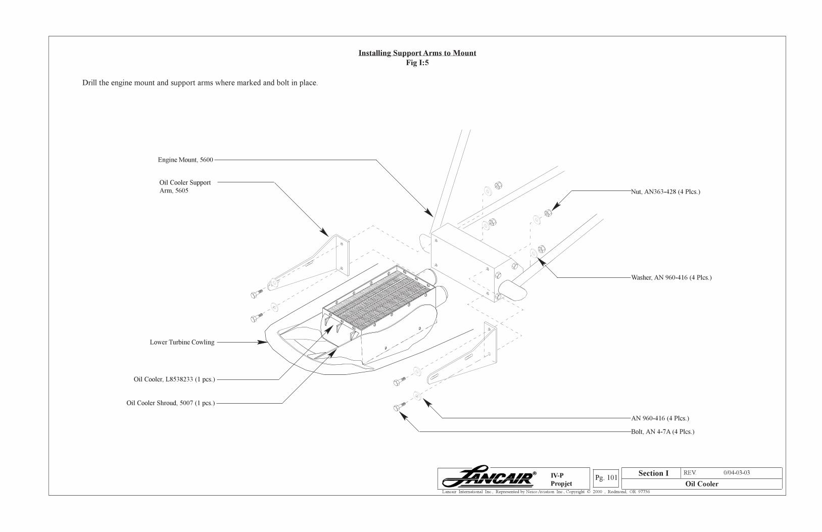
Section A REV. 0/04-03-03
Oil CoolerPg. 101
Lancair International Inc., Represented by Neico Aviation Inc., Copyright © 2000 , Redmond, OR 97756
IV-P
Propjet
Installing Support Arms to Mount
Fig I:5
Drill the engine mount and support arms where marked and bolt in place.
Section I
Washer, AN 960-416 (4 Plcs.)
AN 960-416 (4 Plcs.)
Bolt, AN 4-7A (4 Plcs.)
Nut, AN363-428 (4 Plcs.)
Engine Mount, 5600
Lower Turbine Cowling
Oil Cooler Shroud, 5007 (1 pcs.)
Oil Cooler, L8538233 (1 pcs.)
Oil Cooler Support
Arm, 5605
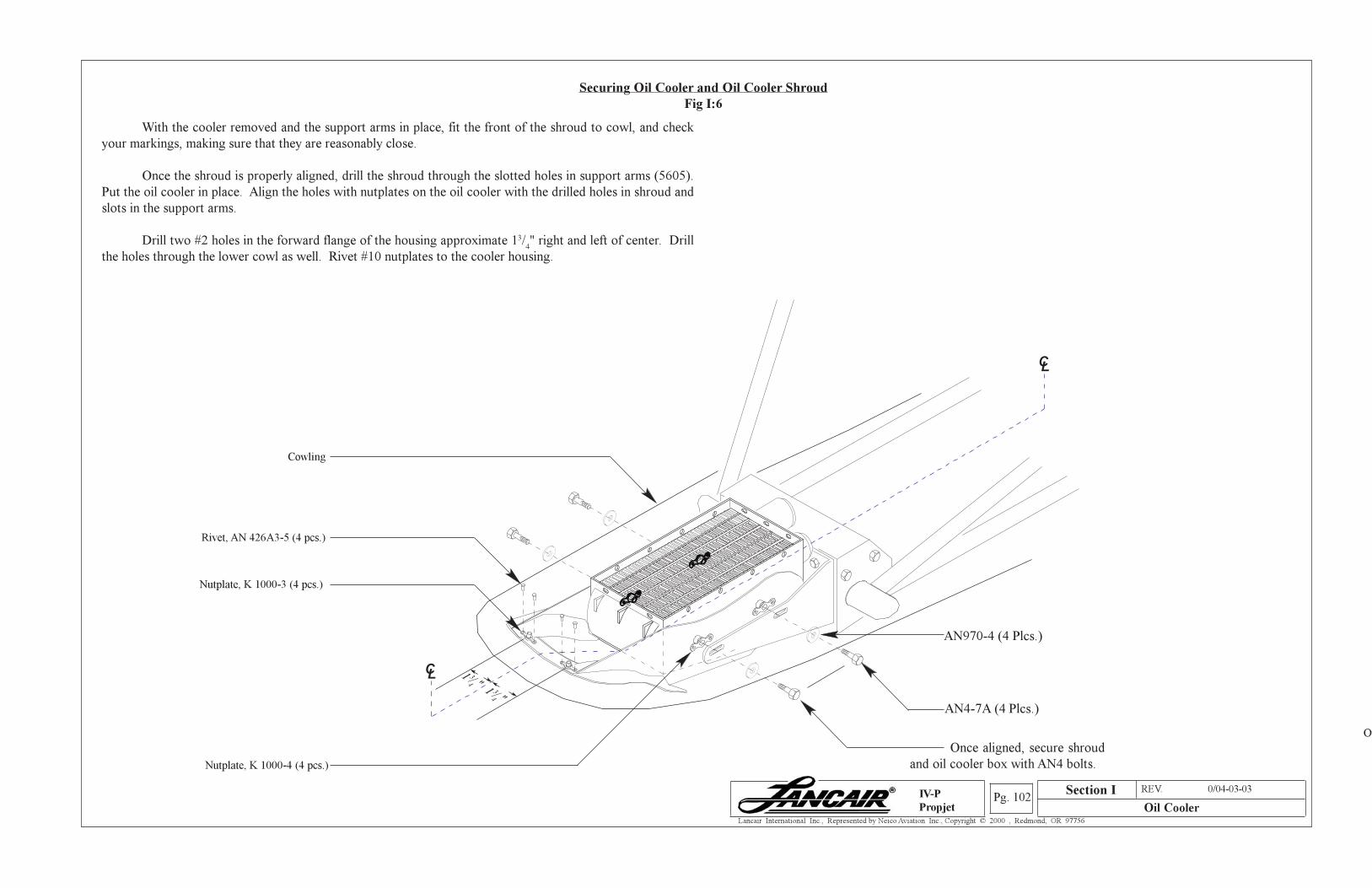
Section A REV. 0/04-03-03
Oil CoolerPg. 102
Lancair International Inc., Represented by Neico Aviation Inc., Copyright © 2000 , Redmond, OR 97756
IV-P
Propjet
Ov
With the cooler removed and the support arms in place, fit the front of the shroud to cowl, and check
your markings, making sure that they are reasonably close.
Once the shroud is properly aligned, drill the shroud through the slotted holes in support arms (5605).
Put the oil cooler in place. Align the holes with nutplates on the oil cooler with the drilled holes in shroud and
slots in the support arms.
Drill two #2 holes in the forward flange of the housing approximate 13/4" right and left of center. Drill
the holes through the lower cowl as well. Rivet #10 nutplates to the cooler housing.
Securing Oil Cooler and Oil Cooler Shroud
Fig I:6
Rivet, AN 426A3-5 (4 pcs.)
CL
CL 1 3/
4 "1 3/4 "
Once aligned, secure shroud
and oil cooler box with AN4 bolts.
Cowling
Nutplate, K 1000-3 (4 pcs.)
Section I
Nutplate, K 1000-4 (4 pcs.)
AN4-7A (4 Plcs.)
AN970-4 (4 Plcs.)
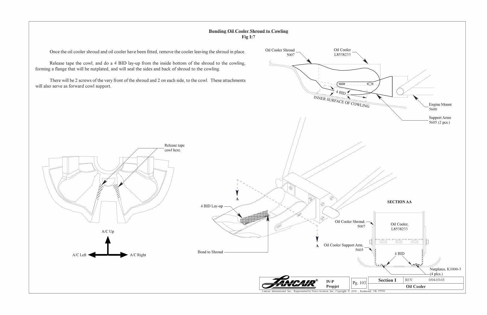
Section A REV. 0/04-03-03
Oil CoolerPg. 103
Lancair International Inc., Represented by Neico Aviation Inc., Copyright © 2000 , Redmond, OR 97756
IV-P
Propjet
12345678901234567890123456789012345678901234567890123456789012345678901234567890123456789012345678901234567890123456789012345678901234567890123456789012345678901234567890123456789012345678901234567890
4 BID
Bonding Oil Cooler Shroud to Cowling
Fig I:7
Once the oil cooler shroud and oil cooler have been fitted, remove the cooler leaving the shroud in place.
Release tape the cowl, and do a 4 BID lay-up from the inside bottom of the shroud to the cowling,
forming a flange that will be nutplated, and will seal the sides and back of shroud to the cowling.
There will be 2 screws of the very front of the shroud and 2 on each side, to the cowl. These attachments
will also serve as forward cowl support.
123451234512345123451234512345123451234512345
123451234512345123451234512345123451234512345
123456712345671234567123456712345671234567123456712345671234567
123456123456123456123456123456123456123456123456123456
Release tape
cowl here.
A/C Up
A/C RightA/C Left
Oil Cooler Shroud
5007
Oil Cooler
L8538233
Engine Mount
5600
INNER SURFACE OF COWLING
Support Arms
5605 (2 pcs.)
SECTION AA4 BID Lay-up
Bond to Shroud
Oil Cooler,
L8538233
4 BID
Oil Cooler Support Arm,
5605
Section I
A
A
Oil Cooler Shroud,
5007
Nutplates, K1000-3
(4 plcs.)
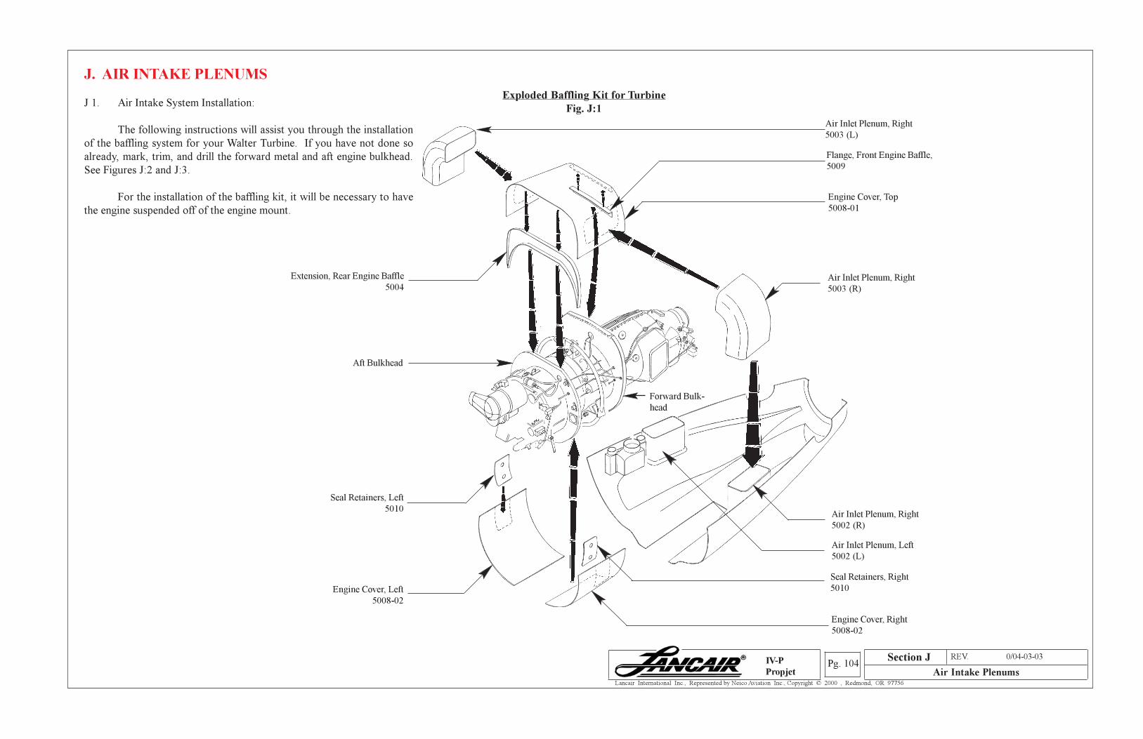
Section A REV. 0/04-03-03
Air Intake PlenumsPg. 104
Lancair International Inc., Represented by Neico Aviation Inc., Copyright © 2000 , Redmond, OR 97756
IV-P
Propjet
J. AIR INTAKE PLENUMS
Exploded Baffling Kit for Turbine
Fig. J:1J 1. Air Intake System Installation:
The following instructions will assist you through the installation
of the baffling system for your Walter Turbine. If you have not done so
already, mark, trim, and drill the forward metal and aft engine bulkhead.
See Figures J:2 and J:3.
For the installation of the baffling kit, it will be necessary to have
the engine suspended off of the engine mount.
Extension, Rear Engine Baffle
5004
Aft Bulkhead
Seal Retainers, Left
5010
Engine Cover, Left
5008-02
Flange, Front Engine Baffle,
5009
Engine Cover, Top
5008-01
Air Inlet Plenum, Right
5002 (R)
Forward Bulk-
head
Air Inlet Plenum, Right
5003 (R)
Air Inlet Plenum, Left
5002 (L)
Seal Retainers, Right
5010
Engine Cover, Right
5008-02
Air Inlet Plenum, Right
5003 (L)
Section J
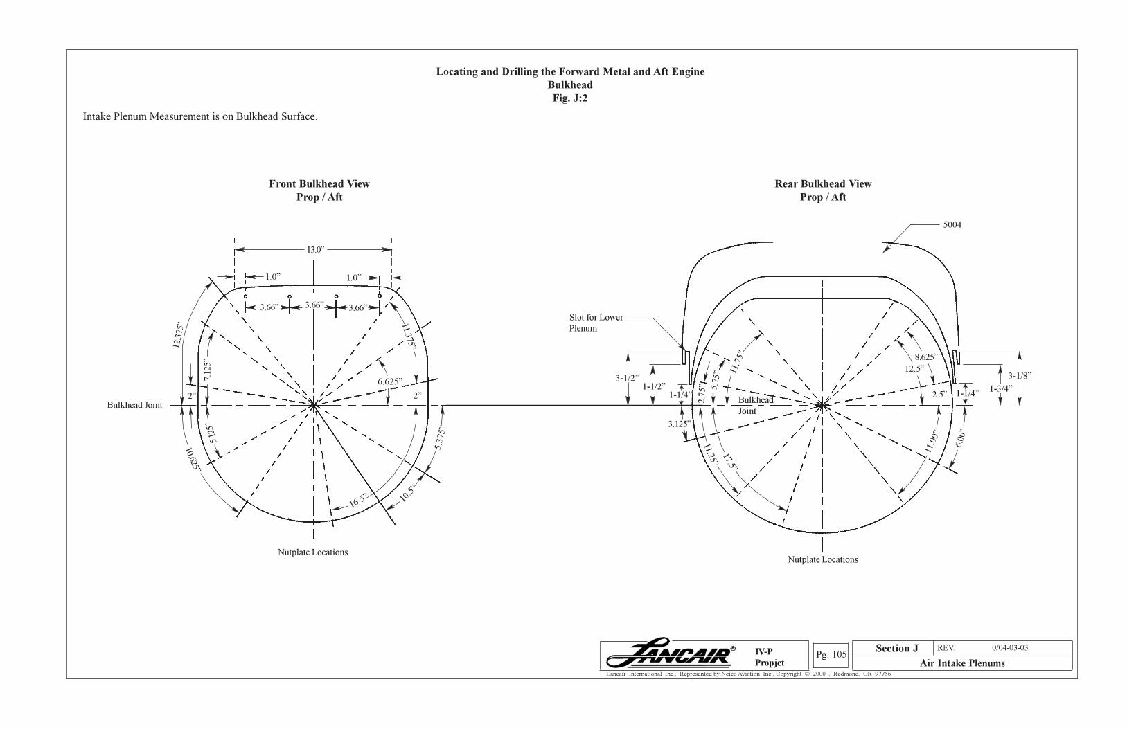
Section A REV. 0/04-03-03
Air Intake PlenumsPg. 105
Lancair International Inc., Represented by Neico Aviation Inc., Copyright © 2000 , Redmond, OR 97756
IV-P
Propjet
Locating and Drilling the Forward Metal and Aft Engine
Bulkhead
Fig. J:2
Intake Plenum Measurement is on Bulkhead Surface.
Rear Bulkhead View
Prop / Aft
Bulkhead
Joint
Nutplate Locations
Slot for Lower
Plenum
2.7
5” 5.7
5”
11.25”
11.7
5”
17.5”
11.0
0”
6.00
”
8.625”
2.5”
12.5”
1-1/4”1-3/4”
3-1/8”
1-1/2”1-1/4”
3-1/2”
3.125”
5004
Front Bulkhead View
Prop / Aft
Bulkhead Joint
Nutplate Locations
13.0”
1.0” 1.0”
3.66” 3.66”3.66”
12.3
75”
2”
7.12
5”5.
125”
10.625”
16.5” 10.5
”
5.3
75”
2”
6.625”
11.375”
Section J

Section A REV. 0/04-03-03
Air Intake PlenumsPg. 106
Lancair International Inc., Represented by Neico Aviation Inc., Copyright © 2000 , Redmond, OR 97756
IV-P
Propjet
Trimming The Forward Bulkhead
Fig. J:3
Using blueprint 5103, trim the front bulkhead. This will ensure a proper fit for the top engine
cover P/N 5008-01.
Blueprint Template,Engine Forward
Bulkhead Modifier, 5103
Front Bulkhead
Trim this edge
to template.
Start Cut
A/C Up
Fwd.
CL
CL
Start Cut
Cut
Cut
Level
Section J
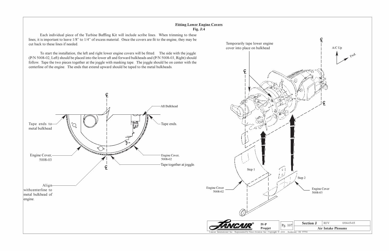
Section A REV. 0/04-03-03
Air Intake PlenumsPg. 107
Lancair International Inc., Represented by Neico Aviation Inc., Copyright © 2000 , Redmond, OR 97756
IV-P
Propjet
Fitting Lower Engine Covers
Fig. J:4
Each individual piece of the Turbine Baffling Kit will include scribe lines. When trimming to these
lines, it is important to leave 1/8” to 1/4” of excess material. Once the covers are fit to the engine, they may be
cut back to these lines if needed.
To start the installation, the left and right lower engine covers will be fitted. The side with the joggle
(P/N 5008-02, Left) should be placed into the lower aft and forward bulkheads and (P/N 5008-03, Right) should
follow. Tape the two pieces together at the joggle with masking tape. The joggle should be on center with the
centerline of the engine. The ends that extend upward should be taped to the metal bulkheads.
Tape ends to
metal bulkhead
Aft Bulkhead
Engine Cover,
5008-02
Tape together at joggle.
Temporarily tape lower engine
cover into place on bulkhead
Engine Cover
5008-02Engine Cover
5008-03
A/C Up
Fwd.
Step 1
Step 2
CL
CL
L
C
Section J
Tape ends.
Align
withcenterline to
metal bulkhead of
engine.
Engine Cover,
5008-03
C
CL
L
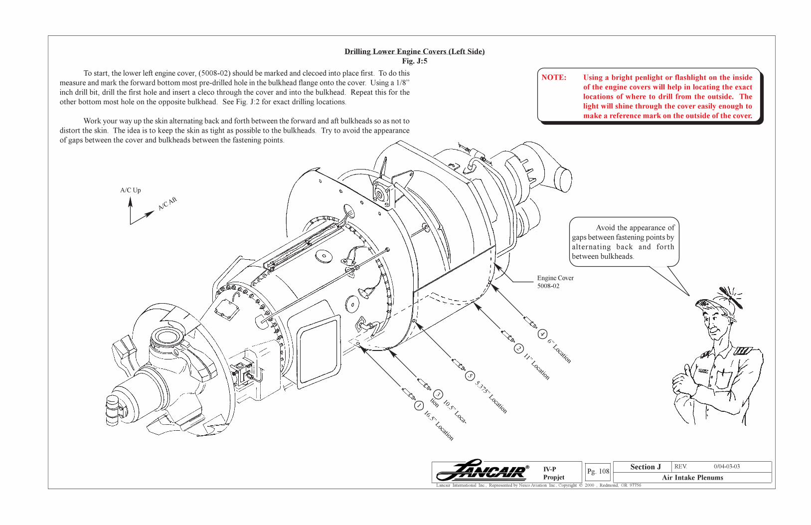
Section A REV. 0/04-03-03
Air Intake PlenumsPg. 108
Lancair International Inc., Represented by Neico Aviation Inc., Copyright © 2000 , Redmond, OR 97756
IV-P
Propjet
Drilling Lower Engine Covers (Left Side)
Fig. J:5
To start, the lower left engine cover, (5008-02) should be marked and clecoed into place first. To do this
measure and mark the forward bottom most pre-drilled hole in the bulkhead flange onto the cover. Using a 1/8”
inch drill bit, drill the first hole and insert a cleco through the cover and into the bulkhead. Repeat this for the
other bottom most hole on the opposite bulkhead. See Fig. J:2 for exact drilling locations.
Work your way up the skin alternating back and forth between the forward and aft bulkheads so as not to
distort the skin. The idea is to keep the skin as tight as possible to the bulkheads. Try to avoid the appearance
of gaps between the cover and bulkheads between the fastening points.
A/C Up
A/C Aft
Engine Cover
5008-02
1 16.5” Location
3 10.5” Loca-
tion
5 5.375” Location
2 11” Location
4 6” Location
Avoid the appearance of
gaps between fastening points by
alternating back and forth
between bulkheads.
Section J
NOTE: Using a bright penlight or flashlight on the inside
of the engine covers will help in locating the exact
locations of where to drill from the outside. The
light will shine through the cover easily enough to
make a reference mark on the outside of the cover.
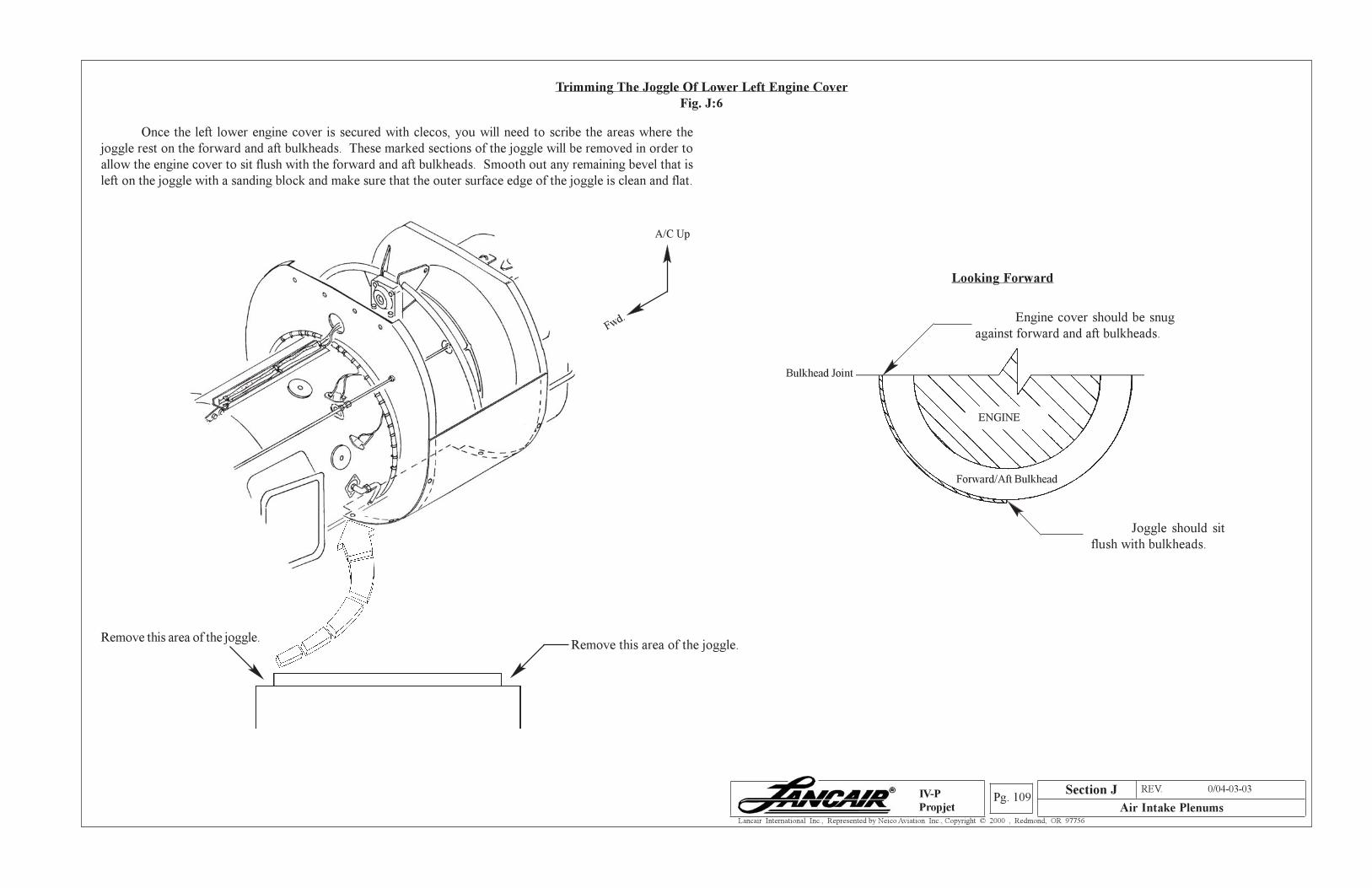
Section A REV. 0/04-03-03
Air Intake PlenumsPg. 109
Lancair International Inc., Represented by Neico Aviation Inc., Copyright © 2000 , Redmond, OR 97756
IV-P
Propjet
Trimming The Joggle Of Lower Left Engine Cover
Fig. J:6
Once the left lower engine cover is secured with clecos, you will need to scribe the areas where the
joggle rest on the forward and aft bulkheads. These marked sections of the joggle will be removed in order to
allow the engine cover to sit flush with the forward and aft bulkheads. Smooth out any remaining bevel that is
left on the joggle with a sanding block and make sure that the outer surface edge of the joggle is clean and flat.
Remove this area of the joggle.Remove this area of the joggle.
A/C Up
Fwd.
Looking Forward
Bulkhead Joint
Engine cover should be snug
against forward and aft bulkheads.
Joggle should sit
flush with bulkheads.
Forward/Aft Bulkhead
ENGINE
Section J
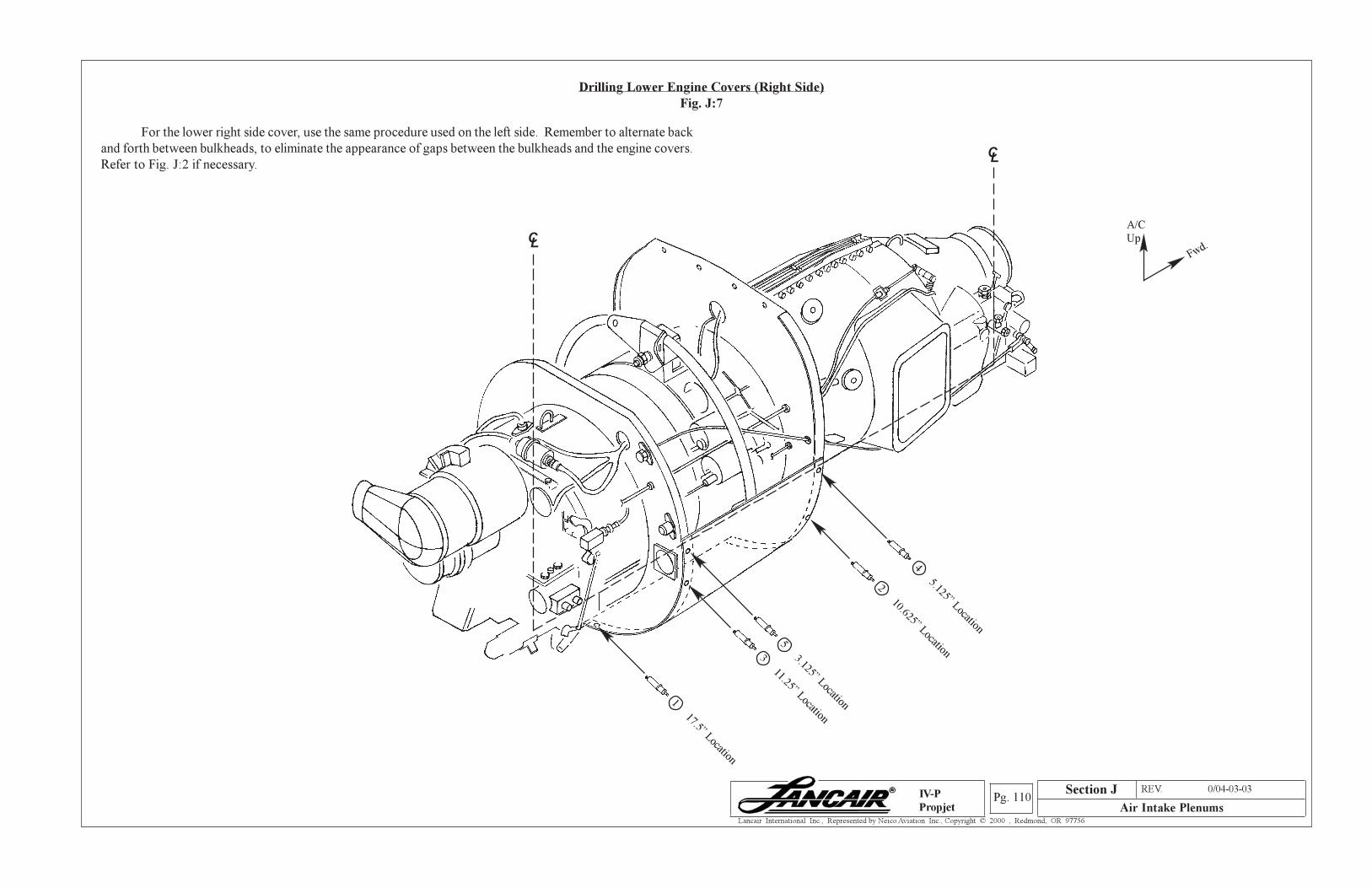
Section A REV. 0/04-03-03
Air Intake PlenumsPg. 110
Lancair International Inc., Represented by Neico Aviation Inc., Copyright © 2000 , Redmond, OR 97756
IV-P
Propjet
Drilling Lower Engine Covers (Right Side)
Fig. J:7
For the lower right side cover, use the same procedure used on the left side. Remember to alternate back
and forth between bulkheads, to eliminate the appearance of gaps between the bulkheads and the engine covers.
Refer to Fig. J:2 if necessary.
A/C
Up
Fwd.CL
CL
4 5.125” Location
2 10.625” Location5 3.125” Location
3 11.25” Location
1 17.5” Location
Section J
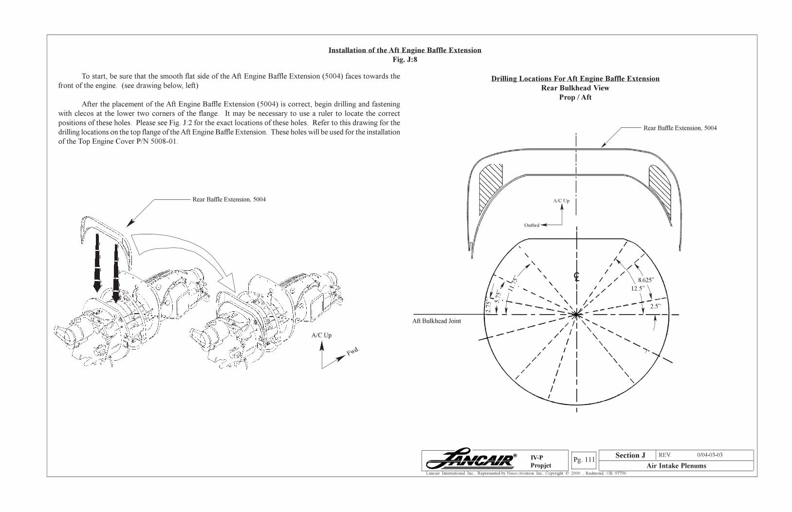
Section A REV. 0/04-03-03
Air Intake PlenumsPg. 111
Lancair International Inc., Represented by Neico Aviation Inc., Copyright © 2000 , Redmond, OR 97756
IV-P
Propjet
Drilling Locations For Aft Engine Baffle Extension
Rear Bulkhead View
Prop / Aft
Installation of the Aft Engine Baffle Extension
Fig. J:8
To start, be sure that the smooth flat side of the Aft Engine Baffle Extension (5004) faces towards the
front of the engine. (see drawing below, left)
After the placement of the Aft Engine Baffle Extension (5004) is correct, begin drilling and fastening
with clecos at the lower two corners of the flange. It may be necessary to use a ruler to locate the correct
positions of these holes. Please see Fig. J:2 for the exact locations of these holes. Refer to this drawing for the
drilling locations on the top flange of the Aft Engine Baffle Extension. These holes will be used for the installation
of the Top Engine Cover P/N 5008-01.
Rear Baffle Extension, 5004
Aft Bulkhead Joint
2.7
5” 5.7
5” 11
.75” 8.625”
2.5”
12.5”
CL
Rear Baffle Extension, 5004
A/C Up
Fwd.
A/C Up
Outbrd
Section J
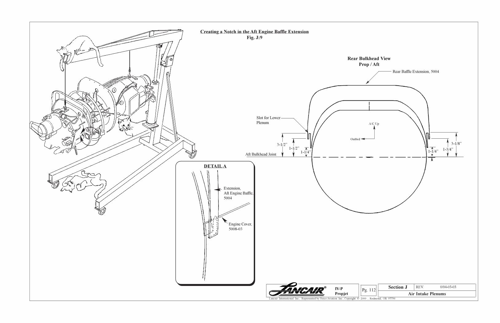
Section A REV. 0/04-03-03
Air Intake PlenumsPg. 112
Lancair International Inc., Represented by Neico Aviation Inc., Copyright © 2000 , Redmond, OR 97756
IV-P
Propjet
Creating a Notch in the Aft Engine Baffle Extension
Fig. J:9
DETAIL A
Engine Cover,
5008-03
Extension,
Aft Engine Baffle,
5004
A
Rear Bulkhead View
Prop / Aft
Aft Bulkhead Joint
Slot for Lower
Plenum
1-1/4”1-3/4”
3-1/8”
1-1/2”1-1/4”
3-1/2”
Rear Baffle Extension, 5004
A/C Up
Outbrd
Section J
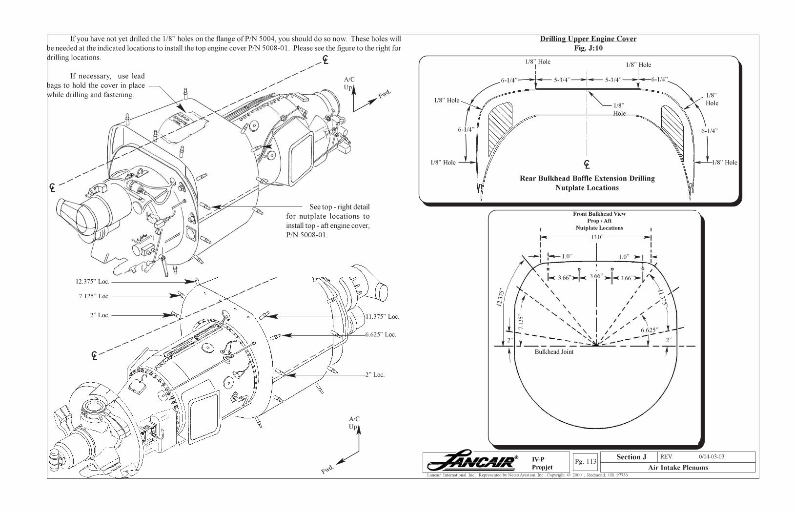
Section A REV. 0/04-03-03
Air Intake PlenumsPg. 113
Lancair International Inc., Represented by Neico Aviation Inc., Copyright © 2000 , Redmond, OR 97756
IV-P
Propjet
Drilling Upper Engine Cover
Fig. J:10
If you have not yet drilled the 1/8” holes on the flange of P/N 5004, you should do so now. These holes will
be needed at the indicated locations to install the top engine cover P/N 5008-01. Please see the figure to the right for
drilling locations.
1/8” Hole
1/8” Hole
1/8” Hole1/8” Hole
1/8” Hole
1/8”
Hole
5-3/4” 5-3/4”
1/8”
Hole
CL
6-1/4”6-1/4”
6-1/4” 6-1/4”
Front Bulkhead View
Prop / Aft
Nutplate Locations
Bulkhead Joint
13.0”
1.0” 1.0”
3.66” 3.66”3.66”
12.3
75”
2”
7.12
5”
2”
6.625”
11.375”
Rear Bulkhead Baffle Extension Drilling
Nutplate Locations
CL
11.375” Loc.
6.625” Loc.
2” Loc.
A/C
Up
Fwd.
CL
12.375” Loc.
7.125” Loc.
2” Loc.
See top - right detail
for nutplate locations to
install top - aft engine cover,
P/N 5008-01.
CL
CL
If necessary, use lead
bags to hold the cover in place
while drilling and fastening.
A/C
Up
Fwd.
Section J
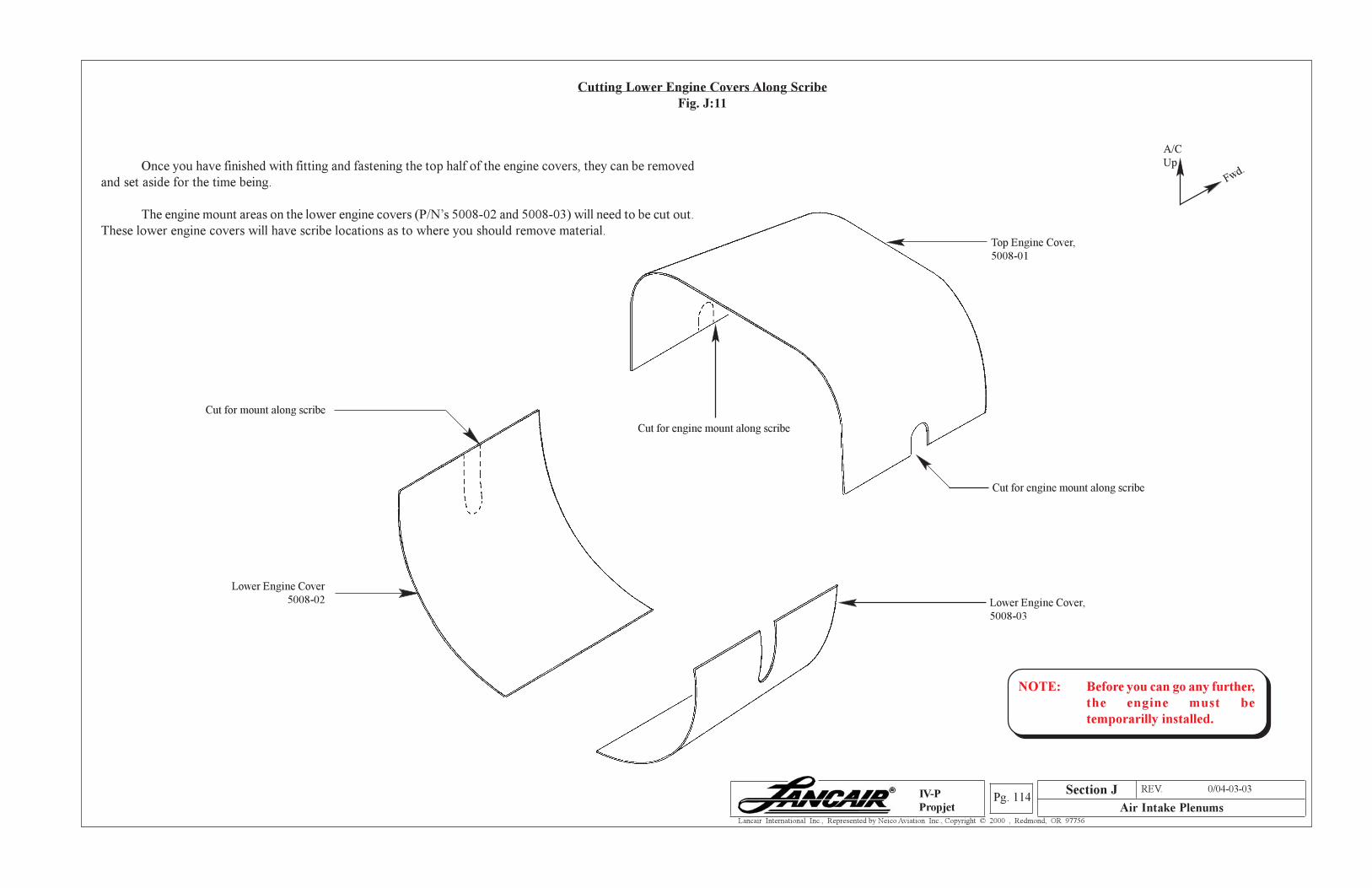
Section A REV. 0/04-03-03
Air Intake PlenumsPg. 114
Lancair International Inc., Represented by Neico Aviation Inc., Copyright © 2000 , Redmond, OR 97756
IV-P
Propjet
Cutting Lower Engine Covers Along Scribe
Fig. J:11
Once you have finished with fitting and fastening the top half of the engine covers, they can be removed
and set aside for the time being.
The engine mount areas on the lower engine covers (P/N’s 5008-02 and 5008-03) will need to be cut out.
These lower engine covers will have scribe locations as to where you should remove material.Top Engine Cover,
5008-01
Cut for engine mount along scribe
Cut for engine mount along scribe
A/C
Up
Fwd.
Lower Engine Cover,
5008-03
NOTE: Before you can go any further,
the engine must be
temporarilly installed.
Lower Engine Cover
5008-02
Cut for mount along scribe
Section J
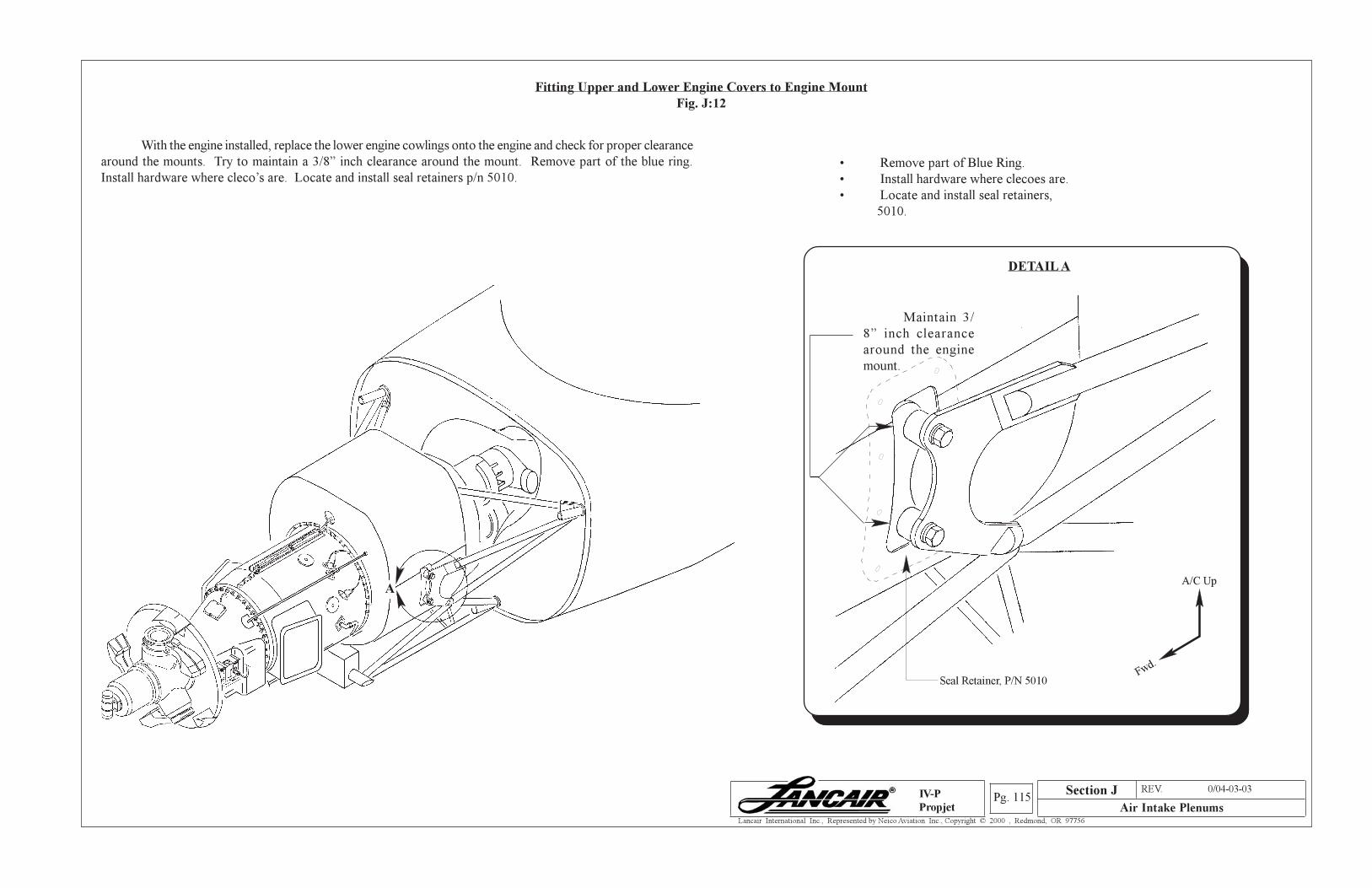
Section A REV. 0/04-03-03
Air Intake PlenumsPg. 115
Lancair International Inc., Represented by Neico Aviation Inc., Copyright © 2000 , Redmond, OR 97756
IV-P
Propjet
Fitting Upper and Lower Engine Covers to Engine Mount
Fig. J:12
With the engine installed, replace the lower engine cowlings onto the engine and check for proper clearance
around the mounts. Try to maintain a 3/8” inch clearance around the mount. Remove part of the blue ring.
Install hardware where cleco’s are. Locate and install seal retainers p/n 5010.
A
Section J
• Remove part of Blue Ring.
• Install hardware where clecoes are.
• Locate and install seal retainers,
5010.
A/C Up
Fwd.
DETAIL A
Maintain 3/
8” inch clearance
around the engine
mount.
Seal Retainer, P/N 5010
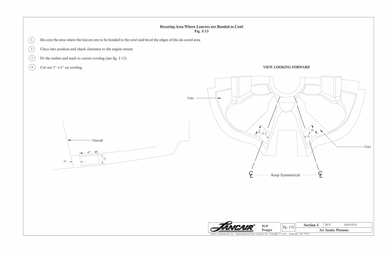
Section A REV. 0/04-03-03
Air Intake PlenumsPg. 116
Lancair International Inc., Represented by Neico Aviation Inc., Copyright © 2000 , Redmond, OR 97756
IV-P
Propjet
Decoring Area Where Louvers are Bonded to Cowl
Fig. J:13
Section J
De-core the area where the louvers are to be bonded to the cowl and bevel the edges of this de-cored area.
Cleco into position and check clearance to the engine mount.
Fit the outlets and mark to cutout cowling (see fig. J:13).
Cut out 3” x 6” on cowling.
1.
2.
3.
4.
Core
Core
CL
CLKeep Symmetrical
VIEW LOOKING FORWARD
6"
3"
Firewall
3"
3"6"
3"
6"
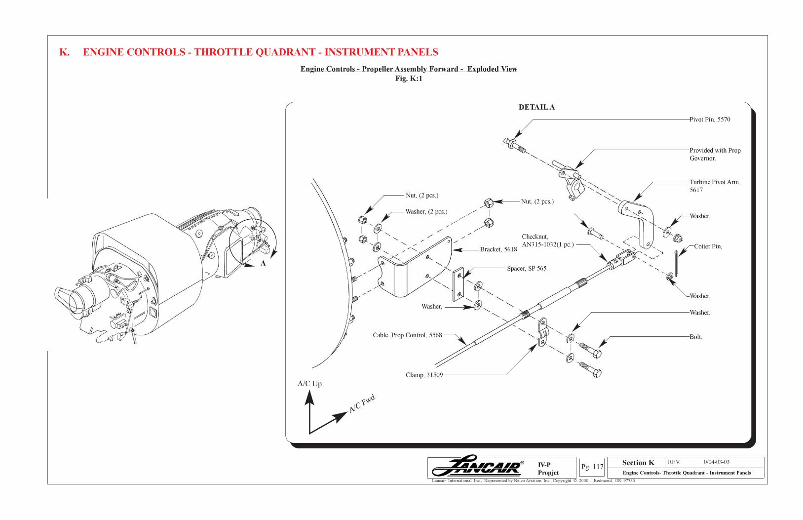
Section A REV. 0/04-03-03
Engine Controls- Throttle Quadrant - Instrument PanelsPg. 117
Lancair International Inc., Represented by Neico Aviation Inc., Copyright © 2000 , Redmond, OR 97756
IV-P
Propjet
K. ENGINE CONTROLS - THROTTLE QUADRANT - INSTRUMENT PANELS
A
Engine Controls - Propeller Assembly Forward - Exploded View
Fig. K:1
Nut, (2 pcs.)
Washer, (2 pcs.)
Nut, (2 pcs.)
Pivot Pin, 5570
Provided with Prop
Governor.
Turbine Pivot Arm,
5617
Washer,
Cotter Pin,
Washer,
Washer,
Bolt,
Clamp, 31509
Washer,
DETAIL A
A/C Up
A/C Fwd.
Cable, Prop Control, 5568
Checknut,
AN315-1032(1 pc.)Bracket, 5618
Spacer, SP 565
Section K
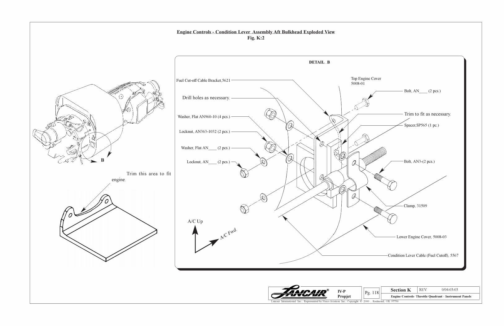
Section A REV. 0/04-03-03
Engine Controls- Throttle Quadrant - Instrument PanelsPg. 118
Lancair International Inc., Represented by Neico Aviation Inc., Copyright © 2000 , Redmond, OR 97756
IV-P
Propjet
Section K
Engine Controls - Condition Lever Assembly Aft Bulkhead Exploded View
Fig. K:2
B
Trim this area to fit
engine.
Fuel Cut-off Cable Bracket,5621
Locknut, AN____ (2 pcs.)
Trim to fit as necessary.
Top Engine Cover
5008-01
Drill holes as necessary.
Spacer,SP565 (1 pc.)
Washer, Flat AN____ (2 pcs.)
Bolt, AN____ (2 pcs.)
Lower Engine Cover, 5008-03
Condition Lever Cable (Fuel Cutoff), 5567
DETAIL B
Locknut, AN363-1032 (2 pcs.)
Washer, Flat AN960-10 (4 pcs.)
A/C Up
A/C Fwd.
Bolt, AN3-(2 pcs.)
Clamp, 31509
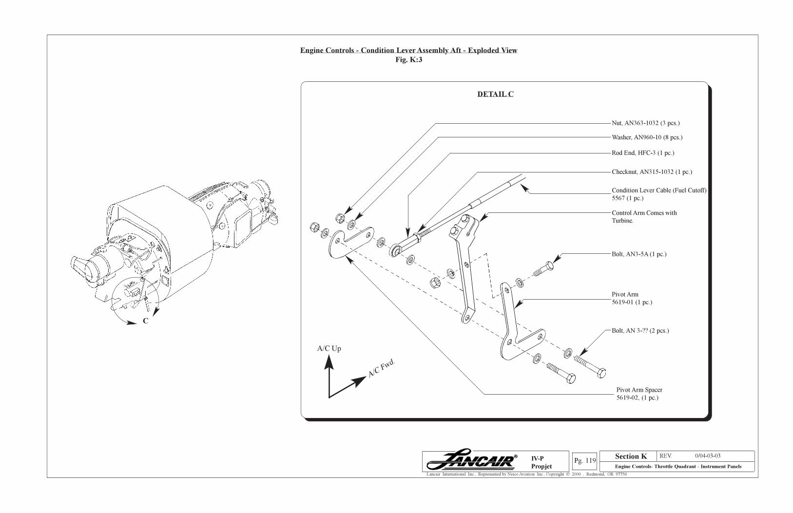
Section A REV. 0/04-03-03
Engine Controls- Throttle Quadrant - Instrument PanelsPg. 119
Lancair International Inc., Represented by Neico Aviation Inc., Copyright © 2000 , Redmond, OR 97756
IV-P
Propjet
Engine Controls - Condition Lever Assembly Aft - Exploded View
Fig. K:3
DETAIL C
Nut, AN363-1032 (3 pcs.)
Washer, AN960-10 (8 pcs.)
Pivot Arm Spacer
5619-02, (1 pc.)
Rod End, HFC-3 (1 pc.)
Pivot Arm
5619-01 (1 pc.)
Bolt, AN3-5A (1 pc.)
Bolt, AN 3-?? (2 pcs.)
Condition Lever Cable (Fuel Cutoff)
5567 (1 pc.)
Control Arm Comes with
Turbine.
Checknut, AN315-1032 (1 pc.)
C
A/C Up
A/C Fwd.
Section K
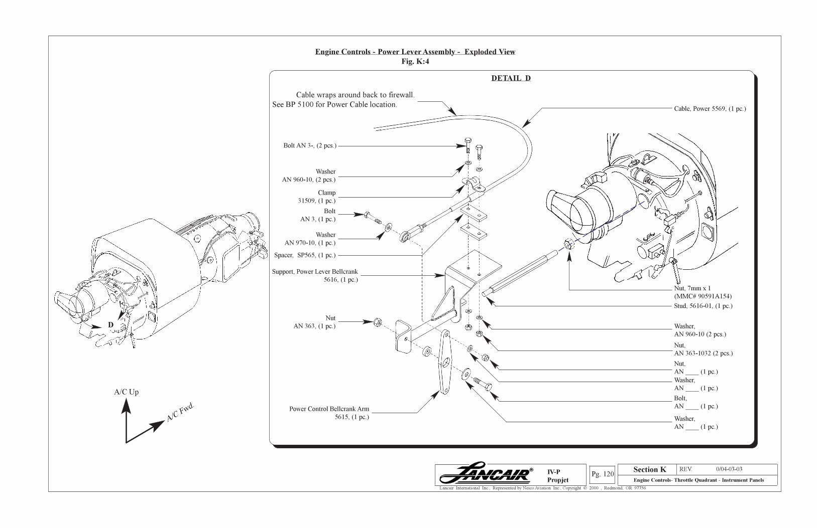
Section A REV. 0/04-03-03
Engine Controls- Throttle Quadrant - Instrument PanelsPg. 120
Lancair International Inc., Represented by Neico Aviation Inc., Copyright © 2000 , Redmond, OR 97756
IV-P
Propjet
Engine Controls - Power Lever Assembly - Exploded View
Fig. K:4
Section K
Cable wraps around back to firewall.
See BP 5100 for Power Cable location.Cable, Power 5569, (1 pc.)
Bolt AN 3-, (2 pcs.)
Washer
AN 960-10, (2 pcs.)
Clamp
31509, (1 pc.)
Spacer, SP565, (1 pc.)
Washer,
AN 960-10 (2 pcs.)
Nut,
AN 363-1032 (2 pcs.)
Washer
AN 970-10, (1 pc.)
Bolt
AN 3, (1 pc.)
Washer,
AN ____ (1 pc.)
Nut,
AN ____ (1 pc.)
Washer,
AN ____ (1 pc.)
Bolt,
AN ____ (1 pc.)Power Control Bellcrank Arm
5615, (1 pc.)
Nut
AN 363, (1 pc.)
Support, Power Lever Bellcrank
5616, (1 pc.)
DETAIL D
D
A/C Up
A/C Fwd.
Nut, 7mm x 1
(MMC# 90591A154)
Stud, 5616-01, (1 pc.)
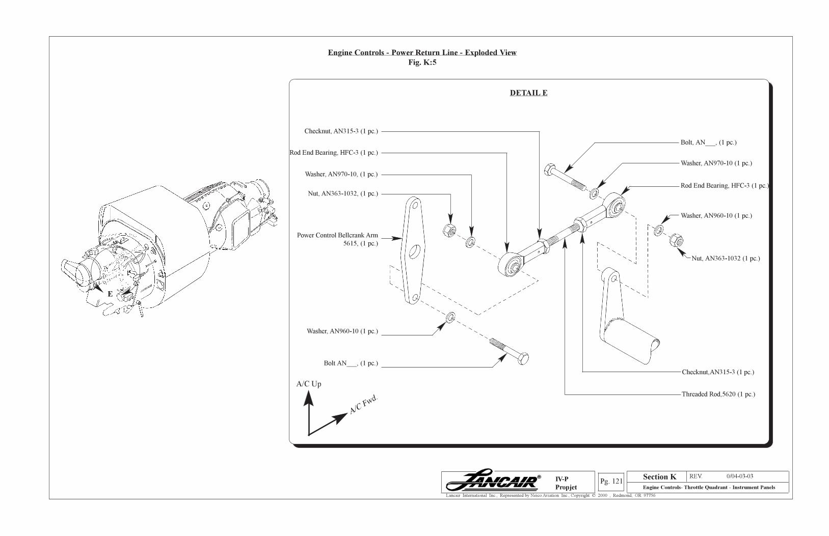
Section A REV. 0/04-03-03
Engine Controls- Throttle Quadrant - Instrument PanelsPg. 121
Lancair International Inc., Represented by Neico Aviation Inc., Copyright © 2000 , Redmond, OR 97756
IV-P
Propjet
Section K
Engine Controls - Power Return Line - Exploded View
Fig. K:5
DETAIL E
Bolt, AN___, (1 pc.)
Washer, AN970-10 (1 pc.)
Power Control Bellcrank Arm
5615, (1 pc.)
Rod End Bearing, HFC-3 (1 pc.)
Checknut,AN315-3 (1 pc.)
Threaded Rod,5620 (1 pc.)
Washer, AN960-10 (1 pc.)
Nut, AN363-1032 (1 pc.)
E
Bolt AN___, (1 pc.)
Washer, AN970-10, (1 pc.)
Rod End Bearing, HFC-3 (1 pc.)
Checknut, AN315-3 (1 pc.)
Washer, AN960-10 (1 pc.)
Nut, AN363-1032, (1 pc.)
A/C Up
A/C Fwd.
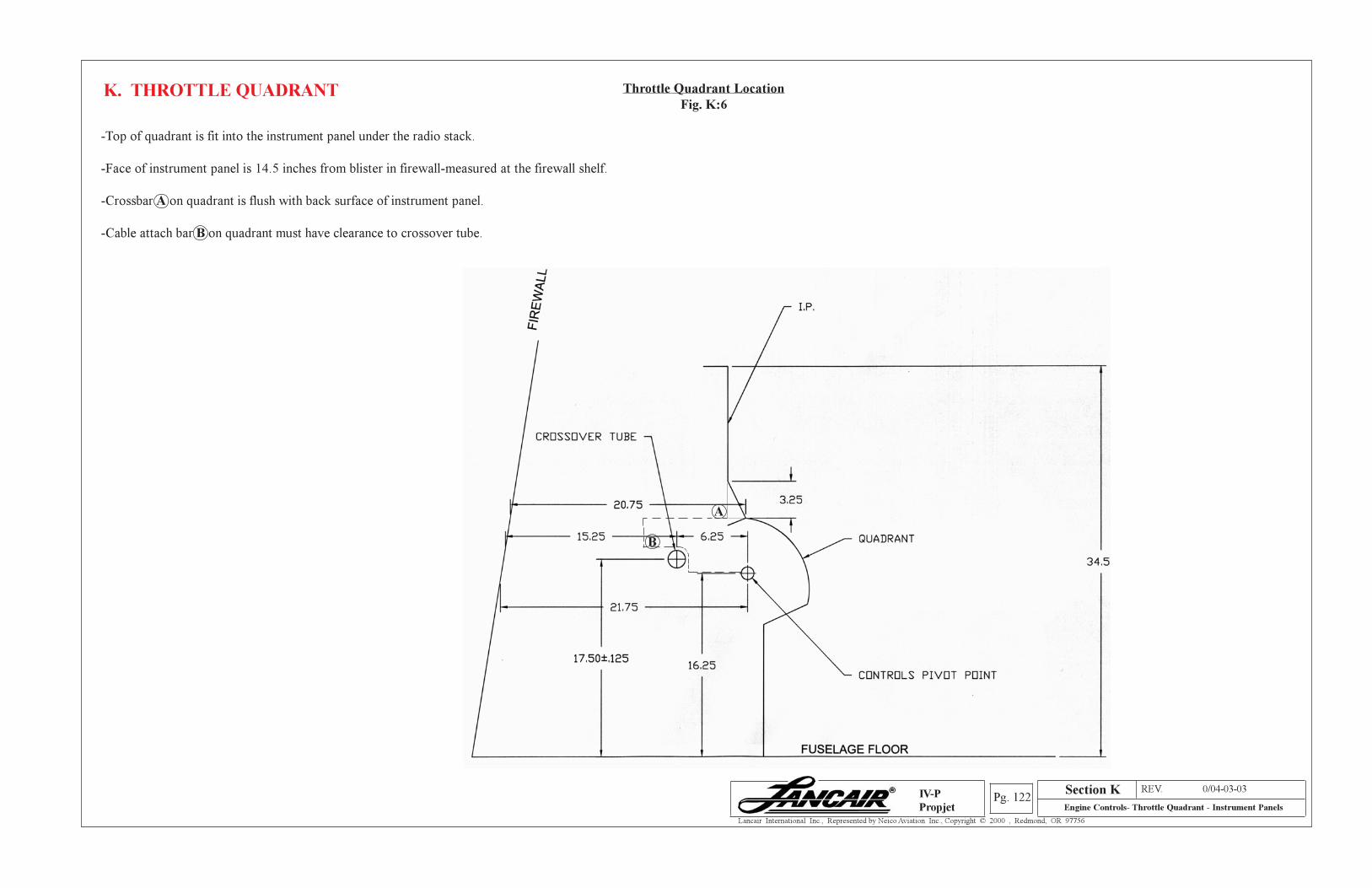
Section A REV. 0/04-03-03
Engine Controls- Throttle Quadrant - Instrument PanelsPg. 122
Lancair International Inc., Represented by Neico Aviation Inc., Copyright © 2000 , Redmond, OR 97756
IV-P
Propjet
Section K
Throttle Quadrant Location
Fig. K:6K. THROTTLE QUADRANT
-Top of quadrant is fit into the instrument panel under the radio stack.
-Face of instrument panel is 14.5 inches from blister in firewall-measured at the firewall shelf.
-Crossbar A on quadrant is flush with back surface of instrument panel.
-Cable attach bar B on quadrant must have clearance to crossover tube.
A
B

Section A REV. 0/04-03-03
Engine Controls- Throttle Quadrant - Instrument PanelsPg. 123
Lancair International Inc., Represented by Neico Aviation Inc., Copyright © 2000 , Redmond, OR 97756
IV-P
Propjet
K. INSTRUMENT PANELS
Section K
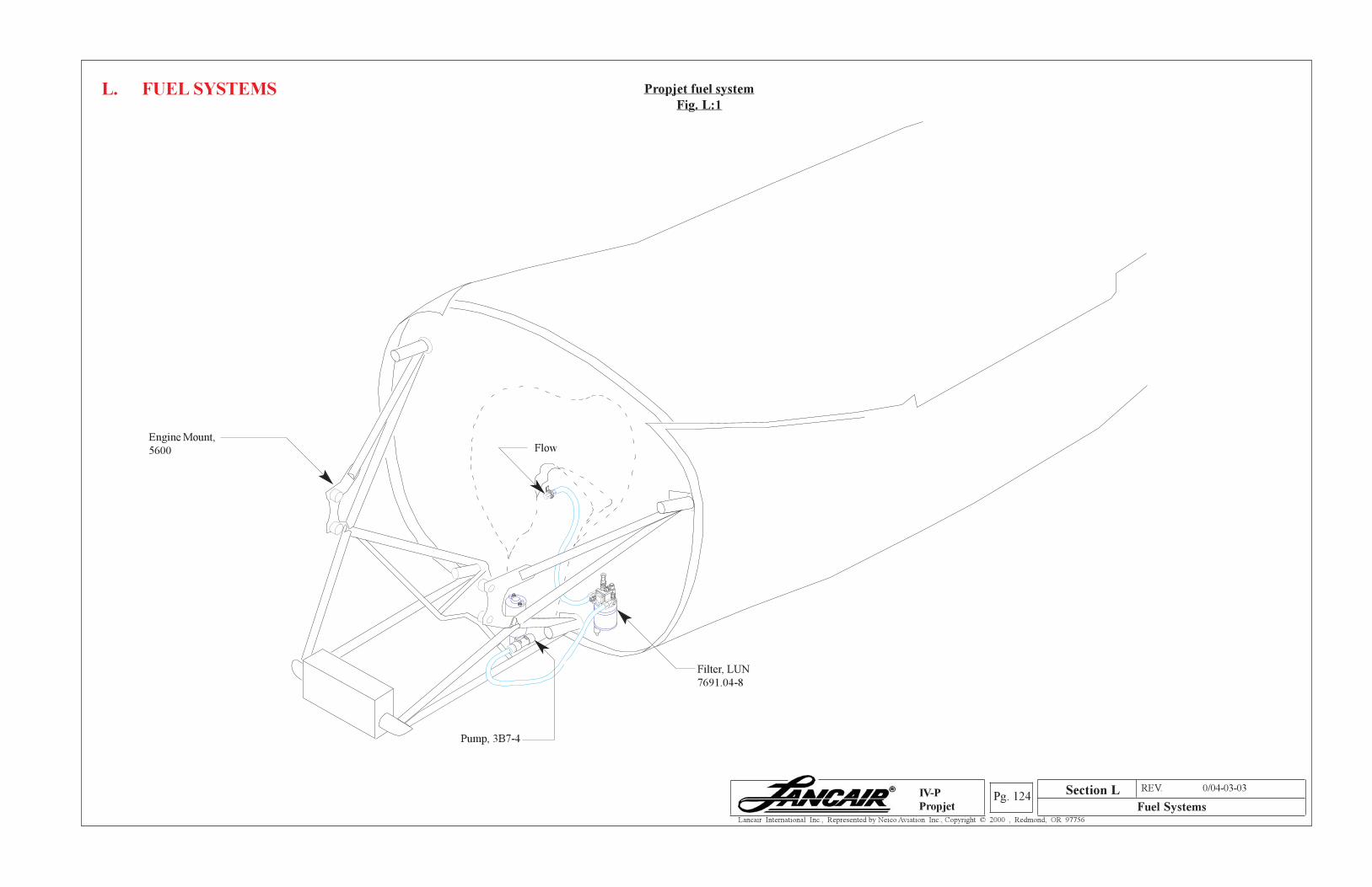
Section A REV. 0/04-03-03
Fuel SystemsPg. 124
Lancair International Inc., Represented by Neico Aviation Inc., Copyright © 2000 , Redmond, OR 97756
IV-P
Propjet
Propjet fuel system
Fig. L:1L. FUEL SYSTEMS
Filter, LUN
7691.04-8
Pump, 3B7-4
FlowEngine Mount,
5600
Section L
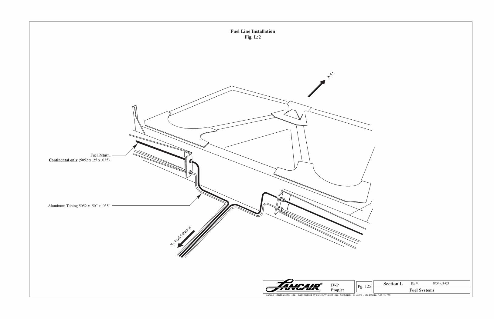
Section A REV. 0/04-03-03
Fuel SystemsPg. 125
Lancair International Inc., Represented by Neico Aviation Inc., Copyright © 2000 , Redmond, OR 97756
IV-P
Propjet
Fuel Line Installation
Fig. L:2
Fuel Return,
Continental only (5052 x .25 x .035).
Aluminum Tubing 5052 x .50” x .035”
To F
uel S
elec
tor
Af t
Section L
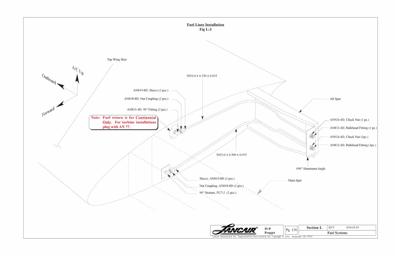
Section A REV. 0/04-03-03
Fuel SystemsPg. 126
Lancair International Inc., Represented by Neico Aviation Inc., Copyright © 2000 , Redmond, OR 97756
IV-P
Propjet
Fuel Lines Installation
Fig L:3
.090" Aluminum Angle
AN819-8D, Sleeve (2 pcs.)
AN818-8D, Nut Coupling (2 pcs.)
AN832-4D, Bulkhead Fitting (1 pc.)
AN924-4D, Check Nut (1 pc.)
AN832-4D, Bulkhead Fitting (1pc.)
AN924-4D, Check Nut (1pc.)
AN821-4D, 90° Fitting (2 pcs.)
5052-0 X 0.500 X 0.035
5052-0 X 0.250 X 0.035
Sleeve, AN819-8D (2 pcs.)
Nut Coupling, AN818-8D (2 pcs.)
90° Strainer, FU7-2 (2 pcs.)
Aft Spar
1234512345123451234512345
Main Spar
Section L
Note: Fuel return is for Continental
Only. For turbine installations
plug with AN ??.
Top Wing Skin
Outboard
A/C Up
Forward
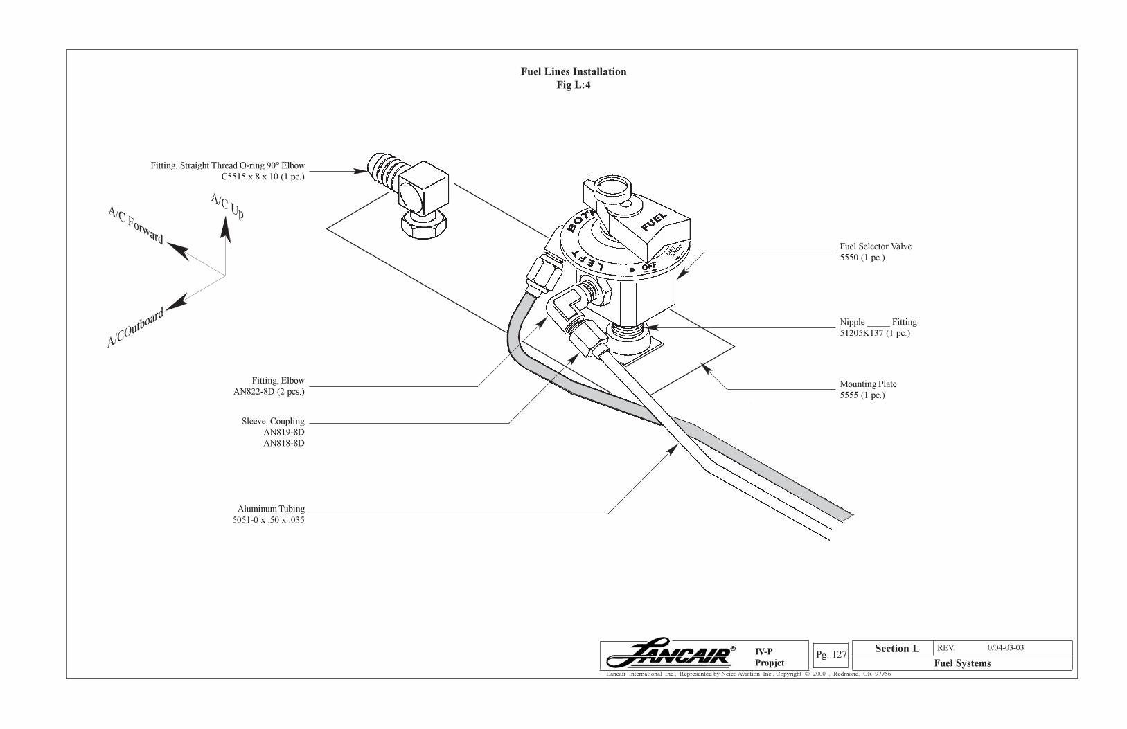
Section A REV. 0/04-03-03
Fuel SystemsPg. 127
Lancair International Inc., Represented by Neico Aviation Inc., Copyright © 2000 , Redmond, OR 97756
IV-P
Propjet
Fitting, Straight Thread O-ring 90° Elbow
C5515 x 8 x 10 (1 pc.)
Fitting, Elbow
AN822-8D (2 pcs.)
Sleeve, Coupling
AN819-8D
AN818-8D
Fuel Selector Valve
5550 (1 pc.)
Nipple _____ Fitting
51205K137 (1 pc.)
Mounting Plate
5555 (1 pc.)
Aluminum Tubing
5051-0 x .50 x .035
Section L
Fuel Lines Installation
Fig L:4
A/C Forward
A/C Up
A/COutboard
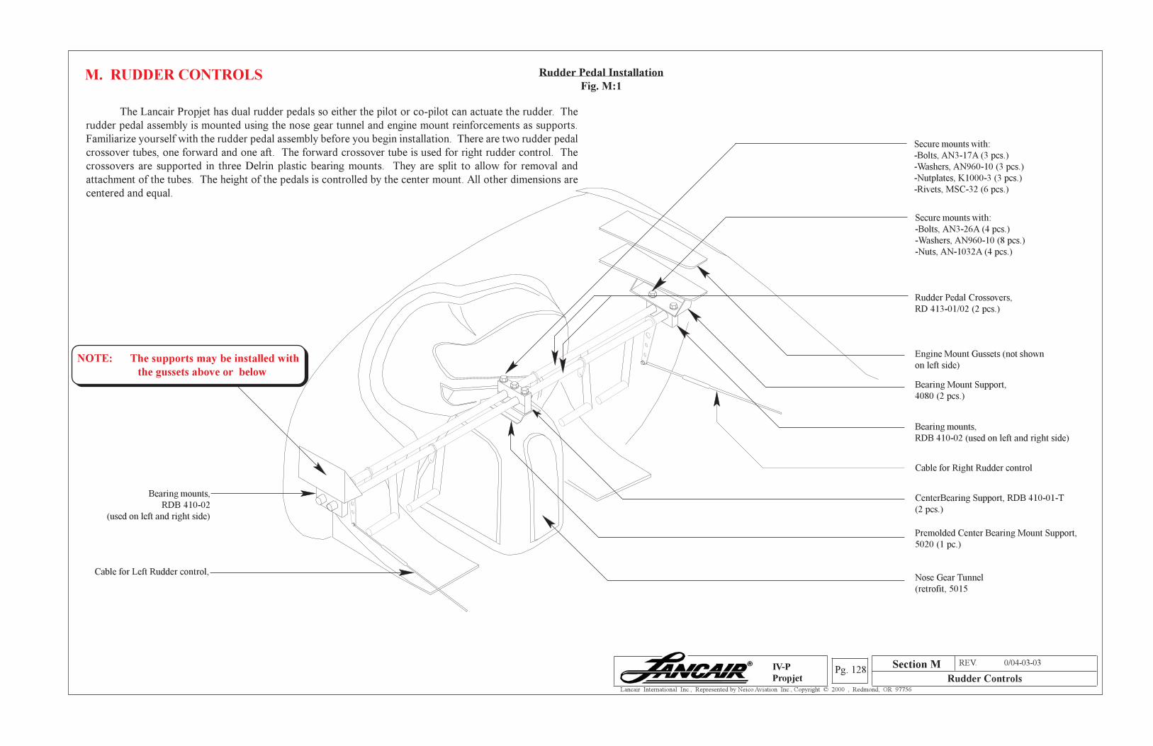
Section A REV. 0/04-03-03
Rudder ControlsPg. 128
Lancair International Inc., Represented by Neico Aviation Inc., Copyright © 2000 , Redmond, OR 97756
IV-P
Propjet
Section M
M. RUDDER CONTROLS
The Lancair Propjet has dual rudder pedals so either the pilot or co-pilot can actuate the rudder. The
rudder pedal assembly is mounted using the nose gear tunnel and engine mount reinforcements as supports.
Familiarize yourself with the rudder pedal assembly before you begin installation. There are two rudder pedal
crossover tubes, one forward and one aft. The forward crossover tube is used for right rudder control. The
crossovers are supported in three Delrin plastic bearing mounts. They are split to allow for removal and
attachment of the tubes. The height of the pedals is controlled by the center mount. All other dimensions are
centered and equal.
Rudder Pedal Installation
Fig. M:1
Rudder Pedal Crossovers,
RD 413-01/02 (2 pcs.)
Engine Mount Gussets (not shown
on left side)
Bearing Mount Support,
4080 (2 pcs.)
Bearing mounts,
RDB 410-02 (used on left and right side)
Cable for Right Rudder control
Premolded Center Bearing Mount Support,
5020 (1 pc.)
CenterBearing Support, RDB 410-01-T
(2 pcs.)
Nose Gear Tunnel
(retrofit, 5015
Cable for Left Rudder control,
Bearing mounts,
RDB 410-02
(used on left and right side)
NOTE: The supports may be installed with
the gussets above or below
Secure mounts with:
-Bolts, AN3-26A (4 pcs.)
-Washers, AN960-10 (8 pcs.)
-Nuts, AN-1032A (4 pcs.)
Secure mounts with:
-Bolts, AN3-17A (3 pcs.)
-Washers, AN960-10 (3 pcs.)
-Nutplates, K1000-3 (3 pcs.)
-Rivets, MSC-32 (6 pcs.)
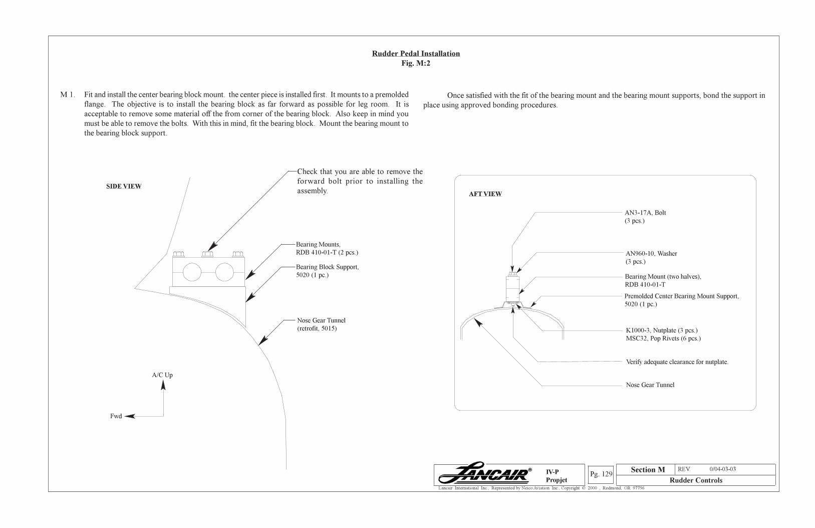
Section A REV. 0/04-03-03
Rudder ControlsPg. 129
Lancair International Inc., Represented by Neico Aviation Inc., Copyright © 2000 , Redmond, OR 97756
IV-P
Propjet
M 1. Fit and install the center bearing block mount. the center piece is installed first. It mounts to a premolded
flange. The objective is to install the bearing block as far forward as possible for leg room. It is
acceptable to remove some material off the from corner of the bearing block. Also keep in mind you
must be able to remove the bolts. With this in mind, fit the bearing block. Mount the bearing mount to
the bearing block support.
Once satisfied with the fit of the bearing mount and the bearing mount supports, bond the support in
place using approved bonding procedures.
Premolded Center Bearing Mount Support,
5020 (1 pc.)
AN3-17A, Bolt
(3 pcs.)
K1000-3, Nutplate (3 pcs.)
MSC32, Pop Rivets (6 pcs.)
AFT VIEW
Verify adequate clearance for nutplate.
Nose Gear Tunnel
SIDE VIEW
Nose Gear Tunnel
(retrofit, 5015)
A/C Up
Fwd
Rudder Pedal Installation
Fig. M:2
Check that you are able to remove the
forward bolt prior to installing the
assembly.
Bearing Block Support,
5020 (1 pc.)
Bearing Mounts,
RDB 410-01-T (2 pcs.)
Bearing Mount (two halves),
RDB 410-01-T
AN960-10, Washer
(3 pcs.)
Section M
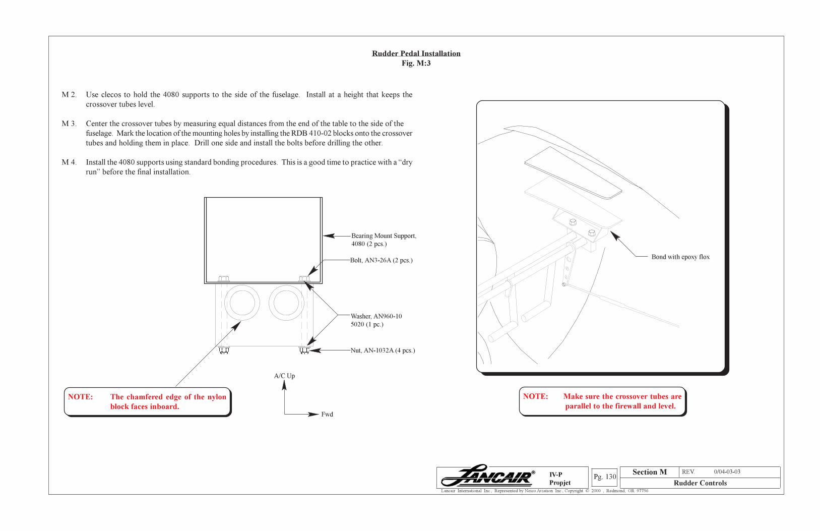
Section A REV. 0/04-03-03
Rudder ControlsPg. 130
Lancair International Inc., Represented by Neico Aviation Inc., Copyright © 2000 , Redmond, OR 97756
IV-P
Propjet
M 2. Use clecos to hold the 4080 supports to the side of the fuselage. Install at a height that keeps the
crossover tubes level.
M 3. Center the crossover tubes by measuring equal distances from the end of the table to the side of the
fuselage. Mark the location of the mounting holes by installing the RDB 410-02 blocks onto the crossover
tubes and holding them in place. Drill one side and install the bolts before drilling the other.
M 4. Install the 4080 supports using standard bonding procedures. This is a good time to practice with a “dry
run” before the final installation.
Rudder Pedal Installation
Fig. M:3
Section M
Bond with epoxy floxBolt, AN3-26A (2 pcs.)
Bearing Mount Support,
4080 (2 pcs.)
Washer, AN960-10
5020 (1 pc.)
A/C Up
Fwd
Nut, AN-1032A (4 pcs.)
NOTE: The chamfered edge of the nylon
block faces inboard.
NOTE: Make sure the crossover tubes are
parallel to the firewall and level.
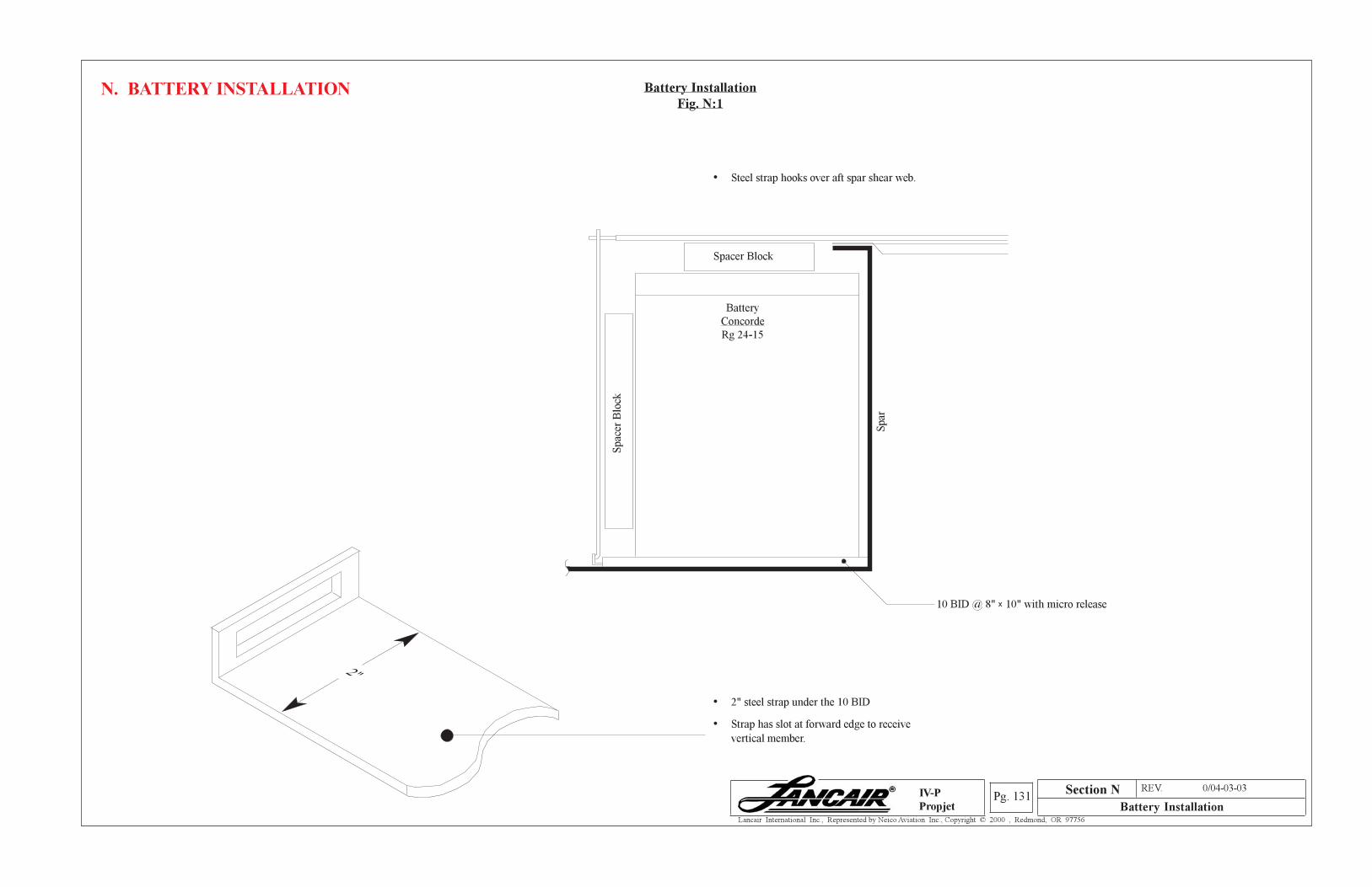
Section A REV. 0/04-03-03
Battery InstallationPg. 131
Lancair International Inc., Represented by Neico Aviation Inc., Copyright © 2000 , Redmond, OR 97756
IV-P
Propjet
N. BATTERY INSTALLATION
Section N
2"
• 2" steel strap under the 10 BID
• Strap has slot at forward edge to receive
vertical member.
• Steel strap hooks over aft spar shear web.
10 BID @ 8" x 10" with micro release
Spar
Spacer Block
Spac
er B
lock
Battery
Concorde
Rg 24-15
Battery Installation
Fig. N:1
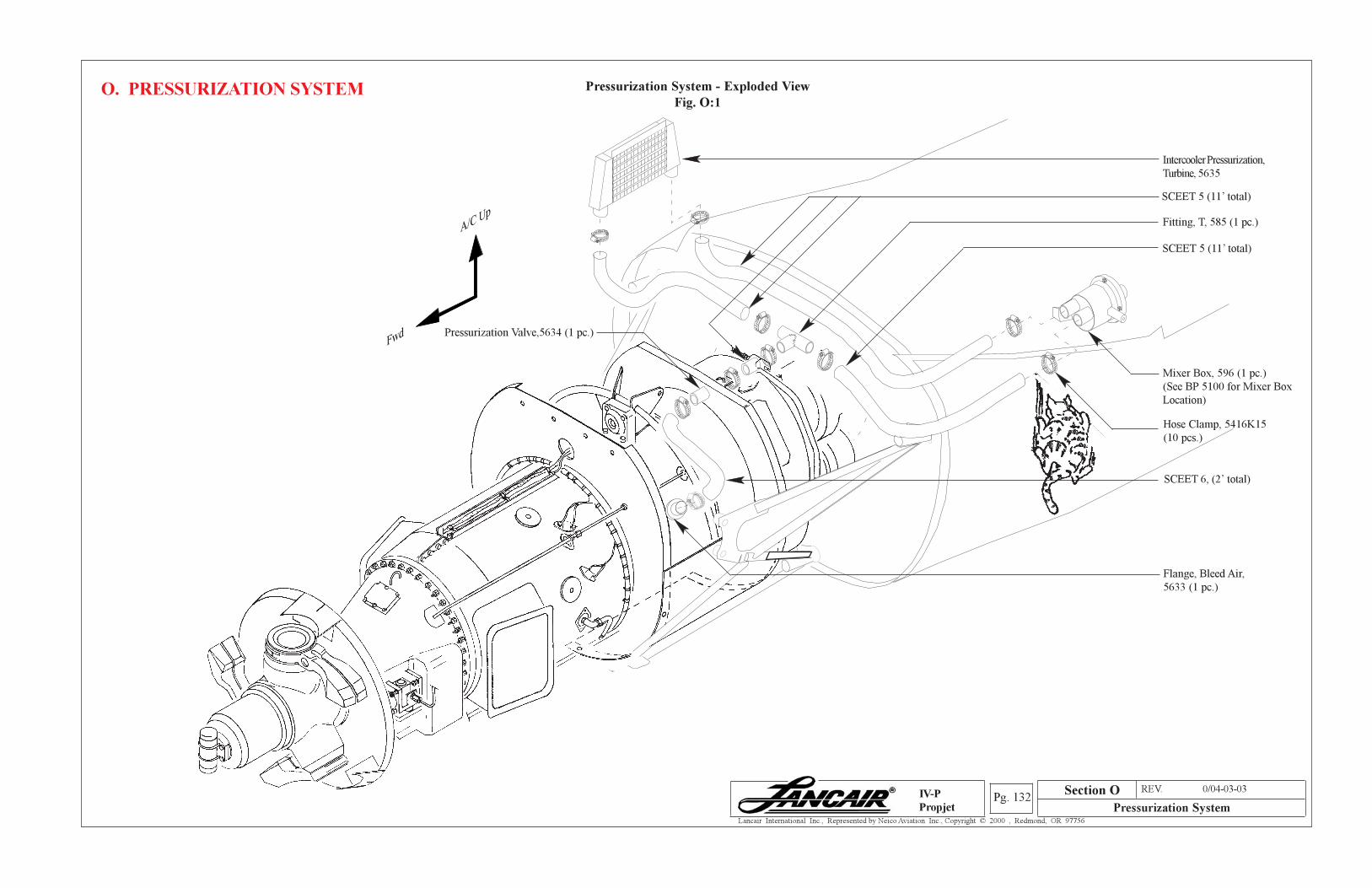
Section A REV. 0/04-03-03
Pressurization SystemPg. 132
Lancair International Inc., Represented by Neico Aviation Inc., Copyright © 2000 , Redmond, OR 97756
IV-P
Propjet
O. PRESSURIZATION SYSTEM Pressurization System - Exploded View
Fig. O:1
Intercooler Pressurization,
Turbine, 5635
Fitting, T, 585 (1 pc.)
SCEET 5 (11’ total)
SCEET 5 (11’ total)
Mixer Box, 596 (1 pc.)
(See BP 5100 for Mixer Box
Location)
SCEET 6, (2’ total)
Flange, Bleed Air,
5633 (1 pc.)
Hose Clamp, 5416K15
(10 pcs.)
A/C Up
Fwd Pressurization Valve,5634 (1 pc.)
Section O
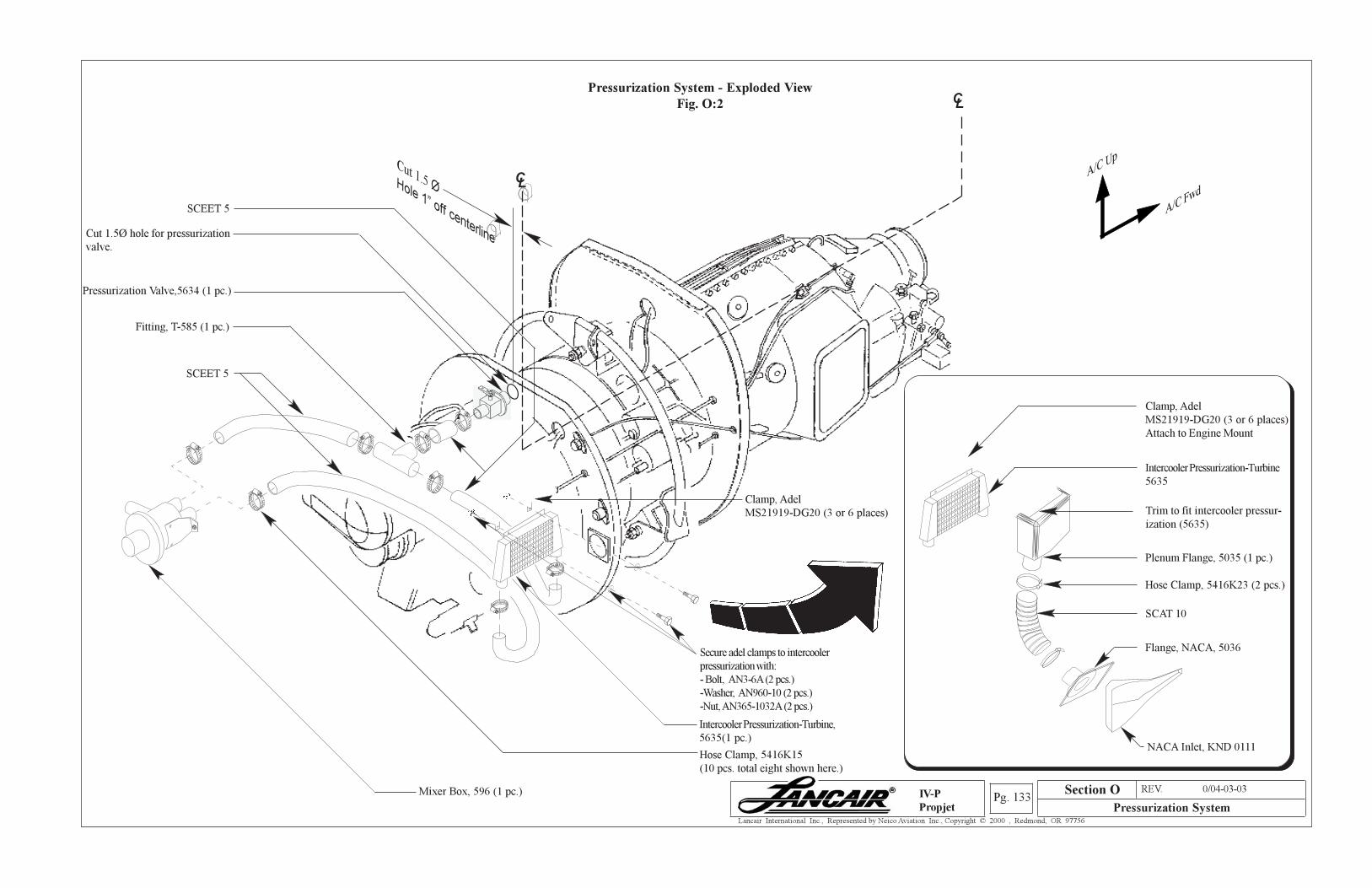
Section A REV. 0/04-03-03
Pressurization SystemPg. 133
Lancair International Inc., Represented by Neico Aviation Inc., Copyright © 2000 , Redmond, OR 97756
IV-P
Propjet
Pressurization System - Exploded View
Fig. O:2
Mixer Box, 596 (1 pc.)
Intercooler Pressurization-Turbine,
5635(1 pc.)
SCEET 5
Hose Clamp, 5416K15
(10 pcs. total eight shown here.)
Hose Clamp, 5416K23 (2 pcs.)
SCAT 10
Flange, NACA, 5036
NACA Inlet, KND 0111
Clamp, Adel
MS21919-DG20 (3 or 6 places)
Attach to Engine Mount
Intercooler Pressurization-Turbine
5635
SCEET 5
L
CL
A/C Up
A/C FwdCL
Fitting, T-585 (1 pc.)
Pressurization Valve,5634 (1 pc.)
Cut 1.5 ØHole 1” off centerlineCut 1.5Ø hole for pressurization
valve.
Plenum Flange, 5035 (1 pc.)
Trim to fit intercooler pressur-
ization (5635)
Section O
Secure adel clamps to intercooler
pressurization with:
- Bolt, AN3-6A (2 pcs.)
-Washer, AN960-10 (2 pcs.)
-Nut, AN365-1032A (2 pcs.)
Clamp, Adel
MS21919-DG20 (3 or 6 places)
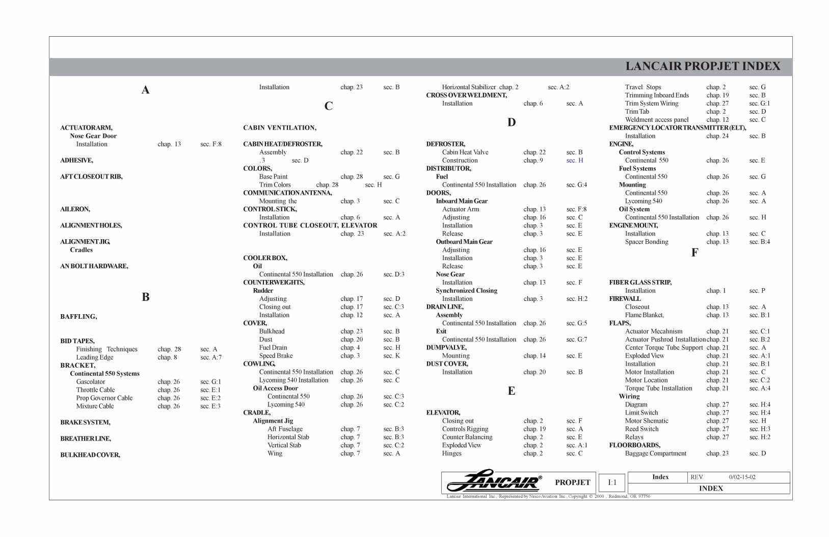
Index REV. 0/02-15-02
INDEXI:1
Lancair International Inc., Represented by Neico Aviation Inc., Copyright © 2000 , Redmond, OR 97756
LANCAIR PROPJET INDEX
PROPJET
A
ACTUATOR ARM,
Nose Gear Door
Installation chap. 13 sec. F:8
ADHESIVE,
AFT CLOSEOUT RIB,
AILERON,
ALIGNMENT HOLES,
ALIGNMENT JIG,
Cradles
AN BOLT HARDWARE,
B
BAFFLING,
BID TAPES,
Finishing Techniques chap. 28 sec. A
Leading Edge chap. 8 sec. A:7
BRACKET,
Continental 550 Systems
Gascolator chap. 26 sec. G:1
Throttle Cable chap. 26 sec. E:1
Prop Governor Cable chap. 26 sec. E:2
Mixture Cable chap. 26 sec. E:3
BRAKE SYSTEM,
BREATHER LINE,
BULKHEAD COVER,
Installation chap. 23 sec. B
C
CABIN VENTILATION,
CABIN HEAT/DEFROSTER,
Assembly chap. 22 sec. B
. 3 sec. D
COLORS,
Base Paint chap. 28 sec. G
Trim Colors chap. 28 sec. H
COMMUNICATION ANTENNA,
Mounting the chap. 3 sec. C
CONTROL STICK,
Installation chap. 6 sec. A
CONTROL TUBE CLOSEOUT, ELEVATOR
Installation chap. 23 sec. A:2
COOLER BOX,
Oil
Continental 550 Installation chap. 26 sec. D:3
COUNTERWEIGHTS,
Rudder
Adjusting chap. 17 sec. D
Closing out chap. 17 sec. C:3
Installation chap. 12 sec. A
COVER,
Bulkhead chap. 23 sec. B
Dust chap. 20 sec. B
Fuel Drain chap. 4 sec. H
Speed Brake chap. 3 sec. K
COWLING,
Continental 550 Installation chap. 26 sec. C
Lycoming 540 Installation chap. 26 sec. C
Oil Access Door
Continental 550 chap. 26 sec. C:3
Lycoming 540 chap. 26 sec. C:2
CRADLE,
Alignment Jig
Aft Fuselage chap. 7 sec. B:3
Horizontal Stab chap. 7 sec. B:3
Vertical Stab chap. 7 sec. C:2
Wing chap. 7 sec. A
Travel Stops chap. 2 sec. G
Trimming Inboard Ends chap. 19 sec. B
Trim System Wiring chap. 27 sec. G:1
Trim Tab chap. 2 sec. D
Weldment access panel chap. 12 sec. C
EMERGENCY LOCATOR TRANSMITTER (ELT),
Installation chap. 24 sec. B
ENGINE,
Control Systems
Continental 550 chap. 26 sec. E
Fuel Systems
Continental 550 chap. 26 sec. G
Mounting
Continental 550 chap. 26 sec. A
Lycoming 540 chap. 26 sec. A
Oil System
Continental 550 Installation chap. 26 sec. H
ENGINE MOUNT,
Installation chap. 13 sec. C
Spacer Bonding chap. 13 sec. B:4
F
FIBER GLASS STRIP,
Installation chap. 1 sec. P
FIREWALL
Closeout chap. 13 sec. A
Flame Blanket, chap. 13 sec. B:1
FLAPS,
Actuator Mecahnism chap. 21 sec. C:1
Actuator Pushrod Installationchap. 21 sec. B:2
Center Torque Tube Support chap. 21 sec. A
Exploded View chap. 21 sec. A:1
Installation chap. 21 sec. B:1
Motor Installation chap. 21 sec. C
Motor Location chap. 21 sec. C:2
Torque Tube Installation chap. 21 sec. A:4
Wiring
Diagram chap. 27 sec. H:4
Limit Switch chap. 27 sec. H:4
Motor Shematic chap. 27 sec. H
Reed Switch chap. 27 sec. H:3
Relays chap. 27 sec. H:2
FLOORBOARDS,
Baggage Compartment chap. 23 sec. D
Horizontal Stabilizer chap. 2 sec. A:2
CROSS OVER WELDMENT,
Installation chap. 6 sec. A
D
DEFROSTER,
Cabin Heat Valve chap. 22 sec. B
Construction chap. 9 sec. H
DISTRIBUTOR,
Fuel
Continental 550 Installation chap. 26 sec. G:4
DOORS,
Inboard Main Gear
Actuator Arm chap. 13 sec. F:8
Adjusting chap. 16 sec. C
Installation chap. 3 sec. E
Release chap. 3 sec. E
Outboard Main Gear
Adjusting chap. 16 sec. E
Installation chap. 3 sec. E
Release chap. 3 sec. E
Nose Gear
Installation chap. 13 sec. F
Synchronized Closing
Installation chap. 3 sec. H:2
DRAIN LINE,
Assembly
Continental 550 Installation chap. 26 sec. G:5
Exit
Continental 550 Installation chap. 26 sec. G:7
DUMP VALVE,
Mounting chap. 14 sec. E
DUST COVER,
Installation chap. 20 sec. B
E
ELEVATOR,
Closing out chap. 2 sec. F
Controls Rigging chap. 19 sec. A
Counter Balancing chap. 2 sec. E
Exploded View chap. 2 sec. A:1
Hinges chap. 2 sec. C
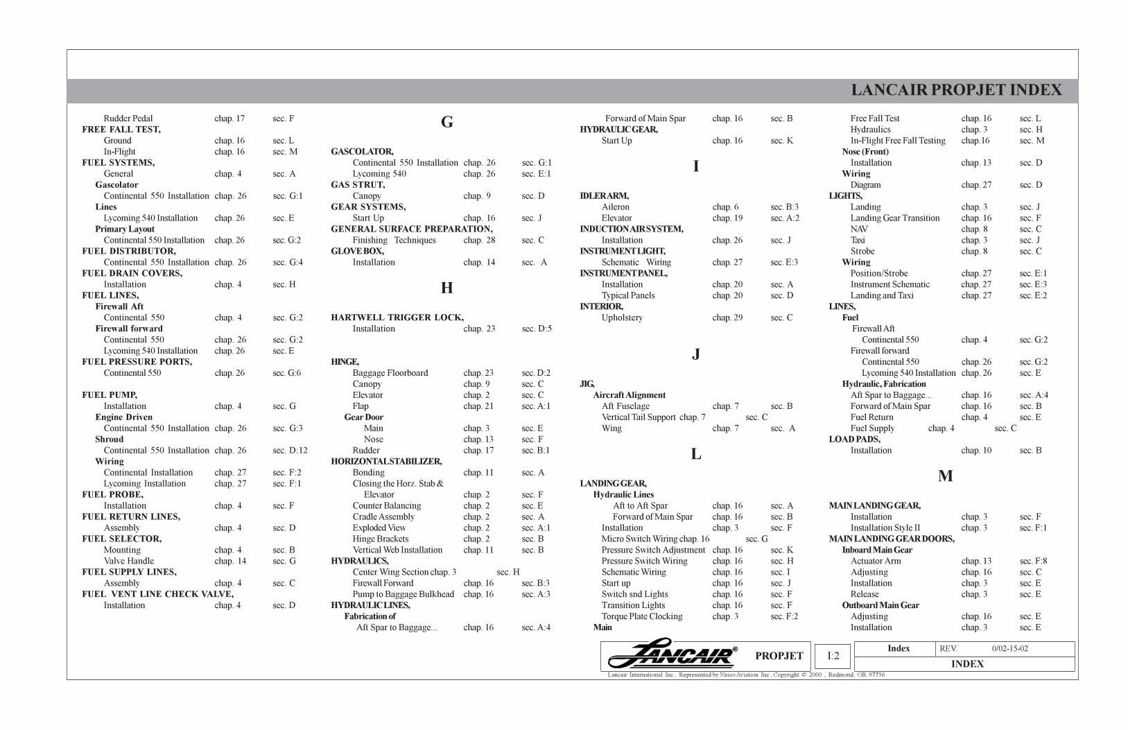
Index REV. 0/02-15-02
INDEXI:2
Lancair International Inc., Represented by Neico Aviation Inc., Copyright © 2000 , Redmond, OR 97756
LANCAIR PROPJET INDEX
PROPJET
Rudder Pedal chap. 17 sec. F
FREE FALL TEST,
Ground chap. 16 sec. L
In-Flight chap. 16 sec. M
FUEL SYSTEMS,
General chap. 4 sec. A
Gascolator
Continental 550 Installation chap. 26 sec. G:1
Lines
Lycoming 540 Installation chap. 26 sec. E
Primary Layout
Continental 550 Installation chap. 26 sec. G:2
FUEL DISTRIBUTOR,
Continental 550 Installation chap. 26 sec. G:4
FUEL DRAIN COVERS,
Installation chap. 4 sec. H
FUEL LINES,
Firewall Aft
Continental 550 chap. 4 sec. G:2
Firewall forward
Continental 550 chap. 26 sec. G:2
Lycoming 540 Installation chap. 26 sec. E
FUEL PRESSURE PORTS,
Continental 550 chap. 26 sec. G:6
FUEL PUMP,
Installation chap. 4 sec. G
Engine Driven
Continental 550 Installation chap. 26 sec. G:3
Shroud
Continental 550 Installation chap. 26 sec. D:12
Wiring
Continental Installation chap. 27 sec. F:2
Lycoming Installation chap. 27 sec. F:1
FUEL PROBE,
Installation chap. 4 sec. F
FUEL RETURN LINES,
Assembly chap. 4 sec. D
FUEL SELECTOR,
Mounting chap. 4 sec. B
Valve Handle chap. 14 sec. G
FUEL SUPPLY LINES,
Assembly chap. 4 sec. C
FUEL VENT LINE CHECK VALVE,
Installation chap. 4 sec. D
G
GASCOLATOR,
Continental 550 Installation chap. 26 sec. G:1
Lycoming 540 chap. 26 sec. E:1
GAS STRUT,
Canopy chap. 9 sec. D
GEAR SYSTEMS,
Start Up chap. 16 sec. J
GENERAL SURFACE PREPARATION,
Finishing Techniques chap. 28 sec. C
GLOVE BOX,
Installation chap. 14 sec. A
H
HARTWELL TRIGGER LOCK,
Installation chap. 23 sec. D:5
HINGE,
Baggage Floorboard chap. 23 sec. D:2
Canopy chap. 9 sec. C
Elevator chap. 2 sec. C
Flap chap. 21 sec. A:1
Gear Door
Main chap. 3 sec. E
Nose chap. 13 sec. F
Rudder chap. 17 sec. B:1
HORIZONTAL STABILIZER,
Bonding chap. 11 sec. A
Closing the Horz. Stab &
Elevator chap. 2 sec. F
Counter Balancing chap. 2 sec. E
Cradle Assembly chap. 2 sec. A
Exploded View chap. 2 sec. A:1
Hinge Brackets chap. 2 sec. B
Vertical Web Installation chap. 11 sec. B
HYDRAULICS,
Center Wing Section chap. 3 sec. H
Firewall Forward chap. 16 sec. B:3
Pump to Baggage Bulkhead chap. 16 sec. A:3
HYDRAULIC LINES,
Fabrication of
Aft Spar to Baggage... chap. 16 sec. A:4
Forward of Main Spar chap. 16 sec. B
HYDRAULIC GEAR,
Start Up chap. 16 sec. K
I
IDLER ARM,
Aileron chap. 6 sec. B:3
Elevator chap. 19 sec. A:2
INDUCTION AIR SYSTEM,
Installation chap. 26 sec. J
INSTRUMENT LIGHT,
Schematic Wiring chap. 27 sec. E:3
INSTRUMENT PANEL,
Installation chap. 20 sec. A
Typical Panels chap. 20 sec. D
INTERIOR,
Upholstery chap. 29 sec. C
J
JIG,
Aircraft Alignment
Aft Fuselage chap. 7 sec. B
Vertical Tail Support chap. 7 sec. C
Wing chap. 7 sec. A
L
LANDING GEAR,
Hydraulic Lines
Aft to Aft Spar chap. 16 sec. A
Forward of Main Spar chap. 16 sec. B
Installation chap. 3 sec. F
Micro Switch Wiring chap. 16 sec. G
Pressure Switch Adjustment chap. 16 sec. K
Pressure Switch Wiring chap. 16 sec. H
Schematic Wiring chap. 16 sec. I
Start up chap. 16 sec. J
Switch snd Lights chap. 16 sec. F
Transition Lights chap. 16 sec. F
Torque Plate Clocking chap. 3 sec. F:2
Main
Free Fall Test chap. 16 sec. L
Hydraulics chap. 3 sec. H
In-Flight Free Fall Testing chap.16 sec. M
Nose (Front)
Installation chap. 13 sec. D
Wiring
Diagram chap. 27 sec. D
LIGHTS,
Landing chap. 3 sec. J
Landing Gear Transition chap. 16 sec. F
NAV chap. 8 sec. C
Taxi chap. 3 sec. J
Strobe chap. 8 sec. C
Wiring
Position/Strobe chap. 27 sec. E:1
Instrument Schematic chap. 27 sec. E:3
Landing and Taxi chap. 27 sec. E:2
LINES,
Fuel
Firewall Aft
Continental 550 chap. 4 sec. G:2
Firewall forward
Continental 550 chap. 26 sec. G:2
Lycoming 540 Installation chap. 26 sec. E
Hydraulic, Fabrication
Aft Spar to Baggage... chap. 16 sec. A:4
Forward of Main Spar chap. 16 sec. B
Fuel Return chap. 4 sec. E
Fuel Supply chap. 4 sec. C
LOAD PADS,
Installation chap. 10 sec. B
M
MAIN LANDING GEAR,
Installation chap. 3 sec. F
Installation Style II chap. 3 sec. F:1
MAIN LANDING GEAR DOORS,
Inboard Main Gear
Actuator Arm chap. 13 sec. F:8
Adjusting chap. 16 sec. C
Installation chap. 3 sec. E
Release chap. 3 sec. E
Outboard Main Gear
Adjusting chap. 16 sec. E
Installation chap. 3 sec. E
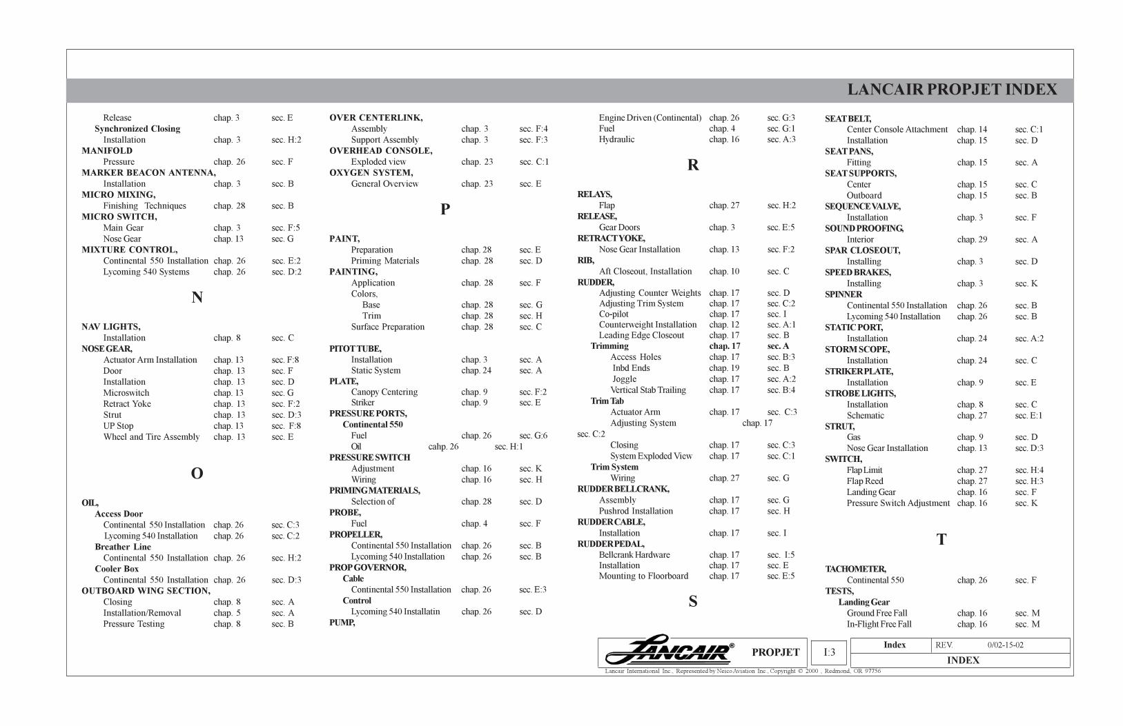
Index REV. 0/02-15-02
INDEXI:3
Lancair International Inc., Represented by Neico Aviation Inc., Copyright © 2000 , Redmond, OR 97756
LANCAIR PROPJET INDEX
PROPJET
Release chap. 3 sec. E
Synchronized Closing
Installation chap. 3 sec. H:2
MANIFOLD
Pressure chap. 26 sec. F
MARKER BEACON ANTENNA,
Installation chap. 3 sec. B
MICRO MIXING,
Finishing Techniques chap. 28 sec. B
MICRO SWITCH,
Main Gear chap. 3 sec. F:5
Nose Gear chap. 13 sec. G
MIXTURE CONTROL,
Continental 550 Installation chap. 26 sec. E:2
Lycoming 540 Systems chap. 26 sec. D:2
N
NAV LIGHTS,
Installation chap. 8 sec. C
NOSE GEAR,
Actuator Arm Installation chap. 13 sec. F:8
Door chap. 13 sec. F
Installation chap. 13 sec. D
Microswitch chap. 13 sec. G
Retract Yoke chap. 13 sec. F:2
Strut chap. 13 sec. D:3
UP Stop chap. 13 sec. F:8
Wheel and Tire Assembly chap. 13 sec. E
O
OIL,
Access Door
Continental 550 Installation chap. 26 sec. C:3
Lycoming 540 Installation chap. 26 sec. C:2
Breather Line
Continental 550 Installation chap. 26 sec. H:2
Cooler Box
Continental 550 Installation chap. 26 sec. D:3
OUTBOARD WING SECTION,
Closing chap. 8 sec. A
Installation/Removal chap. 5 sec. A
Pressure Testing chap. 8 sec. B
OVER CENTERLINK,
Assembly chap. 3 sec. F:4
Support Assembly chap. 3 sec. F:3
OVERHEAD CONSOLE,
Exploded view chap. 23 sec. C:1
OXYGEN SYSTEM,
General Overview chap. 23 sec. E
P
PAINT,
Preparation chap. 28 sec. E
Priming Materials chap. 28 sec. D
PAINTING,
Application chap. 28 sec. F
Colors,
Base chap. 28 sec. G
Trim chap. 28 sec. H
Surface Preparation chap. 28 sec. C
PITOT TUBE,
Installation chap. 3 sec. A
Static System chap. 24 sec. A
PLATE,
Canopy Centering chap. 9 sec. F:2
Striker chap. 9 sec. E
PRESSURE PORTS,
Continental 550
Fuel chap. 26 sec. G:6
Oil cahp. 26 sec. H:1
PRESSURE SWITCH
Adjustment chap. 16 sec. K
Wiring chap. 16 sec. H
PRIMING MATERIALS,
Selection of chap. 28 sec. D
PROBE,
Fuel chap. 4 sec. F
PROPELLER,
Continental 550 Installation chap. 26 sec. B
Lycoming 540 Installation chap. 26 sec. B
PROP GOVERNOR,
Cable
Continental 550 Installation chap. 26 sec. E:3
Control
Lycoming 540 Installatin chap. 26 sec. D
PUMP,
Engine Driven (Continental) chap. 26 sec. G:3
Fuel chap. 4 sec. G:1
Hydraulic chap. 16 sec. A:3
R
RELAYS,
Flap chap. 27 sec. H:2
RELEASE,
Gear Doors chap. 3 sec. E:5
RETRACT YOKE,
Nose Gear Installation chap. 13 sec. F:2
RIB,
Aft Closeout, Installation chap. 10 sec. C
RUDDER,
Adjusting Counter Weights chap. 17 sec. D
Adjusting Trim System chap. 17 sec. C:2
Co-pilot chap. 17 sec. I
Counterweight Installation chap. 12 sec. A:1
Leading Edge Closeout chap. 17 sec. B
Trimming chap. 17 sec. A
Access Holes chap. 17 sec. B:3
Inbd Ends chap. 19 sec. B
Joggle chap. 17 sec. A:2
Vertical Stab Trailing chap. 17 sec. B:4
Trim Tab
Actuator Arm chap. 17 sec. C:3
Adjusting System chap. 17
sec. C:2
Closing chap. 17 sec. C:3
System Exploded View chap. 17 sec. C:1
Trim System
Wiring chap. 27 sec. G
RUDDER BELLCRANK,
Assembly chap. 17 sec. G
Pushrod Installation chap. 17 sec. H
RUDDER CABLE,
Installation chap. 17 sec. I
RUDDER PEDAL,
Bellcrank Hardware chap. 17 sec. I:5
Installation chap. 17 sec. E
Mounting to Floorboard chap. 17 sec. E:5
S
SEAT BELT,
Center Console Attachment chap. 14 sec. C:1
Installation chap. 15 sec. D
SEAT PANS,
Fitting chap. 15 sec. A
SEAT SUPPORTS,
Center chap. 15 sec. C
Outboard chap. 15 sec. B
SEQUENCE VALVE,
Installation chap. 3 sec. F
SOUND PROOFING,
Interior chap. 29 sec. A
SPAR CLOSEOUT,
Installing chap. 3 sec. D
SPEED BRAKES,
Installing chap. 3 sec. K
SPINNER
Continental 550 Installation chap. 26 sec. B
Lycoming 540 Installation chap. 26 sec. B
STATIC PORT,
Installation chap. 24 sec. A:2
STORM SCOPE,
Installation chap. 24 sec. C
STRIKER PLATE,
Installation chap. 9 sec. E
STROBE LIGHTS,
Installation chap. 8 sec. C
Schematic chap. 27 sec. E:1
STRUT,
Gas chap. 9 sec. D
Nose Gear Installation chap. 13 sec. D:3
SWITCH,
Flap Limit chap. 27 sec. H:4
Flap Reed chap. 27 sec. H:3
Landing Gear chap. 16 sec. F
Pressure Switch Adjustment chap. 16 sec. K
T
TACHOMETER,
Continental 550 chap. 26 sec. F
TESTS,
Landing Gear
Ground Free Fall chap. 16 sec. M
In-Flight Free Fall chap. 16 sec. M
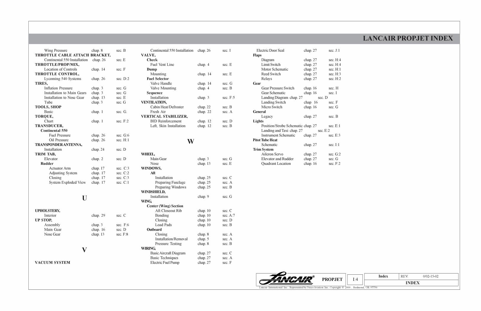
Index REV. 0/02-15-02
INDEXI:4
Lancair International Inc., Represented by Neico Aviation Inc., Copyright © 2000 , Redmond, OR 97756
LANCAIR PROPJET INDEX
PROPJET
Wing Pressure chap. 8 sec. B
THROTTLE CABLE ATTACH BRACKET,
Continental 550 Installation chap. 26 sec. E
THROTTLE/PROP/MIX,
Location of Controls chap. 14 sec. F
THROTTLE CONTROL,
Lycoming 540 Systems chap. 26 sec. D:2
TIRES,
Inflation Pressure chap. 3 sec. G
Installation to Main Gears chap. 3 sec. G
Installation to Nose Gear chap. 13 sec. E
Tube chap. 3 sec. G
TOOLS, SHOP
Basic chap. 1 sec. G.
TORQUE,
Chart chap. 1 sec. F:2
TRANSDUCER,
Continental 550
Fuel Pressure chap. 26 sec. G:6
Oil Pressure chap. 26 sec. H:1
TRANSPONDER ANTENNA,
Installation chap. 24 sec. D
TRIM TAB,
Elevator chap. 2 sec. D
Rudder
Actuator Arm chap. 17 sec. C:3
Adjusting System chap. 17 sec. C:2
Closing chap. 17 sec. C:3
System Exploded View chap. 17 sec. C:1
U
UPHOLSTERY,
Interior chap. 29 sec. C
UP STOP,
Assembly chap. 3 sec. F:6
Main Gear chap. 16 sec. D
Nose Gear chap. 13 sec. F:8
V
VACUUM SYSTEM
Continental 550 Installation chap. 26 sec. I
VALVE,
Check
Fuel Vent Line chap. 4 sec. E
Dump
Mounting chap. 14 sec. E
Fuel Selector
Valve Handle chap. 14 sec. G
Valve Mounting chap. 4 sec. B
Sequence
Installation chap. 3 sec. F:5
VENTILATION,
Cabin Heat/Defroster chap. 22 sec. B
Fresh Air chap. 22 sec. A
VERTICAL STABILIZER,
BID Reinforcement chap. 12 sec. D
Left, Skin Installation chap. 12 sec. B
W
WHEEL,
Main Gear chap. 3 sec. G
Nose chap. 13 sec. E
WINDOWS,
Aft
Installation chap. 25 sec. C
Preparing Fuselage chap. 25 sec. A
Preparing Windows chap. 25 sec. B
WINDSHIELD,
Installation chap. 9 sec. G
WING,
Center (Wing) Section
Aft Closeout Rib chap. 10 sec. C
Bonding chap. 10 sec. A:7
Closing chap. 10 sec. D
Load Pads chap. 10 sec. B
Outboard
Closing chap. 8 sec. A
Installation/Removal chap. 5 sec. A
Pressure Testing chap. 8 sec. B
WIRING,
Basic Aircraft Diagram chap. 27 sec. C
Basic Techniques chap. 27 sec. A
Electric Fuel Pump chap. 27 sec. F
Electric Door Seal chap. 27 sec. J:1
Flaps
Diagram chap. 27 sec. H:4
Limit Switch chap. 27 sec. H:4
Motor Schematic chap. 27 sec. H:1
Reed Switch chap. 27 sec. H:3
Relays chap. 27 sec. H:2
Gear
Gear Pressure Switch chap. 16 sec. H
Gear Schematic chap. 16 sec. I
Landing Diagram chap. 27 sec. D
Landing Switch chap 16 sec. F
Micro Switch chap. 16 sec. G
General
Legacy chap. 27 sec. B
Lights
Position/Strobe Schematic chap. 27 sec. E:1
Landing and Taxi chap. 27 sec. E:2
Instrument Schematic chap. 27 sec. E:3
Pitot Tube Heat
Schematic chap. 27 sec. I:1
Trim System
Aileron Servo chap. 27 sec. G:2
Elevator and Rudder chap. 27 sec. G
Quadrant Location chap. 16 sec. F:2

Index REV. 0/02-15-02
INDEXI:5
Lancair International Inc., Represented by Neico Aviation Inc., Copyright © 2000 , Redmond, OR 97756
LANCAIR PROPJET INDEX
PROPJET