Embed Size (px)
Citation preview
1
LSC/VIRGO Meeting, Caltech, March 18, 2008
Overview of Charging
Research
Valery MitrofanovMoscow State University
On behalf of charging subgroup
LIGO-G080077-00-Z
2
Motivation
Two recent events stimulated more intensive research in the field of charging problems.
● May 2006 Livingston charging event when the noise decreased after freeing of the sticking ITMY,
● GEO case of December 2006 when the big charge built up on the test mass as a result of a power cut and of a possible contact between the test and the reaction masses.
These cases have also shown that whatever mechanism is responsible for the test mass charging and generation of noise associated with charging, it is necessary to provide minimal charge on the test masses.
3
Earthquake stops replacement
The practical step has been done recently by Enhanced LIGO team at
both LIGO detectors: viton tipped earthquake stops were replaced by
fused silica tipped stops.
What can we expect from this operation?
The result of Gregg Harry analysis is presented on the next slide.
The analysis is based on one of possible mechanisms of generation of
Gaussian noise associated with test mass charging (R.Weiss model):
charge relaxation is treated as a random Markov process with a single
correlation time τ.
4
Estimates of noise - сomments (1) Key parameters that determine this noise: ♦ q – amount of charge transferred to the optic by contact with
earthquake stop, ♦ τ - charge relaxation time.Their values were measured in Moscow Univ. and in Trinity Univ.&MIT(they may differ from real test mass values, but we have no opportunity to measure them in situ)
• Also Moscow group has demonstrated dependence of charge relaxation time on cleanness of the sample surface. The recent result: the measured charge relaxation time was found to be more than 5 years (the sample was cleaned in ultrasound bath but this procedure may damage to LIGO optics).
• At present, it is supposed to use First contactTM polymer solution to clean and protect LIGO optics. The nearest goal of LSC charging group is to search “charging outcome” from this procedure.
5
Estimate of noise from chargingG.Harry (LIGO-T080019-00-R)
100 150 200 300 500 700 1000
2. 1020
5. 1020
1. 1019
2. 1019
5. 1019
1. 1018
2. 1018
100 150 200 300 500 700 1000
2. 1020
5. 1020
1. 1019
2. 1019
5. 1019
1. 1018
2. 1018
100 150200 300 500 7001000
2. 1020
5. 10201. 10192. 1019
5. 10191. 10182. 1018
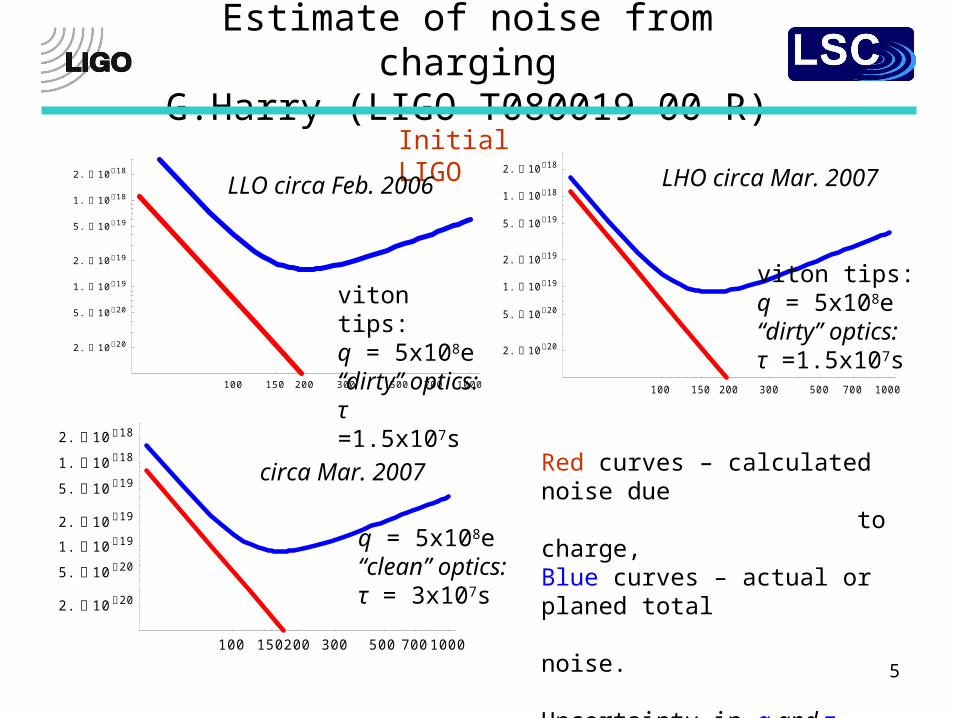
Red curves – calculated noise due to charge,Blue curves – actual or planed total noise.
Uncertainty in q and τ allowed toexplain observed noise.
Initial LIGO
viton tips:q = 5x10⁸e“dirty” optics:τ =1.5x10⁷s
LLO circa Feb. 2006 LHO circa Mar. 2007
circa Mar. 2007
q = 5x10⁸e“clean” optics:τ = 3x10⁷s
viton tips:q = 5x10⁸e“dirty” optics:τ =1.5x10⁷s
6
Estimate of noise from chargingG.Harry (LIGO-T080019-00-R)
100 150200 300 500 70010001. 1024
1. 1023
1. 1022
1. 1021
1. 1020
1. 1019
1. 1018
10 20 50 100 200 500 10001. 1024
1. 1022
1. 1020
1. 1018
1. 1016
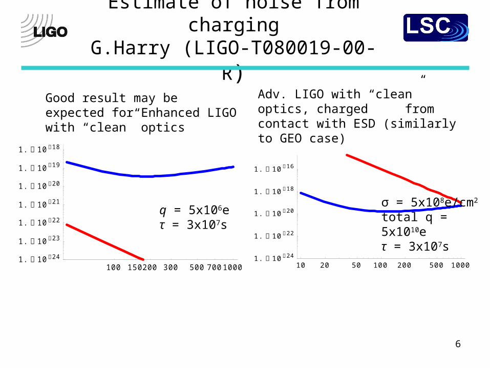
Good result may be expected for Enhanced LIGO with “clean” optics
q = 5x10⁶eτ = 3x10⁷s
Adv. LIGO with “clean” optics, charged from contact with ESD (similarly to GEO case)
σ = 5x10⁸e/cm2
total q = 5x10¹⁰eτ = 3x10⁷s
7
Estimates of noise - comments(2)
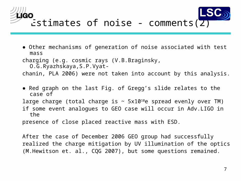
● Other mechanisms of generation of noise associated with test mass charging (e.g. cosmic rays (V.B.Braginsky, O.G.Ryazhskaya,S.P.Vyat-chanin, PLA 2006) were not taken into account by this analysis.
● Red graph on the last Fig. of Gregg’s slide relates to the case of large charge (total charge is ~ 5x10¹⁰e spread evenly over TM)if some event analogues to GEO case will occur in Adv.LIGO in thepresence of close placed reactive mass with ESD.
After the case of December 2006 GEO group had successfully realized the charge mitigation by UV illumination of the optics (M.Hewitson et. al., CQG 2007), but some questions remained.
8
Some questions about charge mitigation by UV illumination of the test mass
• What mechanisms determine the UV charge mitigation of positive and negative charges? Quantitative characteristics of the process?
• What effect does UV light on uneven positional distributions of charges? What minimal charge value on the test mass may be achieved?
• Does UV light cause damage of test mass coating and excess optical and mechanical losses?
9
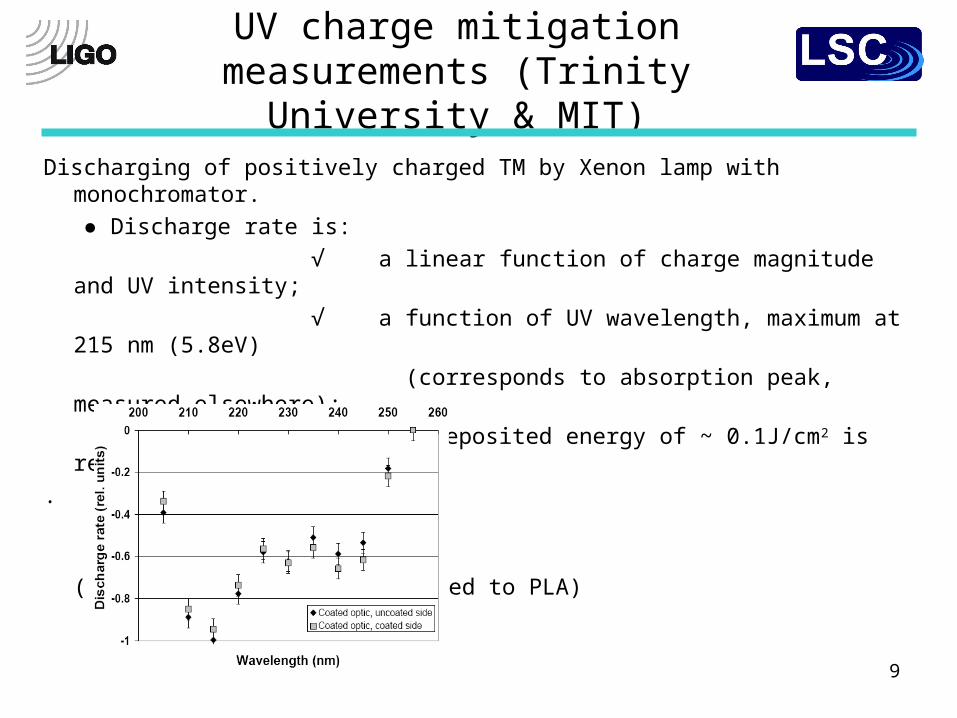
UV charge mitigation measurements (Trinity University & MIT)
Discharging of positively charged TM by Xenon lamp with monochromator.
● Discharge rate is:
√ a linear function of charge magnitude and UV intensity;
√ a function of UV wavelength, maximum at 215 nm (5.8eV)
(corresponds to absorption peak, measured elsewhere);
To discharge TM by 90% deposited energy of ~ 0.1J/cm2 is required.
.
( D.Ugolini, et.al., submitted to PLA)
10
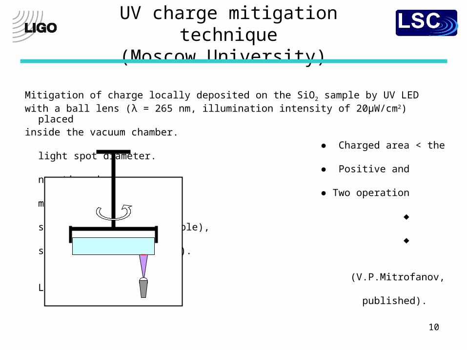
UV charge mitigation technique(Moscow University)
Mitigation of charge locally deposited on the SiO2 sample by UV LED with a ball lens (λ = 265 nm, illumination intensity of 20μW/cm2) placed inside the vacuum chamber. ● Charged area < the light spot diameter.
● Positive and negative charges. ● Two operation modes: ♦ static (sample is immovable), ♦ scanning (sample rotates).
(V.P.Mitrofanov, L.G.Prokhorov, to be published).
11
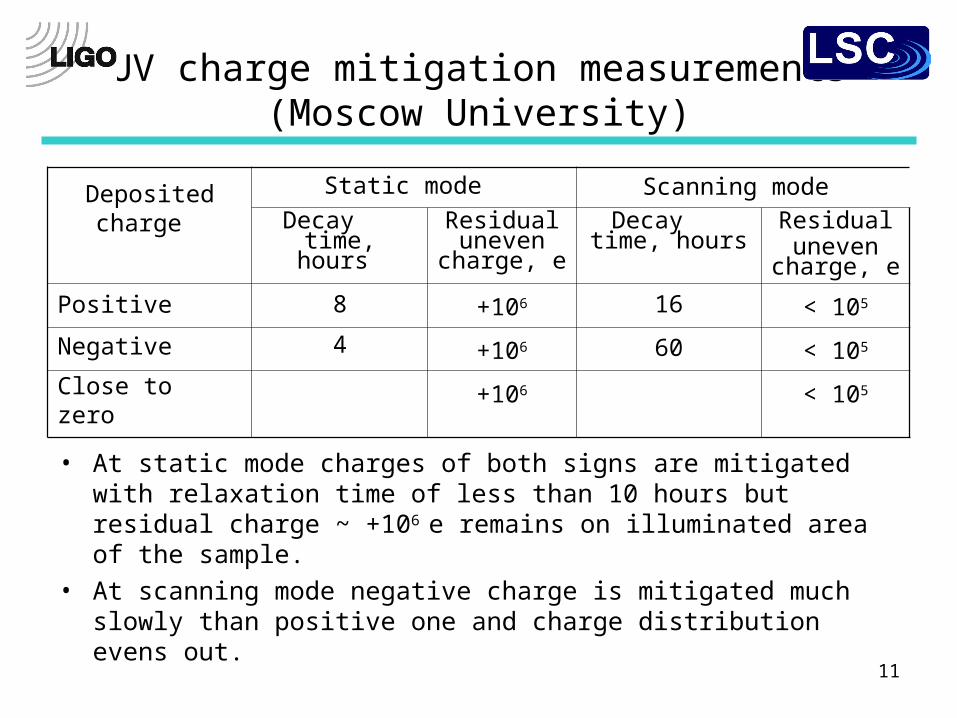
UV charge mitigation measurements (Moscow University)
Depositedcharge
Static mode Scanning mode
Decay time, hours
Residual uneven
charge, e
Decay time, hours
Residualuneven
charge, e
Positive 8 +106 16 < 105
Negative 4 +106 60 < 105
Close to zero +106 < 105
• At static mode charges of both signs are mitigated with relaxation time of less than 10 hours but residual charge ~ +106 e remains on illuminated area of the sample.
• At scanning mode negative charge is mitigated much slowly than positive one and charge distribution evens out.
12
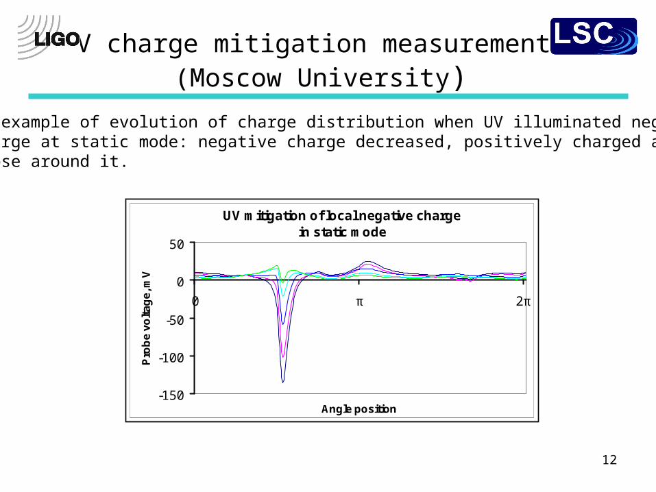
UV charge mitigation measurements (Moscow University)
UV mitigation of local negative charge in static mode
-150
-100
-50
0
50
0 π 2π
Angle position
Pro
be
vo
lta
ge
, mV
An example of evolution of charge distribution when UV illuminated negativecharge at static mode: negative charge decreased, positively charged area arose around it.
13
Interpretation of UV charge mitigation measurements
Such charge behavior may be a result of photoelectron emission together
with positive ion emission from SiO2.
● The electron emission did not arise from excitation of valence band
electrons, but arose from defect states in the bandgap ≈ 9 eV. Several types
of point defects are present in the bulk and on the surface: oxygen vacancy
with a trapped hole (E’- center), nonbridging oxygen (NBO-center), twofold-
cordinated silicon with a trapped hydrogen atom (H-center), etc.
● Positive ion emission during UV irradiation may be attributed to electrostatic
mechanism, where ions adsorbed at or near surface electron traps are ejected
when the underlying electron trap is photoionized by UV.
● Photolysis (UV induced bond dissociation) may likely cause the ion
emission from the surface of SiO2. as well.
14
UV impact on mirror absorption (measurement of Stanford Univ. group)
See talk by Ke-Xun Sun at this session.
15
Conclusion
• We learned a lot of things about TM discharging with UV light. Though there are a lot of things we do not know. Likely, the UV method has the serious disadvantage - additional optical absorption.
Other methods of charge mitigation (venting of the chamber with subsequent neutralization by ions or via surface conductivity of adsorbed water; the glow-discharge ignition at low pressure; coating of TM and suspension fiber by very thin conductive film) has disadvantages as well.
• So it is better to avoid the necessity of charge mitigation after chamber pumping. It is reasonable to control and maximally mitigate charge on TMs at every step of suspension and preparation before the pumping of the chamber as well as to exclude building up large charge in process of operation (contact electrification, electrical discharge).
• Study of UV charge mitigation have shown that the surface of fused silica TM is very complicated structure. Can processes on the surface of TM produce additional noise?
16
Main directions of current and future charging research:
• Further investigation of charge behavior and mechanisms of noise generation associated with charging of the test masses (e.g. Trinity are adding motion control to their Kelvin probe so that to make two-dimensional charging map of optics).
• Testing of elements of Adv.LIGO construction and new technologies from point of view of charging effects (e.g. using of the First ContactTM polymer solution, gold coating of the test mass barrel for TCS, gold coating for ESD).
• Study of different charge mitigation techniques and their impact on optical absorption and mechanical losses.