Embed Size (px)
Citation preview
1
Multimedia Networking
R. Yang
2
Outline
Admin. and review Introduction to multimedia
networkingAn architecture of stored multimediaNetwork support of multimedia app.Application adaptation
3
Preview: Multimedia NetworkingOur goals:
Understand the service requirements of networked multimedia applications
Learn the high level structures designed for multimedia networking
Deal with multimedia in a best-effort network
How the Internet might evolve to better support multimedia?
Schedule of the two classes:
Class 1: Multimedia applications; application adaptation in best-effort networks
Class 2: New architectures: IntServ and DiffServ
4
MM Networking Applications
Fundamental characteristics:
Typically delay sensitive end-to-end delay delay jitter
But loss tolerant: infrequent losses cause minor glitches
Antithesis of data, which are loss intolerant but delay tolerant.
Classes of MM applications:
1) Streaming stored audio and video
2) Streaming live audio and video
3) Real-time interactive audio and video
5
Streaming Stored Multimedia
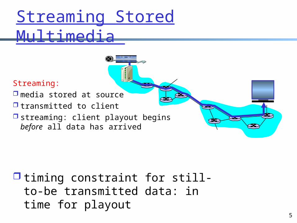
Streaming: media stored at source transmitted to client streaming: client playout begins
before all data has arrived
timing constraint for still-to-be transmitted data: in time for playout
6
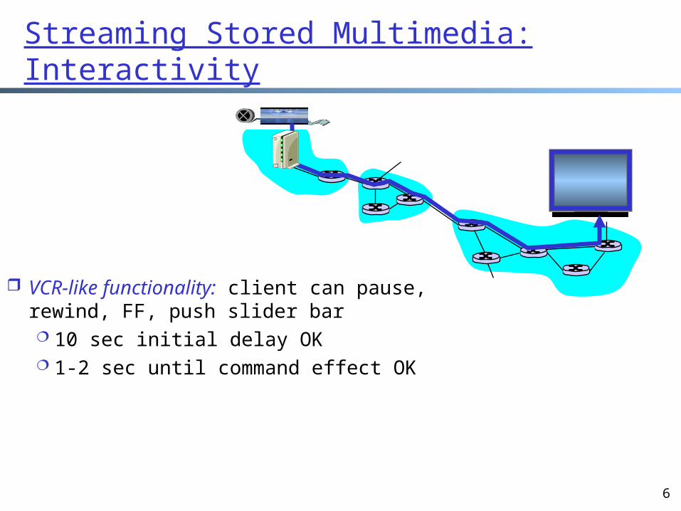
Streaming Stored Multimedia: Interactivity
VCR-like functionality: client can pause, rewind, FF, push slider bar 10 sec initial delay OK 1-2 sec until command effect
OK
7
Streaming Live Multimedia
Examples: Internet radio talk show Live sporting event
Streaming play can lag tens of seconds still have timing constraint (but shorter delay
required)Interactivity fast forward impossible rewind, pause possible!
8
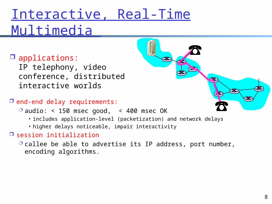
Interactive, Real-Time Multimedia
end-end delay requirements: audio: < 150 msec good, < 400 msec OK
• includes application-level (packetization) and network delays• higher delays noticeable, impair interactivity
session initialization callee be able to advertise its IP address, port number, encoding
algorithms.
applications: IP telephony, video conference, distributed interactive worlds
9
Outline
Admin. and reviewA brief introduction to the physical
layerIntroduction to multimedia
networking An architecture of stored multimediaNetwork support of multimedia app.Application adaptation
10
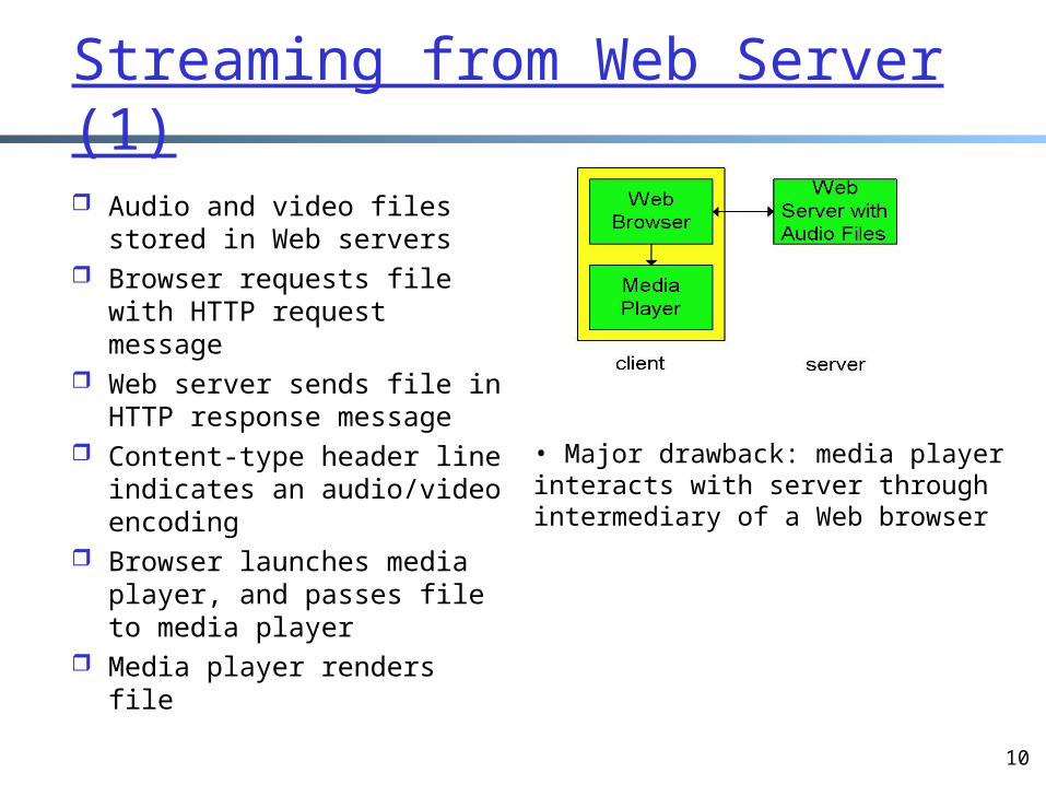
Streaming from Web Server (1) Audio and video files
stored in Web servers Browser requests file with
HTTP request message Web server sends file in
HTTP response message Content-type header line
indicates an audio/video encoding
Browser launches media player, and passes file to media player
Media player renders file
• Major drawback: media playerinteracts with server throughintermediary of a Web browser
11
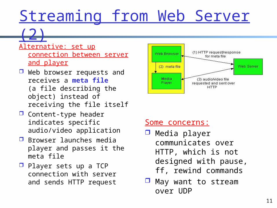
Streaming from Web Server (2)Alternative: set up
connection between server and player
Web browser requests and receives a meta file (a file describing the object) instead of receiving the file itself
Content-type header indicates specific audio/video application
Browser launches media player and passes it the meta file
Player sets up a TCP connection with server and sends HTTP request
Some concerns: Media player
communicates over HTTP, which is not designed with pause, ff, rewind commands
May want to stream over UDP
12
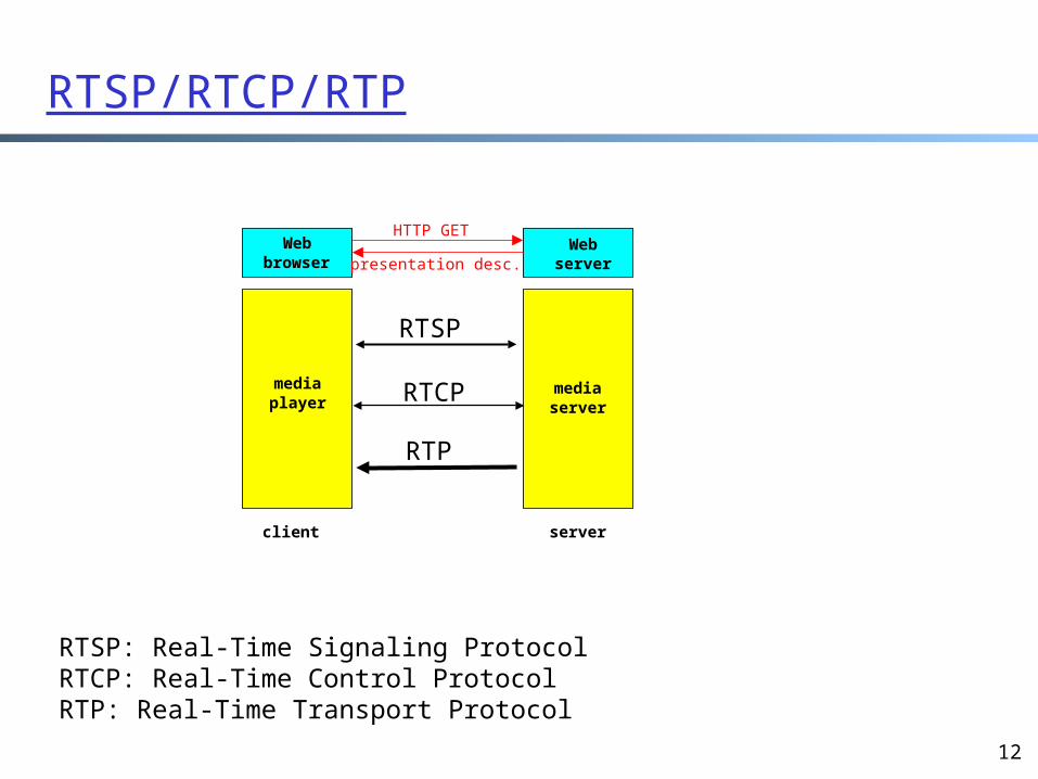
RTSP/RTCP/RTP
HTTP GET
mediaplayer
Webserver
mediaserver
Webbrowser
client server
presentation desc.
RTSP
RTCP
RTP
RTSP: Real-Time Signaling ProtocolRTCP: Real-Time Control ProtocolRTP: Real-Time Transport Protocol
13
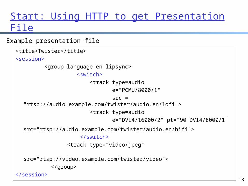
Start: Using HTTP to get Presentation File
<title>Twister</title> <session> <group language=en lipsync> <switch> <track type=audio e="PCMU/8000/1" src =
"rtsp://audio.example.com/twister/audio.en/lofi"> <track type=audio e="DVI4/16000/2" pt="90 DVI4/8000/1"
src="rtsp://audio.example.com/twister/audio.en/hifi"> </switch> <track type="video/jpeg" src="rtsp://video.example.com/twister/video"> </group> </session>
Example presentation file
14
Control: RTSP, Out of Band ControlRTSP messages are sent out-of-band:
The RTSP control messages use a different port number (554) than the media stream, and are therefore sent out-of-band
RTSP can be sent over UDP or TCP Each RTSP message can be sent over a separate TCP
connection The media stream, whose packet structure is not defined
by RTSP, is considered “in-band” If the RTSP messages were to use the same port number
as the media stream, then RTSP messages would be said to be “interleaved” with the media stream
15
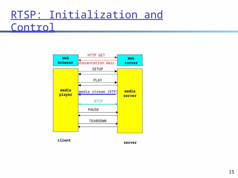
RTSP: Initialization and Control
HTTP GET
SETUP
PLAY
media stream (RTP)mediaplayer
Webserver
mediaserver
Webbrowser
clientserver
presentation desc.
TEARDOWN
PAUSE
RTCP
16
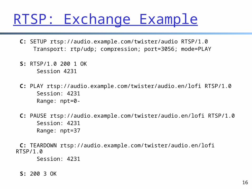
RTSP: Exchange Example C: SETUP rtsp://audio.example.com/twister/audio RTSP/1.0 Transport: rtp/udp; compression; port=3056; mode=PLAY
S: RTSP/1.0 200 1 OK Session 4231
C: PLAY rtsp://audio.example.com/twister/audio.en/lofi RTSP/1.0 Session: 4231 Range: npt=0-
C: PAUSE rtsp://audio.example.com/twister/audio.en/lofi RTSP/1.0 Session: 4231 Range: npt=37
C: TEARDOWN rtsp://audio.example.com/twister/audio.en/lofi RTSP/1.0 Session: 4231
S: 200 3 OK
17
Data: Real-Time Protocol (RTP)
RTP runs in the end systems RTP specifies a packet structure for packets
carrying audio and video data: RFC 1889 RTP packets are encapsulated in UDP segments Interoperability: If two Internet phone
applications run RTP, then they may be able to work together
18
RTP Header
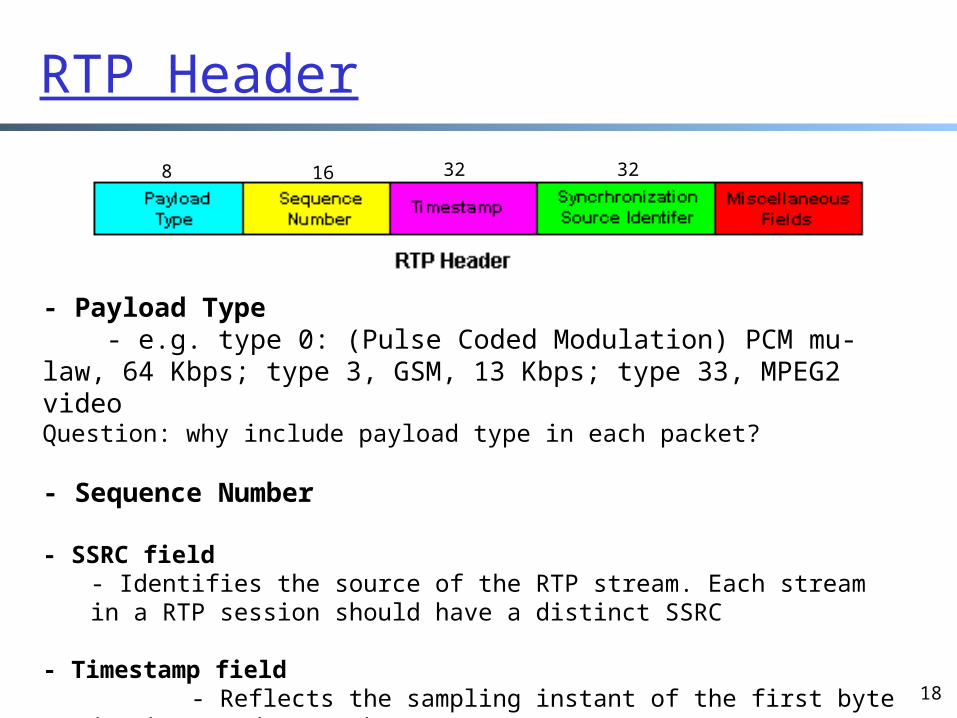
- Payload Type - e.g. type 0: (Pulse Coded Modulation) PCM mu-law, 64 Kbps; type 3, GSM, 13 Kbps; type 33, MPEG2 videoQuestion: why include payload type in each packet?
- Sequence Number
- SSRC field- Identifies the source of the RTP stream. Each stream in a RTP session should have a distinct SSRC
- Timestamp field - Reflects the sampling instant of the first byte in the RTP data packet
8 16 32 32
19
RTP Header (2)
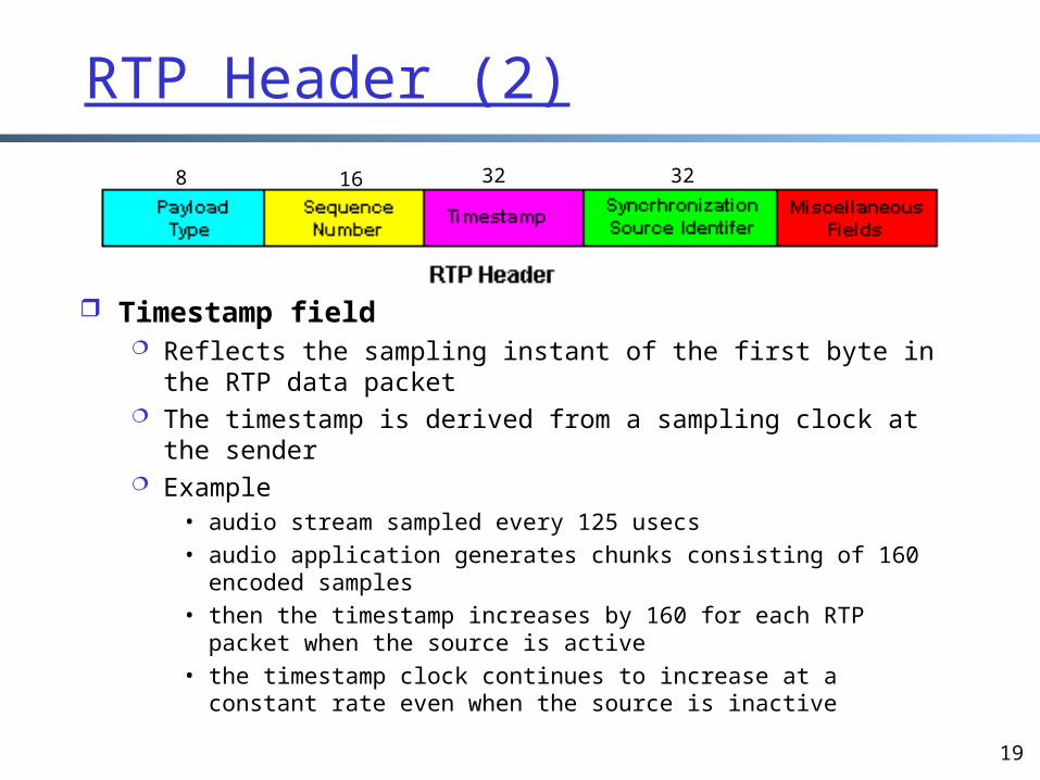
Timestamp field Reflects the sampling instant of the first byte in the RTP
data packet The timestamp is derived from a sampling clock at the
sender Example
• audio stream sampled every 125 usecs • audio application generates chunks consisting of 160 encoded
samples• then the timestamp increases by 160 for each RTP packet
when the source is active• the timestamp clock continues to increase at a constant rate
even when the source is inactive
8 16 32 32
20
H.323 Overview
Foundation for audio and video conferencing across IP networks
Targets real-time communication (rather than on-demand)
Umbrella recommendation from the ITU Broad in scope:
stand-alone devices (e.g., Web phones) applications in PCs
21
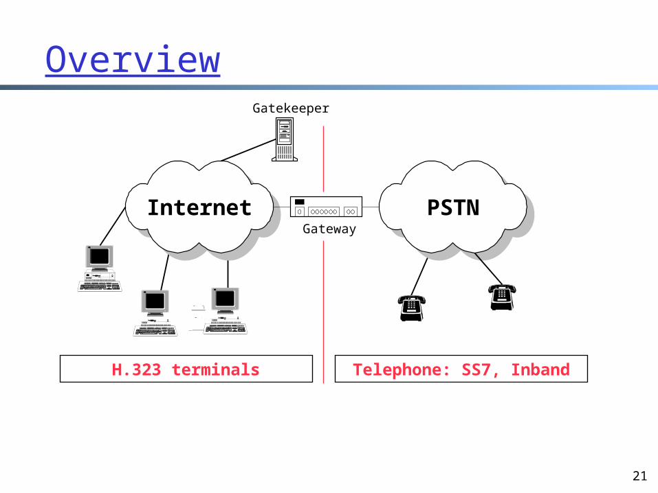
Overview
H.323 terminals Telephone: SS7, Inband
Internet PSTNGateway
Gatekeeper
22
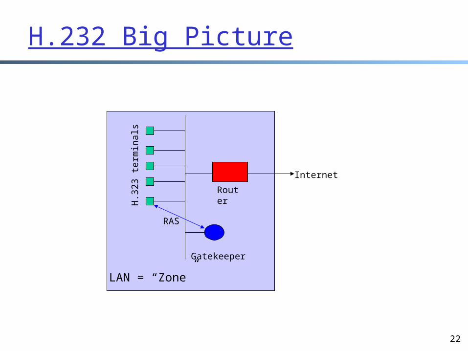
H.232 Big Picture
H.3
23 te
rmin
als
Gatekeeper
Router
Internet
LAN = “Zone”
RAS
23
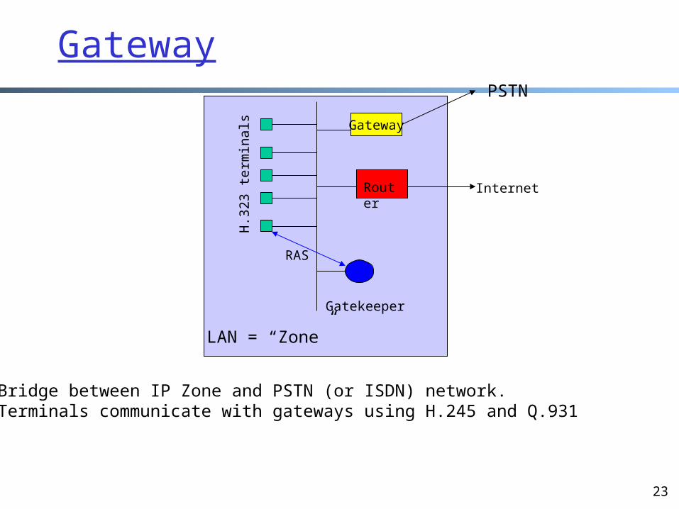
Gateway
H.3
23 te
rmin
als
Gatekeeper
Router Internet
LAN = “Zone”
RAS
Gateway
PSTN
• Bridge between IP Zone and PSTN (or ISDN) network.• Terminals communicate with gateways using H.245 and Q.931
24
Gatekeeper
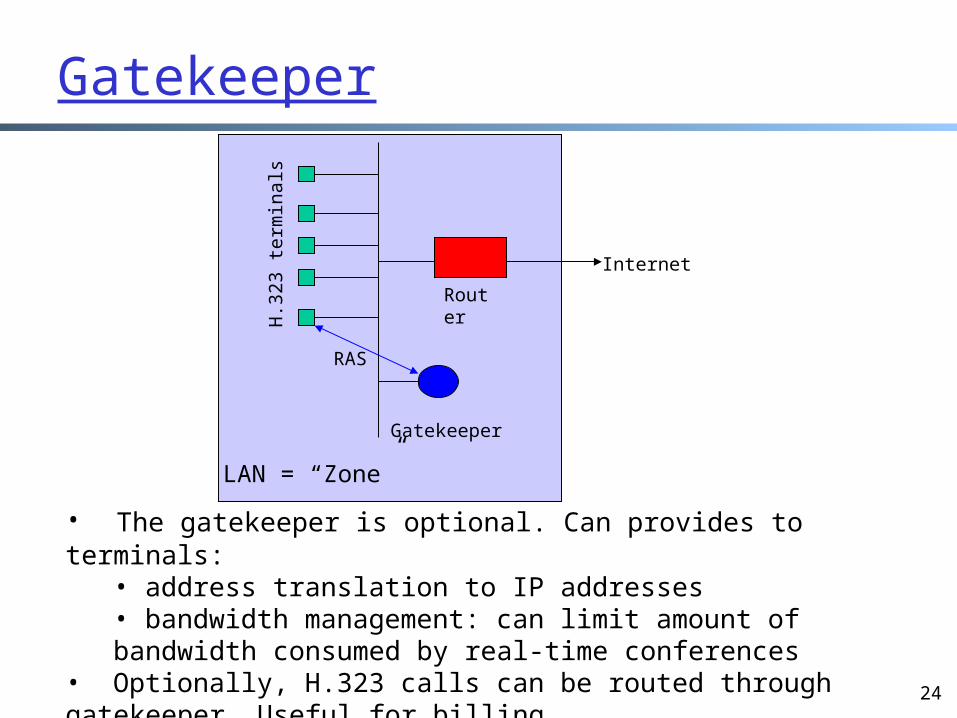
• The gatekeeper is optional. Can provides to terminals:• address translation to IP addresses• bandwidth management: can limit amount of bandwidth consumed by real-time conferences
• Optionally, H.323 calls can be routed through gatekeeper. Useful for billing.• RAS protocol (over TCP) for terminal-gatekeeper communication.
H.3
23 te
rmin
als
Gatekeeper
Router
Internet
LAN = “Zone”
RAS
25
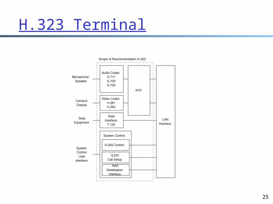
H.323 Terminal
26
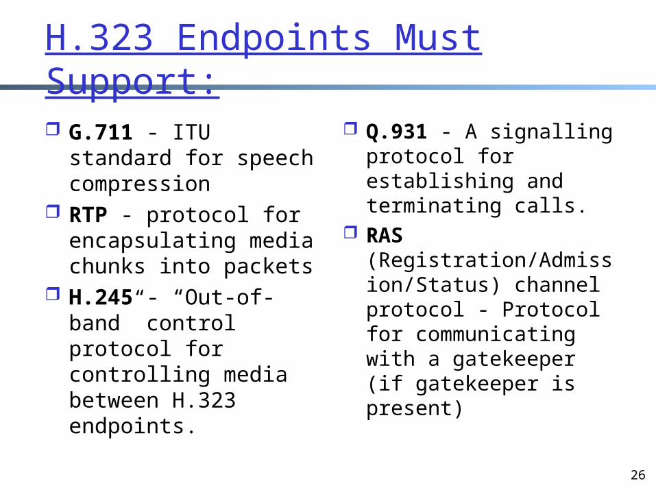
H.323 Endpoints Must Support:
G.711 - ITU standard for speech compression
RTP - protocol for encapsulating media chunks into packets
H.245 - “Out-of-band” control protocol for controlling media between H.323 endpoints.
Q.931 - A signalling protocol for establishing and terminating calls.
RAS (Registration/Admission/Status) channel protocol - Protocol for communicating with a gatekeeper (if gatekeeper is present)
27
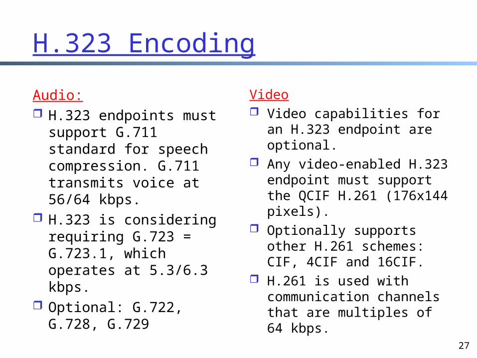
H.323 Encoding
Audio: H.323 endpoints must
support G.711 standard for speech compression. G.711 transmits voice at 56/64 kbps.
H.323 is considering requiring G.723 = G.723.1, which operates at 5.3/6.3 kbps.
Optional: G.722, G.728, G.729
Video Video capabilities for an
H.323 endpoint are optional.
Any video-enabled H.323 endpoint must support the QCIF H.261 (176x144 pixels).
Optionally supports other H.261 schemes: CIF, 4CIF and 16CIF.
H.261 is used with communication channels that are multiples of 64 kbps.
28
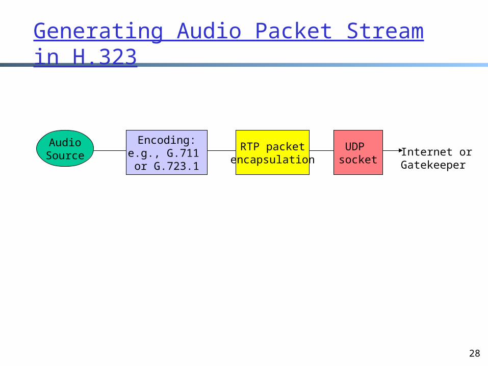
Generating Audio Packet Stream in H.323
AudioSource
Encoding:e.g., G.711 or G.723.1
RTP packetencapsulation
UDP socket
Internet orGatekeeper
29
H.245 Control Channel
H.323 stream may contain multiple channels for different media types.
One H.245 control channel per H.323 session.
H.245 control channel is a reliable (TCP) channel that carries control messages.
Principle tasks: Open and closing
media channels. Capability
exchange: before sending media, endpoints agree on encoding algorithm
Note: H.245 for multimedia conferencing is analogous with RTSP for media streaming
30
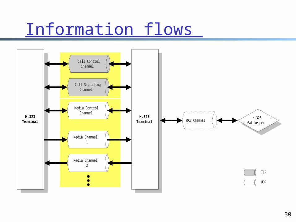
Information flows
H.323Terminal
H.323Terminal
Media Channel1
Media ControlChannel
Media Channel2
Call SignalingChannel
Call ControlChannel
TCP
UDP
31
Gatekeeper 2/2
H.323 terminal must register itself with the gatekeeper in its zone. When the H.323
application is invoked at the terminal, the terminal uses RAS to send its IP address and alias (provided by user) to the gatekeeper.
If gatekeeper is present in a zone, each terminal in zone must contact gatekeeper to ask permission to make a call.
Once it has permission, the terminal can send the gatekeeper an e-mail address, alias string or phone extension. The gatekeeper translates the alias to an IP address. If necessary, a
gatekeeper will poll other gatekeepers in other zones to resolve an IP address. Process varies by vendor.
32
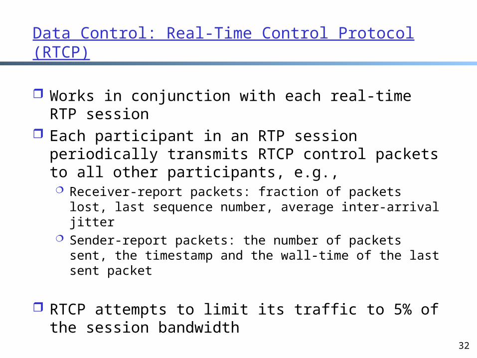
Data Control: Real-Time Control Protocol (RTCP)
Works in conjunction with each real-time RTP session
Each participant in an RTP session periodically transmits RTCP control packets to all other participants, e.g., Receiver-report packets: fraction of packets lost, last
sequence number, average inter-arrival jitter Sender-report packets: the number of packets sent, the
timestamp and the wall-time of the last sent packet
RTCP attempts to limit its traffic to 5% of the session bandwidth
33
OutlineAdmin. and reviewA brief introduction to the physical
layerIntroduction to multimedia
networkingAn architecture of stored multimedia Network support of multimedia app.Application adaptation in best-effort
Internet
34
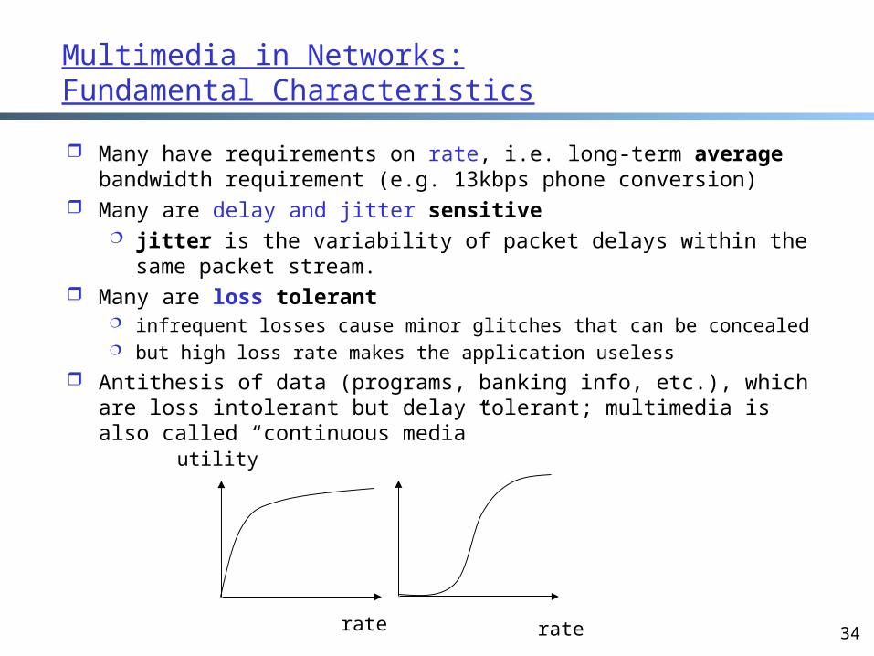
Multimedia in Networks:Fundamental Characteristics
Many have requirements on rate, i.e. long-term average bandwidth requirement (e.g. 13kbps phone conversion)
Many are delay and jitter sensitive jitter is the variability of packet delays within the same
packet stream. Many are loss tolerant
infrequent losses cause minor glitches that can be concealed but high loss rate makes the application useless
Antithesis of data (programs, banking info, etc.), which are loss intolerant but delay tolerant; multimedia is also called “continuous media”
rate rate
utility
35
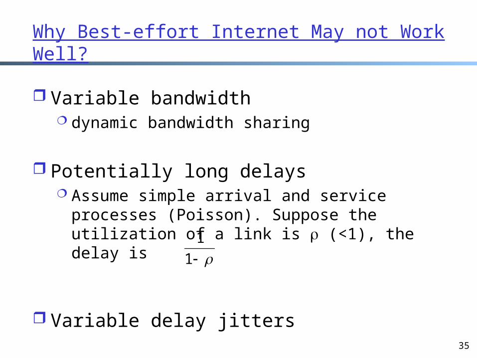
Why Best-effort Internet May not Work Well?
Variable bandwidth dynamic bandwidth sharing
Potentially long delays Assume simple arrival and service processes
(Poisson). Suppose the utilization of a link is (<1), the delay is
Variable delay jitters
1
1
36
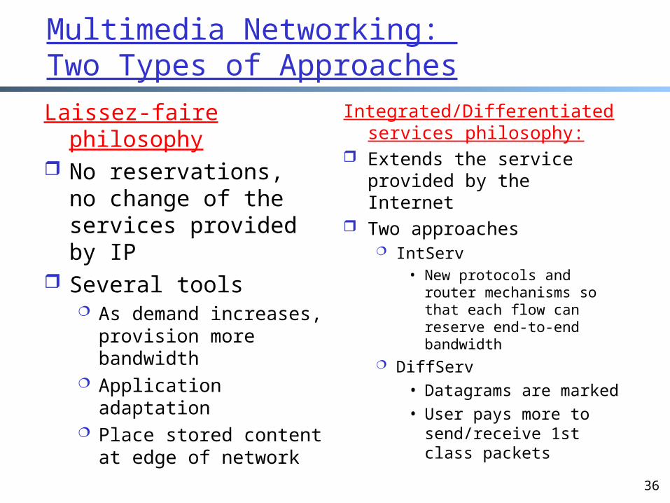
Multimedia Networking: Two Types of Approaches
Laissez-faire philosophy No reservations, no
change of the services provided by IP
Several tools As demand increases,
provision more bandwidth
Application adaptation Place stored content at
edge of network
Integrated/Differentiated services philosophy:
Extends the service provided by the Internet
Two approaches IntServ
• New protocols and router mechanisms so that each flow can reserve end-to-end bandwidth
DiffServ• Datagrams are
marked• User pays more to
send/receive 1st class packets
37
Outline
Admin. and review A brief introduction to the physical layer Introduction to multimedia networking An architecture of stored multimedia Network support of multimedia app. Application adaptation in best-effort
Internet dealing with variable delay dealing with packet loss dealing with variable bandwidth
38
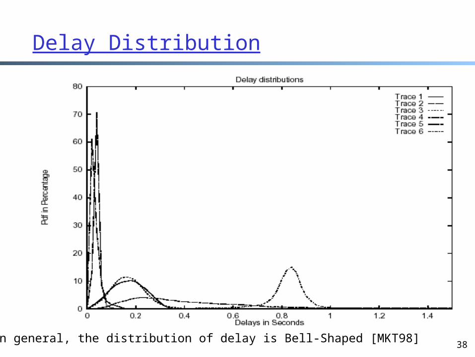
Delay Distribution
In general, the distribution of delay is Bell-Shaped [MKT98]
39
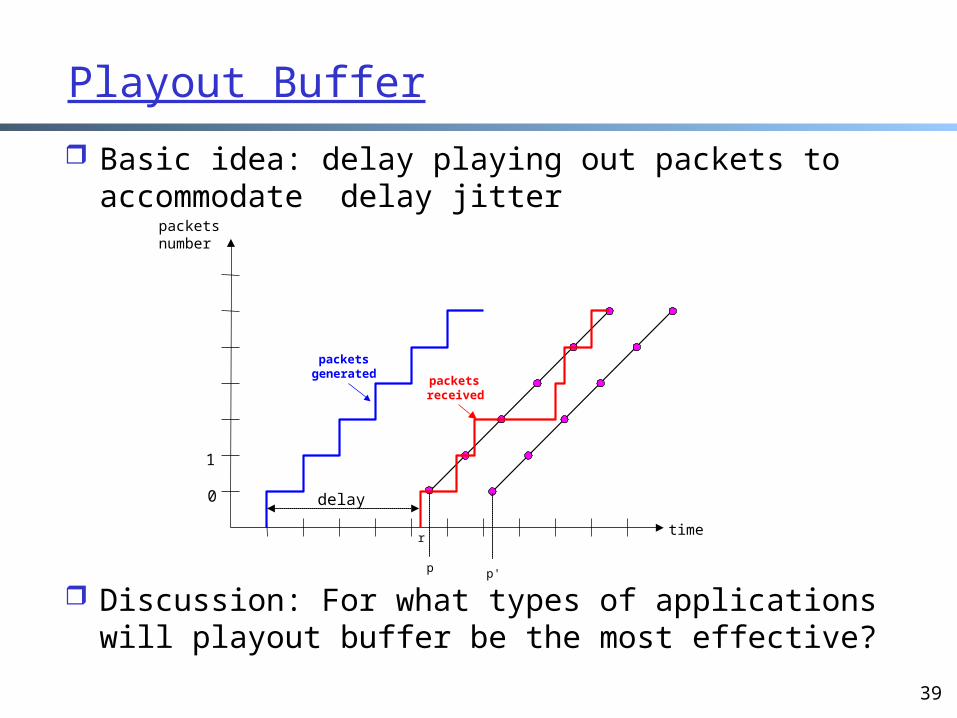
Playout Buffer
Basic idea: delay playing out packets to accommodate delay jitter
Discussion: For what types of applications will playout buffer be the most effective?
packetsnumber
time
packetsgenerated
p p'
delay0
1
r
packets received
40
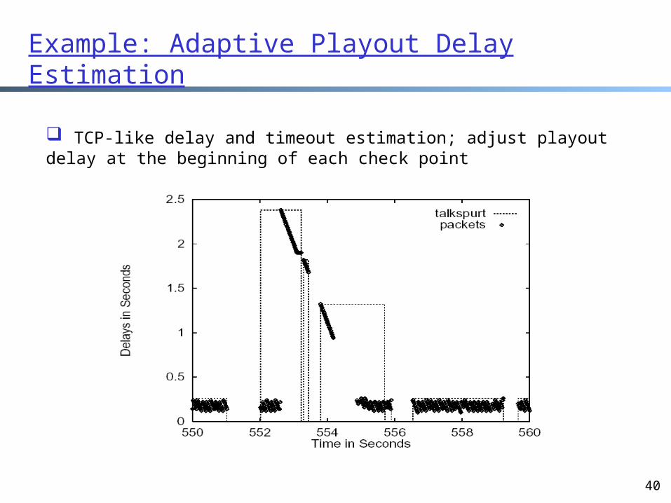
Example: Adaptive Playout Delay Estimation
TCP-like delay and timeout estimation; adjust playout delay at the beginning of each check point
41
OutlineAdmin. and reviewA brief introduction to the physical
layerIntroduction to multimedia
networkingAn architecture of stored multimediaApplication adaptation in best-effort
Internet dealing with variable delay dealing with packet loss dealing with variable bandwidth
42
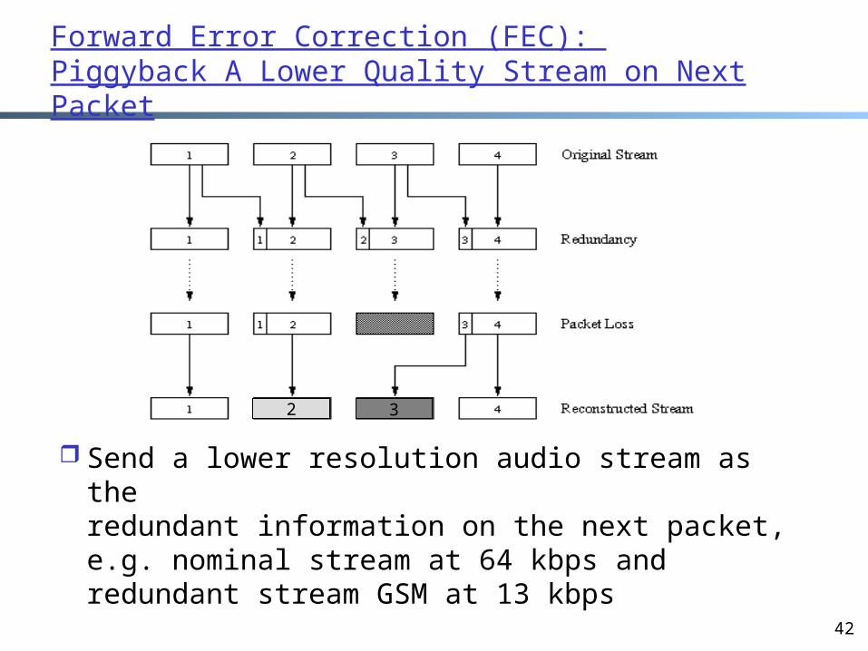
Forward Error Correction (FEC): Piggyback A Lower Quality Stream on Next Packet
Send a lower resolution audio stream as theredundant information on the next packet, e.g. nominal stream at 64 kbps and redundant stream GSM at 13 kbps
2 3

43
Outline Admin. and review A brief introduction to the physical layer Introduction to multimedia networking An architecture of stored multimedia Application adaptation in best-effort
Internet dealing with variable delay dealing with packet loss dealing with variable bandwidth
44
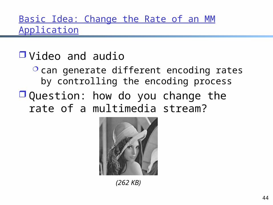
Basic Idea: Change the Rate of an MM Application
Video and audio can generate different encoding rates by
controlling the encoding process Question: how do you change the rate of a
multimedia stream?
(262 KB)
45
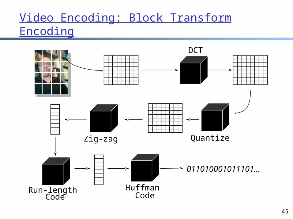
Video Encoding: Block Transform Encoding
DCT
Zig-zag Quantize
Run-length Code
Huffman Code
011010001011101...
46
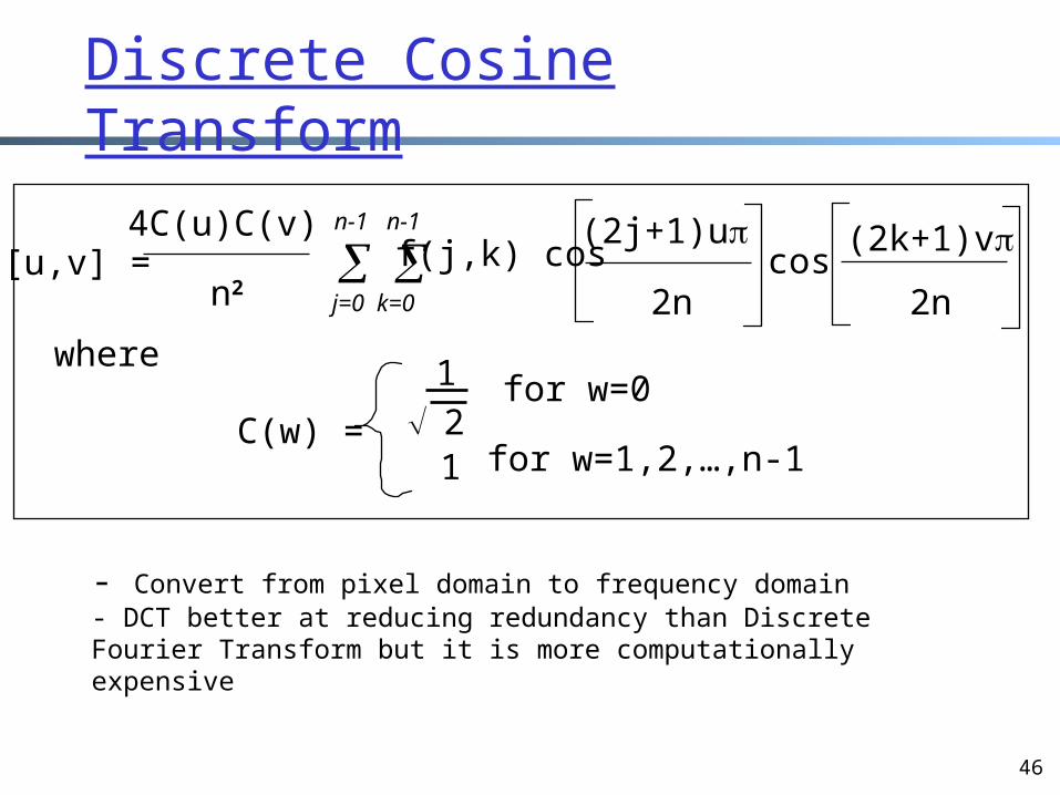
Discrete Cosine Transform
F[u,v] = 4C(u)C(v)
n2n-1 n-1
j=0 k=0
f(j,k) cos(2j+1)u
2n
(2k+1)v
2ncos
where
C(w) =
1
21
for w=0
for w=1,2,…,n-1
- Convert from pixel domain to frequency domain- DCT better at reducing redundancy than Discrete Fourier Transform but it is more computationally expensive
47
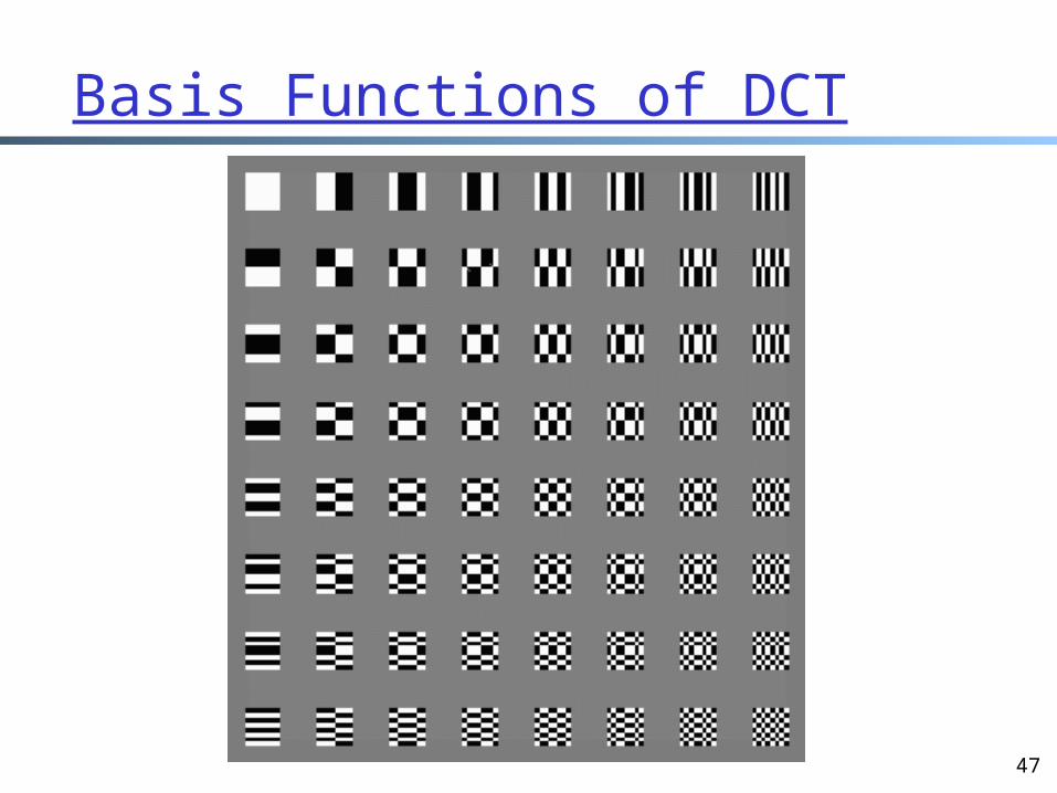
Basis Functions of DCT
48
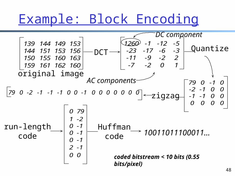
Example: Block Encoding
139 144 149 153144 151 153 156150 155 160 163159 161 162 160
original image
DCT1260 -1 -12 -5-23 -17 -6 -3-11 -9 -2 2-7 -2 0 1
DC component
AC components
Quantize
79 0 -1 0-2 -1 0 0-1 -1 0 00 0 0 0
zigzag79 0 -2 -1 -1 -1 0 0 -1 0 0 0 0 0 0 0
run-lengthcode
0 791 -20 -10 -10 -12 -10 0
Huffmancode 10011011100011...
coded bitstream < 10 bits (0.55 bits/pixel)
49
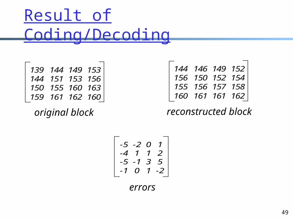
Result of Coding/Decoding
139 144 149 153144 151 153 156150 155 160 163159 161 162 160
144 146 149 152156 150 152 154155 156 157 158160 161 161 162
original block reconstructed block
-5 -2 0 1-4 1 1 2-5 -1 3 5-1 0 1 -2
errors
50
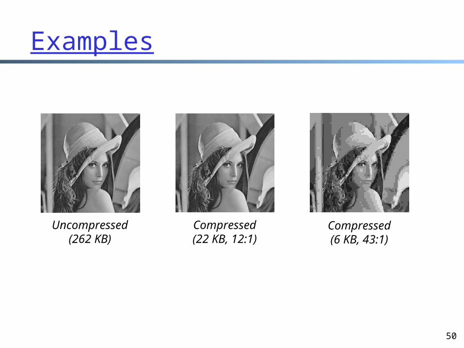
Examples
Uncompressed(262 KB)
Compressed(22 KB, 12:1)
Compressed(6 KB, 43:1)
51
Encode Rate According to Available Bandwidth
Steps Estimate available bandwidth (how?) Encode the stream according to the
estimation of available bandwidth (how?)
52
Backup Slides
53
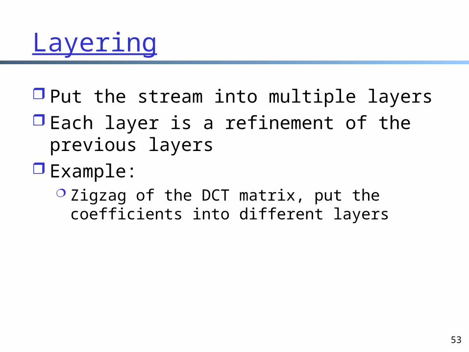
Layering
Put the stream into multiple layers Each layer is a refinement of the previous
layers Example:
Zigzag of the DCT matrix, put the coefficients into different layers
54
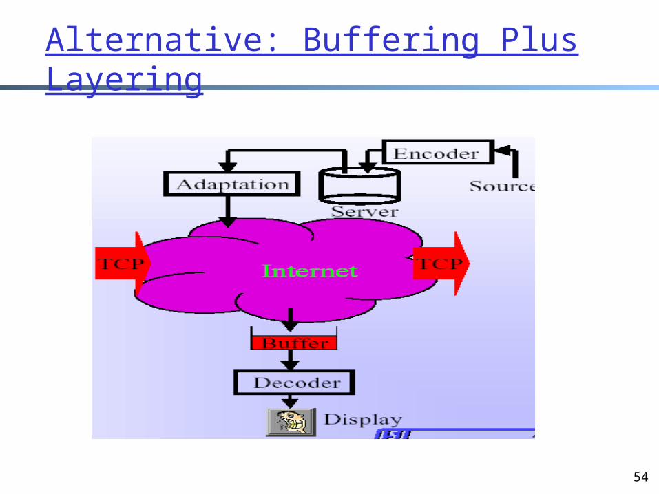
Alternative: Buffering Plus Layering
55
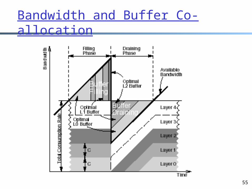
Bandwidth and Buffer Co-allocation