Embed Size (px)
Citation preview
The Exp
1 Radio nter
'1'1 J E lJ\IPORTANCE OF ;" 1 UTUAL CO:-\DUCTANCE
IN '1'EST Ii\C VAClJml T L:BI':S
TH E behavior of a vacuum tube may be predicred if its amplification fauor, plate impedance,
and mutual conducrann:: afC known for the given conditions. Other factors such as inter-electrode capacitances affect its oper,nion, particularly at the high frequencies, but it is usuall~' justifiable to consider only the three as rhe principal parameters. Thc~, or at least their nall1t:s, hal'e become so familiar that their physical signifinlnce is obscured until the\' tend to l.Je: nmsidered mere matherl~atiral constann;.
Th is is particulilrly so of mutual conductance, which, beciulsc it can he derived frolll the other two, is sometimes thought of as a ratio without physical meaning. For testing purposes, however, mutual conductan('e is the most important of thl'lll all. I t expresses the excellence of a particular t~ pe of tube as a po .. \er amplifier, as a detector, as a modulator, as an oscillatur. It is readily measured, and, with tubes having;' large plate impedance (scree:n-grid tubes, for e:xample), it is the only one that can be measured with simple apparatus. In this article we propose to sholl' wh) mutual conductance is so impurtant .
The plate impedance of a \'acuum tube mav be defined as the ratio of the ch:ltlge in plate voltage to a corresponding cha nge in plate current when the control_grid potential is held constant. I t depends upon the area, na ture, and tempera ture of the fila men t {electron_emitting surface}, upon the art:a of rhe plate, and upon the spacing of the elements. Except at \'err high frequencies when rhe inter-elecrrode capacitances introduce appreciable amounts of reactance it may be con_ siden.::d to be a pure resistance.
The: amplification fanor /1-, defined llS the change in plate potential produced br a un ity change in the grid potential II'he:n the: plate current is maintained cons tant, depends onl\upon the spacing of the elements and upon rhe fineness of the grid mesh. It would be the all-important parameter for a tube delivering pOller to a load whose impedance was large as compared I\i th the internal plate impedance, and it is, the:refore, of great importance in SO-('alicd potential am_ plifiers (i.e. amplifiers which are supposed to magnif~'voltage variations and deliver little or IlCJ powet to rhe load circuit). If such a l'ircuit be well designed, the amount of \'oltage ampli_
IET LABS, Inc in the GenRad tradition
534 Main Street, Westbury, NY 11590 www.ietlabs.com
TEL: (516) 334-5959 • (800) 899-8438 • FAX: (516) 334-5988
, THE GENF.IUI. RAI)J() EXPERI ,\a:sn:R
/itatian * shOuld appruximatt: /1-, the amplification factor of the tube.
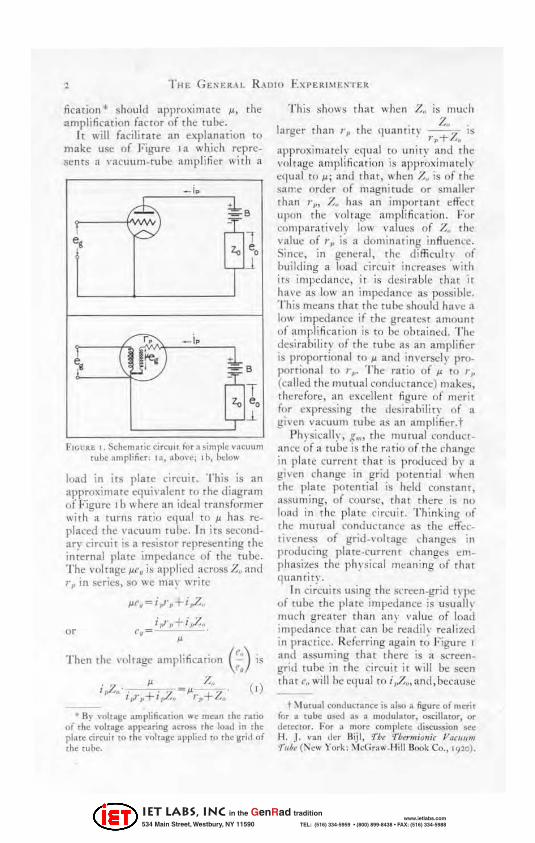
It will facilitate an explanation to make usc of Figure I a which represents ;, ,'acuu m-tuhe amplifier with a
_ i ..
r-b.. ;h. -
~ :p; 1 z, e,
r J
-r; _iF'
~ \ "
Jre. ) i. -T
z, e,
::r i
FrOUll.li 1. ~chemuflc CIrCUli for "simple vacuum tub~ ~mplifi~ r ' ':I, :lho\'e; 11" Ix:luw
load in its plate cin:uir. T his is an approximate c!J.uivalcnt 10 the diagram of Figure I b where an ideal transformer with a turns ratio eq ual to JJ has rcplaced the vacuullI tulle. In its secondary circuit is a res;s(or repreSC;'llting the internal plate impedann! of the rube. The vol t age p.r.~ il:i appl ied across Z" and r ,. in series, so \\e may \\rite
i,.rp+i,Z .. 0' c. =
Then the nllrage amplification ('") . - " '. __ ~''--.. z" ,,7. •.. + . . ,-' +z· ',.1'1' I,;, . r p ..
(,)
• By "011:11:<: :lmplific~liun we mun the u.rio of ,he ,'vtrage ~ppe3ring 3CtoSS the load in the plate cirClli! 10 the vohag~ appli"d to the grid or I lle tuhe.
T his shows th a t when Z. is much
l:Irgcr than r,. th~ {luant i t ~ . Z~.~ is , p+'-'.
approxim;HeI~ equal to unity and the voltage ampl ifi ca tion is approxilllatel~' c(lua! to P; and that, "",111::11 Y.. is of the sawe orde r o f magnitude or smaller than '"p, Z. has an important effect !'POII the vol t age amplification. For comparatively low values of Z~ till'
value of r,. is a dominating influence. Since. in general, the difficuln of building a load cin:u it inncascs 'with its impedance, it is desirable that it hal'c as Iowan impcdalll"C as possible. T his means that the tulx should ha\"!: a low irnpe(i;t nce if the greatest amount of amplification is to be obtained. The desirability of the tube as an amplifier is proportional to p and inversely proportional to r,.. The rat io of ~ to r,. (called the mUfual cond ul"tance) makes, there fore, an excellent figure of merit for expressing the desirahility of a given vacuum tube as an amplifier.t
Ph~sieall~· , .~ .... the mutual conductance of a tulle is the r.ltio of the change in plate currcl\t that is produced b~ a given change in grid potential when the plate potential is hdd constant, assu ming, of course, dwt there is no load in the pl at t;' circuit. Th inking "f the mutual conductance as rhe dfectiveness of grid-voltage changes in producing plate-current changes crnphasi~t;'s the ph~·sical me:ming of that quannty.
I n circuits using the sneen-grid t ~ II(! of tube the plate impedance is usuall~ much greater than a n~ value of load impedan ce that can be readily realized in practice. Rderring aga in to Figure I
and assuming that there is a screengrid rube in the cin·uit it will be seen that I'~ will he equal to i P7.4' and, because
t ~ , urualronducuntc is aiM' a ligur~ of rl1~rir for a rube uSCiI aJ a mO<.lulalOr, oscillaror, or d~rttror. For a mOre Q)nlp]crc discussion sec Ii . J. van dcr Bijl . 'fw 'finr", irmir Varl""" f"," ( ~"", York: :\1c(;r,,""_ ~l il1 lJook Co., 1<J10 ).
IET LABS, Inc in the GenRad tradition
534 Main Street, Westbury, NY 11590 www.ietlabs.com
TEL: (516) 334-5959 • (800) 899-8438 • FAX: (516) 334-5988
rOI., " ', No, '!- .l
. I d . hZ" I'~ IS arge as tumpan:! Wit ~u,g",=( , b~' definition, Tnen the ,'olrage amplification rna) be written
i 7-v • -- =g",Z. , '.
from \\hich we see that the voltage amplification in a screen-grid tube is gh·en b) the produCt of the mutual cond\lctancl' into the imped an ce of the load, In rhe ideal screen-grid tube circuit the only tube parameter of IlllpOrtanCe is the mutual cond uctanl~c." The plaTe impedance of the '!~4-type tube, now in quite general commercial lise, averages about 800,000 ohms. whidl is large enough, as COI11-
rared \\ith most t'ircuit impedances, so that they need ~cldol1l be taken into account whell making gain computa, tlons .
For the reasons sct forth in the fore_ gOing discussion. tne murual Oll1-
ductanCI;! of a vacuum tube ma\' be measured and the resulting value t~ken as an index of the excellence of a c:ivt:n type of vacuum tulle, Some cart: ~ml st he used in saying that one type of tube is bt:ttt'r than another because it has a greater mutual conductan ce, but one can without hesitation say that among tubes of the salll e t~ pe the greater the \ alue of mutual conductance. the better is the tube.
This iact makes it possi ble to use a measuremellt of mutual conductance as an inspection and i\n:epranl'C test for tubes. I mproper sp acing of the elements alHl faulty t'!l1issioll will both prodm'e a lowering in the value of mutuall:onduct ann:. Th is test will not show what is wrong hut it will show whether or not the wbe is defective, That is wl1\ It makes a good teSt for the manufa(:_ turer's production line .
• A1Jx,rt W, H .. ll and :-1. H. Williams, "Ch:lr_ ~c teriSlirll of Shielded,Grid Pl iOlrons," PbVl iw/ R~~ i~" .. XXVII, .'\pril. 19'!6, 1" -438, '
3
II Becau~ mutual conductance IS so
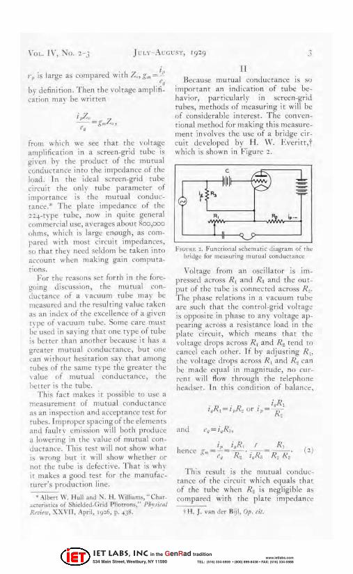
important an indication of tube behavior, panicu1arl~' In screen-grid tubes, methods of measuring it will be of considerable interest . T he conventionalmethod for making this measurement involves the usc of a bridge cir_ cuit de\·cloped b~' H , W, Everitt,t which is shown in Figure 2,
.~" ® d:o Il
. ~,
'f " '¥ '. '" 1, -
I FIGUR-E ~, F .. nrlional scttern:uic di~gram of the
bridge for m<,asuring murual cond ucrance
\'oltagc. from an oscillator is impressed across RI and R~ and the OUt
put of the tu lle is con nected across R~. T he phase relations in a vacuum tube are stich that the control-grid \'oltage is opposite in phase to any voltage appearing 1Il:ross a resistan('e load in the plate circuit, which means that the ,'ultage drops across R! and R~ tend to cancd eacn other. If by adjusting R I ,
the volt age drops across RI and R~ call he made equal in magnitude, 11 0 current will flow tllrough rhe telephone headset, In this condi tion of !Jalalll:e,
hence (' i
Th is result is the mutu al conductance of tne circuit wh ic h equals that of the rube when R~ is negligible a ... t'ompared with the: plate impedance
f H. J, ,'an der Bijl, Op. cit,
IET LABS, Inc in the GenRad tradition
534 Main Street, Westbury, NY 11590 www.ietlabs.com
TEL: (516) 334-5959 • (800) 899-8438 • FAX: (516) 334-5988
4
BIAS P LATE
c;~~~======t-______ .-___ J:+~SATTERY-CRIO 4
'A R,
+------t------l------4---.~ R, 250 """
LOW CURRENT
HIGH CURRENT +o---~ 2 .0 A
4.S ......
PHONES
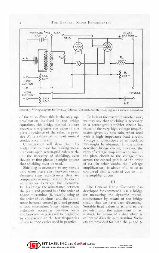
FHJU~E'. J. Wiring Jl.1gram for rVJ'E HJ \\1 UfU.ll·Conductnncr ~ l c!n. R. is gwen a ,·aloe of 1000 ohms
of rhe tube. Sinl'c this is the only approximation involved in the bridgt: ct.t uatiotl .~, this bridge rl1!;:t hod is mon: accurate the greater the valul:' HI the plate: impedance of the rube. In practice Rl is ('alibratcd to read mutual condw.:t ann: direc tk.
Consider:ltion WIll shuw that this bridge mar be used for making measurements upon screen-grid tubes withuut tht: ncccssir~ of shielding, evcn though at first glance it might appear that shiddi ng must be used.
Shidcling is necessary in any circuit (!Ilk when There (.·xist lX-f\\Cen circuit dl'rllcnrs str:1\ admittances that are comparable in' magnitude to the circuit admittances between tht" dements. In this bridge the admittance between the plate and ground is of the order o( 10 ,000 micromhos ( R~ usually being of rhe order of 100 uhms) and the admir_ lance between control grid and ground is 1000 micromhos. Stral' admittances onlin aril y occurring between leilCls and between batteries will be negligible hy comparison at the test fn:quencies of f!oo to 1000 c~'des lI~ed in pran ict:.
'J'o look at the matter in anoriler wal , we may say that shielding is necessa~~ in a screen_grid amplifier circuit because of the very high voltage amplification gi l'en b~' this tube when used with a high impedance load circuit. \ 'oltage amplifications of as much a.s "l00 might oe obtained. In the above described bridge circuit, however, the ratio of voltage drop across the load in the plate circuit to the ,'oltage drop across the control grid is o ( the order uf O. t. In other words, the "voltage amplification" is about o( 1 to 10 as compared with a ratio of '200 to I in the :l1llplificr circuit.
III
The Gelll::ral Radio Compan y has del'eloped for {'ommercial use a bridge for measuring the d~namit mutual conductance b~' Jlleans of the bridge circuit that we hal'e been discussing. Suitable fixed val ues of R~ and Rl are provided and the adjustment of R) is made bl' means of a dial which is calibrated (Iireeth- in micrornhos. Sock ets are prm'ided for ooth the ~- and 5-
IET LABS, Inc in the GenRad tradition
534 Main Street, Westbury, NY 11590 www.ietlabs.com
TEL: (516) 334-5959 • (800) 899-8438 • FAX: (516) 334-5988
prong tubt-s. A low-resistance highcurrent and rt high-resistance low_ current rh eostat are incl uded in the assembly :IS is a direct-current voltmeTer for measuring filanH'llt voltages.
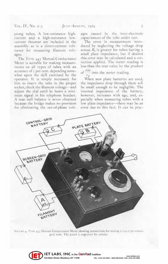
The '!'yn; ++3 ;\ l lItual_Conductance l\lctcr is suitable for making measurements on all t~'pes of tubes with an accuracy of 5 per cent. depending gomeII hat upon the skill exercised by the operator. I t is simply !1el'essar~' for him to insert the rube in the proper socket,check the filament \'oltage- and adjust the dial until he hears a minimum signal in his tdephone headset. ;\ true null halance is never obtained hecause the bridge makes no provision for eliminating the out-Of_phase volt-
;
ages caused h~ the inter-denmde capaciT ances of the rube under test.
The error in measurement introduced oy neglecting the \·oltage drop across Rz is greater fo r tu bes h'l\·i ng :t
small plate impedance, hm if desired this error 11M\· bl' cakulan:d and a cor_ rection appl i~d. The meter readi ng is less than the true \'aille hy the product
r '00 . h d· o - mto t e meter rea Ing. rp -
When new plate batteries an: uscd, the impedance drop through them will he small enough to he negligihle. T he internal impedanre of the battery, however, increases with age, and, especially when measuring tuhes with :t
low plateimpedarlt'e-there may he an t:TroT due to thi~ fact. It c all l~ pTac-
F!(;t'RE~. TI PE HJ ;1] ll!llal_CondllCIIl"ce :Iolerer .howing connecrions for r"~li"g a 1 !~_ryp., ~cr~en_ grid ruhe. The panel is engr,,"~d for [rioJ~~
IET LABS, Inc in the GenRad tradition
534 Main Street, Westbury, NY 11590 www.ietlabs.com
TEL: (516) 334-5959 • (800) 899-8438 • FAX: (516) 334-5988
6 THE GEl';ERA I. R. ... DIO EXI'ERIMEXTE R
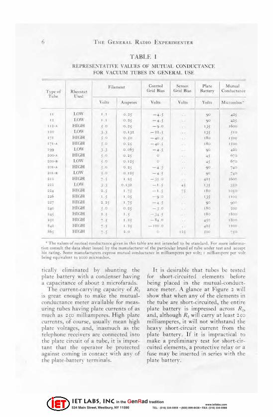
T A BLE
R EI>R .. :.s E:-;T.'~TJ YE V/\LUES OF ~ J UTU,"'L CO~ IJVCT:\:\CE
FOR VACUUM T UBES IN GEi\' ERAL USE:
--
I -,- I &.«"
-Fih",~n' Conlrol " la,C Mu. ual
Typt oi Hhcouat Grid Hias Grid lIias B aIlU)' Con,]una nre T Id", l'~1
\ ',,1 ,. ,""npC't:. ,'"It. \ ',,1 •• ""lis 111 ,n\'n> ho>
" t o\I • • o :s -~·5 '" ~!5
" l.OW • • 0 ' 5 - , 5 9 0 "~ 5
" ;., HI GH 5 0 O,~5 -9 0 135 .600 no LOW J .J O. I JZ - :l· 5 135 S'O .-. HIGH , 0 "50 - 40 j .00 '500 ,-,., HIGH 5 0 0· -: 5 - 40 5 "0 1:00
'W LO\\' 3--1 006] - , 5 " ... -:0 ,~. HI GH 5 0 0 '; 0 '5 ,,~o
: eo-I LOW S 0 o.I~5 0 .- 6-0
lOI-.. HIGH 5 0 '" - , - ,0 -" '01_. LOW SO O. I:, - , 5 ,., ~4 o
~I O IIi GH -5 • :5 -35 0 .I', ."" l:-: LOW .1 J 0, '.i' -. , ' 5 ." .. , .15 0
224 HI GH -5 -. , -, " 0 10 50
116 HIGH • , • 05 -,0 I.1i " 00
:r HIGH , ' 5 • 75 -, , 9 0 "'" '40 HI GH ; 0 <:> ' 5 -J 0 .'0 ' 00
"H HI GH , 5 5 -.;" ; "0 .000
:;0 ]-!l GH - 5 • 15 -S • . o 4 ;0 .'00 8., H IGH - 5 • " _100.0 .l' I lOCI
~t., HIG!I -5 ~.O 1: ; , 00 -SO
• The '-alues of mu , ual conductance gi'-cn in ,his t:l\.>le are n(H ;n .ended to b~ standu,l . 10'0' "'Or~ ;nformat;on consult the dat~ sh~et ;ssutd h)' ,11~ m~nuf~c,,,rer ot th~ I",,,icular \.>r;tnd of ,,,lie "nder ten :Inti :IeeeI" h;. r:lting. Some ",anur~ct"",n; 'Xl'~~ mutual conduct:!n," in milliamperes per volt; r milliamp"'" per \'nlt bt1ng .'lu;,..I,", to IC<XI miCr<:l~lhO",
tieaH\' eli minated b\' !>hulltitll! the plate' batterr with a ~ondenser I~a vi ng a capaci tance of about '2 micro fa rad s,
The current_carrying capaci ty of R2 is great enough to make the mutual conductance meter available for meas_ uring tubes having plate currentS of as nHKh (IS '2 50 milliamperes. High plate currents, of course, usually Illt:an high plate voltages, and, inasmuch as the telephone receivers are connected into the plate circuit of a tube, it is important th at the operator be protec ted against coming in conran wi th an\' of rhe plate-battery termi nals .
It is de~i rab1t: that tuues be tes ted for short-ci reuitcd dements before being placed in th e I1mtu al-conductanee meter. A gl an ce at Figure '2 will show that when am' oi the elements in the tube arc short-circuited, the entire pl ate ba ttery is impressed across R~, and, although R~ will carry at least '250 milli amperes, it will not withstand the heal'Y short-circuit current (rom the plate battery. If it is impractical to make a preliminary tes t for short-circui ted elements, a protective rday or a fuse ma y be insertt.'t! in series with the platc batter ~' .
IET LABS, Inc in the GenRad tradition
534 Main Street, Westbury, NY 11590 www.ietlabs.com
TEL: (516) 334-5959 • (800) 899-8438 • FAX: (516) 334-5988
A R ECTIFI ER-TYPE II I ETER FOR PO\\' ER O UT PUT II I EASUREiVIEK T S AT A U D fO F REQUENCIES
13J J O H !\ D. CRA W FORD
I ~T the courst! of routine experimental work in the lahoratory t here often occur" the need for a {'otlVenient
means of measuring the power delivered by a device at frequencies for which the ordinan' d\,namometertype of wattmeter f:iik 'i'his problem might, for instance, appear when testing the audio_frc<luency amplifiers of a public_address system or when making: the standard fidelit\', sensitivit\" and selectivity tests up~n radio rct:eiverli. In each instance rhe power ou tput. of the tested de\'ice is measured and then compared "ith a measurement of either power or voltage made upon the input.
T he usual method for measuring power output is to make the cie\' ice under test feed a resistive load whose n:sistance at t he test frequency is known. T hen, if the current to or the voltage drop anoss the load be meas-
ured, the power delivered to it can be easily computed fro m the relation
E'l W =7? or W = /2R (I)
where IV = P? wer delivered to t he load l!l wa tts
E=vol tage drop across the load in I'ol ts
! =current to the load in amperes R=n.'sistance of the load in
ohms.
T he ilCCUrac\' of this method depends, of course, upon the accuracy wit h which R and E or J have been determ ined . Since R en rers directl}', the percentage error in IV caused br an error in R is the same as dle percentage error in R, but, because t he square of both E and / are involved, t he percen_ tage error in IV introduced by errors in E and / is slightly more tha n twice as great . With an error in E or / of 5 per
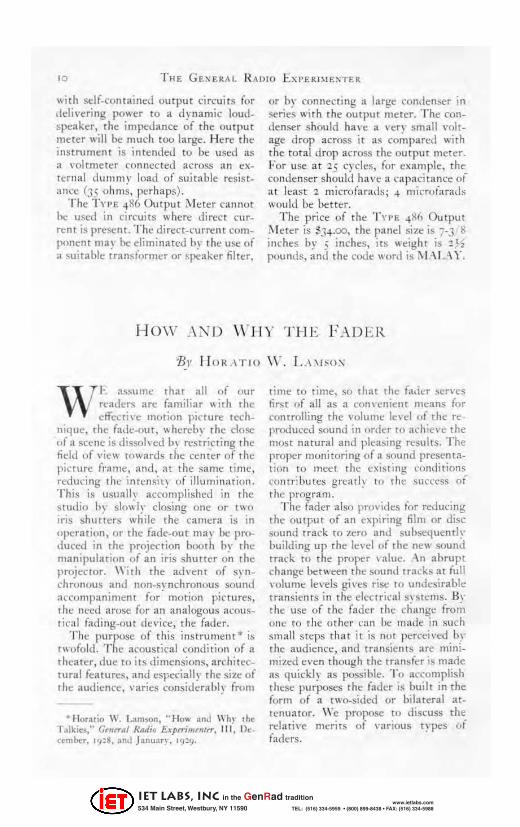
FIGl u: l. The T ",,, .. 86 Omput "'eler
r 7
IET LABS, Inc in the GenRad tradition
534 Main Street, Westbury, NY 11590 www.ietlabs.com
TEL: (516) 334-5959 • (800) 899-8438 • FAX: (516) 334-5988
8
cent., for inst<ll1ce. an I:!ttflt of I :. .~ percent. in IV results; with an error of [0
per cent., there is_an error of :. J.O per cent. in Jr.
The emire {I uesrion of accu rac~' in me:LSutements of this kind is one th>lt nmst be carefull y considered in Ch ClOS_
ing instruments," They ~hould be Gtpa_ ble of giving as accurate reSultS as a re justified b~' the proposed [CSt, yN, if TOO
great an accuracy he demanded, the cost or the instrument 1113\" increase out of all proporrion to its ;Ise (ulncss. In making the sta ndard tests upon radio receivers , (or instance, t he radi O-fn~quency \'olrage delivered by the bes t available eali br:lted generator for lalm_ ratory lJ~ has a possible error of 5 per cen t. in voltage. Little would be gained if it were necessary to Du ild a !<ipecial power-measuring ci rcuit ha vi ng an accume\' vcry gready in exces~ of rhi s value:
The indica tln{! instrume:llr!<i most often used for m~asurt: ments over the: :lUdi O-irequenc:y band are the vacuumtube voltmeter, the hot_wire ammeter, and the rhennocouplc :UllIlIcte r, al! of wh ich may be designed to ha vc exed lent frequency-response characteri stics, Cooperating with the General Radio Company, a large m:ulldacru~r of electrical instruments has developed a new alternating-currtnt voltmeter which makes use of four small copperoxide recti fi ers connected in circuit with ;\ direC T_current galvanome ter, When alternating I'oltages arc applied, the resulting rectified current causes a deflection i!~ rhe galv anome ter which is calibrated direnly in root-mcan-sq uare volts, The principal arll':lntages of this inst rument are its t'omparariveiy Inw cOSt and its ruggedness, It is able tv withs tand a considerable amount of oven'o!t age with no dam agc other tha ll the bending of the poi nter.
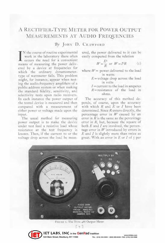
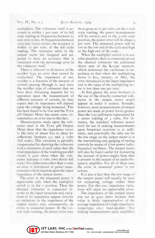
T he General Radio COll1pan~' ha s developed for use in the Illea~uretllent or pOll er output its TYI'f: ~S() Output
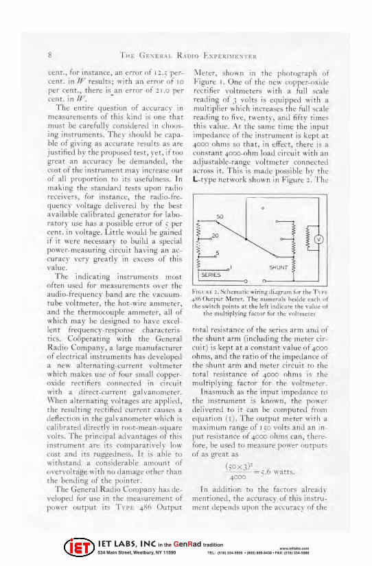
;-"l e rt~r, ~ho\\ 1\ in the phorograph of ]:igurc I. One or the new copper-oxide recriticr volrmeter~ with a full scale reading of .1 volts is eq uipped with a multiplier which incre:lses the full <:('ale reading to tive, twe.nt~' . and Ii(t~. time~ thi s value, :\t rhe same tilllt'- the input impedance of the instrument is kept at 4000 ohms so that, in effect, there is a constant 4ooo-ohrn load cin'uit with an adjustable_range voltmeter connected across it. Th is is made possible by the L-t~'pe network shown in Figure~ . The
0
'" ~'"~ 1 ,
• c' ~, L-
! " SHUNi
I SERIES 0
1' 1(. 1 at: !, ~hem .L lIc ""mngd(.,gT:"" t,'T the I'll'''' ~)(60"lp"l j\'lelt:r, T he nUIIltT"ls Ioesine e:leh " f rhcs" 'iICh ".)ints at the lefl in!liC:L1i! the v allie .1!
rhe multiplying faetor iOT lh~ "nl lmel~r
total resistan ce of the seri es :lflll and of the shunt arm (including the meter circuit) is kept at a constant valut'-of 4000 ohms, and the mtio of the impedance of the shunt arm and meter circuit to the tota l resis tatKe of 4000 nhm.'l is rhe multiplying (actor (or the I'oltm eter,
I na~much as rhe input impedan ce to the instrument is known , the p()\\ cr delil'ered to it {'an be computed (rom cquatioll ( I) , The outpu t meter with a maximum range of 150 vol ts and an input resis tance of 4000 ohms can, there(ore, he used TO measure power outputs of as grea t as
(~oX3)~ '- -- '= ;;;,6 \\'ans. "coo ~
r 11 addition to the fa (rurs alread\' men t ioned, the accuracv of this instniment depends upon the'accuracy of the
IET LABS, Inc in the GenRad tradition
534 Main Street, Westbury, NY 11590 www.ietlabs.com
TEL: (516) 334-5959 • (800) 899-8438 • FAX: (516) 334-5988
multipliers. The voltmeter itself is ac_ .:uratc." to within 5 per celt{. of it ... full ~c3.le reading at frequencies ht!t\\L't'11 '2~ and SCXlO c~c1es .• -\ t frequencies bet wc.:t:n :000 and 10PCO c\Tlcs, the accur:ac,· j~ within 10 per ce~t. of t he full s~ale reading. The resistance units in the 'Jutput meter arc designed and adjusted !0 have an accuracy that is '::(ln~islcnt ..... ith the percentage error in the voltmeter itself.
There is inherent in all rnt:tt:rs nl the rn::tifier rnX' an error that cannot hi: overlooked. The imped ance uf any rectifier is a (unction of the amount of current passing through it. and since the rectiner type of voltmeter tha t we have been di:;;cussing depends for it ... operation upon the measurement of di fferent amounts of curre nt. we may expect that its impeda nce will depen;! upon the voltage being measure..i. This has been lound to be true and the T YH .,.~6 Output ;\ Ieter has under some cir_ C\llllstances an error rlue to thi s fact.
;\ Ieasurements made upon the volt meter used in the T ypl'; .,.86 Output ,\ Ieter show that the impedan ce varies in the ratio of about five to three for deflections between 0.5 and 3 volts (full scale). Thi~ variation is p<lrtillll~· compensated b~' shunting the ,·ol tmeter .... it h a resistance of such value that rhe total impedance o( the rCS1I1 ring parallel circui t is .,.000 ohms when the ,-oh~
meter indicates:! volts (two-thirds full scale) . For deflections other than"2 volts an error is introduced in power measurements which depends upon the input im pedance ul the output meter.
The error in the measured power i~ appreciable only when the multiplie.:r switch is in the I posi tion. Then the shunted ,'oltllleter is connected di· renly to the input terminals and varia_ ri\m! in its impedance appear directlr as variati"ns in the impedance of the uu tput meter, ~lIld. oonse<lucntlr, as error!; in measured power. ;\t thl.' 1.0-
" olt sc al l.' rt"ading. the po .... er error may
he as grcat as I I per cent.; at the ! _\·ol t scale reading. the power meaSUT!;'l1lent II ill be correct; and in the 3-\,ol t scale posi tion, the power error \\ ill he about I, l>er cent. The measured powl'r wi ll ht' nw at the low end of the sea l!;' :llld high at the high end of the scale.:. -
When the multiplier switch is in al1~ other posi tion, there is connected aen.s ... the shu nted voltmt'ter the additional shunt arm of the L_ t~ pe network. which mi nimizes the \·ariations in lmpetianre so that whc.-n (he multiplying facwr is five, twent\" or fifn', the error introduced in the·input imp;..dancc.and in the value of the multiplying: lat:_ tor is less tha n 01\(' pcr cem.
At nrs t glance the crror in\'olved in the usc of th(' dir(,l'll,·.cnnnccred volt. me ter in the OutP~lt meter would appear to make ;t usc::lc.-ss . .-\ct\l aJly. however. most measurements of output power are mad!! at power levels greater than the :!.25 milliwatts reprcsented by a meter reading of J ,'olts. For in+ Stance. the standard rclen:nce power level for use in making measurements upon broadcast recciv!!rs is ~o milliwatts, and practic;llIy tht:: onl y use for the low range on the output mder is in the neutralizing lind ganging of tuning controls by means of a low-power radiofreq uency oscillator. The output Illt"ter will also he found uselu) for measuring the amount of power-supply hum that is present in the output of all audio-fre,!uencr amplifier. For all of rhl;'sc use~ th~ error in measurf;'tl power IS Ilot
SCflOUS.
It is also:t fact that the low rang!." "I' th l;' out put meter will usuallr he used fOl· measuring vol tage rather than power. For this USt', impedance \'aria. tions will cause no appreciable error.
The impedance of the output Illeter was set at -4CX)O ohms hecau~e that value is fairly representative of the a'-erage imlX'dalice of a high_i ml"'Cdance (cone-type, t"tc. ) loud_spl;'aker. For making measurements upon amplifier,;
IET LABS, Inc in the GenRad tradition
534 Main Street, Westbury, NY 11590 www.ietlabs.com
TEL: (516) 334-5959 • (800) 899-8438 • FAX: (516) 334-5988
10
with sclf..cont ained output circui ts for delivering po\\er to a dynam ic loudspeaker, the impedance of the outpu t meter will be much tOO large. Here the instrument is intended to be IIst!d as a \'oltmetef con nected across an extt'rna\ dummy load of suitable resis tance (35 ohms. perhaps).
The T\'I '~: 486 Output ~ I cter cannot he used in circuits where direct CUf·
t!:n[ is presen!. The di rect-l'urrCnt COIll_ ponent Illa~ be eliminated by t he use of a ~uitable Intnslormer or speaker fiher.
or by connecting ;1 large condenser in !l('ries " ' iTh the output meter. The COIl
denser should ha ve a \'err small volt_ age drop across it as co~pared with the total drop across the Output meter. For use at '25 cycles, for c)( :lmple, the condenser should ha ve a capacitance oi at least '1 microfarads; 4 mil'rofarads would be better.
The price of t he T YI'E 4X6 Output i\l eter is ~34.00, the pand size is 7-3 S inches by S inches. it:. ..... eight is '2 ~ pounds. and the code Ilonl is t\1·\L\ y,
HOI'" AND \\ "11 \' TI lE !'.·\ DER
'Bv Il oR .\T IO \\ ' . L .. \"so.\"
WI, assume that all of our re;lder~ arc familiar Ilith the effccril-e motion picture tech
nique. the fade-out, \\herehy the dose of a scene is dissolled b~ restricting the fidel of view towards the center of the pk-ture ftame, and. ar the same time, reduci ng thl: inh:nl'lit~ of illumi nat ion . Th is is usually accomplished in the studio In slo,dy clo. .. ing one or tIl/) Jris shutters Ilhile the camera is in uperation, or the fade-out Illa) be produced in the projet:tion booth by the manipulation of an iris shutter on the projector. With the adl'cllt of synchronous :lnd non-s\"nchronous sound :HTornpaniment for' Illotion pictures, lhe need arose for an analogous at"ou stical fading_nut devicc, the fader.
The purpose of this instrument· is rllofold. The acoustical condition of a theater, due to its dimensiuns, architectural features, and t:spc('ially the siZt; of the audience. I'aries considera bly from
• HOT:uio w. I.~m>on, .. Ho'" ant.! \\"h) ,he T.llkies." Cm",,1 Rllllio Exp"imtllur. III . De. cember, 1'l!8, an,1 J anunrr. up9.
time to time, so that the fader lier\"es first of all as a conlcnient lIlt:ans for ('onrrolli ng the 1'01u1111:: le\-d of the reproduced sound in (,rder til ;lchit."l'c the lIlost natural and plt."a.sing ft.'sults. T he proper monitoring of a sound presentation to IIlct."t th t: csisting l"llnditions l'ontri hll tt:s gn.:: a d~ 10 rhe sUCCess of the progra m.
T he fader also prnvid42 for rcducing the output of an expiring film or disc liOlll1d track to zero and suhsequentl y building up the len'] of rhe new sound track to the proper \ allu.'. -\n abrupt change Ixt\lcen the sound tracks at full \'olulIle levels givt."s rise to undesirable Iransi{""nts in the el&trk-al li\stenl.',. BI' the use of the f"der the ch ange from ont: to the o ther can be made in sllch small steps t ha t it is not pl:rcl·i\"t:d b~the audicnce, and transients are mini_ mizt:d even though the transfer is made as quickly as po~si blc . To accomplish the~e purposes the fader is built in the furm of a two-sided or bilateral at_ tenuator. \\"e propose to discuss the rdar;\'e lllt."rits of \'arious tn>es of faders.
IET LABS, Inc in the GenRad tradition
534 Main Street, Westbury, NY 11590 www.ietlabs.com
TEL: (516) 334-5959 • (800) 899-8438 • FAX: (516) 334-5988
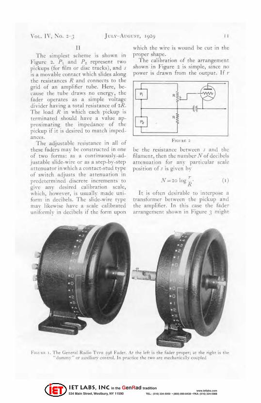
II The simples t scheme is shown in
Figure '1. P I and Pz represent twO pick ups (for film or elise tracks), and J
is a movable con tact which slides along the resistan ces R and connects ro the grid of an amplifi er tube. Here, bet"ause the tube draws no energy, the fader operates as a sim ple voltage divider having a [olal resistance of 'lR. T he load R in which each pickup is terminated should ha ve a value approxim ating the impedance of the pickup if it is desired to match impedances.
The adjustable resistance in all of t hese faders Ill:lV be constructed in ont: of two forms: "as a continuouslv-adiustable slide-wire or as a stt:p-by~step "attenuator in which a contac t-s tud type of switch adj USTS t he attenuation in predetermined discrete increments to gi\'e any desired ca libration scale, which, however, is usually made uniform in decibels. The slide-wire t~ pe ma\' likewise ha ve a scale calibrated uniformly in decibels if the form upon
" which the wire is wound be nit in th e proper shape.
T he cal ibration o ( the arrangement shown in Figure '2 is si mple, since no power is drawn from the output. If ,.
,~u-~ 1---+--II~
1$ ,
be the resistance ben\'l~~n J and the filament, then t he number N of deci hds attenuation for lln y parricular scale position of s is given by
'" N=20]Og . R
( , )
It is often desirable to lIHerpOSe a transiorrner between the pickup and the amplifier. In t his case t he fader arrangement shown in Figure J might
F1Gl"U: I. The General Radio T n.: 598 Fa,ler . At the leit i~ the {"der proper; al the right is Ihe "dummy" or auxiliary con trol . In practic<' th .. tWO are Ille<:h:micaliy cOIJpled
IET LABS, Inc in the GenRad tradition
534 Main Street, Westbury, NY 11590 www.ietlabs.com
TEL: (516) 334-5959 • (800) 899-8438 • FAX: (516) 334-5988
"
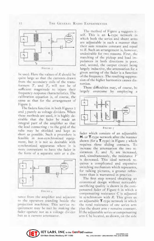
he used. Hefe the values of R shuuld he '1 uitt' largc so tha t the CUfrclUS dra .... n (rum the secomian ('1);1" nl" tht" translormers T, :tnd 'T~ .... ;11 not be of ~"ffkicnt magnitudc to injure their (rcI1uency-res,;unse rh aracterisrics. The ('alibration equation is, of CO\JfSt', rhe same as that (or the lIrrangelllt'IH of " igurc z.
The faders furKlion in buth Figurc~ 1
and 3 purel~ as voltage di"iders. When rhc!tC methods are used. it is highl~ de.~irablc that the fa(h:r bc mad!! an in tegral parr o f th", amplificr so that Thc lead l'Onnecri ng J to thc grid of the mOe rna.1 he shiddctl and kept as shon as possible. SUdl a pmcedure is feasible in non-s~ IH:hrunized ~Iuip _ menl, but it is nut ~ desirable with '~nchronizcd apparatus where it is Illnrc ,"onl'cnicrH to h:!,,!: ,he fad~r in th~ ffltm flf a s~parat~ unit at a dis~
tanl"~ fWIlI the amplifier and adj:u:ent ttl the operators standing heside the projeCtion machines. Th is scn-i..:e requirl·1l1l;·tlt may be Illel uy making tht: rader operate nl)[ as a voltage di\'ider hut a~ a current :It{ellu:uor.
T he method uf Figu~ ~ <;uggcliIs u self. T his is an L.t~'pe network in which both the serie!! and shunt artn!'> are adjustable in such a manner rh:n their sum remains cons tant and cllua l til R. Such an arrangcment is, ho .... cn:r. undesi rable for tlVO reasons. First. tht" matching of the pickup and load iill Ilctlanccs in huth directions is I}(M,r. :Ind, second , the output circuit being largely inductive, the attenuatiOIl fl)r .. gi \'cn setting of thc fader is a function uf the freq ucncr. The resul ring suppre ... sion of the higher harmonics ClUSt;'S di~. torTlon.
These difficulties largely overcome
mar, of course. 1>1:: by' emplo~'ing: :t
fader which consist!! of an adjllluahic H_ or T~typc network after the manner shown ((or a T~type) in Figure 5 which requires th ree sliding cont-acts. Til innease the at tClluation the twO rcsis rnn ct.'s .X\ and X~ arc increased. :tnd. sim ultaneous]\', the resist:lIl Ct.' }. is decreased. Th is' ideal network re· quires a t"Olll pl ic:lted and exrensi\ e switching mechall;~m which represents. (or talking pictures, a greater refine. ment than is warrnnted in practict.'.
T he first step toward obtain ing an economical design without notkeahl,' sacrifici ng quality is shown in the COIlt ·
pens:tted fader of Figure 6 in which :l
colllpensating resistance C is adjusted in s~' nchronism Ilith R. This gi\'e~ u.., :tt1 ;tdjusr:lble T.t~ pc network in which the rot al rcsiiitaltCC of aile series arm plus the shunt arm r rt.'rll ains const an t. ] f thl' adjusta"l~ ser;,·.., or compen~al ing ;trm Cbe lo~·ated. a~ ~ho .... n>on thl' side
IET LABS, Inc in the GenRad tradition
534 Main Street, Westbury, NY 11590 www.ietlabs.com
TEL: (516) 334-5959 • (800) 899-8438 • FAX: (516) 334-5988
VOL 1\', :1'\0. '2-3
tIl\~ard the pi.:kup. it IS possible o~· proper design to maintain the imped~ ance into which the pickup works at ;1
constant ,·alue. T his is the most im_ portant matching requirement. The impedance looking back (rom the load will var" between R and some miniIllum I' aiue, but this is relativcl\' unimportant. To increase the atte;1Uation the sliding COlltacts arc moved so as to reduce r and increase C. The calihration of such a fader prc~nts tOO lengthy a problem for anal~'sis here .
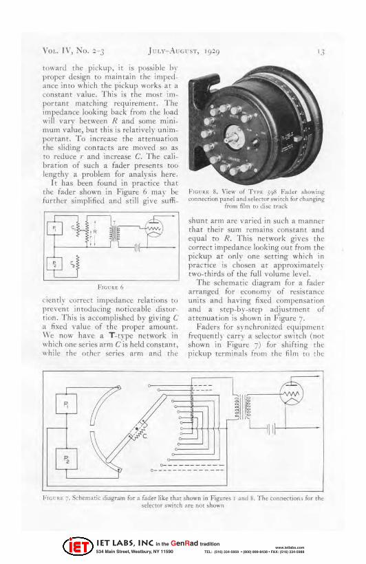
I t has been found in practice that the fader shown in Figure 6 n1:l.~· be further simplified and still give su ffi -
Icb ,,}- , '~ " il; ,
: I ~IH
I~ s FIGlC .n:6
cielltl~· correct impeda nce relations to prevt:nt inroducing noticeable distortion. This is accomplished by giving C a tixed value of the proper amollnt. We now ha ve a T-type network in which one series arm C is held consram. while rhl' other series arm and the
/'.
'3
FIGl' RE B. View of TnE 598 Fader sho"'i,,~ connection panel :lnd ~eleclOr switch for changing
from film til disc track
shunt arm are varied in such a manner that their sum remains constant and e{l lml to R. This network gives the correct impedance looking out from the pickup at only one setting which in practice is chosen at arproximatd~ twa-t hirds of the full I,olume level.
The schematic diagram for a fader :Irranged for economy of n:sistalll:t: units and having fixed compensation and a step-by-s tep adjustment of attenuation is shown in Figure 7.
Faders for synchronized el!uipmen t frequentl~ carry a $t:lector switch (not shown in Figure 7) for shifting the pickup terminals from the film to the
~111-'1 '---
0- _________ _ 0 ___ _ _________ _
I' !C"~E 7. Schematic dbgr3m (or a fader like that shown in Figures I ami 13. The connection i fOf the ~elenl>r switch are nOi sho"·n
IET LABS, Inc in the GenRad tradition
534 Main Street, Westbury, NY 11590 www.ietlabs.com
TEL: (516) 334-5959 • (800) 899-8438 • FAX: (516) 334-5988
disc sound track. Such faders arc usually pf(.lvided with fift een steps on each side which are calibrated to give abou t three decibels attenuation cacho They mar, of course , be designed to
iJa ve any desired im pedance and atten· uat ion, hut, in order to minimize in_ ductive interference in these circuits which are connected to the input nf it
powerful amplifier · tht: impt:da ncc should be kept as low as possible. Thus, the very hig h impedance photO-dectric cell is con nec ted to an amplifier located adjacent to the cd!. The signal (rom this amplifier, which ha s a low internal output impedance, is subseq uendy fed in to the fader at approxim ately th t: same energy level oinai ned directly from the disc pickup.
In order w mi nimize imped an ce variations or to match unlike input and omput circui t impedances, it is occasionall y the practice to install "xed netw(lTks or pads hefore and after the fader. Such pads necessarih' introducl' a certain amount of attenuation wh ic h must be cumpensated for hy :Ill increase in the uv.:r_all gain uf the amplifying s~ stem.
For C01l\'enience of tht upcra turs the fader is llsu all,· installed near one prujector ; and :i dummy control unit, ~' arrring :( duplica te s{·ale, is mounted heside the other, the dummy and the fader being joined by approprmte shafting. In certain install ations au xiliary change-Over switching mechanisms are placed in the dummy eontrol un it.
I n designing the various mechanic al f",atures of the fader, it shou ld be horne in mind th at motion picture theaters are scattered far and wide over the land and that a large majorit) of them do not have imllledi ate access to it t.rained technician. Unl ike a vacuum tube or a phom .. electtic cdl, a defective fader cann!)t be replaced or
·Op. cit.
repaired in a mome nr's time. A failure of this device would seriously interrupt a program schedule .
I t is, therefore, of paramount im .. portan ce that, in conjunction with the amplifiers and associ ated equip .. ment, the fader be rugged in constru ction and as free from service troubles as goexi design, workmanship, and ma .. terial s can insllre. The (·ontaining cabi .. net and switching mechanism shoul d be T\lggt'dl~' built and rigidl y mounted so that tht\' will withstand illl indefinit e amoun·t of ()rdi nar~F handling.
If a dummv control be used, there must be no ;ppreci able backlash I>etween the dials af the dummy and mai'ter units. Early types o( faders llHldc use of a rack and pinion dri\·e betWee11
th t un its. T his was snon found to he ltnsat is (ac tor~ and was superseded by bevel gears an d shafting eq uipped with universal joints to relieve inaccuracicg in the mounting alignment. The 1110st recent design, introduced b~· rhe General Radio Company and il_ lustrated in Figures ( and 8, diminatcs the need for bevd gears and requires only straight shafting and universal joints beTween the di als of the maSter fader and the dUIllIll\ contrul.
I t has been found that a properlr desig ned step .. by-step contact switch is (lu ieter and more reliable in its electrical operation than the ordinary form of conrinuoush"-variable slide wirc.
Care must l;e taken, however, in the proper choice of materials for the l"OIl
taCt studs and brushes in order to 01.tain a combi na tion which sha!1 be free from oxidat ion wh idl might introdu("c erratic contact resistan ces. Minute current variations produced thereby, after enormous amplification, would introdu ce. espe~·i :ll1 y at high volume JeveJs, a disagreeable scratching noise in the loud speakers whenever the (ader was manipul ated or subject!;'d to
j arring.
IET LABS, Inc in the GenRad tradition
534 Main Street, Westbury, NY 11590 www.ietlabs.com
TEL: (516) 334-5959 • (800) 899-8438 • FAX: (516) 334-5988
~ II SC EL L,\ ~ Y
~)I T HE EDITOR
DL f{ I 1'\(; the past few months the General Radio Com pany has bet:n makmg I;:xtcnsive
changes in irs organizat ion for the handling of engineering intorll1ation. Th t:se eha nges have made ne('t:s~ary the combining of the J ul~ and the ;\UguST issue of the E:r.:p,.,-iIllI'IIUr.
• * • • Those readers of the E.\'pt·rillll'll""·
who (0110 .... 1::(1 tht: discussion of the new General Radio system lor determi ning frt:que ncy that was dest' ribed by J. ". Clapp in the i\ la rch and April issues ..... ill be inteteSTt:d in knowing that more data is now availahle. The name;: "Sramla rJ- Frequenc ~ "'. ssem bly" has been givt'Tl [0 this cumbination of \\orking stand ard, multi vibrators. and timi ng mechanisms.
Copies of the new de$Criptive literature ma\' ~ obta ined UI' writin!! (or the Supplelllt!ntary In(orn;ntion Shect~ of the ,oo-serie:s. .'\ t the same time, the p;rticular proulem in the measurement of time or (rciltle-ncr 1\ hich intere:sts you ~ hotlld be men tilJl1t:d.
,. ,. . . There \\ill be enclu~d with the Sep
tember issue 01 the F.,xpC,.;lIIml,/" iI
return postal mailing card upon \, hkh readers witt be asked to indicate whe ther or nor thel' wish to continue upon the mailing li~[. We mention this now so that you may he looki ng ti)r it.
,. .. .. . In r- Ir. Burke's article on t he meas
urement of mutual-conductam:e he states (page 5) that the ·I\ ·I·F.. ++3 .\ Iutual-Conductance ~ I e tl:r m;\I' he used to make mea~urClllenrs ~Ipon tubes ha ving plate currcnts as grea t as ':lSO milli amperes. This holds true only fo r instrUll1ent s bearing a serial number
of 73 or higher. Those with a sm aller seri:11 number ha ve a maximum current-ca rr ying capaci ty of about (1, milli amperes.
An yone havi ng a meter \\ ith the low plate -curren t rating who wishes to convert i t in to onc with the high-current rating, may do SO by replacing the plate resistor R!. The price of the: replan·menr resistor is 5 1.00. When It
is installed by rhe Gl;' neral Radio Company. there is an addit ional charge of 5..1.00 to cover the t'ost of !:tbor. T here is no reason why anyone who can do a good job of soldering should 110[ make [he change for himself.
• • • • r n rhe June issue of the E.\·prrhllrJIll'I"
we presented a few prelimin a ry specifi. cations about th ree new testi ng in. stnullents t haI the General Radin Com pan y was preparing to manufac_ lure for radi o service lahoratories.
The si tua tion with respc!ct to till: T HE 360 T est Osei1Jaror and the: T yt,!:: ","04 T est_Signal Generator n:· mains practi call~' unchanged. The former is, howel'er, about to go into production, pending: an Inspect ion h~' the Radio·..\"ictor Corporation of Amer. iea to sec whether it m(:"cts t he service testing requirements of the Radiola superheterodyne receivers. It witt bl;' a general-purpose tl;'sring instrumem fo r use with all t ypes of rC('eiving set s with addit ional ci r('uirs for testing superherefod ,·nes.
The price will be 5 110.00. Orders aTe now being accepted fo r delivery October 10 , and final specifi cations will be an nou need ill t he !lex t issue of the Exp/,/·imenler.
T he following: is lluotcd from the prelimi nary descri ption of rhe Tn'E ","04 Tes t-Sign al Generator that ap'
[ '5 ]
IET LABS, Inc in the GenRad tradition
534 Main Street, Westbury, NY 11590 www.ietlabs.com
TEL: (516) 334-5959 • (800) 899-8438 • FAX: (516) 334-5988
,r. THE G D'ERAI. R 'IDIO I:'XI'EII.1\IE:-'TEh:
pl"at~d III thl: J une issul" of the E"'pr,.;IIIl'lIIr/": "It will ha ve a moJ ulated vacuum-tuhe vscill a tor capahle of being operated at an y fn:(IUtncy in the hroadcast band . .'\cross the output of this oscill ator will be connected an :lt renuator or vol tage divider so that known radiO-(requenc~' voltages may he impressed upon the input ci rcuit of the receiver. By measuring outpu t power ... an approxim ate frequenc y_ response curve ma~' be obtained for the receiver."
The price and delivery date of the T H E 404 Test-Signal Genera tor will be made later on. . '" . ...
The T \"pF. 598 Fader illustrated un page J I is the newest design of'fadt:r t h:1t the General Radio Compatl} is building fOf the ta lking Illo tion pictu re industry. For a forthcoming issue of the Experimwler we are preparing a descriptive summary of the faders and of the resistance networks capable of being adapted for use as faders, whieh are manufactured by thi s company.
Th e T YI'E 598 Fader is built only to order. Prices will be (I lloted on appl ica tion.
'" '" '" '" T he General Radio Com pan y takes
pleasure in announcing that Harold S. Wilkins joined its staR· on J uly" as a rnemoer of the Engineeri ng Depart_ ment, specializing on mechan ical design problems. i\'1r. Wilki ns was graduated from (he eourse in electro-chemical t.'ngineering at the l\h ssac husetts I n:;tinHe of Tedlnology in 19( 4. He has been with the Bureau of Mines and with the Chl;'mical Warfare Sen·ice of
tht.' l ' . S. Army. Si nce j()I~ he ha ~ been engaged in meeha nical and elec_ trical engineering work for Gray and Davis of Cambridge, H . C. Dorlge, fnc., and th e S. :\. Woods MachineCompany of Bos(()n. In the year JU St passed he has been conducting a consulting busi ness and making experimental investigations un electrical
, refr igerators, oil burners, and household appliances.
l\oJr. Wilk ins is now working on several new instrull1ents, alliong which is a new svnchrpnolls-ll1otor_dri\'en clock tha t will supersede the T YI'E .p' Synchronous i\ lotor.
CO~TR I IlUTORS
T he cont ri but.ors to this issue of the £.\-pcrilll t'llur are all members oi the General Radio Compan y's Engineering Department: CHA RL t:~ T. BL R"E. S. B., ,\ Iassachu
sects Insti tute of Technology, ' 92.1. 5.1\-1. , '924.'" E nginc::c::ring lJeparr_ men t, Genera! Hadio Company . '<)24 to date .
JOHN D. CRAw rollo, S.B .. i\ la ~sach usetts Institute oi Tech nolog~ . " 927 . ' , T he Technology Revie\\, '92-7- 19'19. ' , Engineering Depatt-n1t:nt and Ed itor. Gel/ I'ral Rfldio £.v,,/Tillll'1Ifer, General Hadio Compan~· .
19'29· HORATIO \Y. I.AM:'O:-'-, S. 8., Massa_
chuse tts Insti tute of T ec hnology, ' 9'5. ... A.l\ I. , Harvard L'niversity, 19'7.- . Physicist and Radio Engineer, U. 5. :,\lav)'. 19'7- 19'11. .. Engineering DeplL rtm enr, General Radio COll1pan~ . '921 [Del ate.
T he G eneral R adio Experimen ter is published each month t o furnish descriptions of the latest de· velopments in G eneral Radio apparatus and t o distribute usefu l engineering infonnation. I t is sent without charge t o interested persons. Addr~s reo qUe!iU to the
GENERAL RADIO COMPANY CAMBRIDGE A. MASSACHUSETTS
IET LABS, Inc in the GenRad tradition
534 Main Street, Westbury, NY 11590 www.ietlabs.com
TEL: (516) 334-5959 • (800) 899-8438 • FAX: (516) 334-5988