Embed Size (px)
Citation preview
10 Groundwater withdrawal
Revised and updated by Patrick Okuni and John Farr
Groundwater withdrawal
10.1 Introduction
For community water supply systems, groundwater is almost always the preferred source.
Surface water sources are very likely to be contaminated and much more subject to
seasonal fluctuation. Groundwater withdrawals often can be continued long after drought
conditions have depleted the rivers and streams. Use of groundwater for community
water supplies is probably still very much below its potential in many countries.
Frequently, available data on groundwater resources are grossly inadequate. Successful
development of groundwater supplies may then be promoted by prospecting
(exploration) studies. These bring to light the physical and chemical characteristics of the
groundwater as well as the potential yield.
Tapping of groundwater resources, both for drinking water supply and for irrigation
purposes, dates back to ancient times. In China at least 3000 years ago, wells were
being drilled with hand-operated churn drills to depths as great as 100 m and lined with
bamboo casings. Hand-dug wells have been sunk since time immemorial, sometimes to
a considerable depth, and such wells continue to be constructed in several parts of the
world. The technology for tapping groundwater at great depth through
boreholes/tubewells1 is more recent.
The first type of water well drilling that came into general use was the cable-tool
(percussion) method. Over a period of several centuries it has developed from crude
forms to a number of fairly sophisticated techniques. The need to prevent the collapse
of un-stable ground formations and the problems of controlling at depth the heavy tools
required for percussion drilling, encouraged the development of other drilling methods.
These use rotating cutters or bits that bore into the ground while a fluid is passed
through them (direct-circulation rotary drilling). For water supply wells, use of
a clay-based mud fluid causes problems, as the aquifers to be tapped tend to clog up.
This led to development of the reverse-circulation rotary drilling method in which
a high-rate flow of clean water is used to carry the cuttings out of the drilled hole.
A later logical step was the pneumatic tool placed at the bottom of the drill pipe. In the
1950s, the down-the-hole hammer drilling method was introduced. The efficiency of
this tool proved remarkable and, even in hard-rock formations, small-diameter holes
may now be drilled in a fraction of the time previously required.
200
10
1 The words borehole and tubewell are used interchangeably in different parts of the world. In this publication,
borehole will be used from now on.
No particular water well drilling technique is applicable under all conditions. Any well
construction method can be suitable, depending on the circumstances, though the
general trend is towards rotary drilling to reduce time and cost. So, techniques for
reaching the groundwater range from ancient methods such as the simple digging of
wells with hand tools, and the excavation of the famous ganats (underground galleries
extending many kilometres) in Iran and Afghanistan, to the sophisticated drilling
machines (drilling rigs) capable of making a borehole some hundreds of metres deep
even in hard-rock formations.
10.2 Groundwater occurrence and prospecting
Prospecting for water requires a basic knowledge of the various kinds of groundwater-
bearing formations that can be found in the earth’s crust.
Occurrence
Groundwater occurs in pores, voids or fissures of ground formations. Pores are the
spaces between the mineral grains in sedimentary ground layers and in decomposed
rocks. The amount of pore space in a ground formation depends upon such factors as
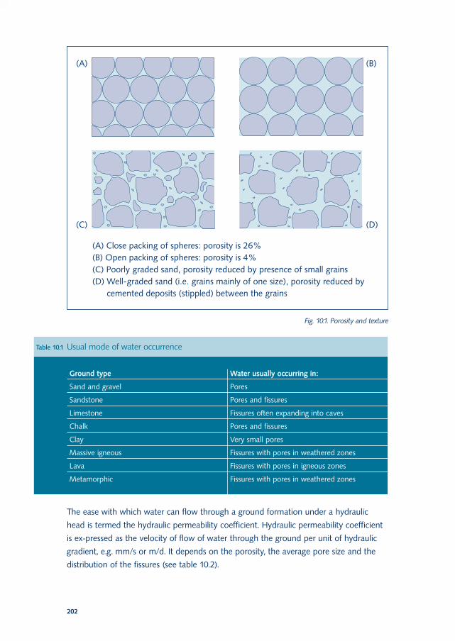
grain size, shape, packing and the presence of cementing material. Porosity is the ratio
of pore space to total ground volume (Fig. 10.1). A high porosity does not always
indicate good permeability (water-bearing potential). Although clays and silts have
a high porosity, the size of the pores is too small to allow water to flow easily.
All openings in rocks such as joints, bedding, cleavage planes and random cracks are
called fissures in hydrogeological terminology. Igneous2 rocks are not generally porous
unless they have been decomposed by weathering. Lavas, which contain cavities formed
by gas bubbles that escaped during the eruption, can be an exception. Even when
a ground formation is highly porous the permeability may be very low because the
voids are not always inter-connected. Fissures may also occur in sedimentary3 rocks.
Geologically young and unweathered fissures in all types of ground formation tend to
be closed and are likely to contain little or no water. As weathering proceeds, the
fissures will open up near the ground surface but remain closed at depth.
Aquifers (water-bearing ground formations) that hold most of their water in large joints
and fissures are called pervious, whereas those with the water in pores are called porous.
Table 10.1 shows common ground types and the way water usually occurs in them.
201
Chapter 10
2 Igneous: originating by solidification of molten or partly molten material (magma)
3 Sedimentary: resulting from the consolidation of layers of loose fragmental material by pressure to form rock
The ease with which water can flow through a ground formation under a hydraulic
head is termed the hydraulic permeability coefficient. Hydraulic permeability coefficient
is ex-pressed as the velocity of flow of water through the ground per unit of hydraulic
gradient, e.g. mm/s or m/d. It depends on the porosity, the average pore size and the
distribution of the fissures (see table 10.2).
202
Fig. 10.1. Porosity and texture
Table 10.1 Usual mode of water occurrence
Ground type Water usually occurring in:
Sand and gravel Pores
Sandstone Pores and fissures
Limestone Fissures often expanding into caves
Chalk Pores and fissures
Clay Very small pores
Massive igneous Fissures with pores in weathered zones
Lava Fissures with pores in igneous zones
Metamorphic Fissures with pores in weathered zones
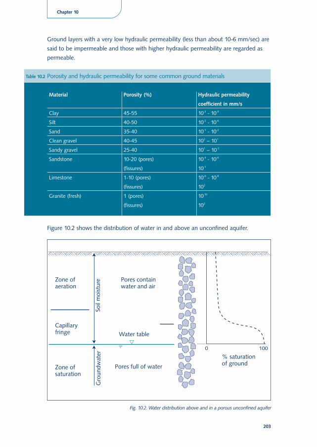
Ground layers with a very low hydraulic permeability (less than about 10-6 mm/sec) are
said to be impermeable and those with higher hydraulic permeability are regarded as
permeable.
Figure 10.2 shows the distribution of water in and above an unconfined aquifer.
203
Chapter 10
Table 10.2 Porosity and hydraulic permeability for some common ground materials
Material Porosity (%) Hydraulic permeability
coefficient in mm/s
Clay 45-55 10-3 - 10-9
Silt 40-50 10-2 - 10-6
Sand 35-40 10-1 - 10-2
Clean gravel 40-45 103 – 101
Sandy gravel 25-40 101 – 10-2
Sandstone 10-20 (pores) 10-4 - 10-6
(fissures) 10-1
Limestone 1-10 (pores) 10-6 - 10-8
(fissures) 102
Granite (fresh) 1 (pores) 10-10
(fissures) 102
Fig. 10.2. Water distribution above and in a porous unconfined aquifer
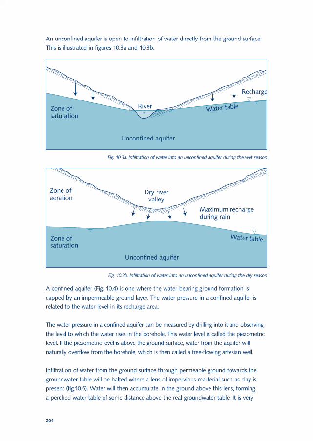
An unconfined aquifer is open to infiltration of water directly from the ground surface.
This is illustrated in figures 10.3a and 10.3b.
A confined aquifer (Fig. 10.4) is one where the water-bearing ground formation is
capped by an impermeable ground layer. The water pressure in a confined aquifer is
related to the water level in its recharge area.
The water pressure in a confined aquifer can be measured by drilling into it and observing
the level to which the water rises in the borehole. This water level is called the piezometric
level. If the piezometric level is above the ground surface, water from the aquifer will
naturally overflow from the borehole, which is then called a free-flowing artesian well.
Infiltration of water from the ground surface through permeable ground towards the
groundwater table will be halted where a lens of impervious ma-terial such as clay is
present (fig.10.5). Water will then accumulate in the ground above this lens, forming
a perched water table of some distance above the real groundwater table. It is very
204
Fig. 10.3a. Infiltration of water into an unconfined aquifer during the wet season
Fig. 10.3b. Infiltration of water into an unconfined aquifer during the dry season
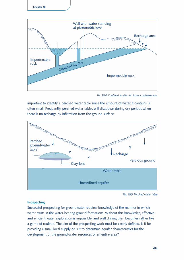
important to identify a perched water table since the amount of water it contains is
often small. Frequently, perched water tables will disappear during dry periods when
there is no recharge by infiltration from the ground surface.
Prospecting
Successful prospecting for groundwater requires knowledge of the manner in which
water exists in the water-bearing ground formations. Without this knowledge, effective
and efficient water exploration is impossible, and well drilling then becomes rather like
a game of roulette. The aim of the prospecting work must be clearly defined. Is it for
providing a small local supply or is it to determine aquifer characteristics for the
development of the ground-water resources of an entire area?
205
Chapter 10
Fig. 10.4. Confined aquifer fed from a recharge area
Fig. 10.5. Perched water table
Available hydrogeological information about the study area should be collected and
collated. This may include: geological maps and reports, topographical maps, logs of
boreholes, surface geological reconnaissance, meteorological records, and hydrological data.
A survey of the study area should be made, preferably towards the end of the dry
season. This survey also taps the indigenous knowledge of local men and women on the
history of water sources, water quality and land uses. They also know the flood-prone
areas not suitable for well development. Consultation with both sexes is needed
because in most cultures men and women have different tasks. Hence their knowledge
of water resources also differs. In cultures where male outsiders cannot talk with
women, it is often possible to sound out women on their knowledge and needs through
a local intermediary such as a female teacher or health worker. In some cases a survey
may be all that is needed for an experienced hydrogeologist to define water sources for
small community supplies and no further investigation will then be required. If essential
data are lacking, some fieldwork is necessary.
The survey should provide sufficient data to form a basis for drawing up a hydrogeological
map showing: the distribution of aquifers; any springs or signs of springs present; depth of
water tables and piezometric levels; yield of existing groundwater sources; and the quality of
the water from them. Sometimes, it is possible to prepare such a map on the basis of an
examination of outcrops and existing water supplies. In other cases, it may involve the use of
specially drilled boreholes and geophysics. Drilling special test boreholes will usually only be
required when an aquifer is to be fully exploited and knowledge is therefore needed of the
hydraulic permeability and water storage capacity.
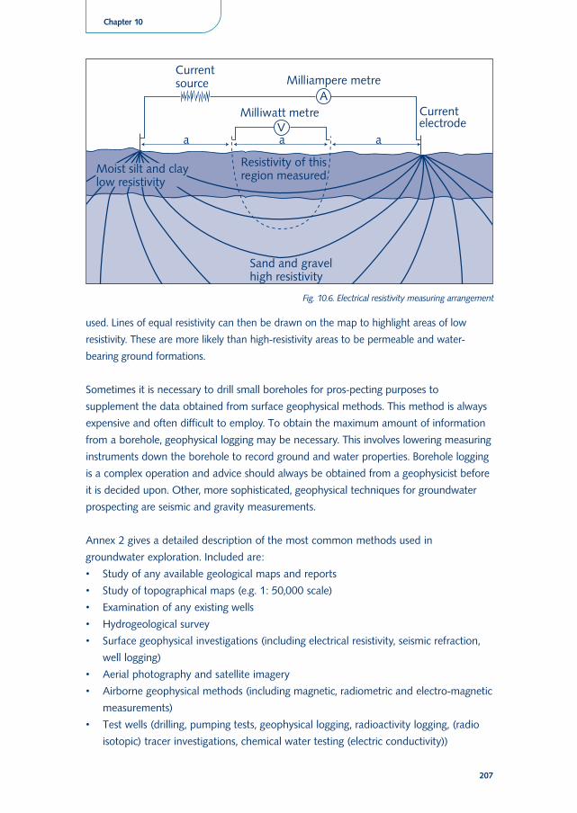
Geophysical investigations, especially electrical resistivity measurements, are very useful in
understanding the distribution and quality of groundwater. The value of the electrical
resistance of a ground formation depends upon the amount, distribution and conductivity of
the water it contains. Resistivity measurements are made by passing an electric current
through the ground between two electrodes and measuring the voltage drop between two
further electrodes (Fig. 10.6). The depth of penetration of the current is controlled by the
spacing of the electrodes. Increasing the electrode spacing makes the current penetrate
deeper, and so a complete resistivity depth probe can be carried out. If a depth probe is
done near an existing well or borehole of which the water level, water quality and aquifer
thickness are known, then the correlation between the resistivity values and the hydro-
geological conditions can be established. This provides a basis for interpreting resistivity
depth probes in other areas with much the same geology, to establish information on water
table depth, water quality and aquifer thickness.
If resistivity measurements are conducted in a grid pattern over an area, the readings can be
plotted on a grid map to form patterns of high and low resistivity for each electrode spacing
206
used. Lines of equal resistivity can then be drawn on the map to highlight areas of low
resistivity. These are more likely than high-resistivity areas to be permeable and water-
bearing ground formations.
Sometimes it is necessary to drill small boreholes for pros-pecting purposes to
supplement the data obtained from surface geophysical methods. This method is always
expensive and often difficult to employ. To obtain the maximum amount of information
from a borehole, geophysical logging may be necessary. This involves lowering measuring
instruments down the borehole to record ground and water properties. Borehole logging
is a complex operation and advice should always be obtained from a geophysicist before
it is decided upon. Other, more sophisticated, geophysical techniques for groundwater
prospecting are seismic and gravity measurements.
Annex 2 gives a detailed description of the most common methods used in
groundwater exploration. Included are:
• Study of any available geological maps and reports
• Study of topographical maps (e.g. 1: 50,000 scale)
• Examination of any existing wells
• Hydrogeological survey
• Surface geophysical investigations (including electrical resistivity, seismic refraction,
well logging)
• Aerial photography and satellite imagery
• Airborne geophysical methods (including magnetic, radiometric and electro-magnetic
measurements)
• Test wells (drilling, pumping tests, geophysical logging, radioactivity logging, (radio
isotopic) tracer investigations, chemical water testing (electric conductivity))
207
Chapter 10
Fig. 10.6. Electrical resistivity measuring arrangement
Safe yield
The safe yield of an aquifer is the maximum withdrawal rate that can be permanently
obtained without depleting the source. Safe yield is estimated to check whether the
planned withdrawal for water supply purposes will be safeguarded in the long run.
Basically, the amount of water withdrawn should not exceed the natural recharge.
Another limitation is that the groundwater table should not be lowered so much that
polluted water from elsewhere would be drawn into the aquifer. Sometimes withdrawal
of water from a new well may cause an appreciable reduction of the yield of existing
wells nearby. In an area where little is known about the extent and capacity of the
aquifer, the new well and any nearby wells should be monitored at least during the early
period of operation. Public access to information on the maximum safe yield of wells
helps reduce risks of overexploitation by the elite. Without conscious information
sharing, the elite often have a monopoly over newly emerging data and may use them
for personal interests. In addition, local water management organisations can be
encouraged to set rules and control water extraction (see also chapter 5: Integrated
Water Resources Management).
10.3 Methods of groundwater withdrawal
The oldest and simplest method of groundwater withdrawal is to dig a hole in the
ground to a depth below the groundwater table. Usually the amount of water that can
be collected in this manual way is quite limited. When more withdrawal capacity is
needed, the aquifer must be tapped over a greater area of contact. This may be done
by enlarging the width of the excavation (horizontal), by extending it to greater depth
(vertical), or by increasing both the width and depth. Which of these methods can and
should be applied in a particular case depends on the thickness of the water-bearing
ground formation, the depth of the groundwater table and, in case of community
inputs, the balance between the inputs and benefits of each method.
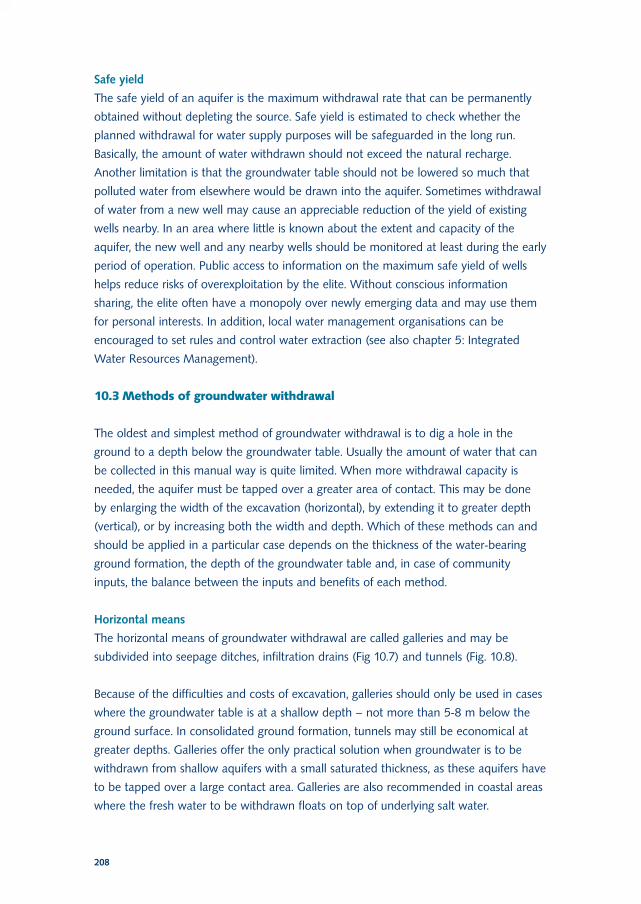
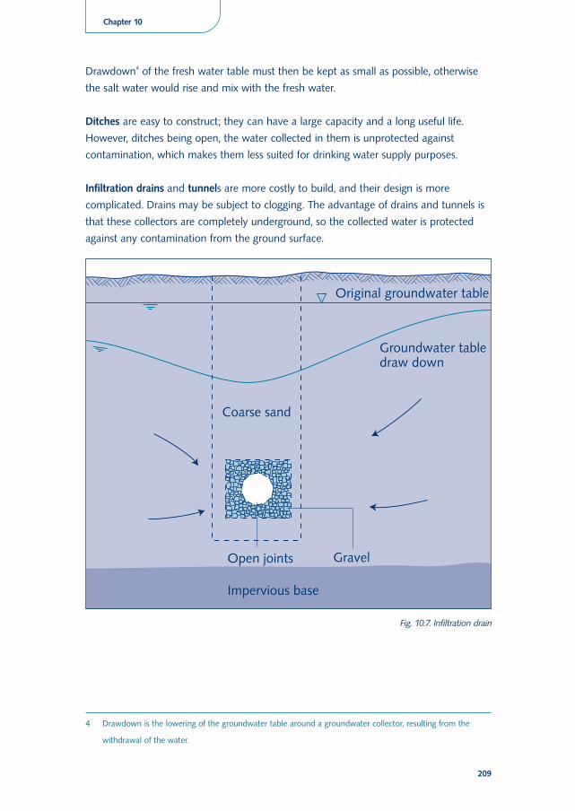
Horizontal means
The horizontal means of groundwater withdrawal are called galleries and may be
subdivided into seepage ditches, infiltration drains (Fig 10.7) and tunnels (Fig. 10.8).
Because of the difficulties and costs of excavation, galleries should only be used in cases
where the groundwater table is at a shallow depth – not more than 5-8 m below the
ground surface. In consolidated ground formation, tunnels may still be economical at
greater depths. Galleries offer the only practical solution when groundwater is to be
withdrawn from shallow aquifers with a small saturated thickness, as these aquifers have
to be tapped over a large contact area. Galleries are also recommended in coastal areas
where the fresh water to be withdrawn floats on top of underlying salt water.
208
Drawdown4 of the fresh water table must then be kept as small as possible, otherwise
the salt water would rise and mix with the fresh water.
Ditches are easy to construct; they can have a large capacity and a long useful life.
However, ditches being open, the water collected in them is unprotected against
contamination, which makes them less suited for drinking water supply purposes.
Infiltration drains and tunnels are more costly to build, and their design is more
complicated. Drains may be subject to clogging. The advantage of drains and tunnels is
that these collectors are completely underground, so the collected water is protected
against any contamination from the ground surface.
209
Chapter 10
4 Drawdown is the lowering of the groundwater table around a groundwater collector, resulting from the
withdrawal of the water.
Fig. 10.7. Infiltration drain
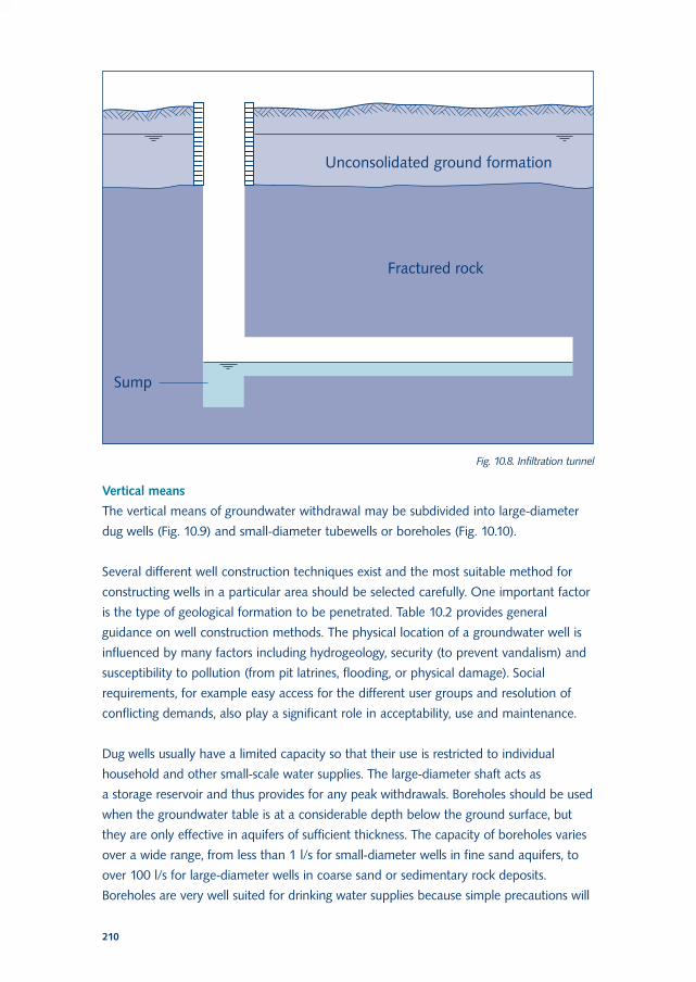
Vertical means
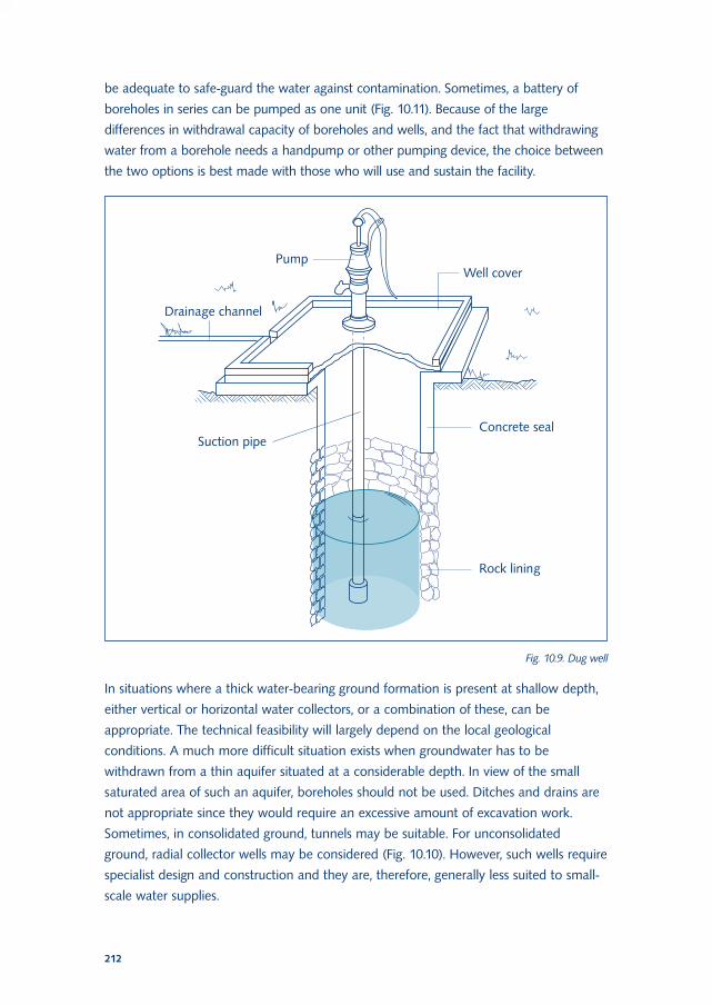
The vertical means of groundwater withdrawal may be subdivided into large-diameter
dug wells (Fig. 10.9) and small-diameter tubewells or boreholes (Fig. 10.10).
Several different well construction techniques exist and the most suitable method for
constructing wells in a particular area should be selected carefully. One important factor
is the type of geological formation to be penetrated. Table 10.2 provides general
guidance on well construction methods. The physical location of a groundwater well is
influenced by many factors including hydrogeology, security (to prevent vandalism) and
susceptibility to pollution (from pit latrines, flooding, or physical damage). Social
requirements, for example easy access for the different user groups and resolution of
conflicting demands, also play a significant role in acceptability, use and maintenance.
Dug wells usually have a limited capacity so that their use is restricted to individual
household and other small-scale water supplies. The large-diameter shaft acts as
a storage reservoir and thus provides for any peak withdrawals. Boreholes should be used
when the groundwater table is at a considerable depth below the ground surface, but
they are only effective in aquifers of sufficient thickness. The capacity of boreholes varies
over a wide range, from less than 1 l/s for small-diameter wells in fine sand aquifers, to
over 100 l/s for large-diameter wells in coarse sand or sedimentary rock deposits.
Boreholes are very well suited for drinking water supplies because simple precautions will
210
Fig. 10.8. Infiltration tunnel
211
Chapter 10
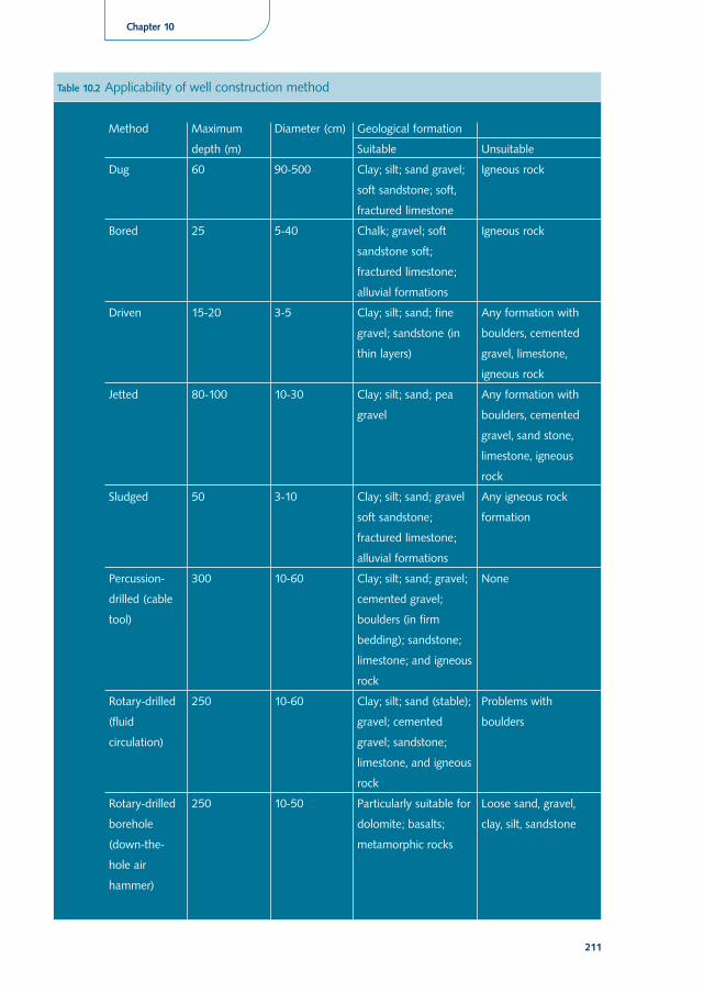
Table 10.2 Applicability of well construction method
Method Maximum
depth (m)
Diameter (cm) Geological formation
Suitable Unsuitable
Dug 60 90-500 Clay; silt; sand gravel;
soft sandstone; soft,
fractured limestone
Igneous rock
Bored 25 5-40 Chalk; gravel; soft
sandstone soft;
fractured limestone;
alluvial formations
Igneous rock
Driven 15-20 3-5 Clay; silt; sand; fine
gravel; sandstone (in
thin layers)
Any formation with
boulders, cemented
gravel, limestone,
igneous rock
Jetted 80-100 10-30 Clay; silt; sand; pea
gravel
Any formation with
boulders, cemented
gravel, sand stone,
limestone, igneous
rock
Sludged 50 3-10 Clay; silt; sand; gravel
soft sandstone;
fractured limestone;
alluvial formations
Any igneous rock
formation
Percussion-
drilled (cable
tool)
300 10-60 Clay; silt; sand; gravel;
cemented gravel;
boulders (in firm
bedding); sandstone;
limestone; and igneous
rock
None
Rotary-drilled
(fluid
circulation)
250 10-60 Clay; silt; sand (stable);
gravel; cemented
gravel; sandstone;
limestone, and igneous
rock
Problems with
boulders
Rotary-drilled
borehole
(down-the-
hole air
hammer)
250 10-50 Particularly suitable for
dolomite; basalts;
metamorphic rocks
Loose sand, gravel,
clay, silt, sandstone
be adequate to safe-guard the water against contamination. Sometimes, a battery of
boreholes in series can be pumped as one unit (Fig. 10.11). Because of the large
differences in withdrawal capacity of boreholes and wells, and the fact that withdrawing
water from a borehole needs a handpump or other pumping device, the choice between
the two options is best made with those who will use and sustain the facility.
In situations where a thick water-bearing ground formation is present at shallow depth,
either vertical or horizontal water collectors, or a combination of these, can be
appropriate. The technical feasibility will largely depend on the local geological
conditions. A much more difficult situation exists when groundwater has to be
withdrawn from a thin aquifer situated at a considerable depth. In view of the small
saturated area of such an aquifer, boreholes should not be used. Ditches and drains are
not appropriate since they would require an excessive amount of excavation work.
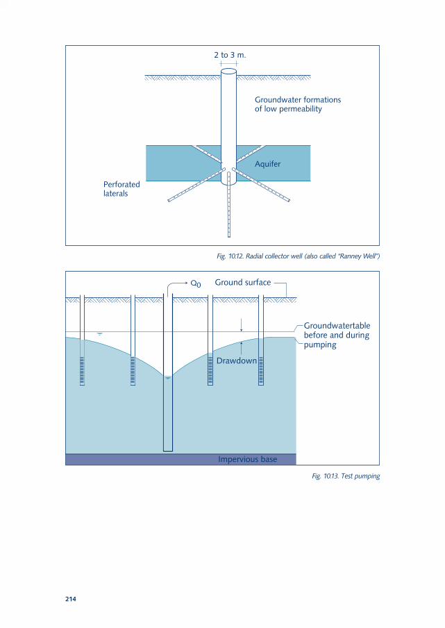
Sometimes, in consolidated ground, tunnels may be suitable. For unconsolidated
ground, radial collector wells may be considered (Fig. 10.10). However, such wells require
specialist design and construction and they are, therefore, generally less suited to small-
scale water supplies.
212
Fig. 10.9. Dug well
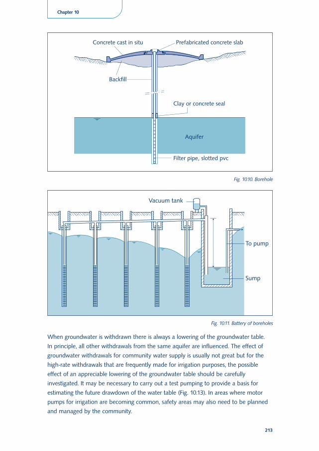
When groundwater is withdrawn there is always a lowering of the groundwater table.
In principle, all other withdrawals from the same aquifer are influenced. The effect of
groundwater withdrawals for community water supply is usually not great but for the
high-rate withdrawals that are frequently made for irrigation purposes, the possible
effect of an appreciable lowering of the groundwater table should be carefully
investigated. It may be necessary to carry out a test pumping to provide a basis for
estimating the future drawdown of the water table (Fig. 10.13). In areas where motor
pumps for irrigation are becoming common, safety areas may also need to be planned
and managed by the community.
213
Chapter 10
Fig. 10.10. Borehole
Fig. 10.11. Battery of boreholes
214
Fig. 10.12. Radial collector well (also called “Ranney Well”)
Fig. 10.13. Test pumping
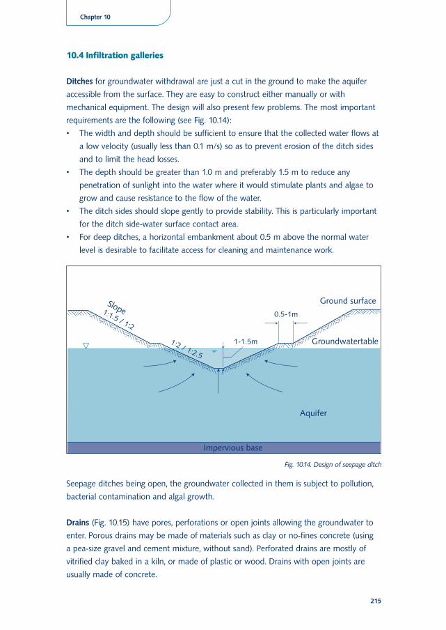
10.4 Infiltration galleries
Ditches for groundwater withdrawal are just a cut in the ground to make the aquifer
accessible from the surface. They are easy to construct either manually or with
mechanical equipment. The design will also present few problems. The most important
requirements are the following (see Fig. 10.14):
• The width and depth should be sufficient to ensure that the collected water flows at
a low velocity (usually less than 0.1 m/s) so as to prevent erosion of the ditch sides
and to limit the head losses.
• The depth should be greater than 1.0 m and preferably 1.5 m to reduce any
penetration of sunlight into the water where it would stimulate plants and algae to
grow and cause resistance to the flow of the water.
• The ditch sides should slope gently to provide stability. This is particularly important
for the ditch side-water surface contact area.
• For deep ditches, a horizontal embankment about 0.5 m above the normal water
level is desirable to facilitate access for cleaning and maintenance work.
Seepage ditches being open, the groundwater collected in them is subject to pollution,
bacterial contamination and algal growth.
Drains (Fig. 10.15) have pores, perforations or open joints allowing the groundwater to
enter. Porous drains may be made of materials such as clay or no-fines concrete (using
a pea-size gravel and cement mixture, without sand). Perforated drains are mostly of
vitrified clay baked in a kiln, or made of plastic or wood. Drains with open joints are
usually made of concrete.
215
Chapter 10
Fig. 10.14. Design of seepage ditch
The choice of material for a particular drain construction depends on the required
strength, the corrosion resistance needed for the type of groundwater to be collected,
and above all on costs and availability. Perforations in the drain need only be made all
round it when the drain is placed completely in the aquifer. For drains laid in the upper
part of an aquifer, perforations in the underside will be adequate and for drains deep
down in the aquifer only upward-facing perforations are needed.
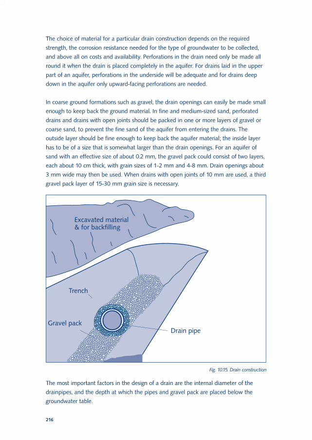
In coarse ground formations such as gravel, the drain openings can easily be made small
enough to keep back the ground material. In fine and medium-sized sand, perforated
drains and drains with open joints should be packed in one or more layers of gravel or
coarse sand, to prevent the fine sand of the aquifer from entering the drains. The
outside layer should be fine enough to keep back the aquifer material; the inside layer
has to be of a size that is somewhat larger than the drain openings. For an aquifer of
sand with an effective size of about 0.2 mm, the gravel pack could consist of two layers,
each about 10 cm thick, with grain sizes of 1-2 mm and 4-8 mm. Drain openings about
3 mm wide may then be used. When drains with open joints of 10 mm are used, a third
gravel pack layer of 15-30 mm grain size is necessary.
The most important factors in the design of a drain are the internal diameter of the
drainpipes, and the depth at which the pipes and gravel pack are placed below the
groundwater table.
216
Fig. 10.15. Drain construction
In spite of the gravel pack, some suspended matter may get into the drain. If this
material is allowed to accumulate it will block the drain. To prevent this, the drains
should be so sized that the flow velocity is sufficiently high to flush out any silt deposits.
For drains to be self-cleaning, the velocity should be higher than 0.5 m/s but it should
not be more than 1.0 m/s, or friction losses will be too high. This would cause an
uneven drawdown and withdrawal of groundwater along the length of the drain. To
accommodate the accumulating quantity of water collected and flowing through the
drain, it may be necessary to provide incremental sizes of the drain along its length.
To keep down excavation costs, the drains should be laid no deeper in the ground than
necessary. However, the drains must remain fully submerged in the groundwater with the
top of the gravel pack at least 0.5 m deep, even at the end of a long dry period when the
groundwater table is likely to be at its lowest level. Using the existing groundwater table
as a basis, the designer should allow for an operating drawdown of at least 1 m, plus
a further drop of the groundwater table of 1 m under dry conditions. The top of the
gravel pack thus should be at a depth of 2.5 m or more under the existing water table.
If communities contribute voluntary labour, they will need to know about the required
minimum depths and the reasons. A simple measuring tool in the shape of an inverted
T helps local committee members monitor the proper depth and width of the trench.
When iron and manganese is present in the groundwater, there is a serious risk of iron
and manganese deposits clogging the drain openings and gravel pack. It is then
necessary to lay the drains deeper, some 4-5 m under the existing water table, to prevent
oxygen from penetrating to the drains and forming the iron and manganese deposits.
10.5 Dug wells
Dug wells are made simply by digging a hole in the ground. They are widely used in
many countries and can be quite satisfactory if conditions are right. Usually no special
equipment or skills are required for their construction.
Experience shows that the diameter of a dug well should be at least 1.2 m if two men
are to work together at the bottom of the well during the digging. For a well serving
a single household or a small community this minimum diameter is usually adequate
but when more people are dependent on a dug well, a larger well, 2-3 m in diameter,
must be provided. Further increasing the size of a well is seldom useful since the
additional water yield so obtained is likely to be very small.
Due to their large diameter and volume, dug wells provide both groundwater
withdrawal and storage. Because of the storage capacity, water can be temporarily
withdrawn at a higher rate than the recharge inflow into the well. The storage effect is
particularly important when the users take the water mostly at peak rates during a few
217
Chapter 10
hours in the morning and the evening. Dug wells have also the advantage that users can
still get access to the water through the manhole in case the pump breaks down. These
and the next points are important aspects to consider with the representatives of male
and female user groups during technology choice.
The depth to which a well can and should be dug largely depends on the type of
ground and the fluctuation of the groundwater table. Important factors are the stability
of the ground and the costs of digging. Private wells are generally less than 10 m deep.
Dug wells for communal use are frequently much deeper; 20-30 m is not unusual and
depths of 50 m and more have been achieved.
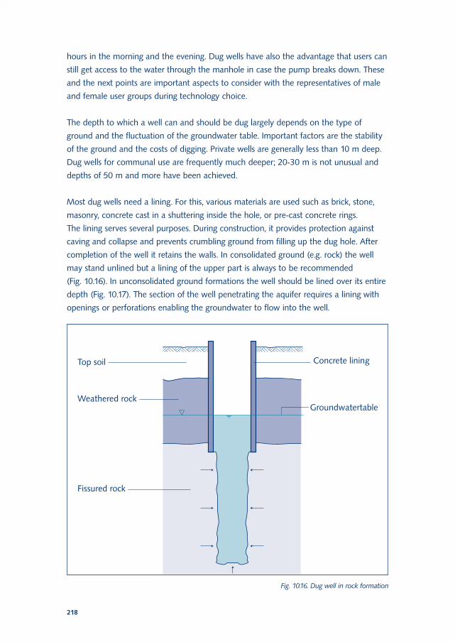
Most dug wells need a lining. For this, various materials are used such as brick, stone,
masonry, concrete cast in a shuttering inside the hole, or pre-cast concrete rings.
The lining serves several purposes. During construction, it provides protection against
caving and collapse and prevents crumbling ground from filling up the dug hole. After
completion of the well it retains the walls. In consolidated ground (e.g. rock) the well
may stand unlined but a lining of the upper part is always to be recommended
(Fig. 10.16). In unconsolidated ground formations the well should be lined over its entire
depth (Fig. 10.17). The section of the well penetrating the aquifer requires a lining with
openings or perforations enabling the groundwater to flow into the well.
218
Fig. 10.16. Dug well in rock formation
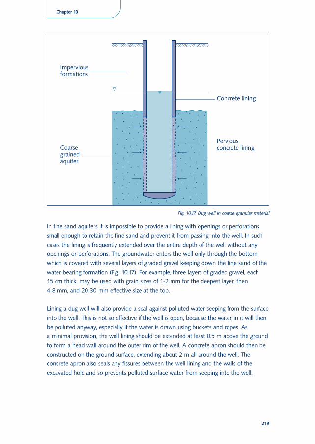
In fine sand aquifers it is impossible to provide a lining with openings or perforations
small enough to retain the fine sand and prevent it from passing into the well. In such
cases the lining is frequently extended over the entire depth of the well without any
openings or perforations. The groundwater enters the well only through the bottom,
which is covered with several layers of graded gravel keeping down the fine sand of the
water-bearing formation (Fig. 10.17). For example, three layers of graded gravel, each
15 cm thick, may be used with grain sizes of 1-2 mm for the deepest layer, then
4-8 mm, and 20-30 mm effective size at the top.
Lining a dug well will also provide a seal against polluted water seeping from the surface
into the well. This is not so effective if the well is open, because the water in it will then
be polluted anyway, especially if the water is drawn using buckets and ropes. As
a minimal provision, the well lining should be extended at least 0.5 m above the ground
to form a head wall around the outer rim of the well. A concrete apron should then be
constructed on the ground surface, extending about 2 m all around the well. The
concrete apron also seals any fissures between the well lining and the walls of the
excavated hole and so prevents polluted surface water from seeping into the well.
219
Chapter 10
Fig. 10.17. Dug well in coarse granular material
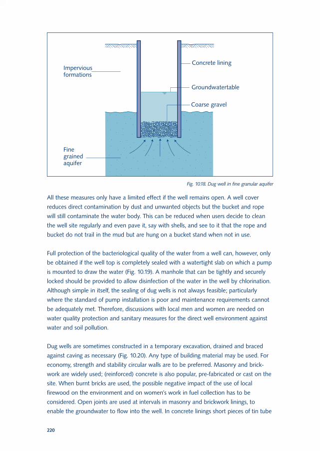
All these measures only have a limited effect if the well remains open. A well cover
reduces direct contamination by dust and unwanted objects but the bucket and rope
will still contaminate the water body. This can be reduced when users decide to clean
the well site regularly and even pave it, say with shells, and see to it that the rope and
bucket do not trail in the mud but are hung on a bucket stand when not in use.
Full protection of the bacteriological quality of the water from a well can, however, only
be obtained if the well top is completely sealed with a watertight slab on which a pump
is mounted to draw the water (Fig. 10.19). A manhole that can be tightly and securely
locked should be provided to allow disinfection of the water in the well by chlorination.
Although simple in itself, the sealing of dug wells is not always feasible; particularly
where the standard of pump installation is poor and maintenance requirements cannot
be adequately met. Therefore, discussions with local men and women are needed on
water quality protection and sanitary measures for the direct well environment against
water and soil pollution.
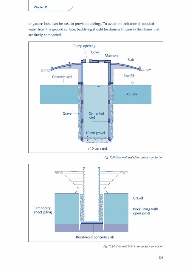
Dug wells are sometimes constructed in a temporary excavation, drained and braced
against caving as necessary (Fig. 10.20). Any type of building material may be used. For
economy, strength and stability circular walls are to be preferred. Masonry and brick-
work are widely used; (reinforced) concrete is also popular, pre-fabricated or cast on the
site. When burnt bricks are used, the possible negative impact of the use of local
firewood on the environment and on women’s work in fuel collection has to be
considered. Open joints are used at intervals in masonry and brickwork linings, to
enable the groundwater to flow into the well. In concrete linings short pieces of tin tube
220
Fig. 10.18. Dug well in fine granular aquifer
221
Chapter 10
or garden hose can be cast to provide openings. To avoid the entrance of polluted
water from the ground surface, backfilling should be done with care in thin layers that
are firmly compacted.
Fig. 10.19 Dug well sealed for sanitary protection
Fig. 10.20. Dug well built in temporary excavation
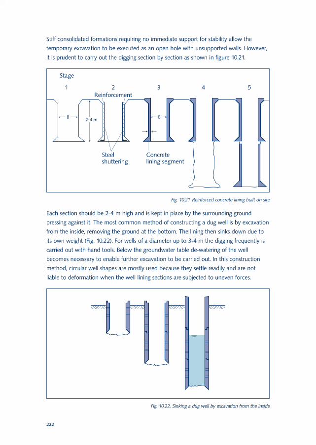
Stiff consolidated formations requiring no immediate support for stability allow the
temporary excavation to be executed as an open hole with unsupported walls. However,
it is prudent to carry out the digging section by section as shown in figure 10.21.
Each section should be 2-4 m high and is kept in place by the surrounding ground
pressing against it. The most common method of constructing a dug well is by excavation
from the inside, removing the ground at the bottom. The lining then sinks down due to
its own weight (Fig. 10.22). For wells of a diameter up to 3-4 m the digging frequently is
carried out with hand tools. Below the groundwater table de-watering of the well
becomes necessary to enable further excavation to be carried out. In this construction
method, circular well shapes are mostly used because they settle readily and are not
liable to deformation when the well lining sections are subjected to uneven forces.
222
Fig. 10.21. Reinforced concrete lining built on site
Fig. 10.22. Sinking a dug well by excavation from the inside
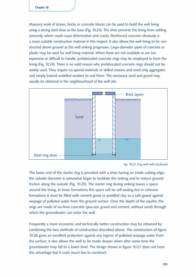
Masonry work of stones, bricks or concrete blocks can be used to build the well lining
using a strong steel shoe as the base (Fig. 10.23). The shoe prevents the lining from settling
unevenly, which could cause deformation and cracks. Reinforced concrete obviously is
a more suitable construction material in this respect. It also allows the well lining to be con-
structed above ground as the well sinking progresses. Large-diameter pipes of concrete or
plastic may be used for well lining material. When these are not available or are too
expensive or difficult to handle, prefabricated concrete rings may be employed to form the
lining (Fig. 10.24). There is no valid reason why prefabricated concrete rings should not be
widely used. They require no special materials or skilled masons and need only aggregates
and simply trained unskilled workers to cast them. The necessary sand and gravel may
usually be obtained in the neighbourhood of the well site.
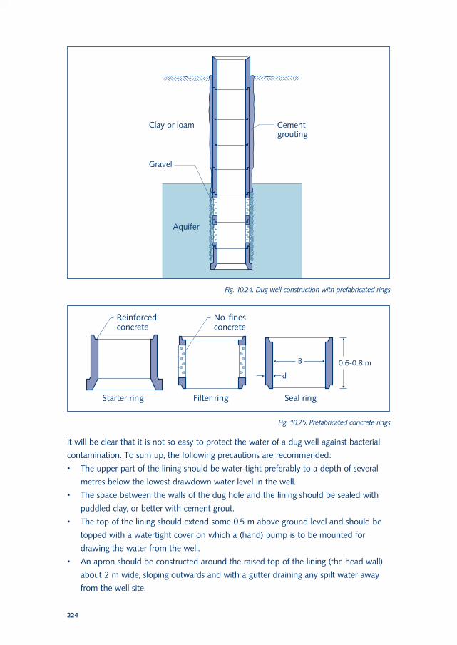
The lower end of the starter ring is provided with a shoe having an inside cutting edge;
the outside diameter is somewhat larger to facilitate the sinking and to reduce ground
friction along the outside (Fig. 10.25). The starter ring during sinking leaves a space
around the lining. In loose formations this space will be self-sealing but in cohesive
formations it must be filled with cement grout or puddled clay as a safe-guard against
seepage of polluted water from the ground surface. Over the depth of the aquifer, the
rings are made of no-fines concrete (pea-size gravel and cement, without sand) through
which the groundwater can enter the well.
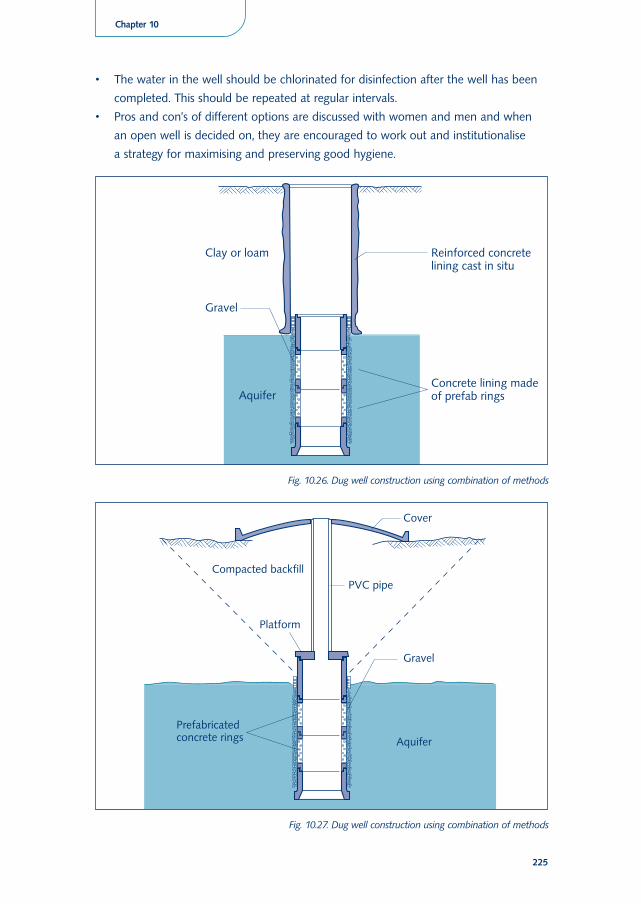
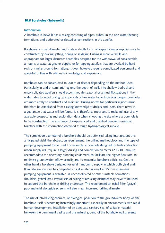
Frequently a more economic and technically better construction may be obtained by
combining the two methods of construction described above. The construction of figure
10.26 gives an excellent protection against any ingress of polluted seepage water from
the surface; it also allows the well to be made deeper when after some time the
groundwater may fall to a lower level. The design shown in figure 10.27 does not have
this advantage but it costs much less to construct.
223
Chapter 10
Fig. 10.23. Dug well with brickwork
It will be clear that it is not so easy to protect the water of a dug well against bacterial
contamination. To sum up, the following precautions are recommended:
• The upper part of the lining should be water-tight preferably to a depth of several
metres below the lowest drawdown water level in the well.
• The space between the walls of the dug hole and the lining should be sealed with
puddled clay, or better with cement grout.
• The top of the lining should extend some 0.5 m above ground level and should be
topped with a watertight cover on which a (hand) pump is to be mounted for
drawing the water from the well.
• An apron should be constructed around the raised top of the lining (the head wall)
about 2 m wide, sloping outwards and with a gutter draining any spilt water away
from the well site.
224
Fig. 10.24. Dug well construction with prefabricated rings
Fig. 10.25. Prefabricated concrete rings
• The water in the well should be chlorinated for disinfection after the well has been
completed. This should be repeated at regular intervals.
• Pros and con’s of different options are discussed with women and men and when
an open well is decided on, they are encouraged to work out and institutionalise
a strategy for maximising and preserving good hygiene.
225
Chapter 10
Fig. 10.26. Dug well construction using combination of methods
Fig. 10.27. Dug well construction using combination of methods
10.6 Boreholes (Tubewells)
Introduction
A borehole (tubewell) has a casing consisting of pipes (tubes) in the non-water bearing
formations, and perforated or slotted screen sections in the aquifer.
Boreholes of small diameter and shallow depth for small capacity water supplies may be
constructed by driving, jetting, boring or sludging. Drilling is more versatile and
appropriate for larger-diameter boreholes designed for the withdrawal of considerable
amounts of water at greater depths, or for tapping aquifers that are overlaid by hard
rock or similar ground formations. It does, however, require complicated equipment and
specialist drillers with adequate knowledge and experience.
Boreholes can be constructed to 200 m or deeper depending on the method used.
Particularly in arid or semi-arid regions, the depth of wells into shallow bedrock and
unconsolidated aquifers should accommodate seasonal or annual fluctuations in the
water table to avoid drying up in periods of low water table. However, deeper boreholes
are more costly to construct and maintain. Drilling norms for particular regions must
therefore be established from existing knowledge of drillers and users. There never is
a guarantee that water will be found. It is, therefore, important to make full use of any
available prospecting and exploration data when choosing the site where a borehole is
to be constructed. The assistance of ex-perienced and qualified people is essential,
together with the information obtained through hydrogeological surveys.
The completion diameter of a borehole should be optimised taking into account the
anticipated yield, the abstraction requirement, the drilling methodology and the type of
pumping equipment to be used. For example, a borehole designed for high abstraction
urban supply will require a larger drilling and completion diameter (200-300 mm) to
accommodate the necessary pumping equipment, to facilitate the higher flow rate, to
minimise groundwater inflow velocity and to maximise borehole efficiency. On the
other hand a borehole designed for rural handpump supply in which both yield and
flow rate are low can be completed at a diameter as small as 75 mm if slim-line
pumping equipment is available. In unconsolidated or other unstable formations
(boulders, gravel, etc.) several sets of casing of reducing diameter may have to be used
to support the borehole as drilling progresses. The requirement to install filter (gravel)
pack material alongside screens will also mean increased drilling diameter.
The risk of introducing chemical or biological pollution to the groundwater body via the
borehole itself is becoming increasingly important, especially in environments with rapid
human development. Installation of an adequate sanitary seal of suitable material
between the permanent casing and the natural ground of the borehole wall prevents
226
direct ingress of surface or near-surface pollutants via this relatively open pathway.
Flooding or agricultural pollution protection may require special designs.
Borehole construction is greatly influenced by local factors and relatively unknown
underground conditions. Several drilling and construction techniques have been
developed for use in these different environments. In many cases, the most modern and
expensive drilling rig and tools is not necessarily the best equipment. Careful
consideration should therefore be given to the degree of technical sophistication of
methods adopted and local knowledge considered. A detailed overview of borehole
drilling methods is given in annex 2.
Driving
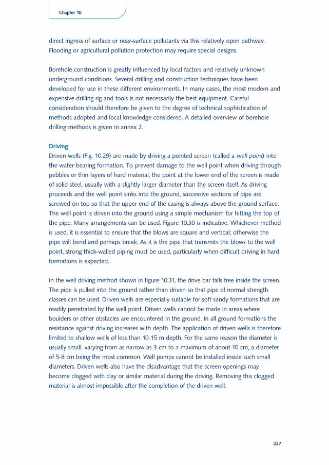
Driven wells (Fig. 10.29) are made by driving a pointed screen (called a well point) into
the water-bearing formation. To prevent damage to the well point when driving through
pebbles or thin layers of hard material, the point at the lower end of the screen is made
of solid steel, usually with a slightly larger diameter than the screen itself. As driving
proceeds and the well point sinks into the ground, successive sections of pipe are
screwed on top so that the upper end of the casing is always above the ground surface.
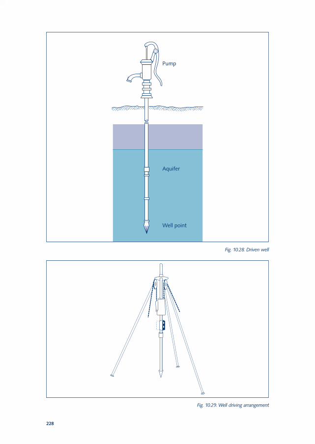
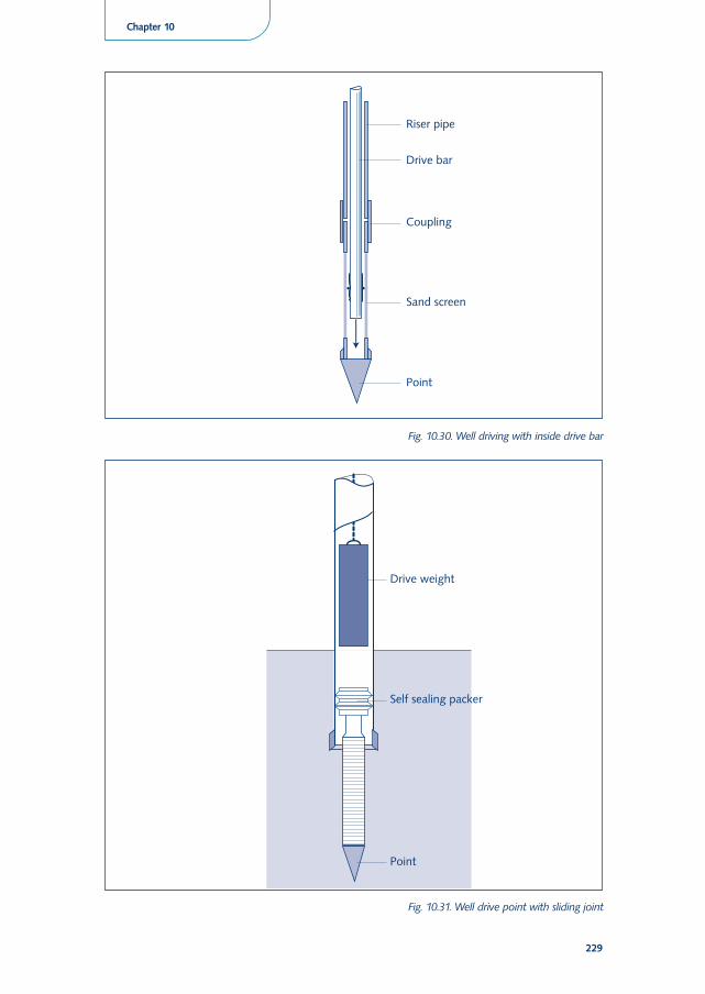
The well point is driven into the ground using a simple mechanism for hitting the top of
the pipe. Many arrangements can be used. Figure 10.30 is indicative. Whichever method
is used, it is essential to ensure that the blows are square and vertical; otherwise the
pipe will bend and perhaps break. As it is the pipe that transmits the blows to the well
point, strong thick-walled piping must be used, particularly when difficult driving in hard
formations is expected.
In the well driving method shown in figure 10.31, the drive bar falls free inside the screen.
The pipe is pulled into the ground rather than driven so that pipe of normal strength
classes can be used. Driven wells are especially suitable for soft sandy formations that are
readily penetrated by the well point. Driven wells cannot be made in areas where
boulders or other obstacles are encountered in the ground. In all ground formations the
resistance against driving increases with depth. The application of driven wells is therefore
limited to shallow wells of less than 10-15 m depth. For the same reason the diameter is
usually small, varying from as narrow as 3 cm to a maximum of about 10 cm, a diameter
of 5-8 cm being the most common. Well pumps cannot be installed inside such small
diameters. Driven wells also have the disadvantage that the screen openings may
become clogged with clay or similar material during the driving. Removing this clogged
material is almost impossible after the completion of the driven well.
227
Chapter 10
228
Fig. 10.28. Driven well
Fig. 10.29. Well driving arrangement
229
Chapter 10
Fig. 10.30. Well driving with inside drive bar
Fig. 10.31. Well drive point with sliding joint
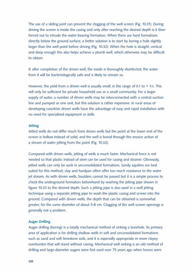
The use of a sliding joint can prevent the clogging of the well screen (Fig. 10.31). During
driving the screen is inside the casing and only after reaching the desired depth is it then
forced out to intrude the water-bearing formation. When there are hard formations
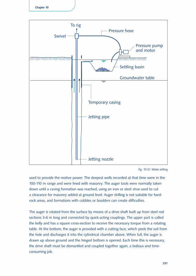
directly below the ground surface, a better solution is to start by boring a hole slightly
larger than the well point before driving (Fig. 10.32). When the hole is straight, vertical
and deep enough this also helps achieve a plumb well, which otherwise may be difficult
to obtain.
If, after completion of the driven well, the inside is thoroughly disinfected, the water
from it will be bacteriologically safe and is likely to remain so.
However, the yield from a driven well is usually small, in the range of 0.1 to 1 1/s. This
will only be sufficient for private household use or a small community. For a larger
supply of water, a number of driven wells may be interconnected with a central suction
line and pumped as one unit, but this solution is rather expensive. In rural areas of
developing countries driven wells have the advantage of easy and rapid installation with
no need for specialised equipment or skills.
Jetting
Jetted wells do not differ much from driven wells but the point at the lower end of the
screen is hollow instead of solid, and the well is bored through the erosive action of
a stream of water jetting from the point (Fig. 10.32).
Compared with driven wells, jetting of wells is much faster. Mechanical force is not
needed so that plastic instead of steel can be used for casing and strainer. Obviously,
jetted wells can only be sunk in unconsolidated formations. Sandy aquifers are best
suited for this method; clay and hardpan often offer too much resistance to the water
jet stream. As with driven wells, boulders cannot be passed but it is a simple process to
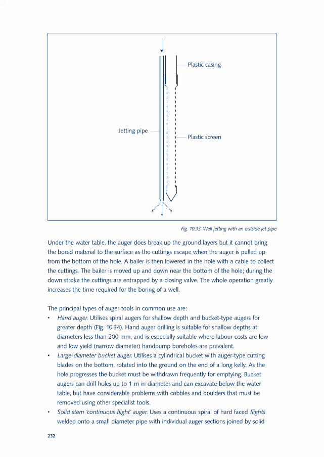
check the underground formation beforehand by washing the jetting pipe shown in
figure 10.33 to the desired depth. Such a jetting pipe is also used in a well jetting
technique using a separate jetting pipe to wash the plastic casing and screen into the
ground. Compared with driven wells, the depth that can be obtained is somewhat
greater, for the same diameter of about 5-8 cm. Clogging of the well screen openings is
generally not a problem.
Auger Drilling
Auger drilling (boring) is a totally mechanical method of sinking a borehole. Its primary
area of application is for drilling shallow wells in soft and unconsolidated formations
such as sand and soft limestone soils, and it is especially appropriate in more clayey
overburden that will stand without caving. Mechanical well sinking is an old method of
drilling and large-diameter augers were first used over 75 years ago when horses were
230
used to provide the motive power. The deepest wells recorded at that time were in the
100-110 m range and were lined with masonry. The auger tools were normally taken
down until a caving formation was reached, using an iron or steel shoe used to cut
a clearance for masonry added at ground level. Auger drilling is not suitable for hard-
rock areas, and formations with cobbles or boulders can create difficulties.
The auger is rotated from the surface by means of a drive shaft built up from steel rod
sections 3-6 m long and connected by quick-acting couplings. The upper part is called
the kelly and has a square cross-section to receive the necessary torque from a rotating
table. At the bottom, the auger is provided with a cutting face, which peels the soil from
the hole and discharges it into the cylindrical chamber above. When full, the auger is
drawn up above ground and the hinged bottom is opened. Each time this is necessary,
the drive shaft must be dismantled and coupled together again, a tedious and time-
consuming job.
231
Chapter 10
Fig. 10.32. Water jetting
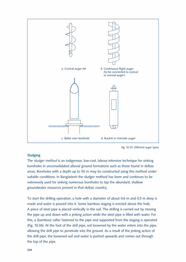
Under the water table, the auger does break up the ground layers but it cannot bring
the bored material to the surface as the cuttings escape when the auger is pulled up
from the bottom of the hole. A bailer is then lowered in the hole with a cable to collect
the cuttings. The bailer is moved up and down near the bottom of the hole; during the
down stroke the cuttings are entrapped by a closing valve. The whole operation greatly
increases the time required for the boring of a well.
The principal types of auger tools in common use are:
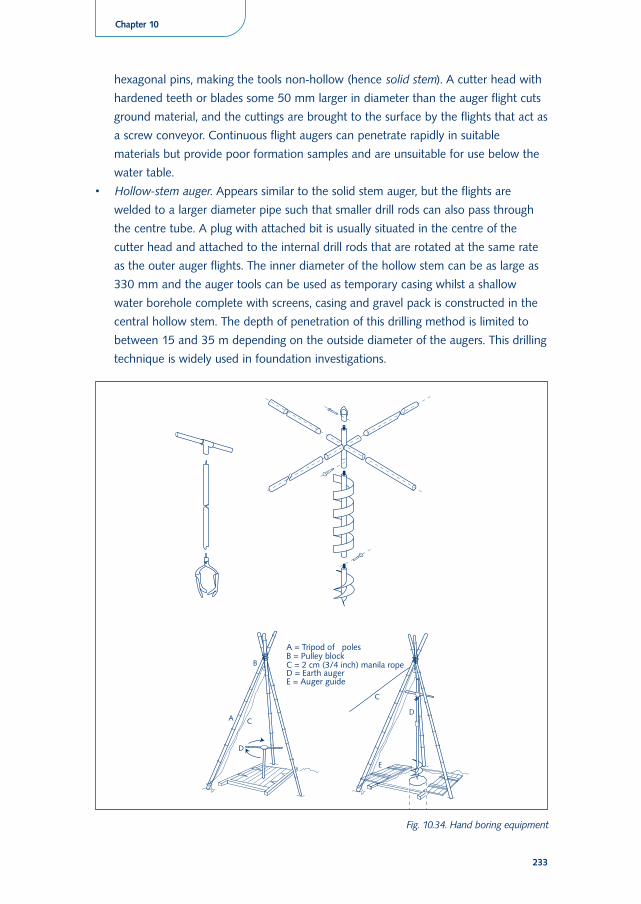
• Hand auger. Utilises spiral augers for shallow depth and bucket-type augers for
greater depth (Fig. 10.34). Hand auger drilling is suitable for shallow depths at
diameters less than 200 mm, and is especially suitable where labour costs are low
and low yield (narrow diameter) handpump boreholes are prevalent.
• Large-diameter bucket auger. Utilises a cylindrical bucket with auger-type cutting
blades on the bottom, rotated into the ground on the end of a long kelly. As the
hole progresses the bucket must be withdrawn frequently for emptying. Bucket
augers can drill holes up to 1 m in diameter and can excavate below the water
table, but have considerable problems with cobbles and boulders that must be
removed using other specialist tools.
• Solid stem ‘continuous flight’ auger. Uses a continuous spiral of hard faced flights
welded onto a small diameter pipe with individual auger sections joined by solid
232
Fig. 10.33. Well jetting with an outside jet pipe
hexagonal pins, making the tools non-hollow (hence solid stem). A cutter head with
hardened teeth or blades some 50 mm larger in diameter than the auger flight cuts
ground material, and the cuttings are brought to the surface by the flights that act as
a screw conveyor. Continuous flight augers can penetrate rapidly in suitable
materials but provide poor formation samples and are unsuitable for use below the
water table.
• Hollow-stem auger. Appears similar to the solid stem auger, but the flights are
welded to a larger diameter pipe such that smaller drill rods can also pass through
the centre tube. A plug with attached bit is usually situated in the centre of the
cutter head and attached to the internal drill rods that are rotated at the same rate
as the outer auger flights. The inner diameter of the hollow stem can be as large as
330 mm and the auger tools can be used as temporary casing whilst a shallow
water borehole complete with screens, casing and gravel pack is constructed in the
central hollow stem. The depth of penetration of this drilling method is limited to
between 15 and 35 m depending on the outside diameter of the augers. This drilling
technique is widely used in foundation investigations.
233
Chapter 10
Fig. 10.34. Hand boring equipment
Sludging
The sludger method is an indigenous, low-cost, labour-intensive technique for sinking
boreholes in unconsolidated alluvial ground formations such as those found in deltaic
areas. Boreholes with a depth up to 50 m may be constructed using this method under
suitable conditions. In Bangladesh the sludger method has been and continues to be
extensively used for sinking numerous boreholes to tap the abundant, shallow
groundwater resources present in that deltaic country.
To start the drilling operation, a hole with a diameter of about 0.6 m and 0.5 m deep is
made and water is poured into it. Some bamboo staging is erected above the hole.
A piece of steel pipe is placed vertically in the soil. The drilling is carried out by moving
the pipe up and down with a jerking action while the steel pipe is filled with water. For
this, a (bamboo) rafter fastened to the pipe and supported from the staging is operated
(Fig. 10.36). At the foot of the drill pipe, soil loosened by the water enters into the pipe,
allowing the drill pipe to penetrate into the ground. As a result of the jerking action of
the drill pipe, the loosened soil and water is pushed upwards and comes out through
the top of the pipe.
234
Fig. 10.35. Different auger types
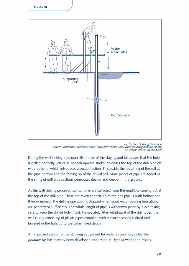
During the well sinking, one man sits on top of the staging and takes care that the hole
is drilled perfectly vertically. At each upward stroke, he closes the top of the drill pipe off
with his hand, which introduces a suction action. This assists the loosening of the soil at
the pipe bottom and the forcing up of the drilled soil. More pieces of pipe are added as
the string of drill pipe sections penetrates deeper and deeper in the ground.
As the well sinking proceeds, soil samples are collected from the mudflow coming out at
the top of the drill pipe. These are taken at each 1.5 m the drill pipe is sunk further, and
then examined. The drilling operation is stopped when good water-bearing formations
are penetrated sufficiently. The whole length of pipe is withdrawn piece by piece taking
care to keep the drilled hole intact. Immediately after withdrawal of the drill tubes, the
well casing consisting of plastic pipes complete with strainer sections is fitted and
lowered in the hole up to the determined depth.
An improved version of the sludging equipment for wider application, called the
pounder rig, has recently been developed and tested in Uganda with good results.
235
Chapter 10
Fig. 10.36. Sludging technique Source: Waterlines, Technical Briefs, http://www.lboro.ac.uk/well/resources/technical-briefs/
43-simple-drilling-methods.pdf
Cable tool percussion drilling
Percussion drilling is one of the two principal drilling methods. It uses a percussive force
to break the rock via a hardened drill bit (either by means of lifting and dropping, or by
means of an air-driven reciprocating piston). Cable tool percussion drilling is a very old
method and was already in use more than 1000 years ago in China. The method
basically has not changed, but the tools have been vastly improved. It is practicable for
drilling both small and large diameter holes to depths as great as 300-500 m. Cable tool
percussion drilling uses relatively inexpensive equipment, but its greatest dis-advantage is
that it is very slow.
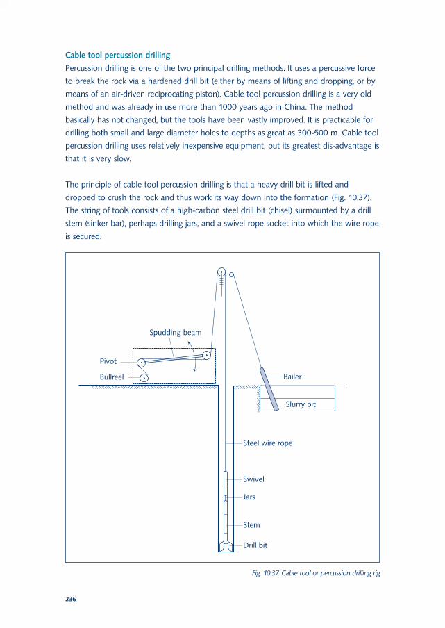
The principle of cable tool percussion drilling is that a heavy drill bit is lifted and
dropped to crush the rock and thus work its way down into the formation (Fig. 10.37).
The string of tools consists of a high-carbon steel drill bit (chisel) surmounted by a drill
stem (sinker bar), perhaps drilling jars, and a swivel rope socket into which the wire rope
is secured.
236
Fig. 10.37. Cable tool or percussion drilling rig
Bits have different shapes depending on the hardness of the formations, and are
required to penetrate, crush, mix and ream. The drill stem provides weight and
directional stability, and by its pumping action in the borehole it moves the cuttings
upward, away from the bit. The tools slowly rotate, moving the bit to a new position on
each stroke and ensuring a circular well.
The drilling process, depending on the diameter and depth of the borehole, consists of
a column of tools weighing between 300 and 4000 kg reciprocating at 40-80 times per
minute at a stroke of between 0.4 and 1.2 m, and slowly rotating. Drilling with a cable
tool requires a skilled driller to progress speedily and with the right rotation of the drill
bit. Water is fed to the well in small quantities until a natural supply is reached to
produce slurry out of the cuttings and to suspend this material above and away from
the bit face, but also to cool and lubricate the tool string. The drilling proceeds until the
driller feels the thickening slurry retarding the tools, and cleans the hole by lowering
a bailer several times. When drilling begins, a short guide tube or conductor pipe is
always drilled or hand-sunk in a truly vertical alignment into the ground to stabilise the
ground around the working area and to start and maintain a vertical hole. In the past it
was common practice to drive casing down to the required depth using a drive-head
and a drive-shoe on the bottom of the casing. However, recovery of temporary (costly)
casing was often impossible, even using heavy jacks. The more recent use of flush-
jointed temporary casing and less forceful methods of installation has ensured that
temporary casing recovery is now the rule rather than the exception.
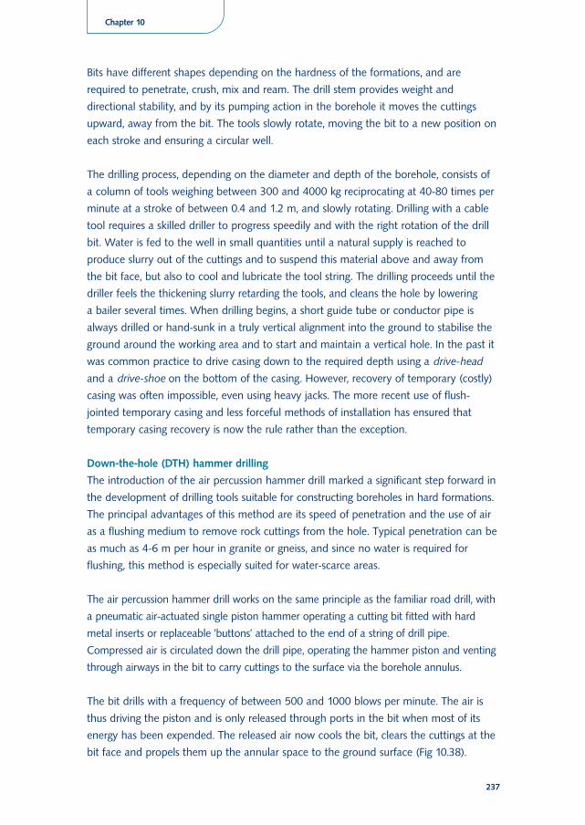
Down-the-hole (DTH) hammer drilling
The introduction of the air percussion hammer drill marked a significant step forward in
the development of drilling tools suitable for constructing boreholes in hard formations.
The principal advantages of this method are its speed of penetration and the use of air
as a flushing medium to remove rock cuttings from the hole. Typical penetration can be
as much as 4-6 m per hour in granite or gneiss, and since no water is required for
flushing, this method is especially suited for water-scarce areas.
The air percussion hammer drill works on the same principle as the familiar road drill, with
a pneumatic air-actuated single piston hammer operating a cutting bit fitted with hard
metal inserts or replaceable ’buttons’ attached to the end of a string of drill pipe.
Compressed air is circulated down the drill pipe, operating the hammer piston and venting
through airways in the bit to carry cuttings to the surface via the borehole annulus.
The bit drills with a frequency of between 500 and 1000 blows per minute. The air is
thus driving the piston and is only released through ports in the bit when most of its
energy has been expended. The released air now cools the bit, clears the cuttings at the
bit face and propels them up the annular space to the ground surface (Fig 10.38).
237
Chapter 10
Hammers with bits of 50-375 mm diameter are widely used, and tools have also been
developed to drill up to 750 mm.
A key disadvantage of air percussion methods is that in unconsolidated ground or clays
the hammer action is curtailed, the material is simply compressed rather than broken,
and penetration is minimal. A minor seepage of groundwater will cause hole-cleaning
difficulties since the cuttings will congeal and stick to the wall of the hole, though this
can be relieved by the injection of water and surfactant into the air supply.
Direct fluid circulation rotary drilling
Rotary drilling is the second principal drilling method. It relies upon the breaking up of
rock material by abrasion and crushing action rather than percussion. The drilling bit is
rotated and applies considerable downward force on the rock that grinds down and
breaks up the formation. Continuous circulation of a flushing fluid then removes the
238
Fig. 10.38. Down-the-hole hammer drill
cuttings and the loosened ground from the hole. Rotary drilling is particularly suitable in
loose ground formations and soft rock, and can be used to drill large-diameter holes to
considerable depths. The flushing medium is extremely important in this process. It may
be air or water with or without additives to increase viscosity.
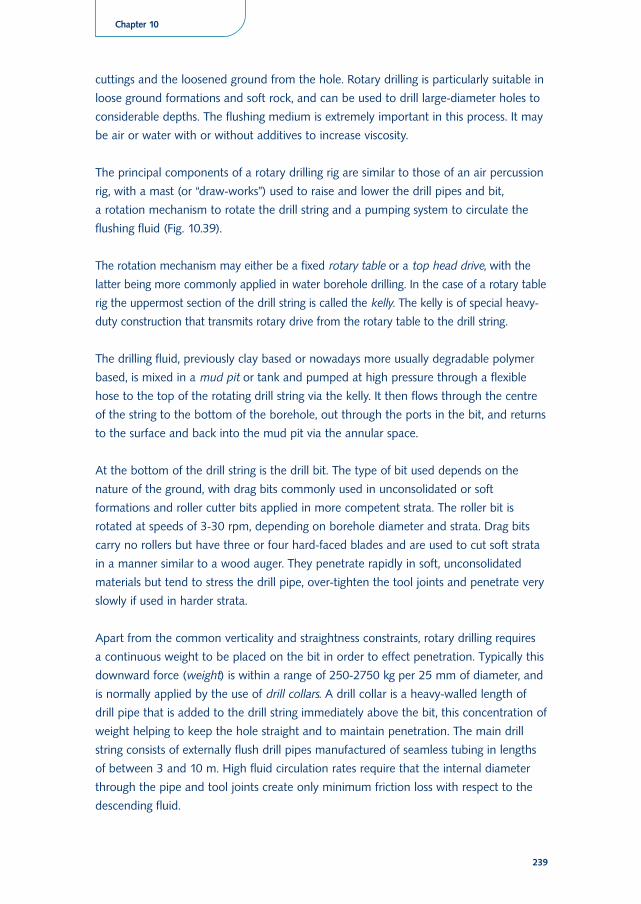
The principal components of a rotary drilling rig are similar to those of an air percussion
rig, with a mast (or “draw-works”) used to raise and lower the drill pipes and bit,
a rotation mechanism to rotate the drill string and a pumping system to circulate the
flushing fluid (Fig. 10.39).
The rotation mechanism may either be a fixed rotary table or a top head drive, with the
latter being more commonly applied in water borehole drilling. In the case of a rotary table
rig the uppermost section of the drill string is called the kelly. The kelly is of special heavy-
duty construction that transmits rotary drive from the rotary table to the drill string.
The drilling fluid, previously clay based or nowadays more usually degradable polymer
based, is mixed in a mud pit or tank and pumped at high pressure through a flexible
hose to the top of the rotating drill string via the kelly. It then flows through the centre
of the string to the bottom of the borehole, out through the ports in the bit, and returns
to the surface and back into the mud pit via the annular space.
At the bottom of the drill string is the drill bit. The type of bit used depends on the
nature of the ground, with drag bits commonly used in unconsolidated or soft
formations and roller cutter bits applied in more competent strata. The roller bit is
rotated at speeds of 3-30 rpm, depending on borehole diameter and strata. Drag bits
carry no rollers but have three or four hard-faced blades and are used to cut soft strata
in a manner similar to a wood auger. They penetrate rapidly in soft, unconsolidated
materials but tend to stress the drill pipe, over-tighten the tool joints and penetrate very
slowly if used in harder strata.
Apart from the common verticality and straightness constraints, rotary drilling requires
a continuous weight to be placed on the bit in order to effect penetration. Typically this
downward force (weight) is within a range of 250-2750 kg per 25 mm of diameter, and
is normally applied by the use of drill collars. A drill collar is a heavy-walled length of
drill pipe that is added to the drill string immediately above the bit, this concentration of
weight helping to keep the hole straight and to maintain penetration. The main drill
string consists of externally flush drill pipes manufactured of seamless tubing in lengths
of between 3 and 10 m. High fluid circulation rates require that the internal diameter
through the pipe and tool joints create only minimum friction loss with respect to the
descending fluid.
239
Chapter 10
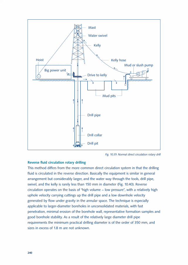
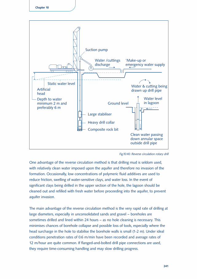
Reverse fluid circulation rotary drilling
This method differs from the more common direct circulation system in that the drilling
fluid is circulated in the reverse direction. Basically the equipment is similar in general
arrangement but considerably larger, and the water way through the tools, drill pipe,
swivel, and the kelly is rarely less than 150 mm in diameter (Fig. 10.40). Reverse
circulation operates on the basis of “high volume – low pressure”, with a relatively high
uphole velocity carrying cuttings up the drill pipe and a low downhole velocity
generated by flow under gravity in the annular space. The technique is especially
applicable to larger-diameter boreholes in unconsolidated materials, with fast
penetration, minimal erosion of the borehole wall, representative formation samples and
good borehole stability. As a result of the relatively large diameter drill pipe
requirements the minimum practical drilling diameter is of the order of 350 mm, and
sizes in excess of 1.8 m are not unknown.
240
Fig. 10.39. Normal direct circulation rotary drill
One advantage of the reverse circulation method is that drilling mud is seldom used,
with relatively clean water imposed upon the aquifer and therefore no invasion of the
formation. Occasionally, low concentrations of polymeric fluid additives are used to
reduce friction, swelling of water-sensitive clays, and water loss. In the event of
significant clays being drilled in the upper section of the hole, the lagoon should be
cleaned out and refilled with fresh water before proceeding into the aquifer, to prevent
aquifer invasion.
The main advantage of the reverse circulation method is the very rapid rate of drilling at
large diameters, especially in unconsolidated sands and gravel – boreholes are
sometimes drilled and lined within 24 hours – as no hole cleaning is necessary. This
minimises chances of borehole collapse and possible loss of tools, especially where the
head surcharge in the hole to stabilise the borehole walls is small (1-2 m). Under ideal
conditions penetration rates of 0.6 m/min have been recorded and average rates of
12 m/hour are quite common. If flanged-and-bolted drill pipe connections are used,
they require time-consuming handling and may slow drilling progress.
241
Chapter 10
Fig.10.40. Reverse circulation rotary drill
Return water will infiltrate permeable formations, particularly coarser unconsolidated
materials, and will result in water losses from the system. In view of this, one of the
prerequisites of reverse circulation drilling is the ready and close availability of
a substantial supply of water for make-up purposes. This is often quoted as 45 m3/h and
in practice can amount to between 9 and 70 m3/h. Fine particles in the return flow that
filter out on the walls of the borehole will help minimise these losses, but a considerable
quantity of “make-up” water must be available at all times. If water losses are sudden
and cannot be immediately made up, the water level in the borehole will drop and
caving of the hole walls usually results.
As noted above, the normal reverse circulation system utilises suction as the motive
power behind the flow circuit. However, there are circumstances such as pipe friction at
greater depths, or a low water table, when suction is insufficient. For this reason most
drilling rigs have provisions for introducing an airlift into the system. Providing that
drilling has reached a sufficient depth for proper operation of an airlift, this will then
induce water within the drill pipe, and the mud pump can be bypassed.
Air circulation rotary drilling
Air circulation has advantages such as longer bit life, faster penetration, and rapid
delivery of cuttings to the surface. Air drilling can, however, only be successful in semi-
consolidated or consolidated formations in which no assistance is required from the
circulating fluid to support the borehole walls.
The drilling equipment is basically similar to that used for conventional fluid flush
drilling; one difference is the design of the drilling bit that has air passages to cool the
bearings of the bits (Fig. 10.41).
One of the limiting factors when drilling with air, especially as the borehole diameter
increases, is the need to produce an adequate uphole air velocity to ensure cuttings
removal. To overcome some limitations, several variations on the reverse circulation
system have been developed such as dual-wall drill pipes or pipes with built-in air
channels. The dual wall method can be used either with DTH hammer and button bits,
or with rotary tricone bits.
Dual wall drilling has an advantage of the formation and groundwater samples
originating over a very short vertical section before being flushed to the surface without
any risk of further contamination. In addition, problems of lost circulation are largely
eliminated. The principal disadvantages of this method are its depth and diameter
limitations (diameter generally less than 254 mm; depth generally less than 200 m in
unconsolidated materials) and the high capital cost of the equipment.
242
Other drilling techniques
Hydraulic tube racking may be used in conjunction with a rig or crane for drilling
relatively shallow wells of large diameters in loose gravel, sand, boulders, or similar
ground formations. A short guide tube is hand-sunk into the ground and the first of
a column of permanent tubes lowered within it. The bottom edge of the column is
serrated and the tubes drilled, perforated, or slotted as required. A hydraulically clamped
spider with long horizontal rams oscillates the tube column downwards slowly but
steadily. When the first tube is close to the spider table, the next tube is placed upon it
and the joint welded. Tubes of 450 mm - 1.2 m can be worked down to 30 m or so
under the right conditions, the advantage of this system being that there is no need for
temporary tubes or large lagoons. There also is no contamination of the aquifer by
drilling fluids.
243
Chapter 10
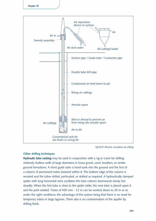
Fig.10.41. Reverse circulation air drilling
Scow (or California Stovepipe) drilling is applied in cable-tool drilling, and combines the
cutting edge of a chisel with the material handling ability of a bailer. The scow consists
of a heavy, thick-walled bailer with a cutting shoe and a flap valve, suspended by a scow
sub by means of a pair of reins and a heavy pin from the drilling jar and swivel socket
assembly. In operation, it is run into the hole and the normal reciprocating action is
applied inside the casing shoe. Water for drilling is added if it is not present naturally.
Material is dislodged by the cutting shoe and swept into the body of the scow. The
scow is then removed for emptying periodically. Scow drilling can be successfully used in
loose, troublesome strata, especially where coarse gravel and boulders occur, and has
the advantage of dislodging and lifting the material rather than expending time and
power on crushing.
Shell and auger drilling is a percussion technique that uses a string of either solid or
hollow rods that are lifted and dropped to provide the cutting action to a chisel bit with
a check valve incorporated in the tool. The auger tool is used to cut and remove clay,
and the shell is similar to a bailer and removes soft strata already loosened by the chisel
bit. If hollow rods are used, drilling fluid to assist in removing cuttings can be
incorporated in a reverse circulation circuit, with flow down the borehole annulus and
return flow through the centre of the rods. This drilling method requires only
a lightweight rig and is often used for site-investigation work, since hole diameters are
limited to 50-100 mm to very shallow depths (< 20 m).
10.7 Construction materials
During the design of a borehole the selection of the correct materials required for its
construction is of extreme importance. In defining the technical specifications of the
materials considerations must be given to the expected dimensions of the borehole
(depth, diameter) and its ultimate usage, as well as the cost and availability of the
materials. Ideally all materials for a borehole, or a complete drilling programme, should
be with the contractor prior to commencing the work. The principal borehole
construction materials, including those used in drilling as well as those incorporated in
the completed structure, are briefly discussed below.
Drilling fluids
Virtually all rotary drilling systems require drilling fluids. The addition of some natural
clay to increase viscosity in order to aid the lifting of rock cuttings and gravel
subsequently led to the use of the term ”mud” for this circulating medium. Nowadays
the term “drilling fluid” is more commonly used, and refers variously to clean water, dry
air, a suspension of solids or a mixture of liquid additives in water or water, surfactants
and colloids dispersed in air.
244
The primary functions of a drilling fluid are:
• To remove cuttings from the face of the borehole and transport them to the surface
• To lubricate and cool the bit and tool string
• To stabilise the borehole whilst drilling proceeds
• To facilitate suspension of cuttings in the borehole when the fluid is not circulating
(e.g. whilst adding additional drill pipe)
• To allow settlement of fine cuttings to the bottom of the settling pits
• To control fluid loss in permeable formations by building up a wall-cake to
consolidate the formation and to reduce the loss of fluid into the formation
• To help control sub-surface hydrostatic pressures
• To help provide some buoyancy to long strings of tools or casing in deep boreholes
The most widely used drilling fluid additives are:
• Clay or bentonite
Natural clay or bentonite is widely used in water well drilling. Different types of clay
may be used, but the only common commercially available clay is montmorillonite
or bentonite.
• Organic polymers
To overcome the possible aquifer degradation inherent with clay-based drilling fluid
additives, organic polymers are now widely used as a clay substitute.
• Air
The ideal drilling strata in which to apply this flushing medium are hard, stable
igneous or metamorphic formations when penetration rates can be high. Fissured
zones can often be penetrated without the fear of lost circulation associ-ated with
water-based fluids.
• Foam
Drilling foam is created when a small volume of water mixed with a surfactant is
injected into the air stream. Foaming agents prevent cuttings from aggregating and
also reduce the surface tension of water droplets so that both can be lifted more
easily to the surface, thus helping to overcome large groundwater inflows. Foam also
reduces the uphole velocity requirements, thereby reducing the volume and pressure
of air required. Loss of air into the formation and hole wall erosion are thus
minimised.
Casing and Screens
Casing used in water boreholes is tubular material that provides support to the walls of
the borehole and may be either temporary (used by the driller during drilling of the
borehole and subsequently withdrawn) or permanent (forming part of the final
construction of the completed borehole). Steel casing is most commonly used, but
thermoplastic casing is now increasingly applied in areas of potentially corrosive
groundwater and where boreholes are generally less than 300 m deep. Other materials
245
Chapter 10
such as glass fibre are also used but are much less common. Selection of casing material
should be based upon water quality, borehole depth and diameter, drilling methods,
local regulations and cost.
A borehole screen is a filtering device that allows groundwater to enter the borehole. It
provides structural support but prevents sediment from entering, especially in
unconsolidated strata. Proper screen design and selection is important for the hydraulic
efficiency of the borehole, as well as for the longevity and long-term cost of the
structure. Screens should have maximum open area to create minimum resistance to
flow into the hole, but at the same time must minimise sediment ingress and provide
adequate structural strength. Optimising each of these criteria for a particular borehole
is the essence of screen design.
Gravel Packs
Gravel pack (or filter pack) is graded granular material placed in a thin zone around the
screens in order to increase the effective hydraulic diameter of the borehole and to help
inhibit the movement of sediments into the borehole. Clearly, the borehole diameter
relative to the final cased completion diameter must be large enough to allow
installation of such material, which in turn implies that larger drilling diameter must be
employed in holes that are scheduled to be gravel packed. Gravel pack material should
be chosen to retain most of the unconsolidated formation material, and screen openings
are then selected so as to retain about 90% of the gravel pack. Gravel packs are 100-
200 mm thick.
Sanitary seals
In order to prevent ingress to the aquifer of any potential contaminants from the
surface via the borehole itself, it is necessary to seal the uppermost section of the
annulus between the outermost casing string and the wall of the borehole. The sealing
material commonly used is cement grout or a bentonite mixture. It is also prudent to
ensure that no potential contaminants can enter the borehole from the surface via the
space between any other internal casing strings.
A sanitary seal should preferably be installed in continuity with a cement or concrete
well head protection slab to minimise cracking and joints. It is common practice for this
slab to be at least 1 m square, with at least 500 mm of its thickness below natural
ground level and 300 mm above (Fig. 10.42). The permanent casing protruding through
this slab should extend at least 300 mm above the slab, which should slope in all
directions away from the casing.
246
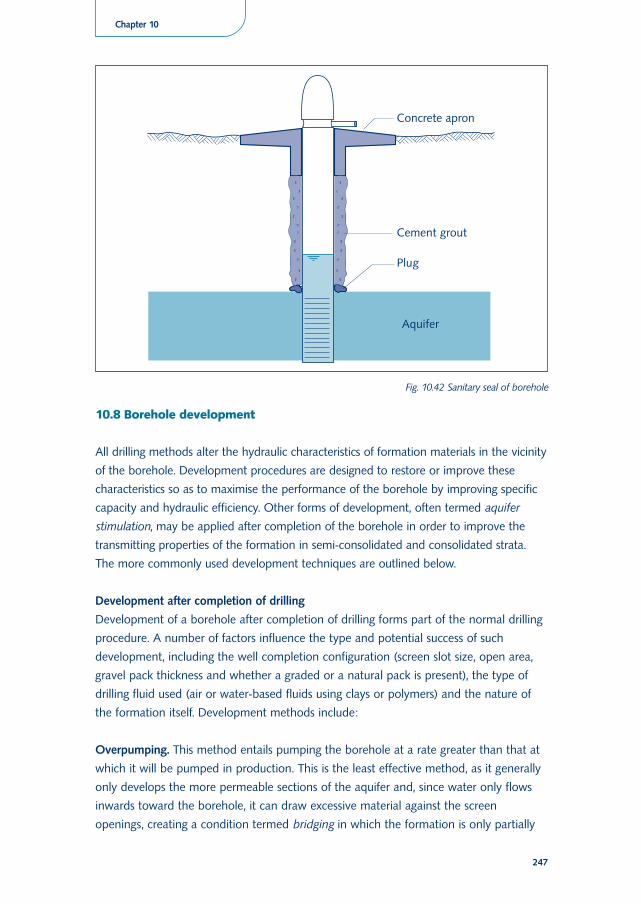
10.8 Borehole development
All drilling methods alter the hydraulic characteristics of formation materials in the vicinity
of the borehole. Development procedures are designed to restore or improve these
characteristics so as to maximise the performance of the borehole by improving specific
capacity and hydraulic efficiency. Other forms of development, often termed aquifer
stimulation, may be applied after completion of the borehole in order to improve the
transmitting properties of the formation in semi-consolidated and consolidated strata.
The more commonly used development techniques are outlined below.
Development after completion of drilling
Development of a borehole after completion of drilling forms part of the normal drilling
procedure. A number of factors influence the type and potential success of such
development, including the well completion configuration (screen slot size, open area,
gravel pack thickness and whether a graded or a natural pack is present), the type of
drilling fluid used (air or water-based fluids using clays or polymers) and the nature of
the formation itself. Development methods include:
Overpumping. This method entails pumping the borehole at a rate greater than that at
which it will be pumped in production. This is the least effective method, as it generally
only develops the more permeable sections of the aquifer and, since water only flows
inwards toward the borehole, it can draw excessive material against the screen
openings, creating a condition termed bridging in which the formation is only partially
247
Chapter 10
Fig. 10.42 Sanitary seal of borehole
stabilised. Formation material may subsequently enter the hole if the formation is
agitated and the bridges collapse.
Surging. This method flushes water backwards and forwards through the screen, so
preventing any bridging behind the screen and moving fines through into the hole. The
surge effect can be generated by intermittent pumping and repeatedly allowing the
water column to fall back into the hole, or preferably by mechanical means using
a close-fitting plunger (surge block) moved up and down on the hole by the drilling rig.
Air surging and pumping. This technique uses an airlift pumping action in combination
with the surging effect described above. Air is injected into the hole to lift the water
column, and then shut off such that the column falls back into the hole.
Jetting. This development method uses the injection of high pressure air or water
through the screens to remove fines and drilling fluids. It uses a special jetting tool that
directs horizontal jets onto the screens to break up any filter cake and agitate and flush
the adjacent gravel pack or formation. This method is most appropriate with rotary rigs.
Jetting and simultaneous pumping. This method combines high pressure water jetting
with pumping (usually using an airlift system) and is particularly applicable in
unconsolidated sands and gravel. Essentially the jetting process loosens the fine material
and the pumping action draws it through the screen and directly to the surface.
In all the development methods noted above the addition of a small quantity of
a polyphosphate compound before or during development will assist in breaking up and
removing any clay material that may clog the screens or the gravel pack.
Hydro-fracturing
In bedrock aquifers groundwater is contained in fractures and borehole yields are often
very low. In such cases the yield may be enhanced by the use of an aquifer stimulation
method such as hydro-fracturing. This is a second level of development (of the aquifer)
in which high pressure pumps are used to inject fluid to overcome the overlying rock
pressure and open up existing and new fractures that will enable water movement into
the borehole. Considerable pumping pressure is required.
Supplementary development methods
Other development or stimulation methods include the use of acid injection in
carbonate aquifers to enlarge fissures by dissolution of aquifer material, and “shooting”
in hard-rock terrain using explosive charges placed in the borehole to increase the
number of fractures around the hole. Such methods are very specialised techniques, and
are not commonly used in the majority of water borehole drilling work.
248
Bibliography
Ball, P. (2001). Drilled wells. (Manuals on drinking water supply; no. 6). St. Gallen, Swizerland,
SKAT.
Blankwaardt, B. (1984). Hand-drilled wells: a manual on siting, design, construction and
maintenance. Dar es Salaam, Tanzania, Rwegurulila Water Resources Institute.
BURGEAP (1974). La construction des puits en Afrique tropicale. (Series techniques rurales en
Afrique). Paris, France, Ministère de la Cooperation et du Developpement.
Campbell, N.D. and Lehr, J.H. (1973). Water well technology. New York, NY, USA,
McGraw-Hill.
Collins, S. (2000). Hand-dug shallow wells. (Manuals on drinking water supply series; no. 5).
St. Gallen, Swizerland, SKAT.
Davis, S.N. and De Wiest, R.J.N. (1966). Hydrogeology. New York, NY, USA, John Wiley &
Sons.
Driscoll, F.G. (1986). Groundwater and wells. 2nd ed. St. Paul, MN, USA, Johnson Division.
Duff, P.D. (1993). Holme’s princples of physical geology. 4th ed. London, UK, Chapman and
Hall.
Huisman, L. (1972). Groundwater recovery. London, UK, Macmillan.
IRC (1988). Handpumps: issues and concepts in rural water supply programmes. (Technical
paper; no. 25). The Hague, The Netherlands, IRC International Water and Sanitation Centre.
Raghunath, H.M. (1987). Ground water: ground water survey and pumping tests, rural water
supply and irrigation systems. 2nd ed. New Delhi, India, Wiley Eastern.
Todd, D.K. (1980). Groundwater hydrology. 2nd ed. New York, NY, USA, John Wiley & Sons.
Watt, S.B. and Wood, W.E. (1979). Hand dug wells and their construction. 2nd ed. London,
UK, ITDG Publications.
Wurzel, P. (2001). Drilling boreholes for handpumps. (Manuals on drinking water supply;
no. 2). St. Gallen, Swizerland, SKAT.
249
Chapter 10

Web sites
HTN Network for Cost-Effective Water and Sanitation Technologies:
http://www.skat.ch/htn/
Water and Sanitation Program: http://www.wsp.org/english/index.html
WatSanWeb: http://www.skat.ch/ws/link/watsan/WW_index.htm
Practica Foundation on low cost drilling techniques: http://www.practicafoundation.nl
Discussion groups
Handpump Technology Network: http://www.jiscmail.ac.uk/lists/htn.html
Water Forum: http://groups.yahoo.com/group/waterforum/
250