Embed Size (px)
Citation preview
100G and 200G single carrier transmission over 2880 and 320 km using an InP IQ modulator and Stokes vector receiver
MOHAMMED Y. S. SOWAILEM,1,4,5 THANG M. HOANG,1,4,6 MATHIEU CHAGNON,1 MOHAMED MORSY-OSMAN,1,2 MENG QIU,1 STEPHANE PAQUET,3 CARL PAQUET,3 IAN WOODS,3 ODILE LIBOIRON-LADOUCEUR,1 AND DAVID V. PLANT
1 1Photonics System Group, Electrical and Computer Engineering Department, McGill University, 3480 University Street, Montreal, QC H3A 0E9, Canada 2Currently with the Elect. Eng. Dep., Alexandria University, Alexandria, Egypt 3Ciena, 2716 Einstein, Quebec, Canada 4These authors have contributed equally in this work [email protected] [email protected]
Abstract: We demonstrate experimentally the transmission of single carrier 56 Gbaud 16-QAM, 8-QAM and QPSK optically modulated signals over 320, 960 and 2,880 km, respectively, using a fully packaged InP IQ modulator and a Stokes vector direct detection (SV-DD) receiver realized using discrete optics. Results show that by optimizing the carrier-to-signal-power ratio, the total throughput-times-distance product for 16 QAM and QPSK are 71,680 Gbps.km and 322,560 Gbps.km, respectively, at bit error rate (BER) below the hard decision forward error correcting threshold (HD-FEC) of 4.5 × 10⁻³. © 2016 Optical Society of America
OCIS codes: (060.2330) Fiber optics communications; (060.4080) Modulation.
References and links
1. D. Rafique, “Fiber nonlinearity compensation: commercial applications and complexity analysis,” J. Lightwave Technol. 34(2), 544–553 (2016).
2. Optical Internetworking Forum (OIF), “OIF-FEC-100-01.0- 100G Forward Error Correction White Paper,”2010.
3. Optical Internetworking Forum (OIF), “OIF-Tech-Options-400G-01.0- Technology options for 400GImplementation Forward,” 2015.
4. D. H. Sim, H. Kim, and Y. C. Chung, “Direct-detection receiver for polarization-division-multiplexed OOK signals,” IEEE Photonics Technol. Lett. 27(21), 2238–2241 (2015).
5. D. Che, A. Li, X. Chen, Q. Hu, Y. Wang, and W. Shieh, “Stokes vector direct detection for short-reach opticalcommunication,” Opt. Lett. 39(11), 3110–3113 (2014).
6. M. M. Osman, M. Chagnon, M. Poulin, S. Lessard, and D. V. Plant, “224-Gb/s 10-km transmission of PDM PAM-4 at 1.3 μm using a single intensity modulated laser and a direct detection MIMO DSP-based receiver,” J.Lightwave Technol. 33(7), 1380–1387 (2015).
7. M. Chagnon, M. Morsy-Osman, D. Patel, V. Veerasubramanian, A. Samani, and D. Plant, “Digital signal processing for dual-polarization intensity and inter-polarization phase modulation formats using stokesdetection,” J. Lightwave Technol. 34(1), 188–195 (2016).
8. K. Kikuchi and S. Kawakami, “Multi-level signaling in the Stokes space and its application to large-capacity optical communications,” Opt. Express 22(7), 7374–7387 (2014).
9. D. Che and W. Shieh, “Polarization demultiplexing for Stokes vector direct detection,” J. Lightwave Technol. 34(2), 754–760 (2016).
10. D. Che, Q. Hu, X. Chen, and W. Shieh, “1-Tb/s Stokes vector direct detection over 480-km SSMFtransmission,” in Proc. OECC (2014), paper THPDP.
11. P. Dong, X. Chen, K. Kim, S. Chandrasekhar, Y.-K. Chen, and J. H. Sinsky, “128-Gb/s 100-km transmissionwith direct detection using silicon photonic Stokes vector receiver and I/Q modulator,” Opt. Express 24(13),14208–14214 (2016).
12. S. Benedetto and P. Poggiolini, “Theory of polarization shift keying modulation,” IEEE Trans. Commun. 40(4),708–721 (1992).
Vol. 24, No. 26 | 26 Dec 2016 | OPTICS EXPRESS 30485
#274119 http://dx.doi.org/10.1364/OE.24.030485 Journal © 2016 Received 22 Aug 2016; revised 13 Oct 2016; accepted 28 Oct 2016; published 23 Dec 2016

13. S. Betti, F. Curti, G. de Marchis, and E. Iannone, “Multilevel coherent optical system based on Stokes parameters modulation,” J. Lightwave Technol. 8(7), 1127–1136 (1990).
14. K. Kikuchi, “Fundamentals of coherent optical fiber communications,” J. Lightwave Technol. 34(1), 157–179(2016).
15. M. Chagnon, M. Morsy-Osman, M. Poulin, C. Paquet, S. Lessard, and D. V. Plant, “Experimental parametricstudy of a silicon photonic modulator enabled 112 Gb/s PAM transmission system with a DAC and ADC,” J. Lightwave Technol. 33(7), 1380–1387 (2015).
16. S. Chandrasekhar, X. Liu, P. J. Winzer, J. E. Simsarian, and R. A. Griffin, “Compact all-InP laser-vector-modulator for generation and transmission of 100-Gb/s PDM-QPSK and 200-Gb/s PDM-16QAM,” J. Lightwave Technol. 32(4), 736–742 (2014).
17. F. Chang, K. Onohara, and T. Mizuochi, “Forward error correction for 100 G Transport networks,” IEEE Commun. Mag. 48(3), S48–S55 (2010).
18. T. Miyazaki, “Linewidth-tolerant QPSK homodyne transmission using a polarization-multiplexed pilot carrier,”IEEE Photonics Technol. Lett. 18(2), 388–390 (2006).
19. P. Johannisson, M. Sjodin, M. Karlsson, E. Tipsuwannakul, and P. Andrekson, “Cancellation of nonlinear phase distortion in self-homodyne coherent system,” IEEE Photonics Technol. Lett. 22(11), 802–804 (2010).
20. M. Y. S. Sowailem, T. M. Hoang, M. Morsy-Osman, M. Chagnon, D. Patel, S. Paquet, C. Paquet, I. Woods, O. Liboiron-Ladouceur, and D. V. Plant, “400G Single carrier 500km transmission with an InP dual polarization IQmodulator,” IEEE Photonics Technol. Lett. 28(11), 1213–1216 (2016).
21. P. J. Reyes-Iglesias, I. Molina-Fernández, A. Moscoso-Mártir, and A. Ortega-Moñux, “High-performance monolithically integrated 120° downconverter with relaxed hardware constraints,” Opt. Express 20(5), 5725–5741 (2012).
22. M. Morsy-Osman, M. Chagnon, X. Xu, Q. Zhuge, M. Poulin, Y. Painchaud, M. Pelletier, C. Paquet, and D. V. Plant, “Colorless and preamplifierless reception using an integrated Si-photonic coherent receiver,” IEEE Photonics Technol. Lett. 25(11), 1027–1030 (2013).
1. Introduction
Data center interconnects (DCIs) are growing significantly due to the massive increase in data services such as cloud computing, social media and virtualization. This growth is driving the demand for faster, compact and cost-effective optics for DCI traffic in metro applications [1]. Amongst the various solutions, coherent transmission deploying dual-polarization IQ modulators (DP-IQM) and coherent receivers is used for 100G signal transmission with QPSK modulation format in long haul applications. Coherent systems are also used for 200G signal transmission with the 16-QAM modulation format for metro applications. These applications have been recently standardized [2, 3]. Metro applications for distances less than 1000 km, found in inter-datacenter interconnects, represent intermediate systems between long haul applications and short reach applications. The transceiver design for metro networks is utmost challenging because of the need of capacity-reach, footprint and cost [1].
Nowadays, there is a growing interest in finding alternative solutions for short reach and metro applications using Stokes vector modulation and detection [4–11] rather than unidimensional intensity modulation/ direct detection (IM/DD) system or complex coherent system. Although the concept of a Stokes vector receiver (SVR) has been described in the 1990s [12, 13], SVR systems with advanced modulation formats have only been demonstrated recently. For instance, 100 Gbps per wavelength over 480 km for metro applications was demonstrated in [10] using a complex IQ modulation on the X polarization and transmitting the carrier on the orthogonal polarization. This modulation scheme presents a hybrid solution between coherent and direct detect systems.
The Stokes vector direct detection (SV-DD) system and single polarization coherent system have a simpler transmitter when compared to that of the dual polarization coherent system. Since only one polarization is modulated, the transmitter in SV-DD requires half the number of the electronic and electro-optic devices including the number of digital-to-analog converters (DACs), amplifiers, Mach-Zehnder modulators compared to the dual polarization coherent system transmitter. This is at the expense of halving the spectral efficiency that can be achieved by the dual polarization coherent system. On the other hand, the SVR, which has several configurations shown in [9], has simpler receiver compared to the single polarization coherent system. The common feature in SVR configurations compared to coherent systems is that SVR does not employ a local oscillator (LO) laser with its associated thermoelectric
Vol. 24, No. 26 | 26 Dec 2016 | OPTICS EXPRESS 30486
cooler (TEC) and driving circuitry. The deployed SVR in this demonstration comprises a 2 × 4 hybrid, two balanced photodetectors (BPDs) and two single-ended photodetectors (SE-PDs) instead of two 2 × 4 hybrids and 4 BPDs in coherent detection. It is worth noting that the single polarization and the dual polarization coherent receivers share the same configuration to avoid the deployment of a polarization stabilizer in single polarization coherent receiver [14]. Moreover, SV-DD systems require less complex digital signal processing (DSP) at the receiver compared to a coherent system since there is no frequency offset removal, laser phase noise mitigation or cycle slip detection.
In parallel to the interests in SV-DD systems, researchers, designers, and manufacturers use photonic integrated devices fabricated on various platforms such as silicon (Si) [15] or indium phosphide (InP) [16] to supply the demand for DCI applications. SV-DD systems have been demonstrated using Si photonics modulators in [6, 7] and using Si photonics IQ modulator (IQM) and Si photonics SVR in [11].
In this paper, we demonstrate, using an InP IQM, a record-breaking single carrier transmission using a SV-DD system at symbol rate of 56 Gbaud with QPSK, 8-QAM and 16-QAM modulation formats corresponding to payload rates of 100G, 150G and 200G, respectively. The system operates below the 7% overhead BCH hard-decision forward error correction (HD-FEC) threshold of 4.5 × 10⁻³ [17] over distances of 2880, 960 and 320 km, respectively. These modulation schemes enable 100G transmissions and 200G transmissions for long haul and metro applications after removal of the FEC and encapsulation overhead. To achieve this result, we optimize the carrier-to-signal-power (CSR) ratio and implement DSP at the transmitter and the receiver including equalization of the transmitter frequency response, non-linear compensation for the Mach-Zehnder modulator (MZM) transfer function, and chromatic dispersion (CD) pre-compensation.
The remainder of the paper is organized as follows: Section 2 provides a description of the Stokes vector transceiver. Section 3 discusses the experimental setup and the applied DSP functions. Section 4 presents the experimental results, and we finally conclude in Section 5.
2. Principle of Stokes vector transceiver
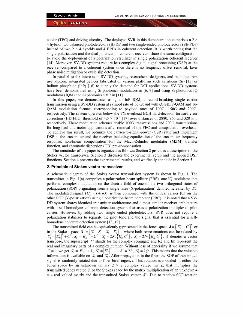
A schematic diagram of the Stokes vector transmission system is shown in Fig. 1. The transmitter in Fig. 1(a) comprises a polarization beam splitter (PBS), one IQ modulator that performs complex modulation on the electric field of one of the two orthogonal states of polarization (SOP) originating from a single laser (X-polarization) denoted hereafter by t
XE The modulated signal ( )t
XE I jQ= + is then combined with the optical carrier (C) on the other SOP (Y-polarization) using a polarization beam combiner (PBC). It is noted that a SV-DD system shares identical transmitter architecture and almost similar receiver architecture with a self-homodyne coherent detection system that uses a polarization-multiplexed pilot carrier. However, by adding two single ended photodetectors, SVR does not require a polarization stabilizer to separate the pilot tone and the signal that is essential for a self-homodyne coherent detection system [18, 19].
The transmitted field can be equivalently represented in the Jones space tXE C =
TJ or
in the Stokes space 0 1 2 3t t t tS S S S =
TtS , where both representations can be related by 2 2
0t t
XS E C= + ,2 2
1t t
XS E C= − , { }*2 2 .t t
XS Re E C= , { }*3 2 .t t
XS Im E C= . T denotes a vector transpose, the superscript ‘*’ stands for the complex conjugate and Re and Im represent the real and imaginary parts of a complex number. Without loss of generality if we assume that
1C = , we get 2
0 1t tXS E= + ,
2
1 1t tXS E= − , 2 2tS I= , 3 2tS Q= . This means that the valuable
information is available on 2tS and 3
tS . After propagation in the fiber, the SOP of transmitted signal is randomly rotated due to fiber birefringence. This rotation is modeled in either the Jones space by an unknown unitary 2 × 2 complex valued matrix that multiplies the transmitted Jones vector J or the Stokes space by the matrix multiplication of an unknown 4 × 4 real valued matrix and the transmitted Stokes vector tS . Due to random SOP rotation
Vol. 24, No. 26 | 26 Dec 2016 | OPTICS EXPRESS 30487
along the fiber, each of the received electric fields on X and Y polarizations ( rXE and r
YE ) is a linear combination of the transmitted polarizations t
XE and C.
Fig. 1. Schematic diagram of SV-DD transceiver (a) transmitter, (b) receiver.
The received Stokes vector 0 1 2 3r r r rS S S S =
TSr can be measured using the direct
detection system illustrated in Fig. 1(b). A PBS is initially used to split the received signal into two orthogonal SOPs. Each SOP is further split using 67/33 polarization maintaining couplers. This coupling ratio ensures that the system performance is independent from the SOP of the signal before the PBS [6]. At the 33% output port of the couplers,
2rXE and
2rYE
are detected separately using single-ended photodetectors to obtain the intensity on both polarizations giving the terms required for calculating
2 2
0r r r
X YS E E= + , and 2 2
1r r r
X YS E E= − . At the 67% output ports of the coupler, the two orthogonal SOPs are introduced to a 90° optical hybrid after SOP alignment using a 90° polarization rotator on one branch. After balanced detection at the output of the hybrid, the beating provides the received Stokes parameters { }*
2 2 .r r rX YS Re E E= , { }*
3 2 .r r rX YS Im E E= . Since 2
tS and 3tS are the only
transmitted Stokes parameters that are required to be retrieved, they can be found via the following 3 × 2 MIMO filter that performs the SOP de-rotation,
111 12 132
221 22 233
3
.
r
tr
tr
Sm m mS
Sm m mS
S
=
(1)
where 11 23, , m m… are coefficients of the inverse rotation matrix that are found adaptively at the receiver via DSP, and are used to recover the Stokes parameters 2
tS and 3tS which in turn
fully describe the complex field of the modulated signal.
3. Experimental setup and DSP stack
3.1 Experimental setup
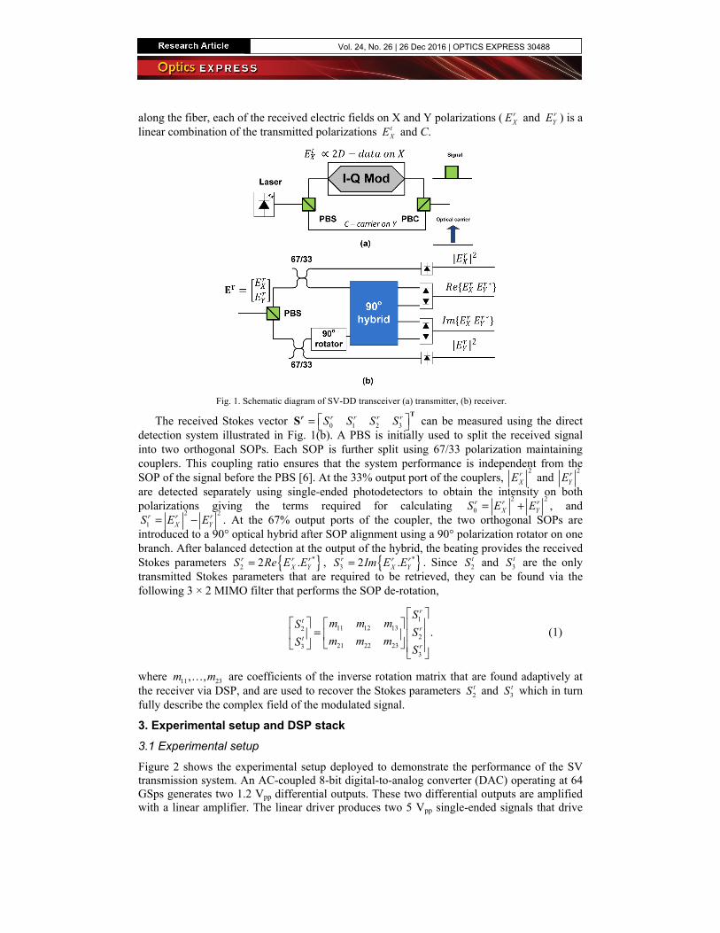
Figure 2 shows the experimental setup deployed to demonstrate the performance of the SV transmission system. An AC-coupled 8-bit digital-to-analog converter (DAC) operating at 64 GSps generates two 1.2 Vpp differential outputs. These two differential outputs are amplified with a linear amplifier. The linear driver produces two 5 Vpp single-ended signals that drive
Vol. 24, No. 26 | 26 Dec 2016 | OPTICS EXPRESS 30488
one half of the DP-IQM. This represents the complex modulation on the X-Pol of the DP-IQM. The InP DP-IQM, has a 35 GHz 3-dB bandwidth, less than 10 dB of insertion loss, a Vπ of 2.5V, and less than 5 ps skew between both polarization paths [20]. To control the carrier power on Y-pol relative to the fixed modulated signal power on the X-pol, the MZM on the Q component of Y-pol is biased at null and the bias for the MZM on the I component of Y-pol is swept to produce the desired CSR. The optical source is a 100 kHz linewidth external cavity laser (ECL) operating at 1550.12 nm with 15.5 dBm optical power.
Fig. 2. (a) Experimental setup (b) SVR details (c) B2B optical spectrum with 0.05 nm resolution bandwidth.
Before transmission, the optical signal is amplified using a booster EDFA to compensate for subsequent switches and couplers loss used in the recirculating loop and to enhance the signal power level for better optical signal to noise ratio during transmission. The optimization of the total launched signal power depends on the optimization of the CSR and launching sufficient power for the modulated signal on the X polarization according to the used modulation format to have the required OSNR for the achieved reach. This dependency on CSR value is because of the booster which has a fixed output power of 23 dBm, so the increase in the CSR value is accompanied by a decrease in the modulated signal power on the X polarization. Thus, the launched signal power is optimized using a variable optical attenuator (VOA) along with the CSR for different modulation formats by minimizing the bit error rate at the maximum reach according to the used modulation format. The signal is then transmitted into a four-span optical recirculating loop. Each span comprises 80 km of SMF-28e + followed by an in-line erbium-doped fiber amplifier (EDFA) with 5 dB noise figure. A tunable optical filter is used after the second span with its center wavelength set to 1550.12 nm and bandwidth set to 2 nm.
The output signal from the re-circulating loop is connected to a 0.8 nm filter followed by a pre-amplifier and a second VOA. The optimum received power, as determined experimentally, is 16.6 dBm. This high required received optical power along with the use of 90/10 coupler instead of 67/33 coupler are needed to compensate for the large insertion loss of all passive discrete optical components that are connected on the optical bench to realize the middle section of a SVR. In particular, the use of a 2 × 8 dual polarization optical hybrid, which has a theoretical insertion loss of 9 dB, instead of a 2 × 4 single polarization hybrid to realize a SVR (see Fig. 1(b)) accounts for an additional 3 dB insertion loss that could have been avoided if a single polarization device is available for the experiment To operate only one half, i.e. one polarization, of the dual polarization hybrid, two polarization controllers
Vol. 24, No. 26 | 26 Dec 2016 | OPTICS EXPRESS 30489
(PC1 and PC2 in Fig. 2(b)) at its inputs are adjusted such that the two input fields beat in one half of the device. At the input of the SVR, a PBS initially splits the incoming signal into two received orthogonal polarizations. Each polarization is then split using a 90/10 polarization maintaining coupler where the 10% port is connected directly to a single-ended photodetector to detect the intensity on each received polarization. The 90% ports are connected to the hybrid, with one of its inputs rotated by 90° as shown in Fig. 1(b). A variable optical delay line (VODL) is used to match the optical delay between the two polarization tributaries of the signal before entering the optical hybrid to have correct signal beating. The optical hybrid is followed by balanced detection which provides the received Stokes parameters. The direct detection terms and the Stokes parameters are then sampled for offline signal processing using a real time oscilloscope (RTO) having four synchronized channels each is running at sampling rate of 80 GSps and having an analog bandwidth of 33 GHz.
3.2 DSP stack
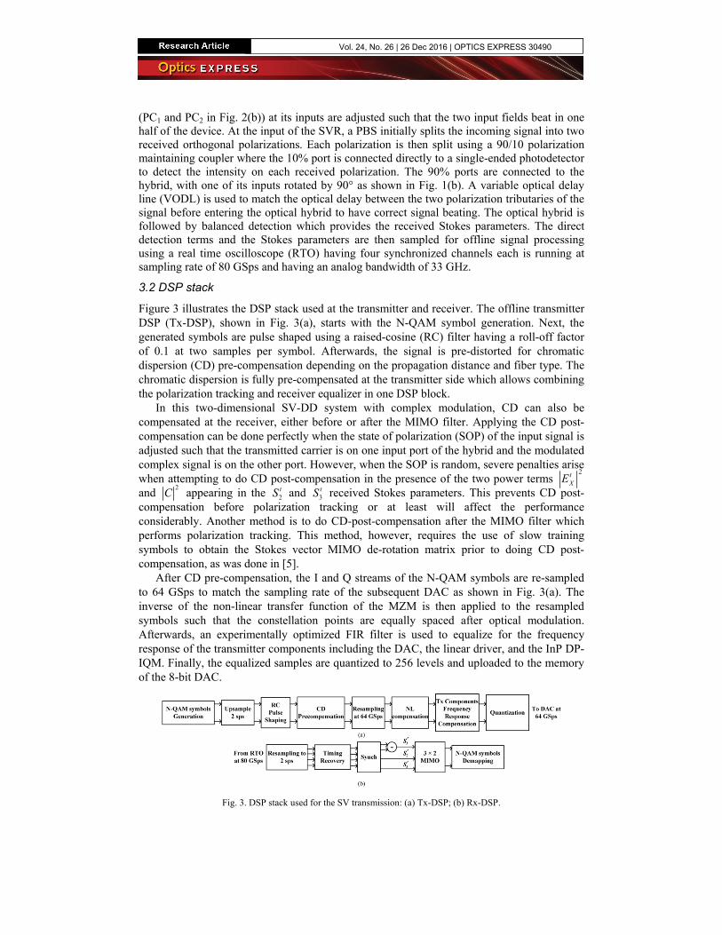
Figure 3 illustrates the DSP stack used at the transmitter and receiver. The offline transmitter DSP (Tx-DSP), shown in Fig. 3(a), starts with the N-QAM symbol generation. Next, the generated symbols are pulse shaped using a raised-cosine (RC) filter having a roll-off factor of 0.1 at two samples per symbol. Afterwards, the signal is pre-distorted for chromatic dispersion (CD) pre-compensation depending on the propagation distance and fiber type. The chromatic dispersion is fully pre-compensated at the transmitter side which allows combining the polarization tracking and receiver equalizer in one DSP block.
In this two-dimensional SV-DD system with complex modulation, CD can also be compensated at the receiver, either before or after the MIMO filter. Applying the CD post-compensation can be done perfectly when the state of polarization (SOP) of the input signal is adjusted such that the transmitted carrier is on one input port of the hybrid and the modulated complex signal is on the other port. However, when the SOP is random, severe penalties arise when attempting to do CD post-compensation in the presence of the two power terms
2tXE
and 2
C appearing in the 2tS and 3
tS received Stokes parameters. This prevents CD post-compensation before polarization tracking or at least will affect the performance considerably. Another method is to do CD-post-compensation after the MIMO filter which performs polarization tracking. This method, however, requires the use of slow training symbols to obtain the Stokes vector MIMO de-rotation matrix prior to doing CD post-compensation, as was done in [5].
After CD pre-compensation, the I and Q streams of the N-QAM symbols are re-sampled to 64 GSps to match the sampling rate of the subsequent DAC as shown in Fig. 3(a). The inverse of the non-linear transfer function of the MZM is then applied to the resampled symbols such that the constellation points are equally spaced after optical modulation. Afterwards, an experimentally optimized FIR filter is used to equalize for the frequency response of the transmitter components including the DAC, the linear driver, and the InP DP-IQM. Finally, the equalized samples are quantized to 256 levels and uploaded to the memory of the 8-bit DAC.
Fig. 3. DSP stack used for the SV transmission: (a) Tx-DSP; (b) Rx-DSP.
Vol. 24, No. 26 | 26 Dec 2016 | OPTICS EXPRESS 30490
The offline receiver DSP (Rx-DSP) starts by re-sampling the captured patterns from 80 GSps to twice the symbol rate because all Rx-DSP operates at two samples per symbol. After re-sampling, a timing recovery to select the appropriate sampling instance is performed using the same algorithm as in [20]. After constructing the 1
rS parameter from the two direct detection terms (
2rXE and
2rYE ), the 3 × 2 real valued MIMO adaptive filtering is used for
two roles: (i) it tracks the polarization rotation and inverts it according to Eq. (1) to recover the transmitted Stokes parameters 2
tS and 3tS and (ii) it equalizes for any residual inter-
symbol interference (ISI). In the 3 × 2 MIMO, training symbol least mean squares (TS-LMS) algorithm is used initially to track the polarization rotation and determine the adaptive filter tap coefficients. After the training symbols, decision directed LMS (DD-LMS) replaces TS-LMS where symbol decisions in the steady-state operation are used to slowly adapt the taps of the 3 × 2 MIMO. Finally, the received symbols are de-mapped into bits for BER counting. The BER counting is done over 13,762,560 bits, 10,321,920 bits, and 6,881,280 bits, in case of 16-QAM, 8-QAM and QPSK, respectively.
4. Results
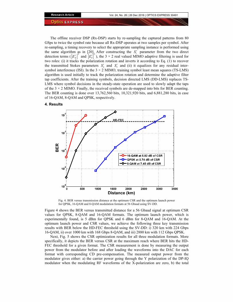
Fig. 4. BER versus transmission distance at the optimum CSR and the optimum launch power for QPSK, 16-QAM and 8-QAM modulation formats at 56 Gbaud using SV-DD.
Figure 4 shows the BER versus transmitted distance for a 56 Gbaud signal at optimum CSR values for QPSK, 8-QAM and 16-QAM formats. The optimum launch power, which is experimentally found, is 5 dBm for QPSK and 6 dBm for 8-QAM and 16-QAM. At the optimum launch power and CSR values, we achieve the following three key transmission results with BER below the HD-FEC threshold using the SV-DD: i) 320 km with 224 Gbps 16-QAM, ii) over 1000 km with 168 Gbps 8-QAM, and iii) 2880 km with 112 Gbps QPSK.
Next, Fig. 5 shows the CSR optimization results for all three modulation formats. More specifically, it depicts the BER versus CSR at the maximum reach where BER hits the HD-FEC threshold for a given format. The CSR measurement is done by measuring the output power from the modulator before and after loading the waveforms into the DAC for each format with corresponding CD pre-compensation. The measured output power from the modulator gives either: a) the carrier power going through the Y polarization of the DP-IQ modulator when the modulating RF waveforms of the X-polarization are zero, b) the total
Vol. 24, No. 26 | 26 Dec 2016 | OPTICS EXPRESS 30491
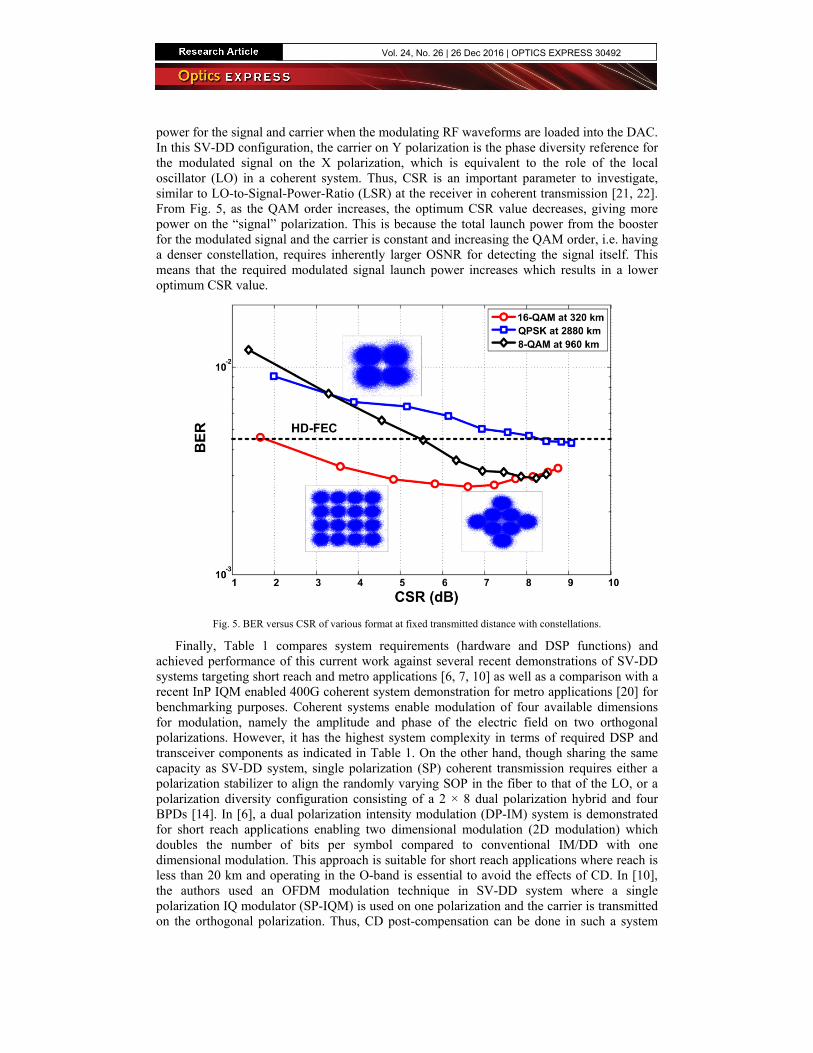
power for the signal and carrier when the modulating RF waveforms are loaded into the DAC. In this SV-DD configuration, the carrier on Y polarization is the phase diversity reference for the modulated signal on the X polarization, which is equivalent to the role of the local oscillator (LO) in a coherent system. Thus, CSR is an important parameter to investigate, similar to LO-to-Signal-Power-Ratio (LSR) at the receiver in coherent transmission [21, 22]. From Fig. 5, as the QAM order increases, the optimum CSR value decreases, giving more power on the “signal” polarization. This is because the total launch power from the booster for the modulated signal and the carrier is constant and increasing the QAM order, i.e. having a denser constellation, requires inherently larger OSNR for detecting the signal itself. This means that the required modulated signal launch power increases which results in a lower optimum CSR value.
Fig. 5. BER versus CSR of various format at fixed transmitted distance with constellations.
Finally, Table 1 compares system requirements (hardware and DSP functions) and achieved performance of this current work against several recent demonstrations of SV-DD systems targeting short reach and metro applications [6, 7, 10] as well as a comparison with a recent InP IQM enabled 400G coherent system demonstration for metro applications [20] for benchmarking purposes. Coherent systems enable modulation of four available dimensions for modulation, namely the amplitude and phase of the electric field on two orthogonal polarizations. However, it has the highest system complexity in terms of required DSP and transceiver components as indicated in Table 1. On the other hand, though sharing the same capacity as SV-DD system, single polarization (SP) coherent transmission requires either a polarization stabilizer to align the randomly varying SOP in the fiber to that of the LO, or a polarization diversity configuration consisting of a 2 × 8 dual polarization hybrid and four BPDs [14]. In [6], a dual polarization intensity modulation (DP-IM) system is demonstrated for short reach applications enabling two dimensional modulation (2D modulation) which doubles the number of bits per symbol compared to conventional IM/DD with one dimensional modulation. This approach is suitable for short reach applications where reach is less than 20 km and operating in the O-band is essential to avoid the effects of CD. In [10], the authors used an OFDM modulation technique in SV-DD system where a single polarization IQ modulator (SP-IQM) is used on one polarization and the carrier is transmitted on the orthogonal polarization. Thus, CD post-compensation can be done in such a system
Vol. 24, No. 26 | 26 Dec 2016 | OPTICS EXPRESS 30492
after the polarization rotation is inverted following the method described in [5] which extends the reach of SV-DD systems. In our work, we use the same configuration in [10] (complex modulation on one polarization and carrier transmission on the other polarization), but instead we use single carrier modulation with CD pre-compensation at the transmitter replacing CD post-compensation. Our SV-DD scheme shows a significant reduction in terms of system complexity (hardware and DSP functions) compared to coherent systems while maintaining an almost similar performance of a SP coherent system.
Table 1. Schemes for SV-DD compared to 400G coherent system demonstration (SP-IQM: single polarization IQ modulator, IFFT: inverse fast Fourier transform).
DP coherent system SV-DD system
(DP-IM) SV-DD system
SP-IQ modulation Our work
Tx main components
• DP-IQM (6 MZMs)• 4 DAC channels • 4 RF amplifiers
• 2 MZMs • 2 DAC channels • 2 RF amplifiers
• SP-IQM (3 MZMs)• 2 DAC channels • 2 RF amplifiers
• SP-IQM (3 MZMs)• 2 DAC channels • 2 RF amplifiers
Rx main components
• Dual Pol. Hybrid• 4 BPDs• 4 ADCs• LO
• Single Pol. Hybrid• 2 SE-PDs and 2
BPDs• 4 ADCs
• Single Pol. Hybrid• 2 SE-PDs and 2
BPDs• 4 ADCs
• Single Pol. Hybrid• 2 SE-PDs and 2
BPDs• 4 ADCs (3 ADCs if
balanced detection used to construct ofS1 parameter)
Main use of DSP at transmitter and
receiver
• Digital Pre-emphasis• 2 × 2 complex
MIMO• CD post-comp• Freq. Offset
Removal• Phase noise
mitigation
• Digital Pre-emphasis• 4 × 2 real MIMO
• OFDM synch• Stokes training (4 ×
2 real MIMO)• IFFT / FFT• Channel equal. • CD post-comp
• Digital Pre-emphasis• CD pre-comp• 3 × 2 real MIMO
Modulation format
DP-16QAM DP-PAM4 OFDM 16QAM
Modulated dimensions
4 2 2 2
Throughput-times- distance
(Gbps.km) 143,360 2,240 48,000 71,680
Bit rate (Gbps) 448 224 100 224
Reach (km) 320 10 480 320
BER at specified reach
1.5 × 10⁻³ 3.8 × 10⁻³ ~2 × 10⁻² 2.8 × 10⁻³
Reference [20] [6] [10]
5. Conclusion
We demonstrated 100G and 200G Stokes-Vector transmission using an InP DP-IQM and a SVR DD on a single carrier using different modulation formats, namely QPSK, 8-QAM and 16-QAM. For 56 Gbaud 16-QAM signal, the total throughput-times-distance product is 71,680 Gbps.km at an optimized CSR value of 6 dB. For 56 Gbaud QPSK signal, the total throughput-times-distance product is 322,560 Gbps.km at an optimized CSR value of 8 dB. These results show the viability of using SVR DD and small form factor integrated InP IQM to meet 100G and 200G transmission system requirements for metro applications.
Vol. 24, No. 26 | 26 Dec 2016 | OPTICS EXPRESS 30493


![피 단체급식 - adweb.co.kr600g, 고다슬라이스치즈 200g, 백후추 10g, 백포도주 100g, 파슬리가루 10g, 올리브유 100g 재료 [100인분] TIP 1. 고다슬라이스치즈](https://img.pdfslide.net/doc/110x75/5f0e7cd07e708231d43f7c5f/-ee-adwebcokr-600g-eee-200g-e-10g.jpg)

![400G+5G - img3.gelonghui.com · [Table_MainInfo][Table_Title] / 400G+5G [Table_Summary] 1 2 BAT 17% 40% ICP 3 400G 2019 2020 4 100G 400G (( ) 5G 1 4G 5G 6G/10G 25G 10G/100G 100G/200G/400G](https://img.pdfslide.net/doc/110x75/5e6c5d2df191f20be52e7612/400g5g-img3-tablemaininfotabletitle-400g5g-tablesummary-1-2-bat.jpg)


![ORFI '583b]] 157B] — (1ü.200g) 398 IA .2,700PJ 7 E 27 H (H ...ORFI '583b]] 157B] — (1ü.200g) 398 IA .2,700PJ 7 E 27 H (H) ! (G) (H) öJIlL2JË E-lRJlIûffi*T3-5-1 (100g) l) (100g)](https://img.pdfslide.net/doc/110x75/5f999dd3b4776f561367126a/orfi-583b-157b-a-1200g-398-ia-2700pj-7-e-27-h-h-orfi-583b-157b.jpg)