Embed Size (px)
Citation preview
100G backplane PAM4 PHY encoding (revised)
IEEE P802.3bj March 2012, Hawaii
Matt Brown – AppliedMicro Sudeep Bhoja – Broadcom
2 IEEE P802.3bj, March 2012, Hawaii
Contributors and Supporters
Ran Adee, Intel
Stephen Bates, PMC-Sierra
Will Bliss, Broadcom
David Chalupsky, Intel
Dariush Dabiri, APM
Dan Dove, APM
Howard Frazier, Broadcom
Ali Ghiasi, Broadcom
Ziad Hatab, Vitesse
Dimitrios Giannakopoulos, APM
Adam Healey, LSI
Beth Kochuparambil, Cisco
Kent Lusted, Intel
Richard Mellitz, Intel
Venkatesh Nagapudi, APM
Vasu Parthasarathy, Broadcom
Jamal Riani, Marvell
3 IEEE P802.3bj, March 2012, Hawaii
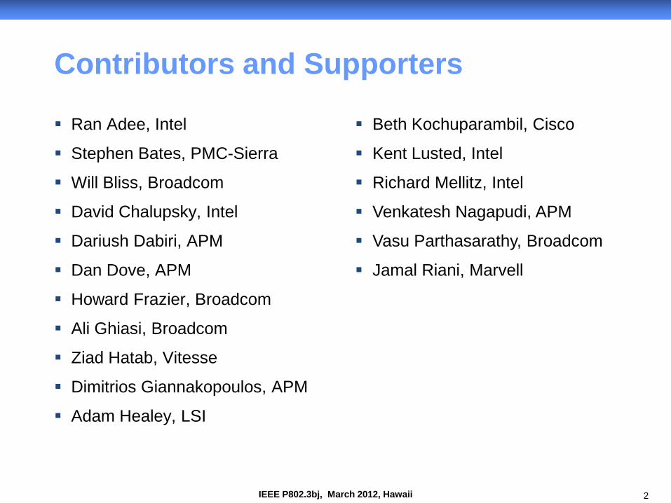
Introduction
Provide a strawman baseline specification for the PAM4 FEC, PMA, and PMD transmitter encoding.
Revised from January presentation to incorporate 256B/257B transcoding and alignment marker mapping.
4 IEEE P802.3bj, March 2012, Hawaii
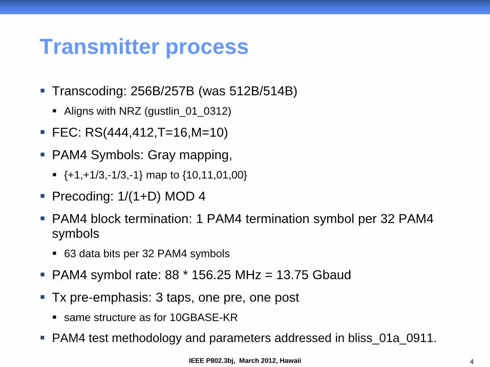
Transmitter process
Transcoding: 256B/257B (was 512B/514B) Aligns with NRZ (gustlin_01_0312)
FEC: RS(444,412,T=16,M=10)
PAM4 Symbols: Gray mapping, {+1,+1/3,-1/3,-1} map to {10,11,01,00}
Precoding: 1/(1+D) MOD 4
PAM4 block termination: 1 PAM4 termination symbol per 32 PAM4 symbols 63 data bits per 32 PAM4 symbols
PAM4 symbol rate: 88 * 156.25 MHz = 13.75 Gbaud
Tx pre-emphasis: 3 taps, one pre, one post same structure as for 10GBASE-KR
PAM4 test methodology and parameters addressed in bliss_01a_0911.
5 IEEE P802.3bj, March 2012, Hawaii
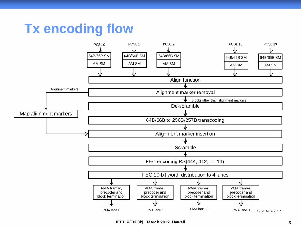
Tx encoding flow
Align function
PCSL 0
FEC 10-bit word distribution to 4 lanes
AM SM
PMA framer, precoder and
block termination
13.75 Gbaud * 4
PCSL 1 PCSL 2 PCSL 18 PCSL 19
PMA lane 0 PMA lane 1 PMA lane 2 PMA lane 3
Scramble
FEC encoding RS(444, 412, t = 16)
64B/66B to 256B/257B transcoding
64B/66B SM
Alignment marker removal
AM SM
64B/66B SM
AM SM
64B/66B SM
AM SM
64B/66B SM
AM SM
64B/66B SM
De-scramble
Alignment marker insertion
Map alignment markers
Alignment markers
Blocks other than alignment markers
PMA framer, precoder and
block termination
PMA framer, precoder and
block termination
PMA framer, precoder and
block termination
6 IEEE P802.3bj, March 2012, Hawaii
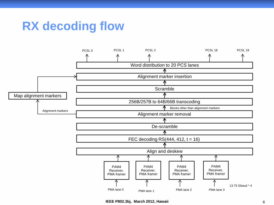
RX decoding flow
Word distribution to 20 PCS lanes
PCSL 0
Align and deskew
PAM4 Receiver,
PMA framer
13.75 Gbaud * 4
PCSL 1 PCSL 2 PCSL 18 PCSL 19
PMA lane 0 PMA lane 1
PAM4 Receiver,
PMA framer
PAM4 Receiver,
PMA framer
PAM4 Receiver,
PMA framer
PMA lane 2 PMA lane 3
De-scramble
FEC decoding RS(444, 412, t = 16)
256B/257B to 64B/66B transcoding
Alignment marker insertion
Scramble
Alignment marker removal
Map alignment markers
Alignment markers Blocks other than alignment markers
7 IEEE P802.3bj, March 2012, Hawaii
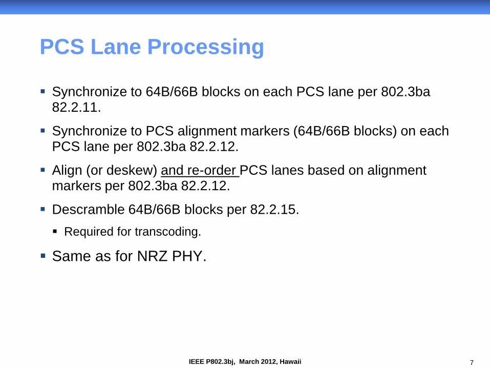
PCS Lane Processing
Synchronize to 64B/66B blocks on each PCS lane per 802.3ba 82.2.11.
Synchronize to PCS alignment markers (64B/66B blocks) on each PCS lane per 802.3ba 82.2.12.
Align (or deskew) and re-order PCS lanes based on alignment markers per 802.3ba 82.2.12.
Descramble 64B/66B blocks per 82.2.15. Required for transcoding.
Same as for NRZ PHY.
8 IEEE P802.3bj, March 2012, Hawaii
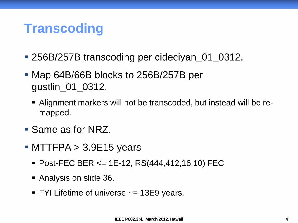
Transcoding
256B/257B transcoding per cideciyan_01_0312.
Map 64B/66B blocks to 256B/257B per gustlin_01_0312. Alignment markers will not be transcoded, but instead will be re-
mapped.
Same as for NRZ.
MTTFPA > 3.9E15 years Post-FEC BER <= 1E-12, RS(444,412,16,10) FEC
Analysis on slide 36.
FYI Lifetime of universe ~= 13E9 years.
9 IEEE P802.3bj, March 2012, Hawaii
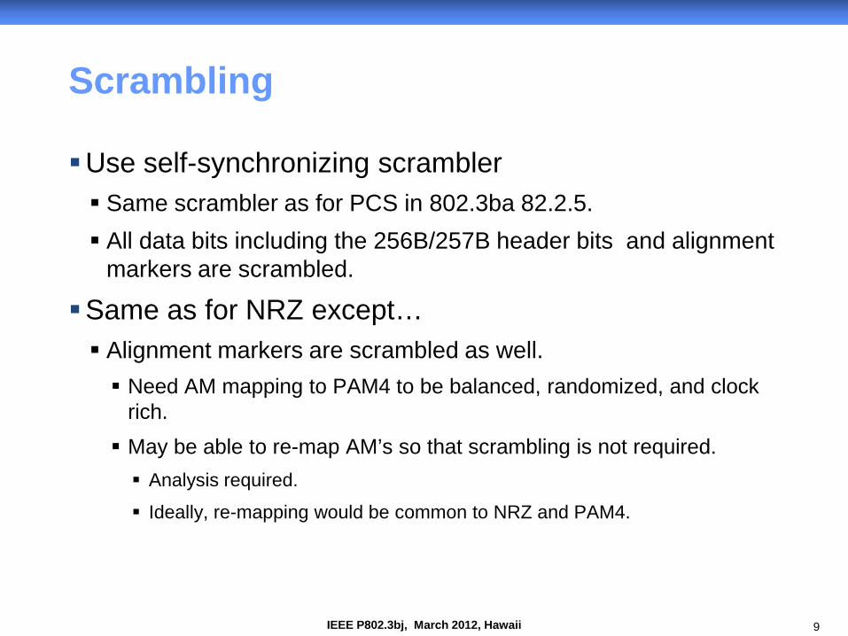
Scrambling
Use self-synchronizing scrambler Same scrambler as for PCS in 802.3ba 82.2.5. All data bits including the 256B/257B header bits and alignment
markers are scrambled.
Same as for NRZ except… Alignment markers are scrambled as well. Need AM mapping to PAM4 to be balanced, randomized, and clock
rich. May be able to re-map AM’s so that scrambling is not required. Analysis required.
Ideally, re-mapping would be common to NRZ and PAM4.
10 IEEE P802.3bj, March 2012, Hawaii
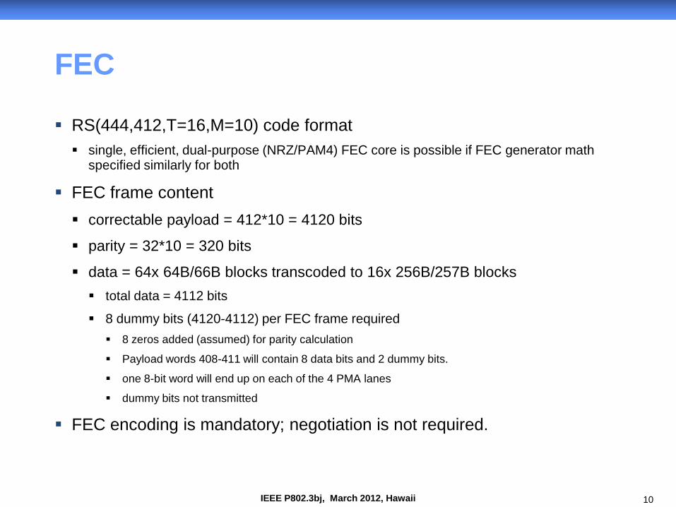
FEC
RS(444,412,T=16,M=10) code format single, efficient, dual-purpose (NRZ/PAM4) FEC core is possible if FEC generator math
specified similarly for both
FEC frame content correctable payload = 412*10 = 4120 bits
parity = 32*10 = 320 bits
data = 64x 64B/66B blocks transcoded to 16x 256B/257B blocks total data = 4112 bits
8 dummy bits (4120-4112) per FEC frame required 8 zeros added (assumed) for parity calculation
Payload words 408-411 will contain 8 data bits and 2 dummy bits.
one 8-bit word will end up on each of the 4 PMA lanes
dummy bits not transmitted
FEC encoding is mandatory; negotiation is not required.
11 IEEE P802.3bj, March 2012, Hawaii
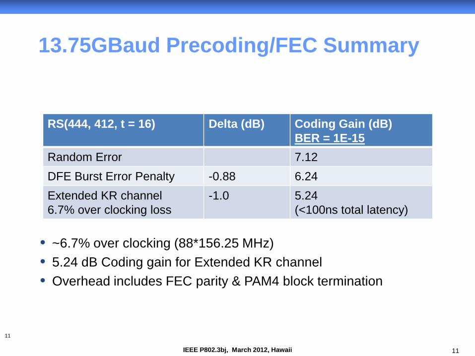
13.75GBaud Precoding/FEC Summary
11
RS(444, 412, t = 16) Delta (dB) Coding Gain (dB) BER = 1E-15
Random Error 7.12 DFE Burst Error Penalty -0.88 6.24 Extended KR channel 6.7% over clocking loss
-1.0 5.24 (<100ns total latency)
• ~6.7% over clocking (88*156.25 MHz) • 5.24 dB Coding gain for Extended KR channel • Overhead includes FEC parity & PAM4 block termination
12 IEEE P802.3bj, March 2012, Hawaii
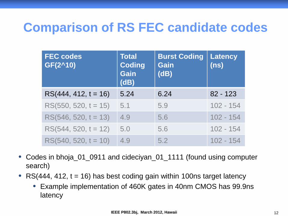
Comparison of RS FEC candidate codes
FEC codes GF(2^10)
Total Coding Gain (dB)
Burst Coding Gain (dB)
Latency (ns)
RS(444, 412, t = 16) 5.24 6.24 82 - 123 RS(550, 520, t = 15) 5.1 5.9 102 - 154 RS(546, 520, t = 13) 4.9 5.6 102 - 154 RS(544, 520, t = 12) 5.0 5.6 102 - 154 RS(540, 520, t = 10) 4.9 5.2 102 - 154
• Codes in bhoja_01_0911 and cideciyan_01_1111 (found using computer search)
• RS(444, 412, t = 16) has best coding gain within 100ns target latency • Example implementation of 460K gates in 40nm CMOS has 99.9ns
latency
13 IEEE P802.3bj, March 2012, Hawaii
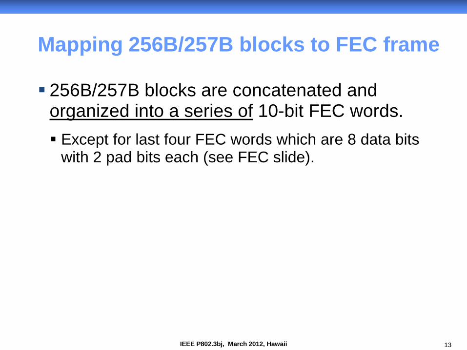
Mapping 256B/257B blocks to FEC frame
256B/257B blocks are concatenated and organized into a series of 10-bit FEC words. Except for last four FEC words which are 8 data bits
with 2 pad bits each (see FEC slide).
14 IEEE P802.3bj, March 2012, Hawaii
pppppppppp pppppppppp pppppppppp pppppppppp
pppppppppp pppppppppp pppppppppp pppppppppp
… … … …
pppppppppp pppppppppp pppppppppp pppppppppp
pppppppppp pppppppppp pppppppppp pppppppppp
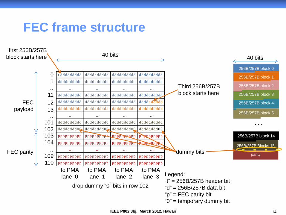
FEC frame structure
tddddddddd 0 1
… 11
…
12
…
dddddddddd
… …
first 256B/257B block starts here
Third 256B/257B block starts here
… … … … …
101 dddddddd00 dddddddd00 dddddddd00 dddddddd00 102
dummy bits
dddddddddd
dddddddddd dddddddddd
dddddddddd dddddddddd
dddddddddd
dddddddddd dddddddddd dddddddddd dddddddddd
dddddddddd dddddddddd dddddddddd ddddtddddd
dddddddddd dddddddddd dddddddddd dddddddddd
dddddddddd dddddddddd dddddddddd dddddddddd
…
103 104
109 110
40 bits
to PMA lane 0
FEC parity
FEC payload
to PMA lane 1
to PMA lane 2
to PMA lane 3
drop dummy “0” bits in row 102
Legend: “t” = 256B/257B header bit “d” = 256B/257B data bit “p” = FEC parity bit “0” = temporary dummy bit
parity
256B/257B Blocks 15
40 bits
13
256B/257B block 0
256B/257B block 1
256B/257B block 2
256B/257B block 3
256B/257B block 4
256B/257B block 5
256B/257B block 14
…
15 IEEE P802.3bj, March 2012, Hawaii
RS Symbol index
0 1 2 3 4 5 6 7 8 9 10 11 12 13 14 15
Row index
0 B0
1 B0 7b 3b B1
2 B1
3 B1 4b 6b B2
4 B2 1b 9b B3
5 B3
6 B3 8b 2b B4
7 B4
8 5b 5b B5
9 B5 2b 8b B6
10 B6
11 B6 9b 1b B7
12 B7 6b 4b B8
… …
22 B13 70b
B138b
B14 2b
B14 80b
23 B14 160b
24 B14 10b
B14 5b
B15 5b
B15 140b
25 B15 80b
B15 8b
0 B15 8b
0 B15 8b
0 B15 8b
0 Checksum
26 Checksum
27 Checksum No data
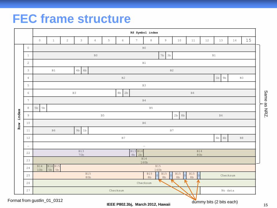
FEC frame structure
dummy bits (2 bits each) Format from gustlin_01_0312
Same as N
RZ.
16 IEEE P802.3bj, March 2012, Hawaii
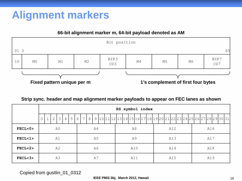
Alignment markers
RS symbol index
0 1 2 3 4 5 6 7 8 9 10 11 12 13 14 15 16 17 18 19 20 21 22 23 24 25 26 27 28 29 30 31
FECL<0> A0 A4 A8 A12 A16
FECL<1> A1 A5 A9 A13 A17
FECL<2> A2 A6 A10 A14 A18
FECL<3> A3 A7 A11 A15 A19
Bit position
01 2 65
10 M0 M1 M2 BIP3 CD3
M4 M5 M6 BIP7 CD7
66-bit alignment marker m, 64-bit payload denoted as AM
Fixed pattern unique per m 1’s complement of first four bytes
Strip sync. header and map alignment marker payloads to appear on FEC lanes as shown
Copied from gustlin_01_0312
17 IEEE P802.3bj, March 2012, Hawaii
RS Symbol index
0 1 2 3 4 5 6 7 8 9 10 11 12 13 14 15
Row index
0 A00 A10 A20 A30 A01 A11 A21 A31 A02 A12 A22 A32 A03 A13 A23 A33
1 A04 A14 A24 A34 A05 A15 A25 A35 A06 A46
A16 A56
A26 A66
A36 A76
A47 A57 A67 A77
2 A48 A58 A68 A78 A49 A59 A69 A79 A410 A510 A610 A710 A411 A511 A611 A711
3 A412 A812
A512 A912
A612 A1012
A712 A1112
A813 A913 A1013 A1113 A814 A914 A1014 A1114 A815 A915 A1015 A1115
4 A816 A916 A1016 A1116 A817 A917 A1017 A1117 A818 A918 A1018 A1118 A819 A1219
A919 A1319
A1019 A1419
A1119 A1519
5 A1220 A1320 A1420 A1520 A1221 A1321 A1421 A1521 A1222 A1322 A1422 A1522 A1223 A1323 A1423 A1523
6 A1224 A1324 A1424 A1524 A1225 A1625
A1325 A1725
A1425 A1825
A1525 A1925
A1626 A1726 A1826 A1926 A1627 A1727 A1827 A1827
7 A1628 A1728 A1828 A1928 A1629 A1729 A1829 A1929 A1630 A1730 A1830 A1930 A1631 A1731 A1831 A1931
8 P 5b
B5 5b
B5 150b
9 B5
100b B5 2b
B6 8b
B6 50b
… …
24 B14 10b
B14 5b
B15 5b
B15 140b
25 B15 80b
B15 8b
0 B15 8b
0 B15 8b
0 B15 8b
0 Checksum
40b
26 Checksum
160b
27 Checksum
120b
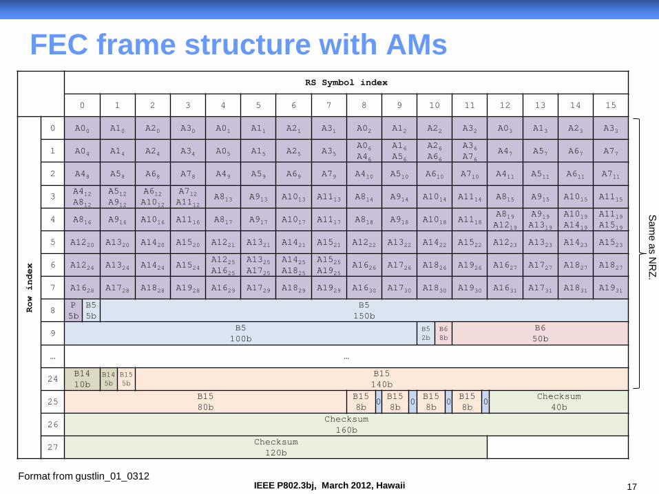
FEC frame structure with AMs
Format from gustlin_01_0312
Same as N
RZ.
18 IEEE P802.3bj, March 2012, Hawaii
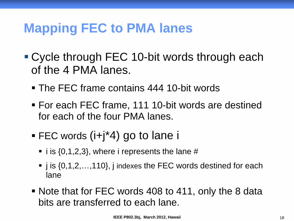
Mapping FEC to PMA lanes
Cycle through FEC 10-bit words through each of the 4 PMA lanes. The FEC frame contains 444 10-bit words
For each FEC frame, 111 10-bit words are destined for each of the four PMA lanes.
FEC words (i+j*4) go to lane i i is {0,1,2,3}, where i represents the lane #
j is {0,1,2,…,110}, j indexes the FEC words destined for each lane
Note that for FEC words 408 to 411, only the 8 data bits are transferred to each lane.
19 IEEE P802.3bj, March 2012, Hawaii
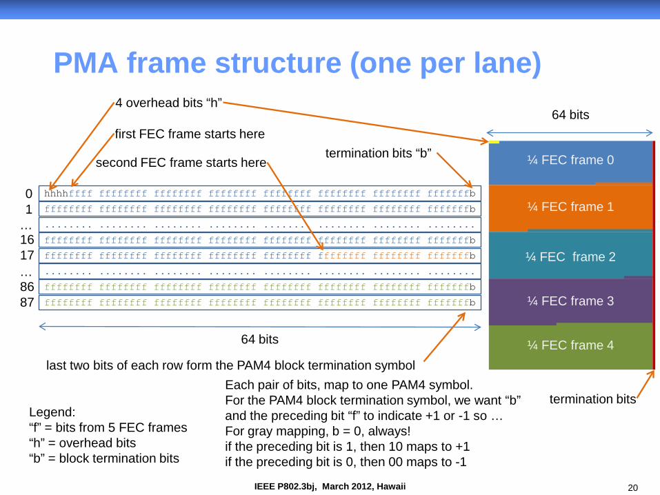
PMA Frame
PMA frame generated for each PMA lane.
PMA frame is composed of… 5 quarter FEC frames, 5*(4440-8)/4 = 5540 bits
4 overhead bits essential to give a resultant PAM4 symbol rate of 88 * 156.25 MHz
various possible applications discussed on subsequent slide
88 PAM4 block termination bits 1 termination bit per 63 data bits
5632 bits total
20 IEEE P802.3bj, March 2012, Hawaii
PMA frame structure (one per lane)
hhhhffff ffffffff ffffffff ffffffff ffffffff ffffffff ffffffff fffffffb 0 1
…
4 overhead bits “h”
64 bits
Legend: “f” = bits from 5 FEC frames “h” = overhead bits “b” = block termination bits
termination bits “b”
ffffffff ffffffff ffffffff ffffffff ffffffff ffffffff ffffffff fffffffb
........ ........ ........ ........ ........ ........ ........ ........
ffffffff ffffffff ffffffff ffffffff ffffffff ffffffff ffffffff fffffffb
ffffffff ffffffff ffffffff ffffffff ffffffff ffffffff ffffffff fffffffb
first FEC frame starts here
… ........ ........ ........ ........ ........ ........ ........ ........
ffffffff ffffffff ffffffff ffffffff ffffffff ffffffff ffffffff fffffffb
ffffffff ffffffff ffffffff ffffffff ffffffff ffffffff ffffffff fffffffb
second FEC frame starts here
Each pair of bits, map to one PAM4 symbol. For the PAM4 block termination symbol, we want “b” and the preceding bit “f” to indicate +1 or -1 so … For gray mapping, b = 0, always! if the preceding bit is 1, then 10 maps to +1 if the preceding bit is 0, then 00 maps to -1
last two bits of each row form the PAM4 block termination symbol
¼ FEC frame 0
64 bits
¼ FEC frame 1
¼ FEC frame 2
¼ FEC frame 3
¼ FEC frame 4
termination bits
86 87
16 17
21 IEEE P802.3bj, March 2012, Hawaii
PMA Frame Overhead Bits
Each PMA per-lane frame has 4 overhead bits.
Must be randomized or at least “friendly”.
Various applications … PMA frame alignment (see previous slide)
lane identification
control channel for remote transmitter control
vendor specific use
22 IEEE P802.3bj, March 2012, Hawaii
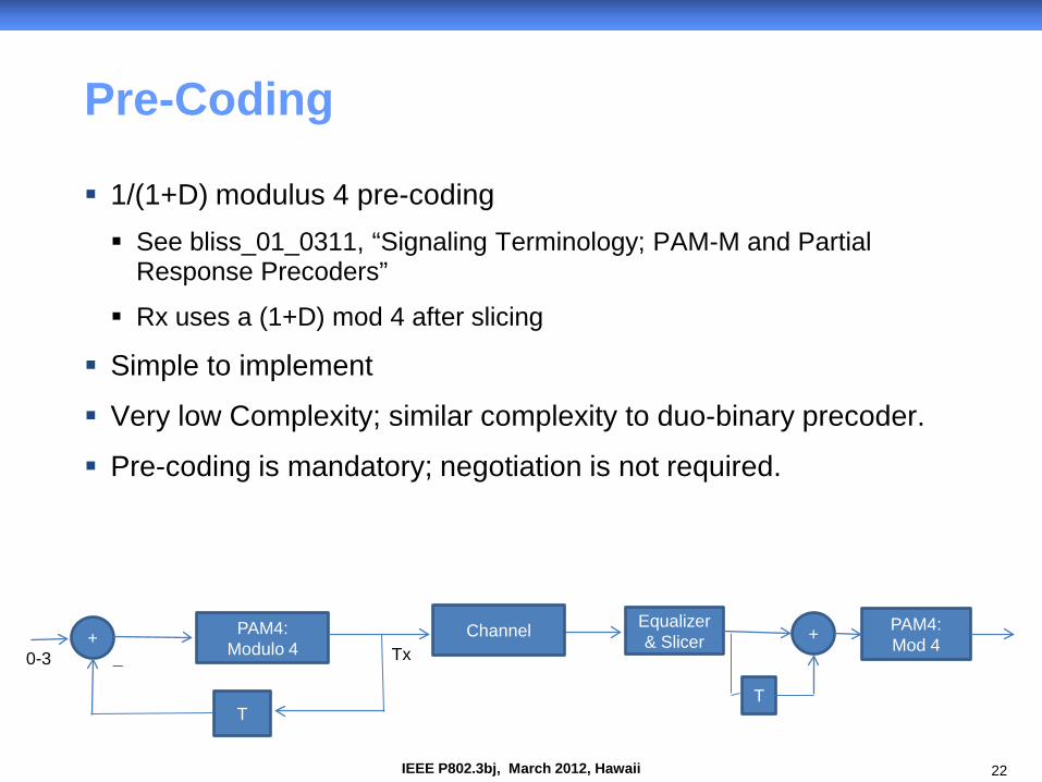
Pre-Coding
1/(1+D) modulus 4 pre-coding See bliss_01_0311, “Signaling Terminology; PAM-M and Partial
Response Precoders”
Rx uses a (1+D) mod 4 after slicing
Simple to implement
Very low Complexity; similar complexity to duo-binary precoder.
Pre-coding is mandatory; negotiation is not required.
+ PAM4: Modulo 4
T
Tx
Equalizer & Slicer Channel +
T
PAM4: Mod 4
0-3 _
23 IEEE P802.3bj, March 2012, Hawaii
12.8 12.9 13 13.1 13.2 13.3 13.4 13.5 13.6 13.7 13.80
1
2
3
4
5
6
7
8
Baud Rate GB/s
Codi
ng G
ain@
1E-1
5 BE
R (d
B)
RS on GF(210). Block size 4440 bits
PAM4 with Precoding for burst errorsPAM4 Burst Error Coding gainRandom Error coding gain
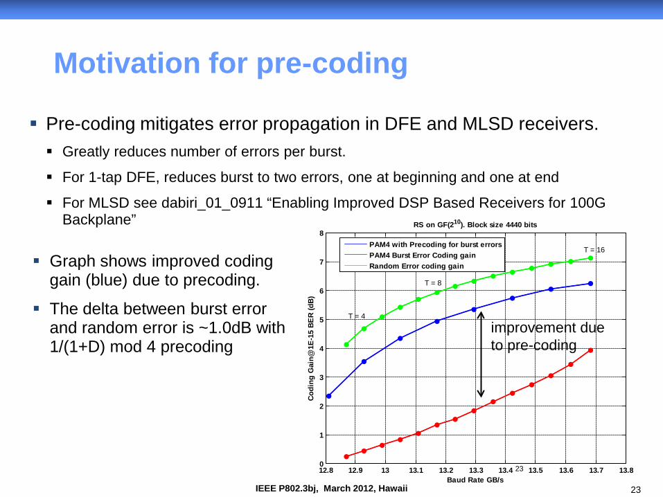
Motivation for pre-coding
Pre-coding mitigates error propagation in DFE and MLSD receivers. Greatly reduces number of errors per burst.
For 1-tap DFE, reduces burst to two errors, one at beginning and one at end
For MLSD see dabiri_01_0911 “Enabling Improved DSP Based Receivers for 100G Backplane”
23
Graph shows improved coding gain (blue) due to precoding.
The delta between burst error and random error is ~1.0dB with 1/(1+D) mod 4 precoding
improvement due to pre-coding
T = 16
T = 4
T = 8
24 IEEE P802.3bj, March 2012, Hawaii
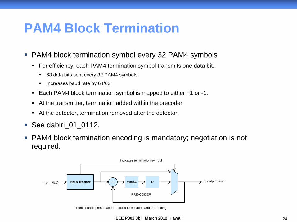
PAM4 Block Termination
PAM4 block termination symbol every 32 PAM4 symbols For efficiency, each PAM4 termination symbol transmits one data bit. 63 data bits sent every 32 PAM4 symbols
Increases baud rate by 64/63.
Each PAM4 block termination symbol is mapped to either +1 or -1.
At the transmitter, termination added within the precoder.
At the detector, termination removed after the detector.
See dabiri_01_0112.
PAM4 block termination encoding is mandatory; negotiation is not required.
PMA framer from FEC mod4 D
indicates termination symbol
Functional representation of block termination and pre-coding
PRE-CODER
to output driver
25 IEEE P802.3bj, March 2012, Hawaii
Motivation for PAM4 Block Termination
Block termination by transmitting known PAM4 symbols on a regular cycle enables… efficient and effective MLSD, maximum likelihood sequence detection
(dabiri_01_0911)
parallel DFE implementations Keshab K. Parhi, Pipelining of parallel multiplexor loop and Decision Feedback
Equalizers, ICASSP, 2004
26 IEEE P802.3bj, March 2012, Hawaii
PAM4 encoding
Gray mapping pre-coder output {10, 11, 01, 00} maps to {+1,+1/3,-1/3,-1}
based on 2B1Q coding used in HDSL and ISDN
27 IEEE P802.3bj, March 2012, Hawaii
PMA synchonization
Lock to PAM4 termination blocks by searching for PAM4 termination symbols PAM4 termination symbols (1 in 32) are always either +1 or -1.
Similar to framing on 10 or 01 sequence for 64B/66B, can borrow and modify 64B/66B synchronization state machine.
Lock to PMA frame Use known content of overhead bits. Once locked to the PAM4 termination blocks, look for 4 bits (2 PAM4 symbols)
every 88 rows.
Again, similar to 64B/66B synchronization.
28 IEEE P802.3bj, March 2012, Hawaii
Energy Efficient Ethernet Operation
Fast synchronization for REFRESH and WAKE. Synchronize on PAM4 termination symbols.
Use prescribed sequence to accelerate synchronization.
For REFRESH, PCS and FEC not required. Replace with scrambled sequence. Similar to EEE/LPI for 10GBASE-T.
For WAKE, rapid alignment markers not required by the PMA/PMD receiver. Will still be required at the PCS RX at the PCS end point.
No significant impact to work being done in EEE consensus group. Compatible and complementary with PCS state machine in Gustlin_02_1111.

29 IEEE P802.3bj, March 2012, Hawaii
Thanks!

30 IEEE P802.3bj, March 2012, Hawaii
BACKUP SLIDES
31 IEEE P802.3bj, March 2012, Hawaii
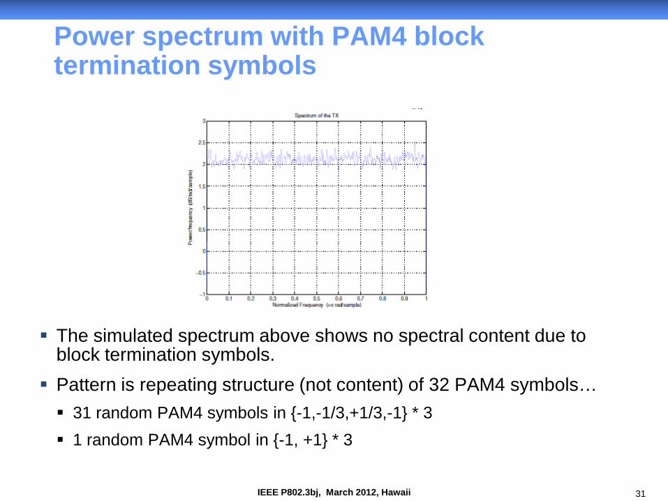
Power spectrum with PAM4 block termination symbols
The simulated spectrum above shows no spectral content due to block termination symbols.
Pattern is repeating structure (not content) of 32 PAM4 symbols… 31 random PAM4 symbols in {-1,-1/3,+1/3,-1} * 3 1 random PAM4 symbol in {-1, +1} * 3
32 IEEE P802.3bj, March 2012, Hawaii
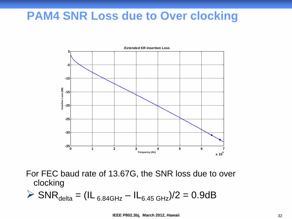
PAM4 SNR Loss due to Over clocking
For FEC baud rate of 13.67G, the SNR loss due to over clocking SNRdelta = (IL 6.84GHz – IL6.45 GHz)/2 = 0.9dB
0 1 2 3 4 5 6 7x 10⁹
-35
-30
-25
-20
-15
-10
-5
0
Frequency (Hz)
Inse
rtion
Los
s (d
B)
Extended KR insertion Loss
33 IEEE P802.3bj, March 2012, Hawaii
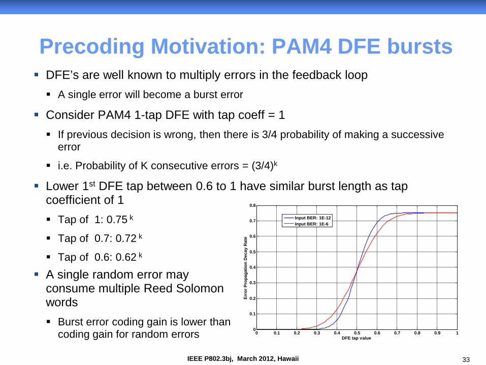
Precoding Motivation: PAM4 DFE bursts DFE’s are well known to multiply errors in the feedback loop A single error will become a burst error
Consider PAM4 1-tap DFE with tap coeff = 1 If previous decision is wrong, then there is 3/4 probability of making a successive
error
i.e. Probability of K consecutive errors = (3/4)k
Lower 1st DFE tap between 0.6 to 1 have similar burst length as tap coefficient of 1 Tap of 1: 0.75 k
Tap of 0.7: 0.72 k
Tap of 0.6: 0.62 k
A single random error may consume multiple Reed Solomon words Burst error coding gain is lower than
coding gain for random errors
0 0.1 0.2 0.3 0.4 0.5 0.6 0.7 0.8 0.9 10
0.1
0.2
0.3
0.4
0.5
0.6
0.7
0.8
DFE tap value
Erro
r Pro
paga
tion
Dec
ay R
ate
Input BER: 1E-12Input BER: 1E-6
34 IEEE P802.3bj, March 2012, Hawaii
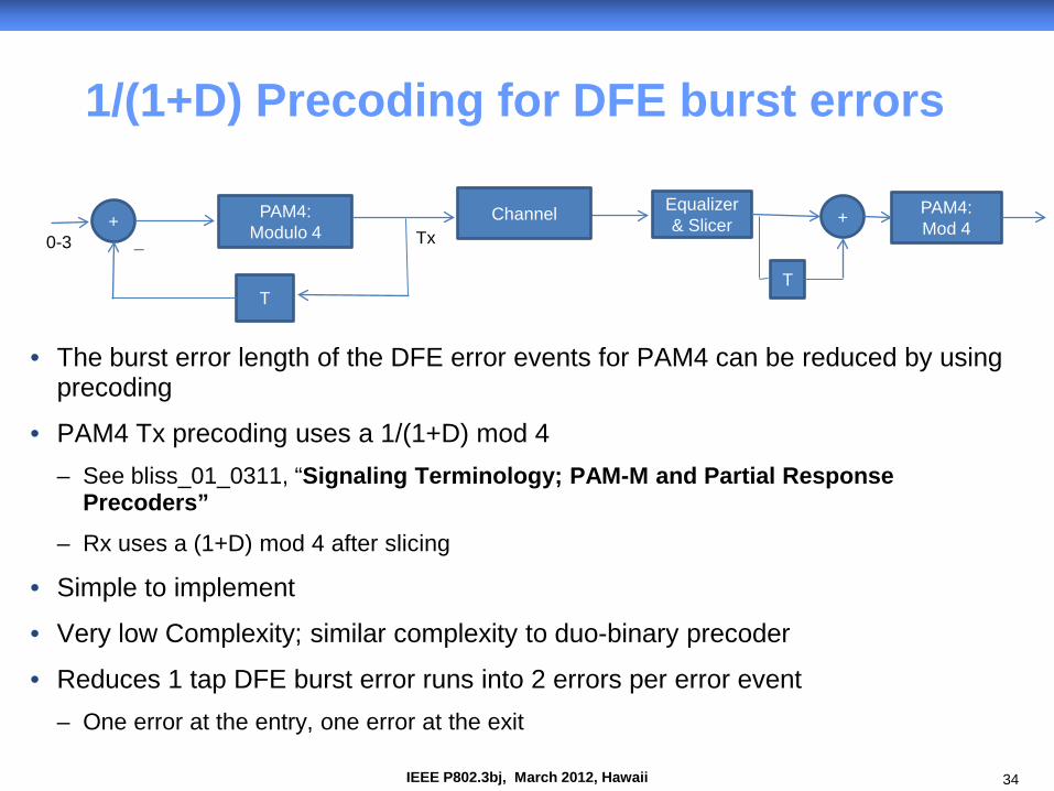
1/(1+D) Precoding for DFE burst errors
• The burst error length of the DFE error events for PAM4 can be reduced by using precoding
• PAM4 Tx precoding uses a 1/(1+D) mod 4 – See bliss_01_0311, “Signaling Terminology; PAM-M and Partial Response
Precoders”
– Rx uses a (1+D) mod 4 after slicing
• Simple to implement
• Very low Complexity; similar complexity to duo-binary precoder
• Reduces 1 tap DFE burst error runs into 2 errors per error event – One error at the entry, one error at the exit
+ PAM4: Modulo 4
T
Tx
Equalizer & Slicer Channel +
T
PAM4: Mod 4
0-3 _
35 IEEE P802.3bj, March 2012, Hawaii
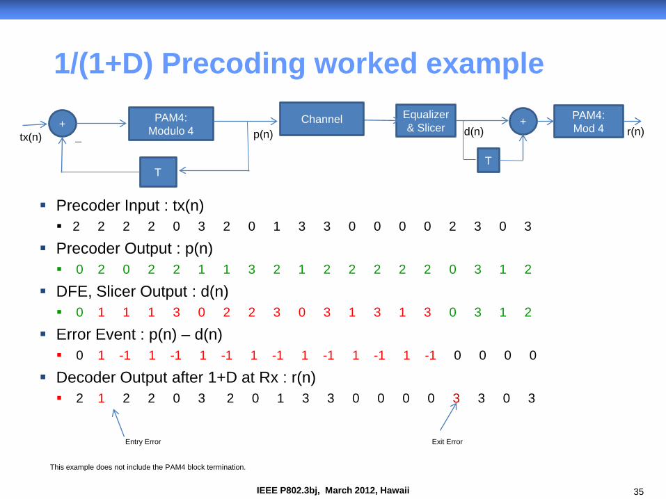
1/(1+D) Precoding worked example
Precoder Input : tx(n) 2 2 2 2 0 3 2 0 1 3 3 0 0 0 0 2 3 0 3
Precoder Output : p(n) 0 2 0 2 2 1 1 3 2 1 2 2 2 2 2 0 3 1 2
DFE, Slicer Output : d(n) 0 1 1 1 3 0 2 2 3 0 3 1 3 1 3 0 3 1 2
Error Event : p(n) – d(n) 0 1 -1 1 -1 1 -1 1 -1 1 -1 1 -1 1 -1 0 0 0 0
Decoder Output after 1+D at Rx : r(n) 2 1 2 2 0 3 2 0 1 3 3 0 0 0 0 3 3 0 3
+ PAM4: Modulo 4
T
p(n)
Equalizer & Slicer
Channel +
T
PAM4: Mod 4
tx(n) d(n) r(n)
Entry Error Exit Error
_
This example does not include the PAM4 block termination.
36 IEEE P802.3bj, March 2012, Hawaii
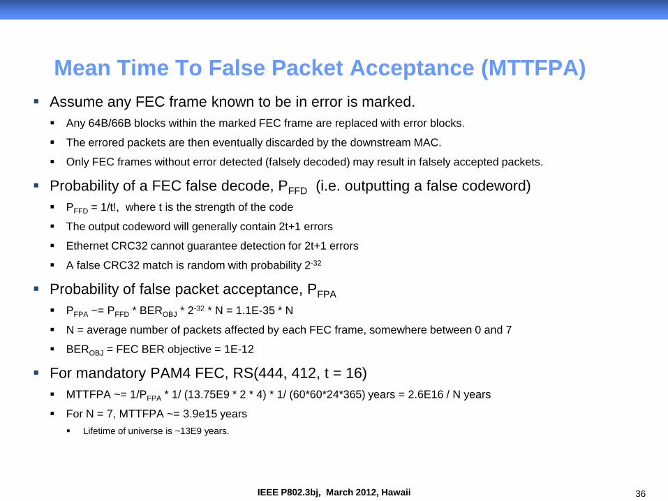
Assume any FEC frame known to be in error is marked. Any 64B/66B blocks within the marked FEC frame are replaced with error blocks.
The errored packets are then eventually discarded by the downstream MAC.
Only FEC frames without error detected (falsely decoded) may result in falsely accepted packets.
Probability of a FEC false decode, PFFD (i.e. outputting a false codeword) PFFD = 1/t!, where t is the strength of the code
The output codeword will generally contain 2t+1 errors
Ethernet CRC32 cannot guarantee detection for 2t+1 errors
A false CRC32 match is random with probability 2-32
Probability of false packet acceptance, PFPA
PFPA ~= PFFD * BEROBJ * 2-32 * N = 1.1E-35 * N
N = average number of packets affected by each FEC frame, somewhere between 0 and 7
BEROBJ = FEC BER objective = 1E-12
For mandatory PAM4 FEC, RS(444, 412, t = 16) MTTFPA ~= 1/PFPA * 1/ (13.75E9 * 2 * 4) * 1/ (60*60*24*365) years = 2.6E16 / N years
For N = 7, MTTFPA ~= 3.9e15 years Lifetime of universe is ~13E9 years.
Mean Time To False Packet Acceptance (MTTFPA)