Embed Size (px)
Citation preview
Perkins 1104 SeriesWORKSHOP MANUAL
Troubleshooting
4 cylinder, naturally aspirated, and turbocharged diesel engines for agricultural and industrial use
Publication RENR2696-00© Proprietary information of Perkins Engines Company Limited 2004, all rights reserved.The information is correct at the time of print.Published by Technical Publications.Perkins Engines Company Limited, Peterborough, PE1 5NA, England
3Table of Contents
Table of Contents
Troubleshooting Section
Electronic TroubleshootingSystem Overview .................................................... 5Glossary ................................................................. 9Electronic Service Tools ........................................ 12Diagnostic Codes .................................................. 13Indicator Lamps .................................................... 15Replacing the ECM ............................................... 18Self-Diagnostics .................................................... 19Sensors and Electrical Connectors ....................... 20Engine Wiring Information .................................... 26
Programming ParametersProgramming Parameters ..................................... 30Factory Passwords ................................................ 30Flash Programming .............................................. 30
System Configuration ParametersSystem Configuration Parameters ........................ 32
Troubleshooting without a Diagnostic CodeAlternator Noise (Noisy Operation) ....................... 33Alternator Will Not Charge (Charging Problem) .... 33Battery .................................................................. 33Can Not Reach Top Engine RPM ......................... 34Coolant in Engine Oil ............................................ 36Coolant Temperature Is Too High ......................... 37ECM Will Not Accept Factory Passwords ............. 38ECM Will Not Communicate with Other Systems orDisplay Modules .................................................. 38
Electronic Service Tool Will Not Communicate withECM .................................................................... 38
Engine Cranks but Will Not Start .......................... 39Engine Has Early Wear ........................................ 41Engine Misfires, Runs Rough or Is Unstable ........ 41Engine Oil in Cooling System ............................... 43Engine Speed Does Not Change .......................... 44Engine Stalls at Low RPM .................................... 45Engine Vibration ................................................... 45Engine Will Not Crank ........................................... 47Excessive Black Smoke ........................................ 48Excessive Engine Oil Consumption ...................... 49Excessive Valve Lash ........................................... 50Excessive White Smoke ....................................... 51Intake Air Temperature Is Too High ....................... 52Intermittent Engine Shutdown ............................... 53Intermittent Low Power or Power Cutout ............... 54Low Engine Oil Pressure ...................................... 56Low Power/Poor or No Response to Throttle ........ 57Mechanical Noise (Knock) in Engine .................... 59Noise Coming from Cylinder ................................. 59Poor Acceleration or Response ............................ 60
Troubleshooting with a Diagnostic CodeCID 0041 FMI 03 8v Sensor Power Supply, VoltageMore Than Normal .............................................. 62
CID 0041 FMI 04 8v Sensor Power Supply, VoltageLess Than Normal ............................................... 62
CID 0091 FMI 02 Throttle Demand Sensor Erratic OrIntermittent .......................................................... 62
CID 0091 FMI 03 Throttle Demand Sensor OpenCircuit Or Shorted High ....................................... 63
CID 0091 FMI 04 Throttle Demand Sensor ShortedLow ..................................................................... 63
CID 0091 FMI 08 Throttle Demand Sensor AbnormalSignal .................................................................. 64
CID 0091 FMI 12 Throttle Demand Sensor Out OfCalibration ........................................................... 64
CID 0100 FMI 03 Engine Oil Pressure Sensor OpenCircuit Or Shorted High ....................................... 64
CID 0100 FMI 04 Engine Oil Pressure SensorShorted Low ........................................................ 65
CID 0100 FMI 10 Engine Oil Pressure Sensor, PowerSupply Open Circuit ............................................ 65
CID 0102 FMI 03 Intake Manifold Pressure Sensor,Open Circuit Or Shorted High ............................. 66
CID 0102 FMI 04 Intake Manifold Pressure SensorShorted Low ........................................................ 66
CID 0102 FMI 10 Intake Manifold Pressure SensorPower Supply Open Circuit ................................. 67
CID 0105 FMI 03 Intake Manifold TemperatureSensor Open Circuit Or Shorted High ................ 67
CID 0105 FMI 04 Intake Manifold TemperatureSensor Shorted Low ........................................... 67
CID 0110 FMI 03 Engine Coolant TemperatureSensor Open Circuit Or Shorted High ................ 68
CID 0110 FMI 04 Engine Coolant TemperatureSensor Shorted Low ........................................... 68
CID 0174 FMI 02 Fuel Temperature Sensor Erratic,Intermittent .......................................................... 69
CID 0247 FMI 09 J1939 Datalink, AbnormalUpdate ................................................................ 69
CID 0253 FMI 02 Incorrect ECM Software ........... 69CID 0262 FMI 03 5v Sensor Power Supply, VoltageMore Than Normal .............................................. 70
CID 0262 FMI 04 5v Sensor Power Supply, VoltageLess Than Normal ............................................... 70
CID 0266 FMI 02 Incorrect Crank-without-injectinputs .................................................................. 71
CID 0320 FMI 02 Speed And Timing SensorIntermittent Loss Of Signal .................................. 71
CID 0320 FMI 11 Speed And Timing Sensor Loss OfSignal .................................................................. 71
CID 0342 FMI 02 Speed And Timing Sensor No.2Intermittent Signal ............................................... 72
CID 0774 FMI 02 Throttle Demand Sensor No.2Erratic Or Intermittent .......................................... 72
CID 0774 FMI 03 Throttle Demand Sensor No.2Open Circuit Or Shorted High ............................. 73
CID 0774 FMI 04 Throttle Demand Sensor No.2Shorted Low ........................................................ 73
CID 0774 FMI 08 Throttle Demand Sensor No.2Abnormal Signal .................................................. 73
CID 0774 FMI 12 Throttle Demand Sensor No.2 OutOf Calibration ...................................................... 74
CID 1627 FMI 03 Fuel Injection Pump Relay Did NotTurn Off ............................................................... 74
CID 1684 FMI 00 Fuel Injection Pump, FuelTemperature More Than Normal ......................... 74
CID 1684 FMI 02 Fuel Injection Pump, SoftwareFailure ................................................................. 75
4Table of Contents
CID 1684 FMI 03 Fuel Injection Pump, FuellingFault .................................................................... 75
CID 1684 FMI 04 Fuel Injection Pump, SupplyVoltage Fault ....................................................... 76
CID 1684 FMI 05 Fuel Injection Pump, Invalid PulseWidth ................................................................... 76
CID 1684 FMI 07 Fuel Injection Pump, MechanicalFault .................................................................... 77
CID 1684 FMI 08 Fuel Injection Pump, CrankshaftReference Fault ................................................... 77
CID 1684 FMI 09 Fuel Injection Pump, CANFault .................................................................... 78
CID 1684 FMI 10 Fuel Injection Pump, Fuel ShutoffSignal Error ......................................................... 78
CID 1684 FMI 11 Fuel Injection Pump, InternalSensor Fault ........................................................ 79
CID 1684 FMI 12 Fuel Injection Pump, DeviceFailure ................................................................. 80
CID 1684 FMI 14 Fuel Injection Pump, NoCommunications ................................................. 80
CID 1743 FMI 02 Engine Speed Mode SelectionSwitch State, Invalid State .................................. 81
CID 1894 FMI 02 Set Speed Control DisengageSwitch State, Invalid State .................................. 81
CID 1895 FMI 02 Set Speed Control Speed ToggleSwitch, Invalid State ............................................ 81
Troubleshooting with an Event CodeEvent Codes ........................................................ 83E015 High Engine Coolant Temperature Derate ... 83E016 High Engine Coolant TemperatureShutdown ............................................................ 83
E017 High Engine Coolant TemperatureWarning ............................................................... 83
E025 High Intake Air Temperature Derate ............ 84E027 High Intake Air Temperature Warning ......... 84E040 Low Engine Oil Pressure Shutdown ............ 85E054 High Fuel Temperature Derate .................... 85E056 High Fuel Temperature Warning .................. 86E100 Low Engine Oil Pressure Warning ............... 87E190 Engine Overspeed Warning ........................ 88E442 Engine Failed to Stop with a No-FuelCommand ........................................................... 88
E883 Engine Failed To Stop When Fuel SolenoidDisengaged ......................................................... 89
Diagnostic Functional Tests5 Volt Engine Pressure Sensor Supply Circuit -Test ..................................................................... 90
Air Inlet Heater Circuit - Test ................................. 97Analog Throttle Position Sensor Circuit - Test .... 102CAN Data Link Circuit - Test ............................... 111Data Link Circuit - Test ........................................ 116Digital Throttle Position Sensor Circuit - Test ...... 124Electrical Connectors - Inspect ........................... 133Electrical Power Supply Circuit - Test ................. 144Engine Oil Level Switch Circuit - Test ................. 149Engine Pressure Sensor Open or Short Circuit -Test ................................................................... 154
Engine Speed/Timing Sensor Circuit - Test ........ 161
Engine Temperature Sensor Open or Short Circuit -Test ................................................................... 168
Fuel Injection Pump Circuit - Test ....................... 175Indicator Lamp Circuit - Test ............................... 192Mode Selection Circuit - Test .............................. 195Set Speed Circuit - Test ...................................... 202Throttle Switch Circuit - Test ............................... 210
Index Section
Index ................................................................... 219
5Troubleshooting Section
Troubleshooting Section
Electronic Troubleshooting
i01798100
System Overview
System Operation
The 1104 models RF, RH, RK and 1106 modelVK engines were designed for electronic control.The engines include an Electronic Control Module(ECM), a fuel injection pump that is electronicallycontrolled, and a collection of engine sensors. TheECM controls the engine operating parametersthrough the software within the ECM and the inputsfrom the various sensors. The software containsparameters that control the engine operation. Theparameters include all of the operating maps andcustomer selected parameters.
6Troubleshooting Section
Electronic Controls
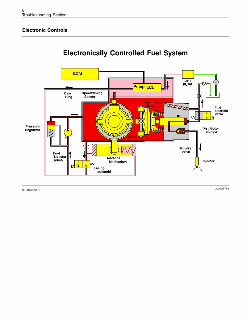
g00908788Illustration 1
7Troubleshooting Section
g00954204Illustration 2
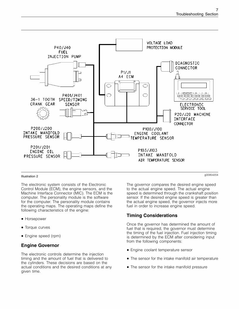
The electronic system consists of the ElectronicControl Module (ECM), the engine sensors, and theMachine Interface Connector (MIC). The ECM is thecomputer. The personality module is the softwarefor the computer. The personality module containsthe operating maps. The operating maps define thefollowing characteristics of the engine:
• Horsepower
• Torque curves
• Engine speed (rpm)
Engine Governor
The electronic controls determine the injectiontiming and the amount of fuel that is delivered tothe cylinders. These decisions are based on theactual conditions and the desired conditions at anygiven time.
The governor compares the desired engine speedto the actual engine speed. The actual enginespeed is determined through the crankshaft positionsensor. If the desired engine speed is greater thanthe actual engine speed, the governor injects morefuel in order to increase engine speed.
Timing Considerations
Once the governor has determined the amount offuel that is required, the governor must determinethe timing of the fuel injection. Fuel injection timingis determined by the ECM after considering inputfrom the following components:
• Engine coolant temperature sensor
• The sensor for the intake manifold air temperature
• The sensor for the intake manifold pressure
8Troubleshooting Section
At start-up, the ECM determines the top deadcenter position of the number 1 cylinder from thespeed/timing sensor in the fuel injection pump.The ECM decides when fuel injection should occurrelative to the top dead center position. The ECMprovides the signal to the fuel injection pump spillvalve which stops fuel flow to the low pressure side.The ECM then forces fuel to flow to the fuel injectornozzles at the desired time. The ECM adjusts timingfor the best engine performance, the best fueleconomy and the best control of exhaust emissions.Actual timing cannot be viewed with an electronicservice tool. Also, the desired timing cannot beviewed with an electronic service tool.
Fuel Injection
The personality module inside the ECM sets certainlimits on the amount of fuel that can be injected.The FRC Limit is a limit that is based on intakemanifold air pressure and engine rpm. The FRCLimit is used to control the air/fuel ratio in order tocontrol the engine’s exhaust emissions. When theECM senses a higher intake manifold air pressure,the ECM increases the FRC Limit. A higher intakemanifold air pressure indicates that there is more airin the cylinder. When the ECM increases the FRCLimit, the ECM allows more fuel into the cylinder.
The Rated Fuel Limit is a limit that is based on thepower rating of the engine and on the engine rpm.The Rated Fuel Limit enables the engine power andtorque outputs to conform to the power and torquecurves of a specific engine model.
These limits are in the personality module and theselimits cannot be changed.
Diagnostic Codes
When the ECM detects an engine problem, the ECMgenerates a diagnostic code. Also, the ECM logsthe diagnostic code in order to indicate the time ofthe problem’s occurrence. The ECM also logs thenumber of occurrences of the problem. There aretwo types of diagnostic fault codes. There are faultcodes and event codes.
Diagnostic Fault Codes
Diagnostic fault codes are provided in order toindicate that an electrical problem or an electronicproblem has been detected by the ECM. In somecases, the engine performance can be affectedwhen the condition that is causing the code exists.More frequently, the operator cannot detect anydifference in the engine performance.
If the operator indicates that a performance problemoccurs, the diagnostic code may indicate the causeof the problem. Use either a laptop computer or ahand held diagnostic tool to access the diagnosticcodes. The problem should then be corrected.
If the operator does not indicate a problem withthe engine performance and a diagnostic code islogged by the ECM. This situation indicates thatthe ECM detected an abnormal engine condition,but the abnormal condition did not affect engineperformance. In this situation, the system has nofaults except when either of the following conditionsexist:
• There are several occurrences of the diagnosticcode in a very short period of time.
• The ECM is indicating an active code at thepresent time.
Diagnostic Event Codes
Diagnostic event codes are used to indicate thatsome operational problem has been detected inthe engine by the ECM. This does not indicate anelectronic malfunction.
Programmable Parameters
Certain parameters that affect the engine operationmay be changed with electronic service tools.The parameters are stored in the ECM, and theparameters are protected from unauthorizedchanges by passwords. These parameters areSystem Configuration Parameters.
System Configuration Parameters are set at thefactory. System Configuration Parameters affectemissions or power ratings within the engine.Factory passwords must be obtained and factorypasswords must be used to change the SystemConfiguration Parameters.
Passwords
System Configuration Parameters are protectedby factory passwords. Factory passwords arecalculated on a computer system that is availableonly to Perkins distributors. Since factory passwordscontain alphabetic characters, only an electronicservice tool may change System ConfigurationParameters. System Configuration Parameters affectthe power rating or the emissions.
Refer to Troubleshooting, “Programming Parameters”and Troubleshooting, “Factory Passwords”.
9Troubleshooting Section
i01798101
Glossary
Active Diagnostic Code – An active diagnostic codealerts the operator or the service technician that anelectronic system malfunction is currently present.Refer to the term “Diagnostic Code” in this glossary.
Alternating Current (AC) – Alternating current is anelectric current that reverses direction at a regularinterval that is reoccurring.
Before Top Dead Center (BTC) – BTDC is the 180degrees of crankshaft rotation before the pistonreaches the top dead center position in the normaldirection of rotation.
Boost Pressure (Engines that are turbocharged) –The difference between the turbocharger outletpressure and atmospheric pressure is commonlyreferred to as boost pressure. The sensor for theintake manifold air pressure measures the amountof boost.
Breakout Harness – The breakout harness is atest harness that is designed to connect into theengine harness. This connection allows a normalcircuit operation and the connection simultaneouslyprovides a Breakout T in order to measure thesignals.
Bypass Circuit – A bypass circuit is a circuit that isused as a substitute circuit for an existing circuit. Abypass circuit is typically used as a test circuit.
CAN Data Link – The CAN Data Link is a serialcommunications port that is used for communicationwith other microprocessor based devices. In thisapplication, the CAN Data Link connects the ECMto the Electronic Fuel Injection Pump.
Code – Refer to “Diagnostic Code” or “Event Code”.
Cold Mode – Cold mode is a mode for cold startingand for cold engine operation that includes timingthat is retarded and low idle that is raised. Thismode is used for engine protection, reduced smokeemissions and faster warm up time.
Communication Adapter Tool – The communicationadapter provides a communication link between theECM and the Electronic Service Tool.
Component Identifier (CID) – The CID is a numberthat identifies the specific component of theelectronic control system that has experienced adiagnostic code.
Coolant Level Sensor – The coolant level sensordetects the absence or presence of coolant at theprobe. The sensor then sends a signal to the ECM.
Coolant Temperature Sensor – The coolanttemperature sensor detects the engine coolanttemperature for cold mode operation and for EngineMonitoring.
Data Link – The Data Link is a serial communicationport that is used for communication with othermicroprocessor based devices.
Desired Engine Speed – The desired engine speedis input to the electronic governor within the ECM.The electronic governor uses the signal from thethrottle position sensor, the engine speed/timingsensor, and other sensors in order to determine thedesired engine speed.
Diagnostic Code – A diagnostic code is sometimesreferred to as a fault code. These codes indicate anelectronic system malfunction.
Diagnostic Lamp – A diagnostic lamp is sometimescalled the check engine light. The diagnostic lampis used to warn the operator of the presence of anactive diagnostic code.
Digital Sensor Return – The common line (ground)from the ECM is used as ground for the digitalsensors.
Digital Sensors – Digital sensors produce a pulsewidth modulated signal. Digital sensors are suppliedwith +8 VDC from the ECM.
Digital Sensor Supply – The +8 VDC supply from theECM is used in order to power the digital sensors.
Direct Current (DC) – Direct current is the type ofcurrent that flows consistently in only one direction.
DT, DT Connector, or Deutsch DT – This is a typeof connector that is used on Perkins engines. Theconnectors are manufactured by Deutsch.
Duty Cycle – Refer to “Pulse Width Modulation”.
Electronic Engine Control – The electronic enginecontrol is a complete electronic system. Theelectronic engine control monitors the engineoperation under all conditions. The electronicengine control also controls the engine operationunder all conditions.
Electronic Service Tool – The electronic service toolallows a computer (PC) to communicate with theECM.
10Troubleshooting Section
Electronic Control Module (ECM) – The ECM is thecontrol computer of the engine. The ECM providespower to the electronics. The ECM monitors datathat is input from the sensors of the engine. TheECM acts as a governor in order to control thespeed and the power of the engine.
Engine Monitoring – Engine Monitoring is the partof the electronic engine control that monitors thesensors. This also warns the operator of detectedproblems.
Engine Oil Pressure Sensor – The engine oilpressure sensor measures engine oil pressure. Thesensor sends the signal to the ECM.
Engine Speed/Timing Sensor – The enginespeed/timing sensor provides a variable amplitudeand pulse width modulated signal to the ECM. TheECM interprets this signal as the crankshaft positionand the engine speed.
Event Code – An event code may be activated inorder to indicate an abnormal engine operatingcondition. These codes usually indicate amechanical problem instead of an electrical systemproblem.
Failure Mode Identifier (FMI) – This identifierindicates the type of failure that has beenexperienced by the component. The FMI hasbeen adopted from the SAE practice of J1587diagnostics.
Flash Programming – Flash programming is themethod of programming or updating an ECM withan electronic service tool over the data link insteadof replacing components.
Fuel Ratio Control (FRC) – The FRC is a limit that isbased on the control of the ratio of the fuel to air.The FRC is used for purposes of emission control.When the ECM senses a higher intake manifoldair pressure (more air into the cylinder), the FRCincreases the FRC Limit (more fuel into the cylinder).
Fuel Temperature Sensor – The fuel temperaturesensor detects the fuel temperature. The ECMmonitors the fuel temperature and the ECM adjuststhe calculated fuel rate accordingly.
Full Load Setting (FLS) – The FLS is the numberthat represents the fuel system adjustment. Thisadjustment is made at the factory in order to finetune the fuel system. The correct value for thisparameter is stamped on the engine informationratings plate. This parameter must be programmed.
Full Torque Setting (FTS) – The FTS is similarto the full load setting. This parameter must beprogrammed.
Harness – The harness is the bundle of wiring(loom) that connects all components of theelectronic system.
Hertz (Hz) – Hertz is the measure of electricalfrequency in cycles per second.
Intake Manifold Air Temperature Sensor – Theintake manifold air temperature sensor detects theair temperature in the intake manifold. The ECMmonitors the air temperature and other data in theintake manifold in order to adjust injection timingand other performance functions.
Intake Manifold Pressure Sensor – The air pressurein the intake manifold may be different to theair pressure outside the engine (atmosphericpressure). This difference in air pressure can becaused by variable air velocity within the manifold.The difference in pressure can also be causedby an increase in air pressure by a turbocharger(if equipped). The sensor for the intake manifoldair pressure measures the difference betweenatmospheric pressure and the air pressure in theintake manifold.
Integrated Electronic Controls – The engine isdesigned with the electronic controls as a necessarypart of the system. The engine will not operatewithout the electronic controls.
J1939 CAN Data Link – This data link is a SAEdiagnostic communications data link that is used tocommunicate between the ECM and the electronicservice tool.
Logged Diagnostic Codes – Logged diagnosticcodes are codes which are stored in the memory.These codes are meant to be an indicator ofpossible causes for intermittent problems. Refer tothe term “Diagnostic Code” in this glossary for moreinformation.
MAB – This is a Bosch acronym for the fuel shutoffinside the “VPM30” Fuel Injection Pump. The MABis a signal wire from the ECM to the Fuel InjectionPump.
Open Circuit – An open circuit is a condition that iscaused by an open switch, or by an electrical wireor a connection that is broken. When this conditionexists, the signal or the supply voltage can nolonger reach the intended destination.
Parameter – A parameter is a value or a limit thatis programmable. This helps determine specificcharacteristics or behaviors of the engine.
11Troubleshooting Section
Password – A password is a group of numericcharacters or a group of alphanumeric charactersthat is designed to restrict access to parameters.The electronic system requires correct passwordsin order to change some parameters (FactoryPasswords). Refer to Troubleshooting, “FactoryPasswords” for more information.
Personality Module – This module is inside theECM. The module contains all the instructions(software) for the ECM and the module containsthe performance maps for a specific engine. Thepersonality module may be reprogrammed throughflash programming.
Power Cycled – Power cycled happens when powerto the ECM is cycled: ON, OFF, and ON. Powercycled refers to the action of cycling the keyswitchfrom any position to the OFF position, and to theSTART/RUN position.
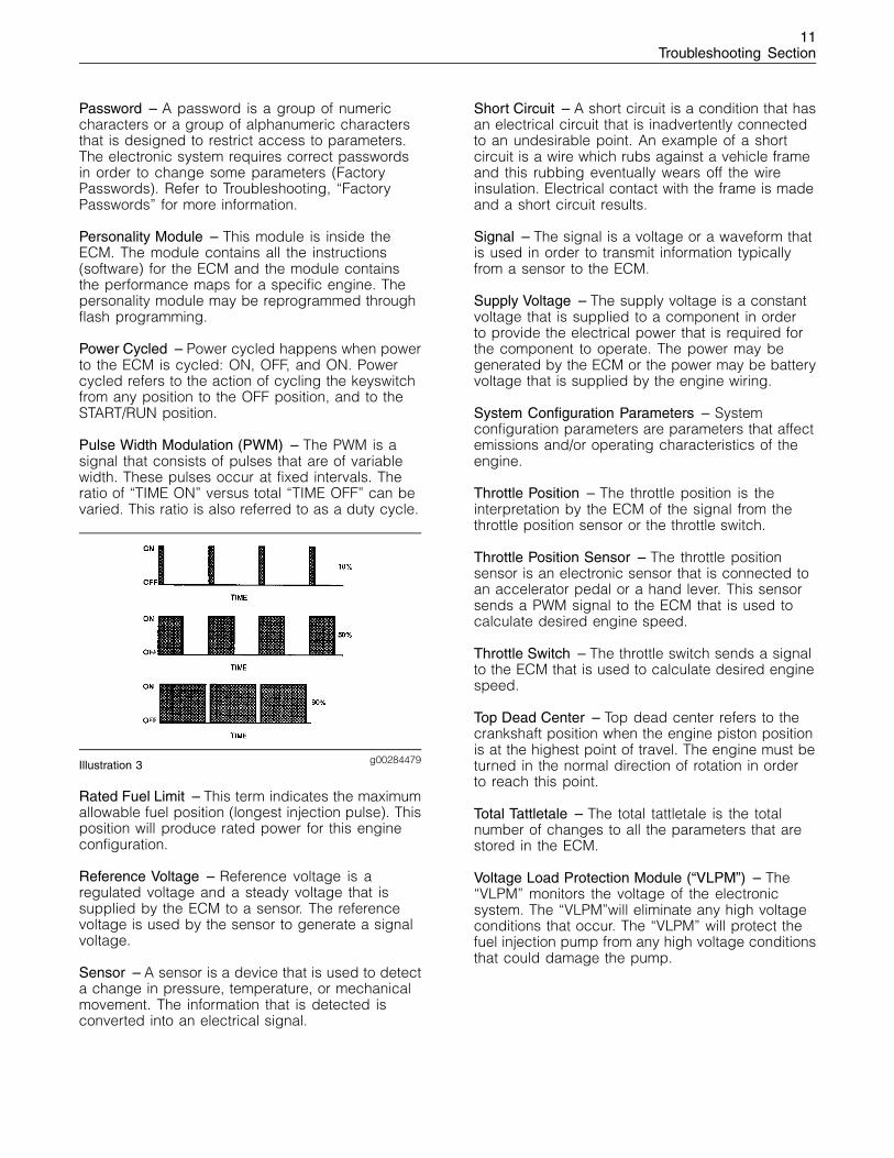
Pulse Width Modulation (PWM) – The PWM is asignal that consists of pulses that are of variablewidth. These pulses occur at fixed intervals. Theratio of “TIME ON” versus total “TIME OFF” can bevaried. This ratio is also referred to as a duty cycle.
g00284479Illustration 3
Rated Fuel Limit – This term indicates the maximumallowable fuel position (longest injection pulse). Thisposition will produce rated power for this engineconfiguration.
Reference Voltage – Reference voltage is aregulated voltage and a steady voltage that issupplied by the ECM to a sensor. The referencevoltage is used by the sensor to generate a signalvoltage.
Sensor – A sensor is a device that is used to detecta change in pressure, temperature, or mechanicalmovement. The information that is detected isconverted into an electrical signal.
Short Circuit – A short circuit is a condition that hasan electrical circuit that is inadvertently connectedto an undesirable point. An example of a shortcircuit is a wire which rubs against a vehicle frameand this rubbing eventually wears off the wireinsulation. Electrical contact with the frame is madeand a short circuit results.
Signal – The signal is a voltage or a waveform thatis used in order to transmit information typicallyfrom a sensor to the ECM.
Supply Voltage – The supply voltage is a constantvoltage that is supplied to a component in orderto provide the electrical power that is required forthe component to operate. The power may begenerated by the ECM or the power may be batteryvoltage that is supplied by the engine wiring.
System Configuration Parameters – Systemconfiguration parameters are parameters that affectemissions and/or operating characteristics of theengine.
Throttle Position – The throttle position is theinterpretation by the ECM of the signal from thethrottle position sensor or the throttle switch.
Throttle Position Sensor – The throttle positionsensor is an electronic sensor that is connected toan accelerator pedal or a hand lever. This sensorsends a PWM signal to the ECM that is used tocalculate desired engine speed.
Throttle Switch – The throttle switch sends a signalto the ECM that is used to calculate desired enginespeed.
Top Dead Center – Top dead center refers to thecrankshaft position when the engine piston positionis at the highest point of travel. The engine must beturned in the normal direction of rotation in orderto reach this point.
Total Tattletale – The total tattletale is the totalnumber of changes to all the parameters that arestored in the ECM.
Voltage Load Protection Module (“VLPM”) – The“VLPM” monitors the voltage of the electronicsystem. The “VLPM”will eliminate any high voltageconditions that occur. The “VLPM” will protect thefuel injection pump from any high voltage conditionsthat could damage the pump.
12Troubleshooting Section
i01798102
Electronic Service Tools
Electronic Service Tools are designed to help theservice technician with the diagnosis and repair ofelectronic engines. Several tools are available toassist the service technician.
Some of the included Diagnostic Functional Testsin this manual require two short jumper wires. Thejumper wires are used to check the continuityof some wiring harness circuits by shorting twoadjacent terminals together in a connector.
A long extension wire may also be needed to checkthe continuity of some wiring harness circuits.
Electronic Service Tool
The electronic service tool can display the followinginformation:
• Parameters
• Event codes
• Diagnostic codes
• Engine configuration
The electronic service tool can be used by thetechnician to perform the following functions:
• Diagnostic tests
• Sensor calibrations
• Flash programming
• Set parameters
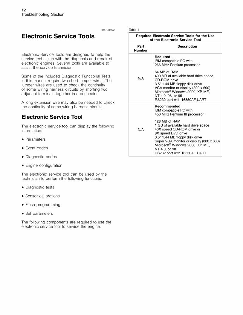
The following components are required to use theelectronic service tool to service the engine.
Table 1
Required Electronic Service Tools for the Useof the Electronic Service Tool
PartNumber
Description
N/A
RequiredIBM compatible PC with266 MHz Pentium processor
64 MB of RAM400 MB of available hard drive spaceCD-ROM drive3.5" 1.44 MB floppy disk driveVGA monitor or display (800 x 600)Microsoft® Windows 2000, XP, ME,NT 4.0, 98, or 95RS232 port with 16550AF UART
N/A
RecommendedIBM compatible PC with450 MHz Pentium III processor
128 MB of RAM1 GB of available hard drive space40X speed CD-ROM drive or8X speed DVD drive3.5" 1.44 MB floppy disk driveSuper VGA monitor or display (800 x 600)Microsoft® Windows 2000, XP, ME,NT 4.0, or 98RS232 port with 16550AF UART
13Troubleshooting Section
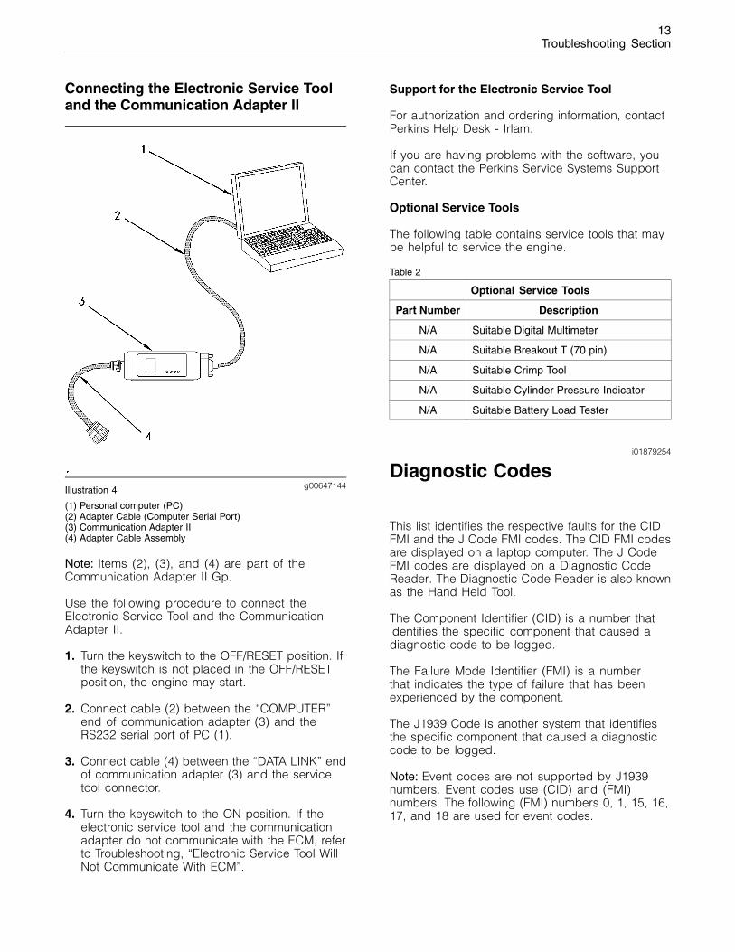
Connecting the Electronic Service Tooland the Communication Adapter II
g00647144Illustration 4
(1) Personal computer (PC)(2) Adapter Cable (Computer Serial Port)(3) Communication Adapter II(4) Adapter Cable Assembly
Note: Items (2), (3), and (4) are part of theCommunication Adapter II Gp.
Use the following procedure to connect theElectronic Service Tool and the CommunicationAdapter II.
1. Turn the keyswitch to the OFF/RESET position. Ifthe keyswitch is not placed in the OFF/RESETposition, the engine may start.
2. Connect cable (2) between the “COMPUTER”end of communication adapter (3) and theRS232 serial port of PC (1).
3. Connect cable (4) between the “DATA LINK” endof communication adapter (3) and the servicetool connector.
4. Turn the keyswitch to the ON position. If theelectronic service tool and the communicationadapter do not communicate with the ECM, referto Troubleshooting, “Electronic Service Tool WillNot Communicate With ECM”.
Support for the Electronic Service Tool
For authorization and ordering information, contactPerkins Help Desk - Irlam.
If you are having problems with the software, youcan contact the Perkins Service Systems SupportCenter.
Optional Service Tools
The following table contains service tools that maybe helpful to service the engine.
Table 2
Optional Service Tools
Part Number Description
N/A Suitable Digital Multimeter
N/A Suitable Breakout T (70 pin)
N/A Suitable Crimp Tool
N/A Suitable Cylinder Pressure Indicator
N/A Suitable Battery Load Tester
i01879254
Diagnostic Codes
This list identifies the respective faults for the CIDFMI and the J Code FMI codes. The CID FMI codesare displayed on a laptop computer. The J CodeFMI codes are displayed on a Diagnostic CodeReader. The Diagnostic Code Reader is also knownas the Hand Held Tool.
The Component Identifier (CID) is a number thatidentifies the specific component that caused adiagnostic code to be logged.
The Failure Mode Identifier (FMI) is a numberthat indicates the type of failure that has beenexperienced by the component.
The J1939 Code is another system that identifiesthe specific component that caused a diagnosticcode to be logged.
Note: Event codes are not supported by J1939numbers. Event codes use (CID) and (FMI)numbers. The following (FMI) numbers 0, 1, 15, 16,17, and 18 are used for event codes.
14Troubleshooting Section
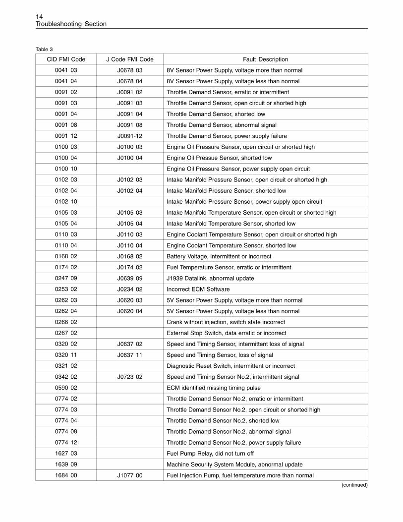
Table 3
CID FMI Code J Code FMI Code Fault Description
0041 03 J0678 03 8V Sensor Power Supply, voltage more than normal
0041 04 J0678 04 8V Sensor Power Supply, voltage less than normal
0091 02 J0091 02 Throttle Demand Sensor, erratic or intermittent
0091 03 J0091 03 Throttle Demand Sensor, open circuit or shorted high
0091 04 J0091 04 Throttle Demand Sensor, shorted low
0091 08 J0091 08 Throttle Demand Sensor, abnormal signal
0091 12 J0091-12 Throttle Demand Sensor, power supply failure
0100 03 J0100 03 Engine Oil Pressure Sensor, open circuit or shorted high
0100 04 J0100 04 Engine Oil Pressue Sensor, shorted low
0100 10 Engine Oil Pressure Sensor, power supply open circuit
0102 03 J0102 03 Intake Manifold Pressure Sensor, open circuit or shorted high
0102 04 J0102 04 Intake Manifold Pressure Sensor, shorted low
0102 10 Intake Manifold Pressure Sensor, power supply open circuit
0105 03 J0105 03 Intake Manifold Temperature Sensor, open circuit or shorted high
0105 04 J0105 04 Intake Manifold Temperature Sensor, shorted low
0110 03 J0110 03 Engine Coolant Temperature Sensor, open circuit or shorted high
0110 04 J0110 04 Engine Coolant Temperature Sensor, shorted low
0168 02 J0168 02 Battery Voltage, intermittent or incorrect
0174 02 J0174 02 Fuel Temperature Sensor, erratic or intermittent
0247 09 J0639 09 J1939 Datalink, abnormal update
0253 02 J0234 02 Incorrect ECM Software
0262 03 J0620 03 5V Sensor Power Supply, voltage more than normal
0262 04 J0620 04 5V Sensor Power Supply, voltage less than normal
0266 02 Crank without injection, switch state incorrect
0267 02 External Stop Switch, data erratic or incorrect
0320 02 J0637 02 Speed and Timing Sensor, intermittent loss of signal
0320 11 J0637 11 Speed and Timing Sensor, loss of signal
0321 02 Diagnostic Reset Switch, intermittent or incorrect
0342 02 J0723 02 Speed and Timing Sensor No.2, intermittent signal
0590 02 ECM identified missing timing pulse
0774 02 Throttle Demand Sensor No.2, erratic or intermittent
0774 03 Throttle Demand Sensor No.2, open circuit or shorted high
0774 04 Throttle Demand Sensor No.2, shorted low
0774 08 Throttle Demand Sensor No.2, abnormal signal
0774 12 Throttle Demand Sensor No.2, power supply failure
1627 03 Fuel Pump Relay, did not turn off
1639 09 Machine Security System Module, abnormal update
1684 00 J1077 00 Fuel Injection Pump, fuel temperature more than normal
(continued)
15Troubleshooting Section
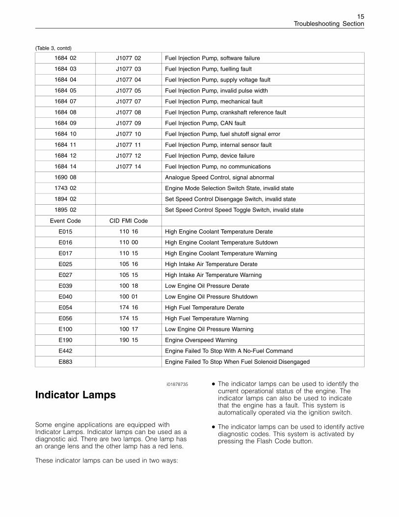
(Table 3, contd)
1684 02 J1077 02 Fuel Injection Pump, software failure
1684 03 J1077 03 Fuel Injection Pump, fuelling fault
1684 04 J1077 04 Fuel Injection Pump, supply voltage fault
1684 05 J1077 05 Fuel Injection Pump, invalid pulse width
1684 07 J1077 07 Fuel Injection Pump, mechanical fault
1684 08 J1077 08 Fuel Injection Pump, crankshaft reference fault
1684 09 J1077 09 Fuel Injection Pump, CAN fault
1684 10 J1077 10 Fuel Injection Pump, fuel shutoff signal error
1684 11 J1077 11 Fuel Injection Pump, internal sensor fault
1684 12 J1077 12 Fuel Injection Pump, device failure
1684 14 J1077 14 Fuel Injection Pump, no communications
1690 08 Analogue Speed Control, signal abnormal
1743 02 Engine Mode Selection Switch State, invalid state
1894 02 Set Speed Control Disengage Switch, invalid state
1895 02 Set Speed Control Speed Toggle Switch, invalid state
Event Code CID FMI Code
E015 110 16 High Engine Coolant Temperature Derate
E016 110 00 High Engine Coolant Temperature Sutdown
E017 110 15 High Engine Coolant Temperature Warning
E025 105 16 High Intake Air Temperature Derate
E027 105 15 High Intake Air Temperature Warning
E039 100 18 Low Engine Oil Pressure Derate
E040 100 01 Low Engine Oil Pressure Shutdown
E054 174 16 High Fuel Temperature Derate
E056 174 15 High Fuel Temperature Warning
E100 100 17 Low Engine Oil Pressure Warning
E190 190 15 Engine Overspeed Warning
E442 Engine Failed To Stop With A No-Fuel Command
E883 Engine Failed To Stop When Fuel Solenoid Disengaged
i01878735
Indicator Lamps
Some engine applications are equipped withIndicator Lamps. Indicator lamps can be used as adiagnostic aid. There are two lamps. One lamp hasan orange lens and the other lamp has a red lens.
These indicator lamps can be used in two ways:
• The indicator lamps can be used to identify thecurrent operational status of the engine. Theindicator lamps can also be used to indicatethat the engine has a fault. This system isautomatically operated via the ignition switch.
• The indicator lamps can be used to identify activediagnostic codes. This system is activated bypressing the Flash Code button.
16Troubleshooting Section
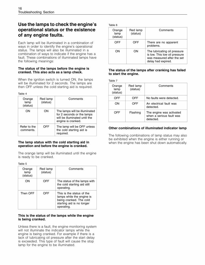
Use the lamps to check the engine’soperational status or the existenceof any engine faults.
Each lamp will be illuminated in a combination ofways in order to identify the engine’s operationalstatus. The lamps will also be illuminated in acombination of ways to indicate if the engine has afault. These combinations of illuminated lamps havethe following meanings:
The status of the lamps before the engine iscranked. This also acts as a lamp check.
When the ignition switch is turned ON, the lampswill be illuminated for 2 seconds. The lamps arethen OFF unless the cold starting aid is required.
Table 4
Orangelamp
(status)
Red lamp(status)
Comments
ON ON The lamps will be illuminatedfor 2 seconds or the lampswill be illuminated until theengine is cranked.
Refer to thecomments.
OFF The lamp will be OFF unlessthe cold starting aid isrequired.
The lamp status with the cold starting aid inoperation and before the engine is cranked.
The orange lamp will be illuminated until the engineis ready to be cranked.
Table 5
Orangelamp
(status)
Red lamp(status)
Comments
ON OFF The status of the lamps withthe cold starting aid stilloperating.
Then OFF OFF This is the status of thelamps while the engine isbeing cranked. The coldstarting aid is no longeroperating.
This is the status of the lamps while the engineis being cranked.
Unless there is a fault, the engine monitoring systemwill not illuminate the indicator lamps while theengine is being cranked. For example if there is alack of lubricating oil pressure after the start delayis exceeded. This type of fault will cause the stoplamp for the engine to be illuminated.
Table 6
Orangelamp
(status)
Red lamp(status)
Comments
OFF OFF There are no apparentproblems.
ON ON The lubricating oil pressureis low. This low oil pressurewas measured after the setdelay had expired.
The status of the lamps after cranking has failedto start the engine.
Table 7
Orangelamp
(status)
Red lamp(status)
Comments
OFF OFF No faults were detected.
ON OFF An electrical fault wasdetected.
OFF Flashing The engine was activatedwhen a serious fault wasdetected.
Other combinations of illuminated indicator lamp
The following combinations of lamp status may alsobe exhibited when the engine is either running orwhen the engine has been shut down automatically.
17Troubleshooting Section
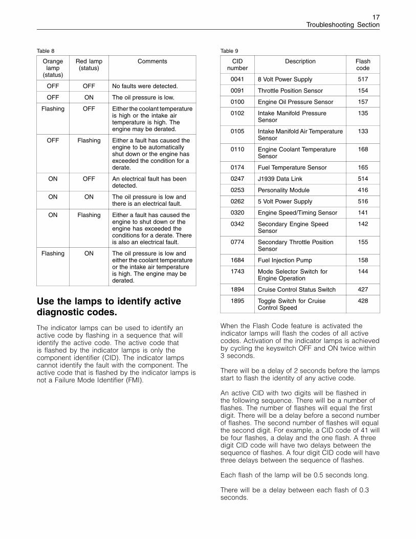
Table 8
Orangelamp
(status)
Red lamp(status)
Comments
OFF OFF No faults were detected.
OFF ON The oil pressure is low.
Flashing OFF Either the coolant temperatureis high or the intake airtemperature is high. Theengine may be derated.
OFF Flashing Either a fault has caused theengine to be automaticallyshut down or the engine hasexceeded the condition for aderate.
ON OFF An electrical fault has beendetected.
ON ON The oil pressure is low andthere is an electrical fault.
ON Flashing Either a fault has caused theengine to shut down or theengine has exceeded theconditions for a derate. Thereis also an electrical fault.
Flashing ON The oil pressure is low andeither the coolant temperatureor the intake air temperatureis high. The engine may bederated.
Use the lamps to identify activediagnostic codes.
The indicator lamps can be used to identify anactive code by flashing in a sequence that willidentify the active code. The active code thatis flashed by the indicator lamps is only thecomponent identifier (CID). The indicator lampscannot identify the fault with the component. Theactive code that is flashed by the indicator lamps isnot a Failure Mode Identifier (FMI).
Table 9
CIDnumber
Description Flashcode
0041 8 Volt Power Supply 517
0091 Throttle Position Sensor 154
0100 Engine Oil Pressure Sensor 157
0102 Intake Manifold PressureSensor
135
0105 Intake Manifold Air TemperatureSensor
133
0110 Engine Coolant TemperatureSensor
168
0174 Fuel Temperature Sensor 165
0247 J1939 Data Link 514
0253 Personality Module 416
0262 5 Volt Power Supply 516
0320 Engine Speed/Timing Sensor 141
0342 Secondary Engine SpeedSensor
142
0774 Secondary Throttle PositionSensor
155
1684 Fuel Injection Pump 158
1743 Mode Selector Switch forEngine Operation
144
1894 Cruise Control Status Switch 427
1895 Toggle Switch for CruiseControl Speed
428
When the Flash Code feature is activated theindicator lamps will flash the codes of all activecodes. Activation of the indicator lamps is achievedby cycling the keyswitch OFF and ON twice within3 seconds.
There will be a delay of 2 seconds before the lampsstart to flash the identity of any active code.
An active CID with two digits will be flashed inthe following sequence. There will be a number offlashes. The number of flashes will equal the firstdigit. There will be a delay before a second numberof flashes. The second number of flashes will equalthe second digit. For example, a CID code of 41 willbe four flashes, a delay and the one flash. A threedigit CID code will have two delays between thesequence of flashes. A four digit CID code will havethree delays between the sequence of flashes.
Each flash of the lamp will be 0.5 seconds long.
There will be a delay between each flash of 0.3seconds.
18Troubleshooting Section
Each delay between each digit of the code will be2 seconds.
After one active code has been identified there willbe a delay of 5 seconds before the next activecode is flashed.
The sequence of flashing the active codes may berestarted at any time by reactivating the cycling ofthe keyswitch.
i01798103
Replacing the ECM
NOTICEKeep all parts clean from contaminants.
Contaminants may cause rapid wear and shortenedcomponent life.
The engine is equipped with an Electronic ControlModule (ECM). The ECM contains no movingparts. Follow the troubleshooting procedures in thismanual in order to be sure that replacing the ECMwill correct the problem. Verify that the suspectECM is the cause of the problem.
Note: Ensure that the ECM is receiving powerand that the ECM is properly grounded beforereplacement of the ECM is attempted. Refer toTroubleshooting, “Electrical Power Supply Circuit -Test”.
A test ECM can be used in order to determine ifthe ECM on the engine is faulty. Install a test ECMin place of the suspect ECM. Flash the personalitymodule into the test ECM. Program the parametersfor the test ECM. The parameters must matchthe parameters in the suspect ECM. Refer to thefollowing test steps for details. If the test ECMresolves the problem, reconnect the suspect ECM.Verify that the problem returns. If the problemreturns, replace the ECM.
Use the electronic service tool to read theparameters in the suspect ECM. Record theparameters in the suspect ECM. The personalitymodule can be flashed into the new ECM. Afterthe ECM is installed on the engine, the parametersmust be programmed into the new ECM.
Note: When a new ECM is not available, you mayneed to remove an ECM from an engine that isnot in service. The ECM must have the sameserial number suffix. Ensure that the replacementECM and the Personality Module Interlock Codematch the suspect ECM. Be sure to record theparameters from the replacement ECM. Use the“Copy Configuration ECM Replacement” function inthe electronic service tool.
NOTICEIf the Personality Module and engine application arenot matched, engine damage may result.
Perform the following procedure in order to replacethe ECM.
1. Connect the electronic service tool to the servicetool connector.
2. Use the “Copy Configuration ECM Replacement”function from the electronic service tool. If the“Copy Configuration” is successful, proceedto Step 4. If the “Copy Configuration” failed,proceed to Step 3.
Note: You may want to record any Logged Faultsand Events for your records.
3. Record the parameters. Record all of theparameters on the “Main Configuration” screen.Also, record all of the parameters on the“Throttle Configuration” screen and on the “ModeConfiguration” screen.
Note: If the parameters cannot be read, theparameters must be obtained elsewhere. Someparameters are stamped on the engine informationplate, but most parameters must be obtained fromthe factory.
4. Remove the ECM.
a. Turn the keyswitch to the OFF position.
b. Turn the battery disconnect switch to the OFFposition.
c. Slacken the 4 mm Allen head screwand disconnect the ECM 70-pin (P1/J1)connectors.
d. Remove the mounting bolts from the ECM.
e. Disconnect the grounding strap from the ECM.
5. Install the replacement ECM.
19Troubleshooting Section
a. Use the old mounting hardware to install thereplacement ECM. The mounting hardwareshould be free of damage.
b. Check that the ECM mounting hardware isinstalled correctly. The rubber grommets areused to protect the ECM from excessivevibration. The ECM should be able to drift inthe rubber grommets.
c. Install the ground strap for the ECM on theengine.
d. Reconnect the J1/P1 70 Pin connector to theECM. Tighten the Allen head screw on theconnectors to a torque of 6 N·m (55 lb in).
6. Download the Flash file.
a. Connect the electronic service tool to theservice connector.
b. Select “WinFlash” from the “Utilities” menu ofthe electronic service tool.
c. Select the appropriate file.
7. If it is necessary, use the electronic service toolto clear the rating interlock in the PersonalityModule. To clear the rating interlock, enter thefactory password when the electronic servicetool is first connected. Activating the “Test ECM”mode will also clear the rating interlock.
8. Use the electronic service tool to program theparameters. Perform the following procedure.
a. If the “Copy Configuration” procedure wassuccessful, use the “Copy Configuration,ECM Replacement” function to load theconfiguration file into the ECM.
b. If the “Copy Configuration” procedure failed,configure the parameters individually. Theparameters should match the parametersfrom step 2.
9. Check for logged diagnostic codes. Factorypasswords are required to clear Logged Events.
i01798104
Self-Diagnostics
The Electronic Control Module (ECM) has the abilityto detect problems with the electronic systemand with engine operation. When a problem isdetected, a code is generated. An alarm may alsobe generated. There are two types of codes:
• Diagnostic
• Event
Diagnostic Code – When a problem with theelectronic system is detected, the ECM generates adiagnostic code. This indicates the specific problemwith the circuitry.
Diagnostic codes can have two different states:
• Active
• Logged
Active Code – An active diagnostic code indicatesthat an active problem has been detected. Activecodes require immediate attention. Always serviceactive codes prior to servicing logged codes.
Logged Code – Every generated code is stored inthe permanent memory of the ECM. The codes arelogged.
Event Code – An event code is generated bythe detection of an abnormal engine operatingcondition. For example, an event code will begenerated if the oil pressure is too low. In this case,the event code indicates the symptom of a problem.
Logged codes may not indicate that a repair isneeded. The problem may have been temporary.The problem may have been resolved since thelogging of the code. If the system is powered, itis possible to generate an active diagnostic codewhenever a component is disconnected. Whenthe component is reconnected, the code is nolonger active. Logged codes may be useful to helptroubleshoot intermittent problems. Logged codescan also be used to review the performance of theengine and the electronic system.
20Troubleshooting Section
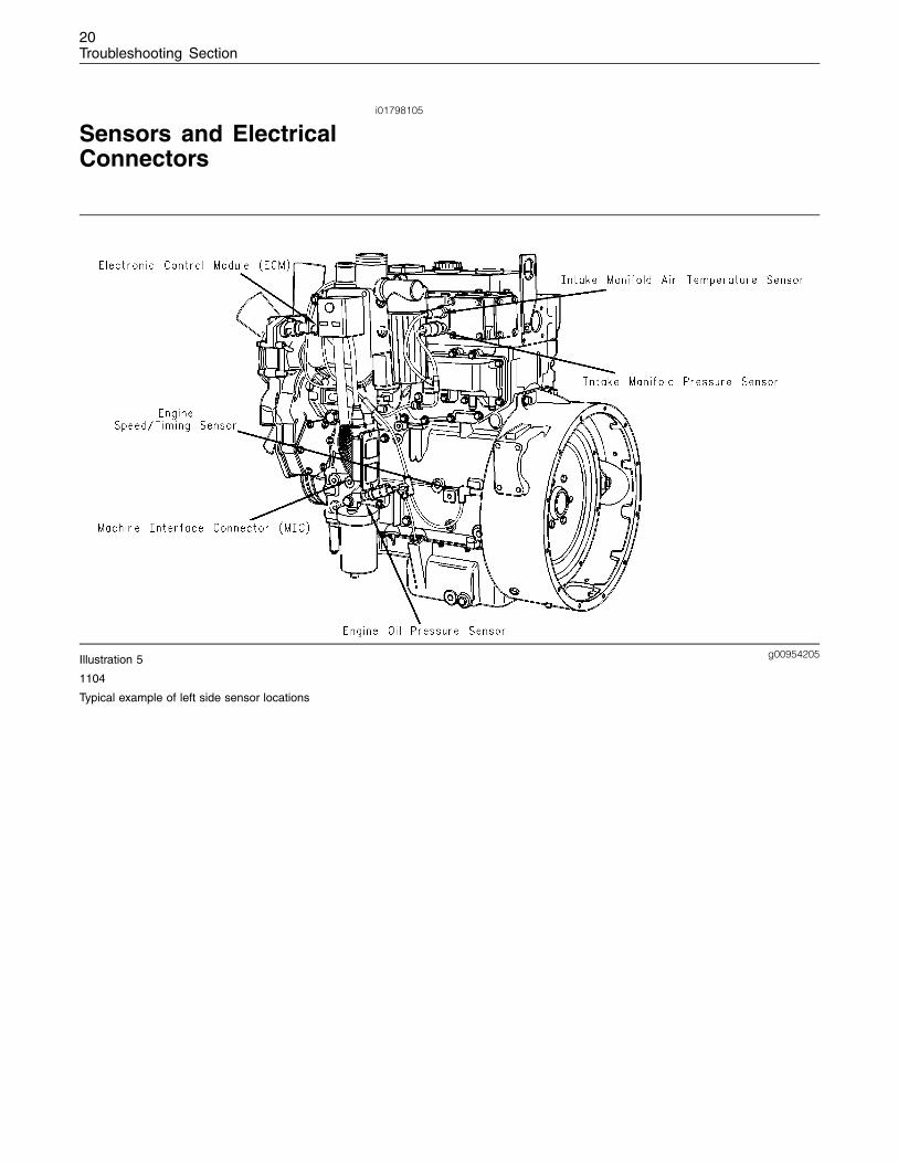
i01798105
Sensors and ElectricalConnectors
g00954205Illustration 5
1104
Typical example of left side sensor locations
21Troubleshooting Section
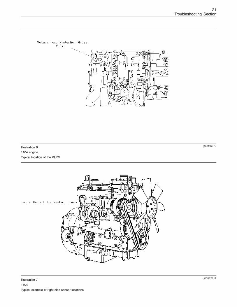
g00915379Illustration 6
1104 engine
Typical location of the VLPM
g00882117Illustration 7
1104
Typical example of right side sensor locations
22Troubleshooting Section
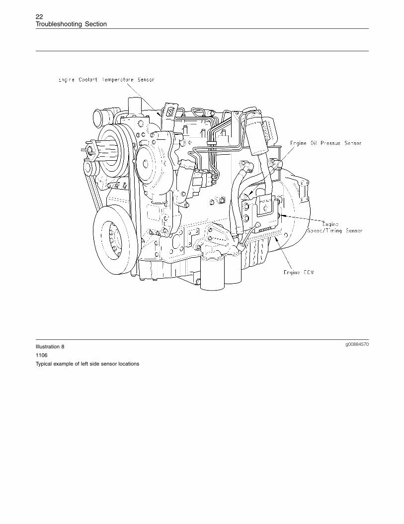
g00884570Illustration 8
1106
Typical example of left side sensor locations
23Troubleshooting Section
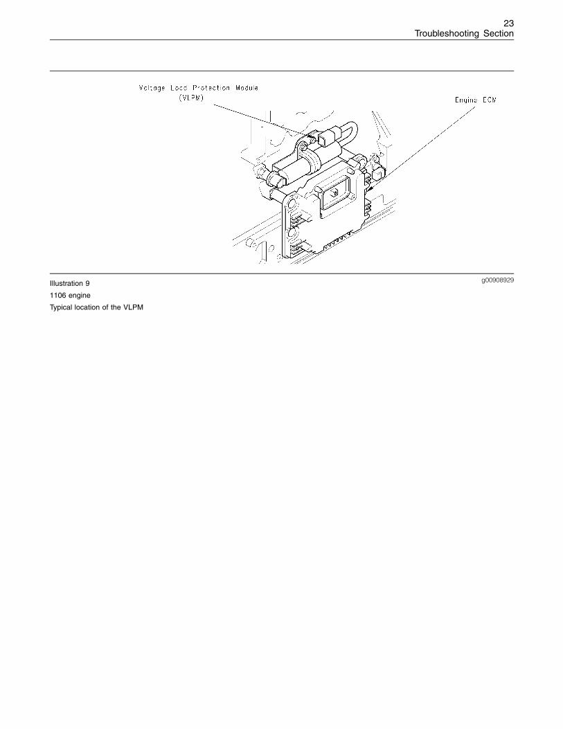
g00908929Illustration 9
1106 engine
Typical location of the VLPM
24Troubleshooting Section
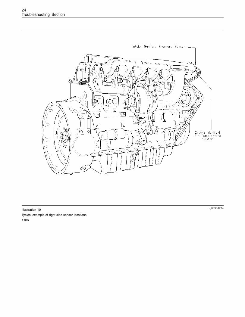
g00954214Illustration 10
Typical example of right side sensor locations
1106
25Troubleshooting Section
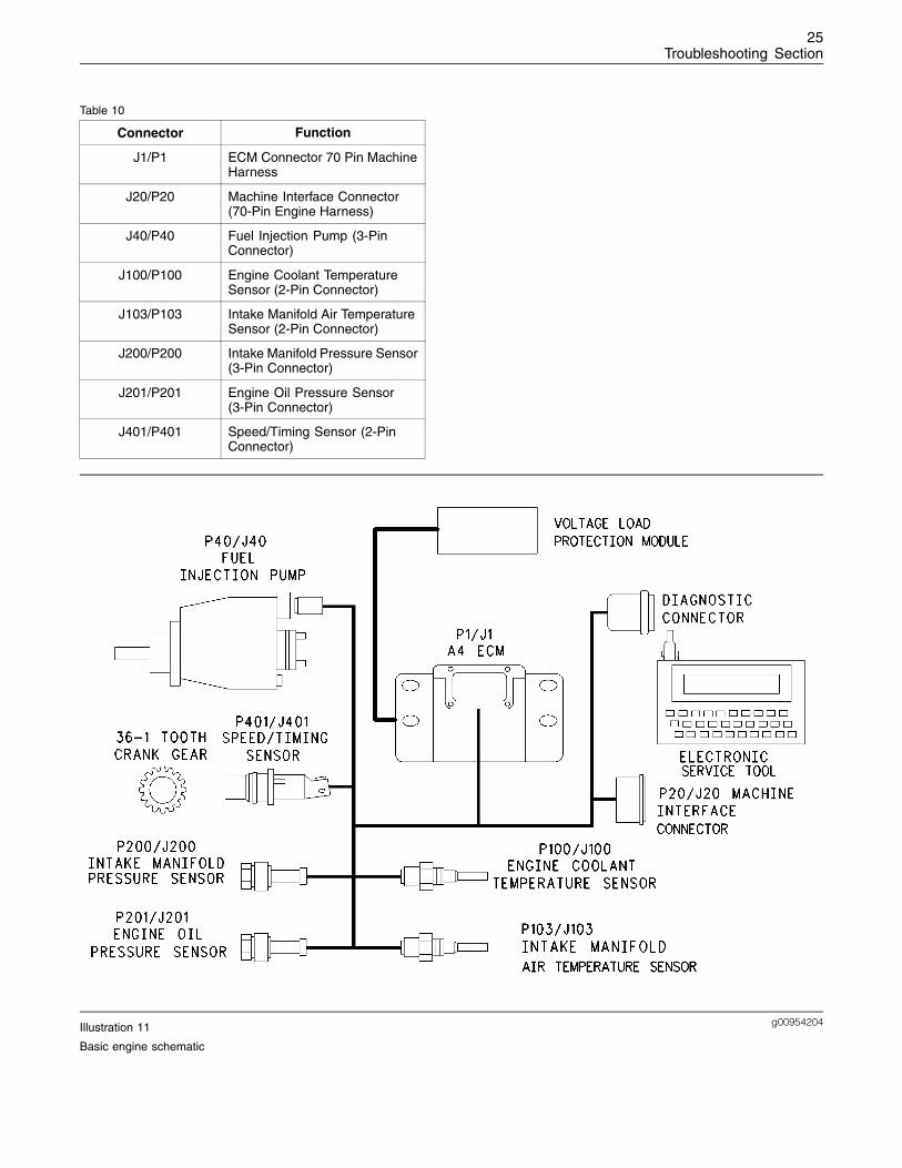
Table 10
Connector Function
J1/P1 ECM Connector 70 Pin MachineHarness
J20/P20 Machine Interface Connector(70-Pin Engine Harness)
J40/P40 Fuel Injection Pump (3-PinConnector)
J100/P100 Engine Coolant TemperatureSensor (2-Pin Connector)
J103/P103 Intake Manifold Air TemperatureSensor (2-Pin Connector)
J200/P200 Intake Manifold Pressure Sensor(3-Pin Connector)
J201/P201 Engine Oil Pressure Sensor(3-Pin Connector)
J401/P401 Speed/Timing Sensor (2-PinConnector)
g00954204Illustration 11
Basic engine schematic
26Troubleshooting Section
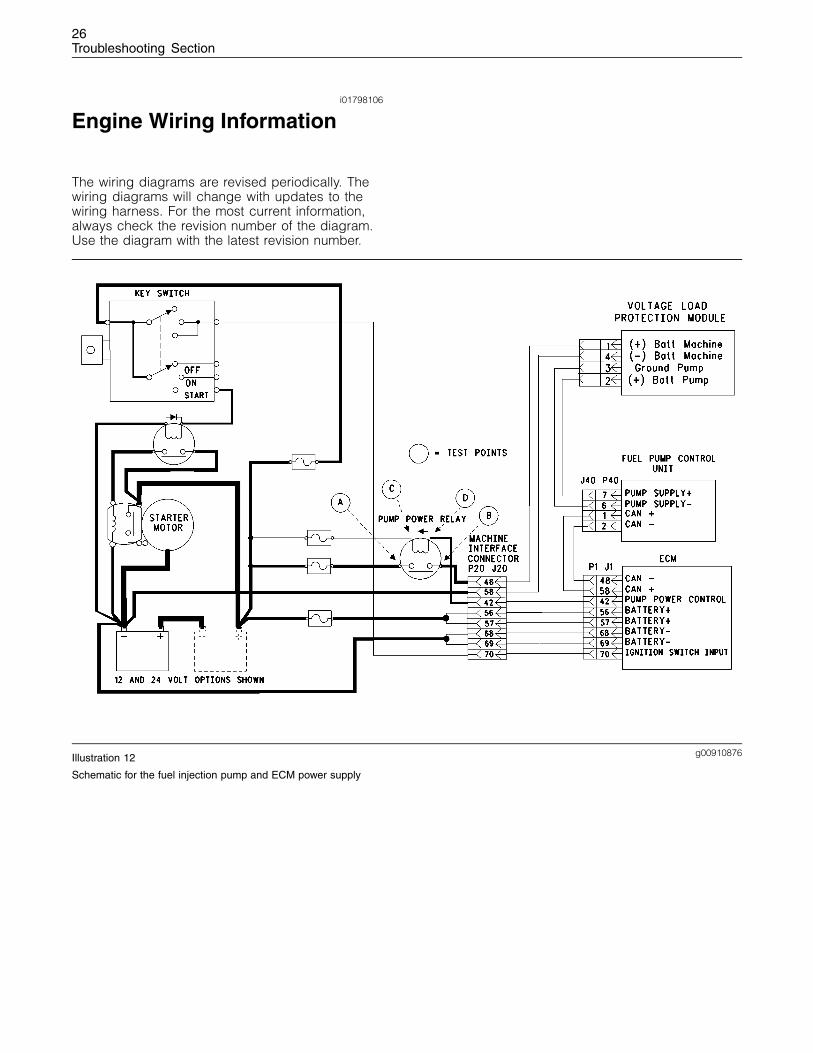
i01798106
Engine Wiring Information
The wiring diagrams are revised periodically. Thewiring diagrams will change with updates to thewiring harness. For the most current information,always check the revision number of the diagram.Use the diagram with the latest revision number.
g00910876Illustration 12
Schematic for the fuel injection pump and ECM power supply
27Troubleshooting Section
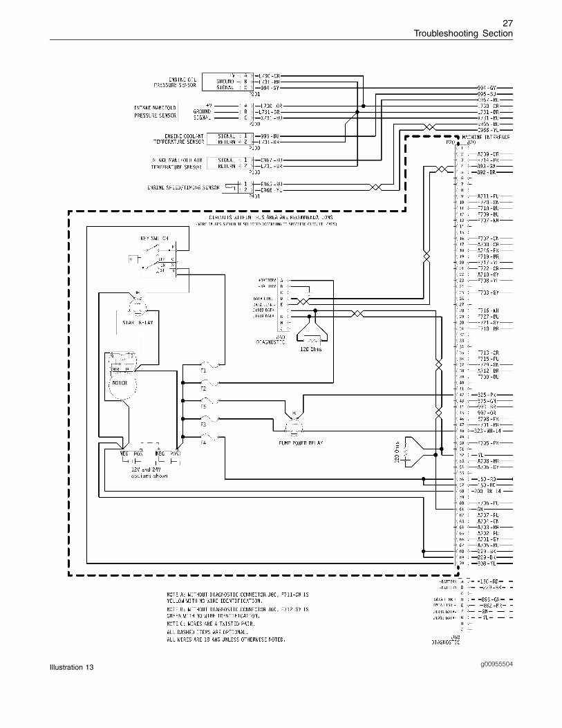
g00955504Illustration 13
28Troubleshooting Section
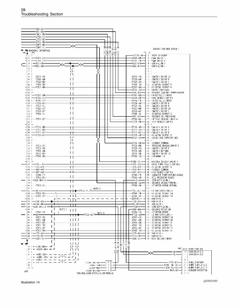
g00955499Illustration 14
29Troubleshooting Section
Note: Each terminal end of the J1939 CAN datalink must be connected with a 120 ohm terminatingresistor.
Note: Digital outputs 7,8,9,10,11,12,13, and 14 areonly suitable for a 12 V system.
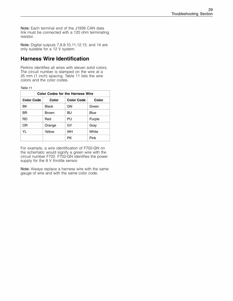
Harness Wire Identification
Perkins identifies all wires with eleven solid colors.The circuit number is stamped on the wire at a25 mm (1 inch) spacing. Table 11 lists the wirecolors and the color codes.
Table 11
Color Codes for the Harness Wire
Color Code Color Color Code Color
BK Black GN Green
BR Brown BU Blue
RD Red PU Purple
OR Orange GY Gray
YL Yellow WH White
PK Pink
For example, a wire identification of F702-GN onthe schematic would signify a green wire with thecircuit number F702. F702-GN identifies the powersupply for the 8 V throttle sensor.
Note: Always replace a harness wire with the samegauge of wire and with the same color code.
30Troubleshooting Section
Programming Parameters
i01798107
Programming Parameters
The electronic service tool can be used to viewcertain parameters that can affect the operation ofthe engine. The electronic service tool can also beused to change certain parameters. The parametersare stored in the Electronic Control Module (ECM).Some of the parameters are protected fromunauthorized changes by passwords. Parametersthat can be changed have a tattletale number. Thetattletale number shows if a parameter has beenchanged.
i01798108
Factory Passwords
Passwords
Passwords are part of a security system that helpsto prevent unauthorized reprogramming of certainparameters. Passwords prevent unauthorizederasing of logged events. Passwords allow thefactory to control access to engine calibrationparameters. Passwords allow the customer tocontrol access to certain programmable engineparameters.
Factory Passwords
Factory passwords are required to clear any eventcode. Factory passwords are required to changecertain parameters such as Full Load Setting. Thefactory passwords restrict changes to authorizedpersonnel. When the correct factory passwordshave been entered, the changes can then be made.
In order to obtain the proper factory passwords,certain information must be given to an authorizedPerkins distributor. Since the factory passwordscontain alphabetic characters, the electronicservice tool can be used to perform this function.In order to obtain the factory passwords, proceedas if you already have the factory passwords. Atsome point, if the factory passwords are actuallyneeded, the electronic service tool will request thefactory passwords and the electronic service toolwill display the information that is required to obtainthe factory passwords.
Note: The old interlock code is required to changethe interlock code on a used ECM. A new interlockcode is also required to change the interlock codeon a used ECM.
The electronic service tool screen for factorypasswords will display the following parameters:
• Serial number of the Electronic Control Module(ECM)
• Engine serial number
• Serial number for the electronic service tool
• Reason Code
• Total Tattletale number
Note: The factory passwords may only be usedfor one programming session. A different set offactory passwords will be required after you exitthe electronic service tool screen. A different set ofpasswords will be required to change informationon another electronic service tool screen.
Customer Passwords
Customer Passwords allow the customer to restrictaccess to parameters that are programmable bythe customer. The customer passwords cannot belonger than eight characters. The customer has theoption of entering one or two customer passwords.
Note: If the owner loses the owner’s customerpasswords, the owner will not be able to programparameters that are protected by customerpasswords. By using factory passwords, one canread customer passwords. Then use those customerpasswords to program parameters that have beenprotected by customer passwords.
i01798110
Flash Programming
Flash Programming – This is a method ofprogramming or updating the personality modulein an ECM.
The electronic service tool can be utilized to flasha new personality module into the ECM. The flashis accomplished by transferring the data from a PCto the ECM.
31Troubleshooting Section
Flash Programming a PersonalityModule
1. Connect the electronic service tool to the servicetool connector.
2. Select “WinFlash” from the “Utilities” menu on theelectronic service tool.
“WinFlash” will try to detect an ECM.
3. When an ECM has been detected, the “ECMSelector” window will appear. Select theappropriate ECM that needs to be flashed andpress “Browse”.
The “Flash File Selection” window will appear.
4. The flash files are located on a disk drive and ina directory. Select the correct disk drive and thecorrect directory from “Drives” and “Directories”on the electronic service tool.
A list of flash files will appear.
5. Select the correct file from the list of flash files.Read the “File Info” and the “Description” inorder to verify that the correct file is selected.Select “OK”.
6. Select the “Begin Flash” button in order toprogram the personality module.
When the flash is completed, this message willappear: “Flash Completed Successfully”.
7. Start the engine and check for proper operation.
a. If a diagnostic code of 253-02 IncorrectECM Software is generated, program anyparameters that were not in the old personalitymodule.
b. Access the “Configuration” screen underthe “Service” menu in order to determinethe parameters that require programming.Look under the “Tattletale” column. All of theparameters should have a tattletale of 1 ormore. If a parameter has a tattletale of 0,program that parameter.
“WinFlash” Error Messages
If you receive any error messages during flashprogramming, click on the “Cancel” button in orderto stop the process. Access the information aboutthe “ECM Summary” under the “Information” menu.Make sure that you are flashing the correct file foryour engine.
32Troubleshooting Section
System ConfigurationParameters
i01798111
System ConfigurationParameters
System Configuration Parameters affect theemissions of the engine or the power of the engine.System configuration parameters are programmedat the factory. Normally, system configurationparameters would never need to be changedthrough the life of the engine. System configurationparameters must be reprogrammed if an ECM isreplaced. Unless the engine rating has changed,system configuration parameters do not need tobe reprogrammed when the Personality Module isreplaced. The correct values for these parametersare stamped on the engine information ratingsplate. The engine information ratings plate islocated on the valve cover or on the air intakemanifold. Factory passwords are required to changethese parameters. The following information is adescription of the system configuration parameters.
“Full Load Setting”
“Full Load Setting” is a number that represents theadjustment to the fuel system that was made atthe factory in order to fine tune the fuel system.The correct value for this parameter is stampedon the engine information ratings plate. If theECM is replaced, the “full load setting” mustbe reprogrammed in order to prevent a 253-02diagnostic code from becoming active.
“Full Torque Setting”
“Full Torque Setting” is similar to “Full Load Setting”.If the ECM is replaced, the full torque setting mustbe reprogrammed in order to prevent a 253-02diagnostic code from becoming active.
Rating Interlock
The Rating Interlock is a code that prevents theuse of an incorrect power rating and/or emissionrating for a specific engine. Each horsepower ratingand each emission certification has a differentcode to all other horsepower ratings and emissioncertifications.
When an ECM is replaced this rating interlock codemust match the code that is stored in the ECM. Ifthe rating interlock code does not match the codethat is stored in the ECM, both of the followingsituations will exist:
• The engine will not run.
• The diagnostic code 253-02 (Incorrect ECMSoftware) will be active.
Note: The flash programming of a new ratinginterlock replaces the old rating interlock.
This code does not need to be programmed whenthe replacement ECM is from the same enginerating.
If the ECM is from a different engine rating, then thefollowing components may need to be changed:pistons, fuel injectors, and other components.The engine information ratings plate must also bechanged in order to reflect the new rating.
Some vehicle systems such as the cooling systemor the transmission may also require changes whenthe engine is rerated. Please contact the local OEMdealer for further information.
“Engine Serial Number”
When a new ECM is delivered, the engine serialnumber in the ECM is not programmed. The “EngineSerial Number” should be programmed to matchthe engine serial number that is stamped on theengine information plate.
“ECM Software Release Date”
This parameter is defined by the rating interlockand this parameter is not programmable. The “ECMSoftware Release Date” is used to provide theversion of the software. The Customer parametersand the software change levels can be monitoredby this date. The date is provided in the month andthe year (NOV99). NOV is the month (November).99 is the year (1999).
33Troubleshooting Section
Troubleshooting without aDiagnostic Code
i01798099
Alternator Noise(Noisy Operation)
Note: This is NOT an electronic system problem.
Refer to Testing and Adjusting for information ondetermining the cause of this condition.
Probable Causes
• Alternator drive belts
• Alternator drive pulley
• Alternator bearings
Recommended Actions
Alternator Drive Belts
1. Inspect the condition of the alternator drive belts.If the alternator drive belts are worn or damaged,replace the belts. Refer to Disassemblyand Assembly, “Alternator - Remove” andDisassembly and Assembly, “Alternator - Install”.Ensure that the alternator drive belts are inalignment. Inspect the alternator mountingbracket for cracks and wear. Repair the mountingbracket or replace the mounting bracket in orderto ensure that the alternator drive belts and thealternator drive pulley are in alignment.
2. Check the tension on the alternator drive belts.Adjust the tension, if necessary. Refer to Testingand Adjusting, “V-Belt - Test”.
Alternator Drive Pulley
Loosen the nut for the alternator drive pulley andtighten the nut to the correct torque. Refer toSpecifications, “Alternator and Regulator” for thecorrect torque.
Alternator Bearings
Verify that there is excessive play of the shaft inthe alternator and that the alternator bearings areworn. The alternator is a nonserviceable item.The alternator must be replaced if the bearingsare worn. Refer to Disassembly and Assembly,“Alternator - Remove” and Disassembly andAssembly , “Alternator - Install”.
i01798098
Alternator Will Not Charge(Charging Problem)
Note: This is NOT an electronic system problem.
Probable Causes
• Alternator drive belts
• Charging circuit
• Regulator
• Alternator
Recommended Actions
Alternator Drive Belts
1. Inspect the condition of the alternator drive belts.If the alternator drive belts are worn or damaged,replace the belts. Refer to Disassemblyand Assembly, “Alternator - Remove” andDisassembly and Assembly, “Alternator - Install”.
Check the tension on the alternator drive belts.Adjust the belt tension if the tension is incorrect.Refer to Testing and Adjusting, “V-Belt - Test”.
Charging Circuit
Inspect the battery cables, wiring, and connectionsin the charging circuit. Clean all connections andtighten all connections. Replace any faulty parts.
Alternator or Regulator
Verify that the alternator or the regulator is operatingcorrectly. Refer to Testing and Adjusting, “Alternator- Test”. The alternator is not a serviceable item. Thealternator must be replaced if the alternator is notoperating correctly.
i01798112
Battery
Note: This is NOT an electronic system problem.
Probable Causes
• Faulty battery
• Auxiliary device drains the battery current.
34Troubleshooting Section
Recommended Actions
Faulty Battery
1. Verify that the battery is no longer able to hold acharge. Refer to Testing and Adjusting, “Battery- Test”.
2. Replace the battery. Refer to Operation andMaintenance, “Battery - Replace”.
Auxiliary Device
1. Verify that the auxiliary device drained the batteryby being left in the ON position.
2. Charge the battery.
3. Verify that the battery is able to maintain acharge.
i01798113
Can Not Reach Top EngineRPM
Note: If this problem occurs only under load, refer toTroubleshooting, “Low Power/Poor or No Responseto Throttle”.
Probable Causes
• Refer to the logged codes.
• Fuel supply
• Air intake and exhaust system
• Individual malfunctioning cylinders
• Valve lash
• Low compression (cylinder pressure)
• Fuel injection nozzles
• Turbocharger (if equipped)
• ECM parameters
• Throttle signal from the throttle position sensor
Recommended Actions
Diagnostic Codes
Check for active diagnostic codes on the electronicservice tool. Troubleshoot any active codes beforecontinuing with this procedure.
Fuel Supply
1. Check the fuel pressure. Refer to SystemsOperation, Testing and Adjusting, “Fuel SystemPressure - Test”.
2. Ensure that the fuel system has been primed.Refer to Systems Operation, Testing andAdjusting, “Fuel System - Prime”.
3. Check the diesel fuel for contamination. Refer toSystems Operation, Testing and Adjusting, “FuelQuality - Test”.
4. Check for air in the fuel system. Refer to SystemsOperation, Testing and Adjusting, “Air in Fuel -Test”.
5. Check that the fuel lines are tight and securedproperly.
6. Check for fuel supply lines that are restricted.
7. Check the fuel filters.
8. Visually check the fuel tank for fuel. The fuelgauge may be faulty.
9. If the engine has a water separator, check forwater in the fuel.
10. Ensure that the fuel supply valve is in the fullOPEN position.
11. If the temperature is below 0 �C (32 �F), checkfor solidified fuel (wax).
12. If the repairs do not eliminate the problemproceed to “Air Intake and Exhaust System”.
Air Intake and Exhaust System
1. Check the air filter restriction indicator, ifequipped.
2. Ensure that the air filter is clean and serviceable.
3. Check the air intake and the exhaust system forthe following defects:
• Blockages
35Troubleshooting Section
• Restrictions
• Damage to the air intake and exhaust linesand hoses
4. Make all necessary repairs to the engine.
5. Ensure that the repairs have eliminated thediagnostic code.
6. If the problem has not been eliminated, proceedto “Individual Malfunctioning Cylinders”.
Individual Malfunctioning Cylinders
1. With the engine speed at a fast idle, loosenthe high pressure fuel line to the fuel injectionnozzle of number 1 cylinder. Note if there is anyreduction in engine speed. Tighten the highpressure fuel line to the fuel injection nozzle.
2. Individually repeat this procedure for each fuelinjection nozzle. If there is no reduction in theengine speed refer to “Check the Turbocharger(if equipped)”.
3. If all cylinders have been checked and noproblems were detected proceed to “ValveLash”.
Valve Lash
1. Check the valve lash and reset the valve lash, ifnecessary. Refer to Systems Operation, Testingand Adjusting, “Engine Valve Lash - Inspect andAdjust”.
2. If the repair does not eliminate the fault proceedto “Check for Low Compression”.
Check for Low Compression
1. Remove the fuel injection nozzles and perform acompression test. Refer to Systems Operation,Testing and Adjusting, “Compression - Test ”data.
2. Make all necessary repairs to the engine.
3. Ensure that the repairs have eliminated the faults.
4. If the repair does not eliminate the fault refer to“Checking the Fuel Injection Nozzles”.
Examples of low compression are shown in thefollowing list:
• Mechanical problem
• Faulty piston rings
• Worn cylinder bores
• Worn valves
• Faulty cylinder head gasket
• Damaged cylinder head
Checking the Fuel Injection Nozzles
1. Remove the fuel injection nozzles from thecylinder head. Refer to Disassembly andAssembly, “Fuel Injection Nozzle - Remove”.
2. Check the fuel injection nozzles. Refer to Testingand Adjusting, “Fuel Injection Nozzle - Test”.
3. Ensure that the repairs have eliminated theproblems.
4. If the problem has not been eliminated, proceedto “Check the Turbocharger (if equipped)”.
Check the Turbocharger (if equipped)
Note: The turbochargers that are equipped on 1100Series engines are nonserviceable items. If anymechanical fault exists then the turbocharger mustbe replaced.
1. Ensure that the mounting bolts for theturbocharger are tight.
2. Check that the turbocharger drain is not blockedor restricted.
3. Check that the turbocharger housing is free ofdirt and debris.
4. Check the turbocharger for worn bearings. Referto Systems Operation, Testing and Adjusting,“Turbocharger - Inspect”.
5. Check that the turbine blades rotate freely onthe turbocharger. Refer to Systems Operation,Testing and Adjusting, “Turbocharger - Inspect”.
6. Ensure that the wastegate on the turbocharger isadjusted correctly. Refer to Systems Operation,Testing and Adjusting, “Turbocharger - Inspect”.
7. Make all necessary repairs to the engine.
8. Ensure that the repairs have eliminated the faults.
9. If the fault has not been eliminated proceed to“ECM Parameters”.
ECM Parameters
1. Ensure that the problem is not a programmedparameter.
36Troubleshooting Section
2. Ensure that the correct mode was selected byusing the electronic service tool.
3. Use the electronic service tool to verify thecorrect engine rating for the engine.
4. Use the electronic service tool to verify themaximum engine speed limit.
5. Use the electronic service tool to reset theparameters to the OEM specifications.
6. Ensure that the repairs have eliminated theperformance problems.
7. If the repairs have not eliminated the faultsproceed to “Check the Signal for the ThrottlePosition Sensor ”.
Check the Signal for the Throttle PositionSensor
1. Use the electronic service tool and observe thesignal for the throttle position sensor.
2. If the signal is erratic, refer to Troubleshooting,“Throttle Position Sensor Circuit - Test”.
3. If the engine has a throttle switch refer toTroubleshooting, “Throttle Switch Circuit - Test”.
i01798114
Coolant in Engine Oil
Note: This is NOT an electronic system problem.
Refer to Testing and Adjusting for information ondetermining the cause of this condition.
Probable Causes
• Engine oil cooler core
• Cylinder head gasket
• Cylinder head
• Cylinder block
Recommended Actions
Engine Oil Cooler Core
1. Drain the engine lubricating oil from the engine.
2. Check for leaks in the oil cooler core. Refer toTesting and Adjusting, “Cooling System” for thecorrect procedure. If a leak is found, install anew oil cooler core. Refer to Disassembly andAssembly, “Engine Oil Cooler - Remove” for thecorrect procedure. Fit new seals between the oilcooler and the oil cooler cover.
3. Remove the oil filter element or elements. Fit anew engine oil filter element or elements. Fill thecrankcase with clean engine oil to the correctlevel. Refer to the Operation and MaintenanceManual, “Engine Oil and Filter - Change” formore information.
Cylinder Head Gasket
1. Remove the cylinder head. Refer to Disassemblyand Assembly, “Cylinder Head - Remove” forthe correct procedure.
2. Inspect the cylinder head gasket for faults andany signs of leakage.
3. Check the cylinder liner projection. Refer toTesting and Adjusting, “Basic Block” for moreinformation. Correct the cylinder liner projectionif it is incorrect.
4. If all of the cylinder liner projections were correct,and if there was no obvious signs of a faultyhead gasket proceed to the recommendedactions for the Cylinder Head.
5. If any of the cylinder liner projections wereincorrect, and this had resulted in the failure ofthe head gasket, fit a new head gasket.
6. To fit a new cylinder head gasket, refer toDisassembly and Assembly, “Cylinder Head -Install” for the correct procedure.
Cylinder Head
Check the cylinder head for flatness. Refer toSystems Operation, “Cylinder Head - Inspect” forthe correct procedure.
Check for cracks in the cylinder head. If a crack isfound, repair the cylinder head and/or replace thecylinder head. Refer to Disassembly and Assembly,“Cylinder Head - Install” for the correct procedure.
If the cylinder head is flat and if the cylinder head isnot cracked then refer to the recommended actionsfor the Cylinder Block.
37Troubleshooting Section
Cylinder Block
Inspect the cylinder block for cracks. If a crackis found, repair the cylinder block or replace thecylinder block.
i01798115
Coolant Temperature Is TooHigh
Note: This is not an electronic system problem.
Refer to Testing and Adjusting for information ondetermining the cause of this condition.
Probable Causes
• Radiator fins
• Coolant level
• Radiator cap and/or pressure relief valve
• Combustion gases in the cooling system
• Engine cooling fan
• Water temperature regulators
• Restriction in the coolant system
• Coolant temperature gauge
• Coolant pump
• Excessive load on the system
Recommended Actions
Radiator Fins
Check the radiator fins for dirt, debris, and/ordamage. Remove any dirt and/or debris andstraighten any bent fins.
Coolant Level
1. Inspect the coolant level. If necessary, addcoolant.
2. Check the cooling system for leaks. Repair anyleaks immediately.
Radiator Cap and/or Pressure ReliefValve
1. Pressure test the cooling system. Refer to Testingand Adjusting, “Cooling System” for the correctprocedure.
2. Check operation of the pressure relief valveand the radiator cap. If necessary, clean thecomponents and/or replace the components.
3. Check that the seating surfaces of the pressurerelief valve and the radiator cap are clean andundamaged.
Combustion Gases in the Cooling System
Switch off the engine and allow the engine to coolto below normal working temperature. Removethe pressure cap for the coolant system. Start theengine and inspect the coolant for the presenceof bubbles. If bubbles are present in the coolant,combustion gases may be entering the coolingsystem. Check the cylinder head gasket. Referto the recommended action for the cylinder headgasket within Troubleshooting, “Coolant in EngineOil”. Check the cylinder head for flatness. Referto the recommended action for checking flatnessof the cylinder head within Systems Operations,“Cylinder Head - Inspect”. Fit the pressure cap ifthere are no bubbles in the coolant.
Water Temperature Regulator
Check the water temperature regulator for correctoperation. Refer to Testing and Adjusting, “CoolingSystem” for the proper procedure. If necessary,replace the water temperature regulator. Refer toDisassembly and Assembly, “Water TemperatureRegulator - Remove and Install” for more information.
Restriction in the Coolant System
1. Visually inspect the cooling system for collapsedhoses and/or other restrictions.
2. Clean the radiator and flush the radiator. Refer toTesting and Adjusting, “Cooling System”.
Coolant Temperature Gauge
Compare the reading for the coolant temperaturefrom the electronic service tool to the reading forthe coolant temperature from a mechanical gauge.
Coolant Pump
Inspect the impeller of the coolant pump fordamage and/or erosion. If necessary, repair thecoolant pump or replace the coolant pump.
38Troubleshooting Section
Excessive Load on the System
Reduce the load and verify that the condition doesnot reoccur.
i01798116
ECM Will Not Accept FactoryPasswords
Probable Causes
• Passwords
• Serial Numbers
• Total Tattletale
• Reason Code
Recommended Actions
1. Verify that the correct passwords were entered.Check every character in each password. Turnthe keyswitch to the OFF position for 30 secondsand then retry.
2. Verify that the electronic service tool is on the“Factory Password” screen.
3. Use the electronic service tool to verify that thefollowing information has been entered correctly:
• Engine serial number
• ECM serial number
• Serial number for the electronic service tool
• Total tattletale
• Reason code
i01798117
ECM Will Not Communicatewith Other Systems or DisplayModules
Probable Causes
• ECM
• Electrical connectors
• Data Link
Recommended Actions
1. Connect the electronic service tool to theservice tool connector. If the ECM does notcommunicate with the electronic service tool,refer to Troubleshooting, “Electronic Service ToolWill Not Communicate with ECM”.
2. Ensure that the following items arecorrectly installed and undamaged. Referto Troubleshooting, “Electrical Connectors -Inspect”.
• J1/P1 ECM connector
• J20/P20 Machine interface connector
• Wiring to display modules
• Wiring to other control modules
3. Troubleshoot the Data Link for possible problems.Refer to Troubleshooting, “Data Link Circuit -Test”.
i01798118
Electronic Service Tool WillNot Communicate with ECM
Probable Causes
• The electronic service tool is not correctlyconfigured.
• The cables to the electronic service tool are notconnected correctly.
• The electronic service is not functioning.
• The electrical power supply to the electronicservice tool
• The engine protection device is disabling thepower supply.
• The electrical power supply to the ECM
• The engine harness
• Battery voltage
39Troubleshooting Section
Recommended Actions
Connect the communication adapter of theelectronic service tool to the PC and to thediagnostic connector. Turn the ignition switch tothe ON position. If the communication adapter forthe electronic service tool activates, and the redpower indicator lamp is ON, proceed to step 3. Ifthe red power indicator lamp remains OFF proceedto step 1.
1. Check the battery voltage to the Data LinkConnector. Refer to Troubleshooting, “Data LinkCircuit - Test, Test Step 4”.
2. Change the electronic service tool components.Refer to Troubleshooting, “Data Link Circuit -Test, Test Step 6”.
3. Start the program for the electronic service tool.If the electronic service tool reports “Connectedand 1 (or more) module detected” then STOP. Ifthe electronic service tool reports “The interfacehardware is not connected” then proceed to step4. If the electronic service tool cannot connect tothe ECM then proceed to step 5.
4. Inspect the cable from the PC to thecommunication adapter. Verify that the correctPC port has been used. Inspect the cable fromthe electronic service tool to the diagnosticconnector. Change the electronic service toolcomponents. Refer to Troubleshooting, “DataLink Circuit - Test, Test Step 6”.
5. Check the battery voltage at the ECM if theelectronic service tool cannot connect to theECM. Refer to Troubleshooting, “Data Link Circuit- Test, Test Step 3”.
6. Connect the electronic service tool directlyto the ECM and follow the test procedure asTroubleshooting, “Data Link Circuit - Test, TestStep 5”.
7. Connect the electronic service tool and the ECMto another battery. Proceed to Troubleshooting,“Data Link Circuit - Test, Test Step 7”.
i01798119
Engine Cranks but Will NotStart
Probable Causes
• Refer to the logged codes.
• Crank without injection (if equipped)
• Starting motor or starting circuit
• Valve lash
• Fuel injection nozzle
• Air inlet heater starting aid
• Air intake and exhaust system
• Low compression (cylinder pressure)
• Fuel supply
Recommended Actions
Diagnostic Codes
Check for active diagnostic codes on the electronicservice tool. Troubleshoot any active codes beforecontinuing with this procedure.
Visual Checks
1. Visually inspect the engine for the followingfaults:
• Missing components
• Damaged components
• Oil leaks
• Coolant leaks
• Fuel leaks
• Hydraulic leaks
• Check electrical cables for damage. Checkthat the electrical cables are properly secured.
• Check for the proper level of fuel, oil, coolant,and hydraulic fluids
2. Try to start the engine. If the engine doesnot start, verify that the crankshaft is rotating.Use a suitable hand tool in order to rotate thecrankshaft.
3. If the crankshaft rotates freely proceed to“Starting Motor Solenoid or Starting Circuit”.
4. If the crankshaft does not rotate freely, check theengine for the following problems:
• Seized piston
• Defects in the drive gears
• Fluid in the cylinder bores
40Troubleshooting Section
• Improper timing of valves
Crank Without Injection (If Equipped)
1. Check if the crank without injection plug isconnected.
2. If the crank without injection plug has beenconnected, connect the normal running plug.
3. Check if the engine will start.
4. If the repairs do not eliminate the problem referto Troubleshooting, “Crank without Inject Circuit- Test”.
Starting Motor Solenoid or StartingCircuit
1. Turn the keyswitch to the OFF position.
2. Check the positive battery and negative batteryconnections to the ECM.
3. Perform a pull test on positive battery wires andnegative battery wires. Refer to Troubleshooting,“Electrical Connectors - Inspect”.
4. Check the negative battery connection on theground stud.
5. Check the connections of starting motorterminals.
6. Check the starting motor solenoid.
7. Remove the starting motor and check the startermotor for proper operation. Check the pinion ofthe starting motor and check the flywheel ringgear.
8. Check the operation of the starting switch. Referto Troubleshooting, “Electrical power SupplyCircuit - Test”.
Valve lash
1. Check the valve lash and reset the valve lashif it is necessary. Refer to Systems Operation,Testing and Adjusting, “Engine Valve Lash -Inspect and Adjust”.
Ensure that the repairs have eliminated the activediagnostic codes before attempting to restart theengine.
If the engine will not start proceed to “Air Intakeand Exhaust System”.
Fuel Injection Nozzles
1. Remove the fuel injection nozzles from thecylinder head. Refer to Disassembly andAssembly, “Fuel Injection Nozzle - Remove”.
2. Check the fuel injection nozzles. Refer toSystems Operation, Testing and Adjusting, “FuelInjection Nozzle - Test”.
3. If the repairs do not eliminate the problemproceed to “Air Inlet Heater Starting Aid”.
Air Inlet Heater Starting Aid
1. Check that the air inlet heater is receiving both anelectrical current and a supply of fuel. Check theoperation of the air inlet heater starting aid. Referto Systems Operation, “Air Inlet Heater - Test”.
2. If the repairs do not eliminate the problemproceed to “Air Intake and Exhaust System”.
Air Intake and Exhaust System
1. Check the air filter restriction indicator, ifequipped.
2. Ensure that the air filter is clean and serviceable.
3. Check the air intake and exhaust systems forthe following defects:
• Blockages
• Restrictions
• Damage to lines or hoses
4. Repair any defects before attempting to restartthe engine.
5. If the engine will not start proceed to “LowCompression”.
Low Compression
1. Remove the fuel nozzles and perform acompression test. Refer to Systems Operations,Testing and Adjusting, “Compression - Test ”data.
Examples of low compression are shown in thefollowing list:
• Outside temperatures are too cold.
• Mechanical problem
• Faulty piston rings
41Troubleshooting Section
• Worn cylinder bores
• Worn valves
• Faulty cylinder head gasket
• Damaged cylinder head
2. Make all necessary repairs to the engine.
3. Ensure that the repairs have eliminated the activediagnostic code.
4. If the engine will not start proceed to “FuelSupply”.
Fuel Supply
1. Check the fuel pressure. Refer to SystemsOperation, Testing and Adjusting, “Fuel SystemPressure - Test”.
2. Ensure that the fuel system has been primed.Refer to Systems Operation, Testing andAdjusting, “Fuel System - Prime”.
3. Check the diesel fuel for contamination. Refer toSystems Operation, Testing and Adjusting, “FuelQuality - Test”.
4. Check for air in the fuel system. Refer to SystemsOperation, Testing and Adjusting, “Air in Fuel -Test”.
5. Check that the fuel lines are tight and securedproperly.
6. Check for fuel supply lines that are restricted.
7. Check the fuel filters.
8. Visually check the fuel tank for fuel. The fuelgauge may be faulty.
9. If the engine has a water separator, check forwater in the fuel.
10. Ensure that the fuel supply valve (if equipped) isin the full OPEN position.
11. If the temperature is below 0 �C (32 �F), checkfor solidified fuel (wax).
i01798120
Engine Has Early Wear
Probable Causes
• Dirt in engine oil
• Leaks in air intake system
• Low oil pressure
Recommended Actions
Dirt in Engine Oil
1. Drain the oil from the crankcase and refill thecrankcase with clean engine oil. Install newengine oil filters. Refer to the Operation andMaintenance Manual for more information.
2. Check the oil filter bypass valve for a weakspring or a broken spring. If the spring is weak orbroken, replace the spring. Refer to Disassemblyand Assembly, “Engine Oil Filter Base” for moreinformation.
Leaks in Air Intake System
A leak in the air intake system may allow unfilteredair into the engine. Inspect the air intake systemfor leaks. Inspect all of the gaskets and theconnections. Repair any leaks. Refer to Testing andAdjusting, “Air Intake System” for more information.
Low Oil Pressure
Refer to Troubleshooting, “Low Engine Oil Pressure”for the testing procedure. Repair any identifiedfaults.
i01798121
Engine Misfires, Runs Roughor Is Unstable
The probable root causes are listed in order below:
Note: If the problem is intermittent and the problemcannot be duplicated, refer to Troubleshooting,“Intermittent Low Power or Power Cutout”.
Note: If the problem only occurs under certainconditions, test the engine under those conditions.Examples of certain conditions are high rpm,full load and engine operating temperature.Troubleshooting the symptoms under otherconditions can give misleading results.
Probable Causes
• Refer to the logged codes.
• Fuel supply
• Air intake and exhaust system
42Troubleshooting Section
• Individual malfunctioning cylinder
• Valve lash
• Low compression (cylinder pressure)
• Fuel injection nozzles
• Air inlet heater starting aid
• Engine speed/timing sensors
• Throttle position sensor
• Fuel injection pump
Recommended Actions
Logged Codes
Check for active diagnostic codes on the electronicservice tool. Troubleshoot any active codes beforecontinuing with this procedure.
Fuel Supply
1. Check the fuel pressure. Refer to SystemsOperation, Testing and Adjusting, “Fuel SystemPressure - Test”.
2. Ensure that the fuel system has been primed.Refer to Systems Operation, Testing andAdjusting, “Fuel System - Prime”.
3. Check the diesel fuel for contamination. Refer toSystems Operation, Testing and Adjusting, “FuelQuality - Test”.
4. Check for air in the fuel system. Refer to SystemsOperation, Testing and Adjusting, “Air in Fuel -Test”.
5. Check that the fuel lines are tight and securedproperly.
6. Check for fuel supply lines that are restricted.
7. Check the fuel filters.
8. Visually check the fuel tank for fuel. The fuelgauge may be faulty.
9. If the engine has a water separator, check forwater in the fuel.
10. Ensure that the fuel supply valve (if equipped) isin the full OPEN position.
11. If the temperature is below 0 �C (32 �F), checkfor solidified fuel (wax).
12. If the repairs do not eliminate the problemproceed to “Air Intake and Exhaust System”.
Air Intake and Exhaust System
1. Check the air filter restriction indicator, ifequipped.
2. Ensure that the air filter is clean and serviceable.
3. Check the air intake and exhaust systems forthe following defects:
• Blockages
• Restrictions
• Damage to lines or hoses
4. If the repairs do not eliminate the problemproceed to “Individual Malfunctioning Cylinders”.
Individual Malfunctioning Cylinders
1. With the engine speed at a fast idle, loosenthe high pressure fuel line to the fuel injectionnozzle of number 1 cylinder. Note if there is anyreduction in engine speed. Tighten the highpressure fuel line to the fuel injection nozzle.
2. Individually repeat this procedure for each fuelinjection nozzle. If there is not a reduction in theengine speed proceed to “Check the Air InletHeater Starting Aid”.
3. If there is a reduction in engine speed proceedto “Valve Lash”.
Valve lash
1. Check the valve lash and reset the valve lashif it is necessary. Refer to Systems Operation,Testing and Adjusting, “Engine Valve Lash -Inspect and Adjust”.
2. If the repair does not eliminate the fault proceedto “Check for Low Compression”.
Check for Low Compression
Examples of low compression are shown on thefollowing list:
• Mechanical problems
• Faulty piston rings
• Worn cylinder bores
• Worn valves
43Troubleshooting Section
• Faulty cylinder head gasket
• Damaged cylinder head
1. Remove the fuel injection nozzles and perform acompression test. Refer to Systems Operations,Testing and Adjusting, “Compression - Test ”data.
2. Make all necessary repairs to the engine.
3. If the repair does not eliminate the fault proceedto “Check the Fuel Injection Nozzles”.
Check the Fuel Injection Nozzles
1. Remove the fuel injection nozzles from thecylinder head. Refer to Disassembly andAssembly, “Fuel Injection Nozzle - Remove”.
2. Check the fuel injection nozzles. Refer toSystems Operation, Testing and Adjusting, “FuelInjection Nozzle - Test”.
3. If the repairs do not eliminate the fault proceedto “Check the Air Inlet Heater Starting Aid”.
Check the Air Inlet Heater Starting Aid
1. Check for proper operation of the air inlet heaterstarting aid. Refer to Systems Operation, Testingand Adjusting, “Electrical System”.
2. If the repairs do not eliminate the fault refer to“Check the Engine Speed/Timing Sensors”.
Check the Engine Speed/Timing Sensors
Note: There are two engine speed/timing sensors.One sensor is positioned in the cylinder block inorder to sense the crankshaft position and thecrankshaft speed. The other sensor is in the fuelinjection pump in order to sense the pump’s internaltiming wheel and speed. The sensor in the fuelinjection pump is not serviceable. If the sensorin the fuel injection pump is faulty then the fuelinjection pump should be replaced.
1. Ensure that the engine speed/timing sensor isinstalled correctly to the cylinder block.
2. Ensure that the connectors and cables for theengine speed/timing sensors are connectedcorrectly.
3. Check the wiring harness in order to ensurethat the cables to the sensors are not too tight.This could cause an intermittent problem dueto vibration.
4. If a fault with the engine speed/timing sensoris suspected refer to Troubleshooting, “EngineSpeed/Timing Circuit - Test”.
5. If a fault with the engine speed/timing sensor isnot suspected proceed to “Check the Signal forthe Throttle Demand Sensor”.
Check the Signal for the Throttle PositionSensor
1. Use the electronic service tool and observe thesignal for the throttle position sensor.
2. If the signal is erratic, refer to Troubleshooting,“Throttle Position Sensor Circuit - Test”.
3. If the engine has a 10 position throttle switchrefer to Troubleshooting, “Throttle Switch Circuit- Test”.
4. If the repairs do not eliminate the fault proceedto “Check the Fuel injection Pump”.
Check the Fuel Injection Pump
Note: The fuel injection pumps that are installedby the factory on the 1100 series engines arenonserviceable items. If any mechanical fault or anyelectrical fault occurs within the fuel injection pumpthen the fuel injection pump must be replaced.
1. Use the electronic service tool to select thecorrect screen display. Refer to Troubleshooting,“Troubleshooting with a Diagnostic Code”.
2. If the problem is not eliminated, check for activediagnostic fault codes.
3. Refer to Troubleshooting, “Fuel Injection PumpCircuit - Test”.
i01798122
Engine Oil in Cooling System
Note: This is NOT an electronic system problem.
Refer to Testing and Adjusting for information ondetermining the cause of this condition.
Probable Causes
• Engine oil cooler core
• Cylinder head gasket
• Cylinder head
44Troubleshooting Section
Recommended Actions
Engine Oil Cooler Core
1. Drain the coolant from the engine and theradiator. Drain the lubricating engine oil from theengine oil cooler. Refer to the Operation andMaintenance Manual for more information.
2. Inspect the engine oil cooler core for leaks. Referto Testing and Adjusting, “Cooling System” forthe correct procedure. If a leak is found, replacethe oil cooler core. Refer to Disassembly andAssembly, “Engine Oil Cooler Core - Remove”.Fit new seals between the oil cooler and the oilcooler cover.
3. Refill the crankcase with clean engine oil tothe correct level. Refer to the Operation andMaintenance Manual for more information.
Cylinder Head Gasket
1. Remove the cylinder head. Refer to Disassemblyand Assembly, “Cylinder Head - Remove” forthe correct procedure.
2. Inspect the cylinder head gasket for faults andany signs of leakage.
3. Check the cylinder liner projection. Refer toTesting and Adjusting, “Basic Block” for thecorrect procedure.
4. If all of the cylinder liner projections were correct,and if there was no obvious signs of a faultyhead gasket proceed to the recommendedactions for the Cylinder Head.
5. If any of the cylinder liner projections wereincorrect, and this had resulted in the failure ofthe head gasket, fit a new head gasket. Refer toDisassembly and Assembly, “Cylinder Head -Install” for the correct procedure.
Cylinder Head
1. Check the cylinder head for flatness. Refer toSystems Operation, “Cylinder Head - Inspect” forthe correct procedure.
2. Check the cylinder head for cracks. If a crack isfound, repair the cylinder head and/or replacethe cylinder head. If the cylinder head is notcracked and the head is flat, fit the head. Referto Disassembly and Assembly, “Cylinder Head -Install” for the correct procedure.
Thoroughly flush the coolant system in order toremove all traces of the engine lubricating oilfrom the coolant system. Fill the coolant systemwith coolant. Refer to Operation and MaintenanceManual for more information.
i01798123
Engine Speed Does NotChange
Note: Use this procedure only if the engine speeddoes not change.
Probable Causes
• Refer to logged codes.
• Throttle switch
• Throttle position sensor
• Engine speed/timing sensor
Recommended Repairs
Diagnostic Codes
Check for active diagnostic codes on the electronicservice tool. Troubleshoot any active codes beforecontinuing with this procedure.
If a problem with the throttle switch is suspectedrefer to Troubleshooting, “Throttle Switch Circuit -Test”.
Refer to Troubleshooting, “Throttle Position SensorCircuit - Test” if any of the following diagnosticcodes are active.
• 91-08 Throttle Position Sensor Abnormal
• 774-08 Sec Throttle Position Signal Abnormal
• 41-03 8 Volt Sensor Power Supply Voltage morethan normal
• 41-04 8 Volt Sensor Power Supply Volltage lessthan normal
Refer to Troubleshooting, “Engine Speed/TimingSensor Circuit - Test” if any of the followingdiagnostic codes are active.
• 320-02 Speed/Timing Sensor intermittent loss ofsignal
45Troubleshooting Section
• 320-11 Speed/Timing Sensor loss of signal
If there are no active diagnostic codes refer tothe Troubleshooting Manual for your machineapplication.
i01798124
Engine Stalls at Low RPM
Probable Causes
• Refer to logged codes.
• Faulty fuel injection nozzles
• Fuel supply
• Accessory equipment
• Power mode control (if equipped)
Recommended Actions
Diagnostic Codes
Check for active diagnostic codes on the ElectronicService Tool. Troubleshoot any active codes beforecontinuing with this procedure.
Fuel Injection Nozzles
1. Check for correct installation of fuel injectionnozzles. Refer to Disassembly and Assembly,“Fuel Injection Nozzle - Install”.
2. Check for proper operation of the fuel injectionnozzle. Refer to Systems Operation, Testing andAdjusting, “Fuel Injection Nozzle - Test”.
Fuel Supply
1. Check the fuel pressure. Refer to SystemsOperation, Testing and Adjusting, “Fuel SystemPressure - Test”.
2. Ensure that the fuel system has been primed.Refer to Systems Operation, Testing andAdjusting, “Fuel System - Prime”.
3. Check the diesel fuel for contamination. Refer toSystems Operation, Testing and Adjusting, “FuelQuality - Test”.
4. Check for air in the fuel system. Refer to SystemsOperation, Testing and Adjusting, “Air in Fuel -Test”.
5. Check that the fuel lines are tight and securedproperly.
6. Check for fuel supply lines that are restricted.
7. Check the fuel filters.
8. Visually check the fuel tank for fuel. The fuelgauge may be faulty.
9. If the engine has a water separator, check forwater in the fuel.
10. Ensure that the fuel supply valve (if equipped) isin the full OPEN position.
11. If the temperature is below 0 �C (32 �F), checkfor solidified fuel (wax).
NOTICEDo not crank the engine continuously for more than30 seconds. Allow the starting motor to cool for twominutes before cranking the engine again.
Accessory Equipment
Check all accessory equipment for problems thatmay create excessive load on the engine. Repairany damaged components or replace any damagedcomponents.
Power Mode Control (If Equipped)
1. Check the Data Link. Refer to Troubleshooting, “Data Link Circuit - Test”.
2. Check the engine wiring harness for defects.Refer to Troubleshooting, “Electricial Connectors- Inspect”.
3. If there are no active diagnostic codes referto the Troubleshooting Manual for your engineapplication.
i01798125
Engine Vibration
Note: This is NOT an electronic system problem.
Refer to Testing and Adjusting for information ondetermining the cause of this condition.
Probable Causes
• Engine supports
• Malfunctioning individual cylinder
46Troubleshooting Section
• Valve lash
• Compression (cylinder pressure)
• Fuel injection nozzles
• Turbocharger (if equipped)
Recommended Actions
Engine Supports
1. Start the engine and run the engine through thespeed range. Check for any of the followingconditions:
• Loose engine supports
• Loose mounting brackets or broken mountingbrackets
• Loose bolts
• Omitted bolts
2. Make all necessary repairs. Ensure thatthe repairs have eliminated the problem.If the vibration is still present proceed to“Malfunctioning Individual Cylinder”.
Malfunctioning Individual Cylinder
1. With the engine speed at a fast idle, loosenthe high pressure fuel line to the fuel injectionnozzle of number 1 cylinder. Note if there is anyreduction in engine speed. Tighten the highpressure fuel line to the fuel injection nozzle.
2. Individually repeat this procedure for each fuelinjection nozzle. If there is no reduction in theengine speed proceed to “Check The FuelInjection Nozzles”.
3. If there is a reduction in engine speed proceedto “Valve Lash”.
Valve Lash
1. Ensure that the valve lash is correct. Reset thevalve lash if it is not correct. Refer to SystemsOperation, Testing and Adjusting, “Engine ValveLash - Inspect and Adjust”.
2. If the repair does not eliminate the fault proceedto “Check for Low Compression (cylinderpressure)”.
Check for Low Compression (cylinderpressure)
1. Remove the fuel injection nozzles from thecylinder head. Refer to Disassembly andAssembly, “Fuel Injection Nozzle - Remove”.
2. Check the fuel injection nozzles. Refer to Testingand Adjusting, “Fuel Injection Nozzle - Test”.
3. Perform a compression test on each cylinder.Refer to Systems Operation, Testing andAdjusting, “Compression - Test”.
4. Ensure that the repairs have eliminated theproblems.
5. If the problem has not been eliminated, proceedto “Check the Fuel Injection Nozzles”.
Check the Fuel Injection Nozzles
1. Remove the fuel injection nozzles from thecylinder head. Refer to Disassembly andAssembly, “Fuel Injection Nozzle - Remove”.
2. Check the fuel injection nozzles. Refer to Testingand Adjusting, “Fuel Injection Nozzle - Test”.
3. Ensure that the repairs have eliminated theproblems.
4. If the problem has not been eliminated, proceedto “Turbocharger (if equipped)”.
Turbocharger (if equipped)
Note: The turbochargers that are equipped on 1100Series engines are nonserviceable items. If anymechanical fault exists then the turbocharger mustbe replaced.
1. Ensure that the mounting bolts for theturbocharger are tight.
2. Check that the turbocharger drain is not blockedor restricted.
3. Check that the turbocharger housing is free ofdirt and debris.
4. Check the turbocharger for worn bearings. Referto Systems Operation, Testing and Adjusting,“Turbocharger - Inspect”. The turbochargers thatare equipped on 1100 Series engines are notserviceable. If any mechanical fault exists thenthe turbocharger must be replaced.
47Troubleshooting Section
5. Check that the turbine blades of the turbochargerrotate freely. Refer to Systems Operation, Testingand Adjusting, “Turbocharger - Inspect”.
6. Ensure that the wastegate on the turbocharger isadjusted correctly. Refer to Systems Operation,Testing and Adjusting, “Turbocharger - Inspect”.The adjustment of the wastegate is set at thefactory. If the adjustment of the wastegateis incorrect then the turbocharger must bereplaced.
7. Make all necessary repairs to the engine.
8. Ensure that the repairs have eliminated the faults.
i01798126
Engine Will Not Crank
Probable Causes
• Machine security system
• Battery cables and/or batteries
• Starting motor solenoid or starting circuit
• Starting motor and/or flywheel ring gear
• Electrical power supply
• Internal engine problem
Recommended Repairs
Machine Security System
1. Verify that the correct keyswitch is being used.Turn the keyswitch to the ON position.
2. Use the electronic service tool in order to checkif the 1639-09 Machine Security System is active.Verify that the lamp for the machine securitysystem is on.
3. If the 1639-09 diagnostic code is active themachine security system is armed. Deactivatethe machine security system and try to start theengine.
4. If the engine will not start use the electronicservice tool to check for logged diagnosticcodes.
5. Make repairs for all diagnostic codes. Ensurethat the repair has eliminated the problem.
6. If there are no active diagnostic codes refer tothe Troubleshooting Manual for your machineapplication.
Battery Cables and/or Batteries
1. Inspect the main power switch, battery posts,and battery cables for loose connections andcorrosion. If the battery cables are corroded,remove the battery cables and clean the batterycables. Clean the battery posts. Replace thecables. Tighten any loose connections.
2. Inspect the batteries.
a. Charge the batteries.
b. Load test the batteries.
Starting Motor Solenoid or StartingCircuit
1. Test the operation of the starting motor solenoid.Refer to Systems Operation/Testing andAdjusting, “Starting System”.
2. Check the wiring to the starting motor solenoid.
Starting Motor and/or Flywheel Ring Gear
1. Test the operation of the starting motor. Checkthe wiring for the starting motor. Refer to SystemOperation, “System Starting”.
2. Inspect the starter motor pinion and the flywheelring gear for damage.
Electrical Power Supply
Check the electrical power supply. Refer toTroubleshooting, “Electrical Power Supply Circuit -Test”.
Internal Engine Problem
1. Disassemble the engine. Refer to Disassemblyand Assembly.
2. Inspect the internal components for the followingconditions:
• Seizure
• Broken components
• Bent components
48Troubleshooting Section
i01798127
Excessive Black Smoke
Probable Causes
• Air intake system or exhaust system
• Individual malfunctioning cylinder
• Valve lash
• Low compression (cylinder pressure)
• Fuel injection nozzles
• Turbocharger (if equipped)
• Broken 5 volt supply wire to the pressure sensorin the intake manifold
• ECM software
Recommended Actions
Air Intake System or Exhaust System
1. Check the air filter restriction indicator, ifequipped.
2. Ensure that the air filter is clean and serviceable.
3. Check the air intake and the exhaust system forthe following defects:
• Blockages
• Restrictions
• Damage to the air intake and exhaust linesand hoses
4. Make all necessary repairs to the engine.
5. If the problem has not been eliminated, proceedto “Individual Malfunctioning Cylinder”.
Individual Malfunctioning Cylinder
1. With the engine speed at a fast idle, loosenthe high pressure fuel line to the fuel injectionnozzle of number 1 cylinder. Note if there is anyreduction in engine speed. Tighten the highpressure fuel line to the fuel injection nozzle.
2. Individually repeat this procedure for each fuelinjection nozzle. If there is no reduction in theengine speed proceed to “Checking the FuelInjection Nozzles”.
3. If there is a reduction in engine speed proceedto “Valve Lash”.
Valve Lash
Ensure that the valve lash is correct. Reset thevalve lash if it is not correct. Refer to Testing andAdjusting, “Engine Valve Lash - Inspect/Adjust”.
If the repair does not eliminate the fault proceed to“Low Compression (cylinder pressure)”.
Low Compression (cylinder pressure)
Examples of low compression are shown in thefollowing list:
• Mechanical problem
• Faulty piston rings
• Worn cylinder bores
• Worn valves
• Faulty cylinder head gasket
• Damaged cylinder head
1. Remove the fuel injection nozzles and perform acompression test. Refer to Systems Operation,Testing and Adjusting, “Compression - Test ”data.
2. Make all necessary repairs to the engine.
3. Ensure that the repairs have eliminated the faults.
4. If the repair does not eliminate the fault proceedto “Checking the Fuel Injection Nozzles”.
Checking the Fuel Injection Nozzles
1. Remove the fuel injection nozzles from thecylinder head. Refer to Disassembly andAssembly, “Fuel Injection Nozzle - Remove”.
2. Check the fuel injection nozzles. Refer to Testingand Adjusting, “Fuel Injection Nozzle - Test”.
3. Ensure that the repairs have eliminated theproblems.
4. If the problem has not been eliminated, proceedto “Check the Turbocharger (if equipped)”.
49Troubleshooting Section
Check the Turbocharger (if equipped)
Note: The turbochargers that are equipped on 1100Series engines are nonserviceable items. If anymechanical fault exists then the turbocharger mustbe replaced.
1. Ensure that the mounting bolts for theturbocharger are tight.
2. Check that the turbocharger drain is not blockedor restricted.
3. Check that the turbocharger housing is free ofdirt and debris.
4. Check the turbocharger for worn bearings. Referto Systems Operation, Testing and Adjusting,“Turbocharger - Inspect”. The turbochargers thatare equipped on 1100 Series engines are notserviceable. If any mechanical fault exists thenthe turbocharger must be replaced.
5. Check that the turbine blades rotate freely onthe turbocharger. Refer to Systems Operation,Testing and Adjusting, “Turbocharger - Inspect”.
6. Ensure that the wastegate on the turbocharger isadjusted correctly. Refer to Systems Operation,Testing and Adjusting, “Turbocharger - Inspect”.The adjustment of the wastegate is set bythe factory. If the adjustment of the wastegateis incorrect then the turbocharger must bereplaced.
7. Make all necessary repairs to the engine.
8. Ensure that the repairs have eliminated the faults.
9. If the repairs have not eliminated the faultproceed to “Broken 5 volt supply wire”.
Broken 5 volt Supply Wire
1. Check the 5 volt supply for the intake manifoldpressure sensor. Refer to Troubleshooting, “5 voltPressue Sensor Supply Circuit - Test”.
2. If the repairs have not eliminated the faultproceed to “Verifying the ECM Software”.
Verifying the ECM Software
1. Connect the electronic service tool to thediagnostic connector and check for the followingconditions:
• Check for the correct engine serial number
• Check for the correct arrangement number
• Check for the correct software
2. Use the electronic service tool to verify anyactive diagnostic codes.
3. If diagnostic codes are present, the ECM mustbe programmed with the correct information.
i01798128
Excessive Engine OilConsumption
Probable Causes
• Oil level
• Engine crankcase breather
• Engine oil temperature
• Air intake and exhaust system
• Turbocharger (if equipped)
• Low compression (cylinder pressure)
Recommended Actions
Oil Level
Remove excess oil. Locate the source of theexcess fluid. Repair the leaks that are causing theproblems. Recheck all fluid levels.
Engine Crankcase Breather
1. Check the engine crankcase breather (ifequipped) for blockage or restrictions.
2. Repair all defects. Verify that the repair haseliminated the problem.
Air Intake and Exhaust System
1. Check the air filter restriction indicator, ifequipped.
2. Ensure that the air filter is clean and serviceable.
3. Check the air intake and the exhaust system forthe following defects:
• Blockages
• Restrictions
• Damage to the air intake and exhaust linesand hoses
50Troubleshooting Section
4. Make all necessary repairs to the engine.
5. Ensure that the repairs have eliminated thediagnostic code.
Turbocharger (if equipped)
Note: The turbochargers that are equipped on1100 Series engines are nonserviceable. If anymechanical fault exists then the turbocharger mustbe replaced.
1. Ensure that the mounting bolts for theturbocharger are tight.
2. Check that the turbocharger drain is not blockedor restricted.
3. Check that the turbocharger housing is free ofdirt and debris.
4. Check the turbocharger for worn bearings. Referto Systems Operation, Testing and Adjusting,“Turbocharger - Inspect”. The turbochargers thatare equipped on 1100 series engines are notserviceable. If any mechanical fault exists thenthe turbocharger should be replaced.
5. Check that the turbine blades rotate freely onthe turbocharger. Refer to Systems Operation,Testing and Adjusting, “Turbocharger - Inspect”.
6. Ensure that the wastegate on the turbocharger isadjusted correctly. Refer to Systems Operation,Testing and Adjusting, “Turbocharger - Inspect”.The adjustment of the wastegate is set at thefactory. If the adjustment of the wastegateis incorrect then the turbocharger must bereplaced.
7. Make all necessary repairs to the engine.
8. Ensure that the repairs have eliminated the faults.
Low Compression (cylinder pressure)
1. Verify that the valve lash is correct. Referto Systems Operation, “Engine Valve Lash -Inspect/Adjust”.
1. Remove the fuel injection nozzles and perform acompression test. Refer to Systems Operation,Testing and Adjusting, “Compression - Test ”data.
2. Make all necessary repairs to the engine.
3. Ensure that the repairs have eliminated the faults.
Examples of low compression are shown in thefollowing list:
• Mechanical problem
• Faulty piston rings
• Worn cylinder bores
• Worn valves
• Faulty cylinder head gasket
• Damaged cylinder head
4. Inspect the internal engine components. Replaceany worn components.
i01798129
Excessive Valve Lash
Note: This is NOT an electronic system problem.
Refer to Testing and Adjusting for information ondetermining the cause of this condition.
Probable Causes
• Lubrication
• Valve lash
• Valve train components
Recommended Actions
Lubrication
1. Remove the valve mechanism covers. Refer toDisassembly and Assembly, “Valve MechanismCover - Remove and Install” for the correctprocedure.
2. Check the lubrication in the valve compartment.Ensure that there is adequate engine oil flow inthe valve compartment. The passages for theengine oil must be clean.
Valve Lash
Adjust the valve lash of the engine. Refer to Testingand Adjusting, “Air Intake and Exhaust System” forthe correct procedure.
Valve Train Components
1. Inspect the following components of the valvetrain:
51Troubleshooting Section
• Rocker arms
• Pushrods
• Valve lifters
• Camshaft
• Valve stems
• Rocker shafts
2. Check the components for the followingconditions: abnormal wear, excessive wear,straightness, and cleanliness. If necessary, usenew parts for replacement.
Note: If the camshaft is replaced, new valve liftersmust also be used.
3. Adjust the valve lash of the engine. Refer toTesting and Adjusting, “Engine Valve Lash -Inspect/Adjust” for the correct procedure.
i01798130
Excessive White Smoke
Note: Some white smoke may be present duringcold start-up conditions when the engine isoperating normally. If the white smoke persists,there may be a problem.
Probable Causes
• Fuel supply
• Individual malfunctioning cylinder
• Valve lash
• Low compression (cylinder pressure)
• Air inlet heater starting aid
• Fuel injection nozzles
• Coolant temperature sensor circuit
• Engine pressure sensors
Recommended Actions
Fuel Supply
1. Check the fuel pressure. Refer to SystemsOperation, Testing and Adjusting, “Fuel SystemPressure - Test”.
2. Ensure that the fuel system has been primed.Refer to Systems Operation, Testing andAdjusting, “Fuel System - Prime”.
3. Check the diesel fuel for contamination. Refer toSystems Operation, Testing and Adjusting, “FuelQuality - Test”.
4. Check for air in the fuel system. Refer to SystemsOperation, Testing and Adjusting, “Air in Fuel -Test”.
5. Check that the fuel lines are tight and securedproperly.
6. Check for fuel supply lines that are restricted.
7. Check the fuel filters.
8. Visually check the fuel tank for fuel. The fuelgauge may be faulty.
9. If the engine has a water separator, check forwater in the fuel.
10. Ensure that the fuel supply valve (if equipped) isin the full OPEN position.
11. If the temperature is below 0 �C (32 �F), checkfor solidified fuel (wax).
Individual Malfunctioning Cylinder
1. With the engine speed at a fast idle, loosenthe high pressure fuel line to the fuel injectionnozzle of number 1 cylinder. Note if there is anyreduction in engine speed. Tighten the highpressure fuel line to the fuel injection nozzle.
2. Individually repeat this procedure for each fuelinjection nozzle.
3. If there is no reduction in the engine speedproceed to “Fuel Injection Nozzles”.
4. If there is a reduction in engine speed proceedto “Valve Lash”.
Valve Lash
1. Ensure that the valve lash is correct. Refer toTesting and Adjusting, “Engine Valve Lash -Inspect/Adjust”. Rest the valve lash if it is notcorrect.
2. If the repair does not eliminate the fault proceedto “Low Compression (cylinder pressure)”.
52Troubleshooting Section
Low Compression (cylinder pressure)
1. Remove the fuel injection nozzles and perform acompression test. Refer to Systems Operation,Testing and Adjusting, “Compression - Test ”data.
2. Make all necessary repairs to the engine.
3. Ensure that the repairs have eliminated the faults.
Examples of low compression are shown in thefollowing list:
• Mechanical problem
• Faulty piston rings
• Worn cylinder bores
• Worn valves
• Faulty cylinder head gasket
• Damaged cylinder head
4. If the repair does not eliminate the fault proceedto “Air Inlet Heater Starting Aid”.
Air Inlet Heater Starting Aid
1. Verify that the air inlet heater is operatingcorrectly. Refer to Testing and Adjusting, “AirInlet Heater - Test”.
2. If the repair does not eliminate the fault proceedto “Fuel Injection Nozzles”.
Fuel Injection Nozzles
1. Remove the fuel injection nozzles from thecylinder head. Refer to Disassembly andAssembly, “Fuel Injection Nozzle - Remove”.
2. Check the fuel injection nozzles. Refer to Testingand Adjusting, “Fuel Injection Nozzle - Test”.
3. Ensure that the repairs have eliminated theproblems.
4. If the problem has not been eliminated, proceedto “Coolant Temperature Sensor Circuit”.
Coolant Temperature Sensor Circuit
1. Connect the electronic service tool to thediagnostic connector.
2. Monitor the display screen on the electronicservice tool in order to verify the presenceof active diagnostic codes for the coolanttemperature. Refer to Troubleshooting, “EngineTemperature Sensor Open or Short Circuit - Test”.
Engine Pressure Sensors
1. Connect the electronic service tool to thediagnostic connector.
2. Monitor the display screen on the electronicservice tool in order to verify the presence ofactive diagnostic codes for the engine pressuresensors. Refer to Troubleshooting, “5 Volt EnginePressure Sensor Supply Circuit - Test”.
i01798131
Intake Air Temperature Is TooHigh
Probable Causes
• High ambient air temperature
• High coolant temperature
• High intake air restriction and/or high altitude
• Faulty intake manifold air temperature sensorand/or circuit
• Insufficient flow of cooling water through theaftercooler (if equipped)
• Insufficient flow of air through the aftercooler (ifequipped)
Recommended Repairs
High Ambient Air Temperature
Determine if the ambient air temperature is withinthe design specifications for the cooling system.
Determine the cause of the high air temperature.Make corrections, when possible.
Coolant Temperature
Refer to Troubleshooting, “Coolant Temperature IsToo High”.
53Troubleshooting Section
Check for High Intake Air Restrictionand/or High Altitude
When intake air pressure is low, the turbocharger(if equipped) works harder in order to achieve thedesired intake manifold pressure. This increasesintake air temperature.
Measure the intake manifold pressure while theengine is operating under load. For specific data,refer to the Technical Marketing Information for theengine.
Intake Air Restriction
Check for plugged air filters. Check for obstructionsto the air intake.
Replace the air filters and/or remove the obstructionfrom the air intake.
High Altitude
Make sure that the settings for the engine arecorrect for the altitude.
Check the Intake Manifold AirTemperature Sensor and/or theCircuit
Allow the intake manifold air temperature sensorto cool and remove the sensor. Check the readingfor the intake air temperature. If the sensor isOK, the reading and the ambient temperature areapproximately equal.
If the reading is not correct, replace the sensor witha sensor that is known to be good. Verify that theproblem is solved.
Check for Sufficient Coolant FlowThrough the Aftercooler (if equipped)
Check the intake temperature of the coolantfor the aftercooler. Compare the reading to theregulated temperature. If the temperature is OK,check the outlet temperature of the coolant. A hightemperature differential indicates an insufficient flowrate.
If there is a high differential between the intaketemperature and the outlet temperature of thecoolant for the aftercooler, perform the followingprocedures:
• Check the coolant circuit of the aftercooler forobstructions.
• Check the pump for proper operation.
• Make repairs, if necessary.
Check for Sufficient Flow of Air Throughthe Aftercooler (if equipped)
Determine the pressure differential of the intake airacross the aftercooler. For specific data, refer to theTechnical Marketing Information for the engine.
If the pressure differential of the air across theaftercooler does not match the specifications, cleanthe aftercooler.
i01798132
Intermittent Engine Shutdown
Note: Use this procedure only if the engine shutsdown completely and the engine must be restarted.
Probable Causes
• Refer to the logged codes.
• Fuel supply
• Engine protection device (if equipped)
• Electrical connectors
Recommended Actions
Logged Codes
Check for any event and active diagnostic codes onthe electronic service tool. Troubleshoot any activecodes before continuing with this procedure.
Fuel Supply
NOTICEDo not crank the engine continuously for more than30 seconds. Allow the starting motor to cool for twominutes before cranking the engine again.
1. Check the fuel pressure. Refer to SystemsOperation, Testing and Adjusting, “Fuel SystemPressure - Test”.
2. Ensure that the fuel system has been primed.Refer to Systems Operation, Testing andAdjusting, “Fuel System - Prime”.
3. Check the diesel fuel for contamination. Refer toSystems Operation, Testing and Adjusting, “FuelQuality - Test”.
4. Check for air in the fuel system. Refer to SystemsOperation, Testing and Adjusting, “Air in Fuel -Test”.
54Troubleshooting Section
5. Check that the fuel lines are tight and securedproperly.
6. Check for fuel supply lines that are restricted.
7. Check the fuel filters.
8. Visually check the fuel tank for fuel. The fuelgauge may be faulty.
9. If the engine has a water separator, check forwater in the fuel.
10. Ensure that the fuel supply valve (if equipped) isin the full OPEN position.
11. If the temperature is below 0 �C (32 �F), checkfor solidified fuel (wax).
Engine Protection Device (if equipped)
1. Check if a warning lamp is ON.
2. Refer to Troubleshooting, “Indicator Lamp Circuit- Test”.
3. Repair any faults and ensure that the engineprotection device is not in operation.
4. If the fault has not been eliminated refer to“Electrical Connectors”.
Electrical Connectors
1. Check for correct installation of ECM connectorsat the following locations:,
• J1/P1 ECM connector
• J20/P20 Machine interface connector
• J401/P401 Speed/timing sensor connector
• J100/P100 Intake manifold air temperaturesensor connector
• J103/P103 Engine coolant temperature sensorconnector
• J201/P201 Engine oil pressue sensorconnector
• J200/P200 Intake manifold pressure sensorconnector
• P40 Fuel injection pump connector
2. Refer to Troubleshooting, “Electrical Connectors- Inspect”.
3. Use the electronic service tool to check forthe following logged diagnostic code: 253-02“Incorrect ECM Software”. If this diagnostic codeis logged, proceed to Troubleshooting, “ElectricalPower Supply Circuit - Test”.
4. Inspect the battery wires from the ECM backto the battery compartment. Refer to theEngine Wiring Diagram. Inspect the wiresand the power relay. Check the power andground connections to the ECM. Refer toTroubleshooting, “Fuel Injection Pump Circuit -Test” for more information.
5. Check the P40 VP30 fuel pump connector. Referto Troubleshooting, “Fuel Injection Pump Circuit- Test”.
6. Repair any faults and ensure that the faults havebeen eliminated.
i01798133
Intermittent Low Power orPower Cutout
Note: Use this procedure only if the engine doesnot shut down completely.
Probable Causes
• Refer to the logged codes.
• Electrical connectors
• Fuel supply
• Intake manifold pressure
• Air intake and exhaust system
• ECM connection
• Throttle position sensor
Recommended Repairs
NOTICEDo not crank the engine continuously for more than30 seconds. Allow the starting motor to cool for twominutes before cranking the engine again.
55Troubleshooting Section
Diagnostic Codes
Check for active diagnostic codes on the electronicservice tool. Troubleshoot any active codes beforecontinuing with this procedure.
Electrical Connectors
1. Refer to Troubleshooting, “Electrical Connectors- Inspect”.
2. Repair the electrical connectors or replace theelectrical connectors.
3. Ensure that all the connector seals are in placeand that the connectors have been correctlyinstalled.
4. Ensure that the repairs have eliminated the fault.If the fault has not been eliminated proceed to“Fuel Supply”.
Fuel Supply
1. Check the fuel pressure. Refer to SystemsOperation, Testing and Adjusting, “Fuel SystemPressure - Test”.
2. Ensure that the fuel system has been primed.Refer to Systems Operation, Testing andAdjusting, “Fuel System - Prime”.
3. Check the diesel fuel for contamination. Refer toSystems Operation, Testing and Adjusting, “FuelQuality - Test”.
4. Check for air in the fuel system. Refer to SystemsOperation, Testing and Adjusting, “Air in Fuel -Test”.
5. Check that the fuel lines are tight and securedproperly.
6. Check for fuel supply lines that are restricted.
7. Check the fuel filters.
8. Visually check the fuel tank for fuel. The fuelgauge may be faulty.
9. If the engine has a water separator, check forwater in the fuel.
10. Ensure that the fuel supply valve (if equipped) isin the full OPEN position.
11. If the temperature is below 0 �C (32 �F), checkfor solidified fuel (wax).
Check the Intake Manifold Pressure
1. Use the electronic service tool to verify the intakemanifold pressure.
2. Turn the start switch to the ON position.
3. Check the intake manifold pressure. Thepressure should read 0 kPa (0 Psi).
4. Use the electronic service tool to check for thefollowing logged diagnostic codes:
• 102-03 Intake Manifold Pressure Sensor opencircuit or shorted high
• 102-04 Intake Manifold Pressure Sensorshorted low
If either of these diagnostic codes are logged,proceed to Troubleshooting, “Engine PressureSensor Open or Short Circuit - Test”.
5. If no faults are found proceed to “Air Intake andExhaust System”.
Air Intake and Exhaust System
1. Check the air filter restriction indicator, ifequipped.
2. Ensure that the air filter is clean and serviceable.
3. Check the air intake and exhaust systems forthe following defects:
• Blockages
• Restrictions
• Damage to the air intake and exhaust linesand hoses
4. Make all necessary repairs to the engine.
5. Ensure that the repairs have eliminated thediagnostic code.
6. If the problem has not been eliminated, proceedto “ECM Connection”.
ECM Connection
1. Check that the J1/P1 connector is correctlyconnected.
2. Verify the proper pin positions for the powerconnections and the ground connections for theEngine Control Module (ECM).
56Troubleshooting Section
3. If a problem is suspected with the ECM powerand ground connections refer to Troubleshooting,“Electrical Power Supply Circuit - Test”.
4. Verify that the ECM connections for the powerand ground connections at the fuel pump areconnected properly.
5. If a fault is suspected with the fuel injectionpump power and ground connections refer toTroubleshooting, “Fuel Injection Pump Circuit- Test”.
6. Repair any faults and ensure that the faults havebeen eliminated.
7. If the repairs do not eliminate the faults, proceedto “Check the Throttle Position Sensor”.
Check the Throttle Position Sensor
1. Use the electronic service tool to observe thethrottle position status.
2. Operate the engine at a maximum no-loadspeed. Check that the throttle position (%) isinside calibration (80 to 87%) at high idle if theprogrammed limit for the upper demand cannotbe obtained.
3. If the engine speed is erratic, reduce the enginespeed.
4. Check that the calibration of the low idle is within20 to 27%.
5. Slowly increase the engine speed. Check thatthe engine speed is steady. Check that theposition increases with more throttle.
6. Refer to Troubleshooting, “Throttle Position Circuit- Test”.
i01798134
Low Engine Oil Pressure
NOTICEDo not operate the engine with low oil pressure.Engine damage will result. If measured oil pressure islow, discontinue engine operation until the problem iscorrected.
Probable Causes
• Engine oil level
• Engine oil pressure gauge
• Engine oil bypass valves
• Piston cooling jets (if equipped)
• Engine oil suction tube
• Engine oil pump
• Bearing clearance
Recommended Actions
Engine Oil Level
Inspect the engine oil level. If necessary, add oil.
Engine Oil Pressure Gauge
Check the actual engine oil pressure with amechanical gauge. Compare the oil pressurereading from the electronic service tool to thepressure on the mechanical gauge.
Engine Oil Bypass Valves
1. Remove the engine oil bypass valves and cleanthe engine oil bypass valves. Clean the bores inthe oil filter base for the bypass valves. Refer toDisassembly and Assembly, “Engine Oil FilterBase - Disassemble”.
2. Install new engine oil filters. Refer to theOperation and Maintenance Manual for moreinformation.
Piston Cooling Jets (if equipped)
Inspect the piston cooling jets for damage. Replaceany piston cooling jet that appears to be crackedor broken. Refer to Disassembly and Assembly,“Piston Cooling Jets - Remove and Install” for thecorrect procedure.
Engine Oil Suction Tube
1. Check the inlet screen on the oil suction tubeand remove any material that may be restrictingoil flow.
2. Check the joints of the oil suction tube for cracksor a damaged O ring seal that may allow airleakage into the supply to the oil pump.
57Troubleshooting Section
Engine Oil Pump
Inspect the components of the engine oil pump forexcessive wear. Repair the oil pump or replace theoil pump, if necessary.
Bearing Clearance
Inspect the engine components for excessivebearing clearance. If necessary, replace thebearings and/or the components. The following listis an example of the components that should beinspected for excessive bearing clearance:
• Crankshaft main bearings
• Connecting rod bearings
• Camshaft bearings
i01798135
Low Power/Poor or NoResponse to Throttle
Probable Causes
• Refer to logged codes.
• Fuel supply
• Air intake and exhaust system
• Individual cylinder problem
• Valve lash
• Low compression (cylinder pressure)
• Fuel injection nozzles
• Turbocharger (if equipped)
• ECM parameters
• Electrical connectors
Recommended Actions
NOTICEDo not crank the engine continuously for more than30 seconds. Allow the starting motor to cool for twominutes before cranking the engine again.
Diagnostic Codes
Check for active diagnostic codes on the electronicservice tool. Troubleshoot any active codes beforecontinuing with this procedure.
Fuel Supply
1. Check the fuel pressure. Refer to SystemsOperation, Testing and Adjusting, “Fuel SystemPressure - Test”.
2. Ensure that the fuel system has been primed.Refer to Systems Operation, Testing andAdjusting, “Fuel System - Prime”.
3. Check the diesel fuel for contamination. Refer toSystems Operation, Testing and Adjusting, “FuelQuality - Test”.
4. Check for air in the fuel system. Refer to SystemsOperation, Testing and Adjusting, “Air in Fuel -Test”.
5. Check that the fuel lines are tight and securedproperly.
6. Check for fuel supply lines that are restricted.
7. Check the fuel filters.
8. Visually check the fuel tank for fuel. The fuelgauge may be faulty.
9. If the engine has a water separator, check forwater in the fuel.
10. Ensure that the fuel supply valve (if equipped) isin the full OPEN position.
11. If the temperature is below 0 �C (32 �F), checkfor solidified fuel (wax).
12. If the repairs do not eliminate the problemproceed to “Air Intake and Exhaust System”.
Air Intake and Exhaust System
1. Check the air filter restriction indicator, ifequipped.
2. Ensure that the air filter is clean and serviceable.
3. Check the air intake and the exhaust system forthe following defects:
• Blockages
• Restrictions
• Damage to the air intake and exhaust linesand hoses
58Troubleshooting Section
4. Make all necessary repairs to the engine.
5. Ensure that the repairs have eliminated thediagnostic code.
6. If the problem has not been eliminated, proceedto “Individual Malfunctioning Cylinders”.
Individual Malfunctioning Cylinders
1. With the engine speed at a fast idle, loosenthe high pressure fuel line to the fuel injectionnozzle of number 1 cylinder. Note if there is anyreduction in engine speed. Tighten the highpressure fuel line to the fuel injection nozzle.
2. Individually repeat this procedure for each fuelinjection nozzle.
3. If there is no reduction in the engine speedproceed to “Checking the Fuel Injection Nozzles”.
4. If all cylinders have been checked and noproblems were detected proceed to “ValveLash”.
Valve Lash
1. Check the valve lash and reset the valve lash, ifnecessary. Refer to Systems Operation, Testingand Adjusting, “Engine Valve lash - Inspect andAdjust”.
2. If the repair does not eliminate the fault proceedto “Check for Low Compression”.
Check for Low Compression
1. Remove the fuel injection nozzles and perform acompression test. Refer to Systems Operation,Testing and Adjusting, “Compression - Test”.
2. Make all necessary repairs to the engine.
3. Ensure that the repairs have eliminated the faults.
4. If the repair does not eliminate the fault proceedto “Checking the Fuel Injection Nozzles”.
Examples of low compression are shown in thefollowing list:
• Mechanical problem
• Faulty piston rings
• Worn cylinder bores
• Worn valves
• Faulty cylinder head gasket
• Damaged cylinder head
Checking the Fuel Injection Nozzles
1. Remove the fuel injection nozzles from thecylinder head. Refer to Disassembly andAssembly, “Fuel Injection Nozzle - Remove”.
2. Check the fuel injection nozzles. Refer to Testingand Adjusting, “Fuel Injection Nozzle - Test”.
3. Ensure that the repairs have eliminated theproblems.
4. If the problem has not been eliminated, proceedto “Check the Turbocharger (if equipped)”.
Check the Turbocharger (if equipped)
Note: The turbochargers that are equipped on 1100Series engines are nonserviceable items. If anymechanical fault exists then the turbocharger mustbe replaced.
1. Ensure that the mounting bolts for theturbocharger are tight.
2. Check that the turbocharger drain is not blockedor restricted.
3. Check that the turbocharger housing is free ofdirt and debris.
4. Check the turbocharger for worn bearings. Referto Systems Operation, Testing and Adjusting,“Turbocharger - Inspect”. The turbochargers thatare equipped to 1100 series engines are notserviceable. If any mechanical fault exists thenthe turbocharger should be replaced.
5. Check that the turbine blades rotate freely onthe turbocharger. Refer to Systems Operation,Testing and Adjusting, “Turbocharger - Inspect”.
6. Ensure that the wastegate on the turbocharger isadjusted correctly. Refer to Systems Operation,Testing and Adjusting, “Turbocharger - Inspect”.The adjustment to the wastegate is set at thefactory. If the adjustment of the wastegateis incorrect then the turbocharger must bereplaced.
7. Make all necessary repairs to the engine.
8. Ensure that the repairs have eliminated the faults.
9. If the fault has not been eliminated proceed to“ECM Parameters”.
59Troubleshooting Section
ECM Parameters
1. Ensure that the problem is not a programmedparameter.
2. Use the electronic service tool to ensure that thecorrect mode was selected.
3. Use the electronic service tool to verify that thecorrect engine rating has been provided.
4. Use the electronic service tool to verify themaximum engine speed limit.
5. Use the electronic service tool to reset theparameters to the OEM specifications.
6. Ensure that the repairs have eliminated theperformance problems.
7. If the repairs have not eliminated the faultsproceed to “Electronic System Problem”.
Electronic System Problem
1. Ensure that the correct mode is selected.
2. Turn the start switch to the ON position.
3. Use the electronic service tool to verify that theintake manifold pressure is 0 kPa (0 psi). Checkthe 5 V sensor supply for the intake manifoldpressure. Refer to Troubleshooting, “5 Volt EnginePressure Sensor Supply Circuit - Test”.
4. Use the electronic service tool to verify thethrottle position status.
5. Run the engine until the speed is equal to themaximum no-load speed.
6. If the maximum no-load speed can not beobtained refer to Troubleshooting, “ThrottleSwitch Circuit - Test” and Troubleshooting, “ModeSelection Circuit - Test”.
7. If the engine speed is erratic refer toTroubleshooting, “Throttle Position Sensor Circuit- Test”.
i01798136
Mechanical Noise (Knock) inEngine
Probable Causes
• Accessory equipment
• Valve train components
• Connecting rod and main bearings
Recommended Actions
Accessory Equipment
Isolate the source of the noise. Remove the suspectengine accessories. Inspect the suspect engineaccessories. Repair the engine accessories and/orreplace the engine accessories if any defects arefound.
Valve Train Components
Remove the valve mechanism covers. Checkthe following items for damage: camshaft, valvesprings, lifters, pushrods, and bridges. Thoroughlyclean the valve train components. If the camshaftis being replaced, also replace the valve lifters.Ensure that all of the valves move freely. Replaceany damaged parts.
Connecting Rod and Main Bearings
Inspect the connecting rod and main bearings.Also, inspect the bearing surfaces (journals) on thecrankshaft. Replace any damaged parts.
i01798137
Noise Coming from Cylinder
Probable Causes
• Fuel quality
• Fuel injection nozzles
• Valve lash
Recommended Actions
Fuel Quality
Check the fuel quality. Remove unsatisfactory fuelfrom the fuel tank. Install new fuel filters. Use theproper grade of clean fuel in the fuel tank.
Fuel Injection Nozzles
1. Remove the fuel injection nozzles from thecylinder head. Refer to Disassembly andAssembly, “Fuel Injection Nozzle - Remove”.
2. Check the fuel injection nozzles. Refer to Testingand Adjusting, “Fuel Injection Nozzle - Test”.
60Troubleshooting Section
3. Ensure that the repairs have eliminated theproblems.
Valve Lash
Refer to Troubleshooting, “Excessive Valve Lash”.
i01798138
Poor Acceleration or Response
Probable Causes
• Refer to the logged codes.
• Fuel supply
• Individual malfunctioning cylinders
• Valve lash
• Low compression
• Fuel injection nozzles
• Turbocharger (if equipped)
• ECM parameters
• Intake manifold pressure (engines that areturbocharged)
Recommended Repairs
Diagnostic Codes
Check for active diagnostic codes on the electronicservice tool. Troubleshoot any active codes beforecontinuing with this procedure.
Fuel Supply
NOTICEDo not crank the engine continuously for more than30 seconds. Allow the starting motor to cool for twominutes before cranking the engine again.
1. Check the fuel pressure. Refer to SystemsOperation, Testing and Adjusting, “Fuel SystemPressure - Test”.
2. Ensure that the fuel system has been primed.Refer to Systems Operation, Testing andAdjusting, “Fuel System - Prime”.
3. Check the diesel fuel for contamination. Refer toSystems Operation, Testing and Adjusting, “FuelQuality - Test”.
4. Check for air in the fuel system. Refer to SystemsOperation, Testing and Adjusting, “Air in Fuel -Test”.
5. Check that the fuel lines are tight and securedproperly.
6. Check for fuel supply lines that are restricted.
7. Check the fuel filters.
8. Visually check the fuel tank for fuel. The fuelgauge may be faulty.
9. If the engine has a water separator, check forwater in the fuel.
10. Ensure that the fuel supply valve (if equipped) isin the full OPEN position.
11. If the temperature is below 0 �C (32 �F), checkfor solidified fuel (wax).
Individual Malfunctioning Cylinder
1. With the engine speed at a fast idle, loosenthe high pressure fuel line to the fuel injectionnozzle of number 1 cylinder. Note if there is anyreduction in engine speed. Tighten the fuel lineto the fuel injection nozzle.
2. Individually repeat this procedure for each fuelinjection nozzle.
3. If there is no reduction in the engine speedproceed to “Check the Fuel Injection Nozzles”.
4. If there is a reduction in engine speed proceedto “Valve Lash”.
Valve Lash
1. Check the valve lash and reset the valve lash, ifnecessary. Refer to Systems Operation, Testingand Adjusting, “Engine Valve lash - Inspect andAdjust”.
2. If the repair does not eliminate the fault proceedto “Check for Low Compression”.
Check for Low Compression
1. Remove the fuel injection nozzles and perform acompression test. Refer to Systems Operation,Testing and Adjusting, “Compression - Test ”data.
61Troubleshooting Section
2. Make all necessary repairs to the engine.
3. Ensure that the repairs have eliminated the faults.
4. If the repair does not eliminate the fault proceedto “Check the Fuel Injection Nozzles”.
Examples of low compression are shown in thefollowing list:
• Mechanical problem
• Faulty piston rings
• Worn cylinder bores
• Worn valves
• Faulty cylinder head gasket
• Damaged cylinder head
Check the Fuel Injection Nozzles
1. Remove the fuel injection nozzles from thecylinder head. Refer to Disassembly andAssembly, “Fuel Injection Nozzle - Remove”.
2. Check the fuel injection nozzles. Refer to Testingand Adjusting, “Fuel Injection Nozzle - Test”.
3. Ensure that the repairs have eliminated theproblems.
4. If the problem has not been eliminated,proceedto “Check the Turbocharger (if equipped)”.
Check the Turbocharger (if equipped)
Note: The turbochargers that are equipped on 1100Series are nonserviceable items. If any mechanicalfault exists then the turbocharger must be replaced.
1. Ensure that the mounting bolts for theturbocharger are tight.
2. Check that the turbocharger drain is not blockedor restricted.
3. Check that the turbocharger housing is free ofdirt and debris.
4. Check the turbocharger for worn bearings. Referto Systems Operation, Testing and Adjusting,“Turbocharger - Inspect”. The turbochargers thatare equipped to 1100 series engines are notserviceable. If any mechanical fault exists thenthe turbocharger must be replaced.
5. Check that the turbine blades rotate freely onthe turbocharger. Refer to Systems Operation,Testing and Adjusting, “Turbocharger - Inspect”.
6. Ensure that the wastegate on the turbocharger isadjusted correctly. Refer to Systems Operation,Testing and Adjusting, “Turbocharger - Inspect”.The adjustment of the wastegate is set at thefactory. If adjustment of the wastegate is requiredthen the turbocharger must be replaced.
7. Make all necessary repairs to the engine.
8. Ensure that the repairs have eliminated the faults.
9. If the fault has not been eliminated proceed to“ECM Parameters”.
ECM Parameters
1. Ensure that the problem is not a programmedparameter.
2. Use the electronic service tool in order to ensurethat the correct mode was selected.
3. Use the electronic service tool to verify thecorrect engine rating for the engine.
4. Use the electronic service tool to verify themaximum engine speed limit.
5. Use the electronic service tool to reset theparameters to the OEM specifications.
6. Ensure that the repairs have eliminated theperformance problems.
7. If the repairs have not eliminated the faultsproceed to “Check Intake Manifold Pressure”.
Check Intake Manifold Pressure (Enginesthat are turbocharged)
1. Turn the start switch to the ON position.
2. Use the electronic service tool to observe theintake manifold pressure. The intake manifoldpressure should be 0 kPa (0 psi).
62Troubleshooting Section
Troubleshooting with aDiagnostic Code
i01798139
CID 0041 FMI 03 8v SensorPower Supply, Voltage MoreThan Normal
Conditions Which Generate This Code:
The ECM detects all of the following conditions:
• The ECM has been powered for at least threeseconds.
• The ECM reads signal voltage that is abovenormal.
System Response:
The ECM will log the diagnostic code. Thediagnostic code may be viewed on the electronicservice tool.
The ECM will return the engine to low idle or a safespeed. The engine will remain at low idle or safespeed while the diagnostic code remains active.
Possible Performance Effect:
• Low power
Troubleshooting:
Perform the following diagnostic procedure:“Throttle Position Sensor Circuit - Test”
Results:
• OK – STOP.
i01798140
CID 0041 FMI 04 8v SensorPower Supply, Voltage LessThan Normal
Conditions Which Generate This Code:
The ECM detects all of the following conditions:
• The ECM has been powered for at least threeseconds.
• The ECM reads signal voltage that is belownormal.
System Response:
The ECM will log the diagnostic code. Thediagnostic code may be viewed on the electronicservice tool.
The ECM will return the engine to idle or a safespeed. The engine will remain at idle or safe speedwhile the diagnostic codes remain active.
Possible Performance Effect:
• Low power
Troubleshooting:
Perform the following diagnostic procedure:“Throttle Position Sensor Circuit - Test”
Results:
• OK – STOP.
i01798141
CID 0091 FMI 02 ThrottleDemand Sensor Erratic OrIntermittent
Conditions Which Generate This Code:
If the engine is equipped with a throttle switch thenthe signal from this switch is invalid.
If the engine is equipped with a throttle positionsensor then the signal from the throttle idle validationswitch is invalid.
System Response:
The ECM will log the diagnostic code. Thediagnostic code may be viewed on the electronicservice tool.
Possible Performance Effect:
The engine speed defaults to low idle or apredetermined safe speed.
The engine will remain at this speed while thediagnostic code remains active.
63Troubleshooting Section
The reduction of speed is determined by the currentspeed of the engine.
When a fault is detected and the engine is abovethe predetermined safe speed, the engine willreduce speed to the safe speed.
When a fault is detected and the engine is belowthe predetermined safe speed, the engine willmatch the correct speed.
The throttle switch is ignored by the ECM until thefault is repaired.
The throttle switch will also be ignored by the ECMuntil the keyswitch has been turned to the OFFposition and then back to the ON position.
Troubleshooting:
Proceed to “Test Step 1” if the engine is equippedwith a throttle switch.
Proceed to “Test Step 2” if the engine is equippedwith a throttle position sensor.
Test Step 1.
Perform the following diagnostic procedure:“Throttle Switch Circuit - Test”
Results:
• OK – STOP.
Test Step 2.
Perform the following diagnostic procedure:“Throttle Position Circuit - Test”
Results:
• OK – STOP.
i01798142
CID 0091 FMI 03 ThrottleDemand Sensor Open CircuitOr Shorted High
Conditions Which Generate This Code:
The ECM detects all of the following conditions:
• The ECM has been powered for at least 3seconds.
• The ECM reads a signal voltage that is abovenormal.
System Response:
The ECM will log the diagnostic code. Thediagnostic codes may be viewed on the electronicservice tool.
The ECM will return the engine to low idle or tothe predetermined safe speed while the diagnosticcode remains active.
Possible Performance Effect:
• Low power
• Reduced engine speed
Troubleshooting:
Perform the following diagnostic procedure:“Throttle Switch Circuit - Test”
Results:
• OK – STOP.
i01798143
CID 0091 FMI 04 ThrottleDemand Sensor Shorted Low
Conditions Which Generate This Code:
The ECM detects all of the following conditions:
• The ECM has been powered for at least 3seconds.
• The ECM reads a signal voltage that is belownormal.
System Response:
The ECM will log the diagnostic code. Thediagnostic code may be viewed on the electronicservice tool.
The ECM will return the engine to the low idle or tothe predetermined safe speed while the diagnosticcode remains active.
Possible Performance Effect:
• Low power
• Reduced engine speed
Troubleshooting:
Perform the following diagnostic procedure:“Throttle Position Sensor Circuit - Test”
64Troubleshooting Section
Results:
• OK – STOP.
i01798144
CID 0091 FMI 08 ThrottleDemand Sensor AbnormalSignal
Conditions Which Generate This Code:
The ECM is not receiving a correct throttle positionsignal.
System Response:
The ECM will log the diagnostic code. Thediagnostic code may be viewed on the electronicservice tool.
The ECM returns the engine to low idle or asafe speed when the problem is detected. Thediagnostic code is logged only if the engine isrunning. The electronic service tool will indicateDIAG and a throttle position of 0 percent whilethe diagnostic code is active. This will happenregardless of the position of the throttle pedalassembly. The engine will remain at low idle or atthe safe speed while the code is active.
Troubleshooting:
The diagnostic code is likely to be caused by oneof the following conditions:
• Open circuit for the throttle position sensor
• Open circuit for the voltage supply
Perform the following diagnostic procedure:“Throttle Position Sensor Circuit - Test”
Results:
• OK – STOP.
i01798145
CID 0091 FMI 12 ThrottleDemand Sensor Out OfCalibration
Conditions Which Generate This Code:
The ECM detects the following conditions:
• A 5 volt failure
• A 5 volt fault
System Response:
The ECM will log the diagnostic code. Thediagnostic code may be viewed on the electronicservice tool.
The ECM will return the engine to the low idle or tothe predetermined safe speed while the diagnosticcode remains active.
Possible Performance Effect:
• Low power
• Reduced engine speed
Troubleshooting:
Perform the following diagnostic procedure:“Throttle Position Sensor Circuit - Test”
Results:
• OK – STOP.
i01798146
CID 0100 FMI 03 Engine OilPressure Sensor Open CircuitOr Shorted High
Conditions Which Generate This Code:
The ECM detects all of the following conditions:
• Signal voltage is above normal.
• The ECM has been powered for at least 15seconds.
65Troubleshooting Section
• CID 262-03 5V Sensor Power Supply, VoltageMore Than Normal and CID 262-04 5V SensorPower Supply, Voltage Less Than Normal are notactive.
System Response:
The ECM will set the engine oil pressure to a defaultvalue.
The electronic service tool will display “Open/ShortHigh” for the engine oil pressure on the statusscreen.
The ECM will generate a CID 100 FMI 03 diagnosticcode on the Data Link. The diagnostic code will bedisplayed on the diagnostic screen of the electronicservice tool.
Troubleshooting:
Perform the following diagnostic procedure:
Perform the following diagnostic procedure: “EnginePressure Sensor Open or Short Circuit - Test”
Results:
• OK – STOP.
i01798147
CID 0100 FMI 04 Engine OilPressure Sensor Shorted Low
Conditions Which Generate This Code:
The ECM detects all of the following conditions:
• The signal voltage that is below normal
• The ECM has been powered for at least twoseconds.
• CID 262-03 5V Sensor Power Supply, VoltageMore Than Normal and CID 262-04 5V SensorPower Supply, Voltage Less Than Normal are notactive.
System Response:
The ECM will log the diagnostic code. Thediagnostic code may be viewed on the electronicservice tool. The ECM flags oil pressure as invaliddata and a default value is used.
Troubleshooting:
Perform the following diagnostic procedure:
Perform the following diagnostic procedure: “EnginePressure Sensor Open or Short Circuit - Test”
Results:
• OK – STOP.
i01877641
CID 0100 FMI 10 EngineOil Pressure Sensor, PowerSupply Open Circuit
Conditions Which Generate This Code:
If the 5 volt connection to the sensor is an opencircuit, this fault will result in a logged code.
The Electronic Control Module (ECM) detects all ofthe following conditions:
• No other CID 0262 or CID 0102 codes are active.
• The engine speed is greater than 600 rpm.
• Engine oil pressure signal is within the expectedrange for this failure mode.
• Engine oil pressure signal remains abnormallyconstant because the variations in the sensorsignal are too small.
• All of the above conditions occur simultaneouslyfor a period of 10 seconds.
System Response:
The ECM will log the diagnostic code. Thediagnostic code may be viewed on the electronicservice tool. The ECM will flag the engine oilpressure as invalid data. The engine oil pressureis set to a default value.
Possible Performance Effect:
Perform the following diagnostic procedure: “EnginePressure Sensor Open or Short Circuit - Test”
Results:
• OK – STOP.
66Troubleshooting Section
i01798148
CID 0102 FMI 03 IntakeManifold Pressure Sensor,Open Circuit Or Shorted High
Conditions Which Generate This Code:
The Electronic Control Module (ECM) detects all ofthe following conditions:
• The ECM reads a signal voltage that is abovenormal.
• The ECM has been powered for at least fifteenseconds.
• CID 262-03 5V Sensor Power Supply VoltageMore Than Normal and CID 262-04 5V SensorPower Supply Voltage Less Than Normal are notactive.
System Response:
The ECM will set the intake manifold pressure to adefault value.
The electronic service tool will display “Open/ShortHigh” for the intake manifold pressure on the statusscreen.
The ECM will generate a CID 102 FMI 03 diagnosticcode on the Data Link. The diagnostic code will bedisplayed on a diagnostic screen of the electronicservice tool.
Possible Performance Effect:
The engine could have low power while thediagnostic code is active.
Perform the following diagnostic procedure: “EnginePressure Sensor Open or Short Circuit - Test”
Results:
• OK – STOP.
i01798149
CID 0102 FMI 04 IntakeManifold Pressure SensorShorted Low
Conditions Which Generate This Code:
The Electronic Control Module (ECM) detects all ofthe following conditions:
• The ECM detects a signal voltage that is belownormal.
• The ECM has been powered for at least fifteenseconds.
• CID 262-03 5V Sensor Power Supply, VoltageMore Than Normal and CID 262-04 5V SensorPower Supply, Voltage Less Than Normal are notactive.
System Response:
The ECM will set intake manifold pressure to adefault value.
The electronic service tool will display “Short toGround” for the intake manifold pressure on thestatus screen.
The ECM will generate a CID 102 FMI 04 diagnosticcode on the Data Link. The diagnostic code will bedisplayed on a diagnostic screen of the electronicservice tool.
Possible Performance Effect:
The engine could have low power while thediagnostic code is active.
Perform the following diagnostic procedure: “EnginePressure Sensor Open or Short Circuit - Test”
Results:
• OK – STOP.
67Troubleshooting Section
i01877642
CID 0102 FMI 10 IntakeManifold Pressure SensorPower Supply Open Circuit
Conditions Which Generate This Code:
If the 5 volt connection to the sensor is an opencircuit, this fault will result in a logged code.
The Electronic Control Module (ECM) detects all ofthe following conditions:
• No other CID 0262 or CID 0102 codes are active.
• The engine speed is greater than 600 rpm.
• The pressure sensor signal from the intakemanifold is within the expected range for thisfailure mode.
• The pressure sensor signal from the intakemanifold remains abnormally constant becausethe variations in the sensor signal are too small.
• All of the above conditions occur simultaneouslyfor a period of 30 seconds.
System Response:
The ECM will log the diagnostic code. Thediagnostic code may be viewed on the electronicservice tool. The ECM will flag the intake manifoldpressure as invalid data. The intake manifoldpressure is set to a default value.
Perform the following diagnostic procedure: “EnginePressure Sensor Open or Short Circuit - Test”
Results:
• OK – STOP.
i01798150
CID 0105 FMI 03 IntakeManifold Temperature SensorOpen Circuit Or Shorted High
Conditions Which Generate This Code:
The Electronic Control Module (ECM) detects all ofthe following conditions:
• The ECM reads signal voltage that is abovenormal.
• The ECM has been powered for at least fifteenseconds.
System Response:
The ECM will log the diagnostic code. Thediagnostic code may be viewed on the electronicservice tool. The ECM flags the intake airtemperature as invalid data and a default value isused.
Possible Performance Effect:
• Low power
• Poor cold starting
Troubleshooting:
Perform the following diagnostic procedure: “EngineTemperature Sensor Open or Short Circuit - Test”
Results:
• OK – STOP.
i01798151
CID 0105 FMI 04 IntakeManifold Temperature SensorShorted Low
Conditions Which Generate This Code:
The Electronic Control Module (ECM) detects all ofthe following conditions:
• The ECM reads signal voltage that is belownormal.
• The ECM has been powered for at least fifteenseconds.
System Response:
The ECM will log the diagnostic code. Thediagnostic code may be viewed on the electronicservice tool. The ECM flags the intake airtemperature as invalid data and a default value isused.
Possible Performance Effect:
• Low power
• Poor cold starting
68Troubleshooting Section
Troubleshooting:
Perform the following diagnostic procedure: “EngineTemperature Sensor Open or Short Circuit - Test”
Results:
• OK – STOP.
i01798152
CID 0110 FMI 03 EngineCoolant Temperature SensorOpen Circuit Or Shorted High
Conditions Which Generate This Code:
The Electronic Control Module (ECM) detects all ofthe following conditions:
• The ECM reads signal voltage that is abovenormal.
• The ECM has been powered for at least threeseconds.
System Response:
The ECM will log the diagnostic code. Thediagnostic code may be viewed on the electronicservice tool. The ECM flags coolant temperature asinvalid data and a default value is used.
Possible Performance Effect:
• Engine misfires
• Low power
• Reduced engine speed (rpm)
• Poor cold starting
Troubleshooting:
Further troubleshooting is required.
Perform the following diagnostic procedure: “EngineTemperature Sensor Open/Short Circuit - Test”
Results:
• OK – STOP.
i01798153
CID 0110 FMI 04 EngineCoolant Temperature SensorShorted Low
Conditions Which Generate This Code:
The Electronic Control Module (ECM) detects all ofthe following conditions:
• The ECM reads signal voltage that is belownormal.
• The ECM has been powered for at least threeseconds.
System Response:
The ECM will log the diagnostic code. Thediagnostic code may be viewed on the electronicservice tool. The ECM flags coolant temperature asinvalid data and a default value is used.
Possible Performance Effect:
• Engine misfires
• Low power
• Reduced engine speed (rpm)
• Poor cold starting
Troubleshooting:
Further troubleshooting is required.
Perform the following diagnostic procedure: “EngineTemperature Sensor Open/Short Circuit - Test”
Results:
• OK – STOP.
69Troubleshooting Section
i01798154
CID 0174 FMI 02 FuelTemperature Sensor Erratic,Intermittent
Conditions Which Generate This Code:
Note: If both of the following diagnostic codes areactive, then the fuel injection pump has suffered acomplete failure of the electrical supply:
• 174-02
• 342-02
Both of the diagnostic codes will be active if therehas been a communication fault between theElectronic Control Module (ECM) and the CAN DataLink for the fuel injection pump. When only one ofthe diagnostic codes is active there is not a faultwith the electrical supply for the fuel injection pump.
If the ECM has detected 174-02 only, then one ofthe following conditions has been detected:
• The fuel temperature signal is erratic.
• Fuel temperature that is intermittent.
System Response:
The ECM will log the diagnostic code. Thediagnostic code may be viewed on the electronicservice tool. The ECM logs the diagnostic code onlyif the engine is running.
Possible Performance Effect:
• The engine may shut down.
• The engine will have low power.
Troubleshooting:
Further troubleshooting is required.
Perform the following diagnostic procedure: “FuelInjection Pump Circuit - Test”
Results:
• OK – STOP.
i01798155
CID 0247 FMI 09 J1939 Datalink,Abnormal Update
Conditions Which Generate This Code:
The ECM has detected a loss of communicationswith another device on the J1939 data link.
System Response:
Some system functions may not operate properly.
The ECM will generate a CID 247 FMI 09 diagnosticcode on the Data Link. The diagnostic code will bedisplayed on a diagnostic screen of the electronicservice tool.
Perform the following diagnostic procedure:“Troubleshooting, “CAN Data Link Circuit - Test”.”
Results:
• – STOP.
i01798156
CID 0253 FMI 02 Incorrect ECMSoftware
Conditions Which Generate This Code:
The personality module is the software that isloaded into the ECM in order to determine thepower and torque outputs for a particular enginemodel and/or a particular engine application. Theengine’s personality module is loaded by thefactory. A replacement personality module can beloaded into the ECM. The diagnostic code 0253indicates that the personality module is neither theoriginal personality module nor a replacement of theoriginal personality module.
Note: The personality module is a flash personalitymodule. The personality module is installed into theECM by flash programming.
System Response:
The ECM will not log any diagnostic code exceptdiagnostic code 0253. The diagnostic code may beviewed on a display module or on the electronicservice tool. As a result of this code, the fuelinjection pump is disabled for the engine. Theengine will not start, and the electronic service toolwill not be able to reset the diagnostic code in orderto allow the engine to start.
70Troubleshooting Section
Possible Performance Effect:
• Engine shutdown
Troubleshooting:
Check the part number of ECM Personality Module.Ensure that the personality module part numberagrees with the original engine arrangement.
Expected Result:
The correct personality module is installed in theECM.
Results:
• OK – The correct personality module is installedin the ECM. STOP.
• Not OK – The correct personality module is notinstalled in the ECM.
Repair: Reprogram the ECM with the correctpersonality module. Refer to Troubleshooting,“Flash Programming”.
STOP.
i01798157
CID 0262 FMI 03 5v SensorPower Supply, Voltage MoreThan Normal
Conditions Which Generate This Code:
The Electronic Control Module (ECM) detects all ofthe following conditions:
• The ECM reads signal voltage that is abovenormal.
• The ECM has been powered for at least threeseconds.
System Response:
The ECM will log the diagnostic code. Thediagnostic code may be viewed on the electronicservice tool.
Possible Performance Effect:
• Low power
• Possible engine misfire
Troubleshooting:
Further troubleshooting is required.
Perform the following diagnostic procedure: “5 VoltPressure Sensor Supply Circuit - Test”
Results:
• OK – STOP.
i01798158
CID 0262 FMI 04 5v SensorPower Supply, Voltage LessThan Normal
Conditions Which Generate This Code:
The Electronic Control Module (ECM) detects all ofthe following conditions:
• The ECM reads signal voltage that is belownormal.
• The ECM has been powered for at least threeseconds.
System Response:
The ECM will log the diagnostic code. Thediagnostic code may be viewed on the electronicservice tool.
Possible Performance Effect:
• Low power
• Possible engine misfire
Troubleshooting:
Further troubleshooting is required.
Perform the following diagnostic procedure: “5 VoltPressure Sensor Circuit - Test”
Results:
• OK – STOP.
71Troubleshooting Section
i01897931
CID 0266 FMI 02 IncorrectCrank-without-inject inputs
Conditions Which Generate This Code:
The Electronic Control Module (ECM) detects all ofthe following conditions:
• The Crank Without Injection input from thenormally closed relay is above 11.5 VDC.
• The Crank Without Injection input from thenormally open relay is below 0.5 VDC.
System Response:
The diagnostic code may be viewed on a displaymodule or on the electronic service tool.
The Crank Without Injection will be disabled.
Possible Performance Effect:
• None
Troubleshooting:
Perform the following diagnostic procedure: “CrankWithout Injection Circuit - Test”
Results:
• OK – STOP.
i01798159
CID 0320 FMI 02 Speed AndTiming Sensor IntermittentLoss Of Signal
Conditions Which Generate This Code:
The signal for the speed/timing sensor is intermittent.This speed/timing sensor is located near theflywheel housing.
System Response:
The Electronic Control Module (ECM) will use thespeed/timing sensor in the fuel injection pump todetermine engine speed. The ECM will log thediagnostic code. The diagnostic code may beviewed on the electronic service tool.
Possible Performance Effect:
There may be a slight change in engine response.
The ECM will limit the maximum engine speed to1200 rpm.
If the signal is lost from both of the enginespeed/timing sensors, the ECM will shut down theengine.
Perform the following diagnostic procedure: “EngineSpeed/Timing Sensor Circuit - Test”
Results:
• OK – STOP.
• REPAIRED, OK – STOP.
i01798160
CID 0320 FMI 11 Speed AndTiming Sensor Loss Of Signal
Conditions Which Generate This Code:
The signal for the speed/timing sensor is lost. Thisspeed/timing sensor is located near the flywheelhousing.
System Response:
The Electronic Control Module (ECM) will use thespeed/timing sensor in the fuel injection pump todetermine engine speed. The ECM will log thediagnostic code. The diagnostic code may beviewed on the electronic service tool.
Possible Performance Effect:
There may be a slight change in engine response.
The ECM will limit the maximum engine speed to1200 rpm.
If the signal is lost from both of the enginespeed/timing sensors, the ECM will shut down theengine.
Perform the following diagnostic procedure: “Engine Speed/Timing Sensor Circuit - Test”
Results:
• OK – STOP.
• REPAIRED, OK – STOP.
72Troubleshooting Section
i01798161
CID 0342 FMI 02 SpeedAnd Timing Sensor No.2Intermittent Signal
Conditions Which Generate This Code:
Note: If both of the following diagnostic codes areactive, then the fuel injection pump has suffered acomplete failure of the electrical supply:
• 0174-02
• 0342-02
Both of the diagnostic codes will be active if therehas been a communication fault between theElectronic Control Module (ECM) and the CAN datalink for the fuel injection pump. If only the 0342-02 isactive there is not a fault with the electrical supplyfor the fuel injection pump.
The signal for the speed/timing sensor in the fuelinjection pump is intermittent or lost for less thanone second.
System Response:
The Electronic Control Module (ECM) will log thediagnostic code. The ECM will force the engine to adefault value or a safe speed. The diagnostic codemay be viewed on the electronic service tool.
Possible Performance Effect:
The engine will shut down.
Test Step 1.
Perform the following diagnostic procedure: “FuelInjection Pump Circuit - Test”
Results:
• OK – STOP.
Test Step 2.
Perform the following diagnostic procedure: “CANData Link Circuit - Test”
Results:
• OK – STOP.
• REPAIRED, OK – STOP.
i01798162
CID 0774 FMI 02 ThrottleDemand Sensor No.2 ErraticOr Intermittent
Conditions Which Generate This Code:
The ECM detects one of the following conditions:
• Erratic data
• Intermittent data
• Incorrect data
System Response:
The ECM will log the diagnostic code. Thediagnostic code may be viewed on the electronicservice tool.
The ECM will return the engine to low idle or to asafe speed while the diagnostic code is active.
Possible Performance Effect:
The engine speed defaults to low idle or apredetermined safe speed.
The engine will remain at this speed while thediagnostic code remains active.
The reduction of speed is determined by the currentspeed of the engine.
When a fault is detected and the engine is abovethe predetermined safe speed, the engine willreduce speed to the safe speed.
When a fault is detected and the engine is belowthe predetermined safe speed, the engine willmatch the correct speed.
The throttle is ignored by the ECM until the fault isrepaired.
The throttle switch will also be ignored by the ECMuntil the keyswitch has been turned to the OFFposition and then back to the ON position.
• Low power
• Reduced engine speed
Perform the following diagnostic procedure:“Throttle Switch Circuit - Test”
73Troubleshooting Section
Results:
• OK – STOP.
i01798163
CID 0774 FMI 03 ThrottleDemand Sensor No.2 OpenCircuit Or Shorted High
Conditions Which Generate This Code:
The ECM detects one of the following conditions:
• Voltage for the throttle position sensor is abovenormal.
• Invalid throttle position signal
System Response:
The ECM will log the diagnostic code. Thediagnostic code may be viewed on the electronicservice tool.
The ECM will return the engine to low idle or to asafe speed while the diagnostic code is active.
Possible Performance Effect:
• Low power
• Reduced engine speed
Troubleshooting:
Perform the following diagnostic procedure:“Throttle Position Sensor Circuit - Test”
Results:
• OK – STOP.
i01798164
CID 0774 FMI 04 ThrottleDemand Sensor No.2 ShortedLow
Conditions Which Generate This Code:
The ECM detects one of the following conditions:
• Voltage for the throttle position sensor is belownormal.
• Invalid throttle position signal
System Response:
The ECM will log the diagnostic code. Thediagnostic code may be viewed on the electronicservice tool.
The ECM will return the engine to low idle or to asafe speed while the diagnostic code is active.
Possible Performance Effect:
• Low power
• Reduced engine speed
Troubleshooting:
Perform the following diagnostic procedure:“Throttle Position Sensor Circuit - Test”
Results:
• OK – STOP.
i01798165
CID 0774 FMI 08 ThrottleDemand Sensor No.2Abnormal Signal
Conditions Which Generate This Code:
The ECM detects one of the following conditions:
• Voltage for the throttle position sensor is abnormal.
• Invalid throttle position signal
System Response:
The ECM will log the diagnostic code. Thediagnostic code may be viewed on the electronicservice tool.
The ECM will return the engine to low idle or to asafe speed while the diagnostic code is active.
Possible Performance Effect:
• Low power
• Reduced engine speed
Perform the following diagnostic procedure:“Throttle Position Sensor Circuit - Test”
74Troubleshooting Section
Results:
• OK – STOP.
i01798166
CID 0774 FMI 12 ThrottleDemand Sensor No.2 Out OfCalibration
Conditions Which Generate This Code:
The ECM detects one of the following conditions:
• Throttle position sensor signal is abnormal.
• Failure of the throttle position sensor
System Response:
The ECM will log the diagnostic code. Thediagnostic code may be viewed on the electronicservice tool.
The ECM will return the engine to low idle or to asafe speed while the diagnostic code is active.
Possible Performance Effect:
• Low power
• Reduced engine speed
Perform the following diagnostic procedure:“Throttle Position Sensor Circuit - Test”
Results:
• OK – STOP.
i01877645
CID 1627 FMI 03 Fuel InjectionPump Relay Did Not Turn Off
Conditions Which Generate This Code:
The ECM still receives signals from the relay ofthe fuel injection pump even though the ECM hasalready switched off the relay.
System Response:
The ECM will log the diagnostic code. Thediagnostic code may be viewed on the electronicservice tool.
Possible Performance Effect:
Perform the following diagnostic procedure: “FuelInjection Pump Circuit - Test”
Results:
• OK – STOP.
i01798167
CID 1684 FMI 00 Fuel InjectionPump, Fuel Temperature MoreThan Normal
Conditions Which Generate This Code:
This code is generated by the fuel injection pump.
There are two conditions that will generate thiscode:
The fuel temperature may be above therecommended maximum operating temperature.The Perkins recommended maximum operating fueltemperature is 70 �C (158.0 �F) at the inlet to thefuel injection pump. The electronic fuel injectionpump will note that the fuel temperature is too high.
There may be an internal fault within the fuelinjection pump.
System Response:
The ECM will log the diagnostic code. Thediagnostic code may be viewed on the electronicservice tool.
The fuel injection pump will reduce the availablequantity of fuel for injection if the fuel temperatureis too high and the diagnostic code is still active.E054 High Fuel Temperature Derate is the eventcode that will be logged on the ECM.
Possible Performance Effect:
• The fuel injection pump will be derated.
• Low engine power
• Reduced engine speed
75Troubleshooting Section
Test Step 1.
Check the fuel system for restrictions.
Check the fuel temperature.
Check for active diagnostic codes
Results:
• OK – STOP.
Test Step 2.
If the fault has not been eliminated refer to SystemsOperation, Testing and Adjusting, “Fuel System -Inspect”.
Results:
• OK – STOP.
i01798168
CID 1684 FMI 02 Fuel InjectionPump, Software Failure
Conditions Which Generate This Code:
This code is generated by the fuel injection pump.
The fuel injection pump will detect the followingcondition:
• An internal failure of the fuel injection pumpsoftware.
System Response:
The ECM will log the diagnostic code. Thediagnostic code may be viewed on the electronicservice tool.
The ECM will not allow the engine to start while thediagnostic code is active.
If the engine is running and the diagnostic codebecomes active, the ECM will cause the engine toshutdown.
Possible Performance Effect:
The ECM will cause the engine to shutdown.
The engine will not start while the diagnostic codeis active.
Troubleshooting:
Contact the Perkins Technical Support Centre inorder to check if the software version is correct. Alsocheck that there have been no software updates.
If the problem still exists contact the PerkinsTechnical Support Centre in order to change the fuelinjection pump. The warranty of the fuel injectionpump will be affected if the pump is replacedwithout prior consultation.
Replace the fuel injection pump. Refer toDisassembly and Assembly, “Fuel Injection PumpRemove and Install”.
Check for active diagnostic codes.
Results:
• OK – STOP.
i01798169
CID 1684 FMI 03 Fuel InjectionPump, Fuelling Fault
Conditions Which Generate This Code:
This code is generated by the fuel injection pump.
The fuel injection pump will detect the followingcondition:
• An internal problem with the fuel injection pump
The ECM will log the diagnostic code. Thediagnostic code may be viewed on the electronicservice tool.
System Response:
The ECM will have no response to this active code.The engine may have reduced power.
Possible Performance Effect:
An incorrect amount of fuel may be injected into thecylinders. Continuing to use the engine under theseconditions may lead to engine failure.
Troubleshooting:
Contact the Perkins Technical Support Centre inorder to check if the software version is correct. Alsocheck that there have been no software updates.
76Troubleshooting Section
If the problem still exists contact the PerkinsTechnical Support Centre in order to change the fuelinjection pump. The warranty of the fuel injectionpump will be affected if the pump is replacedwithout prior consultation.
Replace the fuel injection pump. Refer toDisassembly and Assembly, “Fuel Injection PumpRemove and Install”.
Check for active diagnostic codes.
Results:
• OK – STOP.
i01798170
CID 1684 FMI 04 Fuel InjectionPump, Supply Voltage Fault
Conditions Which Generate This Code:
This code is generated by the fuel injection pump.
The fuel injection pump detects one of the followingconditions while the engine is running:
• Supply voltage below normal
• Intermittent signal
The ECM will log the diagnostic code. Thediagnostic code may be viewed on the electronicservice tool.
System Response:
Possible Performance Effect:
The diagnostic code is logged, but there will be noother system response.
• There is no obvious effect on engine performance.
Troubleshooting:
Further troubleshooting is required.
Perform the following diagnostic procedure: “FuelInjection Pump Circuit - Test”
Results:
• OK – STOP.
i01798171
CID 1684 FMI 05 Fuel InjectionPump, Invalid Pulse Width
Conditions Which Generate This Code:
The Electronic Control Module (ECM) detects thefollowing improper response from the fuel injectionpump.
• Invalid “PWM” signal from the fuel injection pump
This invalid “PWM” is likely to be caused by a faultin the CAN Data Link in either the ECM or in thefuel injection pump.
The ECM will log the diagnostic code. Thediagnostic code may be viewed on the electronicservice tool.
The ECM will cause the fuel injection pump to stopinjecting fuel. The ECM will then cause the engineto shut down while the diagnostic code is active.
Troubleshooting:
A. Connect a test ECM in order to determine ifthe problem is in the original ECM or in the fuelinjection pump.
Note: The parameters of the test ECM must matchthe parameters in the suspect ECM. If the testECM resolves the problem, reconnect the suspectECM. Verify that the problem returns. If the problemreturns, replace the suspect ECM.
B. If the ECM is OK, contact the Perkins TechnicalSupport Centre in order to change the fuelinjection pump. The warranty of the fuel injectionpump will be affected if the pump is replacedwithout prior consultation.
Replace the fuel injection pump. Refer toDisassembly and Assembly, “Fuel InjectionPump Remove and Install”.
C. Check for active diagnostic codes.
Results:
• OK – STOP.
77Troubleshooting Section
i01798172
CID 1684 FMI 07 Fuel InjectionPump, Mechanical Fault
Conditions Which Generate This Code:
This code is generated by the fuel injection pump.
The ECM will log the diagnostic code. Thediagnostic code may be viewed on the electronicservice tool.
System Response:
The ECM will cause the fuel injection pump to stopinjecting fuel. The ECM will then cause the engineto shut down while the diagnostic code is active.
Possible Performance Effect:
The engine will shut down.
Troubleshooting:
Refer to Troubleshooting, “Fuel Injection PumpCircuit - Test”.
Check for active diagnostic codes.
Results:
• OK – STOP.
i01798173
CID 1684 FMI 08 Fuel InjectionPump, Crankshaft ReferenceFault
Conditions Which Generate This Code:
This code is generated by the fuel injection pump.
The fuel injection pump detects one of the followingconditions:
• The fuel injection pump did not receive a positionsignal.
• The signal that is received by the fuel injectionpump is incorrect.
The ECM will log the diagnostic code. Thediagnostic code may be viewed on the electronicservice tool.
System Response:
The fuel injection pump will use the enginespeed/timing sensor in order to set the enginetiming. The ECM will derate the engine power by20% while the diagnostic code is active.
Possible Performance Effect:
The engine will experience any of the followingconditions:
• Small loss of engine performance
• Increased emissions
• The engine may be difficult to start.
Troubleshooting:
Further troubleshooting is required.
Test Step 1.
Check for the following active code:
• Diagnostic code 320-02
• Diagnostic code 320-11
Results:
• Codes Active – Proceed to Test Step 2.
Test Step 2.
Perform the following diagnostic procedure: “EngineSpeed/Timing Sensor Circuit - Test”
Results:
• OK – STOP.
• Not OK – Proceed to Test Step 3.
Test Step 3.
Pay close attention to the following areas:
• P1/J1 ECM connector
• P40/J40 Fuel injection pump connector
• P1:59 Engine position
• P40:8 Engine position
Refer to Troubleshooting, “Electrical Connectors- Inspect”.
78Troubleshooting Section
Results:
• OK – Proceed to Test Step 4.
Test Step 4.
Check continuity between the following connections:
• P1:59 Engine position
• P40:8 Engine position
Expected Result:
If the fault is cleared then STOP.
If the fault still exists, repair the wire harness orreplace the wire harness.
Ensure that the repairs have eliminated the problem.
Check for active diagnostic codes.
Results:
• OK – STOP.
i01798174
CID 1684 FMI 09 Fuel InjectionPump, CAN Fault
Conditions Which Generate This Code:
This code is generated by the fuel injection pump.
The fuel injection pump detects one of the followingconditions:
• Failure of the CAN Data Link
• The ECM sends incorrect data.
• The fuel injection pump sends incorrect data.
The ECM will log the diagnostic code. Thediagnostic code may be viewed on the electronicservice tool.
System Response:
The ECM will cause the fuel injection pump to stopthe injection of fuel.
Possible Performance Effect:
The ECM will cause the following conditions:
• The engine will shut down.
• The engine will not start.
Troubleshooting:
Further troubleshooting is required.
Connect a test ECM in order to determine if theoriginal ECM is the cause of the problem.
Note: The parameters of the test ECM must matchthe parameters in the suspect ECM. If the testECM resolves the problem, reconnect the suspectECM. Verify that the problem returns. If the problemreturns, replace the suspect ECM.
Expected Result:
If the fault is cleared then STOP.
If the fault is still active, perform the followingTroubleshooting, “CAN Data Link Circuit - Test”.
If the fault is cleared then STOP.
If the fault is still active, contact the PerkinsTechnical Support Centre in order to change the fuelinjection pump. The warranty of the fuel injectionpump will be affected if the pump is replacedwithout prior consultation.
Replace the fuel injection pump. Refer toDisassembly and Assembly, “Fuel Injection PumpRemove and Install”.
Check for active diagnostic codes.
Results:
• OK – STOP.
i01798175
CID 1684 FMI 10 Fuel InjectionPump, Fuel Shutoff SignalError
Conditions Which Generate This Code:
The Electronic Control Module (ECM) detects oneof the following improper responses from the fuelinjection pump.
• Open circuit
• Wire shorted high.
79Troubleshooting Section
• Wire shorted low.
The ECM will log the diagnostic code. Thediagnostic code may be viewed on the electronicservice tool.
System Response:
The engine may shut down while the diagnosticcode is active. Also, the engine may not start whilethe diagnostic code is active.
Troubleshooting:
Further troubleshooting is required.
Test Step 1.
Use a multimeter to check the following connections:
• J1:1
• P40:5
Note: While the engine is cranking and running, thebattery voltage at terminal P40:5 should drop to 0volts.
Ensure that the problem has been eliminated.
Results:
• Check for active diagnostic codes – STOP.
Test Step 2.
Connect a test ECM to the engine in order todetermine if the original ECM is causing theproblem.
Note: The parameters of the test ECM must matchthe parameters in the suspect ECM. If the testECM resolves the problem, reconnect the suspectECM. Verify that the problem returns. If the problemreturns, replace the suspect ECM.
Results:
• OK – STOP.
• Not OK – Proceed to Test Step 3.
Test Step 3.
Contact the Perkins Technical Support Centrein order to change the fuel injection pump. Thewarranty of the fuel injection pump will be affectedif the pump is replaced without prior consultation.
Replace the fuel injection pump. Refer toDisassembly and Assembly, “Fuel Injection PumpRemove and Install”.
Check for active diagnostic codes.
Results:
• OK – STOP.
i01798176
CID 1684 FMI 11 Fuel InjectionPump, Internal Sensor Fault
Conditions Which Generate This Code:
This code is generated by the fuel injection pump.
The problem is internal to the fuel injection pump.
There may be air in the fuel injection pump.
The voltage and/or resistance at the connectors forthe fuel injection pump are incorrect.
The ECM will log the diagnostic code. Thediagnostic code may be viewed on the electronicservice tool.
System Response:
The ECM will derate the engine power by 20% whilethe diagnostic code is active.
Possible Performance Effect:
The engine may experience any of the followingconditions while the diagnostic code remains active:
• Low power
• Reduced engine speed
Troubleshooting:
Further troubleshooting is required.
Test Step 1.
Check the tightness of all fuel line connections.Check for air in the fuel injection pump. Refer toOperation and Maintenance Manual, “Fuel System- Prime”.
Results:
• OK – Proceed to Test Step 2.
Test Step 2.
Refer to Troubleshooting, “Fuel Injection PumpCircuit - Test”.
80Troubleshooting Section
Check for active diagnostic codes.
Results:
• OK – STOP.
i01798177
CID 1684 FMI 12 Fuel InjectionPump, Device Failure
Conditions Which Generate This Code:
This code is generated by the fuel injection pump.
The problem is internal to the fuel injection pump.
The ECM will log the diagnostic code. Thediagnostic code may be viewed on the electronicservice tool.
System Response:
The ECM will derate the engine power by 20% whilethe diagnostic code is active.
Possible Performance Effect:
While the diagnostic code is active the engine willexperience the following conditions:
• Low power
• Reduced engine speed
Troubleshooting:
Contact the Perkins Technical Support Centre inorder to check if the software version is correct. Alsocheck that there have been no software updates.
If the problem still exists contact the PerkinsTechnical Support Centre in order to change the fuelinjection pump. The warranty of the fuel injectionpump will be affected if the pump is replacedwithout prior consultation.
Replace the fuel injection pump. Refer toDisassembly and Assembly, “Fuel Injection PumpRemove and Install”.
Check for active diagnostic codes.
Results:
• OK – STOP.
i01798178
CID 1684 FMI 14 Fuel InjectionPump, No Communications
Conditions Which Generate This Code:
The ECM detects a communication failure with thefuel injection pump.
Also, the connectors for the fuel injection pump tothe wiring harness may be disconnected or faulty.
System Response:
The ECM will log the diagnostic code. Thediagnostic code may be viewed on the electronicservice tool.
Troubleshooting:
Further troubleshooting is required.
Test Step 1.
Perform a Troubleshooting, “Fuel Injection PumpCircuit - Test”.
Results:
• OK – Proceed to Test Step 2.
Test Step 2.
Connect a test ECM in order to determine if theproblem is in the original ECM or in the fuel injectionpump.
Note: The parameters of the test ECM must matchthe parameters in the suspect ECM. If the testECM resolves the problem, reconnect the suspectECM. Verify that the problem returns. If the problemreturns, replace the suspect ECM.
Check for active diagnostic codes.
Results:
• OK – Proceed to Test Step 3.
Test Step 3.
Contact the Perkins Technical support Centre inorder to check if the software version is correct. Alsocheck that there have been no software updates.
81Troubleshooting Section
If the problem still exists contact the PerkinsTechnical Support Centre in order to change the fuelinjection pump. The warranty of the fuel injectionpump will be affected if the pump is replacedwithout prior consultation.
Check for active diagnostic codes.
Results:
• OK – STOP.
i01798179
CID 1743 FMI 02 Engine SpeedMode Selection Switch State,Invalid State
Conditions Which Generate This Code:
The ECM has detected one of the followingconditions:
• Erratic data
• Intermittent data
• Incorrect data
System Response:
The ECM will return the engine to the last goodmode selection or setting. The ECM will not allowthe engine to advance to another mode selectionuntil the problem is repaired.
Possible Performance Effect:
The engine will start but the engine will havereduced engine speed.
Troubleshooting:
Refer to Troubleshooting, “Mode Selection Circuit -Test”.
Results:
• OK – STOP.
i01798180
CID 1894 FMI 02 Set SpeedControl Disengage SwitchState, Invalid State
Conditions Which Generate This Code:
The ECM detects one of the following conditions:
• Erratic data
• Intermittent data
• Incorrect data
System Response:
The engine speed fails to disengage from the setspeed.
The ECM will log the diagnostic code. Thediagnostic code may be viewed on the electronicservice tool.
The ECM will have no response to this active code.There is no loss of engine performance.
Troubleshooting:
Further troubleshooting is required.
Refer to Troubleshooting, “Throttle Switch Circuit -Test”.
Results:
• OK – STOP.
i01798181
CID 1895 FMI 02 Set SpeedControl Speed Toggle Switch,Invalid State
Conditions Which Generate This Code:
The ECM detects one of the following conditions:
• Erratic data
• Intermittent data
• Incorrect data
82Troubleshooting Section
System Response:
The engine speed fails to disengage from the setspeed.
The ECM will log the diagnostic code. Thediagnostic code may be viewed on the electronicservice tool.
The ECM will have no response to this active code.There is no loss of engine performance.
Troubleshooting:
Further troubleshooting is required.
Refer to Troubleshooting, “Throttle Switch Circuit -Test”.
Results:
• OK – STOP.
83Troubleshooting Section
Troubleshooting with anEvent Code
i01798182
Event Codes
Note: If a diagnostic code has already been loggedthen any associated event code to that fault will notbe logged as well.
The ECM can log events. Events refer to engineoperating conditions such as low oil pressure orhigh coolant temperature. Logged events usuallyindicate a mechanical problem instead of anelectronic system problem.
Programmable Engine Parameters
The following features may be programmed:
• Engine Warning
• Engine Derate
• Engine Shutdown
When the features are activated the event will belogged in the ECM.
i01798183
E015 High Engine CoolantTemperature Derate
Conditions Which Generate This Code:
The engine has been running for at least 3 minutes.The engine coolant temperature has exceeded thetrip point and the delay time has expired.
System Response:
The alarm output is activated. The event is logged.
Possible Performance Effect:
The engine power is reduced.
Troubleshooting:
Refer to Troubleshooting, “Coolant Temperature IsToo High”.
Results:
• OK – STOP.
i01897925
E016 High Engine CoolantTemperature Shutdown
Conditions Which Generate This Code:
The engine has been running for at least 3 minutes.The engine coolant temperature has exceeded thetrip point and the delay time has expired.
System Response:
If the engine shutdown is “ENABLED” the fuel willbe shut off. The event will be logged.
Possible Performance Effect:
The engine is shut down.
Troubleshooting:
Refer to Troubleshooting, “Coolant Temperature IsToo High”.
Results:
• OK – STOP.
i01798184
E017 High Engine CoolantTemperature Warning
Conditions Which Generate This Code:
The engine has been running for at least 3 minutes.The engine coolant temperature has exceeded thetrip point and the delay time has expired.
System Response:
The alarm output is activated. The event is logged.
Possible Performance Effect:
The engine operation is not immediately affected.However, if the coolant temperature continues torise, the engine will be derated.
84Troubleshooting Section
Troubleshooting:
Refer to Troubleshooting, “Coolant Temperature IsToo High”.
Results:
• OK – STOP.
i01798185
E025 High Intake AirTemperature Derate
Conditions Which Generate This Code:
The engine has been running for at least 3 minutes.The intake air temperature has exceeded thesetpoint and the delay time has expired. No othercodes for the intake manifold air temperature areactive.
System Response:
The alarm output is activated. The event is logged.
Possible Performance Effect:
The engine power is reduced.
Troubleshooting:
Refer to Troubleshooting, “Intake Manifold AirTemperature Is Too High”.
Results:
• OK – STOP.
i01798186
E027 High Intake AirTemperature Warning
Conditions Which Generate This Code:
The engine has been running for at least 3 minutes.The intake manifold air temperature has exceededthe trip point for the machine’s application andthe delay time of 4 seconds has expired. No othercodes for the intake manifold air temperature areactive. The ECM will reset when the intake manifoldair temperature cools below the trip point for themachine application.
The ECM detects the following conditions:
• The intake manifold air temperature is greaterthan 76 �C (168 �F) for the 1106 engine.
• The intake manifold air temperature is greaterthan 135 �C (275 �F) for the 1104 turbochargedengine.
• The intake manifold air temperature is greaterthan 82 �C (179 �F) for the aftercooled 1104turbocharged engine.
• The intake manifold air temperature is greaterthan 112 �C (233 �F) for the 1104 naturallyaspirated engine.
The ECM will reset when the following conditionsare met:
• The intake manifold air temperature is less than74 �C (165 �F) for the 1106 engine.
• The intake manifold air temperature is less than133 �C (271 �F) for the 1104 turbocharged engine.
• The intake manifold air temperature is lessthan 80 �C (176 �F) for the aftercooled 1104turbocharged engine.
• The intake manifold air temperature is less than110 �C (230 �F) for the 1104 naturally aspiratedengine.
System Response:
The alarm output is activated. The code is logged.
Possible Performance Effect:
The ECM will derate the engine. The ECM willcontinue to derate the engine at a higher rate as theintake manifold air temperature rises.
Troubleshooting:
Refer to Troubleshooting, “Intake Manifold AirTemperature Is Too High”.
Results:
• OK – STOP.
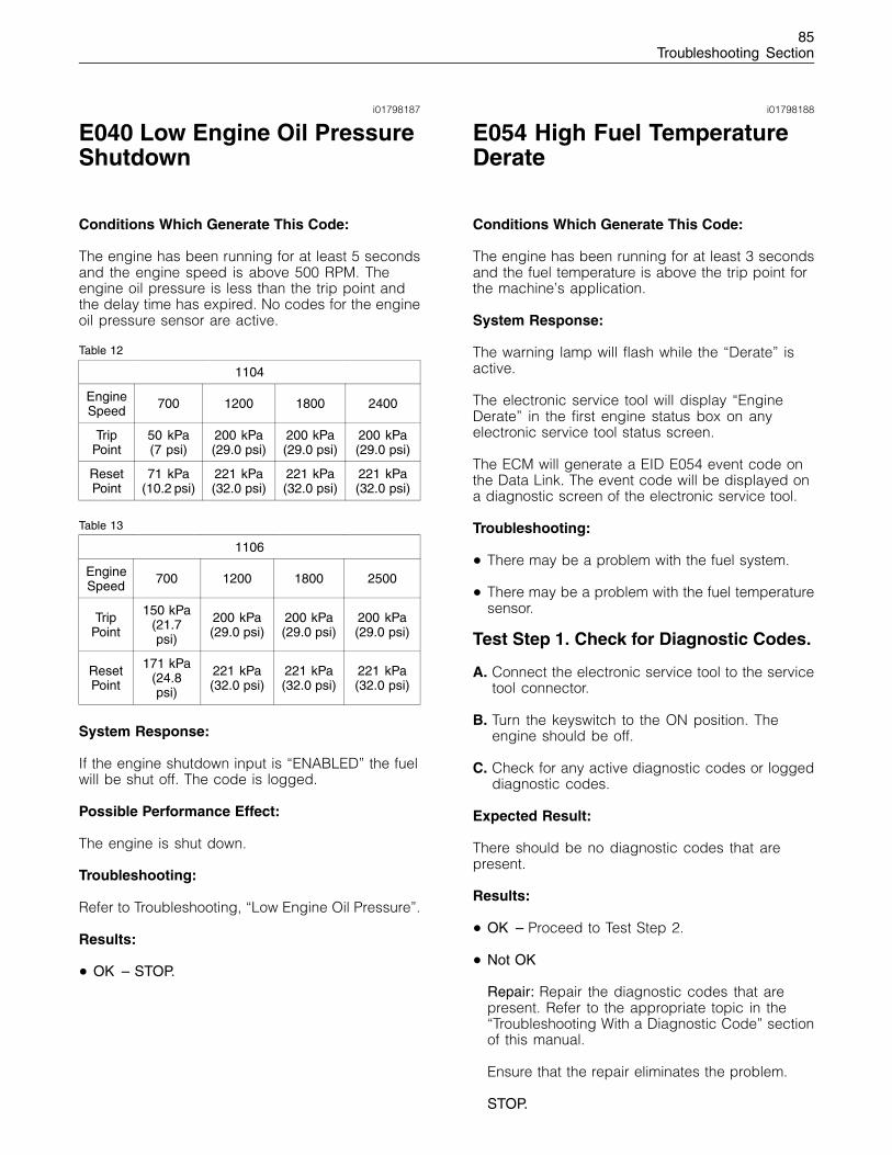
85Troubleshooting Section
i01798187
E040 Low Engine Oil PressureShutdown
Conditions Which Generate This Code:
The engine has been running for at least 5 secondsand the engine speed is above 500 RPM. Theengine oil pressure is less than the trip point andthe delay time has expired. No codes for the engineoil pressure sensor are active.
Table 12
1104
EngineSpeed 700 1200 1800 2400
TripPoint
50 kPa(7 psi)
200 kPa(29.0 psi)
200 kPa(29.0 psi)
200 kPa(29.0 psi)
ResetPoint
71 kPa(10.2 psi)
221 kPa(32.0 psi)
221 kPa(32.0 psi)
221 kPa(32.0 psi)
Table 13
1106
EngineSpeed 700 1200 1800 2500
TripPoint
150 kPa(21.7psi)
200 kPa(29.0 psi)
200 kPa(29.0 psi)
200 kPa(29.0 psi)
ResetPoint
171 kPa(24.8psi)
221 kPa(32.0 psi)
221 kPa(32.0 psi)
221 kPa(32.0 psi)
System Response:
If the engine shutdown input is “ENABLED” the fuelwill be shut off. The code is logged.
Possible Performance Effect:
The engine is shut down.
Troubleshooting:
Refer to Troubleshooting, “Low Engine Oil Pressure”.
Results:
• OK – STOP.
i01798188
E054 High Fuel TemperatureDerate
Conditions Which Generate This Code:
The engine has been running for at least 3 secondsand the fuel temperature is above the trip point forthe machine’s application.
System Response:
The warning lamp will flash while the “Derate” isactive.
The electronic service tool will display “EngineDerate” in the first engine status box on anyelectronic service tool status screen.
The ECM will generate a EID E054 event code onthe Data Link. The event code will be displayed ona diagnostic screen of the electronic service tool.
Troubleshooting:
• There may be a problem with the fuel system.
• There may be a problem with the fuel temperaturesensor.
Test Step 1. Check for Diagnostic Codes.
A. Connect the electronic service tool to the servicetool connector.
B. Turn the keyswitch to the ON position. Theengine should be off.
C. Check for any active diagnostic codes or loggeddiagnostic codes.
Expected Result:
There should be no diagnostic codes that arepresent.
Results:
• OK – Proceed to Test Step 2.
• Not OK
Repair: Repair the diagnostic codes that arepresent. Refer to the appropriate topic in the“Troubleshooting With a Diagnostic Code” sectionof this manual.
Ensure that the repair eliminates the problem.
STOP.
86Troubleshooting Section
Test Step 2. Perform a Check of the FuelSystem.
A. Perform a check of the fuel system. Refer to theappropriate topic in Testing and Adjusting forpossible causes.
Expected Result:
There are no problems with the fuel system.
Results:
• OK – There may be an intermittent problem.
Repair: Monitor the operation of the engine.
Repair the problem.
Ensure that the repair eliminates the problem.
STOP.
• Not OK
Repair: Repair the problem.
Ensure that the repair eliminates the problem.
STOP.
i01798189
E056 High Fuel TemperatureWarning
Conditions Which Generate This Code:
The fuel temperature has exceeded the trip pointand the delay time has expired. The ECM will resetthe warning when the fuel temperature is above thereset value.
The ECM detects all of the following conditions:
• The engine has been running at least threeminutes. This three minute delay begins once theengine speed is within 50 rpm of the low idlesetting.
• 174-02 Fuel Temperature Sensor erratic orintermittent
System Response:
The ECM will log the event. The event code can beviewed on the diagnostic screen of the electronicservice tool.
Troubleshooting:
• There may be a problem with the fuel system.
• There may be a problem with the fuel temperaturesensor.
Test Step 1. Check for Diagnostic Codes.
A. Connect the electronic service tool to the servicetool connector.
B. Turn the keyswitch to the ON position. Theengine should be off.
C. Check for any active diagnostic codes or loggeddiagnostic codes.
Expected Result:
There should be no diagnostic codes that arepresent.
Results:
• OK – Proceed to Test Step 2.
• Not OK
Repair: Repair the diagnostic codes that arepresent. Refer to the appropriate topic in the“Troubleshooting With a Diagnostic Code” sectionof this manual.
Ensure that the repair eliminates the problem.
STOP.
Test Step 2. Perform a Check of the FuelSystem.
A. Perform a check of the fuel system. Refer to theappropriate topic in Testing and Adjusting forpossible causes.
Expected Result:
There are no problems with the fuel system.
Results:
• OK – There may be an intermittent problem.
Repair: Monitor the operation of the engine.
Repair the problem.
Ensure that the repair eliminates the problem.
STOP.
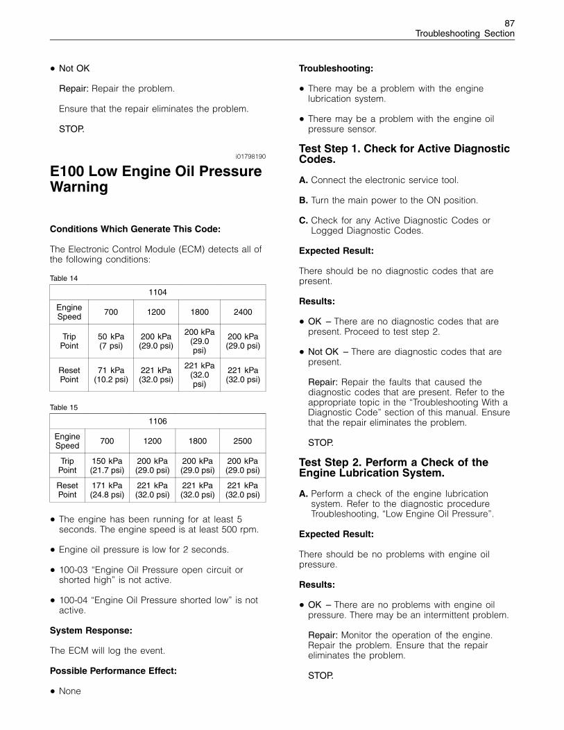
87Troubleshooting Section
• Not OK
Repair: Repair the problem.
Ensure that the repair eliminates the problem.
STOP.
i01798190
E100 Low Engine Oil PressureWarning
Conditions Which Generate This Code:
The Electronic Control Module (ECM) detects all ofthe following conditions:
Table 14
1104
EngineSpeed 700 1200 1800 2400
TripPoint
50 kPa(7 psi)
200 kPa(29.0 psi)
200 kPa(29.0psi)
200 kPa(29.0 psi)
ResetPoint
71 kPa(10.2 psi)
221 kPa(32.0 psi)
221 kPa(32.0psi)
221 kPa(32.0 psi)
Table 15
1106
EngineSpeed 700 1200 1800 2500
TripPoint
150 kPa(21.7 psi)
200 kPa(29.0 psi)
200 kPa(29.0 psi)
200 kPa(29.0 psi)
ResetPoint
171 kPa(24.8 psi)
221 kPa(32.0 psi)
221 kPa(32.0 psi)
221 kPa(32.0 psi)
• The engine has been running for at least 5seconds. The engine speed is at least 500 rpm.
• Engine oil pressure is low for 2 seconds.
• 100-03 “Engine Oil Pressure open circuit orshorted high” is not active.
• 100-04 “Engine Oil Pressure shorted low” is notactive.
System Response:
The ECM will log the event.
Possible Performance Effect:
• None
Troubleshooting:
• There may be a problem with the enginelubrication system.
• There may be a problem with the engine oilpressure sensor.
Test Step 1. Check for Active DiagnosticCodes.
A. Connect the electronic service tool.
B. Turn the main power to the ON position.
C. Check for any Active Diagnostic Codes orLogged Diagnostic Codes.
Expected Result:
There should be no diagnostic codes that arepresent.
Results:
• OK – There are no diagnostic codes that arepresent. Proceed to test step 2.
• Not OK – There are diagnostic codes that arepresent.
Repair: Repair the faults that caused thediagnostic codes that are present. Refer to theappropriate topic in the “Troubleshooting With aDiagnostic Code” section of this manual. Ensurethat the repair eliminates the problem.
STOP.
Test Step 2. Perform a Check of theEngine Lubrication System.
A. Perform a check of the engine lubricationsystem. Refer to the diagnostic procedureTroubleshooting, “Low Engine Oil Pressure”.
Expected Result:
There should be no problems with engine oilpressure.
Results:
• OK – There are no problems with engine oilpressure. There may be an intermittent problem.
Repair: Monitor the operation of the engine.Repair the problem. Ensure that the repaireliminates the problem.
STOP.
88Troubleshooting Section
• Not OK – There are problems with engine oilpressure.
Repair: Repair the problem. Ensure that the repaireliminates the problem.
STOP.
i01798191
E190 Engine OverspeedWarning
Conditions Which Generate This Code:
Engine speed is above 3000 rpm for the 1104 formore than 0.6 seconds or the engine speed isabove 3300 RPM for the 1106 for more than 0.6seconds. The reset point for both the 1104 and1106 is 2800 RPM.
Note: This Event Code represents an event. Thisdoes not represent an electronic system fault.
System Response:
The event is logged in memory. The event maybe viewed on a display module or the electronicservice tool.
Possible Performance Effect:
None
Troubleshooting:
This event indicates excessive engine speed. Thisdoes not represent a problem with the EngineControl Module (ECM). This does not represent aproblem with the Electronic Speed/Timing Sensor.
Engine Overspeed Warning
This event records the engine overspeed warning.No troubleshooting is required.
Expected Result:
Results:
• OK – STOP.
i01798192
E442 Engine Failed to Stopwith a No-Fuel Command
Conditions Which Generate This Code:
The engine shutdown was slow when the keyswitchwas turned to the OFF position.
The engine failed to shutdown when the keyswitchwas turned to the OFF position.
The engine failed to shutdown when the fuelinjection pump stopped fuel injection.
System Response:
If the engine still fails to shut down, the ECM willdisable the power relay for the fuel injection pump.
The event code is logged in the ECM memory.
Possible Performance Effect:
Slow engine shutdown
Troubleshooting:
No troubleshooting will be required unless thediagnostic code 1684-09 is active.
Test Step 1.
Connect a test ECM in order to determine if theoriginal ECM is the cause of the problem.
Note: The parameters of the test ECM must matchthe parameters in the suspect ECM.
If the test ECM resolves the problem, reconnect thesuspect ECM.
Verify that the problem returns. If the problemreturns, replace the suspect ECM.
Results:
• OK – STOP.
• Not OK – Proceed to Test Step 2.
Test Step 2.
Perform the following diagnostic procedure: “CANData Link Circuit - Test”
89Troubleshooting Section
Results:
• OK – STOP.
i01798193
E883 Engine Failed ToStop When Fuel SolenoidDisengaged
Conditions Which Generate This Code:
The engine shutdown was slow when the keyswitchwas turned to the OFF position.
The engine failed to stop when the ECM disabledthe fuel injection pump.
The engine failed to shutdown when the keyswitchwas turned to the OFF position.
System Response:
The ECM attempts to shut down the engine byinstructing the fuel injection pump to stop fuelinjection.
The event code is logged in the ECM memory.
Possible Performance Effect:
Slow engine shutdown
Troubleshooting:
No troubleshooting will be required unless thediagnostic code 1684-10 is active.
Test Step 1.
Use a multimeter to check the following connections:
• J1:1
• P40:5
Ensure that the problem has been eliminated.
Results:
• Check for active diagnostic codes – STOP.
Test Step 2.
Connect a test ECM to the engine in order todetermine if the original ECM is causing theproblem.
Note: The parameters of the test ECM must matchthe parameters in the suspect ECM.
If the test ECM resolves the problem, reconnect thesuspect ECM.
Verify that the problem returns with the suspectECM.
If the problem returns, replace the suspect ECM.
Results:
• OK – STOP.
• Not OK – Proceed to Test Step 3.
Test Step 3.
Replace the fuel injection pump. Refer toDisassembly and Assembly, “Fuel Injection PumpRemove and Install”.
Results:
• OK – STOP.
90Troubleshooting Section
Diagnostic FunctionalTests
i01798194
5 Volt Engine Pressure SensorSupply Circuit - Test
System Operation Description:
Use this procedure under the following situation:
Use this procedure if another procedure hasdirected you here. Also use this procedure if any ofthe following diagnostic codes are active:
• 262-03 5 Volt Sensor Power Supply voltage morethan normal
• 262-04 5 Volt Sensor Power Supply voltage lessthan normal
The following background information is relatedto this procedure:
The Electronic Control Module (ECM) suppliesregulated +5 VDC to the following sensors:
• J201/P201 Engine Oil Pressure Sensor
• J200/P200 Intake Manifold Pressure Sensor
• J40/P40 Throttle Sensor
The supply for the +5 V engine pressure sensor isrouted from the ECM through ECM engine harnessconnector J1/P1 terminal 2 to terminal “A” of eachpressure sensor connector. The supply voltage is5.0 ± 0.5 VDC.
The +5 V short circuit diagnostic code is probablycaused by a short circuit or an open circuit in theharness. The next probable cause is a sensor andthe least probable cause is the ECM.
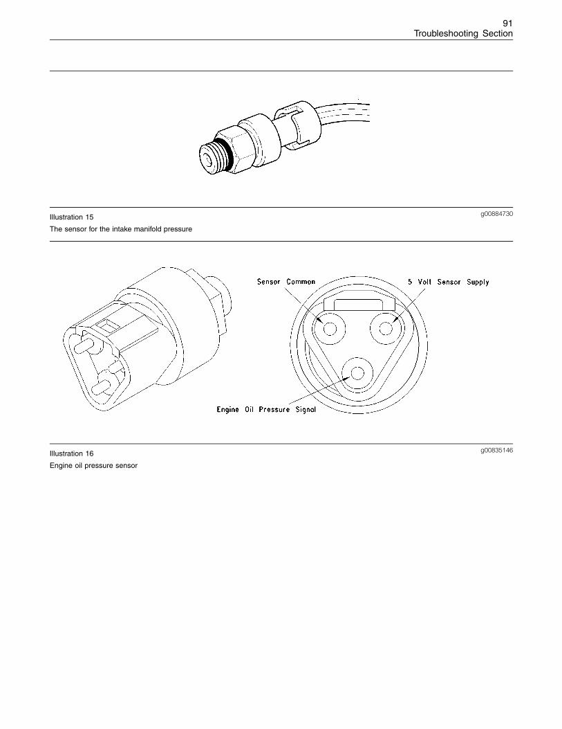
91Troubleshooting Section
g00884730Illustration 15
The sensor for the intake manifold pressure
g00835146Illustration 16
Engine oil pressure sensor
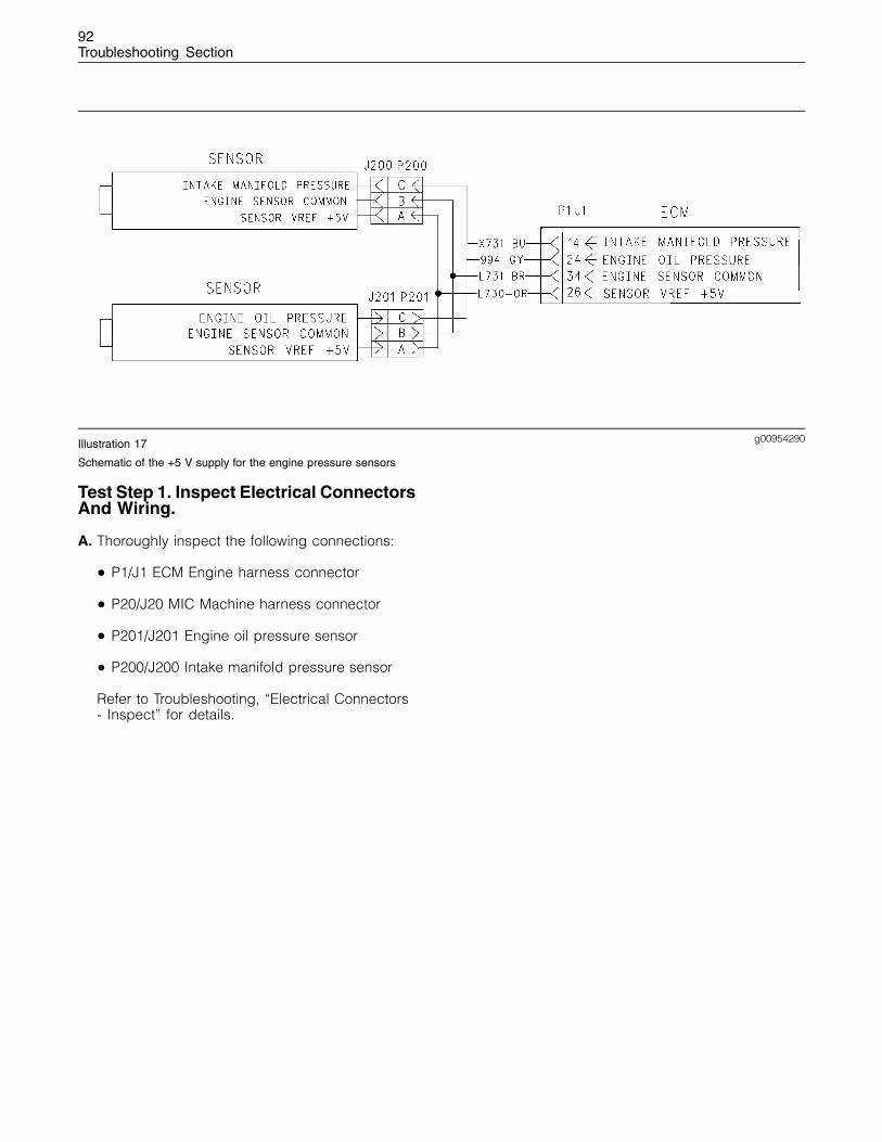
92Troubleshooting Section
g00954290Illustration 17
Schematic of the +5 V supply for the engine pressure sensors
Test Step 1. Inspect Electrical ConnectorsAnd Wiring.
A. Thoroughly inspect the following connections:
• P1/J1 ECM Engine harness connector
• P20/J20 MIC Machine harness connector
• P201/J201 Engine oil pressure sensor
• P200/J200 Intake manifold pressure sensor
Refer to Troubleshooting, “Electrical Connectors- Inspect” for details.
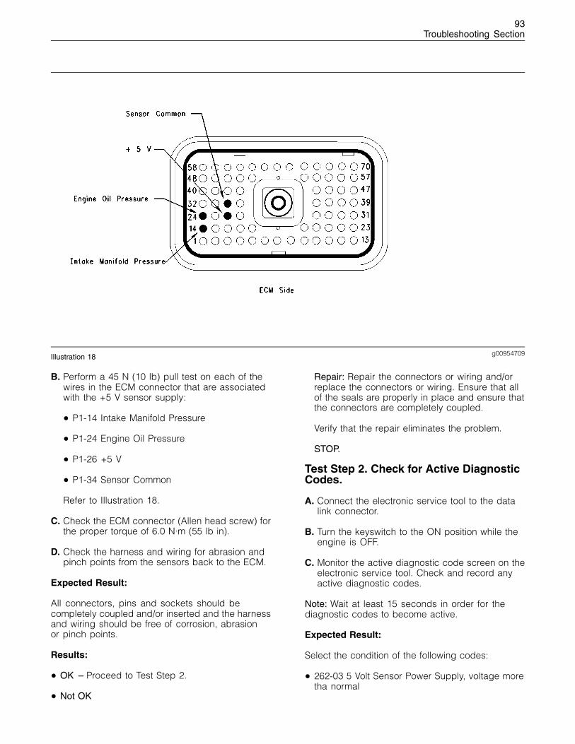
93Troubleshooting Section
g00954709Illustration 18
B. Perform a 45 N (10 lb) pull test on each of thewires in the ECM connector that are associatedwith the +5 V sensor supply:
• P1-14 Intake Manifold Pressure
• P1-24 Engine Oil Pressure
• P1-26 +5 V
• P1-34 Sensor Common
Refer to Illustration 18.
C. Check the ECM connector (Allen head screw) forthe proper torque of 6.0 N·m (55 lb in).
D. Check the harness and wiring for abrasion andpinch points from the sensors back to the ECM.
Expected Result:
All connectors, pins and sockets should becompletely coupled and/or inserted and the harnessand wiring should be free of corrosion, abrasionor pinch points.
Results:
• OK – Proceed to Test Step 2.
• Not OK
Repair: Repair the connectors or wiring and/orreplace the connectors or wiring. Ensure that allof the seals are properly in place and ensure thatthe connectors are completely coupled.
Verify that the repair eliminates the problem.
STOP.
Test Step 2. Check for Active DiagnosticCodes.
A. Connect the electronic service tool to the datalink connector.
B. Turn the keyswitch to the ON position while theengine is OFF.
C. Monitor the active diagnostic code screen on theelectronic service tool. Check and record anyactive diagnostic codes.
Note: Wait at least 15 seconds in order for thediagnostic codes to become active.
Expected Result:
Select the condition of the following codes:
• 262-03 5 Volt Sensor Power Supply, voltage moretha normal
94Troubleshooting Section
• 262-04 5 Volt Sensor Power Supply, voltage lessthan normal
Results:
• Active – Proceed to Test Step 3.
• Logged ONLY – Proceed to Test Step 5.
• Not Active or Logged – The +5 V supply isoperating correctly at this time. STOP.
Test Step 3. Disconnect The ECM EngineHarness Connector From The ECM.
A. Connect the electronic service tool to thediagnostic connector.
Batteries give off flammable fumes which can ex-plode.
To avoid injury or death, do not strike a match,cause a spark, or smoke in the vicinity of a battery.
NOTICEDo Not connect the bypass harness to the battery un-til the 20 Amp in-line fuse has been removed from the+Battery line. If the fuse is not removed before con-nection to the battery, a spark may result.
B. Turn the keyswitch to the OFF position while theengine is off.
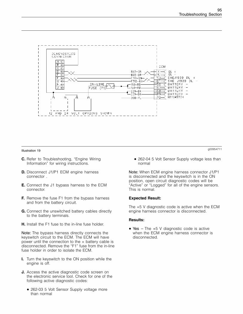
95Troubleshooting Section
g00954711Illustration 19
C. Refer to Troubleshooting, “Engine WiringInformation” for wiring instructions.
D. Disconnect J1/P1 ECM engine harnessconnector .
E. Connect the J1 bypass harness to the ECMconnector.
F. Remove the fuse F1 from the bypass harnessand from the battery circuit.
G. Connect the unswitched battery cables directlyto the battery terminals.
H. Install the F1 fuse to the in-line fuse holder.
Note: The bypass harness directly connects thekeyswitch circuit to the ECM. The ECM will havepower until the connection to the + battery cable isdisconnected. Remove the “F1” fuse from the in-linefuse holder in order to isolate the ECM.
I. Turn the keyswitch to the ON position while theengine is off.
J. Access the active diagnostic code screen onthe electronic service tool. Check for one of thefollowing active diagnostic codes:
• 262-03 5 Volt Sensor Supply voltage morethan normal
• 262-04 5 Volt Sensor Supply voltage less thannormal
Note: When ECM engine harness connector J1/P1is disconnected and the keyswitch is in the ONposition, open circuit diagnostic codes will be“Active” or “Logged” for all of the engine sensors.This is normal.
Expected Result:
The +5 V diagnostic code is active when the ECMengine harness connector is disconnected.
Results:
• Yes – The +5 V diagnostic code is activewhen the ECM engine harness connector isdisconnected.
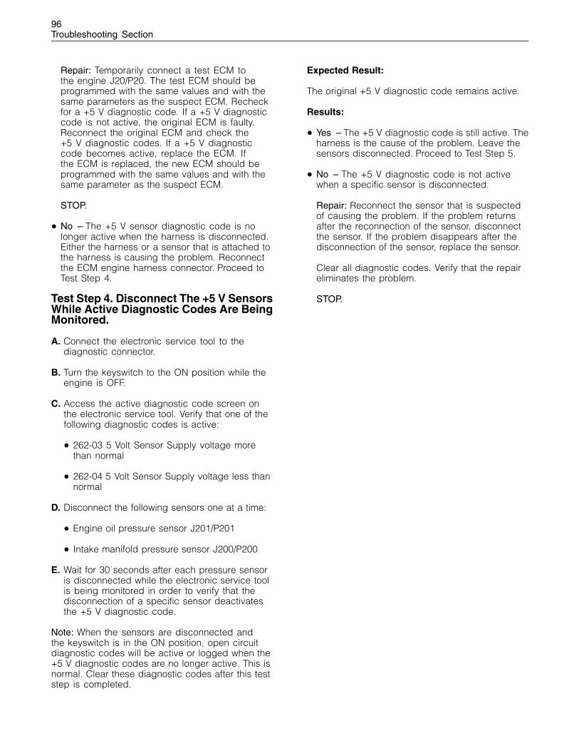
96Troubleshooting Section
Repair: Temporarily connect a test ECM tothe engine J20/P20. The test ECM should beprogrammed with the same values and with thesame parameters as the suspect ECM. Recheckfor a +5 V diagnostic code. If a +5 V diagnosticcode is not active, the original ECM is faulty.Reconnect the original ECM and check the+5 V diagnostic codes. If a +5 V diagnosticcode becomes active, replace the ECM. Ifthe ECM is replaced, the new ECM should beprogrammed with the same values and with thesame parameter as the suspect ECM.
STOP.
• No – The +5 V sensor diagnostic code is nolonger active when the harness is disconnected.Either the harness or a sensor that is attached tothe harness is causing the problem. Reconnectthe ECM engine harness connector. Proceed toTest Step 4.
Test Step 4. Disconnect The +5 V SensorsWhile Active Diagnostic Codes Are BeingMonitored.
A. Connect the electronic service tool to thediagnostic connector.
B. Turn the keyswitch to the ON position while theengine is OFF.
C. Access the active diagnostic code screen onthe electronic service tool. Verify that one of thefollowing diagnostic codes is active:
• 262-03 5 Volt Sensor Supply voltage morethan normal
• 262-04 5 Volt Sensor Supply voltage less thannormal
D. Disconnect the following sensors one at a time:
• Engine oil pressure sensor J201/P201
• Intake manifold pressure sensor J200/P200
E. Wait for 30 seconds after each pressure sensoris disconnected while the electronic service toolis being monitored in order to verify that thedisconnection of a specific sensor deactivatesthe +5 V diagnostic code.
Note: When the sensors are disconnected andthe keyswitch is in the ON position, open circuitdiagnostic codes will be active or logged when the+5 V diagnostic codes are no longer active. This isnormal. Clear these diagnostic codes after this teststep is completed.
Expected Result:
The original +5 V diagnostic code remains active.
Results:
• Yes – The +5 V diagnostic code is still active. Theharness is the cause of the problem. Leave thesensors disconnected. Proceed to Test Step 5.
• No – The +5 V diagnostic code is not activewhen a specific sensor is disconnected.
Repair: Reconnect the sensor that is suspectedof causing the problem. If the problem returnsafter the reconnection of the sensor, disconnectthe sensor. If the problem disappears after thedisconnection of the sensor, replace the sensor.
Clear all diagnostic codes. Verify that the repaireliminates the problem.
STOP.
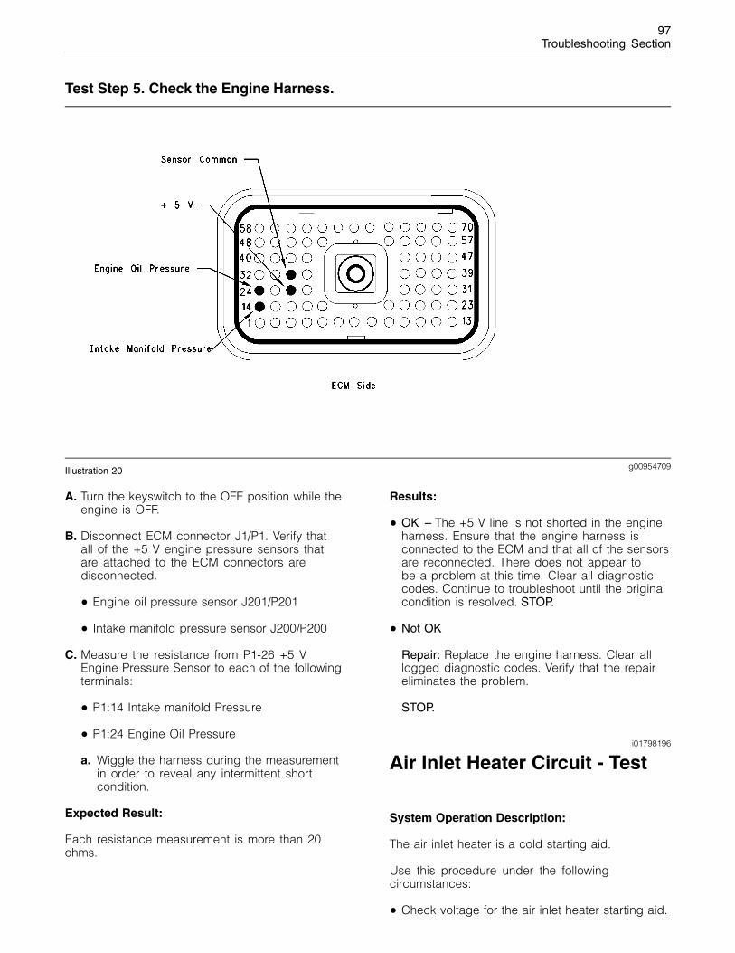
97Troubleshooting Section
Test Step 5. Check the Engine Harness.
g00954709Illustration 20
A. Turn the keyswitch to the OFF position while theengine is OFF.
B. Disconnect ECM connector J1/P1. Verify thatall of the +5 V engine pressure sensors thatare attached to the ECM connectors aredisconnected.
• Engine oil pressure sensor J201/P201
• Intake manifold pressure sensor J200/P200
C. Measure the resistance from P1-26 +5 VEngine Pressure Sensor to each of the followingterminals:
• P1:14 Intake manifold Pressure
• P1:24 Engine Oil Pressure
a. Wiggle the harness during the measurementin order to reveal any intermittent shortcondition.
Expected Result:
Each resistance measurement is more than 20ohms.
Results:
• OK – The +5 V line is not shorted in the engineharness. Ensure that the engine harness isconnected to the ECM and that all of the sensorsare reconnected. There does not appear tobe a problem at this time. Clear all diagnosticcodes. Continue to troubleshoot until the originalcondition is resolved. STOP.
• Not OK
Repair: Replace the engine harness. Clear alllogged diagnostic codes. Verify that the repaireliminates the problem.
STOP.
i01798196
Air Inlet Heater Circuit - Test
System Operation Description:
The air inlet heater is a cold starting aid.
Use this procedure under the followingcircumstances:
• Check voltage for the air inlet heater starting aid.
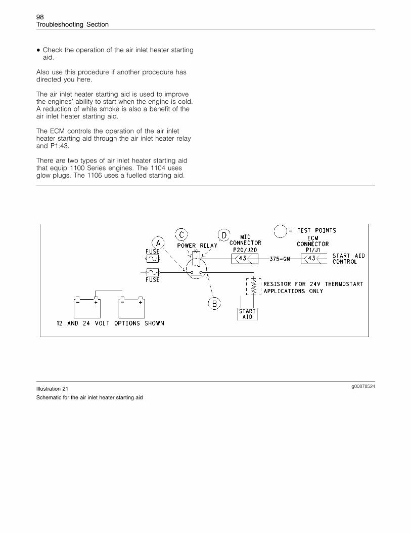
98Troubleshooting Section
• Check the operation of the air inlet heater startingaid.
Also use this procedure if another procedure hasdirected you here.
The air inlet heater starting aid is used to improvethe engines’ ability to start when the engine is cold.A reduction of white smoke is also a benefit of theair inlet heater starting aid.
The ECM controls the operation of the air inletheater starting aid through the air inlet heater relayand P1:43.
There are two types of air inlet heater starting aidthat equip 1100 Series engines. The 1104 usesglow plugs. The 1106 uses a fuelled starting aid.
g00878524Illustration 21
Schematic for the air inlet heater starting aid
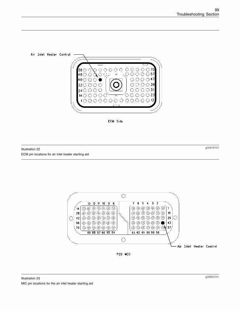
99Troubleshooting Section
g00878757Illustration 22
ECM pin locations for air inlet heater starting aid
g00954741Illustration 23
MIC pin locations for the air inlet heater starting aid
100Troubleshooting Section
Test Step 1. Inspect Electrical Connectorsand Wiring
A. Thoroughly inspect the J1/P1 ECM connector andJ20/P20 MIC. Inspect the terminal connections onthe air inlet heater relay. Refer to Troubleshooting,“Electrical Connectors - Inspect” for details.
B. Perform a 45 N (10 lb) pull test on each of thewires in the ECM connector that are associatedwith the air inlet heater starting aid. Refer toIllustration 22 and 23.
C. Check the ECM connector (Allen head screw) forthe proper torque of 6.0 N·m (55 lb in).
D. Check the harness and wiring for abrasion andfor pinch points from the sensors back to theECM.
Expected Result:
All connectors, pins and sockets should becompletely coupled and/or inserted and the harnessand wiring should be free of corrosion, abrasionor pinch points.
Results:
• OK – The wiring and the connectors are good.Proceed to Test Step 2.
• Not OK – There is a problem with the wiring andthe connectors.
Repair: Perform the following repair:
Repair the connectors or wiring and/or replacethe connectors or wiring. Ensure that all of theseals are properly in place and ensure that theconnectors are completely coupled.
Verify that the repair eliminates the problem.
STOP.
Test Step 2. Check the Supply to thePower Relay for the Air Inlet HeaterStarting Aid
A. Turn the ignition key switch to the ON position.Refer to Illustration 21.
B. Measure the resistance between the followingcontacts:
• A The supply side of the air inlet heater powerrelay and NEG battery
• C Positive side of the air inlet heater relay coiland NEG battery
Expected Result:
The battery voltage is correct.
Results:
• OK – Proceed to Test Step 3.
• Not OK – There is a problem in the wires betweenthe battery and the air inlet heater starting aid.
Repair: Check the fuse and wires. Repair thewires or replace the fuse. Verify that the repairshave eliminated the problem.
STOP.
Test Step 3. Check the Output fromthe Power Relay for the Air Inlet HeaterStarting Aid
A. Turn the ignition key switch to the ON position.Refer to Illustration 21.
B. Measure the voltage between the followingcontacts:
• (B)
• NEG battery
Expected Result:
The battery has the proper voltage.
Results:
• OK – There is a problem in the wires between therelay and the air inlet heater starting aid.
Repair: Repair the wires or replace the wires.Verify that the repair has eliminated the problem.
STOP.
• Not OK – Proceed to Test Step 4.
Test Step 4. Ground the Input to thePower Relay at the MIC
A. Turn the keyswitch to the OFF position.
B. Disconnect P20 connector from the MIC andconnect a 70 pin Breakout T.
C. Connect the electronic service tool to thediagnostic connector.
D. Turn the keyswitch to the ON position.
101Troubleshooting Section
E. Use the override setting in the electronic servicetool in order to engage the air inlet heaterstarting aid.
F. Measure the voltage between P20:43 air inletheater control and socket 69 NEG battery on theBreakout T.
Expected Result:
The voltage is 0 volts when the air inlet heaterstarting aid is engaged.
Results:
• OK – Proceed to Test Step 5.
• Not OK – The problem is in the wires betweenthe power relay for the air inlet heater starting aidand the MIC.
Repair: Repair the harness or replace the harness.Verify that the repair has eliminated the problem.
STOP.
Test Step 5. Ground the Input to thePower Relay at the ECM connector
A. Turn the ignition key switch to the OFF position.
B. Remove the 70 pin Breakout T and reconnectthe P20 MIC.
C. Disconnect the P1 ECM connector from the ECMand connect a 70 pin Breakout T.
D. Connect the electronic service tool to thediagnostic connector.
E. Turn the keyswitch to the ON position.
F. Insert a jumper wire between J1:43 on theBreakout T. Monitor the status screen on theelectronic service tool. Slowly connect anddisconnect the other end of the jumper wire tosocket 69 NEG battery on the Breakout T.
Expected Result:
When the jumper wire is connected the status of therelay should be closed.
When the jumper wire is disconnected the status ofthe relay should be open.
Results:
• OK – Proceed to Test Step 6.
• Not OK – The problem is in the wire harnessbetween the MIC and the ECM connector.
Repair: Repair the damaged wire or replace thewire. Verify that the problem has been eliminated.
If the repair has not eliminated the problemproceed to test step 6.
STOP.
Test Step 6. Override the Air Inlet HeaterStarting Aid in order to Test the ECM
A. Turn the ignition key switch to the OFF position.
B. Remove the 70 pin Breakout T.
C. Connect the P1 ECM connector.
D. Connect the electronic service tool to thediagnostic connector.
E. Turn the keyswitch to the ON position.
F. Use the electronic service tool to monitor thestatus screen.
G. Use the override parameter for the air inlet heaterstarting aid to override the following systems:
• Glow plug starting aid (if equipped)
• Fuelled starting aid (if equipped)
H. Verify that the air inlet heater starting aid is either“enabled” or “disabled”.
I. Verify that the lamp for the air inlet heater startingaid is on.
Expected Result:
The air inlet heater starting aid is working properly.
Results:
• OK – The ECM is operating properly. STOP.
• Not OK – The ECM is not working properly.
Repair: Temporarily connect a test ECM. Removeall jumpers and replace all connectors. The testECM should be programmed with the correctsoftware. All parameters should be set to thesame value of the suspect ECM.
If the problem is eliminated with the test ECM,reconnect the suspect ECM. If the problem returnswith the suspect ECM, replace the suspect ECM.
Verify that the repair has eliminated the problem.
STOP.
102Troubleshooting Section
i01794909
Analog Throttle PositionSensor Circuit - Test
System Operation Description:
Use this procedure if another procedure hasdirected you here. Use this procedure if any of thefollowing diagnostic codes are active:
• 91-02 Throttle Demand Sensor erratic orintermittent
• 91-03 Throttle Demand Sensor open circuit orshorted high
• 91-04 Throttle Demand Sensor shorted low
• 774-02 Throttle Demand Sensor No.2 erratic orintermittent
• 774-03 Throttle Demand Sensor No.2 open circuitor shorted high
• 774-04 Throttle Demand Sensor No.2 shorted low
• 262-03 5V Sensor Supply Voltage more thannormal
• 262-04 5V Sensor Supply Voltage less thannormal
The throttle demand sensor is an Analog sensor andthis sensor is mounted on the throttle pedal. Thethrottle demand sensor provides an output voltageto the ECM. This sensor output voltage will vary withthe position of the throttle from 0.5 volts to 4.5 volts.The throttle demand sensor is attached directlyto the throttle assembly. Foot or hand operatedversions of the throttle assembly are also available.
The sensor receives +5 volt power from the ECM.The sensor will produce a voltage that will alterbetween low idle and high idle. The voltage ischanged into a throttle position within the range 0 to100 percent by the ECM.
The throttle demand sensor senses the speedrequirement from the throttle position. A secondthrottle demand sensor may override this speedrequirement from the first throttle demand sensor.This override will be subject to an input from eitherthe SAE J1939 (CAN), or from the Set SpeedControl. The input status can be checked on theelectronic service tool Status Display Screen.
The system will check the switch position in relationto the throttle position signal when the idle validationhas been set for use. If the switch position and thesignal from the throttle demand sensor are validthen the throttle will operate as normal.
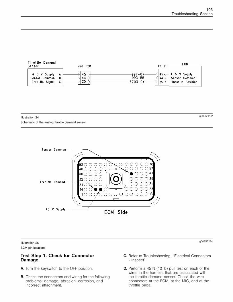
103Troubleshooting Section
g00955292Illustration 24
Schematic of the analog throttle demand sensor
g00955294Illustration 25
ECM pin locations
Test Step 1. Check for ConnectorDamage.
A. Turn the keyswitch to the OFF position.
B. Check the connectors and wiring for the followingproblems: damage, abrasion, corrosion, andincorrect attachment.
C. Refer to Troubleshooting, “Electrical Connectors- Inspect”.
D. Perform a 45 N (10 lb) pull test on each of thewires in the harness that are associated withthe throttle demand sensor. Check the wireconnectors at the ECM, at the MIC, and at thethrottle pedal.
104Troubleshooting Section
• P1:18 Throttle No 2
• P1:25 Throttle No 1
• P1:44 Sensor common
• P1:45 +5V DC sensor supply
E. Check the ECM connector (Allen head screw) forthe proper torque of 6.0 N·m (55 lb in).
Expected Result:
The connectors and wiring should be free of thefollowing problems: damage, abrasion, corrosion,and incorrect attachment.
Results:
• OK – Proceed to Test Step 2.
• Not OK
Repair: Repair the connectors or wiring and/orreplace the connectors or wiring.
STOP.
Test Step 2. Check for active DiagnosticCodes.
A. Turn the keyswitch to the ON position.
B. Use the electronic service tool to check fordiagnostic codes.
Expected Result:
RESULT 1 The electronic service tool displays thefollowing active diagnostic codes:
• 91-03
• 91-04
• 774-03
• 774-04
RESULT 2 The electronic service tool displays thefollowing active diagnostic codes:
• 91-12
• 774-12
• 262-03
• 262-04
RESULT 3 The electronic service tool displays thefollowing active diagnostic codes:
• 91-02
• 774-02
RESULT 4 The electronic service tool displays noactive diagnostic codes:
Results:
• Result 1 – Proceed to Test Step 3.
• Result 2 – Proceed to Test Step 5.
• Result 3
Repair: Refer to Troubleshooting, “Idle ValidationCircuit Test”.
STOP.
• Result 4 – Proceed to Test Step 3.
Test Step 3. Check the Throttle Positionwith the Electronic Service Tool.
A. Connect the electronic service tool to thediagnostic connector.
B. Turn the keyswitch to the ON position. Theengine should be off.
C. Observe the throttle position reading on theelectronic service tool.
D. Depress the throttle and release the throttle.
Expected Result:
The output should increase when the throttle pedalis depressed.
The output should be between “20 percent” and“27 percent” at the low idle position. The outputshould be between “80 percent” and “87 percent”at the high idle position.
Results:
• OK – The throttle demand sensor is operatingcorrectly. Proceed to Test Step 5.
• Not OK – The ECM is not receiving a correctsignal from the sensor. There may be a problemin the harness. Proceed to Test Step 4.
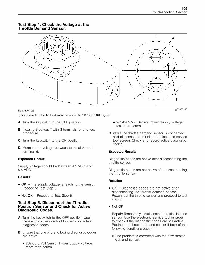
105Troubleshooting Section
Test Step 4. Check the Voltage at theThrottle Demand Sensor.
g00835148Illustration 26
Typical example of the throttle demand sensor for the 1106 and 1104 engines
A. Turn the keyswitch to the OFF position.
B. Install a Breakout T with 3 terminals for this testprocedure.
C. Turn the keyswitch to the ON position.
D. Measure the voltage between terminal A andterminal B.
Expected Result:
Supply voltage should be between 4.5 VDC and5.5 VDC.
Results:
• OK – The supply voltage is reaching the sensor.Proceed to Test Step 5.
• Not OK – Proceed to Test Step 6.
Test Step 5. Disconnect the ThrottlePosition Sensor and Check for ActiveDiagnostic Codes.
A. Turn the keyswitch to the OFF position. Usethe electronic service tool to check for activediagnostic codes.
B. Ensure that one of the following diagnostic codesare active:
• 262-03 5 Volt Sensor Power Supply voltagemore than normal
• 262-04 5 Volt Sensor Power Supply voltageless than normal
C. While the throttle demand sensor is connectedand disconnected, monitor the electronic servicetool screen. Check and record active diagnosticcodes.
Expected Result:
Diagnostic codes are active after disconnecting thethrottle sensor.
Diagnostic codes are not active after disconnectingthe throttle sensor.
Results:
• OK – Diagnostic codes are not active afterdisconnecting the throttle demand sensor.Reconnect the throttle sensor and proceed to teststep 7.
• Not OK
Repair: Temporarily install another throttle demandsensor. Use the electronic service tool in orderto check if the diagnostic codes are still active.Replace the throttle demand sensor if both of thefollowing conditions occur:
• The problem is corrected with the new throttledemand sensor.

106Troubleshooting Section
• The problem returns after the old throttledemand sensor has been reconnected.
STOP.
Test Step 6. Check the Throttle SelectionStatus with the Electronic Service Tool.
A. Check the status of the throttle selection switch(if equipped). The throttle selection status canbe observed on the status display screen of theelectronic service tool.
Expected Result:
If the throttle selection switch status is shown in theOFF position, then the throttle 1 has control of theengine speed.
If the throttle selection switch status is shown in theON position then the throttle 2 has control of theengine speed.
The throttle could be overridden by instructions viathe SAE J1939 (CAN) or the set speed control.
Results:
• OK – The throttle demand switch is operatingcorrectly.
Repair: There may be an intermittent fault. Referto Troubleshooting, “Electrical Connectors -Inspect”.
STOP.
• Not OK – The wrong throttle is selected. Changeto the other throttle. There may be a fault with theinput from the selector switch. Proceed to Step 7.
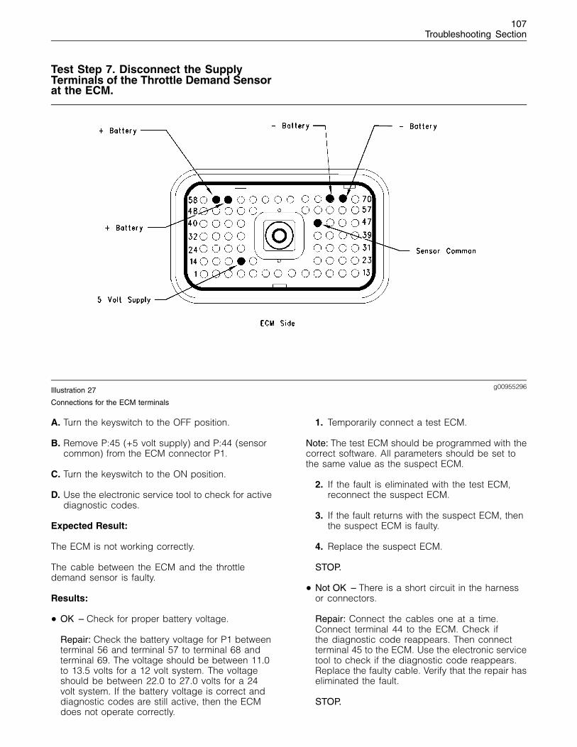
107Troubleshooting Section
Test Step 7. Disconnect the SupplyTerminals of the Throttle Demand Sensorat the ECM.
g00955296Illustration 27
Connections for the ECM terminals
A. Turn the keyswitch to the OFF position.
B. Remove P:45 (+5 volt supply) and P:44 (sensorcommon) from the ECM connector P1.
C. Turn the keyswitch to the ON position.
D. Use the electronic service tool to check for activediagnostic codes.
Expected Result:
The ECM is not working correctly.
The cable between the ECM and the throttledemand sensor is faulty.
Results:
• OK – Check for proper battery voltage.
Repair: Check the battery voltage for P1 betweenterminal 56 and terminal 57 to terminal 68 andterminal 69. The voltage should be between 11.0to 13.5 volts for a 12 volt system. The voltageshould be between 22.0 to 27.0 volts for a 24volt system. If the battery voltage is correct anddiagnostic codes are still active, then the ECMdoes not operate correctly.
1. Temporarily connect a test ECM.
Note: The test ECM should be programmed with thecorrect software. All parameters should be set tothe same value as the suspect ECM.
2. If the fault is eliminated with the test ECM,reconnect the suspect ECM.
3. If the fault returns with the suspect ECM, thenthe suspect ECM is faulty.
4. Replace the suspect ECM.
STOP.
• Not OK – There is a short circuit in the harnessor connectors.
Repair: Connect the cables one at a time.Connect terminal 44 to the ECM. Check ifthe diagnostic code reappears. Then connectterminal 45 to the ECM. Use the electronic servicetool to check if the diagnostic code reappears.Replace the faulty cable. Verify that the repair haseliminated the fault.
STOP.
108Troubleshooting Section
Test Step 8. Check the Position of ThrottleDemand Sensor.
A. Turn the keyswitch to the OFF position.
B. Install a Breakout T with 3 terminals to the throttledemand sensor.
C. Turn the keyswitch to the ON position.
D. Measure the voltage between terminal C andterminal B of the Breakout T.
E. Observe the voltage while the engine speedcontrol is moved from the minimum to themaximum position.
Expected Result:
The voltage should be between 20 and 80 percentof the sensor supply voltage when the speedcontrol is moved from the minimum to the maximumposition.
Results:
• OK – The throttle demand sensor is workingcorrectly. Proceed to Test Step 9.
• Not OK – The throttle demand sensor is faulty.Proceed to Test Step 10.
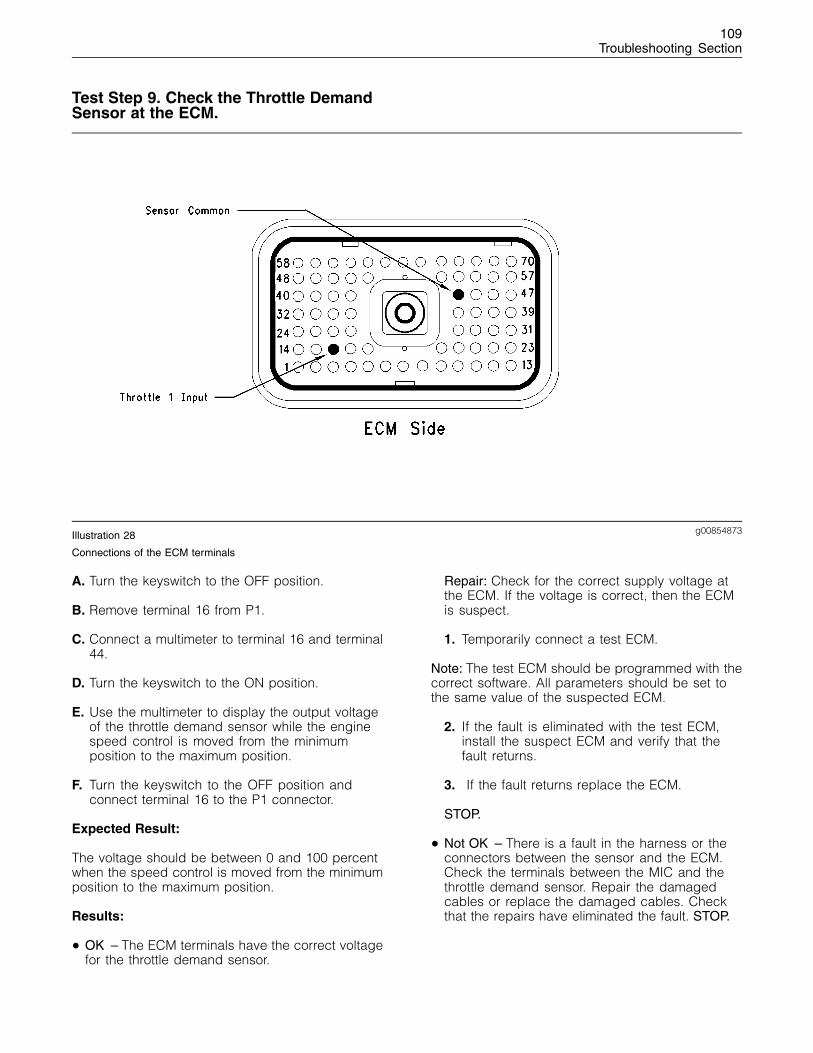
109Troubleshooting Section
Test Step 9. Check the Throttle DemandSensor at the ECM.
g00854873Illustration 28
Connections of the ECM terminals
A. Turn the keyswitch to the OFF position.
B. Remove terminal 16 from P1.
C. Connect a multimeter to terminal 16 and terminal44.
D. Turn the keyswitch to the ON position.
E. Use the multimeter to display the output voltageof the throttle demand sensor while the enginespeed control is moved from the minimumposition to the maximum position.
F. Turn the keyswitch to the OFF position andconnect terminal 16 to the P1 connector.
Expected Result:
The voltage should be between 0 and 100 percentwhen the speed control is moved from the minimumposition to the maximum position.
Results:
• OK – The ECM terminals have the correct voltagefor the throttle demand sensor.
Repair: Check for the correct supply voltage atthe ECM. If the voltage is correct, then the ECMis suspect.
1. Temporarily connect a test ECM.
Note: The test ECM should be programmed with thecorrect software. All parameters should be set tothe same value of the suspected ECM.
2. If the fault is eliminated with the test ECM,install the suspect ECM and verify that thefault returns.
3. If the fault returns replace the ECM.
STOP.
• Not OK – There is a fault in the harness or theconnectors between the sensor and the ECM.Check the terminals between the MIC and thethrottle demand sensor. Repair the damagedcables or replace the damaged cables. Checkthat the repairs have eliminated the fault. STOP.
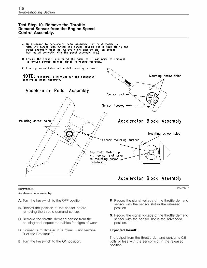
110Troubleshooting Section
Test Step 10. Remove the ThrottleDemand Sensor from the Engine SpeedControl Assembly.
g00706977Illustration 29
Accelerator pedal assembly
A. Turn the keyswitch to the OFF position.
B. Record the position of the sensor beforeremoving the throttle demand sensor.
C. Remove the throttle demand sensor from thehousing and inspect the cables for signs of wear.
D. Connect a multimeter to terminal C and terminalB of the Breakout T.
E. Turn the keyswitch to the ON position.
F. Record the signal voltage of the throttle demandsensor with the sensor slot in the releasedposition.
G. Record the signal voltage of the throttle demandsensor with the sensor slot in the advancedposition.
Expected Result:
The output from the throttle demand sensor is 0.5volts or less with the sensor slot in the releasedposition.
111Troubleshooting Section
The output from the throttle demand sensor is 4.5volts or more with the sensor slot in the advancedposition.
Results:
• OK
Repair: The operation of the throttle demandsensor is correct. The fault is caused by the footpedal or the lever assembly. Adjust the assemblyor replace the assembly.
Verify that the repairs have eliminated the fault.
STOP.
• Not OK – The throttle demand sensor is faulty.
Repair: Replace the throttle demand sensor.
Verify that the repair has eliminated the fault.
STOP.
i01798197
CAN Data Link Circuit - Test
System Operation Description:
Use this procedure if another procedure hasdirected you here. Also use this procedure if any ofthe following diagnostic codes are active:
• 342-2 Speed and Timining Sensor No.2intermittent signal
The CAN Data Link is the communication linkbetween the Electronic Control Module (ECM) andthe fuel injection pump. The CAN Data Link is usedto communicate the following information:
• Engine timing
• Fuel demand to the fuel injection pump
• Data from the fuel injection pump
• Status of the fuel injection pump
A failure in the CAN Data Link will cause thefollowing conditions:
• The engine will shut down.
• The engine will not start.
Note: Do not attempt to repair the wire harnessbetween the ECM and the fuel injection pump. Ifthe wire harness is damaged the wire harness mustbe replaced.
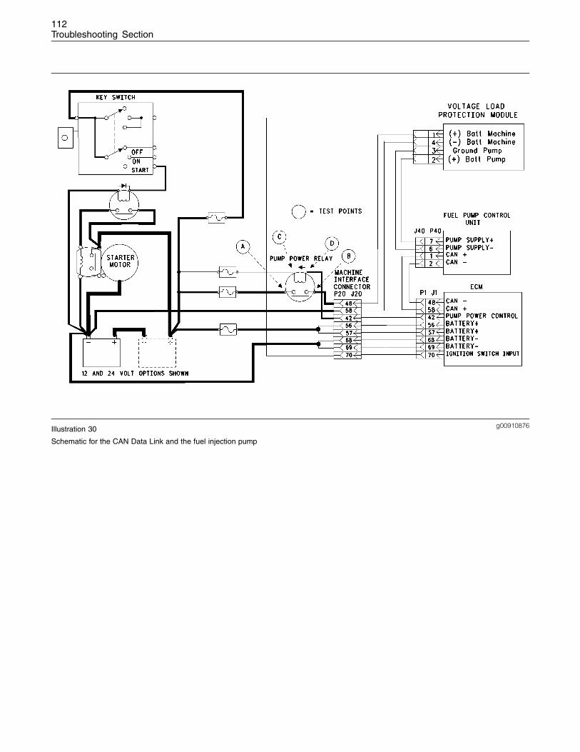
112Troubleshooting Section
g00910876Illustration 30
Schematic for the CAN Data Link and the fuel injection pump
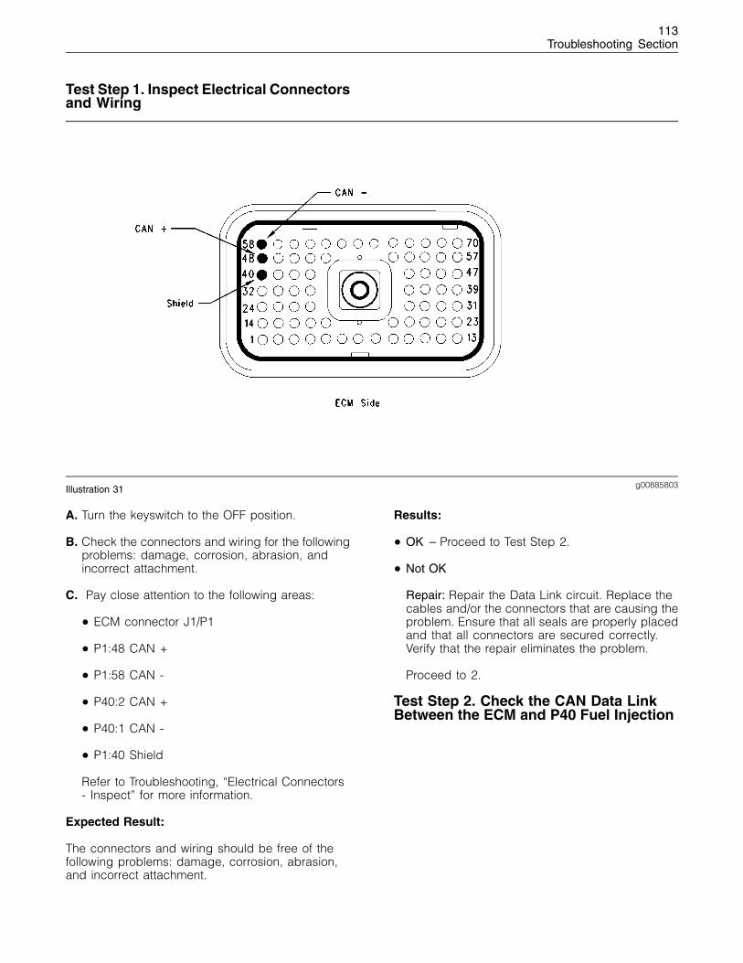
113Troubleshooting Section
Test Step 1. Inspect Electrical Connectorsand Wiring
g00885803Illustration 31
A. Turn the keyswitch to the OFF position.
B. Check the connectors and wiring for the followingproblems: damage, corrosion, abrasion, andincorrect attachment.
C. Pay close attention to the following areas:
• ECM connector J1/P1
• P1:48 CAN +
• P1:58 CAN -
• P40:2 CAN +
• P40:1 CAN -
• P1:40 Shield
Refer to Troubleshooting, “Electrical Connectors- Inspect” for more information.
Expected Result:
The connectors and wiring should be free of thefollowing problems: damage, corrosion, abrasion,and incorrect attachment.
Results:
• OK – Proceed to Test Step 2.
• Not OK
Repair: Repair the Data Link circuit. Replace thecables and/or the connectors that are causing theproblem. Ensure that all seals are properly placedand that all connectors are secured correctly.Verify that the repair eliminates the problem.
Proceed to 2.
Test Step 2. Check the CAN Data LinkBetween the ECM and P40 Fuel Injection
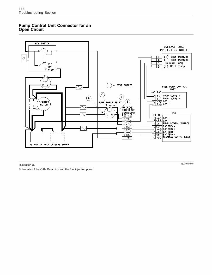
114Troubleshooting Section
Pump Control Unit Connector for anOpen Circuit
g00910876Illustration 32
Schematic of the CAN Data Link and the fuel injection pump
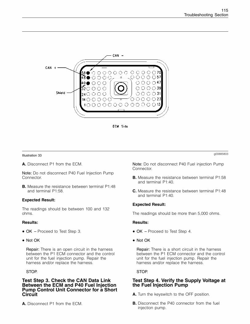
115Troubleshooting Section
g00885803Illustration 33
A. Disconnect P1 from the ECM.
Note: Do not disconnect P40 Fuel Injection PumpConnector.
B. Measure the resistance between terminal P1:48and terminal P1:58.
Expected Result:
The readings should be between 100 and 132ohms.
Results:
• OK – Proceed to Test Step 3.
• Not OK
Repair: There is an open circuit in the harnessbetween the P1 ECM connector and the controlunit for the fuel injection pump. Repair theharness and/or replace the harness.
STOP.
Test Step 3. Check the CAN Data LinkBetween the ECM and P40 Fuel InjectionPump Control Unit Connector for a ShortCircuit
A. Disconnect P1 from the ECM.
Note: Do not disconnect P40 Fuel injection PumpConnector.
B. Measure the resistance between terminal P1:58and terminal P1:40.
C. Measure the resistance between terminal P1:48and terminal P1:40.
Expected Result:
The readings should be more than 5,000 ohms.
Results:
• OK – Proceed to Test Step 4.
• Not OK
Repair: There is a short circuit in the harnessbetween the P1 ECM connector and the controlunit for the fuel injection pump. Repair theharness and/or replace the harness.
STOP.
Test Step 4. Verify the Supply Voltage atthe Fuel Injection Pump
A. Turn the keyswitch to the OFF position.
B. Disconnect the P40 connector from the fuelinjection pump.
116Troubleshooting Section
C. Turn the keyswitch to the ON position.
D. Measure the voltage between terminal J40:7 andterminal J40:6.
E. Turn the keyswitch to the OFF position.
F. Reconnect the P40 connector.
Expected Result:
The voltage for a 12 V system should be constant.The voltage should be between 11.0 volts and 13.5volts.
The voltage for a 24 volt system should be constant.The voltage should be between 22.0 volts and 27.0volts.
Results:
• OK
Repair: Perform the following repairs:
1. Temporarily connect a test ECM.
Note: The test ECM should be programmed with thecorrect software. All parameters should be set tothe same value as the suspect ECM.
2. If the fault is eliminated with the test ECM,reconnect the suspect ECM.
3. If the fault returns with the suspect ECM,then the suspect ECM is faulty. Replace thesuspect ECM.
STOP.
• Not OK – No voltage or the voltage is less thanthe permissible limit.
Repair: Refer to Troubleshooting, “Fuel InjectionPump Circuit - Test”.
Verify that the repair has eliminated the fault.
STOP.
i01798198
Data Link Circuit - Test
System Operation Description:
Use this procedure under the followingcircumstances:
Use this procedure if the electronic service tool willnot communicate with the Electronic Control Module(ECM) through the data link. If the electronic servicetool will not power up, refer to Troubleshooting,“Electrical Power Supply Circuit - Test”.
Use this test if the Engine Monitoring System(EMS) displays “Error” or incorrect values are beingdisplayed. An incorrect value may be “0” for enginespeed.
The following background information is relatedto this procedure:
The Data Link is the standard Data Link that isused by the ECM in order to communicate with theelectronic service tool.
The ECM provides the following two connections forthe Data Link from the ECM connector J1:
• J1:5 ( Data Link Negative) to J20:5
• J1:4 ( Data Link Positive) to J20:4
Communication
The electronic service tool may indicate thefollowing error message:
• The version of the ECM is not recognized andthe integrity of the changed parameters anddisplayed data is not guaranteed.
This message will indicate that the version of thesoftware that is in the electronic service tool is notthe same version of the software that is in the ECM.Contact the Perkins Technical Service Centre inorder to confirm the correct version of the software.
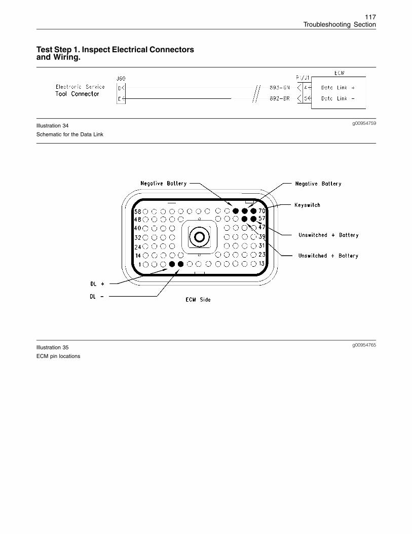
117Troubleshooting Section
Test Step 1. Inspect Electrical Connectorsand Wiring.
g00954759Illustration 34
Schematic for the Data Link
g00954765Illustration 35
ECM pin locations
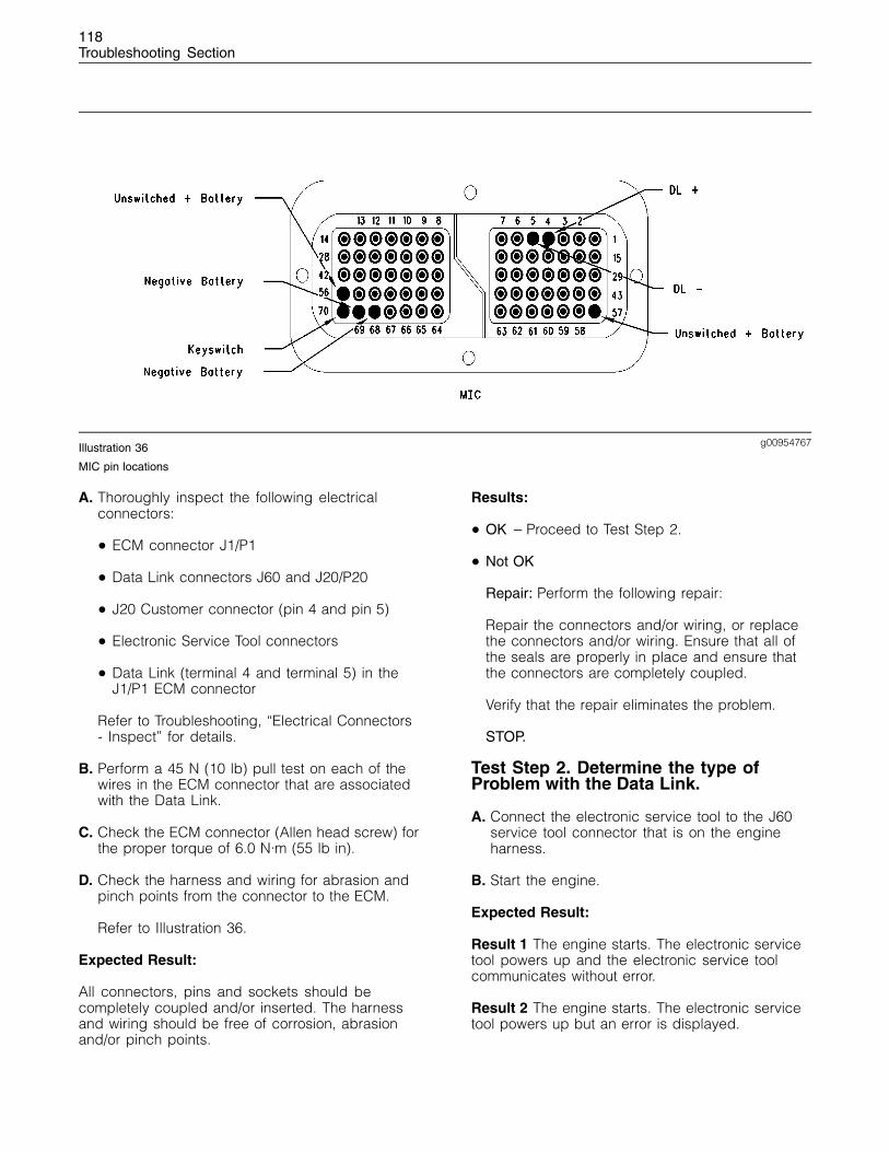
118Troubleshooting Section
g00954767Illustration 36
MIC pin locations
A. Thoroughly inspect the following electricalconnectors:
• ECM connector J1/P1
• Data Link connectors J60 and J20/P20
• J20 Customer connector (pin 4 and pin 5)
• Electronic Service Tool connectors
• Data Link (terminal 4 and terminal 5) in theJ1/P1 ECM connector
Refer to Troubleshooting, “Electrical Connectors- Inspect” for details.
B. Perform a 45 N (10 lb) pull test on each of thewires in the ECM connector that are associatedwith the Data Link.
C. Check the ECM connector (Allen head screw) forthe proper torque of 6.0 N·m (55 lb in).
D. Check the harness and wiring for abrasion andpinch points from the connector to the ECM.
Refer to Illustration 36.
Expected Result:
All connectors, pins and sockets should becompletely coupled and/or inserted. The harnessand wiring should be free of corrosion, abrasionand/or pinch points.
Results:
• OK – Proceed to Test Step 2.
• Not OK
Repair: Perform the following repair:
Repair the connectors and/or wiring, or replacethe connectors and/or wiring. Ensure that all ofthe seals are properly in place and ensure thatthe connectors are completely coupled.
Verify that the repair eliminates the problem.
STOP.
Test Step 2. Determine the type ofProblem with the Data Link.
A. Connect the electronic service tool to the J60service tool connector that is on the engineharness.
B. Start the engine.
Expected Result:
Result 1 The engine starts. The electronic servicetool powers up and the electronic service toolcommunicates without error.
Result 2 The engine starts. The electronic servicetool powers up but an error is displayed.
119Troubleshooting Section
Result 3 The engine cranks but the engine will notstart regardless of the condition of the electronicservice tool.
Result 4 The engine will not crank regardless of thecondition of the electronic service tool.
Result 5 The engine starts but the electronic servicetool does not power up.
Results:
• Result 1 – There is not a problem with the DataLink at this time. If an intermittent condition exists,thoroughly inspect all wiring and connectors.
Repair: Perform the following diagnosticprocedure:
Troubleshooting, “Electrical Connectors - Inspect”
STOP.
• Result 2 – The electronic service tool displaysan error message. The ECM is receiving batterypower. Proceed to Test Step 3.
• Result 3 –
Repair: Perform the following diagnosticprocedure:
Troubleshooting, “Engine Will Not Crank”
STOP.
• Result 4 –
Repair: Perform the following diagnosticprocedure:
Troubleshooting, “Engine Cranks But Will NotStart”
STOP.
• Result 5 – The electronic service tool does notpower up or the communications adapter doesnot power up. Ensure that the ECM is receivingthe correct battery power. Proceed to Test Step 4.
Test Step 3. Check the Battery Voltage atthe ECM.
A. Ensure that the electronic service tool isconnected to the J60 service tool connector.
B. Disconnect ECM connector P1 from ECMconnector J1.
C. Turn the keyswitch to the ON position.
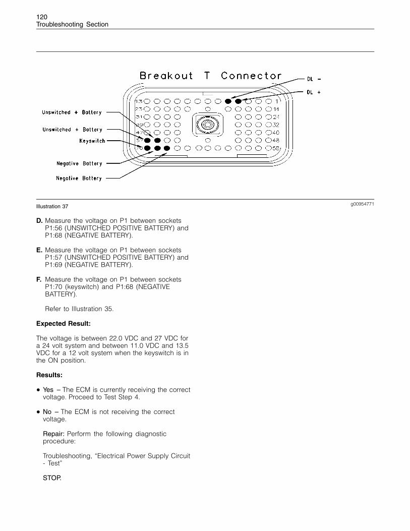
120Troubleshooting Section
g00954771Illustration 37
D. Measure the voltage on P1 between socketsP1:56 (UNSWITCHED POSITIVE BATTERY) andP1:68 (NEGATIVE BATTERY).
E. Measure the voltage on P1 between socketsP1:57 (UNSWITCHED POSITIVE BATTERY) andP1:69 (NEGATIVE BATTERY).
F. Measure the voltage on P1 between socketsP1:70 (keyswitch) and P1:68 (NEGATIVEBATTERY).
Refer to Illustration 35.
Expected Result:
The voltage is between 22.0 VDC and 27 VDC fora 24 volt system and between 11.0 VDC and 13.5VDC for a 12 volt system when the keyswitch is inthe ON position.
Results:
• Yes – The ECM is currently receiving the correctvoltage. Proceed to Test Step 4.
• No – The ECM is not receiving the correctvoltage.
Repair: Perform the following diagnosticprocedure:
Troubleshooting, “Electrical Power Supply Circuit- Test”
STOP.
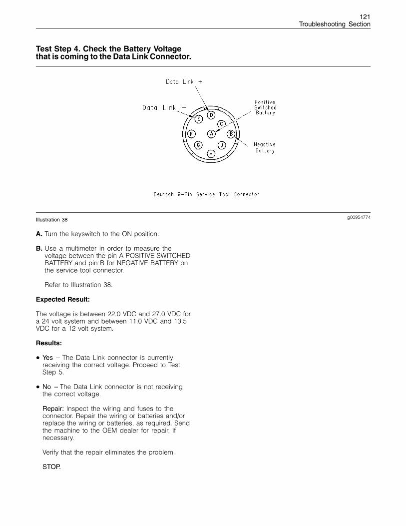
121Troubleshooting Section
Test Step 4. Check the Battery Voltagethat is coming to the Data Link Connector.
g00954774Illustration 38
A. Turn the keyswitch to the ON position.
B. Use a multimeter in order to measure thevoltage between the pin A POSITIVE SWITCHEDBATTERY and pin B for NEGATIVE BATTERY onthe service tool connector.
Refer to Illustration 38.
Expected Result:
The voltage is between 22.0 VDC and 27.0 VDC fora 24 volt system and between 11.0 VDC and 13.5VDC for a 12 volt system.
Results:
• Yes – The Data Link connector is currentlyreceiving the correct voltage. Proceed to TestStep 5.
• No – The Data Link connector is not receivingthe correct voltage.
Repair: Inspect the wiring and fuses to theconnector. Repair the wiring or batteries and/orreplace the wiring or batteries, as required. Sendthe machine to the OEM dealer for repair, ifnecessary.
Verify that the repair eliminates the problem.
STOP.
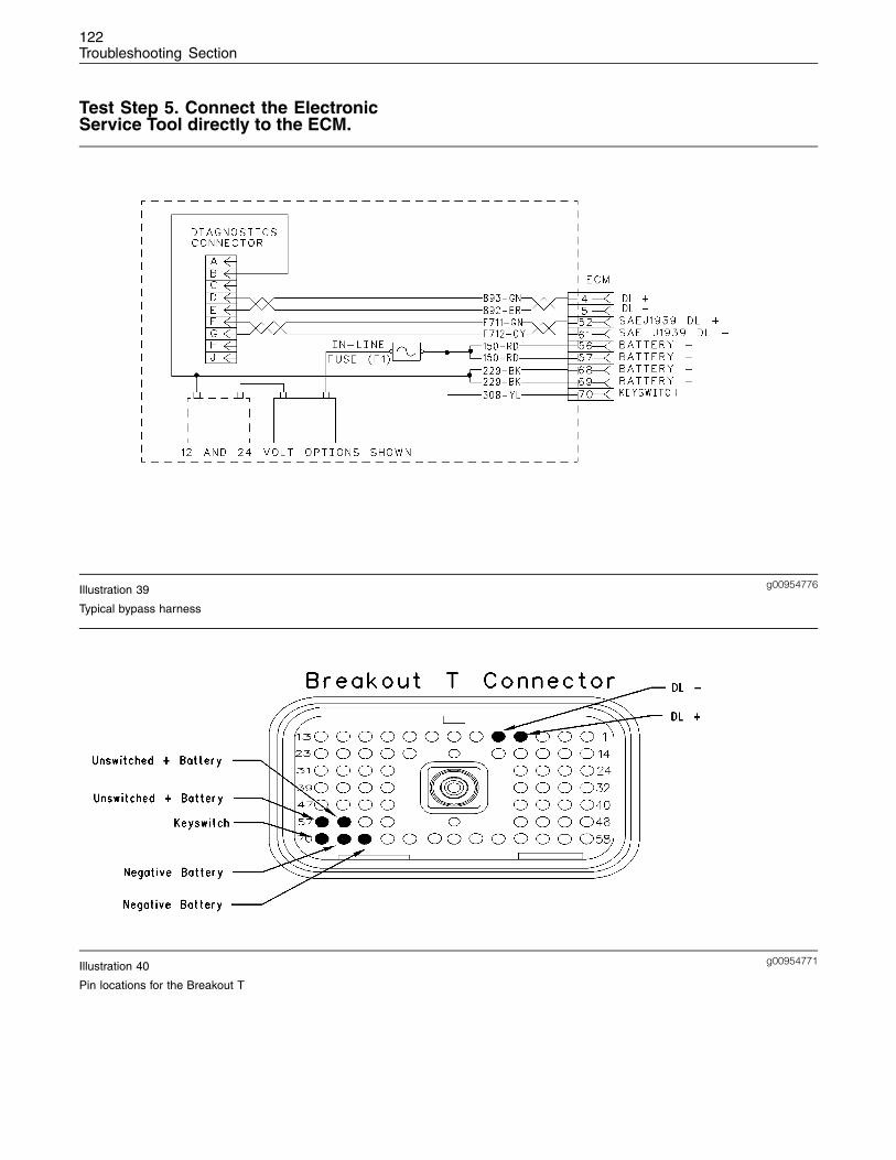
122Troubleshooting Section
Test Step 5. Connect the ElectronicService Tool directly to the ECM.
g00954776Illustration 39
Typical bypass harness
g00954771Illustration 40
Pin locations for the Breakout T
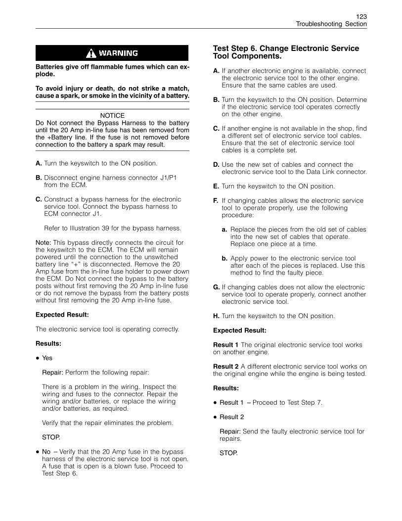
123Troubleshooting Section
Batteries give off flammable fumes which can ex-plode.
To avoid injury or death, do not strike a match,cause a spark, or smoke in the vicinity of a battery.
NOTICEDo Not connect the Bypass Harness to the batteryuntil the 20 Amp in-line fuse has been removed fromthe +Battery line. If the fuse is not removed beforeconnection to the battery a spark may result.
A. Turn the keyswitch to the ON position.
B. Disconnect engine harness connector J1/P1from the ECM.
C. Construct a bypass harness for the electronicservice tool. Connect the bypass harness toECM connector J1.
Refer to Illustration 39 for the bypass harness.
Note: This bypass directly connects the circuit forthe keyswitch to the ECM. The ECM will remainpowered until the connection to the unswitchedbattery line “+” is disconnected. Remove the 20Amp fuse from the in-line fuse holder to power downthe ECM. Do Not connect the bypass to the batteryposts without first removing the 20 Amp in-line fuseor do not remove the bypass from the battery postswithout first removing the 20 Amp in-line fuse.
Expected Result:
The electronic service tool is operating correctly.
Results:
• Yes
Repair: Perform the following repair:
There is a problem in the wiring. Inspect thewiring and fuses to the connector. Repair thewiring and/or batteries, or replace the wiringand/or batteries, as required.
Verify that the repair eliminates the problem.
STOP.
• No – Verify that the 20 Amp fuse in the bypassharness of the electronic service tool is not open.A fuse that is open is a blown fuse. Proceed toTest Step 6.
Test Step 6. Change Electronic ServiceTool Components.
A. If another electronic engine is available, connectthe electronic service tool to the other engine.Ensure that the same cables are used.
B. Turn the keyswitch to the ON position. Determineif the electronic service tool operates correctlyon the other engine.
C. If another engine is not available in the shop, finda different set of electronic service tool cables.Ensure that the set of electronic service toolcables is a complete set.
D. Use the new set of cables and connect theelectronic service tool to the Data Link connector.
E. Turn the keyswitch to the ON position.
F. If changing cables allows the electronic servicetool to operate properly, use the followingprocedure:
a. Replace the pieces from the old set of cablesinto the new set of cables that operate.Replace one piece at a time.
b. Apply power to the electronic service toolafter each of the pieces is replaced. Use thismethod to find the faulty piece.
G. If changing cables does not allow the electronicservice tool to operate properly, connect anotherelectronic service tool.
H. Turn the keyswitch to the ON position.
Expected Result:
Result 1 The original electronic service tool workson another engine.
Result 2 A different electronic service tool works onthe original engine while the engine is being tested.
Results:
• Result 1 – Proceed to Test Step 7.
• Result 2
Repair: Send the faulty electronic service tool forrepairs.
STOP.
124Troubleshooting Section
Test Step 7. Connect an ElectronicService Tool and the ECM to anotherBattery.
Batteries give off flammable fumes which can ex-plode.
To avoid injury or death, do not strike a match,cause a spark, or smoke in the vicinity of a battery.
NOTICEDo Not connect the Bypass Harness to the batteryuntil the 20 Amp in-line fuse has been removed fromthe +Battery line. If the fuse is not removed beforeconnection to the battery a spark may result.
A. Connect the battery wires from the bypassharness of the electronic service tool to adifferent battery that is not on the engine.
Expected Result:
The electronic service tool is operating correctly.
Results:
• Yes
Repair: Perform the following diagnosticprocedure:
Troubleshooting, “Electrical Power Supply Circuit- Test”
STOP.
• No
Repair: Perform the following repair:
1. Temporarily connect a test ECM.
Note: The test ECM should be programmed with thecorrect software. All parameters should be set tothe same value as the suspect ECM.
2. Remove all jumpers and reconnect allconnectors.
3. Recheck the system for active diagnosticcodes.
4. Repeat the test step.
5. If the problem is resolved with the test ECM,reconnect the suspect ECM.
6. If the problem returns with the suspect ECM,replace the suspect ECM.
7. Verify that the repair eliminates the problem.
STOP.
i01798879
Digital Throttle Position SensorCircuit - Test
System Operation Description:
Use this procedure if another procedure hasdirected you here. Use this procedure if any of thefollowing diagnostic codes are active:
• 91-08 Throttle Demand Sensor abnormal signal
• 774-08 Throttle Demand Sensor No.2 abnormalsignal
• 41-03 8 Volt Sensor Power Supply, voltage morethan normal
• 41-04 8 Volt Sensor Power Supply, voltage lessthan normal
The pedal mounted throttle position sensor providesa throttle position signal to the Electronic ControlModule (ECM). The pedal mounted throttle positionsensor is attached directly to the throttle assembly.Foot or hand operated versions of the throttleassembly are available.
The pedal mounted throttle position sensor willproduce a duty cycle of 10 to 22 percent at low idleand 75 to 90 percent when the accelerator pedalis fully depressed.
The pedal mounted throttle position sensor willproduce a minimum duty cycle when the pedalis released. The pedal mounted throttle positionsensor will produce a maximum duty cycle whenthe pedal is fully depressed.
The pedal mounted throttle position sensor sendsa pulse width modulated signal. The signal varieswith the throttle position. The signal is expressed asa percentage.
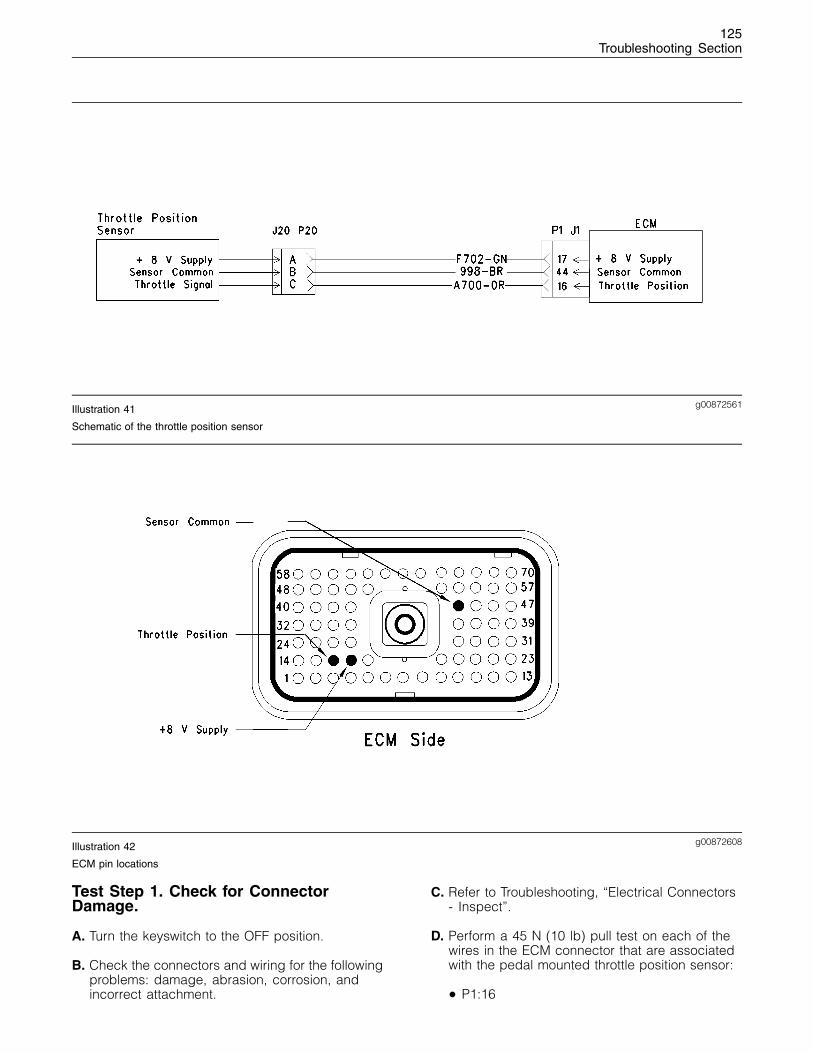
125Troubleshooting Section
g00872561Illustration 41
Schematic of the throttle position sensor
g00872608Illustration 42
ECM pin locations
Test Step 1. Check for ConnectorDamage.
A. Turn the keyswitch to the OFF position.
B. Check the connectors and wiring for the followingproblems: damage, abrasion, corrosion, andincorrect attachment.
C. Refer to Troubleshooting, “Electrical Connectors- Inspect”.
D. Perform a 45 N (10 lb) pull test on each of thewires in the ECM connector that are associatedwith the pedal mounted throttle position sensor:
• P1:16
126Troubleshooting Section
• P1:17
• P1:44
E. Check the ECM connector (Allen Head Screw)for the proper torque of 6.0 N·m (55 lb in).
Expected Result:
The connectors and wiring should be free of thefollowing problems: damage, abrasion, corrosion,and incorrect attachment.
Results:
• OK – Proceed to Test Step 2.
• Not OK
Repair: Repair the connectors or wiring and/orreplace the connectors or wiring.
STOP.
Test Step 2. Check for active DiagnosticCodes.
A. Turn the keyswitch to the ON position.
B. Use the electronic service tool to check fordiagnostic codes.
Expected Result:
RESULT 1 The electronic service tool displays thefollowing active diagnostic codes:
• 91-08
• 774-08
RESULT 2 The electronic service tool displays thefollowing active diagnostic codes:
• 41-03
• 41-04
RESULT 3 The electronic service tool displays noactive diagnostic codes.
Results:
• Result 1 – Proceed to Test Step 3.
• Result 2 – Proceed to Test Step 5.
• Result 3 – Proceed to Test Step 3.
Test Step 3. Check the Throttle Positionwith the Electronic Service Tool.
A. Connect the electronic service tool to the servicetool connector.
B. Turn the keyswitch to the ON position. Theengine should be OFF.
C. Observe the throttle position reading on theelectronic service tool.
D. Depress the throttle and release the throttle.
Expected Result:
The output should be “0 percent” when the pedalis released. The output should increase to “100percent” when the throttle pedal is fully depressed.
The output should be between “20 percent” and“27 percent” at the low idle position. The outputshould be between “80 percent”and “87 percent ”at the high idle position.
Results:
• OK – The throttle position sensor is operatingcorrectly. Proceed to Test Step 5.
• Not OK – The ECM is not receiving a correctsignal from the sensor. There may be a problemin the harness. Proceed to Test Step 4.

127Troubleshooting Section
Test Step 4. Check the Voltage at theThrottle Position Sensor.
g00835148Illustration 43
Typical example of the throttle position sensor for the 1104 and 1106 engines
A. Turn the keyswitch to the OFF position.
B. Install a Breakout T with 3 terminals for this testprocedure.
C. Turn the keyswitch to the ON position.
D. Measure the voltage between terminal A andterminal B.
Expected Result:
Supply voltage should be between 7.6 VDC and8.4 VDC.
Results:
• OK – The supply voltage is reaching the sensor.Proceed to Test Step 5.
• Not OK – Proceed to Test Step 6.
Test Step 5. Disconnect the ThrottlePosition Sensor and Check for ActiveDiagnostic Codes.
A. Turn the keyswitch to the ON position. Usethe electronic service tool to check for activediagnostic codes.
B. Ensure that one of the following diagnostic codesare active:
• 41-03 8 Volt Sensor Power Supply, voltagemore than normal
• 41-04 8 Volt Sensor Power Supply, voltageless than normal
C. While the throttle position sensor is connectedand disconnected, monitor the electronic servicetool screen. Check and record active diagnosticcodes.
Expected Result:
Diagnostic codes are active after disconnecting thethrottle sensor.
Diagnostic codes are not active after disconnectingthe throttle sensor.
Results:
• OK – Diagnostic codes are not active afterdisconnecting the throttle position sensor.Reconnect the throttle sensor and proceed to teststep 7.
• Not OK
Repair: Temporarily install another throttle positionsensor. Use the electronic service tool in orderto check if the diagnostic codes are still active.Replace the throttle position sensor if both of thefollowing conditions occur:
• The problem is corrected with the new throttleposition sensor.
128Troubleshooting Section
• The problem returns after the old throttleposition sensor has been reconnected.
STOP.
Test Step 6. Check the Throttle SelectionStatus with the Electronic Service Tool.
A. Check the status of the throttle selection switch(if equipped). The throttle selection status canbe observed on the status display screen of theelectronic service tool.
Expected Result:
If the throttle selection switch status is shown in theOFF position, then the throttle 1 has control of theengine speed.
If the throttle selection switch status is shown in theON position then the throttle 2 has control of theengine speed.
The throttle could be overridden by instructions viathe SAE J1939 (CAN) or the set speed control.
Results:
• OK – The throttle position sensor is operatingcorrectly.
Repair: There may be an intermittent fault. Referto Troubleshooting, “Electrical Connectors -Inspect”.
STOP.
• Not OK – The wrong throttle is selected. Changeto the other throttle. There may be a fault with theinput from the selector switch. Proceed to Step 7.
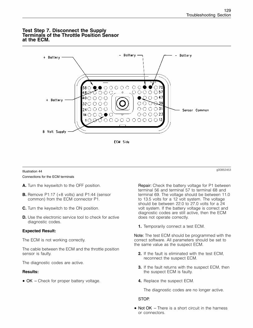
129Troubleshooting Section
Test Step 7. Disconnect the SupplyTerminals of the Throttle Position Sensorat the ECM.
g00852453Illustration 44
Connections for the ECM terminals
A. Turn the keyswitch to the OFF position.
B. Remove P1:17 (+8 volts) and P1:44 (sensorcommon) from the ECM connector P1.
C. Turn the keyswitch to the ON position.
D. Use the electronic service tool to check for activediagnostic codes.
Expected Result:
The ECM is not working correctly.
The cable between the ECM and the throttle positionsensor is faulty.
The diagnostic codes are active.
Results:
• OK – Check for proper battery voltage.
Repair: Check the battery voltage for P1 betweenterminal 56 and terminal 57 to terminal 68 andterminal 69. The voltage should be between 11.0to 13.5 volts for a 12 volt system. The voltageshould be between 22.0 to 27.0 volts for a 24volt system. If the battery voltage is correct anddiagnostic codes are still active, then the ECMdoes not operate correctly.
1. Temporarily connect a test ECM.
Note: The test ECM should be programmed with thecorrect software. All parameters should be set tothe same value as the suspect ECM.
2. If the fault is eliminated with the test ECM,reconnect the suspect ECM.
3. If the fault returns with the suspect ECM, thenthe suspect ECM is faulty.
4. Replace the suspect ECM.
The diagnostic codes are no longer active.
STOP.
• Not OK – There is a short circuit in the harnessor connectors.
130Troubleshooting Section
Repair: Connect the cables one at a time.Connect terminal 44 to the ECM. Check ifthe diagnostic code reappears. Then connectterminal 17 to the ECM. Use the electronic servicetool to check if the diagnostic code reappears.Replace the faulty cable. Verify that the repair haseliminated the fault.
STOP.
Test Step 8. Check the Position of ThrottlePosition Sensor.
A. Turn the keyswitch to the OFF position.
B. Install a Breakout T with 3 terminals to the throttleposition sensor.
C. Turn the keyswitch to the ON position.
D. Measure the PWM signal. Connect one probeto terminal C (throttle position sensor) and theother probe to terminal B sensor common of theBreakout T.
E. Observe the position while the engine speedcontrol is moved from the minimum to themaximum position.
Expected Result:
The position should be between 10 and 22 percentin the low idle position.
The position should be between 75 and 90 percentin the high idle position.
Results:
• OK – The throttle position is working correctly.Proceed to Test Step 9.
• Not OK – The throttle position sensor is faulty.Proceed to Test Step 10.
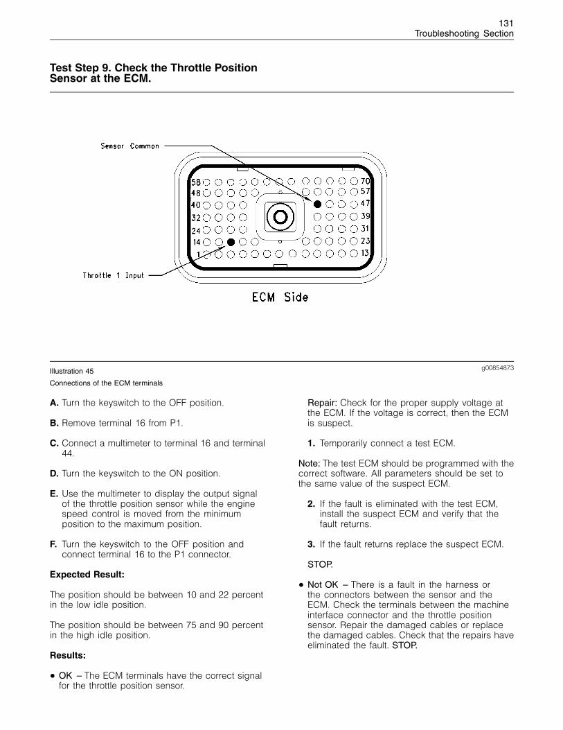
131Troubleshooting Section
Test Step 9. Check the Throttle PositionSensor at the ECM.
g00854873Illustration 45
Connections of the ECM terminals
A. Turn the keyswitch to the OFF position.
B. Remove terminal 16 from P1.
C. Connect a multimeter to terminal 16 and terminal44.
D. Turn the keyswitch to the ON position.
E. Use the multimeter to display the output signalof the throttle position sensor while the enginespeed control is moved from the minimumposition to the maximum position.
F. Turn the keyswitch to the OFF position andconnect terminal 16 to the P1 connector.
Expected Result:
The position should be between 10 and 22 percentin the low idle position.
The position should be between 75 and 90 percentin the high idle position.
Results:
• OK – The ECM terminals have the correct signalfor the throttle position sensor.
Repair: Check for the proper supply voltage atthe ECM. If the voltage is correct, then the ECMis suspect.
1. Temporarily connect a test ECM.
Note: The test ECM should be programmed with thecorrect software. All parameters should be set tothe same value of the suspect ECM.
2. If the fault is eliminated with the test ECM,install the suspect ECM and verify that thefault returns.
3. If the fault returns replace the suspect ECM.
STOP.
• Not OK – There is a fault in the harness orthe connectors between the sensor and theECM. Check the terminals between the machineinterface connector and the throttle positionsensor. Repair the damaged cables or replacethe damaged cables. Check that the repairs haveeliminated the fault. STOP.

132Troubleshooting Section
Test Step 10. Remove the ThrottlePosition Sensor from the Engine SpeedControl Assembly.
g00706977Illustration 46
Accelerator pedal assembly
A. Turn the keyswitch to the OFF position.
B. Record the position of the sensor beforeremoving the throttle position sensor.
C. Remove the throttle position sensor from thehousing and inspect the cables for signs of wear.
D. Connect a multimeter to terminal C of theBreakout T.
E. Turn the keyswitch to the ON position.
F. Record the output signal of the throttle positionsensor with the sensor slot in the releasedposition.
G. Record the output signal of the throttle positionsensor with the sensor slot in the advancedposition.
Expected Result:
The throttle position sensor output is 10 percent orless.
133Troubleshooting Section
The throttle position sensor output is 90 percent ormore.
Results:
• OK
Repair: The operation of the throttle positionsensor is correct. The fault is caused by the footpedal or the lever assembly. Adjust the assemblyor replace the assembly.
Verify that the repairs have eliminated the fault.
STOP.
• Not OK – The throttle position sensor is faulty.
Repair: Replace the throttle position sensor.
Verify that the repair has eliminated the fault.
STOP.
i01798199
Electrical Connectors - Inspect
System Operation Description:
Use this procedure in order to check the electricalconnectors:
Use the following steps to help determine if theconnector is the cause of the problem. If a problemis found in the electrical connector, repair theconnector and verify that the problem has beencorrected.
The following background information is relatedto this procedure:
Many of the operational procedures and thediagnostic code procedures in this troubleshootingguide will instruct you to check a specific electricalconnector. The engine uses a variety of Deutschand AMP connectors.
Intermittent electrical problems are often causedby poor connections. Always check for an activediagnostic code before breaking any connections.Also, always check for an active diagnostic codeafter the connector is reconnected in order to verifythat the problem disappears.
Simply disconnecting the connectors and thenreconnecting the connectors can temporarily solvea problem at times. If this occurs, check for thefollowing conditions:
• Loose terminals
• Bent terminals
• Improperly crimped terminals
• Corrosion
• Improper harness routing
The original source of the problem must then beidentified in order to ensure that the problem doesnot reoccur.
Follow this procedure to thoroughly inspect theconnectors in order to determine if the connectorsare the cause of the problem.
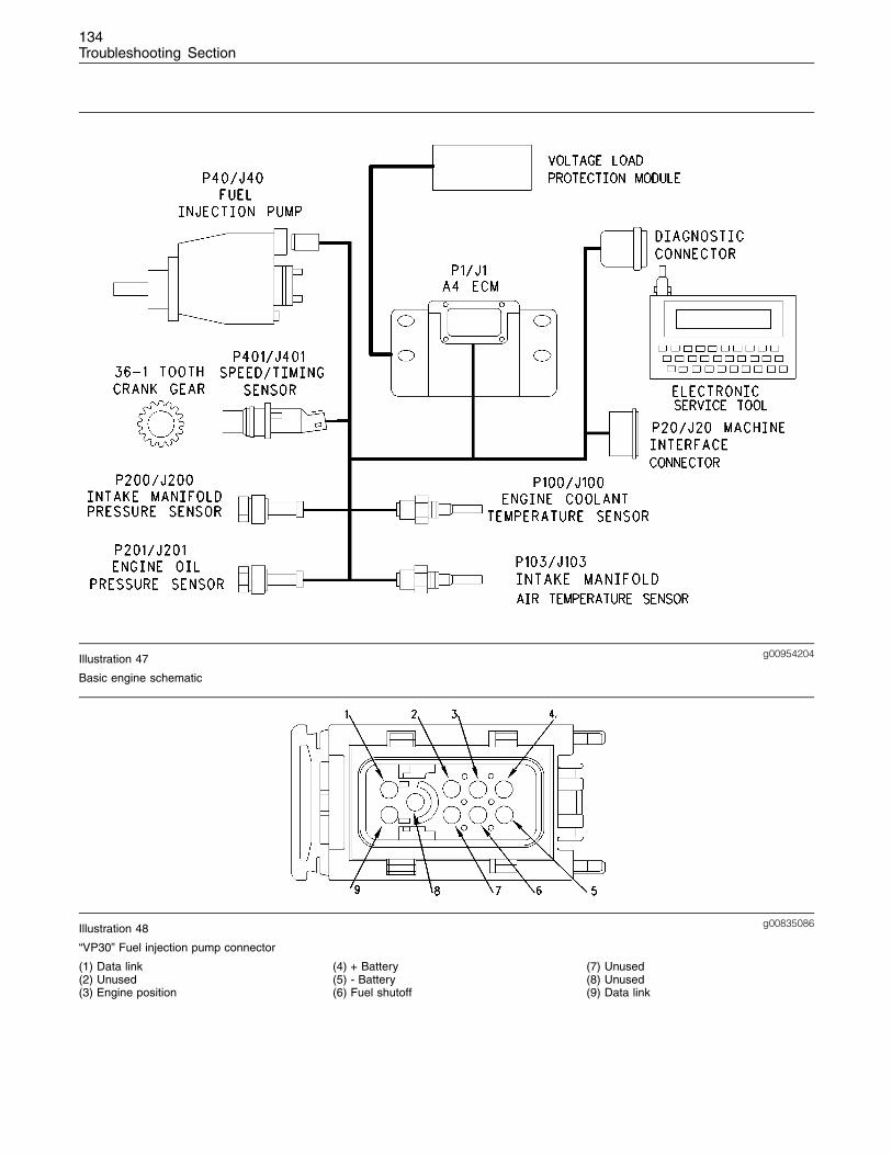
134Troubleshooting Section
g00954204Illustration 47
Basic engine schematic
g00835086Illustration 48
“VP30” Fuel injection pump connector
(1) Data link(2) Unused(3) Engine position
(4) + Battery(5) - Battery(6) Fuel shutoff
(7) Unused(8) Unused(9) Data link
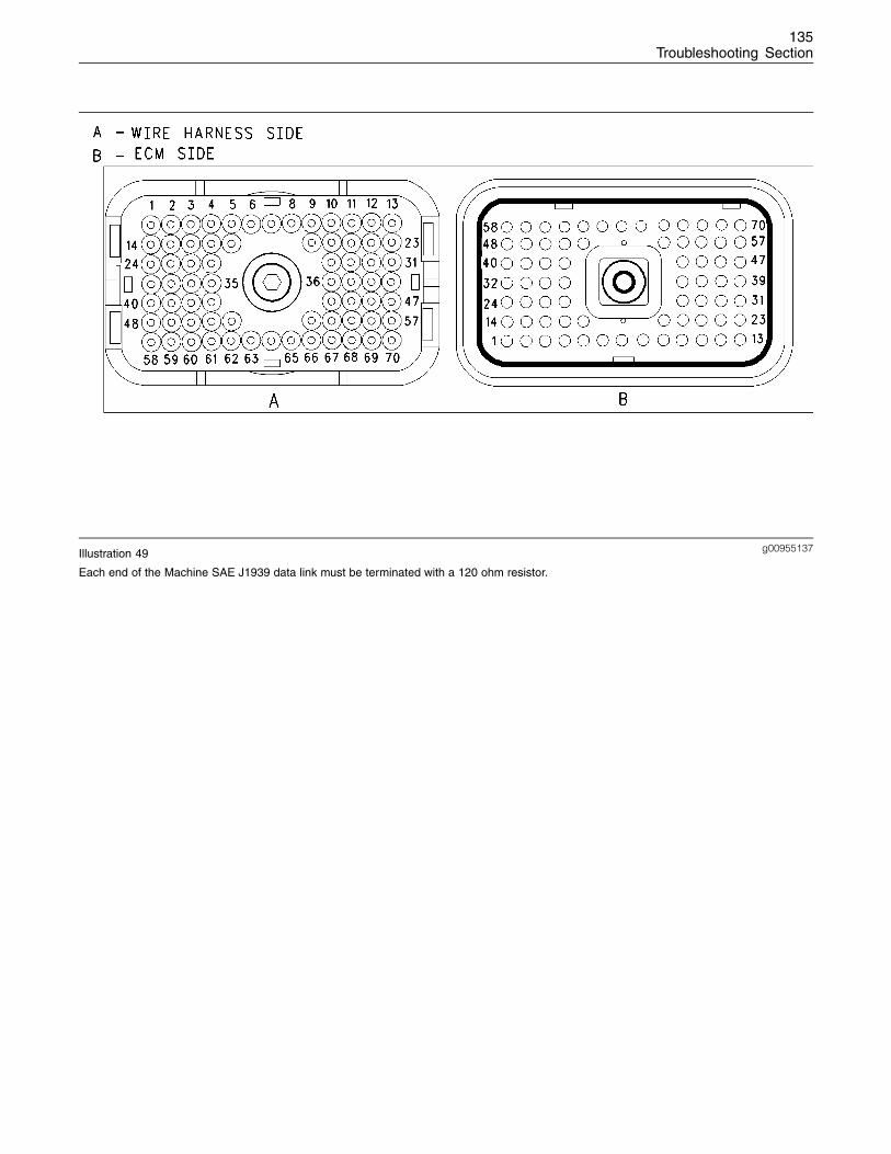
135Troubleshooting Section
g00955137Illustration 49
Each end of the Machine SAE J1939 data link must be terminated with a 120 ohm resistor.

136Troubleshooting Section
g00863007Illustration 50
ECM
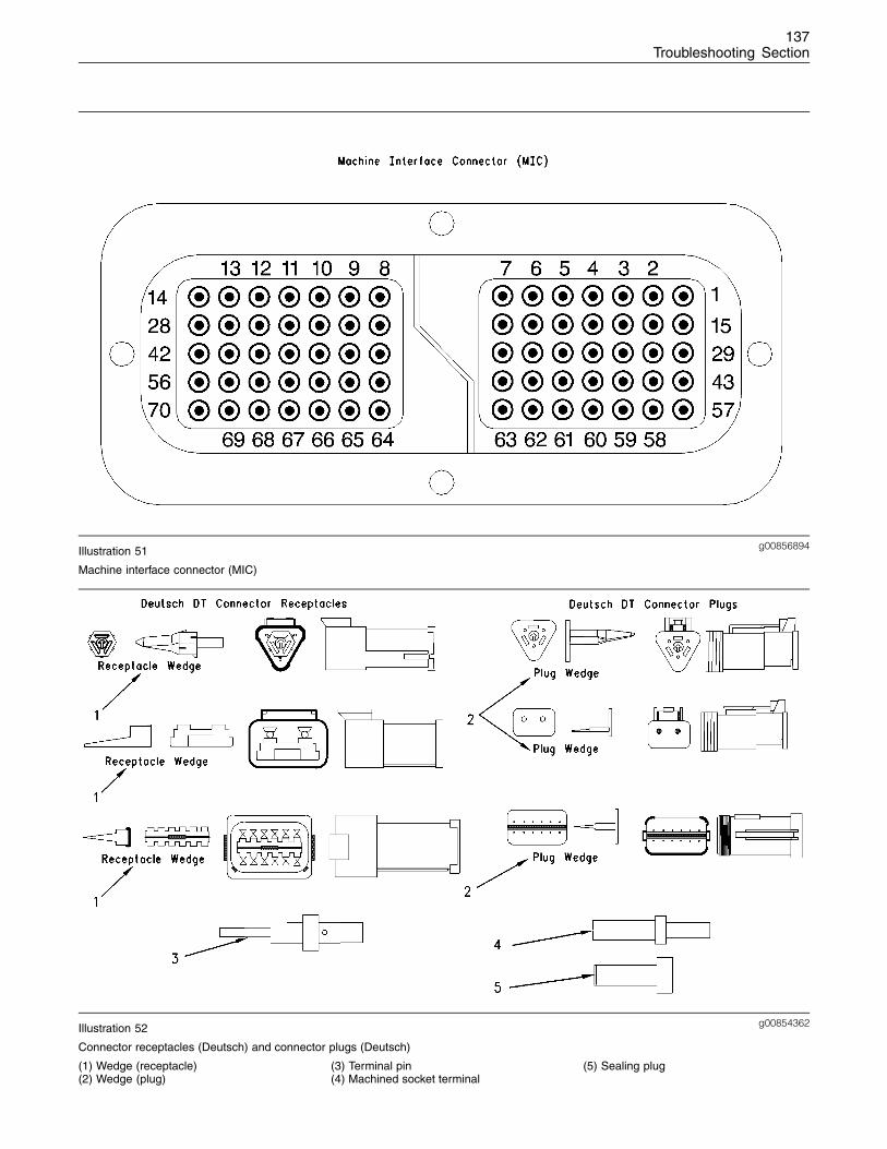
137Troubleshooting Section
g00856894Illustration 51
Machine interface connector (MIC)
g00854362Illustration 52
Connector receptacles (Deutsch) and connector plugs (Deutsch)
(1) Wedge (receptacle)(2) Wedge (plug)
(3) Terminal pin(4) Machined socket terminal
(5) Sealing plug
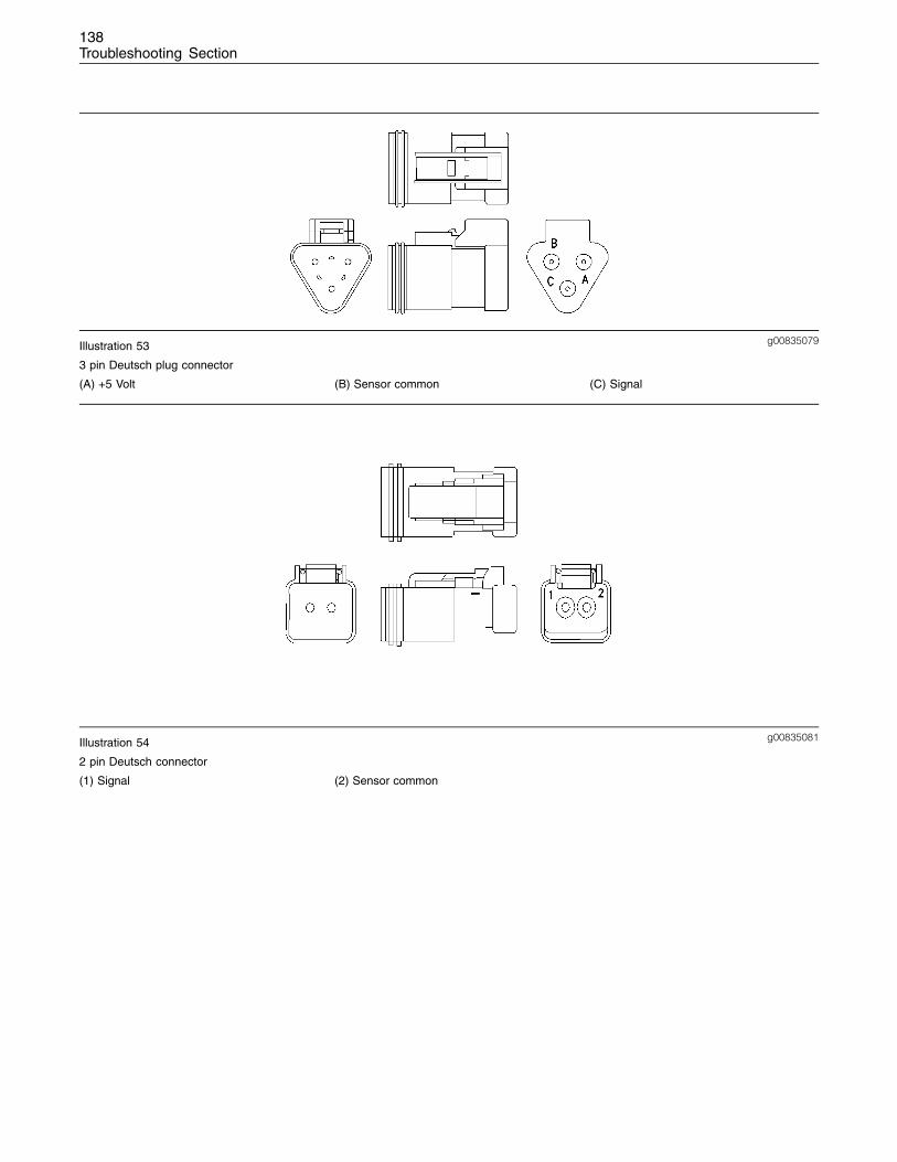
138Troubleshooting Section
g00835079Illustration 53
3 pin Deutsch plug connector
(A) +5 Volt (B) Sensor common (C) Signal
g00835081Illustration 54
2 pin Deutsch connector
(1) Signal (2) Sensor common
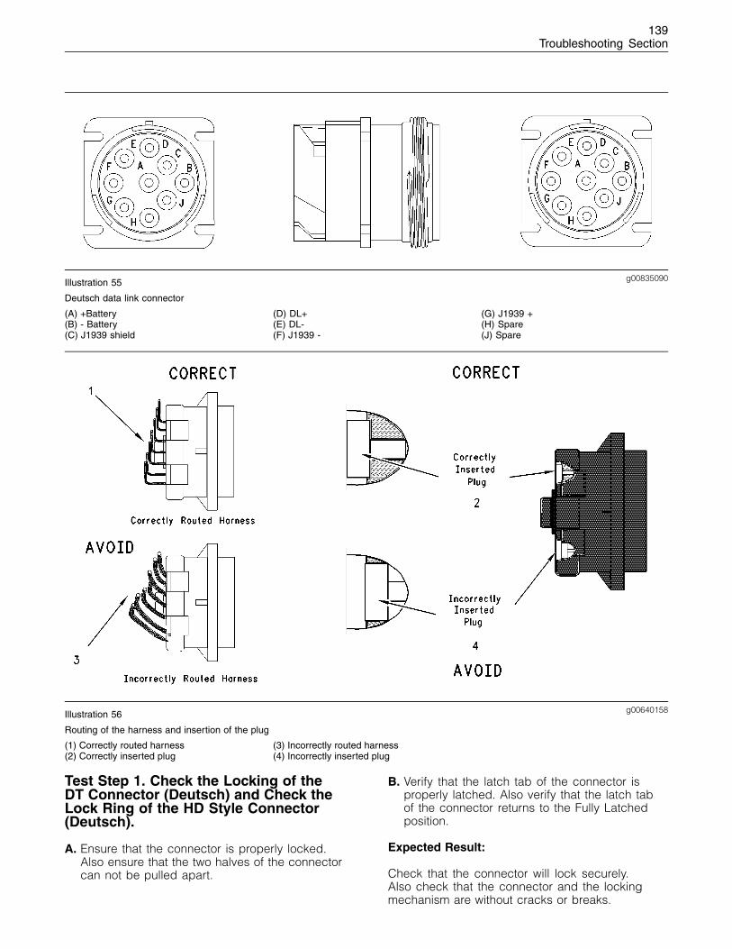
139Troubleshooting Section
g00835090Illustration 55
Deutsch data link connector
(A) +Battery(B) - Battery(C) J1939 shield
(D) DL+(E) DL-(F) J1939 -
(G) J1939 +(H) Spare(J) Spare
g00640158Illustration 56
Routing of the harness and insertion of the plug
(1) Correctly routed harness(2) Correctly inserted plug
(3) Incorrectly routed harness(4) Incorrectly inserted plug
Test Step 1. Check the Locking of theDT Connector (Deutsch) and Check theLock Ring of the HD Style Connector(Deutsch).
A. Ensure that the connector is properly locked.Also ensure that the two halves of the connectorcan not be pulled apart.
B. Verify that the latch tab of the connector isproperly latched. Also verify that the latch tabof the connector returns to the Fully Latchedposition.
Expected Result:
Check that the connector will lock securely.Also check that the connector and the lockingmechanism are without cracks or breaks.
140Troubleshooting Section
Results:
• OK – Proceed to Test Step 2.
• Not OK – Repair the connector or replace theconnector, as required.
Repair: Verify that the repair has eliminated thefault.
If the repair has not eliminated the fault, proceedto test step 2.
Test Step 2. Check the Allen Head Screwon the Connector for the ElectronicControl Module (ECM)
A. Ensure that the connector bolt is properlytightened. Be careful not to overtighten the boltand break the connector.
B. Do not exceed 6.0 N·m (55 lb in) of torque onthe connector bolt of the ECM when the P1/J1ECM connector is being installed on the ECM.
Expected Result:
The ECM connector is secure and the connectorbolt of the ECM is properly torqued.
Results:
• OK – Proceed to Test Step 3.
• Not OK – Secure the ECM connector.
Repair: Tighten the Allen head screw to theproper torque.
Verify that the fault has been eliminated.
If the fault has not been eliminated proceed totest step 3.
Test Step 3. Perform a Pull Test on eachWire Terminal Connection.
A. Each terminal and each connector shouldwithstand a 45 N (10 lb) pull test. Each wireshould remain in the connector body. This testchecks whether the wire was properly crimpedin the terminal and whether the terminal wasproperly inserted into the connector.
B. The DT connectors use an orange wedge to lockthe terminals in place.
C. Check in order to ensure that the orange wedgeis not missing and that the orange wedge isinstalled properly on the DT connectors.
Note: Terminals should always be crimped onto thewires by use of a crimp tool. Do not solder theterminals.
Expected Result:
Check that each terminal and each connectorwithstands 45 N (10 lb) of pull. Each wire remainsin the connector body.
Results:
• OK – Proceed to Test Step 4.
• Not OK – Repair the wiring or replace theconnector or the terminal.
Repair: Verify that the repair has eliminated thefault.
If the fault has not been eliminated proceed totest step 4.
Test Step 4. Monitor the ElectronicService Tool while the Wiring and theConnectors are being pulled.
A. Turn the keyswitch to the ON position.
B. If there is an inactive diagnostic code thatpertains to the circuit, perform the following test:
Monitor the “Inactive Diagnostic Code” screen ofthe electronic service tool while the diagnosticcode remains active. Pull each of the harnessesand the connectors that connect to thecomponent. If the harness is being pulled andthe inactive diagnostic code disappears referto Troubleshooting, “Troubleshooting with aDiagnostic Code” for the correct procedure.
C. If there is an active diagnostic code on thecircuit for a particular component, perform thefollowing test:
Monitor the “Active Diagnostic Code” screen ofthe electronic service tool for the componentwhile the harnesses are being pulled. Verifythat the code has been eliminated. If the coderemains active there is a problem in the wiringor the connector.
D. If there are no active diagnostic codes or inactivediagnostic codes, perform the following test:
Monitor the “Status Display” screen on theelectronic service tool for a particular parameterwhile the wiring harness is being pulled.
141Troubleshooting Section
If the harness is being pulled and the readingchanges erratically, there is a problem in thecables or the connector.
Expected Result:
If the problem appears to be external to theharnesses and connectors, then pulling on theharness and the connectors will have no effect oneither the component status of the active diagnosticcode or on the engine performance.
Results:
• OK – Proceed to Test Step 5.
• Not OK – Repair the harness and/or theconnectors or replace the harness and/orconnectors that are causing the problem. If thefault has not been eliminated proceed to teststep 5.
Test Step 5. Check Wires for Nicks and/orAbrasions in the Insulation.
A. Carefully inspect each wire for signs of abrasion,nicks, or cuts.
The following areas are locations that shouldbe checked:
• Exposed insulation
• Points of rubbing wire against the engine
• Points of rubbing wire against a sharp point
B. Check all of the hold down clamps for theharness in order to verify that the harness isproperly clamped. Also check all of the holddown clamps for the harness in order to verifythat the harness is not compressed by theclamp. Pull back the harness sleeves in orderto check for a flattened portion of wire. Theflattened portion of wire is caused by the clampthat holds the harness.
Expected Result:
The wires are free of abrasion, nicks, or cuts andthe harness is properly clamped.
Results:
• OK – Proceed to Test Step 6.
• Not OK – Repair the wires or replace the wires,as required. If the fault has not been eliminatedproceed to test step 6.
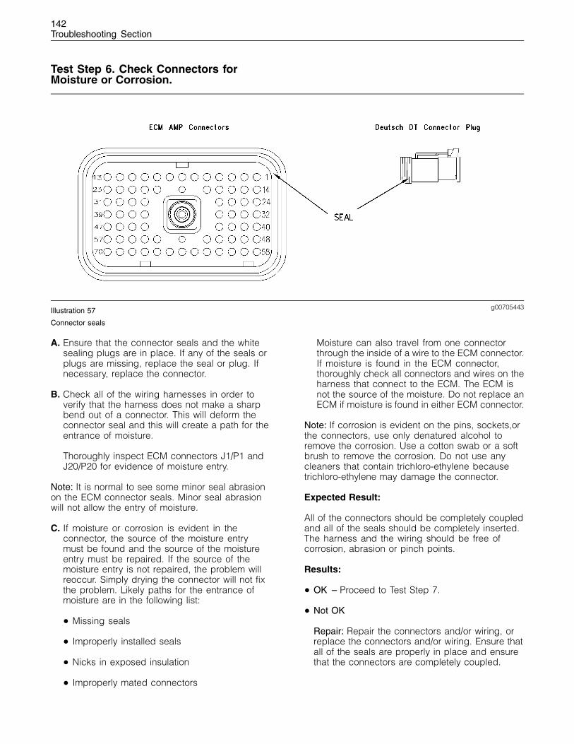
142Troubleshooting Section
Test Step 6. Check Connectors forMoisture or Corrosion.
g00705443Illustration 57
Connector seals
A. Ensure that the connector seals and the whitesealing plugs are in place. If any of the seals orplugs are missing, replace the seal or plug. Ifnecessary, replace the connector.
B. Check all of the wiring harnesses in order toverify that the harness does not make a sharpbend out of a connector. This will deform theconnector seal and this will create a path for theentrance of moisture.
Thoroughly inspect ECM connectors J1/P1 andJ20/P20 for evidence of moisture entry.
Note: It is normal to see some minor seal abrasionon the ECM connector seals. Minor seal abrasionwill not allow the entry of moisture.
C. If moisture or corrosion is evident in theconnector, the source of the moisture entrymust be found and the source of the moistureentry must be repaired. If the source of themoisture entry is not repaired, the problem willreoccur. Simply drying the connector will not fixthe problem. Likely paths for the entrance ofmoisture are in the following list:
• Missing seals
• Improperly installed seals
• Nicks in exposed insulation
• Improperly mated connectors
Moisture can also travel from one connectorthrough the inside of a wire to the ECM connector.If moisture is found in the ECM connector,thoroughly check all connectors and wires on theharness that connect to the ECM. The ECM isnot the source of the moisture. Do not replace anECM if moisture is found in either ECM connector.
Note: If corrosion is evident on the pins, sockets,orthe connectors, use only denatured alcohol toremove the corrosion. Use a cotton swab or a softbrush to remove the corrosion. Do not use anycleaners that contain trichloro-ethylene becausetrichloro-ethylene may damage the connector.
Expected Result:
All of the connectors should be completely coupledand all of the seals should be completely inserted.The harness and the wiring should be free ofcorrosion, abrasion or pinch points.
Results:
• OK – Proceed to Test Step 7.
• Not OK
Repair: Repair the connectors and/or wiring, orreplace the connectors and/or wiring. Ensure thatall of the seals are properly in place and ensurethat the connectors are completely coupled.
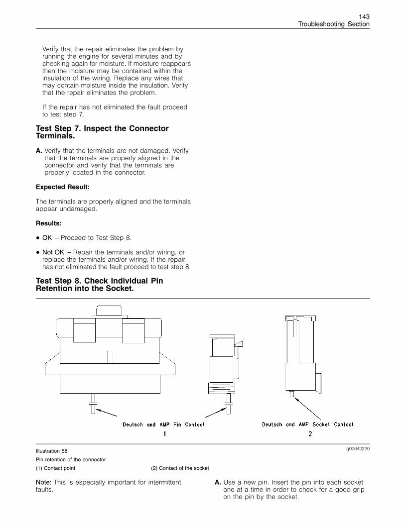
143Troubleshooting Section
Verify that the repair eliminates the problem byrunning the engine for several minutes and bychecking again for moisture. If moisture reappearsthen the moisture may be contained within theinsulation of the wiring. Replace any wires thatmay contain moisture inside the insulation. Verifythat the repair eliminates the problem.
If the repair has not eliminated the fault proceedto test step 7.
Test Step 7. Inspect the ConnectorTerminals.
A. Verify that the terminals are not damaged. Verifythat the terminals are properly aligned in theconnector and verify that the terminals areproperly located in the connector.
Expected Result:
The terminals are properly aligned and the terminalsappear undamaged.
Results:
• OK – Proceed to Test Step 8.
• Not OK – Repair the terminals and/or wiring, orreplace the terminals and/or wiring. If the repairhas not eliminated the fault proceed to test step 8.
Test Step 8. Check Individual PinRetention into the Socket.
g00640220Illustration 58
Pin retention of the connector
(1) Contact point (2) Contact of the socket
Note: This is especially important for intermittentfaults.
A. Use a new pin. Insert the pin into each socketone at a time in order to check for a good gripon the pin by the socket.
144Troubleshooting Section
B. Use a new socket. Insert the socket over eachpin one at a time in order to check for a goodgrip on the pin by the socket. The pins arelocated on the mating side of the connector.
C. The contact terminal should stay connectedwhen the connector is held in the position shownin Illustration 58. The contact terminal is the pinor the socket.
Expected Result:
The pins and the sockets appear to be OK.
Results:
• OK – STOP.
• Not OK – Replace the terminal. STOP.
i01798200
Electrical Power Supply Circuit- Test
System Operation Description:
Use this procedure under the followingconditions:
This procedure tests whether the correct voltage issupplied by the wiring. Use this procedure if thediagnostic code is logged or active.
• 253-02 Incorrect ECM Software
Note: This code can be generated by rapidlycycling the keyswitch. If this occurs, clear thelogged diagnostic codes in order to prevent futureconfusion or an incorrect diagnosis.
The electronic service tool will indicate Low BatteryVoltage if the ECM is not receiving the batterysupply voltage.
Also use this procedure if another procedure hasdirected you here.
The following background information is relatedto this procedure:
The ECM receives electrical power (battery voltage)through the wiring within the engine harness.The ECM input at connector P1:70 (keyswitch)receives battery voltage from the keyswitch whenthe keyswitch is in the ON position or the STARTposition. The ECM will power up when the ECMdetects battery voltage at the keyswitch. The ECMwill power down when battery voltage is removedfrom the keyswitch.
The cause of an intermittent power supply tothe ECM can occur on either the positive side(unswitched +battery) or the negative side (batterynegative). Both sides are routed from the ECM to thebattery. The three connections for the unswitched+battery should be routed through a dedicatedprotection circuit.
The engine ECM requires the keyswitch to be in theON position in order to maintain communications.
Temporarily bypassing the engine wiring maybe an effective means of determining the rootcause of intermittent problems such as intermittentshutdowns. If the symptoms disappear with thebypass wiring, the engine wiring is the cause of theproblem. A means of bypassing engine wiring isexplained in this test procedure.
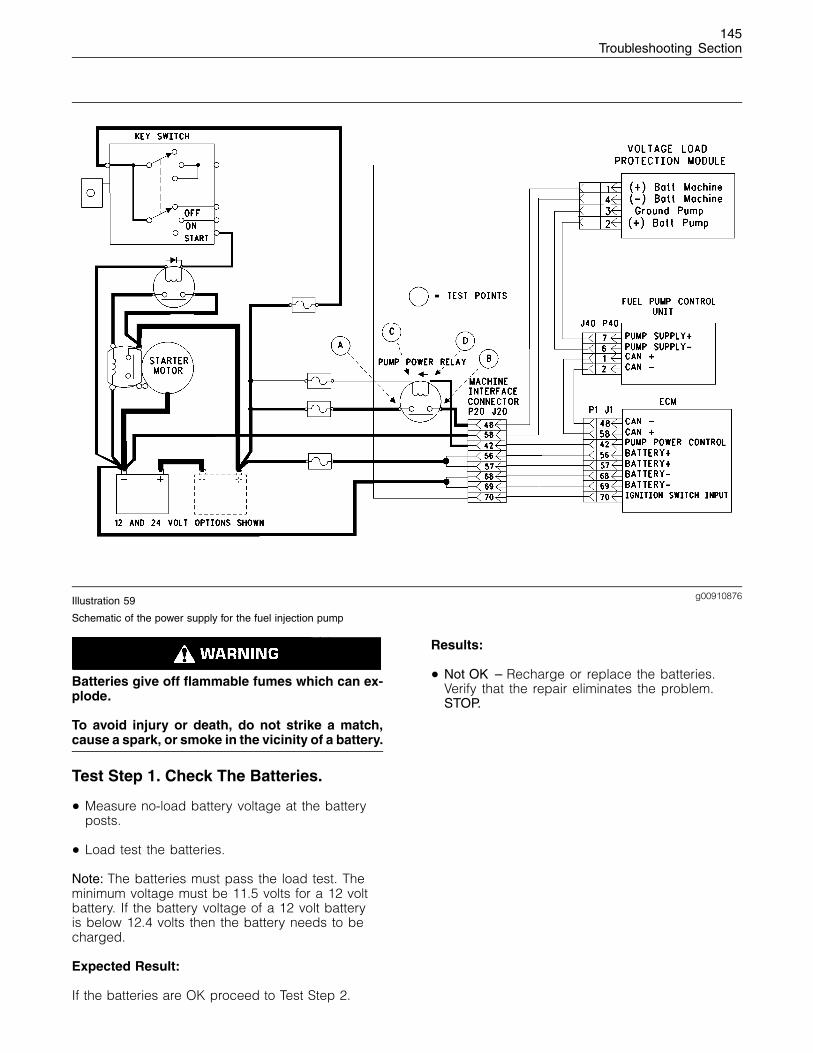
145Troubleshooting Section
g00910876Illustration 59
Schematic of the power supply for the fuel injection pump
Batteries give off flammable fumes which can ex-plode.
To avoid injury or death, do not strike a match,cause a spark, or smoke in the vicinity of a battery.
Test Step 1. Check The Batteries.
• Measure no-load battery voltage at the batteryposts.
• Load test the batteries.
Note: The batteries must pass the load test. Theminimum voltage must be 11.5 volts for a 12 voltbattery. If the battery voltage of a 12 volt batteryis below 12.4 volts then the battery needs to becharged.
Expected Result:
If the batteries are OK proceed to Test Step 2.
Results:
• Not OK – Recharge or replace the batteries.Verify that the repair eliminates the problem.STOP.
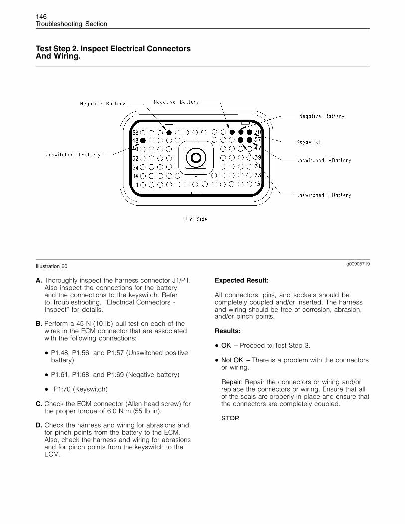
146Troubleshooting Section
Test Step 2. Inspect Electrical ConnectorsAnd Wiring.
g00905719Illustration 60
A. Thoroughly inspect the harness connector J1/P1.Also inspect the connections for the batteryand the connections to the keyswitch. Referto Troubleshooting, “Electrical Connectors -Inspect” for details.
B. Perform a 45 N (10 lb) pull test on each of thewires in the ECM connector that are associatedwith the following connections:
• P1:48, P1:56, and P1:57 (Unswitched positivebattery)
• P1:61, P1:68, and P1:69 (Negative battery)
• P1:70 (Keyswitch)
C. Check the ECM connector (Allen head screw) forthe proper torque of 6.0 N·m (55 lb in).
D. Check the harness and wiring for abrasions andfor pinch points from the battery to the ECM.Also, check the harness and wiring for abrasionsand for pinch points from the keyswitch to theECM.
Expected Result:
All connectors, pins, and sockets should becompletely coupled and/or inserted. The harnessand wiring should be free of corrosion, abrasion,and/or pinch points.
Results:
• OK – Proceed to Test Step 3.
• Not OK – There is a problem with the connectorsor wiring.
Repair: Repair the connectors or wiring and/orreplace the connectors or wiring. Ensure that allof the seals are properly in place and ensure thatthe connectors are completely coupled.
STOP.
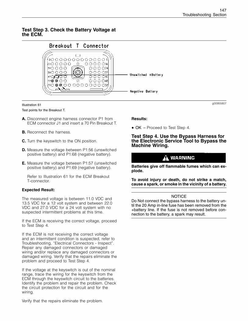
147Troubleshooting Section
Test Step 3. Check the Battery Voltage atthe ECM.
g00955807Illustration 61
Test points for the Breakout T.
A. Disconnect engine harness connector P1 fromECM connector J1 and insert a 70 Pin Breakout T.
B. Reconnect the harness.
C. Turn the keyswitch to the ON position.
D. Measure the voltage between P1:56 (unswitchedpositive battery) and P1:68 (negative battery).
E. Measure the voltage between P1:57 (unswitchedpositive battery) and P1:69 (negative battery).
Refer to Illustration 61 for the ECM BreakoutT-connector.
Expected Result:
The measured voltage is between 11.0 VDC and13.5 VDC for a 12 volt system and between 22.0VDC and 27.0 VDC for a 24 volt system with nosuspected intermittent problems at this time.
If the ECM is receiving the correct voltage, proceedto Test Step 4.
If the ECM is not receiving the correct voltageand an intermittent condition is suspected, refer toTroubleshooting, “Electrical Connectors - Inspect”.Repair any damaged connectors or damagedwiring and/or replace any damaged connectors ordamaged wiring. Verify that the repairs eliminate theproblem and proceed to Test Step 4.
If the voltage at the keyswitch is out of the nominalrange, trace the wiring for the keyswitch from theECM through the keyswitch circuit to the batteries.Identify the problem and repair the problem. Checkthe circuit protection for the circuit and for thewiring.
Verify that the repairs eliminate the problem.
Results:
• OK – Proceed to Test Step 4.
Test Step 4. Use the Bypass Harness forthe Electronic Service Tool to Bypass theMachine Wiring.
Batteries give off flammable fumes which can ex-plode.
To avoid injury or death, do not strike a match,cause a spark, or smoke in the vicinity of a battery.
NOTICEDo Not connect the bypass harness to the battery un-til the 20 Amp in-line fuse has been removed from the+battery line. If the fuse is not removed before con-nection to the battery, a spark may result.
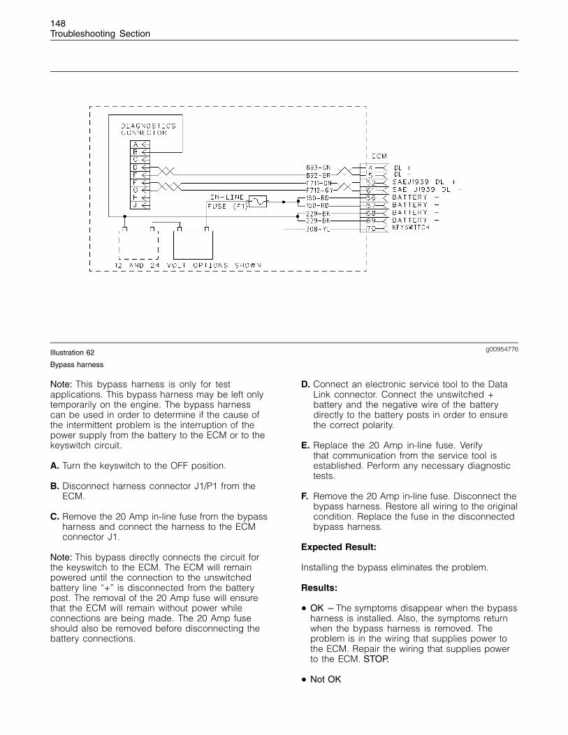
148Troubleshooting Section
g00954776Illustration 62
Bypass harness
Note: This bypass harness is only for testapplications. This bypass harness may be left onlytemporarily on the engine. The bypass harnesscan be used in order to determine if the cause ofthe intermittent problem is the interruption of thepower supply from the battery to the ECM or to thekeyswitch circuit.
A. Turn the keyswitch to the OFF position.
B. Disconnect harness connector J1/P1 from theECM.
C. Remove the 20 Amp in-line fuse from the bypassharness and connect the harness to the ECMconnector J1.
Note: This bypass directly connects the circuit forthe keyswitch to the ECM. The ECM will remainpowered until the connection to the unswitchedbattery line “+” is disconnected from the batterypost. The removal of the 20 Amp fuse will ensurethat the ECM will remain without power whileconnections are being made. The 20 Amp fuseshould also be removed before disconnecting thebattery connections.
D. Connect an electronic service tool to the DataLink connector. Connect the unswitched +battery and the negative wire of the batterydirectly to the battery posts in order to ensurethe correct polarity.
E. Replace the 20 Amp in-line fuse. Verifythat communication from the service tool isestablished. Perform any necessary diagnostictests.
F. Remove the 20 Amp in-line fuse. Disconnect thebypass harness. Restore all wiring to the originalcondition. Replace the fuse in the disconnectedbypass harness.
Expected Result:
Installing the bypass eliminates the problem.
Results:
• OK – The symptoms disappear when the bypassharness is installed. Also, the symptoms returnwhen the bypass harness is removed. Theproblem is in the wiring that supplies power tothe ECM. Repair the wiring that supplies powerto the ECM. STOP.
• Not OK
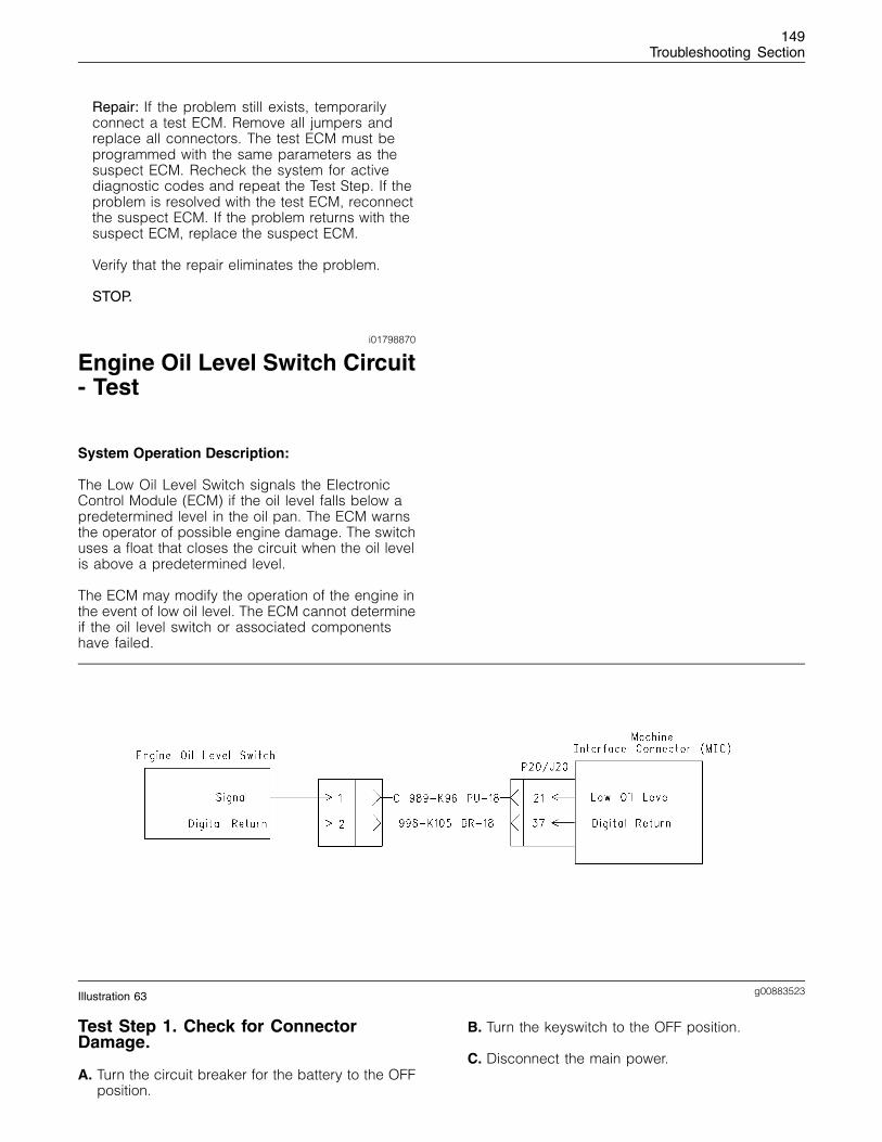
149Troubleshooting Section
Repair: If the problem still exists, temporarilyconnect a test ECM. Remove all jumpers andreplace all connectors. The test ECM must beprogrammed with the same parameters as thesuspect ECM. Recheck the system for activediagnostic codes and repeat the Test Step. If theproblem is resolved with the test ECM, reconnectthe suspect ECM. If the problem returns with thesuspect ECM, replace the suspect ECM.
Verify that the repair eliminates the problem.
STOP.
i01798870
Engine Oil Level Switch Circuit- Test
System Operation Description:
The Low Oil Level Switch signals the ElectronicControl Module (ECM) if the oil level falls below apredetermined level in the oil pan. The ECM warnsthe operator of possible engine damage. The switchuses a float that closes the circuit when the oil levelis above a predetermined level.
The ECM may modify the operation of the engine inthe event of low oil level. The ECM cannot determineif the oil level switch or associated componentshave failed.
g00883523Illustration 63
Test Step 1. Check for ConnectorDamage.
A. Turn the circuit breaker for the battery to the OFFposition.
B. Turn the keyswitch to the OFF position.
C. Disconnect the main power.
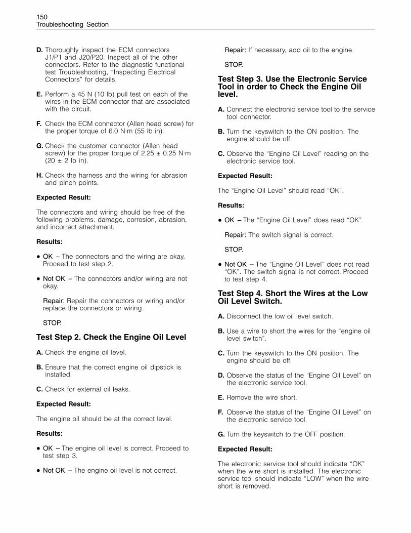
150Troubleshooting Section
D. Thoroughly inspect the ECM connectorsJ1/P1 and J20/P20. Inspect all of the otherconnectors. Refer to the diagnostic functionaltest Troubleshooting, “Inspecting ElectricalConnectors” for details.
E. Perform a 45 N (10 lb) pull test on each of thewires in the ECM connector that are associatedwith the circuit.
F. Check the ECM connector (Allen head screw) forthe proper torque of 6.0 N·m (55 lb in).
G. Check the customer connector (Allen headscrew) for the proper torque of 2.25 ± 0.25 N·m(20 ± 2 lb in).
H. Check the harness and the wiring for abrasionand pinch points.
Expected Result:
The connectors and wiring should be free of thefollowing problems: damage, corrosion, abrasion,and incorrect attachment.
Results:
• OK – The connectors and the wiring are okay.Proceed to test step 2.
• Not OK – The connectors and/or wiring are notokay.
Repair: Repair the connectors or wiring and/orreplace the connectors or wiring.
STOP.
Test Step 2. Check the Engine Oil Level
A. Check the engine oil level.
B. Ensure that the correct engine oil dipstick isinstalled.
C. Check for external oil leaks.
Expected Result:
The engine oil should be at the correct level.
Results:
• OK – The engine oil level is correct. Proceed totest step 3.
• Not OK – The engine oil level is not correct.
Repair: If necessary, add oil to the engine.
STOP.
Test Step 3. Use the Electronic ServiceTool in order to Check the Engine Oillevel.
A. Connect the electronic service tool to the servicetool connector.
B. Turn the keyswitch to the ON position. Theengine should be off.
C. Observe the “Engine Oil Level” reading on theelectronic service tool.
Expected Result:
The “Engine Oil Level” should read “OK”.
Results:
• OK – The “Engine Oil Level” does read “OK”.
Repair: The switch signal is correct.
STOP.
• Not OK – The “Engine Oil Level” does not read“OK”. The switch signal is not correct. Proceedto test step 4.
Test Step 4. Short the Wires at the LowOil Level Switch.
A. Disconnect the low oil level switch.
B. Use a wire to short the wires for the “engine oillevel switch”.
C. Turn the keyswitch to the ON position. Theengine should be off.
D. Observe the status of the “Engine Oil Level” onthe electronic service tool.
E. Remove the wire short.
F. Observe the status of the “Engine Oil Level” onthe electronic service tool.
G. Turn the keyswitch to the OFF position.
Expected Result:
The electronic service tool should indicate “OK”when the wire short is installed. The electronicservice tool should indicate “LOW” when the wireshort is removed.
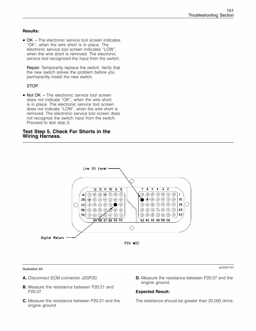
151Troubleshooting Section
Results:
• OK – The electronic service tool screen indicates“OK”, when the wire short is in place. Theelectronic service tool screen indicates “LOW”,when the wire short is removed. The electronicservice tool recognized the input from the switch.
Repair: Temporarily replace the switch. Verify thatthe new switch solves the problem before youpermanently install the new switch.
STOP.
• Not OK – The electronic service tool screendoes not indicate “OK”, when the wire shortis in place. The electronic service tool screendoes not indicate “LOW”, when the wire short isremoved. The electronic service tool screen doesnot recognize the switch input from the switch.Proceed to test step 5.
Test Step 5. Check For Shorts in theWiring Harness.
g00955140Illustration 64
A. Disconnect ECM connector J20/P20.
B. Measure the resistance between P20:21 andP20:37.
C. Measure the resistance between P20:21 and theengine ground.
D. Measure the resistance between P20:37 and theengine ground.
Expected Result:
The resistance should be greater than 20,000 ohms.
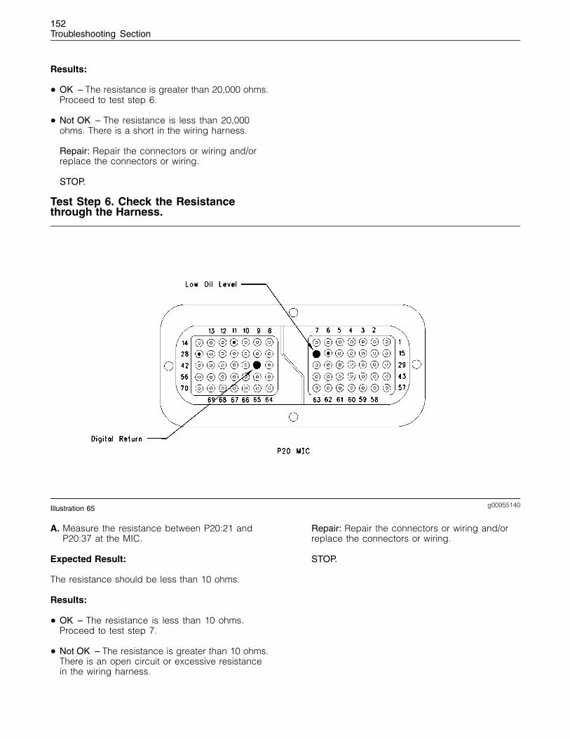
152Troubleshooting Section
Results:
• OK – The resistance is greater than 20,000 ohms.Proceed to test step 6.
• Not OK – The resistance is less than 20,000ohms. There is a short in the wiring harness.
Repair: Repair the connectors or wiring and/orreplace the connectors or wiring.
STOP.
Test Step 6. Check the Resistancethrough the Harness.
g00955140Illustration 65
A. Measure the resistance between P20:21 andP20:37 at the MIC.
Expected Result:
The resistance should be less than 10 ohms.
Results:
• OK – The resistance is less than 10 ohms.Proceed to test step 7.
• Not OK – The resistance is greater than 10 ohms.There is an open circuit or excessive resistancein the wiring harness.
Repair: Repair the connectors or wiring and/orreplace the connectors or wiring.
STOP.
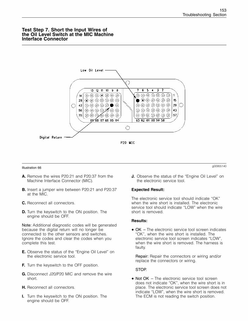
153Troubleshooting Section
Test Step 7. Short the Input Wires ofthe Oil Level Switch at the MIC MachineInterface Connector
g00955140Illustration 66
A. Remove the wires P20:21 and P20:37 from theMachine Interface Connector (MIC).
B. Insert a jumper wire between P20:21 and P20:37at the MIC.
C. Reconnect all connectors.
D. Turn the keyswitch to the ON position. Theengine should be OFF.
Note: Additional diagnostic codes will be generatedbecause the digital return will no longer beconnected to the other sensors and switches.Ignore the codes and clear the codes when youcomplete this test.
E. Observe the status of the “Engine Oil Level” onthe electronic service tool.
F. Turn the keyswitch to the OFF position.
G. Disconnect J20/P20 MIC and remove the wireshort.
H. Reconnect all connectors.
I. Turn the keyswitch to the ON position. Theengine should be OFF.
J. Observe the status of the “Engine Oil Level” onthe electronic service tool.
Expected Result:
The electronic service tool should indicate “OK”when the wire short is installed. The electronicservice tool should indicate “LOW” when the wireshort is removed.
Results:
• OK – The electronic service tool screen indicates“OK”, when the wire short is installed. Theelectronic service tool screen indicates “LOW”,when the wire short is removed. The harness isfaulty.
Repair: Repair the connectors or wiring and/orreplace the connectors or wiring.
STOP.
• Not OK – The electronic service tool screendoes not indicate “OK”, when the wire short is inplace. The electronic service tool screen does notindicate “LOW”, when the wire short is removed.The ECM is not reading the switch position.
154Troubleshooting Section
Repair: Replace the ECM. Refer to the diagnosticprocedure Troubleshooting, “Replacing the ECM”.
STOP.
i01798871
Engine Pressure Sensor Openor Short Circuit - Test
System Operation Description:
Use this procedure under the followingconditions:
Use this procedure if another procedure hasdirected you here. Also use this procedure whenthere is an active fault for any of the followingsensors:
• Oil pressure sensor
• The sensor for the Intake Manifold Pressure
The following background information is relatedto this procedure:
The troubleshooting procedures for the diagnosticcodes of each pressure sensor are identical.The pressure sensors are sensors that havethree terminals. The pressure sensors are activesensors. Active sensors require supply voltage fromthe Electronic Control Module (ECM). The ECMconnector J1/P1 terminal 26 supplies +5 volts toterminal “A” of each sensor. The ECM connectorJ1/P1 terminal 34 is the common connection for thepressure sensors. The sensor common connectionis shared between all of the pressure sensors. Thecommon line is connected to each sensor connectorterminal “B”. The signal voltage from terminal “C” ofeach sensor is supplied to the appropriate terminalat the ECM connector J1/P1.
Use this procedure for the following diagnosticcodes:
• 100-03 Engine Oil Pressure Sensor Open Circuitor Shorted High
• 100-04 Engine Oil Pressure Sensor Shorted Low
• 100-10 Engine Oil Pressure Sensor Power SupplyOpen Circuit
• 102-03 Intake Manifold Pressure Sensor OpenCircuit or Shorted High
• 102-04 Intake Manifold Pressure Sensor ShortedLow
• 102-10 Intake Manifold Pressure Sensor PowerSupply Open Circuit
Note: The following diagnostic codes should notbe active:
• 262-03 5 Volt Sensor Supply, voltage more thannormal
• 262-04 5 Volt Sensor Supply, voltage less thannormal
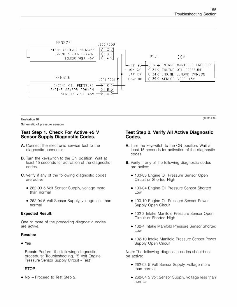
155Troubleshooting Section
g00954290Illustration 67
Schematic of pressure sensors
Test Step 1. Check For Active +5 VSensor Supply Diagnostic Codes.
A. Connect the electronic service tool to thediagnostic connector.
B. Turn the keyswitch to the ON position. Wait atleast 15 seconds for activation of the diagnosticcodes.
C. Verify if any of the following diagnostic codesare active:
• 262-03 5 Volt Sensor Supply, voltage morethan normal
• 262-04 5 Volt Sensor Supply, voltage less thannormal
Expected Result:
One or more of the preceding diagnostic codesare active.
Results:
• Yes
Repair: Perform the following diagnosticprocedure: Troubleshooting, “5 Volt EnginePressure Sensor Supply Circuit - Test”.
STOP.
• No – Proceed to Test Step 2.
Test Step 2. Verify All Active DiagnosticCodes.
A. Turn the keyswitch to the ON position. Wait atleast 15 seconds for activation of the diagnosticcodes.
B. Verify if any of the following diagnostic codesare active:
• 100-03 Engine Oil Pressure Sensor OpenCircuit or Shorted High
• 100-04 Engine Oil Pressure Sensor ShortedLow
• 100-10 Engine Oil Pressure Sensor PowerSupply Open Circuit
• 102-3 Intake Manifold Pressure Sensor OpenCircuit or Shorted High
• 102-4 Intake Manifold Pressure Sensor ShortedLow
• 102-10 Intake Manifold Pressure Sensor PowerSupply Open Circuit
Note: The following diagnostic codes should notbe active:
• 262-03 5 Volt Sensor Supply, voltage morethan normal
• 262-04 5 Volt Sensor Supply, voltage less thannormal

156Troubleshooting Section
Expected Result:
One or more of the preceding diagnostic codesare active.
Results:
• Yes – Proceed to Test Step 3.
• No
Repair: If the preceding codes are logged butnot active and the engine is not running properly,refer to Troubleshooting, “Troubleshooting withouta Diagnostic Code”. If the engine is runningproperly at this time, an intermittent conditionmay be causing the logged codes. Refer toTroubleshooting, “Electrical Connectors - Inspect”.
STOP.
Test Step 3. Inspect Electrical ConnectorsAnd Wiring.
g00955141Illustration 68
A. Thoroughly inspect the following terminalconnections on the P1 ECM connector:
• P:14 Intake Manifold Pressure
• P:24 Engine Oil Pressure
• P:26 +5 V
• P:34 Sensor Common
B. Thoroughly inspect the following engine pressuresensors:
• J1/P1 ECM Engine Harness Connector
• J20/P20 Machine Interface Connector
157Troubleshooting Section
• J200/P200 Intake Manifold Pressure Sensor
• J201/P201 Engine Oil Pressure Sensor
C. Refer to Troubleshooting, “Electrical Connectors- Inspect”.
D. Perform a 45 N (10 lb) pull test on each of thewires in the ECM connector and the sensorconnectors that are associated with the activediagnostic code.
Refer to Illustration 68.
E. Check the ECM connector (Allen head screw) forthe proper torque of 6.0 N·m (55 lb in).
F. Check the harness and wiring for abrasions andfor pinch points from the sensors back to theECM.
Expected Result:
All connectors, pins, and sockets should becompletely coupled and inserted. The harness andwiring should be free of corrosion, abrasion, andpinch points.
Results:
• OK – Proceed to Test Step 4.
• Not OK
Repair: Repair the connectors or wiring and/orreplace the connectors or wiring. Ensure that allof the seals are properly in place and ensure thatthe connectors are completely coupled.
Verify that the repair eliminates the problem.
Use the electronic service tool in order to clear alllogged diagnostic codes.
STOP.
Test Step 4. Verify that the DiagnosticCode is Still Active.
A. Turn the keyswitch to the ON position. Wait atleast 15 seconds for activation of the diagnosticcodes.
B. Use the electronic service tool to check for activediagnostic codes. Record all active diagnosticcodes.
C. Determine if the problem is related to anopen circuit diagnostic code or a short circuitdiagnostic code.
Expected Result:
Either a short circuit diagnostic code is active or anopen circuit diagnostic code is active.
Results:
• SHORT Circuit – A short circuit diagnostic codeis active at this time. Proceed to Test Step 5.
• OPEN Circuit – An open circuit diagnostic codeis active at this time. Proceed to Test Step 6.
Test Step 5. Disconnect The Sensor InOrder To Create An Open Circuit.
A. Turn the keyswitch to the OFF position.
B. Disconnect the sensor connector of the sensorwith the short circuit diagnostic code.
C. Turn the keyswitch to the ON position. Wait atleast 15 seconds for activation of the diagnosticcodes.
D. Use the electronic service tool to check the“Active Diagnostic Code” screen. Check for anopen circuit diagnostic code.
Expected Result:
An open circuit diagnostic code for thedisconnected sensor is now active.
Results:
• OK – A short circuit diagnostic code was activebefore disconnecting the sensor. An opencircuit diagnostic code became active afterdisconnecting the sensor. Proceed to Test Step 7.
• Not OK – There is a short circuit between thesensor harness connector and the ECM. Leavethe sensor disconnected. Proceed to Test Step 9.
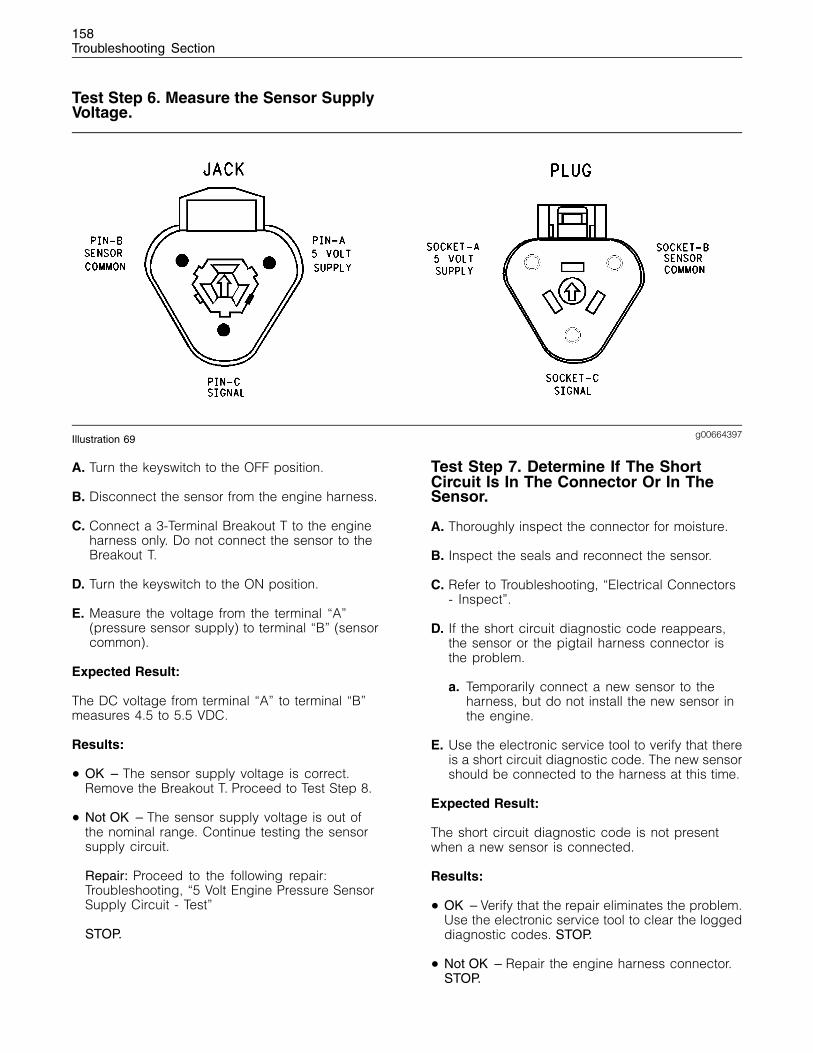
158Troubleshooting Section
Test Step 6. Measure the Sensor SupplyVoltage.
g00664397Illustration 69
A. Turn the keyswitch to the OFF position.
B. Disconnect the sensor from the engine harness.
C. Connect a 3-Terminal Breakout T to the engineharness only. Do not connect the sensor to theBreakout T.
D. Turn the keyswitch to the ON position.
E. Measure the voltage from the terminal “A”(pressure sensor supply) to terminal “B” (sensorcommon).
Expected Result:
The DC voltage from terminal “A” to terminal “B”measures 4.5 to 5.5 VDC.
Results:
• OK – The sensor supply voltage is correct.Remove the Breakout T. Proceed to Test Step 8.
• Not OK – The sensor supply voltage is out ofthe nominal range. Continue testing the sensorsupply circuit.
Repair: Proceed to the following repair:Troubleshooting, “5 Volt Engine Pressure SensorSupply Circuit - Test”
STOP.
Test Step 7. Determine If The ShortCircuit Is In The Connector Or In TheSensor.
A. Thoroughly inspect the connector for moisture.
B. Inspect the seals and reconnect the sensor.
C. Refer to Troubleshooting, “Electrical Connectors- Inspect”.
D. If the short circuit diagnostic code reappears,the sensor or the pigtail harness connector isthe problem.
a. Temporarily connect a new sensor to theharness, but do not install the new sensor inthe engine.
E. Use the electronic service tool to verify that thereis a short circuit diagnostic code. The new sensorshould be connected to the harness at this time.
Expected Result:
The short circuit diagnostic code is not presentwhen a new sensor is connected.
Results:
• OK – Verify that the repair eliminates the problem.Use the electronic service tool to clear the loggeddiagnostic codes. STOP.
• Not OK – Repair the engine harness connector.STOP.
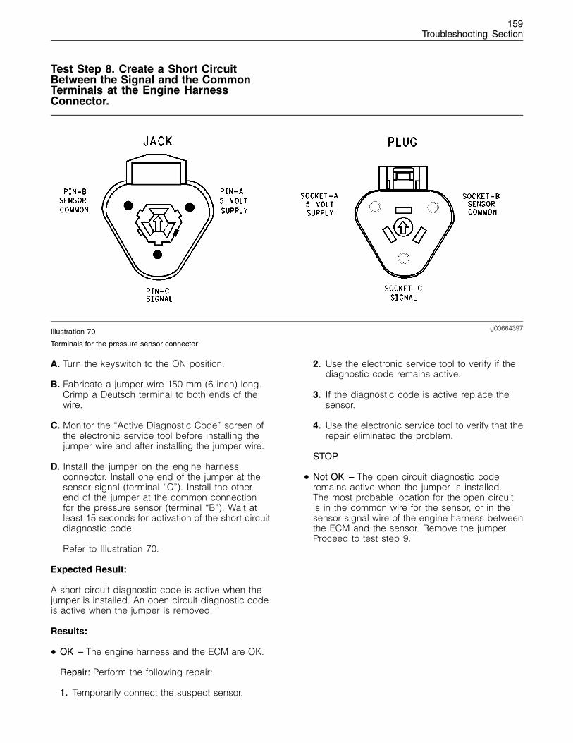
159Troubleshooting Section
Test Step 8. Create a Short CircuitBetween the Signal and the CommonTerminals at the Engine HarnessConnector.
g00664397Illustration 70
Terminals for the pressure sensor connector
A. Turn the keyswitch to the ON position.
B. Fabricate a jumper wire 150 mm (6 inch) long.Crimp a Deutsch terminal to both ends of thewire.
C. Monitor the “Active Diagnostic Code” screen ofthe electronic service tool before installing thejumper wire and after installing the jumper wire.
D. Install the jumper on the engine harnessconnector. Install one end of the jumper at thesensor signal (terminal “C”). Install the otherend of the jumper at the common connectionfor the pressure sensor (terminal “B”). Wait atleast 15 seconds for activation of the short circuitdiagnostic code.
Refer to Illustration 70.
Expected Result:
A short circuit diagnostic code is active when thejumper is installed. An open circuit diagnostic codeis active when the jumper is removed.
Results:
• OK – The engine harness and the ECM are OK.
Repair: Perform the following repair:
1. Temporarily connect the suspect sensor.
2. Use the electronic service tool to verify if thediagnostic code remains active.
3. If the diagnostic code is active replace thesensor.
4. Use the electronic service tool to verify that therepair eliminated the problem.
STOP.
• Not OK – The open circuit diagnostic coderemains active when the jumper is installed.The most probable location for the open circuitis in the common wire for the sensor, or in thesensor signal wire of the engine harness betweenthe ECM and the sensor. Remove the jumper.Proceed to test step 9.
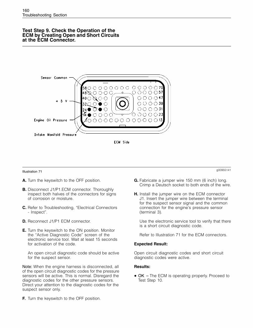
160Troubleshooting Section
Test Step 9. Check the Operation of theECM by Creating Open and Short Circuitsat the ECM Connector.
g00955141Illustration 71
A. Turn the keyswitch to the OFF position.
B. Disconnect J1/P1.ECM connector. Thoroughlyinspect both halves of the connectors for signsof corrosion or moisture.
C. Refer to Troubleshooting, “Electrical Connectors- Inspect”.
D. Reconnect J1/P1 ECM connector.
E. Turn the keyswitch to the ON position. Monitorthe “Active Diagnostic Code” screen of theelectronic service tool. Wait at least 15 secondsfor activation of the code.
An open circuit diagnostic code should be activefor the suspect sensor.
Note: When the engine harness is disconnected, allof the open circuit diagnostic codes for the pressuresensors will be active. This is normal. Disregard thediagnostic codes for the other pressure sensors.Direct your attention to the diagnostic codes for thesuspect sensor only.
F. Turn the keyswitch to the OFF position.
G. Fabricate a jumper wire 150 mm (6 inch) long.Crimp a Deutsch socket to both ends of the wire.
H. Install the jumper wire on the ECM connectorJ1. Insert the jumper wire between the terminalfor the suspect sensor signal and the commonconnection for the engine’s pressure sensor(terminal 3).
Use the electronic service tool to verify that thereis a short circuit diagnostic code.
Refer to Illustration 71 for the ECM connectors.
Expected Result:
Open circuit diagnostic codes and short circuitdiagnostic codes were active.
Results:
• OK – The ECM is operating properly. Proceed toTest Step 10.
161Troubleshooting Section
• Not OK – One of the following conditions exists:The open circuit diagnostic code is not activewhen the harness is disconnected. The shortcircuit diagnostic code is not active when thejumper wire is installed.
Repair: Perform the following repair:
1. Temporarily connect a test ECM.
Note: The test ECM should have the same valuesand the same parameters as the suspect ECM.
2. Remove all jumpers and replace all connectors.
3. Use the electronic service tool to recheck thesystem for active diagnostic codes.
4. Repeat the test step.
5. If the problem is resolved with the test ECM,reconnect the suspect ECM.
6. If the problem returns with the suspect ECM,replace the ECM.
7. Verify that the repair eliminates the problem.
STOP.
Test Step 10. Bypass the HarnessWiring Between the ECM and the SensorConnector.
A. Turn the keyswitch to the OFF position.
B. Disconnect J1/P1 ECM connector and the sensorconnector.
C. Remove the sensor signal wire from the ECMconnector.
D. Remove the signal wire (terminal “C”) from thesensor connector on the engine harness.
E. Fabricate a jumper wire that is long enough toreach from the ECM to the sensor connector oruse an engine sensor harness bypass with 3terminals.
Note: If an engine sensor harness bypass is beingmade, crimp a Deutsch socket on one end in orderto connect to the ECM. Crimp either a Deutsch pinor a Deutsch socket on the other end, as required.
F. Insert the one end of the engine sensor harnessbypass into P1 ECM connector on the engineharness. Insert the other end of the enginesensor harness bypass into the sensor connectorof the engine harness.
G. Reconnect J1/P1 ECM engine connector and thesensor connector.
H. Turn the keyswitch to the ON position.
I. Use the electronic service tool to monitor the“Active Diagnostic Code” screen for either theopen circuit diagnostic code for the sensor orthe short circuit diagnostic code for the sensor.
Expected Result:
The diagnostic code disappears when the jumperor the bypass is installed.
Results:
• OK – There is a problem in the wiring harness.
Repair: Perform the following repair:
1. Repair the faulty wiring harness or replace thefaulty wiring harness.
2. Clear all diagnostic codes.
3. Use the electronic service tool in order to verifythat the repair eliminates the problem.
STOP.
• Not OK – Restart this procedure and carefullyperform each step. STOP.
i01798872
Engine Speed/Timing SensorCircuit - Test
System Operation Description:
Use this procedure to troubleshoot the systemunder the following conditions:
• There is an active diagnostic code for the enginespeed/timing sensors.
• Use this procedure if another procedure hasdirected you here.
The engine uses two engine speed/timing sensors.One sensor is located in the cylinder block. Thespeed/timing sensor that is mounted on the cylinderblock measures the crankshaft speed and thespeed/timing sensor calculates the position of thecrankshaft. In order to determine the engine rpm,the Electronic Control Module (ECM) measures thetime between pulses that are created by the sensoras the speed-timing wheel rotates.
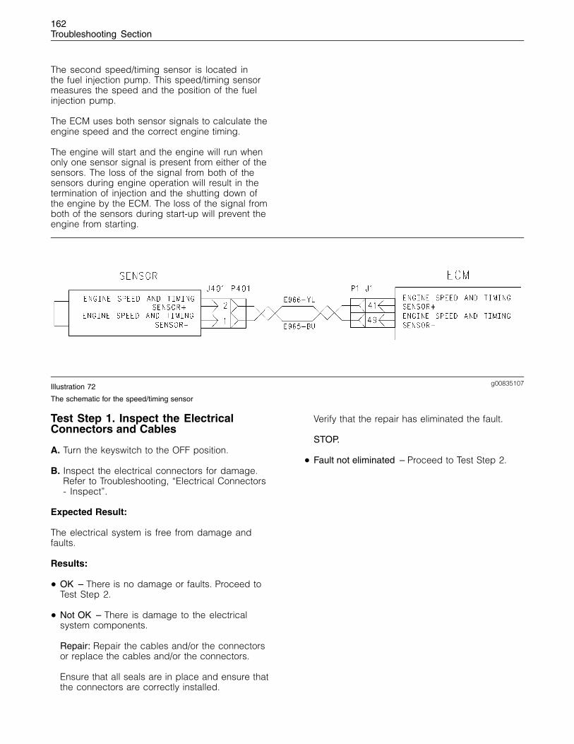
162Troubleshooting Section
The second speed/timing sensor is located inthe fuel injection pump. This speed/timing sensormeasures the speed and the position of the fuelinjection pump.
The ECM uses both sensor signals to calculate theengine speed and the correct engine timing.
The engine will start and the engine will run whenonly one sensor signal is present from either of thesensors. The loss of the signal from both of thesensors during engine operation will result in thetermination of injection and the shutting down ofthe engine by the ECM. The loss of the signal fromboth of the sensors during start-up will prevent theengine from starting.
g00835107Illustration 72
The schematic for the speed/timing sensor
Test Step 1. Inspect the ElectricalConnectors and Cables
A. Turn the keyswitch to the OFF position.
B. Inspect the electrical connectors for damage.Refer to Troubleshooting, “Electrical Connectors- Inspect”.
Expected Result:
The electrical system is free from damage andfaults.
Results:
• OK – There is no damage or faults. Proceed toTest Step 2.
• Not OK – There is damage to the electricalsystem components.
Repair: Repair the cables and/or the connectorsor replace the cables and/or the connectors.
Ensure that all seals are in place and ensure thatthe connectors are correctly installed.
Verify that the repair has eliminated the fault.
STOP.
• Fault not eliminated – Proceed to Test Step 2.
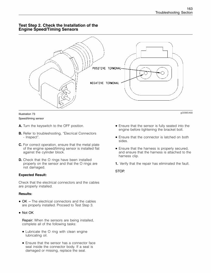
163Troubleshooting Section
Test Step 2. Check the Installation of theEngine Speed/Timing Sensors
g00985468Illustration 73
Speed/timing sensor
A. Turn the keyswitch to the OFF position.
B. Refer to troubleshooting, “Elecrical Connectors- Inspect”.
C. For correct operation, ensure that the metal plateof the engine speed/timing sensor is installed flatagainst the cylinder block.
D. Check that the O rings have been installedproperly on the sensor and that the O rings arenot damaged.
Expected Result:
Check that the electrical connectors and the cablesare properly installed.
Results:
• OK – The electrical connectors and the cablesare properly installed. Proceed to Test Step 3.
• Not OK
Repair: When the sensors are being installed,complete all of the following tasks:
• Lubricate the O ring with clean enginelubricating oil.
• Ensure that the sensor has a connector faceseal inside the connector body. If a seal isdamaged or missing, replace the seal.
• Ensure that the sensor is fully seated into theengine before tightening the bracket bolt.
• Ensure that the connector is latched on bothsides.
• Ensure that the harness is properly secured,and ensure that the harness is attached to theharness clip.
1. Verify that the repair has eliminated the fault.
STOP.
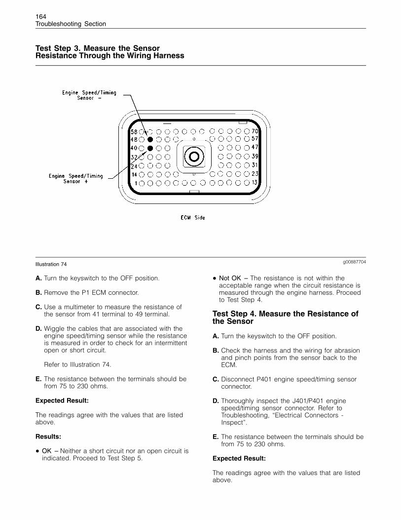
164Troubleshooting Section
Test Step 3. Measure the SensorResistance Through the Wiring Harness
g00887704Illustration 74
A. Turn the keyswitch to the OFF position.
B. Remove the P1 ECM connector.
C. Use a multimeter to measure the resistance ofthe sensor from 41 terminal to 49 terminal.
D. Wiggle the cables that are associated with theengine speed/timing sensor while the resistanceis measured in order to check for an intermittentopen or short circuit.
Refer to Illustration 74.
E. The resistance between the terminals should befrom 75 to 230 ohms.
Expected Result:
The readings agree with the values that are listedabove.
Results:
• OK – Neither a short circuit nor an open circuit isindicated. Proceed to Test Step 5.
• Not OK – The resistance is not within theacceptable range when the circuit resistance ismeasured through the engine harness. Proceedto Test Step 4.
Test Step 4. Measure the Resistance ofthe Sensor
A. Turn the keyswitch to the OFF position.
B. Check the harness and the wiring for abrasionand pinch points from the sensor back to theECM.
C. Disconnect P401 engine speed/timing sensorconnector.
D. Thoroughly inspect the J401/P401 enginespeed/timing sensor connector. Refer toTroubleshooting, “Electrical Connectors -Inspect”.
E. The resistance between the terminals should befrom 75 to 230 ohms.
Expected Result:
The readings agree with the values that are listedabove.
165Troubleshooting Section
Results:
• OK – The sensor resistance is within tolerance.
Repair: There is a fault in the cable between theP1 ECM connector and the P401 connector.
Repair the faulty cable or replace the faulty cable.
Verify that the repair has eliminated the faults.
STOP.
• Not OK – The sensor resistance is out of thenominal range.
Repair: Perform the following procedure in orderto check and install the new sensor:
1. Before installing the new sensor, measure theresistance of the new sensor.
If the new sensor resistance is in the correctrange, install the new sensor in the engine.
Ensure that the O ring is installed and free ofdamage.
Seat the sensor and tighten the setscrew.
If the sensor will not seat, repair the sensor orreplace the sensor, as required.
Ensure that the sensor is properly orientedand that the harness is secured in the properlocation.
2. Verify that the repair eliminates the problem.
STOP.
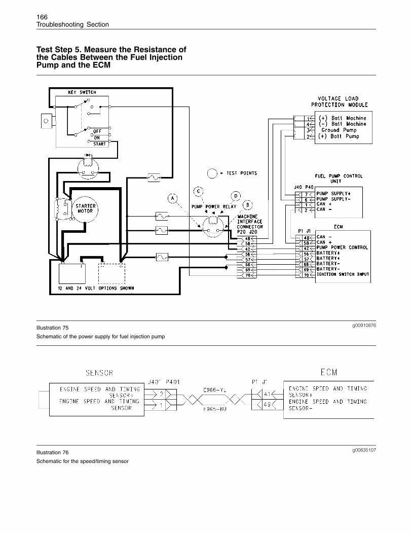
166Troubleshooting Section
Test Step 5. Measure the Resistance ofthe Cables Between the Fuel InjectionPump and the ECM
g00910876Illustration 75
Schematic of the power supply for fuel injection pump
g00835107Illustration 76
Schematic for the speed/timing sensor

167Troubleshooting Section
g00885751Illustration 77
g00863550Illustration 78
Fuel pump power supply
A. Turn the keyswitch to the OFF position.
B. Disconnect the P1 ECM connector and the P40fuel injection pump connector.
C. Measure the resistance from terminal 59 enginespeed/timing sensor at the ECM and to terminal8 engine speed/timing sensor of the P40 fuelinjection pump connector.
D. The resistance should be less than 2 ohms.
Expected Result:
The readings agree with the values that are listedabove.
Results:
• OK – The ECM does not operate properly.
Repair: Perform the following repairs on thesuspect ECM.
1. Temporarily install a test ECM.
Note: The test ECM should be programmed with thecorrect software. All parameters should be set tothe same value as the suspect ECM.
2. If the fault is eliminated with the test ECM,reconnect the suspect ECM.
3. If the fault returns with the suspect ECM,then the suspect ECM is faulty. Replace thesuspect ECM.
STOP.
• Not OK – The readings are higher than 2 ohms.Proceed to Test Step 6.
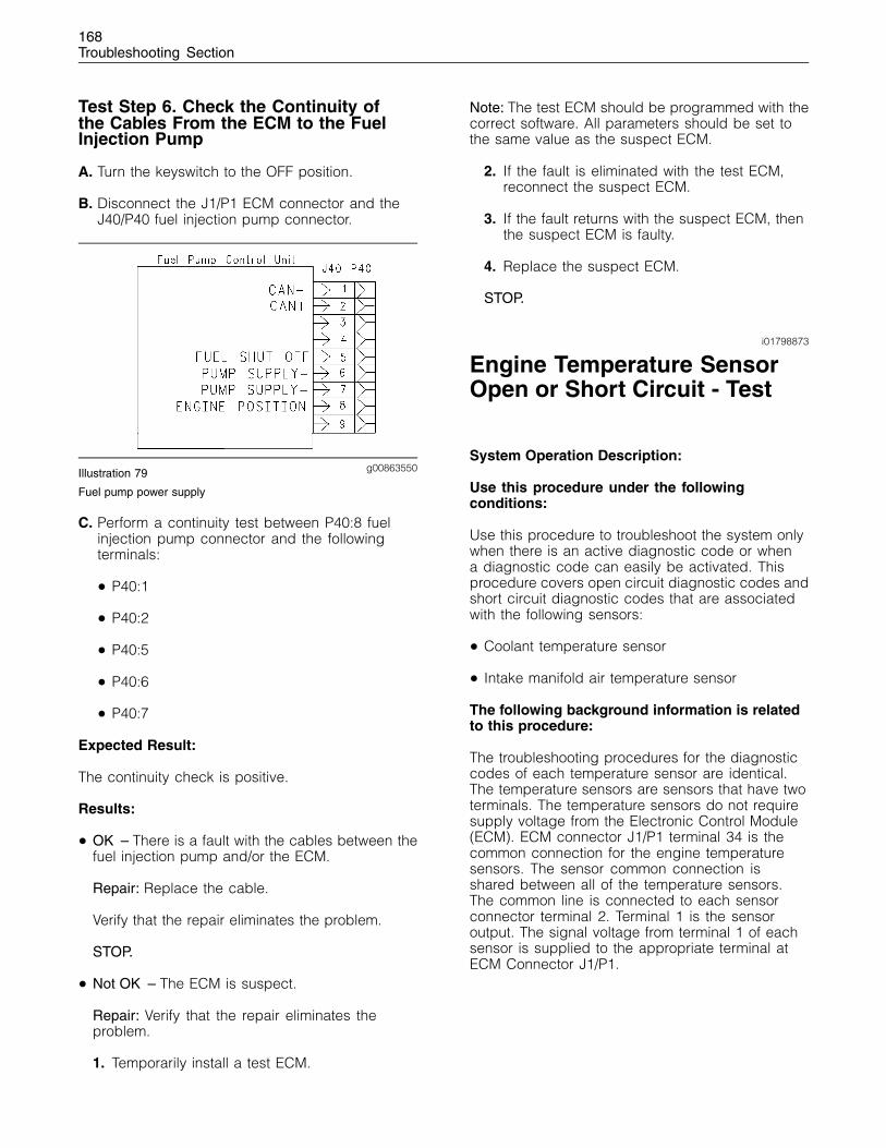
168Troubleshooting Section
Test Step 6. Check the Continuity ofthe Cables From the ECM to the FuelInjection Pump
A. Turn the keyswitch to the OFF position.
B. Disconnect the J1/P1 ECM connector and theJ40/P40 fuel injection pump connector.
g00863550Illustration 79
Fuel pump power supply
C. Perform a continuity test between P40:8 fuelinjection pump connector and the followingterminals:
• P40:1
• P40:2
• P40:5
• P40:6
• P40:7
Expected Result:
The continuity check is positive.
Results:
• OK – There is a fault with the cables between thefuel injection pump and/or the ECM.
Repair: Replace the cable.
Verify that the repair eliminates the problem.
STOP.
• Not OK – The ECM is suspect.
Repair: Verify that the repair eliminates theproblem.
1. Temporarily install a test ECM.
Note: The test ECM should be programmed with thecorrect software. All parameters should be set tothe same value as the suspect ECM.
2. If the fault is eliminated with the test ECM,reconnect the suspect ECM.
3. If the fault returns with the suspect ECM, thenthe suspect ECM is faulty.
4. Replace the suspect ECM.
STOP.
i01798873
Engine Temperature SensorOpen or Short Circuit - Test
System Operation Description:
Use this procedure under the followingconditions:
Use this procedure to troubleshoot the system onlywhen there is an active diagnostic code or whena diagnostic code can easily be activated. Thisprocedure covers open circuit diagnostic codes andshort circuit diagnostic codes that are associatedwith the following sensors:
• Coolant temperature sensor
• Intake manifold air temperature sensor
The following background information is relatedto this procedure:
The troubleshooting procedures for the diagnosticcodes of each temperature sensor are identical.The temperature sensors are sensors that have twoterminals. The temperature sensors do not requiresupply voltage from the Electronic Control Module(ECM). ECM connector J1/P1 terminal 34 is thecommon connection for the engine temperaturesensors. The sensor common connection isshared between all of the temperature sensors.The common line is connected to each sensorconnector terminal 2. Terminal 1 is the sensoroutput. The signal voltage from terminal 1 of eachsensor is supplied to the appropriate terminal atECM Connector J1/P1.
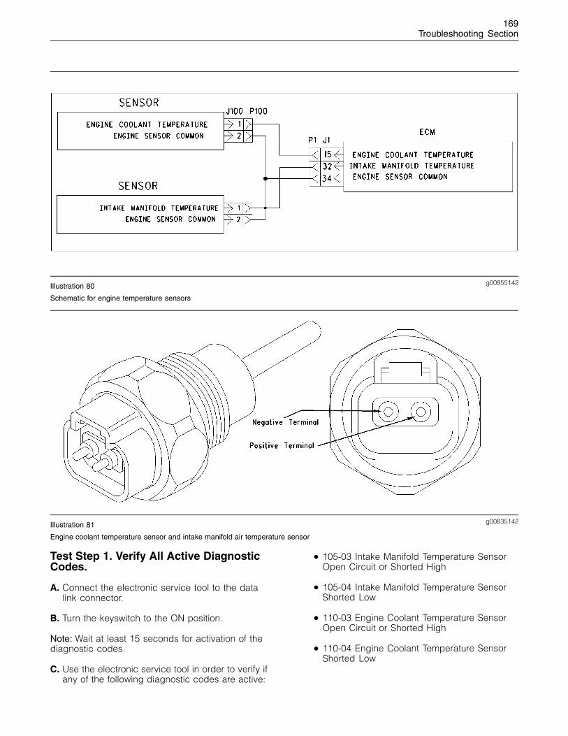
169Troubleshooting Section
g00955142Illustration 80
Schematic for engine temperature sensors
g00835142Illustration 81
Engine coolant temperature sensor and intake manifold air temperature sensor
Test Step 1. Verify All Active DiagnosticCodes.
A. Connect the electronic service tool to the datalink connector.
B. Turn the keyswitch to the ON position.
Note: Wait at least 15 seconds for activation of thediagnostic codes.
C. Use the electronic service tool in order to verify ifany of the following diagnostic codes are active:
• 105-03 Intake Manifold Temperature SensorOpen Circuit or Shorted High
• 105-04 Intake Manifold Temperature SensorShorted Low
• 110-03 Engine Coolant Temperature SensorOpen Circuit or Shorted High
• 110-04 Engine Coolant Temperature SensorShorted Low
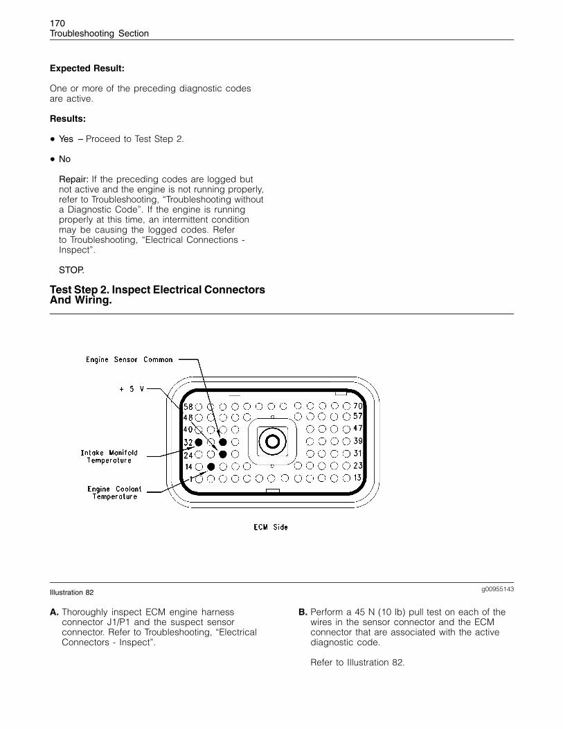
170Troubleshooting Section
Expected Result:
One or more of the preceding diagnostic codesare active.
Results:
• Yes – Proceed to Test Step 2.
• No
Repair: If the preceding codes are logged butnot active and the engine is not running properly,refer to Troubleshooting, “Troubleshooting withouta Diagnostic Code”. If the engine is runningproperly at this time, an intermittent conditionmay be causing the logged codes. Referto Troubleshooting, “Electrical Connections -Inspect”.
STOP.
Test Step 2. Inspect Electrical ConnectorsAnd Wiring.
g00955143Illustration 82
A. Thoroughly inspect ECM engine harnessconnector J1/P1 and the suspect sensorconnector. Refer to Troubleshooting, “ElectricalConnectors - Inspect”.
B. Perform a 45 N (10 lb) pull test on each of thewires in the sensor connector and the ECMconnector that are associated with the activediagnostic code.
Refer to Illustration 82.
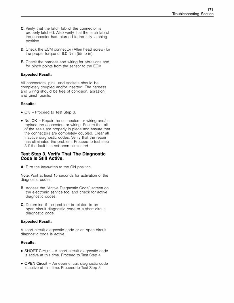
171Troubleshooting Section
C. Verify that the latch tab of the connector isproperly latched. Also verify that the latch tab ofthe connector has returned to the fully latchingposition.
D. Check the ECM connector (Allen head screw) forthe proper torque of 6.0 N·m (55 lb in).
E. Check the harness and wiring for abrasions andfor pinch points from the sensor to the ECM.
Expected Result:
All connectors, pins, and sockets should becompletely coupled and/or inserted. The harnessand wiring should be free of corrosion, abrasion,and pinch points.
Results:
• OK – Proceed to Test Step 3.
• Not OK – Repair the connectors or wiring and/orreplace the connectors or wiring. Ensure that allof the seals are properly in place and ensure thatthe connectors are completely coupled. Clear allinactive diagnostic codes. Verify that the repairhas eliminated the problem. Proceed to test step3 if the fault has not been eliminated.
Test Step 3. Verify That The DiagnosticCode Is Still Active.
A. Turn the keyswitch to the ON position.
Note: Wait at least 15 seconds for activation of thediagnostic codes.
B. Access the “Active Diagnostic Code” screen onthe electronic service tool and check for activediagnostic codes.
C. Determine if the problem is related to anopen circuit diagnostic code or a short circuitdiagnostic code.
Expected Result:
A short circuit diagnostic code or an open circuitdiagnostic code is active.
Results:
• SHORT Circuit – A short circuit diagnostic codeis active at this time. Proceed to Test Step 4.
• OPEN Circuit – An open circuit diagnostic codeis active at this time. Proceed to Test Step 5.
172Troubleshooting Section
Test Step 4. Disconnect The Sensor InOrder To Create An Open Circuit.
g00835142Illustration 83
Engine coolant temperature sensor
A. Turn the keyswitch to the OFF position.
B. Disconnect the sensor connector of the sensorwith the short circuit diagnostic code.
C. Turn the keyswitch to the ON position.
Note: Wait at least 15 seconds for activation of thediagnostic codes.
D. Access the “Active Diagnostic Code” screen ofthe electronic service tool. Check for an activeopen circuit diagnostic code.
Expected Result:
An open circuit diagnostic code for thedisconnected sensor is now active.
Results:
• OK – A short circuit diagnostic code was activebefore disconnecting the sensor. An opencircuit diagnostic code became active afterdisconnecting the sensor.
Repair: Refer to Troubleshooting, “ElectricalConnectors - Inspect”.
Inspect the seals of the connectors for damage.
Connect the sensor and verify that the faultreturns. If the fault returns, the sensor is faulty.
Replace the sensor.
Remove all inactive diagnostic fault codes.
STOP.
• Not OK – There is a short circuit between thesensor harness connector and the ECM. Leavethe sensor disconnected. Proceed to Test Step 6.
Test Step 5. Create A Short CircuitBetween The Signal And The CommonTerminals At The Sensor HarnessConnector.
A. Turn the keyswitch to the ON position.
Note: Wait at least 15 seconds for the activation ofany diagnostic fault codes.
B. Fabricate a jumper wire 150 mm (6 inch) long.Crimp a Deutsch terminal to both ends of thewire.
C. Monitor the “Active Diagnostic Code” screen onthe electronic service tool before installing thejumper wire and after installing the jumper wire.
D. Install the jumper on the engine harnessconnector. Install one end of the jumper at thesensor signal (positive terminal). Install the otherend of the jumper at the common connection forthe engine temperature sensor (terminal 2).
173Troubleshooting Section
Note: Wait at least 15 seconds for activation of theshort circuit diagnostic code.
Expected Result:
A short circuit diagnostic code is active when thejumper is installed. An open circuit diagnostic codeis active when the jumper is removed.
Results:
• OK – The engine harness and the ECM are OK.
Repair: Perform the following repair:
1. Temporarily connect the suspect sensor.
2. If the diagnostic code remains active, replacethe sensor.
3. Verify that the repair eliminates the problem.
4. Clear all inactive diagnostic codes.
STOP.
• Not OK – The open circuit diagnostic coderemains active with the jumper in place. Themost probable location for the open is in thesensor common or the sensor signal wire in theengine harness between the ECM and the sensor.Remove the jumper. Proceed to Test Step 6.
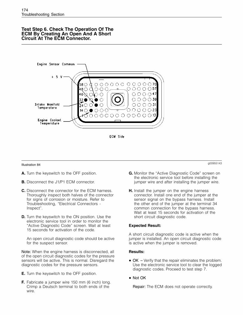
174Troubleshooting Section
Test Step 6. Check The Operation Of TheECM By Creating An Open And A ShortCircuit At The ECM Connector.
g00955143Illustration 84
A. Turn the keyswitch to the OFF position.
B. Disconnect the J1/P1 ECM connector.
C. Disconnect the connector for the ECM harness.Thoroughly inspect both halves of the connectorfor signs of corrosion or moisture. Refer toTroubleshooting, “Electrical Connectors -Inspect”.
D. Turn the keyswitch to the ON position. Use theelectronic service tool in order to monitor the“Active Diagnostic Code” screen. Wait at least15 seconds for activation of the code.
An open circuit diagnostic code should be activefor the suspect sensor.
Note: When the engine harness is disconnected, allof the open circuit diagnostic codes for the pressuresensors will be active. This is normal. Disregard thediagnostic codes for the pressure sensors.
E. Turn the keyswitch to the OFF position.
F. Fabricate a jumper wire 150 mm (6 inch) long.Crimp a Deutsch terminal to both ends of thewire.
G. Monitor the “Active Diagnostic Code” screen onthe electronic service tool before installing thejumper wire and after installing the jumper wire.
H. Install the jumper on the engine harnessconnector. Install one end of the jumper at thesensor signal on the bypass harness. Installthe other end of the jumper at the terminal 34common connection for the bypass harness.Wait at least 15 seconds for activation of theshort circuit diagnostic code.
Expected Result:
A short circuit diagnostic code is active when thejumper is installed. An open circuit diagnostic codeis active when the jumper is removed.
Results:
• OK – Verify that the repair eliminates the problem.Use the electronic service tool to clear the loggeddiagnostic codes. Proceed to test step 7.
• Not OK
Repair: The ECM does not operate correctly.
175Troubleshooting Section
1. Temporarily connect a test ECM.
Note: The test ECM should be programmed with thecorrect software. All parameters should be set tothe same value of the suspect ECM.
2. Remove all jumpers and replace all connectors.
3. If the fault is eliminated with the test ECM,install the suspect ECM and verify that thefault returns.
4. If the fault returns replace the suspect ECM.
5. Verify that the repair eliminates the problem.
STOP.
Test Step 7. Bypass The Harness WiringBetween The ECM And The SensorConnector.
A. Turn the keyswitch to the OFF position.
B. Disconnect the J1/P1connector for the ECMharness, and the suspect sensor connector.
C. Remove the sensor signal wire from the P1 ECMconnector.
D. Remove the signal wire (positive terminal) fromthe sensor connector on the engine harness.
E. Fabricate a jumper wire that is long enough toreach from the ECM to the sensor connector withDeutsch sockets on both ends.
F. Insert one end of the jumper into the ECMconnector. Insert the other end of the jumper intothe sensor connector of the engine harness.
G. Reconnect the connector for the ECM harnessand the sensor connector.
H. Turn the keyswitch to the ON position.
I. Use the electronic service tool in order to monitorthe “Active Diagnostic Code” screen for eitherthe open circuit diagnostic code for the sensor orthe short circuit diagnostic code for the sensor.
Expected Result:
The diagnostic code disappears when the jumperis installed.
Results:
• OK – There is a problem in the wiring harness.
Repair: Perform the following repair:
1. Repair the faulty wiring harness or replace thefaulty wiring harness.
2. Clear all diagnostic codes.
3. Verify that the repair eliminates the problem.
STOP.
• Not OK – Restart this procedure and carefullyperform each step. STOP.
i01798874
Fuel Injection Pump Circuit -Test
System Operation Description:
Use this procedure under the followingconditions:
Note: The Bosch VP30 fuel injection pump isinstalled on the engine at the factory. The pumpis not serviceable.
Use this procedure if another procedure hasdirected you here. Also use this procedure if any ofthe following diagnostic codes are active:
• 1684-04 Fuel Injection Pump supply voltage fault
• 1684-07 Fuel Injection Pump mechanical fault
• 1684-11 Fuel Injection Pump internal sensor fault
• 1684-14 Fuel Injection Pump no communications
• 174-02 Fuel Temperature Sensor erratic orintermittent
• 342-02 Speed and Timing Sensor No.2intermittent signal
The following background information is relatedto this procedure:
The fuel injection pump receives an electricalsupply from the OEM cables and from the relayfor the fuel injection pump through the MachineInterface Connector (MIC).
The loss of power to the fuel injection pump canoccur on either the positive side or the negativeside of the pump. The positive side is supplied fromthe pump power relay to the fuel injection pump.The positive supply includes a fuse in order toprotect the circuit. The negative side is connecteddirectly to the battery.
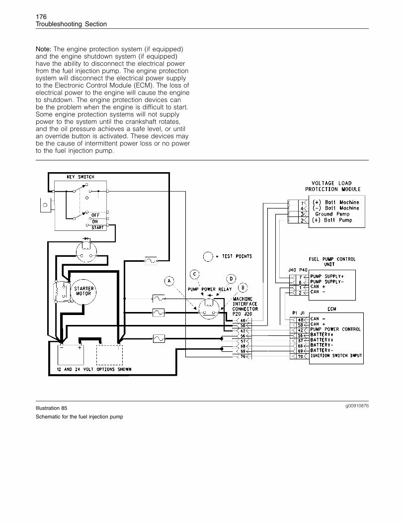
176Troubleshooting Section
Note: The engine protection system (if equipped)and the engine shutdown system (if equipped)have the ability to disconnect the electrical powerfrom the fuel injection pump. The engine protectionsystem will disconnect the electrical power supplyto the Electronic Control Module (ECM). The loss ofelectrical power to the engine will cause the engineto shutdown. The engine protection devices canbe the problem when the engine is difficult to start.Some engine protection systems will not supplypower to the system until the crankshaft rotates,and the oil pressure achieves a safe level, or untilan override button is activated. These devices maybe the cause of intermittent power loss or no powerto the fuel injection pump.
g00910876Illustration 85
Schematic for the fuel injection pump
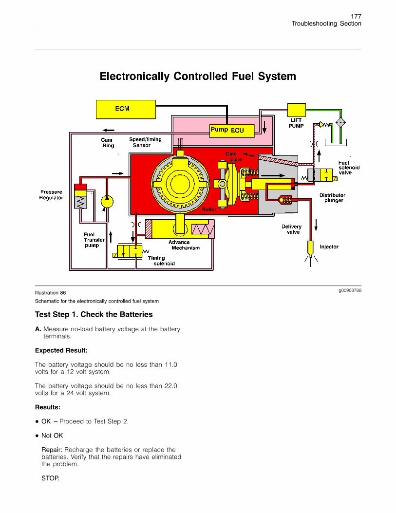
177Troubleshooting Section
g00908788Illustration 86
Schematic for the electronically controlled fuel system
Test Step 1. Check the Batteries
A. Measure no-load battery voltage at the batteryterminals.
Expected Result:
The battery voltage should be no less than 11.0volts for a 12 volt system.
The battery voltage should be no less than 22.0volts for a 24 volt system.
Results:
• OK – Proceed to Test Step 2.
• Not OK
Repair: Recharge the batteries or replace thebatteries. Verify that the repairs have eliminatedthe problem.
STOP.
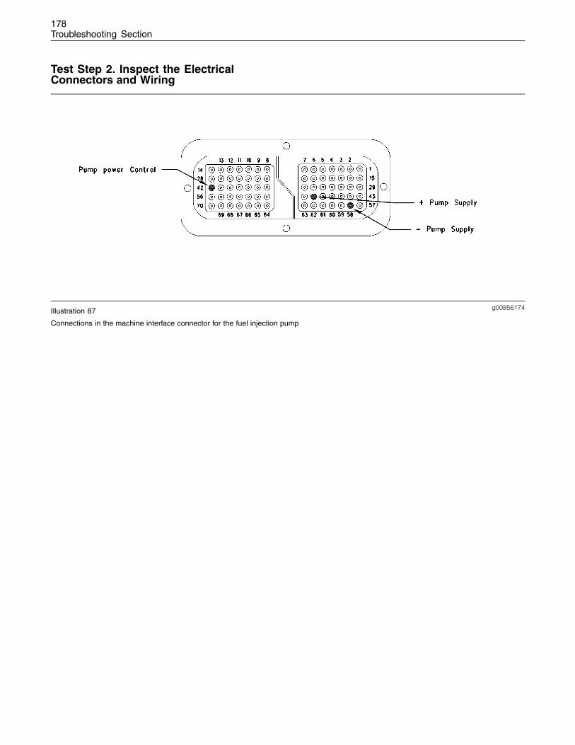
178Troubleshooting Section
Test Step 2. Inspect the ElectricalConnectors and Wiring
g00856174Illustration 87
Connections in the machine interface connector for the fuel injection pump
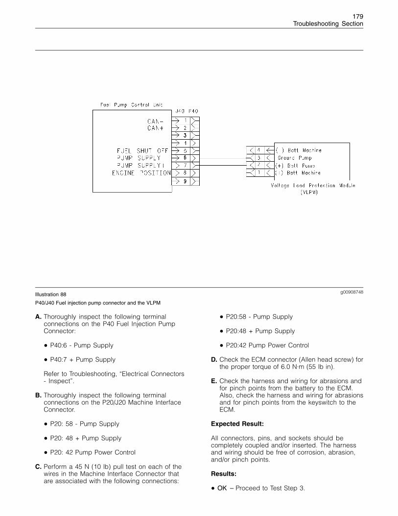
179Troubleshooting Section
g00908748Illustration 88
P40/J40 Fuel injection pump connector and the VLPM
A. Thoroughly inspect the following terminalconnections on the P40 Fuel Injection PumpConnector:
• P40:6 - Pump Supply
• P40:7 + Pump Supply
Refer to Troubleshooting, “Electrical Connectors- Inspect”.
B. Thoroughly inspect the following terminalconnections on the P20/J20 Machine InterfaceConnector.
• P20: 58 - Pump Supply
• P20: 48 + Pump Supply
• P20: 42 Pump Power Control
C. Perform a 45 N (10 lb) pull test on each of thewires in the Machine Interface Connector thatare associated with the following connections:
• P20:58 - Pump Supply
• P20:48 + Pump Supply
• P20:42 Pump Power Control
D. Check the ECM connector (Allen head screw) forthe proper torque of 6.0 N·m (55 lb in).
E. Check the harness and wiring for abrasions andfor pinch points from the battery to the ECM.Also, check the harness and wiring for abrasionsand for pinch points from the keyswitch to theECM.
Expected Result:
All connectors, pins, and sockets should becompletely coupled and/or inserted. The harnessand wiring should be free of corrosion, abrasion,and/or pinch points.
Results:
• OK – Proceed to Test Step 3.

180Troubleshooting Section
• Not OK – There is a problem with the wiring orconnectors. Repair the wiring and/or connectorsor replace the wiring and/or connectors. Verifythat the repair has eliminated the problem. STOP.
Test Step 3. Check the Supply Voltage atthe Machine Interface Connector
g00856527Illustration 89
Breakout T
g00856174Illustration 90
Connections in the J20/P20 Machine Interface Connector for the fuel injection pump
A. Disconnect the machine interface connectorP20 from ECM connector J1 and insert a 70 PinBreakout T.
B. Reconnect the harness.
C. Turn the keyswitch to the ON position.
D. Measure the voltage between P20:48 + PumpSupply and P20:58 - Pump Supply.
Expected Result:
The measured voltage is between 11.0 VDC and13.5 VDC for a 12 volt system and between 22.0VDC and 27.0 VDC for a 24 volt system with nosuspected intermittent problems at this time.
Results:
• OK – Proceed to Test Step 4.
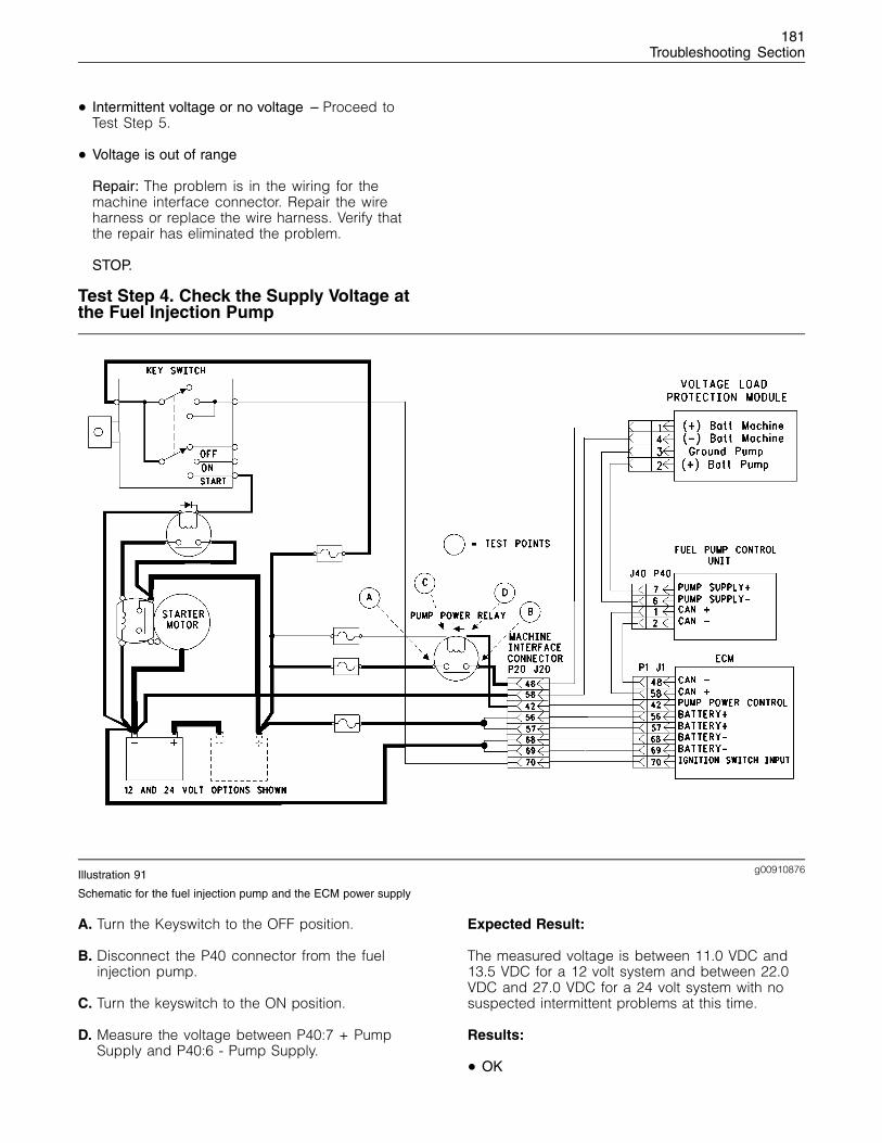
181Troubleshooting Section
• Intermittent voltage or no voltage – Proceed toTest Step 5.
• Voltage is out of range
Repair: The problem is in the wiring for themachine interface connector. Repair the wireharness or replace the wire harness. Verify thatthe repair has eliminated the problem.
STOP.
Test Step 4. Check the Supply Voltage atthe Fuel Injection Pump
g00910876Illustration 91
Schematic for the fuel injection pump and the ECM power supply
A. Turn the Keyswitch to the OFF position.
B. Disconnect the P40 connector from the fuelinjection pump.
C. Turn the keyswitch to the ON position.
D. Measure the voltage between P40:7 + PumpSupply and P40:6 - Pump Supply.
Expected Result:
The measured voltage is between 11.0 VDC and13.5 VDC for a 12 volt system and between 22.0VDC and 27.0 VDC for a 24 volt system with nosuspected intermittent problems at this time.
Results:
• OK
182Troubleshooting Section
Repair: The wiring harness and the voltagesupply to the fuel injection pump are correct.The problem is in the fuel injection pump orthere is a communication problem betweenthe ECM and the fuel injection pump. Refer toTroubleshooting, “CAN Data Link Circuit - Test”.If the CAN Data Link is correct the problem isin the fuel injection pump. Contact the PerkinsTechnical Support Centre in order to check if thesoftware version is correct. Also check that therehave been no software updates. If the problemstill exists contact the Perkins Technical SupportCentre in order to change the fuel injectionpump. The warranty of the fuel injection pumpwill be affected if the pump is replaced withoutprior consultation. Replace the fuel injectionpump. Refer to Disassembly and Assembly, “FuelInjection Pump Remove and Install”. Check foractive diagnostic codes.
STOP.
• Intermittent voltage or the voltage is out of range
Repair: There is a problem in the wiring betweenJ20 connector and J40 connector. Repair thewiring or replace the wiring. Verify that the repairhas eliminated the problem.
STOP.
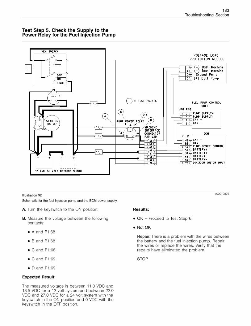
183Troubleshooting Section
Test Step 5. Check the Supply to thePower Relay for the Fuel Injection Pump
g00910876Illustration 92
Schematic for the fuel injection pump and the ECM power supply
A. Turn the keyswitch to the ON position.
B. Measure the voltage between the followingcontacts:
• A and P1:68
• B and P1:68
• C and P1:68
• C and P1:69
• D and P1:69
Expected Result:
The measured voltage is between 11.0 VDC and13.5 VDC for a 12 volt system and between 22.0VDC and 27.0 VDC for a 24 volt system with thekeyswitch in the ON position and 0 VDC with thekeyswitch in the OFF position.
Results:
• OK – Proceed to Test Step 6.
• Not OK
Repair: There is a problem with the wires betweenthe battery and the fuel injection pump. Repairthe wires or replace the wires. Verify that therepairs have eliminated the problem.
STOP.
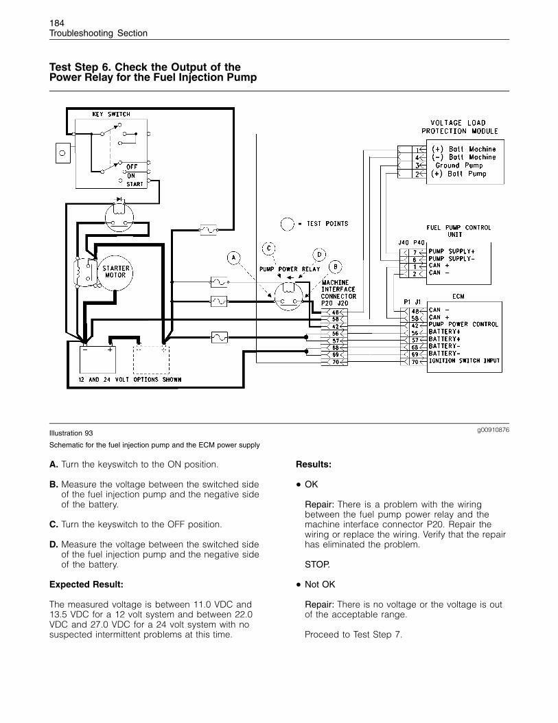
184Troubleshooting Section
Test Step 6. Check the Output of thePower Relay for the Fuel Injection Pump
g00910876Illustration 93
Schematic for the fuel injection pump and the ECM power supply
A. Turn the keyswitch to the ON position.
B. Measure the voltage between the switched sideof the fuel injection pump and the negative sideof the battery.
C. Turn the keyswitch to the OFF position.
D. Measure the voltage between the switched sideof the fuel injection pump and the negative sideof the battery.
Expected Result:
The measured voltage is between 11.0 VDC and13.5 VDC for a 12 volt system and between 22.0VDC and 27.0 VDC for a 24 volt system with nosuspected intermittent problems at this time.
Results:
• OK
Repair: There is a problem with the wiringbetween the fuel pump power relay and themachine interface connector P20. Repair thewiring or replace the wiring. Verify that the repairhas eliminated the problem.
STOP.
• Not OK
Repair: There is no voltage or the voltage is outof the acceptable range.
Proceed to Test Step 7.
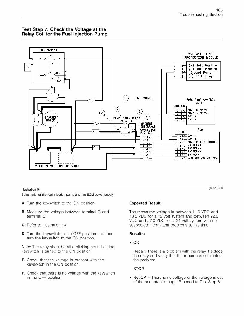
185Troubleshooting Section
Test Step 7. Check the Voltage at theRelay Coil for the Fuel Injection Pump
g00910876Illustration 94
Schematic for the fuel injection pump and the ECM power supply
A. Turn the keyswitch to the ON position.
B. Measure the voltage between terminal C andterminal D.
C. Refer to illustration 94.
D. Turn the keyswitch to the OFF position and thenturn the keyswitch to the ON position.
Note: The relay should emit a clicking sound as thekeyswitch is turned to the ON position.
E. Check that the voltage is present with thekeyswitch in the ON position.
F. Check that there is no voltage with the keyswitchin the OFF position.
Expected Result:
The measured voltage is between 11.0 VDC and13.5 VDC for a 12 volt system and between 22.0VDC and 27.0 VDC for a 24 volt system with nosuspected intermittent problems at this time.
Results:
• OK
Repair: There is a problem with the relay. Replacethe relay and verify that the repair has eliminatedthe problem.
STOP.
• Not OK – There is no voltage or the voltage is outof the acceptable range. Proceed to Test Step 8.
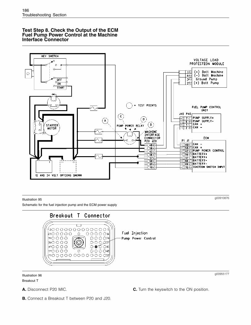
186Troubleshooting Section
Test Step 8. Check the Output of the ECMFuel Pump Power Control at the MachineInterface Connector
g00910876Illustration 95
Schematic for the fuel injection pump and the ECM power supply
g00955177Illustration 96
Breakout T
A. Disconnect P20 MIC.
B. Connect a Breakout T between P20 and J20.
C. Turn the keyswitch to the ON position.
187Troubleshooting Section
D. Measure the voltage between the positive side ofthe fuel injection pump Test Point C power relaycoil and terminal 42 of the Breakout T.
E. Refer to illustration 95 and illustration 96.
Expected Result:
The measured voltage is between 11.0 VDC and13.5 VDC for a 12 volt system and between 22.0VDC and 27.0 VDC for a 24 volt system with nosuspected intermittent problems at this time.
Results:
• OK
Repair: There is a problem with the wires betweenthe relay and the P20 MIC.
Repair the wiring or replace the wiring. Verify thatthe repair has eliminated the problem.
STOP.
• Not OK – Proceed to Test Step 9.
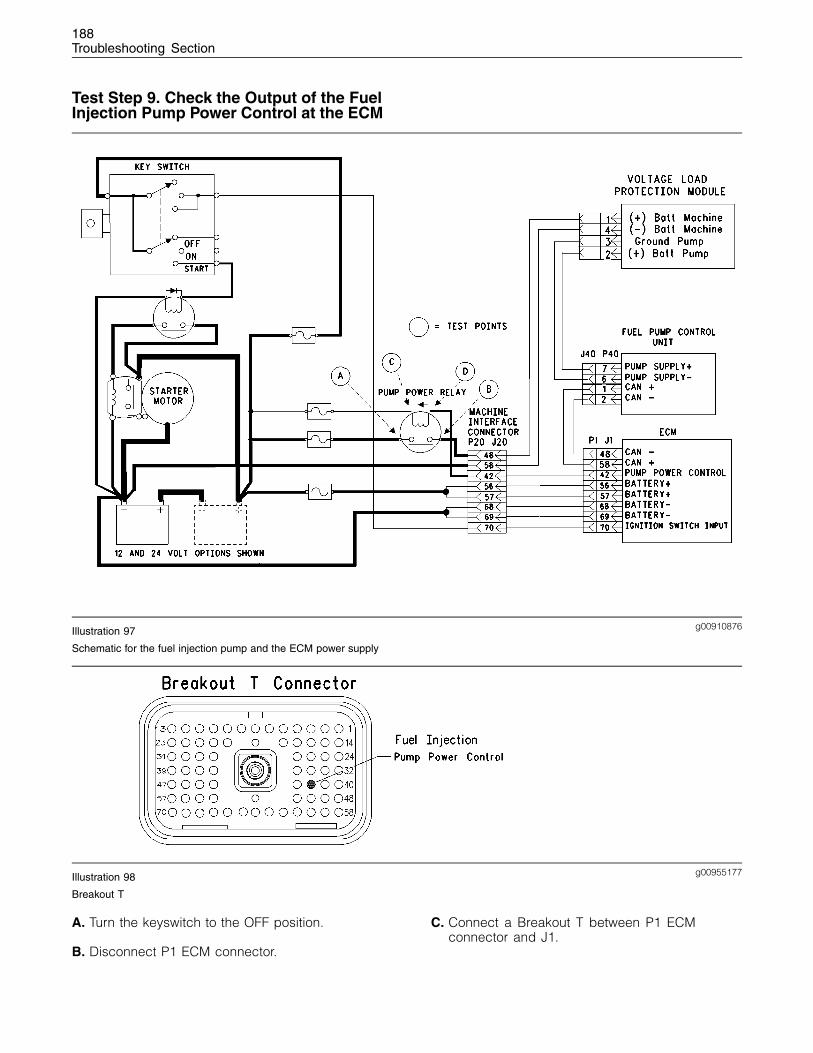
188Troubleshooting Section
Test Step 9. Check the Output of the FuelInjection Pump Power Control at the ECM
g00910876Illustration 97
Schematic for the fuel injection pump and the ECM power supply
g00955177Illustration 98
Breakout T
A. Turn the keyswitch to the OFF position.
B. Disconnect P1 ECM connector.
C. Connect a Breakout T between P1 ECMconnector and J1.
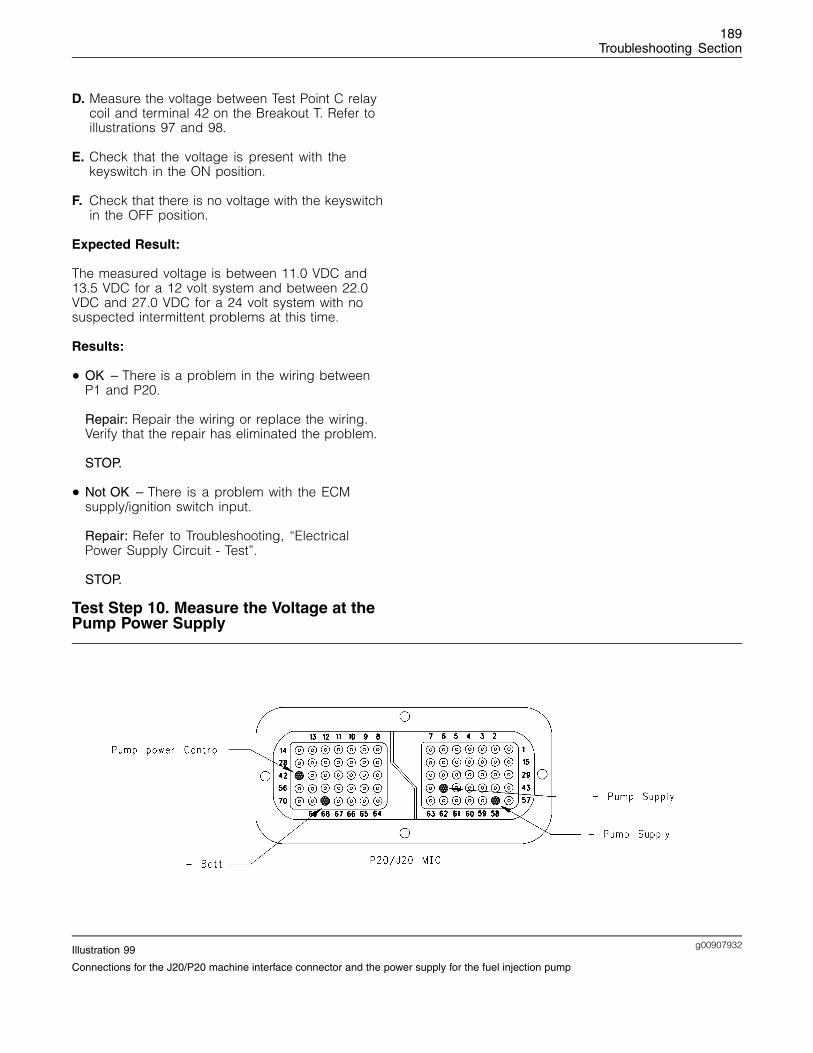
189Troubleshooting Section
D. Measure the voltage between Test Point C relaycoil and terminal 42 on the Breakout T. Refer toillustrations 97 and 98.
E. Check that the voltage is present with thekeyswitch in the ON position.
F. Check that there is no voltage with the keyswitchin the OFF position.
Expected Result:
The measured voltage is between 11.0 VDC and13.5 VDC for a 12 volt system and between 22.0VDC and 27.0 VDC for a 24 volt system with nosuspected intermittent problems at this time.
Results:
• OK – There is a problem in the wiring betweenP1 and P20.
Repair: Repair the wiring or replace the wiring.Verify that the repair has eliminated the problem.
STOP.
• Not OK – There is a problem with the ECMsupply/ignition switch input.
Repair: Refer to Troubleshooting, “ElectricalPower Supply Circuit - Test”.
STOP.
Test Step 10. Measure the Voltage at thePump Power Supply
g00907932Illustration 99
Connections for the J20/P20 machine interface connector and the power supply for the fuel injection pump
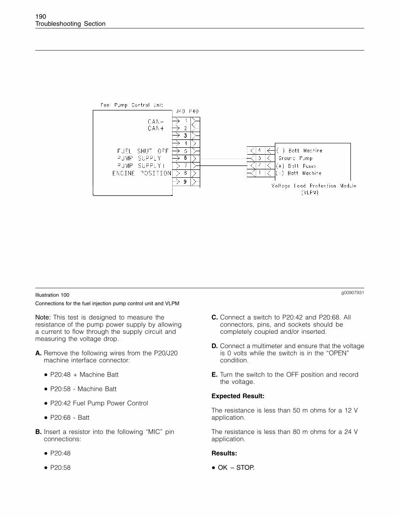
190Troubleshooting Section
g00907931Illustration 100
Connections for the fuel injection pump control unit and VLPM
Note: This test is designed to measure theresistance of the pump power supply by allowinga current to flow through the supply circuit andmeasuring the voltage drop.
A. Remove the following wires from the P20/J20machine interface connector:
• P20:48 + Machine Batt
• P20:58 - Machine Batt
• P20:42 Fuel Pump Power Control
• P20:68 - Batt
B. Insert a resistor into the following “MIC” pinconnections:
• P20:48
• P20:58
C. Connect a switch to P20:42 and P20:68. Allconnectors, pins, and sockets should becompletely coupled and/or inserted.
D. Connect a multimeter and ensure that the voltageis 0 volts while the switch is in the “OPEN”condition.
E. Turn the switch to the OFF position and recordthe voltage.
Expected Result:
The resistance is less than 50 m ohms for a 12 Vapplication.
The resistance is less than 80 m ohms for a 24 Vapplication.
Results:
• OK – STOP.
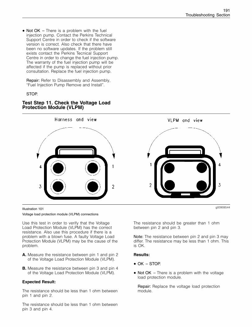
191Troubleshooting Section
• Not OK – There is a problem with the fuelinjection pump. Contact the Perkins TechnicalSupport Centre in order to check if the softwareversion is correct. Also check that there havebeen no software updates. If the problem stillexists contact the Perkins Tecnical SupportCentre in order to change the fuel injection pump.The warranty of the fuel injection pump will beaffected if the pump is replaced without priorconsultation. Replace the fuel injection pump.
Repair: Refer to Disassembly and Assembly,“Fuel Injection Pump Remove and Install”.
STOP.
Test Step 11. Check the Voltage LoadProtection Module (VLPM)
g00908544Illustration 101
Voltage load protection module (VLPM) connections
Use this test in order to verify that the VoltageLoad Protection Module (VLPM) has the correctresistance. Also use this procedure if there is aproblem with a blown fuse. A faulty Voltage LoadProtection Module (VLPM) may be the cause of theproblem.
A. Measure the resistance between pin 1 and pin 2of the Voltage Load Protection Module (VLPM).
B. Measure the resistance between pin 3 and pin 4of the Voltage Load Protection Module (VLPM).
Expected Result:
The resistance should be less than 1 ohm betweenpin 1 and pin 2.
The resistance should be less than 1 ohm betweenpin 3 and pin 4.
The resistance should be greater than 1 ohmbetween pin 2 and pin 3.
Note: The resistance between pin 2 and pin 3 maydiffer. The resistance may be less than 1 ohm. Thisis OK.
Results:
• OK – STOP.
• Not OK – There is a problem with the voltageload protection module.
Repair: Replace the voltage load protectionmodule.
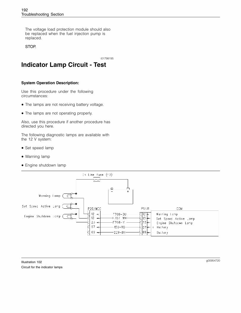
192Troubleshooting Section
The voltage load protection module should alsobe replaced when the fuel injection pump isreplaced.
STOP.
i01798195
Indicator Lamp Circuit - Test
System Operation Description:
Use this procedure under the followingcircumstances:
• The lamps are not receiving battery voltage.
• The lamps are not operating properly.
Also, use this procedure if another procedure hasdirected you here.
The following diagnostic lamps are available withthe 12 V system:
• Set speed lamp
• Warning lamp
• Engine shutdown lamp
g00954720Illustration 102
Circuit for the indicator lamps
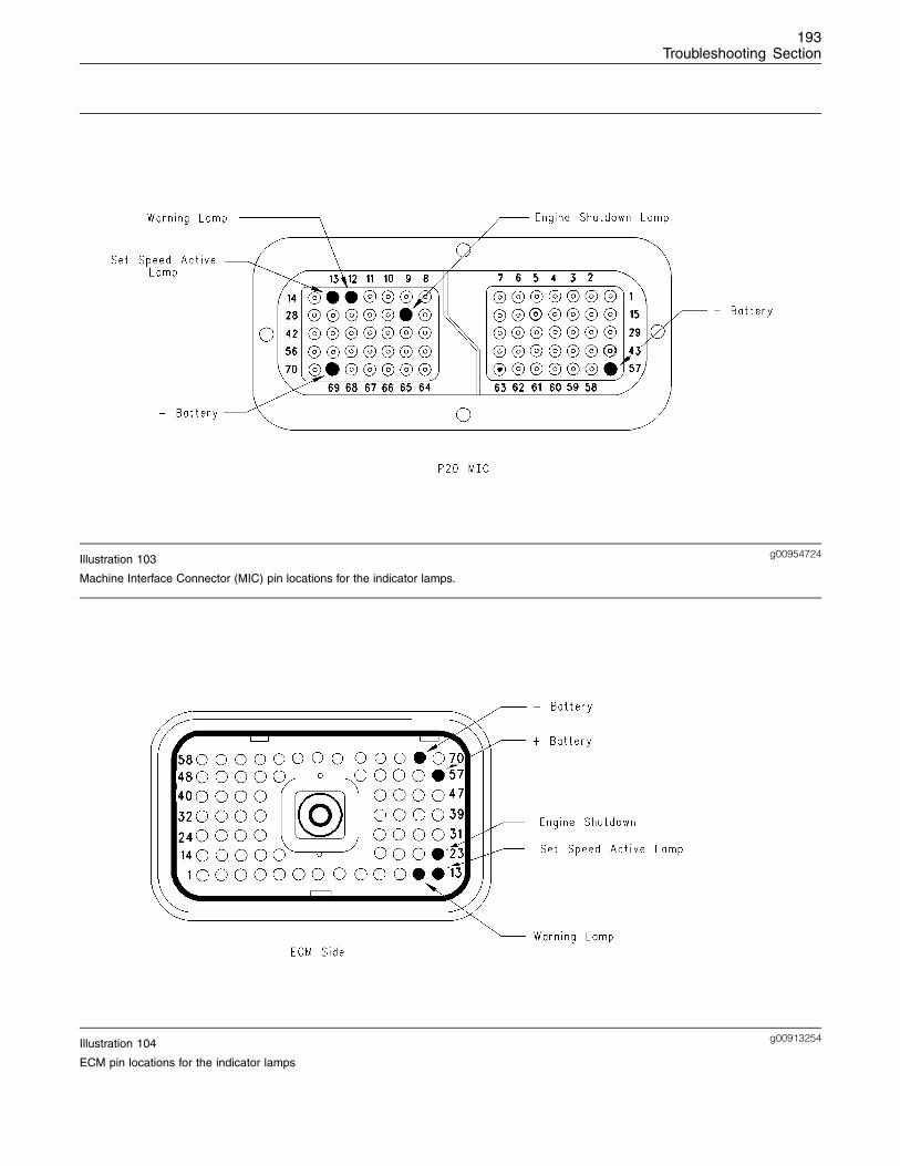
193Troubleshooting Section
g00954724Illustration 103
Machine Interface Connector (MIC) pin locations for the indicator lamps.
g00913254Illustration 104
ECM pin locations for the indicator lamps
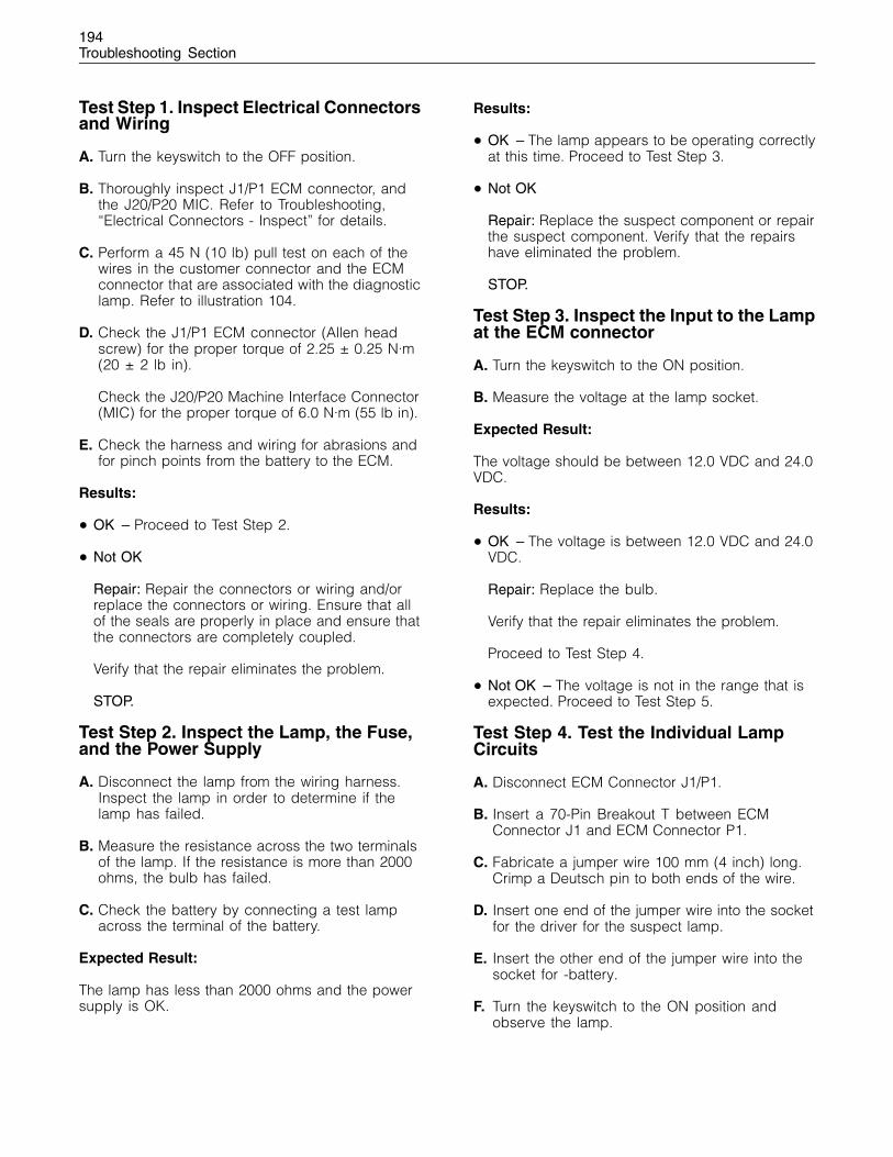
194Troubleshooting Section
Test Step 1. Inspect Electrical Connectorsand Wiring
A. Turn the keyswitch to the OFF position.
B. Thoroughly inspect J1/P1 ECM connector, andthe J20/P20 MIC. Refer to Troubleshooting,“Electrical Connectors - Inspect” for details.
C. Perform a 45 N (10 lb) pull test on each of thewires in the customer connector and the ECMconnector that are associated with the diagnosticlamp. Refer to illustration 104.
D. Check the J1/P1 ECM connector (Allen headscrew) for the proper torque of 2.25 ± 0.25 N·m(20 ± 2 lb in).
Check the J20/P20 Machine Interface Connector(MIC) for the proper torque of 6.0 N·m (55 lb in).
E. Check the harness and wiring for abrasions andfor pinch points from the battery to the ECM.
Results:
• OK – Proceed to Test Step 2.
• Not OK
Repair: Repair the connectors or wiring and/orreplace the connectors or wiring. Ensure that allof the seals are properly in place and ensure thatthe connectors are completely coupled.
Verify that the repair eliminates the problem.
STOP.
Test Step 2. Inspect the Lamp, the Fuse,and the Power Supply
A. Disconnect the lamp from the wiring harness.Inspect the lamp in order to determine if thelamp has failed.
B. Measure the resistance across the two terminalsof the lamp. If the resistance is more than 2000ohms, the bulb has failed.
C. Check the battery by connecting a test lampacross the terminal of the battery.
Expected Result:
The lamp has less than 2000 ohms and the powersupply is OK.
Results:
• OK – The lamp appears to be operating correctlyat this time. Proceed to Test Step 3.
• Not OK
Repair: Replace the suspect component or repairthe suspect component. Verify that the repairshave eliminated the problem.
STOP.
Test Step 3. Inspect the Input to the Lampat the ECM connector
A. Turn the keyswitch to the ON position.
B. Measure the voltage at the lamp socket.
Expected Result:
The voltage should be between 12.0 VDC and 24.0VDC.
Results:
• OK – The voltage is between 12.0 VDC and 24.0VDC.
Repair: Replace the bulb.
Verify that the repair eliminates the problem.
Proceed to Test Step 4.
• Not OK – The voltage is not in the range that isexpected. Proceed to Test Step 5.
Test Step 4. Test the Individual LampCircuits
A. Disconnect ECM Connector J1/P1.
B. Insert a 70-Pin Breakout T between ECMConnector J1 and ECM Connector P1.
C. Fabricate a jumper wire 100 mm (4 inch) long.Crimp a Deutsch pin to both ends of the wire.
D. Insert one end of the jumper wire into the socketfor the driver for the suspect lamp.
E. Insert the other end of the jumper wire into thesocket for -battery.
F. Turn the keyswitch to the ON position andobserve the lamp.
195Troubleshooting Section
Expected Result:
The diagnostic lamp turns on while the jumper isconnected to both sockets. Also, the diagnosticlamp turns off when the jumper is removed fromone of the sockets.
Results:
• OK – The circuit for the diagnostic lamp isfunctioning properly. Proceed to Test Step 5.
• Not OK – The lamp did not turn on. The lampcircuit is not functioning properly. There is aproblem in the wiring between the lamp and theECM.
Repair: Repair the lamp circuit.
Verify that the repair eliminated the problem.
STOP.
Test Step 5. Check the Voltage at theECM.
A. Disconnect ECM Connector J1/P1.
B. Insert a 70-Pin Breakout T between ECMConnector J1 and ECM Connector P1.
C. Connect a voltage test lamp between J1:57 +battery and J1:69 Neg. battery.
D. Connect a voltage test lamp to J1:57 + batteryand J1:23 engine shutdown lamp.
Expected Result:
The lamp should illuminate.
Results:
• OK – The ECM is operating correctly. There isa problem in the wiring or the lamp. Repair thewiring or the lamp, as required. Verify that therepair eliminates the problem. STOP.
• Not OK – Temporarily connect a test ECM. Thetest ECM must be programmed with the sameparameters as the suspect ECM. Check theoperation of the diagnostic lamp when the testECM is installed. If the problem is resolved withthe test ECM, then reconnect the suspect ECM. Ifthe problem returns with the suspect ECM, thenreplace the suspect ECM. STOP.
i01798876
Mode Selection Circuit - Test
System Operation Description:
Use this procedure under the followingcircumstances:
• Check if the switch can be switched to ground.
• Check if the mode selector switch operatescorrectly.
Also, use this procedure if another procedure hasdirected you here.
The mode selector switch provides the operatorwith the ability to select a maximum of eightdifferent modes of operation. Different modes ofoperation can be used in a particular situation bygiving the operator a means to select the mostefficient method of completing the required work.The following mode selections are available:
• Economy Mode
• Machine Mode
• Power Take-off Mode
Three digital switch inputs can be used in order toselect the most efficient mode. With three switches,a maximum of eight modes can be applied by useof a multiple position switch. With two switches,four modes can be selected. With one switch, twomodes can be selected. Each mode has a singlefuel limit map, a rated speed, and a matched fueldelivery. Each mode also has specific droop valuefor throttle 1 and throttle 2.
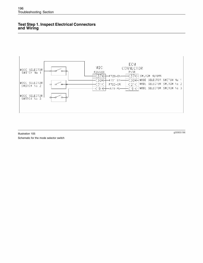
196Troubleshooting Section
Test Step 1. Inspect Electrical Connectorsand Wiring
g00955196Illustration 105
Schematic for the mode selector switch
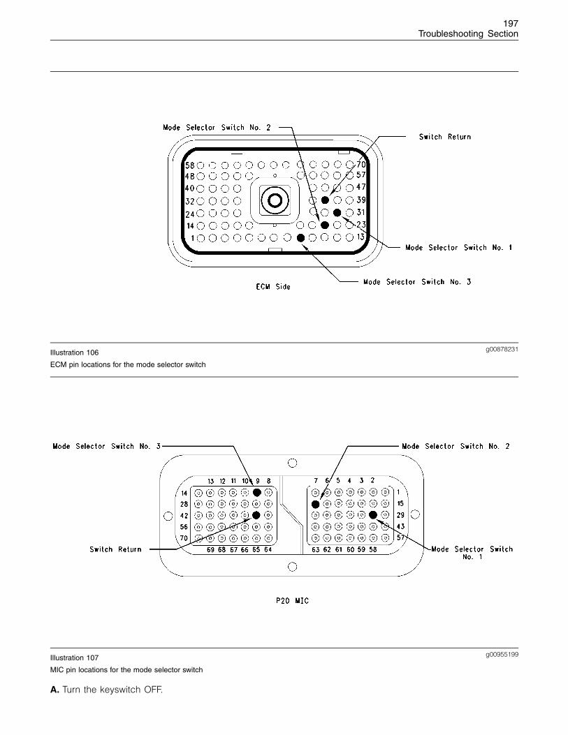
197Troubleshooting Section
g00878231Illustration 106
ECM pin locations for the mode selector switch
g00955199Illustration 107
MIC pin locations for the mode selector switch
A. Turn the keyswitch OFF.
198Troubleshooting Section
B. Thoroughly inspect J1/P1 ECM connector, andthe J20/P20 MIC. Refer to Troubleshooting,“Electrical Connectors - Inspect” for details.
C. Perform a 45 N (10 lb) pull test on each ofthe wires in the P1/J1 ECM connector and theP20/J20 MIC that are associated with the ModeSelector Switch: Refer to illustration 106 and 107.
D. Check the J1/P1 ECM connector (Allen headscrew) for the proper torque of 2.25 ± 0.25 N·m(20 ± 2 lb in).
Check the J20/P20 Machine Interface Connector(MIC) for the proper torque of 6.0 N·m (55 lb in).
E. Check the harness and wiring for abrasions andfor pinch points from the battery to the ECM.
Results:
• OK – Proceed to Test Step 2.
• Not OK
Repair: Repair the connectors or wiring and/orreplace the connectors or wiring. Ensure that allof the seals are properly in place and ensure thatthe connectors are completely coupled.
Verify that the repair eliminates the problem.
STOP.
• – If the problem has not been eliminatedproceed to Test Step 2.
Test Step 2. Check the Status of the ModeSelector Switch
A. Turn the keyswitch to the OFF position.
B. Connect the electronic service tool to thediagnostic connector.
C. Turn the keyswitch to the ON position.
D. Monitor the status screen on the electronicservice tool. Cycle the mode switch to the ONposition and to the OFF position.
Expected Result:
The switch status should change as you cycle themode switches. When the switch is in the OFFposition the switch has an open condition. Whenthe switch is in the ON position the switch has aclosed condition.
Results:
• OK
Repair: Verify that the status of the switchchanges as the switch is cycled.
STOP.
• Not OK – There is a problem with the circuit forthe mode selector switch. Proceed to Test Step 3.
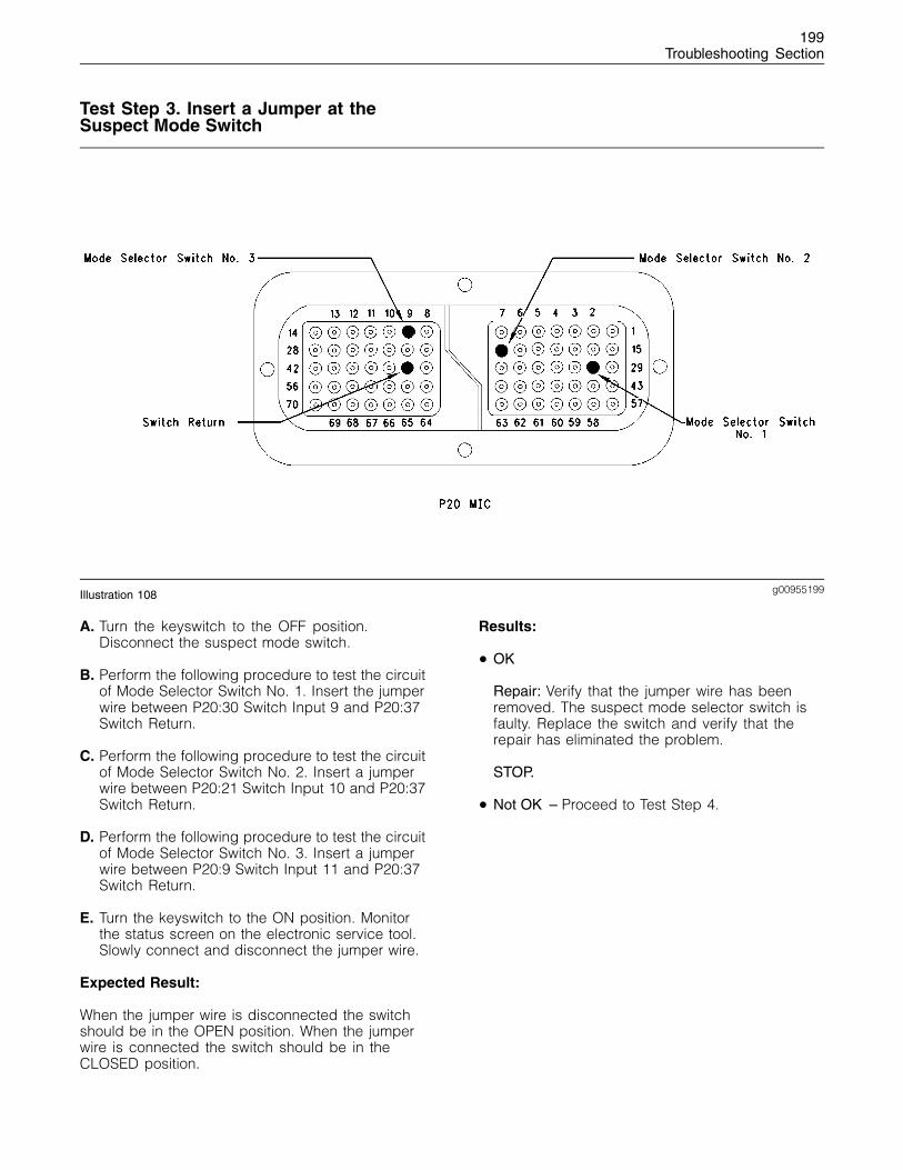
199Troubleshooting Section
Test Step 3. Insert a Jumper at theSuspect Mode Switch
g00955199Illustration 108
A. Turn the keyswitch to the OFF position.Disconnect the suspect mode switch.
B. Perform the following procedure to test the circuitof Mode Selector Switch No. 1. Insert the jumperwire between P20:30 Switch Input 9 and P20:37Switch Return.
C. Perform the following procedure to test the circuitof Mode Selector Switch No. 2. Insert a jumperwire between P20:21 Switch Input 10 and P20:37Switch Return.
D. Perform the following procedure to test the circuitof Mode Selector Switch No. 3. Insert a jumperwire between P20:9 Switch Input 11 and P20:37Switch Return.
E. Turn the keyswitch to the ON position. Monitorthe status screen on the electronic service tool.Slowly connect and disconnect the jumper wire.
Expected Result:
When the jumper wire is disconnected the switchshould be in the OPEN position. When the jumperwire is connected the switch should be in theCLOSED position.
Results:
• OK
Repair: Verify that the jumper wire has beenremoved. The suspect mode selector switch isfaulty. Replace the switch and verify that therepair has eliminated the problem.
STOP.
• Not OK – Proceed to Test Step 4.
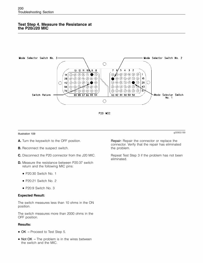
200Troubleshooting Section
Test Step 4. Measure the Resistance atthe P20/J20 MIC
g00955199Illustration 109
A. Turn the keyswitch to the OFF position.
B. Reconnect the suspect switch.
C. Disconnect the P20 connector from the J20 MIC.
D. Measure the resistance between P20:37 switchreturn and the following MIC pins:
• P20:30 Switch No. 1
• P20:21 Switch No. 2
• P20:9 Switch No. 3
Expected Result:
The switch measures less than 10 ohms in the ONposition.
The switch measures more than 2000 ohms in theOFF position.
Results:
• OK – Proceed to Test Step 5.
• Not OK – The problem is in the wires betweenthe switch and the MIC.
Repair: Repair the connector or replace theconnector. Verify that the repair has eliminatedthe problem.
Repeat Test Step 3 if the problem has not beeneliminated.
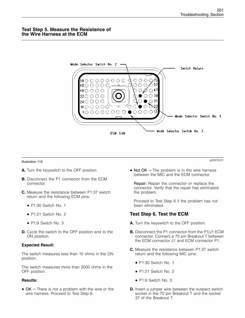
201Troubleshooting Section
Test Step 5. Measure the Resistance ofthe Wire Harness at the ECM
g00878231Illustration 110
A. Turn the keyswitch to the OFF position.
B. Disconnect the P1 connector from the ECMconnector.
C. Measure the resistance between P1:37 switchreturn and the following ECM pins:
• P1:30 Switch No. 1
• P1:21 Switch No. 2
• P1:9 Switch No. 3
D. Cycle the switch to the OFF position and to theON position.
Expected Result:
The switch measures less than 10 ohms in the ONposition.
The switch measures more than 2000 ohms in theOFF position.
Results:
• OK – There is not a problem with the wire or thewire harness. Proceed to Test Step 6.
• Not OK – The problem is in the wire harnessbetween the MIC and the ECM connector.
Repair: Repair the connector or replace theconnector. Verify that the repair has eliminatedthe problem.
Proceed to Test Step 6 if the problem has notbeen eliminated.
Test Step 6. Test the ECM
A. Turn the keyswitch to the OFF position.
B. Disconnect the P1 connector from the P1/J1 ECMconnector. Connect a 70 pin Breakout T betweenthe ECM connector J1 and ECM connector P1.
C. Measure the resistance between P1:37 switchreturn and the following MIC pins:
• P1:30 Switch No. 1
• P1:21 Switch No. 2
• P1:9 Switch No. 3
D. Insert a jumper wire between the suspect switchsocket in the 70 pin Breakout T and the socket37 of the Breakout T.
202Troubleshooting Section
E. Turn the keyswitch to the ON position. Monitorthe status screen on the electronic service tool.Slowly connect and disconnect the jumper wirefrom the 70 pin Breakout T.
Expected Result:
With the switch in the OFF position, the switch willhave an open condition.
With the switch in the ON position, the switch willhave a closed condition.
Results:
• OK – The ECM is operating correctly. STOP.
• Not OK
Repair: If the problem has not been eliminatedtemporarily connect a test ECM. Remove alljumpers and replace all connectors. The test ECMshould be programmed with the correct software.All parameters should be set to the same value ofthe suspect ECM.
If the problem is eliminated with the test ECM,reconnect the suspect ECM. If the problem returnswith the suspect ECM, replace the suspect ECM.
Verify that the repair has eliminated the problem.
STOP.
i01798877
Set Speed Circuit - Test
System Operation Description:
Use this procedure under the followingcircumstances:
• Verify that the set speed switch receives theproper supply voltage.
• Check that the set speed switches operatecorrectly.
Also, use this procedure if another procedure hasdirected you here.
The set speed switch provides the operator with theability to select the desired engine speed. Enginespeed will decrease with increasing load. The setspeed control can be used to control the enginespeed. Also for certain engine applications, the setspeed control can be used to control the vehiclespeed.
The 1104 and 1106 engines have the followingoptions of set speed control:
• Single speed
• Dual Speed
• No speed (no set speed control)
The set speed switches are listed below:
• P1:28 Set Speed Control ON or OFF
• P1:11 Set Speed Continue or Accelerate
• P1:19 Set Speed 1 or Set Speed 2
• P1:20 Set Speed Set or Decelerate
• P1:29 Clutch or Brake Automatic Disengage
Warning lamps are used to indicate the status ofthe set speed control.
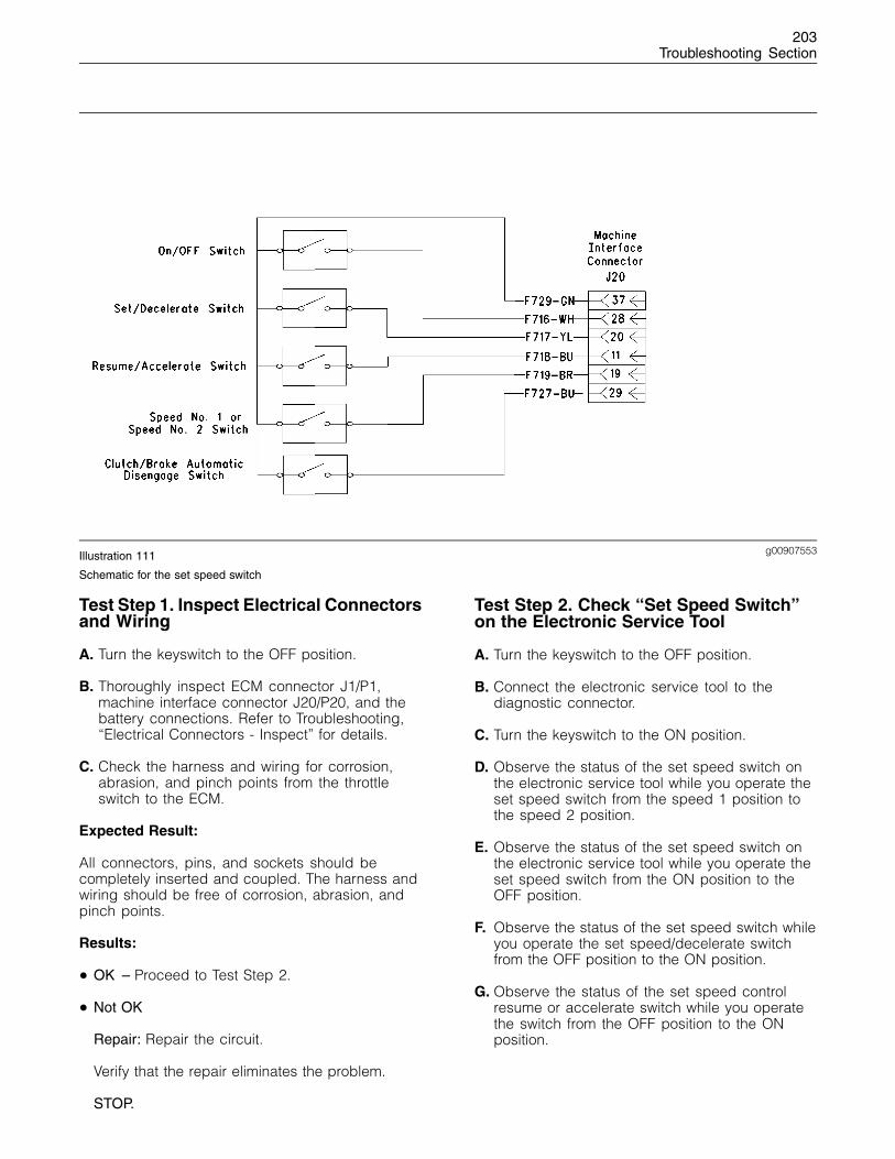
203Troubleshooting Section
g00907553Illustration 111
Schematic for the set speed switch
Test Step 1. Inspect Electrical Connectorsand Wiring
A. Turn the keyswitch to the OFF position.
B. Thoroughly inspect ECM connector J1/P1,machine interface connector J20/P20, and thebattery connections. Refer to Troubleshooting,“Electrical Connectors - Inspect” for details.
C. Check the harness and wiring for corrosion,abrasion, and pinch points from the throttleswitch to the ECM.
Expected Result:
All connectors, pins, and sockets should becompletely inserted and coupled. The harness andwiring should be free of corrosion, abrasion, andpinch points.
Results:
• OK – Proceed to Test Step 2.
• Not OK
Repair: Repair the circuit.
Verify that the repair eliminates the problem.
STOP.
Test Step 2. Check “Set Speed Switch”on the Electronic Service Tool
A. Turn the keyswitch to the OFF position.
B. Connect the electronic service tool to thediagnostic connector.
C. Turn the keyswitch to the ON position.
D. Observe the status of the set speed switch onthe electronic service tool while you operate theset speed switch from the speed 1 position tothe speed 2 position.
E. Observe the status of the set speed switch onthe electronic service tool while you operate theset speed switch from the ON position to theOFF position.
F. Observe the status of the set speed switch whileyou operate the set speed/decelerate switchfrom the OFF position to the ON position.
G. Observe the status of the set speed controlresume or accelerate switch while you operatethe switch from the OFF position to the ONposition.
204Troubleshooting Section
Expected Result:
Result 1 the electronic service tool will show thatthe speed 1 status is selected with the set speedswitch in the OFF position.
The electronic service tool will show that the speed2 status is selected with the set speed switch inthe ON position.
Note: If the engine application has two enginespeed controls ensure that speed 1 is selected.
Result 2 The electronic service tool will show thatthe set speed control switch is in the “OPEN”condition when the set speed control switch is inthe OFF position.
The electronic service tool will show that the setspeed switch is in the “CLOSED” position when theset speed switch is in the ON position.
Note: The set speed control lamp should be OFFwhen the set speed control switch is in the OFFposition. The set speed control lamp should beflashing when the set speed control switch is in theON position.
Result 3 When the set speed switch is in the OFFposition the set speed/decelerate switch should bein the OPEN position.
When the set speed/decelerate switch is in the ONposition the set speed/decelerate switch should bein the CLOSED position.
Result 4 When the set speed control resume oraccelerate switch is in the OFF position the displayscreen should show an OPEN condition.
When the set speed control resume or accelerateswitch is in the ON position the display screenshould show a CLOSED condition.
Note: The set speed control lamp 1 should changefrom flashing to ON when the set speed resume oraccelerate switch is CLOSED.
Results:
• OK – The set speed control switches operatecorrectly. STOP.
• Not OK – Proceed to Test Step 3.
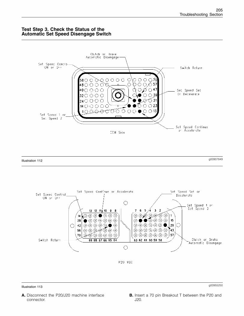
205Troubleshooting Section
Test Step 3. Check the Status of theAutomatic Set Speed Disengage Switch
g00907849Illustration 112
g00955250Illustration 113
A. Disconnect the P20/J20 machine interfaceconnector.
B. Insert a 70 pin Breakout T between the P20 andJ20.
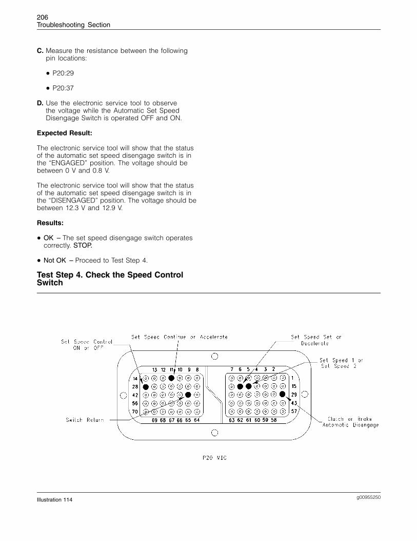
206Troubleshooting Section
C. Measure the resistance between the followingpin locations:
• P20:29
• P20:37
D. Use the electronic service tool to observethe voltage while the Automatic Set SpeedDisengage Switch is operated OFF and ON.
Expected Result:
The electronic service tool will show that the statusof the automatic set speed disengage switch is inthe “ENGAGED” position. The voltage should bebetween 0 V and 0.8 V.
The electronic service tool will show that the statusof the automatic set speed disengage switch is inthe “DISENGAGED” position. The voltage should bebetween 12.3 V and 12.9 V.
Results:
• OK – The set speed disengage switch operatescorrectly. STOP.
• Not OK – Proceed to Test Step 4.
Test Step 4. Check the Speed ControlSwitch
g00955250Illustration 114
207Troubleshooting Section
A. Turn the keyswitch to the OFF position.
B. Remove the two wires from the P20:11 set speedcontrol continue or accelerate switch. Use asuitable jumper in order to join the two wirestogether.
C. Turn the keyswitch to the ON position.
D. Monitor the status screen on the electronicservice tool. Slowly connect and disconnect thejumper from the P20:11.
E. Repeat this procedure for each of the following“machine interface connections”:
• P20:19 Set Speed Control 1 or Speed 2
• P20:20 Set Speed Control Speed or Decelerate
• P20:28 Set Speed Control ON or OFF
• P20:29 Set Speed Control Kickout Switch
• P20:37 Switch Return
Expected Result:
When the jumper wire is connected the status of theset speed switch should be “CLOSED”.
When the jumper wire is disconnected the status ofthe set speed switch should be “OPEN”.
Results:
• OK – The switch is faulty.
Repair: Replace the switch and verify that therepair has eliminated the problem.
STOP.
• Not OK – There is a problem with the wiringharness between the set speed control switchand the engine ECM. Proceed to Test Step 5.
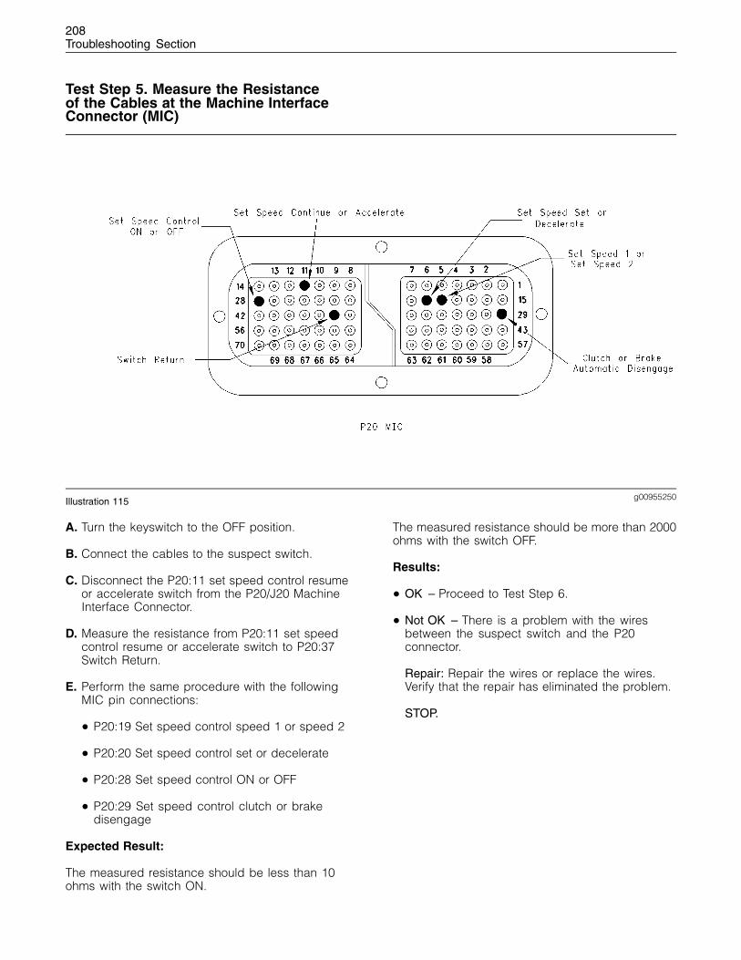
208Troubleshooting Section
Test Step 5. Measure the Resistanceof the Cables at the Machine InterfaceConnector (MIC)
g00955250Illustration 115
A. Turn the keyswitch to the OFF position.
B. Connect the cables to the suspect switch.
C. Disconnect the P20:11 set speed control resumeor accelerate switch from the P20/J20 MachineInterface Connector.
D. Measure the resistance from P20:11 set speedcontrol resume or accelerate switch to P20:37Switch Return.
E. Perform the same procedure with the followingMIC pin connections:
• P20:19 Set speed control speed 1 or speed 2
• P20:20 Set speed control set or decelerate
• P20:28 Set speed control ON or OFF
• P20:29 Set speed control clutch or brakedisengage
Expected Result:
The measured resistance should be less than 10ohms with the switch ON.
The measured resistance should be more than 2000ohms with the switch OFF.
Results:
• OK – Proceed to Test Step 6.
• Not OK – There is a problem with the wiresbetween the suspect switch and the P20connector.
Repair: Repair the wires or replace the wires.Verify that the repair has eliminated the problem.
STOP.
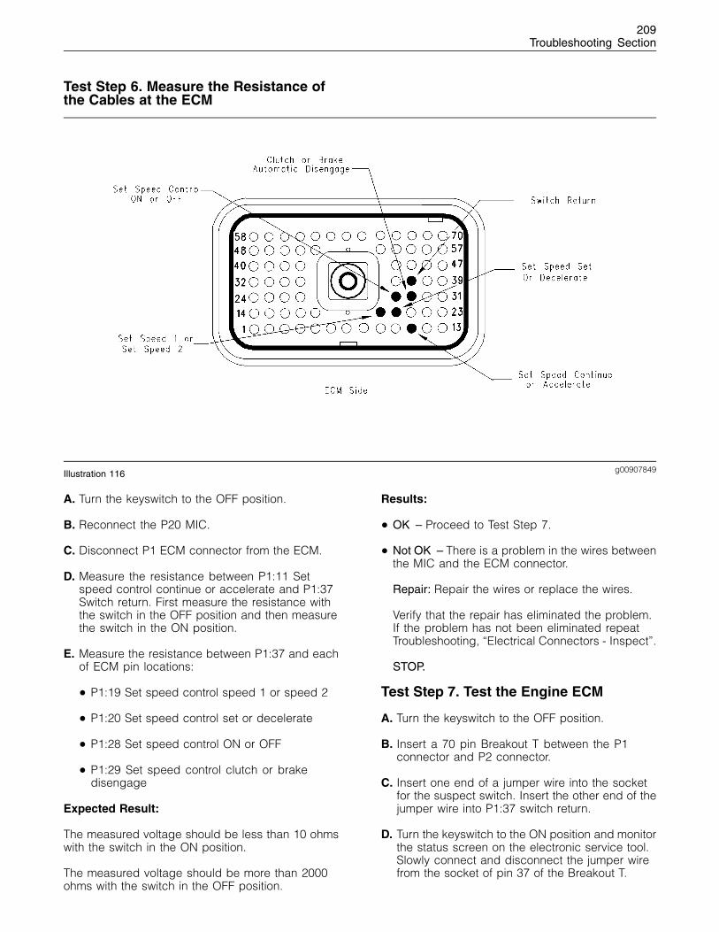
209Troubleshooting Section
Test Step 6. Measure the Resistance ofthe Cables at the ECM
g00907849Illustration 116
A. Turn the keyswitch to the OFF position.
B. Reconnect the P20 MIC.
C. Disconnect P1 ECM connector from the ECM.
D. Measure the resistance between P1:11 Setspeed control continue or accelerate and P1:37Switch return. First measure the resistance withthe switch in the OFF position and then measurethe switch in the ON position.
E. Measure the resistance between P1:37 and eachof ECM pin locations:
• P1:19 Set speed control speed 1 or speed 2
• P1:20 Set speed control set or decelerate
• P1:28 Set speed control ON or OFF
• P1:29 Set speed control clutch or brakedisengage
Expected Result:
The measured voltage should be less than 10 ohmswith the switch in the ON position.
The measured voltage should be more than 2000ohms with the switch in the OFF position.
Results:
• OK – Proceed to Test Step 7.
• Not OK – There is a problem in the wires betweenthe MIC and the ECM connector.
Repair: Repair the wires or replace the wires.
Verify that the repair has eliminated the problem.If the problem has not been eliminated repeatTroubleshooting, “Electrical Connectors - Inspect”.
STOP.
Test Step 7. Test the Engine ECM
A. Turn the keyswitch to the OFF position.
B. Insert a 70 pin Breakout T between the P1connector and P2 connector.
C. Insert one end of a jumper wire into the socketfor the suspect switch. Insert the other end of thejumper wire into P1:37 switch return.
D. Turn the keyswitch to the ON position and monitorthe status screen on the electronic service tool.Slowly connect and disconnect the jumper wirefrom the socket of pin 37 of the Breakout T.
210Troubleshooting Section
E. Repeat this procedure for each of the followingECM pin connections:
• P1:11 Set speed control continue or accelerate
• P1:19 Set speed control speed 1 or speed 2
• P1:20 Set speed control or decelerate
• P1:28 Set speed control ON or OFF
• P1:29 Set speed control clutch or brakedisengage
Expected Result:
The status screen should display an OPEN conditionwith the switch in the OFF position.
The status screen should display a CLOSEDcondition with the switch in the ON position.
Results:
• OK – The ECM is working correctly. STOP.
• Not OK – The ECM is not working properly.
Repair: Temporarily connect a test ECM.
The test ECM should be programmed with thecorrect software. All parameters should be set tothe same values as the suspect ECM.
If the problem is eliminated with the test ECM,reconnect the suspect ECM.
If the problem returns with the suspect ECM, thenthe suspect ECM is faulty.
Replace the suspect ECM.
Verify that the repair has eliminated the problem.
STOP.
i01798878
Throttle Switch Circuit - Test
System Operation Description:
Use this procedure under the followingcircumstances:
• Throttle switch inputs can be switched to ground.
• Verification of the throttle switch
Also, use this procedure if another procedure hasdirected you here.
The throttle switch provides the operator with theability to select the desired engine speed. Enginespeed will decrease with increasing load. Thethrottle switch is a rotary switch with ten positions.
The throttle switch is connected to the four throttleinputs of the Electronic Control Module (ECM). Eachposition generates a specific on/off pattern on thethrottle inputs. A diagnostic code is generated if apattern that does not correspond with any of theswitch positions is detected.
Once a diagnostic code is generated, the ECMignores the throttle input signals and desired enginespeed is set to the last valid pattern that wasrecognized by the ECM. Desired engine speed isset to low idle while the engine is not running.
Voltage at the throttle inputs to the ECM should be11.5 ± 0.5 VDC when the throttle inputs are open.The voltage should be less than 0.5 VDC when thethrottle inputs are closed.
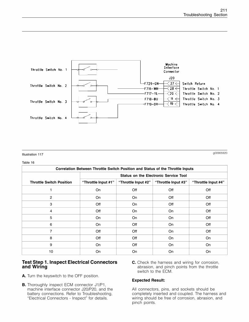
211Troubleshooting Section
g00905920Illustration 117
Table 16
Correlation Between Throttle Switch Position and Status of the Throttle Inputs
Status on the Electronic Service Tool
Throttle Switch Position “Throttle Input #1” “Throttle Input #2” “Throttle Input #3” “Throttle Input #4”
1 On Off Off Off
2 On On Off Off
3 Off On Off Off
4 Off On On Off
5 On On On Off
6 On Off On Off
7 Off Off On Off
8 Off Off On On
9 On Off On On
10 On On On On
Test Step 1. Inspect Electrical Connectorsand Wiring
A. Turn the keyswitch to the OFF position.
B. Thoroughly inspect ECM connector J1/P1,machine interface connector J20/P20, and thebattery connections. Refer to Troubleshooting,“Electrical Connectors - Inspect” for details.
C. Check the harness and wiring for corrosion,abrasion, and pinch points from the throttleswitch to the ECM.
Expected Result:
All connectors, pins, and sockets should becompletely inserted and coupled. The harness andwiring should be free of corrosion, abrasion, andpinch points.
212Troubleshooting Section
Results:
• OK – Proceed to Test Step 2.
• Not OK
Repair: Repair the circuit.
Verify that the repair eliminates the problem.
STOP.
Test Step 2. Check “Throttle SwitchPosition” on the Electronic Service Tool
A. Turn the keyswitch to the OFF position.
B. Connect the electronic service tool to thediagnostic connector.
C. Turn the keyswitch to the ON position.
D. Observe the status of the throttle switch and thethrottle inputs on the electronic service tool whileyou operate the throttle switch in each position.
Expected Result:
The status on the electronic service tool shouldcorrespond with the information in Table 16.
Results:
• OK – The throttle switch is functioning properlyat this time.
Repair: Refer to Troubleshooting, “ElectricalConnectors - Inspect” if the problem isintermittent.
STOP.
• Not OK – Record the suspect input. Proceed toTest Step 3.
Test Step 3. Jumper the Switch Input atthe Suspect Throttle Position Switch
A. Turn the keyswitch to the OFF position.
B. Observe the status of the suspect throttle inputon the electronic service tool.
C. Use a suitable piece of wire to short P/20:37Switch Return to the terminal for the suspectthrottle input.
D. Observe the status of the suspect throttle inputon the electronic service tool.
E. Remove the wire short.
Expected Result:
The status of the suspect throttle input should be“OFF” when the jumper wire is disconnected. Thestatus should be “ON” when the jumper wire isconnected.
Results:
• OK – The harness and the ECM are OK.
Repair: Replace the throttle switch.
Verify that the repair eliminates the problem.
STOP.
• Not OK – Proceed to Test Step 4.
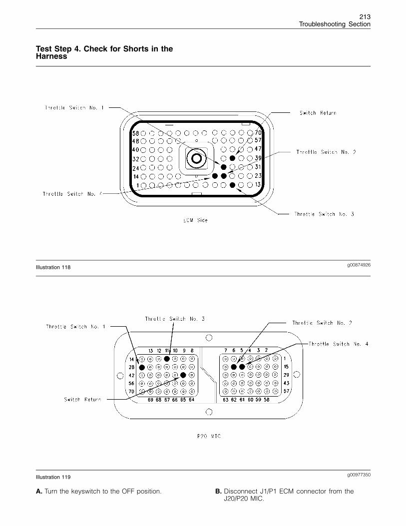
213Troubleshooting Section
Test Step 4. Check for Shorts in theHarness
g00874926Illustration 118
g00977350Illustration 119
A. Turn the keyswitch to the OFF position. B. Disconnect J1/P1 ECM connector from theJ20/P20 MIC.
214Troubleshooting Section
C. Measure the resistance between the P1:37switch return and the terminal for the suspectthrottle input.
D. Measure the resistance between the terminalfor the suspect throttle input and the remainingterminals at the J20/P20 MIC:
• P20:28 Throttle Switch No. 1
• P20:20 Throttle Switch No. 2
• P20:11 Throttle Switch No. 3
• P20:19 Throttle Switch No. 4
Expected Result:
Resistance should be greater than 2,000 ohms foreach reading.
Results:
• OK – Proceed to Test Step 5.
• Not OK – There is a short in the harness betweenthe ECM and the throttle switch.
Repair: Repair the circuit.
Verify that the repair eliminates the problem.
STOP.
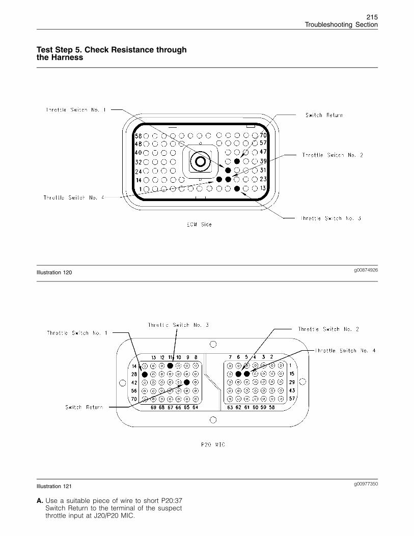
215Troubleshooting Section
Test Step 5. Check Resistance throughthe Harness
g00874926Illustration 120
g00977350Illustration 121
A. Use a suitable piece of wire to short P20:37Switch Return to the terminal of the suspectthrottle input at J20/P20 MIC.
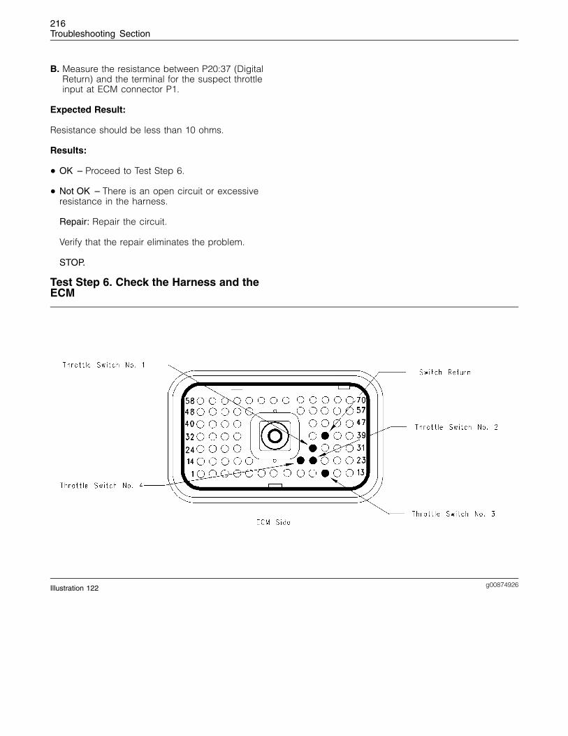
216Troubleshooting Section
B. Measure the resistance between P20:37 (DigitalReturn) and the terminal for the suspect throttleinput at ECM connector P1.
Expected Result:
Resistance should be less than 10 ohms.
Results:
• OK – Proceed to Test Step 6.
• Not OK – There is an open circuit or excessiveresistance in the harness.
Repair: Repair the circuit.
Verify that the repair eliminates the problem.
STOP.
Test Step 6. Check the Harness and theECM
g00874926Illustration 122
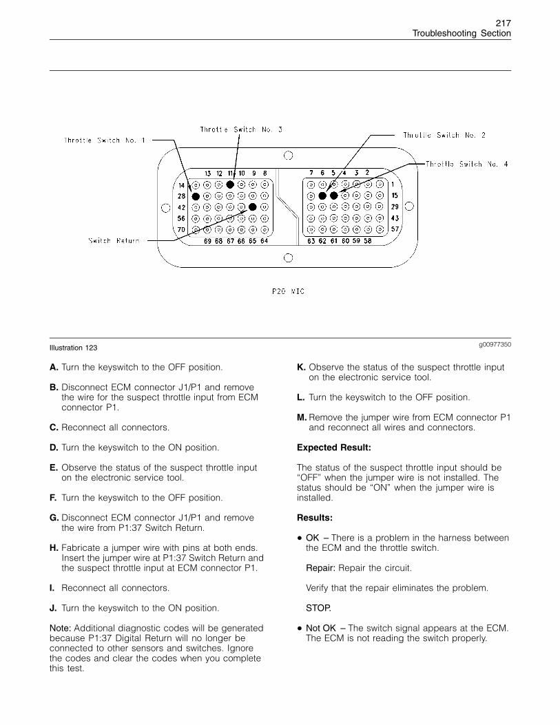
217Troubleshooting Section
g00977350Illustration 123
A. Turn the keyswitch to the OFF position.
B. Disconnect ECM connector J1/P1 and removethe wire for the suspect throttle input from ECMconnector P1.
C. Reconnect all connectors.
D. Turn the keyswitch to the ON position.
E. Observe the status of the suspect throttle inputon the electronic service tool.
F. Turn the keyswitch to the OFF position.
G. Disconnect ECM connector J1/P1 and removethe wire from P1:37 Switch Return.
H. Fabricate a jumper wire with pins at both ends.Insert the jumper wire at P1:37 Switch Return andthe suspect throttle input at ECM connector P1.
I. Reconnect all connectors.
J. Turn the keyswitch to the ON position.
Note: Additional diagnostic codes will be generatedbecause P1:37 Digital Return will no longer beconnected to other sensors and switches. Ignorethe codes and clear the codes when you completethis test.
K. Observe the status of the suspect throttle inputon the electronic service tool.
L. Turn the keyswitch to the OFF position.
M. Remove the jumper wire from ECM connector P1and reconnect all wires and connectors.
Expected Result:
The status of the suspect throttle input should be“OFF” when the jumper wire is not installed. Thestatus should be “ON” when the jumper wire isinstalled.
Results:
• OK – There is a problem in the harness betweenthe ECM and the throttle switch.
Repair: Repair the circuit.
Verify that the repair eliminates the problem.
STOP.
• Not OK – The switch signal appears at the ECM.The ECM is not reading the switch properly.

218Troubleshooting Section
Repair: Verify your results. Replace the ECM.Refer to Troubleshooting, “Replacing the ECM”before replacing the ECM.
STOP.
219Index Section
Index
Numerics
5 Volt Engine Pressure Sensor Supply Circuit -Test ...................................................................... 90
A
Air Inlet Heater Circuit - Test.................................. 97Alternator Noise (Noisy Operation) ....................... 33
Probable Causes ............................................... 33Recommended Actions...................................... 33
Alternator Will Not Charge (Charging Problem) .... 33Probable Causes ............................................... 33Recommended Actions...................................... 33
Analog Throttle Position Sensor Circuit - Test ..... 102
B
Battery ................................................................... 33Probable Causes ............................................... 33Recommended Actions...................................... 34
C
CAN Data Link Circuit - Test................................ 111Can Not Reach Top Engine RPM.......................... 34
Probable Causes ............................................... 34Recommended Actions...................................... 34
CID 0041 FMI 03 8v Sensor Power Supply, VoltageMore Than Normal............................................... 62
CID 0041 FMI 04 8v Sensor Power Supply, VoltageLess Than Normal ............................................... 62
CID 0091 FMI 02 Throttle Demand Sensor Erratic OrIntermittent........................................................... 62
CID 0091 FMI 03 Throttle Demand Sensor OpenCircuit Or Shorted High ....................................... 63
CID 0091 FMI 04 Throttle Demand Sensor ShortedLow ...................................................................... 63
CID 0091 FMI 08 Throttle Demand Sensor AbnormalSignal................................................................... 64
CID 0091 FMI 12 Throttle Demand Sensor Out OfCalibration............................................................ 64
CID 0100 FMI 03 Engine Oil Pressure Sensor OpenCircuit Or Shorted High ....................................... 64
CID 0100 FMI 04 Engine Oil Pressure SensorShorted Low ........................................................ 65
CID 0100 FMI 10 Engine Oil Pressure Sensor, PowerSupply Open Circuit............................................. 65
CID 0102 FMI 03 Intake Manifold Pressure Sensor,Open Circuit Or Shorted High.............................. 66
CID 0102 FMI 04 Intake Manifold Pressure SensorShorted Low ........................................................ 66
CID 0102 FMI 10 Intake Manifold Pressure SensorPower Supply Open Circuit.................................. 67
CID 0105 FMI 03 Intake Manifold TemperatureSensor Open Circuit Or Shorted High ................. 67
CID 0105 FMI 04 Intake Manifold TemperatureSensor Shorted Low ............................................ 67
CID 0110 FMI 03 Engine Coolant TemperatureSensor Open Circuit Or Shorted High ................. 68
CID 0110 FMI 04 Engine Coolant TemperatureSensor Shorted Low ............................................ 68
CID 0174 FMI 02 Fuel Temperature Sensor Erratic,Intermittent........................................................... 69
CID 0247 FMI 09 J1939 Datalink, AbnormalUpdate ................................................................. 69
CID 0253 FMI 02 Incorrect ECM Software ............ 69CID 0262 FMI 03 5v Sensor Power Supply, VoltageMore Than Normal............................................... 70
CID 0262 FMI 04 5v Sensor Power Supply, VoltageLess Than Normal ............................................... 70
CID 0266 FMI 02 Incorrect Crank-without-injectinputs ................................................................... 71
CID 0320 FMI 02 Speed And Timing SensorIntermittent Loss Of Signal .................................. 71
CID 0320 FMI 11 Speed And Timing Sensor Loss OfSignal................................................................... 71
CID 0342 FMI 02 Speed And Timing Sensor No.2Intermittent Signal................................................ 72
CID 0774 FMI 02 Throttle Demand Sensor No.2Erratic Or Intermittent .......................................... 72
CID 0774 FMI 03 Throttle Demand Sensor No.2Open Circuit Or Shorted High.............................. 73
CID 0774 FMI 04 Throttle Demand Sensor No.2Shorted Low ........................................................ 73
CID 0774 FMI 08 Throttle Demand Sensor No.2Abnormal Signal .................................................. 73
CID 0774 FMI 12 Throttle Demand Sensor No.2 OutOf Calibration....................................................... 74
CID 1627 FMI 03 Fuel Injection Pump Relay Did NotTurn Off ................................................................ 74
CID 1684 FMI 00 Fuel Injection Pump, FuelTemperature More Than Normal.......................... 74
CID 1684 FMI 02 Fuel Injection Pump, SoftwareFailure.................................................................. 75
CID 1684 FMI 03 Fuel Injection Pump, FuellingFault ..................................................................... 75
CID 1684 FMI 04 Fuel Injection Pump, SupplyVoltage Fault ........................................................ 76
CID 1684 FMI 05 Fuel Injection Pump, Invalid PulseWidth.................................................................... 76
CID 1684 FMI 07 Fuel Injection Pump, MechanicalFault ..................................................................... 77
CID 1684 FMI 08 Fuel Injection Pump, CrankshaftReference Fault ................................................... 77
CID 1684 FMI 09 Fuel Injection Pump, CAN Fault.. 78CID 1684 FMI 10 Fuel Injection Pump, Fuel ShutoffSignal Error.......................................................... 78
CID 1684 FMI 11 Fuel Injection Pump, InternalSensor Fault ........................................................ 79
CID 1684 FMI 12 Fuel Injection Pump, DeviceFailure.................................................................. 80
CID 1684 FMI 14 Fuel Injection Pump, NoCommunications .................................................. 80
CID 1743 FMI 02 Engine Speed Mode SelectionSwitch State, Invalid State ................................... 81
220Index Section
CID 1894 FMI 02 Set Speed Control DisengageSwitch State, Invalid State ................................... 81
CID 1895 FMI 02 Set Speed Control Speed ToggleSwitch, Invalid State ............................................ 81
Coolant in Engine Oil............................................. 36Probable Causes ............................................... 36Recommended Actions...................................... 36
Coolant Temperature Is Too High .......................... 37Probable Causes ............................................... 37Recommended Actions...................................... 37
D
Data Link Circuit - Test ........................................ 116Diagnostic Codes .................................................. 13Diagnostic Functional Tests................................... 90Digital Throttle Position Sensor Circuit - Test ...... 124
E
E015 High Engine Coolant Temperature Derate ... 83E016 High Engine Coolant TemperatureShutdown............................................................. 83
E017 High Engine Coolant Temperature Warning.. 83E025 High Intake Air Temperature Derate............. 84E027 High Intake Air Temperature Warning .......... 84E040 Low Engine Oil Pressure Shutdown............. 85E054 High Fuel Temperature Derate..................... 85E056 High Fuel Temperature Warning .................. 86E100 Low Engine Oil Pressure Warning ............... 87E190 Engine Overspeed Warning ......................... 88E442 Engine Failed to Stop with a No-FuelCommand ............................................................ 88
E883 Engine Failed To Stop When Fuel SolenoidDisengaged.......................................................... 89
ECM Will Not Accept Factory Passwords.............. 38Probable Causes ............................................... 38Recommended Actions...................................... 38
ECM Will Not Communicate with Other Systems orDisplay Modules .................................................. 38Probable Causes ............................................... 38Recommended Actions...................................... 38
Electrical Connectors - Inspect............................ 133Electrical Power Supply Circuit - Test .................. 144Electronic Service Tool Will Not Communicate withECM..................................................................... 38Probable Causes ............................................... 38Recommended Actions...................................... 39
Electronic Service Tools ........................................ 12Electronic Service Tool ...................................... 12
Electronic Troubleshooting ...................................... 5Engine Cranks but Will Not Start ........................... 39
Probable Causes ............................................... 39Recommended Actions...................................... 39
Engine Has Early Wear ......................................... 41Probable Causes ............................................... 41Recommended Actions...................................... 41
Engine Misfires, Runs Rough or Is Unstable......... 41Probable Causes ............................................... 41Recommended Actions...................................... 42
Engine Oil in Cooling System................................ 43Probable Causes ............................................... 43Recommended Actions...................................... 44
Engine Oil Level Switch Circuit - Test .................. 149Engine Pressure Sensor Open or Short Circuit -Test .................................................................... 154
Engine Speed Does Not Change .......................... 44Probable Causes ............................................... 44Recommended Repairs ..................................... 44
Engine Speed/Timing Sensor Circuit - Test......... 161Engine Stalls at Low RPM..................................... 45
Probable Causes ............................................... 45Recommended Actions...................................... 45
Engine Temperature Sensor Open or Short Circuit -Test .................................................................... 168
Engine Vibration .................................................... 45Probable Causes ............................................... 45Recommended Actions...................................... 46
Engine Will Not Crank ........................................... 47Probable Causes ............................................... 47Recommended Repairs ..................................... 47
Engine Wiring Information ..................................... 26Harness Wire Identification................................ 29
Event Codes .......................................................... 83Programmable Engine Parameters.................... 83
Excessive Black Smoke......................................... 48Probable Causes ............................................... 48Recommended Actions...................................... 48
Excessive Engine Oil Consumption....................... 49Probable Causes ............................................... 49Recommended Actions...................................... 49
Excessive Valve Lash............................................ 50Probable Causes ............................................... 50Recommended Actions...................................... 50
Excessive White Smoke ........................................ 51Probable Causes ............................................... 51Recommended Actions...................................... 51
F
Factory Passwords ................................................ 30Customer Passwords ......................................... 30Factory Passwords............................................. 30Passwords.......................................................... 30
Flash Programming ............................................... 30Flash Programming a Personality Module ......... 31
Fuel Injection Pump Circuit - Test........................ 175
G
Glossary .................................................................. 9
I
Important Safety Information ................................... 2
221Index Section
Indicator Lamp Circuit - Test................................ 192Indicator Lamps..................................................... 15
Use the lamps to check the engine’s operationalstatus or the existence of any engine faults. .... 16
Use the lamps to identify active diagnosticcodes................................................................ 17
Intake Air Temperature Is Too High ....................... 52Probable Causes ............................................... 52Recommended Repairs ..................................... 52
Intermittent Engine Shutdown ............................... 53Probable Causes ............................................... 53Recommended Actions...................................... 53
Intermittent Low Power or Power Cutout ............... 54Probable Causes ............................................... 54Recommended Repairs ..................................... 54
L
Low Engine Oil Pressure ....................................... 56Probable Causes ............................................... 56Recommended Actions...................................... 56
Low Power/Poor or No Response to Throttle ........ 57Probable Causes ............................................... 57Recommended Actions...................................... 57
M
Mechanical Noise (Knock) in Engine..................... 59Probable Causes ............................................... 59Recommended Actions...................................... 59
Mode Selection Circuit - Test............................... 195
N
Noise Coming from Cylinder.................................. 59Probable Causes ............................................... 59Recommended Actions...................................... 59
P
Poor Acceleration or Response ............................. 60Probable Causes ............................................... 60Recommended Repairs ..................................... 60
Programming Parameters...................................... 30
R
Replacing the ECM................................................ 18
S
Self-Diagnostics..................................................... 19Sensors and Electrical Connectors ....................... 20Set Speed Circuit - Test....................................... 202
System Configuration Parameters......................... 32“ECM Software Release Date”........................... 32“Engine Serial Number” ..................................... 32“Full Load Setting”.............................................. 32“Full Torque Setting”........................................... 32Rating Interlock.................................................. 32
System Overview..................................................... 5Diagnostic Codes................................................. 8Passwords............................................................ 8Programmable Parameters .................................. 8System Operation ................................................ 5
T
Table of Contents..................................................... 3Throttle Switch Circuit - Test................................ 210Troubleshooting Section .......................................... 5Troubleshooting with a Diagnostic Code ............... 62Troubleshooting with an Event Code ..................... 83Troubleshooting without a Diagnostic Code .......... 33