Embed Size (px)
Citation preview
Fibertronics Inc.Fibertronics Inc.
Reliable, Consistent, Quality
Fibertronics Inc.Fibertronics Inc.
Reliable, Consistent, Quality
Fibertronics Inc.300 North Drive, Suite 106Melbourne, FL 32934
[email protected](877) 320-3143
W:E:P:
A:
1
Author: Parker AllenFeedback: [email protected]
12 Fiber OM3 MTP/MPO Cables
12 Fiber OM3 MTP/MPO Cables
Product Guide
Fibertronics Inc.Fibertronics Inc.
Reliable, Consistent, Quality
Fibertronics Inc.Fibertronics Inc.
Reliable, Consistent, Quality
Fibertronics Inc.300 North Drive, Suite 106Melbourne, FL 32934
[email protected](877) 320-3143
W:E:P:
A:
2
Author: Parker AllenFeedback: [email protected]
12 Fiber OM3 MTP/MPO Cables
Table of Contents
What is MTP/MPO? 3
Multimode OM3 4
Gender and Keys 5
Polarity Options 6
Method A Applications 7
Method B Applications 8
Universal Cassette 9
Method C Applications 10
Fibertronics Inc.Fibertronics Inc.
Reliable, Consistent, Quality
Fibertronics Inc.Fibertronics Inc.
Reliable, Consistent, Quality
Fibertronics Inc.300 North Drive, Suite 106Melbourne, FL 32934
[email protected](877) 320-3143
W:E:P:
A:
3
Author: Parker AllenFeedback: [email protected]
12 Fiber OM3 MTP/MPO Cables
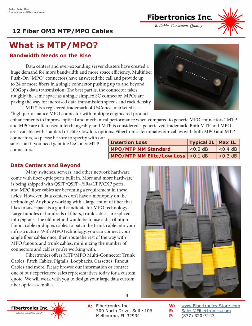
Insertion Loss Typical IL Max ILMPO/MTP MM Standard <0.2 dB <0.4 dBMPO/MTP MM Elite/Low Loss <0.1 dB <0.3 dB
Bandwidth Needs on the Rise
Data centers and ever-expanding server clusters have created a huge demand for more bandwidth and more space efficiency. Multifiber Push-On “MPO” connectors have answered the call and provide up to 24 or more fibers in a single connector pushing up to and beyond 100Gbps data transmission. The best part is, the connector takes roughly the same space as a single simplex SC connector. MPOs are paving the way for increased data transmission speeds and rack density. MTP® is a registered trademark of UsConec, marketed as a “high performance MPO connector with multiple engineered product
What is MTP/MPO?
enhancements to improve optical and mechanical performance when compared to generic MPO connectors.” MTP and MPO are often used interchangeably, and MTP is considered a genericized trademark. Both MTP and MPO are available with standard or elite / low loss options. Fibertronics terminates our cables with both MPO and MTP
Data Centers and Beyond Many switches, servers, and other network hardware come with fiber optic ports built in. More and more hardware is being shipped with QSFP/QSFP+/SR4/CFP/CXP ports, and MPO fiber cables are becoming a requirement in these fields. However, data centers don’t have a monopoly on the technology! Anybody working with a large count of fiber that likes to save space is a good candidate for MPO technology. Large bundles of hundreds of fibers, trunk cables, are spliced into pigtails. The old method would be to use a distribution fanout cable or duplex cables to patch the trunk cable into your infrastructure. With MPO technology, you can connect your single fiber cables once, then route the rest of the way with MPO fanouts and trunk cables, minimizing the number of connectors and cables you’re working with. Fibertronics offers MTP/MPO Multi-Connector Trunk Cables, Patch Cables, Pigtails, Loopbacks, Cassettes, Fanout Cables and more. Please browse our information or contact one of our experienced sales representatives today for a custom quote! We will work with you to design your large data custom fiber optic assemblies.
connectors, so please be sure to specify with our sales staff if you need genuine UsConec MTP connectors.
Fibertronics Inc.Fibertronics Inc.
Reliable, Consistent, Quality
Fibertronics Inc.Fibertronics Inc.
Reliable, Consistent, Quality
Fibertronics Inc.300 North Drive, Suite 106Melbourne, FL 32934
[email protected](877) 320-3143
W:E:P:
A:
4
Author: Parker AllenFeedback: [email protected]
12 Fiber OM3 MTP/MPO Cables
10 Gb 40 Gb 40 Gb (QSFP+ eSR4) 100 Gb (24 Fiber)OM1 33m N/A N/A N/AOM2 82m N/A N/A N/AOM3 300m 100m 330m 100mOM4 400m 150m 550m 150m
Multimode Variants
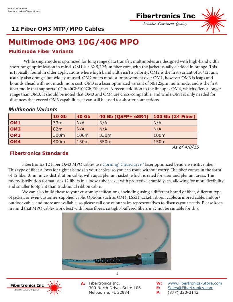
Multimode Fiber Variants
While singlemode is optimized for long range data transfer, multimodes are designed with high-bandwidth short range optimization in mind. OM1 is a 62.5/125µm fiber core, with the jacket usually cladded in orange. This is typically found in older applications where high bandwidth isn’t a priority. OM2 is the first variant of 50/125µm, usually also orange, but widely unused. OM2 offers modest improvement over OM1, however OM3 is leaps and bounds ahead with not much more cost. OM3 is a laser optimized variant of 50/125µm multimode, and is the first fiber mode that supports 10Gb/40Gb/100Gb Ethernet. A recent addition to the lineup is OM4, which offers a longer range than OM3. It should be noted that OM3 and OM4 are cross-compatible, and while OM4 is only needed for distances that exceed OM3 capabilities, it can still be used for shorter connections.
Multimode OM3 10G/40G MPO
Fibertronics Standards
Fibertronics 12 Fiber OM3 MPO cables use Corning® ClearCurve ® laser optimized bend-insensitive fiber. This type of fiber allows for tighter bends in your cables, so you can route without worry. The fiber comes in the form of 12 fiber 3mm microdistribution cable, with aqua plenum jacket, which is rated for riser and plenum areas. The microdistribution format uses 12 fibers in a loose tube jacket with protective aramid yarn, allowing for more flexibility and smaller footprint than traditional ribbon cable. We can also build these to your custom specifications, including using a different brand of fiber, different type of jacket, or even customer-supplied cable. Options such as OM4, LSZH jacket, ribbon cable, armored cable, indoor/outdoor cable, and more are available, so please call one of our sales representatives to discuss your needs. Please keep in mind that MPO cables work best with loose fibers, so tight-buffered fibers may not be suitable for this.
As of 4/8/15
Fibertronics Inc.Fibertronics Inc.
Reliable, Consistent, Quality
Fibertronics Inc.Fibertronics Inc.
Reliable, Consistent, Quality
Fibertronics Inc.300 North Drive, Suite 106Melbourne, FL 32934
[email protected](877) 320-3143
W:E:P:
A:
5
Author: Parker AllenFeedback: [email protected]
12 Fiber OM3 MTP/MPO Cables
Cassettes Male PortTransceivers Male PortPatch Cables Female to FemaleExtender Cables Male to FemaleTrunk Cables Male to Male (Custom Mix)
Gender Standards
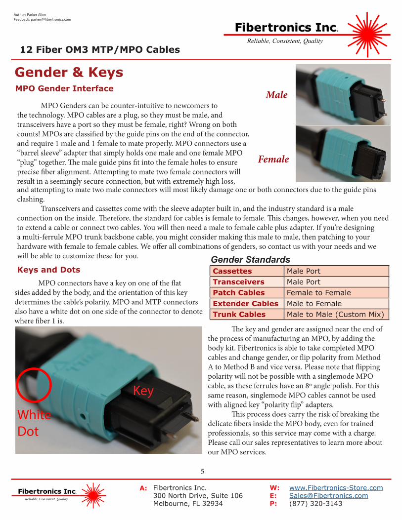
MPO Gender Interface
MPO Genders can be counter-intuitive to newcomers to the technology. MPO cables are a plug, so they must be male, and transceivers have a port so they must be female, right? Wrong on both counts! MPOs are classified by the guide pins on the end of the connector, and require 1 male and 1 female to mate properly. MPO connectors use a “barrel sleeve” adapter that simply holds one male and one female MPO “plug” together. The male guide pins fit into the female holes to ensure precise fiber alignment. Attempting to mate two female connectors will result in a seemingly secure connection, but with extremely high loss,
Gender & Keys
and attempting to mate two male connectors will most likely damage one or both connectors due to the guide pins clashing. Transceivers and cassettes come with the sleeve adapter built in, and the industry standard is a male connection on the inside. Therefore, the standard for cables is female to female. This changes, however, when you need to extend a cable or connect two cables. You will then need a male to female cable plus adapter. If you’re designing a multi-ferrule MPO trunk backbone cable, you might consider making this male to male, then patching to your hardware with female to female cables. We offer all combinations of genders, so contact us with your needs and we will be able to customize these for you.
Keys and Dots MPO connectors have a key on one of the flat sides added by the body, and the orientation of this key determines the cable’s polarity. MPO and MTP connectors also have a white dot on one side of the connector to denote where fiber 1 is.
Male
Female
The key and gender are assigned near the end of the process of manufacturing an MPO, by adding the body kit. Fibertronics is able to take completed MPO cables and change gender, or flip polarity from Method A to Method B and vice versa. Please note that flipping polarity will not be possible with a singlemode MPO cable, as these ferrules have an 8º angle polish. For this same reason, singlemode MPO cables cannot be used with aligned key “polarity flip” adapters. This process does carry the risk of breaking the delicate fibers inside the MPO body, even for trained professionals, so this service may come with a charge. Please call our sales representatives to learn more about our MPO services.
Key
WhiteDot
Fibertronics Inc.Fibertronics Inc.
Reliable, Consistent, Quality
Fibertronics Inc.Fibertronics Inc.
Reliable, Consistent, Quality
Fibertronics Inc.300 North Drive, Suite 106Melbourne, FL 32934
[email protected](877) 320-3143
W:E:P:
A:
6
Author: Parker AllenFeedback: [email protected]
12...
1112
12...
1112
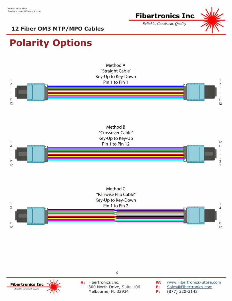
Method A“Straight Cable”
Key-Up to Key-DownPin 1 to Pin 1
12...
1112
1211...21
Method B“Crossover Cable”Key-Up to Key-Up
Pin 1 to Pin 12
12...
1112
12...
1112
Method C“Pairwise Flip Cable”Key-Up to Key-Down
Pin 1 to Pin 2
Polarity Options12 Fiber OM3 MTP/MPO Cables
Fibertronics Inc.Fibertronics Inc.
Reliable, Consistent, Quality
Fibertronics Inc.Fibertronics Inc.
Reliable, Consistent, Quality
Fibertronics Inc.300 North Drive, Suite 106Melbourne, FL 32934
[email protected](877) 320-3143
W:E:P:
A:
7
Author: Parker AllenFeedback: [email protected]
Method A Applications12...
1112
12...
1112
Method A“Straight Cable”
Key-Up to Key-DownPin 1 to Pin 1
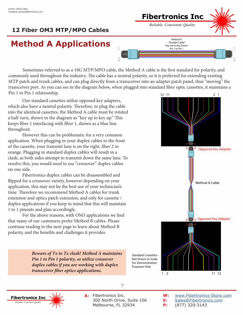
Sometimes referred to as a 10G MTP/MPO cable, the Method A cable is the first standard for polarity, and commonly used throughout the industry. The cable has a neutral polarity, so it is preferred for extending existing MTP patch and trunk cables, and can plug directly from a transceiver into an adapter patch panel, thus “moving” the transceiver port. As you can see in the diagram below, when plugged into standard fiber optic cassettes, it maintains a Pin 1 to Pin 1 relationship.
1 2 11 12
2 112 11
Opposed Key Adapter
Opposed Key Adapter
Method A Cable
Standard Cassettes - Not Drawn to Scale. For Demonstration Purposes Only
Our standard cassettes utilize opposed key adapters, which also have a neutral polarity. Therefore, to plug the cable into the identical cassettes, the Method A cable must be rotated a half-turn, shown in the diagram as “key up to key up.” This keeps fiber 1 interfacing with fiber 1, shown as a blue line throughout. However this can be problematic for a very common application. When plugging in your duplex cables to the front of the cassette, your transmit lane is on the right, fiber 2 in orange. Plugging in standard duplex cables will result in a clash, as both sides attempt to transmit down the same lane. To resolve this, you would need to use “crossover” duplex cables on one side. Fibertronics duplex cables can be disassembled and flipped for a crossover variety, however depending on your application, this may not be the best use of your technician’s time. Therefore we recommend Method A cables for trunk extension and optics patch extension, and only for cassette / duplex applications if you keep in mind that this will maintain 1 to 1 pinouts and plan accordingly. For the above reasons, with OM3 applications we find that many of our customers prefer Method B cables. Please continue reading to the next page to learn about Method B polarity, and the benefits and challenges it provides.
!Beware of Tx to Tx clash! Method A maintains Pin 1 to Pin 1 polarity, so utilize crossover duplex cables if you are working with duplex transceiver fiber optics applications.
12 Fiber OM3 MTP/MPO Cables
Fibertronics Inc.Fibertronics Inc.
Reliable, Consistent, Quality
Fibertronics Inc.Fibertronics Inc.
Reliable, Consistent, Quality
Fibertronics Inc.300 North Drive, Suite 106Melbourne, FL 32934
[email protected](877) 320-3143
W:E:P:
A:
8
Author: Parker AllenFeedback: [email protected]
Method B Applications12...
1112
1211...21
Method B“Crossover Cable”Key-Up to Key-Up
Pin 1 to Pin 12
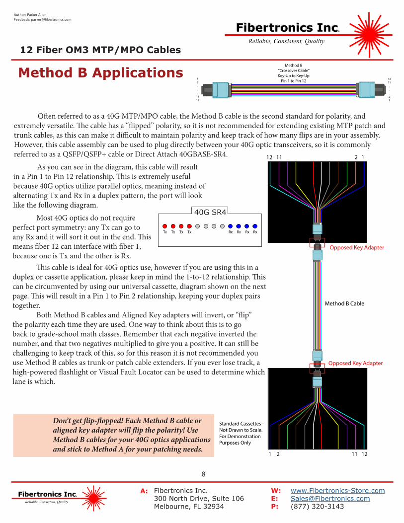
Often referred to as a 40G MTP/MPO cable, the Method B cable is the second standard for polarity, and extremely versatile. The cable has a “flipped” polarity, so it is not recommended for extending existing MTP patch and trunk cables, as this can make it difficult to maintain polarity and keep track of how many flips are in your assembly. However, this cable assembly can be used to plug directly between your 40G optic transceivers, so it is commonly referred to as a QSFP/QSFP+ cable or Direct Attach 40GBASE-SR4.
1 2 11 12
2 112 11
Opposed Key Adapter
Opposed Key Adapter
Method B Cable
Standard Cassettes - Not Drawn to Scale. For Demonstration Purposes Only
As you can see in the diagram, this cable will result in a Pin 1 to Pin 12 relationship. This is extremely useful because 40G optics utilize parallel optics, meaning instead of alternating Tx and Rx in a duplex pattern, the port will look like the following diagram.
!Don’t get flip-flopped! Each Method B cable or aligned key adapter will flip the polarity! Use Method B cables for your 40G optics applications and stick to Method A for your patching needs.
Most 40G optics do not require perfect port symmetry: any Tx can go to any Rx and it will sort it out in the end. This means fiber 12 can interface with fiber 1, because one is Tx and the other is Rx.
Tx Tx Tx Tx Rx Rx Rx Rx
40G SR4
This cable is ideal for 40G optics use, however if you are using this in a duplex or cassette application, please keep in mind the 1-to-12 relationship. This can be circumvented by using our universal cassette, diagram shown on the next page. This will result in a Pin 1 to Pin 2 relationship, keeping your duplex pairs together. Both Method B cables and Aligned Key adapters will invert, or “flip” the polarity each time they are used. One way to think about this is to go back to grade-school math classes. Remember that each negative inverted the number, and that two negatives multiplied to give you a positive. It can still be challenging to keep track of this, so for this reason it is not recommended you use Method B cables as trunk or patch cable extenders. If you ever lose track, a high-powered flashlight or Visual Fault Locator can be used to determine which lane is which.
12 Fiber OM3 MTP/MPO Cables
Fibertronics Inc.Fibertronics Inc.
Reliable, Consistent, Quality
Fibertronics Inc.Fibertronics Inc.
Reliable, Consistent, Quality
Fibertronics Inc.300 North Drive, Suite 106Melbourne, FL 32934
[email protected](877) 320-3143
W:E:P:
A:
9
Author: Parker AllenFeedback: [email protected]
Method B Applications Universal Cassettes
12...
1112
1211...21
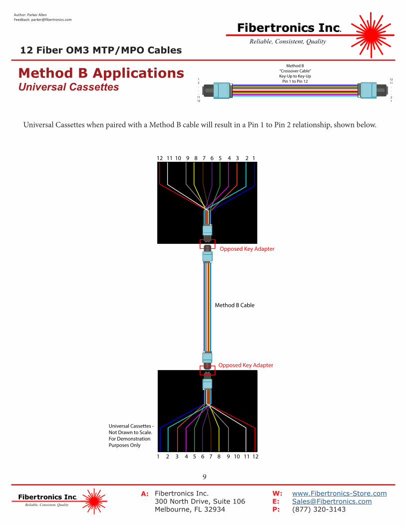
Method B“Crossover Cable”Key-Up to Key-Up
Pin 1 to Pin 12
Universal Cassettes when paired with a Method B cable will result in a Pin 1 to Pin 2 relationship, shown below.
1 2 3 4 5 6 7 8 9 10 11 12
2 112 11
Opposed Key Adapter
Opposed Key Adapter
Method B Cable
Universal Cassettes - Not Drawn to Scale. For Demonstration Purposes Only
4 3 6 5 8 7 10 9
12 Fiber OM3 MTP/MPO Cables
Fibertronics Inc.Fibertronics Inc.
Reliable, Consistent, Quality
Fibertronics Inc.Fibertronics Inc.
Reliable, Consistent, Quality
Fibertronics Inc.300 North Drive, Suite 106Melbourne, FL 32934
[email protected](877) 320-3143
W:E:P:
A:
10
Author: Parker AllenFeedback: [email protected]
Method C Applications12...
1112
12...
1112
Method C“Pairwise Flip Cable”Key-Up to Key-Down
Pin 1 to Pin 2
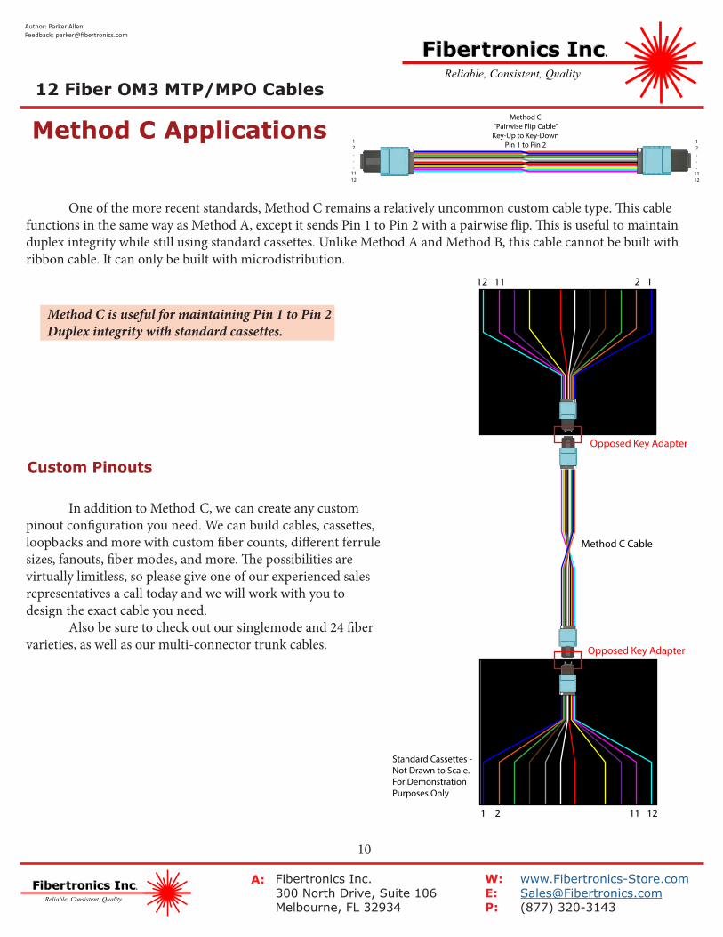
One of the more recent standards, Method C remains a relatively uncommon custom cable type. This cable functions in the same way as Method A, except it sends Pin 1 to Pin 2 with a pairwise flip. This is useful to maintain duplex integrity while still using standard cassettes. Unlike Method A and Method B, this cable cannot be built with ribbon cable. It can only be built with microdistribution.
1 2 11 12
2 112 11
Opposed Key Adapter
Opposed Key Adapter
Method C Cable
Standard Cassettes - Not Drawn to Scale. For Demonstration Purposes Only
In addition to Method C, we can create any custom pinout configuration you need. We can build cables, cassettes, loopbacks and more with custom fiber counts, different ferrule sizes, fanouts, fiber modes, and more. The possibilities are virtually limitless, so please give one of our experienced sales representatives a call today and we will work with you to design the exact cable you need. Also be sure to check out our singlemode and 24 fiber varieties, as well as our multi-connector trunk cables.
Method C is useful for maintaining Pin 1 to Pin 2 Duplex integrity with standard cassettes.
Custom Pinouts
12 Fiber OM3 MTP/MPO Cables


![MPO/MTP TRUNK CABLExfsconnect.com/upload/files/MPO_MTP Assemblies/MP… · · 2018-02-02④ [Fiber type] 1: G652D 2: G657A1 3: G657A2 4: G657B3 5: OM1 6: OM2 7: OM3 8: OM4 ⑤ [Fiber](https://img.pdfslide.net/doc/110x75/5ad27b317f8b9a86158d3116/mpomtp-trunk-assembliesmp2018-02-02-fiber-type-1-g652d-2-g657a1-3-g657a2.jpg)