Embed Size (px)
Citation preview
William Stallings
Computer Organization
and Architecture
8th
Edition
Chapter 12
Processor Structure and
Function
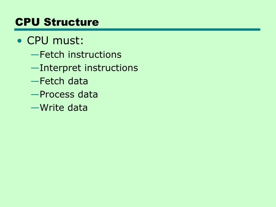
CPU Structure
• CPU must:
—Fetch instructions
—Interpret instructions
—Fetch data
—Process data
—Write data
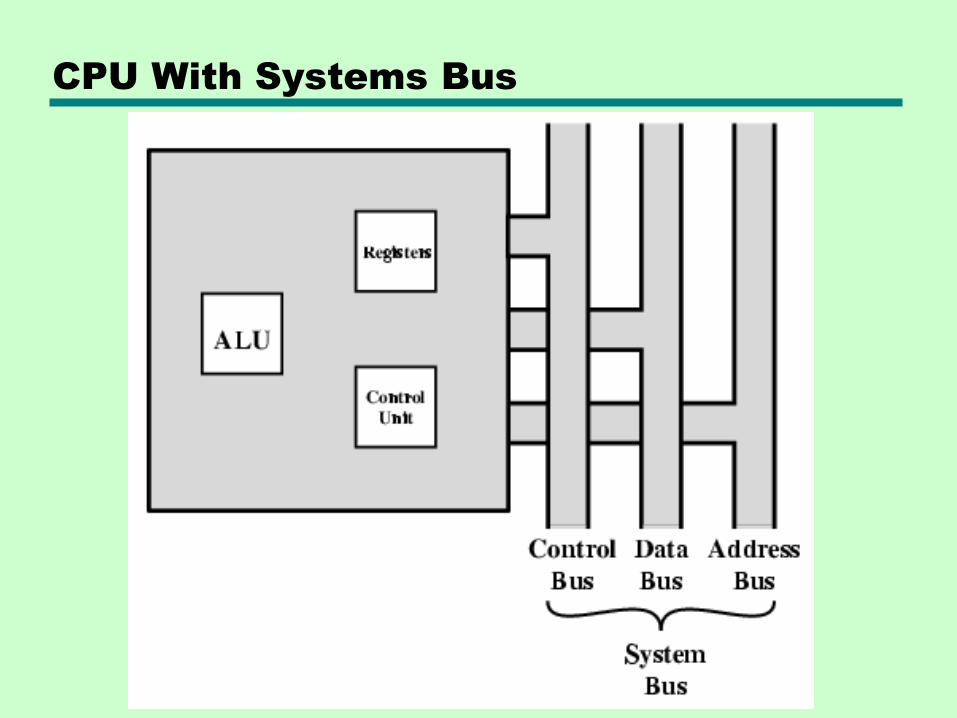
CPU With Systems Bus
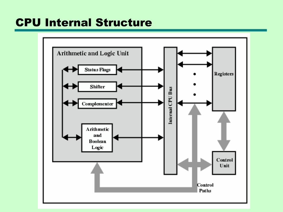
CPU Internal Structure
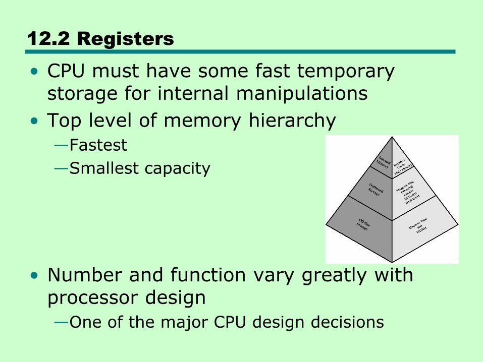
12.2 Registers
• CPU must have some fast temporary storage for internal manipulations
• Top level of memory hierarchy
—Fastest
—Smallest capacity
• Number and function vary greatly with processor design
—One of the major CPU design decisions
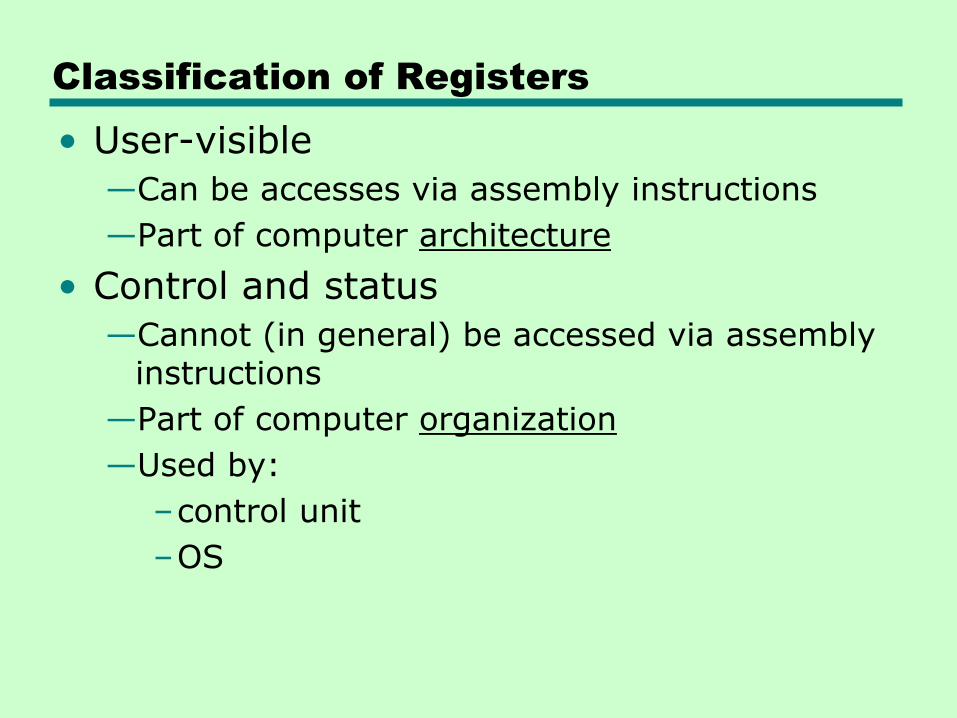
Classification of Registers
• User-visible
—Can be accesses via assembly instructions
—Part of computer architecture
• Control and status
—Cannot (in general) be accessed via assembly instructions
—Part of computer organization
—Used by:
–control unit
–OS
User-Visible Registers
• General Purpose
• Data
• Address
• Condition Codes
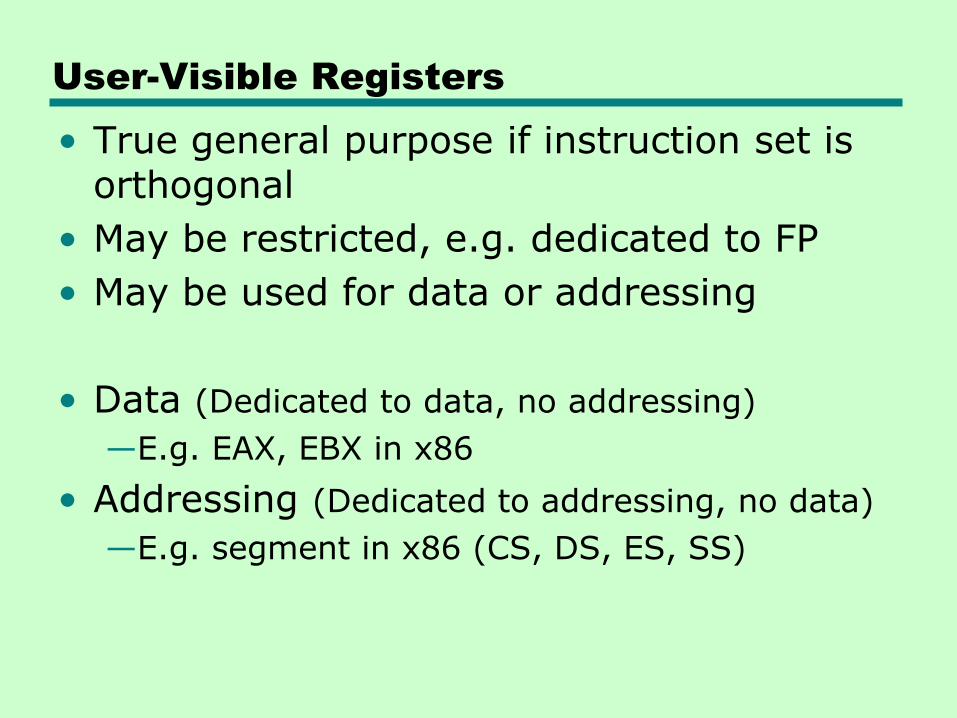
User-Visible Registers
• True general purpose if instruction set is orthogonal
• May be restricted, e.g. dedicated to FP
• May be used for data or addressing
• Data (Dedicated to data, no addressing)
—E.g. EAX, EBX in x86
• Addressing (Dedicated to addressing, no data)
—E.g. segment in x86 (CS, DS, ES, SS)
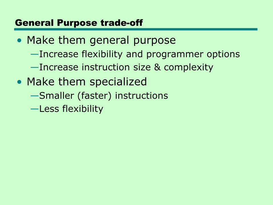
General Purpose trade-off
• Make them general purpose
—Increase flexibility and programmer options
—Increase instruction size & complexity
• Make them specialized
—Smaller (faster) instructions
—Less flexibility
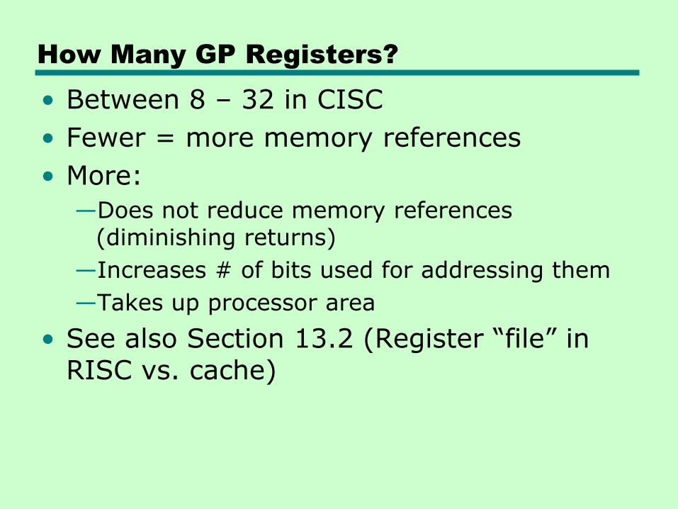
How Many GP Registers?
• Between 8 – 32 in CISC
• Fewer = more memory references
• More:
—Does not reduce memory references (diminishing returns)
—Increases # of bits used for addressing them
—Takes up processor area
• See also Section 13.2 (Register ―file‖ in RISC vs. cache)
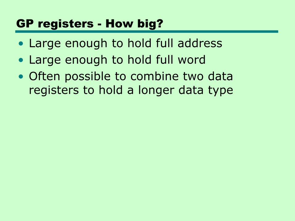
GP registers - How big?
• Large enough to hold full address
• Large enough to hold full word
• Often possible to combine two data registers to hold a longer data type
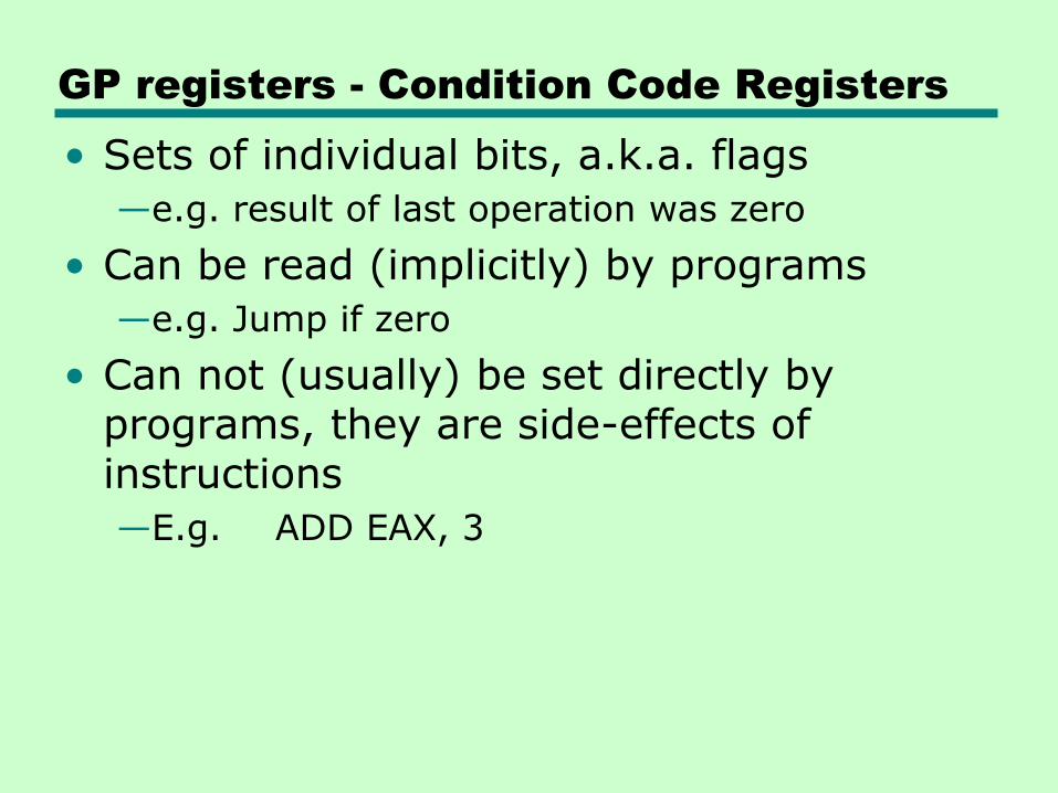
GP registers - Condition Code Registers
• Sets of individual bits, a.k.a. flags
—e.g. result of last operation was zero
• Can be read (implicitly) by programs
—e.g. Jump if zero
• Can not (usually) be set directly by programs, they are side-effects of instructions
—E.g. ADD EAX, 3
• Problem 12.1/476
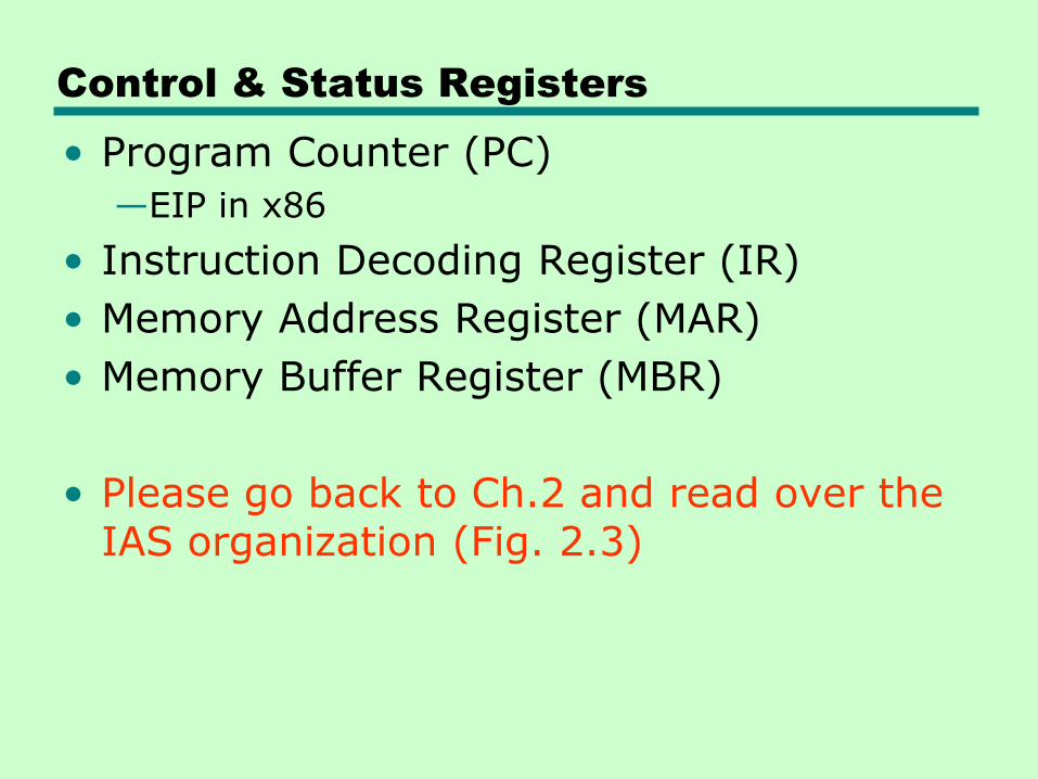
Control & Status Registers
• Program Counter (PC)
—EIP in x86
• Instruction Decoding Register (IR)
• Memory Address Register (MAR)
• Memory Buffer Register (MBR)
• Please go back to Ch.2 and read over the IAS organization (Fig. 2.3)
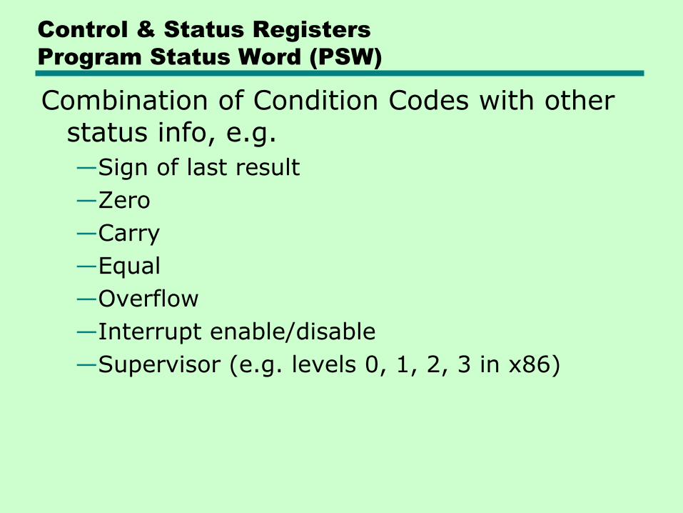
Control & Status Registers
Program Status Word (PSW)
Combination of Condition Codes with other status info, e.g.
—Sign of last result
—Zero
—Carry
—Equal
—Overflow
—Interrupt enable/disable
—Supervisor (e.g. levels 0, 1, 2, 3 in x86)
Supervisor Mode
• Intel ring zero, a.k.a. Kernel mode
• Allows privileged instructions to execute
• Used only by OS (Not available to user programs)
Other Status and Control Registers
• May have registers pointing to:
—Process control blocks (OS)
—Interrupt Vectors (OS)
• May have registers for control of I/O
CPU design and OS design are closely linked!
• E.g. trade-off between placing control info in registers and placing it in a low memory block
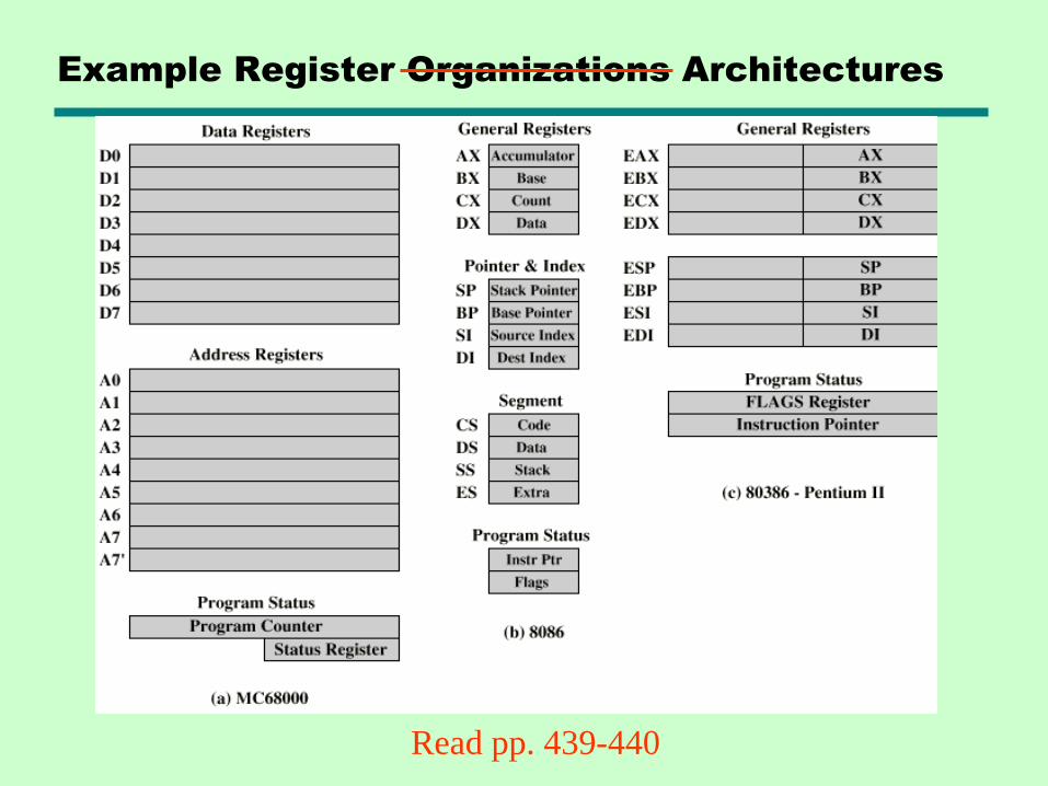
Example Register Organizations Architectures
Read pp. 439-440
12.3 Instruction Cycle
Please go back to Ch.3.2 and read over the FETCH-EXECUTE cycle
Indirect Cycle
• May require memory access to fetch operands
• Indirect addressing requires more memory accesses
• Can be thought of as additional instruction subcycle
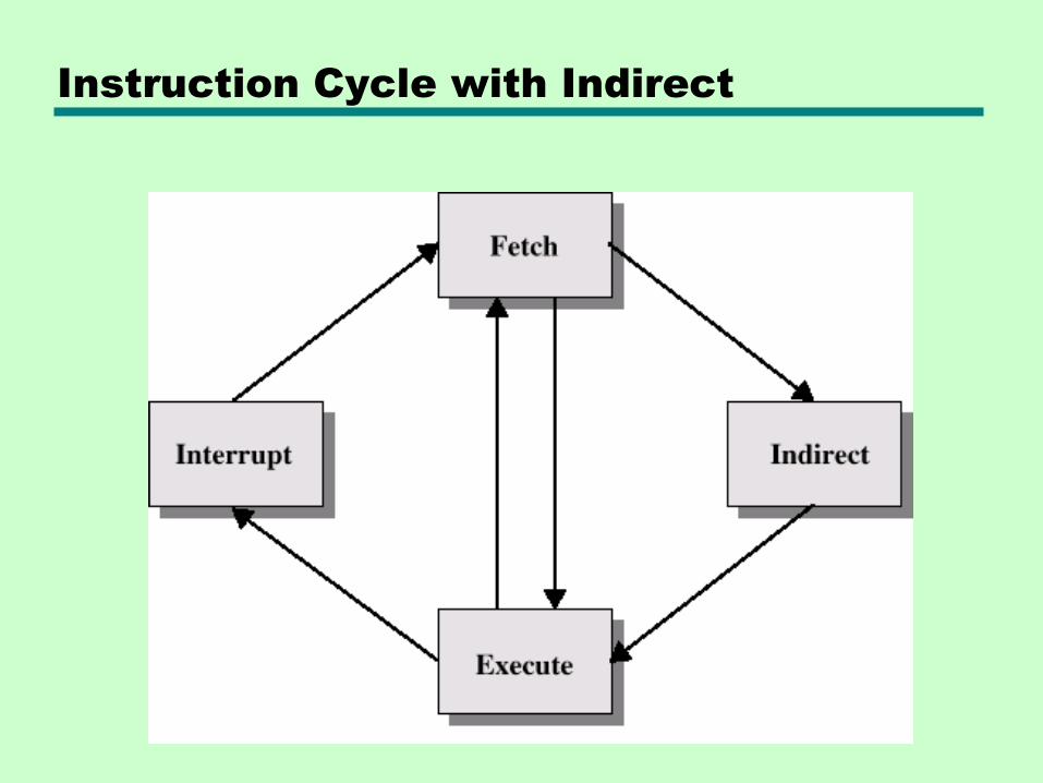
Instruction Cycle with Indirect
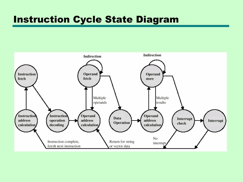
Instruction Cycle State Diagram
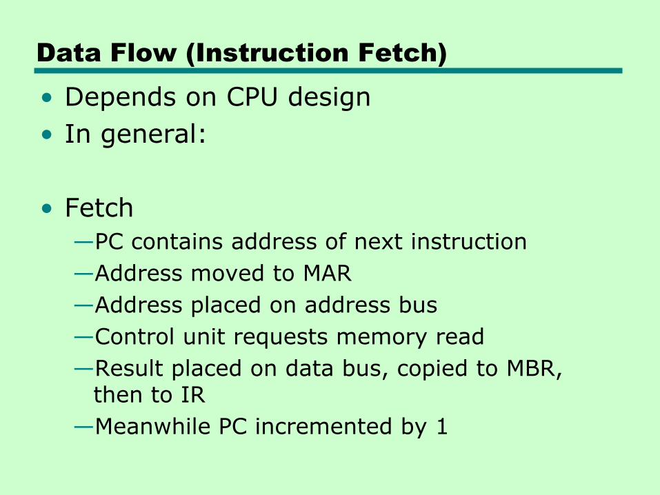
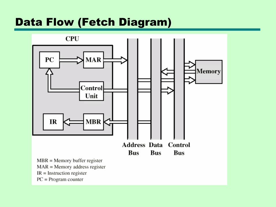
Data Flow (Instruction Fetch)
• Depends on CPU design
• In general:
• Fetch
—PC contains address of next instruction
—Address moved to MAR
—Address placed on address bus
—Control unit requests memory read
—Result placed on data bus, copied to MBR, then to IR
—Meanwhile PC incremented by 1
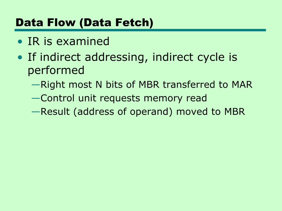
Data Flow (Data Fetch)
• IR is examined
• If indirect addressing, indirect cycle is performed
—Right most N bits of MBR transferred to MAR
—Control unit requests memory read
—Result (address of operand) moved to MBR
Data Flow (Fetch Diagram)
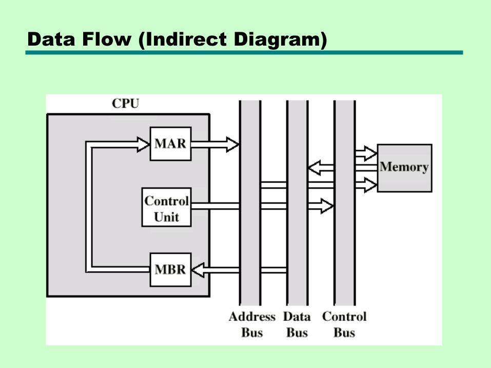
Data Flow (Indirect Diagram)
Data Flow (Execute)
• May take many forms
• Depends on instruction being executed
• May include
—Memory read/write
—Input/Output
—Register transfers
—ALU operations
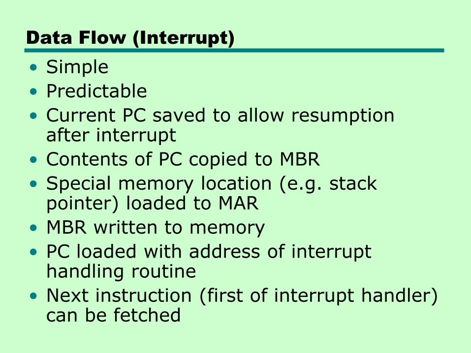
Data Flow (Interrupt)
• Simple
• Predictable
• Current PC saved to allow resumption after interrupt
• Contents of PC copied to MBR
• Special memory location (e.g. stack pointer) loaded to MAR
• MBR written to memory
• PC loaded with address of interrupt handling routine
• Next instruction (first of interrupt handler) can be fetched
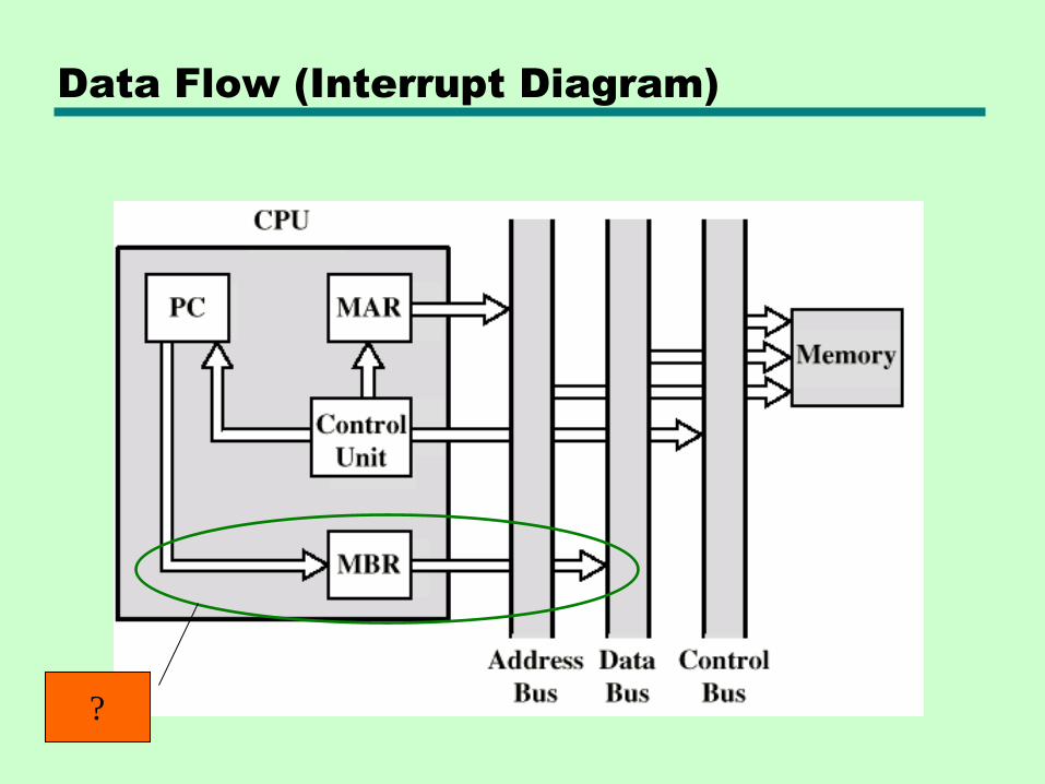
Data Flow (Interrupt Diagram)
?
12.4 Pipelining
Idea: Prefetch
• Fetch is accessing main memory
• Execution usually does not access main memory
• Therefore: Can fetch next instruction during execution of current instruction
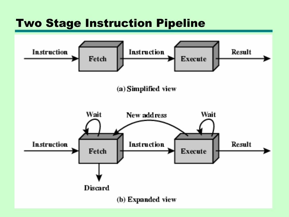
Two Stage Instruction Pipeline
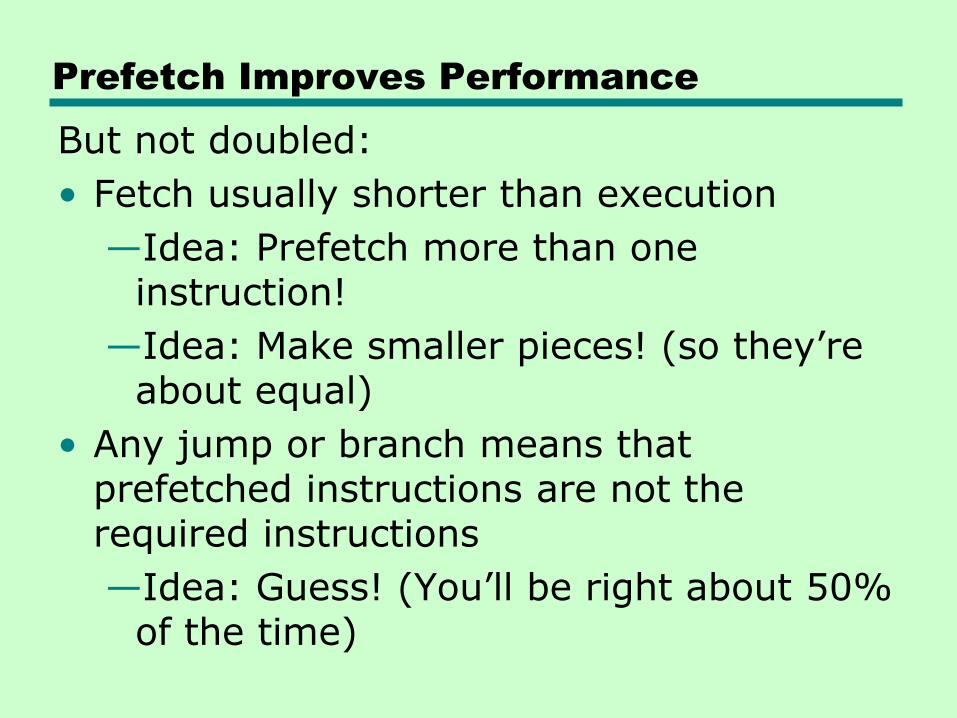
Prefetch Improves Performance
But not doubled:
• Fetch usually shorter than execution
—Idea: Prefetch more than one instruction!
—Idea: Make smaller pieces! (so they’re about equal)
• Any jump or branch means that prefetched instructions are not the required instructions
—Idea: Guess! (You’ll be right about 50% of the time)
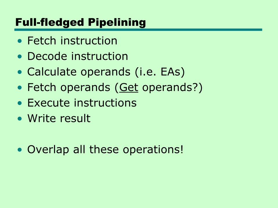
Full-fledged Pipelining
• Fetch instruction
• Decode instruction
• Calculate operands (i.e. EAs)
• Fetch operands (Get operands?)
• Execute instructions
• Write result
• Overlap all these operations!
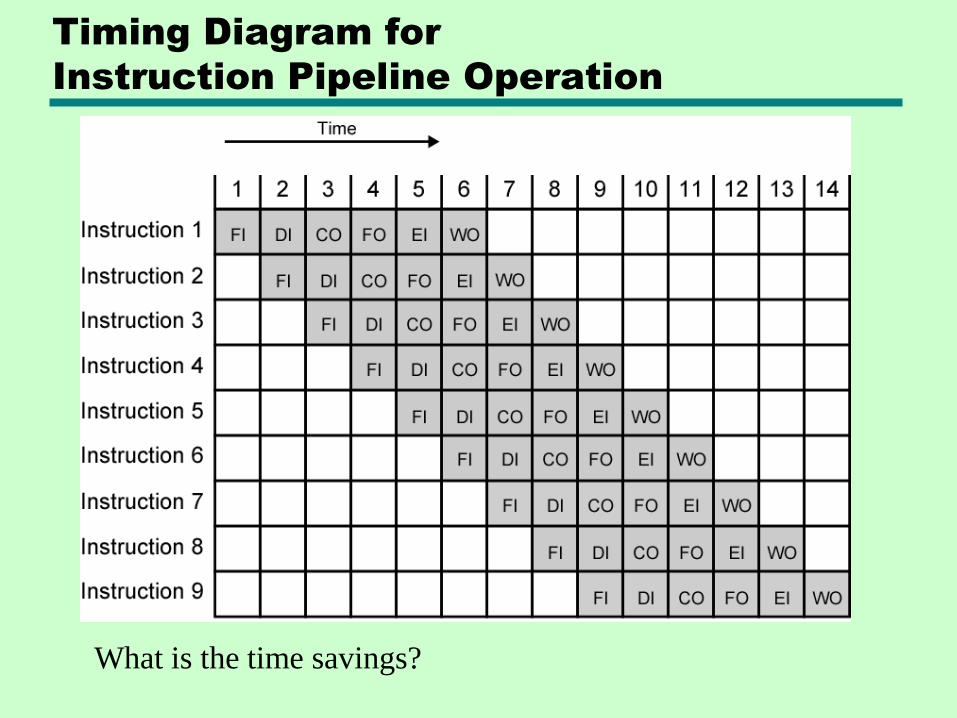
Timing Diagram for
Instruction Pipeline Operation
What is the time savings?
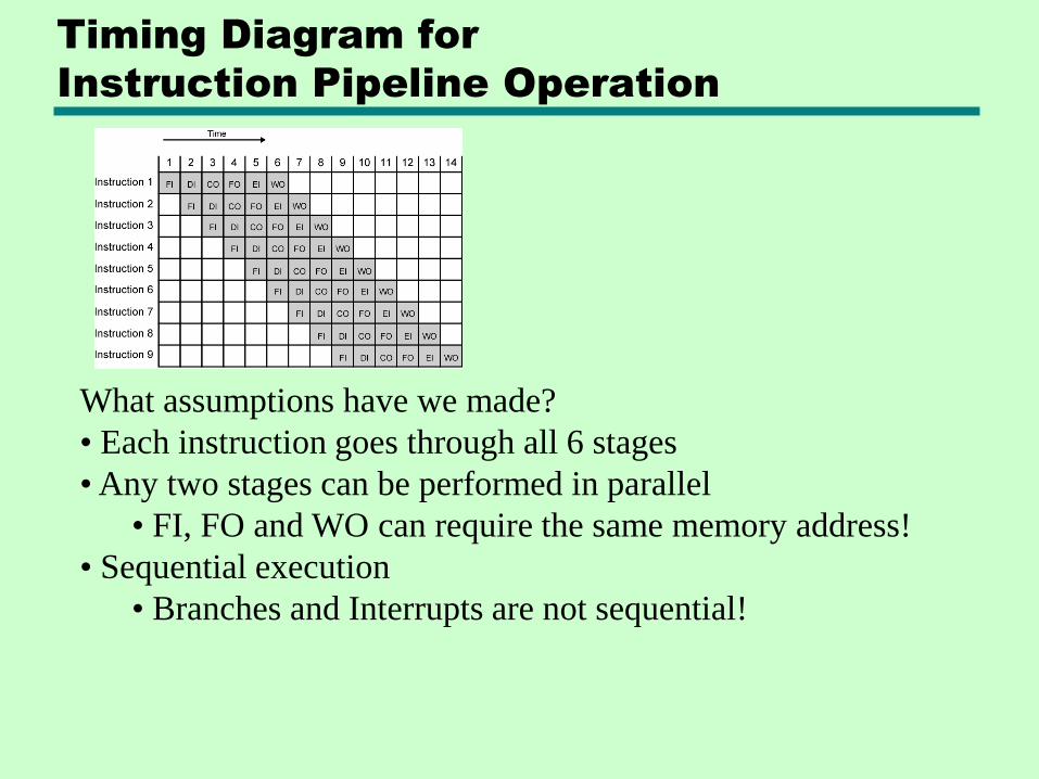
Timing Diagram for
Instruction Pipeline Operation
What assumptions have we made?
• Each instruction goes through all 6 stages
• Any two stages can be performed in parallel
• FI, FO and WO can require the same memory address!
• Sequential execution
• Branches and Interrupts are not sequential!
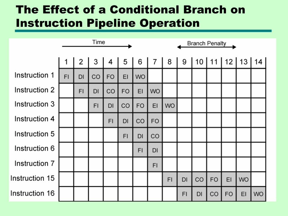
The Effect of a Conditional Branch on
Instruction Pipeline Operation
We have covered pp.433-447
Please read carefully and do all the ―back-reading‖ assignments.
Solve end-of-chapter Problems 12.2, 12.3
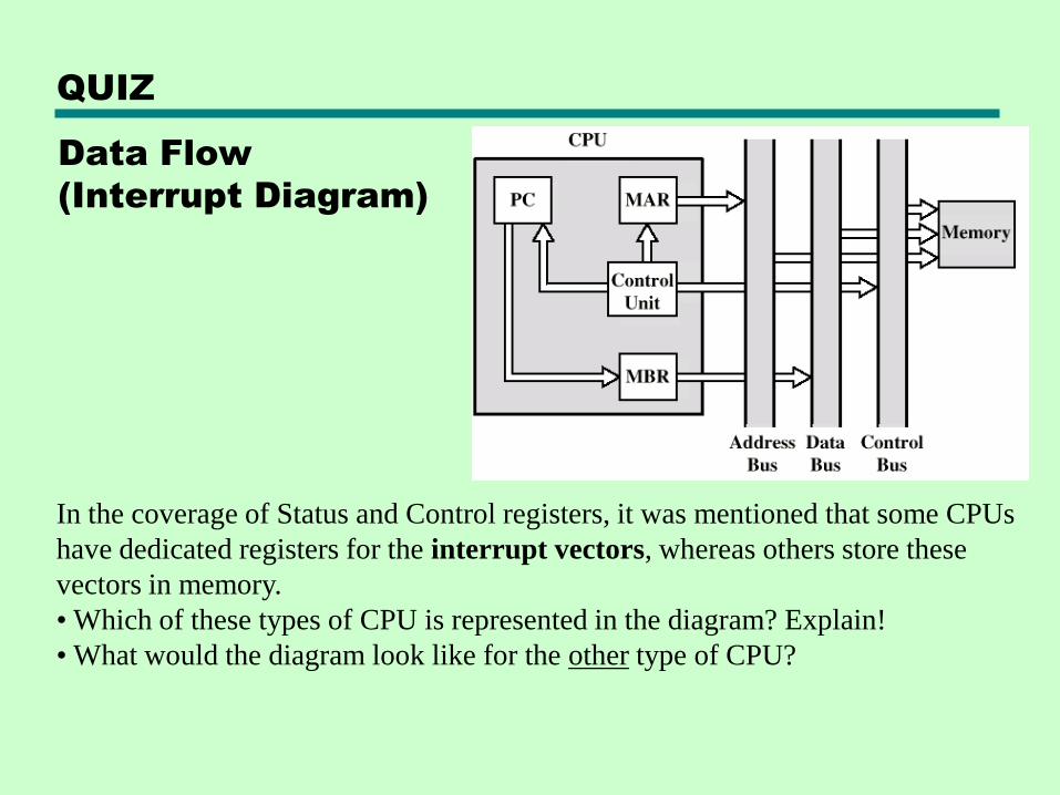
Data Flow
(Interrupt Diagram)
QUIZ
In the coverage of Status and Control registers, it was mentioned that some CPUs
have dedicated registers for the interrupt vectors, whereas others store these
vectors in memory.
• Which of these types of CPU is represented in the diagram? Explain!
• What would the diagram look like for the other type of CPU?
QUIZ
End-of-chapter problem 12.4
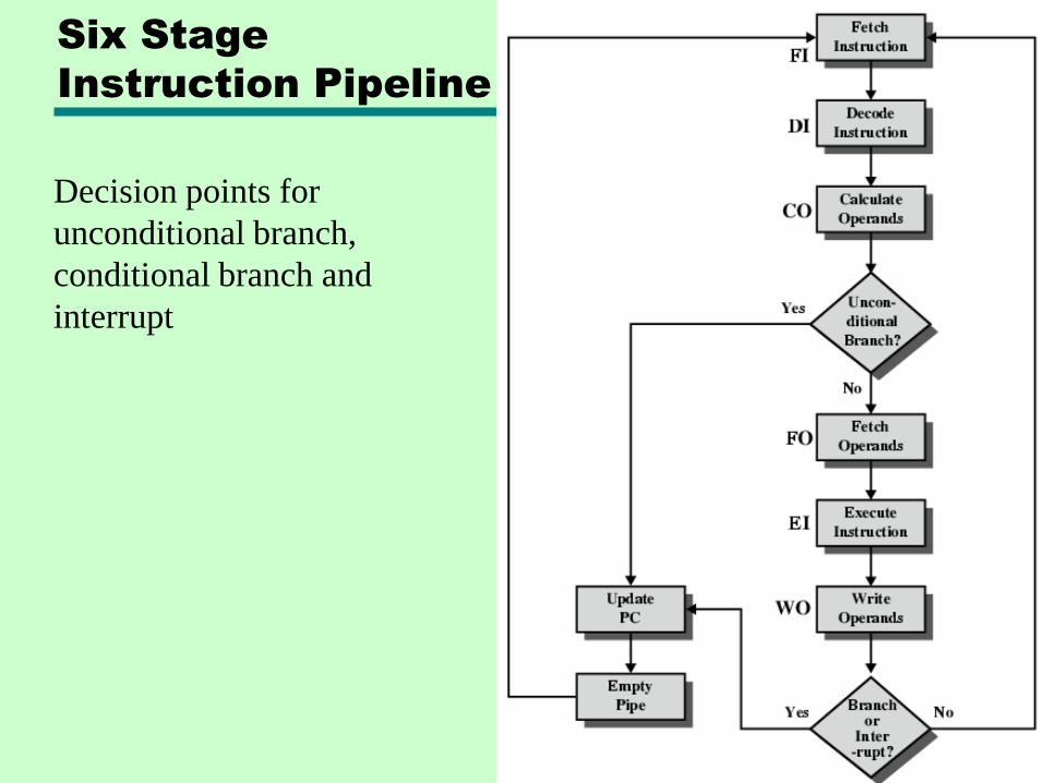
Six Stage
Instruction Pipeline
Decision points for
unconditional branch,
conditional branch and
interrupt
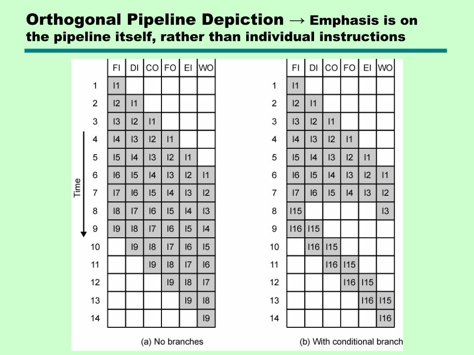
Orthogonal Pipeline Depiction → Emphasis is on
the pipeline itself, rather than individual instructions
Long pipelines – diminishing returns
• The ―N-squared‖ problem
• The longer the pipeline, the more work is lost when it needs to be emptied
• Each stage needs its own latching delays (setup times and hold times)
Conclusion: We need quantitative measures!
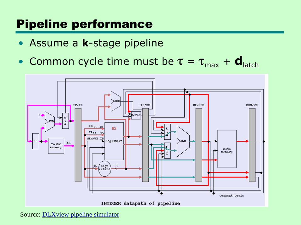
Pipeline performance
• Assume a k-stage pipeline
• Common cycle time must be t = tmax + dlatch
Source: DLXview pipeline simulator
Pipeline performance
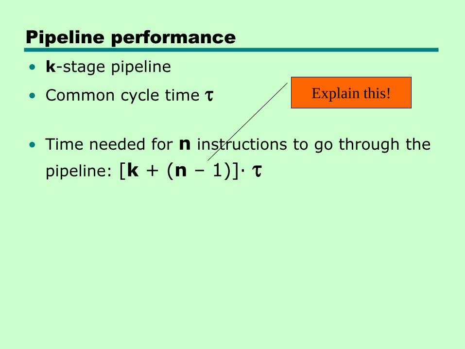
• k-stage pipeline
• Common cycle time t
• Time needed for n instructions to go through the
pipeline: [k + (n – 1)]· t
Explain this!
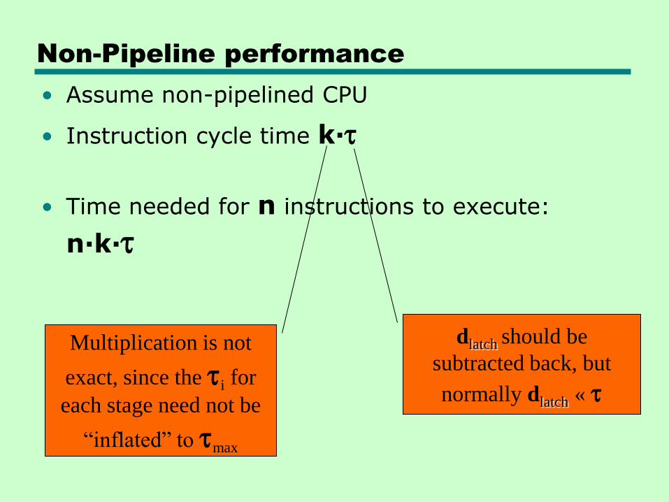
Non-Pipeline performance
• Assume non-pipelined CPU
• Instruction cycle time k·t
• Time needed for n instructions to execute:
n·k·t
dlatch should be
subtracted back, but
normally dlatch « t
Multiplication is not
exact, since the ti for
each stage need not be
“inflated” to tmax
Speedup Factors
with Instruction
Pipelining
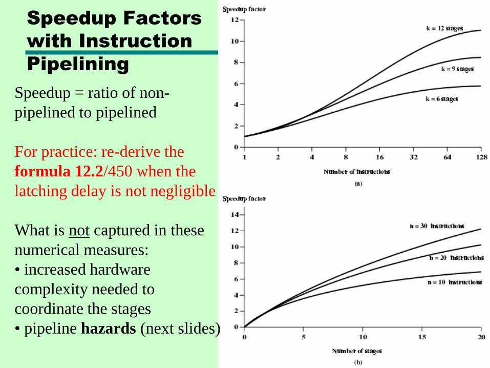
Speedup = ratio of non-
pipelined to pipelined
For practice: re-derive the
formula 12.2/450 when the
latching delay is not negligible
What is not captured in these
numerical measures:
• increased hardware
complexity needed to
coordinate the stages
• pipeline hazards (next slides)
QUIZ
End-of-chapter problem 12.5Hint: Assume a long sequence of instructions
Pipeline Hazards
• The entire pipeline, or a portion thereof, must stall
• Also called pipeline bubbles
• Types of hazards
—Resource
—Data
—Control
Resource Hazards
• Two (or more) instructions in pipeline need same resource
• Executed serially rather than parallel for part of the pipeline
• A.k.a. structural hazard
Example:
• Assume simplified five-stage pipeline
• Each stage takes one clock cycle
• A new instruction enters pipeline each clock cycle
• See next slide
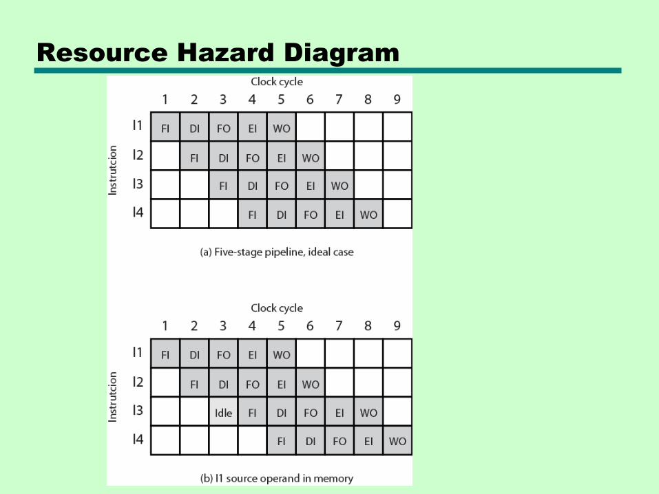
Resource Hazard Diagram
Resource Hazards
Assumptions made in prev. example:
• Main memory has single port
• Assume instruction fetches and data reads and writes performed one at a time
• No cache (or only cache misses)
• The operand needed for I1 is in memory, not in register, so it cannot be read in parallel with instruction fetch for I3
Conclusion: I3 Fetch (FI) stage must idle for one cycle
Another example: Multiple arithmetic or logic instructions are ready to enter the Execute (EI) stage, but there’s only one ALU
Resource Hazards
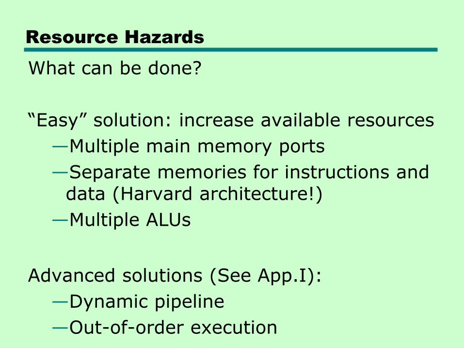
What can be done?
―Easy‖ solution: increase available resources
—Multiple main memory ports
—Separate memories for instructions and data (Harvard architecture!)
—Multiple ALUs
Advanced solutions (See App.I):
—Dynamic pipeline
—Out-of-order execution
Data Hazards
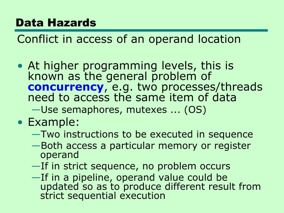
Conflict in access of an operand location
• At higher programming levels, this is known as the general problem of concurrency, e.g. two processes/threads need to access the same item of data—Use semaphores, mutexes ... (OS)
• Example:—Two instructions to be executed in sequence—Both access a particular memory or register
operand—If in strict sequence, no problem occurs—If in a pipeline, operand value could be
updated so as to produce different result from strict sequential execution
Data Hazards
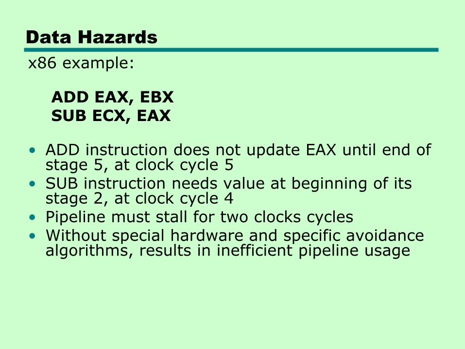
x86 example:
ADD EAX, EBXSUB ECX, EAX
• ADD instruction does not update EAX until end of stage 5, at clock cycle 5
• SUB instruction needs value at beginning of its stage 2, at clock cycle 4
• Pipeline must stall for two clocks cycles• Without special hardware and specific avoidance
algorithms, results in inefficient pipeline usage
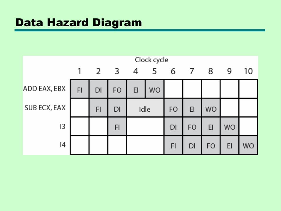
Data Hazard Diagram
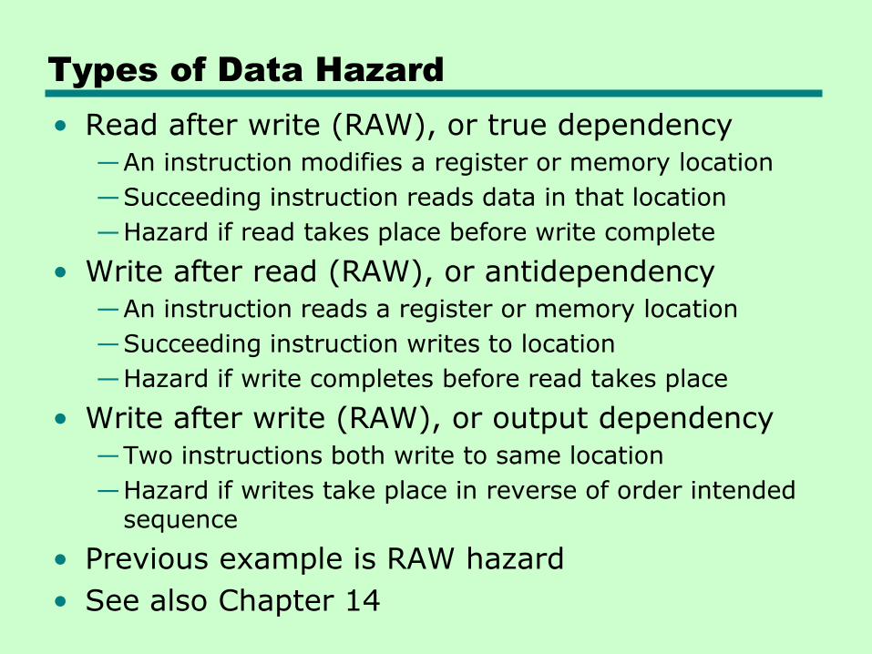
Types of Data Hazard
• Read after write (RAW), or true dependency
—An instruction modifies a register or memory location
—Succeeding instruction reads data in that location
—Hazard if read takes place before write complete
• Write after read (RAW), or antidependency
—An instruction reads a register or memory location
—Succeeding instruction writes to location
—Hazard if write completes before read takes place
• Write after write (RAW), or output dependency
—Two instructions both write to same location
—Hazard if writes take place in reverse of order intended sequence
• Previous example is RAW hazard
• See also Chapter 14
We have covered pp. 448-453.
Homework for Ch.12 – Due Dec 7
(Last homework!)
End-of-chapter problems:
• 6 (Hint: see prev. problem 12.5 for the size of
the instruction queue in 8088)
• 8
• 10
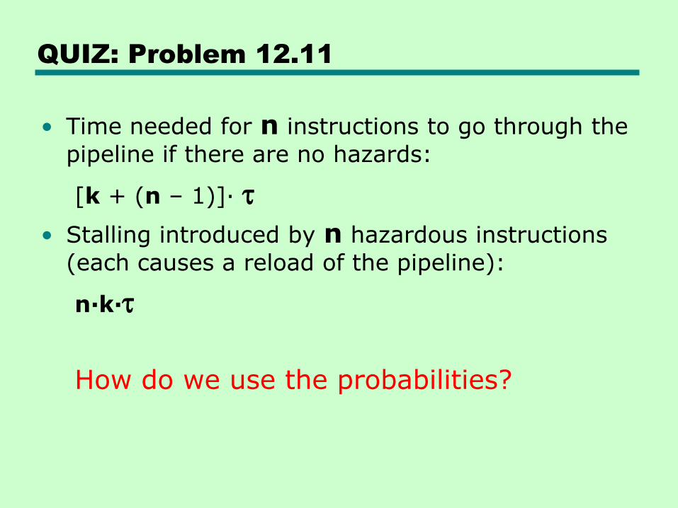
QUIZ: Problem 12.11
• Time needed for n instructions to go through the
pipeline if there are no hazards:
[k + (n – 1)]· t
• Stalling introduced by n hazardous instructions
(each causes a reload of the pipeline):
n·k·t
How do we use the probabilities?
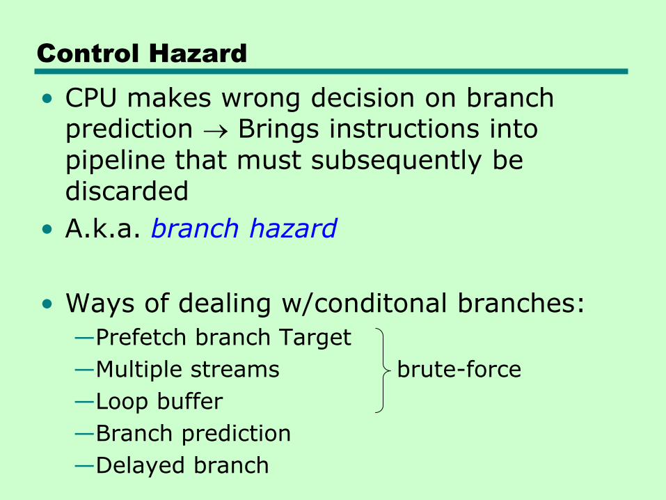
Control Hazard
• CPU makes wrong decision on branch prediction Brings instructions into pipeline that must subsequently be discarded
• A.k.a. branch hazard
• Ways of dealing w/conditonal branches:
—Prefetch branch Target
—Multiple streams brute-force
—Loop buffer
—Branch prediction
—Delayed branch
Prefetch Branch Target
• Use more hardware:
—Target of branch is prefetched in a buffer (queue)
—while the instructions sequentially following the branch are executed normally in pipeline
• Keep target until branch is executed
Multiple Streams
• Use even more hardware two full pipelines!
—Fetch each branch into a separate pipeline and execute them in parallel
—When decision was made, use appropriate pipeline, discard the other
• Problems:
—Increased bus & register contention
—Multiple branches in a row lead to further pipelines being needed
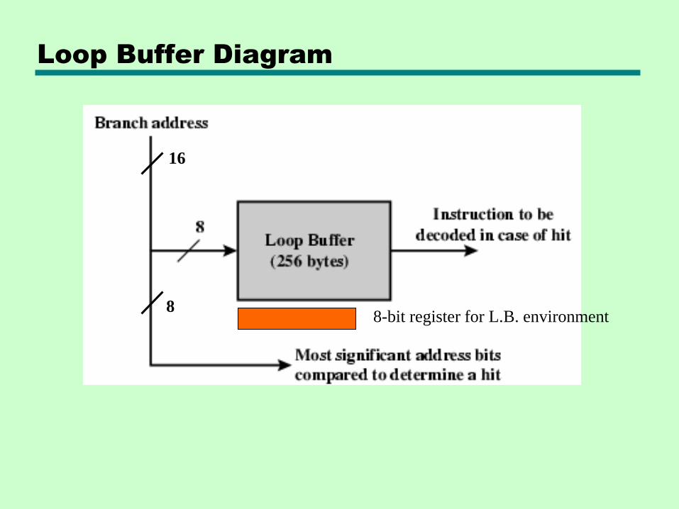
Loop Buffer
• Extends the prefetch approach in another way
—Very fast memory (instruction cache!)
—Maintained by fetch stage of pipeline
—Check buffer before fetching from memory
• Very good for small jumps (if-else, if-then-else) and loops
—Buffer size designed to be able to store all instructions in loop
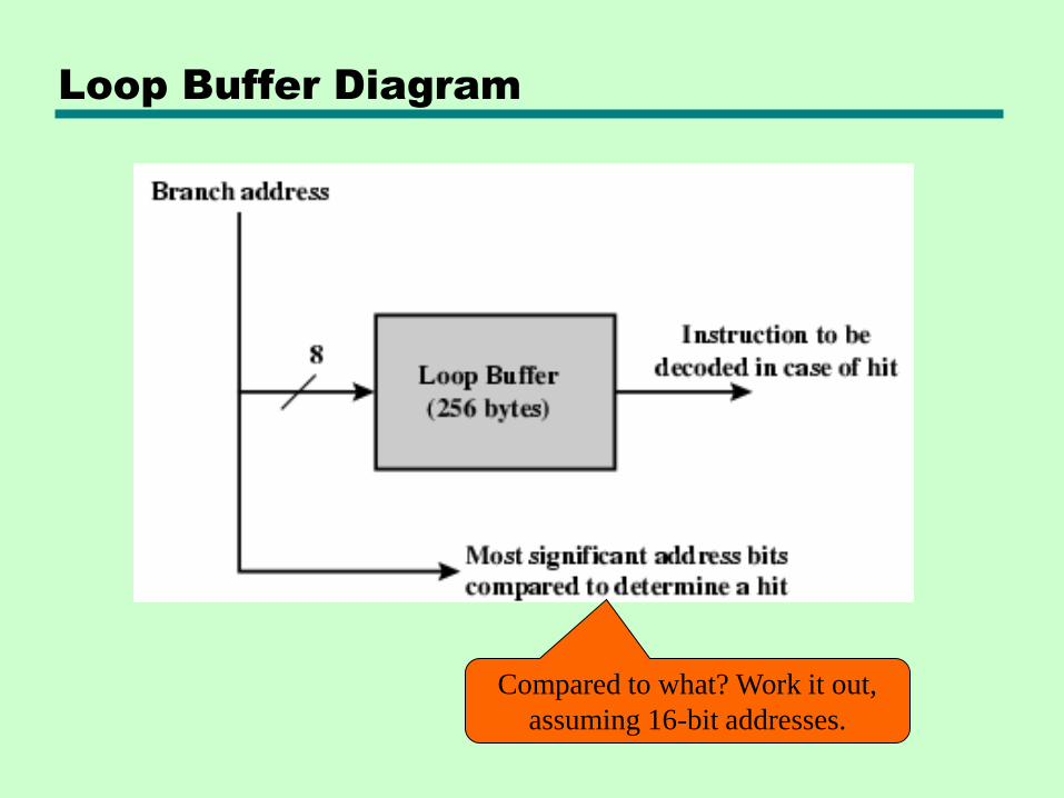
Loop Buffer Diagram
Compared to what? Work it out,
assuming 16-bit addresses.
Loop Buffer Diagram
16
88-bit register for L.B. environment
16
88-bit register for L.B. environment
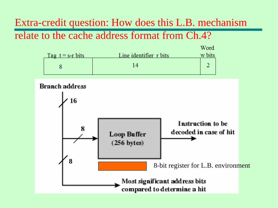
Extra-credit question: How does this L.B. mechanism
relate to the cache address format from Ch.4?
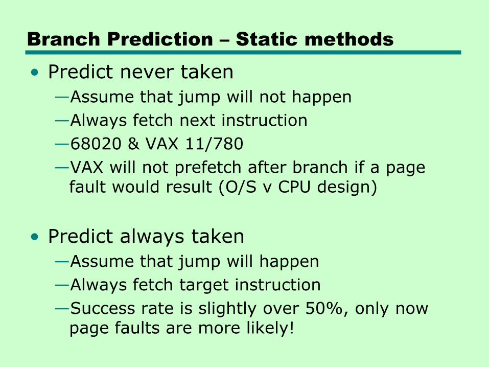
Branch Prediction – Static methods
• Predict never taken
—Assume that jump will not happen
—Always fetch next instruction
—68020 & VAX 11/780
—VAX will not prefetch after branch if a page fault would result (O/S v CPU design)
• Predict always taken
—Assume that jump will happen
—Always fetch target instruction
—Success rate is slightly over 50%, only now page faults are more likely!
Branch Prediction – Static methods
• Predict by Opcode—Based on statistical studies, some instructions
are more likely to result in a jump than others
—Can get up to 75% success
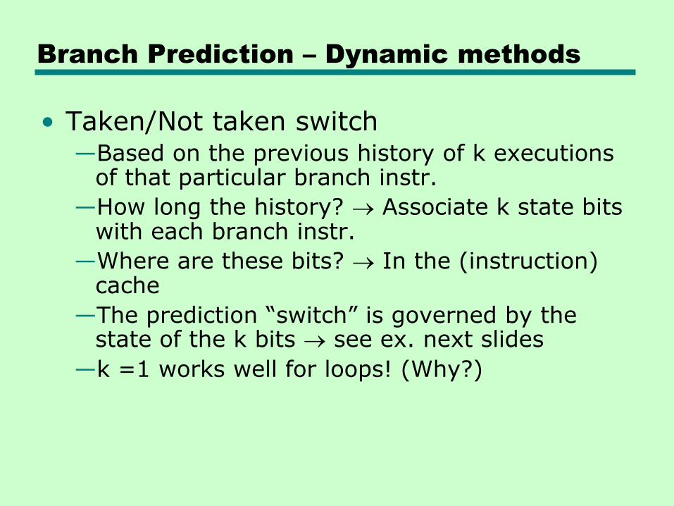
Branch Prediction – Dynamic methods
• Taken/Not taken switch—Based on the previous history of k executions
of that particular branch instr.
—How long the history? Associate k state bits with each branch instr.
—Where are these bits? In the (instruction) cache
—The prediction ―switch‖ is governed by the state of the k bits see ex. next slides
—k =1 works well for loops! (Why?)
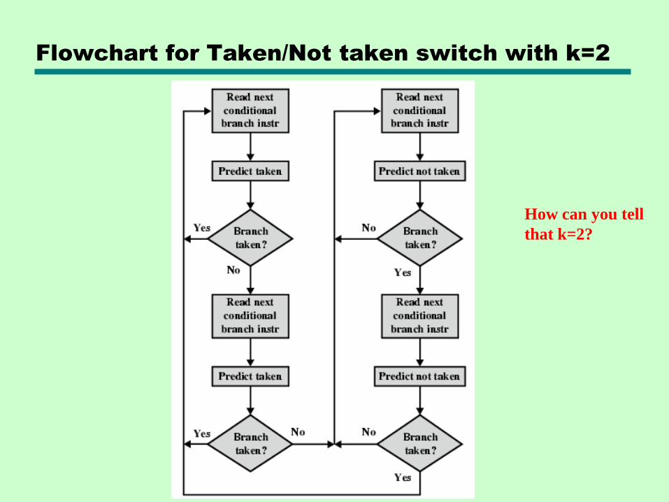
Flowchart for Taken/Not taken switch with k=2
How can you tell
that k=2?
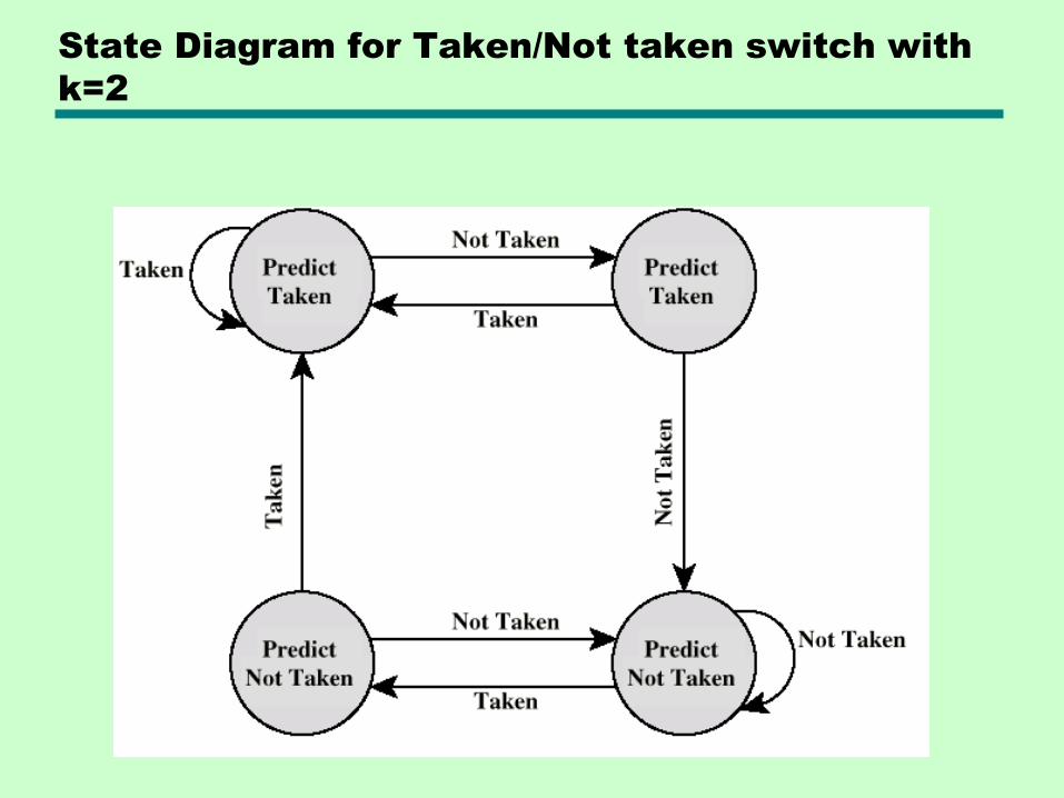
State Diagram for Taken/Not taken switch with
k=2
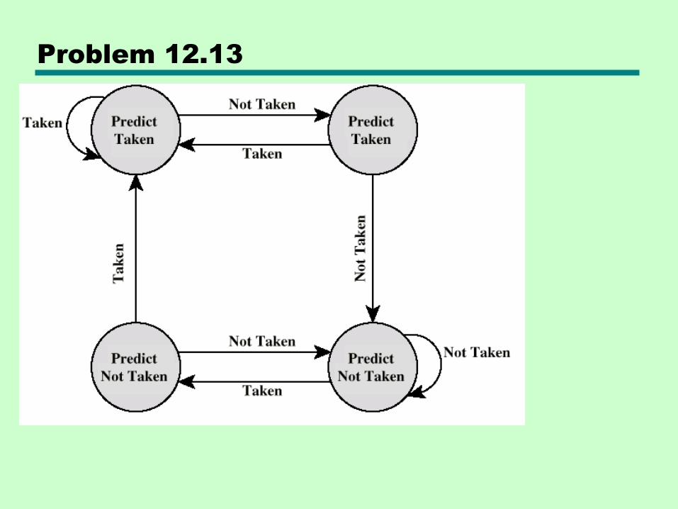
Problem 12.13
Branch Prediction – Dynamic methods
• Improvement of history-bits method: if the branch is predicted taken, it would be nice to have the opcode of the target already prefetched!
Branch Prediction – Dynamic methods
• Correlation-based—In loop-closing branches, history is good
predictor
—In more complex structures, branch direction correlates with that of related branches– Use recent branch history as well
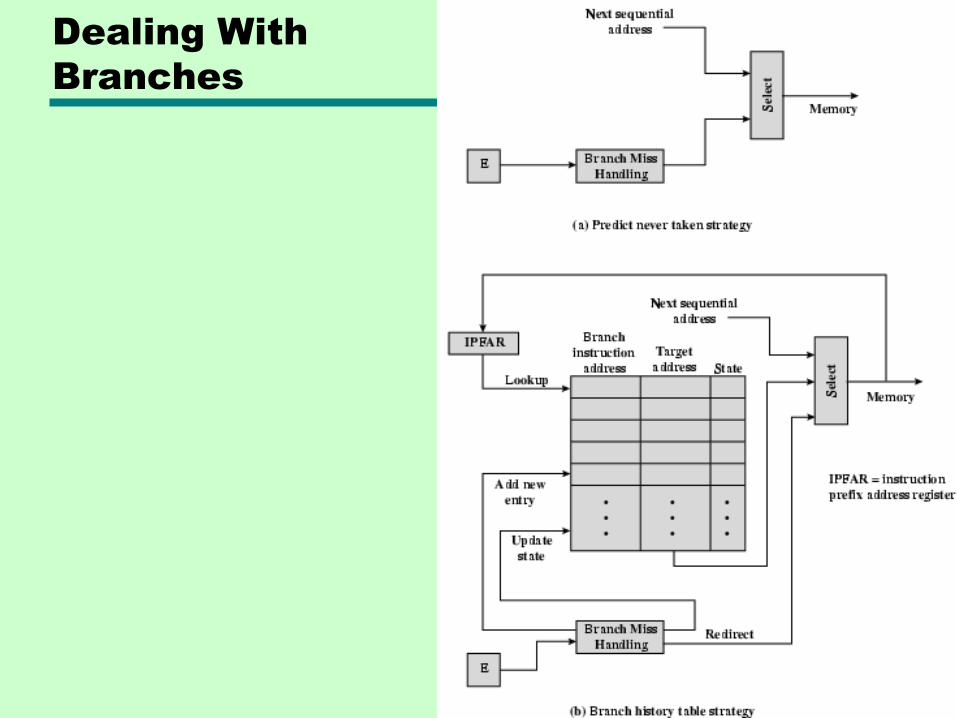
Dealing With
Branches
Branch Prediction – Dynamic methods
• Delayed Branch
—Do not take jump until you have to
—Optimization: Rearrange instructions!
– Does not work for conditional branches whose condition is set by the instruction right before the branch!
– Example on next slide
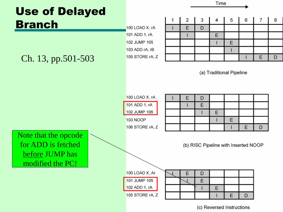
Use of Delayed
Branch
Ch. 13, pp.501-503
Note that the opcode
for ADD is fetched
before JUMP has
modified the PC!
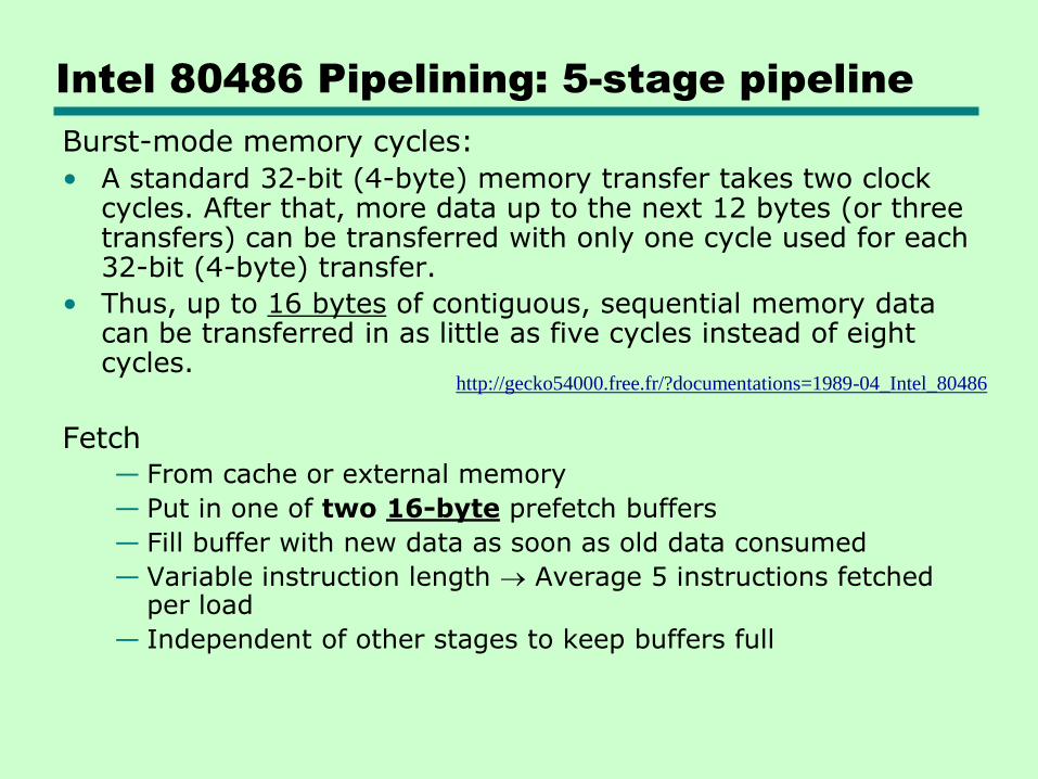
Intel 80486 Pipelining: 5-stage pipeline
Burst-mode memory cycles:
• A standard 32-bit (4-byte) memory transfer takes two clock cycles. After that, more data up to the next 12 bytes (or three transfers) can be transferred with only one cycle used for each 32-bit (4-byte) transfer.
• Thus, up to 16 bytes of contiguous, sequential memory data can be transferred in as little as five cycles instead of eight cycles.
Fetch— From cache or external memory
— Put in one of two 16-byte prefetch buffers
— Fill buffer with new data as soon as old data consumed
— Variable instruction length Average 5 instructions fetched per load
— Independent of other stages to keep buffers full
http://gecko54000.free.fr/?documentations=1989-04_Intel_80486
Intel 80486 Pipelining: 5-stage pipeline
Decode stage 1— Opcode & address-mode info
— The info needed is included in at most first 3 bytes of every instruction
— Can direct D2 stage to get rest of instruction
Decode stage 2— Generate control signals for ALU, based on opcode
— Performs computations needed for complex address modes
Execute— ALU operations, cache access for operands
Writeback— Update registers & flags
— Results sent to cache & bus interface write buffers
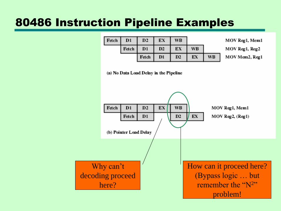
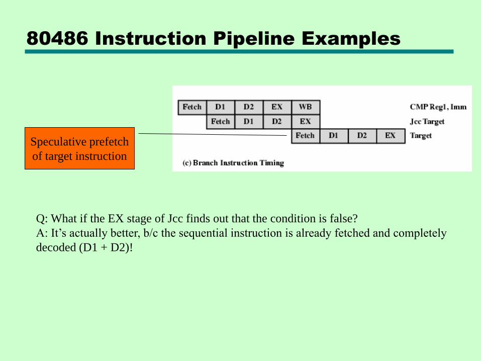
80486 Instruction Pipeline Examples
Why can’t
decoding proceed
here?
How can it proceed here?
(Bypass logic … but
remember the “N2”
problem!
80486 Instruction Pipeline Examples
Q: What if the EX stage of Jcc finds out that the condition is false?
A: It’s actually better, b/c the sequential instruction is already fetched and completely
decoded (D1 + D2)!
Speculative prefetch
of target instruction

SKIP the remainder of Ch.12 (12.5, 12.6)
This concludes the material required for the final.
Review next Tuesday and Thursday!