Embed Size (px)
Citation preview
EDGE and GPRS CS-3/CS-4 in Release B8
Functional Feature Description
EDGE and GPRS CS-3/CS-4 in Release B8
This document covers the following features :
30 06 14: Coding Scheme CS-3
30 06 16: Coding Scheme CS-4
30 07 00: EDGE Coding Schemes
30 07 10: Support of all EDGE Modulation and Coding schemes
30 07 20: EDGE Link adaptation
30 07 30: Incremental Redundancy
30 10 55: Combined GPRS/EDGE resource management
30 14 40: Two incoming A-bis links per BTS
Alcatel File Reference Date Edition Pagedocument.doc v 2 04-KOS-1646 03/05/2004 02 1
All rights reserved. Passing on and copying of this document, use and communication of its contents not permitted without written authorization.
EDGE and GPRS CS-3/CS-4 in Release B8
Contents
1. INTRODUCTION............................................................................................................4
2. HARDWARE SUPPORT................................................................................................4
2.1 Radio equipment performances.............................................................................5
2.1.1 EVOLIUM™ A9100 Base Station :............................................................5
2.1.2 EVOLIUM™ A9110 micro-BTS :...............................................................7
2.2 Support of EDGE in a first generation of EVOLIUM™ BTS....................................8
3. ARCHITECTURE PRINCIPLES :....................................................................................8
3.1 TRX classes concept............................................................................................8
3.2 2 incoming A-bis links per BTS............................................................................10
3.3 Dimensioning rules..............................................................................................11
3.3.1 EDGE/GPRS Capacity in the EVOLIUM™ BTS......................................11
3.3.2 EDGE/GPRS Capacity in the EVOLIUM™ BSC :....................................11
3.3.3 EDGE/GPRS Capacity in the EVOLIUM™ MFS/GPU.............................12
4. EDGE RADIO FEATURES...........................................................................................12
4.1 Modulation and Coding schemes.........................................................................12
4.2 Link adaptation (LA)............................................................................................13
4.3 Incremental Redundancy (IR)..............................................................................14
4.4 The EDGE Family Concept.................................................................................14
4.5 Maximum RLC window size supported by Alcatel BSS........................................15
5. CS-3 / CS-4 RADIO FEATURES.................................................................................15
5.1 Coding schemes.................................................................................................15
5.2 Coding scheme adaptation..................................................................................15
5.3 Activation of high GPRS coding schemes............................................................15
6. RESOURCE MANAGEMENT.......................................................................................17
6.1 Principles of resource management....................................................................17
6.1.1 Ranking of TRX for Circuit / packet allocation..........................................17
6.1.2 Ranking of TRX in mixed BTS configurations..........................................17
6.1.3 Support of EDGE on the BCCH TRX......................................................18
6.2 Dynamic allocation of radio resource...................................................................19
6.3 A-ter resource management................................................................................21
7. GPRS/EDGE FREQUENCY PLANNING......................................................................22
8. MAIN O&M PARAMETERS..........................................................................................22
8.1 EDGE parameters..............................................................................................23
8.2 GPRS CS-3/CS-4 parameters.............................................................................23
9. ANNEXES : QUESTIONS & ANSWERS.......................................................................25
Alcatel File Reference Date Edition Pagedocument.doc v 2 04-KOS-1646 03/05/2004 02 2
All rights reserved. Passing on and copying of this document, use and communication of its contents not permitted without written authorization.

EDGE and GPRS CS-3/CS-4 in Release B8
9.1 Why is A-bis not dynamic ?.................................................................................25
9.2 Why are there limitations in multiplexing EDGE & GPRS TBF on the same
PDCH ?..............................................................................................................26
9.3 Access procedures : how does an EDGE MS perform an access ?.....................28
Alcatel File Reference Date Edition Pagedocument.doc v 2 04-KOS-1646 03/05/2004 02 3
All rights reserved. Passing on and copying of this document, use and communication of its contents not permitted without written authorization.
EDGE and GPRS CS-3/CS-4 in Release B8
1. INTRODUCTION
This document deals with the support of EDGE and the highest coding schemes CS-3 and CS-4 of
GPRS in Alcatel BSS B8.
The scope of the present document is hereafter detailed:
Section 2 deals with the Hardware support of both features
In section 3, architecture principles are presented .
Section 4 describes EDGE radio features.
Section 5 focuses on GPRS CS-3 & CS-4 radio features.
In section 6, Radio Resource Management algorithms are described.
2. HARDWARE SUPPORT
The Alcatel EDGE / GPRS (all coding schemes) solution is very interesting as it minimises the initial
investment. Indeed, its introduction in a GPRS network does not require any new network element.
As a consequence, the existing GPRS network is widely prepared for EDGE/GPRS CS-3&CS-4 on
the hardware part as these features are fully compatible with:
- The A9135 MFS product (PCU function), deployed for GPRS purpose since the B6.2 release,
- The A9120 BSC.
- On the BTS side, EDGE is supported on all A9100 EVOLIUM™ BTS, shipped since 1998,
and the A9110 micro-BTS Evolution.
In addition all TRXs shipped since 2001 in the EVOLIUM™ BTS (EVOLIUM™ Evolution step 2
TRX2) are EDGE compatible. No specific TRX is needed with the Alcatel solution.
2 EVOLIUM™ Evolution step 2 TRX are usually called TRA, while first generation EVOLIUM™ TRX are called
TRE.
Alcatel File Reference Date Edition Pagedocument.doc v 2 04-KOS-1646 03/05/2004 02 4
All rights reserved. Passing on and copying of this document, use and communication of its contents not permitted without written authorization.
EDGE and GPRS CS-3/CS-4 in Release B8
In networks equipped with first generation of EVOLIUM™ BTS, the support of EDGE is achieved by
simple plug & play of the EDGE TRX in the cabinet, one TRX per sector being sufficient to provide
EDGE service.
GPRS Coding Schemes CS-3 & CS-4 are supported by all A9100 EVOLIUM™ BTSs (by all
generations of TRX), by the A9110 micro BTS and by the A9110 micro-BTS Evolution.
2.1 Radio equipment performances
The GPRS/ EDGE features are supported in all GSM bands: 900, 1800, 850 and 1900 MHz.
GSM and GPRS make use of the same GMSK modulation. EDGE makes uses of both GMSK and
8-PSK modulation.
Therefore the output power of EDGE TRX is expressed for both modulations.
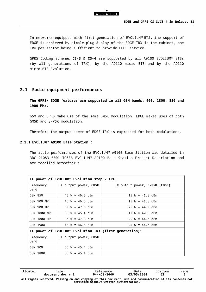
2.1.1 EVOLIUM™ A9100 Base Station :
The radio performances of the EVOLIUM™ A9100 Base Station are detailed in 3DC 21083 0001
TQZZA EVOLIUM™ A9100 Base Station Product Description and are recalled hereafter :
TX power of EVOLIUM™ Evolution step 2 TRX :
Frequency band TX output power, GMSK TX output power, 8-PSK (EDGE)
GSM 850 45 W = 46.5 dBm 15 W = 41.8 dBm
GSM 900 MP 45 W = 46.5 dBm 15 W = 41.8 dBm
GSM 900 HP 60 W = 47.8 dBm 25 W = 44.0 dBm
GSM 1800 MP 35 W = 45.4 dBm 12 W = 40.8 dBm
GSM 1800 HP 60 W = 47.8 dBm 25 W = 44.0 dBm
GSM 1900 45 W = 46.5 dBm 25 W = 44.0 dBm
TX power of EVOLIUM™ Evolution TRX (first generation):
Frequency band TX output power, GMSK
GSM 900 35 W = 45.4 dBm
GSM 1800 35 W = 45.4 dBm
In GSM 900 and 1800, two types of TRX support EDGE and GPRS: the Medium Power (MP) TRX
and High Power (HP) TRX. It is up to the Operator to select the TRX type, depending on the
environment and required radio data throughputs.
Alcatel File Reference Date Edition Pagedocument.doc v 2 04-KOS-1646 03/05/2004 02 5
All rights reserved. Passing on and copying of this document, use and communication of its contents not permitted without written authorization.
EDGE and GPRS CS-3/CS-4 in Release B8
Why is there a difference between GMSK and 8-PSK output power ?
8-PSK modulation brings severe constraints on linearity because of its non-constant modulation
envelope: Power amplifiers can not be used at their maximum power, unlike with GMSK modulation.
This results in a difference between maximum output power for GMSK and 8-PSK modulations,
called back-off or sometimes APD (Average Power Decrease). The impact of the back-off is
relatively small, and only determines the extent of the 8-PSK coverage ,which depends on the radio
environment as well . In urban areas the impact is smaller than in rural environment.
RX sensitivity of TRX :
The RX sensitivity of the TRX allows the delivery at antenna connector of the following values
independently from the frequency band.
Reference sensitivity, GMSK : - 111 dBm (static and dynamic)
Reference sensitivity, 8-PSK (EDGE):< -111 dBm, (static, MCS-1)-108 dBm, (static, MCS-5)-99 dBm, (static, MCS-9)
Why is there a difference in sensitivity between various MCS ?
3GPP standard (Rec. 05.05) defines various sensitivity levels for various MCS. These different
sensitivities simply mean that high throughputs (high MCS) require better radio conditions (higher
signal to noise ratio) than lower data throughputs. The noise factor in the BTS is kept unchanged,
whatever the coding scheme.
Alcatel File Reference Date Edition Pagedocument.doc v 2 04-KOS-1646 03/05/2004 02 6
All rights reserved. Passing on and copying of this document, use and communication of its contents not permitted without written authorization.
EDGE and GPRS CS-3/CS-4 in Release B8
2.1.2 EVOLIUM™ A9110 micro-BTS :
A9110 micro-BTS Evolution :
The radio performances of the EVOLIUM™ A9110-E Micro-BTS are detailed in 3DC 21083 0003
TQZZA Ed. 07 EVOLIUM™ A9110 Micro-BTS Product Description and are recalled hereafter :
Frequency bandNb of antennas
TX output power, GMSK TX output power, 8-PSK (EDGE)
GSM 850 & 900
1 antenna
3.2 W = 35.1 dBm 2.3 W = 33.6 dBm
GSM 1800 & 1900
1 antenna
3.2 W = 35.1 dBm 1.8 W = 32.6 dBm
GSM 850 & 900
2 antennas
7.0 W = 38.5 dBm 5.0 W = 37.0 dBm
GSM 1800 & 1900
2 antennas
7.0 W = 38.5 dBm 4.0 W = 36.0 dBm
Reference sensitivity, GMSK : - 110 dBm (static and dynamic)
Reference sensitivity, 8-PSK (EDGE):< -110 dBm, (static, MCS-1)-1068 dBm, (static, MCS-5)-96 dBm, (static, MCS-9)
A9110 micro-BTS :
TX output power : GMSK : 2 W or 33 dBm
In low Loss configuration, GMSK : 4.5 W or 36.5 dBm
The sensitivity of A9110 BTSs (at the BTS antenna connector) is -107 dBm.
Alcatel File Reference Date Edition Pagedocument.doc v 2 04-KOS-1646 03/05/2004 02 7
All rights reserved. Passing on and copying of this document, use and communication of its contents not permitted without written authorization.
EDGE and GPRS CS-3/CS-4 in Release B8
2.2 Support of EDGE in a first generation of EVOLIUM™ BTS
The Operator simply has to plug as many EDGE TRX (TRA) as EDGE traffic requires.
EDGE TRX (TRA) may provide with a higher GMSK output power than TRE (indeed, a TRE 900
offers 35W while a Medium Power TRA offers 45W)
In case of mixed TRA / TRE configuration, GMSK output power of the EDGE TRX is
automatically aligned to the power of the TRE of the cell, while the 8-PSK output power is
kept untouched.
As a consequence, in a GSM 900 BTS made of a mix of TRE and TRA, the power per TRX will be:
GMSK 8-PSK
High Power TRA : 60 W 35 W 25W
Medium Power TRA : 45 W 35 W 15 W
3. ARCHITECTURE PRINCIPLES :
With the introduction of EDGE or GPRS CS-3/CS-4, a new technical issue appears: the throughput
on the air interface becomes too big and the data traffic corresponding to one radio timeslot cannot
anymore be transported over one single 16kb/s nibble on the terrestrial (A-bis or A-ter) interface, as
it was the case with voice or low data rates; it thus becomes mandatory to use higher bandwidth on
A-bis and A-ter.
The Alcatel solution consists in using several 16kb/s nibbles on A-bis and A-ter interfaces for the
transport of one radio timeslot supporting EDGE or GPRS CS-3 / CS-4.
3.1 TRX classes concept
To support these high data throughputs, Alcatel has developed a solution, which aims at providing
the best trade-off between offered radio throughput and impact on the telecom resource
consumption.
This solution is based on the concept of multiple classes of TRX, which support more or less data
throughput. The higher the packet class, the higher the maximum data throughput, the higher the
impact on BSS Telecom resources.
Alcatel File Reference Date Edition Pagedocument.doc v 2 04-KOS-1646 03/05/2004 02 8
All rights reserved. Passing on and copying of this document, use and communication of its contents not permitted without written authorization.

EDGE and GPRS CS-3/CS-4 in Release B8
Five TRX classes have been defined :
TRX class Supported packet coding scheme
Class 1“Simple” TRX
CS 1,2MCS 1,2
Class 2“Double” TRX
CS 1,2,3,4MCS 1,2,3,4,5,
Class 3“Triple” TRX
CS 1,2,3,4MCS 1,2,3,4,5,6,
Class 4“Quad” TRX
CS 1,2,3,4MCS 1,2,3,4,5,6,7,8
Class 5“Quintuple” TRX
CS 1,2,3,4MCS 1,2,3,4,5,6,7,8,9
All TRX, whatever their class, support also voice traffic.
The Operator defines per cell the number of TRXs of each class. A class 3 TRX offers up to 30 kb/s
per radio timeslot, while a class 1 offers up to 11 kb/s. As a consequence, a class 3 TRX consumes
on the A-bis interface three times more than a class 1 TRX.
The following figures illustrate the example of a cell with one Class 3 TRX and two Simple TRX - the
triple TRX is transported over 6 64 kbps timeslots on A-bis.
1 PDCH = 3 terrestrial nibbles = 1 “main nibble”, also used for voice
+ 2 additional nibbles, only used for packet
Radio
TRX1
TRX2
TRX3
B S
Cell
RSL
TRX1
TRX2
TRX3
Abis
3 nibbles
EDGE TRX (triple)
Main nibbles:voice &packet
additional nibbles:packetonly
The distribution of the TRX classes is a choice let to the Operator according to the expected data
traffic, the radio conditions and the requested data throughput:
Alcatel File Reference Date Edition Pagedocument.doc v 2 04-KOS-1646 03/05/2004 02 9
All rights reserved. Passing on and copying of this document, use and communication of its contents not permitted without written authorization.
EDGE and GPRS CS-3/CS-4 in Release B8
For example in a rural environment with large cells, the proportion of mobiles which could get benefit
from the highest Modulation & Coding Schemes is quite low, and the mean data throughput with a
class 3 TRX is almost as high as the one obtained with a class 5 TRX.
3.2 2 incoming A-bis links per BTS
The EVOLIUM™ BTS can support up to 12 TRX. For such large configuration, and when filled with
simple TRXs, a single PCM (2Mb/s E1 link) is already almost full. To support EDGE in such large
BTS, The EVOLIUM™ BTS is able to transport data on a second E1 link.
The following table provides non exhaustive examples of the supported configurations, with one or
two E1 links:
BTS configuration One A-bis link per BTS
Possible distribution of TRX
per cell
Two A-bis links per BTS
Possible distribution of TRX
per cell
BTS 12 TRX
3 cells @ 4 TRX
4 simple TRX 1 class 5 + 1 double TRX + 2 simple TRX
or
1 triple + 3 double TRX
or
1 triple TRX+ 1 quad TRX +2 simple TRX
BTS 9TRX
3 cells @ 3 TRX
1 double + 2 simple TRX
2 quad TRX + 1 simple TRX
or
3 triple TRX
BTS 6TRX
3 cells @ 2 TRX
1 triple + 1 simple TRX
2 quad TRX
BTS 3 TRX
3 cells @ 1 TRX
1 class 5 TRX
The second incoming A-bis link of a BTS is used for packet traffic only. The first link is used for both
packet and circuit.
A parameter MAX_EXTRA_TS_PRIMARY defines the number of additional A-bis timeslots
dedicated to packet on the primary link. This allows the Operator keeping some free timeslots on the
primary link, for example in anticipation of a further TRX extension of the BTS.
Alcatel File Reference Date Edition Pagedocument.doc v 2 04-KOS-1646 03/05/2004 02 10
All rights reserved. Passing on and copying of this document, use and communication of its contents not permitted without written authorization.
EDGE and GPRS CS-3/CS-4 in Release B8
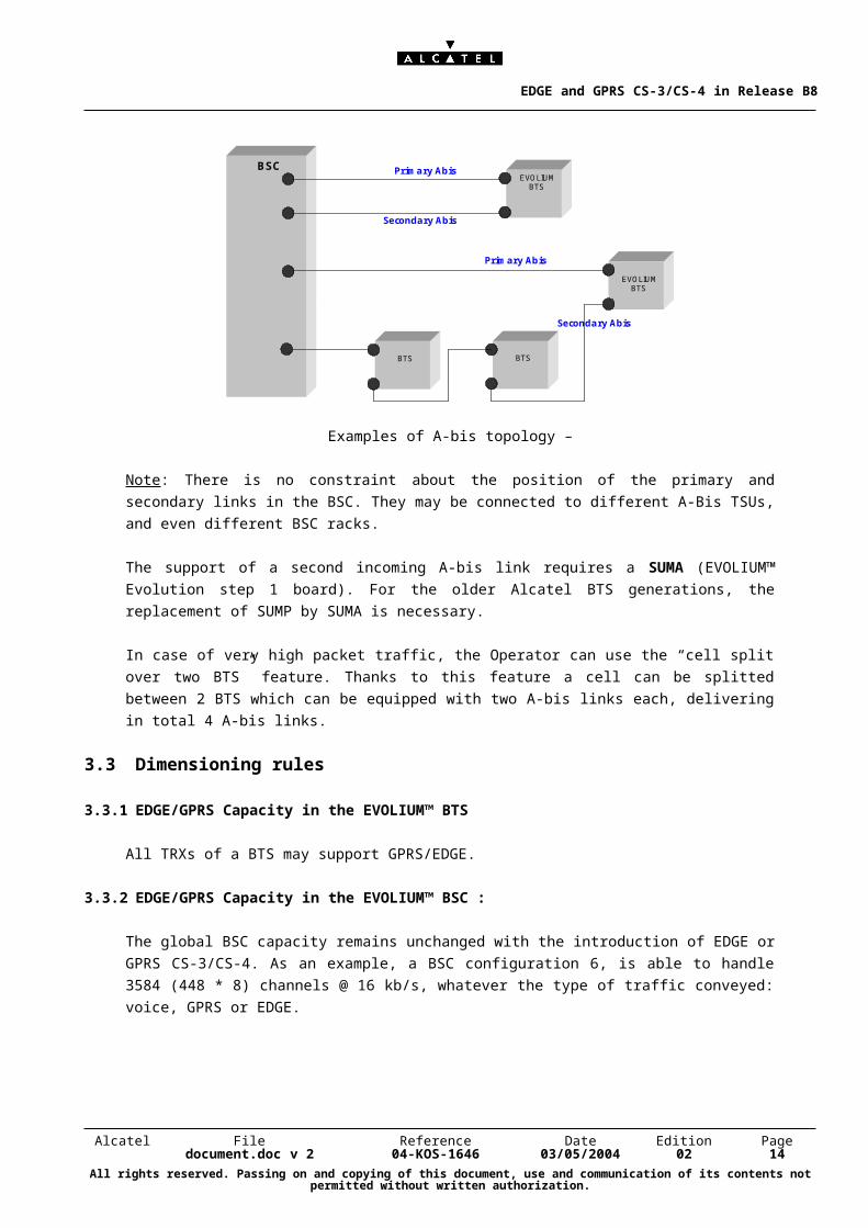
The following figure depicts examples of A-bis topology. Primary link is directly connected from BSC
to BTS. Secondary link may terminate a daisy chain.
BSC
BTS
EVOLIUMBTS
Primary Abis
Secondary Abis
Primary Abis
Secondary Abis
EVOLIUMBTS
BTS
Examples of A-bis topology –
Note: There is no constraint about the position of the primary and secondary links in the BSC. They
may be connected to different A-Bis TSUs, and even different BSC racks.
The support of a second incoming A-bis link requires a SUMA (EVOLIUM™ Evolution step 1 board).
For the older Alcatel BTS generations, the replacement of SUMP by SUMA is necessary.
In case of very high packet traffic, the Operator can use the “cell split over two BTS” feature.
Thanks to this feature a cell can be splitted between 2 BTS which can be equipped with two A-bis
links each, delivering in total 4 A-bis links.
3.3 Dimensioning rules
3.3.1 EDGE/GPRS Capacity in the EVOLIUM™ BTS
All TRXs of a BTS may support GPRS/EDGE.
3.3.2 EDGE/GPRS Capacity in the EVOLIUM™ BSC :
The global BSC capacity remains unchanged with the introduction of EDGE or GPRS CS-3/CS-4.
As an example, a BSC configuration 6, is able to handle 3584 (448 * 8) channels @ 16 kb/s,
whatever the type of traffic conveyed: voice, GPRS or EDGE.
In terms of number of TRX, the support of “one class N” TRX consumes in the BSC the equivalent
of the connectivity consumed by N simple Full Rate TRXs.
Alcatel File Reference Date Edition Pagedocument.doc v 2 04-KOS-1646 03/05/2004 02 11
All rights reserved. Passing on and copying of this document, use and communication of its contents not permitted without written authorization.
EDGE and GPRS CS-3/CS-4 in Release B8
This is similar to the management of Dual Rate TRXs, where one DR TRX is equivalent to 2 FR
TRX.
In the same way, for high data traffic, we will have :
1 class 2 TRX ~ 2 FR TRX,
1 class 3 TRX ~ 3 FR TRX
1 class 4 TRX ~ 4 FR TRX
1 class 5 TRX ~ 5 FR TRX.
It has to be noted that Dual Rate can be also supported on a class N TRX ; the support of “one dual
rate class N” TRX consumes in the BSC the equivalent of the connectivity consumed by (N+1)
simple Full Rate TRXs.
3.3.3 EDGE/GPRS Capacity in the EVOLIUM™ MFS/GPU
The GPU is able to handle both GPRS and EDGE traffic.
The maximum number of simultaneously active PDCH obviously depends on the type of the PDCH,
as an EDGE MCS-9 PDCH transports much more data than a GPRS CS-2 PDCH.
The number of GPU to address the packet traffic can be increased up to 6 GPU per BSS.
More information about Dimensioning Rules can be obtained in “Dimensioning Rules for CS and PS
traffic with BSS Software Release B8” .
4. EDGE RADIO FEATURES
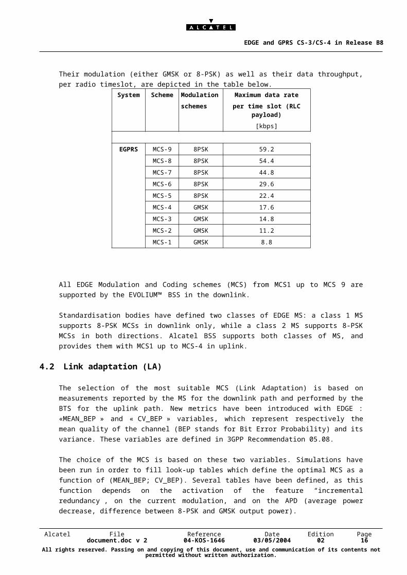
4.1 Modulation and Coding schemes
Nine Modulation and Coding Schemes have been defined by the Standard for E-GPRS.
Their modulation (either GMSK or 8-PSK) as well as their data throughput, per radio timeslot, are
depicted in the table below.
Alcatel File Reference Date Edition Pagedocument.doc v 2 04-KOS-1646 03/05/2004 02 12
All rights reserved. Passing on and copying of this document, use and communication of its contents not permitted without written authorization.
EDGE and GPRS CS-3/CS-4 in Release B8
System Scheme Modulation
schemes
Maximum data rate
per time slot (RLC payload)
[kbps]
EGPRS MCS-9 8PSK 59.2
MCS-8 8PSK 54.4
MCS-7 8PSK 44.8
MCS-6 8PSK 29.6
MCS-5 8PSK 22.4
MCS-4 GMSK 17.6
MCS-3 GMSK 14.8
MCS-2 GMSK 11.2
MCS-1 GMSK 8.8
All EDGE Modulation and Coding schemes (MCS) from MCS1 up to MCS 9 are supported by the
EVOLIUM™ BSS in the downlink.
Standardisation bodies have defined two classes of EDGE MS: a class 1 MS supports 8-PSK MCSs
in downlink only, while a class 2 MS supports 8-PSK MCSs in both directions. Alcatel BSS supports
both classes of MS, and provides them with MCS1 up to MCS-4 in uplink.
4.2 Link adaptation (LA)
The selection of the most suitable MCS (Link Adaptation) is based on measurements reported by
the MS for the downlink path and performed by the BTS for the uplink path. New metrics have been
introduced with EDGE : «MEAN_BEP » and « CV_BEP » variables, which represent respectively
the mean quality of the channel (BEP stands for Bit Error Probability) and its variance. These
variables are defined in 3GPP Recommendation 05.08.
The choice of the MCS is based on these two variables. Simulations have been run in order to fill
look-up tables which define the optimal MCS as a function of (MEAN_BEP; CV_BEP). Several
tables have been defined, as this function depends on the activation of the feature “incremental
redundancy”, on the current modulation, and on the APD (average power decrease, difference
between 8-PSK and GMSK output power).
Alcatel File Reference Date Edition Pagedocument.doc v 2 04-KOS-1646 03/05/2004 02 13
All rights reserved. Passing on and copying of this document, use and communication of its contents not permitted without written authorization.
EDGE and GPRS CS-3/CS-4 in Release B8
4.3 Incremental Redundancy (IR)
In addition to Link Adaptation, the feature Incremental Redundancy3 is introduced for EGPRS. This
function was specified by ETSI as optional for base stations and mandatory for mobiles. The Alcatel
BSS implementation makes use of this feature.
If a block transmitted by the BTS is not properly decoded in the first instance, the bits are stored in
the mobile, as “soft bits”. The same block is repeated with a different puncturing scheme. The
resulting soft bits of the second (and, if necessary, third) transmission are then combined with the
previously transmitted block(s). The decoding is then based on several transmissions and not only
one: this is called joint decoding. This improves the likelihood of ending up with the correct data.
Even if one block of data is found to be not good, it still can be used to improve the total bit error
rate of the system.
In B8 Release, Incremental Redundancy is supported in downlink.
Thanks to Incremental Redundancy, the link adaptation procedure can be more aggressive : if the
chosen MCS is a bit too optimistic, the general quality will not be affected, as Incremental
Redundancy will correct it thanks to joint decoding. However it would be quite dangerous to rely on
Incremental redundancy only since there may be memory shortage in the MS, and the TBF would
then be lost. If the MS indicates that IR operation shall be stopped, the Alcatel BSS will switch to a
mode where IR is not used, which is referred to as type 1 ARQ.
For optimal radio performances, the Alcatel BSS combines both Incremental Redundancy and Link
Adaptation.
4.4 The EDGE Family Concept
In EDGE the family concept allows to change the modulation and coding scheme within a given
family during re-transmission. The re-transmission of a block may be done with the same MCS as
used for the first transmission or with a different more robust MCS.
The Alcatel equipment is fully compliant with this feature.
There are 3 families of modulation and coding schemes:
- family A: MCS-3, MCS-6, MCS-8 and MCS-9
- family B: MCS-2, MCS-5 and MCS-7
- family C: MCS-1 and MCS-4
3 Incremental Redundancy is also referred to as type 2 ARQ (Automatic Repeat Request) mechanism.
Alcatel File Reference Date Edition Pagedocument.doc v 2 04-KOS-1646 03/05/2004 02 14
All rights reserved. Passing on and copying of this document, use and communication of its contents not permitted without written authorization.
EDGE and GPRS CS-3/CS-4 in Release B8
4.5 Maximum RLC window size supported by Alcatel BSS
Contrary to GPRS, where the maximum RLC window size has a fixed value equal to 64, the EDGE
maximum window size depends on the multislot characteristic of the TBF. The maximum window
size implemented in Alcatel BSS is 512, which is the maximum supported by a 4 timeslots capable
MS, as defined in 3GPP 04.60.
5. CS-3 / CS-4 RADIO FEATURES
5.1 Coding schemes
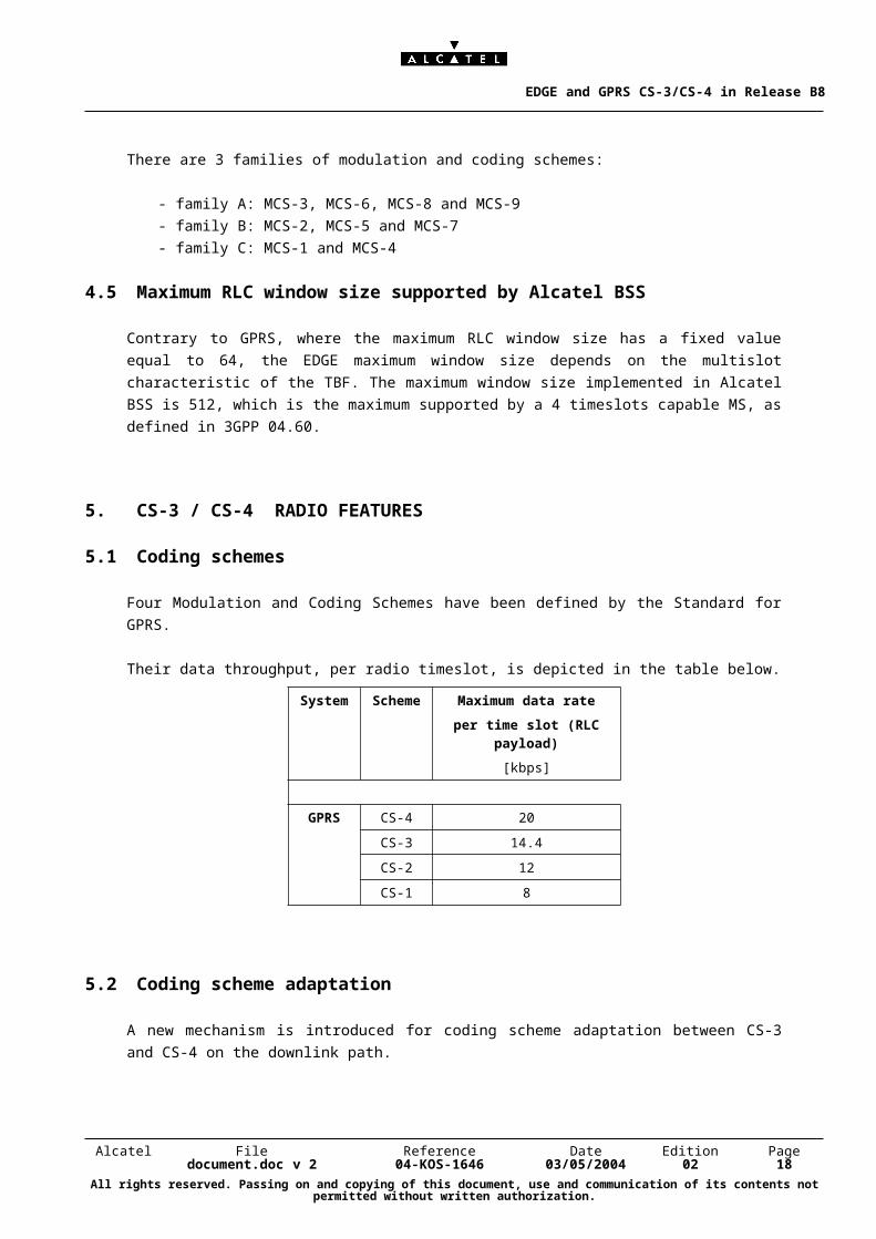
Four Modulation and Coding Schemes have been defined by the Standard for GPRS.
Their data throughput, per radio timeslot, is depicted in the table below.
System Scheme Maximum data rate
per time slot (RLC payload)
[kbps]
GPRS CS-4 20
CS-3 14.4
CS-2 12
CS-1 8
5.2 Coding scheme adaptation
A new mechanism is introduced for coding scheme adaptation between CS-3 and CS-4 on the
downlink path.
Actually this new mechanism is mandatory, as RXQUAL may be not relevant in CS-4 (3GPP
recommendations allow the MS to report systematically a value of 7).
A new metric is therefore used : it is an estimation of SIR (Signal to Interference Ratio), based on
measurements reported by the Mobiles . These measurements, called I_level (level of interference),
are defined in Rec. 05.08. It may happen that I_level is not transmitted by the MS to the BSS ( in
case of usage of BCCH frequency). In this case, the BSS performs an estimation of the Block Error
Rate (BLER).
This metric (SIR or possibly BLER) is used for CS-4 to CS-3 adaptation.
Alcatel File Reference Date Edition Pagedocument.doc v 2 04-KOS-1646 03/05/2004 02 15
All rights reserved. Passing on and copying of this document, use and communication of its contents not permitted without written authorization.
EDGE and GPRS CS-3/CS-4 in Release B8
The adaptation from CS-3 to CS-4 makes usage of both RXQUAL and I_level (resp. BLER).
RXQUAL is used for coding scheme adaptation between CS-2 and CS-3.
In the uplink path, RXQUAL is always used for coding scheme adaptation.
5.3 Activation of high GPRS coding schemes
The Operator may define, for each cell, the maximum GPRS coding scheme allowed in this cell,
through an O&M parameter MAX_GPRS_CS. This parameter can take the values CS-2, CS-3 or
CS-4.
Indeed, the choice of the Operator will be determined by the radio conditions in the cell and the
maximum expected throughput.
As CS-4 is not recommended in case of frequency hopping, the choice of CS-3 in a cell where
EDGE and frequency hopping are activated bring high GPRS data throughput at no additional cost.
Alcatel File Reference Date Edition Pagedocument.doc v 2 04-KOS-1646 03/05/2004 02 16
All rights reserved. Passing on and copying of this document, use and communication of its contents not permitted without written authorization.
EDGE and GPRS CS-3/CS-4 in Release B8
6. RESOURCE MANAGEMENT
6.1 Principles of resource management
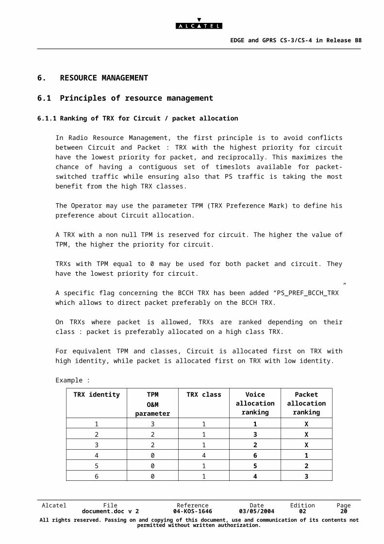
6.1.1 Ranking of TRX for Circuit / packet allocation
In Radio Resource Management, the first principle is to avoid conflicts between Circuit and Packet :
TRX with the highest priority for circuit have the lowest priority for packet, and reciprocally. This
maximizes the chance of having a contiguous set of timeslots available for packet-switched traffic
while ensuring also that PS traffic is taking the most benefit from the high TRX classes.
The Operator may use the parameter TPM (TRX Preference Mark) to define his preference about
Circuit allocation.
A TRX with a non null TPM is reserved for circuit. The higher the value of TPM, the higher the
priority for circuit.
TRXs with TPM equal to 0 may be used for both packet and circuit. They have the lowest priority for
circuit.
A specific flag concerning the BCCH TRX has been added “PS_PREF_BCCH_TRX” which allows to
direct packet preferably on the BCCH TRX.
On TRXs where packet is allowed, TRXs are ranked depending on their class : packet is preferably
allocated on a high class TRX.
For equivalent TPM and classes, Circuit is allocated first on TRX with high identity, while packet is
allocated first on TRX with low identity.
Example :
TRX identity TPM
O&M parameter
TRX class Voice allocation ranking
Packet allocation ranking
1 3 1 1 X
2 2 1 3 X
3 2 1 2 X
4 0 4 6 1
5 0 1 5 2
6 0 1 4 3
Alcatel File Reference Date Edition Pagedocument.doc v 2 04-KOS-1646 03/05/2004 02 17
All rights reserved. Passing on and copying of this document, use and communication of its contents not permitted without written authorization.
EDGE and GPRS CS-3/CS-4 in Release B8
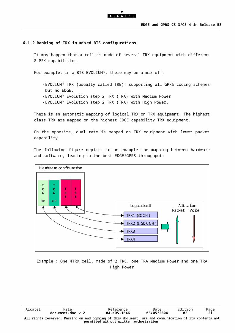
6.1.2 Ranking of TRX in mixed BTS configurations
It may happen that a cell is made of several TRX equipment with different 8-PSK capabilities.
For example, in a BTS EVOLIUM™, there may be a mix of :
- EVOLIUM™ TRX (usually called TRE), supporting all GPRS coding schemes but no EDGE,
- EVOLIUM™ Evolution step 2 TRX (TRA) with Medium Power
- EVOLIUM™ Evolution step 2 TRX (TRA) with High Power.
There is an automatic mapping of logical TRX on TRX equipment. The highest class TRX are
mapped on the highest EDGE capability TRX equipment.
On the opposite, dual rate is mapped on TRX equipment with lower packet capability.
The following figure depicts in an example the mapping between hardware and software, leading to
the best EDGE/GPRS throughput:
TRE
TRE
TRA
MP
TRA
HP
Hardware configuration
Logical cell
TRX1 (BCCH)
TRX2 (1 SDCCH)
TRX3
TRX4
Packet VoiceAllocation
Example : One 4TRX cell, made of 2 TRE, one TRA Medium Power and one TRA High Power
Alcatel File Reference Date Edition Pagedocument.doc v 2 04-KOS-1646 03/05/2004 02 18
All rights reserved. Passing on and copying of this document, use and communication of its contents not permitted without written authorization.
EDGE and GPRS CS-3/CS-4 in Release B8
6.1.3 Support of EDGE on the BCCH TRX
Support of EDGE on the BCCH TRX is possible. However the activation of EDGE on the BCCH
TRX should be performed cautiously. 3GPP Rec. 05.08 has defined a constraint on the transmitted
power of BCCH frequency. This frequency shall usually be transmitted at a constant level. A
tolerance has been introduced with 8-PSK modulation : a fluctuation of up to 2 dB is allowed.
Depending on the configuration in the BTS, it may happen that the difference between GMSK and 8-
PSK power on the BCCH TRX is greater than 2dB. In this case, the Operator is informed that the
back-off is high, and that EDGE should not be activated on the BCCH TRX.
6.2 Dynamic allocation of radio resource
The principles which are applied since the introduction of GPRS in Release B6 are kept for EDGE
(“capacity on demand”). They use the allocation of dynamic pools for circuit and for packet,
depending on the traffic conditions in the cell.
Inside the packet pool, new mechanisms are introduced for the management of GPRS/EDGE traffic.
The main principles are the following :
There are no dedicated (reserved) resource for EDGE traffic: this would be difficult to be tuned by
the Operator, as the penetration of EDGE handsets will increase progressively.
Both GPRS and EDGE traffic are directed to the highest class TRX,
When GPRS and EDGE MS are mixed on the same timeslots, the GPRS traffic is “pushed” towards
timeslots without EDGE, to allow a maximum EDGE traffic availability.
More details on GPRS and EDGE Resource management :
The packet resource management algorithm aims at maximising data throughputs, both for EDGE
and GPRS. Therefore the allocation is performed first on the highest class TRX.
Hereafter are detailed mechanisms which are triggered, when the most suitable timeslots (on the
highest class TRX) are already busy. They depend on the type of the new TBF (EDGE or GPRS)
and on the type of the already allocated TBF :
Already allocated : GPRS or EDGE TBF; new demand : GPRS TBF
As in previous BSS Releases, this GPRS TBF is allocated on other PDCH, as long as packet
resources are available. Otherwise the new GPRS TBF shares PDCH with previously allocated
TBF, until the maximum number of piled TBF is reached.
Alcatel File Reference Date Edition Pagedocument.doc v 2 04-KOS-1646 03/05/2004 02 19
All rights reserved. Passing on and copying of this document, use and communication of its contents not permitted without written authorization.
EDGE and GPRS CS-3/CS-4 in Release B8
Already allocated : GPRS TBF, new demand : EDGE TBF
The EDGE TBF is allocated in the same way as if the GPRS TBF was not present. The GPRS TBF
becomes a candidate for reallocation, and is pushed through this reallocation towards other radio
timeslots. This is performed through a new reallocation process, which is triggered for a GPRS UL
when it shares at least one PDCH with a downlink EDGE TBF. Before the re-allocation is
performed, the EDGE TBF is limited to GMSK modulation (see the annex for more details about the
limitations in multiplexing EDGE and GPRS on the same timeslot).
Already allocated : EDGE TBF, new demand : EDGE TBF
In order to take into account the various throughputs offered by the different EDGE capable TRXs,
specific conditions are defined for TRX selection in case of a new EDGE TBF establishment.
Consequently, as long as the TRXs with the highest throughput do not support a maximum number
of EDGE TBF, the other EDGE capable TRXs (of lower class) are not chosen for EDGE allocation.
As a summary, it is preferred to pile several EDGE TBF on the same high class TRX, rather than
spreading them over TRX of lower class.
Parameters have been defined which indicate for each TRX class the number of TBFs beyond
which it becomes more interesting to serve new EDGE MS on TRX with a lower EGPRS capability.
As an example, in a cell with a class 5 TRX and a class 2 TRX, two EDGE TBF will be piled upon
the class 5 TRX before allocating an EDGE TBF on the class 2 TRX.
TBF Re-allocation
The mechanisms for re-allocation defined in Alcatel B7 Release for GPRS MS apply also for EDGE
and GPRS TBF in B8.
There were three types of re-allocation :
The immediate resource re-allocation upon packet resources decrease (due to load increase in the
cell),
The immediate resource re-allocation upon concurrent TBF establishment,
The re-allocation of the TBF which is allocated less timeslots than its multislot capability.
In addition, an EDGE TBF may be re-allocated if it is not established on the highest class TRX .
This criteria applies for EDGE MS only.
Alcatel File Reference Date Edition Pagedocument.doc v 2 04-KOS-1646 03/05/2004 02 20
All rights reserved. Passing on and copying of this document, use and communication of its contents not permitted without written authorization.
EDGE and GPRS CS-3/CS-4 in Release B8
A GPRS TBF will be re-allocated if it shares timeslots with EDGE, as mentioned in the previous
paragraph.
It has to be noted that a re-allocation can not change the type of the TBF, as this has not been
standardised : an EDGE TBF can only be re-allocated as an EDGE TBF, while a GPRS TBF is re-
allocated as a GPRS TBF.
Maximum number of timeslots allocated to an EDGE or GPRS MS :
A mobile may have different multislot classes for EDGE and for GPRS. The Alcatel BSS makes use
of the EDGE multislot class, for allocating an EDGE TBF.
There is no difference between GPRS and EDGE in the maximum number of timeslots which can
be allocated.
The Alcatel BSS supports the dynamic allocation MAC mode.
The BSS always tries to allocate the maximum number of timeslots to one MS. The theoretical
maximum number of consecutive timeslots that can be allocated to a MS by the BSS depends on
whether the MS is half-duplex or full-duplex :
full-duplex MS will be allocated up to 5 timeslots for uplink and 5 timeslots for downlink,
half-duplex MS will be allocated up to 4 timeslots in the downlink path and 2 timeslots in the uplink
path for TX.
Maximum number of MS which can share a radio timeslot :
There is no difference between GPRS and EDGE in number of MS which can share a PDCH.
Up to 6 TBF on the uplink and 10 TBF on the downlink can be allocated.
The Operator may reduce the maximum number of TBF in each direction through O&M parameters
(MAX_UL_TBF_SPDCH & MAX_DL_TBF_SPDCH).
6.3 A-ter resource management
As in B7 Release, GCH are allocated dynamically on the A-ter interface. A PDCH allocated on a
class N TRX uses N GCH on the A-ter interface. This is valid whatever the TBF allocated on this
PDCH (EDGE or GPRS).
It may happen that the system encounters A-ter congestion. These situations are managed through
a new A-ter Congestion Control mechanism.
Alcatel File Reference Date Edition Pagedocument.doc v 2 04-KOS-1646 03/05/2004 02 21
All rights reserved. Passing on and copying of this document, use and communication of its contents not permitted without written authorization.
EDGE and GPRS CS-3/CS-4 in Release B8
The system enters A-ter congestion state when the number of free GCH on the A-ter interface
becomes lower than a pre-defined threshold.
In this situation, the number of GCH allocated to PDCH carrying only GPRS is reduced. This is valid
for new GPRS establishment and also for on-going GPRS TBF.
Alcatel File Reference Date Edition Pagedocument.doc v 2 04-KOS-1646 03/05/2004 02 22
All rights reserved. Passing on and copying of this document, use and communication of its contents not permitted without written authorization.
EDGE and GPRS CS-3/CS-4 in Release B8
7. GPRS/EDGE FREQUENCY PLANNING
A full flexibility is offered to the Operator for frequency planning, and packet may be activated on:
- Non hopping TRX,
- Baseband hopping TRX,
- Synthesised radio hopping TRX.
Whatever the type of frequency hopping, the support of EDGE can be effective by just plugging one
EDGE capable TRX in the cell.
Therefore it will be possible for the Operator to introduce EDGE without changing its current
frequency planning.
There is a specific issue regarding the support of CS-4, which is not recommended on TRX with
frequency hopping.
Therefore Alcatel has introduced in BSS Release B8 the support of several non-hopping TRX in a
hopping cell. These TRX may be allocated the highest priority for packet allocation, and provide with
up to 8 timeslots at the same radio frequency.
These non-hopping TRX may benefit from a specific radio planning, in order to ensure higher C/I
conditions and offer better throughputs, both for GPRS and EDGE.
If all TRX of the cell are hopping, it is recommended to set MAX_GPRS_CS = CS-2 or CS-3.
8. MAIN O&M PARAMETERS
TRX_Pref_Mark this parameter relates to a TRX. A null value indicates that packet is
allowed on the TRX. A value between 1 and 7 indicates that packet is not allowed and provides with
the priority of circuit allocation (highest value means highest priority)
PS_PREF_BCCH_TRX this flag at cell level indicates whether the Operator wishes to allocate
packet on the BCCH TRX with highest priority
MAX_EXTRA_TS_PRIMARY This is the maximum number of extra A-bis timeslots the system
is allowed to allocate on the primary A-bis of a BTS (makes sense if a second A-bis link is used for
the transport of packet timeslots).
Alcatel File Reference Date Edition Pagedocument.doc v 2 04-KOS-1646 03/05/2004 02 23
All rights reserved. Passing on and copying of this document, use and communication of its contents not permitted without written authorization.
EDGE and GPRS CS-3/CS-4 in Release B8
8.1 EDGE parameters
En_EGPRS this flag enables/disables EDGE on a per cell basis
En_IR this flag, at BSS level, enables/disables the activation of Incremental
redundancy feature
Max_EGPRS_MCS this parameter indicates the highest usable MCS (from MCS-1 up to MCS-
9), which is allowed in a cell
TBF_DL_Init_MCS this parameter indicates the initial MCS to be used at the establishment of
a Downlink EDGE TBF in the cell
TBF_UL_Init_MCS this parameter indicates the initial MCS to be used at the establishment of
an Uplink EDGE TBF in the cell
8.2 GPRS CS-3/CS-4 parameters
MAX_GPRS_CS this parameter, at cell level, indicates the maximum coding scheme
to be used in the cell . it can take the values CS-2, CS-3 or CS-4.
CS_QUAL_DL_2_3_FH_ACK this parameter, at BSS level, indicates the threshold on RXQUAL
used in the radio link supervision to change the TBF coding scheme from CS-2 to CS-3 in downlink
in RLC acknowledged mode, on a TRX where Frequency hopping is activated.
CS_QUAL_DL_3_4_FH_ACK threshold used in the radio link supervision to change the TBF
coding scheme from CS-3 to CS-4 in downlink in RLC acknowledged mode, on a TRX where
Frequency hopping is activated.
CS_SIR_DL_3_4_FH_ACK threshold used in the radio link supervision to change the TBF
coding scheme from CS-3 to CS-4 in downlink in RLC acknowledged mode, on a TRX where
Frequency hopping is activated.
CS_SIR_HST_DL Signal to Interference Ratio hysteresis used in the link adaptation
algorithms to change the Coding Scheme from CS-4 to CS-3 in the downlink direction.
In the same way, there are all parameters for coding scheme adaptation, based on RXQUAL or SIR,
for frequency hopping and non hopping cases, for acknowledged and non acknowledged RLC
mode, in uplink and downlink, between CS-2 and CS-3, and CS-3 and CS-4.Hereafter is the list
related to downlink:
CS_QUAL_DL_2_3_FH_NACK
CS_QUAL_DL_3_4_FH_NACK
Alcatel File Reference Date Edition Pagedocument.doc v 2 04-KOS-1646 03/05/2004 02 24
All rights reserved. Passing on and copying of this document, use and communication of its contents not permitted without written authorization.
EDGE and GPRS CS-3/CS-4 in Release B8
CS_SIR_DL_3_4_FH_NACK
CS_QUAL_DL_2_3_NFH_ACK
CS_QUAL_DL_3_4_NFH_ACK
CS_SIR_DL_3_4__NFH_ACK
CS_QUAL_DL_2_3_NFH_NACK
CS_QUAL_DL_3_4_NFH_NACK
CS_SIR_DL_3_4__NFH_NACK
Alcatel File Reference Date Edition Pagedocument.doc v 2 04-KOS-1646 03/05/2004 02 25
All rights reserved. Passing on and copying of this document, use and communication of its contents not permitted without written authorization.
EDGE and GPRS CS-3/CS-4 in Release B8
9. ANNEXES : QUESTIONS & ANSWERS
9.1 Why is A-bis not dynamic ?
The principle of Dynamic Resource allocation of a terrestrial interface is to under-dimension this
interface, in order to take benefit of the fact that not all radio resources are busy at the same time.
As an example, there is usually dynamic allocation of voice traffic on the A-ter interface, as the
probability to have all radio channels of all cells of a BSS busy at the same time is quite low . The
benefit of this dynamic allocation is the ability to gain a ratio of circa 0.8 between radio interface and
A-ter links, the probability of blocking due to the A-ter interface is then 0.1%.
On the A-bis interface, it is more difficult to expect a significant gain of dynamic implementation, as
the number of resources which can be shared is quite small (31 channels on an E1 link). Dynamic
implementation requires quite a “large number” of common resources to become efficient, and take
benefit from a “statistical effect”. This is not the case with A-bis interface.
If the A-bis interface is under-dimensioned, there will be too many conflicts to be solved between
various packet demands : either only first demands are served, and the following demands are
rejected, or a low grade of service is granted to all demands.
To increase even more the number of resources to be shared, dynamic A-bis could also be
imagined for voice demands, but it is quite unlikely that Operators would appreciate a degradation of
grade of service for voice calls, due to A-bis blocking.
Moreover, dynamic A-bis can hardly reduce the number of required A-bis links :
Let’s consider the case of an EVOLIUM™ BTS, with 12 TRX ( 3 cells @4TRX each).
Each TRX requires 2 64 kbps timeslots for normal voice support. This BTS requires 2*12 =24
channels for voice support. 3 channels for signaling have to be added.
As a consequence, on the E1 link, only 31 – (24 +3) = 4 timeslots are left free.
If these 4 timeslots are considered as a global pool for packet, they may be used for supporting any
EDGE TBF. A mobile using MCS-9 and having a multislot capability of 4 requires will occupy all the
timeslots of the pool. As a consequence, there is no EDGE service available in the other cells.
Whatever the chosen solution, a second E1 link to this BTS is mandatory for supporting EDGE.
On the contrary, in a small BTS, a single E1 link is sufficient for supporting EDGE data traffic,
whatever A-bis mapping, static or dynamic.
Alcatel File Reference Date Edition Pagedocument.doc v 2 04-KOS-1646 03/05/2004 02 26
All rights reserved. Passing on and copying of this document, use and communication of its contents not permitted without written authorization.
EDGE and GPRS CS-3/CS-4 in Release B8
As a conclusion, Dynamic A-bis in most cases does not reduce the number of E1links to be
connected to the BTS ; it brings conflicts between various demands and degrades quality of service.
Therefore Alcatel decided not to implement dynamic A-bis in the support of EDGE, in order to have
data rate determined by radio conditions, and not by the actual traffic load in the BTS.
9.2 Why are there limitations in multiplexing EDGE & GPRS TBF on the same PDCH ?
The issue :
There are technical issues, identified by the 3GPP Standard, for mixing EDGE and GPRS Mobiles
on the same timeslots, as soon as there is EDGE traffic on the Downlink and GPRS traffic on the
Uplink path.
In packet mode, a mobile permanently listens to downlink blocks in order to know whether it is
allowed to transmit on the uplink path : the BSS transmits in each block an USF (Uplink State Flag),
which indicates which mobile will transmit on the uplink path. A GPRS mobile can not decode 8-PSK
modulation, therefore its USF has to be transmitted over the GMSK modulation, even if it is part of
an EDGE block : this potentially reduces the throughput of an EDGE MS, on the downlink path.
Potential solutions :
3GPP standards have proposed a solution for mitigating the throughput loss that might be
experienced by EGPRS users. This is known as “USF granularity 4”. See the explanations in section
“Technical details”.
However this solution does not allow an EDGE MS multiplexed with a GPRS MS to experience
100% of 8-PSK modulation. The EDGE TBF is still limited to GMSK modulation for ~25% of its
transmission.
Moreover this feature “USF granularity4” has not been tested extensively on all GPRS MS, as it was
not implemented in BSS. There is therefore a risk with some GPRS mobiles, that they do not
support properly this feature.
Alcatel choice :
Alcatel has decided to keep the well proven “USF granularity 1”, and has implemented a mechanism
for separating EDGE and GPRS MS, in order to allow 8-PSK modulation for EDGE MS 100% of
their time. When GPRS and EDGE MS are multiplexed, a re-allocation for GPRS MS is triggered
which “pushes” GPRS TBF out of the PDCH allocated to EDGE MS. This solution brings the best
possible throughput to EDGE MS.
Alcatel File Reference Date Edition Pagedocument.doc v 2 04-KOS-1646 03/05/2004 02 27
All rights reserved. Passing on and copying of this document, use and communication of its contents not permitted without written authorization.
EDGE and GPRS CS-3/CS-4 in Release B8
Technical details :
In dynamic USF MAC mode, an uplink state flag (USF) is appended to each downlink radio block to
identify the active TBF that will be allowed to send data in uplink during the next radio block period.
Consequently, a MS performing an uplink packet communication monitors the USF on every
downlink radio block on all the PDCHs it has been assigned at call set-up. When it recognises its
previously assigned USF during radio block period DBN=N (Downlink Block Number), it can transmit
during radio block period UBN=N+1 (Uplink Block Number).
Radio blocks which carry an USF for an uplink GPRS TBF have to be GMSK modulated, while radio
blocks with an USF addressed to an uplink EDGE TBF may be either GMSK or 8-PSK modulated.
Consequently, a throughput loss may occur when GPRS TBFs in uplink and EGPRS TBFs in
downlink are simultaneously active on the same PDCH: some EDGE downlink radio blocks are
forced to be GMSK modulated because they carry an USF intended for an uplink GPRS TBF,
although they could have been 8-PSK modulated.
3GPP standards proposed an alternate solution for mitigating the throughput loss that might be
experienced by EGPRS users. This is known as “USF granularity 4”.
Using this method, once addressed on the DBN=N by its USF, an uplink (GPRS) TBF is allowed to
transmit 4 radio blocks in 4 consecutive uplink radio blocks UBN=N+1, N+2, N+3 and N+4. As a
result, DBN N+1, N+2 and N+3 are no more constrained to be GMSK modulated, as illustrated in
following figure :
G G G
G G G G G G G
DL
UL
DL
UL
GMSK
8-PSK
USF Granularity 1
USF Granularity 4 G GPRS
G G G G
On the first part of the figure, USF granularity 1 is implemented. The blocks of EDGE data in
downlink are GMSK modulated because they carry an USF that is designated to a GPRS mobile.
On the second part of the figure, USF granularity 4 is implemented. Only one block among 4 has to
be GMSK modulated in order that the GPRS MS can transmit four consecutive uplink blocks.
Alcatel File Reference Date Edition Pagedocument.doc v 2 04-KOS-1646 03/05/2004 02 28
All rights reserved. Passing on and copying of this document, use and communication of its contents not permitted without written authorization.
EDGE and GPRS CS-3/CS-4 in Release B8
9.3 Access procedures : how does an EDGE MS perform an access ?
The BSS indicates in System Information on the (P)BCCH whether EDGE is supported in the cell
where the MS camps and if yes, whether the EGPRS PACKET CHANNEL REQUEST message is
supported. If the latter is not supported, an EDGE MS in an EDGE-capable cell has to perform a
two-phase access which lengthens the TBF establishment time. The Alcatel BSS always supports
the EGPRS PACKET CHANNEL REQUEST, both on CCCH and PCCCH.
If EDGE is enabled in the cell, the mobile indicates its EDGE capability by using a new training
sequence.
Two new training sequences are defined for indicating EDGE support in the handset :
One training sequence (TS1) is used to indicate 8-PSK capability both in uplink and downlink and
another one (TS2) to indicate 8-PSK capability only in downlink.
The Alcatel BSS supports both training sequences.
This mechanism allows for one phase access EGPRS TBF establishment for mobiles on PCCCH or
on CCCH.
End of Document
Alcatel File Reference Date Edition Pagedocument.doc v 2 04-KOS-1646 03/05/2004 02 29
All rights reserved. Passing on and copying of this document, use and communication of its contents not permitted without written authorization.

![Hall A - ESfS: Earth Science for Society · 2019. 3. 7. · B8 B9 C5 CS CS CS CS CS CS CS Welcome E4 CS CS CS Bag Drop Area 20' [6.096m] 9' [2.733m] 11'-6" [3.506m] ... Calgary Rock](https://img.pdfslide.net/doc/110x75/60b35dbeabce00272f384634/hall-a-esfs-earth-science-for-society-2019-3-7-b8-b9-c5-cs-cs-cs-cs-cs-cs.jpg)