Embed Size (px)
Citation preview
9/30/2009 AC 150/5320-6E
CHAPTER 3. PAVEMENT DESIGN FOR AIRPLANES WEIGHING MORE THAN 30,000 POUNDS
SECTION 1. DESIGN CONSIDERATIONS.
300. SCOPE. This chapter provides pavement design guidance for airfield pavements intended to serve airplanes with gross weights in excess of 30,000 pounds (13 608 kg). Chapter 5 discusses the design of pavements serving lighter airplanes with gross weights under 30,000 pounds (13 608 kg).
301. DESIGN PHILOSOPHY. The foreword of this AC describes the FAA policy of treating the design of airplane landing gear and the design and evaluation of airport pavements as three separate entities. The design of airport pavements is a complex engineering problem that involves a large number of interacting variables. This chapter presents pavement mechanistic design procedures that are implemented in the FAA Rigid and Flexible Iterative Elastic Layer Design (FAARFIELD) program. FAARFIELD implements both layered elastic-based and three-dimensional finite element-based design procedures for new and overlay designs of flexible and rigid pavements, respectively.
Because of thickness variations, the evaluation of existing pavements should be performed using the same method employed for design. Chapter 6 describes in detail procedures to use when evaluating pavements. Details on the development of the FAA method of design are as follows:
a. Flexible Pavements. For flexible pavement design, FAARFIELD uses the maximum vertical strain at the top of the subgrade and the maximum horizontal strain at the bottom of the asphalt surface layer as the predictors of pavement structural life. FAARFIELD provides the required thickness for all individual layers of flexible pavement (surface, base, and subbase) needed to support a given airplane traffic mix over a particular subgrade.
b. Rigid Pavements. For rigid pavement design, FAARFIELD uses the maximum horizontal stress at the bottom edge of the PCC slab as the predictor of pavement structural life. The maximum horizontal stress for design is determined using an edge loading condition. FAARFIELD provides the required thickness of the rigid pavement slab needed to support a given airplane traffic mix over a particular subgrade/subbase.
302. REPORTING PAVEMENT STRENGTH. When designing new pavements, summarize all pavement designs on FAA Form 5100-1, Airport Pavement Design, which is considered part of the Engineer’s Design Report. Submit the Engineer’s Design Report for FAA review and approval along with initial plans and specifications.
303. BACKGROUND. An airfield pavement and the airplanes that operate on it represent an interactive system that must be addressed in the pavement design process. Design considerations associated with both the airplanes and the pavement must be recognized in order to produce a satisfactory design. Producing a pavement that will achieve the intended design life will require careful construction control and some degree of maintenance. Pavements are designed to provide a finite life and fatigue limits are anticipated. Poor construction and a lack of preventative maintenance will shorten the service life of even the best-designed pavement.
a. Variables. The determination of pavement thickness requirements is a complex engineering problem. Pavements are subject to a wide variety of loading and climatic effects. The design process involves a large number of interacting variables, which are often difficult to quantify. Despite considerable research on this subject, it has been impossible to arrive at a direct solution for thickness requirements. For this reason, pavement engineers must base pavement thickness on a theoretical analysis of load distribution through pavements and soils, the analysis of experimental pavement data, and a study of the performance of pavements under actual service conditions. The FAA developed the FAARFIELD program using failure models based on full-scale tests conducted from the 1940s until the present. Pavements designed and constructed in accordance with FAA standards are intended to provide a minimum structural life of 20 years that is free of major maintenance if no major changes in forecast traffic are encountered. Rehabilitation of surface grades and renewal of skid-resistant properties may be needed before 20 years because of destructive climatic effects and the deteriorating effects of normal usage.
b. Structural Design. The structural design of airport pavements consists of determining both the overall pavement thickness and the thickness of the component parts of the pavement. There are a number of factors that influence the thickness of pavement required to provide satisfactory service. These include the magnitude and character of the airplane loads to be supported, the volume of traffic, the concentration of traffic in certain areas, and the strength of the subgrade soil and quality of materials that make up the pavement structure.
13
AC 150/5320-6E 9/30/2009
304. PAVEMENT DESIGN USING FAARFIELD.
a. Purpose. The design procedure presented in this chapter provides a method of design based on layered elastic and three-dimensional finite element-based structural analysis developed to calculate design thicknesses for airfield pavements. Layered elastic and three-dimensional finite element-based design theories were adopted to address the impact of new complex gear and wheel arrangements. The design method is computationally intense, so the FAA developed a computer program called FAARFIELD to help pavement engineers implement it.
b. Application. The procedures and design software identified in this chapter are intended to provide pavement thickness design standards for all airfield pavements. To aid in the design review, the summary information from the design software should be printed and included with the pavement design submittal. The summary information can be printed from the FAARFIELD Notes Window by clicking the ‘Save XML’ button. FAARFIELD then saves the information into an Extensible Markup Language (XML) format file for future import into FAA Form 5100-1.
FAARFIELD is based on the cumulative damage factor (CDF) concept, in which the contribution of each airplane in a given traffic mix to total damage is separately analyzed. Therefore, the FAARFIELD program should not be used to compare individual airplane pavement thickness requirements with the design methods contained in previous versions of the AC that are based on the “design aircraft” concept. Likewise, due care should be used when using FAARFIELD to evaluate pavement structures originally designed with the thickness design curves in previous versions of this AC. Any comparison between FAARFIELD and the design curve methodology from previous versions of this AC must be performed using the entire traffic mix.
c. Computer Program. The structural computations are performed by two subprograms within FAARFIELD. These subprograms are called LEAF and NIKE3D_FAA. LEAF is a layered elastic computational program implemented as a Microsoft WindowsTM dynamic link library written in Visual BasicTM 2005. NIKE3D_FAA is a three-dimensional finite element computational program implemented as a dynamic link library written in FORTRAN. NIKE3D_FAA is a modification of the NIKE3D program originally developed by the Lawrence Livermore National Laboratory (LLNL) of the U.S. Department of Energy and is distributed in compiled form under a software sharing agreement between LLNL and the FAA.
(1) Airplane Considerations. A wide variety of airplanes with pertinent pavement design characteristics are stored in the program library. The FAARFIELD internal airplane library is divided into six airplane groups: Generic, Airbus, Boeing, Other Commercial, General Aviation, and Military. The designer has considerable latitude in selecting and adjusting airplane weights and frequencies.
(i) Load. The pavement design method is based on the gross weight of the airplane. The pavement should be designed for the maximum anticipated takeoff weight of the airplane at the anticipated facility. The design procedure assumes 95 percent of the gross weight is carried by the main landing gears and 5 percent is carried by the nose gear. FAARFIELD provides manufacturer-recommended gross operating weights for many civil and military airplanes. The FAA recommends using the maximum anticipated takeoff weight, which provides some degree of conservatism in the design. This will allow for changes in operational use and forecast traffic. The conservatism is offset somewhat by ignoring arriving traffic.
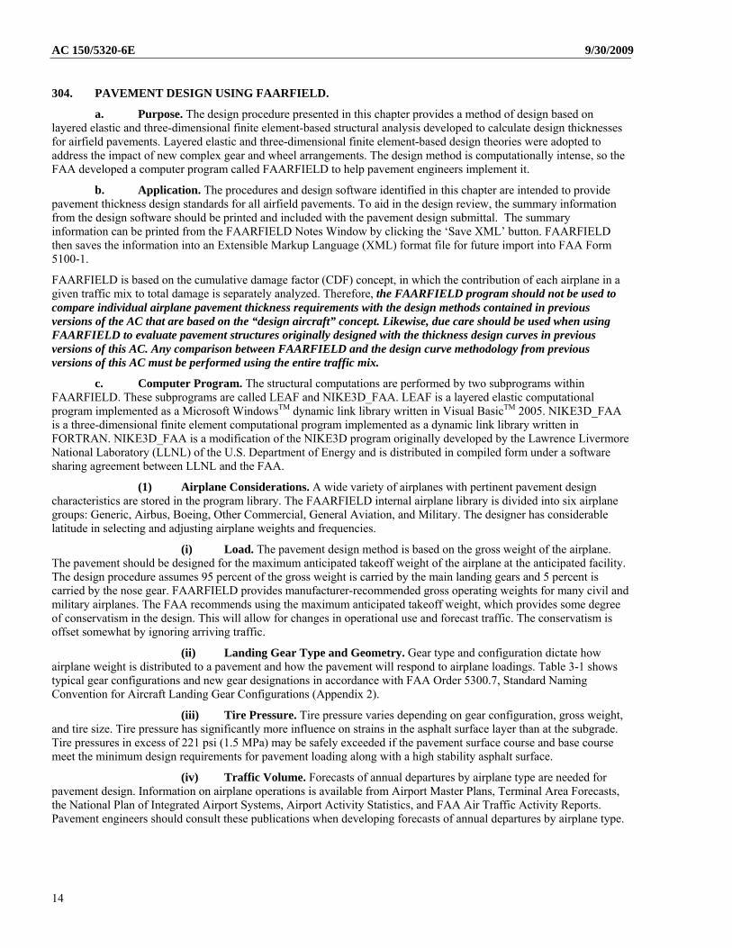
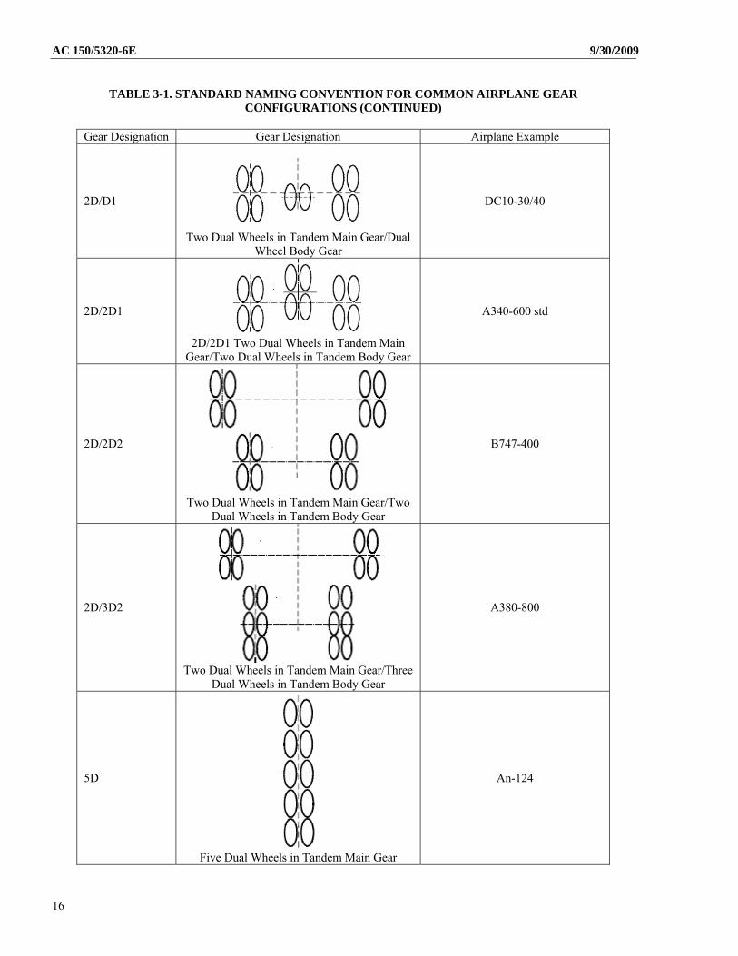
(ii) Landing Gear Type and Geometry. Gear type and configuration dictate how airplane weight is distributed to a pavement and how the pavement will respond to airplane loadings. Table 3-1 shows typical gear configurations and new gear designations in accordance with FAA Order 5300.7, Standard Naming Convention for Aircraft Landing Gear Configurations (Appendix 2).
(iii) Tire Pressure. Tire pressure varies depending on gear configuration, gross weight, and tire size. Tire pressure has significantly more influence on strains in the asphalt surface layer than at the subgrade. Tire pressures in excess of 221 psi (1.5 MPa) may be safely exceeded if the pavement surface course and base course meet the minimum design requirements for pavement loading along with a high stability asphalt surface.
(iv) Traffic Volume. Forecasts of annual departures by airplane type are needed for pavement design. Information on airplane operations is available from Airport Master Plans, Terminal Area Forecasts, the National Plan of Integrated Airport Systems, Airport Activity Statistics, and FAA Air Traffic Activity Reports. Pavement engineers should consult these publications when developing forecasts of annual departures by airplane type.
14
9/30/2009 AC 150/5320-6E
TABLE 3-1. STANDARD NAMING CONVENTION FOR COMMON AIRPLANE GEAR CONFIGURATIONS
Gear Designation Gear Designation Airplane Example
S
Single
Sngl Whl-45
D
Dual
B737-100
2S
2 Singles in Tandem
C-130
2D
2 Duals in Tandem
B767-200
3D
3 Duals in Tandem
B777-200
2T
Two Triple Wheels in Tandem
C-17A
15
AC 150/5320-6E 9/30/2009
TABLE 3-1. STANDARD NAMING CONVENTION FOR COMMON AIRPLANE GEAR CONFIGURATIONS (CONTINUED)
Gear Designation Gear Designation Airplane Example
2D/D1
Two Dual Wheels in Tandem Main Gear/Dual
Wheel Body Gear
DC10-30/40
2D/2D1
2D/2D1 Two Dual Wheels in Tandem Main
Gear/Two Dual Wheels in Tandem Body Gear
A340-600 std
2D/2D2
Two Dual Wheels in Tandem Main Gear/Two
Dual Wheels in Tandem Body Gear
B747-400
2D/3D2
Two Dual Wheels in Tandem Main Gear/Three
Dual Wheels in Tandem Body Gear
A380-800
5D
Five Dual Wheels in Tandem Main Gear
An-124
16
9/30/2009 AC 150/5320-6E
(2) Units. The program may be operated with U.S. customary or metric dimensions.
(3) Availability. FAARFIELD can be downloaded from the Office of Airport Safety and Standards website (http://www.faa.gov/airports/).
(4) Related Reference Material. The internal help file for FAARFIELD contains a user’s manual, which provides detailed information on proper execution of the program. The manual also contains additional technical references for specific details of the FAARFIELD design procedure.
(5) Airplane Traffic Mixture. FAARFIELD was developed and calibrated specifically to produce pavement thickness designs consistent with previous methods based on a mixture of different airplanes rather than an individual airplane. If a single airplane is used for design, a warning will appear in the Airplane Window indicating a non-standard airplane list is used in the design. This warning is intended to alert the user that the program was intended for use with a mixture of different airplane types. Nearly any traffic mix can be developed from the airplanes in the program library. Solution times are a function of the number of airplanes in the mix. The FAARFIELD design procedure deals with mixed traffic differently than did previous design methods. Determination of a design aircraft is not required to operate FAARFIELD. Instead, the program calculates the damaging effects of each airplane in the traffic mix. The damaging effects of all airplanes are summed in accordance with Miner’s law. When the cumulative damage factor (CDF) sums to a value of 1.0, the design conditions have been satisfied.
d. Pavement Design Considerations. There are distinct differences between the previous FAA design methodology and the methodology contained in FAARFIELD. These differences, along with some common design assumptions between the two methods, are discussed below.
(1) Design Life. The FAA design standard for pavements is based on a 20-year design life. The computer program is capable of considering other design life time frames, but the use of a design life other than 20 years constitutes a deviation from FAA standards.
(2) Traffic Mix. The design procedures in previous versions of this AC required the traffic mixture to be converted into a single design aircraft and all annual departures converted to equivalent annual departures of the design aircraft. The design aircraft was determined by selecting the most damaging airplane based on the anticipated gross weight and the number of departures for each airplane. As noted in 303c(5), the FAARFIELD design program does not convert the traffic mixture to equivalent departures of a design aircraft. Instead, it analyzes the damage to the pavement for each airplane and determines a final thickness for the total cumulative damage. FAARFIELD considers the placement of each airplane’s main gear in relationship to the pavement centerline. It also allows the pavement damage associated with a particular airplane to be completely isolated from one or more of the other airplanes in the traffic mixture.
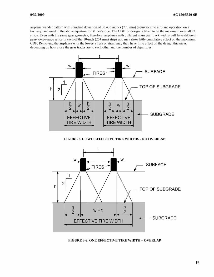
(3) Pass-to-Coverage Ratio. As an airplane moves along a pavement section it seldom travels in a perfectly straight path or along the exact same path as before. This lateral movement is known as airplane wander and is modeled by a statistically normal distribution. As an airplane moves along a taxiway or runway, it may take several trips or passes along the pavement for a specific point on the pavement to receive a full-load application. The ratio of the number of passes required to apply one full load application to a unit area of the pavement is expressed by the pass-to-coverage (P/C) ratio. It is easy to observe the number of passes an airplane may make on a given pavement, but the number of coverages must be mathematically derived based upon the established P/C ratio for each airplane. By definition, one coverage occurs when a unit area of the pavement experiences the maximum response (stress for rigid pavement, strain for flexible pavement) induced by a given airplane. For flexible pavements, coverages are a measure of the number of repetitions of the maximum strain occurring at the top of subgrade. For rigid pavements, coverages are a measure of repetitions of the maximum stress occurring at the bottom of the PCC layer (see Report No. FAA-RD-77-81, Development of a Structural Design Procedure for Rigid Airport Pavements). Coverages resulting from operations of a particular airplane type are a function of the number of airplane passes, the number and spacing of wheels on the airplane main landing gear, the width of the tire-contact area, and the lateral distribution of the wheel-paths relative to the pavement centerline or guideline markings (see Report No. FAA-RD-74-036, Field Survey and Analysis of Aircraft Distribution on Airport Pavements). In calculating the P/C ratio, FAARFIELD uses the concept of effective tire width. For rigid pavements, the effective tire width is defined at the surface of the pavement and is equal to a nominal tire contact patch width. For flexible pavements, for the failure mode of shear in the subgrade layer, the effective tire width is defined at the top of the subgrade. “Response lines” are drawn at a 1:2 slope from the edges of the contact patches to the top of the subgrade, as illustrated in figures 3-1 and 3-2. Tires are considered to be either separate or combined,
17
AC 150/5320-6E 9/30/2009
depending on whether the response lines overlap. Figures 3-1 and 3-2 are shown for information only. All effective tire width and P/C ratio calculations are performed internally within the FAARFIELD program.
(4) Annual Departures and Traffic Cycles. Airport pavement design using FAARFIELD considers only departures and ignores the arrival traffic when determining the number of airplane passes. This is because in most cases airplanes arrive at an airport at a significantly lower weight than at takeoff due to fuel consumption. During touchdown impact, remaining lift on the wings further alleviates the dynamic vertical force that is actually transmitted to the pavement through the landing gears. The FAA has defined a standard traffic cycle (TC) as one takeoff and one landing of the same airplane. In the situation described above, one traffic cycle produces one pass of the airplane which results in a pass-to-traffic cycle ratio (P/TC ) of 1. To determine annual departures for pavement design purposes multiply the number of departing airplanes by the P/TC. For most airport pavement design purposes, a P/TC of 1 may be used.
In cases where the landing weight is not significantly less than the take off weight or in a case where the airplane must travel along the pavement more than once, it may be appropriate to adjust the number of annual departures used for thickness design to reflect a different pass-to-traffic cycle (P/TC) ratio. For example, in the case of a runway with a central taxiway configuration the airplane is required to traffic a large part of the runway during the taxi movement. In this case the airplane must travel along the same portion of the runway pavement two times during the take off operation. For this scenario a P/TC ratio of 2 would be used (assuming that the airplane obtains fuel at the airport), and the number of annual departures used for design should accordingly be increased by a factor of 2. Additional definitions and guidance on determining the P/TC ratio may be found in AC 150/5335-5, “Standardized Method of Reporting Airport Pavement Strength – PCN,” Appendix 1.
(5) Cumulative Damage Factor. In FAARFIELD, the “design aircraft” concept has been replaced by design for fatigue failure expressed in terms of a cumulative damage factor (CDF) using Miner’s rule, CDF is the amount of the structural fatigue life of a pavement that has been used up. It is expressed as the ratio of applied load repetitions to allowable load repetitions to failure. For a single airplane and constant annual departures, CDF is expressed as—
failure tosrepetition allowable ofnumber
srepetition load applied ofnumber CDF
or
failure tocoverages ratio coveragepass
yearsin life departures annualCDF
or
failure tocoverages
coveragesapplied CDF
Table 3-2 describes pavement condition for different values of CDF.
TABLE 3-2. PAVEMENT REMAINING LIFE BASED ON CDF VALUE
CDF value Pavement Remaining Life 1 The pavement has used up all of its fatigue life.
< 1 The pavement has some life remaining, and the value of CDF gives the fraction of the life used.
> 1 The pavement has exceeded its fatigue life.
In the program implementation, CDF is calculated for each 10-inch (254 mm) wide strip along the pavement over a total width of 820 inches (20 828 mm). Pass-to-coverage ratio is computed for each strip based on a normally distributed
18
9/30/2009 AC 150/5320-6E airplane wander pattern with standard deviation of 30.435 inches (773 mm) (equivalent to airplane operation on a taxiway) and used in the above equation for Miner’s rule. The CDF for design is taken to be the maximum over all 82 strips. Even with the same gear geometry, therefore, airplanes with different main gear track widths will have different pass-to-coverage ratios in each of the 10-inch (254 mm) strips and may show little cumulative effect on the maximum CDF. Removing the airplanes with the lowest stress or strain may then have little effect on the design thickness, depending on how close the gear tracks are to each other and the number of departures.
FIGURE 3-1. TWO EFFECTIVE TIRE WIDTHS - NO OVERLAP
FIGURE 3-2. ONE EFFECTIVE TIRE WIDTH – OVERLAP
19
AC 150/5320-6E 9/30/2009
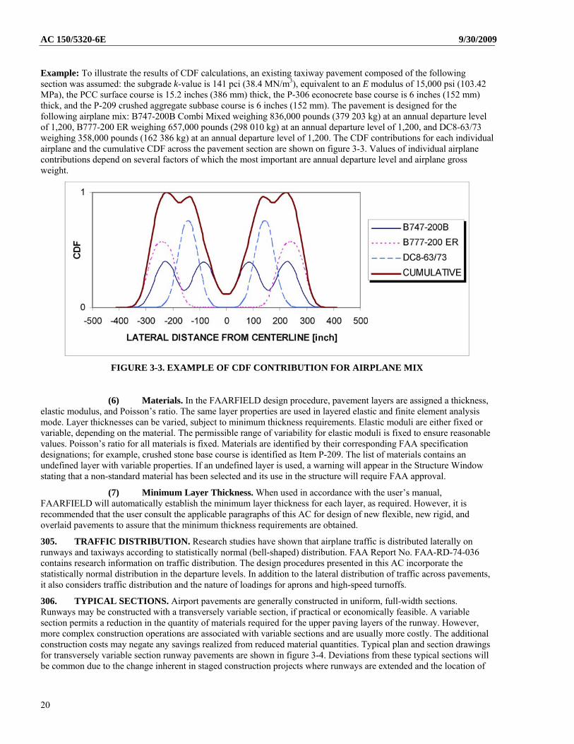
Example: To illustrate the results of CDF calculations, an existing taxiway pavement composed of the following section was assumed: the subgrade k-value is 141 pci (38.4 MN/m3), equivalent to an E modulus of 15,000 psi (103.42 MPa), the PCC surface course is 15.2 inches (386 mm) thick, the P-306 econocrete base course is 6 inches (152 mm) thick, and the P-209 crushed aggregate subbase course is 6 inches (152 mm). The pavement is designed for the following airplane mix: B747-200B Combi Mixed weighing 836,000 pounds (379 203 kg) at an annual departure level of 1,200, B777-200 ER weighing 657,000 pounds (298 010 kg) at an annual departure level of 1,200, and DC8-63/73 weighing 358,000 pounds (162 386 kg) at an annual departure level of 1,200. The CDF contributions for each individual airplane and the cumulative CDF across the pavement section are shown on figure 3-3. Values of individual airplane contributions depend on several factors of which the most important are annual departure level and airplane gross weight.
FIGURE 3-3. EXAMPLE OF CDF CONTRIBUTION FOR AIRPLANE MIX
(6) Materials. In the FAARFIELD design procedure, pavement layers are assigned a thickness, elastic modulus, and Poisson’s ratio. The same layer properties are used in layered elastic and finite element analysis mode. Layer thicknesses can be varied, subject to minimum thickness requirements. Elastic moduli are either fixed or variable, depending on the material. The permissible range of variability for elastic moduli is fixed to ensure reasonable values. Poisson’s ratio for all materials is fixed. Materials are identified by their corresponding FAA specification designations; for example, crushed stone base course is identified as Item P-209. The list of materials contains an undefined layer with variable properties. If an undefined layer is used, a warning will appear in the Structure Window stating that a non-standard material has been selected and its use in the structure will require FAA approval.
(7) Minimum Layer Thickness. When used in accordance with the user’s manual, FAARFIELD will automatically establish the minimum layer thickness for each layer, as required. However, it is recommended that the user consult the applicable paragraphs of this AC for design of new flexible, new rigid, and overlaid pavements to assure that the minimum thickness requirements are obtained.
305. TRAFFIC DISTRIBUTION. Research studies have shown that airplane traffic is distributed laterally on runways and taxiways according to statistically normal (bell-shaped) distribution. FAA Report No. FAA-RD-74-036 contains research information on traffic distribution. The design procedures presented in this AC incorporate the statistically normal distribution in the departure levels. In addition to the lateral distribution of traffic across pavements, it also considers traffic distribution and the nature of loadings for aprons and high-speed turnoffs.
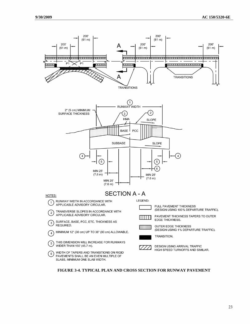
306. TYPICAL SECTIONS. Airport pavements are generally constructed in uniform, full-width sections. Runways may be constructed with a transversely variable section, if practical or economically feasible. A variable section permits a reduction in the quantity of materials required for the upper paving layers of the runway. However, more complex construction operations are associated with variable sections and are usually more costly. The additional construction costs may negate any savings realized from reduced material quantities. Typical plan and section drawings for transversely variable section runway pavements are shown in figure 3-4. Deviations from these typical sections will be common due to the change inherent in staged construction projects where runways are extended and the location of
20
9/30/2009 AC 150/5320-6E taxiways is uncertain. As a general rule-of-thumb the designer should specify full pavement thickness where departing traffic will be using the pavement; pavement thickness designed using arrivals weight and estimated frequency where traffic will be arrivals such as high speed turnoffs; and pavement thickness designed using departure weight and 1 percent of estimated frequency where pavement is required but traffic is unlikely such as along the extreme outer edges of the runway. Note that the full-strength keel section is 50 feet (15 m) on the basis of the research study discussed in paragraph 305.
307. FROST AND PERMAFROST DESIGN. The design of an airport pavement must consider the climatic conditions that will act on the pavement during its construction and service life. The protection of pavements from the adverse effects of seasonal frost and permafrost effects are considered in the design of airport pavements as discussed below.
a. Seasonal Frost. The adverse effects of seasonal frost are discussed in Chapter 2. The design of pavements in seasonal frost areas may be based on either of two approaches. The first approach is based on the control of pavement deformations resulting from frost action. Under this approach, sufficient combined thickness of pavement and non-frost-susceptible material must be provided to eliminate, or limit to an acceptable amount, frost penetration into the subgrade and its adverse effects. The second approach is based on providing adequate pavement load carrying capacity during the critical frost melting period. The second approach provides for the loss of load carrying capacity due to frost melting but ignores the effects of frost heave. Three design procedures that encompass the above approaches have been developed and are discussed below.
(1) Complete Frost Protection. Complete frost protection is accomplished by providing a sufficient thickness of pavement and non-frost-susceptible material to totally contain frost penetration. This method is intended to prevent underlying frost susceptible materials from freezing. To use the complete protection method, the depth of frost penetration is determined by local experience or engineering analysis following the procedure given in Chapter 2. The thickness of pavement required for structural support is compared with the depth of frost penetration computed. The difference between the pavement thickness required for structural support and the computed depth of frost penetration is made up with non-frost susceptible material. Depending on grades and other considerations, provision for complete protection may involve removal and replacement of a considerable amount of subgrade material. Complete frost protection is the most positive, and is usually the most costly, method of providing frost protection.
(2) Limited Subgrade Frost Penetration. The limited subgrade frost penetration method is based on holding frost heave to a tolerable level. Frost is allowed to penetrate a limited amount into the underlying frost susceptible subgrade. Sixty-five percent of the depth of frost penetration is made up with non-frost-susceptible material. Use of the method is similar to the complete protection method. Additional frost protection is required if the thickness of the structural section is less than 65 percent of the frost penetration. The limited subgrade frost penetration method allows a tolerable (based on experience) amount of frost heave.
(3) Reduced Subgrade Strength. The reduced subgrade strength method is based on the concept of providing a pavement with adequate load carrying capacity during the frost melting period. This method does not consider the effects of frost heave. Use of the reduced subgrade strength method involves assigning a subgrade strength rating to the pavement for the frost melting period. The various soil frost groups, as defined in Chapter 2, should be assigned strength ratings as shown below:
TABLE 3-3. REDUCED SUBGRADE STRENGTH RATINGS
Frost Group Flexible Pavement CBR Value Rigid Pavement k-value FG-1 9 50 FG-2 7 40 FG-3 4 25 FG-4 Reduced Subgrade Strength Method Does Not Apply
The required pavement thicknesses are determined using FAARFIELD, using the reduced subgrade strength value from table 3-3 in lieu of the nominal subgrade CBR or k-value determined by testing. Pavement thicknesses thus established reflect the requirements for the subgrade in its weakened condition due to frost melting.
b. Applications. Due to economic considerations, the maximum practical depth of frost protection that should be provided is normally 72 inches (1 829 mm). The recommended applications of the three methods of frost protection discussed above are as follows. In addition to these recommended applications, local experience should be given strong consideration when designing for frost conditions.
21
AC 150/5320-6E 9/30/2009
(1) Complete Frost Protection. The complete frost protection method applies only to FG-3 and FG-4 soils, which are extremely variable in horizontal extent. These soil deposits are characterized by very large, frequent, and abrupt changes in frost heave potential. The variability is such that the use of transition sections is not practical.
(2) Limited Subgrade Frost Penetration. This design method should be used for FG-4, soils except where the conditions require complete protection, see (1) above. The method also applies to soils in frost groups FG-1, FG-2, and FG-3 when the functional requirements of the pavement permit a minor amount of frost heave. Consideration should be given to using transition sections where horizontal variability of frost heave potential permits.
(3) Reduced Subgrade Strength. The reduced subgrade strength method is recommended for FG-1, FG-2, and FG-3 subgrades, which are uniform in horizontal extent or where the functional requirements of the pavement will permit some degree of frost heave. The method may also be used for variable FG-1 through FG-3 subgrades for less sensitive pavements, which are subject to slow speed traffic and heave can be tolerated.
c. Permafrost. The design of pavements in permafrost regions must consider not only the effects of seasonal thawing and refreezing, but also the effects of construction on the existing thermal equilibrium. Changes in the subsurface thermal regime may cause degradation of the permafrost table, resulting in severe differential settlements and drastic reduction of pavement load carrying capacity. Gravel surfaced pavements are rather common in permafrost areas and generally will provide satisfactory service. These pavements often exhibit considerable distortion but are rather easily regraded. The absence of a waterproof surface is not a great problem because these areas usually have low precipitation. Three design methods for asphaltic or concrete surfaced pavements are discussed below.
(1) Complete Protection Method. The objective of the complete protection method is to ensure that the underlying permafrost remains frozen year-round. Seasonal thawing is restricted to non-frost-susceptible materials. This method is analogous to the complete frost protection method of design for seasonal frost. The thickness of pavement required for structural support is first determined. The depth of seasonal thaw is then computed as described in Chapter 2 or using information based on local experience. The difference between the depth of seasonal thaw and the thickness needed for structural support is the amount of non-frost-susceptible material that must be provided to fully contain the depth of seasonal thaw. The use of relatively high moisture retaining soils, such as uniformly graded sands, should be considered. If some heaving can be tolerated, the use of frost-susceptible soils in the FG-1 or FG-2 groups may also be considered. If FG-1 or FG-2 soils are used, they must be placed so as to be as uniform as possible. Normally, economic considerations will limit the depth of treatment to a maximum of 6 feet (1.8 m).
(2) Reduced Subgrade Strength Method. If conditions are such that the complete protection method of design is not practical, the design may be based on the reduced subgrade strength method. The use of this method for permafrost design is identical to that presented in paragraph 307b(3) above. This method should provide a pavement with sufficient structural support during the seasonal permafrost thaw period but will likely result in differential heaving. If practical, it may be advisable to delay paving for 2 or 3 years to allow the embankment to reach equilibrium.
(3) Insulating Panels. A third approach, which is not as common, is the use of insulating panels beneath the pavement structure to protect against degradation of the permafrost. This method can lead to problems if the insulating panels are crushed by the weight of the overburden or by the live loads. Crushing of the cell structure of the insulation results in loss of insulating properties and failure to serve its intended purpose. Pavements using this technique must be very carefully constructed and may be subject to load limitations because of the need to guard against crushing the insulating panels. A significant change in the weight of using airplanes may fail the insulating panels. Since the FAA has no standards or design criteria for the use of insulating panels, the FAA must approve their use on federally funded construction on a case-by-case basis.
22
9/30/2009 AC 150/5320-6E
FIGURE 3-4. TYPICAL PLAN AND CROSS SECTION FOR RUNWAY PAVEMENT
23
AC 150/5320-6E 9/30/2009
SECTION 2. FLEXIBLE PAVEMENT DESIGN
308. GENERAL. Flexible pavements consist of a hot mix asphalt wearing surface placed on a base course and, when required by subgrade conditions, a subbase. The entire flexible pavement structure is ultimately supported by the subgrade. Definitions of the function of the various components are given in the following paragraphs.
309. HOT MIX ASPHALT SURFACING. The hot mix asphalt surface or wearing course must prevent the penetration of surface water to the base course; provide a smooth, well-bonded surface free from loose particles which might endanger airplanes or persons; resist the shearing stresses induced by airplane wheel loads; and furnish a texture of nonskid qualities, yet not cause undue wear on tires. To successfully fulfill these requirements, the surface must be composed of mixtures of aggregates and bituminous binders which will produce a uniform surface of suitable texture possessing maximum stability and durability. Since control of the mixture is of paramount importance, these requirements can best be achieved by use of a central mixing plant where proper control can be most readily obtained. A dense-graded hot mix asphalt concrete such as Item P-401 produced in a central mixing plant will most satisfactorily meet all the above requirements. Whenever a hot mix asphalt surface is subject to spillage of fuel, hydraulic fluid, or other solvents, such as at airplane fueling positions and maintenance areas, protection should be provided by a solvent resistant surface.
310. BASE COURSE. The base course is the principal structural component of the flexible pavement. It has the major function of distributing the imposed wheel loadings to the pavement foundation, the subbase and/or subgrade. The base course must be of such quality and thickness to prevent failure in the subgrade, withstand the stresses produced in the base itself, resist vertical pressures tending to produce consolidation and resulting in distortion of the surface course, and resist volume changes caused by fluctuations in its moisture content. The quality of the base course depends upon composition, physical properties and compaction. Many materials and combinations thereof have proved satisfactory as base courses. They are composed of select, hard, and durable aggregates. Specifications covering the quality of components, gradation, manipulation control, and preparation of various base materials for use on airports for airplane design loads of 30,000 pounds (13 608 kg) or more are as follows:
(1) Item P-208 – Aggregate Base Course¹
(2) Item P-209 – Crushed Aggregate Base Course2
(3) Item P-211 – Lime Rock Base Course
(4) Item P-219 – Recycled Concrete Aggregate Base Course
(5) Item P-304 – Cement Treated Base Course
(6) Item P-306 – Econocrete Subbase Course
(7) Item P-401 – Plant Mix Bituminous Pavements
(8) Item P-403 – HMA Base Course
¹The use of Item P-208, Aggregate Base Course, as base course is limited to pavements designed for gross loads of 60,000 lb (27 216 kg) or less. When Item P-208 is used as base course the minimum thickness of the hot mix asphalt surfacing should be 5 inches (127 mm). 2The use of item P-209, Crushed Aggregate Base Course, as a base course is limited to pavements serving airplanes having gross loads of 100,000 lbs (45 359 kg) or less except as noted in paragraph 317.
Rubblized Portland cement concrete can also be used as a base course for flexible pavement.
Depending on their composition, these materials have been divided into two major types: stabilized (P-211, P-304, P-306, P-401, and P-403) and unstabilized (P-208, P-209, P-219, and rubblized Portland cement concrete) base courses. Details on these materials are described in paragraph 315d.
311. SUBBASE. A subbase is included as an integral part of the flexible pavement structure in all pavements except those on subgrades with a CBR value of 20 or greater (usually GW or GP type soils). The function of the subbase is similar to that of the base course. However, since it is further removed from the surface and is subjected to lower loading intensities, the material requirements are not as strict as for the base course. In the development of pavement thickness requirements the CBR value of the subbase course is a variable.
24
9/30/2009 AC 150/5320-6E
a. Quality. Specifications covering the quality of components, gradations, manipulation control, and preparation of various types of subbase courses for use on airports for airplane design loads of 30,000 pounds (13 608 kg) or more are as follows:
(1) Item P-154 – Subbase Course
(2) Item P-210 – Caliche Base Course
(3) Item P-212 – Shell Base Course
(4) Item P-213 – Sand Clay Base Course¹
(5) Item P-301 – Soil Cement Base Course¹
¹ Use of Items P-213 and P-301 as subbase course is not recommended where frost penetration into the subbase is anticipated.
Any material suitable for use as base course can also be used on subbase if economy and practicality dictate.
b. Sandwich Construction. Pavements should not be configured such that a pervious granular layer is located between two impervious layers. This type of section is often called sandwich construction. Problems are often encountered in sandwich construction when water becomes trapped in the granular layer causing a dramatic loss of strength and results in poor performance. A rubblized concrete layer over a stabilized base layer is not considered as sandwich construction.
312. SUBGRADE. The subgrade soils are subjected to lower stresses than the surface, base, and subbase courses. Subgrade stresses attenuate with depth, and the controlling subgrade stress is usually at the top of the subgrade, unless unusual conditions exist. Unusual conditions such as a layered subgrade or sharply varying water contents or densities can change the location of the controlling stress. The ability of a particular soil to resist shear and deformation vary with its density and moisture content. Such unusual conditions should be revealed during the soils investigation. Specification Item P-152, Excavation and Embankment, covers the construction and density control of subgrade soils. Table 3-4 shows depths below the subgrade surface to which compaction controls apply. To use table 3-4, consider the mix of the airplanes that will be using the pavement feature under consideration. The airplane in the mix that should be used to determine compaction requirements is the airplane requiring the maximum compaction depth from table 3-4, regardless of the anticipated number of operations.
a. Contamination. A loss of structural capacity can result from contamination of base or subbase elements with fines from underlying subgrade soils. This contamination occurs during pavement construction and during pavement loading. Aggregate contamination results in a reduced ability of the aggregate to distribute and reduce stresses applied to the subgrade. Fine grained soils are most likely to contaminate pavement aggregate. This process is not limited to soft subgrade conditions. Problematic soils may be cohesive or noncohesive and usually exhibit poor drainage properties. Chemical and mechanical stabilization of the subbase or subgrade can be effectively used to reduce aggregate contamination (refer to paragraph 206). Geosynthetics are effective at providing separation between fine-grained soils and overlying pavement aggregates (FHWA-HI-95-038) (see Appendix 4). In this application, the geosynthetic is not considered to act as a structural element within the pavement. For separation applications the geosynthetic is designed based on survivability properties. Refer to FHWA-HI-95-038 (see Appendix 4) for additional information about design and construction using separation geosynthetics.
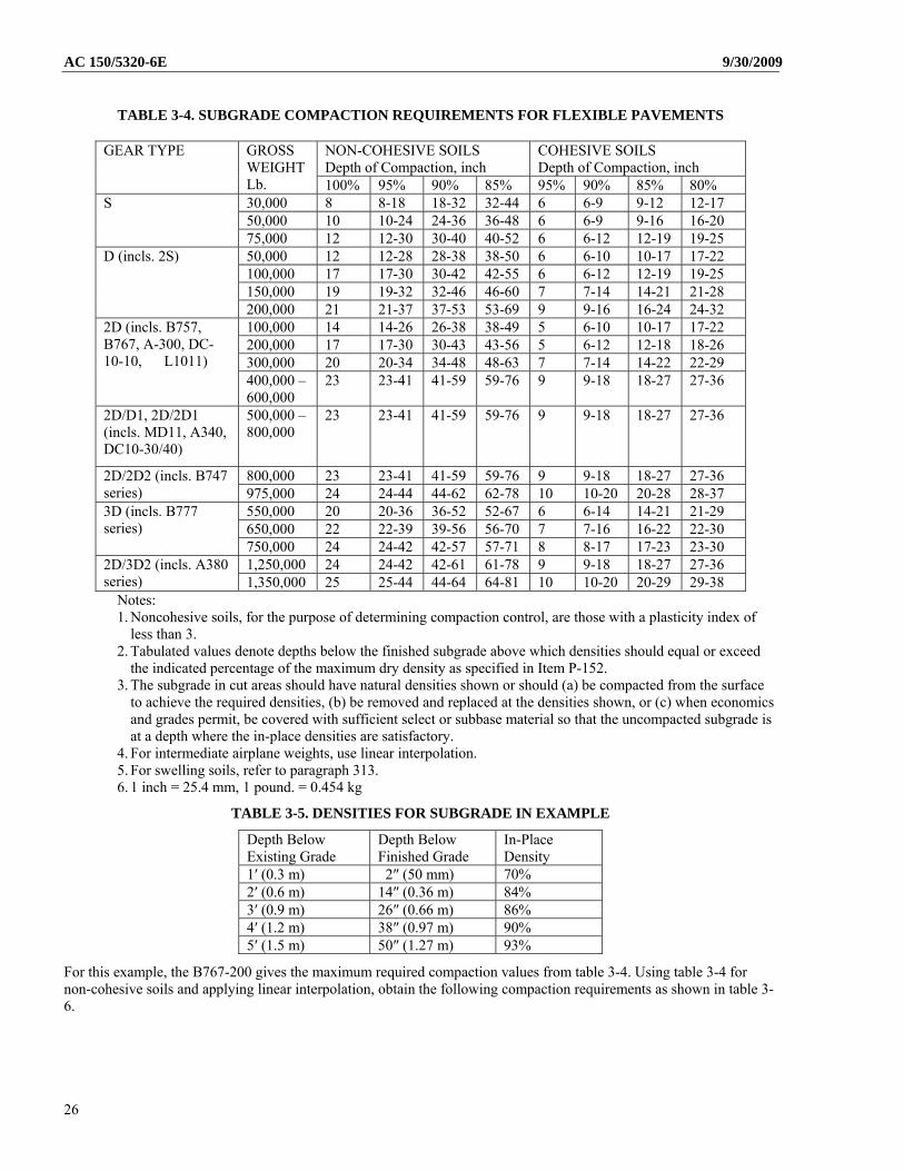
b. Example. An apron extension is to be built to accommodate the following airplane mix: B767-200 (340,000 lbs./154 221 kg), B757-200 (256,000 lbs./116 1200 kg), and A310-200 (315,041 lbs./142 900 kg). A soils investigation has shown the subgrade will be noncohesive. In-place densities of the soils have been determined at even foot increments below the ground surface. Design calculations indicate that the top of subgrade in this area will be approximately 10 inches (254 mm) below the existing grade. Depths and densities may be tabulated as follows in table 3-5.
25
AC 150/5320-6E 9/30/2009
TABLE 3-4. SUBGRADE COMPACTION REQUIREMENTS FOR FLEXIBLE PAVEMENTS
NON-COHESIVE SOILS Depth of Compaction, inch
COHESIVE SOILS Depth of Compaction, inch
GEAR TYPE GROSS WEIGHT Lb. 100% 95% 90% 85% 95% 90% 85% 80% 30,000 8 8-18 18-32 32-44 6 6-9 9-12 12-17 50,000 10 10-24 24-36 36-48 6 6-9 9-16 16-20
S
75,000 12 12-30 30-40 40-52 6 6-12 12-19 19-25 50,000 12 12-28 28-38 38-50 6 6-10 10-17 17-22 100,000 17 17-30 30-42 42-55 6 6-12 12-19 19-25 150,000 19 19-32 32-46 46-60 7 7-14 14-21 21-28
D (incls. 2S)
200,000 21 21-37 37-53 53-69 9 9-16 16-24 24-32 100,000 14 14-26 26-38 38-49 5 6-10 10-17 17-22 200,000 17 17-30 30-43 43-56 5 6-12 12-18 18-26 300,000 20 20-34 34-48 48-63 7 7-14 14-22 22-29
2D (incls. B757, B767, A-300, DC-10-10, L1011)
400,000 – 600,000
23 23-41 41-59 59-76 9 9-18 18-27 27-36
2D/D1, 2D/2D1 (incls. MD11, A340, DC10-30/40)
500,000 – 800,000
23 23-41 41-59 59-76 9 9-18 18-27 27-36
800,000 23 23-41 41-59 59-76 9 9-18 18-27 27-36 2D/2D2 (incls. B747 series) 975,000 24 24-44 44-62 62-78 10 10-20 20-28 28-37
550,000 20 20-36 36-52 52-67 6 6-14 14-21 21-29 650,000 22 22-39 39-56 56-70 7 7-16 16-22 22-30
3D (incls. B777 series)
750,000 24 24-42 42-57 57-71 8 8-17 17-23 23-30 1,250,000 24 24-42 42-61 61-78 9 9-18 18-27 27-36 2D/3D2 (incls. A380
series) 1,350,000 25 25-44 44-64 64-81 10 10-20 20-29 29-38 Notes: 1. Noncohesive soils, for the purpose of determining compaction control, are those with a plasticity index of
less than 3. 2. Tabulated values denote depths below the finished subgrade above which densities should equal or exceed
the indicated percentage of the maximum dry density as specified in Item P-152. 3. The subgrade in cut areas should have natural densities shown or should (a) be compacted from the surface
to achieve the required densities, (b) be removed and replaced at the densities shown, or (c) when economics and grades permit, be covered with sufficient select or subbase material so that the uncompacted subgrade is at a depth where the in-place densities are satisfactory.
4. For intermediate airplane weights, use linear interpolation. 5. For swelling soils, refer to paragraph 313. 6. 1 inch = 25.4 mm, 1 pound. = 0.454 kg
TABLE 3-5. DENSITIES FOR SUBGRADE IN EXAMPLE
Depth Below Existing Grade
Depth Below Finished Grade
In-Place Density
1′ (0.3 m) 2″ (50 mm) 70% 2′ (0.6 m) 14″ (0.36 m) 84% 3′ (0.9 m) 26″ (0.66 m) 86% 4′ (1.2 m) 38″ (0.97 m) 90% 5′ (1.5 m) 50″ (1.27 m) 93%
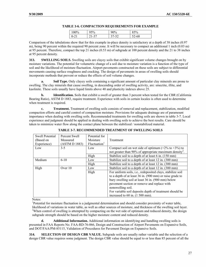
For this example, the B767-200 gives the maximum required compaction values from table 3-4. Using table 3-4 for non-cohesive soils and applying linear interpolation, obtain the following compaction requirements as shown in table 3-6.
26
9/30/2009 AC 150/5320-6E
TABLE 3-6. COMPACTION REQUIREMENTS FOR EXAMPLE
100% 95% 90% 85% 0-21 21-37 37-52 52-68
Comparison of the tabulations show that for this example in-place density is satisfactory at a depth of 38 inches (0.97 m), being 90 percent within the required 90 percent zone. It will be necessary to compact an additional 1 inch (0.03 m) at 95 percent. Therefore, compact the top 21 inches (0.53 m) of subgrade at 100 percent density and the 21 to 38 inches at 95 percent density.
313. SWELLING SOILS. Swelling soils are clayey soils that exhibit significant volume changes brought on by moisture variations. The potential for volumetric change of a soil due to moisture variation is a function of the type of soil and the likelihood of moisture fluctuation. Airport pavements constructed on these soils are subject to differential movements causing surface roughness and cracking. The design of pavements in areas of swelling soils should incorporate methods that prevent or reduce the effects of soil volume changes.
a. Soil Type. Only clayey soils containing a significant amount of particular clay minerals are prone to swelling. The clay minerals that cause swelling, in descending order of swelling activity, are: smectite, illite, and kaolinite. These soils usually have liquid limits above 40 and plasticity indexes above 25.
b. Identification. Soils that exhibit a swell of greater than 3 percent when tested for the CBR (California Bearing Ratio), ASTM D 1883, require treatment. Experience with soils in certain locales is often used to determine when treatment is required.
c. Treatment. Treatment of swelling soils consists of removal and replacement, stabilization, modified compaction efforts and careful control of compaction moisture. Provisions for adequate drainage are of paramount importance when dealing with swelling soils. Recommended treatments for swelling soils are shown in table 3-7. Local experience and judgment should be applied in dealing with swelling soils to achieve the best results. Care should be taken to minimize water flow along the contact plane between the stabilized / nonstabilized material.
TABLE 3-7. RECOMMENDED TREATMENT OF SWELLING SOILS
Swell Potential (Based on Experience)
Percent Swell Measured (ASTM D 1883)
Potential for Moisture Fluctuation1
Treatment
Low Compact soil on wet side of optimum (+2% to +3%) to not greater than 90% of appropriate maximum density2.
Low 3-5
High Stabilize soil to a depth of at least 6 in. (150 mm) Low Stabilize soil to a depth of at least 12 in. (300 mm) Medium 6-10
High Stabilize soil to a depth of at least 12 in. (300 mm) Low Stabilize soil to a depth of at least 12 in. (300 mm) High Over 10 High For uniform soils, i.e., redeposited clays, stabilize soil
to a depth of at least 36 in. (900 mm) or raise grade to bury swelling soil at least 36 in. (900 mm) below pavement section or remove and replace with nonswelling soil. For variable soil deposits depth of treatment should be increased to 60 in. (1 500 mm).
Notes: 1Potential for moisture fluctuation is a judgmental determination and should consider proximity of water table, likelihood of variations in water table, as well as other sources of moisture, and thickness of the swelling soil layer. 2When control of swelling is attempted by compacting on the wet side of optimum and reduced density, the design subgrade strength should be based on the higher moisture content and reduced density.
d. Additional Information. Additional information on identifying and handling swelling soils is presented in FAA Reports No. FAA-RD-76-066, Design and Construction of Airport Pavements on Expansive Soils, and DOT/FAA/PM-85115, Validation of Procedures for Pavement Design on Expansive Soils.
314. SELECTION OF DESIGN CBR VALUE. Subgrade soils are usually rather variable and the selection of a design CBR value requires some judgment. The design CBR value should be equal to or less than 85 percent of all the
27
AC 150/5320-6E 9/30/2009
subgrade CBR values. This corresponds to a design value of one standard deviation below the mean. In some cases subgrade soils that are significantly different in strength occur in different layers. In these instances several designs should be examined to determine the most economical pavement section. It may be more economical to remove and replace a weak layer than to design for it. On the other hand, circumstances may be such that designing for the weakest layer is more economical. Local conditions will dictate which approach should be used.
315. FLEXIBLE PAVEMENT DESIGN. The design process for flexible pavement considers two modes of failure for flexible pavement: vertical strain in the subgrade and horizontal strain in the asphalt layer. Limiting vertical strain in the subgrade is intended to preclude failure by subgrade rutting. Limiting horizontal strain at the bottom of the asphalt surfacing layer guards against pavement failure initiated by cracking of the asphalt surface layer. By default, FAARFIELD computes only the vertical subgrade strain for flexible pavement thickness design. However, the user has the option of enabling the asphalt strain computation by deselecting the “No AC CDF” checkbox in the FAARFIELD options screen. In most cases the thickness design is governed by the subgrade strain criterion. The user has the option of performing the asphalt strain check for the final design, and it is good engineering practice to do so.
a. Design Life. The FAA design standards for airport pavements use the 20 year structural design life criteria as a policy. FAARFIELD is capable of considering design life timeframes other than the 20 year life criteria, but they are considered a deviation from FAA standards.
b. Traffic Mix. Input the complete air traffic mix into FAARFIELD. See paragraph 304c(5).
c. Hot Mix Asphalt Surfacing. Hot mix asphalt surfacing should meet the requirements of FAA Item P-401. A minimum thickness of 4 inches (102 mm) of hot mix surfacing is required. A fixed modulus value for hot mix surfacing is set in the program at 200,000 psi (1 380 MPa). This modulus value was conservatively chosen and corresponds to a pavement temperature of approximately 90 ºF (32ºC).
Two types of asphalt surface layers are available in FAARFIELD: asphalt surface and asphalt overlay. Both have the same properties, with modulus fixed at 200,000 psi (1 380 MPa) and Poisson’s ratio fixed at 0.35. The asphalt overlay type can be placed over asphalt surface or PCC surface types. The asphalt surface type can only be placed on the top of a structure, or under an asphalt overlay.
d. Base Course. Two types of base courses are defined: stabilized and unstabilized (aggregate). A stabilized base course may be required as described in paragraph 317.
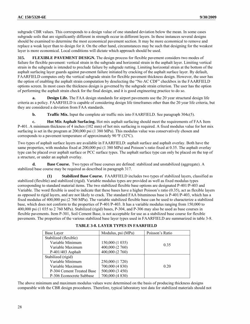
(1) Stabilized Base Course. FAARFIELD includes two types of stabilized layers, classified as stabilized (flexible) and stabilized (rigid). Variable modulus types are provided as well as fixed modulus types corresponding to standard material items. The two stabilized flexible base options are designated P-401/P-403 and Variable. The word flexible is used to indicate that these bases have a higher Poisson’s ratio (0.35), act as flexible layers as opposed to rigid layers, and are not likely to crack. The standard FAA bituminous base is P-401/P-403, which has a fixed modulus of 400,000 psi (2 760 MPa). The variable stabilized flexible base can be used to characterize a stabilized base, which does not conform to the properties of P-401/P-403. It has a variable modulus ranging from 150,000 to 400,000 psi (1 035 to 2 760 MPa). Stabilized (rigid) bases, P-304, and P-306 may also be used as base courses in flexible pavements. Item P-301, Soil Cement Base, is not acceptable for use as a stabilized base course for flexible pavements. The properties of the various stabilized base layer types used in FAARFIELD are summarized in table 3-8.
TABLE 3-8. LAYER TYPES IN FAARFIELD
Base Layer Modulus, psi (MPa) Poisson’s Ratio Stabilized (flexible) Variable Minimum Variable Maximum P-401/403 Asphalt
150,000 (1 035) 400,000 (2 760) 400,000 (2 760)
0.35
Stabilized (rigid) Variable Minimum Variable Maximum P-304 Cement Treated Base P-306 Econocrete Subbase
250,000 (1 720) 700,000 (4 830) 500,000 (3 450) 700,000 (4 830)
0.20
The above minimum and maximum modulus values were determined on the basis of producing thickness designs comparable with the CBR design procedures. Therefore, typical laboratory test data for stabilized materials should not
28
9/30/2009 AC 150/5320-6E be used in preparing input data for FAARFIELD designs. If it is necessary to establish a modulus for a variable base layer the following guidance should be used:
For flexible pavement design, the minimum modulus value of 150,000 psi (1 034 MPa) corresponds to a base course equivalency factor of 1.2 and the maximum value of 400,000 psi (2 758 MPa) corresponds to a base course equivalency factor of 1.6 previously used in CBR method. The equivalency factor represents the ratio of the thickness of a standard aggregate base layer (Item P-208) to a base layer of higher quality in the CBR method. The choice of base course modulus value can have a significant effect on total thickness of a flexible pavement.
When a variable modulus layer is first created, the modulus is automatically set to the minimum value.
(2) Unstabilized (Aggregate) Base Course. The standard aggregate base course for flexible pavement design is Item P-209, Crushed Aggregate Base Course. In FAARFIELD, P-209 Crushed Aggregate corresponds to the standard material. Item P-208, Uncrushed Aggregate, is not suitable as a base course material. Item P-208, when used as a base course is subject to the restrictions in paragraph 310. The modulus of aggregate layers is computed automatically and cannot be changed manually.
To compute the modulus of non-stablized layers, the “Modulus” procedure developed by the U.S. Army Corps of Engineers Waterways Experiment Station is followed with sublayering performed automatically (maximum sublayer thicknesses are 8 inches (203 mm) for uncrushed aggregate and 10 inches (254 mm) for crushed aggregate). The modulus values of the sublayers decrease with increasing depth of a sublayer within the aggregate layer and are also dependent on the modulus of the layer below the aggregate layer.
Aggregate layers can be placed anywhere in the pavement structure except at the surface or subgrade. The following additional restrictions also apply:
Only one crushed layer and one uncrushed layer may be present in a structure. This is for compatibility with the “Modulus” procedure. (Sublayering by the “Modulus” procedure accounts for thick layers, and multiple layers of a single aggregate type are not necessary.) The maximum number of aggregate layers that may be present in a structure is therefore two, one of each type.
If crushed and uncrushed layers are adjacent, the crushed layer must be above the uncrushed layer (to be compatible with the “Modulus” procedure).
The modulus value displayed in the structure table for an aggregate layer is the average value of the sublayer modulus values. The only exception is for newly created layers, in which case the modulus values of 75,000 psi (517 MPa) and 40,000 psi (276 MPa) are displayed for crushed and uncrushed respectively. These default modulus values are never used in calculations.
(3) Minimum Base Course Thickness. FAARFIELD, by default, computes the structural thickness required for the base course. Since it is assumed that the subbase layer provides the equivalent bearing capacity of a CBR 20 subgrade, the structural base course thickness is computed as the thickness required to protect a subgrade of CBR 20.
When an aggregate base course is used, the automatic base thickness design procedure in FAARFIELD consists of two steps:
Step 1 Compute the aggregate base thickness structurally required to protect an assumed CBR 20 subgrade. Step 2 Compare the base thickness computed in step 1 against the minimum base thickness requirements in table 3-9.
Select the thicker of the two values as the design base course thickness.
For traffic mixtures with airplanes exceeding 100,000 pounds (45 400 kg), a stabilized base course is required as described in paragraph 317. The minimum stabilized base thickness is 5 inches (127 mm). When a stabilized base is used, an additional step is added to the automated base thickness design procedure. After the thickness of the aggregate base structurally required to protect a CBR 20 subgrade is computed (step 1 above), the required thickness of the stabilized base is obtained by dividing by 1.6. The required stabilized base thickness thus obtained is compared with the 5 inch (127 mm) minimum requirement, and the larger of the two values is selected as the design stabilized base course thickness.
29
AC 150/5320-6E 9/30/2009
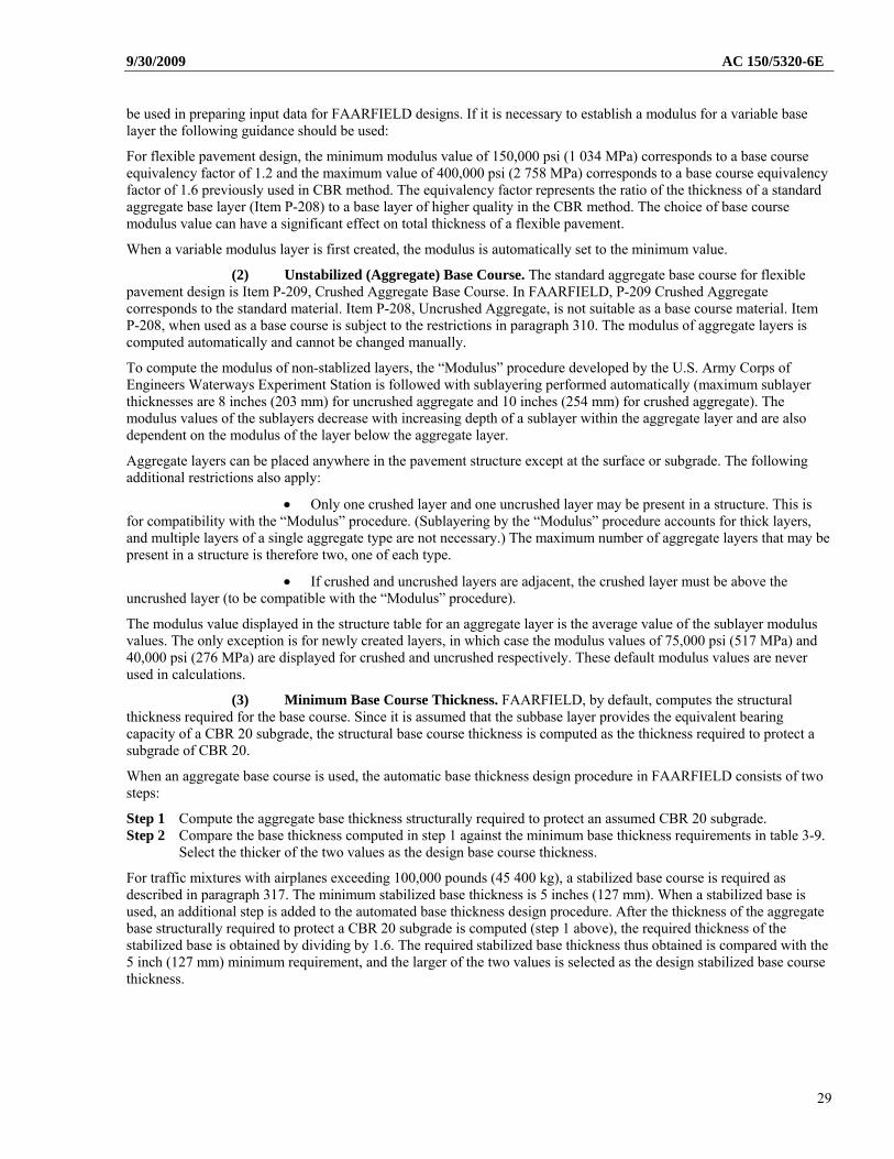
TABLE 3-9. MINIMUM AGGREGATE BASE COURSE THICKNESS
Design Load Range Minimum Base Course (P-209) Thickness Gear Type
lbs (kg) in. (mm) 30,000 - 50,000 (13 600 – 22 700) 4 (100) S 50,000 - 75,000 (22 700 – 34 000) 6 (150) 50,000 - 100,000 (22 700 – 45 400) 6 (150) D 100,000 - 200,000* (45 400 – 90 700) 8 (200) 100,000 - 250,000* (45 400 – 113 400) 6 (150) 2D 250,000 - 400,000* (113 400 – 181 000) 8 (200)
2D (B757, B767) 200,000 - 400,000* (90 700 – 181 000) 6 (150) 2D or 2D/D1 (DC10, L1011) 400,000 - 600,000* (181 000 – 272 000) 8 (150)
400,000 - 600,000* (181 000 – 272 000) 6 (150) 2D/2D2 (B747) 600,000 - 850,000* (272 000 – 385 600) 8 (200)
2D/D1 or 2D/2D1(A340) 568,000 – 840,400 (257 640 – 381 200) 10 (250) 75,000 - 125,000 (34 000 – 56 700) 4 (100) 2S (C130) 125,000 - 175,000* (56 700 – 79 400) 6 (150)
3D (B777) 537,000 – 777,000* (243 500 – 352 440) 10 (250) 3D (A380) 1,239,000 – 1,305,125* (562 000 – 592 000) 9 (230)
*Values are listed for reference. However, when the traffic mixture contains airplanes exceeding 100,000 lbs. (45 400 kg) gross weight, a stabilized base is required.
d. Subbase Course. Subbases may be aggregate or stabilized materials. The minimum thickness of subbase for structural purposes is 4 inches (102 mm). Additional thickness might be required for practical construction limitations. Acceptable aggregate and stabilized materials are defined in paragraphs 309, 310, and 311. Use of Item P-301 is limited to locations not subject to freeze-thaw cycles. More than one layer of subbase material may be used, i.e., P-209 over a layer of P-154. Layering must be done so as not to produce a sandwich (granular layer between two stabilized layers) section and to assure that material quality increases toward the top of the pavement section.
For traffic mixtures with airplanes exceeding 100,000 pounds (45 359 kg), a stabilized base course is required as described in paragraph 317. When a stabilized base course is required, it is recommended that a higher quality material be used for the subbase. Acceptable materials for use as subbase with a stabilized base layer are:
P-208 – Aggregate Base Course P-209 – Crushed Aggregate Base Course
In addition, any material suitable for use as a base course can also be used as a subbase course with a stabilized base layer.
e. Subgrade. The subgrade is assumed to be infinite in thickness and is characterized by either a modulus or CBR value. Subgrade modulus values for flexible pavement design can be determined in a number of ways. The procedure that will be applicable in most cases is to use available CBR values and substitute in the relationship:
CBRE 1500 , (E in psi)
This method will provide designs compatible with the previous FAA design procedure based on the CBR equation. Although FAARFIELD requires input of the material elastic modulus, direct input of CBR values is also acceptable.
f. Seasonal Frost and Permafrost. Seasonal frost and permafrost effects should be considered by applying the techniques in Chapter 2 and section 306.
316. DESIGN EXAMPLE. As an example of the use of the FAARFIELD, assume a flexible pavement is to be designed for the airplane traffic mix in table 3-10.
The subgrade CBR is 8 (E=12,000 psi). Since the traffic mix includes jet airplanes weighing 100,000 pounds (45 359 kg) or more, an asphalt stabilized base will be used. The pavement layer thicknesses obtained from the design software FAARFIELD are listed in table 3-11.
30
9/30/2009 AC 150/5320-6E
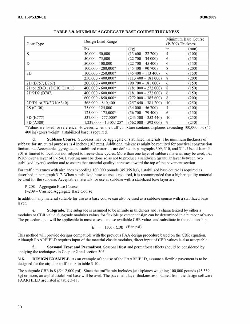
TABLE 3-10. AIRPLANE TRAFFIC MIX EXAMPLE
No. Name Gross Weight, lb Annual Departures Annual Growth, % 1 A320-100 150,796 600 0.00 2 A340-600 std 805,128 1,000 0.00 3 A340-600 std Belly 805,128 1,000 0.00 4 A380-800 1,239,000 300 0.00 5 B737-800 174,700 2,000 0.00 6 B747-400 877,000 400 0.00 7 B747-400ER 913,000 300 0.00 8 B757-300 271,000 1,200 0.00 9 B767-400 ER 451,000 800 0.00 10 B777-300 ER 777,000 1,000 0.00 11 B787-8 478,000 600 0.00
TABLE 3-11. PAVEMENT STRUCTURE INFORMATION FOR DESIGN EXAMPLE
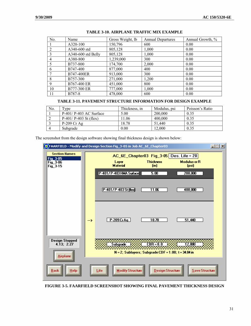
No. Type Thickness, in Modulus, psi Poisson’s Ratio 1 P-401/ P-403 AC Surface 5.00 200,000 0.35 2 P-401/ P-403 St (flex) 11.06 400,000 0.35 3 P-209 Cr Ag 18.78 51,440 0.35 4 Subgrade 0.00 12,000 0.35
The screenshot from the design software showing final thickness design is shown below:
FIGURE 3-5. FAARFIELD SCREENSHOT SHOWING FINAL PAVEMENT THICKNESS DESIGN
31
AC 150/5320-6E 9/30/2009
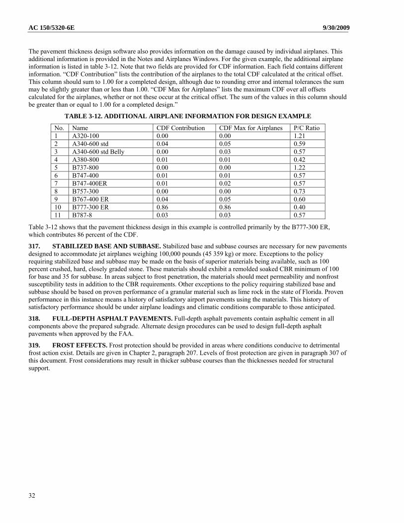
The pavement thickness design software also provides information on the damage caused by individual airplanes. This additional information is provided in the Notes and Airplanes Windows. For the given example, the additional airplane information is listed in table 3-12. Note that two fields are provided for CDF information. Each field contains different information. “CDF Contribution” lists the contribution of the airplanes to the total CDF calculated at the critical offset. This column should sum to 1.00 for a completed design, although due to rounding error and internal tolerances the sum may be slightly greater than or less than 1.00. “CDF Max for Airplanes” lists the maximum CDF over all offsets calculated for the airplanes, whether or not these occur at the critical offset. The sum of the values in this column should be greater than or equal to 1.00 for a completed design.”
TABLE 3-12. ADDITIONAL AIRPLANE INFORMATION FOR DESIGN EXAMPLE
No. Name CDF Contribution CDF Max for Airplanes P/C Ratio 1 A320-100 0.00 0.00 1.21 2 A340-600 std 0.04 0.05 0.59 3 A340-600 std Belly 0.00 0.03 0.57 4 A380-800 0.01 0.01 0.42 5 B737-800 0.00 0.00 1.22 6 B747-400 0.01 0.01 0.57 7 B747-400ER 0.01 0.02 0.57 8 B757-300 0.00 0.00 0.73 9 B767-400 ER 0.04 0.05 0.60 10 B777-300 ER 0.86 0.86 0.40 11 B787-8 0.03 0.03 0.57
Table 3-12 shows that the pavement thickness design in this example is controlled primarily by the B777-300 ER, which contributes 86 percent of the CDF.
317. STABILIZED BASE AND SUBBASE. Stabilized base and subbase courses are necessary for new pavements designed to accommodate jet airplanes weighing 100,000 pounds (45 359 kg) or more. Exceptions to the policy requiring stabilized base and subbase may be made on the basis of superior materials being available, such as 100 percent crushed, hard, closely graded stone. These materials should exhibit a remolded soaked CBR minimum of 100 for base and 35 for subbase. In areas subject to frost penetration, the materials should meet permeability and nonfrost susceptibility tests in addition to the CBR requirements. Other exceptions to the policy requiring stabilized base and subbase should be based on proven performance of a granular material such as lime rock in the state of Florida. Proven performance in this instance means a history of satisfactory airport pavements using the materials. This history of satisfactory performance should be under airplane loadings and climatic conditions comparable to those anticipated.
318. FULL-DEPTH ASPHALT PAVEMENTS. Full-depth asphalt pavements contain asphaltic cement in all components above the prepared subgrade. Alternate design procedures can be used to design full-depth asphalt pavements when approved by the FAA.
319. FROST EFFECTS. Frost protection should be provided in areas where conditions conducive to detrimental frost action exist. Details are given in Chapter 2, paragraph 207. Levels of frost protection are given in paragraph 307 of this document. Frost considerations may result in thicker subbase courses than the thicknesses needed for structural support.
32
9/30/2009 AC 150/5320-6E
SECTION 3. RIGID PAVEMENT DESIGN
320. GENERAL. The design process considers one mode of failure for rigid pavement, cracking of the concrete slab. The cracking of the surface layer is controlled by limiting the horizontal stress at bottom of PCC slab. Failure of subbase and subgrade layers is not considered. FAARFIELD iterates on the concrete layer thickness until the CDF reaches a value of 1.0. Once a CDF of 1.0 is achieved, the section satisfies the design conditions.
a. Structure. Rigid pavements for airports are composed of Portland cement concrete placed on a granular or treated subbase course that is supported on a compacted subgrade.
b. Modeling. A three-dimensional finite element model is used to compute the stresses in concrete slabs. The three dimensional finite element model has the advantage of considering the critical stresses for slab design, which normally occur at slab edges, and also employs similar concepts for new rigid pavement design and rigid overlay design. Rigid overlay design is covered in Chapter 4.
c. Applications. Refer to paragraph 304b.
d. Seasonal Frost and Permafrost. Seasonal frost and permafrost effects should be considered by applying the techniques in Chapter 2.
e. Jointing Details. Jointing details for rigid pavements are presented in this chapter, paragraph 332.
321. CONCRETE PAVEMENT. The concrete surface must provide a texture of nonskid qualities, prevent the infiltration of surface water into the subgrade, and provide structural support to the airplanes. The quality of the concrete, acceptance and control tests, methods of construction and handling, and quality of workmanship are covered in Item P-501, Portland Cement Concrete Pavement.
322. SUBBASE. The purpose of a subbase under a rigid pavement is to provide uniform stable support for the pavement slabs. A minimum thickness of 4 inches (102 mm) of subbase is required under all rigid pavements.
323. SUBBASE QUALITY. The standard FAA subbase for rigid pavements is 4 inches (100 mm) of Item P-154, Subbase Course. In some instances, it may be desirable to use higher-quality materials or thicknesses of P-154 greater than 4 inches (102 mm). The following materials are acceptable for use as subbase under rigid pavements:
Item P-154 – Subbase Course
Item P-208 – Aggregate Base Course
Item P-209 – Crushed Aggregate Base Course
Item P-211 – Lime Rock Base Course
Item P-301 – Soil Cement Base
Item P-304 – Cement Treated Base Course
Item P-306 – Econocrete Subbase Course
Item P-401 – Plant Mix Bituminous Pavements
Item P-403 – HMA Base Course
Rubblized Portland cement concrete can also be used as a subbase for rigid pavements.
High-quality materials meeting state highway specifications can be substituted. Materials of higher quality than P-154 and/or greater thicknesses of subbase are considered in the design program FAARFIELD. The costs of providing the additional thickness or higher-quality subbase should be weighed against the savings in concrete thickness.
324. STABILIZED SUBBASE. Stabilized materials are required for subbase under rigid pavements serving airplanes weighing 100,000 pounds (45 359 kg) or more. Acceptable stabilized materials are P-304 (Cement Treated Base Course), P-306 (Econocrete Subbase Course), and P-401 and P-403 (Plant Mix Bituminous Pavements). The minimum thickness of subbase is 4 inches (102 mm). More than one layer of subbase may be used, i.e., P-306 over a layer of P-209. Layering must be done so as not to produce a sandwich (granular layer between two stabilized layers) section. Exceptions to the policy of using stabilized subbase are the same as those given in paragraph 317.
33
AC 150/5320-6E 9/30/2009
325. SUBGRADE. Subgrade materials under a rigid pavement must be compacted in accordance with table 3-4. Specification Item P-152, Excavation and Embankment, covers the construction and density control of subgrade soils. Swelling soils require special considerations. Paragraph 313 contains guidance on the identification and treatment of swelling soils.
a. Contamination. In rigid pavement systems repeated loading might cause intermixing of soft subgrade soils and aggregate base or subbase. This mixing can create voids below the pavement in which moisture can accumulate causing pumping to occur. Chemical and mechanical stabilization of the subbase or subgrade can effectively reduce aggregate contamination (see paragraph 206). Geosynthetics have been found to be effective at providing separation between fine-grained subgrade soils and pavement aggregates (FHWA-HI-95-038). Geosynthetics should be considered for separation between fine-grained soils and overlying pavement aggregates. In this application, the geosynthetic is not considered to act as a structural element within the pavement. Therefore, the modulus of the base or subbase is not increased when a geosynthetic is used for stabilization. For separation applications, the geosynthetic is designed based on survivability properties. Additional information about design and construction using separation geosynthetics can be found in FHWA-HI-95-038.
326. DETERMINATION OF MODULUS (E VALUE) FOR RIGID PAVEMENT SUBGRADE. In addition to the soils survey and analysis and classification of subgrade conditions, the determination of the foundation modulus is required for rigid pavement design. The foundation modulus should be assigned to the subgrade layer; i.e., the layer below all structural layers. The foundation modulus can be expressed as the modulus of subgrade reaction k or as the elastic (Young’s) modulus E and can be input into the program directly in either form. However, all structural computations are performed using the elastic modulus E. If the foundation modulus is input as a k-value it is automatically converted to the equivalent E value using the following equation:
284.126kESG
where:
ESG = Resilient modulus of the subgrade, in psi k = Foundation modulus of the subgrade, in pci
For existing pavements the E modulus can be determined in the field from non-destructive testing (NDT) such as falling-weight deflectometer (FWD) tests and this may be necessary if direct testing of the subgrade is impractical. If the subgrade is accessible then the k-value can be determined directly by plate-load testing. If the k-modulus can be determined by plate load testing, or is otherwise available, then the k-value should be input directly into the FAARFIELD program without first converting to E modulus.
The preferred method of determining the subgrade modulus is by testing a limited section of representative subgrade, which has been constructed to the required specifications. The plate bearing test procedures are given in AASHTO T 222, Nonrepetitive Static Plate Load Test of Soils and Flexible Pavement Components, for Use in Evaluation and Design of Airport and Highway Pavements. If the construction and testing of a test section of embankment is impractical, the conversion from CBR to k-value for the subgrade can be achieved using the following formula:
7788.0
26
1500
CBR
k , (k in pci)
The designer is cautioned that the obtained values are approximate and engineering judgment should be used in selecting a design value.
327. DETERMINATION OF CONCRETE SLAB THICKNESS. FAARFIELD designs the slab thickness based on the assumption of edge loading. The gear load is located either tangent or perpendicular to the slab edge, and the larger of the two stresses, reduced by 25 percent to account for load transfer through the joint, is taken as the design stress for determining the slab thickness. Use of the design program FAARFIELD requires five groups of design input data: concrete flexural strength, subgrade modulus, design life in years, structural layer data, and airplane mixture information. The program computes only the thickness of the concrete layer. The minimum slab thickness is six inches. Thicknesses of other layers of the rigid pavement structure must be selected by the user.
a. Concrete Flexural Strength. The required thickness of concrete pavement is related to the strength of the concrete used for construction of the pavement. For pavement design, the strength of the concrete is characterized by the flexural strength, since the primary action and failure mode of a concrete pavement is in flexure. For FAA design
34
9/30/2009 AC 150/5320-6E purposes, concrete flexural strength is measured in accordance with the ASTM C78, Standard Test Method for Flexural Strength of Concrete, test method.
Although the flexural strength required for the pavement design is related to the flexural strength required by the P-501 specification, the strengths used for the pavement design and the P-501 specification are not necessarily the same. Unless expedited construction requires early opening of the pavement to airplane traffic (e.g., less than 28 days), Item P-501 typically uses a 28-day strength as a practical construction measure. However, the long-term strength achieved by the concrete is normally expected to be at least 5 percent more than the strength measured at 28 days.
To establish the flexural strength for the thickness design the designer needs to consider several factors, such as:
Capability of the industry in a particular area to produce concrete at a particular strength Flexural strength vs. cement content data from prior projects at the airport The need to avoid high cement contents, which can affect concrete durability Whether early opening requirements necessitate using a lower strength than 28-day
The FAA recommends a design flexural strength of 600 to 700 psi (4.14 to 4.83 MPa) for most airfield applications. Lower strength requirements allow balancing the components of the concrete mixture for performance but may result in slightly thicker pavement requirements. However, these conditions reduce the risk of early cracking, minimize curling and warping stresses, and provide increased performance with respect to fatigue. The strength used for thickness design should be reduced by 5 percent when stating the P-501 specification requirements for the 28-day flexural strength.
b. Subgrade Modulus. The subgrade modulus can be input as either a k-value or an E-value, as described in paragraph 326.
c. Design Life. The standard design life for pavement thickness design is 20 years. The FAARFIELD computer program is capable of considering other design life timeframes, but they are considered a deviation from FAA standards.
d. Material Properties for Subbase Layers. Up to three base/subbase layers can be added to the pavement structure in FAARFIELD for new rigid design. The number of subbase layers is limited because experience shows that above three layers the effect on designed slab thickness is small and does not justify the additional computation time that would be required. The layer thickness must be entered for each base/subbase layer. For standard base/subbase materials, the modulus and Poisson’s ratio are internally set and cannot be changed by the user. However, the variable stabilized and undefined layers allow the user to directly input a modulus value.
e. Airplane Mixture Information. The user inputs specific information for each airplane in the mix, including airplane type, gross weight, number of annual departures, and percentage of annual growth.
328. USE OF FAARFIELD FOR NEW RIGID PAVEMENT DESIGN. This design procedure for airport concrete pavements is based on the computer program FAARFIELD. The internal help file for the FAARFIELD program contains a user’s manual, which provides detailed information on proper execution of the computer program. The manual also contains additional technical references for specific details of the FAARFIELD design procedure. There are distinct differences between the design methodology in FAARFIELD and the design methodology contained in previous versions of this AC. These differences along with some common design assumptions between the two methods are discussed below.
a. Design Life. As noted in paragraph 315a, the FAA design standard for pavements is a 20-year design life. The computer program FAARFIELD is capable of considering other design life timeframes. Use of a design life other than 20 years constitutes a deviation from FAA standards.
b. Traffic Mix. Input the complete air traffic mix into FAARFIELD. See paragraph 304c(5).
c. Materials. Concrete pavement surfacing should meet the requirements of Item P-501. The minimum concrete surfacing thickness is 6 inches (152 mm) for pavements intended to serve airplanes with gross weights above 30,000 pounds (13 608 kg). Elastic moduli are either fixed or variable depending on the material and layer position. A fixed modulus value for concrete is set in the program at 4,000,000 psi (27 580 MPa). This modulus value was chosen to produce results that closely matched thickness requirements for pavements designed with the Westergaard-based design curves for rigid pavement used in previous versions of this AC. Materials are identified by their corresponding FAA specification designations; for example, crushed stone base course is identified as Item P-209. The list of materials contains an undefined layer with variable properties. If an undefined layer is used, such as variable stabilized rigid and
35
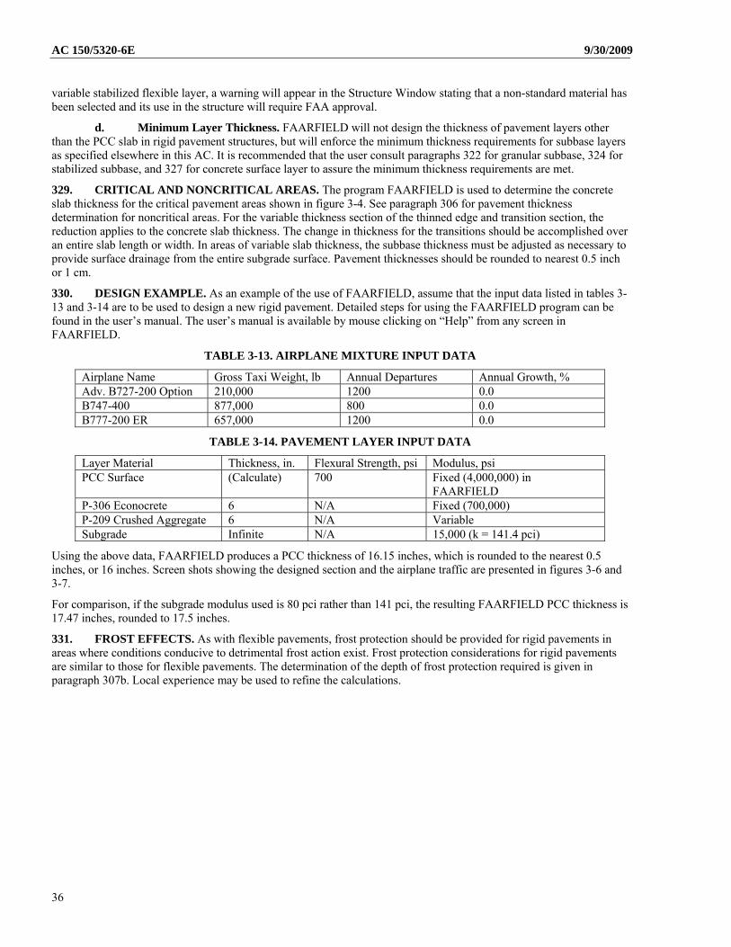
AC 150/5320-6E 9/30/2009
variable stabilized flexible layer, a warning will appear in the Structure Window stating that a non-standard material has been selected and its use in the structure will require FAA approval.
d. Minimum Layer Thickness. FAARFIELD will not design the thickness of pavement layers other than the PCC slab in rigid pavement structures, but will enforce the minimum thickness requirements for subbase layers as specified elsewhere in this AC. It is recommended that the user consult paragraphs 322 for granular subbase, 324 for stabilized subbase, and 327 for concrete surface layer to assure the minimum thickness requirements are met.
329. CRITICAL AND NONCRITICAL AREAS. The program FAARFIELD is used to determine the concrete slab thickness for the critical pavement areas shown in figure 3-4. See paragraph 306 for pavement thickness determination for noncritical areas. For the variable thickness section of the thinned edge and transition section, the reduction applies to the concrete slab thickness. The change in thickness for the transitions should be accomplished over an entire slab length or width. In areas of variable slab thickness, the subbase thickness must be adjusted as necessary to provide surface drainage from the entire subgrade surface. Pavement thicknesses should be rounded to nearest 0.5 inch or 1 cm.
330. DESIGN EXAMPLE. As an example of the use of FAARFIELD, assume that the input data listed in tables 3-13 and 3-14 are to be used to design a new rigid pavement. Detailed steps for using the FAARFIELD program can be found in the user’s manual. The user’s manual is available by mouse clicking on “Help” from any screen in FAARFIELD.
TABLE 3-13. AIRPLANE MIXTURE INPUT DATA
Airplane Name Gross Taxi Weight, lb Annual Departures Annual Growth, % Adv. B727-200 Option 210,000 1200 0.0 B747-400 877,000 800 0.0 B777-200 ER 657,000 1200 0.0
TABLE 3-14. PAVEMENT LAYER INPUT DATA
Layer Material Thickness, in. Flexural Strength, psi Modulus, psi PCC Surface (Calculate) 700 Fixed (4,000,000) in
FAARFIELD P-306 Econocrete 6 N/A Fixed (700,000) P-209 Crushed Aggregate 6 N/A Variable Subgrade Infinite N/A 15,000 (k = 141.4 pci)
Using the above data, FAARFIELD produces a PCC thickness of 16.15 inches, which is rounded to the nearest 0.5 inches, or 16 inches. Screen shots showing the designed section and the airplane traffic are presented in figures 3-6 and 3-7.
For comparison, if the subgrade modulus used is 80 pci rather than 141 pci, the resulting FAARFIELD PCC thickness is 17.47 inches, rounded to 17.5 inches.
331. FROST EFFECTS. As with flexible pavements, frost protection should be provided for rigid pavements in areas where conditions conducive to detrimental frost action exist. Frost protection considerations for rigid pavements are similar to those for flexible pavements. The determination of the depth of frost protection required is given in paragraph 307b. Local experience may be used to refine the calculations.
36
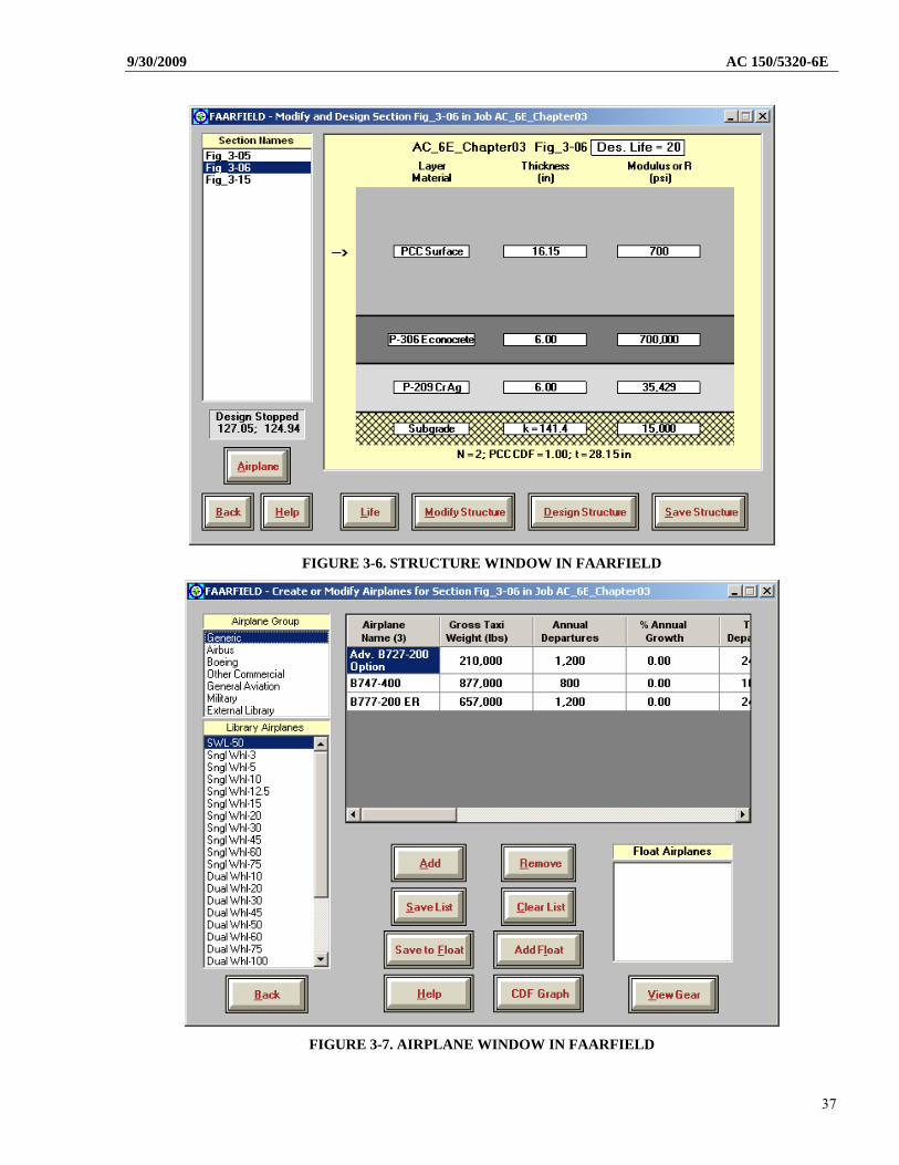
9/30/2009 AC 150/5320-6E
FIGURE 3-6. STRUCTURE WINDOW IN FAARFIELD
FIGURE 3-7. AIRPLANE WINDOW IN FAARFIELD
37
AC 150/5320-6E 9/30/2009
332. JOINTING OF CONCRETE PAVEMENTS. Variations in temperature and moisture content can cause volume changes and slab warping resulting in significant stresses. In order to reduce the detrimental effects of these stresses and to minimize random cracking, it is necessary to divide the pavement into a series of slabs of predetermined dimension by means of joints. These slabs should be as nearly square as possible when no embedded steel is used.
a. Joint Categories. Pavement joints are categorized according to the function that the joint is intended to perform. The categories are isolation, contraction, and construction joints. All joints, regardless of type, should be finished in a manner that permits the joint to be sealed. Pavement joint details are shown in figures 3-8 and 3-9 and are summarized in table 3-15. These various joints are described as follows:
(1) Isolation Joints (Types A, A-1). The function of isolation joints is to isolate intersecting pavements and to isolate structures from the pavement. Type A is used when conditions preclude the use of load transfer devices that span across the joint, such as where the pavement abuts a structure or where horizontal differences in movement of the pavements may occur. These joints are formed by increasing the thickness of the pavement along the edge of the slab. No dowel bars are provided. Type A-1 joints may be used as an alternate in cases where thickened edge joints are undesirable.
(2) Contraction Joints (Types B, C, D). The function of contraction joints is to provide controlled cracking of the pavement when the pavement contracts due to decrease in moisture content or a temperature drop. Contraction joints also decrease stresses caused by slab warping. Details for contraction joints are shown as Types B, C, and D in figure 3-8.
(3) Construction Joints (Type E). Construction joints are required when two abutting slabs are placed at different times, such as at the end of a day’s placement or between paving lanes. Details for construction joints are shown as Types E in figure 3-8.
38
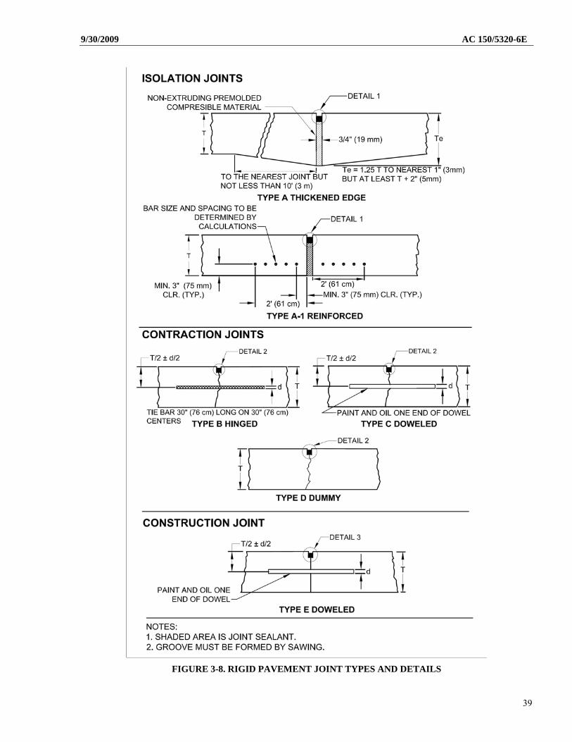
9/30/2009 AC 150/5320-6E
FIGURE 3-8. RIGID PAVEMENT JOINT TYPES AND DETAILS
39
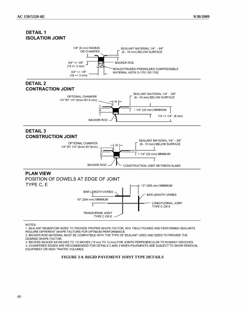
AC 150/5320-6E 9/30/2009
FIGURE 3-9. RIGID PAVEMENT JOINT TYPE DETAILS
40
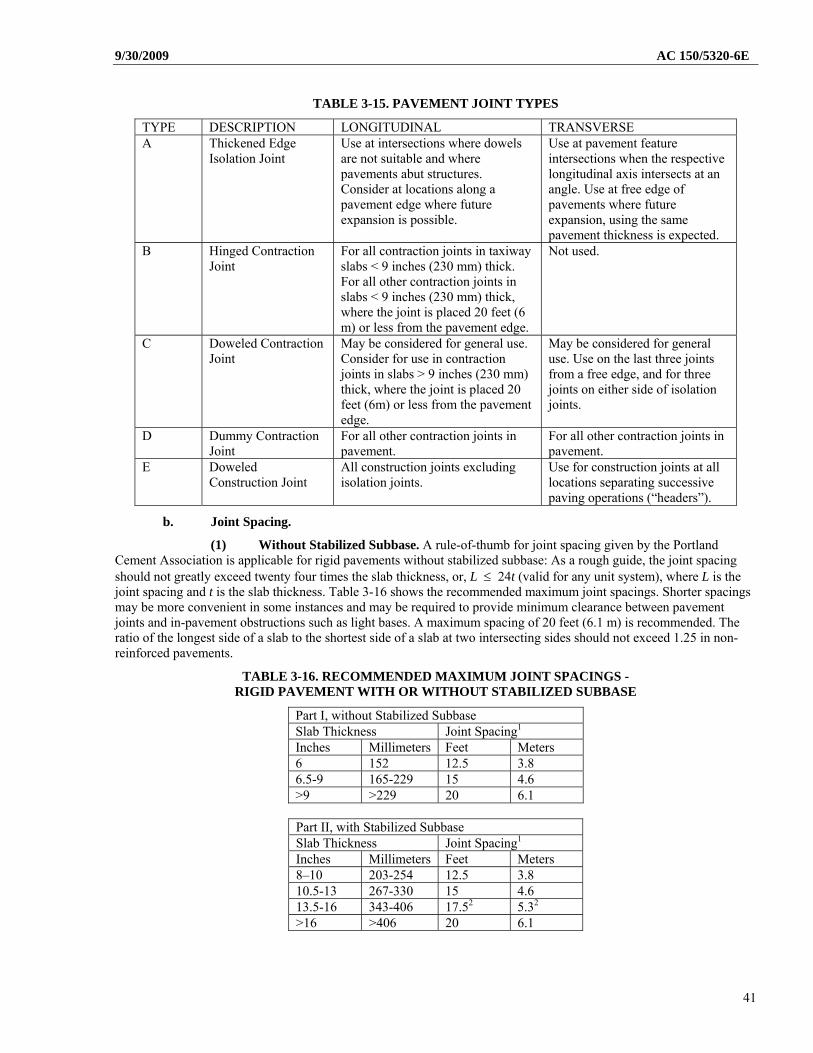
9/30/2009 AC 150/5320-6E
TABLE 3-15. PAVEMENT JOINT TYPES
TYPE DESCRIPTION LONGITUDINAL TRANSVERSE A Thickened Edge
Isolation Joint Use at intersections where dowels are not suitable and where pavements abut structures. Consider at locations along a pavement edge where future expansion is possible.
Use at pavement feature intersections when the respective longitudinal axis intersects at an angle. Use at free edge of pavements where future expansion, using the same pavement thickness is expected.
B Hinged Contraction Joint
For all contraction joints in taxiway slabs < 9 inches (230 mm) thick. For all other contraction joints in slabs < 9 inches (230 mm) thick, where the joint is placed 20 feet (6 m) or less from the pavement edge.
Not used.
C Doweled Contraction Joint
May be considered for general use. Consider for use in contraction joints in slabs > 9 inches (230 mm) thick, where the joint is placed 20 feet (6m) or less from the pavement edge.
May be considered for general use. Use on the last three joints from a free edge, and for three joints on either side of isolation joints.
D Dummy Contraction Joint
For all other contraction joints in pavement.
For all other contraction joints in pavement.
E Doweled Construction Joint
All construction joints excluding isolation joints.
Use for construction joints at all locations separating successive paving operations (“headers”).
b. Joint Spacing.
(1) Without Stabilized Subbase. A rule-of-thumb for joint spacing given by the Portland Cement Association is applicable for rigid pavements without stabilized subbase: As a rough guide, the joint spacing should not greatly exceed twenty four times the slab thickness, or, L 24t (valid for any unit system), where L is the joint spacing and t is the slab thickness. Table 3-16 shows the recommended maximum joint spacings. Shorter spacings may be more convenient in some instances and may be required to provide minimum clearance between pavement joints and in-pavement obstructions such as light bases. A maximum spacing of 20 feet (6.1 m) is recommended. The ratio of the longest side of a slab to the shortest side of a slab at two intersecting sides should not exceed 1.25 in non-reinforced pavements.
TABLE 3-16. RECOMMENDED MAXIMUM JOINT SPACINGS - RIGID PAVEMENT WITH OR WITHOUT STABILIZED SUBBASE
Part I, without Stabilized Subbase Slab Thickness Joint Spacing1 Inches Millimeters Feet Meters 6 152 12.5 3.8 6.5-9 165-229 15 4.6 >9 >229 20 6.1
Part II, with Stabilized Subbase Slab Thickness Joint Spacing1 Inches Millimeters Feet Meters 8–10 203-254 12.5 3.8 10.5-13 267-330 15 4.6 13.5-16 343-406 17.52 5.32 >16 >406 20 6.1
41
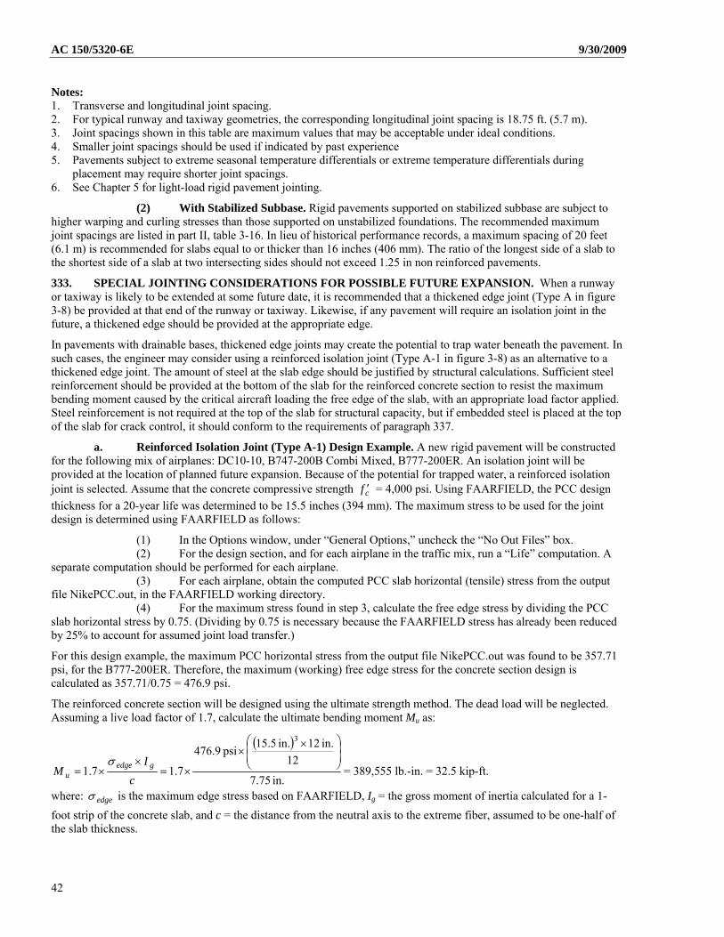
AC 150/5320-6E 9/30/2009
Notes: 1. Transverse and longitudinal joint spacing. 2. For typical runway and taxiway geometries, the corresponding longitudinal joint spacing is 18.75 ft. (5.7 m). 3. Joint spacings shown in this table are maximum values that may be acceptable under ideal conditions. 4. Smaller joint spacings should be used if indicated by past experience 5. Pavements subject to extreme seasonal temperature differentials or extreme temperature differentials during
placement may require shorter joint spacings. 6. See Chapter 5 for light-load rigid pavement jointing.
(2) With Stabilized Subbase. Rigid pavements supported on stabilized subbase are subject to higher warping and curling stresses than those supported on unstabilized foundations. The recommended maximum joint spacings are listed in part II, table 3-16. In lieu of historical performance records, a maximum spacing of 20 feet (6.1 m) is recommended for slabs equal to or thicker than 16 inches (406 mm). The ratio of the longest side of a slab to the shortest side of a slab at two intersecting sides should not exceed 1.25 in non reinforced pavements.
333. SPECIAL JOINTING CONSIDERATIONS FOR POSSIBLE FUTURE EXPANSION. When a runway or taxiway is likely to be extended at some future date, it is recommended that a thickened edge joint (Type A in figure 3-8) be provided at that end of the runway or taxiway. Likewise, if any pavement will require an isolation joint in the future, a thickened edge should be provided at the appropriate edge.
In pavements with drainable bases, thickened edge joints may create the potential to trap water beneath the pavement. In such cases, the engineer may consider using a reinforced isolation joint (Type A-1 in figure 3-8) as an alternative to a thickened edge joint. The amount of steel at the slab edge should be justified by structural calculations. Sufficient steel reinforcement should be provided at the bottom of the slab for the reinforced concrete section to resist the maximum bending moment caused by the critical aircraft loading the free edge of the slab, with an appropriate load factor applied. Steel reinforcement is not required at the top of the slab for structural capacity, but if embedded steel is placed at the top of the slab for crack control, it should conform to the requirements of paragraph 337.
a. Reinforced Isolation Joint (Type A-1) Design Example. A new rigid pavement will be constructed for the following mix of airplanes: DC10-10, B747-200B Combi Mixed, B777-200ER. An isolation joint will be provided at the location of planned future expansion. Because of the potential for trapped water, a reinforced isolation joint is selected. Assume that the concrete compressive strength cf = 4,000 psi. Using FAARFIELD, the PCC design
thickness for a 20-year life was determined to be 15.5 inches (394 mm). The maximum stress to be used for the joint design is determined using FAARFIELD as follows:
(1) In the Options window, under “General Options,” uncheck the “No Out Files” box. (2) For the design section, and for each airplane in the traffic mix, run a “Life” computation. A
separate computation should be performed for each airplane. (3) For each airplane, obtain the computed PCC slab horizontal (tensile) stress from the output
file NikePCC.out, in the FAARFIELD working directory. (4) For the maximum stress found in step 3, calculate the free edge stress by dividing the PCC
slab horizontal stress by 0.75. (Dividing by 0.75 is necessary because the FAARFIELD stress has already been reduced by 25% to account for assumed joint load transfer.)
For this design example, the maximum PCC horizontal stress from the output file NikePCC.out was found to be 357.71 psi, for the B777-200ER. Therefore, the maximum (working) free edge stress for the concrete section design is calculated as 357.71/0.75 = 476.9 psi.
The reinforced concrete section will be designed using the ultimate strength method. The dead load will be neglected. Assuming a live load factor of 1.7, calculate the ultimate bending moment Mu as:
in. 7.75
12
in. 12in. 5.15 psi 9.476
7.17.1
3
c
IM
gedgeu
= 389,555 lb.-in. = 32.5 kip-ft.
where: edge is the maximum edge stress based on FAARFIELD, Ig = the gross moment of inertia calculated for a 1-
foot strip of the concrete slab, and c = the distance from the neutral axis to the extreme fiber, assumed to be one-half of the slab thickness.
42
9/30/2009 AC 150/5320-6E Assume the edge reinforcement will consist of No. 6 bars spaced at 6 inches at the bottom of the slab, as shown in igure 3-8. Calculate the flexural design strength using the following equation:
c
yysn f
fdfAM 59.01
where: = stress reduction factor (= 0.90 for flexure without axial loading)
As = steel area = 2 x 0.44 = 0.88 in2 for 1-ft. width fy = steel yield stress (assume fy = 60,000 psi)
cf = concrete compressive strength
d = depth to steel centroid
= steel ratio bd
As
b = section width = 12 in.
For the minimum 3 in. (76.2 mm) clear cover on No. 6 bars, d = 12.13 in. (308 mm). Using the above values nM is
calculated as 45.5 kip-ft. Since nU MM , the design is adequate for flexure.
A check should also be performed for minimum and maximum steel ratio. The minimum steel ratio is given by:
yf
200min , where fy is in psi. From the above values, obtain min = 0.0033. The calculated steel ratio 0.0060 >
0.0033, hence the minimum steel ratio criterion is satisfied. The maximum steel ratio is determined from the equation:
0213.087000
8700085.075.075.0 1max
yy
cb ff
f
where: b is the balanced steel ratio, 1 = 0.85 (for cf = 4000 psi) and fy is in psi. Since the calculated steel ratio
0.0060 < 0.0213, the maximum steel ratio criterion is also satisfied. For the final design, provide four (4) no. 6 bars
spaced at 6 inches (152 mm).
334. JOINTING STEEL.
a. Tie Bars. Tie bars are used across certain longitudinal contraction joints to hold the slab faces in close contact. The tie bars themselves do not act as load transfer devices. By preventing wide opening of the joint, load transfer is provided by aggregate interlock in the crack below the groove-type joint. Tie bars should be deformed bars conforming to the specifications given in Item P-501. The bars should be 5/8 inch (16 mm) in diameter and 30 inches (762 mm) on center spacing. Do not use tie-bars such that areas of pavement with continuous tied joints greater than 75 feet (23 m) exist.
b. Dowels. Dowels are used at joints to provide for transfer of load across the joint and to prevent relative vertical displacement of adjacent slab ends. Dowels permit longitudinal movement of adjacent slabs.
(1) Where Used. Provision for load transfer by dowels is provided as described in table 3-15. Dowels for contraction joints should be provided at least three joints from a free edge.
(2) Size Length and Spacing. Dowels should be sized such that they will resist the shearing and bending stresses produced by the loads on the pavement. They should be of such length and spacing that the bearing stresses exerted on the concrete will not cause failure of the concrete slab. Table 3-17 indicates the dowel dimensions and spacing for various pavement thicknesses.
(3) Dowel Positioning. The alignment and elevation of dowels is extremely important in obtaining a satisfactory joint. Transverse dowels will require the use of a fixture, usually a wire cage or basket firmly anchored to the subbase, to hold the dowels in position. Supports on the baskets do not need to be cut. During the concrete placement operations, it is advisable to place plastic concrete directly on the dowel assembly immediately prior to passage of the paver to prevent displacement of the assembly by the paving equipment. An alternate procedure for placing dowels in the transverse joint is to use a paving machine equipped with an automated dowel bar inserter.
43
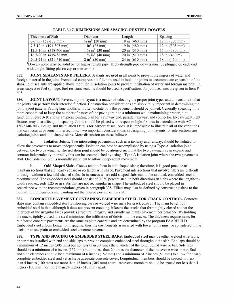
AC 150/5320-6E 9/30/2009
TABLE 3-17. DIMENSIONS AND SPACING OF STEEL DOWELS
Thickness of Slab Diameter Length Spacing 6-7 in (152-178 mm) ¾ in1 (20 mm) 18 in (460 mm) 12 in (305 mm) 7.5-12 in (191-305 mm) 1 in1 (25 mm) 19 in (480 mm) 12 in (305 mm) 12.5-16 in (318-406 mm) 1 ¼ in1 (30 mm) 20 in (510 mm) 15 in (380 mm) 16.5-20 in (419-58 mm) 1 ½ in1 (40 mm) 20 in (510 mm) 18 in (460 m) 20.5-24 in (521-610 mm) 2 in1 (50 mm) 24 in (610 mm) 18 in (460 mm)
1Dowels noted may be solid bar or high-strength pipe. High-strength pipe dowels must be plugged on each end with a tight-fitting plastic cap or mortar mix.
335. JOINT SEALANTS AND FILLERS. Sealants are used in all joints to prevent the ingress of water and foreign material in the joint. Premolded compressible filler are used in isolation joints to accommodate expansion of the slabs. Joint sealants are applied above the filler in isolation joints to prevent infiltration of water and foreign material. In areas subject to fuel spillage, fuel-resistant sealants should be used. Specifications for joint sealants are given in Item P-605.
336. JOINT LAYOUT. Pavement joint layout is a matter of selecting the proper joint types and dimensions so that the joints can perform their intended function. Construction considerations are also vitally important in determining the joint layout pattern. Paving lane widths will often dictate how the pavement should be jointed. Generally speaking, it is more economical to keep the number of passes of the paving train to a minimum while maintaining proper joint function. Figure 3-10 shows a typical jointing plan for a runway end, parallel taxiway, and connector. In-pavement light fixtures may also affect joint spacing. Joints should be placed with respect to light fixtures in accordance with AC 150/5340-30B, Design and Installation Details for Airport Visual Aids. It is impossible to illustrate all of the variations that can occur at pavement intersections. Two important considerations in designing joint layouts for intersections are isolation joints and odd-shaped slabs. More discussion on these follows:
a. Isolation Joints. Two intersecting pavements, such as a taxiway and runway, should be isolated to allow the pavements to move independently. Isolation can best be accomplished by using a Type A isolation joint between the two pavements. The isolation joint should be positioned such that the two pavements can expand and contract independently; normally this can be accomplished by using a Type A isolation joint where the two pavements abut. One isolation joint is normally sufficient to allow independent movement.
b. Odd-Shaped Slabs. Cracks tend to form in odd-shaped slabs; therefore, it is good practice to maintain sections that are nearly square or rectangular in shape. Pavement intersections that involve fillets are difficult to design without a few odd-shaped slabs. In instances where odd-shaped slabs cannot be avoided, embedded steel is recommended. The embedded steel should consist of 0.050 percent steel in both directions in slabs where the length-to-width ratio exceeds 1.25 or in slabs that are not rectangular in shape. The embedded steel should be placed in accordance with the recommendations given in paragraph 338. Fillets may also be defined by constructing slabs to the normal, full dimensions and painting out the unused portion of the slab.
337. CONCRETE PAVEMENT CONTAINING EMBEDDED STEEL FOR CRACK CONTROL. Concrete slabs may contain embedded steel reinforcing bars or welded wire mats for crack control. The main benefit of embedded steel is that, although it does not prevent cracking, it keeps the cracks that form tightly closed so that the interlock of the irregular faces provides structural integrity and usually maintains pavement performance. By holding the cracks tightly closed, the steel minimizes the infiltration of debris into the cracks. The thickness requirements for reinforced concrete pavements are the same as plain concrete and are determined by the program FAARFIELD. Embedded steel allows longer joint spacing; thus the cost benefits associated with fewer joints must be considered in the decision to use plain or embedded steel concrete pavement.
338. TYPE AND SPACING OF EMBEDDED STEEL BARS. Embedded steel may be either welded wire fabric or bar mats installed with end and side laps to provide complete embedded steel throughout the slab. End laps should be a minimum of 12 inches (305 mm) but not less than 30 times the diameter of the longitudinal wire or bar. Side laps should be a minimum of 6 inches (152 mm) but not less than 20 times the diameter of the transverse wire or bar. End and side clearances should be a maximum of 6 inches (152 mm) and a minimum of 2 inches (51 mm) to allow for nearly complete embedded steel and yet achieve adequate concrete cover. Longitudinal members should be spaced not less than 4 inches (100 mm) nor more than 12 inches (305 mm) apart; transverse members should be spaced not less than 4 inches (100 mm) nor more than 24 inches (610 mm) apart.
44
9/30/2009 AC 150/5320-6E
FIG
UR
E 3
-10.
TY
PIC
AL
JO
INT
LA
YO
UT
PA
TT
ER
N F
OR
RU
NW
AY
, PA
RA
LL
EL
TA
XIW
AY
, AN
D C
ON
NE
CT
OR
45
AC 150/5320-6E 9/30/2009
339. AMOUNT OF EMBEDDED STEEL.
a. The steel area required for an embedded steel concrete pavement is determined from the subgrade drag formula and the coefficient of friction formula combined. The resultant formula is expressed as follows:
S
S f
LtLA
7.3
where:
As = area of steel per foot of width or length, square inches L = length or width of slab, feet t = thickness of slab, inches fs = allowable tensile stress in steel, psi
NOTE: To determine the area of steel in metric units:
L should be expressed in meters t should be expressed in millimeters f s should be expressed in mega newtons per square meter The constant 3.7 should be changed to 0.64. As will then be in terms of square centimeters per meter.
b. In this formula the slab weight is assumed to be 12.5 pounds per square foot, per inch of thickness (23.6 MN/m2). The allowable tensile stress in steel will vary with the type and grade of steel. It is recommended that allowable tensile stress be taken as two-thirds of the yield strength of the steel. Based on current specifications the yield strengths and corresponding design stresses (fs) are as listed in table 3-18.
c. The minimum percentage of embedded steel should be 0.05 percent. The percentage of steel is computed by dividing the area of steel, As, by the area of concrete per unit of length (or width) and multiplying by 100. The minimum percentage of steel considered the least amount of steel that can be economically placed is 0.05 percent. Embedded steel allows larger slab sizes and thus decreases the number of transverse contraction joints. The costs associated with providing an embedded steel pavement must be compared with the savings realized in eliminating some of the transverse contraction joints to determine the most economical steel percentage.
The equation in (a) may be reorganized to obtain the relationship between the percentage of steel and the required slab length:
S
Sft
LLP
8.30%
For a 75 ft (23 m) long slab with 10 inch (254 mm) thickness and using fs = 27,000 psi (186 MPa), the required steel percentage would be 0.23 %. For the 75 ft (23 m) long slab with 20 inch (508 mm) thickness and using fs = 47000 psi (324 MPa), the required steel percentage would be 0.1. Both satisfy the minimum required percentage 0.05. They are also smaller than the minimum required steel percentage for CRCP (0.5, see item 342). For safety reasons, the maximum allowable slab length regardless of steel percentage is 75 feet (23 m) for normal concrete slabs containing embedded steel.
TABLE 3-18. YIELD STRENGTHS OF VARIOUS GRADES OF REINFORCING STEEL
ASTM Designation
Type & Grade of Steel Yield Strength, psi (MN/m2)
fs, psi (MN/m2)
A 615 Deformed Billet Steel, Grade 40 40,000 (280) 27,000 (190) A 616 Deformed Rail Steel, Grade 50 50,000 (350) 33,000 (230) A 616 Deformed Rail Steel, Grade 60 60,000 (420) 40,000 (280) A 615 Deformed Billet Steel, Grade 60 60,000 (420) 40,000 (280) A 185 Cold Drawn Welded Steel Wire Fabric 65,000 (460) 43,000 (300) A 497 Cold Drawn Welded Deformed Steel Wire 70,000 (490) 47,000(330)
340. DIMENSIONS AND WEIGHTS OF EMBEDDED STEEL. Dimensions and unit weights of standard deformed reinforcing bars are given in table 3-19, and wire size number, diameters, areas, and weights of wires used in welded wire fabric are given in table 3-20.
46
9/30/2009 AC 150/5320-6E
TABLE 3-19. DIMENSIONS AND UNIT WEIGHTS OF DEFORMED STEEL REINFORCING BARS NOMINAL DIMENSIONS
No. Diameter, in. (mm) Area, in2 (mm2) Perimeter, in. (cm) Unit Weight, lb/ft (kg/m) 3 0.375 9.5 0.11 0.71 1.178 3.0 0.376 0.56 4 0.500 12.7 0.20 1.29 1.571 4.0 0.668 1.00 5 0.625 15.9 0.31 2.00 1.963 5.0 1.043 1.57 6 0.750 19.1 0.44 2.84 2.356 6.0 1.502 2.26 7 0.875 22.2 0.60 3.86 2.749 7.0 2.044 3.07
TABLE 3-20. SECTIONAL AREAS OF WELDED FABRIC
Wire Size Smooth
Number Deformed
Nominal Diameter Inches
Nominal Weight, lb/linear ft
Area of Steel When Center-to-Center Spacing is (in inches)
4 6 8 10 12 W31 D31 0.628 1.054 .93 .62 .465 .372 .31 W30 D30 0.618 1.020 .90 .60 .45 .36 .30 W28 D28 0.597 .952 .84 .56 .42 .336 .28 W26 D26 0.575 .934 .78 .52 .39 .312 .26 W24 D24 0.553 .816 .72 .48 .36 .288 .24 W22 D22 0.529 .748 .66 .44 .33 .264 .22 W20 D20 0.504 .680 .60 .40 .30 .24 .20 W18 D18 0.478 .612 .54 .36 .27 .216 .18 W16 D16 0.451 .544 .48 .32 .24 .192 .16 WI4 D14 0.422 .476 .42 .28 .21 .168 .14 W12 D12 0.390 .408 .36 .24 .18 .144 .12 W11 D11 0.374 .374 .33 .22 .165 .132 .11 W10.5 0.366 .357 .315 .21 .157 .126 .105 WI0 D10 0.356 .340 .30 .20 .15 .12 .10 W9.5 .348 .323 .285 .19 .142 .114 .095 W9 D9 .338 .306 .27 .18 .135 .108 .09 W8.5 .329 .289 .255 .17 .127 .102 .085 W8 D8 .319 .272 .24 .16 .12 .096 .08 W7.5 .309 .255 .225 .15 .112 .09 .075 W7 D7 .298 .238 .21 .14 .105 .084 .07 W6.5 .288 .221 .195 .13 .097 .078 .065 W6 D6 .276 .204 .18 .12 .09 .072 .06 W5.5 .264 .187 .165 .11 .082 .066 .055 W5 D5 .252 .170 .15 .10 .075 .06 .05 W4.5 .240 .153 .135 .09 .067 .054 .045 W4 D4 .225 .136 .12 .08 .06 .048 .04
Note: 1 inch = 2.54 cm, 1 lb/linear ft = 1.5 kg/m
341. WELDED WIRE FABRIC. The use of welded wire fabric requires some special design considerations to achieve the most economical design. The use of smooth welded wire fabric or deformed welded wire fabric is the option of the designer. The choice should be based on the difference in allowable design stresses, the availability of the desired sizes (smooth wire fabric is available in a wider range of sizes), and the costs associated with each style of fabric. It is recommended that the minimum size of longitudinal wire be W5 or D5. The minimum transverse wire should be no smaller than W4 or D4. In addition, should calculated area of longitudinal steel be less than 0.05 percent of the cross-sectional area of slab, the size and spacing of the steel members (bars or wire) should be determined on the premise that the minimum area should not be less than 0.05 percent. This percentage applies in the case of steel having yield strength of 65,000 psi (480 MN/m2). If lower grades are used, the percentage should be revised proportionately upward. For example, table 3-20 shows that W10 wires, spaced 10 inches (255 mm) apart, furnish an area of 0.12 square inches (77 mm2), which satisfies the requirement for pavements up to 20 inches (508 mm) thick. Sizing of individual sheets of welded wire fabric is also important in providing an economical design. Not all fabricators supply all wire sizes in all
47
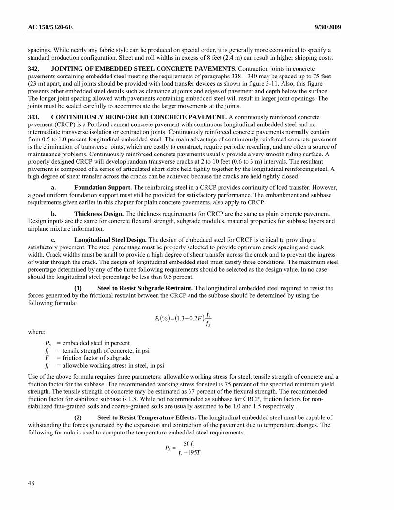
AC 150/5320-6E 9/30/2009
spacings. While nearly any fabric style can be produced on special order, it is generally more economical to specify a standard production configuration. Sheet and roll widths in excess of 8 feet (2.4 m) can result in higher shipping costs.
342. JOINTING OF EMBEDDED STEEL CONCRETE PAVEMENTS. Contraction joints in concrete pavements containing embedded steel meeting the requirements of paragraphs 338 – 340 may be spaced up to 75 feet (23 m) apart, and all joints should be provided with load transfer devices as shown in figure 3-11. Also, this figure presents other embedded steel details such as clearance at joints and edges of pavement and depth below the surface. The longer joint spacing allowed with pavements containing embedded steel will result in larger joint openings. The joints must be sealed carefully to accommodate the larger movements at the joints.
343. CONTINUOUSLY REINFORCED CONCRETE PAVEMENT. A continuously reinforced concrete pavement (CRCP) is a Portland cement concrete pavement with continuous longitudinal embedded steel and no intermediate transverse isolation or contraction joints. Continuously reinforced concrete pavements normally contain from 0.5 to 1.0 percent longitudinal embedded steel. The main advantage of continuously reinforced concrete pavement is the elimination of transverse joints, which are costly to construct, require periodic resealing, and are often a source of maintenance problems. Continuously reinforced concrete pavements usually provide a very smooth riding surface. A properly designed CRCP will develop random transverse cracks at 2 to 10 feet (0.6 to 3 m) intervals. The resultant pavement is composed of a series of articulated short slabs held tightly together by the longitudinal reinforcing steel. A high degree of shear transfer across the cracks can be achieved because the cracks are held tightly closed.
a. Foundation Support. The reinforcing steel in a CRCP provides continuity of load transfer. However, a good uniform foundation support must still be provided for satisfactory performance. The embankment and subbase requirements given earlier in this chapter for plain concrete pavements, also apply to CRCP.
b. Thickness Design. The thickness requirements for CRCP are the same as plain concrete pavement. Design inputs are the same for concrete flexural strength, subgrade modulus, material properties for subbase layers and airplane mixture information.
c. Longitudinal Steel Design. The design of embedded steel for CRCP is critical to providing a satisfactory pavement. The steel percentage must be properly selected to provide optimum crack spacing and crack width. Crack widths must be small to provide a high degree of shear transfer across the crack and to prevent the ingress of water through the crack. The design of longitudinal embedded steel must satisfy three conditions. The maximum steel percentage determined by any of the three following requirements should be selected as the design value. In no case should the longitudinal steel percentage be less than 0.5 percent.
(1) Steel to Resist Subgrade Restraint. The longitudinal embedded steel required to resist the forces generated by the frictional restraint between the CRCP and the subbase should be determined by using the following formula:
S
tS f
fFP 2.03.1%
where:
Ps = embedded steel in percent ft = tensile strength of concrete, in psi F = friction factor of subgrade fs = allowable working stress in steel, in psi
Use of the above formula requires three parameters: allowable working stress for steel, tensile strength of concrete and a friction factor for the subbase. The recommended working stress for steel is 75 percent of the specified minimum yield strength. The tensile strength of concrete may be estimated as 67 percent of the flexural strength. The recommended friction factor for stabilized subbase is 1.8. While not recommended as subbase for CRCP, friction factors for non-stabilized fine-grained soils and coarse-grained soils are usually assumed to be 1.0 and 1.5 respectively.
(2) Steel to Resist Temperature Effects. The longitudinal embedded steel must be capable of withstanding the forces generated by the expansion and contraction of the pavement due to temperature changes. The following formula is used to compute the temperature embedded steel requirements.
Tf
fP
s
tS 195
50
48
9/30/2009 AC 150/5320-6E where:
Ps = embedded steel in percent f t = tensile strength of concrete, 67% of the flexural strength is recommended fs = working stress for steel usually taken as 75% of specified minimum yield strength T = maximum seasonal temperature differential for pavement in degrees Fahrenheit
Reinforcing steel should be specified on the basis of minimum yield strength. All deformed reinforcing steel bars should conform to ASTM A615 or A996. Deformed welded wire fabric should conform to ASTM A497.
(3) Concrete to Steel Strength Ratio. The third consideration in selecting the amount of longitudinal embedded steel is the ratio of concrete tensile strength to the specified minimum yield strength of steel. The steel percentage is obtained by multiplying the ratio of the concrete strength to the yield strength of steel by 100.
y
tS f
fP
100
where:
Ps = embedded steel in percent ft = tensile strength of concrete fy = minimum yield strength of steel
d. Transverse Steel Design. Transverse embedded steel is recommended for CRCP airport pavements to control “chance” longitudinal cracks, which sometimes form. It is also aids in construction by supporting and maintaining longitudinal embedded steel spacing. The following formula is used for determining transverse steel requirements:
1002
% S
SS f
FWP
where:
Ps = embedded steel in percent Ws = width of slab, in feet F = friction factor of subgrade fs = allowable working stress in steel, in psi, 0.75 of yield strength recommended
e. Steel Detailing. Longitudinal embedded steel should be located at mid-depth of the slab or slightly above. Transverse steel may be located either above or below the longitudinal steel. A minimum concrete cover of 3 inches (76 mm) should be maintained over all embedded steel. Longitudinal steel spacing should be 6 to 12 inches (152 to 305 mm). Transverse steel should be spaced at 12 inches (305 mm) or greater. The recommended overlap for splicing of reinforcing bars is 25 diameters or 16 inches (406 mm), whichever is greater. The recommended overlap for splicing deformed welded wire fabric is 32 diameters or 16 inches (406 mm), whichever is greater. When splicing longitudinal steel bar reinforcing it is recommended that the lap splices be made on a 60 degree skew from centerline or staggered such that not more than one-third of the bars are spliced on the same transverse plane.
49
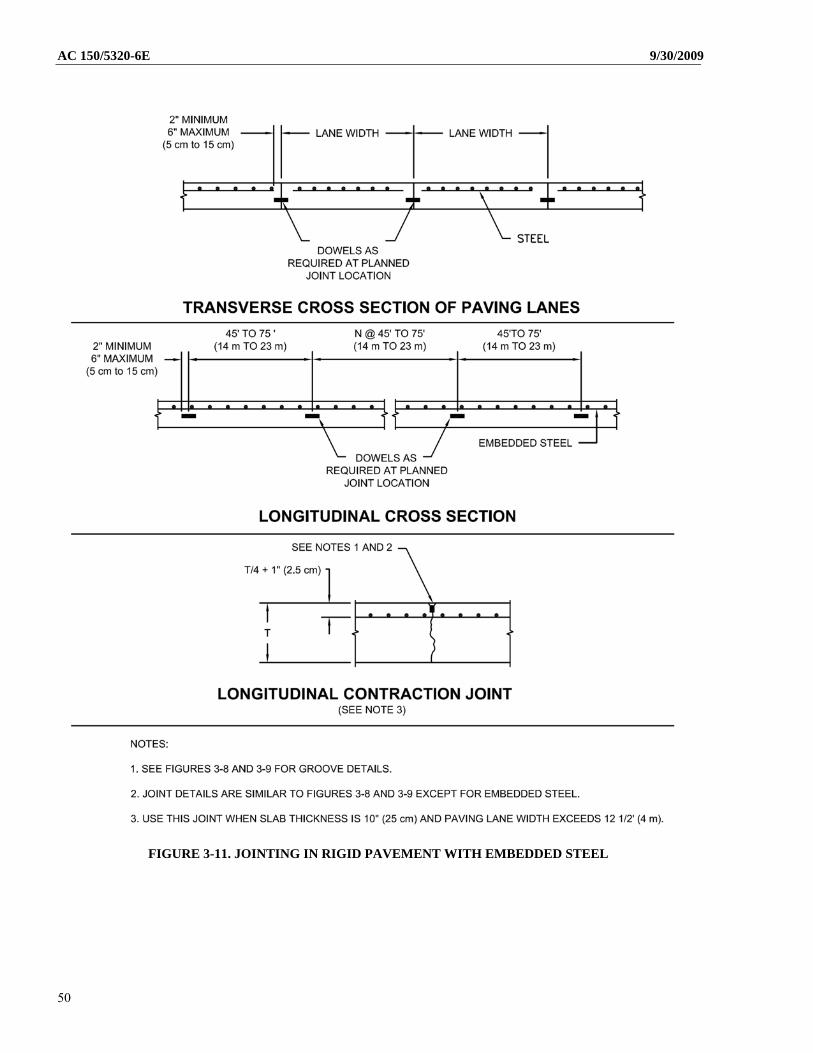
AC 150/5320-6E 9/30/2009
FIGURE 3-11. JOINTING IN RIGID PAVEMENT WITH EMBEDDED STEEL
50
9/30/2009 AC 150/5320-6E 344. CRCP JOINTING. Even though transverse contraction joints can be eliminated with CRCP, some joints will be needed to accommodate construction and to control warping stresses. The two types of joints are discussed below:
a. Construction Joints. Two types of construction joints are necessary for CRCP. Because pavements are constructed in multiple lanes, a longitudinal construction joint is required between lanes. A transverse construction joint must be provided where paving ends and begins, such as at the finish of a day’s paving and the start of the next day’s paving. Typical construction joint details are shown in figure 3-12.
b. Warping Joints. Warping joints or hinged joints are needed when the paving lane width exceeds the recommended maximum longitudinal joint spacings shown in table 3-16. Transverse steel is carried through the joint to provide continuity and positive aggregate interlock across the joint. Since carrying the steel through the joint eliminates any expansion or contraction capacity, the maximum width of tied pavement should not exceed 75 feet (23 m), see paragraph 334a. Typical warping joint details are shown in figures 3-12 and 3-13.
FIGURE 3-12. CONTINUOUSLY REINFORCED CONCRETE PAVEMENT – JOINT DETAILS
345. CRCP TERMINAL TREATMENT. Since long slabs of CRCP are constructed with no transverse joints, provisions must be made to either restrain or accommodate end movements wherever the CRCP abuts other pavements or structures. Rather large end movements, up to 2 inches (51 mm), are experienced with CRCP due to thermal expansion and contraction. End movement is normally not a problem except where CRCP abuts another pavement or structure. Experience with highway CRCP shows that attempts to restrain end movement have not been too successful. More favorable results are achieved where end movement is accommodated rather than restrained. Joints designed to accommodate large movements are required where CRCP intersects other pavements or abuts another structures. Failure to do so may result in damage to the CRCP, pavement or other structure. Wide flange beam type joints or finger type joints can accommodate the movements. The wide flange beam type joint is recommended due to its relatively lower costs. A sketch of the wide flange beam joint is shown on figure 3-14.
51
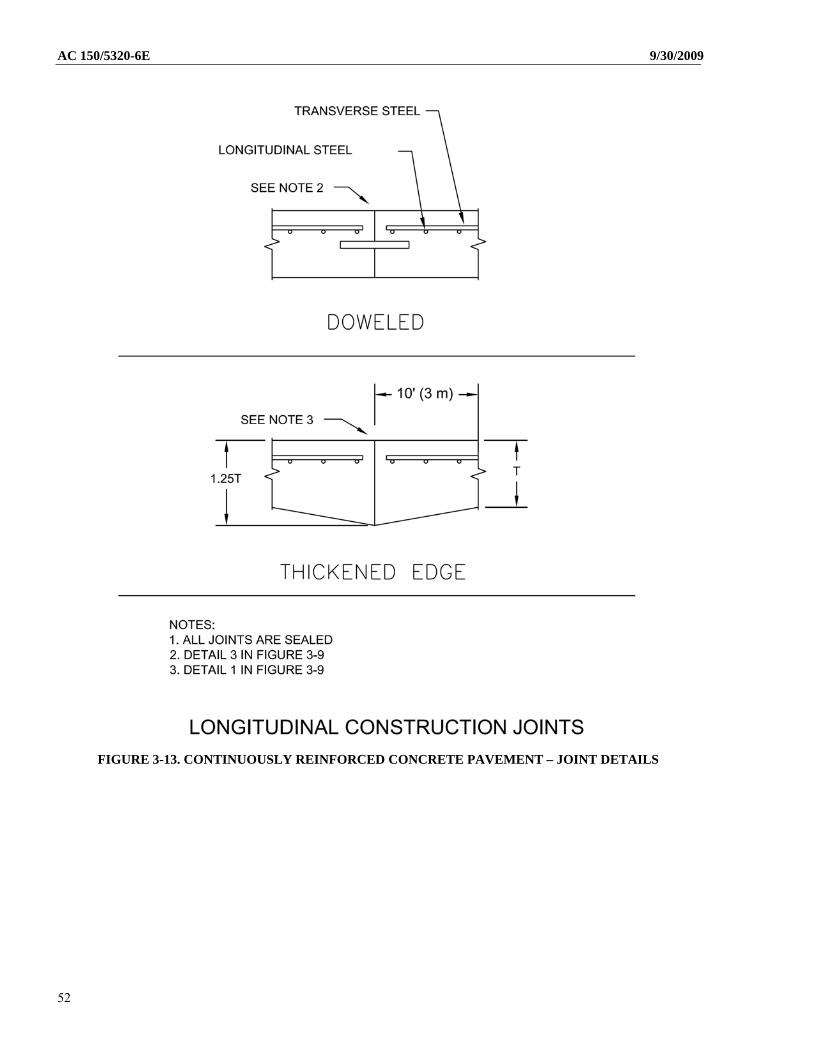
AC 150/5320-6E 9/30/2009
FIGURE 3-13. CONTINUOUSLY REINFORCED CONCRETE PAVEMENT – JOINT DETAILS
52
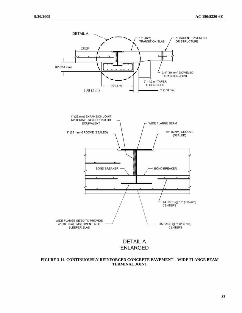
9/30/2009 AC 150/5320-6E
10ft (3 m)
FIGURE 3-14. CONTINUOUSLY REINFORCED CONCRETE PAVEMENT – WIDE FLANGE BEAM TERMINAL JOINT
53
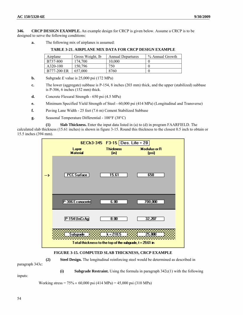
AC 150/5320-6E 9/30/2009
346. CRCP DESIGN EXAMPLE. An example design for CRCP is given below. Assume a CRCP is to be designed to serve the following conditions:
a. The following mix of airplanes is assumed:
TABLE 3-21. AIRPLANE MIX DATA FOR CRCP DESIGN EXAMPLE
Airplane Gross Weight, lb Annual Departures % Annual Growth B737-800 174,700 10,000 0 A320-100 150,796 750 0 B777-200 ER 657,000 8760 0
b. Subgrade E value is 25,000 psi (172 MPa)
c. The lower (aggregate) subbase is P-154, 8 inches (203 mm) thick, and the upper (stabilized) subbase is P-306, 6 inches (152 mm) thick.
d. Concrete Flexural Strength - 650 psi (4.5 MPa)
e. Minimum Specified Yield Strength of Steel - 60,000 psi (414 MPa) (Longitudinal and Transverse)
f. Paving Lane Width - 25 feet (7.6 m) Cement Stabilized Subbase
g. Seasonal Temperature Differential - 100°F (38C)
(1) Slab Thickness. Enter the input data listed in (a) to (d) in program FAARFIELD. The calculated slab thickness (15.61 inches) is shown in figure 3-15. Round this thickness to the closest 0.5 inch to obtain or 15.5 inches (394 mm).
FIGURE 3-15. COMPUTED SLAB THICKNESS, CRCP EXAMPLE
(2) Steel Design. The longitudinal reinforcing steel would be determined as described in paragraph 343c:
(i) Subgrade Restraint. Using the formula in paragraph 342c(1) with the following inputs:
Working stress = 75% 60,000 psi (414 MPa) = 45,000 psi (310 MPa)
54
9/30/2009 AC 150/5320-6E
Friction factor = 1.8 Tensile strength of concrete = 67% of 650 psi (4.5 MPa) = 436 psi (3.0 MPa)
The longitudinal steel required to withstand the forces generated by subgrade restraint is:
%91.0100000,45
4368.12.03.1 SP
(ii) Temperature Effects. The steel required to withstand the forces generated by seasonal temperature changes is computed using the formula given in paragraph 343c(2).
%86.0100195000,45
43650
SP
(iii) Concrete to Steel Strength Ratio. The strength ratio between the concrete and steel is computed by the procedure given in paragraph 343c(3).
%73.0000,60
436100
SP
(iv) Transverse Steel. The transverse reinforcing steel percentage would be determined using the formula in 342d:
05.0100000,452
8.125
SP
This will yield a transverse steel requirement of 0.05 percent
(v) Final Design. The final design would be a 15.5 inch (394 cm) thick concrete slab. Since the steel percentage necessary to satisfy the subgrade restraint condition is the largest steel percentage for longitudinal embedded steel, the value of 0.91 percent would be selected for design. The transverse steel requirement is 0.05 percent. The longitudinal steel requirement can be satisfied by using #7 reinforcing bars spaced at 4 inches (102 mm). The transverse steel requirement can be met by using #4 bars on 24 inch (610 mm) centers.
347. PRESTRESSED CONCRETE PAVEMENT. Prestressed concrete pavements have been used in airport applications in Europe and to a limited extent in the United States. Prestressed concrete airport pavements are usually post-tensioned with high strength steel strands. These pavements are usually considerably thinner than plain, jointed reinforced, or continuously reinforced concrete pavements yet provide high load carrying capacity. Slab lengths on the order of 400 to 500 feet (120 to 152 m) are generally used. A design procedure for prestressed airport pavements was developed under an FAA research effort and is reported in Research Report Number FAA-RD-74-34, Volume II. Use of prestressed concrete airport pavements on federally assisted projects will require FAA approval on a case by case basis.
55

AC 150/5320-6E 9/30/2009
THIS PAGE INTENTIONALLY LEFT BLANK.
56