Embed Size (px)
Citation preview

1560 Black StackThermometer Readout
User’s Guide
Rev. 622102
Hart Scientific
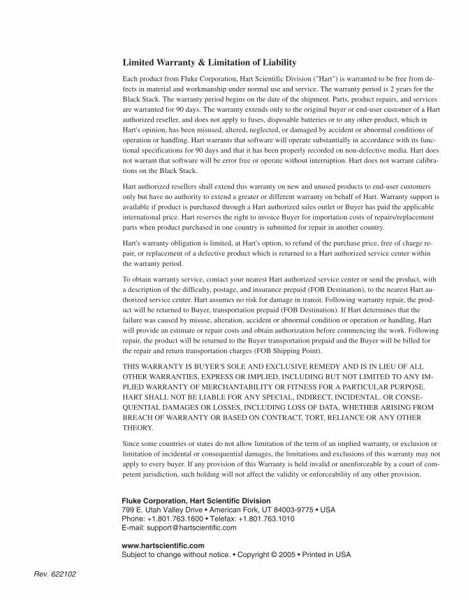
Limited Warranty & Limitation of Liability
Each product from Fluke Corporation, Hart Scientific Division ("Hart") is warranted to be free from de-fects in material and workmanship under normal use and service. The warranty period is 2 years for theBlack Stack. The warranty period begins on the date of the shipment. Parts, product repairs, and servicesare warranted for 90 days. The warranty extends only to the original buyer or end-user customer of a Hartauthorized reseller, and does not apply to fuses, disposable batteries or to any other product, which inHart's opinion, has been misused, altered, neglected, or damaged by accident or abnormal conditions ofoperation or handling. Hart warrants that software will operate substantially in accordance with its func-tional specifications for 90 days and that it has been properly recorded on non-defective media. Hart doesnot warrant that software will be error free or operate without interruption. Hart does not warrant calibra-tions on the Black Stack.
Hart authorized resellers shall extend this warranty on new and unused products to end-user customersonly but have no authority to extend a greater or different warranty on behalf of Hart. Warranty support isavailable if product is purchased through a Hart authorized sales outlet or Buyer has paid the applicableinternational price. Hart reserves the right to invoice Buyer for importation costs of repairs/replacementparts when product purchased in one country is submitted for repair in another country.
Hart's warranty obligation is limited, at Hart's option, to refund of the purchase price, free of charge re-pair, or replacement of a defective product which is returned to a Hart authorized service center withinthe warranty period.
To obtain warranty service, contact your nearest Hart authorized service center or send the product, witha description of the difficulty, postage, and insurance prepaid (FOB Destination), to the nearest Hart au-thorized service center. Hart assumes no risk for damage in transit. Following warranty repair, the prod-uct will be returned to Buyer, transportation prepaid (FOB Destination). If Hart determines that thefailure was caused by misuse, alteration, accident or abnormal condition or operation or handling, Hartwill provide an estimate or repair costs and obtain authorization before commencing the work. Followingrepair, the product will be returned to the Buyer transportation prepaid and the Buyer will be billed forthe repair and return transportation charges (FOB Shipping Point).
THIS WARRANTY IS BUYER'S SOLE AND EXCLUSIVE REMEDY AND IS IN LIEU OF ALLOTHER WARRANTIES, EXPRESS OR IMPLIED, INCLUDING BUT NOT LIMITED TO ANY IM-PLIED WARRANTY OF MERCHANTABILITY OR FITNESS FOR A PARTICULAR PURPOSE.HART SHALL NOT BE LIABLE FOR ANY SPECIAL, INDIRECT, INCIDENTAL. OR CONSE-QUENTIAL DAMAGES OR LOSSES, INCLUDING LOSS OF DATA, WHETHER ARISING FROMBREACH OF WARRANTY OR BASED ON CONTRACT, TORT, RELIANCE OR ANY OTHERTHEORY.
Since some countries or states do not allow limitation of the term of an implied warranty, or exclusion orlimitation of incidental or consequential damages, the limitations and exclusions of this warranty may notapply to every buyer. If any provision of this Warranty is held invalid or unenforceable by a court of com-petent jurisdiction, such holding will not affect the validity or enforceability of any other provision.
Rev. 622102
Fluke Corporation, Hart Scientific Division799 E. Utah Valley Drive • American Fork, UT 84003-9775 • USAPhone: +1.801.763.1600 • Telefax: +1.801.763.1010E-mail: [email protected]
www.hartscientific.comSubject to change without notice. • Copyright © 2005 • Printed in USA
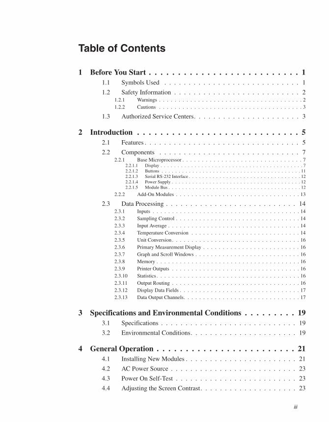
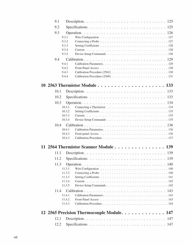
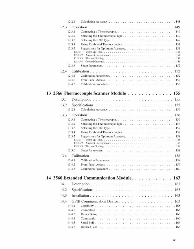
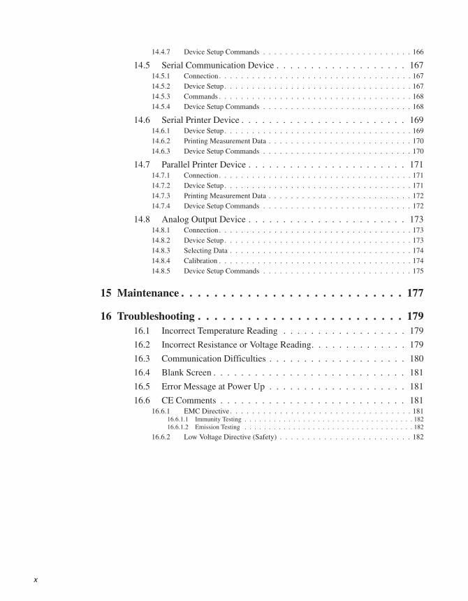
Table of Contents
1 Before You Start . . . . . . . . . . . . . . . . . . . . . . . . . . 11.1 Symbols Used . . . . . . . . . . . . . . . . . . . . . . . . . . . . 1
1.2 Safety Information . . . . . . . . . . . . . . . . . . . . . . . . . . 21.2.1 Warnings . . . . . . . . . . . . . . . . . . . . . . . . . . . . . . . . . . . . . 21.2.2 Cautions . . . . . . . . . . . . . . . . . . . . . . . . . . . . . . . . . . . . . 3
1.3 Authorized Service Centers. . . . . . . . . . . . . . . . . . . . . . 3
2 Introduction . . . . . . . . . . . . . . . . . . . . . . . . . . . . 52.1 Features . . . . . . . . . . . . . . . . . . . . . . . . . . . . . . . . 5
2.2 Components . . . . . . . . . . . . . . . . . . . . . . . . . . . . . 72.2.1 Base Microprocessor . . . . . . . . . . . . . . . . . . . . . . . . . . . . . . . 7
2.2.1.1 Display . . . . . . . . . . . . . . . . . . . . . . . . . . . . . . . . . . . . . . . . . . 72.2.1.2 Buttons . . . . . . . . . . . . . . . . . . . . . . . . . . . . . . . . . . . . . . . . . 112.2.1.3 Serial RS-232 Interface . . . . . . . . . . . . . . . . . . . . . . . . . . . . . . . . . 122.2.1.4 Power Supply . . . . . . . . . . . . . . . . . . . . . . . . . . . . . . . . . . . . . . 122.2.1.5 Module Bus . . . . . . . . . . . . . . . . . . . . . . . . . . . . . . . . . . . . . . . 12
2.2.2 Add-On Modules . . . . . . . . . . . . . . . . . . . . . . . . . . . . . . . . 13
2.3 Data Processing . . . . . . . . . . . . . . . . . . . . . . . . . . . 142.3.1 Inputs . . . . . . . . . . . . . . . . . . . . . . . . . . . . . . . . . . . . . . 142.3.2 Sampling Control . . . . . . . . . . . . . . . . . . . . . . . . . . . . . . . . 142.3.3 Input Average . . . . . . . . . . . . . . . . . . . . . . . . . . . . . . . . . . 142.3.4 Temperature Conversion . . . . . . . . . . . . . . . . . . . . . . . . . . . . 142.3.5 Unit Conversion . . . . . . . . . . . . . . . . . . . . . . . . . . . . . . . . . 162.3.6 Primary Measurement Display . . . . . . . . . . . . . . . . . . . . . . . . . 162.3.7 Graph and Scroll Windows . . . . . . . . . . . . . . . . . . . . . . . . . . . 162.3.8 Memory . . . . . . . . . . . . . . . . . . . . . . . . . . . . . . . . . . . . . 162.3.9 Printer Outputs . . . . . . . . . . . . . . . . . . . . . . . . . . . . . . . . . 162.3.10 Statistics . . . . . . . . . . . . . . . . . . . . . . . . . . . . . . . . . . . . . 162.3.11 Output Routing . . . . . . . . . . . . . . . . . . . . . . . . . . . . . . . . . 162.3.12 Display Data Fields . . . . . . . . . . . . . . . . . . . . . . . . . . . . . . . 172.3.13 Data Output Channels. . . . . . . . . . . . . . . . . . . . . . . . . . . . . . 17
3 Specifications and Environmental Conditions . . . . . . . . . 193.1 Specifications . . . . . . . . . . . . . . . . . . . . . . . . . . . . 19
3.2 Environmental Conditions. . . . . . . . . . . . . . . . . . . . . . 19
4 General Operation . . . . . . . . . . . . . . . . . . . . . . . . 214.1 Installing New Modules . . . . . . . . . . . . . . . . . . . . . . . 21
4.2 AC Power Source . . . . . . . . . . . . . . . . . . . . . . . . . . 23
4.3 Power On Self-Test . . . . . . . . . . . . . . . . . . . . . . . . . 23
4.4 Adjusting the Screen Contrast. . . . . . . . . . . . . . . . . . . . 23
iii
4.5 Making Measurements . . . . . . . . . . . . . . . . . . . . . . . 234.5.1 Selecting Input Channels . . . . . . . . . . . . . . . . . . . . . . . . . . . . 234.5.2 Selecting the Probe Characterization . . . . . . . . . . . . . . . . . . . . . . 254.5.3 Measuring One Channel . . . . . . . . . . . . . . . . . . . . . . . . . . . . 264.5.4 Scanning Channels . . . . . . . . . . . . . . . . . . . . . . . . . . . . . . . 264.5.5 Displaying Measurement Data . . . . . . . . . . . . . . . . . . . . . . . . . 26
5 Soft-Key Functions . . . . . . . . . . . . . . . . . . . . . . . . 295.1 Input Menu . . . . . . . . . . . . . . . . . . . . . . . . . . . . . 29
5.1.1 Measure . . . . . . . . . . . . . . . . . . . . . . . . . . . . . . . . . . . . . 295.1.2 Primary Channel . . . . . . . . . . . . . . . . . . . . . . . . . . . . . . . . 315.1.3 Scan Channels. . . . . . . . . . . . . . . . . . . . . . . . . . . . . . . . . . 315.1.4 Scan Mode . . . . . . . . . . . . . . . . . . . . . . . . . . . . . . . . . . . 325.1.5 Average . . . . . . . . . . . . . . . . . . . . . . . . . . . . . . . . . . . . . 32
5.2 Probe Menu . . . . . . . . . . . . . . . . . . . . . . . . . . . . . 335.2.1 Edit Probe . . . . . . . . . . . . . . . . . . . . . . . . . . . . . . . . . . . . 33
5.2.1.1 R(Ω) Conversion . . . . . . . . . . . . . . . . . . . . . . . . . . . . . . . . . . . . 365.2.1.2 ITS-90 Conversion . . . . . . . . . . . . . . . . . . . . . . . . . . . . . . . . . . . 365.2.1.3 W(T90) Conversion . . . . . . . . . . . . . . . . . . . . . . . . . . . . . . . . . . . . 375.2.1.4 IPTS-68 Conversion . . . . . . . . . . . . . . . . . . . . . . . . . . . . . . . . . . 375.2.1.5 Callendar-Van Dusen Conversion . . . . . . . . . . . . . . . . . . . . . . . . . . . 385.2.1.6 RTD Polynomial Conversion . . . . . . . . . . . . . . . . . . . . . . . . . . . . . . 395.2.1.7 Thermistor T(R) Conversion . . . . . . . . . . . . . . . . . . . . . . . . . . . . . . 395.2.1.8 Thermistor R(T) Conversion . . . . . . . . . . . . . . . . . . . . . . . . . . . . . . 405.2.1.9 Thermocouple Volts Conversion . . . . . . . . . . . . . . . . . . . . . . . . . . . . 405.2.1.10 Standard Thermocouple Conversions. . . . . . . . . . . . . . . . . . . . . . . . . . 415.2.1.11 Thermocouple Table Conversion . . . . . . . . . . . . . . . . . . . . . . . . . . . . 425.2.1.12 Thermocouple Polynomial Conversion . . . . . . . . . . . . . . . . . . . . . . . . . 43
5.2.2 Copy Probe . . . . . . . . . . . . . . . . . . . . . . . . . . . . . . . . . . . 435.2.3 Test Conversion . . . . . . . . . . . . . . . . . . . . . . . . . . . . . . . . . 45
5.3 Output Menu . . . . . . . . . . . . . . . . . . . . . . . . . . . . 455.3.1 Display Window Menu . . . . . . . . . . . . . . . . . . . . . . . . . . . . . 46
5.3.1.1 Statistical Window . . . . . . . . . . . . . . . . . . . . . . . . . . . . . . . . . . . 465.3.1.2 Set Fields . . . . . . . . . . . . . . . . . . . . . . . . . . . . . . . . . . . . . . . . 465.3.1.3 Graph Window . . . . . . . . . . . . . . . . . . . . . . . . . . . . . . . . . . . . . 485.3.1.4 Clear Graph . . . . . . . . . . . . . . . . . . . . . . . . . . . . . . . . . . . . . . . 495.3.1.5 Scrolling Window. . . . . . . . . . . . . . . . . . . . . . . . . . . . . . . . . . . . 49
5.3.2 Output Channel . . . . . . . . . . . . . . . . . . . . . . . . . . . . . . . . . 505.3.3 Print Output . . . . . . . . . . . . . . . . . . . . . . . . . . . . . . . . . . . 515.3.4 Print Memory . . . . . . . . . . . . . . . . . . . . . . . . . . . . . . . . . . 525.3.5 Clear Statistics . . . . . . . . . . . . . . . . . . . . . . . . . . . . . . . . . 53
5.4 Module Menu . . . . . . . . . . . . . . . . . . . . . . . . . . . . 535.4.1 Set Up Screen . . . . . . . . . . . . . . . . . . . . . . . . . . . . . . . . . . 535.4.2 Set Up Device . . . . . . . . . . . . . . . . . . . . . . . . . . . . . . . . . . 545.4.3 Calibrate Device . . . . . . . . . . . . . . . . . . . . . . . . . . . . . . . . 555.4.4 Module Information. . . . . . . . . . . . . . . . . . . . . . . . . . . . . . . 56
5.5 System Menu . . . . . . . . . . . . . . . . . . . . . . . . . . . . 575.5.1 Units. . . . . . . . . . . . . . . . . . . . . . . . . . . . . . . . . . . . . . . 575.5.2 Time . . . . . . . . . . . . . . . . . . . . . . . . . . . . . . . . . . . . . . . 585.5.3 Password . . . . . . . . . . . . . . . . . . . . . . . . . . . . . . . . . . . . 585.5.4 System Information . . . . . . . . . . . . . . . . . . . . . . . . . . . . . . . 59
iv
5.5.5 System Reset . . . . . . . . . . . . . . . . . . . . . . . . . . . . . . . . . . 60
6 Digital Communications Interface . . . . . . . . . . . . . . . 636.1 Overview . . . . . . . . . . . . . . . . . . . . . . . . . . . . . . 63
6.2 Serial Interface . . . . . . . . . . . . . . . . . . . . . . . . . . . 63
6.3 Command Syntax . . . . . . . . . . . . . . . . . . . . . . . . . . 64
6.4 Command Summary. . . . . . . . . . . . . . . . . . . . . . . . . 65
6.5 Commands . . . . . . . . . . . . . . . . . . . . . . . . . . . . . 656.5.1 Measurement Data Commands . . . . . . . . . . . . . . . . . . . . . . . . . 65
6.5.1.1 CALCulate[n]:AVERage[n]:CLEar . . . . . . . . . . . . . . . . . . . . . . . . . . 656.5.1.2 CALCulate[n]:AVERage[n]:CLEar:ALL . . . . . . . . . . . . . . . . . . . . . . . 706.5.1.3 CALCulate[n]:AVERage[n]:DATA? . . . . . . . . . . . . . . . . . . . . . . . . . . 706.5.1.4 CALCulate[n]:AVERage[n][:STATe]? . . . . . . . . . . . . . . . . . . . . . . . . . 716.5.1.5 CALCulate[n]:AVERage[n]:TYPE? . . . . . . . . . . . . . . . . . . . . . . . . . . 716.5.1.6 CONFigure[<channel>]. . . . . . . . . . . . . . . . . . . . . . . . . . . . . . . . . 716.5.1.7 CONFigure? . . . . . . . . . . . . . . . . . . . . . . . . . . . . . . . . . . . . . . 726.5.1.8 DATA[:DATA]:VALue? [MEM,]<numeric_value> . . . . . . . . . . . . . . . . . . 726.5.1.9 DATA:POINts? [MEM] . . . . . . . . . . . . . . . . . . . . . . . . . . . . . . . . 726.5.1.10 FETCh[:TEMPerature]? [<channel>] . . . . . . . . . . . . . . . . . . . . . . . . . 736.5.1.11 MEASure[:TEMPerature]? [<channel>]. . . . . . . . . . . . . . . . . . . . . . . . 736.5.1.12 READ[:TEMPerature]?. . . . . . . . . . . . . . . . . . . . . . . . . . . . . . . . . 736.5.1.13 SENSe[n]:AVERage:DATA? . . . . . . . . . . . . . . . . . . . . . . . . . . . . . . 74
6.5.2 Measurement Control Commands . . . . . . . . . . . . . . . . . . . . . . . 746.5.2.1 ABORt . . . . . . . . . . . . . . . . . . . . . . . . . . . . . . . . . . . . . . . . . 746.5.2.2 INITiate[:IMMediate]. . . . . . . . . . . . . . . . . . . . . . . . . . . . . . . . . . 746.5.2.3 INITiate:CONTinuous <Boolean>. . . . . . . . . . . . . . . . . . . . . . . . . . . 756.5.2.4 INITiate:CONTinuous? . . . . . . . . . . . . . . . . . . . . . . . . . . . . . . . . . 756.5.2.5 SENSe:AVERage:COUNt <numeric_value> . . . . . . . . . . . . . . . . . . . . . 756.5.2.6 SENSe:AVERage:COUNt? . . . . . . . . . . . . . . . . . . . . . . . . . . . . . . . 766.5.2.7 SENSe:AVERage[:STATe] <Boolean> . . . . . . . . . . . . . . . . . . . . . . . . 766.5.2.8 SENSe: AVERage[:STATe]? . . . . . . . . . . . . . . . . . . . . . . . . . . . . . . 766.5.2.9 TRIGger[:SEQuence]:COUNt <numeric_value> . . . . . . . . . . . . . . . . . . . 766.5.2.10 TRIGger[:SEQuence]:COUNt?. . . . . . . . . . . . . . . . . . . . . . . . . . . . . 766.5.2.11 TRIGger[:SEQuence]:DELay <numeric_value> . . . . . . . . . . . . . . . . . . . 776.5.2.12 TRIGger[:SEQuence]:DELay? . . . . . . . . . . . . . . . . . . . . . . . . . . . . . 776.5.2.13 TRIGger[:SEQuence]:TIMer <numeric_value>. . . . . . . . . . . . . . . . . . . . 776.5.2.14 TRIGger[:SEQuence]:TIMer? . . . . . . . . . . . . . . . . . . . . . . . . . . . . . 77
6.5.3 Input Channel Commands . . . . . . . . . . . . . . . . . . . . . . . . . . . 776.5.3.1 ROUTe:CLOSe <channel>. . . . . . . . . . . . . . . . . . . . . . . . . . . . . . . 786.5.3.2 ROUTe:CLOSe:STATe? . . . . . . . . . . . . . . . . . . . . . . . . . . . . . . . . 786.5.3.3 ROUTe:PRIMary? . . . . . . . . . . . . . . . . . . . . . . . . . . . . . . . . . . . 786.5.3.4 ROUTe:SCAN:ALTernate <Boolean> . . . . . . . . . . . . . . . . . . . . . . . . . 796.5.3.5 ROUTe:SCAN:ALTernate? . . . . . . . . . . . . . . . . . . . . . . . . . . . . . . . 796.5.3.6 ROUTe:SCAN[:LIST] <channel_list>. . . . . . . . . . . . . . . . . . . . . . . . . 796.5.3.7 ROUTe:SCAN[:LIST]? . . . . . . . . . . . . . . . . . . . . . . . . . . . . . . . . . 796.5.3.8 ROUTe:SCAN:STATe <Boolean> . . . . . . . . . . . . . . . . . . . . . . . . . . . 806.5.3.9 ROUTe:SCAN:STATe? . . . . . . . . . . . . . . . . . . . . . . . . . . . . . . . . . 80
6.5.4 Probe Commands . . . . . . . . . . . . . . . . . . . . . . . . . . . . . . . . 816.5.4.1 CALCulate[n]:CONVert:CATalog?. . . . . . . . . . . . . . . . . . . . . . . . . . . 826.5.4.2 CALCulate[n]:CONVert:COPY <channel> . . . . . . . . . . . . . . . . . . . . . . 836.5.4.3 CALCulate[n]:CONVert:DATA? . . . . . . . . . . . . . . . . . . . . . . . . . . . . 836.5.4.4 CALCulate[n]:CONVert:NAME <conversion_name> . . . . . . . . . . . . . . . . 836.5.4.5 CALCulate[n]:CONVert:NAME? . . . . . . . . . . . . . . . . . . . . . . . . . . . 856.5.4.6 CALCulate[n]:CONVert:PARameter:CATalog? . . . . . . . . . . . . . . . . . . . . 856.5.4.7 CALCulate[n]:CONVert:PARameter:VALue <parameter_name>, <nu-meric_value>[,<parameter_name>,<numeric_value> . . . ] . . . . . . . . . . . . . . . . . . . . 856.5.4.8 CALCulate[n]:CONVert:PARameter:VALue? <parameter_name> . . . . . . . . . . 856.5.4.9 CALCulate[n]:CONVert:PARameter:VALue? ALL. . . . . . . . . . . . . . . . . . 866.5.4.10 CALCulate[n]:CONVert:SNUMber <serial_number> . . . . . . . . . . . . . . . . 86
v
6.5.4.11 CALCulate[n]:CONVert:SNUMber? . . . . . . . . . . . . . . . . . . . . . . . . . . 866.5.4.12 CALCulate[n]:CONVert:SRLow <sub-range_number>. . . . . . . . . . . . . . . . 866.5.4.13 CALCulate[n]:CONVert:SRLow? . . . . . . . . . . . . . . . . . . . . . . . . . . . 866.5.4.14 CALCulate[n]:CONVert:SRHigh <sub-range_number> . . . . . . . . . . . . . . . 876.5.4.15 CALCulate[n]:CONVert:SRHigh? . . . . . . . . . . . . . . . . . . . . . . . . . . . 876.5.4.16 CALCulate[n]:CONVert:TEST? <numeric_value>[,<numeric_value>] . . . . . . . 87
6.5.5 Output Channel Commands. . . . . . . . . . . . . . . . . . . . . . . . . . . 876.5.5.1 OUTPut[n]:CALC <numeric_value> . . . . . . . . . . . . . . . . . . . . . . . . . 886.5.5.2 OUTPut[n]:CALC? . . . . . . . . . . . . . . . . . . . . . . . . . . . . . . . . . . . 886.5.5.3 OUTPut[n]:NCHannel <channel> . . . . . . . . . . . . . . . . . . . . . . . . . . . 896.5.5.4 OUTPut[n]:NCHannel?. . . . . . . . . . . . . . . . . . . . . . . . . . . . . . . . . 896.5.5.5 OUTPut[n]:PCHannel <channel> . . . . . . . . . . . . . . . . . . . . . . . . . . . 896.5.5.6 OUTPut[n]:PCHannel? . . . . . . . . . . . . . . . . . . . . . . . . . . . . . . . . . 906.5.5.7 OUTPut[n][:STATe] <Boolean> . . . . . . . . . . . . . . . . . . . . . . . . . . . . 906.5.5.8 OUTPut[n][:STATe]? . . . . . . . . . . . . . . . . . . . . . . . . . . . . . . . . . . 90
6.5.6 Printer Commands . . . . . . . . . . . . . . . . . . . . . . . . . . . . . . . 916.5.6.1 HCOPy:ABORt . . . . . . . . . . . . . . . . . . . . . . . . . . . . . . . . . . . . . 916.5.6.2 HCOPy[:IMMediate] <printer_number>,<numeric_value>. . . . . . . . . . . . . . 916.5.6.3 HCOPy:PRINter[n][:STATe] <Boolean> . . . . . . . . . . . . . . . . . . . . . . . 916.5.6.4 HCOPy:PRINter[n][:STATe]? . . . . . . . . . . . . . . . . . . . . . . . . . . . . . 92
6.5.7 Communication Interface Commands . . . . . . . . . . . . . . . . . . . . . 926.5.7.1 SYSTem:COMMunicate:SERial[:RECeive]:BAUD <numeric_value>. . . . . . . . 926.5.7.2 SYSTem:COMMunicate:SERial[:RECeive]:BAUD? . . . . . . . . . . . . . . . . . 926.5.7.3 SYSTem:COMMunicate:SERial[:RECeive]:FDUPlex <Boolean> . . . . . . . . . . 926.5.7.4 SYSTem:COMMunicate:SERial[:RECeive]:FDUP? . . . . . . . . . . . . . . . . . 936.5.7.5 SYSTem:COMMunicate:SERial[:RECeive]:LINefeed <Boolean>. . . . . . . . . . 936.5.7.6 SYSTem:COMMunicate:SERial[:RECeive]:LINefeed? . . . . . . . . . . . . . . . . 93
6.5.8 Module Commands . . . . . . . . . . . . . . . . . . . . . . . . . . . . . . . 946.5.8.1 SYSTem:CONFigure:CDEVice? . . . . . . . . . . . . . . . . . . . . . . . . . . . . 946.5.8.2 SYSTem:CONFigure:COMMunicate[n]:DADDress? . . . . . . . . . . . . . . . . . 946.5.8.3 SYSTem:CONFigure:COMMunicate[n]:MADDress? . . . . . . . . . . . . . . . . . 956.5.8.4 SYSTem:CONFigure:ICHannel? . . . . . . . . . . . . . . . . . . . . . . . . . . . . 956.5.8.5 SYSTem:CONFigure:IDEVice? . . . . . . . . . . . . . . . . . . . . . . . . . . . . 956.5.8.6 SYSTem:CONFigure:INPut[n]:DADDress? . . . . . . . . . . . . . . . . . . . . . . 956.5.8.7 SYSTem:CONFigure:INPut[n]:MADDress?. . . . . . . . . . . . . . . . . . . . . . 956.5.8.8 SYSTem:CONFigure:MNUMber? . . . . . . . . . . . . . . . . . . . . . . . . . . . 966.5.8.9 SYSTem:CONFigure:MODule[n]:DEVice[n]:INFormation? . . . . . . . . . . . . . 966.5.8.10 SYSTem:CONFigure:MODule[n]:DNUMber? . . . . . . . . . . . . . . . . . . . . 966.5.8.11 SYSTem:CONFigure:MODule[n]:INFormation? . . . . . . . . . . . . . . . . . . . 966.5.8.12 SYSTem:CONFigure:OCHannel? . . . . . . . . . . . . . . . . . . . . . . . . . . . 976.5.8.13 SYSTem:CONFigure:ODEVice? . . . . . . . . . . . . . . . . . . . . . . . . . . . . 976.5.8.14 SYSTem:CONFigure:OUTPut[n]:DADDress?. . . . . . . . . . . . . . . . . . . . . 976.5.8.15 SYSTem:CONFigure:OUTPut[n]:MADDress? . . . . . . . . . . . . . . . . . . . . 976.5.8.16 SYSTem:CONFigure:PDEVice? . . . . . . . . . . . . . . . . . . . . . . . . . . . . 976.5.8.17 SYSTem:CONFigure:PRINter[n]:DADDress?. . . . . . . . . . . . . . . . . . . . . 986.5.8.18 SYSTem:CONFigure: PRINter[n]:MADDress? . . . . . . . . . . . . . . . . . . . . 986.5.8.19 SYSTem:MODule[n]:DEVice[n]:READ? <device_command> . . . . . . . . . . . 986.5.8.20 SYSTem:MODule[n]:DEVice[n]:WRITe <device_command>,<value> . . . . . . . 98
6.5.9 System Commands . . . . . . . . . . . . . . . . . . . . . . . . . . . . . . . 996.5.9.1 *IDN? . . . . . . . . . . . . . . . . . . . . . . . . . . . . . . . . . . . . . . . . . . 996.5.9.2 *OPT? . . . . . . . . . . . . . . . . . . . . . . . . . . . . . . . . . . . . . . . . . 1006.5.9.3 *RST. . . . . . . . . . . . . . . . . . . . . . . . . . . . . . . . . . . . . . . . . . 1006.5.9.4 SYSTem:DATE <year>,<month>,<day>. . . . . . . . . . . . . . . . . . . . . . . 1006.5.9.5 SYSTem:DATE?. . . . . . . . . . . . . . . . . . . . . . . . . . . . . . . . . . . . 1016.5.9.6 SYSTem:SNUMber <serial_number> . . . . . . . . . . . . . . . . . . . . . . . . 1016.5.9.7 SYSTem:SNUMber? . . . . . . . . . . . . . . . . . . . . . . . . . . . . . . . . . 1016.5.9.8 SYSTem:TIME <hour>,<minute>,<second> . . . . . . . . . . . . . . . . . . . . 1016.5.9.9 SYSTem:TIME? . . . . . . . . . . . . . . . . . . . . . . . . . . . . . . . . . . . . 1016.5.9.10 SYSTem:VERSion? . . . . . . . . . . . . . . . . . . . . . . . . . . . . . . . . . . 1016.5.9.11 UNIT:TEMPerature <unit> . . . . . . . . . . . . . . . . . . . . . . . . . . . . . . 1026.5.9.12 UNIT:TEMPerature? . . . . . . . . . . . . . . . . . . . . . . . . . . . . . . . . . 102
6.5.10 Status Commands . . . . . . . . . . . . . . . . . . . . . . . . . . . . . . . 1026.5.10.1 *CLS. . . . . . . . . . . . . . . . . . . . . . . . . . . . . . . . . . . . . . . . . . 102
vi
6.5.10.2 *ESE <numeric_value>. . . . . . . . . . . . . . . . . . . . . . . . . . . . . . . . 1026.5.10.3 *ESE? . . . . . . . . . . . . . . . . . . . . . . . . . . . . . . . . . . . . . . . . . 1036.5.10.4 *ESR? . . . . . . . . . . . . . . . . . . . . . . . . . . . . . . . . . . . . . . . . . 1036.5.10.5 *OPC . . . . . . . . . . . . . . . . . . . . . . . . . . . . . . . . . . . . . . . . . 1036.5.10.6 *OPC? . . . . . . . . . . . . . . . . . . . . . . . . . . . . . . . . . . . . . . . . . 1046.5.10.7 *SRE <numeric_value>. . . . . . . . . . . . . . . . . . . . . . . . . . . . . . . . 1046.5.10.8 *SRE? . . . . . . . . . . . . . . . . . . . . . . . . . . . . . . . . . . . . . . . . . 1056.5.10.9 *STB? . . . . . . . . . . . . . . . . . . . . . . . . . . . . . . . . . . . . . . . . . 1056.5.10.10 *TST? . . . . . . . . . . . . . . . . . . . . . . . . . . . . . . . . . . . . . . . . . 1066.5.10.11 *WAI. . . . . . . . . . . . . . . . . . . . . . . . . . . . . . . . . . . . . . . . . . 1066.5.10.12 STATus:OPERation:CONDition? . . . . . . . . . . . . . . . . . . . . . . . . . . . 1066.5.10.13 STATus:OPERation:ENABle <numeric_value> . . . . . . . . . . . . . . . . . . . 1066.5.10.14 STATus:OPERation:ENABle?. . . . . . . . . . . . . . . . . . . . . . . . . . . . . 1076.5.10.15 STATus:OPERation[:EVENt]? . . . . . . . . . . . . . . . . . . . . . . . . . . . . 1076.5.10.16 STATus:PRESet . . . . . . . . . . . . . . . . . . . . . . . . . . . . . . . . . . . . 1076.5.10.17 STATus:QUEStionable:CONDition? . . . . . . . . . . . . . . . . . . . . . . . . . 1076.5.10.18 STATus:QUEStionable:ENABle <numeric_value> . . . . . . . . . . . . . . . . . 1086.5.10.19 STATus:QUEStionable:ENABle? . . . . . . . . . . . . . . . . . . . . . . . . . . . 1086.5.10.20 STATus:QUEStionable[:EVENt]?. . . . . . . . . . . . . . . . . . . . . . . . . . . 1086.5.10.21 STATus:QUEue[:NEXT]? . . . . . . . . . . . . . . . . . . . . . . . . . . . . . . . 1086.5.10.22 SYSTem:ERRor? . . . . . . . . . . . . . . . . . . . . . . . . . . . . . . . . . . . 108
6.6 Programming Example. . . . . . . . . . . . . . . . . . . . . . . 110
7 2560/2567 SPRT Module . . . . . . . . . . . . . . . . . . . . 1137.1 Description . . . . . . . . . . . . . . . . . . . . . . . . . . . . . 113
7.2 Specifications . . . . . . . . . . . . . . . . . . . . . . . . . . . 113
7.3 Operation. . . . . . . . . . . . . . . . . . . . . . . . . . . . . . 1147.3.1 Connecting a Probe . . . . . . . . . . . . . . . . . . . . . . . . . . . . . . 1147.3.2 Setting Coefficients . . . . . . . . . . . . . . . . . . . . . . . . . . . . . . 1157.3.3 Current . . . . . . . . . . . . . . . . . . . . . . . . . . . . . . . . . . . . . 1157.3.4 Device Setup Commands . . . . . . . . . . . . . . . . . . . . . . . . . . . 115
7.4 Calibration . . . . . . . . . . . . . . . . . . . . . . . . . . . . . 1167.4.1 Calibration Parameters. . . . . . . . . . . . . . . . . . . . . . . . . . . . . 1167.4.2 Front-panel Access . . . . . . . . . . . . . . . . . . . . . . . . . . . . . . 1167.4.3 Calibration Procedure (2560) . . . . . . . . . . . . . . . . . . . . . . . . . 1177.4.4 Calibration Procedure (2567) . . . . . . . . . . . . . . . . . . . . . . . . . 118
8 2561 HTPRT Module . . . . . . . . . . . . . . . . . . . . . . 1198.1 Description . . . . . . . . . . . . . . . . . . . . . . . . . . . . . 119
8.2 Specifications . . . . . . . . . . . . . . . . . . . . . . . . . . . 119
8.3 Operation. . . . . . . . . . . . . . . . . . . . . . . . . . . . . . 1208.3.1 Connecting a Probe . . . . . . . . . . . . . . . . . . . . . . . . . . . . . . 1208.3.2 Setting Coefficients . . . . . . . . . . . . . . . . . . . . . . . . . . . . . . 1218.3.3 Current . . . . . . . . . . . . . . . . . . . . . . . . . . . . . . . . . . . . . 1218.3.4 Device Setup Commands . . . . . . . . . . . . . . . . . . . . . . . . . . . 121
8.4 Calibration . . . . . . . . . . . . . . . . . . . . . . . . . . . . . 1228.4.1 Calibration Parameters. . . . . . . . . . . . . . . . . . . . . . . . . . . . . 1228.4.2 Front-panel Access . . . . . . . . . . . . . . . . . . . . . . . . . . . . . . 1228.4.3 Calibration Procedure . . . . . . . . . . . . . . . . . . . . . . . . . . . . . 123
9 2562/2568 PRT Scanner Module . . . . . . . . . . . . . . . . 125
vii
9.1 Description . . . . . . . . . . . . . . . . . . . . . . . . . . . . . 125
9.2 Specifications . . . . . . . . . . . . . . . . . . . . . . . . . . . 125
9.3 Operation. . . . . . . . . . . . . . . . . . . . . . . . . . . . . . 1269.3.1 Wire Configuration . . . . . . . . . . . . . . . . . . . . . . . . . . . . . . 1279.3.2 Connecting a Probe . . . . . . . . . . . . . . . . . . . . . . . . . . . . . . 1279.3.3 Setting Coefficients . . . . . . . . . . . . . . . . . . . . . . . . . . . . . . 1289.3.4 Current . . . . . . . . . . . . . . . . . . . . . . . . . . . . . . . . . . . . . 1289.3.5 Device Setup Commands . . . . . . . . . . . . . . . . . . . . . . . . . . . 128
9.4 Calibration . . . . . . . . . . . . . . . . . . . . . . . . . . . . . 1299.4.1 Calibration Parameters. . . . . . . . . . . . . . . . . . . . . . . . . . . . . 1299.4.2 Front-Panel Access . . . . . . . . . . . . . . . . . . . . . . . . . . . . . . 1309.4.3 Calibration Procedure (2562) . . . . . . . . . . . . . . . . . . . . . . . . . 1309.4.4 Calibration Procedure (2568) . . . . . . . . . . . . . . . . . . . . . . . . . 131
10 2563 Thermistor Module . . . . . . . . . . . . . . . . . . . . 13310.1 Description . . . . . . . . . . . . . . . . . . . . . . . . . . . . . 133
10.2 Specifications . . . . . . . . . . . . . . . . . . . . . . . . . . . 133
10.3 Operation. . . . . . . . . . . . . . . . . . . . . . . . . . . . . . 13410.3.1 Connecting a Thermistor . . . . . . . . . . . . . . . . . . . . . . . . . . . 13410.3.2 Setting Coefficients . . . . . . . . . . . . . . . . . . . . . . . . . . . . . . 13510.3.3 Current . . . . . . . . . . . . . . . . . . . . . . . . . . . . . . . . . . . . . 13510.3.4 Device Setup Commands . . . . . . . . . . . . . . . . . . . . . . . . . . . 135
10.4 Calibration . . . . . . . . . . . . . . . . . . . . . . . . . . . . . 13610.4.1 Calibration Parameters. . . . . . . . . . . . . . . . . . . . . . . . . . . . . 13610.4.2 Front-panel Access . . . . . . . . . . . . . . . . . . . . . . . . . . . . . . 13610.4.3 Calibration Procedure . . . . . . . . . . . . . . . . . . . . . . . . . . . . . 137
11 2564 Thermistor Scanner Module . . . . . . . . . . . . . . . 13911.1 Description . . . . . . . . . . . . . . . . . . . . . . . . . . . . . 139
11.2 Specifications . . . . . . . . . . . . . . . . . . . . . . . . . . . 139
11.3 Operation. . . . . . . . . . . . . . . . . . . . . . . . . . . . . . 14011.3.1 Wire Configuration . . . . . . . . . . . . . . . . . . . . . . . . . . . . . . 14011.3.2 Connecting a Probe . . . . . . . . . . . . . . . . . . . . . . . . . . . . . . 14011.3.3 Setting Coefficients . . . . . . . . . . . . . . . . . . . . . . . . . . . . . . 14111.3.4 Current . . . . . . . . . . . . . . . . . . . . . . . . . . . . . . . . . . . . . 14211.3.5 Device Setup Commands . . . . . . . . . . . . . . . . . . . . . . . . . . . 142
11.4 Calibration . . . . . . . . . . . . . . . . . . . . . . . . . . . . . 14311.4.1 Calibration Parameters. . . . . . . . . . . . . . . . . . . . . . . . . . . . . 14311.4.2 Front-Panel Access . . . . . . . . . . . . . . . . . . . . . . . . . . . . . . 14311.4.3 Calibration Procedure . . . . . . . . . . . . . . . . . . . . . . . . . . . . . 144
12 2565 Precision Thermocouple Module. . . . . . . . . . . . . 14712.1 Description . . . . . . . . . . . . . . . . . . . . . . . . . . . . . 147
12.2 Specifications . . . . . . . . . . . . . . . . . . . . . . . . . . . 147
viii
12.2.1 Calculating Accuracy . . . . . . . . . . . . . . . . . . . . . . . . . . . . . 148
12.3 Operation. . . . . . . . . . . . . . . . . . . . . . . . . . . . . . 14912.3.1 Connecting a Thermocouple. . . . . . . . . . . . . . . . . . . . . . . . . . 14912.3.2 Selecting the Thermocouple Type . . . . . . . . . . . . . . . . . . . . . . . 14912.3.3 Selecting the CJC Type . . . . . . . . . . . . . . . . . . . . . . . . . . . . 14912.3.4 Using Calibrated Thermocouples . . . . . . . . . . . . . . . . . . . . . . . 15112.3.5 Suggestions for Optimum Accuracy. . . . . . . . . . . . . . . . . . . . . . 151
12.3.5.1 Warm-up Time. . . . . . . . . . . . . . . . . . . . . . . . . . . . . . . . . . . . . 15112.3.5.2 Ambient Environment . . . . . . . . . . . . . . . . . . . . . . . . . . . . . . . . . 15112.3.5.3 Thermal Settling . . . . . . . . . . . . . . . . . . . . . . . . . . . . . . . . . . . . 15112.3.5.4 Ground Currents . . . . . . . . . . . . . . . . . . . . . . . . . . . . . . . . . . . . 151
12.3.6 Setup Parameters. . . . . . . . . . . . . . . . . . . . . . . . . . . . . . . . 152
12.4 Calibration . . . . . . . . . . . . . . . . . . . . . . . . . . . . . 15212.4.1 Calibration Parameters. . . . . . . . . . . . . . . . . . . . . . . . . . . . . 15212.4.2 Front-Panel Access . . . . . . . . . . . . . . . . . . . . . . . . . . . . . . 15212.4.3 Calibration Procedure . . . . . . . . . . . . . . . . . . . . . . . . . . . . . 153
13 2566 Thermocouple Scanner Module . . . . . . . . . . . . . 15513.1 Description . . . . . . . . . . . . . . . . . . . . . . . . . . . . . 155
13.2 Specifications . . . . . . . . . . . . . . . . . . . . . . . . . . . 15513.2.1 Calculating Accuracy . . . . . . . . . . . . . . . . . . . . . . . . . . . . . 156
13.3 Operation. . . . . . . . . . . . . . . . . . . . . . . . . . . . . . 15613.3.1 Connecting a Thermocouple. . . . . . . . . . . . . . . . . . . . . . . . . . 15613.3.2 Selecting the Thermocouple Type . . . . . . . . . . . . . . . . . . . . . . . 15613.3.3 Selecting the CJC Type . . . . . . . . . . . . . . . . . . . . . . . . . . . . 15713.3.4 Using Calibrated Thermocouples . . . . . . . . . . . . . . . . . . . . . . . 15713.3.5 Suggestions for Optimum Accuracy. . . . . . . . . . . . . . . . . . . . . . 158
13.3.5.1 Warm-up Time. . . . . . . . . . . . . . . . . . . . . . . . . . . . . . . . . . . . . 15813.3.5.2 Ambient Environment . . . . . . . . . . . . . . . . . . . . . . . . . . . . . . . . . 15813.3.5.3 Thermal Settling . . . . . . . . . . . . . . . . . . . . . . . . . . . . . . . . . . . . 158
13.3.6 Setup Parameters. . . . . . . . . . . . . . . . . . . . . . . . . . . . . . . . 158
13.4 Calibration . . . . . . . . . . . . . . . . . . . . . . . . . . . . . 15813.4.1 Calibration Parameters. . . . . . . . . . . . . . . . . . . . . . . . . . . . . 15813.4.2 Front-Panel Access . . . . . . . . . . . . . . . . . . . . . . . . . . . . . . 15913.4.3 Calibration Procedure . . . . . . . . . . . . . . . . . . . . . . . . . . . . . 160
14 3560 Extended Communication Module. . . . . . . . . . . . 16314.1 Description . . . . . . . . . . . . . . . . . . . . . . . . . . . . . 163
14.2 Specifications . . . . . . . . . . . . . . . . . . . . . . . . . . . 163
14.3 Installation . . . . . . . . . . . . . . . . . . . . . . . . . . . . . 163
14.4 GPIB Communication Device . . . . . . . . . . . . . . . . . . . 16314.4.1 Capability . . . . . . . . . . . . . . . . . . . . . . . . . . . . . . . . . . . 16514.4.2 Connection. . . . . . . . . . . . . . . . . . . . . . . . . . . . . . . . . . . 16514.4.3 Device Setup . . . . . . . . . . . . . . . . . . . . . . . . . . . . . . . . . . 16514.4.4 Commands . . . . . . . . . . . . . . . . . . . . . . . . . . . . . . . . . . . 16614.4.5 Serial Poll . . . . . . . . . . . . . . . . . . . . . . . . . . . . . . . . . . . 16614.4.6 Device Clear . . . . . . . . . . . . . . . . . . . . . . . . . . . . . . . . . . 166
ix
14.4.7 Device Setup Commands . . . . . . . . . . . . . . . . . . . . . . . . . . . 166
14.5 Serial Communication Device . . . . . . . . . . . . . . . . . . . 16714.5.1 Connection. . . . . . . . . . . . . . . . . . . . . . . . . . . . . . . . . . . 16714.5.2 Device Setup . . . . . . . . . . . . . . . . . . . . . . . . . . . . . . . . . . 16714.5.3 Commands . . . . . . . . . . . . . . . . . . . . . . . . . . . . . . . . . . . 16814.5.4 Device Setup Commands . . . . . . . . . . . . . . . . . . . . . . . . . . . 168
14.6 Serial Printer Device . . . . . . . . . . . . . . . . . . . . . . . . 16914.6.1 Device Setup . . . . . . . . . . . . . . . . . . . . . . . . . . . . . . . . . . 16914.6.2 Printing Measurement Data . . . . . . . . . . . . . . . . . . . . . . . . . . 17014.6.3 Device Setup Commands . . . . . . . . . . . . . . . . . . . . . . . . . . . 170
14.7 Parallel Printer Device . . . . . . . . . . . . . . . . . . . . . . . 17114.7.1 Connection. . . . . . . . . . . . . . . . . . . . . . . . . . . . . . . . . . . 17114.7.2 Device Setup . . . . . . . . . . . . . . . . . . . . . . . . . . . . . . . . . . 17114.7.3 Printing Measurement Data . . . . . . . . . . . . . . . . . . . . . . . . . . 17214.7.4 Device Setup Commands . . . . . . . . . . . . . . . . . . . . . . . . . . . 172
14.8 Analog Output Device . . . . . . . . . . . . . . . . . . . . . . . 17314.8.1 Connection. . . . . . . . . . . . . . . . . . . . . . . . . . . . . . . . . . . 17314.8.2 Device Setup . . . . . . . . . . . . . . . . . . . . . . . . . . . . . . . . . . 17314.8.3 Selecting Data . . . . . . . . . . . . . . . . . . . . . . . . . . . . . . . . . 17414.8.4 Calibration . . . . . . . . . . . . . . . . . . . . . . . . . . . . . . . . . . . 17414.8.5 Device Setup Commands . . . . . . . . . . . . . . . . . . . . . . . . . . . 175
15 Maintenance . . . . . . . . . . . . . . . . . . . . . . . . . . . 177
16 Troubleshooting . . . . . . . . . . . . . . . . . . . . . . . . . 17916.1 Incorrect Temperature Reading . . . . . . . . . . . . . . . . . . 179
16.2 Incorrect Resistance or Voltage Reading. . . . . . . . . . . . . . 179
16.3 Communication Difficulties . . . . . . . . . . . . . . . . . . . . 180
16.4 Blank Screen . . . . . . . . . . . . . . . . . . . . . . . . . . . . 181
16.5 Error Message at Power Up . . . . . . . . . . . . . . . . . . . . 181
16.6 CE Comments . . . . . . . . . . . . . . . . . . . . . . . . . . . 18116.6.1 EMC Directive . . . . . . . . . . . . . . . . . . . . . . . . . . . . . . . . . 181
16.6.1.1 Immunity Testing . . . . . . . . . . . . . . . . . . . . . . . . . . . . . . . . . . . 18216.6.1.2 Emission Testing . . . . . . . . . . . . . . . . . . . . . . . . . . . . . . . . . . . 182
16.6.2 Low Voltage Directive (Safety) . . . . . . . . . . . . . . . . . . . . . . . . 182
x
xi
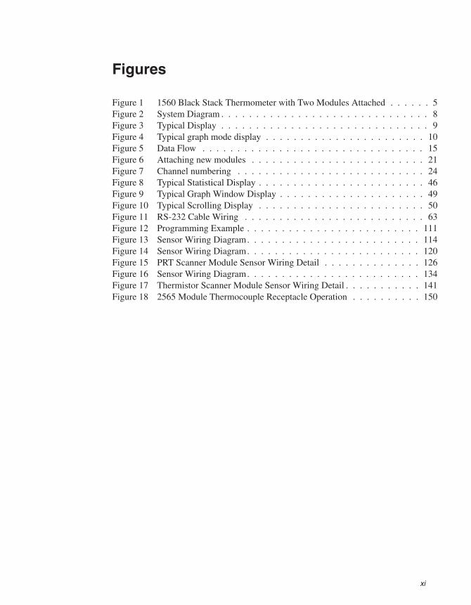
Figures
Figure 1 1560 Black Stack Thermometer with Two Modules Attached . . . . . . 5Figure 2 System Diagram . . . . . . . . . . . . . . . . . . . . . . . . . . . . . . 8Figure 3 Typical Display . . . . . . . . . . . . . . . . . . . . . . . . . . . . . . 9Figure 4 Typical graph mode display . . . . . . . . . . . . . . . . . . . . . . . 10Figure 5 Data Flow . . . . . . . . . . . . . . . . . . . . . . . . . . . . . . . . 15Figure 6 Attaching new modules . . . . . . . . . . . . . . . . . . . . . . . . . 21Figure 7 Channel numbering . . . . . . . . . . . . . . . . . . . . . . . . . . . 24Figure 8 Typical Statistical Display . . . . . . . . . . . . . . . . . . . . . . . . 46Figure 9 Typical Graph Window Display . . . . . . . . . . . . . . . . . . . . . 49Figure 10 Typical Scrolling Display . . . . . . . . . . . . . . . . . . . . . . . . 50Figure 11 RS-232 Cable Wiring . . . . . . . . . . . . . . . . . . . . . . . . . . 63Figure 12 Programming Example . . . . . . . . . . . . . . . . . . . . . . . . . 111Figure 13 Sensor Wiring Diagram. . . . . . . . . . . . . . . . . . . . . . . . . 114Figure 14 Sensor Wiring Diagram. . . . . . . . . . . . . . . . . . . . . . . . . 120Figure 15 PRT Scanner Module Sensor Wiring Detail . . . . . . . . . . . . . . 126Figure 16 Sensor Wiring Diagram. . . . . . . . . . . . . . . . . . . . . . . . . 134Figure 17 Thermistor Scanner Module Sensor Wiring Detail . . . . . . . . . . . 141Figure 18 2565 Module Thermocouple Receptacle Operation . . . . . . . . . . 150
xii
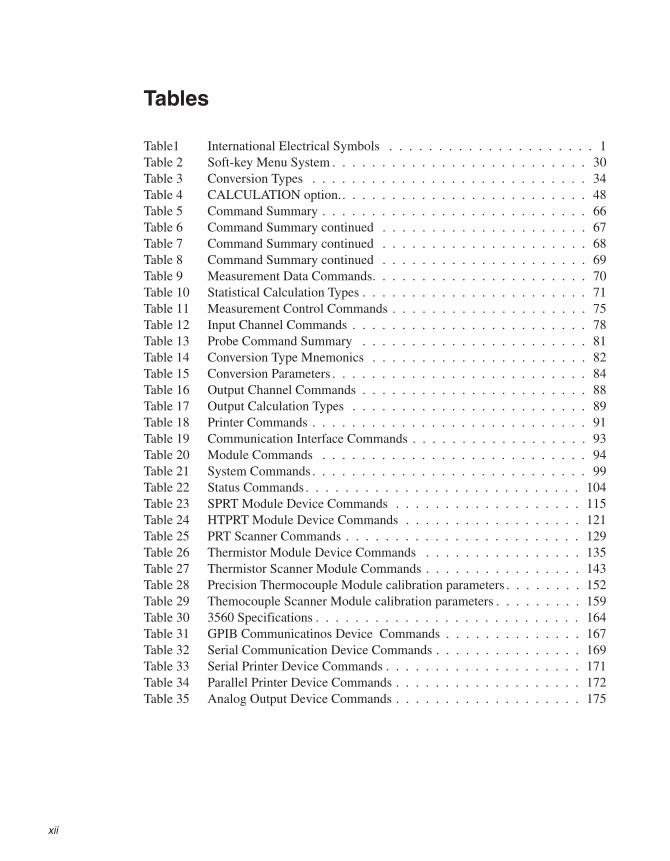
Tables
Table1 International Electrical Symbols . . . . . . . . . . . . . . . . . . . . . 1Table 2 Soft-key Menu System . . . . . . . . . . . . . . . . . . . . . . . . . . 30Table 3 Conversion Types . . . . . . . . . . . . . . . . . . . . . . . . . . . . 34Table 4 CALCULATION option.. . . . . . . . . . . . . . . . . . . . . . . . . 48Table 5 Command Summary . . . . . . . . . . . . . . . . . . . . . . . . . . . 66Table 6 Command Summary continued . . . . . . . . . . . . . . . . . . . . . 67Table 7 Command Summary continued . . . . . . . . . . . . . . . . . . . . . 68Table 8 Command Summary continued . . . . . . . . . . . . . . . . . . . . . 69Table 9 Measurement Data Commands. . . . . . . . . . . . . . . . . . . . . . 70Table 10 Statistical Calculation Types . . . . . . . . . . . . . . . . . . . . . . . 71Table 11 Measurement Control Commands . . . . . . . . . . . . . . . . . . . . 75Table 12 Input Channel Commands . . . . . . . . . . . . . . . . . . . . . . . . 78Table 13 Probe Command Summary . . . . . . . . . . . . . . . . . . . . . . . 81Table 14 Conversion Type Mnemonics . . . . . . . . . . . . . . . . . . . . . . 82Table 15 Conversion Parameters . . . . . . . . . . . . . . . . . . . . . . . . . . 84Table 16 Output Channel Commands . . . . . . . . . . . . . . . . . . . . . . . 88Table 17 Output Calculation Types . . . . . . . . . . . . . . . . . . . . . . . . 89Table 18 Printer Commands . . . . . . . . . . . . . . . . . . . . . . . . . . . . 91Table 19 Communication Interface Commands . . . . . . . . . . . . . . . . . . 93Table 20 Module Commands . . . . . . . . . . . . . . . . . . . . . . . . . . . 94Table 21 System Commands . . . . . . . . . . . . . . . . . . . . . . . . . . . . 99Table 22 Status Commands . . . . . . . . . . . . . . . . . . . . . . . . . . . . 104Table 23 SPRT Module Device Commands . . . . . . . . . . . . . . . . . . . 115Table 24 HTPRT Module Device Commands . . . . . . . . . . . . . . . . . . 121Table 25 PRT Scanner Commands . . . . . . . . . . . . . . . . . . . . . . . . 129Table 26 Thermistor Module Device Commands . . . . . . . . . . . . . . . . 135Table 27 Thermistor Scanner Module Commands . . . . . . . . . . . . . . . . 143Table 28 Precision Thermocouple Module calibration parameters . . . . . . . . 152Table 29 Themocouple Scanner Module calibration parameters . . . . . . . . . 159Table 30 3560 Specifications . . . . . . . . . . . . . . . . . . . . . . . . . . . 164Table 31 GPIB Communicatinos Device Commands . . . . . . . . . . . . . . 167Table 32 Serial Communication Device Commands . . . . . . . . . . . . . . . 169Table 33 Serial Printer Device Commands . . . . . . . . . . . . . . . . . . . . 171Table 34 Parallel Printer Device Commands . . . . . . . . . . . . . . . . . . . 172Table 35 Analog Output Device Commands . . . . . . . . . . . . . . . . . . . 175
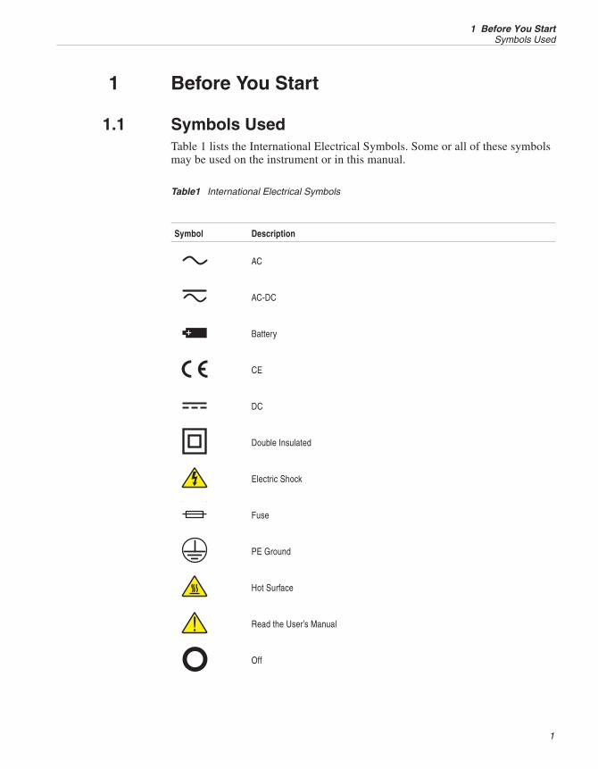
1 Before You Start
1.1 Symbols UsedTable 1 lists the International Electrical Symbols. Some or all of these symbolsmay be used on the instrument or in this manual.
Symbol Description
AC
AC-DC
Battery
CE
DC
Double Insulated
Electric Shock
Fuse
PE Ground
Hot Surface
Read the User’s Manual
Off
1
1 Before You StartSymbols Used
Table1 International Electrical Symbols
On
Canadian Standards Association
OVERVOLTAGE (Installation) CATEGORY II, Pollution Degree 2 per IEC1010-1 re-fers to the level of Impulse Withstand Voltage protection provided. Equipment ofOVERVOLTAGE CATEGORY II is energy-consuming equipment to be supplied fromthe fixed installation. Examples include household, office, and laboratory appliances.
C-TIC Australian EMC
The European Waste Electrical and Electronic Equipment (WEEE) Directive(2002/96/EC) mark.
1.2 Safety InformationUse this instrument only as specified in this manual. Otherwise, the protectionprovided by the instrument may be impaired. Refer to the safety information inWarnings and Cautions.
The following definitions apply to the terms “Warning” and “Caution”.
• “Warning” identifies conditions and actions that may pose hazards to theuser.
• “Caution” identifies conditions and actions that may damage the instru-ment being used.
1.2.1 WarningsDO NOT use this unit in environments other than those listed in the User’sGuide.
Follow all safety guidelines listed in the User’s Guide.
Calibration equipment should only be used by trained personnel.
This instrument can measure extreme temperatures. Precautions must be takento prevent personal injury or damage to objects. Probes may be extremely hotor cold. Cautiously handle probes to prevent personal injury. Carefully placeprobes on a heat/cold resistant surface or rack until they reach roomtemperature.
DO NOT use this instrument in combination with any probe ( PRT, thermistor,or thermocouple) to measure the temperature or resistance of any device wherethe probe might come in contact with a conductor that is electrically energized.Severe electric shock, personal injury, or death may occur.
1560 Thermometer Readout
User’s Guide
2
1.2.2 CautionsThe instrument and thermometer probes are sensitive and can be easily dam-aged. Always handle these devices with care. DO NOT allow them to bedropped, struck, stressed, or overheated.
Probes are fragile devices which can be damaged by mechanical shock, over-heating, and absorption of moisture or fluids in the wires or hub. Damage maynot be visibly apparent but nevertheless can cause drift, instability, and loss ofaccuracy. Observe the following precautions:
DO NOT allow probes to be dropped, struck, bent, or stressed.
DO NOT overheat probes beyond their recommended temperature range.
DO NOT allow any part of the probe other than the sheath to be immersed influid.
DO NOT allow the probe hub or wires to be exposed to excessivetemperatures.
Keep the probe wires clean and away from fluids.
1.3 Authorized Service CentersPlease contact one of the following authorized Service Centers to coordinateservice on your Hart product:
Fluke Corporation, Hart Scientific Division
799 E. Utah Valley Drive
American Fork, UT 84003-9775
USA
Phone: +1.801.763.1600
Telefax: +1.801.763.1010
E-mail: [email protected]
Fluke Nederland B.V.
Customer Support Services
Science Park Eindhoven 5108
5692 EC Son
NETHERLANDS
Phone: +31-402-675300
Telefax: +31-402-675321
E-mail: [email protected]
3
1 Before You StartAuthorized Service Centers

Fluke Int'l Corporation
Service Center - Instrimpex
Room 2301 Sciteck Tower
22 Jianguomenwai Dajie
Chao Yang District
Beijing 100004, PRC
CHINA
Phone: +86-10-6-512-3436
Telefax: +86-10-6-512-3437
E-mail: [email protected]
Fluke South East Asia Pte Ltd.
Fluke ASEAN Regional Office
Service Center
60 Alexandra Terrace #03-16
The Comtech (Lobby D)
118502
SINGAPORE
Phone: +65 6799-5588
Telefax: +65 6799-5588
E-mail: [email protected]
When contacting these Service Centers for support, please have the followinginformation available:
• Model Number
• Serial Number
• Voltage
• Complete description of the problem
1560 Thermometer Readout
User’s Guide
4
2 Introduction
This first section describes the 1560 Black Stack in general. Unique features ofthe 1560 are explained in the first sub-section. Following sub-sections describethe components of the 1560 and the measurement process in greater detail.
2.1 FeaturesThe 1560 Black Stack has a unique modular design that consists of a base con-troller and add-on modules. The base controller is the “brain” of the system. Itdirects all operations and provides control signals and power for the modules.The modules are the appendages that give the system the ability to measuretemperature and communicate with other instruments. Different modules can
5
2 IntroductionFeatures
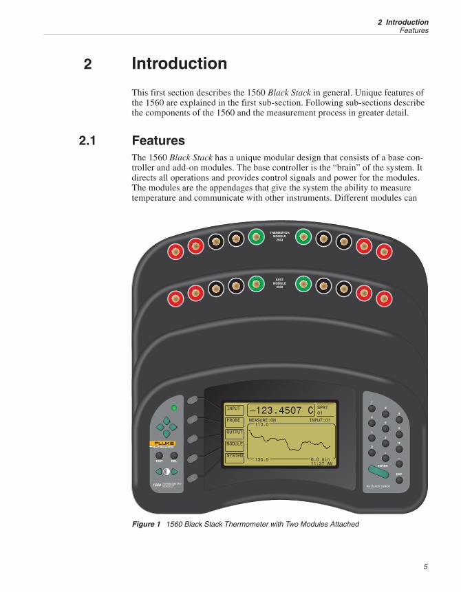
Figure 1 1560 Black Stack Thermometer with Two Modules Attached
have different functions. One module may measure platinum resistance ther-mometers (PRTs) while another may measure thermocouples. Still anothermodule may provide an interface to a printer. Modules may have more than oneindependent function or device. For example, a single module may include aGPIB communications device and a Centronics printer interface device. A sin-gle device, such as a thermocouple scanner, may also contain multiple chan-nels. By adding certain modules together, an instrument can be assembled withextraordinary capabilities.
Every add-on module conforms to specific physical and electrical requirements.This allows any module to be easily connected to the system. Up to eight mod-ules can be stacked onto the base. Modules can be purchased at any time andinstalled quickly and easily in the field allowing the system to grow as needsarise. The base controller automatically recognizes attached modules. Newchannels and functions immediately become available.
Each add-on module is an independent intelligent instrument. Modules containtheir own microcontroller, memory, and analog-to-digital converter, if neces-sary. Communication between modules and the base uses a proprietaryhigh-speed digital bus. Modules are calibrated individually with calibration pa-rameters stored in non-volatile memory within the module.
The physical layout of the 1560 Black Stack is optimized for user convenience.The front panel is tilted for clear viewing of the display and easy access to thebuttons. Measurements are displayed with large easy-to-read numbers. Bright-ness and contrast of the screen are adjustable. The graphics LCD display is ableto show a large amount of information and can be configured for different uses.In its statistical window mode, the display can simultaneously show measure-ments from different channels. It can also show the results of statistical analysisof these measurements. In graph mode, the display shows a plot of measure-ments over time. Operation of the 1560 is made simple and intuitive with theuse of soft-keys. The functions of the five soft-keys are indicated on the graph-ics display and change depending on the selected menu.
The primary purpose of the 1560 Black Stack is to measure temperature.Typically, it will be fitted with modules that allow it to measure with certaintypes of sensors such as PRTs or thermocouples. Since many modules can beattached, each having many channels, the system may have a large number andvariety of input channels. The base controller is capable of recognizing up to 96input channels. The base can be programmed to measure one channel continu-ously or scan many channels automatically. It can also be programmed to ac-quire a certain number of measurements then stop. Measurements can be storedin memory and printed later.
The 1560 Black Stack is designed to measure a variety of sensors: platinum re-sistance thermometers (PRTs) or resistance temperature detectors (RTDs), stan-dard platinum resistance thermometers (SPRTs), thermistors, thermocouples,and others. The base controller is able to mathematically convert measurementsof resistance or volts to temperature using any of the standard algorithms. WithPRTs, RTDs, and SPRTs, temperature can be calculated according to ITS-90,IPTS-68, Callendar-Van Dusen, or a polynomial. Probe-specific characteriza-
1560 Thermometer Readout
User’s Guide
6
tion coefficients are accepted for calibrated sensors. With thermistors, tempera-ture can be calculated according to the Steinhart-Hart equation or a polynomialwith user-specified coefficients. With thermocouples, temperature is calculatedaccording to the standard tables for type B, E, J, K, N, R, S, T, and gold-plati-num thermocouples as well as a polynomial or user-specified table. Adjust-ments to the standard curve can be made for improved accuracy.Thermocouples can be used with internal or external cold-junction compensa-tion. Characterizations are independently chosen for each sensor channel. Tem-perature can be displayed in units of degrees Celsius, degrees Fahrenheit, orKelvin.
The temperature conversion algorithms and characterization coefficients can beeasily tested. You can enter arbitrary resistances or voltages and the corre-sponding temperature is immediately displayed.
In addition to simple temperature measurements, the 1560 will calculate anddisplay statistical results that include: average, standard deviation, maximum,minimum, and spread. It will also display differences between measurements ofany two channels. The 1560 can send measurement results to printer ports,communication ports, and output channels provided by modules.
The 1560 has a built-in clock. This not only allows the display to show the cur-rent time-of-day but allows each measurement to be stamped with the time.Measurements are printed with the time and date.
The 1560 is designed for operation not only with the front panel buttons butalso using any of a variety of digital communication interfaces. The base con-troller includes one built-in serial RS-232 port. IEEE-488 (GPIB) is availablewith an add-on module. Communication interfaces allow the 1560 to acceptcommands to perform a variety of useful functions. Using the serial or GPIBinterface, a remote instrument or computer can control the acquisition of mea-surements and read back measurement data.
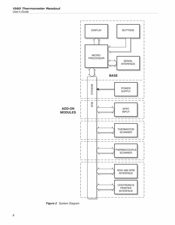
2.2 ComponentsFigure 2 shows the system layout of the 1560 Black Stack. The components aredescribed in the following sections.
2.2.1 Base MicroprocessorThe base microprocessor is the main controller of the system. It controls thedisplay, buttons, serial interface, and flow of data through the module bus. Italso performs temperature and statistical calculations. The microprocessor op-erates from firmware contained in read-only memory (ROM). It uses ran-dom-access memory (RAM) to store measurements and other data temporarily.Data that must be preserved, even when the power is off, are stored in non-vol-atile RAM.
2.2.1.1 Display
The front-panel LCD graphics display allows the user to view measured data as
7
2 IntroductionComponents
1560 Thermometer Readout
User’s Guide
8
Figure 2 System Diagram
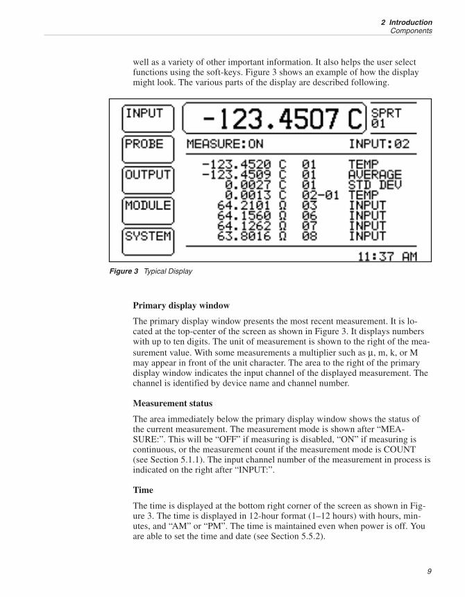
well as a variety of other important information. It also helps the user selectfunctions using the soft-keys. Figure 3 shows an example of how the displaymight look. The various parts of the display are described following.
Primary display window
The primary display window presents the most recent measurement. It is lo-cated at the top-center of the screen as shown in Figure 3. It displays numberswith up to ten digits. The unit of measurement is shown to the right of the mea-surement value. With some measurements a multiplier such as μ, m, k, or Mmay appear in front of the unit character. The area to the right of the primarydisplay window indicates the input channel of the displayed measurement. Thechannel is identified by device name and channel number.
Measurement status
The area immediately below the primary display window shows the status ofthe current measurement. The measurement mode is shown after “MEA-SURE:”. This will be “OFF” if measuring is disabled, “ON” if measuring iscontinuous, or the measurement count if the measurement mode is COUNT(see Section 5.1.1). The input channel number of the measurement in process isindicated on the right after “INPUT:”.
Time
The time is displayed at the bottom right corner of the screen as shown in Fig-ure 3. The time is displayed in 12-hour format (1–12 hours) with hours, min-utes, and “AM” or “PM”. The time is maintained even when power is off. Youare able to set the time and date (see Section 5.5.2).
9
2 IntroductionComponents
Figure 3 Typical Display
Soft-keys
Five soft-key labels are located along the left edge of the display next to thesoft-key buttons. The soft-key labels and the functions of the soft-key buttonschange depending on the selected menu.
Statistical display window
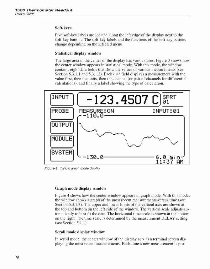
The large area in the center of the display has various uses. Figure 3 shows howthe center window appears in statistical mode. With this mode, the windowcontains eight data fields that show the values of various measurements (seeSection 5.3.1.1 and 5.3.1.2). Each data field displays a measurement with thevalue first, then the units, then the channel (or pair of channels for differentialcalculations), and finally a label showing the type of calculation.
Graph mode display window
Figure 4 shows how the center window appears in graph mode. With this mode,the window shows a graph of the most recent measurements versus time (seeSection 5.3.1.3). The upper and lower limits of the vertical axis are shown atthe top and bottom on the left side of the window. The vertical scale adjusts au-tomatically to best fit the data. The horizontal time scale is shown at the bottomon the right. The time scale is determined by the measurement DELAY setting(see Section 5.1.1).
Scroll mode display window
In scroll mode, the center window of the display acts as a terminal screen dis-playing the most recent measurements. Each time a new measurement is pro-
1560 Thermometer Readout
User’s Guide
10
Figure 4 Typical graph mode display
duced and displayed on the screen in the primary display window it is alsodisplayed on the top of the text output window (see Section 5.3.1.5). Each linecontaining previous measurements is scrolled down one line. Measurements aredisplayed with the input channel number first, then the measurement value, theunits, and the time the measurement was acquired. The time is displayed in24-hour format (0–23 hours) with hours, minutes, and seconds.
Function window
When using the soft-key functions, the center window may temporarily be usedto show specific information. In conjunction with the numeric and arrow but-tons, it can be used to set parameters.
2.2.1.2 Buttons
The buttons are used to select functions and edit parameters. The functions ofthe various buttons are described below.
Soft-keys
The five soft-keys to the left of the display are used to select menus or menufunctions. The functions of the soft-keys are indicated by the soft-key labels onthe display next to the soft-keys. The functions of the soft-keys depend on theselected menu. Soft-key functions are explained in detail in Section 5.
Numeric keys
The ten digit keys, the decimal point (.), minus (–), and exponent (EXP) keysare used to type in numeric data or make numbered selections.
ENTER
The ENTER key,E, is used to enter a new parameter value or option. Gen-erally, when the value of any parameter is changed, ENTER must be pressed toaccept the new value. If EXIT, U, or D, is pressed before ENTER, any dataentered will be ignored and the parameter will remain at its previous value.Within a window with a list of parameters, pressing ENTER will also move thecursor down to the next parameter. If the cursor is at the bottom of the list,pressing ENTER without changing the parameter will exit the window. TheENTER button may be used during some operations to affirm or continue withan action or choice.
DEL
When entering or editing a numeric parameter, the DEL (delete) key is used todelete a digit that is highlighted by the cursor.
EXIT
The EXIT key is used to cancel an operation, exit a window, or return from a
11
2 IntroductionComponents
lower menu to a higher menu. In any window, pressing EXIT will immediatelyexit the window and skip to the next window or return to the menu. If a param-eter is entered or changed and EXIT is pressed before ENTER, the change willbe ignored. During some operations the EXIT button may be used to cancel ordiscontinue with an action or choice. Use EXIT when in a lower soft-key menuto return to the main menu.
U D
The up U and down D arrow keys are used to move the cursor through a listof parameters in a window. Note that new data will not be accepted unlessENTER is pressed first. Thus these keys can also be used to intentionally can-cel a change to a parameter. If the list of parameters is too long to be displayedin the window, U and D can be used to scroll the list. The user can hold eitherof these down to scroll quickly.
L R
The left L and right R arrow keys have two functions. When entering or ed-iting a numeric parameter these can be used to move from digit to digit. Whensetting some parameters these are used to change the option.
These are the display contrast adjustment buttons. They can be used at any timeto adjust the contrast of the display.
2.2.1.3 Serial RS-232 Interface
The base includes an RS-232 serial interface. The connector is located on the bot-tom at the rear of the front section of the base. This can be used to connect the 1560to a printer for a hard copy printout of measurement data or to a computer for re-mote control.
2.2.1.4 Power Supply
The power supply provides the DC power required for the electronic circuits. Itreceives power from the AC mains supply. The AC power socket is located atthe bottom at the rear of the second section of the base. The power supply inputaccepts 100 to 250V, 50 to 60 Hz. nominal AC power.
2.2.1.5 Module Bus
The base microprocessor communicates with all add-on modules and devicesthrough the module bus. The bus is of a proprietary design that is simple, reli-able, and fast. It transfers data very quickly in an 8-bit parallel format. Themodule bus also supplies power to the modules.
1560 Thermometer Readout
User’s Guide
12

2.2.2 Add-On ModulesAdd-on modules provide specific functionality required by the user. Up to eightmodules can be attached to the base. A single module may contain multiple in-dependent devices, each having a different function. For instance, the extendedcommunication module contains a GPIB device for parallel communications, aCentronics interface device for printing to a printer, and an analog output de-vice for output of measurement data as an analog voltage. There are four basicclasses or types of devices based on primary function:
Input device
An input device is used by the base controller for measuring sensors and sig-nals. An input device may have multiple input channels. The input class in-cludes such devices as the SPRT and thermocouple modules.
Output device
An output device is able to receive measurement data from the base controllerand transmit the data to other instruments. A data output device may have mul-tiple output channels. The output class includes such devices as the analogoutput.
Printer interface device
A printer interface device is able to receive text data from the base controllerand send it to an external printer, terminal, or data storage device. The printerinterface class includes the Centronics printer interface and the printer outputfunction of the built-in RS-232 interface.
Communication device
A communication device provides bi-directional communications between anexternal instrument or computer and the 1560 system. This can be used to setparameters, read measurement data, and control the operation of the 1560. Thecommunications class includes the IEEE-488 GPIB interface device and thebi-directional communication function of the built-in RS-232 serial interfacedevice.
Each add-on module contains its own microprocessor that allows it to operateindependently with little supervision from the base controller. It also containsits own circuitry required for its specific application. This may include circuitryfor resistance or voltage sensing, digital conversion, temperature sensing, chan-nel switching, and digital communications. All circuits are directly controlledby the module’s microprocessor. The module microprocessor handles any criti-cal timing, over sampling, and error compensation calculations required tomake accurate measurements. Modules that require calibration to maintain ac-curacy store their own calibration coefficients in non-volatile random-accessmemory (NVRAM). Thus, the module remains calibrated even if it is movedfrom one 1560 system to another. The module calibration parameters can be ac-cessed through the front panel of the base.
13
2 IntroductionComponents
Each module recognizes and responds to a standard set of commands from thebase via the module bus. Standard commands are used for module and deviceidentification, status reporting, configuration, data input, and data output.
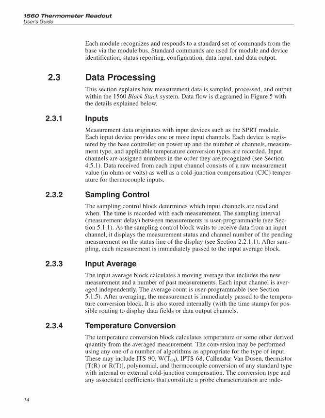
2.3 Data ProcessingThis section explains how measurement data is sampled, processed, and outputwithin the 1560 Black Stack system. Data flow is diagramed in Figure 5 withthe details explained below.
2.3.1 InputsMeasurement data originates with input devices such as the SPRT module.Each input device provides one or more input channels. Each device is regis-tered by the base controller on power up and the number of channels, measure-ment type, and applicable temperature conversion types are recorded. Inputchannels are assigned numbers in the order they are recognized (see Section4.5.1). Data received from each input channel consists of a raw measurementvalue (in ohms or volts) as well as a cold-junction compensation (CJC) temper-ature for thermocouple inputs.
2.3.2 Sampling ControlThe sampling control block determines which input channels are read andwhen. The time is recorded with each measurement. The sampling interval(measurement delay) between measurements is user-programmable (see Sec-tion 5.1.1). As the sampling control block waits to receive data from an inputchannel, it displays the measurement status and channel number of the pendingmeasurement on the status line of the display (see Section 2.2.1.1). After sam-pling, each measurement is immediately passed to the input average block.
2.3.3 Input AverageThe input average block calculates a moving average that includes the newmeasurement and a number of past measurements. Each input channel is aver-aged independently. The average count is user-programmable (see Section5.1.5). After averaging, the measurement is immediately passed to the tempera-ture conversion block. It is also stored internally (with the time stamp) for pos-sible routing to display data fields or data output channels.
2.3.4 Temperature ConversionThe temperature conversion block calculates temperature or some other derivedquantity from the averaged measurement. The conversion may be performedusing any one of a number of algorithms as appropriate for the type of input.These may include ITS-90, W(T90), IPTS-68, Callendar-Van Dusen, thermistor[T(R) or R(T)], polynomial, and thermocouple conversion of any standard typewith internal or external cold-junction compensation. The conversion type andany associated coefficients that constitute a probe characterization are inde-
1560 Thermometer Readout
User’s Guide
14
15
2 IntroductionData Processing
Figure 5 Data Flow
pendently specified for each input channel (see Section 5.2.1). Some conver-sions, namely those for thermocouples, may use the CJC temperature read fromthe module with the measurement. Converted measurements are immediatelypassed to the unit conversion block.
2.3.5 Unit ConversionThe unit conversion block converts measurements to the appropriate units (seeSection 5.5.1). The temperature conversion block produces temperature valuesin degrees Celsius (C). If the system units are degrees Fahrenheit (F) or Kelvin(K), the temperature value is converted accordingly.
2.3.6 Primary Measurement DisplayEach new measurement is immediately displayed on the front panel screen inthe primary measurement window. The channel number appears on the right.
2.3.7 Graph and Scroll WindowsEach new measurement also appears in the graph or scroll window, if visible.
2.3.8 MemoryEach new measurement is stored in memory. Up to 1000 measurements can bestored. (The storage capacity may be reduced if a large number of input chan-nels are added.) If the memory is full, the earliest measurement in memory isdiscarded when a new measurement is stored. The channel number, time, andunits are stored with the measurement value. Measurements stored in memorycan be printed (see Section 5.3.4).
2.3.9 Printer OutputsEach new measurement will be printed to any enabled printer device (see Sec-tion 5.3.3). The channel number, units, time, and date are also printed.
2.3.10 StatisticsEach measurement is processed by the statistics block. The statistics block pro-duces the following: the measurement value (no calculation), average, standard de-viation, maximum, minimum, and spread. Each input channel is processedindependently. The most recent statistical results for each input channel are storedinternally for later transfer to outputs. The statistical registers can be reset by theuser (see Section 5.3.5).
2.3.11 Output RoutingThe output routing block feeds measurements to the appropriate output chan-nels. Any output channel can receive measurements from any input channel aswell as the results of statistical calculations (see Section 5.3.2). When a newmeasurement is available, the output routing block passes it to all display fieldsand output channels programmed to receive it.
1560 Thermometer Readout
User’s Guide
16
2.3.12 Display Data FieldsIn statistical mode, the center display window contains eight programmabledata fields. These can display measurements from any input channel as well asthe results of statistical calculations (see Section 5.3.1.1 and 5.3.1.2). Measure-ments are displayed with the channel number, units, time, and a label identify-ing the type of calculation.
2.3.13 Data Output ChannelsOutput devices can receive measurements from any input channel as well as theresults of statistical calculations (see Section 5.3.2). Each output device pro-vides one or more output channels. Each device is registered by the base con-troller on power up and the number of channels are recorded. Output channelsare assigned numbers in the order they are recognized.
17
2 IntroductionData Processing
3 Specifications and EnvironmentalConditions
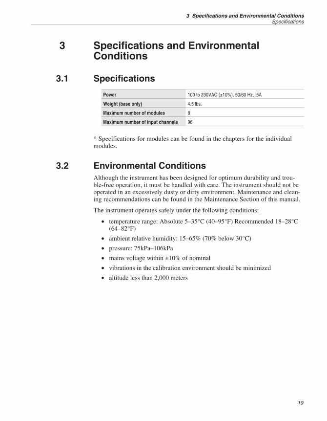
3.1 Specifications
Power 100 to 230VAC (±10%), 50/60 Hz, .5A
Weight (base only) 4.5 lbs.
Maximum number of modules 8
Maximum number of input channels 96
* Specifications for modules can be found in the chapters for the individualmodules.
3.2 Environmental ConditionsAlthough the instrument has been designed for optimum durability and trou-ble-free operation, it must be handled with care. The instrument should not beoperated in an excessively dusty or dirty environment. Maintenance and clean-ing recommendations can be found in the Maintenance Section of this manual.
The instrument operates safely under the following conditions:
• temperature range: Absolute 5–35°C (40–95°F) Recommended 18–28°C(64–82°F)
• ambient relative humidity: 15–65% (70% below 30°C)
• pressure: 75kPa–106kPa
• mains voltage within ±10% of nominal
• vibrations in the calibration environment should be minimized
• altitude less than 2,000 meters
19
3 Specifications and Environmental ConditionsSpecifications
4 General Operation
This section explains basic operation of the 1560 Black Stack. Operation of the1560 is explained in greater detail in subsequent sections: Section 5 explainseach of the functions available with the soft-keys and Section 6 explains thecommunication commands used to operate the 1560 remotely.
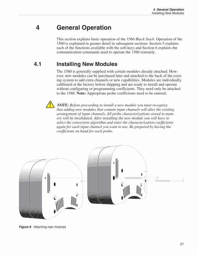
4.1 Installing New ModulesThe 1560 is generally supplied with certain modules already attached. How-ever, new modules can be purchased later and attached to the back of the exist-ing system to add extra channels or new capabilities. Modules are individuallycalibrated at the factory before shipping and are ready to install and operatewithout configuring or programming coefficients. They need only be attachedto the 1560. Note: Appropriate probe coefficients need to be entered.
NOTE: Before proceeding to install a new module you must recognizethat adding new modules that contain input channels will alter the existingarrangement of input channels. All probe characterizations stored in mem-ory will be invalidated. After installing the new module you will have toselect the conversion algorithm and enter the characterization coefficientsagain for each input channel you want to use. Be prepared by having thecoefficients on hand for each probe.
21
4 General OperationInstalling New Modules
Figure 6 Attaching new modules
The procedure for attaching a new module is as follows:
1. Turn off power to the 1560. Disconnect the power cord of the 1560 fromthe mains supply and disconnect the power cord from the back of the1560.
2. Tilt the 1560 on its side to access the back of the last module. If screwsare present in the two top holes, remove them. These holes will beneeded to attach the new module to the back with screws. Remove thebus connector cover.
3. Place the new module onto the back of the last module. Make sure thebus connectors mate properly and the alignment posts insert into theshallow holes. The modules should be pressed together so they are tightagainst each other.
4. Insert two long (3½") screws into the two lower holes of the new moduleto fasten the new module to the one in front of it. Place the bus connectorcover on the last module.
If properly attached, the new module will be automatically recognized by the1560 when it is powered up. Observe the results of the self-test shown on thedisplay just after the power is turned on to verify that the module is recognizedand tested without any problems (see Section 4.3). The correct number of mod-ules should be shown. If the module is not recognized or fails the self-test, turnthe power off, disconnect the module and reattach it making sure the bus con-nections are solid.
The 1560 is now ready for operation with the extra channels and features thenew module provides. If the new module has measurement capability, newchannels will appear in the input channel list when selecting input channels(see Section 5.1.2 and 5.1.3). If the new module provides data output func-tions, new output channels will appear in the channel list when programmingoutput channels (see Section 5.3.2). If the new module provides a printer inter-face, the new printer device will appear in printer device lists when selectingprinting options (see Section 5.3.3 and 5.3.4). If the new module provides com-munication ports these can immediately be used to communicate with and con-trol the 1560 remotely. Devices contained by the new module appear in the listfor setting device parameters (Section 5.4.2) and the new module will appear inthe module list in the system information window (Section 5.5.4).
NOTE: Before making any measurements after installing a new module,be sure to properly select the temperature conversion type and enter probecharacterization coefficients for each input channel you are using. Failureto do so may result in inaccurate temperature measurements!
1560 Thermometer Readout
User’s Guide
22
4.2 AC Power SourceThe 1560 requires an AC power source. See Section 3.1, Specifications, fordeatils. The power supply automatically adjusts to the mains voltage. The 1560may draw up to 0.5A.
The AC power cord attaches to the 1560 at the power socket located at the rearof the second section of the base. The power switch is also located at the rear ofthe second section.
4.3 Power On Self-TestWhen power is turned on, the 1560 will perform a self-test checking all thecomponents in the system including the module bus and each module. It willreport the status of each component on the screen. If an error occurs with thebus or modules it may be the result of an improper connection. Turn the poweroff, check the connections between the modules, and remove and reattach mod-ules if necessary. If modules have been removed or rearranged, a warning mes-sage may appear noting that the module configuration has changed and that allprobe parameters should be checked.
4.4 Adjusting the Screen ContrastWhen the 1560 is first powered on, the screen may appear faded, dark or blankif the contrast is not properly adjusted. Use the <C> buttons located at thebottom of the left side of the front panel to adjust the contrast. As the 1560warms up, the contrast may need to be adjusted.
4.5 Making MeasurementsThe procedure for configuring the 1560 to make measurements on a particularinput channel involves a few simple steps: select the input channel, set the con-version type and probe characterization coefficients, and enable measuring.These steps are explained below.
4.5.1 Selecting Input ChannelsInput channels are selected by number using the PRIM CHAN soft-key in theINPUT menu (see Section 5.1.2). The channel is selected from a windowshowing a list of all available input channels. Each channel in the list is identi-fied with the device name, the channel number, and probe serial number. Thechannel is selected by using the UD buttons to move the cursor to the desiredchannel and pressing ENTER.
23
4 General OperationAC Power Source
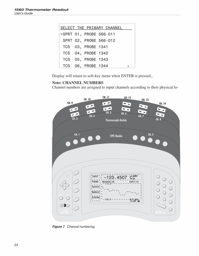
SELECT THE PRIMARY CHANNEL
>SPRT 01, PROBE 566-011
SPRT 02, PROBE 566-012
TCS 03, PROBE 1341
TCS 04, PROBE 1342
TCS 05, PROBE 1343
TCS 06, PROBE 1344 �
Display will return to soft-key menu when ENTER is pressed..
Note: CHANNEL NUMBERSChannel numbers are assigned to input channels according to their physical lo-
1560 Thermometer Readout
User’s Guide
24
EXIT DEL
7
4
1
0
8
5
2
.
9
6
3
EXP
–
ENTER
The 1560
BLACK STACK
Thermocouple Module
SPRT ModuleCH. 1
CH. 3
CH. 9
CH. 4
CH. 10
CH. 5
CH. 11
CH. 6
CH. 12
CH. 7
CH. 13
CH. 8
CH. 14
CH. 2
INPUT
PROBE
OUTPUT
MODULE
SYSTEM
MEASURE:ON INPUT:01113.0
130.0 6.0 min11:37 AM6.0 min11:37 AM
SPRT01SPRT01—123.4507 C
A Fluke Company
Figure 7 Channel numbering
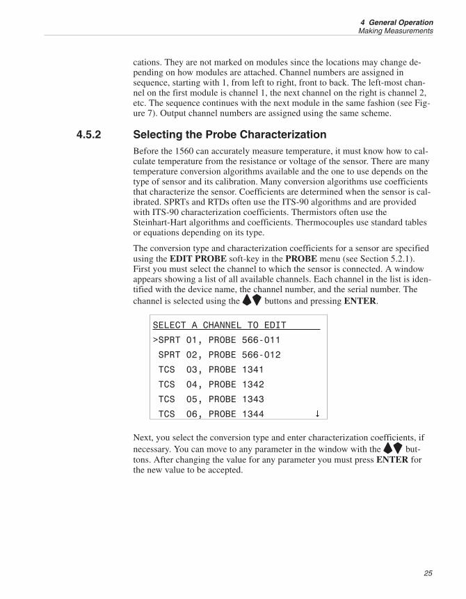
cations. They are not marked on modules since the locations may change de-pending on how modules are attached. Channel numbers are assigned insequence, starting with 1, from left to right, front to back. The left-most chan-nel on the first module is channel 1, the next channel on the right is channel 2,etc. The sequence continues with the next module in the same fashion (see Fig-ure 7). Output channel numbers are assigned using the same scheme.
4.5.2 Selecting the Probe CharacterizationBefore the 1560 can accurately measure temperature, it must know how to cal-culate temperature from the resistance or voltage of the sensor. There are manytemperature conversion algorithms available and the one to use depends on thetype of sensor and its calibration. Many conversion algorithms use coefficientsthat characterize the sensor. Coefficients are determined when the sensor is cal-ibrated. SPRTs and RTDs often use the ITS-90 algorithms and are providedwith ITS-90 characterization coefficients. Thermistors often use theSteinhart-Hart algorithms and coefficients. Thermocouples use standard tablesor equations depending on its type.
The conversion type and characterization coefficients for a sensor are specifiedusing the EDIT PROBE soft-key in the PROBE menu (see Section 5.2.1).First you must select the channel to which the sensor is connected. A windowappears showing a list of all available channels. Each channel in the list is iden-tified with the device name, the channel number, and the serial number. Thechannel is selected using the UD buttons and pressing ENTER.
SELECT A CHANNEL TO EDIT
>SPRT 01, PROBE 566-011
SPRT 02, PROBE 566-012
TCS 03, PROBE 1341
TCS 04, PROBE 1342
TCS 05, PROBE 1343
TCS 06, PROBE 1344 �
Next, you select the conversion type and enter characterization coefficients, ifnecessary. You can move to any parameter in the window with the UD but-tons. After changing the value for any parameter you must press ENTER forthe new value to be accepted.
25
4 General OperationMaking Measurements
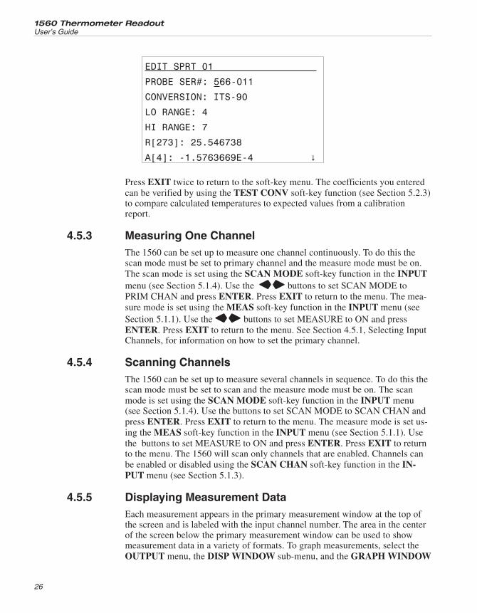
EDIT SPRT 01
PROBE SER#: 566-011
CONVERSION: ITS-90
LO RANGE: 4
HI RANGE: 7
R[273]: 25.546738
A[4]: -1.5763669E-4 �
Press EXIT twice to return to the soft-key menu. The coefficients you enteredcan be verified by using the TEST CONV soft-key function (see Section 5.2.3)to compare calculated temperatures to expected values from a calibrationreport.
4.5.3 Measuring One ChannelThe 1560 can be set up to measure one channel continuously. To do this thescan mode must be set to primary channel and the measure mode must be on.The scan mode is set using the SCAN MODE soft-key function in the INPUTmenu (see Section 5.1.4). Use the LR buttons to set SCAN MODE toPRIM CHAN and press ENTER. Press EXIT to return to the menu. The mea-sure mode is set using the MEAS soft-key function in the INPUT menu (seeSection 5.1.1). Use the LR buttons to set MEASURE to ON and pressENTER. Press EXIT to return to the menu. See Section 4.5.1, Selecting InputChannels, for information on how to set the primary channel.
4.5.4 Scanning ChannelsThe 1560 can be set up to measure several channels in sequence. To do this thescan mode must be set to scan and the measure mode must be on. The scanmode is set using the SCAN MODE soft-key function in the INPUT menu(see Section 5.1.4). Use the buttons to set SCAN MODE to SCAN CHAN andpress ENTER. Press EXIT to return to the menu. The measure mode is set us-ing the MEAS soft-key function in the INPUT menu (see Section 5.1.1). Usethe buttons to set MEASURE to ON and press ENTER. Press EXIT to returnto the menu. The 1560 will scan only channels that are enabled. Channels canbe enabled or disabled using the SCAN CHAN soft-key function in the IN-PUT menu (see Section 5.1.3).
4.5.5 Displaying Measurement DataEach measurement appears in the primary measurement window at the top ofthe screen and is labeled with the input channel number. The area in the centerof the screen below the primary measurement window can be used to showmeasurement data in a variety of formats. To graph measurements, select theOUTPUT menu, the DISP WINDOW sub-menu, and the GRAPH WINDOW
1560 Thermometer Readout
User’s Guide
26

function (see Section 5.3.3). To show multiple lines of selected data, select theSTAT WINDOW function in the DISP WINDOW sub-menu (see Section5.3.1). The type of data is selected using the SET FIELDS function (Section5.3.2). To show a list of most recent measurements, select the SCROLL WIN-DOW function in the DISP WINDOW sub-menu (Section 5.3.5).
27
4 General OperationMaking Measurements
5 Soft-Key Functions
The soft-key menu system provides a convenient method of accessing a largenumber of functions from the front panel with only a few buttons. Thesoft-keys next to the display are used to select particular functions. Labels onthe display next to the soft-key identify the functions. Since there are manymore functions than soft-keys, a nested menu structure is used. Related func-tions appear together in a soft-key menu. The soft-key menu system is outlinedin Table 2. Each soft-key function is described in detail in the following sec-tions, organized by menu. The EXIT key is used to return from a lower menuto the main menu.
5.1 Input MenuThe INPUT menu provides functions for controlling the measurement process,selecting input channels, and setting measurement averaging. The soft-keyfunctions that appear in this menu are MEAS, PRIM CHAN, SCAN CHAN,SCAN MODE, and AVER.
5.1.1 MeasureThe MEAS soft-key allows you to control the measurement action. A windowshows the current settings of the measurement parameters and allows them tobe changed.
SET MEASUREMENT PARAMETERS
MEASURE: ON LR
COUNT N: 1
DELAY: 0
SEQ TIMER: 0
The MEASURE parameter enables or disables measuring. Options are selectedusing the LR buttons and pressing ENTER. The possible options are OFF,ON, and COUNT. If ON is selected the instrument measures continuously. IfCOUNT is selected the instrument immediately begins measuring the numberof measurements given by the COUNT N number. The current measurementstatus is always indicated on the status message line below the primary mea-surement window (see Section 2.2.1.1).
The COUNT N parameter (1 to 32,767) specifies the number of measurementsto acquire before stopping when the MEASURE mode is set to COUNT. Usethe numeric buttons to enter a value and press ENTER.
29
5 Soft-Key FunctionsInput Menu
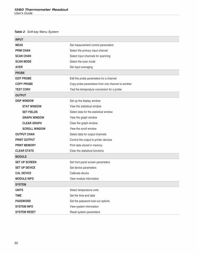
1560 Thermometer Readout
User’s Guide
30
INPUT
MEAS Set measurement control parameters
PRIM CHAN Select the primary input channel
SCAN CHAN Select input channels for scanning
SCAN MODE Select the scan mode
AVER Set input averaging
PROBE
EDIT PROBE Edit the probe parameters for a channel
COPY PROBE Copy probe parameters from one channel to another
TEST CONV Test the temperature conversion for a probe
OUTPUT
DISP WINDOW Set up the display window
STAT WINDOW View the statistical window
SET FIELDS Select data for the statistical window
GRAPH WINDOW View the graph window
CLEAR GRAPH Clear the graph window
SCROLL WINDOW View the scroll window
OUTPUT CHAN Select data for output channels
PRINT OUTPUT Control the output to printer devices
PRINT MEMORY Print data stored in memory
CLEAR STATS Clear the statistical functions
MODULE
SET UP SCREEN Set front panel screen parameters
SET UP DEVICE Set device parameters
CAL DEVICE Calibrate device
MODULE INFO View module information
SYSTEM
UNITS Select temperature units
TIME Set the time and date
PASSWORD Set the password lock-out options
SYSTEM INFO View system information
SYSTEM RESET Reset system parameters
Table 2 Soft-key Menu System
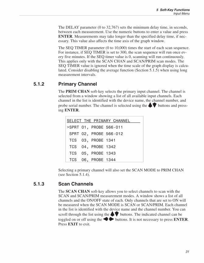
The DELAY parameter (0 to 32,767) sets the minimum delay time, in seconds,between each measurement. Use the numeric buttons to enter a value and pressENTER. Measurements may take longer than the specified delay time, if nec-essary. This value also affects the time axis of the graph window.
The SEQ TIMER parameter (0 to 10,000) times the start of each scan sequence.For instance, if SEQ TIMER is set to 300, the scan sequence will run once ev-ery five minutes. If the SEQ timer value is 0, scanning will run continuously.This applies only with the SCAN CHAN and SCAN/PRIM scan modes. TheSEQ TIMER value is ignored when the time scale of the graph display is calcu-lated. Consider disabling the average function (Section 5.1.5) when using longmeasurement intervals.
5.1.2 Primary ChannelThe PRIM CHAN soft-key selects the primary input channel. The channel isselected from a window showing a list of all available input channels. Eachchannel in the list is identified with the device name, the channel number, andprobe serial number. The channel is selected using the UD buttons and press-ing ENTER.
SELECT THE PRIMARY CHANNEL
>SPRT 01, PROBE 566-011
SPRT 02, PROBE 566-012
TCS 03, PROBE 1341
TCS 04, PROBE 1342
TCS 05, PROBE 1343
TCS 06, PROBE 1344
Selecting a primary channel will also set the SCAN MODE to PRIM CHAN(see Section 5.1.4).
5.1.3 Scan ChannelsThe SCAN CHAN soft-key allows you to select channels to scan with theSCAN and SCAN/PRIM measurement modes. A window shows a list of allchannels and the ON/OFF state of each. Only channels that are set to ON willbe measured when the SCAN MODE is SCAN or SCAN/PRIM. Each channelin the list is identified with the device name and the channel number. You canscroll through the list using the UD buttons. The indicated channel can betoggled on or off using the LR buttons. It is not necessary to press ENTER.Press EXIT to exit.
31
5 Soft-Key FunctionsInput Menu
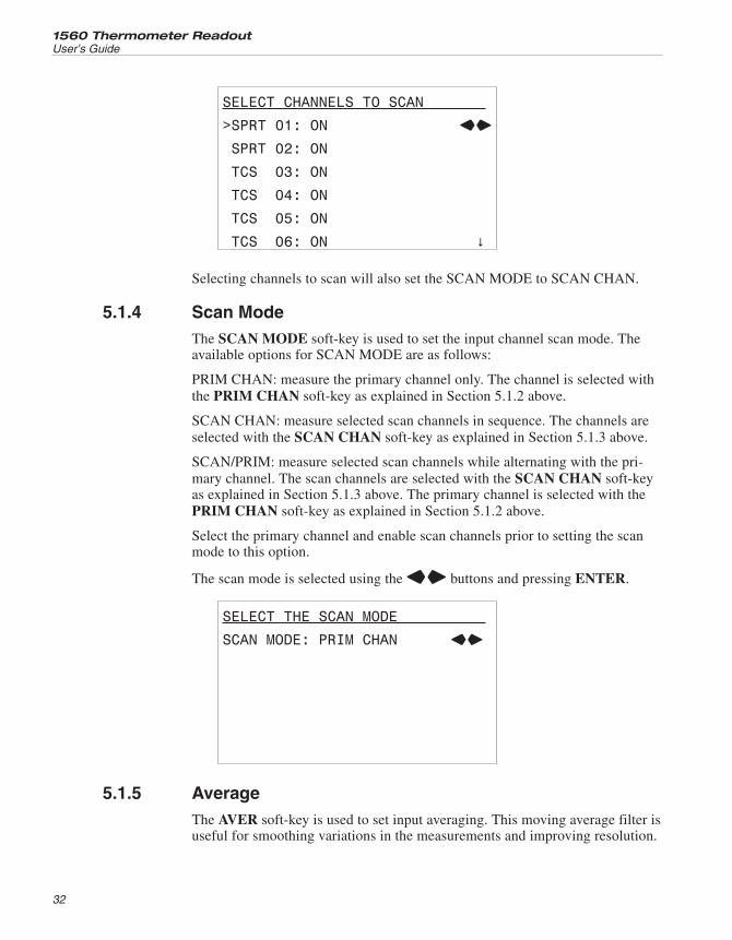
SELECT CHANNELS TO SCAN
>SPRT 01: ON LR
SPRT 02: ON
TCS 03: ON
TCS 04: ON
TCS 05: ON
TCS 06: ON �
Selecting channels to scan will also set the SCAN MODE to SCAN CHAN.
5.1.4 Scan ModeThe SCAN MODE soft-key is used to set the input channel scan mode. Theavailable options for SCAN MODE are as follows:
PRIM CHAN: measure the primary channel only. The channel is selected withthe PRIM CHAN soft-key as explained in Section 5.1.2 above.
SCAN CHAN: measure selected scan channels in sequence. The channels areselected with the SCAN CHAN soft-key as explained in Section 5.1.3 above.
SCAN/PRIM: measure selected scan channels while alternating with the pri-mary channel. The scan channels are selected with the SCAN CHAN soft-keyas explained in Section 5.1.3 above. The primary channel is selected with thePRIM CHAN soft-key as explained in Section 5.1.2 above.
Select the primary channel and enable scan channels prior to setting the scanmode to this option.
The scan mode is selected using the LR buttons and pressing ENTER.
SELECT THE SCAN MODE
SCAN MODE: PRIM CHAN LR
5.1.5 AverageThe AVER soft-key is used to set input averaging. This moving average filter isuseful for smoothing variations in the measurements and improving resolution.
1560 Thermometer Readout
User’s Guide
32
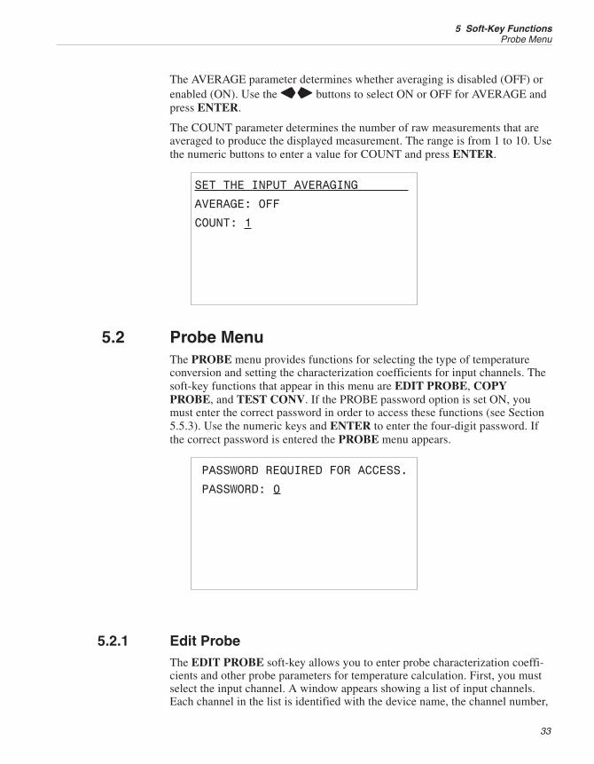
The AVERAGE parameter determines whether averaging is disabled (OFF) orenabled (ON). Use the LR buttons to select ON or OFF for AVERAGE andpress ENTER.
The COUNT parameter determines the number of raw measurements that areaveraged to produce the displayed measurement. The range is from 1 to 10. Usethe numeric buttons to enter a value for COUNT and press ENTER.
SET THE INPUT AVERAGING
AVERAGE: OFF
COUNT: 1
5.2 Probe MenuThe PROBE menu provides functions for selecting the type of temperatureconversion and setting the characterization coefficients for input channels. Thesoft-key functions that appear in this menu are EDIT PROBE, COPYPROBE, and TEST CONV. If the PROBE password option is set ON, youmust enter the correct password in order to access these functions (see Section5.5.3). Use the numeric keys and ENTER to enter the four-digit password. Ifthe correct password is entered the PROBE menu appears.
PASSWORD REQUIRED FOR ACCESS.
PASSWORD: 0
5.2.1 Edit ProbeThe EDIT PROBE soft-key allows you to enter probe characterization coeffi-cients and other probe parameters for temperature calculation. First, you mustselect the input channel. A window appears showing a list of input channels.Each channel in the list is identified with the device name, the channel number,
33
5 Soft-Key FunctionsProbe Menu
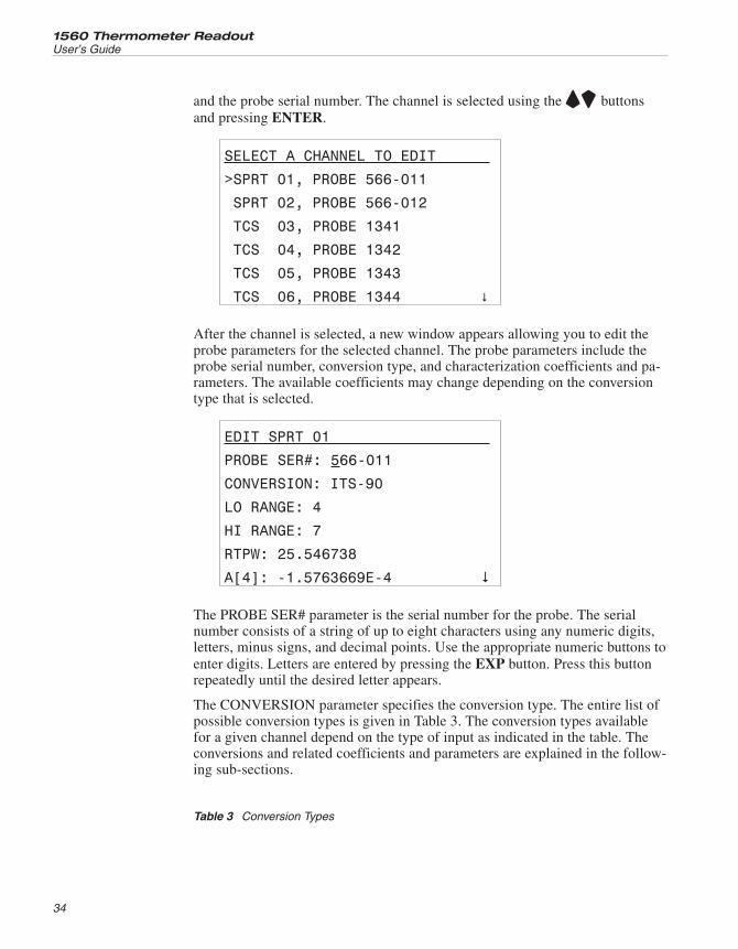
and the probe serial number. The channel is selected using the UD buttonsand pressing ENTER.
SELECT A CHANNEL TO EDIT
>SPRT 01, PROBE 566-011
SPRT 02, PROBE 566-012
TCS 03, PROBE 1341
TCS 04, PROBE 1342
TCS 05, PROBE 1343
TCS 06, PROBE 1344 �
After the channel is selected, a new window appears allowing you to edit theprobe parameters for the selected channel. The probe parameters include theprobe serial number, conversion type, and characterization coefficients and pa-rameters. The available coefficients may change depending on the conversiontype that is selected.
EDIT SPRT 01
PROBE SER#: 566-011
CONVERSION: ITS-90
LO RANGE: 4
HI RANGE: 7
RTPW: 25.546738
A[4]: -1.5763669E-4 �
The PROBE SER# parameter is the serial number for the probe. The serialnumber consists of a string of up to eight characters using any numeric digits,letters, minus signs, and decimal points. Use the appropriate numeric buttons toenter digits. Letters are entered by pressing the EXP button. Press this buttonrepeatedly until the desired letter appears.
The CONVERSION parameter specifies the conversion type. The entire list ofpossible conversion types is given in Table 3. The conversion types availablefor a given channel depend on the type of input as indicated in the table. Theconversions and related coefficients and parameters are explained in the follow-ing sub-sections.
1560 Thermometer Readout
User’s Guide
34
Table 3 Conversion Types
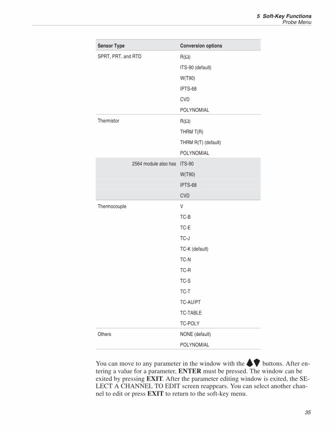
Sensor Type Conversion options
SPRT, PRT, and RTD R(Ω)
ITS-90 (default)
W(T90)
IPTS-68
CVD
POLYNOMIAL
Thermistor R(Ω)
THRM T(R)
THRM R(T) (default)
POLYNOMIAL
2564 module also has ITS-90
W(T90)
IPTS-68
CVD
Thermocouple V
TC-B
TC-E
TC-J
TC-K (default)
TC-N
TC-R
TC-S
TC-T
TC-AU/PT
TC-TABLE
TC-POLY
Others NONE (default)
POLYNOMIAL
You can move to any parameter in the window with the UD buttons. After en-tering a value for a parameter, ENTER must be pressed. The window can beexited by pressing EXIT. After the parameter editing window is exited, the SE-LECT A CHANNEL TO EDIT screen reappears. You can select another chan-nel to edit or press EXIT to return to the soft-key menu.
35
5 Soft-Key FunctionsProbe Menu
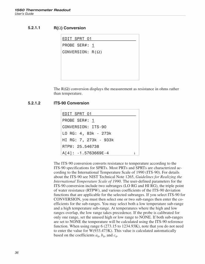
5.2.1.1 R(Ω) Conversion
EDIT SPRT 01
PROBE SER#: 1
CONVERSION: R(Ω)
The R(Ω) conversion displays the measurement as resistance in ohms ratherthan temperature.
5.2.1.2 ITS-90 Conversion
EDIT SPRT 01
PROBE SER#: 1
CONVERSION: ITS-90
LO RG: 4, 83k - 273k
HI RG: 7, 273k - 933k
RTPW: 25.546738
A[4]: -1.5763669E-4 �
The ITS-90 conversion converts resistance to temperature according to theITS-90 specifications for SPRTs. Most PRTs and SPRTs are characterized ac-cording to the International Temperature Scale of 1990 (ITS-90). For detailsabout the ITS-90 see NIST Technical Note 1265, Guidelines for Realizing theInternational Temperature Scale of 1990. The user-defined parameters for theITS-90 conversion include two subranges (LO RG and HI RG), the triple pointof water resistance (RTPW), and various coefficients of the ITS-90 deviationfunctions that are applicable for the selected subranges. If you select ITS-90 forCONVERSION, you must then select one or two sub-ranges then enter the co-efficients for the sub-ranges. You may select both a low temperature sub-rangeand a high temperature sub-range. At temperatures where the high and lowranges overlap, the low range takes precedence. If the probe is calibrated foronly one range, set the unused high or low range to NONE. If both sub-rangesare set to NONE the temperature will be calculated using the ITS-90 referencefunction. When using range 6 (273.15 to 1234.93K), note that you do not needto enter the value for W(933.473K). This value is calculated automaticallybased on the coefficients a6, b6, and c6.
1560 Thermometer Readout
User’s Guide
36
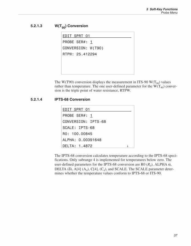
5.2.1.3 W(T90) Conversion
EDIT SPRT 01
PROBE SER#: 1
CONVERSION: W(T90)
RTPW: 25.412294
The W(T90) conversion displays the measurement in ITS-90 W(T90) valuesrather than temperature. The one user-defined parameter for the W(T90) conver-sion is the triple point of water resistance, RTPW.
5.2.1.4 IPTS-68 Conversion
EDIT SPRT 01
PROBE SER#: 1
CONVERSION: IPTS-68
SCALE: IPTS-68
R0: 100.00845
ALPHA: 0.00391648
DELTA: 1.4872 �
The IPTS-68 conversion calculates temperature according to the IPTS-68 speci-fications. Only subrange 4 is implemented for temperatures below zero. Theuser-defined parameters for the IPTS-68 conversion are R0 (R0), ALPHA α,DELTA (δ), A[4] (A4), C[4], (C4), and SCALE. The SCALE parameter deter-mines whether the temperature values conform to IPTS-68 or ITS-90.
37
5 Soft-Key FunctionsProbe Menu
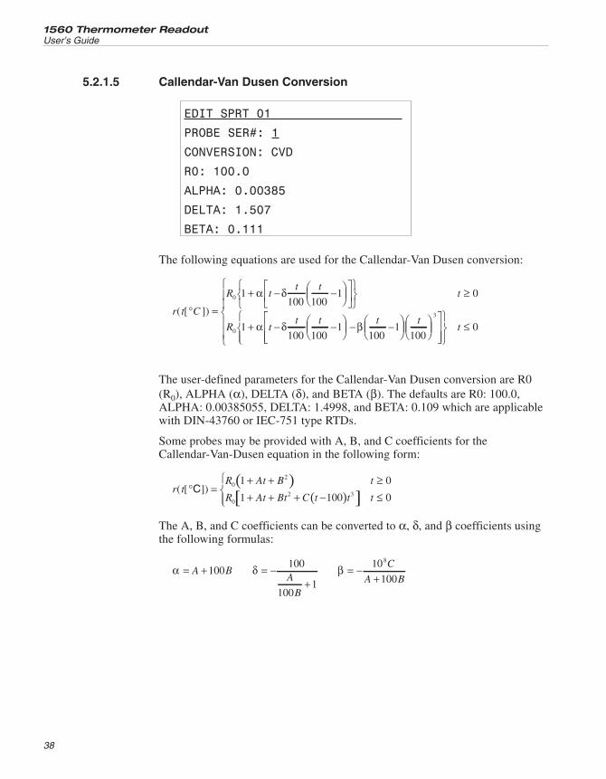
5.2.1.5 Callendar-Van Dusen Conversion
EDIT SPRT 01
PROBE SER#: 1
CONVERSION: CVD
R0: 100.0
ALPHA: 0.00385
DELTA: 1.507
BETA: 0.111
The following equations are used for the Callendar-Van Dusen conversion:
r t C
R tt t
t
R
( [ ])° =
+ − −⎛⎝⎜
⎞⎠⎟
⎡⎣⎢
⎤⎦⎥
⎧⎨⎩
⎫⎬⎭
≥0
0
1100 100
1 0α δ
1100 100
1100
1100
3
+ − −⎛⎝⎜
⎞⎠⎟ − −⎛
⎝⎜⎞⎠⎟
⎛⎝⎜
⎞⎠⎟
⎡
⎣⎢α δ βt
t t t t
⎢
⎤
⎦⎥⎥
⎧⎨⎩⎪
⎫⎬⎭
≤
⎧
⎨⎪⎪
⎩⎪⎪
t 0
The user-defined parameters for the Callendar-Van Dusen conversion are R0(R0), ALPHA (α), DELTA (δ), and BETA (β). The defaults are R0: 100.0,ALPHA: 0.00385055, DELTA: 1.4998, and BETA: 0.109 which are applicablewith DIN-43760 or IEC-751 type RTDs.
Some probes may be provided with A, B, and C coefficients for theCallendar-Van-Dusen equation in the following form:
( )( )[ ]r t
R At B t
R At Bt C t t t( [ ])° =
+ + ≥+ + + − ≤
⎧⎨⎩⎪
C 02
02 3
1 0
1 100 0
The A, B, and C coefficients can be converted to α, δ, and β coefficients usingthe following formulas:
α = +A B100 δ = −+
100
1001
A
B
β = −+10
100
8C
A B
1560 Thermometer Readout
User’s Guide
38
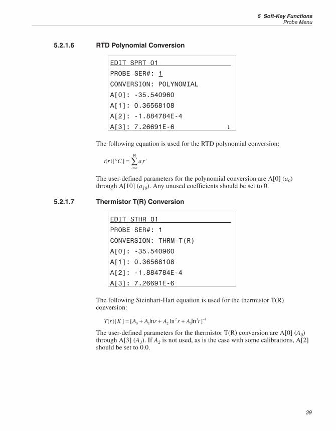
5.2.1.6 RTD Polynomial Conversion
EDIT SPRT 01
PROBE SER#: 1
CONVERSION: POLYNOMIAL
A[0]: -35.540960
A[1]: 0.36568108
A[2]: -1.884784E-4
A[3]: 7.26691E-6 �
The following equation is used for the RTD polynomial conversion:
t r C a rii
i o
( )[ ]° ==∑10
The user-defined parameters for the polynomial conversion are A[0] (a0)through A[10] (a10). Any unused coefficients should be set to 0.
5.2.1.7 Thermistor T(R) Conversion
EDIT STHR 01
PROBE SER#: 1
CONVERSION: THRM-T(R)
A[0]: -35.540960
A[1]: 0.36568108
A[2]: -1.884784E-4
A[3]: 7.26691E-6
The following Steinhart-Hart equation is used for the thermistor T(R)conversion:
T r K A A r A r A r( )[ ] [ ln ]= + + + −0 1 2
23
3 1ln ln
The user-defined parameters for the thermistor T(R) conversion are A[0] (A0)through A[3] (A3). If A2 is not used, as is the case with some calibrations, A[2]should be set to 0.0.
39
5 Soft-Key FunctionsProbe Menu
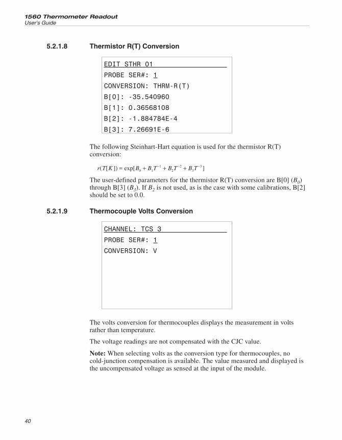
5.2.1.8 Thermistor R(T) Conversion
EDIT STHR 01
PROBE SER#: 1
CONVERSION: THRM-R(T)
B[0]: -35.540960
B[1]: 0.36568108
B[2]: -1.884784E-4
B[3]: 7.26691E-6
The following Steinhart-Hart equation is used for the thermistor R(T)conversion:
r T K B B T B T B T( [ ]) exp[ ]= + + +− − −0 1
12
23
3
The user-defined parameters for the thermistor R(T) conversion are B[0] (B0)through B[3] (B3). If B2 is not used, as is the case with some calibrations, B[2]should be set to 0.0.
5.2.1.9 Thermocouple Volts Conversion
CHANNEL: TCS 3
PROBE SER#: 1
CONVERSION: V
The volts conversion for thermocouples displays the measurement in voltsrather than temperature.
The voltage readings are not compensated with the CJC value.
Note: When selecting volts as the conversion type for thermocouples, nocold-junction compensation is available. The value measured and displayed isthe uncompensated voltage as sensed at the input of the module.
1560 Thermometer Readout
User’s Guide
40
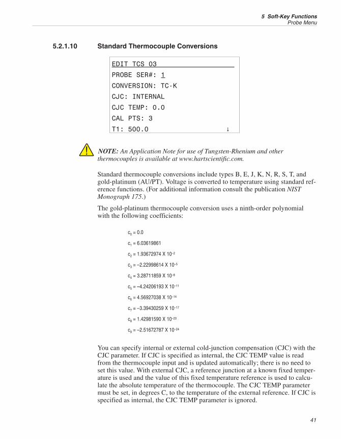
5.2.1.10 Standard Thermocouple Conversions
EDIT TCS 03
PROBE SER#: 1
CONVERSION: TC-K
CJC: INTERNAL
CJC TEMP: 0.0
CAL PTS: 3
T1: 500.0 �
NOTE: An Application Note for use of Tungsten-Rhenium and otherthermocouples is available at www.hartscientific.com.
Standard thermocouple conversions include types B, E, J, K, N, R, S, T, andgold-platinum (AU/PT). Voltage is converted to temperature using standard ref-erence functions. (For additional information consult the publication NISTMonograph 175.)
The gold-platinum thermocouple conversion uses a ninth-order polynomialwith the following coefficients:
c0 = 0.0
c1 = 6.03619861
c2 = 1.93672974 X 10⁻²
c3 = –2.22998614 X 10⁻⁵
c4 = 3.28711859 X 10⁻⁸
c5 = –4.24206193 X 10⁻¹¹
c6 = 4.56927038 X 10⁻¹⁴
c7 = –3.39430259 X 10⁻¹⁷
c8 = 1.42981590 X 10⁻²⁰
c9 = –2.51672787 X 10⁻²⁴
You can specify internal or external cold-junction compensation (CJC) with theCJC parameter. If CJC is specified as internal, the CJC TEMP value is readfrom the thermocouple input and is updated automatically; there is no need toset this value. With external CJC, a reference junction at a known fixed temper-ature is used and the value of this fixed temperature reference is used to calcu-late the absolute temperature of the thermocouple. The CJC TEMP parametermust be set, in degrees C, to the temperature of the external reference. If CJC isspecified as internal, the CJC TEMP parameter is ignored.
41
5 Soft-Key FunctionsProbe Menu
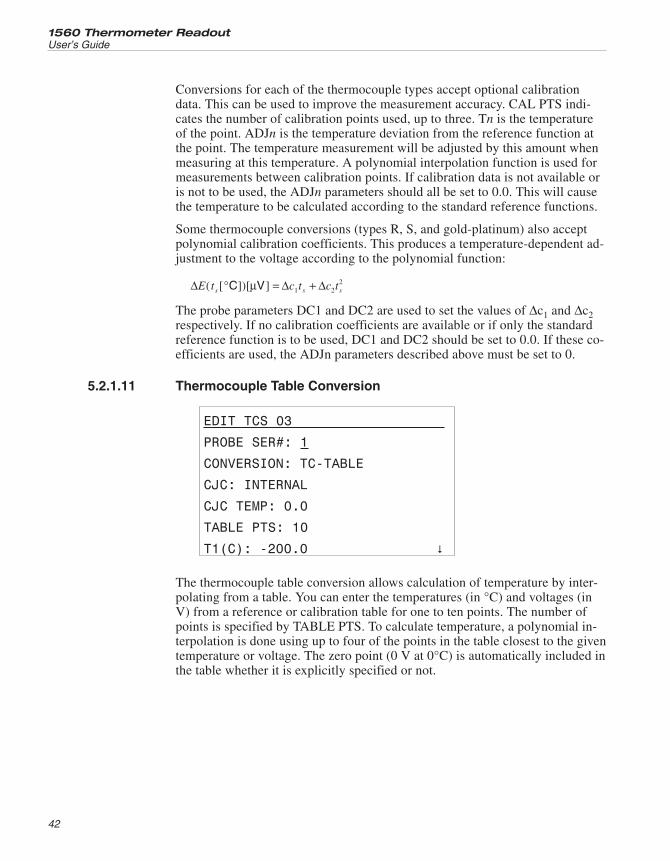
Conversions for each of the thermocouple types accept optional calibrationdata. This can be used to improve the measurement accuracy. CAL PTS indi-cates the number of calibration points used, up to three. Tn is the temperatureof the point. ADJn is the temperature deviation from the reference function atthe point. The temperature measurement will be adjusted by this amount whenmeasuring at this temperature. A polynomial interpolation function is used formeasurements between calibration points. If calibration data is not available oris not to be used, the ADJn parameters should all be set to 0.0. This will causethe temperature to be calculated according to the standard reference functions.
Some thermocouple conversions (types R, S, and gold-platinum) also acceptpolynomial calibration coefficients. This produces a temperature-dependent ad-justment to the voltage according to the polynomial function:
Δ Δ ΔE t c t c ts s s( [ ])[ ]° = +C Vμ 1 22
The probe parameters DC1 and DC2 are used to set the values of Δc1 and Δc2respectively. If no calibration coefficients are available or if only the standardreference function is to be used, DC1 and DC2 should be set to 0.0. If these co-efficients are used, the ADJn parameters described above must be set to 0.
5.2.1.11 Thermocouple Table Conversion
EDIT TCS 03
PROBE SER#: 1
CONVERSION: TC-TABLE
CJC: INTERNAL
CJC TEMP: 0.0
TABLE PTS: 10
T1(C): -200.0 �
The thermocouple table conversion allows calculation of temperature by inter-polating from a table. You can enter the temperatures (in °C) and voltages (inV) from a reference or calibration table for one to ten points. The number ofpoints is specified by TABLE PTS. To calculate temperature, a polynomial in-terpolation is done using up to four of the points in the table closest to the giventemperature or voltage. The zero point (0 V at 0°C) is automatically included inthe table whether it is explicitly specified or not.
1560 Thermometer Readout
User’s Guide
42
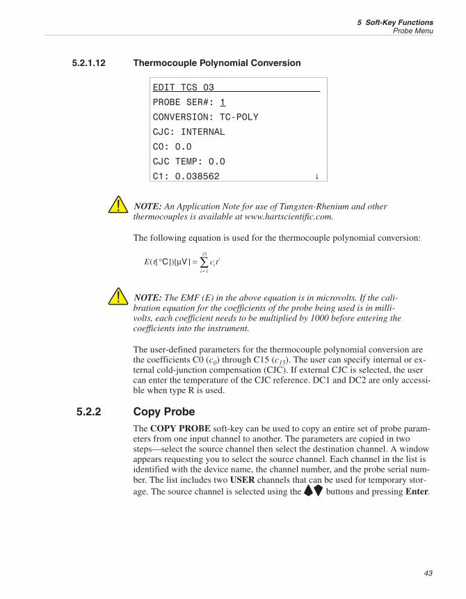
5.2.1.12 Thermocouple Polynomial Conversion
EDIT TCS 03
PROBE SER#: 1
CONVERSION: TC-POLY
CJC: INTERNAL
C0: 0.0
CJC TEMP: 0.0
C1: 0.038562 �
NOTE: An Application Note for use of Tungsten-Rhenium and otherthermocouples is available at www.hartscientific.com.
The following equation is used for the thermocouple polynomial conversion:
E t c tii
i
( [ ])[ ]° ==∑C Vμ
1
15
NOTE: The EMF (E) in the above equation is in microvolts. If the cali-bration equation for the coefficients of the probe being used is in milli-volts, each coefficient needs to be multiplied by 1000 before entering thecoefficients into the instrument.
The user-defined parameters for the thermocouple polynomial conversion arethe coefficients C0 (c0) through C15 (c15). The user can specify internal or ex-ternal cold-junction compensation (CJC). If external CJC is selected, the usercan enter the temperature of the CJC reference. DC1 and DC2 are only accessi-ble when type R is used.
5.2.2 Copy ProbeThe COPY PROBE soft-key can be used to copy an entire set of probe param-eters from one input channel to another. The parameters are copied in twosteps—select the source channel then select the destination channel. A windowappears requesting you to select the source channel. Each channel in the list isidentified with the device name, the channel number, and the probe serial num-ber. The list includes two USER channels that can be used for temporary stor-age. The source channel is selected using the UD buttons and pressing Enter.
43
5 Soft-Key FunctionsProbe Menu
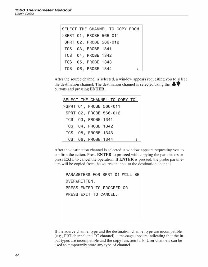
SELECT THE CHANNEL TO COPY FROM
>SPRT 01, PROBE 566-011
SPRT 02, PROBE 566-012
TCS 03, PROBE 1341
TCS 04, PROBE 1342
TCS 05, PROBE 1343
TCS 06, PROBE 1344 �
After the source channel is selected, a window appears requesting you to selectthe destination channel. The destination channel is selected using the UDbuttons and pressing ENTER.
SELECT THE CHANNEL TO COPY TO
>SPRT 01, PROBE 566-011
SPRT 02, PROBE 566-012
TCS 03, PROBE 1341
TCS 04, PROBE 1342
TCS 05, PROBE 1343
TCS 06, PROBE 1344 �
After the destination channel is selected, a window appears requesting you toconfirm the action. Press ENTER to proceed with copying the parameters orpress EXIT to cancel the operation. If ENTER is pressed, the probe parame-ters will be copied from the source channel to the destination channel.
PARAMETERS FOR SPRT 01 WILL BE
OVERWRITTEN.
PRESS ENTER TO PROCEED OR
PRESS EXIT TO CANCEL.
If the source channel type and the destination channel type are incompatible(e.g., PRT channel and TC channel), a message appears indicating that the in-put types are incompatible and the copy function fails. User channels can beused to temporarily store any type of channel.
1560 Thermometer Readout
User’s Guide
44

5.2.3 Test ConversionThe TEST CONV soft-key allows you to test the probe characterization algo-rithm and characterization coefficients for a specific probe. You must first se-lect the channel number of the probe. A window appears requesting you toselect the input channel. Each channel in the list is identified with the devicename, the channel number, and the probe serial number. The channel is selectedusing the UD buttons and pressing ENTER.
SELECT A PROBE TO TEST
>SPRT 01, PROBE 566-011
SPRT 02, PROBE 566-012
TCS 03, PROBE 1341
TCS 04, PROBE 1342
TCS 05, PROBE 1343
TCS 06, PROBE 1344 �
After the probe is selected, a new window appears allowing you to test the tem-perature calculation for the probe. You can enter an input value (e.g. resistance)and the corresponding output value (e.g. temperature) will be shown. PressEXIT to exit.
TEST CONVERSION
RESISTANCE: 100.0145
TEMP (C): 0.0101
5.3 Output MenuThe OUTPUT menu provides functions for controlling the display and outputof data. The soft-key functions that appear in this menu are DISP WINDOW,OUTPUT CHAN, PRINT OUTPUT, PRINT MEMORY, and CLEARSTATS.
45
5 Soft-Key FunctionsOutput Menu
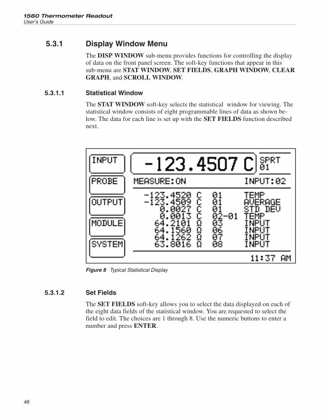
5.3.1 Display Window MenuThe DISP WINDOW sub-menu provides functions for controlling the displayof data on the front panel screen. The soft-key functions that appear in thissub-menu are STAT WINDOW, SET FIELDS, GRAPH WINDOW, CLEARGRAPH, and SCROLL WINDOW.
5.3.1.1 Statistical Window
The STAT WINDOW soft-key selects the statistical window for viewing. Thestatistical window consists of eight programmable lines of data as shown be-low. The data for each line is set up with the SET FIELDS function describednext.
5.3.1.2 Set Fields
The SET FIELDS soft-key allows you to select the data displayed on each ofthe eight data fields of the statistical window. You are requested to select thefield to edit. The choices are 1 through 8. Use the numeric buttons to enter anumber and press ENTER.
1560 Thermometer Readout
User’s Guide
46
Figure 8 Typical Statistical Display
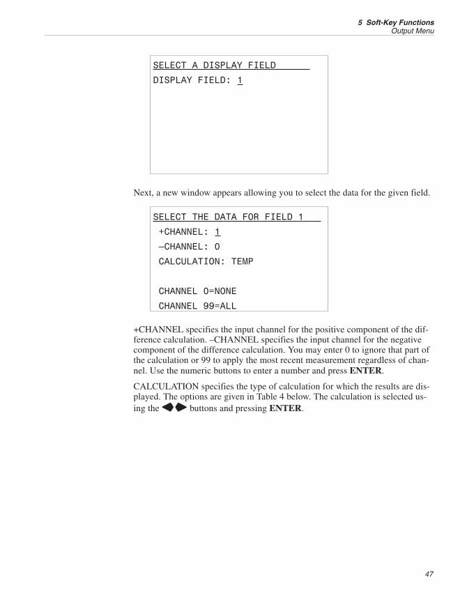
SELECT A DISPLAY FIELD
DISPLAY FIELD: 1
Next, a new window appears allowing you to select the data for the given field.
SELECT THE DATA FOR FIELD 1
+CHANNEL: 1
–CHANNEL: 0
CALCULATION: TEMP
CHANNEL 0=NONE
CHANNEL 99=ALL
+CHANNEL specifies the input channel for the positive component of the dif-ference calculation. –CHANNEL specifies the input channel for the negativecomponent of the difference calculation. You may enter 0 to ignore that part ofthe calculation or 99 to apply the most recent measurement regardless of chan-nel. Use the numeric buttons to enter a number and press ENTER.
CALCULATION specifies the type of calculation for which the results are dis-played. The options are given in Table 4 below. The calculation is selected us-ing the LR buttons and pressing ENTER.
47
5 Soft-Key FunctionsOutput Menu
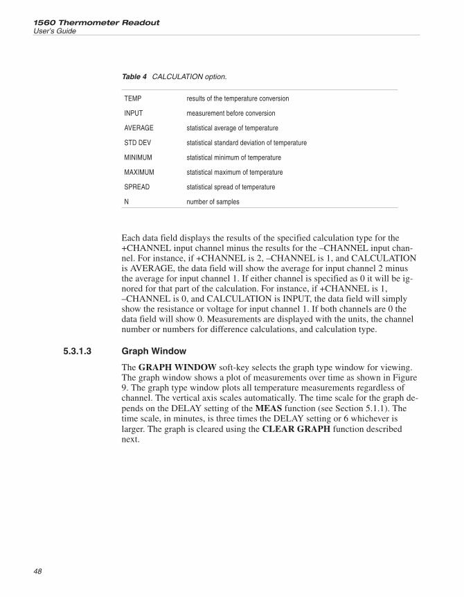
Each data field displays the results of the specified calculation type for the+CHANNEL input channel minus the results for the –CHANNEL input chan-nel. For instance, if +CHANNEL is 2, –CHANNEL is 1, and CALCULATIONis AVERAGE, the data field will show the average for input channel 2 minusthe average for input channel 1. If either channel is specified as 0 it will be ig-nored for that part of the calculation. For instance, if +CHANNEL is 1,–CHANNEL is 0, and CALCULATION is INPUT, the data field will simplyshow the resistance or voltage for input channel 1. If both channels are 0 thedata field will show 0. Measurements are displayed with the units, the channelnumber or numbers for difference calculations, and calculation type.
5.3.1.3 Graph Window
The GRAPH WINDOW soft-key selects the graph type window for viewing.The graph window shows a plot of measurements over time as shown in Figure9. The graph type window plots all temperature measurements regardless ofchannel. The vertical axis scales automatically. The time scale for the graph de-pends on the DELAY setting of the MEAS function (see Section 5.1.1). Thetime scale, in minutes, is three times the DELAY setting or 6 whichever islarger. The graph is cleared using the CLEAR GRAPH function describednext.
1560 Thermometer Readout
User’s Guide
48
TEMP results of the temperature conversion
INPUT measurement before conversion
AVERAGE statistical average of temperature
STD DEV statistical standard deviation of temperature
MINIMUM statistical minimum of temperature
MAXIMUM statistical maximum of temperature
SPREAD statistical spread of temperature
N number of samples
Table 4 CALCULATION option.
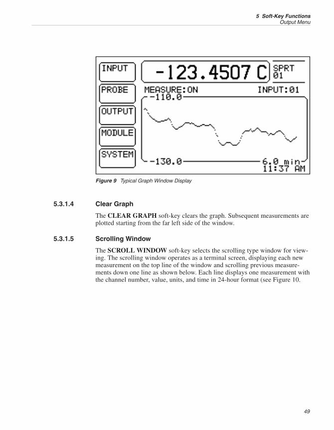
5.3.1.4 Clear Graph
The CLEAR GRAPH soft-key clears the graph. Subsequent measurements areplotted starting from the far left side of the window.
5.3.1.5 Scrolling Window
The SCROLL WINDOW soft-key selects the scrolling type window for view-ing. The scrolling window operates as a terminal screen, displaying each newmeasurement on the top line of the window and scrolling previous measure-ments down one line as shown below. Each line displays one measurement withthe channel number, value, units, and time in 24-hour format (see Figure 10.
49
5 Soft-Key FunctionsOutput Menu
Figure 9 Typical Graph Window Display
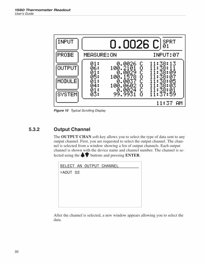
5.3.2 Output ChannelThe OUTPUT CHAN soft-key allows you to select the type of data sent to anyoutput channel. First, you are requested to select the output channel. The chan-nel is selected from a window showing a list of output channels. Each outputchannel is shown with the device name and channel number. The channel is se-lected using the UD buttons and pressing ENTER.
SELECT AN OUTPUT CHANNEL
>AOUT 02
After the channel is selected, a new window appears allowing you to select thedata.
1560 Thermometer Readout
User’s Guide
50
Figure 10 Typical Scrolling Display
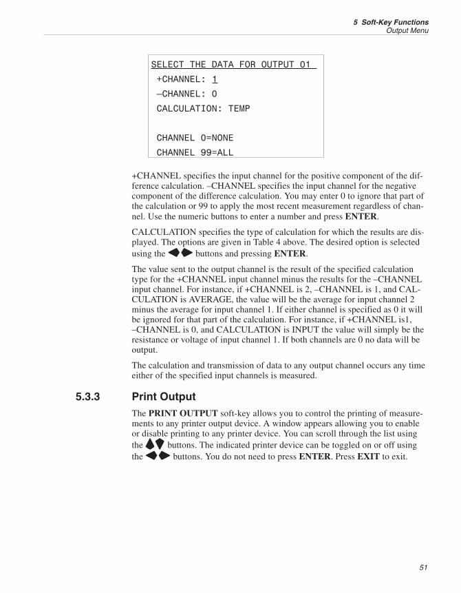
SELECT THE DATA FOR OUTPUT 01
+CHANNEL: 1
–CHANNEL: 0
CALCULATION: TEMP
CHANNEL 0=NONE
CHANNEL 99=ALL
+CHANNEL specifies the input channel for the positive component of the dif-ference calculation. –CHANNEL specifies the input channel for the negativecomponent of the difference calculation. You may enter 0 to ignore that part ofthe calculation or 99 to apply the most recent measurement regardless of chan-nel. Use the numeric buttons to enter a number and press ENTER.
CALCULATION specifies the type of calculation for which the results are dis-played. The options are given in Table 4 above. The desired option is selectedusing the LR buttons and pressing ENTER.
The value sent to the output channel is the result of the specified calculationtype for the +CHANNEL input channel minus the results for the –CHANNELinput channel. For instance, if +CHANNEL is 2, –CHANNEL is 1, and CAL-CULATION is AVERAGE, the value will be the average for input channel 2minus the average for input channel 1. If either channel is specified as 0 it willbe ignored for that part of the calculation. For instance, if +CHANNEL is1,–CHANNEL is 0, and CALCULATION is INPUT the value will simply be theresistance or voltage of input channel 1. If both channels are 0 no data will beoutput.
The calculation and transmission of data to any output channel occurs any timeeither of the specified input channels is measured.
5.3.3 Print OutputThe PRINT OUTPUT soft-key allows you to control the printing of measure-ments to any printer output device. A window appears allowing you to enableor disable printing to any printer device. You can scroll through the list usingthe UD buttons. The indicated printer device can be toggled on or off usingthe LR buttons. You do not need to press ENTER. Press EXIT to exit.
51
5 Soft-Key FunctionsOutput Menu
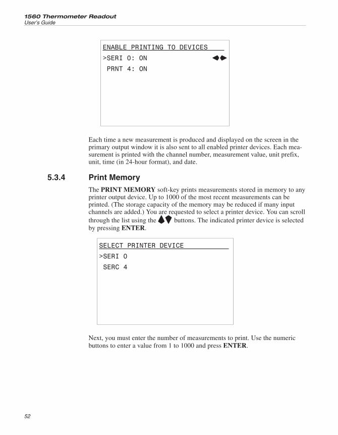
ENABLE PRINTING TO DEVICES
>SERI 0: ON LR
PRNT 4: ON
Each time a new measurement is produced and displayed on the screen in theprimary output window it is also sent to all enabled printer devices. Each mea-surement is printed with the channel number, measurement value, unit prefix,unit, time (in 24-hour format), and date.
5.3.4 Print MemoryThe PRINT MEMORY soft-key prints measurements stored in memory to anyprinter output device. Up to 1000 of the most recent measurements can beprinted. (The storage capacity of the memory may be reduced if many inputchannels are added.) You are requested to select a printer device. You can scrollthrough the list using the UD buttons. The indicated printer device is selectedby pressing ENTER.
SELECT PRINTER DEVICE
>SERI 0
SERC 4
Next, you must enter the number of measurements to print. Use the numericbuttons to enter a value from 1 to 1000 and press ENTER.
1560 Thermometer Readout
User’s Guide
52
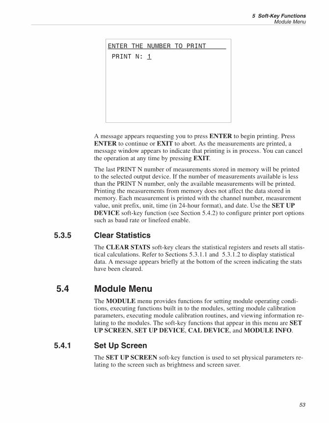
ENTER THE NUMBER TO PRINT
PRINT N: 1
A message appears requesting you to press ENTER to begin printing. PressENTER to continue or EXIT to abort. As the measurements are printed, amessage window appears to indicate that printing is in process. You can cancelthe operation at any time by pressing EXIT.
The last PRINT N number of measurements stored in memory will be printedto the selected output device. If the number of measurements available is lessthan the PRINT N number, only the available measurements will be printed.Printing the measurements from memory does not affect the data stored inmemory. Each measurement is printed with the channel number, measurementvalue, unit prefix, unit, time (in 24-hour format), and date. Use the SET UPDEVICE soft-key function (see Section 5.4.2) to configure printer port optionssuch as baud rate or linefeed enable.
5.3.5 Clear StatisticsThe CLEAR STATS soft-key clears the statistical registers and resets all statis-tical calculations. Refer to Sections 5.3.1.1 and 5.3.1.2 to display statisticaldata. A message appears briefly at the bottom of the screen indicating the statshave been cleared.
5.4 Module MenuThe MODULE menu provides functions for setting module operating condi-tions, executing functions built in to the modules, setting module calibrationparameters, executing module calibration routines, and viewing information re-lating to the modules. The soft-key functions that appear in this menu are SETUP SCREEN, SET UP DEVICE, CAL DEVICE, and MODULE INFO.
5.4.1 Set Up ScreenThe SET UP SCREEN soft-key function is used to set physical parameters re-lating to the screen such as brightness and screen saver.
53
5 Soft-Key FunctionsModule Menu
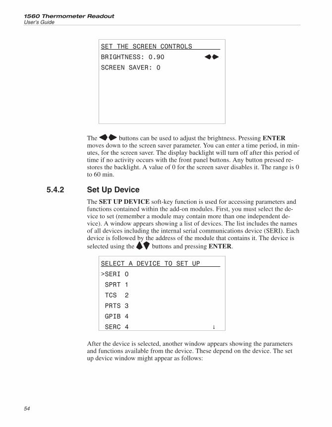
SET THE SCREEN CONTROLS
BRIGHTNESS: 0.90 LR
SCREEN SAVER: 0
The LR buttons can be used to adjust the brightness. Pressing ENTERmoves down to the screen saver parameter. You can enter a time period, in min-utes, for the screen saver. The display backlight will turn off after this period oftime if no activity occurs with the front panel buttons. Any button pressed re-stores the backlight. A value of 0 for the screen saver disables it. The range is 0to 60 min.
5.4.2 Set Up DeviceThe SET UP DEVICE soft-key function is used for accessing parameters andfunctions contained within the add-on modules. First, you must select the de-vice to set (remember a module may contain more than one independent de-vice). A window appears showing a list of devices. The list includes the namesof all devices including the internal serial communications device (SERI). Eachdevice is followed by the address of the module that contains it. The device isselected using the UD buttons and pressing ENTER.
SELECT A DEVICE TO SET UP
>SERI 0
SPRT 1
TCS 2
PRTS 3
GPIB 4
SERC 4 �
After the device is selected, another window appears showing the parametersand functions available from the device. These depend on the device. The setup device window might appear as follows:
1560 Thermometer Readout
User’s Guide
54
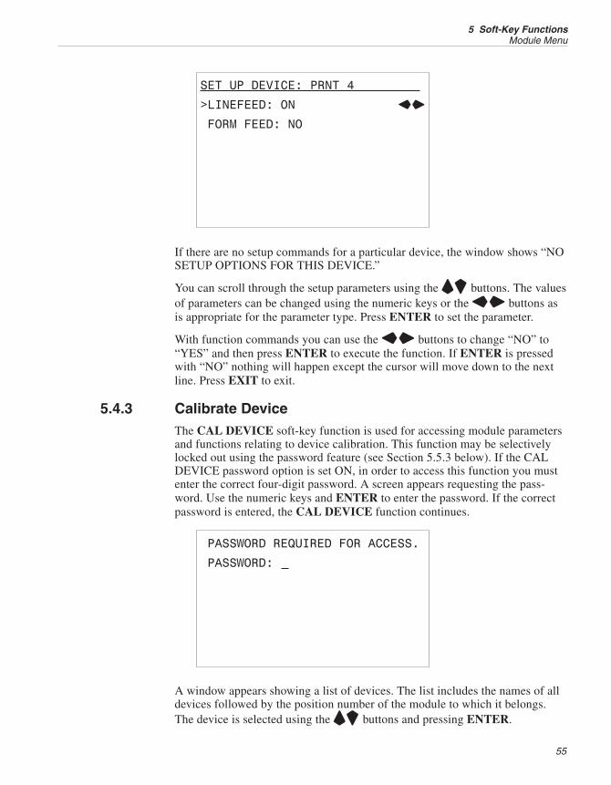
SET UP DEVICE: PRNT 4
>LINEFEED: ON LR
FORM FEED: NO
If there are no setup commands for a particular device, the window shows “NOSETUP OPTIONS FOR THIS DEVICE.”
You can scroll through the setup parameters using the UD buttons. The valuesof parameters can be changed using the numeric keys or the LR buttons asis appropriate for the parameter type. Press ENTER to set the parameter.
With function commands you can use the LR buttons to change “NO” to“YES” and then press ENTER to execute the function. If ENTER is pressedwith “NO” nothing will happen except the cursor will move down to the nextline. Press EXIT to exit.
5.4.3 Calibrate DeviceThe CAL DEVICE soft-key function is used for accessing module parametersand functions relating to device calibration. This function may be selectivelylocked out using the password feature (see Section 5.5.3 below). If the CALDEVICE password option is set ON, in order to access this function you mustenter the correct four-digit password. A screen appears requesting the pass-word. Use the numeric keys and ENTER to enter the password. If the correctpassword is entered, the CAL DEVICE function continues.
PASSWORD REQUIRED FOR ACCESS.
PASSWORD:
A window appears showing a list of devices. The list includes the names of alldevices followed by the position number of the module to which it belongs.The device is selected using the UD buttons and pressing ENTER.
55
5 Soft-Key FunctionsModule Menu
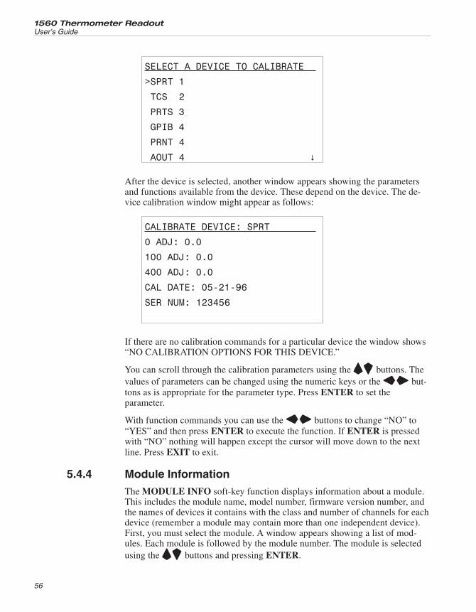
SELECT A DEVICE TO CALIBRATE
>SPRT 1
TCS 2
PRTS 3
GPIB 4
PRNT 4
AOUT 4 �
After the device is selected, another window appears showing the parametersand functions available from the device. These depend on the device. The de-vice calibration window might appear as follows:
CALIBRATE DEVICE: SPRT
0 ADJ: 0.0
100 ADJ: 0.0
400 ADJ: 0.0
CAL DATE: 05-21-96
SER NUM: 123456
If there are no calibration commands for a particular device the window shows“NO CALIBRATION OPTIONS FOR THIS DEVICE.”
You can scroll through the calibration parameters using the UD buttons. Thevalues of parameters can be changed using the numeric keys or the LR but-tons as is appropriate for the parameter type. Press ENTER to set theparameter.
With function commands you can use the LR buttons to change “NO” to“YES” and then press ENTER to execute the function. If ENTER is pressedwith “NO” nothing will happen except the cursor will move down to the nextline. Press EXIT to exit.
5.4.4 Module InformationThe MODULE INFO soft-key function displays information about a module.This includes the module name, model number, firmware version number, andthe names of devices it contains with the class and number of channels for eachdevice (remember a module may contain more than one independent device).First, you must select the module. A window appears showing a list of mod-ules. Each module is followed by the module number. The module is selectedusing the UD buttons and pressing ENTER.
1560 Thermometer Readout
User’s Guide
56
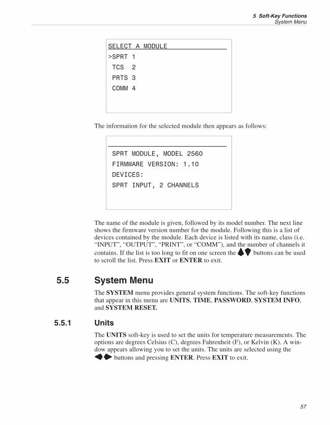
SELECT A MODULE
>SPRT 1
TCS 2
PRTS 3
COMM 4
The information for the selected module then appears as follows:
SPRT MODULE, MODEL 2560
FIRMWARE VERSION: 1.10
DEVICES:
SPRT INPUT, 2 CHANNELS
The name of the module is given, followed by its model number. The next lineshows the firmware version number for the module. Following this is a list ofdevices contained by the module. Each device is listed with its name, class (i.e.“INPUT”, “OUTPUT”, “PRINT”, or “COMM”), and the number of channels itcontains. If the list is too long to fit on one screen the UD buttons can be usedto scroll the list. Press EXIT or ENTER to exit.
5.5 System MenuThe SYSTEM menu provides general system functions. The soft-key functionsthat appear in this menu are UNITS, TIME, PASSWORD, SYSTEM INFO,and SYSTEM RESET.
5.5.1 UnitsThe UNITS soft-key is used to set the units for temperature measurements. Theoptions are degrees Celsius (C), degrees Fahrenheit (F), or Kelvin (K). A win-dow appears allowing you to set the units. The units are selected using theLR buttons and pressing ENTER. Press EXIT to exit.
57
5 Soft-Key FunctionsSystem Menu
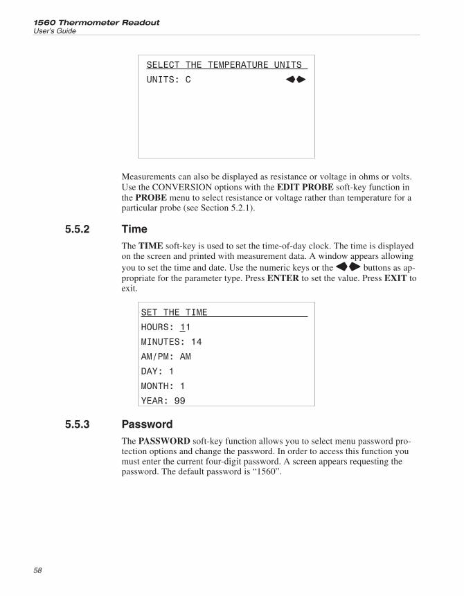
SELECT THE TEMPERATURE UNITS
UNITS: C LR
Measurements can also be displayed as resistance or voltage in ohms or volts.Use the CONVERSION options with the EDIT PROBE soft-key function inthe PROBE menu to select resistance or voltage rather than temperature for aparticular probe (see Section 5.2.1).
5.5.2 TimeThe TIME soft-key is used to set the time-of-day clock. The time is displayedon the screen and printed with measurement data. A window appears allowingyou to set the time and date. Use the numeric keys or the LR buttons as ap-propriate for the parameter type. Press ENTER to set the value. Press EXIT toexit.
SET THE TIME
HOURS: 11
MINUTES: 14
AM/PM: AM
DAY: 1
MONTH: 1
YEAR: 99
5.5.3 PasswordThe PASSWORD soft-key function allows you to select menu password pro-tection options and change the password. In order to access this function youmust enter the current four-digit password. A screen appears requesting thepassword. The default password is “1560”.
1560 Thermometer Readout
User’s Guide
58
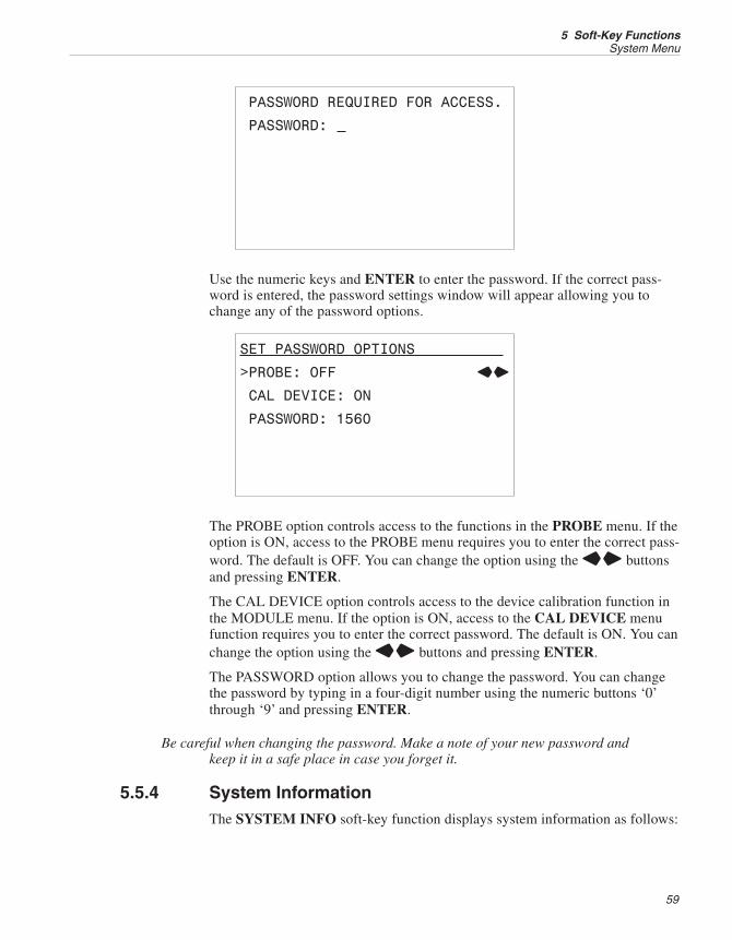
PASSWORD REQUIRED FOR ACCESS.
PASSWORD:
Use the numeric keys and ENTER to enter the password. If the correct pass-word is entered, the password settings window will appear allowing you tochange any of the password options.
SET PASSWORD OPTIONS
>PROBE: OFF LR
CAL DEVICE: ON
PASSWORD: 1560
The PROBE option controls access to the functions in the PROBE menu. If theoption is ON, access to the PROBE menu requires you to enter the correct pass-word. The default is OFF. You can change the option using the LR buttonsand pressing ENTER.
The CAL DEVICE option controls access to the device calibration function inthe MODULE menu. If the option is ON, access to the CAL DEVICE menufunction requires you to enter the correct password. The default is ON. You canchange the option using the LR buttons and pressing ENTER.
The PASSWORD option allows you to change the password. You can changethe password by typing in a four-digit number using the numeric buttons ‘0’through ‘9’ and pressing ENTER.
Be careful when changing the password. Make a note of your new password andkeep it in a safe place in case you forget it.
5.5.4 System InformationThe SYSTEM INFO soft-key function displays system information as follows:
59
5 Soft-Key FunctionsSystem Menu
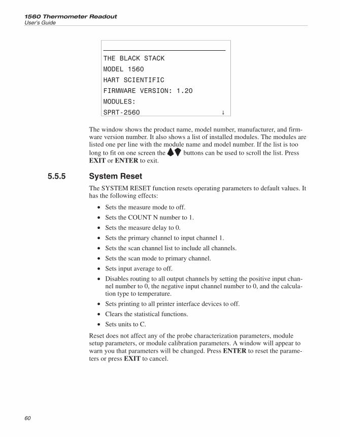
THE
MODEL 1560
HART SCIENTIFIC
FIRMWARE VERSION: 1.20
MODULES:
SPRT-2560 �
The window shows the product name, model number, manufacturer, and firm-ware version number. It also shows a list of installed modules. The modules arelisted one per line with the module name and model number. If the list is toolong to fit on one screen the UD buttons can be used to scroll the list. PressEXIT or ENTER to exit.
5.5.5 System ResetThe SYSTEM RESET function resets operating parameters to default values. Ithas the following effects:
• Sets the measure mode to off.
• Sets the COUNT N number to 1.
• Sets the measure delay to 0.
• Sets the primary channel to input channel 1.
• Sets the scan channel list to include all channels.
• Sets the scan mode to primary channel.
• Sets input average to off.
• Disables routing to all output channels by setting the positive input chan-nel number to 0, the negative input channel number to 0, and the calcula-tion type to temperature.
• Sets printing to all printer interface devices to off.
• Clears the statistical functions.
• Sets units to C.
Reset does not affect any of the probe characterization parameters, modulesetup parameters, or module calibration parameters. A window will appear towarn you that parameters will be changed. Press ENTER to reset the parame-ters or press EXIT to cancel.
1560 Thermometer Readout
User’s Guide
60

RESET SYSTEM PARAMETERS
PRESS ENTER TO CONTINUE
PRESS EXIT TO CANCEL
61
5 Soft-Key FunctionsSystem Menu
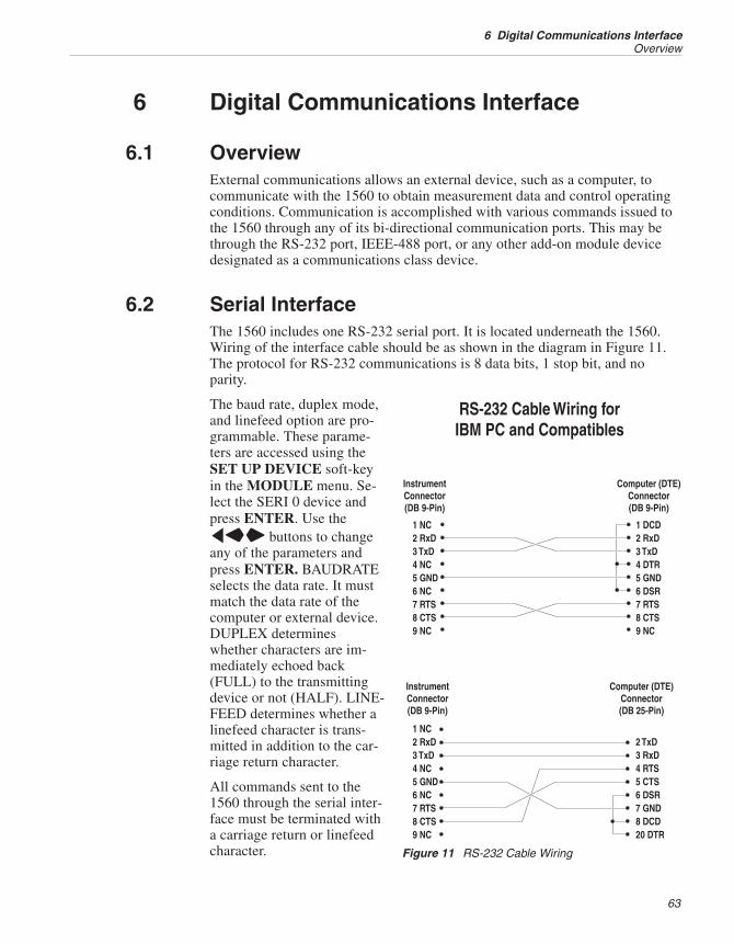
6 Digital Communications Interface
6.1 OverviewExternal communications allows an external device, such as a computer, tocommunicate with the 1560 to obtain measurement data and control operatingconditions. Communication is accomplished with various commands issued tothe 1560 through any of its bi-directional communication ports. This may bethrough the RS-232 port, IEEE-488 port, or any other add-on module devicedesignated as a communications class device.
6.2 Serial InterfaceThe 1560 includes one RS-232 serial port. It is located underneath the 1560.Wiring of the interface cable should be as shown in the diagram in Figure 11.The protocol for RS-232 communications is 8 data bits, 1 stop bit, and noparity.
The baud rate, duplex mode,and linefeed option are pro-grammable. These parame-ters are accessed using theSET UP DEVICE soft-keyin the MODULE menu. Se-lect the SERI 0 device andpress ENTER. Use thelLR buttons to changeany of the parameters andpress ENTER. BAUDRATEselects the data rate. It mustmatch the data rate of thecomputer or external device.DUPLEX determineswhether characters are im-mediately echoed back(FULL) to the transmittingdevice or not (HALF). LINE-FEED determines whether alinefeed character is trans-mitted in addition to the car-riage return character.
All commands sent to the1560 through the serial inter-face must be terminated witha carriage return or linefeedcharacter.
63
6 Digital Communications InterfaceOverview
Figure 11 RS-232 Cable Wiring
6.3 Command SyntaxThe 1560 accepts commands that set parameters, execute functions or respondwith requested data. These commands are in the form of strings of ASCII-en-coded characters. As far as possible, the 1560 conforms to IEEE-488.2, 1992and SCPI-1994. One notable exception is that compound commands are not al-lowed as explained below.
Commands consist of a command header and, if necessary, parameter data. Allcommands must be terminated with either a carriage return (ASCII 0D hex or13 decimal) or newline character (ASCII 0A hex or 10 decimal).
Command headers consist of one or more mnemonics separated by colons (:).Mnemonics may use letter characters, the underscore character (_), and possi-bly numeric digits as well. There is no distinguishing between upper and lowercase letters. Mnemonics often have alternate forms. Most mnemonics have along form that is more readable and a short form consisting of three or fourcharacters that is more efficient.
A mnemonic may end with a numeric suffix that specifies one of a set of inde-pendent function blocks such as input channel data paths. If a numeric suffix isomitted when a particular block must be specified, a suffix of one is assumed.
Query commands are commands that request data in response. Query com-mands have a question mark (?) immediately following the command header.Responses to query commands are generated immediately and placed in theoutput buffer. Responses will be lost if not read before the next command is re-ceived. The input and output buffers can each hold up to 100 characters.
Some commands require parameter data to specify values for one or more pa-rameters. Parameter data follows the command header with a space (ASCII 20hex or 32 decimal) between. Multiple parameters are separated by a comma (,).
Parameter data are of one of several types. Numeric data uses ASCII charactersto represent numbers. Numbers may contain a sign (‘+’ or ‘-’), decimal point(‘.’), and exponent (‘E’ or ‘e’) with its sign. If a fractional component is re-ceived when only an integer is required, the number is rounded to the nearestinteger without any resulting error message. Some commands may accept acharacter mnemonic as a number. The mnemonics DEF, MIN, and MAX areoften acceptable for the default, minimum, and maximum value respectively.Unit suffixes, such as V or OHM, can be appended to numeric parameters andare accepted without error but ignored.
Boolean parameters have the values of 0 or 1. The mnemonics OFF and ON arealso accepted for 0 and 1 respectively.
Character data are mnemonics that represents one of several possible values.For instance, temperature units may be specified with CEL for Celsius or FARfor Fahrenheit.
String data consist of characters enclosed in double quotes. A null string con-sists of double quotes with no characters enclosed.
1560 Thermometer Readout
User’s Guide
64
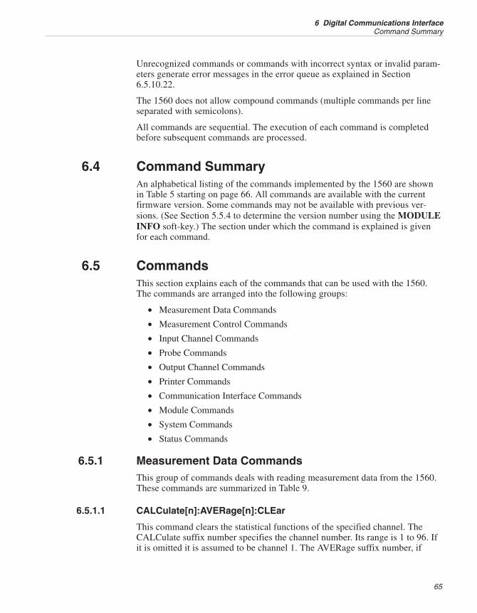
Unrecognized commands or commands with incorrect syntax or invalid param-eters generate error messages in the error queue as explained in Section6.5.10.22.
The 1560 does not allow compound commands (multiple commands per lineseparated with semicolons).
All commands are sequential. The execution of each command is completedbefore subsequent commands are processed.
6.4 Command SummaryAn alphabetical listing of the commands implemented by the 1560 are shownin Table 5 starting on page 66. All commands are available with the currentfirmware version. Some commands may not be available with previous ver-sions. (See Section 5.5.4 to determine the version number using the MODULEINFO soft-key.) The section under which the command is explained is givenfor each command.
6.5 CommandsThis section explains each of the commands that can be used with the 1560.The commands are arranged into the following groups:
• Measurement Data Commands
• Measurement Control Commands
• Input Channel Commands
• Probe Commands
• Output Channel Commands
• Printer Commands
• Communication Interface Commands
• Module Commands
• System Commands
• Status Commands
6.5.1 Measurement Data CommandsThis group of commands deals with reading measurement data from the 1560.These commands are summarized in Table 9.
6.5.1.1 CALCulate[n]:AVERage[n]:CLEar
This command clears the statistical functions of the specified channel. TheCALCulate suffix number specifies the channel number. Its range is 1 to 96. Ifit is omitted it is assumed to be channel 1. The AVERage suffix number, if
65
6 Digital Communications InterfaceCommand Summary
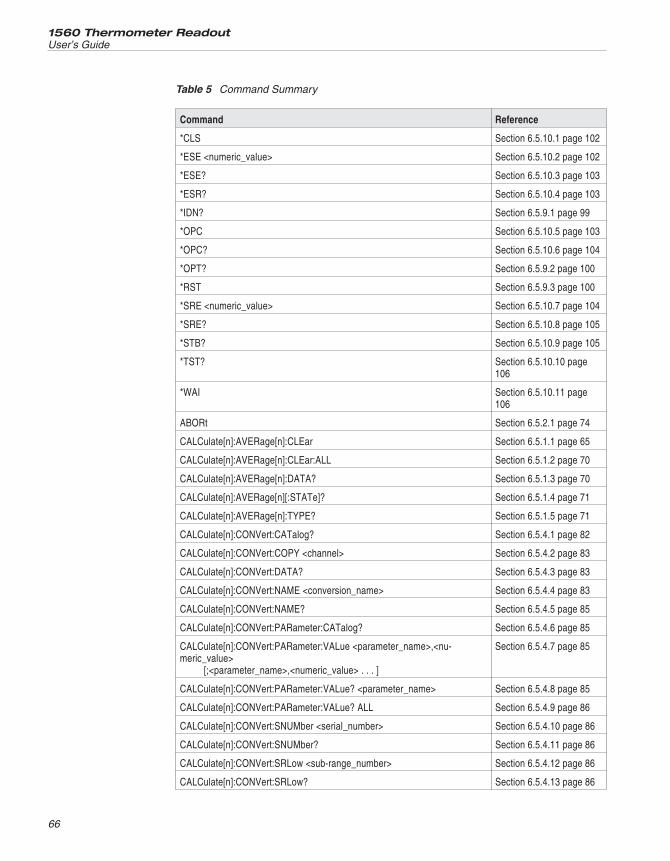
1560 Thermometer Readout
User’s Guide
66
Command Reference
*CLS Section 6.5.10.1 page 102
*ESE <numeric_value> Section 6.5.10.2 page 102
*ESE? Section 6.5.10.3 page 103
*ESR? Section 6.5.10.4 page 103
*IDN? Section 6.5.9.1 page 99
*OPC Section 6.5.10.5 page 103
*OPC? Section 6.5.10.6 page 104
*OPT? Section 6.5.9.2 page 100
*RST Section 6.5.9.3 page 100
*SRE <numeric_value> Section 6.5.10.7 page 104
*SRE? Section 6.5.10.8 page 105
*STB? Section 6.5.10.9 page 105
*TST? Section 6.5.10.10 page106
*WAI Section 6.5.10.11 page106
ABORt Section 6.5.2.1 page 74
CALCulate[n]:AVERage[n]:CLEar Section 6.5.1.1 page 65
CALCulate[n]:AVERage[n]:CLEar:ALL Section 6.5.1.2 page 70
CALCulate[n]:AVERage[n]:DATA? Section 6.5.1.3 page 70
CALCulate[n]:AVERage[n][:STATe]? Section 6.5.1.4 page 71
CALCulate[n]:AVERage[n]:TYPE? Section 6.5.1.5 page 71
CALCulate[n]:CONVert:CATalog? Section 6.5.4.1 page 82
CALCulate[n]:CONVert:COPY <channel> Section 6.5.4.2 page 83
CALCulate[n]:CONVert:DATA? Section 6.5.4.3 page 83
CALCulate[n]:CONVert:NAME <conversion_name> Section 6.5.4.4 page 83
CALCulate[n]:CONVert:NAME? Section 6.5.4.5 page 85
CALCulate[n]:CONVert:PARameter:CATalog? Section 6.5.4.6 page 85
CALCulate[n]:CONVert:PARameter:VALue <parameter_name>,<nu-meric_value>
[;<parameter_name>,<numeric_value> . . . ]
Section 6.5.4.7 page 85
CALCulate[n]:CONVert:PARameter:VALue? <parameter_name> Section 6.5.4.8 page 85
CALCulate[n]:CONVert:PARameter:VALue? ALL Section 6.5.4.9 page 86
CALCulate[n]:CONVert:SNUMber <serial_number> Section 6.5.4.10 page 86
CALCulate[n]:CONVert:SNUMber? Section 6.5.4.11 page 86
CALCulate[n]:CONVert:SRLow <sub-range_number> Section 6.5.4.12 page 86
CALCulate[n]:CONVert:SRLow? Section 6.5.4.13 page 86
Table 5 Command Summary
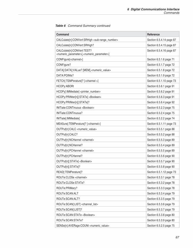
67
6 Digital Communications InterfaceCommands
Command Reference
CALCulate[n]:CONVert:SRHigh <sub-range_number> Section 6.5.4.14 page 87
CALCulate[n]:CONVert:SRHigh? Section 6.5.4.15 page 87
CALCulate[n]:CONVert:TEST?<numeric_parameter>[,<numeric_parameter>]
Section 6.5.4.16 page 87
CONFigure[<channel>] Section 6.5.1.6 page 71
CONFigure? Section 6.5.1.7 page 72
DATA[:DATA]:VALue? [MEM],<numeric_value> Section 6.5.1.8 page 72
DATA:POINts? Section 6.5.1.9 page 72
FETCh[:TEMPerature]? [<channel >] Section 6.5.1.10 page 73
HCOPy:ABORt Section 6.5.6.1 page 91
HCOPy[:IMMediate] <printer_number> Section 6.5.6.2 page 91
HCOPy:PRINter[n][:STATe] <Boolean> Section 6.5.6.3 page 91
HCOPy:PRINter[n][:STATe]? Section 6.5.6.4 page 92
INITiate:CONTinuous <Boolean> Section 6.5.2.3 page 75
INITiate:CONTinuous? Section 6.5.2.4 page 75
INITiate[:IMMediate] Section 6.5.2.2 page 74
MEASure[:TEMPerature]? [<channel>] Section 6.5.1.11 page 73
OUTPut[n]:CALC <numeric_value> Section 6.5.5.1 page 88
OUTPut[n]:CALC? Section 6.5.5.2 page 88
OUTPut[n]:NCHannel <channel> Section 6.5.5.3 page 89
OUTPut[n]:NCHannel? Section 6.5.5.4 page 89
OUTPut[n]:PCHannel <channel> Section 6.5.5.5 page 89
OUTPut[n]:PCHannel? Section 6.5.5.6 page 90
OUTPut[n][:STATe] <Boolean> Section 6.5.5.7 page 90
OUTPut[n][:STATe]? Section 6.5.5.8 page 90
READ[:TEMPerature]? Section 6.5.1.12 page 73
ROUTe:CLOSe <channel> Section 6.5.3.1 page 78
ROUTe:CLOSe:STATe? Section 6.5.3.2 page 78
ROUTe:PRIMary? Section 6.5.3.3 page 78
ROUTe:SCAN:ALT Section 6.5.3.4 page 79
ROUTe:SCAN:ALT? Section 6.5.3.5 page 79
ROUTe:SCAN[:LIST] <channel_list> Section 6.5.3.6 page 79
ROUTe:SCAN[:LIST]? Section 6.5.3.7 page 79
ROUTe:SCAN:STATe <Boolean> Section 6.5.3.8 page 80
ROUTe:SCAN:STATe? Section 6.5.3.9 page 80
SENSe[n]:AVERage:COUNt <numeric_value> Section 6.5.2.5 page 75
Table 6 Command Summary continued
1560 Thermometer Readout
User’s Guide
68
Command Reference
SENSe[n]:AVERage:COUNt? Section 6.5.2.6 page 76
SENSe[n]:AVERage:DATA? Section 6.5.1.13 page 74
SENSe[n]:AVERage[:STATe] <Boolean> Section 6.5.2.7 page 76
SENSe[n]:AVERage[:STATe]? Section 6.5.2.8 page 76
STATus:OPERation:CONDition? Section 6.5.10.12 page106
STATus:OPERation:ENABle <numeric_value> Section 6.5.10.13 page106
STATus:OPERation:ENABle? Section 6.5.10.14 page107
STATus:OPERation[:EVENt]? Section 6.5.10.15 page107
STATus:PRESet Section 6.5.10.16 page107
STATus:QUEStionable:CONDition? Section 6.5.10.17 page107
STATus:QUEStionable:ENABle <numeric_value> Section 6.5.10.18 page108
STATus:QUEStionable:ENABle? Section 6.5.10.19 page108
STATus:QUEStionable[:EVENt]? Section 6.5.10.20 page108
STATus:QUEue[:NEXT]? Section 6.5.10.21 page108
SYSTem:COMMunicate:SERial[:RECeive]:BAUD <numeric_value> Section 6.5.7.1 page 92
SYSTem:COMMunicate:SERial[:RECeive]:BAUD? Section 6.5.7.2 page 92
SYSTem:COMMunicate:SERial[:RECeive]:FDUPlex <Boolean> Section 6.5.7.3 page 92
SYSTem:COMMunicate:SERial[:RECeive]:FDUPlex? Section 6.5.7.4 page 93
SYSTem:COMMunicate:SERial[:RECeive]:LINefeed <Boolean> Section 6.5.7.5 page 93
SYSTem:COMMunicate:SERial[:RECeive]:LINefeed? Section 6.5.7.6 page 93
SYSTem:CONFigure:CDEVice? Section 6.5.8.1 page 94
SYSTem:CONFigure:COMMunicate[n]:DADDress? Section 6.5.8.2 page 94
SYSTem:CONFigure:COMMunicate[n]:MADDress? Section 6.5.8.3 page 95
SYSTem:CONFigure:ICHannel? Section 6.5.8.4 page 95
SYSTem:CONFigure:IDEVice? Section 6.5.8.5 page 95
SYSTem:CONFigure:INPut[n]:DADDress? Section 6.5.8.6 page 95
SYSTem:CONFigure:INPut[n]:MADDress? Section 6.5.8.7 page 95
SYSTem:CONFigure:MNUMber? Section 6.5.8.8 page 96
SYSTem:CONFigure:MODule[n]:DEVice[n]:INFormation? Section 6.5.8.9 page 96
Table 7 Command Summary continued
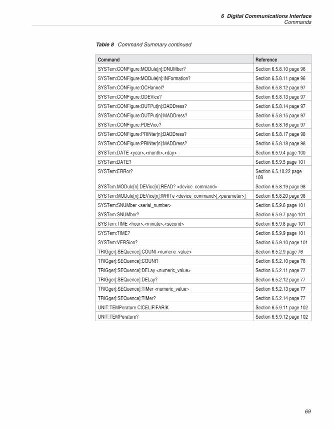
69
6 Digital Communications InterfaceCommands
Command Reference
SYSTem:CONFigure:MODule[n]:DNUMber? Section 6.5.8.10 page 96
SYSTem:CONFigure:MODule[n]:INFormation? Section 6.5.8.11 page 96
SYSTem:CONFigure:OCHannel? Section 6.5.8.12 page 97
SYSTem:CONFigure:ODEVice? Section 6.5.8.13 page 97
SYSTem:CONFigure:OUTPut[n]:DADDress? Section 6.5.8.14 page 97
SYSTem:CONFigure:OUTPut[n]:MADDress? Section 6.5.8.15 page 97
SYSTem:CONFigure:PDEVice? Section 6.5.8.16 page 97
SYSTem:CONFigure:PRINter[n]:DADDress? Section 6.5.8.17 page 98
SYSTem:CONFigure:PRINter[n]:MADDress? Section 6.5.8.18 page 98
SYSTem:DATE <year>,<month>,<day> Section 6.5.9.4 page 100
SYSTem:DATE? Section 6.5.9.5 page 101
SYSTem:ERRor? Section 6.5.10.22 page108
SYSTem:MODule[n]:DEVice[n]:READ? <device_command> Section 6.5.8.19 page 98
SYSTem:MODule[n]:DEVice[n]:WRITe <device_command>[,<parameter>] Section 6.5.8.20 page 98
SYSTem:SNUMber <serial_number> Section 6.5.9.6 page 101
SYSTem:SNUMber? Section 6.5.9.7 page 101
SYSTem:TIME <hour>,<minute>,<second> Section 6.5.9.8 page 101
SYSTem:TIME? Section 6.5.9.9 page 101
SYSTem:VERSion? Section 6.5.9.10 page 101
TRIGger[:SEQuence]:COUNt <numeric_value> Section 6.5.2.9 page 76
TRIGger[:SEQuence]:COUNt? Section 6.5.2.10 page 76
TRIGger[:SEQuence]:DELay <numeric_value> Section 6.5.2.11 page 77
TRIGger[:SEQuence]:DELay? Section 6.5.2.12 page 77
TRIGger[:SEQuence]:TIMer <numeric_value> Section 6.5.2.13 page 77
TRIGger[:SEQuence]:TIMer? Section 6.5.2.14 page 77
UNIT:TEMPerature C|CEL|F|FAR|K Section 6.5.9.11 page 102
UNIT:TEMPerature? Section 6.5.9.12 page 102
Table 8 Command Summary continued
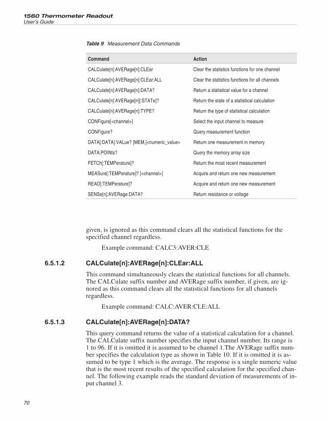
given, is ignored as this command clears all the statistical functions for thespecified channel regardless.
Example command: CALC3:AVER:CLE
6.5.1.2 CALCulate[n]:AVERage[n]:CLEar:ALL
This command simultaneously clears the statistical functions for all channels.The CALCulate suffix number and AVERage suffix number, if given, are ig-nored as this command clears all the statistical functions for all channelsregardless.
Example command: CALC:AVER:CLE:ALL
6.5.1.3 CALCulate[n]:AVERage[n]:DATA?
This query command returns the value of a statistical calculation for a channel.The CALCulate suffix number specifies the input channel number. Its range is1 to 96. If it is omitted it is assumed to be channel 1.The AVERage suffix num-ber specifies the calculation type as shown in Table 10. If it is omitted it is as-sumed to be type 1 which is the average. The response is a single numeric valuethat is the most recent results of the specified calculation for the specified chan-nel. The following example reads the standard deviation of measurements of in-put channel 3.
1560 Thermometer Readout
User’s Guide
70
Command Action
CALCulate[n]:AVERage[n]:CLEar Clear the statistics functions for one channel
CALCulate[n]:AVERage[n]:CLEar:ALL Clear the statistics functions for all channels
CALCulate[n]:AVERage[n]:DATA? Return a statistical value for a channel
CALCulate[n]:AVERage[n][:STATe]? Return the state of a statistical calculation
CALCulate[n]:AVERage[n]:TYPE? Return the type of statistical calculation
CONFigure[<channel>] Select the input channel to measure
CONFigure? Query measurement function
DATA[:DATA]:VALue? [MEM,]<numeric_value> Return one measurement in memory
DATA:POINts? Query the memory array size
FETCh[:TEMPerature]? Return the most recent measurement
MEASure[:TEMPerature]? [<channel>] Acquire and return one new measurement
READ[:TEMPerature]? Acquire and return one new measurement
SENSe[n]:AVERage:DATA? Return resistance or voltage
Table 9 Measurement Data Commands
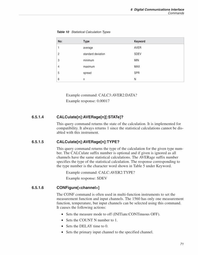
Example command: CALC3:AVER2:DATA?
Example response: 0.00017
6.5.1.4 CALCulate[n]:AVERage[n][:STATe]?
This query command returns the state of the calculation. It is implemented forcompatibility. It always returns 1 since the statistical calculations cannot be dis-abled with this instrument.
6.5.1.5 CALCulate[n]:AVERage[n]:TYPE?
This query command returns the type of the calculation for the given type num-ber. The CALCulate suffix number is optional and if given is ignored as allchannels have the same statistical calculations. The AVERage suffix numberspecifies the type of the statistical calculation. The response corresponding tothe type number is the character word shown in Table 5 under Keyword.
Example command: CALC:AVER2:TYPE?
Example response: SDEV
6.5.1.6 CONFigure[<channel>]
The CONF command is often used in multi-function instruments to set themeasurement function and input channels. The 1560 has only one measurementfunction, temperature, but input channels can be selected using this command.It causes the following actions:
• Sets the measure mode to off (INITiate:CONTinuous OFF).
• Sets the COUNT N number to 1.
• Sets the DELAY time to 0.
• Sets the primary input channel to the specified channel.
71
6 Digital Communications InterfaceCommands
No: Type Keyword
1 average AVER
2 standard deviation SDEV
3 minimum MIN
4 maximum MAX
5 spread SPR
6 n N
Table 10 Statistical Calculation Types
• Sets the scan mode to primary channel.
If an input channel is specified, the primary channel is set to that channel andthe scan mode is set to measure the primary channel only. If multiple channelsare specified the first channel in the list is accepted as the primary channel andthe others are ignored.
The <channel> parameter is enclosed in parentheses with the symbol @ follow-ing the opening parenthesis. For example, (@5) would be used to select inputchannel 5.
Example command: CONF (@3)
6.5.1.7 CONFigure?
This query command returns the measurement type and input channel numbers.“TEMP” is returned for the measurement type showing that the measurementfunction of the 1560 is temperature. A list of selected channels follows. The re-sponse is in the following format:
“TEMP <channel_list>“
The channel list is preceded with @ and enclosed in parentheses. Channel num-bers are separated by commas. The returned channel list depends on the scanmode. If scanning is off, the primary channel number will be returned. If scan-ning is on the list of selected channels for scanning will be returned.
Example command: CONF?
Example response: “TEMP (@3)”
6.5.1.8 DATA[:DATA]:VALue? [MEM,]<numeric_value>
This command returns one measurement stored in memory at the specified lo-cation given by <numeric_value>. The range of <numeric_value> is 1 to 1000.(The actual storage capacity of memory may be less than 1000 depending onthe number of input channels added.) Specifying the data array name, MEM, isoptional. The measurement is returned with the following format:
<channel number>,<measurement value>,<units>,<year>,<month>,<day>, <hours>,<minutes>,<seconds>
Example command: DATA:VAL? 10
Example response: 3,0.0115,C,1996,3,12,11,43,22
6.5.1.9 DATA:POINts? [MEM]
This query command returns the number of data points stored in memory.Specifying the data array name, MEM, is optional.
Example command: DATA:POIN?
Example response: 115
1560 Thermometer Readout
User’s Guide
72
6.5.1.10 FETCh[:TEMPerature]? [<channel>]
This query command returns the most recent measurement. If an input channelis specified the response is the most recent measurement for that channel. The<channel> number is preceded by @ and enclosed in parentheses. For example,(@5) would be used to select input channel 5. If multiple channels are speci-fied, only the first channel in the list is accepted and the others are ignored. Ifno channel is specified this command returns the most recent measurement re-gardless of channel. Other parameters are accepted with this command forcompatibility but are ignored. The FETC? command does not affect the mea-surement action as does the MEAS? and READ? commands explained below.
Example command: FETC? (@3)
Example response: 0.0127
6.5.1.11 MEASure[:TEMPerature]? [<channel>]
This command allows you to select channels, acquire a new measurement, andreceive the measurement data using just one command. It causes the followingactions:
• Sets the measure mode to off (INITiate:CONTinuous OFF).
• Sets the COUNT N number to 1.
• Sets the DELAY time to 0.
• Sets the primary channel to the specified channel.
• Sets the scan mode to primary channel.
• Acquires one measurement (INITiate:IMMediate), waiting until complete.
• Returns the value of the measurement.
If the channel number is omitted the current primary channel will be used. The<channel> number is preceded by @ and enclosed in parentheses. For example,(@5) would be used to select input channel 5.
Example command: MEAS? (@3)
Example response: 0.0127
6.5.1.12 READ[:TEMPerature]?
This command begins a new measurement and responds with the measurementvalue when finished. For this instrument, it is equivalent to the MEAS? com-mand without a specified channel. It causes the following actions:
• Sets the measure mode to off (INITiate:CONTinuous OFF).
• Sets the COUNT N number to 1.
• Sets the DELAY time to 0.
• Sets the scan mode to primary channel.
73
6 Digital Communications InterfaceCommands
• Acquires one measurement from the primary channel, waiting until com-plete.
• Returns the value of the measurement.
Example command: READ?
Example response: 0.0113
6.5.1.13 SENSe[n]:AVERage:DATA?
This query command returns a measurement value from the input averageblock of a given input channel. The measurement is returned as a resistance orvoltage rather than a converted temperature. The measurement value is an aver-age of a number of previous measurements where the average number dependson the setting of the input average function (see Section 5.1.5). The input chan-nel number is specified with the SENS suffix. If the channel number is omittedinput channel 1 is assumed.
Example command: SENS3:AVER:DATA?
Example response: 100.0291
6.5.2 Measurement Control CommandsThis group of commands deals with timing and action of the measurement pro-cess. These commands are summarized in Table 11 on page 75.
6.5.2.1 ABORt
This command cancels the measurement or sequence of measurements in pro-cess. If the measurement mode is continuous a new measurement willimmediatly be initiated. If the measurement mode is COUNT measuring willstop and the measurement mode will change to OFF.
Example command: ABOR
6.5.2.2 INITiate[:IMMediate]
This command starts one measurement or a series of measurements if theCOUNT number is greater than 1. It is equivalent to selecting COUNT for theMEASURE mode with the MEAS soft-key function in the INPUT menu. Themeasurement status indication on the display is updated to reflect any changescaused by the command. This command also sets the state of the INIT:CONTfunction described below to OFF. If measuring is already in process when thiscommand is received no operation will occur and an “Init ignored” error (-213)will be reported.
Example command: INIT
1560 Thermometer Readout
User’s Guide
74
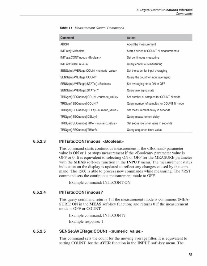
6.5.2.3 INITiate:CONTinuous <Boolean>
This command starts continuous measurement if the <Boolean> parametervalue is ON or 1 or stops measurement if the <Boolean> parameter value isOFF or 0. It is equivalent to selecting ON or OFF for the MEASURE parameterwith the MEAS soft-key function in the INPUT menu. The measurement statusindication on the display is updated to reflect any changes caused by the com-mand. The 1560 is able to process new commands while measuring. The *RSTcommand sets the continuous measurement mode to OFF.
Example command: INIT:CONT ON
6.5.2.4 INITiate:CONTinuous?
This query command returns 1 if the measurement mode is continuous (MEA-SURE: ON in the MEAS soft-key function) and returns 0 if the measurementmode is OFF or COUNT.
Example command: INIT:CONT?
Example response: 1
6.5.2.5 SENSe:AVERage:COUNt <numeric_value>
This command sets the count for the moving average filter. It is equivalent tosetting COUNT for the AVER function in the INPUT soft-key menu. The
75
6 Digital Communications InterfaceCommands
Command Action
ABORt Abort the measurement
INITiate[:IMMediate] Start a series of COUNT N measurements
INITiate:CONTinuous <Boolean> Set continuous measuring
INITiate:CONTinuous? Query continuous measuring
SENSe[n]:AVERage:COUNt <numeric_value> Set the count for input averaging
SENSe[n]:AVERage:COUNt? Query the count for input averaging
SENSe[n]:AVERage[:STATe ] <Boolean> Set averaging state ON or OFF
SENSe[n]:AVERage[:STATe ]? Query averaging state
TRIGger[:SEQuence]:COUNt <numeric_value> Set number of samples for COUNT N mode
TRIGger[:SEQuence]:COUNt? Query number of samples for COUNT N mode
TRIGger[:SEQuence]:DELay <numeric_value> Set measurement delay in seconds
TRIGger[:SEQuence]:DELay? Query measurement delay
TRIGger[:SEQuence]:TIMer <numeric_value> Set sequence timer value in seconds
TRIGger[:SEQuence]:TIMer?> Query sequence timer value
Table 11 Measurement Control Commands
<numeric_value> parameter must be a number between 1 and 10. The charactervalues MIN (1), MAX (10), and DEF (4) are also accepted for the <nu-meric_value> parameter. The *RST command sets the average count to the de-fault (4).
Example command: SENS:AVER:COUN 5
6.5.2.6 SENSe:AVERage:COUNt?
This query command returns the count number for input averaging. The charac-ter values MIN, MAX, and DEF can be appended to the command to read thecorresponding limits and default.
Example command: SENS:AVER:COUN?
Example response: 4
6.5.2.7 SENSe:AVERage[:STATe] <Boolean>
This command disables or enables averaging. It is equivalent to setting the AV-ERAGE option in the AVER function in the INPUT soft-key menu. A<Boolean> parameter value of 1 or ON enables averaging and 0 or OFF dis-ables it. The *RST command sets averaging to OFF.
Example command: SENS:AVER:STAT ON
6.5.2.8 SENSe: AVERage[:STATe]?
This query command returns 1 if input averaging is ON and 0 if it is OFF.
Example command: SENS:AVER:STAT?
Example response: 0
6.5.2.9 TRIGger[:SEQuence]:COUNt <numeric_value>
This command sets the number of measurements that are acquired when mea-surement is initiated with the INIT command. It is equivalent to setting theCOUNT N value with the MEAS soft-key function in the INPUT menu. The<numeric_value> parameter value has the range 1 to 32767. The command alsoacceps the words MIN (1), MAX (32767), and DEF (1) for the <nu-meric_value> parameter. The *RST command sets this value to 1.
Example command: TRIG:COUN 30
6.5.2.10 TRIGger[:SEQuence]:COUNt?
This query command returns the measurement COUNT N value. The wordsMIN, MAX, and DEF can also be appended to the command to read the corre-sponding limits and default.
Example command: TRIG:COUN?
Example response: 1
1560 Thermometer Readout
User’s Guide
76
6.5.2.11 TRIGger[:SEQuence]:DELay <numeric_value>
This command sets the minimum time period between measurements. It isequivalent to setting the DELAY value with the MEAS soft-key function in theINPUT menu. The <numeric_value> parameter value has the range 0 to 32767.The command also acceps the words MIN (0), MAX (32767), and DEF (0) forthe <numeric_value> parameter. The *RST command sets this value to 0.
Example command: TRIG:DEL 10
6.5.2.12 TRIGger[:SEQuence]:DELay?
This query command returns the measurement DELAY period.
Example command: TRIG:DEL?
Example response: 0
6.5.2.13 TRIGger[:SEQuence]:TIMer <numeric_value>
This command sets the scan sequence timer. It is equivalent to setting the SEQTIMER parameter with the MEAS soft-key Function in the INPUT menu. The<numeric_value> has the range 0 to 10000. This command also accepts thewords MIN (0), MAX (10000), and DEF (0) for the <numeric_value>.
6.5.2.14 TRIGger[:SEQuence]:TIMer?
This query command returns the value of the scan sequence timer. The wordsMIN, MAX, or DEF can also be appended to the command to read the corre-sponding limits and default.
6.5.3 Input Channel Commands
77
6 Digital Communications InterfaceCommands
This group of commands deals with the selection of input channels. Thesecommands are summarized in Table 12.
6.5.3.1 ROUTe:CLOSe <channel>
This command selects the primary input channel. It is equivalent to setting theprimary channel using the PRIM CHAN soft-key function in the INPUTmenu. The <channel> parameter specifies the channel number. The channelnumber is preceded by @ and enclosed in parentheses. This command also setsthe scan state to OFF (see Section 6.5.3.8) and the scanning alternate state toOFF (see Section 6.5.3.4). It does not affect the measure mode or INITiatestate. The *RST command sets the primary channel to channel 1.
Example command: ROUT:CLOS (@3)
6.5.3.2 ROUTe:CLOSe:STATe?
This query command returns the number of the current input channel.
Example command: ROUT:CLOS:STAT?
Example response: 3
6.5.3.3 ROUTe:PRIMary?
This query command returns the number of the primary channel.
Example command: ROUT:PRIM?
Example response: 1
1560 Thermometer Readout
User’s Guide
78
Command Action
ROUTe:CLOSe <channel> Select the primary channel
ROUTe:CLOSe:STATe? Query the current channel number being measured
ROUTe:PRIMary? Query primary channel number
ROUTe:SCAN:ALTernate <Boolean> Set the scan/primary channel alternate mode
ROUTe:SCAN:ALTernate? Query the alternate mode
ROUTe:SCAN[:LIST] <channel_list> Select channels for scanning
ROUTe:SCAN[:LIST]? Query scanning channels
ROUTe:SCAN:STATe <Boolean> Enable or disable scanning
ROUTe:SCAN:STATe? Query scanning
Table 12 Input Channel Commands
6.5.3.4 ROUTe:SCAN:ALTernate <Boolean>
This command sets the scan alternate mode. It is equivalent to selecting be-tween the PRIM CHAN and SCAN/PRIM options with the SCAN MODEfunction in the INPUT soft-key menu. A <Boolean> parameter value of 1 orON enables scanning and selects the alternate scan mode where the primarychannel is measured between each channel in the scan list. If the scan state (seeSection 6.5.3.8 ) was previously off it will be set on. A value of 0 or OFF setsthe scan state and scan alternate state off so that only the primary channel ismeasured. The *RST command sets this to OFF.
Example command:ROUT:SCAN:ALT ON
6.5.3.5 ROUTe:SCAN:ALTernate?
This query command returns 1 if the alternate scan mode is ON and 0otherwise.
Example command: ROUT:SCAN:ALT?
Example response: 0
6.5.3.6 ROUTe:SCAN[:LIST] <channel_list>
This command selects input channels for scanning. It is equivalent to selectingscan channels using the SCAN CHAN soft-key function in the INPUT menu.This command also sets the scanning state to ON (see Section 6.5.3.8 ) and thescanning alternate state to OFF (see Section 6.5.3.4 ). It does not affect themeasure mode or INITiate state. The *RST command sets the scan channel listto all channels selected.
The <channel_list> parameter specifies a list of channels to scan. The channellist is preceded by @ and enclosed in parentheses. Channel numbers are sepa-rated by commas. A range can be specified using a colon between two channelnumbers. For example, if you want to select channels 1, 3, 7, and 10 through 15the list may appear as the (@1,3,7,10:15). If any channel number is greater thanthe actual number of channels it will be ignored. Channel numbers may appearin the list in any order. However, they will always be scanned from the lowestnumber to the highest.
Example command: ROUT:SCAN (@2,4)
6.5.3.7 ROUTe:SCAN[:LIST]?
This query command returns the list of channels selected for scanning. Thechannel list is preceded by @ and enclosed in parentheses. Channel numbersare separated by commas. This command returns a list of channels selected forscanning regardless of whether or not scanning is enabled.
Example command: ROUT:SCAN?
Example response: (@2,3,4)
79
6 Digital Communications InterfaceCommands
6.5.3.8 ROUTe:SCAN:STATe <Boolean>
This command enables or disables input channel scanning. It is equivalent toselecting between the PRIM CHAN and SCAN options with the SCANMODE function in the INPUT soft-key menu. A <Boolean> parameter valueof 1 or ON enables scanning. This also disables the alternate scan mode (seeSection 6.5.3.4 ) so that only the selected scan channels are measured. A valueof 0 or OFF disables scanning so that only the primary input channel is mea-sured. The *RST command sets scanning to OFF.
Example command: ROUT:SCAN:STAT ON
6.5.3.9 ROUTe:SCAN:STATe?
This query command returns 1 if the scan state is ON and 0 otherwise.
Example command: ROUT:SCAN:STAT?
Example response: 0
1560 Thermometer Readout
User’s Guide
80
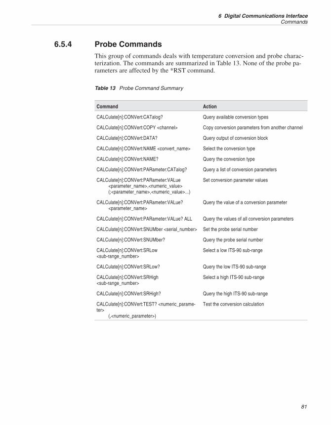
6.5.4 Probe CommandsThis group of commands deals with temperature conversion and probe charac-terization. The commands are summarized in Table 13. None of the probe pa-rameters are affected by the *RST command.
Command Action
CALCulate[n]:CONVert:CATalog? Query available conversion types
CALCulate[n]:CONVert:COPY <channel>annel Copy conversion parameters from another channel
CALCulate[n]:CONVert:DATA? Query output of conversion block
CALCulate[n]:CONVert:NAME <convert_name> Select the conversion type
CALCulate[n]:CONVert:NAME? Query the conversion type
CALCulate[n]:CONVert:PARameter:CATalog? Query a list of conversion parameters
CALCulate[n]:CONVert:PARameter:VALue<parameter_name>,<numeric_value>(;<parameter_name>,<numeric_value>...)
Set conversion parameter values
CALCulate[n]:CONVert:PARameter:VALue?<parameter_name>
Query the value of a conversion parameter
CALCulate[n]:CONVert:PARameter:VALue? ALL Query the values of all conversion parameters
CALCulate[n]:CONVert:SNUMber <serial_number> Set the probe serial number
CALCulate[n]:CONVert:SNUMber? Query the probe serial number
CALCulate[n]:CONVert:SRLow<sub-range_number>
Select a low ITS-90 sub-range
CALCulate[n]:CONVert:SRLow? Query the low ITS-90 sub-range
CALCulate[n]:CONVert:SRHigh<sub-range_number>
Select a high ITS-90 sub-range
CALCulate[n]:CONVert:SRHigh? Query the high ITS-90 sub-range
CALCulate[n]:CONVert:TEST? <numeric_parame-ter>
(,<numeric_parameter>)
Test the conversion calculation
81
6 Digital Communications InterfaceCommands
Table 13 Probe Command Summary
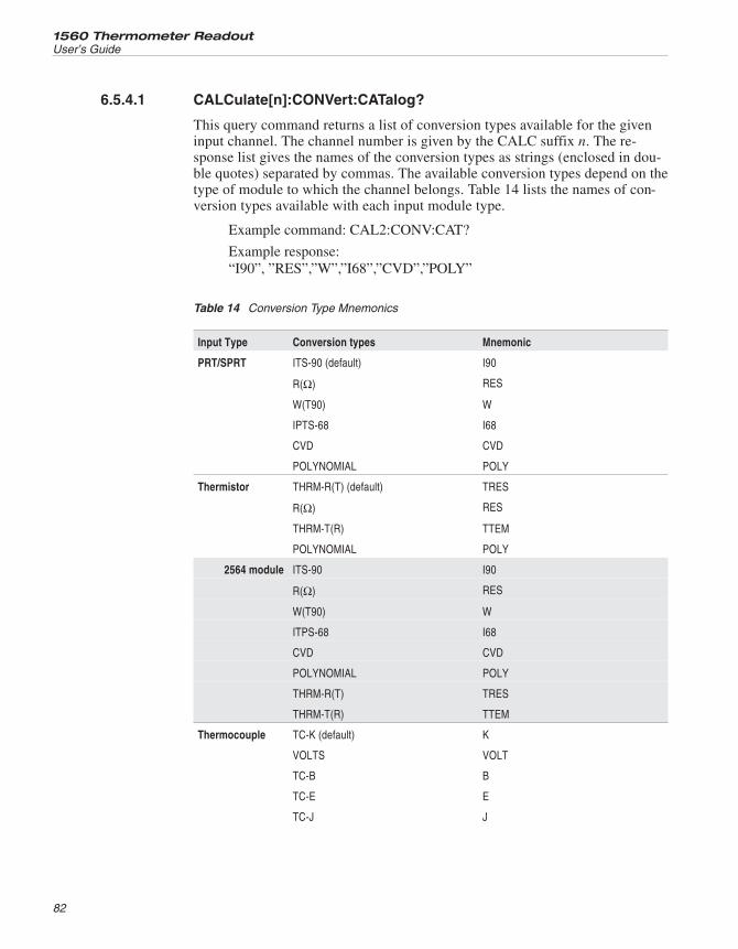
6.5.4.1 CALCulate[n]:CONVert:CATalog?
This query command returns a list of conversion types available for the giveninput channel. The channel number is given by the CALC suffix n. The re-sponse list gives the names of the conversion types as strings (enclosed in dou-ble quotes) separated by commas. The available conversion types depend on thetype of module to which the channel belongs. Table 14 lists the names of con-version types available with each input module type.
Example command: CAL2:CONV:CAT?
Example response:“I90”, ”RES”,”W”,”I68”,”CVD”,”POLY”
Input Type Conversion types Mnemonic
PRT/SPRT ITS-90 (default) I90
R(Ω) RES
W(T90) W
IPTS-68 I68
CVD CVD
POLYNOMIAL POLY
Thermistor THRM-R(T) (default) TRES
R(Ω) RES
THRM-T(R) TTEM
POLYNOMIAL POLY
2564 module ITS-90 I90
R(Ω) RES
W(T90) W
ITPS-68 I68
CVD CVD
POLYNOMIAL POLY
THRM-R(T) TRES
THRM-T(R) TTEM
Thermocouple TC-K (default) K
VOLTS VOLT
TC-B B
TC-E E
TC-J J
1560 Thermometer Readout
User’s Guide
82
Table 14 Conversion Type Mnemonics
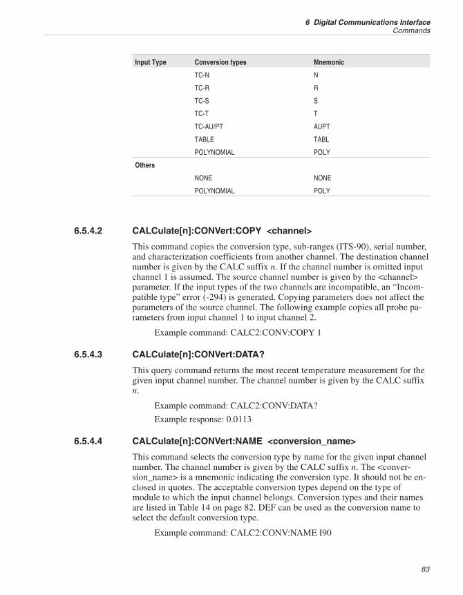
Input Type Conversion types Mnemonic
TC-N N
TC-R R
TC-S S
TC-T T
TC-AU/PT AUPT
TABLE TABL
POLYNOMIAL POLY
Others
NONE NONE
POLYNOMIAL POLY
6.5.4.2 CALCulate[n]:CONVert:COPY <channel>
This command copies the conversion type, sub-ranges (ITS-90), serial number,and characterization coefficients from another channel. The destination channelnumber is given by the CALC suffix n. If the channel number is omitted inputchannel 1 is assumed. The source channel number is given by the <channel>parameter. If the input types of the two channels are incompatible, an “Incom-patible type” error (-294) is generated. Copying parameters does not affect theparameters of the source channel. The following example copies all probe pa-rameters from input channel 1 to input channel 2.
Example command: CALC2:CONV:COPY 1
6.5.4.3 CALCulate[n]:CONVert:DATA?
This query command returns the most recent temperature measurement for thegiven input channel number. The channel number is given by the CALC suffixn.
Example command: CALC2:CONV:DATA?
Example response: 0.0113
6.5.4.4 CALCulate[n]:CONVert:NAME <conversion_name>
This command selects the conversion type by name for the given input channelnumber. The channel number is given by the CALC suffix n. The <conver-sion_name> is a mnemonic indicating the conversion type. It should not be en-closed in quotes. The acceptable conversion types depend on the type ofmodule to which the input channel belongs. Conversion types and their namesare listed in Table 14 on page 82. DEF can be used as the conversion name toselect the default conversion type.
Example command: CALC2:CONV:NAME I90
83
6 Digital Communications InterfaceCommands
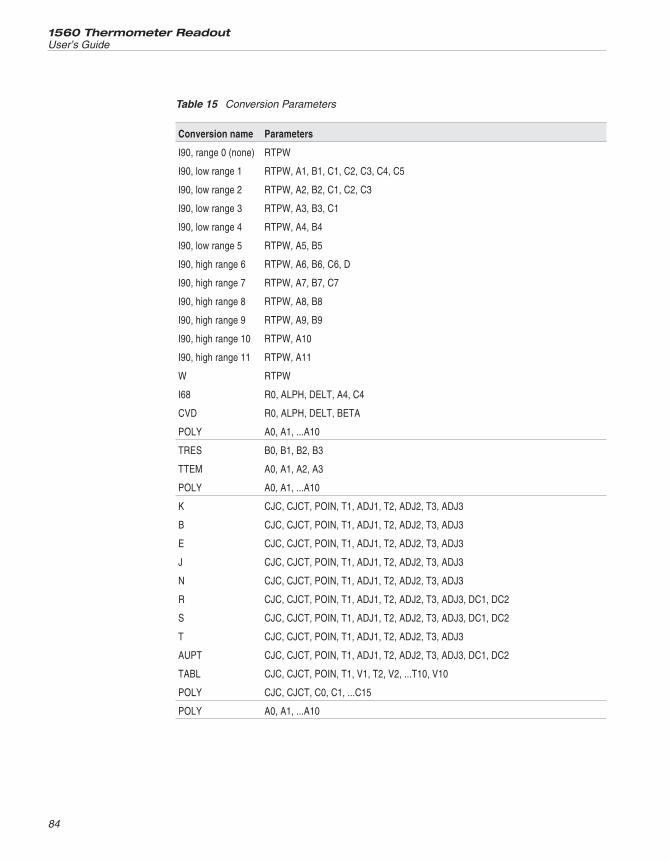
1560 Thermometer Readout
User’s Guide
84
Conversion name Parameters
I90, range 0 (none) RTPW
I90, low range 1 RTPW, A1, B1, C1, C2, C3, C4, C5
I90, low range 2 RTPW, A2, B2, C1, C2, C3
I90, low range 3 RTPW, A3, B3, C1
I90, low range 4 RTPW, A4, B4
I90, low range 5 RTPW, A5, B5
I90, high range 6 RTPW, A6, B6, C6, D
I90, high range 7 RTPW, A7, B7, C7
I90, high range 8 RTPW, A8, B8
I90, high range 9 RTPW, A9, B9
I90, high range 10 RTPW, A10
I90, high range 11 RTPW, A11
W RTPW
I68 R0, ALPH, DELT, A4, C4
CVD R0, ALPH, DELT, BETA
POLY A0, A1, ...A10
TRES B0, B1, B2, B3
TTEM A0, A1, A2, A3
POLY A0, A1, ...A10
K CJC, CJCT, POIN, T1, ADJ1, T2, ADJ2, T3, ADJ3
B CJC, CJCT, POIN, T1, ADJ1, T2, ADJ2, T3, ADJ3
E CJC, CJCT, POIN, T1, ADJ1, T2, ADJ2, T3, ADJ3
J CJC, CJCT, POIN, T1, ADJ1, T2, ADJ2, T3, ADJ3
N CJC, CJCT, POIN, T1, ADJ1, T2, ADJ2, T3, ADJ3
R CJC, CJCT, POIN, T1, ADJ1, T2, ADJ2, T3, ADJ3, DC1, DC2
S CJC, CJCT, POIN, T1, ADJ1, T2, ADJ2, T3, ADJ3, DC1, DC2
T CJC, CJCT, POIN, T1, ADJ1, T2, ADJ2, T3, ADJ3
AUPT CJC, CJCT, POIN, T1, ADJ1, T2, ADJ2, T3, ADJ3, DC1, DC2
TABL CJC, CJCT, POIN, T1, V1, T2, V2, ...T10, V10
POLY CJC, CJCT, C0, C1, ...C15
POLY A0, A1, ...A10
Table 15 Conversion Parameters
6.5.4.5 CALCulate[n]:CONVert:NAME?
This query command returns the name of the selected conversion type for thegiven input channel number. The channel number is given by the CALC suffixn. Conversion types and their names are listed in Table 14. The returned nameis not enclosed in quotes.
Example command: CALC2:CONV:NAME?
Example response: I90
6.5.4.6 CALCulate[n]:CONVert:PARameter:CATalog?
This query command returns the names of probe characterization parametersused with the selected conversion type for the given input channel number. Thechannel number is given by the CALC suffix n. The response list gives thenames of the characterization parameters as strings (enclosed in double quotes)separated by commas. If no parameters are available with the selected conver-sion type, an empty string, “”, is returned. The list of parameters depends onthe selected conversion type. Characterization parameters for the various con-version types are listed in Table 3 on page 34. For the ITS-90 conversion, thelist also depends on the selected sub-ranges (see Section 6.5.4.12 and 6.5.4.14).
Example command: CALC2:CONV:PAR:CAT?
Example response: “A4”,”B4”,”A7”,”B7”,”C7”
6.5.4.7 CALCulate[n]:CONVert:PARameter:VALue <parameter_name>, <nu-meric_value>[,<parameter_name>,<numeric_value> . . . ]
This command sets the values of one or more conversion parameters for thegiven input channel number. The channel number is given by the CALC suffixn. The <parameter_name> is the name of a parameter (see Table 15). It shouldnot be enclosed in quotes. If the given parameter name is not acceptable withthe selected conversion type, a “Settings conflict” error (-221) is generated. The<numeric_value> is the desired value of the parameter. DEF is also accepted toset a parameter to its default value. For the CJC parameter, possible values are0 for internal and 1 for external. Multiple parameters can be set with one com-mand using a comma to separate the parameter names. The order of parametersis not important but the value must always immediately follow the parametername.
Example command: CALC2:CONV:PAR:VALRTPW,100.0145,A8,-3.2878E-4,B8,-1.894E-5
6.5.4.8 CALCulate[n]:CONVert:PARameter:VALue? <parameter_name>
This query command returns the value of the specified conversion parameterfor the given input channel number. The channel number is given by the CALCsuffix n. The <parameter_name> is the name of the parameter as given in Table15. It should not be enclosed in quotes. If the given parameter name is not ac-
85
6 Digital Communications InterfaceCommands
ceptable with the selected conversion type, a “Settings conflict” error (-221) isgenerated.
Example command: CALC2:CONV:PAR:VAL? RTPW
Example response: 100.0145
6.5.4.9 CALCulate[n]:CONVert:PARameter:VALue? ALL
This query command returns the values of all conversion parameters for thegiven input channel number. The channel number is given by the CALC suffixn. Returned values are preceded by the parameter name and a separatingcomma. Parameter names are presented as strings (enclosed in quotes). If thereare no parameters for the given channel, an empty string, “”, is returned.
Example command: CALC2:CONV:PAR:VAL? ALL
Example response: “RTPW”,100.0145,”A8”,–3.2878E-4,”B8”,–1.894E-5
6.5.4.10 CALCulate[n]:CONVert:SNUMber <serial_number>
This command sets the probe serial number for the given input channel number.The channel number is given by the CALC suffix n. The <serial_number> pa-rameter is a string (enclosed in quotes) representing the serial number of theprobe. It can consist of up to eight characters that includes any letters, numericdigits, decimal points, and minus signs.
Example command: CALC2:CONV:SNUM “4-336C”
6.5.4.11 CALCulate[n]:CONVert:SNUMber?
This query command returns the probe serial number for the given input chan-nel number. The channel number is given by the CALC suffix n. The returnedserial number is in string format (enclosed in quotes).
Example command: CALC2:CONV:SNUM?
Example response: “4-336C”
6.5.4.12 CALCulate[n]:CONVert:SRLow <sub-range_number>
This command selects one of the ITS-90 low sub-ranges for the given inputchannel number. The channel number is given by the CALC suffix n. The<sub-range_number> is 0 through 5. 0 sets the sub-range to NONE. If theITS-90 conversion is not selected for the given channel number, a “Settingsconflict” error (-221) is generated.
Example command: CALC2:CONV:SRLOW 4
6.5.4.13 CALCulate[n]:CONVert:SRLow?
This query command returns the selected ITS-90 low sub-range for the giveninput channel number. The channel number is given by the CALC suffix n. The
1560 Thermometer Readout
User’s Guide
86
returned sub-range is a number from 0 to 5. If the ITS-90 conversion is not se-lected for the given channel number, a “Settings conflict” error (-221) isgenerated.
Example command: CALC2:CONV:SRLOW?
Example response: 4
6.5.4.14 CALCulate[n]:CONVert:SRHigh <sub-range_number>
This command selects one of the ITS-90 high sub-ranges for the given inputchannel number. The channel number is given by the CALC suffix n. The<sub-range_number> is 0 or 6 through 11. 0 sets the sub-range to NONE. If theITS-90 conversion is not selected for the given channel number, a “Setting con-flict” error (-221) is generated.
Example command: CALC2:CONV:SRH 7
6.5.4.15 CALCulate[n]:CONVert:SRHigh?
This query command returns the selected ITS-90 low sub-range for the giveninput channel. The channel number is given by the CALC suffix n. The re-turned sub-range is 0 or 6 through 11. If the ITS-90 conversion is not selectedfor the given channel number, a “Setting conflict” error (-221) is generated.
Example command: CALC2:CONV:SRH?
Example response: 7
6.5.4.16 CALCulate[n]:CONVert:TEST? <numeric_value>[,<numeric_value>]
This query command is used to test the temperature conversion for the given in-put channel number. It returns the temperature corresponding to the given resis-tance or voltage. Temperature is calculated using the selected systemtemperature units. The channel number is given by the CALC suffix n. The re-sistance or voltage is specified using the first <numeric_value> parameter. Thesecond <numeric_value> parameter can be used to specify a CJC temperaturefor thermocouple conversions. It is ignored if internal CJC is specified. If it isomitted when external CJC is specified, a value of 0 is assumed.
Example command: CALC2:CONV:TEST? 100.0145
Example response: 0.0100
6.5.5 Output Channel Commands
87
6 Digital Communications InterfaceCommands
This group of commands controls the output of data to output channels. Theyare summarized in Table 16.
6.5.5.1 OUTPut[n]:CALC <numeric_value>
This command selects the calculation type for which results are output to agiven output channel. It is equivalent to setting CALCULATION with theOUTPUT CHAN soft-key function (see Section 5.3.2 ). The output channelnumber is given by the OUTP suffix n. If it is omitted output channel 1 is as-sumed. The command SYST:CONF:OCH? (Section 6.5.8.12) can be used todetermine the number of installed output channels. The <numeric_value> spec-ifies the calculation type according to Table 17. The *RST command sets thecalculation type to 0 (temperature) for all output channels.
Example command: OUTP1:CALC 0
6.5.5.2 OUTPut[n]:CALC?
This query command returns the calculation type for a given output channel.The output channel number is given by the OUTP suffix n. If it is omitted out-put channel 1 is assumed. The response is a number showing the calculationtype (see Table 17).
Example command: OUTP1:CALC?
1560 Thermometer Readout
User’s Guide
88
Command Action
OUTPut[n]:CALC <numeric_value> Select calculation type for an output channel
OUTPut[n]:CALC? Query calculation type for an output channel
OUTPut[n]:NCHannel <channel> Select negative input channel for an output channel
OUTPut[n]:NCHannel? Query negative input channel for an output channel
OUTPut[n]:PCHannel <channel> Select positive input channel for an output channel
OUTPut[n]:PCHannel? Query positive input channel for an output channel
OUTPut[n][:STATe] <Boolean> Enable or disable output channel
OUTPut[n][:STATe]? Query state of output channel
Table 16 Output Channel Commands
Example response:0
6.5.5.3 OUTPut[n]:NCHannel <channel>
This command selects the input channel routed to the negative path of the out-put channel. It is equivalent to setting -CHANNEL with the OUTPUT CHANsoft-key function (see Section 5.3.2). The output channel number is given bythe OUTP suffix n. If it is omitted output channel 1 is assumed. The input chan-nel number is given by the <channel> parameter. The channel number is pre-ceded by @ and enclosed in parentheses. For example, (@2) would be used toselect input channel 2. Use (@) to specify no input channel. This commandalso sets the OUTPut:STATe to ON (see Section 6.5.5.7). The *RST commandsets the negative channel to none for all output channels.
Example command: OUTP1:NCH (@2)
6.5.5.4 OUTPut[n]:NCHannel?
This query command returns the input channel routed to the negative path ofthe output channel. The output channel number is given by the OUTP suffix n.If it is omitted output channel 1 is assumed. The returned channel number ispreceded by @ and enclosed in parentheses. If no channel is selected (@) isreturned.
Example command: OUTP1:NCH?
Example response: (@2)
6.5.5.5 OUTPut[n]:PCHannel <channel>
This command selects the input channel routed to the positive path of the out-put channel. It is equivalent to setting +CHANNEL with the OUTPUT CHANmenu function (see Section 5.3.2). The output channel number is given by theOUTP suffix n. If it is omitted output channel 1 is assumed. The input channelnumber is given by the <channel> parameter. The channel number is precededby @ and enclosed in parentheses. For example, (@2) would be used to select
89
6 Digital Communications InterfaceCommands
Number Type
0 temperature
1 average
2 standard deviation
3 minimum
4 maximum
5 spread
6 n
7 input
Table 17 Output Calculation Types
input channel 2. Use (@) to specify no input channel. This command also setsthe OUTPut:STATe to ON (see Section 6.5.5.7). The *RST command sets thepositive channel to none for all output channels.
Example command: OUTP1:PCH (@1)
6.5.5.6 OUTPut[n]:PCHannel?
This query command returns the input channel routed to the positive path of theoutput channel. The output channel number is given by the OUTP suffix n. If itis omitted output channel 1 is assumed. The returned channel number is pre-ceded by @ and enclosed in parentheses. If no channel is selected (@) isreturned.
Example command: OUTP1:PCH?
Example response: (@1)
6.5.5.7 OUTPut[n][:STATe] <Boolean>
This command enables or disables output to the given output channel. The out-put channel number is given by the OUTP suffix n. If it is omitted output chan-nel 1 is assumed. Giving a <Boolean> parameter value of OFF or 0 sets both+CHANNEL and –CHANNEL to none or 0. Giving a <Boolean> parametervalue of ON or 1 sets the +CHANNEL to the primary input channel and–CHANNEL to none or 0. The *RST command sets all output channels OFF.
Example command: OUTP1 OFF
6.5.5.8 OUTPut[n][:STATe]?
This query command returns the state of the given output channel. The outputchannel number is given by the OUTP suffix n. If it is omitted output channel 1is assumed. The response is 1 if output to the channel is enabled (either+CHANNEL or –CHANNEL is set) or 0 if disabled.
Example command: OUTP1?
Example response: 0
1560 Thermometer Readout
User’s Guide
90
6.5.6 Printer CommandsThis group of commands controls output to printer devices.
6.5.6.1 HCOPy:ABORt
This command cancels the printing of memory data initiated with theHCOP:IMM command.
Example command: HCOP:ABOR
6.5.6.2 HCOPy[:IMMediate] <printer_number>,<numeric_value>
This command initiates printing of memory data to the given printer device.This is equivalent to using the PRINT MEMORY menu function (see Section5.3.4). The printer device number is given by <printer_number>. Printer device1 is the serial port on the base. Other printer devices are assigned numbers se-quentially. The command SYST:CONF: PDEV? (Section 6.5.8.16 ) can be usedto determine the number of installed printer devices. The number of measure-ments to print is specified with <numeric_value>. MAX can be used to print alldata. If the given number is larger than the number of measurements stored inmemeory a ”Data out of range” error (-222) is reported. The number of avail-able measurements can be determined using the DATA:POIN? command (Sec-tion 6.5.1.9). Printing can be canceled with the HCOPy:ABOR command (seeabove). Measurements are printed one measurement per line with the channelnumber, measurement value, unit, time, and date. Use the appropriate commu-nication commands (Section 6.5.7) or device setup commands (Section6.5.8.20) to configure printer port options such as baud rate or linefeed enable.The following example prints the 10 most recent measurements stored in mem-ory to the base serial port.
Example command: HCOP 1,10
6.5.6.3 HCOPy:PRINter[n][:STATe] <Boolean>
This command enables or disables output of measurement data to printer de-vices. This is equivalent to using the PRINT OUTPUT menu function (seeSection 5.3.3). When printing is enabled all measurement data are printed asthey are acquired. The printer device number is given by the PRIN suffix n. If itis omitted printer port 1, the base serial port, is assumed. Printer devices are as-
91
6 Digital Communications InterfaceCommands
Command Action
HCOPy:ABORt Cancel printing of memory data
HCOPy[:IMMediate] <printer_number>,<numeric_value>
Print data in memory to printer device
HCOPy:PRINter[n][:STATe] <Boolean> Enable or disable data output to printer
HCOPy:PRINter[n][:STATe?] Query printer output state
Table 18 Printer Commands
signed numbers sequentially starting with 1 for the base serial port. The com-mand SYST:CONF:PDEV? (Section 6.5.8.16) can be used to query the numberof installed printer devices. Giving a <Boolean> parameter value of ON or 1enables printing and OFF or 0 disables printing. Measurements are printed onemeasurement per line with the channel number, measurement value, unit, time,and date. Use the appropriate communication commands (Section 6.5.7) or de-vice setup commands (Section 6.5.8.20) to configure printer port options suchas baud rate or linefeed enable. The *RST command sets all printer devicesOFF.
Example command: HCOP:PRIN ON
6.5.6.4 HCOPy:PRINter[n][:STATe]?
This query command returns the state of the given printer device. The printerdevice number is given by the PRIN suffix n. If it is omitted printer port 1, thebase serial port, is assumed. The response is 1 if printing to the device is en-abled or 0 if disabled.
Example command: HCOP:PRIN?
Example response: 1
6.5.7 Communication Interface CommandsThis group of commands (Table 19) controls the base serial port configurationoptions. Configuration of add-on communication ports is done using theSYST:MOD:DEV:WRIT command as explained in Section 6.5.8.20.
6.5.7.1 SYSTem:COMMunicate:SERial[:RECeive]:BAUD <numeric_value>
This command sets the baud rate of the base serial port. The <numeric_value>parameter specifies the desired baud rate. The nearest possible baud rate will beselected. The baud rate is not affected by the *RST command.
Example command: SYST:COMM:SER:BAUD 2400
6.5.7.2 SYSTem:COMMunicate:SERial[:RECeive]:BAUD?
This query command returns the baud rate of the base serial port.
Example command: SYST:COMM:SER:BAUD?
Example response: 2400
6.5.7.3 SYSTem:COMMunicate:SERial[:RECeive]:FDUPlex <Boolean>
This command sets the duplex or echo mode of the base serial port. The<Boolean> parameter turns on or off full duplex. A value of 1 or ON turns fullduplex on and 0 or OFF turns it off. If full duplex is ON, all characters receivedwill be echoed back. Duplex is not affected by the *RST command.
Example command: SYST:COMM:SER:FDUP OFF
1560 Thermometer Readout
User’s Guide
92
6.5.7.4 SYSTem:COMMunicate:SERial[:RECeive]:FDUP?
This query command returns the duplex or echo mode of the base serial port.This command returns 1 if full duplex is on and 0 otherwise.
Example command: SYST:COMM:SER:FDUP?
Example response: 0
6.5.7.5 SYSTem:COMMunicate:SERial[:RECeive]:LINefeed <Boolean>
This command enables or disables linefeed for the base serial port. A<Boolean> value of 1 or ON turns the linefeed on and 0 or OFF turns it off. Ifthe linefeed is ON, a linefeed character (ASCII decimal 10) will be appended tothe carriage return at the end of each line during transmission. Linefeed is notaffected by the *RST command.
Example command:SYST: COMM:SER:LIN ON
6.5.7.6 SYSTem:COMMunicate:SERial[:RECeive]:LINefeed?
This query command returns the state of the linefeed for the base serial port. Itreturns 1 if the linefeed is on and 0 otherwise.
Example command: SYST:COMM:SER:LIN?
Example response: 1
93
6 Digital Communications InterfaceCommands
Command Action
SYSTem:COMMunicate:SERial[:RECeive]:BAUD<numeric_value>
Set the baud rate for the base serial port
SYSTem:COMMunicate:SERial[:RECeive]:BAUD? Query the baud rate for the base serial port
SYSTem:COMMunicate:SERial[:RECeive]:FDUPlex Select duplex (echo) mode for the base serial port
SYSTem:COMMunicate:SERial[:RECeive]:FDUP? Query duplex (echo) mode for the base serial port
SYSTem:COMMunicate:SERial[:RECeive]:LINefeed<Boolean>
Enable or disable linefeed for the base serial port
SYSTem:COMMunicate:SERial[:RECeive]:LINefeed? Query linefeed for the base serial port
Table 19 Communication Interface Commands
6.5.8 Module CommandsThis group of commands (Table 20) can be used to determine the module con-figuration and to communicate directly with module devices.
6.5.8.1 SYSTem:CONFigure:CDEVice?
This query command returns the number of installed communication devices.
Example command: SYST:CONF:CDEV?
Example response: 3
6.5.8.2 SYSTem:CONFigure:COMMunicate[n]:DADDress?
This query command returns the device address (number of the device withinits module) of a given communication device. The communication device num-ber is given by the COMM suffix n. Communication devices are assigned num-bers sequentially starting with 1 for the base serial port. The command
1560 Thermometer Readout
User’s Guide
94
Command Action
SYSTem:CONFigure:CDEVice? Query number of communication devices
SYSTem:CONFigure:COMMunicate[n]:DADDress? Query device address of communication device
SYSTem:CONFigure:COMMunicate[n]:MADDress? Query module address of communication device
SYSTem:CONFigure:ICHannel? Query number of input channels
SYSTem:CONFigure:IDEVice? Query number of input devices
SYSTem:CONFigure:INPut[n]:DADDress? Query device address of input device
SYSTem:CONFigure:INPut[n]:MADDress? Query module address of input device
SYSTem:CONFigure:MNUMber? Query number of modules
SYSTem:CONFigure:MODule[n]:DEVice[n]:INFormation?
Query device information
SYSTem:CONFigure:MODule[n]:DNUMber? Query number of devices in module
SYSTem:CONFigure:MODule[n]:INFormation? Query module information
SYSTem:CONFigure:OCHannel? Query number of output channels
SYSTem:CONFigure:ODEVice? Query number of output devices
SYSTem:CONFigure:OUTPut[n]:DADDress? Query device address of output device
SYSTem:CONFigure:OUTPut[n]:MADDress? Query module address of output device
SYSTem:CONFigure:PDEVice? Query number of printer devices
SYSTem:CONFigure:PRINter[n]:DADDress? Query device address of printer device
SYSTem:CONFigure:PRINter[n]:MADDress? Query module address of printer device
SYSTem:MODule[n]:DEVice[n]:READ? nd Read data from a module device
SYSTem:MODule[n]:DEVice[n]:WRITe nd[,rameter] Write data to a module device
Table 20 Module Commands
SYST:CONF:CDEV? can be used to determine the number of installed com-munication devices.
Example command: SYST:CONF:COMM3:DADD?
Example response: 2
6.5.8.3 SYSTem:CONFigure:COMMunicate[n]:MADDress?
This query command returns the module number or address of the module thatcontains a given communication device. The communication device number isgiven by the COMM suffix n. Communication devices are assigned numberssequentially starting with 1 for the base serial port. The commandSYST:CONF:CDEV? can be used to query the number of installed communi-cation devices.
Example command: SYST:CONF:COMM3:MADD?
Example response:3
6.5.8.4 SYSTem:CONFigure:ICHannel?
This query command returns the total number of installed input channels.
Example command:SYST:CONF:ICH?
Example response:10
6.5.8.5 SYSTem:CONFigure:IDEVice?
This query command returns the number of installed input devices.
Example command: SYST:CONF:IDEV?
Example response: 2
6.5.8.6 SYSTem:CONFigure:INPut[n]:DADDress?
This query command returns the device address (number of the device withinits module) of a given input device. The input device number is given by theINP suffix n. Input devices are assigned numbers sequentially starting with 1.The command SYST:CONF:IDEV? (Section 6.5.8.5) can be used to determinethe number of installed input devices.
Example command: SYST:CONF:INP2:DADD?
Example response: 1
6.5.8.7 SYSTem:CONFigure:INPut[n]:MADDress?
This query command returns the number of the module that contains a given in-put device. The input device number is given by the INP suffix n. Input devicesare assigned numbers sequentially starting with 1. The commandSYST:CONF:IDEV? (Section 6.5.8.5) can be used to determine the number ofinstalled input devices.
95
6 Digital Communications InterfaceCommands
Example command: SYST:CONF:INP2:MADD?
Example response: 2
6.5.8.8 SYSTem:CONFigure:MNUMber?
This query command returns the number of installed modules.
Example command: SYST:CONF:MNUM?
Example response: 3
6.5.8.9 SYSTem:CONFigure:MODule[n]:DEVice[n]:INFormation?
This query command returns information about a given device. The device isspecified by module number and device number. The module and device num-bers are given by the MOD suffix and DEV suffix respectively. The commandSYST:CONF:MNUM? (Section 6.5.8.8) can be used to query the number of in-stalled modules and the command SYST:CONF:MOD[n]:DNUM? (Section6.5.8.10) can be used to determine the number of devices within a module.
The format of the response is as follows:
<name>,<class>,<channels>
The <name> parameter is a string, enclosed in quotes, showing the name of thedevice. The <class> parameter is a character mnemonic (without quotes) show-ing the class of the module. This is either INP for input, OUTP for data output,PRIN for printer output, or COMM for communication. The <channels> pa-rameter is a numeric value showing the number of channels in the device.
Example command: SYST:CONF:MOD1:DEV1:INF?
Example response:”SPRT”,INP,2
6.5.8.10 SYSTem:CONFigure:MODule[n]:DNUMber?
This query command returns the number of devices in a given module. Themodule number is given by the MOD suffix n. The commandSYST:CONF:MNUM? (Section 6.5.8.8) can be used to determine the numberof installed modules.
Example command: SYST:CONF:MOD3:DNUM?
Example response: 5
6.5.8.11 SYSTem:CONFigure:MODule[n]:INFormation?
This query command returns information about a given module. The modulenumber is given by the MOD suffix n. The command SYST:CONF:MNUM?(Section 6.5.8.8) can be used to determine the number of installed modules.
The format of the response is as follows:
<name>,<devices>,<model number>,<serial_number>,<firmware version>
1560 Thermometer Readout
User’s Guide
96
The <name> parameter is a string, enclosed in quotes, showing the name of themodule. The <devices> parameter is a numeric value showing the number ofdevices in the module. The <model number> parameter is a character value(without quotes) showing the model number of the module. The <serial num-ber> parameter is a character value (without quotes) showing the serial numberof the module. If the serial number is not available 0 is returned. The <firmwareversion> is a numeric value of the form v.vv showing the firmware versionnumber for the module.
Example command: SYST:CONF:MOD1:INF?
Example response: ”SPRT”,1,2560,A26123,1.12
6.5.8.12 SYSTem:CONFigure:OCHannel?
This query command returns the total number of installed output channels.
Example command: SYST:CONF:OCH?
Example response: 1
6.5.8.13 SYSTem:CONFigure:ODEVice?
This query command returns the number of installed output devices.
Example command: SYST:CONF:ODEV?
Example response: 1
6.5.8.14 SYSTem:CONFigure:OUTPut[n]:DADDress?
This query command returns the device address (number of the device withinits module) of a given output device. The output device number is given by theOUTP suffix n. Output devices are assigned numbers sequentially starting with1. The command SYST:CONF:ODEV? (Section 6.5.8.13) can be used to deter-mine the number of installed output devices.
Example command: SYST:CONF:OUTP1:DADD?
Example response: 5
6.5.8.15 SYSTem:CONFigure:OUTPut[n]:MADDress?
This query command returns the module number or address of the module thatcontains a given output device. The output device number is given by theOUTP suffix n. Output devices are assigned numbers sequentially starting with1. The command SYST:CONF:ODEV? (Section 6.5.8.13) can be used to deter-mine the number of installed output devices.
Example command: SYST:CONF:OUTP1:MADD?
Example response: 3
6.5.8.16 SYSTem:CONFigure:PDEVice?
This query command returns the number of installed printer devices.
97
6 Digital Communications InterfaceCommands
Example command: SYST:CONF:PDEV?
Example response: 1
6.5.8.17 SYSTem:CONFigure:PRINter[n]:DADDress?
This query command returns the device address (number of the device withinits module) of a given printer device. The printer device number is given by thePRIN suffix n. Printer devices are assigned numbers sequentially starting with1. The command SYST:CONF:PDEV? (Section 6.5.8.16) can be used to deter-mine the number of installed printer devices.
Example command: SYST:CONF:PRIN1:DADD?
Example response: 4
6.5.8.18 SYSTem:CONFigure: PRINter[n]:MADDress?
This query command returns the module number or address of the module thatcontains a given printer device. The printer device number is given by the PRINsuffix n. Printer devices are assigned numbers sequentially starting with 1. Thecommand SYST:CONF:PDEV? (Section 6.5.8.16) can be used to determine thenumber of installed printer devices.
Example command: SYST:CONF:PRIN1:MADD?
Example response: 3
6.5.8.19 SYSTem:MODule[n]:DEVice[n]:READ? <device_command>
This query command is used to read configuration parameters directly from adevice. The device is specified by module number and device number. Themodule and device numbers are given by the MOD suffix and DEV suffix re-spectively. The command SYST:CONF:MNUM? (Section 6.5.8.8) can be usedto determine the number of installed modules and the commandSYST:CONF:MOD[n]:DNUM? (Section 6.5.8.10) can be used to determine thenumber of devices within a module. The <device_command> parameter is thecommand string (enclosed in quotes) passed to the device. Each device has aunique set of commands (refer to the operating instructions for a specific mod-ule for a list of its device commands). The response type can be either a nu-meric value or character data depending on the device command.
Example command: SYST:MOD2:DEV1:READ? “CURR”
Example response:10
6.5.8.20 SYSTem:MODule[n]:DEVice[n]:WRITe <device_command>,<value>
This command can be used to directly send a command to a device to set a con-figuration parameter. The device is specified by module number and devicenumber. The module and device numbers are given by the MOD suffix andDEV suffix respectively. The command SYST:CONF:MNUM? (Section6.5.8.8) can be used to determine the number of installed modules and the com-mand SYST:CONF: MOD[n]:DNUM? (Section 6.5.8.10) can be used to deter-
1560 Thermometer Readout
User’s Guide
98
mine the number of devices within a module. The <device_command> is thecommand string (enclosed in quotes) passed to the device. Each device has aunique set of commands (refer to the operating instructions for a specific mod-ule for a list of its device commands). The <value> parameter, numeric or char-acter data depending on the command, may be used to set a parameter. The*RST command does not affect any device configuration parameters.
Example command: SYST:MOD2:DEV1:WRITE “CURR”,10
6.5.9 System CommandsThis group of commands deals with the general system configuration. Thecommands are summarized in Table 21.
6.5.9.1 *IDN?
This query command returns the instrument identification string that indicatesthe manufacturer, model number, serial number, and firmware version. The se-rial number can be set with the SYST:SNUM command (Section 6.5.9.6). If theserial number is not available 0 is returned. The format of the response is asfollows:
HART,1560,<serial_number>,<v.vv>
Example command:*IDN?
Example response:HART,1560,641022,1.11
99
6 Digital Communications InterfaceCommands
Command Action
*IDN? Query instrument identification
*OPT? Return model numbers of installed modules
*RST System reset
SYSTem:DATE <year>,<month>,<day> Set the date
SYSTem:DATE? Query the date
SYSTem:SNUMber <serial_number> Set the system serial number
SYSTem:SNUMber? Query the system serial number
SYSTem:TIME <hour>,<minute>,<second> Set the time
SYSTem:TIME? Query the time
SYSTem:VERSion? Query SCPI implementation version number
UNIT:TEMPerature <unit> Set the temperature unit
UNIT:TEMPerature? Query the current temperature unit setting
Table 21 System Commands
6.5.9.2 *OPT?
This query command returns a list of installed modules. Modules are reportedby position, front to back for the eight positions. The module model number isreported if a module is installed or 0 is returned otherwise. Numbers are sepa-rated by commas. For example, if the 1560 is equipped with one 2560 SPRTmodule in front and two 2566 Thermocouple Scanner modules, the followingexample would have the given response.
Example command: *OPT?
Example response: 2560,2566,2566,0,0,0,0,0
6.5.9.3 *RST
This command sets the instrument operating parameters to defined conditions.It is equivalent to using the SYSTEM RESET function in the SYSTEMsoft-key menu. It has the following effects:
• Sets the measure mode to off.
• Sets the COUNT N number to 1.
• Sets the measurement delay to 0.
• Sets the primary channel to input channel 1.
• Sets the scan channel list to include all channels.
• Sets the scan mode to primary channel.
• Sets input average to off.
• Disables routing to all output channels by setting the positive input chan-nel number to 0, the negative input channel number to 0, and the calcula-tion type to temperature.
• Sets printing to all printer interface devices to off.
• Clears the statistical functions.
• Sets units to C.
This command does not affect probe parameters and characterization coeffi-cients, display setup, time, password options, module device setup or calibra-tion parameters, or communications status registers.
Example command: *RST
6.5.9.4 SYSTem:DATE <year>,<month>,<day>
This command sets the date. It is equivalent to setting the date using the TIMEfunction in the SYSTEM soft-key menu. The <year> parameter is a four-digitnumber. The <month> parameter is a one or two-digit number from 1 to 12.The <day> parameter is a one or two-digit number from 1 to 31.
Example command: SYST:DATE 1996,5,23
1560 Thermometer Readout
User’s Guide
100
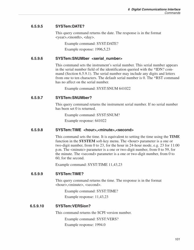
6.5.9.5 SYSTem:DATE?
This query command returns the date. The response is in the format<year>,<month>, <day>.
Example command: SYST:DATE?
Example response: 1996,5,23
6.5.9.6 SYSTem:SNUMber <serial_number>
This command sets the instrument’s serial number. This serial number appearsin the serial number field of the identification queried with the *IDN? com-mand (Section 6.5.9.1). The serial number may include any digits and lettersfrom one to ten characters. The default serial number is 0. The *RST commandhas no affect on the serial number.
Example command: SYST:SNUM 641022
6.5.9.7 SYSTem:SNUMber?
This query command returns the instrument serial number. If no serial numberhas been set 0 is returned.
Example command: SYST:SNUM?
Example response: 641022
6.5.9.8 SYSTem:TIME <hour>,<minute>,<second>
This command sets the time. It is equivalent to setting the time using the TIMEfunction in the SYSTEM soft-key menu. The <hour> parameter is a one ortwo-digit number, from 0 to 23, for the hour in 24-hour mode, e.g. 23 for 11:00p.m. The <minute> parameter is a one or two-digit number, from 0 to 59, forthe minute. The <second> parameter is a one or two-digit number, from 0 to60, for the second.
Example command: SYST:TIME 11,43,23
6.5.9.9 SYSTem:TIME?
This query command returns the time. The response is in the format<hour>,<minute>, <second>.
Example command: SYST:TIME?
Example response: 11,43,23
6.5.9.10 SYSTem:VERSion?
This command returns the SCPI version number.
Example command: SYST:VERS?
Example response: 1994.0
101
6 Digital Communications InterfaceCommands
6.5.9.11 UNIT:TEMPerature <unit>
This command sets the system temperature units. It is equivalent to setting theunits using the UNITS function in the SYSTEM soft-key menu. The <unit>parameter is either C or CEL for Celsius, F or FAR for Fahrenheit, or K forKelvin. The *RST command sets the units to Celsius.
Example command: UNIT:TEMP C
6.5.9.12 UNIT:TEMPerature?
This query command returns the system temperature unit. The response is ei-ther CEL for Celsius, FAR for Fahrenheit, or K for Kelvin.
Example command: UNIT:TEMP?
Example response: CEL
6.5.10 Status CommandsThis group includes commands to report the status and conditions of the instru-ment. The commands are summarized in Table 22 on page 104. None of thestatus registers and queues are directly affected by the *RST command.
6.5.10.1 *CLS
This command clears the status registers. It clears the Event Status Register,Operation Status Event Register, Questionable Status Event Register, and sys-tem error queue. The Status Byte Register is updated to show that the EventStatus Register, Operation Status Condition Register, and Questionable StatusCondition Register are cleared. This command does not affect the OperationStatus Condition Register, Questionable Status Condition Register, Event StatusEnable Register, Operation Status Enable Register, Questionable Status EnableRegister, or the output (response) queue.
6.5.10.2 *ESE <numeric_value>
This command sets the Event Status Enable Register. This register determineswhich event bits of the Event Status Register affect the ESB Event Sum-mary-Message Bit of the Status Byte Register. If any event bit of the Event Sta-tus Register is set (1) while its corresponding mask bit of the Event StatusEnable Register is set, the ESB Event Summary-Message Bit of the Status ByteRegister will be set. The value of the <numeric_value> parameter is a numberfrom 0 to 255 that is the sum of the binary-weighted values of each mask bit.The Event Status Register is described in Section 6.5.10.4 below. The followingexample causes the ESB bit in the Status Byte Register to be set whenever acommand error or execution error occurs.
Example command: *ESE 48
1560 Thermometer Readout
User’s Guide
102
6.5.10.3 *ESE?
This query command returns the Event Status Enable Register (see 6.5.10.2above).
Example command: *ESE?
Example response: 48
6.5.10.4 *ESR?
This query command returns the Event Status Register. It also clears the EventStatus Register and the ESB bit of the Status Byte Register. The value returnedindicates the condition of each of the eight bits of the register by adding the bi-nary-weighted values of each bit. The meaning of each bit, when set (1) , is asfollows where 0 is the least significant and 7 is the most significant:
0 Operation complete (OPC). Execution of the last command is completed.
1 Request control (RQC). No function for this instrument.
2 Query error (QYE). An attempt has been made to read data when none isavailable or pending.
3 Device dependent error (DDE). A hardware error condition occurred.
4 Execution error (EXE). An invalid parameter for a command has beenreceived or the command could not be executed under existingconditions.
5 Command error (CME). An unrecognized command or a command withimproper syntax has been received.
6 User request (URQ). No function for this instrument.
7 Power on (PON). Always set after the power is switched on.
The ESB bit of the Status Byte Register (Section 6.5.10.9) is set (1) wheneverany bit of the Event Status Register is set and its corresponding mask bit in theEvent Status Enable Register (Section 6.5.10.3) is set. The Event Status Regis-ter is cleared when queried with the ESR? command or when the *CLS com-mand is received. The response in the following example would be given afteran invalid command is received by the 1560 and no other error occurred.
Example command: *ESR?
Example response: 32
6.5.10.5 *OPC
This command causes the Operation Complete (OPC) event bit in the EventStatus Register to be set as soon as all pending command operations are com-pleted. Since all commands are sequential for this instrument this command isunnecessary.
103
6 Digital Communications InterfaceCommands
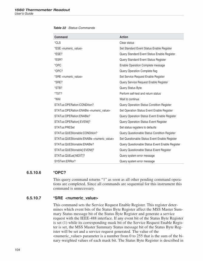
6.5.10.6 *OPC?
This query command returns “1” as soon as all other pending command opera-tions are completed. Since all commands are sequential for this instrument thiscommand is unnecessary.
6.5.10.7 *SRE <numeric_value>
This command sets the Service Request Enable Register. This register deter-mines which event bits of the Status Byte Register affect the MSS Master Sum-mary Status message bit of the Status Byte Register and generate a servicerequest with the IEEE-488 interface. If any event bit of the Status Byte Registeris set (1) while its corresponding mask bit of the Service Request Enable Regis-ter is set, the MSS Master Summary Status message bit of the Status Byte Reg-ister will be set and a service request generated. The value of the<numeric_value> parameter is a number from 0 to 255 that is the sum of the bi-nary-weighted values of each mask bit. The Status Byte Register is described in
1560 Thermometer Readout
User’s Guide
104
Command Action
*CLS Clear status
*ESE <numeric_value> Set Standard Event Status Enable Register
*ESE? Query Standard Event Status Enable Register
*ESR? Query Standard Event Status Register
*OPC Enable Operation Complete message
*OPC? Query Operation Complete flag
*SRE <numeric_value> Set Service Request Enable Register
*SRE? Query Service Request Enable Register
*STB? Query Status Byte
*TST? Perform self-test and return status
*WAI Wait to continue
STATus:OPERation:CONDition? Query Operation Status Condition Register
STATus:OPERation:ENABle <numeric_value> Set Operation Status Event Enable Register
STATus:OPERation:ENABle? Query Operation Status Event Enable Register
STATus:OPERation[:EVENt]? Query Operation Status Event Register
STATus:PRESet Set status registers to defaults
STATus:QUEStionable:CONDition? Query Questionable Status Condition Register
STATus:QUEStionable:ENABle <numeric_value> Set Questionable Status Event Enable Register
STATus:QUEStionable:ENABle? Query Questionable Status Event Enable Register
STATus:QUEStionable[:EVENt]? Query Questionable Status Event Register
STATus:QUEue[:NEXT]? Query system error message
SYSTem:ERRor? Query system error message
Table 22 Status Commands
section 5.5.10.9 below. The following example causes the MSS bit in the StatusByte Register to be set and a service request to be generated whenever the ESBbit of the Status Byte Register is set.
Example command: *SRE 32
6.5.10.8 *SRE?
This query command returns the Service Request Enable Register (see Section6.5.10.7 above).
Example command: *SRE?
Example response: 32
6.5.10.9 *STB?
This query command returns the Status Byte Register. Reading this registerdoes not affect it or the output queue. The value returned indicates the condi-tion of each of the eight bits of the register by adding the binary-weighted val-ues of each bit. The meaning of each bit, when set (1), is as follows where 0 isthe least significant and 7 is the most significant:
0 No function, always 0.
1 No function, always 0.
2 Error Bit (ERR). Indicates that an error message is in the error queue.
3 Questionable Status Bit (QSB). Indicates that a bit in the QuestionableStatus Event Register is set and its corresponding mask bit in the Ques-tionable Status Enable Register is set. It is cleared when the QuestionableStatus Event Register is cleared (by reading it, Section 6.5.10.20).
4 Message Available (MAV). Indicates that data is present in the outputqueue. (Applicable only for IEEE-488 service request and serial poll.)
5 Event Status Bit (ESB). Indicates that a bit in the Event Status Register isset and its corresponding mask bit in the Event Status Enable Register isset. It is cleared when the Event Status Register is cleared (by reading it,Section 6.5.10.4).
6 Master Summary Status (MSS). Indicates that any other bit in the StatusByte Register is set and its corresponding mask bit in the Service Re-quest Enable Register is set (see Section 6.5.10.7).
7 Operation Status Bit. Indicates that a bit in the Operation Status EventRegister is set and its corresponding mask bit in the Operation Status En-able Register is set. It is cleared when the Operation Status Event Regis-ter is cleared (by reading it, Section 6.5.10.15).
The Status Byte Register can also be read from the IEEE-488 interface usingserial poll (see Section 14.4.5). The Status Byte Register can not be set orcleared directly but always reflects the current state of the reported conditions.The response in the following example would be given after an invalid com-
105
6 Digital Communications InterfaceCommands
mand is received by the 1560 if the CME mask bit is set in the Event Status En-able Register and the ESB mask bit is set in the Service Request EnableRegister and no other error occurred.
Example command: *STB?
Example response: 100
6.5.10.10 *TST?
The purpose of this query command is to perform a self-test and report any er-rors that are found. The reponse is 0 if no errors are found. Currently, self-testcan only be performed on power up so this command always returns 0.
6.5.10.11 *WAI
The purpose of this command is to cause a device to wait until all pendingcommand operations (overlapped commands) are completed before executingany subsequent commands. Since all commands are sequential for this instru-ment this command is unnecessary.
6.5.10.12 STATus:OPERation:CONDition?
This query command reads the Operation Status Condition Register. Readingthis register does not affect it. The value returned indicates the condition ofeach of the eight bits of the register by adding the binary-weighted values ofeach bit. The meaning of each bit, when set (1), is as follows where 0 is theleast significant and 7 is the most significant:
0-3 No function, always 0.
4 Measuring. Acquisition of a new measurement is in process.
5-15No function, always 0.
The response in the following example would be given if the measure mode isON or COUNT.
Example command: STAT:OPER:COND?
Example response: 16
6.5.10.13 STATus:OPERation:ENABle <numeric_value>
This command sets the Operation Status Enable Register. This register deter-mines which event bits of the Operation Status Event Register affect the Opera-tion Status Bit (OSB, bit 7) of the Status Byte Register. If any bit in theOperation Status Event Register is set (1) while its corresponding mask bit inthe Operation Status Enable Register is set, the Operation Status Bit in the Sta-tus Byte Register will be set. The value of the <numeric_value> parameter is anumber from 0 to 65535 that is the sum of the binary-weighted values of eachmask bit. The Operation Status Event Register is described in Section6.5.10.15. The following example causes the OSB bit in the Status Byte Regis-ter to be set when a new measurement has been acquired.
1560 Thermometer Readout
User’s Guide
106
Example command: STAT:OPER:ENAB 16
6.5.10.14 STATus:OPERation:ENABle?
This query command returns the Operation Status Enable Register (see6.5.10.13 above).
Example command: STAT:OPER:ENAB?
Example response: 16
6.5.10.15 STATus:OPERation[:EVENt]?
This query command reads the Operation Status Event Register. Bits in thisregister are set whenever the corresponding bit in the Operation Status Condi-tion Register are set. The bit remains set even if the corresponding bit in theOperation Status Condition Register returns FALSE. The Operation StatusEvent Register is cleared when it is read. It can also be cleared with the *CLScommand (see Section 6.5.10.1).
0-3 No function, always 0.
4 Measurement complete. Acquisition of a new measurement is complete.
5-15No function, always 0.
The response in the following example would be given if a new measurementwas acquired since the last time this command was issued.
Example command: STAT:OPER?
Example response: 16
6.5.10.16 STATus:PRESet
This command sets both the Operation Status Enable Register and QuestionableStatus Enable Register to 0 (see Sections 6.5.10.13 and 6.5.10.18).
6.5.10.17 STATus:QUEStionable:CONDition?
This query command reads the Questionable Status Condition Register. Read-ing this register does not affect it. The value returned indicates the condition ofeach of the eight bits of the register by adding the binary-weighted values ofeach bit. The meaning of each bit, when set (1), is as follows where 0 is theleast significant and 7 is the most significant:
0-3 No function, always 0.
4 Temperature. The last temperature measurement is out-of-range or other-wise questionable. This is reset when a new valid measurement isacquired.
5-15No function, always 0.
107
6 Digital Communications InterfaceCommands
6.5.10.18 STATus:QUEStionable:ENABle <numeric_value>
This command sets the Questionable Status Enable Register. This register de-termines which event bits of the Questionable Status Event Register affect theQuestionable Status Bit (QSB, bit 3) of the Status Byte Register. If any bit ofthe Questionable Status Event Register is set (1) while its corresponding maskbit of the Questionable Status Enable Register is set, the QSB bit in the StatusByte Register will be set. The value of the <numeric_value> parameter is anumber from 0 to 65535 that is the sum of the binary-weighted values of eachmask bit. The Questionable Status Event Register is described in Section6.5.10.20.
6.5.10.19 STATus:QUEStionable:ENABle?
This query command returns the Questionable Status Enable Register (see6.5.10.18 above).
6.5.10.20 STATus:QUEStionable[:EVENt]?
This query command reads the Questionable Status Event Register. Readingthis register clears it. The value returned indicates the condition of each of theeight bits of the register by adding the binary-weighted values of each bit. Themeaning of each bit, when set (1), is as follows where 0 is the least significantand 7 is the most significant:
0-3 No function, always 0.
4 Temperature. A previous temperature measurement was out-of-range orotherwise questionable.
5-15No function, always 0.
6.5.10.21 STATus:QUEue[:NEXT]?
This query command functions identically to the SYST:ERR? command (seebelow).
6.5.10.22 SYSTem:ERRor?
This query command returns a system error message if any are present in thesystem error queue. Each error condition produces only one error message at atime. The error queue may contain up to two messages. Messages are reportedin the order they occur. Reading a message from the queue removes the mes-sage so the next message can be read. If more than two errors occur before be-ing read the second error in the queue will be “Queue overflow” and all but thefirst error will be discarded. Any error will also cause the Error Bit (ERR, bit 2)of the Status Byte Register (Section 6.5.10.9) to be set. This command returnserror messages in the following format:
<error_number>,“<error_description>”
1560 Thermometer Readout
User’s Guide
108
The <error_number> is a value between -32768 and 32767. If the error mes-sage queue contains no error messages the following message is reported:
0,“No error”
Following is a list of error messages that may be reported:
0 “No error”. This message is reported when no error message is held inthe error queue.
-100“Command error”. An invalid command was received. This may becaused by any of the following conditions:
• The command was misspelled.
• The header separator was incorrect.
• The command is not acceptable with this instrument or firmware version.
• A query command was missing the question mark.
• A required parameter was missing.
-200“Execution error”. A valid command was received but was unable to beexecuted.
-213“Init ignored”. An INIT:IMM command was received while a measure-ment was already in process.
-221“Settings conflict”. A command could not be executed because of thecurrent configuration or condition of the instrument, possibly because ofincompatible probe type.
-222“Data out of range”. A received parameter value was outside the validrange or the received data type was incorrect.
-294“Incompatible type”. The CALCn:CONV: COPY command was re-ceived but was unable to execute because the source channel and destina-tion channel were of incompatible types.
-300“Device-specific error”. A hardware error occurred.
-315“Configuration memory lost”. The start-up self-test detected that the datain non-volatile RAM was invalid or was cleared because the hardwareconfiguration had changed.
-330“Self-test failed”. The start-up self-test detected a hardware problemsuch as a module bus error.
-350“Queue overflow”. This message is placed at the end of the buffer (inplace of the last message) when an error occurred while the error queuewas full.
-360“Communication error”. Transmission of a response was unsuccessfuldue to output buffer overflow.
-400“Query error”. The remote device attempted to receive data from the1560 but no data was present or pending in the output buffer.
109
6 Digital Communications InterfaceCommands
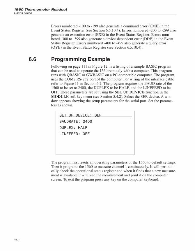
Errors numbered -100 to -199 also generate a command error (CME) in theEvent Status Register (see Section 6.5.10.4). Errors numbered -200 to -299 alsogenerate an execution error (EXE) in the Event Status Register. Errors num-bered -300 to -399 also generate a device-dependent error (DDE) in the EventStatus Register. Errors numbered -400 to -499 also generate a query error(QYE) in the Event Status Register (see Section 6.5.10.4) .
6.6 Programming ExampleFollowing on page 111 in Figure 12 is a listing of a sample BASIC programthat can be used to operate the 1560 remotely with a computer. This programruns with QBASIC or GWBASIC on a PC-compatible computer. The programuses the COM2 RS-232 port of the computer. For wiring of the interface cablerefer to Figure 11 in Section 6.2. The program requires the BAUD rate of the1560 to be set to 2400, the DUPLEX to be HALF, and the LINEFEED to beOFF. These parameters are set using the SET UP DEVICE function in theMODULE soft-key menu (see Section 5.4.2). Select the SER device. A win-dow appears showing the setup parameters for the serial port. Set the parame-ters as shown.
SET UP DEVICE: SER
BAUDRATE: 2400
DUPLEX: HALF
LINEFEED: OFF
The program first resets all operating parameters of the 1560 to default settings.Then it programs the 1560 to measure channel 1 continuously. It will periodi-cally check the operational status register and when it finds that a new measure-ment is available it will read the measurement and print it on the computerscreen. To exit the program press any key on the computer keyboard.
1560 Thermometer Readout
User’s Guide
110
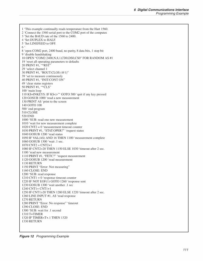
111
6 Digital Communications InterfaceProgramming Example
1 ‘This example continually reads temperature from the Hart 1560.2 ‘Connect the 1560 serial port to the COM2 port of the computer.3 ‘Set the BAUD rate of the 1560 to 2400.4 ‘Set DUPLEX to HALF.5 ‘Set LINEFEED to OFF.6 ‘8 ‘open COM2 port, 2400 baud, no parity, 8 data bits, 1 stop bit9 ‘disable handshaking10 OPEN “COM2:2400,N,8,1,CD0,DS0,CS0" FOR RANDOM AS #119 ‘reset all operating parameters to defaults20 PRINT #1, “*RST”29 ‘select channel 130 PRINT #1, “ROUT:CLOS (@1)”39 ‘set to measure continuously40 PRINT #1, “INIT:CONT ON”49 ‘clear status registers50 PRINT #1, “*CLS”100 ‘main loop110 K$=INKEY$: IF K$<>"" GOTO 500 ‘quit if any key pressed120 GOSUB 1000 ‘read a new measurement130 PRINT A$ ‘print to the screen140 GOTO 100500 ‘end program510 CLOSE520 END1000 ‘SUB: read one new measurement1010 ‘wait for new measurement complete1020 CNT2 = 0 ‘measurement timeout counter1030 PRINT #1, “STAT:OPER?” ‘request status1040 GOSUB 1200 ‘read status1050 IF VAL(A$) AND 16 THEN 1100 ‘measurement complete1060 GOSUB 1300 ‘wait .1 sec.1070 CNT2 = CNT2+11080 IF CNT2>20 THEN 1150 ELSE 1030 ‘timeout after 2 sec.1100 ‘read new measurement1110 PRINT #1, “FETC?” ‘request measurement1120 GOSUB 1200 ‘read measurement1130 RETURN1150 PRINT “Error: Not measuring”1160 CLOSE: END1200 ‘SUB: read response1210 CNT1 = 0 ‘response timeout counter1220 IF NOT EOF(1) GOTO 1260 ‘response sent1230 GOSUB 1300 ‘wait another .1 sec1240 CNT1= CNT1+11250 IF CNT1>20 THEN 1280 ELSE 1220 ‘timeout after 2 sec.1260 LINE INPUT #1, A$ ‘read response1270 RETURN1280 PRINT “Error: No response” ‘timeout1290 CLOSE: END1300 ‘SUB: wait for .1 second1310 T=TIMER1320 IF TIMER<T+.1 THEN 13201330 RETURN
Figure 12 Programming Example
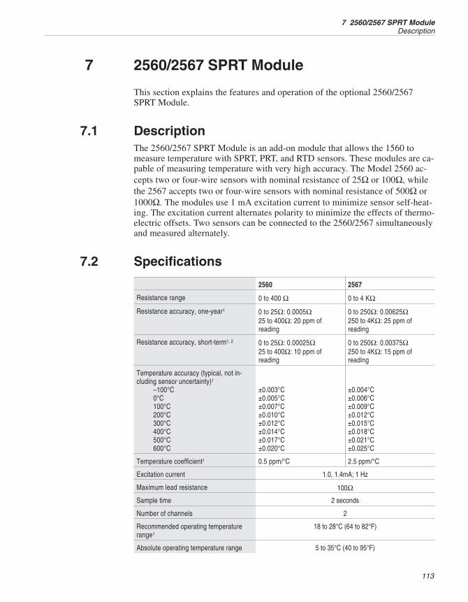
7 2560/2567 SPRT Module
This section explains the features and operation of the optional 2560/2567SPRT Module.
7.1 DescriptionThe 2560/2567 SPRT Module is an add-on module that allows the 1560 tomeasure temperature with SPRT, PRT, and RTD sensors. These modules are ca-pable of measuring temperature with very high accuracy. The Model 2560 ac-cepts two or four-wire sensors with nominal resistance of 25Ω or 100Ω, whilethe 2567 accepts two or four-wire sensors with nominal resistance of 500Ω or1000Ω. The modules use 1 mA excitation current to minimize sensor self-heat-ing. The excitation current alternates polarity to minimize the effects of thermo-electric offsets. Two sensors can be connected to the 2560/2567 simultaneouslyand measured alternately.
7.2 Specifications
2560 2567
Resistance range 0 to 400 Ω 0 to 4 KΩ
Resistance accuracy, one-year1 0 to 25Ω: 0.0005Ω25 to 400Ω: 20 ppm ofreading
0 to 250Ω: 0.00625Ω250 to 4KΩ: 25 ppm ofreading
Resistance accuracy, short-term1, 2 0 to 25Ω: 0.00025Ω25 to 400Ω: 10 ppm ofreading
0 to 250Ω: 0.00375Ω250 to 4KΩ: 15 ppm ofreading
Temperature accuracy (typical, not in-cluding sensor uncertainty)1
–100°C0°C100°C200°C300°C400°C500°C600°C
±0.003°C±0.005°C±0.007°C±0.010°C±0.012°C±0.014°C±0.017°C±0.020°C
±0.004°C±0.006°C±0.009°C±0.012°C±0.015°C±0.018°C±0.021°C±0.025°C
Temperature coefficient1 0.5 ppm/°C 2.5 ppm/°C
Excitation current 1.0, 1.4mA; 1 Hz
Maximum lead resistance 100Ω
Sample time 2 seconds
Number of channels 2
Recommended operating temperaturerange1
18 to 28°C (64 to 82°F)
Absolute operating temperature range 5 to 35°C (40 to 95°F)
113
7 2560/2567 SPRT ModuleDescription
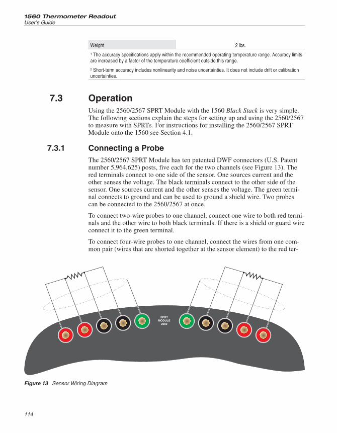
Weight 2 lbs.
1 The accuracy specifications apply within the recommended operating temperature range. Accuracy limitsare increased by a factor of the temperature coefficient outside this range.
2 Short-term accuracy includes nonlinearity and noise uncertainties. It does not include drift or calibrationuncertainties.
7.3 OperationUsing the 2560/2567 SPRT Module with the 1560 Black Stack is very simple.The following sections explain the steps for setting up and using the 2560/2567to measure with SPRTs. For instructions for installing the 2560/2567 SPRTModule onto the 1560 see Section 4.1.
7.3.1 Connecting a ProbeThe 2560/2567 SPRT Module has ten patented DWF connectors (U.S. Patentnumber 5,964,625) posts, five each for the two channels (see Figure 13). Thered terminals connect to one side of the sensor. One sources current and theother senses the voltage. The black terminals connect to the other side of thesensor. One sources current and the other senses the voltage. The green termi-nal connects to ground and can be used to ground a shield wire. Two probescan be connected to the 2560/2567 at once.
To connect two-wire probes to one channel, connect one wire to both red termi-nals and the other wire to both black terminals. If there is a shield or guard wireconnect it to the green terminal.
To connect four-wire probes to one channel, connect the wires from one com-mon pair (wires that are shorted together at the sensor element) to the red ter-
1560 Thermometer Readout
User’s Guide
114
SPRTMODULE
2560
Figure 13 Sensor Wiring Diagram
minals and the wires from the other pair to the black terminals. If there is ashield or guard wire connect it to the green terminal.
7.3.2 Setting CoefficientsOnce a PRT or SPRT probe is properly connected to the 2560/2567, the 1560can read its resistance. To display temperature accurately, the 1560 must beprogrammed with the characterization coefficients for the sensor. This is doneusing the EDIT PROBE soft-key in the PROBE menu (see Section 5.2.1). Thecoefficient values are normally provided with the probe on a calibration report.Be sure to select the proper range for ITS-90 characterizations. If IEC-751RTDs are used you may select the CVD conversion and use R0: 100, ALPHA:0.00385, DELTA: 1.507, and BETA: 0.111.
7.3.3 CurrentThe 2560/2567 sources current to the sensor and measures the resulting voltageacross the sensor to determine its resistance. The current alternates every 0.5seconds to reduce the effects of thermoelectric offsets. The normal current is1.0 mA (2560) or 0.1 mA (2567). The current can be changed to test self-heat-ing effects using the SET UP DEVICE function in the MODULE menu (seeSection 5.4.2). Change the CURRENT parameter and press ENTER.
The SET UP DEVICE function also allows access to two other parameters.SAMP PER selects the sample period between 2 (normal) and 10 seconds. RESRANGE sets the resistance range between AUTO ranging (normal), LOWrange, and HIGH range. The purpose of these options is mainly for trouble-shooting and they should not be changed during normal operation.
7.3.4 Device Setup CommandsThe SYST:MODn:DEVn:READ? and SYST:MODn:DEVn:WRIT commands(see Sections 6.5.8.19 and 6.5.8.20) can be used to read or set the setup param-eters for the 2560/2567 SPRT Module. The device number of the SPRT InputDevice is 1. The module number for the 2560/2567 module is its position in thestack. For example, if the 1560 has four add-on modules, the 2560/2567 beingfirst, the module number for the 2560/2567 is 1. Table 23 shows the devicecommands used to read or set the setup parameters of the SPRT Input Device.
115
7 2560/2567 SPRT ModuleOperation
Device Command Parameter Description
CURR 1, 1.4 (2560)0.1, 0.05 (2567)
Excitation current, mA
SAMP 2, 10 Sample period, seconds
ARNG AUTO, LOW, HIGH Resistance range
Table 23 SPRT Module Device Commands
Below are some examples of using the device commands to set the device setupparameters. For these examples it is assumed that the 2560/2567 SPRT Moduleis placed first in the stack. These commands can be sent through any communi-cation interface including the IEEE-488 and RS-232 interfaces.
SYST: MOD1:DEV1:WRIT "CURR",1.4 Set the excitation current to 1.4mA.
SYST:MOD1:DEV1:READ? "CURR" Read the excitation current.
7.4 CalibrationThis section explains the calibration procedure for the 2560/2567 SPRTModule.
7.4.1 Calibration ParametersThe resistance measurement is derived from the ratio between the voltage mea-surements of the input resistor and reference resistor (100Ω) using the follow-ing equation.
resistance ADJ ratio= ⋅ − +−[ . ( )( ) . ][(.8 3333 10 10 104 400_ 100 0 10. ) ( . )]+ + −100_ 0_ADJ ratio ADJ ratio
Three adjustable calibration parameters are used for calibration: 0_ADJ,100_ADJ, and 400_ADJ. 0_ADJ directly affects the measurement at 0Ω. It hasnegligible effect at 100Ω but significant affect at higher resistances. 100_ADJdirectly affects the measurement at 100Ω. It has negligible effect at 0Ω andproportionately greater effect the higher the resistance. 400_ADJ directly af-fects the measurement at 400Ω. It has negligible effect at 0Ω and 100Ω withgreater effect the more the resistance deviates from 0Ω or 100Ω. Each of theparameters has a positive effect at their primary resistances: increasing thevalue of the parameter increases the measured resistance. The default and theo-retically normal value for each is 0.
7.4.2 Front-panel AccessThe calibration parameters 0_ADJ, 100_ADJ, and 400_ADJ can be adjusted tooptimize the accuracy. They can be accessed from the front panel of the 1560using the CAL DEVICE soft-key function. This is found in the MODULEsub-menu. Pressing the CAL DEVICE soft-key shows a list of devices withthe module position number. Use the UD buttons to move the cursor to theSPRT module and press ENTER.
1560 Thermometer Readout
User’s Guide
116
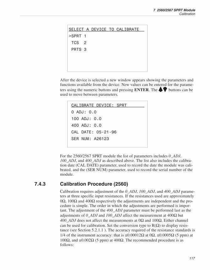
SELECT A DEVICE TO CALIBRATE
>SPRT 1
TCS 2
PRTS 3
After the device is selected a new window appears showing the parameters andfunctions available from the device. New values can be entered for the parame-ters using the numeric buttons and pressing ENTER. The UD buttons can beused to move between parameters.
CALIBRATE DEVICE: SPRT
0 ADJ: 0.0
100 ADJ: 0.0
400 ADJ: 0.0
CAL DATE: 05-21-96
SER NUM: A26123
For the 2560/2567 SPRT module the list of parameters includes 0_ADJ,100_ADJ, and 400_ADJ as described above. The list also includes the calibra-tion date (CAL DATE) parameter, used to record the date the module was cali-brated, and the (SER NUM) parameter, used to record the serial number of themodule.
7.4.3 Calibration Procedure (2560)Calibration requires adjustment of the 0_ADJ, 100_ADJ, and 400_ADJ parame-ters at three specific input resistances. If the resistances used are approximately0Ω, 100Ω and 400Ω respectively the adjustments are independent and the pro-cedure is simple. The order in which the adjustments are performed is impor-tant. The adjustment of the 400_ADJ parameter must be performed last as theadjustments of 0_ADJ and 100_ADJ affect the measurement at 400Ω but400_ADJ does not affect the measurements at 0Ω and 100Ω. Either channelcan be used for calibration. Set the conversion type to R(Ω) to display resis-tance (see Section 5.2.1.1 ). The accuracy required of the resistance standards is1/4 of the instrument accuracy: that is ±0.00012Ω at 0Ω, ±0.0005Ω (5 ppm) at100Ω, and ±0.002Ω (5 ppm) at 400Ω. The recommended procedure is asfollows:
117
7 2560/2567 SPRT ModuleCalibration
1. Connect a 0Ω resistor to the input and measure its resistance. If a short-ing wire is used, the wire should run from the inside black terminal tothe inside red terminal to the outside red terminal then back across to theoutside black terminal. Note the average error in the measurement. Ad-just the 0_ADJ parameter by subtracting the measured error. For exam-ple, if the input is exactly 0.0000Ω and readout shows –0.0011Ω, 0_ADJshould be adjusted by adding 0.0011 to it.
2. Connect a 100Ω resistor (5 ppm accuracy) to the input and measure itsresistance. Note the average error in the measurement. Adjust the100_ADJ parameter by subtracting the measured error. For example, ifthe input is exactly 100.0000Ω and the readout shows 100.0295Ω,100_ADJ should be adjusted by subtracting 0.0295 from it.
3. Connect a 400Ω resistor (5 ppm accuracy) to the input and measure itsresistance. Note the average error in the measurement. Adjust the400_ADJ parameter by subtracting the measured error. For example, ifthe input is exactly 400.0000Ω and the readout shows 399.9913Ω,400_ADJ should be adjusted by adding 0.0087 to it.
4. Record the date with the calibration date parameter.
5. Verify the accuracy at 0Ω, 25Ω or 50Ω, 100Ω, 200Ω, and 400Ω. Verifythe accuracy of both channels with selected resistances. The accuracymust be within the short-term accuracy given in the specifications.
7.4.4 Calibration Procedure (2567)The calibration procedure for the 2567 module is the same as the 2560 exceptthe parameters 0_ADJ, 1K_ADJ, and 4K_ADJ are used to calibrate the mea-surement at 0Ω, 1KΩ, and 4KΩ respectively.
1560 Thermometer Readout
User’s Guide
118
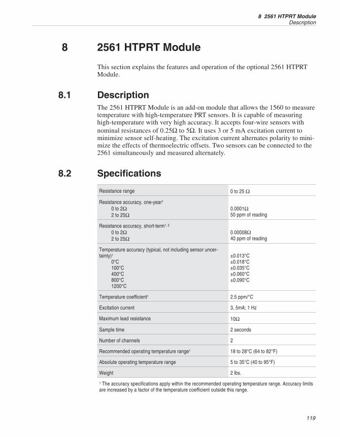
8 2561 HTPRT Module
This section explains the features and operation of the optional 2561 HTPRTModule.
8.1 DescriptionThe 2561 HTPRT Module is an add-on module that allows the 1560 to measuretemperature with high-temperature PRT sensors. It is capable of measuringhigh-temperature with very high accuracy. It accepts four-wire sensors withnominal resistances of 0.25Ω to 5Ω. It uses 3 or 5 mA excitation current tominimize sensor self-heating. The excitation current alternates polarity to mini-mize the effects of thermoelectric offsets. Two sensors can be connected to the2561 simultaneously and measured alternately.
8.2 Specifications
Resistance range 0 to 25 Ω
Resistance accuracy, one-year1
0 to 2Ω2 to 25Ω
0.0001Ω50 ppm of reading
Resistance accuracy, short-term1, 2
0 to 2Ω2 to 25Ω
0.00008Ω40 ppm of reading
Temperature accuracy (typical, not including sensor uncer-tainty)1
0°C100°C400°C800°C1200°C
±0.013°C±0.018°C±0.035°C±0.060°C±0.090°C
Temperature coefficient1 2.5 ppm/°C
Excitation current 3, 5mA; 1 Hz
Maximum lead resistance 10Ω
Sample time 2 seconds
Number of channels 2
Recommended operating temperature range1 18 to 28°C (64 to 82°F)
Absolute operating temperature range 5 to 35°C (40 to 95°F)
Weight 2 lbs.
1 The accuracy specifications apply within the recommended operating temperature range. Accuracy limitsare increased by a factor of the temperature coefficient outside this range.
119
8 2561 HTPRT ModuleDescription
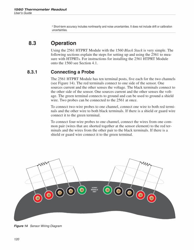
2 Short-term accuracy includes nonlinearity and noise uncertainties. It does not include drift or calibrationuncertainties.
8.3 OperationUsing the 2561 HTPRT Module with the 1560 Black Stack is very simple. Thefollowing sections explain the steps for setting up and using the 2561 to mea-sure with HTPRTs. For instructions for installing the 2561 HTPRT Moduleonto the 1560 see Section 4.1.
8.3.1 Connecting a ProbeThe 2561 HTPRT Module has ten terminal posts, five each for the two channels(see Figure 14). The red terminals connect to one side of the sensor. Onesources current and the other senses the voltage. The black terminals connect tothe other side of the sensor. One sources current and the other senses the volt-age. The green terminal connects to ground and can be used to ground a shieldwire. Two probes can be connected to the 2561 at once.
To connect two-wire probes to one channel, connect one wire to both red termi-nals and the other wire to both black terminals. If there is a shield or guard wireconnect it to the green terminal.
To connect four-wire probes to one channel, connect the wires from one com-mon pair (wires that are shorted together at the sensor element) to the red ter-minals and the wires from the other pair to the black terminals. If there is ashield or guard wire connect it to the green terminal.
1560 Thermometer Readout
User’s Guide
120
HTPRTMODULE
2561
Figure 14 Sensor Wiring Diagram
8.3.2 Setting CoefficientsOnce an HTPRT probe is properly connected to the 2561, the 1560 can read itsresistance. To display temperature accurately, the 1560 must be programmedwith the characterization coefficients for the sensor. This is done using theEDIT PROBE soft-key in the PROBE menu (see Section 5.2.1). The coeffi-cient values are normally provided with the probe on a calibration report. Besure to select the proper range for ITS-90 characterizations.
8.3.3 CurrentThe 2561 sources current to the sensor and measures the resulting voltageacross the sensor to determine its resistance. The current alternates every 0.5seconds to reduce the effects of thermoelectric offsets. The normal current is3.0 mA. The current can be changed to 5.0 mA to test self-heating effects usingthe SET UP DEVICE function in the MODULE menu (see Section 5.4.2).Change the CURRENT parameter from 3.0 to 5.0 and press ENTER.
The SET UP DEVICE function also allows access to one other parameter.SAMP PER selects the sample period between 2 (normal) and 10 seconds. Thepurpose of this option is mainly for troubleshooting and it should not bechanged during normal operation.
8.3.4 Device Setup CommandsThe SYST:MODn:DEVn:READ? and SYST:MODn:DEVn:WRIT commands(see Sections 6.5.8.19 and 6.5.8.20) can be used to read or set the setup param-eters for the 2561 HTPRT Module. The device number of the HTPRT Input De-vice is 1. The module number for the 2561 module is its position in the stack.For example, if the 1560 has four add-on modules, the 2561 being first, themodule number for the 2561 is 1. Table 24 shows the device commands used toread or set the setup parameters of the HTPRT Input Device.
Below are some examples of using the device commands to set the device setupparameters. For these examples it is assumed that the 2561 HTPRT Module isplaced first in the stack. These commands can be sent through any communica-tion interface including the IEEE-488 and RS-232 interfaces.
SYST: MOD1:DEV1:WRIT "CURR",5 Set the excitation current to 5.0mA.
SYST:MOD1:DEV1:READ? "CURR" Read the excitation current.
121
8 2561 HTPRT ModuleOperation
Device Command Parameter Description
CURR 3, 5 Excitation current, mA
SAMP 2, 10 Sample period, seconds
Table 24 HTPRT Module Device Commands
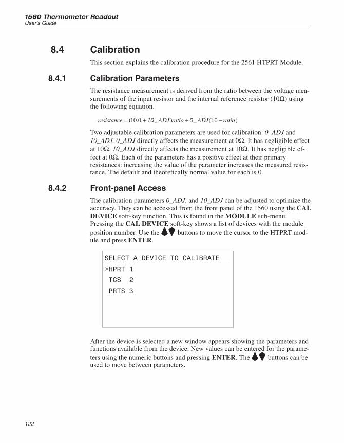
8.4 CalibrationThis section explains the calibration procedure for the 2561 HTPRT Module.
8.4.1 Calibration ParametersThe resistance measurement is derived from the ratio between the voltage mea-surements of the input resistor and the internal reference resistor (10Ω) usingthe following equation.
resistance ADJ ratio ADJ ratio= + + −( . _ ) _ ( . )10 0 1 010 0
Two adjustable calibration parameters are used for calibration: 0_ADJ and10_ADJ. 0_ADJ directly affects the measurement at 0Ω. It has negligible effectat 10Ω. 10_ADJ directly affects the measurement at 10Ω. It has negligible ef-fect at 0Ω. Each of the parameters has a positive effect at their primaryresistances: increasing the value of the parameter increases the measured resis-tance. The default and theoretically normal value for each is 0.
8.4.2 Front-panel AccessThe calibration parameters 0_ADJ, and 10_ADJ can be adjusted to optimize theaccuracy. They can be accessed from the front panel of the 1560 using the CALDEVICE soft-key function. This is found in the MODULE sub-menu.Pressing the CAL DEVICE soft-key shows a list of devices with the moduleposition number. Use the UD buttons to move the cursor to the HTPRT mod-ule and press ENTER.
SELECT A DEVICE TO CALIBRATE
>HPRT 1
TCS 2
PRTS 3
After the device is selected a new window appears showing the parameters andfunctions available from the device. New values can be entered for the parame-ters using the numeric buttons and pressing ENTER. The UD buttons can beused to move between parameters.
1560 Thermometer Readout
User’s Guide
122
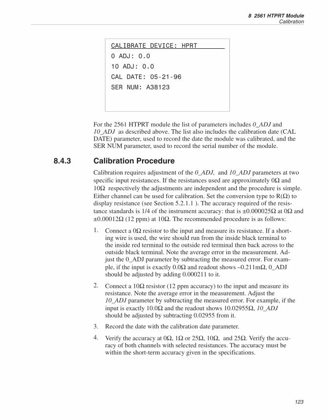
CALIBRATE DEVICE: HPRT
0 ADJ: 0.0
10 ADJ: 0.0
CAL DATE: 05-21-96
SER NUM: A38123
For the 2561 HTPRT module the list of parameters includes 0_ADJ and10_ADJ as described above. The list also includes the calibration date (CALDATE) parameter, used to record the date the module was calibrated, and theSER NUM parameter, used to record the serial number of the module.
8.4.3 Calibration ProcedureCalibration requires adjustment of the 0_ADJ, and 10_ADJ parameters at twospecific input resistances. If the resistances used are approximately 0Ω and10Ω respectively the adjustments are independent and the procedure is simple.Either channel can be used for calibration. Set the conversion type to R(Ω) todisplay resistance (see Section 5.2.1.1 ). The accuracy required of the resis-tance standards is 1/4 of the instrument accuracy: that is ±0.000025Ω at 0Ω and±0.00012Ω (12 ppm) at 10Ω. The recommended procedure is as follows:
1. Connect a 0Ω resistor to the input and measure its resistance. If a short-ing wire is used, the wire should run from the inside black terminal tothe inside red terminal to the outside red terminal then back across to theoutside black terminal. Note the average error in the measurement. Ad-just the 0_ADJ parameter by subtracting the measured error. For exam-ple, if the input is exactly 0.0Ω and readout shows –0.211mΩ, 0_ADJshould be adjusted by adding 0.000211 to it.
2. Connect a 10Ω resistor (12 ppm accuracy) to the input and measure itsresistance. Note the average error in the measurement. Adjust the10_ADJ parameter by subtracting the measured error. For example, if theinput is exactly 10.0Ω and the readout shows 10.02955Ω, 10_ADJshould be adjusted by subtracting 0.02955 from it.
3. Record the date with the calibration date parameter.
4. Verify the accuracy at 0Ω, 1Ω or 25Ω, 10Ω, and 25Ω. Verify the accu-racy of both channels with selected resistances. The accuracy must bewithin the short-term accuracy given in the specifications.
123
8 2561 HTPRT ModuleCalibration
9 2562/2568 PRT Scanner Module
This section explains the features and operation of the optional 2562/2568 PRTScanner Module.
9.1 DescriptionThe 2562/2568 PRT Scanner Module is an add-on module that allows the 1560to measure temperature with up to eight SPRT, PRT, and RTD sensors. Themodules accept two-, three-, or four-wire sensors with nominal resistance of 25and 100Ω (2562) or 500 and 1KΩ (2568). The excitation current alternates po-larity to minimize the effects of thermoelectric offsets. Up to eight sensors canbe connected to the 2562/2568 simultaneously and measured alternately.
9.2 Specifications
2562 2568
Resistance range 0 to 400Ω 0 to 4 kΩ
Resistance accuracy, one-year(Using four-wire connection)1, 3
0 to 25Ω: 0.001Ω25 to 400Ω: 40 ppm of read-
ing
0 to 250Ω: 0.01Ω250 to 4KΩ: 40 ppm of read-
ing
Resistance accuracy, short-term(Using four-wire connection)1, 2, 3
0 to 25Ω: 0.0005Ω25 to 400Ω: 20 ppm of read-
ing
0 to 250Ω: 0.0075Ω250 to 4KΩ: 30 ppm of read-
ing
Temperature accuracy, one-year (Usingfour-wire connection, not including probeuncertainty)1, 3
–100°C0°C100°C200°C300°C400°C500°C600°C
±0.006°C±0.010°C±0.014°C±0.020°C±0.024°C±0.028°C±0.034°C±0.040°C
Temperature coefficient1 0.5 ppm/°C 2.5 ppm/°C
Excitation current 1.0, 1.4 mA; 1 Hz 0.1, 0.05 mA; 1 Hz
Maximum lead resistance 100Ω
Sample time 2 seconds
Number of channels 8
Recommended operating temperaturerange1
18 to 28°C (64 to 82°F)
Absolute operating temperature range 5 to 35°C (40 to 95°F)
Weight 2.5 lbs. (1.1 kg)
125
9 2562/2568 PRT Scanner ModuleDescription
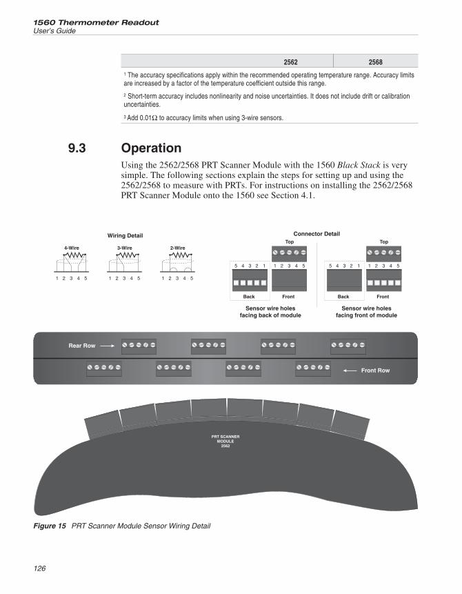
2562 2568
1 The accuracy specifications apply within the recommended operating temperature range. Accuracy limitsare increased by a factor of the temperature coefficient outside this range.
2 Short-term accuracy includes nonlinearity and noise uncertainties. It does not include drift or calibrationuncertainties.
3 Add 0.01Ω to accuracy limits when using 3-wire sensors.
9.3 OperationUsing the 2562/2568 PRT Scanner Module with the 1560 Black Stack is verysimple. The following sections explain the steps for setting up and using the2562/2568 to measure with PRTs. For instructions on installing the 2562/2568PRT Scanner Module onto the 1560 see Section 4.1.
1560 Thermometer Readout
User’s Guide
126
PRT SCANNERMODULE
2562
1 1 12 2 23 3 34 4 45 5 5
4-Wire 3-Wire 2-Wire
Wiring Detail
Front Row
Rear Row
Back Front
Top
11 22 33 44 55
Connector Detail
Back Front
Top
11 22 33 44 55
Sensor wire holesfacing back of module
Sensor wire holesfacing front of module
Figure 15 PRT Scanner Module Sensor Wiring Detail
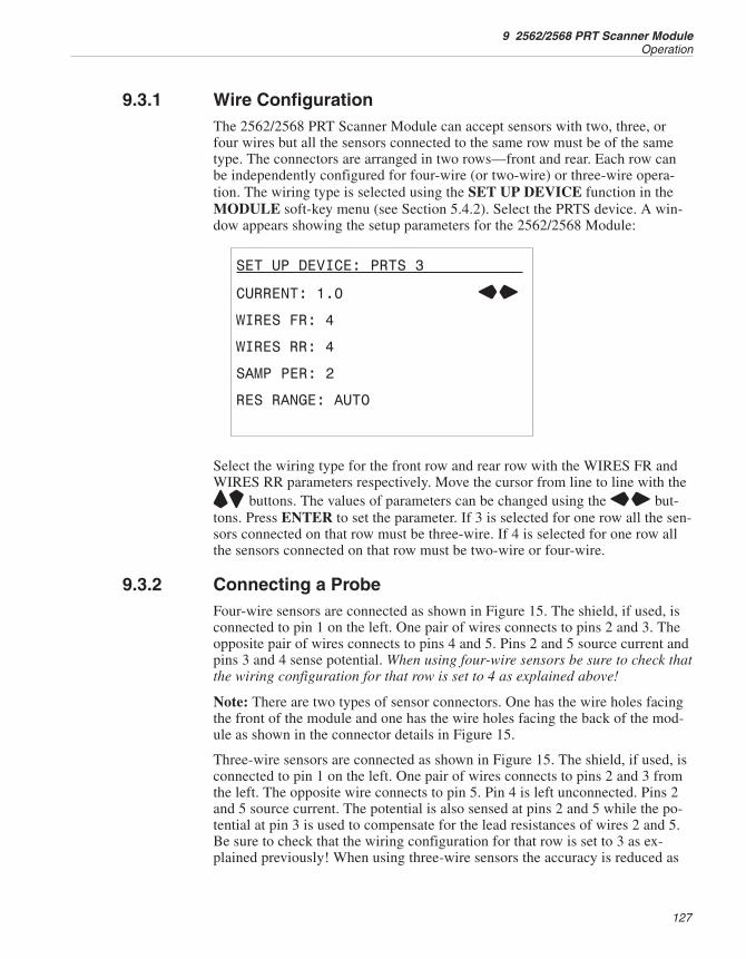
9.3.1 Wire ConfigurationThe 2562/2568 PRT Scanner Module can accept sensors with two, three, orfour wires but all the sensors connected to the same row must be of the sametype. The connectors are arranged in two rows—front and rear. Each row canbe independently configured for four-wire (or two-wire) or three-wire opera-tion. The wiring type is selected using the SET UP DEVICE function in theMODULE soft-key menu (see Section 5.4.2). Select the PRTS device. A win-dow appears showing the setup parameters for the 2562/2568 Module:
SET UP DEVICE: PRTS 3
CURRENT: 1.0 LR
WIRES FR: 4
WIRES RR: 4
SAMP PER: 2
RES RANGE: AUTO
Select the wiring type for the front row and rear row with the WIRES FR andWIRES RR parameters respectively. Move the cursor from line to line with theUD buttons. The values of parameters can be changed using the LR but-tons. Press ENTER to set the parameter. If 3 is selected for one row all the sen-sors connected on that row must be three-wire. If 4 is selected for one row allthe sensors connected on that row must be two-wire or four-wire.
9.3.2 Connecting a ProbeFour-wire sensors are connected as shown in Figure 15. The shield, if used, isconnected to pin 1 on the left. One pair of wires connects to pins 2 and 3. Theopposite pair of wires connects to pins 4 and 5. Pins 2 and 5 source current andpins 3 and 4 sense potential. When using four-wire sensors be sure to check thatthe wiring configuration for that row is set to 4 as explained above!
Note: There are two types of sensor connectors. One has the wire holes facingthe front of the module and one has the wire holes facing the back of the mod-ule as shown in the connector details in Figure 15.
Three-wire sensors are connected as shown in Figure 15. The shield, if used, isconnected to pin 1 on the left. One pair of wires connects to pins 2 and 3 fromthe left. The opposite wire connects to pin 5. Pin 4 is left unconnected. Pins 2and 5 source current. The potential is also sensed at pins 2 and 5 while the po-tential at pin 3 is used to compensate for the lead resistances of wires 2 and 5.Be sure to check that the wiring configuration for that row is set to 3 as ex-plained previously! When using three-wire sensors the accuracy is reduced as
127
9 2562/2568 PRT Scanner ModuleOperation
shown in the specifications. Also, be aware that any difference between theresistances of the lead wires directly affects accuracy.
Two-wire sensors are connected as shown in Figure 15. The shield, if used, isconnected to pin 1 on the left. One wire connects to both pins 2 and 3 from theleft. The opposite wire connects to both pins 4 and 5. Be sure to check that thewiring configuration for that row is set to 4 as explained above! When usingtwo-wire sensors the 2562/2568 is unable to compensate for lead resistance.
9.3.3 Setting CoefficientsOnce a PRT or SPRT probe is properly connected to the 2562/2568, the 1560can read out its resistance. To display temperature accurately the 1560 must beprogrammed with the characterization coefficients for the sensor. This is doneusing the EDIT PROBE soft-key in the PROBE menu (see Section 5.2.1). Thecoefficient values are normally provided with the probe on a calibration report.Be sure to select the proper range for ITS-90 characterizations. If IEC-751RTDs are used you may select the CVD conversion and use R0: 100, ALPHA:0.00385, DELTA: 1.507, and BETA: 0.111.
9.3.4 CurrentThe 2562/2568 sources current to the sensor and measures the resulting voltageacross the sensor to determine its resistance. The current alternates every 0.5seconds to reduce the effects of thermoelectric offsets. The normal current is1.0 mA. The current can be changed to 1.4 mA to test self-heating effects usingthe SET UP DEVICE function in the MODULE menu (see Section 5.4.2).Change the CURRENT parameter from 1.0 to 1.4 and press ENTER.
The SET UP DEVICE function also allows access to two other parameters.SAMP PER selects the sample period between 2 (normal) and 10 seconds. RESRANGE sets the resistance range between AUTO ranging (normal), LOWrange, and HIGH range. The purpose of these options is mainly for trouble-shooting and they should not need to be changed during normal operation.
9.3.5 Device Setup CommandsThe SYST:MODn:DEVn:READ? and SYST:MODn:DEVn:WRIT commands(see Sections 6.5.8.19 and 6.5.8.20) can be used to read or set the setup param-eters for the 2562/2568 PRT Scanner Module. The device number of the PRTScanner Input Device is 1. The module number for the 2562/2568 module is itsposition in the stack. For example, if the 1560 has four add-on modules, the2562/2568 being second, the module number for the 2562/2568 is 2. Table 25
1560 Thermometer Readout
User’s Guide
128
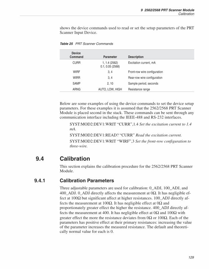
shows the device commands used to read or set the setup parameters of the PRTScanner Input Device.
Below are some examples of using the device commands to set the device setupparameters. For these examples it is assumed that the 2562/2568 PRT ScannerModule is placed second in the stack. These commands can be sent through anycommunication interface including the IEEE-488 and RS-232 interfaces.
SYST:MOD2:DEV1:WRIT “CURR”,1.4 Set the excitation current to 1.4mA.
SYST:MOD2:DEV1:READ? “CURR” Read the excitation current.
SYST:MOD2:DEV1:WRIT “WIRF”,3 Set the front-row configuration tothree-wire.
9.4 CalibrationThis section explains the calibration procedure for the 2562/2568 PRT ScannerModule.
9.4.1 Calibration ParametersThree adjustable parameters are used for calibration: 0_ADJ, 100_ADJ, and400_ADJ. 0_ADJ directly affects the measurement at 0Ω. It has negligible ef-fect at 100Ω but significant affect at higher resistances. 100_ADJ directly af-fects the measurement at 100Ω. It has negligible effect at 0Ω andproportionately greater effect the higher the resistance. 400_ADJ directly af-fects the measurement at 400. It has negligible effect at 0Ω and 100Ω withgreater effect the more the resistance deviates from 0Ω or 100Ω. Each of theparameters has positive effect at their primary resistances: increasing the valueof the parameter increases the measured resistance. The default and theoreti-cally normal value for each is 0.
129
9 2562/2568 PRT Scanner ModuleCalibration
DeviceCommand Parameter Description
CURR 1, 1.4 (2562)0.1, 0.05 (2568)
Excitation current, mA
WIRF 3, 4 Front-row wire configuration
WIRR 3, 4 Rear-row wire configuration
SAMP 2, 10 Sample period, seconds
ARNG AUTO, LOW, HIGH Resistance range
Table 25 PRT Scanner Commands
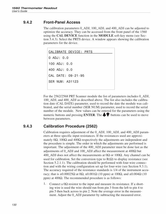
9.4.2 Front-Panel AccessThe calibration parameters 0_ADJ, 100_ADJ, and 400_ADJ can be adjusted tooptimize the accuracy. They can be accessed from the front panel of the 1560using the CAL DEVICE function in the MODULE soft-key menu (see Sec-tion 5.4.3). Select the PRTS device. A window appears showing the calibrationparameters for the device.
CALIBRATE DEVICE: PRTS
0 ADJ: 0.0
100 ADJ: 0.0
400 ADJ: 0.0
CAL DATE: 09-21-95
SER NUM: A31123
For the 2562/2568 PRT Scanner module the list of parameters includes 0_ADJ,100_ADJ, and 400_ADJ as described above. The list also includes the calibra-tion date (CAL DATE) parameter, used to record the date the module was cali-brated, and the serial number (SER NUM) parameter, used to record the serialnumber of the module. New values can be entered for the parameters using thenumeric buttons and pressing ENTER. The UD buttons can be used to movebetween parameters.
9.4.3 Calibration Procedure (2562)Calibration requires adjustment of the 0_ADJ, 100_ADJ, and 400_ADJ param-eters at three specific input resistances. If the resistances used are approxi-mately 0Ω, 100Ω and 400Ω respectively the adjustments are independent andthe procedure is simple. The order in which the adjustments are performed isimportant. The adjustment of the 400_ADJ parameter must be done last as theadjustments of 0_ADJ and 100_ADJ affect the measurement at 400Ω but400_ADJ does not affect the measurements at 0Ω or 100Ω. Any channel can beused for calibration. Set the conversion type to R(Ω) to display resistance (seeSection 5.2.1.1). The calibration should be performed with four-wire connec-tion and with the wiring configuration set up for four-wire (see Section 9.3.1).The accuracy required of the resistance standards is 1/4 of the instrument accu-racy; that is ±0.00025Ω at 0Ω, ±0.001Ω (10 ppm) at 100Ω, and ±0.004Ω (10ppm) at 400Ω. The recommended procedure is as follows:
1. Connect a 0Ω resistor to the input and measure its resistance. If a short-ing wire is used the wire should run from pin 3 from the left to pin 4 topin 5 then back across to pin 2. Note the average error in the measure-ment. Adjust the 0_ADJ parameter by subtracting the measured error.
1560 Thermometer Readout
User’s Guide
130
For example, if the input is exactly 0.0000 and readout shows –0.0011,0_ADJ should be adjusted by adding 0.0011 to it.
2. Connect a 100Ω resistor (10 ppm accuracy) to the input and measure itsresistance. Note the average error in the measurement. Adjust the100_ADJ parameter by subtracting the measured error. For example, ifthe input is exactly 100.0000Ω and the readout shows 100.0295Ω,100_ADJ should be adjusted by subtracting 0.0295 from it.
3. Connect a 400Ω resistor (10 ppm accuracy) to the input and measure itsresistance. Note the average error in the measurement. Adjust the400_ADJ parameter by subtracting the measured error. For example, ifthe input is exactly 400.0000Ω and the readout shows 399.9913Ω,400_ADJ should be adjusted by adding 0.0087 to it.
4. Record the date with the calibration date parameter.
5. Verify the accuracy at 0Ω, 25Ω or 50Ω, 100Ω, 200Ω, and 400Ω on se-lected channels. Verify at least one resistance on each channel. The accuracymust be within the short-term accuracy given in the specifications.
6. Set the wiring configuration of both rows to three-wire (see Section9.3.1). Verify the accuracy with at least one resistance on each channel.The accuracy must be within the short-term accuracy plus the additionalthree-wire uncertainty as given in the specifications.
9.4.4 Calibration Procedure (2568)The calibration procedure for the 2568 Module is the same as the 2562 exceptthe parameters 0_ADJ, 1K_ADJ, and 4K_ADJ are used to calibrate the mea-surement at 0Ω, 1KΩ, and 4KΩ respectively.
131
9 2562/2568 PRT Scanner ModuleCalibration
10 2563 Thermistor Module
This section explains the features and operation of the optional 2563 Thermis-tor Module.
10.1 DescriptionThe 2563 Thermistor Module is an add-on module that allows the 1560 to mea-sure temperature with thermistor sensors. It is capable of measuring tempera-ture with very high accuracy, to 0.0013°C. It accepts nearly every type ofthermistor sensor, two or four-wire. It uses very small excitation currents tominimize sensor self-heating. The excitation current alternates polarity to mini-mize the effects of thermoelectric offsets. Two thermistor sensors can be con-nected to the 2563 simultaneously and measured alternately.
10.2 Specifications
Resistance range 0 to 1 MΩ
Resistance accuracy, one-year1
0 to 2kΩ2k to 100kΩ100kΩ to 1 MΩ
0.1Ω50 ppm of reading200 ppm of reading
Resistance accuracy, short-term1, 2
0 to 2kΩ2k to 100kΩ100kΩ to 1 MΩ
0.08Ω40 ppm of reading180 ppm of reading
Temperature accuracy (with 10kΩ, α=0.04 sensor; not includ-ing sensor uncertainty)1
0°C25°C50°C75°C100°C
±0.0013°C±0.0013°C±0.0013°C±0.0015°C±0.003°C
Temperature coefficient1 2.5 ppm/°C
Excitation current 2.0,10.0 μA; automatically selected; 1Hz.
Maximum lead resistance 100Ω
Sample time 2 seconds
Number of channels 2
Recommended operating temperature range1 18 to 28°C (64 to 82°F)
Absolute operating temperature range 5 to 35°C (40 to 95°F)
Weight 2 lbs. (0.9 kg.)
1 The accuracy specifications apply within the recommended operating temperature range. Accuracy limitsare increased by a factor of the temperature coefficient outside this range.
133
10 2563 Thermistor ModuleDescription
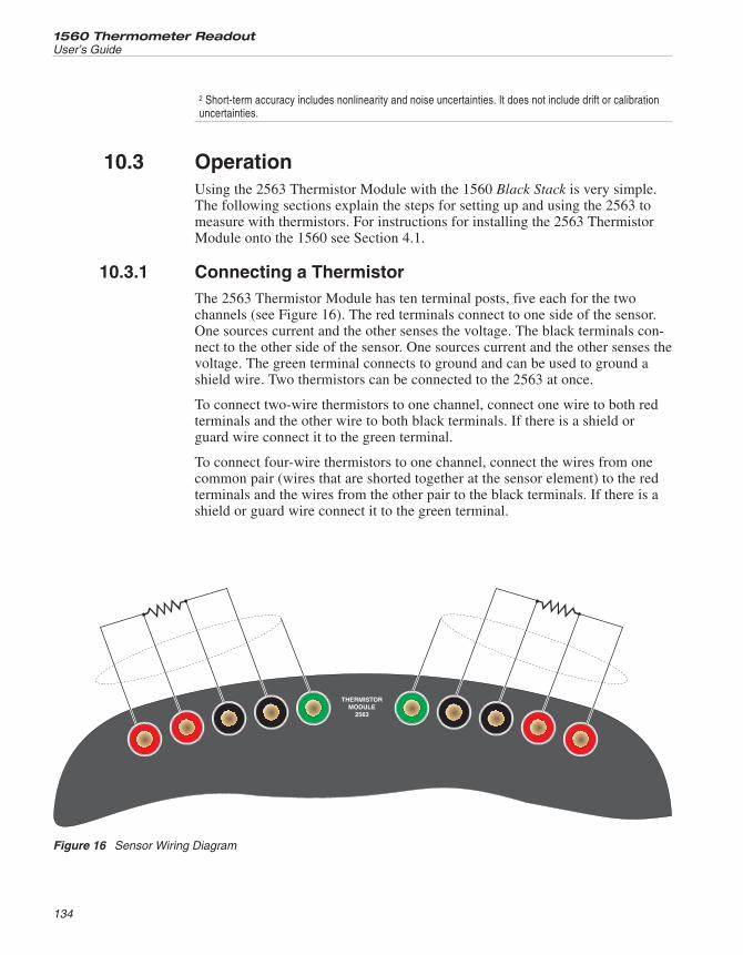
2 Short-term accuracy includes nonlinearity and noise uncertainties. It does not include drift or calibrationuncertainties.
10.3 OperationUsing the 2563 Thermistor Module with the 1560 Black Stack is very simple.The following sections explain the steps for setting up and using the 2563 tomeasure with thermistors. For instructions for installing the 2563 ThermistorModule onto the 1560 see Section 4.1.
10.3.1 Connecting a ThermistorThe 2563 Thermistor Module has ten terminal posts, five each for the twochannels (see Figure 16). The red terminals connect to one side of the sensor.One sources current and the other senses the voltage. The black terminals con-nect to the other side of the sensor. One sources current and the other senses thevoltage. The green terminal connects to ground and can be used to ground ashield wire. Two thermistors can be connected to the 2563 at once.
To connect two-wire thermistors to one channel, connect one wire to both redterminals and the other wire to both black terminals. If there is a shield orguard wire connect it to the green terminal.
To connect four-wire thermistors to one channel, connect the wires from onecommon pair (wires that are shorted together at the sensor element) to the redterminals and the wires from the other pair to the black terminals. If there is ashield or guard wire connect it to the green terminal.
1560 Thermometer Readout
User’s Guide
134
THERMISTORMODULE
2563
Figure 16 Sensor Wiring Diagram
10.3.2 Setting CoefficientsOnce a thermistor is properly connected to the 2563, the 1560 can read out itsresistance. To display temperature accurately, the 1560 must be programmedwith the characterization coefficients for the sensor. This is done using theEDIT PROBE soft-key in the PROBE menu (see Section 5.2.1). The coeffi-cient values are normally provided with the probe on a calibration report. Besure to select the proper equation type, R(T) or T(R).
10.3.3 CurrentThe 2563 sources current to the sensor and measures the resulting voltageacross the sensor to determine its resistance. The current alternates every 0.5seconds to reduce the effects of thermoelectric offsets. The current automati-cally switches between 2 μA and 10 μA depending on the resistance beingmeasured. At lower resistances (below about 50 kΩ) 10 μA is used. At higherresistances 2 μA is used. You can force the current source to use 2 μA for lowresistances, if necessary, using the SET UP DEVICE function in the MOD-ULE menu (see Section5.4.2). Change the CURRENT parameter from AUTOto 2.0 and press ENTER.
The SET UP DEVICE function also allows access to two other parameters.SAMP PER selects the sample period between 2 (normal) and 10 seconds. RESRANGE sets the resistance range between AUTO ranging (normal), LOWrange, and HIGH range. The purpose of these options is mainly for trouble-shooting and they should not need to be changed during normal operation.
10.3.4 Device Setup CommandsThe SYST:MODn:DEVn:READ? and SYST: MODn:DEVn:WRIT commands(see Sections 6.5.8.19 and 6.5.8.20) can be used to read or set the setup param-eters for the 2563 Thermistor Module. The device number of the Thermistor In-put Device is 1. The module number for the 2563 module is its position in thestack. For example, if the 1560 has four add-on modules, the 2563 being third,the module number for the 2563 is 3. Table 26 shows the device commandsused to read or set the setup parameters of the Thermistor Input Device.
Below are some examples of using the device commands to set the device setupparameters. For these examples it is assumed that the 2563 Thermistor Input
135
10 2563 Thermistor ModuleOperation
Device CommandParameter Description
CURR AUTO, 2, 10 Excitation current, μA
SAMP 2, 10 Sample period, seconds
ARNG AUTO, LOW, HIGH Resistance range
Table 26 Thermistor Module Device Commands
Module is placed third in the stack. These commands can be sent through anycommunication interface including the IEEE-488 and RS-232 interfaces.
SYST:MOD2:DEV1:WRIT “CURR”,2 Set the excitation current to 2 μA.
SYST:MOD2:DEV1:READ? “CURR” Read the excitation current.
10.4 CalibrationThis section explains the calibration procedure for the 2563 ThermistorModule.
10.4.1 Calibration ParametersThe resistance measurement is derived from the ratio between the voltage mea-surements of the input resistor and reference resistor (20 kΩ) using the follow-ing equation.
resistance K ADJ ratio= ⋅ × − +−[ . ( _ )( . ) ..1111 10 2 0 10 16 100 0 10 10 2 0 10 104][( . _ ) . _ ( . . )]⋅ + + −10 0K ADJ ratio ADJ ratio
Three adjustable parameters are used for calibration: 0_ADJ, 10K_ADJ, and100K_ADJ. 0_ADJ directly affects the measurement at 0Ω. It has negligible ef-fect at 10 kΩ but significant affect at higher resistances. 10K_ADJ directly af-fects the measurement at 10 kΩ. It has negligible effect at 0Ω andproportionately greater effect the higher the resistance. 100K_ADJ directly af-fects the measurement at 100 kΩ. It has negligible effect at 0Ω and 10 kΩ withgreater effect the more the resistance deviates from 0Ω or 10 kΩ. Each of theparameters has positive effect at their primary resistances: increasing the valueof the parameter increases the measured resistance. The default and theoreti-cally normal value for each is 0.
10.4.2 Front-panel AccessThe calibration parameters 0_ADJ, 10K_ADJ, and 100K_ADJ can be adjustedto optimize the accuracy. They can be accessed from the front panel of the 1560using the CAL DEVICE soft-key function. This is found in the MODULEsub-menu. Pressing the CAL DEVICE soft-key shows a list of devices withthe module position number. Use the UD buttons to move the cursor to theSTHR module and press ENTER.
1560 Thermometer Readout
User’s Guide
136
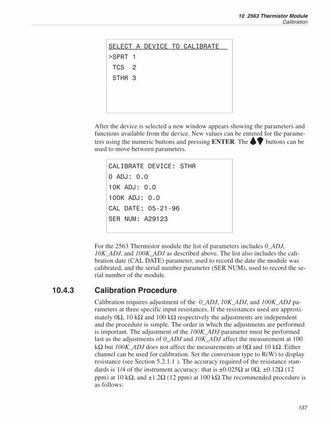
SELECT A DEVICE TO CALIBRATE
>SPRT 1
TCS 2
STHR 3
After the device is selected a new window appears showing the parameters andfunctions available from the device. New values can be entered for the parame-ters using the numeric buttons and pressing ENTER. The UD buttons can beused to move between parameters.
CALIBRATE DEVICE: STHR
0 ADJ: 0.0
10K ADJ: 0.0
100K ADJ: 0.0
CAL DATE: 05-21-96
SER NUM: A29123
For the 2563 Thermistor module the list of parameters includes 0_ADJ,10K_ADJ, and 100K_ADJ as described above. The list also includes the cali-bration date (CAL DATE) parameter, used to record the date the module wascalibrated, and the serial number parameter (SER NUM), used to record the se-rial number of the module.
10.4.3 Calibration ProcedureCalibration requires adjustment of the 0_ADJ, 10K_ADJ, and 100K_ADJ pa-rameters at three specific input resistances. If the resistances used are approxi-mately 0Ω, 10 kΩ and 100 kΩ respectively the adjustments are independentand the procedure is simple. The order in which the adjustments are performedis important. The adjustment of the 100K_ADJ parameter must be performedlast as the adjustments of 0_ADJ and 10K_ADJ affect the measurement at 100kΩ but 100K_ADJ does not affect the measurements at 0Ω and 10 kΩ. Eitherchannel can be used for calibration. Set the conversion type to R(W) to displayresistance (see Section 5.2.1.1 ). The accuracy required of the resistance stan-dards is 1/4 of the instrument accuracy: that is ±0.025Ω at 0Ω, ±0.12Ω (12ppm) at 10 kΩ, and ±1.2Ω (12 ppm) at 100 kΩ.The recommended procedure isas follows:
137
10 2563 Thermistor ModuleCalibration
1. Connect a 0Ω resistor to the input and measure its resistance. If a short-ing wire is used, the wire should run from the inside black terminal tothe inside red terminal to the outside red terminal then back across to theoutside black terminal. Note the average error in the measurement. Ad-just the 0_ADJ parameter by subtracting the measured error. For exam-ple, if the input is exactly 0.0Ω and readout shows -0.11Ω, 0_ADJshould be adjusted by adding 0.11 to it.
2. Connect a 10 kΩ resistor (12 ppm accuracy) to the input and measure itsresistance. Note the average error in the measurement. Adjust the10K_ADJ parameter by subtracting the measured error. For example, ifthe input is exactly 10.00000 kΩ and the readout shows 10.00295 kΩ,10K_ADJ should be adjusted by subtracting 2.95 from it.
3 Connect a 100 kΩ resistor (12 ppm accuracy) to the input and measureits resistance. Note the average error in the measurement. Adjust the100K_ADJ parameter by subtracting the measured error. For example, ifthe input is exactly 100.0000 kΩ and the readout shows 99.9913 kΩ,100K_ADJ should be adjusted by adding 8.7 to it.
4. Record the date with the calibration date parameter.
5. Verify the accuracy at 0Ω, 4kΩ, 10kΩ, 40kΩ, 100kΩ, and 1MΩ on bothchannels. Verify the accuracy of both channels with selected resistances.The accuracy must be within the short-term accuracy given in thespecifications.
1560 Thermometer Readout
User’s Guide
138
11 2564 Thermistor Scanner Module
This section explains the features and operation of the optional 2564 Thermis-tor Scanner Module.
11.1 DescriptionThe 2564 Thermistor Scanner Module is an add-on module that allows the1560 to measure temperature with up to eight thermistors. It accepts nearly ev-ery type of thermistor sensor with either two, three, or four wires. It uses verysmall excitation currents to minimize sensor self-heating. The excitation currentalternates polarity to minimize the effects of thermoelectric offsets. Up to eightsensors can be connected to the 2564 simultaneously and measured alternately.
11.2 Specifications
Resistance range 0 to 1 MΩ
Resistance accuracy, one-year1
0 to 2 kΩ2 to 100 kΩ100 kΩ to 1 MΩ
0.2Ω100 ppm of reading300 ppm of reading
Resistance accuracy, short-term1, 2
0 to 2 kΩ2 to 100 kΩ100 kΩ to 1 MΩ
0.15Ω75 ppm of reading250 ppm of reading
Temparature accuracy, one-year (with 10kΩ, α=0.04 sensor;not including sensor uncertainty)1
0°C25°C50°C75°C100°C
±0.0025°C±0.0025°C±0.0025°C±0.003°C±0.006°C
Temperature coefficient 2.5 ppm/°C
Excitation current 2, 10 μA; automatically selected: 1 Hz
Maximum lead resistance 100Ω
Sample time 2 seconds
Number of channels 8
Recommended operating temperature range1 18 to 28°C (64 to 82°F)
Absolute operating temperature range 5 to 35°C (40 to 95°F)
Weight 2.5 lbs. (1.1 kg.)
1 The accuracy specifications apply within the recommended operating temperature range. Accuracy limitsare increased by a factor of the temperature coefficient outside this range.
2 Short-term accuracy includes nonlinearity and noise uncertainties. It does not include drift or calibrationuncertainties.
139
11 2564 Thermistor Scanner ModuleDescription
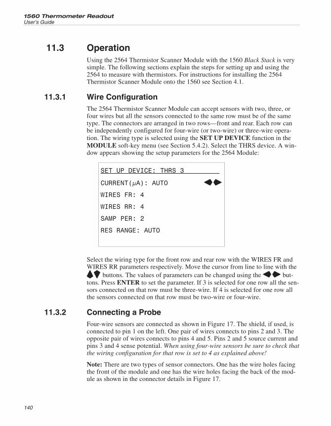
11.3 OperationUsing the 2564 Thermistor Scanner Module with the 1560 Black Stack is verysimple. The following sections explain the steps for setting up and using the2564 to measure with thermistors. For instructions for installing the 2564Thermistor Scanner Module onto the 1560 see Section 4.1.
11.3.1 Wire ConfigurationThe 2564 Thermistor Scanner Module can accept sensors with two, three, orfour wires but all the sensors connected to the same row must be of the sametype. The connectors are arranged in two rows—front and rear. Each row canbe independently configured for four-wire (or two-wire) or three-wire opera-tion. The wiring type is selected using the SET UP DEVICE function in theMODULE soft-key menu (see Section 5.4.2). Select the THRS device. A win-dow appears showing the setup parameters for the 2564 Module:
SET UP DEVICE: THRS 3
CURRENT(µA): AUTO LR
WIRES FR: 4
WIRES RR: 4
SAMP PER: 2
RES RANGE: AUTO
Select the wiring type for the front row and rear row with the WIRES FR andWIRES RR parameters respectively. Move the cursor from line to line with theUD buttons. The values of parameters can be changed using the LR but-tons. Press ENTER to set the parameter. If 3 is selected for one row all the sen-sors connected on that row must be three-wire. If 4 is selected for one row allthe sensors connected on that row must be two-wire or four-wire.
11.3.2 Connecting a ProbeFour-wire sensors are connected as shown in Figure 17. The shield, if used, isconnected to pin 1 on the left. One pair of wires connects to pins 2 and 3. Theopposite pair of wires connects to pins 4 and 5. Pins 2 and 5 source current andpins 3 and 4 sense potential. When using four-wire sensors be sure to check thatthe wiring configuration for that row is set to 4 as explained above!
Note: There are two types of sensor connectors. One has the wire holes facingthe front of the module and one has the wire holes facing the back of the mod-ule as shown in the connector details in Figure 17.
1560 Thermometer Readout
User’s Guide
140
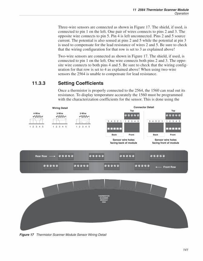
Three-wire sensors are connected as shown in Figure 17. The shield, if used, isconnected to pin 1 on the left. One pair of wires connects to pins 2 and 3. Theopposite wire connects to pin 5. Pin 4 is left unconnected. Pins 2 and 5 sourcecurrent. The potential is also sensed at pins 2 and 5 while the potential at pin 3is used to compensate for the lead resistance of wires 2 and 5. Be sure to checkthat the wiring configuration for that row is set to 3 as explained above!
Two-wire sensors are connected as shown in Figure 17. The shield, if used, isconnected to pin 1 on the left. One wire connects both pins 2 and 3. The oppo-site wire connects to both pins 4 and 5. Be sure to check that the wiring config-uration for that row is set to 4 as explained above! When using two-wiresensors the 2564 is unable to compensate for lead resistance.
11.3.3 Setting CoefficientsOnce a thermistor is properly connected to the 2564, the 1560 can read out itsresistance. To display temperature accurately the 1560 must be programmedwith the characterization coefficients for the sensor. This is done using the
141
11 2564 Thermistor Scanner ModuleOperation
THERMISTORSCANNERMODULE
2564
Front Row
Rear Row
1 1 12 2 23 3 34 4 45 5 5
4-Wire 3-Wire 2-Wire
Wiring Detail
Back Front
Top
11 22 33 44 55
Connector Detail
Back Front
Top
11 22 33 44 55
Sensor wire holesfacing back of module
Sensor wire holesfacing front of module
Figure 17 Thermistor Scanner Module Sensor Wiring Detail
EDIT PROBE soft-key in the PROBE menu (see Section 5.2.1). The coeffi-cient values are normally provided with the probe on a calibration report. Besure to select the proper equation type, R(T) or T(R).
11.3.4 CurrentThe 2564 sources current to the sensor and measures the resulting voltageacross the sensor to determine its resistance. The current alternates every 0.5seconds to reduce the effects of thermoelectric offsets. The current automati-cally switches between 2 μA and 10 μA depending on the resistance beingmeasured. At lower resistances (below about 50 kΩ) 10 μA is used. At higherresistances 2 μA is used. You can force the current source to use 2 μA for lowresistances if necessary using the SET UP DEVICE function in the MODULEmenu (see Section 5.4.2). Change the CURRENT parameter from AUTO to 2.0and press ENTER.
The SET UP DEVICE function also allows access to two other parameters.SAMP PER selects the sample period between 2 (normal) and 10 seconds. RESRANGE sets the resistance range between AUTO ranging (normal), LOWrange, and HIGH range. The purpose of these options is mainly for trouble-shooting and they should not need to be changed during normal operation.
11.3.5 Device Setup CommandsThe SYST:MODn:DEVn:READ? and SYST: MODn:DEVn:WRIT commands(see Sections 6.5.8.19 and 6.5.8.20) can be used to read or set the setup param-eters for the 2564 Thermistor Scanner Module. The device number of theThermistor Scanner Input Device is 1. The module number for the 2564 mod-ule is its position in the stack. For example, if the 1560 has four add-on mod-ules, the 2564 being second, the module number for the 2564 is 2. Table 27shows the device commands used to read or set the setup parameters of theThermistor Scanner Input Device.
Below are some examples of using the device commands to set the device setupparameters. For these examples it is assumed that the 2563 Thermistor ScannerModule is placed second in the stack. These commands can be sent through anycommunication interface including the IEEE-488 and RS-232 interfaces.
SYST:MOD2:DEV1:WRIT “CURR”,2 Set the excitation current to 2 μA.
SYST:MOD2:DEV1:READ? “CURR” Read the excitation current.
1560 Thermometer Readout
User’s Guide
142
SYST:MOD2:DEV1:WRIT “WIRF”,4 Set the front-row configuration tofour-wire.
11.4 CalibrationThis section explains the calibration procedure for the 2564 Thermistor Scan-ner Module.
11.4.1 Calibration ParametersThree adjustable parameters are used for calibration: 0_ADJ, 10K_ADJ, and100K_ADJ. 0_ADJ directly affects the measurement at 0Ω. It has negligible ef-fect at 10 kΩ but significant affect at higher resistances. 10K_ADJ directly af-fects the measurement at 10 kΩ. It has negligible effect at 0Ω andproportionately greater effect the higher the resistance. 100K_ADJ directly af-fects the measurement at 100 kΩ. It has negligible effect at 0Ω and 10 kΩ withgreater effect the more the resistance deviates from 0Ω or 10 kΩ. Each of theparameters has positive effect at their primary resistances: increasing the valueof the parameter increases the measured resistance. The default and theoreti-cally normal value for each is 0.
11.4.2 Front-Panel AccessThe calibration parameters 0_ADJ, 10K_ADJ, and 100K_ADJ can be adjustedto optimize the accuracy. They can be accessed from the front panel of the 1560using the CAL DEVICE function in the MODULE soft-key menu (see Sec-tion 5.4.3). Select the THRS device. A window appears showing the calibrationparameters for the device.
143
11 2564 Thermistor Scanner ModuleCalibration
Device CommandParameter Description
CURR AUTO, 2, 10 Excitation current, μA
WIRF 3, 4 Front-row wireconfiguration
WIRR 3, 4 Rear-row wireconfiguration
SAMP 2, 10 Sample period, seconds
ARNG AUTO, LOW, HIGH Resistance range
Table 27 Thermistor Scanner Module Commands
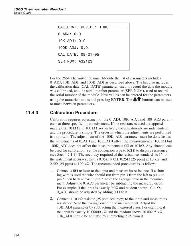
CALIBRATE DEVICE: THRS
0 ADJ: 0.0
10K ADJ: 0.0
100K ADJ: 0.0
CAL DATE: 09-21-95
SER NUM: A32123
For the 2564 Thermistor Scanner Module the list of parameters includes0_ADJ, 10K_ADJ, and 100K_ADJ as described above. The list also includesthe calibration date (CAL DATE) parameter, used to record the date the modulewas calibrated, and the serial number parameter (SER NUM), used to recordthe serial number of the module. New values can be entered for the parametersusing the numeric buttons and pressing ENTER. The UD buttons can be usedto move between parameters.
11.4.3 Calibration ProcedureCalibration requires adjustment of the 0_ADJ, 10K_ADJ, and 100_ADJ param-eters at three specific input resistances. If the resistances used are approxi-mately 0Ω, 10 kΩ and 100 kΩ respectively the adjustments are independentand the procedure is simple. The order in which the adjustments are performedis important. The adjustment of the 100K_ADJ parameter must be done last asthe adjustments of 0_ADJ and 10K_ADJ affect the measurement at 100 kΩ but100K_ADJ does not affect the measurements at 0Ω or 10 kΩ. Any channel canbe used for calibration. Set the conversion type to R(Ω) to display resistance(see Sec. 4.2.1.1). The accuracy required of the resistance standards is 1/4 ofthe instrument accuracy; that is 0.05Ω at 0Ω, 0.25Ω (25 ppm) at 10 kΩ, and2.5Ω (25 ppm) at 100 kΩ. The recommended procedure is as follows:
1. Connect a 0Ω resistor to the input and measure its resistance. If a short-ing wire is used the wire should run from pin 3 from the left to pin 4 topin 5 then back across to pin 2. Note the average error in the measure-ment. Adjust the 0_ADJ parameter by subtracting the measured error.For example, if the input is exactly 0.0Ω and readout shows –0.11Ω,0_ADJ should be adjusted by adding 0.11 to it.
2. Connect a 10 kΩ resistor (25 ppm accuracy) to the input and measure itsresistance. Note the average error in the measurement. Adjust the10K_ADJ parameter by subtracting the measured error. For example, ifthe input is exactly 10.00000 kΩ and the readout shows 10.00295 kΩ,10K_ADJ should be adjusted by subtracting 2.95 from it.
1560 Thermometer Readout
User’s Guide
144
3. Connect a 100 kΩ resistor (25 ppm accuracy) to the input and measureits resistance. Note the average error in the measurement. Adjust the100K_ADJ parameter by subtracting the measured error. For example, ifthe input is exactly 100.0000 kΩ and the readout shows 99.9913 kΩ,100K_ADJ should be adjusted by adding 8.7 to it.
4. Record the date with the calibration date parameter.
5. Verify the accuracy at 0Ω, 4kΩ, 10kΩ, 40kΩ, 100kΩ, and 1MΩ. Verifyat least one resistance on each channel. The accuracy must be within theshort-term accuracy given in the specifications.
6. Set the wiring configuration of both rows to three-wire (see Section11.3.1). Verify the accuracy with at least one resistance on each channel.The accuracy must be within the short-term accuracy given in thespecifications.
145
11 2564 Thermistor Scanner ModuleCalibration
12 2565 Precision Thermocouple Module
NOTE: An Application Note for use of Tungsten-Rhenium and otherthermocouples is available at www.hartscientific.com.
This section explains the features and operation of the optional 2565 PrecisionThermocouple Module.
12.1 DescriptionThe 2565 Precision Thermocouple Module is an add-on module that allows the1560 to measure temperature with extreme accuracy using thermocouples. Twothermocouples can be connected to the 2565 simultaneously and measured al-ternately. The module’s unique clamping receptacles accept thermocouples ter-minated with either bare wires or subminiature thermocouple plugs. Sensorsinside the receptacles measure temperature for precise automatic cold-junctioncompensation. For even greater accuracy, the 2565 also allows you to use anexternal cold-junction reference.
12.2 Specifications
Voltage range 0 to 100 mV
Voltage accuracy, one-year1
0 to 50 mV50 to 100 mV
0.002 mV40 ppm of reading
Voltage accuracy, short-term1,2
0 to 50 mV50 to 100 mV
0.0015 mV30 ppm of reading
Internal CJC accuracy 1 0.05°C (0.09°F)
Temperature accuracy, external CJC1,3
Type E @ 800°CType J @ 1000°CType K @ 1200°CType N @ 1200°CType S @ 1400°CType T @ 300°CType Au/Pt @ 1000°C
±0.025°C (0.045°F)±0.039°C (0.070°F)±0.055°C (0.10°F)±0.054°C (0.098°F)±0.17°C (0.31°F)±0.035°C (0.063°F)±0.078°C (0.14°F)
Temperature accuracy, internal CJC1,3
Type E @ 800°CType J @ 1000°CType K @ 1200°CType N @ 1200°CType S @ 1400°CType T @ 300°CType Au/Pt @ 1000°C
±0.065°C (0.12°F)±0.083°C (0.15°F)±0.10°C (0.18°F)±0.090°C (0.16°F)±0.19°C (0.35°F)±0.070°C (0.13°F)±0.092°C (0.17°F)
Voltage temperature coefficient 1 5 ppm/°C(2.8 ppm/°F)
147
12 2565 Precision Thermocouple ModuleDescription
Internal CJC temperature coefficient 1 0.005°C/°C (0.005°F/°F)
Sample time 2 seconds
Number of channels 2
Recommended operating temperature range 1 18 to 28°C(64 to 82°F)
Absolute operating temperature range 5 to 35°C(40 to 95°F)
Weight 2.5 lbs.
1 The accuracy specifications apply within the recommended operating temperature range. Accuracy limitsare increased by a factor of the temperature coefficient outside this range.
2 Short-term accuracy includes nonlinearity and noise uncertainties. It does not include long-term drift orcalibration uncertainties.
3 Temperature accuracies do not include sensor uncertainties. Accuracies using external CJC do not in-clude cold-junction reference uncertainty.
12.2.1 Calculating AccuracyThe temperature accuracy specifications listed are derived from the voltage ac-curacy and CJC accuracy. The accuracy of a thermocouple readout device interms of temperature depends on the slope of the voltage-temperature relation-ship (Seebeck coefficient) at the temperature of interest (which depends on thetype of thermocouple and its temperature), the accuracy of the voltage mea-surement, the slope of the voltage-temperature relationship at the cold-junctiontemperature, and the accuracy of the cold-junction temperature according to thefollowing equation:
uu
S t
S t
S tut
v CJCJ= +
( )
( )
( )
For the 2565/2566 modules the voltage accuracy is specified. If internal CJC isused, its accuracy is also specified. If external CJC is used, it is up to the userto determine the accuracy of the cold-junction temperature. The temperatureaccuracies listed above for external CJC are assuming negligible cold-junctiontemperature error.
Here is an example of how temperature accuracy is calculated. Suppose we aremeasuring with a type T thermocouple at –200°C and using internal CJC. At–200°C a T thermocouple has a Seebeck coefficient of about 0.016 mV/°C, andat about 25°C (the cold-junction temperature) the Seebeck coefficient is about0.041 mV/°C. From the specifications, the voltage accuracy of the 2565 is0.002 mV (at the voltage we are measuring) and the CJC accuracy is 0.05°C.Applying the above equation for this situation gives a temperature accuracy of0.253°C:
umV
Ct mVC
mVC
mVC
= + ° =°
°
°
0 002
0 016
0 041
0 0160 05 0125
.
.
.
.. . ° + ° = °C C C0128 0 253. .
1560 Thermometer Readout
User’s Guide
148
It could be argued that the voltage errors and CJC errors are uncorrelated so thetwo errors should be combined using a root-sum-square calculations. However,for simplicity, in our calculations we have just added the two components. TheSeebeck coefficients for various types of thermocouples at various temperaturescan be found in the standard tables for thermocouples, such as NIST Mono-graph 175.
12.3 OperationUsing the 2565 Precision Thermocouple Module with the 1560 Black Stack isvery simple. The following sections explain the steps for setting up and usingthe 2565 to measure with thermocouples. For instructions for installing the2565 Precision Thermocouple Module onto the 1560 see Section 4.1.
12.3.1 Connecting a ThermocoupleThe 2565 Precision Thermocouple Module accepts both bare wires and sub-miniature size thermocouple plugs. If a plug is used it must match the thermo-couple type for the internal CJC to be accurate. For example, if you are using atype K thermocouple you must also use a type K plug.
Each receptacle has a cam lever next to it that opens and closes the receptacleas shown in Figure 18. Flipping the lever out opens the receptacle. While thereceptacle is open insert the wires or plug. The positive terminal is to the leftand the negative terminal is to the right. Push the lever back in to clamp thewires or plug. After attaching a thermocouple to the 2565 wait two minutes be-fore measuring for best results. Some shift in the measurement may occur astemperature gradients settle .
The input channels are numbered from left to right as explained in Section4.5.1 and Figure 7.
12.3.2 Selecting the Thermocouple TypeTo display temperature accurately each channel of the 2565 must be pro-grammed for the correct thermocouple type. This is done using the EDITPROBE soft-key in the PROBE menu (see Section 5.2.1). For example, if youare using a type K thermocouple on Input 1 select the EDIT PROBE functionin the PROBE menu, select input channel 1, and set the CONVERSION typeto TC-K. The 1560 converts voltage to temperature according to the standardformulas given in NIST Monograph 175 (see Section 5.2.1.10).
When calibrating thermocouples, or the 2565 module itself, it is often useful todisplay voltage instead of temperature. Voltage is displayed by setting theCONVERSION type to V (see Section 5.2.1.9).
12.3.3 Selecting the CJC TypeThe 1560 and 2565 can operate with either internal or external cold-junctioncompensation (CJC). CJC is necessary because a thermocouple can only mea-
149
12 2565 Precision Thermocouple ModuleOperation
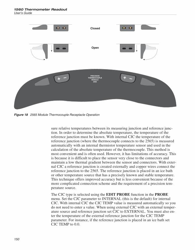
sure relative temperatures between its measuring junction and reference junc-tion. In order to determine the absolute temperature, the temperature of thereference junction must be known. With internal CJC the temperature of thereference junction (where the thermocouple connects to the 2565) is measuredautomatically with an internal thermistor temperature sensor and used in thecalculation of the absolute temperature of the thermocouple. This method ismost convenient and is often used. However, it has limitations of accuracy. Thisis because it is difficult to place the sensor very close to the connectors andmaintain a low thermal gradient between the sensor and connectors. With exter-nal CJC a reference junction is created externally and copper wires connect thereference junction to the 2565. The reference junction is placed in an ice bathor other temperature source that has a precisely known and stable temperature.This technique offers improved accuracy but is less convenient because of themore complicated connection scheme and the requirement of a precision tem-perature source.
The CJC type is selected using the EDIT PROBE function in the PROBEmenu. Set the CJC parameter to INTERNAL (this is the default) for internalCJC. With internal CJC the CJC TEMP value is measured automatically so youdo not need to enter a value. When using external CJC with an external temper-ature source and reference junction set CJC to EXTERNAL. You must also en-ter the temperature of the external reference junction for the CJC TEMPparameter. For instance, if the reference junction is placed in an ice bath setCJC TEMP to 0.0.
1560 Thermometer Readout
User’s Guide
150
PRECISIONTHERMOCOUPLE
MODULE2565
+ – + –
Closed
Open
Figure 18 2565 Module Thermocouple Receptacle Operation
12.3.4 Using Calibrated ThermocouplesThe 1560 normally converts voltage to temperature according to the standardequations given in NIST Monograph 175. However, the actual voltage-tempera-ture characteristics of a specific thermocouple may deviate from the standardequations. The 1560 can be programmed to adjust for this error. This requiresthat the thermocouple be calibrated so that its errors are known.
You can specify the adjustments in two ways. One is to specify temperature ad-justments at several temperatures (see Section 5.2.1.10). For instance, if thethermocouple was calibrated and found to measure high by 0.06°C at 500°Cyou would enter –0.06 as the adjustment with 500°C as the calibration tempera-ture. You can specify adjustments for up to three calibration points. At tempera-tures between the calibration points a polynomial equation is used to estimatethe required adjustment.
For types R, S, and gold-platinum thermocouples the adjustment can also bespecified by coefficients of a second-order polynomial (see Section 5.2.1.10).
12.3.5 Suggestions for Optimum AccuracyThe sensitivity of thermocouple measurements, especially when using internalCJC, requires that the user take certain precautions to ensure accuracy.
12.3.5.1 Warm-up Time
Measurements may change slightly as the 2565 module warms up after beingpowered on. For best accuracy allow the 2565 to warm up for one hour beforemaking precision measurements.
12.3.5.2 Ambient Environment
When using internal cold-junction compensation the connectors and internalsensors are sensitive to ambient temperature disturbances. The 2565 should beoperated in a stable environment free from large and sudden ambient tempera-ture variations. The 2565 will also be more accurate if the ambient temperatureat which it is operated is close to the ambient temperature at which it wascalibrated.
12.3.5.3 Thermal Settling
When a thermocouple is plugged into the 2565 a certain amount of time is re-quired before heat in the connector and receptacle becomes evenly distributed.For best results wait at least two minutes before making precisionmeasurements.
12.3.5.4 Ground Currents
The 2565 inputs are electrically isolated from all other components of the 1560system and ground. This helps prevent ground loops that can produce noise anderrors in the measurements. However, the two input channels are not isolated
151
12 2565 Precision Thermocouple ModuleOperation
from each other. Errors can result if voltage potentials are imposed between thetwo thermocouples. Thus it is recommended that isolated thermocouple junc-tions be used whenever possible. If grounded thermocouples must be used thentake precautions to ensure that potentials do not exist between thethermocouples.
12.3.6 Setup ParametersThe SET UP DEVICE function in the MODULE menu (see Section 5.4.2) al-lows access to two setup parameters.
GROUND allows you to internally connnect the input circuit to ground by set-ting this option ON. This may help to reduce noise.
SAMP PER selects the sample period between 2 (normal) and 10 seconds. Thepurpose of this option is mainly for troubleshooting and it should not need tobe accessed or changed during normal operation.
12.4 CalibrationThis section explains the calibration procedure for the 2565 Precision Thermo-couple Module.
12.4.1 Calibration ParametersEight adjustable parameters are used for calibration. They are listed in Ta-ble 28. The AMP GA parameter is set at the factory according to the type ofamplifier installed. It should not need to be changed after initial calibration. Ifthe voltage measurement is in error by a factor of nearly 2 the AMP GA param-eter may be incorrect.
12.4.2 Front-Panel AccessThe calibration parameters can be accessed from the front panel of the 1560 us-ing the CAL DEVICE function in the MODULE soft-key menu (see Section
1560 Thermometer Readout
User’s Guide
152
Parameter Description
AMP GA Set to the nominal gain of the amplifier
OS 1 Adjusts the voltage accuracy of Input 1 at 0 mV
OS 2 Adjusts the voltage accuracy of Input 2 at 0 mV
GA 1 Adjusts the voltage accuracy of Input 1 at 100 mV
GA 2 Adjusts the voltage accuracy of Input 2 at 100 mV
CJ 1 Adjusts the internal CJC accuracy of Input 1
CJ 2 Adjusts the internal CJC accuracy of Input 2
CAL DATE Records the date the module was calibrated
Table 28 Precision Thermocouple Module calibration parameters
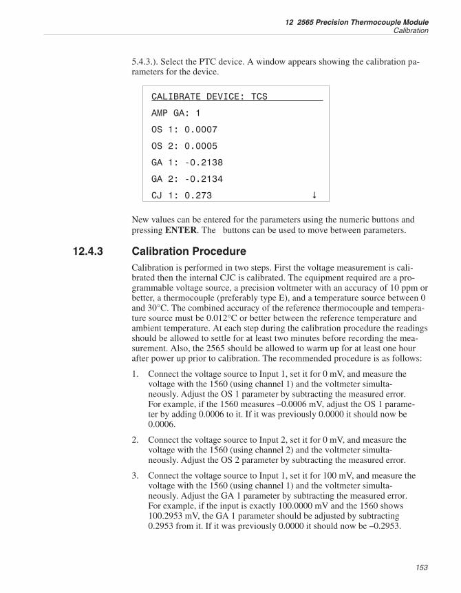
5.4.3.). Select the PTC device. A window appears showing the calibration pa-rameters for the device.
CALIBRATE DEVICE: TCS
AMP GA: 1
OS 1: 0.0007
OS 2: 0.0005
GA 1: -0.2138
GA 2: -0.2134
CJ 1: 0.273 �
New values can be entered for the parameters using the numeric buttons andpressing ENTER. The buttons can be used to move between parameters.
12.4.3 Calibration ProcedureCalibration is performed in two steps. First the voltage measurement is cali-brated then the internal CJC is calibrated. The equipment required are a pro-grammable voltage source, a precision voltmeter with an accuracy of 10 ppm orbetter, a thermocouple (preferably type E), and a temperature source between 0and 30°C. The combined accuracy of the reference thermocouple and tempera-ture source must be 0.012°C or better between the reference temperature andambient temperature. At each step during the calibration procedure the readingsshould be allowed to settle for at least two minutes before recording the mea-surement. Also, the 2565 should be allowed to warm up for at least one hourafter power up prior to calibration. The recommended procedure is as follows:
1. Connect the voltage source to Input 1, set it for 0 mV, and measure thevoltage with the 1560 (using channel 1) and the voltmeter simulta-neously. Adjust the OS 1 parameter by subtracting the measured error.For example, if the 1560 measures –0.0006 mV, adjust the OS 1 parame-ter by adding 0.0006 to it. If it was previously 0.0000 it should now be0.0006.
2. Connect the voltage source to Input 2, set it for 0 mV, and measure thevoltage with the 1560 (using channel 2) and the voltmeter simulta-neously. Adjust the OS 2 parameter by subtracting the measured error.
3. Connect the voltage source to Input 1, set it for 100 mV, and measure thevoltage with the 1560 (using channel 1) and the voltmeter simulta-neously. Adjust the GA 1 parameter by subtracting the measured error.For example, if the input is exactly 100.0000 mV and the 1560 shows100.2953 mV, the GA 1 parameter should be adjusted by subtracting0.2953 from it. If it was previously 0.0000 it should now be –0.2953.
153
12 2565 Precision Thermocouple ModuleCalibration
4. Connect the voltage source to Input 2, set it for 100 mV, and measure thevoltage with the 1560 (using channel 2) and the voltmeter simulta-neously. Adjust the GA 2 parameter by subtracting the measured error.
5. Verify the voltage accuracy of both input channels at 0 and 50 mV. Theaccuracy must be within the short-term voltage accuracy given in thespecifications.
6. Connect the calibrated thermocouple to Input 1 and insert the junctioninto the temperature source. Measure the temperature with the 2565 (usechannel 1 and be sure to program the channel with the correct thermo-couple type). Adjust the CJ 1 parameter by subtracting the measured er-ror. For example, if the thermocouple temperature is actually 0.0°C butthe 1560 reads 0.184°C, the CJ OS 1 parameter should be adjusted bysubtracting 0.184 from it. If it was previously 0.000 it should now be–0.184.
7. Connect the calibrated thermocouple to Input 2. Measure the temperaturewith the 2565 (use channel 2 and be sure to program the channel withthe correct thermocouple type). Adjust the CJ 2 parameter by subtractingthe measured error.
8. Verify the temperature accuracy of both input channels using the cali-brated thermocouple and temperature source. The accuracy should bewithin 75% of the internal CJC accuracy given in the specifications.
9. Record the date with the CAL DATE parameter.
1560 Thermometer Readout
User’s Guide
154
13 2566 Thermocouple Scanner Module
NOTE: An Application Note for use of Tungsten-Rhenium and otherthermocouples is available at www.hartscientific.com.
This section explains the features and operation of the optional 2566 Thermo-couple Scanner Module.
13.1 DescriptionThe 2566 Thermocouple Scanner Module is an add-on module that allows the1560 to measure temperature with up to 12 thermocouples simultaneously. Itaccepts nearly every type of thermocouple sensor. It incorporates built-incold-junction compensation (CJC) for convenience. Alternately, external CJCcan be used for greater accuracy. Up to 12 sensors can be connected to the 2566simultaneously and measured alternately.
13.2 Specifications
Voltage range 0 to 100 mV
Voltage accuracy, one-year1
0 to 50 mV50 to 100 mV
0.004 mV80 ppm of reading
Voltage accuracy, short-term1,2
0 to 50 mV50 to 100 mV
0.003 mV60 ppm of reading
Internal CJC accuracy1 0.2°C (0.36°F)
Temparature accuracy, external CJC 1,3
Type E @ 800°CType J @ 1000°CType K @ 1200°CType N @ 1200°CType S @ 1400°CType T @ 300°C
±0.05°C (0.09°F)±0.08°C (0.14°F)±0.11°C (0.20°F)±0.11°C (0.20°F)±0.33°C (0.60°F)±0.07°C (0.13°F)
Temparature accuracy, internal CJC1,3
Type E @ 800°CType J @ 1000°CType K @ 1000°CType N @ 1000°CType S @ 1400°CType T @ 300°C
±0.21°C (0.38°F)±0.25°C (0.46°F)±0.33°C (0.60°F)±0.26°C (0.47°F)±0.43°C (0.78°F)±0.21°C (0.38°F)
Voltage temperature coefficient1 10 ppm/°C (5.6 ppm/°F)
Internal CJC temperature coefficient1 ±0.03°C/°C (±0.03°F/°F)
Sample time 2 seconds
Number of channels 12
155
13 2566 Thermocouple Scanner ModuleDescription
Recommended operating temperature1 18 to 28°C (64 to 82°F)
Absolute operating temperature range 5 to 35°C (40 to 95°F)
Weight 2.5 lbs.
1 The accuracy specifications apply within the recommended operating temperature range. Accuracy limitsare increased by a factor of the temperature coefficient outside this range.
2 Short-term accuracy includes nonlinearity and noise uncertainties. It does not include long-term drift orcalibration uncertainties.
3 Temperature accuracies do not include sensor uncertainties. Accuracies using external CJC do not in-clude reference junction temperature uncertainty.
13.2.1 Calculating AccuracyPlease refer to Section 12.2.1 for a discussion on calculating temperature accu-racies for thermocouple measurements.
13.3 OperationUsing the 2566 Thermocouple Scanner Module with the 1560 Black Stack isvery simple. The following sections explain the steps for setting up and usingthe 2566 to measure with thermocouples. For instructions for installing the2566 Thermocouple Scanner Module onto the 1560 see Section 4.1.
13.3.1 Connecting a ThermocoupleThe 2566 Thermocouple Scanner Module accepts both standard and subminia-ture size thermocouple connectors. The connection is made with the positiveterminal on the left and the negative terminal on the right. You must use a con-nector that matches the thermocouple type for the internal CJC to be accurate.For example, if you are using a type K thermocouple you must also use a typeK connector which is made from the same type of metal. After inserting thethermocouple connector into the 2566, wait two minutes before measuring forbest results.
The input channels are numbered from left to right and front to back as ex-plained in Section 4.5.1 and Figure 7.
13.3.2 Selecting the Thermocouple TypeTo display temperature accurately the 1560 must be programmed with the cor-rect thermocouple type for each input channel. This is done using the EDITPROBE soft-key in the PROBE menu (see Section 5.2.1). For example, if youare using a type K thermocouple on Input 3 select the EDIT PROBE functionin the PROBE menu, select input channel 3, and set the CONVERSION typeto TC-K. The 1560 converts voltage to temperature according to the standardformulas given in NIST Monograph 175 (see Section 5.2.1.10).
When calibrating thermocouples or the 2566 module itself, it is often useful todisplay voltage instead of temperature. Voltage is displayed by setting theCONVERSION type to V (see Section 5.2.1.9).
1560 Thermometer Readout
User’s Guide
156
13.3.3 Selecting the CJC TypeThe 1560 allows for either internal or external CJC. CJC is necessary becausethermocouples are only able to measure relative temperatures between the mea-suring junction and the reference junction. In order to determine the absolutetemperature, the temperature of the reference junction must be known. With in-ternal CJC the temperature of the reference junction, assumed to be the pointwhere the thermocouple connects to the 2566, is measured using an internalthermistor temperature sensor. This method offers convenience and is most of-ten used. However, it has limitations of accuracy. This is because it is difficultto place the sensor very close to the connectors and maintain a low thermal dif-ferential between the sensor and connectors. With external CJC a referencejunction is created externally and copper wires connect the reference junctionto the 2566. The reference junction is placed in an ice bath or other temperaturesource that has a precisely known and stable temperature. This technique offersimproved accuracy but is less convenient because of the more complicated con-nection scheme and the requirement of a precision temperature source.
The 1560 allows the use of either internal or external CJC. Most applicationswill use internal CJC where the thermocouple probe is connected directly to the2566. The CJC type is selected using the EDIT PROBE function in thePROBE menu. Set the CJC parameter to INTERNAL (this is the default). Withinternal CJC the CJC TEMP value is measured automatically and so you do notneed to enter a value. When using external CJC with an external temperaturesource and reference junction set CJC to EXTERNAL. You must also enter thetemperature of the external reference junction for the CJC TEMP parameter.For instance, if the reference junction is placed in an ice bath set CJC TEMP to0.0.
13.3.4 Using Calibrated ThermocouplesThe 1560 normally converts voltage to temperature according to the standardequations given in NIST Monograph 175. However, the actual voltage-tempera-ture characteristics of thermocouples may deviate from the standard equations.For improved accuracy the 2566 can be programmed to make adjustments tothe standard equations. This requires that the thermocouple be calibrated so thatits errors are known.
You can specify the adjustments in two ways. One is to specify temperature ad-justments at several temperatures (see Section 5.2.1.10). For instance, if thethermocouple was calibrated and found to measure high by 0.06°C at 500°Cyou would enter –0.06 as the adjustment with 500°C as the calibration tempera-ture. You can specify adjustments for up to three calibration points. At tempera-tures between the calibration points a polynomial equation is used to estimatethe required adjustment.
For type R and S and gold-platinum thermocouples the adjustment can be spec-ified by coefficients of a second-order polynomial (see Section 5.2.1.10).
157
13 2566 Thermocouple Scanner ModuleOperation
13.3.5 Suggestions for Optimum AccuracyThe sensitivity of thermocouple measurements, especially when using internalCJC, requires that the user take certain precautions to ensure accuracy as ex-plained in the following sections.
13.3.5.1 Warm-up Time
Measurements may change slightly as the 2566 module warms up after beingpowered on. For best accuracy allow the 2566 to warm up for one hour beforemaking precision measurements.
13.3.5.2 Ambient Environment
When using internal cold-junction compensation the connectors and internalsensors are sensitive to ambient temperature disturbances. The 2566 should beoperated in a stable environment free from large and sudden ambient tempera-ture variations. The 2566 will also be more accurate if the ambient temperaturein which it is operated is close to the ambient temperature in which it was cali-brated. Internal CJC is more accurate for the eight inputs near the center of themodule. Use these channels for more precise measurements rather than the fourinputs on the outside.
13.3.5.3 Thermal Settling
The process of removing and inserting thermocouple plugs into the 2566 pro-duces temperature transients. This heat can cause a small error in the measure-ment for up to two to four minutes after the thermocouple is plugged in. Forbest results wait at least two minutes before making precision measurements.
13.3.6 Setup ParametersThe SET UP DEVICE function in the MODULE menu (see Section 5.4.2) al-lows access to two setup parameters. SAMP PER selects the sample period be-tween 2 (normal) and 10 seconds. POS shows the detected position of themodule in the stack. The purpose of these options is mainly for troubleshootingand they should not need to be accessed or changed during normal operation.
13.4 CalibrationThis section explains the calibration procedure for the 2566 ThermocoupleScanner Module.
13.4.1 Calibration ParametersEighteen adjustable parameters are used for calibration. They are listed in Table29.
1560 Thermometer Readout
User’s Guide
158
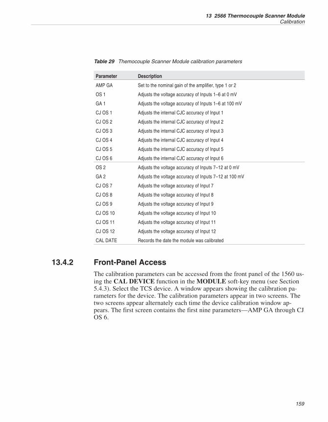
13.4.2 Front-Panel AccessThe calibration parameters can be accessed from the front panel of the 1560 us-ing the CAL DEVICE function in the MODULE soft-key menu (see Section5.4.3). Select the TCS device. A window appears showing the calibration pa-rameters for the device. The calibration parameters appear in two screens. Thetwo screens appear alternately each time the device calibration window ap-pears. The first screen contains the first nine parameters—AMP GA through CJOS 6.
159
13 2566 Thermocouple Scanner ModuleCalibration
Parameter Description
AMP GA Set to the nominal gain of the amplifier, type 1 or 2
OS 1 Adjusts the voltage accuracy of Inputs 1–6 at 0 mV
GA 1 Adjusts the voltage accuracy of Inputs 1–6 at 100 mV
CJ OS 1 Adjusts the internal CJC accuracy of Input 1
CJ OS 2 Adjusts the internal CJC accuracy of Input 2
CJ OS 3 Adjusts the internal CJC accuracy of Input 3
CJ OS 4 Adjusts the internal CJC accuracy of Input 4
CJ OS 5 Adjusts the internal CJC accuracy of Input 5
CJ OS 6 Adjusts the internal CJC accuracy of Input 6
OS 2 Adjusts the voltage accuracy of Inputs 7–12 at 0 mV
GA 2 Adjusts the voltage accuracy of Inputs 7–12 at 100 mV
CJ OS 7 Adjusts the voltage accuracy of Input 7
CJ OS 8 Adjusts the voltage accuracy of Input 8
CJ OS 9 Adjusts the voltage accuracy of Input 9
CJ OS 10 Adjusts the voltage accuracy of Input 10
CJ OS 11 Adjusts the voltage accuracy of Input 11
CJ OS 12 Adjusts the voltage accuracy of Input 12
CAL DATE Records the date the module was calibrated
Table 29 Themocouple Scanner Module calibration parameters
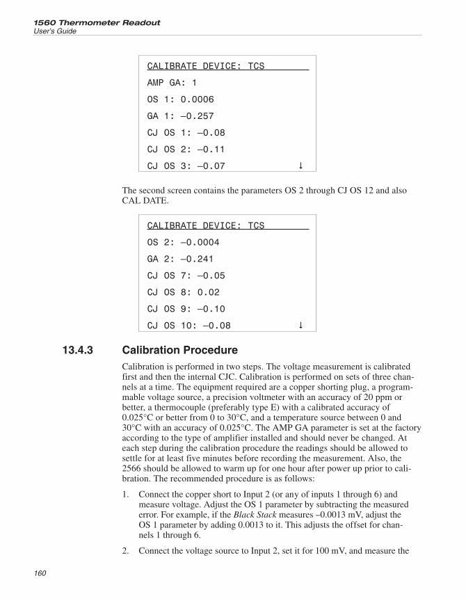
CALIBRATE DEVICE: TCS
AMP GA: 1
OS 1: 0.0006
GA 1: –0.257
CJ OS 1: –0.08
CJ OS 2: –0.11
CJ OS 3: –0.07 �
The second screen contains the parameters OS 2 through CJ OS 12 and alsoCAL DATE.
CALIBRATE DEVICE: TCS
OS 2: –0.0004
GA 2: –0.241
CJ OS 7: –0.05
CJ OS 8: 0.02
CJ OS 9: –0.10
CJ OS 10: –0.08 �
13.4.3 Calibration ProcedureCalibration is performed in two steps. The voltage measurement is calibratedfirst and then the internal CJC. Calibration is performed on sets of three chan-nels at a time. The equipment required are a copper shorting plug, a program-mable voltage source, a precision voltmeter with an accuracy of 20 ppm orbetter, a thermocouple (preferably type E) with a calibrated accuracy of0.025°C or better from 0 to 30°C, and a temperature source between 0 and30°C with an accuracy of 0.025°C. The AMP GA parameter is set at the factoryaccording to the type of amplifier installed and should never be changed. Ateach step during the calibration procedure the readings should be allowed tosettle for at least five minutes before recording the measurement. Also, the2566 should be allowed to warm up for one hour after power up prior to cali-bration. The recommended procedure is as follows:
1. Connect the copper short to Input 2 (or any of inputs 1 through 6) andmeasure voltage. Adjust the OS 1 parameter by subtracting the measurederror. For example, if the Black Stack measures –0.0013 mV, adjust theOS 1 parameter by adding 0.0013 to it. This adjusts the offset for chan-nels 1 through 6.
2. Connect the voltage source to Input 2, set it for 100 mV, and measure the
1560 Thermometer Readout
User’s Guide
160
voltage with the 1560 and the voltmeter simultaneously. Note the aver-age error in the 2566 measurement. Adjust the GA 1 parameter by sub-tracting the measured error. For example, if the input is exactly 100.0000mV and the 1560 shows 100.2953 mV, the GA 1 parameter should beadjusted by subtracting 0.2953 from it. This adjusts the gain for channels1 through 6.
3. Repeat steps 1 and 2 for Input 8 (or any of inputs 7 through 12) adjustingthe OS 2 and GA 2 parameters. This calibrates the voltage measusrementof inputs 7 through 12.
4. Verify the voltage accuracy of each of the 12 input channels at 0 and 50mV. The accuracy must be within the short-term voltage accuracy givenin the specifications.
5. Connect the calibrated thermocouple to Input 1 and insert the measuringjunction into the temperature source. Measure the temperature with the2566 (be sure to program the 1560 with the correct thermocouple type).Note the average error in the 2566 measurement. Adjust the CJ OS 1 pa-rameter by subtracting the measured error. For example, if the tempera-ture measurement should be exactly 0.0°C but the 1560 reads 0.18°C, theCJ OS 1 parameter should be adjusted by subtracting 0.18 from it. Thisadjusts the CJC for Input 1.
6. Repeat step 5 for Inputs 2 through 12 adjusting CJ OS 2 through CJOS12 respectively.
7. Verify the temperature accuracy of each of the 12 input channels usingthe calibrated thermocouple and temperature source. The accuracyshould be within 75% of the internal CJC accuracy given in thespecifications.
8. Record the date with the CAL DATE parameter.
161
13 2566 Thermocouple Scanner ModuleCalibration
14 3560 Extended Communication Module
This section explains the features and operation of the optional 3560 ExtendedCommunication Module.
14.1 DescriptionThe 3560 is an add-on module that extends the communication capabilities ofthe 1560. First, it provides a GPIB (IEEE-488) interface. With this interface asystem controller can remotely operate the 1560 and read measurementsthrough an IEEE-488 bus. The Centronics printer interface allows the 1560 toconnect to a printer. The 1560 can then be programmed to print out measure-ment data in real time. Measurements previously acquired and stored within the1560 can also be printed. The 3560 also provides an analog output. This outputsources a voltage that represents the value of measurements. The analog outputcan be connected to a strip-chart recorder for a graphical plot of temperatureover time. Finally, the 3560 also adds a second RS-232 serial port. This can beused as a bi-directional communication interface or as a serial printer interfacefor the printing out of data.
14.2 SpecificationsSee Table 30 on page 164.
14.3 InstallationThe 3560 Extended Communication Module attaches to the back of the 1560system as any other module. For instructions on installing modules onto the1560 see Section 4.1. Since the 3560 Module has connectors placed on theback it must be installed as the last module in the stack.
Once the 3560 is installed onto the 1560 the 1560 will automatically recognizethe Communication Module and the functions it provides. Five devices areadded: the GPIB Communication Device (GPIB), Serial Communication De-vice (SERC), Serial Printer Device (SERP), Parallel Printer Device (PARP),and Analog Output Device (AOUT). These devices will appear labeled as indi-cated with the appropriate soft-key functions. The operation of each device isexplained in the following sections.
14.4 GPIB Communication DeviceThe GPIB (IEEE-488) interface allows the 1560 to be connected to anIEEE-488 bus along with other instruments. A system controller can remotelycontrol the operation of the 1560 and read measurements.
163
14 3560 Extended Communication ModuleDescription
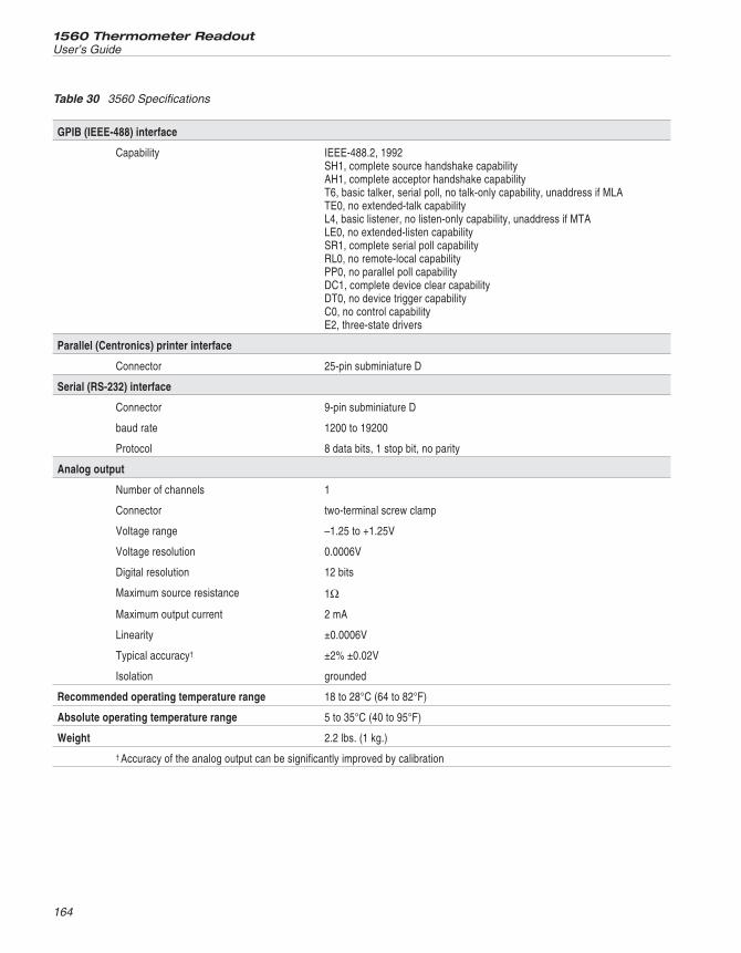
1560 Thermometer Readout
User’s Guide
164
GPIB (IEEE-488) interface
Capability IEEE-488.2, 1992SH1, complete source handshake capabilityAH1, complete acceptor handshake capabilityT6, basic talker, serial poll, no talk-only capability, unaddress if MLATE0, no extended-talk capabilityL4, basic listener, no listen-only capability, unaddress if MTALE0, no extended-listen capabilitySR1, complete serial poll capabilityRL0, no remote-local capabilityPP0, no parallel poll capabilityDC1, complete device clear capabilityDT0, no device trigger capabilityC0, no control capabilityE2, three-state drivers
Parallel (Centronics) printer interface
Connector 25-pin subminiature D
Serial (RS-232) interface
Connector 9-pin subminiature D
baud rate 1200 to 19200
Protocol 8 data bits, 1 stop bit, no parity
Analog output
Number of channels 1
Connector two-terminal screw clamp
Voltage range –1.25 to +1.25V
Voltage resolution 0.0006V
Digital resolution 12 bits
Maximum source resistance 1Ω
Maximum output current 2 mA
Linearity ±0.0006V
Typical accuracy† ±2% ±0.02V
Isolation grounded
Recommended operating temperature range 18 to 28°C (64 to 82°F)
Absolute operating temperature range 5 to 35°C (40 to 95°F)
Weight 2.2 lbs. (1 kg.)
† Accuracy of the analog output can be significantly improved by calibration
Table 30 3560 Specifications
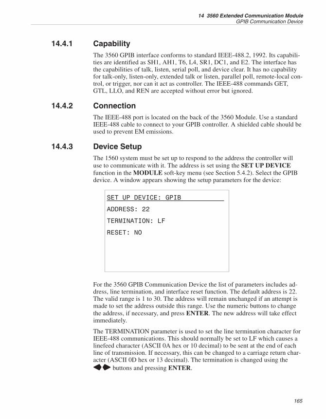
14.4.1 CapabilityThe 3560 GPIB interface conforms to standard IEEE-488.2, 1992. Its capabili-ties are identified as SH1, AH1, T6, L4, SR1, DC1, and E2. The interface hasthe capabilities of talk, listen, serial poll, and device clear. It has no capabilityfor talk-only, listen-only, extended talk or listen, parallel poll, remote-local con-trol, or trigger, nor can it act as controller. The IEEE-488 commands GET,GTL, LLO, and REN are accepted without error but ignored.
14.4.2 ConnectionThe IEEE-488 port is located on the back of the 3560 Module. Use a standardIEEE-488 cable to connect to your GPIB controller. A shielded cable should beused to prevent EM emissions.
14.4.3 Device SetupThe 1560 system must be set up to respond to the address the controller willuse to communicate with it. The address is set using the SET UP DEVICEfunction in the MODULE soft-key menu (see Section 5.4.2). Select the GPIBdevice. A window appears showing the setup parameters for the device:
SET UP DEVICE: GPIB
ADDRESS: 22
TERMINATION: LF
RESET: NO
For the 3560 GPIB Communication Device the list of parameters includes ad-dress, line termination, and interface reset function. The default address is 22.The valid range is 1 to 30. The address will remain unchanged if an attempt ismade to set the address outside this range. Use the numeric buttons to changethe address, if necessary, and press ENTER. The new address will take effectimmediately.
The TERMINATION parameter is used to set the line termination character forIEEE-488 communications. This should normally be set to LF which causes alinefeed character (ASCII 0A hex or 10 decimal) to be sent at the end of eachline of transmission. If necessary, this can be changed to a carriage return char-acter (ASCII 0D hex or 13 decimal). The termination is changed using theLR buttons and pressing ENTER.
165
14 3560 Extended Communication ModuleGPIB Communication Device
The RESET function can be used to reset the IEEE-488 interface and clear theinput and output buffers. This is equivalent to executing the DCL or SDCIEEE-488 device clear commands. Use the LR buttons to change the optionto YES then press ENTER.
14.4.4 CommandsThe commands used for remote communications are explained in detail in Sec-tion 6. Commands are available to control nearly every function of the 1560.For example, the “ROUT:CLOS (@1)” command can be used to select inputchannel 1 for measurement. The “INIT:CONT ON” command can be used toinitiate continuous measuring. The “FETC? (@1)” command can be used toread measurements from input channel 1.
14.4.5 Serial PollSerial poll can be used to alert the IEEE-488 controller whenever certain eventsoccur such as completed measurement or communication error. Serial poll isenabled by setting the desired mask bits of the Service Request Enable Register(see Section 6.5.10.7). For instance, if the SRE register is set using the “*SRE128” command the 1560 will issue a service request whenever the OperationStatus Bit (OSB) in the Status Byte Register is set (see Section 6.5.10.9). Forsummary bits in the Status Byte Register, such as the OSB, reporting must beenabled by setting certain mask bits in the appropriate status register. For in-stance, for the OSB to report a completed measurement, bit 4 of the OperationStatus Enable Register must be set (see Sections 6.5.10.13 and 6.5.10.15).
When a service request is generated by the 1560 it sends the SRQ message tothe IEEE-488 controller. The controller then reads the Status Byte Registerfrom the 1560. (The meaning of each bit in the Status Byte Register is ex-plained in Section 6.5.10.9.) Bit 6 of the status byte will be set if the 1560caused the service request. Once the status byte is read the 1560 removes theSRQ message.
The IEEE-488 controller can use serial poll at any time to read the status bytefrom the 1560. Bit 6 of the status byte will be set if the 1560 is requesting ser-vice or 0 otherwise.
The Status Byte Register can also be polled using the “*STB?” command (seeSection 6.5.10.9).
14.4.6 Device ClearThe 3560 GPIB interface accepts both the DCL and SDC IEEE-488 commandsto clear the device. These clear the input and output buffers.
14.4.7 Device Setup CommandsThe SYST:MODn:DEVn:READ? and SYST: MODn:DEVn:WRIT commands(see Sections 6.5.8.19 and 6.5.8.20) can be used to read or set the setup param-eters for the 3560 GPIB Communication Device. The device number of the
1560 Thermometer Readout
User’s Guide
166
GPIB Communication Device is 1. The module number for the 3560 module isits position in the stack. For example, if the 1560 has four add-on modules, the3560 being the last, the module number for the 3560 is 4. Table 31 shows thedevice commands used to read or set the setup parameters of the GPIB Com-munication Device.
Below are some examples of using the device commands to set the device setupparameters. For these examples it is assumed that the 3560 CommunicationModule is placed fourth in the stack. These commands can be sent through anycommunication interface including the IEEE-488 and RS-232 interfaces.
SYST:MOD4:DEV1:WRIT “ADDR”,17 Set the IEEE-488 address to 17.
SYST:MOD4:DEV1:READ? “ADDR” Read the IEEE-488 address.
SYST:MOD4:DEV1:WRIT “TERM”,LF Set the termination to linefeed.
SYST:MOD4:DEV1:WRIT “RSET”,YES Reset the IEEE-488 interface.
14.5 Serial Communication DeviceThe 3560 Extended Communication Module adds an additional RS-232 serialcommunications interface to the 1560 system. Connecting to the rear panelRS-232 port may be more convenient than connecting to the RS-232 port un-derneath the base.
14.5.1 ConnectionThe RS-232 port is located on the back of the 3560 Module. Wiring of the in-terface cable should be as shown in Figure 11 in Section 6.2. A shielded cableshould be used to prevent EM emissions. The protocol for RS-232 communica-tions is 8 data bits, 1 stop bit, and no parity.
14.5.2 Device SetupThe 3560 Serial Communication Device must be set up to use the same baudrate as the equipment with which it will be communicating. The baud rate is setusing the SET UP DEVICE function in the MODULE soft-key menu (seeSection 5.4.2). Select the SERC device. A window appears showing the setupparameters for the device:
167
14 3560 Extended Communication ModuleSerial Communication Device
Device Command Parameter Description
ADDR 1-30 IEEE-488 address
TERM LF or CR line termination
RSET YES reset interface
Table 31 GPIB Communicatinos Device Commands
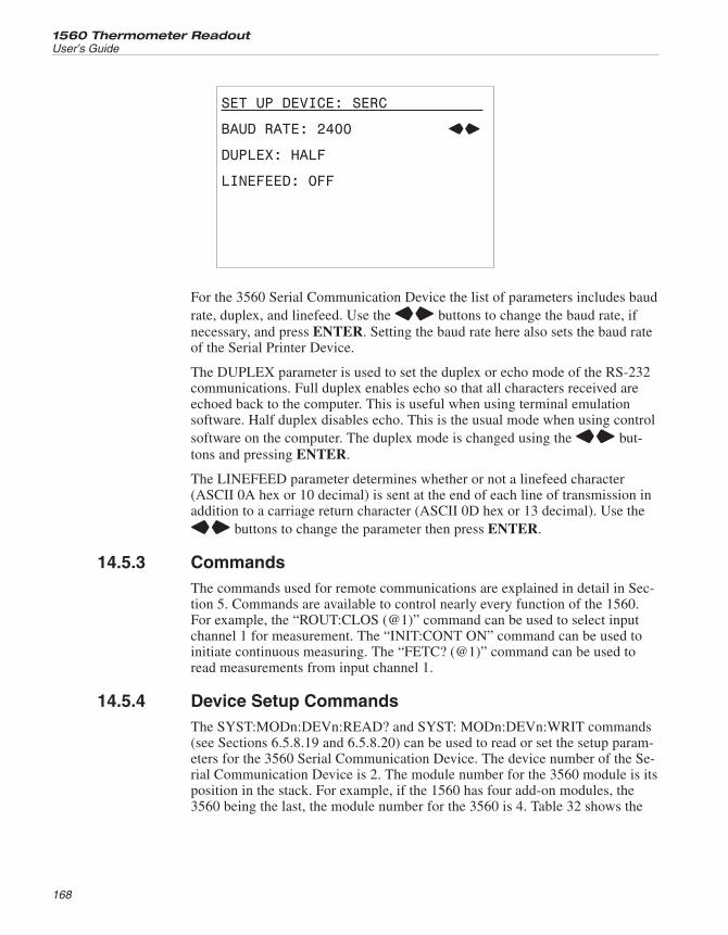
SET UP DEVICE: SERC
BAUD RATE: 2400 LR
DUPLEX: HALF
LINEFEED: OFF
For the 3560 Serial Communication Device the list of parameters includes baudrate, duplex, and linefeed. Use the LR buttons to change the baud rate, ifnecessary, and press ENTER. Setting the baud rate here also sets the baud rateof the Serial Printer Device.
The DUPLEX parameter is used to set the duplex or echo mode of the RS-232communications. Full duplex enables echo so that all characters received areechoed back to the computer. This is useful when using terminal emulationsoftware. Half duplex disables echo. This is the usual mode when using controlsoftware on the computer. The duplex mode is changed using the LR but-tons and pressing ENTER.
The LINEFEED parameter determines whether or not a linefeed character(ASCII 0A hex or 10 decimal) is sent at the end of each line of transmission inaddition to a carriage return character (ASCII 0D hex or 13 decimal). Use theLR buttons to change the parameter then press ENTER.
14.5.3 CommandsThe commands used for remote communications are explained in detail in Sec-tion 5. Commands are available to control nearly every function of the 1560.For example, the “ROUT:CLOS (@1)” command can be used to select inputchannel 1 for measurement. The “INIT:CONT ON” command can be used toinitiate continuous measuring. The “FETC? (@1)” command can be used toread measurements from input channel 1.
14.5.4 Device Setup CommandsThe SYST:MODn:DEVn:READ? and SYST: MODn:DEVn:WRIT commands(see Sections 6.5.8.19 and 6.5.8.20) can be used to read or set the setup param-eters for the 3560 Serial Communication Device. The device number of the Se-rial Communication Device is 2. The module number for the 3560 module is itsposition in the stack. For example, if the 1560 has four add-on modules, the3560 being the last, the module number for the 3560 is 4. Table 32 shows the
1560 Thermometer Readout
User’s Guide
168
device commands used to read or set the setup parameters of the Serial Com-munication Device.
Below are some examples of using the device commands to set the device setupparameters. For these examples it is assumed that the 3560 CommunicationModule is placed fourth in the stack. These commands can be sent through anycommunication interface including the IEEE-488 and RS-232 interfaces.
SYST:MOD4:DEV2:WRIT “BAUD”,9600 Set the baud rate to 9600.
SYST:MOD4:DEV2:WRIT “DUPL”,HALF Set the duplex mode to halfduplex (echo off).
SYST:MOD4:DEV2:READ? “DUPL” Read the duplex mode.
SYST:MOD4:DEV2:WRIT “LFEE”,OFF Disable linefeed.
14.6 Serial Printer DeviceThe RS-232 port of the 3560 can be used as either a communications interfaceor a printer interface. This section explains the operation of the 3560 SerialPrinter Device. The Serial Printer Device can be used to print data to a printeror terminal equipped with an RS-232 serial interface. For connection of theRS-232 interface refer to Section 14.5.1 above.
14.6.1 Device SetupThe setup parameters for the 3560 Serial Printer Device include baud rate andlinefeed. The baud rate must be set the same as the baud rate of the printer orterminal. The parameters are set using the SET UP DEVICE function in theMODULE soft-key menu (see Section 5.4.2). Select the SERP device. A win-dow appears showing the setup parameters for the device:
169
14 3560 Extended Communication ModuleSerial Printer Device
Device Command Parameter Description
BAUD 1200, 2400, 9600, 14400, or19200
baud rate
DUPL HALF or FULL duplex mode
LFEE OFF or ON linefeed
Table 32 Serial Communication Device Commands
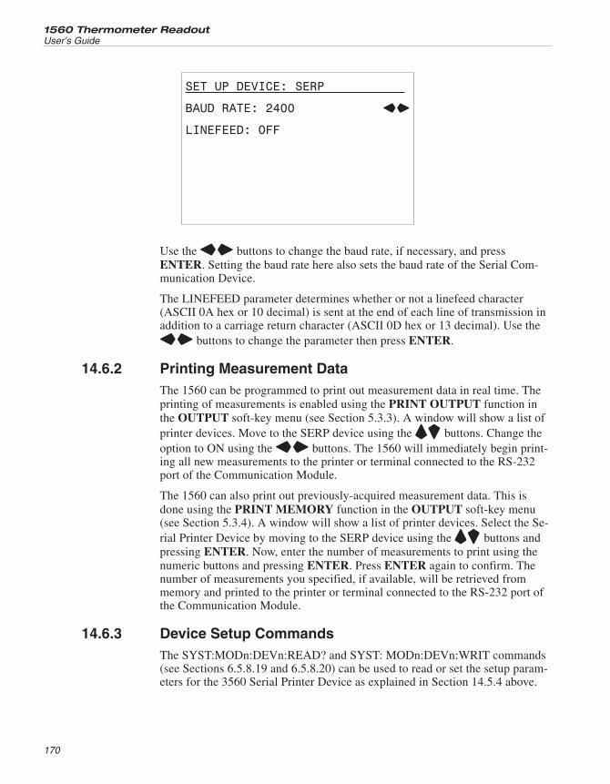
SET UP DEVICE: SERP
BAUD RATE: 2400 LR
LINEFEED: OFF
Use the LR buttons to change the baud rate, if necessary, and pressENTER. Setting the baud rate here also sets the baud rate of the Serial Com-munication Device.
The LINEFEED parameter determines whether or not a linefeed character(ASCII 0A hex or 10 decimal) is sent at the end of each line of transmission inaddition to a carriage return character (ASCII 0D hex or 13 decimal). Use theLR buttons to change the parameter then press ENTER.
14.6.2 Printing Measurement DataThe 1560 can be programmed to print out measurement data in real time. Theprinting of measurements is enabled using the PRINT OUTPUT function inthe OUTPUT soft-key menu (see Section 5.3.3). A window will show a list ofprinter devices. Move to the SERP device using the UD buttons. Change theoption to ON using the LR buttons. The 1560 will immediately begin print-ing all new measurements to the printer or terminal connected to the RS-232port of the Communication Module.
The 1560 can also print out previously-acquired measurement data. This isdone using the PRINT MEMORY function in the OUTPUT soft-key menu(see Section 5.3.4). A window will show a list of printer devices. Select the Se-rial Printer Device by moving to the SERP device using the UD buttons andpressing ENTER. Now, enter the number of measurements to print using thenumeric buttons and pressing ENTER. Press ENTER again to confirm. Thenumber of measurements you specified, if available, will be retrieved frommemory and printed to the printer or terminal connected to the RS-232 port ofthe Communication Module.
14.6.3 Device Setup CommandsThe SYST:MODn:DEVn:READ? and SYST: MODn:DEVn:WRIT commands(see Sections 6.5.8.19 and 6.5.8.20) can be used to read or set the setup param-eters for the 3560 Serial Printer Device as explained in Section 14.5.4 above.
1560 Thermometer Readout
User’s Guide
170
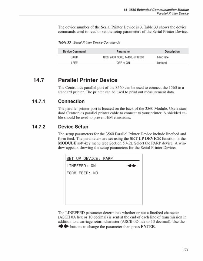
The device number of the Serial Printer Device is 3. Table 33 shows the devicecommands used to read or set the setup parameters of the Serial Printer Device.
14.7 Parallel Printer DeviceThe Centronics parallel port of the 3560 can be used to connect the 1560 to astandard printer. The printer can be used to print out measurement data.
14.7.1 ConnectionThe parallel printer port is located on the back of the 3560 Module. Use a stan-dard Centronics parallel printer cable to connect to your printer. A shielded ca-ble should be used to prevent EM emissions.
14.7.2 Device SetupThe setup parameters for the 3560 Parallel Printer Device include linefeed andform feed. The parameters are set using the SET UP DEVICE function in theMODULE soft-key menu (see Section 5.4.2). Select the PARP device. A win-dow appears showing the setup parameters for the Serial Printer Device:
SET UP DEVICE: PARP
LINEFEED: ON LR
FORM FEED: NO
The LINEFEED parameter determines whether or not a linefeed character(ASCII 0A hex or 10 decimal) is sent at the end of each line of transmission inaddition to a carriage return character (ASCII 0D hex or 13 decimal). Use theLR buttons to change the parameter then press ENTER.
171
14 3560 Extended Communication ModuleParallel Printer Device
Device Command Parameter Description
BAUD 1200, 2400, 9600, 14400, or 19200 baud rate
LFEE OFF or ON linefeed
Table 33 Serial Printer Device Commands
The FORM FEED parameter can be used to eject a partially-printed page of pa-per. Use the LR buttons to change the parameter to YES then pressENTER.
14.7.3 Printing Measurement DataThe 1560 can be programmed to print out measurement data in real time. Theprinting of measurements is enabled using the PRINT OUTPUT function inthe OUTPUT soft-key menu (see Section 5.3.3). A window will show a list ofprinter devices. Move to the PARP device using the UD buttons. Change theoption to ON using the LR buttons. The 1560 will immediately begin print-ing all new measurements to the printer or terminal connected to the parallelprinter port of the Communication Module.
The 1560 can also print previously-acquired measurement data. This is doneusing the PRINT MEMORY function in the OUTPUT soft-key menu (seeSection 5.3.4). A window will show a list of printer devices. Select the ParallelPrinter Device by moving to the PARP device using the UD buttons andpressing ENTER. Now, enter the number of measurements to print using thenumeric buttons and pressing ENTER. Press ENTER again to confirm. Thenumber of measurements you specified, if available, will be retrieved frommemory and printed to the printer or terminal connected to the parallel printerport of the Communication Module.
14.7.4 Device Setup CommandsThe SYST:MODn:DEVn:READ? and SYST: MODn:DEVn:WRIT commands(see Sections 6.5.8.19 and 6.5.8.20) can be used to read or set the setup param-eters for the 3560 Parallel Printer Device. The device number of the ParallelPrinter Device is 4. The module number for the 3560 module is its position inthe stack. For example, if the 1560 has four add-on modules, the 3560 beingthe last, the module number for the 3560 is 4. Table 34 shows the device com-mands used to read or set the setup parameters of the Parallel Printer Device.
Below are some examples of using the device commands to set the device pa-rameters. For these examples it is assumed that the 3560 Communication Mod-ule is placed fourth in the stack. These commands can be sent through anycommunication interface including the IEEE-488 and RS-232 interfaces.
SYST:MOD4:DEV4:WRIT “LFEE”,OFF Disable linefeed.
1560 Thermometer Readout
User’s Guide
172
Device Command Parameter Description
LFEE OFF or ON linefeed
FFEE YES form feed
Table 34 Parallel Printer Device Commands
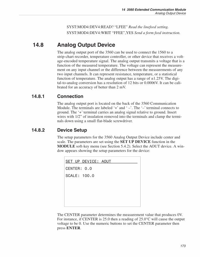
SYST:MOD4:DEV4:READ? “LFEE” Read the linefeed setting.
SYST:MOD4:DEV4:WRIT “FFEE”,YES Send a form feed instruction.
14.8 Analog Output DeviceThe analog output port of the 3560 can be used to connect the 1560 to astrip-chart recorder, temperature controller, or other device that receives a volt-age-encoded temperature signal. The analog output transmits a voltage that is afunction of the measured temperature. The voltage can represent the measure-ment on any input channel or the difference between the measurements of anytwo input channels. It can represent resistance, temperature, or a statisticalfunction of temperature. The analog output has a range of ±1.25V. The digi-tal-to-analog conversion has a resolution of 12 bits or 0.0006V. It can be cali-brated for an accuracy of better than 2 mV.
14.8.1 ConnectionThe analog output port is located on the back of the 3560 CommunicationModule. The terminals are labeled ‘+’ and ‘ –’. The ‘–’ terminal connects toground. The ‘+’ terminal carries an analog signal relative to ground. Insertwires with 1/2” of insulation removed into the terminals and clamp the termi-nals down using a small flat-blade screwdriver.
14.8.2 Device SetupThe setup parameters for the 3560 Analog Output Device include center andscale. The parameters are set using the SET UP DEVICE function in theMODULE soft-key menu (see Section 5.4.2). Select the AOUT device. A win-dow appears showing the setup parameters for the device:
SET UP DEVICE: AOUT
CENTER: 0.0
SCALE: 100.0
The CENTER parameter determines the measurement value that produces 0V.For instance, if CENTER is 25.0 then a reading of 25.0°C will cause the outputvoltage to be 0. Use the numeric buttons to set the CENTER parameter thenpress ENTER.
173
14 3560 Extended Communication ModuleAnalog Output Device
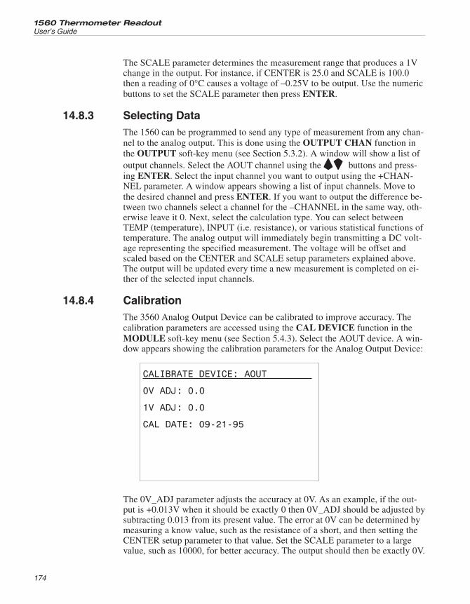
The SCALE parameter determines the measurement range that produces a 1Vchange in the output. For instance, if CENTER is 25.0 and SCALE is 100.0then a reading of 0°C causes a voltage of –0.25V to be output. Use the numericbuttons to set the SCALE parameter then press ENTER.
14.8.3 Selecting DataThe 1560 can be programmed to send any type of measurement from any chan-nel to the analog output. This is done using the OUTPUT CHAN function inthe OUTPUT soft-key menu (see Section 5.3.2). A window will show a list ofoutput channels. Select the AOUT channel using the UD buttons and press-ing ENTER. Select the input channel you want to output using the +CHAN-NEL parameter. A window appears showing a list of input channels. Move tothe desired channel and press ENTER. If you want to output the difference be-tween two channels select a channel for the –CHANNEL in the same way, oth-erwise leave it 0. Next, select the calculation type. You can select betweenTEMP (temperature), INPUT (i.e. resistance), or various statistical functions oftemperature. The analog output will immediately begin transmitting a DC volt-age representing the specified measurement. The voltage will be offset andscaled based on the CENTER and SCALE setup parameters explained above.The output will be updated every time a new measurement is completed on ei-ther of the selected input channels.
14.8.4 CalibrationThe 3560 Analog Output Device can be calibrated to improve accuracy. Thecalibration parameters are accessed using the CAL DEVICE function in theMODULE soft-key menu (see Section 5.4.3). Select the AOUT device. A win-dow appears showing the calibration parameters for the Analog Output Device:
CALIBRATE DEVICE: AOUT
0V ADJ: 0.0
1V ADJ: 0.0
CAL DATE: 09-21-95
The 0V_ADJ parameter adjusts the accuracy at 0V. As an example, if the out-put is +0.013V when it should be exactly 0 then 0V_ADJ should be adjusted bysubtracting 0.013 from its present value. The error at 0V can be determined bymeasuring a know value, such as the resistance of a short, and then setting theCENTER setup parameter to that value. Set the SCALE parameter to a largevalue, such as 10000, for better accuracy. The output should then be exactly 0V.
1560 Thermometer Readout
User’s Guide
174
The 1V_ADJ parameter adjusts the accuracy at 1V. As an example, if the out-put is +0.991V when it should be exactly 1V then 1V_ADJ should be adjustedby adding 0.009 to its present value. The error at 1V can be determined bymeasuring the resistance of a short and setting the SCALE setup parameter to alarge value, such as 10000, and the CENTER parameter to the opposite of thatvalue (–10000). The output should be exactly 1V.
The CAL DATE parameter can be used to record the date the calibration wasperformed.
14.8.5 Device Setup CommandsThe SYST:MODn:DEVn:READ? and SYST: MODn:DEVn:WRIT commands(see Sections 6.5.8.19 and 6.5.8.20) can be used to read or set the setup param-eters for the 3560 Analog Output Device. The device number of the AnalogOutput Device is 5. The module number for the 3560 module is its position inthe stack. For example, if the 1560 has four add-on modules, the 3560 beingthe last, the module number for the 3560 is 4. Table 35 shows the device com-mands used to read or set the setup parameters of the Analog Output Device.
Below are some examples of using the device commands to set the device pa-rameters. For these examples it is assumed that the 3560 Communication Mod-ule is placed fourth in the stack. These commands can be sent through anycommunication interface including the IEEE-488 and RS-232 interfaces.
SYST:MOD4:DEV5:WRIT “CNTR”,25 Set center of range at 25°C.
SYST:MOD4:DEV5:READ? “CNTR” Read center setting.
SYST:MOD4:DEV5:WRIT “SCAL”,10 Set scale to 10°C/V.
175
14 3560 Extended Communication ModuleAnalog Output Device
Device Command Parameter Description
CNTR numeric 0V center
SCAL numeric 1V scale
Table 35 Analog Output Device Commands
15 Maintenance
• The calibration instrument has been designed with the utmost care. Easeof operation and simplicity of maintenance have been a central theme inthe product development. Therefore, with proper care the instrumentshould require very little maintenance. Avoid operating the instrument inan oily, wet, dirty, or dusty environments.
• If the outside of the instrument becomes soiled, it may be wiped cleanwith a damp cloth and mild detergent. Do not use harsh chemicals on thesurface which may damage the paint or the plastic of the outside shell.
• If a hazardous material is spilt on or inside the equipment, the user is re-sponsible for taking the appropriate decontamination steps as outlined bythe national safety council with respect to the material.
• If the mains supply cord becomes damaged, replace it with a cord withthe appropriate gauge wire for the current of the instrument. If there areany questions, call Hart Scientific Customer Service for more informa-tion.
• Before using any cleaning or decontamination method except those rec-ommended by Hart, users should check with Hart Scientific CustomerService to be sure that the proposed method will not damage the equip-ment.
• If the instrument is used in a manner not in accordance with the equip-ment design, the operation of the thermometer may be impaired or safetyhazards may arise.
177
15 Maintenance
16 Troubleshooting
In case you run into difficulty while operating the 1560 system, this sectionprovides some suggestions that may help you solve the problem. Below areseveral situations that may arise followed by possible causes of the problemand suggested actions you might take.
16.1 Incorrect Temperature ReadingWhile attempting to measure temperature the display shows an incorrect valueor no value at all (“. . . . . . . . . . “).
If the temperature readings seem to be incorrect you should first check to see ifthe resistance, or voltage in the case of thermocouples, is being measured cor-rectly. Set up the display to show the resistance or voltage (INPUT) for thechannel (see Section 5.3.1.2). If the resistance or voltage is incorrect refer tothe next subsection for troubleshooting incorrect resistance or voltage readings.If the resistance or voltage is being measured correctly but the displayed tem-perature value is incorrect consider the following possibilities:
• One or more coefficients are incorrect. This is a common mistake.While entering coefficients it is easy to miss a digit or sign. Check all thevalues carefully using the EDIT PROBE function (see Section 5.2.1)comparing them with the values on the calibration certificate for theprobe. Use the TEST CONV function to test the coefficients (see Section5.2.3).
• The selected conversion type is incorrect. Check to make sure the cor-rect conversion type is selected. In the case of thermocouples, make sureyou have selected the correct thermocouple type. Again, you can use theTEST CONV function to test the temperature conversion calculation.
• The measurement is out of range. The 1560 may not be able to calcu-late temperature accurately if the resistance or voltage is outside the validrange. The measured resistance or voltage may be too low or too high ifthe actual temperature is too low or too high or if there is a problem withthe sensor (see below).
16.2 Incorrect Resistance or Voltage ReadingWhile attempting to measure resistance or voltage the display shows an incor-rect value or no value at all (“. . . . . . . . . . “).
Consider the following possibilities:
• Poor or incorrect connection of the probe. A common mistake is toconnect the wires of the probe to the wrong terminals. Check the wiringcarefully, especially when using a four-wire PRT (see Figure 13 on page114 or Figure 15 on page 126). Make sure the lead wires are fasteneddown tightly.
179
16 TroubleshootingIncorrect Temperature Reading
• Open, shorted, or damaged sensor or lead wires. In the case of resis-tance sensors check the resistance across the sensor using a hand-heldDMM. Also check the resistance between common pairs of leads. Checkto make sure there is no conductivity between any of the leads and theprobe sheath. Use a good-quality sensor to avoid errors caused by drift,hysteresis, or insulation leakage. In the case of thermocouples, use ahand-held DMM to check its voltage.
• Improper setting for three or four-wire probe. When using the 2562 or2564 scanner modules you need to make sure the correct wiring type isselected (read carefully Section 9.3.1 or 11.3.1). Selecting three-wire in-put while using four-wire probes may cause errors of 0.01 to 0.1Ω. Se-lecting four-wire input while using three-wire probes will result in erraticor out-of-range readings.
• Electrical interference. Intense radio-frequency radiation near the 1560or probes can induce noise into the measurement circuits resulting in er-ratic readings. The 1560 is intended to operate in a laboratory environ-ment with limited radio-frequency noise. If interference seems to be aproblem you might try eliminating the source of interference or movingthe 1560 to a different location. A well-grounded, shielded cable shouldbe used for the probe leads.
• Stem conduction error. The problem may be that the actual temperatureof the sensor is not what you expect. This is often the result of stem con-duction where heat flowing through the stem of the probe to ambient af-fects the temperature of the probe. It is very important that immersionprobes be inserted to an adequately depth into the material being mea-sured. Measuring temperature using a surface sensor can be especiallydifficult as the sensor is directly exposed to ambient.
16.3 Communication DifficultiesYou are having trouble establishing communications between the 1560 and aremote computer using either the base RS-232 port, the 3560 Module RS-232port, or the 3560 Module IEEE-488 port.
First, test RS-232 communications using the base serial port. Connect a serialcable to a computer running terminal software such as Windows® 3.1 Terminalor Windows® 95 Hyperterminal. Be sure to set the baud rates of both the 1560and the computer to the same number. Use 8 data bits, 1 stop bit, and no parity.Test transmission from the 1560 by enabling the PRINT OUTPUT functionfor the SER0 device. You should see measurement data appear on the com-puter. Test reception by sending a command to the 1560 such as “UNIT:TEMPF” or “UNIT:TEMP C”. You should see the units of the measurement changeaccordingly. Be sure to use a space character to separate the header from theparameter in this and other commands.
Repeat the same tests with the RS-232 port on the 3560 module. Test the trans-mission of measurement data and the reception of commands.
1560 Thermometer Readout
User’s Guide
180
Debugging IEEE-488 communications can be more difficult since it is so muchmore complex. The 3560 Module has a diagnostic mode that can help in trou-bleshooting communication problems. Issuing the command “*DIA” to the3560 Module RS-232 port enables the diagnostic mode. Diagnostic informationwill be printed from the 3560 Module RS-232 port and can be viewed on yourcomputer. You will be able to see how commands are received at the IEEE-488port and monitor the value of the IEEE-488 status byte register (see Section6.5.10.9). If the IEEE-488 port does not seem to be receiving any data checkthat the GPIB addresses are correct (see Section 14.4.3). Also check the cable.If commands are being received but your computer is not receiving any datafrom the 1560 in response to the command check that the termination characteris set correctly (also Section 14.4.3). Setup your software so that it does not re-quire the EOI message.
16.4 Blank ScreenThe screen lights up when the 1560 is switched on but the screen appearsblank.
This problem can be caused by improper adjustment of the contrast. After thepower is switched on allow the 1560 at least one minute to complete its self testand power on sequence. Then, try to adjust the contrast using the contrastbuttons.
16.5 Error Message at Power UpThe 1560 reports an error during the power up self-test.
On power up the 1560 performs a series of self-tests to check the operation ofall its components and each of the modules. The results of the self-tests are re-ported on the screen. Normally, all tests will report “OK.” A failure of one ormore component will cause error messages to be reported. A bus error, a mod-ule error, a failure to recognized a module, or a “BATTERY BACKED RAM”error is often caused by a module being improperly attached in which case thebase will not be able to properly communicate with that module and those be-hind it. Try reattaching the module while ensuring that the bus connectors areall fully inserted. If this does not solve the problem it may be caused by a dam-aged module or the failure of a component within the module such as the fuse.This and other types of component failures generally require a qualified factorytechnician to replace the faulty component. Contact a Hart Scientific Autho-rized Service Center for assistance (see Section 1.3).
16.6 CE Comments
16.6.1 EMC DirectiveHart Scientific's equipment has been tested to meet the European Electromag-netic Compatibility Directive (EMC Directive, 89/336/EEC). The Declaration
181
16 TroubleshootingBlank Screen
of Conformity for your instrument lists the specific standards to which the unitwas tested.
The instrument was designed specifically as a test and measuring device. Com-pliance to the EMC directive is through IEC 61326-1 Electrical equipment formeasurement, control and laboratory use - EMC requirements (1998).
As noted in the IEC 61326-1, the instrument can have varying configurations.The instrument was tested in a typical configuration with shielded, groundedprobe and RS-232 cables. Emissions may, in non-typical applications, exceedthe levels required by the standard. It is not practical to test all configurations,as the manufacturer has no control over the module configuration or the probesthe user may connect to the instrument.
16.6.1.1 Immunity Testing
The instrument was tested to the requirements for industrial locations. This al-lows the instrument to be used in all types of locations from the laboratory tothe factory floor. Criterion A, B, or C was used for Radiated RF (IEC61000-4-3) depending on the module configuration. Criterion A or B was usedfor Conducted RF (IEC 61000-4-6) depending on the module configuration.Therefore, the operation of the instrument may be affected by excessive elec-tromagnetic interference and the instrument may not perform within the normalspecification limits in such an environment.
Criterion A or C was used for Electrostatic Discharge (ESD, IEC 61000-4-2)depending on the module configuration. Criterion A or B was used for ElectricFast Transit (EFT, Burst, IEC 61000-4-4) depending on the module configura-tion. If the instrument is subjected to ESD conditions at industrial levels, the in-strument may require the user to cycle the power to return to normal operation.
16.6.1.2 Emission Testing
The instrument fulfills the limit requirements for Class A equipment but doesnot fulfill the limit requirements for Class B equipment. The instrument wasnot designed to be used in domestic establishments.
16.6.2 Low Voltage Directive (Safety)In order to comply with the European Low Voltage Directive (73/23/EEC),Hart Scientific equipment has been designed to meet the IEC 1010-1 (EN61010-1) and the IEC 1010-2-010 (EN 61010-2-010) standards.
1560 Thermometer Readout
User’s Guide
182
Index
!
LCR 12
LR 12
UD 12
2560 SPRT Module 113
2561 HTPRT Module 119
2562 PRT Scanner Module 125
2563 Thermistor Module 133
2564 Thermistor Scanner Module 139
2565 Precision Thermocouple Module 147
2566 Thermocouple Scanner Module 155
2-wire probe 127,140
3560 Extended Communications Module 163
3-wire probe 127,140
4-wire probe 127,140
Aaccuracy
See specifications
analog output device 173
AVER soft-key 32
average, input 14,32
Bbase 5
base microprocessor 7
basic operation 21
brightness, screen 53
buttons 11
LCR 12
LR 12
UD 12
CCAL DEVICE soft-key 55
calibration 59
2560 SPRT Module 116
2561 SPRT Module 122
2562 PRT Scanner Module 129
2563 Thermistor Module 136
2564 Thermistor Scanner Module 143
2565 Precision Thermocouple Module 152 -153
2566 Thermocouple Scanner Module 158
3560 Analog Output 174
calibration parameters 6
2560 SPRT Module 116
2561 HTPRT Module 122
2562 PRT Scanner Module 129
2564 Thermistor Scanner Module 143
2565 Precisioin Thermocouple Module 152
Calibration Parameters
2563 Thermistor Module 136
Callendar-Van Dusen conversion 6,38
channel numbers 24
characterization coefficients 25,33,45
CJC 7,14,41,43,147,149,155,157
CLEAR GRAPH soft-key 49
CLEAR STATS soft-key 53
cold-junction compensation
See CJC
Index
183
communication device 13,63,163
communication ports 7,12 - 13,63,165,167
communications 63,163
connecting a probe 114,120,127,134,140
contrast, screen 12,23
CONVERSION 34
conversion, temperature
See temperature conversion
COPY PROBE soft-key 43
COUNT N 29
current 115,121,128,135,142
Ddata field 17,46
data processing 14 - 15,17
Del button 11
delay 14
DELAY 10,31,48
device 6,54
device calibration 55
DISP WINDOW menu 46
display 7,46
EEDIT PROBE soft-key 33
ENTER button 11
EXIT button 11
Ffeatures 5
Ggeneral description 5
GPIB
See IEEE-488
graph 48
graph mode display 10,48
GRAPH WINDOW soft-key 48
IIEC-751 38
IEEE-488 13,63,163
input channel 23 - 24,31,33,47
input device 13
INPUT menu 29
inputs 14
installing new modules 21
IPTS-68 conversion 6,37
ITS-90 conversion 6
L
L R
left right arrows 12
Mmaintenance 177
MEAS soft-key 29
MEASURE mode 29
measurement status 9
memory 16,52,170,172
module 5,13
module bus 12,14
MODULE INFO soft-key 56
MODULE menu 53
Nnon-volatile RAM 7,13
numeric keys 11
Index
184
NVRAM
See non-volatile RAM
Oohms conversion
See R(Ω)
OUTPUT CHAN soft-key 50
output channel 16,50,174
output device 13,17,173
OUTPUT menu 45,47,49,51
Ppassword 33,55,58
PASSWORD soft-key 58
platinum resistance thermometer
See PRT
polynomial conversion 39
power supply 12,23
PRIM CHAN 31
PRINT MEMORY soft-key 52
PRINT OUTPUT soft-key 51
printer output device 13,16,51,169,171
probe characterization 21,25,33
PROBE menu 33
PRT 6,113,125
R
R(Ω) 36
resistance temperature detector
See RTD
RS-232 12 - 13,63,167,169
RTD 6,113,125
Ssampling control 14
scan 31
SCAN CHAN soft-key 31
scan mode 26,32
SCAN MODE soft-key 32
screen brightness
See brightness, screen
screen saver 54
SCROLL WINDOW soft-key 49
scrolling display 49
scrolling window 10
self-test 23
Serial
See RS-232
serial number, probe 34
SET FIELDS soft-key 46
SET UP DEVICE soft-key 54
SET UP SCREEN soft-key 53
soft-key 10 - 11,29
soft-key menu 29
specifications
1560 19
2560 Module 113
2561 Module 119
2562 Module 125
2563 Module 133
2564 Module 139
2565 Module 147
2566 Module 155
3560 Module 164
SPRT 6,113,125
standard platinum resistance thermometer
Index
185
See SPRT
STAT WINDOW soft-key 46
statistical display 10,46
statistics 16,47,50
Steinhart-Hart equation 7,39 - 40
SYSTEM INFO soft-key 59
SYSTEM menu 57
Ttemperature conversion 14,25,34,45
TEST CONV soft-key 45
thermistor 6,39 - 40,134,139
thermocouple 7,14,147,156
thermocouple conversions 41,149,156
thermocouple polynomial 43
thermocouple table 42
time 9,14,58
TIME soft-key 58
troubleshooting 179,181
Uunit conversion 16
unit, temperature 57
UNITS soft-key 57
U D
up down arrows 12
USER channel 43
Vvolts conversion 40,149,156
WW(T90) conversion 37
Index
186