Embed Size (px)
Citation preview
MicroLogixProgrammableControllersSelectionGuide
1761, 1762, 1764
2
Publication 1761-SG001A-EN-P
MicroLogix Programmable Controllers Selection Guide
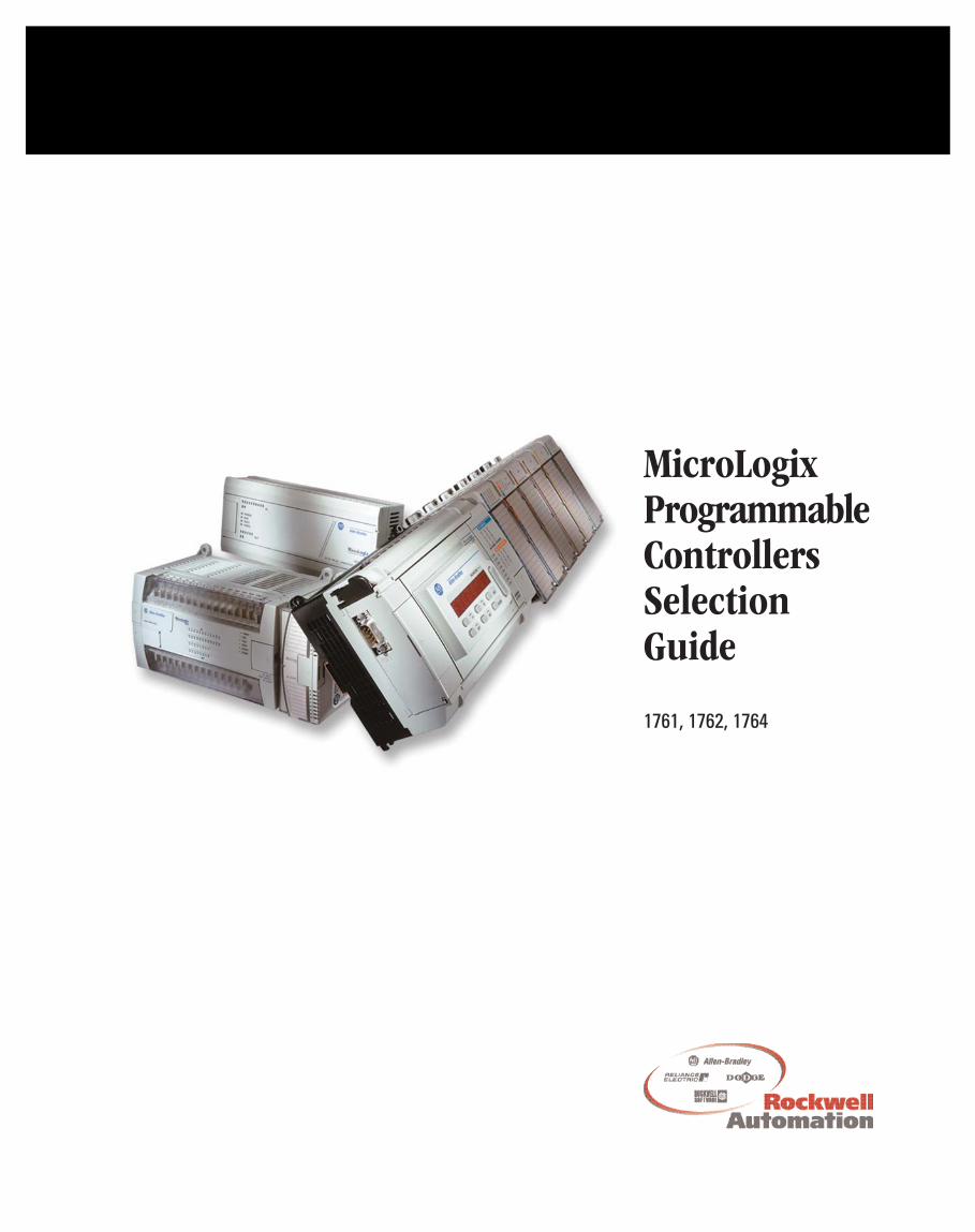
MicroLogix OverviewThe MicroLogix family of programmable controllers provides 3 levels of control. Small onsize, big on performance, the MicroLogix 1000 offers control capabilities in an affordable,compact package. The MicroLogix 1200 is small enough to fit in tight spaces, but powerfulenough to accommodate a broad range of applications. Designed to grow as your needsgrow, the MicroLogix 1500 helps you achieve high-level control in a variety ofapplications.
MMiiccrrooLLooggiixx 11000000 DDeessccrriippttiioonn
Based on the architecture of the market-leading SLC 500 controller family, the MicroLogix1000 brings high speed, powerful instructions and flexible communications to applicationsthat demand compact, cost-effective solutions.
The MicroLogix 1000 programmable controller is available in 10-point, 16-point or 32-pointdigital I/O versions. Analog versions are also available with 20 digital I/O points and 5analog I/O points.
The analog I/O circuitry for the MicroLogix 1000 units is embedded into the basecontroller, not accomplished through add-on modules. So, it provides very high-speed,cost-effective analog performance.
The MicroLogix 1000 controller utilizes RSLogix 500 programming software and shares acommon instruction set with the MicroLogix 1200, MicroLogix 1500 and SLC 500 familiesof controllers.
3
Publication 1761-SG001A-EN-P
MicroLogix Programmable Controllers Selection Guide
AAddvvaannttaaggeessFast processing allows for typical throughput time of 1.5 ms for a 500-instructionprogram
Built-in EEPROM memory retains all of your ladder logic and data if the controller losespower, eliminating the need for battery back-up or separate memory module
Multiple input and output commons allow you to use the controller for either sinking orsourcing input devices and provide isolated commons for multi-voltage outputapplications
Peer-to-peer messaging capability allows you to network up to 32 controllers on a DH-485 network (using a 1761-NET-AIC module)
RTU slave protocol support using DF1 Half-Duplex allows up to 254 slave nodes tocommunicate with a single master using radio modems, leased-line modems or satelliteuplinks
RS-232 communication channel allows for simple connectivity to a personal computerfor program upload, download and monitoring
Controllers that have 24V dc inputs include a built-in high-speed counter (6.6 kHz)
Adjustable DC input filters allow you to customize the input response time and noiserejection to meet your application needs
Regulatory agency certifications for world-wide market (CE, C-Tick, UL, c-UL, includingClass 1 Division 2 Hazardous Location)
4
Publication 1761-SG001A-EN-P
MicroLogix Programmable Controllers Selection Guide
MMiiccrrooLLooggiixx 11220000 DDeessccrriippttiioonn
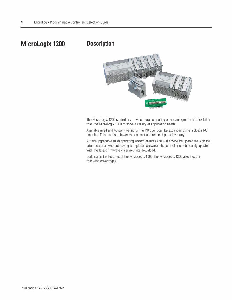
The MicroLogix 1200 controllers provide more computing power and greater I/O flexibilitythan the MicroLogix 1000 to solve a variety of application needs.
Available in 24 and 40-point versions, the I/O count can be expanded using rackless I/Omodules. This results in lower system cost and reduced parts inventory.
A field-upgradable flash operating system ensures you will always be up-to-date with thelatest features, without having to replace hardware. The controller can be easily updatedwith the latest firmware via a web site download.
Building on the features of the MicroLogix 1000, the MicroLogix 1200 also has thefollowing advantages.
5
Publication 1761-SG001A-EN-P
MicroLogix Programmable Controllers Selection Guide
AAddvvaannttaaggeessLarge 6K memory to solve a variety of applications
High performance expansion I/O options (up to 6 modules depending on power budget)
Advanced communications options including peer-to-peer and SCADA/RTU networks,DH-485, DeviceNet and EtherNet/IP via the Communications Port (Channel 0) on thecontroller
An additional Programming/HMI Port, providing connectivity to a DF1-Full Duplexcompatible device such as an operator interface or programming terminal (MicroLogix1200R only)
Communications toggle push button that allows the controller's Channel 0 port to togglebetween user configured communications parameters and factory default settings foreasy programming or troubleshooting
Data file download protection prevents critical user data from being altered via programdownloads
Two built-in analog trim potentiometers
Optional real-time clock
Optional memory module
High-resolution, 1 ms timers
20 kHz high-speed counter, featuring 8 modes of operation
One high-speed output that can be configured as 20 kHz PTO (Pulse Train Output) or asPWM (Pulse Width Modulated) output
Four high-speed latching (pulse-catch) inputs
Four event interrupt inputs (EII)
One, 1 ms, selectable timed interrupt (STI)
32-bit signed integer math
Floating-point data file
Built-in PID capabilities
ASCII read/write capability
Finger-safe terminal blocks meet global safety standards
Removable terminal blocks on 40-point controllers allow pre-wiring
6
Publication 1761-SG001A-EN-P
MicroLogix Programmable Controllers Selection Guide
MMiiccrrooLLooggiixx 11550000 DDeessccrriippttiioonn
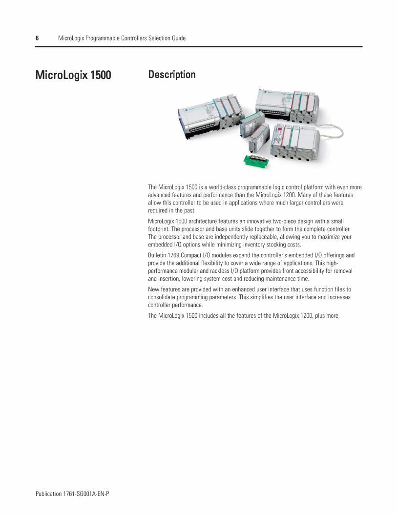
The MicroLogix 1500 is a world-class programmable logic control platform with even moreadvanced features and performance than the MicroLogix 1200. Many of these featuresallow this controller to be used in applications where much larger controllers wererequired in the past.
MicroLogix 1500 architecture features an innovative two-piece design with a smallfootprint. The processor and base units slide together to form the complete controller. The processor and base are independently replaceable, allowing you to maximize yourembedded I/O options while minimizing inventory stocking costs.
Bulletin 1769 Compact I/O modules expand the controller's embedded I/O offerings andprovide the additional flexibility to cover a wide range of applications. This high-performance modular and rackless I/O platform provides front accessibility for removaland insertion, lowering system cost and reducing maintenance time.
New features are provided with an enhanced user interface that uses function files toconsolidate programming parameters. This simplifies the user interface and increasescontroller performance.
The MicroLogix 1500 includes all the features of the MicroLogix 1200, plus more.
7
Publication 1761-SG001A-EN-P
MicroLogix Programmable Controllers Selection Guide
AAddvvaannttaaggeessLarge memory to solve a variety of applications.1764-LSP: 7K user program capacity1764-LRP: 14K user program capacity
Recipe (RCP) instruction saves custom lists of recipe data
Data logging (1764-LRP only) instruction stores data records with optional time stamp ina separate 48K byte memory area
High performance expansion I/O options (up to 16 modules)
Additional configurable RS-232 communications port on the 1764-LRP processor forpeer-to-peer and SCADA/RTU networks, DH-485, DeviceNet and EtherNet/IP
Battery (built-in and optional replacement)
Mode switch for Run/Remote/Program
Optional data access tool (DAT) for monitoring and changing integer and bit values
Two high-speed outputs that can be configured as 20 kHz PTO (Pulse Train Output) or asPWM (Pulse Width Modulated) outputs
Eight high-speed latching (pulse-catch) inputs
Removable terminal blocks on all Base Units and I/O modules allow pre-wiring
8
Publication 1761-SG001A-EN-P
MicroLogix Programmable Controllers Selection Guide
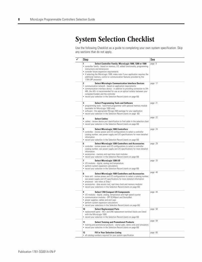
System Selection ChecklistUse the following Checklist as a guide to completing your own system specification. Skipany sections that do not apply.
SStteepp SSeeee 1 Select Controller Family: MicroLogix 1000, 1200 or 1500
controller family - based on memory, I/O, added functionality, programminginstructions and dimensionsconsider future expansion requirementsif selecting the MicroLogix 1500, make note if your application requires theadditional memory, control or communication features provided by the1764-LRP processor
page 9
2 Select Micrologix Communication Interface Devicescommunication network - based on application requirementscommunication interface device - in addition to providing connection to DH-485, the AIC+ is recommended for use as an optical isolator between yourcomputer/modem and the controllerrecord your selection in the Selection Record (starts on page 60)
page 17
3 Select Programming Tools and Softwareprogramming tools - hand-held programmer with optional memory module(available for MicroLogix 1000 only)software - the appropriate RSLogix 500 package for your applicationrecord your selection in the Selection Record (starts on page 60)
page 21
4 Select Cablescables - review device port identification to find cable in the selection chartrecord your selection in the Selection Record (starts on page 60)
page 22
5 Select MicroLogix 1000 Controllerscontroller - review power and I/O configurations to select a controllercatalog number; see power supply and I/O specifications for more detailedinformationrecord your selection in the Selection Record (starts on page 60)
page 24
6 Select MicroLogix 1200 Controllers and Accessoriescontroller - review power and I/O configurations to select a controllercatalog number; see power supply and I/O specifications for more detailedinformationaccessories - memory and real-time clock modulesrecord your selection in the Selection Record (starts on page 60)
page 29
7 Select MicroLogix 1200 I/OI/O modules - digital, analog and temperatureperform system expansion calculationsrecord your selection in the Selection Record (starts on page 60)
page 33
8 Select MicroLogix 1500 Controllers and Accessoriesbase unit - review power and I/O configurations to select a catalog number;see power supply and I/O specifications for more detailed informationprocessor - see notes at Step 1accessories - data access tool; real-time clock and memory modulesrecord your selections in the Selection Record (starts on page 60)
page 40
9 Select 1769 Compact I/O ComponentsI/O modules - digital, analog, temperature and high-speed countercommunication modules - DPI SCANport and DeviceNetpower supplies, cables and end capsperform system expansion calculationsrecord your selections in the Selection Record (starts on page 60)
page 44
10 Select Replacement Partsreplacement parts - AIC+ and DNI replacement terminal blocks are listedwith the MicroLogix 1000record your selection in the Selection Record (starts on page 60)
page 58
11 Select Training and Promotional Productstraining and promotional products - starter paks, demo units and simulatorsrecord your selection in the Selection Record (starts on page 60)
page 59
12 Fill in Your Selection Listingall catalog numbers required for your system specification
page 60
9
Publication 1761-SG001A-EN-P
MicroLogix Programmable Controllers Selection Guide
Select Controller Family: MicroLogix1000, 1200 or 1500
Step 1 - Select:
controller family - based on memory, I/O,added functionality, programminginstructions and dimensions
consider future expansion requirements
if selecting the MicroLogix 1500, makenote if your application requires theadditional memory, control orcommunication features provided by the1764-LRP processor
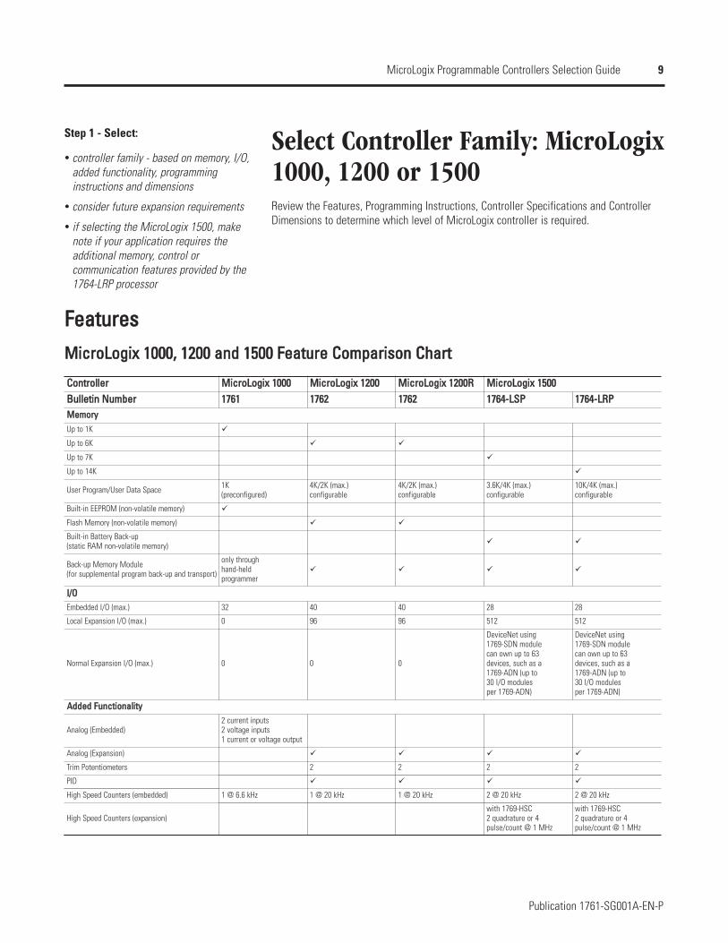
Review the Features, Programming Instructions, Controller Specifications and ControllerDimensions to determine which level of MicroLogix controller is required.
FFeeaattuurreessMMiiccrrooLLooggiixx 11000000,, 11220000 aanndd 11550000 FFeeaattuurree CCoommppaarriissoonn CChhaarrtt
CCoonnttrroolllleerrBBuulllleettiinn NNuummbbeerr
Up to 1K
Up to 6K
Up to 7K
Up to 14K
User Program/User Data Space
Built-in EEPROM (non-volatile memory)
Flash Memory (non-volatile memory)
Built-in Battery Back-up (static RAM non-volatile memory)
Back-up Memory Module (for supplemental program back-up and transport)
Embedded I/O (max.)
Local Expansion I/O (max.)
Normal Expansion I/O (max.)
Analog (Embedded)
Analog (Expansion)
Trim Potentiometers
PID
High Speed Counters (embedded)
High Speed Counters (expansion)
MMiiccrrooLLooggiixx 11000000 MMiiccrrooLLooggiixx 11220000 MMiiccrrooLLooggiixx 11220000RR MMiiccrrooLLooggiixx 1155000011776611 11776622 11776622 11776644--LLSSPP 11776644--LLRRPP
MMeemmoorryy
1K (preconfigured)
4K/2K (max.)configurable
4K/2K (max.)configurable
3.6K/4K (max.)configurable
10K/4K (max.)configurable
only throughhand-heldprogrammer
II//OO32 40 40 28 28
0 96 96 512 512
0 0 0
DeviceNet using1769-SDN modulecan own up to 63 devices, such as a 1769-ADN (up to 30 I/O modules per 1769-ADN)
DeviceNet using1769-SDN modulecan own up to 63 devices, such as a 1769-ADN (up to 30 I/O modules per 1769-ADN)
AAddddeedd FFuunnccttiioonnaalliittyy2 current inputs2 voltage inputs1 current or voltage output
2 2 2 2
1 @ 6.6 kHz 1 @ 20 kHz 1 @ 20 kHz 2 @ 20 kHz 2 @ 20 kHz
with 1769-HSC2 quadrature or 4pulse/count @ 1 MHz
with 1769-HSC2 quadrature or 4pulse/count @ 1 MHz
10
Publication 1761-SG001A-EN-P
MicroLogix Programmable Controllers Selection Guide
MMiiccrrooLLooggiixx 11000000,, 11220000 aanndd 11550000 FFeeaattuurree CCoommppaarriissoonn CChhaarrtt
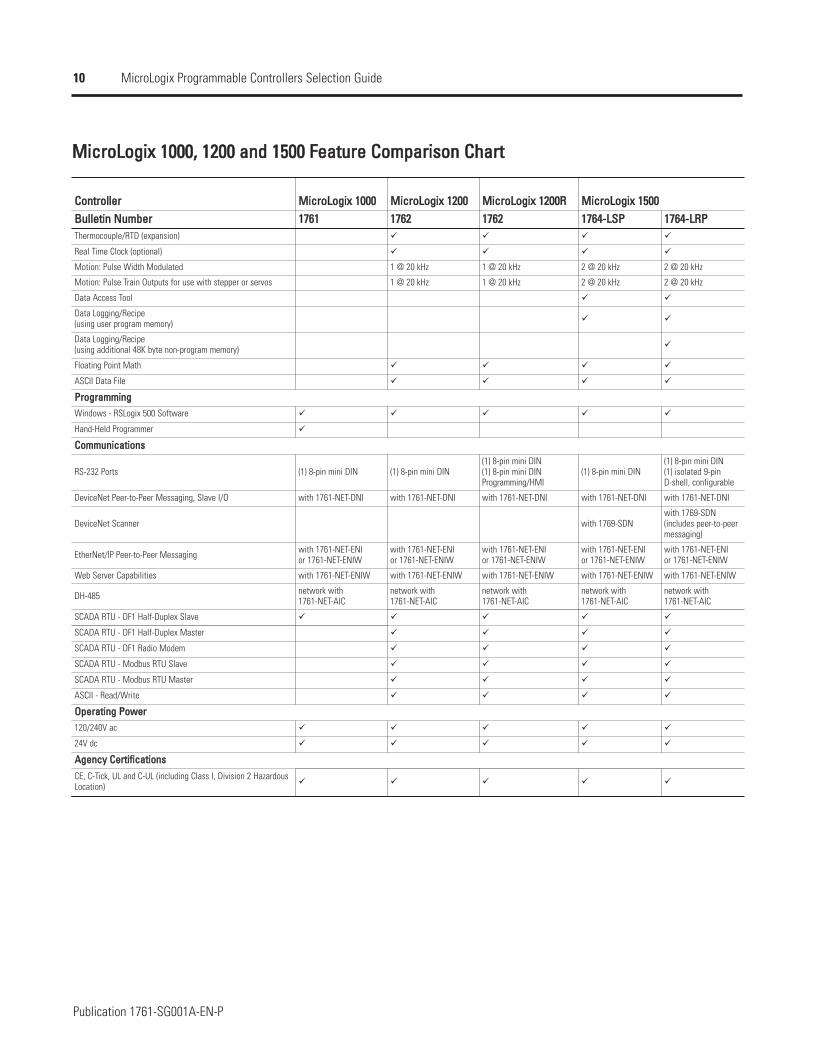
CCoonnttrroolllleerr MMiiccrrooLLooggiixx 11000000 MMiiccrrooLLooggiixx 11220000 MMiiccrrooLLooggiixx 11220000RR MMiiccrrooLLooggiixx 11550000BBuulllleettiinn NNuummbbeerr 11776611 11776622 11776622 11776644--LLSSPP 11776644--LLRRPPThermocouple/RTD (expansion)
Real Time Clock (optional)
Motion: Pulse Width Modulated 1 @ 20 kHz 1 @ 20 kHz 2 @ 20 kHz 2 @ 20 kHz
Motion: Pulse Train Outputs for use with stepper or servos 1 @ 20 kHz 1 @ 20 kHz 2 @ 20 kHz 2 @ 20 kHz
Data Access Tool
Data Logging/Recipe (using user program memory)
Data Logging/Recipe (using additional 48K byte non-program memory)
Floating Point Math
ASCII Data File
PPrrooggrraammmmiinnggWindows - RSLogix 500 Software
Hand-Held Programmer
CCoommmmuunniiccaattiioonnss
RS-232 Ports (1) 8-pin mini DIN (1) 8-pin mini DIN(1) 8-pin mini DIN(1) 8-pin mini DINProgramming/HMI
(1) 8-pin mini DIN(1) 8-pin mini DIN(1) isolated 9-pinD-shell, configurable
DeviceNet Peer-to-Peer Messaging, Slave I/O with 1761-NET-DNI with 1761-NET-DNI with 1761-NET-DNI with 1761-NET-DNI with 1761-NET-DNI
DeviceNet Scanner with 1769-SDNwith 1769-SDN(includes peer-to-peermessaging)
EtherNet/IP Peer-to-Peer Messaging with 1761-NET-ENIor 1761-NET-ENIW
with 1761-NET-ENIor 1761-NET-ENIW
with 1761-NET-ENIor 1761-NET-ENIW
with 1761-NET-ENIor 1761-NET-ENIW
with 1761-NET-ENIor 1761-NET-ENIW
Web Server Capabilities with 1761-NET-ENIW with 1761-NET-ENIW with 1761-NET-ENIW with 1761-NET-ENIW with 1761-NET-ENIW
DH-485 network with1761-NET-AIC
network with1761-NET-AIC
network with1761-NET-AIC
network with1761-NET-AIC
network with1761-NET-AIC
SCADA RTU - DF1 Half-Duplex Slave
SCADA RTU - DF1 Half-Duplex Master
SCADA RTU - DF1 Radio Modem
SCADA RTU - Modbus RTU Slave
SCADA RTU - Modbus RTU Master
ASCII - Read/Write
OOppeerraattiinngg PPoowweerr120/240V ac
24V dc
AAggeennccyy CCeerrttiiffiiccaattiioonnssCE, C-Tick, UL and C-UL (including Class I, Division 2 HazardousLocation)
11
Publication 1761-SG001A-EN-P
MicroLogix Programmable Controllers Selection Guide
PPrrooggrraammmmiinnggIInnssttrruuccttiioonnss
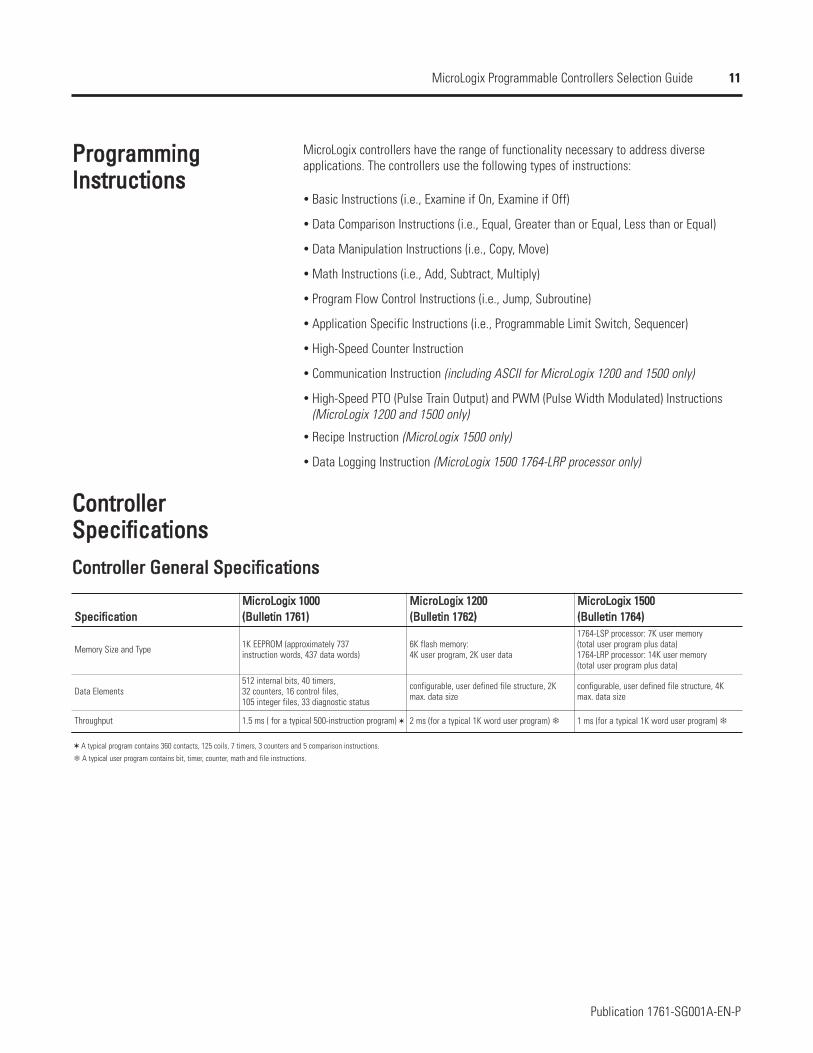
MicroLogix controllers have the range of functionality necessary to address diverseapplications. The controllers use the following types of instructions:
Basic Instructions (i.e., Examine if On, Examine if Off)
Data Comparison Instructions (i.e., Equal, Greater than or Equal, Less than or Equal)
Data Manipulation Instructions (i.e., Copy, Move)
Math Instructions (i.e., Add, Subtract, Multiply)
Program Flow Control Instructions (i.e., Jump, Subroutine)
Application Specific Instructions (i.e., Programmable Limit Switch, Sequencer)
High-Speed Counter Instruction
Communication Instruction (including ASCII for MicroLogix 1200 and 1500 only)
High-Speed PTO (Pulse Train Output) and PWM (Pulse Width Modulated) Instructions(MicroLogix 1200 and 1500 only)
Recipe Instruction (MicroLogix 1500 only)
Data Logging Instruction (MicroLogix 1500 1764-LRP processor only)
CCoonnttrroolllleerrSSppeecciiffiiccaattiioonnssCCoonnttrroolllleerr GGeenneerraall SSppeecciiffiiccaattiioonnss
A typical program contains 360 contacts, 125 coils, 7 timers, 3 counters and 5 comparison instructions.
A typical user program contains bit, timer, counter, math and file instructions.
SSppeecciiffiiccaattiioonnMMiiccrrooLLooggiixx 11000000((BBuulllleettiinn 11776611))
MMiiccrrooLLooggiixx 11220000((BBuulllleettiinn 11776622))
MMiiccrrooLLooggiixx 11550000((BBuulllleettiinn 11776644))
Memory Size and Type 1K EEPROM (approximately 737 instruction words, 437 data words)
6K flash memory: 4K user program, 2K user data
1764-LSP processor: 7K user memory(total user program plus data)1764-LRP processor: 14K user memory(total user program plus data)
Data Elements512 internal bits, 40 timers, 32 counters, 16 control files, 105 integer files, 33 diagnostic status
configurable, user defined file structure, 2Kmax. data size
configurable, user defined file structure, 4Kmax. data size
Throughput 1.5 ms ( for a typical 500-instruction program) 2 ms (for a typical 1K word user program) 1 ms (for a typical 1K word user program)
12
Publication 1761-SG001A-EN-P
MicroLogix Programmable Controllers Selection Guide
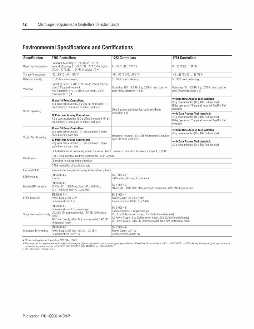
EEnnvviirroonnmmeennttaall SSppeecciiffiiccaattiioonnss aanndd CCeerrttiiffiiccaattiioonnss
SSppeecciiffiiccaattiioonn 11776611 CCoonnttrroolllleerrss 11776622 CCoonnttrroolllleerrss 11776644 CCoonnttrroolllleerrss
Operating TemperatureHorizontal Mounting: 0…55 °C (32…131 °F)Vertical Mounting: 0…45 °C (32…113 °F) for digitalI/O, 0…40 °C (32…104 °F) for analog I/O
0…55 °C (32…131 °F) 0…55 °C (32…131 °F)
Storage Temperature -40…85 °C (-40…185 °F) -40…85 °C (-40…185 °F) -40…85 °C (-40…185 °F)
Relative Humidity 5…95% non-condensing 5…95% non-condensing 5…95% non-condensing
Vibration
Operating: 5 Hz…2 kHz, 0.381 mm (0.015 in) peak-to-peak, 2.5 g panel mounted, Non-Operating: 5 Hz…2 kHz, 0.762 mm (0.030 in)peak-to-peak, 5 g ‡
Operating: 100…500 Hz, 5 g, 0.030 in max. peak-to-peak (Relay Operation: 1.5 g)
Operating: 10…500 Hz, 5 g, 0.030 in max. peak-to-peak (Relay Operation: 2 g)
Shock, Operating
10 and 16 Point Controllers:10 g peak acceleration (7.5 g DIN rail mounted) (11 ± 1ms duration) 3 times each direction, each axis
30 g; 3 pulses each direction, each axis (RelayOperation: 7 g)
without Data Access Tool installed:30 g panel mounted (15 g DIN Rail mounted)Relay operation: 7.5 g panel mounted (5 g DIN Railmounted)
32 Point and Analog Controllers:7.5 g peak acceleration (5.0 g DIN rail mounted) (11 ± 1ms duration) 3 times each direction, each axis
with Data Access Tool installed:20 g panel mounted (15 g DIN Rail mounted)Relay operation: 7.5 g panel mounted (5 g DIN Railmounted)
Shock, Non-Operating
10 and 16 Point Controllers:20 g peak acceleration (11 ± 1 ms duration), 3 timeseach direction, each axis 50 g panel mounted (40 g DIN Rail mounted); 3 pulses
each direction, each axis
without Data Access Tool installed:40 g panel mounted (30 g DIN Rail mounted)
32 Point and Analog Controllers:20 g peak acceleration (11 ± 1 ms duration), 3 timeseach direction, each axis
with Data Access Tool installed:30 g panel mounted (20 g DIN Rail mounted)
Certifications
UL Listed Industrial Control Equipment for use in Class 1, Division 2, Hazardous Locations, Groups A, B, C, D
C-UL Listed Industrial Control Equipment for use in Canada
CE marked for all applicable directives
C-Tick marked for all applicable acts
Electrical/EMC The controller has passed testing at the following levels:
ESD Immunity EN 61000-4-28 kV air
EN 61000-4-24 kV contact, 8 kV air, 4 kV indirect
Radiated RF ImmunityEN 61000-4-310 V/m, 27…1000 MHz; 3V/m, 87…108 MHz,174…230 MHz and 470…790 MHz
EN 61000-4-310V/m, 80…1000 MHz, 80% amplitude modulation, +900 MHz keyed carrier
EFT/B ImmunityEN 61000-4-4Power Supply, I/O: 2 kVCommunications: 1 kV
EN 61000-4-4Power Supply, I/O: 2 kV, 5 kHzCommunications Cable: 1 kV, 5 kHz
Surge Transient Immunity
EN 61000-4-5Communications: 1 kV galvanic gunI/O: 2 kV CM (common mode), 1 kV DM (differentialmode)AC Power Supply: 4 kV CM (common mode), 1 kV DM(differential mode)
EN 61000-4-5Communications: 1 kV galvanic gunI/O: 2 kV CM (common mode), 1 kV DM (differential mode)AC Power Supply: 4 kV CM (common mode), 2 kV DM (differential mode)DC Power Supply: 500V CM (common mode), 500V DM (differential mode)
Conducted RF ImmunityEN 61000-4-6Power Supply, I/O: 10V, 150 kHz…30 MHzCommunications Cable: 3V
EN 61000-4-6Power Supply, I/O: 10VCommunications Cable: 3V
DC input voltage derated linearly from 30°C (30V…26.4V).Recommended storage temperature for maximum battery life (5 years typical with normal operating/storage conditions) of Real-Time Clock modules is -40°C…+40°C (-40°F…+140°F). Battery life may be significantly shorter at elevated temperatures. Applies to 1762-RTC, 1762-MM1RTC, 1764-MM1RTC, and 1764-MM2RTC.
‡ DIN rail mounted controller is 1 g.
13
Publication 1761-SG001A-EN-P
MicroLogix Programmable Controllers Selection Guide
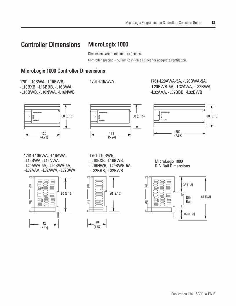
CCoonnttrroolllleerr DDiimmeennssiioonnss MMiiccrrooLLooggiixx 11000000Dimensions are in millimeters (inches).
Controller spacing = 50 mm (2 in) on all sides for adequate ventilation.
MMiiccrrooLLooggiixx 11000000 CCoonnttrroolllleerr DDiimmeennssiioonnss
1761-L16AWA
80 (3.15) 80 (3.15) 80 (3.15)
120(4.72) (5.24)
133 (7.87)200
1761-L10BWA, -L10BWB, -L10BXB, -L16BBB, -L16BWA,-L16BWB, -L16NWA, -L16NWB
1761-L20AWA-5A, -L20BWA-5A, -L20BWB-5A, -L32AWA, -L32BWA,-L32AAA, -L32BBB, -L32BWB
DIN
73 40
80 (3.15) 80 (3.15)
33 (1.3)
16 (0.63)
84 (3.3)
1761-L10BWA, -L16AWA, -L16BWA, -L16NWA,-L20AWA-5A, -L20BWA-5A, -L32AAA, -L32AWA, -L32BWA
1761-L10BWB, -L10BXB, -L16BWB, -L16NWB, -L20BWB-5A,-L32BBB, -L32BWB
MicroLogix 1000DIN Rail Dimensions
(2.87) (1.57)
Rail
14
Publication 1761-SG001A-EN-P
MicroLogix Programmable Controllers Selection Guide
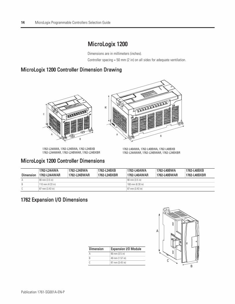
MMiiccrrooLLooggiixx 11220000Dimensions are in millimeters (inches).
Controller spacing = 50 mm (2 in) on all sides for adequate ventilation.
MMiiccrrooLLooggiixx 11220000 CCoonnttrroolllleerr DDiimmeennssiioonn DDrraawwiinngg
C
B
A
C
BA
1762-L24AWA, 1762-L24BWA, 1762-L24BXB1762-L24AWAR, 1762-L24BWAR, 1762-L24BXBR
1762-L40AWA, 1762-L40BWA, 1762-L40BXB1762-L24AWAR, 1762-L24BWAR, 1762-L24BXBR
MMiiccrrooLLooggiixx 11220000 CCoonnttrroolllleerr DDiimmeennssiioonnss
DDiimmeennssiioonnA
B
C
11776622--LL2244AAWWAA11776622--LL2244AAWWAARR
11776622--LL2244BBWWAA11776622--LL2244BBWWAARR
11776622--LL2244BBXXBB11776622--LL2244BBXXBBRR
11776622--LL4400AAWWAA11776622--LL4400AAWWAARR
11776622--LL4400BBWWAA11776622--LL4400BBWWAARR
11776622--LL4400BBXXBB11776622--LL4400BBXXBBRR
90 mm (3.5 in) 90 mm (3.5 in)
110 mm (4.33 in) 160 mm (6.30 in)
87 mm (3.43 in) 87 mm (3.43 in)
11776622 EExxppaannssiioonn II//OO DDiimmeennssiioonnss
A
B
C
DDiimmeennssiioonn EExxppaannssiioonn II//OO MMoodduulleeA 90 mm (3.5 in)
B 40 mm (1.57 in)
C 87 mm (3.43 in)
15
Publication 1761-SG001A-EN-P
MicroLogix Programmable Controllers Selection Guide
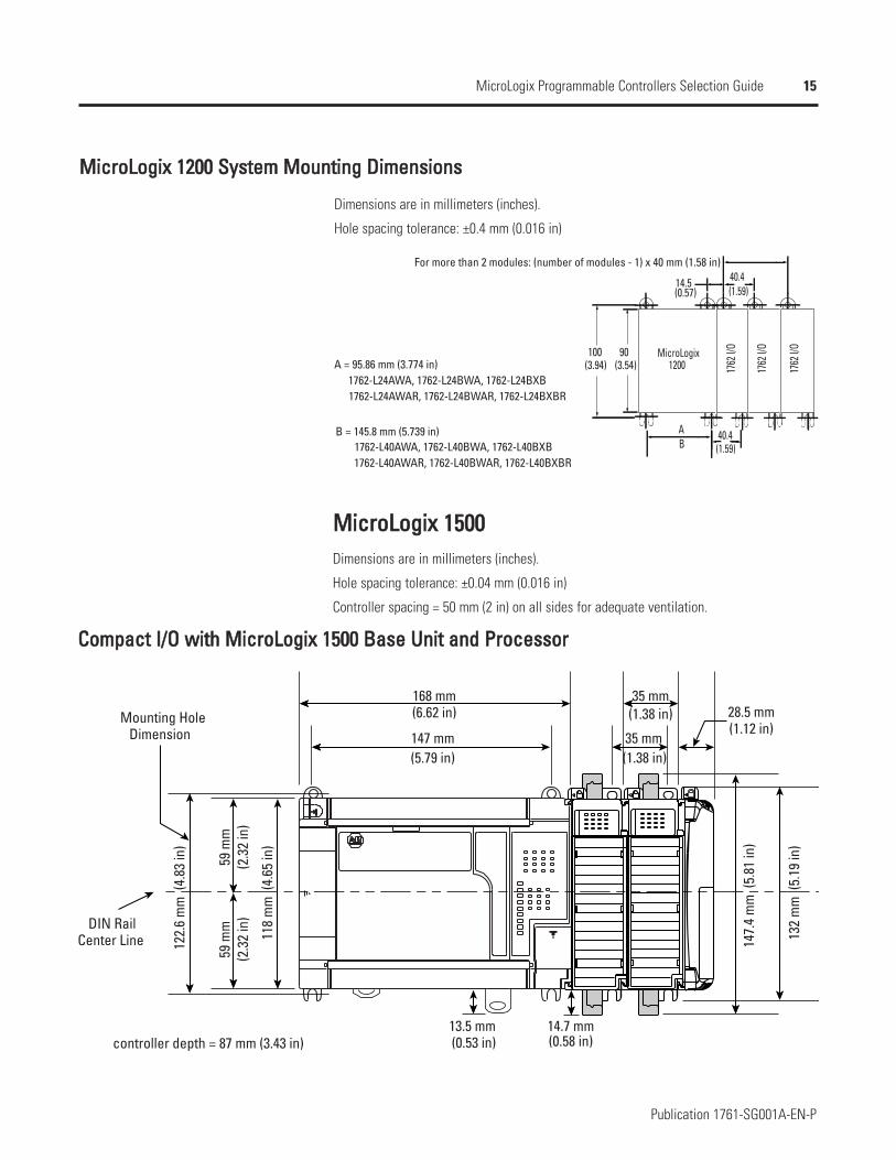
MMiiccrrooLLooggiixx 11220000 SSyysstteemm MMoouunnttiinngg DDiimmeennssiioonnss
Dimensions are in millimeters (inches).
Hole spacing tolerance: ±0.4 mm (0.016 in)
90 100
40.4A
40.4 14.5
MicroLogix
1762
I/O
1762
I/O
1762
I/O
For more than 2 modules: (number of modules - 1) x 40 mm (1.58 in)
A = 95.86 mm (3.774 in) 1762-L24AWA, 1762-L24BWA, 1762-L24BXB1762-L24AWAR, 1762-L24BWAR, 1762-L24BXBR
1762-L40AWAR, 1762-L40BWAR, 1762-L40BXBR
B = 145.8 mm (5.739 in)1762-L40AWA, 1762-L40BWA, 1762-L40BXB
(1.59)(0.57)
(1.59)
(3.54)(3.94) 1200
B
MMiiccrrooLLooggiixx 11550000Dimensions are in millimeters (inches).
Hole spacing tolerance: ±0.04 mm (0.016 in)
Controller spacing = 50 mm (2 in) on all sides for adequate ventilation.
CCoommppaacctt II//OO wwiitthh MMiiccrrooLLooggiixx 11550000 BBaassee UUnniitt aanndd PPrroocceessssoorr
132
mm
(5.
19 in
)
122.
6 m
m (
4.83
in)
118
mm
(4.
65 in
)
147.
4 m
m (
5.81
in)
14.7 mm
35 mm168 mm
35 mm
13.5 mm
59 m
m59
mm
(6.62 in)
147 mm(5.79 in)
(1.38 in)
(1.38 in)
(0.53 in) (0.58 in)
(2.3
2 in
)(2
.32
in)
28.5 mmMounting Hole
DIN Rail
controller depth = 87 mm (3.43 in)
Dimension
Center Line
(1.12 in)
16
Publication 1761-SG001A-EN-P
MicroLogix Programmable Controllers Selection Guide
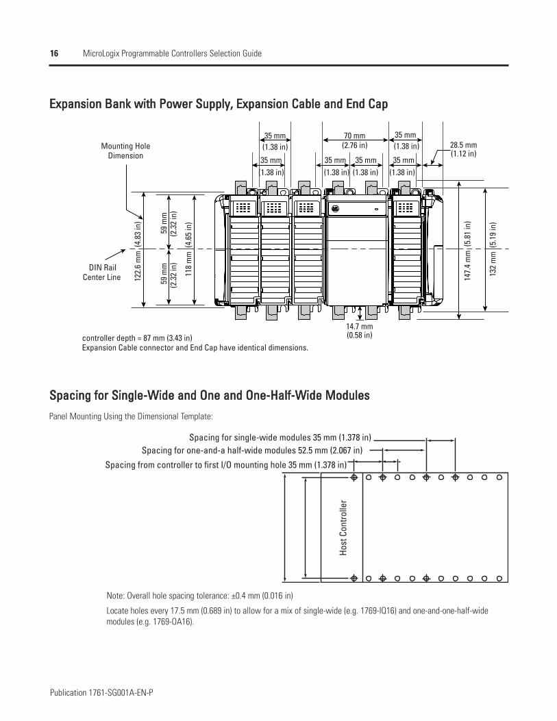
EExxppaannssiioonn BBaannkk wwiitthh PPoowweerr SSuuppppllyy,, EExxppaannssiioonn CCaabbllee aanndd EEnndd CCaapp
132
mm
(5.
19 in
)
122.
6 m
m (
4.83
in)
118
mm
(4.
65 in
)
147.
4 m
m (
5.81
in)
14.7 mm
28.5 mm70 mm35 mm
35 mm59
mm
Mounting Hole
DIN Rail
controller depth = 87 mm (3.43 in)
Dimension
Center Line
(1.38 in)
(1.38 in)
(2.76 in)
35 mm(1.38 in) (1.38 in)
35 mm 35 mm(1.38 in)
35 mm(1.38 in)
(1.12 in)
(0.58 in)Expansion Cable connector and End Cap have identical dimensions.
(2.3
2 in
)59
mm
(2.3
2 in
)
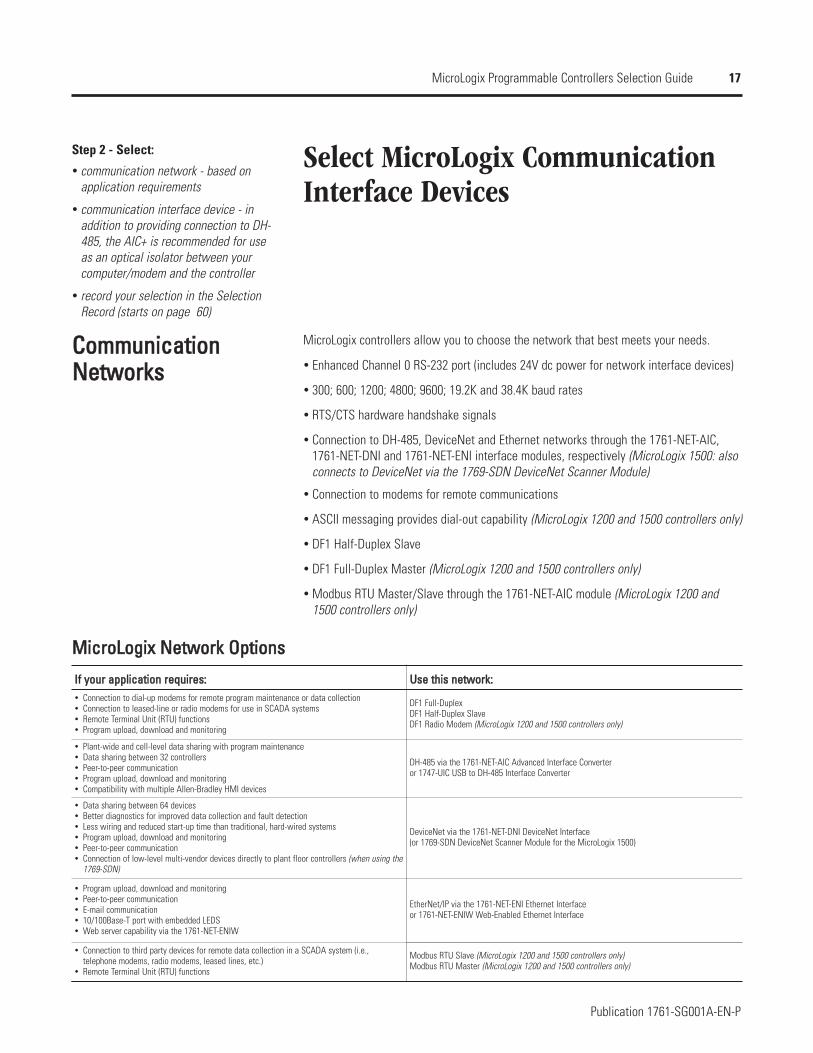
SSppaacciinngg ffoorr SSiinnggllee--WWiiddee aanndd OOnnee aanndd OOnnee--HHaallff--WWiiddee MMoodduulleess
Panel Mounting Using the Dimensional Template:
Spacing for single-wide modules 35 mm (1.378 in)Spacing for one-and-a half-wide modules 52.5 mm (2.067 in)
Spacing from controller to first I/O mounting hole 35 mm (1.378 in)
Host
Con
trolle
r
Note: Overall hole spacing tolerance: ±0.4 mm (0.016 in)
Locate holes every 17.5 mm (0.689 in) to allow for a mix of single-wide (e.g. 1769-IQ16) and one-and-one-half-widemodules (e.g. 1769-OA16).
17
Publication 1761-SG001A-EN-P
MicroLogix Programmable Controllers Selection Guide
Select MicroLogix CommunicationInterface Devices
Step 2 - Select:
communication network - based onapplication requirements
communication interface device - inaddition to providing connection to DH-485, the AIC+ is recommended for useas an optical isolator between yourcomputer/modem and the controller
record your selection in the SelectionRecord (starts on page 60)
CCoommmmuunniiccaattiioonnNNeettwwoorrkkss
MicroLogix controllers allow you to choose the network that best meets your needs.
Enhanced Channel 0 RS-232 port (includes 24V dc power for network interface devices)
300; 600; 1200; 4800; 9600; 19.2K and 38.4K baud rates
RTS/CTS hardware handshake signals
Connection to DH-485, DeviceNet and Ethernet networks through the 1761-NET-AIC,1761-NET-DNI and 1761-NET-ENI interface modules, respectively (MicroLogix 1500: alsoconnects to DeviceNet via the 1769-SDN DeviceNet Scanner Module)
Connection to modems for remote communications
ASCII messaging provides dial-out capability (MicroLogix 1200 and 1500 controllers only)
DF1 Half-Duplex Slave
DF1 Full-Duplex Master (MicroLogix 1200 and 1500 controllers only)
Modbus RTU Master/Slave through the 1761-NET-AIC module (MicroLogix 1200 and1500 controllers only)
MMiiccrrooLLooggiixx NNeettwwoorrkk OOppttiioonnss
IIff yyoouurr aapppplliiccaattiioonn rreeqquuiirreess:: UUssee tthhiiss nneettwwoorrkk::Connection to dial-up modems for remote program maintenance or data collectionConnection to leased-line or radio modems for use in SCADA systemsRemote Terminal Unit (RTU) functionsProgram upload, download and monitoring
DF1 Full-DuplexDF1 Half-Duplex SlaveDF1 Radio Modem (MicroLogix 1200 and 1500 controllers only)
Plant-wide and cell-level data sharing with program maintenanceData sharing between 32 controllersPeer-to-peer communicationProgram upload, download and monitoringCompatibility with multiple Allen-Bradley HMI devices
DH-485 via the 1761-NET-AIC Advanced Interface Converter or 1747-UIC USB to DH-485 Interface Converter
Data sharing between 64 devicesBetter diagnostics for improved data collection and fault detectionLess wiring and reduced start-up time than traditional, hard-wired systemsProgram upload, download and monitoringPeer-to-peer communicationConnection of low-level multi-vendor devices directly to plant floor controllers (when using the1769-SDN)
DeviceNet via the 1761-NET-DNI DeviceNet Interface (or 1769-SDN DeviceNet Scanner Module for the MicroLogix 1500)
Program upload, download and monitoringPeer-to-peer communicationE-mail communication10/100Base-T port with embedded LEDSWeb server capability via the 1761-NET-ENIW
EtherNet/IP via the 1761-NET-ENI Ethernet Interfaceor 1761-NET-ENIW Web-Enabled Ethernet Interface
Connection to third party devices for remote data collection in a SCADA system (i.e.,telephone modems, radio modems, leased lines, etc.)Remote Terminal Unit (RTU) functions
Modbus RTU Slave (MicroLogix 1200 and 1500 controllers only)Modbus RTU Master (MicroLogix 1200 and 1500 controllers only)
18
Publication 1761-SG001A-EN-P
MicroLogix Programmable Controllers Selection Guide
MMiiccrrooLLooggiixx NNeettwwoorrkkIInntteerrffaaccee DDeevviicceess
The network interface devices can be mounted on a panel or DIN rail. See NetworkInterface Devices Communication Port Identification on page 22 for device drawings.
AAIICC++ AAddvvaanncceedd IInntteerrffaaccee CCoonnvveerrtteerr ((11776611--NNEETT--AAIICC))
The AIC+ is an isolated, RS-232 to RS-485 electrical signal converter for supporting serial,half-duplex, multi-drop protocols; such as:
DH-485
DF1 Half-Duplex Master/Slave
Modbus RTU (a single master can communicate with a maximum of 247 slave devices)MicroLogix 1200 and 1500 controllers only
Since RS-232 ports can only be connected point-to-point between two devices, an AIC+ (orsimilar device) is required whenever a MicroLogix controller is configured for one of theseprotocols and needs to communicate with more than one other device at a time. The AIC+also provides electrical isolation between each of its three ports for a more stablenetwork and protection for connected devices.
Any MicroLogix controller can connect to either of the two RS-232 ports on the AIC+.When Channel 0 on a MicroLogix controller is connected to Port 2 (RS-232 8-pin mini-DIN)of the AIC+, the AIC+ can draw its power from the MicroLogix controller. In all othercases, the AIC+ must be powered from an external, 24V dc power supply. The AIC+ canalso be used as an RS-232 to RS-485 converter and port isolator for any other Allen-Bradley controller or terminal with an RS-232 port.
Since the AIC+ is not a protocol converter, all devices connected to a single AIC+ (or anetwork of AIC+s) must be configured for the same protocol.
DDHH--448855//RRSS--448855 NNeettwwoorrkk SSppeecciiffiiccaattiioonnss
SSppeecciiffiiccaattiioonn 11776611--NNEETT--AAIICCMaximum Number of Nodes 32 per multi-drop network
Maximum Length 1219 m (4,000 ft) per multi-drop network
19
Publication 1761-SG001A-EN-P
MicroLogix Programmable Controllers Selection Guide
DDNNII DDeevviicceeNNeett IInntteerrffaaccee ((11776611--NNEETT--DDNNII))DNI capabilities:
Peer-to-peer messaging between Allen-Bradley controllers and other devices using theDF1 Full-Duplex protocol
Programming and on-line monitoring over the DeviceNet network
With a DNI connected to a modem, you can dial in to any other DNI-controllercombination on DeviceNet
Other DeviceNet products can send explicit (Get or Set) messages with the DNI at any time
The controller can initiate an explicit message to a UCMM (Unconnected MessageManager) compatible device on DeviceNet
DDeevviicceeNNeett SSppeecciiffiiccaattiioonnss
SSppeecciiffiiccaattiioonn 11776611--NNEETT--DDNNIIMaximum Number of Nodes 64
Maximum Length 500 m @ 125K baud or 100 m @ 500K baud
DeviceNet Agency Certification ODVA conformance 2.0-A12
EENNII EEtthheerrnneett IInntteerrffaaccee ((11776611--NNEETT--EENNII)) aanndd EENNIIWWEEtthheerrnneett IInntteerrffaaccee wwiitthh WWeebb SSeerrvveerr CCaappaabbiilliittiieess((11776611--NNEETT--EENNIIWW))The ENI provides EtherNet/IP connectivity for all MicroLogix controllers and other DF1Full-Duplex devices. The ENI allows you to easily connect a MicroLogix controller to a newor existing Ethernet network to update/download programs, communicate betweencontrollers and generate e-mail messages via SMTP (simple mail transport protocol).
The ENIW adds web server capabilities, enabling the display of 4 standard data webpages with user-configurable data descriptions and 10 user-configurable web page linkson the ENIW home page.
EEtthheerrnneett SSppeecciiffiiccaattiioonnss
SSppeecciiffiiccaattiioonn 11776611--NNEETT--EENNIICommunication Rate 10/100 MHz (Series C), 10 MHz (Series A and B)
Connector 100Base-T (Series C), 10Base-T (Series A and B)
20
Publication 1761-SG001A-EN-P
MicroLogix Programmable Controllers Selection Guide
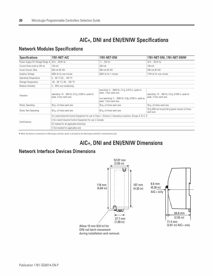
AAIICC++,, DDNNII aanndd EENNII//EENNIIWW SSppeecciiffiiccaattiioonnssNNeettwwoorrkk MMoodduulleess SSppeecciiffiiccaattiioonnss
SSppeecciiffiiccaattiioonnssPower Supply DC Voltage Range
Current Draw (mA) at 24V dc
Inrush Current, Max.
Isolation Voltage
Operating Temperature
Storage Temperature
Relative Humidity
Vibration
Shock, Operating
Shock, Non-Operating
Certifications
11776611--NNEETT--AAIICC 11776611--NNEETT--DDNNII 11776611--NNEETT--EENNII,, 11776611--NNEETT--EENNIIWW20.4…28.8V dc 11…25V dc 20.4…26.4V dc
120 mA 200 mA 100 mA
200 mA @ 24V 400 mA @ 24V 200 mA @ 24V
500V dc for one minute 500V dc for 1 minute 710V dc for one minute
0…60 °C (32…140 °F)
-40…85 °C (-40…185 °F)
5…95% non-condensing
operating: 10…500 Hz, 5.0 g, 0.030 in. peak-to-peak, 2 hour each axis
operating: 5…2000 Hz, 2.5 g, 0.015 in. peak-to-peak, 1 hour each axis
non-operating: 5…2000 Hz, 5.0g, 0.030 in. peak-to-peak, 1 hour each axis
operating: 10…500 Hz, 5.0 g, 0.030 in. peak-to-peak, 2 hour each axis
30 g, ±3 times each axis 30 g, ±3 times each axis 30 g, ±3 times each axis
50 g, ±3 times each axis 50 g, ±3 times each axis 35 g (DIN rail mount) 50 g (panel mount) ±3 timeseach axis
UL Listed Industrial Control Equipment for use in Class 1, Division 2, Hazardous Locations, Groups A, B, C, D
C-UL Listed Industrial Control Equipment for use in Canada
CE marked for all applicable directives
C-Tick marked for applicable acts
When the device is connected to a MicroLogix controller, power is provided by the MicroLogix controller's communication port.
AAIICC++,, DDNNII aanndd EENNII//EENNIIWW DDiimmeennssiioonnssNNeettwwoorrkk IInntteerrffaaccee DDeevviicceess DDiimmeennssiioonnss
Allow 15 mm (0.6 in) for
27.7 mm
107 mm118 mm
52.07 mm
6.6 mm
64.8 mm
71.4 mm
(2.05 in)
(4.64 in)
(1.09 in)
(4.20 in)
(2.81 in) AIC+ only
(2.55 in)
AIC+ only(0.26 in)
during installation and removal.DIN rail latch movement
21
Publication 1761-SG001A-EN-P
MicroLogix Programmable Controllers Selection Guide
Select Programming Tools and Software
Step 3 - Select:
programming tools - hand-heldprogrammer with optional memory module(available for MicroLogix 1000 only)
software - the appropriate RSLogix 500package for your application
record your selection in the SelectionRecord (starts on page 60)
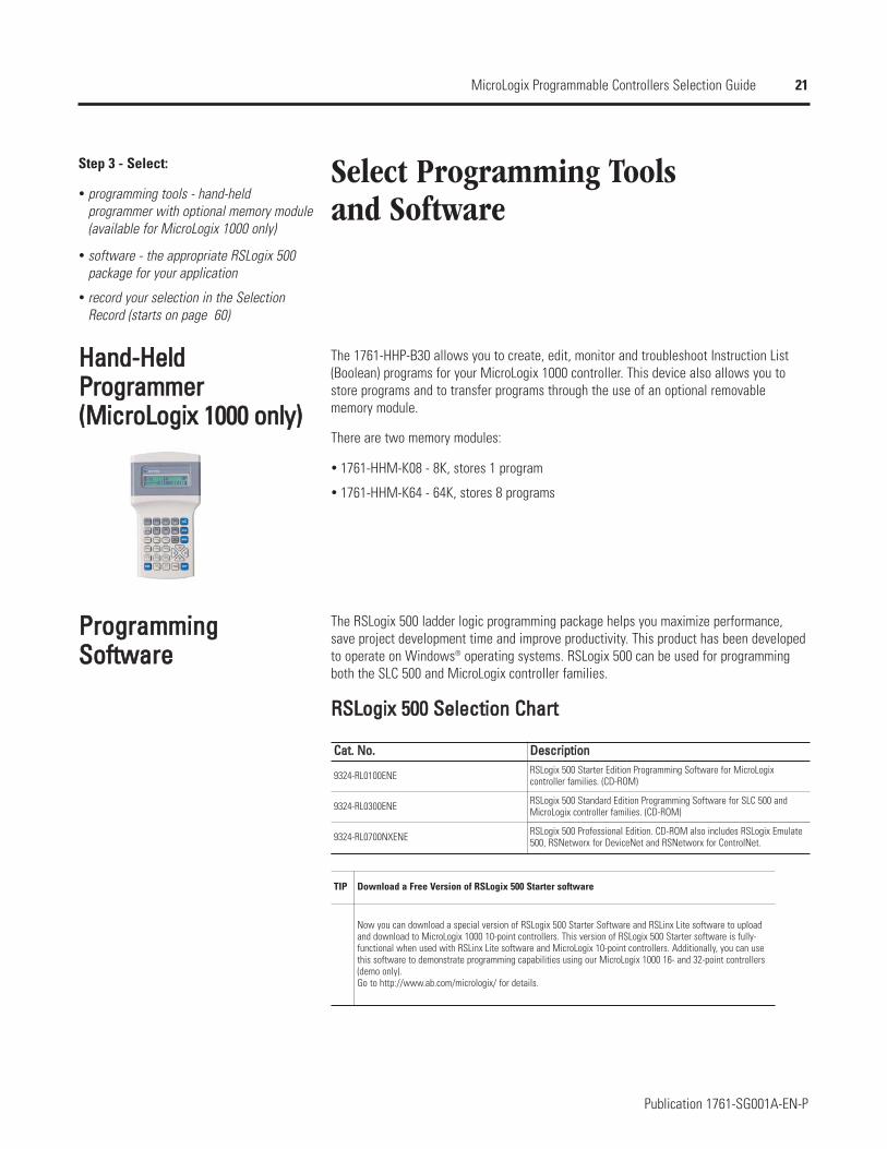
HHaanndd--HHeellddPPrrooggrraammmmeerr((MMiiccrrooLLooggiixx 11000000 oonnllyy))
The 1761-HHP-B30 allows you to create, edit, monitor and troubleshoot Instruction List(Boolean) programs for your MicroLogix 1000 controller. This device also allows you tostore programs and to transfer programs through the use of an optional removablememory module.
There are two memory modules:
1761-HHM-K08 - 8K, stores 1 program
1761-HHM-K64 - 64K, stores 8 programs
PPrrooggrraammmmiinnggSSooffttwwaarree
The RSLogix 500 ladder logic programming package helps you maximize performance,save project development time and improve productivity. This product has been developedto operate on Windows® operating systems. RSLogix 500 can be used for programmingboth the SLC 500 and MicroLogix controller families.
RRSSLLooggiixx 550000 SSeelleeccttiioonn CChhaarrtt
TIP Download a Free Version of RSLogix 500 Starter software
Now you can download a special version of RSLogix 500 Starter Software and RSLinx Lite software to uploadand download to MicroLogix 1000 10-point controllers. This version of RSLogix 500 Starter software is fully-functional when used with RSLinx Lite software and MicroLogix 10-point controllers. Additionally, you can usethis software to demonstrate programming capabilities using our MicroLogix 1000 16- and 32-point controllers(demo only).Go to http://www.ab.com/micrologix/ for details.
CCaatt.. NNoo.. DDeessccrriippttiioonn
9324-RL0100ENE RSLogix 500 Starter Edition Programming Software for MicroLogixcontroller families. (CD-ROM)
9324-RL0300ENE RSLogix 500 Standard Edition Programming Software for SLC 500 andMicroLogix controller families. (CD-ROM)
9324-RL0700NXENE RSLogix 500 Professional Edition. CD-ROM also includes RSLogix Emulate500, RSNetworx for DeviceNet and RSNetworx for ControlNet.
22
Publication 1761-SG001A-EN-P
MicroLogix Programmable Controllers Selection Guide
Select CablesStep 4 - Select:
cables - review device port identificationto find cable in the selection chart
record your selection in the SelectionRecord (starts on page 60)
Cables come in several lengths and connector styles to provide connectivity betweenMicroLogix controllers and other devices. MicroLogix 1200 controllers require Series Cversions of all 1761 cables.
NNeettwwoorrkk CCaabblleeSSeelleeccttiioonnCCoonnttrroolllleerr aanndd PPCC PPoorrtt IIddeennttiiffiiccaattiioonn
DDeevviicceeMicroLogix 1000
MicroLogix 1200
MicroLogix 1200R
MicroLogix 1500
MicroLogix 1500 with 1764-LRP Processor
Personal Computer
CCoommmmuunniiccaattiioonn PPoorrtt DDeessccrriippttiioonn CCoonnnneeccttoorr TTyyppeeCommunications Port (Channel 0) with 24V dc power for communication device 8-pin Mini DIN
Communications Port (Channel 0) with 24V dc power for communication device 8-pin Mini DIN
Communications Port (Channel 0) with 24V dc power for communication device 8-pin Mini DIN
Programming/HMI Port (no 24V dc power) 8-pin Mini DIN
Base Unit Communications Port (Channel 0) with 24V dc power for communication device 8-pin Mini DIN
Base Unit Communications Port (Channel 0) with 24V dc power for communication device 8-pin Mini DIN
Processor Communications Port (Channel 1) 9-pin D Shell (isolated)
Personal Computer Communications Port 9-pin D Shell
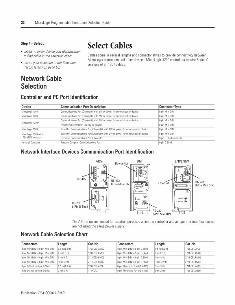
NNeettwwoorrkk IInntteerrffaaccee DDeevviicceess CCoommmmuunniiccaattiioonn PPoorrtt IIddeennttiiffiiccaattiioonn
NODE
DANGER
GND
TX/RX
V±
CAN_L
SHIELDCAN_H
V+
NET
MOD
ETHERNET
FAULT
RS232
NET
TX/RXTX/RX
PWR
CABLE
EXTERNAL
IP
AIC+ DNI ENI/ENIW
DH-485
RS-232
DeviceNet
RS-232Ethernet
9-PIn D Shell
8-PIn Mini DIN
8-PIn Mini DINRS-232
8-PIn Mini DINRS-232
The AIC+ is recommended for isolation purposes when the controller and an operator interface deviceare not using the same power supply.
NNeettwwoorrkk CCaabbllee SSeelleeccttiioonn CChhaarrtt
CCoonnnneeccttoorrss8-pin Mini DIN to 8-pin Mini DIN
8-pin Mini DIN to 8-pin Mini DIN
8-pin Mini DIN to 8-pin Mini DIN
8-pin Mini DIN to 8-pin Mini DIN
9-pin D Shell to 9-pin D Shell
9-pin D Shell to 9-pin D Shell
CCaatt.. NNoo..1761-CBL-AM00
1761-CBL-HM02
2711-CBL-HM05
2711-CBL-HM10
1761-CBL-AC00
1747-CP3
LLeennggtthh CCoonnnneeccttoorrss LLeennggtthh CCaatt.. NNoo..0.5 m (1.5 ft) 8-pin Mini DIN to 9-pin D Shell 0.5 m (1.5 ft) 1761-CBL-AP00
2 m (6.5 ft) 8-pin Mini DIN to 9-pin D Shell 2 m (6.5 ft) 1761-CBL-PM02
5 m (16 ft) 8-pin Mini DIN to 9-pin D Shell 5 m (16 ft) 2711-CBL-PM05
10 m (32 ft) 8-pin Mini DIN to 9-pin D Shell 10 m (32 ft) 2711-CBL-PM10
0.5 m (1.5 ft) 6-pin Phoenix to RJ45 (DH-485) 3 m (10 ft) 1761-CBL-AS03
3 m (10 ft) 6-pin Phoenix to RJ45 (DH-485) 9 m (30 ft) 1761-CBL-AS09
23
Publication 1761-SG001A-EN-P
MicroLogix Programmable Controllers Selection Guide
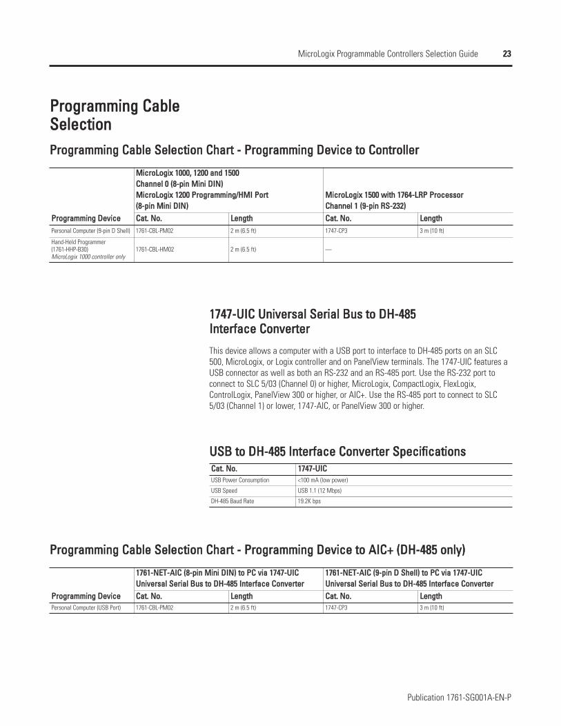
PPrrooggrraammmmiinngg CCaabblleeSSeelleeccttiioonnPPrrooggrraammmmiinngg CCaabbllee SSeelleeccttiioonn CChhaarrtt -- PPrrooggrraammmmiinngg DDeevviiccee ttoo CCoonnttrroolllleerr
PPrrooggrraammmmiinngg DDeevviicceePersonal Computer (9-pin D Shell)
Hand-Held Programmer (1761-HHP-B30)MicroLogix 1000 controller only
MMiiccrrooLLooggiixx 11000000,, 11220000 aanndd 11550000CChhaannnneell 00 ((88--ppiinn MMiinnii DDIINN))MMiiccrrooLLooggiixx 11220000 PPrrooggrraammmmiinngg//HHMMII PPoorrtt((88--ppiinn MMiinnii DDIINN))
MMiiccrrooLLooggiixx 11550000 wwiitthh 11776644--LLRRPP PPrroocceessssoorrCChhaannnneell 11 ((99--ppiinn RRSS--223322))
CCaatt.. NNoo.. LLeennggtthh CCaatt.. NNoo.. LLeennggtthh1761-CBL-PM02 2 m (6.5 ft) 1747-CP3 3 m (10 ft)
1761-CBL-HM02 2 m (6.5 ft) —
11774477--UUIICC UUnniivveerrssaall SSeerriiaall BBuuss ttoo DDHH--448855 IInntteerrffaaccee CCoonnvveerrtteerr
This device allows a computer with a USB port to interface to DH-485 ports on an SLC500, MicroLogix, or Logix controller and on PanelView terminals. The 1747-UIC features aUSB connector as well as both an RS-232 and an RS-485 port. Use the RS-232 port toconnect to SLC 5/03 (Channel 0) or higher, MicroLogix, CompactLogix, FlexLogix,ControlLogix, PanelView 300 or higher, or AIC+. Use the RS-485 port to connect to SLC5/03 (Channel 1) or lower, 1747-AIC, or PanelView 300 or higher.
PPrrooggrraammmmiinngg CCaabbllee SSeelleeccttiioonn CChhaarrtt -- PPrrooggrraammmmiinngg DDeevviiccee ttoo AAIICC++ ((DDHH--448855 oonnllyy))
PPrrooggrraammmmiinngg DDeevviicceePersonal Computer (USB Port)
11776611--NNEETT--AAIICC ((88--ppiinn MMiinnii DDIINN)) ttoo PPCC vviiaa 11774477--UUIICCUUnniivveerrssaall SSeerriiaall BBuuss ttoo DDHH--448855 IInntteerrffaaccee CCoonnvveerrtteerr
11776611--NNEETT--AAIICC ((99--ppiinn DD SShheellll)) ttoo PPCC vviiaa 11774477--UUIICCUUnniivveerrssaall SSeerriiaall BBuuss ttoo DDHH--448855 IInntteerrffaaccee CCoonnvveerrtteerr
CCaatt.. NNoo.. LLeennggtthh CCaatt.. NNoo.. LLeennggtthh1761-CBL-PM02 2 m (6.5 ft) 1747-CP3 3 m (10 ft)
UUSSBB ttoo DDHH--448855 IInntteerrffaaccee CCoonnvveerrtteerr SSppeecciiffiiccaattiioonnssCCaatt.. NNoo.. 11774477--UUIICCUSB Power Consumption <100 mA (low power)
USB Speed USB 1.1 (12 Mbps)
DH-485 Baud Rate 19.2K bps
24
Publication 1761-SG001A-EN-P
MicroLogix Programmable Controllers Selection Guide
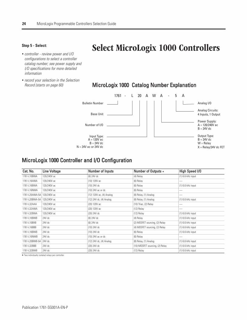
Select MicroLogix 1000 ControllersStep 5 - Select:
controller - review power and I/Oconfigurations to select a controllercatalog number; see power supply andI/O specifications for more detailedinformation
record your selection in the SelectionRecord (starts on page 60) MMiiccrrooLLooggiixx 11000000 CCaattaalloogg NNuummbbeerr EExxppllaannaattiioonn
1761 AL W A - 5 A20-
Bulletin Number
Base Unit
Number of I/O
B = 24V dc
B = 24V dc
B = 24V dc
Analog I/O
Analog Circuits:
N = 24V ac or 24V dc
Input Type:A = 120V ac
Output Type:
W = RelayX = Relay/24V dc FET
Power Supply:A = 120/240V ac
4 Inputs, 1 Output
MMiiccrrooLLooggiixx 11000000 CCoonnttrroolllleerr aanndd II//OO CCoonnffiigguurraattiioonn
CCaatt.. NNoo..1761-L10BWA
1761-L16AWA
1761-L16BWA
1761-L16NWA
1761-L20AWA-5A
1761-L20BWA-5A
1761-L32AAA
1761-L32AWA
1761-L32BWA
1761-L10BWB
1761-L10BXB
1761-L16BBB
1761-L16BWB
1761-L16NWB
1761-L20BWB-5A
1761-L32BBB
1761-L32BWB
LLiinnee VVoollttaaggee NNuummbbeerr ooff IInnppuuttss NNuummbbeerr ooff OOuuttppuuttss HHiigghh SSppeeeedd II//OO120/240V ac (6) 24V dc (4) Relay (1) 6.6 kHz input
120/240V ac (10) 120V ac (6) Relay ⎯
120/240V ac (10) 24V dc (6) Relay (1) 6.6 kHz input
120/240V ac (10) 24V ac or dc (6) Relay ⎯
120/240V ac (12) 120V ac, (4) Analog (8) Relay, (1) Analog ⎯
120/240V ac (12) 24V dc, (4) Analog (8) Relay, (1) Analog (1) 6.6 kHz input
120/240V ac (20) 120V ac (10) Triac, (2) Relay ⎯
120/240V ac (20) 120V ac (12) Relay ⎯
120/240V ac (20) 24V dc (12) Relay (1) 6.6 kHz input
24V dc (6) 24V dc (4) Relay (1) 6.6 kHz input
24V dc (6) 24V dc (2) MOSFET sourcing, (2) Relay (1) 6.6 kHz input
24V dc (10) 24V dc (4) MOSFET sourcing, (2) Relay (1) 6.6 kHz input
24V dc (10) 24V dc (6) Relay (1) 6.6 kHz input
24V dc (10) 24V ac or dc (6) Relay ⎯
24V dc (12) 24V dc, (4) Analog (8) Relay, (1) Analog (1) 6.6 kHz input
24V dc (20) 24V dc (10) MOSFET sourcing, (2) Relay (1) 6.6 kHz input
24V dc (20) 24V dc (12) Relay (1) 6.6 kHz input
Two individually isolated relays per controller.
25
Publication 1761-SG001A-EN-P
MicroLogix Programmable Controllers Selection Guide
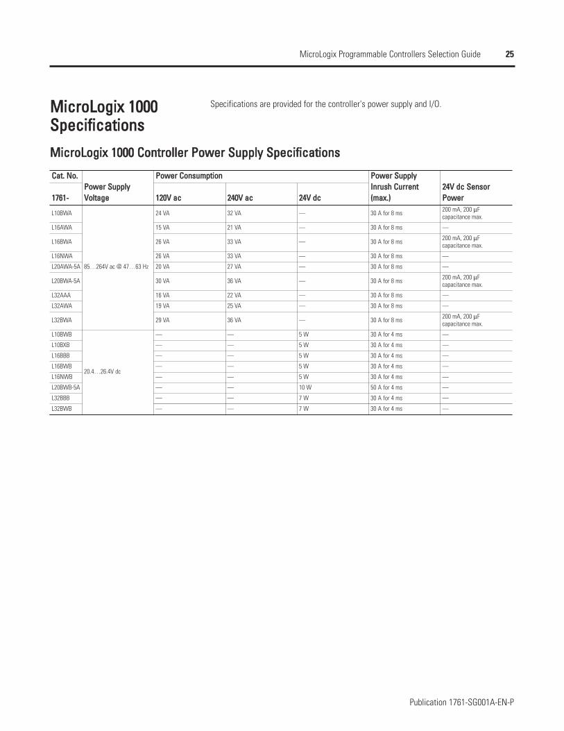
MMiiccrrooLLooggiixx 11000000SSppeecciiffiiccaattiioonnss
Specifications are provided for the controller's power supply and I/O.
MMiiccrrooLLooggiixx 11000000 CCoonnttrroolllleerr PPoowweerr SSuuppppllyy SSppeecciiffiiccaattiioonnss
CCaatt.. NNoo..PPoowweerr SSuuppppllyyVVoollttaaggee
PPoowweerr CCoonnssuummppttiioonn PPoowweerr SSuuppppllyyIInnrruusshh CCuurrrreenntt((mmaaxx..))
2244VV ddcc SSeennssoorrPPoowweerr11776611-- 112200VV aacc 224400VV aacc 2244VV ddcc
L10BWA
85…264V ac @ 47…63 Hz
24 VA 32 VA — 30 A for 8 ms 200 mA, 200 µFcapacitance max.
L16AWA 15 VA 21 VA — 30 A for 8 ms —
L16BWA 26 VA 33 VA — 30 A for 8 ms 200 mA, 200 µFcapacitance max.
L16NWA 26 VA 33 VA — 30 A for 8 ms —
L20AWA-5A 20 VA 27 VA — 30 A for 8 ms —
L20BWA-5A 30 VA 36 VA — 30 A for 8 ms 200 mA, 200 µFcapacitance max.
L32AAA 16 VA 22 VA — 30 A for 8 ms —
L32AWA 19 VA 25 VA — 30 A for 8 ms —
L32BWA 29 VA 36 VA — 30 A for 8 ms 200 mA, 200 µFcapacitance max.
L10BWB
20.4…26.4V dc
— — 5 W 30 A for 4 ms —
L10BXB — — 5 W 30 A for 4 ms —
L16BBB — — 5 W 30 A for 4 ms —
L16BWB — — 5 W 30 A for 4 ms —
L16NWB — — 5 W 30 A for 4 ms —
L20BWB-5A — — 10 W 50 A for 4 ms —
L32BBB — — 7 W 30 A for 4 ms —
L32BWB — — 7 W 30 A for 4 ms —
26
Publication 1761-SG001A-EN-P
MicroLogix Programmable Controllers Selection Guide
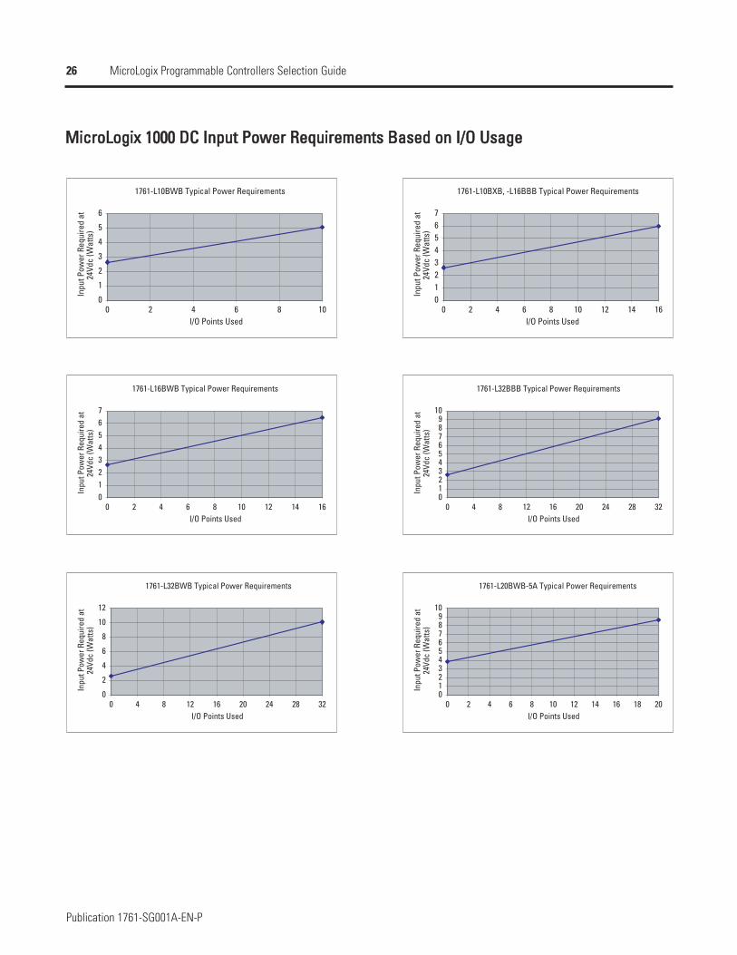
MMiiccrrooLLooggiixx 11000000 DDCC IInnppuutt PPoowweerr RReeqquuiirreemmeennttss BBaasseedd oonn II//OO UUssaaggee
1761-L10BWB Typical Power Requirements
0
1
2
3
4
5
6
0 2 4 6 8 10I/O Points Used
Inpu
t Pow
er R
equi
red
at
24Vd
c (W
atts
)
1761-L10BXB, -L16BBB Typical Power Requirements
01234567
0 2 4 6 8 10 12 14 16I/O Points Used
Inpu
t Pow
er R
equi
red
at
24Vd
c (W
atts
)
1761-L16BWB Typical Power Requirements
01234567
0 2 4 6 8 10 12 14 16I/O Points Used
Inpu
t Pow
er R
equi
red
at
24Vd
c (W
atts
)
1761-L32BBB Typical Power Requirements
0123456789
10
0 4 8 12 16 20 24 28 32I/O Points Used
Inpu
t Pow
er R
equi
red
at
24Vd
c (W
atts
)
1761-L32BWB Typical Power Requirements
0
2
4
6
8
10
12
0 4 8 12 16 20 24 28 32I/O Points Used
Inpu
t Pow
er R
equi
red
at
24Vd
c (W
atts
)
1761-L20BWB-5A Typical Power Requirements
0123456789
10
0 2 4 6 8 10 12 14 16 18 20I/O Points Used
Inpu
t Pow
er R
equi
red
at
24Vd
c (W
atts
)
27
Publication 1761-SG001A-EN-P
MicroLogix Programmable Controllers Selection Guide
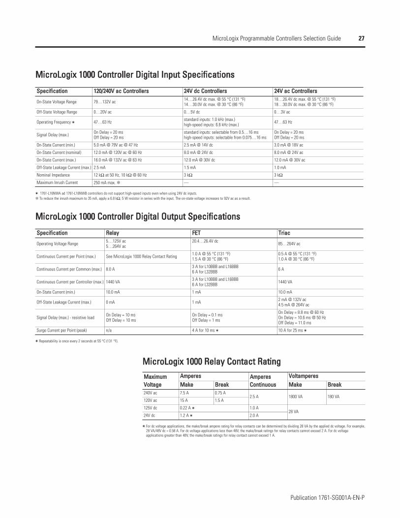
MMiiccrrooLLooggiixx 11000000 CCoonnttrroolllleerr DDiiggiittaall IInnppuutt SSppeecciiffiiccaattiioonnss
SSppeecciiffiiccaattiioonn
On-State Voltage Range
Off-State Voltage Range
Operating Frequency
Signal Delay (max.)
On-State Current (min.)
On-State Current (nominal)
On-State Current (max.)
Off-State Leakage Current (max.)
Nominal Impedance
Maximum Inrush Current
112200//224400VV aacc CCoonnttrroolllleerrss 2244VV ddcc CCoonnttrroolllleerrss 2244VV aacc CCoonnttrroolllleerrss
79…132V ac 14…26.4V dc max. @ 55 °C (131 °F) 14…30.0V dc max. @ 30 °C (86 °F)
18…26.4V dc max. @ 55 °C (131 °F) 18…30.0V dc max. @ 30 °C (86 °F)
0…20V ac 0…5V dc 0…3V ac
47…63 Hz standard inputs: 1.0 kHz (max.)high-speed inputs: 6.6 kHz (max.) 47…63 Hz
On Delay = 20 msOff Delay = 20 ms
standard inputs: selectable from 0.5…16 mshigh-speed inputs: selectable from 0.075…16 ms
On Delay = 20 msOff Delay = 20 ms
5.0 mA @ 79V ac @ 47 Hz 2.5 mA @ 14V dc 3.0 mA @ 18V ac
12.0 mA @ 120V ac @ 60 Hz 8.0 mA @ 24V dc 8.0 mA @ 24V ac
16.0 mA @ 132V ac @ 63 Hz 12.0 mA @ 30V dc 12.0 mA @ 30V ac
2.5 mA 1.5 mA 1.0 mA
12 kΩ at 50 Hz, 10 kΩ @ 60 Hz 3 kΩ 3 kΩ
250 mA max. — —
1761-L16NWA ad 1761-L16NWB controllers do not support high-speed inputs even when using 24V dc inputs.To reduce the inrush maximum to 35 mA, apply a 6.8 kΩ, 5 W resistor in series with the input. The on-state voltage increases to 92V ac as a result.
MMiiccrrooLLooggiixx 11000000 CCoonnttrroolllleerr DDiiggiittaall OOuuttppuutt SSppeecciiffiiccaattiioonnss
SSppeecciiffiiccaattiioonn
Operating Voltage Range
Continuous Current per Point (max.)
Continuous Current per Common (max.)
Continuous Current per Controller (max.)
On-State Current (min.)
Off-State Leakage Current (max.)
Signal Delay (max.) - resistive load
Surge Current per Point (peak)
RReellaayy FFEETT TTrriiaacc5…125V ac5…264V ac
20.4…26.4V dc 85…264V ac
See MicroLogix 1000 Relay Contact Rating 1.0 A @ 55 °C (131 °F)1.5 A @ 30 °C (86 °F)
0.5 A @ 55 °C (131 °F)1.0 A @ 30 °C (86 °F)
8.0 A 3 A for L10BBB and L16BBB6 A for L32BBB 6 A
1440 VA 3 A for L10BBB and L16BBB6 A for L32BBB 1440 VA
10.0 mA 1 mA 10.0 mA
0 mA 1 mA 2 mA @ 132V ac4.5 mA @ 264V ac
On Delay = 10 msOff Delay = 10 ms
On Delay = 0.1 msOff Delay = 1 ms
On Delay = 8.8 ms @ 60 HzOn Delay = 10.6 ms @ 50 HzOff Delay = 11.0 ms
n/a 4 A for 10 ms 10 A for 25 ms
Repeatability is once every 2 seconds at 55 °C (131 °F).
MMiiccrrooLLooggiixx 11000000 RReellaayy CCoonnttaacctt RRaattiinngg
MMaaxxiimmuumm VVoollttaaggee
AAmmppeerreess AAmmppeerreessCCoonnttiinnuuoouuss
VVoollttaammppeerreessMMaakkee BBrreeaakk MMaakkee BBrreeaakk
240V ac 7.5 A 0.75 A2.5 A 1800 VA 180 VA
120V ac 15 A 1.5 A
125V dc 0.22 A 1.0 A28 VA
24V dc 1.2 A 2.0 A
For dc voltage applications, the make/break ampere rating for relay contacts can be determined by dividing 28 VA by the applied dc voltage. For example, 28 VA/48V dc = 0.58 A. For dc voltage applications less than 48V, the make/break ratings for relay contacts cannot exceed 2 A. For dc voltage applications greater than 48V, the make/break ratings for relay contact cannot exceed 1 A.
28
Publication 1761-SG001A-EN-P
MicroLogix Programmable Controllers Selection Guide
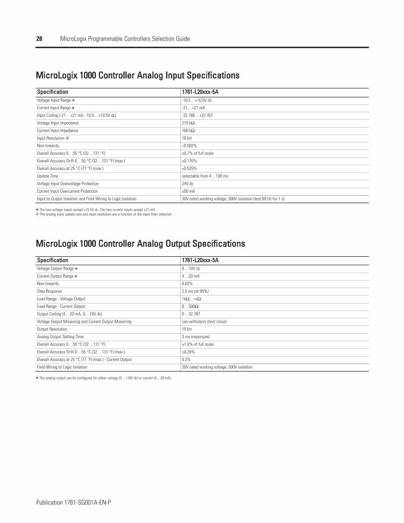
MMiiccrrooLLooggiixx 11000000 CCoonnttrroolllleerr AAnnaalloogg IInnppuutt SSppeecciiffiiccaattiioonnss
SSppeecciiffiiccaattiioonnVoltage Input Range
Current Input Range
Input Coding (-21…+21 mA, -10.5…+10.5V dc)
Voltage Input Impedance
Current Input Impedance
Input Resolution
Non-linearity
Overall Accuracy 0…55 °C (32…131 °F)
Overall Accuracy Drift 0…55 °C (32…131 °F) (max.)
Overall Accuracy at 25 °C (77 °F) (max.)
Update Time
Voltage Input Overvoltage Protection
Current Input Overcurrent Protection
Input to Output Isolation and Field Wiring to Logic Isolation
11776611--LL2200xxxxxx--55AA-10.5…+10.5V dc
-21…+21 mA
-32 768…+32 767
210 kΩ
160 kΩ
16 bit
<0.002%
±0.7% of full scale
±0.176%
±0.525%
selectable from 4…100 ms
24V dc
±50 mA
30V rated working voltage, 500V isolation (test 60 Hz for 1 s)
The two voltage inputs accept ±10.5V dc. The two current inputs accept ±21 mA.The analog input update rate and input resolution are a function of the input filter selection.
MMiiccrrooLLooggiixx 11000000 CCoonnttrroolllleerr AAnnaalloogg OOuuttppuutt SSppeecciiffiiccaattiioonnss
SSppeecciiffiiccaattiioonnVoltage Output Range
Current Output Range
Non-linearity
Step Response
Load Range - Voltage Output
Load Range - Current Output
Output Coding (4…20 mA, 0…10V dc)
Voltage Output Miswiring and Current Output Miswiring
Output Resolution
Analog Output Setting Time
Overall Accuracy 0…55 °C (32…131 °F)
Overall Accuracy Drift 0…55 °C (32…131 °F) (max.)
Overall Accuracy at 25 °C (77 °F) (max.) - Current Output
Field Wiring to Logic Isolation
11776611--LL2200xxxxxx--55AA0…10V dc
4…20 mA
0.02%
2.5 ms (at 95%)
1kΩ…∞Ω
0…500Ω
0…32 767
can withstand short circuit
15 bit
3 ms (maximum)
±1.0% of full scale
±0.28%
0.2%
30V rated working voltage, 500V isolation
The analog output can be configured for either voltage (0…+10V dc) or current (4…20 mA).
29
Publication 1761-SG001A-EN-P
MicroLogix Programmable Controllers Selection Guide
Select MicroLogix 1200 Controllersand Accessories
Step 6 - Select:
controller - review power and I/Oconfigurations to select a controllercatalog number; see power supply andI/O specifications for more detailedinformation
accessories - memory and real-timeclock modules
record your selection in the SelectionRecord (starts on page 60)
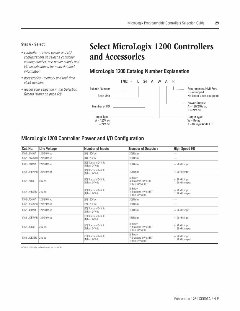
MMiiccrrooLLooggiixx 11220000 CCaattaalloogg NNuummbbeerr EExxppllaannaattiioonn
1762 AL W A R24-
Bulletin Number
Base Unit
Number of I/O
B = 24V dc
Power Supply:
Output Type:
Programming/HMI Port
Input Type:A = 120V ac
X = Relay/24V dc FETW = Relay
B = 24V dcA = 120/240V ac
No Letter = not equippedR = equipped
MMiiccrrooLLooggiixx 11220000 CCoonnttrroolllleerr PPoowweerr aanndd II//OO CCoonnffiigguurraattiioonn
CCaatt.. NNoo.. LLiinnee VVoollttaaggee NNuummbbeerr ooff IInnppuuttss NNuummbbeerr ooff OOuuttppuuttss HHiigghh SSppeeeedd II//OO1762-L24AWA 120/240V ac (14) 120V ac (10) Relay ⎯
1762-L24AWAR 120/240V ac (14) 120V ac (10) Relay ⎯
1762-L24BWA 120/240V ac (10) Standard 24V dc(4) Fast 24V dc (10) Relay (4) 20 kHz input
1762-L24BWAR 120/240V ac (10) Standard 24V dc(4) Fast 24V dc (10) Relay (4) 20 kHz input
1762-L24BXB 24V dc (10) Standard 24V dc(4) Fast 24V dc
(5) Relay(4) Standard 24V dc FET(1) Fast 24V dc FET
(4) 20 kHz input(1) 20 kHz output
1762-L24BXBR 24V dc (10) Standard 24V dc(4) Fast 24V dc
(5) Relay(4) Standard 24V dc FET(1) Fast 24V dc FET
(4) 20 kHz input(1) 20 kHz output
1762-L40AWA 120/240V ac (24) 120V ac (16) Relay ⎯
1762-L40AWAR 120/240V ac (24) 120V ac (16) Relay ⎯
1762-L40BWA 120/240V ac (20) Standard 24V dc(4) Fast 24V dc (16) Relay (4) 20 kHz input
1762-L40BWAR 120/240V ac (20) Standard 24V dc(4) Fast 24V dc (16) Relay (4) 20 kHz input
1762-L40BXB 24V dc (20) Standard 24V dc(4) Fast 24V dc
(8) Relay(7) Standard 24V dc FET(1) Fast 24V dc FET
(4) 20 kHz input(1) 20 kHz output
1762-L40BXBR 24V dc (20) Standard 24V dc(4) Fast 24V dc
(8) Relay(7) Standard 24V dc FET(1) Fast 24V dc FET
(4) 20 kHz input(1) 20 kHz output
Two individually isolated relays per controller.
30
Publication 1761-SG001A-EN-P
MicroLogix Programmable Controllers Selection Guide
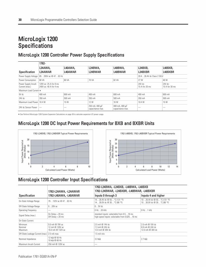
MMiiccrrooLLooggiixx 11220000SSppeecciiffiiccaattiioonnssMMiiccrrooLLooggiixx 11220000 CCoonnttrroolllleerr PPoowweerr SSuuppppllyy SSppeecciiffiiccaattiioonnss
SSppeecciiffiiccaattiioonnPower Supply Voltage
Power Consumption
Power Supply InrushCurrent (max.)
5V dc
24V dc
Maximum Load Power
24V dc Sensor Power
11776622--LL2244AAWWAA,,LL2244AAWWAARR
LL4400AAWWAA,,LL4400AAWWAARR
LL2244BBWWAA,,LL2244BBWWAARR
LL4400BBWWAA,,LL4400BBWWAARR
LL2244BBXXBB,,LL2244BBXXBBRR
LL4400BBXXBB,,LL4400BBXXBBRR
85…265V ac @ 47…63 Hz 20.4…26.4V dc Class 2 SELV
68 VA 80 VA 70 VA 82 VA 27 W 40 W
120V ac: 25 A for 8 ms240V ac: 40 A for 4 ms
24V dc:15 A for 20 ms
24V dc:15 A for 30 ms
Maximum Load Current
400 mA 600 mA 400 mA 600 mA 400 mA 600 mA
350 mA 500 mA 350 mA 500 mA 350 mA 500 mA
10.4 W 15 W 12 W 16 W 10.4 W 15 W
— — 250 mA, 400 µFcapacitance max.
400 mA, 400 µFcapacitance max. — —
See Perform MicroLogix 1200 System Expansion Calculations on page 38 to calculate expansion I/O power usage.
MMiiccrrooLLooggiixx 11220000 DDCC IInnppuutt PPoowweerr RReeqquuiirreemmeennttss ffoorr BBXXBB aanndd BBXXBBRR UUnniittss
1762-L24BXB, 1762-L24BXBR Typical Power Requirements
0
5
10
15
20
0 2 4 6 8 10Calculated Load Power (Watts)
Inpu
t Pow
er R
equi
red
at
24Vd
c (W
atts
)
1762-L40BXB, 1762-L40BXBR Typical Power Requirements
0
5
10
15
20
25
30
0 2 4 6 8 10 12 14Calculated Load Power (Watts)
Inpu
t Pow
er R
equi
red
at
24Vd
c (W
atts
)
MMiiccrrooLLooggiixx 11220000 CCoonnttrroolllleerr IInnppuutt SSppeecciiffiiccaattiioonnss
SSppeecciiffiiccaattiioonn
On-State Voltage Range
Off-State Voltage Range
Operating Frequency
Signal Delay (max.)
MinimumNominalMaximum
Off-State Leakage Current (max.)
Nominal Impedance
Maximum Inrush Current
11776622--LL2244AAWWAA,, --LL2244AAWWAARR11776622--LL4400AAWWAA,, --LL4400AAWWAARR
11776622--LL2244BBWWAA,, --LL2244BBXXBB,, --LL4400BBWWAA,, --LL4400BBXXBB11776622--LL2244BBWWAARR,, --LL2244BBXXBBRR,, --LL4400BBWWAARR,, --LL4400BBXXBBRRIInnppuuttss 00 tthhrroouugghh 33 IInnppuuttss 44 aanndd hhiigghheerr
79…132V ac @ 47…63 Hz 14…26.4V dc @ 55…°C (131 °F)14…30.0V dc @ 30…°C (86 °F)
10…26.4V dc @ 55…°C (131 °F)10…30.0V dc @ 30…°C (86 °F)
0…20V ac 0…5V dc
— 0 Hz…20 kHz 0 Hz…1 kHz
On Delay = 20 msOff Delay = 20 ms
standard inputs: selectable from 0.5…16 mshigh-speed inputs: selectable from 0.025…16 ms
On-State Current:
5.0 mA @ 79V ac12 mA @ 120V ac16.0 mA @ 132V ac
2.5 mA @ 14V dc7.3 mA @ 24V dc12.0 mA @ 30V dc
2.0 mA @ 10V dc8.9 mA @ 24V dc12.0 mA @ 30V dc
2.5 mA max. 1.5 mA min.
12 kΩ @ 50 Hz10 kΩ @ 60 Hz 3.3 kΩ 2.7 kΩ
250 mA @ 120V ac —
31
Publication 1761-SG001A-EN-P
MicroLogix Programmable Controllers Selection Guide
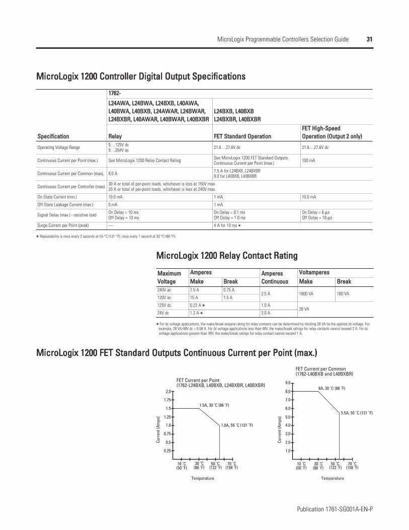
MMiiccrrooLLooggiixx 11220000 CCoonnttrroolllleerr DDiiggiittaall OOuuttppuutt SSppeecciiffiiccaattiioonnss
SSppeecciiffiiccaattiioonn
11776622--
LL2244AAWWAA,, LL2244BBWWAA,, LL2244BBXXBB,, LL4400AAWWAA,, LL4400BBWWAA,, LL4400BBXXBB,, LL2244AAWWAARR,, LL2244BBWWAARR,, LL2244BBXXBBRR,, LL4400AAWWAARR,, LL4400BBWWAARR,, LL4400BBXXBBRR
LL2244BBXXBB,, LL4400BBXXBBLL2244BBXXBBRR,, LL4400BBXXBBRR
RReellaayy FFEETT SSttaannddaarrdd OOppeerraattiioonnFFEETT HHiigghh--SSppeeeeddOOppeerraattiioonn ((OOuuttppuutt 22 oonnllyy))
Operating Voltage Range 5…125V dc5…264V ac 21.6…27.6V dc 21.6…27.6V dc
Continuous Current per Point (max.) See MicroLogix 1200 Relay Contact Rating See MicroLogix 1200 FET Standard OutputsContinuous Current per Point (max.) 100 mA
Continuous Current per Common (max). 8.0 A 7.5 A for L24BXB, L24BXBR8.0 for L40BXB, L40BXBR
Continuous Current per Controller (max). 30 A or total of per-point loads, whichever is less at 150V max.20 A or total of per-point loads, whichever is less at 240V max.
On-State Current (min.) 10.0 mA 1 mA 10.0 mA
Off-State Leakage Current (max.) 0 mA 1 mA
Signal Delay (max.) - resistive load On Delay = 10 msOff Delay = 10 ms
On Delay = 0.1 msOff Delay = 1.0 ms
On Delay = 6 µsOff Delay = 18 µs
Surge Current per Point (peak) — 4 A for 10 ms
Repeatability is once every 2 seconds at 55 °C (131 °F), once every 1 second at 30 °C (86 °F).
MMiiccrrooLLooggiixx 11220000 RReellaayy CCoonnttaacctt RRaattiinngg
MMaaxxiimmuumm VVoollttaaggee240V ac
120V ac
125V dc
24V dc
AAmmppeerreess AAmmppeerreessCCoonnttiinnuuoouuss
VVoollttaammppeerreessMMaakkee BBrreeaakk MMaakkee BBrreeaakk7.5 A 0.75 A
2.5 A 1800 VA 180 VA15 A 1.5 A
0.22 A 1.0 A28 VA
1.2 A 2.0 A
For dc voltage applications, the make/break ampere rating for relay contacts can be determined by dividing 28 VA by the applied dc voltage. Forexample, 28 VA/48V dc = 0.58 A. For dc voltage applications less than 48V, the make/break ratings for relay contacts cannot exceed 2 A. For dcvoltage applications greater than 48V, the make/break ratings for relay contact cannot exceed 1 A.
MMiiccrrooLLooggiixx 11220000 FFEETT SSttaannddaarrdd OOuuttppuuttss CCoonnttiinnuuoouuss CCuurrrreenntt ppeerr PPooiinntt ((mmaaxx..))
0.25
1.0A, 55 ˚C (131 ˚F)
1.5A, 30 ˚C (86 ˚F)
0.5
0.75
1.0
1.25
1.5
1.75
2.0
1.0
10 ˚C 30 ˚C 50 ˚C
5.5A, 55 ˚C (131 ˚F)
8A, 30 ˚C (86 ˚F)
70 ˚C
2.0
3.0
4.0
5.0
6.0
7.0
8.0
9.0FET Current per Point
FET Current per Common
Curr
ent (
Amps
)
Curr
ent (
Amps
)
Temperature Temperature
(1762-L40BXB and L40BXBR)
(158 ˚F)(122 ˚F)(86 ˚F)(50 ˚F)
(1762-L24BXB, L40BXB, L24BXBR, L40BXBR)
70 ˚C(158 ˚F)
50 ˚C(122 ˚F)
30 ˚C(86 ˚F)
10 ˚C(50 ˚F)
32
Publication 1761-SG001A-EN-P
MicroLogix Programmable Controllers Selection Guide
MMiiccrrooLLooggiixx 11220000MMeemmoorryy aanndd RReeaall--TTiimmee CClloocckk MMoodduulleess
The controller is shipped with a memory module port cover in place. You can order thememory module, real-time clock or combination module to suit your needs.
RReeaall--TTiimmee CClloocckk ((11776622--RRTTCC))Allows for time/date scheduling
Self-contained battery provides long-term time base
MMeemmoorryy MMoodduullee ((11776622--MMMM11))Memory modules allow:
user programs and data to be stored as backup
transport programs for use with other controllers
special safety/security features for press control and other critical applications
auto-recovery, through a power cycle, after a controller fault
comparison of programs
data file and memory module write protection
removal/insertion under power
CCoommbbiinnaattiioonn MMeemmoorryy aanndd RReeaall--TTiimmee CClloocckk MMoodduullee((11776622--MMMM11RRTTCC))
Provides all real-time clock and memory back-up functions of the 1762-RTC and 1762-MM1 modules
33
Publication 1761-SG001A-EN-P
MicroLogix Programmable Controllers Selection Guide
Select MicroLogix 1200 I/OStep 7 - Select:
I/O modules - digital, analog andtemperature
perform system expansion calculations
record your selections in the SelectionRecord (starts on page 60)
MicroLogix 1200 I/O expansion modules provide superior functionality at low cost. Avariety of modules complement and extend the capabilities of MicroLogix 1200 controllersby maximizing the flexibility of I/O count and type.
The MicroLogix 1200 system design allows modules to be either DIN rail or panelmounted. The DIN latches and screw mounting holes are an integral part of the packagedesign.
Controller I/O can be expanded using up to 6 expansion modules per controller (dependingon power budget).
AAddvvaannttaaggeess
Rackless design, eliminating added system costs and inventory
Small footprint with high density I/O, minimizing panel space requirements
Integral high-performance I/O bus
Software keying to prevent incorrect positioning within the system
Feature-rich I/O functionality addresses a wide range of applications
AC/DC relay, 24V dc, 120V ac and 240V ac voltages
Thermocouple/mV and RTD/Resistance temperature input modules
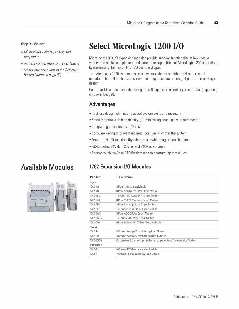
AAvvaaiillaabbllee MMoodduulleess 11776622 EExxppaannssiioonn II//OO MMoodduulleess
CCaatt.. NNoo..
1762-IA8
1762-IQ8
1762-IQ16
1762-OA8
1762-OB8
1762-OB16
1762-OW8
1762-OW16
1762-OX6I
1762-IF4
1762-OF4
1762-IF2OF2
1762-IR4
1762-IT4
DDeessccrriippttiioonnDigital:
8-Point 120V ac Input Module
8-Point Sink/Source 24V dc Input Module
16-Point Sink/Source 24V dc Input Module
8-Point 120/240V ac Triac Output Module
8-Point Sourcing 24V dc Output Module
16-Point Sourcing 24V dc Output Module
8-Point AC/DC Relay Output Module
16-Point AC/DC Relay Output Module
6-Point Isolated AC/DC Relay Output Module
Analog:
4-Channel Voltage/Current Analog Input Module
4-Channel Voltage/Current Analog Output Module
Combination 2-Channel Input 2-Channel Output Voltage/Current Analog Module
Temperature:
4-Channel RTD/Resistance Input Module
4-Channel Thermocouple/mV Input Module
34
Publication 1761-SG001A-EN-P
MicroLogix Programmable Controllers Selection Guide
11776622 DDiiggiittaall II//OO
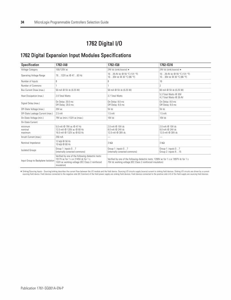
11776622 DDiiggiittaall EExxppaannssiioonn IInnppuutt MMoodduulleess SSppeecciiffiiccaattiioonnss
SSppeecciiffiiccaattiioonnVoltage Category
Operating Voltage Range
Number of Inputs
Number of Commons
Bus Current Draw (max.)
Heat Dissipation (max.)
Signal Delay (max.)
Off-State Voltage (max.)
Off-State Leakage Current (max.)
On-State Voltage (min.)
minimumnominalmaximum
Inrush Current (max.)
Nominal Impedance
Isolated Groups
Input Group to Backplane Isolation
11776622--IIAA88 11776622--IIQQ88 11776622--IIQQ1166100/120V ac 24V dc (sink/source) 24V dc (sink/source)
79…132V ac @ 47…63 Hz 10…26.4V dc @ 55 °C (131 °F)10…30V dc @ 30 °C (86 °F)
10…26.4V dc @ 55 °C (131 °F)10…30V dc @ 30 °C (86 °F)
8 8 16
1 1 2
50 mA @ 5V dc (0.25 W) 50 mA @ 5V dc (0.25 W) 60 mA @ 5V dc (0.25 W)
2.0 Total Watts 3.7 Total Watts 5.3 Total Watts @ 30V4.2 Total Watts @ 26.4V
On Delay: 20.0 msOff Delay: 20.0 ms
On Delay: 8.0 msOff Delay: 8.0 ms
On Delay: 8.0 msOff Delay: 8.0 ms
20V ac 5V dc 5V dc
2.5 mA 1.5 mA 1.5 mA
79V ac (min.) 132V ac (max.) 10V dc 10V dc
On-State Current:
5.0 mA @ 79V ac @ 47 Hz12.0 mA @ 120V ac @ 60 Hz16.0 mA @ 132V ac @ 63 Hz
2.0 mA @ 10V dc8.0 mA @ 24V dc12.0 mA @ 30V dc
2.0 mA @ 10V dc8.0 mA @ 24V dc12.0 mA @ 30V dc
250 mA — —
12 kΩ @ 50 Hz10 kΩ @ 60 Hz 3 kΩ 3 kΩ
Group 1: inputs 0…7(internally conected commons)
Group 1: inputs 0…7(internally conected commons)
Group 1: inputs 0…7Group 2: inputs 8…15
Verified by one of the following dielectric tests:1517V ac for 1 s or 2145V dc for 1 s132V ac working voltage (IEC Class 2 reinforcedinsulation)
Verified by one of the following dielectric tests: 1200V ac for 1 s or 1697V dc for 1 s75V dc working voltage (IEC Class 2 reinforced insulation)
Sinking/Sourcing Inputs - Sourcing/sinking describes the current flow between the I/O module and the field device. Sourcing I/O circuits supply (source) current to sinking field devices. Sinking I/O circuits are driven by a current sourcing field device. Field devices connected to the negative side (DC Common) of the field power supply are sinking field devices. Field devices connected to the positive side (+V) of the field supply are sourcing field devices.
35
Publication 1761-SG001A-EN-P
MicroLogix Programmable Controllers Selection Guide
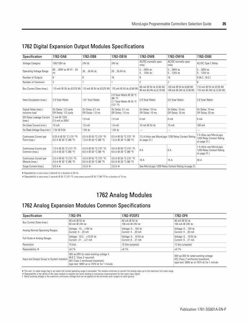
1762 Digital Expansion Output Modules Specifications
Specification
Voltage Category
Operating Voltage Range
Number of Outputs
Number of Commons
Bus Current Draw (max.)
Heat Dissipation (max.)
Signal Delay (max.) -resistive load
Off-State Leakage Current(max.)
On-State Current (min.)
On-State Voltage Drop (min.)
Continuous Current perPoint (max.)
Continuous Current perCommon (max.)
Continuous Current perModule (max.)
Surge Current (max.)
1762-OA8 1762-OB8 1762-OB16 1762-OW8 1762-OW16 1762-OX6I
100/120V ac 24V dc 24V dc AC/DC normally openrelay
AC/DC normally openrelay AC/DC Type C Relay
85…265V ac @ 47…63Hz 20…26.4V dc 20…26.4V dc 5…265V ac
5…125V dc5…265V ac5…125V dc
5…265V ac5…125V dc
8 8 16 8 16 6 (N.C., N.O.)
2 1 1 2 2 6
115 mA @ 5V dc (0.575 W) 115 mA @ 5V dc (0.575 W) 175 mA @ 5V dc (0.88 W) 80 mA @ 5V dc (0.40 W)90 mA @ 24V dc (2.16 W)
120 mA @ 5V dc (0.60 W)140 mA @ 24V dc (3.36 W)
110 mA @ 5V dc (0.55 W)110 mA @ 24V dc (2.64 W)
2.9 Total Watts 1.61 Total Watts
2.9 Total Watts @ 30 °C(86 °F)2.1 Total Watts @ 55 °C(131 °F)
2.9 Total Watts 5.6 Total Watts 2.8 Total Watts
On Delay: 1/2 cycleOff Delay: 1/2 cycle
On Delay: 0.1 msOff Delay: 1.0 ms
On Delay: 0.1 msOff Delay: 1.0 ms
On Delay: 10 msOff Delay: 10 ms
On Delay: 10 msOff Delay: 10 ms
On Delay: 10 msOff Delay: 20 ms
2 mA @ 132V2.5 mA at 265V 1.0 mA 1.0 mA 0 mA 0 mA 0 mA
10 mA 1.0 mA 1.0 mA 10 mA @ 5V dc 10 mA 100 mA
1.5V @ 0.5A 1.0V dc 1.0V dc — — —
0.25 A @ 55 °C (131 °F)0.5 A @ 30 °C (86 °F)
0.5 A @ 55 °C (131 °F)1.0 A @ 30 °C (86 °F)
0.5 A @ 55 °C (131 °F)1.0 A @ 30 °C (86 °F)
2.5 A (Also see MicroLogix 1200 Relay Contact Ratingon page 31.)
7 A (Also see MicroLogix1200 Relay Contact Ratingon page 31.)
1.0 A @ 55 °C (131 °F)2.0 A @ 30 °C (86 °F)
4.0 A @ 55 °C (131 °F)8.0 A @ 30 °C (86 °F)
4.0 A @ 55 °C (131 °F)8.0 A @ 30 °C (86 °F) 8 A 8 A
7 A (Also see MicroLogix1200 Relay Contact Ratingon page 31.)
2.0 A @ 55 °C (131 °F)4.0 A @ 30 °C (86 °F)
4.0 A @ 55 °C (131 °F)8.0 A @ 30 °C (86 °F)
4.0 A @ 55 °C (131 °F)8.0 A @ 30 °C (86 °F) 16 A 16 A 30 A
5.0 A 2.0 A 2.0 A
Repeatability is once every 2 seconds for a duration of 25 ms.Repeatability is once every 2 seconds @ 55 °C (131 °F), once every second @ 30 °C (86 °F) for a duration of 10 ms.
1762 Analog Modules
1762 Analog Expansion Modules Common Specifications
Specification
Bus Current Draw (max.)
Analog Normal Operating Ranges
Full Scale Analog Ranges
Resolution
Repeatability
Input and Output Group to System Isolation
1762-IF4 1762-IF2OF2 1762-OF440 mA @ 5V dc50 mA @ 24V dc
40 mA @ 5V dc105 mA @ 24V dc
40 mA @ 5V dc165 mA @ 24V dc
Voltage: -10…+10V dcCurrent: 4…20 mA
Voltage: 0…10V dcCurrent: 4…20 mA
Voltage: 0…10V dcCurrent: 4…20 mA
Voltage: -10.5…+10.5V dcCurrent: -21…+21 mA
Voltage: 0…10.5V dcCurrent: 0…21 mA
Voltage: 0…10.5V dcCurrent: 0…21 mA
15 bits 12 bits (unipolar) 12 bits (unipolar)
±0.1% ±0.1% ±0.1%
30V ac/30V dc rated working voltage ‡(N.E.C. Class 2 required)(IEC Class 2 reinforced insulation) type test: 500V ac or 707V dc for 1 minute
30V ac/30V dc rated working voltage(IEC Class 2 reinforced insulation) type test: 500V ac or 707V dc for 1 minute
The over- or under-range flag is set when the normal operating range is exceeded. The module continues to convert the analog input up to the maximum full scale range.Repeatability is the ability of the input module to register the same reading in successive measurements for the same input signal.
‡ Rated working voltage is the maximum continuous voltage that can be applied at the terminals with respect to earth ground.
See MicroLogix 1200 Relay Contact Rating on page 31.
36
Publication 1761-SG001A-EN-P
MicroLogix Programmable Controllers Selection Guide
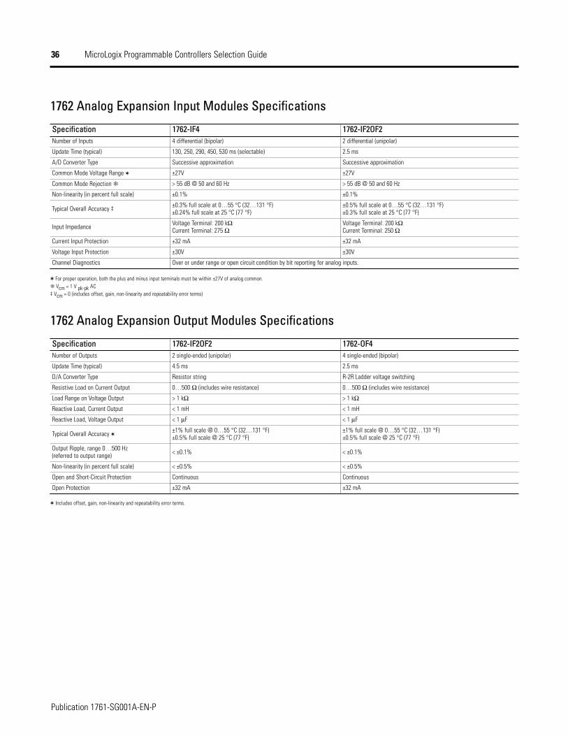
1762 Analog Expansion Input Modules Specifications
Specification 1762-IF4 1762-IF2OF2Number of Inputs 4 differential (bipolar) 2 differential (unipolar)
Update Time (typical) 130, 250, 290, 450, 530 ms (selectable) 2.5 ms
A/D Converter Type Successive approximation Successive approximation
Common Mode Voltage Range ±27V ±27V
Common Mode Rejection > 55 dB @ 50 and 60 Hz > 55 dB @ 50 and 60 Hz
Non-linearity (in percent full scale) ±0.1% ±0.1%
Typical Overall Accuracy ‡ ±0.3% full scale at 0…55 °C (32…131 °F)±0.24% full scale at 25 °C (77 °F)
±0.5% full scale at 0…55 °C (32…131 °F)±0.3% full scale at 25 °C (77 °F)
Input Impedance Voltage Terminal: 200 kΩCurrent Terminal: 275 Ω
Voltage Terminal: 200 kΩCurrent Terminal: 250 Ω
Current Input Protection ±32 mA ±32 mA
Voltage Input Protection ±30V ±30V
Channel Diagnostics Over or under range or open circuit condition by bit reporting for analog inputs.
For proper operation, both the plus and minus input terminals must be within ±27V of analog common.Vcm = 1 V pk-pk AC
‡ Vcm = 0 (includes offset, gain, non-linearity and repeatability error terms)
1762 Analog Expansion Output Modules Specifications
SpecificationNumber of Outputs
Update Time (typical)
D/A Converter Type
Resistive Load on Current Output
Load Range on Voltage Output
Reactive Load, Current Output
Reactive Load, Voltage Output
Typical Overall Accuracy
Output Ripple, range 0…500 Hz(referred to output range)
Non-linearity (in percent full scale)
Open and Short-Circuit Protection
Open Protection
1762-IF2OF2 1762-OF42 single-ended (unipolar) 4 single-ended (bipolar)
4.5 ms 2.5 ms
Resistor string R-2R Ladder voltage switching
0…500 Ω (includes wire resistance) 0…500 Ω (includes wire resistance)
> 1 kΩ > 1 kΩ
< 1 mH < 1 mH
< 1 µF < 1 µF
±1% full scale @ 0…55 °C (32…131 °F)±0.5% full scale @ 25 °C (77 °F)
±1% full scale @ 0…55 °C (32…131 °F)±0.5% full scale @ 25 °C (77 °F)
< ±0.1% < ±0.1%
< ±0.5% < ±0.5%
Continuous Continuous
±32 mA ±32 mA
Includes offset, gain, non-linearity and repeatability error terms.
37
Publication 1761-SG001A-EN-P
MicroLogix Programmable Controllers Selection Guide
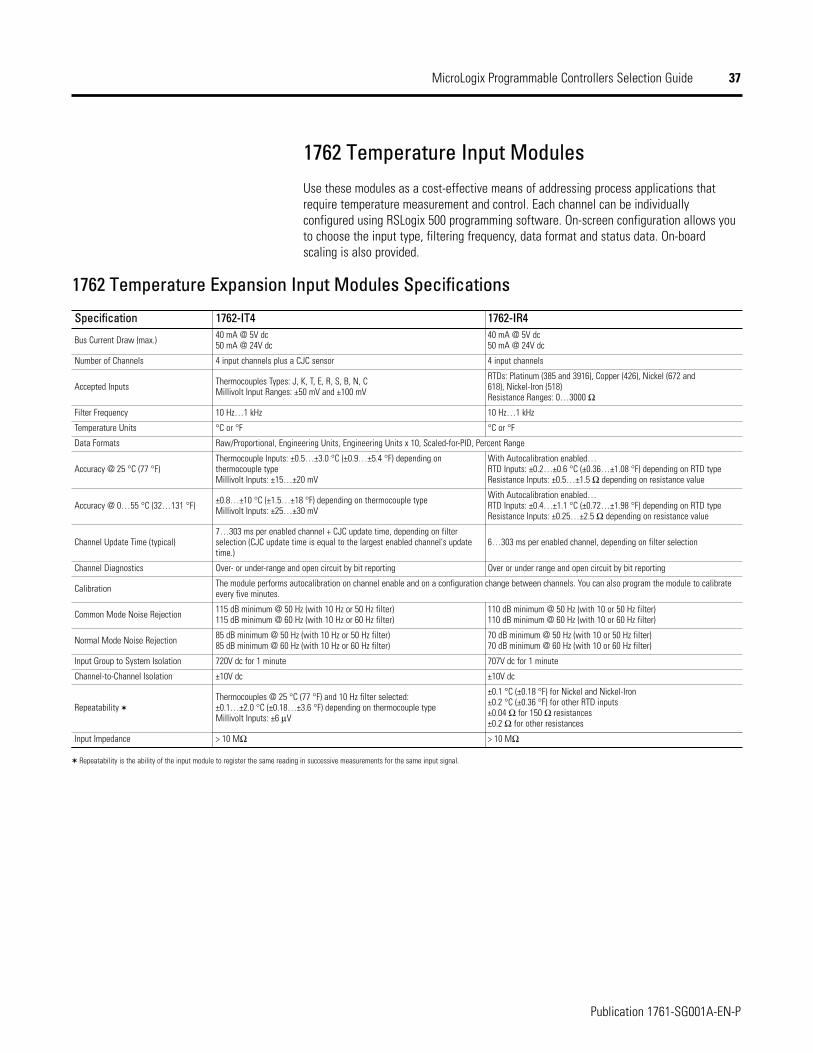
1762 Temperature Input Modules
Use these modules as a cost-effective means of addressing process applications thatrequire temperature measurement and control. Each channel can be individuallyconfigured using RSLogix 500 programming software. On-screen configuration allows youto choose the input type, filtering frequency, data format and status data. On-boardscaling is also provided.
1762 Temperature Expansion Input Modules Specifications
Specification
Bus Current Draw (max.)
Number of Channels
Accepted Inputs
Filter Frequency
Temperature Units
Data Formats
Accuracy @ 25 °C (77 °F)
Accuracy @ 0…55 °C (32…131 °F)
Channel Update Time (typical)
Channel Diagnostics
Calibration
Common Mode Noise Rejection
Normal Mode Noise Rejection
Input Group to System Isolation
Channel-to-Channel Isolation
Repeatability
Input Impedance
1762-IT4 1762-IR440 mA @ 5V dc50 mA @ 24V dc
40 mA @ 5V dc50 mA @ 24V dc
4 input channels plus a CJC sensor 4 input channels
Thermocouples Types: J, K, T, E, R, S, B, N, CMillivolt Input Ranges: ±50 mV and ±100 mV
RTDs: Platinum (385 and 3916), Copper (426), Nickel (672 and 618), Nickel-Iron (518)Resistance Ranges: 0…3000 Ω
10 Hz…1 kHz 10 Hz…1 kHz
°C or °F °C or °F
Raw/Proportional, Engineering Units, Engineering Units x 10, Scaled-for-PID, Percent Range
Thermocouple Inputs: ±0.5…±3.0 °C (±0.9…±5.4 °F) depending onthermocouple typeMillivolt Inputs: ±15…±20 mV
With Autocalibration enabled…RTD Inputs: ±0.2…±0.6 °C (±0.36…±1.08 °F) depending on RTD typeResistance Inputs: ±0.5…±1.5 Ω depending on resistance value
±0.8…±10 °C (±1.5…±18 °F) depending on thermocouple typeMillivolt Inputs: ±25…±30 mV
With Autocalibration enabled…RTD Inputs: ±0.4…±1.1 °C (±0.72…±1.98 °F) depending on RTD typeResistance Inputs: ±0.25…±2.5 Ω depending on resistance value
7…303 ms per enabled channel + CJC update time, depending on filterselection (CJC update time is equal to the largest enabled channel's updatetime.)
6…303 ms per enabled channel, depending on filter selection
Over- or under-range and open circuit by bit reporting Over or under range and open circuit by bit reporting
The module performs autocalibration on channel enable and on a configuration change between channels. You can also program the module to calibrateevery five minutes.
115 dB minimum @ 50 Hz (with 10 Hz or 50 Hz filter)115 dB minimum @ 60 Hz (with 10 Hz or 60 Hz filter)
110 dB minimum @ 50 Hz (with 10 or 50 Hz filter)110 dB minimum @ 60 Hz (with 10 or 60 Hz filter)
85 dB minimum @ 50 Hz (with 10 Hz or 50 Hz filter)85 dB minimum @ 60 Hz (with 10 Hz or 60 Hz filter)
70 dB minimum @ 50 Hz (with 10 or 50 Hz filter)70 dB minimum @ 60 Hz (with 10 or 60 Hz filter)
720V dc for 1 minute 707V dc for 1 minute
±10V dc ±10V dc
Thermocouples @ 25 °C (77 °F) and 10 Hz filter selected: ±0.1…±2.0 °C (±0.18…±3.6 °F) depending on thermocouple typeMillivolt Inputs: ±6 µV
±0.1 °C (±0.18 °F) for Nickel and Nickel-Iron±0.2 °C (±0.36 °F) for other RTD inputs±0.04 Ω for 150 Ω resistances±0.2 Ω for other resistances
> 10 MΩ > 10 MΩ
Repeatability is the ability of the input module to register the same reading in successive measurements for the same input signal.
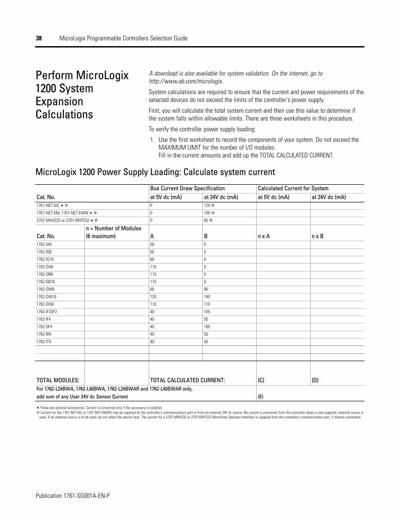
38
Publication 1761-SG001A-EN-P
MicroLogix Programmable Controllers Selection Guide
Perform MicroLogix1200 SystemExpansionCalculations
A download is also available for system validation. On the internet, go tohttp://www.ab.com/micrologix.
System calculations are required to ensure that the current and power requirements of theselected devices do not exceed the limits of the controller's power supply.
First, you will calculate the total system current and then use this value to determine ifthe system falls within allowable limits. There are three worksheets in this procedure.
To verify the controller power supply loading:
1. Use the first worksheet to record the components of your system. Do not exceed theMAXIMUM LIMIT for the number of I/O modules.Fill in the current amounts and add up the TOTAL CALCULATED CURRENT.
MicroLogix 1200 Power Supply Loading: Calculate system current
Cat. No.1762-IA8
1762-IQ8
1762-IQ16
1762-OA8
1762-OB8
1762-OB16
1762-OW8
1762-OW16
1762-OX6I
1762-IF2OF2
1762-IF4
1762-OF4
1762-IR4
1762-IT4
TOTAL MODULES:
Cat. No.Bus Current Draw Specification Calculated Current for Systemat 5V dc (mA) at 24V dc (mA) at 5V dc (mA) at 24V dc (mA)
1761-NET-AIC 0 120
1761-NET-ENI, 1761-NET-ENIW 0 100
2707-MVH232 or 2707-MVP232 0 80
n = Number of Modules(6 maximum) A B n x A n x B
50 0
50 0
60 0
115 0
115 0
175 0
80 90
120 140
110 110
40 105
40 50
40 165
40 50
40 50
TOTAL CALCULATED CURRENT: (C) (D)For 1762-L24BWA, 1762-L40BWA, 1762-L24BWAR and 1762-L40BWAR only,add sum of any User 24V dc Sensor CCurrent (E)
These are optional accessories. Current is consumed only if the accessory is installed.Current for the 1761-NET-AIC or 1761-NET-ENI(W) may be supplied by the controller's communications port or from an external 24V dc source. No current is consumed from the controller when a user-supplied, external source is
used. If an external source is to be used, do not select the device here. The current for a 2707-MVH232 or 2707-MVP232 MicroView Operator Interface is supplied from the controller's communication port, if directly connected.
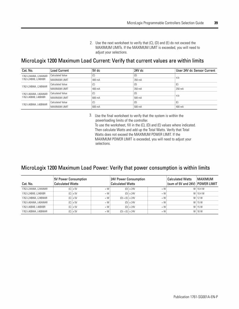
39
Publication 1761-SG001A-EN-P
MicroLogix Programmable Controllers Selection Guide
2. Use the next worksheet to verify that (C), (D) and (E) do not exceed theMAXIMUM LIMITs. If the MAXIMUM LIMIT is exceeded, you will need toadjust your selections.
MicroLogix 1200 Maximum Load Current: Verify that current values are within limits
Cat. No.1762-L24AWA, L24AWAR1762-L24BXB, L24BXBR
1762-L24BWA, L24BWAR
1762-L40AWA, L40AWAR1762-L40BXB, L40BXBR
1762-L40BWA, L40BWAR
Load Current 5V dc 24V dc User 24V dc Sensor CurrentCalculated Value (C) (D)
n/aMAXIMUM LIMIT 400 mA 350 mA
Calculated Value (C) (D) (E)
MAXIMUM LIMIT 400 mA 350 mA 250 mA
Calculated Value (C) (D)n/a
MAXIMUM LIMIT 600 mA 500 mA
Calculated Value (C) (D) (E)
MAXIMUM LIMIT 600 mA 500 mA 400 mA
3.
MicroLogix 1200 Maximum Load Power: Verify that power consumption is within limits
Cat. No.1762-L24AWA, L24AWAR
1762-L24BXB, L24BXBR
1762-L24BWA, L24BWAR
1762-L40AWA, L40AWAR
1762-L40BXB, L40BXBR
1762-L40BWA, L40BWAR
5V Power Consumption Calculated Watts
24V Power ConsumptionCalculated Watts
Calculated Watts(sum of 5V and 24V)
MAXIMUMPOWER LIMIT
(C) x 5V = W (D) x 24V = W W 10.4 W
(C) x 5V = W (D) x 24V = W W 10.4 W
(C) x 5V = W (D) + (E) x 24V = W W 12 W
(C) x 5V = W (D) x 24V = W W 15 W
(C) x 5V = W (D) x 24V = W W 15 W
(C) x 5V = W (D) + (E) x 24V = W W 16 W
Use the final worksheet to verify that the system is within the powerloading limits of the controller.To use the worksheet, fill in the (C), (D) and (E) values where indicated.
Watts does not exceed the MAXIMUM POWER LIMIT. If theThen calculate Watts and add up the Total Watts. Verify that Total
MAXIMUM POWER LIMIT is exceeded, you will need to adjust your selections.
40
Publication 1761-SG001A-EN-P
MicroLogix Programmable Controllers Selection Guide
Select MicroLogix 1500 Controllersand Accessories
Step 8 - Select:
base unit - review power and I/Oconfigurations to select a catalognumber; see power supply and I/Ospecifications for more detailedinformation
processor - see notes at Step 1
accessories - data access tool; real-timeclock and memory modules
record your selections in the SelectionRecord (starts on page 60)
1764 A W A24-
Bulletin Number
Number of I/O
Input Type:
Power Supply:
Output Type:A = 120V acB = 24V dc
W = RelayX = Relay/24V dc FET
A = 120/240V acB = 24V dc
MMiiccrrooLLooggiixx 11550000BBaassee UUnniittss
The Base Unit houses embedded inputs, outputs, power supply and the Channel 0communications port. The base unit also provides the interface to expansion I/O whenrequired by the application.
MMiiccrrooLLooggiixx 11550000 PPoowweerr aanndd II//OO CCoonnffiigguurraattiioonn
CCaatt.. NNoo.. LLiinnee VVoollttaaggee NNuummbbeerr ooff IInnppuuttss NNuummbbeerr ooff OOuuttppuuttss HHiigghh SSppeeeedd II//OO1764-24AWA 120/240V ac (12) 120V ac (12) Relay ⎯
1764-24BWA 120/240V ac (4) Standard 24V dc(8) Fast 24V dc (12) Relay (8) 20 kHz input
1764-28BXB 24V dc (8) Standard 24V dc(8) Fast 24V dc
(6) Relay(4) Standard 24V dc FET(2) Fast 24V dc FET
(8) 20 kHz input(2) 20 kHz output
Two individually isolated relays per base unit.
MMiiccrrooLLooggiixx 11550000 BBaassee UUnniitt PPoowweerr SSuuppppllyy SSppeecciiffiiccaattiioonnss
MMiiccrrooLLooggiixx 11550000 BBaassee UUnniitt CCaattaalloogg NNuummbbeerr EExxppllaannaattiioonn
SSppeecciiffiiccaattiioonn 11776644--2244AAWWAA 11776644--2244BBWWAA 11776644--2288BBXXBBPower Supply Voltage 85…265 V ac @ 47…63 Hz 85…265 V ac @ 47…63 Hz 20.4…30V dc
Power Consumption 70 VA 88 VA 30 W
Power Supply Inrush Current (max.) 120V ac: 25 A for 8 ms240V ac: 40 A for 4 ms
120V ac: 25 A for 8 ms240V ac: 40 A for 4 ms 24V dc: 4 A for 150 ms
Maximum Load Current:
5V dc 2250 mA 2250 mA 2250 mA
24V dc 400 mA 400 mA 400 mA
Maximum Load Power 16 W 22 W 16 W
24V dc Sensor Power — 400 mA , 400 µF capacitance max. —
See Perform MicroLogix 1500 System Expansion Calculations on page 53 to calculate expansion I/O power usage.Do not allow the total load power consumed by the 5V dc, 24V dc and sensor power outputs to exceed 22 W.
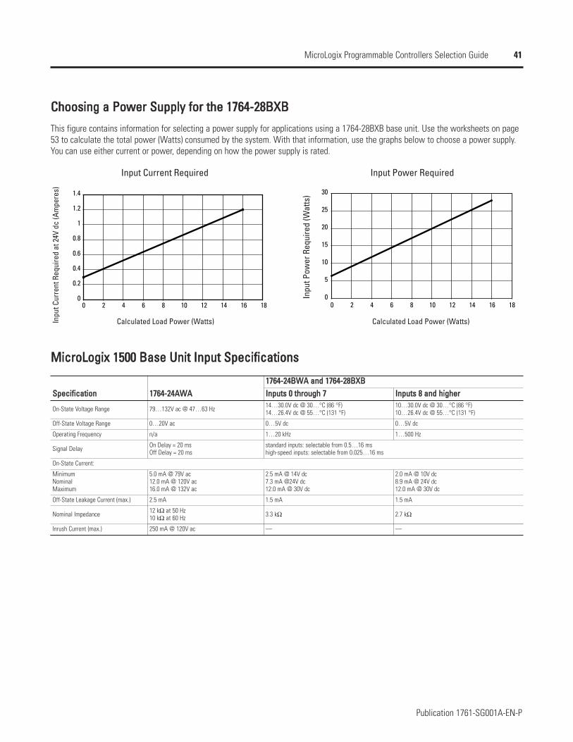
41
Publication 1761-SG001A-EN-P
MicroLogix Programmable Controllers Selection Guide
CChhoooossiinngg aa PPoowweerr SSuuppppllyy ffoorr tthhee 11776644--2288BBXXBB
This figure contains information for selecting a power supply for applications using a 1764-28BXB base unit. Use the worksheets on page53 to calculate the total power (Watts) consumed by the system. With that information, use the graphs below to choose a power supply.You can use either current or power, depending on how the power supply is rated.
0
0.2
0.4
0.6
0.8
1
1.2
1.4
0 2 4 6 8 10 12 14 16 180
5
10
15
20
25
30
0 2 4 6 8 10 12 14 16 18
Input Current Required Input Power Required
Inpu
t Cur
rent
Req
uire
d at
24V
dc
(Am
pere
s)
Inpu
t Pow
er R
equi
red
(Wat
ts)
Calculated Load Power (Watts) Calculated Load Power (Watts)
MMiiccrrooLLooggiixx 11550000 BBaassee UUnniitt IInnppuutt SSppeecciiffiiccaattiioonnss
SSppeecciiffiiccaattiioonn
On-State Voltage Range
Off-State Voltage Range
Operating Frequency
Signal Delay
MinimumNominalMaximum
Off-State Leakage Current (max.)
Nominal Impedance
Inrush Current (max.)
11776644--2244AAWWAA11776644--2244BBWWAA aanndd 11776644--2288BBXXBBIInnppuuttss 00 tthhrroouugghh 77 IInnppuuttss 88 aanndd hhiigghheerr
79…132V ac @ 47…63 Hz 14…30.0V dc @ 30…°C (86 °F)14…26.4V dc @ 55…°C (131 °F)
10…30.0V dc @ 30…°C (86 °F)10…26.4V dc @ 55…°C (131 °F)
0…20V ac 0…5V dc 0…5V dc
n/a 1…20 kHz 1…500 Hz
On Delay = 20 msOff Delay = 20 ms
standard inputs: selectable from 0.5…16 mshigh-speed inputs: selectable from 0.025…16 ms
On-State Current:
5.0 mA @ 79V ac12.0 mA @ 120V ac16.0 mA @ 132V ac
2.5 mA @ 14V dc7.3 mA @24V dc12.0 mA @ 30V dc
2.0 mA @ 10V dc8.9 mA @ 24V dc12.0 mA @ 30V dc
2.5 mA 1.5 mA 1.5 mA
12 kΩ at 50 Hz10 kΩ at 60 Hz 3.3 kΩ 2.7 kΩ
250 mA @ 120V ac — —
42
Publication 1761-SG001A-EN-P
MicroLogix Programmable Controllers Selection Guide
MMiiccrrooLLooggiixx 11550000 BBaassee UUnniitt OOuuttppuutt SSppeecciiffiiccaattiioonnss
SSppeecciiffiiccaattiioonn
Operating Voltage Range
Continuous Current per Point (max.)
Continuous Current per Common (max).
Continuous Current per Controller (max).
On-State Current (min.)
Off-State Leakage Current (max.)
Signal Delay (max.) - resistive load
Surge Current per Point (peak)
11776644--2244AAWWAA,, --2244BBWWAA,, --2288BBXXBB 11776644--2288BBXXBB
RReellaayy FFEETT SSttaannddaarrdd OOppeerraattiioonnFFEETT HHiigghh--SSppeeeeddOOppeerraattiioonn ((OOuuttppuutt 22 aanndd 33 oonnllyy))
5…125V dc5…264V ac 20.4…26.4V dc
See MicroLogix 1500 Relay Contact Rating 1 A @ 55 °C (131 °F)1.5 A @ 30 °C (86 °F) 100 mA
8.0 A 6.0 A
24 A @ 150V20 A @ 240V
18 A @ 150V18 A @ 240V
5 mA @ 79V ac 2.5 mA @ 14V dc 2.0 mA @ 10V dc
0 mA 1 mA
On Delay = 10 msOff Delay = 10 ms
On Delay = 0.1 msOff Delay = 1.0 ms
On Delay = 6 µsOff Delay = 18 µs
— 4 A for 10 ms
Repeatability is once every 2 seconds at 55 °C (131 °F), once every 1 second at 30 °C (86 °F).
MMiiccrrooLLooggiixx 11550000 RReellaayy CCoonnttaacctt RRaattiinngg
MMaaxxiimmuumm VVoollttaaggee
AAmmppeerreess
AAmmppeerreessCCoonnttiinnuuoouuss
VVoollttaammppeerreess
MMaakkee BBrreeaakk MMaakkee BBrreeaakk240V ac 7.5 A 0.75 A
2.5 A 1800 VA 180 VA120V ac 15 A 1.5 A
125V dc 0.22 A 1.0 A28 VA
24V dc 1.2 A 2.0 A
For dc voltage applications, the make/break ampere rating for relay contacts can be determined by dividing 28 VA by the applied dc voltage. Forexample, 28 VA/48V dc = 0.58 A. For dc voltage applications less than 48V, the make/break ratings for relay contacts cannot exceed 2 A. For dcvoltage applications greater than 48V, the make/break ratings for relay contact cannot exceed 1 A.
MMiiccrrooLLooggiixx 11550000PPrroocceessssoorrss
In the controller system, the processor unit provides logic processing, trim potentiometers,Run/Remote/Program mode switch, communications toggle push button and (using the1764-LRP processor) an electrically isolated RS-232 port. The processor also provides theinterface to the DAT, real-time clock and memory modules.
There are two processor units: 1764-LSP and 1764-LRP.
43
Publication 1761-SG001A-EN-P
MicroLogix Programmable Controllers Selection Guide
MMiiccrrooLLooggiixx 11550000AAcccceessssoorriieess
MMiiccrrooLLooggiixx 11550000 DDaattaa AAcccceessss TTooooll ((11776644--DDAATT))The DAT plug-in tool provides an interface for on-the-fly data monitoring and adjustments.The DAT has five primary features:
Direct access to 48 bit elements
Direct access to 48 integer elements
Two function keys for momentary and latching bit changing
Display of controller faults
Removal and insertion under power
MMiiccrrooLLooggiixx 11550000 RReeaall--TTiimmee CClloocckk aanndd MMeemmoorryy MMoodduulleessThese optional modules attach to the processor unit. Both types of modules can beinserted or removed while the unit is under power.
Real-time clock modules establish a time-base for controller functions that need to becoordinated with real-time events. They provide year, month, day of month, day of week,hour, minute and second information to the controller using the RTC function file.
Memory modules allow:
user programs and data to be stored as backup
transport programs for use with other controllers
special safety/security features for press control and other critical applications
auto-recovery, through a power cycle, after a controller fault
comparison of programs
data file and memory module write protection
removal/insertion under power
MMiiccrrooLLooggiixx 11550000 RReeaall--TTiimmee CClloocckk aanndd MMeemmoorryy MMoodduulleessCCaatt.. NNoo..1764-RTC
1764-MM1
1764-MM1RTC
1764-MM2
1764-MM2RTC
DDeessccrriippttiioonnMicroLogix 1500 Real-Time Clock Module
MicroLogix 1500 8K Memory Module
MicroLogix 1500 8K Memory Module with Real-Time Clock
MicroLogix 1500 16K Memory Module
MicroLogix 1500 16K Memory Module with Real-Time Clock
Use with the 1764-LRP processor to support larger program and data requirements.
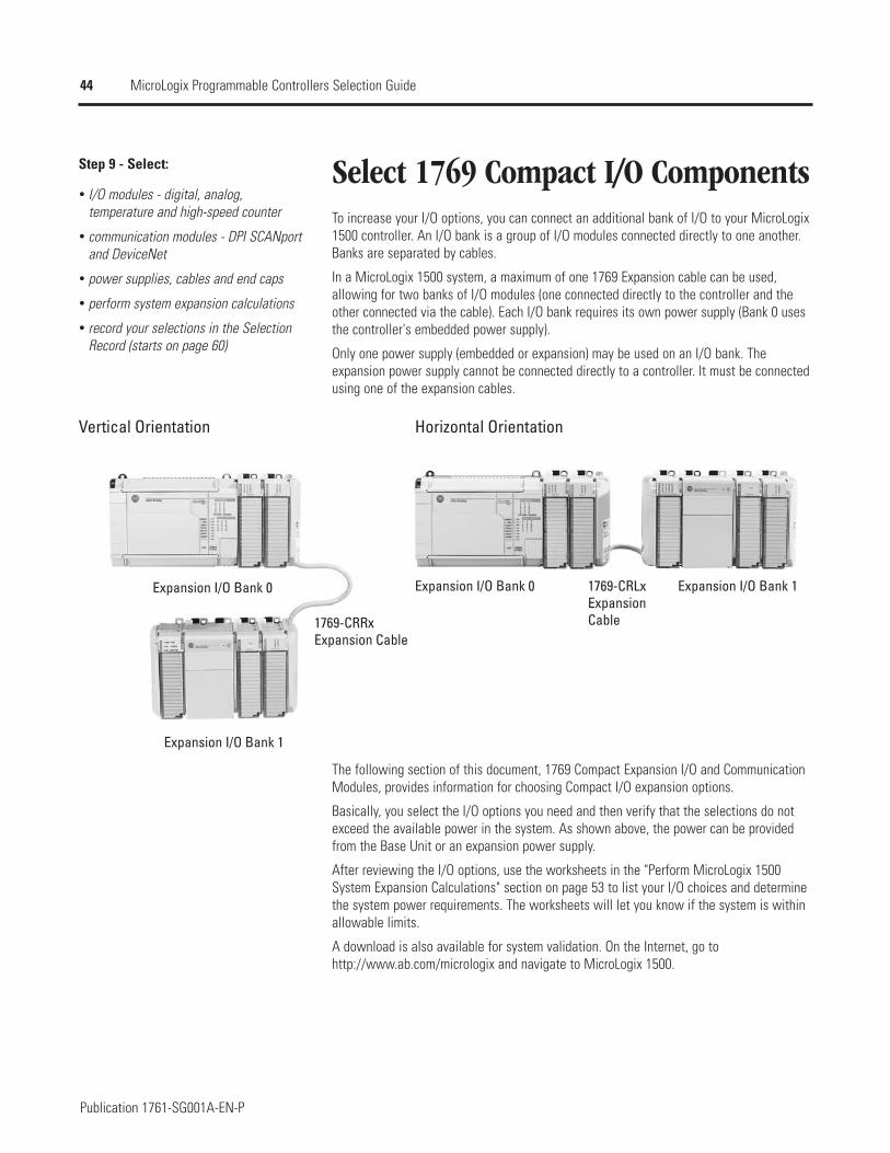
44
Publication 1761-SG001A-EN-P
MicroLogix Programmable Controllers Selection Guide
Select 1769 Compact I/O ComponentsStep 9 - Select:
I/O modules - digital, analog,temperature and high-speed counter
communication modules - DPI SCANportand DeviceNet
power supplies, cables and end caps
perform system expansion calculations
record your selections in the SelectionRecord (starts on page 60)
To increase your I/O options, you can connect an additional bank of I/O to your MicroLogix1500 controller. An I/O bank is a group of I/O modules connected directly to one another.Banks are separated by cables.
In a MicroLogix 1500 system, a maximum of one 1769 Expansion cable can be used,allowing for two banks of I/O modules (one connected directly to the controller and theother connected via the cable). Each I/O bank requires its own power supply (Bank 0 usesthe controller's embedded power supply).
Only one power supply (embedded or expansion) may be used on an I/O bank. Theexpansion power supply cannot be connected directly to a controller. It must be connectedusing one of the expansion cables.
Vertical Orientation Horizontal Orientation
Expansion I/O Bank 0 Expansion I/O Bank 0 Expansion I/O Bank 1
Expansion I/O Bank 1
1769-CRLxExpansion Cable1769-CRRx
Expansion Cable
The following section of this document, 1769 Compact Expansion I/O and CommunicationModules, provides information for choosing Compact I/O expansion options.
Basically, you select the I/O options you need and then verify that the selections do notexceed the available power in the system. As shown above, the power can be providedfrom the Base Unit or an expansion power supply.
After reviewing the I/O options, use the worksheets in the "Perform MicroLogix 1500System Expansion Calculations" section on page 53 to list your I/O choices and determinethe system power requirements. The worksheets will let you know if the system is withinallowable limits.
A download is also available for system validation. On the Internet, go tohttp://www.ab.com/micrologix and navigate to MicroLogix 1500.
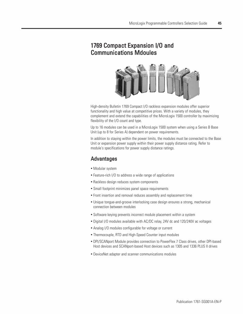
45
Publication 1761-SG001A-EN-P
MicroLogix Programmable Controllers Selection Guide
11776699 CCoommppaacctt EExxppaannssiioonn II//OO aanndd CCoommmmuunniiccaattiioonnss MMddoouulleess
High-density Bulletin 1769 Compact I/O rackless expansion modules offer superiorfunctionality and high value at competitive prices. With a variety of modules, theycomplement and extend the capabilities of the MicroLogix 1500 controller by maximizingflexibility of the I/O count and type.
Up to 16 modules can be used in a MicroLogix 1500 system when using a Series B BaseUnit (up to 8 for Series A) dependent on power requirements.
In addition to staying within the power limits, the modules must be connected to the BaseUnit or expansion power supply within their power supply distance rating. Refer tomodule's specifications for power supply distance ratings.
AAddvvaannttaaggeess
Modular system
Feature-rich I/O to address a wide range of applications
Rackless design reduces system components
Small footprint minimizes panel space requirements
Front insertion and removal reduces assembly and replacement time
Unique tongue-and-groove interlocking case design ensures a strong, mechanicalconnection between modules
Software keying prevents incorrect module placement within a system
Digital I/O modules available with AC/DC relay, 24V dc and 120/240V ac voltages
Analog I/O modules configurable for voltage or current
Thermocouple, RTD and High-Speed Counter input modules
DPI/SCANport Module provides connection to PowerFlex 7 Class drives, other DPI-basedHost devices and SCANport-based Host devices such as 1305 and 1336 PLUS II drives
DeviceNet adapter and scanner communications modules
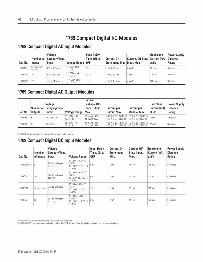
46
Publication 1761-SG001A-EN-P
MicroLogix Programmable Controllers Selection Guide
11776699 CCoommppaacctt DDiiggiittaall II//OO MMoodduulleess
11776699 CCoommppaacctt DDiiggiittaall AACC IInnppuutt MMoodduulleess
CCaatt.. NNoo..
1769-IA8I
1769-IA16
1769-IM12
NNuummbbeerr ooffIInnppuuttss
VVoollttaaggeeCCaatteeggoorryy//TTyyppee,,IInnppuutt VVoollttaaggee RRaannggee
IInnppuutt DDeellaayyTTiimmee,, OONN ttooOOFFFF
CCuurrrreenntt,, OOnn--SSttaattee IInnppuutt,, MMiinn..
CCuurrrreenntt,, OOffff--SSttaatteeIInnppuutt,, MMaaxx..
BBaacckkppllaanneeCCuurrrreenntt ((mmAA))aatt 55VV
PPoowweerr SSuuppppllyyDDiissttaanncceeRRaattiinngg
8 individuallyisolated 100 or 120V ac 79...132V ac @
47...63Hz 20 ms 5 mA @ 79V ac 2.5 mA 90 mA 8 modules
16 100 or 120V ac 79...132V ac @47…63Hz 20 ms 5 mA @ 79V ac 2.5 mA 115 mA 8 modules
12 200 or 240V ac 159...265V ac @47…60Hz 20 ms 5 mA @ 159V ac 2.5 mA 100 mA 8 modules
11776699 CCoommppaacctt DDiiggiittaall AACC OOuuttppuutt MMoodduulleess
CCaatt.. NNoo..
1769-OA8
1769-OA16
NNuummbbeerr ooffOOuuttppuuttss
VVoollttaaggeeCCaatteeggoorryy//TTyyppee,,OOuuttppuutt VVoollttaaggee RRaannggee
CCuurrrreennttLLeeaakkaaggee,, OOffff--SSttaattee OOuuttppuutt,,MMaaxx..
CCuurrrreenntt ppeerrOOuuttppuutt,, MMaaxx..
CCuurrrreenntt ppeerrMMoodduullee,, MMaaxx..
BBaacckkppllaanneeCCuurrrreenntt ((mmAA))aatt 55VV
PPoowweerr SSuuppppllyyDDiissttaanncceeRRaattiinngg
8 100…240V ac 85...265V ac @47…63Hz
2.0 mA @ 132V ac2.5 mA @ 265V ac
0.25 A @ 60 °C (140 °F)0.50 A @ 30 °C (86 °F)
2.0 A @ 60 °C (140 °F)4.0 A @ 30 °C (86 °F) 145 mA 8 modules
16 100...240V ac 85...265V ac @47…63Hz
2.0 mA @ 132V ac2.5 mA @ 265V ac
0.25 A @ 60 °C (140 °F)0.50 A @ 30 °C (86 °F)
4.0 A @ 60 °C (140 °F)8.0 A @ 30 °C (86 °F) 225 mA 8 modules
The 1769-OA16 is dimensionally one and one-half as wide as other modules.
11776699 CCoommppaacctt DDiiggiittaall DDCC IInnppuutt MMoodduulleess
CCaatt.. NNoo..
1769-IQ6XOW4
1769-IQ16
1769-IQ16F
1769-IQ32
NNuummbbeerrooff IInnppuuttss
VVoollttaaggeeCCaatteeggoorryy//TTyyppee,,IInnppuutt VVoollttaaggee RRaannggee
IInnppuutt DDeellaayyTTiimmee,, OONN ttooOOFFFF
CCuurrrreenntt,, OOnn--SSttaattee IInnppuutt,,MMiinn..
CCuurrrreenntt,, OOffff--SSttaattee IInnppuutt,,MMaaxx..
BBaacckkppllaanneeCCuurrrreenntt ((mmAA))aatt 55VV
PPoowweerr SSuuppppllyyDDiissttaanncceeRRaattiinngg
6 24V dc, sinking orsourcing
10...30V dc @ 30 °C(86 °F)10...26.4V dc @ 60 °C(140 °F)
8 ms 2 mA 1.5 mA 105 mA 8 modules
16 24V dc, sinking orsourcing
10...30V dc @ 30 °C(86 °F)10...26.4V dc @ 60 °C(140 °F)
8 ms 2 mA 1.5 mA 115 mA 8 modules
16 high-speed 24V dc, sinking orsourcing
10...30V dc @ 30 °C(86 °F)10...26.4V dc @ 60 °C(140 °F)
1 ms 2 mA 1.5 mA 110 mA 8 modules
32 24V dc, sinking orsourcing
10...30V dc @ 30 °C(86 °F)10...26.4V dc @ 60 °C(140 °F)
8 ms 2 mA 1.5 mA 170 mA 8 modules
The 1769-IQ32 is dimensionally one and one-half as wide as other modules.The 1769-IQ6XOW4 is a combination input/output module. See "1769 Compact Digital Relay Output Modules" for its output specifications.
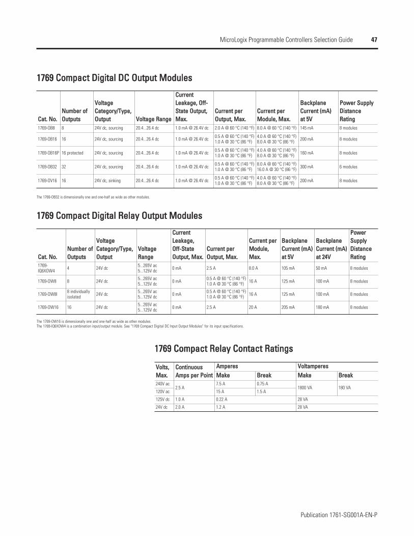
47
Publication 1761-SG001A-EN-P
MicroLogix Programmable Controllers Selection Guide
11776699 CCoommppaacctt DDiiggiittaall DDCC OOuuttppuutt MMoodduulleess
CCaatt.. NNoo..1769-OB8
1769-OB16
1769-OB16P
1769-OB32
1769-OV16
NNuummbbeerr ooffOOuuttppuuttss
VVoollttaaggeeCCaatteeggoorryy//TTyyppee,,OOuuttppuutt VVoollttaaggee RRaannggee
CCuurrrreennttLLeeaakkaaggee,, OOffff--SSttaattee OOuuttppuutt,,MMaaxx..
CCuurrrreenntt ppeerrOOuuttppuutt,, MMaaxx..
CCuurrrreenntt ppeerrMMoodduullee,, MMaaxx..
BBaacckkppllaanneeCCuurrrreenntt ((mmAA))aatt 55VV
PPoowweerr SSuuppppllyyDDiissttaanncceeRRaattiinngg
8 24V dc, sourcing 20.4...26.4 dc 1.0 mA @ 26.4V dc 2.0 A @ 60 °C (140 °F) 8.0 A @ 60 °C (140 °F) 145 mA 8 modules
16 24V dc, sourcing 20.4...26.4 dc 1.0 mA @ 26.4V dc 0.5 A @ 60 °C (140 °F)1.0 A @ 30 °C (86 °F)
4.0 A @ 60 °C (140 °F)8.0 A @ 30 °C (86 °F) 200 mA 8 modules
16 protected 24V dc, sourcing 20.4...26.4 dc 1.0 mA @ 26.4V dc 0.5 A @ 60 °C (140 °F)1.0 A @ 30 °C (86 °F)
4.0 A @ 60 °C (140 °F)8.0 A @ 30 °C (86 °F) 160 mA 8 modules
32 24V dc, sourcing 20.4...26.4 dc 1.0 mA @ 26.4V dc 0.5 A @ 60 °C (140 °F)1.0 A @ 30 °C (86 °F)
8.0 A @ 60 °C (140 °F)16.0 A @ 30 °C (86 °F) 300 mA 6 modules
16 24V dc, sinking 20.4...26.4 dc 1.0 mA @ 26.4V dc 0.5 A @ 60 °C (140 °F)1.0 A @ 30 °C (86 °F)
4.0 A @ 60 °C (140 °F)8.0 A @ 30 °C (86 °F) 200 mA 8 modules
The 1769-OB32 is dimensionally one and one-half as wide as other modules.
11776699 CCoommppaacctt DDiiggiittaall RReellaayy OOuuttppuutt MMoodduulleess
CCaatt.. NNoo..1769-IQ6XOW4
1769-OW8
1769-OW8I
1769-OW16
NNuummbbeerr ooffOOuuttppuuttss
VVoollttaaggeeCCaatteeggoorryy//TTyyppee,,OOuuttppuutt
VVoollttaaggeeRRaannggee
CCuurrrreennttLLeeaakkaaggee,,OOffff--SSttaatteeOOuuttppuutt,, MMaaxx..
CCuurrrreenntt ppeerrOOuuttppuutt,, MMaaxx..
CCuurrrreenntt ppeerrMMoodduullee,,MMaaxx..
BBaacckkppllaanneeCCuurrrreenntt ((mmAA))aatt 55VV
BBaacckkppllaanneeCCuurrrreenntt ((mmAA))aatt 2244VV
PPoowweerrSSuuppppllyyDDiissttaanncceeRRaattiinngg
4 24V dc 5...265V ac5...125V dc 0 mA 2.5 A 8.0 A 105 mA 50 mA 8 modules
8 24V dc 5...265V ac5...125V dc 0 mA 0.5 A @ 60 °C (140 °F)
1.0 A @ 30 °C (86 °F) 16 A 125 mA 100 mA 8 modules
8 individuallyisolated 24V dc 5...265V ac
5...125V dc 0 mA 0.5 A @ 60 °C (140 °F)1.0 A @ 30 °C (86 °F) 16 A 125 mA 100 mA 8 modules
16 24V dc 5...265V ac5...125V dc 0 mA 2.5 A 20 A 205 mA 180 mA 8 modules
The 1769-OW16 is dimensionally one and one-half as wide as other modules.The 1769-IQ6XOW4 is a combination input/output module. See "1769 Compact Digital DC Input Output Modules" for its input specifications.
11776699 CCoommppaacctt RReellaayy CCoonnttaacctt RRaattiinnggss
VVoollttss,,MMaaxx..
CCoonnttiinnuuoouussAAmmppss ppeerr PPooiinntt
AAmmppeerreess VVoollttaammppeerreessMMaakkee BBrreeaakk MMaakkee BBrreeaakk
240V ac2.5 A
7.5 A 0.75 A1800 VA 180 VA
120V ac 15 A 1.5 A
125V dc 1.0 A 0.22 A 28 VA
24V dc 2.0 A 1.2 A 28 VA
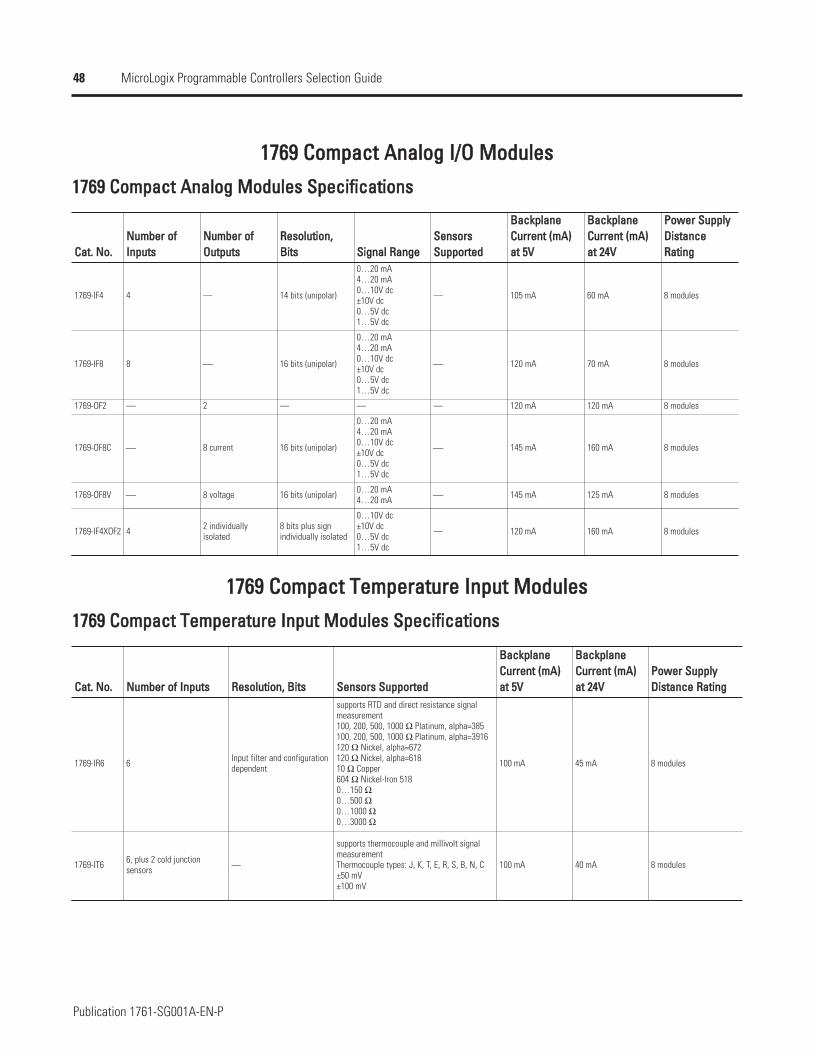
48
Publication 1761-SG001A-EN-P
MicroLogix Programmable Controllers Selection Guide
11776699 CCoommppaacctt AAnnaalloogg II//OO MMoodduulleess
11776699 CCoommppaacctt AAnnaalloogg MMoodduulleess SSppeecciiffiiccaattiioonnss
CCaatt.. NNoo..
1769-IF4
1769-IF8
1769-OF2
1769-OF8C
1769-OF8V
1769-IF4XOF2
NNuummbbeerr ooffIInnppuuttss
NNuummbbeerr ooffOOuuttppuuttss
RReessoolluuttiioonn,,BBiittss SSiiggnnaall RRaannggee
SSeennssoorrssSSuuppppoorrtteedd
BBaacckkppllaanneeCCuurrrreenntt ((mmAA))aatt 55VV
BBaacckkppllaanneeCCuurrrreenntt ((mmAA))aatt 2244VV
PPoowweerr SSuuppppllyyDDiissttaanncceeRRaattiinngg
4 — 14 bits (unipolar)
0…20 mA4…20 mA0…10V dc±10V dc0…5V dc1…5V dc
— 105 mA 60 mA 8 modules
8 ⎯ 16 bits (unipolar)
0…20 mA4…20 mA0…10V dc±10V dc0…5V dc1…5V dc
⎯ 120 mA 70 mA 8 modules
— 2 — — — 120 mA 120 mA 8 modules
⎯ 8 current 16 bits (unipolar)
0…20 mA4…20 mA0…10V dc±10V dc0…5V dc1…5V dc
⎯ 145 mA 160 mA 8 modules
⎯ 8 voltage 16 bits (unipolar) 0…20 mA4…20 mA ⎯ 145 mA 125 mA 8 modules
4 2 individuallyisolated
8 bits plus signindividually isolated
0…10V dc±10V dc0…5V dc1…5V dc
— 120 mA 160 mA 8 modules
11776699 CCoommppaacctt TTeemmppeerraattuurree IInnppuutt MMoodduulleess
11776699 CCoommppaacctt TTeemmppeerraattuurree IInnppuutt MMoodduulleess SSppeecciiffiiccaattiioonnss
CCaatt.. NNoo..
1769-IR6
1769-IT6
NNuummbbeerr ooff IInnppuuttss RReessoolluuttiioonn,, BBiittss SSeennssoorrss SSuuppppoorrtteedd
BBaacckkppllaanneeCCuurrrreenntt ((mmAA))aatt 55VV
BBaacckkppllaanneeCCuurrrreenntt ((mmAA))aatt 2244VV
PPoowweerr SSuuppppllyyDDiissttaannccee RRaattiinngg
6 Input filter and configurationdependent
supports RTD and direct resistance signalmeasurement100, 200, 500, 1000 Ω Platinum, alpha=385100, 200, 500, 1000 Ω Platinum, alpha=3916120 Ω Nickel, alpha=672120 Ω Nickel, alpha=61810 Ω Copper604 Ω Nickel-Iron 5180…150 Ω0…500 Ω0…1000 Ω0…3000 Ω
100 mA 45 mA 8 modules
6, plus 2 cold junctionsensors —
supports thermocouple and millivolt signalmeasurementThermocouple types: J, K, T, E, R, S, B, N, C±50 mV±100 mV
100 mA 40 mA 8 modules
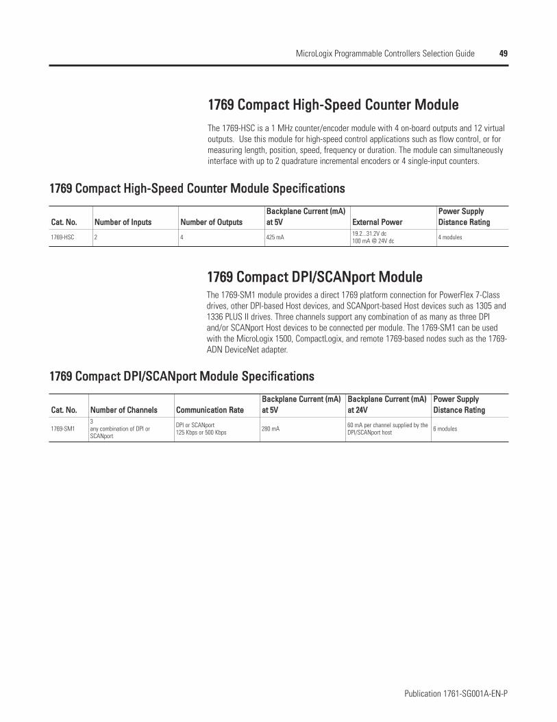
49
Publication 1761-SG001A-EN-P
MicroLogix Programmable Controllers Selection Guide
11776699 CCoommppaacctt HHiigghh--SSppeeeedd CCoouunntteerr MMoodduulleeThe 1769-HSC is a 1 MHz counter/encoder module with 4 on-board outputs and 12 virtualoutputs. Use this module for high-speed control applications such as flow control, or formeasuring length, position, speed, frequency or duration. The module can simultaneouslyinterface with up to 2 quadrature incremental encoders or 4 single-input counters.
11776699 CCoommppaacctt HHiigghh--SSppeeeedd CCoouunntteerr MMoodduullee SSppeecciiffiiccaattiioonnss
CCaatt.. NNoo..
1769-HSC
NNuummbbeerr ooff IInnppuuttss NNuummbbeerr ooff OOuuttppuuttssBBaacckkppllaannee CCuurrrreenntt ((mmAA))aatt 55VV EExxtteerrnnaall PPoowweerr
PPoowweerr SSuuppppllyyDDiissttaannccee RRaattiinngg
2 4 425 mA 19.2...31.2V dc100 mA @ 24V dc 4 modules
11776699 CCoommppaacctt DDPPII//SSCCAANNppoorrtt MMoodduulleeThe 1769-SM1 module provides a direct 1769 platform connection for PowerFlex 7-Classdrives, other DPI-based Host devices, and SCANport-based Host devices such as 1305 and1336 PLUS II drives. Three channels support any combination of as many as three DPIand/or SCANport Host devices to be connected per module. The 1769-SM1 can be usedwith the MicroLogix 1500, CompactLogix, and remote 1769-based nodes such as the 1769-ADN DeviceNet adapter.
11776699 CCoommppaacctt DDPPII//SSCCAANNppoorrtt MMoodduullee SSppeecciiffiiccaattiioonnss
CCaatt.. NNoo..
1769-SM1
NNuummbbeerr ooff CChhaannnneellss CCoommmmuunniiccaattiioonn RRaatteeBBaacckkppllaannee CCuurrrreenntt ((mmAA))aatt 55VV
BBaacckkppllaannee CCuurrrreenntt ((mmAA))aatt 2244VV
PPoowweerr SSuuppppllyyDDiissttaannccee RRaattiinngg
3any combination of DPI orSCANport
DPI or SCANport125 Kbps or 500 Kbps 280 mA 60 mA per channel supplied by the
DPI/SCANport host 6 modules
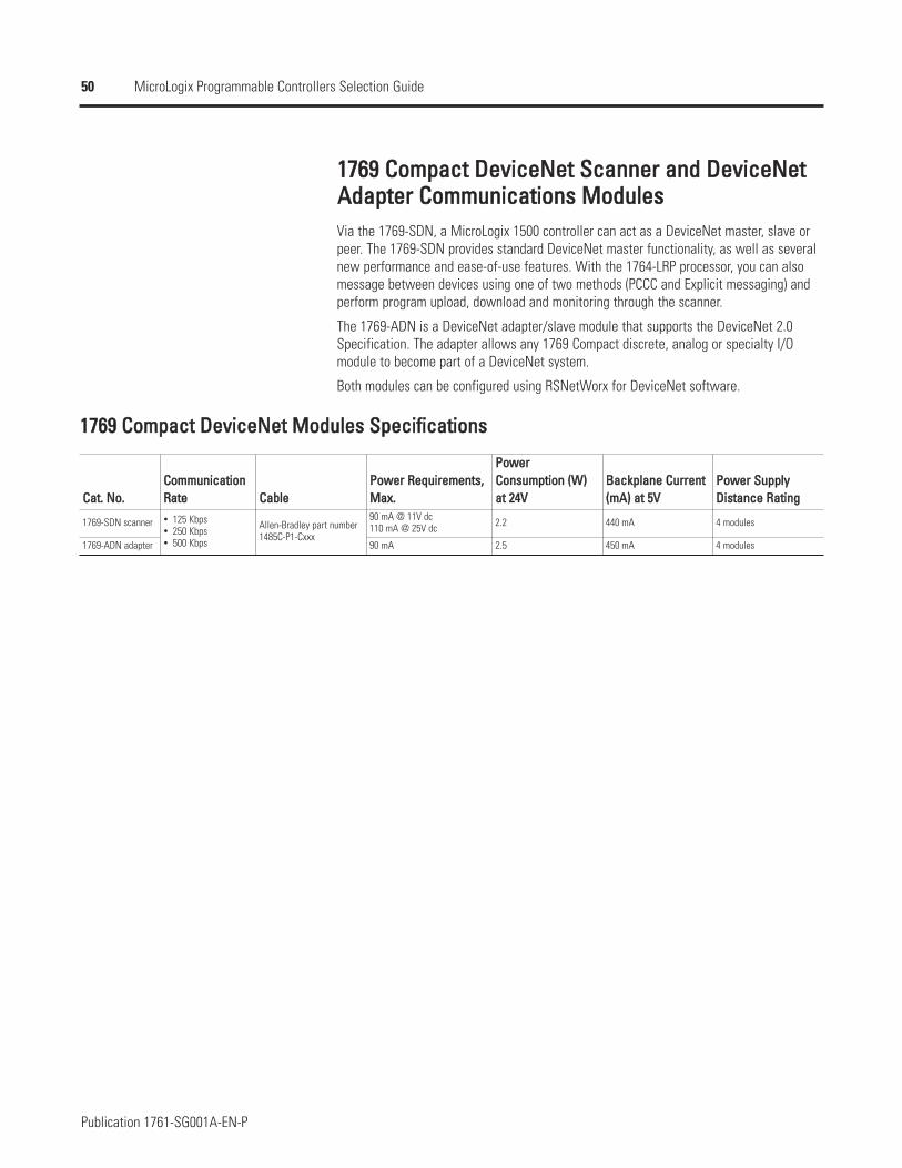
50
Publication 1761-SG001A-EN-P
MicroLogix Programmable Controllers Selection Guide
11776699 CCoommppaacctt DDeevviicceeNNeett SSccaannnneerr aanndd DDeevviicceeNNeettAAddaapptteerr CCoommmmuunniiccaattiioonnss MMoodduulleessVia the 1769-SDN, a MicroLogix 1500 controller can act as a DeviceNet master, slave orpeer. The 1769-SDN provides standard DeviceNet master functionality, as well as severalnew performance and ease-of-use features. With the 1764-LRP processor, you can alsomessage between devices using one of two methods (PCCC and Explicit messaging) andperform program upload, download and monitoring through the scanner.
The 1769-ADN is a DeviceNet adapter/slave module that supports the DeviceNet 2.0Specification. The adapter allows any 1769 Compact discrete, analog or specialty I/Omodule to become part of a DeviceNet system.
Both modules can be configured using RSNetWorx for DeviceNet software.
11776699 CCoommppaacctt DDeevviicceeNNeett MMoodduulleess SSppeecciiffiiccaattiioonnss
CCaatt.. NNoo..
1769-SDN scanner
1769-ADN adapter
CCoommmmuunniiccaattiioonnRRaattee CCaabbllee
PPoowweerr RReeqquuiirreemmeennttss,,MMaaxx..
PPoowweerrCCoonnssuummppttiioonn ((WW))aatt 2244VV
BBaacckkppllaannee CCuurrrreenntt((mmAA)) aatt 55VV
PPoowweerr SSuuppppllyyDDiissttaannccee RRaattiinngg
125 Kbps250 Kbps500 Kbps
Allen-Bradley part number1485C-P1-Cxxx
90 mA @ 11V dc110 mA @ 25V dc 2.2 440 mA 4 modules
90 mA 2.5 450 mA 4 modules
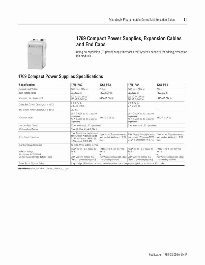
51
Publication 1761-SG001A-EN-P
MicroLogix Programmable Controllers Selection Guide
11776699 CCoommppaacctt PPoowweerr SSuupppplliieess,, EExxppaannssiioonn CCaabblleessaanndd EEnndd CCaappssUsing an expansion I/O power supply increases the system's capacity for adding expansionI/O modules.
11776699 CCoommppaacctt PPoowweerr SSuupppplliieess SSppeecciiffiiccaattiioonnss
Certifications: UL 508, CSA (Class I, Division 2, Group A, B, C, D), CE
2 A @ 5V dc0.8 A @ 24V dc
10 ms (minimum)…10 s (maximum)
0 mA @ 5V dc; 0 mA @ 24V dc
for both +5V dc and for +24V dc
8 (up to eight I/O modules can be connected on either side of the power supply for a maximum of 16 modules)
4 A @ 5V dc2 A @ 24V dc
5 ms (minimum)…10 s (maximum)
SSppeecciiffiiccaattiioonn 11776699--PPAA22 11776699--PPBB22 11776699--PPAA44 11776699--PPBB44Nominal Input Voltage 120V ac or 240V ac 24V dc 120V ac or 240V ac 24V dc
Input Voltage Range 85...265V ac 19.2...31.2V dc 85...265V ac 19.2...32V dc
Maximum Line Requirement 100 VA @ 120V ac130 VA @ 240V ac 50 VA @ 24V dc 200 VA @ 120V ac
240 VA @ 240V ac 100 VA @ 24V dc
Output Bus Current Capacity (0° to 55°C)
24V dc User Power Capacity (0° to 55°C) 250 mA — — —
Maximum Inrush
25 A @ 132V ac, 10 Ω sourceimpedance40 A @ 265V ac, 10 Ω sourceimpedance
30 A @ 31.2V dc
25 A @ 132V ac, 10 Ω sourceimpedance40 A @ 265V ac, 10 Ω sourceimpedance
30 A @ 31.2V dc
Line Loss Ride Through
Minimum Load Current
Short Circuit Protection
Front Access Fuse (replacementpart number: Wickmann 19195-3.15A, Wickmann 19343-1.6A,or Wickmann 19181-4A)
Front Access Fuse (replacementpart number: Wickmann 19193-6.3A)
Front Access Fuse (replacementpart number: Wickmann 19195-3.15A or Wickmann 19181-4A)
Front Access Fuse (replacementpart number: Wickmann 19193-6.3A)
Bus Overvoltage Protection
Isolation Voltage(input power to 1769 bus)Verified by one of these dielectric tests
1836V ac for 1 s or 2596V dcfor 1 sor265V Working Voltage (IECClass 1 - grounding required)
1200V ac for 1 s or 1697V dcfor 1 sor75V Working Voltage (IEC Class1 - grounding required)
1836V ac for 1 s or 2596V dcfor 1 sor265V Working Voltage (IECClass 1 - grounding required)
1200V ac for 1 s or 1697V dcfor 1 sor75V Working Voltage (IEC Class1 - grounding required)
Power Supply Distance Rating
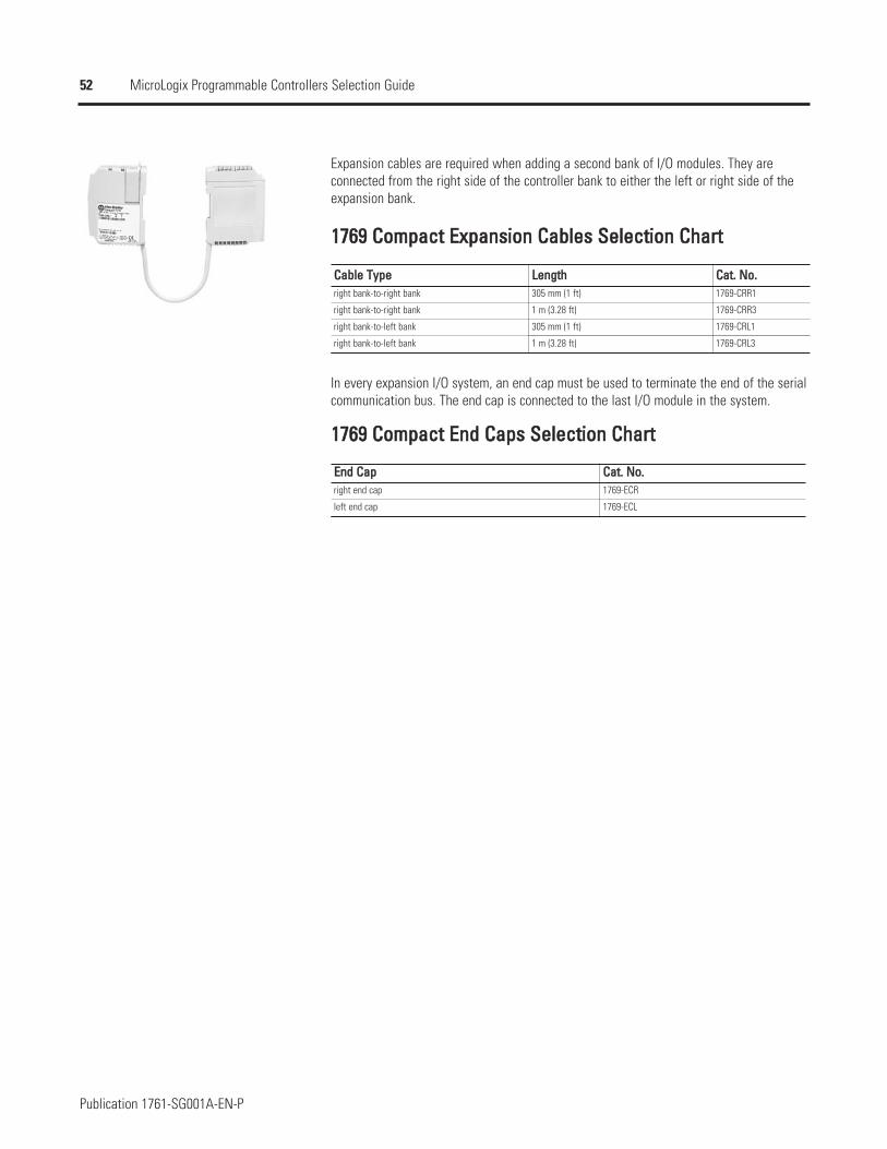
52
Publication 1761-SG001A-EN-P
MicroLogix Programmable Controllers Selection Guide
Expansion cables are required when adding a second bank of I/O modules. They areconnected from the right side of the controller bank to either the left or right side of theexpansion bank.
11776699 CCoommppaacctt EExxppaannssiioonn CCaabblleess SSeelleeccttiioonn CChhaarrtt
CCaabbllee TTyyppeeright bank-to-right bank
right bank-to-right bank
right bank-to-left bank
right bank-to-left bank
CCaatt.. NNoo..1769-CRR1
1769-CRR3
1769-CRL1
1769-CRL3
LLeennggtthh305 mm (1 ft)
1 m (3.28 ft)
305 mm (1 ft)
1 m (3.28 ft)
11776699 CCoommppaacctt EEnndd CCaappss SSeelleeccttiioonn CChhaarrtt
EEnndd CCaapp CCaatt.. NNoo..right end cap 1769-ECR
left end cap 1769-ECL
In every expansion I/O system, an end cap must be used to terminate the end of the serialcommunication bus. The end cap is connected to the last I/O module in the system.
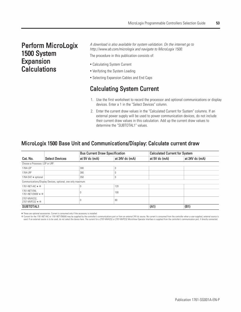
53
Publication 1761-SG001A-EN-P
MicroLogix Programmable Controllers Selection Guide
PPeerrffoorrmm MMiiccrrooLLooggiixx11550000 SSyysstteemmEExxppaannssiioonnCCaallccuullaattiioonnss
A download is also available for system validation. On the internet go tohttp://www.ab.com/micrologix and navigate to MicroLogix 1500.
The procedure in this publication consists of:
Calculating System Current
Verifyting the System Loading
Selecting Expansion Cables and End Caps
CCaallccuullaattiinngg SSyysstteemm CCuurrrreenntt
1.
2.
Use the first worksheet to record the processor and optional communications or displaydevices. Enter a 1 in the "Select Devices" column.
Enter the current draw values in the "Calculated Current for System" columns. If anexternal power supply will be used to power communication devices, do not includetheir current draw values in this calculation. Add up the current draw values todetermine the "SUBTOTAL1" values.
MMiiccrrooLLooggiixx 11550000 BBaassee UUnniitt aanndd CCoommmmuunniiccaattiioonnss//DDiissppllaayy:: CCaallccuullaattee ccuurrrreenntt ddrraaww
CCaatt.. NNoo..
1764-LSP
1764-LRP
1764-DAT optional
1761-NET-AIC
1761-NET-ENI,1761-NET-ENIW
2707-MVH232,2707-MVP232
SSeelleecctt DDeevviicceessBBuuss CCuurrrreenntt DDrraaww SSppeecciiffiiccaattiioonn CCaallccuullaatteedd CCuurrrreenntt ffoorr SSyysstteemmaatt 55VV ddcc ((mmAA)) aatt 2244VV ddcc ((mmAA)) aatt 55VV ddcc ((mmAA)) aatt 2244VV ddcc ((mmAA))
Choose a Processor, LSP or LRP:
300 0
380 0
350 0
Communications/Display Devices, optional, one only maximum:
0 120
0 100
0 80
SSUUBBTTOOTTAALL11 ((AA11)) ((BB11))
These are optional accessories. Current is consumed only if the accessory is installed.Current for the 1761-NET-AIC or 1761-NET-ENI(W) may be supplied by the controller's communications port or from an external 24V dc source. No current is consumed from the controller when a user-supplied, external source is used. If an external source is to be used, do not select the device here. The current for a 2707-MVH232 or 2707-MVP232 MicroView Operator Interface is supplied from the controller's communication port, if directly connected.
54
Publication 1761-SG001A-EN-P
MicroLogix Programmable Controllers Selection Guide
3. Use the next worksheet to record the 1769 I/O modules and communicationsmodules. Enter the number of modules in either the "Base Unit Expansion" or the"Bank 1" column.ImportantWhen planning the system layout, keep in mind that each module has a "PowerSupply Distance Rating". This is the maximum distance an I/O module may be locatedfrom the power supply. For most modules, the rating is 8. For the 1769-HSC, 1769-ADN and 1769-SDN, the rating is 4. For the 1769-SM1, the rating is 6.Depending on its configuration, the 1769-SDN may transfer large amounts of datainto and out of the controller I/O image tables. Care should be taken when usingmore than three of these modules to verify that they are optimally configured. Thiswill ensure that the maximum available 4K data table size will not be exceeded.Refer to the 1769-SDN User Manual for more details.
4. Enter the current draw values in the "Calculated Current" columns. Add up the currentdraw values to determine the "SUBTOTAL2" values.
5. Verify that the total number of modules does not exceed the system limits.
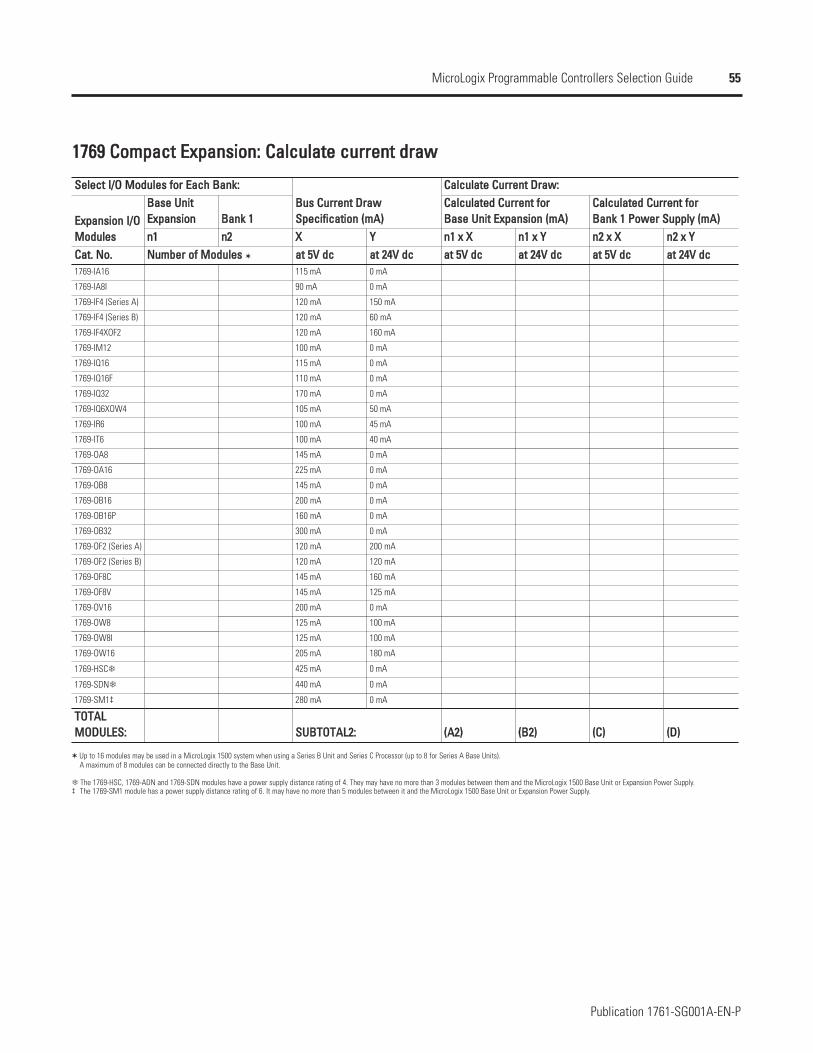
55
Publication 1761-SG001A-EN-P
MicroLogix Programmable Controllers Selection Guide
11776699 CCoommppaacctt EExxppaannssiioonn:: CCaallccuullaattee ccuurrrreenntt ddrraaww
EExxppaannssiioonn II//OOMMoodduulleessCCaatt.. NNoo..1769-IA16
1769-IA8I
1769-IF4 (Series A)
1769-IF4 (Series B)
1769-IF4XOF2
1769-IM12
1769-IQ16
1769-IQ16F
1769-IQ32
1769-IQ6XOW4
1769-IR6
1769-IT6
1769-OA8
1769-OA16
1769-OB8
1769-OB16
1769-OB16P
1769-OB32
1769-OF2 (Series A)
1769-OF2 (Series B)
1769-OF8C
1769-OF8V
1769-OV16
1769-OW8
1769-OW8I
1769-OW16
1769-HSC
1769-SDN
1769-SM1‡
TTOOTTAALL MMOODDUULLEESS::
SSeelleecctt II//OO MMoodduulleess ffoorr EEaacchh BBaannkk::BBuuss CCuurrrreenntt DDrraawwSSppeecciiffiiccaattiioonn ((mmAA))
CCaallccuullaattee CCuurrrreenntt DDrraaww::BBaassee UUnniittEExxppaannssiioonn BBaannkk 11
CCaallccuullaatteedd CCuurrrreenntt ffoorr BBaassee UUnniitt EExxppaannssiioonn ((mmAA))
CCaallccuullaatteedd CCuurrrreenntt ffoorr BBaannkk 11 PPoowweerr SSuuppppllyy ((mmAA))
nn11 nn22 XX YY nn11 xx XX nn11 xx YY nn22 xx XX nn22 xx YYNNuummbbeerr ooff MMoodduulleess aatt 55VV ddcc aatt 2244VV ddcc aatt 55VV ddcc aatt 2244VV ddcc aatt 55VV ddcc aatt 2244VV ddcc
115 mA 0 mA
90 mA 0 mA
120 mA 150 mA
120 mA 60 mA
120 mA 160 mA
100 mA 0 mA
115 mA 0 mA
110 mA 0 mA
170 mA 0 mA
105 mA 50 mA
100 mA 45 mA
100 mA 40 mA
145 mA 0 mA
225 mA 0 mA
145 mA 0 mA
200 mA 0 mA
160 mA 0 mA
300 mA 0 mA
120 mA 200 mA
120 mA 120 mA
145 mA 160 mA
145 mA 125 mA
200 mA 0 mA
125 mA 100 mA
125 mA 100 mA
205 mA 180 mA
425 mA 0 mA
440 mA 0 mA
280 mA 0 mA
SSUUBBTTOOTTAALL22:: ((AA22)) ((BB22)) ((CC)) ((DD))
Up to 16 modules may be used in a MicroLogix 1500 system when using a Series B Unit and Series C Processor (up to 8 for Series A Base Units).A maximum of 8 modules can be connected directly to the Base Unit.
The 1769-HSC, 1769-ADN and 1769-SDN modules have a power supply distance rating of 4. They may have no more than 3 modules between them and the MicroLogix 1500 Base Unit or Expansion Power Supply.‡ The 1769-SM1 module has a power supply distance rating of 6. It may have no more than 5 modules between it and the MicroLogix 1500 Base Unit or Expansion Power Supply.
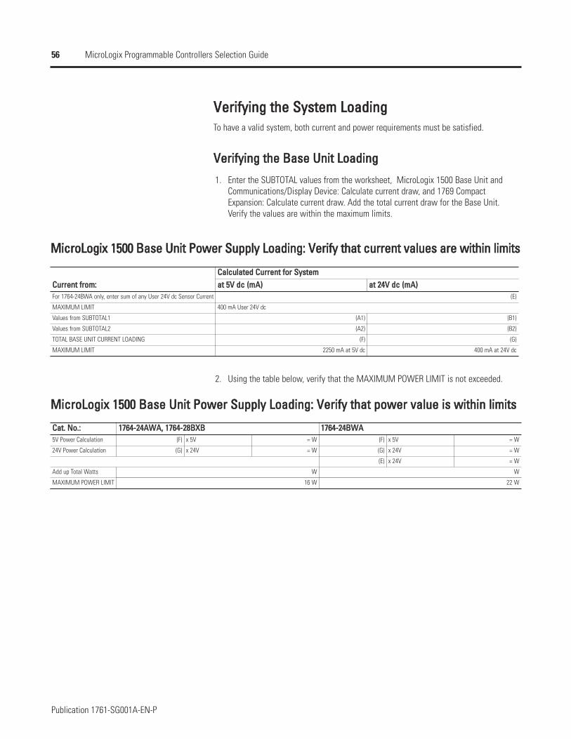
56
Publication 1761-SG001A-EN-P
MicroLogix Programmable Controllers Selection Guide
VVeerriiffyyiinngg tthhee SSyysstteemm LLooaaddiinnggTo have a valid system, both current and power requirements must be satisfied.
VVeerriiffyyiinngg tthhee BBaassee UUnniitt LLooaaddiinngg
1. Enter the SUBTOTAL values from the worksheet, MicroLogix 1500 Base Unit andCommunications/Display Device: Calculate current draw, and 1769 CompactExpansion: Calculate current draw. Add the total current draw for the Base Unit.Verify the values are within the maximum limits.
MMiiccrrooLLooggiixx 11550000 BBaassee UUnniitt PPoowweerr SSuuppppllyy LLooaaddiinngg:: VVeerriiffyy tthhaatt ccuurrrreenntt vvaalluueess aarree wwiitthhiinn lliimmiittss
2. Using the table below, verify that the MAXIMUM POWER LIMIT is not exceeded.
MMiiccrrooLLooggiixx 11550000 BBaassee UUnniitt PPoowweerr SSuuppppllyy LLooaaddiinngg:: VVeerriiffyy tthhaatt ppoowweerr vvaalluuee iiss wwiitthhiinn lliimmiittss
CCaatt.. NNoo..::5V Power Calculation
24V Power Calculation
Add up Total Watts
MAXIMUM POWER LIMIT
11776644--2244AAWWAA,, 11776644--2288BBXXBB 11776644--2244BBWWAA(F) x 5V = W (F) x 5V = W
(G) x 24V = W (G) x 24V = W
(E) x 24V = W
W W
16 W 22 W
CCuurrrreenntt ffrroomm::CCaallccuullaatteedd CCuurrrreenntt ffoorr SSyysstteemmaatt 55VV ddcc ((mmAA)) aatt 2244VV ddcc ((mmAA))
For 1764-24BWA only, enter sum of any User 24V dc Sensor Current (E)
MAXIMUM LIMIT 400 mA User 24V dc
Values from SUBTOTAL1 (A1) (B1)
Values from SUBTOTAL2 (A2) (B2)
TOTAL BASE UNIT CURRENT LOADING (F) (G)
MAXIMUM LIMIT 2250 mA at 5V dc 400 mA at 24V dc
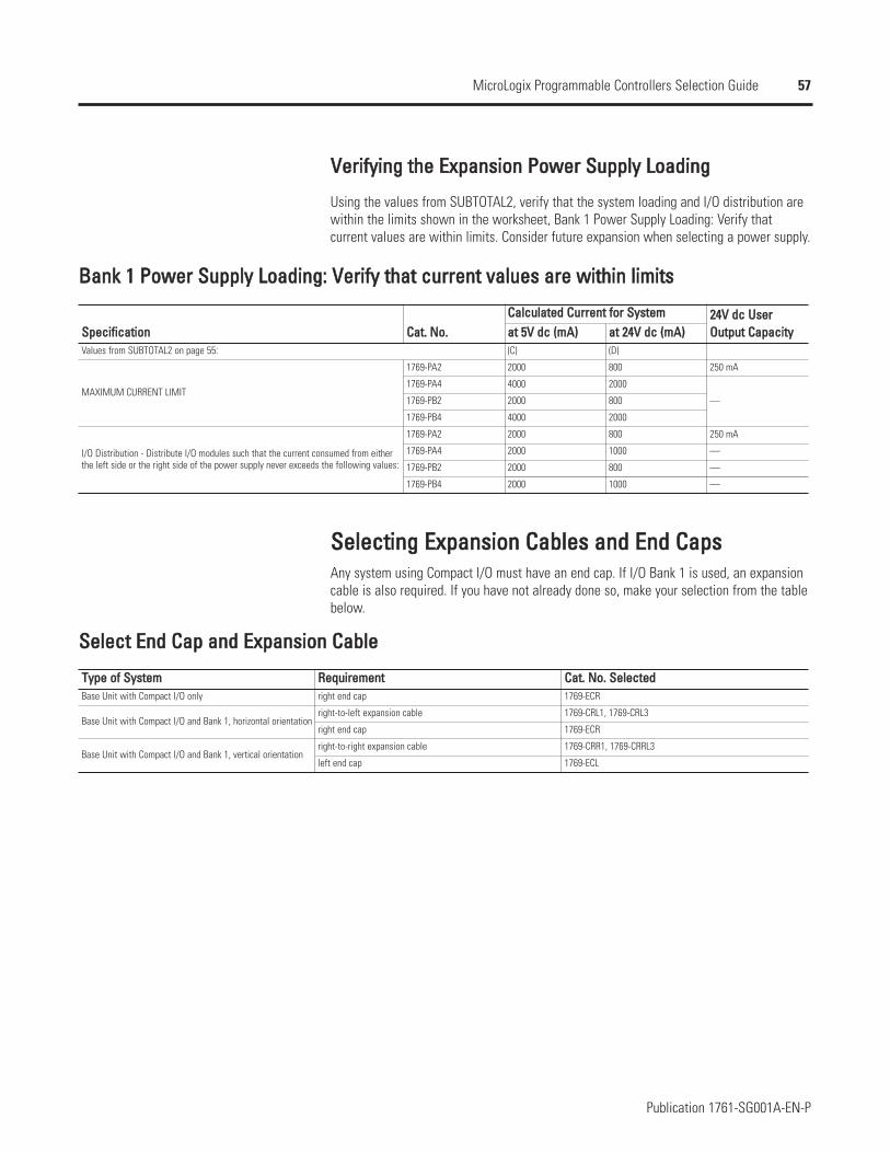
57
Publication 1761-SG001A-EN-P
MicroLogix Programmable Controllers Selection Guide
VVeerriiffyyiinngg tthhee EExxppaannssiioonn PPoowweerr SSuuppppllyy LLooaaddiinngg
Using the values from SUBTOTAL2, verify that the system loading and I/O distribution arewithin the limits shown in the worksheet, Bank 1 Power Supply Loading: Verify thatcurrent values are within limits. Consider future expansion when selecting a power supply.
BBaannkk 11 PPoowweerr SSuuppppllyy LLooaaddiinngg:: VVeerriiffyy tthhaatt ccuurrrreenntt vvaalluueess aarree wwiitthhiinn lliimmiittss
SSppeecciiffiiccaattiioonn
MAXIMUM CURRENT LIMIT
I/O Distribution - Distribute I/O modules such that the current consumed from either the left side or the right side of the power supply never exceeds the following values:
CCaatt.. NNoo..CCaallccuullaatteedd CCuurrrreenntt ffoorr SSyysstteemm 2244VV ddcc UUsseerr
OOuuttppuutt CCaappaacciittyyaatt 55VV ddcc ((mmAA)) aatt 2244VV ddcc ((mmAA))Values from SUBTOTAL2 on page 55: (C) (D)
1769-PA2 2000 800 250 mA
1769-PA4 4000 2000
—1769-PB2 2000 800
1769-PB4 4000 2000
1769-PA2 2000 800 250 mA
1769-PA4 2000 1000 —
1769-PB2 2000 800 —
1769-PB4 2000 1000 —
SSeelleeccttiinngg EExxppaannssiioonn CCaabblleess aanndd EEnndd CCaappssAny system using Compact I/O must have an end cap. If I/O Bank 1 is used, an expansioncable is also required. If you have not already done so, make your selection from the tablebelow.
SSeelleecctt EEnndd CCaapp aanndd EExxppaannssiioonn CCaabbllee
TTyyppee ooff SSyysstteemm RReeqquuiirreemmeenntt CCaatt.. NNoo.. SSeelleecctteeddBase Unit with Compact I/O only right end cap 1769-ECR
Base Unit with Compact I/O and Bank 1, horizontal orientationright-to-left expansion cable 1769-CRL1, 1769-CRL3
right end cap 1769-ECR
Base Unit with Compact I/O and Bank 1, vertical orientationright-to-right expansion cable 1769-CRR1, 1769-CRRL3
left end cap 1769-ECL
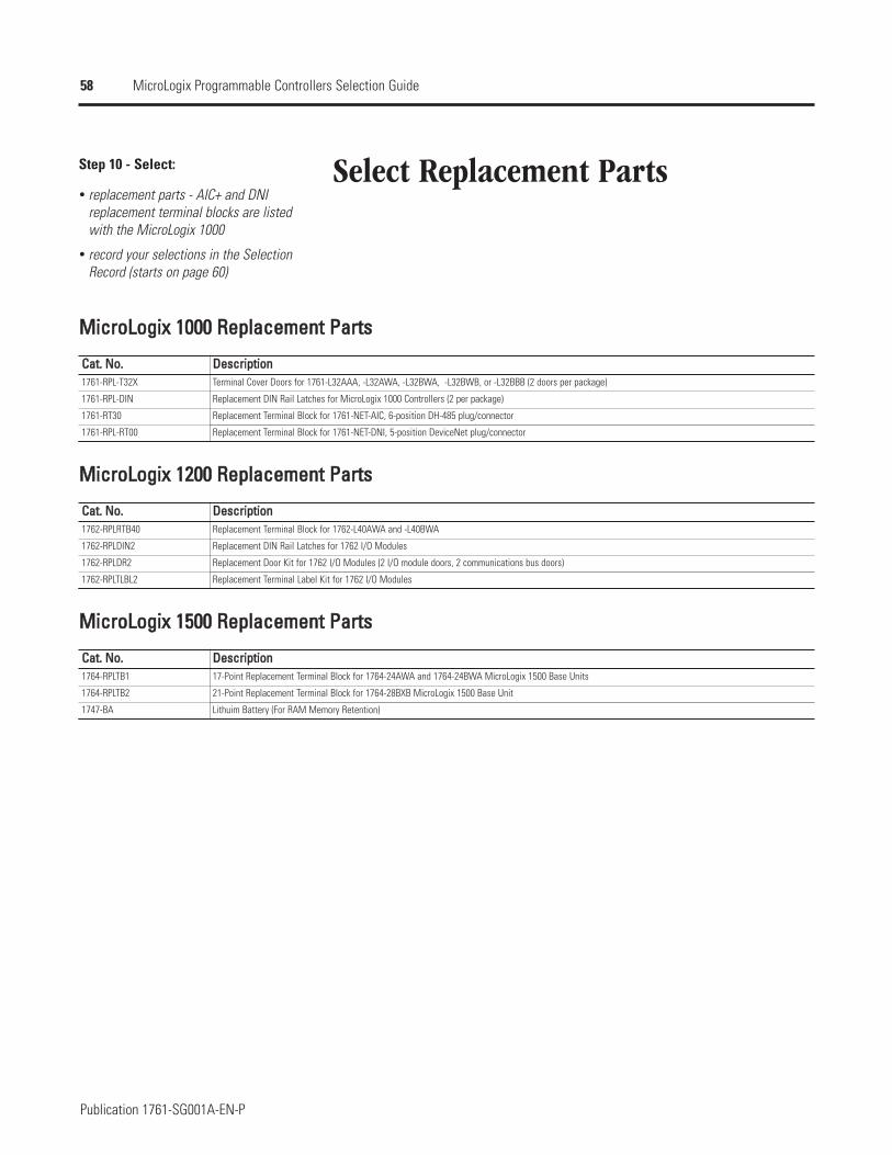
58
Publication 1761-SG001A-EN-P
MicroLogix Programmable Controllers Selection Guide
Select Replacement PartsStep 10 - Select:
replacement parts - AIC+ and DNIreplacement terminal blocks are listedwith the MicroLogix 1000
record your selections in the SelectionRecord (starts on page 60)
MMiiccrrooLLooggiixx 11000000 RReeppllaacceemmeenntt PPaarrttss
CCaatt.. NNoo..1761-RPL-T32X
1761-RPL-DIN
1761-RT30
1761-RPL-RT00
DDeessccrriippttiioonnTerminal Cover Doors for 1761-L32AAA, -L32AWA, -L32BWA, -L32BWB, or -L32BBB (2 doors per package)
Replacement DIN Rail Latches for MicroLogix 1000 Controllers (2 per package)
Replacement Terminal Block for 1761-NET-AIC, 6-position DH-485 plug/connector
Replacement Terminal Block for 1761-NET-DNI, 5-position DeviceNet plug/connector
MMiiccrrooLLooggiixx 11220000 RReeppllaacceemmeenntt PPaarrttss
CCaatt.. NNoo..1762-RPLRTB40
1762-RPLDIN2
1762-RPLDR2
1762-RPLTLBL2
DDeessccrriippttiioonnReplacement Terminal Block for 1762-L40AWA and -L40BWA
Replacement DIN Rail Latches for 1762 I/O Modules
Replacement Door Kit for 1762 I/O Modules (2 I/O module doors, 2 communications bus doors)
Replacement Terminal Label Kit for 1762 I/O Modules
MMiiccrrooLLooggiixx 11550000 RReeppllaacceemmeenntt PPaarrttss
CCaatt.. NNoo..1764-RPLTB1
1764-RPLTB2
1747-BA
DDeessccrriippttiioonn17-Point Replacement Terminal Block for 1764-24AWA and 1764-24BWA MicroLogix 1500 Base Units
21-Point Replacement Terminal Block for 1764-28BXB MicroLogix 1500 Base Unit
Lithuim Battery (For RAM Memory Retention)

59
Publication 1761-SG001A-EN-P
MicroLogix Programmable Controllers Selection Guide
Select Training and Promotional Products
Step 11 - Select:
training and promotional products -starter paks, demo units and simulators
record your selection in the SelectionRecord (starts on page 60)
TTrraaiinniinngg aanndd PPrroommoottiioonnaall PPrroodduuccttss ffoorr MMiiccrrooLLooggiixx 11000000,, 11220000 aanndd 11550000
DDeessccrriippttiioonnMicroMentor Basics Book: Provides an introduction to understanding and applying PLC fundamentals.
MicroLogix 1000 RSLogix Starter Pak includes: 1761-L16BWA controller; 9324-RL0100ENE (RSLogix Starter Programming Software); 1761-CBL-PM02 PC-to-controller cable; 1761-SIM-B16 input switch simulator; user documentation
MicroLogix 1000 10-Point Controller Starter Pak includes: 1761-L16BWA controller; RSLogix 500 Starter Software for 10-Point MicroLogix Controllers; RSLinx Lite;1761-CBL-PM02 PC-to-controller cable; user documentation
MicroLogix 1200 RSLogix Starter Pak includes: 1762-L24BWA controller; 9324-RL0100ENE (RSLogix Starter Programming Software); 1761-CBL-PM02 PC-to-controller cable; 1796-SIM1200 input switch simulator; user documentation
MicroLogix 1500 RSLogix Starter Pak includes: 1764-LSP processor; 1764-24BWA base unit; 9324-RL0100ENE (RSLogix Starter Programming Software); 1764-CBL-PM02 PC-to-controller cable; 1796-SIM1500 input switch simulator; 1764-MM1RTC memory module and real-time clock; user documentation
MicroLogix 1500 RSLogix Starter Pak includes: 1764-LRP processor; 1764-24BWA base unit; 9324-RL0100ENE (RSLogix Starter Programming Software); 1764-CBL-PM02 PC-to-controller cable; 1796-SIM1500 input switch simulator; 1764-MM1RTC memory module and real-time clock; user documentation
MicroLogix 1000 Integrated Demonstration Unit includes: 1761-L20BWA-5A controller; 1761-NET-AIC DH-485 Interface; 1761-NET-DNI DeviceNet Interface;quadrature encoder; 4 selector switches; 8 illuminated pushbuttons; 1 potentiometer; 1 analog meter
MicroLogix 1500 Integrated Demonstration Unit includes: 1764-28BXB base unit; 1764-LSP processor unit; 1769-IF4 Analog Input Module; 1769-OF2 Analog OutputModule;1761-NET-AIC DH-485 Interface Module; 1761-NET-DNI DeviceNet Interface Module; quadrature encoder; 4 selector switches; 8 illuminated pushbuttons;1 potentiometer; 1 analog meter; 1 frequency meter
MicroLogix 1000 Input Simulator. For use with 1761-L16BWA MicroLogix 1000 Programmable Controller.
MicroLogix 1200 Input Simulator. For use with 1762-L24BWA and 1762-L24BXB controllers.
MicroLogix 1500 Input Simulator. For use with 1764-24BWA and 1764-28BXB base units.
MicroLogix 1200/PanelView 300 Micro Integrated Demonstration Unit includes: 1762-L24BWA, 2711-M3A18L1, inductive proximity switch, photo-electric sensor,programming cable.
CCaatt.. NNoo..1761-MMB
1761-L16BWA-R1E
1761-START1000E
1762-START1200E
1764-START1500E
1764-START1500RE
1796-MICRO1
1796-MICRO151(Series B)
1761-SIM-B16
1761-SIM1200
1796-SIM1500
1796-PV300MICRO1
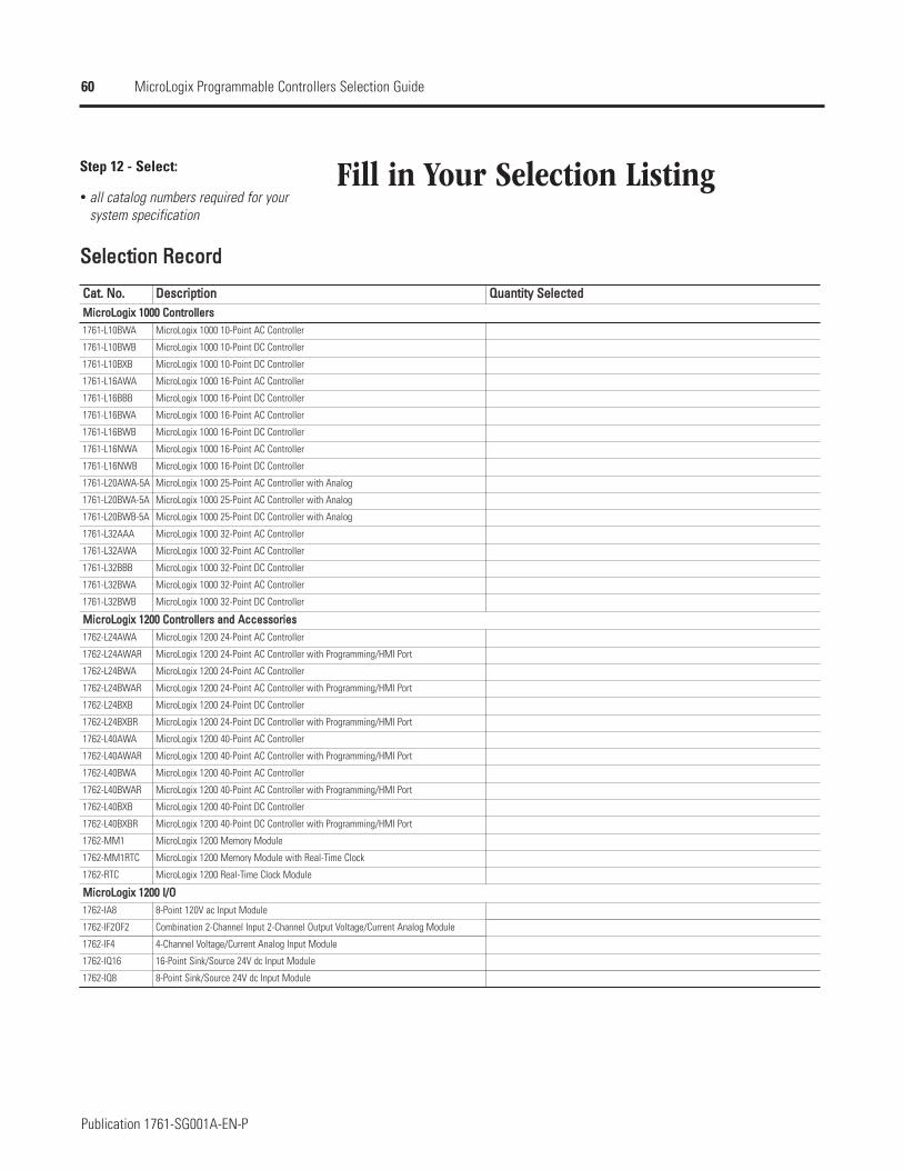
60
Publication 1761-SG001A-EN-P
MicroLogix Programmable Controllers Selection Guide
Fill in Your Selection ListingStep 12 - Select:
all catalog numbers required for yoursystem specification
SSeelleeccttiioonn RReeccoorrdd
CCaatt.. NNoo..
1761-L10BWA
1761-L10BWB
1761-L10BXB
1761-L16AWA
1761-L16BBB
1761-L16BWA
1761-L16BWB
1761-L16NWA
1761-L16NWB
1761-L20AWA-5A
1761-L20BWA-5A
1761-L20BWB-5A
1761-L32AAA
1761-L32AWA
1761-L32BBB
1761-L32BWA
1761-L32BWB
1762-L24AWA
1762-L24AWAR
1762-L24BWA
1762-L24BWAR
1762-L24BXB
1762-L24BXBR
1762-L40AWA
1762-L40AWAR
1762-L40BWA
1762-L40BWAR
1762-L40BXB
1762-L40BXBR
1762-MM1
1762-MM1RTC
1762-RTC
1762-IA8
1762-IF2OF2
1762-IF4
1762-IQ16
1762-IQ8
DDeessccrriippttiioonn QQuuaannttiittyy SSeelleecctteeddMMiiccrrooLLooggiixx 11000000 CCoonnttrroolllleerrss
MicroLogix 1000 10-Point AC Controller
MicroLogix 1000 10-Point DC Controller
MicroLogix 1000 10-Point DC Controller
MicroLogix 1000 16-Point AC Controller
MicroLogix 1000 16-Point DC Controller
MicroLogix 1000 16-Point AC Controller
MicroLogix 1000 16-Point DC Controller
MicroLogix 1000 16-Point AC Controller
MicroLogix 1000 16-Point DC Controller
MicroLogix 1000 25-Point AC Controller with Analog
MicroLogix 1000 25-Point AC Controller with Analog
MicroLogix 1000 25-Point DC Controller with Analog
MicroLogix 1000 32-Point AC Controller
MicroLogix 1000 32-Point AC Controller
MicroLogix 1000 32-Point DC Controller
MicroLogix 1000 32-Point AC Controller
MicroLogix 1000 32-Point DC Controller
MMiiccrrooLLooggiixx 11220000 CCoonnttrroolllleerrss aanndd AAcccceessssoorriieessMicroLogix 1200 24-Point AC Controller
MicroLogix 1200 24-Point AC Controller with Programming/HMI Port
MicroLogix 1200 24-Point AC Controller
MicroLogix 1200 24-Point AC Controller with Programming/HMI Port
MicroLogix 1200 24-Point DC Controller
MicroLogix 1200 24-Point DC Controller with Programming/HMI Port
MicroLogix 1200 40-Point AC Controller
MicroLogix 1200 40-Point AC Controller with Programming/HMI Port
MicroLogix 1200 40-Point AC Controller
MicroLogix 1200 40-Point AC Controller with Programming/HMI Port
MicroLogix 1200 40-Point DC Controller
MicroLogix 1200 40-Point DC Controller with Programming/HMI Port
MicroLogix 1200 Memory Module
MicroLogix 1200 Memory Module with Real-Time Clock
MicroLogix 1200 Real-Time Clock Module
MMiiccrrooLLooggiixx 11220000 II//OO8-Point 120V ac Input Module
Combination 2-Channel Input 2-Channel Output Voltage/Current Analog Module
4-Channel Voltage/Current Analog Input Module
16-Point Sink/Source 24V dc Input Module
8-Point Sink/Source 24V dc Input Module
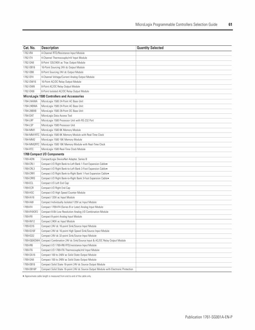
61
Publication 1761-SG001A-EN-P
MicroLogix Programmable Controllers Selection Guide
CCaatt.. NNoo.. DDeessccrriippttiioonn QQuuaannttiittyy SSeelleecctteedd1762-IR4 4-Channel RTD/Resistance Input Module
1762-IT4 4-Channel Thermocouple/mV Input Module
1762-OA8 8-Point 120/240V ac Triac Output Module
1762-OB16 16-Point Sourcing 24V dc Output Module
1762-OB8 8-Point Sourcing 24V dc Output Module
1762-OF4 4-Channel Voltage/Current Analog Output Module
1762-OW16 16-Point AC/DC Relay Output Module
1762-OW8 8-Point AC/DC Relay Output Module
1762-OX6I 6-Point Isolated AC/DC Relay Output Module
MMiiccrrooLLooggiixx 11550000 CCoonnttrroolllleerrss aanndd AAcccceessssoorriieess1764-24AWA MicroLogix 1500 24-Point AC Base Unit
1764-24BWA MicroLogix 1500 24-Point AC Base Unit
1764-28BXB MicroLogix 1500 28-Point DC Base Unit
1764-DAT MicroLogix Data Access Tool
1764-LRP MicroLogix 1500 Processor Unit with RS-232 Port
1764-LSP MicroLogix 1500 Processor Unit
1764-MM1 MicroLogix 1500 8K Memory Module
1764-MM1RTC MicroLogix 1500 8K Memory Module with Real-Time Clock
1764-MM2 MicroLogix 1500 16K Memory Module
1764-MM2RTC MicroLogix 1500 16K Memory Module with Real-Time Clock
1764-RTC MicroLogix 1500 Real-Time Clock Module
11776699 CCoommppaacctt II//OO CCoommppoonneennttss1769-ADN CompactLogix DeviceNet Adapter, Series B
1769-CRL1 Compact I/O Right Bank-to-Left Bank 1-Foot Expansion Cable
1769-CRL3 Compact I/O Right Bank-to-Left Bank 3-Foot Expansion Cable
1769-CRR1 Compact I/O Right Bank-to-Right Bank 1-Foot Expansion Cable
1769-CRR3 Compact I/O Right Bank-to-Right Bank 3-Foot Expansion Cable
1769-ECL Compact I/O Left End Cap
1769-ECR Compact I/O Right End Cap
1769-HSC Compact I/O High Speed Counter Module
1769-IA16 Compact 120V ac Input Module
1769-IA8I Compact Individually Isolated 120V ac Input Module
1769-IF4 Compact 1769-IF4 (Series B or Later) Analog Input Module
1769-IF4XOF2 Compact 8-Bit Low Resolution Analog I/O Combination Module
1769-IF8 Compact 8-point Analog Input Module
1769-IM12 Compact 240V ac Input Module
1769-IQ16 Compact 24V dc 16-point Sink/Source Input Module
1769-IQ16F Compact 24V dc 16-point High Speed Sink/Source Input Module
1769-IQ32 Compact 24V dc 32-point Sink/Source Input Module
1769-IQ6XOW4 Compact Combination 24V dc Sink/Source Input & AC/DC Relay Output Module
1769-IR6 Compact I/O 1769-IR6 RTD/resistance Input Module
1769-IT6 Compact I/O 1769-IT6 Thermocouple/mV Input Module
1769-OA16 Compact 100 to 240V ac Solid State Output Module
1769-OA8 Compact 100 to 240V ac Solid State Output Module
1769-OB16 Compact Solid State 16-point 24V dc Source Output Module
1769-OB16P Compact Solid State 16-point 24V dc Source Output Module with Electronic Protection
Approximate cable length is measured from end-to-end of the cable only.
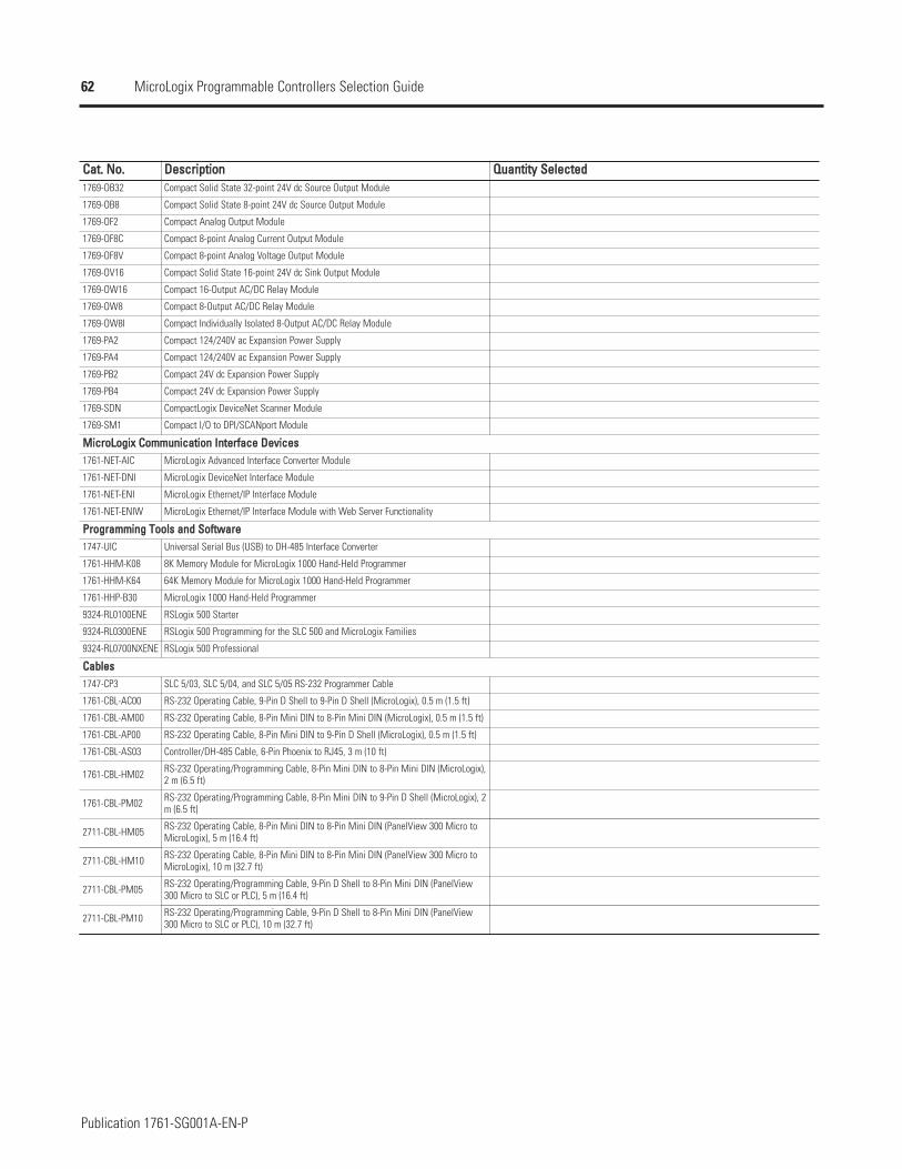
62
Publication 1761-SG001A-EN-P
MicroLogix Programmable Controllers Selection Guide
CCaatt.. NNoo.. DDeessccrriippttiioonn QQuuaannttiittyy SSeelleecctteedd1769-OB32 Compact Solid State 32-point 24V dc Source Output Module
1769-OB8 Compact Solid State 8-point 24V dc Source Output Module
1769-OF2 Compact Analog Output Module
1769-OF8C Compact 8-point Analog Current Output Module
1769-OF8V Compact 8-point Analog Voltage Output Module
1769-OV16 Compact Solid State 16-point 24V dc Sink Output Module
1769-OW16 Compact 16-Output AC/DC Relay Module
1769-OW8 Compact 8-Output AC/DC Relay Module
1769-OW8I Compact Individually Isolated 8-Output AC/DC Relay Module
1769-PA2 Compact 124/240V ac Expansion Power Supply
1769-PA4 Compact 124/240V ac Expansion Power Supply
1769-PB2 Compact 24V dc Expansion Power Supply
1769-PB4 Compact 24V dc Expansion Power Supply
1769-SDN CompactLogix DeviceNet Scanner Module
1769-SM1 Compact I/O to DPI/SCANport Module
MMiiccrrooLLooggiixx CCoommmmuunniiccaattiioonn IInntteerrffaaccee DDeevviicceess1761-NET-AIC MicroLogix Advanced Interface Converter Module
1761-NET-DNI MicroLogix DeviceNet Interface Module
1761-NET-ENI MicroLogix Ethernet/IP Interface Module
1761-NET-ENIW MicroLogix Ethernet/IP Interface Module with Web Server Functionality
PPrrooggrraammmmiinngg TToooollss aanndd SSooffttwwaarree1747-UIC Universal Serial Bus (USB) to DH-485 Interface Converter
1761-HHM-K08 8K Memory Module for MicroLogix 1000 Hand-Held Programmer
1761-HHM-K64 64K Memory Module for MicroLogix 1000 Hand-Held Programmer
1761-HHP-B30 MicroLogix 1000 Hand-Held Programmer
9324-RL0100ENE RSLogix 500 Starter
9324-RL0300ENE RSLogix 500 Programming for the SLC 500 and MicroLogix Families
9324-RL0700NXENE RSLogix 500 Professional
CCaabblleess1747-CP3 SLC 5/03, SLC 5/04, and SLC 5/05 RS-232 Programmer Cable
1761-CBL-AC00 RS-232 Operating Cable, 9-Pin D Shell to 9-Pin D Shell (MicroLogix), 0.5 m (1.5 ft)
1761-CBL-AM00 RS-232 Operating Cable, 8-Pin Mini DIN to 8-Pin Mini DIN (MicroLogix), 0.5 m (1.5 ft)
1761-CBL-AP00 RS-232 Operating Cable, 8-Pin Mini DIN to 9-Pin D Shell (MicroLogix), 0.5 m (1.5 ft)
1761-CBL-AS03 Controller/DH-485 Cable, 6-Pin Phoenix to RJ45, 3 m (10 ft)
1761-CBL-HM02 RS-232 Operating/Programming Cable, 8-Pin Mini DIN to 8-Pin Mini DIN (MicroLogix),2 m (6.5 ft)
1761-CBL-PM02 RS-232 Operating/Programming Cable, 8-Pin Mini DIN to 9-Pin D Shell (MicroLogix), 2m (6.5 ft)
2711-CBL-HM05 RS-232 Operating Cable, 8-Pin Mini DIN to 8-Pin Mini DIN (PanelView 300 Micro toMicroLogix), 5 m (16.4 ft)
2711-CBL-HM10 RS-232 Operating Cable, 8-Pin Mini DIN to 8-Pin Mini DIN (PanelView 300 Micro toMicroLogix), 10 m (32.7 ft)
2711-CBL-PM05 RS-232 Operating/Programming Cable, 9-Pin D Shell to 8-Pin Mini DIN (PanelView300 Micro to SLC or PLC), 5 m (16.4 ft)
2711-CBL-PM10 RS-232 Operating/Programming Cable, 9-Pin D Shell to 8-Pin Mini DIN (PanelView300 Micro to SLC or PLC), 10 m (32.7 ft)
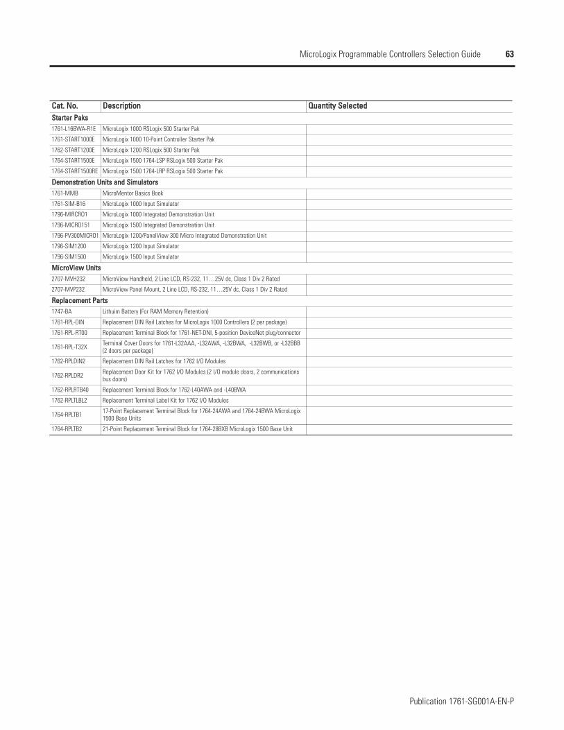
63
Publication 1761-SG001A-EN-P
MicroLogix Programmable Controllers Selection Guide
CCaatt.. NNoo.. DDeessccrriippttiioonn QQuuaannttiittyy SSeelleecctteeddSSttaarrtteerr PPaakkss1761-L16BWA-R1E MicroLogix 1000 RSLogix 500 Starter Pak
1761-START1000E MicroLogix 1000 10-Point Controller Starter Pak
1762-START1200E MicroLogix 1200 RSLogix 500 Starter Pak
1764-START1500E MicroLogix 1500 1764-LSP RSLogix 500 Starter Pak
1764-START1500RE MicroLogix 1500 1764-LRP RSLogix 500 Starter Pak
DDeemmoonnssttrraattiioonn UUnniittss aanndd SSiimmuullaattoorrss1761-MMB MicroMentor Basics Book
1761-SIM-B16 MicroLogix 1000 Input Simulator
1796-MIRCRO1 MicroLogix 1000 Integrated Demonstration Unit
1796-MICRO151 MicroLogix 1500 Integrated Demonstration Unit
1796-PV300MICRO1 MicroLogix 1200/PanelView 300 Micro Integrated Demonstration Unit
1796-SIM1200 MicroLogix 1200 Input Simulator
1796-SIM1500 MicroLogix 1500 Input Simulator
MMiiccrrooVViieeww UUnniittss2707-MVH232 MicroView Handheld, 2 Line LCD, RS-232, 11…25V dc, Class 1 Div 2 Rated
2707-MVP232 MicroView Panel Mount, 2 Line LCD, RS-232, 11…25V dc, Class 1 Div 2 Rated
RReeppllaacceemmeenntt PPaarrttss1747-BA Lithuim Battery (For RAM Memory Retention)
1761-RPL-DIN Replacement DIN Rail Latches for MicroLogix 1000 Controllers (2 per package)
1761-RPL-RT00 Replacement Terminal Block for 1761-NET-DNI, 5-position DeviceNet plug/connector
1761-RPL-T32X Terminal Cover Doors for 1761-L32AAA, -L32AWA, -L32BWA, -L32BWB, or -L32BBB(2 doors per package)
1762-RPLDIN2 Replacement DIN Rail Latches for 1762 I/O Modules
1762-RPLDR2 Replacement Door Kit for 1762 I/O Modules (2 I/O module doors, 2 communicationsbus doors)
1762-RPLRTB40 Replacement Terminal Block for 1762-L40AWA and -L40BWA
1762-RPLTLBL2 Replacement Terminal Label Kit for 1762 I/O Modules
1764-RPLTB1 17-Point Replacement Terminal Block for 1764-24AWA and 1764-24BWA MicroLogix1500 Base Units
1764-RPLTB2 21-Point Replacement Terminal Block for 1764-28BXB MicroLogix 1500 Base Unit
Publication 1761-SG001A-EN-P – August 2004 Copyright © 2004 Rockwell Automation, Inc. All rights reserved. Printed in USA.
www.rockwellautomation.com
Corporate HeadquartersRockwell Automation, 777 East Wisconsin Avenue, Suite 1400, Milwaukee, WI, 53202-5302 USA, Tel: (1) 414.212.5200, Fax: (1) 414.212.5201
Headquarters for Allen-Bradley Products, Rockwell Software Products and Globbal Manufacturing SolutionsAmericas: Rockwell Automation, 1201 South Second Street, Milwaukee, WI 53204-2496 USA, Tel: (1) 414.382.2000, Fax: (1) 414.382.4444Europe: Rockwell Automation SA/NV, Vorstlaan/Boulevard du Souverain 36-BP 3A/B, 1170 Brussels, Belgium, Tel: (32) 2 663 0600, Fax: (32) 2 663 0640Asia Pacific: Rockwell Automation, 27/F Citicorp Centre, 18 Whitfield Road, Causeway Bay, Hong Kong, Tel: (852) 2887 4788, Fax: (852) 2508 1846
Headquarters for Dodge and Reliance Electric ProductsAmericas: Rockwell Automation, 6040 Ponders Court, Greenville, SC 29615-4617 USA, Tel: (1) 864.297.4800, Fax: (1) 864.281.2433Europe: Rockwell Automation, Brühlstraße 22, D-74834 Elztal-Dallau, Germany, Tel: (49) 6261 9410, Fax: (49) 6261 1774Asia Pacific: Rockwell Automation, 55 Newton Road, #11-01/02 Revenue House, Singapore 307987, Tel: (65) 351 6723, Fax: (65) 355 1733
MicroLogix, SLC and RSLogix are trademarks of Rockwell Automation, Inc.
Rockwell Automation SupportRockwell Automation provides technical information on the web to assist you in using our products. Athttp://support.rockwellautomation.com, you can find technical manuals, a knowledge base of FAQs, technical and application notes,sample code and links to software service packs, and a MySupport feature that you can customize to make the best use of these tools.
For an additional level of technical phone support for installation, configuration and troubleshooting, we offer TechConnect Supportprograms. For more information, contact your local distributor or Rockwell Automation representative, or visithttp://support.rockwellautomation.com.
Installation AssistanceIf you experience a problem with a hardware module within the first 24 hours of installation, please review the information that iscontained in this manual. You can also contact a special Customer Support number for initial help in getting your module up and running.
United States
Outside United States
1.440.646.3223Monday - Friday, 8am - 5 pm EST
Please contact your local Rockwell Automation representative for any technical support issues.
New Product Satisfaction ReturnWe test all of our products to ensure that they are fully operational when shipped from the manufacturing facility. However, if yourproduct is not functioning and needs to be returned:
United States
Outside United States
Contact your distributor. You must provide a Customer Support case number (see phone number above to obtain one) to your distributor in order to complete the return process.
Please contact your local Rockwell Automation representative for return procedure.