Embed Size (px)
Citation preview
1918 DATA CATALOG
GENERAL INSTRUMENT CORPORATION. MICROELeCTRONICS
55.00emOMlo.00..~
C/CF-S80 SERIESC/CF-S90 SERIESC/CF-680 SERIES
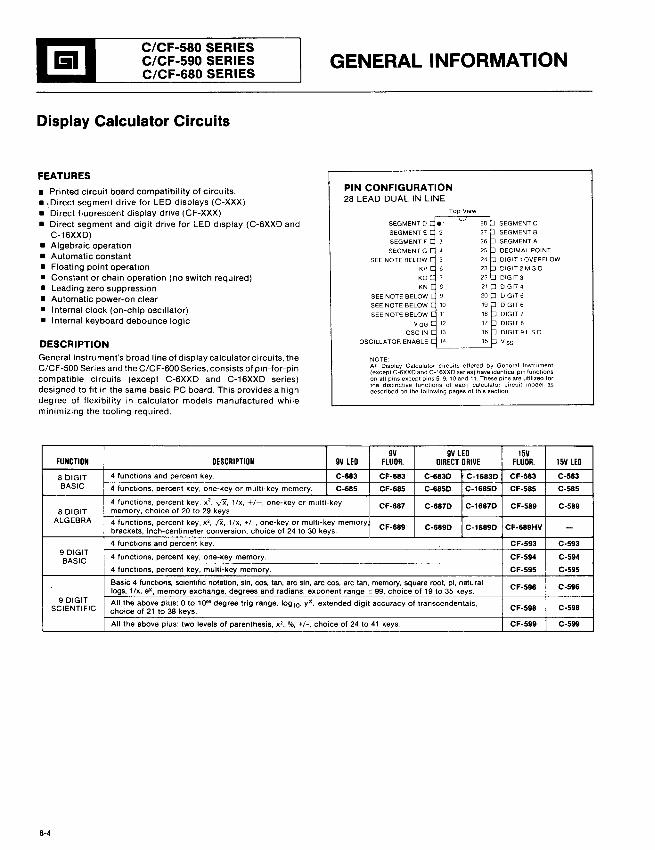
Display Calculator Circuits
FEATURES
GENERAL INFORMATION
NOTEAll Display Calculator circuits offered by General Instrument(except C-6XXD and C-16XXD series) have identical pin functionson all pins except pins 5, 9, 10 and 11. These pins are utilized forthe distinctive functions of each calculator circuit model asdescribed on the following pages of this section
• Printed circuit board compatibility of circuits.• I Direct segment drive for LED displays (C-XXX)• Direct fluorescent display drive (CF-XXX)• Direct segment and digit drive for LED display (C-6XXD and
C-16XXD)• Algebraic operation• Automatic constant• Floating point operation• Constant or chain operation (no switch required)• Leading zero suppression• Automatic power-on clear• Internal clock (on-chip oscillator)• Internal keyboard debounce logic
DESCRIPTIONGeneral Instrument's broad line of display calculator circuits. theC/CF-SOO Series and the C/CF-600 Series, consists of pin-for-pincompatible circuits (except C-6XXD and C-16XXD series)designed to fit in the same basic PC board. This provides a highdegree of flexibility in calculator models manufactured whileminimizing the tooling required.
PIN CONFIGURATION28 LEAD DUAL IN LINE
SEGMENT D
SEGMENT E
SEGMENT F
SEGMENT G
SEE NOTE BELOW
KP
KO
KN
SEE NOTE BELOW
SEE NOTE BELOW
SEE NOTE BELOW
vGG
OSC IN
OSCILLATOR ENABLE
SEGMENT C
SEGMENT 8
SEGMENT A
DECIMAL POINT
DIGIT 1 OVERFLOW
DIGIT 2 M.S.D
0lGIT3
DIGIT 4
DIGIT 5
0lGIT6
DIGIT 7
DIGIT 8
DIGIT 9 LSD
V 55
9Y 9Y LED 15YFUNCTION DESCRIPTION 9Y LED FLUOR. DIRECT DRIYE FLUOR. 15Y LED
B blGIT 4 functions and percent key. C-683 CF-683 C-683D C-1683D CF-583 C-583BASIC 4 functions, percent key, one-key or multi-key memory. C-685 CF-685 C-685D C-1685D CF-585 C-585
4 functions, percent key, x2, ",IX, 1/x, +/-, one-key or multi-key CF-687 C-687D C-1687D CF-589 C-589
B DIGIT memory, choice of 20 to 29 keys.ALGEBRA 4 functions, percent key, x2, IX. 1/x, +/-, one-key or multi-key memory
brackets, inch-centimeter conversion, choice of 24 to 30 keys. CF-689 C-689D C-1689D CF-689HV -4 functions and percent key. CF-593 C-593
9 DIGIT 4 functions, percent key, one-key memory. CF·594 C-594BASIC4 functions, percent key, multi-key memory. CF-595 C-595
Basic 4 functions, scientific notation, sin, cos, tan, arc sin, arc cos, arc tan, memory, square root. pi, naturalCF-596 C-596logs, 1/x, ex, memory exchange, degrees and radians, exponent range:"!: 99, choice of 19 to 35 keys.
9 DIGIT All the above plus: 0 to 1099 degree trig range, log10, yX, extended digit accuracy of transcendentals,SCIENTIFIC choice of 21 to 38 keys. CF-598 C-598
All the above plus: two levels of parenthesis, x2, %, +/-, choice of 24 to 41 keys. CF·599 C-599
8-4
I
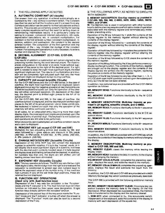
B. MEMORY DESC~lPTION: MUlti-key memory as provided In all algebra, scientific circuits, and C-685D.MR, MEMORY READ: Functions identically to the M = sequenceabove.MC, MEMORY CLEAR: Functions identically to the M C/E sequence above.M+, MEMORY PLUS: Functions identically to the M+ 'sequenceabove.M-, MEMORY MINUS: Functions identically to the M- sequenceabove.MEX, MEMORY EXCHANGE: Functions identically to the MXsequence above.
In addition, the C/CF-589 are provided with a STORE key whichtransfers the contents of the display to memory without changingthe display.
C. MEMORY DESCRIPTION: Multi-key memory as provided In C/CF-585, 595 and 685.MC, MEMORY CLEAR: clears the memory while leaving thedisplay intact.MR, MEMORY READ: transfers the data in memory to the displaywithout changing the memory.M'j:,MEMORY EQUALS/PLUS: completes the preceding operation, displays the result, and adds the result to the memory.M=,MEMORY EQUALS/MINUS:completes the preceding operationl, displays the result and subtracts the result from thememory.
In addition, the C/CF-585 and C/CF-685 are provided with a MEX(Memory Exchange) Key which functions as previously described.
The C/CF-595 is provided with the following additional memorykeys:
MR/MC, MEMORY READ/MEMORY CLEAR: this single key operation transfers the memory data to the display on the firstdepression. When depressed two successive times, the memorydata is transferred to the display and the memory cleared.l, SUM KEY: when connected to Vss, this accumulate switch,independent of the keyboard, adds the contents of the display tomemory with each depression of the equals key.
MR, MEMORY READ: Functions identically to the M = sequenceabove.MC, MEMORY CLEAR: Functions identically to the M C/CEseq uence above.
C/CF-580 SERIES • C/CF-590 SERIES • C/CF-680 SERIES I!ln THE FOLLOWING APPLY AS NOTED TO CIRCUITSWITH MEMORY:A. MEMORY DESCRIPTION: One-Key memory as provided InC/CF-585, 589, 594, 685, C-6850, 6870, 6890, 16850, 16870,16890, and CF-689.M: The Memory key is used in conjunction with other functionkeys to define a two key sequence which sets a mode of operationassociated with the memory register and terminates any immediately preceding entry.Operation of the M key followed by + adds the contents of thedisplay register to the memory register without altering thecontents of the display register.Operation of the M key followed by - subtracts the contents ofthe display register without altering the contents of the displayregister.Operation olthe M key followed by= transfers the contents of thememory register into the display register without altering thecontents of the memory register.Operation of the M key followed by C/CE clears the contents ofthe memory register.Operation of the M key followed by the X key performs a memorydisplay exchange function. The contents of the memory registerare brought out to the display register and the contents of thedisplay register are written into the memory register, replacingthe previous contents of the memory register.Operation of the M key followed by any key other than +, -, X, =,or C/CE shall reset the M condition and act upon the subsequententry as if the M had not been entered.
In addition, two optional keys are provided with the C/CF-594 foroperation as follows:
I THE FOLLOWING APPLY AS NOTED:
A. AUTOMATIC CONSTANT (All circuits)The answer from any operation is entered automatically as aConstant by the = key without a constant switch. The Constantmay then be used with all five functions and the answer from anyConstant calculation can be used for further calculations withoutre-entry. This provides an extremely powerful facility for solvingmany complex equations without the need for writing down orremembering intermediate results. It is particularly useful forraising to a power, compound interest calculations, nth roots,depreciation calculations, etc. In constant multiplication, theconstant is the first entered number (constant multiplicand). Indivision, addition and subtraction, the constant is the secondentered number. The completion of the first operation with thedepression of the = key initiates the storage of the constantnumber. For subsequent operations it is only necessary to enter anumber and depress the = key.
B. DECIMAL ALIGNMENT (C/CF-593, C/CF-594,C/CF-595)The results of addition or subtraction will remain aligned to thepreceding number having the most decimal places. This featureallows computation in the dollar and cents mode without suppression of the zeros to the right of the decimal point. If a rightshift is needed to keep the eight most significant digits, the leastsignificant digits are lost. The results of multiplication and division will be completely right adjusted such that only the mostsignificant digits are displayed except during overflow.
C. CAPACITY (All except Scientific Circuits)For the C/CF-580 Series and the C/CF-~80Series, in the case ofoverflow, the eight most significant digits are displayed (sevendigits and minus sign for negative answers) all decimal points arelit and the keyboard is locked out. Only the operation of the clearkey will allow continued operation. On depression of the clearkey, the decimal point is shifted eight places to the left of itsactual position.For the C/CF-593, 594 and 595, in the case of overflow, theoverflow symbol is displayed, and the decimal point shifted eightplaces to the left of its actual position. Under these conditions,the keyboard is locked out such that only the operation of theclear key will allow continued operation.In all cases, for an attempted entry requiring more than eightdisplay digits, the most significant digits are protected upon theattempted entry of another digit. The keyboard is not locked outand operations are still able to be performed.When division by zero is attempted, an overflow condition resultsand a zero is displayed.
D. PERCENT KEY (,all except C/CF-59G and 598')Multiplies the two preceding entries and divides by 100, andwhen followed by = gives add-on and discount: A+B% yields(AB/l00); A+B%=yields A+(AB/l00). A-B% yields (AB/l00),A-B%=yields A-(AB/l00).
E. CHANGE NOTATION KEY (Scientific Circuits)Depression of the CHG NOT key will convert the displayednumber to scientific notation, if it is in the "normal" mode, or itwill display the 8 most significant digits of a scientific mantissawith the decimal point correctly located (even if it falls beyondthe display area) and trailing zeroes shall be blanked. In addition,for numbers less than one, the digits are left shifted until allleading zeroes have been eliminated.
F. EXPONENT KEY (Scientific Circuits)EEX: This key operates as follows: The EEX key sets the two rightmost digits to zero, the third digit from the right is blanked and thecalculator is conditioned to accept sign and numeral keys todefine the exponent value of the number entry. If the mantissahad numbers in any of the last three digit positions, these areretained but not displayed.
G. FUNCTION KEY OPERATIONS(Used only with dual-function keys)Depression of the F key sets the calculator in the "Function"mode and the F indicator is lit. The dual function keys will thenfunction as indicated by their upper case designation. Singlefunction keys directly perform the indicated function.Depression of the second key of the sequence resets the "Function" mode and the F indicator is turned off when the answer isdisplayed. The "Function" mode can also be reset by a seconddepression of the F key.
8-5
8 C/CF-S80 SERIES • C/CF-S90 SERIES • C/CF-680 SERIES
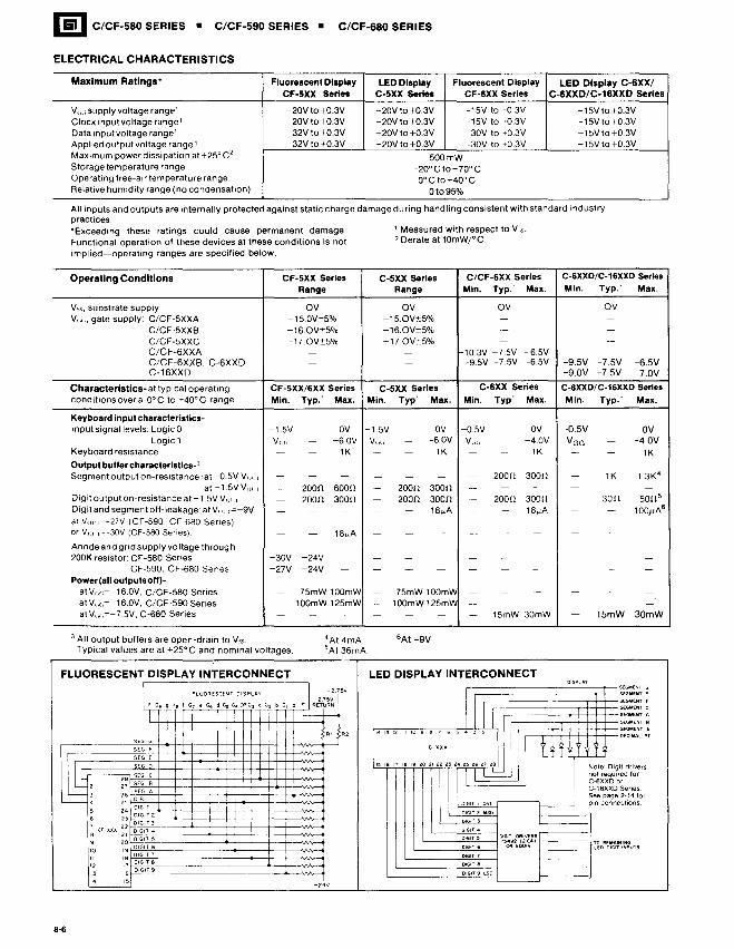
ELECTRICAL CHARACTERISTICS
Maximum Ratings' Fluorescent Display LED Display Fluorescent Display LED Display C-6XX/CF-5XX series C-5XX series CF-6XX Series C-6XXD/C-16XXD series
V",; supply voltage range' -20Vto+0.3V -20V to +0.3V ~15V to +0.3V -15V to +0.3VClock input voltage range' -20V to +0.3V -20V to +0.3V ~15V to +0.3V -15Vto+0.3VData input voltage range 1 -32V to +0.3V -20V to+0.3V ~30V to +0.3V -15Vto+0.3VApplied output voltage range' -32V to +0.3V -20V to +0.3V -30V to +0.3V -15V to +0.3VMaximum power dissipation at +250 C 2
500mWStorage temperature range -20° C to + 70° COperating free-air temperature range 0°Cto+40°CRelative humidity range (no condensation) Ot095%
1 Measured with respect to Vss.
2 Derate at 10mWrC.
All inputs and outputs are internally protected against static charge damage during handling consistent with standard industrypractices."Exceeding these ratings could cause permanent damage.Functional operation of these devices at these conditions is notimplied-operating ranges are specified below.
Operating Conditions CF-5XX Series C-5XX series C/CF-6XX Series C·6XXD/C·16XXD Series
Range Range Min. Typ. Max. Min. Typ.· Max.
V", substrate supply OV OV OV OVV,;,;, gate supply: C/CF-5XXA -15.0V:t5% -15.0V:t5% - -
C/CF·5XXB -16.0V:t5% -16.0V:t5% .- -C/CF-5XXC -17QV:t5% -17.0V:t5% - -C/CF-6XXA - - 10.3V -7.5V -6.5VC/CF-6XXB. C·6XXD - - -9.5V -7.5V -6.5V -9.5V -7.5V -6.5VC-16XXD -9.0V -7.5V ~7.0V
Characteristics-at typical operating CF-5XX/6XX Series C-5XX Series C-6XX series C-6XXD/C-16XXD Series
conditions over a 0° C to +400 C range. Min. Typ. Max. Min. Typ Max. Min. Typ Max. Min. Typ.· Max.
Keyboard input characteristics-input signal levels: Logic 0 -1.5V - OV -1.5V - OV -O.5V - OV -O.5V - OV
Logic 1 V(;(; - -6.0V V{;(; - -6.0V V(;(i - -4.0V VGG - -4.0VKeyboard resistance - - 1K - - 1K - - 1K - - 1KOutput buffer characteristlcs-'Segment output on-resistance: at -O.5V V(HI - - - - - - - 200n 300n - 1K 1.3K4
at ~1.5VV(ll'l - 200n 600n - 200n 300n -- - - - - -Digit output on-resistance at -1.5V Vo\·1 - 200n 300n - 200n 300n - 200n 300n ~- 30n sonsDigitand segment off-leakage: at V", ,=-9V - - - - - 18~A - - 18~A -- -- 100).JA6
at v"" c~27V (CF-590, CF-680 Senes)or VOl'1 =-30V (CF-580 Series) - - 18~A - - - - - - - - -
Anode and grid supply voltage throug h200K resistor: CF·580 Senes -30V -24V - - - - - - - - - -
CF-590, CF-680 Senes -27V -24V - - - - - - - - - -Power(al! outputsoll)-
atV",.~--16.0V,C/CF-580 Series - 75mW 100mW - 75mW 100mW - - - - - -
at V,.,,~-16.0V.C/CF·590 Series - 100mW 125mW - 100mW125mIA - - - - - -atV",,=-7.5V, C-680 Series - - - - - - - 15mW 30mW - 15mW 30mW
3 All output buffers are open-drain to V".. TYPical values are at +25°C and nominal voltages.
4At 4mASAt 36mA.
6At-9V
SEC. F
LED DISPLAY INTERCONNECT
-2<1V
I
FLUORESCENT DISPLAY INTERCONNECT
~ FLUOREscrNT DISPLAY :~ -2.75V-2.75VI F Gg Q Ge ! G7 e G6 d G!I G. DP G3 C G2 b G1 0 • RETURN
! I !
! iii
lliL~f-':'OL=C~'-",;+--jr-+~--1~+H-+-!+-H-++'V'A~L 2 27 f-'S~EG~~B+:=j:=j+:=j=+~:::j:=~:::j::t~~3 26 f-:SEG A
~ : ~: ~~~'I~~"p'2==t==E=1E==Et'~E=t=E~~16 23~IGIT 2
, 22 r;O~'G~"~'t:::===:::=:j=++=:::j:=+=:::j:=~~8 CF-xXX 21 r?IGIT <I
9 20r;~~<G~"-~5~======:::t::::j:=t=:::j:=~~10 19~IGIT 6
Ii '8~Dlli<G~<T8'E=======~=~j:=~~12 17~- -
13 16~-1<1 15
8-6
~ C-S83 C-683
L:.IL- C_F_-S_8_3__C_F_-6_8_3 _
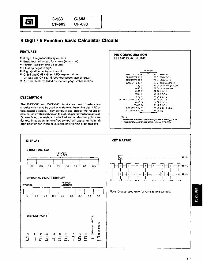
8 Digit / 5 Function Basic Calculator Circuits
NOTE:
The oscillator ia enabled by connecting 8 resistor from VGG to pin'04 (l50K1±l~ for C/CF-583. 470Ki::'tlO% for C/CF-683).
FEATURES
• 8 digit. 7 segment display outputs.• Basic four arithmetic functions (+. -, x, +).• Percent (add-on and discount).• Floating negative sign.• Right-justified entry and result.• C-583 and C-683: direct LED segment drive.
CF-583 and CF-683: direct fluorescent display drive.• All other features listed on the first page of this section.
DESCRIPTION
The C/CF-583 and C/CF-683 circuits are basic five-functioncircuits which may be used with either eight or nine digit LED orfluorescent displays. They compute and display the results ofcalculations with numbers up to eight digits (seven for negative).On overflow, the keyboard is locked and all decimal points arelighted. In addition. an overflow symbol will appear in the ninthdigit position for those calculators having nine digit displays.
PIN CONFIGURATION28 LEAD DUAL IN LINE
SEGMENT 0
SEGMENT E
SEGMENT F
SEGMENTG
NC
KP
KO
KNNC
DO NOT CONNECT
NC
'!GGEXTOSC IN
OSCENABLE
SEGMENT C
SEGMENT B
SEGMENT A
DECIMAL POINT
DIGIT 1 OVERFLOW
DIGIT 2 M.S.D
DIGlT3
D1GIT4
DIGITS
DIGIT 6
DIGIT?
DIGIT8
DIGIT 9 L.SD,
Vss
DISPLAY KEY MATRIX
8 DIGIT DISPLAY
OPTIONAL 9 DIGIT DISPLAY
I0-8 0-90-6 0-70-4 0-5
f---------------------j~Kp
0-2 0-30-1
Note: Diodes used only for CF -583 and CF-683.
09
09
DB
DB
07
0706
8 DIGITNUMBER,
05 06
8 DIGITNUMBER,
05
04
04
03
0302
01 02
SYMBOL
DISPLAY FONT
o 2 3
o 1234 5 6 7 8 9
Lf 5 5. I B 9
NEG
SIGN
ERRoR
c.
6-7
r=lEiI C-585 C-685
L:.I C_F_-_5_85__C_F_-_6_85 _
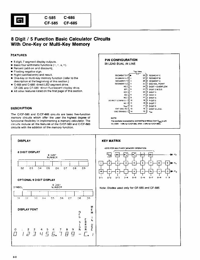
8 Digit / 5 Function Basic Calculator CircuitsWith One-Key or Multi-Key Memory
FEATURES
NOTE:
The oscillator Is enabled by connecting a reaiator from VGG~o pin
14 (150K ::!::.10% for C/CF-S85. 470K ::!:::1~ for ClCF-685).
• 8 digit, 7 segment display outputs.• Basic four arithmetic functions (+, -, x, +).• Percent (add-on and discount).• Floating negative sign.• Right-justified entry and result.• One-key or multi-key memory function (refer to the
description at the beginning of this section.)• C-585 and C-685: direct LED segment drive.
CF-585 and CF-685: direct fluorescent display drive.• All other features listed on the first page of this section.
DESCRIPTION
The C/CF-585 and C/CF-685 circuits are basic five-functionmemory circuits which offer the user the highest degree offunctional flexibility in implementing a memory calculator. Thecircuits include all the features of the C/CF-583 and C/CF-683circuits with the addition of the memory function.
PIN CONFIGURATION28 LEAD DUAL IN LINE
SEGMENT 0
SEGMENTE
SEGMENTF
SEGMENTG
NC
KP
KO
KN
NC
DO NOT CONNECT
NC
vGG
EXTOSC IN
ase ENABLE
SEGMENTC
SeGMENT B
SEGMENT A
DECIMAL POINT
DIGIT 1 OVERFLOW
DIGIT 2 M.S.D,
DIGIT 3
DIGIT 4
DIGIT 5
DIGIT6
DIGIT?
DIGIT 8
DIGIT 9 L.S.D.Vss
DISPLAY
8 DIGIT DISPLAY8 DIGIT
NUMBER
OPTIONAL 9 DIGIT DISPLAY
KEY MATRIX
KEYS FOR MULTI-KEY MEMORY OPERATION!
f-----..... Kp
K N
Note: Diodes used only for CF-585, and CF-685
01 02 03 D4 05 06 07 08 09
MDISPLAY FONT E
N MEG I
E N5 RI R UG 0 S
0 2 3 4 5 6 7 8 9 N R E
0 12:3 Y 5 5. I 89 c.
8-8
1!lI C_-S_8_9__C_F-_S8_9__-,
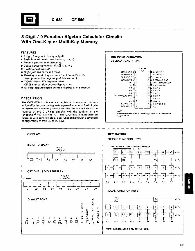
8 Digit / 9 Function Algebra Calculator CircuitsWith One-Key or Multi-Key Memory
NOTE:The oscillator is enabled by connecting a 150fc ±10% resistor fromVGG to pin 14.
FEATURES• 8 digit, 7 segment display outputs.• Basic four arithmetic functions (+, -, x, +).• Percent (add-on and discount).• Convenience functions (x2 , vx. 1/x, +1-)• Floating negative sign.• Right-justified entry and result.• One-key or multi-key memory function (refer to the
description at the beginning of this section.)• C-589: direct LED segment drive.
CF-589: direct fiuorescent display drive.• All other features listed on the first page of this section.
DESCRIPTIONThe C/CF-589 circuits are basic eight-function memory circuitswhich offer the user the highest degree of functional flexibility inimplementing a memory calculator. The circuits include all thefeatures of the C/CF-585 circuits with the addition of thefunctions x~ vx. 1/x and +1-. The C/CF-589 circuits may beoperated with either single or dual function keys with a keyboardconfiguration of from 20 to 29 keys.
PIN CONFIGURATION28 LEAD DUAL IN LINE
SEGMENT 0
SEGMENT E
SEGMENT F
SEGMENT G
NC
KP
KO
KN
KADO NOT CONNECT
NC
vGG
EXT ase IN
ase ENABLE
SEGMENTC
SEGMENT B
SEGMENT A
DECIMAL POINT
DIGIT 1 OVERFLOW
DIGIT 2 M,S,D
DIGIT 3
DIGIT 4DIGIT 5
DIGIT 6
DIGIT 7
DIGIT aDIGIT 9 L.S,O
v"
DISPLAY KEY MATRIX
SINGLE FUNCTION KEYS
DISPLAY FONT ME
N MEG I F
E NS R MI R U 0G 0 S D
0 2 3 4 5 6 7 B 9 N R E E
0 12::1 Lf 5 5. 7 B 9 L I F D-9
K A
K p
KN
KO
ID-8 D-9
Kp
K O
KN
D-8
D·7
0-6 0-70-4 0-5
D-4D-3
D-3D-2
D-2
KEYS FOR MULTI-KEY MEMORY OPERATION~----'------------
DUAL FUNCTION KEYS
D-,
D-'
D9D8D706
8 DIGITNUMBER
D5D40302DI
SYMBOL
8 DIGIT DISPLAY
OPTIONAL 9 DIGIT DISPLAY
8 DIGITNUMBER
Note: Diodes used only for CF-589.
8-9
1!!l,-__C_-S_93 C_F_-_S9_3__
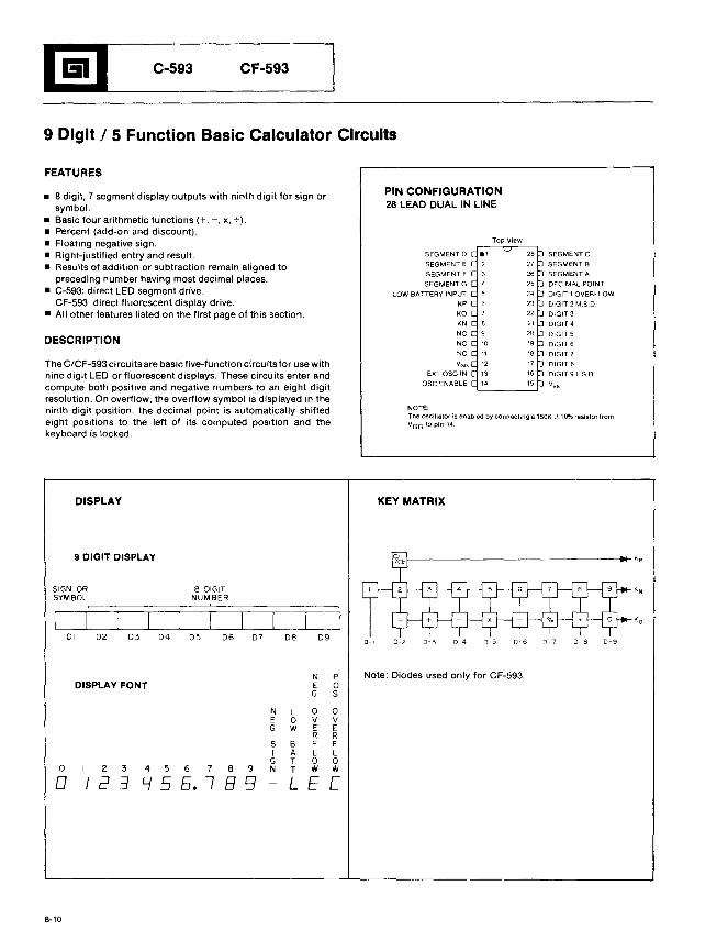
9 Digit I 5 Function Basic Calculator Circuits
FEATURES
NOTE:The oscillator is enabled by connecting a 150K ::t 10% resistor fromVGG to pin 14.
• 8 digit, 7 segment display outputs with ninth digit for sign orsymbol.
• Basic four arithmetic functions (+, -, x, +).• Percent (add-on and discount).• Floating negative sign.• Right-justified entry and result.• Results of addition or subtraction remain aligned to
preceding number having most decimal places.• C-593: direct LED segment drive.
CF-593: direct fluorescent display drive.• All other features listed on the first page of this section.
DESCRIPTION
The C/CF-593 circuits are basic five-function circuits for use withnine digit LED or fluorescent displays. These circuits enter andcompute both positive and negative numbers to an eight digitresolution. On overflow, the overflow symbol is displayed in theninth digit position, the decimal point is automatically shiftedeight positions to the left of its computed position and thekeyboard is locked.
PIN CONFIGURATION28 LEAD DUAL IN LINE
SEGMENT 0
SEGMENT E
SEGMENT F
SEGMENTG
LOW BATTERY INPUTKP
KO
KN
NC
NC
NC
VGG
EXl ase IN
ase ENABLE
SEGMENTC
SEGMENT BSEGMENT A
DECIMAL POINT
DIGIT 1 OVERt LOW
DIGIT 2 M.S.D
0lG1T3
DIGIT 4
DIG!T 5
0181T6
DIGIT 7
DIGIT aDIGIT 9 LSD.
Vss
DISPLAY KEY MATRIX
D- B 0-9D-6 D-70-50-4
\- ~ Kp
0-20-'
9 DIGIT DISPLAY
DISPLAY FONT
o
o2 3
I 2 34 5 6 7 8 9
L.f 5 5. 1 B 9
NEG
SI
GN
N PE 0G S
L 0 0o V VWEE
R RB F FALLTOOT W W
LEC
Note: Diodes used only for CF-593.
8-10
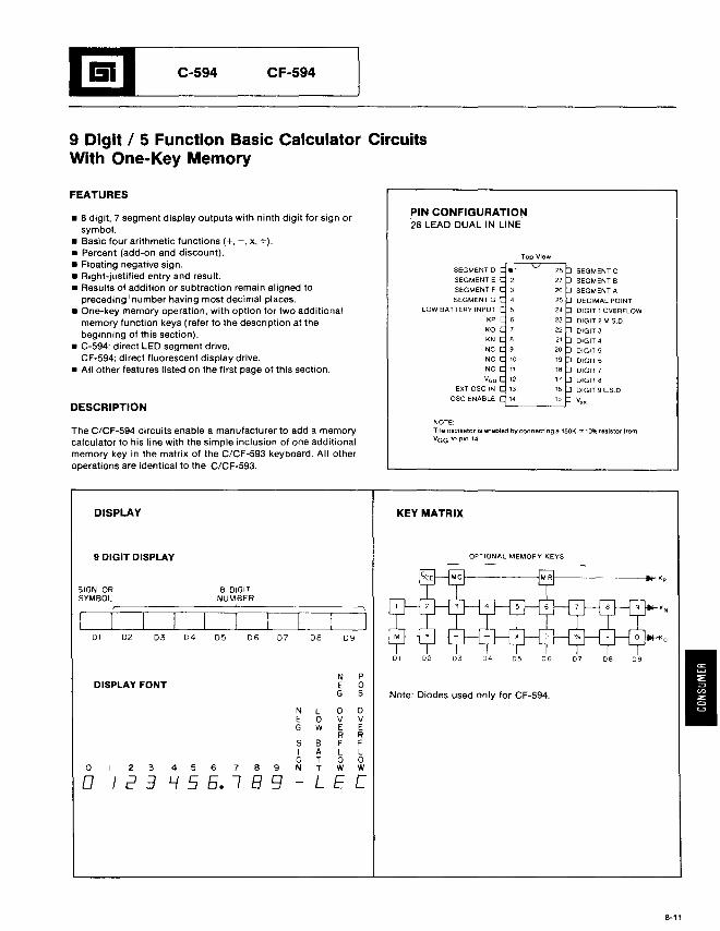
1!!J'--__C_-_5_94 C_F_-_59_4__
9 Digit / 5 Function Basic Calculator CircuitsWith One-Key Memory
FEATURES
• 8 digit, 7 segment display outputs with ninth digit for sign orsymbol.
• Basic four arithmetic functions (+, -, x, +).• Percent (add-on and discount).• Floating negative sign.• Right-justified entry and result.• Results of addition or subtraction remain aligned to
preceding I number having most decimal places.• One-key memory operation, with option for two additional
memory function keys (refer to the description at thebeginning of this section).
• C-594: direct LED segment drive.CF-594: direct fluorescent display drive.
• All other features listed on the first page of this section.
DESCRIPTION
PIN CONFIGURATION28 LEAD DUAL IN LINE
SEGMENT 0
SEGMENT E
SEGMENT F
SEGMENTG
LOW BATTERY INPUT
KP
KO
KN
NC
NC
NC
vGG
EXT asc IN
asc ENABLE
SEGMENT C
SEGMENT B
SEGMENT A
DECIMAL POINT
DIGIT 1 OVERFLOW
DIGIT 2 M,S.D
OIGIT 3
0lGIT4
DIGIT5
DIGIT6
DIGIT 7
DIGIT8
DIGIT 9 L.S.O
v"
The C/CF-594 circuits enable a manufacturer to add a memorycalculator to his line with the simple inclusion of one additionalmemory key in the matrix of the C/CF-593 keyboard. All otheroperations are identical to the C/CF-593.
NOTE:The oscillator is enabled by connecting a 150+< ± 10% resistor fromVaG to pin 14.
DISPLAY KEY MATRIX
9 DIGIT DISPLAY OPTIONAL MEMORY KEYS
DI D2 03 04 D5 D6 D7 D8 D9
N PDISPLAY FONT E 0
G S Note: Diodes used only for CF-594.
N L 0 0E 0 V VG W E E
R R5 B F FI A L LG T 0 0
0 2 3 4 5 6 7 8 9 N T W W
0 I 2 :1 l..f5 5. I B 9 L E [
If---------i>l_ Kp
09080706
8 DIGITNUMBER
05~Ie---------J'------JL------,-_
D I D2 D3 D4
SIGN ORSYMBOL
8-11
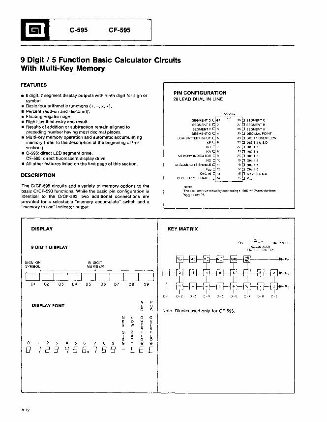
I!lIL-__C_-S_9S C_F_-_S9_S_----'
9 Digit / 5 Function Basic Calculator CircuitsWith Multi-Key Memory
FEATURES
NOTE:The oscillator is enabled by connecting a 150K ±10% resistor fromVGG to pin 14.
• 8 digit. 7 segment display outputs with ninth digit for sign orsymbol.
• Basic four arithmetic functions (+. -, X. +).• Percent (add-on ana a,scount).• Floating negative sign.• Right-justified entry and result.• Results of addition or subtraction remain aligned to
preceding number having most decimal places.• Multi-key memory operation and automatic accumulating
memory (refer to the description at the beginning of thissection.)
• C-595: direct LED segment drive.CF-595: direct fluorescent display drive.
• All other features listed on the first page of this section.
DESCRIPTION
The C/CF-595 circuits add a variety of memory options to thebasic C/CF-593 functions. While the basic pin configuration isidentical to the C/CF-593, two additional connections areprovided for a selectable "memory accumulate" switch and a"memory in use" indicator output.
PIN CONFIGURATION28 LEAD DUAL IN LINE
SEGMENT 0
SEGMENT E
SEGMENT F
SEGMENTG
LOW BATTERY INPUT
KP
KO
KN
MEMORY INDICATOR
NC
ACCUMULATE ENABLE
vGG
OSGIN
OSCILLATOR ENABLE
SEGMENTC
SEGMENT B
SEGMENT A
DECIMAL POINT
DIGIT 1 OVERFLOW
DIGIT 2 M.S.D
DIG1T3
DIGIT 4
DIGIT 5
DIGIT 6
DIGIT7
DIGIT 8
DIGIT 9 L.SD
Vss
DISPLAY
9 DIGIT DISPLAY
KEY MATRIX
VSS~~--"'PINII
ACCUMULATEENABLE SWITCH
t---------i>!-- K p
0-1 0-2 0-3 D-4 0-5 0-6 0-7 0-8 D-9
oo
8-12
DISPLAY FONT
NEG
SIG
23456789N
I 2 3 L.f 5 5. I B 9
N PE 0G S
l 0 0o V VWEE
R RB F FAllTOOT W W
LEC
Note: Diodes used only for CF-595.
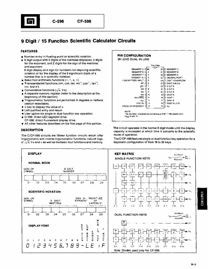
l!lL-__C_-_S9_6 C_F_-S_96__
9 Digit / 15 Function Scientific Calculator Circuits
FEATURES
NOTE:The oscillator is enabled by connecting a 470K .::t;10% resistor fromVGG to pin 14.
• Number entry in floating point or scientific notation.• 9 digit output with 5 digits of the mantissa displayed. 2 digits
for the exponent. and 2 digits for the sign of the mantissaand exponent.8 digit display and sign for numbers not requiring scientificnotation or for the display of the 8 significant digits of anumber that is in scientific notation.
• Basic four arithmetic functions (+. -. x. +).• Transcendental functions (sin. cos. tan. sin-I. COS~l • tan-I.
Inx and e').• Convenience functions (y'x. 1/x).• A separate memory register (refer to the description at the
beginning of this section).• Trigonometric functions are performed in degrees or radians
(switch selectable).• rr key to display the value of rr.• Left-justified entry and result.• User option for single or dual function key operation.• C-596: direct LED segment drive.
CF-596: direct fluorescent display drive.• All other features described on the first page of this section.
PIN CONFIGURATION28 LEAD DUAL IN LINE
SEGMENT 0
SEGMENT E
SEGMENTF
SEGMENTG
LOW BATTERY INPUT
KP
.KO
KNKA
KB
RAD/DEG
VOG
OSCIN
OSCILLATOR ENABLE
SEGMENTC
SEGMENT B
SEGMENT A
DECIMAL POINT
DIGIT 1 OVERFLOW
DIGIT 2 M.S.D.
0lGIT301GIT4
DIGIT 5
DIGIT6
DIGIT 7
DIGITS
DIGIT 9 L.S.D.
v~
DESCRIPTION
The C/CF-596 circuits are fifteen function circuits which offertrigonometric and inverse trigonometric functions. natural logs.e'. v'x. lIx and rr as well as the basic four functions and memory.
The circuit operates in the normal 8 digit mode until the displaycapacity is exceeded at which time it converts to the scientificmode of operation.
The C/CF-596 features single or dual function key operation for akeyboard configuration of from 19 to 35 keys.
DISPLAY KEY MATRIXSINGLE FUNCTION KEYS
DEGREES
Vss ------------~~ IIRADIANS
ID-9
D-9
D-8
D-8
DEGREES
V5S----_~I~ IIRADIANS
D·7
D-7
D-6
D-6
D-50-4
0-4 0-5
f--j--+--f---+--t---+--t.... Kp
D-'
D-'
I-------------------.._Kp
D-2
D-2
DUAL FUNCTION KEYS
D-I
D-I
D9
D9
MEM
I FN
MU 0S DE E
F
DBD7D6
SIGN OF MAGN ITUDEEXPONENT OF
EXPONENT!
B DIGITNUMBER,
D5D4
5 DIGITMANTISSA,
D3D2
SCIENTIFIC NOTATION
NORMAL MODE
DI D2 D3 D4 D5 D6 D7 DB
DISPLAY FONT N LE 0G W
ES B RI A RG T 0
0 3 4 5 6 7 B 9 N T R
0 I 2 :1 I..f 5 5. 7 B 9 LE
DI
SIGN ORSYMBOL
SIGN ORSYMBOL
Note: Diodes used only for CF-596.
8-13
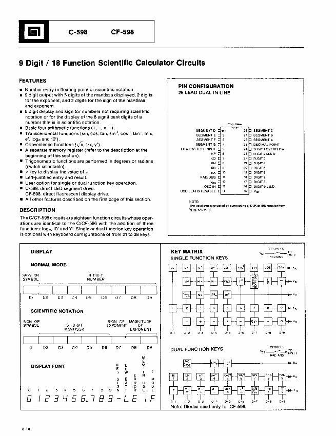
1!il__C_-_5_98 C_F-_5_98__
9 Digit / 18 Function Scientific Calculator Circuits
FEATURES
NOTE:The oscillator is enabled by connecting a 470K ±10% resistor fromVaGI to pin 14.
• Number entry in floating point or scientific notation.• 9 digit output with 5 digits of the mantissa displayed, 2 digits
for the exponent, and 2 digits for the sign of the mantissaand exponent.
• 8 digit display and sign for numbers not requiring scientificnotation or for the display of the 8 significant digits of anumber that is in scientific notation.
• Basic four arithmetic functions (+, -, x, +).• Transcendental functions (sin, cos, tan, sino', coso" tan-', In x,
e', 10glO and 10').• Convenience functions hIX, llx, y').• A separate memory register (refer to the description at the
beginning of this section).• Trigonometric functions are performed in degrees or radians
(switch selectable).• 7T key to display the value of 7T.
• Left-justified entry and result.• User option for single or dual function key operation.• C-598: direct LED segment drive.
CF-598: direct fluorescent display drive.• All other features described on the first page of this section.
DESCRIPTION
PIN CONFIGURATION28 LEAD DUAL IN LINE
SEGMENT 0SEGMENT E
SEGMENT F
SEGMENTG
LOW BATTERY INPUT
KP
KO
KN
KB
KA
RAD/DEG
vGG
esc IN
OSCILLATOR ENABLE
SEGMENTC
SEGMENTS
SEGMENT A
DECIMAL POINT
DIGIT 1 OVERFLOW
DIGIT 2 M.S.O.
DIGIT30lGIT4
DIGITS
DIGIT 6
DIGIT 7
DIGIT8
DIGIT 91.S.D.
Vss
The C/CF-598 circuits are eighteen function circuits whose operations are identical to the C/CF-596 with the addition of threefunctions: 10glO, 10' and Y'. Single or dual function key operationis optional with keyboard configurations of from 21 to 38 keys.
DISPLAY KEY MATRIXSINGLE FUNCTION KEYS
K O
KB
KA
D-9
D-9
D-8
D-8
DEGREES
VSS~S-~~Il
0·7
f-----f--+--f-----+--i..... Kp
f-------------4~Kp
0-5 0-6D-4D-3D-2
0-1 0-2 0-3 0-4 0-5 0-6 0-7
Note: Diodes used only for CF-598.
DUAL FUNCTION KEYS
D-'
D9DBD7
SIGN OF MAGNITUDEEXPONENT OF
EXPONENT,
D6
B DIGITNUMBER,
D5D4
5 DIGITMANTISSA,
D3D2
DI D2 D3 D4 D5 D6 D7 DB D9
ME
DISPLAY FONT N L ME 0G w I F
E NS B R MI A R U 0G T 0 S D
0 3 4 5 6 8 9 N T R E E
0 I 2 3 L.{ 5 5. 7 B 9 LE F
SCIENTIFIC NOTATION
NORMAL MODE
SIGN ORSYMBOL
SIGN ORSYMBOL
DI
8-14
l!lL-__C_-_S_99 C_F_-S_9_9__
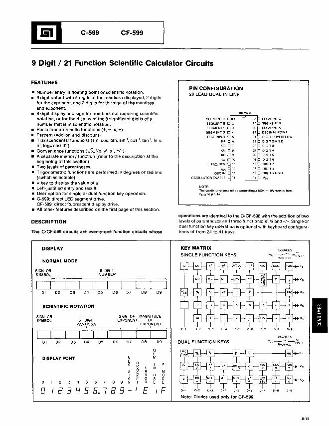
9 Digit / 21 Function Scientific Calculator Circuits
FEATURES
NOTE:The oscillator is enabled by connecting a 150K ± I 0% resistor fromVaG to pin 14.
• Number entry in floating point or scientific notation.• 9 digit output with 5 digits of the. mantissa displayed, 2 digits
for the exponent, and 2 digits for the sign of the mantissaand exponent.
• 8 digit display and sign for numbers not requiring scientificnotation, or for the display of the 8 significant digits of anumber that is in scientific notation.
• Basic four arithmetic functions (+, -, x, +).• Percent (add-on and discount)• Transcendental functions (sin, cos, tan, sino', coso" tan-', In x,
e', 10glO and 10').• Convenience functions (,)X, 'Ix, y', x', +1-).• A separate memory function (refer to the description at the
beginning of this section).• Two levels of parentheses.• Trigonometric functions are performed in degrees or radians
(switch selectable).• .". key to display the value of ."..• Left-justified entry and result.• User option for single or dual function key operation.• C-599: direct LED segment drive.
CF-599: direct fluorescent display drive.• All other features described on the first page of this section.
PIN CONFIGURATION28 LEAD DUAL IN LINE
SEGMENT 0
SEGMENT E
SEGMENT F
SEGMENT G
TEST INPUT
KP
KO
KN
KB
KA
RAD/DEG
VGG
ase IN
OSCILLATOR ENABLE
SEGMENT C
SEGMENT B
SEGMENT A
DECIMAL POINT
DIGIT 1 OVERFLOW
DIGIT 2 M.S.D
DIGIT3
D1GIT4
DIGIT 5
DIGIT 6
DIGIT 7
DIGITS
DIGIT 9 L.SD
Vss
DESCRIPTION
The C/CF-599 circuits are twenty-one function circuits whose
operations are identical to the C/CF-598 with the addition of twolevels of parentheses and three functions: x', % and +1-. Single ordual function key operation is optional with keyboard configurations of from 24 to 41 keys.
DISPLAY
I0-90-.DEGREES
vss---- TORADIANS PIN Il
0·70-60-50-40-30-20-'
KEY MATRIXSINGLE FUNCTION KEYS
DUAL FUNCTION KEYS
09De0706
SIGN OF MAGNITUDEEXPONENT OF
EXPONENT,
e DIGITNUMBER,
0504
5 DIGITMANTISSA,
0302
SCIENTIFIC NOTATION
NORMAL MODE
01
SIGN ORSYMBOL
01
SIGN ORSYMBOL
o I 2 3 I..f 5 5. 7 B 9
DISPLAY FONT
Note: Diodes used on Iy for CF-599,
0-9D-B0-6 0-70-4 0-50-30-20-1
MEM
8 IR E NAC R MK R U 0E 0 S 0T R E E
E F
NEG
SIG
6 7 8 9 N3 4o
8-15
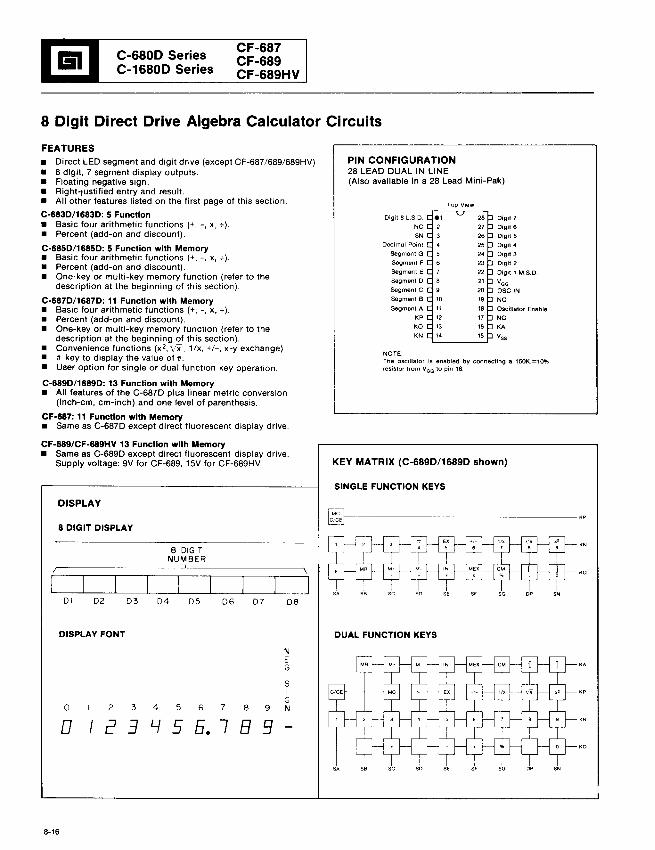
iii C-680D SeriesC-1680D Series
CF-687CF-689CF-689HV
8 Digit Direct Drive Algebra Calculator Circuits
NOTEThe oscillator is enabled by connecting a 150K±1Q%resistor from VGG 10 pin 18
PIN CONFIGURATION28 LEAD DUAL IN LINE(Also available in a 28 Lead Mini-Pak)
FEATURES• Direct LED segment and digit drive (except CF-687/689/689HV)• 8 digit, 7 segment display outputs.• Floating negative sign.• Right-justified entry and result.• All other features listed on the first page of this section.
C-683D/1683D: 5 Function• Basic four arithmetic functions (+, -, x, +).• Percent (add-on and discount).
C-685D/1685D: 5 Function with Memory• Basic four arithmetic functions (+, -, x, +).• Percent (add-on and discount).• One-key or multi-key memory function (refer to the
description at the beginning of this section).
C-687D/1687D: 11 Function with Memory• Basic four arithmetic functions (+, -, X. +).• Percent (add-on and discount).• One-key or multi-key memory function (refer to the
description at the beginning of this section).• Convenience functions (x 2, vX' 1/x, +/-, x-y exchange)• n key to display the value of n.• User option for single or dual function key operation.
C-689D/1689D: 13 Function with Memory• All features of the C-687D plus linear metric conversion
(inch-cm, cm-inch) and one level of parenthesis.
CF-687: 11 Function with Memory• Same as C-687D except direct fluorescent display drive.
Digit 8 L.S.D
NC
SN
Decimal Point
Segment G
Segment F
Segment E
Segment D
Segment C
Segment B
Segment A
KP
KO
KN
Digit 7
Digit 6
Digit 5
Digit 4
Digit 3
Digit 2
Digit 1 M.S.D
VGG
ase INNC
Oscillator Enable
NC
KA
Vss
CF-689/CF-689HV 13 Function with Memory• Same as C-689D except direct fluorescent display drive.
Supply voltage: 9V for CF-689, 15V for CF-689HV.
DISPLAY
8 DIGIT DISPLAY
KEY MATRIX (C-689D/1689D shown)
SINGLE FUNCTION KEYS
~------------------
DI D2 D3 D4 D5 D6 D7 D8
DISPLAY FONT DUAL FUNCTION KEYS
NEG
5IG
0 2 3 4 5 6 7 8 9 N
0 I [3 3 L.f 5 5. 7 B 51
56 se so s, SG De SN
8-16
KO
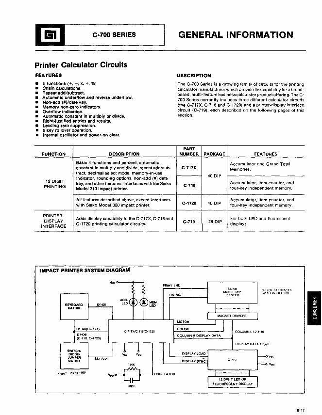
1!IL- C_-_70_0_S_E_R_IE_S__----' GENERAL INFORMATION
Printer Calculator CircuitsFEATURES DESCRIPTION
5 functions (+, -, X, +, %)Chain calculations.Repeat add/subtract.Automatic underflow and reverse underflow.Non-add (#)/date key.Memory non-zero indicators.Overflow indication.Automatic constant in multiply or divide.Right-justified entries and results.Leading zero suppression.2 key rollover operation.Internal oscillator and power-on clear.
The C-700 Series is a growing family of circuits for the printingcalculator manufacturer which provide the capability for a broadbased, multi-feature business calculator product offering. The C700 Series currently includes three different calcuiator circuits(the C-717X, C-718 and C-1720) and a printer-display interfacecircuit (C-719), each described on the following pages of thissection.
PARTFUNCTION DESCRIPTION NUMBER PACKAGE FEATURES
Basic 4 functions and percent, automatic Accumulator and Grand Totalconstant in mUltiply and divide, repeat add/sub- C-717X Memories.tract, decimal select mode, memory-in-use
40 DIPindicator, rounding options, non-add (#) date
12 DIGIT key, and other features. Interfaces with the Seiko Accumulator, item counter. andC-71SPRINTING Model 310 impact printer. four-key independent memory.
All features described above, except interfacesC-1720 40 DIP
Accumulator, item counter, andwith seiko Model 320 impact printer. four-key independent memory.
PRINTER-Adds displaycapability to the C-717X, C-718 and For both LED and fluorescent
DISPLAY C-719 28 DIPINTERFACE
C-1720 printing calculator circuits. displays.
IMPACT PRINTER SYSTEM DIAGRAM
vooo--......__PRINT END
C-717X1e-718/C-1720
C-1720 INTERFACE~
WITH MODEL 320
COLUMNS 1,2,4-18
DISPLAY DATA 1,2,4,8
Vss
vooC-719
SEIKOMODEL 310·
PRINTER
DISPLAY LOAD
DISPLAvlsVNQ .
MOTOR
COLOR
!COLUMN & DISPLAV DATA
TIMING
MEM.LED
SOpF
ACC.LED
Voo
01-06(C-7l8. C-1720)
Dl·D~(C-7l7X)
SWITCHIDIODE!
JUMPERMATRIX
KEVBOAROMATRIX
VOD.'" -14V to -18V
8-17
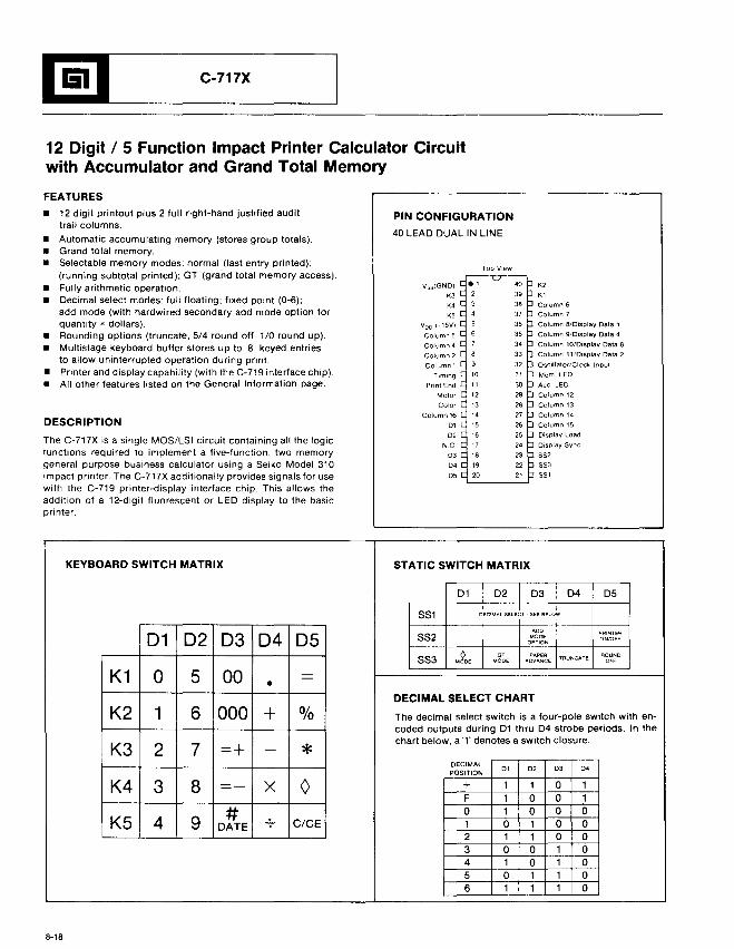
l!lL- C_-7_17
_X
_
12 Digit / 5 Function Impact Printer Calculator Circuitwith Accumulator and Grand Total Memory
FEATURES
• 12 digit printout plus 2 full right-hand justified audittrail columns.
• Automatic accumulating memory (stores group totals).• Grand total memory.• Selectable memory modes: normal (last entry printed);
(running subtotal printed); GT (grand total memory access).• FUlly arithmetic operation.• Decimal select modes: full floating; fixed point (0-6);
add mode (with hardwired secondary add mode option forquantity x dollars).
• Rounding options (truncate, 5/4 round off, 1/0 round up).• Multistage keyboard buffer stores up to B keyed entries
to allow uninterrupted operation during print.• Printer and display capability (with the C-719 interface chip).• All other features listed on the General Information page.
DESCRIPTION
The C-717X is a single MOS/LSI circuit containing all the logicfunctions required to implement a five-function, two memorygeneral purpose business calculator using a Seiko Model 310impact printer. The C-717X additionally provides signals for usewith the C-719 printer-display interface chip. This allows theaddition of a 12-digit fluorescent or LED display to the basicprinter.
PIN CONFIGURATION
40 LEAD DUAL IN LINE
VsS(GNO)
K3
K'K5
Vao (-15V)
Column 5
Column 4
Column 2
Column 1
Timing
Print End
Motor
Color
Column 16
01
02
N.C
03
0'05
K2
K1
Column 6
Column 7
Column 8/Display Data'
Column 9/Display Dala 4
Column 10/0isplay Data 8
Column 11iOispiay Dala 2
Oscillator/Clock Input
Mem. LED
Ace. LED
Column 12
Column 13
Column 14
Column 15
Display Load
Display Sync
SS2
SS3SS1
KEYBOARD SWITCH MATRIX STATIC SWITCH MATRIX
01 02 03 04 05
SS1 decIMAL SELEbT see BELO~
01 02 D3 04 05ADD PAINTER
SS2 MODe ON/OFFOPTION
0 DT PAPER ROUNDSS3 MODE MODe ADVANCE
TRUNCATED"
K1 a 5 00 -• -
DECIMAL SELECT CHART
K2 1 6 000 + % The decimal select switch is a four-pole switch with en-coded outputs during 01 thru 04 strobe periods. In the
K3 2 7 =+ *chart below, a '1' denotes a switch closure.
-DECIMAL
01 02 03 0'POSITION
K4 3 8 - - X 0 + 1 1 0 1-F 1 0 0 1
# 0 1 0 0 0K5 4 9 DATE C/CE 1 0 1 0 0
2 1 1 0 03 0 0 1 04 1 0 1 05 0 1 1 06 1 1 1 0
8-18
1!rIL.- C_-
7_1_8
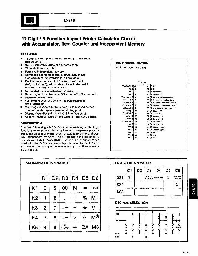
_
12 Digit / 5 Function Impact Printer Calculator Circuitwith Accumulator, Item Counter and Independent Memory
FEATURES
• 12 digit printout pius 2 full right-hand justified audittrail columns.
• Switch-selectable automatic accumulation.• Three digit item counter.• Four-key independent memory.• Arithmetic operation in add/subtract sequences.
algebraic in multiply/divide (business logic).• Decimal select modes: full floating; fixed point
(0-6, excluding 5); add mode (automatic decimal 2in + and -, uniVprice mode in x).
• Non-coded decimal select switch input.• Rounding options (truncate, 5/4 round off, 1/0 round up).• separate clear-all key.• Full floating accuracy on intermediate results in
chain operation.• Multistage keyboard buffer stores up to 6 keyed entries
to allow uninterrupted operation during print.• Display capability (with the C-719 interface chip).• All other features listed on the General Information page.
DESCRIPTIONThe C-718 is a single MOS/LSI circuit containing all the logicfunctions required to implement a five-function general purposeconsumer calculator with an accumulator, item counter and fourkey independent memory. The C-718 has been designed tooperate with a Seiko Model 320 16 column impact printer. Whenused with the C-719 printer-display interface, the C-1720 alsoprovides a 12-digit display capability, using either fluorescent orLED displays.
PIN CONFIGURATION40 LEAD DUAL IN LINE
Vss(GNDI
K3
K4
K5
voo (-15V)
Column 5Column ..
Column 2
Column 1Timing
Print End
MotorColor
Column 16
0'0602
03D405
K2KlColumn 6
Column 7
Column 81Display Data 1
Column 91Display Data ..
Column lO/Dlaplay Data 8
Column 1110isplay Data 2
Oscillator/Clock Input
Mem. LED
Ace. LED
Column 12
Column 13
Column 14
Column 15
Display Load
Display Sync
SS355255'
KEYBOARD SWITCH MATRIX STATIC SWITCH MATRIX
01 02 03 04 05 06
01 02 03 04 05 06 SS1 I PAPERTRUNCATE 5/. PRINTER
ADVANCE 1/0 ON/OFF
SS2 EXT
K1P,O,C
0 5 00 N - C/CE DECiMAL SELEr - SEE BErW-SS3
K2 1 6 + % M+.DECIMAL SELECTION
K3 2 7 =+ - * M- D4
i11fft}103
02
K4 3 8 =- X 0 M*
K5 4 9#
CA MO0'6
DATE 0 , 2 3 • 5 6 + FLOAT
SS3 ~ I ~ I ~ r ! ! ?5S2
I
8-19
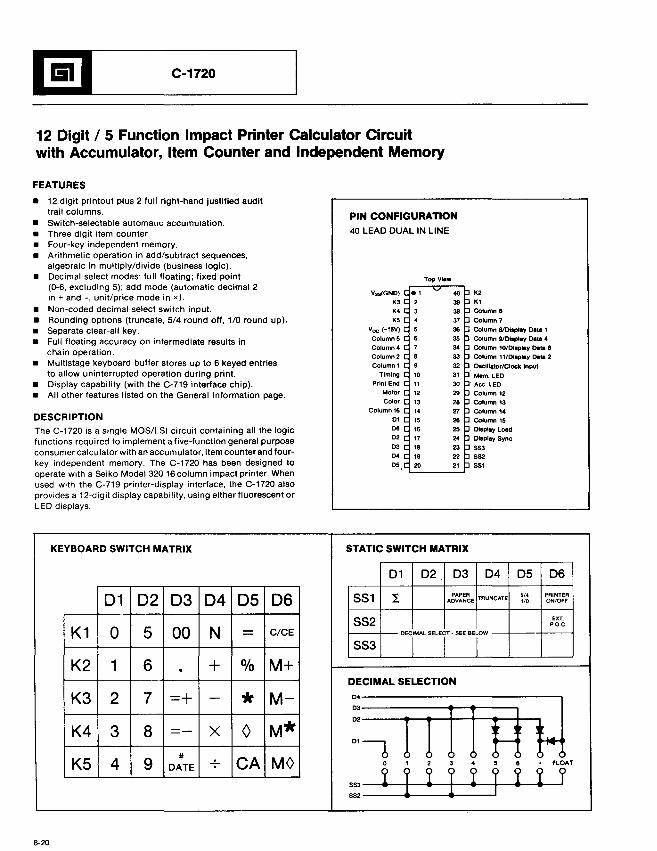
1!I'--- C_-1_72_0 _
12 Digit / 5 Function Impact Printer Calculator Circuitwith Accumulator, Item Counter and Independent Memory
FEATURES
• 12 digit printout plus 2 full right-hand justified audittrail columns.
• Switch-selectable automam; accumulation.• Three digit item counter.• Four-key independent memory.• Arithmetic operation in add/subtract sequences,
algebraic in multiply/divide (business logic).• Decimal select modes: full floating; fixed point
(0-6, excluding 5); add mode (automatic decimal 2in + and -, unit/price mode in x).
• Non-coded decimal select switch input.• Rounding options (truncate, 5/4 round off, 1/0 round up).• separate clear-all key.• Full floating accuracy on intermediate results in
chain operation.• Multistage keyboard buller stores up to 6 keyed entries
to allow uninterrupted operation during print.• Display capability (with the C-719 interface chip).• All other features listed on the General Information page.
DESCRIPTIONThe C-1720 is a single MOS/LSI circuit containing all the logicfunctions required to implement a five-function general purposeconsumer calculator with an accumulator, item counter and fourkey independent memory. The C-1720 has been designed tooperate with a Seiko Model 320 16 column impact printer. Whenused with the C-719 printer-display interface, the C-1720 alsoprovides a 12-digit display capability, using either fluorescent orLED displays.
PIN CONFIGURATION40 LEAD DUAL IN LINE
Vss(GNO)
K'K'K5
Yeo (-15V)
ColumnS
Column 4
Column 2Column 1
Timing
Print End
Motor
Color
Column 16
D'06D2
D'D4
D5,
K2
K'Column 6Column 7
Column 81Dtsplay Data 1
Column 910iaplay Data 4
Column 101Dlapiay D8ta 8
Column 11/Dlsplay Data 2
OIeillator/Clock Input
Mem. LED. Ace. LED
Column 12
Column 13
Column 14
Column 15OIsptey Load
Display Sync
SS3sS255'
KEYBOARD SWITCH MATRIX STATIC SWITCH MATRIX
01 02 03 04 05 06
01 02 03 04 05 06 SS1 I PAPERTRUNCATE '14 PRINTER
ADVANCE 1/0 ON/OFF
SS2 EXTP.O.C.
K1 0 5 00 N - C/CE DECrAL SELEr .SEE SErw-SS3
K2 1 6 + % M+.DECIMAL SELECTION
K3 2 7 =+ - * M- D'
ffttif}JD.
D2
K4 3 8 - - X 0 M*-
K5 4 9#
CA MOD'b
DATE 0 , 2 • • 5 8 . FLOAT
SS3 ! I ! I ! r ! ! f552
8-20
l!lL...-- C_-
7_1_9
_
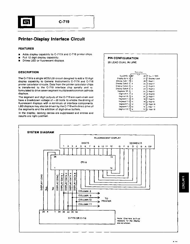
Printer-Display Interface Circuit
FEATURES
• Adds display capability to C-717X and C-718 printer chips.• Full 12 digit display capability.• Drives LED or fluorescent displays.
PIN CONFIGURATION
28 LEAD DUAL IN LINE
DESCRIPTION
The C-719 is a single MOS/LSI circuit designed to add a 12 digitdisplay capability to General Instrument's C-717X and C-718printer calculator circuits. Data from the printer calculator chipsis transferred to the C-719 interface chip serially and reformulated to drive seven segment muitiplexed common cathodedisplays.
The segment and digit outputs of the C-719 are open-drain andhave a breakdown voltage of -30 Volts to enable the driving offluorescent displays with a minimum of interface components.LED displays may also be driven by the C-719 with direct drive ofthe segments and the addition of digit-drive buffers.
In the display, leading zeroes are suppressed and entries andresults are right-justified.
SYSTEM DIAGRAM
Vss(GND)
Display Sync
Display Data 1Display Data 2
O"lsplay Data 4
Display Data 8
Segment DP
Segment A
Segment B
SegmentC
Segment 0
Segment E
Segment F
Segment G
Voo (-15V)
Display Load
Digit 1
Digit 2
Digit 3
Digit 4
Digit 5
Digjt 6
Digit 7
Digit 8
Digit 9
Digit 10
Digit 11
Digit 12
FLUORESCENT DISPLAY
DIGITS SEGMENTS1 2 3 4 5 6 7 8 9 10 11 12 G F E D C B A DP
II I I I I28 15
C"719
1 14
- '" .. <Xl I lIl-a 0 « « .. «« z .... .... .... ....0 > « « « «...J en a a c a> > > > > >::5 ::5 « ::5 ::5 «
...J ...JQ. Q. Q. Q. Q. Q.en 0
~en en en en en
15 ~ 15 15 15 15 15COLUMN 8 ,COLUMN 9
~
COLUMN 10~ TO
PRINTER
COLUMN 11
25 5 1 24 36 33 35 34
C-717X OR C-718 Note: Discrete pull-upresistors for the displayare not shown.
I