Embed Size (px)
Citation preview

8/20/2019 1977 Ford Car Shop Manual Volume 4 Body
http://slidepdf.com/reader/full/1977-ford-car-shop-manual-volume-4-body 1/449
8/20/2019 1977 Ford Car Shop Manual Volume 4 Body
http://slidepdf.com/reader/full/1977-ford-car-shop-manual-volume-4-body 2/449
8/20/2019 1977 Ford Car Shop Manual Volume 4 Body
http://slidepdf.com/reader/full/1977-ford-car-shop-manual-volume-4-body 3/449
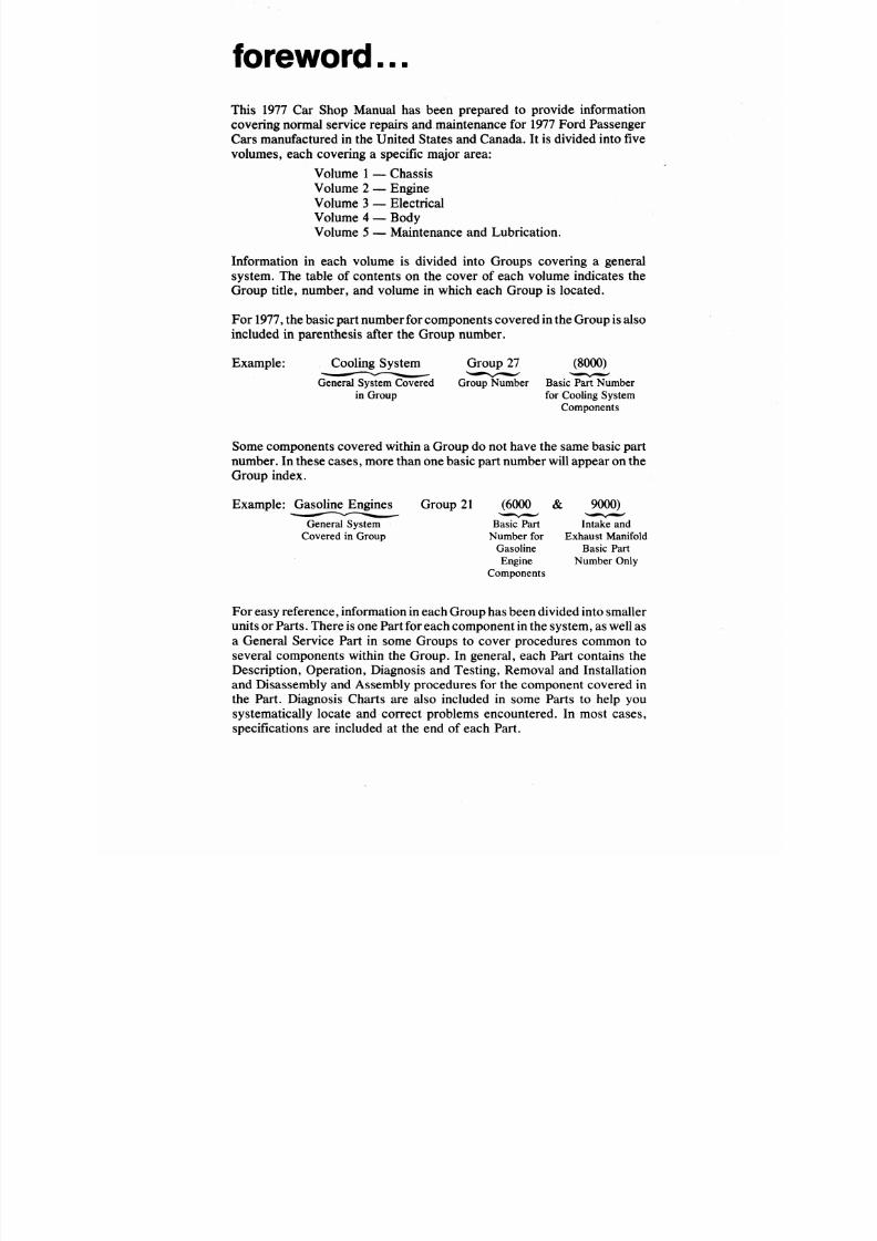
foreword...
This 1977 Car Shop Manual has been prepared to provide information
covering normal service repairs and maintenance for 1977 Ford Passenger
Cars manufactured in the United States and Canada. It is divided into five
volumes, each covering a specific major area:
Volume
1
— Chassis
Volume 2 — Engine
Volume 3 — Electrical
Volume 4 — Body
Volume 5 — M aintenance and Lubrication.
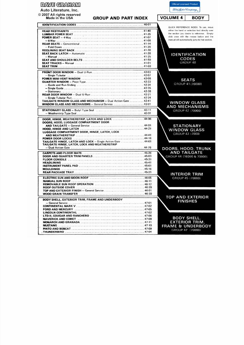
Information in each volume is divided into Groups covering a general
system. The table of contents on the cover of each volume indicates the
Group title, number, and volume in which each Group is located.
For 1977,
the
basic
part
number for components covered
in the Group is
also
included in parenthesis after the Group number.
Example: Cooling System Group 27 (8000)
General System Covered Group Num ber Basic Part Num ber
in Group for Cooling System
Components
Some components covered w ithin a Group do not have the same basic part
number. In these cases , more than one basic part number will appear on the
Group ind ex.
Exam ple: Gasoline Engines Group 21 (6000 & 9000)
General System
Covered in Group
Basic Part
Number for
Gasoline
Engine
Components
Intake and
Exhaust Manifold
Basic Part
Number Only
For
easy referen ce, information
in each Group has
been d ivided into smaller
units
or Parts.
There
is
on e
Part
for
each
component
in the
system,
as
well as
a General Service Part in some Groups to cover procedures common to
several components within the Group. In general, each Part contains the
Description, Operation, Diagnosis and Testing, Removal and Installation
and Disassembly and Assembly procedures for the component covered in
the Part. Diagnosis Charts are also included in some Parts to help you
systematically locate and correct problems encountered. In most cases,
specifications are included at the end of each Part.
8/20/2019 1977 Ford Car Shop Manual Volume 4 Body
http://slidepdf.com/reader/full/1977-ford-car-shop-manual-volume-4-body 4/449
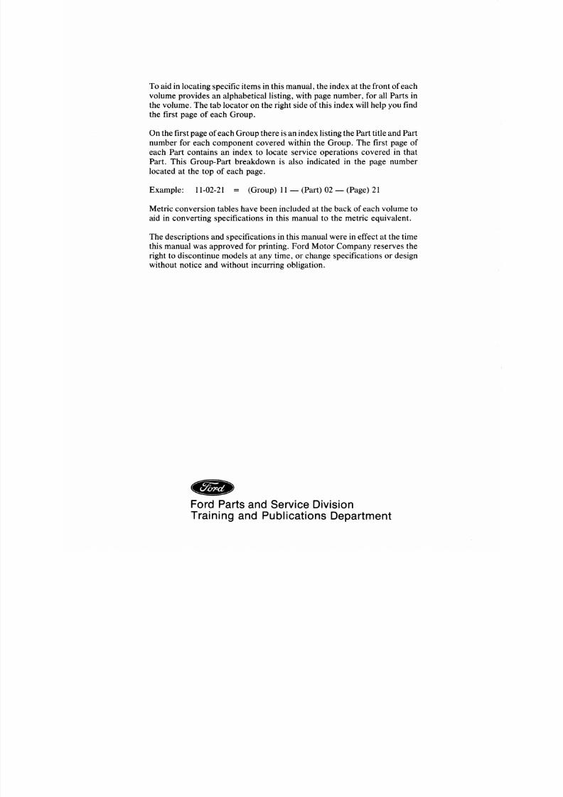
To aid in locating specific items in this ma nua l, the index at the front of each
volume provides an alphabetical listing, with page number, for all Parts in
the vo lum e. The tab lo cator on the right side of this index will help you find
the first page of each Group.
On the first page of each Grou p there is an index listing the Pa rt title and Part
number for each component covered within the Group. The first page of
each Part contains an index to locate service operations covered in that
Part. This Group-Part breakdown is also indicated in the page number
located at the top of each page.
Ex am ple: 11-02-21 = (Group) 11 — (Part) 02 — (Page) 21
Metric conversion tables have been included at the back of each volume to
aid in converting specifications in this manual to the metric equivalent.
The de scription s and specifications in this manual we re in effect at the time
this manual was approved for printing. Ford Motor Company reserves the
right to discontinue models at any time, or change specifications or design
without notice and without incurring obligation.
Ford Parts and Service Division
Training and Publications Department
8/20/2019 1977 Ford Car Shop Manual Volume 4 Body
http://slidepdf.com/reader/full/1977-ford-car-shop-manual-volume-4-body 5/449
40-00-1 Identification Codes
40-0
IDENTIFICATION CODES
GROU
Car Identification Codes
GENERAL DESCRIPTION
OFFICIAL VEHICLE
IDENTIFICATION NUMBER
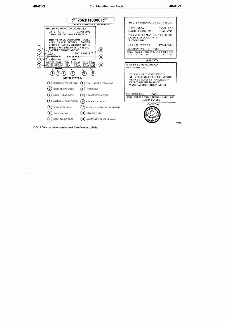
The official Vehicle Identification
Number (VIN) (Fig.
1) for
title
and
registration purposes
is
stamped
on a
meta l tab t h a t is fas tened to the
instrument panel close to the windshield
on the driver's side of the car and is
visible from outside.
VEHICLE CERTIFICATION LABEL
The Vehicle Certification Label (V.C
Label) (Fig. 1) is attached to the rear face
of the left front door on all 4-door models
and Mustangs and Cougars, and to the
left door lock pillar on all other 2-door
models .
The
upper half
of
the label
contains
the
name
of
manufacturer,
month and year of manufacture, Gross
Vehicle Weight Rating (GVWR), Gross
Axle Weight Rating (GAWR), and
the
certification statement.
The V.C. label also contains the
Vehicle Identification Number. This
number
is
also used
for
w ar ran ty
identification
of
the vehicle. The first
number indicates the model year. The
letter following the model year number
indicates
the
manufacturing assembly
plant. The next two numbers designate
the Body Serial Code followed by a letter
expressing the Engine Code.
The last six digits of the Vehicle
Identif ication Number indicate
the
Consecutive Unit Number of each unit
bui l t at each assembly plan t. The
Consecutive Unit Numbers begin
as
follows:
100,001—Ford, LTD II, Ranchero,
M us tang , Thu nderb i rd , G ran ada ,
Maverick, and Pinto.
500,001—Mercury, Cougar, Comet,
Monarch and Mercury Bobcat.
800,001—Lincoln Continental and
Continental Mark V.
The remaining information
on the
V.C. Label consists of the following
vehicle identification codes:
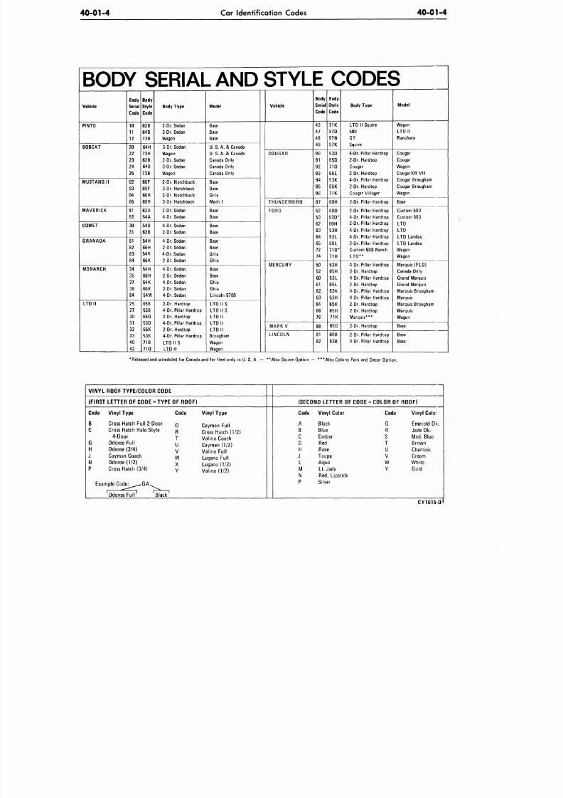
The BODY code is two numerals
a letter identifying the body style.
The COL (color) code is a num
and letter code indicating the ext
paint color code and vinyl roof type
color (if equipped).
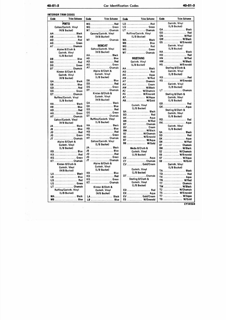
The TRIM code consists
of a
letter or a letter-number combina
designating the interior trim.
The AXL E code is a number or l
indicat ing
the
rear axle ratio
standard or locking type axles.
The TRNS. code is a number or l
indicating the type
of
transmission.
The DSO code, consisting
of
numbers, designates the district in w
the car was ordered and may appea
conjunction with
a
Domestic Spe
Order
or
Foreign Special Order num
when applicable. Ford of Canada D
codes consist of a letter and numbe
The following charts provide
various codes and their respe
identification:
8/20/2019 1977 Ford Car Shop Manual Volume 4 Body
http://slidepdf.com/reader/full/1977-ford-car-shop-manual-volume-4-body 6/449
40-01-2
Car Identification Codes
40-01-2
<f~7S63H 1 0 0 0 0 1 ^
(VEHICLE IDENTIFICATION NUMBER
MFD. BY FORD M OTOR CO. IN U.S.A.
DATE: 07/76 GVWR 5892
GAWR: FRONT 2964, REAR 2928
THIS VEHICLE CONFORMS TO ALL
A P P L I C A B L E F E D E R A L M O T O R
VEHICLE SAFETY STANDARDS IN
EFFECT ON THE DATE OF MANU-
FACTURE SHOWN ABOVE.
F 0 0 3 3 / R 0 1 5 5
7 S 6 3 H 1 0 0 0 0 1 .
PASSENGER
'VEH. ihENT. NO. I TYPE
6 H 7 U 8 ) ( 9 l (10) (11
(UNITED STATES)
T ) CONSECUTIVE UNIT NO. ( ? ) V INYL ROOF TYPE/COLOR
^ ) BODY SERIAL CODE ( j T ) TRIM CODE
j j ) MODEL YEAR CODE MO ) TRANSMISSION CODE
jT) ASSEMBLY PLANT CODE ( 7 f ) REAR AXLE CODE
J ) BODY TYPE CODE Q ? ) DISTRICT - SPECIAL EQUIPMENT
6 J ENGINE CODE H 3 ) VEHICLE TYPE
7 ) BODY COLOR CODE ( 1 4 J ACCESSORY RESERVE LOAD
MFD. BY FORD MOTOR CO. IN U.S.A.
DATE: 07/76
GAWR: FRO NT 2964
GVWR 5892
REAR 2928
THIS VEHICLE MANUFACTURED FOR
EXPORT ONLY ON DATE
SHOWN ABOVE.
7 S 6 3 H 1 0 0 0 0 2
VEH. IDENT. NO. I
P A S S E N G E R
TYPE
BODY I COLOR | TRIM | TR A N S| AXLE | DSO
53H 1C-CA D X 6 90
(EXPORT)
MFD.
BY FORD MOTOR CO.
OF CANADA LTD.
THIS VEHICLE CONFORMS TO
ALL APPLICABLE FEDERAL MOTOR
VEHICLE SAFETY STANDARDS IN
EFFECT ON THE DATE OF
MANUFACTURE SHOWN ABOVE
VEH. IDENT. NO. |
TYPE
BODY I COLOR I TRIM I TRANS. I AXLE
MADE IN CANADA
DSO
( C A N A D A )
Y1410-J
FIG. 1 Vehicle Identification and Certification Labels

8/20/2019 1977 Ford Car Shop Manual Volume 4 Body
http://slidepdf.com/reader/full/1977-ford-car-shop-manual-volume-4-body 7/449
40-01-3
Car Identification Codes
40-0
SPECIFICATION CODES
1977 IDENTIFICATION CODES
ASSEMBLY PLANT CODES
Code Letter
District
A Atlanta
B Oakville (Canada)
E
,
Mahwah
F Dearborn
G Chicago
H Lorain
J Los Angeles
K Kansas City
P Twin Cities
R San Jose
S Allen Park (Pilot)
T Metuchen
U Louisville
W Wayne
X
St .
Thomas
Y Wixom
Z St. Louis
ENGINE CODES
Codes
No.
of
Cyls.
Displacement
A
8
460-4V
r
8
460 -4V (Police)
F 8
302-2V
H ; : : : : : a : . " : : . ' . ; . 3 5 1 - 2 V
L
6 .
250-1V
8 400-4V
S
8 . . . .. ....
400-2V
T
6
200-1V
Y 4 139-2V (2.3L)
Z
6
169-2V (2.8L)
DISTRICT CODES
LI NCOLN- M ERCURY
Code
00
11
15
16
17
21
22
23
26
31
32
33
34
41
42
.
46
51
52
53
54
84
90's
District
. . .
Special
. .
Boston
. . . New
York
. . .
Philadelphia
. . .
Washington
Atlanta
. . .
Dallas
.
Jacksonville
Memphis
Buffalo
Cincinnati
. Cleveland
.
Detroit
. . . Chicago
. . . S t
Louis
. .. Twin Cities
. . .
Denver
. . .
Los Angeles
Oakland
. . . Seattle
Home
O ff
Reserve
. .
Export
DISTRICT CODES
FORD
FORD OF CANADA
TRANSMISSION CODES
Codes Type
M A N U A L
1
3
Speed
6
4
Speed @
7
4
Speed
(b )
AUTOMATIC
V XP(C-3)
W XP( C- 4 ) '
X F M X ]
U
•
XPL( C- 6 )
Z
X PL
(Special)
Mercury
Code
, A1
A2
A3
A4
A 6
A7
12
Region
Central
Eastern
Atlantic
Midwestern
. .
Western
. .
Pacific
. . Export
Ford
Code
B1
B2
B3
B4
B6
B7
12
REAR AXLE RATIO CODES
Conventional Lock
B
1
J
8
2
3
6 0
4
. . .
7
Ratio
2.47
2.50
2.73
2.75
2.79
3 0 0
3
1 8
3 40
EXTERIOR PAINT COLOR CODES
Code
00
11
12
13
14
15
16
17
21
22
23
24
25
26
28
41 .
42
43
45
46
47
48
52
53
54
55
56
57
58
71
72
73
74
75
76
83
84
85
86
87
89
90's
District
Special
Boston
Buffalo
New York
Pittsburgh
Newark
Philadelphia
Washington
Atlanta
Charlotte
Memphis
Jacksonville
Richmond
New Orleans
Louisville
Chicago
Cleveland
Milwaukee
Lansing
Indianapolis
Cincinnati
Detroit
Dallas
Kansas City
Omaha
St. Louis
Davenport
Houston
Twin Cities
Los Angeles
San Jose
Salt Lake City
Seattle
Phoenix
Denver
Government
Home
Off.
Reserve
American
Red
Cross
Recreational Veh. Po
Body Company
Transportation Servic
Export
Code Ref .#
Color
Code Ref. # Color Code Ref. #
Color
1 C .
1G .
1N .
I P .
1Q .
2M .
2R .
2 U .
3G .
3 U .
31 .
3 4 .
4 6 .
47 .
4 V .
5 0 .
6 E .
6 P .
6 U .
1 7 2 4
5 2 9 9
5 4 7 6
5 5 2 3
5 5 2 7
3 4 1 3
5 4 4 0
5 4 5 5
5 0 9 4
5 4 6 7
5 4 9 9
5 0 4 1
5 3 2 8
5 4 0 4
5 2 3 3
5 4 7 7
5 0 8 0
5 4 0 6
5 4 4 1
. . .
Black
. . .
Silver
Met.
. . .
Dove Gray
. . . Med.
Gray Met.(Tie Tone only)
. . .
Med. Silver
Met.
. . .
Dark
R ed
. . . Brt. Red
. . .
Lipstick
R ed
.. . Brt. Dk.
Blue
Met.
. . . L t .
Blue
. . .
Midnig ht Blue
. . . Med. Blue
. . . D k .
Jade
Met.
. . . L t .
Green
. . . D k .
Yellow Green
Met.
— Ok.
Brown
Met.
. . . B r t . Yellow
. . .
Cream
. . .
Lt .Tan
7 0 . . .
7 S . . .
8 G . . .
8 H . . .
8 K . . .
8 N . . .
8 P . . .
8 Y . . .
8 3 . . .
8 4 . . .
9 D . . .
. 5479
. 5489
. 5466
. 5470
. 5486
. 5496
. 5471
. 5494
. 5524
. 5525
. 5418
Lt. Aqua M t . .
Dk. Emerald
Met.
Vista Orange
Tan
Brt. Saddle Met.
Dk. Cordovan
Met.
Lt. Cordovan
Champagne
Met.
Chamois
Dk. Cordovan
White
7T 5490
8J 5484
8W
5 4 9 1
Med.
Emerald
Met.
Med.
Tan Met.
Chamois
Met.
(RPO) DIAMOND BRIGHT (POLISH) " W "
2 S . . .
2 G . . .
3 2 . . .
8 V . . .
8 Z . . .
1 R . . .
.. 5 4 4 4
..
5 0 7 0
.. 5 5 1 1
..
5 4 9 5
.. 5 5 1 0
.. 5 5 1 2
Dk: Red Met.
Med. Red
Met.
Med.
Blue
Met.
Med.
Ember
Met.
Med.
Nectarine
Met.
Lt. Silver
Met.
(RPO) UNIQUE COLORS
(NON
POLISH)
" D "
2 Y . . .
3 V . . .
6 V . . .
7 H . . .
7 L . . .
5 4 9 2
5 4 8 0
5 2 9 8
5 4 6 0
5 4 8 2
5 4 8 3
Rose
Met.
Brt. Blue
Met.
Tan Met.
Med.
Gold Met.
Brt. Aqua
Met.
Lt. Jade
Met.
(RPO) DIAMOND FLARE (POLISH)
" G "
U
5411
Silver
Met.
1L 547 2 Black
Met.
2T 546 2 Rose
Met.
6 Y
5461 Brt.
Yellow Gold
Met.
7B 546 3 Crystal Jade
Met.
CY1
8/20/2019 1977 Ford Car Shop Manual Volume 4 Body
http://slidepdf.com/reader/full/1977-ford-car-shop-manual-volume-4-body 8/449
40-01-4
Car Identification Codes
40-01-4
BODY SERIAL AND STYLE CODES
Vehicle
PINTO
BOBCAT
MUSTANG
II
MAVERICK
COMET
G R A N A D A
MONARCH
LT D II
Body
Serial
Code
10
11
12
20
22
23
24
25
02
03
04
05
91
9 2
30
31
81
82
83
84
34
35
37
38
84
25
27
30
31
32
33
40
42
Body
Style
Code
62 B
64 B
73B
64 H
73H
62 B
64B
73B
60 F
69 F
60 H
69 R
62 A
54 A
54 B
62 B
54 H
66H
54 K
66K
54 H
66H
54 K
66 K
54 M
65B
53 B
65 D
53 D
65 K
53 K
71 B
71 D
Body Type
2-Dr. Sedan
3-Dr. Sedan
Wagon
3-Dr. Sedan
Wagon
2-Dr. Sedan
3-Dr. Sedan
Wagon
2-Dr. Notchback
3-Dr. Hatchback
2-Dr. Notchback
3-Dr. Hatchback
2-Dr. Sedan
4-Dr. Sedan
4-Dr. Sedan
2-Dr. Sedan
4-Dr. Sedan
2-Dr. Sedan
4-Dr. Sedan
2-Dr. Sedan
4-Dr. Sedan
2-Dr. Sedan
4-Dr. Sedan
2-Dr. Sedan
4-Dr. Sedan
2-Dr. Hardtop
4-Dr. Pi l lar Hardtop
2-Dr. Hardtop
4-Dr. Pi l lar Hardtop
2-Dr. Hardtop
4-Dr. Pi l lar Hardtop
LT D
I I S
LT D II
Model
Base
Base
Base
U. S. A. & Canada
U. S. A. & Canada
Canada Only
Canada Only
Canada Only
Base
Base
Ghia
Mach 1
Base
Base
Base
Base
Base
Base
Ghia
Ghia
Base
Base
Ghia
Ghia
Lincoln 5700
LT D I I S
LT D
I I S
LT D
II
LT D
II
LT D II
Brougham
Wagon
Wagon
Vehicle
COUGAR
THUNDERBIRD
FORD
MERCURY
M A R K V
LINCOLN
Body
Serial
Code
43
47
48
49
9 0
91
92
9 3
94
95
9 6
87
52
53
62
63
64
65
72
74
50
52
60
61
62
63
64
66
76
89
81
82
Body
Style
Code
71 K
97D
97 R
97 K
53 D
65 D
71 D
65 L
53 K
65 K
71 K
60H
60D
5 3 D *
60 H
53 H
5 3L
60 L
7 1 D *
71 H
53 H
65 H
53 L
65 L
53 K
53 H
65 K
65 H
71 K
65 D
C
O
C
L
O
Body Type
LT D II Squire
50 0
GT
Squire
4-Dr. Pi l lar Hardtop
2-Dr. Hardtop
Cougar
2-Dr. Hardtop
4-Dr. Pi l lar Hardtop
2-Dr. Hardtop
Cougar Vi l lager
2-Dr. Pi l lar Hardtop
2-Dr. Pi l lar Hardtop
4-Dr. Pi l lar Hardtop
2-Dr. Pi l lar Hardtop
4-Dr. Pi l lar Hardtop
4-Dr. Pi l lar Hardtop
2-Dr. Pi l lar Hardtop
Custom 5 00 Ranch
L T D * *
4-Dr. Pi l lar Hardtop
2-Dr. Hardtop
4-Dr. Pi l lar Hardtop
2-Dr. Hardtop
4-Dr. Pi l lar Hardtop
4-Dr. Pi l lar Hardtop
2-Dr. Hardtop
2-Dr. Hardtop
M a r q u i s * * *
2-Dr. Hardtop
2-Dr. Pi l lar Hardtop
4-Dr. Pi l lar Hardtop
Model
Wagon
LT D II
Ranchero
Cougar
Cougar
Wagon
CougarXR VII
Cougar Brougham
Cougar Brougham
Wagon
Base
Custom 5 00
Custom
50 0
LT D
LT D
LTD Landau
LTD Landau
Wagon
Wagon
Marquis ( F L D )
Canada Only
Grand Marquis
Grand Marquis
Marquis Brougham
Marquis
Marquis Brougham
Marquis
Wagon
Base
Base
Base
i
Released a nd scheduled for Canada and fo r f leet only in U. S. A. - * *A lso Squi re Opt ion - * ** Also Colony Park an d Decor Opt ion .
VINYL ROOF TYPE/COLOR CODE
(FIRST LETTER OF CODE = TYPE OF ROOF)
Code Vinyl Type Code Vinyl Type
B Cross Hatch Full 2-Door
Q
Cayman Full
C Cross Hatch Halo Style
R
Cross Hatch (1/2)
4
-
D o o r
T Valino Coach
G
^
e n S G
^
U
Cayman (1/2)
H Odense(3/4)
v
Valino Full
J Cayman Coach
w
Lugano Full
o
?
denS
u
(1 /
,
2)
/o
// n
x
Lugano (1/2)
P Cross Hatch (3/4)
Y
Valino (1/2)
Example Code^^-GA^^^
'Odense Full' Black
(SECOND LETTER OF CODE = COLOR OF ROOF)
Code Vinyl Color Code Vinyl Colo
A Black Q Emerald Dk.
B Blue R Jade Dk.
C Ember S Med. Blue
D Red T Brown
H Rose U Chamois
J Taupe V Cream
L Aqua W White
M Lt.Jade Y Gold
IM Red, Lipstick
P Silver
CY1615D1
8/20/2019 1977 Ford Car Shop Manual Volume 4 Body
http://slidepdf.com/reader/full/1977-ford-car-shop-manual-volume-4-body 9/449
40-01-5
Car Identification Codes
40-
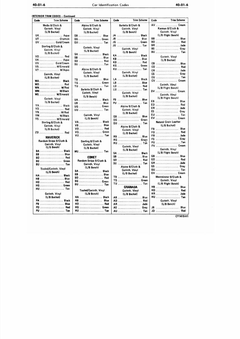
INTERIOR TRIM CODES
Code
Trim Scheme
Code
Trim Scheme Code
Trim Scheme
Code
Trim Sche
PINTO
Colton/Cor inth. Vinyl
(H/B Bucket)
AA Black
AB Blue
AD Red
AG Green
AT Chamois
Alpine B/Cloth &
Corinth.
V iny l
(L/B Bucket)
DB Blue
DD Red
DG . .
Green
DT Chamois
Kirsten B/Cloth &
Corinth. V i n y l
(H/B Bucket)
GA Black
GB Blue
G D . . . R e d
GG Green
GT Chamois
Ruff ino/Cor inth. Vinyl
(L/B Bucket)
HA Black
HB Blue
HD Red
HG Green
HT Chamois
Colton/Cor inth. Vinyl
(H/B Bucket)
JA Black
JB Blue
JD Red
JG Green
JT Chamois
Alpine B/Cloth &
Corinth.
V i n y l
(L/B Bucket)
KB Blue
KD Red
KG Green
KT Chamois
Kirsten B/Cloth &
Corinth. V iny l
(H/B Bucket)
LA Black
LB Blue
LD Red
LG Green
LT Chamois
Ruf f ino/Cor in th . V iny l
(L/B Bucket)
MA Black
MB Blue
MD Red
MG Green
MT Chamois
Carerra/Corinth. Vinyl
(H/B Bucket)
NT Chamois
BOBCAT
Colton/Cor inth. Vinyl
(H/B Bucket)
AA Black
AB Blue
AD Red
AG Green
AT Chamois
Alpine B/Cloth &
Corinth. V iny l
(L/B Bucket)
DB Blue
DD Red
DG Green
DT Chamois
Kirsten B/Cloth &
Corinth.
V iny l
(H/B Bucket)
GA Black
GB Blue
GD Red
GG Green
GT Chamois
Ruff ino/Cor inth. Vinyl
(L/B Bucket)
HA Black
HB Blue
HD Red
HG Green
HT Chamois
Colton/Cor inth. Vinyl
(L/B Bucket)
JA Black
JB Blue
JD Red
JG Green
JT Chamois
Alpine B/Cloth &
Corinth.
V iny l
(L/B Bucket)
KB Blue
KD Red
KG Green
KT Chamois
Kirsten B/Cloth &
Corinth. V iny l
(H/B Bucket)
LA Black
LB Blue
LD Red
LG Green
LT Chamois
Ruff ino/Cor inth. Vinyl
(L/B Bucket)
MA Black
MB Blue
MD Red
MG Green
MT Chamois
MUSTANG
Corinth.
V iny l
(L/B Bucket)
AA Black
AD Red
AK Aqua
AN W/Red
AT Chamois
AV Cream
AW W/Black
A2 W/Chamois
A5 W/Emerald
A7 W/Aqua
A8 W/Gold
Corinth.
V iny l
(L/B Bucket)
BA Black
BD Red
BK Aqua
BN W/Red
BT Chamois
BV Cream
BW W/Black
B2 W/Chamois
B5 W/Emerald
B7 W/Aqua
B8 W/Gold
Media B/Cloth &
Corinth.
V iny l
(L/B Bucket)
CK Aqua
CT Chamois
CV Gold/Cream
Corinth.
V i n y l
(L/B Bucket)
DT Chamois
Sterl ing B/Cloth &
Corinth.
V iny l
(L/B Bucket)
ED Red
EK Aqua
EV Gold/Cream
E5 W/Emerald
Corinth.
V iny l
(L/B Bucket)
GA Bl
GD R
GN W/R
GW W/Bl
G5 W/Emer
Corinth. V i n y l
(L/B Bucket)
HA Bl
HD R
HN W/R
HW W/Bl
H5 W/Emer
Sterl ing B/Cloth &
Corinth.
V i n y l
(L/B Bucket)
K D . . . . R
K5 W/Emer
Corinth.
V iny l
(L/B Bucket)
LT Cham
Sterling B/Cloth &
Corinth.
V i n y l
(L/B Bucket)
QD R
QK Aq
Sterling B/Cloth &
Corinth. V i n y l
(L/B Bucket)
RD R
RK Aq
Corinth. V i n y l
(L/B Bucket)
SA Bl
SD R
SK Aq
SN W/R
ST Cham
SW W/Bla
S2 W/Cham
S5 W/Emer
S7 W/Aq
S8 W/G
Corinth.
V iny l
(L/B Bucket)
TA Bl
TD R
TK Aq
TN W/R
TT Cham
TW W/Bl
T2 W/Cham
T5 W/Emer
T7 W/Aq
T8 W/G
CY1
8/20/2019 1977 Ford Car Shop Manual Volume 4 Body
http://slidepdf.com/reader/full/1977-ford-car-shop-manual-volume-4-body 10/449
Car Identification Codes
40-01-6
-
Continued
Code
Trim Scheme
C o d e
Trim Scheme Code Trim Scheme
Barletta B/Cloth
&
Corinth.
Vinyl
(L/B Bench)
JA Black
JB Blue
JG Green
JU
Tan
Corinth.
Vinyl
(L/B Bench)
KA Black
KB Blue
KD
Red
KG Green
KU
Tan
Corinth.
Vinyl
(L/B Bucket)
LA Black
LB Blue
LD
Red
LU
Tan
Corinth.
Vinyl
(L/B Bucket)
PB Blue
PU
Tan
Alpine B/Cloth
&
Corinth. Vinyl
(L/B Bucket)
QB Blue
QG Green
QU
Tan
Alpine B/Cloth
&
Corinth. Vinyl
(L/B Bucket)
RB Blue
RG Green
RU
Tan
Corinth. Vinyl
(L/B Bucket)
SA Black
SB Blue
SD
Red
SU
Tan
Alpine B/Cloth
&
Corinth.
Vinyl
(L/B Bucket)
TB Blue
TG Green
TU
Tan
GRANADA
Corinth.
Vinyl
(L/B Bucket)
AB Blue
AD
Red
AR Jade
AS Gray
AU
Tan
C o d e
Trim Scheme
Media B/Cloth &
Corinth.
Vinyl
(L/B Bucket)
UK Aqua
UT Chamois
UV Gold/Cream
Sterling B/Cloth
&
Corinth.
Vinyl
(L/B Bucket)
VD
Red
VK Aqua
VV Gold/Cream
V5 W/Emerald
V7 W/Aqua
Corinth.
Vinyl
(L/B Bucket)
WA Black
WD
Red
WN W/Red
WW W/Black
W5 W/Emerald
Corinth.
Vinyl
(L/B Bucket)
YA Black
YD
Red
YN W/Red
YW W/Black
Y5 W/Emerald
Sterling B/Cloth
&
Corinth. Vinyl
(L/B Bucket)
ZD
Red
MAVERICK
Random Stripe B/Cloth
&
Corinth.
Vinyl
(L/B Bench)
BA Black
BB Blue
BD
Red
BG Green
BU
Tan
Tooled/Corinth. Vinyl
(L/B Bench)
HA Black
HB Blue
HD
Red
HG Green
HU
Tan
Corinth.
Vinyl
(L/B Bucket)
PA Black
PB Blue
PD
Red
PU
Tan
Alpine B/Cloth &
Corinth.
Vinyl
(L/B Bucket)
QB Blue
QG Green
QU
Tan
Corinth. Vinyl
(L/B Bucket)
SA Black
SB Blue
SD
Red
SU
Tan
Alpine B/Cloth
&
Corinth.
Vinyl
(L/B Bucket)
TB Blue
TG Green
TU
Tan
Barletta B/Cloth
&
Corinth. Vinyl
(L/B Bench)
UA Black
UB Blue
UG Green
UU
Tan
Corinth.
Vinyl
(L/B Bench)
VA Black
VB Blue
VD
RGd
VG Green
VU
Tan
Sterling B/Cloth
&
Corinth.
Vinyl
(L/B Bucket)
WU
Tan
COMET
Random Stripe B/Cloth
&
Corinth.
Vinyl
(L/B Bench)
BA Black
BB Blue
BD
Red
BG Green
BU
Tan
Tooled/Corinth. Vinyl
(L/B Bench)
HA Black
HB Blue
HD
Red
HG Green
HU
Tan
AV Cream
Kasman B/Cloth &
Corinth.
Vinyl
(L/B Flight Bench)
B B B l u e
BD
Red
BR Jade
BS Gray
BU
Tan
Corinth. Vinyl
(L/B Bucket)
CB Blue
CD
Red
CR Jade
CS Gray
CU
Tan
CV Cream
Corinth.
Vinyl
(L/B Flight Bench)
DV Cream
Corinth. Vinyl
(L/B Flight Bench)
EB Blue
ED
Red
ER Jade
ES Gray
EU
Tan
EV Cream
Natural Grain Leather
(L/B Bucket)
FB Blue
FD
Red
FR Jade
FS Gray
FU
Tan
FV Cream
Corinth.
Vinyl
(L/B Flight Bench)
GB Blue
GD
Red
GR Jade
GS Gray
GU
Tan
GV Cream
Westminster B/Cloth &
Corinth.
Vinyl
(L/B Flight Bench)
HB Blue
HD
Red
HR Jade
HU
Tan
Corinth. Vinyl
(L/B Bench)
JB Blue
JD
Red
CY1419-H1
8/20/2019 1977 Ford Car Shop Manual Volume 4 Body
http://slidepdf.com/reader/full/1977-ford-car-shop-manual-volume-4-body 11/449
40-01-7
Car Identification Codes
40-0
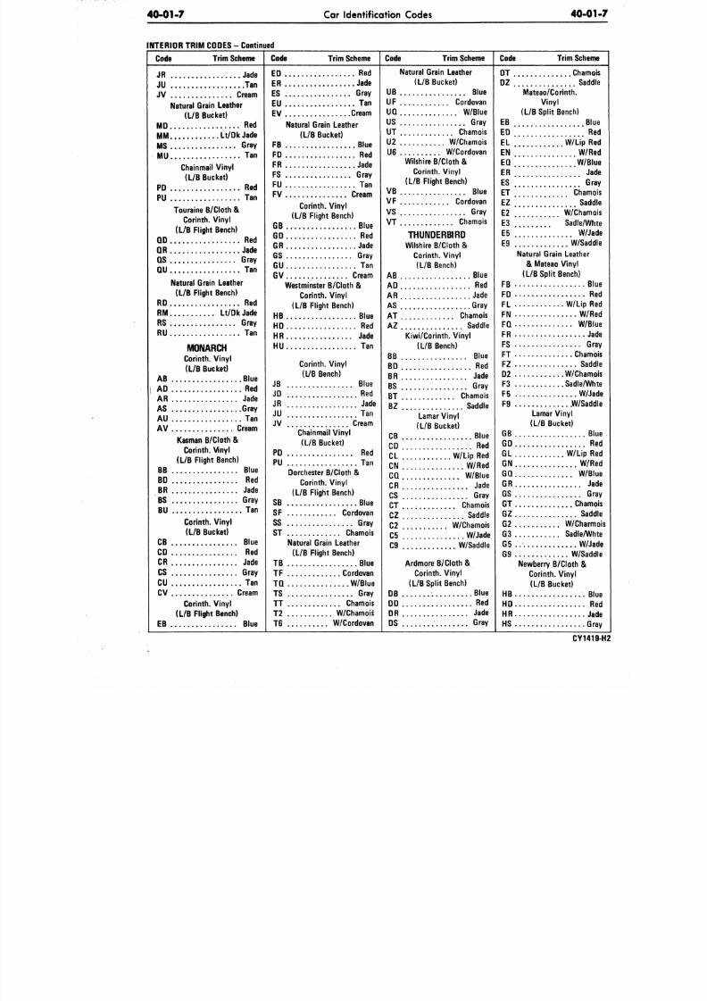
INTERIOR TRIM CODES - Continued
Code
Trim Scheme
C o d e
Trim Scheme Code Trim Scheme Code
Trim Sche
JR Jade
JU Tan
JV Cream
Natural Grain Leather
(L/B Bucket)
MD Red
MM Lt /DkJade
MS Gray
MU
Tan
Chain mail Viny l
(L/B Bucket)
PD Red
PU Tan
Touraine B/Cloth
&
Corinth.
Vinyl
(L/B Flight Bench)
QD Red
QR Jade
QS Gray
QU
Tan
Natural Grain Leather
(L/B Flight Bench)
RD Red
RM Lt /DkJade
RS Gray
RU Tan
MONARCH
Corinth. V inyl
(L/B Bucket)
AB Blue
AD
Red
AR Jade
AS Gray
AU Tan
AV Cream
Kasman B/Cloth &
Corinth. Vinyl
(L/B Flight Bench)
B B B l u e
BD
Red
BR Jade
BS Gray
BU Tan
Corinth. V inyl
(L/B Bucket)
C B B l u e
CD Red
CR Jade
CS Gray
CU
Tan
CV Cream
Corinth.
V inyl
(L/B Flight Bench)
EB Blue
ED
ER
ES
EU
Red
Jade
Gray
Tan
EV Cream
Natural Grain Leather
(L/B Bucket)
FB Blue
FD
Red
FR Jade
FS Gray
FU Tan
FV Cream
Corinth.
Vinyl
(L/B Flight Bench)
GB Blue
GO Red
GR Jade
GS Gray
GU
Tan
GV Cream
Westminster B/Cloth
&
Corinth.
Vinyl
(L/B Flight Bench)
HB Blue
HD Red
HR Jade
HU
Tan
Corinth.
Vinyl
(L/B Bench)
JB Blue
JD Red
JR Jade
JU
Tan
JV Cream
Chainmail Vinyl
(L/B Bucket)
PD Red
PU Tan
Dorchester B/Cloth
&
Corinth.
Vinyl
(L/B Flight Bench)
S B B lu e
SF Cordovan
SS Gray
ST Chamois
Natural Grain Leather
(L/B Flight Bench)
TB Blue
TF Cordovan
TQ W/Blue
TS Gray
TT Chamois
T2
..
W/Chamois
T6 W/Cordovan
Natural Grain Leather
(L/B Bucket)
UB Blue
UF Cordovan
UQ W/Blue
US Gray
UT Chamois
U2 W/Chamois
U6 W/Cordovan
Wilshire B/Cloth
&
Corinth.
Vinyl
(L/B Flight Bench)
V B B l u e
VF Cordovan
VS Gray
VT Chamois
THUNDERBIRD
Wilshire B/Cloth &
Corinth.
Vinyl
(L/B Bench)
AB Blue
AD
Red
AR Jade
AS Gray
AT Chamois
AZ Saddle
Kiwi/Corinth. Viny l
(L/B Bench)
B B B l u e
BD
Red
BR Jade
BS Gray
BT Chamois
BZ Saddle
Lamar Vinyl
(L/B Bucket)
CB Blue
CD
Red
CL W/Lip
Red
CN W/Red
CQ W/Blue
CR Jade
CS Gray
CT Chamois
CZ Saddle
C2 W/Chamois
C5 W/Jade
C9 W/Saddle
Ardmore B/Cloth
&
Corinth.
Vinyl
(L/B Split Bench)
D B B l u e
DD Red
DR Jade
DS Gray
DT Cham
DZ Sad
Mateao/Corinth.
Vinyl
(L/B Split Bench)
EB B
ED
R
EL W/Lip R
EN W/
EQ W/B
ER ................ J
ES G
ET Cham
&
...............
Sa
E2 " " w / C h a m
E3 Sadle/W
E5 W/
E9 W/Sa
Natural Grain Leather
& Mateao Vinyl
(L/B Split Bench)
F B
FD
R
FL W/Lip
FN W/
FQ W/
FR J
FS G
FT Cha
FZ Sa
D2 W/Cha
F3 Sadle/W
F5 W/
F9 .W/Sa
Lamar Vinyl
(L/B Bucket)
GB
GD R
GL W/Lip
GN W
GQ W/
GR
GS G
GT Cha
GZ Sa
G2 W/Cha
G3 Sadle/W
G5 W/
G9 W/Sa
Newberry B/Cloth
&
Corinth.
V inyl
(L/B Bucket)
HB
HD R
HR
HS G
CY14
8/20/2019 1977 Ford Car Shop Manual Volume 4 Body
http://slidepdf.com/reader/full/1977-ford-car-shop-manual-volume-4-body 12/449
40-01-8
Car Identification Codes
40-01-8
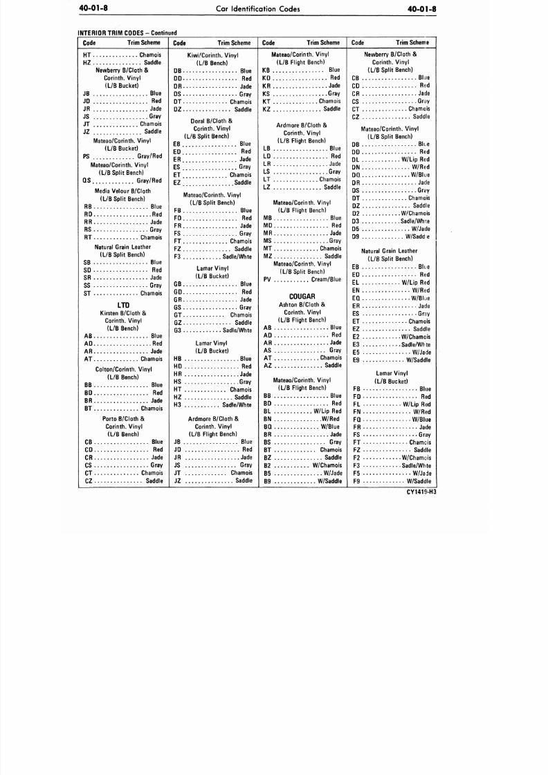
INTERIOR TRIM CODES - Continued
Code
Trim Scheme
C o d e
Trim Scheme
Code Trim Scheme
Mateao/Corinth. V inyl
(L/B Flight Bench)
KB Blue
KD Red
KR Jade
KS Gray
KT Chamois
KZ Saddle
Ardmore B/Cloth &
Corinth. Vinyl
(L/B Flight Bench)
LB Blue
LD Red
LR Jade
LS Gray
LT Chamois
LZ Saddle
Mateao/Corinth. Vinyl
(L/B Flight Bench)
MB Blue
MD Red
MR Jade
MS Gray
MT Chamois
MZ Saddle
Mateao/Corinth. Viny l
(L/B Split Bench)
PV Cream/Blue
C O U G A R
Ashton B/Cloth &
Corinth. Vinyl
(L/B Flight Bench)
AB Blue
AD Red
AR Jade
AS Gray
AT Chamois
AZ Saddle
Mateao/Corinth. Viny l
(L/B Flight Bench)
BB Blue
BD Red
BL W/Lip Red
BN W/Red
BQ W/Blue
BR Jade
BS Gray
BT Chamois
BZ Saddle
B2 W/Chamois
B5 W/Jade
B9 W/Saddle
C o d e
Trim Scheme
HT Chamois
HZ Saddle
Newberry B/Cloth &
Corinth. Vinyl
(L/B Bucket)
JB Blue
JD
Red
JR Jade
JS Gray
JT Chamois
JZ Saddle
Mateao/Corinth. Viny l
(L/B Bucket)
PS Gray/Red
Mateao/Corinth. Vin yl
(L/B Split Bench)
QS Gray/Red
Media Velour B/Cloth
(L/B Split Bench)
RB Blue
RD Red
RR Jade
RS Gray
RT Chamois
Natural Grain Leather
(L/B Split Bench)
SB Blue
SD
Red
SR Jade
SS Gray
ST Chamois
LTD
Kirsten B/Cloth
&
Corinth. Vinyl
(L/B Bench)
AB Blue
AD
Red
AR Jade
AT Chamois
Colton/Corinth. Vinyl
(L/B Bench)
BB Blue
BD Red
BR Jade
BT Chamois
Porto B/Cloth
&
Corinth. Vinyl
(L/B Bench)
CB Blue
CD Red
CR Jade
CS Gray
CT * Chamois
CZ Saddle
Kiwi/Corinth. Vinyl
(L/B Bench)
DB
DD
DR
DS
B l u e
Red
Jade
Gray
DT Chamois
DZ Saddle
Doral B/Cloth &
Corinth. Vinyl
(L/B Split Bench)
EB Blue
ED Red
ER Jade
ES Gray
ET Chamois
EZ Saddle
Mateao/Corinth. Vinyl
(L/B Split Bench)
FB Blue
FD Red
FR Jade
FS Gray
FT Chamois
FZ Saddle
F3 Sadle/Whte
Lamar Vinyl
(L/B Bucket)
GB
GD
GR
GS
Blue
Red
Jade
Gray
GT Chamois
GZ Saddle
G3 Sadle/Whte
Lamar Vinyl
(L/B Bucket)
HB Blue
HD Red
HR Jade
HS Gray
HT Chamois
HZ Saddle
H3 Sadle/Whte
Ardmore B/Cloth
&
Corinth. Vinyl
(L/B Flight Bench)
JB Blue
JD Red
JR Jade
JS Gray
JT Chamois
JZ Saddle
Newberry B/Cloth &
Corinth.
Vinyl
(L/B Split Bench)
C B B l u e
CD Red
CR Jade
CS Gray
CT Chamais
CZ Saddle
Mateao/Corinth. Vinyl
(L/B Split Bench)
DB Blue
DD Red
DL W/Lip Red
DN W/Red
DQ W/Blue
DR Jade
DS Gray
DT Chamois
DZ Saddle
D2 W/Chamois
D3 Sadle/Whte
D5 W/Jade
D9 W/Saddie
Natural Grain Leather
(L/B Split Bench)
EB Blue
ED Red
EL W/Lip Red
EN W/Red
EQ W/Blue
ER Jade
ES Gray
ET Chamois
EZ Saddle
E2 W/Chamois
E3 Sadle/Whte
E5 W/Jade
E9 W/Saddle
Lamar Vinyl
(L/B Bucket)
FB Blue
FD R»d
FL W/Lip Rod
FN W/R«d
FQ W/Blue
FR Jade
FS Gray
FT Chamois
FZ Saddle
F2 W/Chamois
F3 Sadle/Whte
F5 W/Jade
F9 W/Saddle
CY141SUH3
8/20/2019 1977 Ford Car Shop Manual Volume 4 Body
http://slidepdf.com/reader/full/1977-ford-car-shop-manual-volume-4-body 13/449
40-01-9 Car Identification Codes
40-0
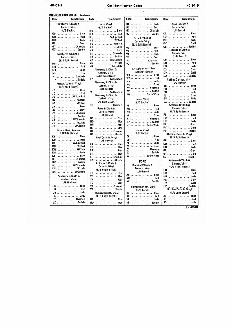
INTERIOR TRIM CODES - Continued
C o d e
Trim Scheme
C o d e
Trim Scheme Code Trim Scheme
Code Trim Sche
Newberry B/Cloth
&
Corinth. Vinyl
(L/B Bucket)
GB Blue
GO Red
GR Jade
GS Gray
GT Chamois
GZ Saddle
Newberry B/Cloth &
Corinth. Vinyl
(L/B Split Bench)
HB Blue
HD Red
HR Jade
HS Gray
HT Chamois
HZ Saddle
Mateao/Corinth. Vinyl
(L/B Split Bench)
JB Blue
JD Red
JL W/LipRed
JN W/Red
JQ W/Blue
JR Jade
JS Gray
JT Chamois
JZ Saddle
J2 W/Chamois
J5 W/Jade
J9 W/Saddle
Natural Grain Leather
(L/B Split Bench)
KB Blue
KD Red
KL W/ Lip Red
KN W/Red
KQ W/Blue
KR Jade
KS Gray
KT - . Chamois
KZ Saddle
K2 W/Chamois
K5 W/Jade
K9 W/Saddle
Newberry B/Cloth
&
Corinth. Vinyl
(L/B Bucket)
LB Blue
LD
Red
LR Jade
LS Gray
LT Chamois
LZ Saddle
Lamar Vinyl
(L/B Bucket)
MB Blue
MD Red
ML W/ Lip Red
MN W/Red
MQ W/Blue
MR Jade
MS Gray
MT Chamois
MZ Saddle
M2 W/Chamois
M5 W/Jade
M9 W/Saddle
Newberry B/Cloth &
Corinth. Viny l
(L/B Flight Bench)
N2 W/Chamois
Newberry B/Cloth &
Corinth. Vinyl
(L/B Bucket)
P2 W/Chamois
Newberry B/Cloth
&
Corinth. Viny l
(L/B Split Bench)
QT Chamois
Porto B/Cloth &
Corinth. Viny l
(L/B Bench)
RB Blue
RD Red
RR Jade
RS Gray
RT Chamois
RZ Saddle
Kiwi/Corinth. Vinyl
(L/B Bench)
SB Blue
SD Red
SR Jade
SS Gray
ST Chamois
SZ Saddle
Ardmore B Cloth &
Corinth. Vinyl
(L/B Flight Bench)
T B B l u e
TD
Red
TR Jade
TS Gray
TT Chamois
TZ Saddle
Mateao/Corinth. Vinyl
(L/B Flight Bench)
UB Blue
UD Red
UR Jade
US Gray
UT Chamois
UZ Saddle
Doral B/Cloth &
Corinth. Vinyl
(L/B Split Bench)
VB Blue
VD Red
VR Jade
VS Gray
VT Chamois
VZ Saddle
Mateao/Corinth. Vinyl
(L/B Split Bench)
WB Blue
WD Red
WR Jade
WS Gray
WT Chamois
WZ Saddle
W3 Sadle/Whte
Lamar Vinyl
(L/B Bucket)
YB Blue
YD Red
YR Jade
YS Gray
YT Chamois
YZ Saddle
Y3 Sadle/Whte
Lamar Vinyl
(L/B Bucket
ZB
ZD
ZR
ZS
Blue
Red
Jade
Gray
ZT Chamois
ZZ Saddle
Z3 Sadle/Whte
FORD
Barletta B/Cloth
&
Corinth. Vinyl
(L/B Bench)
AB Blue
AD
Red
AZ Saddle
Ruffino/Corinth. Vinyl
(L/B Bench)
BB Blue
BD
Red
BR Jade
BZ Saddle
Logan B/Cloth &
Corinth. Vinyl
(LB Bench)
C B B
CD
R
CR J
CY G
CZ Sad
Redondo B/Cloth
&
Corinth. Vinyl
(L/B Bench)
DB B
DD
R
DR J
DS G
DY G
DZ Sad
Ruffino Corinth. Vinyl
(L/B Bench)
EB B
ED
R
ER J
ES G
EY G
EZ Sad
Ardmore B/Cloth
&
Corinth. Vinyl
(L/B Split Bench)
FB B
FD R
FR J
FS G
FY G
FZ Sad
Ruffino/Corinth. Vinyl
(L/B Split Bench)
GB B
GD R
GR J
GS G
GY G
GZ Sad
Ardmore B/Cloth &
Corinth. Vinyl
(L/B Flight Bench)
HB B
HD
R
HR J
HS G
HY G
HZ Sad
Ruffino/Corinth. Vinyl
(L/B Split Bench)
JB B
JD
R
JR J
CY14
8/20/2019 1977 Ford Car Shop Manual Volume 4 Body
http://slidepdf.com/reader/full/1977-ford-car-shop-manual-volume-4-body 14/449
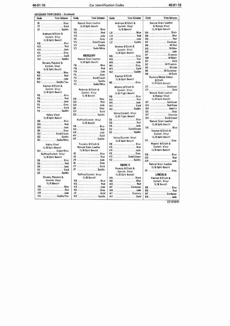
4 0 0 1 - 1 0
Car Identification Codes
40-01-10
INTERIOR TRIM CODES - Continued
C o d e
T r i m S c h e m e C o d e T r i m S c h e m e C o d e T r i m S c h e m e C o d e
Trim
Schem»5
JS Gray
JY Gold
JZ Saddle
Ardmore B/Cloth &
Corinth.
Vinyl
(L/B Split Bench)
KB Blue
KD Red
KR Jade
KS Gray
KY Gold
KZ Saddle
Dynasty Polyknit &
Corinth.
Vinyl
(L/B Split Bench)
NB Blue
ND
Red
I\IR Jade
NU Saddle/Tan
Kasman B/Cloth &
Corinth.
Vinyl
(L/B Split Bench)
PB Blue
PD Red
PR Jade
PS Gray
PY Gold
PZ Saddle
Valino Vinyl
(L/B Split Bench)
QB Blue
QD Red
QR Jade
QS Gray
QV Gold/Cream
QZ Saddle
Q3 Sadle/Whte
Valino Vinyl
(L/B Split Bench)
RV Cream/Blue
Ruffino/Corinth.
Vinyl
(L/B Split Bench)
SB Blue
SD
Red
SR Jade
SY Gold
SZ Saddle
Dynasty Polyknit
&
Corinth.
Vinyl
(L/B Bench)
UB Blue
UD Red
UR Jade
UU Saddle/Tan
Natural Grain Leather
(L/B Split Bench)
YB Blue
YD Red
YR Jade
YS Gray
YV Gold/Cream
YZ Saddle
Y3 Sadle/Whte
MERCURY
Natural Grain Leather
(L/B Split Bench)
FB Blue
FD Red
FR Jade
FS Gray
FV Gold/Cream
FZ Saddle
F3 Sadle/Whte
Redondo B/Cloth
&
Corinth.
Vinyl
(L/B Bench)
GB Blue
GD Red
GR Jade
GS Gray
GY Gold
GZ Saddle
Ruffino/Corinth.
Vinyl
(L/B Bench)
HB Blue
HD Red
HR Jade
HY Gold
HZ Saddle
Touraine B/Cloth &
Natural Grain Leather
(L/B Split Bench)
JB Blue
JD
Red
JR Jade
JS Gray
JY Gold
JZ Saddle
Ruffino/Corinth.
Vinyl
(L/B Bench)
KB Blue
KD Red
KR Jade
KS Gray
JY Gold
KZ Saddle
Ardmore B/Cloth &
Corinth.
Vinyl
(L/B Bench)
LB Blue
LD Red
LR Jade
LZ Saddle
Wilshire B/Cloth &
Corinth.
Vinyl
(L/B Split Bench)
MB Blue
MD
Red
MR Jade
MS Gray
MY Gold
MZ Saddle
Kasman B/Cloth
(L/B Split Bench)
NS
Gray
Wilshire B/Cloth &
Corinth. Vinyl
(L/B Flight Bench)
RB Blue
RD Red
RR Jade
RY Gold
RZ Saddle
Valino/Corinth.
Vinyl
(L/B Flight Bench)
SB Blue
SD Red
SR Jade
SV Gold/Cream
SZ Saddle
Valino/Corinth.
Vinyl
(L/B Split Bench)
VB Blue
VD
Red
VR Jade
VS Gray
VV Gold/Cream
VZ Saddle
MARKV
Venezia B/Cloth &
Corinth.
Vinyl
(L/B Split Bench)
AA Black
AB Blue
AD Red
AF Cordovan
AR Jade
AT Chamois
AY Gold
Natural Grain Leather
& Mateao Vinyl
(L/B Split Bench)
BA Black
BB Blue
BD
Red
BF Cordovan
BN W/Red
BQ W/Blue
BR Jade
BT Chamois
BW W/Black
BY Gold
B2 W/Chamois.
B5 W/Jade
B6 W/Cordovan
B8 W/Gold
Romano/Media Velour
B/Cloth
(L/B Split Bench)
CF Cordovan
CY Gold
Natural Grain Leather
& Mateao Vinyl
(L/B Split Bench)
DF Cordovan
DH Red/Rose
DR Jade/Lt
DS Gray
DT Chamois
DV Gold/Cream
Natural Grain Leather
(L/B Split Bench)
EB Blue
Kasman B/Clo th &
Corinth.
Vinyl
(L/B Split Bench)
FS Gray
Majestic B/Cloth &
Corinth.
Vinyl
(L/B Split Bench)
GB Blue
GD Red
GR Jade
Natural Grain Leather
(L/B Split Bench)
JS Gray
LINCOLN
Kasman B/Clo th
&
Corinth.
Vinyl
(L/B Bench)
BB Blue
BD Red
BF Cordovan
BR Jade
CY1419-H5
8/20/2019 1977 Ford Car Shop Manual Volume 4 Body
http://slidepdf.com/reader/full/1977-ford-car-shop-manual-volume-4-body 15/449
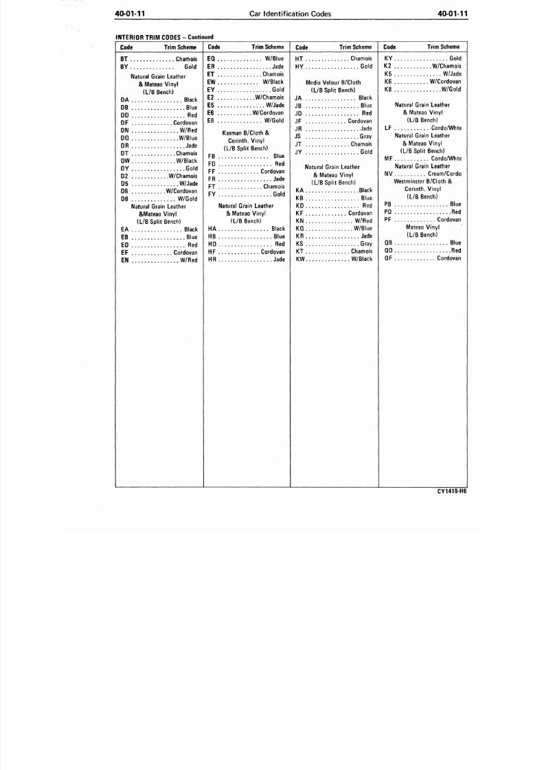
40-01-11 Car Identification Codes 40-0
INTERIOR TRIM CODES
-
Continued
Code
Trim Scheme
Code
Trim Scheme
C o d e
Trim Scheme
HT Chamois
HY Gold
Media Ve lour
B/Cloth
(L/B Split Bench)
JA Black
JB Blue
JD
Red
JF Cordovan
JR Jade
JS Gray
JT Chamois
JY Gold
Natural Grain Leather
& Mateao Vinyl
(L/B Split Bench)
KA Black
KB Blue
KD
Red
KF Cordovan
KN W/Red
KQ W/Blue
KR Jade
KS Gray
KT Chamois
KW W/Black
Code Trim Sche
KY G
K2 W/Cham
K5 W/J
K6 W/Cordo
K8 W/G
Natural Grain Leather
& Mateao Vinyl
(L/B Bench)
LF Cordo/W
Natural Grain Leather
& Mateao Vinyl
(L/B Split Bench)
MF Cordo/W
Natural Grain Leather
NV Cream/Co
Westminster B/Cloth
&
Corinth.
Vinyl
(L/B Bench)
PB B
PD
R
PF Cordo
Mateao Vinyl
(L/B Bench)
QB B
QD
R
QF Cordo
BT Chamois
BY Gold
Natural Grain Leather
& Mateao Vinyl
(L/B Bench)
DA Black
DB Blue
DD
Red
DF Cordovan
DN W/Red
DQ W/Blue
DR Jade
DT Chamois
DW W/Black
DY Gold
D2 W/Chamois
D5 W/Jade
D6 W/Cordovan
D8 W/Gold
Natural Grain Leather
&Mateao Vinyl
(L/B Split Bench)
EA Black
EB Blue
ED
Red
EF Cordovan
EN W/Red
EQ W/Blue
ER Jade
ET Chamois
EW W/Black
EY Gold
E2 W/Chamois
E5 W/Jade
E6 W/Cordovan
E8 W/Gold
Kasman
B/Cloth &
Corinth. Vinyl
(L/B Split Bench)
FB Blue
FD
Red
FF Cordovan
FR Jade
FT Chamois
FY Gold
Natural Grain Leather
& Mateao Vinyl
(L/B Bench)
HA Black
HB Blue
HD
Red
HF Cordovan
HR Jade
CY141
8/20/2019 1977 Ford Car Shop Manual Volume 4 Body
http://slidepdf.com/reader/full/1977-ford-car-shop-manual-volume-4-body 16/449
41-00-1
Seats
41-00
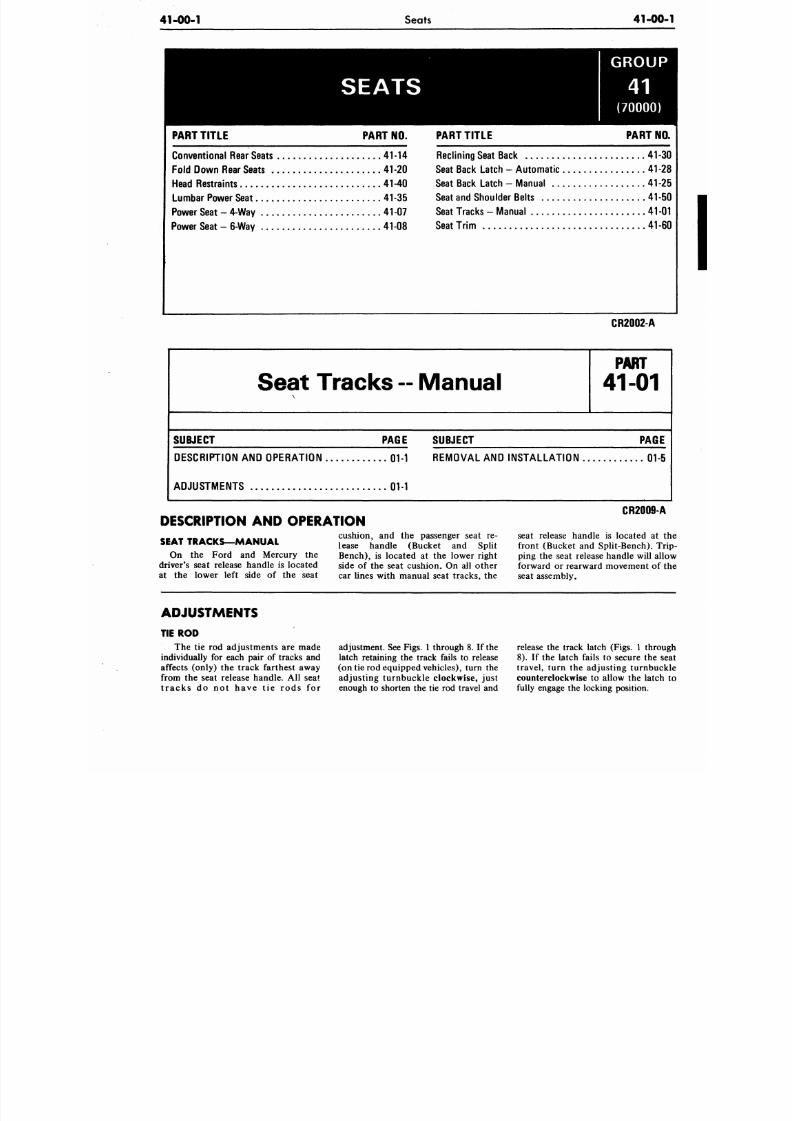
SEATS
PART TITL E PART NO.
Conv entional Rear Seats 41-14
Fo ld Do wn Rear Seats 41-20
Head Restraints 41-40
Lum bar Power Seat 41-35
Power Seat - 4-Way 41-07
Power Seat - 6-Way 41 08
GROUP
(70000)
PART TITL E PART N
Re clining Seat Back 41-
Seat Back Latch - Auto ma tic 41
Seat Back Latch - Manual 41-
Seat and Shoulder Belts 41
Seat Tracks - Manual 41-
Seat Tri m 41
CR2002-A
Seat Tracks -- Manual
P A R T
41-01
SUBJECT PAGE SUBJECT
PAG
DESCRIPTION AND OPERATION 01-1 REMOVAL AND INSTA LLAT ION 01-
ADJUSTMENTS 01-1
DESCRIPTION AND OPERATION
cushion, and the passenger seat re-
lease handle (Bucket and Split
Bench), is located at the lower right
side of the seat cushion. On all other
car lines with manual seat tracks, the
SEAT TRACKS—MANUAL
On the Ford and Mercury the
driver's seat release handle is located
at the lower left side of the seat
CR2009-
seat release handle is located at
front (Bucket and Split-Bench). T
ping the seat release handle will al
forward or rearward movement of
seat assembly.
ADJUSTMENTS
TIE ROD
The tie rod adjustments are made
individually for each pair of tracks and
affects (only) the track farthest away
from the seat release handle. All seat
t racks do not have t ie rods for
adjustment. See Figs. 1 through 8. If the
latch retaining the track fails to release
(on tie rod equipped vehicles), turn the
adjusting turnbuckle clockwise, just
enough to shorten the tie rod travel and
release the track latch (Figs. 1 thro
8). If the latch fails to secure the
travel, turn the adjusting turnbu
counterclockwise to allow the latc
fully engage the locking position.
8/20/2019 1977 Ford Car Shop Manual Volume 4 Body
http://slidepdf.com/reader/full/1977-ford-car-shop-manual-volume-4-body 17/449
41-01-2
Seat Tracks—Manual
41-01-2
CUSHION ASSY.
CUSHION ASSY.
HANDLE
61755
SCREW
384871 -
TORQUE -
12-20
F T.
LBS.
4 REQUIRED
NUT 45344
STUD 384599
(12-20 FT-LB TORQUE)
4-REQ'D
NUT AND WASHER ASSY.
45344 -
TORQUE - 18-32 FT. LBS.
4-REQ'D
FRONT AND REAR
ON MANUAL TRACKS
RETAINER
618B58
SCREW VIEW A
NUT AND WASHER
ASSY. 45344
STUD 385009
4-REQ'D
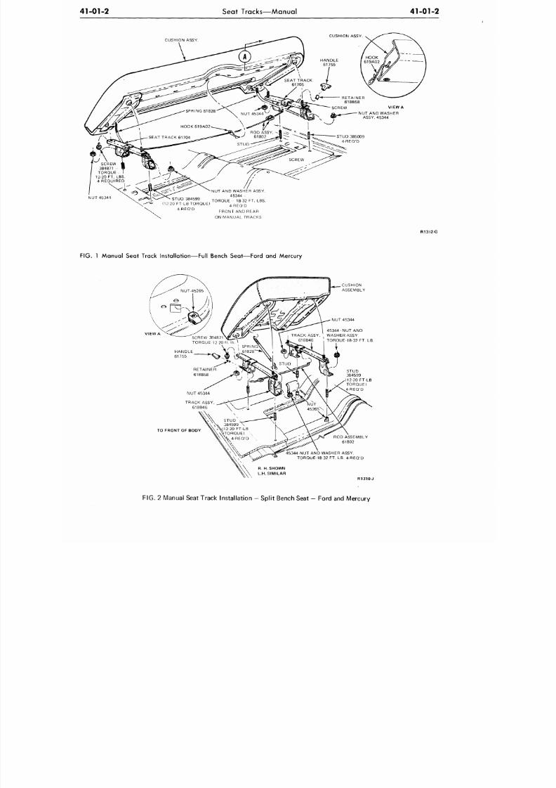
FIG. 1 Manual Seat Track Installation—Full Bench Seat—Ford and Mercury
R13G2-G
CUSHION
ASSEMBLY
45344-NUT AND
TRACK ASSY. ' WASHER ASSY.
618B46 I TORQUE-18-32 FT. LB.
TO FRONT OF BODY
ROD ASSEMBLY
61802
-NUT AND WASHER ASSY.
TORQUE-18-32 FT. LB. 4-REQ'D
R. H. SHOWN
L.H. SIMILAR
R1310-J
FIG. 2 Manual Seat Track Instal lation - Sp li t Bench Seat — Ford and Mercury
8/20/2019 1977 Ford Car Shop Manual Volume 4 Body
http://slidepdf.com/reader/full/1977-ford-car-shop-manual-volume-4-body 18/449
41-01-3 Seat Tracks—Manual
41-01
CUSHION ASSEMBLY
SEAT TRACK
INSULATOR
TO FRONT OF BODY
PASSENGER
SIDE CUSHION
SHOWN
NUT AND WASHER
TORQUE 12-25 FT-LB
N2550-A
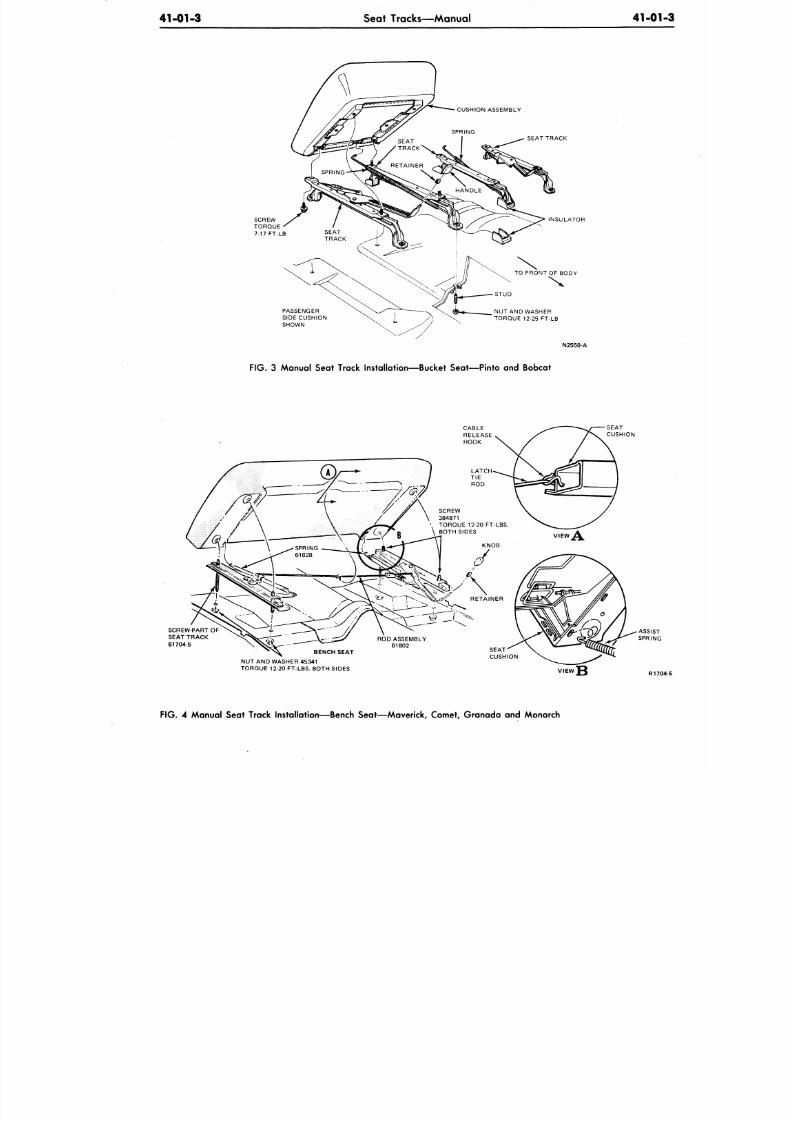
FIG. 3 Manual Seat Track Installation—Bucket Seat—Pinto and Bobcat
SCREW-PART OF
SEAT TRACK
61704-5
NUT AND WASHER 45341
TORQUE 12-20 FT-LBS. BOTH SIDES
VIEW
J 3
R17
F IG .
4 Manual Seat Track Insta l lat ion—Bench Seat—Maverick , Comet, Granada and Monarch
8/20/2019 1977 Ford Car Shop Manual Volume 4 Body
http://slidepdf.com/reader/full/1977-ford-car-shop-manual-volume-4-body 19/449
41-01-4
Seat Tracks—Manual
41-01-4
SCREW
4 REQ'D.
TORQUE
12-20 FT-LB
EACH SIDE OF BODY
OUTBOARD I
TRACK
NUT AND
WASHER
4 REQ'D. DRIVER SIDE
3 REQ'D. PASS. SIDE
TORQUE 12-20 FT-LB
DRIVER SIDE
SEAT TRACKS
PASSENGER SIDE SHOWN
DRIVER SIDE TYPICAL
NUT
TORQUE
18-32 FT-LB
NOTE: DRIVER'S SIDE INBOARD
TRACK DIFFERENT BETWEEN
MAVERICK AND COMET AND
GRANADA AND MONARCH.
OUTBOARD
3te
TO FRONT OF BODY
OUTBOARD
INSULATOR
VIEW B
P A S S . S I D E R E A R ( L . H . )
I N S U L A T O R
P A S S .
S ID E F R O N T ( L . H . )
N2551-A
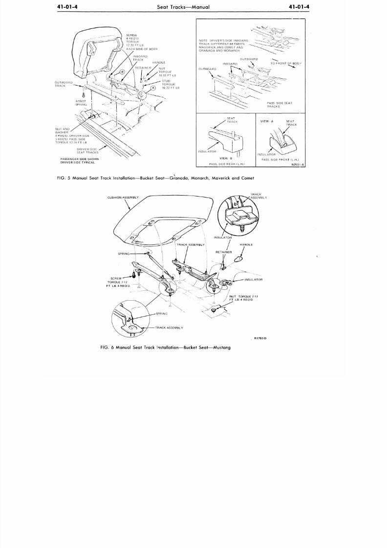
FIG.
5 Manual Seat Track Installation—Bucket Seat—Granada, Monarch, Maverick and Comet
CUSHION ASSEMBLY
SCREW
TORQUE 7-17
FT. LB. 4 REQ'D
INSULATOR
NUT TORQUE 7-17
FT.
LB.4 REQ'D.
FIG. 6 Manual Seat Track Installation—Bucket Seat—Mustang
8/20/2019 1977 Ford Car Shop Manual Volume 4 Body
http://slidepdf.com/reader/full/1977-ford-car-shop-manual-volume-4-body 20/449
41-01-5
Seat Tracks—Manual
41-0
CUSHION ASSE
HAN
NUT AND WASHER
TORQUE 18-32 FT-LB
1 REQ'D. EACH SIDE
STUD
REQ'D. EACH SIDE
TORQUE 16-22 FT-LB
R19
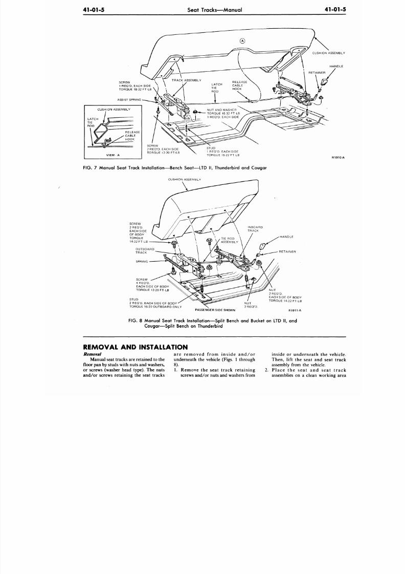
FIG. 7 Manual Seat Track Installation—Bench Seat—LTD II, Thunderbird and Cougar
CUSHION ASSEMBLY
RETAINER
SCREW
4 REQ'D.
EACH SIDE OF BODY
TORQUE 12-20 FT-LB
STUD
2 REQ'D. EACH SIDE OF BODY
TORQUE 16-22 OUTBOARD ONLY
NU T
2 REQ'D.
PASSENGER SIDE SHOWN
NUT
2 REQ'D.
EACH SIDE OF BODY
TORQUE 14-32 FT-LB
R1911-A
FIG.
8 Manual Seat Track Installation—Split Bench and Bucket on LTD II, and
Cougar—Split Bench on Thunderbird
REMOVAL
AND
INSTALLATION
are removed from inside and/or
emoval
Manual seat tracks are retained to the
floor pan by studs with nuts and washers,
or screws (washer head type). The nuts
and/or screws retaining the seat tracks
underneath
the
vehicle (Figs. 1 through
8).
1.
Remove
the
seat track retaining
screws and/or nuts and washers from
inside or underneath the veh
Then, lift the seat and seat t
assembly from
the
vehicle.
P l a c e
the
sea t
and
sea t t r
assemblies
on a
clean working

8/20/2019 1977 Ford Car Shop Manual Volume 4 Body
http://slidepdf.com/reader/full/1977-ford-car-shop-manual-volume-4-body 21/449
41-01-6
Seat Tracks—Manual
41-01-6
and disconnect the adjusting springs
(Figs. 1 through 8).
3. Remove the seat track-to-seat cushion
attaching screws and remove the seat
cushion from the tracks.
4. Disconnect the latch tie rod from the
seat tracks.
5. If the seat tracks are being replaced,
t r a n s f e r t h e r e t r a c t i n g s p r i n g s ,
spacers, anti-squeak, seat side shields
and adjusting lever knob to the new
track assembly.
Installation
1. Mount the seat tracks with the side
shield supports (if so equipped) to the
seat cushion, and connect the tie rod
to the two tracks as they are being
positioned.
2.
Install the seat track-to-seat cushion
re ta in in g sc r ews an d t ig h ten to
specifications shown in appropriate
figures (Figs. 1 thro ugh 8).
3. C o n n e c t t h e a d j u s t i n g s p r i n g s
between the seat t racks and seat
cushion.
4.
Place the seat assembly in to the
vehicle and insure proper alignment.
5. Then, install the screws an d/o r nuts
and washer assemblies and tighten to
specification shown in appropriate
figures (Figs. 1 thro ugh 8).
8/20/2019 1977 Ford Car Shop Manual Volume 4 Body
http://slidepdf.com/reader/full/1977-ford-car-shop-manual-volume-4-body 22/449
41-07-1 Power Seat-4-Way 41-07
SUBJECT
DESCRIPTION
TESTING
Power Seat~4-Way
PAGE SUBJECT
AND OPERATION 07-1 REMOVAL AND INSTALLATION ..
07-1 DISASSEMBLY AND ASSEMBLY ..
P A R T
41-07
PAGE
07-2
07-2
CR2010-A
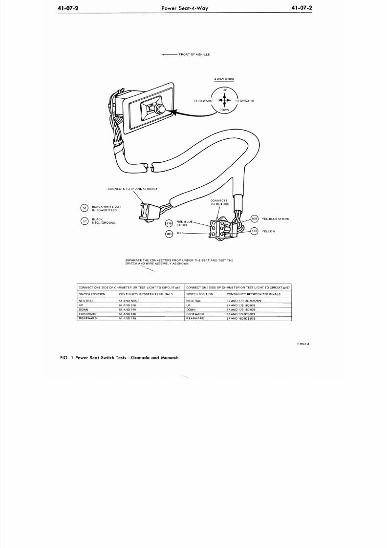
DESCRIPTION AND OPERATION
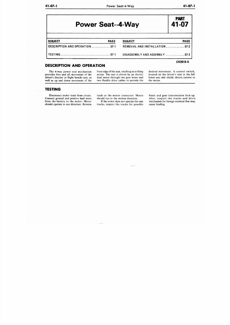
The 4-way power seat mechanism front edge of the seat, resulting in a tilting desired movem ent. A control swit
provides fore and aft movement of
the
action.
The
seat is driven by an electric located on the driver's side in the
driver's (bucket
or
flight bench) seat,
as
dual motor through two gear boxes and lower seat side shield, directs curren t
well as up and down movement of the two flexible drive cables to provide the the motor.
TESTING
Disconnect motor leads from circuit. leads
at the
motor connector. Motor binds
and
gear transmission lock-
Connect ground and positive lead wires should run in the reverse direction. Al so , ins pe ct the t racks and d
from the battery to the motor. Motor If
the
motor does not operate the seat mechanism for foreign material tha t m
should operate in one direction. Reverse trac ks, inspect the tracks for possible cause binding.
8/20/2019 1977 Ford Car Shop Manual Volume 4 Body
http://slidepdf.com/reader/full/1977-ford-car-shop-manual-volume-4-body 23/449
41-07-2
Power Seat-4-Way
41-07-2
FRON T OF VEHICLE
WAY KNOB
BLACK WHITE DOT
B+POWER FEED
BLACK
NEG. (GROUND)
978) YEL-BLUE STRIPE
179) YELLOW
SEPARATE THE CONNECTORS FROM UNDER THE SEAT AND TEST THE
SWITCH AND WIRE ASSEMBLY AS SHOWN
CONNECT ONE SIDE OF OHMMETER OR TEST LIGHT TO CIRCUI T#51
SWITCH POSITION
NEUTRAL
UP
DOWN
FOREWARD
REARWARD
CONTINUITY BETWEEN TERMINALS
51 AND NONE
51
AN D
978
51 AND 979
51
AND 180
51 AND 179
CONNECT ONE SIDE OF OHMMETER OR TEST LIGHT TO CIRCUIT:#57
SWITCH POSITION
NEUTRAL
UP
DOWN
FOREWARD
REARWARD
CONTINUITY BETWEEN TERMINALS
57 AND 179-180-978-979
57 AND 179-180-979
57 AND 179-180-978
57 AND 179-978-979
57 AND 180-978-979
R1967-A
FIG. 1 Power Seat Switch Tests—Granada and Monarch
8/20/2019 1977 Ford Car Shop Manual Volume 4 Body
http://slidepdf.com/reader/full/1977-ford-car-shop-manual-volume-4-body 24/449
41-07-3
Power Seat-4-Way
41-07
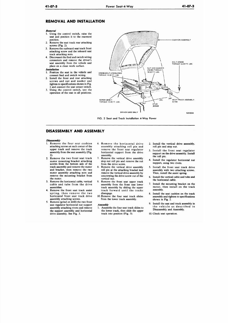
REMOVAL AND INSTALLATION
Removal
1. Using the control switch, raise the
seat and position it to the rearmost
position.
2.
Remove the seat track rear attaching
screws (Fig. 2).
3. Remove the outboard seat track front
attaching screw and the inboard seat
track attaching nuts.
4. Disconnect the feed and switch wiring
connectors and remove the driver's
seat assembly from the vehicle and
place on a clean work surface.
Installation
1. Position the seat in the vehicle and
connect feed and switch wiring.
2. Install the front and rear attaching
screws and nut and washer and
tighten to specifications shown in Fig.
2 and connect the seat sensor switch.
3. Using the control switch, test the
operation of the seat in all positions.
SCREW 384871
TORQUE 12-20 FT. LBS
CUSHION ASSEMBL
BOLT 379488-
TORQUE 14-32 FT. L
379488 BOLT-3 REQUIRED
TORQUE 14-32 FT. LBS.
DRIVER SIDE ONLY
SEAT TRACK ASSEM
61700
N21
FIG. 2 Seat and Track Installation 4-W ay Power
DISASSEMBLY AND ASSEMBLY
1.
Remove the four sea t cushion
attaching screws at each corner of the
upper track and remove the track
assembly from the seat assembly (Fig.
2).
2. Remove the two front seat track
motor mounting bracket attaching
screws from the bottom side of the
track assembly and remove the motor
and bracket, then remove the two
motor assembly attaching nuts and
remove the mounting bracket from
the motor.
3. Remove the horizontal cable, vertical
cable and tube from the drive
assemblies.
4. Remove the front seat track assist
sp r ing , t he n r e m ove the tw o
horizontal front seat track drive
assembly attaching screws.
5. Remove (grind or drill) the two front
seat regulator horizontal nut support
assembly attaching riv ets and remove
the support assembly and horizontal
drive assembly. See Fig. 3.
6 . Re m ove the hor i z on ta l d r ive
assembly attaching roll pin and
remove the front seat regulator
horizontal support from the drive
. assembly.
7. Remove the vertical drive assembly
stop nut roll pin and remove the nut
from the drive screw.
8. Remove the vertical drive assembly
roll pin at the attaching bracket and
remove the vertical drive assembly by
unscrewing the drive screw out of the
vertical nut.
9. Remove the front seat upper track
assembly from the front seat lower
track assembly by sliding the upper
t rack forward unt i l the t racks
disengage.
10. Remove the four seat track slides
from the lower track assembly.
Assembly
1. Assemble the four seat track slides to
the lower track, then slide the upper
track into position (Fig. 3).
2.
Install the vertical drive assem
roll pin and stop nut.
3.
Install the front seat regul
support on the drive assembly. In
the roll pin.
4. Install the regulator horizontal
support, using two rivets.
5. Install the front seat track d
assembly with two attaching scr
Then, install the .assist spring.
6. Install the vertical cable and tube
the horizontal cable.
7.
Install the mounting bracket on
motor, then install on the tr
assembly.
8. Install the seat cushion on the t
assembly and tighten to specifica
shown in Fig. 2.
9. Install the seat and track assemb
t h e v e h i c l e a s d e s c r i b e d
Disassembly and Assembly.
10. Check seat operation.
8/20/2019 1977 Ford Car Shop Manual Volume 4 Body
http://slidepdf.com/reader/full/1977-ford-car-shop-manual-volume-4-body 25/449
41-07-4
Power Seat-4-Way
41-07-4
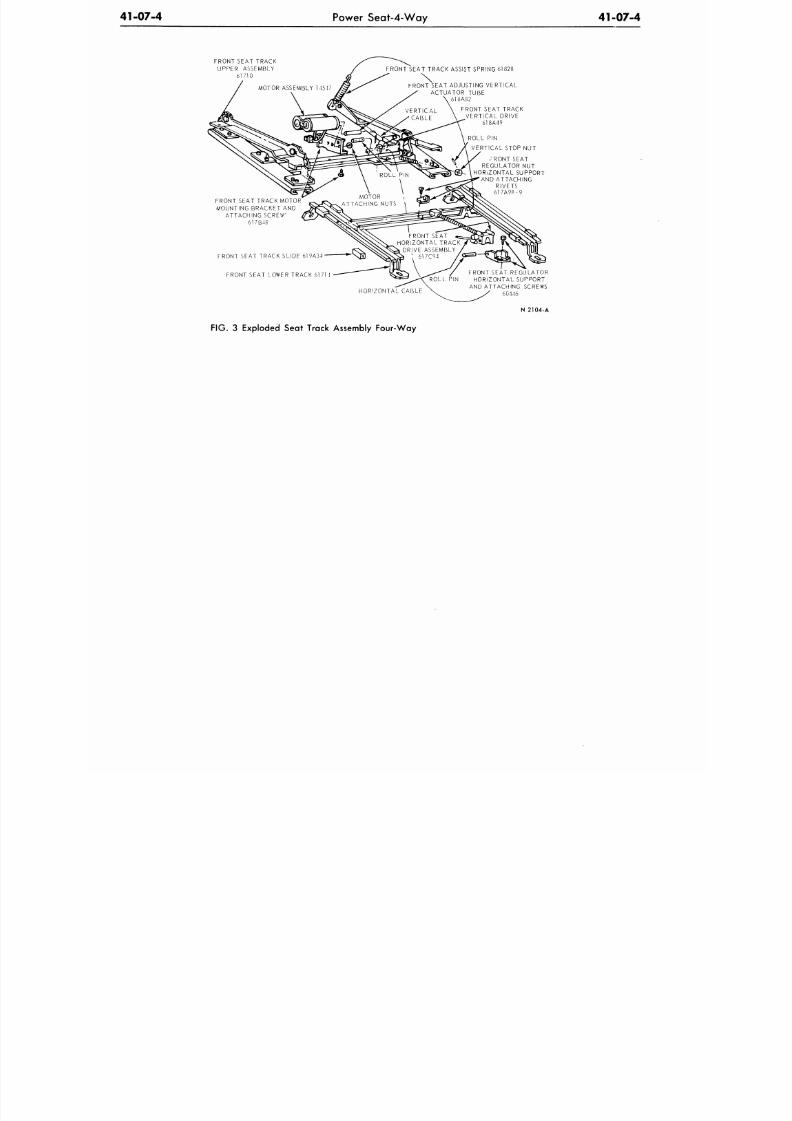
FRONT SEAT TRACK
UPPER ASSEMBLY
61710
FRONT SEAT TRACK ASSIST SPRING 61828
FRONT SEAT ADJUSTING VERTICAL
ACTUATOR TUBE
618A82
FRONT SEAT TRACK
VERTICAL DRIVE
618A49
ROLL PIN
VERTICAL STOP NUT
RONT SEAT
REGULATOR
NU T
HORIZONTAL SUPPORT
AND ATTACHING
RIVETS
617A98
-9
FRONT SEAT TRACK MOTOR
MOUNTING BRACKET
AN D
ATTACHING SCREW"
617B48
FRONT SEAT TRACK SLIDE 619A34
FRONT SEAT LOWER TRACK 61714
HORI ZONTAL CABLE
FRONT SEAT REGULATOR
HORIZONTAL SUPPORT
AND ATTACHING SCREWS
60446
N 2104-A
FIG.
3 Exploded Seat Track Assembly Four-Way
8/20/2019 1977 Ford Car Shop Manual Volume 4 Body
http://slidepdf.com/reader/full/1977-ford-car-shop-manual-volume-4-body 26/449
41-08-1
Power Seat-6-Way
41-0
Power Seat - 6-Way
P A R T
41-08
SUBJECT PAGE
DESCRIPTION AND OPERATION 08-1
TESTING 08-2
DIAGNOSIS 08-3
REMOVAL AND INSTALLATION
Motor and Drive Cables
08-7
Right or Left Track Q8-7
SUBJECT PA
REMOVAL AND INSTALLATION (Cont 'd . )
Seat Track 08
MAJOR REPAIR OPERATIONS
Lincoln Continental Seat Track (Bench Seat) . . 08
Six Way Power Seat - Full Bench 08
Six Way Power Seat - Split Bench 08
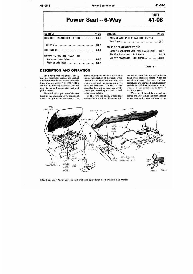
DESCRIPTION AND OPERATION
The 6-way power seat (Figs. 1 and 2)
provides horizontal, vertical and vertical
tilt adjustments. It consists of a reversible
three armature motor (TRI-MOTOR), a
switch and housing assembly, vertical
gear drives and horizontal rack and
pinion drives.
The mechanical portion of the seat
track in the horizontal drive consists of
a rack and pinion on each track. The
pinion housing and motor is attached to
the movable section of the track. When
the switch is actuated, the front armatu re
is energized and the ho rizontal drive
units are activated . The seat is then
propelled forward or rearward by the
pinion gears traveling in a rack in each
lower track section.
In the vertical drive, w orm gear
mechanisms are utilized. The drive units
CR2011-A
are located in the front and rear of th
hand track (standard bench). Whe
switch is actuated, the center and
armatures are energized simultane
and the vertical drive units are activ
The seat is then propelled up or dow
the worm gears.
When the tilt switch is actuated
center armature drives the front ve
worm gear and moves the seat t
SCREW
384871
T O R Q U E 1 2 - 2 0
FT LB
NUT AND WASHER
STUD 45344
384599 TORQUE 18-32
FT. LB
SCREW
382062
TORQUE 18-32 FT LB
VIEW
A
F IG .
1
Six-W ay Power Seat Tracks Bench and Split Bench Ford, Mercury and Mete or
8/20/2019 1977 Ford Car Shop Manual Volume 4 Body
http://slidepdf.com/reader/full/1977-ford-car-shop-manual-volume-4-body 27/449
41-08-2
Power Seat-6-W ay
41-08-2
CUSHION ASSEMBLY
NUT
TORQl-E
14-32 FT.LB
SCREW '
384871 n NU T
TORQUE U 4526E
12-20 FT.LB.
PASSENGER SIDE SHOWN
DRIVER SIDE TYPICAL
RVI52-E
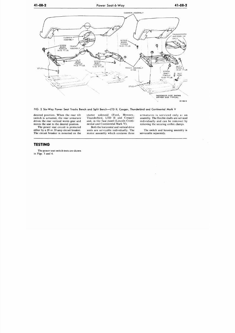
FIG.
2 Six-Way Power Seat Tracks Bench and Split Bench—LTD II, Cougar, Thunderbird and Continental Mark V
desired position. When the rear tilt
switch is actuated, the rear armature
drives the rear vertical worm gear and
moves the seat to the desired position.
The power seat circuit is protected
either by a 20 or 30 amp circuit breaker.
The circuit breaker is mounted on the
starter solenoid (Ford, Mercury,
Thunderbird, LTD II and Cougar)
and, in the fuse panel (Lincoln Conti-
nental and Continental Mark V).
Both the horizontal and vertical drive
units are servicable individually. The
armatures is serv iced only at an
assembly. The flexible shafts are serviced
individually and can be removed by
removing the securing corbin clamps.
The switch and housing assembly is
moto r assembly which contains three serviceable separately.
TESTING
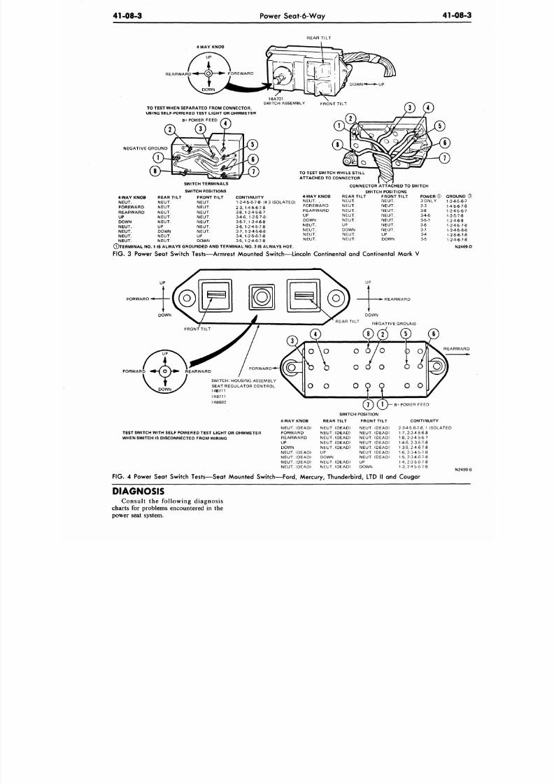
The power seat switch tests are shown
in Figs. 3 and 4.
8/20/2019 1977 Ford Car Shop Manual Volume 4 Body
http://slidepdf.com/reader/full/1977-ford-car-shop-manual-volume-4-body 28/449
41-08-3
Power Seat-6-Way 41-08
REAR TILT
4 WAY KNOB
UP
REARWARD
TO TEST WHEN SEPARATED FROM CONNECTOR,
USING SELF-POWERED TEST LIGHT OR OHMMETER
B+POWER FEED
14A701
SWITCH ASSEMBLY FRONT TILT
NEGATIVE GROUND
TO TEST SWITCH WHILE STILL
ATTACHED TO CONNECTOR
4 WAY KNOB
NEUT.
FOREWARD
REARWARD
UP
DOWN
NEUT.
NEUT.
NEUT.
NEUT.
©TERMINAL NO.
F I G . 3 P o w e r
REA R TILT
NEUT.
NEUT.
NEUT.
NEUT.
NEUT.
UP
DOWN
NEUT.
NEUT.
SWITCH TERMINAL S
SWITC H POSITIONS
FRO NT TILT
NEUT.
NEUT.
NEUT.
NEUT.
NEUT.
NEUT.
NEUT.
UP
DOWN
CONNECTOR ATTACHED TO SWITCH
CONTINUITY
1-2-4-5-6-7-8- (H
3
I S O L A T E D )
2-3,
1-4-5-6-7-8
3-8,1-2-4-5-6-7
34-6,1-2-5-7-8-
3-5-7,
1-2-4-6-8
3-6,1-24-5-7-8
3-7,
1-2-4-5-6-8
3-4,1-2-5-6-7-8
3-5,1-24-6-7-8
4 WAY KNOB
NEUT.
.
FOREWARD
REARWARD
UP
DOWN
NEUT.
NEUT.
NEUT.
NEUT.
SWITCH POSITIONS
REA R TILT
NEUT.
NEUT.
NEUT.
NEUT.
NEUT.
UP
DOWN
NEUT.
NEUT.
FRO NT TILT
NEUT.
NEUT.
NEUT.
NEUT.
NEUT.
NEUT.
NEUT.
UP
DOWN
POWER
©
GROUN
3 O N L Y
2-3
3-8
34-6
3-5-7
3-6
3-7
3 4
3-5
-24-5-
4-5-6-
-2-4-5-
-2-5-7
-24-6-
-24-5-
-2-4-5
1-2-5-6-
-24-6-
1 IS ALWAYS GROUNDED AND TERM INAL NO. 3 IS ALW AYS HOT. N2
Seat Switch Tests—Armrest Mounted Switch—Lincoln Continental and Continental Mark V
UP
FORWARD
UP
REARWARD
DOWN
REAR TILT
NEGATIVE GROUND
FORW RD
^- fo\ *
REARWARD
DOWN
FORWARD-
SWITCH:
HOUSING ASSEMBLY
SEAT REGULATOR CONTROL
14B711
14B711
14B692
TEST SWITCH WITH SELF POWERED TEST LIGHT OR OHMMETER
WHEN SWITCH IS DISCONNECTED FROM W IRING
4-WAY KNOB
NEUT. (DEAD)
FORWARD
REARWARD
UP
DOWN
NEUT. (DEAD)
NEUT. (DEAD)
NEUT. (DEAD)
NEUT. (DEAD)
SWITCH POSITION
REAR TILT FRONT TILT
NEUT. (DEAD)
NEUT. (DEAD)
NEUT. (DEAD)
NEUT. (DEAD)
NEUT. (DEAD)
UP
DOWN
NEUT. (DEAD)
NEUT. (DEAD)
NEUT. (DEAD)
NEUT. (DEAD)
NEUT. (DEAD)
NEUT. (DEAD)
NEUT. (DEAD)
NEUT. (DEAD)
NEUT. (DEAD)
UP
DOWN
B+ POWER FEED
CONTINUITY
2-3-4-5-6-7-8, 1 ISOLATED
1-7,2-34-5-6-8
1-8, 2-34-5-6-7
14 -6 ,
2-3-5-7-8
1-3-5,24-6-7-8
1-6, 2-34-5-7-8
1-5,2-34-6-7-8
14,2-3-5-6-7-8
1-3, 2 4-5-6-7-8
N2
FIG.
4 Power Seat Switch Tests—Seat Mounted Switch—Ford Mercury Thunderbird LTD II and Cougar
DIAGNOSIS
Consul t the following diagn osis
charts for problems encountered in the
power seat system.
8/20/2019 1977 Ford Car Shop Manual Volume 4 Body
http://slidepdf.com/reader/full/1977-ford-car-shop-manual-volume-4-body 29/449
41-08-4
Power Seat-6 -W ay 41-08-4
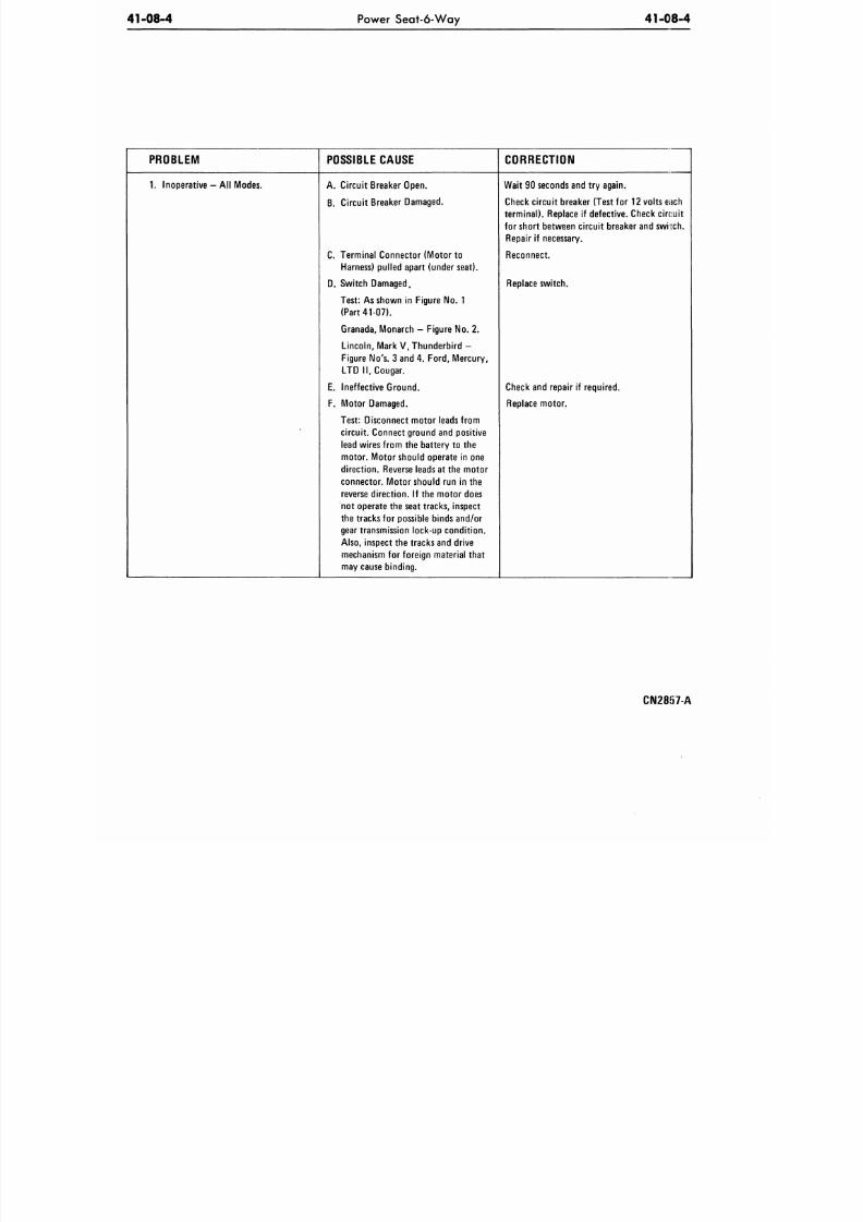
PROBLEM
1.
Inoperative - All Modes.
POSSIBLE CAUSE
A. Circuit Breaker Open.
B. Circuit Breaker Damaged.
C. Terminal Connector (Motor to
Harness) pulled apart (under seat).
D. Switch Damaged.
Test: As shown in Figure No. 1
(P ar t 41-07 ) .
Granada, Monarch
-
Figure
No. 2.
Lincoln, Mark V, Thunderb i rd -
Figure No's. 3 and 4. Ford , Mercury ,
L T D II , Cougar.
E. Ineffective Ground .
F. Motor Damaged.
Test: Disconnect motor leads from
circuit. Connect ground and positive
lead wires from
the
battery
to the
motor . Motor should operate
in one
direction . Reverse leads
at the
motor
connector. Motor should
run in the
reverse direction.
If the
motor does
not operate
the
seat tracks, inspect
the tracks
for
possible binds and/or
gear transmission lock-up condition.
Also, inspect the tracks and drive
mechanism for foreign material th at
may cause binding.
CORRECTION
W a i t
90
seconds
and try
again.
Check circuit breaker (Test for 12 volts each
terminal ) . Replace
if
defective. Check circuit
for short between circuit breaker
and
swi ten.
Repair
if
necessary.
Reconnect.
Replace switch.
Check
and
repair
if
required.
Replace motor.
C I M 2 8 5 7 - A
8/20/2019 1977 Ford Car Shop Manual Volume 4 Body
http://slidepdf.com/reader/full/1977-ford-car-shop-manual-volume-4-body 30/449
41-08-5
Power Seat-6-Way
41-08
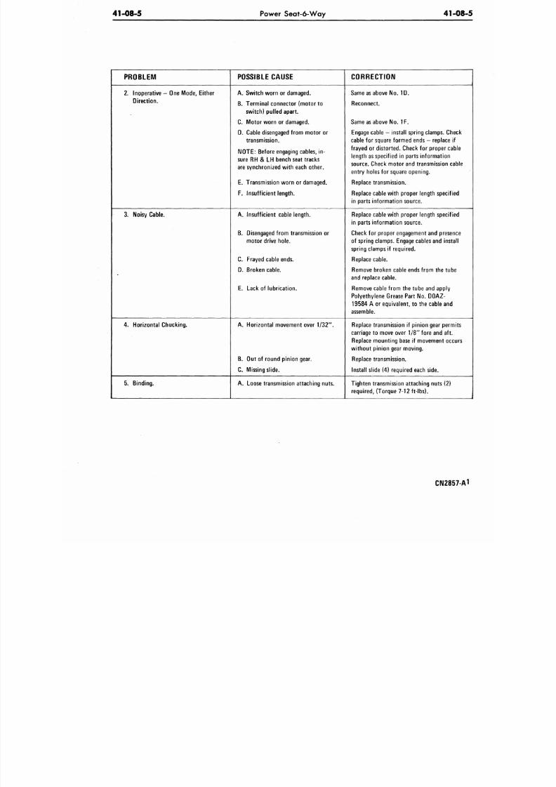
PROBLEM
2.
Inoperative
—
One Mode, Either
Direct ion.
3. Noisy Cable.
4. Horizo ntal Chucking.
5. Binding.
POSSIBLE CAUSE
A. Switch worn or damaged.
B. Terminal connector (motor to
switch) pulled apart.
C. Motor worn or damaged.
D. Cable disengaged from motor or
transmission.
NOTE:
Before e ngaging cables, in-
sure RH & LH bench seat tracks
are synchronized with each other.
E. Transmission wo rn or damaged.
F. Insuff icient length.
A, Insuff icient cable length.
B. Disengaged fro m transmission or
mo tor drive hole.
C. Frayed cable ends.
D. Broken cable.
E. Lack of lubrication.
A. Horizontal movement over 1/32".
B. Out of round pinio n gear.
C. Missing slide .
A. Loose transmission attaching nuts.
CORRECTION
Same as above N o. 1 D.
Reconnect.
Same as above No. 1F.
Engage cable - install spring clamp s. Check
cable for square form ed ends - replace if
frayed o r distorted . Check for prope r cable
length as specified in parts info rm ation
source. Check motor and transmission cable
entry holes for square op ening.
Replace transm ission.
Replace cable with proper length specified
in parts information source.
Replace cable with proper length specified
in parts information source.
Check for proper engagement and presence
of spring clamps. Engage cables and install
spring clamps if required.
Replace c able.
Remove broken cable ends from the tube
and replace cable.
Remove cable from the tube and apply
Polyethylene Grease Part No. DOAZ-
19584 A or equ ivalent, to the cable and
assemble.
Replace transmission if pinion gear permits
carriage to move over 1/8" fore and aft.
Replace mounting base if movement occurs
without pinion gear moving.
Replace transm ission.
Install slide (4) required each side.
Tighten transmission attaching nuts (2)
required, (Torque 7-12 ft-lbs).
CIM2857-
8/20/2019 1977 Ford Car Shop Manual Volume 4 Body
http://slidepdf.com/reader/full/1977-ford-car-shop-manual-volume-4-body 31/449
41-08-6
Power Seat-6-Way
41-08-6
PROBLEM
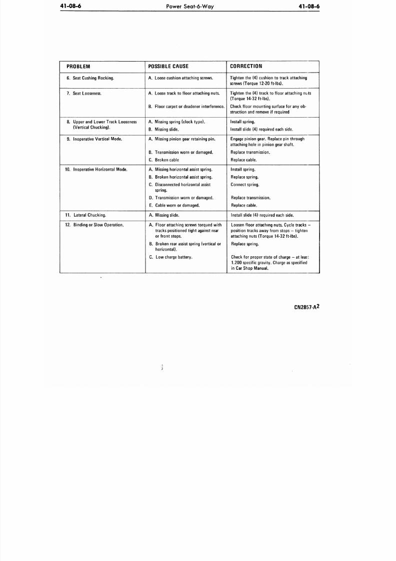
6. Seat Cushing Roc king.
7. Seat Looseness.
8. Upper and Lowe r Track Looseness
(Vertical Chucking).
9. Inoperative Vertical Mode.
10.
Inoperative Horizo ntal Mode.
11. Lateral Chucking.
12.
Binding
or
Slow Operation.
POSSIBLE CAUSE
A. Loose cushion attach ing screws.
A. Loose track to f loor attaching nuts.
B. Floor carpet or deadener interference.
A. Missing spring (clock ty pe ).
B. Missing slide .
A. Missing pinio n gear retaining pin.
B. Transmission worn
or
damaged.
C. Broken cable
A. Missing ho rizo ntal assist spring.
B. Broken ho rizo ntal assist spring.
C. Disconnected horizontal assist
spring.
D. Transmission worn or damaged.
E. Cable wo rn or damaged.
A. Missing slide.
A. Floor attaching screws torque d w ith
tracks positioned tight against rear
or front stops.
B. Broken rear assist spring (ve rtical or
hor izontal) .
C. Low charge battery .
CORRECTION
Tighten
the (4)
cushion
to
track attaching
screws (Torque 12-20 ft-lbs).
Tighten the (4) track to f loor attaching nuts
(Torque 14-32 ft- lbs).
Check floo r mo unting surface for any ob-
struction and remove if required
Install spring.
Install slide (4) required each side.
Engage pinion gear. Replace pin through
attaching hole in pinion gear shaft.
Replace transmission.
Replace cab le.
Install spring.
Replace spring.
Connect spring.
Replace transm ission.
Replace cab le.
Install slide
(4)
required each side.
Loosen floor attaching nuts. Cycle tracks
-
position tracks away fro m stops
—
t ighten
attaching nuts (Torque 14-32 ft- lbs).
Replace sp ring.
Check for proper state of charge
—
at least
1.200 spec ific grav ity. Charge as specified
in Car Shop Manual.
CN2857-A2
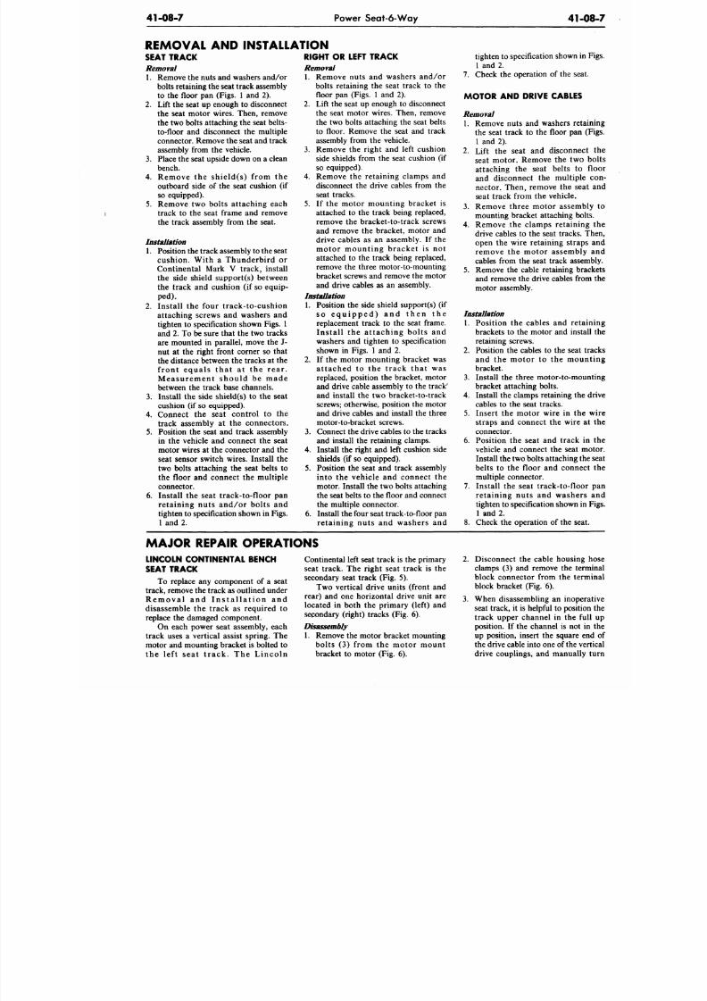
8/20/2019 1977 Ford Car Shop Manual Volume 4 Body
http://slidepdf.com/reader/full/1977-ford-car-shop-manual-volume-4-body 32/449
41-08-7
Power Seat-6 -W ay
41-0
REMOVAL AND INSTALLATION
SEAT TRACK
Removal
1. Remove the nuts and washers and /or
bolts retaining the seat track assembly
to the floor pan (Figs. 1 and 2).
2. Lift the seat up enough to disconnect
the seat motor wires. Then, remove
the two bolts attaching the seat belts-
to-floor and disconnect the multiple
connector. Remove the seat and track
assembly from the vehicle.
3. Place the seat upside down on a clean
bench.
4. Remove the shield(s) f rom the
outboard side of the seat cushion (if
so equipped).
5.
Remove two bolts attaching each
track to the seat frame and remove
the track assembly from the seat.
Installation
1. Position the track assembly to the seat
cushion. With a Thunderbird or
Continental Mark V track, install
the side shield support(s) between
the track and cushion (if so equip-
ped).
2.
Install the four track-to-cushion
attaching screws and washers and
tighten to specification shown F igs. 1
and 2. To be sure that the two tracks
are mounted in parallel, move the J-
nut at the right front corner so that
the distance between the tracks at the
f ront equa ls tha t a t the rear .
M e a sur e m e nt shou ld be m a de
between the track base channels.
3. Install the side shield(s) to the seat
cushion (if so equipped).
4. Connect the seat control to the
track assembly at the connectors.
5. Position the seat and track assembly
in the vehicle and connect the seat
motor wires at the connector and the
seat sensor switch wires. Install the
two bolts attaching the seat belts to
the floor and connect the multiple
connector.
6. Install the seat track-to-floor pan
retaining nuts and/or bolts and
tighten to specification shown in Figs.
1 and 2.
RIGHT OR LEFT TRACK
Removal
1.
Remove nuts and washers and/or
bolts retaining the seat track to the
floor pan (Figs. 1 and 2).
2. Lift the seat up enough to disconnect
the seat motor wires. Then, remove
the two bolts attaching the seat belts
to floor. Remove the seat and track
assembly from the vehicle.
3. Remove the right and left cushion
side shields from the seat cushion (if
so equipped).
4.
Remove the retaining clamps and
disconnect the drive cables from the
seat tracks.
5.
If the motor mounting bracket is
attached to the track being replaced,
remove the bracket-to-track screws
and remove the bracket, motor and
drive cables as an assembly. If the
motor mount ing bracke t i s not
attached to the track being replaced,
remove the three motor-to-mounting
bracket screws and remove the motor
and drive cables as an assembly.
Installation
1. Position the side shield sup port(s) (if
s o e q u i p p e d ) a n d t h e n t h e
replacement track to the seat frame.
Ins ta l l the a t taching bol ts and
washers and tighten to specification
shown in Figs. 1 and 2.
2. If the motor mounting bracket was
a t tached to the t rack tha t was
replaced, position the bracket, motor
and drive cable assembly to the track'
and install the two bracket-to-track
screws; otherwise, position the motor
and drive cables and install the three
motor-to-bracket screws.
3. Connect the drive cables to the tracks
and install the retaining clamps.
4. Install the right and left cushion side
shields (if so equipped).
5. Position the seat and track assembly
into the vehicle and connect the
motor. Install the two bolts attaching
the seat belts to the flo or and connect
the multiple connector.
6. Install the four seat track-to-floor pan
retaining nuts and washers and
tighten to specification shown in
1 and 2.
7. Check the operation of the seat.
MOTOR AND DRIVE CABLES
Removal
1. Remove nuts and washers retai
the seat track to the floor pan (
1 and 2).
2. Lift the seat and disconnect
seat motor. Remove the two
attaching the seat belts to
and disconnect the multiple
nector. Then, remove the seat
seat track from the vehicle.
3. Remove three motor assembl
mounting bracket attaching bolt
4. Remove the clamps retaining
drive cables to the seat tracks. T
open the wire retaining straps
remove the motor assembly
cables from the seat track assem
5.
Remove the cable retaining bra
and remove the drive cables from
motor assembly.
Installation
1. Position the cables and retai
brackets to the motor and instal
retaining screws.
2. Position the cables to the seat t
and the motor to the moun
bracket.
3. Install the three motor-to-mou
bracket attaching bolts.
4. Install the clamps retaining the
cables to the seat tracks.
5. Insert the motor wire in the
straps and connect the wire a
connector.
6. Position the seat and track in
vehicle and connect the seat m
Install the two bolts attaching the
belts to the floor and connec
multiple connector.
7. Install the seat track-to-floor
retaining nuts and washers
tighten to specification shown in
1 and 2.
8. Check the operation of the seat
MAJOR REPAIR OPERATIONS
LINCOLN CONTINENTAL BENCH
SEAT TRACK
To replace any component of a seat
track, remove the track as outlined under
R e m o v a l a n d I n s t a l l a t i o n a n d
disassemble the track as required to
replace the damaged component.
On each power seat assembly, each
track uses a vertical assist spring. The
motor and mounting bracket is bolted to
the le f t sea t t r ack. The Lincoln
Continental left seat track is the primary
seat track. The right seat track is the
secondary seat track (Fig. 5).
Two vertical drive units (front and
rear) and one horizontal drive unit are
located in both the primary (left) and
secondary (right) tracks (Fig. 6).
Disassembly
1. Remove the motor bracket mounting
bolts (3) from the motor mount
bracket to motor (Fig. 6).
2. Disconnect the cable housing
clamps (3) and remove the term
block connector from the term
block bracket (Fig. 6).
3. When disassembling an inoper
seat track, it is helpful to position
track upper channel in the ful
position. If the channel is not in
up position, insert the square en
the drive cable into one of
the
ve
drive couplings, and manually
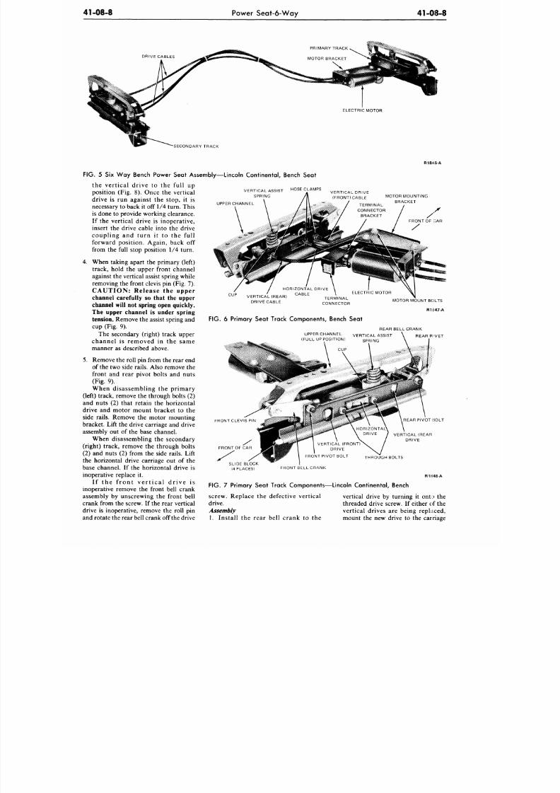
8/20/2019 1977 Ford Car Shop Manual Volume 4 Body
http://slidepdf.com/reader/full/1977-ford-car-shop-manual-volume-4-body 33/449
41-08-8
Power Seat-6-W ay
41-08-8
DRIVE CABLES
•SECONDARY TRACK
R1846-A
VERTICAL ASSIST
SPRING
HOSE CLAMPS
UPPER CHANNEL
CU P
VERTICAL (REAR)
DRIVE CABLE
HORIZONTAL DRIVE
CABLE
TERMINAL
CONNECTOR
FIG. 6 Primary Seat Track Components, Bench Seat
FIG.
5 Six Way Bench Power Seat Assembly—Lincoln Continental, Bench Seat
the vertical drive to the full up
position (Fig. 8). Once the vertical
drive is run against the stop, it is
necessary to back it off 1/4 turn. T his
is done to provide working clearance.
If the vertical drive is inoperative,
insert the drive cable into the drive
coupling and turn it to the full
forward position. Again, back off
from the full stop position 1/4 turn.
4. When taking apart the primary (left)
track, hold the upper front channel
against the vertical assist spring while
removing the front clevis pin (Fig. 7).
CAUTION: Release the upper
channel carefully so that the upper
channel will not spring open quickly.
The upper channel is under spring
tension. Remove the assist spring and
cup (Fig. 9).
The secondary (right) track upper
channel is removed in the same
manner as described above.
5. Remove the roll pin from the rear end
of the two side rails. Also remove the
front and rear pivot bolts and nuts
(Fig. 9).
When disassembling the primary
(left) track, remove the through bolts (2)
and nuts (2) that retain the horizontal
drive and motor mount bracket to the
side rails. Remove the motor mounting
bracket. Lift the drive carriage and drive
assembly out of the base channel.
When disassembling the secondary
(right) track, remove the through bolts
(2) and nuts (2) from the side rails. Lift
the horizontal drive carriage out of the
base channel. If the horizontal drive is
inoperative replace it.
I f the f ront ver t ica l dr ive i s
inoperative remove the front bell crank
assembly by unscrewing the front bell
crank from the screw. If the rear vertical
drive is inoperative, remove the roll pin
and rotate the rear bell crank off the d rive
VERTICAL DRIVE
(FRONT) CABLE
MOTOR MOUNTING
BRACKET
MOTOR MOUNT BOLTS
R1347-A
UPPER CHANNEL
(FULL UP POSITION)
REAR BELL CRANK
VERTICAL ASSIST \ REAR RIVET
REAR PIVOT BOLT
VERTICAL (REAR
DRIVE
THROUGH BOLTS
SLIDE BLOCK
(4 PLACES)
FRONT BELL CRANK
R1H48-A
FIG.
7 Primary Seat Track Components—Lincoln Continental, Bench
screw. Replace the defective vertical
drive.
Assembly
1.
Install the rear bell crank to the
vertical drive by turning it onto the
threaded drive screw. If either of the
vertical drives are being replaced,
mount the new drive to the carriage
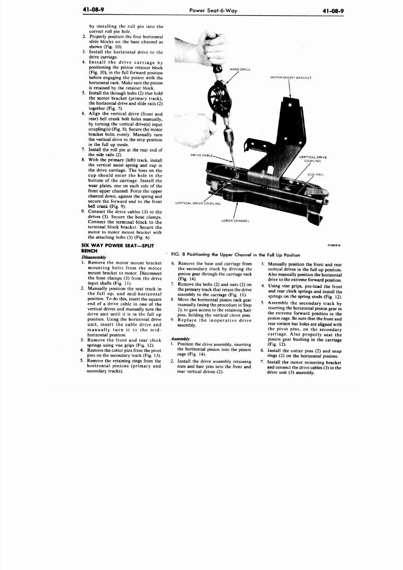
8/20/2019 1977 Ford Car Shop Manual Volume 4 Body
http://slidepdf.com/reader/full/1977-ford-car-shop-manual-volume-4-body 34/449
41-08-9
Power Seat-6-Way
41-0
by installing the roll pin into the
correct roll pin hole.
2. Properly position the four horizontal
slide blocks on the base channel as
shown (Fig. 10).
3. Install the horizontal drive to the
drive carriage.
4. I ns t a l l t he d r ive c a r r i a ge by
positioning the pinion retainer block
(Fig. 10), in the full forward position
before engaging the pinion with the
horizontal rack. Make sure the pinion
is retained by the retainer block.
5. Install the through bolts (2) that hold
the motor bracket (primary track),
the horizontal drive and slide rails (2)
together (Fig. 7).
6. Align the vertical drive (front and
rear) bell crank bolt holes manually,
by turning the vertical drive(s) input
coupling(s) (Fig. 8). Secure the motor
bracket bolts evenly. Manually turn
the vertical drive to the stop position
in the full up mode.
7. Install the roll pin at the rear end of
the side rails (2).
8. With the primary (left) track, install
the vertical assist spring and cup in
the drive carriage. The boss on the
cup should enter the hole in the
bottom of the carriage. Install the
wear plates, one on each side of the
front upper channel. Force the upper
channel down, against the spring and
secure the forward end to the front
bell crank (Fig. 9).
9. Connect the drive cables (3) to the
drives (3). Secure the hose clamps.
Connect the terminal block to the
terminal block bracket. Secure the
motor to motor mount bracket with
the attaching bolts (3) (Fig. 6).
SIX W A Y POW ER SEAT—SPLIT
BENCH
Disassembly
1. Remove the motor mount bracket
mounting bolts f rom the motor
mount bracket to motor. Disconnect
the hose clamps (3) from the drive
input shafts (Fig. 11).
2. Manually position the seat track in
the full up, and mid-horizontal
position. To do this, insert the square
end of a drive cable in one of the
vertical drives and manually turn the
drive unit until it is in the full up
position. Using the horizontal drive
unit, insert the cable drive and
m a nua l ly t u r n i t t o t he m id-
horizontal position.
3.
Remove the front and rear clock
springs using vise grips (Fig. 12).
4. Remove the cotter pins from the pivot
pins on the secondary track (Fig. 13).
5. Remove the retaining rings from the
horizontal pinions (primary and
secondary tracks).
c
HAND DRILL
MOTOR MOUNT BRACKET
DRIVE CABLE
VERTICAL DRIVE COUPLING
LOWER CHANNEL
R184
FIG. 8 Positioning the Upper Channel in the Full Up Position
6. Remove the base and carriage from
the secondary track by driving the
pinion gear through the carriage rack
(Fig. 14).
7. Remove the bolts (2) and nu ts (2) on
the primary track that retain the drive
assembly to the carriage (Fig. 11).
8. Move the horizontal pinion rack gear
manually (using the procedure in Step
2),
to gain access to the retaining hair
pins,
holding the vertical clevis pins.
9 . Replace the inopera t ive dr ive
assembly.
Assembly
1. Position the drive assembly, inserting
the horizontal pinion into the pinion
cage (Fig. 14).
2. Install the drive assembly retaining
nuts and hair pins into the front and
rear vertical drives (2).
3. Manually position the front and r
vertical drives in the full up positi
Also manually position the horizon
drive to the extreme forward positi
4. Using vise grips, pre-load th e fr
and rear clock springs and install
springs on the spring studs (Fig. 1
5.
Assemble the secondary track
inserting the horizontal pinion gea
the extreme forward position in
pinion cage.
Be sure
that th e front
rear torsion bar holes are aligned w
the pivot pins, on the seconda
carriage. Also properly seat
pinion gear bushing in the carri
(Fig. 12).
6. Install the cotter pins (2) and sn
rings (2) on the horizontal pinion
7. Install the motor mou nting brac
and connect the drive cables (3) to
drive unit (3) assembly.
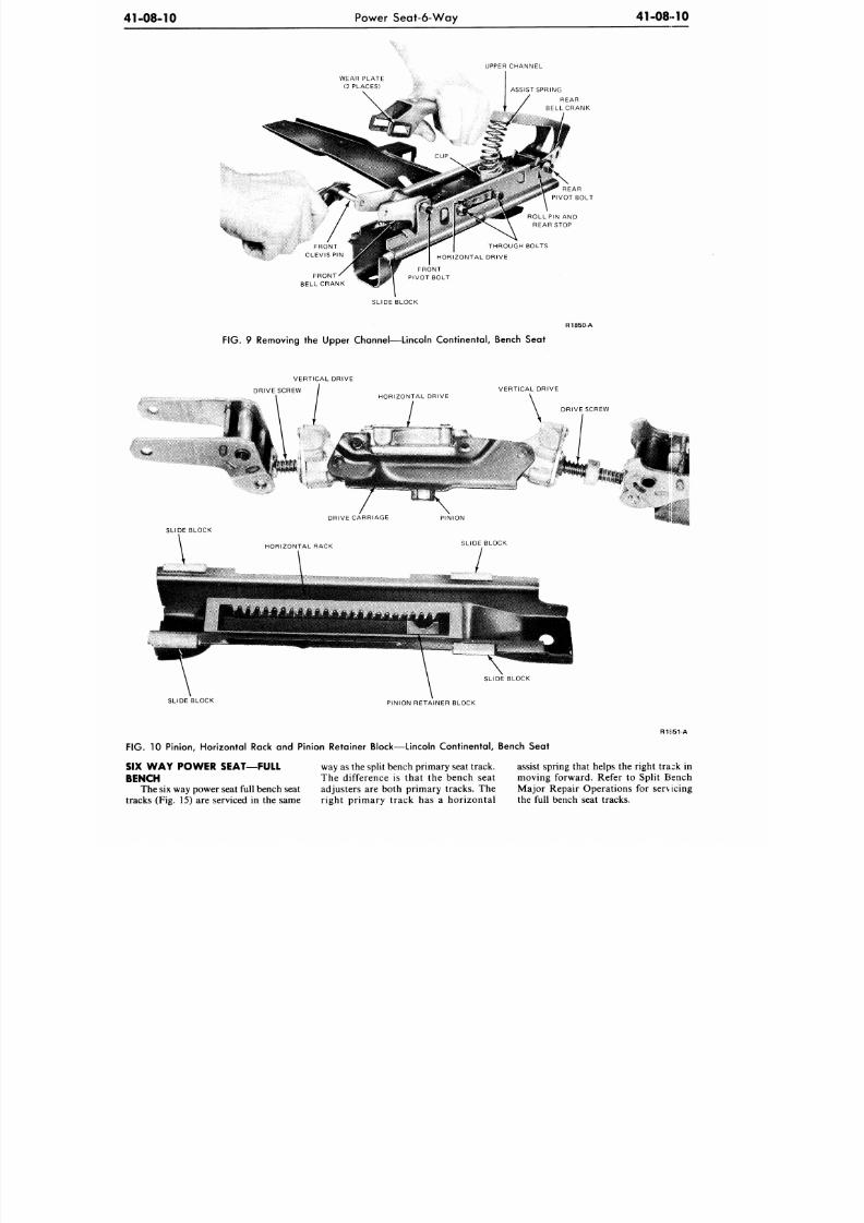
8/20/2019 1977 Ford Car Shop Manual Volume 4 Body
http://slidepdf.com/reader/full/1977-ford-car-shop-manual-volume-4-body 35/449
41-08-10
Power Seat-6-Way
41-0810
UPPER CHANNEL
WEAR PLATE
(2 PLACES)
FRONT
BELL CRANK
ASSIST SPRING
REAR
BELL CRANK
SLIDE BLOCK
R1850 A
FIG.
9 Removing the Upper Channel—Lincoln Continental, Bench Seat
VERTICAL DRIVE
DRIVE SCREW
VERTICAL DRIVE
SLIDE BLOCK
SLIDE BLOCK
PINION RETAINER BLOCK
R1K51-A
FIG. 10 Pinion, Horizontal Rack and Pinion Retainer Block—Lincoln Continental, Bench Seat
SIX W A Y POW ER SEAT—FULL
BENCH
The six way power seat full bench seat
tracks (Fig. 15) are serviced in the same
way as the split bench primary seat track.
The difference is that the bench seat
adjusters are both primary tracks. The
right primary track has a horizontal
assist spring that helps the right trask in
moving forward. Refer to Split Bench
Major Repair Operations for serv icing
the full bench seat tracks.
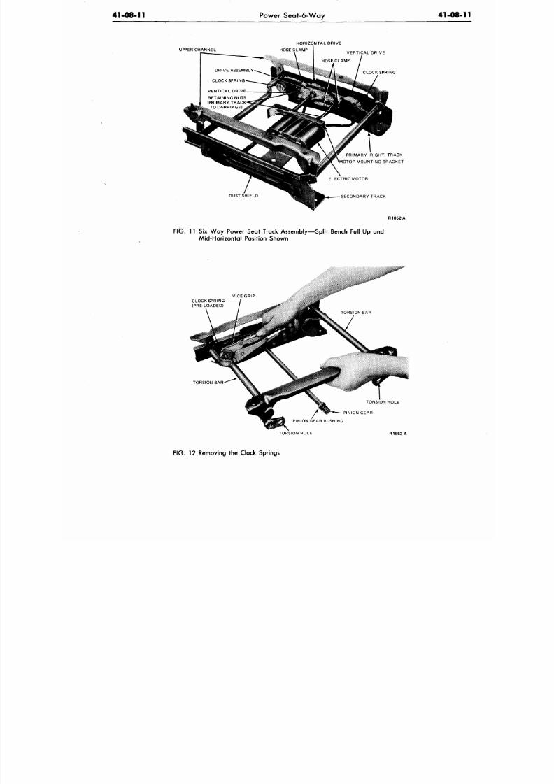
8/20/2019 1977 Ford Car Shop Manual Volume 4 Body
http://slidepdf.com/reader/full/1977-ford-car-shop-manual-volume-4-body 36/449
41-08-11 Power Seat-6-Way
41-08-
RETAINING NUTS
(PRIMARY TRACK
TO CARRIAGE)
DUST SHIELD
PRIMARY (RIGHT) TRACK
MOTOR MOUNTING BRACKET
SECONDARY TRACK
R1852-A
FIG.
11 Six Way Power Seat Track Assembly—Split Bench Full Up and
Mid-Horizontal Position Shown
VICE GRIP
CLOCK SPRING
(PRE-LOADED)
TORSION BAR
TORSION HOLE
PINION GEAR
PINION GEAR BUSHING
TORSION HOLE
R1853-A
FIG.
12 Removing the Clock Springs
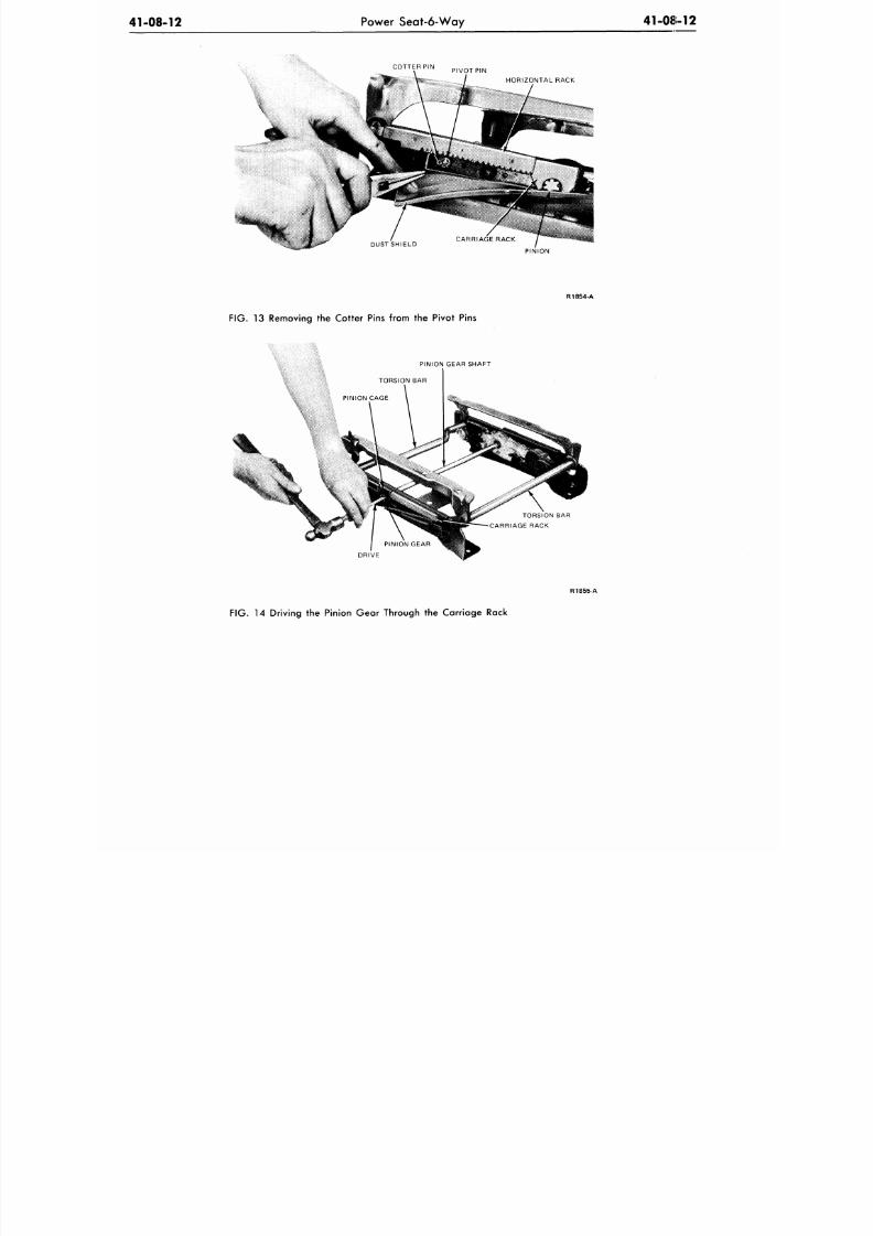
8/20/2019 1977 Ford Car Shop Manual Volume 4 Body
http://slidepdf.com/reader/full/1977-ford-car-shop-manual-volume-4-body 37/449
41-08-12
Power Seat-6-Way
41-08-12
COTTER PIN
PIVOT PIN
HORIZONTAL RACK
PINION
FIG.
13 Removing the Cotter Pins from the Pivot Pins
PINION GEAR SHAFT
TORSION BAR
PINION CAGE
DRIVE
R1855-A
FIG.
14 Driving the Pinion Gear Through the Carriage Rack
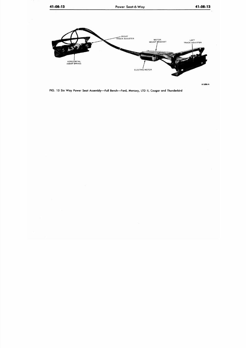
8/20/2019 1977 Ford Car Shop Manual Volume 4 Body
http://slidepdf.com/reader/full/1977-ford-car-shop-manual-volume-4-body 38/449
41-08-13
Power Seat-6-Way
41-08
HORIZONTAL
ASSIST SPRING
LEFT
TRACK ADJUSTER
R18
F IG . 15 Six W ay Power Seat Assembly—Full Bench— Ford, Mercury, LTD I I , Cougar and Thunderbird
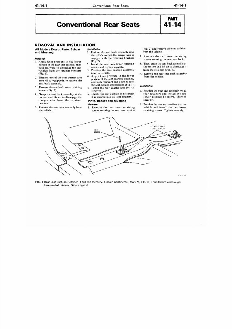
8/20/2019 1977 Ford Car Shop Manual Volume 4 Body
http://slidepdf.com/reader/full/1977-ford-car-shop-manual-volume-4-body 39/449
41-14-1
Conventional Rear Seats
41-14-1
Conventional Rear Seats
REMOVAL AND INSTALLATION
All Models Except Pinto, Bobcat
and Mustang
Removal
1. Apply knee pressure to the lower
portion of the rear seat cushion; then
push rearward to disengage the seat
cushion from the retainer brackets
(Fig. 1).
2. Remove one of the rear quarter arm
rests (if so equipped), to remove the
seat back assembly.
3.
Remove the seat back lower retaining
screws (Fig. 2).
4. Grasp the seat back assembly at the
bottom and lift up to disengage the
hanger wire f rom the re ta iner
brackets.
5. Remove the seat back assembly from
the vehicle.
Installation
1.
Position the seat back assembly into
the vehicle so that the hanger wire is
engaged with the retaining brackets
(Fig. 2).
2. Install the seat back lower retaining
screws and tighten securely.
3. Position the seat cushion assembly
into the vehicle.
4. Apply knee pressure to the lower
portion of the seat cushion assembly
and push rearward and down to lock
the seat cushion into position (Fig. 1).
5.
Install the rear quarter arm rest (if
removed).
6. Check rear seat cushion to be certain
it is secured into its floor retainer.
Pinto, Bobcat and Mustang
Removal
1. Remove the two lower retaining
screws securing the rear seat cushion
(Fig. 3) and remove the seat cushion
from the vehicle.
2. Remove the two lower retaining
screws securing the rear seat back.
3. Then, grasp the seat back assembly at
the bottom and lift up to disengage it
from the retainers (Fig. 3).
4. Remove the rear seat back assembly
from the vehicle.
Installation
1. Position the rear seat assembly to all
four retainers and install the two
lower retaining screws. Tighten
securely.
2. Position the rear seat cushion into the
vehicle and install the two lower
retaining screws. Tighten securely.
R 697-A
FIG.
1 Rear Seat Cushion Retainer—Ford and Mercu ry. Linco ln Contine ntal, Mark V, LTD II , Thu nde rbird and Cougar
have welded retainer. Others typical.
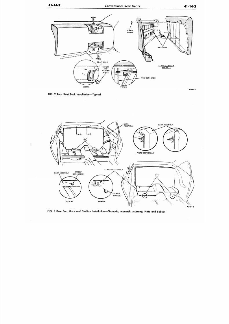
8/20/2019 1977 Ford Car Shop Manual Volume 4 Body
http://slidepdf.com/reader/full/1977-ford-car-shop-manual-volume-4-body 40/449
41-14-2
Conventional Rear Seats
41-1
CUSHION BACK
VIEW-A
VIEW-B
R1
FIG .
2 Rear Seat Back Installation—Typical
BACK ASSEMBLY
VIEWBB
N21
FIG . 3 Rear Seat Back and Cushion Installation—Granada, Monarch, Mustang, Pinto and Bobcat
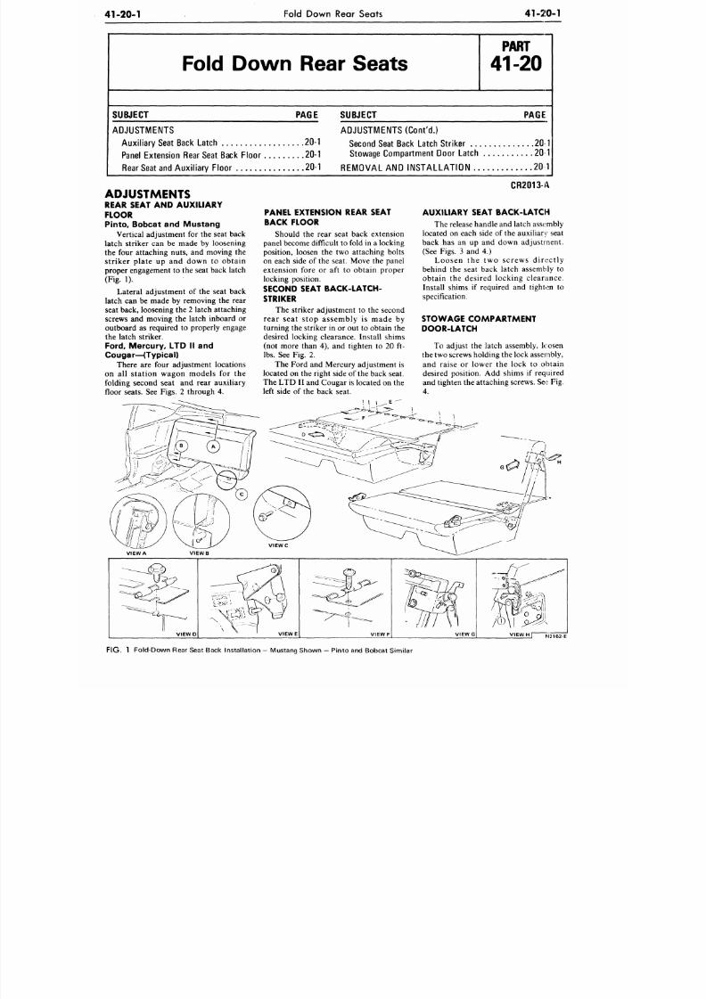
8/20/2019 1977 Ford Car Shop Manual Volume 4 Body
http://slidepdf.com/reader/full/1977-ford-car-shop-manual-volume-4-body 41/449
41-20-1
Fold Down Rear Seats
41-20-1
Fold Down Rear Seats
P A R T
41-20
SUBJECT PAGE
ADJUSTMENTS
Au xilia ry Seat Back Latch 20-1
Panel Exte nsion Rear Seat Back Flo or 20-1
Rear Seat and Au xilia ry Floo r 20-1
SUBJECT PAGE
ADJUSTMENTS (Cont 'd.)
Second Seat Back Latch Striker 20 1
Stowage Com partment Door Latch 20 1
REMOVAL AND INSTALLATION 20 1
CR2013-A
ADJUSTMENTS
REAR SEAT AND AUXILIARY
FLOOR
Pinto, Bobcat and Mustang
Vertical adjustment for the seat back
latch striker can be made by loosening
the four attaching nuts, and moving the
s tr iker pla te up and down to obta in
proper engagement to the seat back latch
(Fig. 1).
Lateral adjustment of the seat back
latch can be made by removing the rear
seat back, loosening the 2 latch attaching
screws and moving the latch inboard or
outboard as required to properly engage
the latch striker.
Ford, Mercury, LTD II and
Cou gar—( Typ ica l )
There are four adjustment locations
on a l l s ta t ion wagon models for the
folding second seat and rear auxiliary
floor seats. See Figs. 2 through 4.
PANEL EXTENSION REAR SEAT
BACK FLOOR
Should the rear seat back extension
panel become difficult to fold in a locking
position, loosen the two attaching bolts
on each side of the seat. Move the panel
extension fore or aft to obtain proper
locking position.
SECOND SEAT BACK-LATCH-
STRIKER
The striker adjustment to the second
rea r s ea t s top a s s embly i s made by
turning the striker in or out to obtain the
desired locking clearance. Install shims
(not more than 4), and tighten to 20 ft-
lbs.
See Fig. 2.
The Ford and Mercury adjustment is
located on the right side of the back seat.
The LT D II and C ougar is located on the
left side of the back seat.
AUXILIARY SEAT BACK-LATCH
The release handle and latch assembly
located on each side of the auxiliary seat
back has an up and down adjus tment .
(See Figs. 3 and 4.)
L o o s e n t h e t w o s c r e w s d i r e c t l y
behind the seat back latch assembly to
obta in the des ired locking c leantnce .
Install shims if required and tighten to
specification.
ST OWAGE COM PART M ENT
DOOR-LATCH
To adjust the latch assembly, loosen
the two screws holding the lock assembly,
and raise or lower the lock to obtain
desired position. Add shims if required
and tighten the attaching screws. See Fig.
4.
VIEW A VIE W B
V I E W D
V IE W E V IE W F
VIEW Hf
FIG . 1 Fold-Do wn Rear Seat Back Instal lat ion - Mustang Shown — Pinto and Bobcat Similar
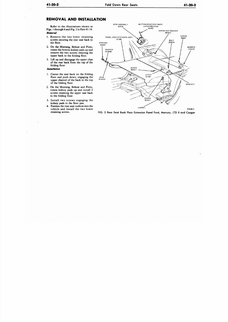
8/20/2019 1977 Ford Car Shop Manual Volume 4 Body
http://slidepdf.com/reader/full/1977-ford-car-shop-manual-volume-4-body 42/449
41-20-2
Fold Down Rear Seats
41-2
REMOVAL AND INSTALLATION
Refer to the illustrations shown in
Figs.
1 through 6 and
Fig.
2 in Part 41-14.
Removal
1. Remove the two lower retaining
screws securing the rear seat back to
the floor.
2.
On the Mustang, Bobcat and Pinto,
rotate the bottom kidney pads up and
remove the two screws retaining the
upper back to the folding floor.
3.
Lift up and disengage the upper clips
of the rear back from the top of the
folding floor .
Installation
1. Center the seat back on the folding
floor and push down, engaging the
upper channel of the back to the top
of the folding floor.
2. On the Mustang, Bobcat and Pinto,
rotate kidney pads up and install 2
screws retaining the upper seat back
to the folding floor.
3. Install two screws engaging the
kidney pads to the floor pan.
4.
Position the rear seat cushion into the
vehicle and install the two lower
retaining screws.
STOP ASSEMBLY
62426
BUTTON-REAR SEAT BACK
LATCH RELEASE
62432
SCREW AND WASHER
382542
SCREW
55927
BRA
CARPET
R1
F IG . 2 Rear Seat Back Floor Extension Panel Ford, Mercury, LTD II and Co
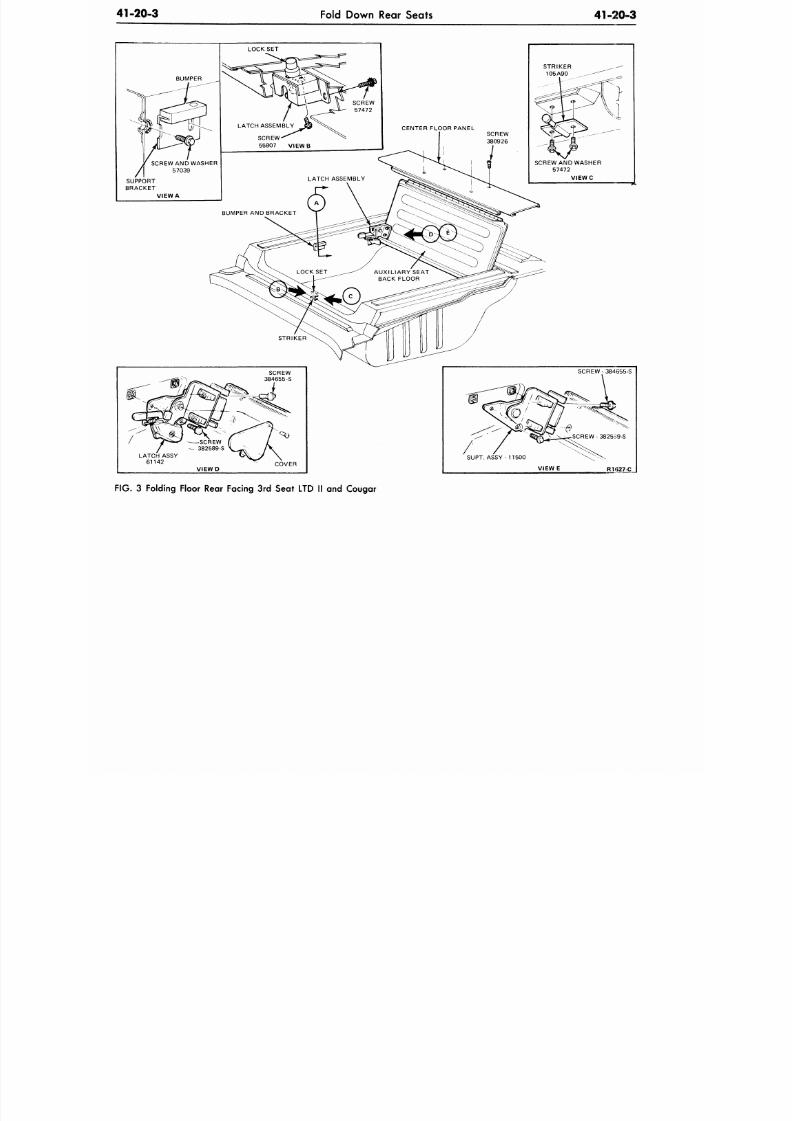
8/20/2019 1977 Ford Car Shop Manual Volume 4 Body
http://slidepdf.com/reader/full/1977-ford-car-shop-manual-volume-4-body 43/449
41-20-3
Fold Down Rear Seats
41-20-3
LOCK SET
SCREW
380926
SCREW AND WASHER
57472
V I E W C
LATCH ASSY
61142
V I E W D
COVER
V I E W E
RHS27-C
F IG .
3 Folding Floor Rear Facing 3rd Seat LTD II and Cougar
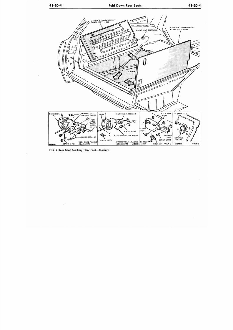
8/20/2019 1977 Ford Car Shop Manual Volume 4 Body
http://slidepdf.com/reader/full/1977-ford-car-shop-manual-volume-4-body 44/449
41-20-4
Fold Down Rear Seats
41-2
STOWAGE COMPARTMENT
PANEL ASSY. 11698
SHIM 431 E 74
SCREW AND
WASHER 382622
VIEW-A
SCREW 51 751
COVER 605A16-7
WITH DUAL FACING
REAR SEATS
HINGE ASSY. 116A00-1
SCREW 57032
\ & & - — / S T UD P RO TE CT OR 3 5 35 3 8
SCREW 57032
WITHOUT DUAL FACING
REAR SEATS VIEW-B
LATCH ASSY.
EW 57471
LOCK SET VIEW-C
SCREW 5 7472
STRIKER
105A90 //
VIEW-D
R1
FIG. 4 Rear Seat Auxiliary Floor Ford—Mercury
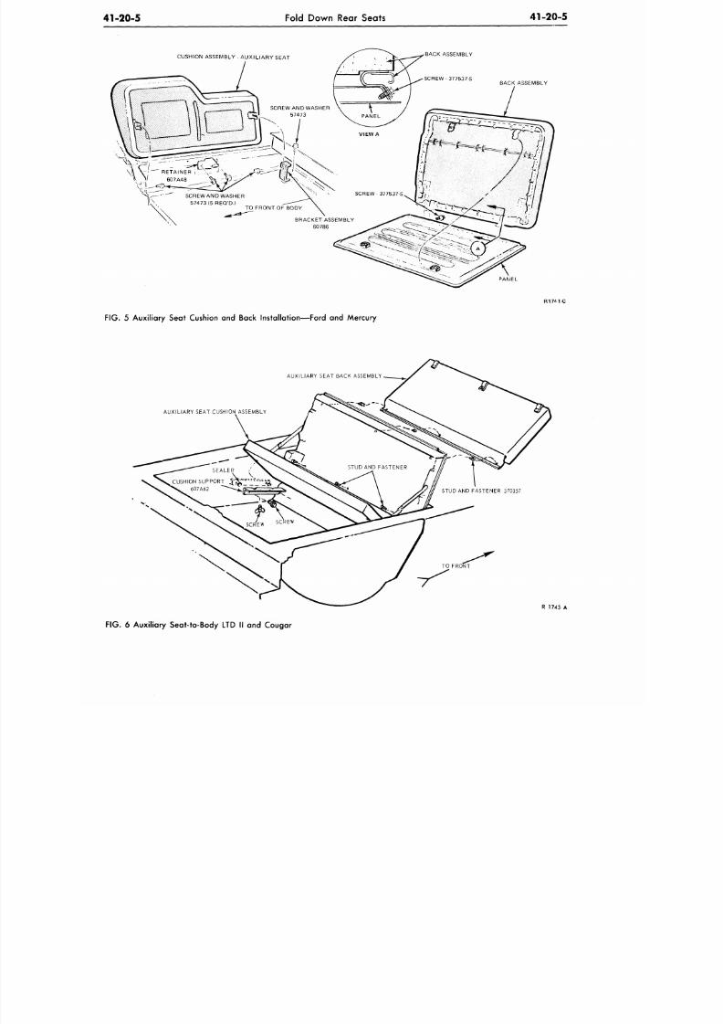
8/20/2019 1977 Ford Car Shop Manual Volume 4 Body
http://slidepdf.com/reader/full/1977-ford-car-shop-manual-volume-4-body 45/449
41-20-5
Fold Down Rear Seats
41-20-5
CUSHION ASSEMBLY - AUX ILIAR Y SEAT
BACK ASSEMBLY
BACK ASSEMBLY
R17 M-C
FIG. 5 Auxiliary Seat Cushion and Back Installation—Ford and Mercury
AUXILIARY SEAT BACK ASSEMBLY
AUXILIARY SEAT CUSHION ASSEMBLY
FROf^T
R 1743 A
FIG.
6 Auxiliary Seat-to-Body LTD II and Cougar
8/20/2019 1977 Ford Car Shop Manual Volume 4 Body
http://slidepdf.com/reader/full/1977-ford-car-shop-manual-volume-4-body 46/449
41-25-1
Seat Back Latch—Manual
41-
Seat Back Latch-Manual
DESCRIPTION AND OPERATION
All folding seats have a latc h designed
to hold the seat back in the normal
position. For rear seat passenger entry
and exit, a latch handle is located on the
left side of all bucket and split bench seats
(drivers side), and on the right side of all
bucket and split bench seats, (passenger
side).
See Figs. 1 throug h 3.
If the seat back will not latch in
position or the latch mechanism will not
unlock, remove the seat trim as required
to inspect the latch mechanism. Then,
replace any damaged parts to put the
CR2014
latch system in proper working ord
Figs.
1 through 3.
Check the front seat back latche
door models only) for smooth ope
The latch should not stick or bind
check to be sure that the latch re
the seat back from moving forwar
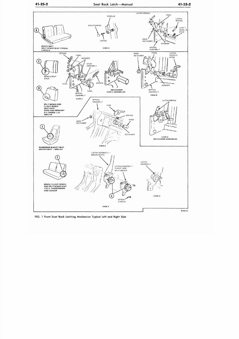
8/20/2019 1977 Ford Car Shop Manual Volume 4 Body
http://slidepdf.com/reader/full/1977-ford-car-shop-manual-volume-4-body 47/449
41-25-2
Seat Back Latch—Manual
41-25-2
LATCH SPRING
HANDLE
PAWL
ESCUTCHEON
BENCH SEAT
SPLIT BENCH SEAT TYPICAL
LINCOLN
SCREW
VIEW A
SPRING
ASSEMBLY
SPRING
PAWL
SPLIT BENCH
AND
FLIGHT BENCH
SEAT BACK
FORD AND MERCURY
R.H. SHOWN,
L.H.
SIMILAR
PASSENGER BUCKET SEAT
DRIVER SEAT - SIMILAR
V I E W E
LATCH ASSEMBLY -
BENCH SEATS
LATCH ASSEMBLY -
FLIGHT AND
SPLIT BENCH
BENCH, FLIGHT BENCH,
AND SPLIT BENCH SEAT
LTD I l .THUNDERBIRD
AND COUGAR
R142' 2-I
FIG. 1 Front Seat Back Latching Mechanism Typical Left and Right Side
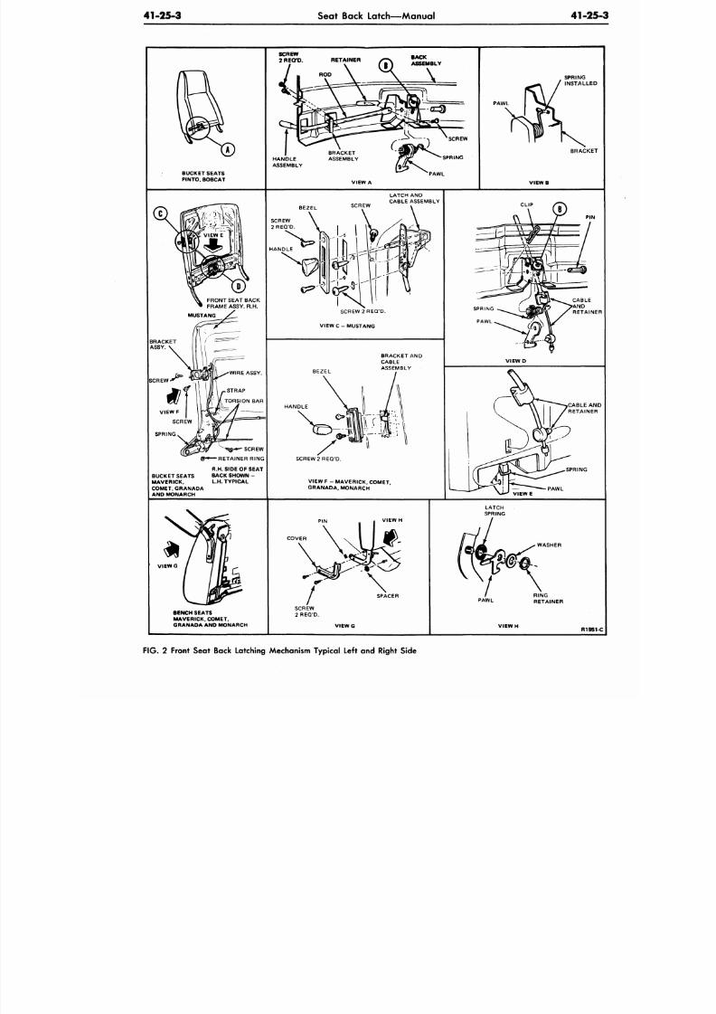
8/20/2019 1977 Ford Car Shop Manual Volume 4 Body
http://slidepdf.com/reader/full/1977-ford-car-shop-manual-volume-4-body 48/449
41-25-3
Seat Back Latch—Manual
41-25
BUCKET SEATS
PINTO. BOBCAT
VIEW A
PAWL
BRACKET
V I E W B
BEZEL
SCREW
LATCH AND
CABLE ASSEMBLY
SCREW
2 R E Q ' D .
SCREW 2 REQ 'D.
VIEW C - MUSTANG
BRACKET AND
CABLE
ASSEMBLY
SCREW
HANDLE
SCREW
RETAINER RING
R.H. SIDE OF SEAT
BUCKET SEATS BACK SHOWN -
MAVE RICK. L.H. TYPICAL
COMET. GRANADA
AND MONARCH
SCREW 2 RE Q'D.
VIEW F - MAVER ICK, COMET.
GRANADA. MONARCH
P IN
V I E W D
SPRING
V I E W E
PAWL
VIEW H
COVER
V I E W G
BENCH SEATS
MAVERICK, COMET,
GRANADA AND MONARCH
SPACER
V I E W G
WASHER
PAWL
R195
FIG. 2 Front Seat Back Latching Mechanism Typical Left and Right Side
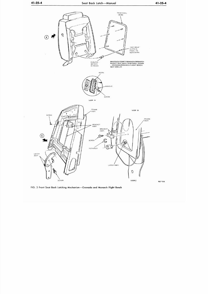
8/20/2019 1977 Ford Car Shop Manual Volume 4 Body
http://slidepdf.com/reader/full/1977-ford-car-shop-manual-volume-4-body 49/449
41-25-4
Seat Back Latch—Manual
41-215-4
TRIM PANEL
-
60762
MAVERICK/COMET/GRANADA/MONARCH
BUCKET SEAT BACK TRIM PANEL SHOWN
- GRANADA/MONARCH FLIGHT BENCH
SEAT SIMILAR
HANDLE
SCREW
VIEW-A
FRAME
ASSY.
SCREW
VIEWC
N27 '0-B
FIG. 3 Front Seat Back Latching Mechanism—Granada and Monarch Flight Bench
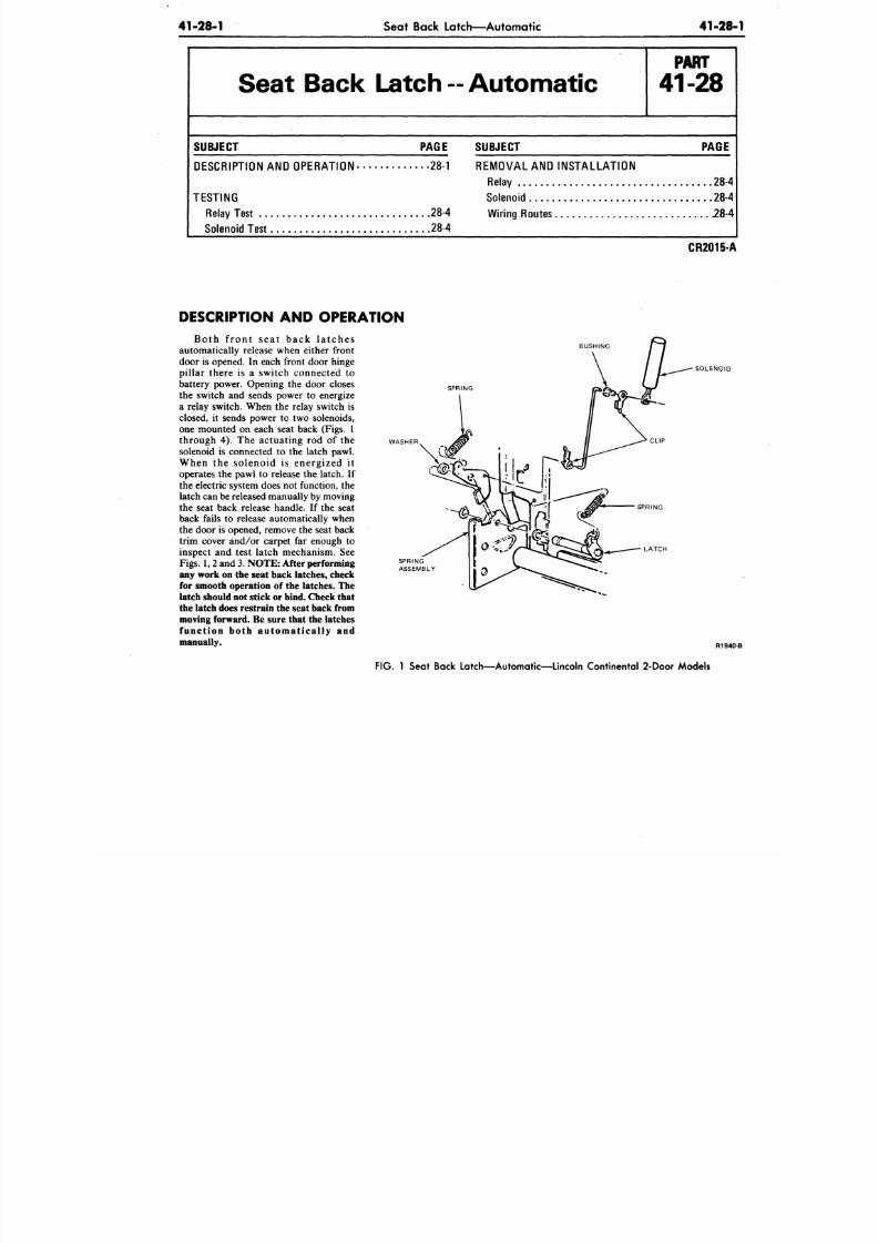
8/20/2019 1977 Ford Car Shop Manual Volume 4 Body
http://slidepdf.com/reader/full/1977-ford-car-shop-manual-volume-4-body 50/449
41-28-1
Seat Back Latch—Automatic
41-28
Seat Back Latch
--
Automatic
P A R T
41-28
S U B JE C T P A G E
DESCRIPTION AND OPERATION 28-1
TESTING
Relay Test 28-4
Solenoid Test 28-4
S U B JE C T P A G E
REMOVAL AND INSTALLATION
Relay 28-4
Solenoid 28-4
Wiring Routes 28 -4
CR2015-A
WASHER
DESCRIPTION AND OPERATION
Both f r on t s e a t ba c k l a t c he s
automatically release when either front
door is opened. In each front door hinge
pillar there is a switch connected to
battery power. Opening the door closes
the switch and sends power to energize
a relay switch. When the relay switch is
closed, it sends power to two solenoids,
one mounted on each seat back (Figs. 1
through 4). The actuating rod of the
solenoid is connected to the latch pawl.
When the solenoid is energized i t
operates the pawl to release the latch. If
the electric system does not function, the
latch can
be
released manually
by
moving
the seat back release handle. If the seat
back fails to release automatically when
the door is opened, remove the seat back
trim cover and/or carpet far enough to
inspect and test latch mechanism. See
Figs. 1,2 and
3.
NO TE : After performing
any work on the seat back latches, check
for smooth operation of the latches. The
latch should not stick or bind. Check that
the latch does restrain the seat back from
moving forward. Be sure that the latches
f u n c t i o n b o t h a u t o m a t i c a l l y a n d
manually.
SPRING
SOLENOID
LATCH
R194
FIG . 1 Seat Back Latch—Automatic—Lincoln Continental 2-Door Models
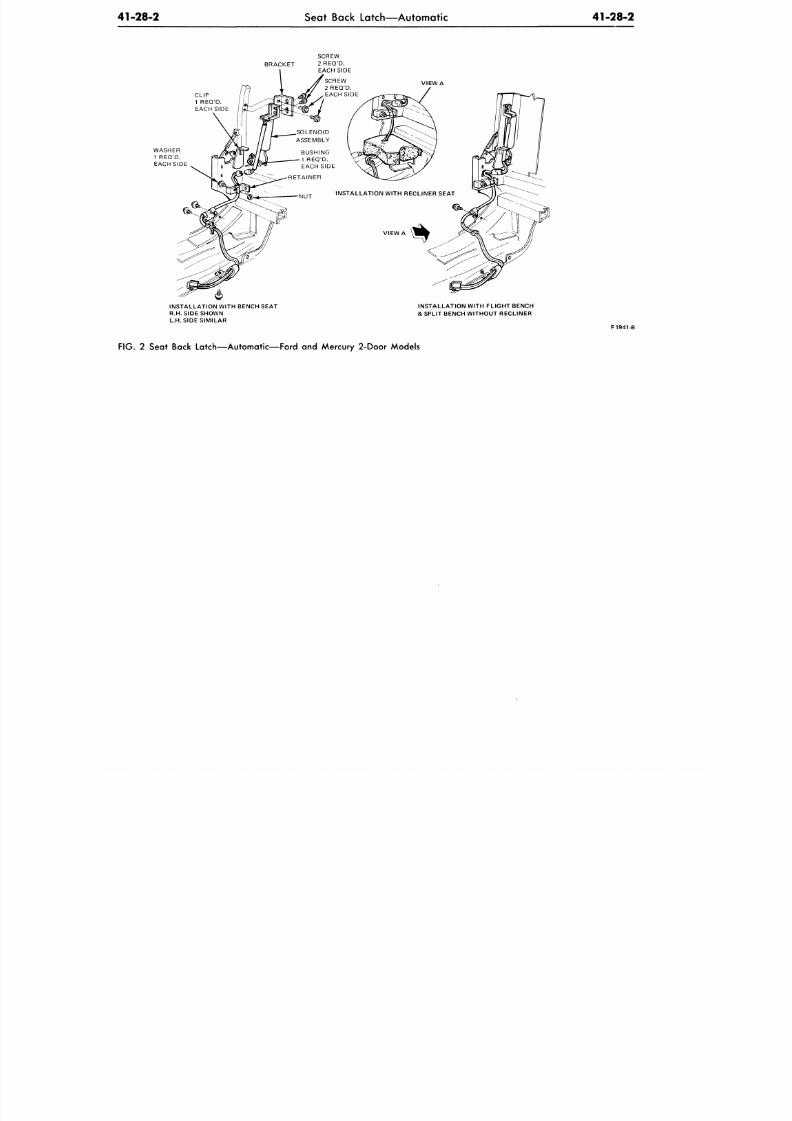
8/20/2019 1977 Ford Car Shop Manual Volume 4 Body
http://slidepdf.com/reader/full/1977-ford-car-shop-manual-volume-4-body 51/449
41-28-2
Seat Back Latch—Automatic
41-28-2
BRACKET
CLIP
1 REQ'D.
EACH SIDE
INSTALLATION WITH BENCH SEAT
R.H.SIDE SHOWN
L.H.SIDE SIMILAR
INSTALLATION WITH FLIGHT BENCH
& SPLIT BENCH WITHOUT RECLINER
F1941-B
FIG. 2 Seat Back Latch—Automatic—Ford and Mercury 2 -Door Mo dels
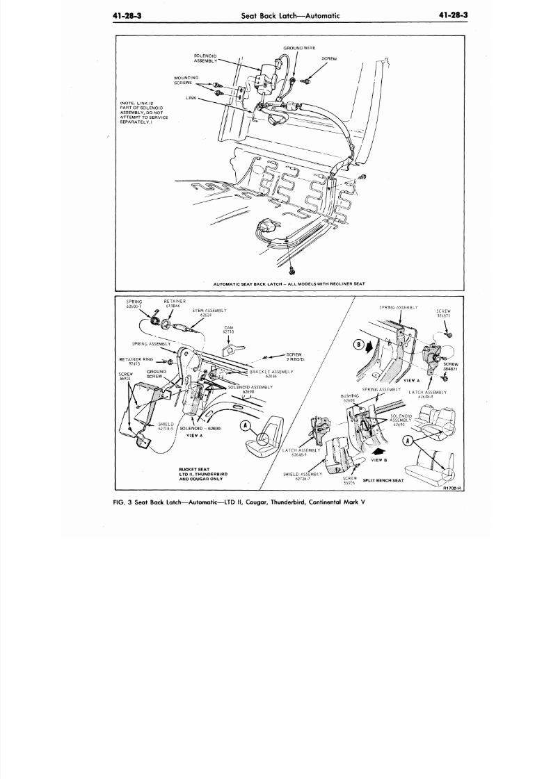
8/20/2019 1977 Ford Car Shop Manual Volume 4 Body
http://slidepdf.com/reader/full/1977-ford-car-shop-manual-volume-4-body 52/449
41-28-3
Seat Back Latch—Automatic
41-28
GROUND WIRE
SOLENOID
ASSEMBLY
(NOTE:
LINK IS
PART OF SOLENOID
ASSEMBLY, DO NOT
ATTEMPT TO SERVICE
SEPARATELY.)
AUTOM ATIC SEAT BACK LATCH - ALL MODELS WITH RECLINER SEAT
SPRING
62600-1
RETAINER
610B66
SCREW
384871
SCREW
56903
SHIELD
/ \
62718-9 / S O L E N O I D - 6 2 6 9 0
55926
S P L I T B E N C H S E A T
BUCKET SEAT
LTD H,THUNDERBiRD
AND COUGAR ONLY
FIG. 3 Sea t Back Latch—Autom atic-—LTD I I, Couga r, Thunderbird, Continental Ma rk V
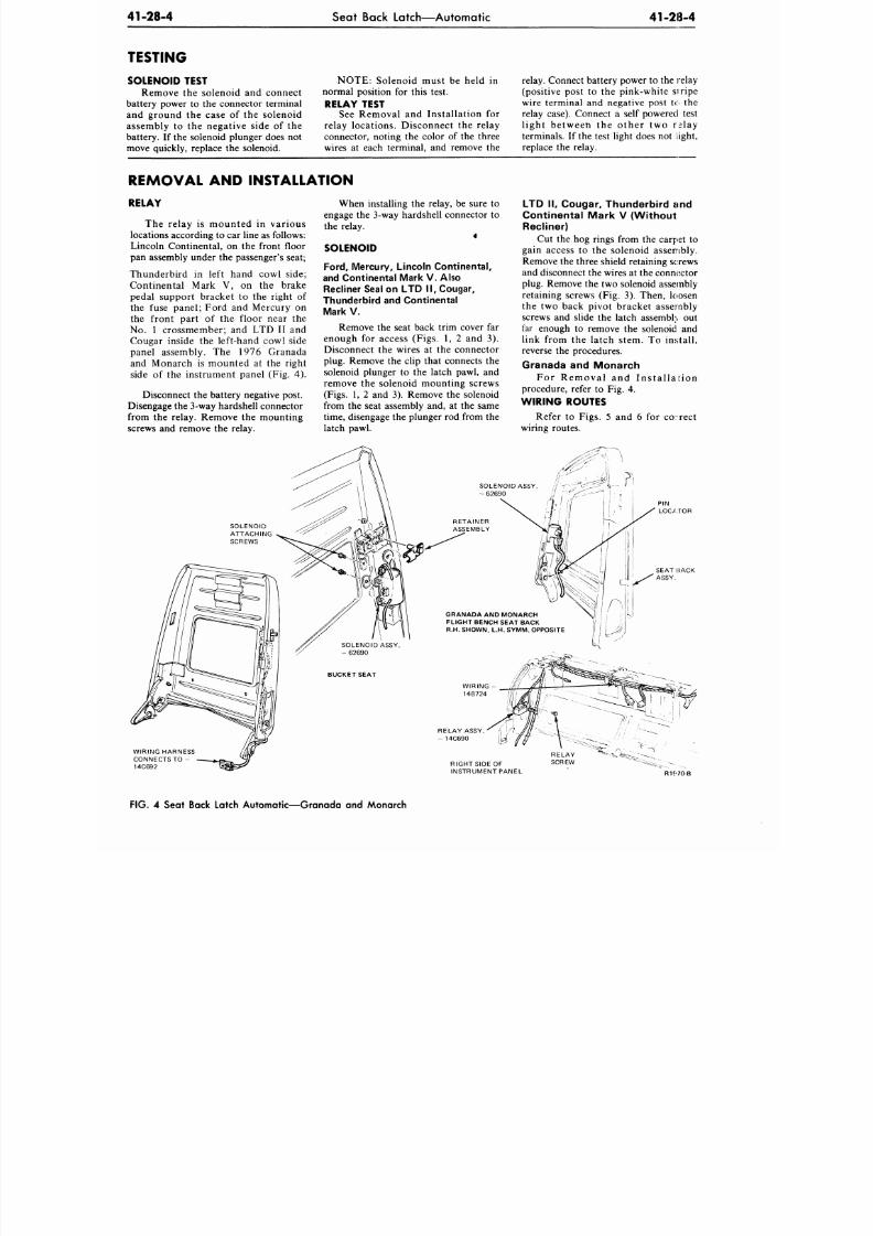
8/20/2019 1977 Ford Car Shop Manual Volume 4 Body
http://slidepdf.com/reader/full/1977-ford-car-shop-manual-volume-4-body 53/449
41-28-4
Seat Back Latch—Automatic
41-28-4
TESTING
SOLENOID TEST
Remove the solenoid and connect
battery power to the connector terminal
and ground the case of the solenoid
assembly to the negative side of the
battery. If the solenoid plunger does not
move quickly, replace the solenoid.
NOTE: Solenoid must be held in
normal position for this test.
RELAY TEST
See Removal and Installation for
relay locations. Disconnect the relay
connector, noting the color of the three
wires at each terminal, and remove the
relay. Connect battery power to the relay
(positive post to the pink-white siripe
wire terminal and negative post to the
relay case). Connect a self powered test
light between the other two r^lay
terminals. If the test light does not light,
replace the relay.
REMOVAL AND INSTALLATION
RELAY
The relay is mounted in various
locations according to car line as follows:
Lincoln Continental, on the front floor
pan assembly under the passenger's seat;
Thun derbird in left hand cow l side;
Continental Mark V, on the brake
pedal support bracket to the right of
the fuse panel; Ford and Mercury on
the front part of the floor near the
No. 1 crossmember; and LTD II and
Cougar inside the left-hand cowl side
panel assembly. The 1976 Granada
and Monarch is mo unted at the right
side of the instrument panel (Fig. 4).
Disconnect the battery negative post.
Disengage the 3-way hardshell connector
from the relay. Remove the mounting
screws and remove the relay.
When installing the relay, be sure to
engage the 3-way hardshell connector to
the relay.
4
SOLENOID
Ford ,
Mercury, L inco ln Con t inental ,
and Continental Mark V . Also
Recliner Seal on LTD II , Cougar,
Thunde rbird and Cont inental
Mark V.
Remove the seat back trim cover far
enough for access (Figs. 1, 2 and 3).
Disconnect the wires at the connector
plug. Remove the clip that connects the
solenoid plunger to the latch pawl, and
remove the solenoid mounting screws
(Figs. 1, 2 and 3). Remove the solenoid
from the seat assembly and, at the same
time, disengage the plunger rod from the
latch pawl.
LTD II, Cougar, Thunde rbird and
Cont inenta l Mark V (Wi thout
Recliner)
Cut the hog rings from the carpet to
gain access to the solenoid assembly.
Remove the three shield retaining screws
and disconnect the w ires at the connector
plug. Remove the two solenoid assembly
retaining screws (Fig. 3). Then, loosen
the two back pivot bracket assembly
screws and slide the latch assembly out
far enough to remove the solenoid and
link from the latch stem. To install,
reverse the procedures.
Granada and Monarch
For Removal and Ins ta l la t ion
procedure, refer to Fig. 4.
WIRING ROUTES
Refer to Figs. 5 and 6 for c o r e d
wiring routes.
SOLENOID ASSY.
- 62690
PIN
LOCATOR
GRANADA AND MONARCH
FLIGHT BENCH SEAT BACK
R.H. SHOWN, L.H. S YMM . OPPOSITE
WIRING HARNESS
CONNECTS TO -
14C692
RELAY ASSY.
- 14C690
RIGHT SIDE OF
INSTRUMENT PANEL
R1£'70-B
FIG. 4 Seat Back Latch Automatic—Granada and Monarch
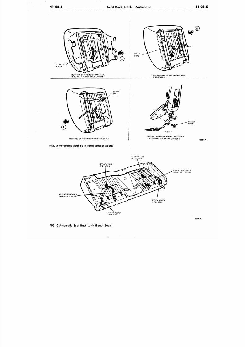
8/20/2019 1977 Ford Car Shop Manual Volume 4 Body
http://slidepdf.com/reader/full/1977-ford-car-shop-manual-volume-4-body 54/449
41-28-5
Seat Back Latch—Automatic
41-28
ROUTING OF 14C692 WIRING ASSY.
(L.H.) WITH POWER SEAT OPTION
ROUTING OF 14C692 WIRING ASSY. (R.H.)
ROUTING OF 14C692 WIRING ASSY.
(L.H.) MANUAL
INSTALLATION OF WIRING RETAINER
L.H. SHOWN, R.H. SYMM. OPPOSITE
N2858
FIG .
5 Automatic Seat Back Latch (Bucket Seats)
WIRING ASSEMBLY
14C691 (2 PLACES)
STRAP 42359
(2 PLACES)
STRAP 42359
(2 PLACES)
SCREW 389184
(2 PLACES)
SCREW 389184
(2 PLACES)
WIRING ASSEMBLY
14C691 (2 PLACES)
N2859-A
FIG .
6 Automatic Seat Back Latch (Bench Seats)
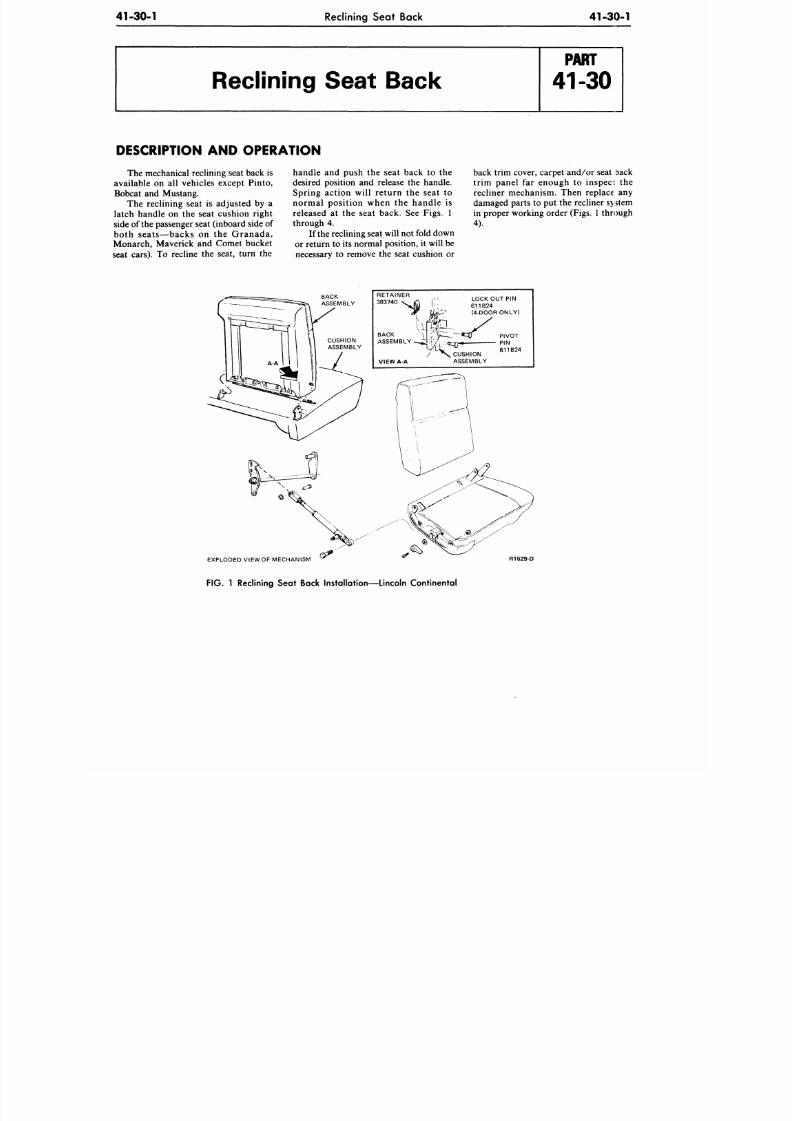
8/20/2019 1977 Ford Car Shop Manual Volume 4 Body
http://slidepdf.com/reader/full/1977-ford-car-shop-manual-volume-4-body 55/449
41-30-1
Reclining Seat Back 4 1 -3 0 -1
Reclining Seat Back
DESCRIPTION AND OPERATION
The mechanical reclining seat back is
available on all vehicles except Pinto,
Bobcat and Mustang.
The reclining seat is adjusted by a
latch handle on the seat cushion right
side of the passenger seat (inboard side of
both seats—backs on the Granada,
Monarch, Maverick and Comet bucket
seat cars). To recline the seat, turn the
handle and push the seat back to the
desired position and release the handle.
Spring action will return the seat to
normal position when the handle is
released at the seat back. See Figs. 1
through 4.
If the reclining seat will not fold down
or return to its normal position, it will be
necessary to remove the seat cushion or
back trim cover, carpet and/or seat back
trim panel far enough to inspect the
recliner mechanism. Then replace any
damaged parts to put the recliner system
in proper working order (Figs. 1 through
4).
RETAINER
383740 ^ O \\
LOCK OUT PIN
611 B24
(4 -DOORONLY)
EXPLODED VIEW OF MECHANISM
FIG. 1 Reclining Seat Back Installation—Lincoln Continental
R1629-D
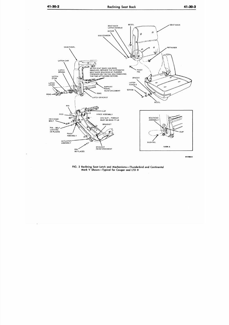
8/20/2019 1977 Ford Car Shop Manual Volume 4 Body
http://slidepdf.com/reader/full/1977-ford-car-shop-manual-volume-4-body 56/449
41-30-2 Reclining Seat Back
41-3
SEAT BACK
LATCH HANDLE
BEZEL
SEAT BACK
SCREW
ESCUTCHEON
TRIM PANEL
LATCH CAM
AFTER SEAT BACK HA S BEEN
REMOVED, SERVICE THE AUTOMATIC
SEAT BACK SOLENOID BY PUSHING
FORWAR D ON THE PAD AND REMOVING
THE TW O ATTACHING SCREWS.
SUPPORT
PANEL
REINFORCEMENT
RING
H E X N U T - T O R Q U E
MUST BE 60-93 FT-LB
BRACKET
REINFORCEMENT
SCREW
BEZEL
VIEW
A
CLIP
R1789
FIG . 2 Reclining Seat Latch and Mechanisms—Thunderbird and Continental
Mark V Shown—Typical for Cougar and LTD II
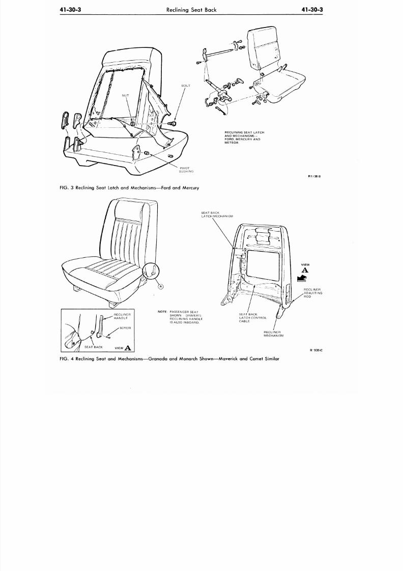
8/20/2019 1977 Ford Car Shop Manual Volume 4 Body
http://slidepdf.com/reader/full/1977-ford-car-shop-manual-volume-4-body 57/449
41-30-3 Reclining Seat Back
41-30-3
RECLINING SEAT LATCH
AND MECHANISMS -
FORD,MERCURY AND
METEOR
R1-I38-B
FIG. 3 Reclining Seat Latch and Mechanisms—Ford and Mercury
SEAT BACK VIEW >\
SEAT BACK
LATCH MECHANISM
NOTE: PASSENGER SEAT
SHOWN DRIVER'S
RECLINING HANDLE
IS ALSO INBOARD.
R 939-C
FIG. 4 Reclining Seat and Mechanisms—Granada and Monarch Shown—Maverick and Comet Similar
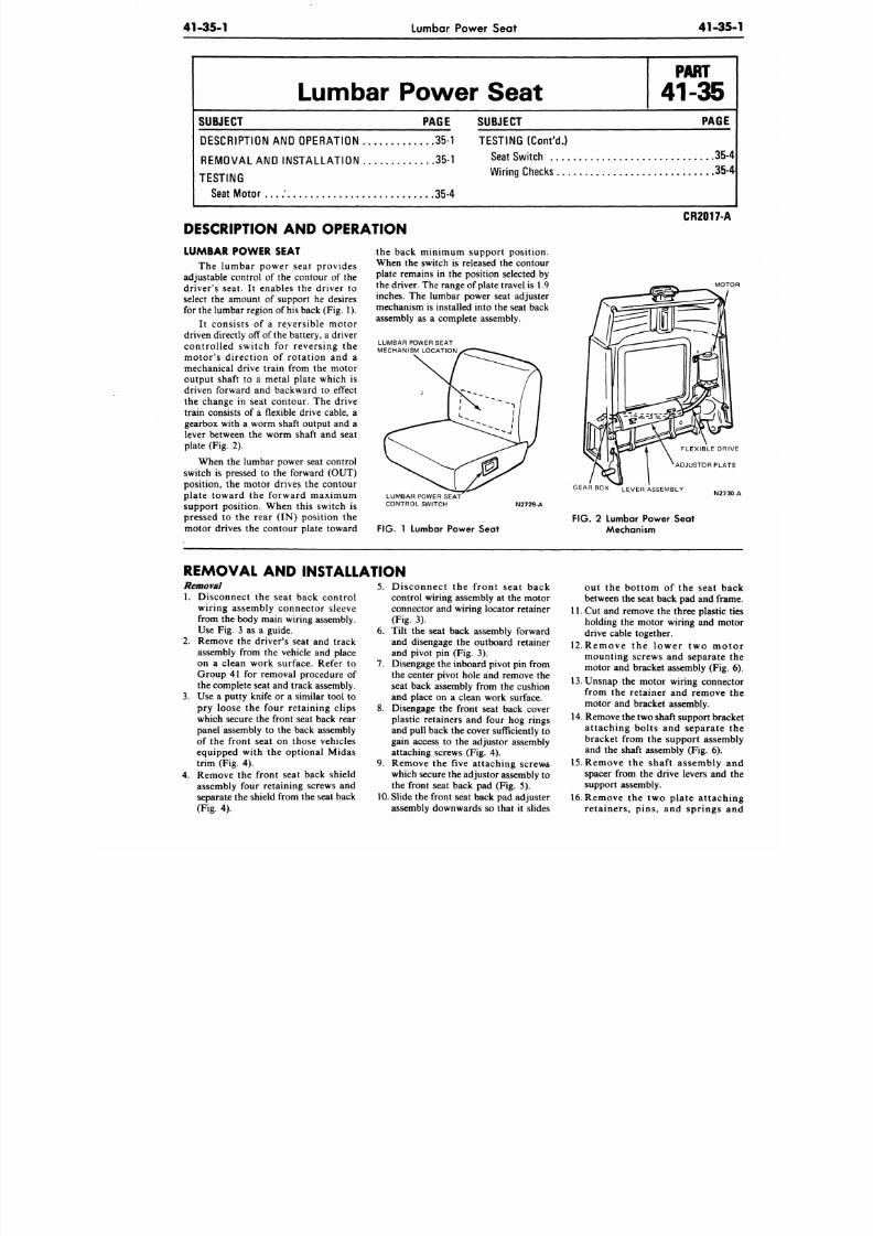
8/20/2019 1977 Ford Car Shop Manual Volume 4 Body
http://slidepdf.com/reader/full/1977-ford-car-shop-manual-volume-4-body 58/449
41-35-1
Lumbar Power Seat
41-35
Lumbar Power Seat
SUBJECT PAGE
DESCRIPTION AND OPERATION 35-1
REMOVA L AND INSTALL ATION 35-1
TESTING
Seat M o t o r . . . ; 35 -4
SUBJECT
PAGE
TESTING (Cont'd.)
Seat Switch
35
Wiring Checks 35
DESCRIPTION AND OPERATION
LUMBAR POWER SEAT
The lumbar power seat provides
adjustable control of the contour of the
driver's seat. It enables the driver to
select the amount of support he desires
for the lumbar region of
his
back (Fig. 1).
It consists of a reversible motor
driven directly off of the battery, a driver
controlled switch for reversing the
motor's direction of rotation and a
mechanical drive train from the motor
output shaft to a metal plate which is
driven forward and backward to effect
the change in seat contour. The drive
train consists of a flexible drive cable, a
gearbox with a worm shaft output and a
lever between the worm shaft and seat
plate (Fig. 2).
When the lumbar power seat control
switch is pressed to the forward (OUT)
position, the motor drives the contour
plate toward the forward maximum
support position. When this switch is
pressed to the rear (IN) position the
motor drives the contour plate toward
the back minimum support position.
When the switch is released the contour
plate remains in the position selected by
the driver. The range of plate travel is 1.9
inches. The lumbar power seat adjuster
mechanism is installed into the seat back
assembly as a com plete assembly.
LUMBAR POWER SEAT
MECHANISM LOCATION
LUMBAR POWER SEAT
CONTROL SWITCH N2729-A
CR2017-A
MO
FLEXIBLE DR
ADJUSTOR PLA
FIG. 1 Lumbar Power Seat
GEARB OX LEVER ASSEMBLY
FIG . 2 Lumbar Power Seat
Mechanism
N27
REMOVAL AND INSTALLATION
Removal
1. Disconnect the seat back control
wiring assembly connector sleeve
from the body main wiring assembly.
Use Fig. 3 as a guide.
2.
Remove the driver's seat and track
assembly from the vehicle and place
on a clean work surface. Refer to
Group 41 for removal procedure of
the complete seat and track assembly.
3. Use a putty knife or a similar tool to
pry loose the four retaining clips
which secure the front seat back rear
panel assembly to the back assembly
of the front seat on those vehicles
equipped with the optional Midas
trim (Fig. 4).
4. Remove the front seat back shield
assembly four retaining screws and
separate the shield from the seat back
(Fig. 4).
5. Disconnect the front seat back
control wiring assembly at the motor
connector and wiring locator retainer
(Fig. 3).
6. Tilt the seat back assembly forward
and disengage the outboard retainer
and pivot pin (Fig. 3).
7. Disengage the inboard pivot pin from
the center pivot hole and remove the
seat back assembly from the cushion
and place on a clean work surface.
8. Disengage the front seat back cover
plastic retainers and four hog rings
and pull back the cover sufficiently to
gain access to the adjustor assembly
attaching screws (Fig. 4).
9. Remove the five attaching screws
which secure the adjustor assembly to
the front seat back pad (Fig. 5).
10. Slide the front seat back pad adjuster
assembly downwards so that it slides
out the bottom of the seat b
between the seat back pad and fra
11. Cut and remove the three plastic
holding the motor wiring and m
drive cable together.
12.Remove the lower two mo
mounting screws and separate
motor and bracket assembly (Fig
13.Unsnap the motor wiring conne
from the retainer and remove
motor and bracket assembly.
14. Remove the two shaft support bra
attaching bolts and separate
bracket from the support assem
and the shaft assembly (Fig. 6).
15. Remove the shaft assem bly
spacer from the drive levers and
support assembly.
16.
Remove the two p late atta ch
retainers, pins, and springs
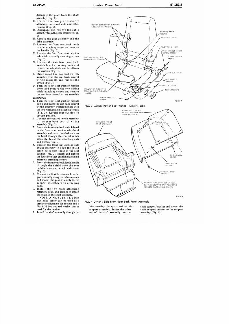
8/20/2019 1977 Ford Car Shop Manual Volume 4 Body
http://slidepdf.com/reader/full/1977-ford-car-shop-manual-volume-4-body 59/449
41-35-2
Lumbar Power Seat
41-35-2
disengage the plate from the shaft
assembly (Fig. 6).
17. Remove the two gear assembly
attaching bolts and nuts and cable
retainer (Fig. 6).
18.
Disengage and remove the cable
assembly from the gear assembly (Fig.
6).
19. Remove the gear assembly and the
drive assembly.
20. Remove the front seat back latch
handle attaching screw and remove
the handle (Fig. 3).
21.
Remove the four front seat cushion
side shield assembly attaching screws
(Fig. 3).
22.
Remove the two front seat back
switch bezel attaching nuts and
remove the side shield and bezel from
the cushion (Fig. 3).
23 . Disconnect the control switch
assembly from the seat back control
wiring assembly and remove the
switch (Fig. 3).
24. Turn the front seat cushion upside
down and remove the two wiring
shield attaching screws and remove
the seat back control wiring assembly
Installation
1. Turn the front seat cushion upside
down and insert the seat back control
wiring assembly. Fasten in place with
the two wiring shield attaching screws
(Fig. 3). Return seat cushion to
upright position.
2. Connect the control switch assembly
to the seat back control wiring
assembly (Fig. 3).
3. Insert the front seat back switch bezel
in the front seat cushion side shield
assembly and push threaded studs on
the bezel through the control switch
assembly/Install the attaching nuts
and tighten (Fig. 3).
4.
Position the front seat cushion side
shield assembly to align the shield
screw holes with those in the seat
cushion (Fig. 3). Install and tighten
the four front seat cushion side shield
assembly attaching screws.
5. Insert the front seat back latch handle
through the shield onto the seat
cushion latch and attach with screw
(Fig. 3).
6. Connect the flexible drive cable to the
gear assembly using the cable retainer
and mount the gear assembly to the
support assembly with attaching
bolts.
7. Install the two plate attaching
retainers, pins, and springs to attach
the plate to the shaft assembly.
NOTE: A No. 8-32 x 1-1/2 inch
pan head screw can be used as a
service replacement for the pin and a
No. 8-32 hex nut and washer can be
used for the retainer.
8. Install the shaft assembly through the
MOTOR CONNECTOR & WIRING
LOCATOR RETAINER
SEAT BACK CONTROL
WIRING ASSY. (14B719)
CONNECTOR SLEEVE
TO
BODY MAIN WIRING ASSY
(14A005)
SCREW 2 REQ'D
(56904)
SCREW
2
REQ'D.
(56910)
RETAINER (38374C
PIVOT PIN (611B24
LATCH HANDLE (67622)
& SCREW (51763)
SCREW 2 RHQ'D.
(56902)
SHIELD (6:?185)
NU T 2 REQ'D
(370713)
SWITCH (14529)
BEZEL (13C704)
N2J33-A
FIG. 3 Lumbar Power Seat Wiring—Driver's Side
PANEL ASSY. (60762)
MIDAS OPTIONAL TRIM
VEHICLES ONLY
DRIVER'S FRONT
SEAT BACK ASSY
CLIP4 REQ'D.
(371520)
SCREW 4 REQ'D.
(56914)
REMOVE SEAT BACK COVER ASSY.
SUFFICIENTLY TO GAIN ACCESS TO
ADJUSTOR ATTACHING SCREWS
N:?V34-A
FIG.
4
Driver's Side Front Seat Back Panel Assembly
drive assembly, the spacer and into the
support assembly. Insert the other
end of the shaft assembly into the
shaft support bracket and mouni the
shaft support bracket to the support
assembly (Fig. 6).
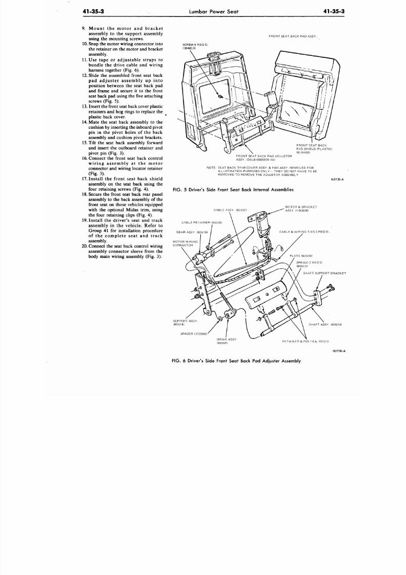
8/20/2019 1977 Ford Car Shop Manual Volume 4 Body
http://slidepdf.com/reader/full/1977-ford-car-shop-manual-volume-4-body 60/449
41-35-3
Lumbar Power Seat
41-35
9. Mount the motor and bracke t
assembly to the support assembly
using the mounting screws.
10. Snap the motor wiring connector into
the retainer on the motor and bracket
assembly.
11.
Use tape or adjustab le straps to
bundle the drive cable and wiring
harness together (Fig. 6).
12.
Slide the assembled front seat back
pad adjuster assembly up into
position between the seat back pad
and frame and secure it to the front
seat back pad using the five attaching
screws (Fig. 5).
13.
Insert the front seat back cover plastic
retainers and hog rings to replace the
plastic back cover.
14.
Mate the seat back assembly to the
cushion by inserting the inboard pivot
pin in the pivot holes of the back
assembly and cushion pivot brackets.
15.
Tilt the seat back assembly forward
and insert the outboard retainer and
pivot pin (Fig. 3).
16.
Connect the front seat back control
wir ing assembly a t the motor
connector and wiring locator retainer
(Fig. 3).
17. Insta ll the front seat back shield
assembly on the seat back using the
four retaining screws (Fig. 4).
18. Secure the front seat back rear panel
assembly to the back assembly of the
front seat on those vehicles equipped
with the optional Midas trim, using
the four retaining clips (Fig. 4).
19.
Install the d river's seat and track
assembly in the vehicle. Refer to
Group 41 for installation procedure
of the complete seat and track
assembly.
20. Connect the seat back control wiring
assembly connector sleeve from the
body main wiring assembly (Fig. 3).
FRONT SEAT BACK PAD ASSY.
SCREW 5 REQ 'D.
(384653)
FRONT SEAT BACK
PAD SHIELD (PLASTIC)
(610A68)
FRONT SEAT BACK PAD ADJUSTOR
ASSY. (D5LB-6565500-AB)
NOTE: SEAT BACK TRIM COVER ASSY. & PAD ASSY. REMOVED FOR
ILLUSTRATION PURPOSES ON LY - THEY DO NOT HAVE TO BE
REMOVED TO REMOVE THE ADJUSTOR ASSEMBLY
N273
FIG. 5 Driver's Side Front Seat Back Internal Assemblies
CABLE ASSY. (65502)
CABLE RETAINER (65503)
GEAR ASSY. (65516)
MOTOR WIRING
CONNECTOR
MOTOR & BRACKET
ASSY. (14C696)
CABLE &WIR INGTIES3 REQ'D .
SHAFT SUPPORT BRA
SUPPORT ASSY
(65514)
SPACER (373596)
SHAFT ASSY. (6551
DRIVE ASSY
(65504)
RETAINER & PIN 2 EA. REQ'D.
N27
FIG .
6 Driver's Side Front Seat Back Pad Adjuster Assembly
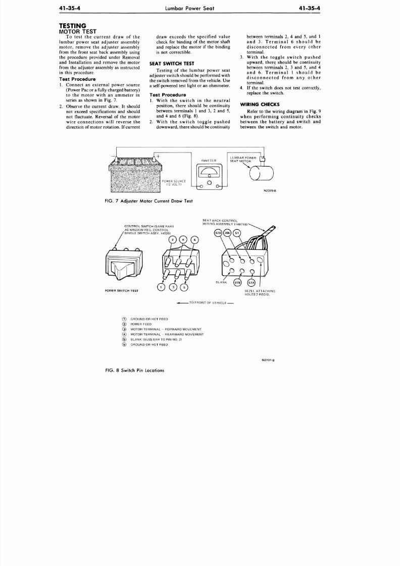
8/20/2019 1977 Ford Car Shop Manual Volume 4 Body
http://slidepdf.com/reader/full/1977-ford-car-shop-manual-volume-4-body 61/449
41-35-4 Lumbar Power Seat
41-35-4
TESTING
MOTOR TEST
To test the current draw of the
lumbar power seat adjuster assembly
motor, remove the adjuster assembly
from the front seat back assembly using
the procedure provided under Removal
and Installation and remove the motor
from the adjuster assembly as instructed
in this procedure.
Test Procedure
1.
Connect an external power source
(Power Pac or a fully charged battery)
to the motor with an ammeter in
series as shown in Fig. 7.
2. Observe the current draw. It should
not exceed specifications and should
not fluctuate. Reversal of the motor
wire connections will reverse the
direction of motor rotation. If current
draw exceeds the specified value
check for binding of the motor shaft
and replace the motor if the binding
is not correctible.
SEAT SWITCH TEST
Testing of the lumbar power seat
adjuster switch should be performed with
the switch removed from the vehicle. Use
a self-powered test light or an ohmmeter.
Test Procedure
1. With the switch in the neutral
position, there should be continuity
between terminals 1 and 3, 2 and 5,
and 4 and 6 (Fig. 8).
2.
With the switch toggle pushed
downward, there should be continuity
between terminals 2, 4 and 5, and 1
and 3 . Te r min a l 6 s hou ld be
disconnected from every other
terminal.
3. With the toggle switch pushed
upward, there^ should be continuity
between terminals 2, 3 and 5, and 4
and 6 . Te r m ina l 1 s hou ld be
d i s connec ted f rom any o the r
terminal.
4.
If the switch does not test correctly,
replace the switch.
W IRING CHECKS
Refer to the wiring diagram in
Fig.
9
when performing continuity checks
between the battery and switch and
between the switch and motor.
N2370-B
FIG. 7 Adjuster Motor Current Draw Test
CONTROL SWITCH (SAME PART
AS WINDOW REG. CONTROL
SINGLE SWITCH ASSY. 14529)
SEAT BACK CONTROL
WIRING ASSEMBLY (14B719)"
POWER SW ITCH TEST
BEZEL ATTACHING
HOLES 2 REQ'D.
.TO FRONTOF VEHICLE
(?) GROUND OR HOT FEED
( D POWER FEED
(3) MOTOR TER MINA L - FORWARD MOVEMENT
(4) MOTOR TERMINA L - REARWARD MOVEMENT
(5) BLANK (BUSS BAR TO PIN NO. 2)
(§) GROUND OR HOT FEED
N2731-B
FIG.
8 Switch Pin Locations
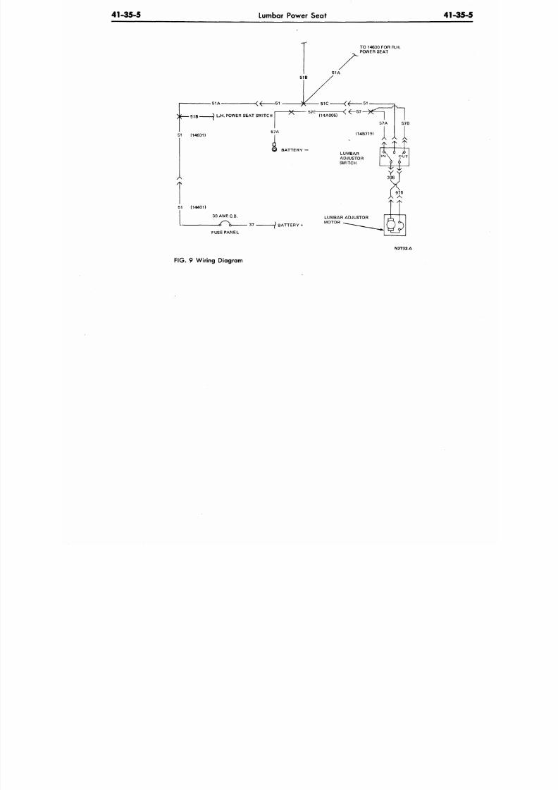
8/20/2019 1977 Ford Car Shop Manual Volume 4 Body
http://slidepdf.com/reader/full/1977-ford-car-shop-manual-volume-4-body 62/449
41-35-5
Lumbar Power Seat
41-35
TO 14630 FOR R.H.
POWER SE AT
51 A
51B-
51 (14631)
51 (14401)
30 AMR C.B.
37
BATTERY
FUSE PANEL
N2732-A
FIG.
9 Wiring Diagram
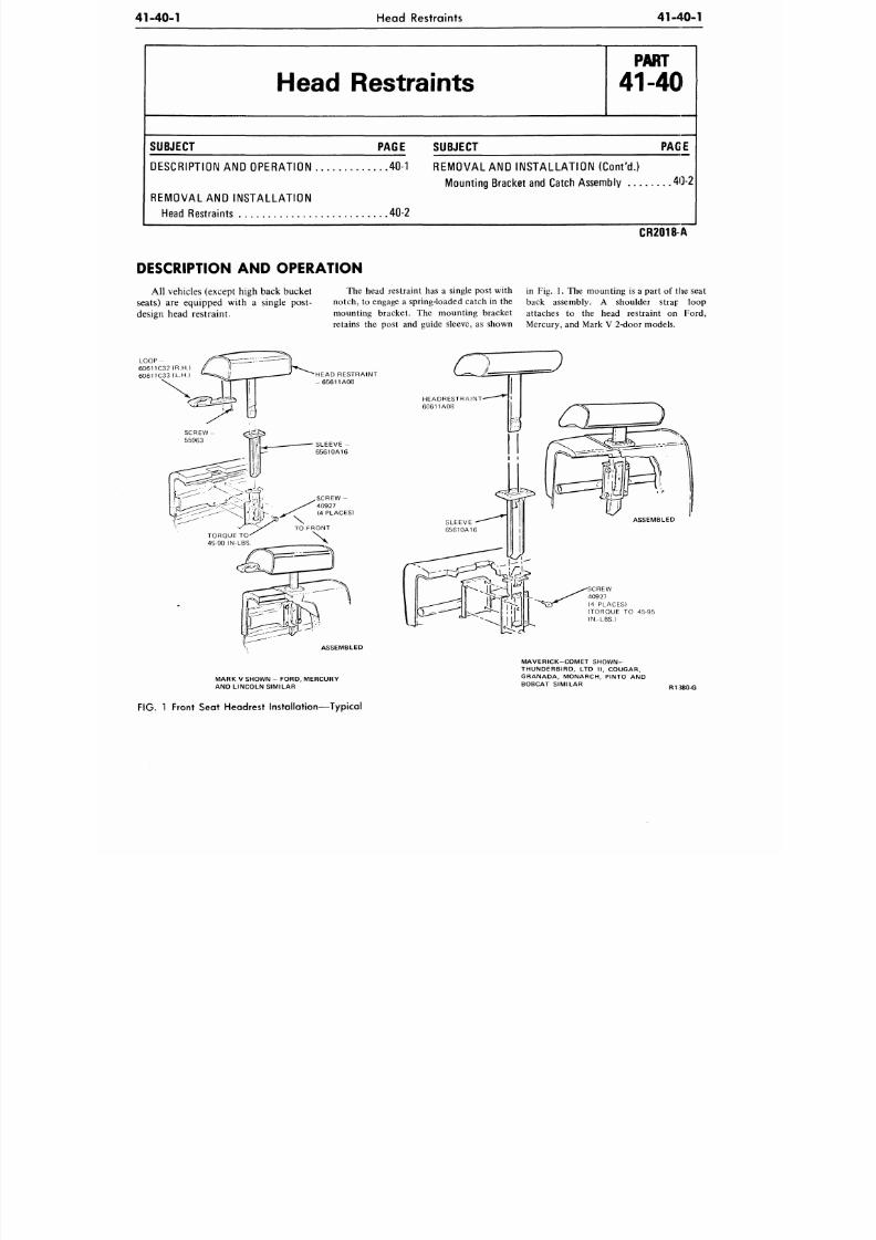
8/20/2019 1977 Ford Car Shop Manual Volume 4 Body
http://slidepdf.com/reader/full/1977-ford-car-shop-manual-volume-4-body 63/449
41-40-1
Head Restraints
41-40-1
Head Restraints
P A R T
41-40
SUBJECT
PAGE SUBJECT
PAGE
DESCRIPTION
AND
OPERATION
40-1
REMOVAL AND INSTALLATION (Cont 'd . )
Mounting Bracket and Catch Assembly
40-2
REMOVAL
AND
INSTALLATION
Head Re straints
40-2
DESCRIPTION AND OPERATION
CR2018A
All vehicles (except high back bucket
seats) are equipped with a single post-
design head restraint.
The head restraint has a single post with
notch, to engage a spring-loaded ca tch in the
mounting bracket. The mounting bracket
retains the post and guide sleeve, as shown
in Fig. 1. The mounting is a part of the seat
back assembly. A shoulder strap loop
attaches to the head restraint on Ford,
Mercury, and Mark V 2-door m odels.
LOOP -
60611C32 (R.H.)
60611C33 (L.H.)
HEAD RESTRAINT
- 6 5 6 1 1 A 0 8
S C R E W -
40927
(4 PLACES)
TO FRONT
ASSEMBLED
MARK
V
SHOWN
-
FORD. MERCURY
AND LINCOLN SIMILAR
SCREW
40927
(4 PLACES)
(TORQUE TO 45-95
IN.-LBS.)
MAVERICK -COMET SHOWN-
THUNDERBIRD,
LTD II ,
COUGAR,
GRANADA, MONARCH, PINTO AND
BOBCAT SIMILAR
R1J80-G
FIG.
1
Front Seat Headrest Installation—Typical
8/20/2019 1977 Ford Car Shop Manual Volume 4 Body
http://slidepdf.com/reader/full/1977-ford-car-shop-manual-volume-4-body 64/449
41-40-2
Head Restraints
41-4
REMOVAL AND INSTALLATION
HEAD RESTRAINT
Removal
The head restraint is removed by
pulling the head restraint post upward
and ou t of the guide sleeve and m ounting
bracket.
If the mounting bracket spring clip
will not disengage from the detent on the
head restraint post to allow removal (Fig.
1), insert a 12-inch length of thin flat
stock into the sleeve at the front side of
the post and push the spring clip out of
the detent while withdrawing the head
restraint.
The guide sleeve is removed by
pulling the sleeve out of the mounting
bracket after first removing the head
restraint. Occasionally, i t may be
necessary to trip the locking tab on the
guide sleeve in order to remove it from
the bracket (Fig. 1). Insert a short piece
of wire having a hooked end into the
sleeve, hook onto the locking tab and pull
it inward. On cars equipped with the
flight or split bench seat, it may be
necessary to remove the front seat back
trim panel to release the head restraint.
Installation
The head restraint is installed by
inserting the post into the sleeve in the
seat back. It can be adjusted by app
hand pressure , e i ther upwar
downward, to the center area of the
restraint assembly. The head res
must operate smoothly througho
full range of travel and must rem
any fixed position.
MOUNTING BRACKET AND
CATCH ASSEMBLY
Remove the head restraint and
assembly from the sleeve and remo
sleeve. Remove the seat back trim
for access, and remove the screw
retain the mounting bracket t
mounting in the seat back.
8/20/2019 1977 Ford Car Shop Manual Volume 4 Body
http://slidepdf.com/reader/full/1977-ford-car-shop-manual-volume-4-body 65/449
41-50-1
Seat and Shoulder Belts
41-50-1
Seat and Shoulder Belts
P A R T
41-50
SUBJECT PAGE
GENERAL INFORMATION 50-1
DESCRIPTION AND OPERATION
Descript ion 50-1
Operation 50-2
RE M OV A L A ND I NS TA LLA TI ON
Front Seat Belt Retractor
and Harness Assem bly 50-3
Rear Seat Belt Retracto r Assembly 50-12
SUBJECT PAGE
MAJOR REPAIR OPERATIONS
Cleaning 50-13
Seat and Shoulde r Belts 50-12
Seat and Shoulder Harness Belt With
Damaged Anc ho r Plate Threads 50-12
Seat Belt With No Anchor Plate
Thread Damage 50-12
CR2019 A
GENERAL INFORMATION
Two distinct front outboard seat belt
systems are being installed in 1977. One
system, used in previous years, is the
three point system. A new system is also
used and it is called the continuous loop
system.
The thre e point system has a fixed
tongue on the front outboard lap/
shoulder belt and two retractors. The
continuous loop system has a movable
tongue on the front outboard lap/
shoulder belt and only one retractor.
The seat belts and shoulder belts are
factory installed in their proper locations.
If the seat belts or shoulder belts are
removed for any reason, they should be
installed as shown in Figs. 3 through 16.
Sealer should be placed around all seat
belt anchor bolt holes in the floor pan.
Tighten the anchor bol ts to the
specification shown at the end of this
Part.
Belt assemblies must be installed in
matched sets as received and must not be
interchanged between vehicle models.
If a component portion (buckle
portion, retractor portion, etc.) of a seat
belt or shoulder belt assembly is
nonfunctional or damaged, the entire
assembly (buckle, tongue and shoulder
harness portions) must be replaced.
The
replacement assembly must be installed
as a matched set and the identification
labels on all portions must bear exactly
the same code, date of manufacture and
m a n u f a c t u r e r ' s n a m e . U n d e r n o
circumstances are seat belt or shoulder
belt components to be replaced as
individual components.
DESCRIPTION AND OPERATION
DESCRIPTION
Both systems incorporate a buzzer
and light w arnings. The seat belt warning
light illuminates for about eight seconds
after the ignition switch is turned on—
regardless of seat belt usage. The seat belt
warning buzzer is grounded by a switch
in the left lap retractor, on the three point
system and by a switch in the left inboard
buckle on the continuous loop system.
The seat belt warning buzzer will sound
for approximately eight seconds unless
the driver's belt is used.
When the occupant restraint system
for front outboard passengers is a 3-point
sy s tem, the outboard lap belt and
shoulder harness are sewn together at the
tongue. To secure the belts, the tongue is
inserted into the buckle.
On the three point system, the
webbing for the lap belt extends from a
belt retractor that automatically locks
when the belt is being worn. This lock
prevents the belt from being pulled out
further, but allows the belt to retract, and
thus maintains a snug fit around the user
for optimum safety. This lap belt
retractor is located
on
or
in
the rocker
panel (depending on car line and model).
With the continuous loop system, the
outboard lap/sh ould er bel t uses a
common sliding tongue. To secure, insert
the tongue into the inboard buckle.
The webbing for the lap belt is
anchored to the side of the sill without
a retractor.
On both systems, the shoulder
harness webbing has the other end fixed
in a retractor, which is located in or on
the rocker, in the " B" pillar post or in the
quarter panel (depending on car lint; and
model). The Mustang, Pinto, Bobcat,
Thunderbird, Ford, Lincoln, Granada
and Monarch (2-doors) shoulder har-
ness retractor is located in the quarter
panel. The Mark V shoulder belt
retractor is located in the headlining
above the opera window. This webbing
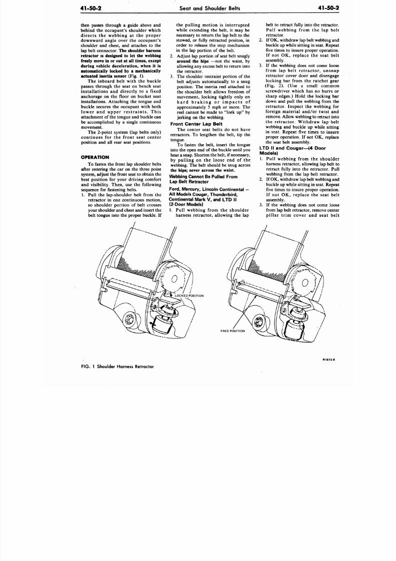
8/20/2019 1977 Ford Car Shop Manual Volume 4 Body
http://slidepdf.com/reader/full/1977-ford-car-shop-manual-volume-4-body 66/449
41-50-2
Seat and Shoulder Belts
4 1 - 5
then passes through a guide above and
behind the occupant's shoulder which
directs the webbing at the proper
downward angle over the occupant's
shoulder and chest, and attaches to the
lap belt connector.
The shoulder harness
retractor is designed to let the webbing
freely move in or out at all times, except
during vehicle deceleration, when it is
automatically locked by a mechanically
actuated inertia sensor (Fig. 1).
The inboard belt with the buckle
passes through the seat on bench seat
installations and directly to a fixed
anchorage on the floor on bucket seat
installations. Attaching the tongue and
buckle secures the occupant with both
lower and upper res t ra in ts . This
attachment of the tongue and buckle can
be accomplished by a single continuous
movement.
The 2-point system (lap belts only)
continues for the front seat center
position and all rear seat positions.
OPERATION
To fasten the front lap shoulder belts
after entering the car on the three point
system, adjust the front seat to obtain the
best position for your driving comfort
and visibility. Then, use the following
sequence for fastening belts.
1. Pull the lap-shoulder belt from the
retractor in one continuous motion,
so shoulder portion of belt crosses
your shoulder and chest and insert the
belt tongue into the proper buckle. If
the pulling motion is interrupted
while extending the belt, it may be
necessary to return the lap belt to the
stowed, or fully retracted positon, in
order to release the stop mechanism
in the lap portion of the belt.
2. Adjust lap portion of seat belt snugly
around the hips
—not the waist, by
allowing any excess belt to return into
the retractor.
3.
The shoulder restraint portion of the
belt adjusts automatically to a snug
position. The inertia reel attached to
the shoulder belt allows freedom of
movement, locking tightly only on
h a r d b r a k i n g o r i m p a c t s o f
approximately 5 mph or more. The
reel cannot be made to "lock up" by
jerking on the webbing.
Front Center Lap Belt
The center seat belts do not have
retractors. To lengthen the belt, tip the
tongue.
To fasten the belt, insert the tongue
into the open end of the buckle until you
hear a snap. Shorten the belt, if necessary,
by pulling on the loose end of the
webbing. The belt should be snug across
the hips; never across the waist.
Webbing Cannot Be Pulled From
Lap Belt Retractor
F ord ,
Merc ury, Linco ln Continental -
Al l Models Cougar, Thund erbird ,
Continental Mark V, and LTD I I
(2-Door Models)
1. Pull webbing from the shoulder
harness retractor, allowing the lap
belt to retract fully into the retra
Pull webbing from the lap
retractor.
2. If OK, withdraw lap belt webbin
buckle up while sitting in seat. Re
five times to insure proper oper
If not OK, replace the seat
assembly.
3. If the webbing does not come
from lap belt retracto r, uns
retractor cover door and disen
locking bar from the ratchet
(Fig. 2). (Use a small com
screwdriver which has no burr
sharp edges.) Hold the locking
down and pull the webbing from
retractor. Inspect the webbing
foreign material and/or twist
remove. Allow webbing to retrac
the retractor. Withdraw lap
webbing and buckle up while si
in seat. Repeat five times to in
proper operation. If not OK, rep
the seat belt assembly.
LTD II and Cougar—(4 Door
Models)
1. Pull webbing from the shou
harness retractor, allowing lap b
retract fully into the retractor.
webbing from the lap belt retrac
2. If OK, withdraw lap belt w ebbin
buckle up while sitting in seat. Re
five times to insure proper oper
If not OK, replace the seat
assembly.
3. If the webbing does not come
from lap belt retractor, remove c
pillar tr im cover and seat
LOCKED POSITION
FREE POSITION
R187
FIG. 1 Shoulder Harness Retractor
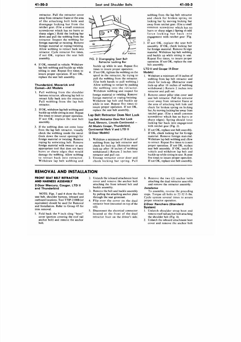
8/20/2019 1977 Ford Car Shop Manual Volume 4 Body
http://slidepdf.com/reader/full/1977-ford-car-shop-manual-volume-4-body 67/449
41-50-3
Seat and Shoulder Belts
4 1 - 5 0 - 3
retractor. Pull the retractor cover
away from retractor frame at the area
of the attaching bolt hole and
disengage locking bar from the
ratchet gear. (Use a small common
screwdriver which has no burrs or
sharp edges.) Hold the locking bar
down and pull the webbing from the
retractor. Inspect the webbing for
foreign material or twisting. Remove
foreign material or roping/twisting.
Allow webbing to retract back into
retractor. Cycle retractor five times,
if not OK, replace the seat belt
assembly.
4.
If OK, reinstall in vehicle. Withdraw
lap belt webbing and buckle up while
sitting in seat. Repeat five times to
insure proper operation. If not OK,
replace the seat belt assembly.
Thunderbird, Maverick and
Comet—All Models
1. Pull webbing from the shoulder
harness retractor, allowing lap belt to
retract fully back into the retractor.
Pull webbing from the lap belt
retractor.
2.
If OK, withdraw lap belt webbing and
buckle up while sitting in seat. Repeat
five times to insure proper operation.
If not OK, replace the seat belt
assembly.
3.
If the webbing does not come loose
from the lap belt retractor, visually
check the webbing inside the snout
(look down the snout opening) for
foreign material or twisting. Remove
roping by untwisting belt. Remove
foreign material with tweezer or any
appropriate tool that does not have
burrs or sharp edges that would
damage the webbing. Allow webbing
to re t ract back in to re t ractor .
Withdraw lap belt webbing and
R1874-A
FIG. 2 Disengaging Seat Belt
Retractor Locking Bar
buckle up while in seat. Repeat five
times to insure proper operation,
4.
If not OK, tighten the webbing on the
spool in the retractor, by trying to
pull the webbing from the retractor.
(Use both hands to pull webbing.)
Allow webbing to retract by pushing
the webbing into the retractor.
Withdraw webbing and inspect for
foreign material or twisting. Remove
foreign material or roping/twisting.
Withdraw lap belt and buckle up
while in seat. Repeat five times to
insure proper operation. If not OK,
replace the seat belt assembly.
Lap Belt Retractor Does Not Lock
Lap Belt Retractor Does Not Lock
Ford ,
Mercury, Lincoln Continental
—
All Models Cougar, Thunderbird,
Continental Mark V and LTD II
(2-Door Models)
1. Withdraw a minimum of 18 inches of
webbing from lap belt retractor and
check for lock-up. (Retractor must
lock-up after 18 inches of webbing
withdrawal.) Return 2 inches into
retractor and pull out.
2.
Unsnap retractor cover door and
check locking bar spring. Pull
webbing from the lap belt retractor
and check for broken spring on
locking bar by moving locking bar
away from ratchet gear. (Use a small
common screwdriver which has no
burrs or sharp edges.) Spring should
fo rce lock ing ba r back in to
engagement with ratchet gear (Fig.
2).
3.
If not OK, replace the seat belt
assembly. If OK, check locking bar
for foreign material. Remove foreign
material. Withdraw lap belt webbing
and buckle up while sitting in seat.
Repeat five times, to insure proper
operation. If not OK, replace the seat
belt assembly.
LTD II and Cougar (4-Door
Models)
1. Withdraw a minimum of 18 inches of
webbing from lap belt retractor and
check for lock-up. (Retractor must
lock-up after 18 inches of webbing
withdrawal.) Return 2 inches into
retractor and pull out.
2.
Remove center pillar trim cover and
seat belt retractor. Pull the retractor
cover away from retractor frame at
the area of attaching bolt hole and
check for broken spring on locking
bar, by moving locking bar away from
ratchet gear. (Use a small common
screwdriver which has no buns or
sharp edges). Spring should force
locking bar back into engagement
with ratchet gear (Fig. 2).
3. If not OK, replace seat belt assembly.
If OK, check locking bar for foreign
material. Remove foreign material.
Withdraw lap belt webbing and allow
to retract. Repeat five times to insure
proper operation. If not OK, replace
seat belt assembly. If OK, install in
vehicle and withdraw lap belt and
buckle up while sitting in seat. Repeat
five times to insure proper operation.
If not OK , replace seat belt assembly.
REMOVAL AND INSTALLATION
FRONT SEAT BELT RETRACTOR
AND HARNESS ASSEMBLY
2-Door Mercury, Cougar, LTD II
and Thunderbird
NOTE: Figs. 3 and 4 show the front
seat belt, shoulder harness, inboard and
outboard locations. Tool T70P-2100B (or
equivalent) should be used for Removal
and Installation. Refer to Group 45 for
trim removal.
1. Fold back the 9 inch sling "boot"
cover (portion covering the roof rail
anchor bolt) and remove the anchor
bolt.
2.
Unlatch the inboard attachment boot
cover and remove the anchor bolt
attaching the front inboard belt and
buckle assembly.
3. Remove the belt and buckle assembly
by pulling the attaching anchor plate
through the seat grommet.
4.
Flip over the cover on the dual
retractor boot (mounted on top of the
sill).
5.
Disconnect the electrical connector
located at the front of the dual
retractor boot on the driver's side.
6. Remove the two (2) anchor bolts
attaching the dual retractor assembly
and remove the retractor assembly.
Installation
To assemble, reverse the preceding
steps.
Torque all bolts to 22-32 ft-lbs.
Cycle system several times to assure
proper retractor operation.
2-Door Ranchero (Standard
System)
1.
Unlatch shoulder strap boot and
remove roof rail anchor bolt attaching
the shoulder belt (Fig. 4).
2.
Unlatch the inboard attachment boot
cover and remove the anchor bolt
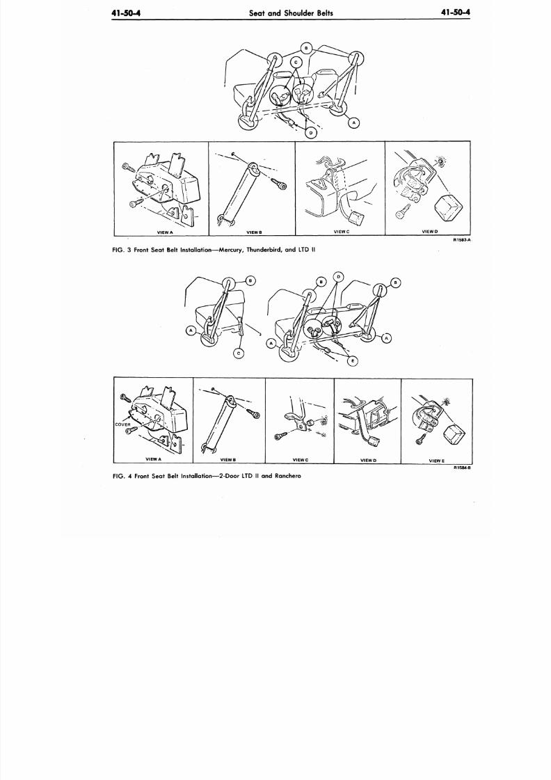
8/20/2019 1977 Ford Car Shop Manual Volume 4 Body
http://slidepdf.com/reader/full/1977-ford-car-shop-manual-volume-4-body 68/449
41-50-4
Seat and Shoulder Belts
41-50
VIEW A
V I E W B
V I E W C
V I E W D
F IG .
3 Front Seat Belt Installation—Mercury, Thunderbird, and LTD II
R1
COVER
VIEW A
V I E W B
V I E W C
V I E W D
V I E W E
R1
FIG. 4 Front Seat Belt Installation—2-Door LTD II and Ranchero
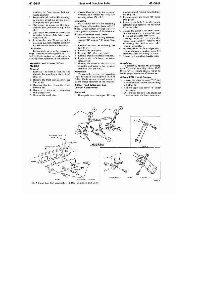
8/20/2019 1977 Ford Car Shop Manual Volume 4 Body
http://slidepdf.com/reader/full/1977-ford-car-shop-manual-volume-4-body 69/449
4 1 - 5 0 - 5
Seat and Shoulder Belts
41-50-5
attaching the front inboard belt and
buckle assembly.
3. Remove the belt and buckle assembly
by pulling attaching anchor plate
through the seat grommet.
4.
Flip open the cover on the dual
retractor boot (mounted on top of the
sill).
5.
Disconnect the electrical connector
located at the front of the driver's side
retractor boot.
6. Remove the two (2) anchor bolts
attaching the dual retractor assembly
and remove the retractor assembly.
Installation
To assemble, reverse the preceding
steps. Torque all attaching bolts to 22-32
ft-lbs. Cycle system several times to
assure proper operation of the retractor.
Maverick and Comet (2-Door
Models)
Removal
1. Remove the bolt attaching the
shoulder harness sling at the roof rail
(Fig. 5).
2.
Remove the front seat assembly. See
Part
41-01.
3. Remove the bolt from the front
inboard belt.
4.
Remove retractor cover-to-quarter
trim panel screw.
5.
Remove the scuff plate.
6. Unsnap three covers in the retractor
assembly and remove the retractor
assembly (three (3) bolts).
Installation
To assemble, reverse the preceding
steps. Torque all attaching bolts to 22-32
ft-lbs. Cycle system several times to
assure proper operation of the retractor.
4-Door Maverick and Comet
1. Remove the bolt attaching shoulder
harness "D" ring on "B" pillar (Fig.
6).
2.
Remove the front seat assembly, see
Part 41-01.
3.
Remove the scuff plate.
4. Remove " B " pillar trim covers.
5.
Remove shoulder harness retractor.
6. Remove the bolt from the front
inboard belt.
7. Unsnap the cover in the retractor
assembly and remove the retractor
assembly (two (2) bolts).
Installation
To assemble, reverse the preceding
steps. Torque all attaching bolts to 22-32
ft-lbs. Cycle system several times to
assure proper operation of the retractor.
4-Door Ford, Mercury, and
Lincoln Continental
Removal
1. Unsnap the cover on upper " D " ring
attachment and remove the attaching
bolt (Fig. 7).
2.
Remove upper and lower "B " pillar
trim panels.
3. Remove the bolt from the upper
retractor and remove the retractor
from the pillar.
4.
Unsnap the driver's side front cover
from the retractor on top of sil I and
disconnect electrical connector.
5. Unsnap the other cover on the
retractor assembly, remove the
at taching bol t and remove the
retractor assembly.
6. With the seat in full forward position,
remove the center anchor cover by
spreading sides and lifting off cover.
7. Remove bolt attaching buckle ends.
Installation
To assemble, reverse the preceding
steps. Torque all attaching bolts to 22-32
ft-lbs. Cycle system several times to
assure proper operation of retractors.
4-Door LTD II and Cougar
1. Unsnap the cover on upper " D " ring
attachment and remove the attaching
bolt (Fig. 8).
2.
Remove upper and lower "B ' pillar
trim panels.
3. Disconnect driver's side electrical
connector from the lower retractor.
VIEW A ACCESS HOLE COVERS
FIG. 5 Front Seat Belt Assemblies—2-Door Maverick and Comet
V I E W B
BUCK ET SEAT BENCH SEAT
H1587-A
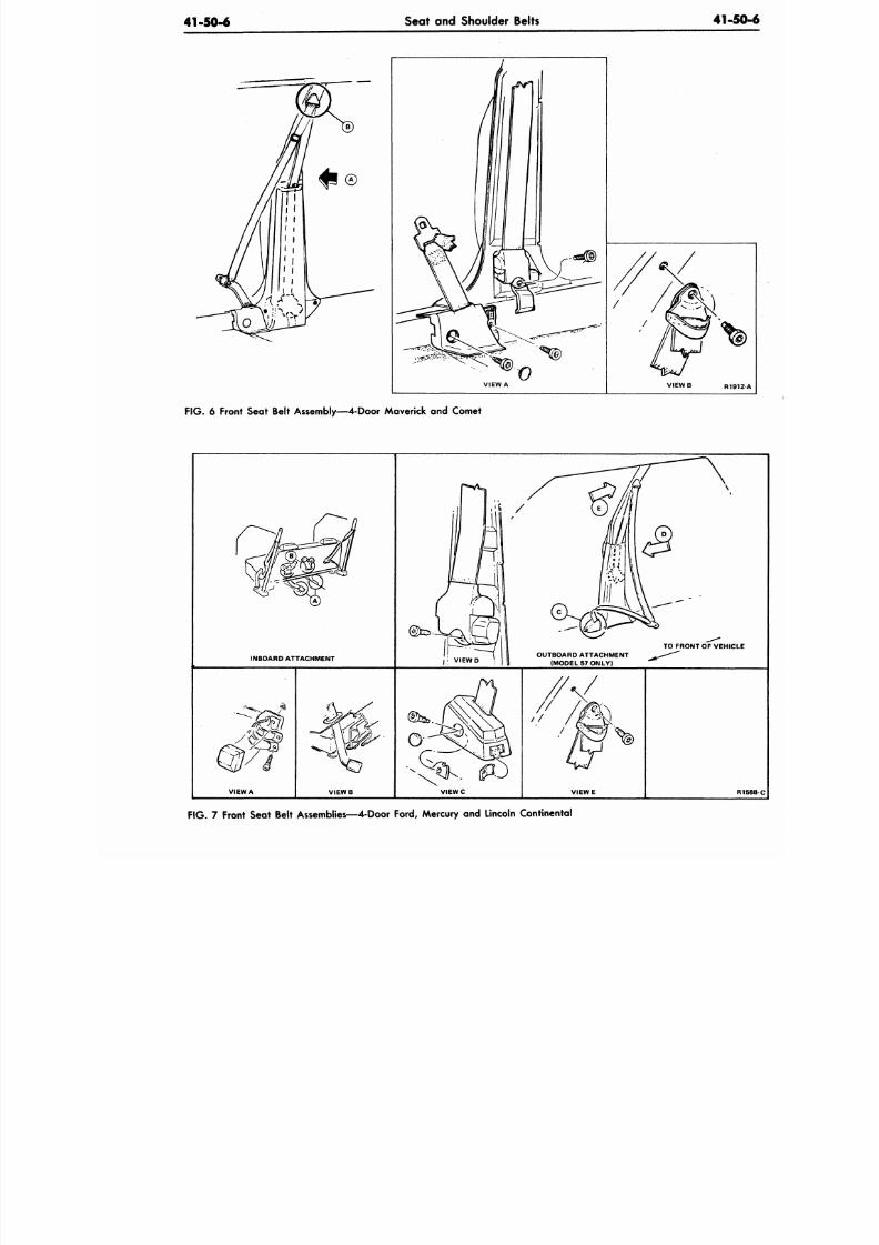
8/20/2019 1977 Ford Car Shop Manual Volume 4 Body
http://slidepdf.com/reader/full/1977-ford-car-shop-manual-volume-4-body 70/449
41-50-6
Seat and Shoulder Belts
4 1 -
VIEW A
VIEW B R1
F IG . 6 Front Seat Belt Assembly—4-Door Maverick and Comet
INBOARD ATTACHMENT
V I E W D
OUTBOARD ATTACHMENT
(MODEL 57 ONLY)
TO FRONT OF VEHIC
VIEW A
V I E W B
V I E W C
V I E W E
F IG .
7 Front Seat Belt Assemblies—4-Door Ford, Mercury and Lincoln Continental
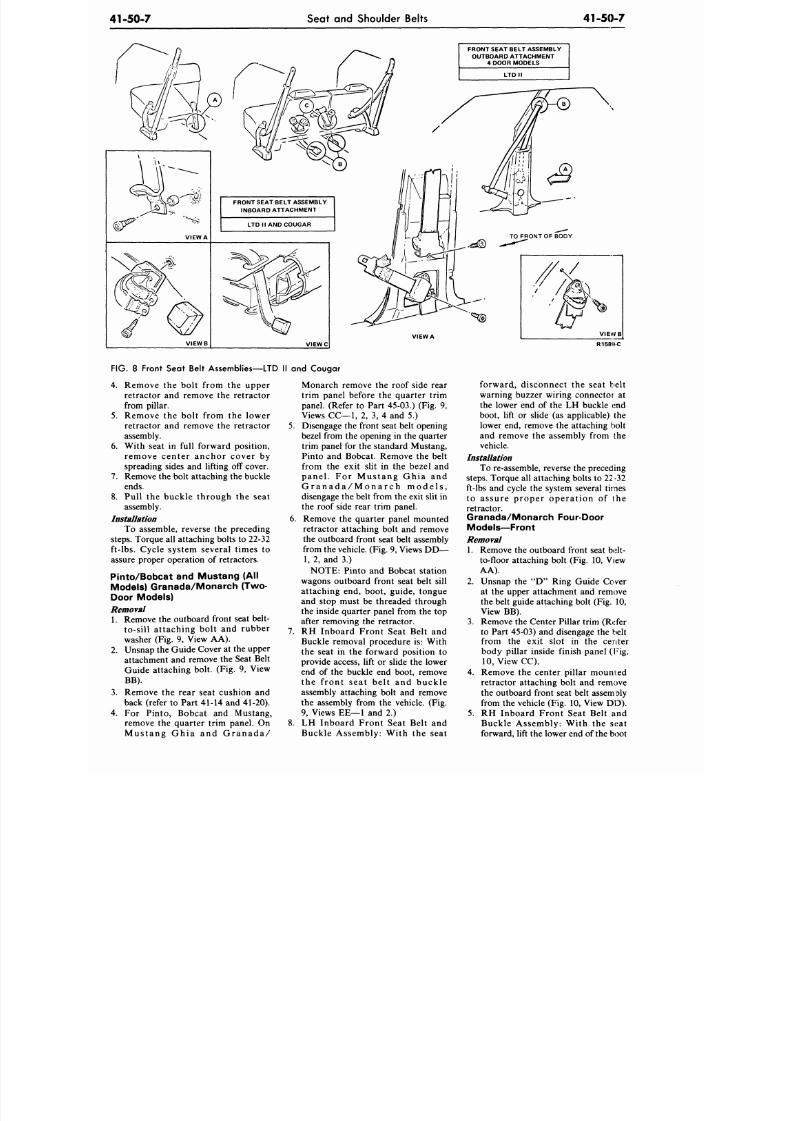
8/20/2019 1977 Ford Car Shop Manual Volume 4 Body
http://slidepdf.com/reader/full/1977-ford-car-shop-manual-volume-4-body 71/449
41-50-7
Seat and Shoulder Belts
41-50-7
FRONT SEAT BELT ASSEMBLY
OUTBOARD ATTACHMENT
4 DOOR MODELS
FRONT SEAT BELT ASSEMBLY
INBOARD ATTACHMENT
R1589-C
FIG.
8 Front Seat Belt Assemblies—LTD II and Cougar
4.
Remove the bolt from the upper
retractor and remove the retractor
from pillar.
5.
Remove the bolt from the lower
retractor and remove the retractor
assembly.
6. With seat in full forward position,
remove center anchor cover by
spreading sides and lifting off cover.
7. Remove the bolt attaching the buckle
ends.
8. Pull the buckle through the seat
assembly.
Installation
To assemble, reverse the preceding
steps.
Torque all attaching bolts to 22-32
ft-lbs. Cycle system several times to
assure proper operation of retractors.
Pinto/Bobcat and Mustang (All
Models) Granada/Monarch (Two-
Door Models)
Removal
1. Remove the outboa rd front seat belt-
to-sill attaching bolt and rubber
washer (Fig. 9, View AA).
2. Unsnap the Guide Cover at the upper
attachment and remove the Seat Belt
Guide attaching bolt. (Fig. 9, View
BB).
3.
Remove the rear seat cushion and
back (refer to Part 41-14 and 41-20).
4. For Pinto, Bobcat and Mustang,
remove the quarter trim panel. On
M u s t a n g G h i a a n d G r a n a d a /
Monarch remove the roof side rear
trim panel before the quarter trim
panel. (Refer to Part 45-03.) (Fig. 9,
Views
CC—1,
2, 3, 4 and 5.)
5. Disengage the front seat belt opening
bezel from the opening in the quarter
trim panel for the standard Mustang,
Pinto and Bobcat. Remove the belt
from the exit slit in the bezel and
pa ne l . For M us ta ng G hia a nd
G r a n a d a / M o n a r c h m o d e ls ,
disengage the belt from the exit slit in
the roof side rear trim panel.
6. Remove the quarter panel mounted
retractor attaching bolt and remove
the outboard front seat belt assembly
from the vehicle. (Fig. 9, Views DD —
1, 2, and 3.)
NOTE: Pinto and Bobcat station
wagons outboard front seat belt sill
attaching end, boot, guide, tongue
and stop must be threaded through
the inside quarter panel from the top
after removing the retractor.
7.
RH Inboard Front Seat Belt and
Buckle removal procedure is: With
the seat in the forward position to
provide access, lift or slide the lower
end of the buckle end boot, remove
the front seat belt and buckle
assembly attaching bolt and remove
the assembly from the vehicle. (Fig.
9, Views EE—1 and 2.)
8. LH Inboard Front Seat Belt and
Buckle Assembly: With the seat
forward, disconnect the seat belt
warning buzzer wiring connector at
the lower end of the LH buckle end
boot, lift or slide (as applicable) the
lower end, remove the attaching bolt
and remove the assembly from the
vehicle.
Installation
To re-assemble, reverse the preceding
steps. Torque all attaching bolts to 22-32
ft-lbs and cycle the system several times
to assure proper operation of the
retractor.
Granada/Monarch Four-Door
Models—Front
Removal
1. Remove the outboa rd front seat belt-
to-floor attaching bolt (Fig. 10, View
AA).
2. Unsnap the "D " Ring Guide Cover
at the upper attachment and remove
the belt guide attaching bolt (Fig. 10,
View BB).
3.
Remove the Center Pillar trim (Refer
to Part 45-03) and disengage the belt
from the exit slot in the center
body pillar inside finish panel (Fig.
10,
View CC).
4. Remove the center pillar mourned
retractor attaching bolt and remove
the outboard front seat belt assem bly
from the vehicle (Fig. 10, View DD).
5. RH Inboard Front Seat Belt and
Buckle Assembly: With the seat
forward, lift the lower end of
the
boot
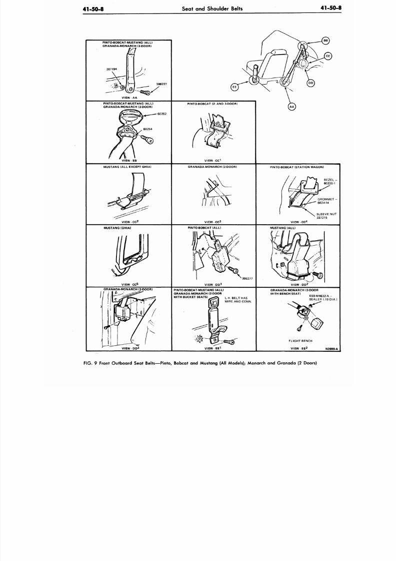
8/20/2019 1977 Ford Car Shop Manual Volume 4 Body
http://slidepdf.com/reader/full/1977-ford-car-shop-manual-volume-4-body 72/449
41-50-8
Seat and Shoulder Belts
4 1 -
PINTO-BOBCAT-MUSTANG (ALL)
GRANADA-MONARCH (2 DOOR)
386227
PINTO-BOBCAT-MUSTANG (ALL)
GRANADA-MONARCH (2 DOOR)
60262
V I E W - B B
PINTO-BOBCAT (2- AND 3-DOOR)
V I E W - C C
1
MUSTANG (ALL EX CEPT GHIA) GRANADA-MONARCH (2-DOOR)
V I E W - C C 2
V I E W - C C
3
PINTO-BOBCAT (STATION WAGON)
G R O M M
602A14
SLEEVE
337215
V I E W - C C
4
MUSTANG (GHIA) PINTO-BOBCAT (ALL)
VIEW - CC
5
MUSTANG (ALL)
386277
VIEW
V I E W - D D 2
GRANADA-MONARCH (2-DOOR)
PINTO-BOBCAT-MUSTANG (ALL)
GRANADA-MONARCH (2-DOOR
GRANADA MONARCH (2-DOOR
WITH BENCH SEAT)
WITH BUCKET SEATS)
VIEW-DD
3
L.H. BELT HAS
WIRE AND CONN.
SEALER
(.19
FLIGHT BENCH
V I E W - E E 2
N2
F IG . 9 Front Outboard Seat Belts—Pinto, Bobcat and Mustang (All Models); Monarch and Granada (2 Doors)
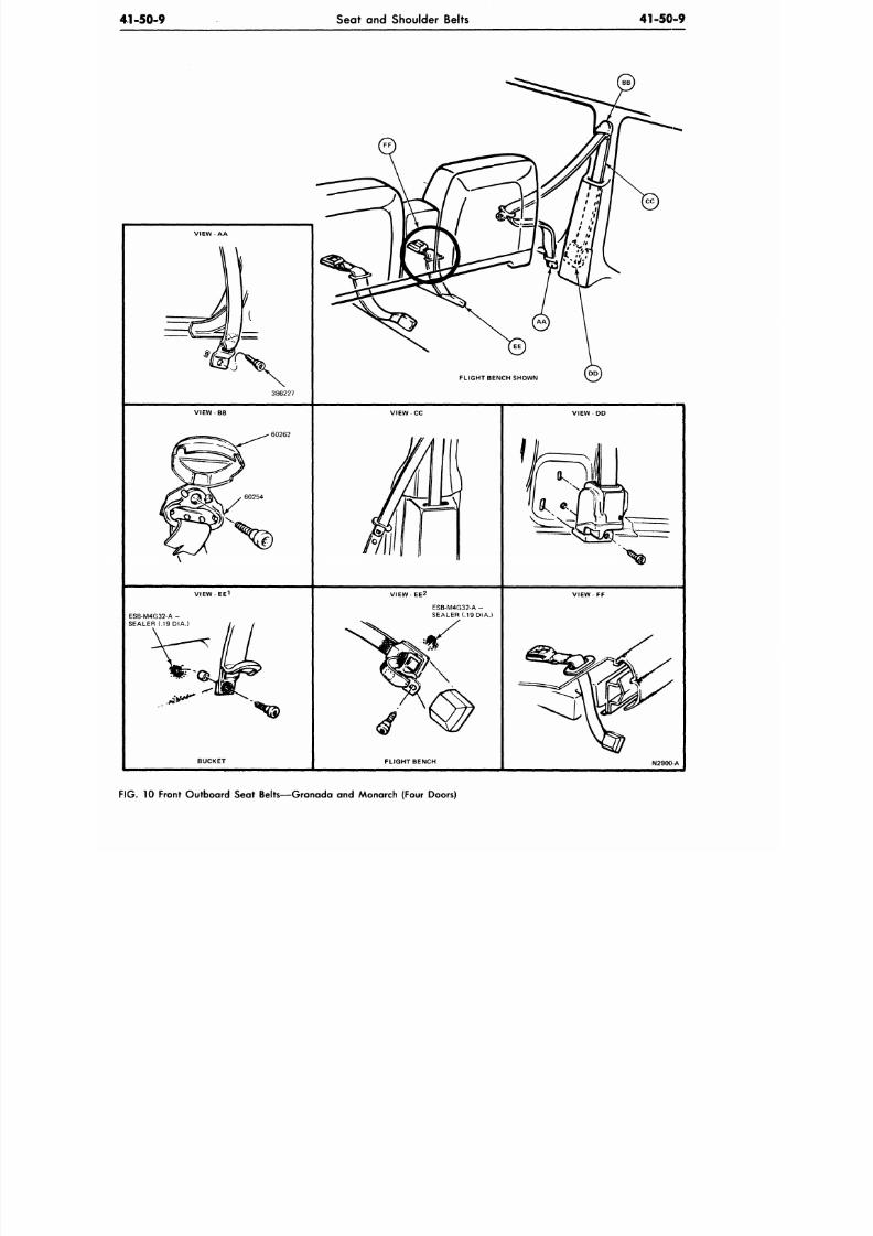
8/20/2019 1977 Ford Car Shop Manual Volume 4 Body
http://slidepdf.com/reader/full/1977-ford-car-shop-manual-volume-4-body 73/449
Seat and Shoulder Belts
41-50-9
386227
FLIGHT BENCH SHOWN
V I E W - B B
60262
VIEW CC
V I E W - E E 1
ESB-M4G32-A -
SEALER (.19DIA.)
VIEW- EE
2
VIEW FF
ESB-M4G32-A -
SEALER (.19 DIA.)
BUCKET
FLIGHT BENCH
N2900A
10 Front Outboard Seat Belts—Granada and Monarch (Four Doors)
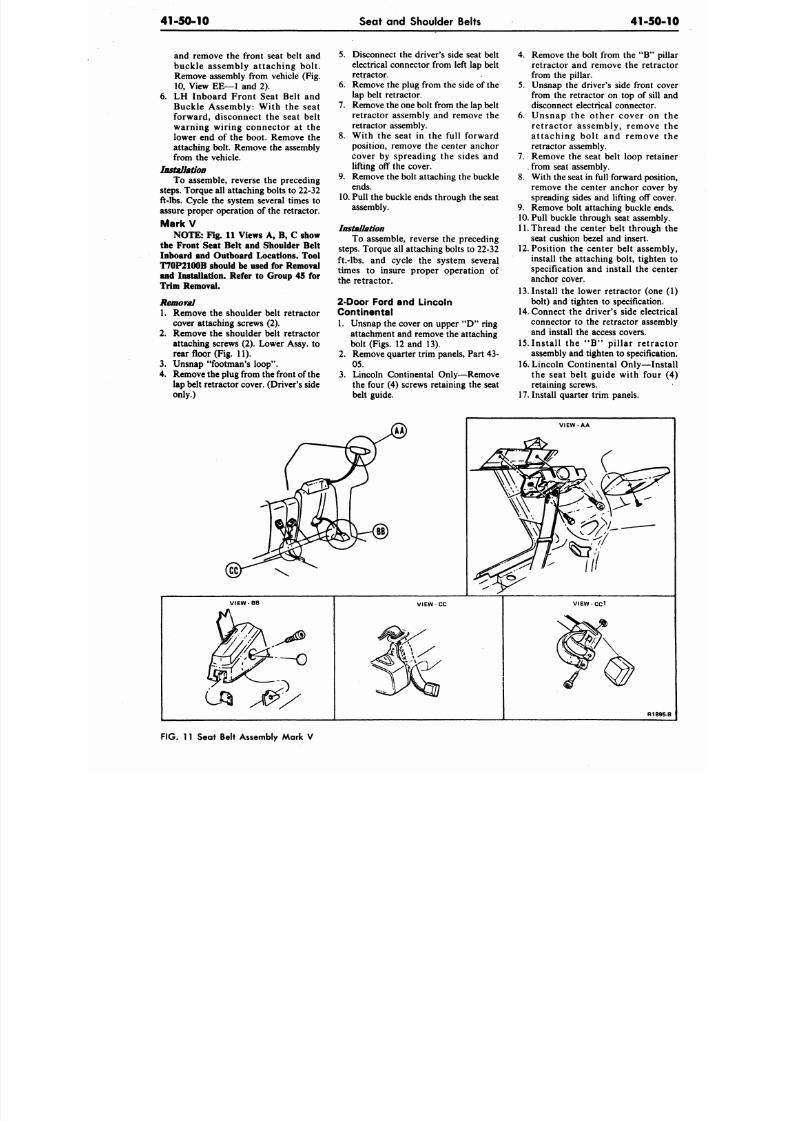
8/20/2019 1977 Ford Car Shop Manual Volume 4 Body
http://slidepdf.com/reader/full/1977-ford-car-shop-manual-volume-4-body 74/449
41-50-10
Seat and Shoulder Belts
41-50
and remove the front seat belt and
buckle assembly attaching bolt.
Remove assembly from vehicle (Fig.
10,
View EE—1 and 2).
6. LH Inboard Front Seat Belt and
Buckle Assembly: With the seat
forward, disconnect the seat belt
warning wiring connector at the
lower end of the boot. Remove the
attaching bolt. Remove the assembly
from the vehicle.
Installation
To assemble, reverse the preceding
steps. Torque all attaching bolts to 22-32
ft-lbs. Cycle the system several times to
assure proper operation of the retractor.
MarkV
NOTE: Fig. 11 Views A, B, C show
the Front Seat Belt and Shoulder Belt
Inboard and Outboard Locations. Tool
T70P2100B should be used for Removal
and Installatioil. Refer to Group 45 for
Trim Removal.
Removal
1. Remove the shoulder belt retractor
cover attaching screws (2).
2.
Remove the shoulder belt retractor
attaching screws (2). Lower Assy, to
rear floor (Fig. 11).
3. Unsnap "footman's loop".
4.
Remove the plug from the front of the
lap belt retractor cover. (Driver's side
only.)
5.
Disconnect the driver's side seat belt
electrical connector from left lap belt
retractor.
6. Remove the plug from the side of the
lap belt retractor.
7. Remove the one bolt from th e lap belt
retractor assembly and remove the
retractor assembly.
8. With the seat in the full forward
position, remove the center anchor
cover by spreading the sides and
lifting off the cover.
9. Remove the bolt attaching the buckle
ends.
10.
Pull the buckle ends through the seat
assembly.
Installation
To assemble, reverse the preceding
steps. Torque all attaching bolts to 22-32
ft.-lbs.
and cycle the system several
times to insure proper operation of
the retractor.
2-Door Ford and Lincoln
Continental
1. Unsnap the cover on upper "D " ring
attachment and remove the attaching
bolt (Figs. 12 and 13).
2.
Remove quarter trim panels, Part 43-
05.
3.
Lincoln Continental Only—Remove
the four (4) screws retaining the seat
belt guide.
4. Remove the bolt from the " B "
retractor and remove the retra
from the pillar.
5.
Unsnap the drive r's side front c
from the retractor on top of sill
disconnect electrical connector.
6. Unsnap the other cover on
retractor assembly, remove
at taching bol t and remove
retractor assembly.
7.
Remove the seat belt loop reta
,
from seat assembly.
8. With the seat in full forward posi
remove the center anchor cove
spreading sides and lifting off co
9. Remove bolt attaching buckle en
10. Pull buckle through seat assemb
11. Thread the center belt through
seat cushion bezel and insert.
12. Position the center belt assem
install the attaching bolt, tighte
specification and install the ce
anchor cover.
13.
Install the lower retractor (on
bolt) and tighten to specification
14.
Connect the driver's side elec
connector to the retractor assem
and install the access covers.
15.
Ins ta l l the " B " p i l lar re t ra
assembly and tighten to specifica
16.
Lincoln Continental Only—In
the seat belt guide with four
retaining screws.
17.
Install quarter trim panels.
V I E W - A A
V I E W - B B
VIEW CC V I E W - C C 1
R18
F IG . 11 Seat Belt Assembly Mark V
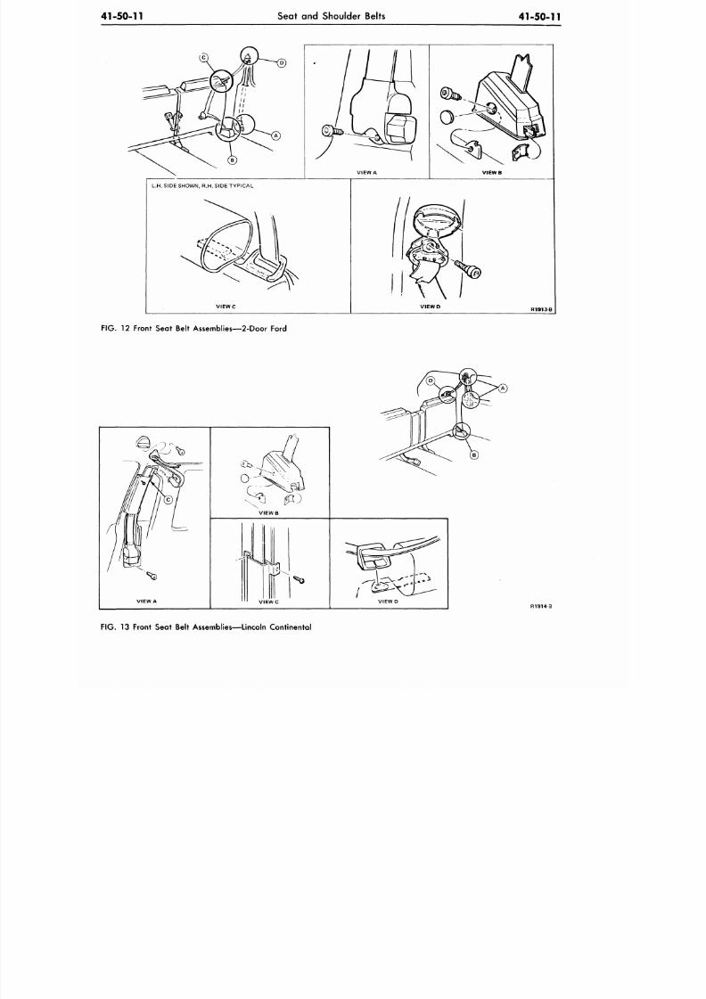
8/20/2019 1977 Ford Car Shop Manual Volume 4 Body
http://slidepdf.com/reader/full/1977-ford-car-shop-manual-volume-4-body 75/449
41-50-11
Seat and Shoulder Belts
41-50-11
L.H. SIDE SHOWN, R.H. SIDE TYPICAL
VIEW C VIEW D
R1913B
FIG.
12 Front Seat Belt Assemblies—2-Door Ford
VIEW A
V I E W B
R1914 3
FIG. 13 Front Seat Belt Assemblies—Lincoln Continental
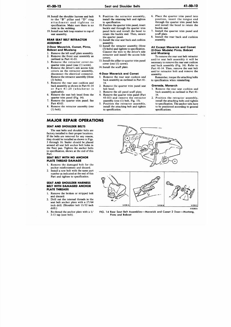
8/20/2019 1977 Ford Car Shop Manual Volume 4 Body
http://slidepdf.com/reader/full/1977-ford-car-shop-manual-volume-4-body 76/449
41-50-12
Seat and Shoulder Belts
4 1 - 5 0
18. Install the shoulder harness and bolt
to the "B " p i l lar and " D " r ing
a t t a c h m e n t a n d t i g h t e n t o
specification. Make sure there is no
twist in the webbing.
19.
Install seat belt loop retainer to top of
seat assembly.
REAR SEAT BELT RETRACTOR
ASSEMBLY
2-Door Maverick, Comet, Pinto,
Bobcat and Mustang
1. Remove the left scuff plate assembly.
2.
Remove the front seat assembly as
outlined in Part
41-01.
3. Remove the retractor cover-to-
quarter trim panel (one (1) screw).
4.
Remove the driver's side access hole
covers on the retractor assembly,
disconnect the electrical connector.
Remove the retractor assembly (three
(3) bolts).
5.
Remove the rear seat cushion and
back assembly as shown in Part 41-14
or P a r t 41 -20 (w h ichever i s
applicable).
6. Remove the seat belt bezel from the
quarter trim panel (Fig. 14).
7. Remove the quarter trim panel. See
Part
45-03.
8. Remove the retractor assembly (one
(1) bolt).
9. Position the retractor assembly,
install the retaining bolt and tighten
to specification.
10.
Position the quarter trim panel, insert
buckle end through the quarter trim
panel hole and install the bezel to
retain the buckle end. Then, secure
the quarter panel.
11. Install the rear seat back and cushion
assembly.
12.
Install the retractor assembly (three
(3) bolts) and tighten to specification.
Connect the wire to the driver's side
retractor and install the access hole
covers.
13. Install the pillar-to-quarter trim panel
cover (one (1) screw).
14.
Install the scuff plate.
4-Door Maverick and Comet
1. Remove the rear seat cushion and
back assembly as outlined in Part 41-
14.
2.
Remove the quarter trim panel seat
belt bezel.
3. Remove the sill panel scuff plate.
4.
Remove the quarter trim panel (Part
45-03) and remove the retractor
assembly (one (1) bolt, Fig. 15).
5. Position the retractor assembly,
install the attaching bolt and tighten
to specification.
6. Place the quarter trim panel
position, insert the tongue
through the quarter trim panel
and install the bezel to retain
buckle end.
7.
Install the quarter trim panel
scuff plate.
8. Install the rear back and cus
assembly.
Al l Except Maver ick and Com
(2-Door Models) Pinto, Bobca
and Mustang
To remove the rear seat belt retr
and/or seat belt assembly it wil
necessary to remove the rear seat cus
and back assembly (Fig. 16). Ref
Part 41-14. Then, remove the seat
and/or retractor bolt and remove
assembly.
Remember, torque the attaching
to specification when reinstalling.
Granada, Mo narch
1. Remove the rear seat cushion
back assembly as outlined in Par
14.
2.
Position the retractor assem
install the attaching bolts and tig
to specification. The anchor tabs
to be positioned according to ge
specifications.
MAJOR REPAIR OPERATIONS
SEAT AND SHOULDER BELTS
The seat belts and shoulder belts are
factory installed in their proper locations.
If the belts are removed for any reason,
they should be installed as shown in Figs.
3 through 16. Sealer should be placed
around all seat belt anchor bolt holes in
the floor pan. Tighten the anchor bolts
to specification, shown at the end of this
Part.
SEAT BELT WITH NO ANCHOR
PLATE THREAD DAMAGE
1. Remove the damaged bolt for the
anchor reinforcement and discard.
2.
Install a new bolt with the same part
number as indicated at the end of this
Part and tighten to specification.
SEAT AND SHOULDER HARNESS
BELT WITH DAMAGED ANCHOR
PLATE THREADS
1. Remove the broken or stripped bolt
and discard.
2.
Drill out the internal threads in the
seat belt anchor plate with a 27/64
inch drill. (Shoulder belt 13/32 inch
drill.)
3. Re-thread the anchor plate with a 1/
2-13 tap (seat belt).
R1
FIG. 14 Rear Seat Belt Assemblies—Maverick and Comet 2 Door—Mustan
Pinto and Bobcat
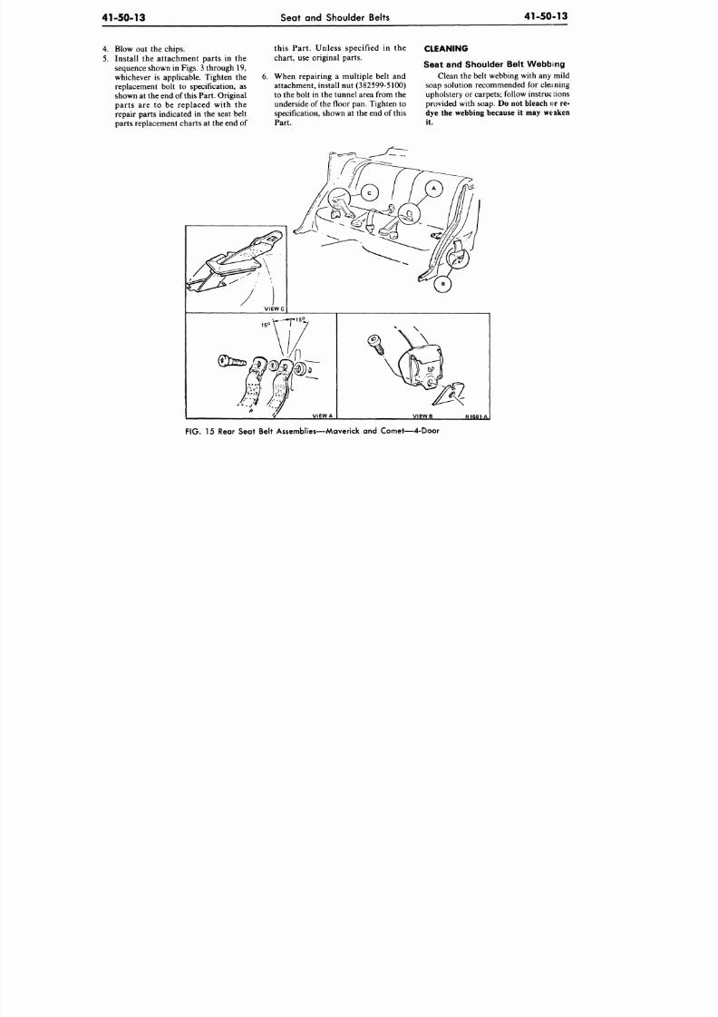
8/20/2019 1977 Ford Car Shop Manual Volume 4 Body
http://slidepdf.com/reader/full/1977-ford-car-shop-manual-volume-4-body 77/449
41-50-13
Seat and Shoulder Belts
41-50-13
4. Blow out the chips.
5. Ins ta l l the a t tachment parts in the
sequence shown in Figs. 3 throu gh 19,
whichever is applicable. Tighten the
replacement bolt to specification, as
shown at the end of this Part. Original
parts are to be replaced with the
repair parts indicated in the seat belt
parts replacement charts at the end of
this Part . Unless specif ied in the
chart, use original parts.
6. When rep airing a mu ltiple belt and
attachment, install nut (382599-5100)
to the bolt in the tunnel area from the
underside of the floor pan. Tighten to
specification, shown at the end of this
Part.
CLEANING
Seat and Shoulder Belt Webbing
Clean the belt webbing with any mild
soap solution recommended for cleaning
upholstery or carpets; follow instruc tions
provided with soap. Do not bleach or re-
dye the webbing because it may weaken
it.
FIG . 15 Rear Seat Belt Assemblies—Maverick an d Co me t—4-D oor
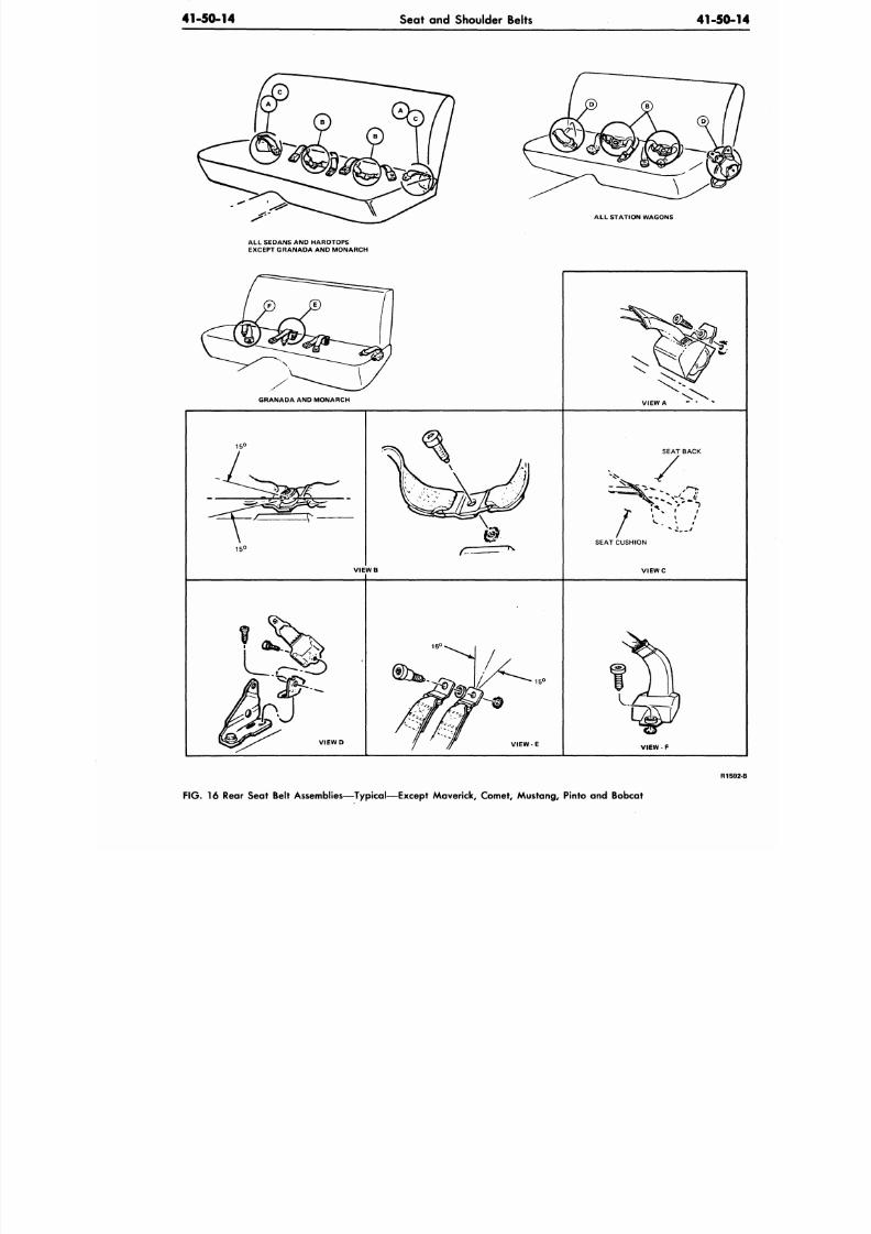
8/20/2019 1977 Ford Car Shop Manual Volume 4 Body
http://slidepdf.com/reader/full/1977-ford-car-shop-manual-volume-4-body 78/449
41-50-14
Seat and Shoulder Belts
41-50
ALL STATION W AGONS
ALL SEDANS AND HARDTOPS
EXCEPT GRANADA AND MONARCH
GRANADA AND MONARCH
VIEW A
15
C
V I E W B
SEAT BACK
SEAT CUSHION
V I E W D
VIEW - E
VIEW - F
R
F IG .
16 Rear Seat Belt Assemblies—Typical—Except Maverick, Comet, Mustang, Pinto and Bobcat
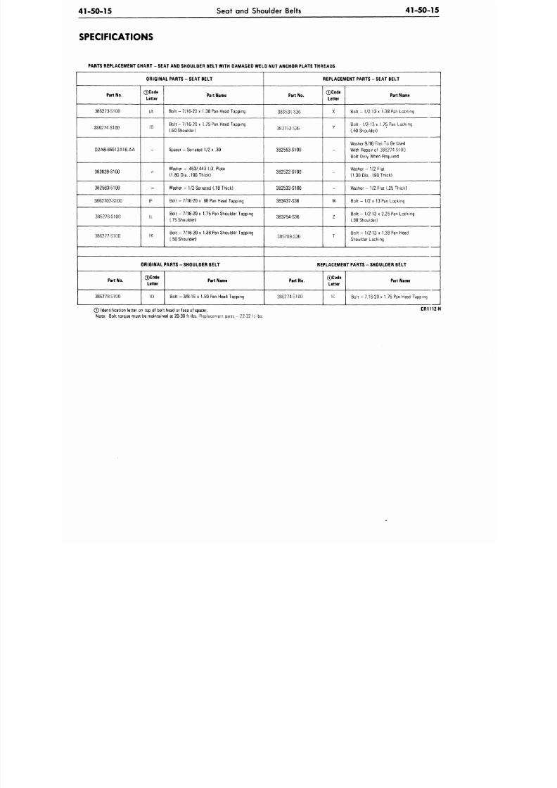
8/20/2019 1977 Ford Car Shop Manual Volume 4 Body
http://slidepdf.com/reader/full/1977-ford-car-shop-manual-volume-4-body 79/449
41-50-15
Seat and Shoulder Belts
41-5015
SPECIFICATIONS
PARTS REPLACEMENT CHART - SEAT AND SHOULDER BELT WITH DAMAGED WELD NUT ANCHOR PLATE THREADS
ORIGIN AL PARTS - SEAT BELT
Part No.
386273-S100
386274-S100
D2AB-65612A16-AA
382629-S100
382583-S100
3862702-S100
386276-S100
386277-S100
0 C o d e
Letter
IA
IB
-
•x-
-
IF
IL
IK
Part Name
Bolt - 7/16-20 x 1.38 Pan Head Tapping
Bolt - 7/16-20 x 1.75 Pan Head Tapping
(.50 Shoulder)
Spacer - Se rrated 1/2 x .30
Washer - .463A443 I.D. Plate
(1.80 Dia. .190 Thick)
Washer-1/2 Serrated (.18 Thick)
Bolt -
7/16-20
x .88 Pan Head Tapping
Bolt -
7/16-20
x 1.75 Pan Shoulder Tapping
(.75 Shoulder)
Bolt - 7/16-20 x 1.38 Pan Shoulder Tapping
(.50 Shoulder)
ORIGINAL PARTS - SHOULDER BELT
Part No.
386278-ST00
0 C o d e
Letter
ID
Part Name
Bolt -3 /8 -1 6 x 1.50 Pan Head Tapping
REPLACEMENT PARTS - SEAT BELT
Part No.
383531-S36
383753-S36
382553-S100
382522-S100
382533-S100
383437-S36
383754-S36
385709-S36
0Code
Letter
X
Y
-
-
-
W
z
T
Part Name
Bolt -
1/2-13
x 1.38 Pan Locking
Bol t -
1/2-13
x 1.75 Pan Locking
(.50 Shoulder)
Washer 9/16 Flat To Be Used
With Repair of 386274-S100
Bolt Only When Required
Washer- 1/2 Flat
(1.30 Dia. .190 Thick)
Washer- 1/2 Flat (.25 Thick)
B o lt - 1/2 x 13 Pan Locking
Bo l t -1 /2- 13 x2 .25 Pan Locking
(.88 Shoulder)
B o l t -
1/2-13
x 1.38 Pan Head
Shoulder Locking
REPLACEMENT PARTS - SHOULDER BELT
Part No.
3862 74-S100
©Code
Letter
IC
Part Name
Bolt - 7.16-20 x 1.75 Pan Head Tapping
© Ide ntificatio n letter on top of bolt head or face of spacer.
Note:
Bolt torqu e must be maintained at 20-30 ft-lbs. Replacement parts - 2 2-32 ft-lbs.
C R 1 I 1 2 H
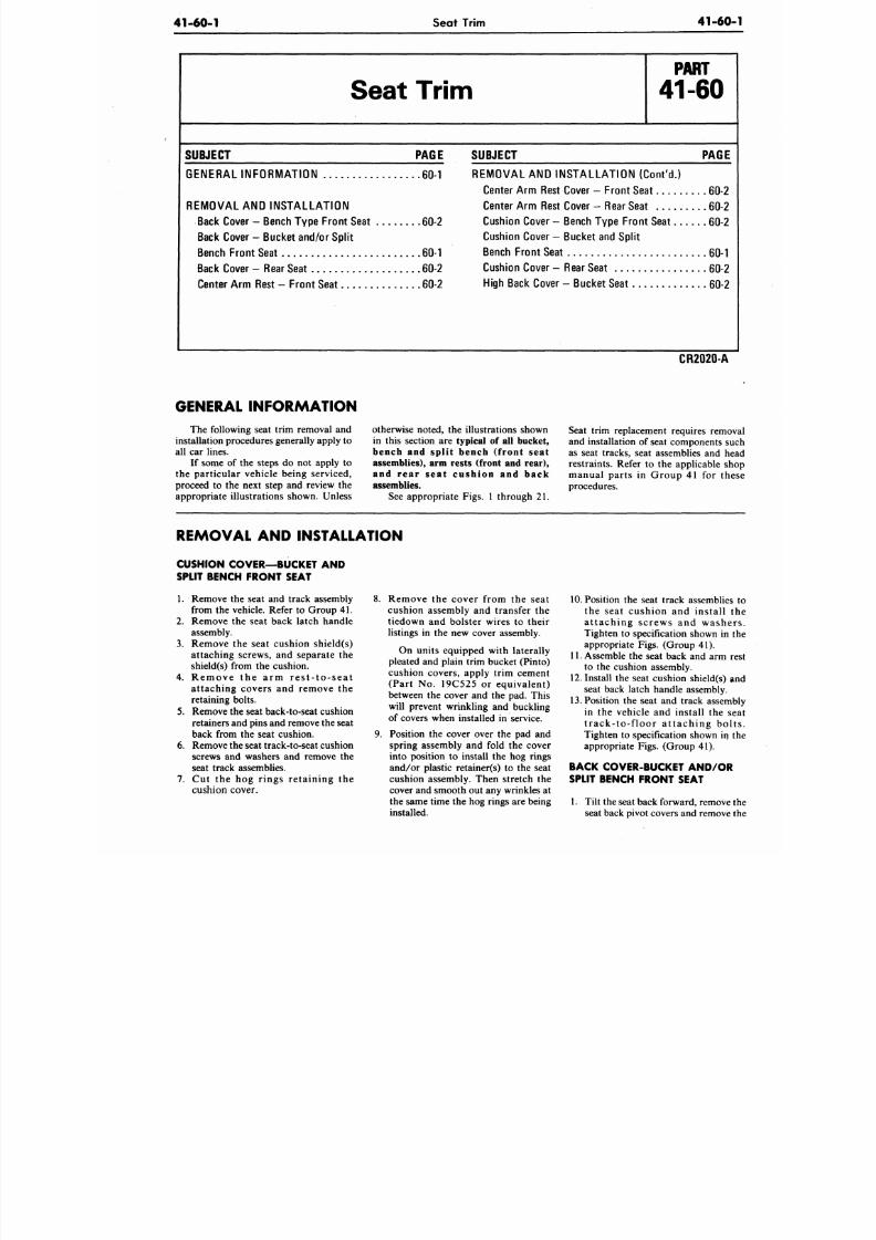
8/20/2019 1977 Ford Car Shop Manual Volume 4 Body
http://slidepdf.com/reader/full/1977-ford-car-shop-manual-volume-4-body 80/449
41-60-1
Seat Trim
4 1 - 6 0
SUBJECT
Seat
G ENERAL INF O RM AT IO N
REM O VAL AND INST AL L AT IO N
Back Cover - Bench Typ e Fro nt Seat
Back Cover - Bucket and/or Sp li t
Bench Front Seat
Back Cover
—
Rear Seat
Center Arm Rest - Front Se at . .
Trim
PAGE
. . 6 0 -1
. . 6 0 -2
60-1
. . 60-2
60-2
SUBJECT
P A R T
41-60
PAGE
REMOVAL AND INSTALLATION (Con t 'd . )
Center Ar m Rest Cover - Fro nt Seat 60-2
Center Ar m Rest Cover - Rear Seat 60-2
Cushion Cover - Bench Typ e Fro nt Seat 60-2
Cushion Cover - Bucke t and Sp lit
Bench Fro nt Seat - Rf)-i
Cushion Cover -
High Back Cover
Rear Seat
- Bucke t Seat
60-2
60-2
CR2020-A
GENERAL INFORMATION
The following seat trim removal and
installation procedures generally apply to
all car lines.
If some of the steps do not apply to
the particular vehicle being serviced,
proceed to the next step and review the
appropriate illustrations shown. Unless
otherwise noted, the illustrations shown
in this section are
typical of all bucket,
bench and split bench (front seat
assemblies), arm rests (front and rear),
and rear seat cushion and back
assemblies.
See appropriate Figs. 1 through 21.
Seat trim replacement requires remo
and installation of seat components s
as seat tracks, seat assemblies and h
restraints. Refer to the applicable s
manual parts in Group 41 for th
procedures.
REMOVAL AND INSTALLATION
CUSHION COVER—BUCKET AND
SPLIT BENCH FRONT SEAT
1. Remove the seat and track assembly
from the vehicle. Refer to Group 41.
2. Remove the seat back latch handle
assembly.
3. Remove the seat cushion shield(s)
attaching screws, and separate the
shield(s) from the cushion.
4.
R e m o v e th e a r m r e s t - t o - s e a t
attaching covers and remove the
retaining bolts.
5. Remove the seat back-to-seat cushion
retainers and pins and remove the seat
back from the seat cushion.
6. Remove the seat track-to-seat cushion
screws and washers and remove the
seat track assemblies.
7.
Cut the hog r ings retaining the
cushion cover.
8. Remove the cover from the seat
cushion assembly and transfer the
tiedown and bolster wires to their
listings in the new cover assembly.
On units equipped with laterally
pleated and plain trim bucket (Pinto)
cushion covers, apply trim cement
(Part No. 19C525 or equivalent)
between the cover and the pad. This
will prevent wrinkling and buckling
of covers when installed in service.
9. Position the cover over the pad and
spring assembly and fold the cover
into position to install the hog rings
and/or plastic retainer(s) to the seat
cushion assembly. Then stretch the
cover and smooth out any wrinkles at
the same time the hog rings are being
installed.
10. Position the seat track assemblie
the seat cushion and install
a t taching screws and washe
Tighten to specification shown in
appropriate Figs. (Group 41).
11. Assemble the seat back and arm
to the cushion assembly.
12. Install the seat cushion shield(s)
seat back latch handle assembly.
13. Position the seat and track assem
in the vehicle and install the s
t r a c k- to - f loor a t t a c h ing bo
Tighten to specification shown in
appropriate Figs. (Group 41).
BACK COVER-BUCKET AND/OR
SPLIT BENCH FRONT SEAT
1.
Tilt the seat back forward, remove
seat back pivot covers and remove
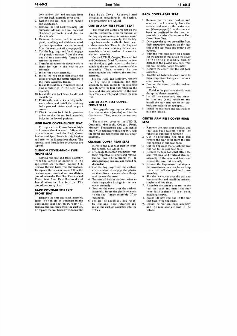
8/20/2019 1977 Ford Car Shop Manual Volume 4 Body
http://slidepdf.com/reader/full/1977-ford-car-shop-manual-volume-4-body 81/449
41-60-2 Seat Trim
41-60-2
bolts and/or pins and retainers from
the seat back assembly pivot arm.
2.
Remove the seat back latch handle
and escutcheon.
3. Remove the seat back assembly (lift
outboard side and pull seat back out
of inboard pin socket), and place on
clean bench.
4.
Remove the seat back trim robe
panel, moulding and shields (retained
by trim clips and/or tabs and screws)
from the seat back (if so equipped).
5. Cut the hog rings and /or disengage
the plastic retainers from the seat
back frame assembly flange and
remove the cover.
6. Transfer all bolster tie-down wires to
their l is tings in the new cover
assembly.
7. Install the cover assembly.
8. Install the hog rings that retain the
cover or attach the plastic retainers to
the frame assembly flange.
9. Install the seat back trim panel, shield
and mouldings to the seat back
assembly.
10.
Install the seat back latch handle and
escutcheon.
11. Position the seat back assembly to the
seat cushion and install the retaining
bolts, pins and retainers and the pivot
covers.
12. Check the seat back latch operation
to be sure that the seat back assembly
holds in the locked position.
HIGH BACK COVER-BUCKET SEAT
To replace the Pinto/Bobcat high
back cover (bucket seat), follow the
procedures outlined for Back Cover
Bucket and Split Bench in this Section
and refer to the illustrations shown. The
removal and installation procedures are
typical.
CUSHION COVER-BENCH TYPE
FRONT SEAT
Remove the seat and track assembly
from the vehicle as outlined in the
applicable seat section (Group 41).
Remove the seat back from the cushion.
To replace the cushion cover, follow the
cushion cover removal and installation
procedures under Rear Seat Cushion and
Front Seat Arm Rest Removal and
Ins ta l la t ion in th is Sect ion . The
procedures are typical.
BACK COVER-BENCH TYPE
FRONT SEAT
Remove the seat and track assembly
from the vehicle as outlined in the
applicable seat section (Group 41).
Remove the seat back from the cushion.
To replace the seat back cover, follow the
S ea t Back Cover Remova l and
Installation procedures in this Section.
The procedures are typical.
CENTER A R M REST-FRONT SEAT
The front seat center arm rest on the
Lincoln Continental requires removal of
the hog rings retaining the arm rest cover
to the seat cushion assembly. Cut the hog
rings from underneath the front seat
cushion assembly. Then, lift the flap and
remove the screw retaining the arm rest
assembly to the seat cushion. Remove the
arm rest assembly.
On the LTD II, Cougar, Thunderbird
and Continental Mark
V,
remove the arm
rest shield(s) to gain access to the bolts
attaching the arm rest to the seat cushion
assembly . Then, remove the two
attaching bolts and remove the arm rest
assembly.
On the Ford and Mercury, remove
the hog ring(s) retaining the flap
assembly to gain access to the retaining
nuts. Remove the four nuts retaining the
back and strainer assembly to the seat
back frame assembly and remove the arm
rest.
CENTER ARM REST COVER-
FRONT SEAT
Disengage the hog rings and the cover
from the retainers (staples) on Lincoln
Continental. Then, remove the arm rest
cover.
The arm rest cover on the LTD II,
Granada, Monarch , Cougar , Ford ,
Mercury, Thunderbird and Continental
Mark V, is retained with a zipper. Unzip
the zipper and remove the arm rest cover
assembly.
CUSHION COVER-REAR SEAT
1.
Remove the rear seat cushion from
the vehicle. See Group 41.
2.
Disengage the button assemblies from
their respective retainers and remove
the buttons. The retainers will be
damaged upon removal and should be
discarded.
3.
Cut the hog rings from the cushion
cover and/or disengage the plastic
retainers from the seat cushion flange
and remove the cover.
4.
Transfer all bolster tie-down wires to
their respective listings in the new
cover assembly.
5. Position the cover over the cushion
assembly. Secure the plastic retainers
to the seat flange assembly (if so
equipped).
6. Install the necessary hog rings,
buttons and (new) retainers and
install the cushion assembly into the
vehicle.
BACK COVER-REAR SEAT
1.
Remove the rear seat cushion and
rear seat back assembly from the
vehicle, and remove the center arm
rest (if so equipped) from the rear seat
back as outlined in the removal
procedure under Center Arm Rest
Cover-Rear Seat.
2.
Disengage the button assemblies from
their respective retainers on the: rear
side of the seat back and remove the
buttons.
3. With the front side down on a bench,
cut the hog rings that retain the cover
to the spr ing assembly and/or
disengage the plastic retainers from
the seat cushion flange assembl
y .
4.
Remove the cover from the seat back
assembly.
5. Transfer all bolster tie-down wires to
their respective listings in the; new
cover assembly.
6. Position the cover over the cushion
assembly.
Position the plastic retainers) over
the spring flange assembly.
7. Install the necessary hog rings,
buttons and (new) retainers and
install the rear arm rest to the seat
back assembly (if so equipped).
8. Install the seat back and seat cushion
into the vehicle.
CENTER A R M REST COVER-REAR
SEAT
1. Remove the rear seat cushion and
rear seat back assembly from the
vehicle as outlined in Group 41.
2. Cut the retaining hog rings and
remove the rear cover from the arm
rest opening in the seat back.
3. Cut the hog rings that attach the arm
rest flap to the rear seat back.
4.
Remove the four bolts that attach the
arm rest link and vertical strainer
assembly to the rear seat back and
remove the arm rest assembly.
5.
Remove the flap-to-arm rest staples,
the cover-to-arm rest staples and slip
the cover off the pad and base
assembly.
6. Slip the new cover over the pad and
base assembly and install the arm rest
staples and hog rings.
7.
Assemble the center arm rest to the
rear seat back and install the four
ve r t i ca l s t r a i ne r - to - s ea t back
attaching screws.
8. Fasten the arm rest flap to the rear
seat back with hog rings.
9. Install the rear seat back assembly
and the rear seat cushion in the
vehicle.
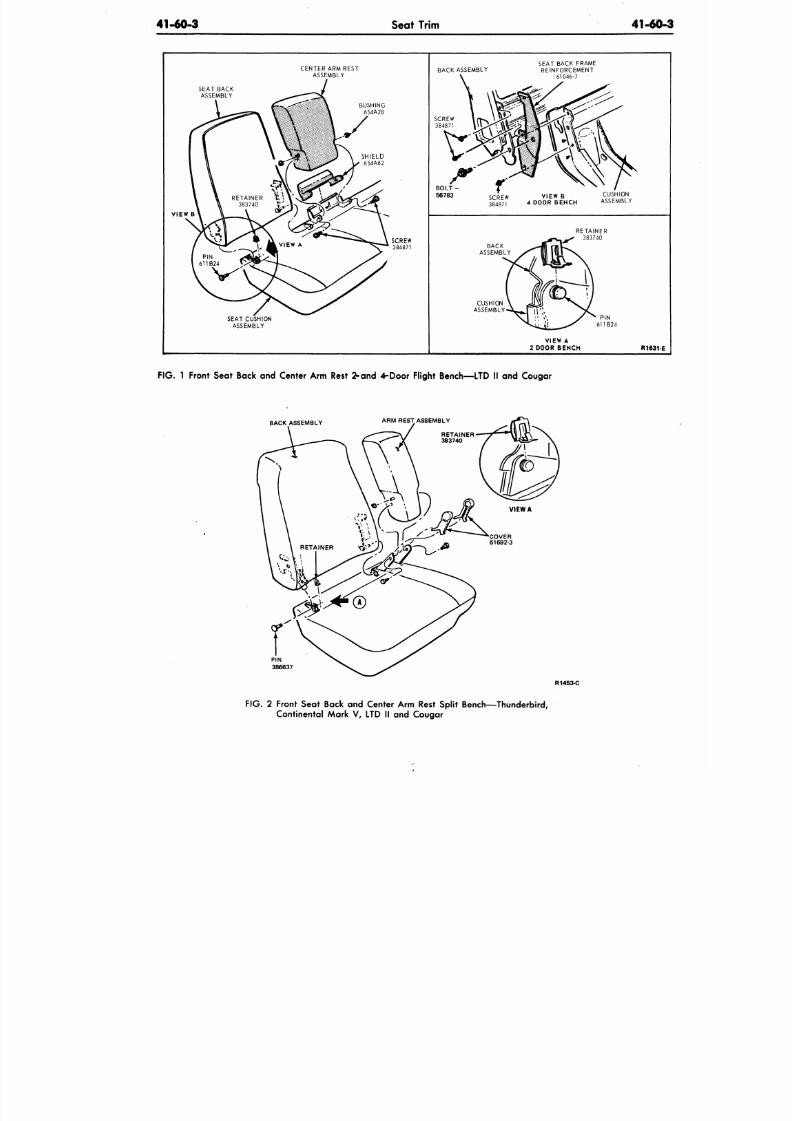
8/20/2019 1977 Ford Car Shop Manual Volume 4 Body
http://slidepdf.com/reader/full/1977-ford-car-shop-manual-volume-4-body 82/449
41-60-3
Seat Trim
41-60
CENTER ARM REST
ASSEMBLY
SEAT BACK
ASSEMBLY
BUSHING
654A28
y
VIEW B
SEAT CUSHION
ASSEMBLY
SHIELD
654A82
BACK ASSEMBLY
SEAT BACK FRAME
REINFORCEMENT
61046-7
qrRFW
38 4
8
7i
VIEW B CUSHION
4 DOOR BENCH ASSEMBLY
VIEW A
2 DOOR BENCH R1631
FIG. 1 Front Seat Back and Center Arm Rest
2-and 4-Door
Flight Bench—LTD II and Cougar
BACK ASSEMBLY
ARM REST ASSEMBLY
PIN
386637
R1453-C
F IG .
2 Front Seat Back and Center Arm Rest Split Bench—Thunderbird,
Continental Mark V, LTD II and Cougar
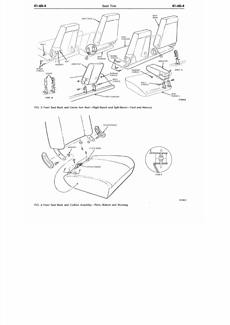
8/20/2019 1977 Ford Car Shop Manual Volume 4 Body
http://slidepdf.com/reader/full/1977-ford-car-shop-manual-volume-4-body 83/449
41-60-4
Seat Trim
41-60-4
NU T
WASHER
A R M R E S T
SEAT
CUSHION
V I E W - B
R1930-B
FIG.
3 Front Seat Back and Center Arm Rest—Flight-Bench and Split-Bench—Ford and Mercury
COVER-61634-5
VIEW A
R1765-E
FIG. 4 Front Seat Back and Cushion Assembly—Pinto, Bobcat and Mustang
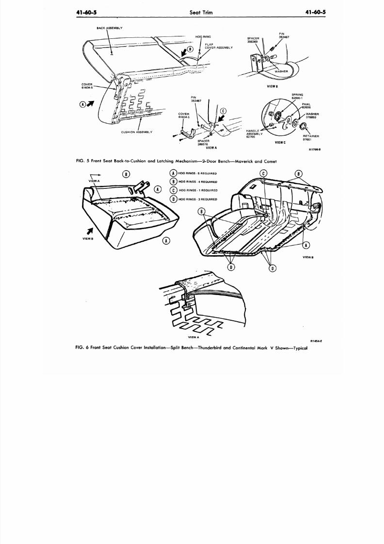
8/20/2019 1977 Ford Car Shop Manual Volume 4 Body
http://slidepdf.com/reader/full/1977-ford-car-shop-manual-volume-4-body 84/449
41-60-5
Seat Trim 41-60
BACK ASSEMBLY
PIN
353467
CUSHION ASSEMBLY
SPACER
386576
VIEW A
V I E W C
R1766-B
FIG .
5 Front Seat Back-to-Cushion and Latching Mechanism—2-Door Bench—Maverick and Comet
C
) HOG RINGS - 5 REQ UIRED
HOG RINGS - 4 R EQUIRED
(J J HOG RINGS - 1 REQUIRED
D ) HOG RINGS - 3 REQUIRED
V I E W B
V I E W B
VIEW A
FIG .
6 Front Seat Cushion Cover Installation—Split Bench—Thunderbird and Continental Mark V Shown— Typical
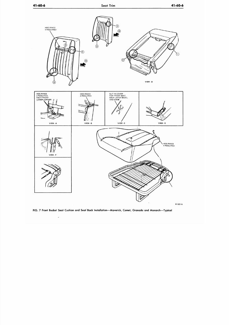
8/20/2019 1977 Ford Car Shop Manual Volume 4 Body
http://slidepdf.com/reader/full/1977-ford-car-shop-manual-volume-4-body 85/449
41-60-6
Seat Trim
41-60-6
HOG RINGS
4 REQUIRED
VIEW D
HOG RINGS
2 REQUIRED
EACH FRONT
LOWER CORNER
V I E W - A
HOG RINGS
4 REQUIRED
VIEW-B
SLIT
IN
COVER
FOR FRONT SEAT
BACK LATCH BEZEL
AND KNOB
V I E W - C
V I E W - E
VIEW - F
HOG RINGS
4 REQUIRED
R1931-A
FIG. 7 Front Bucket Seat Cushion and Seat Back Installation—Maverick Comet Granada and Monarch—Typical
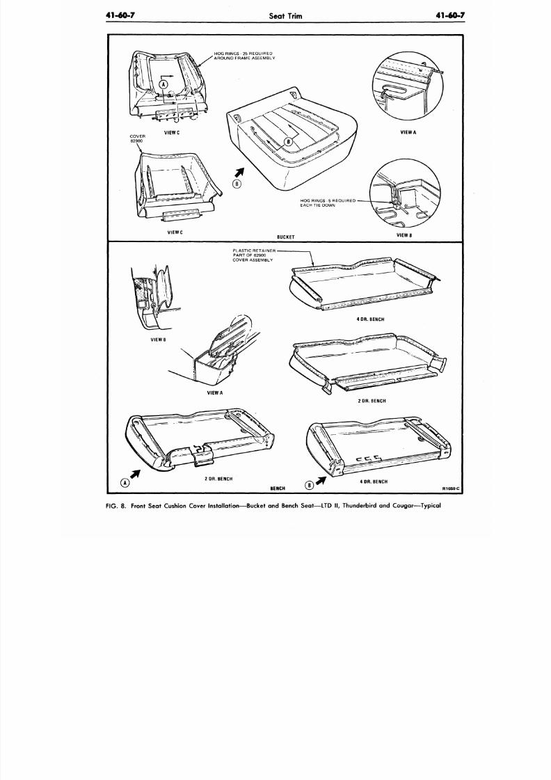
8/20/2019 1977 Ford Car Shop Manual Volume 4 Body
http://slidepdf.com/reader/full/1977-ford-car-shop-manual-volume-4-body 86/449
4140-7
Seat Trim
41-60-
HOG RINGS - 25 REQUIRE D
AROUND FRAME ASSEMBLY
V I E W C
BUCKET
V I E W B
PLASTIC RETAINER
PART OF 62900
COVER ASSEMBLY
4 OR. BENCH
VIEW A
2 DR. BENCH
2 DR. BENCH
BENCH
4 DR. BENCH
R1659-C
F IG .
8. Front Seat Cushion Cover Installation—Bucket and Bench Seat—LTD II, Thunderbird and C ougar— Typical
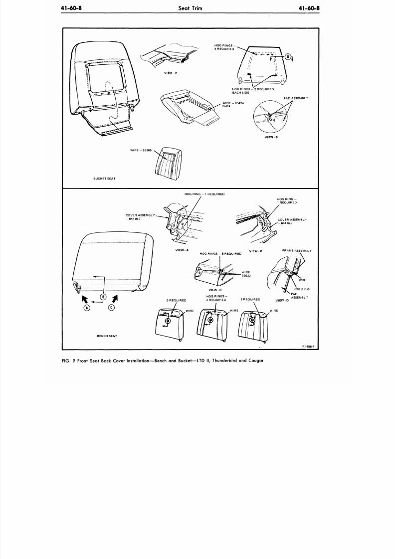
8/20/2019 1977 Ford Car Shop Manual Volume 4 Body
http://slidepdf.com/reader/full/1977-ford-car-shop-manual-volume-4-body 87/449
41-60-8
Seat Trim
41-60-8
PAD ASSEMBLE
VIEW B
W I R E - 6 3 3 6 5
BUCKET SEAT
HOG R IN G - 1 REQUIRED
HOG RING -
1 REQUIRED
COVER ASSEMBL
V
- 6 4 4 1 6 - 7
BENCH SEAT
R1456-F
F IG . 9 Front Seat Back Cover Installation—Bench and Bucket—LTD ll
#
Thunderbird and Cougar
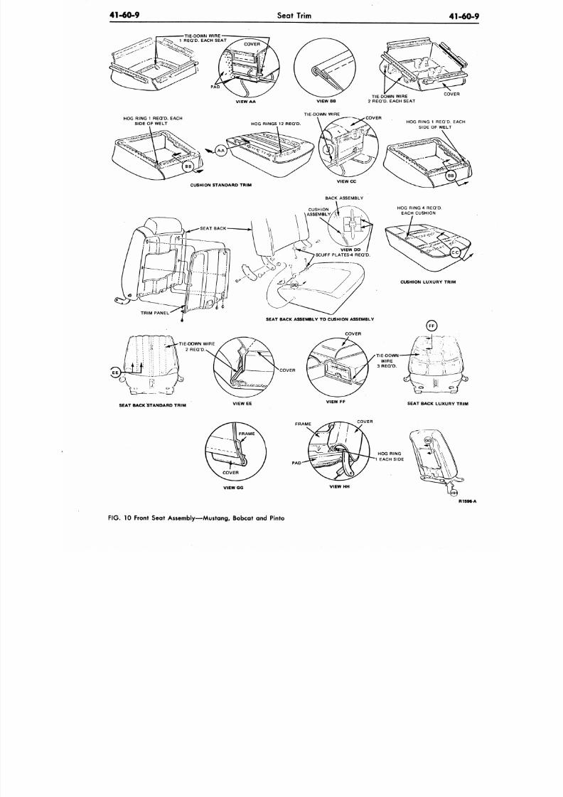
8/20/2019 1977 Ford Car Shop Manual Volume 4 Body
http://slidepdf.com/reader/full/1977-ford-car-shop-manual-volume-4-body 88/449
41-60-9
Seat Trim
41-60
TIE-DOWN WIRE
1 REQ'D. EACH SEAT
PA D
VIEW AA
HOG RING 1 REQ'D. EACH
SIDE OF WELT
VIEW BB
TIE-DOWN WIRE
TIE-DOWN WIRE
2 REQ'D. EACH SEAT
COVER
COVER
HOG RING 1 REQ'D. EACH
SIDE OF WELT
CUSHION LUXURY TRIM
TRIM PANEL
TIE-DOWN WIRE
2 REQ'D
SEAT BACK ASSEMBLY TO CUSHION ASSEMBLY
COVER
COVER
SEAT BACK STANDARD TRIM
VIEW EE
VIEW FF
SEAT BACK LUXURY TRIM
FRAME
PA D
COVER
HOG RING
1 EACH SIDE
VIEW HH
R159
F IG . 10 Front Seat Assembly—Mustang, Bobcat and Pinto
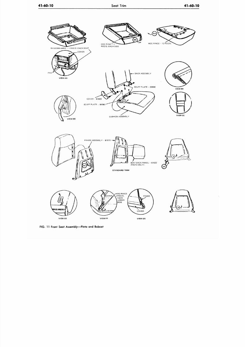
8/20/2019 1977 Ford Car Shop Manual Volume 4 Body
http://slidepdf.com/reader/full/1977-ford-car-shop-manual-volume-4-body 89/449
41-60-10
Seat Trim
41-60-10
TIE-DOWN WIRE - 1 REQ'D. EACH SEAT
.COVER
VIEW AA
HOG RING - 1
REQ'D. EACH SIDE
BACK ASSEMBLY
COVER - 61694
SCUFF PLATE -60060
CUSHION ASSEMBLY
V I E W C C
VIEW DD
FRAME ASSEMBLY - 61015
SEAT BACK PANEL - 61 632
(PINTO ONLY)
STANDARD TRIM
V IE W E E VIEW FF
VIEW GG
F IG . 11 Front Seat Assembly—Pinto and Bobcat
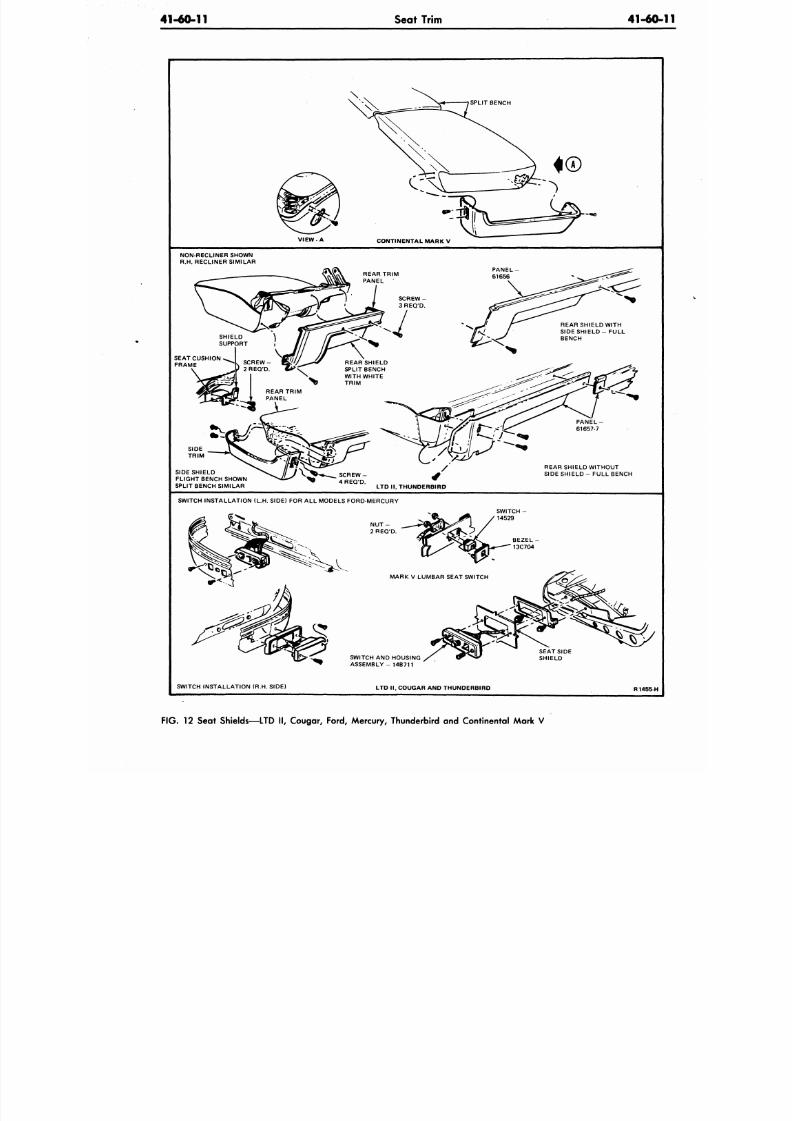
8/20/2019 1977 Ford Car Shop Manual Volume 4 Body
http://slidepdf.com/reader/full/1977-ford-car-shop-manual-volume-4-body 90/449
41-60-11
Seat Trim
41-60
\
SPLIT BENCH
VIEW A
CONTINENTAL MARK V
NON-RECLINER SHOWN
R.H. RECLINER S IMILAR
SEAT CUSHION
FRAME
SIDE SHIELD
FLIGHT BENCH SHOWN
SPLIT BENCH SIMILAR
PANEL -
61657-7
REAR SHIELD WITHOUT
SIDE SHIELD - FUL L BENCH
LTD I I , THUNDERBIRD
SWITCH INSTAL LATION (L.H. SIDE) FOR ALL MODELS FORD-MERCURY
SWITCH AND HOUSING
ASSEMBLY- 14B711
SWITCH INSTA LLATION (R.H. SIDE)
LTD I I , COUGAR AND TH UNDERBIRD
R 1 4 5 5 H
F IG .
12 Seat Shields—LTD II, Cougar, Ford, Mercury, Thunderbird and Continental Mark V
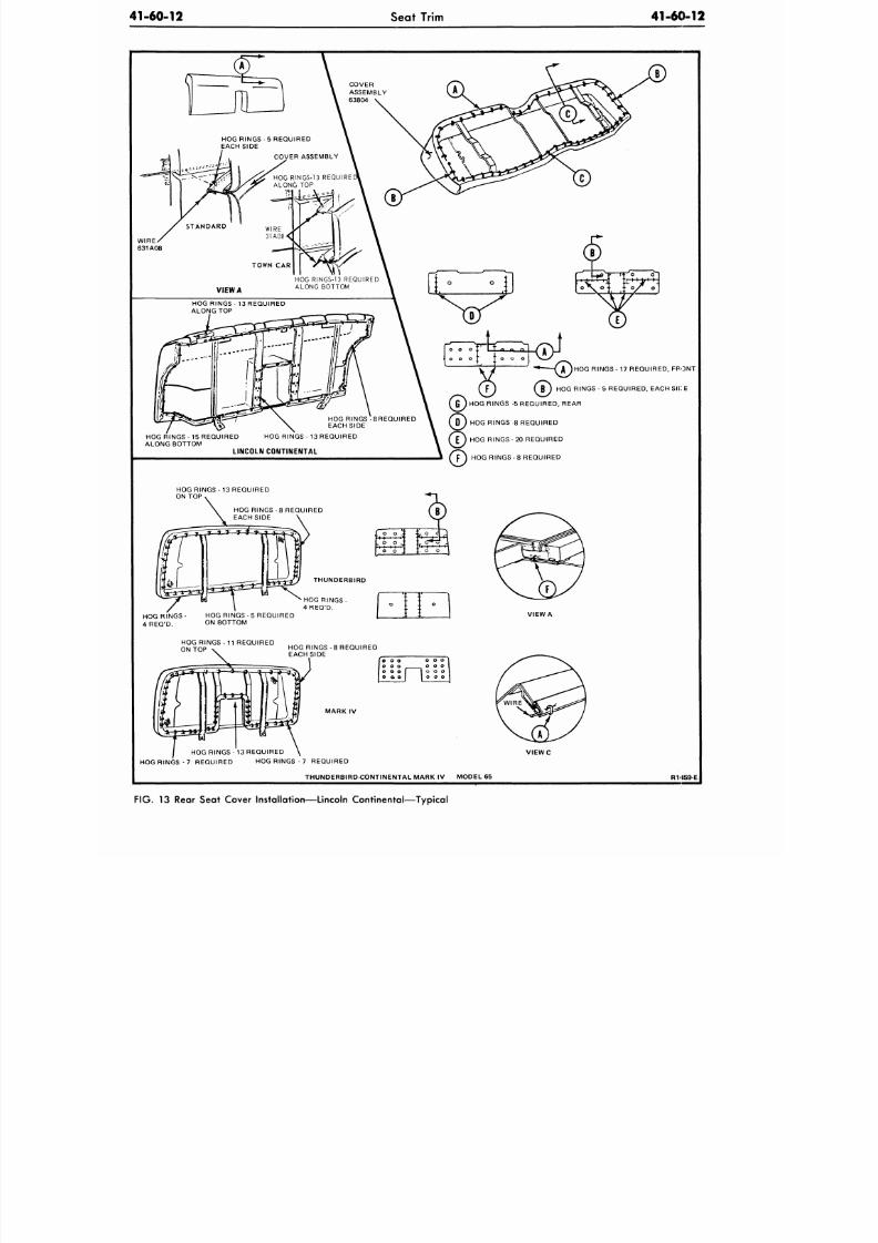
8/20/2019 1977 Ford Car Shop Manual Volume 4 Body
http://slidepdf.com/reader/full/1977-ford-car-shop-manual-volume-4-body 91/449
41-60-12
Seat Trim
41-60-12
c
HOG RINGS - 5 REQUIRED
EACH SIDE
COVER ASSEMBLY
HOG RINGS-13 REQUIRE
ALONG TO P
TOWN CA R
VIEW A
HOG RINGS - 13 REQUIRED
ALONG TOP
HOG RINGS - 13 REQUIRED
OG R INGS-15 REQUIRED
ALONG BOTTOM
LINCOLN CONTINENTAL
HOG RINGS-13 REQUIRED
ALONG BOTTOM
Q
rTTr-tzii^
HOG R INGS-8REQUIRED
EACH SIDE
HOG RINGS - 17 REQUIRED, FRONT
B J HOG R INGS -5 REQUIRED, EACH SICE
HOG RINGS -5 REQUIRED, REAR
HOG RINGS -8 REQUIRED
HOG RINGS - 20 REQUIRED
HOG RINGS - 8 REQUIRED
HOG R INGS-1 3 REQUIRED
ON TOP
HOG RINGS -8 REQUIRED
EACH SIDE
o
, o
o
O _;
o ,
{•
°
r .f
. 0
M
0 I
THUNDERBIRD
HOG RINGS-
4 REQ'D.
HOG RINGS-
4 REQ'D.
HOG RING S-5 REQUIRED
ON BOTTOM
VIEW A
HOG RINGS - 1 1 REQUIRED
ON TOP
HOG RINGS -8 REQUIRED
EACH SIDE
M A R K IV
HOG RINGS - 1 3 REQUIRED
HOG RINGS - 7 REQUIRED HO G RINGS - 7 REQUIRED
V I E W C
THUNDERBIRD-CONTINENTA L MARK IV MODEL 65
R 1 4 5 9 E
FIG.
13 Rear Seat Cover Installation—Lincoln Continental—Typical
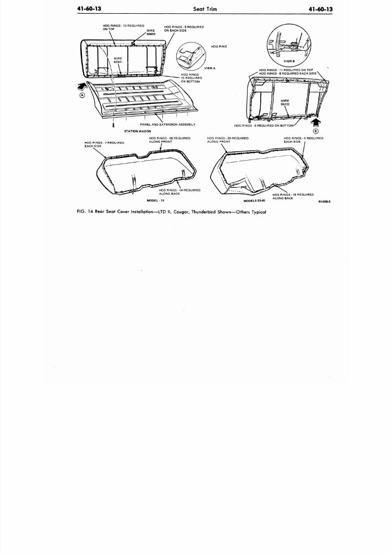
8/20/2019 1977 Ford Car Shop Manual Volume 4 Body
http://slidepdf.com/reader/full/1977-ford-car-shop-manual-volume-4-body 92/449
41-60-13
Seat Trim
41-60-
HOG RINGS - 13 REQUIRED
ON TOP
HOG RINGS - 8 R EQUIRE D
WIRE ON EACH SIDE
<^
1
\
. j
i, *
...\. 8t
L WIRE
\ 63341
^ ft
1
-
—> ' i i '
— ^
— - (
i •
HOG RING
VIEW A
HOG RINGS - 11 REQUIRED ON TOP
HOG RINGS - 8 REQUIRED EACH SIDE \
PANEL AND EXTENSION ASSEMBLY
STATION WAGON
HOG RINGS - 9 REQUIRED ON BOTTOM
HOG RINGS-7 REQUIRED
EACH SIDE
HOG RINGS - 18 REQUIRED
ALONG FRONT
HOG RINGS - 20 REQUIRED
ALONG FRONT
HOG RING S-5 REQUIRED
EACH SIDE i
HOG RINGS - 14 REQUIRED
ALONG BACK
MODEL 7 1 MODELS 53-65
HOG RINGS -18 REQUIRED
ALONG BACK
R145
F IG .
14 Rear Seat Cover Installation—LTD II, Cougar, Thunderbird Shown— Others Typical
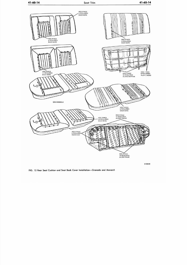
8/20/2019 1977 Ford Car Shop Manual Volume 4 Body
http://slidepdf.com/reader/full/1977-ford-car-shop-manual-volume-4-body 93/449
41-60-14 Seat Trim
41-60-14
HOG RINGS
3 REQUIRED
EACH WIRE
HOG RINGS
18 REQUIRED
ALONG REAR
R1932-B
F IG .
15 Rear Seat Cushion and Seat Back Cover Instal lat ion—Granada and Monarch
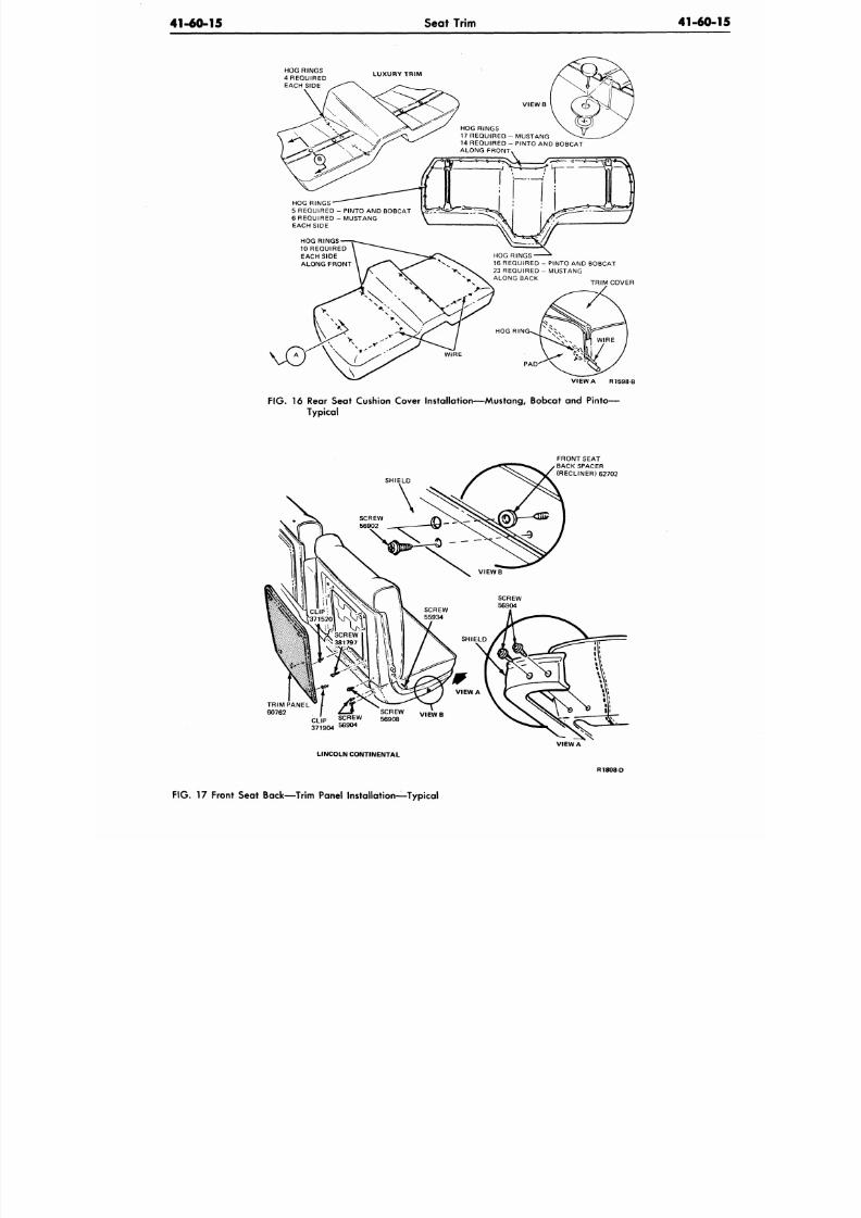
8/20/2019 1977 Ford Car Shop Manual Volume 4 Body
http://slidepdf.com/reader/full/1977-ford-car-shop-manual-volume-4-body 94/449
41-60-15
Seat Trim
41-60-
HOG RINGS
4 REQUIRED
EACH SIDE
LUX URY TR IM
HOG RINGS
5 REQUIRED - PINTO AND BOBCAT
6 REQUIRED - MUSTANG
EACH SIDE
HOG RINGS
1 REQUIRED
EACH SIDE
ALONG FRONT
HOG RINGS
17 REQUIRED - MUSTANG
14 REQUIRED - PINTO AND BOBCAT
ALONG FRONT
HOG RINGS
16 REQUIRED - PINTO AND BOBCAT
23 REQUIRED - M USTANG
ALONG BACK
TRIM COVER
HOG RIN
VIEW A R1598-B
FIG . 16 Rear Seat Cushion Cover Installation—Mustang, Bobcat and Pinto—
Typical
SHIELD
TRIM PANEL
60762
CL
'
P
h ™
S S T
V1EWB
371904
LINCOLN CONTINENTAL
FRONT SEAT
BACK SPACER
(RECLINER) 62702
VIEW A
R1808D
FIG .
17 Front Seat Back—Trim Panel Installation—Typical
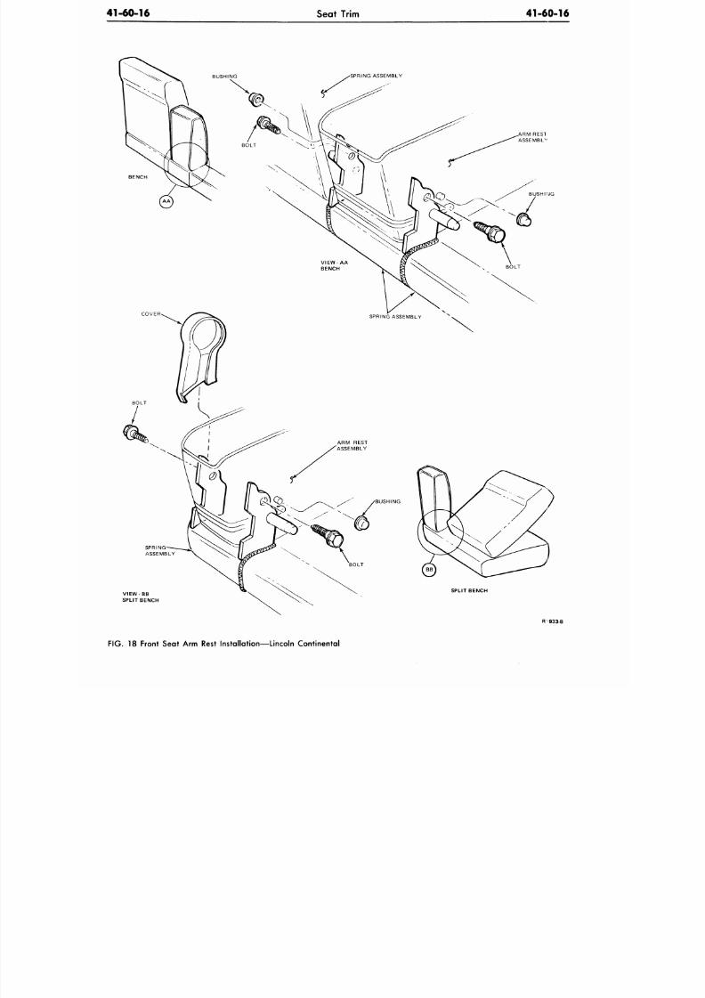
8/20/2019 1977 Ford Car Shop Manual Volume 4 Body
http://slidepdf.com/reader/full/1977-ford-car-shop-manual-volume-4-body 95/449
41-60-16
Seat Trim
41-60-16
PRING ASSEMBLY
VIEW BB
SPLIT BENCH
SPRING ASSE MBLY
BUSHING
SPLIT BENCH
R 933-B
FIG. 18 Front Seat Arm Rest Installation—Lincoln Continental
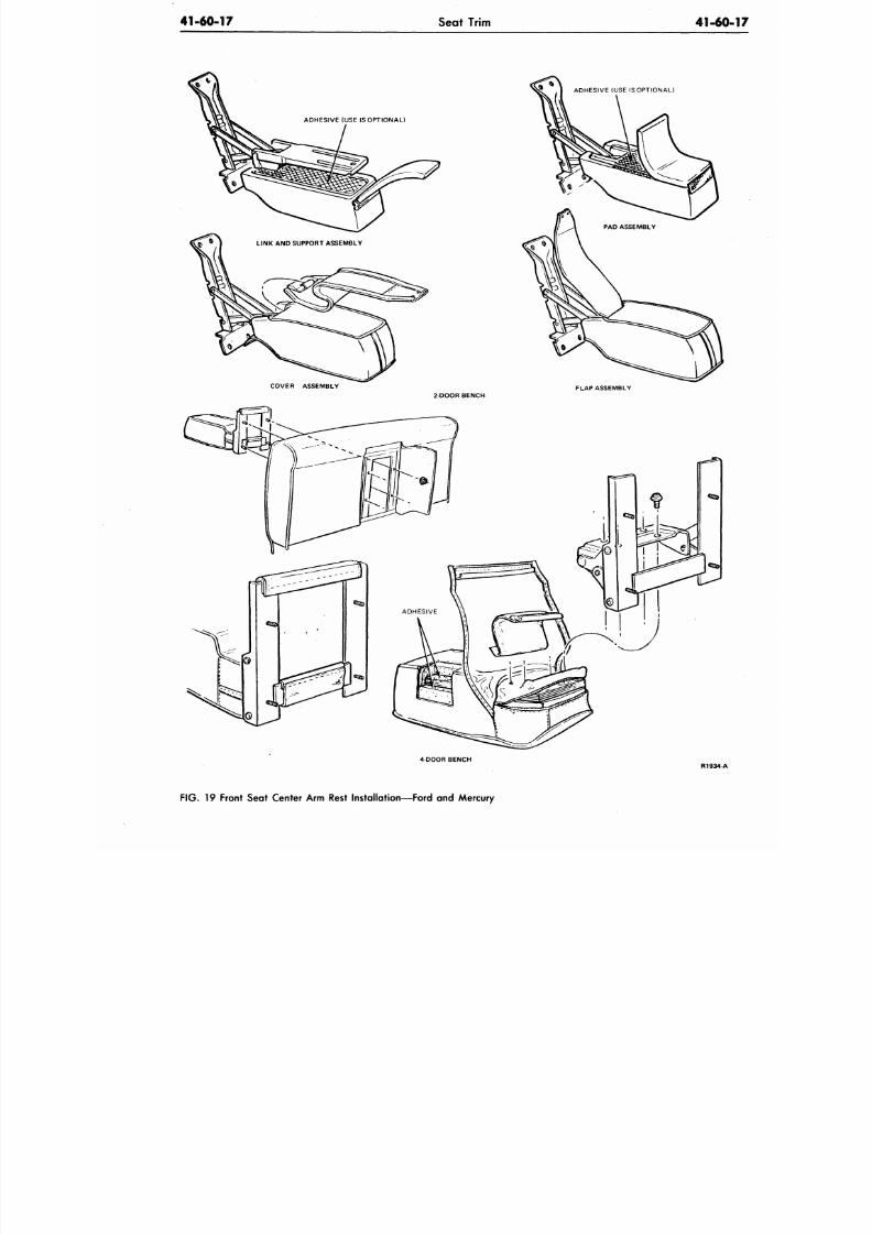
8/20/2019 1977 Ford Car Shop Manual Volume 4 Body
http://slidepdf.com/reader/full/1977-ford-car-shop-manual-volume-4-body 96/449
41-60-17
Seat Trim
41-60
ADHESIVE (USE IS OPTIONAL)
ADHESIVE (USE IS OPTIONAL)
COVER ASSEMBLY
2 DOOR BENCH
FLAP ASSEMBLY
4-DOOR BENCH
R1934-A
F IG .
19 Front Seat Center Arm Rest Installation—Ford and Mercury
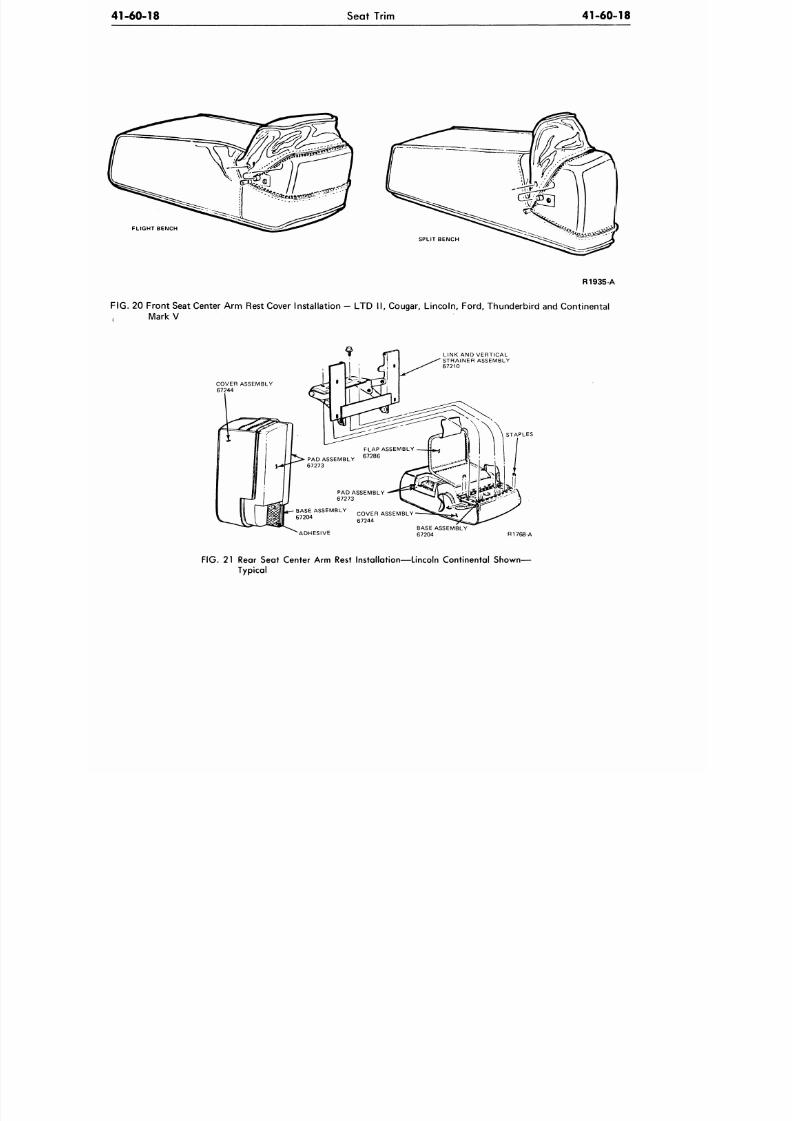
8/20/2019 1977 Ford Car Shop Manual Volume 4 Body
http://slidepdf.com/reader/full/1977-ford-car-shop-manual-volume-4-body 97/449
41-60-18
Seat Trim
41-60-18
FLIGHT BENCH
SPLIT BENCH
R1935-A
FIG.
20 Front Seat Center Arm Rest Cover Installation — LTD II, Cougar, Lincoln, Ford, Thunderbird and Continental
Mark V
COVER ASSEMBLY
67244
LINK AND VERTICAL
STRAINER ASSEMBLY
67210
STAPLES
'ADHESIVE
BASE ASSEMBLY
67204
R1768-A
FIG. 21 Rear Seat Center Arm Rest Installation—Lincoln Continental Shown—
Typical
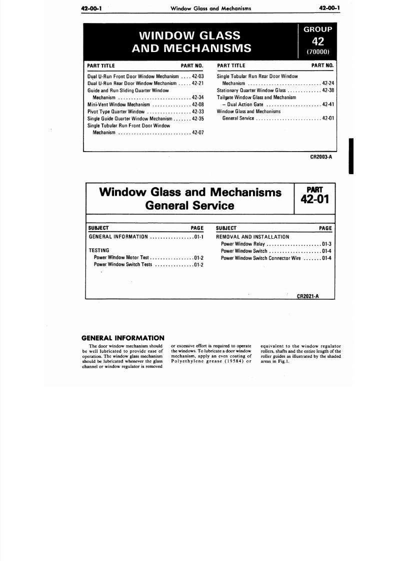
8/20/2019 1977 Ford Car Shop Manual Volume 4 Body
http://slidepdf.com/reader/full/1977-ford-car-shop-manual-volume-4-body 98/449
42-00-1 Window Glass and Mechanisms
42-0
WINDOW GLASS
AND MECHANISMS
G R O U P
(70000)
PART TITL E
Dual U-Run Front Door Window Mechanism
Dual U-Run Rear Door Window Mechanism .
Guide and Run Sliding Quarter Window
Mechanism
Mini-Vent Window Mechanism
Pivot Type Quarter Window
Single Guide Quarter Window Mechanism
Single Tubular Run Front Door Window
Mechanism
PART NO.
. . . . 42 -03
42-21
. . . . 42-34
42-08
. 42-33
42-35
. . . . 42-07
PART TITL E
Single Tubular
Run
Rear Do or W indow
Mechanism
Stationary Quarter Window Glass
Tailgate Window Glass and Mechanism
— Dual Action Gate
Window Glass and Mechanisms
General Service
PART NO
42-
42-3
42-4
42-
CR2003-A
Window Glass and Mechanisms
General
P A R T
42-01
SUBJECT PAGE
GENERAL INFORMATION 01-1
TESTING
Power Window Motor Test
01-2
Power Wind ow Switch Tests 01-2
SUBJECT PAGE
REMOVAL AND INSTALLATION
Power Window Relay 01-3
Power Window Switch
01-4
Power Window Switch Connector Wire 01-
CR2021-A
GENERAL INFORMATION
The door window mechanism should
be well lubricated to provide ease of
operation. The window glass mechanism
should be lubricated whenever the glass
channel or window regulator is removed
or excessive effort is required to operate
the windows. To lubricate a door window
mechanism, apply an even coating of
Polyethylene grease (19584) or
equivalent to the window regu
rollers, shafts and the entire length
roller guides as illustrated by the s
areas in Fig.l.
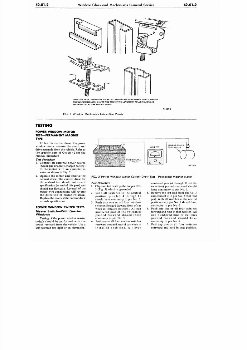
8/20/2019 1977 Ford Car Shop Manual Volume 4 Body
http://slidepdf.com/reader/full/1977-ford-car-shop-manual-volume-4-body 99/449
42-01-2
Window Glass and Mechanisms General Service
42-01-2
APPLY AN EVEN COATING OF POLYETHYLENE GREASE C4AZ-19584-A TO ALL WINDOW
REGULATOR ROLLERS, SHAFTS AND THE ENTIRE LENGTH OF ROLLER GUIDES AS
ILLUSTRATED BY THE SHADED AREAS
FIG. 1 Window Mechanism Lubrication Points
N1607-D
TESTING
P OW E R W I N D O W M O T O R
TEST—PERMANENT MAGNET
TYPE
To test the current draw of a power
window motor, remove the motor and
drive assembly from the vehicle. Refer to
the specific part of Group 42 for the
removal procedure.
Test Procedure
1. Connect an external power source
(power-pac or a fully charged ba ttery)
to the motor with an ammeter in
series as shown in Fig. 2.
2. Operate the motor and observe the
current draw. The current draw for
the no-load test should not exceed
specification (at end of this part) and
should not fluctuate. Reversal of the
motor wire connections will reverse
the direction of motor rotation.
Replace the motor if the current draw
exceeds specification.
POWER W INDOW SWITCH TESTS
Master Switch—With Quarter
Windows
Testing of the power window master
switch should be performed with the
switch removed from the vehicle. Use a
self-powered test light or an ohmmeter.
N2-70-B
FIG. 2 Power Window Motor Current Draw Test—Permanent Magnet Motor
Test
Procedure
1. Clip one test lead probe on pin No.
3 (Fig. 3) which is grounded.
2. With all switches in the neutral
position, pins No. 4 through 11
should have continuity to pin No. 3.
3. Push any one or all four window
switches forward (toward front of car
when in installed position). All odd
numbered pins of the switch(es)
pushed forward should loose
continuity to pin No. 3.
4.
Push any or all four window switches
rearward (toward rear of car when in
in s ta l l ed pos i t ion ) . A l l even
6.
numbered pins (4 through 11) of the
switch(es) pushed rearward should
loose continuity to pin No. 3.
Remove the test lead from pin No. 3
and connect it to pin No. 2 (hot feed
pin).
With all switches in the neutral
position, only pin No. 1 should have
continuity to pin No. 2.
Push any one or all four switches
forward and hold in that position. All
odd numbered pins of switches
pus hed fo rw ard s hou ld have
continuity to pin No. 2.
Pull any one or all four switches
rearward and hold in that position.
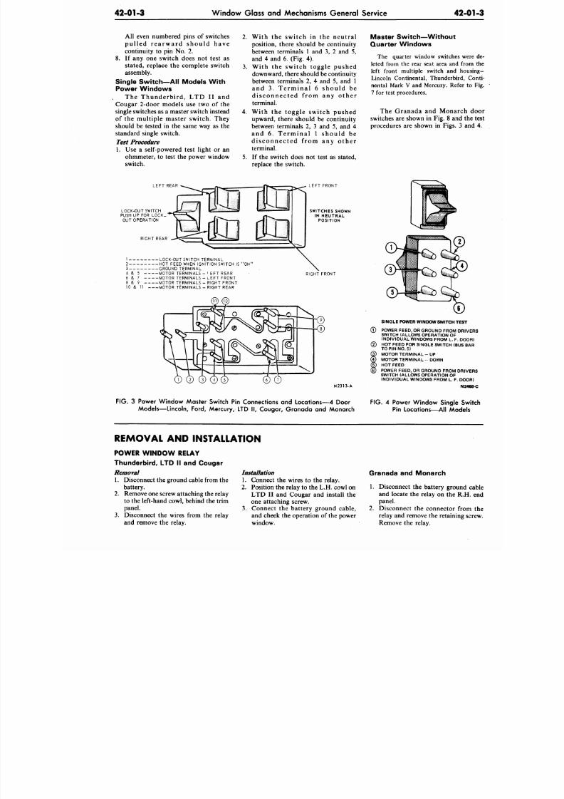
8/20/2019 1977 Ford Car Shop Manual Volume 4 Body
http://slidepdf.com/reader/full/1977-ford-car-shop-manual-volume-4-body 100/449
42-01-3
W indow Glass and Mechanisms Ge neral Service
42-0
All even numbered pins of switches
pu l l ed r ea rw ard s hou ld have
continuity to pin No. 2.
8. If any one switch does not test as
stated, replace the complete switch
assembly.
Single Switch—AH Models With
Power Windows
The Thunderbird , LTD II and
Cougar 2-door models use two of the
single switches as a master switch instead
of the multiple master switch. They
should be tested in the same way as the
standard single switch.
Test
Procedure
1. Use a self-powered test light or an
ohmmeter, to test the power window
switch.
2.
With the switch in the neutral
position, there should be continuity
between terminals 1 and 3, 2 and 5,
and 4 and 6. (Fig. 4).
3. With the switch toggle pushed
downward, there should be continuity
between terminals 2, 4 and 5, and 1
and 3 . Te rm ina l 6 s hou ld be
d i s connec ted f rom any o the r
terminal.
4. With the toggle switch pushed
upward, there should be continuity
between terminals 2, 3 and 5, and 4
and 6 . Te rm ina l 1 s hou ld be
d i s connec ted f rom any o the r
terminal.
5.
If the switch does not test as stated,
replace the switch.
Maste r Swi tch—Wi thou t
Quar te r Windows
The quarter window switches we
leted from the rear seat area and from
left front multiple switch and hou
Lincoln Continental, Thunderbird, C
nental Mark V and Mercury. Refer to
7 for test procedures.
The Granada and Monarch
switches are shown in Fig. 8 and th
procedures are shown in Figs. 3 an
LEFT REAR
LOCK-OUT SWITCH
PUSH UP FOR LOCK_
OUT OPERATION
RIGHT REAR
1 LOCK-OUT SWITCH TERMINAL
2 HOT FEED WHEN IGNITION SWITCH IS "O N'
3 GROUND TERMINA L
4 & 5 MOTOR TERMINALS - I EFT REAR
6 & 7 MOTOR TE RM INA LS -LE FT FRONT
8 & 9 MOTOR TER MINA LS-R IGHT FRONT
10 & 11 MOTOR TERMINALS - RIGHT REAR
LEFT FRONT
SWITCHES SHOWN
IN NEUTRAL
POSITION
RIGHT FRONT
N2313-A
SINGLE POWER WINDOW SW ITCH TEST
© POWER FEED, OR GROUND FROM DRIV
SWITCH (ALLOWS OPERATION OF
INDIVIDUAL WINDOWS FROM L. F. DOO
(2) HOT FEED FOR SINGLE SWITCH (BUS BA
TO PIN NO. 5)
@ MOTOR TERM INAL - UP
0 MOTOR TERMINA L - DOWN
© HOT FEED
© POWER FEED. OR GROUND FROM DRIVE
SWITCH (ALLOWS OPERATION OF
INDIVIDUAL WINDOWS FROM L. F. DOO
N246
FIG. 3 Power Window Master Switch Pin Connections and Locations—4 Door
Models—Lincoln, Ford, Mercury, LTD II, Cougar, Granada and Monarch
FIG. 4 Power Window Single Sw
Pin Locations—All Models
REMOVAL AND INSTALLATION
POWER W IND OW RELAY
Thunderbird, LTD II and Cougar
Removal
1. Disconnect the ground cable from th e
battery.
2.
Remove one screw attaching the relay
to the left-hand cowl, behind the trim
panel.
3. Disconnect the wires from the relay
and remove the relay.
Installation
1. Connect the wires to the relay.
2.
Position the relay to the L.H. cowl on
LTD II and Cougar and install the
one attaching screw.
3. Connect the battery ground cable,
and cheek the operation of the power
window.
Granada and Monarch
1. Disconnect the battery ground
and locate the relay on the R.H.
panel.
2. Disconnect the connector from
relay and remove the retaining sc
Remove the relay.
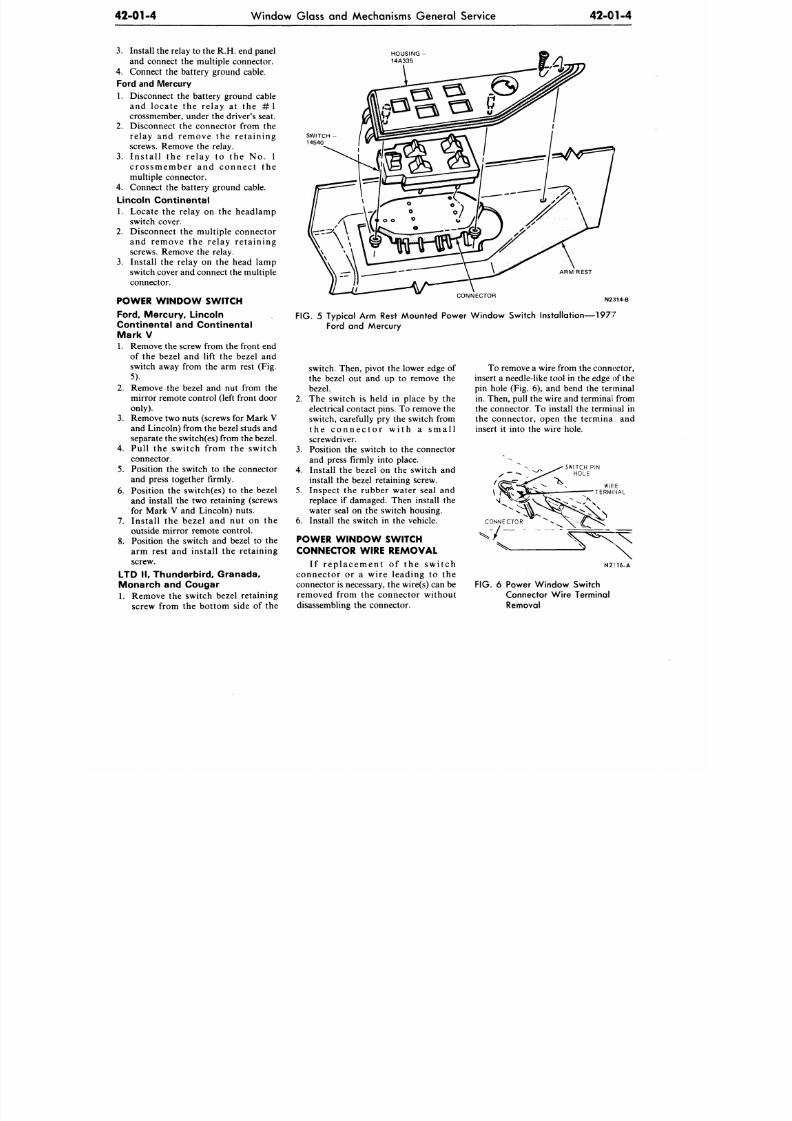
8/20/2019 1977 Ford Car Shop Manual Volume 4 Body
http://slidepdf.com/reader/full/1977-ford-car-shop-manual-volume-4-body 101/449
42-01-4
W indow Glass and Mechanisms Gen eral Service
42-01-4
3. Install the relay to the R.H. end panel
and connect the multiple connector.
4.
Connect the battery ground cable.
Ford and Mercury
1. Disconnect the battery ground cable
and locate the relay at the # 1
crossmember, under the driver's seat.
2.
Disconnect the connector from the
relay and remove the retaining
screws. Remove the relay.
3. In sta ll the relay to the No. 1
crossmember and connect the
multiple connector.
4.
Connect the battery ground cable.
Lincoln Continental
1.
Locate the relay on the headlamp
switch cover.
2. Disconnect the multiple connector
and remove the relay retaining
screws. Remove the relay.
3. Install the relay on the head lamp
switch cover and connect the multiple
connector.
P OWE R W INDO W S WITCH
Ford,
Mercury, Lincoln
Continental and Continental
M a r k V
1. Remove the screw from the front end
of the bezel and lift the bezel and
switch away from the arm rest (Fig.
5).
2. Remove the bezel and nut from the
mirror remote control (left front door
only).
3.
Remove two nuts (screws for Mark V
and Lincoln) from the bezel studs and
separate the switch(es) from the bezel.
4.
Pull the switch from the switch
connector.
5.
Position the switch to the connector
and press together firmly.
6. Position the switch(es) to the bezel
and install the two retaining (screws
for Mark V and Lincoln) nuts.
7. Install the bezel and nut on the
outside mirror remote control.
8. Position the switch and bezel to the
arm rest and install the retaining
screw.
LTD I I , Thunderbird, Granada,
Monarch and Cougar
1. Remove the switch bezel retaining
screw from the bottom side of the
HOUSING
14A335
ARM REST
CONNECTOR
FIG. 5 Typical Arm Rest Mounted Power Window Switch Installation—1977
Ford and Mercury
switch. Then, pivot the lower edge of
the bezel out and up to remove the
bezel.
2. The switch is held in place by the
electrical contact pins. To remove the
switch, carefully pry the switch from
t h e c o n n e c t o r w i t h a s m a l l
screwdriver.
3. Position the switch to the connector
and press firmly into place.
4.
Install the bezel on the switch and
install the bezel retaining screw.
5.
Inspect the rubber water seal and
replace if damaged. Then install the
water seal on the switch housing.
6. Install the switch in the vehicle.
P OWE R W INDO W S WITCH
CONNECTOR WIRE REMOVAL
I f replacement of the switch
connector or a wire leading to the
connector is necessary, the wire(s) can be
removed from the connector without
disassembling the connector.
To remove a wire from the connector,
insert a needle-like tool in the edge of the
pin hole (Fig. 6), and bend the terminal
in. Then, pull the w ire and terminal from
the connector. To install the terminal in
the connector, open the terminal and
insert it into the wire hole.
N2H6-A
FIG. 6 Power Window Switch
Connector Wire Terminal
Removal
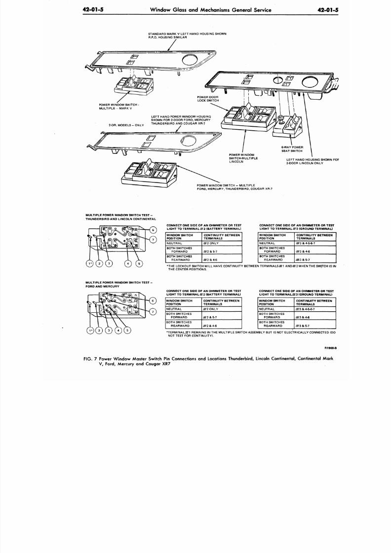
8/20/2019 1977 Ford Car Shop Manual Volume 4 Body
http://slidepdf.com/reader/full/1977-ford-car-shop-manual-volume-4-body 102/449
42-01-5
Window Glass and Mechanisms General Service
42-
STANDARD MARK V LEFT HAND HOUSING SHOWN
R.P.O. HOUSING SIMILAR
POWER DOOR
LOCK SWITCH
POWER WINDOW SWITCH
MULTIPLE - MARK V
2-DR. MODELS-ONLY
LEFT HAND POWER WINDOW HOUSING
SHOWN FOR 2-DOOR FORD, MERCURY
THUNDERBIRD AND COUGAR XR-7
POWER WINDOW
SWITCH-MULTIPLE
LINCOLN
POWER WINDOW SWITCH - MULTIPLE
FORD, MERCURY, THUNDERBIRD, COUGAR XR-7
LEFT HAND HOUSING SHO
2-DOOR LINCOLN ONLY
MULTIPLE POWER WINDOW SWITCH TEST -
THUNDERBIRD AND LINCOLN CONTINENTAL
CONNECT ONE SIDE OF AN OHMMETER OR TEST
LIGHT TO TERMINALS (BATTERY TERMINAL)
WINDOW SWITCH
POSITION
NEUTRAL
BOTH SWITCHES
FORWARD
BOTH SWITCHES
REARWARD
CONTINUITY BETWEEN
TERMINALS
#2 ONLY
# 2
5-7
# 2 & 4 - 6
CONNECT ONE SIDE OF AN OHMMETER OR
LIGHT TO TERMINALS (GROUND TERMI
WINDOW SWITCH
POSITION
NEUTRAL
BOTH SWITCHES
FORWARD
BOTH SWITCHES
REARWARD
CONTINUITY BETW
TERMINALS
# 3 & 4-5-6-7
#3&4-6
•#3
&
5-7
•THE LOCKOUT SWITCH WILL HAVE CONTINUITY BETWEEN TERMINALS-8M AND#2 WHEN THE SWITC
THE CENTER POSITIONS.
MULTIPLE POWER WINDOW SWITCH TEST
FORD AND MERCURY
o
CONNECT ONE SIDE OF AN OHMMETER OR TEST
LIGHT TO TERMINALS (BATTERY TERMINAL)
WINDOW SWITCH
POSITION
NEUTRAL
BOTH SWITCHES
FORWARD
BOTH SWITCHES
REARWARD
CONTINUITY BETWEEN
TERMINALS
#2 ONLY
#2
5-7
* t 2 & 4 - 6
CONNECT ONE SIDE OF AN OHMMETER OR
LIGHT TO TERMINAL#3 (GROUND TERMIN
WINDOW SWITCH
POSITION
NEUTRAL
BOTH SWITCHES
FORWARD
BOTH SWITCHES
REARWARD
CONTINUITY BETW
TERMINALS
4t3
& 4-5-6-7
4*3 8.4-6
# 3
&
5-7
•TERMI NAL REMAINS IN THE MULTIPLE SWITCH ASSEMBLY BUT IS NOT ELECTRICALLY CONNECTE
NOT TEST FOR CONTINUITY).
R
FIG. 7
Power W indo w M aster Switch
Pin
Connections
and
Locations Thunderbird, Lincoln Continental, Continental M
V, Ford, Mercury and Cougar XR7
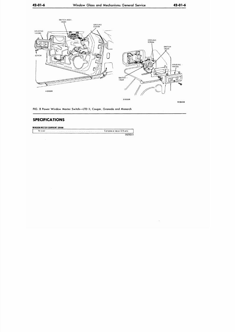
8/20/2019 1977 Ford Car Shop Manual Volume 4 Body
http://slidepdf.com/reader/full/1977-ford-car-shop-manual-volume-4-body 103/449
42-01-6
W indow Glass and Mechanisms Ge neral Service 42-011-6
SWITCH ASSY.
14540
HOUSING
14A355
if
V 1
4 DOOR
GROUND
SCREW
GROUND
SCREW
SWITCH
14529
FIG.
8
Power W indow Master Switch—LTD
II,
Cougar, Gran ada
and
Monarch
R1969-B
SPECIFICATIONS
WINDOW MOTOR CURRENT ORAW
No Load
.
5 amperes or less at 12.8 v olts
CN2433-A
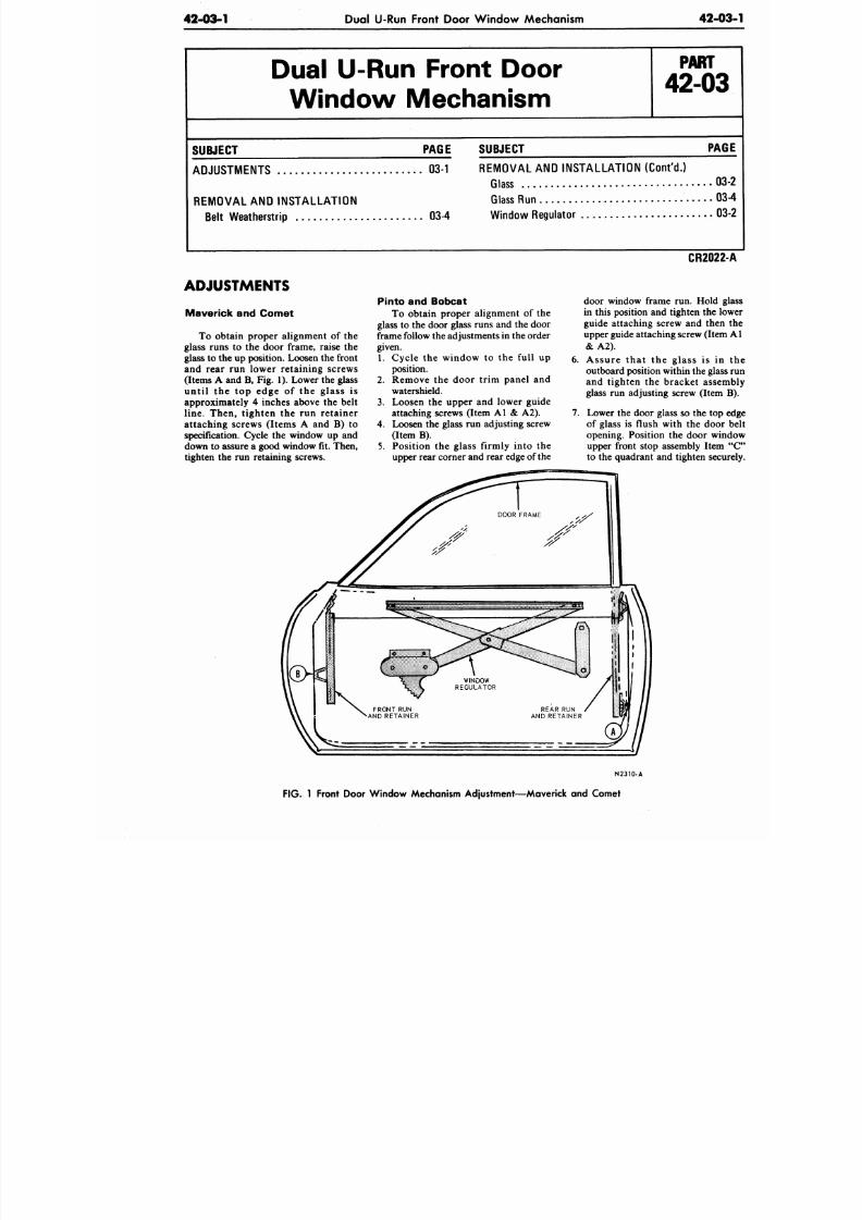
8/20/2019 1977 Ford Car Shop Manual Volume 4 Body
http://slidepdf.com/reader/full/1977-ford-car-shop-manual-volume-4-body 104/449
42-03-1
Dual
U-Run
Front Door Win dow Mechanism
42-
Dual U-Run Front Door
Window Mechanism
P A R T
42-03
SUBJECT
ADJUSTMENTS
03-1
REMOVAL AND INSTALLATION
Belt Weatherstrip
PAGE SUBJECT PA
REMOVAL
AND
INSTALLA TION (Cont'd.)
Glass 0
Glass Run 0
03-4 Windo w Regulator 0
ADJUSTMENTS
Maverick and Comet
To obtain proper alignment of the
glass runs to the door frame, raise the
glass to the up position. Loosen the front
and rear run lower retaining screws
(Items A and B, Fig. 1). Lower the glass
until the top edge of the glass is
approximately 4 inches above the belt
line. Then, tighten the run retainer
attaching screws (Items A and B) to
specification. Cycle the window up and
down to assure a good window fit. Then,
tighten the run retaining screws.
Pinto and Bobcat
To obtain proper alignment of the
glass to the door glass runs and the door
frame follow the adjustments in the order
given.
1. Cycle the window to the full up
position.
2. Remove the door trim panel and
watershield.
3. Loosen the upper and lower guide
attaching screws (Item A l & A2).
4. Loosen the glass run adjusting screw
(Item B).
5. Position the glass firmly into the
upper rear corner and rear edge of the
CR202
door window frame run. Hold
in this position and tighten the
guide attaching screw and the
upper guide attaching screw (Ite
& A2).
6. Assure that the glass is i
outboard position within the gla
and tighten the bracket ass
glass run adjusting screw (Item
7. Lower the door glass so the to
of glass is flush with the doo
opening. Position the door w
upper front stop assembly Ite
to the quadrant and tighten sec
N2310-A
FIG. 1 Front Door Window Mechanism Adjustment—Maverick and Comet
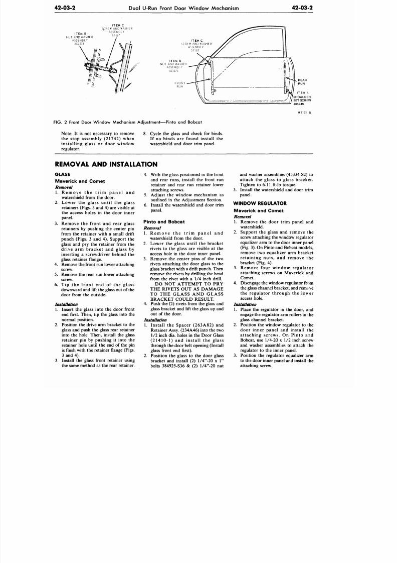
8/20/2019 1977 Ford Car Shop Manual Volume 4 Body
http://slidepdf.com/reader/full/1977-ford-car-shop-manual-volume-4-body 105/449
2-03-2
Dual U-Run Front Door W indow Mechanism
42-03-2
ITEM B
NUT AND WASHER
A S S E M B L Y
383278
ITEM C
S£REW AND WASHER
A S S E M B L Y
57-187
I T E M
C
SCREW AND WASHER
A S S E M B L Y
57487
ITEM B
N U T A N D WA S H E R
A S S E M B L Y
383278
2 Front Door Window Mechanism Adjustment—Pinto and Bobcat
N 2 1 7 E - E
Note: It is not necessary to remove
the stop assembly (21742) when
installing glass or door window
regulator.
8. Cycle the glass and check for binds.
If no binds are found install the
watershield and door trim panel.
REMOVAL AND INSTALLATION
GLASS
Maverick and Comet
Removal
1. R e m o v e t h e t r i m p a n e l a n d
watershield from the door.
2. Lower the glass until the glass
retainers (Figs. 3 and 4) are visible at
the access holes in the door inner
panel.
3. Remove the front and rear glass
retainers by pushing the center pin
from the retainer with a small drift
punch (Figs. 3 and 4). Support the
glass and pry the retainer from the
drive arm bracket and glass by
inserting a screwdriver behind the
glass retainer flange.
Remove the front run lower attaching
screw.
. Remove the rear run lower attaching
screw.
downward and lift the glass out of the
door from the outside.
Installation
1. Insert the glass into the door front
end first. Then, tip the glass into the
normal position.
2. Position the drive arm bracket to the
glass and push the glass rear retainer
into the hole. Then, install the glass
retainer pin by pushing it into the
retainer hole until the end of the pin
is flush with the retainer flange (Figs.
3 and 4).
3. Install the glass front retainer using
the same method as the rear retainer.
4. With the glass positioned in the front
and rear runs, install the front run
retainer and rear run retainer lower
attaching screws.
5.
Adjust the window mechanism as
outlined in the Adjustment Section.
6. Install the watershield and door trim
panel.
Pinto and Bobcat
Removal
1. R e m o v e t h e t r i m p a n e l a n d
watershield from the door.
2. Lower the glass until the bracket
rivets to the glass are visible at the
access hole in the door inner panel.
3. Remove the center pins of the two
rivets attaching the door glass to the
glass bracket with a drift punch. Then
remove the
rivets
by drilling the head
from the rivet with a 1/4 inch drill.
DO NOT ATTEMPT TO PRY
THE RIVETS OUT AS DAMAGE
TO THE GLASS AND GLASS
BRACKET COULD RESULT.
4. Push the (2)
rivets
from the glass and
glass bracket and lift the glass up and
out of the door.
Installation
1. Install the Spacer (263A82) and
Retainer A ssy. (234A46) into the two
1/2 inch dia. holes in the Door Glass
(21410-1) and install the glass
through the door belt opening (Install
glass front end first).
2. Position the glass to the door glass
bracket and install (2) l/4"-20 x 1"
bolts 384925-S36 & (2) l/4"-20 nut
and washer assemblies (45334-S2) to
attach the glass to glass bracket.
Tighten to 6-11 ft-lb torque.
3. Install the watershield and door trim
panel.
W INDOW REGULATOR
Maverick and Comet
Removal
1. Remove the door trim panel and
watershield.
2. Support the glass and remove the
screw attaching the window regulator
equalizer arm to the door inner panel
(Fig. 3). On Pinto and Bobcat models,
remove two equalizer arm bracket
retaining nuts , and remove the
bracket (Fig. 4).
3. Remove four window regulator
attaching screws on Maverick and
Comet.
4.
Disengage the window regulator from
the glass channel bracket, and remove
the regulator through the lower
access hole.
Installation
1. Place the regulator in the door, and
engage the regulator arm rollers in the
glass channel bracket.
2.
Position the window regulator to the
door inner panel and install the
attaching screws. On Pinto and
Bobcat, use 1/4-20 x 1/2 inch screw
and washer assemblies to attach the
regulator to the inner panel.
3. Position the regulator equalizer ami
to the door inner panel and install the
attaching screw.
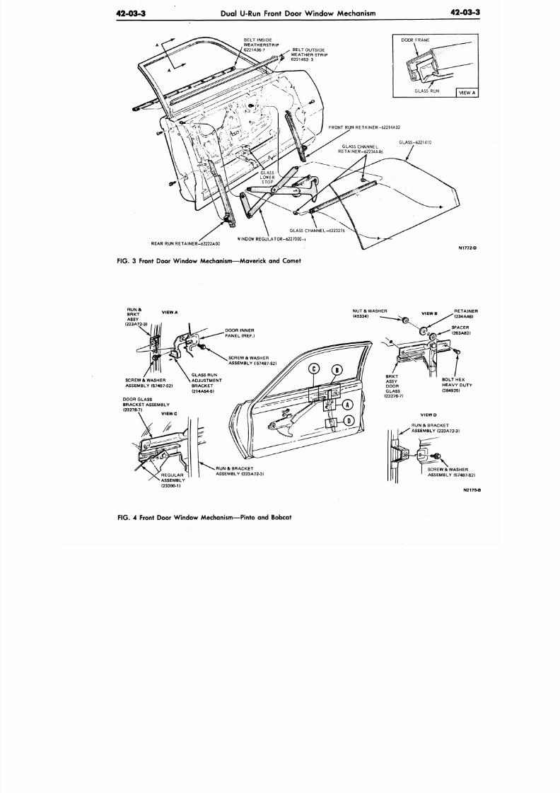
8/20/2019 1977 Ford Car Shop Manual Volume 4 Body
http://slidepdf.com/reader/full/1977-ford-car-shop-manual-volume-4-body 106/449
42-03-3
Dual U-Run Front Door W indo w Mechanism
42-0
BELT INSIDE
WEATHERSTRIP
6221436-7 , BELT OUTSIDE
»>& WEATHER STRIP
6221452-3
DOOR FRAME
GLASS RUN
V |
GLASS CHANNE L
RETAINER-62234A46
GLASS CHANNEL-6223276
WINDOW REGULATOR-6227000..
GLASS-6221410
REAR RUN RETAINER-62222A00
N17
F IG .
3 Front Door Window Mechanism—Maverick and Comet
VIEW A
NU T & WASHER
(45334)
SCREW & WASHER
ASSEMBLY (57487-S2)
DOOR GLASS
BRACKET ASSEMBLY
(23276-7)
V I E W C
DOOR INNER
PANEL (REF.)
SCREW & WASHER
ASSEMBLY (57487-S2)
GLASS RUN
ADJUSTMENT
BRACKET
(214A54-5)
.RUN &
BRACKET
ASSEMBLY (223A72-3)
SCREW & WASHER
ASSEMBLY (57487
N
F IG .
4 Front Door W indow Mechanism—Pinto and Bobcat
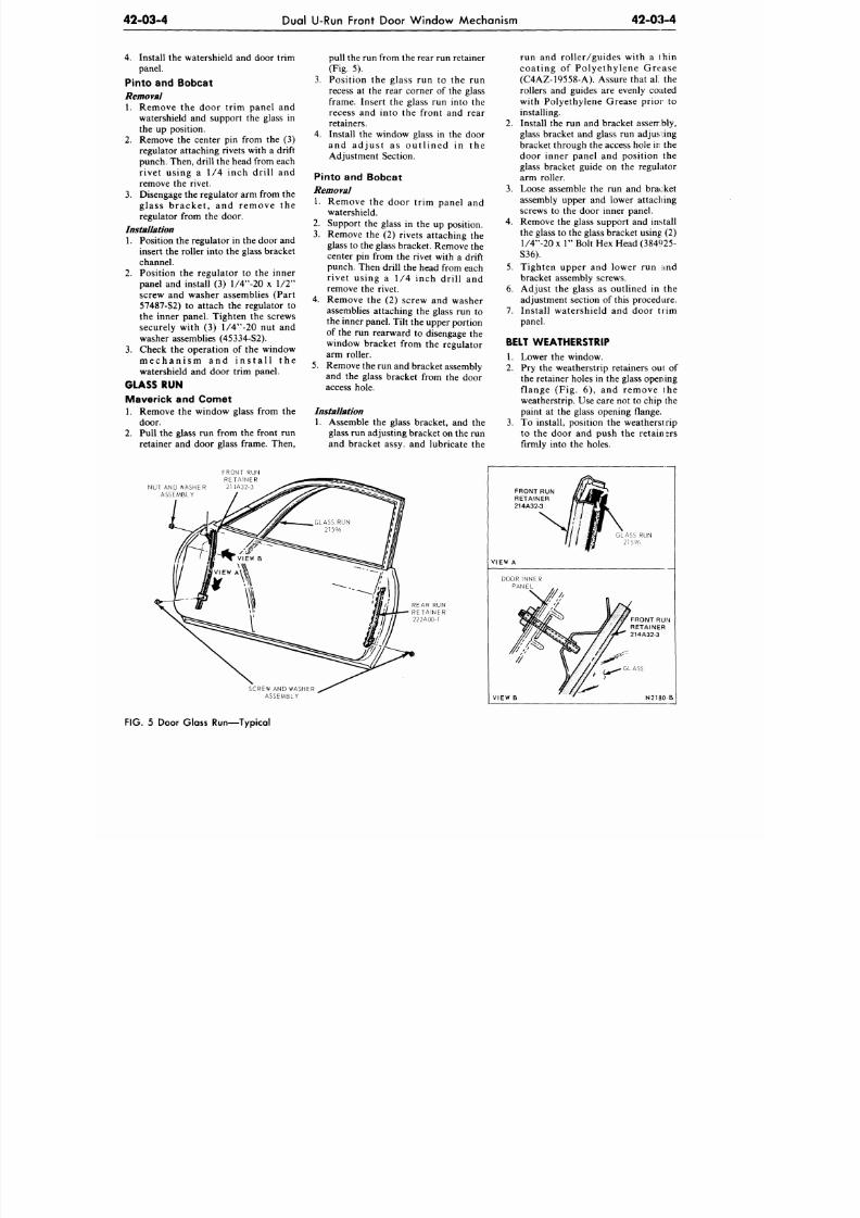
8/20/2019 1977 Ford Car Shop Manual Volume 4 Body
http://slidepdf.com/reader/full/1977-ford-car-shop-manual-volume-4-body 107/449
42-03-4
Dual U-Run Front Door Window Mechanism
42-03-4
4.
Install the watershield and door trim
panel.
Pinto and Bobcat
Removal
1. Remove the door trim panel and
watershield and support the glass in
the up position.
2.
Remove the center pin from the (3)
regulator attaching rivets with a drift
punch. Then, drill the head from each
rivet using a 1/4 inch drill and
remove the rivet.
3. Disengage the regulator arm from the
glass bracket, and remove the
regulator from the door.
Installation
1. Position the regulator in the door and
insert the roller into the glass bracket
channel.
2.
Position the regulator to the inner
panel and install (3) l/4 -20 x 1/2
screw and washer assemblies (Part
57487-S2) to attach the regulator to
the inner panel. Tighten the screws
securely with (3) l/4 -20 nut and
washer assemblies (45334-S2).
3.
Check the operation of the window
mechanism and install the
watershield and door trim panel.
GLASS
RUN
Maverick
and
Comet
1. Remove the window glass from the
door.
2.
Pull the glass run from the front run
retainer and door glass frame. Then,
pull the run from the rear run retainer
(Fig. 5).
3. Position the glass run to the run
recess at the rear corner of the glass
frame. Insert the glass run into the
recess and into the front and rear
retainers.
4. Install the window glass in the door
and adjust as outlined in the
Adjustment Section.
Pinto and Bobcat
Removal
1. Remove the door trim panel and
watershield.
2.
Support the glass in the up position.
3. Remove the (2) rivets attaching the
glass to the glass bracket. Remove the
center pin from the rivet with a drift
punch. Then drill the head from each
rivet using a 1/4 inch drill and
remove the rivet.
4.
Remove the (2) screw and washer
assemblies attaching the glass run to
the inner panel. Tilt the upper portion
of the run rearward to disengage the
window bracket from the regulator
arm roller.
5.
Remove the run and bracket assembly
and the glass bracket from the door
access hole.
Installation
1. Assemble the glass bracket, and the
glass run adjusting bracket on the run
and bracket assy, and lubricate the
run and roller/guides with a thin
coating of Polyethylene Grease
(C4AZ-19558-A). Assure that ali the
rollers and guides are evenly coated
with Polyethylene Grease prior to
installing.
2.
Install the run and bracket assembly,
glass bracket and glass run adjusting
bracket through the access hole in the
door inner panel and position the
glass bracket guide on the regulator
arm roller.
3. Loose assemble the run and bracket
assembly upper and lower attaching
screws to the door inner panel.
4. Remove the glass support and install
the glass to the glass bracket using (2)
l/4 -20 x 1 Bolt Hex Head (384925-
S36).
5. Tighten upper and lower run :ind
bracket assembly screws.
6. Adjust the glass as outlined in the
adjustment section of this procedure.
7. Install watershield and door trim
panel.
BELT WEATHERSTRIP
1. Lower the window.
2.
Pry the weatherstrip retainers out of
the retainer holes in the glass opening
flange (Fig. 6), and remove the
weatherstrip. Use care not to chip the
paint at the glass opening flange.
3. To install, position the weatherstrip
to the door and push the retainers
firmly into the holes.
FRONT
RUN
RETAINER
NUT AND WASHER 21-1A32-3
ASSEMBLY
SCREW
AND
WASHER
ASSEMBLY
VIEW A
VIEW B
N2180
FIG. 5 Door Glass Run—Typical
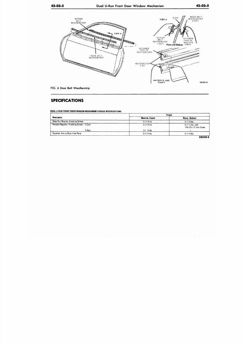
8/20/2019 1977 Ford Car Shop Manual Volume 4 Body
http://slidepdf.com/reader/full/1977-ford-car-shop-manual-volume-4-body 108/449
42-03-5
Dual U-Run Front Door Window Mechanism
42-0
OUTSIDE
BELT
WEATHERSTRIP
VIEW
A
GLASS
INSIDE BELT
WEATHERSTRIP
21436-7
OUTSIDE
BELT
WEATHERSTRIP
21452-3
RETAINER
.
,
(PART OF
/ / WEATHER-
Pinto and Bobcat STRIP)
RETAINER
(PART
OF
WEATHERSTRIP)
WEATHERSTRIP
21452
N2
FIG.
6 Door Belt Weatherstrip
SPECIFICATIONS
DUAL
U-RUN
FRONT DOOR WINDOW MECHANISM TORQUE SPECIFICATIONS
Description
Glass
Run
Retainer Attac hing Screws
Window Regulator Attaching Screws
-
2-Qobr
4-Door
Equalizer Arm
to
Door Inner Panel
Torque
Maverick, Comet
6-11 ft-lbs
6-11 ft-lbs
3-7 ft-lbs
6-11 ft-lbs
Pinto, Bobcat
6-11 ft-lbs
6-11
ft-lbs with
1/4x20x1/2
Inch Sc
6-11 ft-lbs
CN
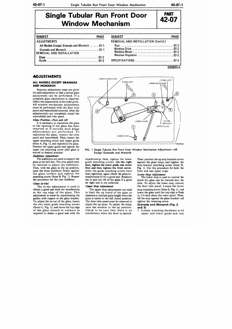
8/20/2019 1977 Ford Car Shop Manual Volume 4 Body
http://slidepdf.com/reader/full/1977-ford-car-shop-manual-volume-4-body 109/449
42-07-1
Single Tubular Run Front Door W indo w Mechanism
4 2 - 0 7 - 1
Single Tubular Run Front Door
Window Mechanism
P A R T
42-07
S U B JE C T P A G E
ADJUSTMENTS
All Models Except Granada and Monarch 07-1
Granada and Monarch 07-1
REMOVAL AND INST ALLATION
Glass 07-2
Guide 07-2
S U B JE C T P A G E
REMOVAL AND INSTALLATION (Con t 'd . )
Run 07-2
Window Drive 07-2
Window Mo tor 07-2
Window Regulator 07-2
SPECIFICATIONS 07-4
CR2023-A
ADJUSTMENTS
ALL MODELS EXCEPT GRANADA
AND MONARCH
Separate adjustment steps are given
for each adjustment so that a partial glass
adju stme nt can be performe d. If a
complete glass adjustment is required,
follow the ad justments in the order given.
All window mechanism adjustments
must be performed with the door trim
panel and w atershield removed. After the
adjustment(s) are completed, install the
watershield and trim panel.
Glass Position—Fore and Aft
It is necessary to reposition the glass
in the opening if the glass has been
removed or if extreme door hinge
a d j u s t m e n t s a r e p e r f o r m e d . T o
reposition the glass, remove the trim
panel and watershield. Then, loosen the
upper attaching screw and upper guide
(Item A, Fig. 1), and reposition the glass.
Position the upper guide and tighten the
upper run attaching screw after glass is
moved to desired position.
Stabilizer Adjustment
The stabilizers are used to support th e
glass at the belt line. The trim panel must
be removed to adjust the stabilizers.
Then, with the glass in the up position,
push the front stabilizer firmly against
the glass surface and t ighten the
attaching screw (Item B, Fig. 1). Repeat
the procedure for the rear stabilizer.
Glass In-Out
The in-out adjustment is used to
obtain a good seal with the weatherstrip
at the top edge of the glass. This
adjustment is made by repositioning the
guides with respect to the glass bracket.
To adjust the in-out of the glass, loosen
the two lower guide attaching screws
(Items C , Fig. 1), and move the top edge
of the glass inward or outward as
required to obtain a good seal with the
UPPER FRONT STOP
STABIL IZER
/GLASS
/ BRACKET
UPPER GUIDE
LOWER STOP
N2305-D
FIG.
1 Single Tubular Run Front Door W indow Mechanism Adjustment— All
Except Granada and Monarch
weatherstrip; then, tighten the lower
guide attaching screws.
On the right
door, tighten the lower guide rear screw
first and then tighten the front screw.
After the guide attaching screws have
been tightened, again check the glass-to-
weatherstrip fit for a good seal. Readjust
the in and out tilt of the glass if a good
air tight seal is not achieved.
Upper
Stop
Adjustment
The upper stop adjustments are used
to limit the up travel of the glass to
maintain
a
constant g lass height when the
glass is raised to the full closed position.
The door trim panel must be removed to
adjust the up stops. To adjust the stops,
raise the window to the up position.
Check to be sure that there is no
interference when the door is
#
opened.
Then, position the up stop brackets down
against the glass stops, and tighten the
stop bracket attaching screw (Item D,
Fig. 1). Use this procedure for both the
front and rear upper stops.
Lower
Stop
Adjustment
The lower stop is used to control the
depth the glass can be lowered into the
door. To adjust the lower stop, remove
the door trim panel. Loosen the lower
stop retaining screw (Item E, Fig. 1), and
lower the glass until the top edge is flush
to 1/4 inch above the outer panel. Then,
lift the stop against the glass bracket and
tighten the retaining screw.
Granada and Monarch (Fig. 2
and 3)
1. Loosen attaching hardware until
upper and lower guide and rear
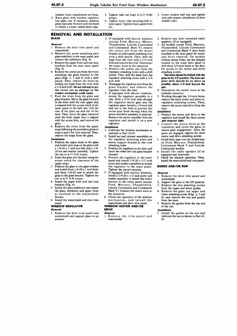
8/20/2019 1977 Ford Car Shop Manual Volume 4 Body
http://slidepdf.com/reader/full/1977-ford-car-shop-manual-volume-4-body 110/449
424)7-2 Single Tubular
Run
Front Door W indo w Mechanism
42-
retainer lower attachments are loose.
2.
Raise glass with window regu lator
into glass run. If necessary, position
glass manually forward and rearward
to obtain a proper sealed glass edge.
3. Tighten tube nut (top) to 6-11 ft-lbs
torque.
4. Tighten lower tube attaching bolt to
inner panel. Tighten lower guide bolts
(2).
5. Lower window half way and
lock side retainer attachment (
models only).
REMOVAL AND INSTALLATION
GLASS
Removal
1.
Remove
the
door trim panel
and
watershield.
2.
Remove one screw attaching each
glass stabilizer to the inner panel, and
remove the stabilizers (Fig. 4).
3. Remove the upper front and rear stop
brackets from the door inner panel
(Fig. 4).
4.
Remove the center pin from the rive ts
attaching the glass bracket to the
glass (Figs.
2, 3 and 4)
with
a
drift
punch. Then, remove the rivets by
drilling the head from the rivet with
a 1/4 inch drill. Do
not
attempt to
pry
the rivets
out as
damage
to the
window mechanism could result.
5. Push the rivets from the glass and
glass bracket. Move the glass forward
in the door until the rear upper stop
is aligned with the access notch in the
inner panel at the belt line. Lift the
rear
of the
glass
up and out of the
door. Then, move the glass rearward
until the front upper stop is aligned
with the access hole, and remove the
glass.
6. Remove
the
rivets from
the
upper
stops following the procedure given in
steps 4 and 5 for rivet removal. Then,
remove
the
stops from
the
glass.
Installation
1.
Position
the
upper stops
to the
glass
and install each stop on the glass with
a 1/4-20 x 1 inch hex bolt and a 1/4-
20 nut and washer assembly. Tighten
the nut to 6-11 ft-lb torque.
2.
Insert the glass into the door using the
access notch for clearance of the
upper stops.
3. Position the glass to the glass bracket
and install three 1/4-20 x 1 inch bolts
and three 1/4-20 nuts to attach the
glass
to
the glass bracket. T ighten
the
nut to 6-11 ft-lb torque.
4. Install
the
upper front
and
rear stop
brackets (Fig. 4).
5.
Install the glass stabilizers and adjust
the glass, stabilizers
and
upper stops
as out l ined in the A d jus tmen t
Section.
6. Install the watershield and door trim
panel.
W IND OW REGULATOR
Removal
1. Remove the door trim panel and
watershield and support glass in up
position.
2. If equipped with electric windows
(except Ford, Mercury, Meteor,
Thunderbird, Lincoln Continental
and Continental Mark V), remove
the center pin from the mo to r
bracket-to-inner panel attaching rivet
with a drift punch. Then, drill the
head from the rivet with a 1/4 inch
drill and remove the rivet. Disconnect
the motor wires
at the
connector.
3. Remove the center pin from the
regulator attaching rivets with a drift
punch. Then, drill the head from the
regulator attaching rivets with a 1/4
inch drill.
4.
Disengage the regulator arm from the
glass bracket , and remove the
regulator from
the
door.
5. If equipped with electric windows,
mount the regulator assembly in a
vise. Drill a 5/16 inch hole through
the regulator sector gear and the
regulator plate. Install a 1/4 inch bolt
and nut in the hole to prevent the
sector gear from moving when the
motor and drive assembly is removed.
Remove the motor assembly from
the
regulator and install it on a new
regulator.
Installation
1. Lubricate the window mechanism as
outlined in Part 42-01.
2. Install
nut and
retainer assemblies
on
the regulator mounting plate and
motor support bracket at the rivet
attaching holes.
3. Position the regulator in the door and
insert
the
roller into
the
glass bracket
channel.
4.
Position the regulator to the inner
panel and install 1/4-20 x 1/2 inch
screw and washer assemblies to attach
the regulator to the inner panel.
Tighten the screws securely.
5.
If equipped with electric windows,
install a 1/4-20 x 1/2 inch screw and
washer assembly to attach the motor
bracket
to the
inner panel (except
F o r d , M e r c u r y , T h u n d e r b i r d ,
Lincoln Continental and Continental
Mark
V).
Connect the motor wires at
the connector.
6. Check the operation of the window
m e c h a n i s m ,
and
i n s t a l l
the
watershield and door trim panel.
W I N D O W M O T O R A N D / O R
DRIVE
Removal
1. Remove the
watershield.
t r i m p a n e l and
2.
Remove any door mounted
speakers,
(if
so equipped).
3.
All
models except Ford, Me
Thunderbird, Lincoln Conti
and Continental Mark V have
punched in the door panel for
and dr ive removal .
On
m
without access holes, use the d
located on the inner door pa
drill three 3/4 inch holes in th
for access to the motor and
attaching screws.
The holes should be drilled
glass in the U P position. The h
pilot drill should
be as
sh
possible, about
1/4
inch beyo
saw.
4. Disconnect
the
motor wires
multiple connector.
5.
Working through the 3/4 inch
remove the three motor and dr
regulator attaching screws.
remove the motor
and
drive fro
door.
Installation
1. Position the motor and drive
regulator and install the three
just snug-not tight.
2.
Connect the motor wires
connector and cycle the gl
assure gear engagement. Aft
gears are engaged, tighten th
motor
and
drive attaching scr
3. Install body tape over the drille
on Ford, Mercury, Thunde
Continental Mark V and L
Continental models.
4.
Ins ta l l the radio speaker
equipped and removed).
5.
Check the window operation.
install the watershield and trim
GUIDES A N D / O R RUN
Removal
1. Remove the door trim pane
watershield.
2. Support
the
glass
in the UP
po
3. Remove the two attaching s
from the upper and lower gui
4.
Remove the glass run uppe
lower attaching screw (Figs.
2
4) , and remove the run and
from the door.
5.
Remove the guides from the t
of the run.
Installation
1. Install the guides on the ru
lubricate the run as shown in P
01.
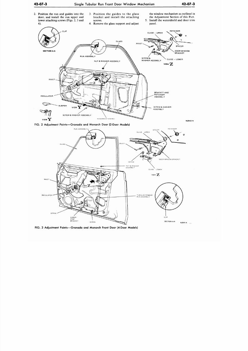
8/20/2019 1977 Ford Car Shop Manual Volume 4 Body
http://slidepdf.com/reader/full/1977-ford-car-shop-manual-volume-4-body 111/449
Single Tubular Run Front Door W indo w Mechanism
42-07-3
Position the run and guides into the 3. Po sition the gu ides to the glass
door, and install the run upper and brack et and install the attac hin g
lower attaching screws (Figs. 2, 3 and screws.
4). 4. Remove the glass support and adjust
the window mechanism as outlined in
the Adjustment Section of this Part.
5. Install the watershield and door trim
panel.
RETAINER
SCREW & WASHER
ASSEMBLY
1UN & BHACKET ASSEMBL
SCREW & WASHER ASSEMBLY
VIEW Y ^
FIG.
2 Adjustment Points—Granada and Monarch Door (2-Door Models)
RUN ASSEMBLY
N2542 A
REGULATOR
LOWER
STOP
BRACKET
FIG. 3 Adjustment Points—Granada and Monarch Front Door (4-Door Models)
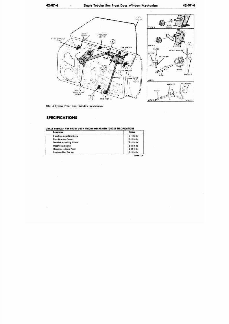
8/20/2019 1977 Ford Car Shop Manual Volume 4 Body
http://slidepdf.com/reader/full/1977-ford-car-shop-manual-volume-4-body 112/449
42-07-4
Single Tubular Run Front Door W indo w Mechanism
42-07
STOP BRACKET
21742
SEE VIEW A
F IG . 4 Typical Front Door Win dow Mechanism
SPECIFICATIONS
VIEW A
VIEW B
RIVET
VIEW C
WASHER RETAINER
RIVET
V I E W D
N2473
SINGLE TUBULAR RUN FRONT DOOR WINDOW MECHANISM TORQUE SPECIFICATIONS
Description
Glass Stop Attaching Screw
Run Attach ing Screws
Stabilizer Attach ing Screws
Upper Stop Bracket
Regulator-to-lnner Panel
Guide-to-Glass Bracket
Torque
6-11 ft-lbs
6-11 ft-lbs
6-11 ft-lbs
6-11 ft-lbs
6-11 ft-lbs
6-11 ft-lbs
CN2437-B
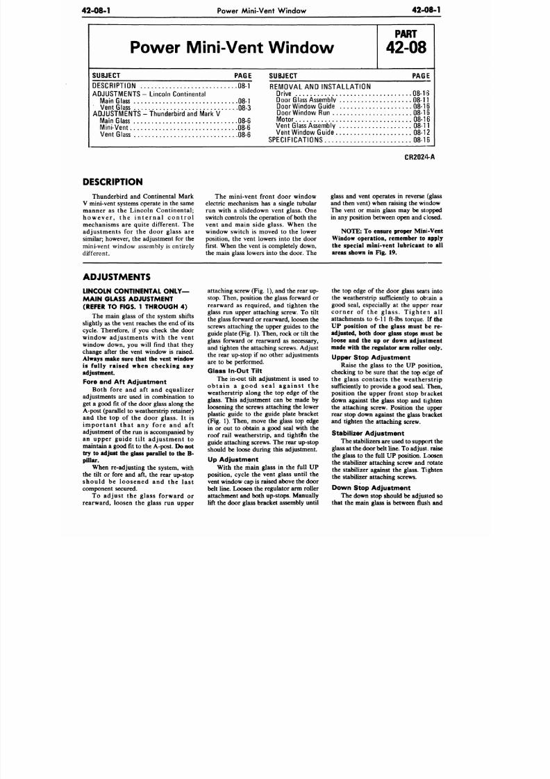
8/20/2019 1977 Ford Car Shop Manual Volume 4 Body
http://slidepdf.com/reader/full/1977-ford-car-shop-manual-volume-4-body 113/449
42-08-1
Power Mini-Vent Window
42-08-1
Power Mini-Vent Window
P A R T
42-08
SUBJECT PAGE
DESCRIPTION 08-1
ADJUSTMENTS- Lincoln Cont inental
Mam Glass 08-1
Vent Glass 08-3
ADJUSTMENTS - Thunderbird and Mark V
Main Glass 08-6
Mini-Vent 08-6
Vent Glass 08-6
SUBJECT PAGE
REMOVAL
AND
INSTALLATION
Drive 08-H3
Doo r Glass Assem bly
08-11
Door Window Guide
08-16
Door Window Run 08-16
Motor
08-16
Vent Glass Assembly
08-11
Vent Window Guide 08-12
SPECIFICATIONS
08-16
CR2024-A
DESCRIPTION
Thunderbird
and
Continental Mark
V mini-vent systems operate in the same
manner
as the
Lincoln Continental;
h o w e v e r ,
the
i n t e r n a l c o n t r o l
mechanisms
are
quite different.
The
adjus tments
for the
door glass
are
similar; however, the adjustment for the
mini-vent window assembly is entirely
different.
The mini-vent front door window
electric mechanism has a single tubular
run with
a
slidedown vent glass.
One
switch controls the operation of both
the
vent
and
main side glass. When
the
window switch
is
moved
to the
lower
position, the vent lowers into the door
first. When the vent is completely down,
the main glass lowers into
the
door.
The
glass
and
vent operates
in
reverse (glass
and then vent) when raising the window
The vent
or
main glass
may be
stopped
in any position between open and closed.
NOTE: To
ensure proper Mini-Vent
Window operation, remember to apply
the special mini-vent lubricant to all
areas shown
in
Fig.
19.
ADJUSTMENTS
LINCOLN CONTINENTAL O N L Y -
MAIN GLASS ADJUSTMENT
(REFER
TO
FIGS.
1
THROUGH
4)
The main glass
of the
system shifts
slightly as the vent reaches the end of its
cycle. Therefore, if you check the door
window adjustments with
the
vent
window down,
you
will find that they
change after
the
vent window
is
raised.
Always make sure that
the
vent window
is fully raised when checking
any
adjustment.
Fore and
Aft
Adjustment
Both fore
and aft and
equalizer
adjustments
are
used
in
combination
to
get
a
good
fit of
the door glass along
the
A-post (parallel to weatherstrip retainer)
and the top of the door glass. It is
i m p o r t a n t t h a t
any
fore
and aft
adjustment of the
run is
accompanied by
an upper guide ti l t adjustment
to
maintain a good it o the A-post.
Do not
try
to
adjust the glass parallel
to
the
B-
pillar.
When re-adjusting
the
system, with
the tilt or fore and aft, the rear up-stop
s hou ld
be
loos ened
and the
las t
component secured.
To adjust
the
glass forward
or
rearward, loosen the glass run upper
attaching screw (Fig. 1), and the rear up-
stop.
Then, position
the
glass forward
or
rearward as required, and tighten the
glass run upper attaching screw. To tilt
the glass forward
or
rearward, loosen
the
screws attach ing
the
upper guides
to the
guide plate (Fig. 1). Then, rock
or
tilt the
glass forward
or
rearward
as
necessary,
and tighten the attaching screws. Adjust
the rear up-stop
if
no other adjustments
are
to be
performed.
Glass In-Out Tilt
The in-out tilt adjustment
is
used
to
o b t a i n a g oo d s e a l a g a i n s t the
weatherstrip along the top edge of the
glass. This adjustment
can be
made
by
loosening
the
screws attaching
the
lower
plastic guide
to the
guide plate bracket
(Fig.
1).
Then, move
the
glass
top
edge
in or out to obtain a good seal with the
roof rail weatherstrip,
and
tightSn
the
guide attaching screws. The rear up-stop
should
be
loose during this adjustment.
Up Adjustment
With
the
main glass
in the
full
UP
position, cycle
the
vent glass until
the
vent window cap is raised above the door
belt line. Loosen the regulator arm roller
attachment and both up-stops. Manually
lift the door glass bracket assembly un til
the
top
edge
of
the door glass seats into
the weatherstrip sufficiently
to
obtain
a
good seal, especially at the upper rear
c o r n e r of the g la s s . T igh ten all
attachments
to
6-11 ft-lbs torque, [f the
UP position of the glass must be re-
adjusted, both door glass stops must
be
loose
and the up or
down adjustment
made with the regulator arm roller only.
Upper Stop Adjustment
Raise the glass to the UP position,
checking to be sure that the top eclge of
the glass contacts the weatherstrip
sufficiently
to
provide
a
good seal. Then,
position
the
upper front stop bracket
down against
the
glass stop
and
tighten
the attaching screw. Position
the
upper
rear stop down against
the
glass bracket
and tighten
the
attaching screw.
Stabilizer Adjustment
The stabilizers are used to support the
glass
at the door belt line. To adjust„ raise
the glass to the full UP position. Loosen
the stabilizer attaching screw
and
rotate
the stabilizer against
the
glass. Tighten
the stabilizer attaching screws.
Down Stop Adjustment
The down stop should be adjusted
so
that
the
main glass
is
between flush
and
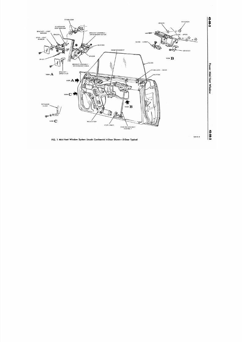
8/20/2019 1977 Ford Car Shop Manual Volume 4 Body
http://slidepdf.com/reader/full/1977-ford-car-shop-manual-volume-4-body 114/449
STABILIZER
RET AI NER
BRACKET - VENT
WINDOW
STOP - VENT
WINDOW
RI VET
VIEW
VIEW
VIEW
REGULATOR
STOP LOWER
RUN AND BRACKET
ASSEMBLY
F I G . 1 Mini -Vent Window
S/stem
Lincoln Continental 4-Door Shown—2-Door Typica l
N2515 B
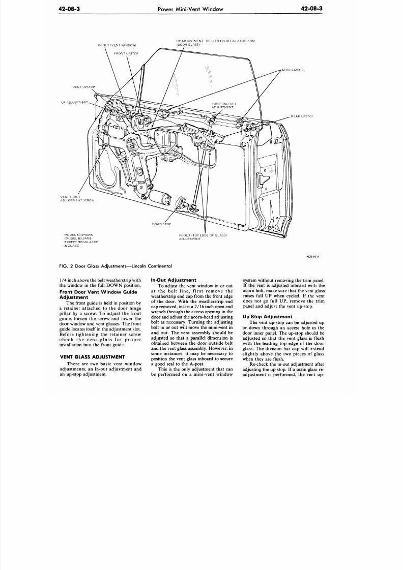
8/20/2019 1977 Ford Car Shop Manual Volume 4 Body
http://slidepdf.com/reader/full/1977-ford-car-shop-manual-volume-4-body 115/449
42-08-3
Power Mini-Vent Window
42-08-3
IN-OUT (VENT WINDOW)
FRONT UPSTOP
UP ADJUSTMENT ROLLER ON REGULATOR ARM
(DOOR GLASS)
VENT UPSTOP
UP ADJUSTMENT
VENT GUIDE
ADJUSTMENT SCREW
STABIL IZERS
REAR UPSTOl
:
DOWN STOP
MODEL 53 SHOWN
(MODEL 60 SAME
EXCEPT REGULATOR
& GLASS)
IN-OUT (TOP EDGE OF GLASS)
ADJUSTMENT
FIG. 2 Door Glass Adjustments—Lincoln Continental
N25 16-A
1/4 inch above the belt w eatherstrip with
the window in the full DOWN position.
Front Door Vent W indow Guide
Adjustment
The front guide is held in position by
a retainer attached to the door hinge
pillar by a screw. To adjust the front
guide, loosen the screw and lower the
door window and vent glasses. The front
guide locates itself in the adjustment slot.
Before tightening the retainer screw
check the vent g lass for proper
installation into the front guide.
VENT GLASS ADJUSTMENT
There are two basic vent window
adjustments; an in-out adjustment and
an up-stop adjustment.
In-Out Adjustment
To adjust the vent window in or out
at the belt l ine, f irs t remove the
weatherstrip end cap from the front edge
of the door. With the weatherstrip end
cap removed, insert a 7/16 inch open end
wrench through the access opening in the
door and adjust the acorn-head adjusting
bolt as necessary. Turning the adjusting
bolt in or out will move the mini-vent in
and out. The vent assembly should be
adjusted so that a parallel dimension is
obtained between the door outside belt
and the vent glass assembly. However, in
some instances, it may be necessary to
position the vent glass inboard to secure
a good seal to the A-post.
This is the only adjustment that can
be performed on a mini-vent window
system without removing the trim panel.
If the vent is adjusted inboard wii:h the
acorn bolt, make sure that the vent glass
raises full UP when cycled. If the vent
does not go full UP, remove the trim
panel and adjust the vent up-stop.
Up-Stop Adjustme nt
The vent up-stop can be adjusted up
or down through an access hole in the
door inner panel. The up-stop should be
adjusted so that the vent glass is flush
with the leading top edge of the door
glass. The division bar cap will extend
slightly above the two pieces of glass
when they are flush.
Re-check the in-out adjustment after
adjusting the up-stop. If a main glass re-
adjustment is performed, the vent up-
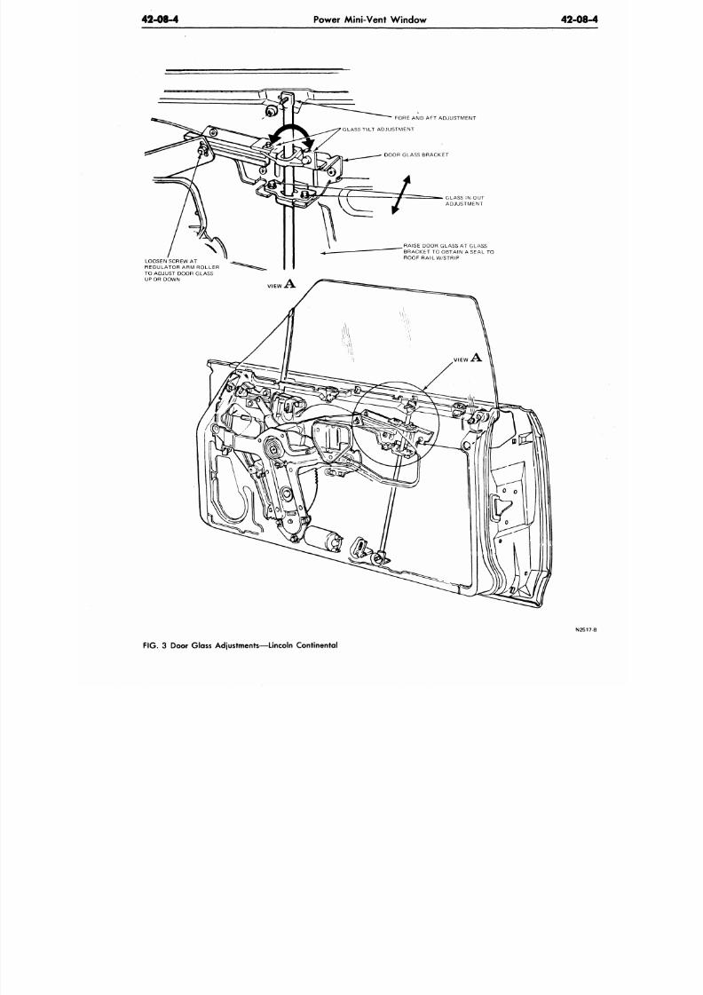
8/20/2019 1977 Ford Car Shop Manual Volume 4 Body
http://slidepdf.com/reader/full/1977-ford-car-shop-manual-volume-4-body 116/449
42-08-4 Power Mini-Vent Window
42-08
LOOSEN SCREW AT
REGULATOR ARM ROLLER
TO ADJUST DOOR GLASS
UP OR DOWN
FORE AND AFT ADJUSTMENT
'GLASS TILT ADJUSTMENT
DOOR GLASS BRACKET
GLASS iN-OUT
ADJUSTMENT
RAISE DOOR GLASS AT GLASS
BRACKET TO OBTAIN A SEAL TO
ROOF RAIL W/STRIP
FIG. 3 Door Glass Adjustments—Lincoln Continental
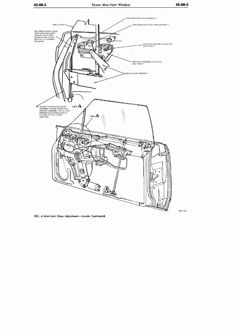
8/20/2019 1977 Ford Car Shop Manual Volume 4 Body
http://slidepdf.com/reader/full/1977-ford-car-shop-manual-volume-4-body 117/449
42-08-5
Power Mini-Vent W indow 42-08-5
VENT GLASS
VENT WINDOW STOP ASSEMBLY
VENT WINDOW STABILIZER ASSEMBLY
RETAINER FRONT DOOR
VENT WINDOW GUIDE.
ASSURE THAT VENT
GLASS IS INSTALLED
WITHIN "C" CHANNEL
OF GUIDE
BRACKET ASSEMBLY DIVISION
BAR OUTER
BRACKET ASSEMBLY DIVISION
BAR INNER
REGULATOR ASSEMBLY
DO NOT TIGHTEN RETAINER
VIEW A .
ASSEMBLY GUIDE SCREW AND
WASHER ASSEMBLY UNTIL VENT
WINDOW AND DOOR GLASS IS
CYCLED TO FULL DOWN
POSITION
N25-
8-A
FIG. 4
Mini-Vent Glass Adjustment—Lincoln Continental
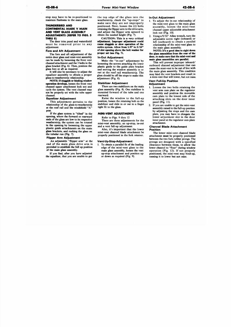
8/20/2019 1977 Ford Car Shop Manual Volume 4 Body
http://slidepdf.com/reader/full/1977-ford-car-shop-manual-volume-4-body 118/449
42-08-6
Power Mini-Vent Window
42-08-
stop may have to be re-positioned to
maintain flushne ss to the m ain glass.
THUNDERBIRD AND
CONTINENTAL MARK V MAIN
AND VENT GLASS ASSEMBLY
ADJUSTMENTS (REFER TO FIGS. 5
THRU 8)
The door trim panel and watershield
m u s t b e r e m o v e d p r i o r t o a n y
adjustment.
Fore and Aft Adjustment
The fore and aft adjustment of the
entire door glass and m ini-vent assembly
can be made by loosening the front vent
channel attachment and the 3 bolts in the
glass bracket (Fig. 6). Then, position the
glass fore or aft as required.
It will also be necessary to adjust the
equalizer assembly to obtain a proper
glass-to-weatherstrip relationship.
NOTE:
If sluggish o r binding window
operation develops, loosen the front vent
channel upper attachment lock nut and
cycle the system. The vent channel may
not be properly set with the tube upper
channel.
Equalizer Adjustment
This adjustment pertains to the
relationship of the glass-to-weatherstrip
at the roof rail and the windshield "A"
post.
If the glass system is "tilted" in the
opening, where the forward or rearward
ends of the glass are low to its respective
weatherstrip, the system can be rotated
in the opening by loosening the upper
plastic guide attachments on the main
glass brackets, and rocking the glass on
the tubular run (Fig. 7).
Flipper Arm Adjustment
An adjustable "flipper arm" at the
end of the main glass drive arm is
provided to establish the full up position
of the main glass assembly.
If you find, after you have adjusted
the equalizer, that you are unable to get
the top edge of the glass into the
weatherstrip, check the "up-stops" to
make sure they are not improperly
positioned. Next, loosen the (2) bolts
retaining the flipper arm to the drive arm,
and adjust the flipper arm upward to
obtain the needed height (Fig. 7).
CAUTION: This is a very critical
adjustment. Improper adjustment could
cause sluggish or slow operation of the
entire system. Allow from 1/8" to 3 /16 "
of slot opening above the bolt washer for
proper set (see Fig. 7).
In-Out Adjustment
Make the "in-out" adjustment by
loosening the screws attaching the lower
plastic guide to the guide plate bracket
and moving the window assembly in or
out at the roof rail weatherstrip. The
glass should be off the stops to make this
adjustment (Fig. 8).
Stabilizer Adjustment
There are two stabilizers on the main
glass assembly (Fig. 8). One stabilizer is
mounted forward of the tube and one
rearward.
Raise the window to the full-up
position, loosen the retaining bolt on the
stabilizer and slide in or out to a finger
tight fit to the glass.
MINI-VENT ADJUSTMENTS
Refer to Figs. 9 thru 12
There are three adjustments for the
mini-vent assembly; an up-stop, in-out
and a vent full-up adjustment.
Also, it's important that the lower
mini-vent channel blade attachment be
properly positioned in the fork retainer.
Vent-Up-Stop-Adjustment
1. To obtain a parallel fit of the leading
edge of the mini-vent glass to the
main glass assembly, loosen the vent
up-stop attachment and position up
or down as required (Fig. 9).
In-Out Adjustment
1.
To adjust the in-out relationship
the mini-vent glass to the main gla
assembly, loosen the mini-ve
channel upper adjustable attachme
lock nut (Fig. 10).
2. Using a 9/32 " Allen wrench, turn
adjustable screw right (inboard)
left (outboard) to obtain a paral
relationship of the mini-vent glass
the main glass assembly.
NO TE: It's a good idea to sight do
the glass assemblies from the rear of
door, to make sure th at the mini-vent a
main glass assemblies are parallel.
This will prevent improper inboa
outboard channel adjustment that c
cause the mini-vent to be out of line w
the main glass assembly. This conditi
may bind the vent brackets and result
a mini-vent that will lower, but not ra
Vent Full-Up Position
Adjustment
1. Loosen the two bolts retaining t
vent arm cam plate on the regulat
assembly and position the moveab
cam plate to the lowest side of t
attaching slots on the door inn
panel (Fig. 11).
2. If you are unable to get the mini-ve
assembly raised to the full-up positi
by adjusting the stops and the ca
plate, you may have to elongate t
lower adjustment slot in the do
inner panel at the regulator cam pla
attachment.
Channel Blade Attachment
Position
The lower mini-vent channel bla
attachment must be properly position
between the two fork rubber prongs. T
prongs are designed with a specifi
clearance between them, to allow t
lower channel to "float" during wind
operation (Fig. 12). If not proper
positioned, the mini-vent may bind-u
causing it to lower but not raise.
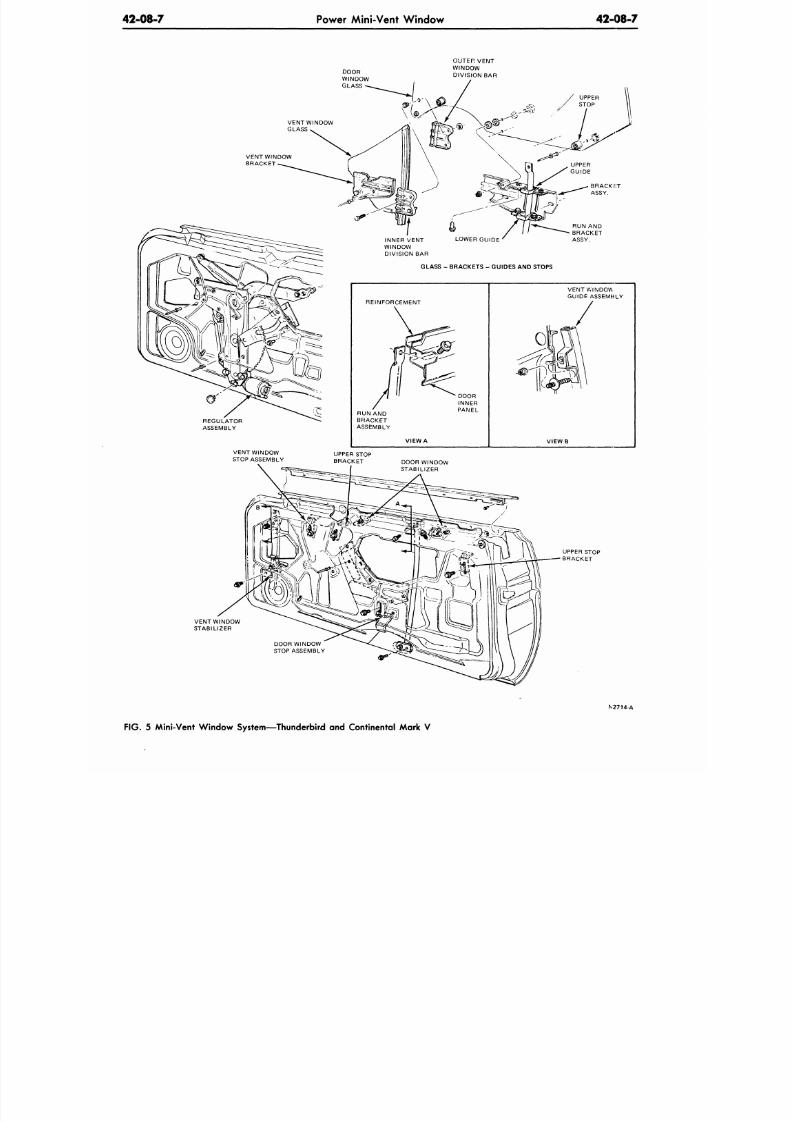
8/20/2019 1977 Ford Car Shop Manual Volume 4 Body
http://slidepdf.com/reader/full/1977-ford-car-shop-manual-volume-4-body 119/449
42-08-7
Power Mini-Vent W indow
42-08-7
OUTER VENT
WINDOW
DIVISION BAR
VENT WINDOW
STABILIZER
DOOR WINDOW
STOP AS SEMBLY
N2714-A
FIG. 5 Mini-Vent W indo w System— Thunderbird and Continental Ma rk V
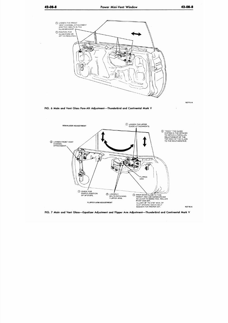
8/20/2019 1977 Ford Car Shop Manual Volume 4 Body
http://slidepdf.com/reader/full/1977-ford-car-shop-manual-volume-4-body 120/449
42-08-8 Power Mini-Vent Window
42-08
(7) LOOSEN THE FRONT
VENT CHANNEL ATTACHMENT
AND THE 3 BOLTS IN THE
GLASS BRACKET
(2) POSITION THE
GLASS FORE OR
AFT AS REQUIRED.
F IG .
6 Main and Vent Glass Fore-Aft Adjustment—Thunderbird and Continental Mark V
EQUALIZER ADJUSTMENT
LOOSEN FRONT VENT
CHANNEL
ATTACHMENT.
(7) LOOSEN THE UPPER
GUIDE ATTACHMENTS.
0 CHECK FOR
PROPER POSITION
OF UP STOPS.
(3) "ROCK" THE GLASS
SYSTEM IN THE OPENING
TO OBTAIN A PARALLEL
RELATIONSHIP OF THE
TOP EDGE OF THE GLASS
TO THE WEATHERSTRIP.
(2) LOOSEN 2
BOLTS RETAINING
FLIPPER ARM.
FLIPPER ARM ADJUSTMENT
(3) DROP DOOR GLASS TO THIS
HEIGHT AND USE SCREWDRIVER
AS LEVER TO SWING REG. ROLLER
PIVOT AND SET.
ALLOW 1/8" TO 3/16" MAX. OF
SLOT OPENING ABOVE BOLT
WASHER FOR PROPER SET.
N2716
FIG. 7 Main and Vent Glass—Equalizer Adjustment and Flipper Arm Adjustment—Thunderbird and Continental Mark V
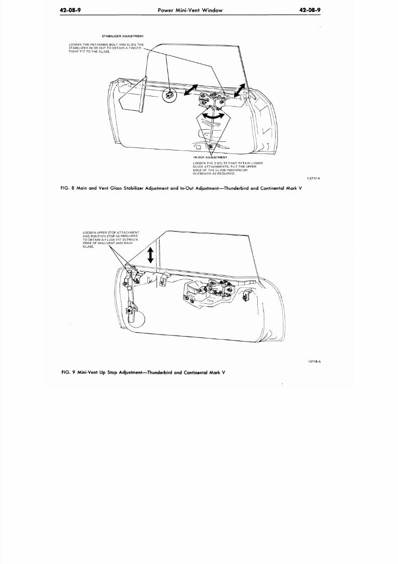
8/20/2019 1977 Ford Car Shop Manual Volume 4 Body
http://slidepdf.com/reader/full/1977-ford-car-shop-manual-volume-4-body 121/449
42-08-9
Power Mini-Vent Window 42-08-9
STABILIZER ADJUSTMENT
LOOSEN THE RETAINING BOLT AND SLIDE THE
STABILIZER IN OR OUT TO OBTAIN A FINGER
TIGHT FIT TO THE GLASS.
IN-OUT ADJUSTMENT
LOOSEN THE 2 BOLTS THAT RETAIN LOWER
GUIDE ATTACHM ENTS. TILT THE UPPER
EDGE OF THE GLASS INBOARD OR
OUTBOARD AS REQUIRED.
N2717-A
F IG . 8 Main and Vent Glass Stabil izer Adjustment and In-Out Adjustment—Thunderbird and Continental Mark V
LOOSEN UPPER STOP ATTACHMENT
AND POSITION STOP AS REQUIRED
TO OBTAIN A FLUSH FIT BETWEEN
EDGE OF MINI-VENT AND MAIN
GLASS.
M2718-A
F IG . 9 Mini-Vent Up Stop Adjustment—Thunderbird and Continental Mark V
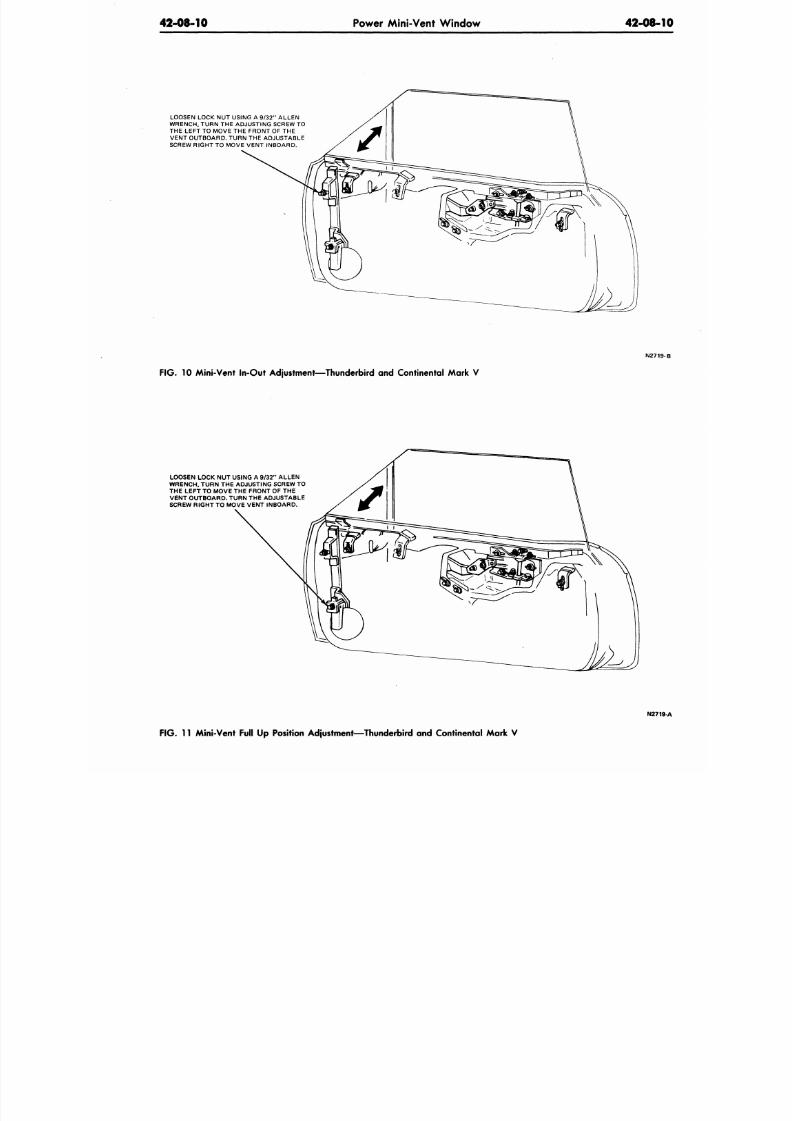
8/20/2019 1977 Ford Car Shop Manual Volume 4 Body
http://slidepdf.com/reader/full/1977-ford-car-shop-manual-volume-4-body 122/449
42-08-10
Power Mini-Vent W indow 42-08-
LOOSEN LOCK NUT USING A 9/32 " A LLEN
WRENCH, TURN THE ADJUSTING SCREW TO
THE LEFT TO MOVE THE FRONT OF THE
VENT OUTBOARD. TURN THE ADJUSTABLE
SCREW RIGHT TO MOVE VE NT INBOARD.
N271
FIG. 10 Mini-Vent In-Out Adjustment—Thunderbird and Continental Mark V
LOOSEN LOCK NUT USING A 9/3 2" ALLEN
WRENCH, TURN THE ADJUSTING SCREW TO
THE LEFT TO MOVE THE FRONT OF THE
VENT OUTBOARD. TURN THE ADJUSTABLE
SCREW RIGHT TO MOVE VENT INBOARD.
N27
F IG .
11 Mini-Vent Full Up Position Adjustment—Thunderbird and Continental Mark V
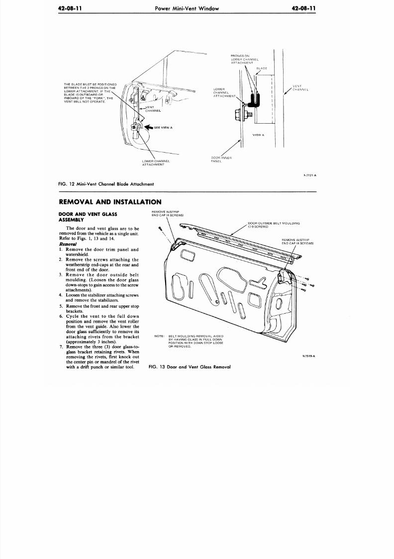
8/20/2019 1977 Ford Car Shop Manual Volume 4 Body
http://slidepdf.com/reader/full/1977-ford-car-shop-manual-volume-4-body 123/449
42-08-11 Power Mini-Vent Window
42-08-11
THE BLADE MUST BE POSITIONED
BETWEEN THE 2 PRONGS ON THE
LOWER ATTACHMENT. IF THE
BLADE IS OUTBOARD OR
INBOARD OF THE "F ORK", THE
VENT WILL NOT OPERATE.
PRONGS ON
LOWER CHANNEL
ATTACHMENT
LOWER
CHANNEL
ATTACHMENT
V E N T
' C H A N N E . L
LOWER CHANNEL
ATTACHMENT
DOOR INNER
PANEL
\ 2721 A
F IG .
12 Mini-Vent Channel Blade Attachment
REMOVAL AND INSTALLATION
DOOR AND VENT GLASS
ASSEMBLY
The door and vent glass are to be
removed from the vehicle as a single unit.
Refer to Figs. 1, 13 and 14.
Removal
1. Remove the door trim panel and
watershield.
2.
Remove the screws attaching the
weatherstrip end-caps at the rear and
front end of the door.
3. Remove the door outs ide bel t
moulding. (Loosen the door glass
down-stops to gain access to the screw
attachments).
4.
Loosen the stabilizer attaching screws
and remove the stabilizers.
5.
Remove the front and rear upper stop
brackets.
6. Cycle the vent to the full down
position and remove the vent roller
from the vent guide. Also lower the
door glass sufficiently to remove its
attaching rivets from the bracket
(approximately 3 inches).
7.
Remove the three (3) door glass-to-
glass bracket retaining rivets. When
removing the rivets, first knock out
the center pin or mandrel of the rivet
with a drift punch or similar tool.
REMOVE W/STRIP
END CAP (4 SCREWS)
DOOR OUTSIDE BELT MOULDING
(7-9 SCREWS)
REMOVE W/STRIP
END CAP (4 SCREWS)
NOTE:
BELT MOULDING REMOVAL AIDED
BY HAVING GLASS IN FULL DOWN
POSITION WITH DOWN STOP LOOSE
OR REMOVED.
F IG . 13 Door and Vent Glass Removal
N:?519-A
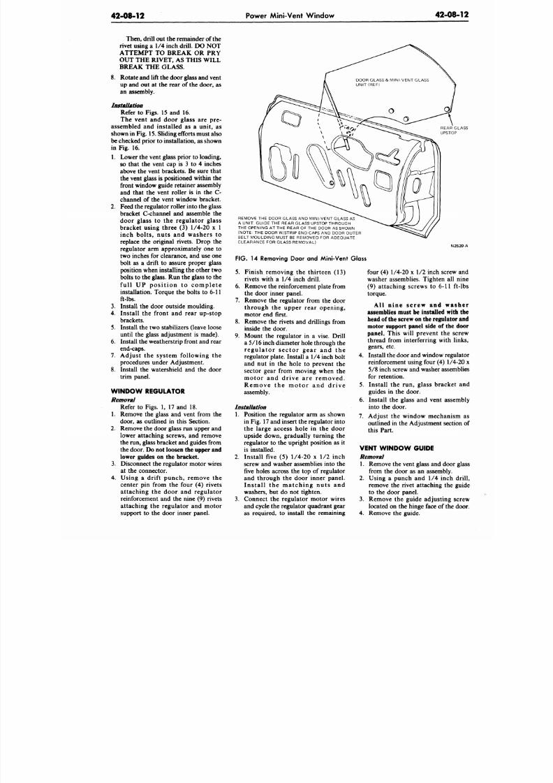
8/20/2019 1977 Ford Car Shop Manual Volume 4 Body
http://slidepdf.com/reader/full/1977-ford-car-shop-manual-volume-4-body 124/449
42-08-12
Power Mini-Vent W indow
42-08-1
Then, drill out the remainder of the
rivet using
a 1/4
inch drill. DO
NOT
ATTEMPT TO BREAK OR PRY
OUT THE RIVET, AS THIS WILL
BREAK THE
GLASS.
8. Rotate and lift the door glass and vent
up
and out at the
rear
of
the door,
as
an assembly.
Installation
Refer
to
Figs.
15 and 16.
The vent
and
door glass
are pre-
assembled
and
installed
as a
unit,
as
shown in Fig. 15. Sliding efforts must also
be checked prior to installation, as shown
in Fig. 16.
1. Lower the vent glass prior to loading,
so that
the
vent
cap is 3 to 4
inches
above
the
vent brackets. Be sure that
the vent glass
is
positioned within
the
front w indow guide retainer assembly
and that the vent roller is in the C-
channel
of
the vent window bracket.
2. Feed the regulator roller into the glass
bracket C-channel
and
assemble
the
door glass
to the
regulator glass
bracket using three (3) 1/4-20 x 1
inch bolts, nuts
and
washers
to
replace
the
original rivets. Drop
the
regulator
arm
approximately
one to
two inches
for
clearance,
and
use
one
bolt
as a
drift
to
assure proper glass
position when installing the other two
bolts to the
glass.
Run
the glass
to the
full
UP
p o s i t i o n
to
c o m p l e t e
installation. Torque the bolts to 6-11
ft-lbs.
3.
Install
the
door outside moulding.
4. Install
the
front
and
rear up-stop
brackets.
5. Install
the
two stabilizers (leave loose
until
the
glass adjustment
is
made).
6. Install the weatherstrip front and rear
end-caps.
7. Adjust
the
system following
the
procedures under Adjustment.
8. Install
the
w atershield
and the
door
trim panel.
W IND OW REGULATOR
Removal
Refer
to
Figs.
1, 17 and 18.
1. Remove
the
glass
and
vent from
the
door,
as
outlined
in
this Section.
2. Remove the door glass
run
upper and
lower attaching screws,
and
remove
the run , glass bracket and guides from
the door.
Do not loosen the upper and
lower guides on the bracket.
3.
Disconnect
the
regulator motor wires
at
the
connector.
4. Using
a
drift punch, remove
the
center
pin
from
the
four
(4)
rivets
attaching
the
door
and
regulator
reinforcement
and the
nine
(9)
rivets
attaching
the
regulator
and
motor
support
to the
door inner panel.
REAR GL
UPSTOP
REMOVE
THE
DOOR GLASS
AND
MINI-VENT GLASS
AS
A UNIT. GUIDE
THE
REAR GLASS UPSTOP THROUGH
THE OPENING AT THE REAR OF THE DOOR AS SHOWN
(NOTE: THE
DOOR W/STRIP
END
CAPS
AND
DOOR OUTER
BELT MOULDING MUST
BE
REMOVED
FOR
ADEQUATE
CLEARANCE FOR GLASS REM OVAL)
N252
FIG . 14
Removing Door
and
Mini-Vent Glass
5.
Finish removing
the
thirteen
(13)
rivets with
a 1/4
inch drill.
6. Remove
the
reinforcement plate from
the door inner panel.
7. Remove
the
regulator from
the
door
through
the
upper rear opening,
motor
end
first.
8. Remove
the
rivets
and
drillings from
inside the door.
9. Mount
the
regulator
in a
vise. Drill
a 5/16 inch diameter hole through
the
r e gu la to r s e c to r ge a r
and the
regulator plate. Install
a 1/4
inch bolt
and
nut in the
hole
to
prevent
the
sector gear from moving when
the
m otor
and
dr ive
are
r e m ove d .
R e m o v e
the
m o t o r
and
d r i v e
assembly.
Installation
1. Position
the
regulator
arm as
shown
in
Fig.
17 and insert the regulator into
the large access hole
in the
door
upside down, gradually turning
the
regulator
to the
upright position
as it
is installed.
2. Install five (5) 1/4-20 x 1/2 inch
screw
and
washer assemblies into
the
five holes across
the top of
regulator
and through
the
door inner panel.
I ns t a l l
the
m a tc h ing nu t s
and
washers,
but do not
tighten.
3.
Connect
the
regulator motor wires
and cycle the regulator quadrant gear
as required,
to
install
the
remaining
four (4)
1/4-20 x 1/2
inch screw
a
washer assemblies. Tighten
all
n
(9) attaching screws
to 6-11
ft-
torque.
All nine screw and was
assemblies must be installed with
head of the screw on the regulato
motor support panel side of the d
panel. This will prevent
the
scr
thread from interferring with lin
gears,
etc.
4. Install the door and window regul
reinforcement using four (4)
1/4-2
5/8
inch screw and washer assemb
for retention.
5. Install
the run,
glass bracket
guides
in the
door.
6. Install
the
glass
and
vent assem
into
the
door.
7. Adjust
the
window mechanism
outlined
in
the Adjustment section
this Part.
VENT W IND OW GUIDE
Removal
1. Remove
the
vent glass
and
door g
from
the
door
as an
assembly.
2. Using
a
punch
and 1/4
inch d
remove
the
rivet attaching
the
gu
to
the
door panel.
3.
Remove
the
guide adjusting sc
located
on the
hinge face
of
the d
4. Remove
the
guide.
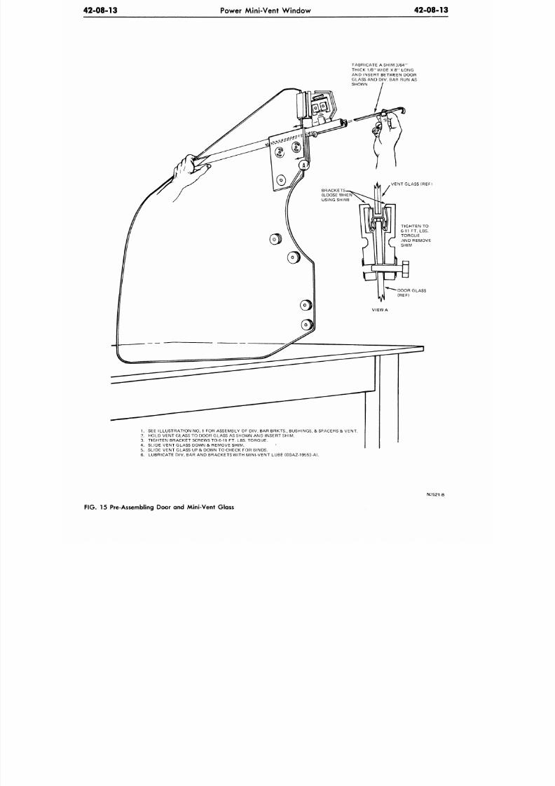
8/20/2019 1977 Ford Car Shop Manual Volume 4 Body
http://slidepdf.com/reader/full/1977-ford-car-shop-manual-volume-4-body 125/449
42-08-13 Power Mini-Vent Window
42-08-13
FABRICATE A SHIM 3/64"
THICK 1/8 " WIDE X 8 " LONG
AND INSERT BETWEEN DOOR
GLASS AND DIV. BAR RUN AS
SHOWN
VENT GLASS (REF I
TIGHTEN TO
6-11 FT. LBS.
TORQUE
AND REMOVE
SHIM
1. SEE ILLUS TRA TION NO. 1 FOR ASSEMBLY OF DIV. BAR BRKTS., BUSHINGS, & SPACERS & VENT .
2. HOLD VEN T GLASS TO DOOR GLASS AS SHOWN AND INSERT SHIM .
3. TIGHTE N BRA CKET SCREWS TO 6-11 FT. LBS. TORQU E.
4. SLIDE VENT GLASS DOWN & REMOVE SHIM.
5. SLIDE VE NT GLASS UP & DOWN TO CHECK FOR BINDS.
6. LUBRICATE DIV. BAR AND BRACKETS WITH MINI-VENT LUBE (D3AZ-1955 3-A).
N; 521-B
F IG . 15 Pre-Assembling Door and Mini-Vent Glass
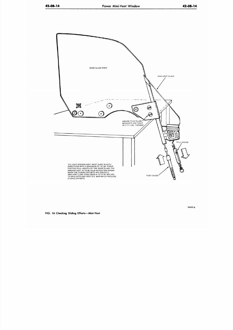
8/20/2019 1977 Ford Car Shop Manual Volume 4 Body
http://slidepdf.com/reader/full/1977-ford-car-shop-manual-volume-4-body 126/449
42-08-14
Power Mini-Vent Window
42-08-1
MINI-VENT GLASS
ASSURE THAT GLASS
BRACKETS ARE TIGHT
(6-11 FT. LBS. TORQUE)
THE VENT WINDOW ASSY. MUST SLIDE
IN
BOTH
DIRECTIONS WITH A MAXIMUM OF 14 LBS. FORCE
FOR THE FULL LENGTH OF THE DOOR GLASS . THE
WINDOW ASSY. IS TO
BE
HELD
IN
POSITION SHOWN
WHEN THE SLIDING EFFORTS ARE CHECKED.
MINI-VENT LUBE (D3AZ-19553-A) IS TO BE APPLIED
TO BRACKETS AND VENT DIV.
BAR
WHICH REDUCES
SLIDING EFFORTS.
PUSH GAUGE'
N2522
FIG. 16
Checking Sliding Efforts—Mini-Vent
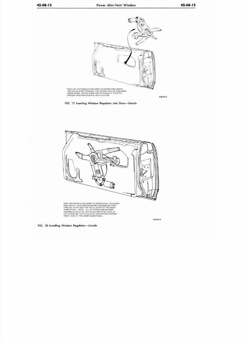
8/20/2019 1977 Ford Car Shop Manual Volume 4 Body
http://slidepdf.com/reader/full/1977-ford-car-shop-manual-volume-4-body 127/449
42-08-15
Power Mini-Vent Window
42-08-15
POSITION THE REGULAT OR ARMS AS SHOWN AND INSERT
THE REGULATOR THROUGH THE ACCESS HOLE IN THE DOOR
INNER PANEL UPSIDE DOWN
AND
GRADUALLY TURN
TO
UPRIGHT POSITION DURING INSTALLATION
FIG. 17 Inserting Wind ow Regulator Into Door—Lincoln
POSITION REGULATOR ARMS
TO
INNER PANEL AS SHOWN
AND INSTALL (9) SCREW & WASHER ASSEMBLIES (PART
57487-S2) TO ATTACH THE REGULATOR TO THE DOOR
INNER PANEL. NOTE: ALL (9) SCREW AND WASHER
ASSEMBLIES MUST BE INSTALLED W ITH THE HEAD OF
THE SCREW ON THE REGULATOR AND MOTOR SUPPORT
PANEL SIDE OF THE DOOR INNER PA NEL.
N2524 A
FIG. 18 Installing Window Regulator—Lincoln
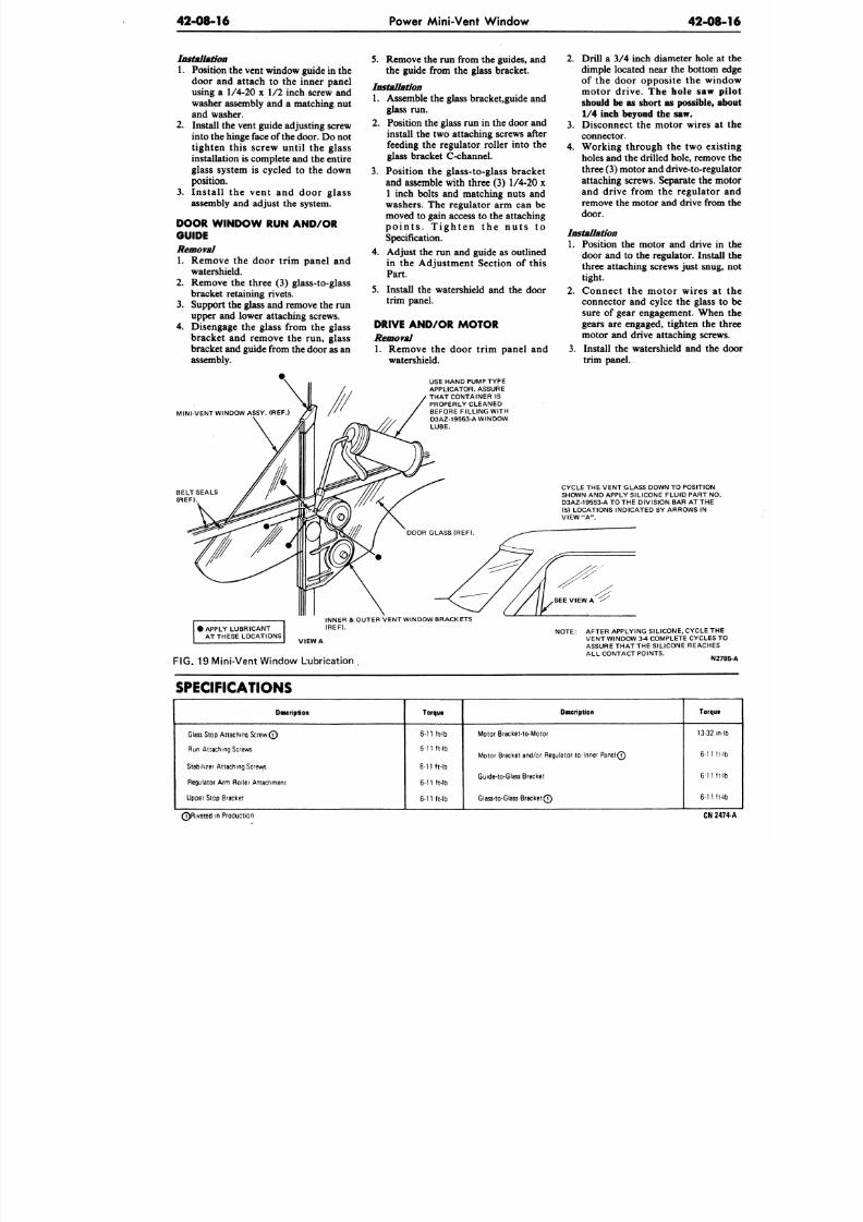
8/20/2019 1977 Ford Car Shop Manual Volume 4 Body
http://slidepdf.com/reader/full/1977-ford-car-shop-manual-volume-4-body 128/449
42-08-16 Power Mini-Vent W indow
42-08
Installation
1. Position the vent window guide in the
door and attach to the inner panel
using a 1/4-20 x 1/2 inch screw and
washer assembly and a matching nut
and washer.
2. Install the vent guide adjusting screw
into the hinge face of the door. Do not
tighten this screw until the glass
installation is complete and the entire
glass system is cycled to the down
position.
3.
Ins ta l l
the
vent
and
door glass
assembly and adjust the system.
DOOR W INDOW
RUN
AND/OR
GUIDE
Removal
1. Remove the door trim panel and
watershield.
2.
Remove the three (3) glass-to-glass
bracket retaining rivets.
3. Support the glass and remove the run
upper and lower attaching screws.
4. Disengage
the
glass from
the
glass
bracket and remove the run, glass
bracket and guide from the door
as
an
assembly.
MINI-VENT W INDOW ASSY. (REF.)
5. Remove the run from the guides, and
the guide from the glass bracket.
Installation
1. Assemble the glass bracket,guide and
glass run.
2.
Position the glass run in the door and
install the two attaching screws after
feeding
the
regulator roller into
the
glass bracket C-channel.
3.
Position
the
glass-to-glass bracket
and assemble with three (3) 1/4-20 x
1 inch bolts and matching nuts and
washers.
The
regulator
arm can be
moved to gain access to the attaching
p o i n t s . T i g h t e n the n u t s to
Specification.
4. Adjust the run and guide as outlined
in the Adjustment Section of this
Part.
5.
Install the w atershield and the door
trim panel.
DRIVE AND/OR MOTOR
Removal
1. Remove the door trim panel and
watershield.
USE HAND PUMP TYPE
APPLICATOR. ASSURE
THAT CONTAINER IS
PROPERLY CLEANED
BEFORE FILLING WITH
D3AZ-19553-A WINDOW
LUBE.
2.
Drill a 3/4 inch diameter hole
dimple located near the bottom
of the door opposite the wi
motor drive.
The
hole
saw
should
be as
short
as
possible,
1/4
inch beyond
the saw.
3. Disconnect the motor wires a
connector.
4. Working through the two ex
holes and the drilled hole, remov
three 3) motor and drive-to-reg
attaching screws. Separate
the
m
and drive from the regulator
remove the motor and drive from
door.
Installation
1. Position the motor and drive i
door and to the regulator. Insta
three attaching screws just snug
tight.
2.
Connect the motor wires a
connector and cylce the glass
sure of gear engagement. Whe
gears
are
engaged, tighten
the
motor
and
drive attaching screw
3. Install the w atershield and the
trim panel.
CYCLE THE VENT GLASS DOWN TO POSITION
SHOWN
AND
APPLY SILICONE FLUID P ART
NO
D3AZ-19553-ATOTHE D IVISION BAR AT THE
(5) LOCATIONS INDICATED BY ARROWS IN
VIEW
"A".
• APPLY LUBRICANT
AT THESE LOCATIONS
INNER
&
OUTER VENT WINDOW BRACKETS
(REF).
VIEW
A
FIG. 19 Mini-Vent W indow Lubrication
.
NOTE: AFTER APPLYING SILICONE, CYCLE TH
VENT WINDOW 3-4 COMPLETE CYCLES
ASSURE THA T THE SILICONE REACHES
ALL CONTACT POINTS.
N2
SPECIFICATIONS
Description
Glass Stop Attaching S cr e w 0
Run Attaching Screws
Stabilizer Attaching Screws
Regulator Arm Roller Attachment
Upper Stop Bracket
Torque
6-11 ft-lb
6-11 ft-lb
6-11 ft-lb
6-11 ft-lb
6-11 ft-lb
Description
Motor Bracket-to-Motor
Motor Bracket and/or Regulator to-Inner PanelQ
Guide-to-Glass Bracket
Glass-to-Glass B ra ck etQ
Torqu
13-32 m
6-11 f
6-11 f
6-11 f
Q R i v e t e d in Production
CN 2
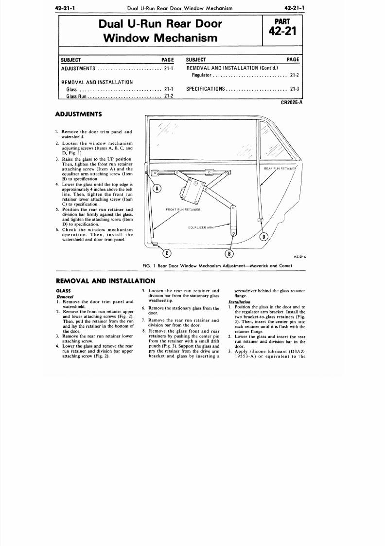
8/20/2019 1977 Ford Car Shop Manual Volume 4 Body
http://slidepdf.com/reader/full/1977-ford-car-shop-manual-volume-4-body 129/449
42-21-1
Dual U-Run Rear Door Window Mechanism
42-211-1
Dual
U-Run
Rear Door
Window Mechanism
P A R T
42-21
SUBJECT PAGE
ADJUSTMENTS 21-1
REMOVAL AND INSTALLATION
Glass 21-1
Glass Run 21-2
SUBJECT
PAGE
REMOVAL AND INSTALLATION (Cont 'd . )
Regulator
21-2
SPECIFICATIONS 21-3
CR2025 A
ADJUSTMENTS
1. Remove the door trim panel and
watershield.
2. Loosen the window mechanism
adjusting screws (Items A, B, C, and
D, Fig. 1).
3.
Raise the glass to the UP position.
Then, tighten the front run retainer
attaching screw (Item A) and the
equalizer arm attaching screw (Item
B) to specification.
4.
Lower the glass until the top edge is
approximately 4 inches above the belt
line.
Then, tighten the front run
retainer lower attaching screw (Item
C) to specification.
5.
Position the rear run retainer and
division bar firmly against the glass,
and tighten the attaching screw (Item
D) to specification.
6. Check the window mechanism
operation. Then, install the
watershield and door trim panel.
N2:t29-A
FIG.
1 Rear Door Window Mechanism Adjustment—Maverick and Comet
REMOVAL
AND
INSTALLATION
GLASS
Removal
1. Remove the door trim panel and
watershield.
2. Remove the front run retainer upper
and lower attaching screws (Fig. 2).
Then, pull the retainer from the run
and lay the retainer in the bottom of
the door.
3. Remove the rear run retainer lower
attaching screw.
4. Lower the glass and remove the rear
run retainer and division bar upper
attaching screw (Fig. 2).
5. Loosen the rear run retainer and
division bar from the stationary glass
weatherstrip.
6. Remove the stationary glass from the
door.
7.
Remove the rear run retainer and
division bar from the door.
8. Remove the glass front and rear
retainers by pushing the center pin
from the retainer with a small drift
punch (Fig. 3). Support the glass and
pry the retainer from the drive arm
bracket and glass by inserting a
screwdriver behind the glass retainer
flange.
Installation
1. Position the glass in the door and to
the regulator arm bracket. Install the
two bracket-to-glass retainers (Fig.
3) . Then, insert the center pin into
each retainer until it is flush with the
retainer flange.
2.
Lower the glass and insert the rear
run retainer and division bar in the
door.
3. Apply silicone lubricant (D3AZ-
19553-A) or equivalent to i:he
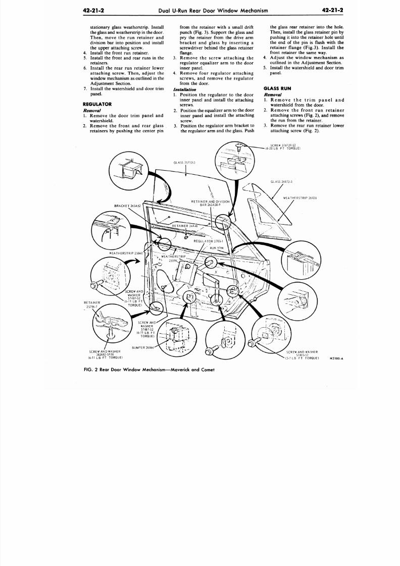
8/20/2019 1977 Ford Car Shop Manual Volume 4 Body
http://slidepdf.com/reader/full/1977-ford-car-shop-manual-volume-4-body 130/449
4 2 -2 1 -2 Dual U-Run Rear Door Window Mechanism
4 2 - 2
stationary glass weatherstrip. Install
the glass and weatherstrip in the door.
Then, move the run retainer and
division bar into position and install
the upper attaching screw.
4. Install the front run retainer.
5.
Install the front and rear runs in the
retainers.
6. Install the rear run retainer lower
attaching screw. Then, adjust the
window mechanism as outlined in the
Adjustment Section.
7. Install the watershield and door trim
panel.
REGULATOR
Removal
1.
Remove the door trim panel and
watershield.
2.
Remove the front and rear glass
retainers by pushing the center pin
from the retainer with a small drift
punch (Fig. 3). Support the glass and
pry the retainer from the drive arm
bracket and glass by inserting a
screwdriver behind the glass retainer
flange.
3. Remove the screw attaching the
regulator equalizer arm to the door
inner panel.
4.
Remove four regulator attaching
screws, and remove the regulator
from the door.
Installation
1. Position the regulator to the door
inner panel and install the attaching
screws.
2.
Position the equalizer arm to the door
inner panel and install the attaching
screw.
3. Position the regulator arm bracket to
the regulator arm and the glass. Push
the glass rear retainer into the
Then, install the glass retainer p
pushing it into the retainer hole
the end of the pin is flush wit
retainer flange (Fig.3). Instal
front retainer the same way.
4.
Adjust the window mechanis
outlined in the Adjustment Sec
5. Install the watershield and door
panel.
GLASS RUN
Removal
1.
R e m o v e t h e t r i m p a n e l
watershield from the door.
2.
Remove the front run ret
attaching screws (Fig. 2), and re
the run from the retainer.
3.
Remove the rear run retainer
attaching screw (Fig. 2).
SCREW 376129-S2
(8-20 LB FT TORQUE)
WEATHERSTRIP 26928
SCREW AND WASHER
382682-S100
(6-11 LB FT TORQUE)
SCREW AND WASHER
57485-S2
(3-7 LB FT TORQUE)
N2
FIG. 2 Rear Door Window Mechanism—Maverick and Comet
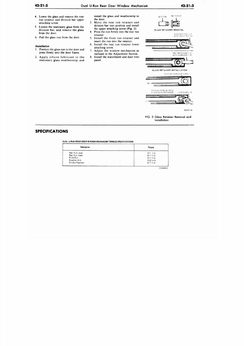
8/20/2019 1977 Ford Car Shop Manual Volume 4 Body
http://slidepdf.com/reader/full/1977-ford-car-shop-manual-volume-4-body 131/449
42-21-3
Dual U-Run Rear Door Window Mechanism
42-21-3
4. Lower the glass and remove the rear
run retainer and division bar upper
attaching screw.
5. Loosen the stationary glass from the
division bar, and remove the glass
from the door.
6. Pull the glass run from the door.
Installation
1. Position the glass run to the door and
press firmly into the door frame.
2. Apply s ilicon lubricant to the
stationary glass weatherstrip, and
install the glass and weatherstrip in
the door.
3. Move the rear run retainer and
division bar into position and install
the upper attaching screw (Fig. 2).
4. Press the run firmly into the rear run
retainer.
5. Install the front run retainer and
insert the run into the retainer.
6. Install the rear run retainer lower
attaching screw.
7. Adjust the window mechanism as
outlined in the Adjustment Section.
8. Install the watershield and door trim
panel.
BUTTON RETAINER
GLASS RETA INER REMOVAL
PUSH BUTTON C UT
WITH DRIFT PU^ CH
PRY RETAINER CU T
WITH SCREWDRIV \R
GLASS RETAINER INSTALLA TION
PUSH RETAINER
IN
FIRML'
PUSH BUTTON IN UNTIL
FLUSH WITH RET AINE R SCREWDRIV
i R
______ \
\
N242.S-A
FIG.
3 Glass Retainer Removal and
Installation
SPECIFICATIONS
DUAL U RUN REAR DOOR WINDOW MECHANISM TORQUE SPECIFICATIONS
Description
Rear Run Lower
Rear Run Upper
Front Run
Equalizer Arm
Window Regulator
Torque
3-7 ft-lb
6-11 ft-lb
6-11 ft-lb
8-20 in-lb
6-11 ft-lb
CN2443-B
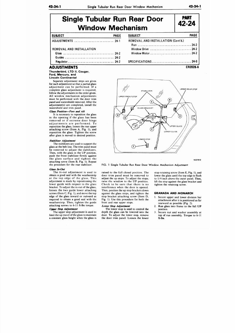
8/20/2019 1977 Ford Car Shop Manual Volume 4 Body
http://slidepdf.com/reader/full/1977-ford-car-shop-manual-volume-4-body 132/449
42-24-1
Single Tubular Run Rear Door W indo w Mechanism
42-2
Single Tubular Run Rear Door
Window Mechanism
P A R T
42-24
SUBJECT
PAGE SUBJECT
PAG
ADJUSTMENTS 24-1
REMOVAL AND INSTALLATION
Glass
Guides
Regulator
24-2
24-2
24-2
REMOVAL AND INSTALLATION (Cont 'd . )
Run 24-
Window Drive 24-
Window Motor 24-
SPECIFICATIONS 24-
ADJUSTMENTS
Thunderbird, LTD II, Cougar,
Ford, Mercury, and
Lincoln Continental
Separate adjustment steps are given
for each adjustment so that a partial glass
adjustm ent can be performed. If a
complete glass adjustment is required,
follow the adjustments
in
the o rder given.
All window mechanism adjustments
must be performed with the door trim
panel and watershield removed. After the
adjustment(s) are completed, install the
watershield and trim panel.
Glass Position— ore
and Aft
It is necessary to reposition the glass
in the opening if the glass has been
removed or if extreme door hinge
a d j u s t m e n t s a r e p e r f o r m e d . T o
reposition the glass, loosen the run upper
attaching screw (Item A, Fig. 1), and
reposition the glass. Tighten the screw
after glass is moved to desired position.
Stabilizer Adjustment
The stabilizers are used to support the
glass at the belt line. The trim panel must
be removed to adjust the stabilizers.
Then, with the glass in the UP position,
push the front stabilizer firmly against
the glass surface and tighten the
attaching screw (Item B, Fig. 1). Repeat
the procedure for the rear stabilizer.
Glass
In Out
The in-out adjustment is used to
obtain a good seal with the weatherstrip
at the top edge of the glass. This
adjustment is made by repositioning the
lower guide with respect to the glass
bracket. To adjust the in-out of the glass,
loosen the two guide lower attaching
screws (Item C, Fig. 1), and move the top
edge of the glass inward or outward as
required to obtain a good seal with the
weatherstrip. Then, tighten the guide
attaching screws to 6-11 ft-lbs torque.
Upper Stop
Adjustment
The upper stop adjustment is used to
limit the up travel of the glass to maintain
a constant glass height when the glass is
CR2026
UPPER REAR STO
N2
FIG. 1 Single Tubular Run Rear Door Window Mechanism Adjustment
raised to the full closed position. The
door trim panel must be removed to
adjust the up stops. To adjust the stops,
raise the window to the UP position.
Check to be sure that there is no
interference when the door is opened.
Then, position the up stop brackets down
against the glass stops, and tighten the
stop bracket attaching screw (Item D,
Fig. 1). Use this procedure for both the
front and rear upper stops.
Lower Stop Adjustment
The lower stop is used to control the
depth the glass can be lowered into the
door. To adjust the lower stop, remove
the door trim panel. Loosen the lower
stop retaining screw (Item E, Fig. 1)
lower the glass until the top edge is
to 1/4 inch above the outer panel. T
lift the stop against the glass bracke
tighten the retaining screw.
GRANADA AND MONARCH
1. Secure upper and lower division
attachment after it is positioned a
rearward as possible (Fig. 2).
2.
Run glass into frame to the ful
position.
3.
Secure nut and washer assemb
top of run assembly. Torque to
ft-lbs.
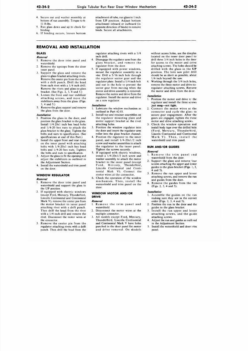
8/20/2019 1977 Ford Car Shop Manual Volume 4 Body
http://slidepdf.com/reader/full/1977-ford-car-shop-manual-volume-4-body 133/449
42-24-2
Single Tubular Run Rear Door Window Mechanism
42-24-2
4. Secure nut and washer assembly at
bottom of run assembly. Torque to 6-
11 ft-lbs.
5. Run glass down and up to check for
binding.
6. If binding occurs, loosen bottom
attachment of
tube,
run glass to 1 inch
from UP position. Adjust bottom
attachment inboard or outboard (in
opposite direction of binds) to remove
binds. Secure all attachments.
REMOVAL AND INSTALLATION
GLASS
Removal
1. Remove the door trim panel and
watershield.
2. Remove the upstops from the door
inner panel.
3.
Support the glass and remove the
glass-to-glass bracket attaching rivets.
Remove the center pin from the rivets
with a drift punch. Drill the head
from each rivet with a 1/4 inch drill.
Remove the rivets and glass-to-glass
bracket. (See Figs. 2, 3, 4 and 5.)
4.
Loosen the front and rear stabilizer
attaching screws, and move the
stabilizers away from the glass. (Figs.
3, 4 and 5.)
5. Remove the glass support and remove
the glass from the door.
Installation
1. Position the glass in the door, and
position the glass bracket to the glass.
Install
1/4-20x1
inch hex head bolts
and 1/4-20 hex nuts to attach the
glass bracket to the glass. Tighten the
bolts and nuts to specification. (See
specifications at end of this Part.)
2. Install the upper front and rear stops
on the inner panel with attaching
bolts with
1/4-20x1
inch hex head
bolts and 1/4-20 hex nuts. Tighten
the bolts and nuts to specification.
3. Adjust the glass to fit the opening and
adjust the stabilizers as outlined in
the Adjustment Section.
4. Install the watershield and trim panel
on the door.
W IND OW REGULATOR
Removal
1. Remove the door trim panel and
watershield and support the glass in
the UP position.
2.
If equipped with electric windows
(except Ford, Mercury, Thunderbird,
Lincoln Continental and Continental
Mark V), remove the center pin from
the motor bracket to inner panel
attaching rivet with a drift punch.
Then drill the head from the rivet
with a 1/4 inch drill and remove the
rivet. Disconnect the motor wires at
the connector.
3.
Remove the center pin from the
regulator attaching rivets with a drift
punch. Then drill the head from the
regulator attaching rivets with a 1/4
inch drill.
4.
Disengage the regulator arm from the
glass bracke t , and remove the
regulator from the door.
5. If equipped with power windows,
mount the regulator assembly in a
vise. Drill a 5/16 inch hole through
the regulator sector gear and the
regulator plate. Install a 1/4 inch bolt
and nut in the hole to prevent the
sector gear from moving when the
motor and drive assembly is removed.
Remove the motor and drive from the
regulator. Install the motor and drive
on a new regulator.
Installation
1. Lubricate the window mechanism as
outlined in Part 42-01.
2. Install nut and retainer assemblies on
the regulator mounting plate and
motor support bracket at the rivet
attaching holes.
3.
Position the window regulator into
the door and insert the regulator arm
roller into the glass bracket channel.
4. Position the regulato r to the inner
panel, and install 1/4-20x1/2 inch
screw and washer assemblies to attach
the regulator to the inner panel.
Tighten the screws securely.
5. If equipped with electric windows,
install a 1/4-20x1/2 inch screw and
washer assembly to attach the motor
bracket to the inner panel (except
Ford, Mercury, Thunderbird,
Lincoln Continental and Conti-
nental M ark V ). Con nect the
motor wires at the connector.
6. Check the operation of the window
m e c ha n i sm . T he n , i ns t a l l t he
watershield and trim panel on the
door.
W I N D O W M O T O R A N D / O R
DRIVE
Removal
1. Re m ove th e t r im pa ne l a nd
watershield.
2. Disconnect the moto r wires at the
multiple connector.
3.
All models except Ford, Mercury,
Thunderbird, Lincoln Continental
and Continental Mark V have holes
punched in the door panel for motor
and drive removal. On models
without access holes, use the dimples
located on the inner door panel to
drill three 3/4 inch holes in the door
for access to the motor and drive
attaching screws. The holes should be
drilled with the glass in the UP
position. The hole saw pilot drill
should be as short as possible, about
1/4 inch beyond the saw.
4. Working through the 3/4 inch holes,
remove the three motor and drive-to-
regulator attaching screws. Remove
the motor and drive from the dcor.
Installation
1.
Position the motor and drive to the
regulator and install the three screws
just snug—not tight.
2. Connect the motor wires at the
connector and cycle the glass to
assure gear engagement. After the
gears are engaged, tighten the three
motor and drive attaching screws.
3.
Check the window operation and
install body tape over the drilled hole
( For d , M e r c ur y , T hunde r b i r d ,
Lincoln Continental and Continental
M a r k V ) . T h e n , i n s t a l l t h e
watershield and trim panel.
RUN AND/OR GUIDES
Removal
1. Re m ove the t r im pa n e l a n d
watershield from the door.
2. Support the glass and remove four
screws attaching the upper and lower
guides to the glass bracket (Figs. 2, 3,
4 and 5).
3.
Remove the run upper and lower
attaching screws, and remove the run
and guides from the door.
4. Remove the guides from the run
(Figs.
2, 3, 4 and 5).
Installation
1. Assemble the guides on the run
making sure they are in the correct
order (Figs. 2, 3, 4 and 5).
2. Position the run in the door and the
guides to the glass bracket.
3.
Install the run upper and lower
attaching screws, and the guide
attaching screws.
4.
Adjust the run and guides as outli led
in the Adjustment Section.
5. Install the watershield and door t rim
panel.
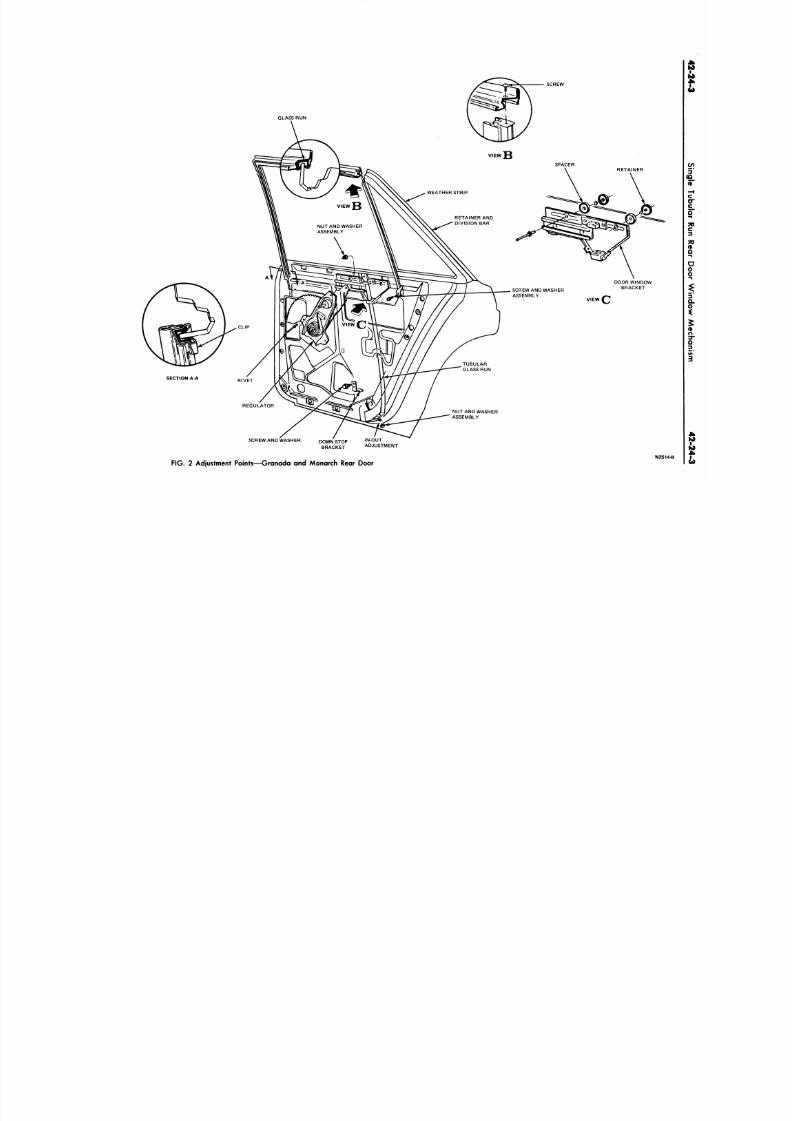
8/20/2019 1977 Ford Car Shop Manual Volume 4 Body
http://slidepdf.com/reader/full/1977-ford-car-shop-manual-volume-4-body 134/449
GLASS RUN
SCREW
WEATHER STRIP
RETAINER AND
DIVISION BAR
NUT AND WASHER
ASSEMBLY
SPACER
SCREW AND WASHER
ASSEMBLY
DOOR WINDOW
BRACKET
VIEW
SCREW AND WASHER IN-OUT
ADJUSTMENT
FIG. 2 Adjustment Points—Granada and Monarch Rear Door
N
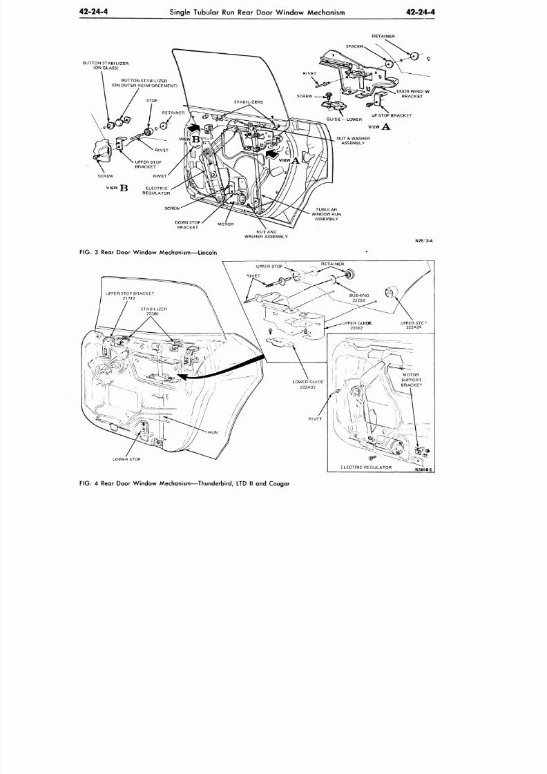
8/20/2019 1977 Ford Car Shop Manual Volume 4 Body
http://slidepdf.com/reader/full/1977-ford-car-shop-manual-volume-4-body 135/449
42-24-4
Single Tubular Run Rear Door W indow Mechanism
42-24-4
RETAINER
BUTTON STABILIZER
(ON GLASS)
BUTTON STABILIZER
(ON OUTER REINFORCEMENT)
STOP
RIVET
UPPER STOP
BRACKET
SCREW RIVE T
VIEW JQ ELECTRIC
REGULATOR
DOOR WINDOW
BRACKET
UP STOP BRACK ET
SCREW
DOWN STOP ^
MO
-f
OR
BRACKET
TUBULAR
WINDOW RUN
ASSEMBLY
NUT AND
WASHER ASSEMBLY
N25" 3-A
F IG . 3 Rear Door Wind ow Mechanism—Lincoln
LOWER STOP
FIG. 4 Rear Door Wind ow Mechanism—T hunderbird, LTD II and Cougar
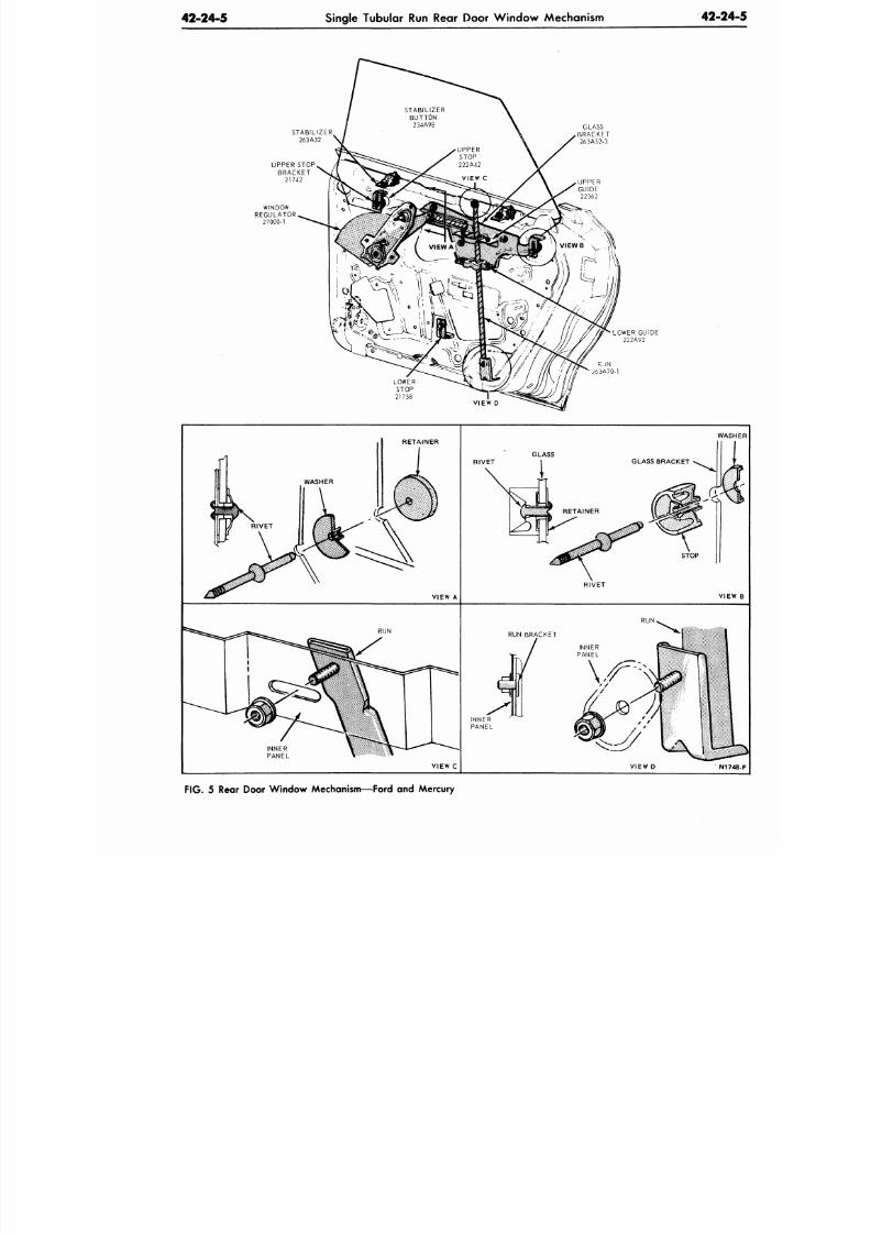
8/20/2019 1977 Ford Car Shop Manual Volume 4 Body
http://slidepdf.com/reader/full/1977-ford-car-shop-manual-volume-4-body 136/449
42-24-5
Single Tubular
Run
Rear Door W indow Mechanism
42-2
G L A S S
B R A C K E T
2 6 3 A 5 2 - 3
LOWER GUIDE
2 2 2 A 9 2
LOWER
S T O P
21758
R-JN
Z63A70-1
VIEW D
RETAINER
VIEW
A
GLASS
WA
RIVET
RIVET
VI
RUN
RUN
RUN BRACKET
INNER
PANEL
VIEW C
VIEW
D
N
F IG . 5 Rear Door Window Mechanism—Ford and Mercury

8/20/2019 1977 Ford Car Shop Manual Volume 4 Body
http://slidepdf.com/reader/full/1977-ford-car-shop-manual-volume-4-body 137/449
42-24-6
Single Tubular Run Rear Door W indow Mechanism
42-24-6
SPECIFICATIONS
SINGLE TUBULAR RUN REAR OOOR WINDOW MECHANISM TORQUE SPECIFICATIONS
Description
Glass Stop Attach ing Screw ©
Run Attaching Screws
Stabilizer Attaching Screws
Upper Stop Bracket
Motor Bracket-to-Motor
Motor Bracket and/or Regulator-to-lnner Panel ©
Guide-to-Glass Bracket
Glass-to-Glass Brac ket ©
Torque
6-11 ft-lb
6-11 ft-lb
6-11 ft-lb
6-11 ft-lb
13-32 in-lb
6-11 ft-lb
6-11 ft-lb
6-11 ft-lb
© Rivets are used in prod uction .
CN2445-B
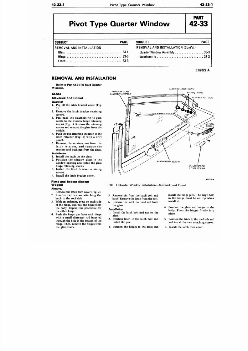
8/20/2019 1977 Ford Car Shop Manual Volume 4 Body
http://slidepdf.com/reader/full/1977-ford-car-shop-manual-volume-4-body 138/449
42-33-1
Pivot Type Quarter Window
42-3
Pivot Ty pe Quarter W indow
P A R T
42-33
SUBJECT PAGE
REMOVAL
AND
I NS TA LLA TI ON
Glass 33-1
Hinge
33-3
Latch 33-3
SUBJECT
PAG
REMOVAL AND INSTALLATION (Cont 'd . )
Quarter Window Assembly 33
Weatherstrip 33
CR2027
REMOVAL AND INSTALLATION
Refer to Part 43-01
for
fixed Quarter
Windows.
GLASS
Maverick and Comet
Removal
1. Pry off the latch bracket cover (Fig.
1).
2.
Remove the latch bracket retaining
screws.
Peel back the w ea th er s t rip to gain
access to the window hinge retaining
screws (Fig. 1). Remove the retaining
screws
and
remove
the
glass from
the
vehicle.
Push the pin attaching the latch
to the
la tch retainer (Fig. 1) with a drift
punch.
R emo v e the r e ta in er nut from the
l a t c h r e t a i n e r , and r e m o v e the
retainer
and
bushings from
the
glass.
Installation
1. Install the latch on the glass.
Po s i t io n
the
w in d o w g las s
in the
window opening and install the glass
hinge retaining screws.
Instal l the latch bracket retain ing
screws.
Install the latch bracke t cover.
3.
4.
5.
2.
3.
4.
Pinto and Bobcat (Except
Wagon)
Removal
1. Remove the latch trim cover (Fig. 2).
2.
R e m o v e
two
sc r ews a t tach in g
the
latch to the roof side.
3.
With
an
assistant, press
on
each side
of the hinge, and pull the hinge from
the body. Repeat this procedure for
the other hinge.
4. Push the hinge pin from each hinge
with a small d iameter rod inserted
through the hole in the bottom of the
hinge. Then, remove
the
hinges from
the glass frame.
W INDO W GLASS
ASSEMBLY 6229706-7
LATCH RETAINER-302A02
BUSHINP-302A02
RETAINER NUT
LATCH BRACKET
COVER 6230584
FIG. 1 Quarter W indow Installation—Mav erick and Comet
5. Remove pin from the latch bolt and
latch. Remove the latch from the bolt.
6. Remove the latch bolt and nut from
the glass.
Installation
1. Install
the
latch bolt
and nut on the
glass.
2.
Position latch
to the
latch bolt
and
install the pin.
3.
Position the hinges to the glass and
install the hinge pins. The larg
in the h inge must be on top
installed.
4. Position the glass and hinges
body. Press the hinges firml
place.
5. Position the latch to the roof s
and install
the two
attaching s
6. Install the latch trim cover.
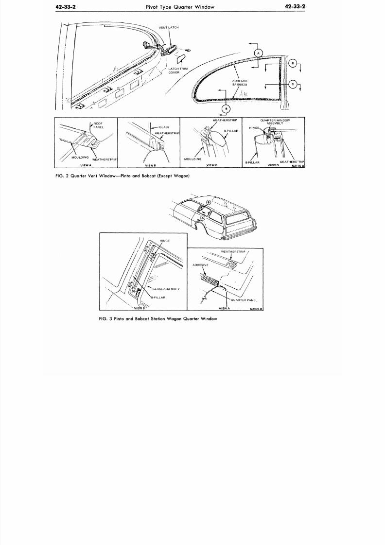
8/20/2019 1977 Ford Car Shop Manual Volume 4 Body
http://slidepdf.com/reader/full/1977-ford-car-shop-manual-volume-4-body 139/449
42-33-2
Pivot Type Quarter Window
42-33-2
VENT LATCH
WEATHERSTRIP
VIEW A
-—GLASS
WEATHERSTRIP
VIEWB
WEATHERSTRIP
B-PILLAR
MOULDING
VIEWC
QUARTER
WINDOW
ASSEMBLY
HINGE
B-PILLAR WEATHERS"RIP
VIE W P N21 75-B
FIG . 2 Quarter Vent Wind ow— Pinto and Bobcat (Except Wag on)
•QUARTER PANEL
I
VIEW A N2478-B
FIG.
3 Pinto and Bobcat Station Wa gon Quarter W indow
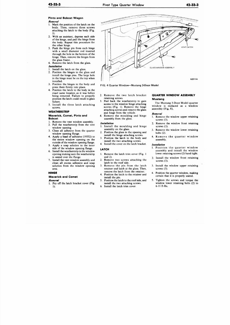
8/20/2019 1977 Ford Car Shop Manual Volume 4 Body
http://slidepdf.com/reader/full/1977-ford-car-shop-manual-volume-4-body 140/449
42-33-3
Pivot Type Quarter Window
42-
Pinto and Bobcat Wa gon
Removal
1. Mark the position of the latch on the
body. Then, remove three screws
attaching the latch to the body (Fig.
3).
2. With an assistant, depress each side
of the hinge, and pull the hinge from
the body. Repeat this procedure for
the other hinge.
3.
Push the hinge pin from each hinge
with a small diameter rod inserted
through the hole in the bottom of the
hinge. Then, remove the hinges from
the glass frame.
4. Remove the latch from the glass.
Installation
1. Install the latch on the glass.
2. Position the hinges to the glass and
install the hinge pins. The large hole
in the hinge must be on the top when
installed.
3.
Position the hinges to the body and
press them firmly into place.
4. Position the latch to the body in the
exact same location as it was before
being removed. Failure to properly
position the latch could result in glass
failure.
5. Install the three latch attaching
screws.
WEATHERSTRIP
Maver ick , Comet, P in to and
Bobcat
1.
Remove the vent window assembly.
2. Pull the weatherstrip from the vent
window opening.
3.
Clean all adhesive from the qua rter
window opening flange.
4. Apply a bead of adhesive (19552) to
the entire window opening on the
outside of the window opening flange.
5. Apply a soap solution to the inner
side of the window opening flange.
6. Install the weatherstrip in the window
opening making sure the weatherstrip
is seated over the flange.
7. Install the vent window assembly and
clean all excess adhesive and soap
solution from the window opening
area.
HINGE
M aver ick an d Co m et
Removal
1. Pry off the latch bracket cover (Fig.
1).
GLASS WINDOW ASSEMBLY
N
FIG. 4 Quarter Window—Mustang 3-Door Model
2. Remove the two la tch bracke t
retaining screws.
3.
Peel back the weatherstrip to gain
access to the window hinge attaching
screws (Fig. 1). Remove the hinge
attaching screws and remove the glass
and hinge from the vehicle.
4.
Remove the moulding and hinge
assembly from the glass.
Installation
1. Install the moulding and hinge
assembly on the glass.
2.
Position the glass in the opening and
install the hinge attaching screws.
3.
Position the latch to the body and
install the two attaching screws.
4. Install the cover on the latch bracket.
LATCH
1. Remove the latch trim cover (Fig. 1
and 2).
2. Remove two screws attaching the
latch to the roof side.
3.
Remove the pin from the latch
retainer and latch at the glass. Then,
remove the latch from the retainer.
4.
Position the latch to the retainer and
install the pin.
5. Position the latch to the roof side, and
install the two attaching screws.
6. Install the latch trim cover.
QUARTER WI ND O W ASSEMB
M u s t a n g
The Mustang 3-Door Model qu
window is replaced as a wi
assembly (Fig. 4 ).
Removal
1. Remove the window upper reta
screws (3).
2. Remove the window front ret
screws (3).
3.
Remove the window lower ret
bolts (2).
4. R e m o v e t h e q u a r t e r w i n
assembly.
Installation
1.
P o s i t i o n t h e q u a r t e r w i n
assembly and install the wi
lower retaining screws (2) hand
2. Install the window front ret
screws (3).
3. Install the window upper reta
screws (3).
4.
Position the qua rter window, m
certain that it is properly seate
5. Tighten the screws and torqu
window lower retaining bolts
6-11 ft-lbs.
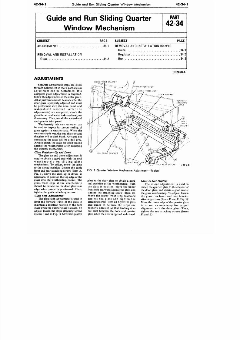
8/20/2019 1977 Ford Car Shop Manual Volume 4 Body
http://slidepdf.com/reader/full/1977-ford-car-shop-manual-volume-4-body 141/449
42-34-1
Guide and Run Sliding Quarter Windo w Mechanism
42-34-1
Guide and Run Sliding Quarter
Window Mechanism
P A R T
42-34
SUBJECT
ADJUSTMENTS
34-1
REM O VAL AND INST AL L AT IO N
Glass
PAGE SUBJECT PAGE
REMOVAL
AND
INSTA LLATIO N (Cont 'd.)
Guide 34-3
Regulator
34-2
34-2 Run 34-3
ADJUSTMENTS
Separate adjustment steps
are
given
for each adjustment so that a partial glass
adjustment
can be
performed.
If a
complete glass adjustment
is
required,
follow the adjustments in the order given.
All adjustments should be made after the
door glass is properly adjusted and must
be performed with
the
trim panel
and
w a te r sh i e ld r e m ove d . A f t e r the
adjustment(s)
are
completed, check
the
glass
for
air and w ater leaks and readjust
if necessary. Then, install the watershield
and quarter trim panel.
Weatherstrip lubricant or water can
be used
to
inspect
for
proper sealing
of
glass against a weatherstrip. When the
weatherstrip
is
wet, the area that contacts
the glass will be dark black. Any area not
contacting the glass will be a dull grey.
Always check
the
glass
for
good sealing
against the weatherstrip after adjusting
the window mechanism.
Glass Position
—
Up and Down
The glass up and down adjustment is
used
to
obtain
a
good seal with
the
roof
w e a t h e r s t r i p on s l i d i n g g l a s s
mechanisms.
To
adjust, move
the
glass
to
the
closed position. Loosen
the
guide
front and rear attaching screws (Item A,
Fig.
1).
Move
the
glass
up or
down,
as
necessary, to position the top edge of the
glass into
the
weatherstrip pocket.
The
glass front edge at the weatherstrip
should
be
parallel
to the
door glass rear
edge when properly positioned. Then,
tighten
the
guide attaching screws.
Glass Stop Adjustments
The glass stop adjustment is used to
limit
the
forward travel
of the
glass
to
maintain a constant position
to the
door
glass when the quarter glass is closed. To
adjust, loosen the stops attaching screws
(Items B and C, Fig. 1). Move the quarter
CR2028-A
GUIDE FRONT BRACKET
A
I.
//UPPER FRONT STOP
LOWER FRONT STOP
GUIDE ASSEMBLY
Vt
REAR STOP
ATTACHING
BOLT
" * - . .
%
. . / ^ R U N R EA R B RA CK ET N 17 6-C
FIG.
1
Quarter Window Mechanism Adjustment—Typical
glass to
the
door glass to obtain a good
seal position
at
the
weatherstrip. With
the glass
in
position, move
the
upper
front stop rearward against the glass and
tighten the attachin g screw (Item B).
Move
the
lower front stop rearward
agains t the glass and t ighten the
attaching screw (Item C). Cycle the glass
and check
to be
sure
the
stops
are
properly adjusted so that binding does
not exist between
the
door
and
quarter
glass when the door is opened and closed.
Glass In-Out Position
The in-out adjustment
is
used
:o
match the quarter glass to the contour of
the door glass,
and
obtain
a
good seal
at
the glass weatherstrip.
To
adjust, loosen
the glass run front and rear bracket
attaching screws (Items D and E, Fig.
I).
Move the lower edge of the quarter glass
in
or out as
necessary
for
proper
alignment with
the
door glass. Then,
tighten the run attaching screws (Items
D
and E).
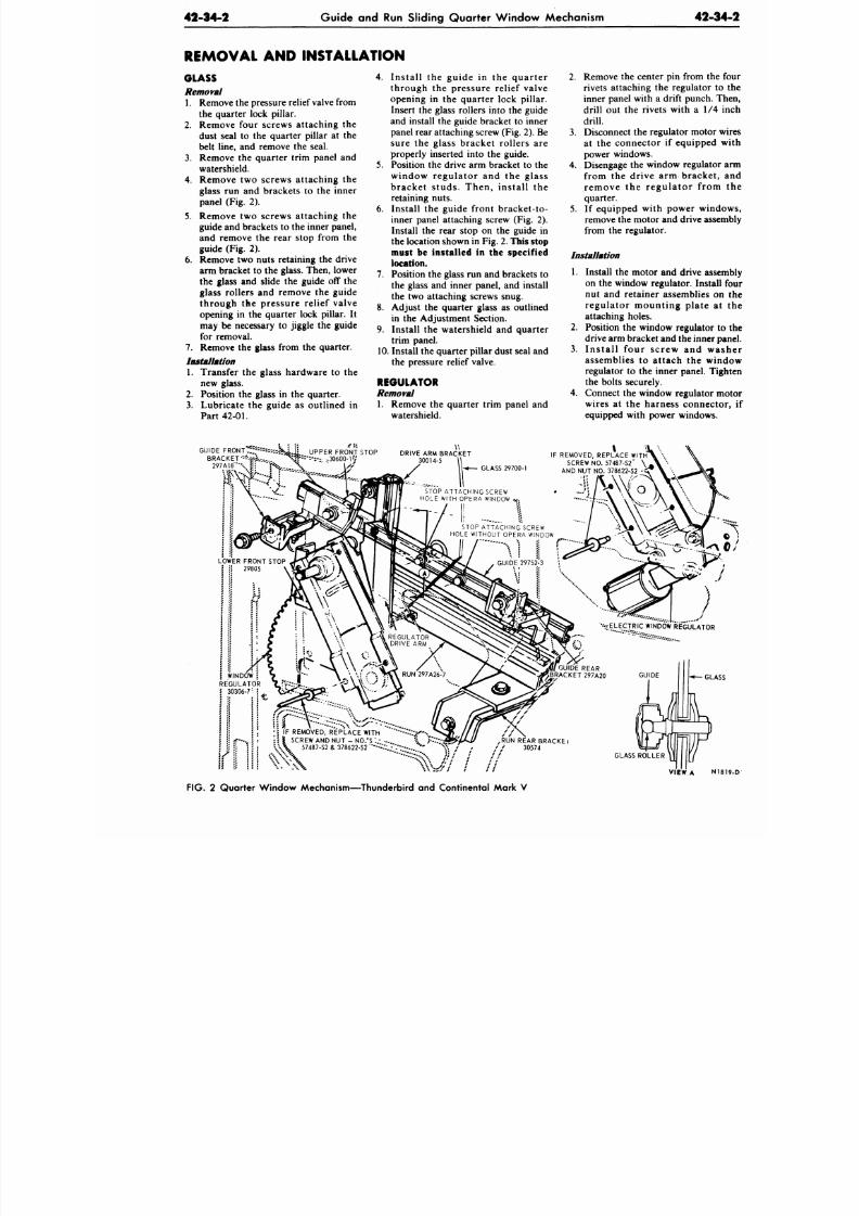
8/20/2019 1977 Ford Car Shop Manual Volume 4 Body
http://slidepdf.com/reader/full/1977-ford-car-shop-manual-volume-4-body 142/449
42-34-2
Guide and Run Sliding Quarter Window Mechanism
42-3
REMOVAL AND INSTALLATION
GLASS
Removal
1. Remove the pressure relief
valve
from
the quarter lock pillar.
2 . Remove four screws attach ing the
dust seal to the quarter pillar at the
belt line, and remove the seal.
3 .
Remove the quarter trim panel and
watershield.
4 .
Remove two screws attaching the
glass run and brackets to the inner
panel (Fig. 2).
5 .
Remove two screws attaching the
guide and brackets to the inner panel,
and remove the rear stop from the
guide (Fig. 2).
6. Remove two nuts retaining the drive
arm bracket to the glass. Then, lower
the glass and slide the guide
off
the
glass rollers and remove the guide
through the pressure relief valve
opening in the quarter lock pillar. It
may be necessary to jiggle the guide
for removal.
7 .
Remove the glass from the quarter.
Installation
1.
Transfer the glass hardware to the
new glass.
2 .
Position the glass in the quarter.
3 .
Lubrica te the guide as outlined in
Part
42-01.
4 . Install the guide in the quarte r
through the pressure relief valve
opening in the quarter lock pillar.
Insert the glass rollers into the guide
and install the guide bracket to inner
panel rear attaching screw F i g . 2 ) . Be
sure the glass bracket rollers are
properly inserted into the guide.
5 .
Position the drive arm bracket to the
window regulator and the glass
bracket studs. Then, install the
retaining nuts.
6. Install the guide front bracket-to-
inner panel attaching screw (Fig. 2).
Install the rear stop on the guide in
the location shown in
F i g . 2 .
This stop
must be installed in the specified
location.
7 .
Position the glass run and brackets to
the glass and inner panel, and install
the two attaching screws snug.
8. Adjust the quarter glass as outlined
in the Adjustment Section.
9. Install the watershield and quarter
trim panel.
1 0 .
Install the quarter pillar dust seal and
the pressure relief valve.
REGULATOR
Removal
1. Remove the quarter trim panel and
watershield.
2 .
Remove the center pin from th
rivets attaching the regulator
inner panel with a drift punch.
drill out the rivets with a 1/4
drill.
3 . Disconnect the regulator motor
at the connector if equipped
power w indows.
4 .
Disengage the window regulato
from the drive arm bracket
remove the regulator from
quarter.
5 .
If equipped with power win
remove the m otor and drive ass
from the regulator.
Installation
1.
Install the motor and drive ass
on the window regulator. Insta
nut and retainer assemblies o
regulator mounting plate a
attaching holes.
2 .
Position the window regulator
drive arm bracket and the inner
3 .
Install four screw and w
assemblies to attach the wi
regulator to the inner panel. T
the bolts securely.
4 .
Connect the window regulator
wires at the harness connec
equipped with power windows
GUIDE FRONT' f:*
:
"--tt
BRACKET
GLASS 29700-1
IF REMOVED, REPLACE WITH
SCREW NO. 57487 -S2' \
AND NUT NO. 378622-S2 -
UPPER FRONT STOP
--.--.
;
. 30600-1?/
DRIVE ARM BRACKET
30014-5
STOP ATT ACHING SCREW
HOLE WITH OPERA WINDOW
STOP ATT ACHING SCREW
HOLE WITHOUT OPERA WINDOW
W I N D O W J
R E G U L A T O R
30306- 7
\
• • *E L EC T RI C W I N D O W R E G U L A T O R
. . : y .
v
.
v
G U I D E
. IF REMOVED, REPLACE
\\ \ SCREW AND NUT
\
57487-S2 & 378622-S2
ACEWTh - X ^ X
-
NO. 'S :.-
... i £>?
622-S2
" * - - • - - ; . - > - . . . . • "
*••?
111
*U N
REAR BRACKE i
/ 30574
GLA
GLASS ROLLE R
VIEW
A
N
F I G . 2 Quarter W indow Mechanism—Thunderbird and Continental Mark V
8/20/2019 1977 Ford Car Shop Manual Volume 4 Body
http://slidepdf.com/reader/full/1977-ford-car-shop-manual-volume-4-body 143/449
42-34-3 Guide
and Run
Sliding Quarter W indow Mechanism
42-34-3
5.
C h e c k the w i n d o w for p r o p e r
o p e r a t i o n . T h e n , i n s t a l l the
watershield and quarter trim panel.
GUIDE
Removal
1.
Remo ve the pressure relief valve from
the quarter lock pillar.
2.
Remove four screws a t taching the
dust seal
to the
quarter lock pillar
at
the belt line, and remove the seal.
3.
Remove
the
quar ter trim panel
and
watershield.
4.
R e m o v e two s c rews a t t ach ing the
guide and brackets to the inner panel
(Fig. 2).
5. Remove
the
rear stop from
the
guide
(Fig. 2).
6. Remove
two
nuts retaining
the
drive
a rm bracke t to the glass (Fig. 2).
Then, lift the glass up and out of the
run. Lower the glass and slide the
guide off the glass rollers and remove
the guide through the pressure relief
valve opening. It may be necessary to
jiggle
the
guide
for
removal.
7 . Remove the b r a c k e t s , s t o p , and
bumper from the guide.
Installation
1. Assemble the b racke t s , s top , and
bumper to the guide (Fig. 2).
2.
L ubr ica te the guide as out l ined in
Part
42-01.
3.
Ins e r t
the
gu ide in to
the
q u a r t e r
t h r o u g h the pres sure re l ief va lve
opening. Insert
the
glass rollers into
the guide and position the guide to the
quarter inner panel.
4.
Position the drive arm bracket to the
glass, and install the two re ta ining
nuts.
5.
Install the two screws attaching the
guide bracket
to the
inner panel.
6. Install the rear stop on the guide in
the location shown in Fig. 2.
This stop
must be installed in the specified
location.
7.
Adjust th e guide and upper front stop
a s o u t l i n e d in the A d j u s t m e n t
Section.
8. Install the watershield, qu arter trim
panel, quarte r pillar dust seal, and the
pressure relief valve.
RUN
Removal
1. Remove the qua rter trim panel and
watershield.
2.
Remove the glass run front bracket
a n d r e a r b r a c k e t - t o - i n n e r p a n e l
attaching screws,
and
remove
the run
(Fig. 2).
3.
Remove
the
brackets from
the run.
Installation
1. Position the front and rear brackets
to the g la s s run, and ins ta l l ihe
attaching screws.
2.
Position the run to the inner panel
an d
the
bottom edge
of the
glass.
3.
Install the glass run brackets to-inner
panel attaching screws.
4.
Adjust the glass run as required.
5.
Install the w atershie ld and qua r te r
trim panel.
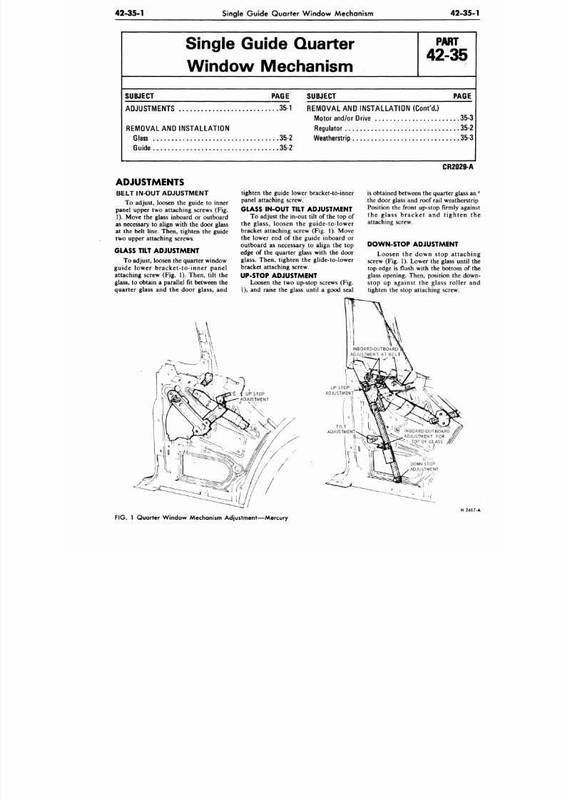
8/20/2019 1977 Ford Car Shop Manual Volume 4 Body
http://slidepdf.com/reader/full/1977-ford-car-shop-manual-volume-4-body 144/449
42-35-1
Single Guide Quarter Window Mechanism
42-35
Single Guide Quarter
Window Mechanism
P A R T
42-35
SUBJECT PAGE
ADJUSTMENTS 35-1
REMOVAL AND INSTALLATION
Glass 35-2
Guide
35-2
SUBJECT PAGE
REMOVAL AND INSTALLATION
(Cont'd.)
Motor and/or Drive
35-
Regulator
35-
Weatherstrip
35-
ADJUSTMENTS
BELT IN-OUT ADJUSTMENT
To adjust, loosen the guide to inner
panel upper two attaching screws (Fig.
1).
Move the glass inboard or outboard
as necessary to align with the door glass
at the belt line. Then, tighten the guide
two upper attaching screws.
GLASS TILT ADJUSTMENT
To adjust, loosen the quarter window
guide lower bracket- to- inner panel
attaching screw (Fig. 1). Then, tilt the
glass, to obtain a parallel fit between the
quarter glass and the door glass, and
tighten the guide lower bracket-to-inner
panel attaching screw.
GLASS IN-OUT TILT ADJUSTMENT
To adjust the in-out tilt of the top of
the glass, loosen the guide-to-lower
bracket attaching screw (Fig. 1). Move
the lower end of the guide inboard or
outboard as necessary to align the top
edge of the quarter glass with the door
glass. Then, tighten the glide-to-lower
bracket attaching screw.
UP-STOP ADJUSTMENT
Loosen the two up-stop screws (Fig.
1), and raise the glass until a good seal
CR2029-A
is obtained between the quarter glass
the door glass and roof rail weatherst
Position the front up-stop firmly aga
the glass bracket and t ighten
attaching screw.
DOWN-STOP ADJUSTMENT
Loosen the down stop attach
screw (Fig. 1). Lower the glass until
top edge is flush with the bottom of
glass opening. Then, position the do
stop up against the glass roller a
tighten the stop attaching screw.
N 24
FIG.
1 Quarter Window Mechanism Adjustment—Mercury
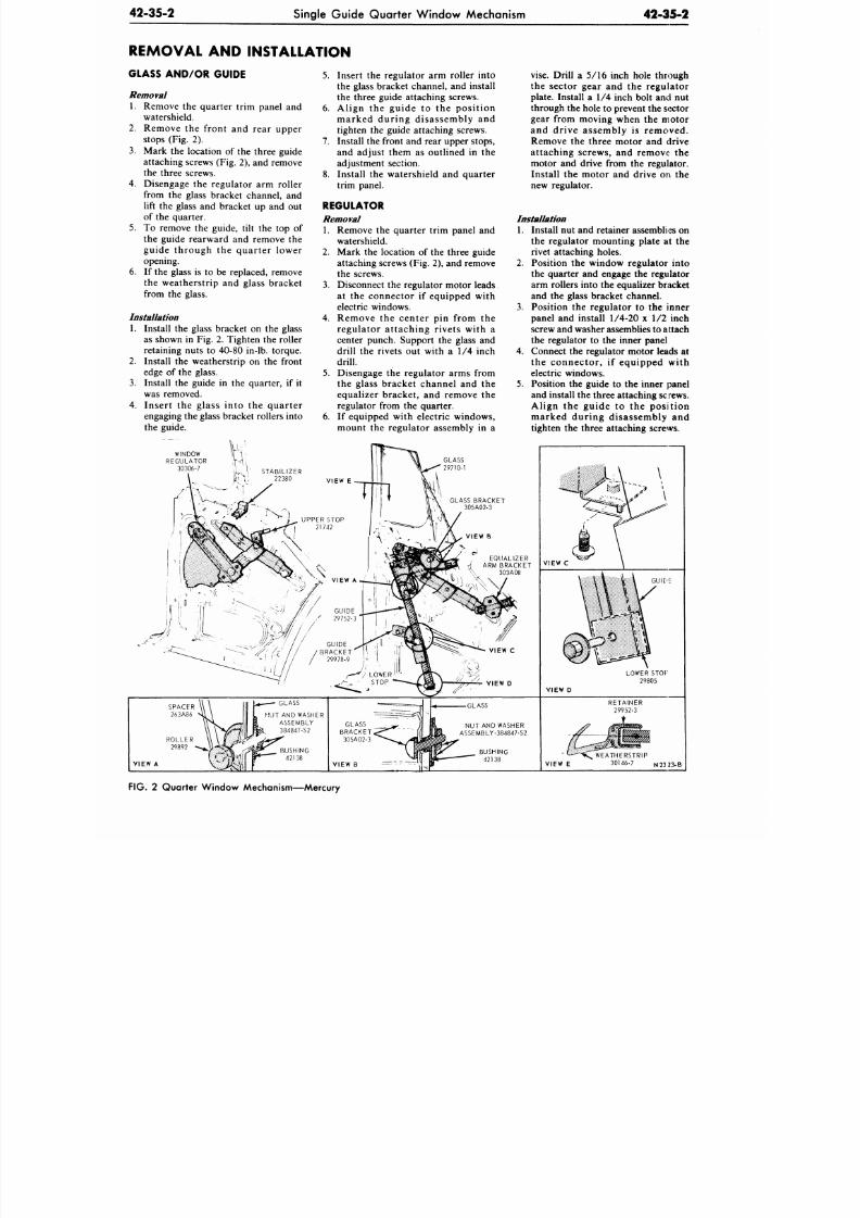
8/20/2019 1977 Ford Car Shop Manual Volume 4 Body
http://slidepdf.com/reader/full/1977-ford-car-shop-manual-volume-4-body 145/449
42-35-2
Single Guide Qu arter W indow Mechanism
42-35-2
REMOVAL AND INSTALLATION
GLASS AND/OR GUIDE
Removal
1. Remove the quarter trim panel and
watershield.
2.
Remove the front and rear upper
stops (Fig. 2).
3.
Mark the location of the three guide
attaching screws (Fig. 2), and remove
the three screws.
4.
Disengage the regulator arm roller
from the glass bracket channel, and
lift the glass and bracket up and out
of the quarter.
5.
To remove the guide, tilt the top of
the guide rearward and remove the
guide through the quarter lower
opening.
6. If the glass is to be replaced, remove
the weatherstrip and glass bracket
from the glass.
Installation
2.
4.
Install the glass bracket on the glass
as shown in Fig. 2. Tighten the roller
retaining nuts to 40-80 in-lb. torque.
Install the weatherstrip on the front
edge of the glass.
Install the guide in the quarter, if it
was removed.
Insert the glass into the quarter
engaging the glass bracket rollers into
the guide.
WINDOW
REGULATOR
30306-7
5.
Insert the regulator arm roller into
the glass bracket channel, and install
the three guide attaching screws.
6. Align the guide to the position
marked during disassembly and
tighten the guide attaching screws.
7. Install the front and rear upper stops,
and adjust them as outlined in the
adjustment section.
8. Install the watershield and quarter
trim panel.
REGULATOR
Removal
1. Remove the quarter trim panel and
watershield.
2.
Mark the location of the three guide
attaching screws (Fig. 2), and remove
the screws.
3. Disconnect the regulator motor leads
at the connector if equipped with
electric windows.
4.
Remove the center pin from the
regulator attaching rivets with a
center punch. Support the glass and
drill the rivets out with a 1/4 inch
drill.
5.
Disengage the regulator arms from
the glass bracket channel and the
equalizer bracket, and remove the
regulator from the quarter.
6. If equipped with electric windows,
mount the regulator assembly in a
GLASS
29710-1
GLASS BRACKET
305A02-3
vise. Drill a 5/16 inch hole through
the sector gear and the regulator
plate. Install a 1/4 inch bolt and nut
through the hole to prevent the sector
gear from moving when the motor
and drive assembly is removed.
Remove the three motor and drive
attaching screws, and remove the
motor and drive from the regulator.
Install the motor and drive on the
new regulator.
Installation
1. Install nut and retainer assemblies on
the regulator mounting plate at the
rivet attaching holes.
2.
Position the window regulator into
the quarter and engage the regulator
arm rollers into the equalizer bracket
and the glass bracket channel.
3. Position the regulator to the inner
panel and install 1/4-20 x 1/2 inch
screw and washer assemblies to attach
the regulator to the inner panel
4.
Connect the regulator motor leads at
the connector, if equipped with
electric windows.
5. Position the guide to the inner panel
and install the three attaching sc rews.
Align the guide to the position
marked during disassembly and
tighten the three attaching screws.
. EQUALIZER
vf ARM BRACKET
^ 303A08
VIEW D
VIEW C
GUIDE
VIEW D
GLASS
HUT AND WASHER
ASSEMBLY
384847-S2
VIEW A
GLASS
NUT AND WASHER
ASSEMBLY-384847-S2
VIEW B
VIEW E
WEATHERSTRIP
30146-7 N23 23-B
FIG.
2 Quarter Window Mechanism—Mercury
8/20/2019 1977 Ford Car Shop Manual Volume 4 Body
http://slidepdf.com/reader/full/1977-ford-car-shop-manual-volume-4-body 146/449
42-35-3
Single Guide Quarter Window Mechanism
42-35
6. Check the window operation and
install the watershield and quarter
trim panel.
MOTOR AND/OR DRIVE
Removal
1. Remove the quarter trim panel and
watershield.
2. Locate two dril l dimples in the
quarter inner panel.
3. Raise the glass to the UP position and
drill two 3/4 inch holes in the inner
panel with a hole saw. The hole saw
pilot drill should be as short as
possible, about 1/4 inch beyond the
saw.
4. Disconnect the motor lead wires at
the connector.
5.
Remove three motor and drive
attaching screws and remove the
motor and drive from the regulator.
Installation
1.
Position the motor and drive to the
regulator and install the three screws
just snug—not tight.
2. Connect the motor wires at the
connector and cycle the glass to
assure gear engagement . Then,
tighten the three motor and dr
attaching screws.
3.
Install body tape over the two
inch drilled holes.
4. Install the watershield and quar
trim panel.
QUARTER W IND OW
WEATHERSTRIP
The weatherstrip is held on the gl
by the r e t a ine r . T o r e p l a c e
weatherstrip, slide it up and out of
retainer. Lubricate the new weathers
before sliding it into the retainer.
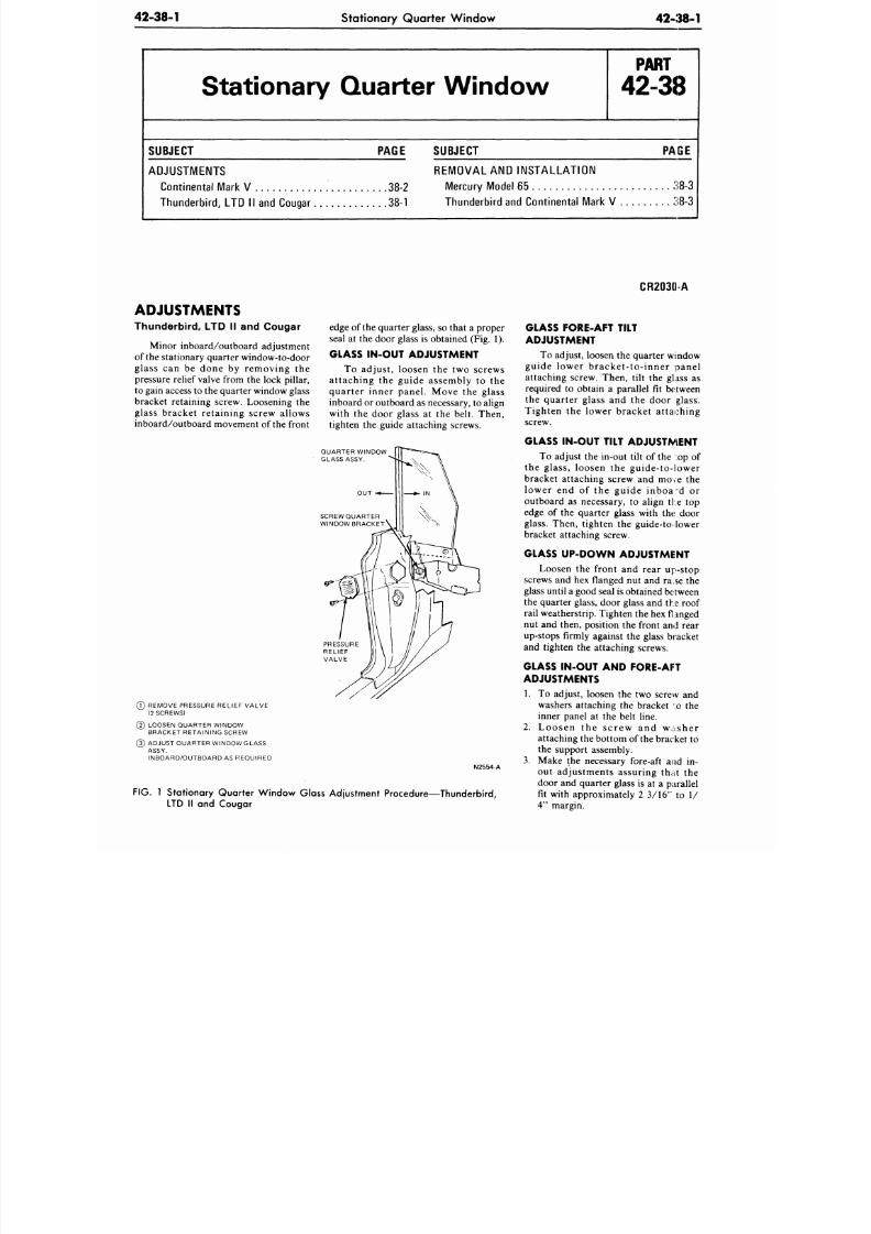
8/20/2019 1977 Ford Car Shop Manual Volume 4 Body
http://slidepdf.com/reader/full/1977-ford-car-shop-manual-volume-4-body 147/449
42-38-1
Stationary Quarter Window
42-38-1
Stationary Quarter W indow
P A R T
42-38
SUBJECT PAGE
SUBJECT PAGE
ADJUSTMENTS
Continental Mark V 38-2
Thu nde rbird , LTD II and Cougar 38-1
REM O VAL AND INST AL L AT IO N
Mercury Model 65 38-3
Thu nde rbird and Continental Mark V 38-3
ADJUSTMENTS
Thunderbird, LTD II and Cougar
Minor inboard/outboard adjustment
of the stationary quarter window-to-door
glass can be done by removing the
pressure relief valve from the lock pillar,
to gain access to the quarter window glass
bracket retaining screw. Loosening the
glass bracket retaining screw allows
inboard/outboard movement of the front
edge of the quarter
glass,
so that a proper
seal at the door glass is obtained (Fig. 1).
GLASS IN-OUT ADJUSTMENT
To adjust, loosen the two screws
attaching the guide assembly to the
quarter inner panel. Move the glass
inboard or o utboard as necessary, to align
with the door glass at the belt. Then,
tighten the guide attaching screws.
QUARTER WINDOW
GLASS ASSY.
O U T
SCREW QUARTE R
WINDOW BRACKET
(7) REMOVE PRESSURE RELIEF VALVE
(2 SCREWS)
(2) LOOSEN QUARTER WINDOW
BRACKET RETAINING SCREW
(3) ADJUST QUARTER WINDOW GLASS
ASSY.
INBOARD/OUTBOARD AS REQUIRED
FIG.
1 Stationary Quarter W indow Glass Adjustme nt Procedure—Thunderbird,
LTD II and Cougar
CR2030-A
GLASS FORE-AFT TILT
ADJUSTMENT
To adjust, loosen the quarter window
guide lower bracket- to- inner panel
attaching screw. Then, tilt the glass as
required to obtain a parallel fit between
the quarter glass and the door glass.
Tighten the lower bracket attaching
screw.
GLASS IN-OUT TILT ADJUSTMENT
To adjust the in-out tilt of the :op of
the glass, loosen the guide-to-lower
bracket attaching screw and move the
lower end of the guide inboa-d or
outboard as necessary, to align the top
edge of the quarter glass with the door
glass. Then, tighten the guide-to- lower
bracket attaching screw.
GLASS UP-DO W N ADJUSTMENT
Loosen the front and rear up-stop
screws and hex flanged nut and ra^se the
glass until a good seal is ob tained between
the quarter glass, door glass and the roof
rail weatherstrip. Tighten the hex fl anged
nut and then, position the front and rear
up-stops firmly against the glass bracket
and tighten the attaching screws.
GLASS IN-OUT AND FORE-AFT
ADJUSTMENTS
1. To adjust, loosen the two screw and
washers attaching the bracket :o the
inner panel at the belt line.
2. Loosen the sc rew and washer
attaching the bottom of the bracket to
the support assembly.
3. Make the necessary fore-aft and in-
out adjustments assuring that the
door and quarter glass is at a parallel
fit with approximately 2 3/16" to 1/
4" margin.
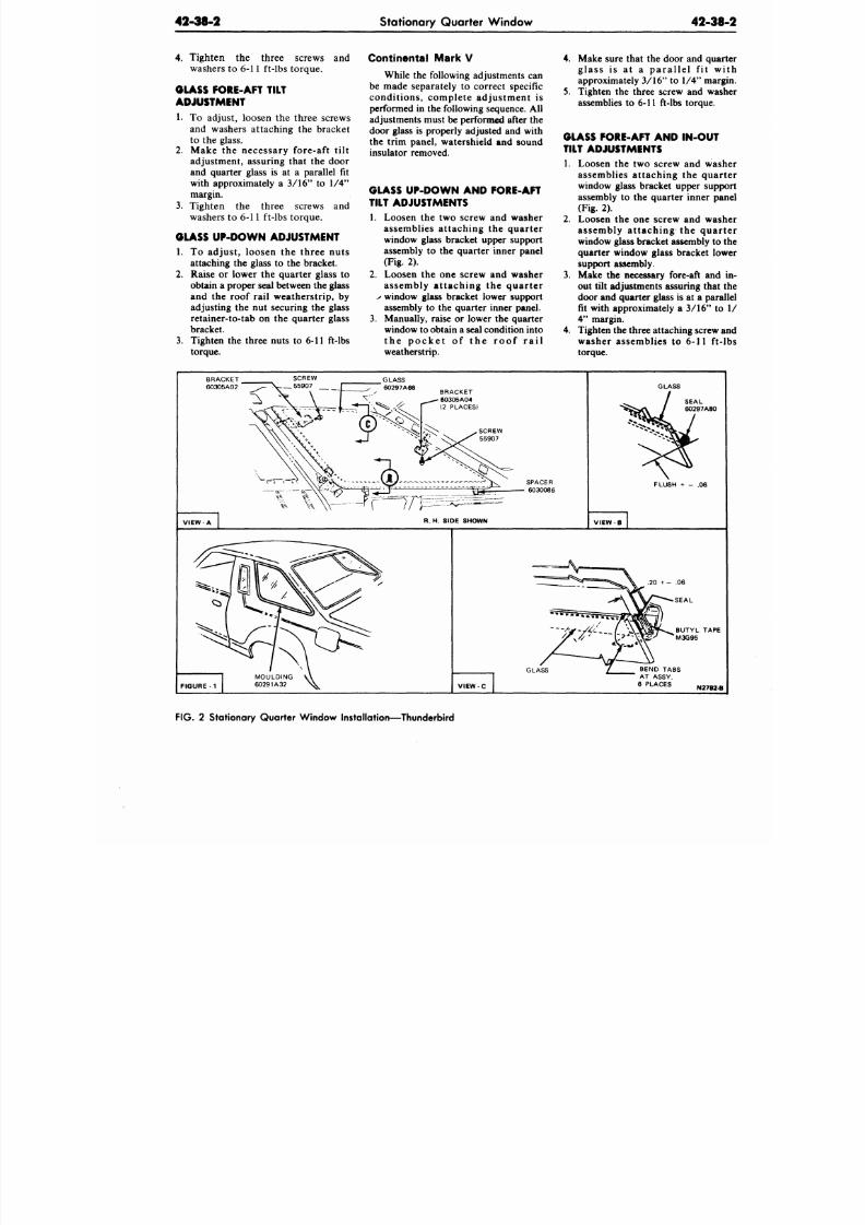
8/20/2019 1977 Ford Car Shop Manual Volume 4 Body
http://slidepdf.com/reader/full/1977-ford-car-shop-manual-volume-4-body 148/449
42-38-2 Stationary Quarter Window
42-38
4. Tighten the three screws and
washers to 6-11 ft-lbs torque.
GLASS FORE-AFT TILT
ADJUSTMENT
1. To adjust, loosen the three screws
and washers attaching the bracket
to the glass.
2. Make the necessary fore-aft tilt
adjustment, assuring that the door
and quarter glass is at a parallel fit
with approximately a 3/16" to 1/4"
margin.
3. Tighten the three screws and
washers to 6-11 ft-lbs torque.
GLASS UP-DO W N ADJUSTMENT
1. To adjust, loosen the three nuts
attaching the glass to the bracket.
2. Raise or lower the quarte r glass to
obtain a proper seal between the glass
and the roof rail weatherstrip, by
adjusting the nut securing the glass
retainer-to-tab on the quarter glass
bracket.
3. Tighten the three nuts to 6-11 ft-lbs
torque.
Continental Mark V
While the following adjustments can
be made separately to correct specific
condit ions, complete adjustment is
performed in the following sequence. All
adjustments must be performed after the
door glass is properly adjusted and with
the trim panel, watershield and sound
insulator removed.
GLASS UP -DO W N AN D FORE-AFT
TILT ADJUSTMENTS
1. Loosen the two screw and washer
assemblies at taching the quarter
window glass bracket upper support
assembly to the quarter inner panel
(Fig. 2).
2. Loosen the one screw and washer
assembly a t taching the quar te r
s
window glass bracket lower support
assembly to the quarter inner panel.
3. Manually, raise or lower the quarter
window to obtain a seal condition into
t h e p o c k e t o f t h e r o o f r a i l
weatherstrip.
4.
Make sure that the door and qua
glass is at a parallel f i t w
approximately 3/16" to 1/4" mar
5. Tighten the three screw and wa
assemblies to 6-11 ft-lbs torque.
GLASS FORE-AFT AND IN-OUT
TILT ADJUSTMENTS
1. Loosen the two screw and was
assemblies attaching the qua
window glass bracket upper sup
assembly to the quarter inner pa
(Fig. 2).
2. Loosen the one screw and wa
assembly a t taching the qua
window glass bracket assembly to
quarter window glass bracket lo
support assembly.
3.
Make the necessary fore-aft and
out tilt adjustments assuring that
door and quarter glass is at a para
fit with approximately a 3/16" to
4"
margin.
4.
Tighten the three attaching screw
washer assemblies to 6-11 ft
torque.
GLASS
6O297A68
BRACKET
60305A04
(2 PLACES)
SCREW
55907
VIEW A
R. H. SIDE SHOWN
GLASS
FLUSH + - .06
VIEW B
VIEW C
BUTYL TAPE
M3G95
GLASS
BEND TABS
AT ASSY.
6 PLACES
N2782-B
FIG. 2 Stationary Quarter Window Installation—Thunderbird
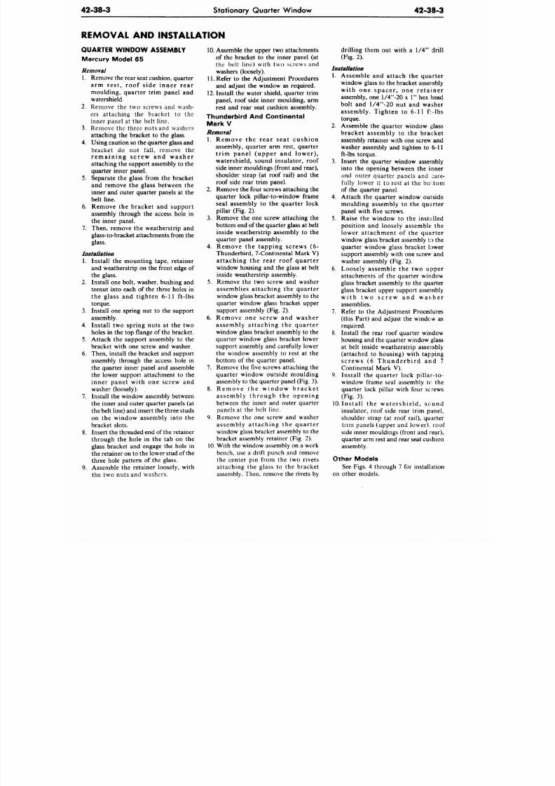
8/20/2019 1977 Ford Car Shop Manual Volume 4 Body
http://slidepdf.com/reader/full/1977-ford-car-shop-manual-volume-4-body 149/449
42-38-3
Stationary Quarter Window
42-38-3
REMOVAL AND INSTALLATION
QUARTER W IND OW ASSEMBLY
Mercury Model 65
Removal
1.
Remove the rear seat cushion, quarter
arm rest, roof s ide inner rear
moulding, quarter trim panel and
watershield.
2. Remove the two screws and wash-
ers attaching the bracket to the
inner panel at the belt line.
3. Remove the three nuts and washers
attaching the bracket to the glass.
4.
Using caution so the quarter glass and
bracket do not fall, remove the
r e m a i n i n g s c r e w a n d w a s h e r
attaching the support assembly to the
quarter inner panel.
5.
Separate the glass from the bracket
and remove the glass between the
inner and outer quarter panels at the
belt line.
6. Remove the bracket and support
assembly through the access hole in
the inner panel.
7. Then, remove the weatherstrip and
glass-to-bracket a ttachments from the
glass.
Installation
1. Install the mounting tape, retainer
and weatherstrip on the front edge of
the glass.
2.
Install one bolt, washer, bushing and
teenut into each of the three holes in
the glass and tighten 6-11 ft-lbs
torque.
3. Install one spring nut to the support
assembly.
4.
Install two spring nuts at the two
holes in the top flange of the bracket.
5.
Attach the support assembly to the
bracket with one screw and washer.
6. Then, install the bracket and support
assembly through the access hole in
the quarter inner panel and assemble
the lower support attachment to the
inner panel with one screw and
washer (loosely). .
7.
Install the window assembly between
the inner and outer quarter panels (at
the belt line) and insert the three studs
on the window assembly into the
bracket slots.
8. Insert the threaded end of the retainer
through the hole in the tab on the
glass bracket and engage the hole in
the retainer on to the lower stud of the
three hole pattern of the glass.
9. Assemble the retainer loosely, with
the two nuts and washers.
10.
Assemble the upper two attachments
of the bracket to the inner panel (at
the belt line) with two screws and
washers (loosely).
11. Refer to the Adjustment Procedures
and adjust the window as required.
12.
Install the water shield, quarter trim
panel, roof side inner moulding, arm
rest and rear seat cushion assembly.
Thunderbird And Continental
Mark V
Removal
1. Remove the rear seat cushion
assembly, quarter arm rest, quarter
t r im panel (upper and lower) ,
watershield, sound insulator, roof
side inner m ouldings (front and rear),
shoulder strap (at roof rail) and the
roof side rear trim panel.
2.
Remove the four screws attaching the
quarter lock pillar-to-window frame
seal assembly to the quarter lock
pillar (Fig. 2).
3. Remove the one screw attaching the
bottom end of the quarter glass at belt
inside weatherstrip assembly to the
quarter panel assembly.
4.
Remove the tapping screws (6-
Thunderbird, 7-Continental Mark V)
attaching the rear roof quarter
window housing and the glass at belt
inside weatherstrip assembly.
5.
Remove the two screw and washer
assemblies attaching the quarter
window glass bracket assembly to the
quarter window glass bracket upper
support assembly (Fig. 2).
6. Remove one screw and washer
assembly attaching the quarter
window glass bracket assembly to the
quarter window glass bracket lower
support assembly and carefully lower
the window assembly to rest at the
bottom of the quarter panel.
7. Remove the
five
screws attaching the
quarter window outside moulding
assembly to the quarter panel (Fig. 3).
8. Rem ove the w indow b rac ke t
assembly through the opening
between the inner and outer quarter
panels at the belt line.
9. Remove the one screw and washer
assembly attaching the quarter
window glass bracket assembly to the
bracket assembly retainer (Fig. 2).
10. W ith the window assembly on a work
bench, use a drift punch and remove
the center pin from the two rivets
attaching the glass to the bracket
assembly. Then, remove the rivets by
drilling them out with a 1/4" drill
(Fig. 2).
Installation
1.
Assemble and attach the quarter
window glass to the bracket assembly
with one spacer , one re ta iner
assembly, one l/4"-20 x 1" hex head
bolt and l/4"-20 nut and washer
assembly. Tighten to 6-11
f*-lbs
torque.
2.
Assemble the quarte r window glass
bracket assembly to the bracket
assembly retainer with one screw and
washer assembly and tighten to 6-11
ft-lbs torque.
3. Insert the quarter window assembly
into the opening between the inner
and outer quarter panels and care-
fully lower it to rest at the bottom
of the quarter panel.
4.
Attach the quarter window outside
moulding assembly to the quarter
panel with five screws.
5. Raise the window to the installed
position and loosely assemble the
lower attachment of the quarter
window glass bracket assembly to the
quarter window glass bracket lower
support assembly with one screw and
washer assembly (Fig. 2).
6. Loosely assemble the two upper
attachments of the quarter window
glass bracket assembly to the quarter
glass bracket upper support assembly
w i th tw o s c rew and w as he r
assemblies.
7. Refer to the Adjustment Procedures
(this Part) and adjust the window as
required.
8. Install the rear roof quarter window
housing and the quarte r window glass
at belt inside weatherstrip assembly
(attached to housing) with tapping
s c rew s (6 Thunderb i rd and 7
Continental Mark V).
9. Install the quarter lock pillar-to-
window frame seal assembly to the
quarter lock pillar with four screws
(Fig. 3).
10.
Ins ta l l the w atershie ld , sound
insulator, roof side rear trim panel,
shoulder strap (at roof rail), quarter
trim panels (upper and lower), roof
side inner m ouldings (front and rear),
quarter arm rest and rear seat cushion
assembly.
Other Models
See Figs. 4 through 7 for installation
on other models.
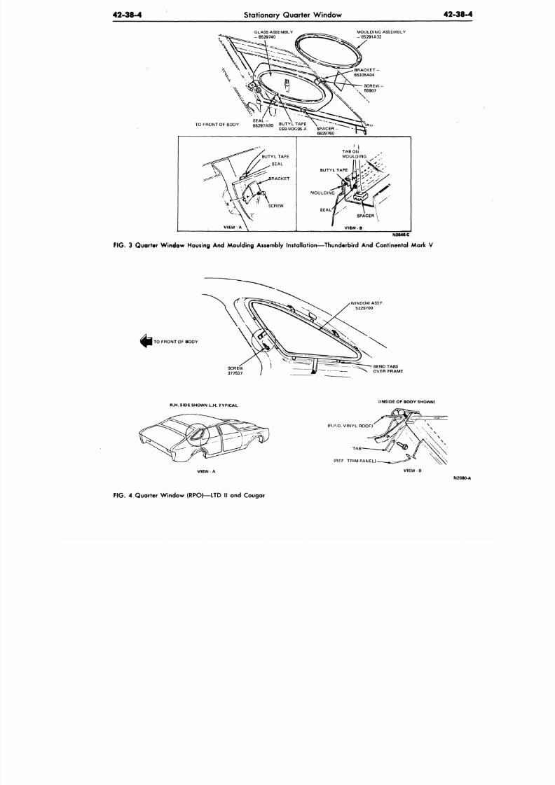
8/20/2019 1977 Ford Car Shop Manual Volume 4 Body
http://slidepdf.com/reader/full/1977-ford-car-shop-manual-volume-4-body 150/449
42-38-4
Stationary Quarter Window
42-38
GLASS ASSEMBLY
- 6529740
MOULDING ASSEMBLY
- 65291A32
SEAL
TO FRONT OF BODY 65297A80 BUTYL TAPE
ESB-M3G95-A SPACER -
6629760
BUTYL TAPE
SEAL
ACKET
SCREW
BUTYL TAPE
MOULDING
SEAL
N2646-C
FIG.
3 Quarter Window Housing And
Moulding
Assembly
Installation—Thunderbird And Continental Mark V
WINDOW ASSY.
5329700
TO FRONT OF BODY
r BEND TABS
OVER FRAME
R.H. SIDE SHOWN L.H. TYPICAL
(INSIDE
OF
BODY SHOWN)
VIEW A
(R.P.O. VINYL ROOF)
TA B
(REF: TRIM PANEL)
VIEW
B
N28
FIG.
4 Quarter Window (RPO>—LTD II and Cougar
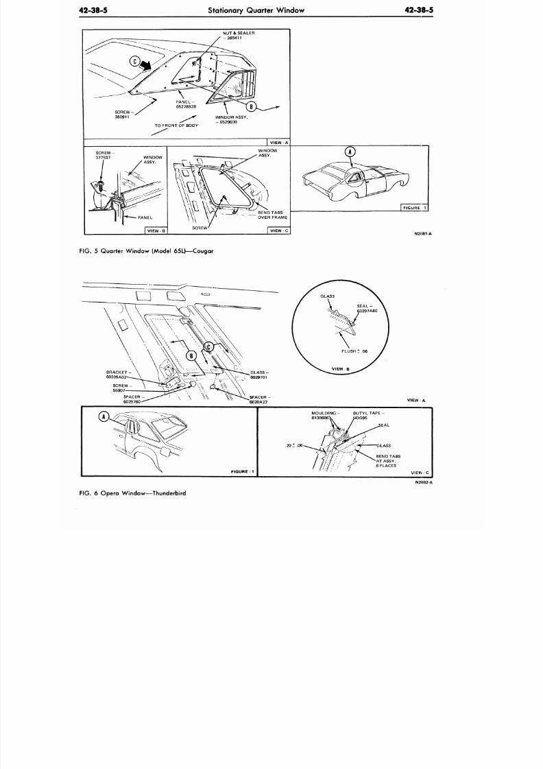
8/20/2019 1977 Ford Car Shop Manual Volume 4 Body
http://slidepdf.com/reader/full/1977-ford-car-shop-manual-volume-4-body 151/449
42-38-5
Stationary Quarter Window
42-38-5
NUT & SEALER
-385411
TO FRONT OF BODY
WINDOW ASSY.
- 6529600
|
VIEW-A
N2(E81-A
FIG. 5
Quarter Window (Model 65L)—Cougar
VIEW A
FIGURE 1
BUTYL TAPE-
G95
EAL
.20 ± .06
VIEW C
N21J82 A
FIG. 6
Opera Window—Thunderbird
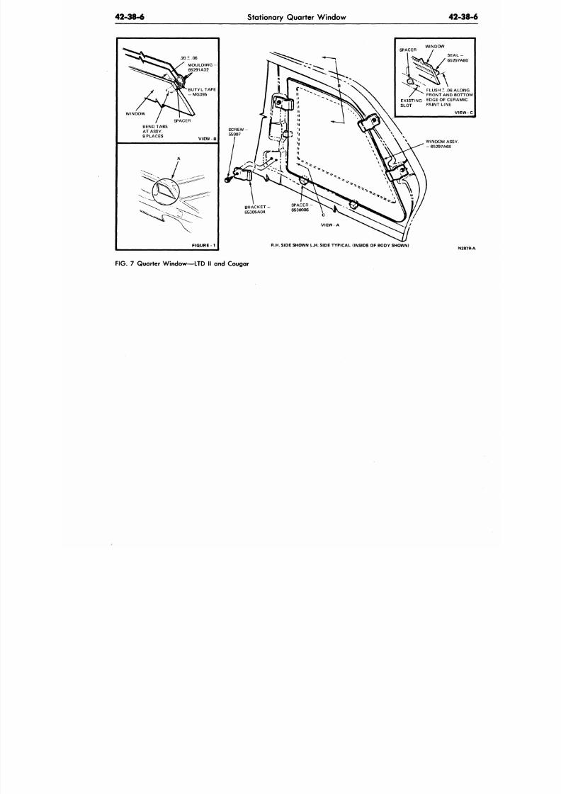
8/20/2019 1977 Ford Car Shop Manual Volume 4 Body
http://slidepdf.com/reader/full/1977-ford-car-shop-manual-volume-4-body 152/449
42-38-6 Stationary Quarter Window
42-38
20 ± .06
MOULDING -
65291A32
BUTYL TAPE
- MG395
WINDOW
VIEW - B
FIGURE -1
SCREW
55907
SPACER
WINDOW
FLUSH ± .06 ALON
FRONT AND BOTTO
EXISTING
E
DGE OF CERAMIC
SLOT PAINT LINE
VIEW
BRACKET
65305A04
WINDOW ASSY.
- 65297A68
R.H. SIDE SHOWN L.H. SIDE TYPICAL (INSIDE OF BODY SHOWN)
N28
FIG. 7 Quarter Window—LTD II and Cougar
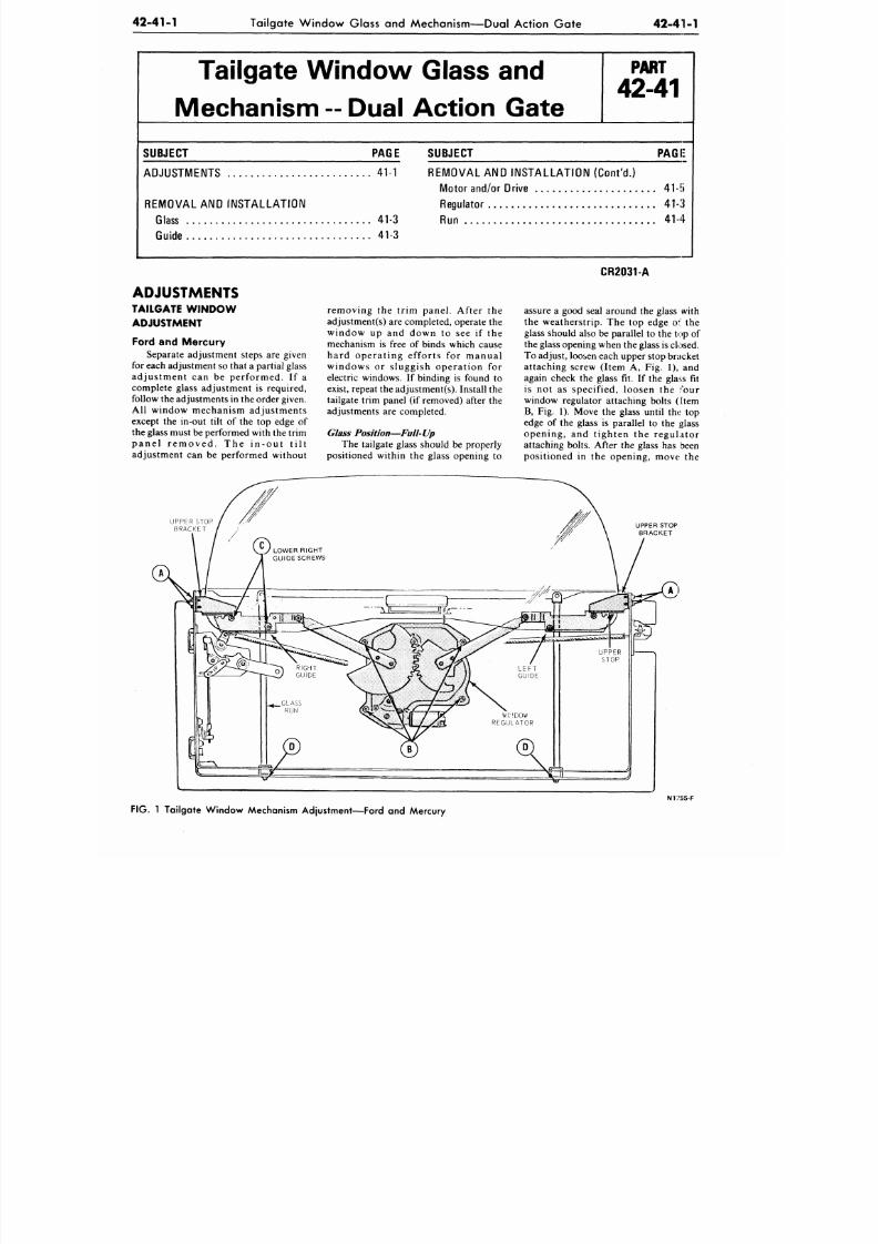
8/20/2019 1977 Ford Car Shop Manual Volume 4 Body
http://slidepdf.com/reader/full/1977-ford-car-shop-manual-volume-4-body 153/449
42-41-1
Tailgate Window Glass
and
Mechanism—D ual Action G ate
42-41-1
Tailgate W indow Glass
and
Mechanism
-
Dual Action Gate
P A R T
42-41
SUBJECT PAGE
ADJUSTMENTS
41-1
REMOVAL AND INSTALLATION
Glass 41-3
Guide
41-3
SUBJECT PAGE
REM O VAL AND INSTALLA TION (Con t 'd . )
Motor and/or Drive
41-{i
Regulator
41-3
Ru n
41-4
ADJUSTMENTS
TAILGATE W IND OW
ADJUSTMENT
Ford
and
Mercury
Separate adjustment steps
are
given
for each adjustment so that a partial glass
a d j u s t m e n t can be p e r f o r m e d . If a
complete glass adjustment
is
required,
follow the adjustments in the order given.
Al l w in d o w mech an ism ad ju s tmen ts
except the in-out tilt of the top edge of
the glass must be performed with the trim
p a n e l r e m o v e d . The i n - o u t t i l t
ad justment can be performed without
r e m o v i n g
the
t r im p an e l . A f te r
the
adjustment(s) are completed, operate the
w i n d o w
up and
d o w n
to see if the
mechanism is free of binds which cause
h a r d o p e r a t i n g e f f o r t s for m a n u a l
w i n d o w s
or
s lu g g i s h o p e r a t i o n
for
electric windows.
If
binding
is
found
to
exist, repeat the adjustmen t(s). Install the
tailgate trim panel (if removed) after the
adjustments are completed.
Glass Position— Full-Up
The tailgate glass should be properly
positioned within the glass opening to
CR2031-A
assure a good seal around the glass with
the weathers tr ip .
The top
edge
of the
glass should also
be
parallel
to
the top of
the glass opening when the glass is closed.
To adjust, loosen each upper stop bracket
attaching screw (Item A, Fig. 1), and
again check the glass fit. If the glass fit
is not as specif ied , loosen the four
window regulator attaching bolts (Item
B, Fig. 1). Move the glass un til th«.
s
top
edge of the glass is parallel to the glass
o p e n i n g , and t i g h t e n the r e g u l a t o r
attaching bolts. After
the
glass
has
been
posit ioned in the opening , m ove the
UPPER STOP
BRACKET
UPPER STOP
BRACKET
FIG.
1 Tailgate Window Mechanism Adjustment—Ford
and
Mercury
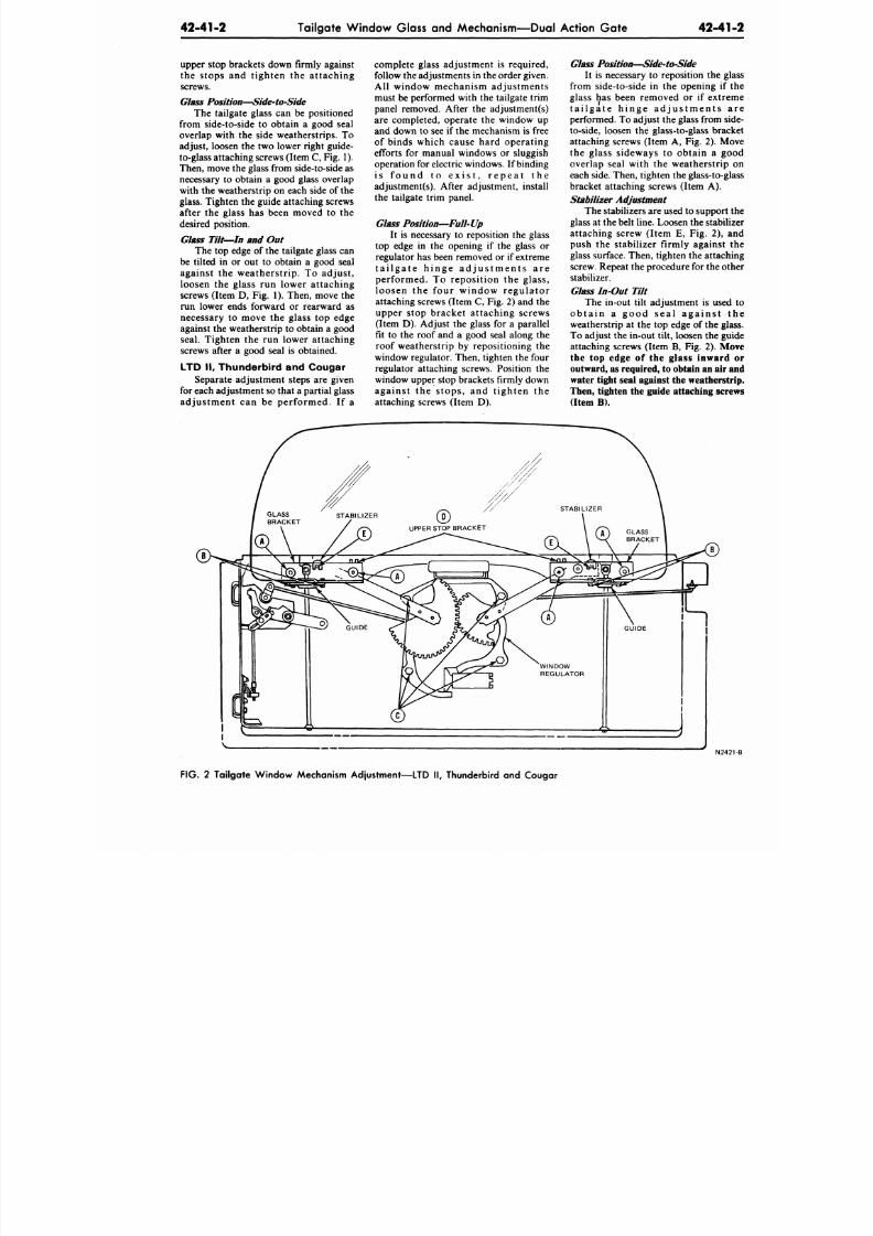
8/20/2019 1977 Ford Car Shop Manual Volume 4 Body
http://slidepdf.com/reader/full/1977-ford-car-shop-manual-volume-4-body 154/449
42-41-2
Tailgate Window Glass and Mechanism—Dual Action Gate
42-41
upper stop brackets down firmly against
the stops and tighten the attaching
screws.
Glass Position—Side-to-Side
The tailgate glass can be positioned
from side-to-side to obtain a good seal
overlap with the side weatherstrips. To
adjust, loosen the two lower right guide-
to-glass attaching screws (Item
C, Fig.
1).
Then, move the glass from side-to-side as
necessary to obtain a good glass overlap
with the weatherstrip on each side of the
glass. Tighten the guide attaching screws
after the glass has been moved to the
desired position.
Glass Tilt—In and Out
The top edge of the tailgate glass can
be tilted in or out to obtain a good seal
against the weatherstrip. To adjust,
loosen the glass run lower attaching
screws (Item D, Fig. 1). Then, move the
run lower ends forward or rearward as
necessary to move the glass top edge
against the weatherstrip to obtain a good
seal. Tighten the run lower attaching
screws after a good seal is obtained.
LTD II, Thunderbird and Cougar
Separate adjustment steps are given
for each adjustment so that a partial glass
adjustment can be performed. If a
complete glass adjustment is required,
follow the adjustments in the order given.
All window mechanism adjustments
must be performed with the tailgate trim
panel removed. After the adjustments)
are completed, operate the window up
and down to see if the mechanism is free
of binds which cause hard operating
efforts for manual windows or sluggish
operation for electric w indows. If binding
i s f o u n d t o e x i s t , r e p e a t t h e
adjustment(s). After adjustment, install
the tailgate trim panel.
Glass Position—Full-Up
It is necessary to reposition the glass
top edge in the opening if the glass or
regulator has been removed or if extreme
t a i l g a t e h i n g e a d j u s t m e n t s a r e
performed. To reposition the glass,
loosen the four window regulator
attaching screws (Item C, F ig. 2) and the
upper stop bracket attaching screws
(Item D). Adjust the glass for a parallel
fit to the roof and a good seal along the
roof weatherstrip by repositioning the
window regulator. Then, tighten the four
regulator attaching screws. Position the
window upper stop b rackets firmly down
against the stops, and t ighten the
attaching screws (Item D).
Glass Position—Side-to-Side
It is necessary to reposition the g
from side-to-side in the opening if
glass has been removed or if extr
t a i l g a t e h i n g e a d j u s t m e n t s
performed. To adjust the glass from s
to-side, loosen the glass-to-glass bra
attaching screws (Item A, Fig. 2). M
the glass sideways to obtain a g
overlap seal with the weatherstrip
each side. Then, tighten the glass-to-g
bracket attaching screws (Item A).
Stabilizer Adjustment
The stabilizers are used to support
glass at the belt line. Loosen the stabi
attaching screw (Item E, Fig. 2),
push the stabilizer firmly against
glass surface. Then, tighten the attach
screw. Repeat the p rocedure for the o
stabilizer.
Glass In-Out
Tilt
The in-out tilt adjustment is use
ob ta in a good se a l a ga ins t
weatherstrip at the top edge of the gl
To adjust the in-out tilt, loosen the g
attaching screws (Item
B,
Fig. 2).
M
the top edge of the glass inward
outward, as required, to obtain an a
water tight seal against the weathers
Then, tighten the guide attaching scr
(Item B).
N24
FIG. 2 Tailgate Wind ow Mechanism Adjustment—LTD II, Thunderbird and Cougar
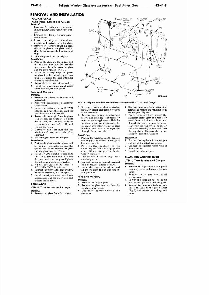
8/20/2019 1977 Ford Car Shop Manual Volume 4 Body
http://slidepdf.com/reader/full/1977-ford-car-shop-manual-volume-4-body 155/449
42-41-3
Tailgate Window Glass
and
Mechanism—Dual Action Gate
42-41-3
REMOVAL
AND
INSTALLATION
TAILGATE GLASS
Thunderb i rd ,
LTD II and
Cougar
Removal
1 . R emo v e
23
t a i l g a t e t r i m p a n e l
attaching screws and remove the trim
panel.
2.
R e m o v e
the
ta i lg a te in n er p an e l
access cover.
3.
L o w e r
the
t a i l g a t e
to the
d o w n
position and partially raise the glass.
4. Remove two screws attaching each
side of the glass to the glass bracket
(Fig. 3), and remove the bushings and
stops.
5. Slide the glass from the tailgate
Installation
1.
Position the glass into the tailgate and
to
the
g lass brackets .
Be
sure
the
spacers
are
placed between
the
glass
an d the glass bracket (Fig. 3).
2. Install the bushings, stops and glass-
to-g lass bracket at taching screws
(Fig.
3).
Tighten
the
glass attaching
screws
to
specification.
3. Adjust
the
glass from side-to-side.
4. Install the tailgate inner panel access
cover and tailgate trim panel.
Ford
and
Mercury
Removal
1. Remove
the
tailgate inside cover
and
watershield.
2. Remove the tailgate inner panel lower
access cover.
3. Lo wer
the
tai lgate
to the
D O W N
position, and raise the glass until the
glass brackets are accessible.
4.
Remove
the
center
pin
from
the
glass-
to-glass bracket rivets with
a
drift
punch. Then, drill the heads from the
r ivets with
a 1/4
inch dr i l l ,
and
remove the rivets.
5. Disconnect the wires from the rear
window defroster terminals ,
if so
equipped.
6. Slide
the
glass from
the
tailgate.
Installation
1. Position the glass into the tailgate and
to the g lass brackets . Be sure the
spacers are placed between the glass
an d
the
glass bracket
(Fig. 4).
2. Install 1/4-20 x 1 inch hex head bolts
an d 1/4-20 hex head nuts to attach
the glass bracket
to the
glass. Tighten
the bolts
and
nuts
to
specification.
3. A d j u s t
the
g l a s s
as
o u t l i n e d
in
A D J U S T M E N T S in this part.
4. Connect the wires to the rear window
defroster terminals,
if so
equipped.
5. Install the tailgate inner panel lower
access cover, and the watershield and
tailgate inside cover.
£ >- *—UPPER S10P REGULATOR
BRACKET 44000
422B36
GUIDE
422B15
BUSHING
2 5 7 5 4
42138
FIG.
3 Tailgate Window Mechanism—Thunderbird, LTD II, and Cougar
N2769-A
2. If equipped with an electric window
regulator, disconnect the motor wires
at
the
connector.
3. R emo v e fo u r r eg u la to r a t tach in g
screws and disengage the regulator
from
the
mounting b rackets. Slide
the
regulator
to one
side
to
disengage
the
regulator arm rollers from the glass
brackets ,
and
remove
the
regulator
through
the
access hole.
Installation
1. Position
the
regulator into
the
tailgate
and engage the rollers in the glass
bracket channels.
2.
P o s i t i o n
the
r e g u l a t o r
to the
mo u n t in g su r f ace
and
engage
the
c r a n k (if so e q u i p p e d ) w i t h the
window regulator.
3. I n s t a l l
the
w i n d o w r e g u l a t o r
attaching screws.
4. Connect the motor wires, if equipped
with
an
electric tailgate window.
5. Install the glass in the tailgate and
adjust the glass full-up and side-to-
side positions.
Ford
and
Mercury
Removal
REGULATOR
LTD II, Thund erbird and Cougar
Removal
1. Remove the glass from the tailgate.
1.
Remove the tailgate glass.
2. Remove
the
glass brackets from
the
regulator arm rollers.
3. Disconnect the motor wires at the
connector.
4. R emo v e fo ur reg u la to r a t tach in g
screws and remove the regulator from
the tailgate
(Fig. 4).
5. Drill a 5/16 inch hole through the
regulator sector gear and regulator
plate. Install
a 1/4
inch bolt
and nut
through
the
hole
to
prevent
the
sector
gear from moving when the mo to r
and drive assembly
is
removed from
th e r eg u la to r . R emo v e
the
m o t o r
assembly from the regulator.
Installation
1. Position
the
regulator
in the
tailgate
and install the attaching screws.
2. Connect the regulator motor wires at
the connector.
3. Install the tailgate glass.
GLASS RUN AND /OR GUIDE
LTD II, Thund erbird
and
Cougar
Removal
1. Remove
23
tailgate inside trim panel
attaching screws
and
remove
the
trim
panel.
2. R e m o v e the ta i lg a te in n er p an e l
access cover.
3. L o w e r
the
t a i l g a t e
to the
d o w n
position and partially raise the glass.
4. Remove two screws attaching sach
side
of the
glass
to the
glass bracket
(Fig. 3), and remove the bushing*, and
stops.
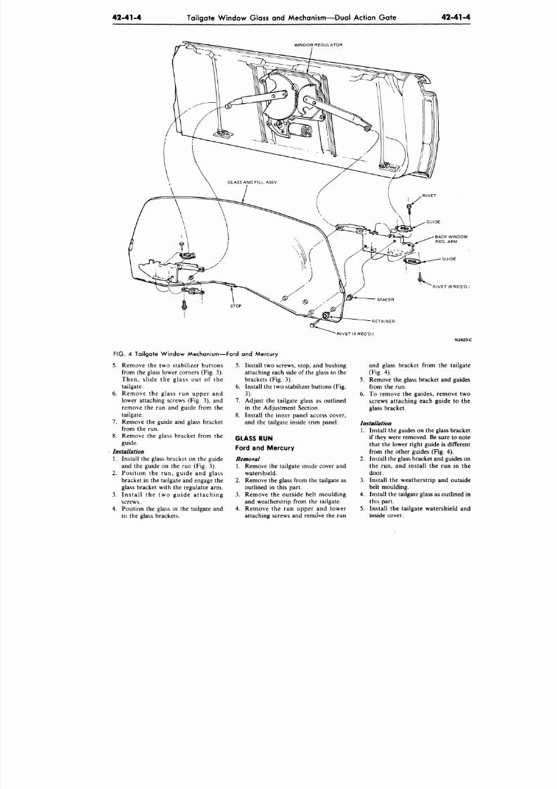
8/20/2019 1977 Ford Car Shop Manual Volume 4 Body
http://slidepdf.com/reader/full/1977-ford-car-shop-manual-volume-4-body 156/449
42-41-4
Tailgate Window Glass and Mechanism—Dual Action Gate
42-41
WINDOW REGULATOR
BACK WINDO
REG.
A RM
GUIDE
RIVET(6REQ'D
RETAINER
RIVET (6 REQ'D.)
N242
FIG. 4 Tailgate Window Mechanism—Ford and Mercury
5.
Remove the two s tabi l izer but tons
from the glass lower corners (Fig. 3).
Then, s l ide the glass out of the
tailgate.
6 . Remove the glass run upper and
lower attaching screws (Fig. 3), and
remove the run and guide from the
tailgate.
7.
Remove the guide and glass bracket
from the run.
8. Remove the glass bracket from the
guide.
Installation
1.
Install the glass bracket on the guide
and the guide on the run (Fig. 3).
2. Pos i t ion the run, guide and glass
bracket in the tailgate and engage the
glass bracket with the regulator arm.
3.
I n s t a l l t h e t w o g u i d e a t t a c h i n g
screws.
4. Position the glass in the tailgate and
to the glass brackets.
5.
Install two screws, stop, and bushing
attaching each side of the glass to the
brackets (Fig. 3).
6. Install the two stabilizer buttons (Fig.
3).
7. Adjust the tailgate glass as outlined
in the Adjustment Section.
8. Install the inner panel access cover,
and the tailgate inside trim panel.
GLASS RUN
Ford and Mercury
Removal
1. Remove the tailgate inside cover and
watershield.
2.
Remove the glass from the tailgate as
outlined in this part.
3.
Remove the outs ide bel t moulding
and weatherstrip from the tailgate.
4.
Remove the run uppe r and lower
attaching screws and remove the run
and glass bracket from the tailga
(Fig. 4).
5.
Remove the glass bracket and guid
from the run.
6. To remove the guides, remove tw
screws attaching each guide to t
glass bracket.
Installation
1. Install the guides on the glass brack
if they were removed. Be sure to no
that the lower right guide is differe
from the other guides (Fig. 4).
2.
Install the glass bracket and guides
the run, and install the run in t
door.
3.
Install the weath erstrip and outs
belt moulding.
4.
Install the tailgate glass as outlined
this part.
5.
Install the tailgate watershield a
inside cover.

8/20/2019 1977 Ford Car Shop Manual Volume 4 Body
http://slidepdf.com/reader/full/1977-ford-car-shop-manual-volume-4-body 157/449
42-41-5
Tailgate Window Glass and Mechanism—Dual Action Gate 42-41-5
WINDOW MOTOR AND/OR
DRIVE
Removal
1.
Remove the tailgate inner panel and
watershield.
2. Disconnect the motor wires at the
connector.
3. Working through the access hole(s),
remove the three motor and drive-to-
regulator attaching screws. Remove
the motor and drive from the tailgate.
Installation
1. Position the mo tor and drive to the
window regulator , and instal l the
three screws
just snug—not tight.
2. C o n n ec t th e mo to r w i r es a t th e
connector and cycle the g lais to
assure gear engagement. After the
gears are engaged, tighten the three
motor and drive attaching screws.
3. Check the window operation. Then,
install the watershield and tailgate
inner panel.
8/20/2019 1977 Ford Car Shop Manual Volume 4 Body
http://slidepdf.com/reader/full/1977-ford-car-shop-manual-volume-4-body 158/449
43-01-1
Stationary Window Glass
43-01
STATIONARY WINDOW GLASS
PART
T IT L E PART NO.
PART TITLE
GROUP
(70000)
PART NO.
Stationary Glass - Buty l Type
Seal
43-1
1 Station ary Glass - We atherstrip Typ e Seal 43-01
CR2004-A
Stationary Glass -
Weatherstrip Type Seal
P A R T
43-01
SUBJECT PAGE
REM O VAL AND INST AL L AT IO N
Back Window Mouldings
01-1
Back Windo w - Wea therstrip
Typ e Seal 01-6
Opera Wind ow 01-9
SUBJECT PAGE
REM O VAL AND INST AL L A T IO N (Con t' d .)
Quarter Wind ow Mou ldings 01-1
Stationary Quarter Wind ow Glass 01-6
Windshield Mou ldings 01-1
Windshield - Wea therstrip Type Seal 01-1
REMOVAL AND INSTALLATION
Be f or e r e m oving the e x t e r io r
mouldings, it should be determined by
the types of retainer used whether a
respective door, quarter or luggage
compartment trim panel must first be
removed to provide access.
If a weld stud is distorted or broken
off, it can be replaced with a screw
(37956O-S1O1) or pop rivet as shown in
Fig. 23.
WINDSHIELD MOULDINGS
The windshield mouldings for the
Maverick, Comet, Pinto and Bobcat are
shown in Figs. 2 and 3. The mouldings
are retained with retainers set in the glass
opening and should be released from the
retainers with the tool shown in Fig. 1.
BACK W INDO W MOULDINGS
The back window mouldings are
shown in Figs. 4 throug h 11. If the
mouldings are retained with retainers set
in the glass opening, the m oulding should
be released with the tool shown in Fig.
1.
QUARTER W IND OW MOULDINGS
The s ta t ionary quar te r window
mouldings on the Pinto and Bobcat are
retained within the weatherstrip (Fig.
12). Refer to Quarter Window and Glass
Removal and Installation procedures
(this Section).
The mouldings for Mustang are
shown in Figs. 15 and 16. Granada and
Monarch are shown in Figs. 17 and 18.
CR2032-A
LTD II and Cougar mouldings a
shown in Figs. 19 and 20.
WINDSHIELD WEATHERSTRIP
TYPE SEAL
Removal
PVC tape is to be used on the pin
weld flange (Pinto and Bobcat), in pla
of sealer.
1. Remove the windshield wiper blad
and arms.
2.
Remove the side and top mouldi
using Tool T64P-42006 or equival
(Fig. 1).
3. Using Tool T64P-42006 or equival
(Fig. 1), remove the windshield low
moulding. Start at the center, th
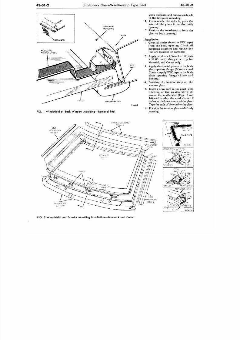
8/20/2019 1977 Ford Car Shop Manual Volume 4 Body
http://slidepdf.com/reader/full/1977-ford-car-shop-manual-volume-4-body 159/449
43-01-2
Stationary Glass-Weatherstrip Type Seal
43-01-2
EXTERIOR
MOULDING
WEATHERSTRIP
FIG. 1 W indshield or Back Win dow M oulding—R emova l Tool
work outboard and remove each side
of the two-piece moulding.
4.
From inside the vehicle, push the
windshield glass from the body
opening.
5.
Remove the weatherstrip from the
glass or body opening.
Installation
1. Clean all sealer (butyl or PVC tape)
from the body opening. Check all
moulding retainers and replace any
that are loosened or damaged.
2. Apply butyl tape (.06 inch x
1 .00
inch
x 59.00 inch) along cowl top for
Maverick and Comet only.
3. Apply sheet metal primer to the body
glass opening flange (Maveric K and
Comet). Apply PVC tape to the body
glass opening flange (Pinto and
Bobcat).
4.
Position the weatherstrip on the
window glass.
5. Insert a draw cord in the pinch weld
opening of the weatherstrip all
around the weatherstrip (Figs. 13 and
14) and overlap the cord about 18
inches at the lower center of the glass.
M446-E Ta pe the en ds of the cor d to the glass.
6 . Pos i t i on the wind ow glass t o t he ; bod y
o p e n i n g .
UPPER MOULDING
03144-5
SIDE
M O U L D I N G
03136-7
M O U L D I N G
03148-9
SIDE
M O U L D I N G
03136-7
M O U L D I N G 0 3 1 4 8 - 9
RETAINER
SPACER
V EW-D
T O P M O U L D I N G
WEATHERSTRIP
03110
FIG. 2 Windshield and Exterior Moulding Instal lat ion—Maverick and Comet
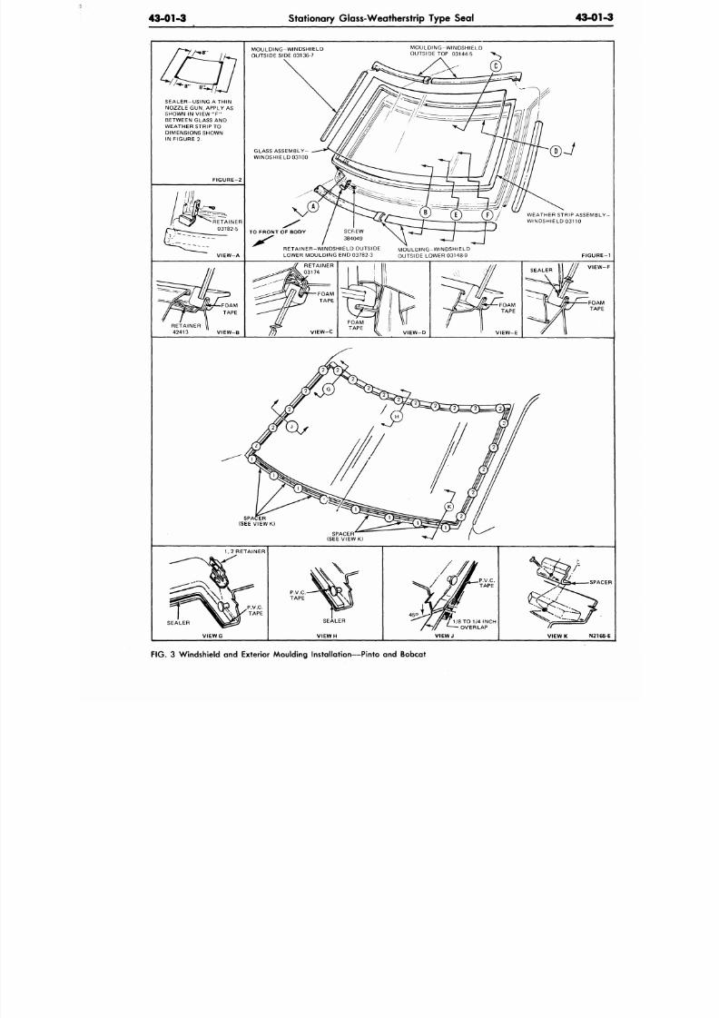
8/20/2019 1977 Ford Car Shop Manual Volume 4 Body
http://slidepdf.com/reader/full/1977-ford-car-shop-manual-volume-4-body 160/449
43-01-3
Stationary Glass-Weatherstrip Type Seal
43-01
SEALER-USING ATHIN
NOZZLE GUN, APPLY
AS
SHOWN
IN
VIEW
"F"
BETWEEN GLASS AND
WEATHER STRIP TO
DIMENSIONS SHOWN
IN FIGURE 2.
FIGURE-2
VIEW-A
MOULDING-WINDSHIELD
OUTSIDE SIDE 03136-7
MOULDING-WINDSHIELD
OUTSIDE TOP 03144-5
GLASS ASSEMBLY-
WINDSHIELD 03100
TO FRONT OF BODY
RETAINER-WINDSHIELD OUTSIDE
LOWER MOULDING END 03782-3
MOULDING-WINDSHIELD
OUTSIDE LOWER 03148-9
WEATHER STRIP ASSEM
WINDSHIELD 03110
FIGUR
RETAINER
42413 ' VIEW-B
VIEW-C
FOAM
TAPE
VIEW-D
VIEW-E
SEALER
VIE
SP
(SEE VIEW K)
SPACER
(SEE VIEW
K)
1,2
RETAINER
SEALER
V I E W G
1/8 TO 1/4
INCH
OVERLAP
SPA
VIEW K N21
FIG .
3
Windshield and Exterior Moulding Installation—Pinto and Bobcat
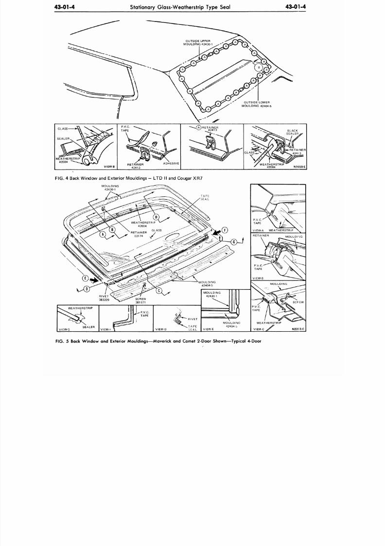
8/20/2019 1977 Ford Car Shop Manual Volume 4 Body
http://slidepdf.com/reader/full/1977-ford-car-shop-manual-volume-4-body 161/449
43-01-4 Stationary Glass-Weatherstrip Type Seal
43-01-4
OUTSIDE LOWER
MOULDING 42404-5
WEATHERSTRIP
42084 N1659-E
FIG.
4 Back Window and Exterior Mouldings - LTD II and Cougar XR7
MOULDING
42430-1
FIG.
5 Back Window and Exterior Mouldings—M averick and Comet 2-Door Shown—Ty pical 4-Door
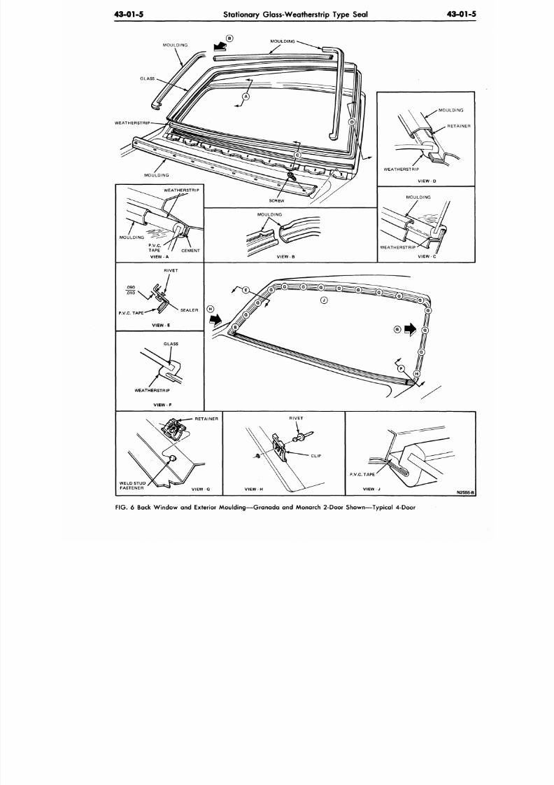
8/20/2019 1977 Ford Car Shop Manual Volume 4 Body
http://slidepdf.com/reader/full/1977-ford-car-shop-manual-volume-4-body 162/449
43-01-5
Stationary Glass-Weatherstrip Type Seal
43-0
MOULDING
GLASS
WEATHERSTRIP
MOULDING
RETAI
WEATHERSTRIP
VIEW-D
MOULDING
P.V.C.
TAPE
' / CEMEN T
VIEW A
MOULDING
WEATHERSTRIP
V I E W - C
.090
Ino
P.V.C. TAPE-
SEALER
VIEW
GLASS
WEATHERSTRIP
V I E W - F
RETAINER
VIEW-G
RIVET
V I E W - H
P.V.C. TAPE
N
F IG .
6 Back Win dow and Exterior Mould ing— Gra nada and Monarch
2-Door
Shown—Typical
4-Door
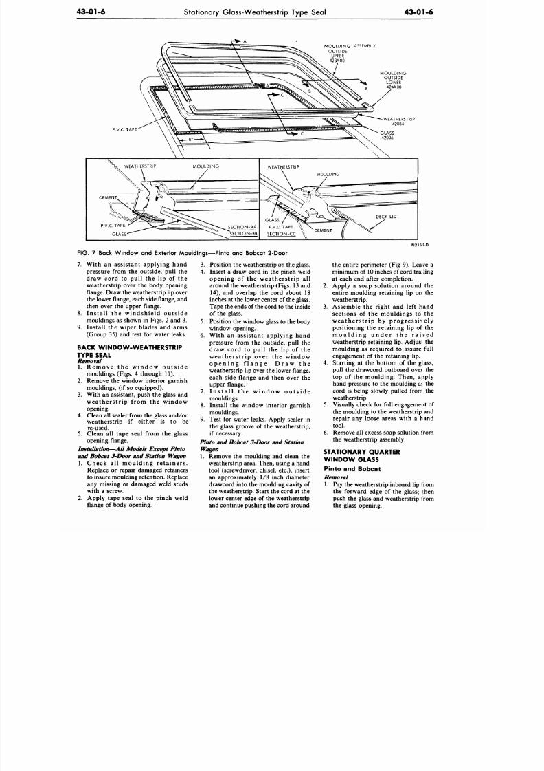
8/20/2019 1977 Ford Car Shop Manual Volume 4 Body
http://slidepdf.com/reader/full/1977-ford-car-shop-manual-volume-4-body 163/449
43-01-6
Stationary Glass-Weatherstrip Type Seal
43-01-6
MOULDING ASSEMBLY
OUTSIDE
UPPER
423A00
FIG. 7 Back Window and Exterior Mouldings—Pinto and Bobcat 2-Door
7. With an assist ant applying hand 3.
pressure from the outside, pull the 4.
draw cord to pull the lip of the
weatherstrip over the body opening
flange. Draw the weatherstrip lip over
the lower flange, each side flange, and
then over the upper flange.
8 . Ins ta l l the windshield outs ide
mouldings as shown in Figs. 2 and 3. 5.
9. Install the wiper blades and arms
(Group 35) and test for water leaks. 6.
BACK WINDOW-WEATHERSTRIP
TYPE SEAL
Removal
1. Rem ove the w indo w ou t s ide
mouldings (Figs. 4 through 11).
2.
Remove the window interior garnish
mouldings, (if so equipped).
3. With an assistant, push the glass and
weathers t r ip f rom the window
opening.
4. Clean all sealer from the glass and/o r
•weatherstrip if either is to be
re-used.
5.
Clean all tape seal from the glass
opening flange.
Installation—All
Models Except Pinto
and Bobcat 3 Door and Station Wagon
1. Check a l l moulding re ta iners .
Replace or repair damaged retainers
to insure moulding retention. Replace
any missing or damaged weld studs
with a screw.
2.
Apply tape seal to the pinch weld
flange of body opening.
Position the w eatherstrip on the glass.
Insert a draw cord in the pinch weld
opening of the weatherstrip all
around the weatherstrip (Figs. 13 and
14),
and overlap the cord about 18
inches at the lower center of the glass.
Tape the ends of the cord to the inside
of the glass.
Position the window glass to the body
window opening.
With an assistant applying hand
pressure from the outside, pull the
draw cord to pull the lip of the
weathers t r ip over the window
o p e n i n g f l a n g e . D r a w t h e
weatherstrip lip over the lower flange,
each side flange and then over the
upper flange.
7. I n s t a l l t h e w i n d o w o u t s i d e
mouldings.
8. Install the window interior garnish
mouldings.
9. Test for water leaks. Apply sealer in
the glass groove of the weatherstrip,
if necessary.
Pinto and Bobcat 3 Door and Station
Wagon
1. Remove the moulding and clean the
weatherstrip area. Then, using a hand
tool (screwdriver, chisel, etc.), insert
an approximately 1/8 inch diameter
drawcord into the moulding cavity of
the weatherstrip. Start the cord at the
lower center edge of the weatherstrip
and continue pushing the cord around
N216'5 D
the entire perimeter (Fig 9). Leave a
minimum of
10
inches of cord trailing
at each end after completion.
2.
Apply a soap solution around the
entire moulding retaining lip on the
weatherstrip.
3. Assemble the right and left hand
sections of the mouldings to the
w ea the r s t r ip by p rog res s ive ly
positioning the retaining lip of the
m o u l d i n g u n d e r t h e r a i s e d
weatherstrip retaining lip. Adjust the
moulding as required to assure full
engagement of the retaining lip.
4.
Starting at the bottom of the glass,
pull the drawcord outboard over the
top of the moulding. Then, apply
hand pressure to the moulding as the
cord is being slowly pulled from the
weatherstrip.
5.
Visually check for full engagement of
the moulding to the weatherstrip and
repair any loose areas with a hand
tool.
6. Remove all excess soap solution from
the weatherstrip assembly.
STATIONARY QUARTER
W INDO W GLAS S
Pinto and Bobcat
Removal
1. Pry the weatherstrip inboard lip from
the forward edge of the glass; then
push the glass and weatherstrip from
the glass opening.
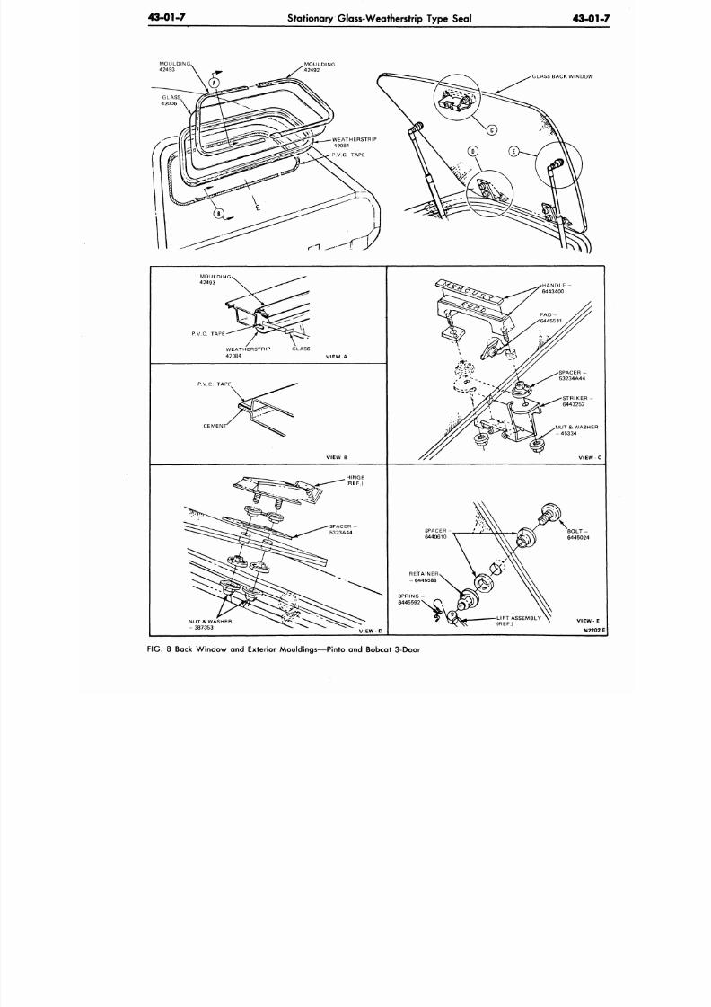
8/20/2019 1977 Ford Car Shop Manual Volume 4 Body
http://slidepdf.com/reader/full/1977-ford-car-shop-manual-volume-4-body 164/449
43-01-7
Stationary Glass-Weatherstrip Type Seal
43-0
GLASS BACK WINDOW
P.V.C. TAPE
WEATHERSTRIP
42084
GLASS
VIEW A
P.V.C. TAPE
CEMEN
VIEW B
STRIKER
6443252
NUT& WASHE
- 45334
VIEW
NUT& WASHER
- 387353
SPACER
6440610
VIEW-D
FIG.
8 Back Windo w and Exterior Mouldings— Pinto and Bobcat 3-Door
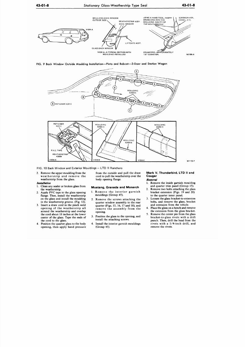
8/20/2019 1977 Ford Car Shop Manual Volume 4 Body
http://slidepdf.com/reader/full/1977-ford-car-shop-manual-volume-4-body 165/449
43-01-8
Stationary Glass-Weatherstrip Type Seal 43-01-8
MOULDING-BACK WINDOW
OUTSIDE SIDE
USING A HAND TOOL, INSERT
DRAWCORD INTO THE
WEATHERSTRIP ASSY MOULDING CAVITY OF
BACK WINDOW THE WEATHER STRIP
SCREWDRIVER,
CHISEL, ETC.
LIFTGATE ASSY.
GLASS-BACK WINDOW
VIEW A- A TYPICAL SECTION WITH
MOULDING INSTALLED
DRAWCORD-APPROXIMATELY
1/8" DIAMETER.
N2556-A
FIG.
9 Back Window Outside Moulding Instal lation—Pinto and Bobcat—3-Door and Station Wagon
c
P.V.C. TAPE
WEATHERSTRIP'
42084
VIEW-A
VIEW-C
N1I72 -F
FIG. 10 Back Window and Exter ior Mouldings- LTD I I Ranchero
2. Remove the upper moulding from the
w e a t h e r s t r i p a n d r e m o v e t h e
weatherstrip from the glass.
Installation
1.
Clean any sealer or broken glass from
the weatherstrip.
2. Apply PVC tape to the glass opening
flange. Then, install the weatherstrip
on the glass and install the moulding
in the weatherstrip groove. (Fig. 12).
3.
Insert a draw cord in the pinch weld
opening of the weatherstr ip all
around the weatherstrip and overlap
the cord about 18 inches at the lower
center of the glass. Tape the ends of
the cord to the glass.
4. Position the quarte r glass to the body
opening, then apply hand pressure
from the outside and pull the draw
cord to pull the weatherstrip over the
body opening flange.
Mustang, Granada and Monarch
1. Re m ove the i n t e r io r ga r n i sh
mouldings (Group 45).
2.
3.
Remove the screws attaching the
quarter window assembly to the rear
quarter (Figs. 15, 16, 17 and 18), and
remove the assembly from the
opening.
Position the glass to the opening, and
install the attaching screws.
4.
Install the interior garnish mouldings
(Group 45).
Mark V, Thunderbird, LTD II and
Cougar
Removal
1.
Remove the inside garnish moulding
and quarter trim panel (Group 45).
2.
Remove two bolts attaching the glass
bracket extension (Figs. 19 and 20)
to the quarter inner panel.
3.
Loosen the glass bracket-to-extension
bolts,
and remove the glass, bracket
and extension from the vehicle.
4. Place the glass on a bench and remove
the extension from the glass bracket.
5. Remove the center pin from the glass
bracket-to-glass rivets with a drift
punch. Then, drill the head from the
rivets with a
1/4-inch
drill, and
remove the rivets.
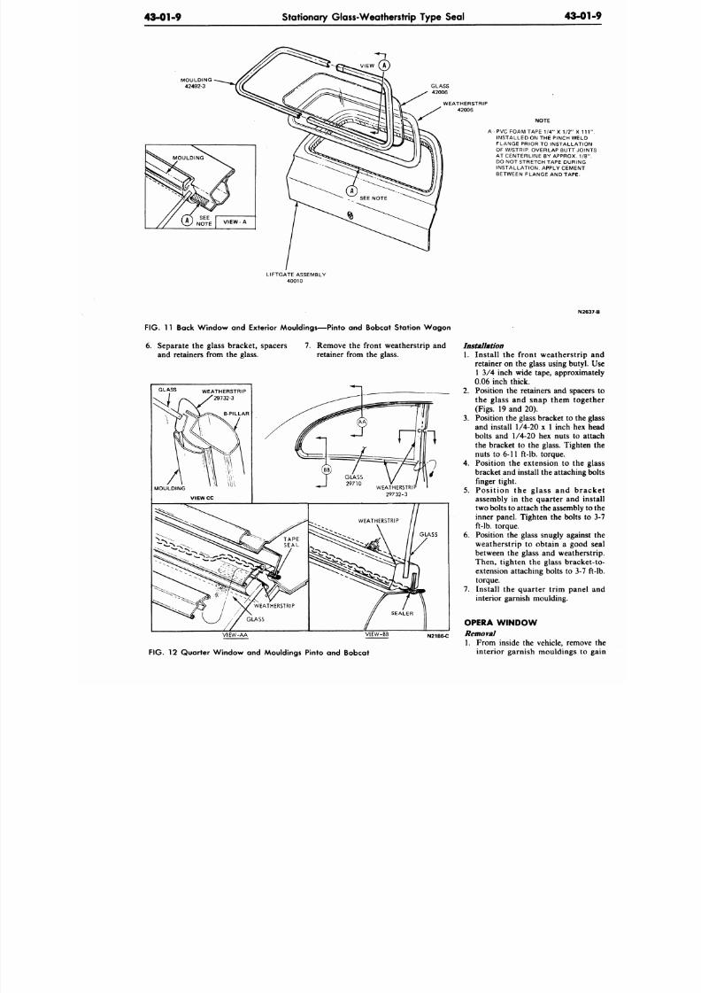
8/20/2019 1977 Ford Car Shop Manual Volume 4 Body
http://slidepdf.com/reader/full/1977-ford-car-shop-manual-volume-4-body 166/449
43-01-9
Stationary Glass-Weatherstrip Type Seal
43-0
MOULDING
42492-3
WEATHERSTRIP
42006
NOTE
A
-
P VC FOA M TAPE
1 I A
X 1
12
X
INSTALLED ON THE PINCH WEL
FLANGE PRIOR
TO
INSTALLATI
OF W7STRIP. OVERLAP BUTT JO
AT CENTERLINE BY APPROX. 1
DO NOT STRETCH TAPE DURING
INSTALLATION. APPLY CEMENT
BETWEEN FLANGE
AND
TAPE-
LIFTGATE ASSEMBLY
40010
F IG . 11
Back Window
and
Exterior Mouldings—Pinto
and
Bobcat Station W ag on
6. Separate the glass bracket, spacers
and retainers from the glass.
7. Remove the front weatherstrip and
retainer from the glass.
GLASS
WEATHERSTRIP
'29732-3
V IE W -AA VIEW -BB
N2186-C
F IG . 12
Quarter Window
and
Mouldings Pinto
and
Bobcat
N
Installation
1. Install the front weatherstri
retainer on the glass using buty
1 3/4 inch wide tape, approxi
0.06 inch thick.
2.
Position the retainers and spac
the glass
and
snap them tog
(Figs. 19 and 20).
3. Position the glass bracket to th
and install
1/4-20 x
1 inch
he
bolts and 1/4-20 hex nuts to
the bracket to the glass. Tight
nuts
to
6-11 ft-lb. torque.
4.
Position the extension to the
bracket and install the a ttaching
finger tight.
5.
Pos i t ion the glass and b r
assembly in the quarter and
two
bolts to attach the assembly
inner panel. Tighten the bolts
ft-lb.
torque.
6. Position
the
glass snugly again
weatherstrip to obtain a goo
between the glass and weathe
Then, tighten
the
glass brack
extension attaching bolts to 3-
torque.
7.
Install
the
quarter trim pane
interior garnish moulding.
OP E RA WINDOW
Removal
1. From inside the vehicle, remo
interior garnish mouldings t
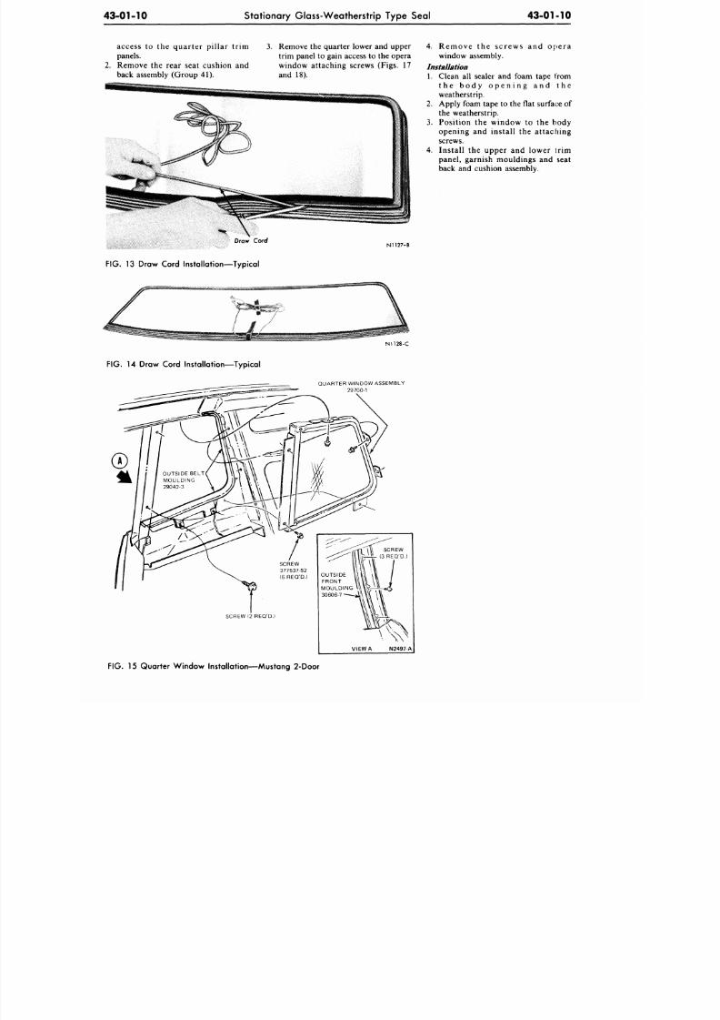
8/20/2019 1977 Ford Car Shop Manual Volume 4 Body
http://slidepdf.com/reader/full/1977-ford-car-shop-manual-volume-4-body 167/449
43-01-10
Stationary Glass-Weatherstrip Type Seal
43-01-10
access to the quarter pillar trim
panels.
2. Remove the rear seat cushion and
back assembly (Group 41).
3. Remove the quarter lower and upper
trim panel to gain access to the opera
window attaching screws (Figs. 17
and 18).
4. Remove the screws and opera
window assembly.
Installation
1.
Clean all sealer and foam tape from
t h e b o d y o p e n i n g a n d t h e
weatherstrip.
2. Apply foam tap e to the flat surface of
the weatherstrip.
3. Posit ion the window to the body
opening and instal l the at taching
screws.
4. Instal l the upper and lower tr im
panel, garnish mouldings and seat
back and cushion assembly.
Draw Cord
N1127-B
FIG.
13 Draw Cord Installation—Typical
N1128-C
FIG. 14 Draw Cord Installation—Typical
QUARTER WINDOW ASSEMBLY
29700-1
FIG.
15 Quarter W indow Insta llat ion—Mustang 2-Door
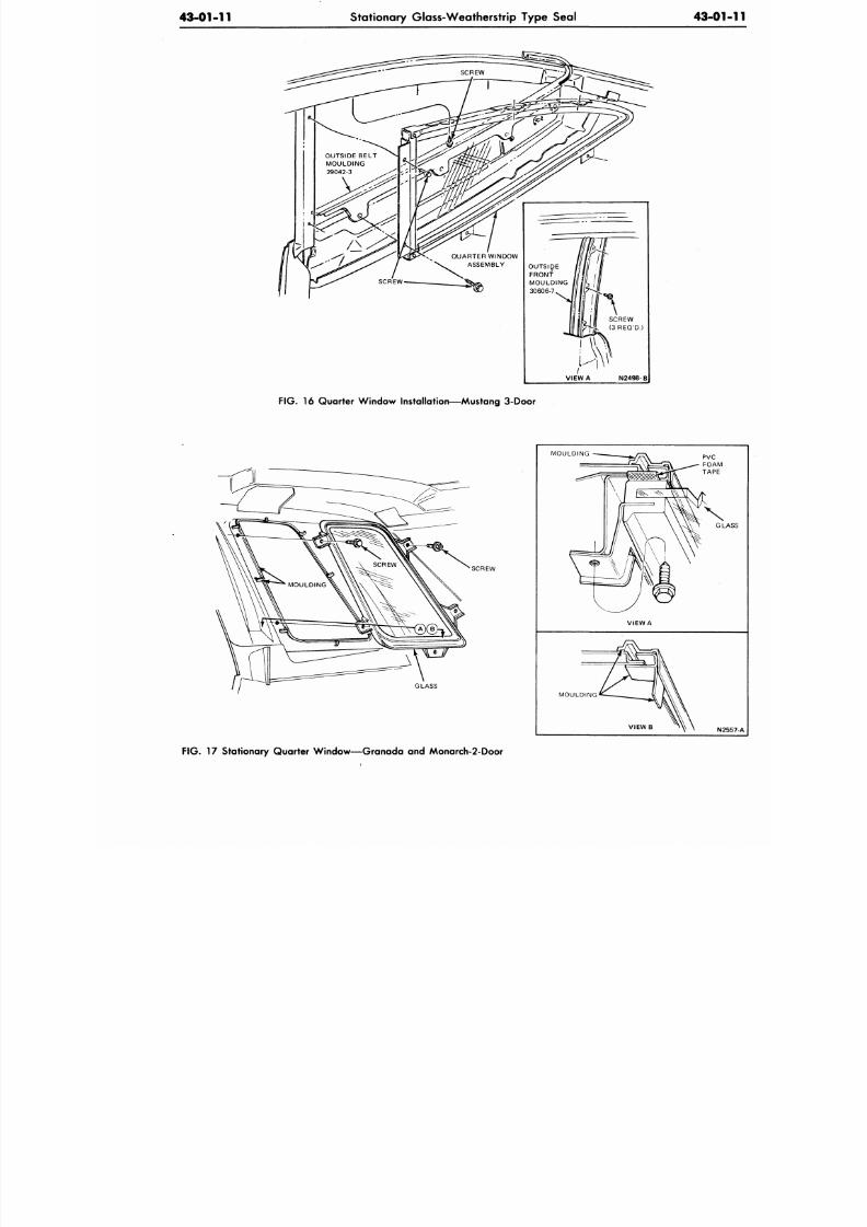
8/20/2019 1977 Ford Car Shop Manual Volume 4 Body
http://slidepdf.com/reader/full/1977-ford-car-shop-manual-volume-4-body 168/449
43-01-11
Stationary Glass-Weatherstrip Type Seal
43-01
VIEW
A
N2498-
FIG.
16 Quarter Window Installation—Mustang
3-Door
SCREW
GLASS
MOULDING
MOULDING
G
N
FIG.
17 Stationary Quarter Window—Granada and M onarch-2-Door
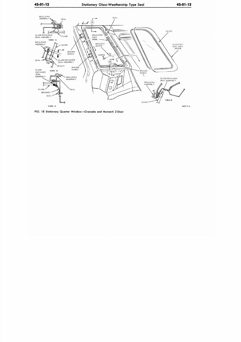
8/20/2019 1977 Ford Car Shop Manual Volume 4 Body
http://slidepdf.com/reader/full/1977-ford-car-shop-manual-volume-4-body 169/449
43-01-12
Stationary Glass-Weatherstrip Type Seal
43-01-12
SEAL
GLASS RET.
SEAL ASSY.
297A28
GLASS RETAINER
SEAL ASSEMBLY
VIEW - A
MOULDING
ASSEMBLY
VIEW - C
FIG. 18 Stationary Quarter Window—Granada and Monarch 2-Door
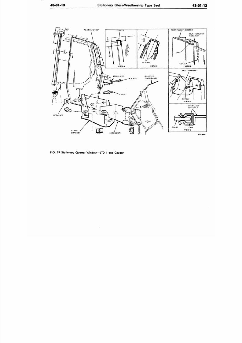
8/20/2019 1977 Ford Car Shop Manual Volume 4 Body
http://slidepdf.com/reader/full/1977-ford-car-shop-manual-volume-4-body 170/449
43-01-13
Stationary Glass-Weatherstrip Type Seal
43-01
STABILIZER QUARTER
SCREW INNER PANEL
RETAINER
GLASS
BRACKET
N24
FIG.
19 Stationary Quarter Window—LTD II and Cougar
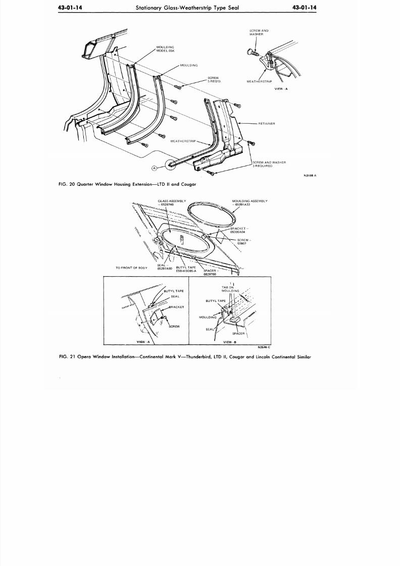
8/20/2019 1977 Ford Car Shop Manual Volume 4 Body
http://slidepdf.com/reader/full/1977-ford-car-shop-manual-volume-4-body 171/449
43-01-14
Stationary Glass-Weatherstrip Type Seal
43-01-14
MOUL DING
MODEL 65K
MOUL DING
SCREW
5 REQ'D.
WEATHERSTRIP
SCREW
AND
WASHER
3 REQUIRED
N2I558-A
FIG. 20
Qua rter W indo w Housing Extension—LTD
II and
Cougar
GLASS ASSEMBLY
MOULDING ASSEMBLY
- 65291A32
SEAL
-
TO FRONT OF BODY 65297A80 BUTYL TAPE
ESB-M3G95-A SPACER
-
6629 7 60
BUTYL TAPE
SEAL
RACKET
SCREW
TAB ON
MOULDING
BUTYL TAPE
MOULDING
SEAL' / /
-
V I E W - B
N2646C
FIG. 21
Op era Win dow Installation—Continental Mark V— Thunderbird,
LTD II,
Cougar
and
Lincoln Continental Similar
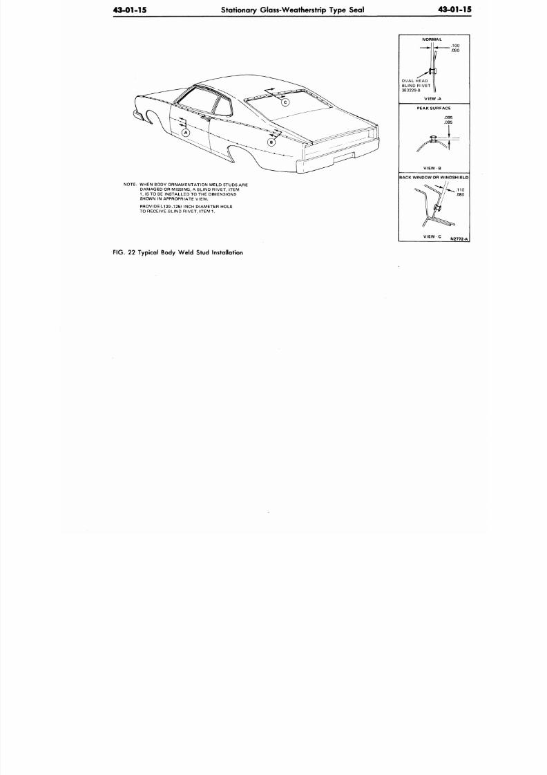
8/20/2019 1977 Ford Car Shop Manual Volume 4 Body
http://slidepdf.com/reader/full/1977-ford-car-shop-manual-volume-4-body 172/449
43-01-15
Stationary Glass-Weatherstrip Type Seal
43-0
NOTE: WHEN BODY ORNAMENTATION WELD STUDS ARE
DAMAGED OR MISSING, A BLIND RIVET, ITEM
1,
IS TO BE INSTA LLED TO THE DIMENSIONS
SHOWN IN APPROPRIATE VIEW.
PROVIDE (.129-.125) INCH DIAMETE R HOLE
TO RECEIVE BLIND RIVET, ITEM 1.
NORMAL
OVAL HEAD
BLIND RIVET
383229-B
.1
PEAK SURFACE
.095
.085
J_
BACK WINDOW OR WINDS
V I E W - C
N2
F IG . 22 Typical Body We ld Stud Instal lat ion
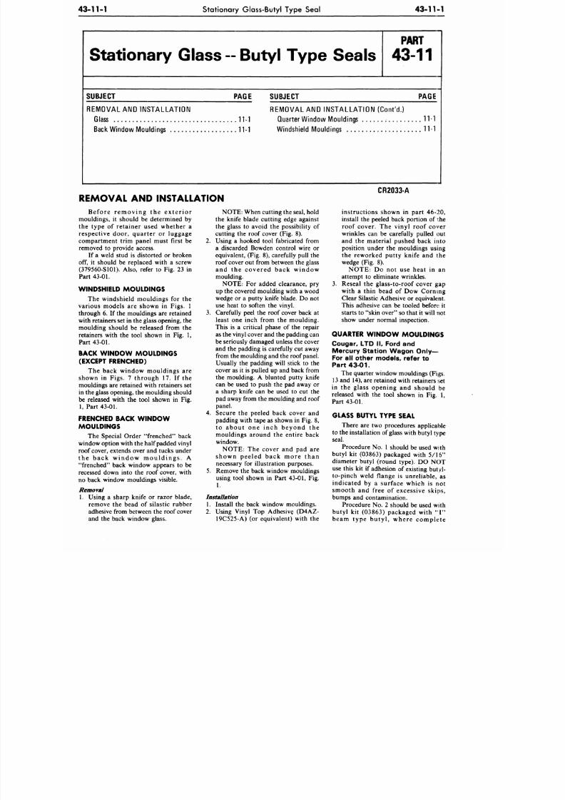
8/20/2019 1977 Ford Car Shop Manual Volume 4 Body
http://slidepdf.com/reader/full/1977-ford-car-shop-manual-volume-4-body 173/449
43-11-1
Stationary Glass-Butyl Type Seal
43-11-1
Stationary Glass -- Butyl Type Seals
P A R T
43-11
SUBJECT
PAGE SUBJECT
PAGE
REM O VAL
AND
INST AL L AT IO N
Glass
11-1
Back Window Mouldings
11-1
REM O VAL
AND
INSTA LLATION (Con t'd .)
Quarter Window Mouldings
11-1
Windshield Mouldings
11-1
REMOVAL
AND
INSTALLATION
Before removing the exterior
mouldings, it should be determined by
the type of retainer used whether a
respective door, quarter or luggage
compartment trim panel must first be
removed to provide access.
If a weld stud is distorted or broken
off, it should be replaced with a screw
(37956O-S1O1). Also, refer to Fig. 23 in
Part 43-01.
WINDSHIELD MOULDINGS
The windshield mouldings for the
various models are shown in Figs. 1
through 6. If the mouldings are retained
with retainers set in the glass opening, the
moulding should be released from the
retainers with the tool shown in Fig. 1,
Part 43-01.
BACK W INDO W MOULDINGS
(EXCEPT FRENCHED)
The back window mouldings are
shown in Figs. 7 through 17. If the
mouldings are retained with retainers set
in the glass opening, the moulding should
be released with the tool shown in Fig.
1, Part 43-01.
FRENCHED BACK W IND OW
MOULDINGS
The Special Order frenched back
window option with the half padded vinyl
roof cover, extends over and tucks under
the back window mouldings. A
frenched back window appears to be
recessed down into the roof cover, with
no back window mouldings visible.
Removal
1. Using a sharp knife or razor blade,
remove the bead of silastic rubber
adhesive from between the roof cover
and the back window glass.
NOTE: When cutting the seal, hold
the knife blade cutting edge against
the glass to avoid the possibility of
cutting the roof cover (Fig. 8).
2.
Using a hooked tool fabricated from
a discarded Bowden control wire or
equivalent, (Fig. 8), carefully pull the
roof cover out from between the glass
and the covered back window
moulding.
NOTE: For added clearance, pry
up the covered moulding with a wood
wedge or a putty knife blade. Do not
use heat to soften the vinyl.
3 .
Carefully peel the roof cover back at
least one inch from the moulding.
This is a critical phase of the repair
as the vinyl cover and the padding can
be seriously damaged unless the cover
and the padding is carefully cut away
from the moulding and the roof panel.
Usually the padding will stick to the
cover as it is pulled up and back from
the moulding. A blunted putty knife
can be used to push the pad away or
a sharp knife can be used to cut the
pad away from the moulding and roof
panel.
4. Secure the peeled back cover and
padding with tape as shown in Fig. 8,
to about one inch beyond the
mouldings around the entire back
window.
NOTE: The cover and pad are
shown peeled back more than
necessary for illustration purposes.
5. Remove the back window mouldings
using tool shown in Part
43-01,
Fig.
1.
Installation
1. Install the back window mouldings.
2. Using Vinyl Top Adhesive (D4AZ-
19C525-A) (or equivalent) with the
CR2033A
instructions shown in part 46-20,
install the peeled back portion of the
roof cover. The vinyl roof cover
wrinkles can be carefully pulled out
and the material pushed back into
position under the mouldings using
the reworked putty knife and the
wedge (Fig. 8).
NOTE: Do not use heat in an
attempt to eliminate wrinkles.
3 . Reseal the glass-to-roof cover gap
with a thin bead of Dow Corning
Clear Silastic Adhesive or equivalent.
This adhesive can be tooled before it
starts to skin over so that it will not
show under normal inspection.
QUARTER W INDOW MOULDINGS
Cougar, LTD II, Ford and
Mercury Station Wagon Only—
For
all
other models, refer
to
Part 43-01.
The quarter window mouldings (Figs.
13 and 14), are retained with retainers set
in the glass opening and should be
released with the tool shown in Fig. 1,
Part 43-01.
G L A S S B U T Y L T Y P E S E A L
There are two procedures applicable
to the installation of glass with butyl type
seal.
Procedure No. 1 should be used with
butyl kit (03863) packaged with 5/16
diameter butyl (round type). DO NOT
use this kit if adhesion of existing butyl-
to-pinch weld flange is unreliable, as
indicated by a surface which is not
smooth and free of excessive skips,
bumps and contamination.
Procedure No. 2 should be used with
butyl kit (03863) packaged with I
beam type butyl, where complete
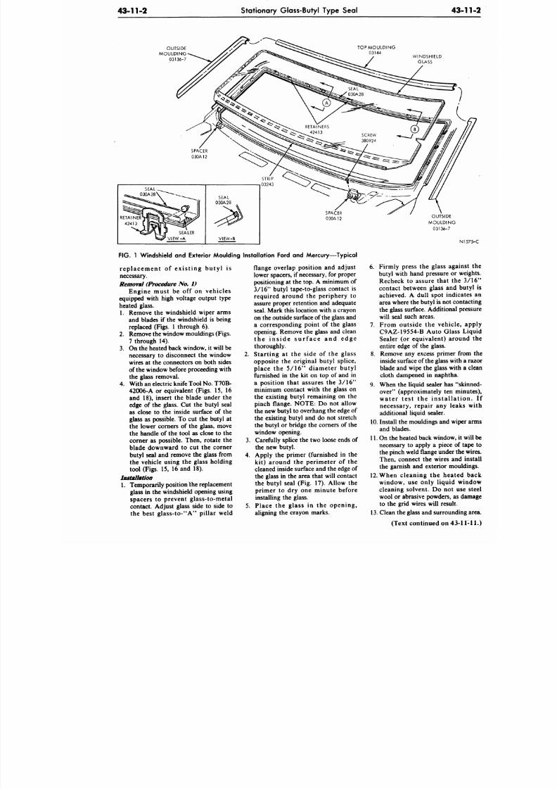
8/20/2019 1977 Ford Car Shop Manual Volume 4 Body
http://slidepdf.com/reader/full/1977-ford-car-shop-manual-volume-4-body 174/449
43-11-2
Stationary Glass-Butyl Type Seal
43-
T O P M O U L D I N G
03144
WINDSHIELD
GLASS
FIG. 1 Windshield and Exterior Moulding Installation Ford and Mercury—Typical
repla cem ent of exis t ing butyl is
necessary.
Removal (Procedure
No.
1
Engine must be off on vehicles
equipped with high voltage output type
heated glass.
1. Remove the windshield wiper arms
and blades if the windshield is being
replaced (Figs. 1 through 6).
2.
Remove the window mouldings (Figs.
7 through 14).
3.
On the heated back window, it will be
necessary to disconnect the window
wires at the connectors on both sides
of the window before proceeding with
the glass removal.
4.
With an electric knife Tool No. T70B-
42006-A or equivalent (Figs. 15, 16
and 18), insert the blade under the
edge of the glass. Cut the butyl seal
as close to the inside surface of the
glass as possible. To cut the butyl at
the lower corners of the glass, move
the handle of the tool as close to the
corner as possible. Then, rotate the
blade downward to cut the corner
butyl seal and remove the glass from
the vehicle using the glass holding
tool (Figs. 15, 16 and 18).
Installation
1. Temporarily position the replacement
glass in the windshield opening using
spacers to prevent glass-to-metal
contact. Adjust glass side to side to
the best glass-to-"A" pillar weld
flange overlap position and adjust
lower spacers, if necessary, for proper
positioning at the top. A minimum of
3/16" butyl tape-to-glass contact is
required around the periphery to
assure proper retention and adequate
seal. Mark this location with a crayon
on the outside surface of the glass and
a corresponding point of the glass
opening. Remove the glass and clean
the in s ide s u r f ace and edge
thoroughly.
2. Starting at the side of the glass
opposite the original butyl splice,
place the 5/16" diameter butyl
furnished in the kit on top of and in
a position that assures the 3/16"
minimum contact with the glass on
the existing butyl remaining on the
pinch flange. NOTE: Do not allow
the new butyl to overhang the edge of
the existing butyl and do not stretch
the butyl or bridge the corners of the
window opening.
3. Carefully splice the two loose ends of
the new butyl.
4. Apply the primer (furnished in the
kit) around the perimeter of the
cleaned inside surface and the edge of
the glass in the area that will contact
the butyl seal (Fig. 17). Allow the
primer to dry one minute before
installing the glass.
5.
Place the glass in the opening,
aligning the crayon marks.
N
6. Firmly press the glass again
butyl with hand pressure or w
Recheck to assure that the
contact between glass and bu
achieved. A dull spot indica
area where the butyl is not cont
the glass surface. A dditional pr
will seal such areas.
7.
From outside the vehicle,
C9AZ-19554-B Auto Glass L
Sealer (or equivalent) aroun
entire edge of the glass.
8. Remove any excess primer fro
inside surface of the glass with
blade and wipe the glass with
cloth dampened in naphtha.
9. When the liquid sealer has "sk
over" (approximately ten min
water tes t the ins ta l la t io
necessary, repair any leaks
additional liquid sealer.
10.
Install the mouldings and wipe
and blades.
11. On the heated back window, it
necessary to apply a piece of t
the pinch weld flange under the
Then, connect the wires and
the garnish and exterior mould
12. When cleaning the heated
window, use only liquid w
cleaning solvent. Do not use
wool or abrasive powders, as d
to the grid wires will result.
13. Clean the glass and surroundin
(Text continued on 43-1
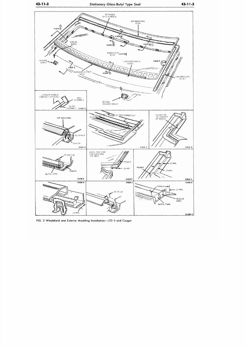
8/20/2019 1977 Ford Car Shop Manual Volume 4 Body
http://slidepdf.com/reader/full/1977-ford-car-shop-manual-volume-4-body 175/449
43-11-3
Stationary Glass-Butyl Type Seal
4 3 - 1 1 - 3
.18 WIDTH VISIBLE
CONTACT (TYPICAL)
FIG. 2 Windshield and Exterior Moulding Installation—LTD II and Cougar
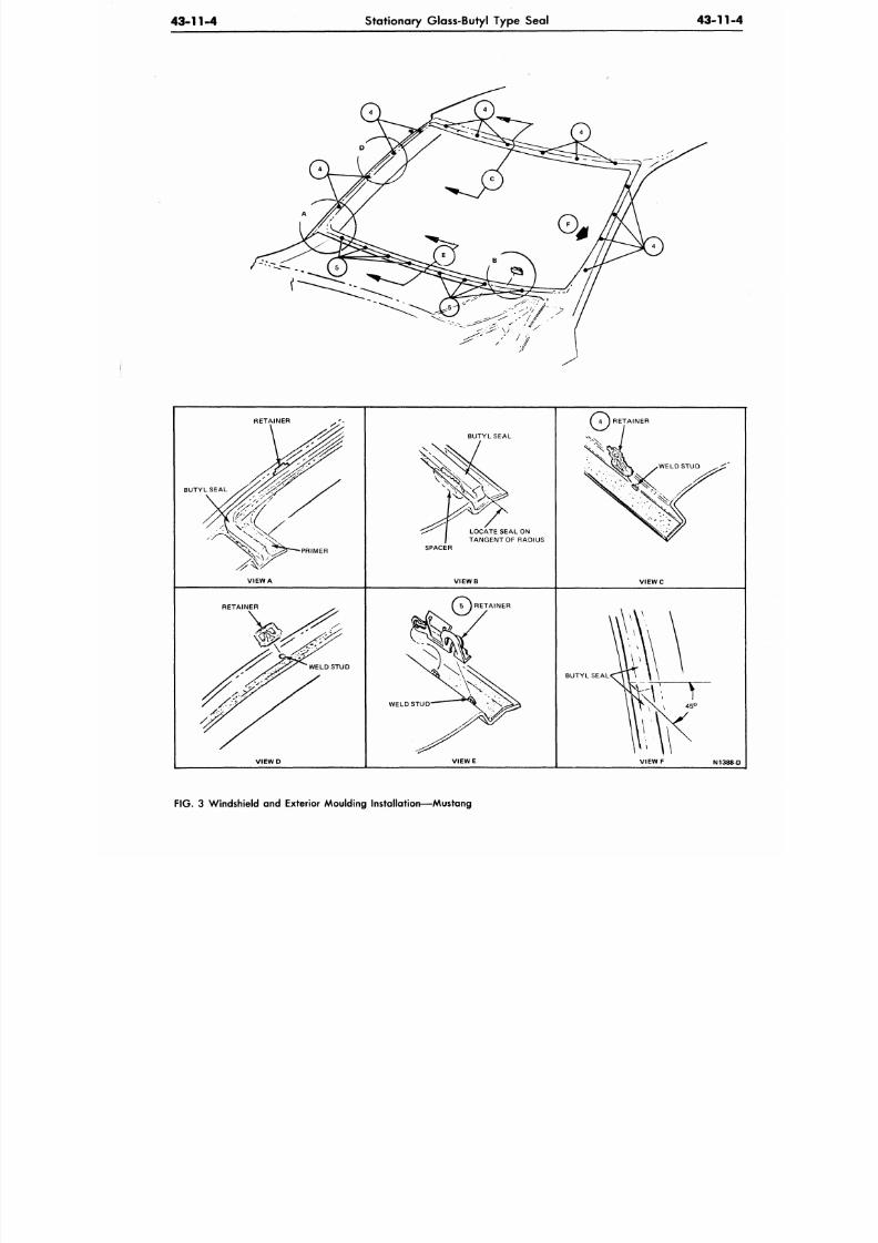
8/20/2019 1977 Ford Car Shop Manual Volume 4 Body
http://slidepdf.com/reader/full/1977-ford-car-shop-manual-volume-4-body 176/449
43-11-4
Stationary Glass-Butyl Type Seal
4 3 - 1 1
RETAINER
BUTYL SEAL
PRIMER
VIEW A
BUTYL SEAL
LOCATE SEAL ON
TANGENT OF RADIUS
SPACER
V I E W B
RETAINER
V I E W C
RETAINER
WELD STUD
RETAINER
WELD STUD
BUTYL SEAL
V I E W D
V I E W E
V I E W F
N138
FIG. 3 Windshield and Exterior Moulding Installation—Mustang
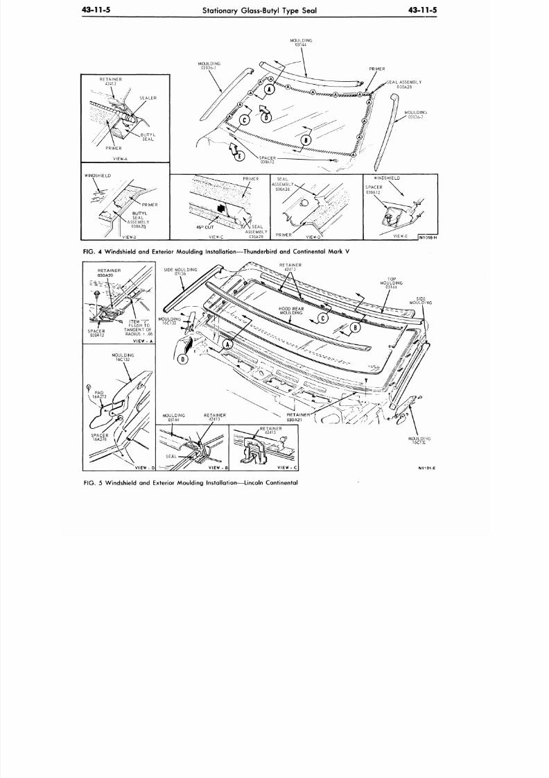
8/20/2019 1977 Ford Car Shop Manual Volume 4 Body
http://slidepdf.com/reader/full/1977-ford-car-shop-manual-volume-4-body 177/449
43-11-5
Stationary Glass-Butyl Type Seal
43-11-5
WINDSHIELD
SEALER
PRIMER
VIEW-B
MOULDING
03136-7
PRIMER
SEAL ASSEMBLY
0
30A28
PRIMER
45° CUT " "" ^S -UW \ SEA L
ASSEMBLY
VIEW-C 030A28
PRIMER
WINDSHIELD
VIEW-E
FIG. 4 Windshield and Exterior Mou lding Installation—T hunde rbird and Continental Mark V
RETAINER
42413
TOP
MOULDING
03144
MOULDING
16C13I
N1191-E
FIG. 5 Windshield and Exterior Mou lding Installation—Linco ln Co ntinental
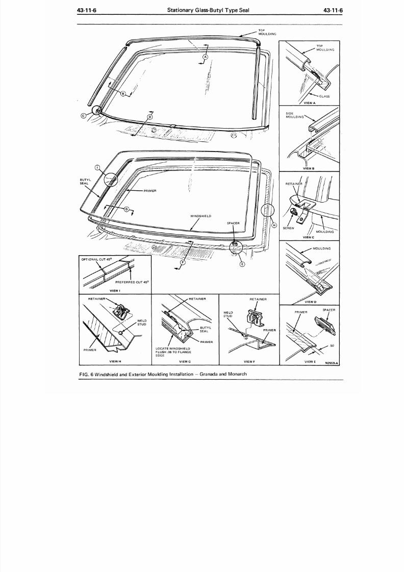
8/20/2019 1977 Ford Car Shop Manual Volume 4 Body
http://slidepdf.com/reader/full/1977-ford-car-shop-manual-volume-4-body 178/449
43-11-6
Stationary Glass-Butyl Type Seal
43-11
PREFERRED CUT 45 °
VIEW I
RETAINER
V I E W H
TOP
MOULDING
PRIMER
LOCATE WINDSHIELD
FLUSH .06 TO FLANGE
EDGE
VIEW G
RETAINER
PRIMER
VIEW F
TOP
MOULDING
GLASS
VIEW A
V I E W B
RETAINER
SCREW
V I E W C
MOULDING
V I E W D
PRIMER
SPACER
V I E W E
F I G .
6 Windshield and Exterior Moulding Installation — Granada and Monarch
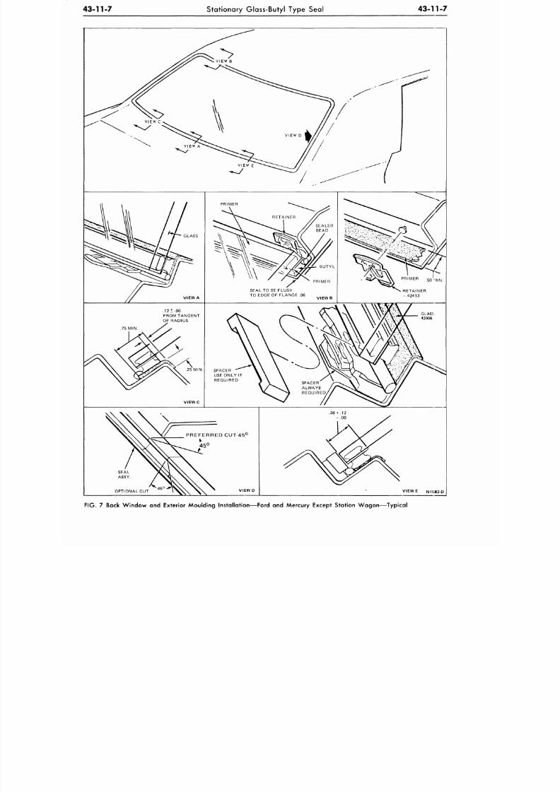
8/20/2019 1977 Ford Car Shop Manual Volume 4 Body
http://slidepdf.com/reader/full/1977-ford-car-shop-manual-volume-4-body 179/449
43-11-7
Stationary Glass-Butyl Type Seal
43-11-7
PREFERRED CUT 45°
45 °
FIG. 7 Back Window and Exterior Mou lding Installation—Ford and Mercury Except Stat ion W ago n—Typ ical
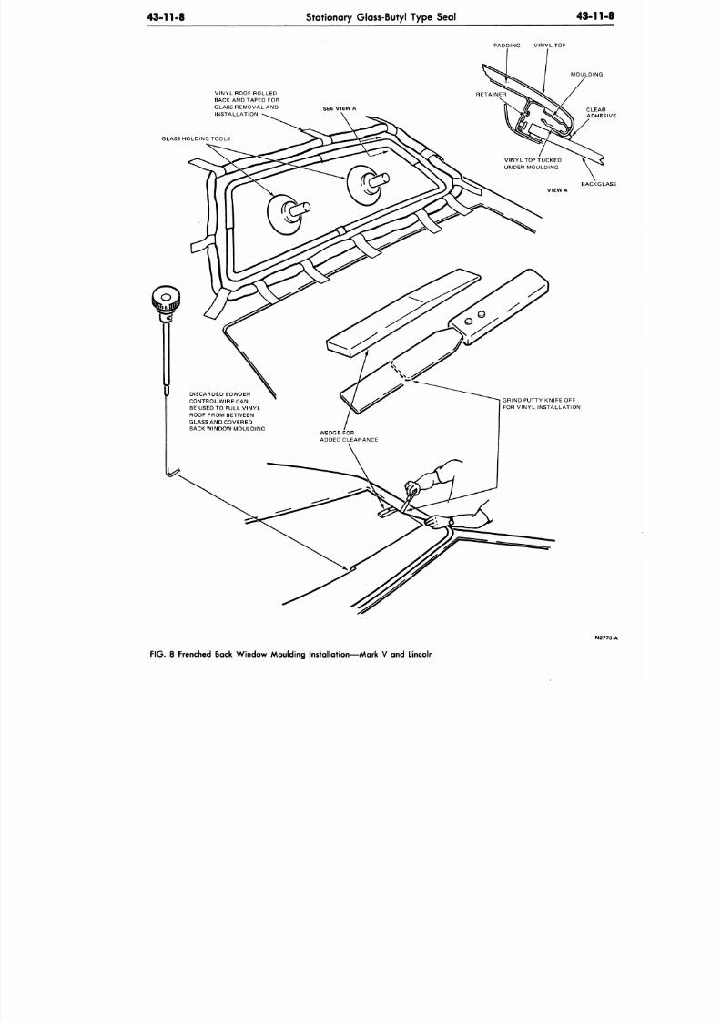
8/20/2019 1977 Ford Car Shop Manual Volume 4 Body
http://slidepdf.com/reader/full/1977-ford-car-shop-manual-volume-4-body 180/449
43-11-8
Stationary Glass-Butyl Type Seal
43-11
PADDING VIN YL TOP
VINYL ROOF ROLLED
BACK AND TAPED FOR
GLASS REMOVAL AND
INSTALLATION
GLASS HOLDING TOOLS
MOULDING
SEE VIEW A
VINYL TOP TUCKED
UNDER MOULDING
VIEW A
DISCARDED BOWDEN
CONTROL WIRE CAN
BE USED TO PULL VINY L
ROOF FROM BETWEEN
GLASS AND COVERED
BACK WINDOW M OULDING
WEDGE FOR
ADDED CLEARANCE
BACKG
GRIND PUTTY KNIFE OFF
FOR VINYL INSTALLATION
N
F IG . 8 Frenched Back Window Moulding Installation—Mark V and Lincoln
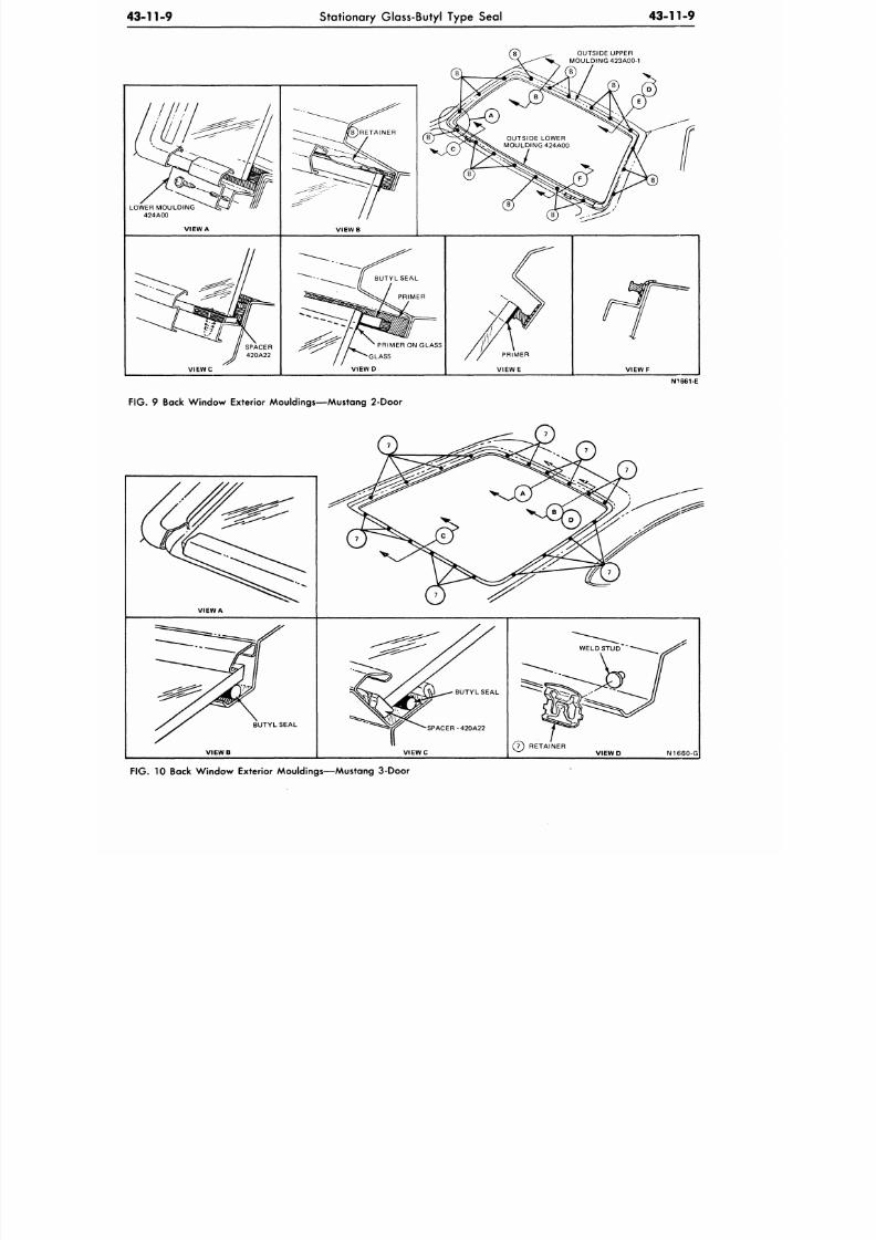
8/20/2019 1977 Ford Car Shop Manual Volume 4 Body
http://slidepdf.com/reader/full/1977-ford-car-shop-manual-volume-4-body 181/449
43-11-9
Stationary Glass-Butyl Type Seal
43-111-9
OUTSIDE UPPER
MOULDING 423A00-1
LOWER MOULDING
424A00
VIEW A
V I E W B
SPACER
420A22
V I E W C
PRIMER ON GLASS
•GLASS
V I E W D
V I E W F
N1661-E
FIG. 9 Back Window Exterior Mouldings—Mustang 2-Door
VIEW A
BUTYL SEAL
BUTYL SEAL
SPACER-420A22
VIEWB
VIEWC
(7) RETAINER
VIEWD N1660-G
FIG. 10 Back Window Exterior Mouldings—Mustang 3-Door
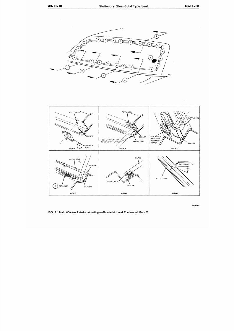
8/20/2019 1977 Ford Car Shop Manual Volume 4 Body
http://slidepdf.com/reader/full/1977-ford-car-shop-manual-volume-4-body 182/449
43-11-10
Stationary Glass-Butyl Type Seal
43-11-
VIEW A
PRIMER
A TRETAINER
42413
RETAINER
SEAL TO BE FLUSH
TO EDGE OF FLANGt
VIEWB
SPACER
AN D
RETAINER
ASSEMBLY
420A64
BUTYL S
SEALER
VIEWC
PRIMER
GLASS
BUTYL SEAL
SEALER
BUTYL SEAL
VIEWD VIEW E
VIEW F
N1
FIG.
11 Back Window Exterior Mouldings—Thunderbird and Continental Mark V
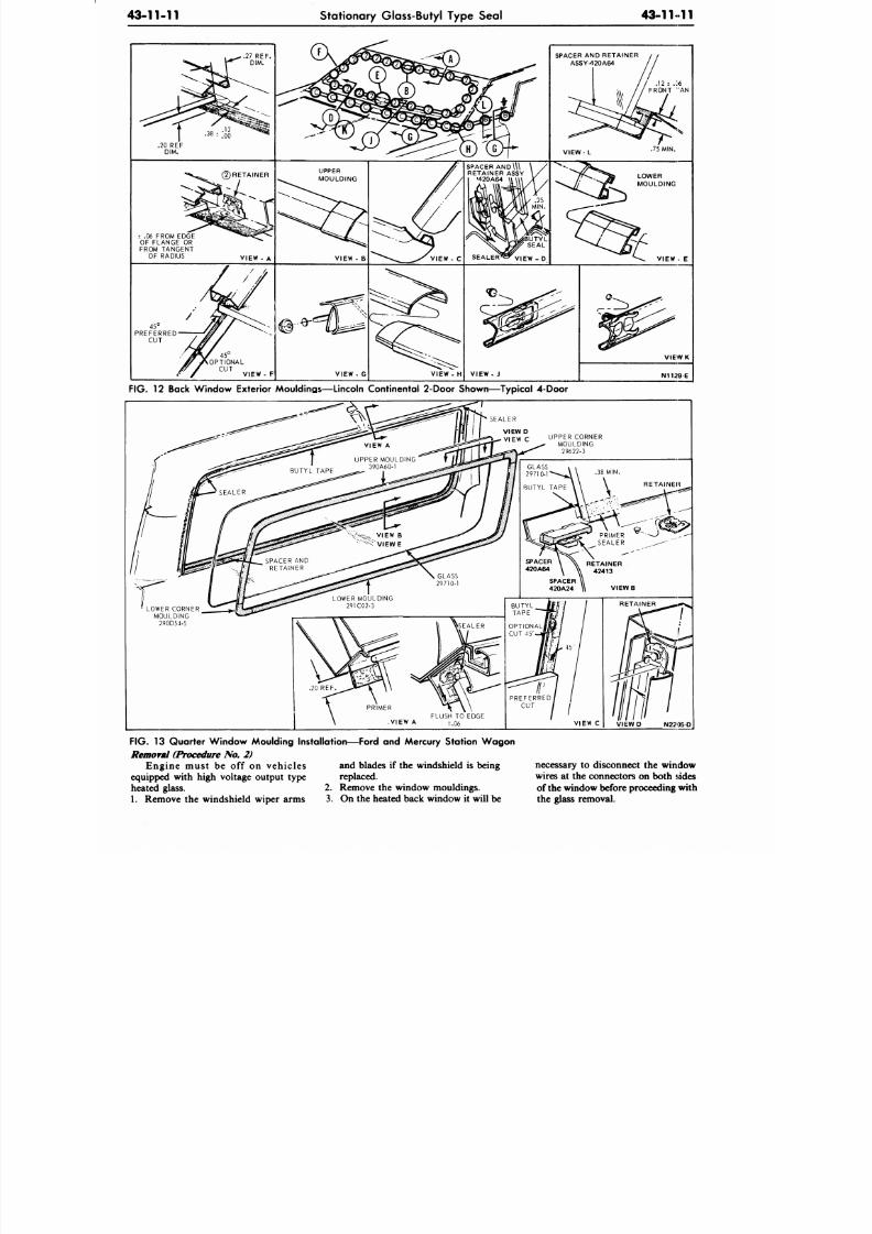
8/20/2019 1977 Ford Car Shop Manual Volume 4 Body
http://slidepdf.com/reader/full/1977-ford-car-shop-manual-volume-4-body 183/449
43-11-11 Stationary Glass-Butyl Type Seal
43-11 11
SPACER AND \\\
RETAINER ASSY
'420A64
± .06 FROM EDGE
OF FLANGE OR
FROM TANGENT
OF RADIUS
VIEW - G
VIEW - H
V I E W - J
V I E W K
N1129-E
FIG.
12 Back W indow Exterior Mouldings—Lincoln Continental 2-Door Show n—Ty pical 4-Door
F IG .
13 Quarter W indo w Moulding Instal lation—Ford and Mercury Station W ag on
Remova l (Procedure No. 2)
Engine must be off on vehicles
equipped with high voltage output type
heated glass.
1. Remove the windshield wiper arms
and blades if the windshield is being
replaced.
2.
Remove the window mouldings.
3.
On the heated back window it will be
necessary to disconnect the window
wires at the connectors on both sides
of the window before proceeding with
the glass removal.
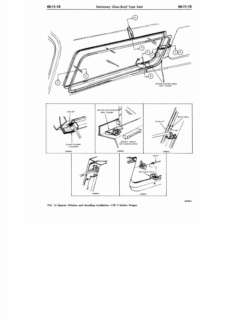
8/20/2019 1977 Ford Car Shop Manual Volume 4 Body
http://slidepdf.com/reader/full/1977-ford-car-shop-manual-volume-4-body 184/449
4 3 - 1 1 - 1 2
Stationary Glass-Butyl Type Seal
43-11-
SPACER AND RETAINER
ASSY - 420A64
SEALER
FLUSH TO EDGE
±0.06 INCH.
VIEW A
SPACER AND RETAINER
ASSY -420A64
SPACER -420A24
(NOT ALWAYS USED)
VIEWB
BUTYL SEA
VIEWC
VIEWD
RIVET
VIEW
E
N24
FIG.
14 Quarter Window and Moulding Installation—LTD II Station Wagon
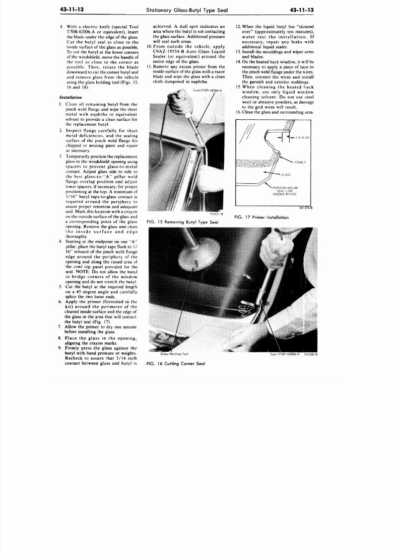
8/20/2019 1977 Ford Car Shop Manual Volume 4 Body
http://slidepdf.com/reader/full/1977-ford-car-shop-manual-volume-4-body 185/449
43-11-13
Stationary Glass-Butyl Type Seal 43-11-13
4.
With
a
electric knife (special Tool
T70B-42006-A
or
equivalent), insert
the blade under
the
edge
of
the glass.
C ut the butyl seal as close to the
inside surface of the glass as possible.
To cut the butyl at the lower corners
of the windshield, move the handle of
the tool as close to the co rn er as
p o ss ib le . Th en , ro ta te the b lad e
downward to cut the corner butyl seal
and remove glass from the vehicle
using the glass holding tool (Figs. 15,
16 and 18).
Installation
1. Clean all remaining butyl from the
pinch weld flange and wipe the sheet
metal with naphtha
or
equivalent
solvent
to
provide
a
clean surface
for
the replacement butyl.
2. Inspect flange carefully for sheet
metal deficiencies, and the sealing
surface of the pinch weld flange for
chipped
or
missing paint
and
repair
as necessary.
3. Tempo rarily position the replacement
glass in the windshield opening using
sp acer s to prevent g lass- to-m etal
contact. Adjust glass side to side to
th e b es t g las s - to - "A" p i l la r we ld
flange overlap position and adjust
lower spacers,
if
necessary,
for
proper
positioning
at the
top.
A
minimum
of
3/16" butyl tape-to-glass contact is
required around the per iphery to
assure proper retention and adequate
seal. Mark this location with a crayon
on the outside surface of the glass and
a corresponding poin t
of the
glass
opening. Remove
the
glass
and
clean
t h e i n s i d e s u r f a c e and e d g e
thoroughly.
4. Starting at the midpoint on one A
pillar, place the butyl tape flush to 1/
16"
inboard
of
the pinch weld flange
edge around
the
p er ip h ery
of the
opening and along the raised area of
the cowl top panel provided for the
seal. NOTE: Do not allow the butyl
to b r id g e co rn er s of the w in d o w
opening and do not stretch the butyl.
5. Cut the butyl at the required length
on a 45 degree angle and carefully
splice the two loose ends.
6. Apply
the
primer (furnished
in the
k i t ) a ro u n d the p e r i m e t e r of the
cleaned inside surface
and the
edge
of
the glass
in the
area that will contact
the butyl seal (Fig. 17).
7.
Allow
the
primer
to dry one
minute
before installing the glass.
8 . Place the g l a s s in the o p e n i n g ,
aligning
the
crayon marks.
9. Firmly press
the
glass against
the
butyl with hand pressure
or
weights.
Recheck to assure that 3/16 inch
contact between glass and butyl is
achieved. A dull spot indicates an
area where the butyl is not contacting
the glass surface. Additional pressure
will seal such areas.
10.
F r o m o u t s i d e the v eh ic le , ap p ly
C9AZ-19554-B Auto Glass Liquid
Sealer
(or
eq u iv a len t ) a ro u n d
the
entire edge of the glass.
11.
Remove
any
excess primer from
the
inside surface of the glass with a razor
blade
and
wipe
the
glass with
a
clean
cloth dampened in naphtha.
Tool-T70P-42006-A
12. When the liquid butyl has "skinned
over" (approximately ten minutes),
w a t e r t e s t the i n s t a l l a t i o n . If
n ecessary , r ep a i r any leaks with
additional liquid sealer.
13. Install the mouldings and wiper arms
and blades.
14. On the heated back window, it will be
necessary to apply a piece of tape to
the pinch weld flange under the wires.
Then, connect the wires and install
the garnish and exterior moldings.
15. W h e n c l e a n i n g
the
h ea ted b ack
w i n d o w ,
use
only l iquid window
cleaning so lvent .
Do not use
steel
wool
or
abrasive powders,
as
damage
to the grid wires will result.
16. Clean the glass and surrounding area.
3/ 8
INCH
PRIMER
GLASS
PORTION BELOW
SEAL LINE
HIDDEN WIPERS
N 1 8 3 1 - B
FIG.
15 Removing Butyl Type Seal
FIG. 17 Primer Installation
Glass Holding Tool
FIG.
16 Cutting Corner Seal
Too l -T70P-42006-A N1830-B
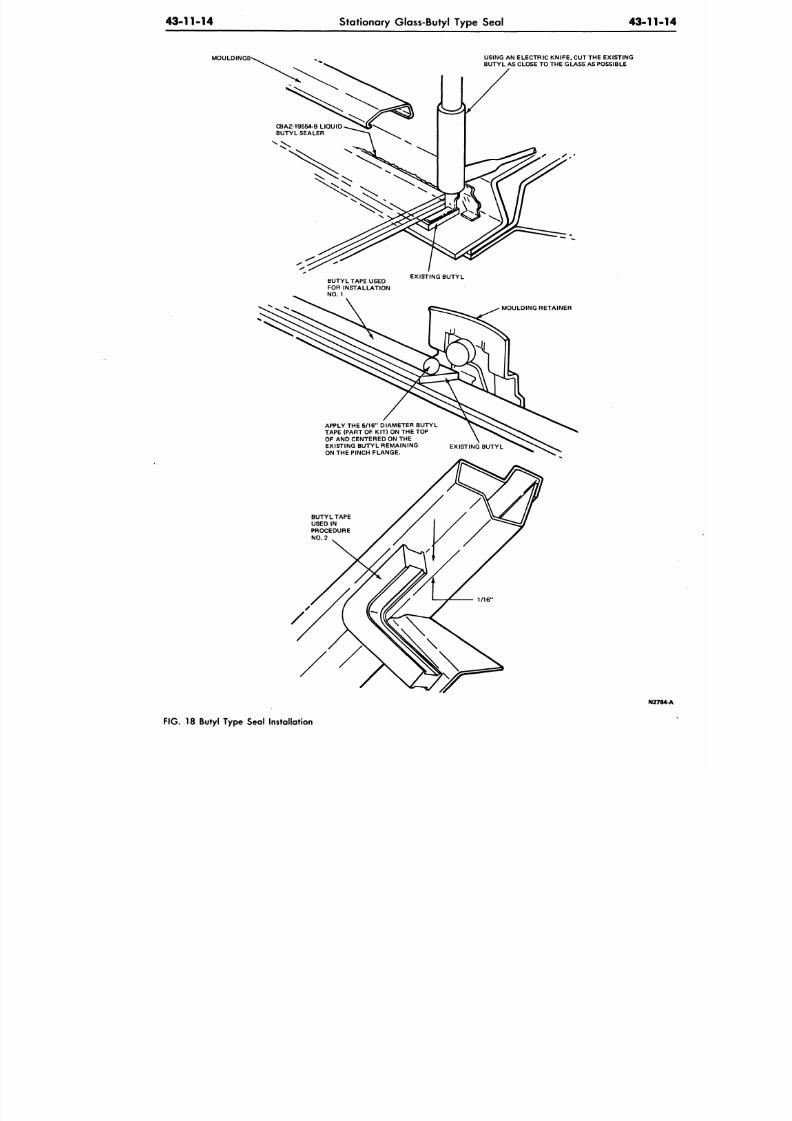
8/20/2019 1977 Ford Car Shop Manual Volume 4 Body
http://slidepdf.com/reader/full/1977-ford-car-shop-manual-volume-4-body 186/449
43-11-14
Stationary Glass-Butyl Type Seal
43-11
MOULDIN
USING AN ELECTRIC KN IFE, CUT THE EXISTING
BUTYL AS CLOSE TO THE GLASS AS POSSIBLE
BUTYL TAPE USED
FOR INSTALLATION
NO .
1
EXISTING BUTYL
MOULDING RETAINER
APPLY THE 5/16 DIAMETER BUTYL
TAPE (PART OF KIT) ON THE TOP
OF AND CENTERED ON THE
EXISTING BUTYL REMAINING EXISTING BUTYL
ON THE PINCH FLANGE.
BUTYLTAPE
USED IN
PROCEDURE
NO . 2
N27
FIG. 18 Butyl Type Seal Installation
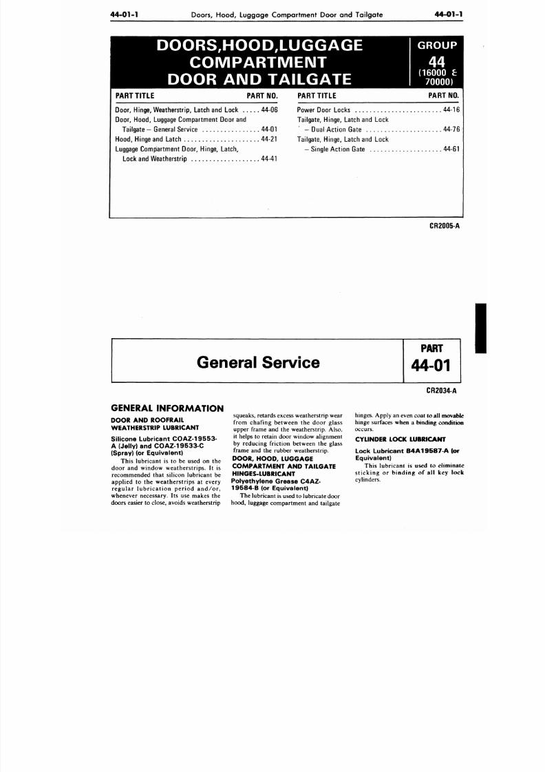
8/20/2019 1977 Ford Car Shop Manual Volume 4 Body
http://slidepdf.com/reader/full/1977-ford-car-shop-manual-volume-4-body 187/449
44-01-1
Doors, Hood, Luggage Compartment Door and Tailgate
44-01
DOORS,HOOD,LUGGAGE
C O M P A R T M E N T
DOOR AND TAILGATE
GROUP
(16000 £
70000)
PART TIT LE PART NO.
Doo r, Hinge, We athe rstrip, Latch and Lock 44-06
Door, H ood , Luggage Com partment Door and
Tailga te - General Service 44-01
Hood ,
Hinge and Latch 44-21
Luggage Compartment Door, Hinge, Latch,
Lock and Wea therstrip 44-41
PART TIT LE PART NO
Power Door Locks 44-
Tailgate, Hinge, Latch and Lock
- Dual Ac tio n Gate 44-
Tailgate, Hinge, Latch and Lock
- Single Ac tion Gate 44-
CR2005
General Service
GENERAL INFORMATION
DOOR AND ROOFRAIL
WEATHERSTRIP LUBRICANT
Sil icone Lubr icant COAZ-19553-
A (Je l ly ) and COAZ 19533-C
(Spray) (or Equivalent)
This lubricant is to be used on the
door and window weatherstrips. It is
recommended that silicon lubricant be
applied to the weatherstrips at every
regular lubrication period and/or,
whenever necessary. Its use makes the
doors easier to close, avoids weatherstrip
squeaks, retards excess weatherstrip wear
from chafing between the door glass
upper frame and the weatherstrip. Also,
it helps to retain door window alignment
by reducing friction between the glass
frame and the rubber weatherstrip.
DOOR, HOOD, LUGGAGE
COMPARTMENT AND TAILGATE
HINGES-LUBRICANT
Polyethylene Grease C4AZ-
19 58 4 B (or Eq uivalent)
The lubricant is used to lubricate door
hood, luggage compartment and tailgate
CR2034-A
hinges. Apply an even coat to all m ov
hinge surfaces when a binding condi
occurs.
CYLINDER LOCK LUBRICANT
Lock Lubr icant B4A19587-A (o
Equivalent)
This lubricant is used to elimin
sticking or binding of all key l
cylinders.
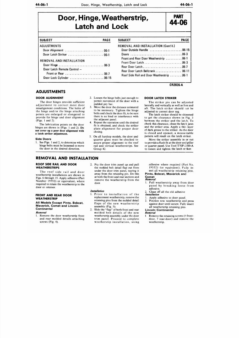
8/20/2019 1977 Ford Car Shop Manual Volume 4 Body
http://slidepdf.com/reader/full/1977-ford-car-shop-manual-volume-4-body 188/449
44-06-1
Door, H inge, W eatherstrip, Latch and Lock
44-06-1
Door, Hinge, W eatherstrip,
Latch and Lock
P A R T
44-06
SUBJECT PAGE
ADJUSTMENTS
Door Alignme nt 06-1
Door Latch Striker 06-1
REMOVAL AND INSTALLATION
Doo r Hinge 06-3
Door Latch Remote Con trol -
Fro nt or Rear 06-7
Door Lock Cylinder 06-15
SUBJECT PAIS£
REMOVAL AND INSTALL ATION (Cont'd .)
Door Outside Handle 06-15
Doors 06-3
Front and Rear Door Weatherstrip 06-1
Fron t Door Latch 06 3
Rear Door Latch 0 67
Rear Door Latch Bellcrank
06
11
Roof Side Rail and Door Weatherstrip 06-1
ADJUSTMENTS
DOOR ALIGNMENT
The door hinges provide sufficient
adjus tm ent to corre ct mos t door
misalignment conditions. The holes of
the hinge and/or the hinge attaching
points are enlarged or elongated to
provide for hinge and door alignment
(Figs. 1 and 2).
The lubrication points on the door
hinges are shown in (Figs. 1 and 2).
Do
not cover up a poor door alignment with
a latch striker adjustment.
Side Doors
1. See Figs.
1
and 2, to determine which
hinge bolts must be loosened to m ove
the door in the desired direction.
2.
Loosen the hinge bolts just enough to
permit movement of the door with a
padded pry bar.
3. Move the door the distance estimated
to be necessary. Tighten the hinge
bolts and check the door fit, to be sure
there is no bind or interference with
the adjacent panel.
4.
Repeat the operation until the desired
fit is obtained, and check the striker
plate alignment for proper door
closing.
5. On all hardtop models, the door and
quarter glass must be checked to
assure proper alignment to the roof
rail and vertical weatherstrips. See
Group 42.
CR2035-A
DOOR LATCH STRIKER
The striker pin can be adjusted
laterally and vertically as well as fore and
aft. The latch striker should not be
adjusted to correct door sag.
The latch striker should be shimmed
to get the clearance shown in Fig. 3
between the striker and the latch. To
check this clearance, clean the latch jaws
and the striker area. Apply a thin layer
of dark grease to the striker. As the door
is closed and opened, a measureable
pattern will result on the latch striker.
Move the striker assembly in or out
to provide a flush itat the door and pillar
or quarter panel. Use Tool T7OP-21OO-A
to loosen and tighten the latch striker.
REMOVAL AND INSTALLATION
ROOF SIDE RAIL AND DOOR
WEATHERSTRIPS
The roo f s ide r a i l and door
weatherstrip installations are shown in
Figs. 6 through 15. Apply adhesive (Part
Number 19552) or equivalent, where
required to retain the weatherstrip to the
door or retainer.
FRONT AND REAR DOOR
WEATHERSTRIP
All Models Except Pinto, Bobcat,
Mav er ick, Comet and L inco ln
Cont inenta l
Removal
1. Remove the door weatherstrip front
and rear molded details attaching
screws (Fig. 4).
2.
Pry the door trim panel up and pull
the molded belt detail flap out from
under the door trim panel, tearing it
away from the retaining pin. Do this
at both the front and rear sections and
remove the weatherstrip from the
door.
Installation
1. P r i o r t o i n s t a l l a t i o n o f t h e
replacement weatherstrip, remove the
retaining pins from the molded detail
f laps of the new w eat he rs t r ip
assembly (Fig. 5).
2.
Slide the "flap" of both front and rear
molded belt details of the new
weatherstrip assembly under the door
trim panel. Proceed to complete
w ea the r s t ip in s ta l l a t ion , u s ing
adhesive where required (Part No.
19552) (or equivalent). Fully in-
sert all weatherstrip retaining pins.
Pinto,
Bobcat , Maver ick and
Comet
Removal
1. Pull weatherstrip away from door
panel by breaking loose f rom
adhesive.
2.
Clean off all the old adhesive
Installation
1. Apply adhesive to door panel.
2.
Position new weatherstrip and press
against door until secure. Fully insert
all weatherstrip retaining pins.
Lincoln Continental
Removal
1. Remove the retaining screws i< front-
door, 7 rear-door) and remove the
weatherstrip.
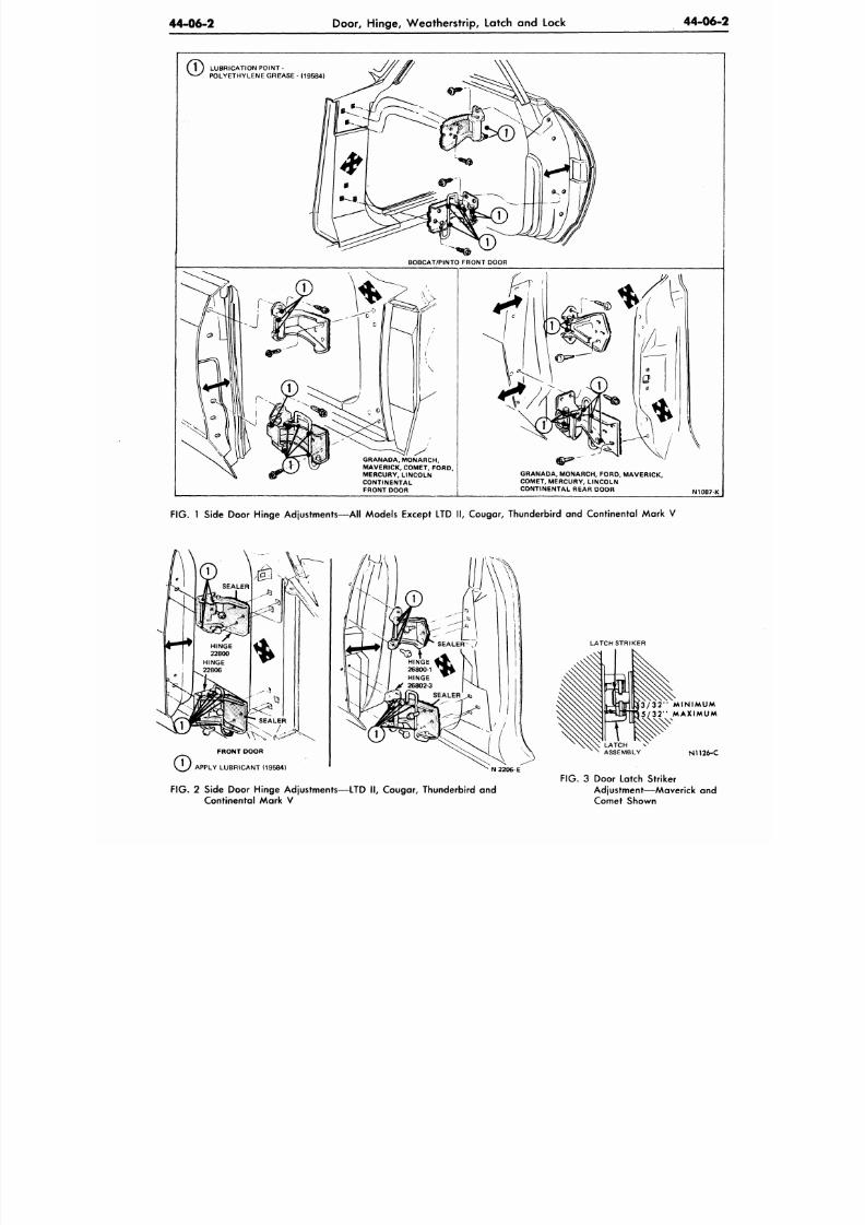
8/20/2019 1977 Ford Car Shop Manual Volume 4 Body
http://slidepdf.com/reader/full/1977-ford-car-shop-manual-volume-4-body 189/449
44-06-2
Door, Hinge, W eatherstrip, Latch and Lock
44-06-
1 ) LUBRICATIO N POINT -
* —
'
POLYETHYLENE GREASE - (19584)
GRANADA, MONARCH,
MAVERICK, COMET, FORD,
MERCURY , LINCOLN
CONTINENTAL
FRONT DOOR
GRANADA, MONARCH ,
FORD.
MAVERICK,
COMET, MER CURY, LINCOLN
CONTINENTAL REAR DOO R
N1087-K
FIG.
1 Side Door Hinge Adjustm ents—A ll Mod els Except LTD II, Cougar, Thunderbird and Co ntinental M ark V
FRONT DOOR
APPLY LUBRICANT (19584)
N 2206-E
FIG .
2 Side Door Hinge Adjustments—LTD II, Couga r, Thunderbird and
Continental Mark V
LATCH STRIKER
3/32 MINIMUM
5/32 MAXIMUM
LATCH
ASSEMBLY
N1126-C
FIG. 3 Door Latch Striker
Adjustment—Maverick and
Comet Shown
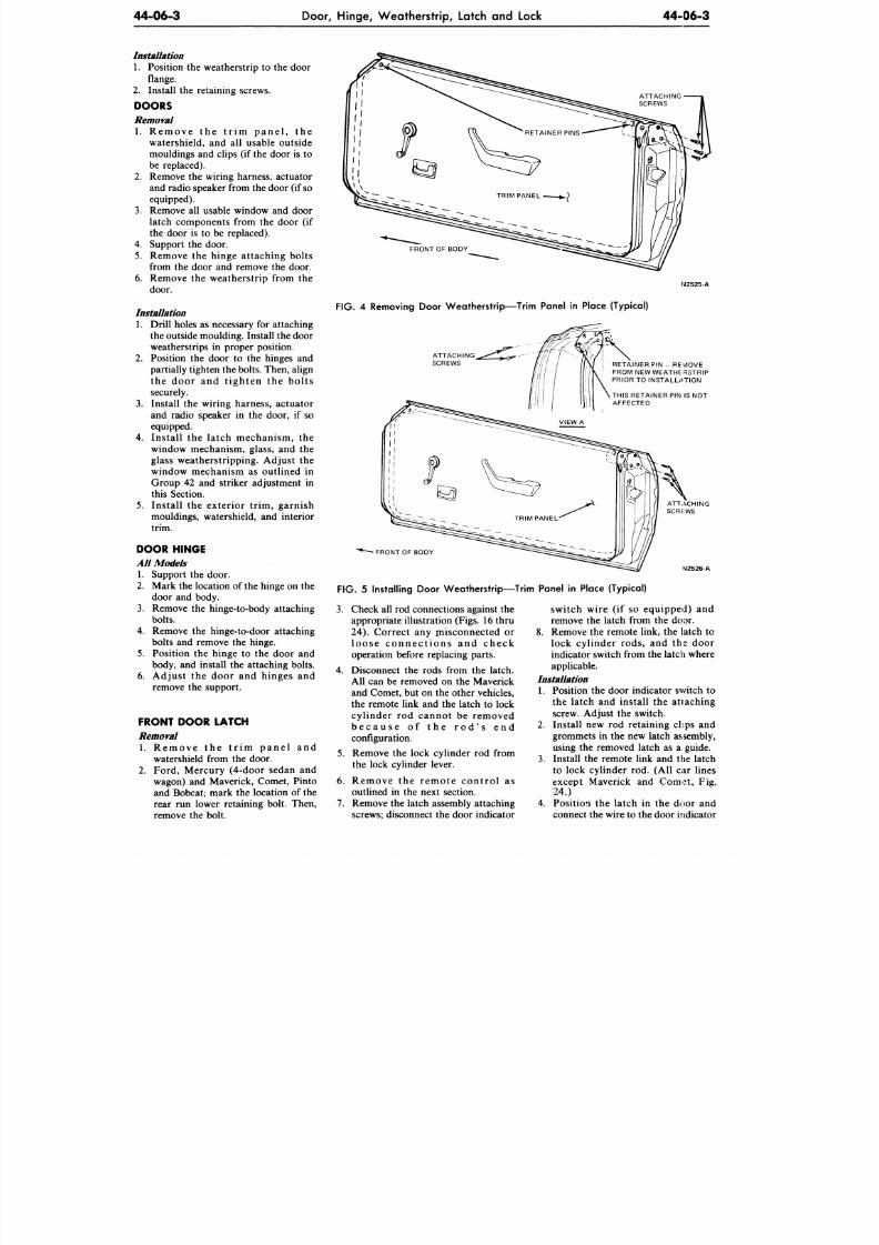
8/20/2019 1977 Ford Car Shop Manual Volume 4 Body
http://slidepdf.com/reader/full/1977-ford-car-shop-manual-volume-4-body 190/449
44-06-3
Door, Hinge, Weatherstrip, Latch and Lock 44-06-3
Installation
1. Position
the
weatherstrip
to the
door
flange.
2.
Install
the
retaining screws.
DOORS
Removal
1. Remove the tr i m p a n e l , the
watershield,
and all
usable outside
mouldings
and
clips
(if
the door
is to
be replaced).
2. Remove the wiring harness, actuator
and radio speaker from the door (if so
equipped).
3. Remove all usable window and door
latch components from
the
door
(if
the door is to be replaced).
4.
Support
the
door.
5.
Remove the hinge attaching bolts
from
the
door
and
remove
the
door.
6. Remove the weatherstrip from the
door.
Installation
1. Drill holes as necessary for attaching
the outside moulding. Install the door
weatherstrips in proper position.
2.
Position
the
door
to the
hinges
and
partially tighten th e bolts. Then, align
the door and t ighten the bol ts
securely.
3. Install the wiring harness, actuator
and radio speaker
in the
door,
if so
equipped.
4.
Install
the
latch mechanism,
the
window mechanism, glass, and the
glass weatherstripping. Adjust
the
window mechanism as outlined in
Group
42 and
striker adjustment
in
this Section.
5. Install
the
exterior trim , garnish
mouldings, watershield, and interior
trim.
DOOR HINGE
All Models
1. Support the door.
2.
Mark the location of the hinge on the
door
and
body.
3. Remove the hinge-to-body attaching
bolts.
4.
Remove the hinge-to-door attaching
bolts
and
remove
the
hinge.
5. Position the hinge to the door and
body, and install the attaching bolts.
6. Adjust
the
door
and
hinges
and
remove the support.
FRONT DOOR LATCH
Removal
1 . Remove
the
t r im p a n e l
and
watershield from the door.
2.
Ford, Mercury (4-door sedan
and
wagon) and Maverick, Comet, Pinto
and Bobcat; mark the location of the
rear
run
lower retaining bolt. Then,
remove the bolt.
N2525-A
FIG. 4 Removing Door Weatherstr ip—Trim Panel in Place (Typical)
ATTACHING
SCREWS
RETAINER
PIN -
REMOVE
FROM NEW WEATHERSTRIP
PRIOR
TO
INSTALLATION
THIS RETAINER PIN IS NOT
AFFECTED
FRONT OF BODY
VI2526A
F IG . 5
Instal l ing Door Weatherstr ip—Trim Panel
in
Place (Typical)
3.
Check all rod connections against
the
appropriate illustration (Figs. 16 thru
24).
Correct
any
misconnected
or
l o o s e c o n n e c t i o n s and c h e c k
operation before replacing parts.
4. Disconnect
the
rods from
the
latch.
All
can be
removed
on the
Maverick
and Comet, but on the other vehicles,
the remote link
and the
latch
to
lock
cylinder rod cannot be removed
b e c a u s e
of the
r o d ' s
end
configuration.
5.
Remove
the
lock cylinder
rod
from
the lock cylinder lever.
6. Remove
the
r emote con t ro l
as
outlined in the next section.
7. Remove the latch assembly attaching
screws; disconnect the door indicator
switch wire
(if so
equipped)
and
remove the latch from the door.
8. Remove
the
remote link,
the
latch
to
lock cylinder rods, and the door
indicator switch from the latch where
applicable.
Installation
1. Position the door indicator switch to
the latch and install the attaching
screw. Adjust
the
switch.
2.
Install
new rod
retaining clips
and
grommets
in the
new latch assembly,
using the removed latch as a guide.
3. Install the remote link and the latch
to lock cylinder rod. (All car lines
except Maverick
and
Comet,
Fig.
24.)
4.
Position the latch in the door and
connect the wire to the door indicator
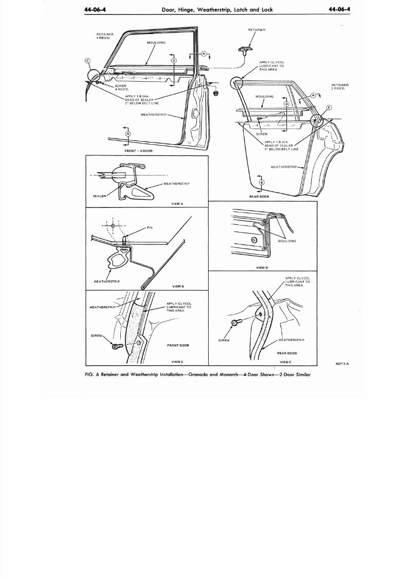
8/20/2019 1977 Ford Car Shop Manual Volume 4 Body
http://slidepdf.com/reader/full/1977-ford-car-shop-manual-volume-4-body 191/449
44-06-4
Door, Hinge, Weatherstrip, Latch and Lock
44-0
RETAINER
4 REQ'D.
APPLY
1/8 DIA.
BEAD OF SEALER
2 "
BELOW BELT LINE
APPLY 1/8 DIA.
BEAD OF SEALER
2 " BELOW BELT LINE
FIG. 6 Retainer and Weatherstrip Installation—Granada and Monarch— 4-Door Shown— 2-Door Similar
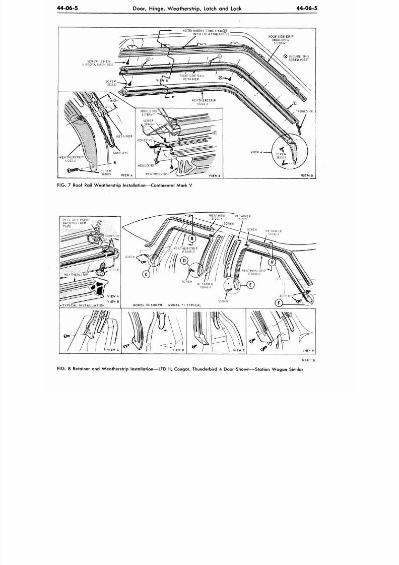
8/20/2019 1977 Ford Car Shop Manual Volume 4 Body
http://slidepdf.com/reader/full/1977-ford-car-shop-manual-volume-4-body 192/449
44-06-5
Door, Hinge, Weatherstrip, Latch and Lock
44-06-5
NOTE: INSERT TABS IT E M ®
INTO LOCATING HOLES [
ROOF SIDE DRIP
MOULDING
517B16-7
SCREW - 384474
8 REQ'D. EACH SIDE
SECURE THi:
SCREW F IRS"
WEATHERSTRIP
51222-3
SCREW
384049
V | E W A
ADHES /E
N2374-D
FIG. 7 Roof Rail Weatherstrip Installation—Continental Mark V
ETAINER RETAINER
51204-5 24510
N 2 3 7 ' - |
F IG .
8 Retainer and Weathe rstrip Installation—L TD II , Cougar, Thunderbird 4 Door Show n— Station W ag on Similar
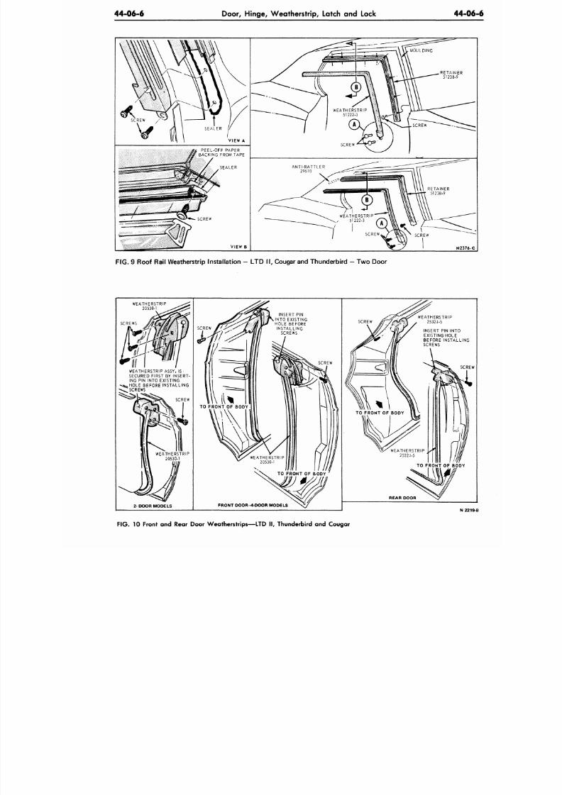
8/20/2019 1977 Ford Car Shop Manual Volume 4 Body
http://slidepdf.com/reader/full/1977-ford-car-shop-manual-volume-4-body 193/449
44-06-6
Door, H inge, W eathers trip, Latch and Lock
44-0
F I G . 9 Roof Rai l W eatherstrip Installation — LT D I I , Cougar and Thunderbird — Tw o Door
WEATHERSTRIP
20530-1
SCREWS
WEATHERSTRIP ASSY. IS '
SECURED FIRST BY INSERT-
ING PIN INTO EXISTING
BEFORE INSTALLING
SCREWS
SCREW
2-DOOR MODELS
SCREW
INSERT PIN
INTO EXISTING
HOLE BEFORE
INSTALLING
SCREWS
SCREW
FRONT DOOR -4 DOOR MODELS
SCREW
INSERT PIN INTO
EXISTING HOLE
BEFORE INSTALLING
SCREWS
SCR
REAR DOOR
N 2
FIG. 10 Front and Rear Door W eatherstr ips—LTD I I , Thunderbird and Cougar
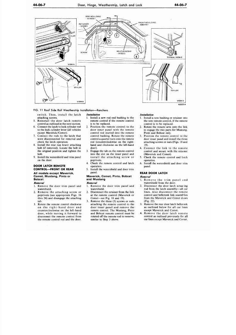
8/20/2019 1977 Ford Car Shop Manual Volume 4 Body
http://slidepdf.com/reader/full/1977-ford-car-shop-manual-volume-4-body 194/449
44-06-7
Door, Hinge, Weatherstrip, Latch and Lock
44-06-7
SIDE MOULDING
- 517B16-7
V I E W B
SEALER
V I E W )
FIG. 11
Roof Side Rail Weatherstrip Installation—Ranchero
swi tch. Then, ins ta l l the la tch
attaching screws.
5. Reinstall the door latch remote
control as outlined in the next section.
6. Connect the latch to lock cylinder rod
to the lock cy linder lever (all vehicles
except Maverick/Comet).
7. Connect
the
rods
to the
latch that
were disconnected
for
removal
and
check
the
latch operation.
8. Install
the
rear
run
lower attaching
bolt
(if
removed). Locate
the
bolt
in
the original position
and
tighten
the
bolt.
9. Install the watershield and trim panel
on the door.
DOOR LATCH REMOTE
CONTROL—FRONT OR REAR
All models except Maverick,
Comet , Mustang, P into or
Bobcat
Removal
1. Remove the door trim panel and
watershield.
2.
Remove the attaching screw or
poprivets (see appropriate Figs. 16
thru 24)
and
disengage
the
attaching
tab.
3. Rotate the remote control clockwise
on the r i g h t - h a n d d o o r and
counterclockwise
on the
left-hand
door, while moving
it
forward
to
disconnect
the
remote control from
the remote control
rod and the
door.
Installation
1. Install a new rod end bushing to the
remote control if the remote control
is to be replaced.
2. Position the remote control to the
door inner panel with the remote
control rod started into the remote
control bushing. Rotate
the
remote
control a quarter turn onto the remote
rod (counterclockwise
on the
right-
hand
and
clockwise
on the
left-hand
door).
3. Engage the tab
on
the remote control
into
the
slot
on the
inner panel
and
i ns t a l l the a t t a c h ing sc re w or
poprivets.
4. Check the remote control and latch
operation.
5. Install the w atershield and door trim
panel.
Mave rick, C omet, Pinto, Bobcat
and Mustang
Removal
1. Remove the door trim panel and
watershield.
2.
Disconnect the retainer from the link
at
the
remote control (Maverick
or
Comet—see Fig. 18
and 19).
3. Remove the three (3) screws or nuts
attaching the remote control to the
door inner panel and remove the
remote control.
The
Mustang, Pinto
and Bobcat remote control must
be
rotated
off
the remote
rod to
remove,
similar
to
Step
3
above.
IM2220-A
Installation
1. Install a new bushing or retainer into
the new remote control, if the remote
control is to be replaced.
Rotate the remote arm onto the link
to engage the two parts for Mustang,
Pinto and Bobcat only.
Position
the
remote control
to the
door inner panel
and
install the three
attaching screws or nuts
(Figs.
18 and
19).
Connec t
the
link
to the
remote
control
and
secure with
the
retainer
(Maverick
and
Comet).
Check
the
remote control
and
latch
operation.
Install
the
w atershield
and
door trim
panel.
2.
3.
4.
5.
6.
REAR DOOR LATCH
Removal
1 . Re m ove the t r i m p a n e l and
watershield from the door.
2. Disconnect
the
door latch actuating
rod from
the
latch assembly—all
car
lines.
Also disconnect
the
remote
control
and
bellcrank link assemblies
from
the
Maverick
and
Comet doors
(Fig.
22).
3. Remove the rear door latch bellcrank
as outlined below
for all car
lines
except Maverick
and
Comet.
4. Remove
the
door la tch remote
control
as
outlined previously
for all
car lines except Maverick and Comet.
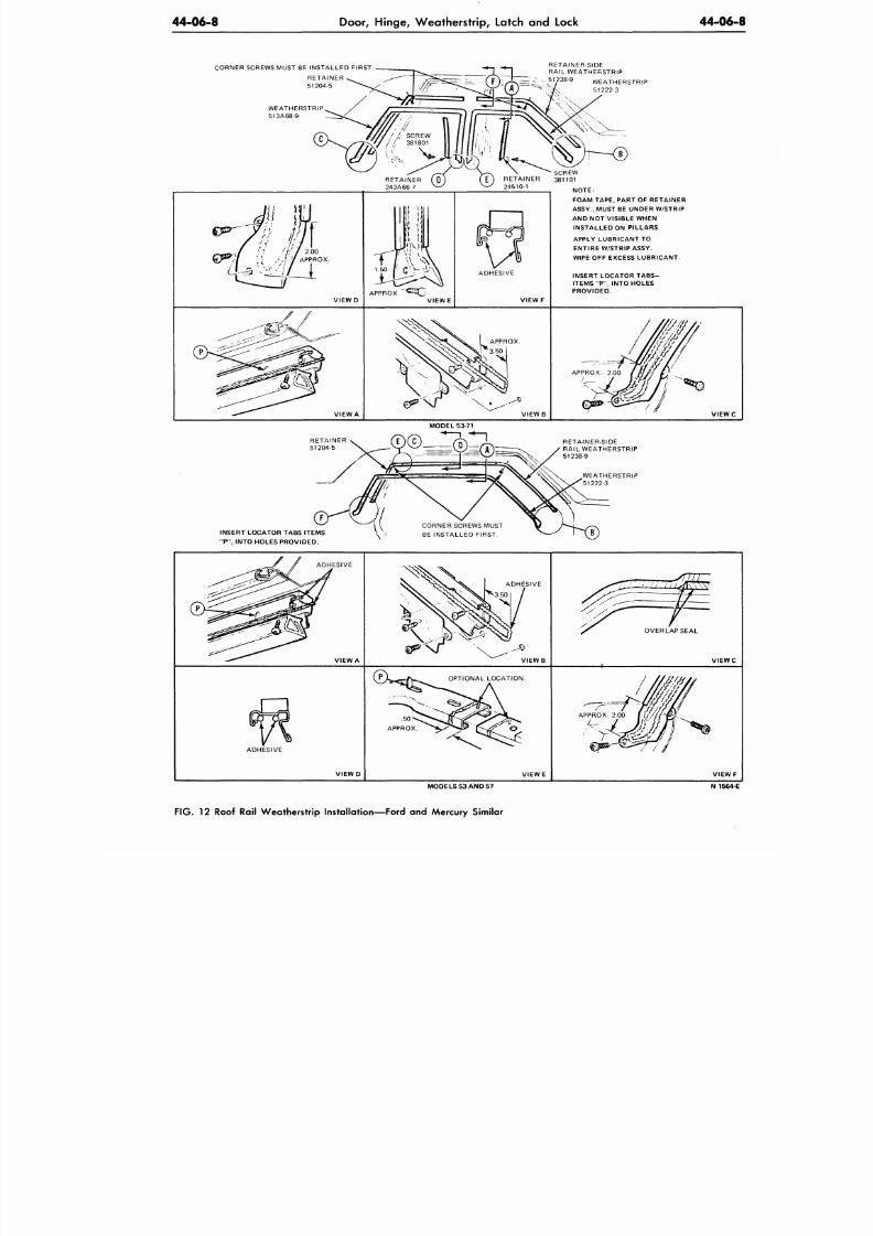
8/20/2019 1977 Ford Car Shop Manual Volume 4 Body
http://slidepdf.com/reader/full/1977-ford-car-shop-manual-volume-4-body 195/449
44-06-8
Door, H inge, W eathers trip, Latch and Lock
44-0
CORNER SCREWS MUST BE INSTALLED FIRST.
WEATHERSTRIP
513A68-9
RETAINER SIDE
RAIL WEATHERSTRIP
_ ^ { ?)--/< = -.
x
51238-9 WEATHERSTRIP
;V *)—
51222-3
SCREW
RETAINER 381101
24510-1
V I E W D
APPROX
ADHESIVE
V I E W F
NOTE:
FOAM TAPE, PART OF RETAINER
ASSY., MUST BE UNDER W/STRIP
AND NOT VISIBLE WHEN
INSTALLED ON PILLARS
APPLY LUBRICANT TO
ENTIRE W/STRIP ASSY.
WIPE OFF EXCESS LUBRICANT.
INSERT LOCATOR TABS-
ITEMS "P", INTO HOLES
PROVIDED.
VIEW A
V I E W B
APPROX. 2.00
V I E W
MODEL S3 71
INSERT LOCATOR TABS ITEMS
"P", INTO HOLES PROVIDED.
RETAINER-SIDE
RAIL WEATHERSTRIP
51238-9
WEATHERSTRIP
51222-3
ADHESIVE
VIEW A
ADHESIVE
OVERLAP SEAL
V I E W
OPTIONAL LOCATION.
ADHESIVE
.50
APPROX
VIEW D
V IE W E V IE W
MODELS 53 AND 57 N 15
F IG . 12 Roof Rail Weatherstrip Installation—Ford and Mercury Similar
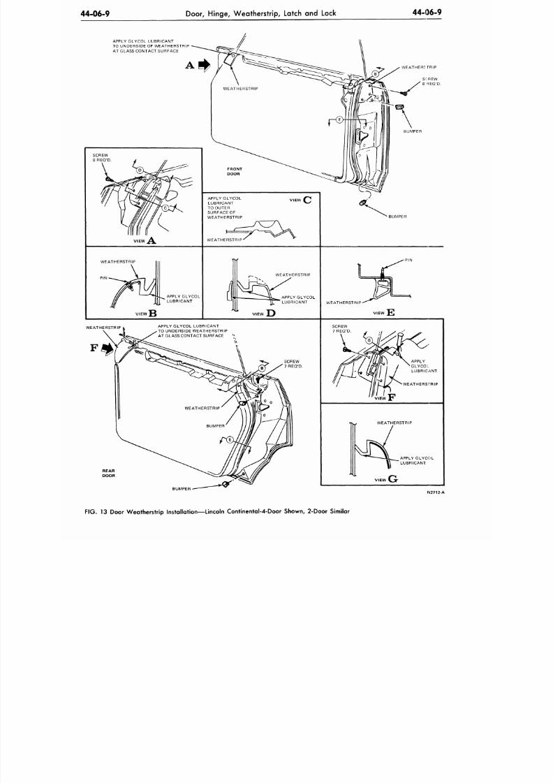
8/20/2019 1977 Ford Car Shop Manual Volume 4 Body
http://slidepdf.com/reader/full/1977-ford-car-shop-manual-volume-4-body 196/449
44-06-9
Door,
Hing e, W eathe rstrip, Latch and Lock
44-06-9
APPLY GLYCOL LUBRICANT
TO UNDERSIDE OF WEATHERSTRIP
AT GLASS CONTACT SURFACE
WEATHERS TRIP
VIEW
APPLY GLYCOL
LUBRICANT
TO OUTER
SURFACE OF
WEATHERSTRIP
WEATHERSTRIP
BUMPER
WEATHERSTRIP
P IN
APPLY GLYCOL
LUBRICANT
PI N
WEATHERSTRIP
APPLY GLYCOL
LUBRICANT
WEATHERSTRIP
VIEW
WEATHERSTRIP
APPLY GLYCOL LUBRICANT
TO UNDERSIDE WEATHERSTRIP
AT GLASS CONTACT SURFACE
SCREW
7 REQ'D.
WEATHERSTRIP
VIEW
REAR
DOOR
WEATHERSTRIP
APPLY GLYCOL
LUBRICANT
G
BUMPER
FIG . 13 Door W eatherstrip Installation—Lincoln C ontinental-4-Door Sh own,
2-Door
Similar
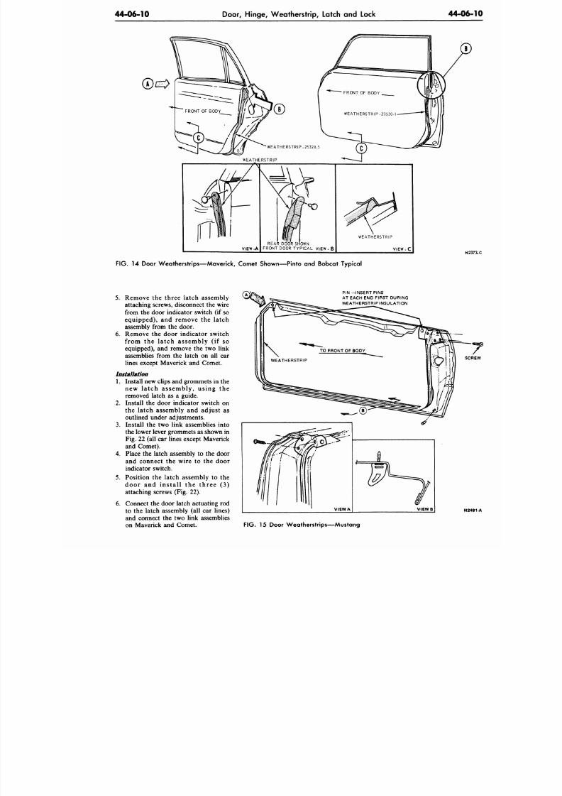
8/20/2019 1977 Ford Car Shop Manual Volume 4 Body
http://slidepdf.com/reader/full/1977-ford-car-shop-manual-volume-4-body 197/449
44-06-10
Door, H inge, W eatherstrip, Latch and Lock
4 4 - 0 6
VIEW-A
REAR DOOR SHOWN
FRONT DOOR TYPICAL VIEW - B
WEATHERSTRIP
V I E W - C
N
F IG .
14 Door Weatherstr ips—Maverick, Comet Shown—Pinto and Bobcat Typical
5. Remove the three latch assembly
attaching screws, disconnect the wire
from the door indicator switch (if so
equipped), and remove the latch
assembly from the door.
6. Remove the door indicator switch
from the latch assembly (if so
equipped), and remove the two link
assemblies from the latch on all car
lines except Maverick and Comet.
Installation
1. Install new clips and grommets in the
new latch assembly, using the
removed latch as a guide.
2.
Install the door indicator switch on
the latch assembly and adjust as
outlined under adjustments.
3. Install the two link assemblies into
the lower lever gromm ets as shown in
Fig. 22 (all car lines except M averick
and Comet).
4.
Place the latch assembly to the door
and connect the wire to the door
indicator switch.
5.
Position the latch assembly to the
door and ins ta l l the three (3)
attaching screws (Fig. 22).
6. Connect the door latch actuating rod
to the latch assembly (all car lines)
and connect the two link assemblies
on Maverick and Comet.
PIN —INSERT PINS
AT EACH END FIRST DURING
WEATHERSTRIP INSULATION
N
F IG . 15 Door Weatherstr ips—Mustang
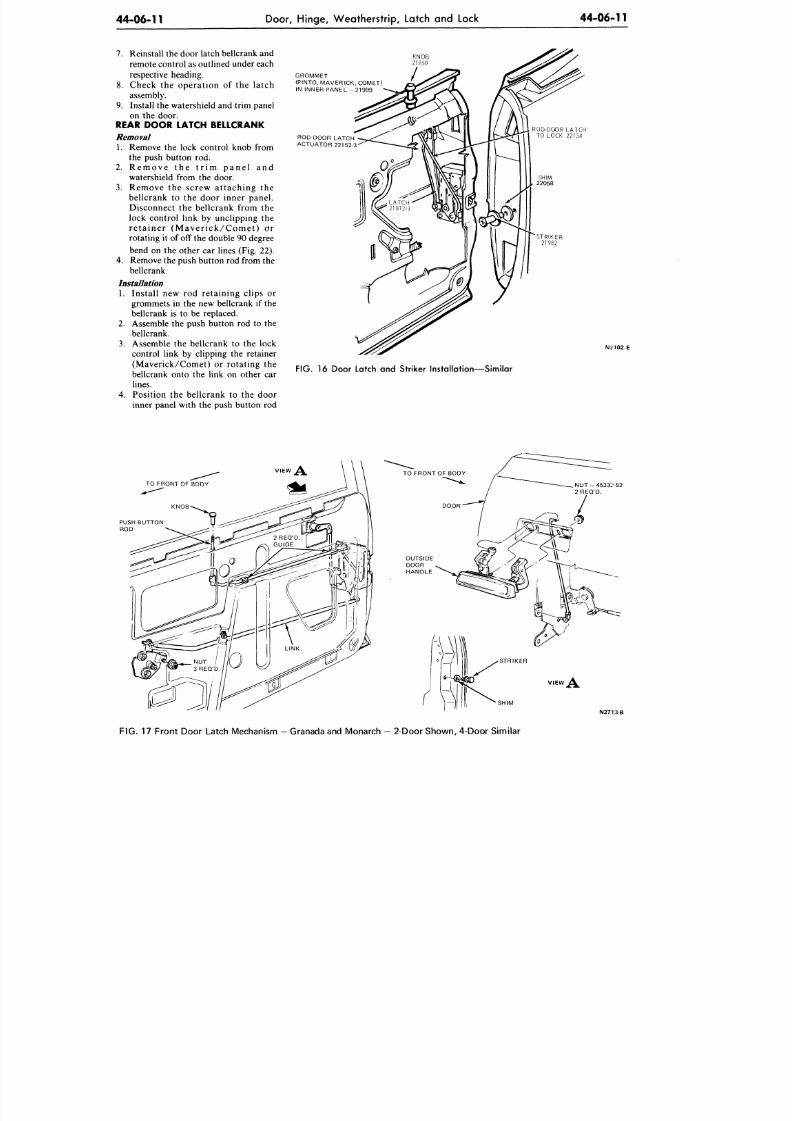
8/20/2019 1977 Ford Car Shop Manual Volume 4 Body
http://slidepdf.com/reader/full/1977-ford-car-shop-manual-volume-4-body 198/449
44-06-11
Door, H inge, W eathe rstrip, Latch and Lock
44-06-11
7. Reinstall the door latch bellcrank and
remote control as outlined under each
respective heading.
8. Check the operation of the latch
assembly.
9. Install the watershield and trim panel
on the door.
REAR DOOR LATCH BELLCRANK
Removal
1. Remove the lock control knob from
the push button rod.
2. Re m ove the t r im pa ne l a nd
watershield from the door.
3.
Remove the screw attaching the
bellcrank to the door inner panel.
Disconnect the bellcrank from the
lock control link by unclipping the
r e t a ine r ( M a ve r i c k /Com e t ) o r
rotating it of off the double 90 degree
bend on the other car lines (Fig. 22).
4. Remove the push button rod from the
bellcrank.
Installation
1. Install new rod retaining clips or
grommets in the new bellcrank if the
bellcrank is to be replaced.
2. Assemble the push button rod to the
bellcrank.
3. Assemble the bellcrank to the lock
control link by clipping the retainer
(Maverick/Comet) or rotating the
bellcrank onto the link on other car
lines.
4. Position the bellcrank to the door
inner panel with the push button rod
K N O B
2 1 8 5 0
GROMMET
(PINTO, MAVE RICK, COMET)
IN INNER PANEL - 21999
ROD-DOOR LATCH
ACTUATOR 221 52-3
STRIKER
2 1 9 8 2
N2102-E
FIG.
16 Door Latch and Striker Installation—Similar
NUT - 4533: -S2
2 REQ'D.
PUSH BUTTON
ROD
N27i:i-B
FIG. 17 Front Door Latch Mechanism — Granada and Monarch — 2-Door S how n, 4-Door Simi lar
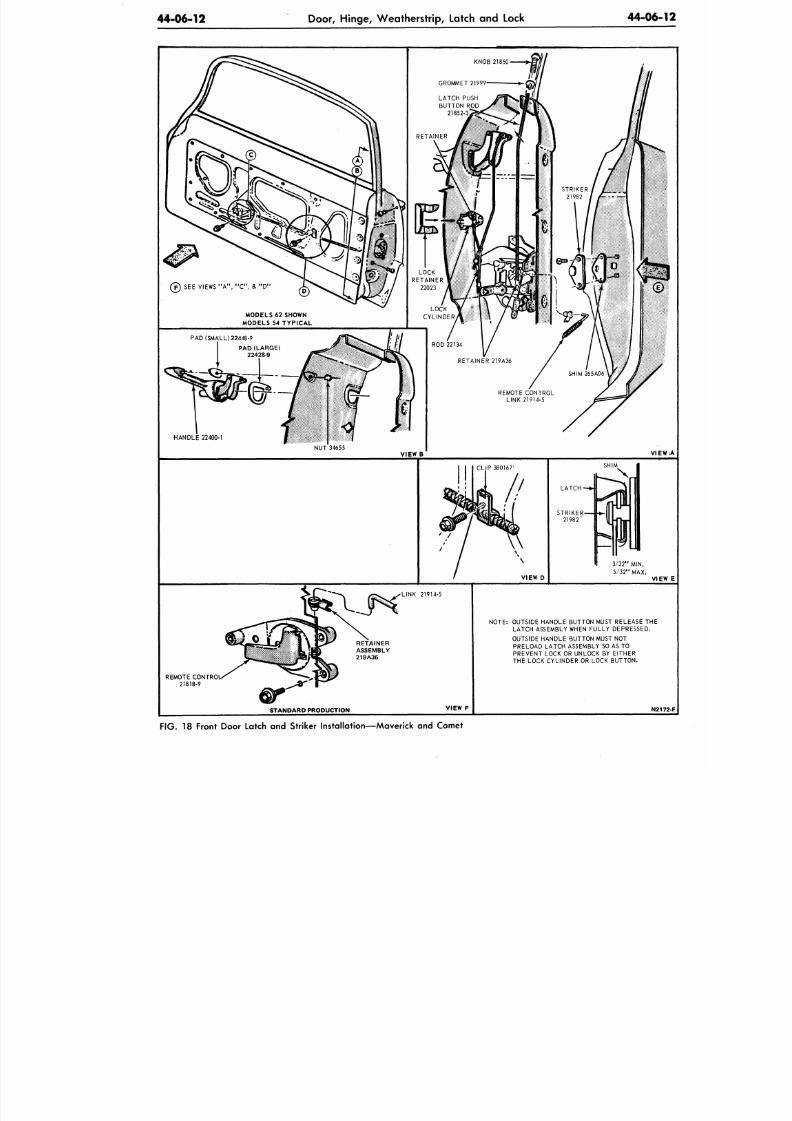
8/20/2019 1977 Ford Car Shop Manual Volume 4 Body
http://slidepdf.com/reader/full/1977-ford-car-shop-manual-volume-4-body 199/449
44-06-12
Door, Hinge, Weatherstrip, Latch and Lock
44-06
LATCH PUSH
BUTTON ROD
21852-3
( ? ) S EE VIEW S " A " , " C " , & " D "
MODELS 62 SHOWN
MODELS 54 TYPICAL
PAD (SMALL 22448-9
ROD 22134
RETAINER 219A36
PAD (LARGE)
22428-9
REMOTE CONTROL
LINK 21914-5
3/32" MIN.
5 /32" MAX.
NOTE: OUTSIDE HANDLE BUTTON MUST RELEASE THE
LATCH ASSEMBLY WHEN FULLY DEPRESSED.
OUTSIDE HANDLE BUTTON MUST NOT
PRELOAD LATCH ASSEMBLY SO AS TO
PREVENT LOCK OR UNLOCK BY EITHER
THE LOCK CYLINDER OR LOCK BUTTON.
RETAINER
ASSEMBLY
219A36
REMOTE CONTRO
21818-9
STANDARD PRODUCTION
F IG .
18 Front Door Latch and Striker Installation—Maverick and Comet
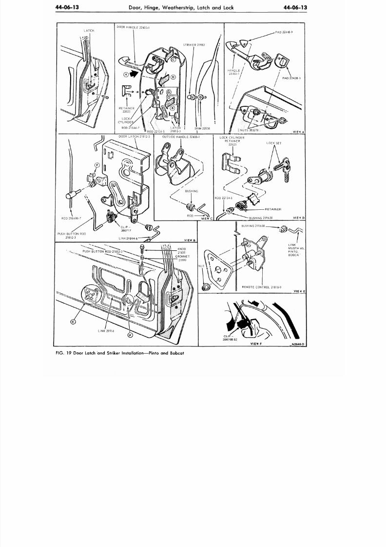
8/20/2019 1977 Ford Car Shop Manual Volume 4 Body
http://slidepdf.com/reader/full/1977-ford-car-shop-manual-volume-4-body 200/449
44-06-13
Door, Hinge, Weatherstrip, Latch
and
Lock
44-06-13
V
R O D 2 1 8 A 6 - 7
»> \
L A T C H
.'
RO D 22134-5 2 1 8 1 2 - 3
FIG. 19
Door Latch
and
Striker Installation—Pinto
and
Bobcat
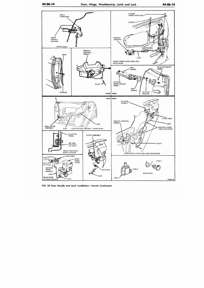
8/20/2019 1977 Ford Car Shop Manual Volume 4 Body
http://slidepdf.com/reader/full/1977-ford-car-shop-manual-volume-4-body 201/449
44-06-14
Door, Hinge, Weatherstrip, Latch and Lock
44-06
LINK
CLIP LOCK BUTTON LINKA GE - REAR DOOR
FIG.
20 Door Handle and Latch Installation—Lincoln Continental
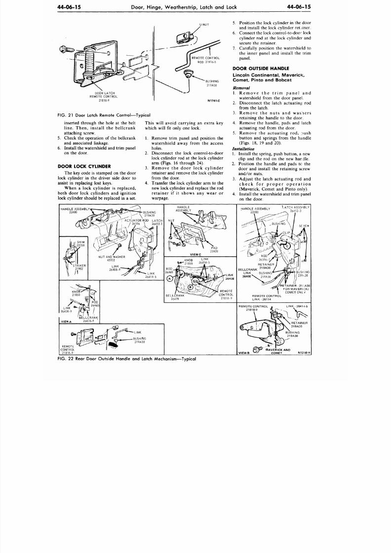
8/20/2019 1977 Ford Car Shop Manual Volume 4 Body
http://slidepdf.com/reader/full/1977-ford-car-shop-manual-volume-4-body 202/449
44-06-15
Door, H inge, W eathe rstrip, Latch and Lock
44-06-15
DOOR LATCH
REMOTE CONTROL
21818-9
BUSHING
219A38
N1741-C
FIG.
21 Door Latch Remote Control—Typical
6.
inserted through the hole at the belt
l ine . T hen , in s ta l l the be l l c rank
attaching screw.
Check the operation of the bellcrank
and associated linkage.
Install the watershield and trim panel
on the door.
DOOR LOCK CYLINDER
The key code is stamped on the door
lock cylinder in the driver side door to
assist in replacing lost keys.
When a lock cyl inder is replaced,
both door lock cyl inders and igni t ion
lock cylinder should be replaced in a set.
This will avoid carrying an extra key
which will fit only one lock.
1. Remove trim panel and position the
watershie ld away from the access
holes.
2.
Disconnect the lock control-to-door
lock cylinder rod at the lock cylinder
arm (Figs. 16 through 24).
3.
R e m o v e t h e d o o r lo c k c y l i n d e r
retainer and remove the lock cylinder
from the door.
4.
Transfer the lock cylinder arm to the
new lock cylinder and replace the rod
re ta iner i f i t shows any wear or
warpage.
5.
Position the lock cylinder in the door
and install the lock cylinder retainer.
6. Conn ect the lock control-to-d oor lock
cylinder rod at the lock cylinder and
secure the retainer.
7. Carefully position the watershield to
the inner panel and install the trim
panel.
DOOR OUTSIDE HANDLE
Lincoln Cont inenta l , Maver ick,
Comet , Pinto and Bobcat
Removal
1. R e m o v e t h e t r i m p a n e l a n d
watershield from the door panel.
2.
Disconnect the la tch ac tuat ing rod
from the latch.
3.
R e m o v e t h e n u t s a n d w a s h e r s
retaining the handle to the door.
4.
Remo ve the handle, pads and latch
actuating rod from the door.
5 . Remove the ac tuat ing rod, :>ush
button and springs from the handle
(Figs. 18, 19 and 20).
Installation
1. Install the spring, push butto n, a new
clip and the rod on the new har die.
2.
Position the handle and pads to the
door and install the retaining screw
and/or nuts .
3.
Adjus t the la tch ac tuat ing rod and
c h e c k f o r p r o p e r o p e r a t i o n
(Maverick, Comet and Pinto only).
4.
Install the watershield and trim panel
on the door.
HANDLE ASSEMBLY
22400
iHANDLE ASSEMBLY ^
22400 — 26412-3
ASSEMBLY
BELLCRANK
LINK BUSHING
26408 S ^ 219A38
'RETAINER -21 SA36
FOR MAVERICK/
COMETONL V
REMOTE CONTROL
LINK -26114
REMOTE CONTROL
21818-9
LINK -26414-5
MAVERICK AND
V I E W B
>
« ' COMET N12I3O-H
FIG. 22 Rear Door Outside Handle and Latch Mechanism—Typical
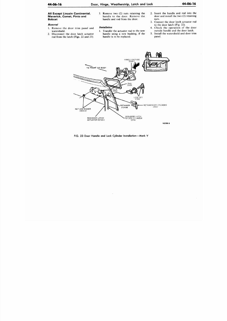
8/20/2019 1977 Ford Car Shop Manual Volume 4 Body
http://slidepdf.com/reader/full/1977-ford-car-shop-manual-volume-4-body 203/449
44-06-16
Door, Hinge, Weatherstrip, Latch and Lock
44-0
All Except Lincoln Continental,
Maverick, Comet, Pinto and
Bobcat
Removal
1. Remove the door tr im panel and
watershield.
2. Disconnect the door latch actuator
rod from
the
latch (Figs.
22 and 23).
3. Remove two (2) nuts retaining the
h a n d l e to the d o o r . R emo v e the
handle and rod from the door.
Installation
1. Transfer
the
actuator
rod to the new
handle using a new bushing, if the
handle
is to be
replaced.
2.
Insert
the
handle
and rod
in
door
and
install
the two (2)
re
nuts.
3.
Connect
the
door latch a ctuat
to
the
door latch
(Fig. 22).
4. C h eck the o p era t io n of the
outside handle and the door l
5.
Install
the
watershield
and
do
panel.
RETAINER-KEY CYLINDER
22023
NUT AND WASHER
34655-S2
ROD-DOOR LATCH
ACTUATOR 22152-3
ROD-DOOR LATCH
TO LOCK CYLINDER
22134
N2099-B
FIG. 23 Door Handle and Lock Cylinder Installation—Mark V
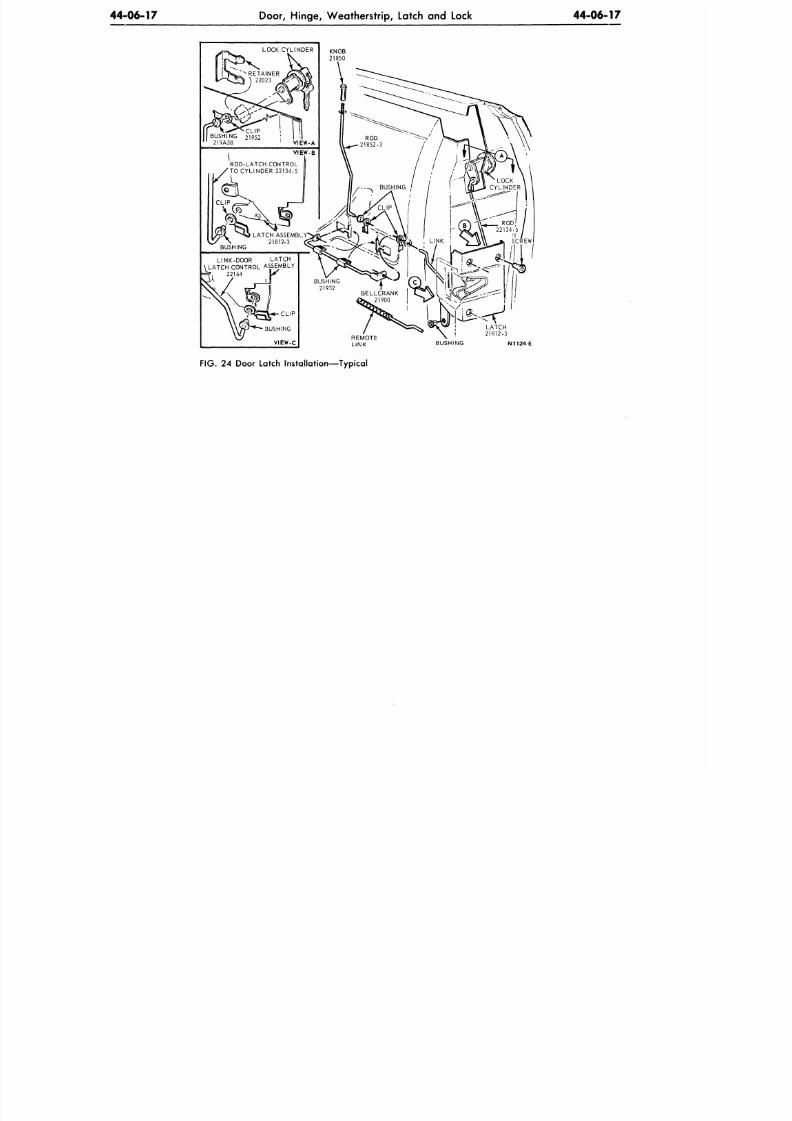
8/20/2019 1977 Ford Car Shop Manual Volume 4 Body
http://slidepdf.com/reader/full/1977-ford-car-shop-manual-volume-4-body 204/449
4 4 - 0 6 - 1 7
Door, Hing e, W eathe rstrip, Latch and Lock 44-06-17
LOCK CYLINDER
KNOB
21850
LINK-DOOR LATCH
LATCH CONTROL ASSEMBLY
22164 IX
L A T C H
2 1 8 1 2 - 3
N1124-E
FIG.
24 Door Latch Installation—Typical
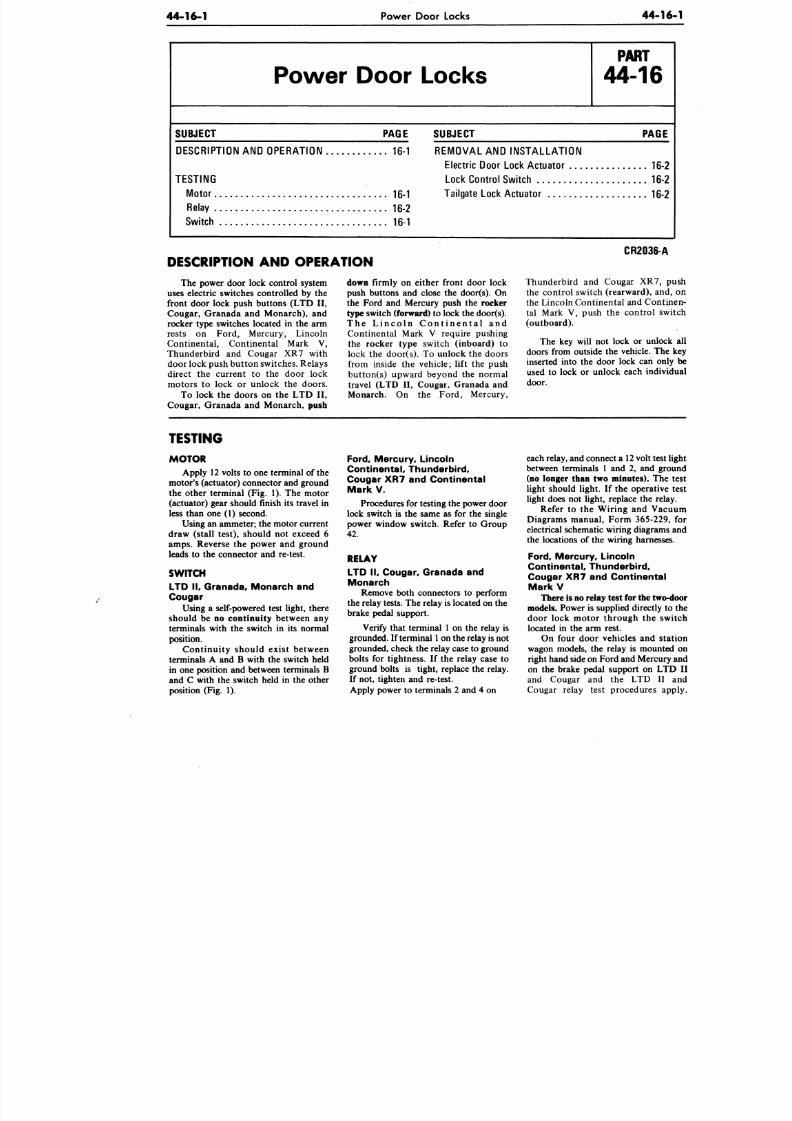
8/20/2019 1977 Ford Car Shop Manual Volume 4 Body
http://slidepdf.com/reader/full/1977-ford-car-shop-manual-volume-4-body 205/449
44-16-1
Power Door Locks
44-
Power Door Locks
P A R T
44-16
SUBJECT PAGE
DESCRIPTION
A ND
OPERATION
16-1
TESTING
Motor 16-1
Relay 16-2
Switch
16-1
SUBJECT PAG
REMOVAL
AN D
INSTALLATION
Electric Door Lock Actuator 16
Lock Control Switch
16
Tailgate Lock Actuator 16
DESCRIPTION AND OPERATION
The power door lock control system
uses electric switches controlled by the
front door lock push buttons (LTD II,
Cougar, Granada and Monarch), and
rocker type switches located in the arm
rests on Ford, Mercury, Lincoln
Continental, Continental Mark V,
Thunderbird and Cougar XR7 with
door lock push butto n switches. Relays
direct the current to the door lock
motors to lock or unlock the doors.
To lock the doors on the LTD II,
Cougar, Granada and Monarch,
push
down
firmly on either front door lock
push buttons and close the door(s). On
the Ford and Mercury push the rocker
type
switch
(forward)
to lock the door(s).
T h e L i n c o l n C o n t i n e n t a l a n d
Continental Mark V require pushing
the rocker type switch (inboard) to
lock the door(s). To unlock the doors
from inside the vehicle; lift the push
button(s) upward beyond the normal
travel (LTD II, Cougar, Granada and
Monarch. On the Ford, Mercury,
CR2036-
Thunderbird and Cougar XR7,
the control switch (rearward), a
the Lincoln Continental and Con
tal Mark V, push the control
(outboard).
The key will not lock or unl
doors from outside the vehicle. T
inserted into the door lock can o
used to lock or unlock each ind
door.
TESTING
MOTOR
Apply 12 volts to one terminal of the
motor's (actuator) connector and ground
the other terminal (Fig. 1). The motor
(actuator) gear should finish its travel in
less than one (1) second.
Using an am meter; the motor current
draw (stall test), should not exceed 6
amps. Reverse the power and ground
leads to the connector and re-test.
SWITCH
LT D I I ,
Granada,
Monarch an d
Cougar
Using a self-powered test light, there
should be no continuity between any
terminals with the switch in its normal
position.
Continuity should exist between
terminals A and B with the switch held
in one position and between terminals B
and C with the switch held in the other
position (Fig. 1).
Ford, Mercury, Lincoln
Continental, Thunderbird,
Cougar
X R7 and
Continental
Mark V.
Procedures for testing the power door
lock switch is the same as for the single
power window switch. Refer to Group
42.
RELAY
LT D I I , Cougar, Granada an d
Monarch
Remove both connectors to perform
the relay tests. The relay is located on the
brake pedal support.
Verify that terminal 1 on the relay is
grounded. If terminal
1
on the relay
is
not
grounded, check the relay case to ground
bolts for tightness. If the relay case to
ground bolts is tight, replace the relay.
If not, tighten and re-test.
Apply power to terminals 2 and 4 on
each relay, and connect a 12 volt te
between terminals 1 and 2, and g
(no longer than two minutes). T
light should light. If the operati
light does not light, replace the r
Refer to the Wiring and V
Diagrams manual, Form 365-22
electrical schematic wiring diagram
the locations of the wiring harnes
Ford,
Mercury, Lincoln
Continental, Thunderbird,
Cougar X R7 and Continent
MarkV
There is no relay test for the t
models. Power is supplied directl
door lock motor through the
located in the arm rest.
On four door vehicles and
wagon models, the relay is moun
right hand side on Ford and Merc
on the brake pedal support on L
and Cougar and the LTD I
Cougar relay test procedures
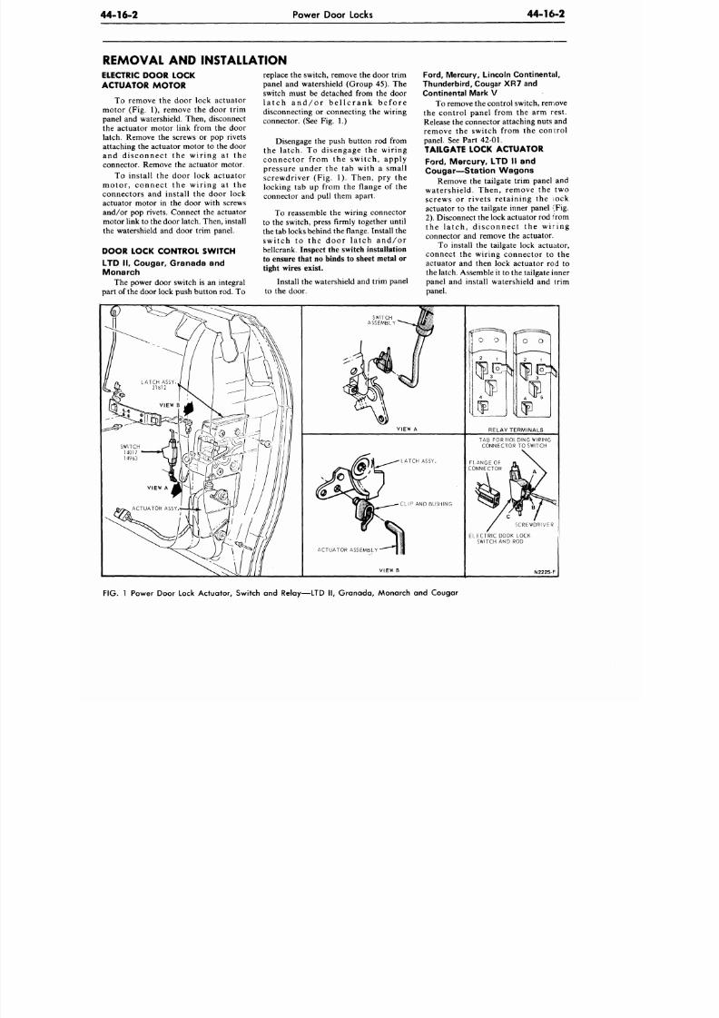
8/20/2019 1977 Ford Car Shop Manual Volume 4 Body
http://slidepdf.com/reader/full/1977-ford-car-shop-manual-volume-4-body 206/449
44-16-2
Power Door Locks
44-16-2
REMOVAL AND INSTALLATION
ELECTRIC DOOR LOCK
ACTUATOR MOTOR
To remove the door lock actuator
motor (Fig. 1), remove the door trim
panel and watershield. Then, disconnect
the actuator motor link from the door
latch. Remove the screws or pop rivets
attaching the actuator motor to the door
and disconnect the wir ing at the
connector. Remove the actuator motor.
To install the door lock actuator
motor , connec t the wir ing a t the
connectors and install the door lock
actuator motor in the door with screws
and/or pop rivets. Connect the actuator
motor link to the door latch . Then, install
the watershield and door trim panel.
DOOR LOCK CONTROL SWITCH
LTD I I , Cougar, Granada and
M o n ar ch
The power door switch is an integral
part of the door lock push button rod. To
replace the switch, remove the door trim
panel and watershield (Group 45). The
switch must be detached from the door
l a t c h a n d / o r b e l l c r a n k b e f o r e
disconnecting or connecting the wiring
connector. (See Fig. 1.)
Disengage the push button rod from
the latch. To disengage the wiring
connector from the switch, apply
pressure under the tab with a small
screwdriver (Fig. 1). Then, pry the
locking tab up from the flange of the
connector and pull them apart.
To reassemble the wiring connector
to the switch, press firmly together until
the tab locks behind the flange. Install the
swi tch to the door la tch and/or
bellcrank. Inspect the switch installation
to ensure that no binds to sheet metal or
tight wires exist.
Install the watershield and trim panel
to the door.
Ford , Mercury, L incoln Co nt inenta l ,
Thund erbi rd, Cougar XR7 and
Continental Mark V
To remove the con trol switch, remove
the control panel from the arm rest.
Release the connector attaching nuts and
remove the switch from the control
panel. See Part
42-01.
TAILGATE LOCK ACTUATOR
Ford, Mercury, LTD II and
Cougar—Station Wagons
Remove the tailgate trim panel and
watershield. Then, remove the two
screws or rivets retaining the lock
actuator to the tailgate inner panel (Fig.
2). Disconnect the lock actuator rod from
the la tch, disconnec t the wir ing
connector and remove the actuator.
To install the tailgate lock actuator,
connect the wiring connector to the
actuator and then lock actuator rod to
the latch. A ssemble it to the tailgate inner
panel and install watershield and trim
panel.
SWITCH
ASSEMBLY'
V I E W A
LATCH ASSY.
CLIP AND BUSHING
ACTUATOR ASSEMBLY
VIEW B
RELAY TERMINALS
TAB FOR HOLDING WIRING
CONNECTOR TO SWITCH
SCREWDRIVER
ELECTRIC DOOK LOCK
SWITCH AND ROD
N2225-F
FIG.
1 Power Door Lock Actua tor, Switch and Relay—LTD II, Gra nad a, Monarch and Cougar
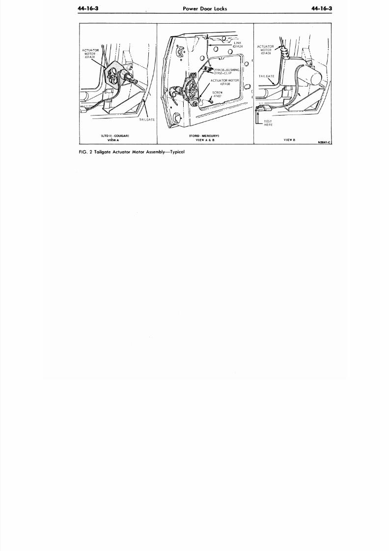
8/20/2019 1977 Ford Car Shop Manual Volume 4 Body
http://slidepdf.com/reader/full/1977-ford-car-shop-manual-volume-4-body 207/449
44-16-3
Power Door Locks
44-1
ACTUATOR
MOTOR
431A38
(LTD I I -COUGAR)
VIEW A
( F O R D - M E R C U R Y )
VIEW A& B
TEST
HERE
VIEW
B
N26
F IG .
2
Tailgate Actuator Motor Assembly—Typical
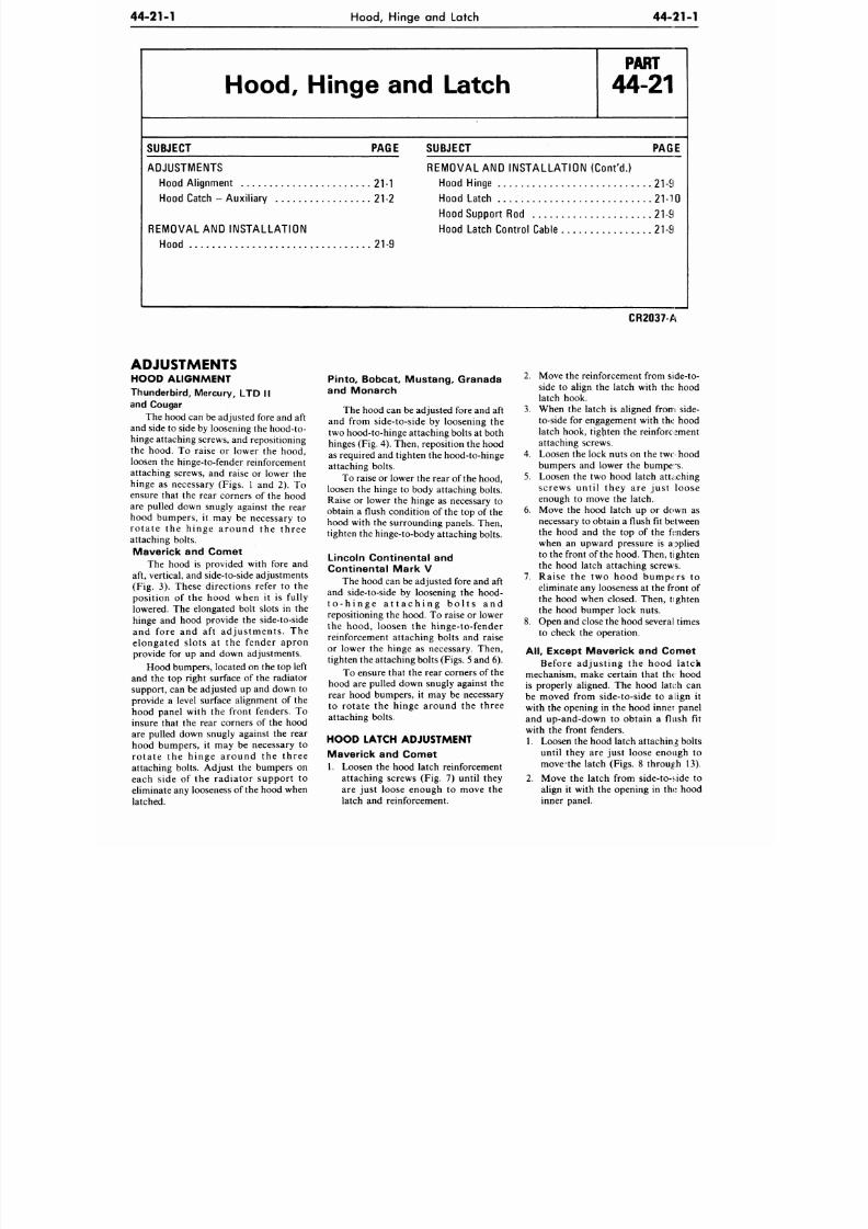
8/20/2019 1977 Ford Car Shop Manual Volume 4 Body
http://slidepdf.com/reader/full/1977-ford-car-shop-manual-volume-4-body 208/449
44-21-1
Hood, Hinge and Latch
44-21-1
Hood, Hinge and Latch
P A R T
44-21
SUBJECT PAGE
ADJUSTMENTS
Hood Alignm ent 21-1
Hood Catch - Au xiliary 21-2
REMOVAL AND INSTALLATION
Hood 21-9
SUBJECT PAGE
REMOVAL AND INSTALLATION (Cont 'd . )
Hood Hinge 21-9
Hood Latch 21-10
Hood Support Rod 21-9
Hood Latch Con trol Cable 21-9
CR2037-A
ADJUSTMENTS
HOOD ALIGNMENT
Thunderbird, Mercury, LTD II
and Cougar
The hood can be adjusted fore and aft
and side to side by loosening the hood-to-
hinge attaching screws, and repositioning
the hood. To raise or lower the hood,
loosen the hinge-to-fender reinforcement
attaching screws, and raise or lower the
hinge as necessary (Figs. 1 and 2). To
ensure that the rear corners of the hood
are pulled down snugly against the rear
hood bumpers, it may be necessary to
r o t a t e t h e h i n g e a r o u n d t h e t h r e e
attaching bolts.
Maverick and Comet
The hood is provided with fore and
aft, vertical, and side-to-side adjustments
(Fig. 3). These directions refer to the
position of the hood when it is fully
lowered. The elongated bolt slots in the
hinge and hood provide the side-to-side
an d fo re an d a f t ad ju s tmen ts . Th e
e lo n g a ted s lo t s a t th e f en d er ap ro n
provide for up and down adjustments.
Hood bumpers, located on the top left
and the top right surface of the radiator
support, can be adjusted up and down to
provide a level surface alignment of the
hood panel with the front fenders. To
insure that the rear corners of the hood
are pulled down snugly against the rear
hood bumpers, it may be necessary to
r o t a t e t h e h i n g e a r o u n d t h e t h r e e
attaching bolts. Adjust the bumpers on
each s ide of the radiator suppor t to
eliminate any looseness of the hood when
latched.
Pinto, Bobcat, M ustang , Granada
and Monarch
The hood can be adjusted fore and aft
and from side-to-side by loosening the
two hood-to-hinge attaching bolts at both
hinges (Fig. 4). Then, reposition the hood
as required and tighten the hood-to-hinge
attaching bolts.
To raise or lower the rear of the hood,
loosen the hinge to body attaching bolts.
Raise or lower the hinge as necessary to
obtain a flush condition of the top of the
hood with the surrounding panels. Then,
tighten the hinge-to-body attaching bolts.
Lincoln Continental and
Continental Mark V
The hood can be adjusted fore and aft
and side-to-side by loosening the hood-
t o - h i n g e a t t a c h i n g b o l t s a n d
repositioning the hood. To raise or lower
the hood, loosen the h inge- to-fender
reinforcement attaching bolts and raise
or lower the hinge as necessary. Then,
tighten the attaching bolts (Figs. 5 and 6).
To ensure that the rear corners of the
hood are pulled down snugly against the
rear hood bumpers, it may be necessary
to ro tate the h inge around the three
attaching bolts.
HOOD LATCH ADJUSTMENT
Maverick and Comet
1. Loosen the hood latch reinforcement
attaching screws (Fig. 7) until they
are just loose enough to move the
latch and reinforcement.
2. Move the reinforcement from side-to-
side to align the latch with the hood
latch hook.
3. When the latch is aligned from side-
to-side for engagement with the hood
latch hook, tighten the reinforcement
attaching screws.
4. Loosen the lock nuts on the tw<:> hood
bumpers and lower the bumpe's.
5. Loosen the two hood latch attaching
screws u n t i l th ey a r e ju s t lo o se
enough to move the latch.
6. Move the hood latch up or down as
necessary to obtain a flush fit between
the hood and the top of the fenders
when an up ward pressure is a pplied
to the front of the hood. Then, tighten
the hood latch attaching screws.
7 . R a ise th e two h o o d b u mp er s to
eliminate any looseness at the front of
the hood when closed. Then, tighten
the hood bumper lock nuts.
8. Open and close the hood several times
to check the operation.
All,
Except Maverick and Comet
B efo re ad ju s t in g th e h o o d la tc h
mechanism, make certain that the- hood
is properly aligned. The hood latch can
be moved from side-to-side to align it
with the opening in the hood inner panel
and up-and-down to obtain a flush fit
with the front fenders.
1. Loosen the hood latch attaching bolts
until they are just loose enough to
m ov eth e latch (Figs. 8 through 13).
2. Move the latch from side-to-side to
align it with the opening in the hood
inner panel.
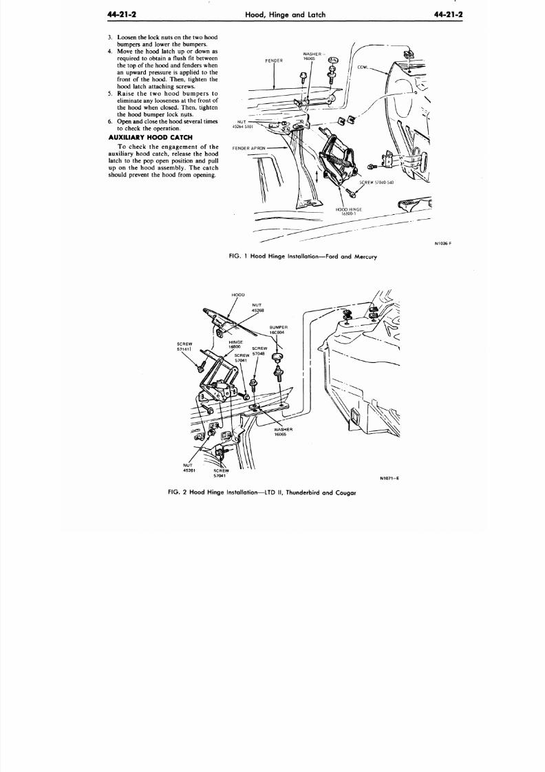
8/20/2019 1977 Ford Car Shop Manual Volume 4 Body
http://slidepdf.com/reader/full/1977-ford-car-shop-manual-volume-4-body 209/449
44-21-2
Hood, Hinge and Latch
44-21
3. Loosen the lock nuts on the two hood
bumpers and lower the bumpers.
4.
Move the hood latch up or down as
required to obtain a flush fit between
the top of the hood and fenders when
an upward pressure is applied to the
front of the hood. Then, tighten the
hood latch attaching screws.
5. R a i s e t h e t w o h o o d b u m p e r s t o
eliminate any looseness at the front of
the hood when closed. Then, tighten
the hood bumper lock nuts.
6. Open and close the hood several times
to check the operation.
AUXILIARY HOOD CATCH
To ch eck th e en g ag emen t o f th e
auxiliary hood catch, release the hood
latch to the pop open position and pull
up on the hood assembly . The catch
should prevent the hood from opening.
FENDER
NUT
45264-S101
FENDER APRON
N1036-F
F IG .
1 Hood Hinge Installation—Ford and Mercury
HOOD
HINGE
16800
S C R E W
| \
SCREW
5 7
?
4 8
57041
NU T
45261 SCREW
57041
N1071-E
FIG. 2 Hood Hinge Installation—LTD II, Thunderbird and Cougar
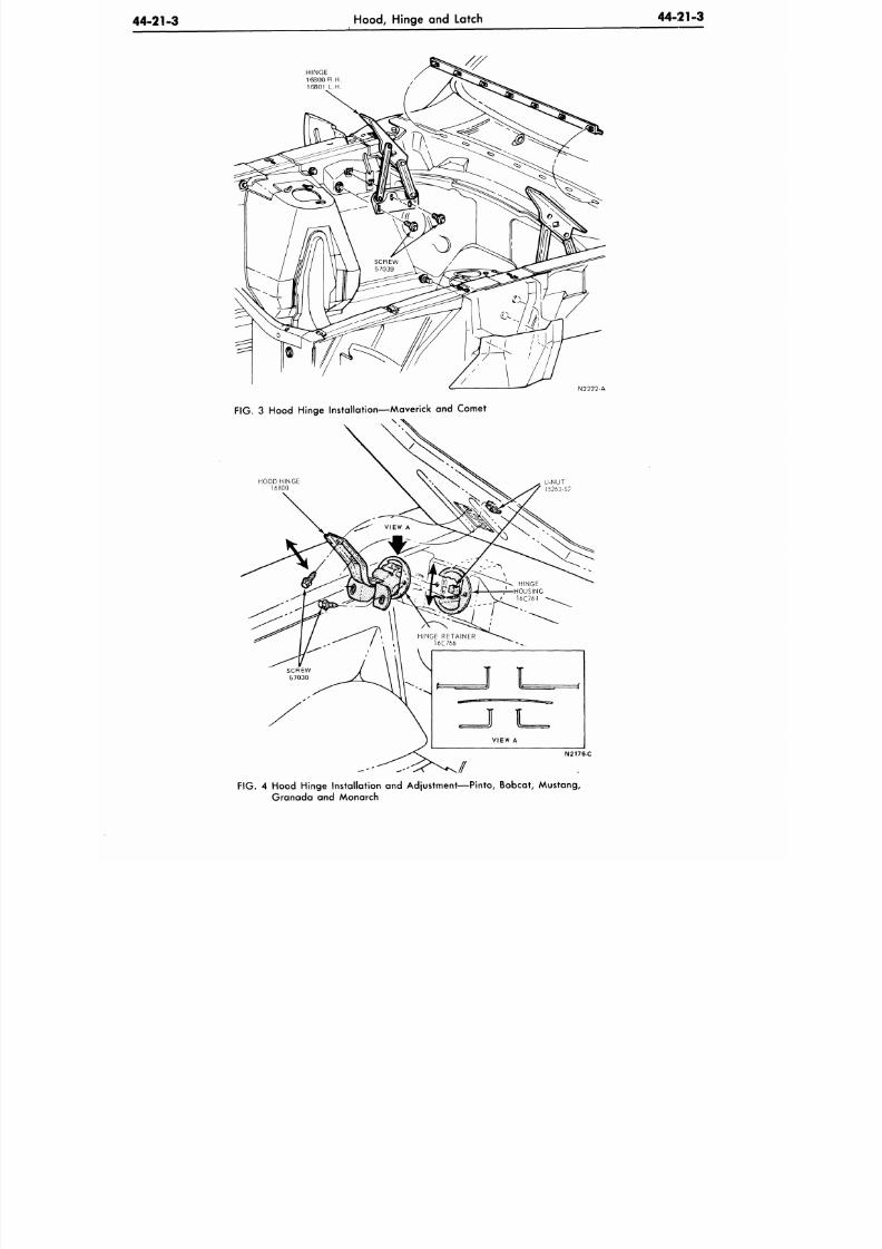
8/20/2019 1977 Ford Car Shop Manual Volume 4 Body
http://slidepdf.com/reader/full/1977-ford-car-shop-manual-volume-4-body 210/449
44-21-3
Hood,
Hinge and Latch
44-21-3
HINGE
16800 R.H
16801 L.H
N2222-A
FIG. 3 Hood Hinge Instal lation—Maverick and Comet
HOOD HINGE
16800
U-NUT
45263-S7
N2176-C
FIG. 4 Hood Hinge Instal lation and Adjustment—Pinto, Bobcat, Mustang,
Granada and Monarch
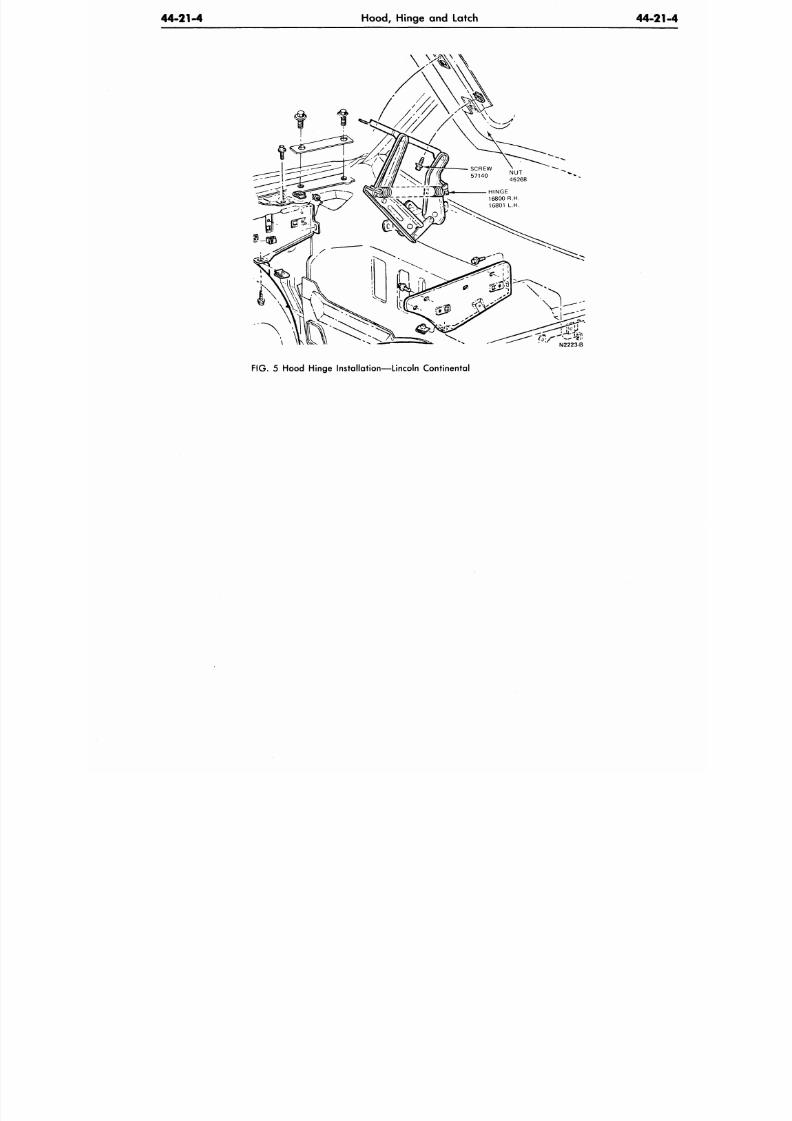
8/20/2019 1977 Ford Car Shop Manual Volume 4 Body
http://slidepdf.com/reader/full/1977-ford-car-shop-manual-volume-4-body 211/449
44-21-4
Hood, Hinge and Latch
44-2
\
N2223-B
FIG. 5 Hood Hinge Installation—Lincoln Continental
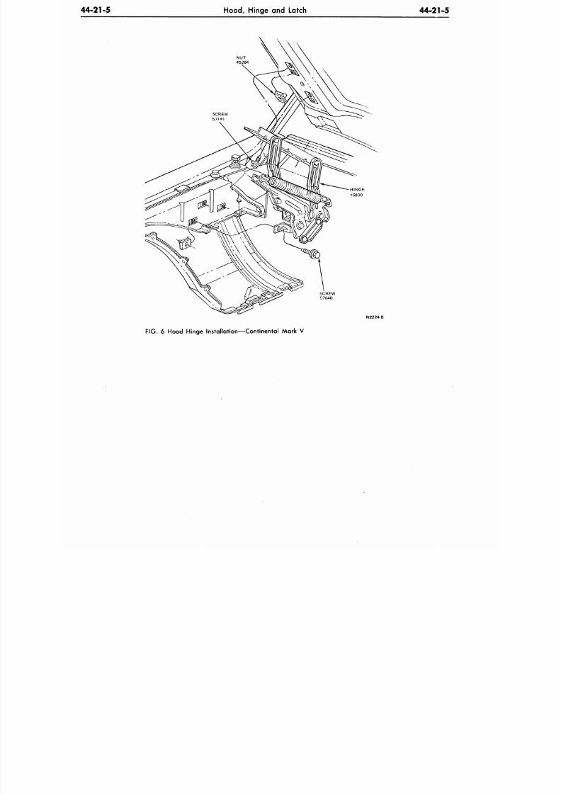
8/20/2019 1977 Ford Car Shop Manual Volume 4 Body
http://slidepdf.com/reader/full/1977-ford-car-shop-manual-volume-4-body 212/449
44-21-5
Hood, Hinge
and
Latch
44-21-5
NU T
45264
SCREW
57040
N2224-B
FIG.
6
Hood Hinge Installation—Continental Mark
V
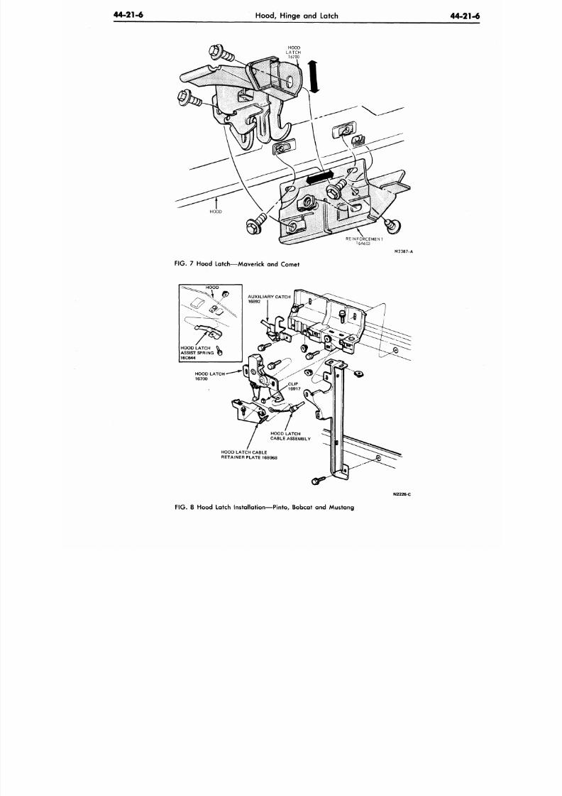
8/20/2019 1977 Ford Car Shop Manual Volume 4 Body
http://slidepdf.com/reader/full/1977-ford-car-shop-manual-volume-4-body 213/449
44-21-6
Hood,
Hinge and Latch
44-2
HOOD
LATCH
16700
REINFORCEMENT
16A603
N2387-A
FIG.
7 Hood Latch—Maverick and Comet
HOOD LATCH
ASSIST SPRING
16C644
HOOD LATCH
•
16700
HOOD LATCH CABLE
RETAINER PLATE 16B968
N2226-C
F IG .
8 Hood Latch Installation—Pinto, Bobcat and Mustang
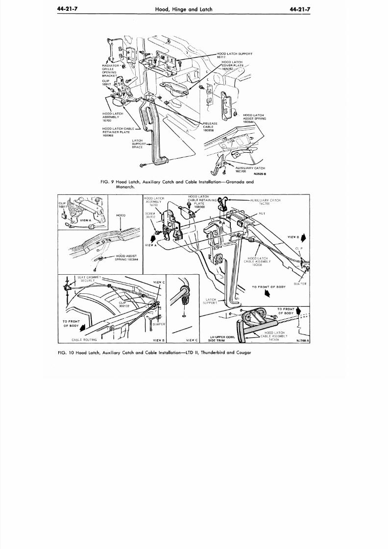
8/20/2019 1977 Ford Car Shop Manual Volume 4 Body
http://slidepdf.com/reader/full/1977-ford-car-shop-manual-volume-4-body 214/449
44-21-7
Hood,
Hinge and Latch
4 4 - 2 1 - 7
HOOD LATCH SUPPORT
16717
HOOD LATCH CABLE
RETAINER PLATE
16B968
AUXILIARY CATCH
16C708
N2529-B
FIG. 9 Hood Latch, Auxiliary Catch and Cable Installation —G ranad a and
Monarch.
AUXILLIARY CATCH
16C708
NUT
CABLE ROUTING
VIEW B
VIEW B
CL P
NJ768-A
F IG .
10 Hood Latch, Auxiliary Catch and Cable Installation—LTD II, Thunderbird and Cougar
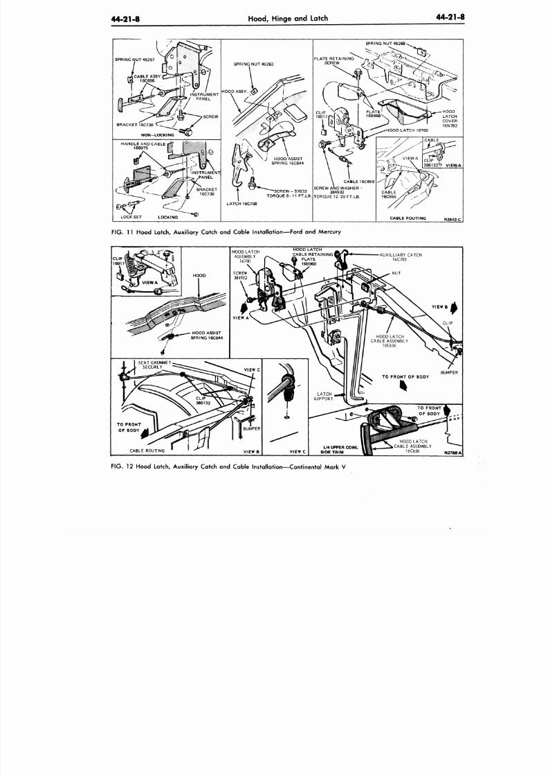
8/20/2019 1977 Ford Car Shop Manual Volume 4 Body
http://slidepdf.com/reader/full/1977-ford-car-shop-manual-volume-4-body 215/449
44-21-8
Hood, Hinge and Latch
44-21
SPRING NUT 45257
BRACKET 16C730
d ^
J
NON-LOCKING
INSTRUMENT
PANEL
SCREW
HANDL E AND CABL E
16B975
INSTRUMENT
PANEL
LOCK SET
SPRING NUT 45263
HOOD ASSY.
LATCH 16C708
SPRING NUT 45268.
SCREW AN D WASHER
-
384932
TORQUE 12-20 FT.LB.
CABLE ROUTING N2642
FIG. 11 Hood Latch Auxiliary Catch and Cable Installation—Ford and Mercury
FIG.
12 Hood Latch Auxiliary Catch and Cable Installation—Continental Mark V
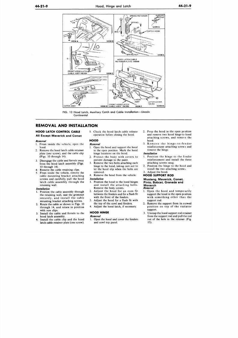
8/20/2019 1977 Ford Car Shop Manual Volume 4 Body
http://slidepdf.com/reader/full/1977-ford-car-shop-manual-volume-4-body 216/449
44-21-9
Hood, Hinge and Latch
4 4 - 2 1 - 9
* VIEW A V IE W B
FRONT HOOD LATCH
CABLE ASSY-16C656
VIEWC
CATCH ASSY
VIEWD
VIEWE
HOOD LATCH CABLE
RETAINER PLATE-16B968
CLIP
FRONT HOOD LATCH
CABLE ASSY - 16C656
VIEWF
LATCH COVER
16N782
N2493-B
FIG. 13 Hood Latch, Auxiliary Catch and Cable Installation—Lincoln
Continental
REMOVAL AND INSTALLATION
HOOD LATCH CONTROL CABLE
All Except Maver ick and Comet
Removal
1. From inside the vehicle, open the
hood.
2.
Remove the hood latch cable retainer
plate (one screw), and the cable clip
(Figs.
10 through 14).
3. Disengage the cable and ferrule away
from the hood latch assembly (Figs.
10 through 14).
4.
Remove the cable retaining clips.
5.
From inside the vehicle, remove the
cable mounting bracket attaching
screws and carefully pull the hood
latch cable assembly through the
retaining wall.
Installation
1.
Position the cable assembly through
the retaining wall, seat the grommet
securely, and install the cable
mounting bracket attaching screws.
2.
Route the cable as shown in Figs. 10
through 14, and retain in position
with new clips.
3. Install the cable and ferrule to the
hood latch assembly.
4. Install the cable clip and the hood
latch cable retainer plate (one screw).
5.
Check the hood latch cable release
operation before closing the hood.
HOOD
Removal
1. Open the hood and support the hood
in the open position. Mark the hood
hinge locations on the hood.
2.
Protect the body with covers to
prevent damage to the paint.
3. Remove the two bolts attaching each
hinge to the hood, taking care not to
let the hood slip when the bolts are
removed.
4.
Remove the hood from the vehicle.
Installation
1. Position the hood to the hood hinges
and install the attaching bolts .
Remove the body covers.
2.
Adjust the hood for an even fit
between the fenders and for a flush fit
with the front of the fenders.
3. Adjust the hood for a flush fit with
the top of the cowl and fenders.
4. Adjust the hood latch, if necessary.
HOOD HINGE
Removal
1. Open the hood and cover the fenders
and cowl top panel.
2.
Prop the hood in the open position
and remove two hood hinge-tohood
attaching screws, and remove the
hood.
3. R e m o v e th e h i n g e - t o - f e n d e r
reinforcement attaching screws and
remove the hinge.
Installation
1. Position the hinge to the fender
reinforcement and install the three
attaching screws snug.
2.
Position the hinge to the hood and
install the two attaching screws.
3. Adjust the hood.
HOOD SUPPORT ROD
Must ang , Maver ick , Com et ,
Pinto, Bobcat, Granada and
Monarch
Removal
1. Open the hood and temporarily
support the hood in the open position
with something other than the
support rod.
2.
Remove the support from its snowed
position on top of the radiator
support.
3. Unsnap the hood support rod retainer
from the support rod and pull the rod
out of the hole in the retainer (Fig.
15).
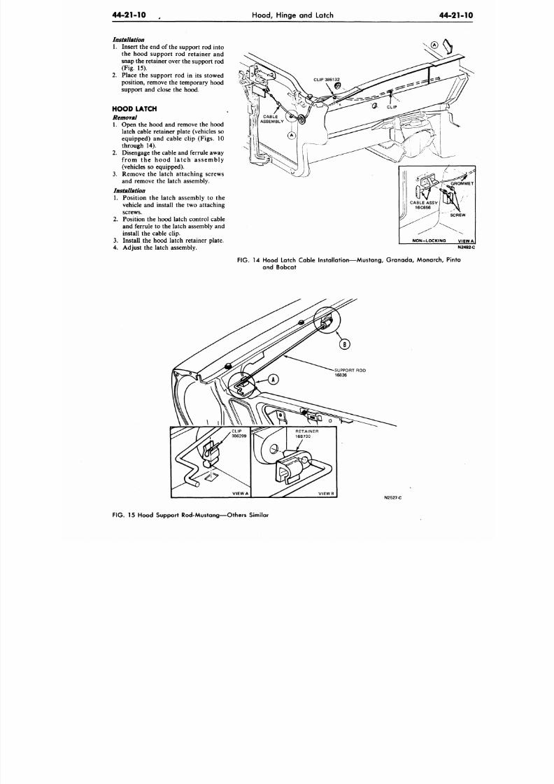
8/20/2019 1977 Ford Car Shop Manual Volume 4 Body
http://slidepdf.com/reader/full/1977-ford-car-shop-manual-volume-4-body 217/449
44-21-10
Hood,
Hinge and Latch
44-21
Installation
1. Insert the end of the support rod into
the hood support rod retainer and
snap the retainer over the support rod
(Fig. 15).
2. Place the support rod in its stowed
position, remove the temporary hood
support and close the hood.
HOOD LATCH
Removal
1. Open the hood and remove the hood
latch cable retainer plate (vehicles so
equipped) and cable clip (Figs. 10
through 14).
2.
Disengage the cable and ferrule away
from the hood latch assembly
(vehicles so equipped).
3. Remove the latch attaching screws
and remove the latch assembly.
Installation
1. Position the latch assembly to the
vehicle and install the two attaching
screws.
2. Position the hood latch control cable
and ferrule to the latch assembly and
install the cable clip.
3. Install the hood latch retainer plate.
4.
Adjust the latch assembly.
NON-LOCK ING V
N
F IG .
14 Hood Latch Cable Installation—Mustang, Granada, Monarch, Pinto
and Bobcat
V I E W B
N2527-C
F IG .
15 Hood Support Rod-Mustang—Others Similar
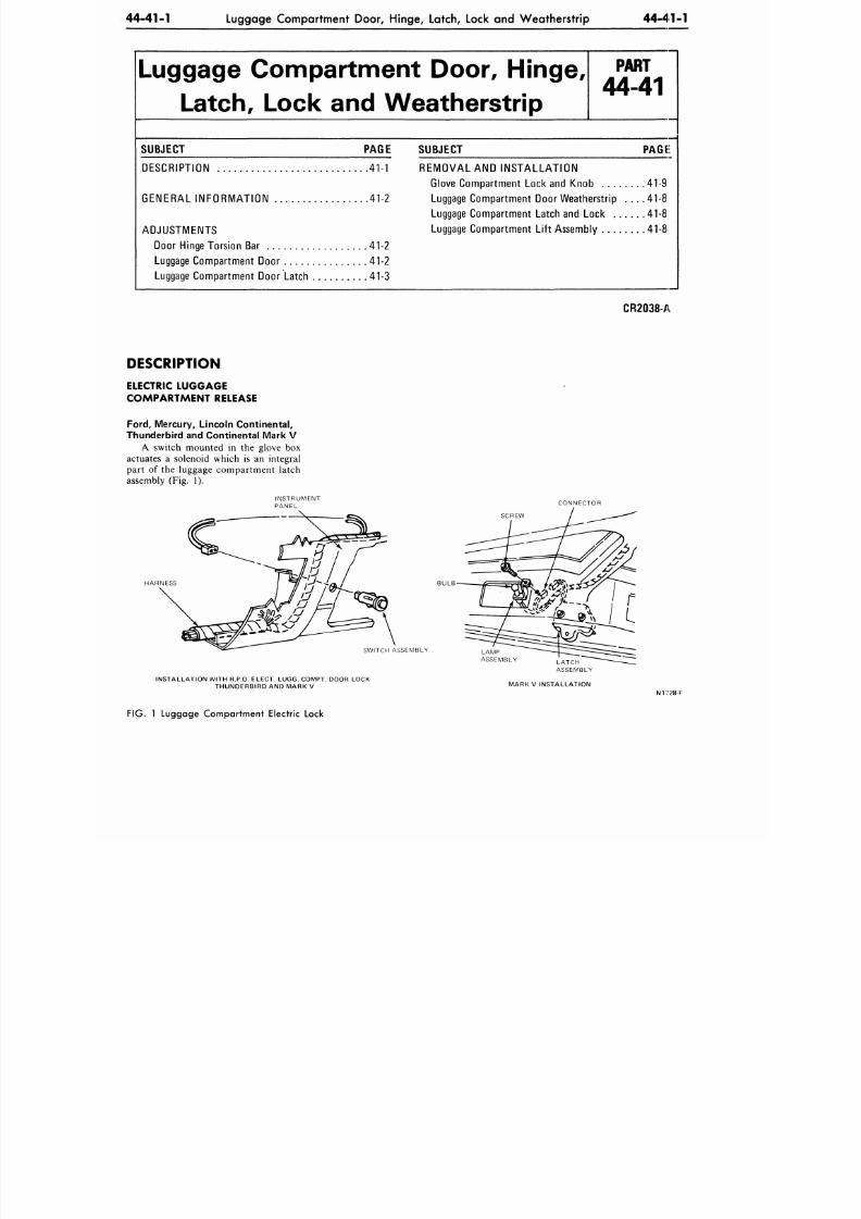
8/20/2019 1977 Ford Car Shop Manual Volume 4 Body
http://slidepdf.com/reader/full/1977-ford-car-shop-manual-volume-4-body 218/449
44-41-1
Luggage Compartment Door, Hinge, Latch, Lock and Weatherstrip
44-41-1
Luggage Compartment Door, Hinge,
Latch, Lock and Weatherstrip
P A R T
44-41
SUBJECT PAGE
DESCRIPTION 41-1
GENERAL INFORMATION 41-2
ADJUSTMENTS
Door Hinge Torsion Bar 41-2
Luggage Compartment Door 41-2
Luggage Compartment Door Latch 41-3
SUBJECT
PAGE:
REMOVAL
AND INS TALLATION
Glove Compartment Lock and Knob 41-9
Luggage Co mp artment Door Wea therstrip . . . . 41-8
Luggage Compartment Latch and Lock
41-8
Luggage Compartment Lift Assembly 41-8
CR2038-A
DESCRIPTION
ELECTRIC LUGGAGE
COMPARTMENT RELEASE
Ford,
Mercury, Lincoln Continental,
Thunderbird and Continental Mark V
A switch mounted in the glove box
actuates
a
solenoid which
is an
integral
part
of the
luggage com partm ent latch
assembly
(Fig. 1).
INSTRUMENT
PANEL
CONNECTOR
SCREW
SWITCH ASSEMBLY
LAMP
ASSEMBLY
INSTALLATION WITH R.P.O. ELECT. LUGG. COMPT. DOOR LOCK
THUNDERBIRD AND MARK V
MARK V INSTALLATION
N1728-F
FIG. 1 Lugga ge Com partm ent Electric Lock
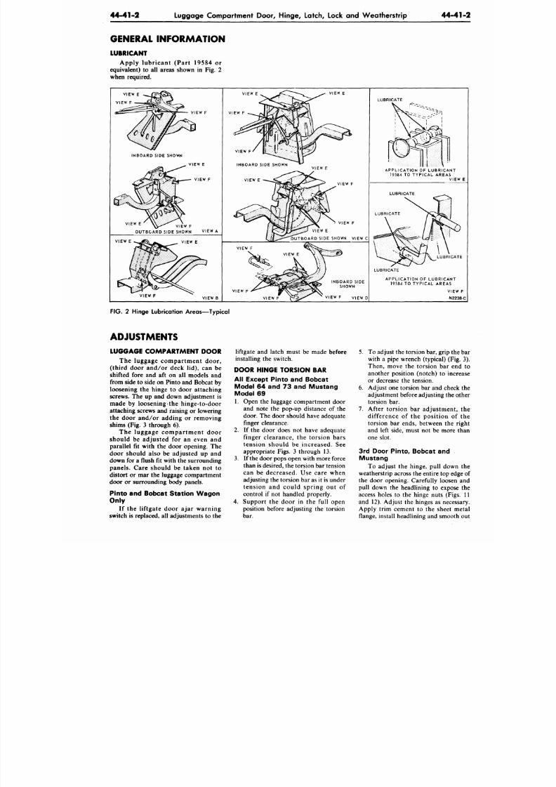
8/20/2019 1977 Ford Car Shop Manual Volume 4 Body
http://slidepdf.com/reader/full/1977-ford-car-shop-manual-volume-4-body 219/449
44-41-2
Luggage Compartment Door, Hinge, Latch, Lock and Weatherstrip
44-41
GENERAL INFORMATION
LUBRICANT
Apply lubricant (Part 19584 or
equivalent) to all areas shown in Fig. 2
when required.
VIEW E
VIEW F
VIEW F
INBOARD SIDE SHOWN
VIEW E
VIEW F
VIEW E
VIEW F
OUTBOARD SIDE SHOWN
VIEW A
VIEW E
VIEW E
VIEW F
VIEW B
VIEW E
VIEW E
VIEW F
VIEW F
VIEW F
VIEW E
OUT BO ARD SIDE SHOWN VI EW C
VIEW F
VIEW F
VIEW F
INBOARD SIDE
SHOWN
VIEW F VIEW D
LUBRICATE
A P P L I C A T I O N O F L U B R I C A N T
19584 TO TYPICAL AREAS
VIEW
LUBRICATE
LUBRICATE
LUBRICATE
LUBRICATE
A P P L I C A T I O N O F L U B R I C A N T
19584 TO TYPIC AL AREAS
VIEW F
N2238-
FIG. 2 Hinge Lubrication Areas—Typical
ADJUSTMENTS
LUGGAGE COMPA RTMENT DOOR
The luggage compartment door,
(third door and/or deck lid), can be
shifted fore and aft on all models and
from side to side on Pinto and Bobcat by
loosening the hinge to door attaching
screws. The up and down adjustment is
made by loosening the hinge-to-door
attaching screws and raising or lowering
the door and/or adding or removing
shims (Fig. 3 through 6).
The luggage compar tment door
should be adjusted for an even and
parallel fit with the door opening. The
door should also be adjusted up and
down for a flus h fit with the surrounding
panels. Care should be taken not to
distort or mar the luggage compartment
door or surrounding body panels.
Pinto and Bobcat Station Wagon
Only
If the liftgate door ajar warning
switch is replaced, all adjustments to the
liftgate and latch must be made before
installing the switch.
DOOR HINGE TORSION BAR
All Except Pinto and Bobcat
Model 64 and 73 and Mustang
Model 69
1. Open the luggage compartment door
and note the pop-up distance of the
door. The door should have adequate
finger clearance.
2. If the door does not have adequate
finger clearance, the torsion bars
tension should be increased. See
appropriate Figs. 3 through 13.
3. If the door pops open with more force
than is desired, the torsion bar tension
can be decreased. Use care when
adjusting the torsion bar as it is under
tension and could spring out of
control if not handled properly.
4. Support the door in the full open
position before adjusting the torsion
bar.
5. To adjust the torsion bar, grip the
with a pipe wrench (typical) (Fig.
Then, move the torsion bar end
another position (notch) to increa
or decrease the tension.
6. Adjust one torsion bar and check t
adjustment before adjusting the oth
torsion bar.
7. After torsion bar adjustment, t
difference of the position of t
torsion bar ends, between the rig
and left side, must not be more th
one slot.
3rd Door Pinto, Bobcat and
Mustang
To adjust the hinge, pull down t
weatherstrip across the entire top edge
the door opening. Carefully loosen a
pull down the headlining to expose t
access holes to the hinge nuts (Figs.
and 12). Adjust the hinges as necessa
Apply trim cement to the sheet me
flange, install headlining and smooth o
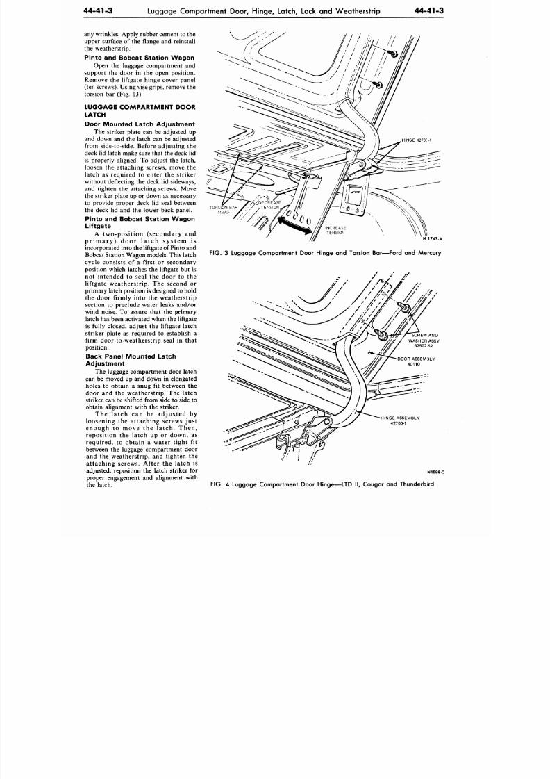
8/20/2019 1977 Ford Car Shop Manual Volume 4 Body
http://slidepdf.com/reader/full/1977-ford-car-shop-manual-volume-4-body 220/449
44-41-3
Luggage Compartment Door, Hinge, Latch, Lock and Weatherstrip
44-41-3
any wrinkles. Apply rubber cement to the
upper surface of the flange and reinstall
the weatherstrip.
Pinto and Bobcat Station Wagon
Open the luggage compartment and
support the door in the open position.
Remove the liftgate hinge cover panel
(ten screws). Using vise grips, remove the
torsion bar (Fig. 13).
LUGGAGE COMPARTMENT DOOR
LATCH
Door Mounted Latch Adjustment
The striker plate can be adjusted up
and down and the latch can be adjusted
from side-to-side. Before adjusting the
deck lid latch make sure that the deck lid
is properly aligned. To adjust the latch,
loosen the attaching screws, move the
latch as required to enter the striker
without deflecting the deck lid sideways,
and tighten the attaching screws. Move
the striker plate up or down as necessary
to provide proper deck lid seal between
the deck lid and the lower back panel.
Pinto and Bobcat Station Wagon
Liftgate
A two-po sition (seconda ry and
p r i m a r y ) d o o r l a t c h s y s t e m i s
incorporated into the liftgate of Pinto and
Bobcat Station Wagon models. This latch
cycle consists of a first or secondary
position which latches the liftgate but is
not intended to seal the door to the
liftgate weatherstrip. The second or
primary latch position
is
designed to hold
the door firmly into the weatherstrip
section to preclude water leaks and/or
wind noise. To assure that the
primary
latch has been activated when the liftgate
is fully closed, adjust the liftgate latch
striker plate as required to establish a
firm door-to-weatherstrip seal in that
position.
Back Panel Mounted Latch
Adjustment
The luggage compartment door latch
can be moved up and down in elongated
holes to obtain a snug fit between the
door and the weatherstrip. The latch
striker can be shifted from side to side to
obtain alignment with the striker.
The la tch can be adjus te d by
loosening the attaching screws just
enough to move the la tch . Then,
reposition the latch up or down, as
required, to obtain a water tight fit
between the luggage compartment door
and the weatherstrip, and tighten the
attaching screws. After the latch is
adjusted, reposition the latch striker for
proper engagement and alignment with
the latch.
FIG.
3 Luggage Compartment Door Minge and Torsion Bar—Ford and Mercury
SCREW AND
WASHER ASSY
57502 S2
HINGE ASSEMBLY
42700-1
N1598-C
FIG.
4 Luggage Co mpa rtme nt Door Hinge—LTD II, Cougar and Th underbird
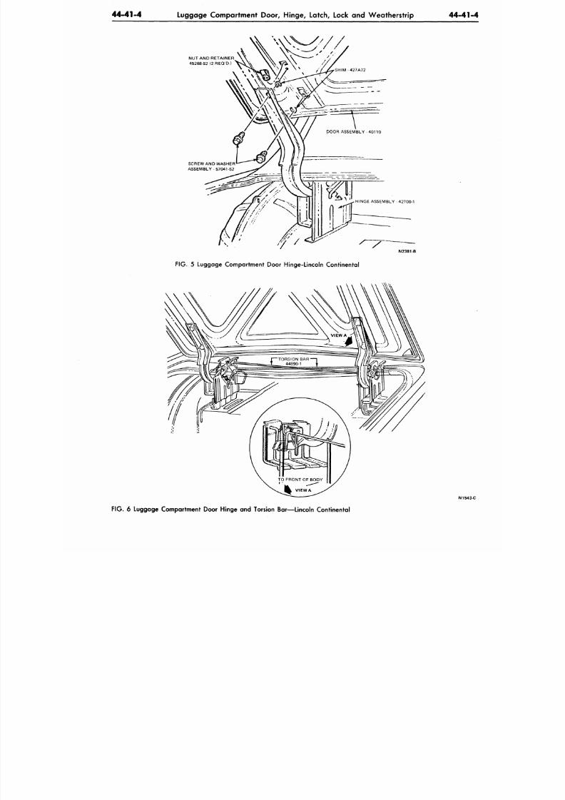
8/20/2019 1977 Ford Car Shop Manual Volume 4 Body
http://slidepdf.com/reader/full/1977-ford-car-shop-manual-volume-4-body 221/449
44-41-4
Luggage Compartment Door, Hinge, Latch, Lock and Weatherstrip
44-41
NUT AND RETAINER
45268-S2 (2 REQ'D.)
SCREW AN D WASHER
ASSEMBLY-57041-S2
N2381-B
FIG. 5 Luggage Compartment Door Hinge-Lincoln Continental
N1543
FIG .
6 Luggage Compartment Door Hinge and Torsion Bar—Lincoln Continental
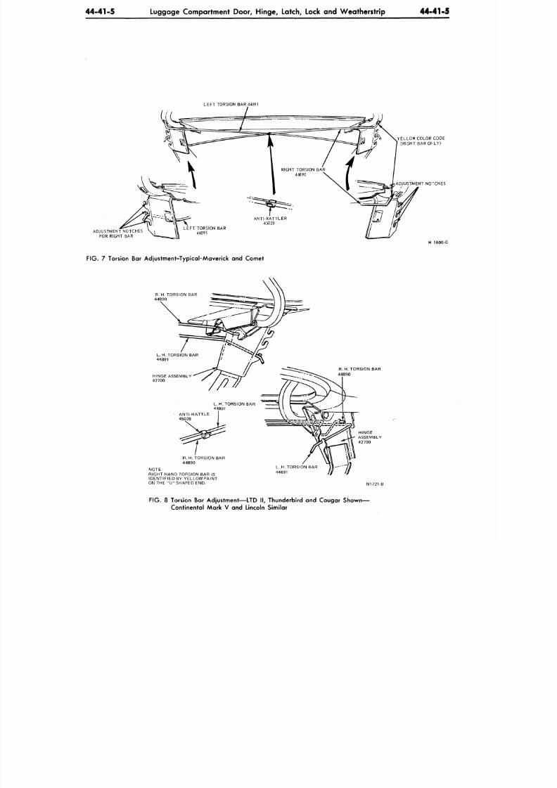
8/20/2019 1977 Ford Car Shop Manual Volume 4 Body
http://slidepdf.com/reader/full/1977-ford-car-shop-manual-volume-4-body 222/449
44-41-5
Luggage Compartment Door, Hinge, Latch, Lock and Weatherstrip 44-41-5
LEFT TORSION BAR 44891
ADJUSTMENT NOTCHES \ \
FOR RIGHT BAR
X
F IG . 7 Torsion Bar Adjustment-Typical-Maverick and Comet
YELLOW COLOR CODE
(RIGHT BAR OhLY)
ADJUSTMENT NOTCHES
1600-C
R. H. TORSION BAR
44890
HINGE ASSEMBLY
42700
R. H. TORSION BAR
44890
NOTE:
RIGHT HAND TORSION BAR IS
IDENTIFIED BY YELLOW PAINT
ON THE " U " SHAPED END.
R. H. TORSION BAR
44890
N1721-
FIG. 8 Torsion Bar Adjustment—LTD II, Thunderbird and Cougar Shown—
Continental Mark V and Lincoln Similar
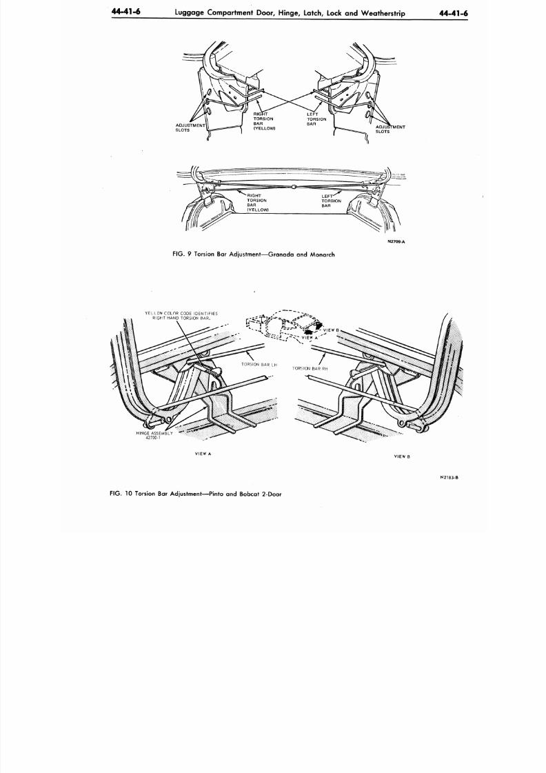
8/20/2019 1977 Ford Car Shop Manual Volume 4 Body
http://slidepdf.com/reader/full/1977-ford-car-shop-manual-volume-4-body 223/449
4 4- 41 -6 Luggage Compartment Door, Hinge, Latch, Lock and W eatherstrip 4 4 -4
ADJUSTMENT
SLOTS
RIGHT
TORSION
BAR
(YELLOW)
L EF T ' S -
TORSION
BAR '/ > %
ADJUSTMENT
=5
=*=
&
-_ SLOTS
FIG.
9 Torsion Bar Adjustment—Granada and Monarch
N2709-A
Y E L L O W C O L O R CO D E I D E N T I F I E S
R I G H T H A N D T O R S I O N B A R .
H I N G E A S S E M B L Y
42700 -1
VIEW A
VIEW B
N2183
FIG.
10 Torsion Bar Adjustment—Pinto and Bobcat 2-Door
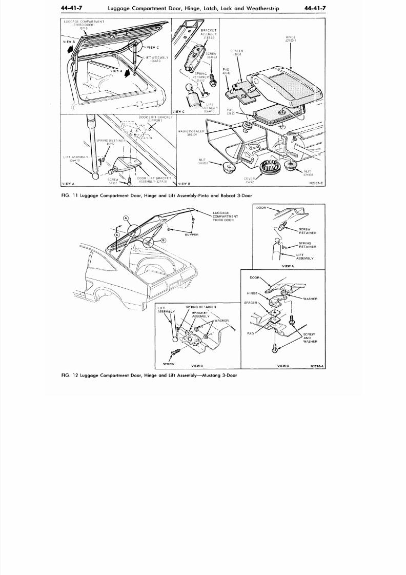
8/20/2019 1977 Ford Car Shop Manual Volume 4 Body
http://slidepdf.com/reader/full/1977-ford-car-shop-manual-volume-4-body 224/449
44-41-7
Luggage Compartmen t Doo r, Hinge, Latch, Lock and W eather strip
44-41-7
L U G G A G E C O M P A R T M E N T
( T H I R D D O O R )
.10110
H I N G E
42700 -1
V I E W A
SCREW
57367
D O OR L I F T B R A C K E T \
A S S E M B L Y - 4 2 7 A 4 8 v
N U T
376838
V I E W B
N2I07-C
FIG. 11 Luggage Compartment Door, Hinge and Lift Assembly-Pinto and Bobcat 3-Door
S C R E W
V I E W C
N2710-A
F IG . 12 Luggage Compartment Door, Hinge and Lift Assembly—Mustang 3-Door
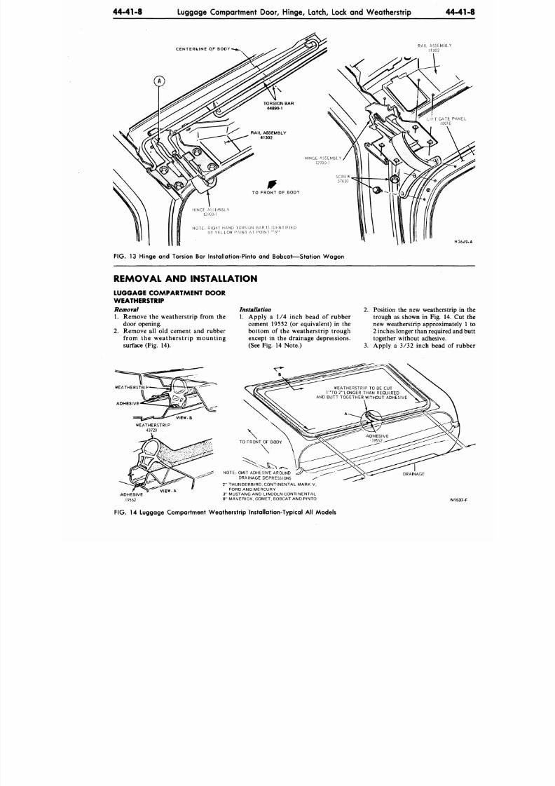
8/20/2019 1977 Ford Car Shop Manual Volume 4 Body
http://slidepdf.com/reader/full/1977-ford-car-shop-manual-volume-4-body 225/449
44-41-8
Luggage Compartment Door, Hinge, Latch, Lock and Weatherstrip
44-4
CENTER4.INE OF BODY
R A I L A S S E M B L Y
•11302
H I N G E A S S E M B L Y
12900-1
TO FRONT OF BODY
N O T E :
R I G H T H A N D T O R S I O N B A R I S I D E N T I F I E D
B Y Y E L L O W P A I N T A T P O I N T " A "
N26
FIG.
13 Hinge and Torsion Bar Installation-Pinto and Bobca t—Station W ag on
REMOVAL AND INSTALLATION
LUGGAGE COMPARTMENT DOOR
WEATHERSTRIP
Removal
1. Remove the weatherstrip from the
door opening.
2. Remove all old cement and rubber
from the weatherstrip mounting
surface (Fig. 14).
Installation 2.
1. Apply a 1/4 inch bead of rubber
cement 19552 (or equivalent) in the
bottom of the weatherstrip trough
except in the drainage depressions.
(See Fig. 14 Note .) 3.
Position the new weatherstrip in
trough as shown in Fig. 14. Cu
new weatherstrip approximately
2 inches longer than required and
together without adhesive.
Apply a 3/32 inch bead of ru
WEATHERSTRIP TO BE CUT
1"TO 2"I_ONGER THAN REQUIRED
AND BUTT TOGETHER WITHOUT ADHESIVE
NOTE: OMIT ADHESIVE AROUND
DRAINAGE DEPRESSIONS
2" THUNDERBIRD, CONTINENTAL MARK V,
FORD AND MERCURY
3" MUSTANG AND LINCOLN CONTINENTAL
0" MAVERICK, COMET, BOBCAT AND PINTO
DRAINAGE
N1537
FIG. 14 Luggage Compartment W eatherstrip Installation-Typical All Models
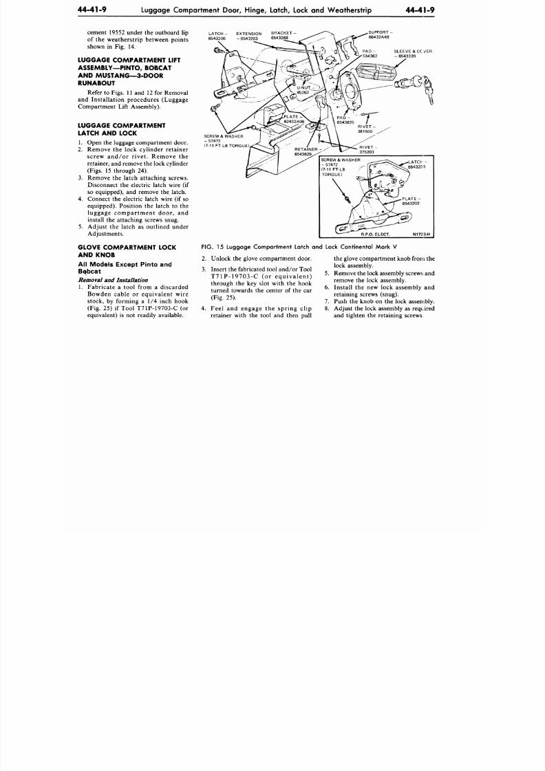
8/20/2019 1977 Ford Car Shop Manual Volume 4 Body
http://slidepdf.com/reader/full/1977-ford-car-shop-manual-volume-4-body 226/449
44-41-9
Luggage Compartment Door, Hinge, Latch, Lock and W eatherstrip
44-41-9
cement 19552 under the outboard
lip
of the weatherstrip between points
shown
in
Fig.
14.
LUGGAGE COMPARTMENT LIFT
ASSEMBLY—PINTO, BOBCAT
AND MUS TANG—3- DOOR
RUNABOUT
Refer to Figs. 11
and
12
for
Removal
and Installation procedures (Luggage
Compartment Lift Assembly).
LUGGAGE COMPARTMENT
LATCH AND LOCK
1.
Open the luggage compartment door.
2.
Remove
the
lock cylinder retainer
screw and/or r ivet. Remove
the
retainer, and remove the lock cylinder
(Figs. 15 through
24).
3. Remove
the
latch attaching screws.
Disconnect
the
electric latch wire
(if
so equipped),
and
remove
the
latch.
4. Connect
the
electric latch wire
(if
so
equipped). Position
the
latch
to the
luggage compartment door,
and
install
the
attaching screws snug.
5.
Adjust
the
latch
as
outlined under
Adjustments.
GLOVE COMPARTMENT LOCK
AND K NOB
All Models Except Pinto and
Bqbcat
Removal and Installation
1. Fabricate
a
tool from
a
discarded
Bowden cable
or
equivalent wire
stock,
by
forming
a 1/4
inch hook
(Fig.
25) if
Tool T71P-19703-C
(or
equivalent)
is not
readily available.
LATCH
-
EXTENSION
6543200
-
6543283
B R A C K E T -
6543268
SUPPORT
-
66432A48
SLEEVE &CCv/ER
- 6543320
SCREW & WASHER
- 57472
(7-11 FT-LB TORQUE)
R I V E T -
375203
SCREW & WASHER
-
57472
(7-11 FT-LB
TORQUE)
\
^
\
R.P.O. ELECT.
^T_65432C'O
f
^PLATE
-
6543202
N1723-H
FIG. 15 Luggage Compartment Latch and Lock Continental Mark V
2. Unlock the glove compartment door.
3. Insert the fabricated tool and /or Tool
T71P -19703-C
(or
equ iva len t )
through
the key
slot with
the
hook
turned towards
the
center
of
the
car
(Fig.
25).
4. Feel
and
engage
the
spring clip
retainer with
the
tool
and
then pull
the glove compartment knob from the
lock assembly.
5.
Remove the lock assembly screws and
remove
the
lock assembly.
6. Install
the new
lock assembly
and
retaining screws (snug).
7. Push
the
knob
on the
lock assembly.
8. Adjust the lock assembly
as
required
and tighten
the
retaining screws.
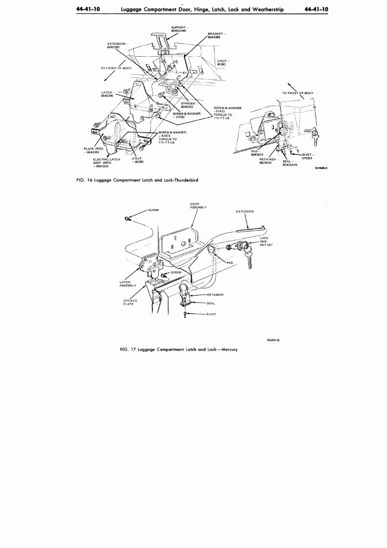
8/20/2019 1977 Ford Car Shop Manual Volume 4 Body
http://slidepdf.com/reader/full/1977-ford-car-shop-manual-volume-4-body 227/449
44-41-10
Luggage Compartment Door, Hinge, Latch, Lock and Weatherstrip
44-41-
EXTENSION -
6043283
PLATE(RPO)
- 6543202
ELECTRIC LATCH
ASSY. (RPO)
- 6543200
SCREW & WASHER
- 5 7 4 7 2
TORQUE TO
7-11 FT-LB
\
TO FRONT OF BODY
\
R I V E T -
375203
N104
FIG. 16 Luggage Compartment Latch and Lock-Thunderbird
EXTENSION
STRIKER
PLATE
N2237-D
FIG. 17 Luggage Compartment Latch and Lock—M ercury
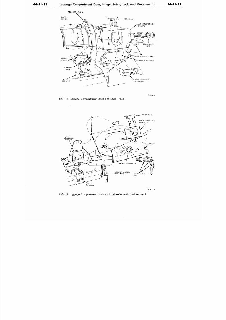
8/20/2019 1977 Ford Car Shop Manual Volume 4 Body
http://slidepdf.com/reader/full/1977-ford-car-shop-manual-volume-4-body 228/449
44-41-11
Luggage Compartment
Door,
Hinge, Latch, Lock and W eatherstrip 44-411-11
RELEASE LEVER
LATCH
COVER
RETAINER
LOCK MOUNTING
BRACKET
LATCH
STRIKER
LOCK CYLINDER PAD
REINFORCEMENT
LOCK CYLINDER
RETAINER
N2530 A
FIG.
18 Luggage Compartment Latch and Lock—Ford
LATCH
ASSEMBLY
RETAINER
N 2 5 3 1 B
FIG.
19 Luggage Compartment Latch and Lock—Granada and Monarch
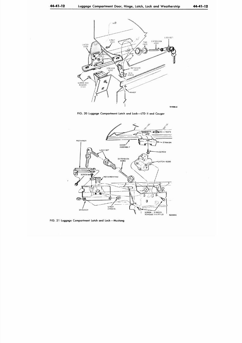
8/20/2019 1977 Ford Car Shop Manual Volume 4 Body
http://slidepdf.com/reader/full/1977-ford-car-shop-manual-volume-4-body 229/449
4 4- 41 -1 2 Luggage Compartment Door, Hinge, Latch, Lock and W eatherstrip 44 -4 1
LOCKSET
LATCH
43200
N1596-D
FIG. 20 Luggage Compartment Latch and Lock—LTD II and Cougar
RETAINER
S C R E W - 3 R E Q ' D .
TORQUE 7-11 FT-LB N2239 E
FIG. 21 Luggage Compartment Latch and Lock—Mustang
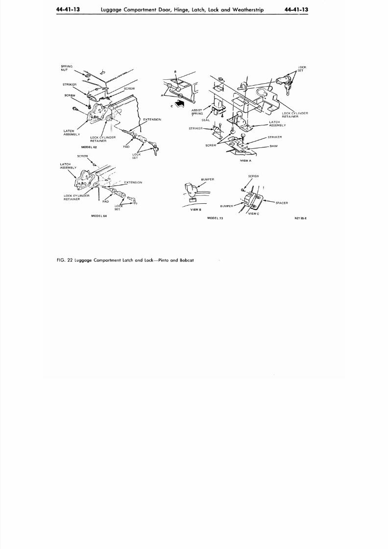
8/20/2019 1977 Ford Car Shop Manual Volume 4 Body
http://slidepdf.com/reader/full/1977-ford-car-shop-manual-volume-4-body 230/449
44-41-13
Luggage Compartment Door, Hinge, Latch, Lock and Weatherstrip
44-41-13
LOCK CYLINDER
RETAINER
MODEL 64
V I E W C
SPACER
MODEL 7 3 IM21
35-E
FIG.
22 Luggage Compartment Latch and Lock—Pinto and Bobcat
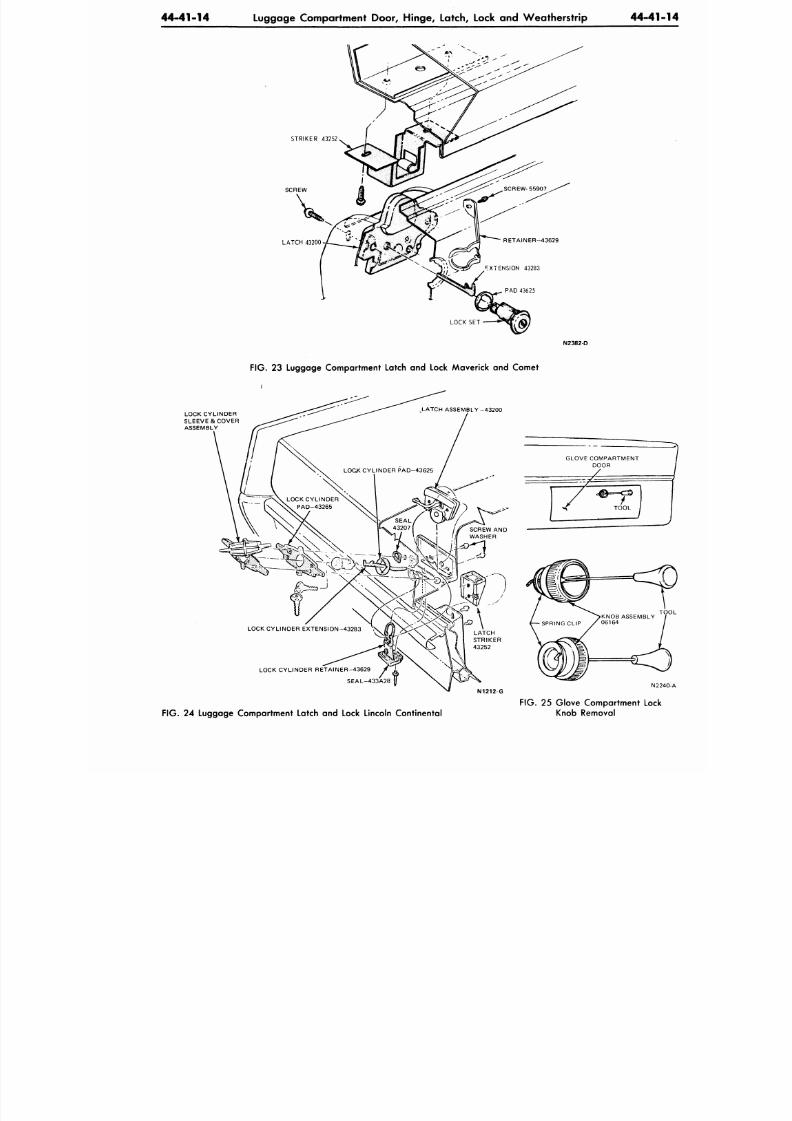
8/20/2019 1977 Ford Car Shop Manual Volume 4 Body
http://slidepdf.com/reader/full/1977-ford-car-shop-manual-volume-4-body 231/449
4 4- 41 -1 4 Luggage Compartment Door, Hinge, Latch, Lock and W eatherstrip 44 -4 1
STRIKER 43252
SCREW
LATCH 43200
FIG. 23 Luggage Compartment Latch and Lock Maverick and Comet
LOCK CYLINDER
SLEEVE & COVER
ASSEMBLY
LOCK CYLINDER RE TAINE R-436 29
SEAL-433A28
N2
N1212 G
FIG. 24 Luggage Compartment Latch and Lock Lincoln Continental
FIG.
25 Glove Compartment Lock
Knob Removal
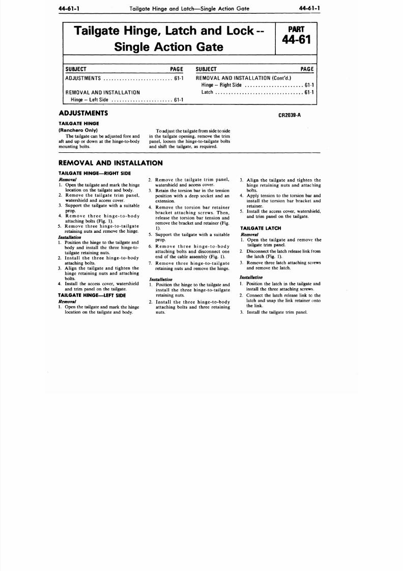
8/20/2019 1977 Ford Car Shop Manual Volume 4 Body
http://slidepdf.com/reader/full/1977-ford-car-shop-manual-volume-4-body 232/449
44-61-1
Tailgate Hinge and Latch—Single Action Gate
44-61-1
Tailgate Hinge, Latch and L o ck -
Single Action Gate
P A R T
44-61
SUBJECT PAGE
SUBJECT
PAGE
ADJUSTMENTS 61-1
REMOVAL AND INSTALLATION
Hinge- Le f t S ide
REMOVAL AND INSTALLATION (Con t 'd . )
Hinge - Right Side 61 1
Latch 61 1
61-1
ADJUSTMENTS
TAILGATE HINGE
(Ranchero Only)
The tailgate can be adjusted fore and
aft and up or down at the hinge-to-body
mounting bolts.
CR2039-A
To
adjust the tailgate from
side
to side
in the tailgate opening, remove the trim
panel, loosen the hinge-to-tailgate bolts
and shift the tailgate, as required.
REMOVAL AND INSTALLATION
TAILGATE HINGE—RIGHT SIDE
Removal
1. Open the tailgate and mark the hinge
location on the tailgate and body.
2.
Remove the tai lgate tr im panel,
watershield and access cover.
3.
Support the tailgate with a suitable
prop.
4.
R e m o v e t h r e e h i n g e - t o - b o d y
attaching bolts (Fig. 1).
5. Remove three hinge- to- ta i lga te
retaining nuts and remove the hinge.
Installation
1. Position the hinge to the tailgate and
body and install the three hinge-to-
tailgate retaining n uts.
2. Ins ta l l the three hinge- to-body
attaching bolts.
3.
Align the tailgate and tighten the
hinge retaining nuts and attaching
bolts.
4. Install the access cover, watershield
and trim panel on the tailgate.
TAILGATE HINGE—LEFT SIDE
Removal
1. Open the tailgate and mark the hinge
location on the tailgate and body.
2. Remove the tai lgate tr im panel,
watershield and access cover.
3. Retain the torsion bar in the tension
position with a deep socket and an
extension.
4. Remove the torsion bar retainer
bracket at taching screws. Then,
release the torsion bar tension and
remove the bracket and retainer (Fig.
1).
5. Support the tailgate with a suitable
prop.
6. R e m o v e t h r e e h i n g e - t o - b o d y
attaching bolts and disconnect one
end of the cable assembly (Fig. 1).
7. Remove three hinge-to-tailgate
retaining nuts and remove the hinge.
Installation
1. Position the hinge to the tailgate and
install the three hinge-to-tailgate
retaining nu ts.
2.
Ins ta l l the three hinge- to-body
attaching bolts and three retaining
nuts.
3.
Align the tailgate and tighten the
hinge retaining nuts and attaching
bolts.
4. Apply tension to the torsion bar and
install the torsion bar bracket and
retainer.
5. Install the access cover, watershield,
and trim panel on the tailgate.
TAILGATE LATCH
Removal
1. Open the tailgate and remove the
tailgate trim panel.
2.
Disconnect the latch release link from
the latch (Fig. 1).
3.
Remove three latch attaching screws
and remove the latch.
Installation
1. Position the latch in the tailgate and
install the three attaching screws.
2. Connect the latch release link to the
latch and snap the link retainer onto
the link.
3.
Install the tailgate trim panel.
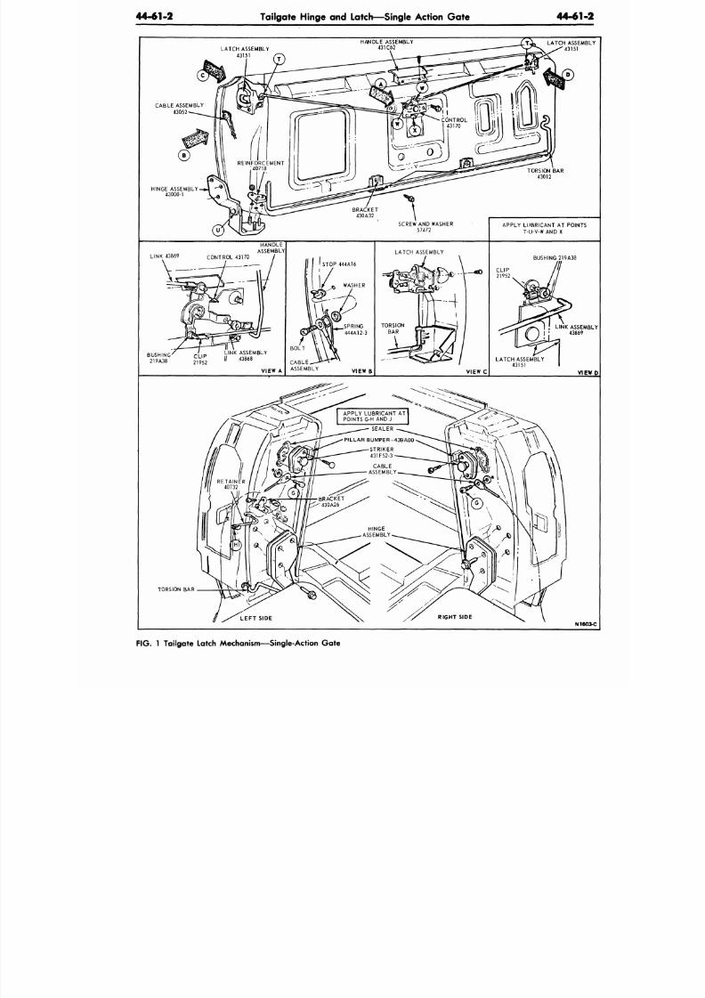
8/20/2019 1977 Ford Car Shop Manual Volume 4 Body
http://slidepdf.com/reader/full/1977-ford-car-shop-manual-volume-4-body 233/449
44-61-2
Tailgate Hinge and Latch—Single Action Gate
44-61-
LATCH ASSEMBLY
43151
HANDLE ASSEMBLY
431C62
LATCH ASSEM
43151
CABLE ASSEMBLY
43052
HINGE ASSEMBLY
43000-1
APPLY LUBRICANT
AT
POINTS
T-U-V-W AND X
LINK 43869
STOP 444A16
WASHER
VIEW B
LATCH ASSEMBLY
BUSHING 219A38
LATCH ASSEMBLY
43151
VIEW C
J LINK ASSEM
43869
VIE
TORSION
BA R
N160
FIG.
1 Tailgate Latch Mechanism —Single-Action Ga te
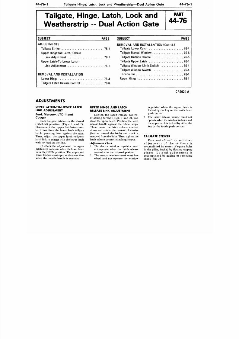
8/20/2019 1977 Ford Car Shop Manual Volume 4 Body
http://slidepdf.com/reader/full/1977-ford-car-shop-manual-volume-4-body 234/449
44-76-1
Tailgate Hinge , Latch, Lock and W eathe rstrip— Dua l Action G at e
44-76-1
Tailgate, Hinge, Latch, Lock and
W eatherstrip - Dual Action Gate
P A R T
44-76
SUBJECT PAGE
ADJUSTMENTS
Tailgate Striker 76-1
Upper Hinge and Latch Release
Link Adju stme nt 76-1
Upper Latch-To-Lower Latch
Link Adjustm ent 76-1
REMOVAL AND INSTALLATION
Lower Hinge 76-3
Tailgate Latch Release Co ntrol 76-6
SUBJECT PAGE
REMOVAL AND INSTALLATION (Cont 'd . )
Tailgate Lowe r Catch 76-4
Tailgate Manual Windo w 76-6
Tailgate Outside Handle 76-5
Tailgate Upper Latch 76-4
Tailgate Windo w Lim it Switch 76-4
Tailgate Windo w Switch 76-4
Torsio n Bar 76-4
Upper Hinge 76-4
CR2020-A
ADJUSTMENTS
UPPER LATCH-TO-LOWER LATCH
LINK ADJUSTMENT
Ford, Mercury, LTD II and
Cougar
Place tailgate latches in the closed
(latched) position (Figs. 1 and 2).
Disconnect the upper latch-to-lower
latch link from the lower latch tailgate
latch operating lever against the stop.
Then, adjust the upper latch-to-lower
latch link to engage with the lower latch
with no load on the link.
To check the adjustment, the upper
latch must not close when the lower latch
is in the. OPEN position. The upper and
lower latches must open at the same time
when the outside handle is operated.
UPPER HINGE AND LATCH
RELEASE LINK ADJUSTMENT
Loosen the latch release control
attaching screws (Figs. 1 and 2), and
close the upper latch. Position the latch
release handle against the rubber stops.
Then, move the latch release control
down and rotate the control clockwise
(bottom toward the latch) until slack is
removed from the links. Then, tighten the
latch release control attaching screws.
Adjustment Check
1. The electric window regulator must
not operate when the latch release
control is in the released position.
2.
The manual window crank must free
wheel and not operate the window
regulator when the upper larch is
locked by the key or the inside latch
push button.
The inside release handle muit not
operate when the window is down and
the upper latch is locked by either the
key or the inside push button.
TAILGATE STRIKER
Fore and aft and up and down
a d j u s t m e n t o f t h e s t r i k e r s i s
accomplished by means of square holes
in the pillar, backed by floating tapping
p l a t e s . L a t e r a l a d j u s t m e n t is
accomplished by adding or removing
shims (Fig. 3).
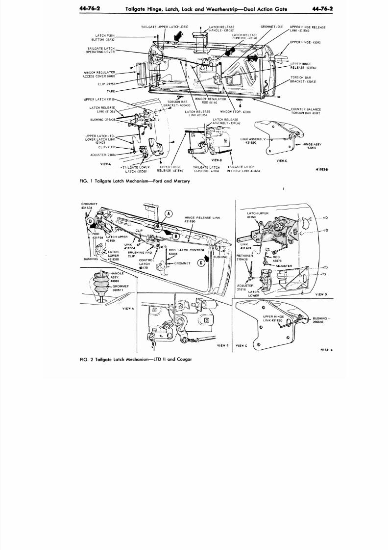
8/20/2019 1977 Ford Car Shop Manual Volume 4 Body
http://slidepdf.com/reader/full/1977-ford-car-shop-manual-volume-4-body 235/449
44-76-2
Tailgate Hinge, Latch, Lock and W eatherstrip—Du al Action G ate
44-7
TAILGATE UPPER LATCH 43150
LATCH RELEASE
HANDLE-431C62
LATCH PUSH
BUTTON-31A32
TAILGATE LATCH
OPERATING LEVER
WINDOW REGULATOR
ACCESS COVER 07090
GROMMET-051 1 UPPER HINGE RELEAS
'L INK-431E60
UPPER HINGE-43090
UPPER HINGE
RELEASE-431E60
LATCH RELEASE
• ASSEMBLY-431C62
COUNTER BALANCE
TORSION BAR 43012
UPPER L ATCH-TO -
LOWER LATCH LINK
431A24
CLIP-21952
ADJUSTER-21816
VIEW-A
VIEW-C
•TAILGATE LOWER
LATCH 431D88
UPPER HINGE
RELEASE-431E60
TAILGATE LATCH TAILGATE LATCH
CONTROL-43884 RELEASE LINK 431D54
N175
F IG .
1
Tailgate Latch Mechanism—Ford
and
Mercury
431F6 4 LATCH UPPER
43150
LINK
431D54 ^
BRUSHING AND /
CLIP /
X
N
F IG . 2
Tailgate Latch Mechanism—LTD
II and
Cougar
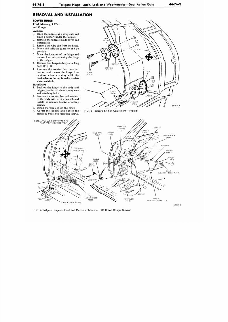
8/20/2019 1977 Ford Car Shop Manual Volume 4 Body
http://slidepdf.com/reader/full/1977-ford-car-shop-manual-volume-4-body 236/449
44-76-3
Tailgate Hinge, Latch, Lock
and
We atherstrip—Dua l Action G ate
44-76-3
REMOVAL AND INSTALLATION
LOWER HINGE
Ford,
Mercury,
LTD
II
and Cougar
Removal
1. Open the tailgate as a drop gate and
place a support under the tailgate.
2. Remove the tailgate inside cover and
watershield.
3. Remove the wire clip from the hinge.
4. Mo v e the tai lga te g lass to the up
position.
5. Mark the location of the hinge and
remove four nuts retaining the hinge
to the tailgate.
6. Remove four hinge-to-body attaching
bolts (Fig. 4).
7 . R emo v e the t o r s i o n bar r e t a i n e r
bracket
and
remove
the
hinge. Use
cau t ion wh en work in g wi t h the
torsion bar as the bar is under tension
when installed.
Installation
1. Position
the
hinge
to the
body
and
tailgate, and install the retaining nuts
and attaching bolts.
2. Position
the
torsion
bar and
retainer
to
the
body with
a
pipe wrench
and
install the retainer bracke t a ttaching
screws.
3. Install the wire clip on the hinge.
4.
Adjust the tai lgate and tighten the
FIG. 3 lailgate Striker Adjustment—Typical
attaching bolts and retaining screws.
NOTE: APPLY LUBRICANT AT POINTS
"AC," "AD," "AE," AND "AG."
UPPER HINGE
43086
BOLT
TIGHTEN 25-38 FT. I.B.
SCREW
TORQUE 25-38 FT. LB.
TORQUE- 25-38 FT. LB
FIG. 4 Tailgate Hinges — Ford and Mercury Shown —
LTD
II
and
Cougar S imilar
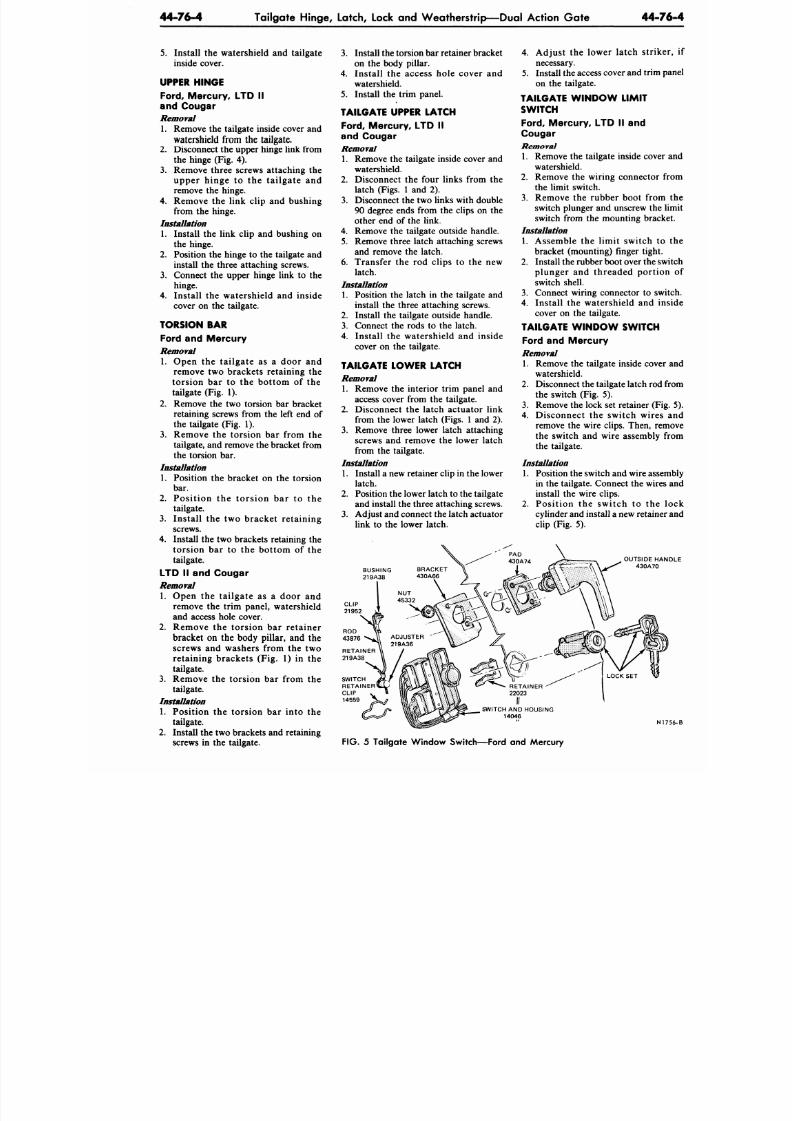
8/20/2019 1977 Ford Car Shop Manual Volume 4 Body
http://slidepdf.com/reader/full/1977-ford-car-shop-manual-volume-4-body 237/449
44-76-4
Tailgate Hinge, Latch, Lock and Weatherstrip—Dual Action Gate
44-
5. Install the watershield and tailgate
inside cover.
UPPER HINGE
Ford,
Mercury, LTD II
and Cougar
Removal
1. Remove the tailgate inside cover and
watershield from
th e
tailgate.
2.
Disconnect the upper hinge link from
the hinge (Fig. 4).
3. Remove three screws attaching the
upper hinge to the tailgate and
remove the hinge.
4.
Remove the link clip and bushing
from the hinge.
Installation
1. Install the link clip and bushing on
the hinge.
2. Position the hinge to the tailgate and
install the three attaching screws.
3. Connect the upper hinge link to the
hinge.
4. Install the watershield and inside
cover on the tailgate.
TORSION BAR
Ford and Mercury
Removal
1. Open the tailgate as a door and
remove two brackets retaining the
torsion bar to the bottom of the
tailgate (Fig. 1).
2. Remove the two torsion bar bracket
retaining screws from the left end of
the tailgate (Fig. 1).
3. Remove the torsion bar from the
tailgate, and remove the bracket from
the torsion bar.
Installation
1. Position the bracket on the torsion
bar.
2. Position the torsion bar to the
tailgate.
3.
Install the two bracket retaining
screws.
4. Install the two brackets retaining the
torsion bar to the bottom of the
tailgate.
LTD II and Cougar
Removal
1. Open the tailgate as a door and
remove the trim panel, watershield
and access hole cover.
2. Remove the torsion bar retainer
bracket on the body pillar, and the
screws and washers from the two
retaining brackets (Fig. 1) in the
tailgate.
3. Remove the torsion bar from the
tailgate.
Installation
1.
Position the torsion bar into the
tailgate.
2.
Install the two brackets and retaining
screws in the tailgate.
3. Install the torsion bar retainer bracket
on the body pillar.
4.
Install the access hole cover and
watershield.
5. Install the trim panel.
TAILGATE UPPER LATCH
Ford, Mercury, LTD II
and Cougar
Removal
1. Remove the tailgate inside cover and
watershield.
2. Disconnect the four links from the
latch (Figs. 1 and 2).
3. Disconnect the two links with double
90 degree ends from the clips on the
other end of the link.
4. Remove the tailgate outside handle.
5. Remove three latch attaching screws
and remove the latch.
6. Transfer the rod clips to the new
latch.
Installation
1. Position the latch in the tailgate and
install the three attaching screws.
2. Install the tailgate outside handle.
3.
Connect the rods to the latch.
4. Install the watershield and inside
cover on the tailgate.
TAILGATE LOWER LATCH
Removal
1. Remove the interior trim panel and
access cover from the tailgate.
2.
Disconnect the latch actuator link
from the lower latch (Figs. 1 and 2).
3. Remove three lower latch attaching
screws and remove the lower latch
from the tailgate.
Installation
1. Install a new retainer clip in the lower
latch.
2. Position the lower latch to the tailgate
and install the three attaching screws.
3. Adjust and connect the latch actuator
link to the lower latch.
BUSHING
219A38
4. Adjust the lower latch strik
necessary.
5. Install the access cover and trim
on the tailgate.
TAILGATE W IND OW LIMIT
SWITCH
Ford,
Mercury, LTD II and
Cougar
Removal
1. Remove the tailgate inside cov
watershield.
2. Remove the wiring connector
the limit switch.
3. Remove the rubber boot from
switch plunger and unscrew the
switch from the mounting brac
Installation
1. Assemble the limit switch t
bracket (mounting) finger tight
2. Install the rubber boot over the
plunger and threaded portio
switch shell.
3. Connect wiring connector to s
4.
Install the watershield and
cover on the tailgate.
TAILGATE W IND OW SWITCH
Ford and Mercury
Removal
1. Remove the tailgate inside cov
watershield.
2. Disconnect the tailgate latch ro
the switch (Fig. 5).
3. Remove the lock set retainer (F
4. Disconnect the switch wire
remove the wire clips. Then, re
the switch and wire assembly
the tailgate.
Installation
1. Position the switch and wire ass
in the tailgate. Connect the wire
install the wire clips.
2. Position the switch to the
cylinder and install a new retain
clip (Fig. 5).
OUTSIDE H
430A70
CLIP
21952
N
FIG.
5 Tailgate Window Switch—Ford and Mercury
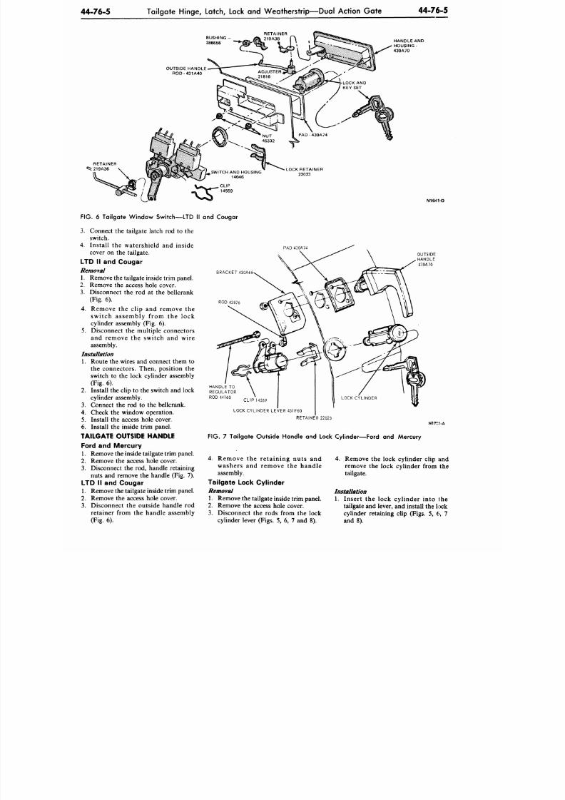
8/20/2019 1977 Ford Car Shop Manual Volume 4 Body
http://slidepdf.com/reader/full/1977-ford-car-shop-manual-volume-4-body 238/449
44-76-5
Tailgate Hinge, Latch, Lock and Weatherstrip—Dual Action Gate
44-76-5
BUSHING -
RETAINER
219A38
HANDLE AND
HOUSING-
430A70
N1641-D
BRACKET 430A66
ROD 43876
FIG.
6 Tailgate Window Switch—LTD II and Cougar
3.
Connect the tailgate latch rod to the
switch.
4. Install the watershield and inside
cover on the tailgate.
LTD II and Cougar
Removal
1. Remove the tailgate inside trim panel.
2.
Remove the access hole cover.
3.
Disconnect the rod at the bellcrank
(Fig. 6).
4.
Remove the clip and remove the
switch assembly from the lock
cylinder assembly (Fig. 6).
5.
Disconnect the multiple connectors
and remove the switch and wire
assembly.
Installation
1. Route the wires and connect them to
the connectors. Then, position the
switch to the lock cylinder assembly
(Fig. 6).
2. Install the clip to the switch and lock
cylinder assembly.
3.
Connect the rod to the bellcrank.
4. Check the window operation.
5. Install the access hole cover.
6. Install the inside trim panel.
TAILGATE OUTSIDE HANDLE
Ford and Mercury
1. Remove the inside tailgate trim panel.
2.
Remove the access hole cover.
3.
Disconnect the rod, handle retaining
nuts and remove the handle (Fig. 7).
LTD II and Cougar
1. Remove the tailgate inside trim panel.
2. Remove the access hole cover.
3.
Disconnect the outside handle rod
retainer from the handle assembly
(Fig. 6).
PAD 430A74
LOCK CYLINDER LEVER 431F60
RETAINER 22023
N17f :? -A
FIG.
7 Tailgate Outside Handle and Lock Cylinder—Ford and Mercury
4.
Remove the retaining nuts and
washers and remove the handle
assembly.
Tailgate Lock Cylinder
Removal
1. Remove the tailgate inside trim panel.
2. Remove the access hole cover.
3.
Disconnect th e rods from the lock
cylinder lever (Figs. 5, 6, 7 and 8).
4. Remove the lock cylinder clip and
remove the lock cylinder from the
tailgate.
Installation
1.
Insert the lock cylinder into the
tailgate and lever, and install the lock
cylinder retaining clip (Figs. 5, 6, 7
and 8).
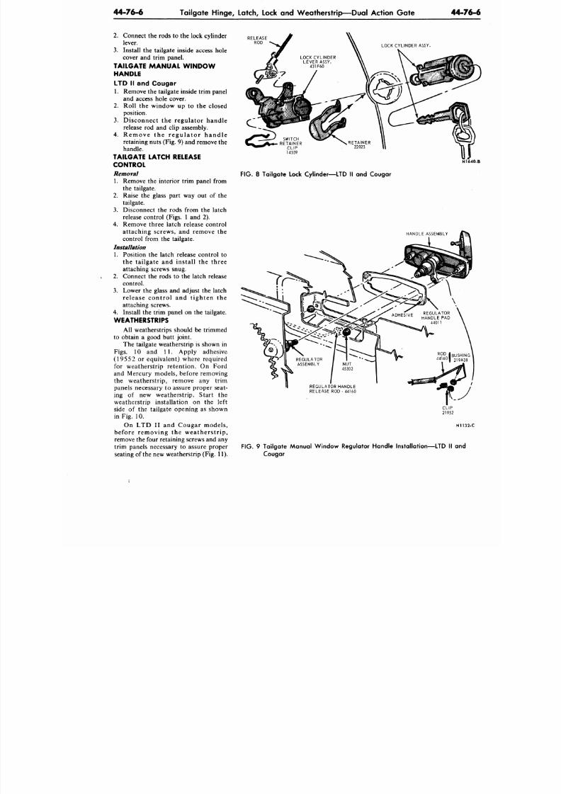
8/20/2019 1977 Ford Car Shop Manual Volume 4 Body
http://slidepdf.com/reader/full/1977-ford-car-shop-manual-volume-4-body 239/449
44-76-6
Tailgate Hinge, Latch, Lock and Weatherstrip—Dual Action Gate
44-7
2.
Connect the rods to the lock cylinder
lever.
3. Install the tailgate inside access hole
cover and trim panel.
TAILGATE MAN UAL W INDO W
HANDLE
LTD II and Cougar
1. Remove the tailgate inside trim panel
and access hole cover.
2. Roll the window up to the closed
position.
3.
Disconnect the regulator handle
release rod and clip assembly.
4.
Remove the r egu la to r hand le
retaining nuts (Fig. 9) and remove the
handle.
TAILGATE LATCH RELEASE
CONTROL
Removal
1. Remove the interior trim panel from
the tailgate.
2.
Raise the glass part way out of the
tailgate.
3. Disconnect the rods from the latch
release control (Figs. 1 and 2).
4. Remove three latch release control
attaching screws, and remove the
control from the tailgate.
Installation
1. Position the latch release control to
the tailgate and install the three
attaching screws snug.
2.
Connect the rods to the latch release
control.
3. Lower the glass and adjust the latch
release control and tighten the
attaching screws.
4. Install the trim panel on the tailgate.
WEATHERSTRIPS
All weatherstrips should be trimmed
to obtain a good butt joint.
The tailgate weatherstrip is shown in
Figs.
10 and 11 . Apply adhesive
(19552 or equivalent) where required
for weatherstrip retention. On Ford
and Mercury models, before removing
the weatherstrip, remove any trim
panels necessary to assure proper seat-
ing of new weatherstrip. Start the
weatherstrip installation on the left
side of the tailgate opening as shown
in Fig. 10.
On LTD II and Cougar models,
before removing the weatherstrip,
remove the four retaining screws and any
trim panels necessary to assure proper
seating of the new weatherstrip (Fig. 11).
RELEASE
ROD
N1
FIG. 8 Tailgate Lock Cylinder—LTD II and Cougar
HANDLE ASSEMBLY
ADHFSIVF REGULATOR
ADHESIVE
H A N D L E p A D
44011
N113
FIG. 9 Tailgate Manual Window Regulator Handle Installation—LTD II and
Cougar
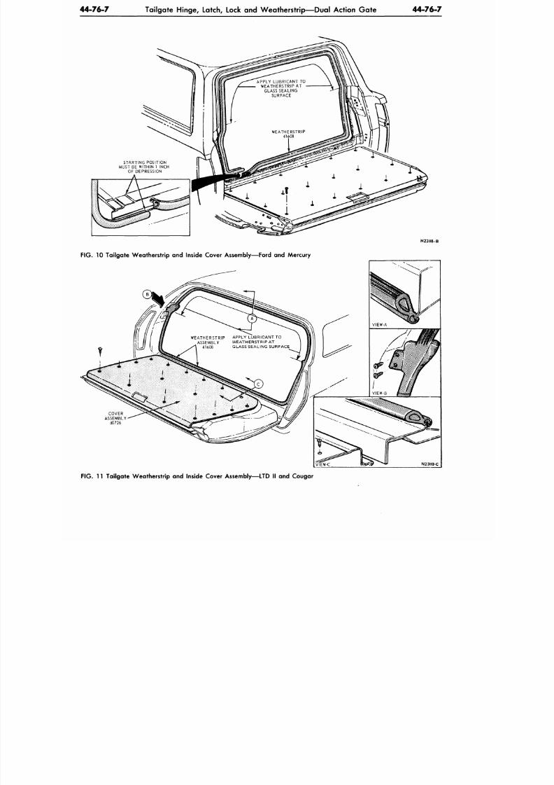
8/20/2019 1977 Ford Car Shop Manual Volume 4 Body
http://slidepdf.com/reader/full/1977-ford-car-shop-manual-volume-4-body 240/449
44-76-7
Tailgate H inge, Latch, Lock and W eathe rstrip— Dua l Action G ate
44-76-7
APPLY LUBRICANT TO
WEATHERSTRIP AT
GLASS SEALING
SURFACE
WEATHERSTRIP
41608
STARTING POSITION
MUST BE WITHIN 1 INCH
OF DEPRESSION
A
N23H8-B
FIG. 10 Tailgate Weatherstrip and Inside Cover Assembly—Ford and Mercury
COVER
ASSEMBLY
40726
WEATHERSTRIP APPLY LUBRIC ANT TO
ASSEMBLY WEATHE RSTRIP AT
41608 GLASS SEALING SURFACE
N23H9-C
F IG .
11 Tailgate W eatherstrip an d Inside Cover Assembly—LTD II and Cougar
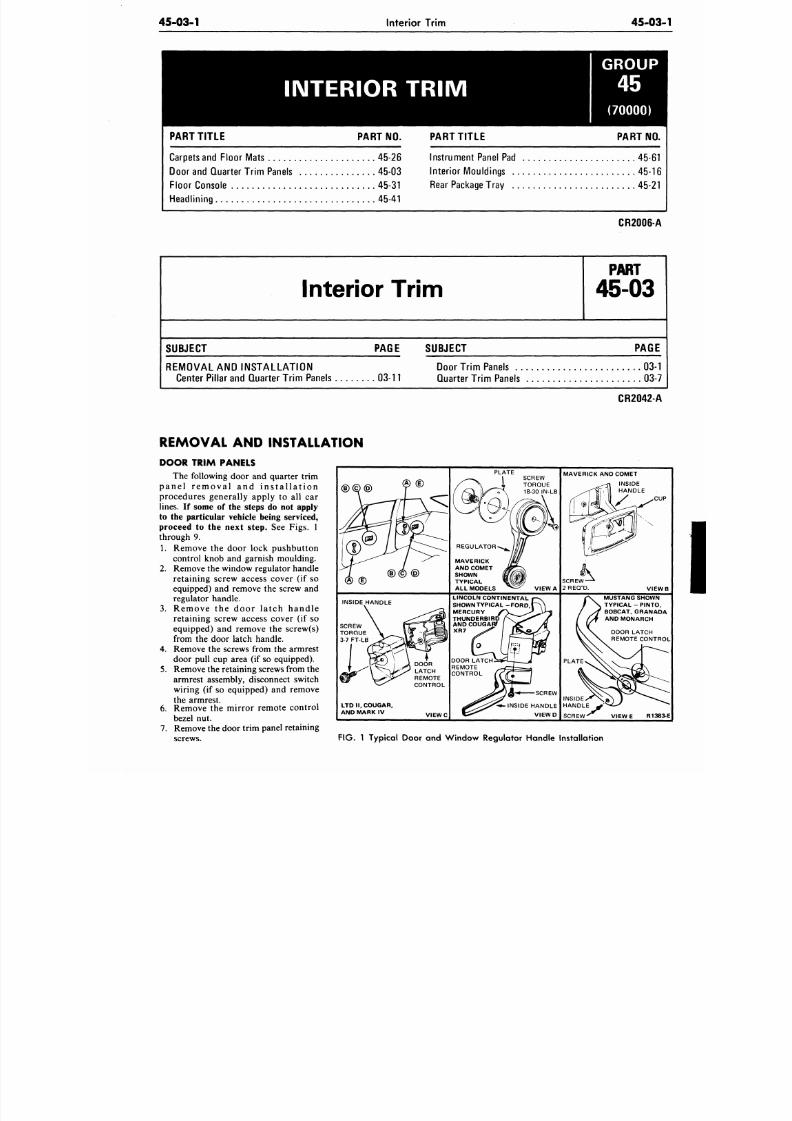
8/20/2019 1977 Ford Car Shop Manual Volume 4 Body
http://slidepdf.com/reader/full/1977-ford-car-shop-manual-volume-4-body 241/449
45-03-1
Interior Trim
45-03
INTERIOR TRIM
GROUP
(70000)
PART TITL E PART NO.
Carpets and Floo r Mats 45-26
Door and Quarter Trim Panels 45-03
Floo r Console 45-31
Headlining 45-41
PART TITLE PART NO
Instrum en t Panel Pad 45-61
Interior Mouldings 45-16
Rear Package Tray 45-2 1
CR2006-A
Interior Trim
P A R T
45-03
SUBJECT
PAGE SUBJECT
PAGE
REM O VAL AND INST AL L AT IO N
Center Pillar and Quarter Trim Panels
03-11
Door Trim Panels . .
Quarter Trim Panels
03-1
03-7
REMOVAL AND INSTALLATION
CR2042-A
DOOR TRIM PANELS
The following door and quarter trim
p a n e l r e m o v a l a n d i n s t a l l a t i o n
procedures generally apply to all car
lines. If some of the steps do not apply
to the particular vehicle being serviced,
proceed to the next step. See Figs. 1
through 9.
1.
Remove the door lock pushbutton
control knob and garnish moulding.
2. Remove the window regulator handle
retaining screw access cover (if so
equipped) and remove the screw and
regulator handle.
3.
Remove the door la tch handle
retaining screw access cover (if so
equipped) and remove the screw(s)
from the door latch handle.
4. Remove the screws from th e armrest
door pull cup area (if so equipped).
5.
Remove the retaining screws from th e
armrest assembly, disconnect switch
wiring (if so equipped) and remove
the armrest.
6. Remove the mirror remote control
bezel nut.
7. Remove the door trim panel retaining
screws.
®
<D
<D
INSIDE HANDLE
LTD I I , COUGAR,
AND MARK IV
DOOR
LATCH
REMOTE
CONTROL
V I E W C
PLATE
REGULATOR
MAVERICK
AND COMET
SHOWN
TYPICAL
ALL MODELS
VIEW A
LINCOLN CONTINENTAL
SHOWNTYPICAL -FORD, |
MERCURY
THUNDERBIf
ANDCOl
XR7
DOOR LATCH
REMOTE
CONTROL
MAVERICK AND COM ET
C
V I E
MUSTANG SHOWN
TYPICAL - PINTO
BOBCAT. GRANAD
AND MONARCH
SCREW
V I E W E
R138
FIG . 1 Typical Door and Win dow Regulator Handle Installation
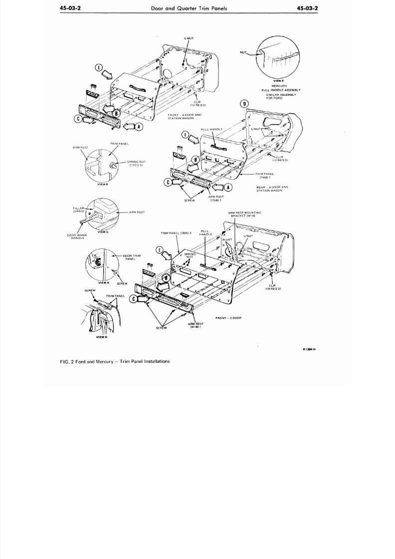
8/20/2019 1977 Ford Car Shop Manual Volume 4 Body
http://slidepdf.com/reader/full/1977-ford-car-shop-manual-volume-4-body 242/449
45-03-2
Door and Quarter Trim Panels
45-03-2
DOOR INSIDE
HANDLE
CLIP
(14REQ'D)
FRONT
-
2-DOOR
ARM REST
24140 1
V I E W D
R I 3 9 4 H
FIG. 2 Ford and Mercury — Trim Panel Installations
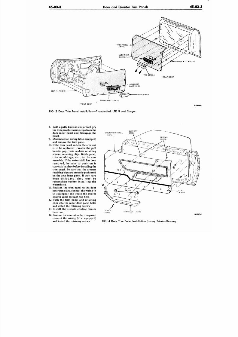
8/20/2019 1977 Ford Car Shop Manual Volume 4 Body
http://slidepdf.com/reader/full/1977-ford-car-shop-manual-volume-4-body 243/449
45-03-3
Door and Quarter Trim Panels 45-03
CLIP (14REQ'D)
PAD 24100-1
TRIM PANEL 23942-3
FRONTDOOR
R18
FIG . 3 Door Trim Panel Installation—Thunderbird, LTD II and Cougar
8. With a putty knife or similar tool, pry
the trim panel retaining clips from the
door inner panel and disengage the
panel.
9. Disconnect all wiring (if so equipped)
and remove the trim panel.
10.
If the trim panel an d/o r the arm rest
is to be replaced, transfer the pull
handle pop rivets and/or retaining
screws, retaining clips, finish panel,
trim mouldings, etc., to the new
assembly. If the watershield has been
removed, be sure to position it
correctly in place before installing the
trim panel. Be sure that the armrest
retaining clips are properly positioned
on the door inner panel. If they have
been dis lodged, they must be
reinstalled before installing the
watershield.
11. Position the trim panel to the door
inner panel and connect the wiring (if
so equipped) and route the mirror
control cable through the hole.
12.
Push the trim panel and retaining
clips into the inner door panel holes
and install the retaining screws.
13.
Install the remote control mirror
bezel nut.
14. Position the armrest to the trim panel,
connect the wiring (if so equipped)
and install the retaining screws.
DOOR TRIM PANEL
- 23942
ARM REST 24140
R18
FIG .
4 Door Trim Panel Installation (Luxury Trim)—Mustang
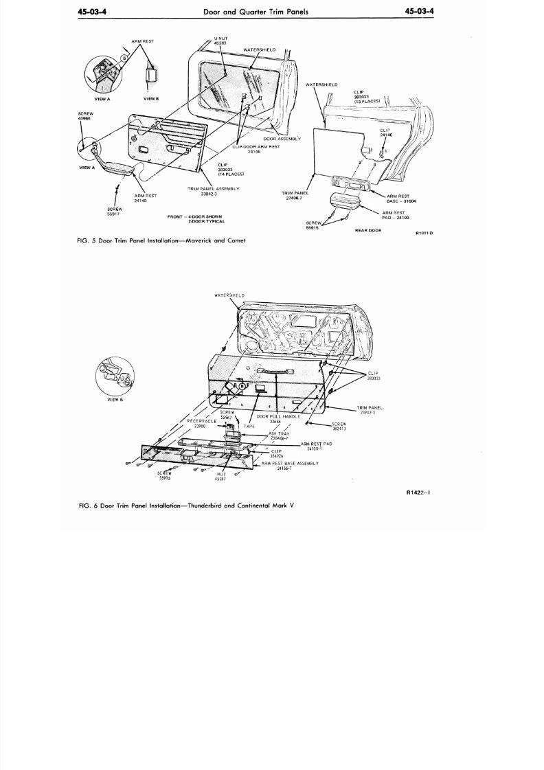
8/20/2019 1977 Ford Car Shop Manual Volume 4 Body
http://slidepdf.com/reader/full/1977-ford-car-shop-manual-volume-4-body 244/449
45-03-4
Door and Quarter Trim Panels
45-03-4
^
U-NUT
/ ? 45263
ARM REST
B A S E - 3 1 6 0 4
ARM REST
P A D - 2 4 1 0 0
REAR DOOR
R1II11-D
FIG. 5 Door Trim Panel Installation—Maverick and Comet
WATERSHIELD
VIEW
B
,RM REST
PAD
24100-1
ARM REST BASE ASSEMBLY
24156-7
R142;»-l
FIG. 6 Door Trim Panel Installation—Thunderbird and Continental Mark V
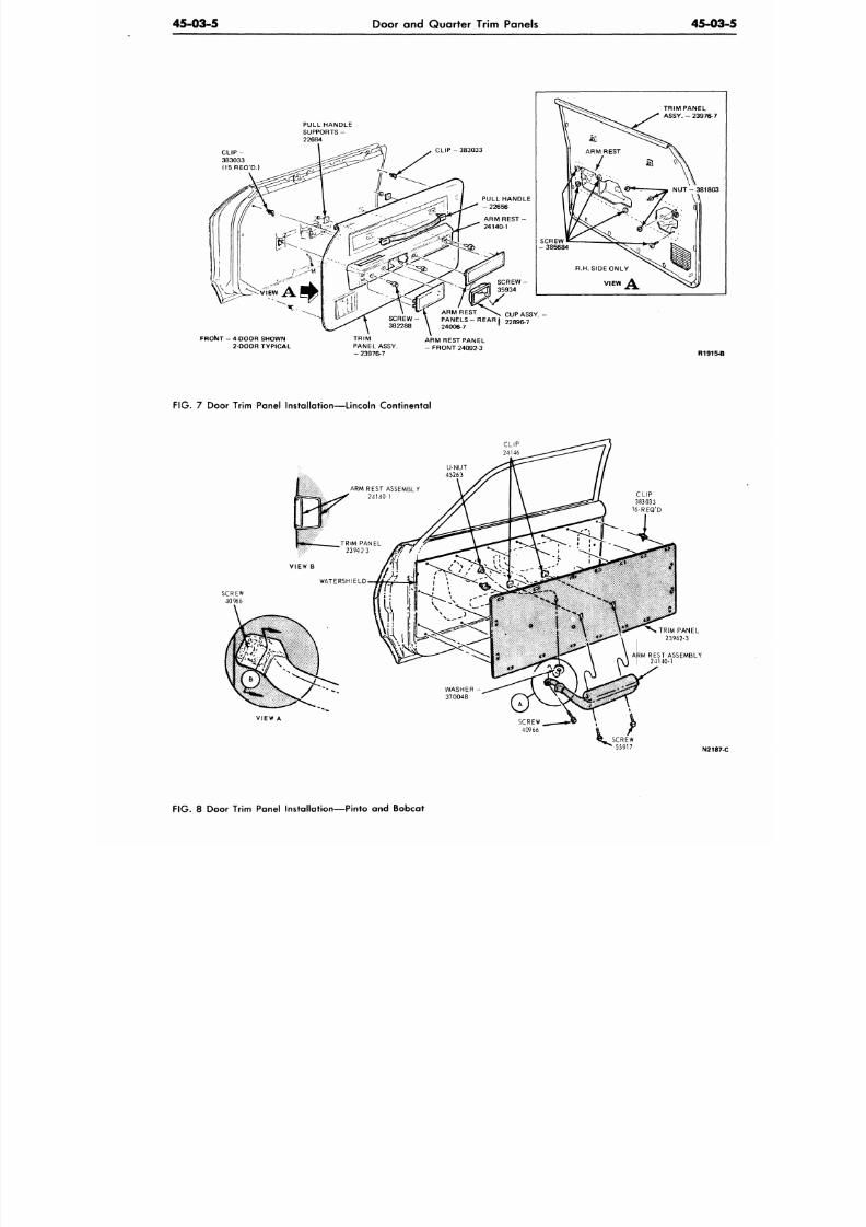
8/20/2019 1977 Ford Car Shop Manual Volume 4 Body
http://slidepdf.com/reader/full/1977-ford-car-shop-manual-volume-4-body 245/449
45-03-5
Door and Quarter Trim Panels
45-03
CLIP-
383033
(15 REQ'D.)
PULL HANDLE
SUPPORTS -
22684
CLIP
-
383033
PULL HANDLE
-22656
ARM REST
-
24140-1
382288
FRONT
- 4
DOOR SHOWN
2 DOOR TYPICAL
TRIM
PANEL ASSY.
-
23976-7
\
SCREW -
SCREW
-3 8 5 6 8 4
TRIM PANEL
ASSY. - 23976-7
NUT -381803
R.H. SIDE ONLY
V I E W
A
ARM REST \
r u P
» «
Y
SCREW- \ PANELS-REAR, 22896 7
24006-7
ARM REST PANEL
- FRONT 24092-3
R1915-B
F IG . 7 Door Trim Panel Installation—Lincoln Continental
CLIP
24146
VIEW
A
N2187
FIG. 8 Door Trim Panel Installation—Pinto and Bobcat
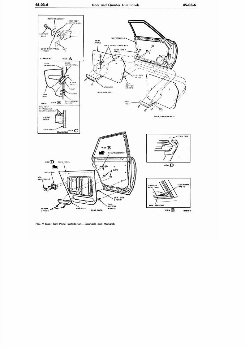
8/20/2019 1977 Ford Car Shop Manual Volume 4 Body
http://slidepdf.com/reader/full/1977-ford-car-shop-manual-volume-4-body 246/449
45-03-6
Door and Quarter Trim Panels
45-03-6
REINFORCEMENT
ASH
RECEPTACLE
CLIP
BOTTOM
A R M R E S T 4 R E Q D
REAR DOOR
TUCK FOAM
TAPE
IN
WEATHERSTRIP
FIG.
9 Door Trim Panel Installation—Granada and Monarch
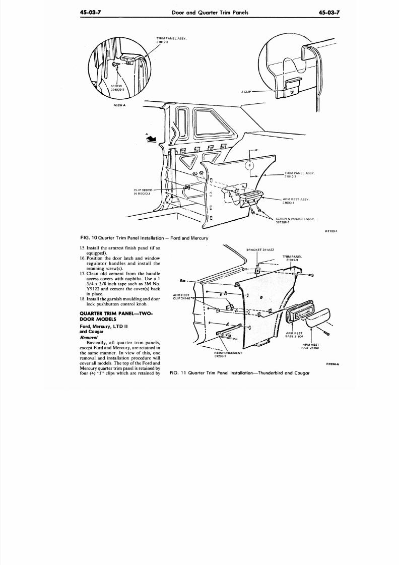
8/20/2019 1977 Ford Car Shop Manual Volume 4 Body
http://slidepdf.com/reader/full/1977-ford-car-shop-manual-volume-4-body 247/449
45-03-7
Door and Quarter Trim Panels
45-03
TRIM PANEL ASSY.
31012-3
ARM REST ASSY.
31600-1
SCREW & WASHER ASSY.
382288-S
FIG.
10 Quarter Trim Panel Instal lation
—
Fo rd and Mercury
15. Install the armrest finish panel (if so
equipped).
16.
Position the door latch and window
regulator handles and install the
retaining screw(s).
17. Clean old cement from the han dle
access covers with naphtha. Use a 1
3/4 x 3/8 inch tape such as 3M No.
Y9122 and cement the cover(s) back
in place.
18. Install the garnish moulding and door
lock pushbutton control knob.
QUARTER TRIM PANEL—TWO-
DOOR MODELS
Ford, Mercury, LTD I I
and Cougar
Removal
Basically, all quarter trim panels,
except Ford and Mercury, are retained in
the same manner. In view of this, one
removal and installation procedure will
cover all models. The top of the Ford and
Mercury quarter trim panel is retained by
four (4) "J" clips which are retained by
BRACKET 311A22
TRIM PANEL
31012-3
ARM REST
PAD 24100
REINFORCEMENT
31296-7
R15
FIG. 11 Quarter Trim Panel Installation—Thunderbird and Cougar
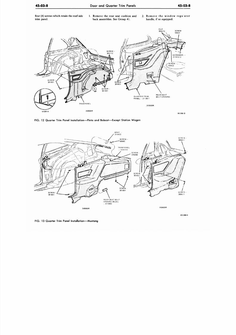
8/20/2019 1977 Ford Car Shop Manual Volume 4 Body
http://slidepdf.com/reader/full/1977-ford-car-shop-manual-volume-4-body 248/449
45-03-8
Door and Quarter Trim Panels
45-03-8
four (4) screws which retain the roof side 1. Remove the rear seat cushion and 2. Rem ove the wind ow re gu la to r
trim panel. back assemblies. See Group 41. handle, if so equipped.
QUARTER TRIM
PANEL - 31136-7
REAR SEAT
BELT OPENING
VIEW A
3-DOOR
R 1 7 0 0 D
F IG . 12 Quarter Trim Panel Installat ion—Pinto and Bo bcat—Ex cept Station W ag on
SCRE N -
3806 i 1
REAR SEAT BELT
OPENING BEZEL
- 611B90
3-DOOR
2DOOR
R1: 89-H
F IG .
13 Quarter Trim Panel Instal lat ion—Mustang
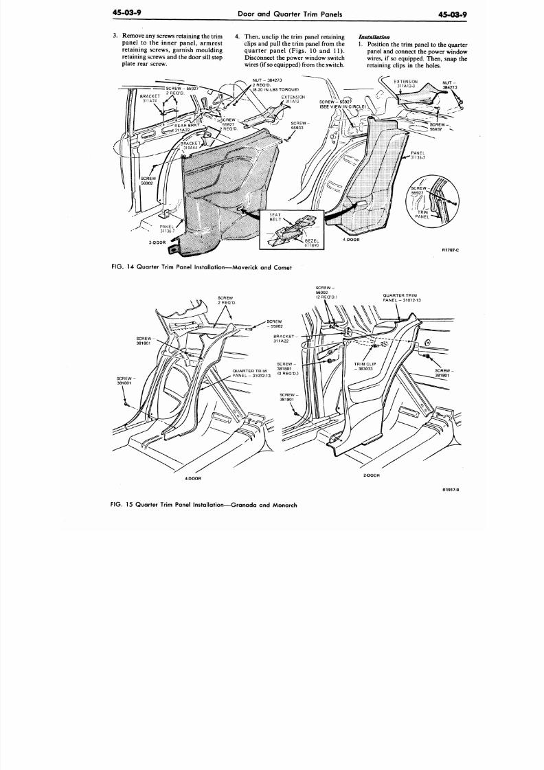
8/20/2019 1977 Ford Car Shop Manual Volume 4 Body
http://slidepdf.com/reader/full/1977-ford-car-shop-manual-volume-4-body 249/449
45-03-9
Door and Quarter Trim Panels
45-0
3. Remove any screws retaining the trim 4. Then, unclip the trim panel retaining
pan el to the inner pane l, arm rest clips and pull the trim panel from the
retaining screws, garnish moulding
retaining screws and the door sill step
plate rear screw.
qua rter panel (Fig s. 10 and 11).
Disconnect the power window switch
wires (if so equipped) from the switch.
Installation
1. Position the trim panel to the qu
panel and connect the power wi
wires, if so equipped. Then, sna
retaining clips in the holes.
R170
FIG. 14 Quarter Trim Panel Installation—Maverick and Comet
QUARTER TRIM
PANEL -31012-13
4 DOOR
2 DOOR
R191
FIG. 15 Quarter Trim Panel Installation—Granada and Monarch
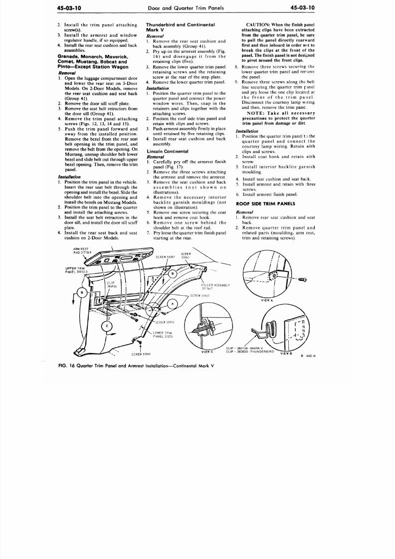
8/20/2019 1977 Ford Car Shop Manual Volume 4 Body
http://slidepdf.com/reader/full/1977-ford-car-shop-manual-volume-4-body 250/449
45-03-10
Door and Quarter Trim Panels
4 5 - 0 3 - 1 0
2.
Instal l the tr im panel at taching
screw(s).
3. Instal l the armrest and window
regulator handle, if so equipped.
4. Install the rear seat cushion and back
assemblies.
Granada, Monarch, Maverick,
Comet Mustang, Bobcat and
Pinto—Except Station Wagon
Removal
1.
Open the luggage compartment door
and lower the rear seat on 3-Door
Models. On 2-Door Models, remove
the rear seat cushion and seat back
(Group 41).
2.
Rem ove the door sill scuff plate.
3. Rem ove the seat belt retractors from
the door sill (Group 41).
4. Remove the trim panel attaching
screws (Figs. 12, 13, 14 and 15).
5. Push the trim panel forward and
away from the installed position.
Remove the bezel from the rear seat
belt opening in the trim panel, and
remove the belt from the opening. On
Mustang, unsnap shoulder belt lower
bezel and slide belt out through upper
bezel opening. Then, remove the trim
panel.
Installation
1.
Position the trim panel in the vehicle.
Insert the rear seat belt through th e
opening and install the bezel. Slide the
shoulder belt into the opening and
install the bezels on Mustang Models.
2. Position the trim panel to the quarter
and install the attaching
screws.
3.
Install the seat belt retractors
in the
door sill,
a nd
install the
door sill scuff
plate.
4. Install the rear seat back
and seat
cushion on 2-Door Models.
Thunderbird and Continental
Mark V
Removal
1.
Remove the rear seat cushion and
back assembly (Group 41).
2.
Pry up on the armrest assembly (Fig.
1 6 ) an d d is en g a g e i t f ro m th e
retaining clips (five).
3. Remove the lower quarte r trim panel
retain ing screws and the retain ing
screw at the rear of the step plate.
4. Remove the lower quarte r trim panel.
Installation
1.
Position the qua rter trim panel to the
quarter panel and connect the power
window wires . Then, snap in the
retainers and clips together with the
attaching screws.
2. Position the roof side trim panel and
retain with clips and screws.
3.
Push
armrest assembly firmly in place
until retained by five retaining clips.
4. Install rear seat cushion and back
assembly.
Lincoln Continental
Removal
1. Carefully pry off the armrest finish
panel
(Fig. 17).
2. Remove the three screws attaching
the armrest and remove the armrest.
3. Remo ve the seat cushion and back
a s s e m b l i e s ( n o t s h o w n o n
illustrations).
4.
R e m o v e t h e n e c e s s a r y i n t e r i o r
b a c k l i t e g a r n i s h m o u l d i n g s ( n o t
shown on illustration).
5.
Remove one screw securing the coat
hook and remove coat hook.
6. R e m o v e o n e s c r e w b e h i n d t h e
shoulder belt at the roof rail.
7. Pry loose the quarter trim finish panel
starting at the rear.
CAUTION: When the finish panel
attaching clips have been extracted
from the quarter trim panel, be sure
to pull the panel directly rearward
first and then inboard in order not to
break the clips at the front of the
panel. The finish panel is not designed
to pivot around the front clips.
8. Remove three screws securing the
lower quarter trim panel and remove
the panel.
9. Rem ove three screws along the belt
line securing the quarter tr im panel
and pry loose the one clip located at
t h e f r o n t o f t h e t r i m p a n e l .
Disconnect the courtesy lamp wiring
and then, remove the trim pane.
N O T E : T a k e a l l n e c e s s a r y
precautions to protect the quarter
trim panel from damage or dirt.
Installation
1.
Position the quarter trim panel t;> the
q u a r t e r p a n e l a n d c o n n e c t t h e
courtesy lamp wiring. Retain with
clips and screws.
2.
Instal l coat hook and retain with
screw.
3. I n s t a l l i n t e r i o r b a c k l i t e g a r n i s h
moulding.
4. Install seat cushion and seat back.
5. Install armrest and retain with ihree
screws.
6. Install armrest finish panel.
ROOF SIDE TRIM PANELS
Removal
1. Remove rear seat cushion and seat
back.
2.
R e m o v e q u a r t e r t r i m p a n e l a n d
related par ts (moulding , arm rest ,
trim and retaining screws).
ARM REST
PAD 31718-9
UPPER TRIM
PANEL 31012-3
SCREW 55961
VIEW C
FIG.
16 Quarter Trim Panel and Armrest Installation—Continental Mark V
CLIP - 38 3134 - MARK V
CLIP - 383033 • THUND ERBIR D
VIEW B
R 443-D
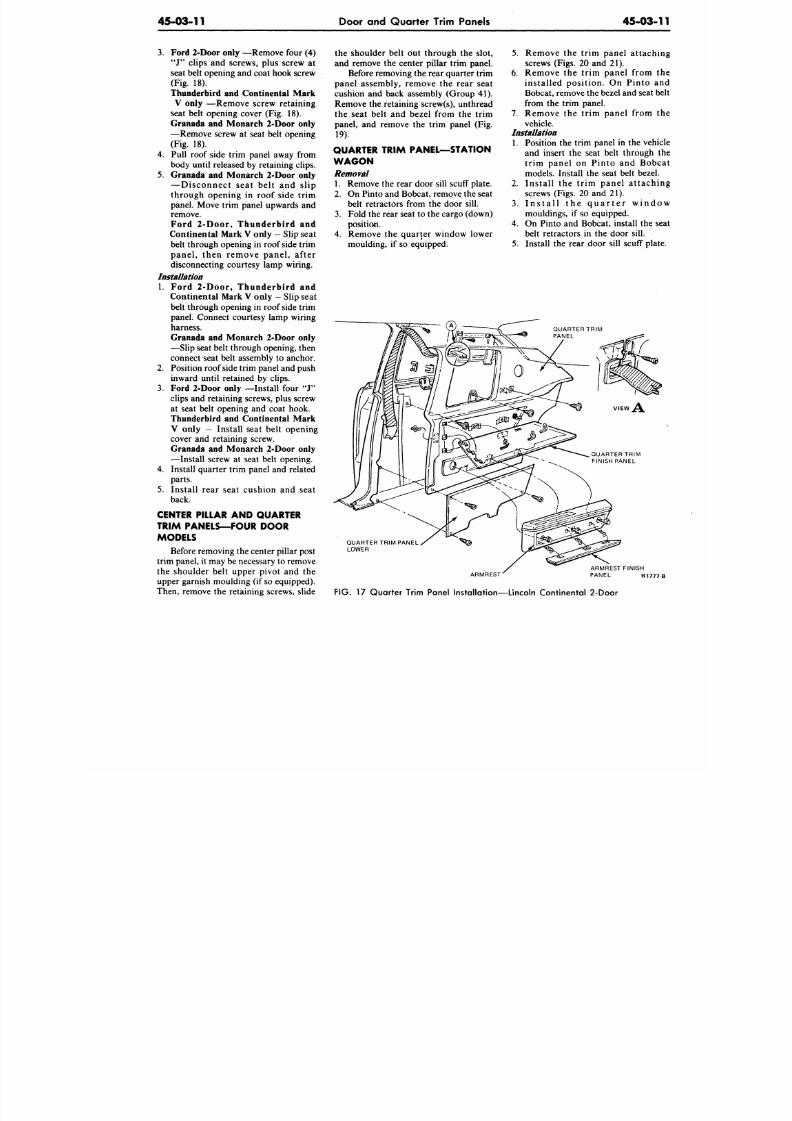
8/20/2019 1977 Ford Car Shop Manual Volume 4 Body
http://slidepdf.com/reader/full/1977-ford-car-shop-manual-volume-4-body 251/449
45-03-11
Door and Quarter Trim Panels
45-03-1
3. Ford 2-Door only
—Remove four (4)
"J" clips and screws, plus screw at
seat belt opening and coat hook screw
(Fig. 18).
Thunderbird and Continental Mark
V only
—Remove screw re ta ining
seat belt opening cover (Fig. 18).
Granada and Monarch 2-Door only
—Remove screw at seat belt opening
(Fig. 18).
4. Pull roof side trim pan el away from
body until released by retaining clips.
5. Granada and Monarch 2-Door only
— D i s c o n n e c t s e a t b e l t a n d s l i p
through opening in roof s ide t r im
panel. Move trim panel upwards and
remove.
Ford 2- Door , Th u n d erb ird an d
Continental Mark V only
—
Slip seat
belt through opening in roof side trim
p a n e l , t h e n r e m o v e p a n e l , a f t e r
disconnecting courtesy lamp wiring.
Installation
1. Ford 2- Door , Th u n d erb ird an d
Continental Mark V only —
Slip seat
belt through opening in roof side trim
panel. Connect courtesy lamp wiring
harness.
Granada and Monarch 2-Door only
—Slip seat belt through opening, then
connect seat belt assembly to anchor.
2.
Position roof side trim panel and push
inward until retained by clips.
3. Ford 2-Door only
—Install four "J"
clips and retaining screws, plus screw
at seat belt opening and coat hook.
Thunderbird and Continental Mark
V only
— Ins ta l l seat be l t op ening
cover and retaining screw.
Granada and Monarch 2-Door only
—Install screw at seat belt opening.
4.
Install quar ter trim panel and related
parts .
5. Ins ta l l rear sea t cushion and seat
back.
CENTER PILLAR AND QUARTER
TRIM PANELS—FOUR DOOR
MODELS
Before removing the center pillar post
trim panel, it may be necessary to remove
the shoulder belt upper pivot and the
upper garnish moulding (if so equipped).
Then, remove the retaining screws, slide
the shoulder belt out through the slot,
and remove the center pillar trim panel.
Before removing the rear quarter trim
panel assembly, remove the rear sea t
cushion and back assembly (Group 41).
Remove the retaining screw(s), unthread
the seat belt and bezel from the trim
panel, and remove the trim panel (Fig.
19).
QUARTER TRIM PANEL—STATION
W A G O N
Removal
1. Rem ove the rear door sill scuff plate.
2.
On Pinto and Bobcat, remove the seat
belt retractors from the door sill.
3.
Fold the rear seat to the cargo (down)
position.
4.
Remove the quarter window lower
moulding, if so equipped.
5.
Remove the t r im pane l a t t a ch i
screws (Figs. 20 and 21).
6 . Remove the t r im panel from t
ins ta l l ed pos i t ion . On P in to a
Bobcat, remo ve the bezel and seat b
from the trim panel.
7 . Remove the t r im panel from t
vehicle.
Installation
1. Position the trim panel in the vehi
and insert the seat belt through
t r im pane l on P in to and Bobc
models. Install the seat belt bezel.
2. I n s t a l l t h e t r i m p a n e l a t t a c h i
screws (Figs. 20 and 21).
3.
I n s t a l l t h e q u a r t e r w i n d o
mouldings, if so equipped.
4.
On Pint o and Bobcat, install the s
belt retractors in the door sill.
5.
Install the rear door sill scuff plat
r- ®. —-^r—-~~
QUARTER TRIM PANEL
LOWER
ARMREST
FIG.
17 Quarter Trim Panel Installation—Lincoln Continental 2-Door
ARMREST FINISH
PANEL R1777
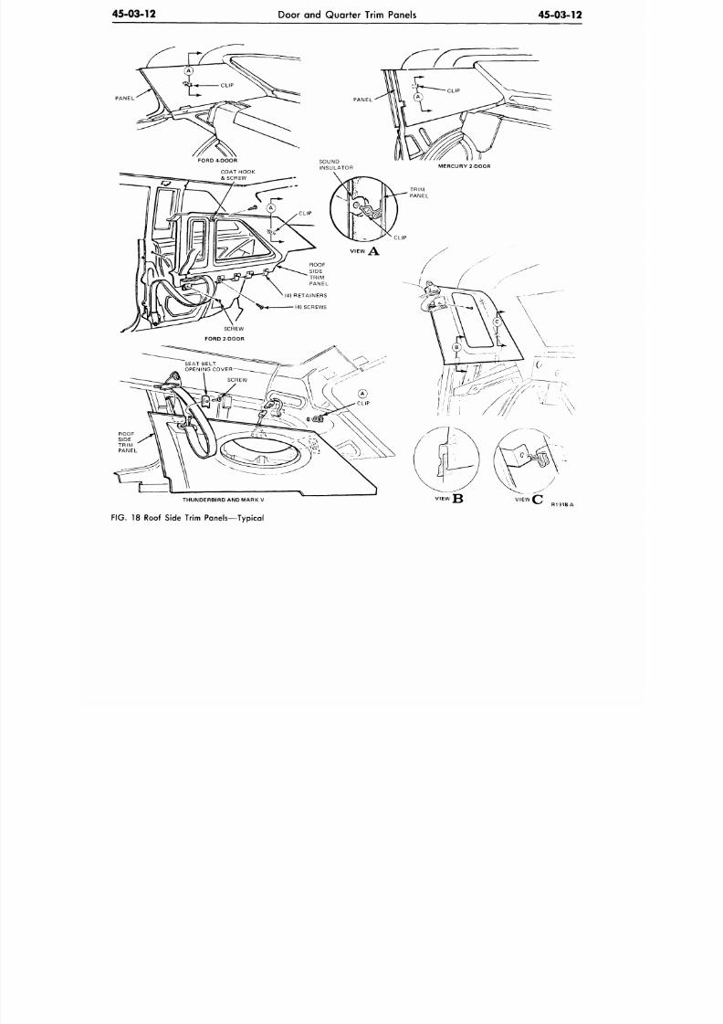
8/20/2019 1977 Ford Car Shop Manual Volume 4 Body
http://slidepdf.com/reader/full/1977-ford-car-shop-manual-volume-4-body 252/449
45-03-12
Door and Quarter Trim Panels
45-03-12
PANEL
THUNDERBIRD AND MARK V
FIG.
18 Roof Side Trim Panels—Typical
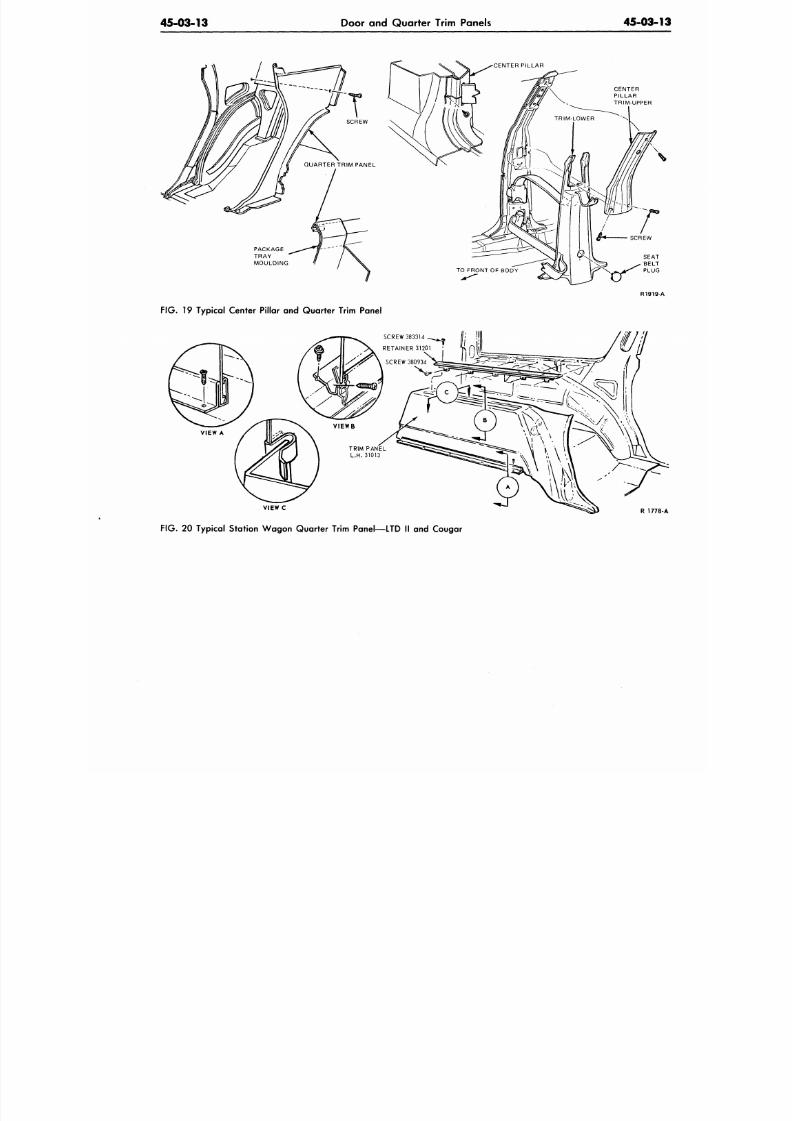
8/20/2019 1977 Ford Car Shop Manual Volume 4 Body
http://slidepdf.com/reader/full/1977-ford-car-shop-manual-volume-4-body 253/449
45-03-13
Door and Quarter Trim Panels
45-03-
CENTER
PILLAR
PACKAGE
TRAY
MOULDING
SEAT
BELT
PLUG
FIG .
19 Typical Center Pillar and Quarter Trim Panel
VIEW c
R
177
FIG . 20 Ty pical Station Wa gon Quarter Trim Panel—LTD II and Cougar
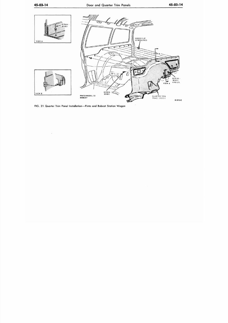
8/20/2019 1977 Ford Car Shop Manual Volume 4 Body
http://slidepdf.com/reader/full/1977-ford-car-shop-manual-volume-4-body 254/449
45-03-14
Door and Quarter Trim Panels
45-03-14
VIEW A
PINTO MODEL 73
BOBCAT
QUARTER TRIM
PANEL-31 01 2-3
R1812-C
FIG.
21 Q uarter Trim Panel Installation—Pinto and Bobcat Station W ag on
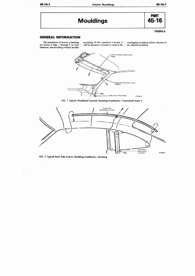
8/20/2019 1977 Ford Car Shop Manual Volume 4 Body
http://slidepdf.com/reader/full/1977-ford-car-shop-manual-volume-4-body 255/449
45-16-1
Interior Mouldings
45-1
Mouldings
CR2043
GENERAL INFORMATION
The installation of interior mouldings mo ulding . If this cond ition is found, it overlapping moulding before remova
are shown in Figs. 1 throu gh 4. In most will be necessary to loosen or remove the the desired moulding,
instances, one moulding overlaps another
UPPER GARNISH MOULDING
03590
SIDE GARNISH MOULDING
03598-9
COWL SIDE TRIM PANEL R1445-B
FIG. 1 Typical W indshield Garnish Moulding Installation—C ontinental Mark V
R144
FIG. 2 Typical Roof Side Interior Moulding Installation—Mustang
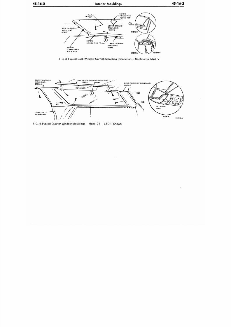
8/20/2019 1977 Ford Car Shop Manual Volume 4 Body
http://slidepdf.com/reader/full/1977-ford-car-shop-manual-volume-4-body 256/449
45-16-2
Interior Mouldings
45 16 2
SUDE GARNISH—"*N.
MOULDING J
42416-7
A
rr
/
CREW
1 REQUIRED
EACH SIDE
I \
I ^4-
= ^ =
SCREW
5 REQUIRED ^«- .
SCREW
/ 1 REQUIRED
f ALONG TOP
. V (9
UPPER GARNISH
MOULDING
42324-5
* 7
^^^£
(B) /
- 7 LOWER GARNISH
MOULDING
42304
VIEW A
R1447-C
FIG.
3 Typical Back Window Garnish Moulding Installation
—
Continental Mark V
FRONT GARNISH
MOULDING
29014-5
QUARTER
TRIM PANEL
FIG.
4 Typical Quarter Window
Mouldings
- Model 71 - LTD II Shown
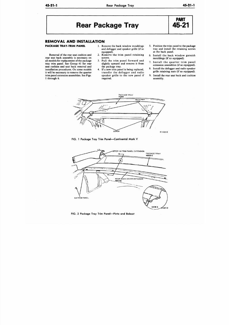
8/20/2019 1977 Ford Car Shop Manual Volume 4 Body
http://slidepdf.com/reader/full/1977-ford-car-shop-manual-volume-4-body 257/449
45-21-1
Rear Package Tray
45-21
Rear Package Tray
REMOVAL AND INSTALLATION
PACKAGE TRAY-TRIM PANEL
Removal of the rear seat cushion and 2.
rear seat back assembly is necessary on
all models for replacement of the package 3.
tray trim panel. See Group 41 for rear
seat cushion and seat back removal and
installation procedures. On some models 4.
it will be necessary to remove the quarter
trim panel extension assemblies. See Figs.
1 through 6.
Remove the back window mouldings
and defogger and speaker grille (if so
equipped).
Remove the trim panel retaining
screws.
Pull the trim panel forward and
slightly upward and remove it from
the package tray.
If a new trim panel is being replaced,
transfer the defogger and radio
speaker grille to the new panel if
required.
5.
Position the trim panel to the pac
tray and install the retaining scr
at the back panel.
6. Install the back window garn
mouldings (if so equipped).
7. Ins ta l l the quar ter t r im pa
extension assemblies (if so equipp
8. Install the defogger and radio spe
grille retaining nuts (if so equipp
9. Install the rear seat back and cus
assembly.
PACKAGE TRAY
SCREW R 1332-D
FIG.
1 Package Tray Trim Panel—Continental Mark V
UPPER 1/4 TRIM PANEL EXTENSION
PACKAGE TRAY
46665-6
1/4 TRIM PANEL
R1331-O
F IG .
2 Package Tray Trim Panel—Pinto and Bobcat
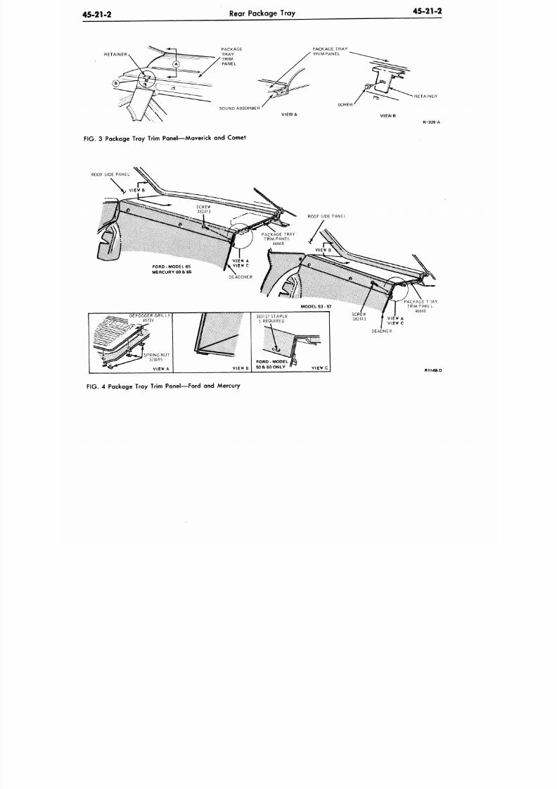
8/20/2019 1977 Ford Car Shop Manual Volume 4 Body
http://slidepdf.com/reader/full/1977-ford-car-shop-manual-volume-4-body 258/449
45-21-2
Rear Package Tray
45-21-2
RETAINER
SOUND ABSORBER
VIEW A
PACKAGE TRAY
TRIM PANEL
SCREW
RETAINER
R1928 A
FIG.
3 Package Tray Trim Panel—Maverick and Comet
ROOF SIDE PANEL
VIEW A
VIEW B
53 & 60 ONLY
VIEW C
PACKAGE T
:
A Y
TRIM PANE L
46668
DEADNER
R1448-D
FIG.
4 Package Tray Trim Panel—Ford and Mercury
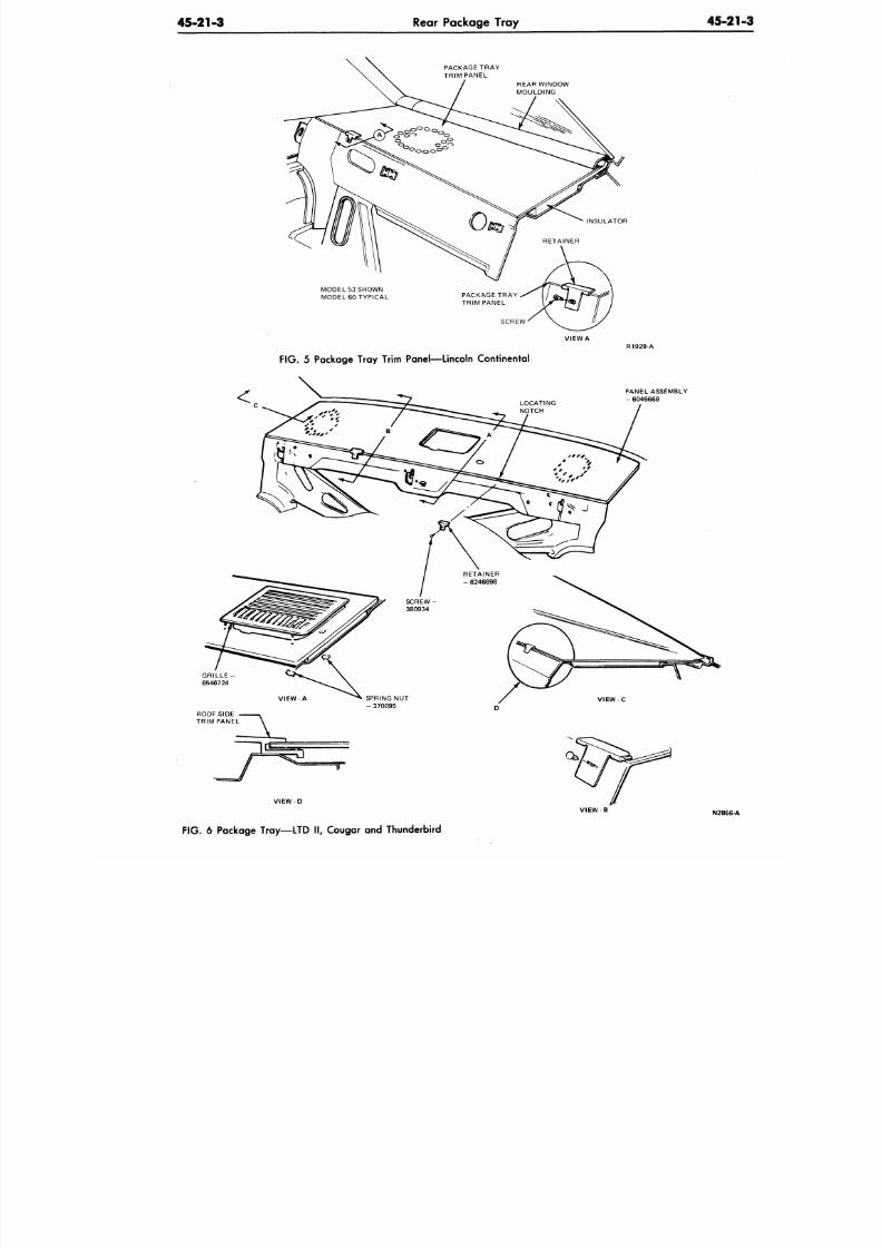
8/20/2019 1977 Ford Car Shop Manual Volume 4 Body
http://slidepdf.com/reader/full/1977-ford-car-shop-manual-volume-4-body 259/449
45-21-3
Rear Package Tray
45-2
PACKAGE TRAY
TRIM PANEL
REAR WINDOW
MOULDING
MODEL 53 SHOWN
MODEL60 TYPICAL
SCREW
VIEW A
F IG .
5 Package Tray Trim Panel—Lincoln Continental
PANEL ASSEMBLY
- 6046668
ROOF SIDE
TRIM PANEL
V I E W - D
V I E W - B
N2866-
F IG .
6 Package Tray—LTD I I , Cougar and Thunderbird
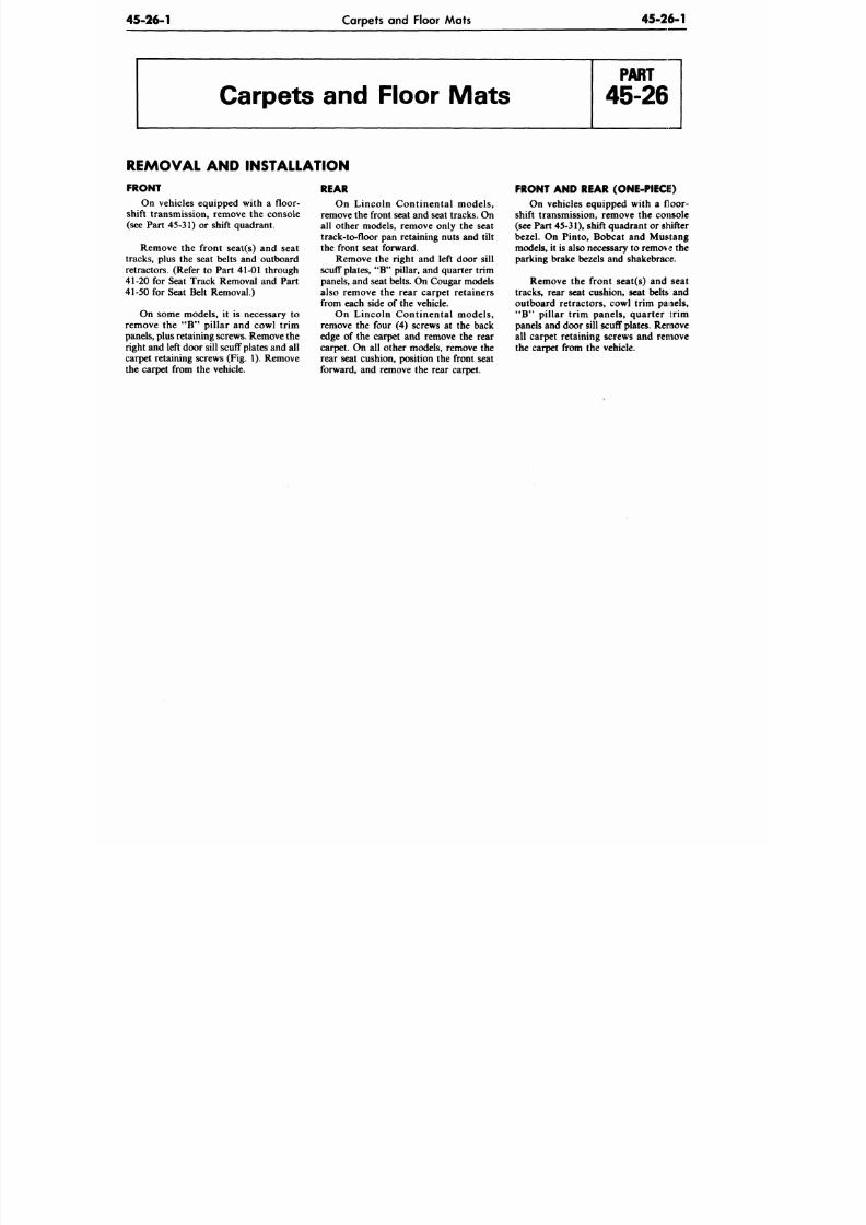
8/20/2019 1977 Ford Car Shop Manual Volume 4 Body
http://slidepdf.com/reader/full/1977-ford-car-shop-manual-volume-4-body 260/449
45-26-1
Carpets and Floor Mats
45-26-1
Carpets and Floor Mats
REMOVAL AND INSTALLATION
FRONT
On vehicles equipped with a floor-
shift transmission, remove the console
(see Part 45-31) or shift quadrant.
Remove the front seat(s) and seat
tracks, plus the seat belts and outboard
retractors. (Refer to Part 41-01 through
41-20 for Seat Track Removal and Part
41-50 for Seat Belt Removal.)
On some models, it is necessary to
remove the " B " pillar and cowl trim
panels, plus retaining screws. Remove the
right and left doo r sill scuff p lates and all
carpet retaining screws (Fig. 1). Remove
the carpet from the vehicle.
REAR
On Lincoln Continental models,
remove the front seat and seat tracks. On
all other models, remove only the seat
track-to-floor pan retaining nuts and tilt
the front seat forward.
Remove the right and left door sill
scuff plates, "B" pillar, and quarter trim
panels, and seat belts. On Cougar models
also remove the rear carpet retainers
from each side of the vehicle.
On Lincoln Continental models,
remove the four (4) screws at the back
edge of the carpet and remove the rear
carpet. On all other models, remove the
rear seat cushion, position the front seat
forward, and remove the rear carpet.
FRONT AND REAR (ONE-PIECIi)
On vehicles equipped with a floor-
shift transmission, remove the console
(see Part 45-31), shift quadra nt o r shifter
bezel. On Pinto, Bobcat and Mustang
models, it is also necessary to remove the
parking brake bezels and shakebrace.
Remove the front seat(s) and seat
tracks, rear seat cushion, seat belts and
outboard retractors, cowl trim panels,
" B " pillar trim panels, quarter trim
panels and d oor sill scuff plates. Remove
all carpet retaining screws and remove
the carpet from the vehicle.
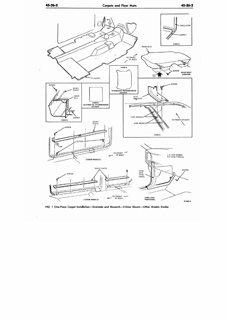
8/20/2019 1977 Ford Car Shop Manual Volume 4 Body
http://slidepdf.com/reader/full/1977-ford-car-shop-manual-volume-4-body 261/449
45-26-2
Carpets and Floor Mats
45-2
INSULATO
CARPET
R192
FIG. 1 One-Piece Carpet Installation—Granada and Monarch— 2-Door Shown—Other Models Similar
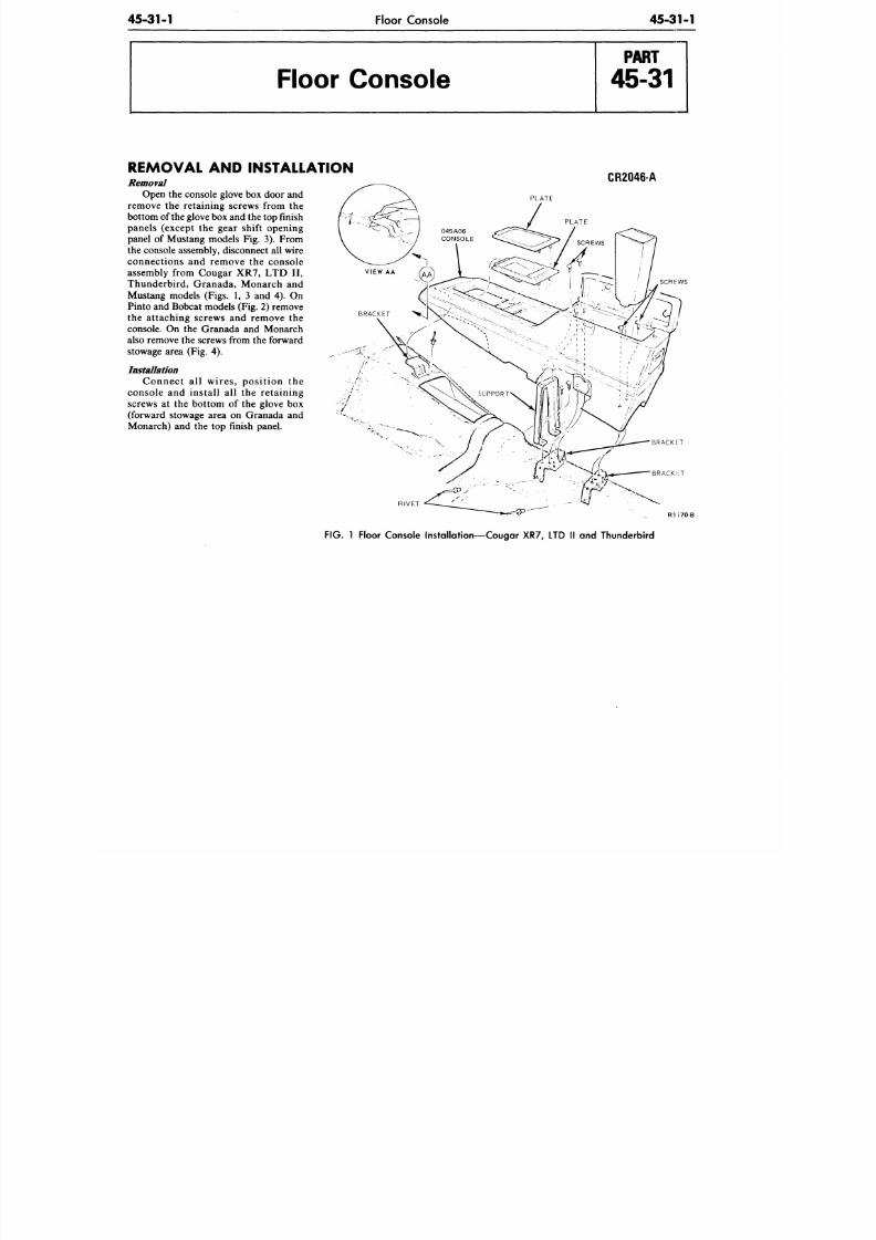
8/20/2019 1977 Ford Car Shop Manual Volume 4 Body
http://slidepdf.com/reader/full/1977-ford-car-shop-manual-volume-4-body 262/449
45-31-1
Floor Console
45-31-1
Floor Console
REMOVAL AND INSTALLATION
Removal
Open the console glove box door and
remove the retaining screws from the
bottom of the glove box and the top finish
panels (except the gear shift opening
panel of Mustang models Fig. 3). From
the console assembly, disconnect all wire
connections and remove the console
assembly from Cougar XR7, LTD II,
Thunderbird, Granada, Monarch and
Mustang models (Figs. 1, 3 and 4). On
Pinto and Bobcat models (Fig. 2) remove
the attaching screws and remove the
console. On the Granada and Monarch
also remove the screws from the forward
stowage area (Fig. 4).
Installation
Connect al l wires, posit ion the
console and install all the retaining
screws at the bottom of the glove box
(forward stowage area on Granada and
Monarch) and the top finish panel.
CR2046-A
PLATE
SCREWS
BRACKl iT
R IVET
R177O-B
FIG. 1 Floor Console Installation—Cougar XR7, LTD II and Thunderbird
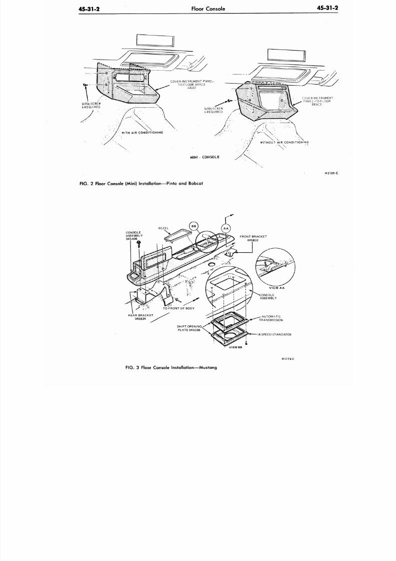
8/20/2019 1977 Ford Car Shop Manual Volume 4 Body
http://slidepdf.com/reader/full/1977-ford-car-shop-manual-volume-4-body 263/449
45-31-2
Floor Console
45-3
COVER-INSTRUMENT PANEL
TO-FLOOR BRACE
44G02
: \
F IG .
2 Floor Console (Mini) Installation—Pinto and Bobcat
N2
CONSOLE
ASSEMBLY
045A06
REAR BRACKET
045B34
AUTOMATIC
TRANSMISSION
(4 SPEED STANDARD)
VIEWBB
F IG . 3 Floor Console Installation—Mustang
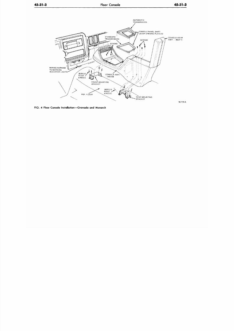
8/20/2019 1977 Ford Car Shop Manual Volume 4 Body
http://slidepdf.com/reader/full/1977-ford-car-shop-manual-volume-4-body 264/449
4 5 - 3 1 - 3 Floor Console
45-31-3
AUTOMATIC
TRANSMISSION
CONSOLE PANEL SHIFT
LEVER OPENING PLATE(S)
WIRING HARNESS
TO WARNING
INDICATOR LIGHTS
CONSOLE DO:)R
ASSY. - 060A '0
REAR MOUNTING
BRACKET
N2774-A
FIG . 4 Floor Console Installation—Granada and Monarch
8/20/2019 1977 Ford Car Shop Manual Volume 4 Body
http://slidepdf.com/reader/full/1977-ford-car-shop-manual-volume-4-body 265/449
45-41-1
Headlining
45-4
SUBJECT
ADJUSTMENTS
Sun Visor
Headlining
PAGE SUBJECT
REMOVAL AND INSTALLATION
41-1
P A R T
45-41
PAGE
41-1
CR2047-A
ADJUSTMENTS
SUN VISOR—WITHOUT LIGHT
Occasionally a sun visor will not stay
in engagement with the retaining clip at
the center of the windshield. This could
be caused by the rod at the end of the
visor being too far in or out. Outboard
edge of rubber tip should be flush with
center clip (outer walls). Work the visor
in or out for proper engagement. If the
rod length is OK, the rubber tip on the
end may be worn.
SUN VISOR—WITH LIGHT
If the visor will not stay engaged in
the retaining clip at the center of the
windshield, loosen the visor retaining
screw (near the elbow) and shift the
sideways into proper position.
Tighten the v isor retain ing s
snug enough to hold the visor in the
position, but loose enough to allow
visor to be rotated up and down o
pivot shaft.
REMOVAL AND INSTALLATION
HEADLINING
Sedans and Hardtops— Except
Thunderbird and Continental
M a r k V
The fo llowing headlin ing removal
and instal lat ion procedures generally
apply to all models. If some of the steps
do not apply to the par t icu lar model
being serviced, proceed to the next step.
Th e Mav er ick , C o met , P in to an d
Bobcat require windshield and back
window glass removal for headlin ing
installation. See Group 43. Refer to the
appro priate F igs. 1 throug h 29.
Removal
1.
Remove the sun v isor and bracket
assemblies.
2. Remove the windshield upper garnish
moulding. Remove the upper screw
from the two windshield side garnish
m o u l d i n g s a n d p o s i t i o n t h e
mouldings away from the windshield
A pillar.
3. Remove the shoulder belt assemblies,
sh o u ld er b e l t r e ta in er s an d co a t
hooks.
4.
Remove the roof s ide and center
garnish mouldings. On al l 4-door
sedans, f irst remove the center cap
from the junction of the front and
rear s ide mouldings at the center
pillar. On some 4-doors, there is also
a joint cover at the rear quarter. On
2-door hardtops, there is one joint
cover at the rear quarter.
5. Remove the rear seat cushion and
back assembly (Group 41).
6. Remove the right and left quarter
trim panels (Group 45).
7. Remove the roof side rear trim covers
(right and left).
8 . Remove the back window garnish
mouldings and remove the package
tray (Group 45).
9. Unho ok the headlining from the tabs.
10. Remove the dome l ight and upper
rear quarter lights. Pry off lens and
remove the attaching screws.
11. Rem ove the staples th at fasten th e
headlining to the roof side retainer
assemblies.
12.
Pull th e head linin g loose from a ll
cemented areas.
13.
Un hook the right and left retain ers
from the headlining rear support rod,
disengage all support rods from the
holes in the left and right roof rails,
and remove the headlining from the
vehicle.
Installation
1. Unpackage the new headlining and
lay it out on a flat surface.
2. Trim the listings (or "pockets") on
t h e n e w h e a d l i n i n g t o t h e
approximate length of those on the
old one. Remove the suppor t rods
from the old headlining and install
them in the same relative rod listings
of the new headlining.
Roof headlining support rods are
co lo r co d ed a t each en d . Wh en
ordering new rods, be sure to not
color at each end of the rod.
3. Position the headlining in the ve
T o m a i n t a i n t h e m o s t d r
h e a d r o o m a n d w r i n k l e -
headlining, insert the support
into the
upper holes in the hi
possible hole in the right hand
without having support rod sn
across unit.
4.
Hook the rear retainers to the
support rod.
5. Staple the headlining to the ret
assemblies.
6. Cem ent the headlining in place
trim the excess material.
7. Install the roof side rear trim co
the package tray, the rear win
garnish mouldings and quarter
panels and lights.
8. Cut a hole in the headlining ma
for the dome light and install the
and bezel.
9 . Instal l a l l the garn ish mould
shoulder belt assemblies, retai
coat hooks and sun visors.
Maver ick , Comet , P into and
Bobcat
Removal
1. Rem ove the right and left winds
wiper arm assemblies.
2. R e m o v e th e w i n d s h i e l d
mouldings by using the proce
outlined in Group 43.
3. Remove the weathers tr ip f rom
glass opening.
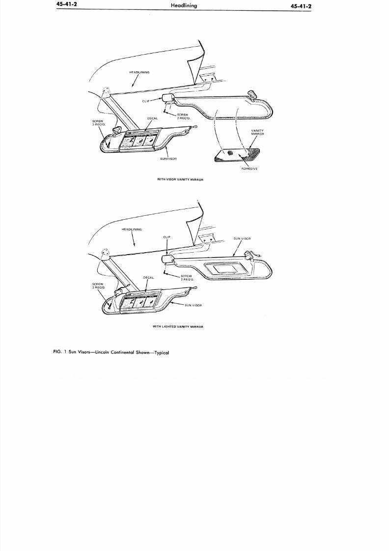
8/20/2019 1977 Ford Car Shop Manual Volume 4 Body
http://slidepdf.com/reader/full/1977-ford-car-shop-manual-volume-4-body 266/449
45-41-2
Headlining
45-41-2
ADHESIVE
WITH VISOR VANITY MIRROR
SUN VISOR
WITH LIGHTED VANITY MIRROR
IG .
1 Sun Visors—Lincoln Continental Shown—Typical
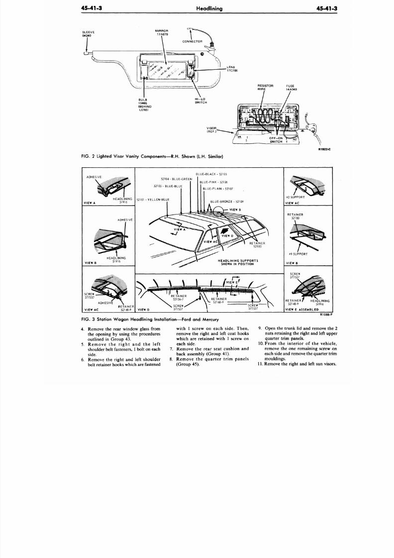
8/20/2019 1977 Ford Car Shop Manual Volume 4 Body
http://slidepdf.com/reader/full/1977-ford-car-shop-manual-volume-4-body 267/449
45-41-3
Headlining
45-4
R1922-
F IG .
2 Lighted Visor Vanity Components—R.H. Shown (L.H. Similar)
ADHESIVE
VIEW A
ADHESIVE
VIEW B
VIEW AC
52104- BLUE-GREEN
52103 - BLUE-BLUE
52101 -YELLOW -BLUE
BLUE-BLACK - 52105
BLUE-PINK - 52106
BLUE-PLAIN - 52107
BLUE-BRONZE - 52109
VIEW B
RETAINER
52180
HEADLIN ING SUPPORTS
SHOWN IN POSITION
VIEW D
RETAINER f HEADLINING
52148-9 51916
VIEW E ASSEMBLED
FIG.
3 Station W ag on H eadlining Installation—Fo rd and Mercury
4. Remove the rear window glass from
the opening by using the procedures
outlined in Group 43.
5. Remove the r ight and the lef t
shoulder belt fasteners, 1 bolt on each
side.
6. Remove the right and left shoulder
belt retainer hooks which are fastened
7.
8.
with 1 screw on each side. Then,
remove the right and left coat hooks
which are retained with 1 screw on
each side.
Remove the rear seat cushion and
back assembly (Group 41).
Remove the quarter tr im panels
(Group 45).
R108
9. Open the trunk lid and remove
nuts retaining the right and left u
quarter trim panels.
10. From the interior of the veh
remove the one remaining screw
each side and remove the quarter
mouldings.
11. Remove the right and left sun vi
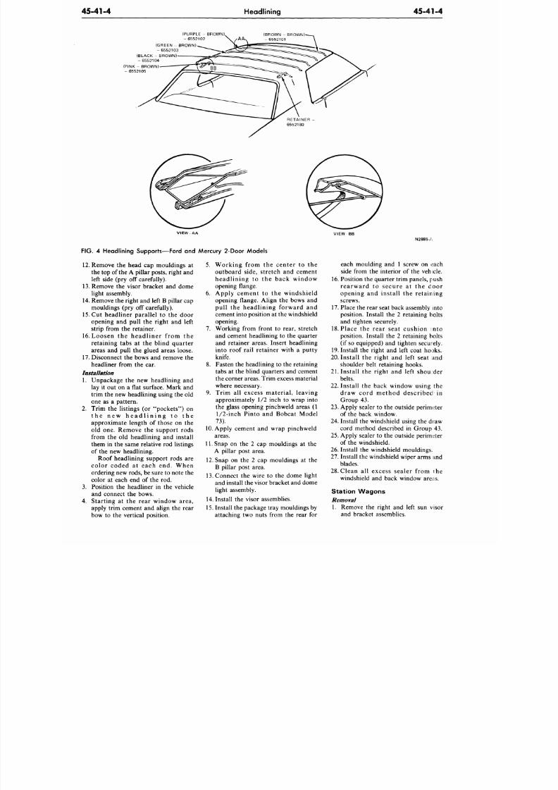
8/20/2019 1977 Ford Car Shop Manual Volume 4 Body
http://slidepdf.com/reader/full/1977-ford-car-shop-manual-volume-4-body 268/449
45-41-4
Headlining
45-41-4
(PURPLE - BROWN)
- 6552102
(BROWN - BROWN)-
- 6 5 5 2 1 0 1
(GREEN - BROWN)
- 6552103
(BLACK - BROWN)
- 6552104
(PINK - BROWN)
- 6552105
RETAINER
6552180
FIG. 4 Headlining Supports—Ford and Mercury 2-Door Models
12.
Remove the head cap mouldings a t
the top of the A pillar posts, right and
left side (pry off carefully).
13.
Remove the visor bracket and dome
light assembly.
14.
Remo ve the right an d left B pillar cap
mouldings (pry off carefully).
15.
Cut h eadl iner para l le l to the do or
opening and pull the right and left
strip from the retainer.
16.
L o o s e n t h e h e a d l i n e r f r o m t h e
re ta ining tabs a t the bl ind quarter
areas and pull the glued areas loose.
17.
Disconnect the bows and remove the
headliner from the car.
Installation
1. Unpackage the new headlining and
lay it out on a flat surface. Mark and
trim the new headlining using the old
one as a pattern.
2.
Trim the listings (or "poc kets" ) on
t h e n e w h e a d l i n i n g to t h e
approximate length of those on the
old one . Remove the support rods
from the old headlining and install
them in the same relative rod listings
of the new headlining.
Roof headlining support rods are
co lo r coded a t e ach end . When
ordering new rods, be sure to note the
color at each end of the rod.
3.
Position the headliner in the vehicle
and connect the bows.
4. Start ing a t the rear window area ,
apply trim cement and align the rear
bow to the vertical position.
5. Work ing f rom the cen te r to the
outboard s ide , s t re tch and cement
h e a d l i n i n g t o t h e b a c k w i n d o w
opening flange.
6 . App ly cement to the winds h ie ld
opening flange. Align the bows and
pu l l the head l in ing fo rward and
cement into position at the windshield
opening.
7. Working from front to rear, stretch
and cement headlining to the quarter
and retainer areas. Insert headlining
into roof rail retainer with a putty
knife.
8. Fasten the headlining to the retaining
tabs at the blind quarters and cement
the corner areas. Trim excess material
where necessary.
9 . Trim a l l excess materia l , leaving
approximately 1/2 inch to wrap into
the glass opening pinchweld areas (1
1/2-inch
Pinto and Bobcat Model
73).
10. Apply cem ent and w rap pinch weld
areas.
11.
Snap on the 2 cap mouldings at the
A pillar post area.
12.
Snap on the 2 cap mould ings at th e
B pillar post area.
13.
Connect the wire to the dom e light
and install the visor bracket and dome
light assembly.
14.
Install th e visor assem blies.
15.
Install the package tray mouldings by
attaching two nuts from the rear for
N2885-A
each mou lding and 1 screw on each
side from the in terio r of the veh icle.
16. Position the quarter trim panels, push
r e a r w a r d t o s e c u r e a t t h e d o o r
open ing and ins ta l l the re t a i l ing
screws.
17.
Place the rear seat back assembly into
position. Install the 2 retaining bolts
and tighten securely.
18.
P lace the rea r s ea t cus h ion in to
position. Install the 2 retaining bolts
(if so equipped) and tighten securely.
19.
Install the rig ht and left coat h ooks.
20. Insta ll the rig ht an d left seat and
shoulder belt retaining hooks.
21 . Ins ta l l the r ight and lef t should er
belts.
22 .
Ins ta l l the back window us ing the
d r a w c o r d m e t h o d d e s c r i b e d i n
Group 43.
23 . Apply sealer to the outside perimeter
of the back window.
24. Install the windshield using the draw
cord method described in Group 43.
25.
Apply sealer to the outside perimeter
of the windshield.
26.
Install the windshield mou ldings.
27.
Install the windshield wiper arm s :tnd
blades.
28.
Clean a l l excess sea ler from ihe
windshield and back window areas.
Station W agons
Removal
1. Remove the right and left sun visor
and bracket assemblies.
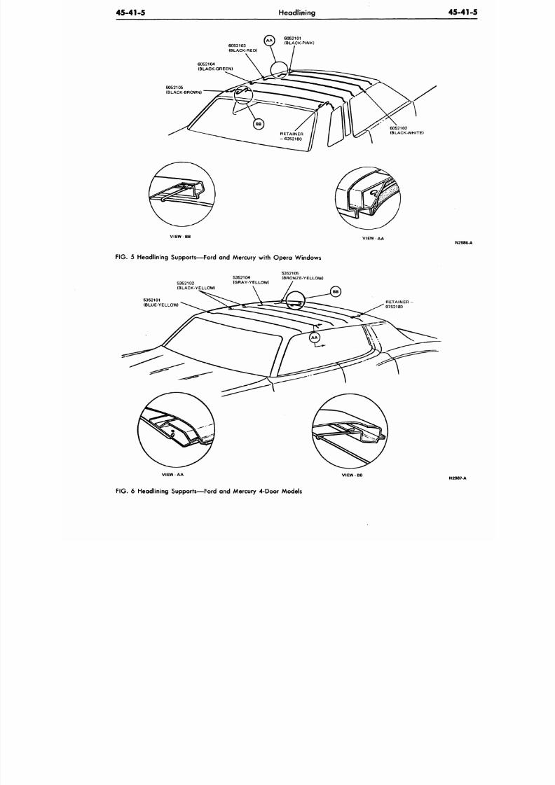
8/20/2019 1977 Ford Car Shop Manual Volume 4 Body
http://slidepdf.com/reader/full/1977-ford-car-shop-manual-volume-4-body 269/449
45-41-5
Headlining
45-4
6052103
(BLACK-RED)
(BLACK-PINK)
6052104
(BLACK-GREEN)
6052105
(BLACK-BROWN)
6052102
(BLACK-WHITE)
VIEW
V I E W - A A
N2
FIG. 5 Headlining Supports—Ford and Mercury with Opera Windows
5352102
(BLACK-YELLOW)
5352104
(GRAY-YELLOW)
5352105
(BRONZE-YELLOW)
5352101
(BLUE-YELLOW)
RETAINER
9752180
VIEW
-
AA
VIEW
N2887
F IG .
6 Headlining Supports—Ford and Mercury 4-Door Models
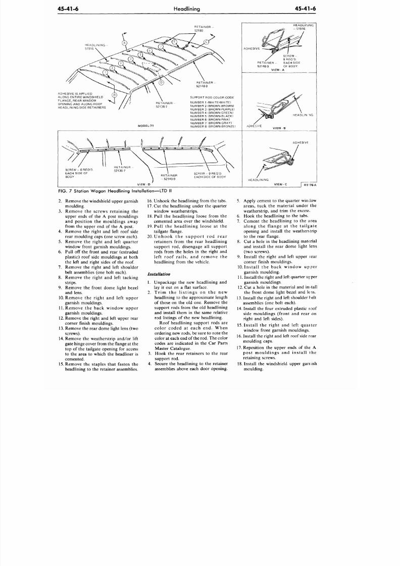
8/20/2019 1977 Ford Car Shop Manual Volume 4 Body
http://slidepdf.com/reader/full/1977-ford-car-shop-manual-volume-4-body 270/449
45-41-6
Headlining
45-41-6
HEADLINING
51916
ADHESIVE IS APPLIED
ALONG ENTIRE WINDSHIELD
FLANGE, REAR WINDOW
OPENING AND ALONG ROOF
HEADLINING SIDE RETAINERS
RETAINER
52136-7
MODEL-71
RETAINER -
52148-9
SUPPORT ROD COLOR CODE
NUMBER 1 (WHITE-WHITE)
NUMBER 2 (BROWN-BROWN)
NUMBER 3 (BROWN-PURPLE)
NUMBER 4 (BROWN-GREEN)
NUMBER 5 (BROWN-BLACK)
NUMBER 6 (BROWN-PINK)
NUMBER 7 (BROWN-GRAY)
NUMBER 8 (BROWN-BRONZE)
ADHESIVE
HEADLINING
- 5 1 9 1 6
SCREW -
9 REQ'D.
RETAINER - EACH SIDE
52148-9 OF BODY
VIEW
-
A
HEADLIN \ IG
ADHESIVE
VIEW - B
ADHESIVE:
SCREW- 6 REQ'D
EACH SIDE OF
BODY
S C R E W - 9 R E Q ' D .
EACH SIDE OF BODY
HEADLINING
VIEW - D
R1776-A
FIG. 7 Station Wagon Headlining Installation—LTD II
2.
Remov e the windshield upper garnish
moulding.
3.
Remove the s c rews re ta in ing the
upper ends of the A post mouldings
and pos i t ion the mouldings away
from the upper end of the A post.
4. Rem ove the right and left roof side
rear moulding caps (one screw each).
5.
Remove the r ight and lef t quarter
window front garnish mouldings.
6. Pull off the front and rear (extrud ed
plastic) roof side mouldings at both
the left and right sides of the
roof.
7. Rem ove the right and left sho ulder
belt assemblies (one bolt each).
8. Remove the right and left tacking
strips.
9. Remov e the front dom e light bezel
and lens.
10.
Rem ove the r ig ht and lef t upp er
garnish mouldings.
11.
R e m o v e t h e b a c k w i n d o w u p p e r
garnish mouldings.
12.
Rem ove the right and left upper rear
corner finish mouldings.
13.
Remove the rear dome light lens (two
screws).
14. Remove the w eatherstrip an d/o r lift
gate hinge cover from the flange at the
top of the tailgate opening for access
to the area to which the headliner is
cemented.
15.
Rem ove the staples tha t fasten the
headlining to the retainer assemblies.
16. Unhook the headlining from the tabs.
17.
Cut the headlining under the quarter
window weatherstrips.
18.
Pull the he adlinin g loose from the
cemented area over the windshield.
19.
Pu l l the he ad l i n in g loos e a t th e
tailgate flange.
2 0 . U n h o o k t h e s u p p o r t r o d r e a r
re ta iners from the rear headl ining
support rod, disengage a l l support
rods from the holes in the right and
le f t roo f ra i l s , and remove the
headlining from the vehicle.
Installation
1. Unpackage the new headlining and
lay it out on a flat surface.
2. T r i m t h e l i s t i n g s on t h e n e w
headlining to the approximate length
of those on the old one. Remove the
support rods from the old headlining
and install them in the same relative
rod listings of the new headlining.
Roof headlining support rods are
co lo r coded a t e ach end . When
ordering new rods, be sure to note the
color at each end of the rod. Th e color
codes are indicated in the Car Parts
Master Catalogue.
3.
Hook the rear retainers to the rear
support rod.
4. Secure the headlining to the retainer
assemblies above each door opening.
5.
8.
Apply cement to the quarter window
areas , tuck the materia l under the
weatherstrip, and trim the excess.
Hook the headlining to the tabs.
Cement the headlining to the <irea
a long the f l ange a t the t a i lga te
opening and install the weatherstrip
to the rear flange.
Cut a hole in the headlining material
and install the rear dome light lens
(two screws).
9. Install the right and left upper rear
corner finish mouldings.
l O . I n s t a l l t h e b a c k w i n d o w u p p e r
garnish moulding.
11.
Install the right and left quarter upper
garnish mouldings.
12.
Cut a hole in the material and install
the front dome light bezel and
le
us.
13.
Install the right and left shoulder belt
assemblies (one bolt each).
14. Install the four ex truded plastic roof
side mouldings (front and rear on
right and left sides).
15.
Ins ta l l the r ight and lef t q ua rte r
window front garnish mouldings.
16.
Install the right and left roof side n;ar
moulding caps.
17.
Reposition the u pper ends of the A
p o s t m o u l d i n g s a n d i n s t a l l t h e
retaining screws.
18.
Install the wind shield up per g arnish
moulding.
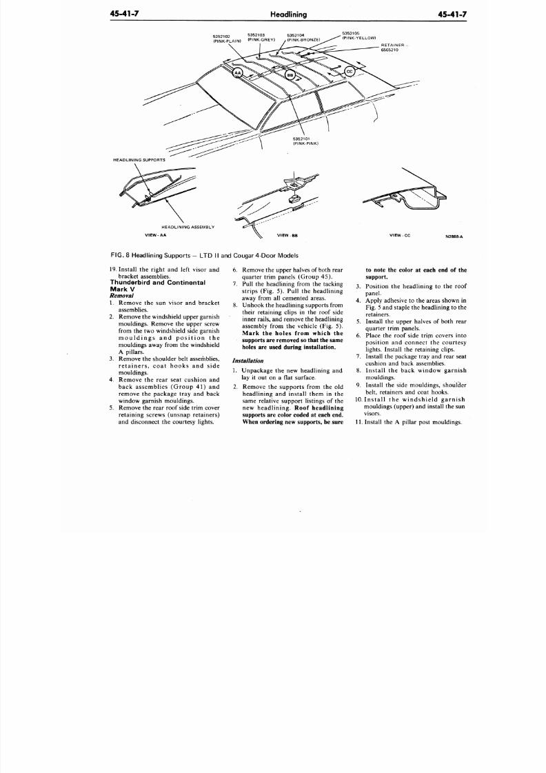
8/20/2019 1977 Ford Car Shop Manual Volume 4 Body
http://slidepdf.com/reader/full/1977-ford-car-shop-manual-volume-4-body 271/449
45-41-7
Headlining
45-4
5352102 5352103 5352104
(PINK-PLAIN) (PINK-GREY) (PINK-BRONZE)
5352105
(PINK-YELLOW)
RETAINER
6565210
HEAD LINING SUPPORTS
HEADLINING ASSEMBLY
VIEW AA
FIG. 8 Headlining Supports - LT D II and Cougar 4-Door M odels
19. Install t he right and left visor and
bracket assemblies.
Thunderbird and Continental
Mark V
Removal
1. Remove the sun visor and bracket
assemblies.
2.
Remo ve the windshield upper garnish
mouldings. Remove the upper screw
from the two windshield side garnish
m o u l d i n g s a n d p o s i t i o n t h e
mouldings away from the windshield
A pillars.
3. Remo ve the shoulder belt assemblies,
r e t a i n e r s , c o a t h o o k s a n d s i d e
mouldings.
4. Remove the rear seat cushion and
b ack as semb l ies (Gro u p 4 1 ) an d
remove the package tray and back
window garnish mouldings.
5.
Remo ve the rear roof side trim cover
retaining screws (unsnap retainers)
and disconnect the courtesy lights.
6. Remove the upper halves of both rear
quarter tr im panels (Group 45).
7. Pull the headlining from the tacking
strips (Fig. 5). Pull the headlining
away from all cemented areas.
8. Unho ok the headlining supports from
their retaining clips in the roof side
inner rails, and remove the he adlining
assembly from the vehicle (Fig. 5).
Mark the holes from which the
supports are removed so that the same
holes are used during installation.
Installation
1. Unpackage the new headlining and
lay it out on a flat surface.
2. Remove the supports from the old
headlin ing and instal l them in the
same relative support listings of the
n ew h ead l in in g . Roof headl ining
supports are color coded at each end.
When ordering new supports, be sure
to note the color at each end o
support.
3. Position the headlining to the
panel.
4. Apply adhesive to the areas show
Fig. 5 and staple the headlining t
retainers.
5.
Install the upper halves of both
quarter trim panels.
6. Place the roof side trirn covers
posit ion and connect the cour
lights. Install the retaining clips.
7. Install the package tray and rear
cushion and back assemblies.
8. I n s ta l l th e b ack win d o w g ar
mouldings.
9. Install the side mou ldings, shou
belt, retainers and coat hooks.
10. I n s t a l l t h e w i n d s h i e l d g a r n
mouldings (upper) and install the
visors.
11. Install the A p illar post mouldin
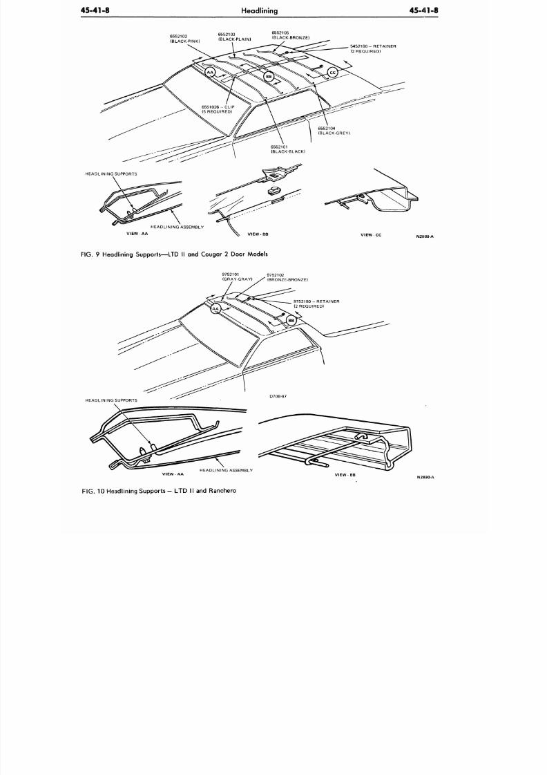
8/20/2019 1977 Ford Car Shop Manual Volume 4 Body
http://slidepdf.com/reader/full/1977-ford-car-shop-manual-volume-4-body 272/449
45-41-8
Headlining
45-41-8
HEADLINING SUPPORTS
6552102
(BLACK-PINK)
6552103
(BLACK-PLAIN)
6552105
(BLACK-BRONZE)
5 4 5 2 1 8 0 - R E T A I N E R
(2 REQUIRED)
V I E W - A A
V I E W - C C
FIG.
9 Headlining Supports—LTD II and Cougar 2 Door Models
9752101 9752102
(GRAY-GRAY) S (BRONZE-BRONZE)
N2H90-A
FIG.
10 Headlining Supports - LTD II and Ranchero
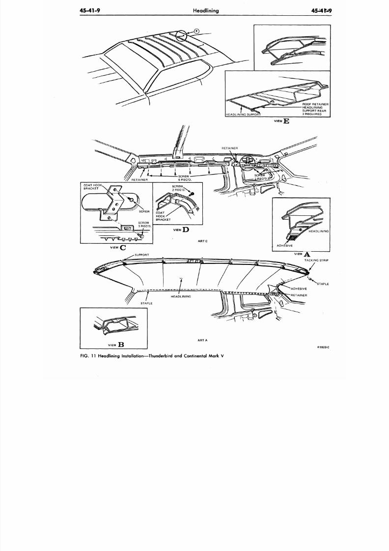
8/20/2019 1977 Ford Car Shop Manual Volume 4 Body
http://slidepdf.com/reader/full/1977-ford-car-shop-manual-volume-4-body 273/449
45-41-9
Headlining
45 -4
ROOF RETAIN
HEADLINING
SUPPORT REA
2 REQUIRED
L
t.L
(
STAP
VIEW
AR T A
R192
FIG. 11 Headlining Installation—Thunderbird and Continental Mark V
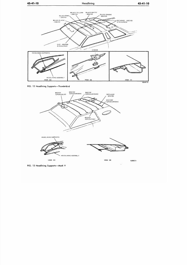
8/20/2019 1977 Ford Car Shop Manual Volume 4 Body
http://slidepdf.com/reader/full/1977-ford-car-shop-manual-volume-4-body 274/449
45-41-10
Headlining
45-41 10
(BLACK-YELLOW) (BLACK-WHITE)
- 6 0 5 2 1 0 3 - 6 0 5 2 1 0 4
(BLACK-PINK)
- 5352102
(BLACK-GREEN)
- 6 0 5 2 1 0 5
(BLACK-BLACK)
- 5 3 5 2 1 0 1
R E T A I N E R - 6 0 5 2 1 8 0
(2 REQUIRED)
HEADLINING ASSEMBLY
V I E W - A A
VIEW BB
V I E W - C C
N2891-A
FIG.
12 Headlining Supports—Thunderbird
6552101 6552102 6552104
(GREEN-BLUE) (GREEN-BROWN) (GREEN-BRONZE)
RETAINER
- 6 2 5 2 1 8 0
65521042
(GREEN-BROWN)
HEADLINING SUPPORTS
HEADLINING ASSEMBLY
V IE W -A A V IE W -B B
N2892-A
FIG. 13 Headlining Supports—Mark V
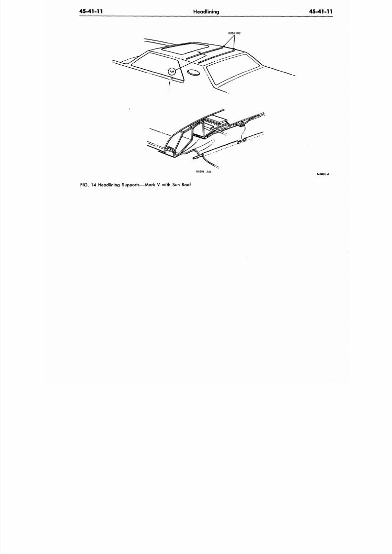
8/20/2019 1977 Ford Car Shop Manual Volume 4 Body
http://slidepdf.com/reader/full/1977-ford-car-shop-manual-volume-4-body 275/449
45-41-11
Headlining
45-41-
6052102
VIEW A A
N2893
FIG . 14 Headlining Supports—Mark V with Sun Roof
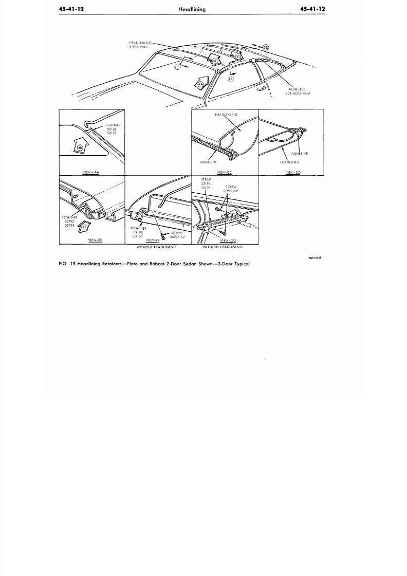
8/20/2019 1977 Ford Car Shop Manual Volume 4 Body
http://slidepdf.com/reader/full/1977-ford-car-shop-manual-volume-4-body 276/449
45-41-12
Headlining
45-41-12
H E A D L I N I N G
5 1 9 1 6 - A W A
VIEW -
AA
VIEW-EE
RETAINER
52182
V * ^
SCREW
52183 \ T 55927-S2
VIEW-FF
B
"
ADHESIVE
VIEW-CC
STRAP
52194
52195 SCREW
55927-S2
ADHESIVE
HEADLINER
V I E W - D D
WITHOUT HEADLINING WITHOUT HEADLINING
FIG. 15 Headlining Retainers—Pinto and Bobcat 2-Door Sedan Shown—3-Door Typical
N2190-B
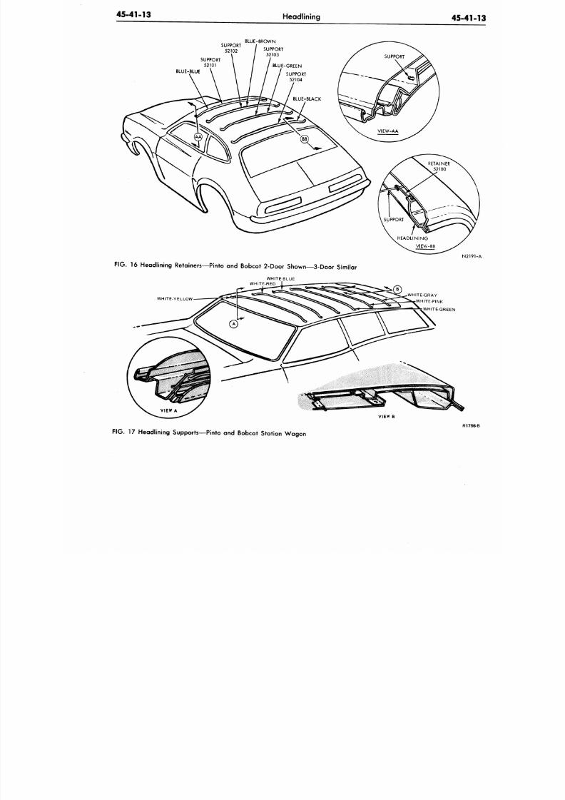
8/20/2019 1977 Ford Car Shop Manual Volume 4 Body
http://slidepdf.com/reader/full/1977-ford-car-shop-manual-volume-4-body 277/449
45-41-13
Headlining
45-41
SUPPORT
52102
BLUE-BROWN
SUPPORT
52101
BLUE-BLUE
N 2 1
FIG.
16 Headlining Retainers—Pinto and Bobcat
2-Door
Shown—3-Door Similar
WHITE-BLUE
WHITE-RED
WHITE-YELLOW
WHITE-GRAY
WHITE-PINK
WHITE-GREEN
VIEW B
FIG.
17 Headlining Supports—Pinto and Bobcat Station W ago n
R17
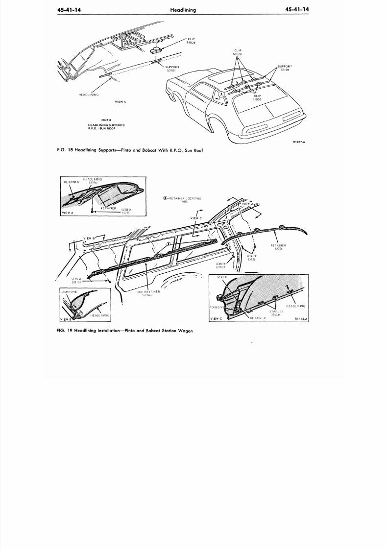
8/20/2019 1977 Ford Car Shop Manual Volume 4 Body
http://slidepdf.com/reader/full/1977-ford-car-shop-manual-volume-4-body 278/449
45-41-14
Headlining
45-41 14
HEADLINING
PINTO
HEADLINING SUPPORTS
R.P.O. SUN ROOF
CLIP
51026
SUPPORT
52101
R178 ' A
FIG.
18 Headlining Supports—Pinto and Bobcat W ith
R.P.O.
Sun Roof
HEADLINING
RETAINER 51916
VIEW
HEADLII^ING
STAPLES
375346
RETAINER R 1 K1 3 - A
FIG .
19 Headlining Installation—Pinto and Bobcat Station Wa gon
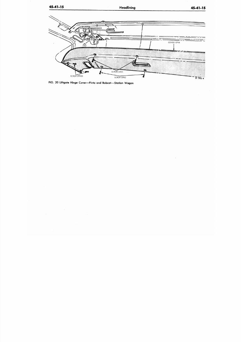
8/20/2019 1977 Ford Car Shop Manual Volume 4 Body
http://slidepdf.com/reader/full/1977-ford-car-shop-manual-volume-4-body 279/449
45-41-15
Headlining
45-41-
SCREW 379183
SCREW 55962
FIG. 20 Liftgate Hinge Cover—Pinto and Bobcat—Station Wagon
R
17
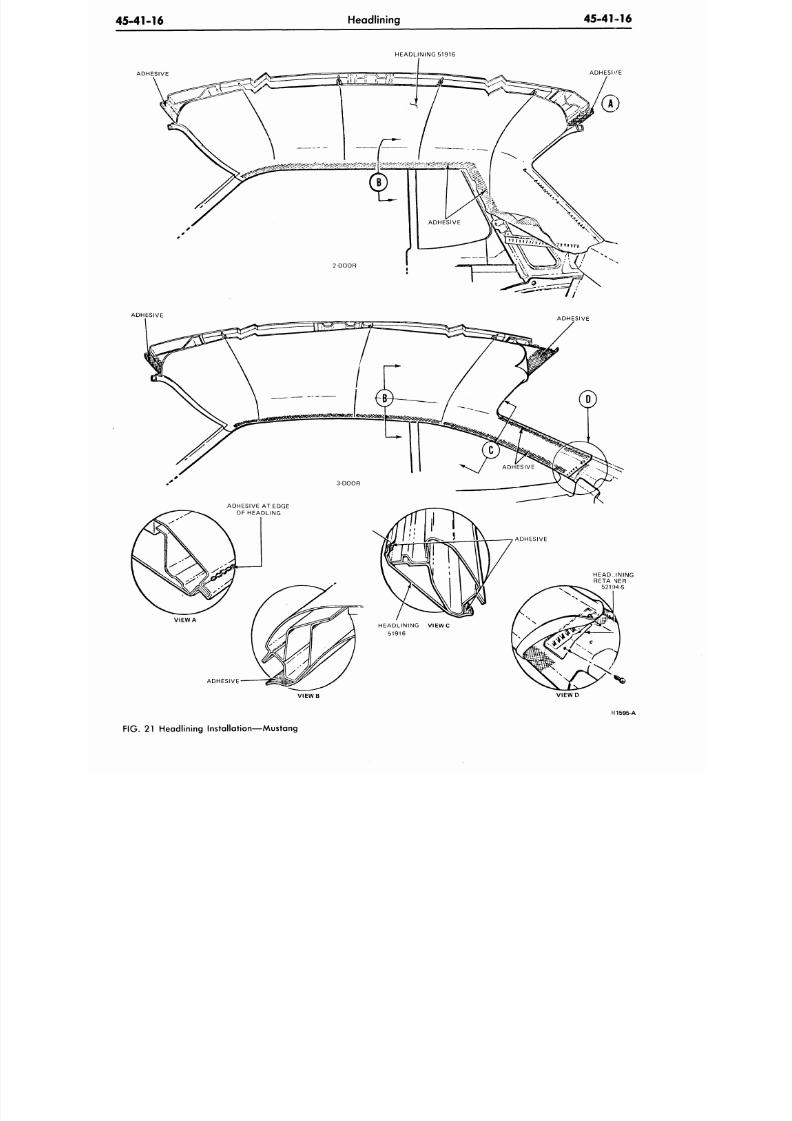
8/20/2019 1977 Ford Car Shop Manual Volume 4 Body
http://slidepdf.com/reader/full/1977-ford-car-shop-manual-volume-4-body 280/449
45-41-16
Headlining
45-41-16
HEADLINING 51916
ADHESIVE
ADHESIVE
HEADLINING
RETA NJER
521SI4-5
ADHESIVE
V IE W B V IE W D
FI1595-A
FIG.
21 Headlining Installation—Mustang
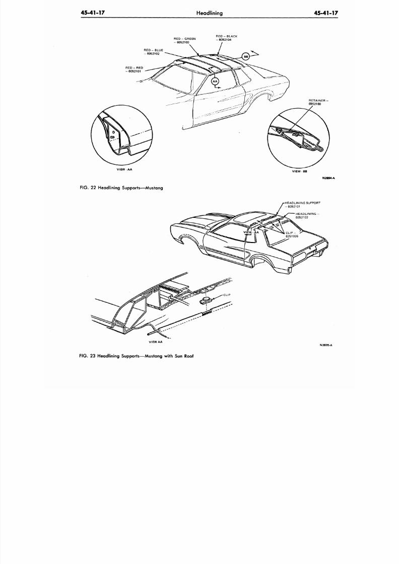
8/20/2019 1977 Ford Car Shop Manual Volume 4 Body
http://slidepdf.com/reader/full/1977-ford-car-shop-manual-volume-4-body 281/449
45-41-17
Headlining
45-41-
RED - GREEN
- 6 0 5 2 1 0 3
R E D - B L A C K
- 6 0 5 2 1 0 4
R E D - B L U E
- 6 0 5 2 1 0 2
V IE WAA
FIG .
22 Headlining Supports—Mustang
RETAINER -
6952180
VIEW BB
N2894
HEADLINING SUPPORT
- 6052101
HEADL IN ING -
6052102
V I E W A A
N
2895-A
FIG . 23 Headlining Supports—Mustang with Sun Roof
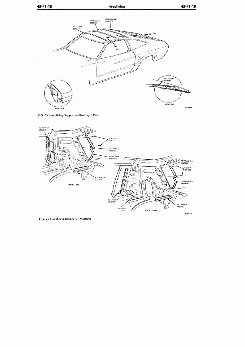
8/20/2019 1977 Ford Car Shop Manual Volume 4 Body
http://slidepdf.com/reader/full/1977-ford-car-shop-manual-volume-4-body 282/449
45-41-18
Headlining
45-41-18
RED-BROWN
6952103
RED-RED
6952101
VIEW BB
VIEW-AA
N2895-A
FIG. 2 4 Headlining Supports—Mustang 3-Door
RETAINER -
6053983
RETAINED
6050982
SCRHW
3775:57
RETAINER -
6052194
S C R E W -
377537
N28H7-A
FIG .
25 Headlining Retainers—Mustang
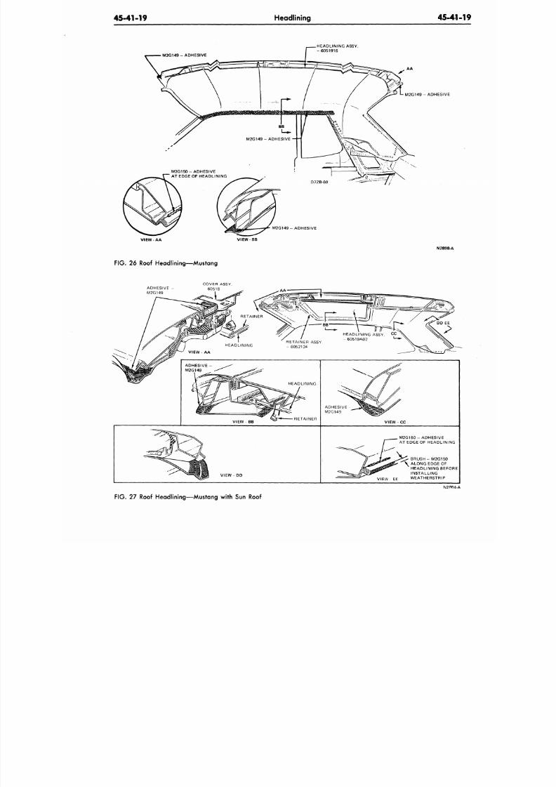
8/20/2019 1977 Ford Car Shop Manual Volume 4 Body
http://slidepdf.com/reader/full/1977-ford-car-shop-manual-volume-4-body 283/449
45-41-19
Headlining
45-41-1
HEADLINING ASSY.
-6051916
A A
M2G149-ADHESIVE
M2G149-ADHESIVE
VIEW-AA
VIEW
BB
N2898-A
FIG. 26
Roof H eadlining— Mustan g
ADHESIVE
-
M2G149
COVER ASSY.
60518
RETAINER
HEADLINING
RETAINER ASSY
- 6052124
ADHESIVE-
M2G149
m
VIEW
-
BB
VIEW - DD
HEADLINING
At
* -*
-RETAINER
ADHESIVE ^
M2G149
U/
VIEW - CC
M2G150 - ADHESIVE
r AT EDGE OF HEADLINING
fl J-&* •JrZZ' BRU SH- M2G150
/ rSr\
t
ti >'
\ ALONG EDGE OF
K ^ T ^ g g ^
9
HEADLINING BEFORE
' 3 § ^ ^ INSTALLING
^ VIEW EF WEATHERSTRIP
N2P84-A
FIG. 27
Roof H eadlining— Mustan g with Sun Roof
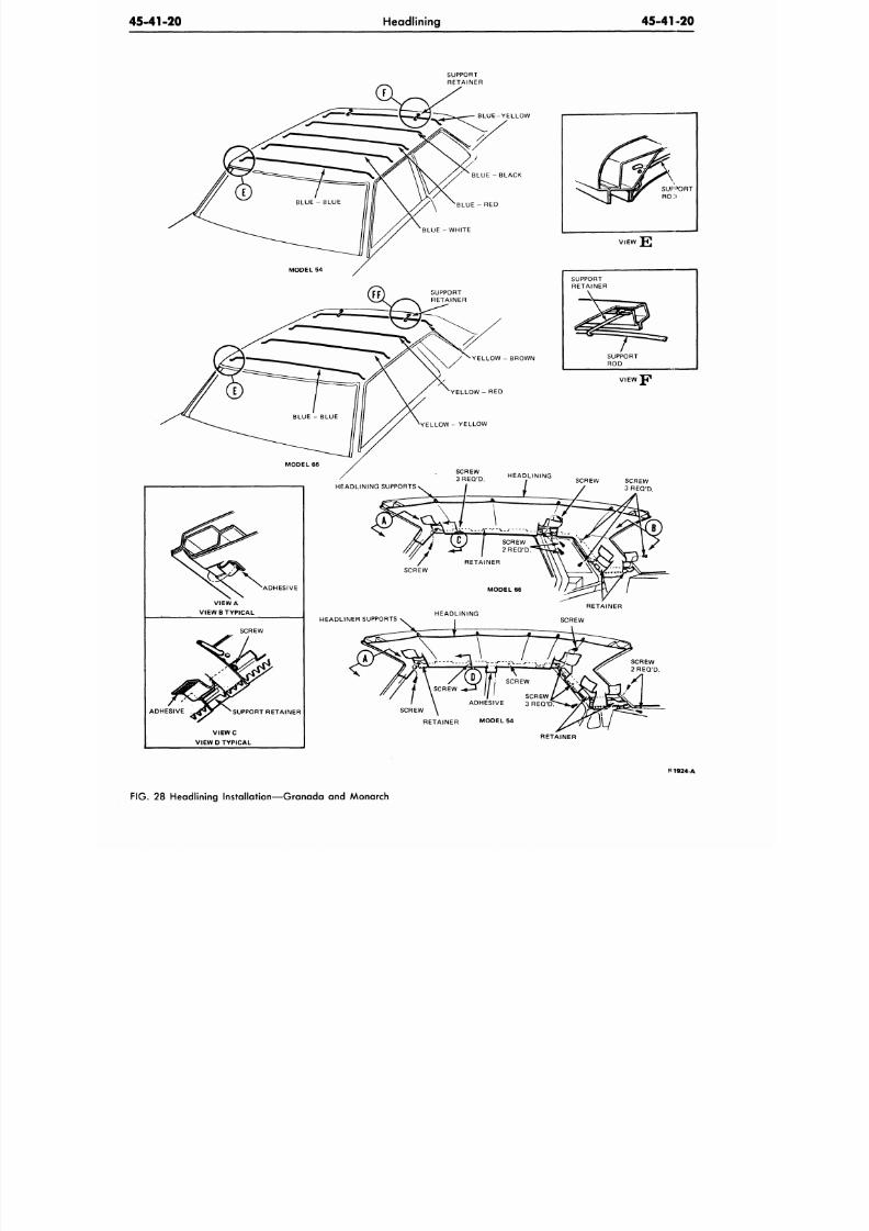
8/20/2019 1977 Ford Car Shop Manual Volume 4 Body
http://slidepdf.com/reader/full/1977-ford-car-shop-manual-volume-4-body 284/449
45-41-20
Headlining
45-41-20
SCREW
ADHESIVE 3REQ'DT
ADHESIVE
V I E W C
VIEW D TYPICAL
RETAINER
B1924-A
FIG. 28 Headlining Installation—Granada and Monarch
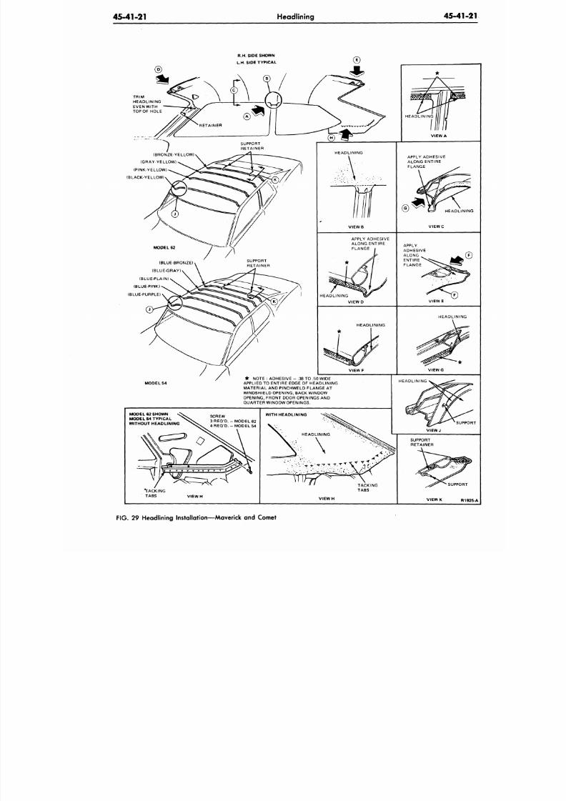
8/20/2019 1977 Ford Car Shop Manual Volume 4 Body
http://slidepdf.com/reader/full/1977-ford-car-shop-manual-volume-4-body 285/449
45-41-21
Headlining
45-41-2
R.H. SIDE SHOWN
L.H. SIDE TYP ICAL
TRIM
HEADLINING
EVEN WITH
TOP OF HOLE
(BRONZE-YELLOW)
(GRAY-YELLOW)
(PINK-YELLOW)
(BLACK-YELLOW)
(BLUE-BRONZE)
(BLUE-GRAY)
(BLUE-PLAIN)
(BLUE-PINK)
(BLUE-PURPLE)
MODEL 54
* NOTE
:
ADHESIVE
-
.38 TO .50 WIDE
APPLIED TO ENTIRE EDGE OF HEADLINING
MATERIAL AND PINCHWELD FLANGE AT
WINDSHIELD OPENING, BACK WINDOW
OPENING. FRONT DOOR OPENINGS AND
QUARTER WINDOW OPENINGS.
MODEL 62 SHOWN
MODEL 54 TYPICAL
WITHOUT HEADLINING
SCREW
3 R E Q ' D . - M O D E L 6 2
4 REQ'D.
-
MODEL 54
WITH HEADLINING
HEADLINING
\
>Vrr .T. VV;
TACKING
TABS
SUPPORT
V I E W H
R192
FIG. 29 Headlining Installation—Maverick and Comet
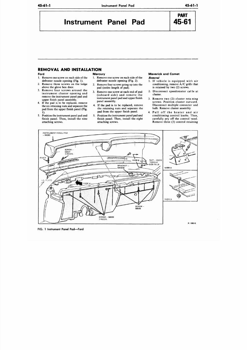
8/20/2019 1977 Ford Car Shop Manual Volume 4 Body
http://slidepdf.com/reader/full/1977-ford-car-shop-manual-volume-4-body 286/449
45-61-1
Instrument Panel Pad
45-61-1
Instrument Panel Pad
REMOVAL AND INSTALLATION
Ford
1. Remove one screw on each side of the
defroster nozzle opening (Fig. 1).
2. Remove three screws on the ledge
above the glove box doo r.
3. Remove four screws around the
instrument cluster opening and
remove the instrument panel pad and
upper finish panel assembly.
4. If the pad is to be replaced, remove
the six retaining nuts and separate the
pad from the upper finish panel (Fig.
1).
5. Position the instrument panel pad and
finish panel. Then, install the nine
attaching screws.
Mercury
1. Remove one screw on each side of the
defroster nozzle opening (Fig. 2).
2. Remove four screws going up into the
pad (entire length of pad).
3. Remove one screw at each end of
pad
( inboard s ide) and remove the
instrument panel pad and upper finish
panel assembly.
4. If the pad is to be replaced, remove
the retaining nuts and separate the
pad from the upper finish panel.
5. Position the instrum ent panel pad and
finish panel. Then, install the eight
attaching screws.
Maverick and Comet
Removal
1. If vehicle is equipped with air
conditioning, remove A/C grilk that
is retained by two (2) screws.
2. Disconnect speedometer cable at
cluster.
3.
Remove two (2) cluster retaining
screws. Position cluster outward.
Disconnect multiple connector and
bulb. Remove cluster assembly
4. Pu l l of f t he he a t e r a nd a i r
conditioning control knobs. Then,
carefully pry off the control bezel.
Remove three (3) control retaining
INSTRUMENT PANEL PAD
- 0 4 2 8 2
SCREW
56930
S C R E W - 5 6 9 3 0
7 REQ'D.
VIEW A
VIEW B
R 1382 E
FIG. 1 Instrument Panel Pad—Ford
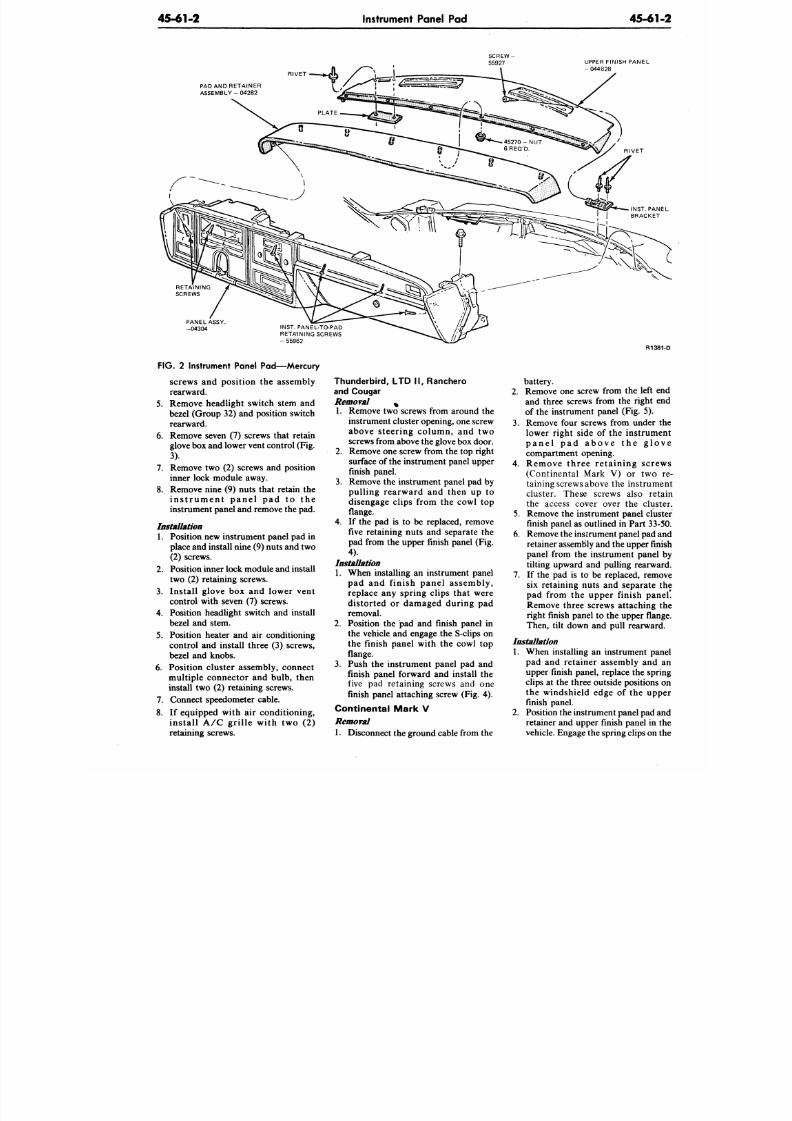
8/20/2019 1977 Ford Car Shop Manual Volume 4 Body
http://slidepdf.com/reader/full/1977-ford-car-shop-manual-volume-4-body 287/449
45-61-2
Instrument Panel Pad
45-61
UPPER FINISH PANEL
- 044B28
PAD AND RETAINER
A S S E M B L Y - 0 4 2 8 2
R IVET
PANEL ASSY.
-04304
INST. PANEL-TO-PAD
RETAINING SCREWS
- 55962
FIG.
2 Instrument Panel Pad—Mercury
screws and position the assembly
rearward.
5. Remove headlight switch stem and
bezel (Group 32) and position switch
rearward.
6. Remove seven (7) screws that retain
glove box and lower vent control (Fig.
3).
7. Remove two (2) screws and position
inner lock module away.
8. Remove nine (9) nuts that retain the
i n s t r u m e n t p a n e l p a d t o t h e
instrument panel and remove the pad.
Installation
1.
Position new instrument panel pad in
place and install nine (9) nuts and two
(2) screws.
2. Position inner lock module and install
two (2) retaining screws.
3.
Install glove box and lower vent
control with seven (7) screws.
4. Position headlight switch and install
bezel and stem.
5. Position heater and air conditioning
control and install three (3) screws,
bezel and knobs.
6. Position cluster assembly, connect
multiple connector and bulb, then
install two (2) retaining screws.
7. Connect speedometer cable.
8. If equipped with air conditioning,
install A/C gril le with two (2)
retaining screws.
Thunderbi rd, LTD I I , Ranchero
and Cougar
Removal
%
1. Remove two screws from a round the
instrument cluster opening, one screw
above steering column, and two
screws from above the glove box door.
2.
Remove one screw from the top right
surface of the instrument panel upper
finish panel.
3. Remove the instrument panel pad by
pulling rearward and then up to
disengage clips from the cowl top
flange.
4.
If the pad is to be replaced, remove
five retaining nuts and separate the
pad from the upper finish panel (Fig.
4).
Installation
1. When installing an instrument panel
pad and f inish panel assembly,
replace any spring clips that were
distorted or damaged during pad
removal.
2. Position the pad and finish panel in
the vehicle and engage the S-clips on
the finish panel with the cowl top
flange.
3. Push the instrument panel pad and
finish panel forward and install the
five pad retaining screws and one
finish panel attaching screw (Fig. 4).
Continental Mark V
Removal
1. Disconnect the ground cable from the
R138
battery.
2. Remove one screw from the left e
and three screws from the right e
of the instrument panel (Fig. 5).
3. Remove four screws from under
lower right side of the instrum
p a n e l p a d a b o v e t h e g l o
compartment opening.
4. Remove three re ta ining scre
(Continental Mark V) or two
taining screws above the instrum
cluster. These screws also ret
the access cover over the clus
5. Remove the instrument panel clu
finish panel as outlined in P art 33-
6. Remove the instrumen t panel pad a
retainer assembly and the upper fi
panel from the instrument panel
tilting upward and pulling rearwa
7. If the pad is to be replaced, remo
six retaining nuts and separate
pad from the upper finish pan
Remove three screws attaching
right finish panel to the upper fla
Then, tilt down and pull rearwar
Installation
1. When installing an instrument pa
pad and retainer assembly and
upper finish panel, replace the spr
clips at the three outside positions
the windshield edge of the upp
finish panel.
2.
Position the instrume nt panel pad a
retainer and upper finish panel in
vehicle. Engage the spring clips on
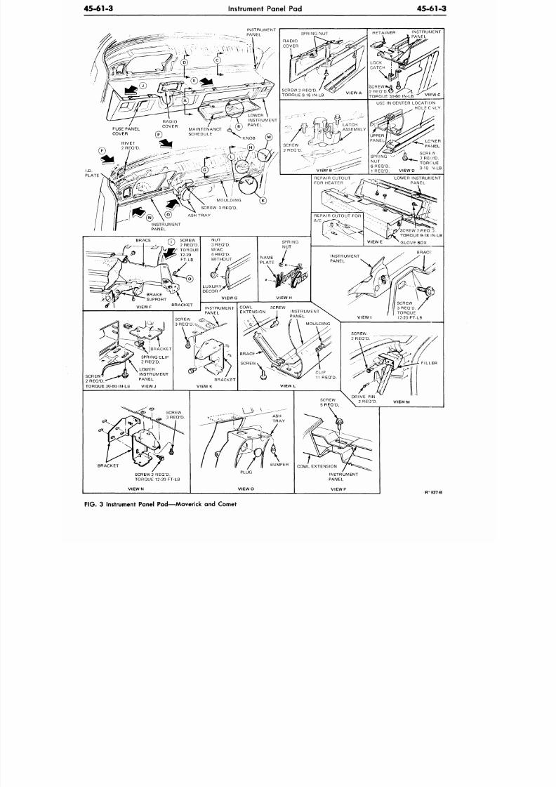
8/20/2019 1977 Ford Car Shop Manual Volume 4 Body
http://slidepdf.com/reader/full/1977-ford-car-shop-manual-volume-4-body 288/449
45-61-3
Instrument Panel Pad
45-61-3
FT
927
B
F IG . 3 Instrument Panel Pad—Maverick and Comet
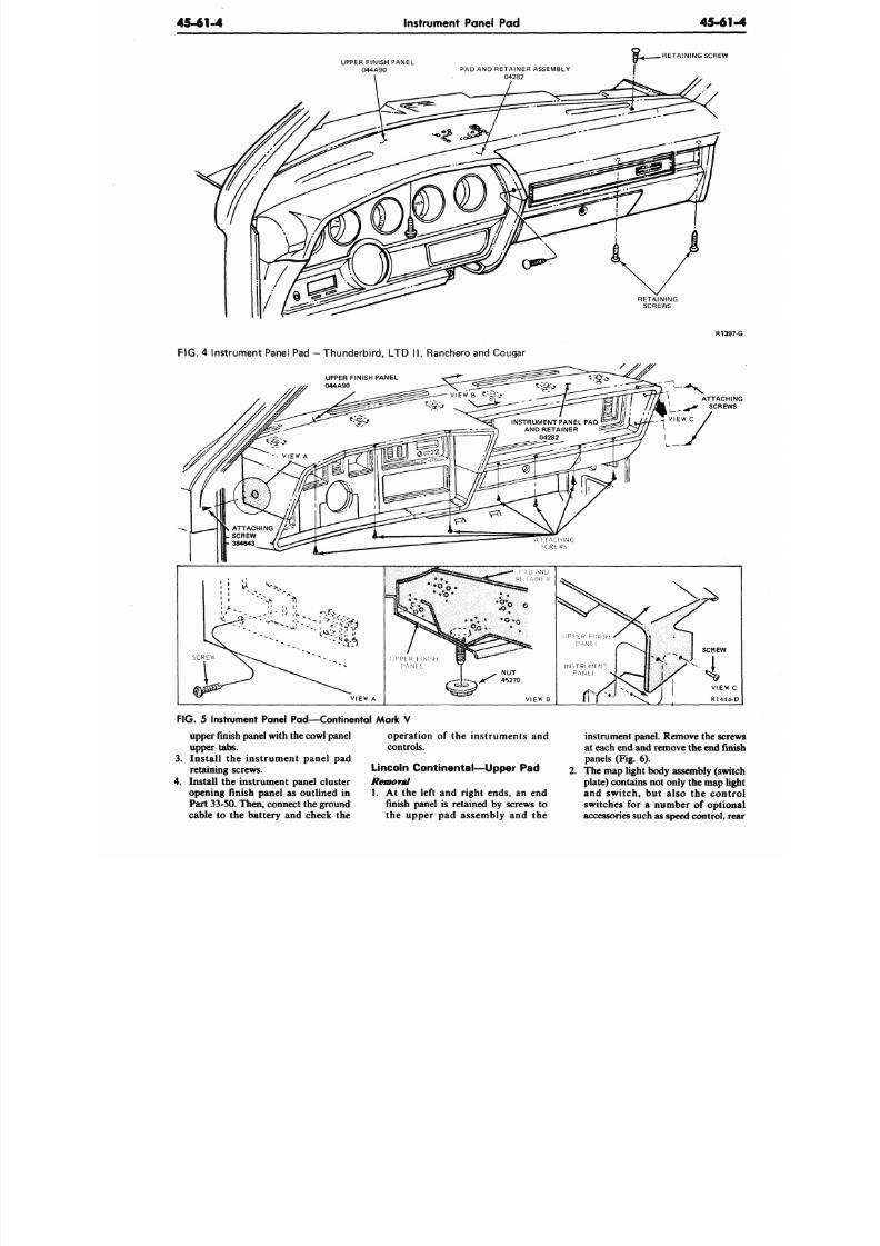
8/20/2019 1977 Ford Car Shop Manual Volume 4 Body
http://slidepdf.com/reader/full/1977-ford-car-shop-manual-volume-4-body 289/449
45-61-4 Instrument Panel Pad
45-61
UPPER FINISH PANEL
044A90
PAD AND RETAINER ASSEMBLY
04282
RETAINING SCREW
RETAINING
SCREWS
R139
FIG. 4 Instrument Panel Pad — Thun de rbi rd, LTD I I , Ranchero and Cougar
UPPER FINISH PANEL
044A90
AT [ACHING
CRtWS
VIEW A
VIEW
FIG .
5 Instrument Panel Pad—Continental Mark V
upper finish panel with the co wl panel
upper tabs.
3. Install the instrument panel pad
retaining screws.
4. Install the instrument panel cluster
opening finish panel as outlined in
Part 33-50. Then, connect the ground
cable to the battery and check the
operation of the instruments and
controls.
Lincoln Continental—Upper Pad
Removal
1. At the left and right ends, an end
finish panel is retained by screws to
the upper pad assembly and the
instrument panel. Remove the scre
at each end and remove the end fin
panels (Fig. 6).
2. The map light body assembly (sw
plate) contains not only the map lig
and switch, but also the cont
switches for a number of option
accessories such as speed control, r
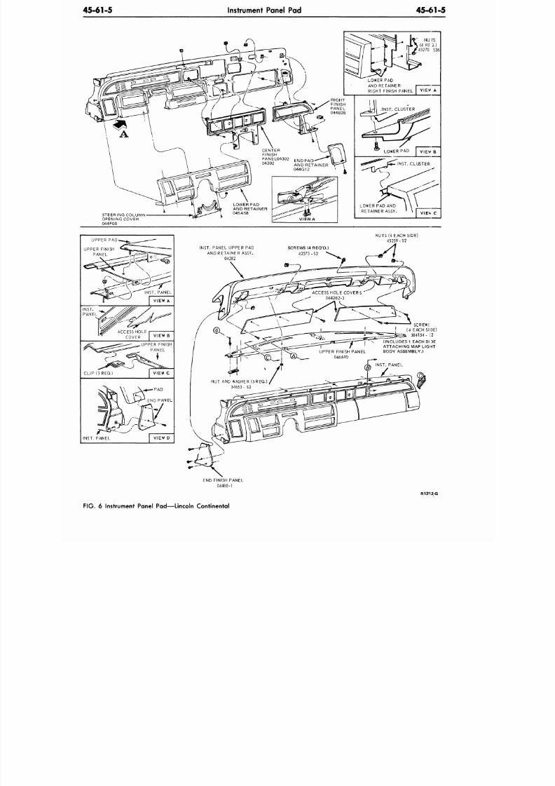
8/20/2019 1977 Ford Car Shop Manual Volume 4 Body
http://slidepdf.com/reader/full/1977-ford-car-shop-manual-volume-4-body 290/449
45-61-5
Instrument Panel Pad
45-61-5
STEERING COLUMN
OPENING COVER
044F08
RIGHT
FINISH
PANEL
044B28
VIEW A
LOWER PAD
AND RETAINER
RIGHT FINISH PANEL I VIEW A
LOWER PAD AND
RETAINER ASSY. VIEW C
UPPER PAD
UPPER FINISH
PANEL
INST. PANEL
VIEW A
ACCESS HOLE i
COVER
V I E W B
UPPER FINISH
PANEL
VIEW C
INST. PANEL
VIEW D
NUTS (4 EACH SIDE)
45259 -S2
INST. PANEL UPPER PAD
AND RETAINER ASSY.
04282
SCREWS (4 REQ'D.)
4 2 3 7 3 - S 2
SCREWS
( 4 E A C H S I D E )
3 8 4 1 5 4 - \2
(INCLUDES 1 EACH SI DE
ATTACHING MAP LIGHT
BODY ASSEMBLY.)
END FINISH PANEL
l- l
R1252-G
FIG. 6 Instrument Panel Pad—Lincoln Continental
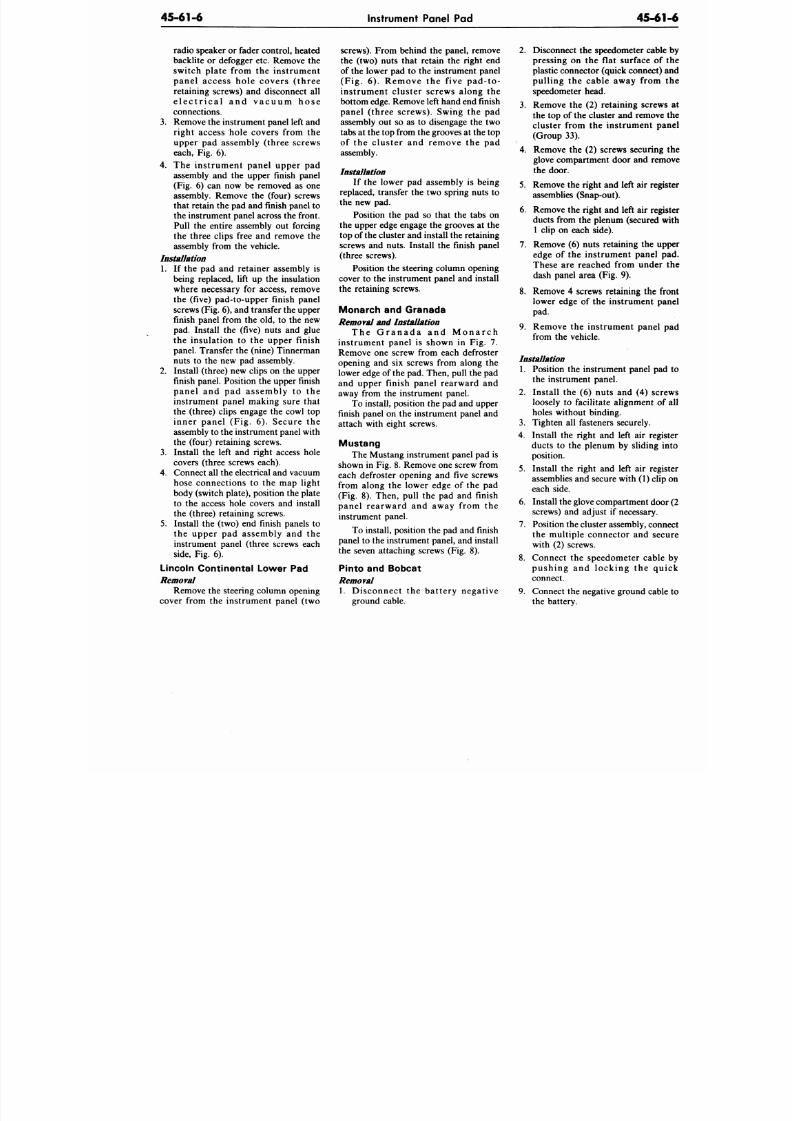
8/20/2019 1977 Ford Car Shop Manual Volume 4 Body
http://slidepdf.com/reader/full/1977-ford-car-shop-manual-volume-4-body 291/449
45-61-6 Instrument Panel Pad
45-6
radio speaker or fader con trol, heated
backlite or defogger etc. Remove the
switch plate from the instrument
panel access hole covers ( three
retaining screws) and disconnect all
e l e c t r i c a l a n d v a c u u m h o s e
connections.
3. Remove the instrument panel left and
right access hole covers from the
upper pad assembly (three screws
each, Fig. 6).
4. The instrument panel upper pad
assembly and the upper finish panel
(Fig. 6) can now be removed as one
assembly. Remove the (four) screws
that retain the pad and finish panel to
the instrument panel across the front.
Pull the entire assembly out forcing
the three clips free and remove the
assembly from the vehicle.
Installation
1. If the pad and retainer assembly is
being replaced, lift up the insulation
where necessary for access, remove
the (five) pad-to-upper finish panel
screws (Fig. 6), and transfer the upper
finish panel from the old, to the new
pad. Install the (five) nuts and glue
the insulation to the upper finish
panel. Transfer the (nine) Tinnerman
nuts to the new pad assembly.
2.
Install (three) new clips on the upper
finish panel. Position the upper finish
panel and pad assembly to the
instrument panel making sure that
the (three) clips engage the cowl top
inner panel (Fig. 6). Secure the
assembly to the instrum ent panel with
the (four) retaining screws.
3.
Install the left and righ t access hole
covers (three screws each).
4.
Connect all the electrical and vacuum
hose connections to the map light
body (switch plate), position the plate
to the access hole covers and install
the (three) retaining screws.
5.
Install the (two) end finish panels to
the upper pad assembly and the
instrument panel (three screws each
side,
Fig. 6).
Lincoln Continental Lower Pad
Removal
Remove the steering column opening
cover from the instrument panel (two
screws). From behind the panel, remove
the (two) nuts that retain the right end
of the lower pad to the instrument panel
(Fig. 6). Remove the five pad-to-
instrument cluster screws along the
bottom edge. Remove left hand end finish
panel (three screws). Swing the pad
assembly out so as to disengage the two
tabs at the top from the grooves at the top
of the cluster and remove the pad
assembly.
Installation
If the lower pad assembly is being
replaced, transfer the two spring nuts to
the new pad.
Position the pad so that the tabs on
the upper edge engage the grooves at the
top of the cluster and install the retaining
screws and nuts. Install the finish panel
(three screws).
Position the steering column opening
cover to the instrument panel and install
the retaining screws.
Monarch and Granada
emoval
and Installation
T h e G r a n a d a a n d M o n a r c h
instrument panel is shown in Fig. 7.
Remove one screw from each defroster
opening and six screws from along the
lower edge of the pad. Then, pull the pad
and upper finish panel rearward and
away from the instrument panel.
To install, position the pad and upper
finish panel on the instrument panel and
attach with eight screws.
Mustang
The Mustang instrument panel pad is
shown in Fig. 8. Remove one screw from
each defroster opening and five screws
from along the lower edge of the pad
(Fig. 8). Then, pull the pad and finish
panel rearward and away from the
instrument panel.
To install, position the pad and finish
panel to the instrument panel, and install
the seven attaching screws (Fig. 8).
Pinto and Bobcat
Removal
1. Disconnect the battery negative
ground cable.
2.
Disconnect the speedometer cab
pressing on the flat surface o
plastic connector (quick connect
pulling the cable away from
speedometer head.
3. Remove the (2) retaining screw
the top of the cluster and remov
cluster from the instrument p
(Group 33).
4. Remove the (2) screws securin
glove compartment door and rem
the door.
5.
Remove the righ t and left air re
assemblies (Snap-out).
6. Remove the righ t and left air reg
ducts from the plenum (secured
1 clip on each side).
7. Remove (6) nuts retaining the
edge of the instrument panel
These are reached from unde
dash panel area (Fig. 9).
8. Remove 4 screws retaining the
lower edge of the instrument p
pad.
9. Remove the instrument panel
from the vehicle.
Installation
1. Position the instrument panel p
the instrument panel.
2.
Install the (6) nuts and (4) sc
loosely to facilitate alignment o
holes without binding.
3.
Tighten all fasteners securely.
4.
Install the right and left air reg
ducts to the plenum by sliding
position.
5.
Install the right and left air reg
assemblies and secure with (1) cl
each side.
6. Install the glove compartment do
screws) and adjust if necessary.
7.
Position the cluster assembly, con
the multiple connector and se
with (2) screws.
8. Connect the speedometer cabl
pushing and locking the q
connect.
9. Connect the negative ground cab
the battery.
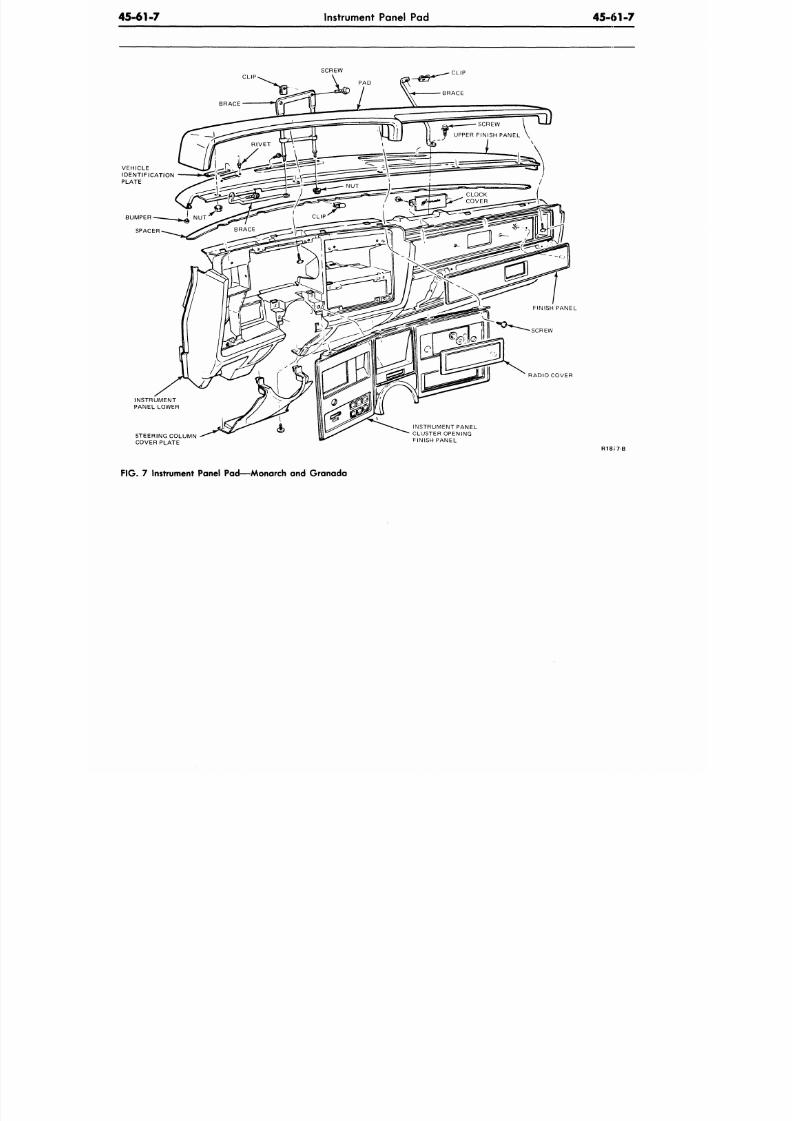
8/20/2019 1977 Ford Car Shop Manual Volume 4 Body
http://slidepdf.com/reader/full/1977-ford-car-shop-manual-volume-4-body 292/449
45-61-7
Instrument Panel Pad
45-61-7
SCREW
CLIP
VEHICLE
IDENTIFICATION
PLATE
FINISH PANEL
RADIO COVER
INSTRUMENT
PANEL LOWER
STEERING COLUMN
COVER PLATE
INSTRUMENT PANEL
CLUSTER OPENING
FINISH PANEL
R 1 8 J 7 B
FIG. 7 Instrument Panel Pad—Monarch and Granada
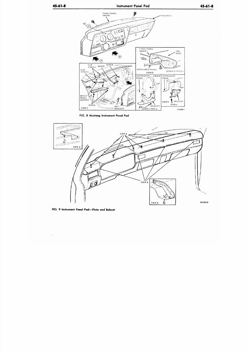
8/20/2019 1977 Ford Car Shop Manual Volume 4 Body
http://slidepdf.com/reader/full/1977-ford-car-shop-manual-volume-4-body 293/449
45-61-8
Instrument Panel Pad
45-6
FINISH PANEL
044 A90
F IG .
8 Mustang Instrument Panel Pad
N2192
FIG.
9 Instrument Panel Pad—Pinto and Bobcat
8/20/2019 1977 Ford Car Shop Manual Volume 4 Body
http://slidepdf.com/reader/full/1977-ford-car-shop-manual-volume-4-body 294/449
46-01-1
Tops and Exterior Finishes
46-0
TOPS AND EXTERIOR FINISHES
PART TITL E PART NO.
Top and Exte rior Finish General Service 46-01
Electric Moo n Roof 46-05
Manua l Sun Roof Panel 46-11
GROU
(70000
PART TITL E PART
Removable Sun Roof 46
Roof Outside Cover 46
Woo d Grain Transfer 4
CR2007
GENERAL INFORMATION
For detailed information on paint
repair, refer to the handbook entitled
Spot Repairing Original Enamel finishes
with Acrylic lacquer, Form FD-7953-Q.
CLEANING
Paint
The outside finish should be washed
frequently. Never wipe the painted
surface with a dry cloth. Dusting the
finish when it is dry tends to rub the dust
and dirt into the baked enamel, and
leaves a sandpaper effect on the surface.
To keep the finish bright and attractive
and eliminate the necessity of using
polish, wash the car whenever it has
accumulated a moderate amount of dirt
and road salt.
Wood Grain Transfers
Never wipe the panels or trim rails
with a dry cloth. This method of cleaning
tends to rub dust particles into the
finished surface and leave fine scratches.
Flush off all loose dirt and
elements, and wipe the body panel
rails with a sponge and plenty of
water. If desired, a mild soap ma
used. Rinse thoroughly with clear
and wipe dry.
Glass
The glass should be cleaned
Ford Glass Cleaner (C8AZ-19C50
or equivalent, using a clean, soft, lin
cloth. Follow the directions shown o
container.
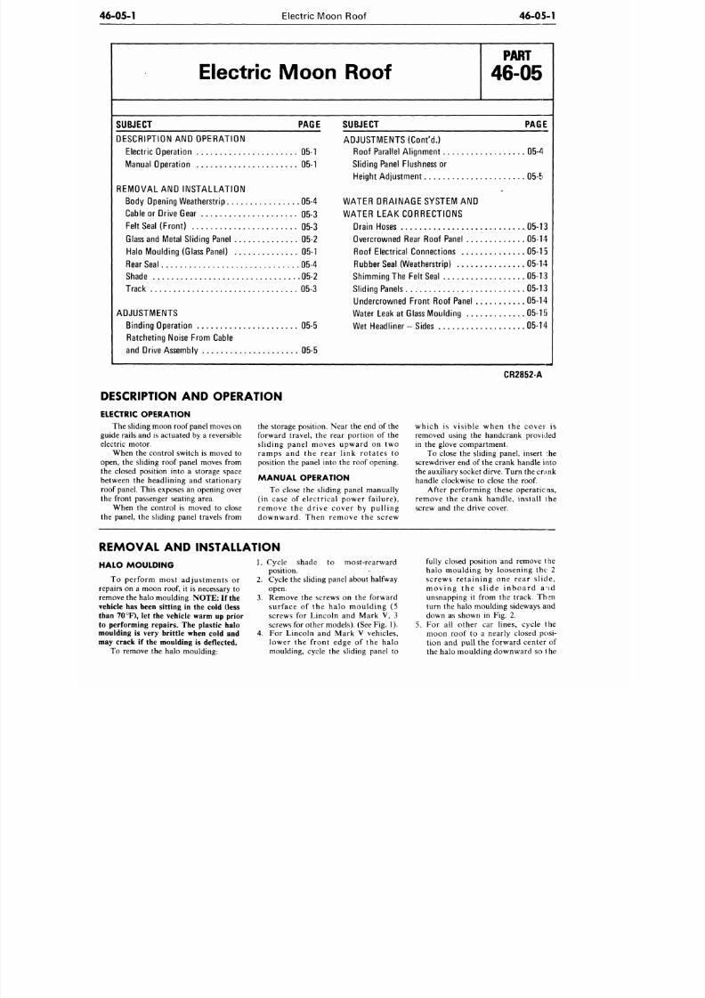
8/20/2019 1977 Ford Car Shop Manual Volume 4 Body
http://slidepdf.com/reader/full/1977-ford-car-shop-manual-volume-4-body 295/449
46-05-1
Electric Moon Roof
46-05-1
Electric Moon Roof
P A R T
46-05
SUBJECT PAGE
DESCRIPTION
AND
OPERATION
Electric Operation
05-1
Manual Operation
05-1
REMOVAL
AND
INSTALLATION
Body Opening Weatherstrip
05-4
Cable
or
Drive Gear
05-3
Felt Seal (Front)
05-3
Glass and Metal Sliding Panel 05-2
Halo Moulding (Glass Panel)
05-1
Rear Seal
05-4
Shade
05-2
Track
05-3
ADJUSTMENTS
Binding Operation
05-5
Ratcheting Noise From Cable
and Drive Assembly
05-5
SUBJECT PA£E
ADJUSTMENTS (Cont 'd.)
Roof Parallel Alignment
05-4
Sliding Panel Flushness
or
Height Adjustment
05-5
WATER DRAINAGE SYSTEM AND
WATER LEAK CORRECTIONS
Drain Hoses .05-13
Overcrowned Rear Roof Panel
05-14
Roof Electrical Connections
05-15
Rubber Seal (W eatherstrip) 05-14
Shimming
The
Felt Seal
05-13
Sliding Panels
05-13
Undercrowned Front Roof Panel
05-14
Water Leak
at
Glass Mo ulding 05-1 )
Wet Headliner
-
Sides
05-14
DESCRIPTION AND OPERATION
ELECTRIC OPERATION
The sliding moon roof panel moves
on
guide rails and is actuated by a reversible
electric motor.
When the control switch is moved to
open,
the
sliding roof panel moves from
the closed position into a storage space
between
the
headl ining
and
s ta t ionary
roof panel. This exposes
an
opening over
the front passenger seating area.
When the control is moved to close
the panel,
the
sliding panel travels from
the storage position. Near
the end of the
forward travel, the rear portion of the
s l id ing pane l moves upward
on two
r a m p s and the rea r l ink ro ta te s to
position
the
panel into
the
roof opening.
MANUAL OPERATION
To close
the
sliding panel manually
(in case
of
electrical power failure),
remove
the
drive cover
by
pull ing
downward. Then remove
the
screw
CR2852-A
w h i c h
is
v i s ib le when
the
c o v e r
is
removed using the handcrank provided
in
the
glove compartment.
To close the sliding panel, insert :he
screwdriver
end of the
crank handle into
the auxiliary socket dirve. Turn the crank
handle clockwise
to
close
the roof.
After perf ormin g these operatic ns,
r e m o v e
the
c rank han d le , in s ta l l
the
screw and the drive cover.
REMOVAL
AND
INSTALLATION
HALO MOULDING
T o pe r fo rm mos t ad jus tmen ts
or
repairs on a moon roof, it is necessary to
remove
the
halo moulding.
NOTE:
If
the
vehicle has been sitting in the cold (less
than 70 °F), let the vehicle warm up prior
to performing repairs.
The
plastic halo
moulding is very brittle when cold and
may crack if the moulding is deflected.
To remove the halo moulding:
1. Cycle shade to most-rearward
position.
2.
Cycle
the
sliding panel about halfway
open.
3.
Remove
the
screws
on the
forward
s ur face of the h a l o m o u l d i n g (5
screws
for
Lincoln
and
Mark
V, 3
screws
for
other m odels).
(See
Fig.
1).
4.
For Lincoln and M a r k V vehicles,
l o w e r
the
front ed ge
of the
ha lo
moulding, cycle the sliding panel to
5.
fully closed position
and
remove
the
ha lo mould ing by loosening the 2
s c r e w s r e t a i n i n g
one
rea r s l id e ,
m o v i n g
the
s l i d e i n b o a r d
a id
unsnapping it from the track. Then
turn
the
halo moulding sideways
and
down as shown in Fig. 2.
F or
all
o the r
car
lines, cycle
the
moon roof to a nearly closed posi-
t ion
and
pul l
the
forward center
of
the halo moulding downward
so t he
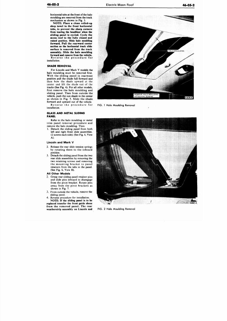
8/20/2019 1977 Ford Car Shop Manual Volume 4 Body
http://slidepdf.com/reader/full/1977-ford-car-shop-manual-volume-4-body 296/449
46-05-2
Electric Moon Roof
46-0
horizontal tabs at the front of the halo
moulding are removed from the track
mechanism as shown in Fig. 3.
NOTE: Place a clean rolled-up
shop towel in the front horizontal
tabs, to prevent the sharp corners
from tearing the headliner when the
sliding panel
is
cycled. Cycle
the
moon roof
to the
fully closed and
raised position. Slide halo moulding
forward. Pull
the
rearward center
section so the horizontal track slide
surface is removed from the track
assembly. Slide the halo moulding
forward and remove from the vehicle.
Reverse the procedure for
installation.
SHADE REMOVAL
For Lincoln and Mark V models the
halo moulding must be removed first.
With the sliding panel in rearmost
position pull the shade full forward and
then bow the shade upward at the
center and lift the shade out of the
tracks (See Fig. 4). For all other models,
first remove the halo moulding and
sliding panel. Then from outside the
vehicle, push the sun shade in the center
as shown
in Fig. 5.
Slide
the
shade
forward
and
upward
out of
the vehicle.
R e v e r s e
the
p r o c e d u r e
for
installation.
GLASS AND METAL SLIDING
PANEL
Refer to the halo moulding or metal
tr im panel removal procedure and
remove the halo moulding. Then:
1. Detach the sliding panel from both
left and right front slide assemblies.
(2 screws each side). (See Fig. 6, View
A).
Lincoln and Mark V
2. Release the rear slide tension springs
by rotating them
to the
inboard
position.
3. Detach the sliding panel from the two
rear slide assemblies by removing the
two retaining screws and removing
the mount ing bracke t to pa ne l
retainers from the tabs in the panel.
(See Fig.
6,
View
B).
All Other Models
2. Grasp rear sliding panel retainer pins
and slide pins inboard to disengage
from the pivot bracket. Rotate p ins
away from the pivot brackets as
shown in Fig. 7.
3. From outside the vehicle, remove the
sliding panel.
4. Reverse procedure
for
installation.
NOTE:
If
the sliding panel
is to be
replaced transfer
the
front guide shoes
from the removed pane l . The rear
weatherstrip assembly on Lincoln and
FIG.
1 Halo Mo ulding Remov al
FIG.
2 Halo Moulding Removal
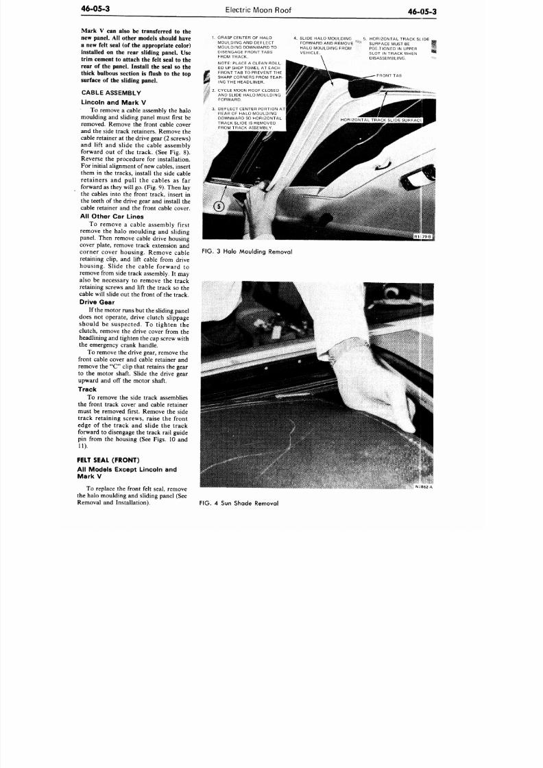
8/20/2019 1977 Ford Car Shop Manual Volume 4 Body
http://slidepdf.com/reader/full/1977-ford-car-shop-manual-volume-4-body 297/449
46-05-3
Electric Moon Roof
46-05-3
Mark V can also be transferred to the
new panel. All other models should have
a new felt seal (of the appropriate color)
installed on the rear sliding panel. Use
trim cement to attach the felt seal to the
rear of the panel. Install the seal so the
thick bulbous section is flush to the top
surface of the sliding panel.
CABLE ASSEMBLY
Lincoln and Mark V
To remove a cable assembly the halo
moulding and sliding panel must first be
removed. Remove the front cable cover
and the side track retainers. Remove the
cable retainer at the drive gear (2 screws)
and lift and slide the cable assembly
forward out of the track. (See Fig. 8).
Reverse the procedure for installation.
For initial alignment of new
cables,
insert
them in the tracks, install the side cable
retainers and pull the cables as far
forward as they will go. (Fig. 9). Then lay
the cables into the front track, insert in
the teeth of the drive gear and install the
cable retainer and the front cable cover.
All Other Car Lines
To remove a cable assembly first
remove the halo moulding and sliding
panel. Then remove cable drive housing
cover plate, remove track extension and
corner cover housing. Remove cable
retaining clip, and lift cable from drive
housing. Slide the cable forward to
remove from side track assembly. It may
also be necessary to remove the track
retaining screws and lift the track so the
cable will slide out the front of the track.
Drive Gear
If the motor runs but the sliding panel
does not operate, drive clutch slippage
should be suspected. To tighten the
clutch, remove the drive cover from the
headlining and tighten the cap screw with
the emergency crank handle.
To remove the drive gear, remove the
front cable cover and cable retainer and
remove the " C " clip that retains the gear
to the motor shaft. Slide the drive gear
upward and off the motor shaft.
Track
To remove the side track assemblies
the front track cover and cable retainer
must be removed first. Remove the side
track retaining screws, raise the front
edge of the track and slide the track
forward to disengage the track rail guide
pin from the housing (See Figs. 10 and
11).
FELT SEAL (FRONT)
Ail Models Except Lincoln and
Mark V
To replace the front felt seal, remove
the halo moulding and sliding panel (See
Removal and Installation).
1.
GRASP CENTER OF HALO
MOULDING AND DEFLECT
MOULDING DOWNWARD TO
DISENGAGE FRONT TABS
FROM TRACK.
NOTE: PLACE A CLEAN ROLL-
ED UP SHOP TOWEL AT EACH
FRONT TAB TO PREVENT THE
SHARP CORNERS FROM TEAR-
ING THE HEADLINER.
2. CYCLE MOON ROOF CLOSED
AND SLIDE HALO MOULDING
FORWARD.
3. DEFLECT CENTER PORTION AT
REAR OF HALO MOULDING
DOWNWARD SO HORIZONTAL
TRACK SLIDE IS REMOVED
FROM TRACK ASSEMBLY.
SLIDE HALO MOULDING
FORWARD AND REMOVE
HALO MOULDING FROM
VEHICLE.
5. HORIZONTAL TRACK SLIDE
SURFACE MUST BE
POSITIONED IN UPPER
SLOT IN TRACK WHEN
DISASSEMBLING.
FRONT TAB
FIG. 3 Halo Moulding Removal
NJ862-A
FIG. 4 Sun Shade Removal
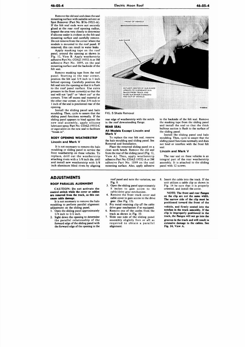
8/20/2019 1977 Ford Car Shop Manual Volume 4 Body
http://slidepdf.com/reader/full/1977-ford-car-shop-manual-volume-4-body 298/449
46-05-4
Electric Moon Roof
46-0
Remove the old seal and clean the seal
mounting surface w ith suitable solvent or
Spot Remover (Part No. B7A-19521-A).
If the felt seal ends were not securely
glued at the rear roof opening radius,
inspect the area very closely to determine
if silicone sealer is evident on the felt seal
mounting surface and carefully remove.
Do not remove from the corner where the
module is mounted to the roof panel. If
removed, this can result in water leaks.
Apply masking tape on the roof
panel, around the opening as shown in
Fig. 12, View B. Apply weatherstrip
adhesive Part
No .
COAZ-19552-A or 3M
adhesive Part No. 1099, on the seal
mounting surface and the backside of the
felt seal.
Remove masking tape from the roof
panel. Star t ing in the rear corner ,
position the felt seal 3 /4 inch to 1 inch
behind opening. Carefully position the
felt seal into the opening so that it is flush
to the roof panel surface. Use extra
pressure in the front corner(s) so that the
seal will not "pull" or "short cut" at the
corners. Trim off excess seal material at
the other rear corner, so that 3 /4 inch to
1 inch of the seal is positioned rear of the
opening.
Install the sliding panel and halo
moulding. Then, cycle to assure that the
sliding panel functions normally. If the
sliding panel appears to bind against the
new seal assembly, apply si l icone
lubricant spray Part No. COAZ-19553-C
or equivalent on th e new seal to facilitate
"break-in".
BODY OPENING WEATHERSTRIP
Lincoln and Mark V
It is not necessary to remove the halo
moulding or sliding panel to service the
front weatherstrip on these vehicles. To
replace, dr i l l out the weatherstr ip
attaching rivets with a 1/8 inch dia. drill
and install new wea therstrip with 1/8
inch aluminum blind rivets by aligning
FRONT OF VEHICLE
DEFLECT CENTER OF SUN SHADE
UPWARD TO DISENGAGE SUN
SHADE FROM TRACK AND
SLIDE SUN SHADE FORWARD
AND OUT OF VEHICLE.
FIG. 5 Shade Removal
rear edge of weatherstrip with the notch
in the roof downstanding flange.
REAR SEAL
All Models Except Lincoln and
Mark V
To replace the rear felt seal, remove
the halo moulding and sliding panel. See
Removal and Installation.
Place the removed sliding panel on a
clean work bench. Remove the old seal
from the rear of the sliding panel (Fig. 12,
View A). Then, apply weatherstrip
adhesive Part
No.
COAZ-19552-A or 3M
adhesive Part No. 1099 on the seal
mounting surface. Also, apply adhesive
to the backside of the felt seal. Rem
the masking tape from the sliding p
and install the seal so that the th
bulbous section is flush to the surfac
the sliding panel.
Install the sliding panel and h
moulding. Then, cycle to assure that
sliding panel functions norm ally and d
not bind or interfere with the front
seal.
Lincoln and Ma rk V
The rear seal on these vehicles i
integral part of the rear weathers
assembly. It is attached to the slid
panel with 12 screws.
ADJUSTMENTS
ROOF PARALLEL ALIGNMENT
CAUTION: Do not activate the
control switch while the cover or cables
are removed from the track, as this can
cause cable damage.
It is not necessary to remove the halo
moulding to perform parallel alignment
adjustment on the sliding panel.
1. Open the sliding panel approximately
1/4 inch to 1/2 inch.
2. Sight down the opening to determine
the para l le l re la t ionship of the
forward edge of the sliding panel with
the forward edge of the opening in the
roof panel and note the variation, see
Fig. 8.
3. Open the sliding panel approximately
8 inches to gain access to the
cable/drive gear mechanism.
4. Remove the front track cover and
cable cover to gain access to the drive
gear. (See Fig. 13).
5. Pry metal retaining clip off the cable
drive gear mechanism if so equipped.
6. Remove one of the cables from the
track as shown in Fig. 10.
7.
Slide one side of the sliding pan el
assembly slightly fore or aft as
r e qu i r e d t o ob t a in a pa r a l l e l
alignment.
8. Insert the cable into the track. If
unit utilizes a cable clip as show
Fig. 14 be sure that it is prop
oriented, and install the -cover.
NOTE: The front and rear fla
on the clip are not the same wi
The narrow side of the clip mus
positioned toward the front of
vehicle, and firmly seated into
notches in the track assembly. If
clip is improperly positioned in
track, the flanges will not go into
grooves in the track and will resu
extensive damage to the cables.
Fig. 14, View A.
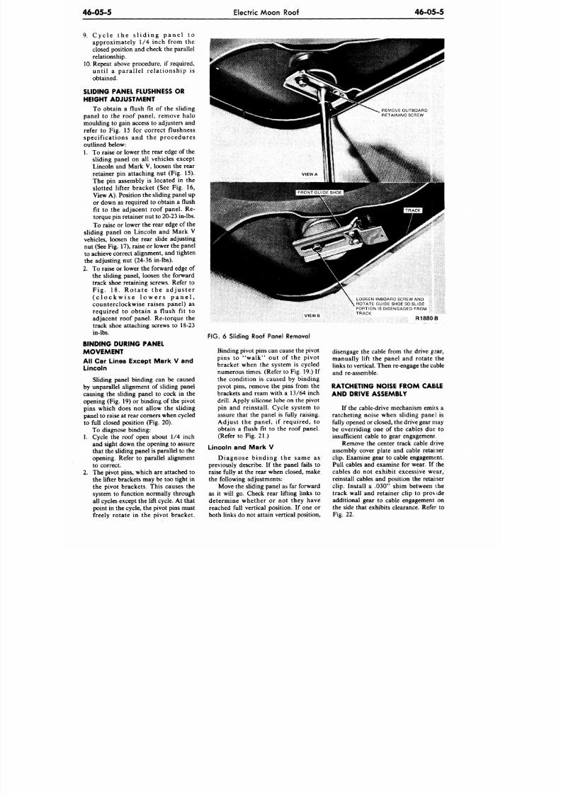
8/20/2019 1977 Ford Car Shop Manual Volume 4 Body
http://slidepdf.com/reader/full/1977-ford-car-shop-manual-volume-4-body 299/449
46-05-5
Electric Moon Roof
46-05-5
9. C y c l e t h e s l i d i n g p a n e l t o
approximately 1/4 inch from the
closed position and check the parallel
relationship.
10. Repeat above procedure, if required,
unt i l a para l le l re la t io nship i s
obtained.
SLIDING PANEL FLUSHNESS OR
HEIGHT ADJUSTMENT
To obtain a flush fit of the sliding
panel to the roof panel, remove halo
moulding to gain access to adjusters and
refer to Fig. 15 for correct flushness
specif ications and the procedures
outlined below:
1.
To raise or lower the rear edge of the
sliding panel on all vehicles except
Lincoln and Mark V, loosen the rear
retainer pin attaching nut (Fig. 15).
The pin assembly is located in the
slotted lifter bracket (See Fig. 16,
View A). Position the sliding panel up
or down as required to obtain a flush
fit to the adjacent roof panel. Re-
torque pin retainer nut to 20-23 in-lbs.
To raise or lower the rear edge of the
sliding panel on Lincoln and Mark V
vehicles, loosen the rear slide adjusting
nut (See Fig. 17), raise or lower the panel
to achieve correct alignment, and tighten
the adjusting nut (24-36 in-lbs).
2. To raise or lower the forward edge of
the sliding panel, loosen the forward
track shoe retaining screws. Refer to
F ig . 18 . Ro ta t e t he a d jus t e r
( c l o c k w i s e l o w e r s p a n e l ,
counterclockwise raises panel) as
required to obtain a flush fit to
adjacent roof panel. Re-torque the
track shoe attaching screws to 18-23
in-lbs.
BINDING DURING PANEL
MOVEMENT
All Car Lines Except Mark V and
Lincoln
Sliding panel binding can be caused
by unparallel alignment of sliding panel
causing the sliding panel to cock in the
opening (Fig. 19) or binding of the pivot
pins which does not allow the sliding
panel to raise at rear corners when cycled
to full closed position (Fig. 20).
To diagnose binding:
1. Cycle the roof open about 1/4 inch
and sight down the opening to assure
that the sliding panel is parallel to the
opening. Refer to parallel alignment
to correct.
2. The pivot pins, which are attached to
the lifter b rackets may be too tight in
the pivot brackets. This causes the
system to function normally through
all cycles except the lift cycle. At that
point in the cycle, the pivot pins must
freely rotate in the pivot bracket.
VIEWB
FIG. 6 Sliding Roof Panel Removal
Binding pivot pins can cause the pivot
pins to "walk" out of the pivot
bracket when the system is cycled
numerous times. (Refer to Fig. 19.) If
the condition is caused by binding
pivot pins, remove the pins from the
brackets and ream with a 13/64 inch
drill. Apply silicone lube on the pivot
pin and reinstall. Cycle system to
assure that the panel is fully raising.
Adjust the panel, if required, to
obtain a flush fit to the roof panel.
(Refer to Fig. 21.)
Lincoln and Mark V
Diagnose binding the same as
previously describe. If the panel fails to
raise fully at the rear when closed, make
the following adjustments:
Move the sliding panel as far forward
as it will go. Check rear lifting links to
determine whether or not they have
reached full vertical position. If one or
both links do not attain vertical position,
LOOSEN INBOARD SCREW AND
ROTATE GUIDE SHOE SO SLIDE
PORTION IS DISENGAGED FROM
TRACK
R1880B
disengage the cable from the drive gear,
manually lift the panel and rotate the
links to vertical. Then re-engage the cable
and re-assemble.
RATCHETING NOISE FROM CAELE
AND DRIVE ASSEMBLY
If the cable-drive m echanism emit s a
ratcheting noise when sliding panel is
fully opened or closed, the drive gear may
be overriding one of the cables due to
insufficient cable to gear engagement.
Remove the center track cable drive
assembly cover plate and cable retailer
clip.
Examine gear to cable engagement.
Pull cables and examine for wear. If the
cables do not exhibit excessive wear,
reinstall cables and position the retainer
clip. Install a .030" shim between the
track wall and retainer clip to provide
additional gear to cable engagement on
the side that exhibits clearance. Refer to
Fig. 22.
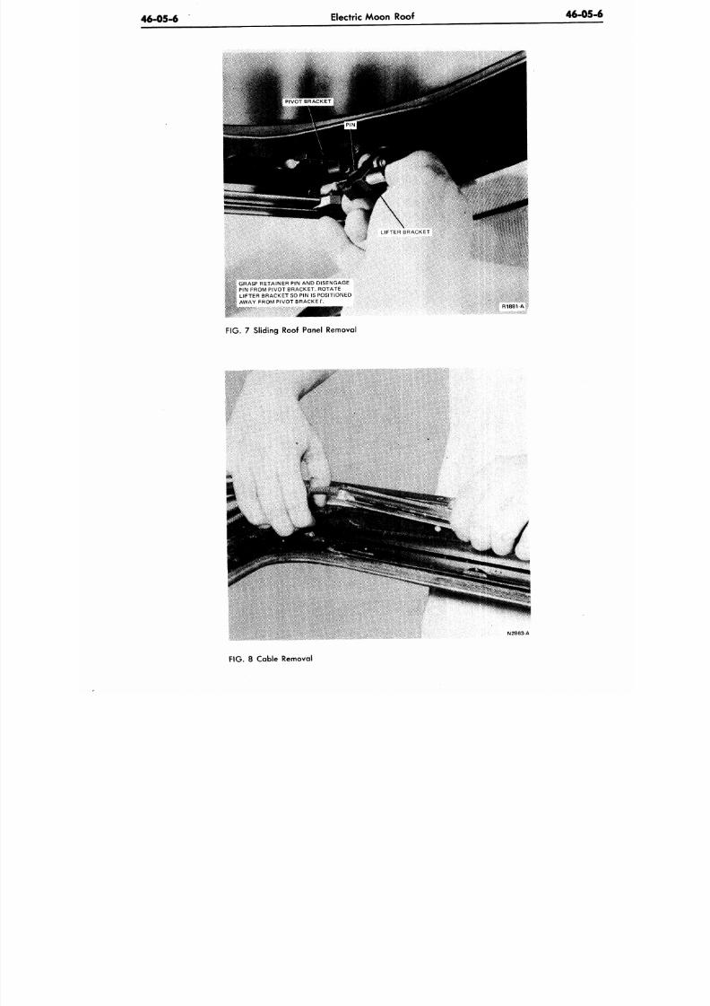
8/20/2019 1977 Ford Car Shop Manual Volume 4 Body
http://slidepdf.com/reader/full/1977-ford-car-shop-manual-volume-4-body 300/449
46-05-6
Electric Moon Roof
46-05
GRASP RETAINER PIN AND DISENGAGE
PIN FROM PIVOT BRACKET. ROTATE
•, LIFTER BRACKE T SO PIN IS POSITIONED
-" AWAY FROM PIVOT BRACKE T.
R1881-A
FIG. 7 Sliding Roof Panel Removal
N2863-A
F IG .
8 Cable Removal
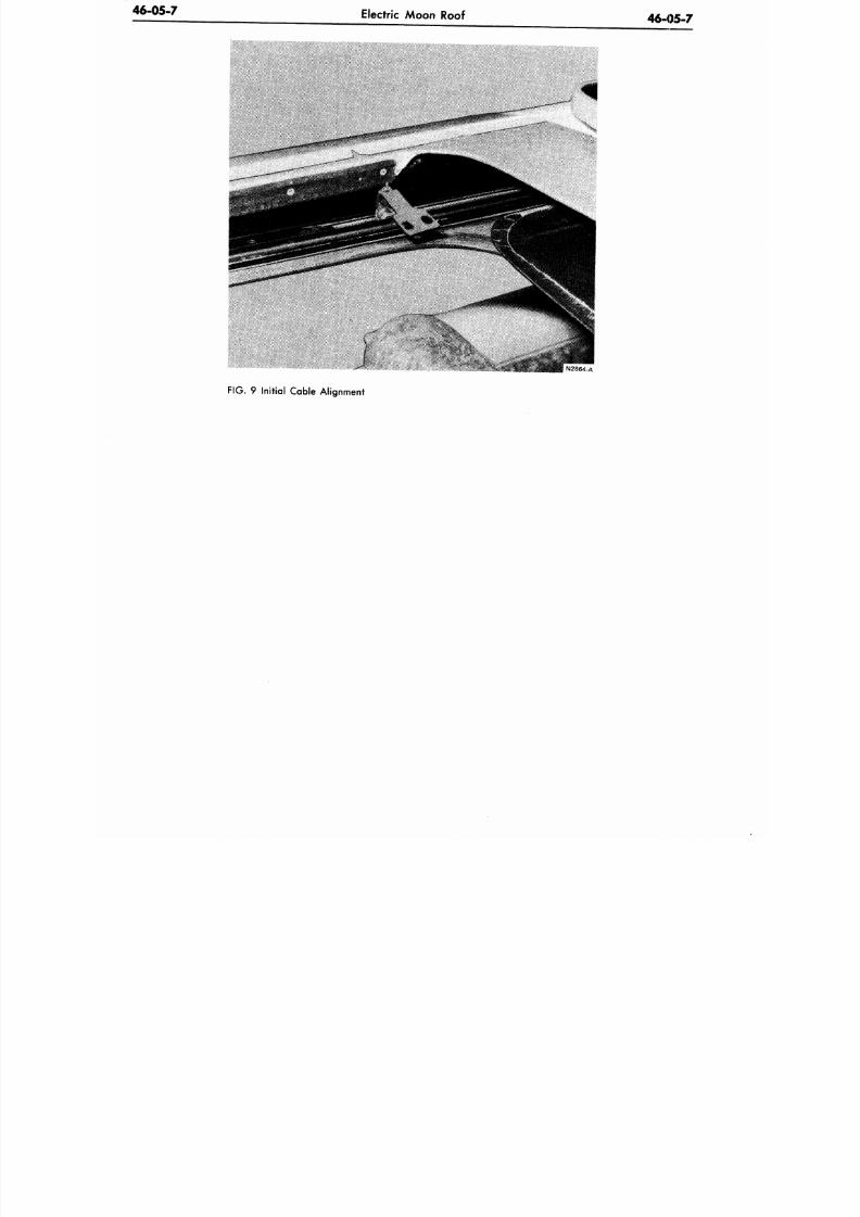
8/20/2019 1977 Ford Car Shop Manual Volume 4 Body
http://slidepdf.com/reader/full/1977-ford-car-shop-manual-volume-4-body 301/449
46-05-7
Electric Moon Roof
46-05-7
FIG.
9 Initial Cable Alignment
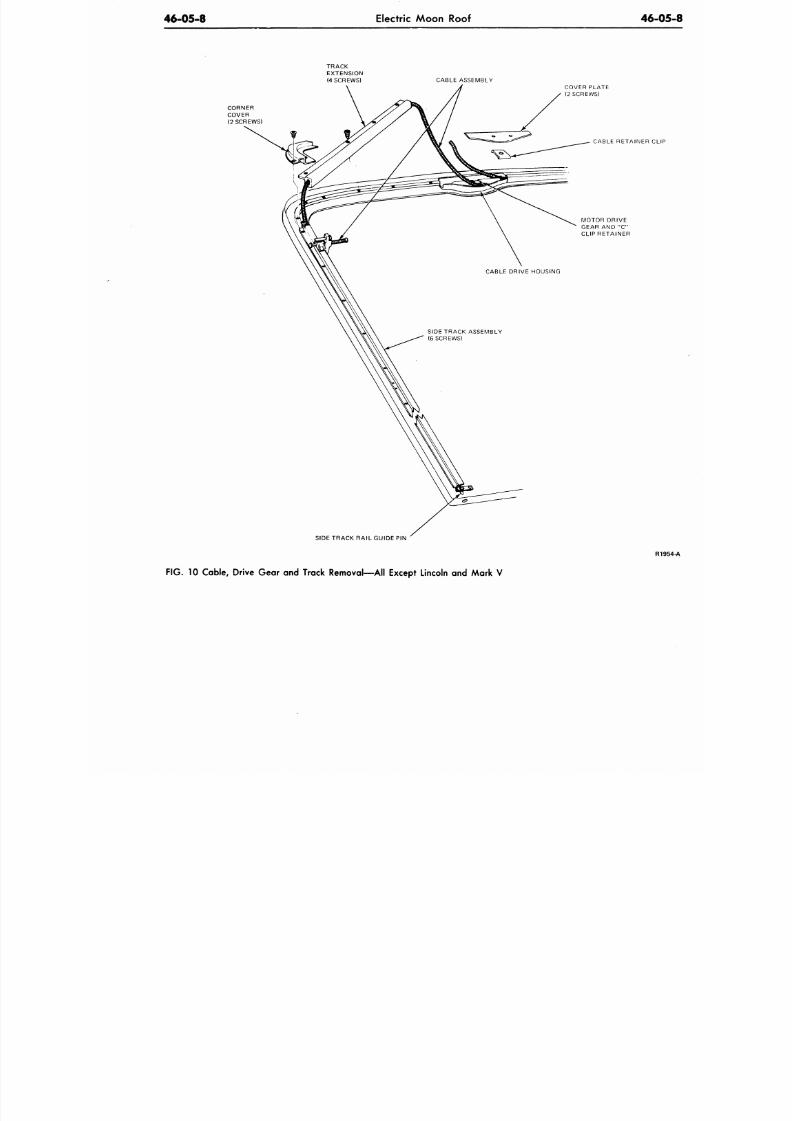
8/20/2019 1977 Ford Car Shop Manual Volume 4 Body
http://slidepdf.com/reader/full/1977-ford-car-shop-manual-volume-4-body 302/449
46-05-8
Electric Moon Roof
46-
CABLE ASSEMBLY
COVER PLATE
(2 SCREWS)
CABLE RETAINER CL
MOTOR DRIVE
GEAR AND "C"
CLIP RETAINER
SIDE TRACK RAIL GUIDE PIN
R
F IG . 10 Cable, Drive Gear and Track Removal—All Except Lincoln and Mark V
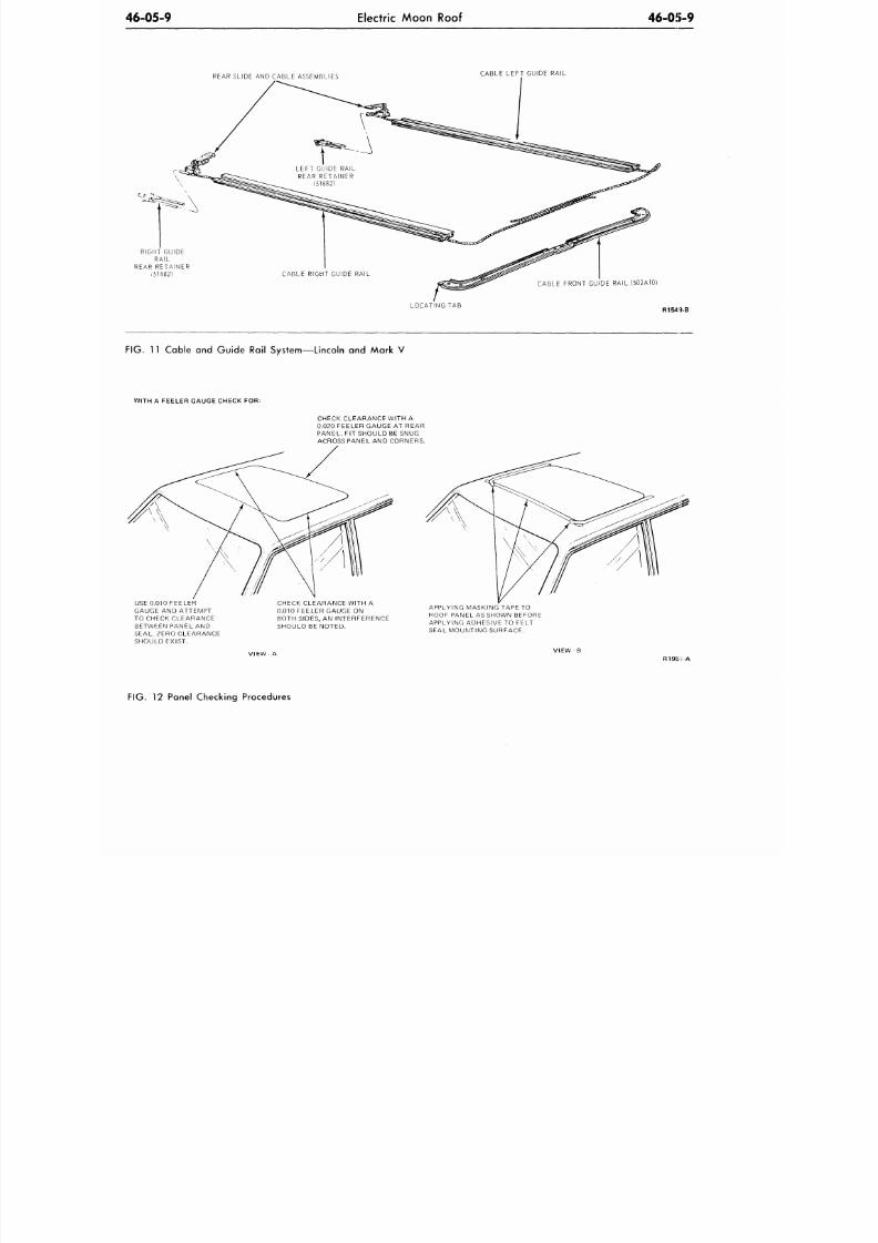
8/20/2019 1977 Ford Car Shop Manual Volume 4 Body
http://slidepdf.com/reader/full/1977-ford-car-shop-manual-volume-4-body 303/449
46-05-9
Electric Moon Roof
46-05-9
R E A R S L I D E
AND
C A B L E A S S E M B L IE S
C A B L E L E F T G U ID E R A I L
R I G H T G U I D E
R A I L
R E A R R E T A I N E R
151882)
C A B L E F R O N T G U I D E R A I L ( 5 0 2 A 1 0 )
L O C A T I N G
TAB
R154 3-B
FIG. 11
Cable
and
Guide Rail System—Lincoln
and
Mark
V
WITH A FEELER GAUGE CHECK FOR:
CHECK CLEARANCE WITH A
0.020 FEELER GAUGE AT REAR
PANEL.
FIT
SHOULD
BE
SNUG
ACROSS PAN EL
AND
CORNERS.
USE 0.010 FEELER
GAUGE AND ATTEMPT
TO CHECK CLEARANCE
BETWEEN PANEL AND
SEAL. ZERO CLEARANCE
SHOULD EXIST.
CHECK CLEARANCE WITH A
0.010 FEELER GAUGE ON
BOTH SIDES, AN INTERFERENCE
SHOULD BE NOTED.
APPLYING MASKING TAPE
TO
ROOF PANEL
AS
SHOWN BEFORE
APPLYING ADHESIVE TO FELT
SEAL MOUNTING SURFACE.
R195J: A
FIG. 12 Pane l Check ing Procedures
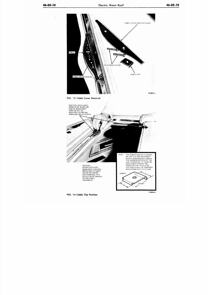
8/20/2019 1977 Ford Car Shop Manual Volume 4 Body
http://slidepdf.com/reader/full/1977-ford-car-shop-manual-volume-4-body 304/449
46-05-10
Electric Moon Roof
46-05
CABLE DRIVE HOUSING COVER
CABLE CLIP
R1883-A
FIG. 13 Cable Cover Removal
POSITION CABLE
AWAY
FROM GEAR. SLIDE ONE
SIDE OF MOON ROOF
FORE OR AFT AS
REQUIRED
TO
OBTAIN
PARALLEL RELATIONSHIP
CAUTION:
DO
NOT
ACTIVATE
MOON ROOF CONTROL
SWITCH WHILE CABLE
COVER OR CABLES
ARE REMOVED. THIS
COULD CAUSE DAMAGE
TO THE CABLE
ASSEMBLIES.
THE DOWNSTANDING FLANGES
ON THE CLIP ARE DIFFERENT
WIDTHS (DIMENSIONS A AND B).
THE NARROW PORTION
OF THE
CLIP (DIMENSION
"B")
MUST
BE
POSITIONED TOW ARD
THE
FRONT
OF THE
VEHICLE
OR
THE CABLES WILL
BE
DAMAGED
WHEN MOON ROOF IS CYCLED.
R1884
A
FIG.
14 Cable Clip Position
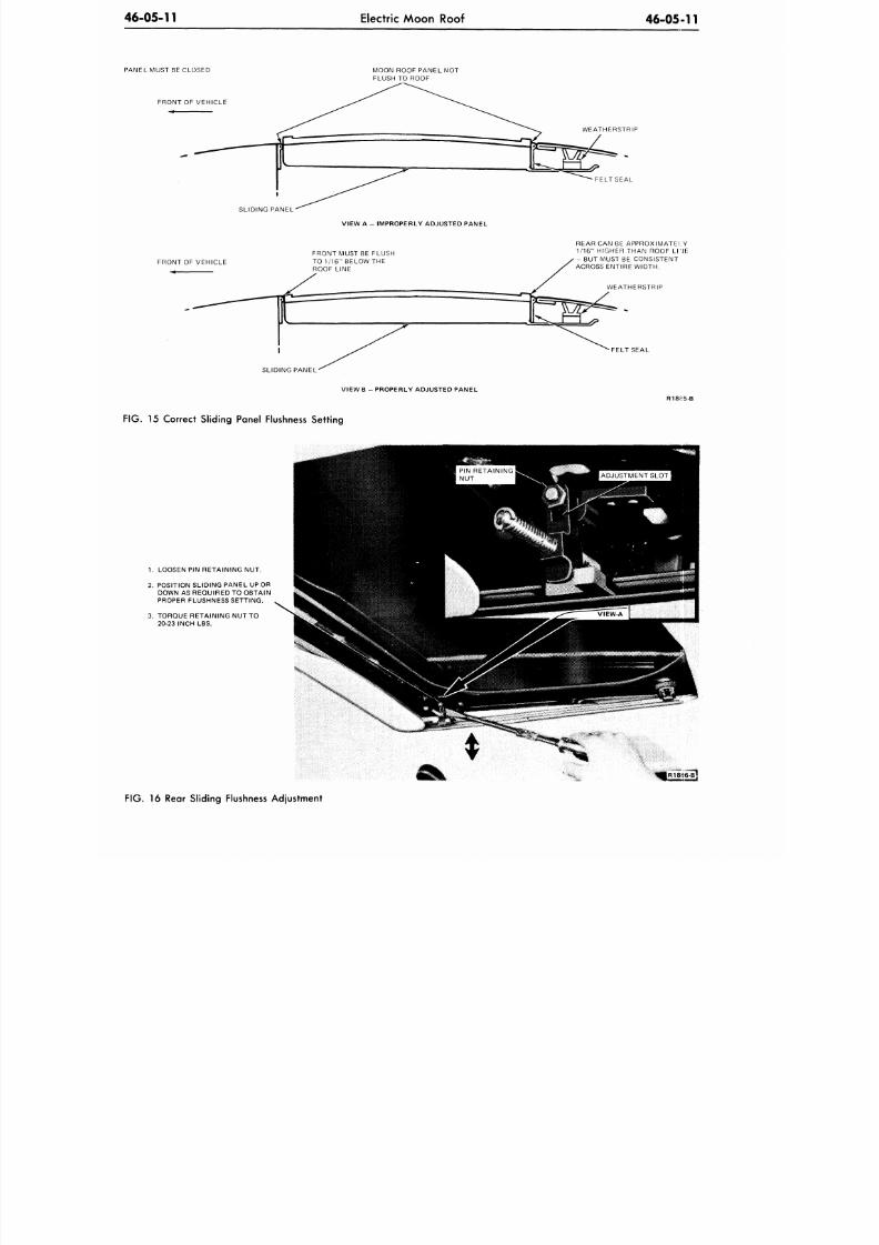
8/20/2019 1977 Ford Car Shop Manual Volume 4 Body
http://slidepdf.com/reader/full/1977-ford-car-shop-manual-volume-4-body 305/449
46-05-11
Electric Moon Roof
46-05-11
PANEL MUST BE CLOSED
FRONT OF VEHICLE
SLIDING PANEL
MOON ROOF PANEL NOT
FLUSH TO ROOF
WEATHERSTRIP
VIEW A - IMPROPERLY ADJUSTED PANEL
FRONT OF VEHICLE
FRONT MUST BE FLUSH
TO 1/16" BELOW THE
ROOF LINE
REAR CAN BE APPROXIMATELY
1/16" HIGHER THAN ROOF LTJE
- BUT MUST BE CONSISTENT
ACROSS ENTIRE WIDTH.
WEATHERSTRIP
FELT SEAL
SLIDING PANEL
VIEW B - PROPERLY ADJUSTE D PANEL
FIG. 15 Correct Sliding Panel Flushness Setting
R18::5-B
1. LOOSEN PIN RETA INING NUT .
2. POSITION SLIDING PANEL UP OR
DOWN AS REQUIRED TO OBTAIN
PROPER FLUSHNESS SETTING.
3. TORQUE RETAINING NUT TO
20-23 INCH LBS.
FIG.
16 Rear Sliding Flushness Adjustment
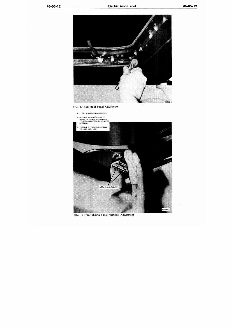
8/20/2019 1977 Ford Car Shop Manual Volume 4 Body
http://slidepdf.com/reader/full/1977-ford-car-shop-manual-volume-4-body 306/449
46-05-12
Electric Moon Roof
46-05-
N2865-A
FIG.
17 Rear Roof Panel Adjustment
1. LOOSEN ATT ACH ING SCREWS.
2. ROTATE ADJUSTOR NUT TO
RAISE OR LOWER MOON ROOF
TO OBTAIN PROPER FLUSHNESS
SETTING.
3. TORQUE ATTACH
ING
SCREWS
TO 18-23 INCH LBS.
mlmmmMip
F IG .
18 Front Sliding Panel Flushness Adjustment
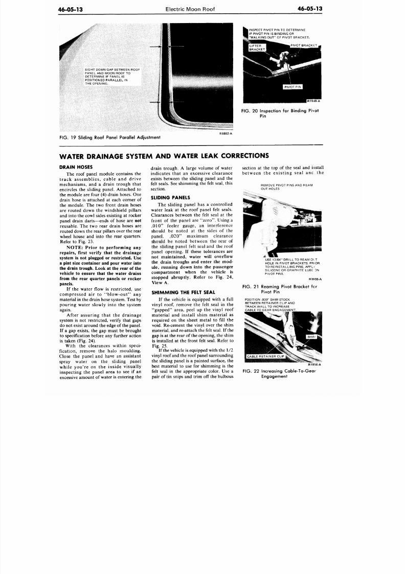
8/20/2019 1977 Ford Car Shop Manual Volume 4 Body
http://slidepdf.com/reader/full/1977-ford-car-shop-manual-volume-4-body 307/449
46-05-13
Electric Moon Roof
46-05-13
SIGHT DOWN GAP BETWEEN ROOF
PANEL AND MOON ROOF TO
DETERMINE IF PANEL IS
POSITIONED PARALLEL IN
THE OPENING.
INSPECT PIVOT PIN TO DETERMINE
IF PIVOT PIN IS BINDING OR
I "WA LKING OUT " OF PIVOT BRACKET,
R1949 A
FIG.
20 Inspection for Binding Pivot
Pin
FIG. 19 Sliding Roof Panel Parallel Adjustment
R1882-A
WATER DRAINAGE SYSTEM AND WATER LEAK CORRECTIONS
DRAIN HOSES
The roof panel module contains the
track assemblies , cable and drive
mechanisms, and a drain trough that
encircles the sliding panel. Attached to
the module are four (4) drain hoses. One
drain hose is attached at each corner of
the module. The two front drain hoses
are routed down the windshield pillars
and into the cowl sides existing at rocker
panel drain darts—ends of hose are
not
reusable. The two rear drain hoses are
routed down the rear pillars over the rear
wheel house and into the rear quarters.
Refer to Fig. 23.
NOTE: Prior to performing any
repairs, first verify that the drainage
system is not plugged or restricted. Use
a pint size container and pour water into
the drain trough. Look at the rear of the
vehicle to ensure that the water drains
from the rear quarter panels or rocker
panels.
If
the water flow is restricted, use
compressed air to "blow-out" any
material in the drain hose system. Test by
pouring water slowly into the system
again.
After assuring that the drainage
system is not restricted, verify that gaps
do not exist around the edge of the panel.
If a gap exists, the gap must be brought
to specification before any further action
is taken (Fig. 24).
With the clearances within speci-
fication, remove the halo moulding.
Close the panel and have an assistant
spray water on the sliding panel
while you're on the inside visually
inspecting the panel area to see if an
excessive amount of water is entering the
drain trough. A large volume of water
indicates that an excessive clearance
exists between the sliding panel and the
felt seals. See shimming the felt seal, this
section.
SLIDING PANELS
The sliding panel has a controlled
water leak at the roof panel felt seals.
Clearances between the felt seal at the
front of the panel are "zer o" . Using a
.010" feeler gauge, an interference
should be note d at the sides of the
panel. .020" maximum clearance
should be noted between the rear of
the sliding panel felt seal and the roof
panel opening. If these tolerances are
not maintained, water will overflow
the drain troughs and enter the mod-
ule, running down into the passenger
compartment when the vehicle is
stopped abruptly. Refer to Fig. 24,
View A.
SHIMMING THE FELT SEAL
If the vehicle is equipped with a full
vinyl roof, remove the felt seal in the
"gapped" area, peel up the vinyl roof
material and install shim material as
required on the sheet metal to fill the
void. Re-cement the vinyl over the shim
material, and re-attach the felt seal. If the
gap is at the rear of the opening, the shim
is installed at the front felt seal. Refer to
Fig. 25.
If the vehicle is equipped w ith the 1/2
vinyl roof and the roof panel surrounding
the sliding panel is a painted surface, the
best material to use for shimming is the
felt seal in the appropriate color. Use a
pair of tin snips and trim off the bulbous
section at the top of the seal and install
between the existing seal anc the
REMOVE PIVOT PINS AND REAM
OUT HOLES
USE 13/64" DRILL TO REAM OUT
HOLE IN PIVOT BRACKETS. PRIOR
TO REINSTAL LING PINS, APPLV
SILICONE OR GRAPHITE LUBE DN
PIVOT PINS.
R15I55-A
FIG. 21 Reaming Pivot Bracket for
Pivot Pin
POSITION .030" SHIM STOCK
BETWEEN RETAINER CLIP AND
TRACK WALL TO INCREASE
CABLE TO GEAR ENGAGEMENT.
R19EI6-A
FIG. 22 Increasing Cable-To-Geai
Engagement
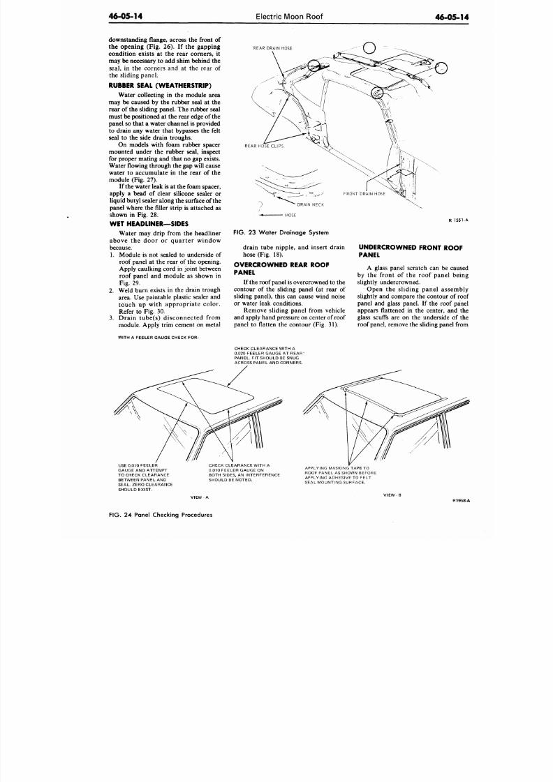
8/20/2019 1977 Ford Car Shop Manual Volume 4 Body
http://slidepdf.com/reader/full/1977-ford-car-shop-manual-volume-4-body 308/449
46-05-14
Electric Moon Roof
46-05-1
downstanding flange, across the front of
the opening (Fig. 26). If the gapping
condition exists at the rear corners, it
may be necessary to add shim behind the
seal, in the corners and at the rear of
the sliding panel.
RUBBER SEAL (WEATHERSTRIP)
Water collecting in the module area
may be caused by the rubber seal at the
rear of the sliding panel. The rubber seal
must be positioned at the rear edge of the
panel so that a water channel is provided
to drain any water that bypasses the felt
seal to the side drain troughs.
On models with foam rubber spacer
mounted under the rubber seal, inspect
for proper mating and that no gap exists.
Water
flowing
hrough the gap will cause
water to accumulate in the rear of the
module (Fig. 27).
If the water leak is at the foam spacer,
apply a bead of clear silicone sealer or
liquid butyl sealer along the surface of the
panel where the filler strip is attached as
shown in Fig. 28.
WET HEADLINER—SIDES
Water may drip from the headliner
above the door or quarter window
because.
1. Module is not sealed to underside of
roof panel at the rear of the opening.
Apply caulking cord in joint between
roof panel and module as shown in
Fig. 29.
2.
Weld burn exists in the drain trough
area. Use paintable plastic sealer and
touch up with appropriate color.
Refer to Fig. 30.
3.
Drain tube(s) disconnected from
module. Apply trim cement on metal
W ITH A FEELER GAUGE CHECK FOR:
REAR DRAIN HOSE
REAR HOSE CLIPS
-« HOSE
FIG.
23 Wa ter Draina ge System
drain tube nipple, and insert drain
hose (Fig. 18).
OVERCROWNED REAR ROOF
PANEL
If the roof panel is overcrowned to the
contour of the sliding panel (at rear of
sliding panel), this can cause wind noise
or water leak conditions.
Remove sliding panel from vehicle
and apply hand pressure on center of roof
panel to flatten the contour (Fig. 31).
R 155
UNDERCROWNED FRONT ROOF
PANEL
A glass panel scratch can be caus
by the front of the roof panel bei
slightly undercrowned.
Open the sliding panel assemb
slightly and compare the contour of ro
panel and glass panel. If the roof pa
appears flattened in the center, and
glass scuffs are on the underside of
roof panel, remove the sliding panel fro
CHECK CLEARANCE WITH A
0.020
FEELER GAUGE AT REAR '
PANEL. FIT SHOULD BE SNUG
ACROSS PANEL AND CORNERS.
USE 0.010 FE ELER
GAUGE AND ATTEMPT
TO CHECK CLEARANCE
BETWEEN PANEL AND
SEAL. ZERO CLEARANCE
SHOULD EXIST.
CHECK CLEARANCE W ITH A
0.010 FEELER GAUGE ON
BOTH SIDES. AN INTERFERENCE
SHOULD BE NOTED.
APPLYING MASKING TAPE TO
ROOF PANEL AS SHOWN BEFORE
APPLYING ADHESIVE TO FELT
SEAL MOUNTING SURFACE.
VIEW A
V I E W - B
R19
FIG. 24 Panel Checking Procedures
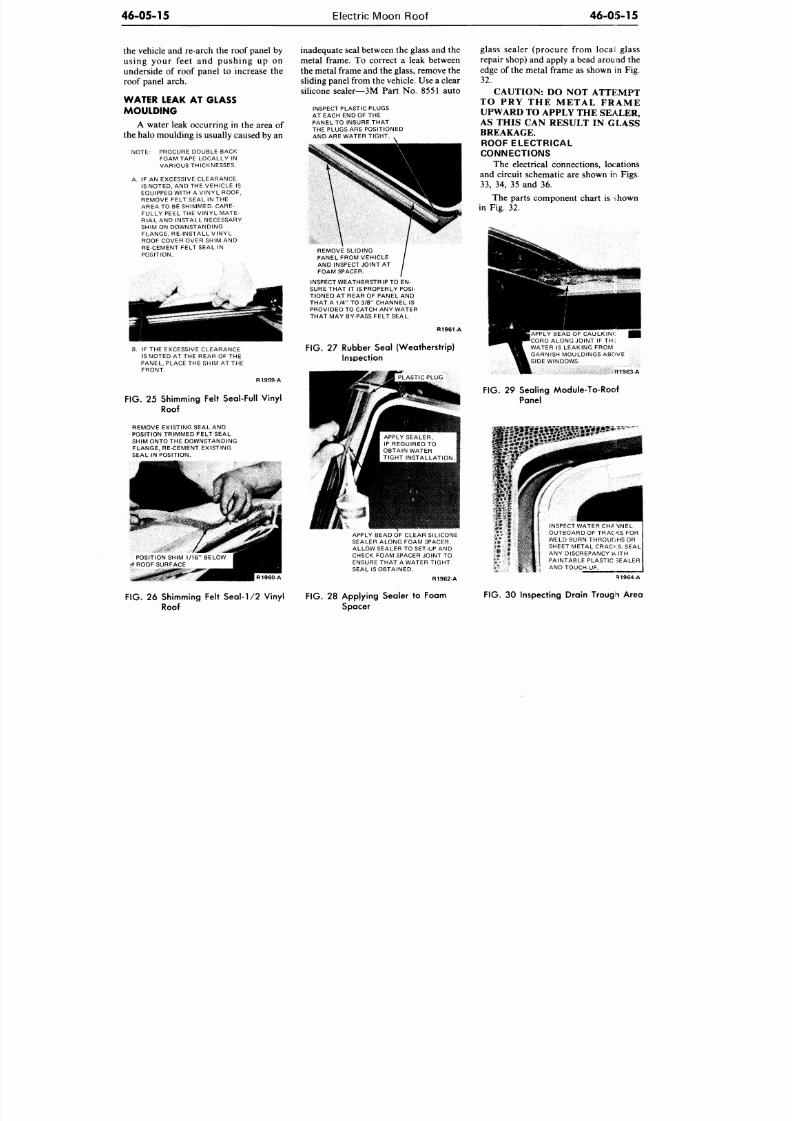
8/20/2019 1977 Ford Car Shop Manual Volume 4 Body
http://slidepdf.com/reader/full/1977-ford-car-shop-manual-volume-4-body 309/449
46-05-15
Electric Moon Roof
4 6 - 0 5 - 1 5
the vehicle and re-arch the roof panel by
using your feet and pushing up on
underside of roof panel to increase the
roof panel arch.
WATER LEAK AT GLASS
MOULDING
A water leak occurring in the area of
the halo m oulding is usually caused by an
NOTE: PROCURE DOUBLE BACK
FOAM TAPE LOCALLY IN
VARIOUS THICKNESSES.
A. IF AN EXCESSIVE CLEARANCE
IS NOTED, AND THE V EHICLE IS
EQUIPPED WITH A VINY L ROOF,
REMOVE FELT SEAL IN THE
AREA TO BE SHIMMED. CARE-
FULLY PEEL THE VINYL MATE-
RIAL AND INSTALL NECESSARY
SHIM ON DOWNSTANDING
FLANGE. RE-INSTALL VIN YL
ROOF COVER OVER SHIM AND
RE-CEMENT FELT SEAL IN
POSITION.
inadequa te seal between the glass and the
metal frame. To correct a leak between
the metal frame and the glass, remove the
sliding panel from the vehicle. Use a clear
silicone sealer—3M Part No. 8551 auto
INSPECT PLAST IC PLUGS
AT EACH END OF THE
PANEL TO INSURE TH AT
THE PLUGS ARE POSITIONED
AND ARE WATER TIGHT.
REMOVE SLIDING
PANEL FROM VEHICLE
AND INSPECT JOINT AT
FOAM SPACER.
I
INSPECT WEATHERSTRIP TO EN-
SURE THAT IT IS PROPERLY
POSI-
TIONED AT REAR OF PANEL AND
THAT A 1/4" TO 3/8" CHANNEL IS
PROVIDED TO CATCH ANY WATER
THAT MAY BY-PASS FELT SEAL.
R1961-A
B. IF THE EXCESSIVE CLEARAN CE
IS NOTED AT THE REAR OF THE
PANEL, PLACE THE SHIM A T THE
FRONT.
FIG. 27 Rubber Seal (Weatherstrip)
Inspection
R1959 A
FIG.
25 Shimming Felt Seal-Full Vinyl
Roof
REMOVE EXISTING SEAL AND
POSITION TRIMMED FELT SEAL
SHIM ONTO THE DOW NSTANDING
FLANG E, RE-CEMENT E XISTING
SEAL IN POSITION.
APPLY SEALER,
IF REQUIRED TO
OBTAIN WATER
TIGHT INSTALLATION.
POSITION SHIM 1/16" BELOW
-* ROOF SURFACE
R1960 A
APPLY BEAD OF CLEAR L CONE
SEALER ALONG FOAM SPACER.
ALLOW SEALER TO SET-UP AND
CHECK FOAM SPACER JOINT TO
ENSURE THAT A WATER TIGHT
SEAL IS OBTAINED.
Ft 1962 A
glass sealer (procure from local glass
repair shop) and apply a bead arou nd the
edge of the metal frame as shown in Fig.
32.
CAUTION: DO NOT ATTEMPT
T O P R Y T H E M E T A L F R A M E
UPWARD TO APPLY THE SEALER,
AS THIS CAN RESULT IN GLASS
BREAKAGE.
ROOF ELECTRICAL
CONNECTIONS
The electrical connections, locations
and circuit schematic are shown in Figs.
33,
34, 35 and 36.
The parts component chart is ihown
in Fig. 32.
jAPPLY BEAD OF CAULKINC
•CORD ALONG JOINT IF TH;
WATER IS LEAKING FROM
GARNISH MOULDINGS ABOVE
SIDE WINDOWS.
K1963-A
F IG . 29 Sealing Module-To-Roof
Panel
INSPECT WATER CHANiNEL
OUTBOARD OF TRACKS FOR
WELD BURN THROUCiHS OR
SHEET METAL CRACKS. SEAL
ANY DISCREPANCY WITH
PAINTABLE PLASTIC SEALER
AND TOUCH-UP.
R1964-A
FIG. 26 Shimming Felt Seal-1/2 Vinyl
Roof
FIG.
28 Applying Sealer to Foam
Spacer
FIG. 30 Inspecting Drain Trough Area
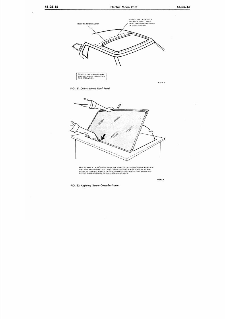
8/20/2019 1977 Ford Car Shop Manual Volume 4 Body
http://slidepdf.com/reader/full/1977-ford-car-shop-manual-volume-4-body 310/449
46-05-16
Electric Moon Roof
46-05-1
ROOF REINFORCEMENT
TO FLATTEN OR DE-ARCH
THE ROOF PANEL, APPLY
HAND PRESSURE AT CENTER
OF ROOF OPENING.
REMOVE THE SLIDING PANE L
AND SUN SHADE TO PERFORM I
THIS OPERATION. I
R1965- A
FIG. 31 Overcrowned Roof Panel
PLACE PANEL AT A 45° ANGLE FROM THE HOR IZONTAL SURFACE OF WORK BENCH
AND SEAL MOULDING BY APPLYING CLEAR SILICONE SEALER, PART 3M NO. 8551
CLEAR AUTO GLASS SEALER, OR EQUIV ALENT BETWEEN MOULDING AND GLASS.
REPEAT THIS PROCEDURE FOR ALL REMAINING SIDES.
R1889-A
FIG .
32 Applying Sealer-Glass-To-Frame
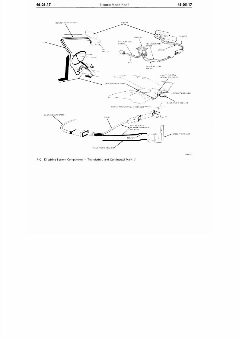
8/20/2019 1977 Ford Car Shop Manual Volume 4 Body
http://slidepdf.com/reader/full/1977-ford-car-shop-manual-volume-4-body 311/449
46-05-17
Electric Moon Roof
46-0')-17
HEADER WIRE (BLACK)
MOTOR
(BLACK)
EXISTING WIRE (RED)
CIRCUIT BREAKER
HEADER WIRE (BLACK)
CIRCUIT BREAKER
HEADER WIRE (BLACK)
M 8 9 2 - C
FIG. 33 Wiring System Components — Thunderbird and Continental Mark V
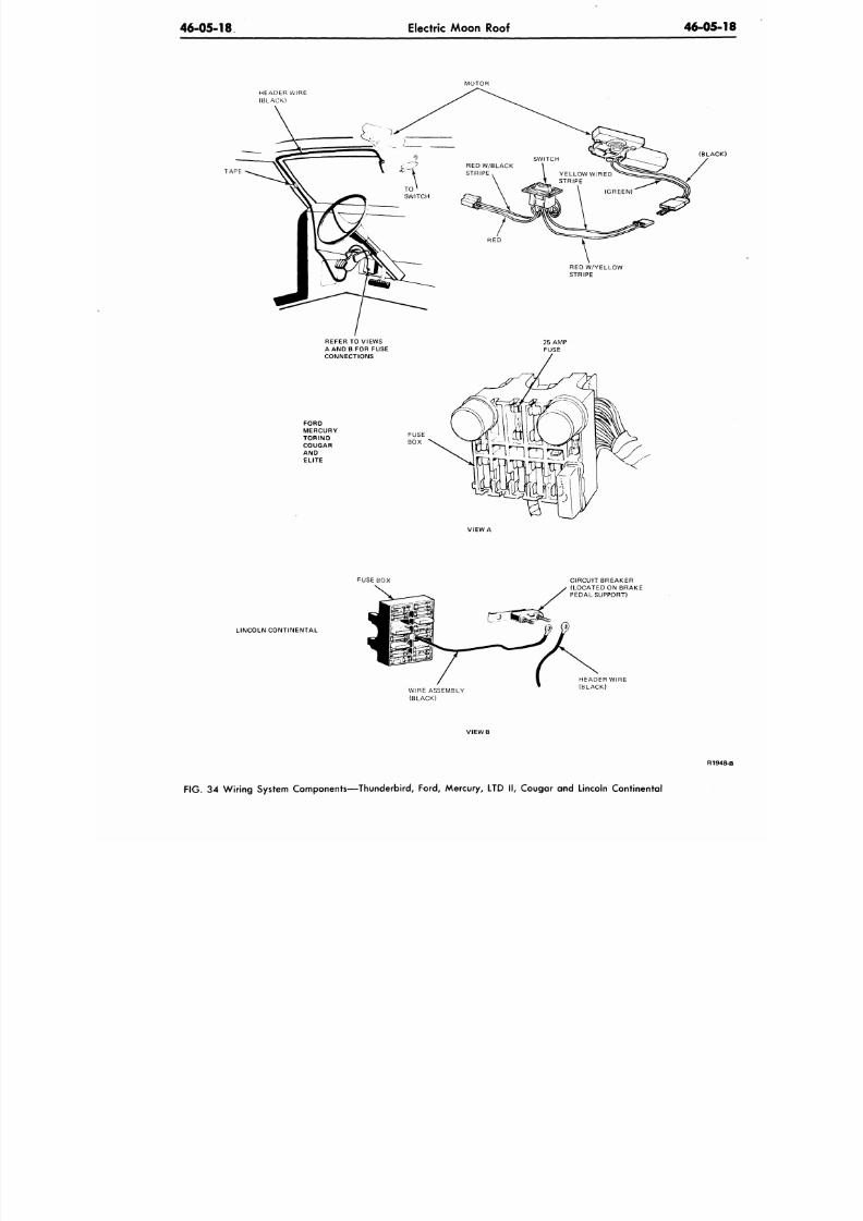
8/20/2019 1977 Ford Car Shop Manual Volume 4 Body
http://slidepdf.com/reader/full/1977-ford-car-shop-manual-volume-4-body 312/449
46-05-18
Electric Moon Roof
46-05
MOTOR
HEADER WIRE
(BLACK)
TAPE
REFER
TO
VIEWS
A AND B FOR FUSE
CONNECTIONS
FORD
MERCURY
TORINO
COUGAR
AN D
ELITE
RED W/YELLOW
STRIPE
(BLAC
VIEW A
FUSE BOX
LINCOLN CONTINENTAL
WIRE ASSEMBLY
(BLACK)
CIRCUIT BREAKER
(LOCATED ON BRAKE
PEDAL SUPPORT)
HEADER WIRE
(BLACK)
VIEW B
FIG. 34
Wiring System Compo nents—Thunderbird,
Ford,
Mercury,
LTD II,
Cougar
and
Lincoln Continental
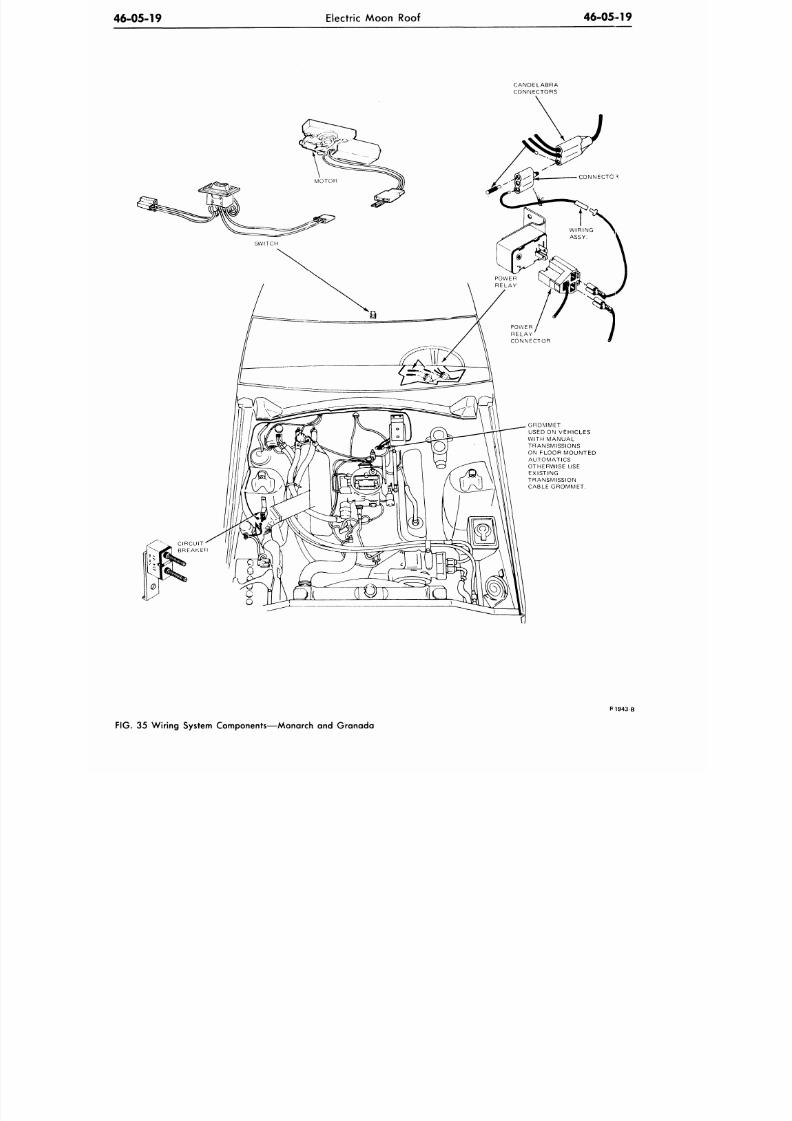
8/20/2019 1977 Ford Car Shop Manual Volume 4 Body
http://slidepdf.com/reader/full/1977-ford-car-shop-manual-volume-4-body 313/449
46-05-19
Electric Moon Roof
46-05-19
CANDELABRA
CONNECTORS
POWER
RELAY
CONNECTOR
GROMMET
USED ON VEHICLES
WITH MANUAL
TRANSMISSIONS
ON FLOOR MOUNTED
AUTOMATICS
OTHERWISE USE
EXISTING
TRANSMISSION
CABLE GROMMET.
P1943 B
FIG. 35 Wiring System Components—Monarch and Granada
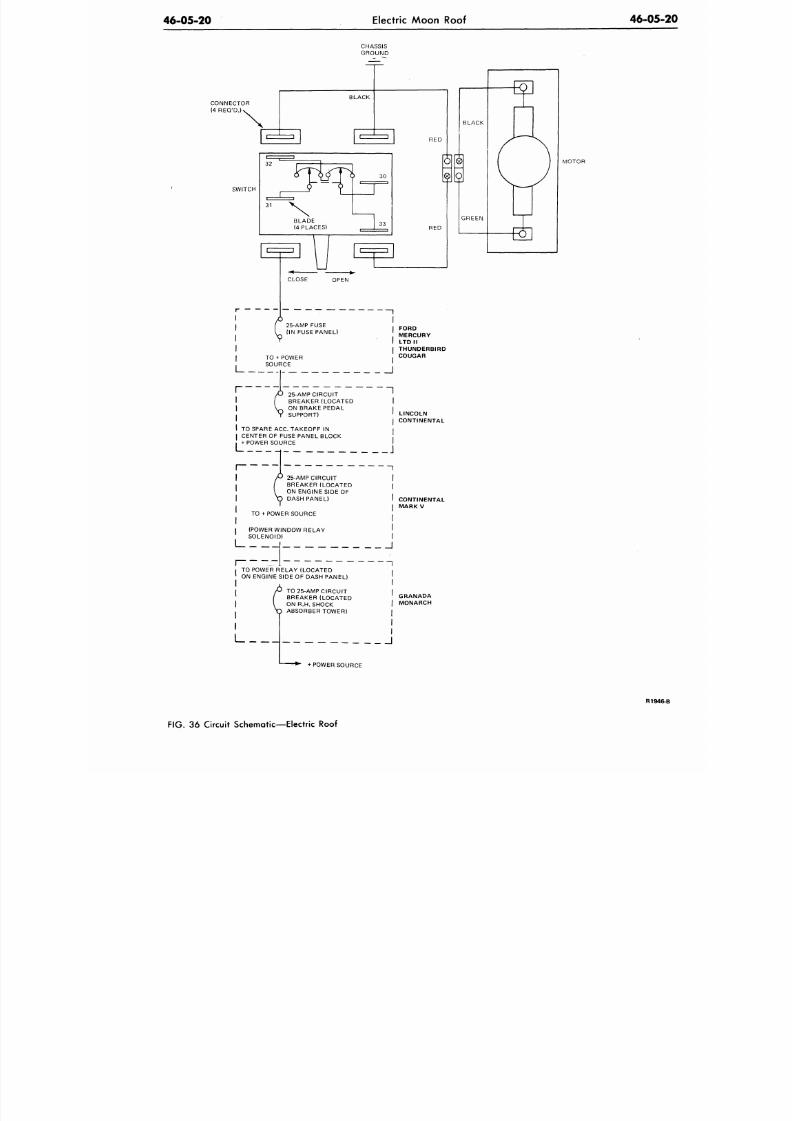
8/20/2019 1977 Ford Car Shop Manual Volume 4 Body
http://slidepdf.com/reader/full/1977-ford-car-shop-manual-volume-4-body 314/449
46-05-20
Electric
Moon Roof
46-05
CHASSIS
GROUND
CONNECTOR
(4 REQ'D.)<
SWITCH
3 0
BLACK
R E D
GREEN
MOTOR
CLOSE OPEN
25-AMP FUSE
(IN FUSE PANEL)
TO + POWER
SOURCE
I
I FORD
MERCURY
I LTD II
I THUNDERBIRD
,
COUGAR
_J
L
25-AMP CIRCUIT
BREAKER (LOCATED
ON BRAKE PEDAL
SUPPORT)
TO SPARE ACC. TAKEOFF IN
CENTER OF FUSE PANEL BLOCK
POWER SOURCE
LINCOLN
CONTINENTAL
25-AMP CIRCUIT I
BREAKER (LOCATED |
ON ENGINE SIDE OF
DASH PANEL) I
I
TO + POWER SOURCE •
(POWER WINDOW RELAY '
SOLENOID) I
I 1 1
CONTINENTAL
MARK V
ON ENGINE SIDE OF DASH PANEL)
P TO 25-AMP CIRCUIT
/
BREAKER (LOCATED
\
ON R.H. SHOCK
ABSORBER TOWER)
L
GRANADA
MONARCH
J
+ POWER SOURCE
R 1 9 4
FIG.
36
Circuit Sche matic—Electric Roof
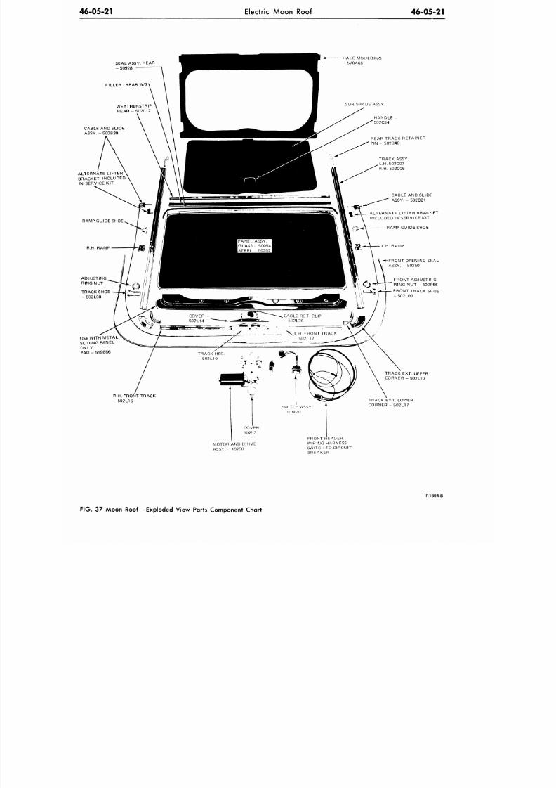
8/20/2019 1977 Ford Car Shop Manual Volume 4 Body
http://slidepdf.com/reader/full/1977-ford-car-shop-manual-volume-4-body 315/449
46-05-21
Electric Moon Roof
46-05-21
SEAL ASSY. REAR
- 50928
FILLER
-
REAR
W/S
ALO MOULDING
5 / 8 A 6 6
CABLE AND SLIDE
ASSY. - 502B20
ALTERNATE LIFTER
BRACKET INCLUDED
IN SERVICE KIT
SUN SHADE ASSY.
u
>
V
V
L . H . FRONT TRACK
502L17
HANDLE -
502C34
REAR TRACK RETAINER
PIN - 502B40
TRACK ASSY.
L.H.502C07
R.H.502C06
CABLE AND SLIDE
ASSY.
-
502B21
ALTERNATE L IFTER BRACKET
INCLUDED
IN
SERVICE
KIT
RAMP GUIDE SHOE
-* -FRONT OPENING Si iAL
ASSY.
-
50250
FRONT ADJUSTING
RING/NUT - 502IJ66
FRONT TRACK SHOE
- 502L09
USE WITH M ETAL
SLIDING PANEL
ONLY
PAD - 519B66
R.H. FRONT TRACK
- 5 0 2 L 1 6
TRACK
EXT.
UPPER
CORNER - 502L17
TRACK EXT. LOWER
CORNER
-
502L17
MOTOR
AND
DRIVE
ASSY. 15790
FRONT HEADER
WIRING HARNESS
SWITCH TO-CIRCUIT
BREAKER
R1894-B
FIG. 37 Moon Roof—Exploded View Parts Component Chart
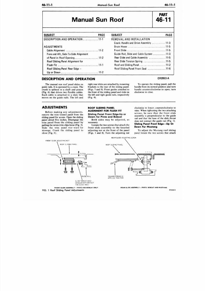
8/20/2019 1977 Ford Car Shop Manual Volume 4 Body
http://slidepdf.com/reader/full/1977-ford-car-shop-manual-volume-4-body 316/449
46-11-1 Manual-Sun Roof
46-1
Manual Sun Roof
P A R T
46-11
SUBJECT PAGE
SUBJECT
PAG
DESCRIPTION AND OPERATION 11-1
ADJUSTMENTS
Cable Alignm ent 11-2
Fore and Aft, Side-To-Side Alignment
of Panel in Roo f Opening 11-2
Roof Sliding Panel Alignment for
Flush Fit 11-1
Roo f Sliding Panel Rear Edge -
Up or Dow n 11-2
REM O VAL AND INST AL L AT IO N
Crank Handle and Drive Assem bly 11-3
Drain Hoses 1.1-5
Fro nt Slide 11-5
Guide
Rail,
Slide and Cable System 11-3
Rear Slide and Cable Assem bly 11-5
Rear Slide Tension Spring 11-5
Roo f and Sliding Panel 11-2
Roo f Sliding Panel Fro nt Seal 11-6
DESCRIPTION AND OPERATION
The manual sun roof panel slides on
guide rails. It is operated by a crank. The
crank is splined to a shaft and pinion
(Fig. 6) that drives two flexible cables.
Each cable is attached to a slide that
moves on the guide rails. The left and
right rear slides are attached by mounting
brackets to the rear of the sliding panel.
(Figs. 5 and 8). Front guides attached to
the front of the sliding panel and slide on
the left and right guide rails, respectively
(Fig. 4).
CR2853-A
To operate the sliding panel, pu
handle from its stowed position and
handle counterclockwise to open;
clockwise to close.
ADJUSTMENTS
Before making any adjustments,
remove the trim (inner) panel from the
sliding panel for access. Open the sliding
panel about five inches. Disengage the
trim panel from the sliding panel by
pulling the seven trim clips loose (Fig. 3).
Slide the trim panel rear-ward for
stowage. Crank the sliding panel to
close (Fig. 4) .
FRONT SLIDE ADJUSTING NUT
ROOF SLIDING PANEL
ROOF SLIDING PANEL
ALIGNMENT FOR FLUSH FIT
Sliding Panel Front Edge-Up or
Down for Pinto and Bobcat
Both sides may be adjusted, as
necessary.
Loosen the two screws that attach the
front slide assembly to the knurled
adjusting nut at the front of the panel
(Figs. 1 and 4). Turn the adjusting nut
clockwise to lower; counterclockwi
raise. When tightening the two attac
screws, be sure that the front
assembly is perpendicular to the g
rail and that the base of the slide t
does not contact the guide rail (Fig
Sliding Panel Front Edge—Up
Down For Mustang
To adjust the Mustang roof sli
panel loosen the two screws that a
REAR SLIDE ADJUSTING SCREW
ROOF SLIDING PANEL
GUIDE RAIL
SLIDE THROAT BASE
(SHOULD NOT CONTACT
THE GUIDE RAIL)
FRONT SLIDE ASSEMBLY - PINTO AND BOBCAT ONLY
TENSION SPRING IN
APPLIED POSITION
REAR SLIDE ASSEMBLY - PINTO BOBCAT AND MUSTANG
FIG.
1 Roof Sliding Panel Adjustments
R
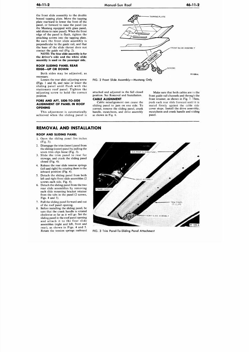
8/20/2019 1977 Ford Car Shop Manual Volume 4 Body
http://slidepdf.com/reader/full/1977-ford-car-shop-manual-volume-4-body 317/449
46-11-2
Manual-Sun Roof
46-11-2
the front slide assembly to the double
bossed tapping plate. Move the tapping
plate rearward to lower the front of the
panel, or forward to raise the panel (on
the Mustang equipped with glass panel,
add shims to raise panel). When the front
edge of the panel is f lush, tighten the
attaching screws into the tapping plate.
Be sure the f ront s l ide assembly is
perpendicular to the guide rail, and that
the base of the s l ide throat does not
contact the guide rail (Fig. 2).
NO TE: The blue slide assembly is for
the driver's side and the white slide
assembly is used on the passenger side.
ROOF SLIDING PANEL REAR
EDGE—UP OR D OW N
Both sides may be adjusted, as
necessary.
Loosen the rear slide adjusting screw
(Figs. 1 and 4), and raise or lower the
sliding panel until f lush with the
stationary roof panel. Tighten the
adjusting screw to hold the correct
position.
FORE AND AFT, SIDE-TO-SIDE
ALIGNMENT OF PANEL IN ROOF
OPENING
This adjustment is automatically
achieved when the sliding panel is
TAPPING PLATE
FRONT SLIDE ASSEMBLY
SCREWS
R1I559-A
FIG. 2 Front Slide Assembly—Mustang Only
attached and adjusted in the full closed
position. See Removal and Installation.
CABLE ALIGNMENT
Cable misalignment can cause the
sl id ing panel to jam on one s ide. To
correct, remove the sliding panel, crank
handle, escutcheon, and drive assembly
as shown in Fig. 6.
Make sure that both cables are
i n
the
front guide rail channels and through the
front retainer, as shown in Fig. 7. Then,
push each rear slide forward until it is
seated firmly against the cable side
cover stops. Install the drive assembly,
escutcheon and crank handle and sliding
panel.
REMOVAL AND INSTALLATION
ROOF AND SLIDING PANEL
1. Open the sliding panel five inches
(Fig. 3).
2. Disengage the trim (inner) panel from
the sliding (outer) panel by pulling the
seven trim clips loose (Fig. 3).
3. S l id e th e t r im p an e l to r ea r fo r
stowage, and crank the sliding panel
closed (Fig. 4).
4. Release the rear slide tension springs
(left and right) by rotating them to the
inboard position (Fig. 4).
5.
Detach the sliding panel from both
left and right front slide assemblies (2
screws each side, Fig. 4).
6. Deta ch the sliding panel from the two
rear s l ide assemblies by removing
each slide mounting bracket retainer
from the tabs in the panel (2 screws,
Figs.
4 and 5).
7. Pull the sliding panel forward and out
of the roof panel opening.
8. Before installing the sliding panel, be
sure that the crank handle is rotated
clockwise as far as it will go. Set the
sliding panel in the roof panel opening
an d a t tach i t to th e fo u r s l id e
assemblies (right and left, front and
rear) , as shown in Figs . 4 and 5 .
Rotate the tension springs outboard
TRIM PANEL
(7) CLIPS
FRONT SLIDE ASSEMBLY
V S J S J * ? ?
FIG. 3 Trim Panel-To-Sliding Panel Attachment
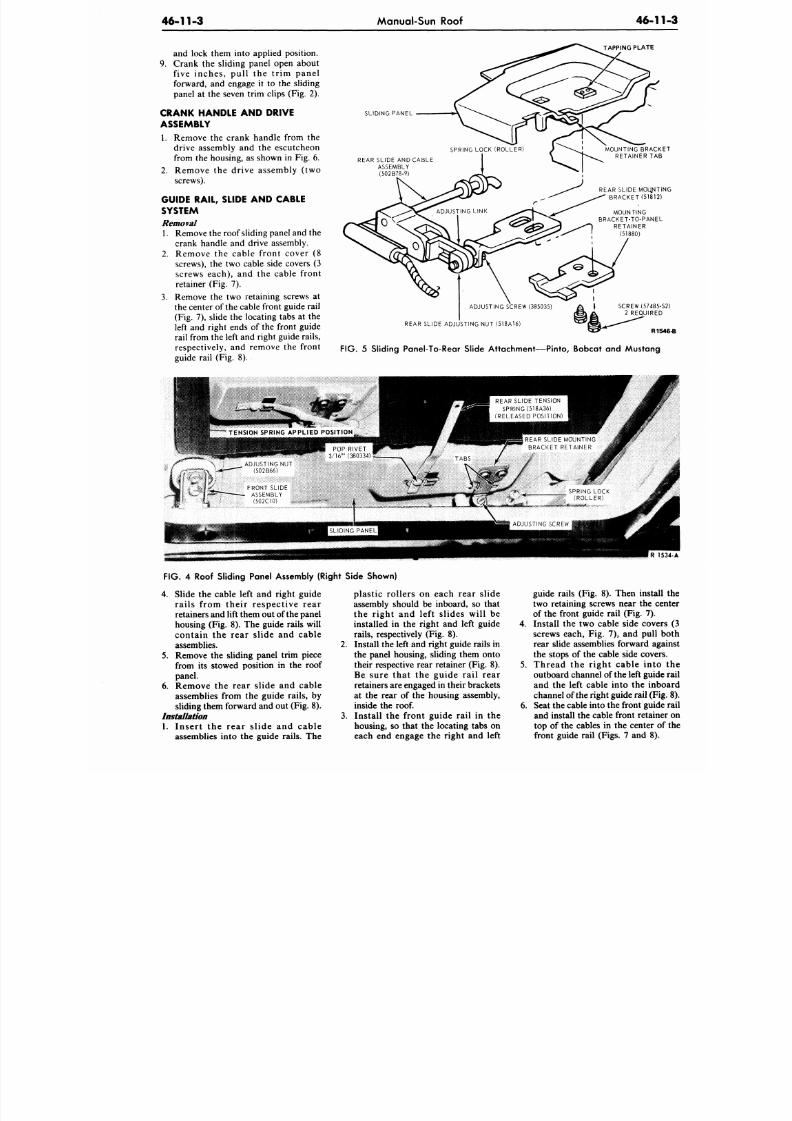
8/20/2019 1977 Ford Car Shop Manual Volume 4 Body
http://slidepdf.com/reader/full/1977-ford-car-shop-manual-volume-4-body 318/449
46-11-3
Manual-Sun Roof
46-1
and lock them into applied position.
9. Crank the sliding pane l open about
f iv e in ch es , p u l l the t r i m p a n e l
forward, and engage it to the sliding
panel
at the
seven trim clips (Fig.
2).
CRANK HANDLE AND DRIVE
ASSEMBLY
1.
Remove the crank handle from the
drive assembly
and the
escutcheon
from the housing,
as
shown
in
Fig.
6.
2. R e m o v e
the
d r iv e as semb ly
(two
screws).
GUIDE RAIL, SLIDE AND CABLE
SYSTEM
Removal
1. Remove the roof sliding panel and the
crank handle
and
drive assembly.
2.
R e m o v e
the
cable f ront cover
(8
screws), the two cable side covers (3
screws each) , and the cable front
retainer (Fig. 7).
3. Remove the two retaining screws at
the center of the cable front guide rail
(Fig. 7), slide the locating tabs at the
left
and
right ends
of
the front guide
rail from the left and right guide rails,
respectively, and remove the front
guide rail (Fig. 8).
TAPPING PLATE
SLIDING PANEL
REAR SLIDE ANDCABLE
ASSEMBLY
(502B78-9)
MOUNTING BRAC
RETAINER TAB
REAR SLIDE MOUNT
BRACKET (51812
MOUNTING
BRACKET-TO-PANE
RETAINER
(51880)
ADJUSTING SCREW (385035) A \ SCREW (57485
(§|}& 2 REQUIRED
REAR SLIDE ADJUSTING NUT (518A16) ^ ^ S L *
^&*^ R1
FIG. 5
Sliding Panel-To-Rear Slide Attachment—Pinto, Bobcat and Mustang
REAR SLIDE TENSION
SPRING (518A36)
(RELEASED POSITION)
TENSION SPRING APPLIED POSIT ION
FIG. 4
Roof Sliding Panel Assembly (Right Side Shown)
4. Slide
the
cable left
and
right guide
rails from their respect ive rear
retainers and lift them out of the panel
housing (Fig.
8).
The guide rails will
con t a in the rear slide and cable
assemblies. 2.
5. Remove
the
sliding panel trim piece
from
its
stowed position
in the
roof
panel.
6. Remove
the
rear slide
and
cable
assemblies from the guide rails, by
sliding them forward and out (Fig.
8).
Installation 3.
1. In ser t
the
rear s l id e
and
c a b l e
assemblies into
the
guide rails.
The
plast ic rol lers
on
each rear slide
assembly should
be
inboard,
so
that
the r ight
and
lef t s l ide s w il l
be
installed
in the
right
and
left guide
rails, respectively (Fig.
8).
Install the left and right guide rails in
the panel housing, sliding them onto
their respective rear retainer (Fig.
8).
Be sure that
the
gui de rail rear
retainers are engaged in their brackets
at
the
rear
of
the housing assembly,
inside the
roof.
Install
the
front guid e rail
in the
housing, so that the locating tabs on
each
end
engage
the
right
and
left
guide rails (Fig. 8). Then insta
two retaining screws near
the
c
of the front guide rail (Fig.
7).
4. Install
the two
cable side cove
screws each,
Fig. 7), and
pull
rear slide assemblies forward ag
the stops
of
the cable side cove
5. Thread
the
right c able in t
outboard channel o f the left guid
an d
the
left cable into
the
in
channel of the right guide rail (F
6. Seat the cable into the front guid
and install the cable front retain
top
of
the cables
in the
center
o
front guide rail (Figs.
7
and
8)
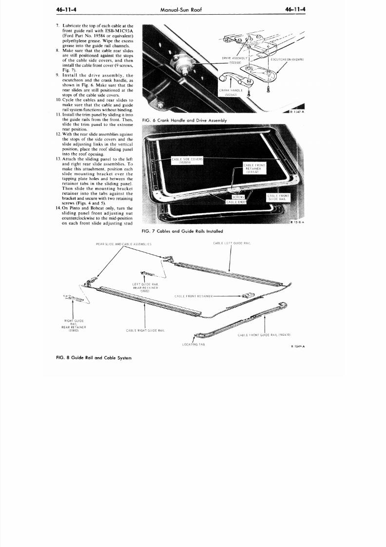
8/20/2019 1977 Ford Car Shop Manual Volume 4 Body
http://slidepdf.com/reader/full/1977-ford-car-shop-manual-volume-4-body 319/449
46-11-4
Manual-Sun Roof
46-111-4
7.
Lubricate the top of each cable at the
front guide rail with ESB-M1C93A
(Ford Part No. 19584 or equivalent)
polyethylene grease. Wipe the excess
grease into the guide rail channels.
8. Make sure that the cable rear slides
are still positioned against the stops
of the cable side covers, and then
install the cable front cover (9 screws,
Fig. 7).
9. Install the drive assembly, the
escutcheon and the crank handle, as
shown in Fig. 6. Make sure that the
rear slides are still positioned at the
stops of the cable side covers.
10. Cycle the cables and rear slides to
make sure that the cable and guide
rail system functions without binding.
11. Install the trim panel by sliding it into
the guide rails from the front. Then,
slide the trim panel to the extreme
rear position.
12.
W ith the rear slide assemblies against
the stops of the side covers and the
slide adjusting links in the vertical
position, place the roof sliding panel
into the roof opening.
13.
Attach the sliding panel to the left
and right rear slide assemblies. To
make this attachment, position each
slide mounting bracket over the
tapping plate holes and between the
retainer tabs in the sliding panel.
Then slide the mounting bracket
retainer into the tabs against the
bracket and secure with two retaining
screws (Figs. 4 and 5).
14. On Pinto and Bobcat only, turn the
sliding panel front adjusting nut
counterclockwise to the mid-position
on each front slide adjusting stud
R 1:547-A
FIG.
6 Crank Handle and Drive Assembly
R 1 5 ^ 8 - A
FIG. 7 Cables and Guide Rails Installed
REAR SLIDE AND CABLE ASSEMBLIES
CABLE LEFT GUIDE RAIL
RIGHT GUIDE
RAIL
REAR RETAINER
(51882)
CABLE FRONT GUIDE RAIL (502A10)
LOCATING TAB
R 154<»-A
FIG. 8 Guide Rail and Cable System
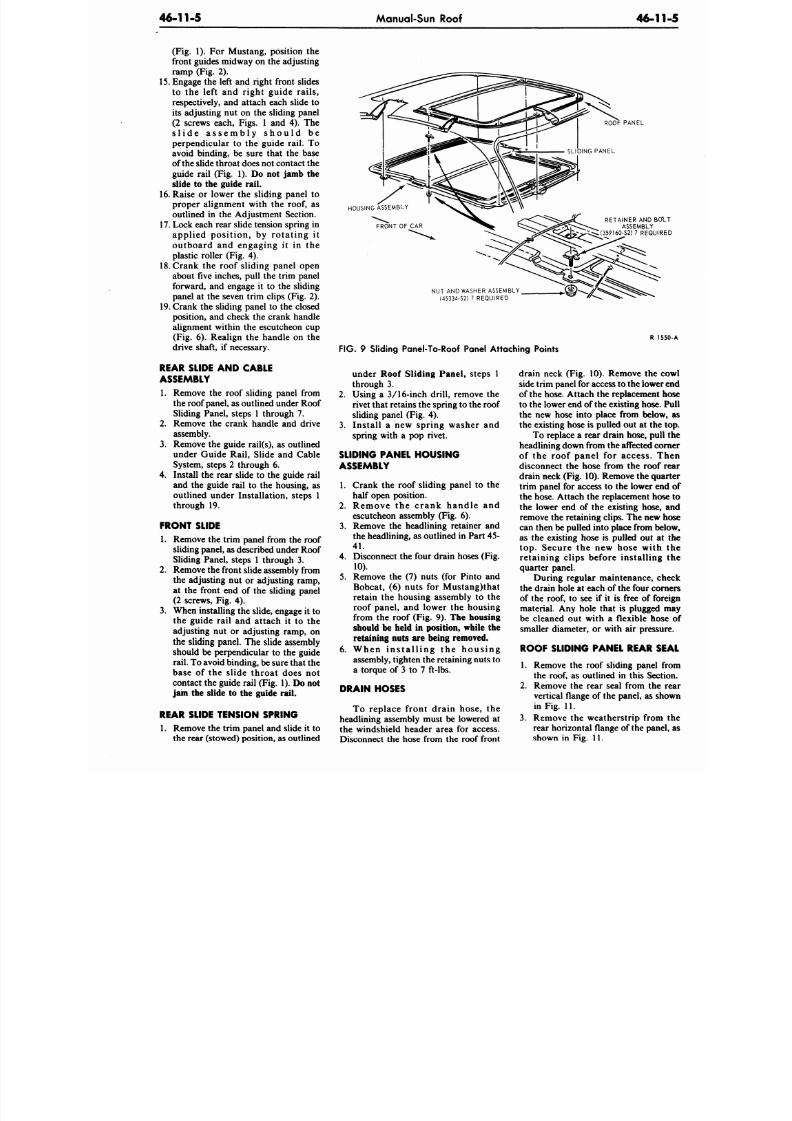
8/20/2019 1977 Ford Car Shop Manual Volume 4 Body
http://slidepdf.com/reader/full/1977-ford-car-shop-manual-volume-4-body 320/449
46-11-5
Manual-Sun Roof
46-1
(Fig. 1). For Mustang, position the
front guides midway on the adjusting
ramp (Fig. 2).
15. Engage the left and right front slides
to the left and right guide rails,
respectively, and attach each slide to
its adjusting
nut on the
sliding panel
(2 screws each, Figs. 1 and 4). The
s l i d e a s s e m b l y s h o u l d be
perpendicular
to the
guide rail.
To
avoid binding,
be
sure that
the
base
of the slide throat does not contact the
guide rail (Fig. 1).
Do not
jamb
the
slide
to the
guide rail.
16.
Raise
or
lower
the
sliding panel
to
proper alignment with the roof, as
outlined in the Adjustment Section.
17.
Lock each rear slide tension spring in
applied position, by ro ta t ing it
outboard and engaging it in the
plastic roller (Fig. 4).
18. Crank the roof sliding panel open
about five inches, pull the trim panel
forward, and engage it to the sliding
panel at the seven trim clips (Fig. 2).
19. Crank
the
sliding panel
to the
closed
position, and check the crank handle
alignment within the escutcheon cup
(Fig. 6). Realign the handle on the
drive shaft, if necessary.
REAR SLIDE AND CABLE
ASSEMBLY
1. Remove the roof sliding panel from
the roof panel, as outlined under Roof
Sliding Panel, steps 1 through 7.
2.
Remove the crank handle and drive
assembly.
3. Remove the guide rail(s), as outlined
under Guide Rail, Slide
and
Cable
System, steps 2 through 6.
4.
Install the rear slide to the guide rail
and
the
guide rail
to the
housing,
as
outlined under Installation, steps 1
through 19.
FRONT SLIDE
1. Remove the trim panel from the roof
sliding panel,
as
described under Roof
Sliding Panel, steps 1 through 3.
2.
Remove the front slide assembly from
the adjusting nut or adjusting ramp,
at the front end of the sliding panel
(2 screws, Fig. 4).
3. When installing the slide, engage it to
the guide rail and attach it to the
adjusting nut or adjusting ramp, on
the
sliding panel. The slide assembly
should be perpendicular to the guide
rail. To avoid binding, be sure that the
base of the slide throat does not
contact the guide rail (Fig. 1).
Do not
jam the slide to the guide rail.
REAR SLIDE TENSION SPRING
1. Remove the trim panel and slide it to
the rear (stowed) position, as outlined
ROOF PANEL
HOUSING ASSEMBLY
FRONT OF CAR
RETAINER AND B
ASSEMBLY
^ ^ ( 3 5 9 1 6 0 - S 2 ) 7 REQUI
NUT
AND
WASHER ASSEMBLY
(45334-S2) 7 REQUIRED
R
FIG. 9 Sliding Panel-To-Roof Panel Attaching Points
under Roof Sliding Panel, steps 1
through
3.
2.
Using a 3/16-inch drill, remove the
rivet that retains the spring to the roof
sliding panel (Fig. 4).
3. Install a new spring washer and
spring with a pop rivet.
SLIDING PANEL HOUSING
ASSEMBLY
1. Crank the roof sliding panel to the
half open position.
2.
Remove the c rank h and le and
escutcheon assembly
(Fig. 6).
3. Remove the headlining retainer and
the headlining, as outlined in Part
45-
41.
4. Disconnect the four d rain hoses (Fig.
10).
5.
Remove the (7) nuts (for Pinto and
Bobcat, (6) nuts for Mustang)that
retain the housing assembly to the
roof panel,
and
lower
the
housing
from the roof (Fig. 9). The
housing
should
be
held
in
position, while
the
retaining nuts
are
being removed.
6 . When in s ta l l ing the h o u s i n g
assembly, tighten the retaining nuts to
a torque of 3 to 7 ft-lbs.
DRAIN HOSES
To replace front drain hose, the
headlining assembly must be lowered at
the windshield header area for access.
Disconnect the hose from the roof front
drain neck (Fig. 10). Remove the
side trim panel for access to
the low
of
the
hose. Attach the replacement
to the lower end of the existing hose
the new hose into place from belo
the existing hose is pulled out at
th
To replace
a
rear drain hose, pu
headlining down from the affected c
of
the
roof panel
for
access.
disconnect the hose from the roof
drain neck (Fig. 10). Remove
the q
trim panel for access to the lower e
the hose. Attach the replacement h
the lower end of the existing hose
remove the retaining clips.
The new
can then be pulled into place from
as the existing hose is pulled out
top. Secure the new hose with
retaining clips before installing
quarter panel.
During regular maintenance, c
the drain hole at each of the four co
of the roof, to see if it is free of fo
material.
Any
hole that
is
plugged
be cleaned out with a flexible ho
smaller diameter, or with air press
ROOF SLIDING PANEL REAR S
1.
Remove
the
roof sliding panel
the roof, as outlined in this Sec
2.
Remove the rear seal from th
vertical flange of the panel, as s
in Fig. 11.
3. Remove the weatherstrip from
rear horizontal flange of the pan
shown
in Fig. 11.
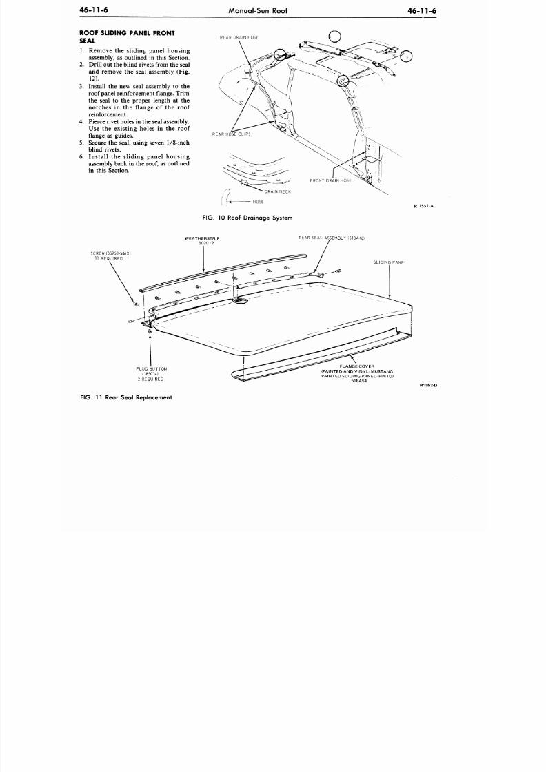
8/20/2019 1977 Ford Car Shop Manual Volume 4 Body
http://slidepdf.com/reader/full/1977-ford-car-shop-manual-volume-4-body 321/449
46-11-6
Manual-Sun Roof
4 6 - 1 1 - 6
ROOF SLIDING PANEL FRONT
SEAL
1. Remove the sliding panel housing
assembly, as outlined in this Section.
2. Drill out the blind rivets from th e seal
and remove the seal assembly (Fig.
12).
3. Install the new seal assembly to the
roof panel reinforcement flange. Trim
the seal to the proper length at the
notches in the f lange of the roof
reinforcement.
4.
Pierce rivet holes in the seal assembly.
Use the existing holes in the roof
flange as guides.
5.
Secure the seal, using seven
1/8-inch
blind rivets.
6 . Instal l the s l id ing panel housing
assembly back in the
roof,
as outlined
in this Section.
REAR DRAIN HOSE
REAR HOSE CLIPS
R I S 5 1 - A
FIG. 10 Roof Drainage System
SCREW (55953-S46X)
11 REQUIRED
PLUG BUTTON
(385034)
2 REQUIRED
WEATHERSTRIP
502C12
REAR SEAL ASSEMBLY (518A46)
FIG. 11 Rear Seal Replacement
SLIDING PANEL
FLANGE COVER
(PAINTED AND VINYL- MUSTANG
PAINTED SLIDING PANEL- PINTO)
518A54
R 1552-D
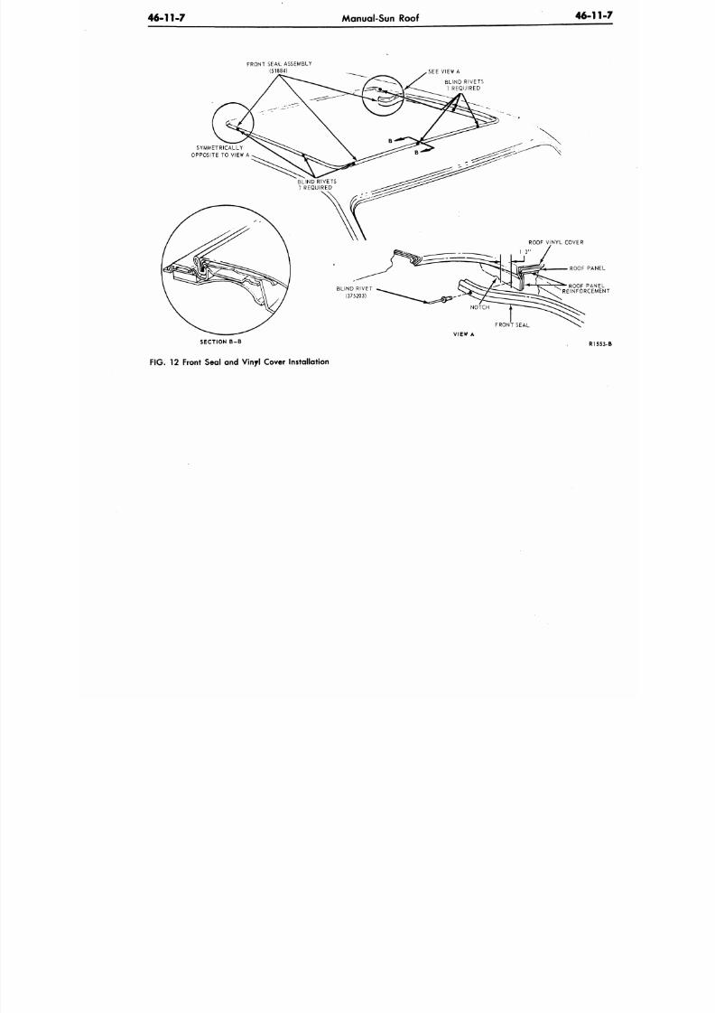
8/20/2019 1977 Ford Car Shop Manual Volume 4 Body
http://slidepdf.com/reader/full/1977-ford-car-shop-manual-volume-4-body 322/449
46-11-7
Manual-Sun Roof
46-1
FRONT SEA-L ASSEMBLY
(51884)
SEE VIEW A
SYMMETRICALLY
OPPOSITE TO VIEW A
ROOF PA
ROOF PAN
REINFORCEM
VIEW A
SECTION B-B
FIG.
12 Front Seal and Vinyl Cover Installation
R1
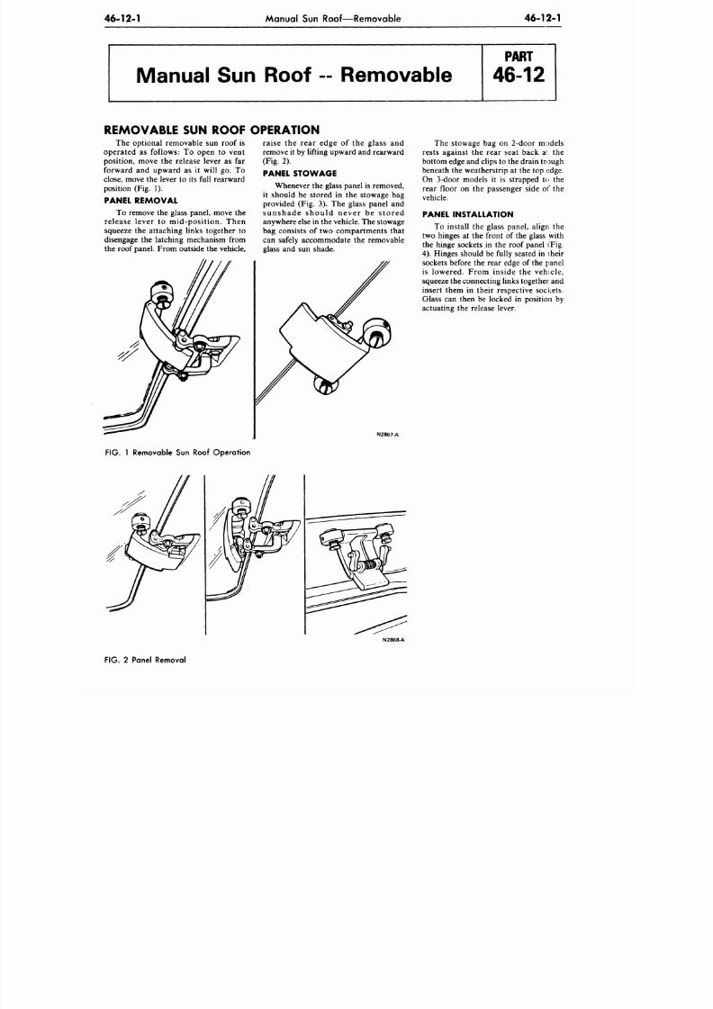
8/20/2019 1977 Ford Car Shop Manual Volume 4 Body
http://slidepdf.com/reader/full/1977-ford-car-shop-manual-volume-4-body 323/449
46 -12-1 Manual Sun Roof—Removable
46-12-1
Manual Sun Roof - Removable
REMOVABLE SUN ROOF
The optional removable sun roof is
operated as follows: To open to vent
position, move the release lever as far
forward and upward as it will go. To
close, move the lever to its full rearward
position (Fig. 1).
PANEL REMOVAL
To remove the glass panel, move the
release lever to mid-position. Then
squeeze the attaching links together to
disengage the latching mechanism from
the roof panel. From outside the vehicle,
OPERATION
raise the rear edge of the glass and
remove it by lifting upward and rearward
(Fig. 2).
PANEL STOWAGE
Whenever the glass panel is removed,
it should be stored in the stowage bag
provided (Fig. 3). The glass panel and
sunshade should never be s tored
anywhere else in the vehicle. The stowage
bag consists of two compartments that
can safely accommodate the removable
glass and sun shade.
N2867-A
FIG. 1 Removable Sun Roof Operation
The stowage bag on 2-door models
rests against the rear seat back ai: the
bottom edge and clips to the drain trough
beneath the weatherstrip at the top edge.
On 3-door models it is strapped to the
rear floor on the passenger side of the
vehicle.
PANEL INSTALLATION
To install the glass panel, align the
two hinges at the front of the glass with
the hinge sockets in the roof panel (Fig.
4).
Hinges should be fully seated in iheir
sockets before the rear edge of the panel
is lowered. From inside the vehicle,
squeeze the connecting links together and
insert them in their respective sockets.
Glass can then be locked in position by
actuating the release lever.
N2868-A
FIG.
2 Panel Removal
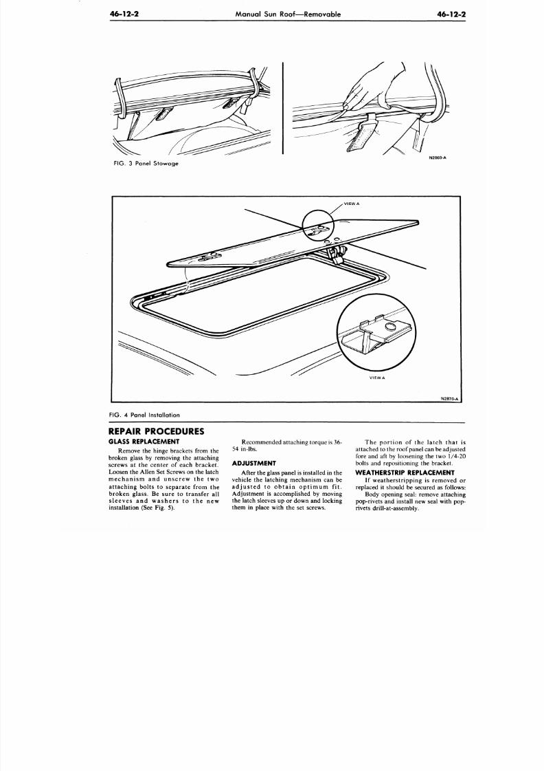
8/20/2019 1977 Ford Car Shop Manual Volume 4 Body
http://slidepdf.com/reader/full/1977-ford-car-shop-manual-volume-4-body 324/449
46-12-2
Manual Sun Roof—Removable
46-1
N2869-A
FIG. 3 Panel Stowage
VIEW
A
N2870
FIG.
4
Panel Installation
REPAIR PROCEDURES
GLASS REPLACEMENT
Remove the hinge brackets from the
broken glass by removing the attaching
screws at the center of each bracket.
Loosen the Allen Set Screws on the latch
mechanism and unscrew the two
attaching bolts to separate from the
broken glass. Be sure to transfer all
sleeves and washers to the new
installation (See Fig. 5).
Recommended attaching torque is 36-
54 in-lbs.
ADJUSTMENT
After the glass panel is installed in the
vehicle
the
latching mechanism
can be
a d j u s t e d
to
o b t a i n o p t i m u m
fit.
Adjustment
is
accomplished
by
moving
the latch sleeves
up or
down
and
locking
them in place with the set screws.
T h e p o r t i o n of the la tch th
attached
to
the roof panel can be a dj
fore
and aft by
loosening
the two 1
bolts
and
repositioning
the
bracket.
WEATHERSTRIP REPLACEMENT
I f wea th er s t r ip p in g is remove
replaced it should be secured as fol
Body opening seal: remove attac
pop-rivets and install new seal w ith
rivets drill-at-assembly.
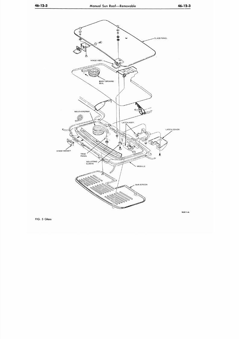
8/20/2019 1977 Ford Car Shop Manual Volume 4 Body
http://slidepdf.com/reader/full/1977-ford-car-shop-manual-volume-4-body 325/449
46-12-3
Manual Sun Roof—Removable
4 6 - 1 2 - 3
HINGE SOCKET
GLASS PANEL
LATCH COVER
N2871-A
FIG.
5 Glass
8/20/2019 1977 Ford Car Shop Manual Volume 4 Body
http://slidepdf.com/reader/full/1977-ford-car-shop-manual-volume-4-body 326/449
46 -1 2- 4 Manual Sun Roof—Removable 46 -1
Weatherstrip roof opening: pull off HINGE SOCKET REPLACEMENT the headlining for access. Parts can
and reinstall new part by pushing on (no In order to repla ce the front hing e be removed and replaced in the no
adhesive required). sock ets, it is necessary to locally lower manner (2 attaching screws).
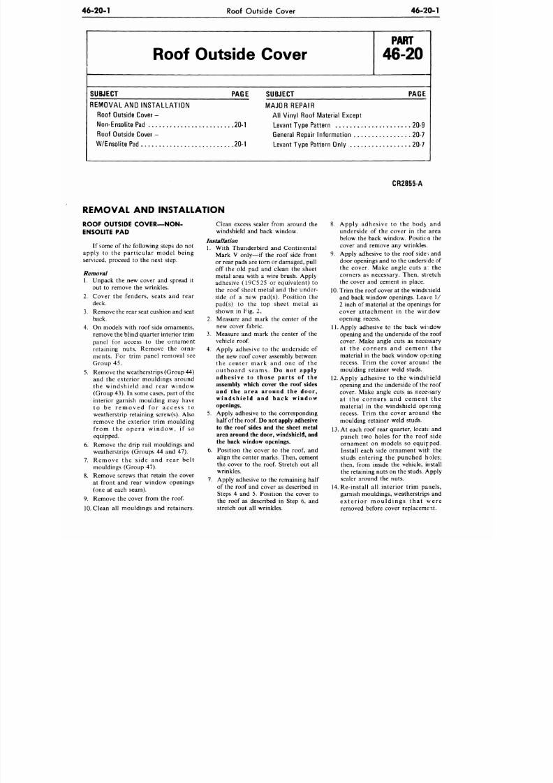
8/20/2019 1977 Ford Car Shop Manual Volume 4 Body
http://slidepdf.com/reader/full/1977-ford-car-shop-manual-volume-4-body 327/449
46-20-1
Roof Outside Cover
46-20-1
SUBJECT
Roof Outside Cover
PAGE SUBJECT
REMOVAL
AND
INSTALL ATION MAJOR REPAIR
Roof Outside Cover
- All
Vinyl Roof Material Except
Non-Ensolite Pad
20-1
Levant Type Pattern
Roof Outside Cover
-
General Repair Infor m atio n
W/Ensolite Pad
20-1
Levant Type Pattern Only
P A R T
46-20
PAGE
20-9
20-7
20-7
CR2855-A
REMOVAL
AND
INSTALLATION
ROOF OUTSIDE COVER—NON-
ENSOLITE
PAD
If some
of
the following steps
do not
apply
to the
particular model being
serviced, proceed
to the
next step.
Removal
1. Unpack
the new
cover
and
spread
it
out
to
remove
the
w rinkles.
2. Cover
the
fenders, seats
and
rear
deck.
3. Remove the rear seat cushion and seat
back.
4.
On
models with roof side ornaments,
remove the blind quarter interior trim
panel
for
access
to the
ornament
retaining nuts. Remove
the
orna-
ments. For trim panel removal see
Group
45.
5. Remove the weatherstrips (Group 44)
and
the
exterior mouldings around
the windshield
and
rear window
(Group 43).
In
some cases, part of the
interior garnish moulding
may
have
to
be
r e m o v e d
for
a c c e s s
to
weatherstrip retaining screw(s). Also
remove
the
exterior trim moulding
from
the
ope r a w indow ,
if so
equipped.
6. Remove
the
drip rail mouldings
and
weatherstrips (Groups 44 and 47).
7. Remove
the
side
and
rear belt
mouldings (Group
47).
8. Remove screws that retain
the
cover
at front
and
rear window openings
(one
at
each seam).
9. Remove
the
cover from
the roof.
10. Clean
all
mouldings
and
retainers.
Clean excess sealer from around
the
windshield
and
back window.
Installation
1. With Thunderbird
and
Continental
Mark
V
only—if
the
roof side front
or rear pads are torn
or
damaged, pull
off
the old pad and
clean
the
sheet
metal area with
a
wire brush. Apply
adhesive (19C 525
or
equivalent)
to
the roof sheet metal
and the
under-
side
of a new
pad(s). Position
the
pad(s)
to the top
sheet metal
as
shown in Fig. 2.
2.
Measure
and
mark
the
center
of the
new cover fabric.
3.
Measure
and
mark
the
center
of the
vehicle
roof.
4. Apply adhesive
to the
underside
of
the
new
roof cover assembly between
the center mark
and one of the
outboard seams.
Do not apply
adhesive to those parts of the
assembly which cover the roof sides
and
the
area around
the
door,
windshie ld and back window
openings.
5. Apply adhesive
to the
corresponding
half of the roof. Do not apply adhesive
to
the
roof sides
and the
sheet metal
area around the door, windshield, and
the back window openings.
6. Position
the
cover
to the roof, and
align
the
center marks. Then, cement
the cover
to the roof.
Stretch
out all
wrinkles.
7. Apply adhesive
to the
remaining half
of the roof and cover as described in
Steps
4 and 5.
Position
the
cover
to
the roof
as
described
in
Step
6, and
stretch
out all
wrinkles.
8. Apply adhesive
to the
bod>
and
underside
of the
cover
in the
area
below
the
back window. Position
the
cover
and
remove
any
wrinkles.
9. Apply adhesive
to the
roof sides
and
door openings
and to the
underside of
the cover. Make angle cuts
a: the
corners
as
necessary. Then, stretch
the cover
and
cement
in
place.
10.
Trim
the
roof cover
at the
windshield
and back window openings. Leave
1/
2 inch
of
material
at the
openings
for
cover attachment
in the
wirdow
opening recess.
11. Apply adhesive
to the
back window
opening
and the
underside
of the
roof
cover. Make angle cuts
as
necessary
at
the
c or ne r s
and
cement
the
material
in the
back window opening
recess. Trim
the
cover around
the
moulding retainer weld studs.
12.
Apply adhesive
to the
windshield
opening and
the
underside
of
the roof
cover. Make angle cuts
as
necessary
at
the
c or ne r s
and
cement
the
material
in the
windshield opening
recess. Trim
the
cover around
the
moulding retainer weld studs.
13.
At
each roof rear quarter, locate
and
punch
two
holes
for the
roof side
ornament
on
models
so
equipped.
Install each side ornament with
the
studs entering
the
punched holes;
then, from inside
the
vehicle, install
the retaining nuts on the studs. Apply
sealer around
the
nuts.
14.
Re-install
all
interior trim panels,
garnish mouldings, weatherstrips
and
e x te r io r m ould ings t ha t w e r e
removed before cover replacement.
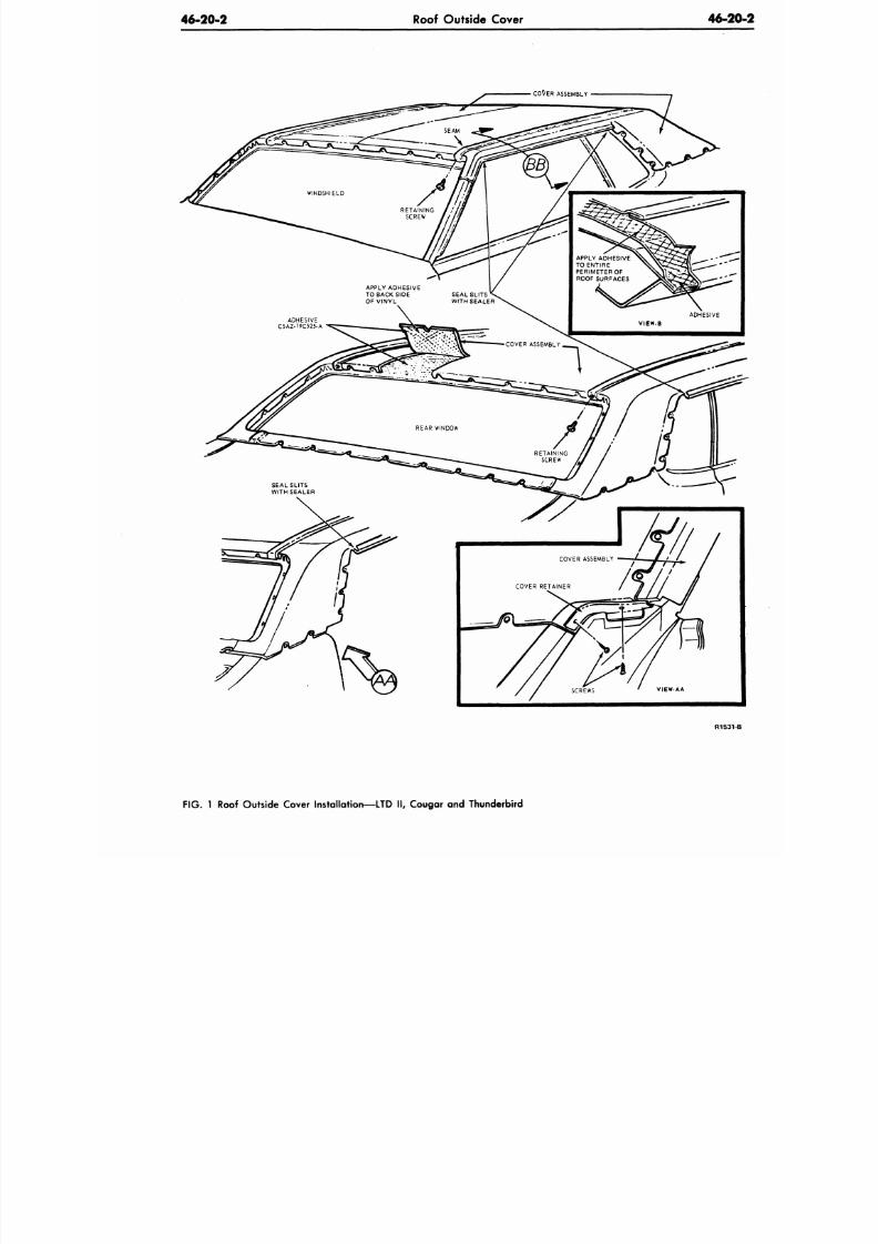
8/20/2019 1977 Ford Car Shop Manual Volume 4 Body
http://slidepdf.com/reader/full/1977-ford-car-shop-manual-volume-4-body 328/449
46-20-2
Roof Outside Cover
46-2
CO^ER ASSEMBLY
APPLY ADHESIVE
TO ENTIRE
PERIMETER OF
ROOF SURFACES
R 1 5 3
F IG .
1 Roof Outside Cover Installation—LTD II, Cougar and Thunderbird
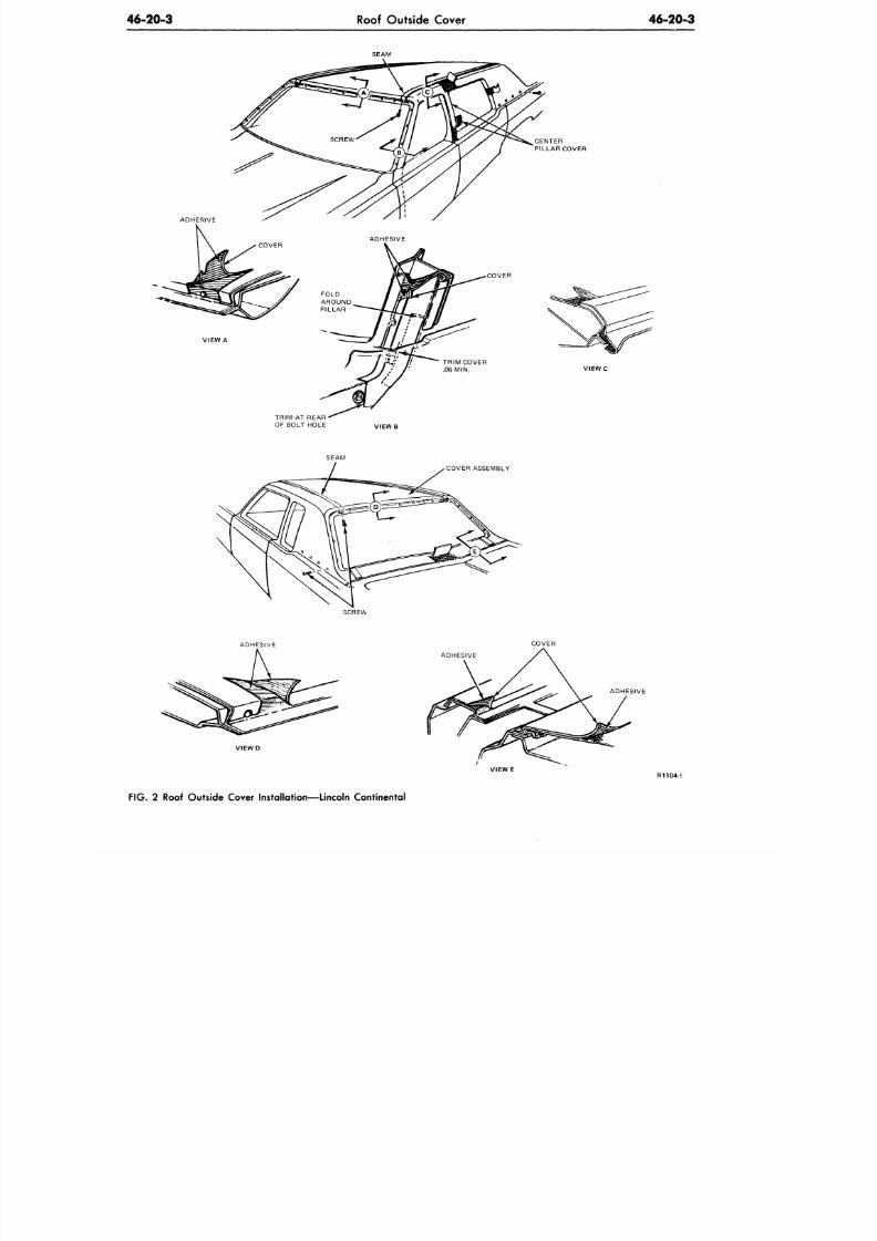
8/20/2019 1977 Ford Car Shop Manual Volume 4 Body
http://slidepdf.com/reader/full/1977-ford-car-shop-manual-volume-4-body 329/449
46-20-3
Roof Outside Cover
46-20-3
SEAM
VIEW A
CENTER
PILLAR COVER
COVER
TRIM COVER
.06 MIIM.
VIEW C
TRIM AT REAR
OF BOLT HOLE
SEAM
COVER ASSEMBLY
SCREW
ADHESIVE
COVER
ADHESIVE
VIEW E
ADHESIVE
R1104c
FIG . 2
Roof Outside Cover Installation—Lincoln Continental
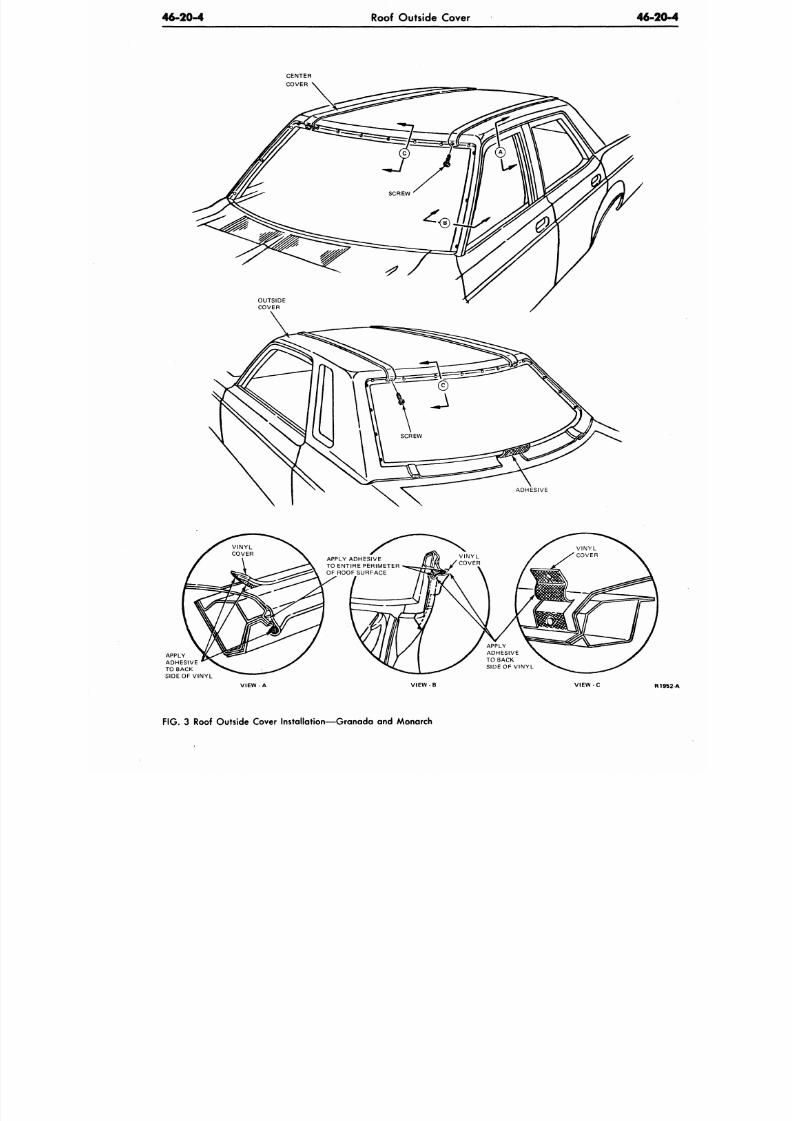
8/20/2019 1977 Ford Car Shop Manual Volume 4 Body
http://slidepdf.com/reader/full/1977-ford-car-shop-manual-volume-4-body 330/449
46-20-4
Roof Outside Cover
46-2
ADHESIVE
APPLY
ADHESIVE
TO BACK
SIDE OF VINYL
APPLY ADHESIVE
TO ENTIRE PERIMETER
OF ROOF SURFACE
R
FIG. 3 Roof Outside Cover Installation—Granada and Monarch
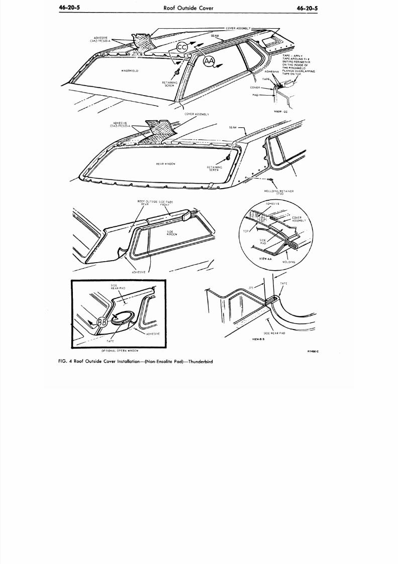
8/20/2019 1977 Ford Car Shop Manual Volume 4 Body
http://slidepdf.com/reader/full/1977-ford-car-shop-manual-volume-4-body 331/449
46-20-5
Roof Outside Cover
46-20-5
COVER ASSEMBLY
ADHESIVE
C5AZ-19C525 -A
TAPE - APPLY
TAPE AROUND Tl -E
ENTIRE PERIMETI-R
ON THE INSIDE
Of
:
TH E
PINCHWELD
A D H E S I V E
F L A N
G E O V E R L A P P IN G
TAPE ON TOP.
MOULDING RETAINER
STUD
ROOF OUTSIDE SIDE PADS
REAR FRONT
VIEW-B B
OPTIONAL OPERA WINDOW
FIG . 4 Roof Outside Cover Installation—(Non-Ensolite Pad)—Thunderbird
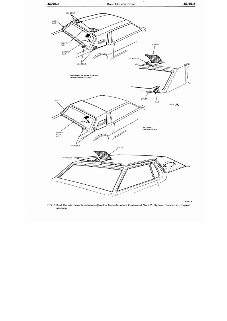
8/20/2019 1977 Ford Car Shop Manual Volume 4 Body
http://slidepdf.com/reader/full/1977-ford-car-shop-manual-volume-4-body 332/449
46-20-6
Roof Outside Cover
46-2
ADHESIVE
SIDE
PAD
CONTINENTAL MARK V SHOWN
THUNDERBIRD TYPICAL
R194
FIG. 5 Roof Outside Cover Installation—(Ensolite Pad)—Standard Continental Mark V, Optional Thunderbird, Typica
Mustang
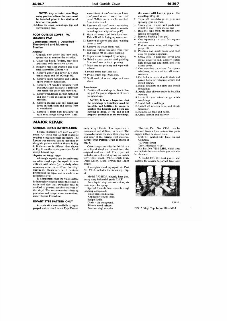
8/20/2019 1977 Ford Car Shop Manual Volume 4 Body
http://slidepdf.com/reader/full/1977-ford-car-shop-manual-volume-4-body 333/449
46-20-7
Roof Outside Cover
46-20-7
N O T E : Any exterior mouldings
using positive bolt-on fasteners must
be installed prior
to
installation
of
interior trim parts.
15. Clean
the
glass, mouldings,
top and
surrounding area.
ROOF OUTSIDE CO VER —W /
ENSOLITE
PAD
Continental Mark
V
Described—
Thunderbird
and
M u stan g
Simil iar
Removal
1. Unpack
new
cover
and new pad,
spread
out to
remove
the
wrinkles.
2. Cover
the
hood, fenders, rear deck
and seats with protective covers.
3.
Remove rear seat cushion
and
seat
back assemblies (Group
41).
4. Remove upper
and
lower
1/4
trim
panels rig ht
and
left (Group
45).
5. Remove opera windows
and
outside
opera window mouldings.
6. Remove
1/4
window housing right
and left,
to
gain access
to
T-Bolt nuts
that retain
the
outer belt moulding.
7. Remove windshield garnish moulding
and
sun
visors including
sun
visor
brackets.
8. Remove staples
and
pull headliner
down
on
both sides
and
across front
at windshield.
9. Remove T-Bolts nuts retaining
the
halo mouldings along both sides,
across front of roof and across lower
roof panel
at
rear. Lower rear roof
panel T-Bolt nuts
can be
reached
from inside trunk.
10.
Remove
all
roof cover retaining
mouldings
and
rear window outside
mouldings
and
clips (Group
43).
11. Mark
all
seam
and
hole locations.
This will
aid in
lining
up new
cover.
12.
Remove
all
screws
and
clips retaining
cover
to roof.
13.
Remove
the
cover from
roof.
14.
Remove rubber backing from roof
and scrape
off all
excess backing.
15. Repair areas damaged
by
scraping.
16. Grind excess cement
and
padding
from roof area prior
to
priming.
17. Mask area for priming and wipe with
solvent.
18.
Prime entire
top (1st)
coat.
19. Prime entire
top (2nd)
coat.
20. Scuff sand, blow
and
wipe roof area
clean.
Installation
1. Position
all
mouldings
in
place
to
line
up
pad for
proper alignment
of
cover
to mouldings.
NOTE: It is very important that
the mouldings be installed around the
backlite and beltline to properly
position the Ensolite pad before any
cutting is done. If the pad is not
properly positioned to the mouldings,
the cover will have a gap at the
mouldings Fig. 5).
2. Tape
all
m ould ings
to
prevent
spraying glue
on
them.
3.
Spray glue
to
roof
and
pads
and
install
to roof.
Trim excess
pad
4.
Remove tape from mouldings
and
remove mouldings.
5. Remove backing from
pad.
6.
Cut
ope n ing
in pad for
ope r a
windows.
7. Position cover
on top and
inspect
for
proper
fit.
8. Position
and
mark cover
and
roof
area
for
proper alignment.
9. Spray glue
to pad and
cover
and
install cover
to pad.
Loosely install
halo mouldings
and
mark
and
trim
excess cover.
10.
Cut
opening
in
cover
for
opera
windows, trim
and
install outer
retainers.
11.
Cut
holes
in
cover
at
weld studs
and
punch holes
for
retaining screws
and
install screws.
12.
Install retainers
and
clips
and
install
mouldings.
13.
Apply clear silicone sealer in bac klite
opening.
14. I n s t a l l r e a r w i n d o w g a r n i s h
mouldings.
15.
Install halo mouldings.
16. Install
all
interior trim
and
staple
headliner.
17. Remove
all
tape
and
paper.
18.
Clean interior
and
exterior.
MAJOR REPAIR
GENERAL REPAIR INFORMATION
Several materials
are
used
as
vinyl
roofs.
Of
these
the
Levant material
requires
a
separate repair procedure.
The
Levant
type material
can
be identified
by
the grain pattern which
is
shown
in Fig.
8.
If the
texture
is
different than shown
in Fig.
8, use the
repair procedure
for all
except Levant type.
Repairs on White Vinyl
Although repairs
can be
performed
on white vinyl tops,
the
repair
is
more
difficult with white (particularly when
repairing
a cut or
scuff
on the
vinyl
sur f a c e ) . H ow e ve r , w i th c e r t a in
precautions
the
repair
can be
made
to an
acceptable level.
It
is
important that
the
vinyl surface
is thoroughly cleaned before
the
repair
is
made
and
also that excessive heat
be
avoided
to
prevent possible charring
of
the vinyl.
The
recommended cleaning
procedure
and
temperatures
are
outlined
under Repair Procedures.
LEVANT TYPE PATTERN ONLY
A repair
kit is
now available
to
repair
gouged, cut or torn Levant Type Pattern
only Vinyl Roofs.
The
repairs
are
permanent
and
difficult
to
detect.
The
repaired area has the same strength, grain
and color
of the
original roof material.
Levant Type Pattern Grain is shown in
Fig. 8.
Color sprays provided
in
this
kit are
pure liquid vinyl
and
absorb into
the
original roof material.
The
repair
kit
includes six colors of sprays to match
vinyl tops (Black, White, Dark Blue,
Dark Green, Dark Brown
and
Light
Beige).
A complete vinyl
top
repair
kit,
Part
No. VR-1, includes the following: (Fig.
6)
Model 750-HDA electric heat
gun,
heavy duty industrial grade 75O°F.
Pure liquid vinyl aerosol colors,
six
basic
top
color sprays.
Special formula heat curable vinyl
patching compound.
Vinyl prep-conditioner.
Applicator trowel tools.
Scalpel knife.
Grain
- die
compound.
Silicone mold release.
Practice vinyl samples.
The
kit,
Part
No. VR-1, can be
obtained from
a
local automotive parts
supply jobber
or
direct from:
D e t r o i t A u t o b o d y E q u i p m e n t
Company
100 Park Street
Troy, Michigan 48064
Kit Part No. VR-l-LHG, which does
not include the electric heat gun, can also
be obtained.
A model HG-501 heat
gun is
also
suitable
for
repairs
on
Levant type vinyl
R15&9-A
FIG.
6
Vinyl
Top
Repair Kit—VR-1
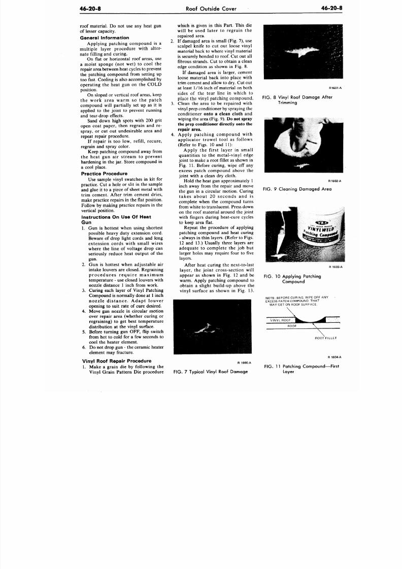
8/20/2019 1977 Ford Car Shop Manual Volume 4 Body
http://slidepdf.com/reader/full/1977-ford-car-shop-manual-volume-4-body 334/449
46-20-8
Roof Outside Cover
46-20
roof material. Do not use any heat gun
of lesser capacity.
General Information
Applying patching compound is a
multiple layer procedure with alter-
nate filling and curing.
On flat or horizontal roof areas, use
a moist sponge (not wet) to cool the
repair area between heat cycles to prevent
the patching compound from setting up
too fast. Cooling is also accomplished by
operating the heat gun on the COLD
position.
On sloped or vertical roof areas, keep
the work area warm so the patch
compound will partially set up as it is
applied to the joint to prevent running
and tear-drop effects.
Sand down high spots with 200 grit
open coat paper, then regrain and re-
spray, or cut out undesirable area and
repeat repair procedure.
If repair is too low, refill, recure,
regrain and spray color.
Keep patching compound away from
the heat gun air stream to prevent
hardening in the jar. Store compound in
a cool place.
Practice Procedure
Use sample vinyl swatches in kit for
practice. Cut a hole or slit in the sample
and glue it to a piece of sheet metal with
trim cement. After trim cement dries,
make practice repa irs in the flat position.
Follow by making practice repairs in the
vertical position.
Instructions On Use Of Heat
Gun
1. Gun is hottest when using shortest
possible heavy duty extension cord.
Beware of drop light cords and long
extension cords with small wires
where the line of voltage drop can
seriously reduce heat output of the
gun.
2.
Gun is hottest when adjustable air
intake louvers are closed. Regraining
p r o c e d u r e s r e q u i r e m a x i m u m
temperature - use closed louvers with
nozzle distance 1 inch from work.
3. Curing each layer of Vinyl Patching
Compound is normally done at 1 inch
nozzle d is tance. Adapt louver
opening to suit rate of cure desired.
4.
Move gun nozzle in circular motion
over repair area (whether curing or
regraining) to get best temperature
distribution at the vinyl surface.
5. Before turning gun OF F, flip switch
from hot to cold for a few seconds to
cool the heater element.
6. Do not drop gun - the ceramic heater
element may fracture.
Vinyl Roof Repair Procedure
1. Make a grain die by following the
Vinyl Grain Pattern Die procedure
which is given in this Part. This die
will be used later to regrain the
repaired area.
2.
If damaged area is small (Fig. 7), use
scalpel knife to cut out loose vinyl
material back to where vinyl material
is securely bonded to roof. Cut out all
fibrous strands. Cut to obtain a clean
edge condition as shown in Fig. 8.
If damaged area is larger, cement
loose material back into place with
trim cement and allow to dry. Cut out
at least 1/16 inch of material on both
sides of the tear line in which to
place the vinyl patching compo und.
3. Clean the area to be repaired with
vinyl prep conditioner by spraying the
conditioner onto a clean cloth and
wiping the area (Fig. 9).
Do not spray
the prep conditioner directly onto the
repair area.
4.
Apply patching compound with
applicator trowel tool as follows
(Refer to Figs. 10 and 11):
Apply the first layer in small
quantities to the metal-vinyl edge
joint to make a root fillet as shown in
Fig. 11. Before curing, wipe off any
excess patch compound above the
joint with a clean dry cloth.
Hold the heat gun approximately 1
inch away from the repair and move
the gun in a circular motion. Curing
takes about 20 seconds and is
complete when the compound turns
from white to translucent. Press down
on the roof material around the joint
with fingers during heat-cure cycles
to keep area flat.
Repeat the procedure of applying
patching compound and heat curing
- always in thin layers. (Refer to Figs.
12 and 13.) Usually three layers are
adequate to complete the job but
larger holes may require four to five
layers.
After heat curing the next-to-last
layer, the joint cross-section will
appear as shown in Fig. 12 and be
warm. Apply patching compound to
obtain a slight build-up above the
vinyl surface as shown in Fig. 13.
R 1 6
FIG. 8 Vinyl Roof Damage After
Trimming
R16
FIG. 9 Cleaning Damaged Area
R 1
FIG.
10 Applying Patching
Compound
NOTE: BEFORE CURING, WIPE OFF ANY
EXCESS PATCH COMPOUND THA T
MAY GET ON ROOF SURFACE.
ROOT FILLE
R 16
R 1600-A
FIG. 7 Typical Vinyl Roof Damage
FIG.
11 Patching Compound—Fir
Layer
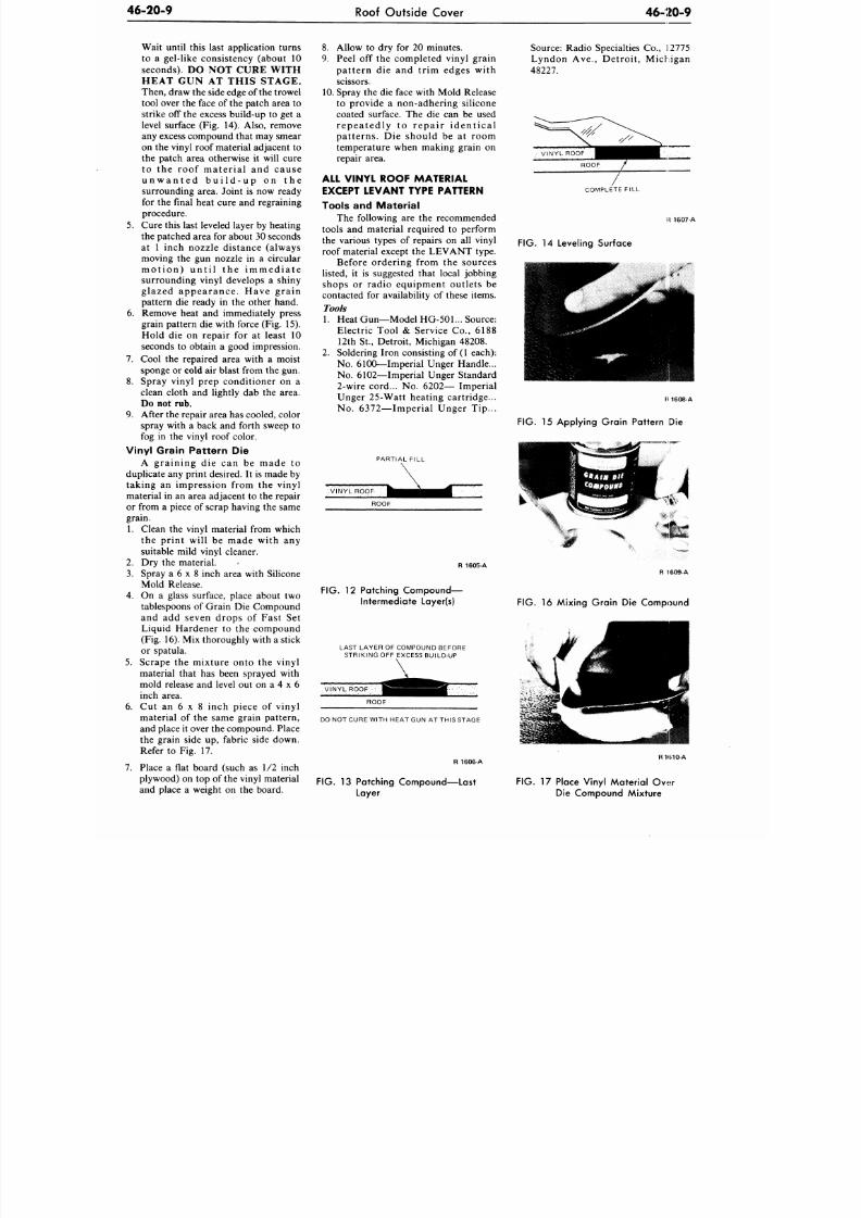
8/20/2019 1977 Ford Car Shop Manual Volume 4 Body
http://slidepdf.com/reader/full/1977-ford-car-shop-manual-volume-4-body 335/449
46-20-9
Roof Outside Cover 46 -20-9
Wait until this last application turns
to a gel-like consistency (about 10
seconds). DO NOT CURE WITH
HEAT GUN AT THIS STAGE.
Then, draw the side edge of the trowel
tool over the face of the patch area to
strike off the excess build-up to get a
level surface (Fig. 14). Also, remove
any excess compound that may smear
on the vinyl roof material adjacent to
the patch area otherwise it will cure
to the roof material and cause
u n w a n t e d b u i l d - u p on t h e
surrounding area. Joint is now ready
for the final heat cure and regraining
procedure.
5.
Cure this last leveled layer by heating
the patched area for about 30 seconds
at 1 inch nozzle distanc e (always
moving the gun nozzle in a circular
m o t i o n ) u n t i l t h e i m m e d i a t e
surrounding vinyl develops a shiny
glazed appearance. Have grain
pattern die ready in the other hand.
6. Remove heat and immediately press
grain pattern die with force (Fig. 15).
Hold die on repair for at least 10
seconds to obtain a good impression.
7. Cool the repaired area w ith a moist
sponge or
cold
air blast from the gun.
8. Spray vinyl prep conditioner on a
clean cloth and lightly dab the area.
Do not rub.
9. After the repair area has cooled, color
spray with a back and forth sweep to
fog in the vinyl roof color.
Vinyl Grain Pattern Die
A graining die can be made to
duplicate any print desired. It is made by
taking an impression from the vinyl
material in an area adjacent to the repair
or from a piece of scrap having the same
grain.
1. Clean the vinyl material from which
the print will be made with any
suitable mild vinyl cleaner.
2.
Dry the material.
3. Spray a 6 x 8 inch area with Silicone
Mold Release.
4. On a glass surface, place about two
tablespoons of Grain Die Compound
and add seven drops of Fast Set
Liquid Hardener to the compound
(Fig. 16). Mix thoroughly with a stick
or spatula.
5. Scrape the mixture onto the vinyl
material that has been sprayed with
mold release and level out on a 4 x 6
inch area.
6. Cut an 6 x 8 inch piece of vinyl
material of the same grain pattern,
and place it over the compound. Place
the grain side up, fabric side down.
Refer to Fig. 17.
7. Place a flat board (such as 1/2 inch
plywood) on top of the vinyl material
and place a weight on the board.
8. Allow to dry for 20 minutes.
9. Peel off the completed vinyl grain
pattern die and trim edges with
scissors.
10.
Spray the die face with Mold Release
to provide a non-adhering silicone
coated surface. The die can be used
repea ted ly to r epa i r iden t i ca l
patterns. Die should be at room
temperature when making grain on
repair area.
ALL VINYL ROOF MATERIAL
EXCEPT LEVANT TYPE PATTERN
Tools and Mater ia l
The following are the recommended
tools and material required to perform
the various types of repairs on all vinyl
roof material except the LEVANT type.
Before ordering from the sources
listed, it is suggested that local jobbing
shops or radio equipment outlets be
contacted for availability of these items.
Tools
1.
Heat Gun—Model
HG-501...
Source:
Electric Tool & Service Co., 6188
12th St., Detroit, Michigan 48208.
2. Soldering Iron consisting of
1
each):
No. 6100—Imperial Unger Handle...
No .
6102—Imperial Unger Standard
2-wire cord... No. 6202— Imperial
Unger 25-Watt heating cartridge...
No. 6372—Imperial Unger Tip...
PARTIAL F ILL
ROOF
R 1605-A
FIG. 12 Patching Compound—
Intermediate Layer(s)
LAST LAYER OF COMPOUND BEFORE
STRIKING OFF EXCESS BUILD-UP
ROOF
DO NOT CURE WITH HEAT GUN AT THIS STAGE
R 1606- A
FIG. 13 Patching Compound—Last
Layer
Source: Radio Specialties Co., 12775
Lyndon Ave., Detroit, Michigan
48227.
COMPLETE FILL
1607-A
FIG. 14 Leveling Surface
1608-A
FIG.
15 Applying Grain Pattern Die
FIG. 16 Mixing Grain Die Compound
RH510-A
FIG. 17 Place Vinyl Material Ov*r
Die Compound Mixture
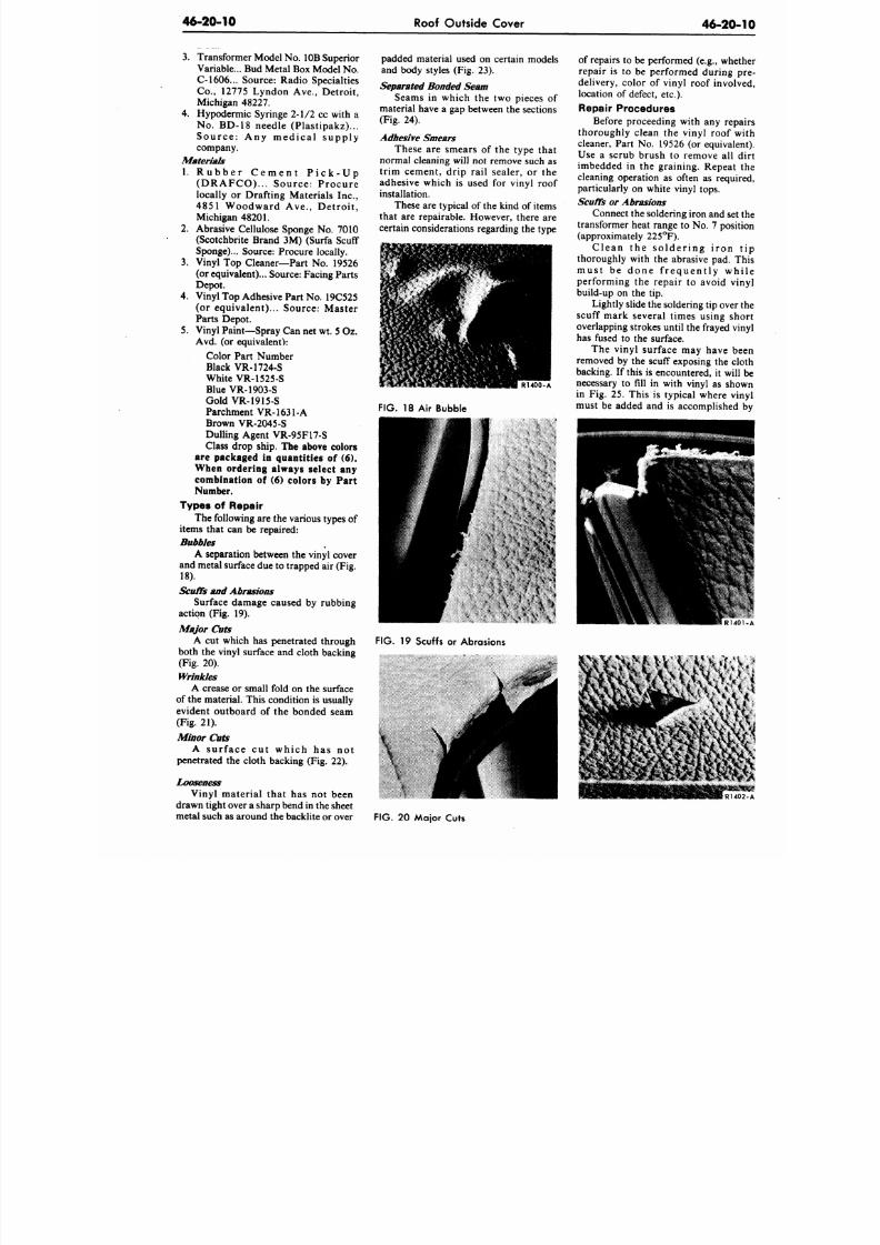
8/20/2019 1977 Ford Car Shop Manual Volume 4 Body
http://slidepdf.com/reader/full/1977-ford-car-shop-manual-volume-4-body 336/449
46-20-14)
Roof Outside Cover
46-20
3.
Transformer Model
No .
10B Superior
Variable... Bud Metal Box Model No.
C-1606... Source: Radio Specialties
Co.,
12775 Lyndon Ave., Detroit,
Michigan 48227.
4. Hypodermic Syringe 2-1/2 cc with a
No.
BD-18 needle (Plastipakz)...
S o u r c e : A n y m e d i c a l s u p p l y
company.
Materials
1. R u b b e r C e m e n t P i c k - U p
( D RA FCO ) . . . Sour c e : P r oc ur e
locally or Drafting Materials Inc.,
4851 Woodward Ave . , Det roi t ,
Michigan 48201.
2. Abrasive Cellulose Sponge No. 7010
(Scotchbrite Brand 3M) (Surfa Scuff
Sponge)... Source: Procure locally.
3. Vinyl Top Cleaner—P art No. 19526
(or equ ivalent)... Source: Facing Parts
Depot.
4. Vinyl Top Adhesive Part No. 19C525
(or equivalent)... Source: Master
Parts Depot.
5. Vinyl Paint—Spray Can net wt.
5
Oz.
Avd. (or equivalent):
Color Part Number
Black VR-1724-S
White VR-1525-S
Blue VR-19O3-S
Gold VR-1915-S
Parchment VR-1631-A
Brown VR-2045-S
Dulling Agent VR-95F17-S
Class drop ship.
The above colors
are packaged in quantities of (6).
When ordering always select any
combination of (6) colors by Part
Number.
Types of Repair
The following are the various types of
items that can be repaired:
Bubbles
A separation between the vinyl cover
and metal surface due to trapped air (Fig.
18).
Scuffs and Abrasions
Surface damage caused by rubbing
action (Fig. 19).
Major Cuts
A cut which has penetrated through
both the vinyl surface and cloth backing
(Fig. 20).
Wrinkles
A crease or small fold on the surface
of the material. This condition is usually
evident outboard of the bonded seam
(Fig. 21).
Minor Cuts
A sur f a c e c u t w hic h ha s no t
penetrated the cloth backing (Fig. 22).
padded material used on certain models
and body styles (Fig. 23).
Separated Bonded Seam
Seams in which the two pieces of
material have a gap between the sections
(Fig. 24).
Adhesive Smears
These are smears of the type that
normal cleaning will not remove such as
trim cement, drip rail sealer, or the
adhesive which is used for vinyl roof
installation.
These are typical of the kind of items
that are repairable. However, there are
certain considerations regarding the type
R1400-A
FIG.
18 Air Bubble
of repairs to be performed (e.g., wh
repair is to be performed during
delivery, color of vinyl roof invo
location of defect, etc.).
Repair Procedures
Before proceeding with any re
thoroughly clean the vinyl roof
cleaner, Part No. 19526 (or equiva
Use a scrub brush to remove all
imbedded in the graining. Repea
cleaning operation as often as requ
particularly on white vinyl tops.
Scuffs
or
Abrasions
Connect the soldering iron and se
transformer heat range to No. 7 pos
(approximately 225°F).
C le a n the so lde r in g i r on
thoroughly with the abrasive pad.
m u s t be d o n e f r e q u e n t l y w
performing the repair to avoid v
build-up on the tip.
Lightly slide the soldering tip ove
scuff mark several times using s
overlapping strokes until the frayed
has fused to the surface.
The vinyl surface may have
removed by the scuff exposing the
backing. If this is encountered, it wi
necessary to fill in with vinyl as sh
in Fig. 25. This is typical where v
must be added and is accomplishe
FIG.
19 Scuffs or Abrasions
\
Vinyl material that has not been
drawn tight over a sharp bend in the sheet
metal such as around the backlite or over
FIG.
20 Major Cuts
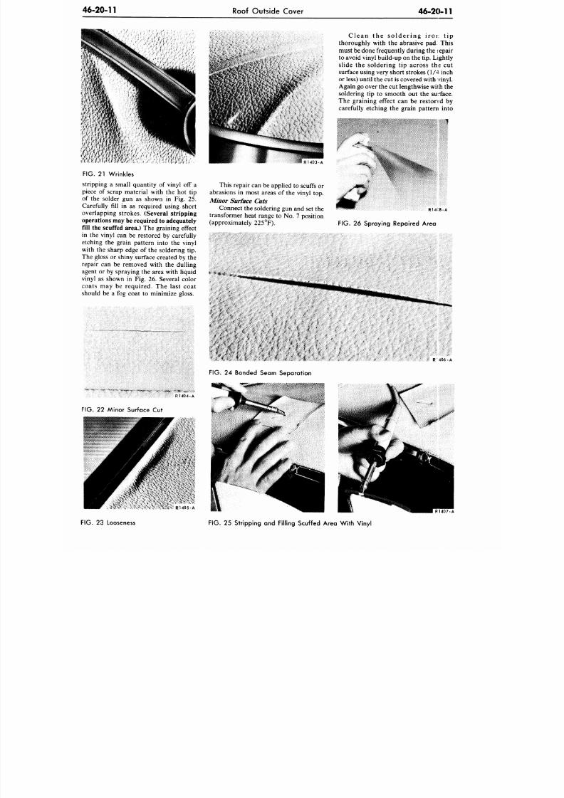
8/20/2019 1977 Ford Car Shop Manual Volume 4 Body
http://slidepdf.com/reader/full/1977-ford-car-shop-manual-volume-4-body 337/449
46-20-11
Roof Outside Cover
46-20-11
. < , ' * J
K
(
C l e a n t h e s o l d e r i n g ir o r . t i p
thoroughly with the abrasive pad. This
must be done frequently during the repair
to avoid vinyl build-up on the tip . Lightly
sl ide the so lder ing t ip across the cut
surface using very short strokes (1 /4 inch
or less) until the cu t is covered with vinyl.
Again go over the cut lengthwise with th e
soldering tip to smooth out the su:*face.
The graining effect can be restored by
carefully etching the grain pattern into
1
F IG . 21 Wrinkles
stripping a small quantity of vinyl off a
piece of scrap material with the hot tip
of the solder gun as shown in Fig. 25.
Carefully fill in as required using short
overlapping strokes.
(Several stripping
operations may be required to adequately
fill the scuffed area.)
The graining effect
in the vinyl can be restored by carefully
etching the grain pattern into the vinyl
with the sharp edge of the soldering tip.
The gloss or shiny surface created by the
repair can be removed with the dulling
agent or by spraying the area with liquid
vinyl as shown in Fig. 26. Several color
coats may be required . The las t coat
should be a fog coat to minimize gloss.
R1404-A
F IG . 22 Minor Surface Cut
R 1 4 0 3 - A
This repa ir can be applied to scuffs or
abrasions in most areas of the vinyl top.
Minor Surface Cuts
Connect the soldering gun and set the
transformer heat range to No. 7 position
(approximately 225°F).
R14C8-A
F IG . 26 Spraying Repaired Area
R 4 0 6 - A
FIG. 24 Bonded Seam Separation
R1405-A
F IG .
23 Looseness
F IG . 2 5 Stripping and Fil ling Scuffed Area W ith Vinyl
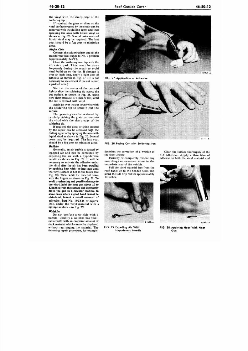
8/20/2019 1977 Ford Car Shop Manual Volume 4 Body
http://slidepdf.com/reader/full/1977-ford-car-shop-manual-volume-4-body 338/449
46-20-12
Roof Outside Cover
4 6 - 2 0 -
the vinyl with the sharp edge of the
soldering tip.
If required, the gloss or shine on the
vinyl surface created by the repair can be
removed with the dulling agent and then
spraying the area with liquid vinyl as
shown in Fig. 26. Several color coats of
liquid vinyl may be required. The last
coat should be a fog coat to minimize
gloss.
Major Cuts
Connect the soldering iron and set the
transformer heat range to No. 7 position
(approximately 225°F).
Clean the soldering iron tip with the
abras ive pad. This must be done
frequently during the repair to avoid
vinyl build-up on the tip. If damage is
over an inch long, apply a light coat of
adhesive as shown in Fig. 27. (It is not
necessary to use cement if the cut is over
a padded area.)
Start at the center of the cut and
lightly slide the soldering tip across the
cut surface, as shown in Fig. 28, using
very short strokes (1/4 inch or less) until
the cut is covered with vinyl.
Again go over the cu t lengthwise with
the soldering tip to smooth out the
surface.
The graining can be restored by
carefully etching the grain pattern into
the vinyl with the sharp edge of the
soldering tip.
If required the gloss or shine created
by the repair can be removed with the
dulling agent or by spraying the area with
liquid vinyl as shown in Fig. 26. Several
coats may be required. The last coat
should be a fog coat to minimize gloss.
Bubbles
Generally, an air bubble is caused by
trapped air and can be corrected by
expelling the air with a hypodermic
needle as shown in Fig. 29. It will be
necessary to activate the adhesive under
the vinyl after the air has been expelled
by applying heat with the heat gun until
the vinyl surface is hot to the touch (see
Fig. 30). Then, work the material down
with the fingers as shown in Fig. 29.
To
avoid overheating and possible damage to
the vinyl, hold the heat gun about 10 to
12 inches from the surface and constantly
move the gun in a circular motion. In
some cases where a good bond cannot be
obtained, insert a small amount of
adhesive, Part No. 19C525 or equiva-
lent, under the vinyl material with a
syringe as shown in Fig. 29.
Wrinkles
Do not confuse a wrinkle with a
bubble. Usually a wrinkle has small
radial folds with an excessive amount of
slack material which cannot be displaced
without rearranging the material. The
following repair procedure, for example,
RU0
FIG.
27 Application of Adhesive
R 1 4 1 1
FIG.
28 Fusing Cut with Soldering Iron
describes the correction of a wrinkle at
the front corner.
Partially or completely remove any
mouldings or ornamentation in the
immediate area of the wrinkle.
Pull the vinyl material free from the
roof panel up to the bonded seam and
along the side drip rail for approximately
10 inches.
Clean the surface thoroughly of t
old adhesive. Apply a thin film
adhesive to both the vinyl material a
R1412-A-
R141
FIG.
29 Expelling Air With
Hypodermic Needle
FIG. 30 Applying Heat With Heat
Gu n
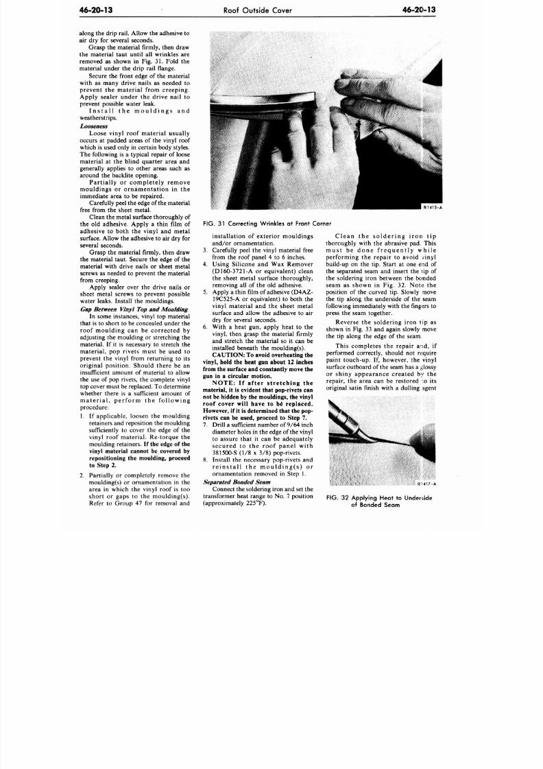
8/20/2019 1977 Ford Car Shop Manual Volume 4 Body
http://slidepdf.com/reader/full/1977-ford-car-shop-manual-volume-4-body 339/449
46-20-13
Roof Outside Cover
46-20-13
along the drip rail. Allow the adhesive to
air dry for several seconds.
Grasp the material firmly, then draw
the material taut until all wrinkles are
removed as shown in Fig. 31. Fold the
material under the drip rail flange.
Secure the front edge of the material
with as many drive nails as needed to
prevent the material from creeping.
Apply sealer under the drive nail to
prevent possible water leak.
Install the mouldings and
weatherstrips.
Looseness
Loose vinyl roof material usually
occurs at padded areas of the vinyl roof
which is used only in certain body styles.
The following is a typical repair of loose
material at the blind quarter area and
generally applies to other areas such as
around the backlite opening.
Partially or completely remove
mouldings or ornamentation in the
immediate area to be repaired.
Carefully peel the edge of the material
free from the sheet metal.
Clean the metal surface thoroughly of
the old adhesive. Apply a thin film of
adhesive to both the vinyl and metal
surface. Allow the adhesive to air dry for
several seconds.
Grasp the material firmly, then draw
the material taut. Secure the edge of the
material with drive nails or sheet metal
screws as needed to prevent the material
from creeping.
Apply sealer over the drive nails or
sheet metal screws to prevent possible
water leaks. Install the mouldings.
Gap Between Vinyl Top and Moulding
In some instances, vinyl top material
that is to short to be concealed under the
roof moulding can be corrected by
adjusting the moulding or stretching the
material. If it is necessary to stretch the
material, pop rivets must be used to
prevent the vinyl from returning to its
original position. Should there be an
insufficient amount of material to allow
the use of pop rivets, the complete vinyl
top cover must be replaced. To determine
whether there is a sufficient amount of
material, perform the following
procedure:
1. If applicable, loosen the moulding
retainers and reposition the moulding
sufficiently to cover the edge of the
vinyl roof material. Re-torque the
moulding retainers. If the edge of the
vinyl material cannot be covered by
repositioning the moulding, proceed
to Step 2.
2.
Partially or completely remove the
moulding(s) or ornamentation in the
area in which the vinyl roof is too
short or gaps to the moulding(s).
Refer to Group 47 for removal and
R 1 4 1 5 - A
FIG. 31
Correcting Wrinkles
at
Front Corner
installation of exterior mouldings
and/or ornamentation.
3.
Carefully peel the vinyl material free
from the roof panel 4 to 6 inches.
4.
Using Silicone and Wax Remover
(D160-3721-A or equivalent) clean
the sheet metal surface thoroughly,
removing all of the old adhesive.
5.
Apply a thin film of adhesive (D4AZ-
19C525-A or equivalent) to both the
vinyl material and the sheet metal
surface and allow the adhesive to air
dry for several seconds.
6. With a heat gun, apply heat to the
vinyl, then grasp the material firmly
and stretch the material so it can be
installed beneath the moulding(s).
CAUTION: To avoid overheating the
vinyl, hold the heat gun about 12 inches
from the surface and constantly move the
gun in a circular motion.
NOTE: If after stretching the
material, it is evident that pop-rivets can
not be hidden by the mouldings, the vinyl
roof cover will have to be replaced.
However, if it is determined that the pop-
rivets can be used, proceed to Step 7.
7. Drill a sufficient number of 9/64 inch
diameter holes in the edge of the vinyl
to assure that it can be adequately
secured to the roof panel with
3815OO-S (1/8 x 3/8) pop-rivets.
8. Install the necessary pop-rivets and
reinstall the moulding(s) or
ornamentation removed in Step 1.
Separated Bonded Seam
Connect the soldering iron and set the
transformer heat range to No. 7 position
(approximately 225°F).
Clean the soldering iron tip
thoroughly with the abrasive pad. This
must be done frequent ly while
performing the repair to avoid vinyl
build-up on the tip. Start at one end of
the separated seam and insert the
lip
of
the soldering iron between the bonded
seam as shown in Fig. 32. Note the
position of the curved tip. Slowly move
the tip along the underside of the seam
following immediately with the fingers to
press the seam together.
Reverse the soldering iron tip as
shown in Fig. 33 and again slowly move
the tip along the edge of the seam.
This completes the repair and, if
performed correctly, should not require
paint touch-up. If, however, the vinyl
surface outboard of the seam has a glossy
or shiny appearance created by the
repair, the area can be restored :o its
original satin finish with a dulling agent
RU17-A
FIG.
32
Applying Heat
to
Underside
of Bonded Seam
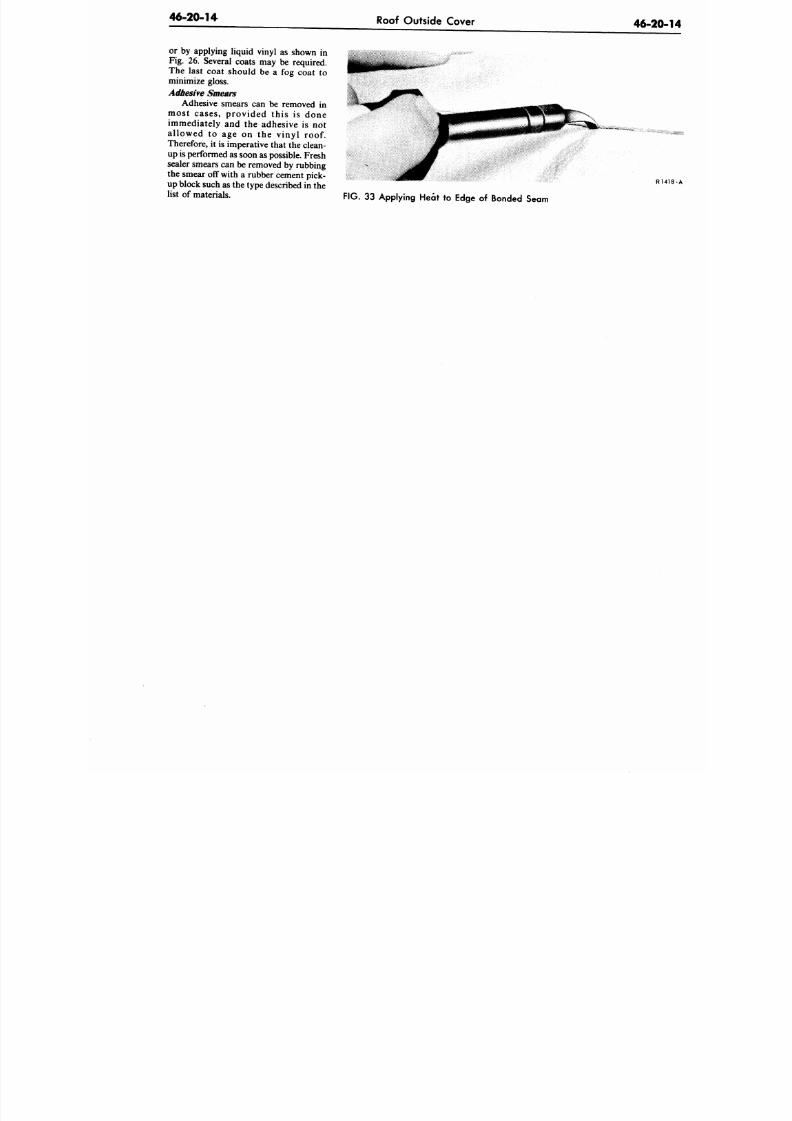
8/20/2019 1977 Ford Car Shop Manual Volume 4 Body
http://slidepdf.com/reader/full/1977-ford-car-shop-manual-volume-4-body 340/449
46-20-14
Roof Outside Cover
46-20
or by applying liquid vinyl as shown in
Fig. 26. Several coats may be required.
The last coat should be a fog coat to
minimize gloss.
Adhesive Smears
Adhesive smears can be removed in
most cases, provided this is done
immediately and the adhesive is not
allowed to age on the vinyl roof.
Therefore, it is imperative tha t the clean-
up is performed as soon as possible. Fresh
sealer smears can be removed by rubbing
the smear off with a rubber cement pick-
up block such as the type described in the
list of materials.
R
FIG. 33 Applying Heat to Edge of Bonded Seam
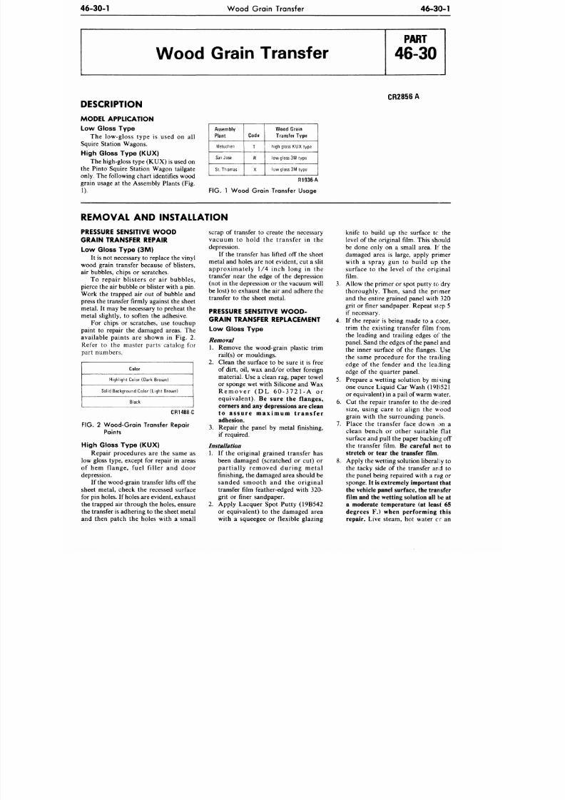
8/20/2019 1977 Ford Car Shop Manual Volume 4 Body
http://slidepdf.com/reader/full/1977-ford-car-shop-manual-volume-4-body 341/449
46-30-1
W ood Grain Transfer
46-30-1
Wood Grain Transfer
DESCRIPTION
MODEL APPLICATION
Low Gloss Type
The low-gloss type is used on all
Squire Station Wagons.
High Gloss Type (KUX)
The high-gloss type (KUX) is used on
the Pinto Squire Station Wagon tailgate
only. The following c hart identifies wood
grain usage at the Assembly Plants (Fig.
1).
CR2856A
Assembly
Plant
Metuchen
San Jose
St. Thomas
Code
T
R
X
Wood Grain
Transfer Type
high gloss KUX type
low gloss 3M type
low gloss 3M type
R1936-A
FIG .
1 W o o d Gra in T ran s fe r Usage
REMOVAL AND INSTALLATION
PRESSURE SENSITIVE W O O D
GRAIN TRANSFER REPAIR
Low Gloss Type <3M)
It is not necessary to replace the vinyl
wood grain transfer because of blisters,
air bubbles, chips or scratches.
To repair b l is ters or air bubbles ,
pierce the air bubble or blister w ith a pin.
Work the trapped air out of bubble and
press the transfer firmly against the sheet
metal. It may be necessary to preheat the
metal slightly, to soften the adhesive.
For chips or scratches, use touchup
paint to repair the damaged areas. The
available pain ts are shown in Fig . 2 .
Refer to the master parts catalog for
par t numbers .
Color
Highlight Color (Dark Brown)
Solid Background Color (Light Brown)
Black
CR1488 C
FIG. 2 Wood-Grain Transfer Repair
Paints
High Gloss Type (KU X)
Repair procedures are the same as
low gloss type, except for repair in areas
of hem f lange, fuel f i l ler and door
depression.
If the wood-grain transfer lifts off the
sheet metal, check the recessed surface
for pin holes. If holes are evident, ex haust
the trapped air through the holes, ensure
the transfer is adhering to the sheet metal
and then patch the holes with a small
scrap of transfer to create the necessary
v acu u m to h o ld th e t r an s fe r in th e
depression.
If the transfer has lifted off the sheet
metal and holes are not evident, cut a slit
ap p ro x imate ly 1 /4 in ch lo n g in th e
transfer near the edge of the depression
(not in the depression or the vacuum will
be lost) to exhaust the air and adhere the
transfer to the sheet metal.
PRESSURE SENSITIVE W O O D -
GRAIN TRANSFER REPLACEMENT
Low Gloss Type
Removal
1. Remove the wood-grain plastic trim
rail(s) or mouldings.
2. Clean th e surface to be sure it is free
of dirt, oil, wax and/or other foreign
material. Use a clean rag, paper towel
or sponge wet with Silicone and Wax
R e m o v e r ( D L 6 0 - 3 7 2 1 - A o r
e q u i v a l e n t ) .
Be sure the flanges,
corners and any depressions are clean
t o a s s u r e m a x i m u m t r a n s f e r
adhesion.
3.
Repair the panel by metal finishing,
if required.
Installation
1. If the original grained transfer has
been damaged (scratched or cut) or
p a r t i a l l y r e m o v e d d u r i n g m e t a l
finishing, the damaged area should be
s a n d e d s m o o t h a n d t h e o r i g i n a l
transfer film feather-edged with 320-
grit or finer sandpaper.
2. Apply Lacquer Spot Putty (19B542
or equivalent) to the damaged area
with a squeegee or flexible glazing
knife to build up the surface tc the
level of the original film. This should
be done only on a small area. If the
damaged area is large, apply primer
with a spray gun to build up the
surface to the level of the original
film.
3.
Allow the primer or spot putty to dry
thoroughly . Then, sand the pr imer
and the entire grained panel with 320
grit or finer sandpaper. Repeat step 5
if necessary.
4.
If the repair is being made to a coor,
trim the existing transfer film from
the leading and trailing edges of the
panel. Sand the edges of the panel and
the inner surface of the flanges. Use
the same procedure for the trailing
edge of the fender and the leading
edge of the quarter panel.
5. Prep are a wetting solution by mixing
one ounce Liquid Car Wash (19B521
or equivalent) in a pail of warm water.
6. Cut the repair transfer to the desired
size, using care to align the wood
grain with the surrounding panels.
7. Place the transfer face down on a
clean bench or o ther su itab le f lat
surface and pull the paper backing off
the transfer film.
Be careful not to
stretch or tear the transfer Him.
8. Apply the wetting solution liberally to
the tacky side of the transfer and to
the panel being repaired with a rag or
sponge.
It is extreme ly important that
the vehicle panel surface, the transfer
film and the wetting solution all be at
a moderate temperature (at least 65
degrees F.) when performing this
repair.
Live steam, hot water cr an
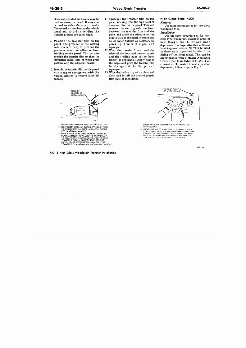
8/20/2019 1977 Ford Car Shop Manual Volume 4 Body
http://slidepdf.com/reader/full/1977-ford-car-shop-manual-volume-4-body 342/449
46-30-2
W oo d Grain Transfer
46-30
electrically heated air blower may be
used to warm the panel. It may also
be used to soften the repair transfer
film to make it conform to the vehicle
panel and to aid in bending the
transfer around the panel edges.
9. Position the transfer film on the
panel. The presence of the wetting
solution will help to prevent the
pressure sensitive adhesive from
sticking to the panel. This permits
moving the transfer film to align the
simulated caulk lines or wood grain
pattern with the adjacent panels.
10. Smooth the transfer film on the panel
with a rag or sponge wet with the
wetting solution to remove large air
pockets.
11. Squeegee the transfer film on the
panel, working from the high point of
a con tour line on the panel. This will
remove the wetting solution from
between the transfer film and the
panel and allow the adhesive on the
film to stick to the panel. Remove any
air or water bubbles as necessary by
pricking them with a pin, and
squeegee.
12. Wrap the transfer film around the
edges of the door and quarter panels
and the trailing edge of the front
fender (as applicable). Apply heat to
the edges and press the transfer film
firmly against the f lange, and
squeegee.
13. Wipe the surface dry with a clean soft
cloth and install the grained plastic
trim rails or mouldings.
High Gloss Type (KU X)
Removal
Use same procedure as for low-g
woodgrain type.
Installation
Use the same procedure as for l
gloss type woodgrain, except in area
hem flange, fuel f i l ler and d
depression. It is imperative tha t suffic
heat (approximately 200°F.) be u
in these areas to prevent transfer f
lifting off the sheet metal. This can
accomplished with a Master Applia
Corp.
Heat Gun (Model HG501
equivalent. To install transfer in d
depression, follow steps in Fig. 3.
PIECE OF
PLASTIC OR
METAL SCALE
PIECE OF PLASTIC
OR METAL SCALE
1. INSURE THE DEPRESSION IS FREE OF MOISTURE.
2. HEAT SHEET META L IN DOOR DEPRESSION AREA
TO APPROXIMATELY 200°F, AND APPLY TRANS-
FER IN NORMAL MANNER.
3. WITH A PIECE OF PLASTIC OR METAL SCALE IN
PLACE AS SHOWN TO ALLOW THE TRAPPED A IR
TO ESCAPE. SO A VACUUM IS CREATED TO HOLD
TRANSFER FIRMLY IN DEPRESSION (DO NOT
PUNCH HOLES IN TRANSF ER). SQUEEGEE THE
TRANSFER FILM INTO PLACE AROUND THE HANDLE.
4.
PRESS THE FILM SECURELY INTO THE SHALLOW
DEPRESSIONS.
5. USING HOT AIR TO MAKE THE FILM PLIA BLE, CARE-
FULLY PRESS THE FILM INTO THE DEEP DEPRESSION-
EXHAUSTING THE TRAPPED AIR TOWARD THE PIECE
OF PLASTIC, WITH THE AIR EXHAUSTED, REMOVE
THE PLASTIC TOOL AND SMOOTH THE FILM.
R1937-A
FIG.
3 High Gloss W ood gra in Transfer Installation
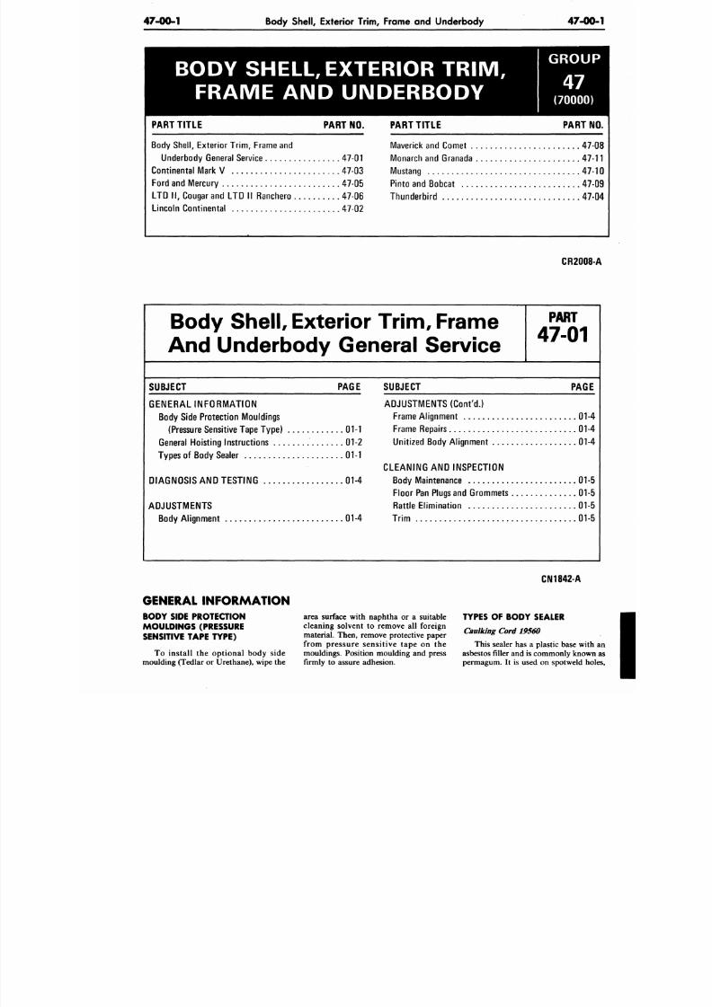
8/20/2019 1977 Ford Car Shop Manual Volume 4 Body
http://slidepdf.com/reader/full/1977-ford-car-shop-manual-volume-4-body 343/449
47-00-1
Body Shell, Exterior Trim, Frame and Underbody 47-00
BODY SHELL, EXTERIOR T R IM ,
FRAME AND UNDERBODY
PART TITL E PART NO.
Body She ll, Exterior Tr im , Frame and
Underbody General Service 47-01
Continental Mark V 47-03
Ford and Mercury 47-05
LT D II , Cougar a nd LTD
II
Ranchero 47-06
Lincoln Continental 47-02
GROUP
(70000)
PART TITL E PART N
Maverick and Comet 47
Monarch and Granada 47-
Mustang 47-
Pinto and Bobcat 47
Thunderbi rd 47
CR2008
Body
Shell,
Exterior Trim , Frame
And Underbody General Service
P A R T
47-01
SUBJECT PAGE
G ENERAL INF O RM AT IO N
Body Side Protection Mouldings
(Pressure Sensitive Tape Type) 01-1
General Ho isting Instructions 01-2
Types of Body Sealer 01-1
DIAGNOSIS AND TESTING 01-4
ADJUSTMENTS
Body Al ignment 01-4
SUBJECT PAGE
ADJUSTMENTS (Cont 'd.)
Frame Al ignment
01-4
Frame Repairs 01-4
Unit ized Body Al ignment 01-4
CLEANING
AND
INSPECTION
Body Maintenance 01-5
Floor Pan Plugs and Grommets
01-5
Rattle Elimination 01-5
Trim 01-5
GENERAL INFORMATION
BODY SIDE PROTECTION
MOULDINGS (PRESSURE
SENSITIVE TAPE TYPE)
To install the optional body side
moulding (Tedlar
or
Urethane), wipe
the
area surface with naphtha
or a
suitable
cleaning solvent to remove all foreign
material. Then, remove protective paper
from pressure sensitive tape on the
mouldings. Position moulding
and
press
firmly to assure adhesion.
CN1842-A
TYPES OF BODY SEALER
Caulking Cord 19560
This sealer has
a
plastic base with
asbestos filler and is commonly know
permagum. It is used on spotweld ho
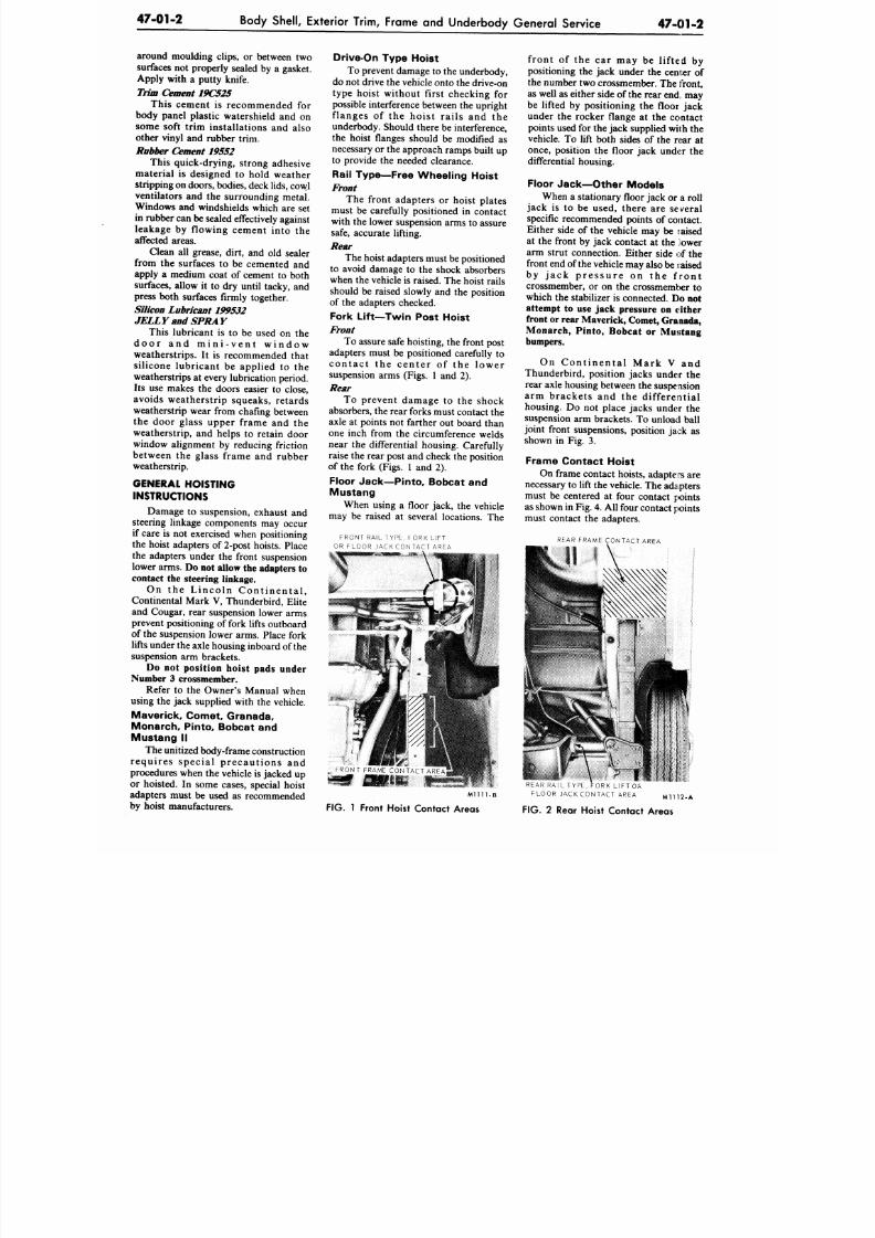
8/20/2019 1977 Ford Car Shop Manual Volume 4 Body
http://slidepdf.com/reader/full/1977-ford-car-shop-manual-volume-4-body 344/449
47-01-2
Body Shell, Exterior Trim, Frame and Underbody General Service
47-01-2
around moulding clips, or between two
surfaces not properly sealed by a gasket.
Apply with a putty knife.
Trim Cement 19C52S
This cement is recommended for
body panel plastic watershield and on
some soft trim installations and also
other vinyl and rubber trim.
Rubber Cement 19552
This quick-drying, strong adhesive
material is designed to hold weather
stripping
on
doors, bodies, deck lids,
cow.1
ventilators and the surrounding metal.
Windows and windshields which are set
in rubber can be sealed effectively against
leakage by flowing cement into the
affected areas.
Clean all grease, dirt, and old sealer
from the surfaces to be cemented and
apply a medium coat of cement to both
surfaces, allow it to dry until tacky, and
press both surfaces firmly together.
Silicon Lubricant 199532
JELLY
and
SPRAY
This lubricant is to be used on the
d o o r a n d m i n i - v e n t w i n d o w
weatherstrips. It is recommended that
silicone lubricant be applied to the
weatherstrips at every lubrication period.
Its use makes the doors easier to close,
avoids weatherstrip squeaks, retards
weatherstrip wear from chafing between
the door glass upper frame and the
weatherstrip, and helps to retain door
window alignment by reducing friction
between the glass frame and rubber
weatherstrip.
GENERAL HOISTING
INSTRUCTIONS
Damage to suspension, exhaust and
steering linkage components may occur
if care is not exercised when positioning
the hoist adapters of 2-post hoists. Place
the adapters under the front suspension
lower arms.
Do not allow the adapters to
contact the steering linkage.
O n t h e L i n c o l n C o n t i n e n t a l ,
Continental Mark V, Thunderbird, Elite
and Cougar, rear suspension lower arms
prevent positioning of fork lifts outboard
of the suspension lower arms. Place fork
lifts under th e axle housing inboard of the
suspension arm brackets.
Do not position hoist pads under
Number
3
crossmember.
Refer to the Owner's Manual when
using the jack supplied w ith the vehicle.
Maver ick , Comet Granada,
Mo narch, Pinto, Bobcat and
Mustang II
The unitized body-frame construction
r e qu i r e s spe c i a l p r e c a u t ions a nd
procedures when the vehicle is jacked up
or hoisted. In some cases, special hoist
adapters must be used as recommended
by hoist manufacturers.
Drive-On Type Hoist
To prevent damage to the underbody,
do not d rive the vehicle onto the drive-on
type hoist without first checking for
possible interference between the upright
f langes of the hoist rai ls and the
underbody. Should there be interference,
the hoist flanges should be modified as
necessary or the approach ramps built up
to provide the needed clearance.
Rail Type—Free Wheeling Hoist
Front
The front adapters or hoist plates
must be carefully positioned in contact
with the lower suspension arms to assure
safe,
accurate lifting.
Rear
The hoist adapters must
be
positioned
to avoid damage to the shock absorbers
when the vehicle is raised. The hoist rails
should be raised slowly and the position
of the adapters checked.
Fork Lif t—Twin Post Hoist
Front
To assure safe hoisting, the front post
adapters must be positioned carefully to
co nta c t the cen ter of the lower
suspension arms (Figs. 1 and 2).
Rear
To prevent damage to the shock
absorbers, the rear forks m ust contact the
axle at points not farther out board than
one inch from the circumference welds
near the differential housing. Carefully
raise the rear post and check the position
of the fork (Figs. 1 and 2).
Floor Jack—Pinto, Bobcat and
Mustang
When using a floor jack, the vehicle
may be raised at several locations. The
F R O N T R A I L T Y P E , F O R K L I F T
O R F L O O R J A C K C O N T A C T A R E A
front of the car may be lifted by
positioning the jack under the center of
the number two crossmember. The front,
as well as either side of
the
rear end. may
be lifted by positioning the floor jack
under the rocker flange at the contact
points used for the jack supplied wilh the
vehicle. To lift both sides of the rear at
once, position the floor jack under the
differential housing.
Floor Jack—Other Models
When a stationary floor jack or a roll
jack is to be used, there are several
specific recommended points of contact.
Either side of the vehicle may be raised
at the front by jack contact at the lower
arm strut connection. Either side of the
front end of the vehicle may also be raised
b y j a c k p r e s s u r e o n t h e f r o n t
crossmember, or on the crossmemter to
which the stabilizer is connected.
Do not
attempt to use jack pressure on either
front or
rear
Maverick, Comet, Granada,
Monarch, Pinto, Bobcat or Mustang
bumpers.
O n C o n t i n e n t a l M a r k V a n d
Thunderbird, position jacks under the
rear axle housing between the suspension
arm brackets and the differential
housing. Do not place jacks under the
suspension arm brackets. To unload ball
joint front suspensions, position jack as
shown in Fig. 3.
Frame Co ntact Ho ist
On frame contact hoists, adapte rs are
necessary to lift the vehicle. The ad apters
must be centered at four contact points
as shown in Fig.
4.
All four contact join ts
must contact the adapters.
REAR FRAME CONTACT AREA
FRONT FRAME CONTACT AREA
smm
M l l l l - l
FIG. 1 Front Hoist Contact Areas
REAR RAIL TYPE, FORK LIFT OR
FLOOR JACK CONTACT AREA M11 12-A
FIG.
2 Rear Hoist Contact Areas
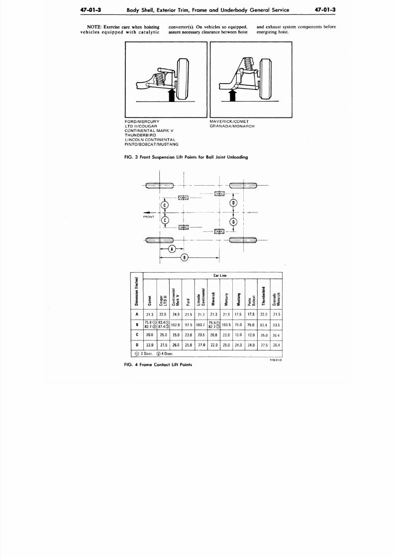
8/20/2019 1977 Ford Car Shop Manual Volume 4 Body
http://slidepdf.com/reader/full/1977-ford-car-shop-manual-volume-4-body 345/449
47-01-3
Body Shell, Exterior Trim, Frame and Underbody General Service
47-01
NOTE : Exercise care when hoisting conv erter(s). On vehicles so equipped, and exhaust system components be
ve hi cle s eq u ip pe d w ith ca ta ly ti c assure necessary clearance between hoist energizing hoist.
FORD/MERCURY
LT D I I/COUGAR
CONTINENTAL MARK V
THUNDERBIRD
LINCOLN CONTINENTAL
PINTO/BOBCAT/MUSTANG
MAVERICK/COMET
GRANADA/MONARCH
FIG. 3 Front Suspension Lift Points for Ball Joint Unloading
D
i
m
e
o
n
A
B
C
D
Car Line
C
o
m
e
21.3
75.8©
82.7©
20.0
22.0
C
o
L
I
22.0
• 8 3 . 4 0
87 .4 ©
25.0
27.5
C
o
n
a
M
a
k
V
24.9
102.9
25.0
26.0
F
d
21.5
97.5
23.0
25.0
L
n
n
C
o
n
a
21.7
103.7
23.5
27.0
M
a
c
21.3
75.8®
82.7©
20.0
22.0
M
e
c
y
21.5
100.5
23.0
25.0
M
u
a
17.5
75.0
12.0
24.0
P
n
o
o
17.5
75.0
12.0
24:0
T
b
d
22.0
83.4
25.0
27.5
G
r
a
M
o
c
21.5
83.5
26.4
26.4
© 2 Door. (2)4 Door.
FIG.
4 Frame Contact Lift Points
8/20/2019 1977 Ford Car Shop Manual Volume 4 Body
http://slidepdf.com/reader/full/1977-ford-car-shop-manual-volume-4-body 346/449
47-01-4
Body Shell, Exterior Trim, Frame and Underbody General Service
4 7 - 0 1 - 4
DIAGNOSIS AND TESTING
Sealer locations should be considered
when checking for dust or water leaks.
The forward motion of the vehicle causes
any unsealed small opening in the lower
section of the body to permit air to be
drawn into the body. Dust will follow any
path taken by the air from the point of
entry into the passenger and luggage
compartments. Opening the ventilator air
ducts will equalize these pressures. Dust
accumulates in the rocker panel, and may
eventually work its way to the kick-up or
the rear body pillar, and follow the
contour of the wheelhouse into the
luggage compartment.
To eliminate dust leakage, determine
the exact point at which the dust enters.
The point of entry is often deceptive, in
that the dust may enter at one point, then
follow the passages formed by interior
trim to another point.
Under certain conditions, water can
enter the body at any point where dust
can enter. Any consideration of water
leakage must take into account all points
covered under dust leaks.
To determine the exact location of a
dust leak, it may be necessary to remove
the following trim from the vehicle:
1. Cowl trim panel.
2.
Quarter trim panel.
3.
Rear seat back and seat cushion.
4.
Luggage compartment floor mats,
spare wheel, and side trim panel.
5.
Center pillar trim on 4-door models.
6. Scuff plates.
After removing the trim, the location
of most leaks will be readily evideni The
entrance of dust is usually indicated by
a pointed shaft of dust or silt. Seal these
leaks, and road test the vehicle on a (dusty
road to make sure that all leaks are
sealed.
After the road tests, check for
indications of a dust pattern around the
door openings, cowl panel, lower part of
the quarter panel, and in the luggage
compartment.
Sometimes leaks can be located by
putting bright lights under the vehicle,
with the above components removed, and
checking the interior of the body oints
and weld lines. The light will show
through where leaks exist.
ADJUSTMENTS
UNITIZED BODY ALIGNMENT
Servicing the unitized body should
present no unusual difficulties or
necessitate additional equipment, other
than required for conventional frame and
body repair. The application of heat and
the use of heavy duty jacks must be
carefully controlled because of the
difference in the gauge of the metal in the
sub-frame of a unitized body and the
stress points developed in a single welded
unit construction. It is possible to pull
damaged areas back into alignment with
the use of l ight-weight jacks and
hydraulic equipment, without heating the
metal.
Rough-out badly damaged areas
before taking measurements for squaring
up a body. If necessary, remove the glass
from the damaged area to prevent
breakage. In severe cases, reinforcement
brackets and other inner construction
may have to be removed or cut to permit
restoration of the outer shell and pillars,
without excessive strain on the parts.
Straighten, install, and secure all such
parts in place, before attempting to align
the body.
In cases of severe or sharp bends, it
may be necessary to use heat. Any
attempt to cold-straighten a severely bent
bracket may cause ruptures of the welds
and may also cause cracks in the bent
part. Never heat the area more than a
dull red.
Checking Underbody for
Misa l ignm ent
The dimensions of the underbody
must be restored in the repair of major
body damage, to provide correct front
and rear wheel geometry. The underbody
dimensions are given in each Part of this
Group for the respective models. All the
dimensions are detailed to the center line
of existing holes in the underbody
assembly. Once the frame and suspension
members are aligned, the balance of the
repair can be performed.
BODY ALIGNMENT
When checking alignment of a badly
damaged body, be sure that all necessary
frame corrections have been made before
attempting to align the body.
Rough out badly damaged areas
before taking measurements for squaring
up a body. Remove the glass to prevent
breakage. In severe cases, reinforcement
brackets and other inner construction
may have to be removed or cut to permit
restoration of the outer shell and pillars
without excessive strain on the parts.
Straighten, install and secure all parts in
place before attempting to align the body.
In cases of severe or sharp bends, it
may be necessary to use heat. Any
attempt to cold-straighten a severely bent
bracket may cause ruptures of the welds
(if any) and may also cause cracks in the
bent part. Never heat the area more than
enough to give a dull red.
Check ing Body for Misal ignm ent
To align or square up a body, take two
opposite diagonal measurements between
the front, center, or rear pillars. Take the
measurements between reference points,
such as crease lines or weld joints which
are diagonally opposite each othe r, on the
two pillars being measured. Since all
measurements should be made from the
bare metal, remove all interior trim from
the checking points.
Do not attempt to correct any serious
m i s a l i g n m e n t w i t h o n e j a c k i n g
operation. This is particularly true if
other sections of the body also require
a l i g n i n g . A l i g n e a c h s e c t i o n
p ropor t iona te ly , un t i l the p roper
dimensions are obtained. If frame
alignment is questionable, refer to the
frame dimensions given in each Part of
this Group for the respective models.
FRAME ALIGNMENT
Frame misalignment can affect front
wheel alignment, body alignment and
the operation of the chassis parts .
Window glass cracks, door and window
opening troubles, and air or water leaks
at the doors are often caused by
improperly tightened body bolts or frame
misalignment.
Before checking frame alignment,
inspect all frame members for cracks,
twists, or bends. Check all welded
connections for cracks. Inspect the bolts
and body support brackets for looseness.
M a k e a n y n e c e s s a r y r e p a i r s o r
replacements.
FRAME REPAIRS
To prevent internal stresses in the
metal, frame straightening should be
limited to parts which are not severely
bent. If heat is needed to straighten a
frame member, keep the temperature
below 1200 degrees F. Excessive heat
may weaken the metal in the frame
members and cause permanent damage.
Electric welding equipment should be
used for all frame welding and heat
should be kept t o a minimum area so that
8/20/2019 1977 Ford Car Shop Manual Volume 4 Body
http://slidepdf.com/reader/full/1977-ford-car-shop-manual-volume-4-body 347/449
47-01-5
Body Shell, Exterior Trim, Frame and Underbody General Service
47-01
the hardness of the metal will not be
affected.
When a reinforcement is to be welded
to a frame side member, run the welds
lengthwise a long the s ide of the
reinforcement.
If a damaged frame member is to be
replaced, use the same method of
attachment as on the original fra
member . New bol ts , r equi red
replacement of parts, should be of
same specifications as the original bo
CLEANING AND INSPECTION
FLOOR PAN PLUGS AND
GROMME TS
Many plugs and grommets are used
in the floor pan and dash panel. The
floor-pan plugs seal the various access
holes. If any plugs are missing or
improperly installed, a dust or water leak
may result. This also applies to the
grommets used on the dash panel. When
dust or water leaks are evident, these
plugs and grommets should be checked
for proper installation.
RATTLE ELIMINATION
Most rattles a re caused by a loose bolt
or screw. Foreign objects such as nuts,
bolts, or small pieces of body deadener in
the door wells, pillars and quarter panels,
are often the source of rattles. Door wells
can be checked by carefully striking the
underside of the door with a rubber
mallet. The impact made by the mallet
will indicate if loose objects are in the
doorwell.
All bolts and screws should be
tightened periodically. In the event that
tightening the bolts and screws, located
on such assemblies as the doors, hood,
and deck lid does not eliminate the
rattles, the trouble is probably caused by
misalignment. If this is the case, follow
t h e a d j u s t m e n t a n d a l i g n m e n t
procedures for these assemblies.
Rattles and squeaks are sometimes
c a u s e d by w e a t h e r s t r i p p i n g a n d
antisqueak material that has slipped out
of position. Apply additional cement or
other adhesive, and install the material in
the proper location, to eliminate this
condition.
TRIM
The bright metal parts of the vehicle
require no special care. Periodic cleaning
will preserve the beauty and life of these
finishes. Wash with clear water, or if the
parts are very dirty use multi-purpose
cleaner (19523 or equivalent). Using a
clean soft cloth or a sponge and water,
rinse and wipe the parts dry. Chrome
Cleaner may be used sparingly to remove
rust or salt corrosion from chrome plated
parts. Do not scour aluminum or chrome
finished parts with steel wool or polish
them with products containing abrasives.
A custom silicone polish (19530 or
equiva lent ) wi l l provide exce l lent
protection for all bright metal parts.
BODY MAINTENANCE
Regular body maintenance preserves
the vehicle's appearance during the life of
the vehicle. The following steps
suggested as a guide for regular bo
maintenance.
1. Vacuum the interior thoroughly
wash the vehicle.
2. Check all openings for water le
and seal where necessary.
3. Cement all loose weatherstrips wh
are still usable.
4.
Replace all door and deck
weatherstrips which are unfit
service.
5. Apply si l icone lubricant to
weatherstripping.
6. Replace all cracked, fogged,
chipped glass.
7. Align the hood, doors, and deck
if necessary.
8. Inspect the windshield wiper bla
and replace them if necessary.
9. Tighten the sill plate and garn
moulding screws.
10.
Clean the seats, door trim panels,
headlining.
11.Touch up or paint chipped
scratched areas.
12. Drain holes located on the under
of each rocker panel, quarter pa
a n d d o o r , s h o u l d b e c l e a
periodically.
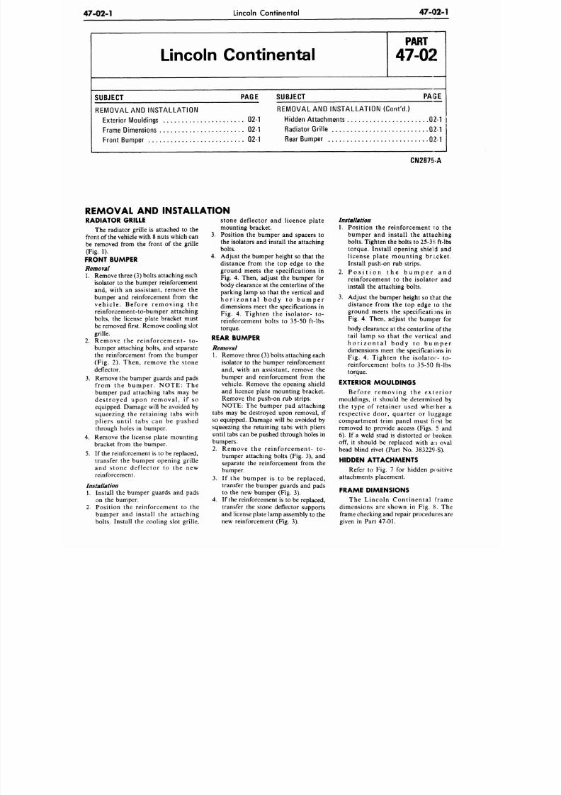
8/20/2019 1977 Ford Car Shop Manual Volume 4 Body
http://slidepdf.com/reader/full/1977-ford-car-shop-manual-volume-4-body 348/449
47-02-1
Lincoln Continental
47-02-1
Lincoln Continental
P A R T
47-02
SUBJECT PAGE
REMOVAL AND INS TALLATION
Exte rior Mouldings 02-1
Frame Dimensions 02-1
Front Bumper 02-1
SUBJECT PAI3£
REMOVAL AND INSTALLATION (Con t 'd . )
Hidden Attachments 0 ;M
Rad iator Grille 02-1
Rear Bump er 02-1
CN2875-A
REMOVAL AND INSTALLATION
RADIATOR GRILLE
The radiator grille is attached to the
front of the vehicle with 8 nuts which can
be removed from the front of the grille
(Fig. 1).
FRONT BUMPER
Removal
1. Remove three (3) bolts attaching each
isolator to the bumper reinforcement
and, with an assistant, remove the
bumper and reinforcement from the
ve h ic l e . Be f or e r e m oving the
reinforcement-to-bumper attaching
bolts, the license plate bracket must
be removed first. Remove cooling slot
grille.
2. Remove the reinforcement- to-
bumper attaching bolts, and separate
the reinforcement from the bumper
(Fig. 2). Then, remove the stone
deflector.
3. Remove the bumper guards and pads
f rom the bumper . NOTE: The
bumper pad attaching tabs may be
dest royed upon removal , i f so
equipped. Damage will be avoided by
squeezing the retaining tabs with
pliers unti l tabs can be pushed
through holes in bumper.
4. Remove the license plate mounting
bracket from the bumper.
5. If the reinforcement is to be replaced,
transfer the bumper opening grille
and stone deflector to the new
reinforcement.
Installation
1. Install the bumper gu ards and pads
on the bumper.
2. Position the reinforcement to the
bumper and install the attaching
bolts. Install the cooling slot grille,
stone deflector and licence plate
mounting bracket.
3. Position the bump er and spacers to
the isolators and install the attaching
bolts.
4. Adjust the bumper height so that the
distance from the top edge to the
ground meets the specifications in
Fig. 4. Then, adjust the bumper for
body clearance at the centerline of the
parking lamp so that the vertical and
h o r i z o n t a l b o d y t o b u m p e r
dimensions meet the specifications in
Fig. 4. Tighten the isolator- to-
reinforcement bolts to 35-50 ft-lbs
torque.
REAR BUMPER
Removal
1. Remove three (3) bolts attaching each
isolator to the bumper reinforcement
and, with an assistant, remove the
bumper and reinforcement from the
vehicle. Remove the opening shield
and licence plate mounting bracket.
Remove the push-on rub strips.
NOTE: The bumper pad attaching
tabs may be destroyed upon removal, if
so equipped. Damage will be avoided by
squeezing the retaining tabs with pliers
until tabs can be pushed through holes in
bumpers.
2. Remove the reinforcement- to-
bumper attaching bolts (Fig. 3), and
separate the reinforcement from the
bumper.
3.
If the bumper is to be replaced,
transfer the bumper guards and pads
to the new bumper (Fig. 3).
4. If the reinforcement is to be replaced,
transfer the stone deflector supports
and license plate lamp assembly to the
new reinforcement (Fig. 3).
Installation
1. Position the reinforcement i:o the
bumper and install the attaching
bolts. Tighten the bolts to 25-3>i ft-lbs
torque. Install opening shield and
license plate mounting bracket.
Install push-on rub strips.
2. P o s i t i o n t h e b u m p e r a n d
reinforcement to the isolator and
install the attaching bolts.
3. Adjust the bumper height so that the
distance from the top edge to the
ground meets the specifications in
Fig. 4. Then, adjust the bumper for
body clearance at the centerline of the
tail lamp so that the vertical and
h o r i z o n t a l b o d y t o b u m p e r
dimensions meet the specifications in
Fig. 4. Tighten the isolator- to-
reinforcement bolts to 35-50 ft-lbs
torque.
EXTERIOR MOULDINGS
Be f or e r e m oving the e x t e r io r
mouldings, it should be determined by
the type of retainer used whether a
respective door, quarter or luggage
compartment trim panel must first be
removed to provide access (Figs. 5 and
6). If a weld stud is distorted or broken
off, it should be replaced with an oval
head blind rivet (Part No. 383229 -S).
HIDDEN ATTACHMENTS
Refer to Fig. 7 for hidden positive
attachments placement.
FRAME DIMENSIONS
The Lincoln Contin enta l f rame
dimensions are shown in Fig. 8. The
frame checking and repair procedures are
given in Part 47-01.
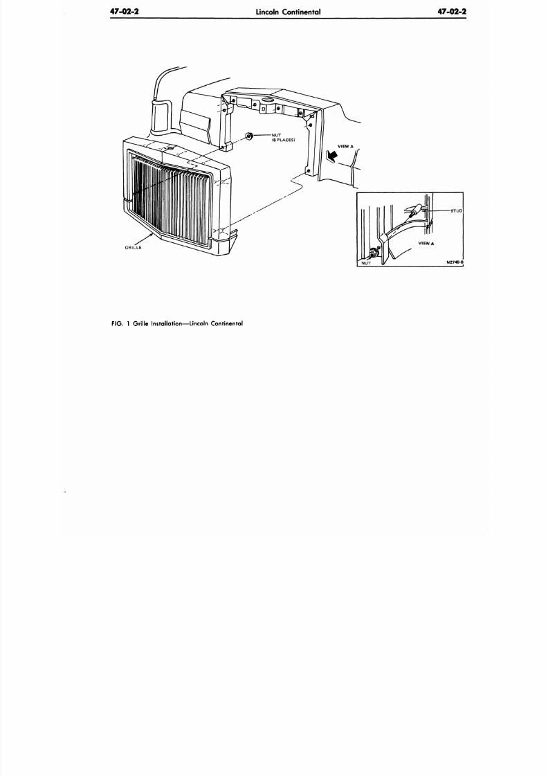
8/20/2019 1977 Ford Car Shop Manual Volume 4 Body
http://slidepdf.com/reader/full/1977-ford-car-shop-manual-volume-4-body 349/449
47-02-2
Lincoln Continental
47-02
GRILLE
F IG .
1 Grille Installation—Lincoln Continental
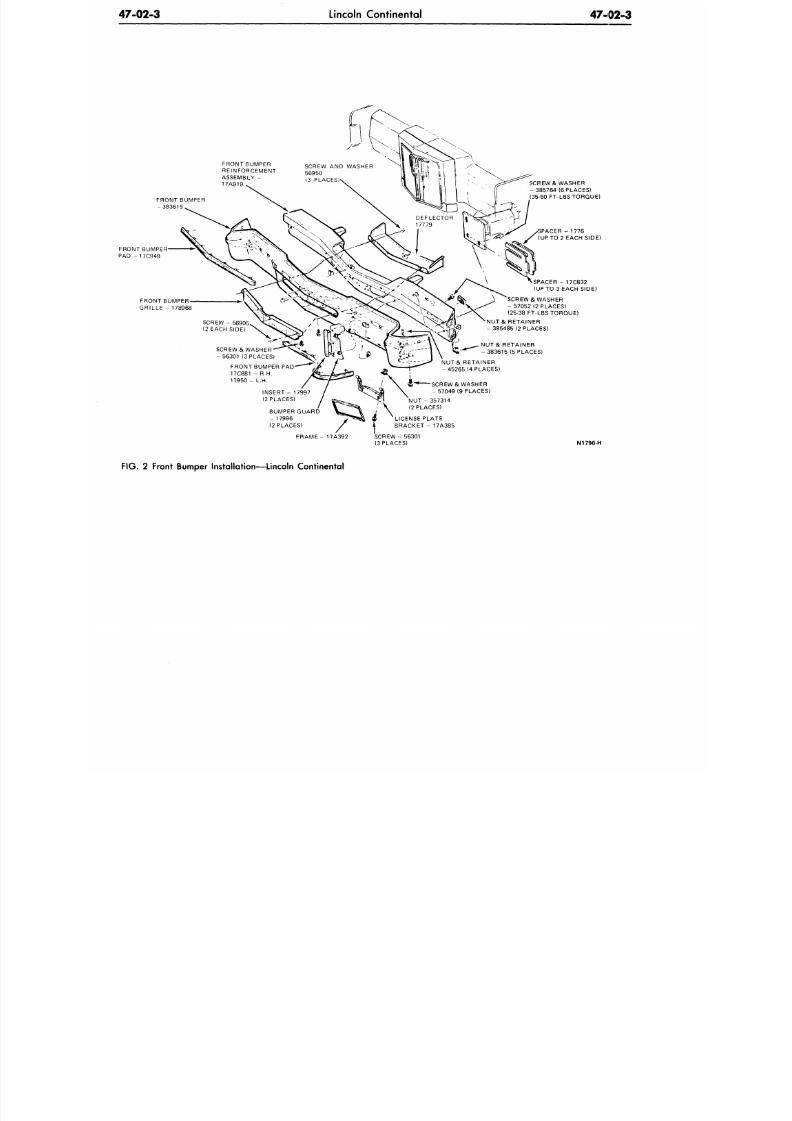
8/20/2019 1977 Ford Car Shop Manual Volume 4 Body
http://slidepdf.com/reader/full/1977-ford-car-shop-manual-volume-4-body 350/449
47-02-3
Lincoln Continental
47-02-3
/^
FRONT BUMPER
REINFORCEMENT
ASSEMBLY -
17A919
FRONT BUMPER
- 3 8 3 6 1 5
FRONT BUMPER
PAD - 17C949
FRONT BUMPER
GRILLE - 178968
SCREW & WASHER
-5 63 01 (3 PLACES)
FRONT BUMPER PAD
17C881 - R H.
1 7 9 5 0 -
L.H.
INSERT - 17997
(2 PLACES)
BUMPER GUARD
- 17996
(2 PLACES)
SCREW & WASHER
- 385 764 (6 PLACES)
(35-50 FT-LBS TORQUE)
PACER - 1776
(UP TO 2 EACH SIDE)
SPACER - 17C832
(UP TO 3 EACH SIDE)
SCREW & WASHER
- 57052 (2 PLACES)
(25-38 FT-LBS TORQUE)
NUT & RETAINER
- 385485 (2 PLACES)
NUT & RETAINER
-383615 (5 PLACES)
NUT & RETAINER
-45 26 5 (4 PLACES)
— SCREW& WASHER
- 57049 (9 PLACES)
NUT - 357314
(2 PLACES)
LICENSE P LATE
BRACKET - 1 7A385
FRAME - 17A392
SCREW - 5 6301
(3 PLACES)
N1796-H
FIG . 2 Front Bumper Installation—Lincoln Continental
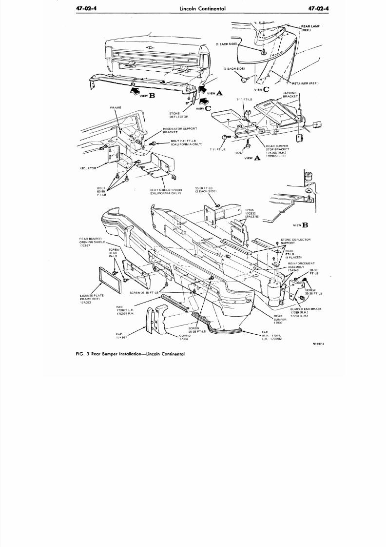
8/20/2019 1977 Ford Car Shop Manual Volume 4 Body
http://slidepdf.com/reader/full/1977-ford-car-shop-manual-volume-4-body 351/449
47-02-4
Lincoln Continental
47-02
REAR LAMP
(REF.)
REAR BUMPER
STOP BRACK ET
BOLT 17K755(R.H.)
17B965(L.H.)
REAR BUMPER
OPENING SHIELD
17C857
LICENSE PLATE
FRAME (KIT)
17A392
BUMPER END BRACE
17789 (R.H.)
REAR 17793 (L.H.)
BUMPER
17906
SCREW
25-38 FT-LB
GUARD
17984
PAD
(R.H.
- 17914,
L.H. - 17C996)
N1797
F IG . 3 Rear Bumper Installation—Lincoln Continental
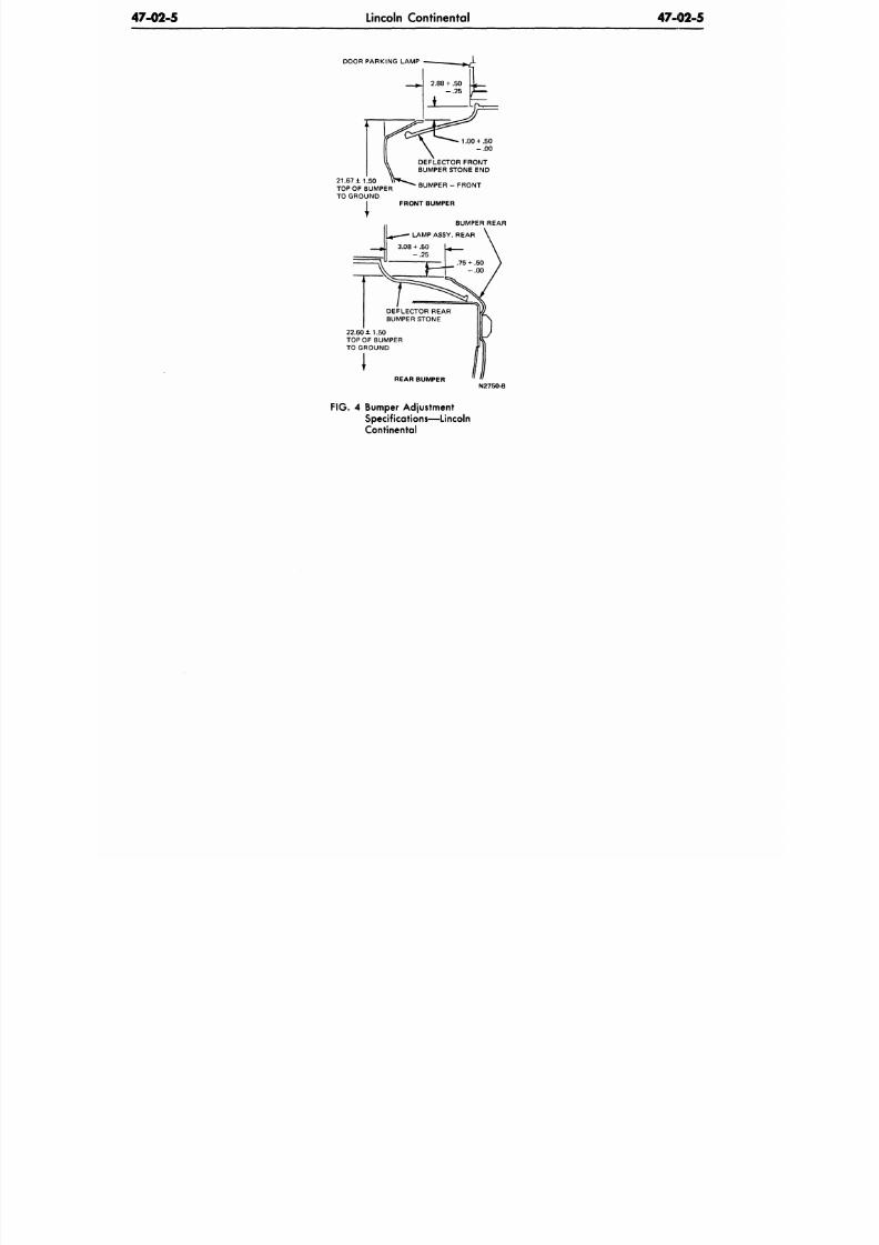
8/20/2019 1977 Ford Car Shop Manual Volume 4 Body
http://slidepdf.com/reader/full/1977-ford-car-shop-manual-volume-4-body 352/449
47-02-5
Lincoln Continental
47-02-5
DOOR PARKING LAMP
21.67 ± 1 . 5 0
TOP OF BUMPER
TO GROUND
1.00
+
.5 0
- . 0 0
DEFLECTOR FRONT
BUMPER STONE END
BUMPER - FRONT
FRONT BUMPER
BUMPER REAR
LAMP ASSY. REAR
22.60 ± 1.50
TOP OF BUMPER
TO GROUND
REAR BUMPER
N2750-B
F IG .
4 Bumper Adjustment
Specifications—Lincoln
Continental
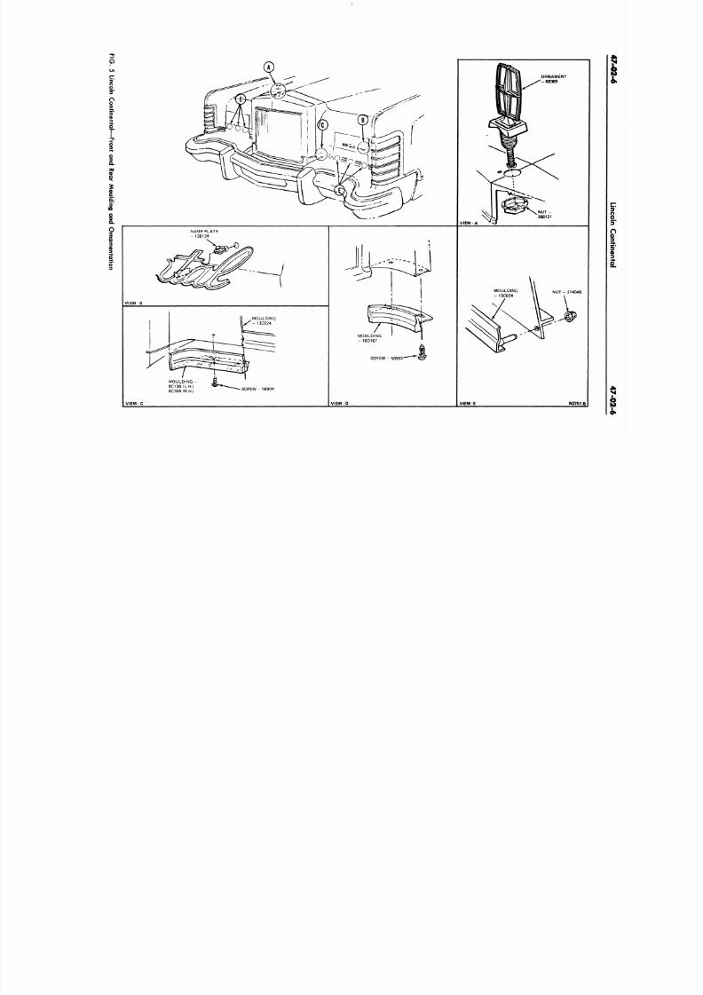
8/20/2019 1977 Ford Car Shop Manual Volume 4 Body
http://slidepdf.com/reader/full/1977-ford-car-shop-manual-volume-4-body 353/449
p
[T.
3
n
9
|
I'
I
o
VIEW A
ORNAMENT
N U T -
366121
NAME PLATE
- 138124
VIEW
B
SCREW - 56904
NUT
-
374046
S C R E W - 5 6 9 0 3
V IEW D
VIEW E
N2751-B
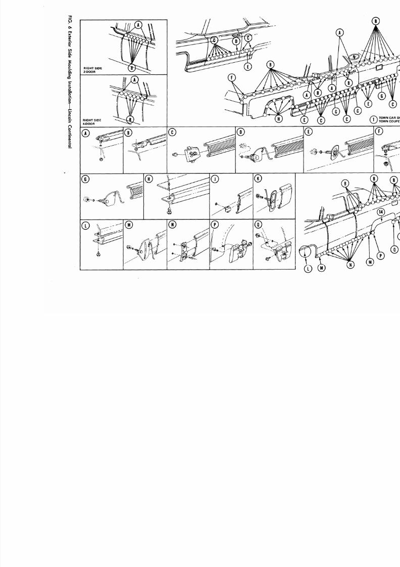
8/20/2019 1977 Ford Car Shop Manual Volume 4 Body
http://slidepdf.com/reader/full/1977-ford-car-shop-manual-volume-4-body 354/449
F
G
6
E
e
o
S
d
M
d
n
n
a
a
o
—
L
n
n
C
n
a
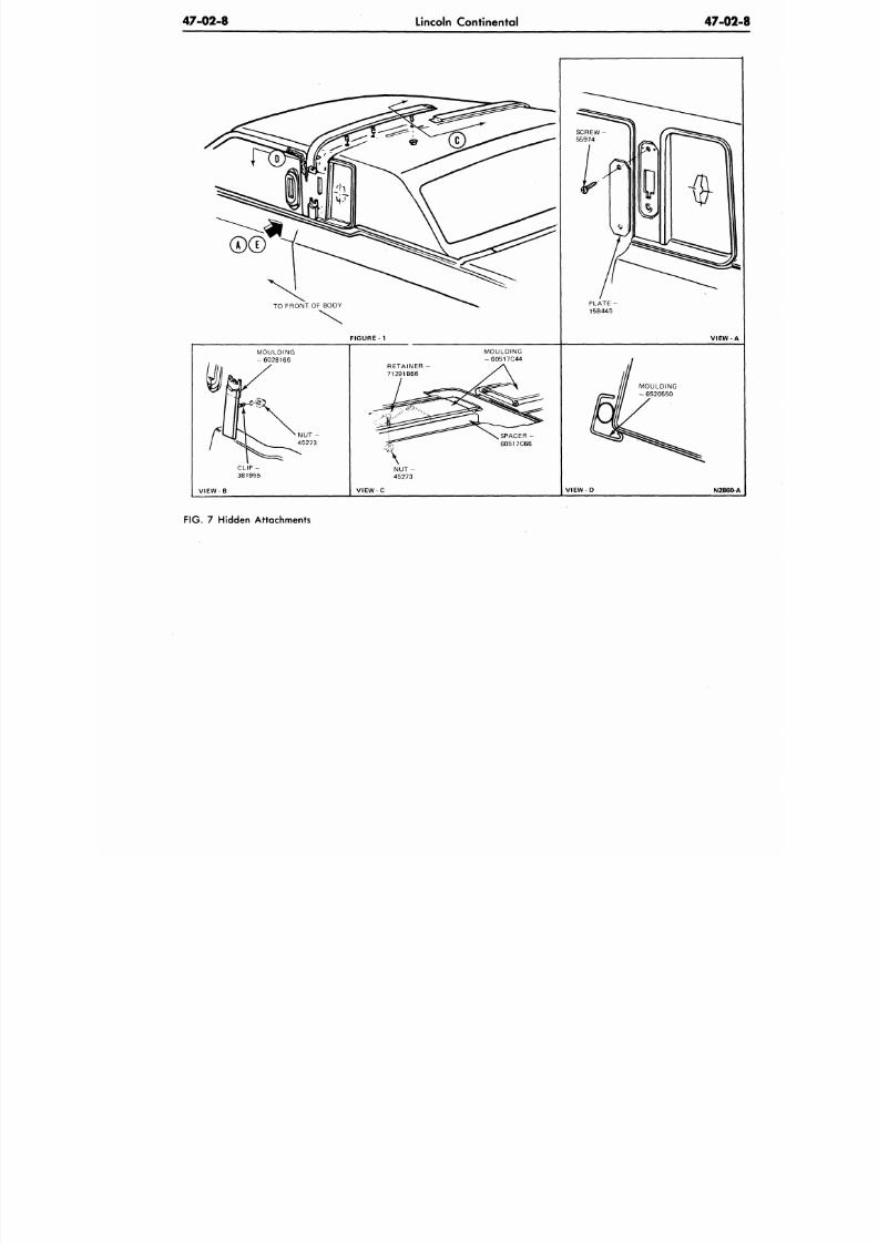
8/20/2019 1977 Ford Car Shop Manual Volume 4 Body
http://slidepdf.com/reader/full/1977-ford-car-shop-manual-volume-4-body 355/449
47-02-8
Lincoln Continental
47-0
F IG U R E -1 V IE W
MOULDING
- 6 0 5 1 7 C 4 4
RETAINER
71291B66
MOULDING
- 6520550
V I E W - D
N2860
FIG . 7 Hidden Attachments
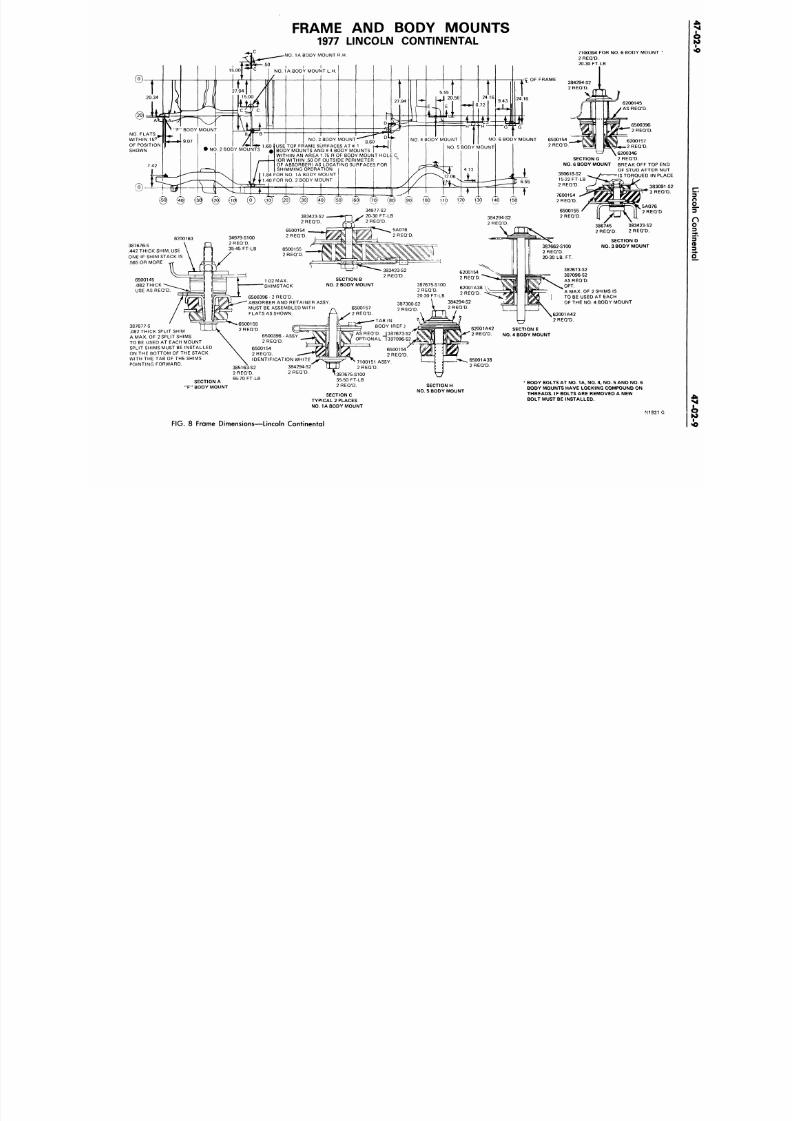
8/20/2019 1977 Ford Car Shop Manual Volume 4 Body
http://slidepdf.com/reader/full/1977-ford-car-shop-manual-volume-4-body 356/449
FRAME AND BODY MOUNTS
1977 LINCOLN CONTINENTAL
7100394 FOR NO. 6 BODY MOUNT
2 REQ'D.
20 30 FT LB
NO.
FLATS
WITHIN 15
C
OF POSITION
SHOWN
NO .
1A BODY MOUNT R.H
NO.
1 A BODY MOUNT L.H
F" BODY MOUNT
9.07
NO. 6 BODY MOUNT
O.
3 BODY MOUNT
NO.
4 BODY MOUNT
6200157
2 REQ'D.
6200346
2 REQ'D.
BREAK OFF TOP
OF STUD AFTER
= IS TORQUED IN P
- ..60 IUSE TOP FRAME SURFACES AT «
• NO. 2 BODY MOUNTS
# B 0
DY MOUNTS AND K 4 BODY MOUNTS
NO . 5 BODY MOUNT
WITHIN AN AREA 1.75 R OF BODY MOUNT HOLE C,
(OR WITHIN .50 OF OUTSIDE PERIMETER
OF ABSORBER) AS LOCATING SURFACES FOR
SHIMMING OPERATION
SECTION G
NO.
6 BODY MOUNT
380618-S2
15-22 FT-LB
2 REQ'D.
FOR NO. 1A BODY MOUNT
1 40 FOR NO. 2 BODY MOUNT
34977S2
20-30 FT-LB
2 REQ'D.
383423-S2
2 REQ'D.
34979-S100
2 REQ'D.
35-45 FT-LB
SECTION D
NO .
3 BODY MOUNT
SECTION B
NO.
2 BODY MOUNT
1.02 MAX.
SHIMSTACK
387675-S100
2 REQ'D.
20-30 FT-LB
6500396 -2 REQ'D.
ABSORBER AND RETAINER ASSY
MUST BE ASSEMBLED WITH
FLATS AS SHOWN.
TAB IN
BODY (REF.)
SECTION E
NO.
4 BODY MOUNT
S REQ'D. I337673-S2
6500396 - ASSY
2 REQ'D.
6500154
2 REQ'D.
IDENTIFICATION WHITE
384294-S2
6200163
387676-S
.442 THICK SHIM, USE
ONE IF SHIM STACK IS
.565 OR MORE
6500145
.082 THICK
USE AS REQ'D.
387677-S
.082 THICK SPLIT SHIM
A MAX. OF 2 SPLIT SHIMS
TO BE USED AT EACH MOUNT
SPLIT SHIMS MUST BE INSTALLED
ON THE BOTTOM OF THE STACK
WITH THE TAB OF THE SHIMS
POINTING FORWARD.
387673-S2
387096-S 2
AS REQ'D.
OPT.
A MAX. OF 2 SHIMS IS
TO BE USED AT EACH
OF THE NO. 4 BODY MOUNT
SECTION A
*F"
BODY MOUNT
2 REQ'D.
I387675-S100
35-50 FT-LB
2 REQ'D.
SECTION C
TYPICAL 2 PLACES
NO. 1A BODY MOUNT
SECTION H
NO.
5 BODY MOUNT
BODY BOLTS AT NO. 1A. NO. 4. NO. 5 AND NO. 6
BODY MOUNTS HAVE LOCKING COMPOUND ON
THREADS. IF BOLTS ARE REMOVED A NEW
BOLT MUST BE INSTALLED.
N 1 3 2 1
FIG. 8 Frame Dimensions—Lincoln Continental
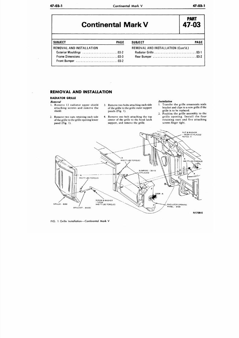
8/20/2019 1977 Ford Car Shop Manual Volume 4 Body
http://slidepdf.com/reader/full/1977-ford-car-shop-manual-volume-4-body 357/449
474)3-1
Continental Mark V
47-0
Continental MarkV
P A R T
47-03
SUBJECT PAGE
REM O VAL AND INST AL L AT IO N
Exterior Mouldings
03-2
Frame Dimensions
03-3
Front Bumper , 03-2
SUBJECT
PA
REMOVAL AND INSTALLATION (Con t 'd . )
Radiator Grille
03
Rear Bumper
03
REMOVAL AND INSTALLATION
RADIATOR GRILLE
Removal
1. Remove
13
radiator upper shield
attaching screws
and
remove
the
shield.
2.
Remove two nuts retaining each side
of the grille to the grille opening lower
panel (Fig. 1).
3. Remove two bolts attaching each side
of
the
grille to the g rille outer su pport
panels (Fig.
1).
4. Remove one bolt attaching the top
center
of
the grille
to
the hood latch
support, and remove the grille.
Installation
1. Transfer
the
grille ornament
bracket and clips to a new grille
grille is to be replaced.
2. Position the grille assembly
gr i l le opening. Ins ta l l
th
retaining nuts
and
five atta
screws finger tight.
NUT
&
WASHER
-45334(21 PLACE
NOTED:
A
G R I L L E - 8 2 0 0
B R A C K E T - 8 A 0 2 2
N170
FIG.
1
Grille Installation—Continental Mark
V
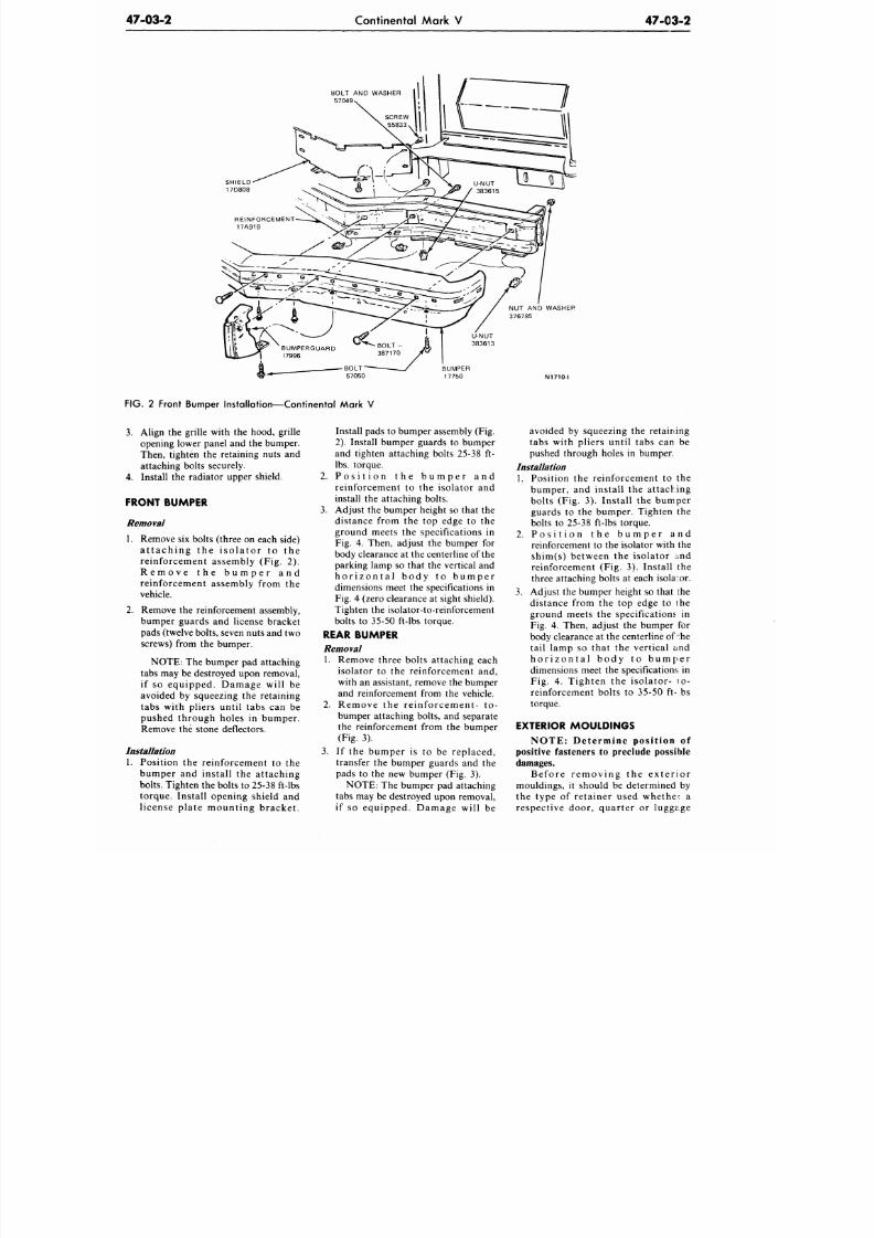
8/20/2019 1977 Ford Car Shop Manual Volume 4 Body
http://slidepdf.com/reader/full/1977-ford-car-shop-manual-volume-4-body 358/449
47-03-2
Continental Mark V
47-03-2
BOLT AND WASHER
57049«
SHIELD
17D808
U-NUT
383613
BUMPER
17750
N1710-I
FIG. 2 Front Bumper Installation—Continental Mark V
3.
Align the grille with the hood, grille
opening lower panel and the bumper.
Then, tighten the retaining nuts and
attaching bolts securely.
4.
Install the radiator upper shield.
FRONT BUMPER
Removal
1. Remove six bolts (three on each side)
a t t a c h ing the i so l a to r t o t he
reinforcement assembly (Fig. 2).
R e m o v e t h e b u m p e r a n d
reinforcement assembly from the
vehicle.
2. Remove the reinforcement assembly,
bumper guards and license bracket
pads (twelve bolts, seven nuts and two
screws) from the bumper.
NOTE: The bumper pad attaching
tabs may be destroyed upon removal,
if so equipped. Damage will be
avoided by squeezing the retaining
tabs with pliers until tabs can be
pushed through holes in bumper.
Remove the stone deflectors.
Installation
1. Position the reinforcement to the
bumper and install the attaching
bolts. Tighten the bolts to 25-38 ft-lbs
torque. Install opening shield and
license plate mounting bracket.
Install pads to bumper assembly (Fig.
2). Install bumper guards to bumper
and tighten attaching bolts 25-38 ft-
lbs.
torque.
2. P o s i t i o n t h e b u m p e r a n d
reinforcement to the isolator and
install the attaching bolts.
3.
Adjust the bumper height so that the
distance from the top edge to the
ground meets the specifications in
Fig. 4. Then, adjust the bumper for
body clearance at the centerline of the
parking lamp so that the vertical and
h o r i z o n t a l b o d y t o b u m p e r
dimensions meet the specifications in
Fig. 4 (zero clearance at sight shield).
Tighten the isolator-to-reinforcement
bolts to 35-50 ft-lbs torque.
REAR BUMPER
Removal
1. Remove three bolts attaching each
isolator to the reinforcement and,
with an assistant, remove the bumper
and reinforcement from the vehicle.
2. Remove the reinforcement- to-
bumper attaching bolts, and separate
the reinforcement from the bumper
(Fig. 3).
3.
If the bumper is to be replaced,
transfer the bumper guards and the
pads to the new bumper (Fig. 3).
NOTE: The bumper pad attaching
tabs may be destroyed upon removal,
if so equipped. Damage will be
avoided by squeezing the retaining
tabs with pliers until tabs can be
pushed through holes in bumper.
Installation
1. Position the reinforcement to the
bumper, and install the attaching
bolts (Fig. 3). Install the bumper
guards to the bumper. Tighten the
bolts to 25-38 ft-lbs torque.
2. P o s i t i o n t h e b u m p e r a n d
reinforcement to the isolator with the
shim(s) between the isolator and
reinforcement (Fig. 3). Install the
three attaching bolts at each isolator.
3. Adjust the bumper height so that the
distance from the top edge to ihe
ground meets the specifications in
Fig. 4. Then, adjust the bumper for
body clearance at the centerline of :he
tail lamp so that the vertical and
h o r i z o n t a l b o d y t o b u m p e r
dimensions meet the specifications in
Fig. 4. Tighten the isolator- 10-
reinforcement bolts to 35-50 ft- bs
torque.
EXTERIOR MOULDINGS
NOTE: Determine position of
positive fasteners to preclude possible
damages.
Before removing the exte r ior
mouldings, it should be determined by
the type of retainer used whether a
respective door, quarter or luggage
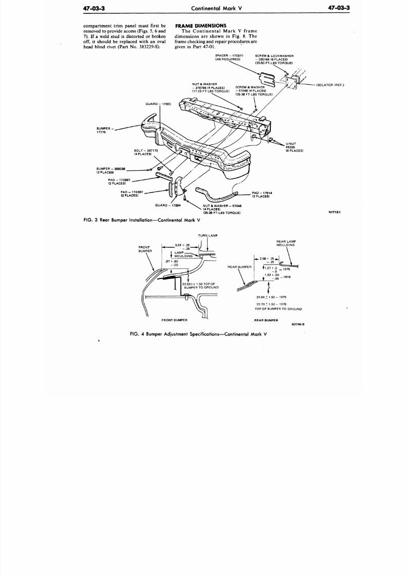
8/20/2019 1977 Ford Car Shop Manual Volume 4 Body
http://slidepdf.com/reader/full/1977-ford-car-shop-manual-volume-4-body 359/449
47-03-3
Continental Mark V
47-0
compar tment tr im panel must f ir s t be
removed
to
provide access (Figs.
5, 6
an d
7) .
If a
weld stud
is
distorted
or
broken
off, it should be replaced with an oval
head blind rivet (Part No. 383229-S).
FRAME DIMENSIONS
The Continental Mark V frame
dimensions are shown in Fig. 8. The
frame checking and repair procedures are
given in Part 47-01.
S P A C E R - 1 7 C 9 7 7
(AS REQUIRED)
SCREW & LOCKWASHER
- 385764
(6
PLACES)
(35-50 FT-LBS TORQUE)
NU T & WASHER
- 376785
(4
PLACES)
(17-23 FT-LBS TORQUE)
SCREW & WASHER
- 57048 (4 PLACES)
(25-38 FT-LBS TORQUE)
ISOLATOR (RE
U-NUT
45265
(8 PLACES)
P A D -
17K867
(2 PLACES)
PAD - 17914
(2 PLACES)
G U A R D - 1 7 8 9 4
NU T
&
W A S H E R - 5 7 0 4 8
(4 PLACES)
(25-38 FT-LBS TORQUE)
N1712
F IG . 3 Rear Bumper Installation—Continental Mark V
TURN LAMP
REAR BUMPER
FRONT BUMPER
24.04
± 1.50 - 1975
2 3 . 7 9 ± 1 . 5 0 - 1 9 7 6
TOP OF BUMPER
TO
GROUND
REAR BUMPER
FIG. 4
Bumper Adjustment Specifications—Continental Mark
V
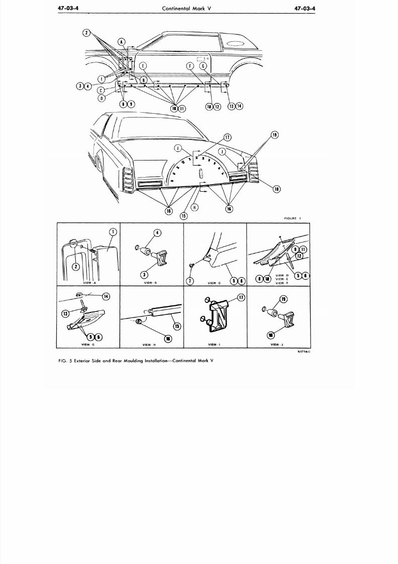
8/20/2019 1977 Ford Car Shop Manual Volume 4 Body
http://slidepdf.com/reader/full/1977-ford-car-shop-manual-volume-4-body 360/449
47-03-4
Continental Mark V
47-03-4
FIGURE 1
V I E W - A
VIEW B
VIEW G
VIEW- H
VIEW I
VIEW J
N1714-O
FIG . 5 Exterior Side and Rear Moulding Installation—Continental Mark V
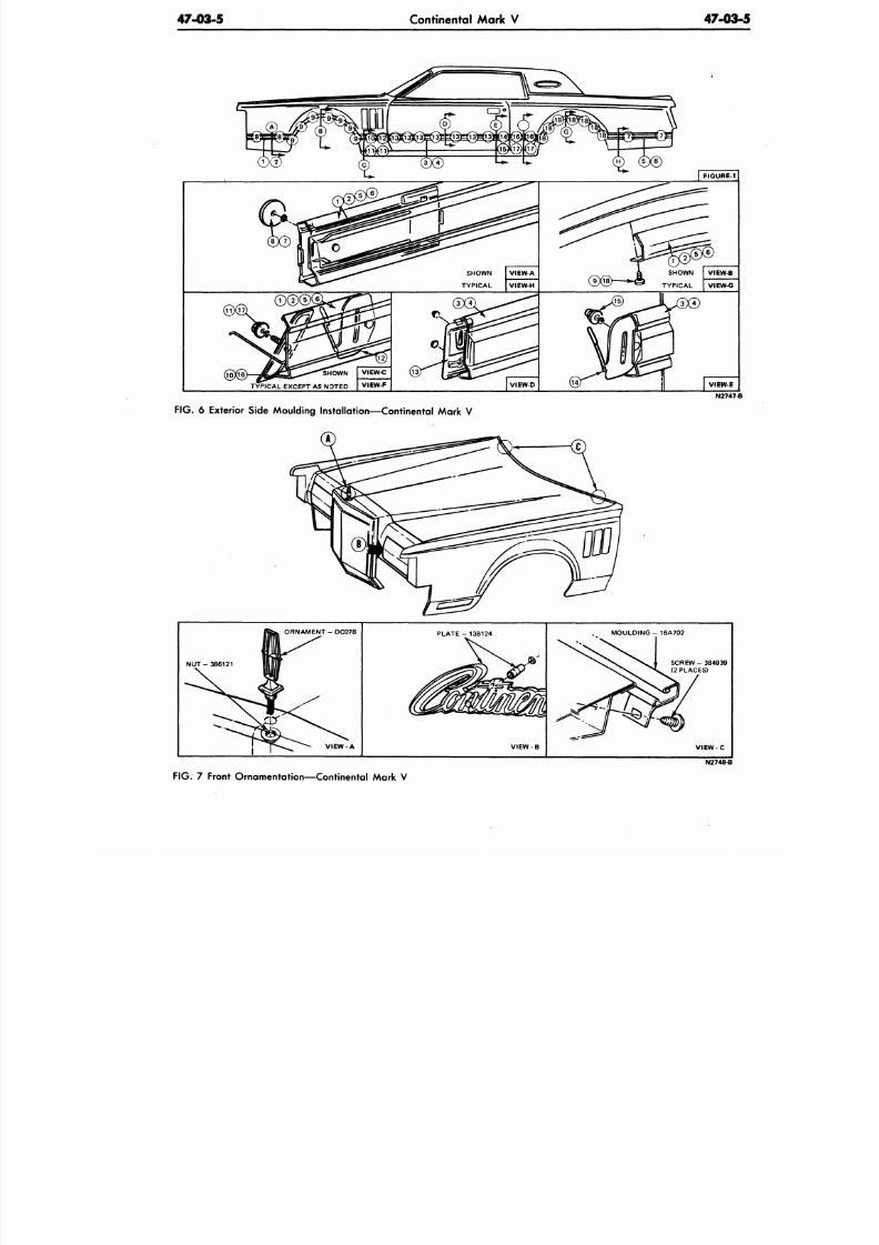
8/20/2019 1977 Ford Car Shop Manual Volume 4 Body
http://slidepdf.com/reader/full/1977-ford-car-shop-manual-volume-4-body 361/449
47-03-5
Continental Mark V 47-0
N274
FIG.
6 Exterior Side Moulding Installation—Continental Mark V
T
ORNAM ENT - DC078
N U T - 3 8 6 1 2 1
V I E W - A
PLATE - 138124
VIEW
MOULDING - 16A702
VIEW - C
N2748-B
FIG.
7 Front Ornamentation—Continental Mark V
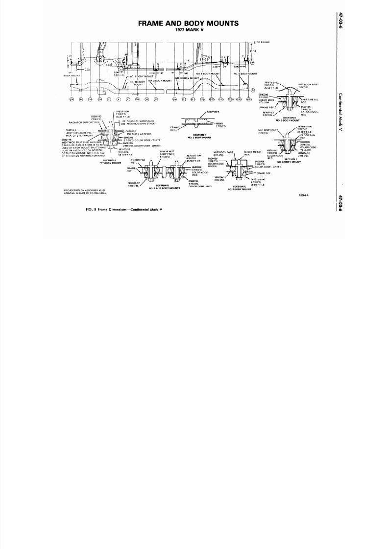
8/20/2019 1977 Ford Car Shop Manual Volume 4 Body
http://slidepdf.com/reader/full/1977-ford-car-shop-manual-volume-4-body 362/449
FRAME AND BODY MOUNTS
1977 MARK V
17.10
,C_
OF FRAME
BODY MOUNT
NO.
6 BODY MOUNT
1@b
1@5
<22:5 1 @
1@5
6200 163
2 REQD.
RADIATOR SUPPORT REF. \ /
• 34979-S100
2 REQD.
35-45 FT-LB
387676-S
.450 THICK AS REQD.
MAX. OF 2 PER MOUNT
6500145
^
.090 THICK SPLIT SHIM AS REQD.
A MAX. OF 2 SPLIT SHIMS IS TO BE
USED
AT
EACH MOUNT. SPLIT SHIMS
MUST
BE
INSTALLED
ON
BOTTOM
OF THE SHIM STACK WITH THE TAB
OF THE SHIMS POINTING FORWARD
.70 - NOMINAL SHIM STACK
1.00
-
MAXIMUM SHIM STACK
387677-S
.090 THICK AS REQD.
6500396
2 REQD. COLOR CODE - WHITE "
6500155
2 REQ D. COLOR CODE - WHITE "
385163-S2
2 REQD 7/16-14
NUT
55-70 FT-LB BODY PART
4 REQD.
SECTION A FLOOR PAN '
"F " BODY MOUNT REF.
v
FRAME-
REF.
PROJECTION ON ABSORBER MUST
ENGAGE IN SLOT OF FRAME HOLE.
SECTION B
NO. 1 & IB BODY MOUNTS
BODY REF.
6500396
2 REQD.
COLOR CODE-
YELLOW
FRAME REF
NUT-BODY PART
2 REQD.
SHEET METAL
REF.
6500155
2 REQD.
COLOR CODE
-
RED
SECTION E
NO. 5 BODY MOUNT
SECTION G
NO. 2 BODY MOUNT
NUT-BODY PART
2 REQD.
^387675-S100
2 REQD
^S 35-50 FT-LB
1 ^ F L O O R PAN
WR F
387675-S100
4 REQD.
35-50 FT-LB
6500396
4 REQD.
COLOR CODE
-
RED
6500155
4 REQD.
COLOR CODE - RED
NUT-BODY PART
2 REQD.
6500155
2 REQD.
COLOR CODE
GREEN
SHEET METAL
REF.
6500396
2 REQD.
COLOR CODE
6500155 S J ^ a N YELLOW
2 REQD.
y
LLUJ 387674-S2
COLOR CODE-
2 REQD.
R E D
SECTION F
NO. 6 BODY MOUNT
2 REQD.
COLOR CODE-GREEN
FRAME REF.
SECTION C
NO. 3 BODY MOUNT
R2050-A
FIG.
8 Frame Dimensions—Continental Mark V
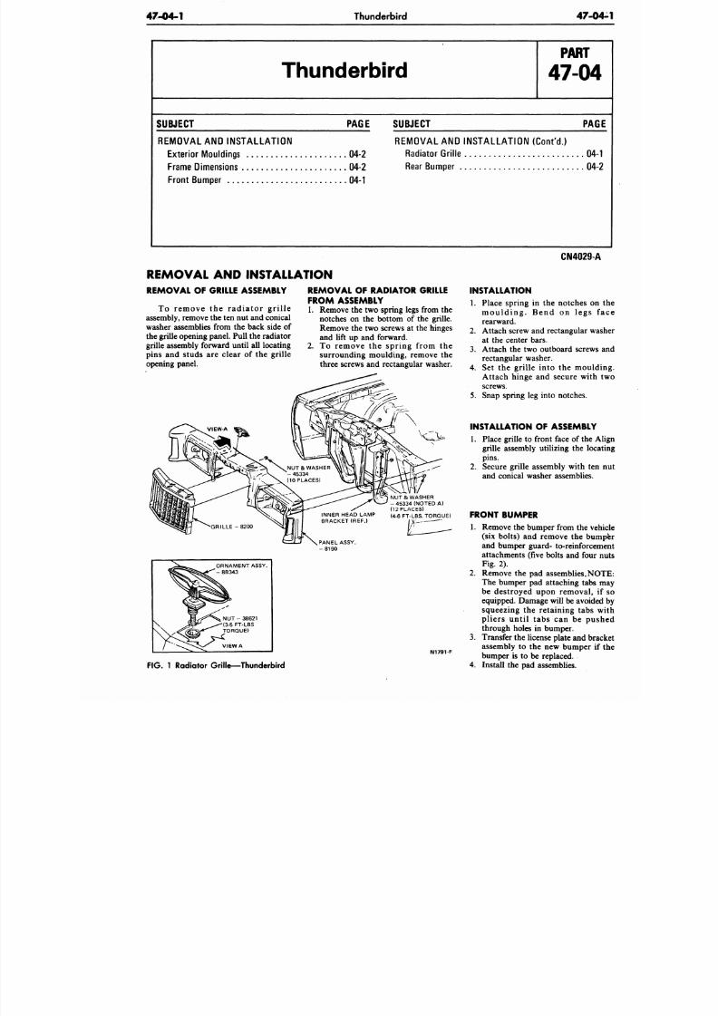
8/20/2019 1977 Ford Car Shop Manual Volume 4 Body
http://slidepdf.com/reader/full/1977-ford-car-shop-manual-volume-4-body 363/449
47-04-1
Thunderbird
47-0
Thunderbird
P A R T
47-04
SUBJECT PAGE
REMOVAL AND INSTALLATION
Exterior Mouldings
04-2
Frame Dimensions
04-2
Front Bumper
04-1
SUBJECT
PAG
REMOVAL AND INSTALLATION (Cont'd.)
Radiator Grille
04-
Rear Bumper
04-
REMOVAL AND INSTALLATION
REMOVAL OF GRILLE ASSEMBLY
To r emove the r ad ia to r g r i l l e
assembly, remove the ten nut and conical
washer assemblies from the back side of
the grille opening panel. Pull the rad iator
grille assembly forward until all locating
pins and studs are clear of the grille
opening panel.
REMOVAL OF RADIATOR GRILLE
FROM ASSEMBLY
1. Remove the two spring legs from the
notches on the bottom of the grille.
Remove the two screws at the hinges
and lift up and forward.
2. To remove the spring from the
surrounding moulding, remove the
three screws and rectangular washer.
NUT & WASHER
- 45334 (NOTED A)
(12 PLACES)
INNER HEAD LAMP
( 4
.
6
FT-LBS. TORQUE)
( R E F )
PANEL ASSY.
- 8 1 9 0
ORNAMENT ASSY.
- 8B343
N1791-F
FIG.
1 Radiator Gril le—T hunde rbird
CN4029-A
INSTALLATION
1. Place spring in the notches on
moulding. Bend on legs
rearward.
2. Attach screw and rectangular w
at the center bars.
3.
Attach the two outboard screw
rectangular washer.
4. Set the grille into the mould
Attach hinge and secure with
screws.
5. Snap spring leg into notches.
INSTALLATION OF ASSEMBLY
1. Place grille to front face of the A
grille assembly utilizing the loc
pins.
2. Secure grille assembly with ten
and conical washer assemblies.
FRONT BUMPER
1.
Remove the bumper from the ve
(six bolts) and remove the bum
and bumper guard- to-reinforce
attachments (five bolts and four
Fig. 2).
2. Remove the pad assemblies. NO
The bumper pad attaching tabs
be destroyed upon removal, i
equipped. Damage will be avoide
squeezing the retaining tabs
pliers until tabs can be pus
through holes in bumper.
3. Transfer the license plate and br
assembly to the new bumper if
bumper is to be replaced.
4.
Install the pad assemblies.
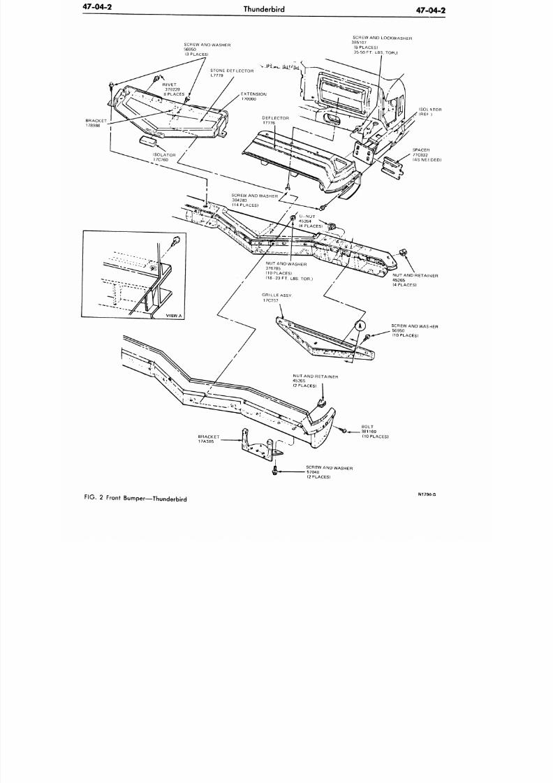
8/20/2019 1977 Ford Car Shop Manual Volume 4 Body
http://slidepdf.com/reader/full/1977-ford-car-shop-manual-volume-4-body 364/449
47-04-2
Thunderbird
47-04-2
SCREW AN D WASHER
56950
(3 PLACES)
SCREW AND LOCKWASHER
385107
(6 PLACES)
35-50 FT. LBS. TOR.)
NUT AND WASHER
376785
(10 PLACES)
(18 23 FT. LBS. TOR.)
NUT AND RETAINER
45265
(2 PLACES)
ISOL ATOR
< (REF )
SPACER
77C832
(AS NEIEDED)
NUT AND RETAINER
45265
(4 PLACES)
SCREW AND WASHER
56950
(10 PLACES)
BRACKET
17A385
BOLT
381169
(10 PLACES)
SCREW AND WASHER
57048
(2 PLACES)
FIG.
2 Front Bumper—Thunderbird
N1790-G
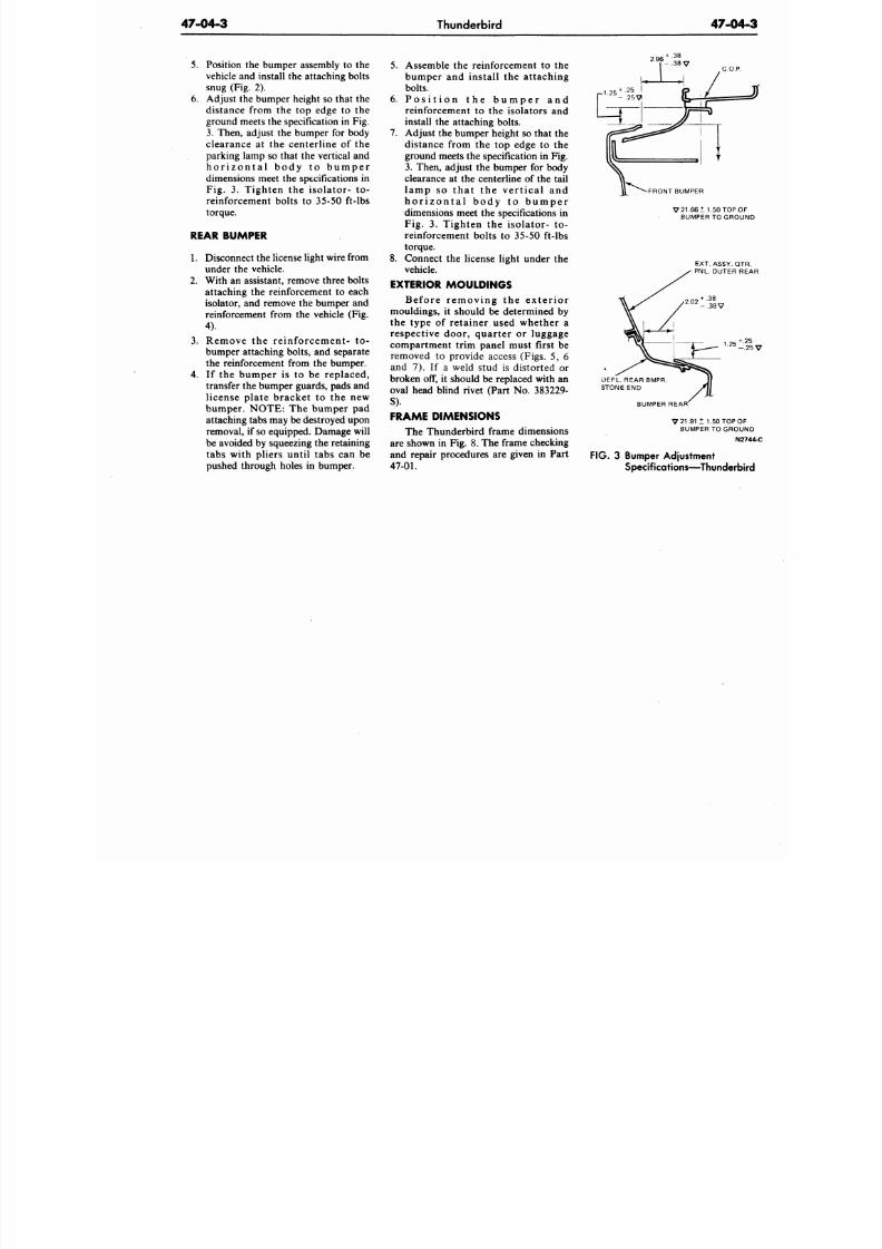
8/20/2019 1977 Ford Car Shop Manual Volume 4 Body
http://slidepdf.com/reader/full/1977-ford-car-shop-manual-volume-4-body 365/449
47-04-3
Thunderbird
47-0
5.
Position the bumper assembly
to the
vehicle and install the attaching bolts
snug (Fig.
2).
6. Adjust the bumper height so that the
distance from the top edge to the
ground meets the specification in Fig.
3. Then, adjust the bumper for body
clearance at the centerline of the
parking lamp so that the vertical and
h o r i z o n t a l b o d y
to
b u m p e r
dimensions meet the specifications in
Fig.
3.
Tighten
the
isolator-
to-
reinforcement bolts
to
35-50 ft-lbs
torque.
REAR BUMPER
1. Disconnect the license light wire from
under the vehicle.
2.
With an assistant, remove three bolts
attaching the reinforcement
to
each
isolator, and remove the bumper and
reinforcement from the vehicle (Fig.
4).
3.
Remove
the
re inforcement-
to-
bumper attaching bolts, and separate
the reinforcement from the bumper.
4.
If the bumper is to be replaced,
transfer the bumper guards, pads and
license plate bracket
to the new
bumper. NOTE: The bumper
pad
attaching tabs may be destroyed upon
removal, if so equipped. Damage will
be avoided by squeezing the retaining
tabs with pliers until tabs can be
pushed through holes in bumper.
5.
Assemble the reinforcement to the
bumper and install the attaching
bolts.
6 . P o s i t i o n the b u m p e r and
reinforcement
to the
isolators
and
install the attaching bolts.
7. Adjust the bumper height so that the
distance from
the top
edge
to the
ground meets the specification in Fig.
3.
Then, adjust the bumper
for
body
clearance at the centerline of the tail
l amp
so
t h a t
the
ve r t i ca l
and
h o r i z o n t a l b o d y to b u m p e r
dimensions meet the specifications in
Fig.
3.
Tighten
the
isolator-
to-
reinforcement bolts to 35-50 ft-lbs
torque.
8. Connect the license light under the
vehicle.
EXTERIOR MOULDINGS
Befo re r emov ing the e x t e r i o r
mouldings, it should be determined by
the type
of
retainer used whether
a
respective door, quarter
or
luggage
compartment trim panel must first be
removed
to
provide access (Figs.
5, 6
and 7). If a weld stud is distorted or
broken off, it should be replaced with an
oval head blind rivet (Part No. 383229-
S).
FRAME DIMENSIONS
The Thunderbird frame dimensions
are shown in Fig. 8. The frame checking
and repair procedures are given in Part
47-01.
2.96
GO.
-FRONT BUMPER
V 21.66 ±1.5 0 TO
BUMPER TO GR
EXT. ASSY.
PNL. OUTER
+ .38
- 3 8 V
1.25
DEFL. REAR BMPR
STONE END
BUMPER REAR
V 2 1 . 9 1
±
1.50 TOP
BUMPER TO GR
FIG. 3
Bumper Adjustment
Specifications—Thunder
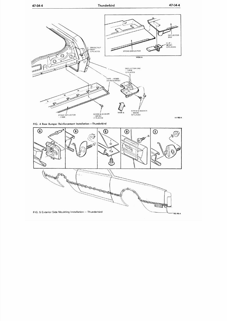
8/20/2019 1977 Ford Car Shop Manual Volume 4 Body
http://slidepdf.com/reader/full/1977-ford-car-shop-manual-volume-4-body 366/449
47-04-4
Thunderbird
47-04-4
STONE DEFLECTOR
- 17808
SCREW & WASHER
- 384783
(7 PLACES)
VIEW A
SCREW
&
WASHER
- 384283
(8 PLACES)
M1182-K
FIG .
4
Rear Bumper Reinforcement Installation—Thunderbird
FIG. 5 Exterior Side Moulding Instal lation
—
Thunderbi rd
N2 / 45-A
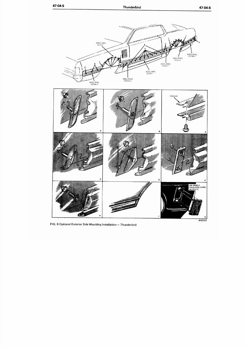
8/20/2019 1977 Ford Car Shop Manual Volume 4 Body
http://slidepdf.com/reader/full/1977-ford-car-shop-manual-volume-4-body 367/449
47-04-5
Thunderbird
47-
FIG. 6 Optional Exterior Side Moulding Installation - Thunderbird
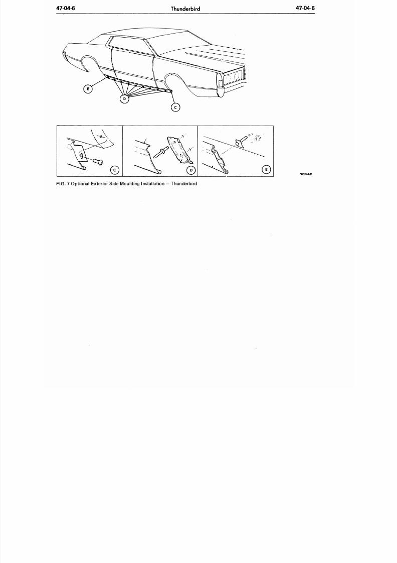
8/20/2019 1977 Ford Car Shop Manual Volume 4 Body
http://slidepdf.com/reader/full/1977-ford-car-shop-manual-volume-4-body 368/449
47-04-6
Thunderbird
47-04-6
FIG. 7 Optional Exterior Side Moulding Installation — Thunderbird
N2394-C
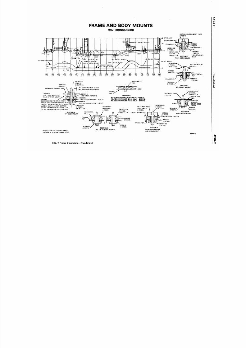
8/20/2019 1977 Ford Car Shop Manual Volume 4 Body
http://slidepdf.com/reader/full/1977-ford-car-shop-manual-volume-4-body 369/449
FRAME AND BODY MOUNTS
1977 THUNDERBIRD
1.25
'F "
BODY MOUNT
RETAINER ASSY. BODY PART
2 REQ'D.
6500396
2 REQ'D.
COLOR CODE
-
BLUE
6500155
f
2 REQ 'D .
COLOR CODE
BLUE
NUT-BODY PART
*
2 REQ'D.
SHEET METAL
REF.
I
C_OF FRAME
FLOOR PAN REF
FRAME REF
387674-S2
2 R E Q ' D .
387675-S100
2REO/ D.
35-50 FT-
SECTION C
NO.
3 BODY MOUNT
NO.
2C BODY MOUNT
/ * N O .
2 BODY MOUNT
SHEET METAL
REF.
6200 163
2 REQ'D.
RADIATOR SUPPORT REF.
SECTION E
NO. 5
BODY MOUNT
.70 - NOMINAL SHIM STACK
1.00 - MAXIMUM SHIM STACK
^387675-S1OO
/ , 2 REQ'D.
NUT-BODY PART
2 REQ'D.
=E=-^ 387677-S
.090 THICK AS REQ'D.
6500396
2 REQ'D. COLOR CODE - VIOLET
6500155
2 REQ'D . COLOR CODE - VIOLET
385163-S2
SECTION
G
NO.
2 BODY MOUNT - 4 DR. ONLY - 2 REQ'D.
NO.
1C BODY MOUNT - 2 DR. ONLY - 2 REQ'D.
NO.
2C BODY MOUNT - 4 DR. ONLY - 2 REQ'D.
RETAINER ASSY.
BODY PARTS
2 REQ'D.
SHEET METAL REF
387675-S100
4 REQ'D.
\ / 3 5- 5 0 FT-L B
ECTION A
BODY MOUNT
387676-S
.450 THICK AS REQ'D
MAX. OF 1 PER MOUNT
6500145
.090 THICK SPLIT SHIM AS REQ'D
A MAX. OF
2
SPLIT SHIMS IS TO
BE
USED AT EACH MOUNT. SPLIT SHIMS
MUST BE INSTALLED ON BOTTOM
OF THE SHIM STACK WITH THE TAB
OF THE SHIMS POINTING FORWARD.
\ ^ j 35-50 FT-LB
FLOOR
PAN
65003396
2 REQ'D.
COLOR CODE
GREEN
6200145
2 REQ'D.
SECTION
F
NO . 6
BODY MOUNT
2 REQ'D.
PROJECTION ON ABSORBER MUST
ENGAGE
IN
SLOT OF FRAME HOLE.
SECTION B
NO.
1 & 1B BODY MOUNTS
SECTION D
NO.
4 BODY MOUNT
H.D. SEDAN ONLY
R1794-E
F I G . 9 FrGme Dimensions—Thunderbird
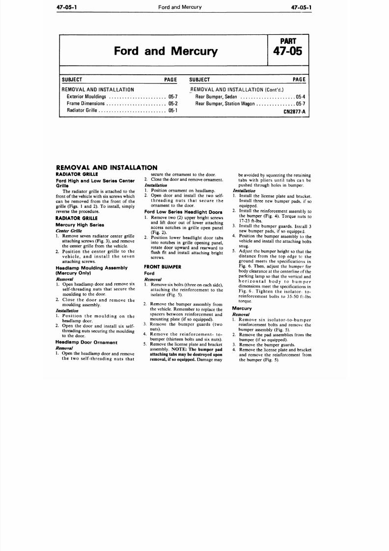
8/20/2019 1977 Ford Car Shop Manual Volume 4 Body
http://slidepdf.com/reader/full/1977-ford-car-shop-manual-volume-4-body 370/449
47-05-1
Ford and Mercury
47-05 -1
Ford and Mercury
P A R T
47-05
SUBJECT PAGE
REMOVAL AND INSTALLATION
Exterior Mou ldings
05-7
Frame Dimensions 05-2
Radiator Grille 05-1
SUBJECT
PAGE
REMOVAL AND INSTAL LATION (Cont'd .)
Rear Bu mp er, Sedan
05 4
Rear Bumper, Station Wagon 05 7
CN2877A
REMOVAL AND INSTALLATION
RADIATOR GRILLE
Ford High and Low Series Center
Grille
The radiator grille is attached to the
front of the vehicle with six screws which
can be removed from the front of the
grille (Figs. 1 and 2). To install, simply
reverse the procedure.
RADIATOR GRILLE
Mercury High Series
Center G rille
1. Remove seven radiator center grille
attaching screws (Fig. 3), and remove
the center grille from the vehicle.
2.
Position the center grille to the
veh ic le , and in s ta l l the seven
attaching screws.
Headlamp Moulding Assembly
(Mercury Only )
Removal
1. Open headlamp door and remove six
self-threading nuts that secure the
moulding to the door.
2. Close
the
door
and
remove
the
moulding assembly.
Installation
1. Position
the
m o u l d i n g
on the
headlamp door.
2.
Open the door and install six self-
threading nuts securing the moulding
to the door.
Headlamp Door Ornament
Removal
1. Open the headlamp door and remove
th e two self-threading nuts that
secure
the
ornament
to the
door.
2.
Close the door and remove ornament.
Installation
1. Position ornament on headlamp.
2.
Open door and install the two self-
threading nuts that secure the
ornament
to the
door.
Ford
Low
Series Headlight Doors
1. Remove two (2) upper bright screws
and lift door
out of
lower attaching
access notches in grille open panel
(Fig. 2).
2.
Position lower headlight door tabs
into notches in grille opening panel,
rotate door upward and rearward to
flush fit and install attaching bright
screws.
FRONT BUMPER
Ford
Removal
1. Remove six bolts (three on each side),
attaching the reinforcement to the
isolator (Fig.
5).
2. Remove
the
bumper assembly from
the vehicle. Remember to replace the
spacers between reinforcement and
mounting plate
(if
so equipped).
3. Remove the bumper guards (two
nuts).
4. Remove the re inforcement- to-
bumper (thirteen bolts and six nuts).
5.
Remove the license plate and bracket
assembly.
NOTE:
The
bumper
pad
attaching tabs may be destroyed upon
removal,
if so
equipped. Damage may
be avoided by squeezing the retaining
tabs with pliers until tabs can be
pushed through holes in bumper.
Installation
1. Install the license plate and bracket.
Install three new bumper pads, if so
equipped.
2.
Install the reinforcement assembly to
the bumper (Fig. 4). Torque nuts to
17-23 ft-lbs.
3. Install the bumper guards. Install 3
new bumper pads, if so equipped.
4. Position
the
bumper assembly
to the
vehicle and install the attaching bolts
snug.
5. Adjust the bumper height so that the
distance from the top edge to the
ground meets the specifications in
Fig. 6. Then, adjust the bumper for
body clearance
at
the centerline of the
parking lamp so that the vertical and
h o r i z o n t a l b o d y to b u m p e r
dimensions meet the specifications in
Fig. 6. Tighten the isolator- to-
reinforcement bolts to 35-50 ft-lbs
torque.
Mercury
Removal
1. Remove six i s o la to r - to -bumper
reinforcement bolts and remove the
bumper assembly (Fig. 5).
2.
Remove the pad assemblies from the
bumper
(if
so equipped).
3. Remove the bumper guards.
4.
Remove the license plate and bracket
and remove the reinforcemen t from
the bumper (Fig. 5).
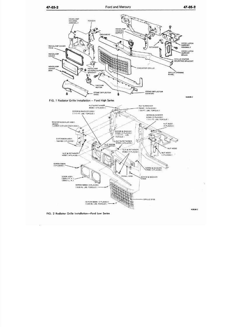
8/20/2019 1977 Ford Car Shop Manual Volume 4 Body
http://slidepdf.com/reader/full/1977-ford-car-shop-manual-volume-4-body 371/449
47-05-2
Ford and M ercury
47-05
HEADLAMP
HOUSING
ASSEMBLY
HEADLAMP COVER
TRIM
HEADLAMP
COVER
BAR
STONE DEFLECTOR
(CENTER)
HOOD LATC
SUPPORT
ASSEMBLY
HOOD LATC
SUPPORT
BRACE
GRILLE CENTER
MOUNTING BRACKE
N2535-C
F I G .
1 Radia tor Grille Installa tion - Ford High Series
NUT& RETAINER
45263 ( 2 PLACES )
SCREW & WASHER 57031
( 7-11 FT. LBS. TORQUE )
NUT & WASHER
45334 ( 10 PLACES )
( 3-6 FT. LBS. TORQUE )
SCREW & WASHER
57030 (4 PLACES )
7-11 FT. LBS. TORQUE )
WASHER & SEALER ASSY.
381923
(LOWER 3 STUDS EACH SIDE )
EXTENSION ASSY.
16A168( 2 PLACES)
NUT & RETAINER/
^*
45267 { 4 PLACES ) < ^
NUT 45257
(4 PLACES)
SCREW 55 974
(4 PLACES)
SCREW & WASHER
57030 (4 PLACES )
( 7-11 F T . LBS.
TORQUE)
DOOR ASSY.
13045 ( R. H.
13043 ( L. H. )
SCREW 56904 ( 4 PLACES )
(8-20 IN. LBS. TORQUE)
GRILLE 8150
SCREW 56904 ( 2 PLACES )
( 8-20 IN. LBS. TORQUE ) "
N
FIG.
2 Radiator Grille Installation—Ford Low Series
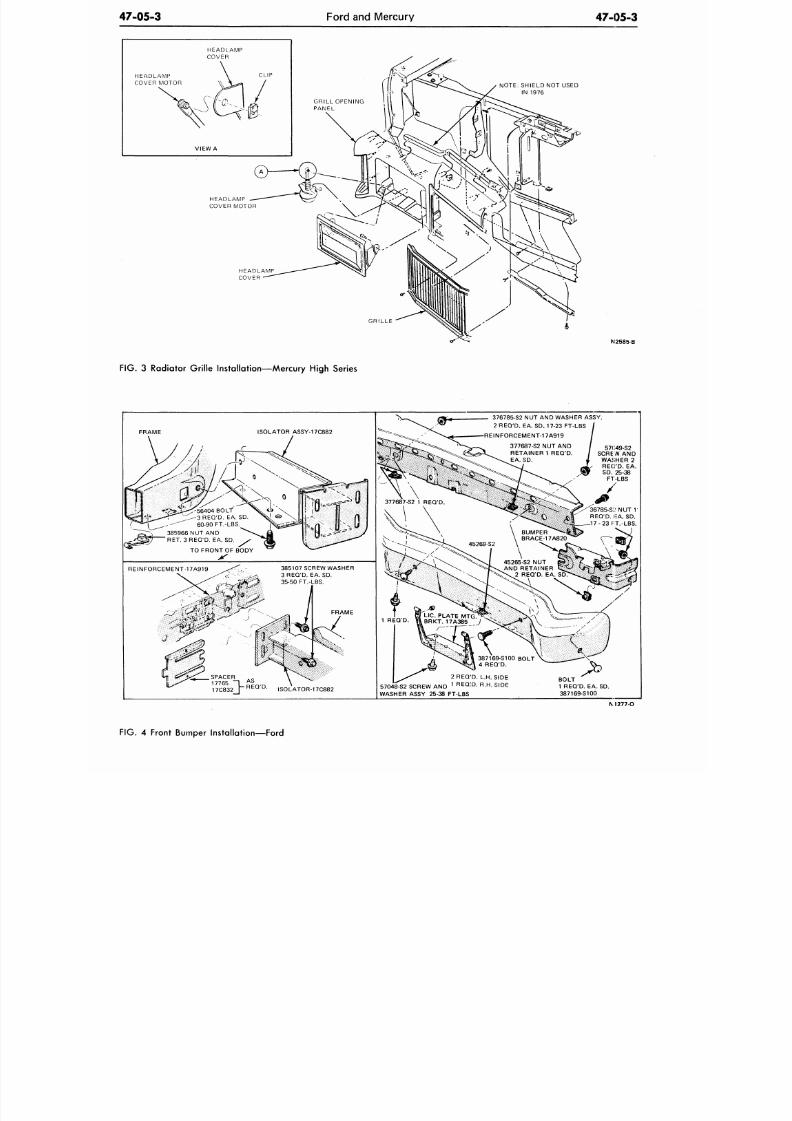
8/20/2019 1977 Ford Car Shop Manual Volume 4 Body
http://slidepdf.com/reader/full/1977-ford-car-shop-manual-volume-4-body 372/449
47-05-3
Ford and Mercury
47-05-3
HEADLAMP
COVER MOTOR
NOTE: SHIELD NOT USED
IN 1976
HEADLAMP
COVER
GRILLE
N2585-B
FIG.
3 Radiator Grille Installation—Mercury High Series
ISOLATOR ASSY-17C882
60-90 FT.-LBS.
385966 NUT AND
RET. 3 REQ'D. EA
TO FRONT OF BODY
REINFORCEMENT-17A919
385107 SCREW WASHER
3 REQ'D. EA. SD.
35-50 FT.-LBS.
FRAME
17C832
—l Ab
, V- REQ'D.
ISOLATOR-17C882
376785-S2 NUT AND WASHER ASSY.
2 REQ'D. EA. SD. 17-23 FT-LBS
-REINFORCEMENT-17A919
377687-S2 NUT AND
RETAINER 1 REQ'D.
EA . SD .
57G49-S2
SCREW AND
WASHER 2
REG'D.
EA .
SD .
25-38
FT-LBS
/-""36785-S;: NUT
1
REQ 'D. IEA. SD.
1 7 - 2 3 FT.-LBS.
2 REQ'D. L.H. SIDE
57048^52 SCREW AND
1 R
E Q : D .
R.H. SIDE
WASHER ASSY 25-38 FT-LBS
BOLT
1 REQ'D. EA. SD.
387169-S100
M 2 7 7 - O
FIG. 4 Front Bumper Installation—Ford
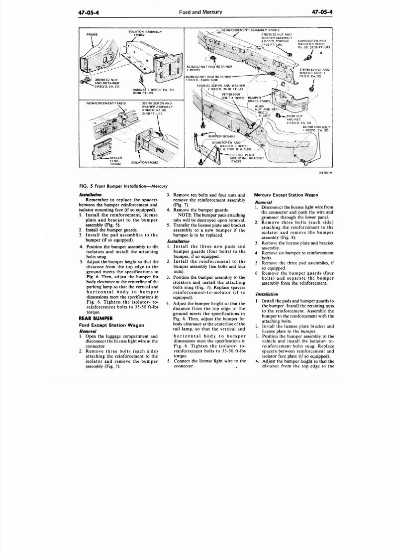
8/20/2019 1977 Ford Car Shop Manual Volume 4 Body
http://slidepdf.com/reader/full/1977-ford-car-shop-manual-volume-4-body 373/449
47-05-4
Ford and Mercury
47-05-
FRAME
ISOLATOR ASSEMBLY
17C882
56404-S2 3 REQ'D. EA. SD.
60-90 FT-LBS
REINFORCEMENT-17 A9 19 385107 SCREW AND
WASHER ASSEMBLY
3 REQ'D. EA. SD.
35-50 FT.-LBS.
REINFORCEMENT ASSEMBLY -17A919
376785-S2 NUT AND
WASHER ASSEMBLY
4 REQ'D. TORQUE
17-23 FT. LBS.
45265-S2 NUT AND RETAINER
1 REQ'D. |
45265-S2 NUT AND RETAINER
1 REQ'D. EACH SIDE
57049 SCREW AND
WASHER 2 R EQ'D.
EA. SD. 25-38 FT.-LB
J •
3 7 6 7 85 -S2NUI AN
WASHER ASSY. 1
REQ'D. EA. SD.
57048-S2 SCREW AND WASHER
1 REQ'D. 25-38 FT-LBS
57048 SCREW AND
WASHER 2 REQ'D.
L.H.SIDE
R.
H.SIDE
• ^ . 4 5 2 6 5 N U T
AND RET.
2 REQ'D. EA.SD.
387169-S100
BOL
1 REQ'D. EA. SD
N1751
FIG.
5 Front Bumper Installation—Mercury
Installation
Remember
to replace the spacers
between the bumper reinforcement and
isolator m ounting
face (if so equipped).
1.
Install the
reinforcement, license
plate and bracket to the bumper
assembly (Fig. 5).
2. Install the bumper guards.
3. Install the pad assemblies to the
bumper
(if so equipped).
4.
Position the bumper assembly to tHe
isolators and install the attaching
bolts snug.
5.
Adjust the bumper height so that the
distance from the top edge to the
ground meets the specifications in
Fig. 6. Then, adjust the bumper for
body clearance at the centerline of the
parking lamp so that the vertical and
h o r i z o n t a l b o d y t o b u m p e r
dimensions meet the specifications in
Fig. 6. Tighten the isolator- to-
reinforcement bolts to 35-50 ft-lbs
torque.
REAR BUMPER
Ford Except Stat ion Wagon
Removal
1. Open the luggage compartment and
disconnect the license light wire at the
connector.
2.
Remove three bolts (each side)
attaching the reinforcement to the
isolator and remove the bumper
assembly (Fig. 7).
3.
Remove ten bolts and four nuts and
remove the reinforcement assembly
(Fig. 7).
4.
Remove the bumper guards.
NOTE: The bumper pads attaching
tabs will be destroyed upon removal.
5.
Transfer the license plate and bracket
assembly to a new bumper if the
bumper is to be replaced.
Installation
1. Install the three new pads and
bumper guards (four bolts) to the
bumper, if so equipped.
2. Install the reinforcement to the
bumper assembly (ten bolts and four
nuts).
3.
Position the bumper assembly to the
isolators and install the attaching
bolts snug (Fig. 7). Replace spacers
reinforce men t- to- isolato r ( if so
equipped).
4.
Adjust the bumper height so that the
distance from the top edge to the
ground meets the specifications in
Fig. 6. Then, adjust the bumper for
body clearance at the centerline of the
tail lamp, so that the vertical and
h o r i z o n t a l b o d y t o b u m p e r
dimensions meet the specifications in
Fig. 6. Tighten the isolator- to-
reinforcement bolts to 35-50 ft-lbs
torque.
5. Connect the license light wire to the
connector. ,
Mercury Except Station Wagon
Removal
1. Disconnect the license light wire fro
the connector and push the wire a
grommet through the lower panel
2. Remove three bolts (each sid
attaching the reinforcement to
isolator and remove the bump
assembly (Fig. 8).
3.
Remove the license plate and brac
assembly.
4. Remove six bumper to reinforcem
bolts.
5. Remove the three pad assemblies
so equipped.
6. Remove the bumper guards (fo
bolts) and separate the bump
assembly from the reinforcement.
Installation
1. Install the pads and bumper guards
the bumper. Install the retaining n
to the reinforcement. Assemble
bumper to the reinforcement with
attaching bolts.
2. Install the license plate bracket a
license plate to the bumper.
3.
Position the bumper assembly to
vehicle and install the isolator-
reinforcement bolts snug. Repl
spacers between reinforcement a
isolator face plate (if so equipped)
4. Adjust the bumper height so that
distance from the top edge to
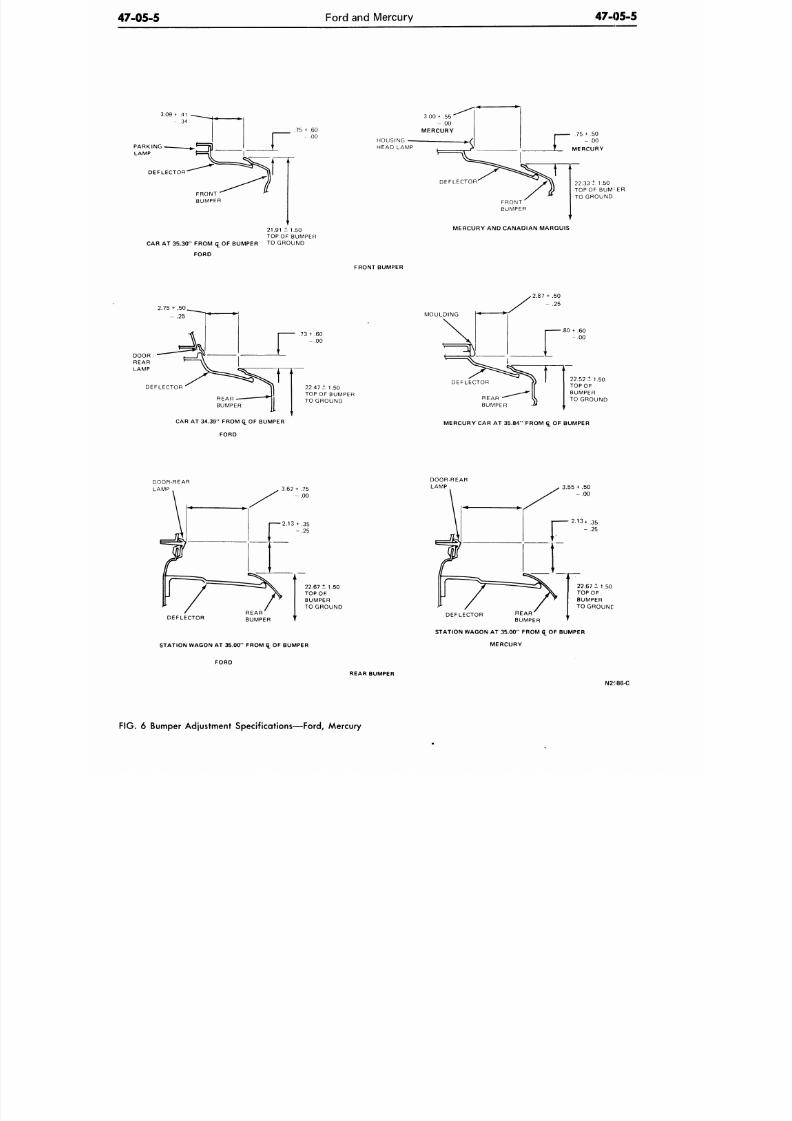
8/20/2019 1977 Ford Car Shop Manual Volume 4 Body
http://slidepdf.com/reader/full/1977-ford-car-shop-manual-volume-4-body 374/449
47-05-5
Ford and M ercury 47-05-5
3.09 -• .41
- .34
PARKING
x
LAMP
D E F L E C T O R "
CAR AT 35.30'
FRONT —
BUMPER
FROM (£OF BUMPER
FORD
.75 +
1
21.91 ±
TOP OF
TO GR(
.6 0
.0 0
1.50
BUMPER
DUND
HEAD LAMP
DEFLECTOR
22.33+ 1.50
TOP OF BUM
:
E R
TO GROUND
FRONT
BUMPER
MERCURY AND CANADIAN MARQUIS
FRONT BUMPER
DEFLECTOR
REAR
-
BUMPER
CAR AT 34.39" FROM £ OF BUMPER
FORD
22.47 ± 1.50
TOP OF BUMPER
TO GROUND
MOULDING
\
-* •
^ ^
DEFLECTOR
REAR -*
BUMPER
>2.87 + .50
/ - .25
r
30 + .60
- . 0 0
22.52 ± 1.50
TOP OF
BUMPER
TO GROUND
MERCURY CAR AT 35.84" FROM <£ OF BUMPER
DOOR-REAR
LAMP
22.67 ± 1.50
TOP OF
BUMPER
TO GROUND
DEFLECTOR
STATION WAGON AT 35.00" FROM
q_
OF BUMPER
FORD
DEFLECTOR
STATION W AGON AT 35 .00" FROM <£ OF BUMPER
MERCURY
REAR BUMPER
N2586-C
F IG .
6 Bumper Adjustment Specifications—Ford, Mercury
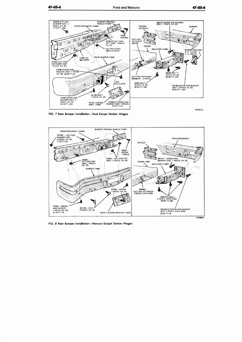
8/20/2019 1977 Ford Car Shop Manual Volume 4 Body
http://slidepdf.com/reader/full/1977-ford-car-shop-manual-volume-4-body 375/449
47 -05-6
Ford and Mercury
47-05
384695 NUT AND
WASHER ASSY. 2
REQ'D.
EA. SD.
17-23 FT.-LBS.
BUMPER OPENING
SHIELD-17C857
REINFORCEMENT-17A946
BUMPER
377687 NUT AND
RETAINER ASSY.
1 REQ 'D. EA. SD.
57048 SCREW AND
WASHER ASSY 1
EA. SD. 25-38 FT-LB
57048 SCREW AND
WASHER ASSY. 2
REQ'D.
EA. SD.
25-38 FT.-LBS.
REAR LICENSE
BRKT. 13406
57049-S2 SCREW AND
WASHER ASSY 2 REQ'D.
25-38 FT-LB
385107 SCREW AND WASHER
ASSY. 1 REQ'D. EA. SD.
FIG . 7 Rear Bumper Installation—Ford Except Station W ag on
385764 SCREW A ND WASHER
ASSY. 2 REQ 'D. EA. SD.
30-55 FT.-LBS.
N1757-
REINFORCEMENT-17A946
BUMPER OPENING SHIELD-17C857
376785 - NUT AND
. WASHER ASSY.
/ 2 REQ'D. EA. SD. REINFORCEMENT
5 7 0 4 8 - S C R E W
AND WASHER
1 REQ'D. EA. SD.
25-38 FT-LB
3 8 7 1 6 9 - B O L T
2 REQ 'D. EA. SD.
REAR LICENSE BRACKET-13406
385764-S2 SCREW AN D WASHER
ASSY 2 REQ'D. EACH SIDE
35-50 FT-LB
N1568
FIG . 8 Rear Bumper Installation—M ercury Except Station W ag on
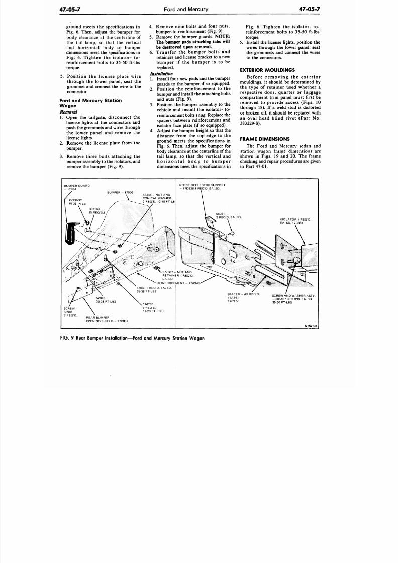
8/20/2019 1977 Ford Car Shop Manual Volume 4 Body
http://slidepdf.com/reader/full/1977-ford-car-shop-manual-volume-4-body 376/449
47-05-7
Ford and Mercury
47-05-7
ground meets the specifications in
Fig. 6. Then, adjust the bumper for
body clearance at the centerline of
the tail lamp, so that the vertical
and horizontal body to bumper
dimensions meet the specifications in
Fig. 6. Tighten the isolator- to-
reinforcement bolts to 35-50 ft-lbs
torque.
5. Position the license plate wire
through the lower panel, seat the
grommet and connect the wire to the
connector.
Ford and Mercury Station
Wagon
Removal
1. Open the tailgate, disconnect the
license lights at the connectors and
push
the
grommets and w ires through
the lower panel and remove the
license lights.
2. Remove the license plate from the
bumper.
3. Remove three bolts attaching the
bumper assembly to the isolators, and
remove the bumper (Fig. 9).
4.
Remove nine bolts and four nuts,
bumper-to-reinforcement (Fig. 9).
5. Remove the bumper guards.
NOTE:
The bumper pads attaching tabs will
be destroyed upon removal.
6. Transfer the bumper bolts and
retainers and license bracket to a new
bumper if the bumper is to be
replaced.
Installation
1. Install four new pads and the bumper
guards to the bumper if so equipped.
2. Position the reinforcement to the
bumper and install the attaching bolts
and nuts (Fig. 9).
3. Position the bumper assembly to the
vehicle and install the isolator- to-
reinforcement bolts snug. Replace the
spacers between reinforcement and
isolator face plate (if so equipped).
4.
Adjust the bumper height so that the
distance from the top edge to the
ground meets the specifications in
Fig. 6. Then, adjust the bumper for
body clearance at the centerline of the
tail lamp, so that the vertical and
h o r i z o n t a l b o d y t o b u m p e r
dimensions meet the specifications in
Fig. 6. Tighten the isolator- to-
reinforcement bolts to 35-50 ft-lbs
torque.
5.
Install the license lights, position the
wires through the lower panel, seat
the grommets and connect the wires
to the connectors.
EXTERIOR MOULDINGS
Befo re r emov ing the ex te r io r
mouldings, it should be determined by
the type of retainer used whether a
respective door, quarter or luggage
compartment trim panel must first be
removed to provide access (Figs. 10
through 18). If a weld stud is distorted
or broken off, it should be replaced with
an oval head blind rivet (Pan: No.
383229-S).
FRAME DIMENSIONS
The Ford and Mercury sedan and
station wagon frame dimensions are
shown in Figs. 19 and 20. The frame
checking and repair procedures are given
in Part 47-01.
BUMPER GUARD
- 17984
BUMPER - 17906
4 5 3 4 4 - N U T A N D
CONICAL WASHER
2 REQ'D. 12-18 FT-LB
STONE DEFLECTOR SUPPORT
- 17D836 1 REQ'D. EA. SD .
3 7 7 6 8 7 - N U T A N D
RETAINER 1 REQ'D.
EA.SD.
REINFORCEMENT- 17A946
57048 1 REQ'D. EA.SD .
25-38 FT-LBS
376785
5 REQ'D.
17-23 FT-LBS
REAR BUMPER
OPENING S HI EL D- 17C857
SPACER - AS REQ'D.
17A761
17C977
SCREW AND WASHER
ASSY.
-
385107
3
REQ'D. EA.
SD .
35-50 FT-LBS
N1570-K
FIG.
9 Rear Bumper Installation—Ford and Mercury Station W ag on
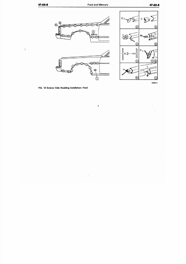
8/20/2019 1977 Ford Car Shop Manual Volume 4 Body
http://slidepdf.com/reader/full/1977-ford-car-shop-manual-volume-4-body 377/449
47-05-8
Ford and Mercury
47-0
C k-
N258
FIG. 10 Exterior Side Moulding Installation—Ford
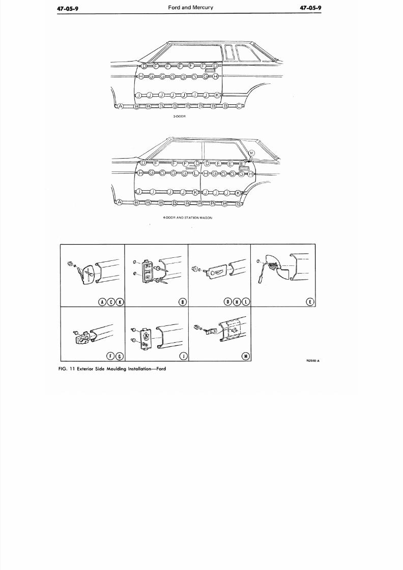
8/20/2019 1977 Ford Car Shop Manual Volume 4 Body
http://slidepdf.com/reader/full/1977-ford-car-shop-manual-volume-4-body 378/449
47-05-9
Ford and Mercury
47-05-9
2-D00R
4-D00R AND STATION WAGON
igh^--^
N2SII8-A
FIG. 11 Exterior Side Moulding Installation—Ford
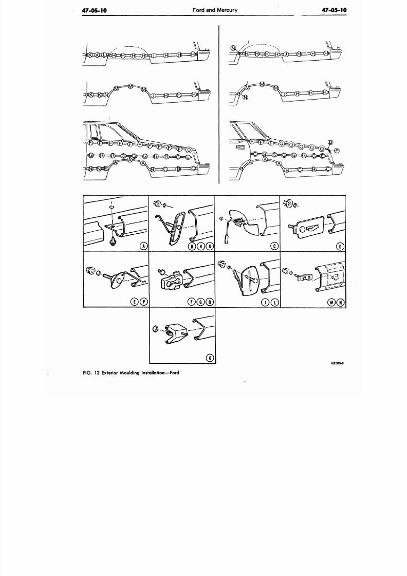
8/20/2019 1977 Ford Car Shop Manual Volume 4 Body
http://slidepdf.com/reader/full/1977-ford-car-shop-manual-volume-4-body 379/449
47-05-10
Ford and Mercury
47-05-
© 0®
N258
FIG. 12 Exterior Moulding Installation—Ford
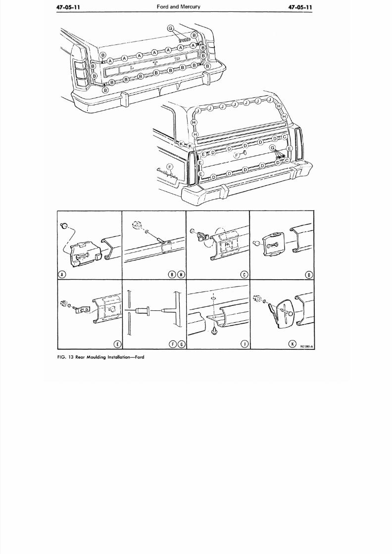
8/20/2019 1977 Ford Car Shop Manual Volume 4 Body
http://slidepdf.com/reader/full/1977-ford-car-shop-manual-volume-4-body 380/449
47-05-11
Ford and M ercury
47-05-11
N2590-A
F IG .
13 Rear Moulding Installation—Ford
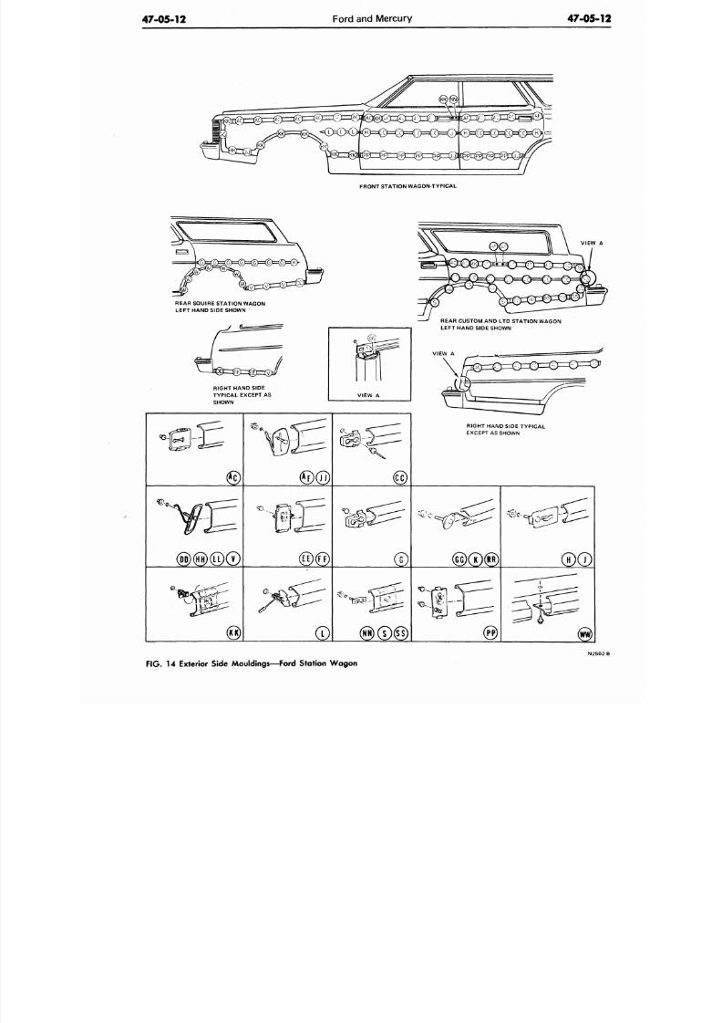
8/20/2019 1977 Ford Car Shop Manual Volume 4 Body
http://slidepdf.com/reader/full/1977-ford-car-shop-manual-volume-4-body 381/449
47-05-12
Ford and Mercury
47-05-1
FRONT STATION WAGON-TYPICAL
REAR SQUIRE STATION WAGON
LEFT HAND SIDE SHOWN
RIGHT HAND SIDE
TYPICAL EXCEPT AS
SHOWN
VIEW A
REAR CUSTOM AND LTD STATION WAGON
LEFT HAND SIDE SHOWN
VIEW A
RIGHT HAND SIDE TY PICAL
EXCEPT AS SHOWN
£.—
@(HH)@©
FIG.
14
Exterior Side Mouldings—Ford Station W agon
N2 5 0
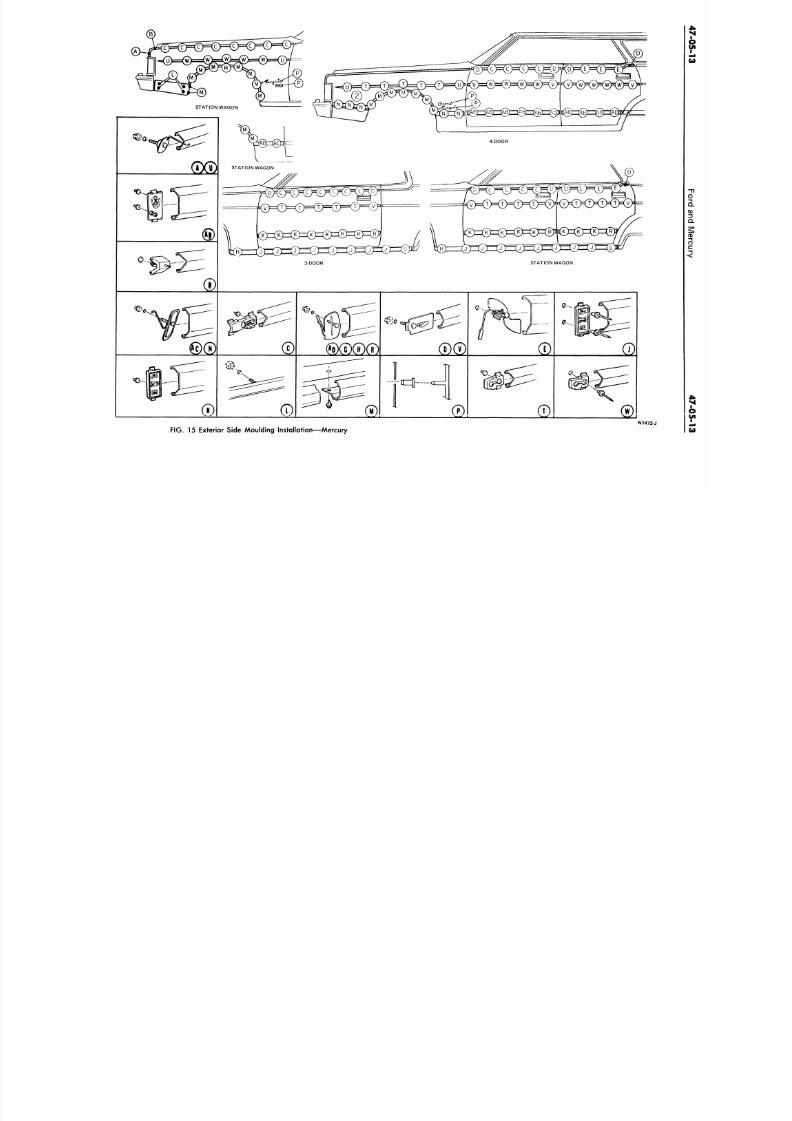
8/20/2019 1977 Ford Car Shop Manual Volume 4 Body
http://slidepdf.com/reader/full/1977-ford-car-shop-manual-volume-4-body 382/449
FIG. 15 Exterior Side Moulding Installat ion—Mercury
N1472-J
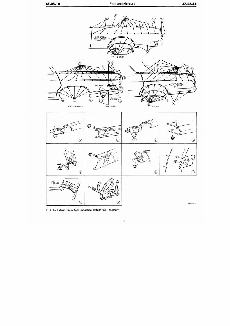
8/20/2019 1977 Ford Car Shop Manual Volume 4 Body
http://slidepdf.com/reader/full/1977-ford-car-shop-manual-volume-4-body 383/449
47-05-14
Ford and Mercury
47-05-
STATION WAGON
RIGHTSIDE
4-DOOR
©
©
N25
F IG .
16 Exterior Rear Side Moulding Installation—Mercury
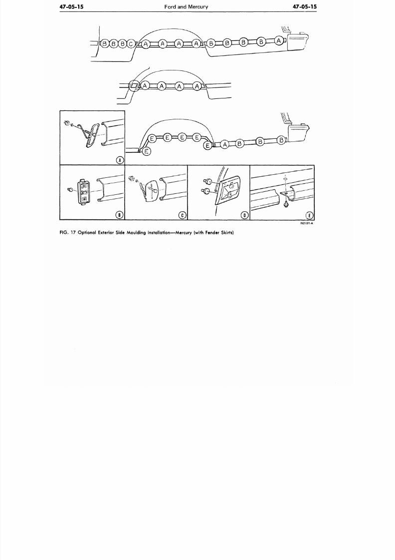
8/20/2019 1977 Ford Car Shop Manual Volume 4 Body
http://slidepdf.com/reader/full/1977-ford-car-shop-manual-volume-4-body 384/449
47-05-15
Ford and Mercury
47-05-15
N2591-A
F IG .
17 Optional Exterior Side Moulding Installation—Mercury (with Fender Skirts)
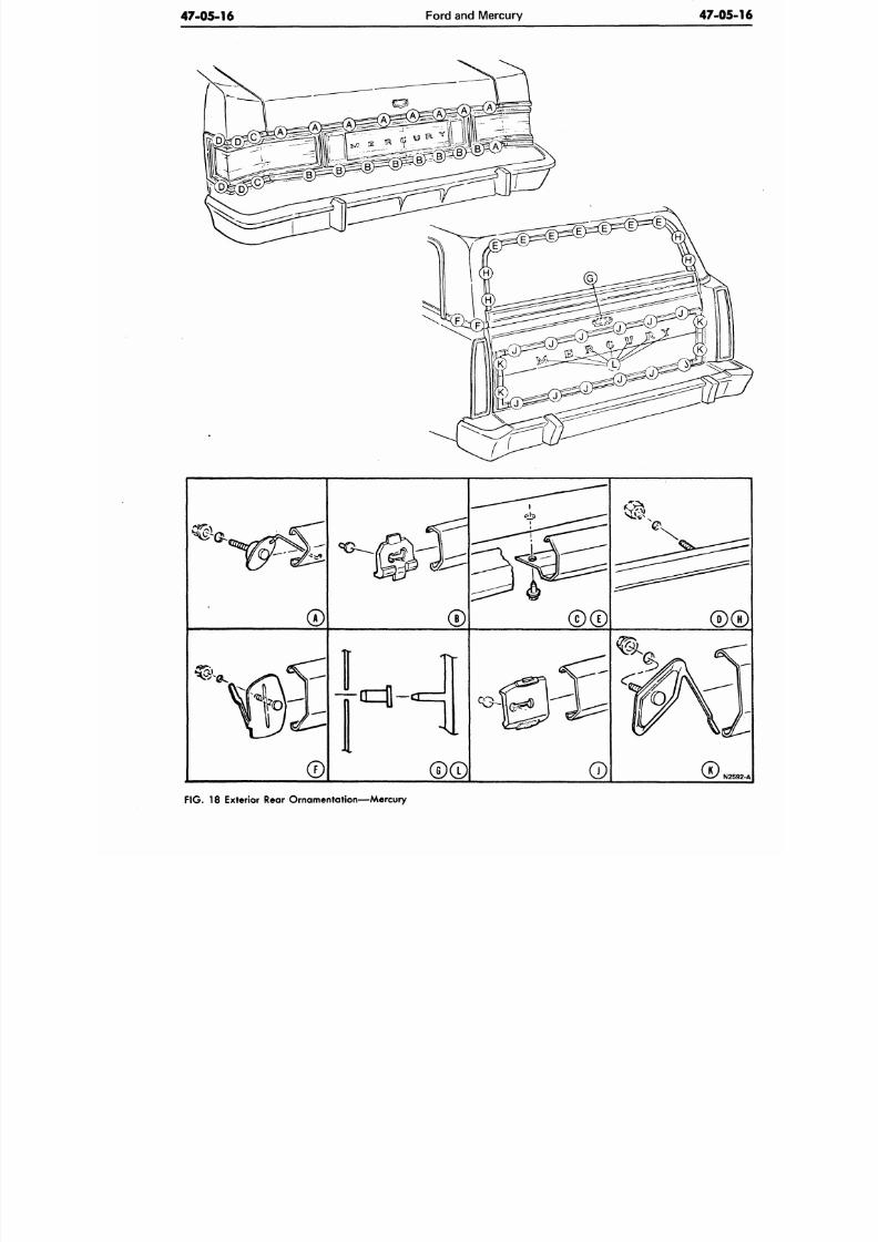
8/20/2019 1977 Ford Car Shop Manual Volume 4 Body
http://slidepdf.com/reader/full/1977-ford-car-shop-manual-volume-4-body 385/449
47-05-16
Ford and Mercury
47-05
N2
FIG.
18 Exterior Rear Ornamentation—Mercury
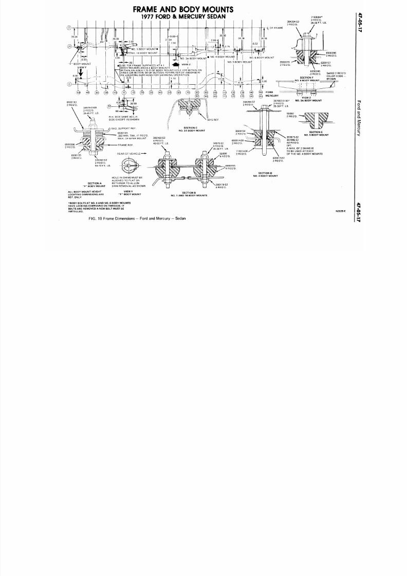
8/20/2019 1977 Ford Car Shop Manual Volume 4 Body
http://slidepdf.com/reader/full/1977-ford-car-shop-manual-volume-4-body 386/449
FRAME
A ND
BODY MOUNTS
1977 FORD & MERCURY SEDAN
5A10 3 2 R
COLOR CO
BROWN
NO. 1 BO DY M O UNT*
NO. 1B BODY MOUNT
F
f l
F
NO. 6 BODY MOUNT
O. 4 BODY MOUNT
I
NO.
5 BODY MOUNT
T*NO. 3A BODY MOUNT
F" BODY MOUNT
VIEW Y
USE TOP FRAME SURFACES AT
M
1
BODY MOUNTS ANDtt 4 BODY MOUNTS
WITHIN AN AREA 1.75 R OF BODY MOUNT HOLE (OR WITHIN AN
AREA (OR WITHIN .50 OF OUTSIDE PERIMETER OF ABSORBER)
AS LOCATING SURFACES FOR SHIMMING OPERATION
3.23
6200346
,2REQ 'D .
SECTION F
NO. 6 BODY MOUNT
150 FORD
?53 MERCURY
V I E W Z
NO. 3A BODY MOUNT
R.H. SIDE SAME AS L.H.
SIDE EXCEPT AS SHOWN
SECTION C
NO. 3A BODY MOUNT
RAD. SUPPORT REF
6500145
.082 MIN. THK. IF REQ'D.
MAX. OF 6 PER MOUNT
386168-S2
4 REQ'D.
40-50 FT. LB
34978-S2
4 REG'D.
20-30 FT. LB.
REAR OF VEHICLE
325162-S2
2 REQ'D.
55-70 FT. LB.
SECTION E
NO. 5 BODY MOUNT
387673-S2
387096-S2
AS REQ'D.
OPT.
A MAX. OF 2 SHIMS IS
TO BE USED AT EACH
OF THE NO. 4 BODY M OUNTS
SECTION A
"F " BODY MOUNT
AL L BODY MOUNT HEIGHT
LOCATING DIMENSIONS ARE
REF. ONLY
HOLE IN SHIMS MUST BE
ALIGNED TO FLAT ON
RETAINER TO ALLOW
SHIM REMOVAL AS SHOWN.
V I E W Y
"F " BODY MOUNT
62001A42
2 REQ'D.
SECTION D
NO. 4 BODY MOUNT
Y~J \386179-S2
V= ) 4 REQ'D.
SECTION B
NO. 1 AND 1B BODY MOUNTS
•BODY BOLTS AT NO. 4 AND NO. 6 BODY MOUNTS
HAVE LOCKING COMPOUND ON THREADS. IF
BOLTS ARE REMOVED A NEW BOLT MUST BE
INSTALLED.
FIG. 19 Frame Dimensions — Ford and Me rcury — Sedan
N2
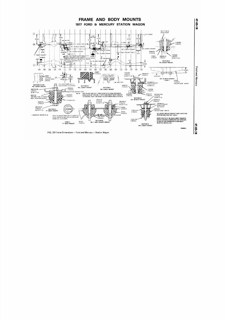
8/20/2019 1977 Ford Car Shop Manual Volume 4 Body
http://slidepdf.com/reader/full/1977-ford-car-shop-manual-volume-4-body 387/449
FRAME AND BODY MOUN TS
1977 FORD & MERCURY STATION WAGON
NUT 7/16-14
BODY PART
NO.
1 BO DY M O UN T*_
NO.
1B BODY MOUNT
NO. 6 BODY MOUNT
NO. 5 BODY MOUNT
I I
NO.
4 BODY MOUNT (REF.)
NO.
3B BODY MOUNT
I
NO.
3A BODY MOUNT
G
NO. 2 BODY MOUNT
#4-5.15
" F "
BODY MOUNT
VIEWX
USE TOP FRAME SURFACES AT
H 1 W|CIAI
V
BODY MOUNTS ANDH 4 BODY Vlt w Y
.92
NO. 3B MOUNT
I i/
BODY MOUNTS AND
H
4 BODY
MOUNTSWITHIN AN AREA 1.75 R OF BODY
MOUNT HOLE q_ (OR WITHIN .50 OF| |
OUTSIDE PERIMETER OF
ABSORBER)
il.S6
SECTION F
NO.
6 BODY MOUNT
NO.
3A BODY MOUNT
1.12 i t ';|
7100394
2 REQD.
20-30 FT-LB
8097 ^
2 R E Q ' D .
(20)
COLOR CODE -
GREEN
NO. 3A BODY M OUNT
V /
SECTION G FOR
NO.
2 BODY MOUNT
R.H. SIDE SAME AS L.H.
SIDE EXCEPT AS SHOWN
SECTION
H
NO.
3
BODY MOUNT SECTION
C
NO .
3 BODY MOUNT
6500163
2 REQ'D.
RADIATOR SUPPORT REF.
NCTE:
USE GUIDE PINS 5ZF 13306 OVER STUD AND ABSORBER
387330-S100
2 REQ'D.
20-30 FT-LB
SHOULDER OF THE NO. 1 LEFT AND RIG HT BODY MO UNT
TO INSURE THAT THE BODY IS CENTERED WHEN DECKED.
82 MIN. TH K. IF REQ'D
6 PER MOUNT
SECTION D
NO.
3B BODY MOUNT
4978-S2
4 REQ'D.
20-30 FT
398168-S2
4 REQ'D.
40-50 FT-LB
6500154
COLOR CODE -WHITE
SECTION A
F BODY MOUNT
SECTION B
NO.
1 AND IB BODY MOUNT
5A1O3
2 REQ'D.
COLOR CODE -WHITE
— REAR OF V E H I C L E - •
HOLE IN SHIMS MUST BE ALIGNED TO
FLAT ON RETAINER TO ALLOW SHIM
REMOVAL AS SHOWN.
V I E W X
"F "
BODY MOUNT
SECTION E
NO .
5 BODY MOUNT
ALL BODY MOUNT HEIGHT AND LOCATING
DIMENSIONS ARE REF. ONLY
BODY BOLTS AT 3B AND 6 BODY MOUNTS
HAVE LOCKING COMPOUND ON THREADS.
IF BOLTS ARE REMOVED A NEW BOLT
MUST BE INSTALLED.
N2640-E
F I G .
20
Frame Dimensions — Ford
and
Mercury — Station W agon
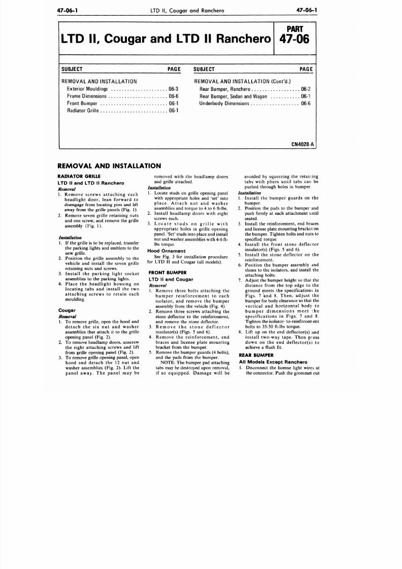
8/20/2019 1977 Ford Car Shop Manual Volume 4 Body
http://slidepdf.com/reader/full/1977-ford-car-shop-manual-volume-4-body 388/449
47-06-1
LTD II, Cougar and Ranchero
47-06-1
LTD II, Cougar and LTD II Ranchero
P A R T
47-06
SUBJECT PAGE SUBJECT PAGE
REM O VAL AND INST AL L AT IO N
Exterio r Mouldings 06-3
Frame Dime nsions 06-6
Front Bumpe r 06-1
Radiator Gri l le 06-1
REMOVAL AND INSTALLATION (Con t 'd . )
Rear Bum per, Ranchero 06-2
Rear Bum per, Sedan and Wagon 06-1
Underbo dy Dimensions 06-ti
CN4028A
REMOVAL AND INSTALLATION
RADIATOR GRILLE
LTD II and LTD II Ranchero
Removal
1. Remove screws attaching each
headlight door, lean forward to
disengage from locating pins and lift
away from the grille panels (Fig. 1).
2. Remove seven grille retaining nu ts
and one screw, and remove the grille
assembly (Fig. 1).
Installation
1. If the grille is to be replaced, transfer
the parking lights and emblem to the
new grille.
2. Position the grille assembly to the
vehicle and install the seven grille
retaining nuts and screws.
3.
Install the parking l ight socket
assemblies to the parking lights.
4. Place the headlight housing on
locating tabs and install the two
attaching screws to retain each
moulding.
Cougar
Removal
1. To remove grille, open the hood and
detach the six nut and washer
assemblies that attach it to the grille
opening panel (Fig. 2).
2. To remove headlamp doors, unscrew
the eight attaching screws and lift
from grille opening panel (Fig. 2).
3.
To remove grille opening panel, open
hood and detach the 12 nut and
washer assemblies (Fig. 2). Lift the
panel away. The panel may be
removed with the headlamp doors
and grille attached.
Installation
1. Locate studs on grille opening panel
with appropriate holes and 'set' into
place . At tach nut and washer
assemblies and torque to 4 to 6 ft-lbs.
2. Install headlamp doors with eight
screws each.
3.
L o c a t e s t u d s o n g r i l l e w i t h
appropriate holes in grille opening
panel. 'Set' studs into place and install
nut and washer assemblies with 4-6 ft-
lbs torque.
Hood Ornament
See Fig. 3 for installation procedure
for LTD II and Cougar (all models).
FRONT BUMPER
LTD II and Cougar
Removal
1. Remove three bolts attaching the
bumper re inforcement to each
isolator, and remove the bumper
assembly from the vehicle (Fig. 4).
2. Remove three screws attaching th e
stone deflector to the reinforcement,
and remove the stone deflector.
3.
R e m o v e th e s t o n e d e f l e c t o r
insulator(s) (Figs. 5 and 6).
4. Remove the reinforcement, end
braces and license plate mounting
bracket from the bumper.
5. Remove the bumper guards (4 bolts),
and the pads from the bumper.
NOTE: The bumper pad attaching
tabs may be destroyed upon removal,
if so equipped. Damage will be
avoided by squeezing the retaining
tabs with pliers until tabs can be
pushed through holes in bumper.
Installation
1. Install the bumper guards on the
bumper.
2. Position the pads to the bumper and
push firmly at each attachment until
seated.
3.
Install the reinforcement, end braces
and license plate mounting b racket on
the bumper. Tighten bolts and nuts to
specified torque.
4. Install the front stone deflector
insulator(s) (Figs. 5 and 6).
5. Install the stone deflector on the
reinforcement.
6. Position the bumper assembly and
shims to the isolators, and install the
attaching bolts.
7. Adjust the bumper height so that the
distance from the top edge to the
ground meets the specifications in
Figs. 7 and 8. The n, adjust the
bumper for body clearance so thai the
vertical and horizontal body to
b u m p e r d i m e n s i o n s m e e t t h e
specific ation s in Figs . 7 and 8.
Tighten the isolator- to-reinforcement
bolts to 35-50 ft-lbs torque.
8. Lift up on the end deflector(s) and
install two-way tape. Then press
down on the end deflector(s) to
achieve a flush fit.
REAR BUMPER
All Models Except Ranchero
1. Disconnect the license light wires at
the connector. Push the grommet out
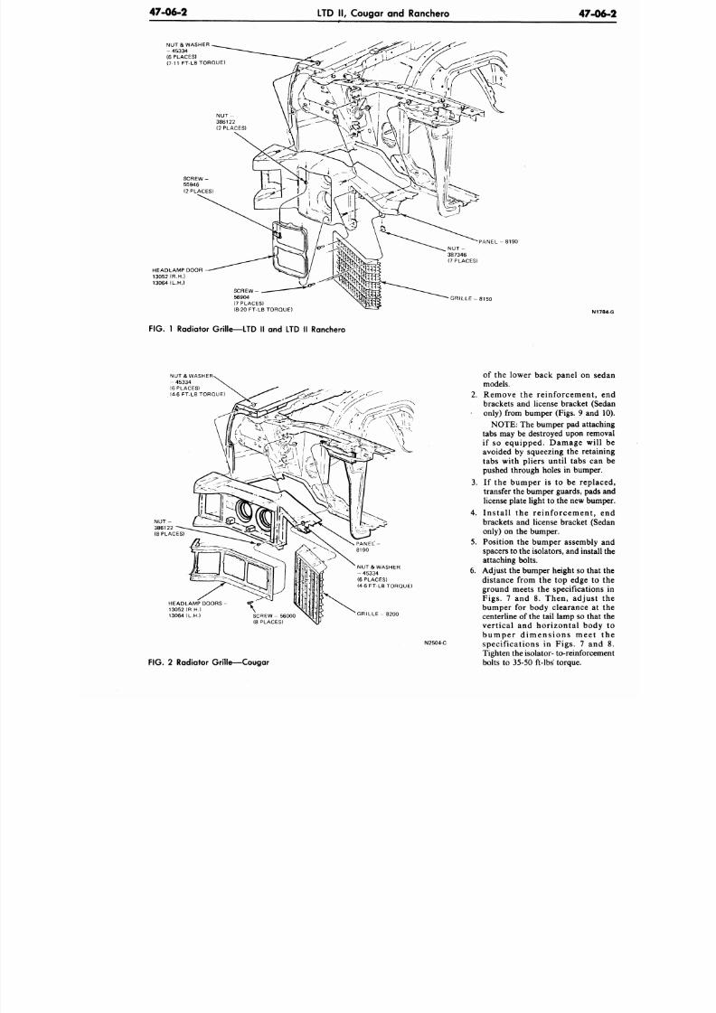
8/20/2019 1977 Ford Car Shop Manual Volume 4 Body
http://slidepdf.com/reader/full/1977-ford-car-shop-manual-volume-4-body 389/449
47-06-2
LTD II, Cougar and Ranchero
47-0
NUT & WASHER
- 45334
(6 PLACES)
(7-11 FT-LB TORQUE)
HEADLAMP DOOR -
13052 (R.H.)
13064 (L.H.)
P A N E L - 8 1 9 0
SCREW -
56904
(7 PLACES)
(8-20 FT-LB TORQUE)
GRILLE - 8150
N
F IG .
1 Radiator Grille—LTD II and LTD II Ranchero
NUT & WASHER
- 45334
(6 PLACES)
(4-6 FT-LB TORQUE)
HEADLAMP DOORS
13052 (R.H.)
13064 (L.H.)
SCREW- 56000
(8 PLACES)
NUT& WASHER
- 45334
(6 PLACES)
(4-6 FT-LB TORQUE)
G R I L L E - 8 2 0 0
N2504-C
F IG . 2 Radiator Gri l le—Cougar
of the lower back panel on s
models.
2.
Remove the reinforcement,
brackets and license bracket (S
only) from bumper (Figs. 9 and
NOTE: The bumper pad attac
tabs may be destroyed upon rem
if so equipped. Damage wi
avoided by squeezing the reta
tabs with pliers until tabs ca
pushed through holes in bumpe
3. If the bumper is to be repl
transfer the bumper guards, pad
license plate light to the new bu
4.
Ins ta l l the re inforcement ,
brackets and license bracket (S
only) on the bumper.
5.
Position the bumper assembly
spacers to the isolators, and insta
attaching bolts.
6. Adjust the bumper height so tha
distance from the top edge to
ground meets the specification
Figs. 7 and 8. The n, adjust
bumper for body clearance a
centerline of the tail lamp so tha
vertical and horizontal bod
b u m p e r d i m e n s i o n s m e e t
specific ations in Figs. 7 an
Tighten the isolator- to-reinforce
bolts to 35-50 ft-lbs torque.
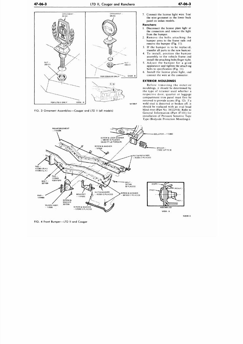
8/20/2019 1977 Ford Car Shop Manual Volume 4 Body
http://slidepdf.com/reader/full/1977-ford-car-shop-manual-volume-4-body 390/449
47-06-3
LTD II, Cougar and Ranchero
47-06-3
FOR LTD II ONLY
ORNAMENT -
8B343
VIEW - B
N1789-F
FIG.
3 Ornament Assemblies—Cougar and LTD II (all models)
7.
Connec t the license light wire. Seat
the wire grommet in the lower back
panel on sedan models.
Ranchero
1.
Disconnect the license plate lighi at
the connectors and remove the light
from the bumper.
2. R emo v e th e b o l t s a t tach in g th e
bumper arms to the frame rails and
remove the bumper (Fig. 11).
3.
I f the bumper is to be replaced ,
transfer all parts to the new bumper.
4. To in s ta l l , p o s i t io n th e b u mp er
assembly to the vehicle frame and
install the attaching bolts finger ti^ht.
5.
A d j u s t t h e b u m p e r f o r a g o o d
appearance and tighten the attaching
bolts to specification (Fig. 11).
6. Install the license plate light, and
connect the wire at the connector.
EXTERIOR MOULDINGS
B e f o r e r e m o v i n g t h e e x t e r i o r
mouldings, it should be determined by
the type of retainer used whether a
r esp ec t iv e d o o r , q u ar te r o r lu g g ag e
compartment trim panel must first be
removed to provide access (Fig. 12). If a
weld stud is distorted or broken off, it
should be replaced with an oval head
blind rivet (Part No. 383229-S). Refer to
General Information (Part 47-01) for
installation of Pressure Sensitive Tape
Type (Bodyside Protection Mouldings).
REINFORCEMENT
- 1 7 A 3 8 5
SCREW & LOCK WASHER
-38 51 07 (3 PLACES)
(35-50
FT-LB TORQUE)
PAD -
17C881 (R.H.)
17C950(L.H.)
ISOLATOR - 17C882
SPACER -
17832 (UP TO 3)
NUT & RETAINER
-45265 (7 PLACES)
SCREWS WASHER
-387359 (7 PLACES)
GUARD ASSY
-
17996
SCREW & WASHER
-5 704 8 (2 PLACES)
N402(iA
FIG. 4 Front Bumper—LTD II and Cougar
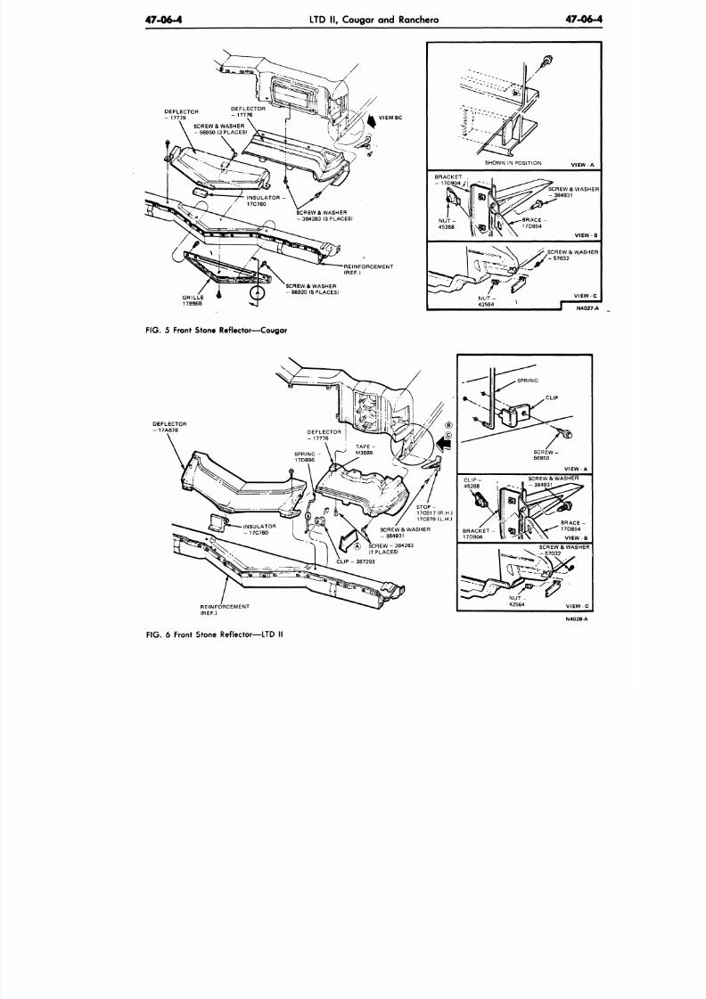
8/20/2019 1977 Ford Car Shop Manual Volume 4 Body
http://slidepdf.com/reader/full/1977-ford-car-shop-manual-volume-4-body 391/449
47-06-4
LTD II, Cougar and Ranchero
47-0
DEFLECTOR
- 17779
SCREW & WASHER
- 56950
(3
PLACES)
V I E W B C
REINFORCEMENT
R E F
GRILLE
17B968
SCREW
&
WASHER
- 56920
(5
PLACES)
J f
v
v
i
BRACKET
- 1 7 D 9 0 4 /
TO
N U T -
45268
\
SHOWN
1 §
NU T -
42564
it?
IN POSITION
^ ^ ^ - B R A C E
X ^ 1 7D 8 54
\
ft
VIEW
-^SCREWS WAS
- 384931
V I E
' SCREW
&
WAS
V I E W
F I G 5
Front Stone Reflector—Cougar
REINFORCEMENT
(REF.)
^ ^
C L I P -
45268
|
B R A C K E T -
17D904
^ S P R I N G
^ ^ L ^
0 P
S C R E W -
56950
V I E W - A
SCREW & WASHER
\\ \
^ l l \ \ \
VIEWB
SCREW
&
WASHER
fe_ \ ^
-57032
NUT - *^
42564 VIEW-C
N4028-A
F I G 6 Front Stone Reflector—LTD
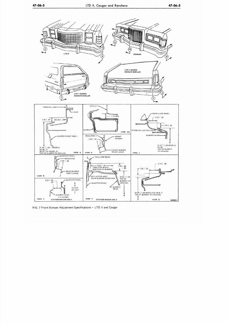
8/20/2019 1977 Ford Car Shop Manual Volume 4 Body
http://slidepdf.com/reader/full/1977-ford-car-shop-manual-volume-4-body 392/449
47-06-5 LTD II , Cou gar a nd Ranchero
47-06-5
PARKING LAMP
G.O.P.
BUMPER FRONT (REF.)
21.44 1 1 .5 0- MODELS
5 3 , 6 5 , 7 1
20.70 FOR MODEL 97
TOP OF BUMPER TO GROUND
GRILLE
BUMPER
VIEW- AA
MOULDING
1.251.25
FRONT BUMPER
TRIM FLANGE
REAR LAMP BEZEL
2.121.38
STONE DEFLECTOR END'
BUMPER REAR-
21.67 1 1.50 MODELS
53 , 65
TOP OF BUMPER
TO GROUND
OUARTER PANEL
MOULDING
1.251.25
REAR BUMPER
TRIM FLANGE
VIEW-D
•
TAIL LAMP BEZEL
2.20 + .50
- . 2 5
1
•QUARTER PANEL
t
TO FRT.
OF VEH.
I
V I E W - E
•BUMPER REAR
L.H. SHOWN
STATION WAGON ONLY
3 .151 .38
21.44 1 1.50 MODELS 53, 65 & 71
TOP OF BUMPER TO GROUND
VIEW F
STATION WAGON ONLY
N2593-C
FIG. 7 Front Bumper Adju stme nt Specificat ions - LTD II and Cougar
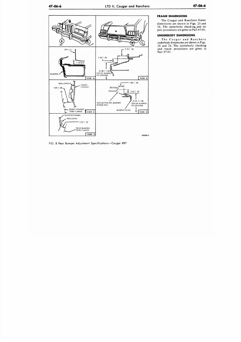
8/20/2019 1977 Ford Car Shop Manual Volume 4 Body
http://slidepdf.com/reader/full/1977-ford-car-shop-manual-volume-4-body 393/449
47-06-6
LTD II, Cougar and Ranchero
47-0
FRAME DIMENSIONS
The Cougar and Ranchero fr
dimensions are shown in Figs. 25
26 . The underbody checking
#
and
pair procedures are given in Part
47
UNDERBODY DIMENSIONS
T h e C o u g a r
and
R a n c h
underbody dim ensions are shown in
25
and 26. The
u n d erb o d y ch ec
and repair procedures are give
Part 4 7 - 0 1 .
N2594-C
FIG. 8 Rear Bumper Adjustment Specifications—Cougar XR7
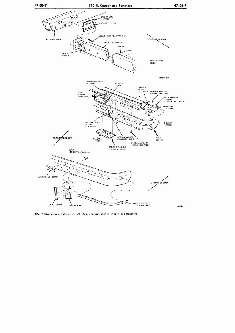
8/20/2019 1977 Ford Car Shop Manual Volume 4 Body
http://slidepdf.com/reader/full/1977-ford-car-shop-manual-volume-4-body 394/449
4 7 - 0 6 - 7
LTD II, Cougar and Ranchero
47-06-7
SPACER ASSY.
- 17C977
SPACER - 17A761
BOLT (35-50 FT-LB TORQUE)
ISOLATOR 17C884-5
FRAME
TO FRONT OF BODY
CLIP
3REQ'D
END BRACKET
17A881
REINFORCEMENT
- 17A946
SHIELD
17C857
1976 ONLY
U-NUT-
45265
(6 PLACES) SCREW & WASHER
- 57049 (2 PLACES)
TO FRONT OF BODY
NUT & WASHER
- 387685
(17-23 FT-LBS TORQUE)
BRACKET
- 17A881
ANTI-RATTLER
- 370677
(2 PLACES)
BRACKET
- 13406
B O L T -
387169
SCREW & WASHER
- 57049 (4 PLACES)
BOLT
(25-38 FT-LB TORQUE)
SCREW & WASHER
- 57030 (2 PLACES)
CENTER PAD-17C997
TO FRONT OF BODY
P A D - 1 7 A 4 6 5
G U A R D - 1 7 9 8 4
PAD-17914 (R IGHT)
17C996(LEFT)
N1787-H
FIG.
9 Rear Bumper Installation—A ll Models Except Station Wa go n and Ranchero
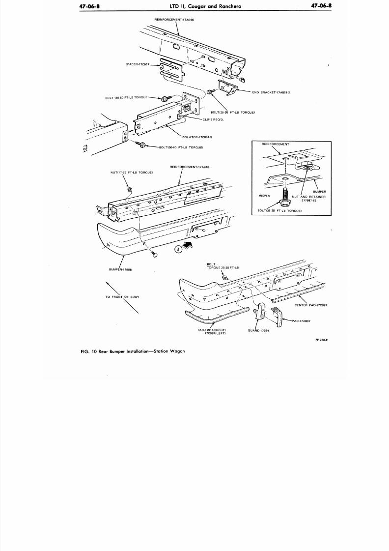
8/20/2019 1977 Ford Car Shop Manual Volume 4 Body
http://slidepdf.com/reader/full/1977-ford-car-shop-manual-volume-4-body 395/449
47-06-8
LTD II, Cougar and Ranchero
47-06
REINFORCEMENT-17A946
END BRACKET-17A881-2
BOLK25-38 FT-LB TORQUE)
C L I P 3 R E O / D .
ISOLATOR-17C884-5
•BOLTI60-90 FT-LB TORQUE)
REINFORCEMENT-17A946
NUT(17-23 FT-LB TORQUE)
REINFORCEMENT
VIEW A
BUMPE
NUT AND RETAINER
377687-S2
BOLTI25-38 FT-LB TORQUE)
BUMPER-17906
BOLT
TORQUE 25-38 FT-LB
TO FRONT OF BODY
PAD-17A807
PAD-17914(RIGHT)
17C997ILEFT)
GUARD-17984
N1786
FIG. 10 Rear Bumper Instal lat ion—Station W ag on
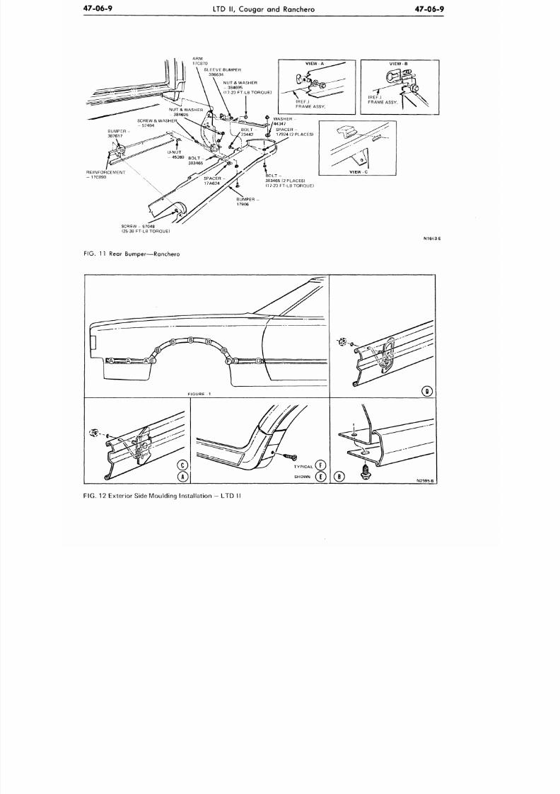
8/20/2019 1977 Ford Car Shop Manual Volume 4 Body
http://slidepdf.com/reader/full/1977-ford-car-shop-manual-volume-4-body 396/449
47-06-9 LTD II, Cougar and Ranchero
47-06-9
AR M
17C870
SLEEVE BUMPER
386634
NUT& WASHER
- 384695
(17-23 FT-LB TORQUE)
(REF.)
FRAME ASSY.
WASHER
-
44347
SPACER -
17924 (2 PLACES)
REINFORCEMENT
- 17C890
O L T -
383465 (2 PLACES)
(17-23 FT-LB TORQUE)
SCREW - 57048
(25-38 FT-LB TORQUE)
BUMPER -
17906
VIEW
(REF.)
FRAME ASSY
N16<:3-E
FIG. 1 1
Rear Bum per—R anchero
N2595-B
FIG. 12 Exterior Side Moulding Instal lation - LTD II
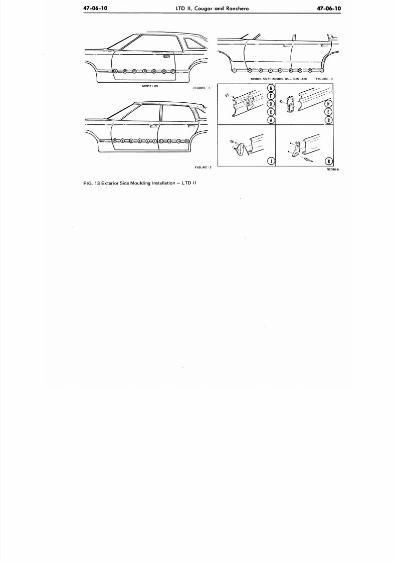
8/20/2019 1977 Ford Car Shop Manual Volume 4 Body
http://slidepdf.com/reader/full/1977-ford-car-shop-manual-volume-4-body 397/449
47-06-10
LTD II , Cougar and Ranchero
47-06
MODEL 65
FIGURE 1
, _ .
t ^
q > r z> —
MODEL 53-71 (MODEL 65 - SIMILAR FIGURE -
N2
FIG.
13 Exterior Side Moulding Installat ion - LTD
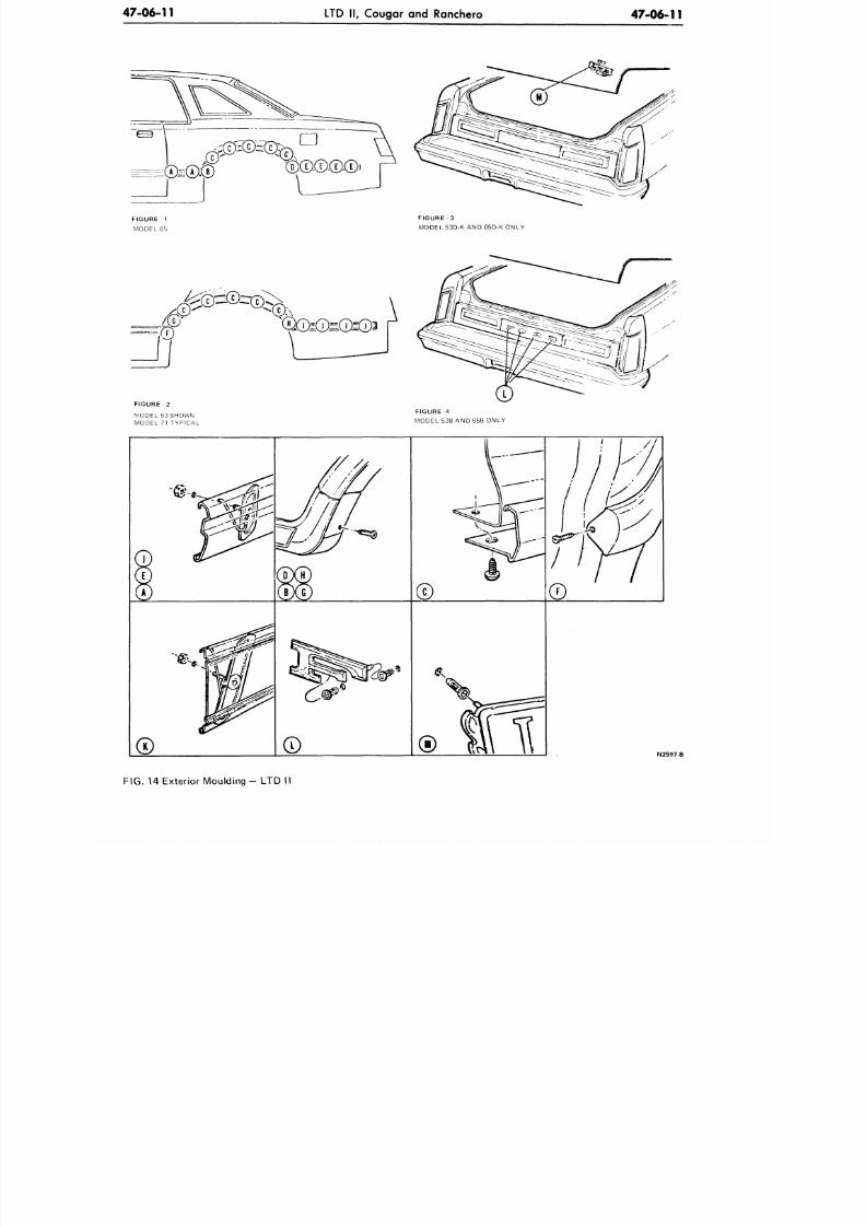
8/20/2019 1977 Ford Car Shop Manual Volume 4 Body
http://slidepdf.com/reader/full/1977-ford-car-shop-manual-volume-4-body 398/449
4 7 - 0 6 - 1 1
LTD II, Cougar and Ranchero
47-06-11
FIGURE 1
MODEL 65
FIGURE 3
MODEL 53D-K AND 65D-K ONLY
= ; ©
FIGURE 2
MODEL 53SHOWN
MODEL 71 TYPICAL
FIGURE 4
MODEL 53B AND 65B ONLY
N2597-B
FIG.
14 Exterior Moulding - LTD II
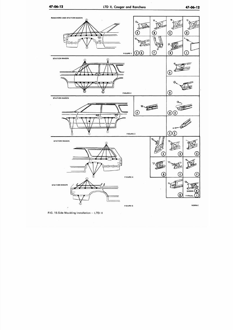
8/20/2019 1977 Ford Car Shop Manual Volume 4 Body
http://slidepdf.com/reader/full/1977-ford-car-shop-manual-volume-4-body 399/449
47-06-12
LTD II, Cougar and Ranchero
47-06
RANCHERO AND STATION WAGON
FIGURE
1
STATION WAGON
FIGURE
2
©
STATION WAGON
FIGURE
3
STATION WAGON
STATION WAGON
FIGURE
4
SHOWN
TYPICAL
FIGURE
5
N2
FIG. 15 Side Moulding Installation - LTD II
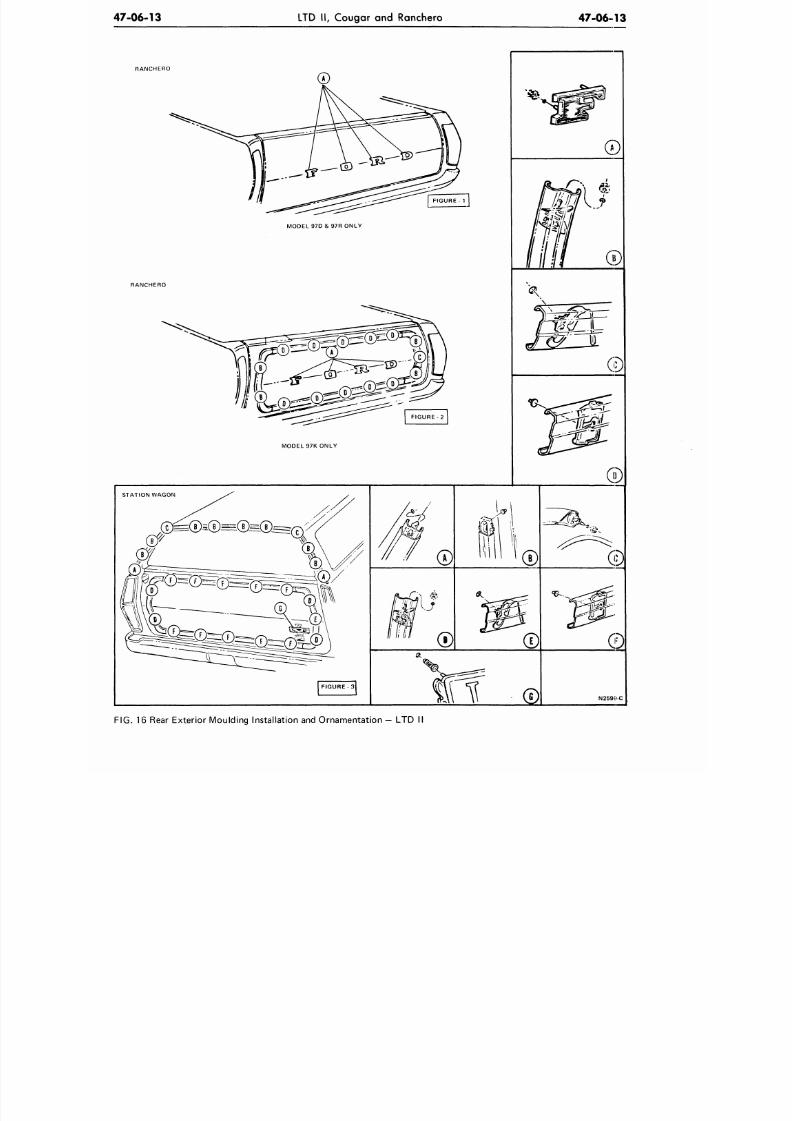
8/20/2019 1977 Ford Car Shop Manual Volume 4 Body
http://slidepdf.com/reader/full/1977-ford-car-shop-manual-volume-4-body 400/449
47-06-13
LTD
II,
Cougar
and
Ranchero
4 7 - 0 6 - 1 3
RANCHERO
RANCHERO
MODEL 97D
&
97R O NLY
MODEL 97K ONLY
STATION WAGON
FIGURE 3
©
FIG. 16
Rear Exterior M oulding Installat ion and Orname ntat ion
—
LTD
II
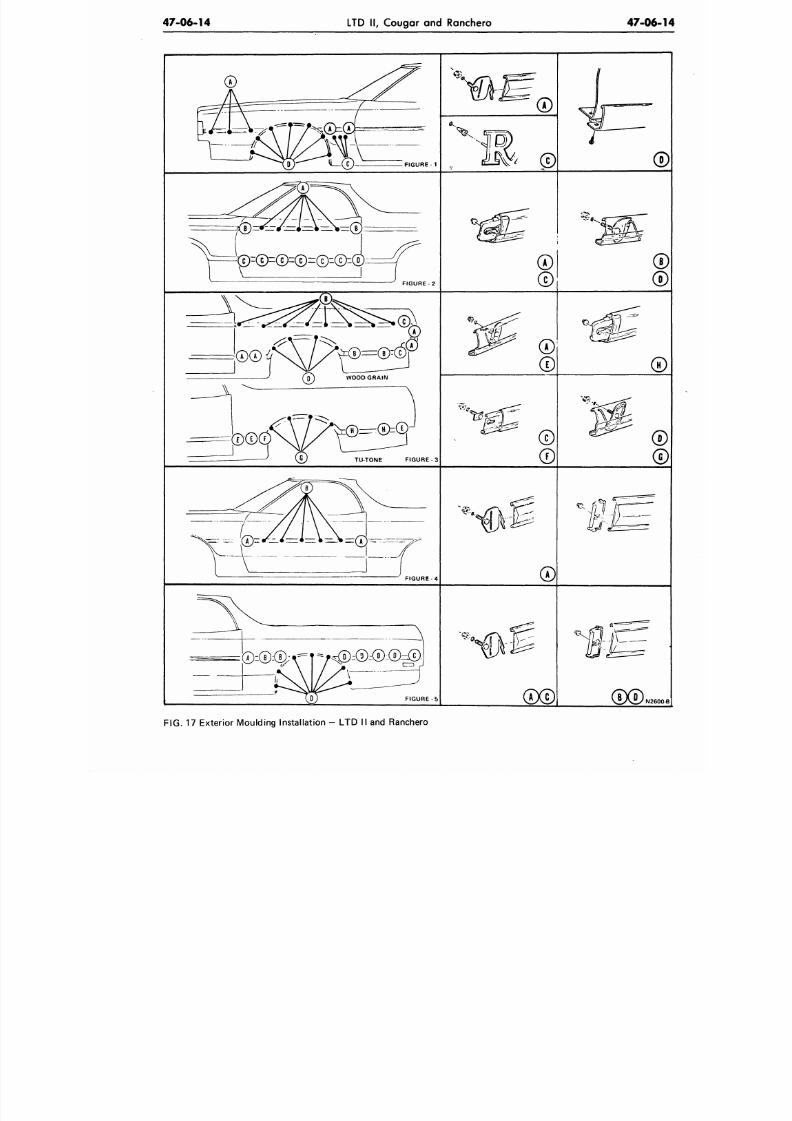
8/20/2019 1977 Ford Car Shop Manual Volume 4 Body
http://slidepdf.com/reader/full/1977-ford-car-shop-manual-volume-4-body 401/449
47-06-14
LTD II, Cougar and Ranchero
47-06-
®
F I G U R E - 1
FIGURE
2
TU-TONE F IGURE-3
FIGURE
-4
FIGURE
-5
L J Y
FIG. 17
Exterior Moulding Installation
- LTD II
and Ranchero
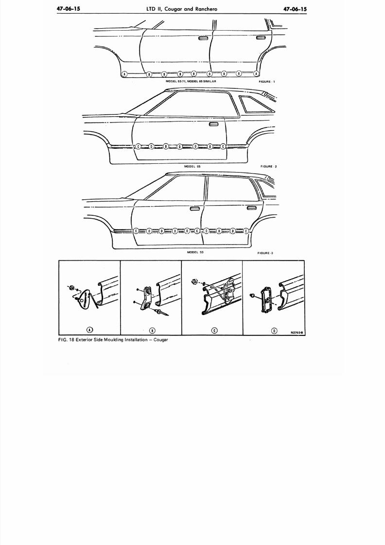
8/20/2019 1977 Ford Car Shop Manual Volume 4 Body
http://slidepdf.com/reader/full/1977-ford-car-shop-manual-volume-4-body 402/449
47-06-15
LTD II, Cougar and Ranchero
47-06-15
MODEL
65
FIGURE
-2
MODEL 53
FIGURE 3
N2763-B
FIG. 18 Exterior Side Moulding Installation — Cougar
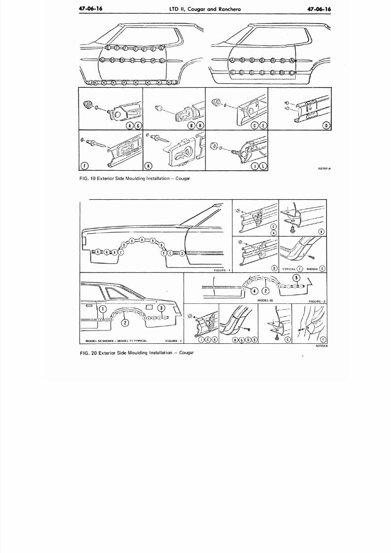
8/20/2019 1977 Ford Car Shop Manual Volume 4 Body
http://slidepdf.com/reader/full/1977-ford-car-shop-manual-volume-4-body 403/449
47-06-16
LTD II, Cougar and Ranchero
47-06-1
SE
FIG. 19 Exterior Side Moulding Installation — Cougar
FIGURE
- 1
(T)YPICAL
( T )
SHOWN
MODEL 53 SHOWN - MODEL 71 TYPICAL FIGURE - 1
FIGURE
- 2
0©0©
II h
©
N2762-
FIG. 20 Exterior Side Moulding Installation - Cougar
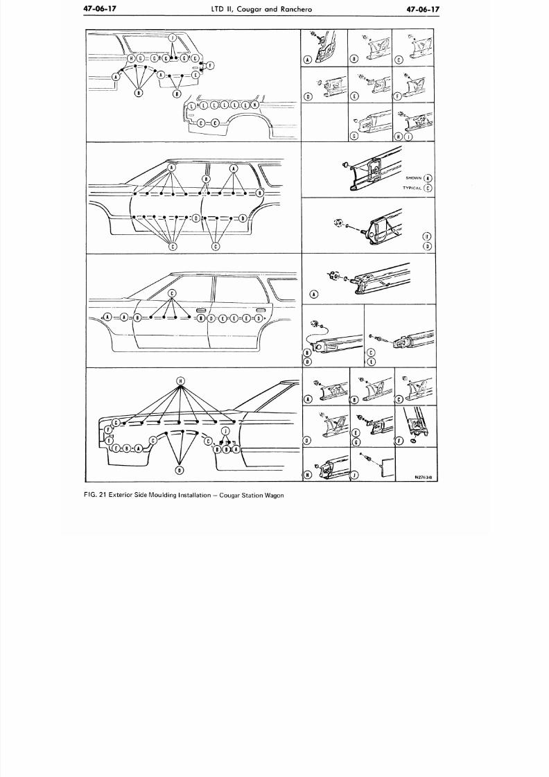
8/20/2019 1977 Ford Car Shop Manual Volume 4 Body
http://slidepdf.com/reader/full/1977-ford-car-shop-manual-volume-4-body 404/449
47-06-17
LTD II , Cougar and Ranchero
47-06-17
©
©
* s
©
©
©
©
©
D
N27(.3-B
FIG.
21 Exterior Side Moulding Installat ion
—
Cougar Station Wagon
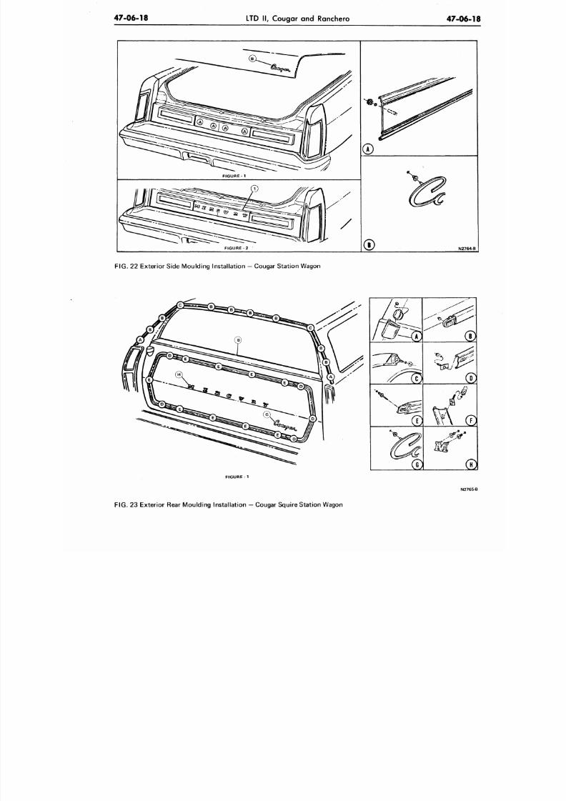
8/20/2019 1977 Ford Car Shop Manual Volume 4 Body
http://slidepdf.com/reader/full/1977-ford-car-shop-manual-volume-4-body 405/449
47-06-18
LTD II, Cougar and Ranchero
47-06-
FIGURE - 1
FIGURE 2
N2764
F I G . 22 Exterior Side Moulding Instal lat ion — Cougar Station Wagon
FIGURE 1
®
N276
F I G .
23 Exterior Rear Moulding Instal lat ion — Cougar Squire Station Wagon
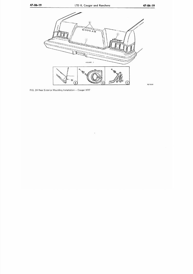
8/20/2019 1977 Ford Car Shop Manual Volume 4 Body
http://slidepdf.com/reader/full/1977-ford-car-shop-manual-volume-4-body 406/449
47-06-19
LTD II , Coug ar an d Ranchero
47-06-19
N2?66-B
FIG. 24 Rear Exterio r Mou lding Installation - Cougar XR7
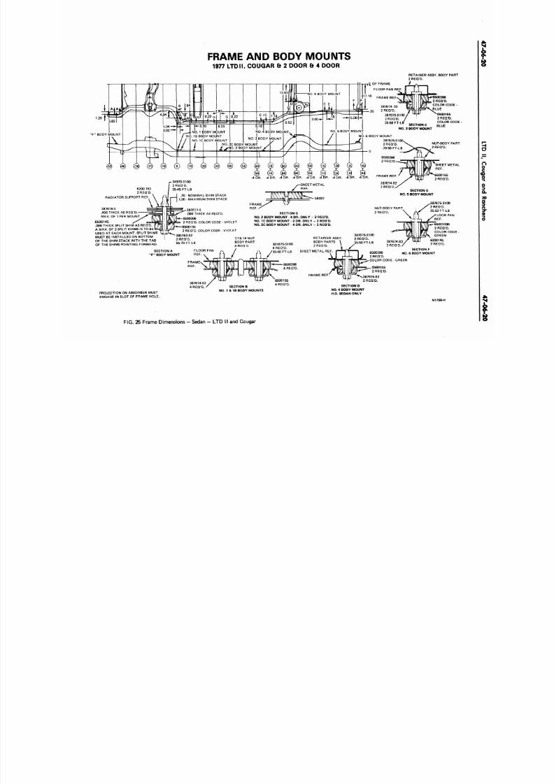
8/20/2019 1977 Ford Car Shop Manual Volume 4 Body
http://slidepdf.com/reader/full/1977-ford-car-shop-manual-volume-4-body 407/449
FRAME AND BODY MOUNTS
1977 LTDII. COUGAR & 2 DOOR & 4 DOOR
1.25
NO. 1 BODY MOUNT
NO.
1B BODY MOUNT
NO. IC BODY MOUN T
,<£ OF FRAME
FLOOR PAN REF.
1 0
FRAME REF
387674-S2
2 REQ 'D.
387675-S100
2 REQ 'D.
35-50 FT-L
RETAINER ASSY. BODY PART
2 REQ 'D.
2 REQ 'D.
COLOR CODE -
BLUE
6500155
2 REQ 'D.
COLOR CODE
BLUE
ECTION C
NO . 3
BODY MOUNT
'F " BODY MOUNT
NO. 6 BODY MOUNT
387675-S100
2 REQ'D.
35-50 FT-LB
0
6500396
2 REQ'D.
NUT-BODY PART
2 REQ 'D.
6200 163
2 REQ 'D.
RADIATOR SUPPORT REF
387676-S
.450 THICK AS REQ'D.
MAX. OF 1 PER MOUNT
6500145
.090 THICK SPLIT SHIM AS REQ'D.
A MAX. OF 2 SPLIT SHIMS IS TO BE
USED AT EACH MOUNT. SPLIT SHIMS
MUST BE INSTALLED ON BOTTOM
OF THE SHIM STACK WITH THE TAB
OF THE SHIMS POINTING FORWARD.
SHEET METAL
REF..
SHEET METAL
REF.
F RAM E REF .
.70 - NOMINA L SHIM STACK
1.00 - MAXIMUM SHIM STACK
387677-S
.090 THICK AS REQ'D.
6500396
2 REQ'D. COLOR CODE - VIOLET
6500155
2 REQ'D. COLOR CODE - VIOLET
385163-S2
2 REQ 'D.
55-70 FT-LB
SECTION E
NO . 5 BODY MOUNT
SECTION A
'F "
BODY MOUNT
5B097
SECTION G
NO . 2 BODY MOUNT 4 DR. ONLY - 2 REQ'D.
NO .
1C BODY MOUNT - 2 DR. ONLY - 2 REQ'D.
NO. 2C BODY MOUNT - 4 DR. ONLY - 2 REQ'D.
RETAINER ASSY.
BODY PARTS
2 REQ'D.
SHEET M ET AL REF .
FRAME REF. '
NUT-BODY PART
2 REQ'D.
6500396
2 REQ 'D.
COLOR CODE
387674-S2
2 REQ 'D.
SECTION F
NO. 6 BODY MOUNT
387675 S100
2 REQ 'D.
35-50 FT-LB
FLOOR PAN
65003396
2 REQ 'D.
COLOR CODE
GREEN
6200145
2 REQ 'D.
GREEN
PROJECTION ON ABSORBER MUST
ENGAGE IN SLOT OF FRAME HOLE.
SECTION B
NO. 1 & 1B BODY MO UNTS
6500155
2 REQ 'D.
' ^ 3 8 7 6 7 4 - 8 2
2 REQ 'D.
SECTION D
NO.
4 BODY MOUNT
H.D.SEDANONLY
N17S8-H
FIG.
25 Frame Dimensions - Sedan - LTD II and Cougar
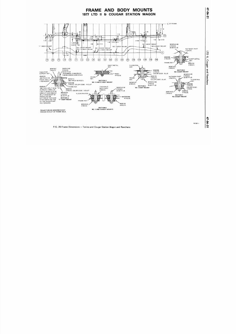
8/20/2019 1977 Ford Car Shop Manual Volume 4 Body
http://slidepdf.com/reader/full/1977-ford-car-shop-manual-volume-4-body 408/449
FRAME
AND
BODY MOU NTS
1977 LTD II & COUGAR STATION WAGON
C_OF FRAME
" F "
BODY MOUNT
NUT-BODY PAR
2REQ 'D .
SHEET ME
REF.
RADIATOR
SUPPORT REF.
6500145
.450 THICK AS
REQ'D. MAX.
OF
1 PER MOUNT
6500145
.090 THICK SPLIT SHIM
AS REQ'D.
A
MAX.
OF
2 SPLIT SHIMS
IS TO BE
USED
AT
EACH MOUNT
SPLIT SHIMS MUST BE
INSTALLED
ON
BOTTOM OF THE SHIM
STACK WITH THE TAB
OF THE SHIMS POINT-
ING FORWARD.
34979-S100
2 REQ'D.
35-45 FT-LB
.70-NOMINAL SHIM STACK
1.00-MAXIMUMSHIM STACK
387677-S
.090 THICK AS REQ'D.
6500396
2 REQ'D. COLOR CODE
FRAME
REF.
6500155
2 REQ'D. COLOR CODE
385163-S2
2 REQ'D.
55-70 FT-LB
SECTION A
' BODY MOUNT
FRAME REF
387674-S2
2 REQ'D.
SECTION E
NO. 5 BODY MOUNT
VIO L ET
FLOOR
PAN REF
FRAME '
REF.
SECTION
G
NO. 2 AN D 2C BODY MOUNT
VIOLET
7/16-14 NUT
BODY PART
4 REQ'D.
NUT-BODY PART
2 REQ'D.
387674-S2
4 REQ'D.
SECTION
C
NO. 3 BODY MOUNT
387675-S100
2 REQ D.
35-50 FT-LB
387675-S100
2 REQ D.
35-50 FT-LB
FLOOR
^ /REF.
387674-S2
2 REQD.
SECTION
F
NO. 6 BODY MOUNT
6500396
2 REQ'D.
COLOR CODE
GREEN
145
2 REQ'D.
PROJECTION ON ABSORBER MUST
ENGAGE IN SLOT OF FRAME HOLE.
SECTION B
NO. 1 AND 1B BODY MOUNTS
N13
F I G . 26
Frame Dimensions
-
Tor ino
and
Cougar Station Wagon
and
Ranchero
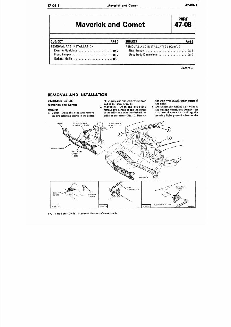
8/20/2019 1977 Ford Car Shop Manual Volume 4 Body
http://slidepdf.com/reader/full/1977-ford-car-shop-manual-volume-4-body 409/449
47-08-1
Maverick and Comet
47-0
Maverick and Comet
P A R T
47-08
SUBJECT PAGE
REMOVAL AND IN STALLATION
Exterior Mouldings 08-2
Front Bumper 08-2
Radiator Grille 08-1
SUBJECT
PAGE
REMOVAL AND INSTALLATION (Con t'd .)
Rear Bump er 08-2
Underbody Dimensions 08-2
CN2874-A
REMOVAL AND INSTALLATION
RADIATOR GRILLE
Maver ick and Comet
Removal
1. Comet— Open the hood and remove
the two retaining screws in the center
COMET
of the grille and one snap rivet at each
end of the grille (Fig. 1).
2. M a v e r i c k — O p e n t h e h o o d a n d
remove two screws at the top center
of the grille, and one screw behind the
grille at the center (Fig. 1). Remove
the snap rivet at each upper corn
the grille.
Disconnect the parking light wir
the multiple connectors. Remov
t wo met a l s crews at t ach in g
parking light ground wires at
SCREW-55929
FIG.
1 Radiator Grille—Maverick Shown—Comet Similar
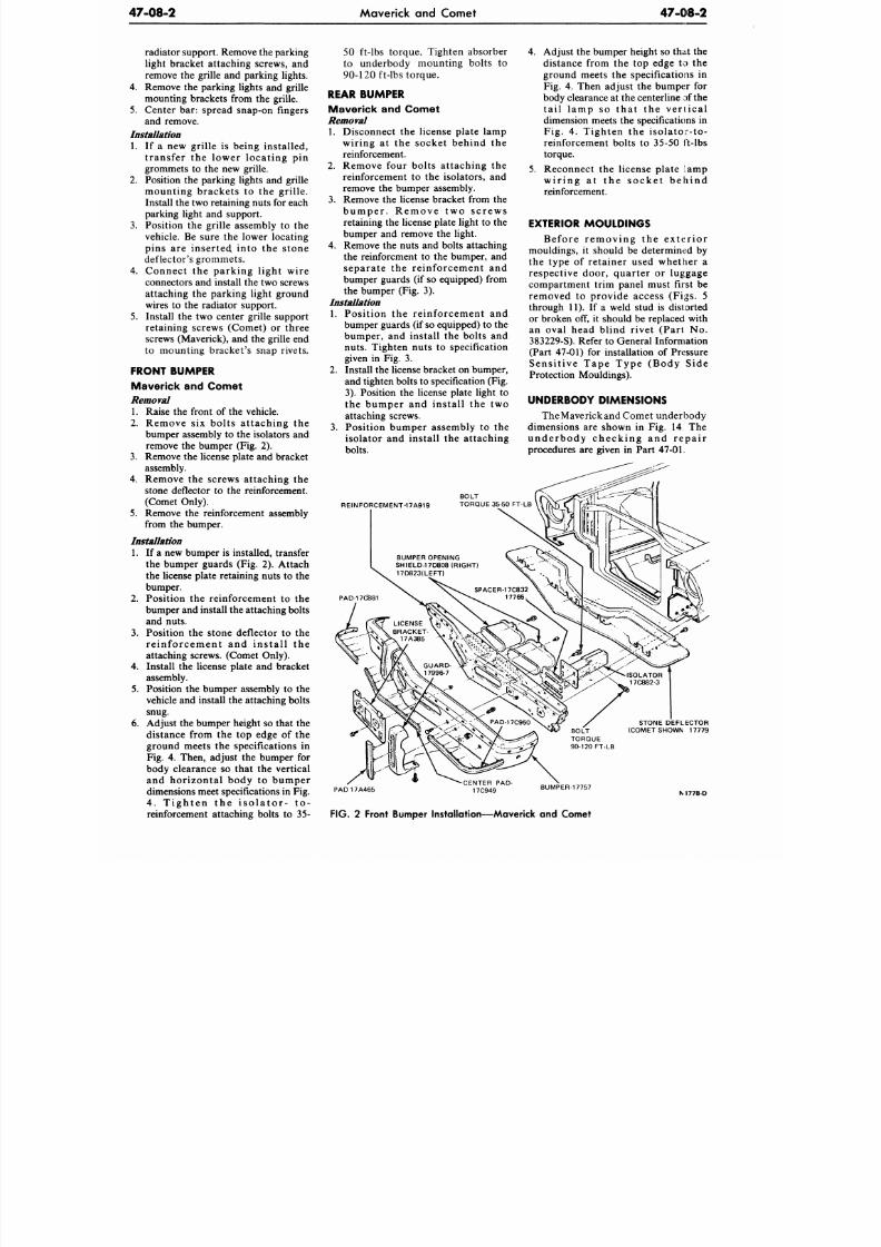
8/20/2019 1977 Ford Car Shop Manual Volume 4 Body
http://slidepdf.com/reader/full/1977-ford-car-shop-manual-volume-4-body 410/449
47-08-2
Maverick and Comet
47-08-2
radiator support. Remove the parking
light bracket attaching screws, and
remove the grille and parking lights.
4. Remove the parking lights and grille
mounting brackets from the grille.
5. Center bar: spread snap-on fingers
and remove.
Installation
1. If a new grille is being installed,
transfer the lower locating pin
grommets to the new grille.
2. Position the parking lights and grille
mounting brackets to the grille.
Install the two retaining nuts for each
parking light and support.
3.
Position the grille assembly to the
vehicle. Be sure the lower locating
pins are inserted^ into the stone
deflector's grommets.
4.
Connect the parking light wire
connectors and install the two screws
attaching the parking light ground
wires to the radiator support.
5.
Install the two center grille support
retaining screws (Comet) or three
screws (Maverick), and the grille end
to mounting bracket's snap rivets.
FRONT BUMPER
Maver ick and Comet
Removal
1. Raise the front of the vehicle.
2.
Remove six bolts attaching the
bumper assembly to the isolators and
remove the bumper (Fig. 2).
3. Remove the license plate and bracket
assembly.
4.
Remove the screws attaching the
stone deflector to the reinforcement.
(Comet Only).
5.
Remove the reinforcement assembly
from the bumper.
Installation
1. If a new bumper is installed, transfer
the bumper guards (Fig. 2). Attach
the license plate retaining nuts to the
bumper.
2.
Position the reinforcement to the
bumper and install the attaching bolts
and nuts.
3. Position the stone deflector to the
re in fo rcemen t and in s ta l l the
attaching screws. (Comet Only).
4.
Install the license plate and bracket
assembly.
5.
Position the bumper assembly to the
vehicle and install the attaching bolts
snug.
6. Adjust the bumper height so that the
distance from the top edge of the
ground meets the specifications in
Fig. 4. Then, adjust the bumper for
body clearance so that the vertical
and horizontal body to bumper
dimensions meet specifications in Fig.
4 .
T i g h t e n t h e i s o l a t o r - t o -
reinforcement attaching bolts to 35-
50 ft-lbs torque. Tighten absorber
to underbody mounting bolts to
90-120 ft-lbs torque.
REAR BUMPER
Maver ick and Comet
Removal
1. Disconnect the license plate lamp
wiring at the socket behind the
reinforcement.
2. Remove four bolts attaching the
reinforcement to the isolators, and
remove the bumper assembly.
3. Remove the license bracket from the
b u m p e r . R e m o v e t w o s c r e w s
retaining the license plate light to the
bumper and remove the light.
4. Remove the nuts and bolts attaching
the reinforcment to the bumper, and
separate the reinforcement and
bumper guards (if so equipped) from
the bumper (Fig. 3).
Installation
1. Position the reinforcement and
bumper guards (if so equipped) to the
bumper, and install the bolts and
nuts. Tighten nuts to specification
given in Fig. 3.
2.
Install the license bracket on bumper,
and tighten bolts to specification (Fig.
3).
Position the license plate light to
the bumper and install the two
attaching screws.
3.
Position bumper assembly to the
isolator and install the attaching
bolts.
REINFORCEMENT-17A919
4.
Adjust the bumper height so that the
distance from the top edge to the
ground meets the specifications in
Fig. 4. Then adjust the bumper for
body clearance at the centerline :>f the
ta i l lamp so tha t the ve r t ical
dimension meets the specifications in
Fig. 4. Tighten the isolator-to-
reinforcement bolts to 35-50 ft-lbs
torque.
5. Reconnect the license plate lamp
w i r i n g a t t h e s o c k e t b e h i n d
reinforcement.
EXTERIOR MOULDINGS
Befo re r emov ing the ex te r io r
mouldings, it should be determined by
the type of retainer used whether a
respective door, quarter or luggage
compartment trim panel must first be
removed to provide access (Figs. 5
through 11). If a weld stud is distorted
or broken off, it should be replaced with
an oval head blind rivet (Part No.
383229-S). Refer to G eneral Information
(Part 47-01) for installation of Pressure
Sens i t ive Tape Type (Body Side
Protection Mouldings).
UNDERBODY DIMENSIONS
The Maverick and Com et under body
dimensions are shown in Fig. 14 The
u n d e r b o d y c h e c k i n g a n d r e p a i r
procedures are given in Part
47-01.
BUMPER OPENING
SHIELD-17D808(R IGHT)
17D823(LEFT)
STONE DEFLECTOR
(COMET SHOWN 17779
PAD17A465
-CENTER PAD-
17C949
BUMPER-17757
M 7 7 8 - D
FIG. 2 Front Bumper Installation—Maverick and Comet
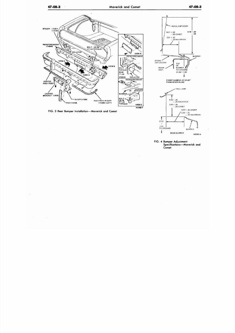
8/20/2019 1977 Ford Car Shop Manual Volume 4 Body
http://slidepdf.com/reader/full/1977-ford-car-shop-manual-volume-4-body 411/449
47-08-3
Maverick and Comet
47-0
SPACER -17C97 7
17A761
N2399-F
F IG .
3 Rear Bumper Instal lat ion—Maverick and Comet
BUM
TOP
OF
BUMPER
TO GROUND
21.36+ 1.50
FRONT BUMPER AT 27.20"
FROMCENTERLINE
TAIL -LAMP
4.05
+
.35
- . 2 5 M A V E R I C K
3.93 +
.35
- . 25 COMET
3.09+.25 COME
3.28
+
.25
- .25 MAVE
BUMPER
REAR BUMPER
N2
F IG . 4 Bumper Adjustment
Specif ications—Maverick
Comet
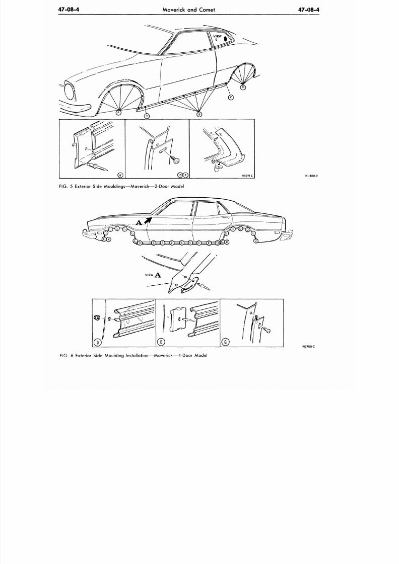
8/20/2019 1977 Ford Car Shop Manual Volume 4 Body
http://slidepdf.com/reader/full/1977-ford-car-shop-manual-volume-4-body 412/449
47-08-4
Maverick and Comet
47-08-4
FIG. 5 Exterior Side Mouldings—Maverick—2-Door Model
N: 400-C
; / /
N2759-C
FIG. 6 Exterior Side Moulding Installat ion—Maverick—4-Door Model
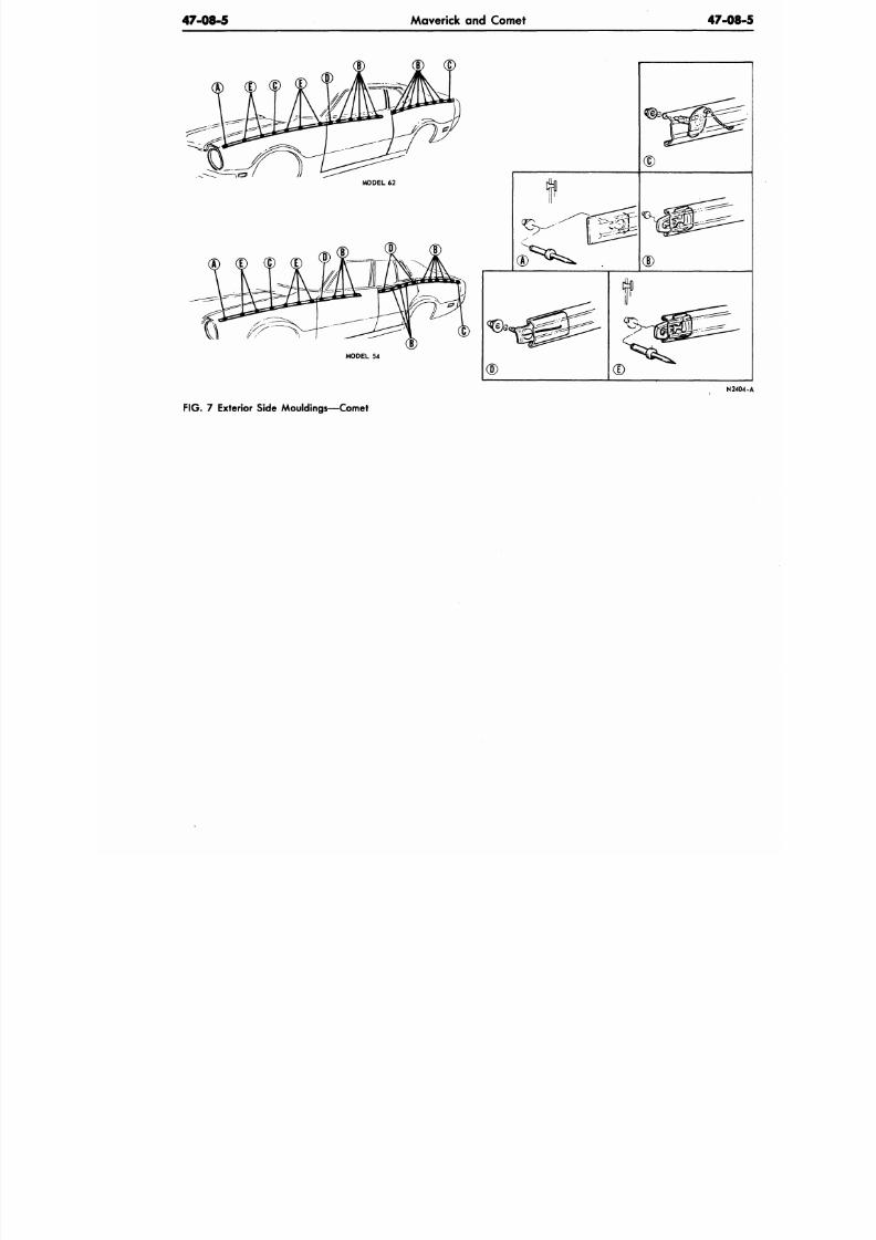
8/20/2019 1977 Ford Car Shop Manual Volume 4 Body
http://slidepdf.com/reader/full/1977-ford-car-shop-manual-volume-4-body 413/449
47-08-5
Maverick and Comet 47 -0
N
F IG .
7 Exterior Side Mouldings—Comet
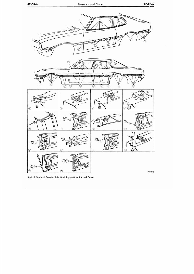
8/20/2019 1977 Ford Car Shop Manual Volume 4 Body
http://slidepdf.com/reader/full/1977-ford-car-shop-manual-volume-4-body 414/449
47-08-6
Maverick and Comet 47-08-6
v
" ' " - ^ .
®
N2 »05-C
FIG.
8
Optional Exterior Side Mouldings—Maverick
and
Comet
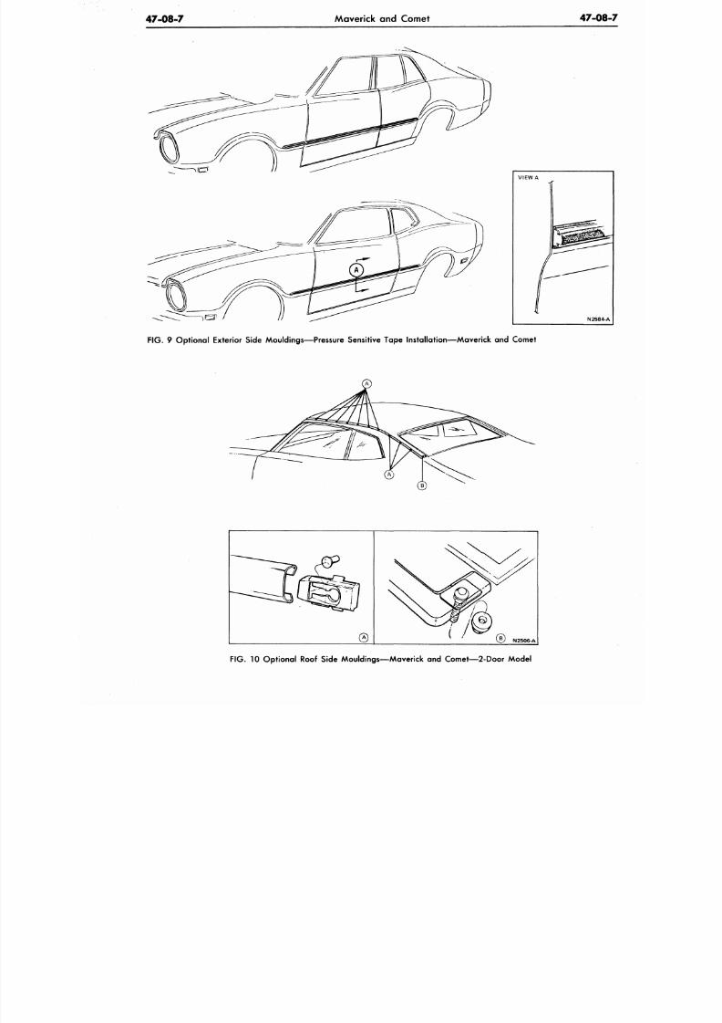
8/20/2019 1977 Ford Car Shop Manual Volume 4 Body
http://slidepdf.com/reader/full/1977-ford-car-shop-manual-volume-4-body 415/449
47-08-7
Maverick and Comet
47-0
F IG . 9 Optional Exterior Side Mouldings—Pressure Sensitive Tape Installation—Maverick and Comet
F IG . 10 Opt ional Roof Side Mouldings—Maver ick and Comet—2-Door Model
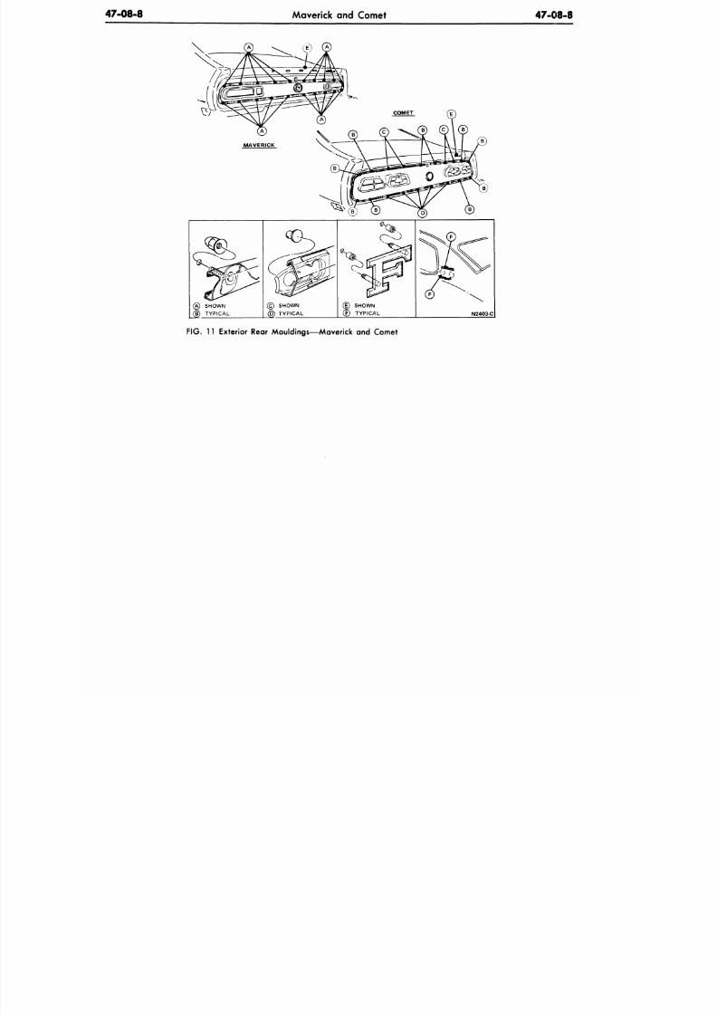
8/20/2019 1977 Ford Car Shop Manual Volume 4 Body
http://slidepdf.com/reader/full/1977-ford-car-shop-manual-volume-4-body 416/449
47-08-8
Maverick and Comet
47-08-8
(A) SHOWN
C§) TYPICAL
© SHOWN
(B) TYPICAL
SHOWN
CF) TYPICAL
N2403-C
FIG. 11 Exterior Rear Mouldings—Maverick and Comet
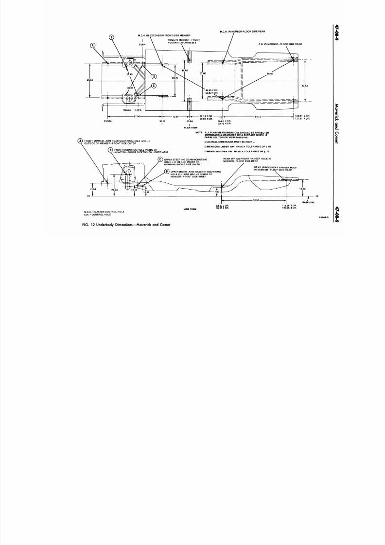
8/20/2019 1977 Ford Car Shop Manual Volume 4 Body
http://slidepdf.com/reader/full/1977-ford-car-shop-manual-volume-4-body 417/449
M.C.H. IN MEMBER-FLOOR SIDE REAR
M.C.H. I N EXTENSION FRONT SIDE MEMBER
HOLE IN MEMBER - FRONT
FLOOR SIDE C R O S S # 2
26 52
C.H.
IN MEMBER-FLOOR SIDE REAR
13.59-
26.90A 30.10
A ) FRONT BUMPER-ARM REAR MOUNTING HOLE (M.C.H.)
OUTSIDE OF MEMBER-FR ONT SIDE OUTER
FRONT MOUNTING HOLE INSIDE OF
ADAPT ER-FRO NT SUSPENSION LOWER ARM
43:69
PLAN VIEW
NOTE: ALL PLAN VIEW DIMENSIONS SHOULD BE PROJECTED
DOWNWARD & MEASURED ON A SURFACE W HICH IS
PARALLEL TO SIDE VIEW BASELINE.
DIAGONAL DIMENSIONS MUST BE EQUAL.
DIMENSIONS UNDER 100" HAVE A TO LERANCE OF + .06
DIMENSIONS OVER 100" HAVE A TOLERANCE OF + .12
C ) UPPER STEERING GEAR MO UNTING
HOLE L.H. (M.C.H.) INSIDE OF
MEMBER-FRONT SIDE INNER
D ) UPPER IDLE R-A RM BRACKET MOUNTING
HOLE R.H. SIDE (M.C.H.) INSIDE OF
MEMBER-FRONT SIDE INNER
REAR SPRING FRONT HANGER HOLE IN
MEMBER-FLOOR SIDE REAR
REAR SPRING REAR HANGER HOLE
IN MEMBER-FLOOR SIDE REAR
BASELINE
SIDE VIEW
116.95 2 DR.
123.85 4 DR.
M.C.H. = MASTER CONTROL HOLE
C.H.
= CONTROL HOLE
N
FIG. 12 Underbody Dimensions—Maverick and Comet
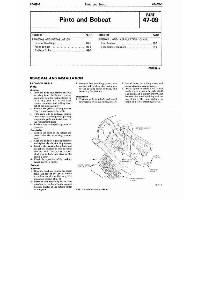
8/20/2019 1977 Ford Car Shop Manual Volume 4 Body
http://slidepdf.com/reader/full/1977-ford-car-shop-manual-volume-4-body 418/449
47-09-1 Pinto and Bobcat
47-09-1
Pinto and Bobcat
P A R T
47-09
SUBJECT PAGE
REMOVAL AND INS TALLATIO N
Exterior Mouldings 09-2
Front Bumper 09-1
Rad iator Grille 09-1
SUBJECT
PAGE
REMOVAL AND INSTA LLATIO N (Con t 'd . )
Rear Bum per 09-2
Underbo dy Dimensions 09-3
REMOVAL AND INSTALLATION
CN2876-A
RADIATOR GRILLE
Pinto
Removal
1. Open the hood and remove the two
parking lamp bulb and socke t
assemblies from the parking lamps by
r o t a t i n g t h e b u l b s o c k e t s
counterclockwise and pulling them
out of the lamp assembly.
2. Remove six grille attaching screws
(Fig. 1), and remove the grille.
3.
If the grille is to be replaced, remove
two screws attaching each parking
lamp to the grille and install them on
the replacement grille.
4. Replace any damaged clip nuts or
retainers.
Installation
1. Position the grille to the vehicle and
install the six attaching screws
loosely.
2.
Align the grille for a good appearance
and tighten the six attaching screws.
3.
Position the parking lamp bulb and
socket assemblies in the parking
la m ps , a nd r o t a t e t he soc ke t
clockwise to lock into place in the
parking lamp.
4. Check the operation of the parking
lamps and turn signals.
Bobcat
Removal
1. Open the hood and remove one screw
from the top of the grille, which
a t taches to the radia tor gr i l le
mounting bracket (Fig. 2).
2. Remove one attaching screw that
attaches to the hood latch support
bracket, located at the bottom center
of the grille.
3.
Remove four attaching screws, two
on each side of the grille, that attach
to the parking lamp housing, and
remove grille from car.
Installation
1. Position grille in vehicle and install
four screws, two on each side, loosely.
2.
3.
Install lower attaching screw and
upper attaching screw, loosely.
Adjust grille to obtain a 0.532-inch
uniform gap between the sight shield
and grille, and a similar uniform gap
between the hood moulding and the
top of the grille, then, tighten the
upper and lower attaching screws.
SCREW & WASHER
- 57030
SCREW- 56904
(5 PLACES) '
BRACKET
8A036
RADIATOR GRILLE
- 8 2 0 0
FIG. 1 Radiator Gri l le—Pinto
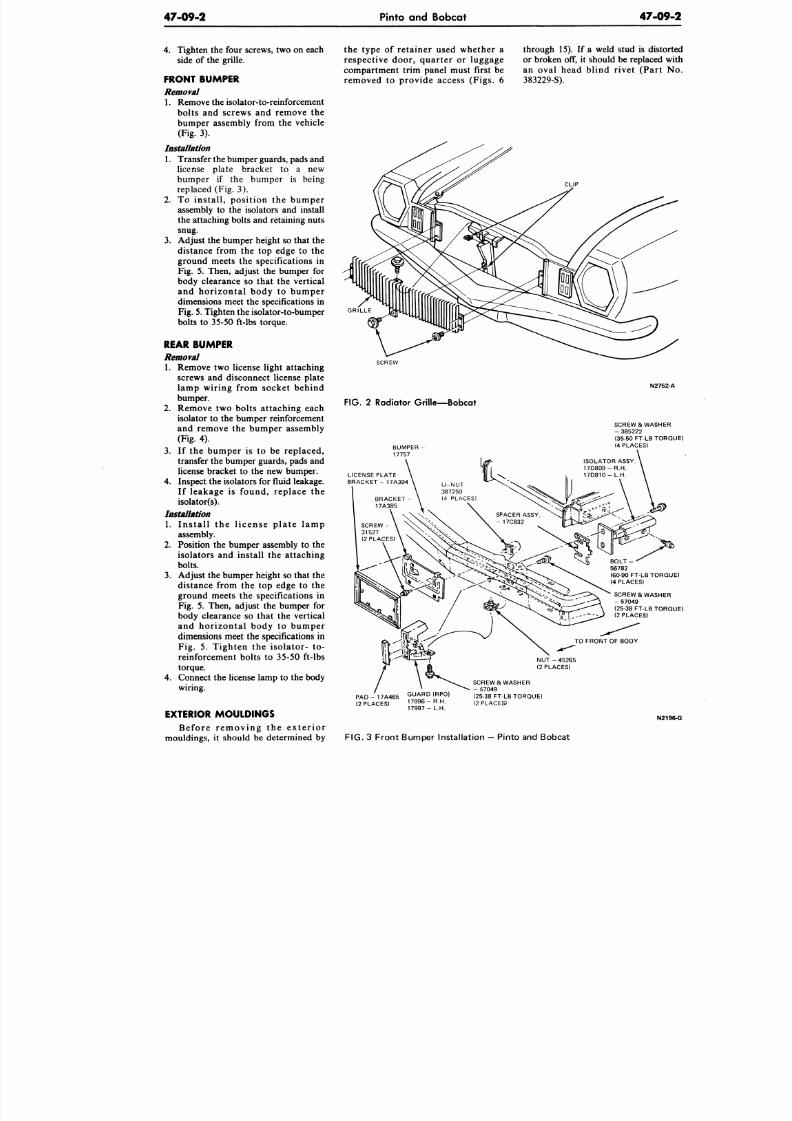
8/20/2019 1977 Ford Car Shop Manual Volume 4 Body
http://slidepdf.com/reader/full/1977-ford-car-shop-manual-volume-4-body 419/449
47-09-2
Pinto and Bobcat
47-0
4. Tighten the four screws, two on each
side of the grille.
FRONT BUMPER
Removal
1. Remove the isolator-to-reinforcement
bolts
and
screws
and
remove
the
bumper assembly from the vehicle
(Fig.
3).
Installation
1. Transfer the bumper guards, pads and
license plate bracket
to a new
bumper if the bumper is being
replaced (Fig.
3).
2.
To
install , position
the
bumper
assembly to the isolators and install
the attaching bolts and retaining nuts
snug.
3. Adjust the bumper height so that the
distance from the top edge to the
ground meets
the
specifications
in
Fig. 5. Then, adjust the bumper for
body clearance so that the vertical
and horizontal body
to
bumper
dimensions meet the specifications in
Fig.
5.
Tighten the isolator-to-bumper
bolts
to
35-50 ft-lbs torque.
REAR BUMPER
Removal
1. Remove two license light attaching
screws and disconnect license plate
lamp wiring from socket behind
bumper.
2. Remove two bolts attaching each
isolator to the bumper reinforcement
and remove the bum per assembly
(Fig. 4).
3.
If the
bumper
is to be
replaced,
transfer the bumper guards, pads and
license bracke t
to
the new bumper.
4.
Inspect the isolators for fluid leakage.
If leakage is found, replace the
isolator(s).
Installation
1. Ins ta l l
the
l icense p la te lamp
assembly.
2. Position the bumper assembly
to
the
isolators
and
install
the
attaching
bolts.
3.
Adjust the bumper height so that the
distance from
the top
edge
to the
ground meets the specifications in
Fig.
5.
Then, adjust the bumper
for
body clearance
so
that
the
vertical
and horizontal body to bumper
dimensions meet the specifications in
Fig.
5.
Tighten
the
isolator-
to-
reinforcement bolts to 35-50 ft-lbs
torque.
4.
Connect the license lamp to the body
wiring.
EXTERIOR MOULDINGS
Befo re r emov ing the e x t e r i o r
mouldings, it should be determined by
the type of retaine r used whe ther a
respective door, quarter
or
luggage
compartment trim panel must first be
removed to provide access (Figs. 6
through 15). If a weld stud is dis
or broken
off, it
should be replace
an oval head blind rivet (Par
383229-S).
GRILLE
SCREW
FIG.
2
Radiator Grille—Bobcat
N2
SCREW & WAS
- 385222
(35-50 FT-LB T
(4 PLACES)
SCREW & WAS
- 57049
(25-38 FT-LB T
(2 PLACES)
N U T - 4 5 2 6 5
(2 PLACES)
P A D - 1 7 A 4 6 5 G U A RD ( RP O)
(2 PLACES, ]™*™
SCREW & WASHER
- 57049
(25-38 FT-LB TORQUE)
(2 PLACES)
N
FIG.
3 Front Bumper Installation
—
Pinto and Bobcat
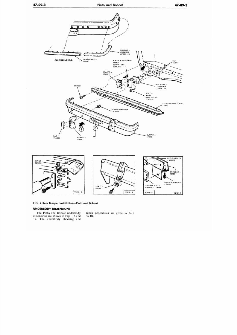
8/20/2019 1977 Ford Car Shop Manual Volume 4 Body
http://slidepdf.com/reader/full/1977-ford-car-shop-manual-volume-4-body 420/449
47-09-3
Pinto and Bobcat
47-09-3
P A D -
17A465
LICENSE PLATE
F R A M E - 1 7 A 3 9 4
V I E W - C
^ . - 3 5 8 1 5 9
in
^ ^ ^ B R A C K E T -
1 13406
SCREW & WASHER
- 3 1 5 2 7
N2197-F
FIG.
4 Rear Bumper Installation—Pinto and Bobcat
UNDERBODY DIMENSIONS
The Pinto and Bobcat underbody repair procedures are given in Part
dimensions are shown in Figs. 16 and
47-01.
17. The underbody checking and
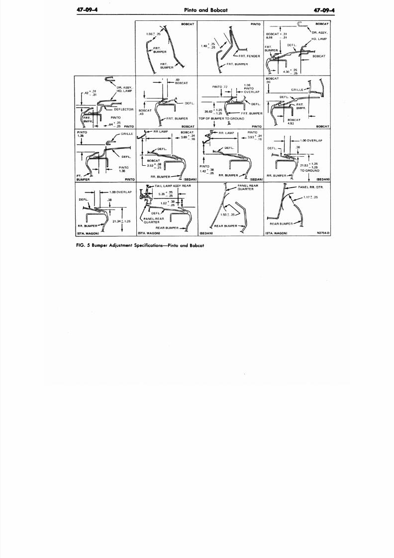
8/20/2019 1977 Ford Car Shop Manual Volume 4 Body
http://slidepdf.com/reader/full/1977-ford-car-shop-manual-volume-4-body 421/449
47-09-4
Pinto and Bobcat
47-09
BOBCAT PINTO
FRT. FENDER
FRT. BUMPER
BOBCAT
- . 2 5
BOBCAT
DEFLECTOR
PINTO
^ . 6 4
+ .25
- .25 PINTO
DEFL.
1.06
* , i PINTO
— H | -* — O V E R L A P
DEFL.
20.62
+ 1.25
FRT. BUMPER
BOBCAT
-1 .2 5 ^ « FRT. BUMPER
TOP OF BUMPER TO GROUND
T PINTO
BOBCAT
4.53
BOBCAT
GRILLE
DEFL.
PINTO
1.38
PINTO
3.93
RR. BUMPER
(SEDAN)
PINTO
+ .34
- . 1 6
PINTO
1.42
+ .38
- . 2 5
RR. BUMPER,
(SEDAN)
1.00 OVER LAP
+ 1.25
- 1 . 2 5
TO GROUND
R R . B U M P E R - H
(SEDAN
TAIL LAMP ASSY REAR
1.00 OVER LAP
DEFL
21.34 ±1.25
RR. BUMPER
(STA. WAGON)
REAR BUMPER
(STA. WAGON)
(SEDAN)
PANEL REAR
QUARTER
PANEL RR.QTR.
1.171.25
REAR BUMPER **j(
(STA. WAGON)
N2754-D
F IG .
5 Bumper Adjustment Specifications—Pinto and Bobcat
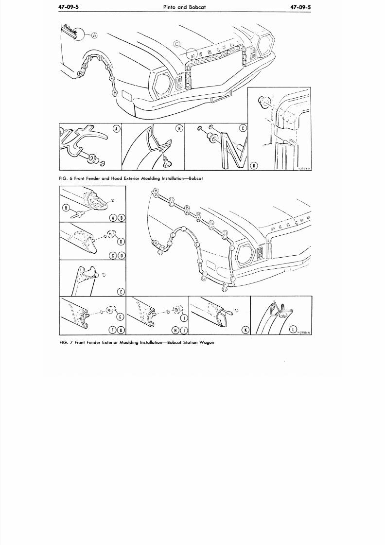
8/20/2019 1977 Ford Car Shop Manual Volume 4 Body
http://slidepdf.com/reader/full/1977-ford-car-shop-manual-volume-4-body 422/449
47-09-5
Pinto and Bobcat
47-09-5
FIG. 6 Front Fender and Hood Exterior Moulding Installation—Bobcat
M2755-A
F IG . 7 Front Fender Exterior Moulding Instal lat ion—Bobcat Station W ag on
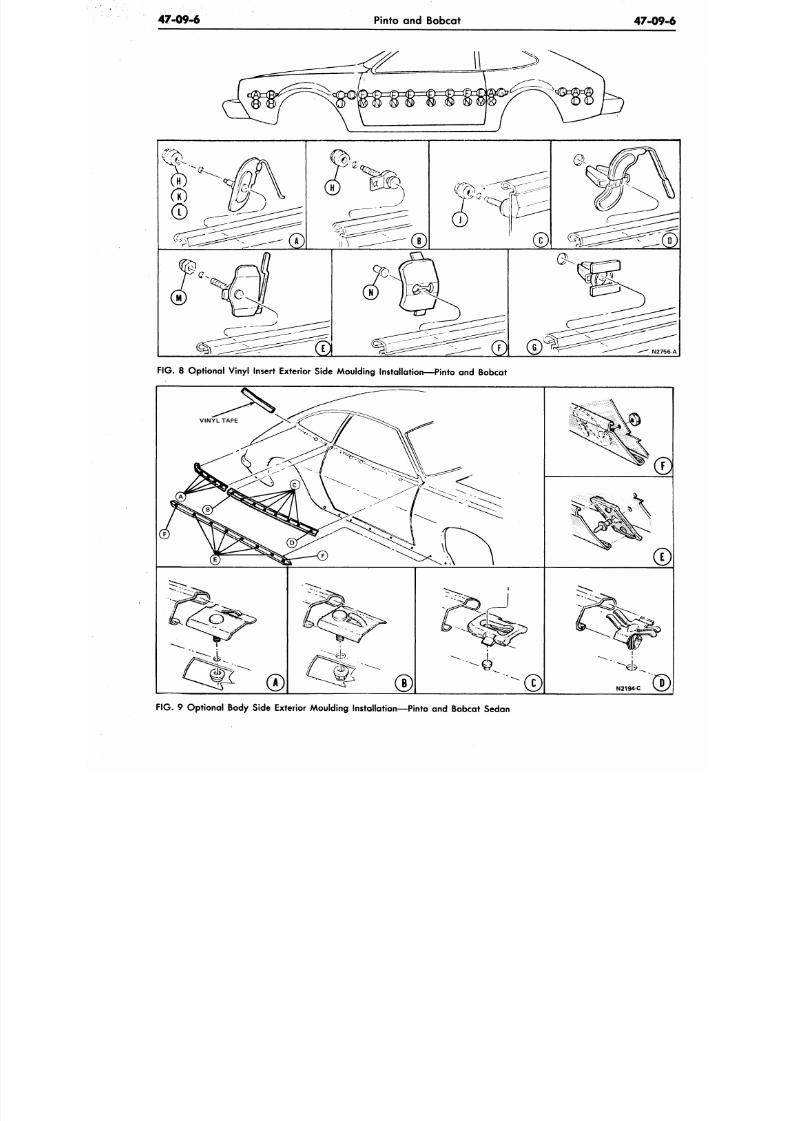
8/20/2019 1977 Ford Car Shop Manual Volume 4 Body
http://slidepdf.com/reader/full/1977-ford-car-shop-manual-volume-4-body 423/449
47-09-6
Pinto and Bobcat
47-0
N2
F IG .
8 Optional Vinyl Insert Exterior Side Moulding Installation—Pinto and Bobcat
N2194-C
F IG . 9 Optional Body Side Exterior Moulding Instal lat ion—Pinto and Bobcat Sedan
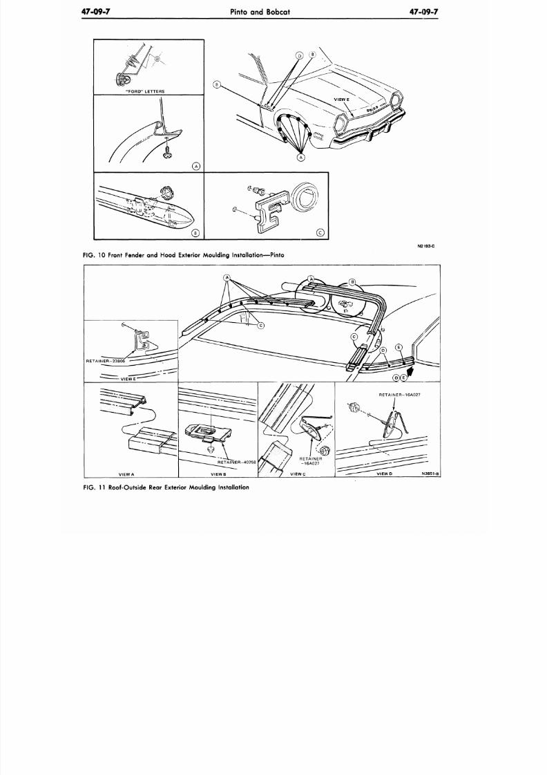
8/20/2019 1977 Ford Car Shop Manual Volume 4 Body
http://slidepdf.com/reader/full/1977-ford-car-shop-manual-volume-4-body 424/449
47-09-7
Pinto and Bobcat
47 -09 -7
"FORD" LETTERS
©
©
FIG. 10 Front Fender and Hood Exterior Moulding Installation—Pinto
N2I93-C
FIG. 11 Roof-Outside Rear Exterior Moulding Installation
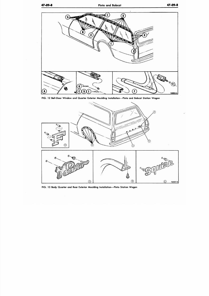
8/20/2019 1977 Ford Car Shop Manual Volume 4 Body
http://slidepdf.com/reader/full/1977-ford-car-shop-manual-volume-4-body 425/449
47-09-8
Pinto and Bobcat
47-09
F IG . 12 Belt-Door W indo w and Qu arter Exterior Moulding Instal lat ion—Pinto and Bobcat Station W ag on
F IG .
13 Body Quarter and Rear Exterior Moulding Installat ion—Pinto S tation W ag on
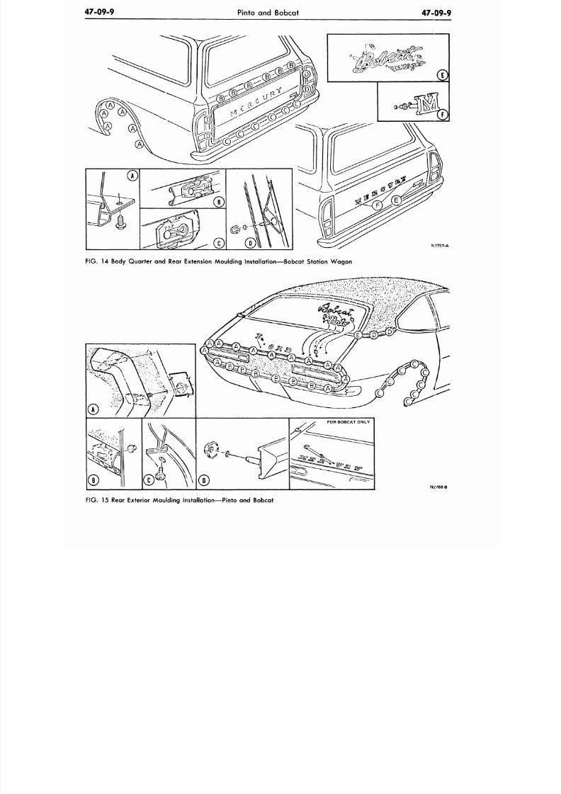
8/20/2019 1977 Ford Car Shop Manual Volume 4 Body
http://slidepdf.com/reader/full/1977-ford-car-shop-manual-volume-4-body 426/449
47-09-9
Pinto and Bobcat
47-09-9
N:>757-A
FIG. 14 Body Quarte r and Rear Extension Moulding Installation—Bo bcat Station W ag on
N2758-B
FIG.
15 Rear Exterior Moulding Installation—Pinto and Bobcat
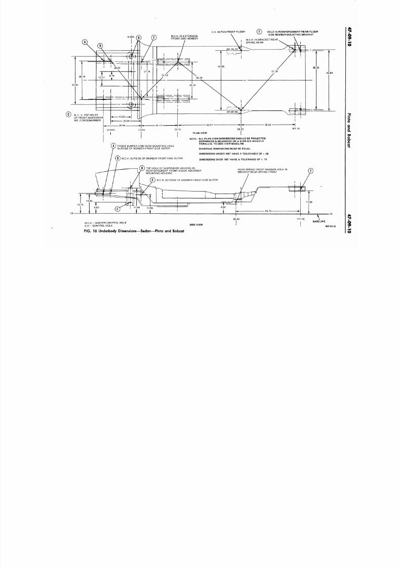
8/20/2019 1977 Ford Car Shop Manual Volume 4 Body
http://slidepdf.com/reader/full/1977-ford-car-shop-manual-volume-4-body 427/449
C.H.
IN PAN-FRONT FLOOR
HOLE IN REINFORCEMENT-REAR FLOOR
SIDE MEMBER MOUNTING BRACKET
M. C. H. TOP HOLES
OF FRONT SUSPENSION
NO . 2CROSSMEMBER
107.18
A ) F RONT BUMPER-ARM REAR MOUNT ING HOLE
OUTSIDE OF MEMBER-FRONT SIDE OUTER
NOTE: ALL PLAN VIEW DIMENSIO NS SHOULD BE PROJECTED
DOWNWARD & MEASURED ON A SURFACE WHICH IS
PARALLEL TO SIDE VIEW BASELINE .
DIAGONAL DIMENSIONS MUST BE EQUAL.
DIMENSIONS UNDER 100" HAVE A TOLERANCE OF + .06
DIMENSIONS OVER 10 0" HAVE A TOLERANCE OF + .12
.C.H. OUTSIDE OF MEMBER-FRONT SIDE OUTER
TOP HOLE OF SUSPENSION HOUSING-IN
REINFORCEMENT-FRONT SHOCK ABSORBER
MOUNTING HOUSING
REAR SPRING FRONT HANGER HOLE IN
BRACKET-REAR SPRING FRONT
E ) M.C.H. OUTSIDE OF MEMBER-FRONT SIDE OUTER
M.C.H. = MASTER CONTR OL HOLE
C.H.
= CONTROL HOLE
BASELINE
SIDE VIEW
N2121
FIG.
16 Underbody Dimensions—Sedan—Pinto and Bobcat
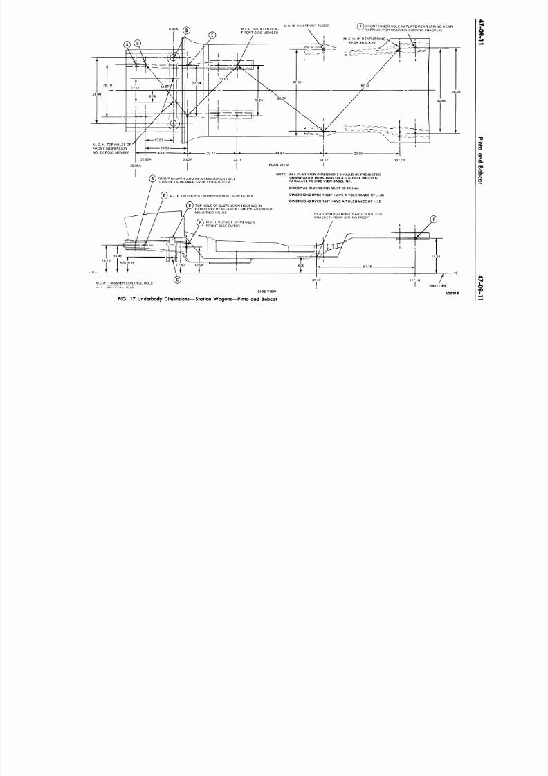
8/20/2019 1977 Ford Car Shop Manual Volume 4 Body
http://slidepdf.com/reader/full/1977-ford-car-shop-manual-volume-4-body 428/449
C.H.
IN PAN-FRONT FLOOR
( p ) FRONT INNER HOLE IN PLATE-REAR SPRING REAR
V
- ^ TAPPING (FOR MOUNTING SPRING SHACKLE)
M. C. H. TOP HOLES OF
FRONT SUSPENSION
NO . 2 CROSS MEMBER
107.18
28.08A
-10-
FRONT BUMPER-ARM REAR MOUNTING HOLE
OUTSIDE OF MEMBER FRONT SIDE OUTER
D ) M .C.H. OUTSIDE OF MEMBER-FRONT SIDE OUTER
B ) TOP HOLE OF SUSPENSION HOUSING-IN
REINFORCEMENT-FRONT SHOCK ABSORBER
MOUNTING HOUSE
M.C.H. OUTSIDE OF MEMBER
FRONT SIDE OUTER
NOTE: ALL PLAN VIEW DIMENSIONS SHOULD BE PROJECTED
DOWNWARD & MEASURED ON A SURFACE WHICH IS
PARALLEL TO SIDE VIEW BASELINE .
DIAGONAL DIMENSIONS MUST BE EQUAL.
DIMENSIONS UNDER 100" HAVE A TOLERANCE OF ± .06
DIMENSIONS OVER 100" HAVE A TOLERANCE OF +.12
REAR SPRING FRONT HANGER HOLE IN
BRACKET-REAR SPRING FRONT
J L
i n
T
8.00
.51 .7 6 -
-1
RASE LINE
N 2 6 3 8
M.C.H. = MASTER CONTROL HOLE
v
* - ^
SIDE VIEW
FIG. 17 Underbody Dimensions—Station Wagons—Pinto and Bobcat
65.40
117.16
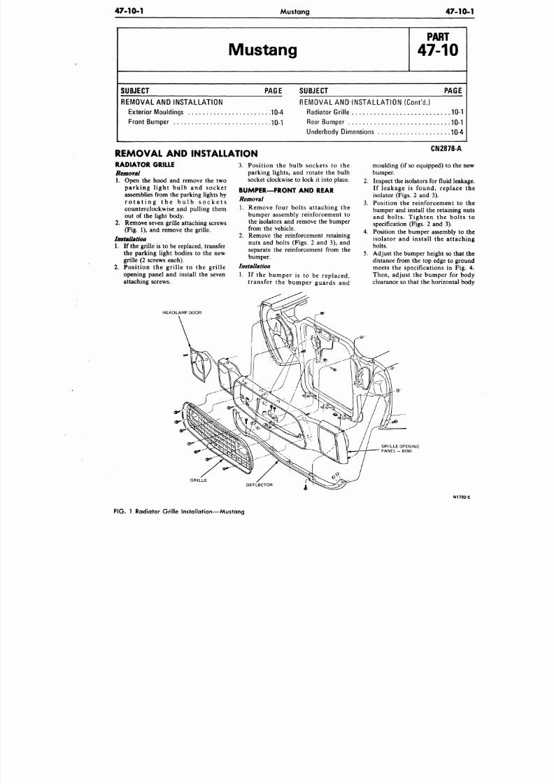
8/20/2019 1977 Ford Car Shop Manual Volume 4 Body
http://slidepdf.com/reader/full/1977-ford-car-shop-manual-volume-4-body 429/449
47-10-1
Mustang 47-1
Mustang
P A R T
47-10
S U B J E C T
PAGE
REMOVAL AND INS TALLATION
Exte rior Mou ldings 10-4
Front Bumper 10-1
SUBJECT PAGE
REMOVAL AND INSTALLATION (Con t 'd . )
Rad iator Grille 10-
Rear Bum per 10-
Underbody Dimensions 10-4
REMOVAL AND INSTALLATION
RADIATOR GRILLE
Removal
1. Open the hood and remove the two
parking l ight bulb and socke t
assemblies from the parking lights by
r o t a t i n g t h e b u l b s o c k e t s
counterclockwise and pulling them
out of the light body.
2. Remove seven grille attaching screws
(Fig. 1), and remove the grille.
Installation
1. If the grille is to be replaced, transfer
the
parking light bodies to the new
grille
(2 screws each).
2. Posit ion the gri l le to the gri l le
opening panel and install the seven
attaching screws.
HEADLAMP DOOR
3. Position the bulb sockets to the
parking lights, and rotate the bulb
socket clockwise to lock it into place.
BUMPER—FRONT AND REAR
Removal
1. Remove four bolts attaching the
bumper assembly reinforcement to
the isolators and remove the bumper
from the vehicle.
2. Remove the reinforcement retaining
nuts and bolts (Figs. 2 and 3), and
separate the reinforcement from the
bumper.
Installation
1. If the bumper is to be replaced,
transfer the bumper guards and
GRILLE
CN2878-A
moulding (if
so
equipped) to the
bumper.
2. Inspect the isolators for fluid lea
If leakage is found, replace
isolator (Figs. 2 and 3).
3. Position the reinforcement to
bumper and install the retaining
and bolts. Tighten the bolt
specification (Figs. 2 and 3).
4. Position the bumper assembly t
isolator and install the attac
bolts.
5. Adjust the bumper height so tha
distance from the top edge to gr
meets the specifications in Fi
Then, adjust the bumper for b
clearance so that the horizontal
GRILLE OPENING
P A N E L - 8 1 9 0
DEFLECTOR
N17
FIG. 1 Radiator Grille Installation—Mustang
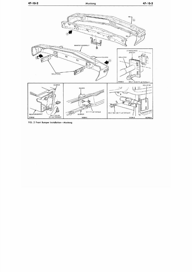
8/20/2019 1977 Ford Car Shop Manual Volume 4 Body
http://slidepdf.com/reader/full/1977-ford-car-shop-manual-volume-4-body 430/449
47-10-2
Mustang 47 -110-2
VIEW A (BOLT 35-50 FT-LB TORQUE)
FIG.
2 Front Bumper Installation—Mustang
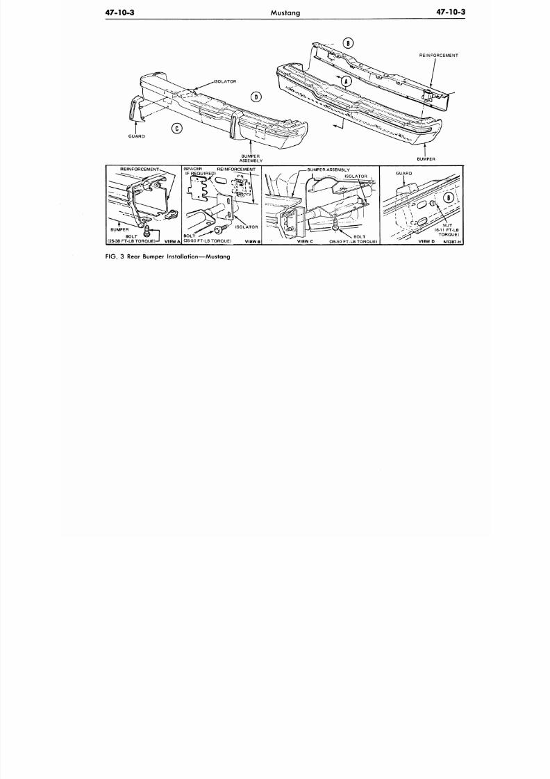
8/20/2019 1977 Ford Car Shop Manual Volume 4 Body
http://slidepdf.com/reader/full/1977-ford-car-shop-manual-volume-4-body 431/449
47-10-3
Mustang
47-10
GUARD
REINFORCEMENT
BUMPER
REINFORCEMENT
BUMPER
BOLT
(25-38 FT-LB TORQUE)-" V IEW A
(SPACER REINFORCEMENT
IF REQUIRED)
BOLT
(35-50 FT-LB TORQUE)
ISOLATOR
VIEWB
•
BUMPER ASS EMBLY
ISOLATOR
VIEWC
BOLT
(35-50 FT-LB TORQUE)
GUARD
NU T
(6-11 FT-LB
TORQUE
VIEW D N1387-
FIG. 3 Rear Bumper Installation—Mustang
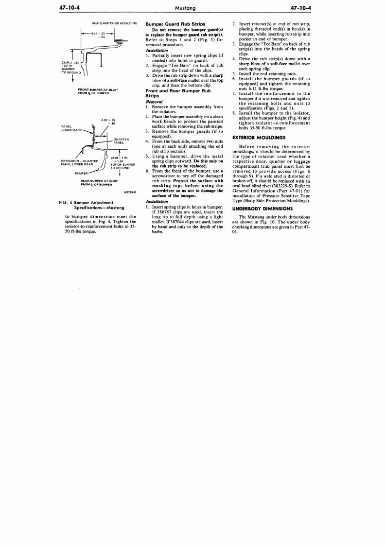
8/20/2019 1977 Ford Car Shop Manual Volume 4 Body
http://slidepdf.com/reader/full/1977-ford-car-shop-manual-volume-4-body 432/449
4 7 - 1 0 - 4
Mustang
4 7 - 1 0 - 4
HEADLAMP DOOR MOULDING
FRONT BUMPER AT
26.20
FROM Q. OF BUMPER
PANEL
LOWER BACK
EXTENSION - QUART ER
PANEL LOWER REAR
BUMPER
22.09 + 1.25
- 1.50
TOP OF BUMPER
TO GROUND
REAR BUMPER AT 30.00"
FROM
L
OF BUMPER
N2724-B
F I G 4 Bumper Adjustment
Specif ications—Mustang
to bumper dimensions meet the
specifications in Fig. 4. Tighten the
isolator-to-reinforcement bolts to 35-
50 ft-lbs torque.
Bumper Guard Rub Strips
Do not remove the bumper guard(s)
to replace the bumper guard rub strip(s).
Refer to S teps 1 and 2 (Fig . 5) for
removal procedures.
Installation
1. Partially insert new spring clips (if
needed) into holes in guards.
2 . Engage "Tee Bars" on back of rub
strip into the head of the clips.
3 .
Drive the rub strip down with a sharp
blow of a
soft-face
m allet over the top
clip,
and then the bottom clip.
Front and Rear Bumper Rub
Strips
Removal
1. Remove the bump er assembly from
the isolators.
2 .
Place the bum per assembly on a clean
work bench to protect the painted
surface while removing the rub strips.
3 . Remove the bum per guards (if so
equipped).
4 . From the back side, remove two nuts
(one at each end) attaching the end
rub strip sections.
5. Using a hammer, drive the metal
spring clips outward. Do this only on
the rub strip to be replaced.
6. From the front of the bumper, use a
screwdriver to pry off the damaged
rub strip. Protect the surface with
masking tape before using the
screwdriver so as not to damage the
surface of the bumper.
Installation
1. Insert spring clips in holes in bumper.
If 386787 clips are used, insert the
long tip to full depth using a light
mallet. If 387044 clips are used, insert
by hand and only to the depth of the
barbs.
2 . Insert retainer(s) at end of rub strip,
placing threaded end(s) in hoie(s) in
bumper, while inserting rub stiip into
pocket in end of bumper.
3 . Engage the "Tee Bars" on back of rub
strip(s) into the heads of the spring
clips.
4 . Drive the rub strip(s) down with a
sharp blow of a soft-face mallet over
each spring clip.
5.
Install the end retaining nuts.
6. Install the bumper guards (if so
equipped) and tighten the retaining
nuts 6-11 ft-lbs torque.
7 . Install the reinforcement to the
bumper if it was removed and tighten
the retaining bolts and nuts to
specification (Figs. 2 and 3).
8. Install the bumper to the isolator,
adjust the bumper height (Fig. 4) and
tighten isolator-to-reinforcement
bolts 35-50 ft-lbs torque.
EXTERIOR MOULDINGS
Be f or e r e m oving the e x t e r io r
mouldings, it should be determined by
the type of retainer used whether a
respective door, quarter or luggage
compartment trim panel must first be
removed to provide access (Figs. 6
through 9). If a weld stud is distorted or
broken off, it should be replaced with an
oval head blind riv et (383229-S). Refer to
General Information (Part 47-01) for
installation of Pressure Sensitive Tape
Type (Body Side Protection Mouldings).
UNDERBODY DIMENSIONS
The Mustang u nder body dimensions
are shown in Fig. 10. The under body
checking dimensions are given in Pa rt 4 7 -
0 1 .
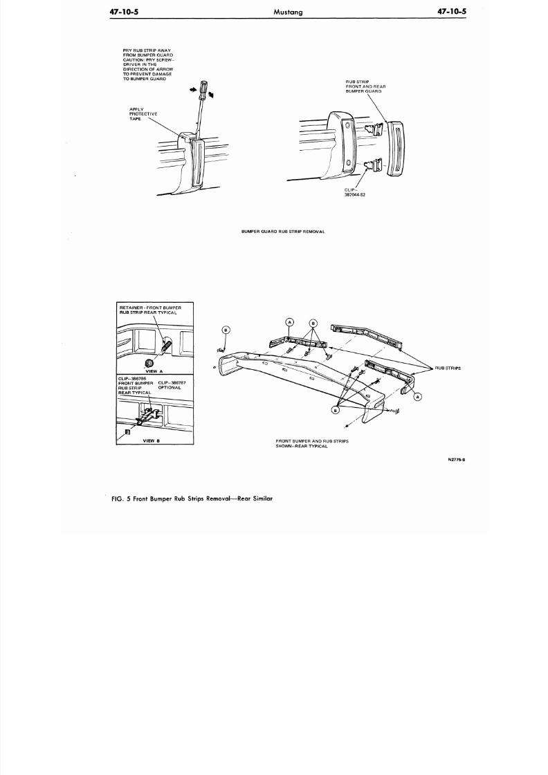
8/20/2019 1977 Ford Car Shop Manual Volume 4 Body
http://slidepdf.com/reader/full/1977-ford-car-shop-manual-volume-4-body 433/449
47-10-5
Mustang
47-10
PRY RUB STRIP AWAY
FROM BUMPER GUARD
CAUTION: PRY SCREW-
DRIVER IN THE
DIRECTION OF ARROW
TO PREVENT DAMAGE
TO BUMPER GUARD
APPLY
PROTECTIVE
TAPE
RUB STRIP
FRONT AND REAR
BUMPER GUARD
BUMPER GUARD RUB STRIP REMOV AL
RETAINER - FRONT BUMPER
RUB STRIP REAR TYPICA L
VIEW A
CLIP-386786
FRONT BUMPER CLIP-386 787
RUB STRIP OPTIONAL
REAR TYPICAL
VIEW B
RUB STRI
FRONT BUMPER AND RUB STRIPS
SHOWN-REAR TYPICAL
N27
FIG. 5 Front Bumper Rub Strips Removal—Rear Similar
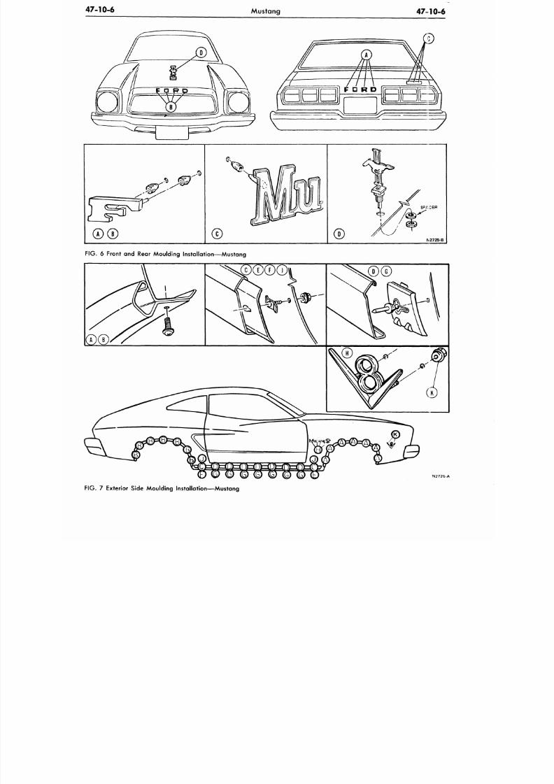
8/20/2019 1977 Ford Car Shop Manual Volume 4 Body
http://slidepdf.com/reader/full/1977-ford-car-shop-manual-volume-4-body 434/449
47-10-6
Mustang
47 10-6
FIG.
6 Front and Rear Moulding Installation— Mustang
N 2 7 2 6 A
F IG .
7 Exterior Side Moulding Installation—Mustang
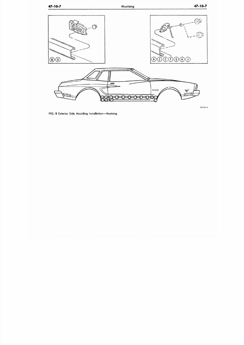
8/20/2019 1977 Ford Car Shop Manual Volume 4 Body
http://slidepdf.com/reader/full/1977-ford-car-shop-manual-volume-4-body 435/449
47-10-7
Mustang 47-10
A
C E F G H i
F IG .
8 Exterior Side Moulding Installation—Mustang
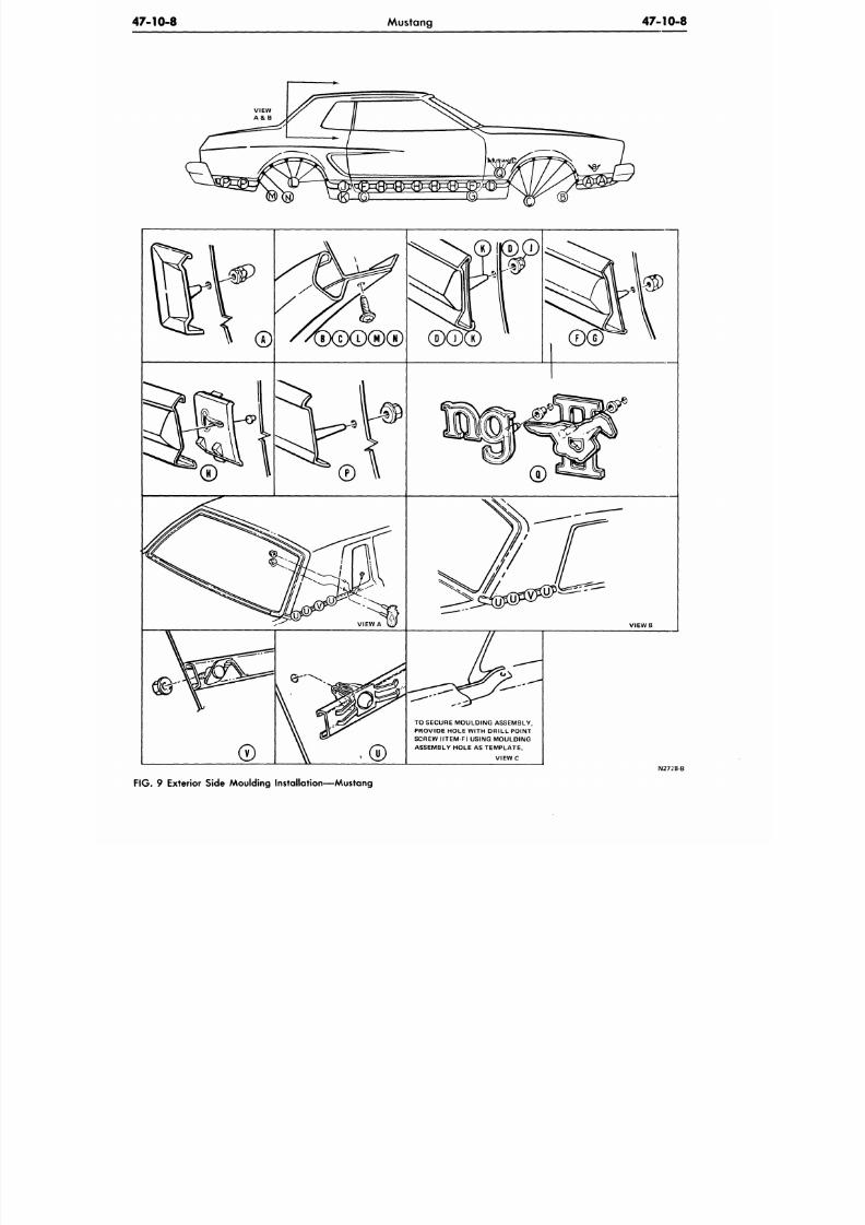
8/20/2019 1977 Ford Car Shop Manual Volume 4 Body
http://slidepdf.com/reader/full/1977-ford-car-shop-manual-volume-4-body 436/449
47-10-8
Mustang 47-10-8
V I E W B
TO SECURE MOULDING ASSEMBLY,
PROVIDE HOLE WITH DRILL POINT
SCREW (ITEM-F) USING MOULDING
ASSEMBLY HOLE AS TEMPLATE.
V I E W C
N272I8-B
FIG. 9 Exterior Side Moulding Installation—Mustang
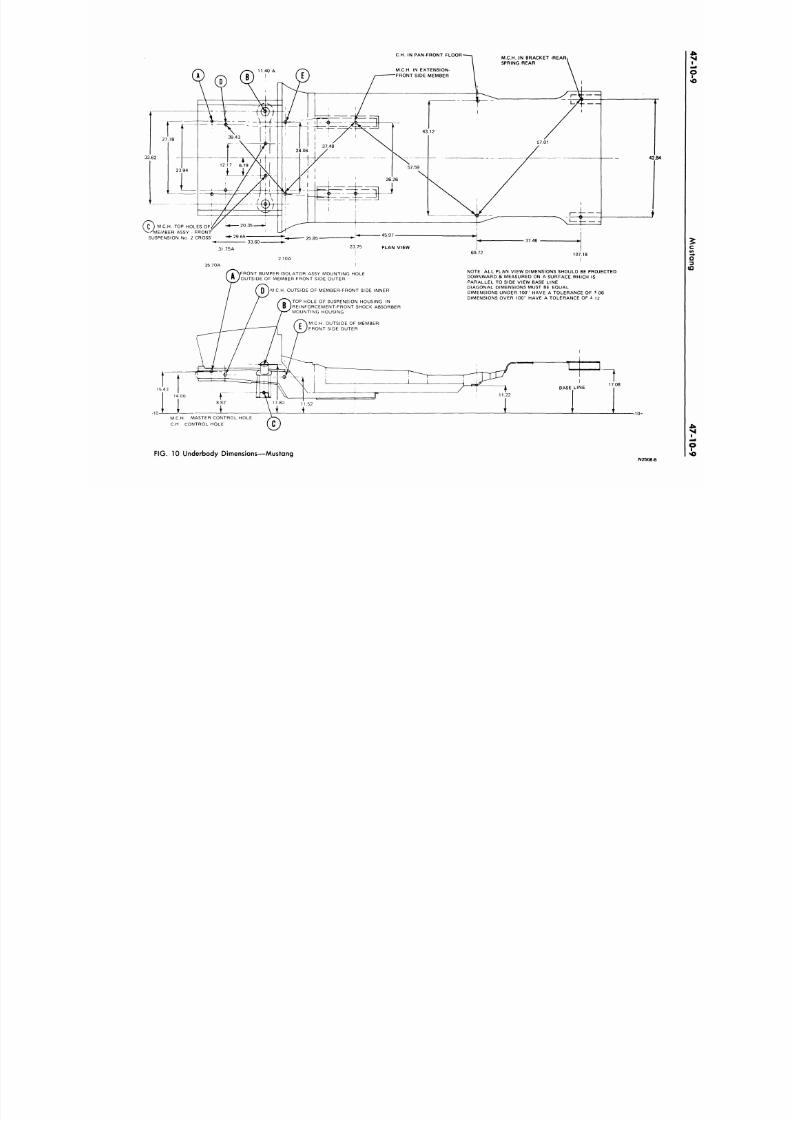
8/20/2019 1977 Ford Car Shop Manual Volume 4 Body
http://slidepdf.com/reader/full/1977-ford-car-shop-manual-volume-4-body 437/449
C.H. IN PAN-FRONT FLOOR-
M C H
- TOP HOLES OF
ASSY - FRONT
SUSPENSION No. 2 CROSS
31.75A
\FRONT BUMPER-ISOLATOR ASSY MOUNTING HOLE
'OUTSIDE OF MEMBER-FRONT SIDE OUTER
(M C.H. OUTSIDE OF MEMBER-FRONT SIDE INNER
vTOP HOLE OF SUSPENSION HOUSING- IN
(REINFORCEMENT-FRONT SHOCK ABSORBER
MOUNTING HOUSING
NOTE: ALL PLAN VIEW DIMENSIONS SHOULD BE PROJECTED
DOWNWARD & MEASURED ON A SURFACE WHICH IS
PARALLEL TO SIDE VIEW BASE LINE
DIAGONAL DIMENSIONS MUST BE EQUAL
DIMENSIONS UNDER 100" HAVE A TOLERANCE OF ±.06
DIMENSIONS
OVER
100" HAVE A TOLERANCE OF
±.12
42.8
M C H .
OUTSIDE OF MEMBER
FRONT SIDE OUTER
M C H .
MASTER CONTROL HOLE
C.H.
CONTROL HOLE
FIG. 10 Underbody Dimensions—Mustang
2508B
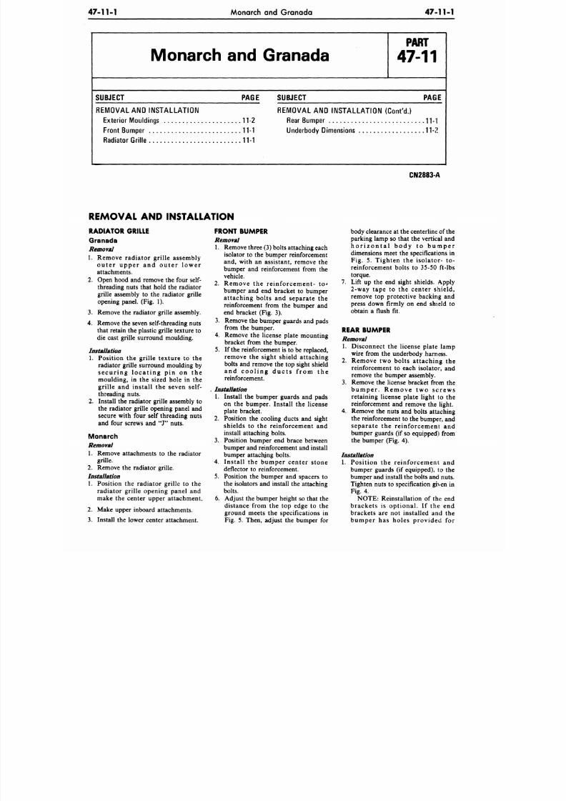
8/20/2019 1977 Ford Car Shop Manual Volume 4 Body
http://slidepdf.com/reader/full/1977-ford-car-shop-manual-volume-4-body 438/449
47-11-1
Monarch
and
Granada
47-11-1
Monarch
and
Granada
P A R T
47-11
SUBJECT PAGE
REMOVAL
AND
INSTALLATION
Exterior M ouldings 11-2
Front Bumper
11-1
Radiator Grille 11-1
SUBJECT
PAGE
REMOVAL
AND
INSTALLATION (Con t'd .)
Rear Bumper
11-1
Underbody Dimensions
11-2
CN2883-A
REMOVAL
AND
INSTALLATION
RADIATOR GRILLE
Granada
Removal
1. Remove radiator grille assembly
o u t e r u p p e r and ou t e r l ow e r
attachments.
2. Open hood and remove the four self-
threading nuts that hold the radiator
grille assembly to the radiator grille
opening panel.
(Fig. 1).
3.
Remove the radiator grille assembly.
4.
Remove
the
seven self-threading nuts
that retain
the
plastic grille texture
to
die cast grille surround moulding.
Installation
1.
Position the grille texture to the
radiator grille surround moulding by
s e c u r i n g l o c a t i n g pin on the
moulding, in the sized hole in the
grille and install the seven self-
threading nuts.
2. Install the radiator grille assembly to
the radiator grille opening panel and
secure with four self threading nuts
and four screws and J nuts.
Monarch
Removal
1.
Remove attachments to the radiator
grille.
2. Remove the radiator grille.
Installation
1. Position the radiator grille to the
radiator grille opening panel and
make the center upper attachment.
2. Make upper inboard attachments.
3.
Install the lower center attachment.
FRONT BUMPER
Removal
1. Remove three (3) bolts attaching each
isolator to the bumper reinforcement
and, with an assistant, remove the
bumper and reinforcement from the
vehicle.
2. Remove the re inforcement- to-«
bumper
and end
bracket
to
bumper
attaching bolts and separate the
reinforcement from
the
bumper
and
end bracket (Fig. 3).
3.
Remove the bumper guards and pads
from
the
bumper.
4. Remove the license plate mounting
bracket from the bumper.
5. If the reinforcement is to be replaced,
remove
the
sight shield attaching
bolts and remove the top sight shield
a n d c o o l i n g d u c t s f r o m the
reinforcement.
Installation
1. Install
the
bumper guards
and
pads
on the bumper. Install the license
plate bracket.
2. Position the cooling ducts and sight
shields
to the
reinforcement
and
install attaching bolts.
3.
Position bumper
end
brace between
bumper and reinforcement and install
bumper attaching bolts.
4. Install the bump er center stone
deflector to reinforcement.
5. Position the bumper and spacers to
the isolators and install the attaching
bolts.
6. Adjust the bumper height so that the
distance from the top edge to the
ground meets the specifications in
Fig. 5. Then, adjust the bumper for
body clearance at the centerline of the
parking lamp so that the vertical and
h o r i z o n t a l b o d y
to
b u m p e r
dimensions meet the specifications in
Fig. 5. Tighten the isolator- to-
reinforcement bolts to 35-50 ft-lbs
torque.
7. Lift up the end sight shields. Apply
2-way tape to the center shield,
remove top protective backing and
press down firmly on end shield to
obtain
a
flush
fit.
REAR BUMPER
Removal
1. Disconnect
the
license plate lamp
wire from the underbody harness.
2.
Remove
two
bolts at taching
the
reinforcement to each isolator, and
remove the bumper assembly.
3.
Remove the license bracket from the
b u m p e r . R e m o v e two s c r e w s
retaining license plate light to the
reinforcement and remove the light.
4.
Remove
the
nuts
and
bolts attaching
the reinforcement to the bumper, and
separa te
the
reinforcement
and
bumper guards
(if
so equipped) from
the bumper (Fig. 4).
Installation
1. Position the reinforcement and
bumper guards
(if
equipped),
to the
bumper and install the bolts and nu ts.
Tighten nuts to specification given in
Fig. 4.
NOTE : Reinstallation of the end
bracke ts is opt iona l . If the end
brackets are not installed and the
bum pe r has holes provided for
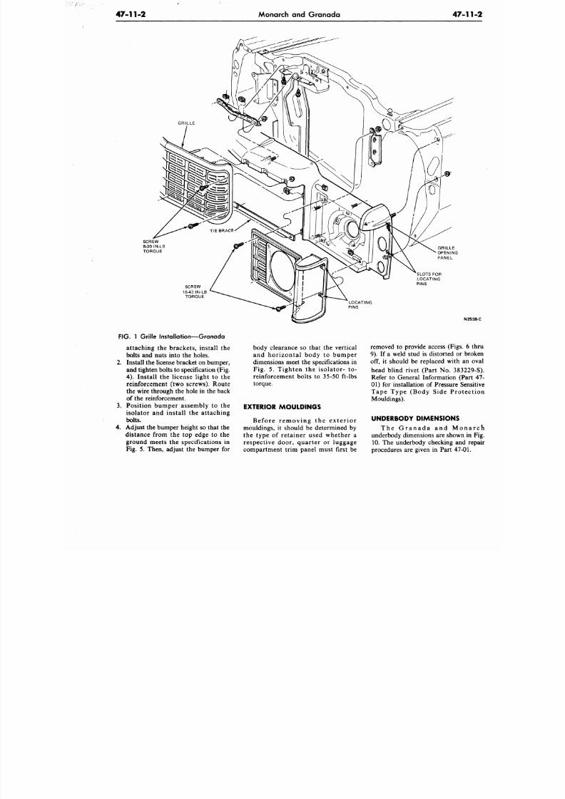
8/20/2019 1977 Ford Car Shop Manual Volume 4 Body
http://slidepdf.com/reader/full/1977-ford-car-shop-manual-volume-4-body 439/449
47-11-2
Monarch and Granada
47-1
SCREW
18-43 IN-LB
TORQUE
SLOTS FOR
LOCATING
PINS
N2
FIG.
1 Grille Installation—Granada
attaching the brackets, install the
bolts and nuts into the holes.
2. Install the license bracket on bumper,
and tighten bolts to specification (Fig.
4) . Install the license light to the
reinforcement (two screws). Route
the wire through the hole in the back
of the reinforcement.
3.
Position bumper assembly to the
isolator and install the attaching
bolts.
4. Adjust the bumper height so that the
distance from the top edge to the
ground meets the specifications in
Fig. 5. Then, adjust the bumper for
body clearance so that the vertical
and horizontal body to bumper
dimensions meet the specifications in
Fig. 5. Tighten the isolator- to-
reinforcement bolts to 35-50 ft-lbs
torque.
EXTERIOR MOULDINGS
Be f or e r e m oving the e x t e r io r
mouldings, it should be determined by
the type of retainer used whether a
respective door, quarter or luggage
compartment trim panel must first be
removed to provide access (Figs. 6
9). If a weld stud is distorted or br
off, it should be replaced with an
head blind rivet (Part No. 38322
Refer to General Information (Par
01) for installation of Pressure Sens
Tape Type (Body Side Protec
Mouldings).
UNDERBODY DIMENSIONS
T h e G r a n a d a a n d M o n a
underbody dimensions are shown in
10. The underbody checking and r
procedures are given in Part 47-01
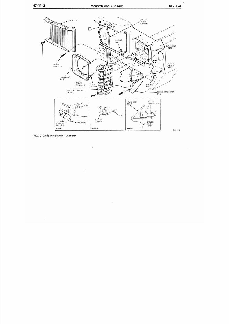
8/20/2019 1977 Ford Car Shop Manual Volume 4 Body
http://slidepdf.com/reader/full/1977-ford-car-shop-manual-volume-4-body 440/449
47 11 3
Monarch and Granada
47-11-3
HEADLAMP
DOOR
PARKING LAMP
GRILLE
MOULDING
VIEW-A
VIEW-B
HEADLAMP
DOOR
STONE DEFLECTOR
END
C L I P -
386450-S100
GRILLE
PANEL
- 8 1 9 0
VIEW-C
N25J9 B
FIG. 2 Grille Installation—Monarch
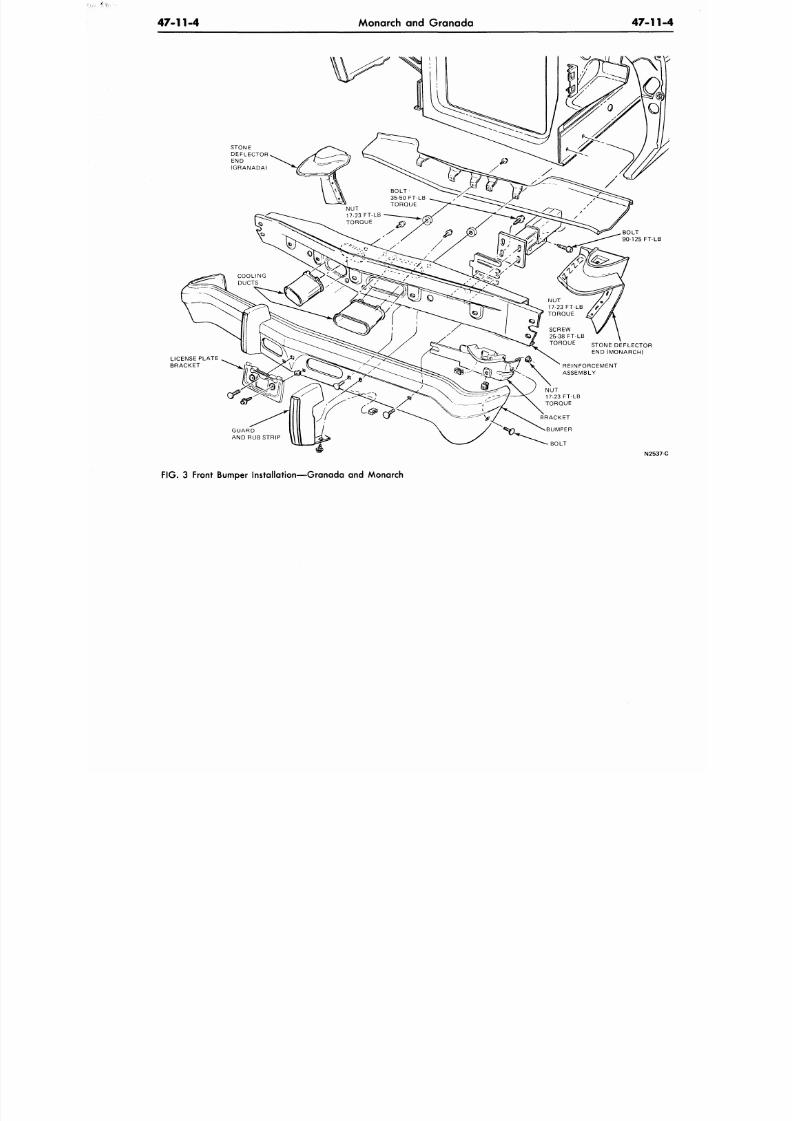
8/20/2019 1977 Ford Car Shop Manual Volume 4 Body
http://slidepdf.com/reader/full/1977-ford-car-shop-manual-volume-4-body 441/449
47-11-4
Monarch and Granada 47 -11
STONE
DEFLECTOR
END
(GRANADA)
SCREW
25-38 FT-LB
TORQUE STONE DEFLECTOR
END (MONARCH)
LICENSE PLATE
BRACKET
GUARD
AND RUB STRIP
N253
F IG . 3 Front Bumper Instal lat ion—Granada and Monarch
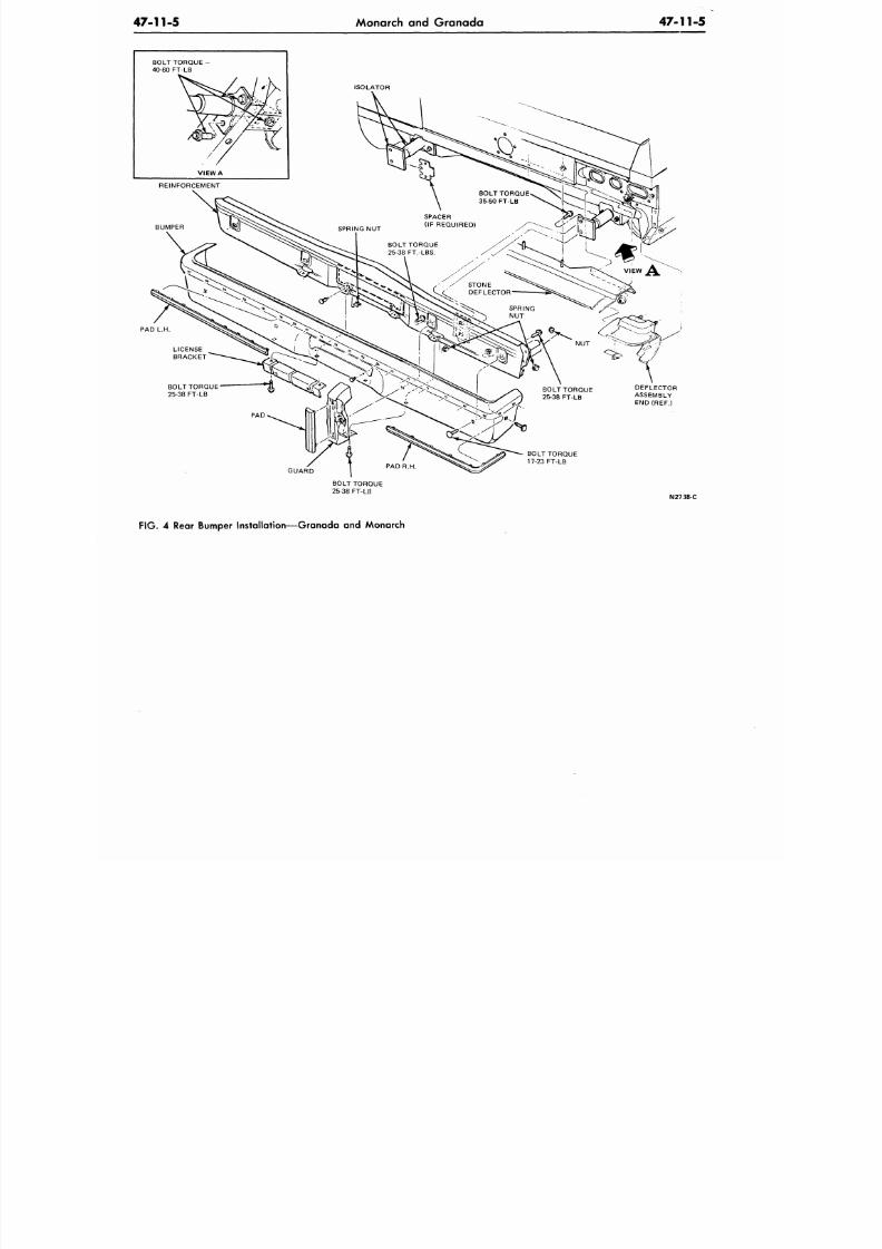
8/20/2019 1977 Ford Car Shop Manual Volume 4 Body
http://slidepdf.com/reader/full/1977-ford-car-shop-manual-volume-4-body 442/449
47 -11-5 Monarch and Granada
47-11-5
B O L T T O R Q U E -
40-60 FT-LB
ISOLATOR
BOLT TORQUE
25-38 FT-LB
DEFLECTOR
ASSEMBLY
END(REF.)
GUARD
BOLT TORQUE
17-23 FT-LB
BOLT TORQUE
25-38 FT-LB
N2738-C
FIG . 4 Rear Bumper Installation—Granada and Monarch
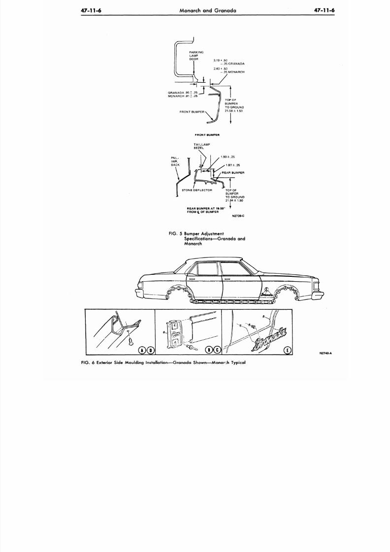
8/20/2019 1977 Ford Car Shop Manual Volume 4 Body
http://slidepdf.com/reader/full/1977-ford-car-shop-manual-volume-4-body 443/449
47-11-6
Monarch and Granada 47 -1
3.19+ .50
- . 2 5 G R A N A D A
2.40 + .50
- .25 MONARCH
GRANADA
MONARCH .91 ± .25
FRONT BUMPER
TOP O F
BUMPER
TO GROUND
21.58 ±1.50
FRONT BUMPER
STONE DEFLECTOR
TOP OF
BUMPER
TO GROUND
21.94
± 1 . 5 0
REAR BUMPER AT 19.00'
FROMQ. OF BUMPER
. \
N2739-C
F IG .
5 Bumper Adjustment
Specif icat ions—Granada and
Monarch
N27
F IG .
6 Exterior Side Moulding Installation—Granada Shown—Monarch Typical
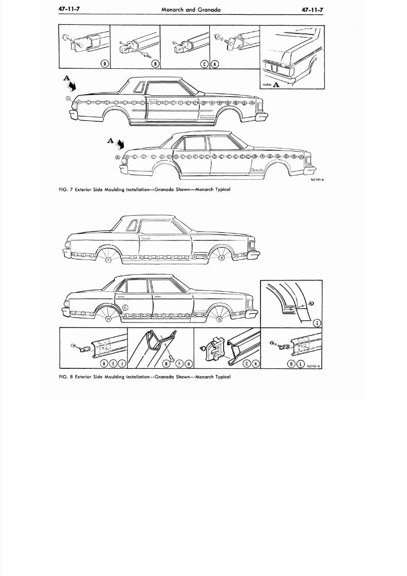
8/20/2019 1977 Ford Car Shop Manual Volume 4 Body
http://slidepdf.com/reader/full/1977-ford-car-shop-manual-volume-4-body 444/449
47-11-7
Monarch and Granada
47-11-7
N2741-A
FIG.
7 Exterior Side Moulding Installation—Granada Shown—Monarch Typical
FIG. 8 Exterior Side Moulding Installation—Granada Shown—Monarch Typical
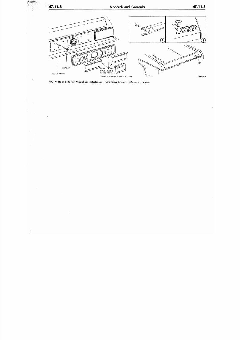
8/20/2019 1977 Ford Car Shop Manual Volume 4 Body
http://slidepdf.com/reader/full/1977-ford-car-shop-manual-volume-4-body 445/449
47-11-8
Monarch and Granada
47-1
NOTE: ONE PIECE ASSY. FOR 1976
N
FIG.
9 Rear Exterior Moulding Instal lat ion—Granada Shown—Monarch Typical
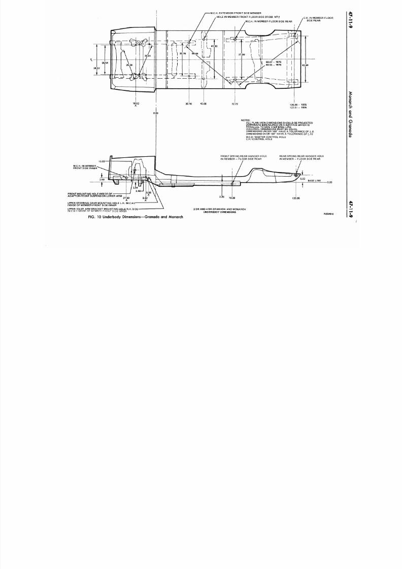
8/20/2019 1977 Ford Car Shop Manual Volume 4 Body
http://slidepdf.com/reader/full/1977-ford-car-shop-manual-volume-4-body 446/449
M.C.H. EXTENSION FRONT SIDE MEMBER
HOLE IN MEMBER FRONT FLOOR SIDE CROSS N2 2
M.C.H. IN MEMBER-FLOOR SIDE REAR
^ S ~ ^ j f S_r- •
,C.H.
IN MEMBER-FLOOR
SIDE REAR
0.00
1 2 6 . 9 0 - 1975
127.51 - 1976
NOTES:
ALL PLAN VIEW DIMENSIONS SHOULD BE PROJECTED
DOWNWARD &MEASURED ON A SURFACE WHICH IS
PARALLEL TO SIDE VIEW BASE LINE
DIAGONAL DIMENSIONS MUST BE EQUAL
DIMENSIONS UNDER 100" HAVE A TOLERANCE OF + 6
DIMENSIONS OVER 100" HAVE A TOLERANCE OF+ .12
MC.H.= MASTER CONTROL HOLE
C.H.= CONTROLHOLE
10.03
FRONT SPRING REAR HANGER HOLE
IN MEMBER - FLOOR SIDE REAR
REAR SPRING REAR HANGER HOLE
IN MEMBER - FLOOR SIDE REAR
M.C.H. IN MEMBER
FRONT SIDE INNER
FRONT MOUNTING HOLE INSIDE OF
ADAPTOR-FRONT SUSPENSION LOWER ARM
UPPER STEERING GEAR MO UNTING HOLE L.H. (M.C.H. )
INSIDE OF MEMBER-FRONT SIDE INNER
123.85
H
-
SIDE
"
2 DR A ND 4 DR GRANADA AND M ONARCH
UNDERBODY DIMENSIONS
FIG. 10 Underbody Dimensions—Granada and Monarch
N2549-C
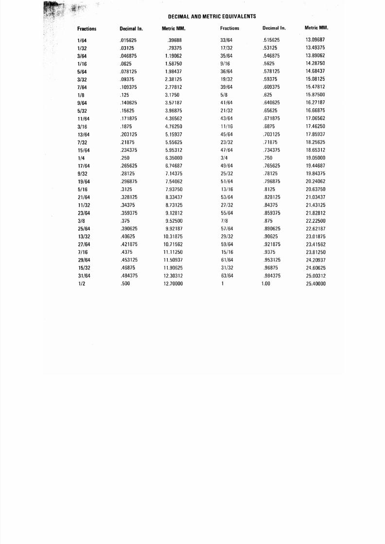
8/20/2019 1977 Ford Car Shop Manual Volume 4 Body
http://slidepdf.com/reader/full/1977-ford-car-shop-manual-volume-4-body 447/449
DECIMAL
AND
METRIC EQUIVALENTS
Fractions
1/64
1/32
3/64
1/16
5/64
3/32
7/64
1/8
9/64
5/32
11/64
3/16
13/64
7/32
15/64
1/4
17/64
9/32
19/64
5/16
21/64
11/32
23/64
3/8
25/64
13/32
27/64
7 /16
29/64
15/32
31 /64
1/2
Decimal In .
.015625
.03125
.046875
.0625
.078125
.09375
.109375
.125
.140625
.15625
.171875
.1875
.203125
.21875
.234375
.250
.265625
.28125
.296875
.3125
.328125
.34375
.359375
.375
.390625
.40625
.421875
.4375
.453125
.46875
.484375
.500
Metric M M .
.39688
.79375
1.19062
1.58750
1.98437
2.38125
2.77812
3.1750
3.57187
3.96875
4.36562
4.76250
5.15937
5.55625
5.95312
6.35000
6.74687
7.14375
7.54062
7.93750
8.33437
8.73125
9.12812
9.52500
9.92187
10.31875
10.71562
11.11250
11.50937
11.90625
12.30312
12.70000
Fractions
33/64
17/32
35/64
9/16
36/64
19/32
39/64
5/8
41/64
21/32
43/64
11/16
45/64
23/32
47/64
3/4
49/64
25/32
51/64
13/16
53/64
27/32
55/64
7/8
57/64
29/32
59/64
15/16
61/64
31/32
63/64
1
Decimal In .
.515625
.53125
.546875
.5625
.578125
.59375
.609375
.625
.640625
.65625
.671875
.6875
.703125
.71875
.734375
.750
.765625
.78125
.796875
.8125
.828125
.84375
.859375
.875
.890625
.90625
.921875
.9375
.953125
.96875
.984375
1.00
Metric M
13.0968
13.4937
13.8906
14.287
14.6843
15.0812
15.4781
15.8750
16.2718
16.6687
17.0656
17.462
17.8593
18.256
18.653
19.050
19.446
19.843
20.240
20.637
21.034
21.431
21.828
22.225
22.621
23.018
23.415
23.812
24.209
24.606
25.003
25.400
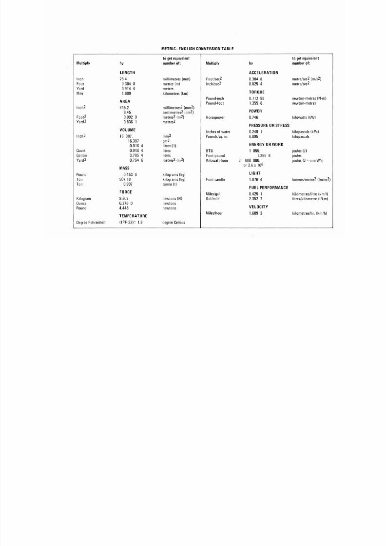
8/20/2019 1977 Ford Car Shop Manual Volume 4 Body
http://slidepdf.com/reader/full/1977-ford-car-shop-manual-volume-4-body 448/449
Multiply
Inch
Foot
Yard
Mile
Inch2
Foot2
Yard2
Inch3
Quart
Gallon
Yard3
Pound
Ton
Ton
Kilogram
Ounce
Pound
Degree Fahrenheit
by
LENGTH
25.4
0.304 8
0.914 4
1.609
A
t r
A
AREA
645.2
6.45
0.092 9
0.836
1
VOLUME
16 387.
16.387
0.016 4
0.946
4
3.785
4
0.764
6
MASS
0.453
6
907.18
0.907
FORCE
9.807
0.278
0
4.448
TEMPERATURE
(t°F-32)t 1.8
METRIC-ENGLISH
to get equivalent
number o f:
millimetres
(mm)
metres
(m )
metres
kilometres (km)
millimetres2 (mm2)
centimetres2 (cm2)
metres2
(m2)
metres2
mm3
CIT)3
litres (1 )
litres
litres
metres3 (m3)
kilograms (kg)
kilograms (kg)
tonne
(t)
newtons(N)
newtons
newtons
degree Celsius
CONVERSION TABLE
Multiply
Foot/sec2
Inch/sec2
Pound-inch
Pound-foot
Horsepower
Inches o f water
Pounds/sq. in.
BTU
Foot-pound
Kilowatt-hour
Foot candle
Miles/gal
Gal/mile
Miles/hour
by
ACCELERATION
0.304 8
0.025 4
TORQUE
0.112 98
1.355 8
POWER
0.746
PRESSURE
OR
STRESS
0.249 1
6.895
ENERGY OR WORK
1 055 .
1.355 8
3 600 000.
or 3.6 x 10⁶
LIGHT
1.076 4
FUEL PERFORMANCE
0.425
1
2.352
7
VELOCITY
1.609 3
to get equivalent
number of:
metre/sec2 (m/s2)
metre/sec2
newton-metres (N
newton-metres
kilowatts (kW)
kilopascals (kPa)
kilopascals
joules (J)
joules
joules (J = one W's
Iumens/metre2 (Im
kilometres/litre (k
litres/kilometre (I
kilometres/hr.
(k
8/20/2019 1977 Ford Car Shop Manual Volume 4 Body
http://slidepdf.com/reader/full/1977-ford-car-shop-manual-volume-4-body 449/449
CO
C
< o
o
Dear Shop Manual User:
The Ford Mo tor Com pany wants yo ur Sho p Manuals to be as useful as possible.
In form at ion that y ou prov ide on th is pre-addressed and prepa id fo rm wi l l be an impo r tant par t
o f our fu ture p lann ing.
Did you f ind any errors or i tems not covered in this manual?
Name of Shop Manual Year
Section and Page
I
& Suggestions fo r imp rov ing manuals.