Embed Size (px)
Citation preview
MYTHS AND FALLACIES IN EARTHQUAKE ENGINEERING - CONFLICTS BETWEEN DESIGN
AND REALITY
M.J. Nige! Priestleyl
This paper wm presented during the year ar the 1993 MZNSEE Travelling Lecture
SUMMARY
Current practice in seismic analysis and design is examined, with particular reference to reinforced concrete structures. The attitude of the paper is deliberately iconoclastic, tilting at targets it is hoped will not be seen as windmills. It is suggested that our current emphasis on strength-based design and ductility leads us in directions that are not always rational. A pure displacement-based design approach is advanced as a viable alternative. Improvements resulting from increased sophistication of analyses are seen to be largely illusory. Energy absorption is shown to be a mixed blessing. Finally, accepted practices for flexural design, shear design, development of reinforcement, and the philosophic basis of capacity design are questioned.
1. INTRODUCTION
It has long been recognized that our codified approaches for seismic design bear a comparatively tenuous relationship to expected performance. Design is based on a static 'snapshot' simulation of the dynamic event, using methods extrapolated from approaches felt to he adequate and conservative for gravity load design. A major difference between gravity load effects and seismic response is that ultimate strength should never be developed under gravity load, while i t is almost certain to be developed under seismic response, typically at a level of excitation which may be a fraction of the design level of seismic attack. Further, although ductile seismic response implies greater dependency on displacements than forces, we still, as a matter of conven~ence and tradition, design for specified force levels, and treat displacements in a comparatively cursory way.
When the design approach is based on carefully considered philosophy, as in the capacity design approach pioneered in New Zealand and gradually becoming accepted in many other seismic regions, excellent results are to be expected because the design structure 1s comparatively insensitive to the various assumptions made.
it appears, however, that the enormous approximations involved in seismic design are perhaps becoming less appreciated, rather than more, as sophisticated analytical techniques become specified by codes and accepted into common design practice, as a matter of routine. In the
United States, and I suspect elsewhere, this has resulted in a tendency for the functions of analysis and design to be separated, and performed by different specialists. The analyst is responsible for modelling the structure and running the lateral force analysis - typically a 3-D modal analysis process. Results from the analysis are presented to the designer who determines member sizes, reinforcement quantities (if reinforced concrete construction) and detailing aspects. The analyst is typically more involved in the analytical process than the correct simulation of member characteristics, with potential dangers. The result of the separation of design and analysis tends to be that analysis drives the design process, rather than the reverse, which might seem to be more appropriate.
There is also room to examine current design and detailing practice, much of which is also extrapolated from gravity load considerations. Occasionally, this process can lead us in directions which are inappropriate for seismic behaviour. Even when tenets of stmctural performance are based on purely dynamic characteristics, such as energy absorption under cyclic response, the directions we are accustomed to taking are not necessarily the best for s u ~ v a l and damage control.
In this paper, some of the accepted seismic design and analysis procedures are identified as 'myths' or 'fallacies' - an . . overstatement perhaps, to make a rather dry topic seem more interesting. Nevertheless, a critical examination of the bases - of our design processes is always appropriate, since the origin of these are often obscure, and lost in the history of design practice, or worse, in code committee minutes. Some of the points to be made are well known, others perhaps less so.
' Professor of Structural Engineering University of California, Sun Diego, U S A . (Fellow)
BULLETIN OF THE N E W ZEALAND NATIONAL SOCIETY FOR EARTHQUAKE ENGINEERING, Vol. 26, No. 3, September 1993
2. THE ELASTIC SPECI'RAL ANALYSIS FALLACY
The fundamental basis of seismic design is still the assumption that an elastic (or modified elastic) acceleration response spectrum provides the best means for establishing required performance of a structure. The limitations of the approach are well known, and accepted because of the design convenience, and because of the lack of a viable design alternative. A case can be made that this is a fallacy, and that viable design alternatives exist, or could be developed with comparative ease.
To summarize the limitations:
(1) Response is based on a 'snapshot' of structural response: that is, response at the moment of peak base shear for an equivalent elastically responding structure. Duration effects, which tend to be period-dependent, with short-period structures suffering a greater number of response cycles than long-period structures are not considered. The merits of using modal combination rules to provide some insight into higher mode effects seems hardly worth while when these will have to be considered by largely empirical rules later in the capacity design process.
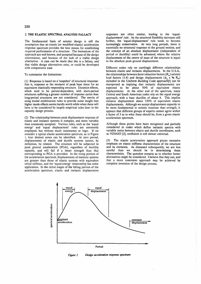
(2) The relationship between peak displacement response of elastic and inelastic systems is complex, and more variable than commonly accepted. Various rules, such as the 'equal energy' and 'equal displacement' rules are commonly employed, but without much consistency or logic. If we consider a typical elastic acceleration spectrum, as in Figure 1, four distinct zones can be identified. At zero period, displacements of elastic and ductile systems cannot, by definition, be related. The structure will be subjected to peak ground acceleration (PGA), regardless of ductility capacity, and will fail if a lesser strength than that - .
corresponding to PGA is provided. In the rising portion of the acceleration spectrum, displacements of inelastic systems are greater than those of elastic systems with equivalent initial stiffness, and the 'equal-energy' relationship has some application. In the initial stages of the falling portion of the acceleration spectrum, elastic and inelastic displacement
responses are often similar, leading to the 'equal- displacement' rule. As the structural flexibility increases still further, the 'equal-displacement' rule tends to become increasingly conservative. At very long periods, there is essentially no structural response to the ground motion, and the concept of an absolute displacement (independent of period or ductility) could be advanced, where the relative displacement of the centre of mass of the structure is equal to the absolute peak ground displacement.
Different codes rely on startlingly different relationships between elastic and inelastic displacements. In the U.S.A, the relationships between force reduction factors (%) seismic load factors (1.4) and design displacements (A x %!a %) included in the Uniform Building Code approach[l] can be interpreted as implying that inelastic displacements are expected to be about 50% of equivalent elastic displacements. At the other end of the spectrum, many Central and South American codes rely on the equal energy approach, with a base ductility of about 4. This implies inelastic displacement about 150% of equivalent elastic displacements. Although we accept displacement capacity to be more fundamental to seismic response than strength, it appears that different groups of experts cannot agree within a factor of 3 as to what these should be, from a given elastic acceleration spectrum.
Although these points have been recognized and partially considered in codes which define inelastic spectra with variable ratios between elastic and ductile coordinates, such as NZS4203 [Z], confusion is still almost universal.
(3) The elastic acceleration approach places excessive emphasis on elastic stiffness characteristics of the structure and its elements. As discussed subsequently, we are less careful than we should be in detennining these characteristics. The question remains as to whether better alternatives might be considered. I believe that they can, and that a more consistent approach may be achieved by complete inversion of the design process.
C
Period
Figure I Dengn accelemtion V m specbwn
It should be noted that although many researchers have discussed displacement-based design, the processes described are in fact still strength-based. Moehle [3], for example, discusses the relative merits of ductility-based and displacement-based design, but in his comparison, the starting point is stiil a given strength and stiffness (and hence period) with the difference being whether displacements or ductilities are checked. As acknowledged by Moehle, when properly carried out, the two approaches are directly equivalent. In the approach described below, strength and stiffness are the end product of the design process, rather than the starting point.
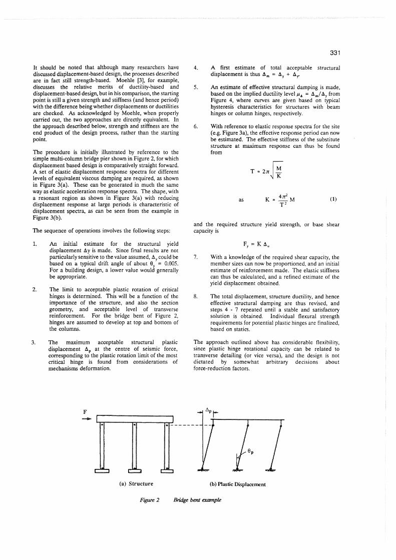
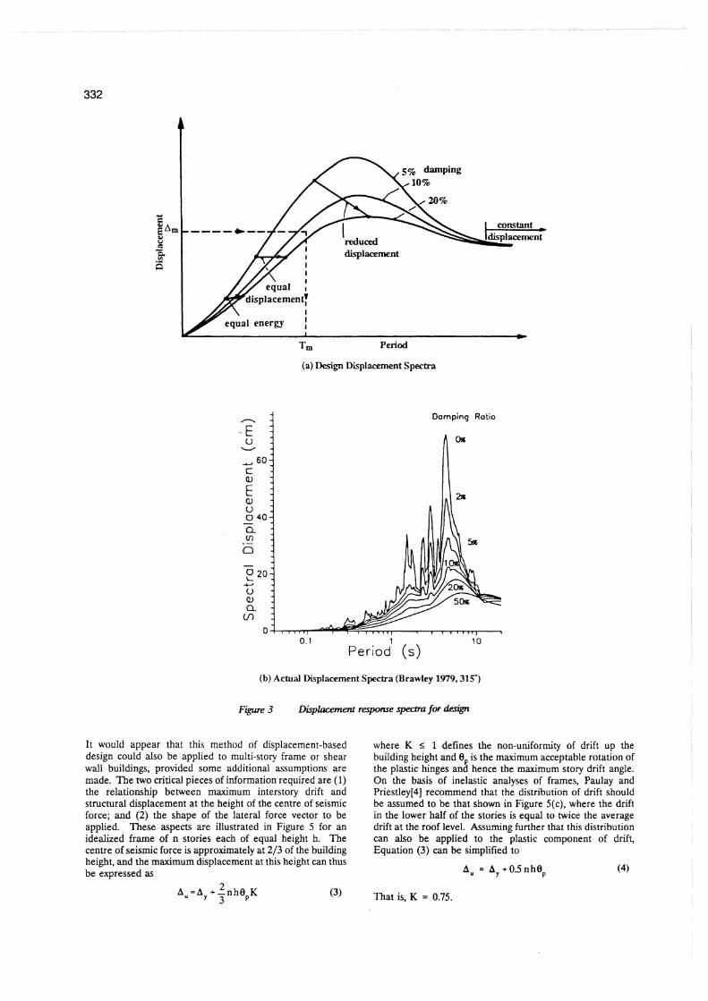
The procedure is initially illustrated by reference to the simple multi-column bridge pier shown in Figure 2, for which displacement based design is comparatively straight forward. A set of elastic displacement response spectra for different levels of equivalent viscous damping are required, as shown in Figure 3(a). These can be generated in much the same way as elastic acceleration response spectra. The shape, with a resonant region as shown in Figure 3ja) with reducing displacement response at large periods is characteristic of displacement spectra, as can be seen from the example in Figure 3(b).
The sequence of operations involves the following steps:
I. An initial estimate for the structural yleld displacement Ay is made. Since final results are not particularly sensitive to the value assumed, A, could be based on a typical drift angle of about 8, = 0.005. For a building design, a lower value would generally be appropriate.
2. The limit to acceptable plastic rotation of critical hinges is determined. This will be a function of the importance of the structure, and also the section geometry, and acceptable level of transverse reinforcement. For the bridge bent of Figure 2, hinges are assumed to develop at top and bottom of the columns.
3. The maximum acceptable structural plastic displacement A, at the centre of seismic force, corresponding to the plastic rotation limit of the most critical hinge is found from considerations of mechanisms deformation.
4. A first estimate of total acceptable structural displacement is thus A, = A, + A,
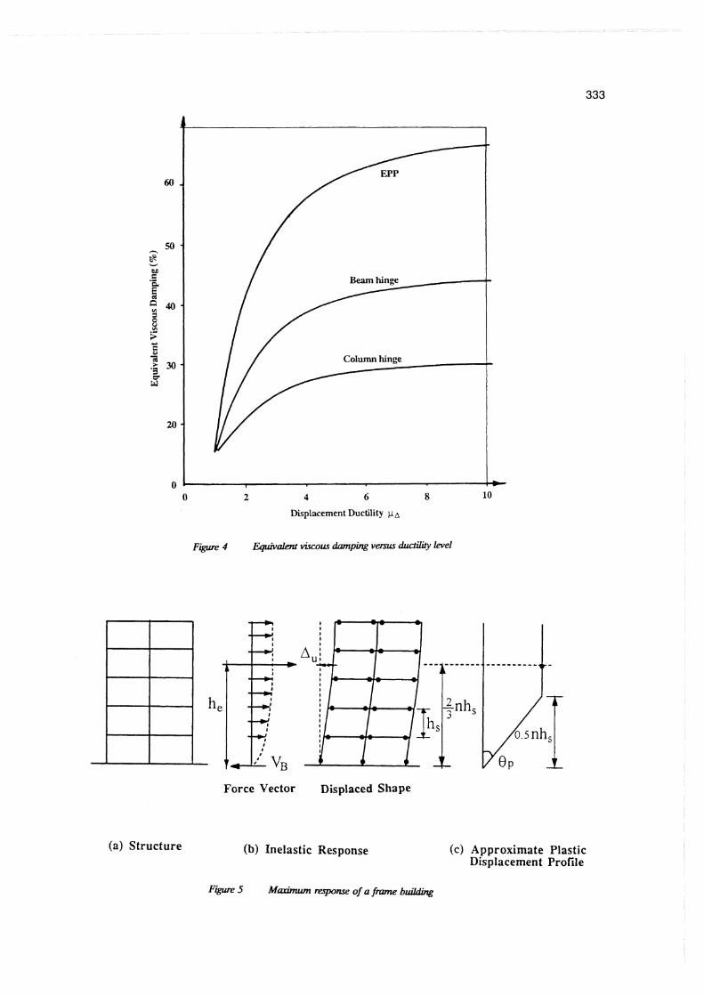
5. An estimate of effective structural damping is made, based on the implied ductility level p, = A,/A, from Figure 4, where curves are given based on typical hysteresis characteristics for structures with beam hinges or column hinges, respectively.
6. With reference to elastic response spectra for the site (e.g. Figure 3a), the effective response period can now be estimated. The effective stiffness of the substitute structure at maximum response can thus be found from
and the required structure yield strength, or base shear capacity is
7. With a knowledge of the required shear capacity, the member sizes can now be proportioned, and an initial estimate of reinforcement made. The elastic stiffness can thus be calculated, and a refined estimate of the yield displacement obtained.
8. The total displacement, structure ductility, and hence effective structural damping are thus revised, and steps 4 - 7 repeated until a stable and satisfactory solution is obtained. Individual flexural strength requirements for potential plastic hinges are finalized, based on statics.
The approach outlined above has considerable flexibility, since plastic hinge rotational capacity can be related to transverse detailing (or vice versa), and the design is not dictated by somewhat arbitrary decisions about force-reduction factors.
(a) Structure (b) mastic Displacement
Figwe2 Bdgebent
Trn Period
(a) Design Displacement Spectra
Damping Ratio
0.1 1 10 Period ( s )
(b) Actual Displacement Spectra (Brawley 1979,315')
Figure 3 LXsplaumenf response spedm for design
It would appear that this method of displacement-based design could also be applied to multi-story frame or shear wall buildings, provided some additional assumptionz are made. The two critical pieces of information required are (1) the relationship between maximum interstory drift and structural displacement at the height of the centre of seismic force; and (2) the shape of the lateral force vector to be applied. These aspects are illustrated in Figure 5 for an idealized frame of n stories each of equal height h. The centre of seismic force is approximately at 213 of the building height, and the maximum displacement at this height can thus be expressed as
where K < 1 defines the non-uniformity of drift up the building height and 8, is the maximum acceptable rotation of the plastic hinges and hence the maximum story drift angle. On the basis of inelastic analyses of frames, Paulay and Priestley[4] recommend that the distribution of drift should be assumed to be that shown in Figure 5(c), where the drift in the lower half of the stories is equal to twice the average drift at the roof level. Assuming further that this distribution can also be applied to the plastic component of drift, Equation (3) can be simplified to
(3) That is, K = 0.75.
Displacement Ductility pa
Force Vector Displaced Shape
(a) Structure (b) Inelastic Response
Figure5 M m i m u m ~ l ~ ~ e o f a f i m n e b u i k l i n g
( c ) Approximate Plastic Displacement Profile
It is suggested that improved estimates of plastic drift would be obtained by elastic analysis of a substitute structure[S], where stiffness of members containing hinges is reduced in proportion to their expected ductility. Hence, if beam hinges are expected to have rotational ductilities of p, = 7 (which might correspond to a structure displacement ductility of p, = 4) then the appropriate stiffness for the beams in the elastic analysis would be Q = fL/p = 0.14 fL. The adequacy of the design can thus be checked by a lateral elastic analysis of the substitute structure.
If the inelastic displaced shape can be approximated by Figure 5(c), it follows that the vector of lateral inertial forces to be applied to the structure should also take the same shape.
The displacement-based design approach outlined above appears attractive in principle, but will need to be checked by specific examples covering a wide range of structural types and periods.
3. THE REFINED ANALYSIS MYTH
In the Introduction to this paper, it was noted that structural analyses for design purposes have become more sophisticated in recent years, with the consequences that the analysis and design functions are frequently separated and camed out by different people. The reason for the increased sophistication in the analysis is principally related to the availability of powerful computers rather than a perceived inadequacy of earlier, and simpler analysis techniques.
Although 3-D modal analysis is undoubtedly useful in structures with unusual or irregular geometry, it is doubtful if it produces better results than those obtained from simpler methods say simple lateral analysis based on an assumed lateral force distribution. The myth here, then, is that refinement of the analysis produces more 'accurate' results. It is appropriate to consider the refinement of the analytical process in light of the approximations still remaining.
Elastic modal analysis essentially relies on the equal-displacement approximation, since it is not feasible to use different force-reduction factors associated with different modes of elastic response. As noted above with reference to Figure 1, this is appropriate for a comparatively narrow band of periods.
Deflection profiles from elastic modal analyses tend to underestimate drift levels in the lower stories of a building. As noted earlier, it is felt that agreement could be improved by use of a substitute structure approach.
Elastic analyses are generally based on approximations of meniber stiffness that should be considered gross, even in the elastic range. As an example of this, let us consider that the columns of the lowest story of the frame shown in Figure S(a) are reinforced concrete 600 x 600 columns, reinforced with 8 - D28 bars of yield strength 455 MPa. Concrete strength is c = 31 Mpa It will be normal in the analysis to assume that all three columns at the lowest level have the same stiffness, though it is possible the central column might be allocated slightly higher stiffness because of increased axial load. It would seem to be impossible to allocate different stiffnesses to the two outer columns when multi-modal response is considered.
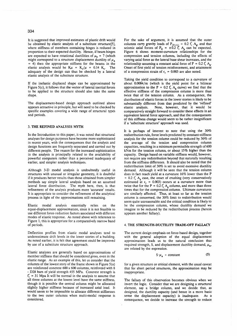
For the sake of argument, it is assumed that the outer columns cany gravity loads of P(,+, - 0.2 fl A, and that seismic axial forces of PE = 50.2 I. A, can be expected. Figure 6 shows moment-curvature relationships for the compression and tension columns, including the effects of varying axial force as the lateral base shear increases, and the relationship assuming a constant axial force of F = 0.2 f: $. Onset of first yield of tension reinforcement, and attainment of a compression strain of E, = 0.003 are also noted.
Taking the yield condition to correspond to a curvature of about 0.0084/m (which is the yield point for a bilinear approximation to the P = 0.2 f: $ curve) we find that the effective stiffness of the compression column is more than twice that of the tension column. As a consequence, the distribution of elastic forces in the lower stories is likely to be substantially different born that predicted by the 'refined' elastic analysis. Note, however, that it would be comparatively straight forward to consider these effects in an equivalent lateral force approach, and that the consequences of this stiffness change would seem to be rather insignificant if a 'substitute structure' approach was used.
It is perhaps of interest to note that using the 30% redistribution rule, force levels predicted by constant-stiflness analysis for the tension column could be reduced by 30% of the average of the tension and compression column capacities, resulting in a minimum permissible strength of 600 kNm for the tension column, or about 15% higher than the capacity. Design based on variable stiffness would, however, not require any redistribution beyond that naturally resulting from the stiffness difference. It should also be noted that the redistribution limit of 30% is set to avoid excessive ductility demand. Although it will be seen that the tension column does in fact reach yield at a curvature 16% lower than the P = 0.2 c A, case, the onset of crushing (very conservatively estimated at F, = 0.003) occurs at a curvature more than twice that for the P = 0.2 f', $ column, and more than three times that for the compression column. Ultimate curvatures are similarly affected. Thus, at least so far as the tension column is concerned, the 30% limit to redistribution would seem quite unreasonable and the critical condition is likely to be the compression column, whose ductility demand we imagine to be reduced by the redistribution process (herein appears another fallacy).
4. THE STRENGTH-DUCTILITY TRADEOFF FALLACY
The current design emphasis on force-based design, together with the general adoption of the equal displacement approximation leads us to the natural conclusion that required strength, S, and displacement ductility demand, p,, are related by the expression.
S.p, = constant ( 5 )
for a given structure or critical element, with the usual caveat that for short period structures, the approximation may be inappropriate.
The fallacy of this observation becomes obvious when we invert the logic. Consider that we are designing a structural element, say a bridge column, and we decide that, as designed, the ductility capacity (and hence in a more basic sense the displacement capacity) is inadequate. As a consequence, we decide to increase the strength to reduce
lux) - - P = 0 2 f ', A, -) 0.4 f ' c A8 (variable)
0 first yield of tension rebar
8 = 0.003
-a
Curvature (radlm)
Figure 6 Z n j k n c e of mial force on moment-auvatwe md&oNhip fw rarrmgulm wlwnn
the ductility capacity. We do this by increasing the longitudinal steel ratio, and keeping the section size constant. Have we really improved anything? Probably not - the equal-displacement approximation still says we require the same ultimate displacement capacity, even though the ductility demand has apparently reduced, and it is certainly not clear that increasing the longitudinal reinforcement ratio has increased the ultimate displacement.
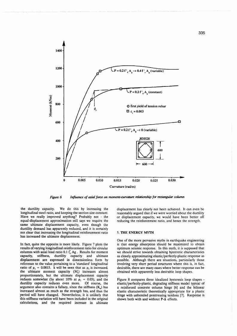
In fact, quite the opposite is more likely. Figure 7 plots the, results of varying longitudinal reinforcement ratio for circular columns with axial load ratio 0.1 f', Ag . Results for moment capacity, stiffness, ductility capacity and ultimate displacement are expressed in dimensionless form by reference to the value pertaining to a 'standard' longitudinal ratio of p, = 0.0015. k will be seen that as p, is increased, the ultimate moment capacity (M,) increases almost proportionately, but the ultimate displacement capacity reduces somewhat (by about 10% at p, = 0.03), and the ductility capacity reduces even more. Of course, the argument also contains a fallacy, since the stiffness (&) has increased almost as much as the strength has, and thus the period will have changed. Nevertheless, it is unlikely that this stiffness variation will have been included in the original calculations, and the required increase in ultimate
displacement has clearly not been achieved. It can even be reasonably argued that if we were worried about the ductility or displacement capacity, we would have been better off reducing the reinforcement ratio, and hence the strength.
5. THE ENERGY MYTH
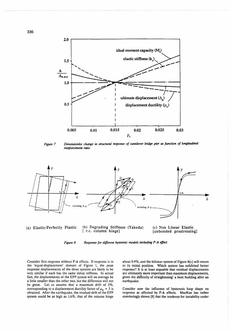
One of the more pervasive myths in earthquake engineering is that energy absorption should be maximized to obtain optimum seismic response. In this myth, it is supposed that we should strive towards obtaining hysteretic characteristics as closely approximating elastic/perfectly-plastic response as possible. Although there are situations, particularly those involving very short period structures where this is, in fact, desirable, there are many cases where better response can be obtained with apparently less desirable loop shapes.
Figure 8 compares three idealized hysteresis loop shapes - elastic/perfectly-plastic, degrading stiffness model typical of a reinforced concrete column hinge [6] and the bilinear elastic characteristic theoretically appropriate for a plastic hinge with unbonded prestressing tendons [7]. Response is shown both with and without P-A effects.
ideal moment capacity (MJ
, ultimate displacement (A
I displacement ductility (pA
Figrue 7 Lhwmionles dumge in stnutuml mpome of amtileva bridge pier as fwrdion of longi td id rmfofTmeLtratio
(a) Elastic-Perfectly Plastic (b) Degrading Stiffness (Takeda) (c) Non Linear Elastic [ r.c. column hinge] [unbonded prestressing]
Figure 8 Raponre for different hyst& mod& irrduding P-A fled
Consider first response without P-A effects. If response is in the 'equal-displacement' domain of Figure 1, the peak response displacements of the three systems are likely to be very similar if each has the same initial stiffness. In actual fact, the displacements of the EPP system will on average be a little smaller than the other two, but the difference will not be great. Let us assume that a maximum drift of 2%, corresponding to a displacement ductility factor of ,u, = 5 is obtained. After the earthquake, the residual drift of the EPP system could be as high as 1.6%, that of the column hinge
about 0.9%, and the bilinear system of Figure 8(c) wiU return to its initial position. Which system has exhibited better response? It is at least arguable that residual displacements are ultimately more important than maximum displacements, given the difficulty of straightening' a bent building after an earthquake.
Consider now the influence of hysteresis loop shape on response as affected by P-A effects. MacRae has rather convincingly shown [8] that the tendency for instability under
P-A is strongly related to the shape of the loop. In Figure 8, the influence of P-A moments on the inelastic response shape is shown by dashed lines. With the EPP loop of Figure 8(a), response at a given instant of the seismic response has resulted in a residual deformation corresponding to point B. The structure will oscillate with the elastic s t ihes s about this point until response acceleration sufficient to develop the yield strength develop. As will be seen in Figure 8(a), the acceleration required to make the system reach the upper yield line is much less than that for the lower yield line. It is thus probable that plasticity,will develop in the direction of increasing, rather than reducing residual displacement. With a long duration and an EPP loop shape, the system is inherently unstable under P-A effects.
With the degrading stiffness model of Figure 8(b), and a residual deformation corresponding to point B, the lower yield line is closer to the zero acceleration line, and is thus more likely to be attained than the upper yield line. The system is thus inherently stable, since the probabilities of inelastic deformation favour decreased residual set. MacRae [8] has demonstrated the validity of this argument with avery large number of dynamic inelastic time-history analyses.
Since the system in Figure 8(c) is elastic non-linear, there are no residual displacements to be considered, and the system is stable for P-A effects.
It should also be noted that for longer period structures, where P-A effects are likely to be significant, the equal displacement rule would indicate that P-A effects are unlikely to significantly increase the maximum displacement of the stable systems significantly. This is also supported by time-history analyses. For the EPP system, which as noted is inherently unstable, neither the equal displacement nor equal energy rules can be applied, since the increase in maximum and residual displacement is strongly influenced by the duration of the earthquake record.
One should not, of course, dismiss the value of hysteretic energy absorption. However, it is clear that current emphasis on the loop shape is overstated. Steel structures, with deformation characteristics approximating EPP loops, have a greater tendency for undesirable deformation response than the equivalent reinforced concrete structures.
6. T H E D I S T R I B U T I O N O F F L E X U R A L REINFORCEMENT FALLACY
The discussions above have largely related to analysis issues. However, it is clear that many aspects of design and detailing could also bear critical review. The remainder of this paper will examine a few issues specifically related to reinforced concrete design, though more could be identified, both with reinforced concrete, and with over materials.
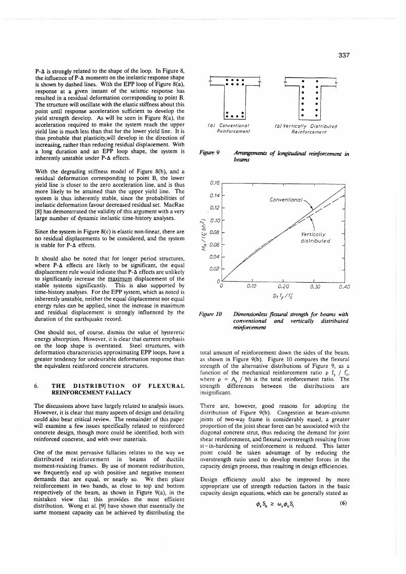
One of the most pervasive fallacies relates to the way we distributed reinforcement in beams of ductile moment-resisting frames. By use of moment redistribution, we frequently end up with positive and negative moment demands that are equal, or nearly so. We then place reinforcement in two bands, as close to top and bottom respectively of the beam, as shown in Figure 9(a), in the mistaken view that this provides the most efficient distribution. Wong et al. [9] have shown that essentially the same moment capacity can be achieved by distributing the
( 0 ) Conventional f b i Ver t ica l ly D~sr r i 'bu ted Reinforcement Reinforcement
Figwe 10 D i m e m i o h fleaLml strength for b m with conventional and vertically distributed reinforcement
total amount of reinforcement down the sides of the beam, as shown in Figure 9(b). Figure 10 compares the flexural strength of the alternative distributions of Figure 9, as a function of the mechanical reinforcement ratio p f, / f',, where p = 4 / bh is the total reinforcement ratio. The strength differences between the distributions are insignificant.
There are, however, good reasons for adopting the distribution of Figure 9(b). Congestion at beam-column joints of two-way frame is considerably eased, a greater proportion of the joint shear force can be associated with the diagonal concrete strut, thus reducing the demand for joint shear reinforcement, and flexural overstrength resulting from st-in-hardening of reinforcement is reduced. This latter point could be taken advantage of by reducing the overstrength ratio used to develop member forces in the capacity design process, thus resulting in design efficiencies.
Design efficiency could also be improved by more appropriate use of strength reduction factors in the basic capacity design equations, which can be generally stated as
where S, is the nominal strength of a particular action (flexure, shear, etc.), S, is the strength required for that action resulting from the basic analysis assumptions, @, is a strength reduction factor applied to S , to provide a dependable strength, 9, and @, are dynamic amplification factors and overstrength factors, which again relate to the analysis assumptions, design efficiency and action considered.
Currently in seismic design, we associate a strength reduction factor to the basic flexural strength of plastic hinges, but not to members or actions protected by capacity design principles, on the basis of perceived conservatism in the values of cs, and @, currently specified.
It would appear that the logic may have thus been inverted. It is clear that we do not need a flexural strength reduction factor for plastic hinges, since small variations in strength bom the specified value will only result in small variations in ductility demand. As noted in relation to Figure 7, increasing the reinforcement content, which is the end result of application of a flexural strength reduction factor, may not improve overall safety.
However, if we wish to totally proscribe non-ductile inelastic deformation (e.g. shear) we need a high degree of assurity that the dependable strength of that mode cannot be exceeded. If we believe strength reduction factors need to be associated with that action (e.g. shear) as a result of possible nonconservatism of design equations, or possible material understrength, then they should be utilized in the capacity design process. If the product us@, is felt to be such that no strength reduction factor is needed, this implies that us@, is too high, and should be reduced.
This may seem to be a matter of semantics, since the end result would probably be little pifferent in current design practice. However, if design is to be permitted in accordance with more advanced analytical processes (e.g. time-history analysis to determine expected dynamic influences once strength of plastic hinges has been determined) then vaiues for o, and @, might become determined by the results of the analysis process. In this case, it would be better to have the variability of design strength properly associated with the correct parameters.
Of course, the process could be greatly simplified if we did away with strength reduction factors completely, as is the case in Japanese design. The value of 9 would thus be inherent in the equations for strength. It is hard to see that we would lose much in the process.
Shear design of reinforced concrete is so full of myths, fallacies and contradictions that it is hard to know where to begin in an examination of current design. Perhaps the basic myth, and that central to our inconsistencies in shear design is that of shear itself. It has been argued that we tie ourselves into intellectual knots by separating flexure and shear, and considering them essentially independent entities. Compression field theory as developed by Collins et al. [lo] is an attempt to integrate the actions. Similar attempts have been made elsewhere [ I l l The fact remains, however, that it is very convenient to separate the flexural and shear actions, and also that the more fundamental approaches are not only inconvenient from a design viewpoint, but also do not
produce notably better agreement with experimental results, particularly when shear strength of ductile linear members characteristic of framed structures is considered.
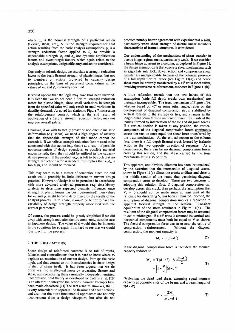
Our understanding of the mechanisms of shear transfer in plastic hinge regions seems particularly weak. If we consider a beam hinge adjacent to a column, as depicted in Figure 11, the design assumption is that concrete shear mechanisms such as aggregate interlock, dowel action and compression shear transfer are undependable, because of the potential presence of a full depth flexural crack (see Figure ll(a)) and hence shear must be entirely transferred by a 45" truss mechanism, involving transverse reinforcement, as shown in Figure ll(b).
A little reflection reveals that the two halves of this assumption (wide full depth crack; truss mechanism) are mutually incompatible. The truss mechanism of Figure Ll(b), whether based on 45" or some other angle, relies on the development of diagonal compression struts, stabilized by vertical tension in the stirrups or ties, and changes in the longitudinal beam tension and compression resultants at the 'nodes' formed by intersection of the tie and diagonal forces. If a vertical section is taken at any position, the vertical component of the diagonal compression forces continuous across the seaism must equal the shear force transferred by the truss mechanism. At the critical section at the column face, there is a full depth flexural crack formed by inelastic action in the two opposite direction of response. As a consequence, there can be no diagonal compression forces crossing this section, and the shear canied by the truss mechanism must also be zero.
This apparent, and obvious, dilemma has been 'rationalized' by the assertion that the intersection of diagonal cracks, shown in Figure l l (a) allows the cracks to dilate and close in the middle section of the beam, thus permitting diagonal compression struts to develop. There are two concerns to adopting this solution: first, if diagonal compression can develop across this crack, then perhaps the assumption that V, = 0 should not be made since at least part of the rationale for discarding V, has been eliminated. Second, the assumption of diagonal compression implies a reduction to apparent flexural strength of the section. Consider equilibrium of the stress resultants in Figure ll(b). The resultant of the diagonal compression forces may be assumed to act at midheight. Lf a 45" truss is assumed its vertical and horizontal components must both be equal to V as shown. The flexural compression force acts at or near the centre of compression reinforcement. Without the diagonal compression, the moment capacity is
If the diagonal compression force is included, the moment capacity reduces to
Neglecting the dead load shear, assuming equal moment capacity at opposite ends of the beam, and a beam length of ~ ( d - d')
and hence
(a) Conditions at high ductility
(b) The 45' truss mechanism
Figure 11 Shem mmrfer in beam plartic huga
In a deep beam with (say) x = 4, this implies a 20% reduction in moment capacity, which is not supported by experimental results. Even with more slender beams (say x = 10) the moment reduction should be evident. Note that when dead-load shear is added, negative moment capacity should be further eroded, if the truss mechanism were correct.
Since this behaviour is not apparent in experimental results, it would appear that alternative mechanisms must be relied upon. If a full depth crack can develop, it is difficult to escape the conclusion that all shear must be carried by dowel action. If this is the case, the primary shear transfer function of transverse reinforcement in the plastic hinge region must be to reduce the unsupported length over which dowel action of the longitudinal reinforcement occurs, hence increasing the
shear that can be transferred. Rational models for the amount of shear reinforcement required can be developed, which are very different from those resulting from the truss model. Critical aspects include diameter of longitudinal reinforcement (the bigger the better), and location of the first stirrup from the column face - which should be as small as possible.
As mentioned, there are many other inconsistencies in shear design. A particularly troublesome one is the way in which we treat the enhancement of shear strength by axial compression. Our codes indicate that the degree of enhancement depends on whether the structural element is a beam or a wall, and whether the axial compression comes from applied gravity forces, or from prestress. Differences in influence of more than 100% are possible. Since the differences appear to result from semantic definitions, a degree of scepticism is appropriate.
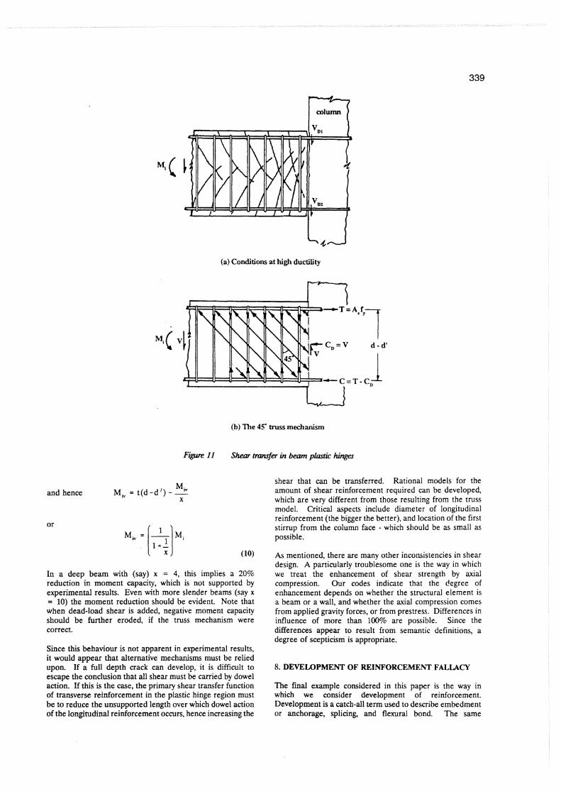
8. DEVELOPMENT OF REINFORCEMENT FALLACY
?he final example considered in this paper is the way in which we consider development of reinforcement. Development is a catch-all term used to describe embedment or anchorage, splicing, and flexural bond. The same
(a) Column Base Lap Splice (b) Knee Joint
(c) Column Top (d) Column Mid-Height Lap Splice
Figure 12 Anchomge and spkcing of reinforcement
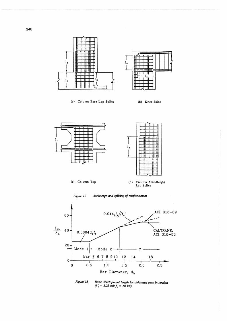
CALTRANS, ACI 318-83
2q Mode 1 1 Mode 2 ?
Bar Diameter, d b
Figure 13 Basic development Iengh for deformed bars in t&n Cf: =3 .Ukn ; f y = 60kri)
equations, with modifiers in some cases, are used to describe the three simations. Although this is convenient for design, it is unlikely to be realistic in practice, considering the wide number of possible situations occurring, as illustrated for a bridge column in Figure 12. A number of rather different conditions exist depending on location, whether or not confinement is present, and whether or not the splitting cracks assumed in the basic development length equation can actually develop.
The fundamental basis of the basic development length equation can also be questioned. In the ACI code, this length is given by
where & is in mm2 and S, and f; are in Mpa. Modifiers are included to represent the influence of cover, bal spacing, location in the concrete pour, confinement etc. Figure 13 shows the ratio of basic development length to bar diameter for U.S. bar sizes, for $. = 414 MPa and = 22.5 MPa. In Figure 13, the equation definitions are in American Standard units. It will be seen that the basic development length increases in terms of number of bar diameters as the diameter increases. In fact, considering the range of bar sizes used in the USA (#3 = lOmm to $18 = 56 mrn dia.) Equation (11) implies the dimensionless development length increases by a factor of six, or the W development length increases by a factor of 36. Tests on scale models do not support a scale dependency of this nature.
T o some extent, of course, the modification factors applied to t',, reduce the apparent scale dependency, but it would appear from Figure 13, that the fundamental basis of our dk~elopment caimlations may be flawed. Returning to more fundamental approaches results in eauations that are more intellectually sa;isfying [12] and fit t h i data better.
9. CONCLUSIONS
In this paper, a somewhat irreverent examination of aspects of seismic analysis and design has been presented. In order to establish inconsistencies and inaccuracies commonly accepted by the design profession, a number of the examples have been deliberately overstated. A critical review of thls paper will show that some of the arguments are at best simplistic, if not flawed.
It should be emphasized that i t is not contended that current seismic design practice, particularly the version adopted in New Zealand is unsafe. If this paper has a message or conclusion, it is simply the following cautionary note related to the tendency for increased complexity in analysis: given the wide range, and occasional gross nature of the assumptions and approximations inherent in seismic design, we might be better keeping the design and analysis processes simple enough so that we still understand what we are doing.
10. REFERENCES
I . Uniform Building Ccde, International Conference of Building Officials, Whittier, California, 1988, 926 p.
2. Code of Practice for General Structural Design and Design hadings for Buildings, NZS 4203: 1984, New Zealand Standard, Standards Association of New Zealand.
3. Moehle, J.P., "Displacement-Based Design of RC Structures Subjected to Earthquakes," Earthquake Spectra, Vol 8, No.3, August 1992, pp. 403-428.
4. Paulay, T. and MJ.N. Priestley, Seismic Design of Concrete and Masonry Structures, John Wiley and Sons, New York, NY, 1992, 744 pp.
5. Shibata, A and M.A Sozen, "Substitute-Structure Method for Seismic Design in Reinforced Concrete." J o d of the Structural Division, ASCE, Vol. 102, No. ST1, pp. 1-18,1976.
6. Takeda, T., M.A. Sozen and N.N. Nielsen, "Reinforced Concrete Response to Simulated Earthquakes," Journal of the Structural Divisio4 ASCE, Vol. 96, No. ST12, December 1970,PP.2557-2573.
7. Priestley, M J . Nigel and Jian Ren Tao, "Seismic Response of Precast Prestressed Concrete Frames with Partially Debonded Tendons." PCI Journal, Vol. 38, No. 1, January/February 1993, pp. 58-69,
8. MacRae, G.A., M J . Nigel Priestley and Jian Tao, "P-A Design in Seismic Regions," University of California, San Diego, Structural System Research Project, Repori No. SSRP 93105, May 1993, 115 pp.
9. Wong, P.KC., MJ.N. Priestley and R. Park, "Seismic Resistance of Frames with Vertically Distributed Longitudinal Reinforcement in Beams," ACI Srmctural J o m d , Vol. 87, No.4, July-August 1990, pp. 4881198.
10. Collins, M.P. and F J . Vecchio, "Predicting the Response of Reinforced Concrete Beams Subjected to Shear using the Modified Diagonal Compression Field Theory," ACI Structural Jomal, Vo1.85, May-June 1988.
11. Hsu, T.T.C., "Softened Truss Model Theory for Shear and Torsion," ACI Structural Journal, Title No. 85-S56, Nov.-Dec. 1988, pp. 624-635.
12. Priestley, MJ.N., "Seismic Assessment of Existing Concrete Bridges," in Seismic Assessment and Retrofit of Bridges, University of California, San Diego, Structural Systems Research Project, Report No. SSRP 91/03, July 1991, 84-149.
A second, and more serious (perhaps!) point brought out at the start of this paper related to displacement-based design: if we accept that displacements are more important than forces, it is time we started basing our designs on displacement, rather than acceleration spectra.