Embed Size (px)
Citation preview
92750300
1997-2003 Ford F150 2WD 3” Suspension Kit
Thank you for choosing Rough Country for your suspension needs. Rough Country recommends a certified technician install this system. In addition to these instructions, professional knowledge of disassemble/reassembly procedures as well as post installation checks must be known. Attempts to install this system without this knowledge and expertise may jeopardize the integrity and/or operating safety of the vehicle.
Please read instructions before beginning installation. Check the kit hardware against the kit contents list. Be sure you have all needed parts and know where they go, separating parts according to where they go and placing hardware with the brackets before you begin with save on installation time. If you are missing any components, are unsure where they go, or have a question about the installation please call Rough Country at 800-222-7023.
PRODUCT USE INFORMATION
As a general rule, the taller a vehicle is, the easier it will roll. Offset, as much as possible, what is lost in rollover resis-tance by increasing tire track width. In other words, go "wide" as you go "tall". Many sportsmen remove their mud tires after hunting season and install ones more appropriate for street driving; always use as wide a tire and wheel combina-tion as possible to enhance vehicle stability.
Braking performance and capability are decreased when significantly larger/heavier tires and wheels are used. Take this into consideration while driving.
Do not add, alter, or fabricate any factory or after-market parts which increase vehicle height over the intended height of the Rough Country product purchased. Missing component brands, lifts, and/or combining body lift with suspension lifts voids all warranties. Rough Country makes no claims regarding lifting devices and excludes any and all implied claims. We will not be responsible for any product that is altered.
NOTICE TO DEALER AND VEHICLE OWNER
Any vehicle equipped with any Rough Country product should have a “Warning to Driver” decal installed on the inside of the windshield or on the vehicle’s dash. The decal should act as a constant reminder for whoever is operating the vehi-cle of its unique handling characteristics.
INSTALLING DEALER - It is your responsibility to install the warning decal and forward these installation instructions on to the vehicle owner for review. These instructions should be kept in the vehicle for its service life. We hope installing your Rough Country lift kit is a positive experience. Please note that variations in construc-tion and assembly in the vehicle manufacturing process will virtually ensure that some parts may seem difficult to install. Additionally, the current trend in manufacturing of vehicles results in a frame that is highly flexible and may shift slightly on disassembly prior to installation. The use of pry bars and tapered punches for align-ment is considered normal and usually does not indicate a faulty product. However, if you are uncertain about some aspect of the installation process, please feel free to call our tech support department at 800-222-7023. We do not recommend that you modify the Rough Country parts in any way as this will void any warranty ex-pressed or implied.
1. Jack up the front of the truck and support the frame rails with jack stands. The tool list is on the back page. NEVER WORK UNDER ANUNSUPPORTED VEHICLE.
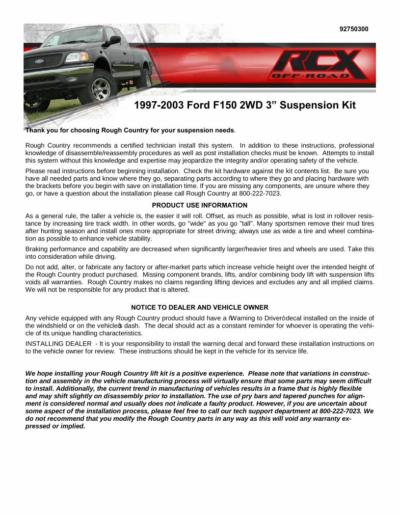
2. Starting on the passenger side of the truck remove the front tire. 3. Remove the brake calipers from the spindle bracket using a 13 mm wrench as shown in Photo 1. Zip tie the caliper
to the frame rail. Do not let the caliper hang from the hose. Remove the two bolts securing the bracket from the spindle using an 18mm socket. See Photo 2. Retain hardware for reuse.
4. Remove the dust cap from the brake rotor using a flat head screwdriver. You will be reusing the dust cap later so do not puncture it. See Photo 3.
5. Using pliers remove the cotter key from the spindle shaft. See Photo 4. Using a 1”socket remove the spindle nut and washer. Retain hardware for reuse.
6. Slide the rotor off the spindle shaft. Make sure to keep the bearings inside the rotor. See Photo 5 & 6.
PHOTO 1 PHOTO 2
PHOTO 3 PHOTO 4
PHOTO 5 PHOTO 6
INSTALLATION INSTRUCTIONS
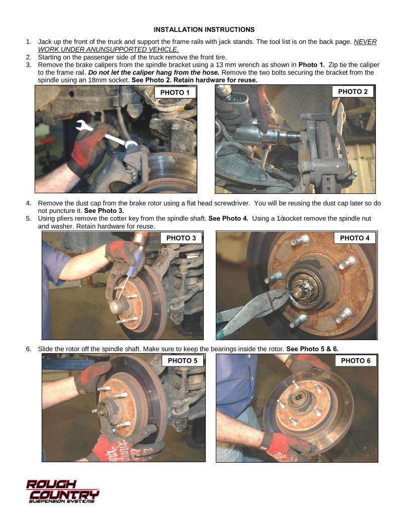
7. Using pliers remove the cotter pin from the tie rod. See Photo 7. 8. Using a 21mm socket remove the castle nut. Using a hammer hit the spindle only as shown in Photo 8 until the tie
rod pops out. Do not strike the tie rod itself or the threaded shaft. Retain the hardware for reuse.
9. If your vehicle has an anti-lock brake system, remove the sensor from the spindle. This will be reinstalled on the new spindle.
10. Support the lower control arm with a jack. Raise the lower control arm 1”. This should be enough to relieve the ten-sion on the shock.
11. Using pliers remove the cotter pin from the upper ball joint. See Photo 9. 12. Using the 21 MM wrench loosen castle nut. Using a hammer hit the spindle as shown in Photo 10 until the upper
ball joint pops out. Do not strike the ball joint itself or the threaded shaft.
13. Using pliers remove the cotter pin from the lower ball joint. See Photo 11. 14. Using the 24mm socket loosen the castle nut. Using the hammer hit the spindle as shown in Photo 12 until the ball
joint breaks free. Do not strike the ball joint itself or the threaded shaft. Remove the upper and lower castle nut and place spindle aside. Retain hardware for reuse.
PHOTO 7 PHOTO 8
PHOTO 9 PHOTO 10
PHOTO 11 PHOTO 12
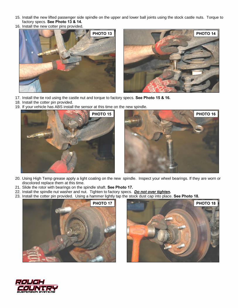
15. Install the new lifted passenger side spindle on the upper and lower ball joints using the stock castle nuts. Torque to factory specs. See Photo 13 & 14.
16. Install the new cotter pins provided.
17. Install the tie rod using the castle nut and torque to factory specs. See Photo 15 & 16. 18. Install the cotter pin provided. 19. If your vehicle has ABS install the sensor at this time on the new spindle.
20. Using High Temp grease apply a light coating on the new spindle. Inspect your wheel bearings. If they are worn or discolored replace them at this time.
21. Slide the rotor with bearings on the spindle shaft. See Photo 17. 22. Install the spindle nut washer and nut. Tighten to factory specs. Do not over tighten. 23. Install the cotter pin provided. Using a hammer lightly tap the stock dust cap into place. See Photo 18.
PHOTO 13 PHOTO 14
PHOTO 15 PHOTO 16
PHOTO 17 PHOTO 18
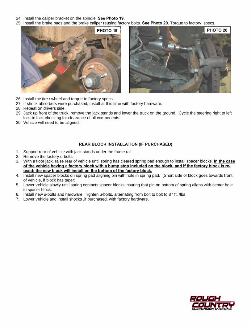
24. Install the caliper bracket on the spindle. See Photo 19. 25. Install the brake pads and the brake caliper reusing factory bolts. See Photo 20. Torque to factory specs.
26. Install the tire / wheel and torque to factory specs. 27. If shock absorbers were purchased, install at this time with factory hardware. 28. Repeat on drivers side. 29. Jack up front of the truck, remove the jack stands and lower the truck on the ground. Cycle the steering right to left
lock to lock checking for clearance of all components. 30. Vehicle will need to be aligned.
PHOTO 19 PHOTO 20
REAR BLOCK INSTALLATION (IF PURCHASED)
1. Support rear of vehicle with jack stands under the frame rail. 2. Remove the factory u-bolts. 3. With a floor jack, raise rear of vehicle until spring has cleared spring pad enough to install spacer blocks. In the case
of the vehicle having a factory block with a bump stop included on the block, and if the factory block is re-used; the new block will install on the bottom of the factory block.
4. Install new spacer blocks on spring pad aligning pin with hole in spring pad. (Short side of block goes towards front of vehicle, if block has taper).
5. Lower vehicle slowly until spring contacts spacer blocks insuring that pin on bottom of spring aligns with center hole in spacer block.
6. Install new u-bolts and hardware. Tighten u-bolts, alternating from bolt to bolt to 87 ft. /lbs 7. Lower vehicle and install shocks ,if purchased, with factory hardware.


POST INSTALLATION INSTRUCTIONS
1. Lug nuts should be check after 50 miles and all nuts and bolts should be checked and tightened after 500 miles. All parts should be checked every 3000 miles for the life of the vehicle.
2. Recheck brake hoses and lines for proper clearances. 3. Perform steering sweep to check for appropriate tire clearance. Note- Some oversized tires may require trimming of
the bumper and valance 4. If new tires are installed that are more than 10% taller than original tires, the speedometer must be recalibrated for
the anti-lock brake system (if applicable) to function properly. Contact an authorized Ford dealer for details on recali-bration.
5. Adjust headlights back to proper settings. 6. Have a qualified alignment center realign front end to factory specs. 7. Install “Warning to Driver” decal on sun visor.
Thank you for purchasing a Rough Country Suspension System.
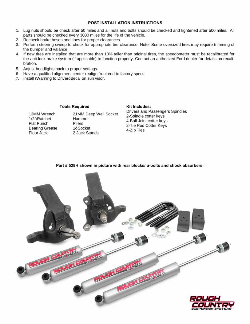
13MM Wrench 21MM Deep Well Socket 1/2” Ratchet Hammer Flat Punch Pliers Bearing Grease 1” Socket Floor Jack 2 Jack Stands
Tools Required Kit Includes: Drivers and Passengers Spindles 2-Spindle cotter keys 4-Ball Joint cotter keys 2-Tie Rod Cotter Keys 4-Zip Ties
Part # 528H shown in picture with rear blocks/ u-bolts and shock absorbers.