Embed Size (px)
Citation preview
P/N 60506 & 60507 1997-98 GM LS1 FUEL INJECTION WIRE
HARNESS INSTALLATION INSTRUCTIONS P/N 60508 & 60509
1999-02 GM LS1 FUEL INJECTION WIRE HARNESS INSTALLATION INSTRUCTIONS
Manual P/N 90520
Seventh Edition June 24, 2009
Copyright © Oct. 2001
PAINLESS PERFORMANCE PRODUCTS 2501 Ludelle Street - Fort Worth, Texas 76105-1036 - (800) 423-9696
TABLE OF CONTENTS 1.0 INTRODUCTION.......................................................................................................................... 1 2.0 ABOUT THESE INSTRUCTIONS............................................................................................... 1 3.0 TOOLS NEEDED.......................................................................................................................... 2 4.0 PRE-INSTALLATION AND HARNESS ROUTING GUIDELINES........................................... 2
4.1 TRANSMISSION FUNCTION...................................................................................... 2 4.2 GET TO KNOW THE ENGINE THAT YOU ARE USING........................................... 3
5.0 GENERAL INSTALLATION INSTRUCTIONS.......................................................................... 4 5.1 GROUNDING THE VEHICLE....................................................................................... 4 5.2 ROUGH INSTALLATION............................................................................................... 5 5.3 HARNESS ATTACHMENT........................................................................................... 5 5.4 TERMINAL INSTALLATION INSTRUCTIONS.......................................................... 5
6.0 GM LS1 SYSTEM WIRE HARNESS INSTALLATION.............................................................. 6 6.1 CONTENTS OF THE WIRE HARNESS KIT................................................................ 6 6.2 SPECIFIC CIRCUIT CONNECTIONS........................................................................... 5 6.3 ENGINE GROUP INSTALLATIONS............................................................................... 10 6.4 TAIL SECTION INSTALLATIONS................................................................................. 15
7.0 TROUBLE-SHOOTING INSTRUCTIONS................................................................................... 16 7.1 THE "CHECK ENGINE" LIGHT................................................................................... 16 7.2 RETRIEVING TROUBLE CODES FROM THE COMPUTER..................................... 17 7.3 WHEN TO CALL "PAINLESS WIRING" TECH LINE................................................ 17
LIST OF FIGURES
Figure 6.1 Diagnostic Link Connector (DLC) & Check Engine Light ............................................. 6 Figure 6.2 Brake Switch Connection ............................................................................................... 7 Figure 6.3 Brake Switch Relay......................................................................................................... 8 Figure 6.4 Gear Indicator Switch ..................................................................................................... 8 Figure 6.5 Air Pump & Air Solenoid Relays .................................................................................. 10 Figure 6.6 Canister Purge Solenoid ................................................................................................. 10 Figure 6.7 Canister Vent Solenoid ................................................................................................... 10 Figure 6.8 Air Pump Connection ..................................................................................................... 10 Figure 6.9 Air Bleed Solenoid.......................................................................................................... 10 Figure 6.10 Fuel Pump Relay Connector............................................................................................ 10 Figure 6.11 EGR Valve....................................................................................................................... 12 Figure 6.12 Knock Sensor Connector.................................................................................................. 12 Figure 6.13 Oxygen Sensors ................................................................................................................ 13 Figure 6.14 MAP Sensor .................................................................................................................... 13 Figure 6.15 CMP Sensor .................................................................................................................... 13 Figure 6.16 CKP Sensor .................................................................................................................... 13 Figure 6.17 Injectors 1, 3, 5, 7............................................................................................................. 13 Figure 6.18 Injectors 2, 4, 6, 8 ............................................................................................................ 13 Figure 6.19 TPS Sensor ...................................................................................................................... 14 Figure 6.20 IAC................................................................................................................................... 14 Figure 6.21 MAF Sensor .................................................................................................................... 14 Figure 6.22 Driver Side Coil Connector.............................................................................................. 14 Figure 6.23 Passenger Side Coil Connector......................................................................................... 14 Figure 6.24 ECT Sensor....................................................................................................................... 14 Figure 6.25 IAT Sensor........................................................................................................................ 15 Figure 6.26 VSS (4L60E)...................................................................................................................... 16 Figure 6.27 Transmission Connection (4L60E)………........................................................................ 16 Figure 6.28 Transmission Connections (T56 manual).....…................................................................. 16 Figure 7.1 Fuse Identification.............................................................................................................. 16
LIST OF TABLES Table 4.1 Compatible Parts.............................................................................................................. 3 Table 6.1 Dash Section Connections................................................................................................ 9 Table 6.2 Engine Section Connections............................................................................................. 11 Table 6.3 Tail Section Connections.................................................................................................. 15
i
1.0 INTRODUCTION
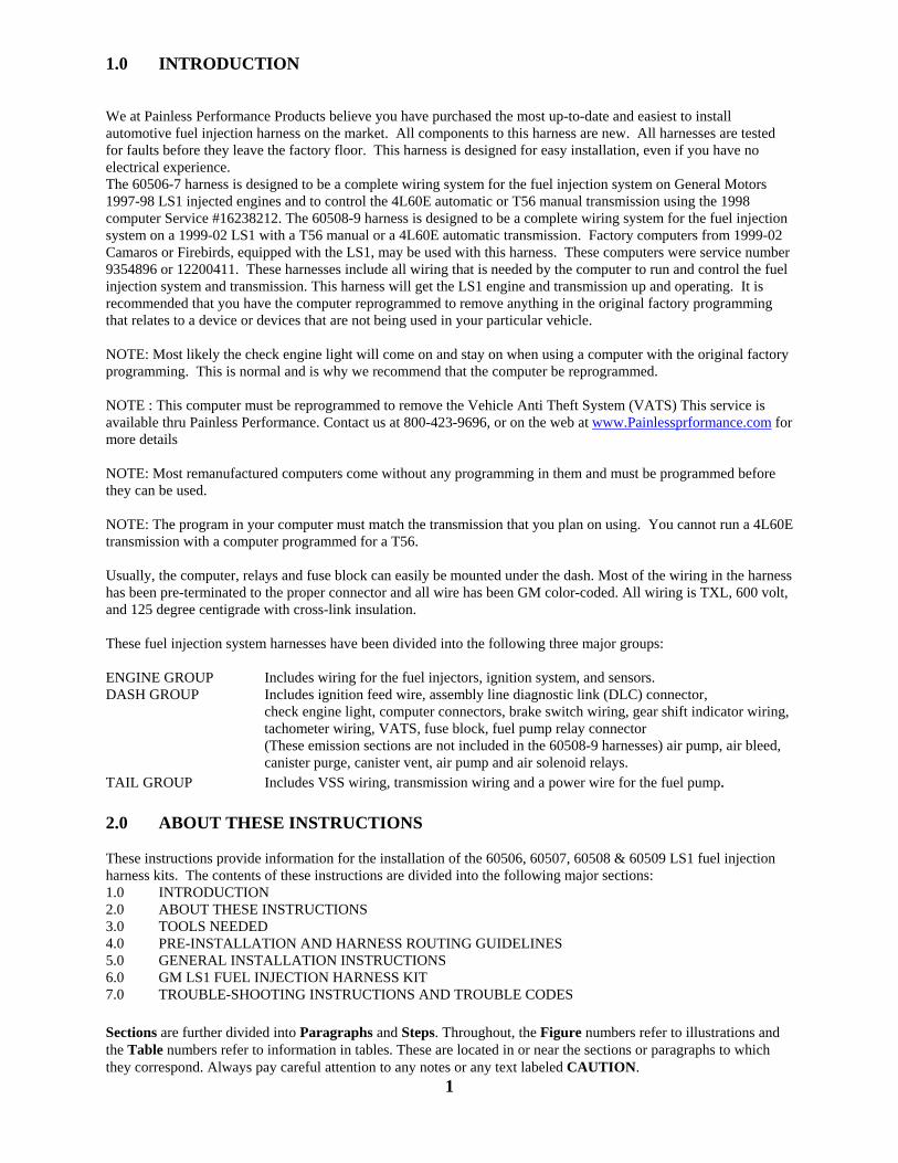
We at Painless Performance Products believe you have purchased the most up-to-date and easiest to install automotive fuel injection harness on the market. All components to this harness are new. All harnesses are tested for faults before they leave the factory floor. This harness is designed for easy installation, even if you have no electrical experience. The 60506-7 harness is designed to be a complete wiring system for the fuel injection system on General Motors 1997-98 LS1 injected engines and to control the 4L60E automatic or T56 manual transmission using the 1998 computer Service #16238212. The 60508-9 harness is designed to be a complete wiring system for the fuel injection system on a 1999-02 LS1 with a T56 manual or a 4L60E automatic transmission. Factory computers from 1999-02 Camaros or Firebirds, equipped with the LS1, may be used with this harness. These computers were service number 9354896 or 12200411. These harnesses include all wiring that is needed by the computer to run and control the fuel injection system and transmission. This harness will get the LS1 engine and transmission up and operating. It is recommended that you have the computer reprogrammed to remove anything in the original factory programming that relates to a device or devices that are not being used in your particular vehicle. NOTE: Most likely the check engine light will come on and stay on when using a computer with the original factory programming. This is normal and is why we recommend that the computer be reprogrammed. NOTE : This computer must be reprogrammed to remove the Vehicle Anti Theft System (VATS) This service is available thru Painless Performance. Contact us at 800-423-9696, or on the web at www.Painlessprformance.com for more details NOTE: Most remanufactured computers come without any programming in them and must be programmed before they can be used. NOTE: The program in your computer must match the transmission that you plan on using. You cannot run a 4L60E transmission with a computer programmed for a T56. Usually, the computer, relays and fuse block can easily be mounted under the dash. Most of the wiring in the harness has been pre-terminated to the proper connector and all wire has been GM color-coded. All wiring is TXL, 600 volt, and 125 degree centigrade with cross-link insulation. These fuel injection system harnesses have been divided into the following three major groups: ENGINE GROUP Includes wiring for the fuel injectors, ignition system, and sensors. DASH GROUP Includes ignition feed wire, assembly line diagnostic link (DLC) connector,
check engine light, computer connectors, brake switch wiring, gear shift indicator wiring, tachometer wiring, VATS, fuse block, fuel pump relay connector (These emission sections are not included in the 60508-9 harnesses) air pump, air bleed, canister purge, canister vent, air pump and air solenoid relays.
TAIL GROUP Includes VSS wiring, transmission wiring and a power wire for the fuel pump. 2.0 ABOUT THESE INSTRUCTIONS These instructions provide information for the installation of the 60506, 60507, 60508 & 60509 LS1 fuel injection harness kits. The contents of these instructions are divided into the following major sections: 1.0 INTRODUCTION 2.0 ABOUT THESE INSTRUCTIONS 3.0 TOOLS NEEDED 4.0 PRE-INSTALLATION AND HARNESS ROUTING GUIDELINES 5.0 GENERAL INSTALLATION INSTRUCTIONS 6.0 GM LS1 FUEL INJECTION HARNESS KIT 7.0 TROUBLE-SHOOTING INSTRUCTIONS AND TROUBLE CODES
Sections are further divided into Paragraphs and Steps. Throughout, the Figure numbers refer to illustrations and the Table numbers refer to information in tables. These are located in or near the sections or paragraphs to which they correspond. Always pay careful attention to any notes or any text labeled CAUTION.
1
3.0 TOOLS NEEDED In addition to your regular tools, you will need, at least, the following: Crimping tool NOTE: USE A QUALITY TOOL TO AVOID OVER-CRIMPING. Wire stripper Continuity tester CAUTION: DO NOT USE A TEST LIGHT TO TEST THE COMPUTER OR SENSOR WIRING. YOU WILL DAMAGE THE COMPUTER. Electric drill 1 5/8" Hole saw (for the rubber grommet in the firewall)
4.0 PRE-INSTALLATION AND HARNESS ROUTING GUIDELINES The installation of your harness kit will consist of two parts: ~ The physical routing, positioning, and securing of the harness, wire groups, and individual wires and
connectors. ~ The proper electrical connection of the individual circuits. We cannot tell you how to route the harness in your automobile. That depends a great deal upon the particular make of the automobile and what extent you want to secure and conceal the harness. We do offer some general guidelines and routing practices starting in Paragraph 5.3, general installation instructions in Section 5.0, and precise instruction concerning the electrical connections you will have to make beginning in Section 6.0. To help you begin thinking through the installation of your wire harness, read the following sections: 4.1 TRANSMISSION FUNCTION If you are using the T56 transmission, read Paragraph 4.1.1, then skip to the note at the end of the page. If you are using the 4L60E, then skip Paragraph 4.1.1, and start at paragraph 4.1.2.
4.1.1 If you are using a T56 transmission, tape off and store the purple and pink (brake switch) wires, the orange/black and black/white (gear indicator switch) wires in the dash group and the 13-position (transmission) round connector in the tail section. Plug in the skip shift solenoid, reverse lockout solenoid and vehicle speed sensor connector to the transmission as shown in Figure 6.28. We have included a wire to turn on a skip shift light if you are planning on using one. This wire is white/black and provides a ground to the skip shift light. You must connect power to the other side of the light.
4.1.2 If you ARE going to use a 4L60E transmission, tape off and store the skip shift light wire, skip
shift solenoid and reverse lockout solenoid connectors. You must use the vehicle speed sensor (VSS), correct brake switch and a gear indicator switch. These are necessary to make the transmission work correctly. The brake switch should be closed (electrically connected) when the brakes ARE NOT being applied and open (not electrically connected) when the brakes ARE being applied. This is the opposite of a standard brake light switch. If you are using a pressure brake switch, a SPDT relay must be installed to unlock the converter when the brakes are applied.
NOTE: Emission devices The 60506-7 harnesses have provisions for the emission devices. We have rolled up the canister
purge, canister vent, air pump and air bleed solenoid wiring in the dash section and it may be left there if these items are not to be used. If you plan on using these items you will need to route these wires out to the engine compartment. Secure the wires to the main harness using the tie wraps supplied.
The 60508-9 harnesses have no emission wiring included. 2
4.2 YOU SHOULD GET TO KNOW THE PARTICULAR ENGINE YOU ARE USING:
NOTE: The 1997-02 LS1 engine had four oxygen sensors from the factory. We have included provisions for only two oxygen sensors, which include one on the driver side and one on the passenger side of the engine. We have removed the two rear oxygen sensors since they originally where behind the catalytic converters and most people don’t want to run more than two oxygen sensors. This system has two rectangular connectors at the computer.
4.2.1 PPPI recommends the use of the following parts. See Table 4.1A for 60506-7 or 4.1B for 60508-
9. These will meet all requirements and are compatible with PPPI harnesses. The numbers given are GM and AC Delco part numbers. You must use the computer listed on table 4.1 with our harness.
4.2.2 Familiarize yourself with the harness by locating each of the harness groups and by looking at the
connectors on the wire ends.
4.2.3 Decide where and how the computer, fuse block and relays will be mounted. PPPI wire harness kits are designed to mount either under the dash or in the kick panel on the passenger side. They must be no further apart than the wiring will allow (approx. 18 inches).
4.2.4 A good exercise is to lay out the wire harness on the floor beside your vehicle and identify all the
connectors and wires.
4.2.5 You will want to route the harness through and around open areas. Inside edges provide extra protection from hazards and also provide places for tie wraps, clips and other support.
4.2.6 Route the harness away from sharp edges, exhaust pipes, and the hood, trunk and door hinges.
4.2.7 Plan where harness supports will be located. Use a support approximately every 6 inches unless the harness routes under the floor carpet.
4.2.8 Allow enough slack in the harness at places where movement could possibly occur (body to frame, frame to engine, etc.).
4.2.9 The wires should be bundled into harness groups. Use tape, nylon ties or poly split loom.
Table 4.1A 60506-7 Compatible Parts
3
LS1 Fuel Injection Harness (97 - 98) Part # 60506 & 60507
Main Computer…………………Service #16238212 Fuel Pump Relay………………..Delco# 15-8240 Brake Switch…………………….Delco# D850A Gear Indicator Switch…………...Delco# D2286A Intake Air Temperature………….Delco# 213-243 MAF Sensor……………………..Delco# 213-353 Engine Coolant Temperature……GM# 12551708 Oxygen Sensor (Pass. Side)……..Delco# AFS97 Oxygen Sensor (Drvr. Side)……..Delco# AFS98 TPS Sensor………………………Delco# 213-912 MAP Sensor…………………..…Delco# 213-331 Idle Air Control Motor…………..GM# 17113391
Knock Sensors…………………...Delco# 213-362 EGR Valve……………………….Delco# 214-5597 Coils………………………….…..Delco# D580 Cam Position Sensor……………..Delco# 213-355 Crankshaft Position Sensor………Delco# 213-354 Air Pump…………………………Delco# 215-353 Air Pump Relay………..………...Delco# 15-8426 Air Solenoid Relay………………Delco# 15-8426 Air Bleed Solenoid………………GM# 1997201 Canister Purge Solenoid…………GM# 1997278 Canister Vent Solenoid…………..GM# 24574755 VSS(4L60E Only)……………….Delco# 213-328
Table 4.1B 60508-9 Compatible Parts 5.0 GENERAL INSTALLATION INSTRUCTIONS
CAUTION: ~ DO NOT DISCONNECT THE BATTERY OR THE COMPUTER CONNECTORS WHILE THE IGNITION IS ON. ~ DO NOT SHORT ANY WIRES IN THIS HARNESS TO GROUND (WITH THE EXCEPTION OF LABELED GROUND WIRES) OR DAMAGE TO THE COMPUTER WILL RESULT. ~ GIVING OR RECEIVING A "JUMP START" MAY DAMAGE THE COMPUTER. ~ DO NOT USE A TEST LIGHT WHEN TESTING COMPUTER SENSORS OR COMPUTER CIRCUITS. DAMAGE TO THE COMPUTER WILL RESULT! ~ WHEN ROUTING THE WIRES FOR THE VEHICLE SPEED SENSOR (IF USED) MAKE CERTAIN THAT THEY ARE AT LEAST 12 INCHES AWAY FROM ANY IGNITION WIRING (SPARK PLUG WIRES, ETC.).
Notes:
~ There is a normal, small current drain on these fuel injected systems. ~ Each connector in this harness is different and will not fit in the wrong place. NEVER FORCE ANY CONNECTOR. ~ When connecting the plugs to the computer USE EXTREME CARE to make sure none of the pins in the computer are or become bent. ~ The fuel pump and pressure regulator you are using MUST maintain a constant pressure of 55-60
PSI (pounds per square inch). If using a higher pressure pump you must add an inline regulator to bring the pressure down to the 55-60 range since the LS1 fuel system does not have a built-in regulator on the fuel rail as in many earlier GM fuel injection systems.
5.1 GROUNDING THE VEHICLE A perfectly and beautifully wired automobile will nevertheless have problems if everything is not properly grounded. Don't go to the effort to installing a quality wire harness only to neglect proper grounding.
Note: The installer of this harness is responsible for all ground wires not provided with this part.
5.1.1 Connect a ground strap or cable (minimum of a 4 Ga. wire) from the negative battery terminal to the chassis (frame).
5.1.2 Connect a ground strap (minimum of a 4 Ga. wire) from the engine to the chassis (frame). DO NOT RELY UPON THE MOTOR MOUNTS TO MAKE THIS CONNECTION.
5.1.3 Connect a ground strap from the engine to the body. 4
LS1 Fuel Injection Harness (99 - 02) Part # 60508 & 60509
Main Computer…………………Service #9354896 Service #12200411 Fuel Pump Relay………………..Delco #15-8240 Brake Switch…………………….Delco #D850A Gear Indicator Switch…………...Delco #D2286A Intake Air Temperature………….GM #12160244
Delco #213-243 MAF Sensor……………………..GM #25179711 Engine Coolant Temperature……GM #5326388 Delco #213-953 Oxygen Sensor (Pass. Side)……..GM #25312196
Delco #AFS97 Oxygen Sensor (Drvr. Side)……..GM #25312197
Delco #AFS98
TPS Sensor………………………GM #17123852 Delco #213-912
MAP Sensor…………………..…GM #16212460 Delco #213-331
Idle Air Control Motor…………..GM #17113391 Knock Sensors…………………...GM #10456603
Delco# 213-362 Coils………………………….…..GM #12558948
Delco# D580 Cam Position Sensor……………..GM #12561211
Delco# 213-363 Crankshaft Position Sensor………GM #12560228
Delco# 213-354 VSS(4L60E Only)……………….Delco# 213-328
5.2 ROUGH INSTALLATION
CAUTION: DISCONNECT THE POWER FROM YOUR VEHICLE BY REMOVING THE NEGATIVE BATTERY CABLE FROM THE BATTERY.
Note: Make no wire connections or permanent mounting of any kind at this time.
5.2.1 Position the computer and sensors in their intend locations. 5.2.2 Drill a 1-5/8" hole for the firewall grommet near the computer for the engine group and tail section
to pass through. 5.2.3 Route the engine group and tail section through the hole. Push the grommet (already installed on
the harness) into the hole until it is seated. 5.2.4 Route the dash group over to the driver's side of the car. 5.2.5 Route the fuse block and relays to the place they will be mounted.
5.3 HARNESS ATTACHMENT
Note: Harness routing and shaping will be a time-consuming task. Taking your time will enhance the beauty of your vehicle. Please take your time and be patient.
5.3.1 Permanently mount your computer. You should mount the fuse block and relays at this time. 5.3.2 Mold harness groups to the contour of the dash, engine, frame, etc. Remember to route harness
away from sharp edges, exhaust pipes, hinges, and moving parts. 5.3.3 Attach harness groups to your automobile with clips or ties starting at the computer and working
your way outward.
Note: Do not tighten tie wraps or mounting devices at this time. Make all harness attachments LOOSELY.
5.3.4 When used every 1-1/2" or so on the visible areas of the harness, colored plastic wire ties make a very attractive assembly. Otherwise, a tie installed in other areas every 6" or so will hold the wires in place securely. REMEMBER TO TAKE YOUR TIME.
5.4 TERMINAL INSTALLATION INSTRUCTION
Note: In the following steps you will be making the circuit connections. Before you start, you should carefully read Sections 6.0, and continually refer to the wire charts, DOUBLE CHECKING your length calculations before cutting any wire or making any connections. These directions are for the wires, which do not have a connector already, installed on them.
5.4.1 Have all tools and connectors handy. 5.4.2 Select the correct terminal for the wire and application. 5.4.3 Determine the correct wire length and cut the wire. Remember to allow enough slack in the harness and wires at places where movement could occur. DOUBLE CHECK YOUR CALCULATIONS. 5.4.4 Strip insulation away from wire. Only strip as much insulation off as necessary for the type of
terminal lug you are using.
Note: In the following step, make sure that the terminal is crimped with proper die in the crimping tool. An improper crimp will not make a good connection. DO NOT OVER-CRIMP.
5.4.5 Crimp the terminal onto the wire. 5.4.6 Connecting the wires and connectors throughout the harness is a simple process. Make sure that
each wire is properly routed and then attached. DO NOT ATTACH THEN ROUTE AFTERWARD.
5.4.7 When all the wires are attached, tighten the mounts and ties to secure the harness permanently. 5.4.8 Attach the connectors to the computer. BEING VERY CAREFUL NOT TO BEND ANY PINS. 5.4.9 After all connections have been made throughout the harness, connect the battery to the vehicle.
5
CAUTION: BE SURE THE IGNITION IS OFF WHEN YOU RECONNECT THE BATTERY OR YOU WILL DAMAGE THE COMPUTER.
6.0 GM 97 - 99 LS1 SYSTEM WIRE HARNESS INSTALLATION INSTRUCTIONS 6.1 CONTENTS OF THE 60506-7 & 60508-9 WIRE HARNESS KIT Take inventory to see that you have everything you are supposed to have in this kit. If anything is missing, contact the dealer where you obtained the kit or contact Painless Performance at (817) 244-6898. The kit should contain the following items:
~ The main wire harness with the connectors already on the ends of most of the wires. ~ Fuel Injection Installation Instructions P/N 90520 (This Booklet). ~ 4” & 7” tie wraps.
6.2 SPECIFIC CIRCUIT CONNECTIONS
Note: If you have not already done so, read sections 4.0 and 5.0 of these instructions and think through the installation of the harness before securing or cutting any wires.
6.2.1 DASH SECTION INSTALLATION
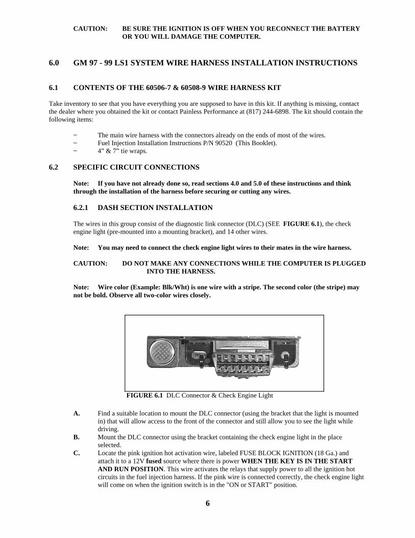
The wires in this group consist of the diagnostic link connector (DLC) (SEE FIGURE 6.1), the check engine light (pre-mounted into a mounting bracket), and 14 other wires.
Note: You may need to connect the check engine light wires to their mates in the wire harness.
CAUTION: DO NOT MAKE ANY CONNECTIONS WHILE THE COMPUTER IS PLUGGED
INTO THE HARNESS.
Note: Wire color (Example: Blk/Wht) is one wire with a stripe. The second color (the stripe) may not be bold. Observe all two-color wires closely.
A. Find a suitable location to mount the DLC connector (using the bracket that the light is mounted in) that will allow access to the front of the connector and still allow you to see the light while driving.
B. Mount the DLC connector using the bracket containing the check engine light in the place selected.
C. Locate the pink ignition hot activation wire, labeled FUSE BLOCK IGNITION (18 Ga.) and attach it to a 12V fused source where there is power WHEN THE KEY IS IN THE START AND RUN POSITION. This wire activates the relays that supply power to all the ignition hot circuits in the fuel injection harness. If the pink wire is connected correctly, the check engine light will come on when the ignition switch is in the "ON or START" position.
6
FIGURE 6.1 DLC Connector & Check Engine Light
D. Locate the Orn/Blk and Blk/Wht wires in the dash group. These two wires are for the Gear
INDICATOR Switch, NOT the Neutral Safety Switch. If you have a GM column then you can use the combination switch Delco P/N D2286A and wire it as described in paragraph 2 or 3 below. The ORN/BLK wire needs to be grounded in "Park and Neutral" and ungrounded in "Drive". This can also be done with a toggle switch or a switch on the parking brake.
NOTE: The Orn/Blk and Blk/Wht wires are only needed if using a 4L60E transmission. If you are
using a manual transmission then you will tape and stow these wires.
CAUTION: DO NOT CONNECT THESE WIRES USING DIRECTIONS FROM DIFFERENT PARAGRAPHS. YOU MAY DAMAGE THE COMPUTER.
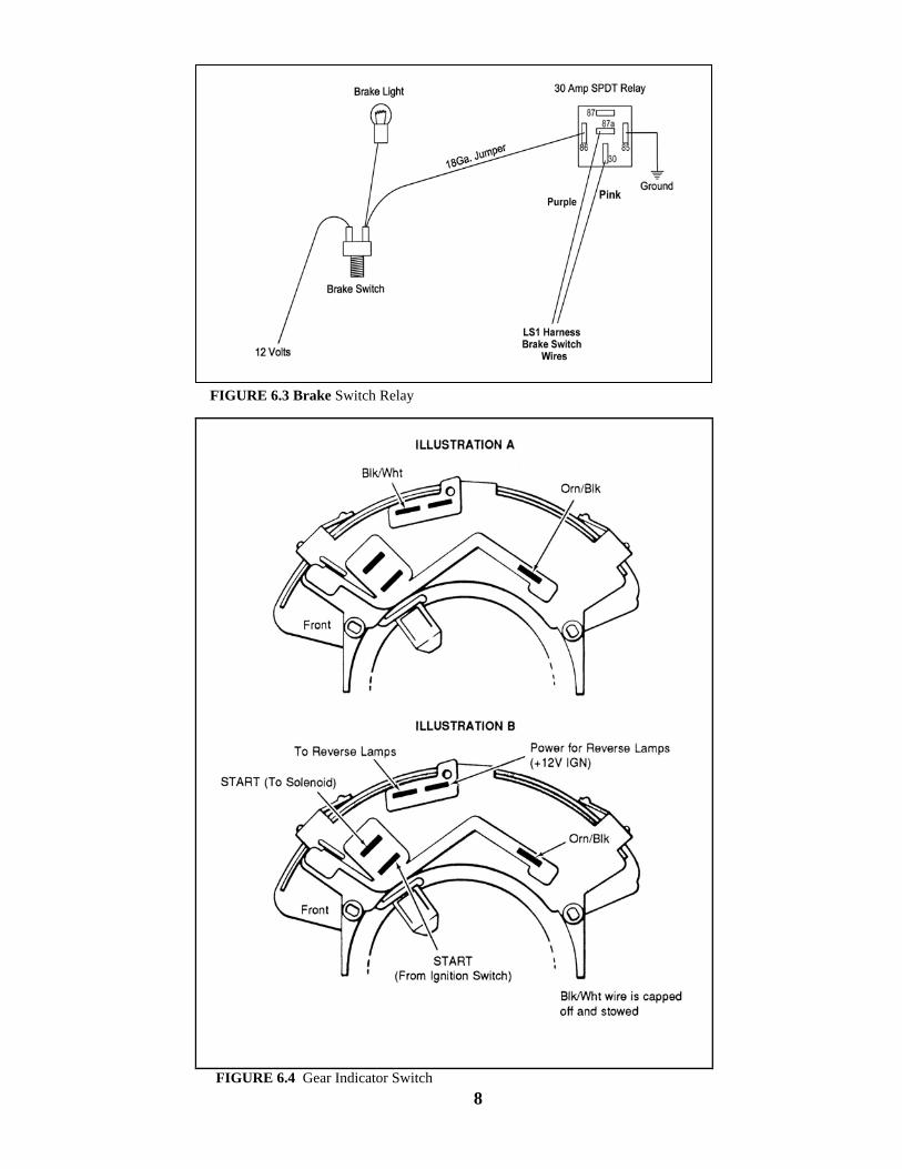
D.1. The recommended switch is a combination reverse light, gear indicator AND neutral safety switch. You may use it for all these purposes if you wire it EXACTLY as shown in Figure 6.4 Illustration B
D.2. If you are going to use the recommended switch as a gear indicator for the computers benefit
ONLY, then you will wire it as shown in Figure 6.4 Illustration A.
D.3. You may want to install your own switch. This switch must connect the Orn/Blk wire to ground only when the car is in PARK OR NEUTRAL. You may or may not want to use the Blk/Wht wire. The other end of the Blk/Wht wire is already grounded throughout the harness.
E. The purple and pink wires labeled BRAKE SWITCH are the wires that connects to the brake
switch to let the computer know when the brake is applied. If you ARE NOT using a 4L60E then you will tape off and store these wires. If you ARE using the 4L60E transmission then you will have to install an electrical switch described in Paragraph 4.1.2. The pink wire provides power for this switch and the purple wire is the signal going to the computer.
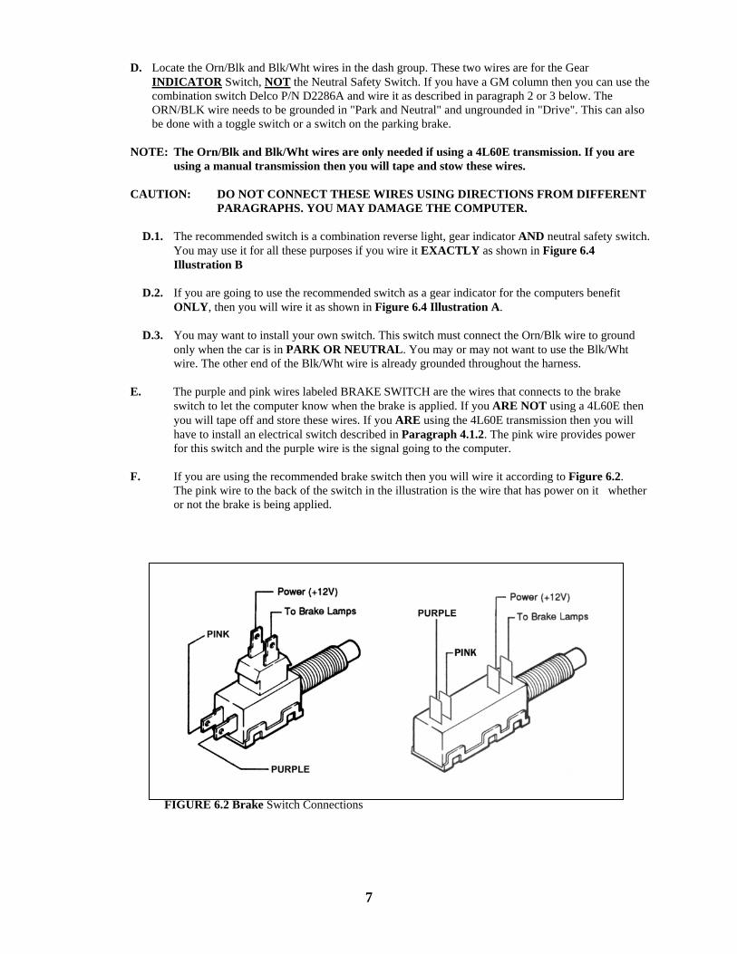
F. If you are using the recommended brake switch then you will wire it according to Figure 6.2.
The pink wire to the back of the switch in the illustration is the wire that has power on it whether or not the brake is being applied.
7
FIGURE 6.2 Brake Switch Connections
8
FIGURE 6.3 Brake Switch Relay
FIGURE 6.4 Gear Indicator Switch
CAUTION: FAILURE TO WIRE THIS SWITCH CORRECTLY WILL RESULT IN A DANGEROUS SITUATION ON THE VEHICLE.
G. If your vehicle has a pressure type brake switch, you may use a relay as shown in Figure 6.3. The relay must be a SPDT Relay and wired correctly or it could result in a dangerous situation with the vehicle. The torque converter may not unlock.
The wire labeled FUEL TEST is a test point for the fuel pump. After the vehicle has been wired
and tested OK, tape off this wire and store it in the harness.
H. The wires labeled VATS (lt.green, red and black) are to be connected a VATS module if needed. If not used, cap & stow these wires.
These wires are included for those whose sanctioning body does NOT allow reprogramming of the computer used. Please contact Painless if a VATS module is needed
Note: The 60508-9 harnesses have a blue VATS signal wire instead of the lt. green.
I. Fan #1 relay wire (green) and fan #2 relay wire (blue) are relay ground wires activated by the
computer.
Note: Fan #1 will come ON at 226°f and go OFF at 217°f. Fan #2 will come ON at 235°f and go OFF at 226°f.
J. The wire labeled TACH (white) is the signal wire for a tachometer if used.
K. The VSS output wire (green/white) sends out a signal to operate the electronic cruise control or speedometer if so equipped.
L. The wire labeled SKIP SHIFT LIGHT (white/black) is only used with the T56 manual
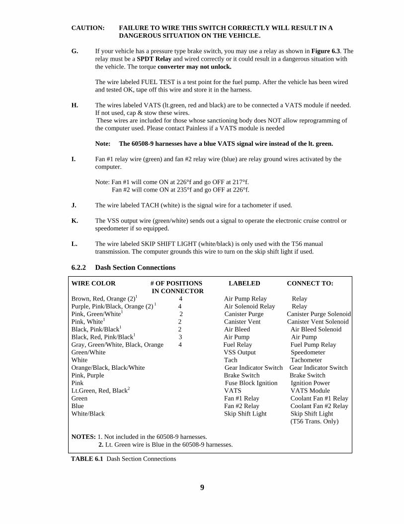
transmission. The computer grounds this wire to turn on the skip shift light if used. 6.2.2 Dash Section Connections WIRE COLOR # OF POSITIONS LABELED CONNECT TO:
IN CONNECTOR Brown, Red, Orange (2)1 4 Air Pump Relay Relay Purple, Pink/Black, Orange (2) 1 4 Air Solenoid Relay Relay Pink, Green/White1 2 Canister Purge Canister Purge Solenoid Pink, White1 2 Canister Vent Canister Vent Solenoid Black, Pink/Black1 2 Air Bleed Air Bleed Solenoid Black, Red, Pink/Black1 3 Air Pump Air Pump Gray, Green/White, Black, Orange 4 Fuel Relay Fuel Pump Relay Green/White VSS Output Speedometer White Tach Tachometer Orange/Black, Black/White Gear Indicator Switch Gear Indicator Switch Pink, Purple Brake Switch Brake Switch Pink Fuse Block Ignition Ignition Power Lt.Green, Red, Black2 VATS VATS Module Green Fan #1 Relay Coolant Fan #1 Relay Blue Fan #2 Relay Coolant Fan #2 Relay White/Black Skip Shift Light Skip Shift Light (T56 Trans. Only) NOTES: 1. Not included in the 60508-9 harnesses. 2. Lt. Green wire is Blue in the 60508-9 harnesses.
9
TABLE 6.1 Dash Section Connections
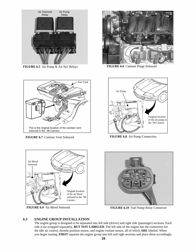
6.3 ENGINE GROUP INSTALLATION
The engine group is designed to be separated into left side (driver) and right side (passenger) sections. Each side is tie-wrapped separately, BUT NOT LABELED. The left side of the engine has the connectors for the idle air control, throttle position sensor, and engine coolant sensor, all of which ARE labeled. When you begin routing, FIRST separate the engine group into left and right sections and place them accordingly.
10
FIGURE 6.7 Canister Vent Solenoid FIGURE 6.8 Air Pump Connection
FIGURE 6.10 Fuel Pump Relay ConnectorFIGURE 6.9 Air Bleed Solenoid
This is the original location of the canister vent solenoid in the `98 Camaro.
Fuel Tank
Original location of the air pump in the `98 Camaro.
Air Pump
Original location of the air bleed solenoid in the `98 Camaro.
Air Bleed Solenoid
FIGURE 6.5 Air Pump & Air Sol. Relays FIGURE 6.6 Canister Purge Solenoid
Air Solenoid Relay
Air Pump Relay
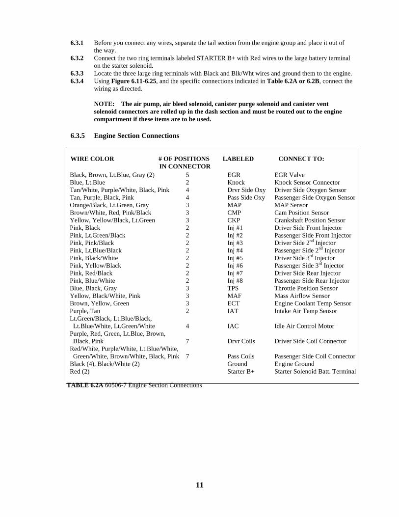
6.3.1 Before you connect any wires, separate the tail section from the engine group and place it out of
the way. 6.3.2 Connect the two ring terminals labeled STARTER B+ with Red wires to the large battery terminal
on the starter solenoid. 6.3.3 Locate the three large ring terminals with Black and Blk/Wht wires and ground them to the engine. 6.3.4 Using Figure 6.11-6.25, and the specific connections indicated in Table 6.2A or 6.2B, connect the
wiring as directed. NOTE: The air pump, air bleed solenoid, canister purge solenoid and canister vent solenoid connectors are rolled up in the dash section and must be routed out to the engine compartment if these items are to be used.
6.3.5 Engine Section Connections WIRE COLOR # OF POSITIONS LABELED CONNECT TO: IN CONNECTOR
11
TABLE 6.2A 60506-7 Engine Section Connections
Black, Brown, Lt.Blue, Gray (2) Blue, Lt.Blue Tan/White, Purple/White, Black, Pink Tan, Purple, Black, Pink Orange/Black, Lt.Green, Gray Brown/White, Red, Pink/Black Yellow, Yellow/Black, Lt.Green Pink, Black Pink, Lt.Green/Black Pink, Pink/Black Pink, Lt.Blue/Black Pink, Black/White Pink, Yellow/Black Pink, Red/Black Pink, Blue/White Blue, Black, Gray Yellow, Black/White, Pink Brown, Yellow, Green Purple, Tan Lt.Green/Black, Lt.Blue/Black, Lt.Blue/White, Lt.Green/White Purple, Red, Green, Lt.Blue, Brown, Black, Pink Red/White, Purple/White, Lt.Blue/White, Green/White, Brown/White, Black, PinkBlack (4), Black/White (2) Red (2)
5 2 4 4 3 3 3 2 2 2 2 2 2 2 2 3 3 3 2 4 7 7
EGR Knock Drvr Side Oxy Pass Side Oxy MAP CMP CKP Inj #1 Inj #2 Inj #3 Inj #4 Inj #5 Inj #6 Inj #7 Inj #8 TPS MAF ECT IAT IAC Drvr Coils Pass Coils Ground Starter B+
EGR Valve Knock Sensor Connector Driver Side Oxygen Sensor Passenger Side Oxygen SensorMAP Sensor Cam Position Sensor Crankshaft Position Sensor Driver Side Front Injector Passenger Side Front Injector Driver Side 2nd Injector Passenger Side 2nd Injector Driver Side 3rd Injector Passenger Side 3rd Injector Driver Side Rear Injector Passenger Side Rear Injector Throttle Position Sensor Mass Airflow Sensor Engine Coolant Temp Sensor Intake Air Temp Sensor Idle Air Control Motor Driver Side Coil Connector Passenger Side Coil ConnectorEngine Ground Starter Solenoid Batt. Terminal
WIRE COLOR # OF POSITIONS LABELED CONNECT TO: IN CONNECTOR
12
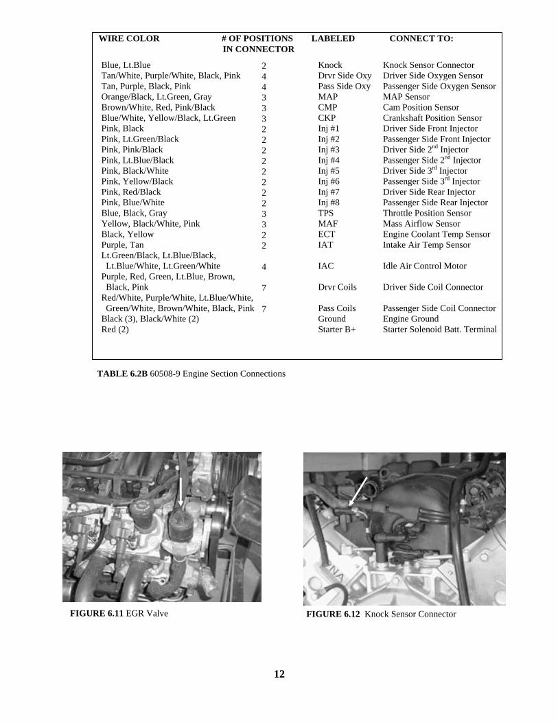
FIGURE 6.11 EGR Valve FIGURE 6.12 Knock Sensor Connector
Blue, Lt.Blue Tan/White, Purple/White, Black, Pink Tan, Purple, Black, Pink Orange/Black, Lt.Green, Gray Brown/White, Red, Pink/Black Blue/White, Yellow/Black, Lt.Green Pink, Black Pink, Lt.Green/Black Pink, Pink/Black Pink, Lt.Blue/Black Pink, Black/White Pink, Yellow/Black Pink, Red/Black Pink, Blue/White Blue, Black, Gray Yellow, Black/White, Pink Black, Yellow Purple, Tan Lt.Green/Black, Lt.Blue/Black, Lt.Blue/White, Lt.Green/White Purple, Red, Green, Lt.Blue, Brown, Black, Pink Red/White, Purple/White, Lt.Blue/White, Green/White, Brown/White, Black, PinkBlack (3), Black/White (2) Red (2)
2 4 4 3 3 3 2 2 2 2 2 2 2 2 3 3 2 2 4 7 7
Knock Drvr Side Oxy Pass Side Oxy MAP CMP CKP Inj #1 Inj #2 Inj #3 Inj #4 Inj #5 Inj #6 Inj #7 Inj #8 TPS MAF ECT IAT IAC Drvr Coils Pass Coils Ground Starter B+
Knock Sensor Connector Driver Side Oxygen Sensor Passenger Side Oxygen SensorMAP Sensor Cam Position Sensor Crankshaft Position Sensor Driver Side Front Injector Passenger Side Front Injector Driver Side 2nd Injector Passenger Side 2nd Injector Driver Side 3rd Injector Passenger Side 3rd Injector Driver Side Rear Injector Passenger Side Rear Injector Throttle Position Sensor Mass Airflow Sensor Engine Coolant Temp Sensor Intake Air Temp Sensor Idle Air Control Motor Driver Side Coil Connector Passenger Side Coil ConnectorEngine Ground Starter Solenoid Batt. Terminal
TABLE 6.2B 60508-9 Engine Section Connections
13
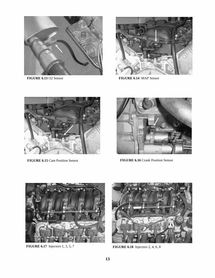
FIGURE 6.17 Injectors 1, 3, 5, 7 FIGURE 6.18 Injectors 2, 4, 6, 8
INJ #1
INJ #3
INJ #5
INJ #7
INJ #8
INJ #6
INJ #4
INJ #2
FIGURE 6.13 O2 Sensor FIGURE 6.14 MAP Sensor
FIGURE 6.15 Cam Position Sensor FIGURE 6.16 Crank Position Sensor
14
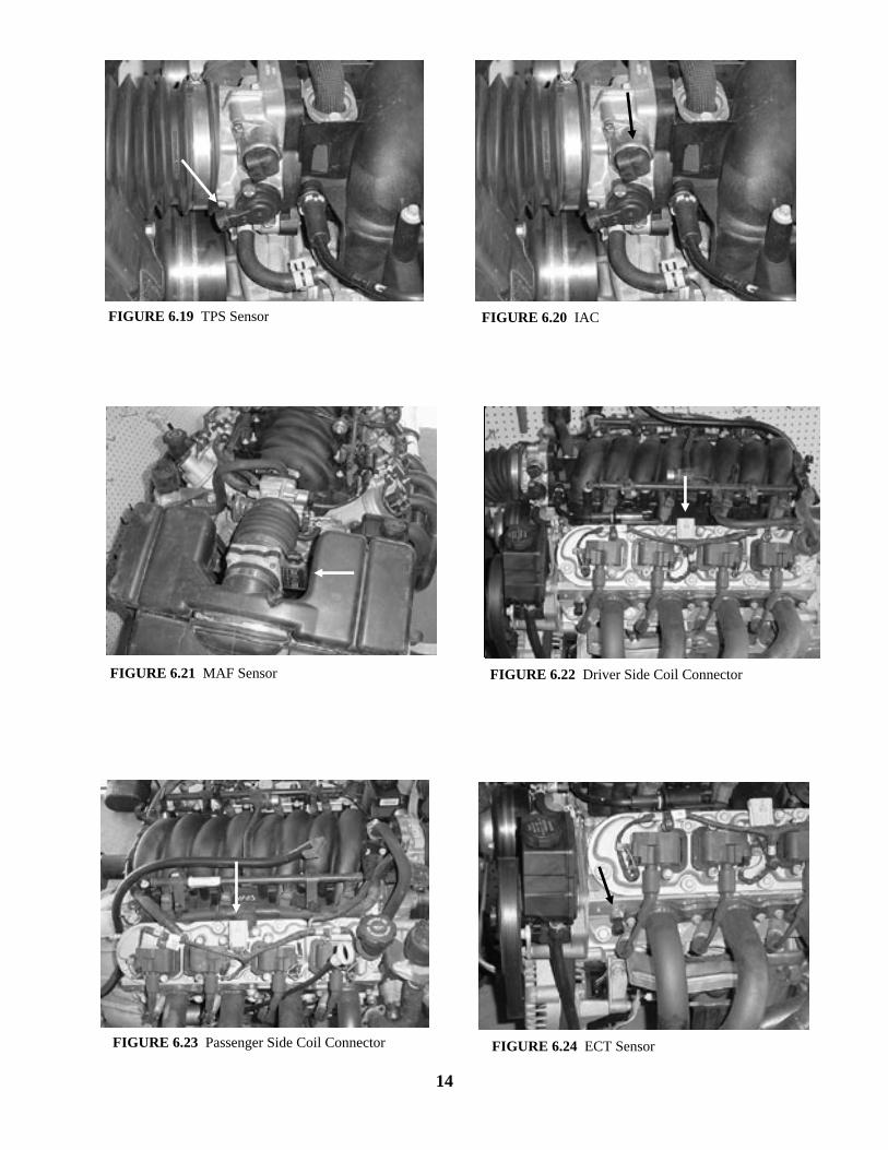
FIGURE 6.19 TPS Sensor FIGURE 6.20 IAC
FIGURE 6.22 Driver Side Coil ConnectorFIGURE 6.21 MAF Sensor
FIGURE 6.23 Passenger Side Coil Connector FIGURE 6.24 ECT Sensor
6.4 TAIL SECTION INSTALLATION
6.4.1 Locate the tail section that you earlier separated from the engine group. Begin routing it towards the rear of the vehicle. Be sure to avoid all sharp edges, moving or hot parts, or anything else that may damage the harness.
6.4.2 If you ARE using the 4L60E transmission, route the 13-position connector to the transmission and attach it. Tape up the reverse lockout and skip shift solenoid connectors and store them in the
harness.
6.4.3 If you ARE using the T56 manual transmission, route the reverse lockout and skip shift solenoid connectors to the transmission and attach them. Tape up the 13-position connector labeled TRANS and store it in the harness.
6.4.4 Take the connector for the Vehicle Speed Sensor (VSS) and connect to the Vehicle Speed Sensor.
6.4.5 Take the gray wire labeled FUEL PUMP and route it to the fuel pump. This is the power wire for
the fuel pump. 6.4.6 Tail Section Connections
WIRE COLOR # OF POSITIONS LABELED CONNECT TO: IN CONNECTOR
15
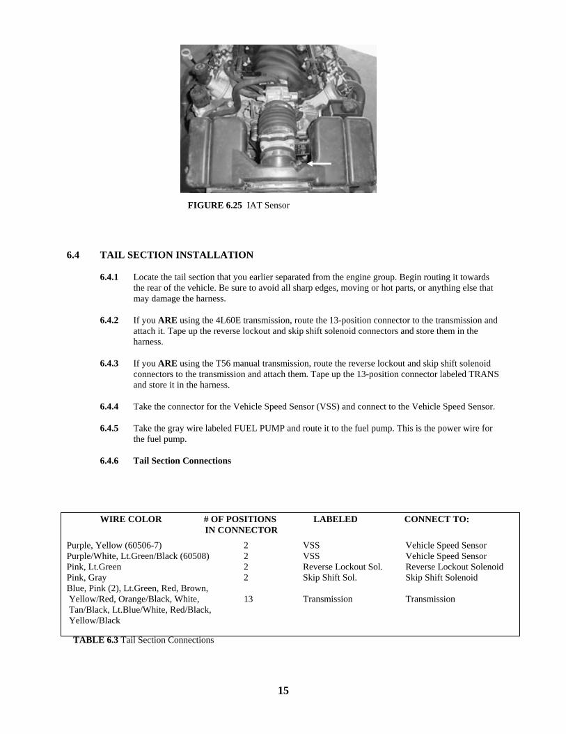
FIGURE 6.25 IAT Sensor
Purple, Yellow (60506-7) Purple/White, Lt.Green/Black (60508) Pink, Lt.Green Pink, Gray Blue, Pink (2), Lt.Green, Red, Brown, Yellow/Red, Orange/Black, White, Tan/Black, Lt.Blue/White, Red/Black, Yellow/Black G
2 2 2 2 13
VSS VSS Reverse Lockout Sol. Skip Shift Sol. Transmission
Vehicle Speed Sensor Vehicle Speed Sensor Reverse Lockout Solenoid Skip Shift Solenoid Transmission
TABLE 6.3 Tail Section Connections
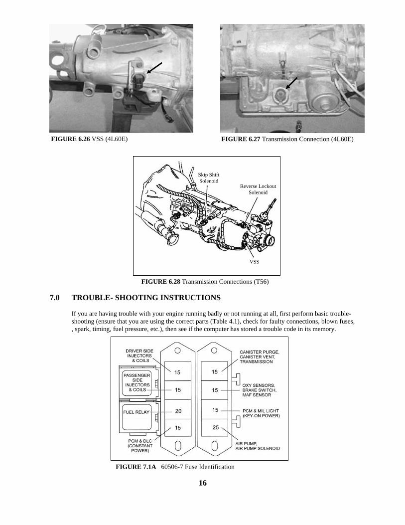
7.0 TROUBLE- SHOOTING INSTRUCTIONS
If you are having trouble with your engine running badly or not running at all, first perform basic trouble-shooting (ensure that you are using the correct parts (Table 4.1), check for faulty connections, blown fuses, , spark, timing, fuel pressure, etc.), then see if the computer has stored a trouble code in its memory.
16
FIGURE 7.1A 60506-7 Fuse Identification
FIGURE 6.26 VSS (4L60E) FIGURE 6.27 Transmission Connection (4L60E)
FIGURE 6.28 Transmission Connections (T56)
Skip Shift Solenoid
Reverse Lockout Solenoid
VSS
7.1 THE "CHECK ENGINE" LIGHT
Normally, the "check engine" light should come on when the ignition is turned on, then go out a few moments after the engine starts running. If it reappears, or stays on while the engine is running, the computer has detected a problem and a trouble code has been set.
NOTE: Most likely the check engine light will come on and stay on when using a computer with the original factory programming this is normal and is why we recommended that the computer be reprogrammed to remove any items that the factory vehicle had that aren’t being used in the vehicle you are installing the engine into.
7.2 RETRIEVING TROUBLE CODES FROM THE COMPUTER
7.2.1 In order to retrieve the trouble codes stored in the computer, a scanner must be connected to the Assembly Diagnostic Link (DLC) connector (installed and connected in Paragraph 6.2.1). Follow the instructions provided with the scanner to read the codes set in the computer.
7.2.2 After you have read any codes, write them down for reference. Remove the connector from the DLC connector.
7.2.3 Take the codes one at a time and match them to the codes in a Camaro/Firebird repair manual. This will tell you which circuit the computer has detected a problem.
Note: A code indicates a problem in a specific circuit, NOT THAT A PARTICULAR PART IS
BAD.
7.2.4 Before taking more extensive corrective actions for any trouble codes make sure that all connections on the indicated circuit, INCLUDING THE COMPUTER, are clean and tight. Inspect the wiring in the circuit for any broken, shorted, or exposed wires. Finally, insure all ground wires are clean and secure.
7.2.5 If a trouble code is detected and the problem has been fixed, clear the codes by first making sure the ignition is off then disconnecting the NEGATIVE battery cable for at least 3 minutes.
7.3 WHEN TO CALL PAINLESS PERFORMANCE PRODUCTS' TECH LINE
7.3.1 These harness kits have been built with the highest regard to quality control. Before calling us please double check all connections and perform normal basic trouble-shooting (fuel pressure, timing, ignition system, etc.). 7.3.2 If you have any questions concerning the installation of this harness or having trouble in general,
feel free to call Painless Performance Products' tech line at (817) 423-9696. Calls are answered from 8am to 5pm central time, Monday thru Friday, except holidays. Email questions to [email protected]
17
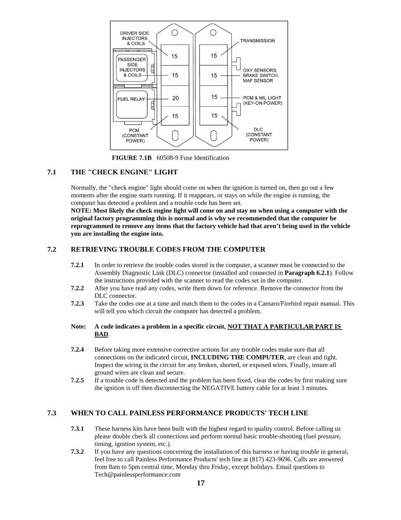
FIGURE 7.1B 60508-9 Fuse Identification

We have attempted to provide you with the most accurate instructions possible, and are always concerned about corrections or improvements that can be made. If you have found any errors or omissions, or if you simply have comments or suggestions concerning these instructions, please write us at the address on the cover and let us know about them. Or, better yet, send us a fax at (817) 244-4024. We sincerely appreciate your business.
Painless Performance Limited Warranty
and Return Policy Chassis harnesses, fuel injection harnesses, and Striker ColdShot units are covered under a lifetime warranty. All other products manufactured and/or sold by Painless Performance are warranted to the original purchaser to be free from defects in material and workmanship under normal use. Painless Performance will repair or replace defective products without charge during the first 12 months from the purchase date. No products will be considered for warranty without a copy of the purchase receipt showing the sellers name, address and date of purchase. You must return the product to the dealer you purchased it from to initiate warranty procedures.
18