Embed Size (px)
Citation preview
Basin Research (1998) 10, 441–468
The dammed Hikurangi Trough: a channel-fed trenchblocked by subducting seamounts and their wakeavalanches (New Zealand–France GeodyNZ Project)Keith B. Lewis,* Jean-Yves Collot† and Serge E. Lallemand‡
NIWA, PO Box 14901, Wellington, New Zealand†ORSTOM, Villefranche sur mer, France‡Universite de Montpellier II, Montpellier, France
ABSTRACT
The Hikurangi Trough, off eastern New Zealand, is at the southern end of the Tonga–Kermadec–Hikurangi subduction system, which merges into a zone of intracontinentaltransform. The trough is mainly a turbidite-filled structural trench but includes an oblique-collision, foredeep basin. Its northern end has a sharp boundary with the deep, sediment-starved, Kermadec Trench.
Swath-mapping, sampling and seismic surveys show modern sediment input is mainly viaKaikoura Canyon, which intercepts littoral drift at the southern, intracontinental apex of thetrough, with minor input from seep gullies. Glacial age input was via many canyons and aboutan order of magnitude greater. Beyond a narrow, gravelly, intracontinental foredeep, thesouthern trench-basin is characterized by a channel meandering around the seaward edge ofmainly Plio-Pleistocene, overbank deposits that reach 5 km in thickness. The aggradingchannel has sandy turbidites, but low-backscatter, and long-wavelength bedforms indicatingthick flows. Levees on both sides are capped by tangentially aligned mudwaves on the outsidesof bends, indicating centrifugal overflow from heads of dense, fast-moving, autosuspensionflows. The higher, left-bank levee also has levee-parallel mudwaves, indicating Coriolis and/orboundary currents effects on dilute flows or tail plumes.
In the northern trough, basin-fill is generally less than 2 km thick and includes widespreadoverbank turbidites, a massive, blocky, avalanche deposit and an extensive, buried, debris flowdeposit. A line of low seamounts on the subducting plate acts as a dam preventing modernturbidity currents from reaching the Kermadec Trench. Major margin collapse probablyoccurred in the wake of a large subducting seamount; this seamount and its wake debris flowprobably dammed the trench from 2 Ma to 0.5 Ma. Before this, similar dams may havere-routed turbidity currents across the plateau.
Island, to an opposite facing zone of oblique collisionINTRODUCTION and subduction south-west of New Zealand. Relative
motion between the plates, in areas remote from itsShallow Hikurangi Trough but deep Kermadecdeforming edge, ranges from 45 mm yr−1 in a directionTrench – why?of 266° at the trough’s northern end to 38 mm yr−1 in a
The Hikurangi Trough, off eastern New Zealand, is at direction of 259° at its southern extremity (De Metsthe southern extremity of the Tonga–Kermadec– et al., 1994) (Fig. 1). Obliquity, the angle between theHikurangi subduction system (Lewis, 1980). It represents direction of relative plate motion and the orthogonal tothe topographic expression of oblique convergence the deformation front, ranges from a low of 30° (nearlybetween the over-riding Australian Plate and the subduct- orthogonal) in the north to more than 80° (highly oblique)ing and underthrusting Pacific Plate (Fig. 1). The trough in the south.is largely a turbidite-filled structural trench but it merges The trough is shallow for what is largely a structuralsouthwards into a foredeep at the edge of a transform trench, at least partly because thickened oceanic crust ofzone of highly oblique collision. The intracontinental the Hikurangi Plateau is being subducted (Davy, 1992;
Uruski & Wood, 1993; Mortimer & Parkinson, 1996). Itstransform zone links, via the Alpine Fault of South
© 1998 Blackwell Science Ltd 441
K. B. Lewis et al.
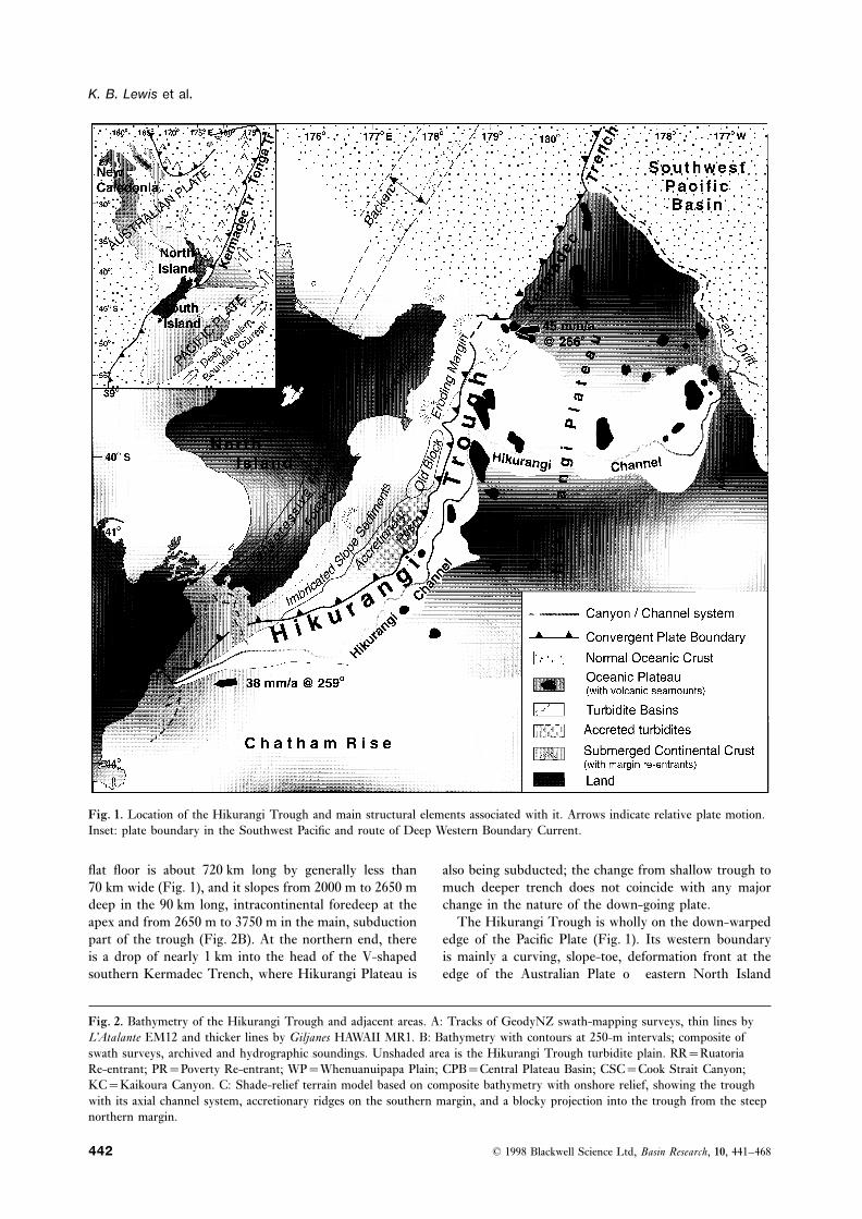
Fig. 1. Location of the Hikurangi Trough and main structural elements associated with it. Arrows indicate relative plate motion.Inset: plate boundary in the Southwest Pacific and route of Deep Western Boundary Current.
flat floor is about 720 km long by generally less than also being subducted; the change from shallow trough tomuch deeper trench does not coincide with any major70 km wide (Fig. 1), and it slopes from 2000 m to 2650 m
deep in the 90 km long, intracontinental foredeep at the change in the nature of the down-going plate.The Hikurangi Trough is wholly on the down-warpedapex and from 2650 m to 3750 m in the main, subduction
part of the trough (Fig. 2B). At the northern end, there edge of the Pacific Plate (Fig. 1). Its western boundaryis mainly a curving, slope-toe, deformation front at theis a drop of nearly 1 km into the head of the V-shaped
southern Kermadec Trench, where Hikurangi Plateau is edge of the Australian Plate off eastern North Island
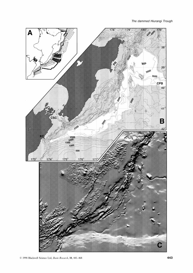
Fig. 2. Bathymetry of the Hikurangi Trough and adjacent areas. A: Tracks of GeodyNZ swath-mapping surveys, thin lines byL’Atalante EM12 and thicker lines by Giljanes HAWAII MR1. B: Bathymetry with contours at 250-m intervals; composite ofswath surveys, archived and hydrographic soundings. Unshaded area is the Hikurangi Trough turbidite plain. RR=RuatoriaRe-entrant; PR=Poverty Re-entrant; WP=Whenuanuipapa Plain; CPB=Central Plateau Basin; CSC=Cook Strait Canyon;KC=Kaikoura Canyon. C: Shade-relief terrain model based on composite bathymetry with onshore relief, showing the troughwith its axial channel system, accretionary ridges on the southern margin, and a blocky projection into the trough from the steepnorthern margin.
© 1998 Blackwell Science Ltd, Basin Research, 10, 441–468442
The dammed Hiurangi Trough
© 1998 Blackwell Science Ltd, Basin Research, 10, 441–468 443
K. B. Lewis et al.
(Fig. 1). The trough’s eastern flank is marked by a change than take the direct route to the central Kermadec Trenchalong the trough–trench axis.to the undulating, seamount-studded topography of the
Hikurangi Plateau (Wood & Davy, 1994) (Figs 1 and 2).At the trough’s southern end, the subducting oceanic Trench basins – a dynamic, interactive systemplateau merges into the continental Chatham Rise, whichhas been highly obliquely underthrusting beneath north- A filled trench is a highly dynamic type of sedimentary
basin. It is being constantly consumed along one edgeeastern South Island (Lewis et al., 1986; Barnes, 1994;Barnes et al., 1998), although motion may now be locked and compression in the adjacent margin implies a con-
stantly varying input. There is on-going structural and(Reyners et al., 1997). The trough’s northern limit, off
East Cape (Fig. 1), is marked by a change from flat plain sedimentary interaction between basin and flankingmargin.to the small, steep-sided, en echelon, enclosed basins of
the southern Kermadec Trench (Collot et al., 1996). In The nature of the adjacent Hikurangi margin changessignificantly from south to north (Lewis & Pettinga, 1992;the same area, there is an apparent offset and change in
trend of the plate boundary (Katz, 1974, 1982; Collot Collot et al., 1996), and it is to be expected that the troughthat interacts with it will also display significant lateralet al., 1996). To the north, the axis of the Kermadec
Trench slopes from over 4500 m adjacent to the trough, changes. In the southern intracontinental environment, amargin of slope clinoforms and turbidites is being shearedto 6000 m deep at the northern end of the Hikurangi
Plateau, and from 7000 m to 10 000 m deep north of the by transpressional plate boundary faults, mainly on theupper margin and adjacent land (Barnes & De Mercierplateau (Collot et al., 1996; CANZ, 1997).
The evolution of the Hikurangi Trough and the cause Lepinay, 1997). Off southern North Island, there is anorthward widening accretionary prism of offscraped Plio-of the discontinuity between the Hikurangi Trough and
Kermadec Trench have long been causes of speculation Pleistocene trench sediments in front of an imbricatebackstop of Cenozoic slope strata (Figs 1, 2) (Barnes &(Brodie & Hatherton, 1958; Van Der Linden, 1969; Cole
& Lewis, 1981; Katz, 1982; Davy, 1992). Many authors Mercier de Lepinay, 1997; Barnes et al., 1998). Theaccretionary prism reaches a maximum width of overhave considered that the apparent offset between trough
and trench signifies a major structural break, related in 70 km about half way along the Hikurangi Trough (Lewis,1980; 1986b; Davey et al., 1986a; Lewis & Pettinga, 1992).some way to the NW/SE-trending continental edge of
northern New Zealand with which it is aligned (Fig. 1). Further north, the accretionary prism narrows to less than10 km wide in front of a steep block of relatively old,However, apparent continuity between an old structural
trend on the over-riding plate and a major change in Cretaceous rocks (Lewis, 1985; Collot et al., 1996; Lewiset al., 1997). At the northern end of the trough, thecharacter on the downgoing plate is puzzling, particularly
as convergence is oblique. The question of whether there margin is steep, without an accretionary prism, and isinferred to have been tectonically eroded by a seamount-is a major structural break between Kermadec Trench
and Hikurangi Trough, or whether the discontinuity has studded downgoing plate (Collot et al., 1996).In this paper, we examine the lateral changes of thesome other cause, remains unresolved.
In this paper, we examine the main geomorphic fea- trough and the evolutionary changes recorded in its filland relate these to interactive lateral and temporal changestures of the Hikurangi Trough and ask why it exists
distinct from the Kermadec Trench. in the adjacent margin. In this way, we consider that theHikurangi Trough may provide models for many of thecomplexites of highly deformed, trench-fill basins pre-served in fold belts around the world (Underwood &Turbidite plain with a re-routed axial channelBachman, 1982), including the adjacent mountain rangesof New Zealand (MacKinnon, 1983; Barnes, 1988; BarnesThe flat plain of the Hikurangi Trough is characterized
by an active turbidite channel, the Hikurangi Channel & Korsch, 1990).(Lewis, 1994) (Figs 1 and 2). The Hikurangi Channelmeanders three-quarters of the way along the trough METHODSfrom its southern end, before turning at right-angles outof the trough to deeply incise the Hikurangi Plateau The primary dataset for this study is the first extensive
swath mapping survey undertaken in New Zealandbefore emerging at a distal fan at the edge of theSouthwest Pacific Basin (Fig. 1). There, the Pacific waters. It is part of the GeodyNZ Project undertaken
jointly by New Zealand and French institutions to studyOcean’s powerful Deep Western Boundary Current(Fig. 1 inset) sweeps along the scarp at the edge of the key offshore segments of the obliquely compressive plate
boundary through the New Zealand region (Collot et al.,Hikurangi Plateau carrying sediment north-westwardsinto a turbidite–contourite ‘fan drift’ (Fig. 1). This 1994, 1995). Most of the data were collected in December
1993 on the French Research Vessel L’Atalante using adeposit almost reaches the central Kermadec Trench(Carter & McCave, 1994; Collot et al., 1996). hull-mounted, Simrad EM12D, dual, multibeam, swath-
mapping system. The EM12D measures depth andThe puzzle is why channelled turbidity currents arerouted out of the trough and across the plateau, rather seabed reflectivity from 162 beams that cover a swath
© 1998 Blackwell Science Ltd, Basin Research, 10, 441–468444
The dammed Hiurangi Trough
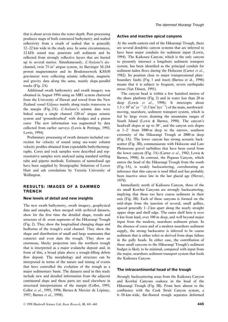
that is about seven times the water depth. Post-processing Active and inactive apical canyonsproduces maps of both contoured bathymetry and seabed
At the south-eastern end of the Hikurangi Trough, therereflectivity from a swath of seabed that is generallyare several dendritic canyon systems that are inferred to12–22 km wide in the study area. In some circumstances,have been major conduits for sediment input (Lewis,12 kHz sound may penetrate soft sediment and be1994). The Kaikoura Canyon, which is the only canyonreflected from strongly reflective layers that are buriedto presently intersect a longshore sediment transportup to several metres. Simultaneously, L’Atalante’s six-system, has been identified as the principal conduit forchannel, twin 75-in3 airgun system, its Barringer M-244sediment-laden flows during the Holocene (Carter et al.,proton magnetometer and its Brodenseewerk KSS301982). Its position close to major transpressional plate-gravimeter were collecting seismic reflection, magneticboundary faults (Fig. 1 and inset) (Barnes et al., 1998)and gravity data along the same, mainly slope-parallelmeans that it is subject to frequent, severe earthquaketracks (Fig. 2A).stress (Van Dissen, 1991).Additional swath bathymetry and swath imagery was
The canyon head is within a few hundred metres ofobtained in August 1994 using an MR1 system charteredthe shore platform (Fig. 3) and in water less than 20 mfrom the University of Hawaii and towed from the Newdeep (Lewis et al., 1998). It intercepts aboutZealand vessel Giljanes mainly along tracks transverse to1.5×106 m3 yr−1 (1.5 km3 kyr−1) of the main, northward-the margin (Fig. 2A). L’Atalante’s seismic data weremoving, nearshore, sediment transport system, which islinked using a single channel 120-in3 airgun seismicfed by large rivers draining the mountains ranges ofsystem and ‘groundtruthed’ with dredges and a pistonSouth Island (Lewis & Barnes, 1998). The canyon’s
corer. The new information was augmented by dataheadwall slopes at up to 30°, and the canyon axis slopes
collected from earlier surveys (Lewis & Pettinga, 1992;at 1–2° from 1000 m deep to the narrow, southern
Lewis, 1994). extremity of the Hikurangi Trough at 2000 m deepPreliminary processing of swath datasets included cor- (Fig. 3A). The lower canyon has strong acoustic back-
rection for velocity of sound using sea-water column scatter (Fig. 3B), commensurate with Holocene and Latevelocity profiles obtained from expendable bathythermog- Pleistocene gravel turbidites that have been cored fromraphs. Cores and rock samples were described and rep- the lower canyon (Fig. 3A) (Carter et al., 1982; Lewis &resentative samples were analysed using standard settling Barnes, 1998). In contrast, the Pegasus Canyon, whichtube and pipette methods. Estimates of nannofossil age enters the head of the Hikurangi Trough from the southhave been supplied by Stratigraphic Solutions of Lower (Fig. 3A), is weakly backscattering, corroborating anHutt and ash correlations by Victoria University of inference that this canyon is mud filled and has probablyWellington. been inactive since late in the last glacial age (Herzer,
1979).Immediately north of Kaikoura Canyon, three of theRESULTS: IMAGES OF A DAMMED
six small Kowhai Canyons are strongly backscattering,TRENCHimplying that these too have coarse sediment in their
New levels of detail and new insights axis (Fig. 3B). Each of these canyons is formed on themid-slope from the junction of several, small gullies,The new swath bathymetry, swath imagery, geophysicalspaced generally 1–2 km apart along the nearly straightdata and samples, when merged with archived datasets,upper slope and shelf edge. The outer shelf here is over
show for the first time the detailed shape, trends and6 km from land, over 100 m deep, and well beyond major
structure of different segments of the Hikurangi Trough input from the modern, nearshore sediment prism. In(Fig. 2). They show the longitudinal changing shape and the absence of cores and of a modern nearshore sedimentbedforms of the trough’s axial channel. They show the supply, the strong backscatter is inferred to be coarseshape and distribution of small and large seamounts that sediment that is either relict or derived from slope failureconstrict and even dam the trough. They show an in the gully heads. In either case, the contribution ofenormous, blocky projection into the northern trough these small canyons to the Hikurangi Trough’s sedimentthat is interpreted as a major avalanche deposit and, in budget is likely to be minimal, compared with input fromfront of this, a broad plain above a trough-filling debris the major, nearshore sediment transport system that feedsflow deposit. The morphology and structure can be the Kaikoura Canyon.interpreted in terms of the nature and timing of eventsthat have controlled the evolution of the trough as a
The intracontinental head of the troughmajor sedimentary basin. The datasets used in this studyinclude new and detailed information from the adjacent Strongly backscattering areas from the Kaikoura Canyoncontinental slope and these parts are used elsewhere in and Kowhai Canyons coalesce in the head of thestructural interpretations of the margin (Collot, 1995; Hikurangi Trough (Fig. 3B). From here almost to theCollot et al., 1995, 1996; Barnes & Mercier de Lepinay, confluence with the Cook Strait Canyon system, a
6–10-km-wide, flat-floored trough separates deformed1997; Barnes et al., 1998).
© 1998 Blackwell Science Ltd, Basin Research, 10, 441–468 445
K. B. Lewis et al.
Fig. 3. Bathymetry and sonar backscatter of the southern extremity of the Hikurangi Trough and of its feeder canyons.A: Bathymetry with contours at 50-m intervals showing the Kaikoura Canyon’s head within a few hundred metres of the shore.B: Sea-floor backscatter, where dark is strong backscatter from the southern extremity of the Hikurangi Trough and from thelower part of Kaikoura Canyon and some of the Kowhai Canyons.
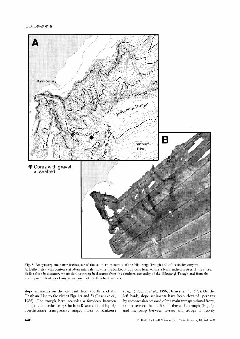
slope sediments on the left bank from the flank of the (Fig. 1) (Collot et al., 1996; Barnes et al., 1998). On theleft bank, slope sediments have been elevated, perhapsChatham Rise to the right (Figs 4A and 5) (Lewis et al.,
1986). The trough here occupies a foredeep between by compression seaward of the main transpressional front,into a terrace that is 500 m above the trough (Fig. 4),obliquely underthrusting Chatham Rise and the obliquely
overthrusting transpressive ranges north of Kaikoura and the scarp between terrace and trough is heavily
© 1998 Blackwell Science Ltd, Basin Research, 10, 441–468446
The dammed Hiurangi Trough
Fig. 4. Backscatter in the southern Hikurangi Trough. A: Diagrammatic representation of topography and backscatter, whereticked lines are scarps, ticked broken line is the shelf break and stippling represents strong reflectivity from channel andoverbank sediment waves. Rectangles are locations of MR1 images shown in B–D. B: Backscatter from the intracontinental headof the Hikurangi Trough showing regularly spaced slope gullies and slope failure with dark, debris flow deposits in the trough.C: Weak backscatter from the narrowing and deepening channel floor in southern subduction trench showing low, long-wavelength sediment-waves in the channel axis, on the flanks of the left-bank levee, and on the insides of bends. D: Weakbackscatter from the 230–280-m-deep, meandering channel floor in the southern Hikurangi Trough showing mud-wave trainstangential to overflow at bends on both sides, mud-waves subparallel to the channel on higher left bank only.
incised by gullies and small avalanche scars (Fig. 4A,B). waves are about 10 m high and are more strongly back-scattering on their downslope face.The small gullies are generally 1–2 km apart. In the
trough below the avalanche scars, speckled, stronglybackscattering sediments indicate the extent of blocky The wide, southern oblique subductionavalanche deposits derived from the scars. Backscatter troughfrom trough sediments decreases north-eastwards frombeing more reflective than the adjacent slopes in the Off southern North Island, the Hikurangi Trough extends
as a flat, generally 50–80-km-wide, turbidite basin, in asouth to being generally less reflective near Cook Strait.At the edge of the intracontinental zone foredeep, just gentle curve seaward of an accretionary prism of
offscraped trench sediments that reaches a maximumbefore the confluence with the Cook Strait Canyon, thereare transverse bedforms with a wavelength of 3–4 km in width of about 70 km at about 41°S. (Figs 1, 2 and 5;
Lewis, 1980; Davey et al., 1986a,b; Barnes & Mercier dea 5-km wide channel, the Hikurangi Channel (Fig. 4A),that is incised up to 80 m below the general level of the Lepinay, 1997). New and archived seismic data show
parallel-bedded, turbidite basin-fill overlying the down-rapidly widening trough (Lewis, 1994). The transverse
© 1998 Blackwell Science Ltd, Basin Research, 10, 441–468 447
K. B. Lewis et al.
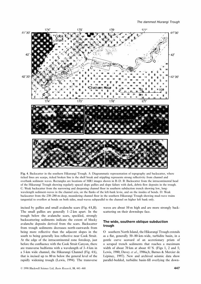
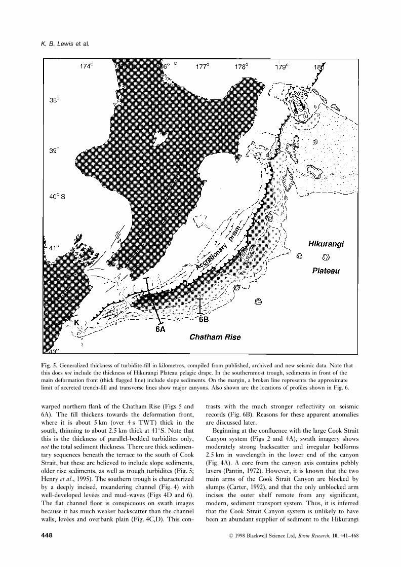
Fig. 5. Generalized thickness of turbidite-fill in kilometres, compiled from published, archived and new seismic data. Note thatthis does not include the thickness of Hikurangi Plateau pelagic drape. In the southernmost trough, sediments in front of themain deformation front (thick flagged line) include slope sediments. On the margin, a broken line represents the approximatelimit of accreted trench-fill and transverse lines show major canyons. Also shown are the locations of profiles shown in Fig. 6.
warped northern flank of the Chatham Rise (Figs 5 and trasts with the much stronger reflectivity on seismicrecords (Fig. 6B). Reasons for these apparent anomalies6A). The fill thickens towards the deformation front,
where it is about 5 km (over 4 s TWT) thick in the are discussed later.Beginning at the confluence with the large Cook Straitsouth, thinning to about 2.5 km thick at 41°S. Note that
this is the thickness of parallel-bedded turbidites only, Canyon system (Figs 2 and 4A), swath imagery showsmoderately strong backscatter and irregular bedformsnot the total sediment thickness. There are thick sedimen-
tary sequences beneath the terrace to the south of Cook 2.5 km in wavelength in the lower end of the canyon(Fig. 4A). A core from the canyon axis contains pebblyStrait, but these are believed to include slope sediments,
older rise sediments, as well as trough turbidites (Fig. 5; layers (Pantin, 1972). However, it is known that the twomain arms of the Cook Strait Canyon are blocked byHenry et al., 1995). The southern trough is characterized
by a deeply incised, meandering channel (Fig. 4) with slumps (Carter, 1992), and that the only unblocked armincises the outer shelf remote from any significant,well-developed levees and mud-waves (Figs 4D and 6).
The flat channel floor is conspicuous on swath images modern, sediment transport system. Thus, it is inferredthat the Cook Strait Canyon system is unlikely to havebecause it has much weaker backscatter than the channel
walls, levees and overbank plain (Fig. 4C,D). This con- been an abundant supplier of sediment to the Hikurangi
© 1998 Blackwell Science Ltd, Basin Research, 10, 441–468448
The dammed Hiurangi Trough
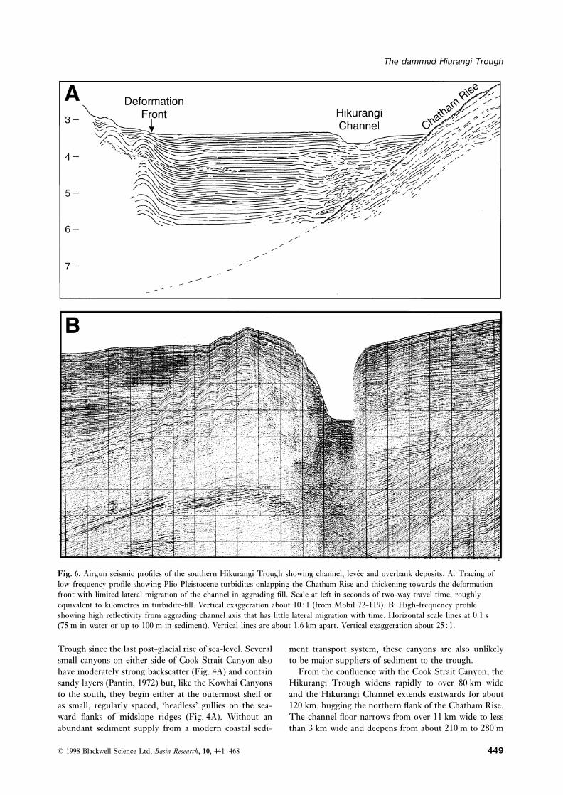
Fig. 6. Airgun seismic profiles of the southern Hikurangi Trough showing channel, levee and overbank deposits. A: Tracing oflow-frequency profile showing Plio-Pleistocene turbidites onlapping the Chatham Rise and thickening towards the deformationfront with limited lateral migration of the channel in aggrading fill. Scale at left in seconds of two-way travel time, roughlyequivalent to kilometres in turbidite-fill. Vertical exaggeration about 1051 (from Mobil 72-119). B: High-frequency profileshowing high reflectivity from aggrading channel axis that has little lateral migration with time. Horizontal scale lines at 0.1 s(75 m in water or up to 100 m in sediment). Vertical lines are about 1.6 km apart. Vertical exaggeration about 2551.
Trough since the last post-glacial rise of sea-level. Several ment transport system, these canyons are also unlikelyto be major suppliers of sediment to the trough.small canyons on either side of Cook Strait Canyon also
have moderately strong backscatter (Fig. 4A) and contain From the confluence with the Cook Strait Canyon, theHikurangi Trough widens rapidly to over 80 km widesandy layers (Pantin, 1972) but, like the Kowhai Canyons
to the south, they begin either at the outermost shelf or and the Hikurangi Channel extends eastwards for about120 km, hugging the northern flank of the Chatham Rise.as small, regularly spaced, ‘headless’ gullies on the sea-
ward flanks of midslope ridges (Fig. 4A). Without an The channel floor narrows from over 11 km wide to lessthan 3 km wide and deepens from about 210 m to 280 mabundant sediment supply from a modern coastal sedi-
© 1998 Blackwell Science Ltd, Basin Research, 10, 441–468 449
K. B. Lewis et al.
below the left-bank levee, which is generally 30–100 m bank levee, is generally fainter and subparallel with thelevee crest, being best displayed on the insides of bendsabove the adjacent turbidite plain. Backscatter imagesbetween the well-developed waves on the outside ofshow conspicuous bedforms in the channel axisbends. This form may be a product of the same Coriolis-(Fig. 4A,C). Close to Cook Strait, light and dark bandinginfluenced overflows that elevated the left bank levee.indicates transverse waveforms with a wavelength of
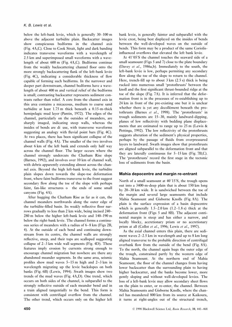
At 41°05∞S the channel touches the seaward side of a2.5 km and superimposed small waveforms with a wave-small seamount (Figs 5 and 7) close to the plate boundarylength of about 600 m (Fig. 4A,C). Bedforms continue(Davey et al., 1986a,b). Immediately to the south, thefrom the weakly backscattering channel floor onto theleft-bank levee is low, perhaps permiting any secondarymore strongly backscattering flank of the left-bank leveeflow along the toe of the slope to return to the channel.(Fig. 4C), indicating a considerable thickness of flowHere, trench-fill up to about 3 km (2.5 s) thick is beingcapable of forming such bedforms. In the narrower andrucked into numerous small ‘protothrusts’ between thedeeper part downstream, channel bedforms have a wave-knoll and the first significant thrust-bounded ridge at thelength of about 400 m and vertical relief of the bedformstoe of the slope (Fig. 7A). It is inferred that the defor-is small; contrasting backscatter represents sediment con-mation front is in the processes of re-establishing up totrasts rather than relief. A core from the channel axis in24 km in front of the pre-existing one but it is unclearthis area contains a micaceous, medium to coarse sandwhether there is yet any decollement beneath the pro-turbidite at least 1.75 m thick beneath a 0.15-m-thicktothrusts (Barnes et al., 1998). The ‘protothrusts’ inhemipelagic mud layer (Pantin, 1972). The edges of thetrough sediments are 15–30, mainly landward-dipping,channel, particularly on the outsides of meanders, areplanes of low reflectivity with bedding plane displace-sharply imaged, indicating steep walls, whereas thements that are estimated to range up to 25 m (Lewis &insides of bends are diffuse, with transverse waveformsPettinga, 1992). The low reflectivity of the protothrustssuggesting an analogy with fluvial point bars (Fig. 4C).suggests alteration of the sediment’s physical properties,At two places, there has been significant collapse of theperhaps by the passage of fluids from overpressuredchannel walls (Fig. 4A). The smaller of the two involveslayers to landward. Swath images show that protothrustsabout 6 km of the left bank and extends only half wayare aligned subparallel to the deformation front and thatacross the channel floor. The larger occurs where thethey are laterally continuous for 5–15 km (Fig. 7B,C).channel strongly undercuts the Chatham Rise slopeThe ‘protothrusts’ record the first stage in the tectonic(Barnes, 1992), and involves over 10 km of channel wall,loss of sediments from the basin.with debris apparently extending almost across the chan-
nel axis. Beyond the high left-bank levee, the turbiditeMahia depocentre and margin re-entrantplain slopes down towards the slope-toe deformation
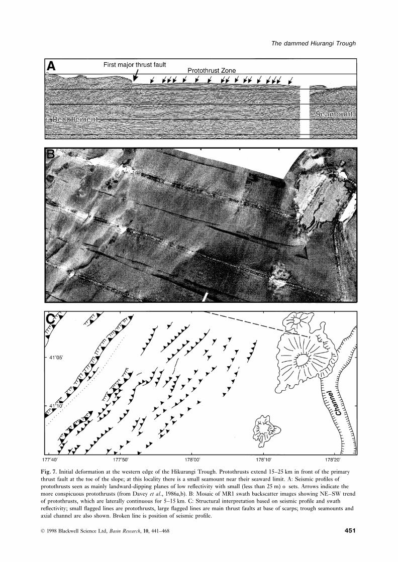
front, where faint bedforms transverse to the front suggestNorth of a small seamount at 40°15∞S, the trough opens
secondary flow along the toe of the slope with perhaps out into a 3400-m-deep plain that is about 150 km longfaint, fan-like structures off the ends of some small by 20–30 km wide. It is sandwiched between the toe ofcanyons (Fig. 4A). the margin and several large seamounts that include
After hugging the Chatham Rise as far as it can, the Mahia Seamount and Gisborne Knolls (Fig. 8A). Thechannel meanders northwards along the outer edge of plain is the surface expression of a basin depocentrethe turbidite-filled basin. Its weakly reflective floor nar- which is generally 1.5–2.0 km (1.2–1.8 s) thick at therows gradually to less than 2 km wide, being incised 240– deformation front (Figs 5 and 8B). The adjacent conti-280 m below the higher left-bank levee and 140–190 m nental margin is steep and has either a narrow, andbelow the right-bank levee. The channel forms a continu- locally blocky, accretionary prism or no accretionaryous series of meanders with a radius of 6–8 km (Figs 2B, prism at all (Collot et al., 1996; Lewis et al., 1997).4). At the outside of each bend and continuing down- As the axial channel enters this plain, there are sedi-stream from its centre, the channel walls are strongly ment waves 2–2.5 km in wavelength and up to 8 km longreflective, steep, and their tops are scalloped suggesting aligned transverse to the probable direction of centrifugalcollapse of 2–3 km wide wall segments (Fig. 4D). These overbank flow from the outside of the bend (Fig. 8A).features imply erosion by currents strong enough to To the north, the channel again hugs the outer edge ofencourage channel migration but nowhere are there any the trough, constrained partly by the western edge ofabandoned meander segments. In the same area, seismic Mahia Seamount. At the northern end of Mahiaprofiles show mud waves 5–15 m high and 2–3 km in Seamount, the floor of the channel changes from havingwavelength migrating up the levee backslopes on both lower backscatter than the surrounding plain to havingbanks (Fig. 6B) (Lewis, 1994). Swath images show two higher backscatter, and the banks become lower, moretrends of the mud waves (Fig. 4A,D). One trend, which gently sloping and without well-developed levees. Theoccurs on both sides of the channel, is subparallel to the loss of a left-bank levee may allow secondary sheet flowsstrongly reflective outside of each meander bend and in on the plain to enter, or re-enter, the channel. Betweena train aligned tangentially to the bend. This form is Mahia Seamounts and Gisborne Knolls, where the chan-consistent with centrifugal overflow from the channel. nel has meandered 800 km from its source at Kaikoura,
it turns at right-angles out of the structural trench,The other trend, which occurs only on the higher left
© 1998 Blackwell Science Ltd, Basin Research, 10, 441–468450
The dammed Hiurangi Trough
Fig. 7. Initial deformation at the western edge of the Hikurangi Trough. Protothrusts extend 15–25 km in front of the primarythrust fault at the toe of the slope; at this locality there is a small seamount near their seaward limit. A: Seismic profiles ofprotothrusts seen as mainly landward-dipping planes of low reflectivity with small (less than 25 m) offsets. Arrows indicate themore conspicuous protothrusts (from Davey et al., 1986a,b). B: Mosaic of MR1 swath backscatter images showing NE–SW trendof protothrusts, which are laterally continuous for 5–15 km. C: Structural interpretation based on seismic profile and swathreflectivity; small flagged lines are protothrusts, large flagged lines are main thrust faults at base of scarps; trough seamounts andaxial channel are also shown. Broken line is position of seismic profile.
© 1998 Blackwell Science Ltd, Basin Research, 10, 441–468 451
K. B. Lewis et al.
© 1998 Blackwell Science Ltd, Basin Research, 10, 441–468452
The dammed Hiurangi Trough
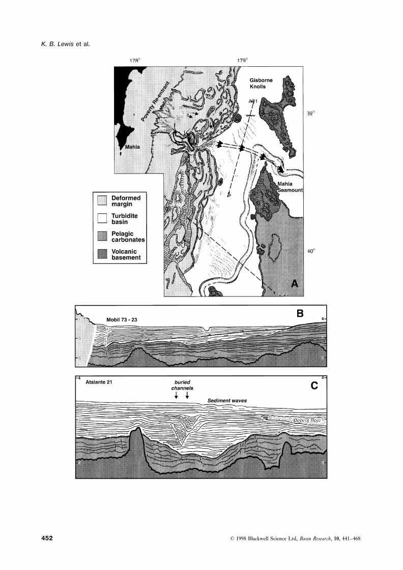
exhibiting ‘point bar’ deposition at bends, and heads 70 km along the toe of a steep margin (Fig. 9) that iseastwards across the Hikurangi Plateau, before inferred to have been eroded and over-steepened bydebouching onto a fan-drft at the edge of the Southwest repeated seamount impacts (Collot et al., 1996). ThePacific Basin (Lewis, 1994). turbidite layers of the trough are undisturbed right to
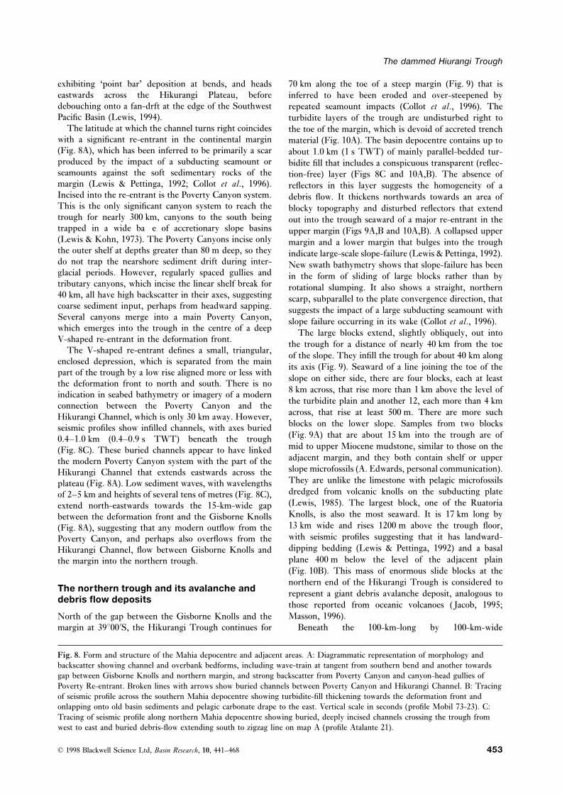
The latitude at which the channel turns right coincides the toe of the margin, which is devoid of accreted trenchwith a significant re-entrant in the continental margin material (Fig. 10A). The basin depocentre contains up to(Fig. 8A), which has been inferred to be primarily a scar about 1.0 km (1 s TWT) of mainly parallel-bedded tur-produced by the impact of a subducting seamount or bidite fill that includes a conspicuous transparent (reflec-seamounts against the soft sedimentary rocks of the tion-free) layer (Figs 8C and 10A,B). The absence ofmargin (Lewis & Pettinga, 1992; Collot et al., 1996). reflectors in this layer suggests the homogeneity of aIncised into the re-entrant is the Poverty Canyon system. debris flow. It thickens northwards towards an area ofThis is the only significant canyon system to reach the blocky topography and disturbed reflectors that extendtrough for nearly 300 km, canyons to the south being out into the trough seaward of a major re-entrant in thetrapped in a wide baffle of accretionary slope basins upper margin (Figs 9A,B and 10A,B). A collapsed upper(Lewis & Kohn, 1973). The Poverty Canyons incise only margin and a lower margin that bulges into the troughthe outer shelf at depths greater than 80 m deep, so they indicate large-scale slope-failure (Lewis & Pettinga, 1992).do not trap the nearshore sediment drift during inter- New swath bathymetry shows that slope-failure has beenglacial periods. However, regularly spaced gullies and in the form of sliding of large blocks rather than bytributary canyons, which incise the linear shelf break for rotational slumping. It also shows a straight, northern40 km, all have high backscatter in their axes, suggesting scarp, subparallel to the plate convergence direction, thatcoarse sediment input, perhaps from headward sapping. suggests the impact of a large subducting seamount withSeveral canyons merge into a main Poverty Canyon, slope failure occurring in its wake (Collot et al., 1996).which emerges into the trough in the centre of a deep The large blocks extend, slightly obliquely, out intoV-shaped re-entrant in the deformation front. the trough for a distance of nearly 40 km from the toe
The V-shaped re-entrant defines a small, triangular, of the slope. They infill the trough for about 40 km alongenclosed depression, which is separated from the main
its axis (Fig. 9). Seaward of a line joining the toe of thepart of the trough by a low rise aligned more or less with
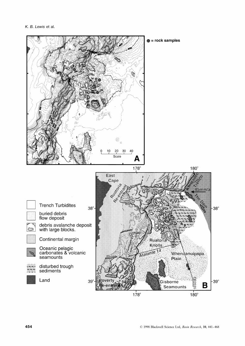
slope on either side, there are four blocks, each at leastthe deformation front to north and south. There is no8 km across, that rise more than 1 km above the level ofindication in seabed bathymetry or imagery of a modernthe turbidite plain and another 12, each more than 4 kmconnection between the Poverty Canyon and theacross, that rise at least 500 m. There are more suchHikurangi Channel, which is only 30 km away. However,blocks on the lower slope. Samples from two blocksseismic profiles show infilled channels, with axes buried(Fig. 9A) that are about 15 km into the trough are of0.4–1.0 km (0.4–0.9 s TWT) beneath the troughmid to upper Miocene mudstone, similar to those on the(Fig. 8C). These buried channels appear to have linkedadjacent margin, and they both contain shelf or upperthe modern Poverty Canyon system with the part of theslope microfossils (A. Edwards, personal communication).Hikurangi Channel that extends eastwards across theThey are unlike the limestone with pelagic microfossilsplateau (Fig. 8A). Low sediment waves, with wavelengthsdredged from volcanic knolls on the subducting plateof 2–5 km and heights of several tens of metres (Fig. 8C),(Lewis, 1985). The largest block, one of the Ruatoriaextend north-eastwards towards the 15-km-wide gapKnolls, is also the most seaward. It is 17 km long bybetween the deformation front and the Gisborne Knolls13 km wide and rises 1200 m above the trough floor,(Fig. 8A), suggesting that any modern outflow from thewith seismic profiles suggesting that it has landward-Poverty Canyon, and perhaps also overflows from thedipping bedding (Lewis & Pettinga, 1992) and a basalHikurangi Channel, flow between Gisborne Knolls andplane 400 m below the level of the adjacent plainthe margin into the northern trough.(Fig. 10B). This mass of enormous slide blocks at thenorthern end of the Hikurangi Trough is considered to
The northern trough and its avalanche and represent a giant debris avalanche deposit, analogous todebris flow deposits those reported from oceanic volcanoes ( Jacob, 1995;
Masson, 1996).North of the gap between the Gisborne Knolls and themargin at 39°00∞S, the Hikurangi Trough continues for Beneath the 100-km-long by 100-km-wide
Fig. 8. Form and structure of the Mahia depocentre and adjacent areas. A: Diagrammatic representation of morphology andbackscatter showing channel and overbank bedforms, including wave-train at tangent from southern bend and another towardsgap between Gisborne Knolls and northern margin, and strong backscatter from Poverty Canyon and canyon-head gullies ofPoverty Re-entrant. Broken lines with arrows show buried channels between Poverty Canyon and Hikurangi Channel. B: Tracingof seismic profile across the southern Mahia depocentre showing turbidite-fill thickening towards the deformation front andonlapping onto old basin sediments and pelagic carbonate drape to the east. Vertical scale in seconds (profile Mobil 73-23). C:Tracing of seismic profile along northern Mahia depocentre showing buried, deeply incised channels crossing the trough fromwest to east and buried debris-flow extending south to zigzag line on map A (profile Atalante 21).
© 1998 Blackwell Science Ltd, Basin Research, 10, 441–468 453
K. B. Lewis et al.
© 1998 Blackwell Science Ltd, Basin Research, 10, 441–468454
The dammed Hiurangi Trough
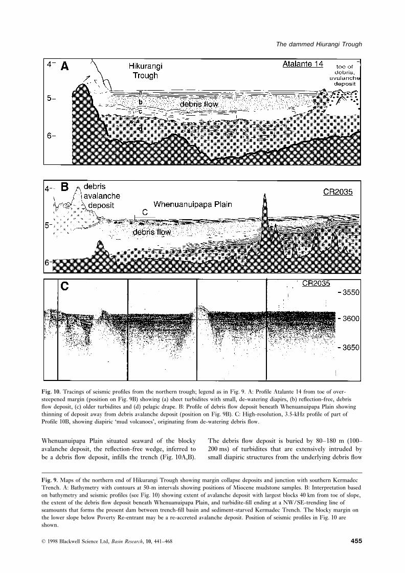
Fig. 10. Tracings of seismic profiles from the northern trough; legend as in Fig. 9. A: Profile Atalante 14 from toe of over-steepened margin (position on Fig. 9B) showing (a) sheet turbidites with small, de-watering diapirs, (b) reflection-free, debrisflow deposit, (c) older turbidites and (d) pelagic drape. B: Profile of debris flow deposit beneath Whenuanuipapa Plain showingthinning of deposit away from debris avalanche deposit (position on Fig. 9B). C: High-resolution, 3.5-kHz profile of part ofProfile 10B, showing diapiric ‘mud volcanoes’, originating from de-watering debris flow.
Whenuanuipapa Plain situated seaward of the blocky The debris flow deposit is buried by 80–180 m (100–200 ms) of turbidites that are extensively intruded byavalanche deposit, the reflection-free wedge, inferred to
be a debris flow deposit, infills the trench (Fig. 10A,B). small diapiric structures from the underlying debris flow
Fig. 9. Maps of the northern end of Hikurangi Trough showing margin collapse deposits and junction with southern KermadecTrench. A: Bathymetry with contours at 50-m intervals showing positions of Miocene mudstone samples. B: Interpretation basedon bathymetry and seismic profiles (see Fig. 10) showing extent of avalanche deposit with largest blocks 40 km from toe of slope,the extent of the debris flow deposit beneath Whenuanuipapa Plain, and turbidite-fill ending at a NW/SE-trending line ofseamounts that forms the present dam between trench-fill basin and sediment-starved Kermadec Trench. The blocky margin onthe lower slope below Poverty Re-entrant may be a re-accreted avalanche deposit. Position of seismic profiles in Fig. 10 areshown.
© 1998 Blackwell Science Ltd, Basin Research, 10, 441–468 455
K. B. Lewis et al.
(Fig. 10A–C). The diapirs are most numerous where theDISCUSSION OF SEDIMENT/
underlying debris flow is thickest (Fig. 10B,C). TheSTRUCTURE INTERACTIONS IN A
debris flow deposit itself is about 250–300 m (300–DAMMED TRENCH350 ms) thick close to the debris avalanche and thins
away from it to about 65 m (80 ms) thick, where it ends Sedimentary inputs and tectonic outputsabruptly 70 km to the south-east (Figs 9B and 10B). It
A sediment-filled trench is a special type of sedimentaryoverlies a lower layer of parallel-bedded sediments thatbasin, one that is being continuously consumed byare 170–350 m thick and dip towards the margin, whichtectonic processes along one side. Hence, basin character-in turn covers faulted ‘pelagic drape’ up to about 1 kmistics depend not only on the nature and rate of sediment(1 s) thick infilling hollows in the underlying irregularsupply and loss but also on the rate of sediment loss bybasement (Fig. 10A,B). Except for the seismically trans-subduction processes. The Hikurangi Trough is a sedi-parent, debris-flow wedge, the sequence correlates withmentary basin because inputs have exceeded outputs,a similar sequence in the central basin of the Hikurangiwhereas in the Kermadec Trench they have not.Plateau that is crossed by the eastward-trending
At a continent-flanked trench, such as the HikurangiHikurangi Channel (Lewis, 1994; Wood & Davy, 1994).Trough, sediment input is likely to be high, sourcedThe top turbidite of the Whenuanuipapa Plain equates,from uplifted forearc strata onshore. Where the trenchat least partly, with inferred Quaternary, channel-ends at a transform that includes a component of conti-overbank turbidites of the plateau, the lower parallel-nental collision and uplift, as it does at the Hikurangibedded sediments partly with inferred Pliocene sheetTrough, then sediment supply to the apex of the trenchturbidites, and the deeper ‘pelagic drape’ with a slowlyis likely to be particularly large.deposited, carbonate-rich Miocene and Palaeocene layer
Outputs from shallower parts of the trench can alsothat infills depressions in the (inferred Mesozoic) thick-be voluminous. In the absence of significant barriers,ened oceanic basement.sediments may be transported along the trench axis toSome of the diapirs penetrating the upper turbiditesits deepest part, perhaps accumulating in small depo-of the Whenuanuipapa Plain break through as mudcentres along the way. These small depocentres are likelyvolcanoes at the seabed (Fig. 10C), indicating prolongedto be consumed beneath the margin, so that a wideand still on-going dewatering of the underlying, thick,turbidite plan never develops. However, at the Hikurangidebris flow. The limited number of reflectors beneathTrough a predominantly apical sediment supply has beenthe debris flow suggest some disruption of underlyingcontained within a restricted length of trench. Tectonicwater-rich turbidites by rapid loading when the debrisoutputs by accretion and subduction increase with bothflow was deposited. Available profiles indicate that theincreasing rates of convergence and decreasing obliquitydebris flow infills the trough depocentre south of the aval-of convergence (Underwood & Bachman, 1982; Vonanche deposit and extends beneath the WhenuanuipapaHuene & Scholl, 1991); decreasing obliquity implies anPlain for up to 100 km from the deformation frontincreasing orthogonal component of convergence. The(Fig. 9B). It has a total area of about 4000 km2. A debrisHikurangi Trough’s rate of convergence increases, andflow deposit that is up to 250–300 m thick and extendsits obliquity of convergence decreases, towards the northout into the trough for 100 km must have been a(De Mets et al., 1990, 1994). Consequently, tectonicsignificant, if temporary, barrier to turbidity currentsoutput by subduction processes are likely to increase infrom the south.that direction and the rate of sediment supply decreasesin the same direction. The net effect is that the HikurangiTrough is a sedimentary basin with turbidite fill that
The modern seamount chain dam thins from about 5 km thick in the south to less than1 km in the north.The Whenuanuipapa Plain, which represents the north-
The degree to which the subducting plate is ‘rough-ern limit of the Hikurangi Trough turbidite plain, endsened’ by tensional grabens or seamounts influences theat a NW/SE-trending chain of low seamountsmechanism and rate of loss by tectonic processes. A(Fig. 9A,B). This seamount chain intersects the trenchsmooth basement, with few seamounts, such as occurs inat 37°45∞S, and its subducted parts are discernible beneaththe southern Hikurangi Trough (Wood & Davy, 1994),the inner trench wall (Collot et al., 1996). To the north,encourages offscraping of trench-fill into an accretionarythe southern Kermadec Trench is characterized by greatlyprism, whereas a ‘rough’ basement topography with manyincreased depths, by en echelon enclosed basins, by aseamounts, like the northern trough, protects sedimentV-shaped profile, and by the absence of turbidites,in depressions and enables more of it to be subductedalthough there is still up to 1 km of pelagic-drapebeneath the margin (Malavieille et al., 1991; Lallemandsediments (Collot et al., 1996). The chain of low seam-et al., 1994; Mountney & Westbrook, 1996). It is esti-ounts is currently the dam that separates the flat plainsmated that of the order of 60 000 km3 of turbidite filland turbidite basins of the Hikurangi Trough fromremains in the Hikurangi Trough, with in excess ofthe enclosed, sediment-starved basins of the southern
Kermadec Trench. 20 000 km3 of Quaternary trough turbidites preserved in
© 1998 Blackwell Science Ltd, Basin Research, 10, 441–468456
The dammed Hiurangi Trough
the accretionary prism on the adjacent margin. The Morgenstern, 1967; Krause et al., 1970; Hughes Clarke,1990; Garcia & Hull, 1994; Garfield et al., 1994).amount of trench-fill subducted beneath the margin is
unknown, although in the central trough very little At Kaikoura Canyon, major inputs of other types areless likely. Direct hyperpycnal inflow of turbid fluviatiletrench-fill is subducted, the decollement between
offscraped and subducted sediment being close to the water (Droz et al., 1996) is impossible as there are nosignificant rivers near the canyon head. However, stormboundary between turbidite fill and the underlying pelagic
drape that blankets the plateau. effects could be significant in a bay exposed to the fullforce of southerly storms. Storm-initiated flows frombreaking internal waves and storm-generated edge-wavesKaikoura Canyon supply to the troughcan reportedly resuspend large quantities of sand andgenerate rip-like flows (Inman et al., 1976), and theseBecause it is the only canyon that projects close enough
to the coast to intercept a major longshore sediment could theoretically ‘ignite’ to reach catastrophic equilib-rium like an earthquake-triggered event (Parker, 1983).transport system (Lewis et al., 1998), the Kaikoura
Canyon is inferred to have been the main conduit for However, in a zone of severe earthquakes, such eventsare unlikely to rival the near instantaneous failure ofturbidites to the Hikurangi Trough during the late
Holocene (Carter et al., 1982; Lewis, 1994). Longshore large volumes of sediment from ground shaking, but theymay be responsible for distributing fine shelf sedimentstransport into the canyon head is estimated at be currently
of the order of 1.5 km3 kyr−1 (Lewis & Barnes, 1998). into proximal parts of the canyon where they can beincorporated into later large events.The rate of deposition in the southern Hikurangi Trough
has been about 0.65 m kyr−1 during the last 0.5 Myr Physical and theoretical modelling demonstrate thatan initial slide in a steep canyon head rapidly metamor-(Barnes & Mercier de Lepinay, 1997), and the average
over the whole trough is estimated to have been about phoses into a turbidity current, perhaps via a debris flowstage (Mulder et al., 1997), by entraining water via0.4 m kyr−1. The area of the trough, including the area
accreted to the over-riding plate during the last 0.5 Myr tunnels in the base of the initial flow and increasing thevolume in motion by 2–6 times (Allen, 1971). Even as(Barnes & Mercier de Lepinay, 1997), is about 37 000 km3
and, accepting the average sedimentation rate of the flow becomes a turbidity current, gravel can stillmove by grain-flow or debris-flow processes at the base0.4 m kyr−1, the volume added to the trough during the
late Quaternary has been about 15 km3 kyr−1. This of the flow (Lowe, 1982) and the low sinuosity and steepgradient of the Kaikoura Canyon is typical of conduitsestimate includes nonturbidite deposition, including
tephra from andesite volcanoes to windward, and fine- with high bedload transport (Clark et al., 1992; Clark &Pickering, 1996). Concurrently, the more fluid, uppergrained sediment from rivers and resuspended from the
shelf. It does not include turbidite deposition on the flow may outpace the gravelly base (Masson, 1994), andmay become supercritical, resulting in additional mixingouter part of the Hikurangi Plateau or in the Hikurangi
Channel’s distal fan-drift. Nevertheless, the average rate at the upper interface. Given an erodible substrate ofsoft, hemipelagic and storm deposits, each major turbidityof addition to the Hikurangi Trough is probably an order
of magnitude greater than the Holocene input from the current may rapidly attain a state of self-perpetuatingautosuspension (Bagnold, 1962), or even ‘ignite’ into aKaikoura Canyon. Clearly, deposition was very much
greater during glacial ages when many other canyons self-accelerating, ignitive autosuspension current, whicherodes more than it deposits and increasing its powersupplied sediment directly to the shelf edge and when
large amounts of bedload was not trapped by glacial lakes until a state of ‘catastrophic equilibrium’ is reached(Pantin, 1979, 1983; Parker et al., 1986). In the Kaikoura(Carter & Carter, 1990).
The canyon-head fill consists of longshore-migrating Canyon and head of the Hikurangi Trough, exchange ofsediment with the seabed probably takes place in twofine sand and mud, with some locally derived gravels
(Lewis et al., 1998). The frequency of major collapse of stages; most erosion of fine, soft sediment takes place atthe head of the flow while coarse sediment is depositedthe metastable pile can be gauged from the periodicity
of the resultant deposits. Turbidites in the main trough, from the body and tail of the flow (Simpson, 1987). Theresult is an ongoing exchange of sediment with thewhere deposition can be dated from tephra layers, sug-
gests that major turbidity currents occur there once every seabed, with a fluid, autosuspension turbidity currentthat overflows the Hikurangi Channel for enormousfew centuries (Lewis, 1994). This invites a correlation
with major earthquakes, because movements of the major distances and ultimately bears little resemblance in formand composition to the flow that began in the canyonplate boundary faults near Kaikoura, which are capable
of producing seismic shaking with a modified Mercalli head.In the Kaikoura Canyon, it apparently takes several(MM) intensity of more than VIII, occur at intervals of
90–400 years (van Dissen, 1991). Correlations between centuries for sufficient metastable sediment to accumulatein the canyon head to generate a flow that will ‘ignite’earthquakes, slope failure and turbidity currents are well
documented and it is inferred that severe shaking of into a long-distance turbidity current. Minor flows maynever ‘ignite’, but deposit their entrained sediment asmetastable sediment increases pore pressure and sensi-
tivity to the point of failure (Houtz & Wellman, 1962; ‘fuel’ for the next big one. Theory predicts that, in any
© 1998 Blackwell Science Ltd, Basin Research, 10, 441–468 457
K. B. Lewis et al.
particular morphological setting, catastrophic equilibrium reaches the trough without any such baffle, the low ridgeat the outer edge of the small triangular ponded basin atflows will naturally attain a similar size, concentration
and velocity, producing the uniformly sized turbidites its toe being an insignificant barrier to high-velocityturbidity currents (Underwood, 1986; Garcia & Hull,characteristic of many modern and fossil basins (Pantin,
1983), including the Hikurangi Trough (Lewis, 1985). 1994). With the virtual absence of a left-bank levee onthe Hikurangi Channel opposite the Poverty Canyons,flows might be funnelled directly into the segment of theOther canyons and ‘headless’ gullies at highchannel that crosses the plateau to the east. However,and low sea-levelsediment waves in the trough to the north-east of thePoverty Canyon toe suggest that at least some flows fromAlthough the Kaikoura Canyon is inferred to be currently
the most important conduit for sediment to the trough, Poverty Canyon may turn left into the northern end ofthe Hikurangi Trough, perhaps under the influence ofit was probably a relatively minor feature during low-
stands of sea-level. Then, the Pegasus Canyon system either Coriolis forces or a shallow branch of the DeepWestern Boundary Current that crosses the Hikurangiintercepted enormous amounts of sand moving longshore
from rivers far to the south (Herzer, 1979), little sediment Plateau (McCave & Carter, 1997). Although the head ofthe Poverty Canyon is sufficiently deep to have only beenthen being trapped in shelf sediment prisms or in
supraglacial lakes (Carter & Carter, 1990). At the same a major conduit for detrital sediments during periods ofglacially lowered sea-level, regularly spaced, stronglytime, the extensive Cook Strait Canyon system was a
major supplier of sediment from rivers that now flow reflective gullies along the straight shelf edge imply inputfrom seeps, which are known to occur both to seawardinto the western straits (Lewis et al., 1994), with sediment
from Cook Strait reaching the fan-drift at the far end of and to landward (Lewis & Marshall, 1996). Thus,although Poverty Canyon may have been the only signifi-the Hikurangi Channel (Carter & Mitchell, 1987). Like
most of the world’s canyons, the Pegasus and Cook Strait cant source of turbidity currents north of Cook Strait itsmain input was during glacial ages, with minor on-goingcanyons, which carried large quantities of traction load
during low-stands, carry little during high stands (Griggs input from seep-gullies.et al., 1970; Carter & Mitchell, 1987; Thornberg &Kulm, 1987). The absence of fans
The small canyons that form at the confluence ofsemiregularly spaced gullies, some on midslope ridges, It has been observed that well-developed, submarine fans
form in trenches at the bottom of steep canyons, althoughowe little to coastal sources. The gullies resemble thoseattributed to ‘spring sapping’ at fluid seeps (Orange & they form recognizable features only if their rate of
development exceeds the rate at which they are beingBreen, 1992; Orange et al., 1994), the regular spacing ofthe seeps being caused by a self-regulating feedback of destroyed by subduction or accretion (Thornberg &
Kulm, 1987; Thornburg et al., 1990). They are inevitablythe excess pore pressure gradient in the underlying rocks.Seeps of methane-rich fluids, with vent faunas and transitory features. It has also been observed that trenches
with well-developed axial channels do not have well-carbonate crusts or chimneys, occur widely along theHikurangi Margin, generally associated with com- developed submarine fans (Underwood & Bachman,
1982). The Hikurangi Trough, with its well-developedpressional deformation of Neogene sediments (Lewis &Marshall, 1996). Seep gullies are typically aligned along channel and absence of fans, conforms to this observation.
Nowhere along the Hikurangi Trough are there large,faults or outcrops of porous sediment (Fujioka & Taira,1989; Henry et al., 1989; Lallemand et al., 1992; Le canyon-toe, distributary fans, similar to those of some
other modern and ancient turbidite-filled trenches (MuttiPichon et al., 1992), and those of the southern HikurangiMargin are aligned along fault-controlled scarps, where & Normark, 1987); the faint, fan-shaped backscatter
patterns on the flat trough floor beyond some smallfluids are expelled from compressed rocks to landward(Lewis et al., 1986; Barnes et al., 1998). The gullies, canyons (Fig. 4A) have little or no bathymetric
expression. Another analogue may be the sediments thatwhich begin as shear strength is reduced close to a seepsite, develop by headward sapping above the seep and are confined in the head of the Hikurangi Trough between
the flank of the Chatham Rise and margin of north-by erosion below it. This may generate enough rock-debris to produce the strong backscatter seen in the small eastern South Island. They may represent a structurally
confined and deforming trench-apex fan, similar to thecanyon axes. Although gullies that incise the shelf breakmay be enhanced by funnelling of nearshore sediments Boso Fan at the head of the Sagami Trough of Japan
(Soh et al., 1990). Like fans elsewhere, the trough-headduring lowstands of sea-level, and despite the number ofgullies along the margin, their input to the Hikurangi sediments are at the toe of canyons where coarse sediment
is deposited at a reduction in slope, perhaps because ofTrough is likely to be small.Canyons that incise the upper slope landward of the a hydraulic jump in large flows. The hydraulic jump
entrains water, reduces effective density, reduces velocityaccretionary prism supply little to the trough becausetheir load is trapped in the baffle of slope basins (Lewis, (Rothwell et al., 1992), encourages deposition of coarse
sediment, increases flow thickness, increases turbulence,1980). Further north, the large Poverty Canyon system
© 1998 Blackwell Science Ltd, Basin Research, 10, 441–468458
The dammed Hiurangi Trough
increases the amount of fine sediment that can remain in with continually reducing proportions of the originalshelf sediment.suspension (Kenyon et al., 1995) and may assist formation
of turbidity currents capable of long-distance, self- In the Hikurangi Channel, where does the mud thatis entrained into long-distance flows come from? Littleperpetuating flow (Komar, 1971; Pantin, 1979).
We have no reliable estimates of deposition rate in the comes from the erosion of channel floor and walls becausethe channel system aggrades and, since there is nohead of the trough, but further north, Holocene rates of
deposition, based on the depth to dated rhyolitic tephras, evidence of rapid meander migration, any erosion of theoutsides of bends is compensated by deposition on pointare about 0.15 m kyr−1, with one turbidite every 1000–
1500 years (Ninkovich, 1968; Lewis & Kohn, 1973); rates bars. The lack of extensive meander migration, evincedby abandoned meander loops and systems, indicates thatincrease to 0.3 m kyr−1, with one turbidite every 300–
400 years, on a right-bank levee (Lewis, 1985, 1994). the Hikurangi Channel is broadly in equilibrium withthe prevailing flow conditions (Shor et al., 1990). ThereHowever, average rates of overbank deposition in the
southern trough, averaged over several glacial–interglacial is some from collapse of channel walls (Fig. 4) but,although this makes a significant contribution to somecycles, are more than 0.65 m kyr−1 (Barnes & Mercier
de Lepinay, 1998). Such rates of deposition are moder- channel systems (Masson, 1994; Masson et al., 1995), itis here localized and does not provide an ongoing supplyately rapid for a deep-water basin (Rothwell et al., 1992),
although slow compared with large fans (Damuth & along the channel. Alternatively, much of the sedimentrequired to ‘fuel’ the larger flows may be input to theFlood, 1984; Feeley et al., 1990).channel by dilute, turbid flows that never ‘ignited’. Suchdilute flows may begin during storms on the narrowshelves of the region, flow down the margin and depositBedforms and flow in an axial channelthin watery clay-rich layers in bathymetric lows (Lewis,1973; Lewis & Kohn, 1973). Such layers may build upThe conspicuous channel-axis bedforms of the Hikurangi
Trough are indicative of the flows with which they are over centuries to form the ‘hemipelagic’ mud, whichforms 30–50% of the mud in some cores from thein equilibrium, although the relationship is not yet well
quantified. Transverse sediment waves are probably turbidite plain (Lewis, 1985), although such deposits maymore appropriately be termed ‘hemiturbidite’ (Howe,formed by large eddies, which in turn may be related to
thickness of the flow (Yalin, 1972; Zeng et al., 1991). 1996). The lowest place for such watery, muddy ‘hemitur-bidite’ layers (Howe, 1996) to accumulate is the channelThe ratio between bedform wavelength and flow thick-
ness has been inferred to range from 751 to 151 (Allen, itself. Over time, a significant layer of fine sediment mayaccumulate in the channel ready for the next autosuspen-1984; Zeng et al., 1991). Therefore, the 3.5-km wave-
length bedforms that occur in the channel axis before sion flow, which entrains the mud and deposits coarsersediment in its wake.the confluence with the Cook Strait Canyon (Fig. 4A)
were formed by flows at least 500 m thick. Those beyond There is debatable evidence of a significant layer offine sediment in the channel at the present time. Mostthe Cook Strait confluence, which have a wavelength of
2.5 km, were formed by flows at least 350 m thick. Small of the channel in the Hikurangi Trough has lowerbackscatter than adjacent overbank areas (Fig. 4C,D).superimposed bedforms with a wavelength of 600 m may
relate to the tails of large flows or to small flows that Generally, though not universally, lower reflectivity isindicative of finer grained sediment at the seabed. Thiswere at least 90 m thick. Transverse bedforms on the
insides of meanders, although comparable with those on indication of fine-grained sediment in the axis of thechannel appears to contradict the evidence from cores,fluviatile point-bars (Miall, 1989), have a wavelength
indicate of flow thicknesses greater than the channel which show that graded silty sand and sandy silt tur-bidites are thicker and more abundant in the channeldepth.
One of the enigmas of long-distance autosuspension axis than on the surrounding plain (Lewis, 1985).However, in one core from the southern trough, the topcurrents in the Hikurangi Trough is that they must erode
soft sediment from a channel that is aggrading. Entraining turbidite is buried by over 0.4 m of soft ‘hemiturbidite’mud (P. M. Barnes, personal communication), whichnew, fine sediment into the flow, which is critical for the
continuation of the flow, is an important mechanism of may have been lost in the coring process from otherarchived cores and perhaps partly even from this core.sediment transport (Piper & Stow, 1991). Entrainment
is quantified for the 1929 Grand Banks turbidity current, Thus, the low backscatter from the channel axis mayreflect a surface layer of soft, fine sediment. Despite thewhich entrained 50–100 km3 of sediment on the lower
slope (Hughes Clarke et al., 1990), and is well docu- generally positive correlation between backscatter inten-sity and grain size, constructive and destructive inter-mented for channels in supraglacial lakes that are both
cut and filled during passage of a turbidity current (Eyles, ference in well-layered sediments can produce anomalousresults (Gardner et al., 1991) as can biological activity,1987). Mainly deep-water, rather than shallow-water,
foraminifers occur in distal turbidites of the Hikurangi which increases surface roughness and backscatter fromfine sediments in overbank areas (Kenyon, 1992). Hence,system (Fenner et al., 1992), demonstrating that trough
mud is entrained and carried to more distal areas along the swath imagery of a weakly reflective channel suggests,
© 1998 Blackwell Science Ltd, Basin Research, 10, 441–468 459
K. B. Lewis et al.
but does prove, the presence of a significant layer of soft mudwaves occur beside the river-fed Zaire Channel(Droz et al., 1996).mud sitting within the channel that is waiting to be
entrained in the next catastrophic flow. Turbidity currents may considerably overlap a channelbut still follow its course. ‘Intermediate’ flow are perhapsChannel sinuosity is likewise indicative of flow, with
high sinuosity being incompatible with very fast-moving twice as deep as the channel and exceptionally large onesare 10 times the channel depth (Clark & Pickering, 1996).turbidity currents (Klaucke et al., 1997). The sinuosity/
gradient profile of the Hikurangi Channel, which has a In the Hikurangi Trough, where the channel is 150–200 m below the right-bank levee and 200–280 m belowmaximum sinuosity of 1.5 and a channel slope decreasing
from 15400 to 15800 in the southern Hikurangi Trough, the left bank levee, an ‘intermediate’ flow might equateto the >500-m-thick flow inferred to form the channelis in the midrange for canyon/channel systems and is
characteristic of silt-dominated flows; the Cascadia axis bedforms. For such a flow, loss of the fine, diluteupper part of each turbidity current to overbank areas, asystem, which is also at a convergent margin, has a
similar profile (Clark et al., 1992). phenomenon known as flow stripping (Piper & Normark,1983), could continue for hundreds of kilometres, produc-ing the thin silt turbidites that have been correlatedFlows out of and into the channelelsewhere over vast areas (Hess, 1995; Klaucke et al.,1998). Continuous flow stripping requires that the chan-The form of the trough’s channel levees reflects the
muddy nature of the upper part of equilibrium flows nel be in dynamic equilibrium with the turbidity currentsthat are typical of this system. The overbank flow of thealong the channel. Since the left bank levee is consistently
higher than the right, even at left-hand bends (Lewis, channel may form secondary, sheet flows along the toeof the margin, producing margin-transverse bedforms1994), the implication is that southern hemisphere
Coriolis effects have consistently exceeded centrifugal (Figs 4A and 6A). In some instances, the stripped flowmay rejoin the main channel flow at places with reducedeffects in the elevated heads of thick turbidity flows
(Carter & Carter, 1988). Such consistent cross-flow asym- levees (Rothwell et al., 1992; Masson et al., 1995); insome case, the channel may recapture only the coarsestmetry is achieved in moderately slow and dilute flows
(Komar, 1969; Piper & Savoye, 1993; Klaucke et al., part of the flow (Masson, 1994). In the Hikurangi Trough,overbank flows probably rejoin the channel at several1997). Nevertheless, there is strong evidence of centrifu-
gal outflow of some flows. places where the channel approaches the margin and itsleft bank levee is low, notably where seamounts andThe 5–15-m-high, 2–3-km-wavelength mud-waves
that occur tangentially to the outsides of bends on both protothrusts fill the gap between channel and margin(Fig. 7C) and immediately before it turns east out of thebanks (Figs 4D, 6B) is evidence of strong, centrifugal
outflows. Centrifugal effects probably occur in the heads trough (Fig. 8A).Where the channel turns right out of the trough,of larger, denser, faster turbidity currents (Griggs &
Kulm, 1970). A detailed consideration of turbidity cur- turbidites indicate that sheet flows continue northwardsalong the toe of the margin and detour around the giantrent flow parameters is beyond the scope of this paper.
There are many variables, and assumptions must be avalanche deposit for 170 km to the northern end thetrough (Figs 2 and 8). On the central basin of themade about many of them. Analyses of some turbidite
systems have been made on the basis of grain size of the Hikurangi Plateau, sheet-flows were inferred to havetravelled eastwards for more than 300 km prior to itsdeposits (Van Tassel, 1981; Komar, 1985) but this method
has been questioned (Hiscott, 1994). For others, being cut by an extension of the Hikurangi Channel(Fig. 1; Lewis, 1994). Elsewhere, unconfined, overbank,interpretations of flow characteristics have been made
from channel dimensions (Komar, 1969). However, a sheet-flows, which deposit their loads slowly as they slowdown, are even more widely dispersed (Pickering et al.,generalized formula for a 500-m-thick autosuspension
current, where gravity is balanced against friction, sug- 1989; Clark & Pickering, 1996), some having travelledfor over 1000 km and over significant bathymetric highsgests that velocities at the head of a moderate-sized flow,
may reach about 30 m s−1 in the lower Kaikoura Canyon, (Garcia & Hull, 1994).12 m s−1 in the restricted upper trough, 6 m s−1 in thesouthern trough near Cook Strait, and 4 m s−1 off The Ruatoria avalanche and debris flowMahia, and thereafter increasing to 6 m s−1 as the axial depositsslope increases after the channel leaves the trough(H. M. Pantin, personal communication). Although autosuspension currents can propagate for
enormous distances, at least part of the reason they haveThe weakly backscattering mudwaves that occur along,and parallel to, the levee crest on the higher left bank never reached the southern Kermadec Trench may be
damming by avalanche and debris flow deposits. At thelevee only probably reflect outflow that was stronglyinfluenced by Coriolis forces, for instance, the thick, northern end of the Hikurangi Trough, a huge, blocky
avalanche deposit and associated massive debris flowdilute and slowly moving tail-plumes of major turbiditycurrents or some dilute, nonautosuspension flows that deposit have infilled the northern end of the basin. These
deposits were large enough to act as an ‘earth dam’,occur between the major flows. Similar levee-parallel
© 1998 Blackwell Science Ltd, Basin Research, 10, 441–468460
The dammed Hiurangi Trough
which, for a time during the Pleistocene, ponded turbidity of the order of 300–700 kyr. Thus the debris flow andperhaps also the avalanche deposit are tentatively inferredcurrents coming from the south and prevented their
passage to the southern Kermadec Trench. Structural to be mid Pleistocene in age (Fig. 11A,B). Elsewhere, thelargest slide blocks in debris avalanches are concentrateddetails of the failure, its possible causes, and its impli-
cations for margin evolution will be presented elsewhere; in the middle of a deposit ( Jacobs, 1995; Masson, 1996),so that the presence of the largest slide blocks in thehere, we concentrate on those aspects that are directly
related to the evolution of the trough. Hikurangi Trough at the leading edge of the avalanchedeposit could imply a two-stage process whereby theThe margin collapse into the northern end of the
trough added a huge amount of fill into the basin. The large blocks slid from the margin first, and were laterpushed along in front of the main avalanche. Debrisavalanche deposit, which extends 40 km out into the
trough, covers an area within the trough of about avalaches are thought to be catastrophic events that movedisaggregated blocks for many tens of kilometres, and up1500 km2 and constitutes an estimated 1500 km3 of basin
fill. This is only part of the total avalanche deposit, which to 230 km, across an oceanic basin (Moore et al., 1989),generating enormous tsunamis (Moore & Moore, 1984;also covers an extensive area of the lower slope in blocky
topography. Its original extent within the basin may have Dawson et al., 1988). In contrast, deep-seated, rotationalslumps move relatively intact blocks for up to severalbeen larger because the subducting plate is carrying it
back towards the margin at the convergence rate of tens of kilometres over a long period of time (Mooreet al., 1989). If this is correct, then in the northern45 km Myr−1 (Fig. 1). In addition to the blocky avalanche
deposit, the debris flow deposit, which now extends Hikurangi Trough, an initial slow slump may have beenpushed along in front of a subsequent thin, fast-moving,100 km out into the basin, covers an area of 4000 km2
and constitutes an estimated 800 km3 of basin-fill. blocky avalanche.From the geometry of the re-entrant’s northern scarp,Although the avalanche deposit and debris flow deposit
together constitute a massive slope failure, they are not it has been inferred that the Ruatoria Re-entrant isprimarily a seamount impact scar (Collot et al., 1996)the world’s largest. Margin collapses off South Africa are
nearly an order of magnitude larger (Dingle, 1977, 1980), with margin collapse of collision fractured rocks in itswake (Collot & Fisher, 1989; Lallemand et al., 1990; Vonbut may not be single features. Both the main Storegga
Slide off Norway (Bugge et al., 1987, 1988; Jansen et al., Huene & Lallemand, 1990). The implication for theevolution of the Hikurangi Trough is that a subducting1987) and the Nuuanu debris avalanche of the Hawaiian
Islands are about twice as big ( Jacobs, 1995; Moore et al., seamount can dam a trench from the time that it firstbegins to imbricate trough sediments between itself and1989). Even the 13×17-km slide block that has moved
at least 40 km out into the basin is not the world’s largest the margin until the debris that collapsed in its wake iscarried back into or beneath the margin by the subductingslide-block, being only about one-third of the volume of
a volcanic block, Tuscaloosa Seamount, that collapsed plate. If the leading edge of the seamount or line ofseamounts that formed the Ruatoria Re-entrant is aheadfrom the flank of the Hawaiian Islands ( Jacobs, 1995).
Together, avalanche and debris flow deposits infilled of the scar, then it must be 90 km or more landward ofthe toe of the margin in the direction of relative platethe trench axis and are inferred to have acted as a major
barrier to the passage of turbidity currents. The avalanche convergence. This implies that, with convergence of45 km Myr−1, the seamount first began to dam the trenchdeposit raised the level of the trough axis by a minimum
of 500 m and the debris flow deposit raised it by over at about 2 Ma, that is, in latest Pliocene or earlyPleistocene times (Fig. 11C,D), and its wake effects are250 m at its inner edge and by 65 m at 100 km out into
the basin. It must have taken a considerable time for still limiting propagation along the trough to some extenttoday (Fig. 11).turbidites to overtop the debris flow and then bury it
with 80–180 m of sediment. There are no reliable esti-mates of long-term sedimentation rates in this area but The past and present damsin the southern part of the trough, the rate of accumu-lation for the last few glacial–interglacial cycles, based on Turbidites are almost level with saddles in the line of
low seamounts that limits the flow of distal, sheet tur-seismic stratigraphy, is about 0.65 m kyr−1 (Barnes et al.,1998) in an area where Holocene rates are 0.15 m kyr−1. bidity currents into the empty Kermadec Trench (Figs
9A and 11A). The present dam is about to be overtoppedRates of Holocene (and latest Pleistocene) turbidite/hemiturbidite deposition on the central Hikurangi Plateau by accumulating turbidites. Nevertheless, the seamounts
may still act as an effective barrier because the distalare inferred to be only about half that in the southerntrough (Fenner et al., 1992). If average, long-term rates turbidity currents will have lost most of their energy
after negotiating 800 km of channel and a 170-km-long,of deposition in the northern trough are less than in thesouthern trough and more than the central plateau, due circuitous route around seamounts and avalanche deposits
since leaving the channel, any remaining energy beingto greater ash input, then the long-term average may beabout 0.5 m kyr−1. If this value is accepted as a working dissipated through reflection and interference at the line
of seamounts (Pantin & Leeder, 1987).approximation, then the 150–350 m of sediment that ittook to overtop the debris flow and then bury it required The debris flow deposit, which infills the gap between
© 1998 Blackwell Science Ltd, Basin Research, 10, 441–468 461
K. B. Lewis et al.
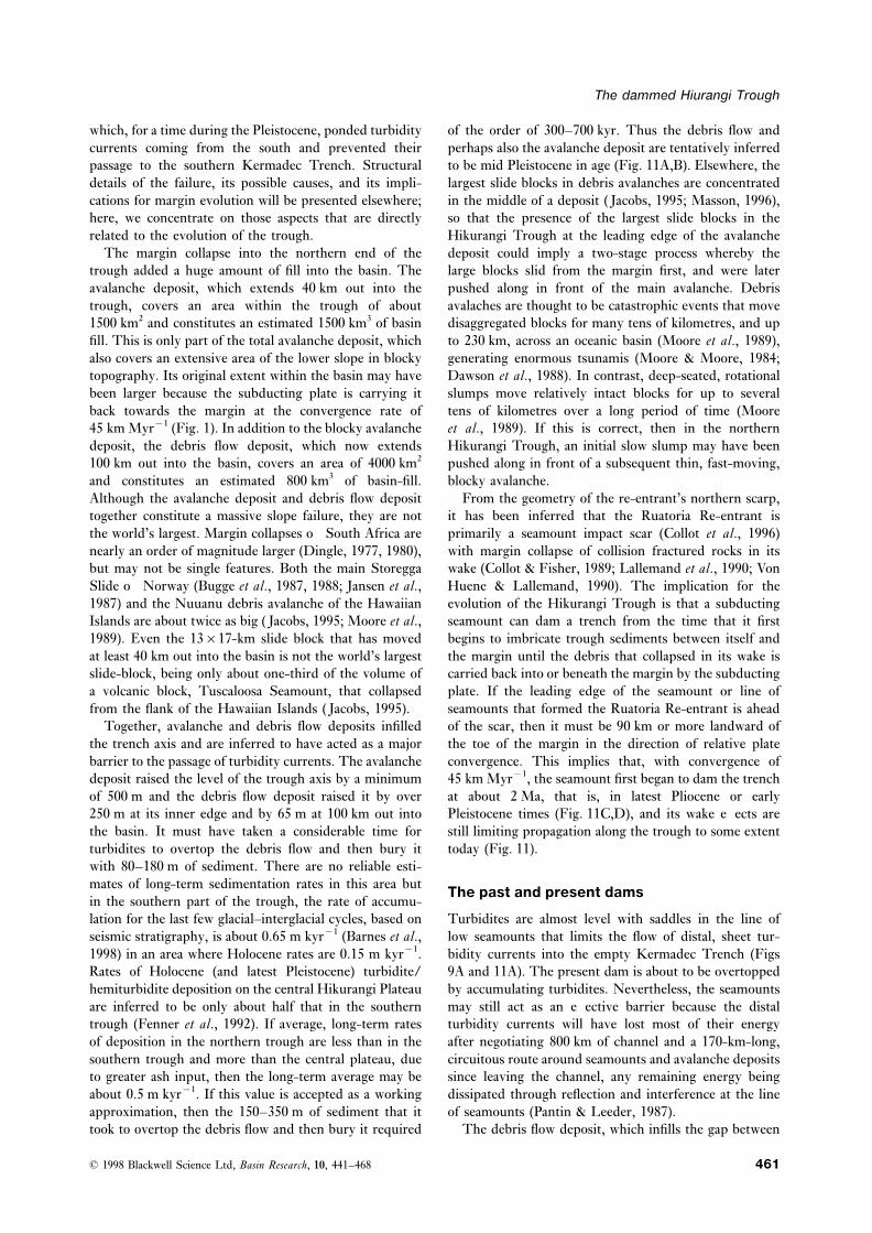
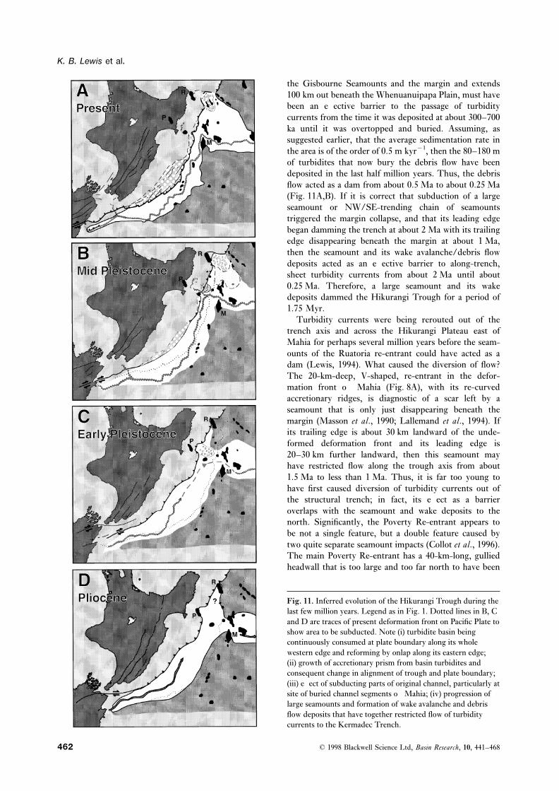
the Gisbourne Seamounts and the margin and extends100 km out beneath the Whenuanuipapa Plain, must havebeen an effective barrier to the passage of turbiditycurrents from the time it was deposited at about 300–700ka until it was overtopped and buried. Assuming, assuggested earlier, that the average sedimentation rate inthe area is of the order of 0.5 m kyr−1, then the 80–180 mof turbidites that now bury the debris flow have beendeposited in the last half million years. Thus, the debrisflow acted as a dam from about 0.5 Ma to about 0.25 Ma(Fig. 11A,B). If it is correct that subduction of a largeseamount or NW/SE-trending chain of seamountstriggered the margin collapse, and that its leading edgebegan damming the trench at about 2 Ma with its trailingedge disappearing beneath the margin at about 1 Ma,then the seamount and its wake avalanche/debris flowdeposits acted as an effective barrier to along-trench,sheet turbidity currents from about 2 Ma until about0.25 Ma. Therefore, a large seamount and its wakedeposits dammed the Hikurangi Trough for a period of1.75 Myr.
Turbidity currents were being rerouted out of thetrench axis and across the Hikurangi Plateau east ofMahia for perhaps several million years before the seam-ounts of the Ruatoria re-entrant could have acted as adam (Lewis, 1994). What caused the diversion of flow?The 20-km-deep, V-shaped, re-entrant in the defor-mation front off Mahia (Fig. 8A), with its re-curvedaccretionary ridges, is diagnostic of a scar left by aseamount that is only just disappearing beneath themargin (Masson et al., 1990; Lallemand et al., 1994). Ifits trailing edge is about 30 km landward of the unde-formed deformation front and its leading edge is20–30 km further landward, then this seamount mayhave restricted flow along the trough axis from about1.5 Ma to less than 1 Ma. Thus, it is far too young tohave first caused diversion of turbidity currents out ofthe structural trench; in fact, its effect as a barrieroverlaps with the seamount and wake deposits to thenorth. Significantly, the Poverty Re-entrant appears tobe not a single feature, but a double feature caused bytwo quite separate seamount impacts (Collot et al., 1996).The main Poverty Re-entrant has a 40-km-long, gulliedheadwall that is too large and too far north to have been
Fig. 11. Inferred evolution of the Hikurangi Trough during thelast few million years. Legend as in Fig. 1. Dotted lines in B, Cand D are traces of present deformation front on Pacific Plate toshow area to be subducted. Note (i) turbidite basin beingcontinuously consumed at plate boundary along its wholewestern edge and reforming by onlap along its eastern edge;(ii) growth of accretionary prism from basin turbidites andconsequent change in alignment of trough and plate boundary;(iii) effect of subducting parts of original channel, particularly atsite of buried channel segments off Mahia; (iv) progression oflarge seamounts and formation of wake avalanche and debrisflow deposits that have together restricted flow of turbiditycurrents to the Kermadec Trench.
© 1998 Blackwell Science Ltd, Basin Research, 10, 441–468462
The dammed Hiurangi Trough
formed by the seamount that formed the V-shaped Kermadec Trench (Carter & McCave, 1994), which hasa thin turbidite–contourite deposit in its axis (Collotindentation in the deformation front at its southern edge
(Fig. 8A). It has an almost circular, midslope basin that et al., 1996), unlike the bare southern Kermadec Trench.Thus, the trench-axis turbidity currents of the Hikurangiis characteristic of a very much older, almost healed,
impact scar formed by a seamount that is now many tens Trough, which subducting seamounts and their wakeavalanche and debris-flow deposits have prevented fromof kilometres to landward of its healing re-entrant (von
Huene & Lallemand, 1990; Lallemand et al., 1994). In reaching the southern Kermadec Trench, eventuallyreach the much deeper central Kermadec Trench, butaddition, it has a bulge in the lower slope, with very
blocky ridges, that may represent a debris avalanche that they take a very long route to get there.has been accreted from the subducting plate back ontothe over-riding plate (Lewis et al., 1997). This almost CONCLUSIONShealed scar and re-accreted avalanche deposit is clearlymuch older than the Ruatoria Re-entrant to the north 1 The Hikurangi Trough is mainly a sediment-filled
trench basin with a narrow, intracontinental, obliqueand is inferred to have been formed by a seamount andits wake avalanche deposits that dammed the trough to collision foredeep basin at its southern apex.
2 Trench fill is mainly overbank turbidites that reachthe passage of turbidity currents to the north during thelate Pliocene (Fig. 11C,D). It must have, at least for a 1–5 km thickness along the western edge, where the
basin is being consumed by frontal accretion, with precur-time, re-routed turbidity currents out of the structuraltrench, eastward across the central basin of the sor protothrusts in the south, and by subduction beneath
a tectonically eroded margin in the north.Hikurangi Plateau.Between the Poverty and Ruatoria re-entrants, the 3 At its northern end, the broad, flat plain of the
Hikurangi Trough changes abruptly to the narrow,whole margin has been tectonically eroded and thedeformation front moved landward by the impacts of V-profiled, southern kermadec trench because the north-
ward passage of distal turbidity currents along the troughmany seamounts (Collot et al., 1996); transverse scarps(Figs 2 and 8A) on the margin may be ghosts of seamount is dammed by a line of low seamounts.
4 The northern part of the trough has been dammedimpact scars even older than the Poverty Re-entrant.This evidence for a succession of seamount impacts going for several million years by a succession of subducting
seamounts and by massive avalanche and debris flowback several million years suggests that the northernHikurangi Trough was blocked by these seamounts and deposits that collapse from the margin in the wake of the
seamounts.their wake deposits, more-or-less continuously, sinceperhaps early Pliocene times. 5 At present, the main sediment input to the Hikurangi
Trough is via the Kaikoura Canyon, at its southern,intracontinental apex, as this in the only canyon thatWider effects of damming the troughintercepts a major nearshore sediment supply duringinterglacial ages.Damming of the trough axis to the passage of turbidity
currents for several million years promoted in-filling of 6 During glacial ages, several extensive canyon systems,which begin at the modern shelf break, funnelled sedi-the structural trench to form the wide, turbidite plain,
the Hikurangi Trough. An indirect consequence of thick ment into the trough at a rate about an order of magnitudegreater than at present.deposits on the subducting plate was development of a
wide accretionary prism adjacent to the central part of 7 There is additional minor input from headward-sapping of regularly spaced seep gullies at several fault-the trough (Fig. 11). Damming of turbidity currents in
the trough axis also prompted overflow onto a low part controlled scarps along the margin.8 There are no clearly defined depositional fans in theof the Hikurangi Plateau to the east and infilling of a
basin there (Lewis, 1994). Beginning at the end of the Hikurangi Trough, although coarse, gravelly sedimentdumped at the end of canyons into the narrow, intraconti-Miocene, sheet turbidity currents were first ponded
behind a Miocene drift at the plateau edge and then nental head of the trough may be considered partlyanalogous.eroded by a channel that cut back from the plateau edge
as the drift was overtopped. By analogy with an outflow 9 A well-developed, meandering, trench-axis channelsystem has bedforms indicating the passage of turbiditychannel from a ponded basin off California (Masson
et al., 1995), the plateau-edge channel is inferred to have currents that considerably overlap the channel banks.10 Centrifugal outflow of the heads of high-velocitycut headward to eventually linked with the axial channel
of the Hikurangi Trough to form one continuous, turbidity currents produces trains of sediment wavesaligned tangentially to the outsides of bends.1400-km-long channel between Kaikoura and the
Southwest Pacific Basin. At the far end of the channel, 11 Coriolis effects (and perhaps deep boundary flows)on thick, dilute flows, including tails of turbidity currents,a distal fan deposit is elongated northwards along the
bottom of the Hikurangi Plateau’s north-eastern scarp by produces a left bank levee that is higher than that of theright banks, and levee-parallel sediment waves.the Pacific Ocean’s Deep Western Boundary Current.
The elongate ‘fan-drift’ extends to the edge of the central 12 Some large turbidity currents, perhaps mainly those
© 1998 Blackwell Science Ltd, Basin Research, 10, 441–468 463
K. B. Lewis et al.
triggered by rupture of large plate-boundary faults, are made the paper more succinct and, we hope, moreintelligible.inferred to reach and then maintain a steady state of
high-velocity, self-perpetuating autosuspension by erod-ing soft mud at their heads and depositing coarser,graded, turbidite layers from their body and tail. Fine REFERENCESsediment in the channel axis may have accumulated from
A, J.R.L. (1971) Mixing at turbidity current heads, anddilute, muddy ‘hemiturbidite’ flows since the precedingits geological implications. J. sedim. Petrol., 41, 97–113.autosuspension flow.
A, J.R.L. (1984) Physical Sedimentology. George Allen and13 Basin and margin are interactive. In the southern part Unwin, London.of the trough, where there is thick basin-fill, slow ortho- B, R.A. (1962) Auto-suspension of transported sedi-gonal convergence, and few seamounts on the down- ment; turbidity currents. Proc. Royal Soc. London, Series A,going plate, trough turbidites are frontally accreted to 265, 315–319.form a wide accretionary prism that traps sediment in B, P.M. (1988) Submarine fan sedimentation at a conver-
gent margin: the Cretaceous Mangapokia Formation, Newslope basins and reduced lateral input to the trough. InZealand. Sediment. Geol., 59, 155–178.the northern part of the trough, where there is thin
B, P.M. (1990) Provenance of Cretaceous accretionarybasin-fill, more rapid orthogonal convergence and numer-wedge sediments: the Mangapokia Formation, Wairarapa,ous seamounts, trough sediments are subducted and theNew Zealand. New Zealand Jl. Geol. Geophys., 33, 125–135.margin is being tectonically eroded, and fractured by
B, P.M. (1992) Mid-bathyal current scours and sedimentseamount impacts, which promotes collapse of massivedrifts adjacent to the Hikurangi deep-sea turbidite channel,
avalanche and debris flow deposits into the basin. eastern New Zealand: evidence from character mapping.14 The most recent margin collapse was into the north- Mar. Geol., 106, 169–189.ern end of the trough at about 0.5 Ma. The avalanche B, P.M. (1994) Continental extension of the Pacific Platedeposit now projects 40 km into the trough, with about at the southern termination of the Hikurangi subduction16 blocks more than 4 km wide and 500 m high added zone: the North Mernoo Fault Zone, offshore New Zealand.
Tectonics, 13, 735–754.to the basin-fill, the largest being 13×17 km and nearlyB, P.M. & M L, B. (1997) Rates and2 km thick. A debris flow deposit in front of the avalanche
mechanics of rapid frontal accretion along the very obliquelydeposit extends 100 km into the trough and thins fromconvergent southern Hikurangi margin, New Zealand.250 m thick near the avalanche deposit to about 65 mJ. geophys. Res., 102, 24 931–24 952.thick at the seaward edge. Blanketting turbidites, up to
B, P.M., M L, B., C, J.-Y.,180 m thick, are intruded by numerous dewateringD, J. & A, J.-C. (1998) Structure and strain
diapirs. partitioning in a transition zone from oblique subduction to15 It is inferred that the thick debris flow deposit was oblique continental collision: offshore southern Hikurangiover-topped at about 0.25 Ma and the seamount that margin, New Zealand. Tectonics.promoted margin collapse first touched the margin at B, P.M. & K, R.J. (1990) Structural analysis of aabout 2 Ma. Therefore, a large seamount and its wake middle Cretaceous accretionary wedge, Wairarapa, New
Zealand. New Zealand Jl. Geol. Geophys., 33, 355–375.avalanche/debris flow deposits may block the passage ofB, J.W. & H, T. (1958) T turbidity currents along the trough for about 1.5–2 Myr.
K H T. Deep Sea Res., 5,16 For about the last 5 myr, seamounts and their wake18–28.avalanche/debris flow deposits have dammed the north-
B, T., B, S., B, R.H., E, T.,ern Hikurangi Trough to the passage of turbidity currentsJ, E., K, N.H., H, H. & S, H.P.into the southern Kermadec Trench, causing them to be(1987) A giant three-stage submarine slide off Norway. Geo-
rerouted across the central Hikurangi Plateau and into Mar. Lett., 7, 191–198.the path of the deep western boundary currents, which B, T., B, R.H. & K, N.H. (1988) Thecarries some sediment into the central kermadec trench. Storegga Slide. Phil. Trans. Royal Soc. London, 325, 357–388.The southern kermadec trench has been bypassed. C. (1997) New Zealand Regional Bathymetry. 154 000 000.
NIWA Chart, Misc. Ser. 73.C, L. (1992) Acoustical characterisation of seafloor sedi-ACKNOWLEDGMENTS ments and its relationship to active sedimentary processes in
Cook Strait, New Zealand. New Zealand Jl Geol. Geophys.,We are deeply indebted to Dr Phil Barnes, NIWA, New35, 289–300.Zealand, Dr Bryan Davy, GNS, New Zealand, and Dr
C, L. & C, R.M. (1988) Late Quaternary develop-Henry Pantin, University of Leeds, UK, for their veryment of left-bank-dominated levees in the Bounty Channel,constructive criticisms of drafts of this paper. We thankNew Zealand. Mar. Geol., 78, 85–197.
also Dr G. Lamarche and Mr R. Garlick for processing C, L. & C, R.M. (1990) Lacustrine sediment trapsand compilation of data from Atalante and other surveys. and their effect on continental shelf sedimentation – Southwe are particularly grateful to two referees, Dr Phil Island, New Zealand. Geo-Mar. Lett., 10, 3–100.Weaver, Southampton Oceanographic Centre, UK, and C, L., C, R.M. & G, G.B. (1982)Professor Bob Carter, University of Townsville, Sedimentation in the Conway Trough, a deep near-shore
marine basin at the junction of the Alpine transform andAustralia, for their many helpful suggestions, which have
© 1998 Blackwell Science Ltd, Basin Research, 10, 441–468464
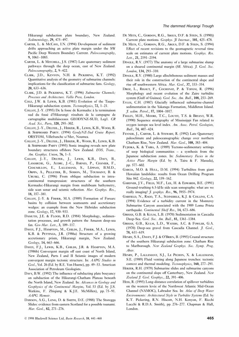
The dammed Hiurangi Trough
Hikurangi subduction plate boundary, New Zealand. D M, C., G, R.G., A, D.F. & S, S. (1990))Sedimentology, 29, 475–497. Current plate motions. Geophys. Jl Internat., 101, 425–478.
C, L. & MC, I.N. (1994) Development of sediment D M, C., G, R.G., A, D.F. & S, S. (1994)drifts approaching an active plate margin under the SW Effect of recent revisions to the geomagnetic reversal timePacific Deep Western Boundary Current. Paleoceanography, scale on estimates of current plate motions. Geophys. Res.9, 1061–1085. Lett., 21, 2191–2194.
C, L. & M, J.S. (1987) Late quaternary sediment D, R.V. (1977) The anatomy of a large submarine slumppathways through the deep ocean, east of New Zealand. on a sheared continental margin (SE Africa). J. Geol. Soc.Paleoceanography, 2, 9–422. London, 134, 293–310.
C, J.D., K, N.H. & P, K.T. (1992) D, R.V. (1980) Large allochthonous sediment masses andQuantitative analysis of the geometry of submarine channels: their role in the construction of the continental slope andimplications for the classification of submarine fans. Geology, rise off southwestern Africa. Mar. Geol., 37, 333–354.20, 633–636. D, L., R, F., C, P. & T, R. (1996)
C, J.D. & P, K.T. (1996) Submarine Channels; Morphology and recent evolution of the Zaire turbiditeProcesses and Architecture. Vallis Press, London. system (Gulf of Guinea). Geol. Soc. Am. Bull., 108, 253–269.
C, J.W. & L, K.B. (1981) Evolution of the Taupo- E, C.H. (1987) Glacially influenced submarine-channelHikurangi subduction system. Tectonophysics, 72, 1–21. sedimentation in the Yakataga Formation, Middleton Island.
C, J.-Y. (1995) De la fosse de Kermadec a la terminaison J. sedim. Petrol., 57, 1004–1017.sud du fosse d’Hikurangi: resultats de la campagne de F, M.H., M, T.C., L, T.S. & B, W.R.cartographie multifaisceaux GEODYNZ-SUD, Leg1. CR (1990) Sequence stratigraphy of Mississippi Fan related toAcad. Sci., Paris, 320, 295–302. oxygen isotope sea level index. Am. Assoc. Petrol. Geologists,
C, J.-Y., D, J., H, R., L, K.B., W, R. Bull., 74, 407–424.& S P. (1994) GeodyNZ-Sud Cruise Report. F, J., C, L. & S, R. (1992) Late QuaternaryORSTOM, Villefranche s/Mer, Noumea. paleoclimate and paleoceanographic change over northern
C, J.-Y., D, J., H, R., W, R., L, K.B. Chatham Rise, New Zealand. Mar. Geol., 108, 383–404.& S P (1995) Sonic imaging reveals new plate F, K. & T, A. (1989) Tectono-sedimentary settingsboundary structures offshore New Zealand. EOS, Trans., of seep biological communities – a synthesis from theAm. Geophys. Union, 76, 1–5. Japanese subduction zones. In: Sedimentary Facies in the
C, J.-Y., D, J., L, K.B., D, B., Active Plate Margin (Ed. by A. Taira & F. Masuda),L, G., A, J.-C., B, P., C, F., pp. 577–602.C, E., L, S., L, B.M.D., G, M.O. & H, D.M. (1994) Turbidites from giantO, A., P, B., S, M., T, B. & Hawaiian landslides: results from Ocean Drilling ProgramU, C. (1996) From oblique subduction to intra-
Site 842. Geology, 22, 159–162.continental transpression: structures of the southern
G, J.V., F, M.F., L, H. & E, B.E. (1991)Kermadec-Hikurangi margin from multibeam bathymetry,
Ground-truthing 6.5-kHz side scan sonographs: what are weside scan sonar and seismic reflection. Mar. Geophys. Res.,
really imaging? J. geophys. Res., 96, 5955–5974.18, 357–381.
G, N., R, T.A., S, K.J. & C, C.A.C, J.-Y. & F, M.A. (1989) Formation of Forearc(1994) Evidence of a turbidity current in the Montereybasins by collision between seamounts and accretionarySubmarine Canyon associated with the 1989 Loma Prietawedges: an example from the New Hebrides subductionearthquake. Continental Shelf Res., 14, 673–686.zone. Geology, 17, 930–933.
G, G.B. & K, L.B. (1970) Sedimentation in CascadiaD, J.E. & F, R.D. (1984) Morphology, sedimen-Deep-Sea. Geol. Soc. Am. Bull., 81, 1361–1384.tation processes, and growth pattern the Amazon deep-sea
G, G.B., K, L.D., W, A.C. & F, G.A.fan. Geo-Mar. Lett., 3, 109–117.(1970) Deep-sea gravel from Cascadia Channel. J. Geol.,D, F.J., H, M., C, J., F, M.A., L,78, 611–619.K.B. & P, J.R. (1986a) Structure of a growing
H, S.A., D, F.J. & O’B, B. (1995) Crustal structureaccretionary prism, Hikurangi margin, New Zealand.of the southern Hikurangi subduction zone: Chatham RiseGeology, 14, 663–666.to Marlborough. New Zealand Geophys. Soc. Symp. Prog.D, F.J., L, K.B., C, J.R. & H, M.A.Abstr.(1986b) Convergent margin off east coast of North Island,
H, P., L, S.J., L P, X. & L,New Zealand, Parts I and II Seismic images of modernS.E. (1989) Fluid venting along Japanese trenches: tectonicconvergent margin tectonic structure. In: AAPG Studies incontext and thermal modeling. Tectonophysics, 160, 277–291.Geol., Vol. 26 (Ed. by R.E. Von Huene), pp. 49–53. American
H, R.H. (1979) Submarine slides and submarine canyonsAssociation of Petroleum Geologists.on the continental slope off Canterbury, New Zealand. NewD, B.W. (1992) The influence of subducting plate bouyancyZealand J. Geol. Geophys., 22, 391–406.on subduction of the Hikurangi-Chatham Plateau beneath
H, R. (1995) Long-distance correlation of spillover turbiditesthe North Island, New Zealand. In: Advances in Geology andon the western levee of the Northwest Atlantic Mid-OceanGeophysics of the Continental Margins, Vol. 53 (Ed. by J.S.Channel (NAMOC), Labrador Sea. In: Atlas of Deep WaterWatkins, F. Zhiqiang & K.J.E. McMillen), pp. 75–91.Environments: Architectural Style in Turbidite Systems (Ed. byAAPG Memoir.K.T. Pickering, R.N. Hiscott, N.H. Kenyon, F. RicchiD, A.G., L, D. & S, D.E. (1988) The StoreggaLucchi & R.D.A. Smith), pp. 276–277. Chapman & Hall,Slides: evidence from eastern Scotland for a possible tsunami.
Mar. Geol., 82, 271–276. London.
© 1998 Blackwell Science Ltd, Basin Research, 10, 441–468 465
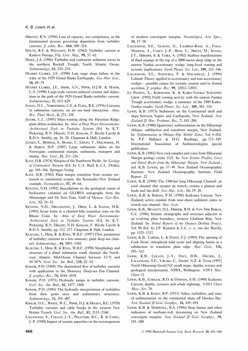
K. B. Lewis et al.
H, R.N. (1994) Loss of capacity, not competence, as the of modern convergent margins. Oceanologica Acta Spec.,fundamental process governing deposition from turbidity 10, 17–30.currents. J. sedim. Res., A64, 209–214. L, S.E., G, G., L-R, A., F-
H, R.E. & W, H.W. (1962) Turbidity current at M, A., C, J.-P., B, C., S, M., I,Kadavu Passage, Fiji. Geol. Mag., 99, 57–62. J.T., H, S. & T, A. (1992) Seafloor manifestations
H, J.A. (1996) Turbidite and contourite sediment waves in of fluid seepage at the top of a 2000-metre-deep ridge in thethe northern Rockall Trough, North Atlantic Ocean. eastern Nankai accretionary wedge: long-lived venting andSedimentology, 43, 219–234. tectonic implications. Earth Planet. Sci. Lett., 109, 333–346.
H C, J.E. (1990) Late stage slope failure in the L, S.E., S, P. & M, J. (1994)wake of the 1929 Grand Banks Earthquake. Geo-Mar. Lett., Colomb Theory applied to accretionary and non-accretionary10, 69–79. wedges – possible causes for tectonic erosion and/or frontal
H C, J.E., S, A.N., P, D.J.W. & M, accretion. J. geophys. Res., 99, 12033–12055.L.A. (1990) Large-scale current-induced erosion and depos- L P, X., K, K. & K-N Sition in the path of the 1929 Grand Banks turbidity current. C. (1992) Fuild venting activity with the eastern NankaiSedimentology, 37, 613–629. Trough accretionary wedge: a summary of the 1989 Kaiko-
I, D.L., N, C.E. & F, R.E. (1976) Currents Nankai results. Earth Planet. Sci. Lett., 109, 303–318.in submarine canyons: an air–sea–land interaction. Annu. L, K.B. (1973) Sediments on the Continental shelf andRev. Fluid Mech., 8, 275–310. slope between Napier and Castlepoint, New Zealand. New
J, C.L. (1995) Mass-wasting along the Hawaiian Ridge: Zealand Jl Mar. Freshwat. Res., 7, 183–208.giant debris avalanches. In: Atlas of Deep Water Environments: L, K.B. (1980) Quaternary sedimentation on the HikurangiArchitectural Style in Turbidite Systems (Ed. by K.T. oblique- subduction and transform margin, New Zealand.Pickering, R.N. Hiscott, N.H. Kenyon, F. Ricchi Lucchi & In: Sedimentation in Oblique-Slip Mobile Zones, Vol. 4 (Ed.R.D.A. Smith), pp. 26–28. Chapman & Hall, London. by P.F. Ballance & H.G. Reading), pp. 171–189.
J, E., B, S., B, T., E, T., H, H. International Association of Sedimentologists special& S, H.P. (1987) Large submarine slides on the publication.Norwegian continental margin, sediments, transport and L, K.B. (1985) New rock samples and cores from Hikurangitiming. Mar. Geol., 21, 211–226. Margin geology cruise 1121. In: New Seismic Profiles, Cores
K, H.R. (1974) Margins of the Southwest Pacific. In: Geology and Dated Rocks from the Hikurangi Margin, New Zealand.,of Continental Margins (Ed. by C.A. Burk & C.L. Drake), (ed. K.B. Lewis), pp. 37–49. New Zealand Oceanographicpp. 549–566. Springer-Verlag. Institute. New Zealand Oceanographic Institute Field
K, H.R. (1982) Plate margin transition from oceanic arc- Report. 22.trench to continental system: the Kermadec-New Zealand L, K.B. (1994) The 1500 km long Hikurangi Channel: anexample. Tectonophysics, 87, 49–64.
axial channel that escapes its trench, crosses a plateau andK, N.H. (1992) Speculations on the geological causes of
feeds and fan-drift. Geo-Mar. Lett., 14, 19–28.backscatter variation on GLORIA sonographs from the
L, K.B. & B, P.M. (1998) Kaikoura Canyon, NewMississippi and De Soto Fans, Gulf of Mexico. Geo-Mar.
Zealand; active conduit from near-shore sediment zones toLett., 12, 24–32.trench-axis channel. Mar. Geol.K, N.H., M, J., D, L. & I, M.K.
L, K.B., B, D.J., H, R.H. & V D B,(1995) Scour holes in a channel-lobe transition zone on theC.C. (1986) Seismic stratigraphy and structure adjacent toRhone Cone. In: Atlas of Deep Water Environments:an evolving plate boundary, western Chatham Rise, NewArchitectural Style in Turbidite Systems (Ed. by K.T.Zealand. In: Initial Reports of the Deepsea Drilling Project,Pickering, R.N. Hiscott, N.H. Kenyon, F. Ricchi Lucchi &Vol. 90 (Ed. by J.P. Kennett & C.C. e. a. von der Borch),R.D.A. Smith), pp. 212–217. Chapman & Hall, London.pp. 1325–1337.K, I., H, R. & R, W.B.F. (1997) Flow parameters
L, K.B., C, L. & D, F.J. (1994) The opening ofof turbidity currents in a low-sinuosity giant deep-sea chan-Cook Strait: interglacial tidal scour and aligning basins at anel. Sedimentology., 44, 1093–1102.subduction to transform plate edge. Mar. Geol., 116,K, I., H, R. & R, W.B.F. (1998) Morphology and293–312.structure of a distal submarine trunk channel; the North-
L, K.B., C, J.-Y., D, B.W., D, J.,west Atlantic Mid-Ocean Channel between 53°N andL, S.E., U, C., G N.Z. & T (1997)44°30∞N. Geol. Soc. Am. Bull., 110, 22–34.North Hikurangi GeodyNZ swath maps: depths, texture andK, P.D. (1969) The channelized flow of turbidity currentsgeological interpretation. NIWA, Wellington. NIWA Misc.with application to the Monterey Deep-sea Fan Channel.Chart 72.J. geophys. Res., 74, 4544–4558.
L, K.B., G, R.D. & D, S.M. (1998) KaikouraK, P.D. (1971) Hydraulic jumps in turbidity currents.Canyon; depths, textures and whale sightings. NIWA ChartGeol. Soc. Am. Bull., 82, 1477–1488.Missc. Ser. 78.K, P.D. (1985) The hydraulic interpretation of turbidites
L, K.B. & K, B.P. (1973) Ashes, turbidites, and ratesfrom their grain sizes and sedimentary structures.of sedimentation on the continental slope off Hawkes Bay.Sedimentology, 32, 395–407.New Zealand Jl Geol. Geophys., 16, 439–454.K, D.C., W, W.C., P, D.J. & H, B.C. (1970)
L, K.B. & M, B.A. (1996) Seep faunas and otherTurbidity currents and cable breaks in the western Newindicators of methane-rich dewatering on New ZealandBritain Trench. Geol. Soc. Am. Bull., 81, 2153–2160.convergent margins. New Zealand Jl Geol. Geophys., 39,L, S., C, J.-Y., P, B.C., R. & C,
J.-P. (1990) Impact of oceanic asperities on the tectonogenesis 181–200.
© 1998 Blackwell Science Ltd, Basin Research, 10, 441–468466
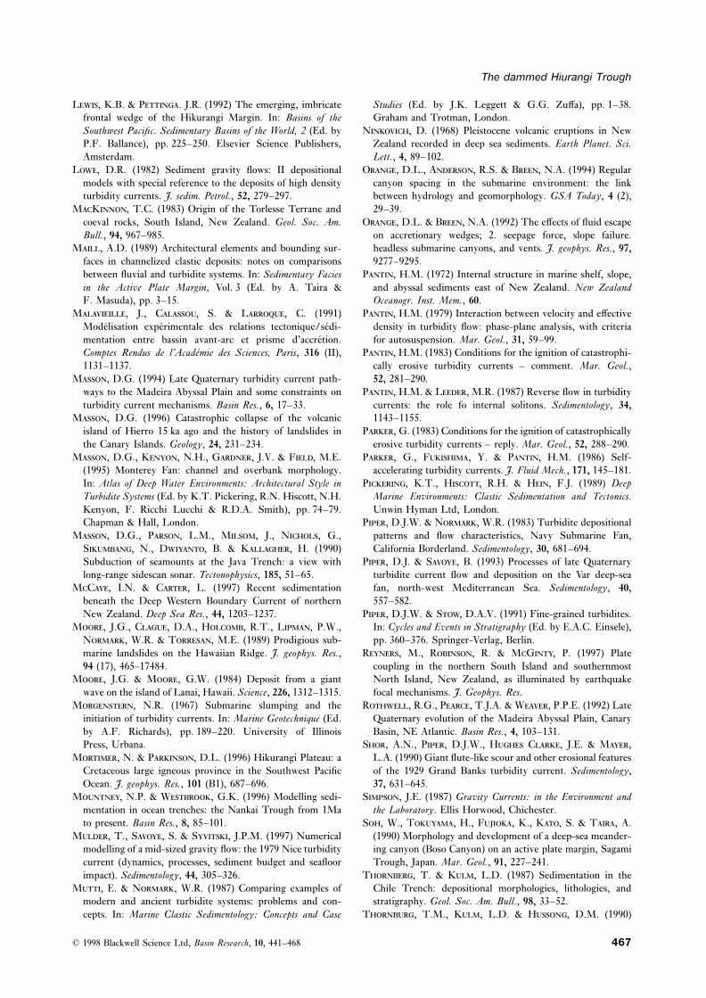
The dammed Hiurangi Trough
L, K.B. & P. J.R. (1992) The emerging, imbricate Studies (Ed. by J.K. Leggett & G.G. Zuffa), pp. 1–38.Graham and Trotman, London.frontal wedge of the Hikurangi Margin. In: Basins of the
Southwest Pacific. Sedimentary Basins of the World, 2 (Ed. by N, D. (1968) Pleistocene volcanic eruptions in NewZealand recorded in deep sea sediments. Earth Planet. Sci.P.F. Ballance), pp. 225–250. Elsevier Science Publishers,
Amsterdam. Lett., 4, 89–102.O, D.L., A, R.S. & B, N.A. (1994) RegularL, D.R. (1982) Sediment gravity flows: II depositional
models with special reference to the deposits of high density canyon spacing in the submarine environment: the linkbetween hydrology and geomorphology. GSA Today, 4 (2),turbidity currents. J. sedim. Petrol., 52, 279–297.
MK, T.C. (1983) Origin of the Torlesse Terrane and 29–39.O, D.L. & B, N.A. (1992) The effects of fluid escapecoeval rocks, South Island, New Zealand. Geol. Soc. Am.
Bull., 94, 967–985. on accretionary wedges; 2. seepage force, slope failure.headless submarine canyons, and vents. J. geophys. Res., 97,M, A.D. (1989) Architectural elements and bounding sur-
faces in channelized clastic deposits: notes on comparisons 9277–9295.P, H.M. (1972) Internal structure in marine shelf, slope,between fluvial and turbidite systems. In: Sedimentary Facies
in the Active Plate Margin, Vol. 3 (Ed. by A. Taira & and abyssal sediments east of New Zealand. New ZealandOceanogr. Inst. Mem., 60.F. Masuda), pp. 3–15.
M, J., C, S. & L, C. (1991) P, H.M. (1979) Interaction between velocity and effectivedensity in turbidity flow: phase-plane analysis, with criteriaModelisation experimentale des relations tectonique/sedi-
mentation entre bassin avant-arc et prisme d’accretion. for autosuspension. Mar. Geol., 31, 59–99.P, H.M. (1983) Conditions for the ignition of catastrophi-Comptes Rendus de l’Academie des Sciences, Paris, 316 (II),
1131–1137. cally erosive turbidity currents – comment. Mar. Geol.,52, 281–290.M, D.G. (1994) Late Quaternary turbidity current path-
ways to the Madeira Abyssal Plain and some constraints on P, H.M. & L, M.R. (1987) Reverse flow in turbiditycurrents: the role fo internal solitons. Sedimentology, 34,turbidity current mechanisms. Basin Res., 6, 17–33.
M, D.G. (1996) Catastrophic collapse of the volcanic 1143–1155.P, G. (1983) Conditions for the ignition of catastrophicallyisland of Hierro 15 ka ago and the history of landslides in
the Canary Islands. Geology, 24, 231–234. erosive turbidity currents – reply. Mar. Geol., 52, 288–290.P, G., F, Y. & P, H.M. (1986) Self-M, D.G., K, N.H., G, J.V. & F, M.E.
(1995) Monterey Fan: channel and overbank morphology. accelerating turbidity currents. J. Fluid Mech., 171, 145–181.P, K.T., H, R.H. & H, F.J. (1989) DeepIn: Atlas of Deep Water Environments: Architectural Style in
Turbidite Systems (Ed. by K.T. Pickering, R.N. Hiscott, N.H. Marine Environments: Clastic Sedimentation and Tectonics.Unwin Hyman Ltd, London.Kenyon, F. Ricchi Lucchi & R.D.A. Smith), pp. 74–79.
Chapman & Hall, London. P, D.J.W. & N, W.R. (1983) Turbidite depositionalpatterns and flow characteristics, Navy Submarine Fan,M, D.G., P, L.M., M, J., N, G.,
S, N., D, B. & K, H. (1990) California Borderland. Sedimentology, 30, 681–694.P, D.J. & S, B. (1993) Processes of late QuaternarySubduction of seamounts at the Java Trench: a view with
long-range sidescan sonar. Tectonophysics, 185, 51–65. turbidite current flow and deposition on the Var deep-seafan, north-west Mediterranean Sea. Sedimentology, 40,MC, I.N. & C, L. (1997) Recent sedimentation
beneath the Deep Western Boundary Current of northern 557–582.P, D.J.W. & S, D.A.V. (1991) Fine-grained turbidites.New Zealand. Deep Sea Res., 44, 1203–1237.
M, J.G., C, D.A., H, R.T., L, P.W., In: Cycles and Events in Stratigraphy (Ed. by E.A.C. Einsele),pp. 360–376. Springer-Verlag, Berlin.N, W.R. & T, M.E. (1989) Prodigious sub-
marine landslides on the Hawaiian Ridge. J. geophys. Res., R, M., R, R. & MG, P. (1997) Platecoupling in the northern South Island and southernmost94 (17), 465–17484.
M, J.G. & M, G.W. (1984) Deposit from a giant North Island, New Zealand, as illuminated by earthquakefocal mechanisms. J. Geophys. Res.wave on the island of Lanai, Hawaii. Science, 226, 1312–1315.
M, N.R. (1967) Submarine slumping and the R, R.G., P, T.J.A. & W, P.P.E. (1992) LateQuaternary evolution of the Madeira Abyssal Plain, Canaryinitiation of turbidity currents. In: Marine Geotechnique (Ed.
by A.F. Richards), pp. 189–220. University of Illinois Basin, NE Atlantic. Basin Res., 4, 103–131.S, A.N., P, D.J.W., H C, J.E. & M,Press, Urbana.
M, N. & P, D.L. (1996) Hikurangi Plateau: a L.A. (1990) Giant flute-like scour and other erosional featuresof the 1929 Grand Banks turbidity current. Sedimentology,Cretaceous large igneous province in the Southwest Pacific
Ocean. J. geophys. Res., 101 (B1), 687–696. 37, 631–645.S, J.E. (1987) Gravity Currents: in the Environment andM, N.P. & W, G.K. (1996) Modelling sedi-
mentation in ocean trenches: the Nankai Trough from 1Ma the Laboratory. Ellis Horwood, Chichester.S, W., T, H., F, K., K, S. & T, A.to present. Basin Res., 8, 85–101.
M, T., S, S. & S, J.P.M. (1997) Numerical (1990) Morphology and development of a deep-sea meander-ing canyon (Boso Canyon) on an active plate margin, Sagamimodelling of a mid-sized gravity flow: the 1979 Nice turbidity
current (dynamics, processes, sediment budget and seafloor Trough, Japan. Mar. Geol., 91, 227–241.T, T. & K, L.D. (1987) Sedimentation in theimpact). Sedimentology, 44, 305–326.
M, E. & N, W.R. (1987) Comparing examples of Chile Trench: depositional morphologies, lithologies, andstratigraphy. Geol. Soc. Am. Bull., 98, 33–52.modern and ancient turbidite systems: problems and con-
cepts. In: Marine Clastic Sedimentology: Concepts and Case T, T.M., K, L.D. & H, D.M. (1990)
© 1998 Blackwell Science Ltd, Basin Research, 10, 441–468 467
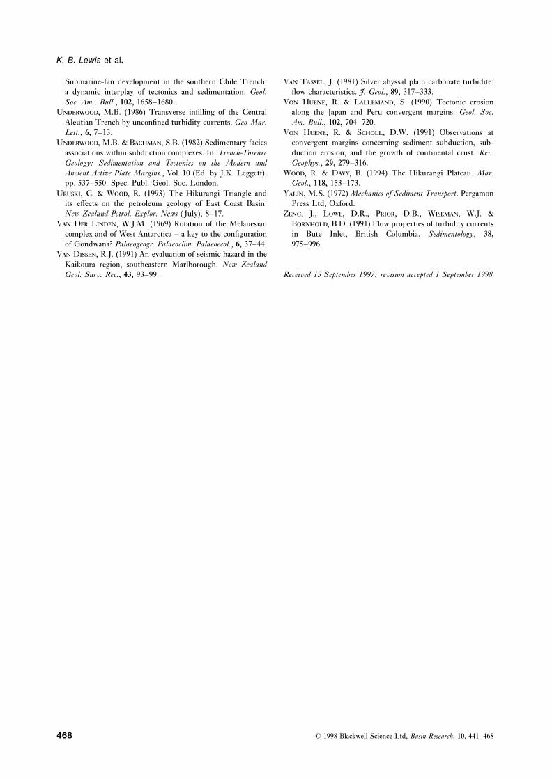
K. B. Lewis et al.
Submarine-fan development in the southern Chile Trench: V T, J. (1981) Silver abyssal plain carbonate turbidite:flow characteristics. J. Geol., 89, 317–333.a dynamic interplay of tectonics and sedimentation. Geol.
Soc. Am., Bull., 102, 1658–1680. V H, R. & L, S. (1990) Tectonic erosionalong the Japan and Peru convergent margins. Geol. Soc.U, M.B. (1986) Transverse infilling of the Central
Aleutian Trench by unconfined turbidity currents. Geo-Mar. Am. Bull., 102, 704–720.V H, R. & S, D.W. (1991) Observations atLett., 6, 7–13.
U, M.B. & B, S.B. (1982) Sedimentary facies convergent margins concerning sediment subduction, sub-duction erosion, and the growth of continental crust. Rev.associations within subduction complexes. In: Trench-Forearc
Geology: Sedimentation and Tectonics on the Modern and Geophys., 29, 279–316.W, R. & D, B. (1994) The Hikurangi Plateau. Mar.Ancient Active Plate Margins., Vol. 10 (Ed. by J.K. Leggett),
pp. 537–550. Spec. Publ. Geol. Soc. London. Geol., 118, 153–173.Y, M.S. (1972) Mechanics of Sediment Transport. PergamonU, C. & W, R. (1993) The Hikurangi Triangle and
its effects on the petroleum geology of East Coast Basin. Press Ltd, Oxford.Z, J., L, D.R., P, D.B., W, W.J. &New Zealand Petrol. Explor. News ( July), 8–17.
V D L, W.J.M. (1969) Rotation of the Melanesian B, B.D. (1991) Flow properties of turbidity currentsin Bute Inlet, British Columbia. Sedimentology, 38,complex and of West Antarctica – a key to the configuration
of Gondwana? Palaeogeogr. Palaeoclim. Palaeoecol., 6, 37–44. 975–996.V D, R.J. (1991) An evaluation of seismic hazard in the
Kaikoura region, southeastern Marlborough. New ZealandGeol. Surv. Rec., 43, 93–99. Received 15 September 1997; revision accepted 1 September 1998
© 1998 Blackwell Science Ltd, Basin Research, 10, 441–468468