Embed Size (px)
Citation preview
1/12
2. ARM intro. Cortex M4 Registers. STM32 Memory layout.BE2M37MAM – Microprocessors
Stanislav V́ıtek
Czech Technical University in Prague
2/12
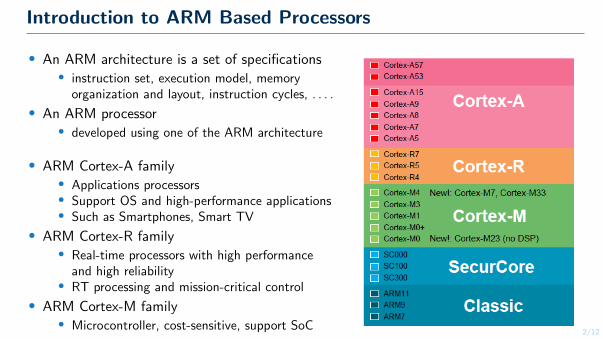
Introduction to ARM Based Processors
● An ARM architecture is a set of specifications● instruction set, execution model, memory
organization and layout, instruction cycles, . . . .
● An ARM processor● developed using one of the ARM architecture
● ARM Cortex-A family● Applications processors● Support OS and high-performance applications● Such as Smartphones, Smart TV
● ARM Cortex-R family● Real-time processors with high performance
and high reliability● RT processing and mission-critical control
● ARM Cortex-M family● Microcontroller, cost-sensitive, support SoC
3/12
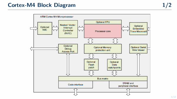
Cortex-M4 Block Diagram 1/2
4/12
Cortex-M4 Block Diagram 1/2
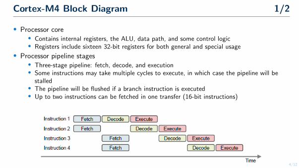
● Processor core● Contains internal registers, the ALU, data path, and some control logic● Registers include sixteen 32-bit registers for both general and special usage
● Processor pipeline stages● Three-stage pipeline: fetch, decode, and execution● Some instructions may take multiple cycles to execute, in which case the pipeline will be
stalled● The pipeline will be flushed if a branch instruction is executed● Up to two instructions can be fetched in one transfer (16-bit instructions)
5/12
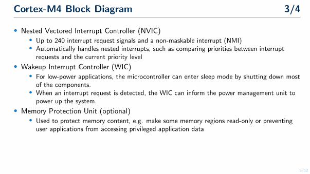
Cortex-M4 Block Diagram 3/4
● Nested Vectored Interrupt Controller (NVIC)● Up to 240 interrupt request signals and a non-maskable interrupt (NMI)● Automatically handles nested interrupts, such as comparing priorities between interrupt
requests and the current priority level
● Wakeup Interrupt Controller (WIC)● For low-power applications, the microcontroller can enter sleep mode by shutting down most
of the components.● When an interrupt request is detected, the WIC can inform the power management unit to
power up the system.
● Memory Protection Unit (optional)● Used to protect memory content, e.g. make some memory regions read-only or preventing
user applications from accessing privileged application data
6/12
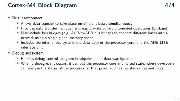
Cortex-M4 Block Diagram 4/4
● Bus interconnect● Allows data transfer to take place on different buses simultaneously● Provides data transfer management, e.g. a write buffer, bitoriented operations (bit-band)● May include bus bridges (e.g. AHB-to-APB bus bridge) to connect different buses into a
network using a single global memory space● Includes the internal bus system, the data path in the processor core, and the AHB LITE
interface unit
● Debug subsystem● Handles debug control, program breakpoints, and data watchpoints● When a debug event occurs, it can put the processor core in a halted state, where developers
can analyse the status of the processor at that point, such as register values and flags
7/12
Cortex-M4 Registers
● Processor registers● The internal registers are used to store and process temporary data within the processor core● All registers are inside the processor core, hence they can be accessed quickly● Load-store architecture● To process memory data, they have to be first loaded from memory to registers, processed
inside the processor core using register data only, and then written back to memory if needed
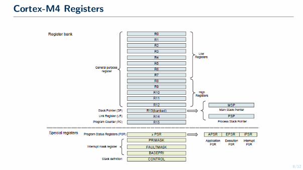
● Cortex-M4 registers● Register bank● Sixteen 32-bit registers (thirteen are used for general-purpose);● Special registers
8/12
Cortex-M4 Registers
9/12
Cortex-M4 Registers
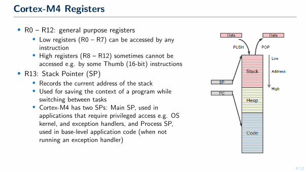
● R0 – R12: general purpose registers● Low registers (R0 – R7) can be accessed by any
instruction● High registers (R8 – R12) sometimes cannot be
accessed e.g. by some Thumb (16-bit) instructions
● R13: Stack Pointer (SP)● Records the current address of the stack● Used for saving the context of a program while
switching between tasks● Cortex-M4 has two SPs: Main SP, used in
applications that require privileged access e.g. OSkernel, and exception handlers, and Process SP,used in base-level application code (when notrunning an exception handler)
10/12
Cortex-M4 Registers
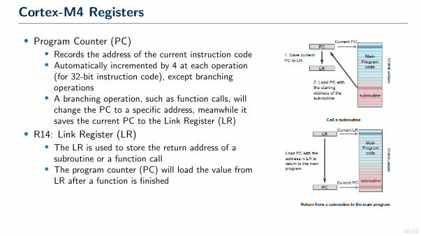
● Program Counter (PC)● Records the address of the current instruction code● Automatically incremented by 4 at each operation
(for 32-bit instruction code), except branchingoperations
● A branching operation, such as function calls, willchange the PC to a specific address, meanwhile itsaves the current PC to the Link Register (LR)
● R14: Link Register (LR)● The LR is used to store the return address of a
subroutine or a function call● The program counter (PC) will load the value from
LR after a function is finished
11/12
Cortex-M4 Registers
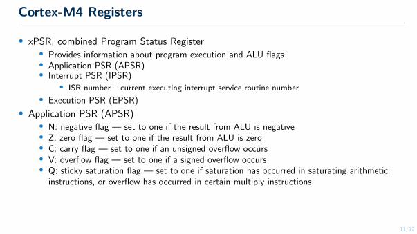
● xPSR, combined Program Status Register● Provides information about program execution and ALU flags● Application PSR (APSR)● Interrupt PSR (IPSR)
● ISR number – current executing interrupt service routine number
● Execution PSR (EPSR)
● Application PSR (APSR)● N: negative flag — set to one if the result from ALU is negative● Z: zero flag — set to one if the result from ALU is zero● C: carry flag — set to one if an unsigned overflow occurs● V: overflow flag — set to one if a signed overflow occurs● Q: sticky saturation flag — set to one if saturation has occurred in saturating arithmetic
instructions, or overflow has occurred in certain multiply instructions
12/12
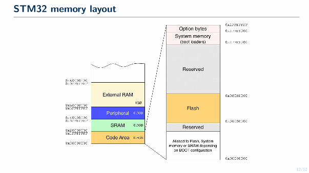
STM32 memory layout