Embed Size (px)
Citation preview
7/28/2019 2 Cellular Concepts R
http://slidepdf.com/reader/full/2-cellular-concepts-r 1/4
Mobile Communications Cellular Concept
BSNL Online Awareness Programme Page 1 of 4
For Restricted Circulation
2 CELLULAR CONCEPTS
STRUCTURE
2.1 INTRODUCTION 2.2 CELLS : 2.3 CELLULAR SYSTEM CHARACTERISTICS 2.4 FREQUENCY REUSE :
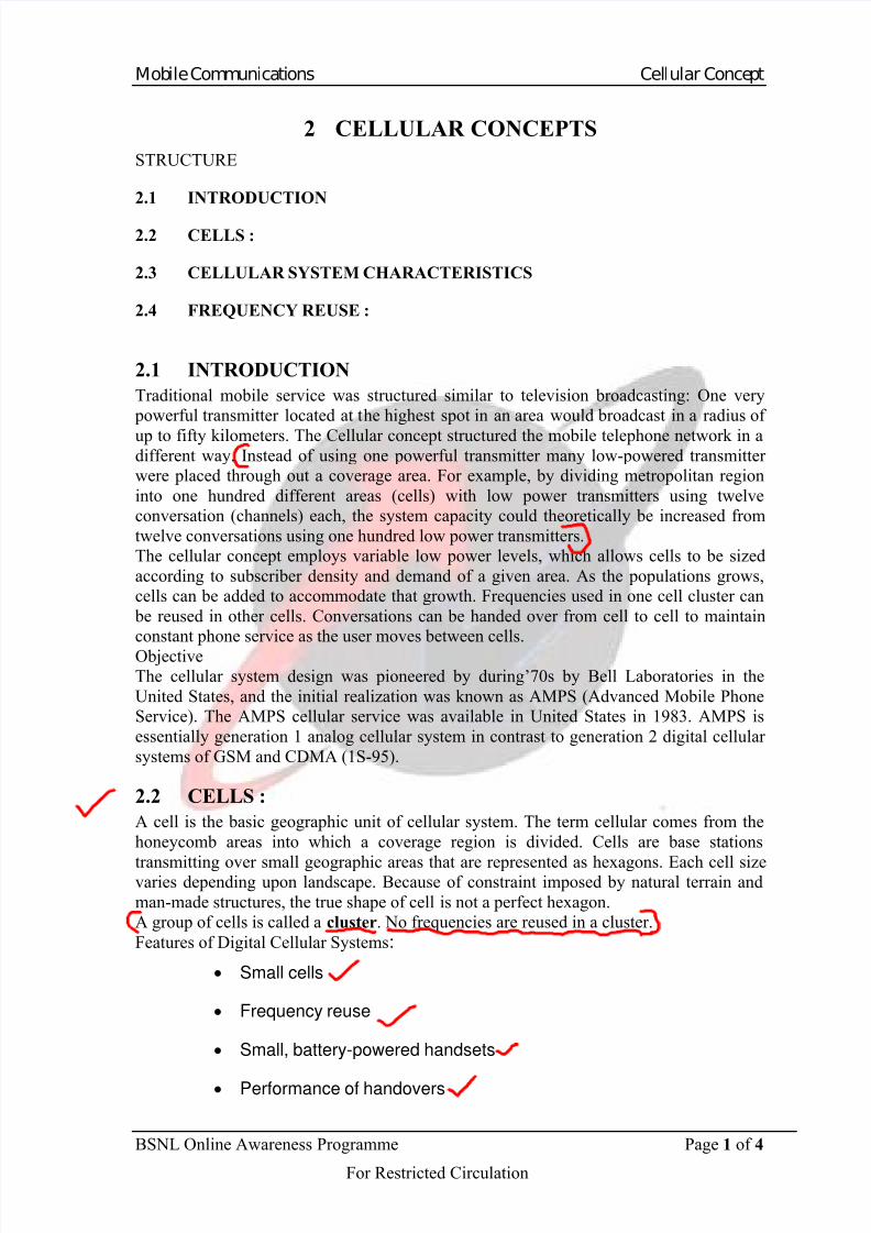
2.1 INTRODUCTION
Traditional mobile service was structured similar to television broadcasting: One very
powerful transmitter located at the highest spot in an area would broadcast in a radius of
up to fifty kilometers. The Cellular concept structured the mobile telephone network in adifferent way. Instead of using one powerful transmitter many low-powered transmitter
were placed through out a coverage area. For example, by dividing metropolitan region
into one hundred different areas (cells) with low power transmitters using twelve
conversation (channels) each, the system capacity could theoretically be increased from
twelve conversations using one hundred low power transmitters.
The cellular concept employs variable low power levels, which allows cells to be sized
according to subscriber density and demand of a given area. As the populations grows,
cells can be added to accommodate that growth. Frequencies used in one cell cluster can
be reused in other cells. Conversations can be handed over from cell to cell to maintain
constant phone service as the user moves between cells.
Objective
The cellular system design was pioneered by during’70s by Bell Laboratories in the
United States, and the initial realization was known as AMPS (Advanced Mobile Phone
Service). The AMPS cellular service was available in United States in 1983. AMPS is
essentially generation 1 analog cellular system in contrast to generation 2 digital cellular
systems of GSM and CDMA (1S-95).
2.2 CELLS :
A cell is the basic geographic unit of cellular system. The term cellular comes from the
honeycomb areas into which a coverage region is divided. Cells are base stations
transmitting over small geographic areas that are represented as hexagons. Each cell sizevaries depending upon landscape. Because of constraint imposed by natural terrain and
man-made structures, the true shape of cell is not a perfect hexagon.
A group of cells is called a cluster. No frequencies are reused in a cluster.
Features of Digital Cellular Systems:
Small cells
Frequency reuse
Small, battery-powered handsets
Performance of handovers
7/28/2019 2 Cellular Concepts R
http://slidepdf.com/reader/full/2-cellular-concepts-r 2/4
Mobile Communications Cellular Concept
BSNL Online Awareness Programme Page 2 of 4
For Restricted Circulation
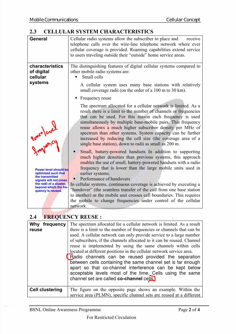
2.3 CELLULAR SYSTEM CHARACTERISTICS
General Cellular radio systems allow the subscriber to place and receive
telephone calls over the wire-line telephone network where ever
cellular coverage is provided. Roaming capabilities extend service
to users traveling outside their “outside” home service areas.
characteristicsof digitalcellular systems
The distinguishing features of digital cellular systems compared to
other mobile radio systems are:
Small cells
A cellular system uses many base stations with relatively
small coverage radii (on the order of a 100 m to 30 km).
Frequency reuse
The spectrum allocated for a cellular network is limited. As a
result there is a limit to the number of channels or frequencies
that can be used. For this reason each frequency is usedsimultaneously by multiple base-mobile pairs. This frequency
reuse allows a much higher subscriber density per MHz of
spectrum than other systems. System capacity can be further
increased by reducing the cell size (the coverage area of a
single base station), down to radii as small as 200 m.
Small, battery-powered handsets In addition to supporting
much higher densities than previous systems, this approach
enables the use of small, battery-powered handsets with a radio
frequency that is lower than the large mobile units used in
earlier systems. Performance of handovers
In cellular systems, continuous coverage is achieved by executing a
“handover” (the seamless transfer of the call from one base station
to another) as the mobile unit crosses cell boundaries. This requires
the mobile to change frequencies under control of the cellular
network.
2.4 FREQUENCY REUSE :
Why frequencyreuse
The spectrum allocated for a cellular network is limited. As a result
there is a limit to the number of frequencies or channels that can be
used. A cellular network can only provide service to a large number of subscribers, if the channels allocated to it can be reused. Channel
reuse is implemented by using the same channels within cells
located at different positions in the cellular network service area.
Radio channels can be reused provided the separationbetween cells containing the same channel set is far enoughapart so that co-channel interference can be kept belowacceptable levels most of the time. Cells using the samechannel set are called co-channel cells.
Cell clustering The figure on the opposite page shows an example. Within the
service area (PLMN), specific channel sets are reused at a different
Power level should beoptimized such thatthe transmittedsignals will not crossthe radii of a cluster,beyond which the fre-quency is reused.
7/28/2019 2 Cellular Concepts R
http://slidepdf.com/reader/full/2-cellular-concepts-r 3/4
Mobile Communications Cellular Concept
BSNL Online Awareness Programme Page 3 of 4
For Restricted Circulation
location (another cell). In the example, there are 7 channel sets: A
through G. Neighboring cells are not allowed to use the same
frequencies. For this reason all channel sets are used in a cluster of
neighboring cells. As there are 7 channel sets, the PLMN can be
divided into clusters of 7 cells each. The figure shows three clusters.
The number of channel sets is called K. K is also called the reusefactor. In the figure, K=7. Valid values of K can be found using
equation (where i and j are integers):
K=i²+j²+I*j
Explaining this equation is beyond the scope of this course. Some
constraints to K are provided later in this chapter. Note that in the
example: Cells are shaped ideally (hexagons). The distance between
cells using the same channel set is always the same.
Other cellclusters
The figure on the opposite page shows some examples of possible
clusters. The more cells in a cluster, the greater the separation
between co-channel cells when Other clusters are deployed. Theidea is to keep co-channel cell separation the same throughout the
system area for cells of the same size. Some valid cluster sizes that
allow this are: 1, 3, 4, 7, 9 and 12.
Procedure for locating co-channel cells
It is always possible to find cells using the same channel set, if only
the value of K is known. The following procedure is used.
In the figure on the opposite page an example is shown with K = 19.
SignalattenuationWith distance
Frequencies can be reused throughout a service area because radio
signals typically attenuate with distance to the base station (or
mobile station). When the distance between cells using the same
frequencies becomes too small, co-channelInterference might occur and lead to service interruption or
unacceptable quality of service.
Step Action
1 Use the integer values i and j from the equation, and start
With the upper left cell. Through this cell, draw the j-axis.
2 Draw the i-axis. To find the starting point for the i-axis, count j cellsdown the j-axis. In the example, one has to count 2 cells down (j=2).The positive direction of the i-axis is always two cell faces (120degrees) relative to the positive direction of the j-axis.
3 Find the first co-channel cell. It is found by counting i cells in thepositive i-axis direction. In the example, i = 3.
4 Find the other co-locating cells by repeating the previous steps. TheStarting point is again at the upper left cell, but now choose another
Direction for the j-axis (e.g. rotate the j-axis with 60 degrees, which isone cell face). As each cell has 6 faces, one will find 6 co-channelcells around the starting cells. These are the nearest located co-channel cells.
7/28/2019 2 Cellular Concepts R
http://slidepdf.com/reader/full/2-cellular-concepts-r 4/4
Mobile Communications Cellular Concept
BSNL Online Awareness Programme Page 4 of 4
For Restricted Circulation
Capacity/Performance Trade-offs : n If K increases, then performance increases n If K increases, then call capacity decreases per cell The number of sites to cover a given area with a given high traffic density, and hence the
cost of the infrastructure, is determined directly by the reuse factor and the number of
traffic channels that can be extracted from the available spectrum. These two factors arecompounded in what is called spectral efficiency of the system. Not all systems allow the
same performance in this domain: they depend in particular on the robustness of the radio
transmission scheme against interference, but also on the use of a number of technical
tricks, such as reducing transmission during the silences of a speech communication. The
spectral efficiency, together with the constraints on the cell size, determines also the
possible compromises between the capacity and the cost of the infrastructure. All this
explains the importance given to spectral efficiency.
Many technical tricks to improve spectral efficiency were conceived during the system
design and have been introduced in GSM. They increase the complexity, but this is
balanced by the economical advantages of a better efficiency. The major points are the
following:The control of the transmitted power on the radio path aims at minimizing the average
power broadcast by mobile stations as well as by base stations, whilst keeping
transmission quality above a given threshold. This reduces the level of interference
caused to the other communications;
Frequency hopping improves transmission quality at slow speeds through frequency
diversity, and improves spectral efficiency through interferer diversity;
Discontinuous transmission, where by transmission is suppressed when possible, allows a
reduction in the interference level of other communications. Depending on the type of
user information transmitted, it is possible to derive the need for effective transmission. In
the case of speech, the mechanism called VAD (Voice Activity Detection) allows
transmission requirements to be reduced by an important factor (typically, reduced by
half);
The mobile assisted handover, whereby the mobile station provides measurements
concerning neighboring cells, enables efficient handover decision algorithms aimed at
minimizing the interference generated by the cell (whilst keeping the transmission quality
above some threshold).
References:
1. The GSM system for mobile communication-Michel Mouly & Marie-
Bernadette Pautet.
2. GSM system Engineering-Asha Mehrotra (Artech House Publisher).