Embed Size (px)
Citation preview
- 3 -
WBI-PRINT 6 WBI GmbH, Henricistr. 50, 52072 Aachen, Germany www.wbionline.de
2. Methods of mechanized tunneling
2.1 Tunnel boring machines (TBMs)
2.1.1 Overview
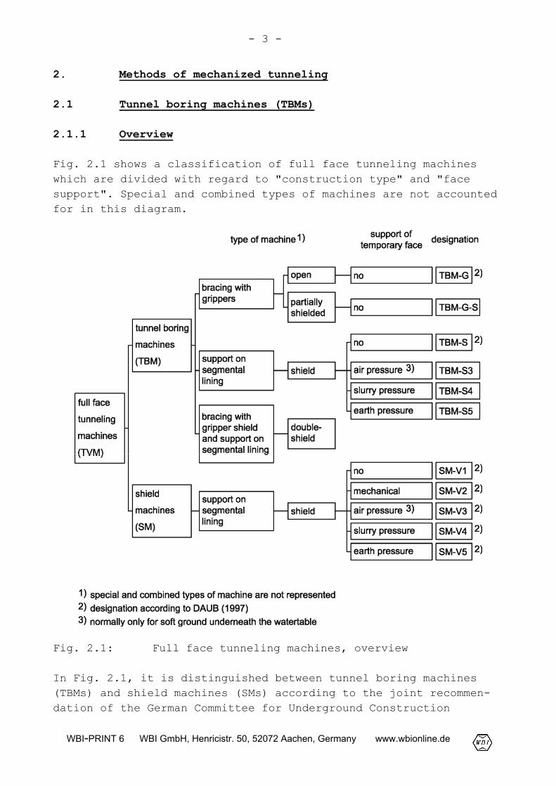
Fig. 2.1 shows a classification of full face tunneling machineswhich are divided with regard to "construction type" and "facesupport". Special and combined types of machines are not accountedfor in this diagram.
Fig. 2.1: Full face tunneling machines, overview
In Fig. 2.1, it is distinguished between tunnel boring machines(TBMs) and shield machines (SMs) according to the joint recommen-dation of the German Committee for Underground Construction
- 4 -
WBI-PRINT 6 WBI GmbH, Henricistr. 50, 52072 Aachen, Germany www.wbionline.de
(DAUB), the Austrian Society of Geomechanics (ÖGG), the GermanRoad and Traffic Research Society (FGSV) and the Swiss Associationof Engineers and Architects (SIA).
Tunnel boring machines are mainly applied in rock, while shieldmachines are basically used in soils.
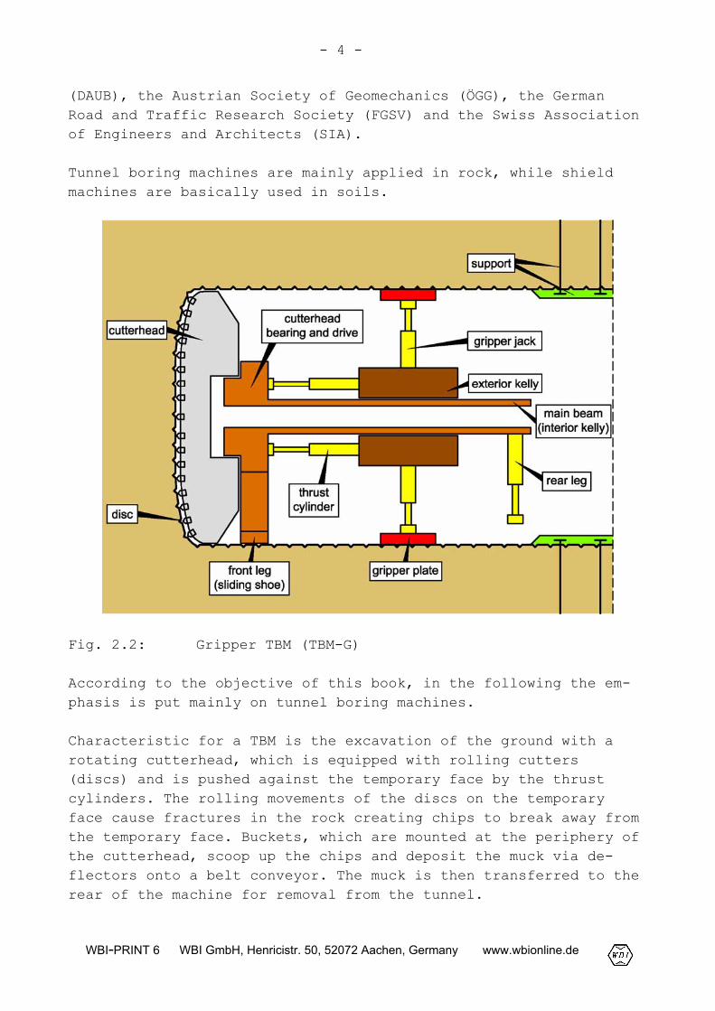
Fig. 2.2: Gripper TBM (TBM-G)
According to the objective of this book, in the following the em-phasis is put mainly on tunnel boring machines.
Characteristic for a TBM is the excavation of the ground with arotating cutterhead, which is equipped with rolling cutters(discs) and is pushed against the temporary face by the thrustcylinders. The rolling movements of the discs on the temporaryface cause fractures in the rock creating chips to break away fromthe temporary face. Buckets, which are mounted at the periphery ofthe cutterhead, scoop up the chips and deposit the muck via de-flectors onto a belt conveyor. The muck is then transferred to therear of the machine for removal from the tunnel.
- 5 -
WBI-PRINT 6 WBI GmbH, Henricistr. 50, 52072 Aachen, Germany www.wbionline.de
2.1.2 Gripper TBM
A Gripper TBM is suitable for application in a rock mass in whicha support of the excavated cross-section in the area of the tempo-rary face and of the machine is not required or may be achievedwith minor efforts, e. g. rock bolts, steel sets and shotcrete,applied locally at the roof of the tunnel.
A Gripper TBM is composed of four groups of systems:
- drilling system,- thrust, gripper and bracing system,- support and lining system,- conveyor system.
The drilling system consists of the cutterhead, the cutting tools(discs), the cutterhead bearing and drive (Fig. 2.2). The cutter-head is driven by hydraulic or electric motors and is mounted onthe main beam or interior kelly, respectively.
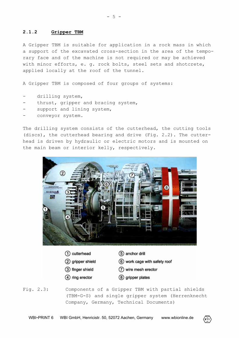
Fig. 2.3: Components of a Gripper TBM with partial shields(TBM-G-S) and single gripper system (HerrenknechtCompany, Germany, Technical Documents)
- 6 -
WBI-PRINT 6 WBI GmbH, Henricistr. 50, 52072 Aachen, Germany www.wbionline.de
The thrust, gripper and bracing system consists of the thrust cyl-inders, the gripper jacks, the gripper plates as well as the frontleg and the rear leg. It can be distinguished between two types ofgripper systems, the single gripper system with a sliding shoe(Fig. 2.2 to 2.4) and the double gripper system (Fig. 2.5).
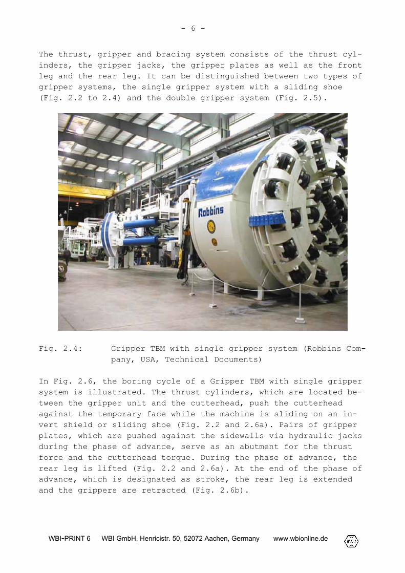
Fig. 2.4: Gripper TBM with single gripper system (Robbins Com-pany, USA, Technical Documents)
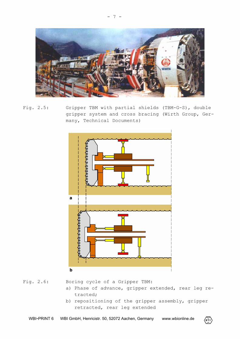
In Fig. 2.6, the boring cycle of a Gripper TBM with single grippersystem is illustrated. The thrust cylinders, which are located be-tween the gripper unit and the cutterhead, push the cutterheadagainst the temporary face while the machine is sliding on an in-vert shield or sliding shoe (Fig. 2.2 and 2.6a). Pairs of gripperplates, which are pushed against the sidewalls via hydraulic jacksduring the phase of advance, serve as an abutment for the thrustforce and the cutterhead torque. During the phase of advance, therear leg is lifted (Fig. 2.2 and 2.6a). At the end of the phase ofadvance, which is designated as stroke, the rear leg is extendedand the grippers are retracted (Fig. 2.6b).
- 7 -
WBI-PRINT 6 WBI GmbH, Henricistr. 50, 52072 Aachen, Germany www.wbionline.de
Fig. 2.5: Gripper TBM with partial shields (TBM-G-S), doublegripper system and cross bracing (Wirth Group, Ger-many, Technical Documents)
Fig. 2.6: Boring cycle of a Gripper TBM:a) Phase of advance, gripper extended, rear leg re-
tracted;b) repositioning of the gripper assembly, gripper
retracted, rear leg extended
- 8 -
WBI-PRINT 6 WBI GmbH, Henricistr. 50, 52072 Aachen, Germany www.wbionline.de
For repositioning the gripper assembly for the next boring cycle,the thrust cylinders are also retracted and the gripper unit issliding forward. Then, the rear leg is lifted and the new strokebegins.
The double gripper system consists of two bracing planes, thefront and the rear gripper unit, which are connected with the ex-terior kelly. The main beam, which is bearing the cutterhead andthe drive, is supported by the exterior kelly and movable in lon-gitudinal direction. Machines with double gripper system areguided mainly by the gripper units, while in machines with singlegripper system also the thrust cylinders are used for steering.Particularly in case of large boring diameters, the double grippersystem is frequently combined with a cross bracing. Here, in eachgripper unit, four pairs of gripper plates, which are distortedagainst each other, are pushed against the sidewalls (Fig. 2.5).
Gripper TBMs are mostly equipped with partial shields or hoods be-cause also in stable rock conditions rockfall is to be expectedlocally. The partial shields or hoods serve as protection againstfalling rock and are often extended backwards by lamellae (Fig.2.3 and 2.4). Such a lamella roof, also denoted as finger shield,bridges the unsupported area between the shield and the area inwhich the support will be installed.
With the so-called partial or cutterhead shields with radiallymovable segments, a supporting pressure on the rock mass aroundthe cutterhead can be applied (Maidl et al., 2001). Partialshields also protect the cutterhead against falling rock and thuscan avoid a blockade of the cutterhead. With lateral, radiallymovable bracing shields as well as with a vertically adjustablesliding shoe and invert shield, respectively, the position of thecutterhead can be fixed. A steel dust shield integrated in thecutterhead shield protects the working room from dust and smallrock particles.
For the support of the excavation contour in the machine area of aGripper TBM, steel sets, steel meshes, rock bolts and shotcretecan be used. The steel sets and meshes are installed as a headgearnormally immediately behind the cutterhead or the finger shield,respectively, using a ring erector and a wire mesh erector (Fig.2.3). With the drilling equipment, boreholes for rock bolts, ex-ploration drillings and advancing support in form of spiles or in-
- 9 -
WBI-PRINT 6 WBI GmbH, Henricistr. 50, 52072 Aachen, Germany www.wbionline.de
jections can be carried out. The support of the entire cross-section will usually be completed in the backup area. The applica-tion of shotcrete in the machine area is extremely difficult dueto problems regarding space, dust and rebound, and leads to a con-siderable reduction of the performance rates. Furthermore, theshotcrete would be damaged by the bracing forces induced by thegripper plates. Shotcrete in the machine area, therefore, is ap-plied only over short tunnel sections, e. g. in the area of faultzones.
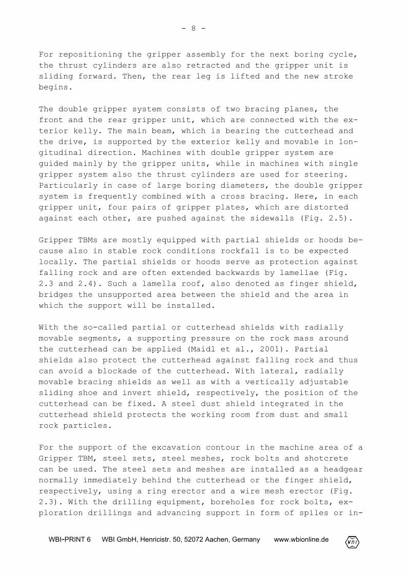
In the tunnel invert, often a floor segment is installed, whichcan be equipped with fasteners for rails, if a rail conveyance ofthe excavated material is foreseen (Fig. 2.7).
Fig. 2.7: Floor segment (Darcy and Gmür, 2004)
During the advance of a Gripper TBM, the chips created by therolling disk cutters at the temporary face are picked up by thebuckets located at the periphery of the cutterhead and transportedvia hoppers onto a belt conveyor. In tunnel boring machines withlarge diameters and a center free bearing of the cutterhead, thebelt conveyor can be arranged centrally. The conveyor belt is ledthrough the main beam and the interior kelly, respectively, to ahand-over point. From there, the excavated material is transportedvia rail conveyance, dumpers or belt conveyors further through thetunnel.
- 10 -
WBI-PRINT 6 WBI GmbH, Henricistr. 50, 52072 Aachen, Germany www.wbionline.de
2.1.3 Shielded TBM without face support (TBM-S)
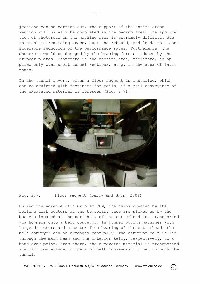
Shielded tunnel boring machines (Fig. 2.8 and 2.9) are utilized,if the rock mass, because of its too low strength, is not able tocarry the bracing forces of a Gripper TBM, which are necessary totransmit the required thrust forces.
Fig. 2.8: Shielded TBM (TBM-S)
A shielded TBM without facilities for a face support can also beapplied, if the excavation contour is not stable and if rock col-lapse may occur. The shield skin, which covers the entire machine,serves as a temporary support. As final support, usually pre-castlining segments of reinforced concrete are used. The lining seg-ments are installed under the protection of the rear part of theshield, the so-called tail-skin. Unlike to a Gripper TBM the com-pleted segmental lining serves as an abutment for the thrust force(Fig. 2.8).
- 11 -
WBI-PRINT 6 WBI GmbH, Henricistr. 50, 52072 Aachen, Germany www.wbionline.de
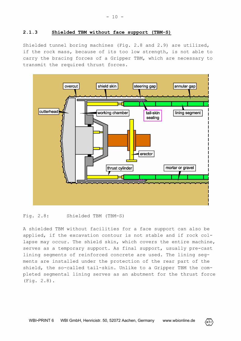
Fig. 2.9: Shielded TBM (TBM-S) for the Adler Tunnel, Switzer-land (Herrenknecht Company, Germany, Technical Docu-ments)
The cutterhead usually has a slightly larger diameter than theshield skin. This causes a so-called overcut to avoid that theshield gets stuck. The space between the shield skin and the exca-vation contour is referred to as steering gap (Fig. 2.8). In un-stable rock mass or soil the steering gap may be close.
The interface between the segmental lining and the excavation con-tour, the so-called annular gap, is normally grouted with mortarusing injection lines which are integrated in the tail-skin (Fig.2.8). The mortar in the annular gap leads to a bedding of the seg-mental lining which is maintained to a large extent also aftersetting of the grout. A complete bedding of the segmental liningis necessary to keep the bending moments and deformations of thelining small. A sufficient bedding and a completely filled annular
- 12 -
WBI-PRINT 6 WBI GmbH, Henricistr. 50, 52072 Aachen, Germany www.wbionline.de
gap, respectively, is also required to carry the loads exerted bythe thrust cylinders, particularly during driving of curves. Fortaking over the cutterhead torque, the shearing bond between thesegmental lining and the rock mass is needed (see Section 5.4.3).
Instead of mortar grouting it is also possible to pneumaticallyinject gravel into the annular gap via openings in the lining seg-ments.
Between the shield skin and the segmental lining, a so-calledtail-skin sealing is mounted to avoid leakage of the annular groutinto the machine area (Fig. 2.8).
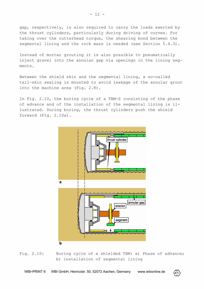
In Fig. 2.10, the boring cycle of a TBM-S consisting of the phaseof advance and of the installation of the segmental lining is il-lustrated. During boring, the thrust cylinders push the shieldforward (Fig. 2.10a).
Fig. 2.10: Boring cycle of a shielded TBM: a) Phase of advance;b) installation of segmental lining
- 13 -
WBI-PRINT 6 WBI GmbH, Henricistr. 50, 52072 Aachen, Germany www.wbionline.de
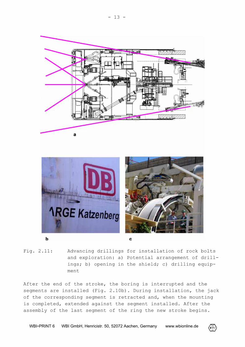
Fig. 2.11: Advancing drillings for installation of rock boltsand exploration: a) Potential arrangement of drill-ings; b) opening in the shield; c) drilling equip-ment
After the end of the stroke, the boring is interrupted and thesegments are installed (Fig. 2.10b). During installation, the jackof the corresponding segment is retracted and, when the mountingis completed, extended against the segment installed. After theassembly of the last segment of the ring the new stroke begins.
- 14 -
WBI-PRINT 6 WBI GmbH, Henricistr. 50, 52072 Aachen, Germany www.wbionline.de
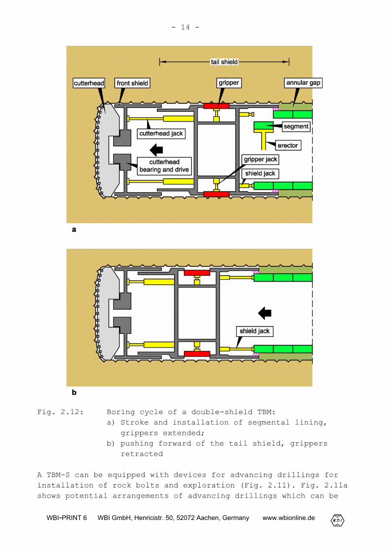
Fig. 2.12: Boring cycle of a double-shield TBM:a) Stroke and installation of segmental lining,
grippers extended;b) pushing forward of the tail shield, grippers
retracted
A TBM-S can be equipped with devices for advancing drillings forinstallation of rock bolts and exploration (Fig. 2.11). Fig. 2.11ashows potential arrangements of advancing drillings which can be
- 15 -
WBI-PRINT 6 WBI GmbH, Henricistr. 50, 52072 Aachen, Germany www.wbionline.de
carried out through the shield skin and the cutterhead. For carry-ing out such boreholes, corresponding openings in the shield skinand the cutterhead must be provided (Fig. 2.11b).
2.1.4 Double-shield TBM
The double-shield TBM (Fig. 2.12 and 2.13), also referred to astelescopic shield TBM, represents a combination of a Gripper TBMand a shielded TBM. It is composed of a front shield with cutter-head, main bearing and drive as well as of a tail shield includinggrippers, gripper jacks, cutterhead jacks and shield jacks.
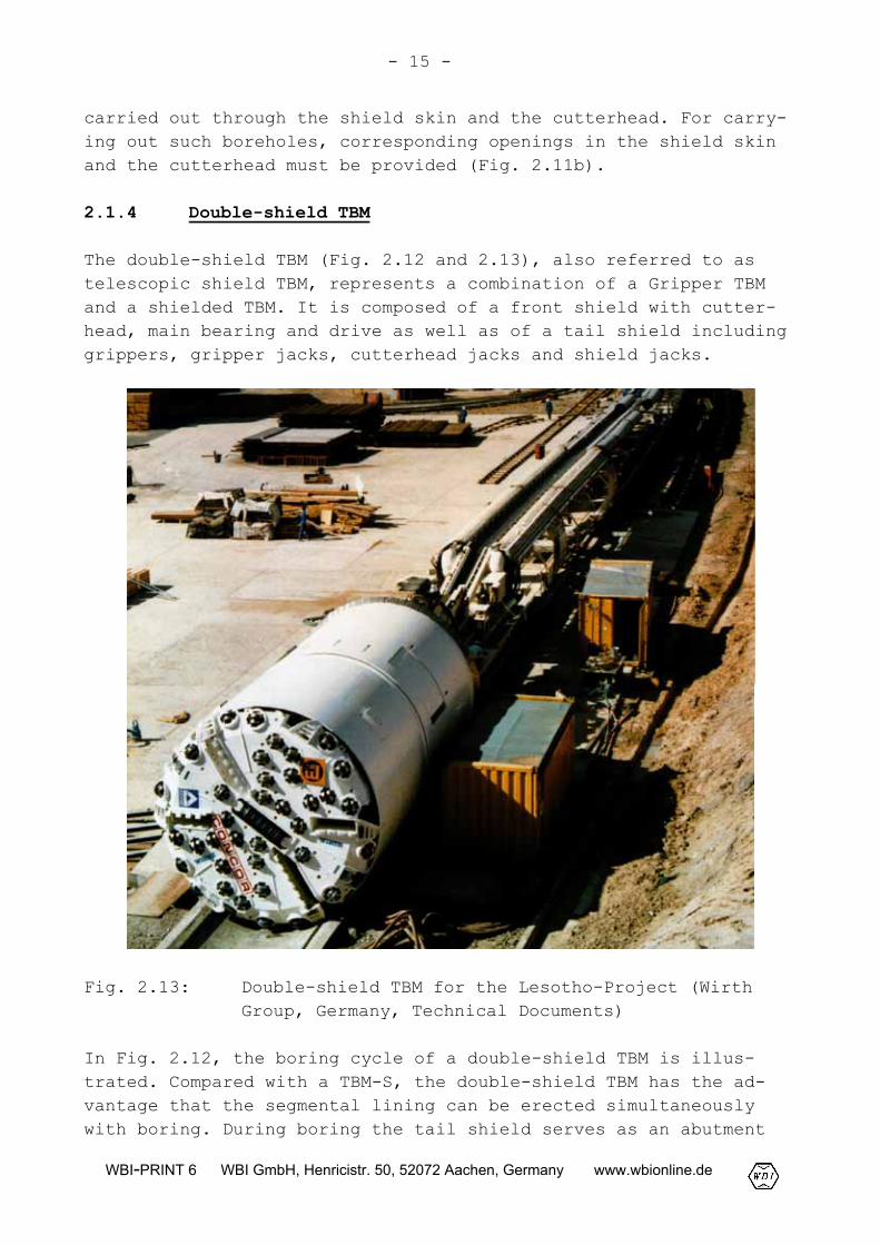
Fig. 2.13: Double-shield TBM for the Lesotho-Project (WirthGroup, Germany, Technical Documents)
In Fig. 2.12, the boring cycle of a double-shield TBM is illus-trated. Compared with a TBM-S, the double-shield TBM has the ad-vantage that the segmental lining can be erected simultaneouslywith boring. During boring the tail shield serves as an abutment
- 16 -
WBI-PRINT 6 WBI GmbH, Henricistr. 50, 52072 Aachen, Germany www.wbionline.de
of the front shield with the cutterhead. The tail skin remainsstationary, because it is supported by the gripper bracing. Thecutterhead jacks, which are arranged between the front shield andthe tail shield, are extended to push the cutterhead forward. Theinstallation of the segmental lining is carried out in the sameway as for a TBM-S. After the stroke and the ring assembly is com-pleted, the grippers are retracted and the tail shield is pushedforward by the shield jacks which are supported by the last in-stalled segmental ring. Then, the new stroke begins.
To avoid leakage of water, the telescopic joint must be sealed.
Fig. 2.13 shows the double-shield TBM for the Lesotho-Project.
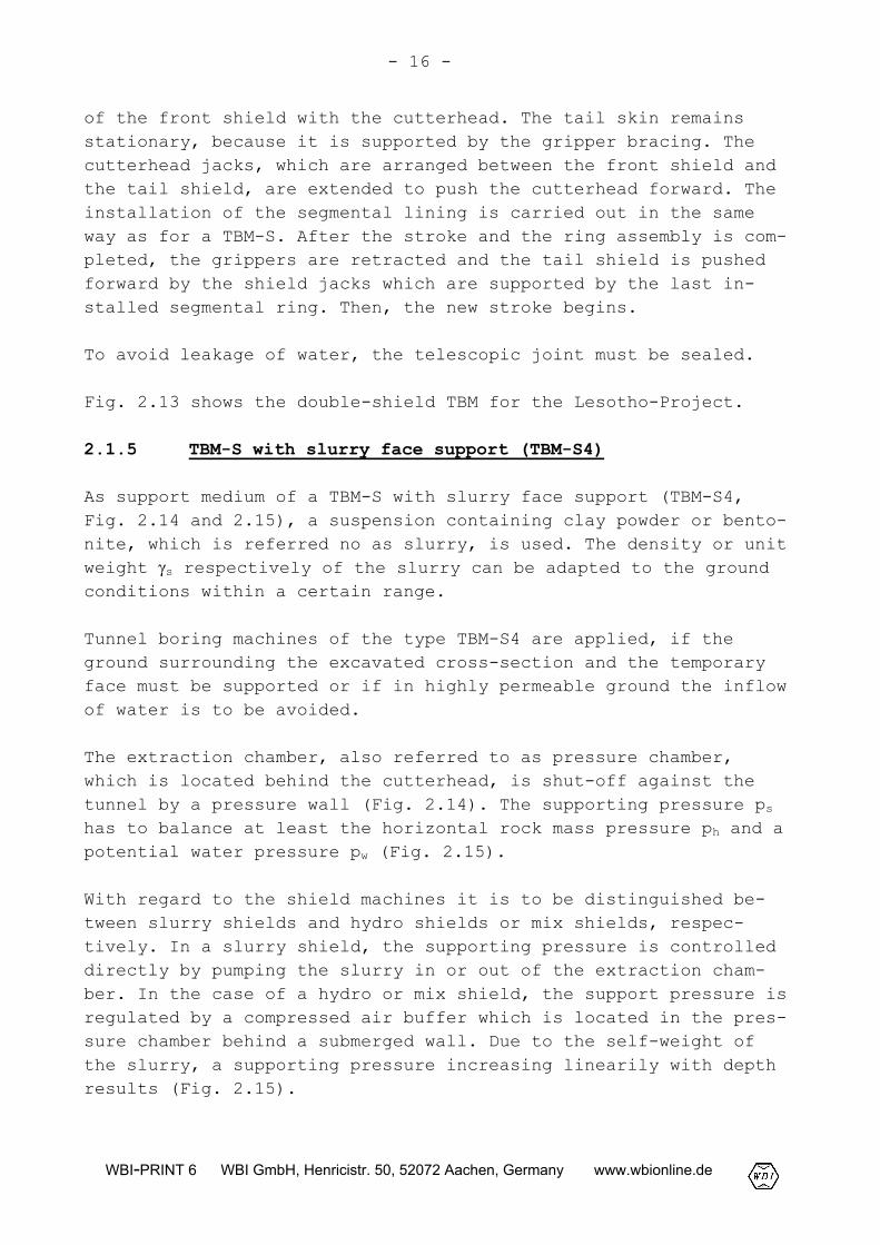
2.1.5 TBM-S with slurry face support (TBM-S4)
As support medium of a TBM-S with slurry face support (TBM-S4,Fig. 2.14 and 2.15), a suspension containing clay powder or bento-nite, which is referred no as slurry, is used. The density or unitweight �s respectively of the slurry can be adapted to the groundconditions within a certain range.
Tunnel boring machines of the type TBM-S4 are applied, if theground surrounding the excavated cross-section and the temporaryface must be supported or if in highly permeable ground the inflowof water is to be avoided.
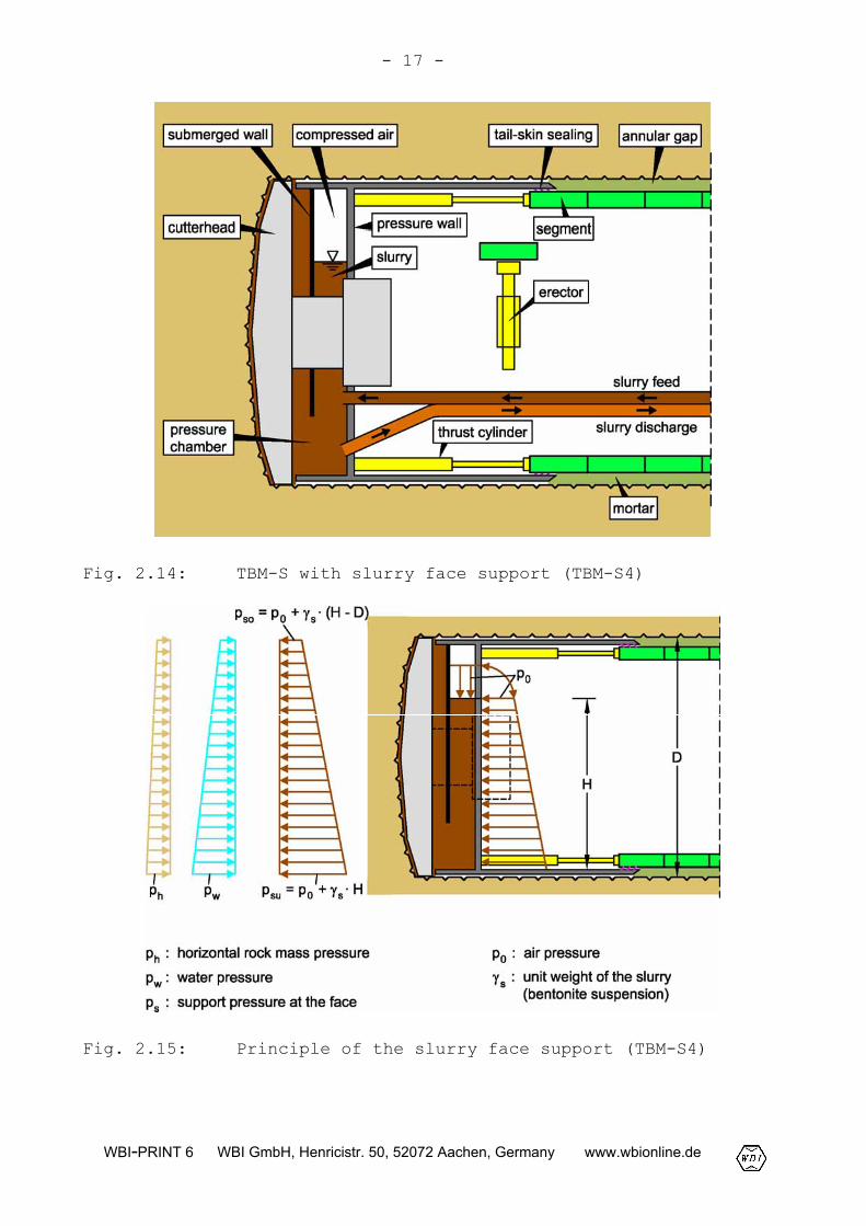
The extraction chamber, also referred to as pressure chamber,which is located behind the cutterhead, is shut-off against thetunnel by a pressure wall (Fig. 2.14). The supporting pressure pshas to balance at least the horizontal rock mass pressure ph and apotential water pressure pw (Fig. 2.15).
With regard to the shield machines it is to be distinguished be-tween slurry shields and hydro shields or mix shields, respec-tively. In a slurry shield, the supporting pressure is controlleddirectly by pumping the slurry in or out of the extraction cham-ber. In the case of a hydro or mix shield, the support pressure isregulated by a compressed air buffer which is located in the pres-sure chamber behind a submerged wall. Due to the self-weight ofthe slurry, a supporting pressure increasing linearily with depthresults (Fig. 2.15).
- 17 -
WBI-PRINT 6 WBI GmbH, Henricistr. 50, 52072 Aachen, Germany www.wbionline.de
Fig. 2.14: TBM-S with slurry face support (TBM-S4)
Fig. 2.15: Principle of the slurry face support (TBM-S4)
- 18 -
WBI-PRINT 6 WBI GmbH, Henricistr. 50, 52072 Aachen, Germany www.wbionline.de
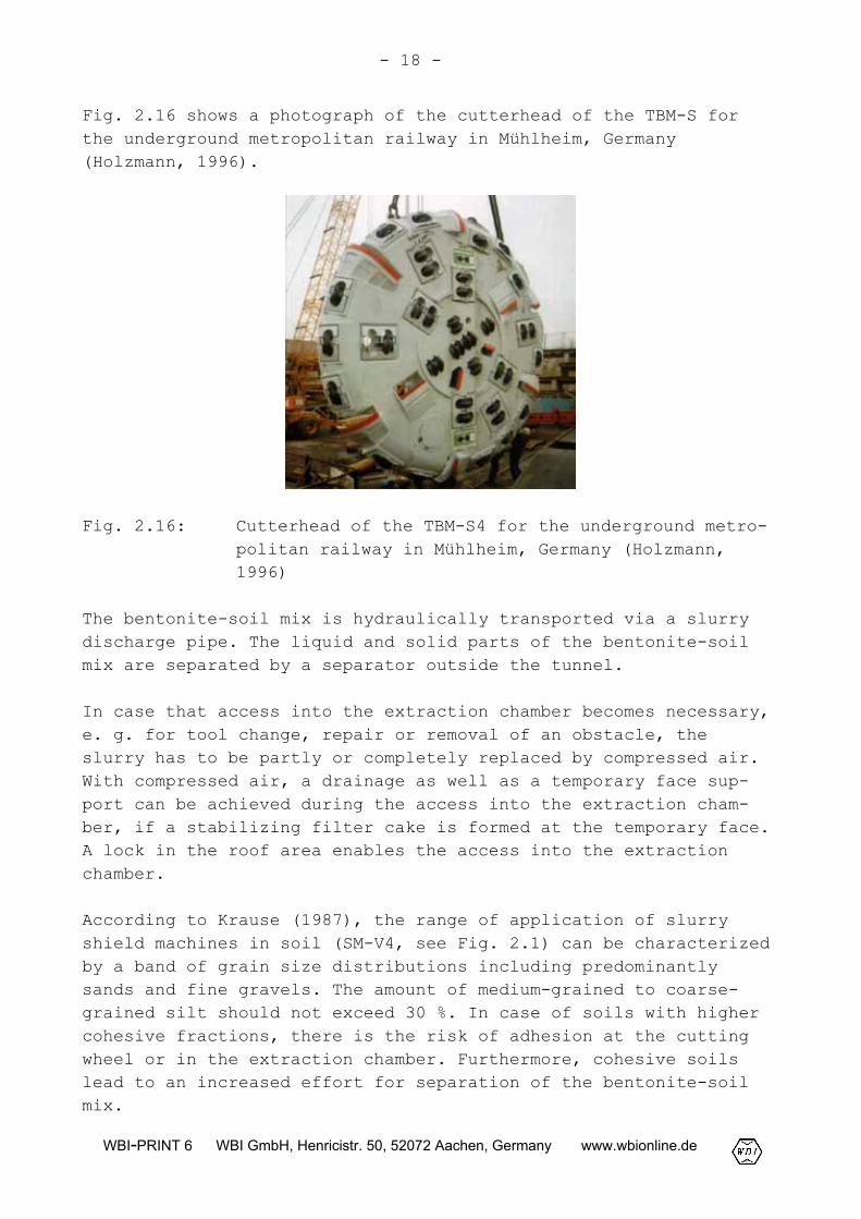
Fig. 2.16 shows a photograph of the cutterhead of the TBM-S forthe underground metropolitan railway in Mühlheim, Germany(Holzmann, 1996).
Fig. 2.16: Cutterhead of the TBM-S4 for the underground metro-politan railway in Mühlheim, Germany (Holzmann,1996)
The bentonite-soil mix is hydraulically transported via a slurrydischarge pipe. The liquid and solid parts of the bentonite-soilmix are separated by a separator outside the tunnel.
In case that access into the extraction chamber becomes necessary,e. g. for tool change, repair or removal of an obstacle, theslurry has to be partly or completely replaced by compressed air.With compressed air, a drainage as well as a temporary face sup-port can be achieved during the access into the extraction cham-ber, if a stabilizing filter cake is formed at the temporary face.A lock in the roof area enables the access into the extractionchamber.
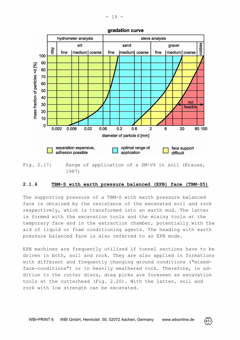
According to Krause (1987), the range of application of slurryshield machines in soil (SM-V4, see Fig. 2.1) can be characterizedby a band of grain size distributions including predominantlysands and fine gravels. The amount of medium-grained to coarse-grained silt should not exceed 30 %. In case of soils with highercohesive fractions, there is the risk of adhesion at the cuttingwheel or in the extraction chamber. Furthermore, cohesive soilslead to an increased effort for separation of the bentonite-soilmix.
- 19 -
WBI-PRINT 6 WBI GmbH, Henricistr. 50, 52072 Aachen, Germany www.wbionline.de
Fig. 2.17: Range of application of a SM-V4 in soil (Krause,1987)
2.1.6 TBM-S with earth pressure balanced (EPB) face (TBM-S5)
The supporting pressure of a TBM-S with earth pressure balancedface is obtained by the resistance of the excavated soil and rockrespectively, which is transformed into an earth mud. The latteris formed with the excavation tools and the mixing tools at thetemporary face and in the extraction chamber, potentially with theaid of liquid or foam conditioning agents. The heading with earthpressure balanced face is also referred to as EPB mode.
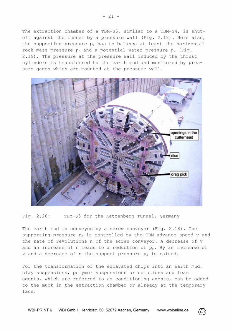
EPB machines are frequently utilized if tunnel sections have to bedriven in both, soil and rock. They are also applied in formationswith different and frequently changing ground conditions ("mixed-face-conditions") or in heavily weathered rock. Therefore, in ad-dition to the cutter discs, drag picks are foreseen as excavationtools at the cutterhead (Fig. 2.20). With the latter, soil androck with low strength can be excavated.
- 20 -
WBI-PRINT 6 WBI GmbH, Henricistr. 50, 52072 Aachen, Germany www.wbionline.de
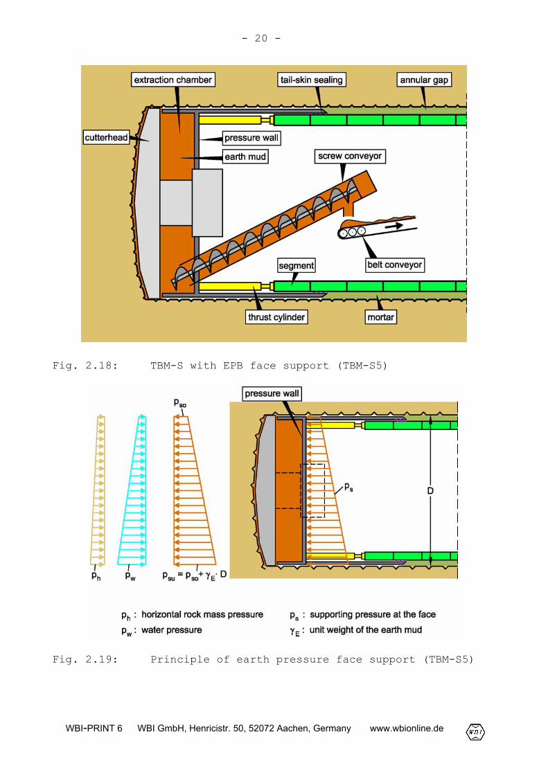
Fig. 2.18: TBM-S with EPB face support (TBM-S5)
Fig. 2.19: Principle of earth pressure face support (TBM-S5)
- 21 -
WBI-PRINT 6 WBI GmbH, Henricistr. 50, 52072 Aachen, Germany www.wbionline.de
The extraction chamber of a TBM-S5, similar to a TBM-S4, is shut-off against the tunnel by a pressure wall (Fig. 2.18). Here also,the supporting pressure ps has to balance at least the horizontalrock mass pressure ph and a potential water pressure pw (Fig.2.19). The pressure at the pressure wall induced by the thrustcylinders is transferred to the earth mud and monitored by pres-sure gages which are mounted at the pressure wall.
Fig. 2.20: TBM-S5 for the Katzenberg Tunnel, Germany
The earth mud is conveyed by a screw conveyor (Fig. 2.18). Thesupporting pressure ps is controlled by the TBM advance speed v andthe rate of revolutions n of the screw conveyor. A decrease of vand an increase of n leads to a reduction of ps. By an increase ofv and a decrease of n the support pressure ps is raised.
For the transformation of the excavated chips into an earth mud,clay suspensions, polymer suspensions or solutions and foamagents, which are referred to as conditioning agents, can be addedto the muck in the extraction chamber or already at the temporaryface.
- 22 -
WBI-PRINT 6 WBI GmbH, Henricistr. 50, 52072 Aachen, Germany www.wbionline.de
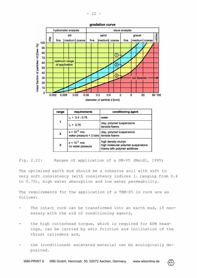
Fig. 2.21: Ranges of application of a SM-V5 (Maidl, 1995)
The optimized earth mud should be a cohesive soil with soft tovery soft consistency (with consistency indices Ic ranging from 0.4to 0.75), high water absorption and low water permeability.
The requirements for the application of a TBM-S5 in rock are asfollows:
- The intact rock can be transformed into an earth mud, if nec-essary with the aid of conditioning agents,
- the high cutterhead torque, which is required for EPB head-ings, can be carried by skin friction and inclination of thethrust cylinders and,
- the (conditioned) excavated material can be ecologically de-posited.
- 23 -
WBI-PRINT 6 WBI GmbH, Henricistr. 50, 52072 Aachen, Germany www.wbionline.de
The ranges of application of an EPB shield in soil (SM-V5, seeFig. 2.1) in connection with suitable conditioning agents aregiven in Fig. 2.21 (Maidl, 1995).
2.1.7 TBM with convertible mode
TBMs with convertible mode, which allow for a change of drivingmode during excavation, can be usefully utilized in varying groundand groundwater conditions. By machine modifications these typesof TBM enable a better adjustment to the ground conditions encoun-tered in the corresponding tunnel sections. In the past, a numberof convertible shielded machines for tunneling in soil were devel-oped, which allow for different combinations of modes, such asopen mode, EPB mode, slurry mode or compressed air mode. As an ex-ample, the mix shield, which was developed by the German companiesWayss & Freytag and Herrenknecht, can be operated as EPB-shield,as hydro shield as well as shield with air pressure support (Maidlet al., 1994).
For rock tunneling, TBMs operating with open mode and closedslurry or EPB mode, respectively, are applied. According to thestate-of-the-art, a change of modes can be carried out within afew shifts, depending on the machine design.
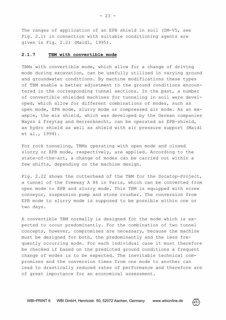
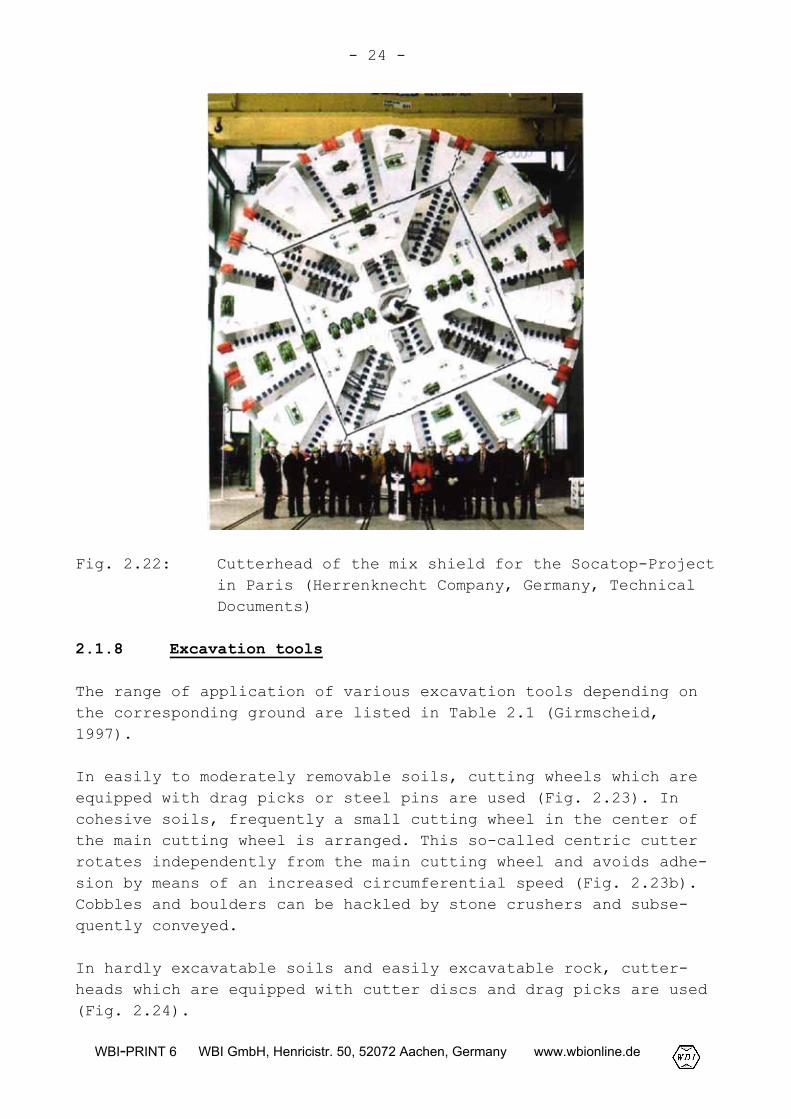
Fig. 2.22 shows the cutterhead of the TBM for the Socatop-Project,a tunnel of the freeway A 86 in Paris, which can be converted fromopen mode to EPB and slurry mode. This TBM is equipped with screwconveyor, suspension pump and stone crusher. The conversion fromEPB mode to slurry mode is supposed to be possible within one ortwo days.
A convertible TBM normally is designed for the mode which is ex-pected to occur predominantly. For the combination of two tunnelconcepts, however, compromises are necessary, because the machinemust be designed for both, the predominantly and the less fre-quently occurring mode. For each individual case it must thereforebe checked if based on the predicted ground conditions a frequentchange of modes is to be expected. The inevitable technical com-promises and the conversion times from one mode to another canlead to drastically reduced rates of performance and therefore areof great importance for an economical assessment.
- 24 -
WBI-PRINT 6 WBI GmbH, Henricistr. 50, 52072 Aachen, Germany www.wbionline.de
Fig. 2.22: Cutterhead of the mix shield for the Socatop-Projectin Paris (Herrenknecht Company, Germany, TechnicalDocuments)
2.1.8 Excavation tools
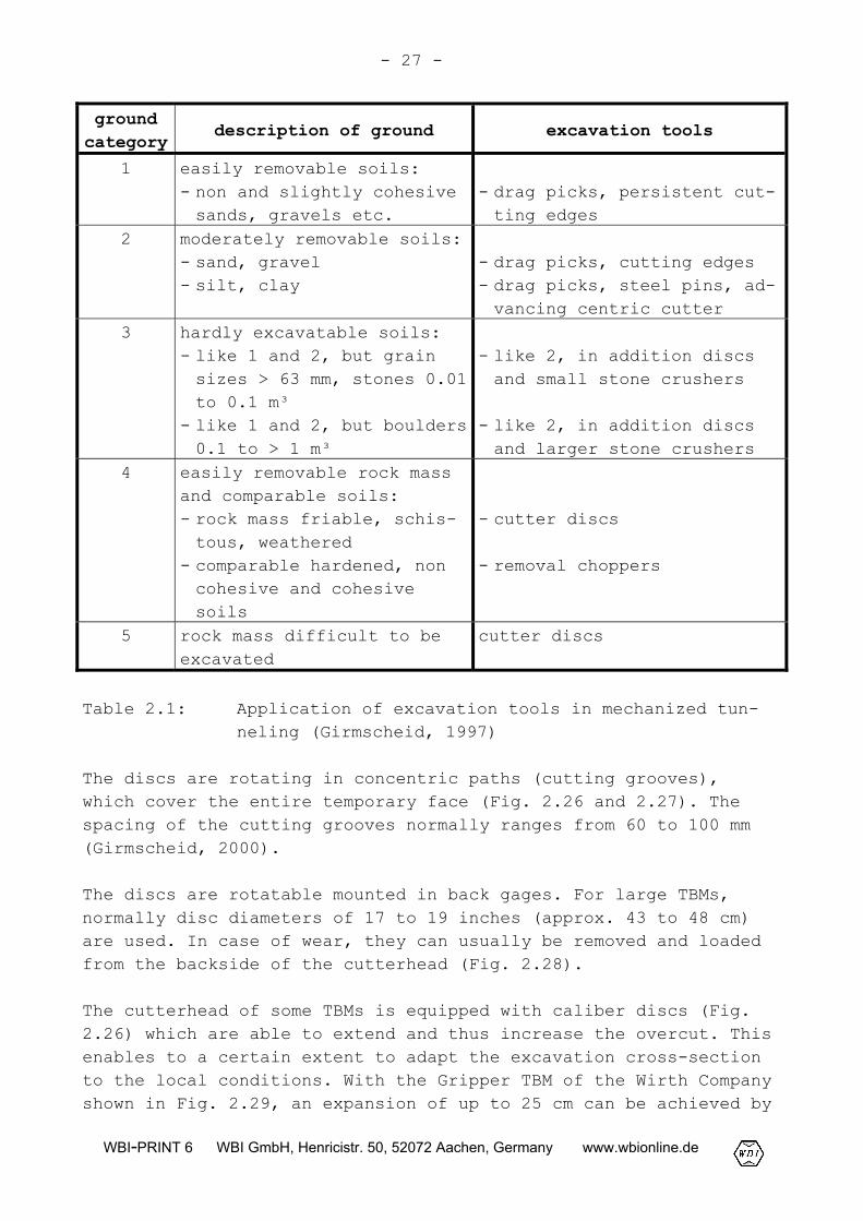
The range of application of various excavation tools depending onthe corresponding ground are listed in Table 2.1 (Girmscheid,1997).
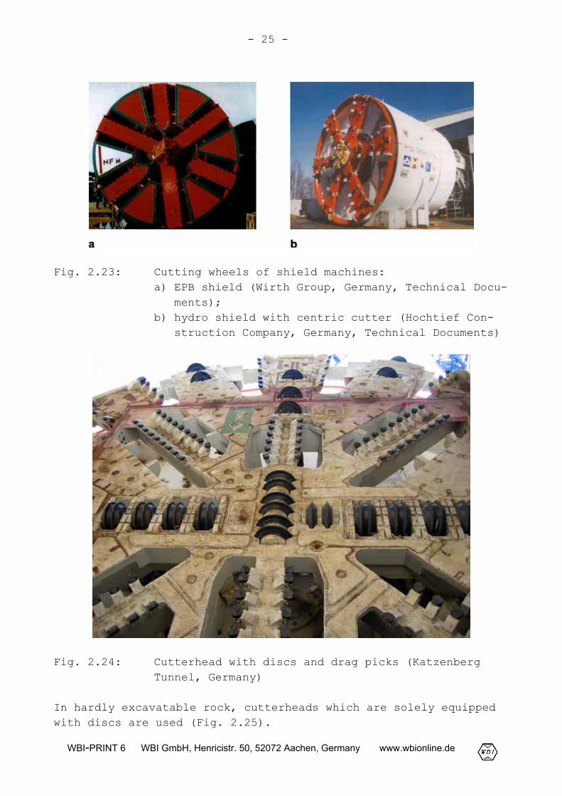
In easily to moderately removable soils, cutting wheels which areequipped with drag picks or steel pins are used (Fig. 2.23). Incohesive soils, frequently a small cutting wheel in the center ofthe main cutting wheel is arranged. This so-called centric cutterrotates independently from the main cutting wheel and avoids adhe-sion by means of an increased circumferential speed (Fig. 2.23b).Cobbles and boulders can be hackled by stone crushers and subse-quently conveyed.
In hardly excavatable soils and easily excavatable rock, cutter-heads which are equipped with cutter discs and drag picks are used(Fig. 2.24).
- 25 -
WBI-PRINT 6 WBI GmbH, Henricistr. 50, 52072 Aachen, Germany www.wbionline.de
Fig. 2.23: Cutting wheels of shield machines:a) EPB shield (Wirth Group, Germany, Technical Docu-
ments);b) hydro shield with centric cutter (Hochtief Con-
struction Company, Germany, Technical Documents)
Fig. 2.24: Cutterhead with discs and drag picks (KatzenbergTunnel, Germany)
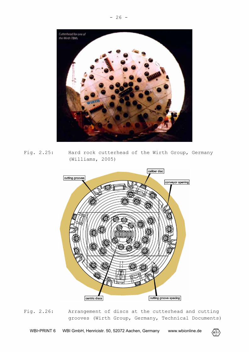
In hardly excavatable rock, cutterheads which are solely equippedwith discs are used (Fig. 2.25).
- 26 -
WBI-PRINT 6 WBI GmbH, Henricistr. 50, 52072 Aachen, Germany www.wbionline.de
Fig. 2.25: Hard rock cutterhead of the Wirth Group, Germany(Williams, 2005)
Fig. 2.26: Arrangement of discs at the cutterhead and cuttinggrooves (Wirth Group, Germany, Technical Documents)
- 27 -
WBI-PRINT 6 WBI GmbH, Henricistr. 50, 52072 Aachen, Germany www.wbionline.de
groundcategory
description of ground excavation tools
1 easily removable soils:- non and slightly cohesivesands, gravels etc.
- drag picks, persistent cut-ting edges
2 moderately removable soils:- sand, gravel- silt, clay
- drag picks, cutting edges- drag picks, steel pins, ad-vancing centric cutter
3 hardly excavatable soils:- like 1 and 2, but grainsizes > 63 mm, stones 0.01to 0.1 m³
- like 1 and 2, but boulders0.1 to > 1 m³
- like 2, in addition discsand small stone crushers
- like 2, in addition discsand larger stone crushers
4 easily removable rock massand comparable soils:- rock mass friable, schis-tous, weathered
- comparable hardened, noncohesive and cohesivesoils
- cutter discs
- removal choppers
5 rock mass difficult to beexcavated
cutter discs
Table 2.1: Application of excavation tools in mechanized tun-neling (Girmscheid, 1997)
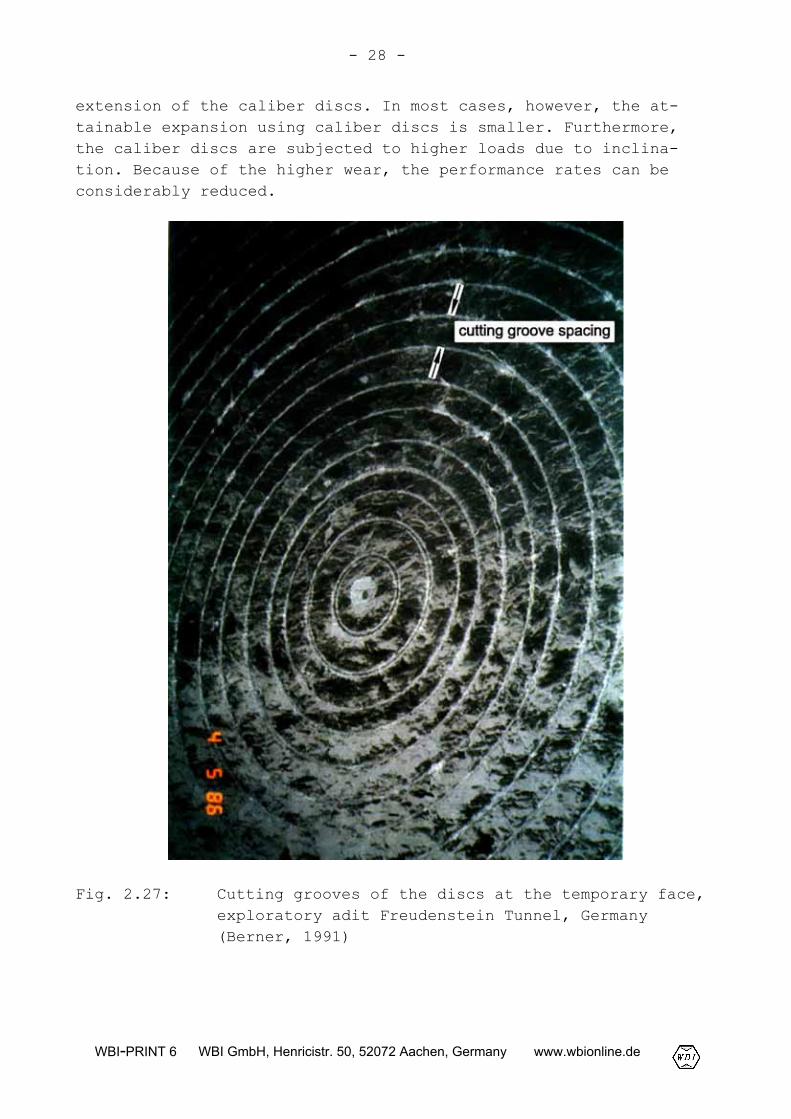
The discs are rotating in concentric paths (cutting grooves),which cover the entire temporary face (Fig. 2.26 and 2.27). Thespacing of the cutting grooves normally ranges from 60 to 100 mm(Girmscheid, 2000).
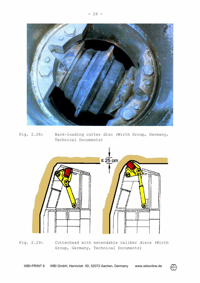
The discs are rotatable mounted in back gages. For large TBMs,normally disc diameters of 17 to 19 inches (approx. 43 to 48 cm)are used. In case of wear, they can usually be removed and loadedfrom the backside of the cutterhead (Fig. 2.28).
The cutterhead of some TBMs is equipped with caliber discs (Fig.2.26) which are able to extend and thus increase the overcut. Thisenables to a certain extent to adapt the excavation cross-sectionto the local conditions. With the Gripper TBM of the Wirth Companyshown in Fig. 2.29, an expansion of up to 25 cm can be achieved by
- 28 -
WBI-PRINT 6 WBI GmbH, Henricistr. 50, 52072 Aachen, Germany www.wbionline.de
extension of the caliber discs. In most cases, however, the at-tainable expansion using caliber discs is smaller. Furthermore,the caliber discs are subjected to higher loads due to inclina-tion. Because of the higher wear, the performance rates can beconsiderably reduced.
Fig. 2.27: Cutting grooves of the discs at the temporary face,exploratory adit Freudenstein Tunnel, Germany(Berner, 1991)
- 29 -
WBI-PRINT 6 WBI GmbH, Henricistr. 50, 52072 Aachen, Germany www.wbionline.de
Fig. 2.28: Back-loading cutter disc (Wirth Group, Germany,Technical Documents)
Fig. 2.29: Cutterhead with extendable caliber discs (WirthGroup, Germany, Technical Documents)
- 30 -
WBI-PRINT 6 WBI GmbH, Henricistr. 50, 52072 Aachen, Germany www.wbionline.de
2.1.9 Annular gap, steering gap and tail-skin sealing
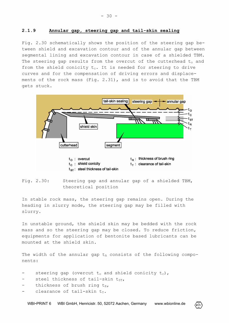
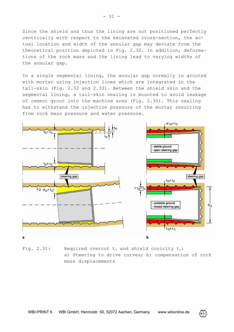
Fig. 2.30 schematically shows the position of the steering gap be-tween shield and excavation contour and of the annular gap betweensegmental lining and excavation contour in case of a shielded TBM.The steering gap results from the overcut of the cutterhead to andfrom the shield conicity tc. It is needed for steering to drivecurves and for the compensation of driving errors and displace-ments of the rock mass (Fig. 2.31), and is to avoid that the TBMgets stuck.
Fig. 2.30: Steering gap and annular gap of a shielded TBM,theoretical position
In stable rock mass, the steering gap remains open. During theheading in slurry mode, the steering gap may be filled withslurry.
In unstable ground, the shield skin may be bedded with the rockmass and so the steering gap may be closed. To reduce friction,equipments for application of bentonite based lubricants can bemounted at the shield skin.
The width of the annular gap tA consists of the following compo-nents:
- steering gap (overcut to and shield conicity tc),- steel thickness of tail-skin tST,- thickness of brush ring tR,- clearance of tail-skin tT.
- 31 -
WBI-PRINT 6 WBI GmbH, Henricistr. 50, 52072 Aachen, Germany www.wbionline.de
Since the shield and thus the lining are not positioned perfectlycentrically with respect to the excavated cross-section, the ac-tual location and width of the annular gap may deviate from thetheoretical position depicted in Fig. 2.30. In addition, deforma-tions of the rock mass and the lining lead to varying widths ofthe annular gap.
In a single segmental lining, the annular gap normally is groutedwith mortar using injection lines which are integrated in thetail-skin (Fig. 2.32 and 2.33). Between the shield skin and thesegmental lining, a tail-skin sealing is mounted to avoid leakageof cement grout into the machine area (Fig. 2.30). This sealinghas to withstand the injection pressure of the mortar resultingfrom rock mass pressure and water pressure.
Fig. 2.31: Required overcut to and shield conicity tc:a) Steering to drive curves; b) compensation of rockmass displacements
- 32 -
WBI-PRINT 6 WBI GmbH, Henricistr. 50, 52072 Aachen, Germany www.wbionline.de
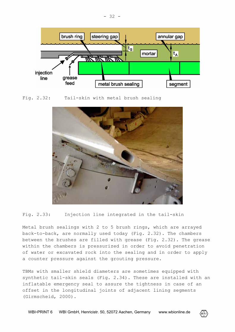
Fig. 2.32: Tail-skin with metal brush sealing
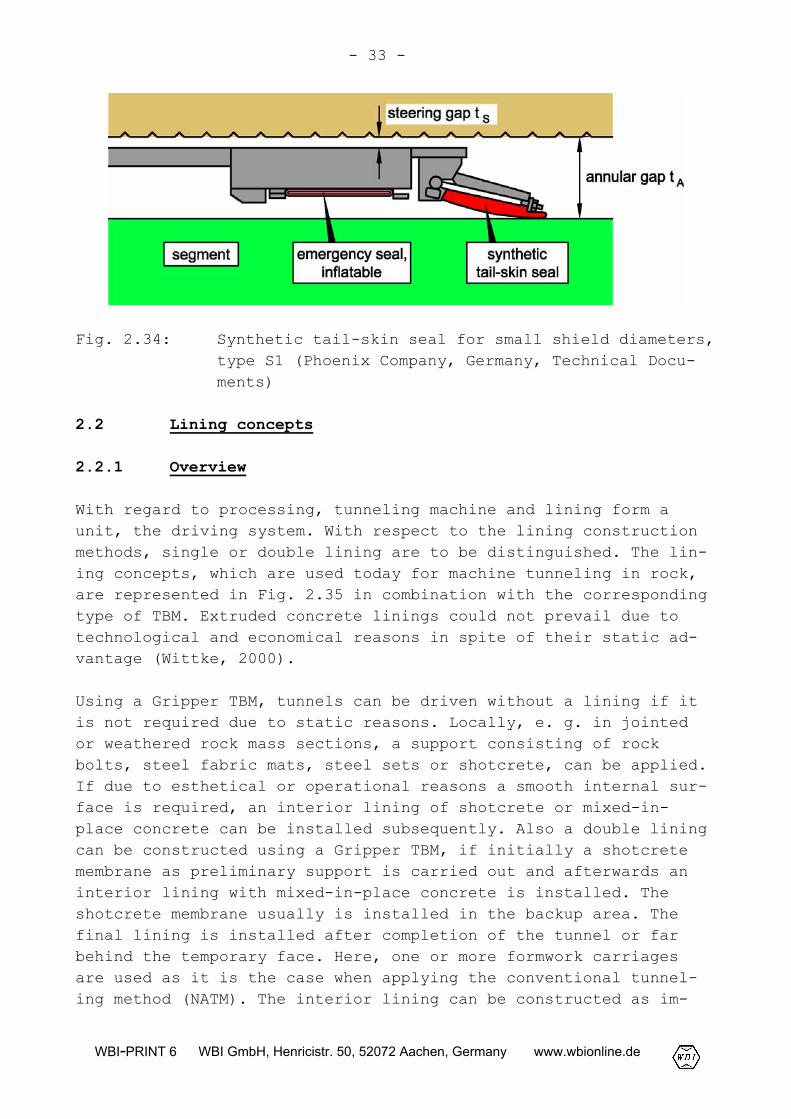
Fig. 2.33: Injection line integrated in the tail-skin
Metal brush sealings with 2 to 5 brush rings, which are arrayedback-to-back, are normally used today (Fig. 2.32). The chambersbetween the brushes are filled with grease (Fig. 2.32). The greasewithin the chambers is pressurized in order to avoid penetrationof water or excavated rock into the sealing and in order to applya counter pressure against the grouting pressure.
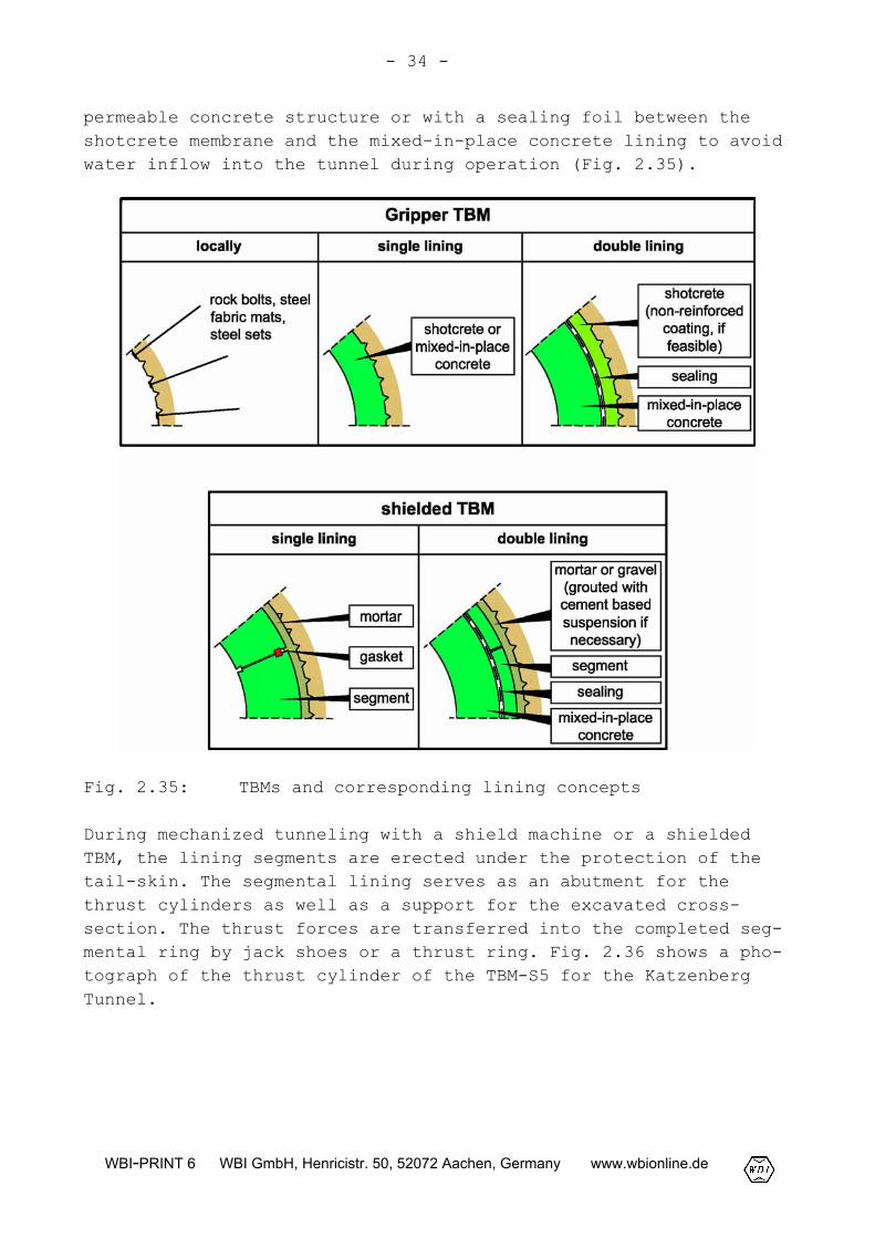
TBMs with smaller shield diameters are sometimes equipped withsynthetic tail-skin seals (Fig. 2.34). These are installed with aninflatable emergency seal to assure the tightness in case of anoffset in the longitudinal joints of adjacent lining segments(Girmscheid, 2000).
- 33 -
WBI-PRINT 6 WBI GmbH, Henricistr. 50, 52072 Aachen, Germany www.wbionline.de
Fig. 2.34: Synthetic tail-skin seal for small shield diameters,type S1 (Phoenix Company, Germany, Technical Docu-ments)
2.2 Lining concepts
2.2.1 Overview
With regard to processing, tunneling machine and lining form aunit, the driving system. With respect to the lining constructionmethods, single or double lining are to be distinguished. The lin-ing concepts, which are used today for machine tunneling in rock,are represented in Fig. 2.35 in combination with the correspondingtype of TBM. Extruded concrete linings could not prevail due totechnological and economical reasons in spite of their static ad-vantage (Wittke, 2000).
Using a Gripper TBM, tunnels can be driven without a lining if itis not required due to static reasons. Locally, e. g. in jointedor weathered rock mass sections, a support consisting of rockbolts, steel fabric mats, steel sets or shotcrete, can be applied.If due to esthetical or operational reasons a smooth internal sur-face is required, an interior lining of shotcrete or mixed-in-place concrete can be installed subsequently. Also a double liningcan be constructed using a Gripper TBM, if initially a shotcretemembrane as preliminary support is carried out and afterwards aninterior lining with mixed-in-place concrete is installed. Theshotcrete membrane usually is installed in the backup area. Thefinal lining is installed after completion of the tunnel or farbehind the temporary face. Here, one or more formwork carriagesare used as it is the case when applying the conventional tunnel-ing method (NATM). The interior lining can be constructed as im-
- 34 -
WBI-PRINT 6 WBI GmbH, Henricistr. 50, 52072 Aachen, Germany www.wbionline.de
permeable concrete structure or with a sealing foil between theshotcrete membrane and the mixed-in-place concrete lining to avoidwater inflow into the tunnel during operation (Fig. 2.35).
Fig. 2.35: TBMs and corresponding lining concepts
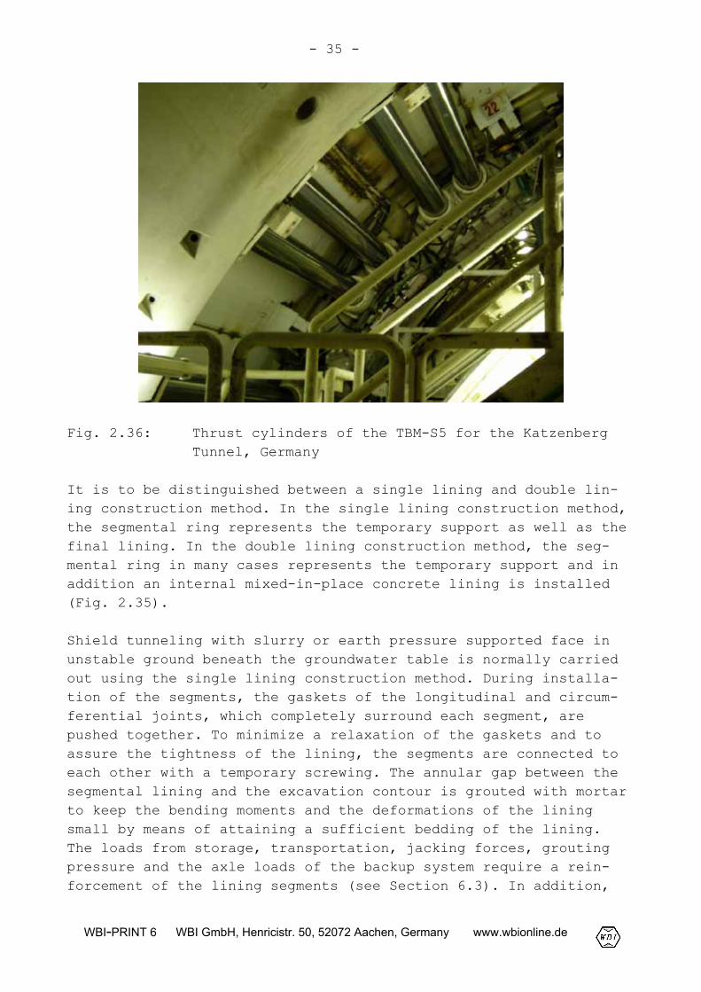
During mechanized tunneling with a shield machine or a shieldedTBM, the lining segments are erected under the protection of thetail-skin. The segmental lining serves as an abutment for thethrust cylinders as well as a support for the excavated cross-section. The thrust forces are transferred into the completed seg-mental ring by jack shoes or a thrust ring. Fig. 2.36 shows a pho-tograph of the thrust cylinder of the TBM-S5 for the KatzenbergTunnel.
- 35 -
WBI-PRINT 6 WBI GmbH, Henricistr. 50, 52072 Aachen, Germany www.wbionline.de
Fig. 2.36: Thrust cylinders of the TBM-S5 for the KatzenbergTunnel, Germany
It is to be distinguished between a single lining and double lin-ing construction method. In the single lining construction method,the segmental ring represents the temporary support as well as thefinal lining. In the double lining construction method, the seg-mental ring in many cases represents the temporary support and inaddition an internal mixed-in-place concrete lining is installed(Fig. 2.35).
Shield tunneling with slurry or earth pressure supported face inunstable ground beneath the groundwater table is normally carriedout using the single lining construction method. During installa-tion of the segments, the gaskets of the longitudinal and circum-ferential joints, which completely surround each segment, arepushed together. To minimize a relaxation of the gaskets and toassure the tightness of the lining, the segments are connected toeach other with a temporary screwing. The annular gap between thesegmental lining and the excavation contour is grouted with mortarto keep the bending moments and the deformations of the liningsmall by means of attaining a sufficient bedding of the lining.The loads from storage, transportation, jacking forces, groutingpressure and the axle loads of the backup system require a rein-forcement of the lining segments (see Section 6.3). In addition,

- 36 -
WBI-PRINT 6 WBI GmbH, Henricistr. 50, 52072 Aachen, Germany www.wbionline.de
the loads from self-weight of the lining, rock mass pressure, wa-ter pressure, temperature and fire are to be considered (see Sec-tion 6.2).
Fig. 2.37: Single segmental lining
For rock tunnels driven in Switzerland, the double segmental lin-ing construction method is frequently used. When a double liningis carried out, essential functions, such as e. g. watertightness,are taken care of by the internal lining and a sealing foil ar-ranged between the internal and external lining, respectively. Dueto this reason and because the segmental lining is invisible inthe final state, minor demands can be allowed for the productiontolerances of the segments. Compared with the single lining con-struction method, the segments are often designed distinctly sim-pler. The segments are mostly carried out as unsealed block seg-ments. The thickness of the segments depends on to what extent thesegmental lining is planned for permanent load transfer. If theexternal lining is planned as load bearing structural member, theinternal lining has only to carry the water pressure and thus canbe constructed non-reinforced. Applying the double lining con-struction method, the annular gap is frequently filled pneumati-cally with pea gravel. Depending of the requirements on the lin-ing, the latter can be post-grouted with cement-based suspension(Fig. 2.35).
- 37 -
WBI-PRINT 6 WBI GmbH, Henricistr. 50, 52072 Aachen, Germany www.wbionline.de
2.2.2 Single segmental lining
General
To avoid damages of the segments when installed, such as e. g.spalling at the grooves for the gaskets, shearing of coupling ele-ments or bending cracks, the selection of the type of segment in-cluding design layout and reinforcement is of great importance.The mounting tolerances for the construction of the ring, the pro-duction tolerances and joint tolerances of the segments and thesegmental lining respectively should be adjusted in cooperationwith the planners and shield engineers. Influences due to produc-tion, storage and transportation of the segments have also to betaken into account. Furthermore, loads resulting from ring con-struction and thrust, potential constraints due to installation ofthe segments, deformations of the segmental ring due to groutingof the annular gap as well as loads from the backup system must beconsidered. For specification of details of design, tests or pre-liminary investigations, respectively, may be helpful.
Type of segment
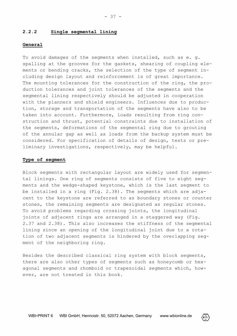
Block segments with rectangular layout are widely used for segmen-tal linings. One ring of segments consists of five to eight seg-ments and the wedge-shaped keystone, which is the last segment tobe installed in a ring (Fig. 2.38). The segments which are adja-cent to the keystone are referred to as boundary stones or counterstones, the remaining segments are designated as regular stones.To avoid problems regarding crossing joints, the longitudinaljoints of adjacent rings are arranged in a staggered way (Fig.2.37 and 2.38). This also increases the stiffness of the segmentallining since an opening of the longitudinal joint due to a rota-tion of two adjacent segments is hindered by the overlapping seg-ment of the neighboring ring.
Besides the described classical ring system with block segments,there are also other types of segments such as honeycomb or hex-agonal segments and rhomboid or trapezoidal segments which, how-ever, are not treated in this book.
- 38 -
WBI-PRINT 6 WBI GmbH, Henricistr. 50, 52072 Aachen, Germany www.wbionline.de
Fig. 2.38: Block segments with offset of longitudinal joints
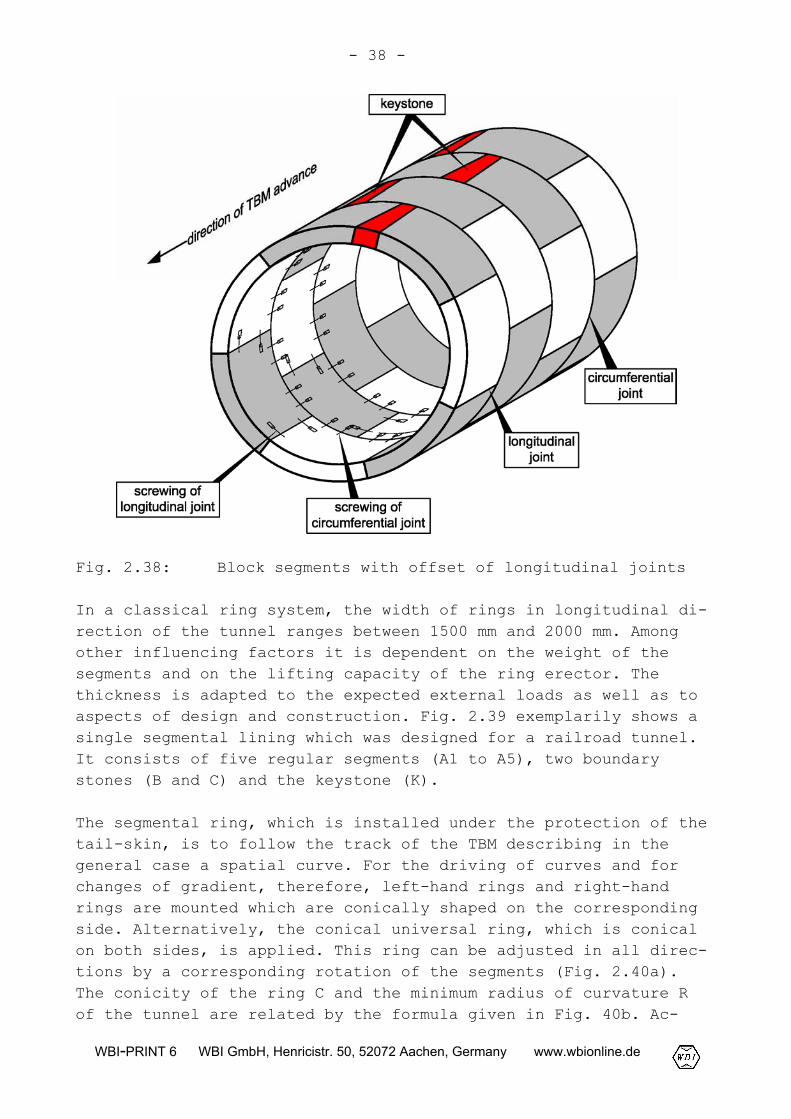
In a classical ring system, the width of rings in longitudinal di-rection of the tunnel ranges between 1500 mm and 2000 mm. Amongother influencing factors it is dependent on the weight of thesegments and on the lifting capacity of the ring erector. Thethickness is adapted to the expected external loads as well as toaspects of design and construction. Fig. 2.39 exemplarily shows asingle segmental lining which was designed for a railroad tunnel.It consists of five regular segments (A1 to A5), two boundarystones (B and C) and the keystone (K).
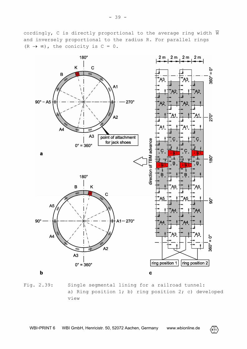
The segmental ring, which is installed under the protection of thetail-skin, is to follow the track of the TBM describing in thegeneral case a spatial curve. For the driving of curves and forchanges of gradient, therefore, left-hand rings and right-handrings are mounted which are conically shaped on the correspondingside. Alternatively, the conical universal ring, which is conicalon both sides, is applied. This ring can be adjusted in all direc-tions by a corresponding rotation of the segments (Fig. 2.40a).The conicity of the ring C and the minimum radius of curvature Rof the tunnel are related by the formula given in Fig. 40b. Ac-
- 39 -
WBI-PRINT 6 WBI GmbH, Henricistr. 50, 52072 Aachen, Germany www.wbionline.de
cordingly, C is directly proportional to the average ring width Wand inversely proportional to the radius R. For parallel rings(R � �), the conicity is C = 0.
Fig. 2.39: Single segmental lining for a railroad tunnel:a) Ring position 1; b) ring position 2; c) developedview
- 40 -
WBI-PRINT 6 WBI GmbH, Henricistr. 50, 52072 Aachen, Germany www.wbionline.de
Fig. 2.40: Conicity of segmental rings: a) Types of rings; b)relationship between conicity and minimum radius ofcurvature of the tunnel
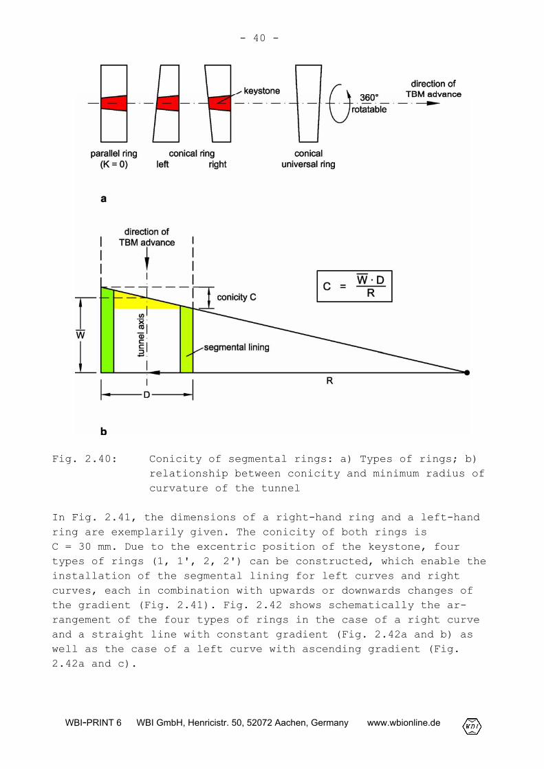
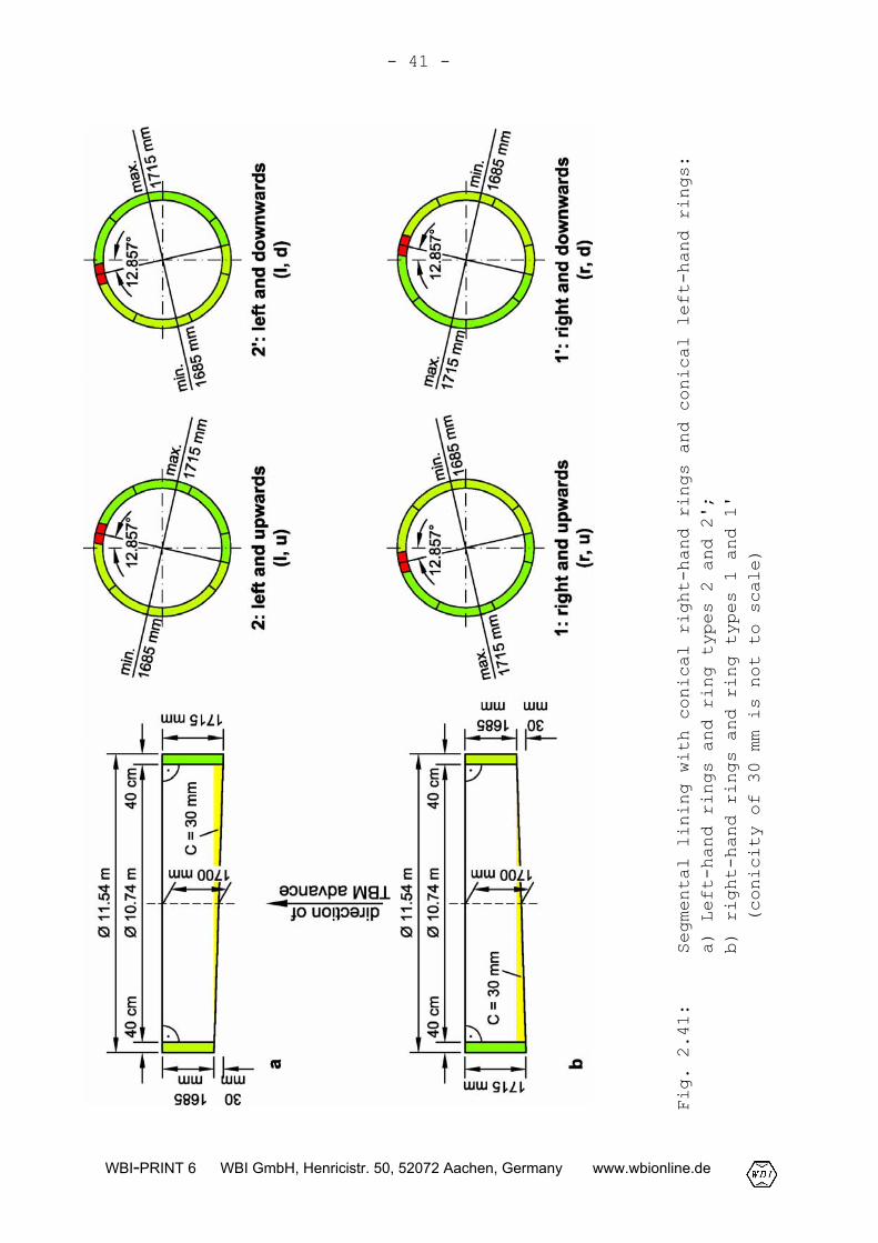
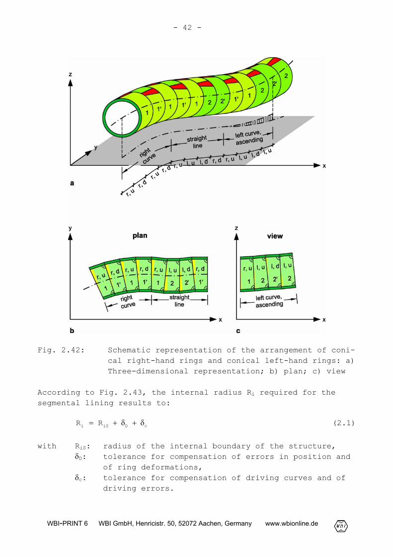
In Fig. 2.41, the dimensions of a right-hand ring and a left-handring are exemplarily given. The conicity of both rings isC = 30 mm. Due to the excentric position of the keystone, fourtypes of rings (1, 1', 2, 2') can be constructed, which enable theinstallation of the segmental lining for left curves and rightcurves, each in combination with upwards or downwards changes ofthe gradient (Fig. 2.41). Fig. 2.42 shows schematically the ar-rangement of the four types of rings in the case of a right curveand a straight line with constant gradient (Fig. 2.42a and b) aswell as the case of a left curve with ascending gradient (Fig.2.42a and c).
- 41 -
WBI-PRINT 6 WBI GmbH, Henricistr. 50, 52072 Aachen, Germany www.wbionline.de
Fig. 2.41:
Segmental lining with conical right-hand rings and conical left-hand rings:
a) Left-hand rings and ring types 2 and 2';
b) right-hand rings and ring types 1 and 1'
(conicity of 30 mm is not to scale)
- 42 -
WBI-PRINT 6 WBI GmbH, Henricistr. 50, 52072 Aachen, Germany www.wbionline.de
Fig. 2.42: Schematic representation of the arrangement of coni-cal right-hand rings and conical left-hand rings: a)Three-dimensional representation; b) plan; c) view
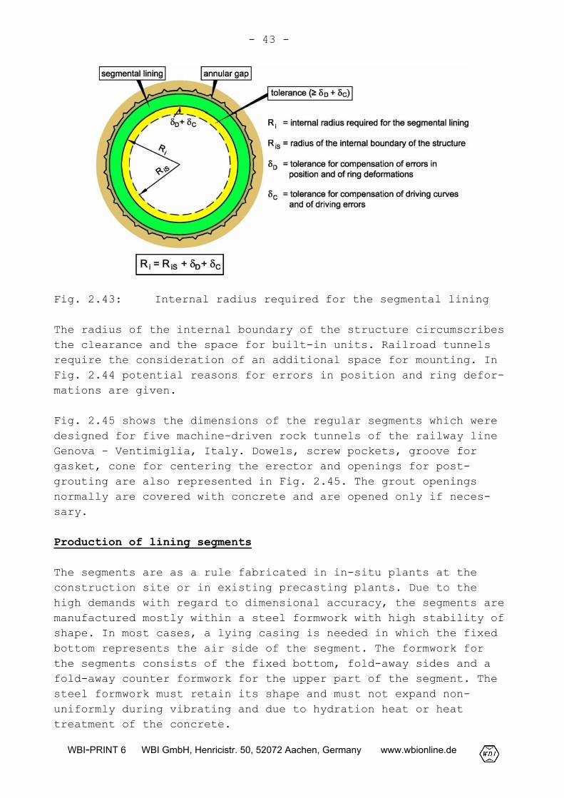
According to Fig. 2.43, the internal radius Ri required for thesegmental lining results to:
cDiSi RR ����� (2.1)
with RiS: radius of the internal boundary of the structure,�D: tolerance for compensation of errors in position and
of ring deformations,�c: tolerance for compensation of driving curves and of
driving errors.
- 43 -
WBI-PRINT 6 WBI GmbH, Henricistr. 50, 52072 Aachen, Germany www.wbionline.de
Fig. 2.43: Internal radius required for the segmental lining
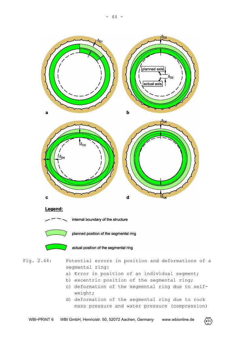
The radius of the internal boundary of the structure circumscribesthe clearance and the space for built-in units. Railroad tunnelsrequire the consideration of an additional space for mounting. InFig. 2.44 potential reasons for errors in position and ring defor-mations are given.
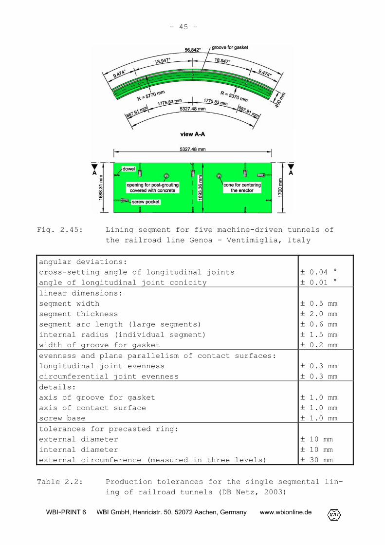
Fig. 2.45 shows the dimensions of the regular segments which weredesigned for five machine-driven rock tunnels of the railway lineGenova - Ventimiglia, Italy. Dowels, screw pockets, groove forgasket, cone for centering the erector and openings for post-grouting are also represented in Fig. 2.45. The grout openingsnormally are covered with concrete and are opened only if neces-sary.
Production of lining segments
The segments are as a rule fabricated in in-situ plants at theconstruction site or in existing precasting plants. Due to thehigh demands with regard to dimensional accuracy, the segments aremanufactured mostly within a steel formwork with high stability ofshape. In most cases, a lying casing is needed in which the fixedbottom represents the air side of the segment. The formwork forthe segments consists of the fixed bottom, fold-away sides and afold-away counter formwork for the upper part of the segment. Thesteel formwork must retain its shape and must not expand non-uniformly during vibrating and due to hydration heat or heattreatment of the concrete.
- 44 -
WBI-PRINT 6 WBI GmbH, Henricistr. 50, 52072 Aachen, Germany www.wbionline.de
Fig. 2.44: Potential errors in position and deformations of asegmental ring:a) Error in position of an individual segment;b) excentric position of the segmental ring;c) deformation of the segmental ring due to self-
weight;d) deformation of the segmental ring due to rock
mass pressure and water pressure (compression)
- 45 -
WBI-PRINT 6 WBI GmbH, Henricistr. 50, 52072 Aachen, Germany www.wbionline.de
Fig. 2.45: Lining segment for five machine-driven tunnels ofthe railroad line Genoa - Ventimiglia, Italy
angular deviations:cross-setting angle of longitudinal jointsangle of longitudinal joint conicity
� 0.04 °� 0.01 °
linear dimensions:segment widthsegment thicknesssegment arc length (large segments)internal radius (individual segment)width of groove for gasket
� 0.5 mm� 2.0 mm� 0.6 mm� 1.5 mm� 0.2 mm
evenness and plane parallelism of contact surfaces:longitudinal joint evennesscircumferential joint evenness
� 0.3 mm� 0.3 mm
details:axis of groove for gasketaxis of contact surfacescrew base
� 1.0 mm� 1.0 mm� 1.0 mm
tolerances for precasted ring:external diameterinternal diameterexternal circumference (measured in three levels)
� 10 mm� 10 mm� 30 mm
Table 2.2: Production tolerances for the single segmental lin-ing of railroad tunnels (DB Netz, 2003)
- 46 -
WBI-PRINT 6 WBI GmbH, Henricistr. 50, 52072 Aachen, Germany www.wbionline.de
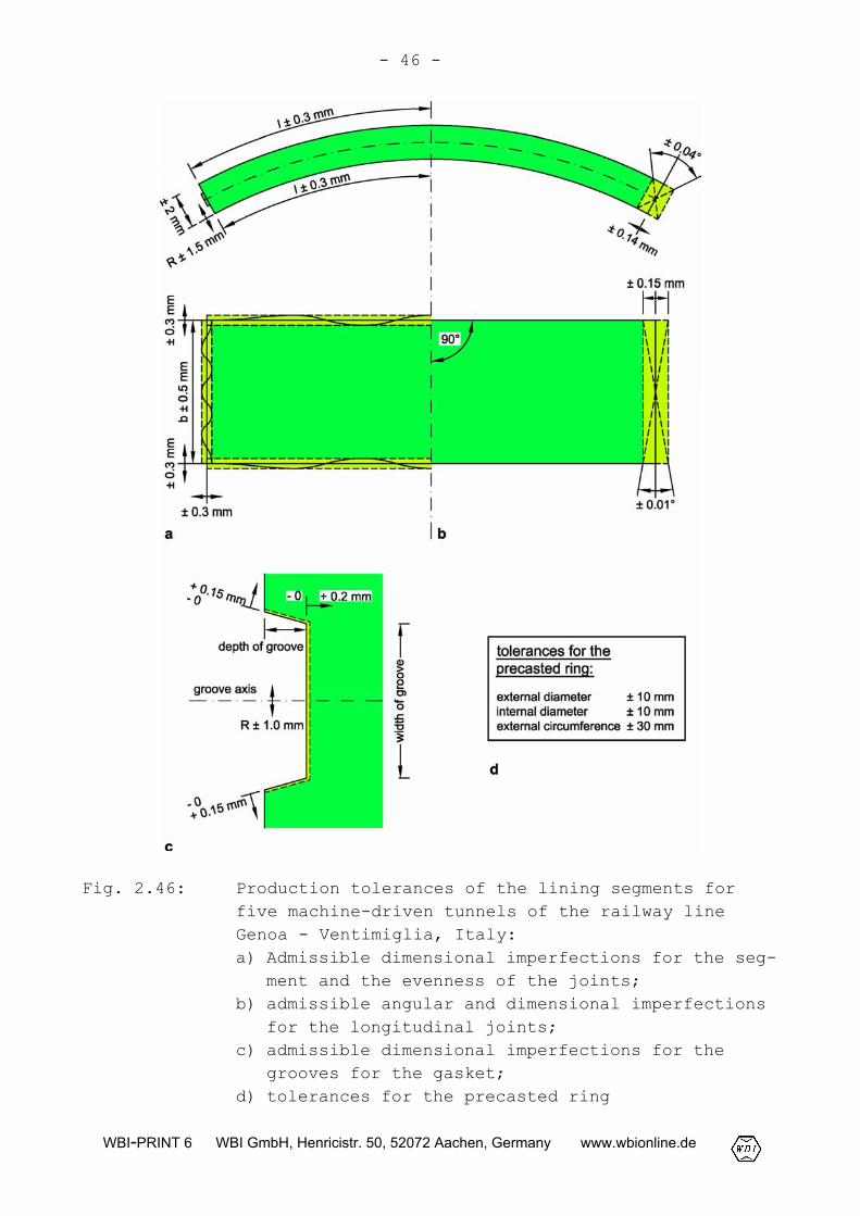
Fig. 2.46: Production tolerances of the lining segments forfive machine-driven tunnels of the railway lineGenoa - Ventimiglia, Italy:a) Admissible dimensional imperfections for the seg-
ment and the evenness of the joints;b) admissible angular and dimensional imperfections
for the longitudinal joints;c) admissible dimensional imperfections for the
grooves for the gasket;d) tolerances for the precasted ring
- 47 -
WBI-PRINT 6 WBI GmbH, Henricistr. 50, 52072 Aachen, Germany www.wbionline.de
To specify admissible production tolerances for the dimensions ofsegments, the specific boundary conditions of the project as wellas the corresponding standards have to be taken into account. InFig. 2.46, the admissible dimensional and angular imperfectionsfor a lining segment designed for five machine-driven tunnels ofthe railroad line Genova - Ventimiglia, Italy, are exemplarilygiven. For the single segmental lining of railway tunnels of theGerman Railroad, the production tolerances specified in the Guide-line 853 (DB Netz, 2003), which are listed in Table 2.2, arevalid.
For the concrete of lining segments, generally the same require-ments are valid as for mixed-in-place concrete used for internallinings. According to Guideline 853 of the German Railroad (DB,2003), for single segmental lining, a concrete grade of at least B45 corresponding to C 35/45 or higher is demanded. The compositionof concrete must be adjusted to the specific boundary conditionsof the project, e. g. concreting technique. As important proper-ties watertightness, a high impact resistance and flexural tensilestrength as well as resistance of concrete against aggressivenessof ground and groundwater are required. The setting of the con-crete and thus the development of strength can be accelerated by aheat treatment during the hardening of the concrete.
After stripping, the groove for the gaskets should be post-treated. Air bubbles near the surface should be opened by brushingwith a steel brush and then filled with synthetic resin.
The reinforcement should be carried out with bars of not more than20 mm in diameter. If larger diameters are used, only small imper-fections of bending radii can lead to difficulties with fittingthe reinforcement cages into the formwork. As a consequence, theeffort for installation of the reinforcement is disproportionatelyhigh. Reinforcing bar spacers of fiber-cement should be used toguarantee the scheduled cover.

- 48 -
WBI-PRINT 6 WBI GmbH, Henricistr. 50, 52072 Aachen, Germany www.wbionline.de
Fig. 2.47: Reinforcement cages for lining segments
Longitudinal and circumferential joints
The load transfer across the longitudinal joints takes placethrough contact of adjacent lining segments. From a statical pointof view, the longitudinal joints are hinges with restricted bear-ing capacity for bending moments (torsion springs). Bending mo-ments are transferred by excentric forces acting in ring direc-tion. Shear forces are transferred by the friction which existsbetween the contact surfaces of the joint.
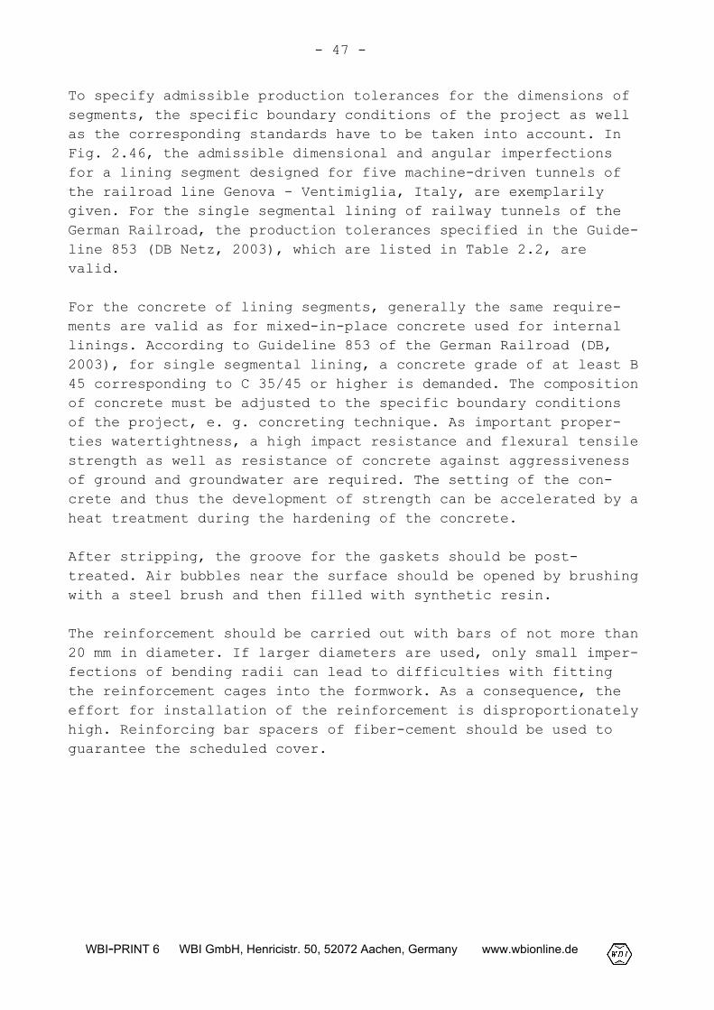
The longitudinal joints can be designed as curved or planar buttjoints. Due to their small stiffness against torsion convex curvedjoints are suitable especially in case of high compressive forcesin connection with large angles of torsion between two adjacentsegments. If the longitudinal joints are designed with planarfaces (Fig. 2.48a), the possibility for torsion is restricted to alarge extent. In this case, the ability of torsion can be in-creased by reducing the width of the contact surface. On the otherhand, this leads to increased stresses due to compression and ten-sile splitting in the area of the longitudinal joints.
- 49 -
WBI-PRINT 6 WBI GmbH, Henricistr. 50, 52072 Aachen, Germany www.wbionline.de
Fig. 2.48: Design of planar joints for a single segmental lin-ing: a) Longitudinal joint; b) circumferential joint
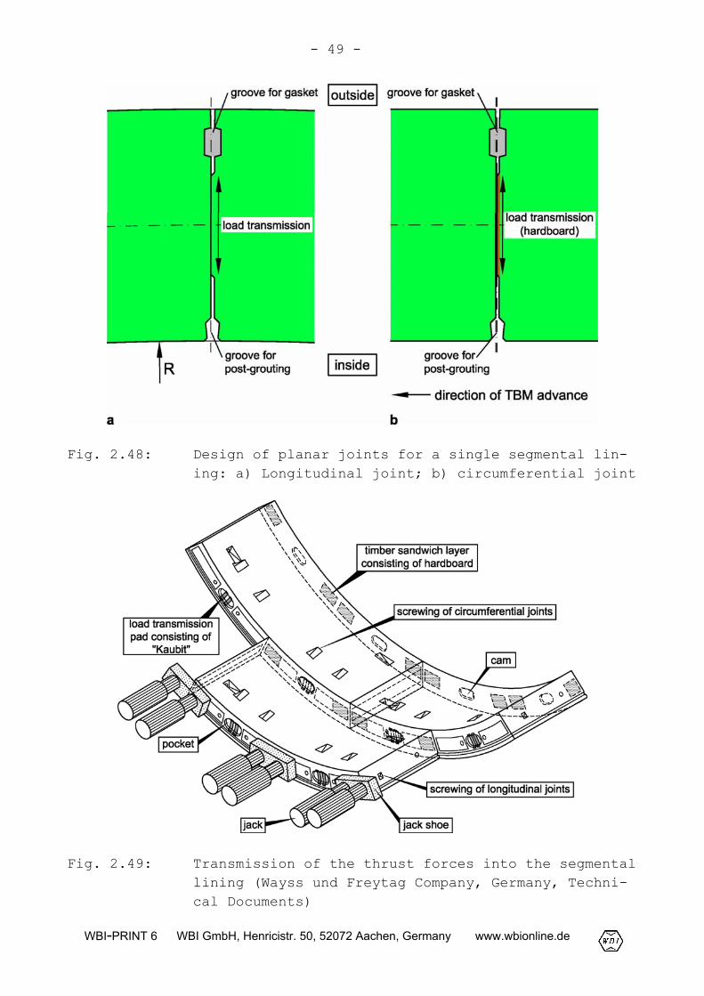
Fig. 2.49: Transmission of the thrust forces into the segmentallining (Wayss und Freytag Company, Germany, Techni-cal Documents)
- 50 -
WBI-PRINT 6 WBI GmbH, Henricistr. 50, 52072 Aachen, Germany www.wbionline.de
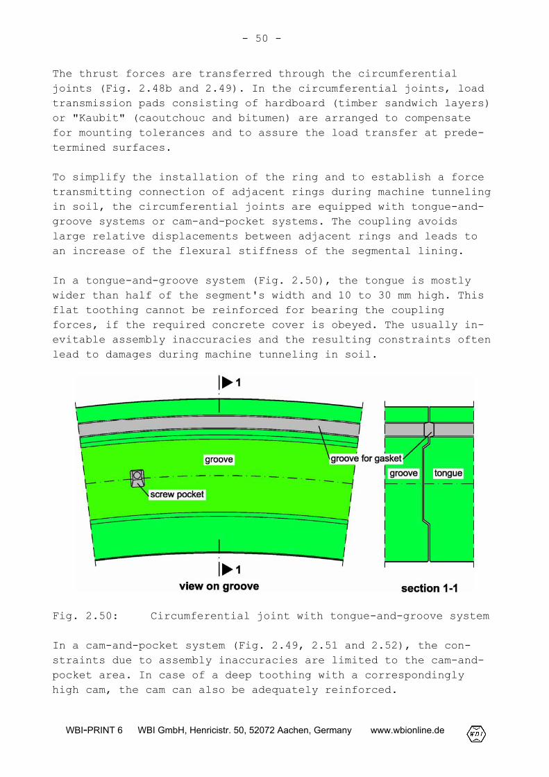
The thrust forces are transferred through the circumferentialjoints (Fig. 2.48b and 2.49). In the circumferential joints, loadtransmission pads consisting of hardboard (timber sandwich layers)or "Kaubit" (caoutchouc and bitumen) are arranged to compensatefor mounting tolerances and to assure the load transfer at prede-termined surfaces.
To simplify the installation of the ring and to establish a forcetransmitting connection of adjacent rings during machine tunnelingin soil, the circumferential joints are equipped with tongue-and-groove systems or cam-and-pocket systems. The coupling avoidslarge relative displacements between adjacent rings and leads toan increase of the flexural stiffness of the segmental lining.
In a tongue-and-groove system (Fig. 2.50), the tongue is mostlywider than half of the segment's width and 10 to 30 mm high. Thisflat toothing cannot be reinforced for bearing the couplingforces, if the required concrete cover is obeyed. The usually in-evitable assembly inaccuracies and the resulting constraints oftenlead to damages during machine tunneling in soil.
Fig. 2.50: Circumferential joint with tongue-and-groove system
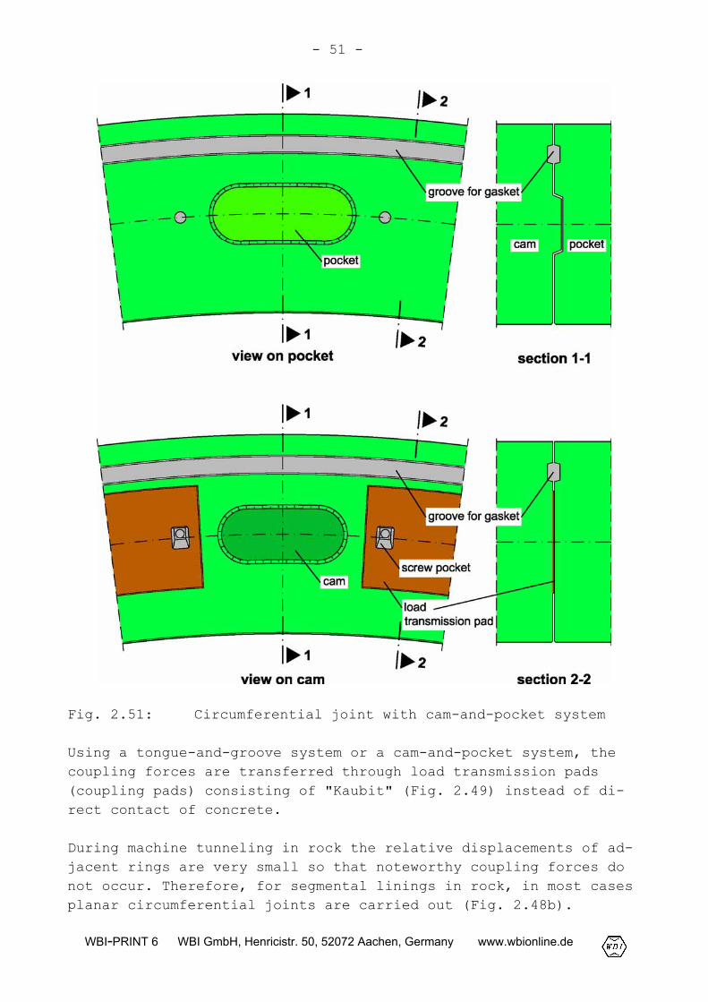
In a cam-and-pocket system (Fig. 2.49, 2.51 and 2.52), the con-straints due to assembly inaccuracies are limited to the cam-and-pocket area. In case of a deep toothing with a correspondinglyhigh cam, the cam can also be adequately reinforced.
- 51 -
WBI-PRINT 6 WBI GmbH, Henricistr. 50, 52072 Aachen, Germany www.wbionline.de
Fig. 2.51: Circumferential joint with cam-and-pocket system
Using a tongue-and-groove system or a cam-and-pocket system, thecoupling forces are transferred through load transmission pads(coupling pads) consisting of "Kaubit" (Fig. 2.49) instead of di-rect contact of concrete.
During machine tunneling in rock the relative displacements of ad-jacent rings are very small so that noteworthy coupling forces donot occur. Therefore, for segmental linings in rock, in most casesplanar circumferential joints are carried out (Fig. 2.48b).
- 52 -
WBI-PRINT 6 WBI GmbH, Henricistr. 50, 52072 Aachen, Germany www.wbionline.de
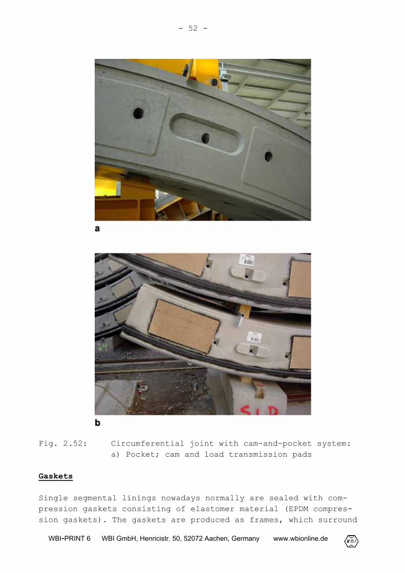
Fig. 2.52: Circumferential joint with cam-and-pocket system:a) Pocket; cam and load transmission pads
Gaskets
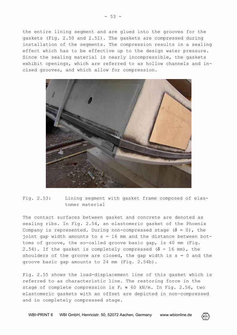
Single segmental linings nowadays normally are sealed with com-pression gaskets consisting of elastomer material (EPDM compres-sion gaskets). The gaskets are produced as frames, which surround
- 53 -
WBI-PRINT 6 WBI GmbH, Henricistr. 50, 52072 Aachen, Germany www.wbionline.de
the entire lining segment and are glued into the grooves for thegaskets (Fig. 2.50 and 2.51). The gaskets are compressed duringinstallation of the segments. The compression results in a sealingeffect which has to be effective up to the design water pressure.Since the sealing material is nearly incompressible, the gasketsexhibit openings, which are referred to as hollow channels and in-cised grooves, and which allow for compression.
Fig. 2.53: Lining segment with gasket frame composed of elas-tomer material
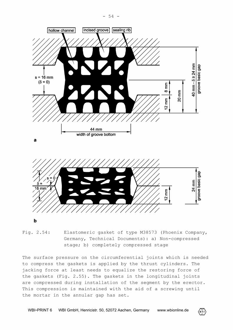
The contact surfaces between gasket and concrete are denoted assealing ribs. In Fig. 2.54, an elastomeric gasket of the PhoenixCompany is represented. During non-compressed stage (� = 0), thejoint gap width amounts to s = 16 mm and the distance between bot-toms of groove, the so-called groove basic gap, is 40 mm (Fig.2.54). If the gasket is completely compressed (� = 16 mm), theshoulders of the groove are closed, the gap width is s = 0 and thegroove basic gap amounts to 24 mm (Fig. 2.54b).
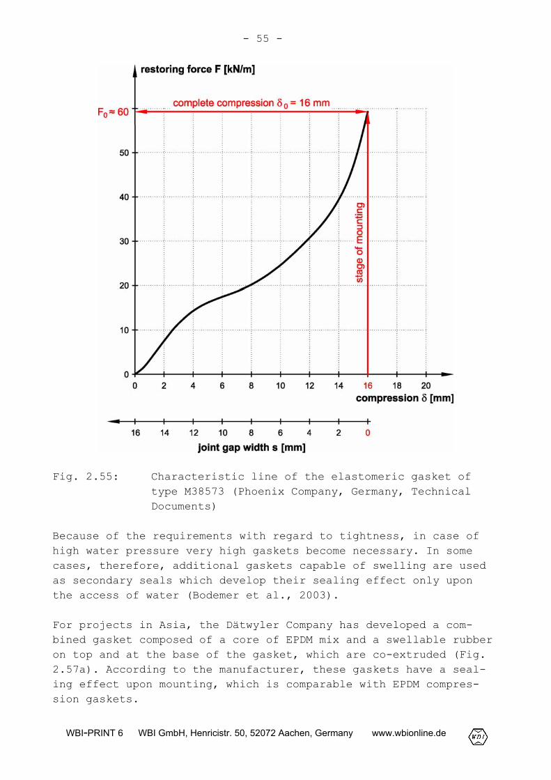
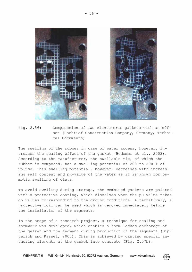
Fig. 2.55 shows the load-displacement line of this gasket which isreferred to as characteristic line. The restoring force in thestage of complete compression is F0 60 kN/m. In Fig. 2.56, twoelastomeric gaskets with an offset are depicted in non-compressedand in completely compressed stage.
- 54 -
WBI-PRINT 6 WBI GmbH, Henricistr. 50, 52072 Aachen, Germany www.wbionline.de
Fig. 2.54: Elastomeric gasket of type M38573 (Phoenix Company,Germany, Technical Documents): a) Non-compressedstage; b) completely compressed stage
The surface pressure on the circumferential joints which is neededto compress the gaskets is applied by the thrust cylinders. Thejacking force at least needs to equalize the restoring force ofthe gaskets (Fig. 2.55). The gaskets in the longitudinal jointsare compressed during installation of the segment by the erector.This compression is maintained with the aid of a screwing untilthe mortar in the annular gap has set.
- 55 -
WBI-PRINT 6 WBI GmbH, Henricistr. 50, 52072 Aachen, Germany www.wbionline.de
Fig. 2.55: Characteristic line of the elastomeric gasket oftype M38573 (Phoenix Company, Germany, TechnicalDocuments)
Because of the requirements with regard to tightness, in case ofhigh water pressure very high gaskets become necessary. In somecases, therefore, additional gaskets capable of swelling are usedas secondary seals which develop their sealing effect only uponthe access of water (Bodemer et al., 2003).
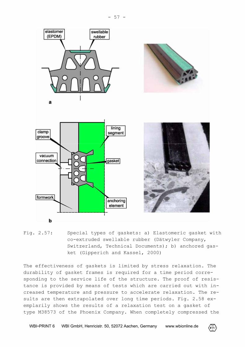
For projects in Asia, the Dätwyler Company has developed a com-bined gasket composed of a core of EPDM mix and a swellable rubberon top and at the base of the gasket, which are co-extruded (Fig.2.57a). According to the manufacturer, these gaskets have a seal-ing effect upon mounting, which is comparable with EPDM compres-sion gaskets.
- 56 -
WBI-PRINT 6 WBI GmbH, Henricistr. 50, 52072 Aachen, Germany www.wbionline.de
Fig. 2.56: Compression of two elastomeric gaskets with an off-set (Hochtief Construction Company, Germany, Techni-cal Documents)
The swelling of the rubber in case of water access, however, in-creases the sealing effect of the gasket (Bodemer et al., 2003).According to the manufacturer, the swellable mix, of which therubber is composed, has a swelling potential of 200 to 800 % ofvolume. This swelling potential, however, decreases with increas-ing salt content and pH-value of the water as it is known for os-motic swelling of clays.
To avoid swelling during storage, the combined gaskets are paintedwith a protective coating, which dissolves when the pH-value takeson values corresponding to the ground conditions. Alternatively, aprotective foil can be used which is removed immediately beforethe installation of the segments.
In the scope of a research project, a technique for sealing andformwork was developed, which enables a form-locked anchorage ofthe gasket and the segment during production of the segments (Gip-perich and Kassel, 2000). This is achieved by casting special an-choring elements at the gasket into concrete (Fig. 2.57b).
- 57 -
WBI-PRINT 6 WBI GmbH, Henricistr. 50, 52072 Aachen, Germany www.wbionline.de
Fig. 2.57: Special types of gaskets: a) Elastomeric gasket withco-extruded swellable rubber (Dätwyler Company,Switzerland, Technical Documents); b) anchored gas-ket (Gipperich and Kassel, 2000)
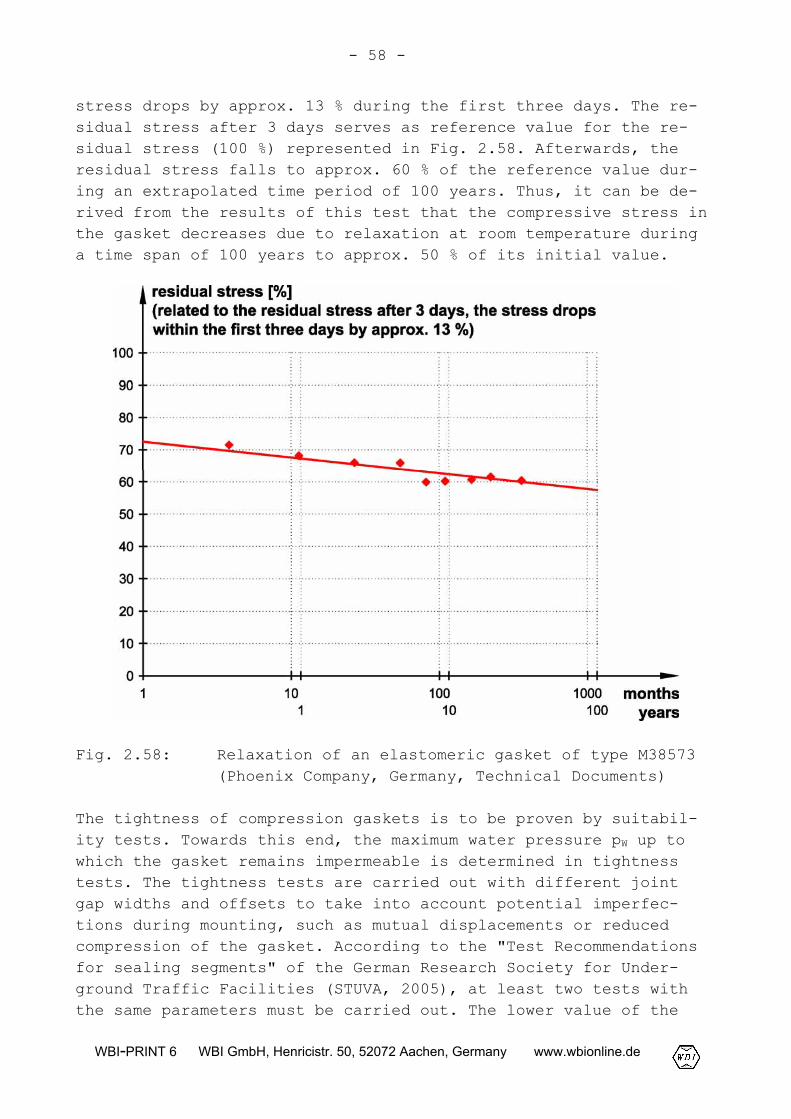
The effectiveness of gaskets is limited by stress relaxation. Thedurability of gasket frames is required for a time period corre-sponding to the service life of the structure. The proof of resis-tance is provided by means of tests which are carried out with in-creased temperature and pressure to accelerate relaxation. The re-sults are then extrapolated over long time periods. Fig. 2.58 ex-emplarily shows the results of a relaxation test on a gasket oftype M38573 of the Phoenix Company. When completely compressed the
- 58 -
WBI-PRINT 6 WBI GmbH, Henricistr. 50, 52072 Aachen, Germany www.wbionline.de
stress drops by approx. 13 % during the first three days. The re-sidual stress after 3 days serves as reference value for the re-sidual stress (100 %) represented in Fig. 2.58. Afterwards, theresidual stress falls to approx. 60 % of the reference value dur-ing an extrapolated time period of 100 years. Thus, it can be de-rived from the results of this test that the compressive stress inthe gasket decreases due to relaxation at room temperature duringa time span of 100 years to approx. 50 % of its initial value.
Fig. 2.58: Relaxation of an elastomeric gasket of type M38573(Phoenix Company, Germany, Technical Documents)
The tightness of compression gaskets is to be proven by suitabil-ity tests. Towards this end, the maximum water pressure pW up towhich the gasket remains impermeable is determined in tightnesstests. The tightness tests are carried out with different jointgap widths and offsets to take into account potential imperfec-tions during mounting, such as mutual displacements or reducedcompression of the gasket. According to the "Test Recommendationsfor sealing segments" of the German Research Society for Under-ground Traffic Facilities (STUVA, 2005), at least two tests withthe same parameters must be carried out. The lower value of the
- 59 -
WBI-PRINT 6 WBI GmbH, Henricistr. 50, 52072 Aachen, Germany www.wbionline.de
acceptable water pressures determined in both tests is decisivefor the evaluation.
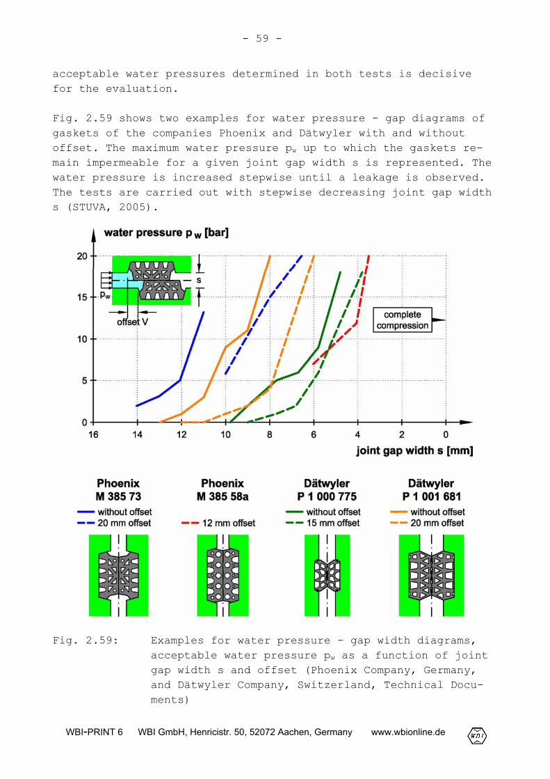
Fig. 2.59 shows two examples for water pressure - gap diagrams ofgaskets of the companies Phoenix and Dätwyler with and withoutoffset. The maximum water pressure pw up to which the gaskets re-main impermeable for a given joint gap width s is represented. Thewater pressure is increased stepwise until a leakage is observed.The tests are carried out with stepwise decreasing joint gap widths (STUVA, 2005).
Fig. 2.59: Examples for water pressure - gap width diagrams,acceptable water pressure pw as a function of jointgap width s and offset (Phoenix Company, Germany,and Dätwyler Company, Switzerland, Technical Docu-ments)
- 60 -
WBI-PRINT 6 WBI GmbH, Henricistr. 50, 52072 Aachen, Germany www.wbionline.de
Further details regarding the performance of such tests can befound in the STUVA recommendations (STUVA, 2005).
Segment connections
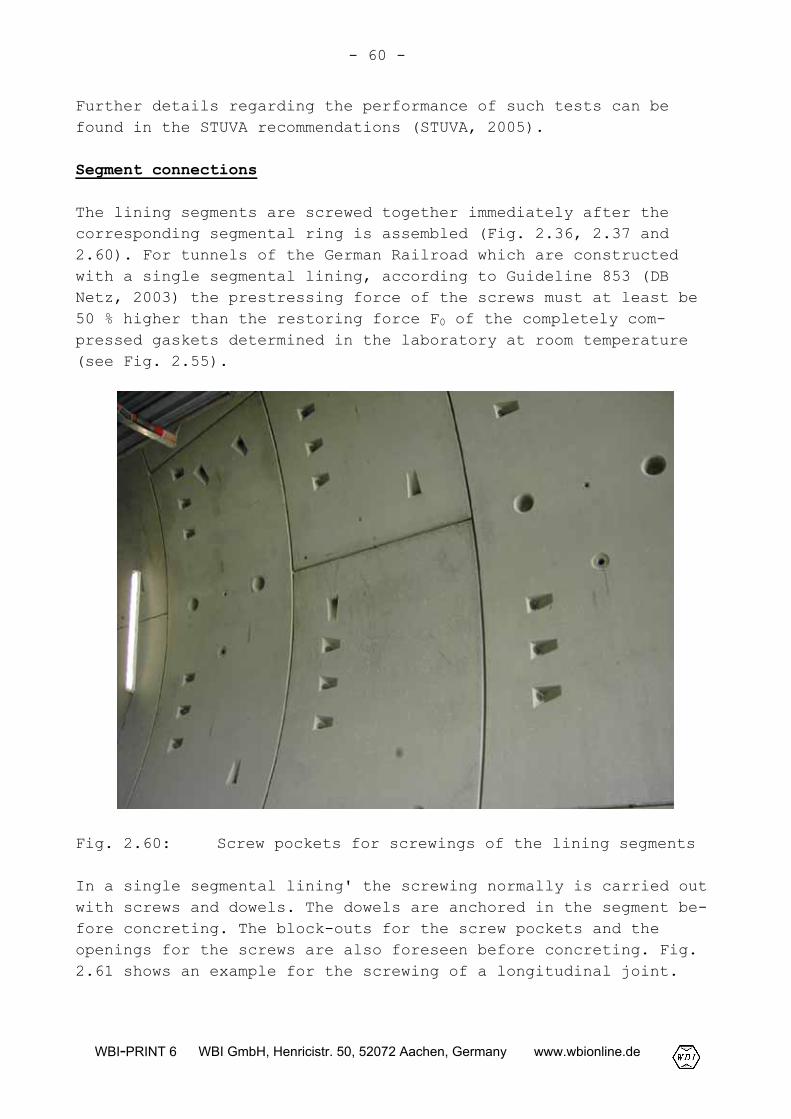
The lining segments are screwed together immediately after thecorresponding segmental ring is assembled (Fig. 2.36, 2.37 and2.60). For tunnels of the German Railroad which are constructedwith a single segmental lining, according to Guideline 853 (DBNetz, 2003) the prestressing force of the screws must at least be50 % higher than the restoring force F0 of the completely com-pressed gaskets determined in the laboratory at room temperature(see Fig. 2.55).
Fig. 2.60: Screw pockets for screwings of the lining segments
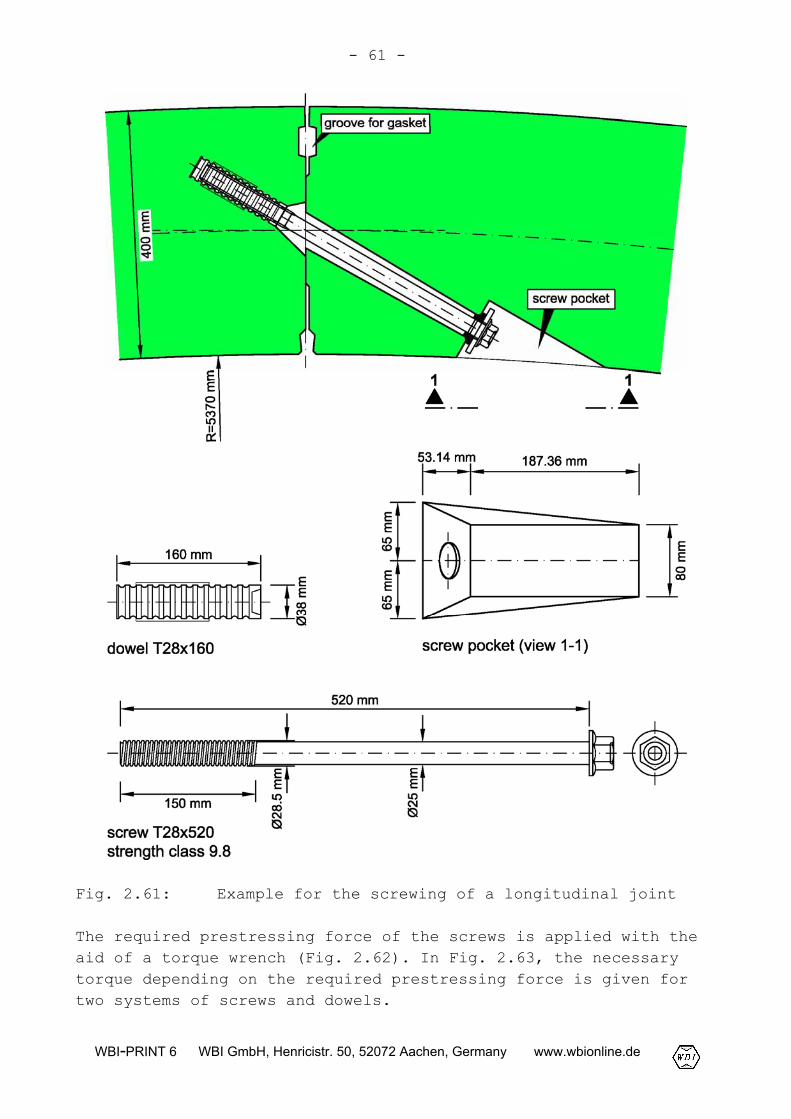
In a single segmental lining' the screwing normally is carried outwith screws and dowels. The dowels are anchored in the segment be-fore concreting. The block-outs for the screw pockets and theopenings for the screws are also foreseen before concreting. Fig.2.61 shows an example for the screwing of a longitudinal joint.
- 61 -
WBI-PRINT 6 WBI GmbH, Henricistr. 50, 52072 Aachen, Germany www.wbionline.de
Fig. 2.61: Example for the screwing of a longitudinal joint
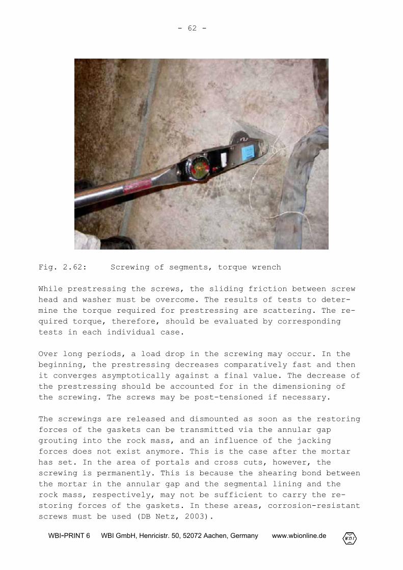
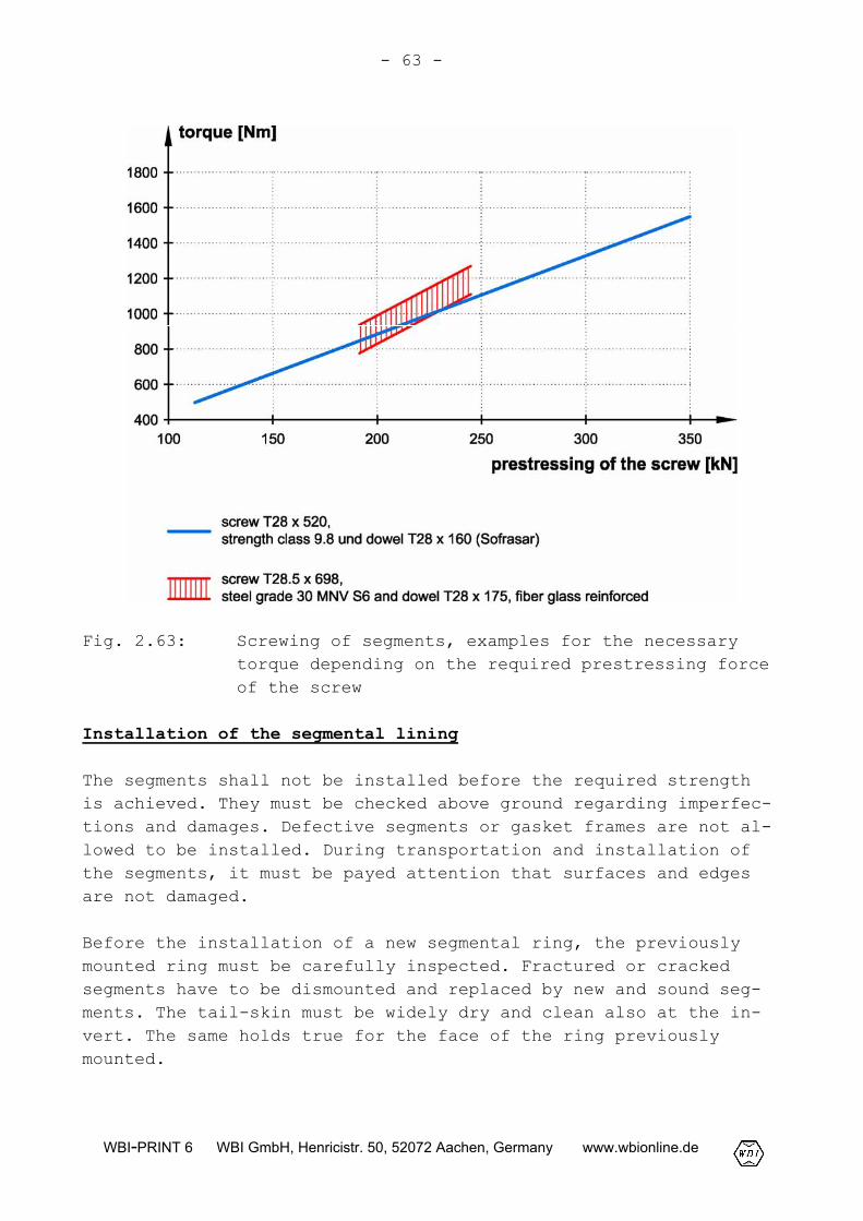
The required prestressing force of the screws is applied with theaid of a torque wrench (Fig. 2.62). In Fig. 2.63, the necessarytorque depending on the required prestressing force is given fortwo systems of screws and dowels.
- 62 -
WBI-PRINT 6 WBI GmbH, Henricistr. 50, 52072 Aachen, Germany www.wbionline.de
Fig. 2.62: Screwing of segments, torque wrench
While prestressing the screws, the sliding friction between screwhead and washer must be overcome. The results of tests to deter-mine the torque required for prestressing are scattering. The re-quired torque, therefore, should be evaluated by correspondingtests in each individual case.
Over long periods, a load drop in the screwing may occur. In thebeginning, the prestressing decreases comparatively fast and thenit converges asymptotically against a final value. The decrease ofthe prestressing should be accounted for in the dimensioning ofthe screwing. The screws may be post-tensioned if necessary.
The screwings are released and dismounted as soon as the restoringforces of the gaskets can be transmitted via the annular gapgrouting into the rock mass, and an influence of the jackingforces does not exist anymore. This is the case after the mortarhas set. In the area of portals and cross cuts, however, thescrewing is permanently. This is because the shearing bond betweenthe mortar in the annular gap and the segmental lining and therock mass, respectively, may not be sufficient to carry the re-storing forces of the gaskets. In these areas, corrosion-resistantscrews must be used (DB Netz, 2003).
- 63 -
WBI-PRINT 6 WBI GmbH, Henricistr. 50, 52072 Aachen, Germany www.wbionline.de
Fig. 2.63: Screwing of segments, examples for the necessarytorque depending on the required prestressing forceof the screw
Installation of the segmental lining
The segments shall not be installed before the required strengthis achieved. They must be checked above ground regarding imperfec-tions and damages. Defective segments or gasket frames are not al-lowed to be installed. During transportation and installation ofthe segments, it must be payed attention that surfaces and edgesare not damaged.
Before the installation of a new segmental ring, the previouslymounted ring must be carefully inspected. Fractured or crackedsegments have to be dismounted and replaced by new and sound seg-ments. The tail-skin must be widely dry and clean also at the in-vert. The same holds true for the face of the ring previouslymounted.
- 64 -
WBI-PRINT 6 WBI GmbH, Henricistr. 50, 52072 Aachen, Germany www.wbionline.de
In case of a classical ring system, the first segment is attachedfloating at the invert to the ring mounted before. When positionedcorrectly by the erector, the segment is pushed against the previ-ously mounted ring by the thrust cylinders. Subsequently, the tem-porary screwings in the circumferential joints are fixed. Theerector is not retracted from the segment before all screws arefixed and prestressed respectively.
The following segments are installed alternatingly left and rightfrom the first segment. The longitudinal joints must be completelyclosed. Otherwise, there is a risk that the longitudinal jointsare compressed by the annular grout after the segment has left thetail-skin. In this case, movements in the circumferential jointsmay occur which can cause damages to the segments on the outsideof the ring.
Before the keystone is installed it must be checked if there isenough space between the counter stones for mounting the keystone.If this is not the case, the ring should be dismantled and thenerected again. The attempt to expand the ring by inserting thekeystone and thus to enlarge the space between counter stones fre-quently leads to damages at the ring and as a consequence to leak-ages in the area of the keystone.
The keystone should be installed with the erector far enough tocreate the required prestressing of the gaskets in the circumfer-ential joints. In order to completely install the keystone withthe aid of the thrust cylinder, the jacks of the adjacent segmentsare slightly retracted to avoid restraints. The thrust cylindersare only pushed again when the screws in the longitudinal jointsare completely fixed.
2.2.3 Double segmental lining
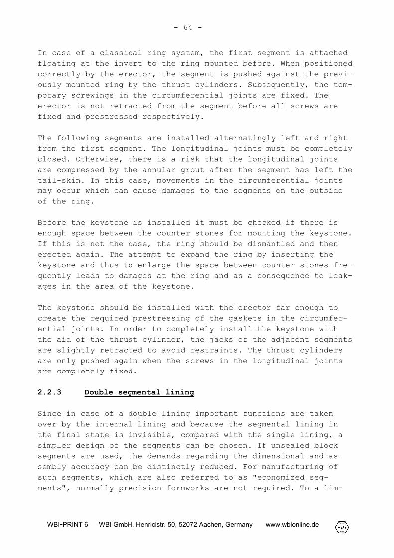
Since in case of a double lining important functions are takenover by the internal lining and because the segmental lining inthe final state is invisible, compared with the single lining, asimpler design of the segments can be chosen. If unsealed blocksegments are used, the demands regarding the dimensional and as-sembly accuracy can be distinctly reduced. For manufacturing ofsuch segments, which are also referred to as "economized seg-ments", normally precision formworks are not required. To a lim-
- 65 -
WBI-PRINT 6 WBI GmbH, Henricistr. 50, 52072 Aachen, Germany www.wbionline.de
ited extent, also damages may be accepted which can not be toler-ated in the case of a single segmental lining.
Fig. 2.64: Economized segment for a double lining, Tunnel Mur-genthal, Switzerland (Hentschel, 1998)
As a consequence of minor requirements with regard to the dimen-sional and assembly accuracy, the double lining constructionmethod leads to considerable lower set-up times for a ring of ap-prox. 15 to 20 minutes and to higher rates of heading. This advan-tage, however, at least in part is compensated by the time spentfor the installation of the sealing and of the mixed-in-phase con-crete lining. The construction time required for a double liningis highly dependent on the used number of formwork carriages.Therefore, regarding the total construction time, it cannot be di-rectly compared with the single lining construction method.
The wall thickness of the segmental ring of a double lining usu-ally is smaller than that of a single lining since the transfer ofthe external loads is partly taken over by the internal lining.The load bearing capacity of a double lining composed of a segmen-tal lining and an internal cast-in-place concrete lining, however,is smaller than that of a single segmental lining of the samethickness, because there is no or only limited shearing bond be-tween internal and external lining. For this reason, the totalwall thickness required for a double lining normally is greaterthan that for a single lining.
- 66 -
WBI-PRINT 6 WBI GmbH, Henricistr. 50, 52072 Aachen, Germany www.wbionline.de
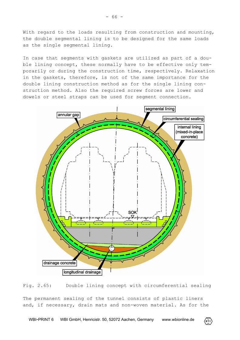
With regard to the loads resulting from construction and mounting,the double segmental lining is to be designed for the same loadsas the single segmental lining.
In case that segments with gaskets are utilized as part of a dou-ble lining concept, these normally have to be effective only tem-porarily or during the construction time, respectively. Relaxationin the gaskets, therefore, is not of the same importance for thedouble lining construction method as for the single lining con-struction method. Also the required screw forces are lower anddowels or steel straps can be used for segment connection.
Fig. 2.65: Double lining concept with circumferential sealing
The permanent sealing of the tunnel consists of plastic linersand, if necessary, drain mats and non-woven material. As for the
- 67 -
WBI-PRINT 6 WBI GmbH, Henricistr. 50, 52072 Aachen, Germany www.wbionline.de
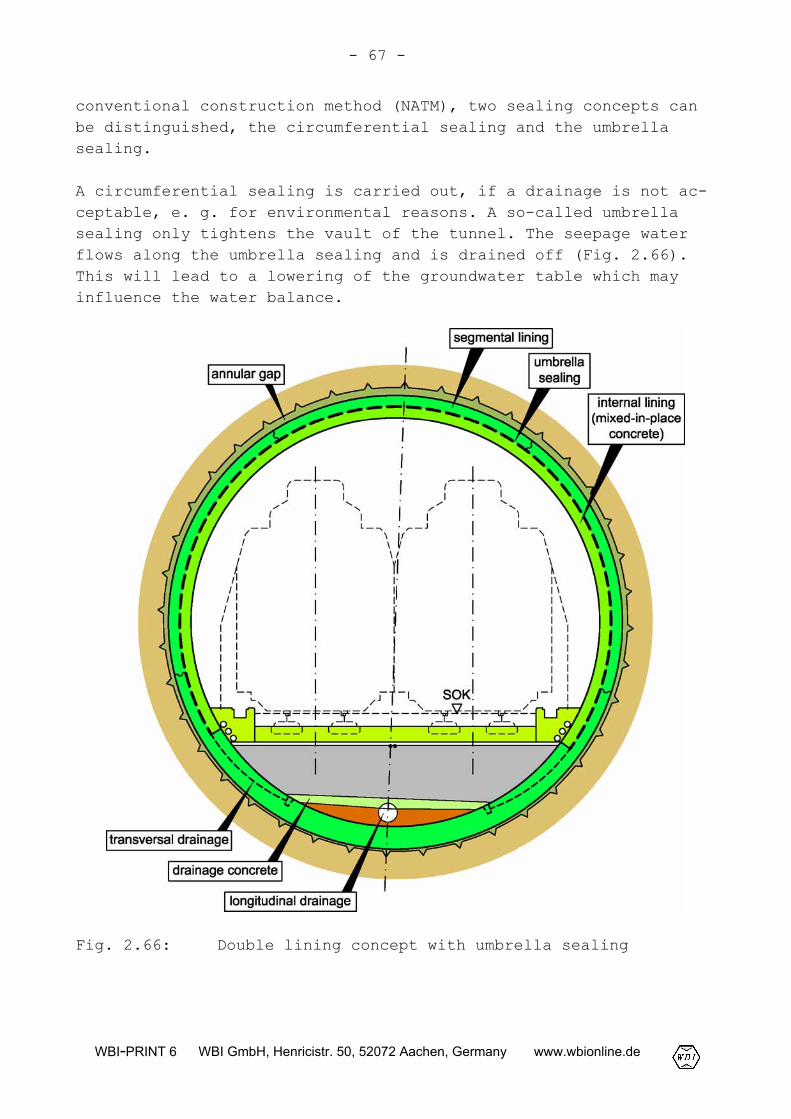
conventional construction method (NATM), two sealing concepts canbe distinguished, the circumferential sealing and the umbrellasealing.
A circumferential sealing is carried out, if a drainage is not ac-ceptable, e. g. for environmental reasons. A so-called umbrellasealing only tightens the vault of the tunnel. The seepage waterflows along the umbrella sealing and is drained off (Fig. 2.66).This will lead to a lowering of the groundwater table which mayinfluence the water balance.
Fig. 2.66: Double lining concept with umbrella sealing
- 68 -
WBI-PRINT 6 WBI GmbH, Henricistr. 50, 52072 Aachen, Germany www.wbionline.de
The increased effort of maintenance due to encrustation and s in-terring of the drains is a further disadvantage of drained tun-nels.
In the area of the invert, the annular gap of a double segmentallining is mostly grouted with mortar. The remaining annular gap isthen filled pneumatically with a uniform fine gravel (pea gravel).The fine gravel in the annular gap causes an inevitable flow inlongitudinal direction of the tunnel. This can be eliminated orreduced by post-grouting of the fine gravel in the annular gapwith mortar.
2.2.4 Structural fire protection
General
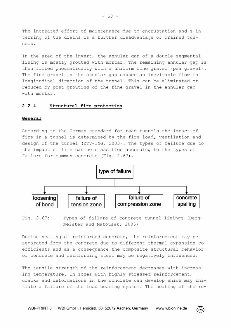
According to the German standard for road tunnels the impact offire in a tunnel is determined by the fire load, ventilation anddesign of the tunnel (ZTV-ING, 2003). The types of failure due tothe impact of fire can be classified according to the types offailure for common concrete (Fig. 2.67).
Fig. 2.67: Types of failure of concrete tunnel linings (Berg-meister and Matousek, 2005)
During heating of reinforced concrete, the reinforcement may beseparated from the concrete due to different thermal expansion co-efficients and as a consequence the composite structural behaviorof concrete and reinforcing steel may be negatively influenced.
The tensile strength of the reinforcement decreases with increas-ing temperature. In zones with highly stressed reinforcement,cracks and deformations in the concrete can develop which may ini-tiate a failure of the load bearing system. The heating of the re-
- 69 -
WBI-PRINT 6 WBI GmbH, Henricistr. 50, 52072 Aachen, Germany www.wbionline.de
inforcing steel due to the impact of fire can be considerably re-duced by a sufficient cover of concrete.
The decrease of the compressive strength due to heating can alsolead to a failure of the compression zone under the impact of fireparticularly in highly reinforced parts. With regard to the fail-ure due to concrete spalling, Bergmeister and Matousek (2005) dis-tinguish between
- global spalling of concrete layers,- local spalling of individual grains of aggregate, and- explosive spalling.
Global spalling results from long lasting fire. This type of fail-ure is mainly caused by a non-uniform temperature distributionover the cross-section and by the resulting constraints.
Local spalling is caused by physical and chemical alterations inthe aggregate and the hardened cement lime. The aggregate expandswhile the hardened cement lime shrinks due to dehydration andchemical alteration. Local spalling mostly is limited to depths ofup to 20 mm (Bergmeister and Matousek, 2005).
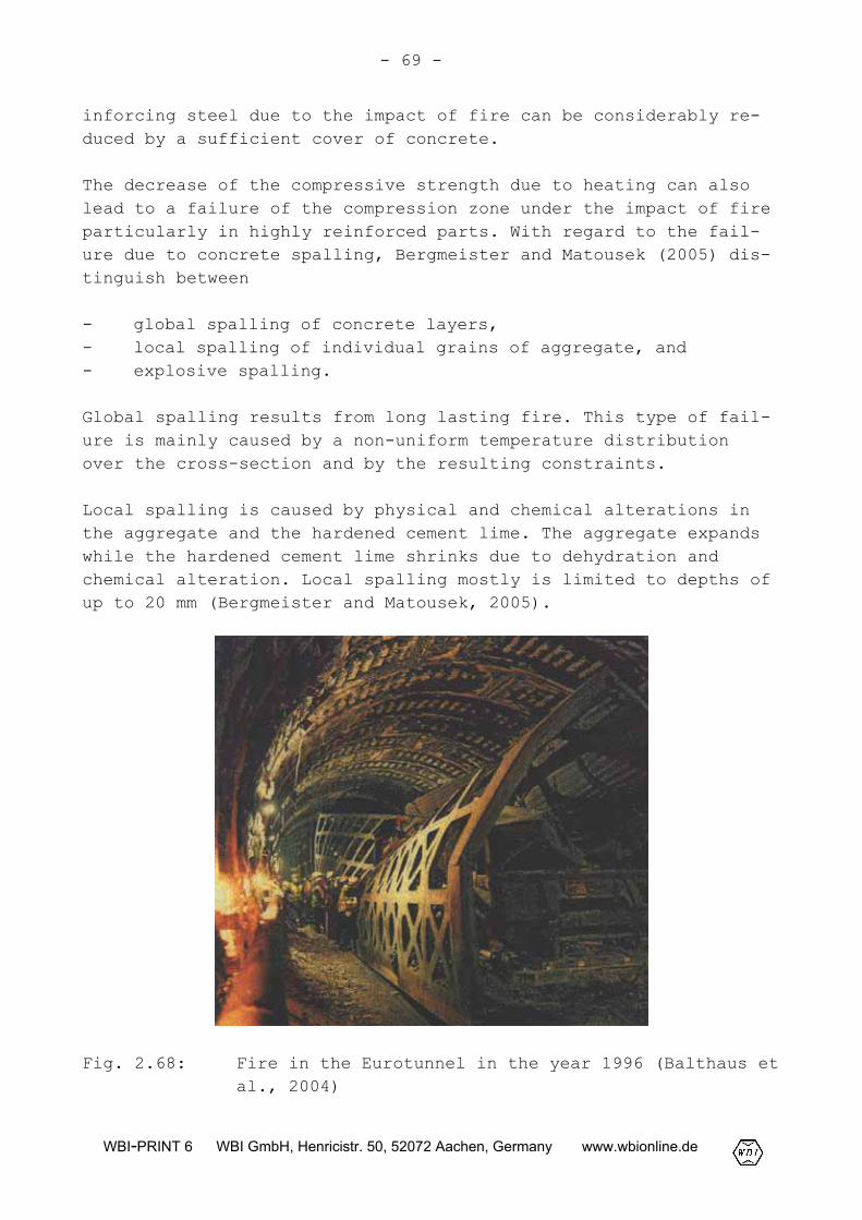
Fig. 2.68: Fire in the Eurotunnel in the year 1996 (Balthaus etal., 2004)
- 70 -
WBI-PRINT 6 WBI GmbH, Henricistr. 50, 52072 Aachen, Germany www.wbionline.de
In a tunnel without special safety measures for the reinforcedconcrete, the most extensive damages in case of fire result fromexplosive spalling. This is caused by the extremely fast heatingat the beginning of the fire. The results of tests have shown thatspalling begins in the first minutes and normally ends after 20 to30 minutes (Balthaus et al., 2004 and 2005). Explosive spallingextends to greater depths and can lead to an impairment of theload bearing capacity up to an endangering of the local stability.During a fire in the Eurotunnel in the year 1996, as an example,more than two thirds of the 40 cm thick segmental lining were de-stroyed (Fig. 2.68).
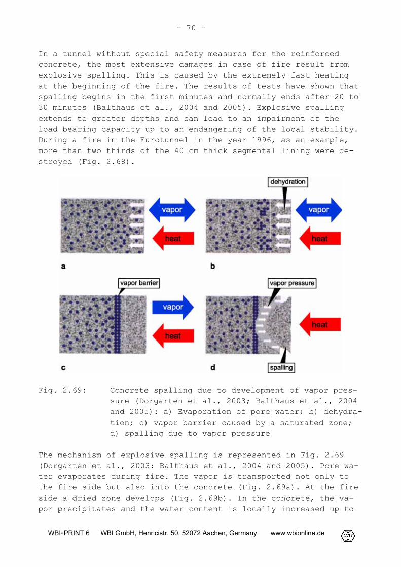
Fig. 2.69: Concrete spalling due to development of vapor pres-sure (Dorgarten et al., 2003; Balthaus et al., 2004and 2005): a) Evaporation of pore water; b) dehydra-tion; c) vapor barrier caused by a saturated zone;d) spalling due to vapor pressure
The mechanism of explosive spalling is represented in Fig. 2.69(Dorgarten et al., 2003: Balthaus et al., 2004 and 2005). Pore wa-ter evaporates during fire. The vapor is transported not only tothe fire side but also into the concrete (Fig. 2.69a). At the fireside a dried zone develops (Fig. 2.69b). In the concrete, the va-por precipitates and the water content is locally increased up to
- 71 -
WBI-PRINT 6 WBI GmbH, Henricistr. 50, 52072 Aachen, Germany www.wbionline.de
saturation. The saturated zone reduces the vapor permeability andthus forms a vapor barrier (Fig. 2.69c). In front of this vaporbarrier, a high vapor pressure develops, which causes explosivespalling when the tensile strength of the concrete is exceeded(Fig. 2.69d).
Other reasons for concrete spalling are alterations due to chemi-cal reactions, mineralogical transformations and decompositionprocesses. The dehydration of the hardened cement lime begins at atemperature of approx. 400 °C and leads to a decrease of strength.At a temperature of 573 °C, the crystal lattice of quartz istransformed. This leads to a volume increase. At temperatures ofapprox. 800 °C, limestone is decarbonated and decomposed into limeand carbon dioxide, which escapes through the voids. Also thisprocess leads to a loss of strength of the concrete (Balthaus etal., 2004).
Protection goals and fire dimensioning curves
The protection goals of the structural fire protection in tunnel-ing are to maintain the load bearing capacity of the structureduring and after a fire and to limit the cost for reconstruction.According to ZTV-ING (2003), the structure has to be designed suchthat in case of fire
- no damages occur that may endanger the stability of the tun-nel,
- no permanent deformations occur that may restrict the serv-iceability of the tunnel,
- the tightness of the tunnel lining is ensured to a large ex-tent.
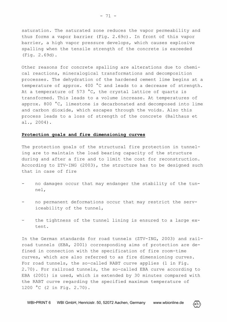
In the German standards for road tunnels (ZTV-ING, 2003) and rail-road tunnels (EBA, 2001) corresponding aims of protection are de-fined in connection with the specification of fire room-timecurves, which are also referred to as fire dimensioning curves.For road tunnels, the so-called RABT curve applies (1 in Fig.2.70). For railroad tunnels, the so-called EBA curve according toEBA (2001) is used, which is extended by 30 minutes compared withthe RABT curve regarding the specified maximum temperature of1200 °C (2 in Fig. 2.70).
- 72 -
WBI-PRINT 6 WBI GmbH, Henricistr. 50, 52072 Aachen, Germany www.wbionline.de
Fig. 2.70: Fire dimensioning curves
In the Netherlands, the Rijkswaterstraat curve (RWS curve) is usedas fire dimensioning curve. It is based on a longer duration offire and a higher maximum temperature than the German fire dimen-sioning curves (3 in Fig. 2.70). For the railway line advancing tothe Brenner tunnel in Austria, the so-called BEGA curve was speci-fied as fire dimensioning curve (Balthaus et al., 2004).
All fire dimensioning curves show a sharp rise of temperature upto values of approx. 1200 °C in a very short initial phase of only5 minutes (Fig. 2.70).
Measures for structural fire protection
According to the German standard for road tunnels (ZTV-ING, 2003),the measures for structural fire protection have to prevent tem-peratures of more than 300 °C in the load bearing reinforcement incase of fire. In a tunnel with a double lining, this requirement
- 73 -
WBI-PRINT 6 WBI GmbH, Henricistr. 50, 52072 Aachen, Germany www.wbionline.de
can normally be met with a sufficient concrete cover. According toZTV-ING (2003), no measures for fire protection are required forinternal linings with a thickness of at least 30 cm and a nominalconcrete cover of 6 cm.
Suspended ceilings and ceilings of tunnels driven according to thecut-and-cover method must be equipped with a fire protection fac-ing and a concrete cover of 2 cm (ZTV-ING, 2003). This is to re-duce concrete spalling so that the remaining concrete protects theload bearing reinforcement from heating up to more than 300 °C.For mined tunnels corresponding experience is not available (Dor-garten et al., 2003).
With protection facings, such as fire protection plates or plas-ters, the structural fire protection of tunnels also can be im-proved. These act like an insulation and are thus to avoid aninadmissable heating of the load bearing reinforcement. Fire pro-tection plates are available with thicknesses ranging from 6 mm toapprox. 30 mm. Fire protection plasters are mostly applied asspray plasters (Balthaus et al., 2005). However, a problem withregards to durability of fire protection facings, particularly ex-ists in case of dynamic impact resulting from operation and incase of humidity (Dorgarten et al., 2003). This requires highercost for maintenance and repair.
Fire resistant concrete
As it is known from structural engineering, spalling can be re-duced by adding synthetic fibers which are uniformly distributedin the concrete. In case of fire, the synthetic fibers melt andform a system of voids and microcracks within the concrete. Thisway a system of channels is generated which enables a vapor trans-port also through the saturated zone (see Fig. 2.69). This leadsto a considerable reduction of the vapor pressure which can causeexplosive spalling (Paliga and Schaab, 2002).
In the scope of a research project conducted by the Hochtief Con-struction Company, the Institute of Materials, Solid Structure andFire Protection of the Technical University of Brunswick (iBMB),the German Research Society for Unterground Traffic Facilities(STUVA) and the Consulting Company Prof. Dr.-Ing. Duddek und Part-ner, fire resistant concretes for tunneling were developed (Dor-garten et al., 2003; Balthaus et al., 2004).
- 74 -
WBI-PRINT 6 WBI GmbH, Henricistr. 50, 52072 Aachen, Germany www.wbionline.de
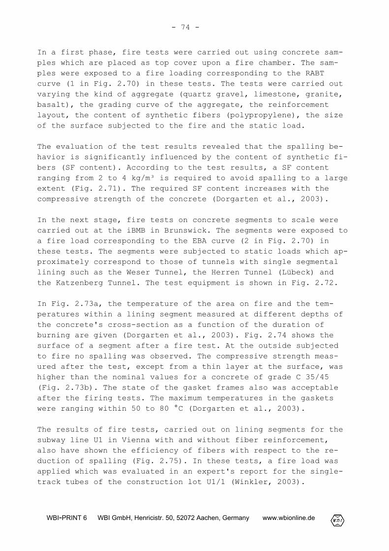
In a first phase, fire tests were carried out using concrete sam-ples which are placed as top cover upon a fire chamber. The sam-ples were exposed to a fire loading corresponding to the RABTcurve (1 in Fig. 2.70) in these tests. The tests were carried outvarying the kind of aggregate (quartz gravel, limestone, granite,basalt), the grading curve of the aggregate, the reinforcementlayout, the content of synthetic fibers (polypropylene), the sizeof the surface subjected to the fire and the static load.
The evaluation of the test results revealed that the spalling be-havior is significantly influenced by the content of synthetic fi-bers (SF content). According to the test results, a SF contentranging from 2 to 4 kg/m³ is required to avoid spalling to a largeextent (Fig. 2.71). The required SF content increases with thecompressive strength of the concrete (Dorgarten et al., 2003).
In the next stage, fire tests on concrete segments to scale werecarried out at the iBMB in Brunswick. The segments were exposed toa fire load corresponding to the EBA curve (2 in Fig. 2.70) inthese tests. The segments were subjected to static loads which ap-proximately correspond to those of tunnels with single segmentallining such as the Weser Tunnel, the Herren Tunnel (Lübeck) andthe Katzenberg Tunnel. The test equipment is shown in Fig. 2.72.
In Fig. 2.73a, the temperature of the area on fire and the tem-peratures within a lining segment measured at different depths ofthe concrete's cross-section as a function of the duration ofburning are given (Dorgarten et al., 2003). Fig. 2.74 shows thesurface of a segment after a fire test. At the outside subjectedto fire no spalling was observed. The compressive strength meas-ured after the test, except from a thin layer at the surface, washigher than the nominal values for a concrete of grade C 35/45(Fig. 2.73b). The state of the gasket frames also was acceptableafter the firing tests. The maximum temperatures in the gasketswere ranging within 50 to 80 °C (Dorgarten et al., 2003).
The results of fire tests, carried out on lining segments for thesubway line U1 in Vienna with and without fiber reinforcement,also have shown the efficiency of fibers with respect to the re-duction of spalling (Fig. 2.75). In these tests, a fire load wasapplied which was evaluated in an expert's report for the single-track tubes of the construction lot U1/1 (Winkler, 2003).
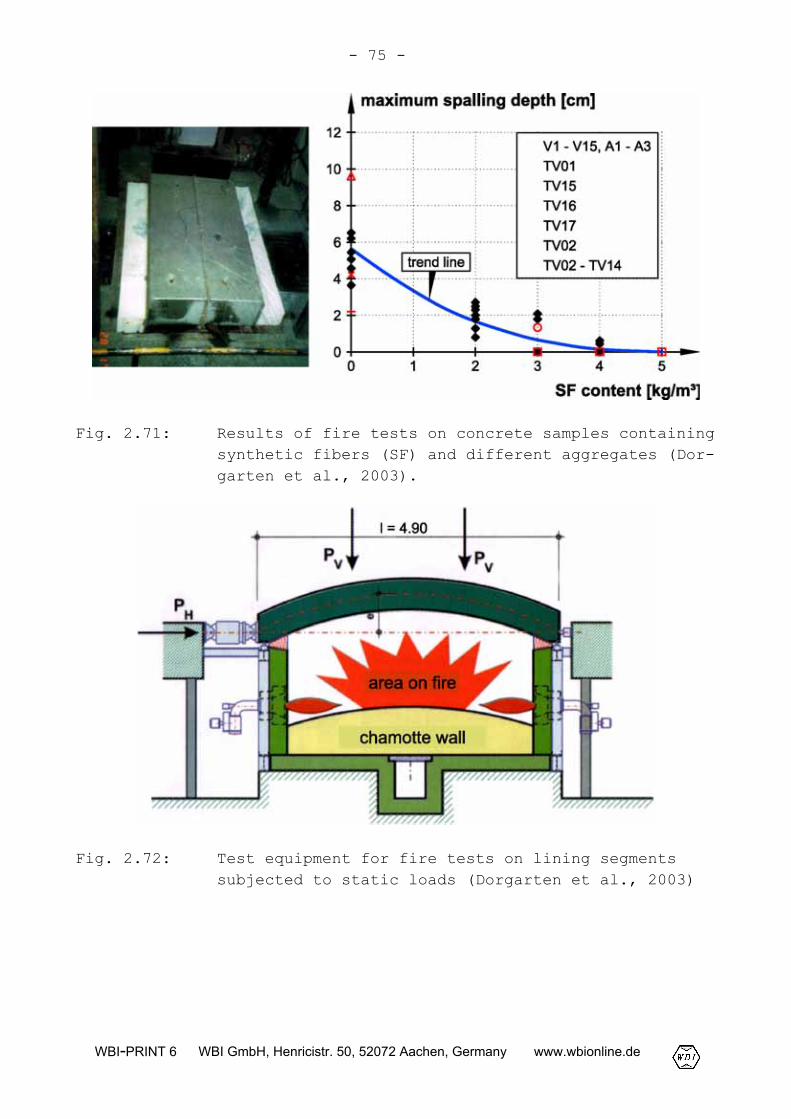
- 75 -
WBI-PRINT 6 WBI GmbH, Henricistr. 50, 52072 Aachen, Germany www.wbionline.de
Fig. 2.71: Results of fire tests on concrete samples containingsynthetic fibers (SF) and different aggregates (Dor-garten et al., 2003).
Fig. 2.72: Test equipment for fire tests on lining segmentssubjected to static loads (Dorgarten et al., 2003)
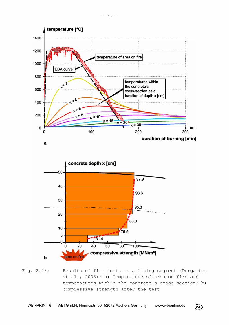
- 76 -
WBI-PRINT 6 WBI GmbH, Henricistr. 50, 52072 Aachen, Germany www.wbionline.de
Fig. 2.73: Results of fire tests on a lining segment (Dorgartenet al., 2003): a) Temperature of area on fire andtemperatures within the concrete's cross-section; b)compressive strength after the test
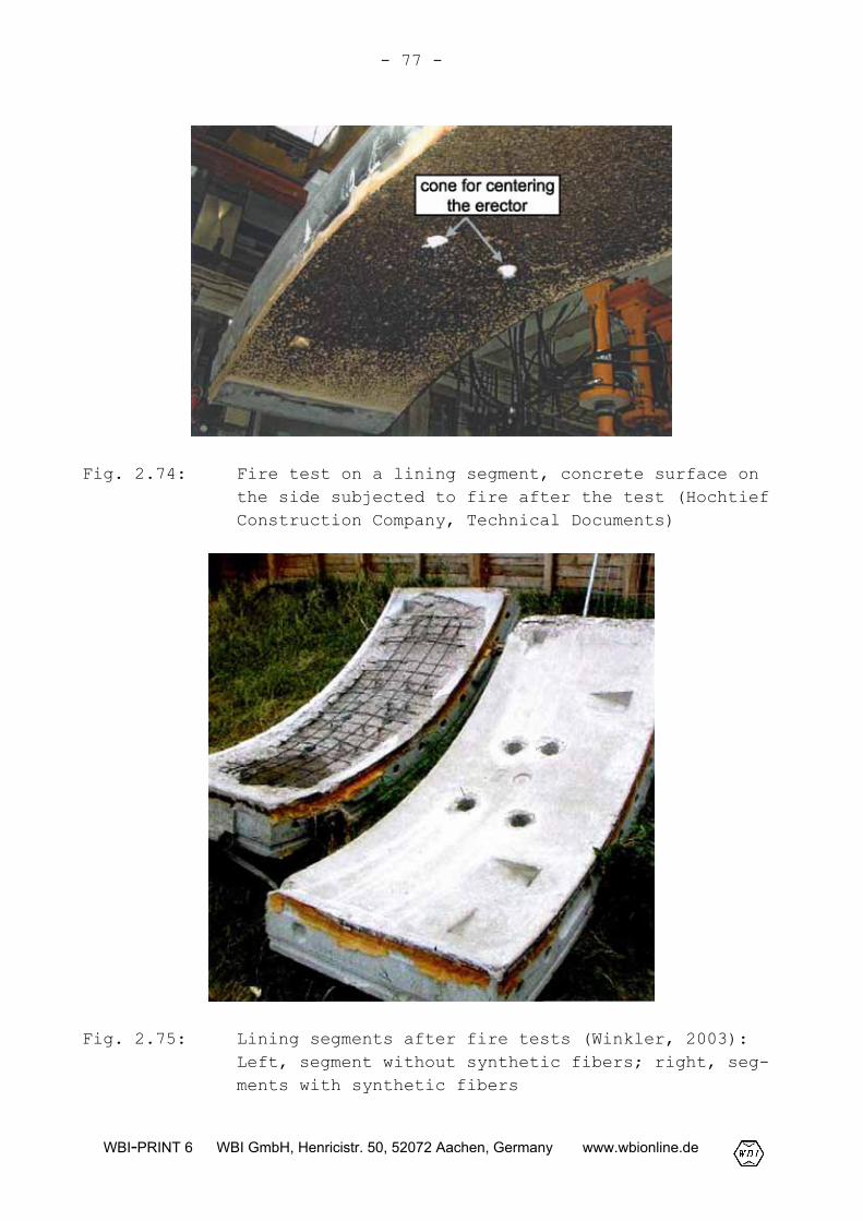
- 77 -
WBI-PRINT 6 WBI GmbH, Henricistr. 50, 52072 Aachen, Germany www.wbionline.de
Fig. 2.74: Fire test on a lining segment, concrete surface onthe side subjected to fire after the test (HochtiefConstruction Company, Technical Documents)
Fig. 2.75: Lining segments after fire tests (Winkler, 2003):Left, segment without synthetic fibers; right, seg-ments with synthetic fibers