Embed Size (px)
Citation preview
2.0 Project Description
October 2010 2-1 Whittier Project EIR Public Draft
2.0 Project Description
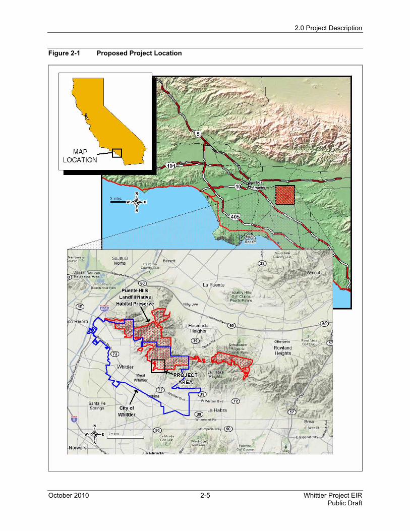
The proposed Whittier Main Oil Field Development Project (Project) would involve drilling wells and producing oil and gas from the Project Site, which comprises approximately 7 acres of the property owned by the City of Whittier that is part of the Puente Hills Landfill Native Habitat Preserve (Preserve). The Preserve is located at the eastern edge of Los Angeles County, bounded by the San Gabriel River on the west and the Chino Hills to the east (see Figure 2-1).
The 3,869-acre Preserve extends across three municipalities: the City of La Habra Heights; the City of Whittier; and the communities of Rowland Heights and Hacienda Heights, both in unincorporated Los Angeles County. Both the San Gabriel and Lower Los Angeles Rivers and Mountains Conservancy and the Wildlife Corridor Conservation Authority, public agencies, have jurisdictional interests in the western Puente Hills (PHLNHPA 2007).
The City owns approximately 1,290 acres of former oil fields in the Preserve in the hills north of the developed areas of the City. This area was commonly known as the Whittier Main Field, an active oil field that produced oil for more than 100 years with approximately 500 drilled wells until the early 1990s. The majority of the land encompassing the oil field was purchased from Chevron and Unocal Corporation by the City of Whittier. The City's purchase of the Whittier Main Oilfield was funded by a grant of Proposition A funds. Conditions of this funding prevent the City from using the land for anything other than open space. In order to use the proposed approximately 7 acres of the surface within the oilfield area for drilling and pumping, the City will be required to either reimburse the Los Angeles County Proposition A District for the 7 acres or provide a comparable area of land that can be used for open space. City staff is in contact with the Los Angeles County Proposition A District to determine the appropriate approach to comply with this requirement. The proposed lease includes a provision that the City will not issue a conditional use permit (CUP) until a release from protected area status is obtained from the Proposition A District.
The land is currently managed for the City by the Puente Hills Landfill Native Habitat Preservation Authority (Habitat Authority), a joint powers agency whose members include the City of Whittier, County of Los Angeles, the Hacienda Heights Improvement Association and Los Angeles County Sanitation Districts. On October 28, 2008, the City awarded a lease to Matrix Oil Corporation (Matrix) that could permit resumption of oil and gas extraction from the site. The agreement leases the City’s mineral rights underlying the Whittier Main Field to Matrix and provides that, subject to a conditional use permit (CUP) and contractual provisions, Matrix could have certain rights, including drilling exploratory oil wells and extracting oil, gas, and other hydrocarbons, such as natural gas liquids, from the land. In exchange for these rights, the Project could generate a substantial long-term income stream for the City and for the preservation and enhancement of the Preserve’s ecological resources and native habitat. Matrix, the Applicant and the operator of the Whittier Main Oil Field, submitted a CUP application to the City of Whittier in April 2009 to drill, explore, and produce the remaining recoverable oil and gas reserves at the site.
2.0 Project Description
Whittier Project EIR 2-2 October 2010 Public Draft
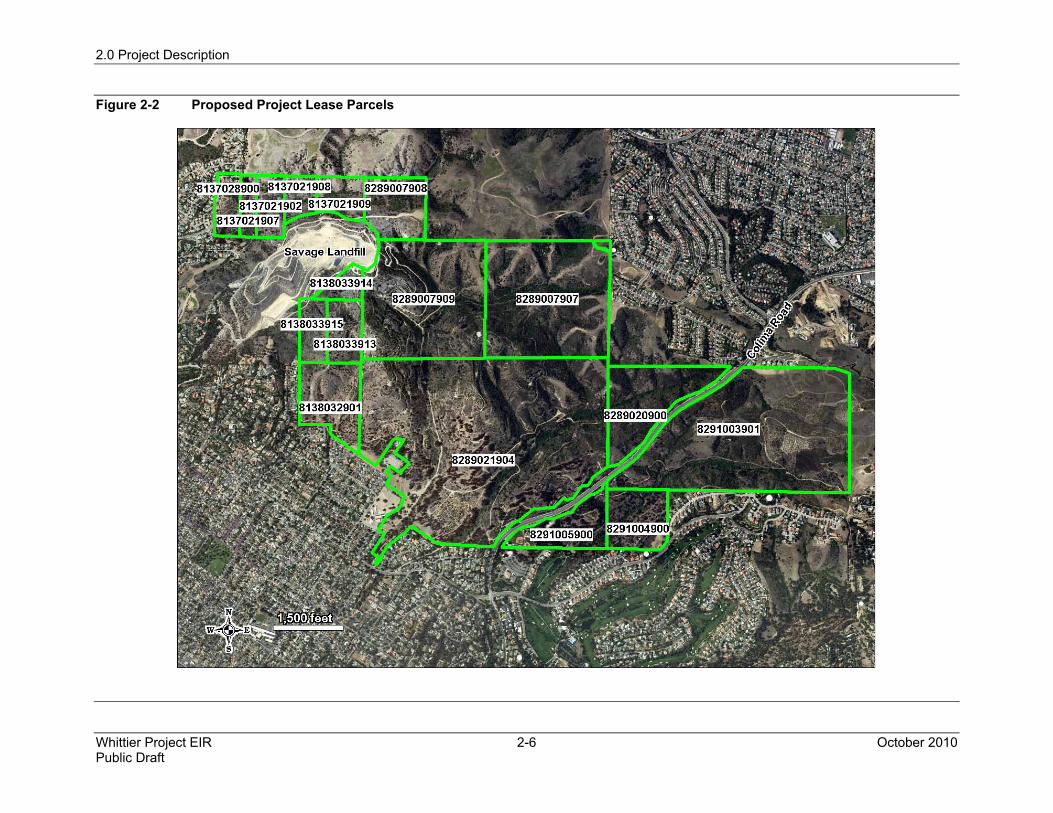
The proposed Project Site is a subset of the Preserve in the southeastern area, defined by a set of parcels owned by the City (see Figure 2-2). The portion of the Preserve within the City of Whittier is zoned Open Space.
The remainder of this chapter contains three major sections. The first section identifies the proposed Project's objectives. The second section provides background information on the area and oil activities in the Whittier and Los Angeles areas. The third section details the phases of the proposed Project.
2.1 Proposed Project Objectives
Pursuant to Section 15124(b) of the CEQA Guidelines, the description of the proposed project is to contain “a clearly written statement of objectives” that will aid the lead agency in developing a reasonable range of alternatives to evaluate in the EIR, will aid decision makers in preparing findings and, if necessary, a statement of overriding considerations.
The City, as owner and lessor of the oil field property, and Matrix, as prospective developer, operator, and lessee, each have interest in the Project.
2.1.1 City Objectives
• Generate a substantial, long-term income stream for the City.
• Provide long-term resources to help manage environmental issues associated with the Project within the Preserve.
• Minimize environmental impacts from the project to the Preserve.
• Minimize noise impacts to surrounding areas.
• Minimize traffic impacts to surrounding areas.
• Minimize impacts to the functioning of the Core habitat of the Preserve.
• Minimize impacts to operational, recreational, and educational opportunities of the Preserve.
• Facilitate the long-term preservation and enhancement of the Preserve’s ecological resources and native habitat.
• Employ current technologies in an effort to reduce environmental impacts to less-than-significant levels.
• Maintain reasonable fire safety levels for the community and open space.
2.0 Project Description
October 2010 2-3 Whittier Project EIR Public Draft
2.1.2 Matrix Objectives
• Develop the Whittier Main Oil Field, pursuant to the terms of the Oil and Gas Lease with the City of Whittier dated October 28, 2008, utilizing current “slant-drill, or high-angle well” technology and other state-of-the-art techniques, while maintaining safe and efficient operations.
• Minimize impact to the Preserve, as defined in the Lease, by utilizing existing roads as much as possible, and placement of production equipment and facilities on three consolidated sites utilizing up to seven acres.
• Operate in accordance with all prevailing laws and regulations to maximize safety and protect the environment.
• Minimize and mitigate negative impacts of the project on the local community.
• Stimulate the local economy by providing opportunities for qualified local businesses to sell goods and services and to qualified workers to apply for jobs.
• Maximize oil and gas production from the field, thereby maximizing royalty payments to the City of Whittier.
2.2 Historical Operations
Historical operations include both the history related to oil operations in the area and the formation of the Preserve. The following sections discuss both.
2.2.3 Whittier Main Oil Field Historical Operations
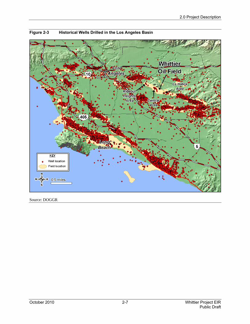
Oil drilling and production in the Los Angeles Basin has a long history. According to the California Division of Oil, Gas and Geothermal Resources (DOGGR) database, almost 30,000 oil wells were drilled in the Los Angeles Basin in the last 100 to 150 years. Figure 2-3 shows the location of these wells.
The Whittier Main Oil Field is part of a larger oil-producing trend lying along the Whittier Fault Complex that runs southeast from Monterey Park through Montebello, Whittier, La Habra, Brea, and Yorba Linda. Historically, oil from the Miocene Puente and Pliocene Fernando formations has been produced from 1,000 to 6,000 feet below surface level.
The Whittier Main Oil Field is located in Los Angeles County, California, approximately 30 miles east of downtown Los Angeles. Oil was first discovered in the Puente Hills in 1884, approximately 7 miles north of Fullerton and 4 miles south of Puente, by William “Billy” Rowland on his father’s former ranch, Rancho La Puente. By 1900, oil fields in the Puente Hills produced a combined 50,000 barrels (bbl) of oil per month and the success of small, local companies attracted the attention of many larger outside oil interests (RMP 2007). Whittier Consolidated Oil Company discovered the Whittier field in 1901. The first commercial well,
2.0 Project Description
Whittier Project EIR 2-4 October 2010 Public Draft
approximately 3,200 feet deep and completed in October of 1919, flowed 204 barrels per day (bpd) of 25 American Petroleum Institute (API) gravity oil.
Between 1980 and 1989, the Whittier Main Oil Field produced approximately 800 bpd. In 1989, the last normally producing year, the field produced 269,000 barrels of oil. Existing available technology limited oil extraction to depths between 1,000 and 6,000 feet and exclusively from vertical wells. In 1989, Chevron began abandonment of the Whittier Main Oil Field due to low oil prices.
The DOGGR database indicates that historically 494 wells have been located in the general area of the Whittier Main Oil Field (the Project Site), an additional 19 wells in the La Habra Heights area (east of the Project Site), and 49 wells in the Rideout Heights area (north of the Project Site along the Sycamore Canyon area, see Figure 2-3). Most wells are listed as plugged and a few are designated as idle. A plugged well is fully abandoned with cement in the well bore. An idle well is non-operational and not producing, but has not been plugged
In the general vicinity of the Project Site, historical operators included Chevron, Central, Chem-Rex, City of Whittier, Commonwealth, Lyon Brothers, Macrom, Mohawk, Montebello Mascot, New England Oil, Parcan Oil, Union Oil, Whitely, Taylor, and Whittier Strong.
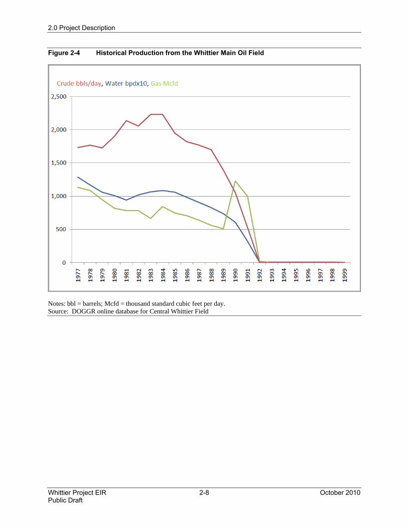
Information from DOGGR on the oil and natural gas production since 1977 from the central Whittier field is plotted in Figure 2-4. The DOGGR database indicates some minimal production of gas until 1999 with most activity ceasing in 1992.
Oil activities continue in the Whittier Oil Field area (see Figure 2-4), where Matrix produces oil and gas from wells at two locations: Honolulu Terrace (2.7 miles northwest of the proposed Project Site) and Sycamore Canyon, also known as Rideout Heights (3.6 miles northwest of the proposed Project Site). Honolulu Terrace lies within a residential area outside of the Preserve boundary. The Sycamore Canyon wells are along Sycamore Canyon Road within the western edge of the Preserve boundary.
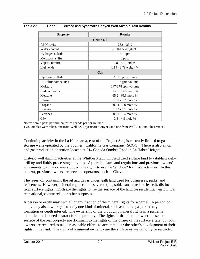
Table 2-1 shows the properties of crude oil and produced gas from tests performed on samples of oil and gas (casing gas) from one Honolulu Terrace well and one Sycamore Canyon well in October of 2009. The wells are drilled into a formation and reservoir that are anticipated to be the same or similar to the proposed Project wells.
2.0 Project Description
October 2010 2-5 Whittier Project EIR Public Draft
Figure 2-1 Proposed Project Location
2.0 Project Description
Whittier Project EIR 2-6 October 2010 Public Draft
Figure 2-2 Proposed Project Lease Parcels
2.0 Project Description
October 2010 2-7 Whittier Project EIR Public Draft
Figure 2-3 Historical Wells Drilled in the Los Angeles Basin
Source: DOGGR
2.0 Project Description
Whittier Project EIR 2-8 October 2010 Public Draft
Figure 2-4 Historical Production from the Whittier Main Oil Field
Notes: bbl = barrels; Mcfd = thousand standard cubic feet per day. Source: DOGGR online database for Central Whittier Field
2.0 Project Description
October 2010 2-9 Whittier Project EIR Public Draft
Table 2-1 Honolulu Terrace and Sycamore Canyon Well Sample Test Results
Property Results Crude Oil
API Gravity 25.6 - 33.9 Water content 0.10-1.5 weight % Hydrogen sulfide < 1 ppm Mercaptan sulfur 2 ppm Vapor Pressure 2.8 - 6.3 Reid psi Light ends 1.15 - 3.79 weight %
Gas Hydrogen sulfide < 0.1 ppm volume All sulfur compounds 0.1-1.2 ppm volume Moisture 247-378 ppm volume Carbon dioxide 0.28 - 19.8 mole % Methane 65.2 - 69.3 mole % Ethane 11.1 - 3.2 mole % Propane 0.64 - 9.8 mole % Butanes 1.42 - 6.1 mole % Pentanes 0.81 - 3.4 mole % C6+ 3.3 - 4.8 mole %
Notes: ppm = parts per million; psi = pounds per square inch. Two samples were taken, one from Well S22 (Sycamore Canyon) and one from Well 7 (Honolulu Terrace).
Continuing activity in the La Habra area, east of the Project Site, is currently limited to gas storage wells operated by the Southern California Gas Company (SCGC). There is also an oil and gas production operation located at 214 Canada Sombre Road in La Habra Heights.
Historic well drilling activities at the Whittier Main Oil Field used surface land to establish well-drilling and fluids-processing activities. Applicable laws and regulations and previous owners’ agreements with landowners govern the rights to use the “surface” for these activities. In this context, previous owners are previous operators, such as Chevron.
The reservoir containing the oil and gas is underneath land used for businesses, parks, and residences. However, mineral rights can be severed (i.e., sold, transferred, or leased), distinct from surface rights, which are the rights to use the surface of the land for residential, agricultural, recreational, commercial, or other purposes.
A person or entity may own all or any fraction of the mineral rights for a parcel. A person or entity may also own rights to only one kind of mineral, such as oil and gas, or to only one formation or depth interval. The ownership of the producing mineral rights in a parcel is identified in the deed abstract for the property. The rights of the mineral owner to use the surface of the real property are dominant to the rights of the owner of the surface estate, but both owners are required to make reasonable efforts to accommodate the other’s development of their rights in the land. The rights of a mineral owner to use the surface estate can only be restricted
2.0 Project Description
Whittier Project EIR 2-10 October 2010 Public Draft
by an express grant of such rights from the mineral owner to the surface owner. Mineral rights are, in all respects, real property rights. Real property rights are those rights primarily established under the common law of California and generally governed by the California Civil Code, Division 2, Part 2.
In 1995, Chevron sold the Whittier Main Oil Field area, including surface and mineral rights, to the Trust for Public Lands, which is a nonprofit, land conservation organization that uses public and private monies to purchase and preserve open space. The sale included an environmental remediation program overseen by Chevron and the City, which was completed in 1997. Ultimately, the City of Whittier acquired both surface and mineral rights for the Whittier Main Oil Field.
On October 28, 2008, the City entered into an Oil, Gas, and Mineral Lease Agreement with Matrix Oil Corporation (Matrix) of Santa Barbara, California. This Agreement leases the entirety of the City’s mineral rights, without limitations, underlying the Whittier Main Oil Field to Matrix and provides Matrix with certain other rights including drilling exploratory oil wells and extracting oil, gas, and other hydrocarbons from the land. In exchange, Matrix would pay the City royalties on proceeds from the sale of produced oil and natural gas.
2.2.4 Preserve History and Current Operations
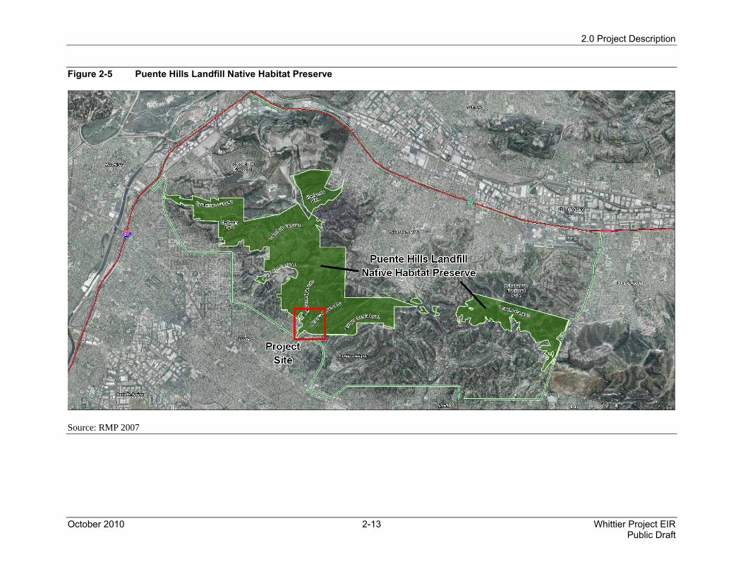
The Puente Hills Landfill Native Habitat Preservation Authority began in 1994 as a condition of approval for the operation of the Puente Hills Landfill. Figure 2-5 shows the Preserve boundary. The purpose of the Habitat Authority is to acquire, restore, and maintain open space in the Puente Hills as permanent protection for the native habitat with special consideration given to the community of Hacienda Heights (RMP 2007).
Solid-waste disposal fees from the Puente Hills Landfill provide the primary funding for the Habitat Authority. This funding will continue through the remaining life of the landfill, currently scheduled to close in November 2013. The Puente Hills Landfill is owned by the County of Los Angeles and is managed by the Sanitation District of the Los Angeles County Solid Waste Management Department. The Oil and Gas Lease between the City of Whittier and Matrix provides for continuing funding for the Habitat Authority with annual administrative fees and mitigation fees upon issuance and acceptance of a CUP. A successful Project would provide a stable source of funding for the Habitat Authority for as long as the wells produce oil and gas.
The Habitat Authority’s first acquisition was 517 acres in Powder Canyon, La Habra Heights, in May 1996. Later that year the Authority acquired 63 acres in Hacienda Heights. The Habitat Authority currently owns 1,881 acres in Hacienda Heights, La Habra Heights, and Whittier, acquired through 27 land transactions ranging from less than 1 acre to more than 950 acres. Other member agencies on the Authority’s Board of Directors own the remaining 1,988 acres. The Habitat Authority contractually manages the lands owned by the City of Whittier, including the Project Site.
Currently, activity at the Whittier Main Oil Field is limited to Preserve operations and activities, which consist of restoration and management of natural areas, and management of educational and recreational facilities. Visitors and hikers currently access the Preserve from the parking
2.0 Project Description
October 2010 2-11 Whittier Project EIR Public Draft
area along Colima Road. An outdoor seating area and restroom facilities are located at the top of the loop trail and a Ranger Residence is just inside the Preserve, near the Catalina Avenue entrance to the Preserve.
2.3 Proposed Project Phases
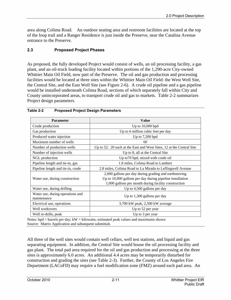
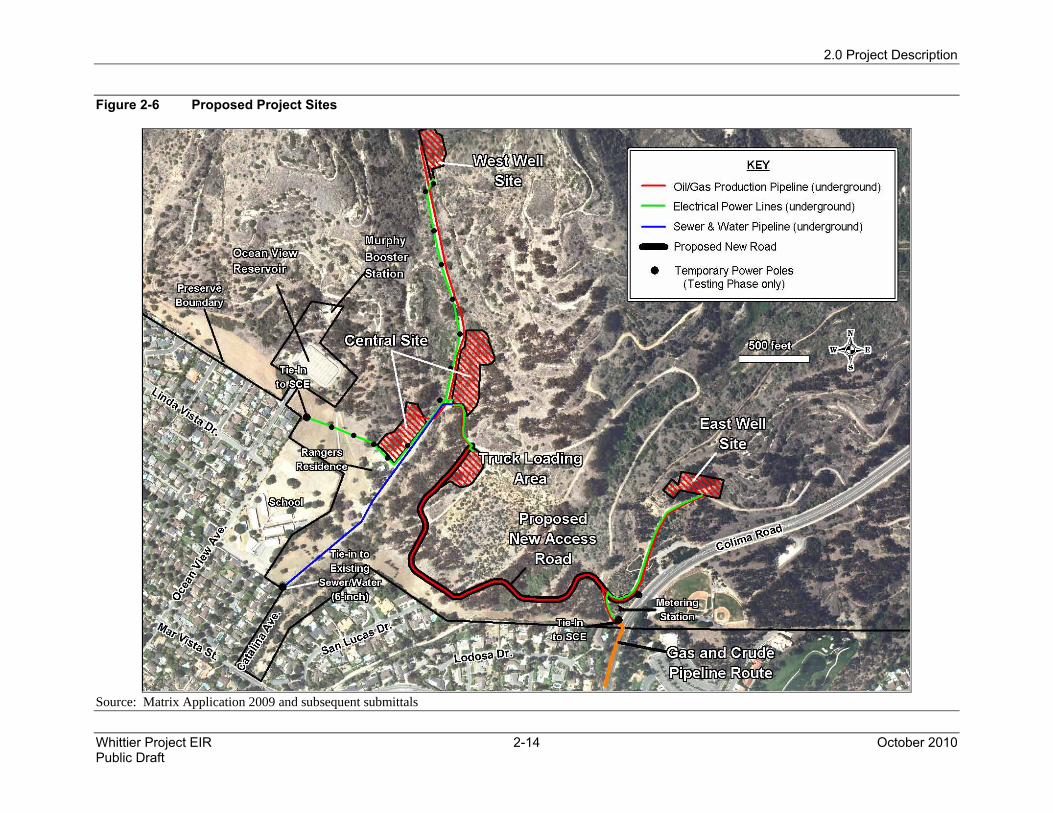
As proposed, the fully developed Project would consist of wells, an oil processing facility, a gas plant, and an oil-truck loading facility located within portions of the 1,290-acre City-owned Whittier Main Oil Field, now part of the Preserve. The oil and gas production and processing facilities would be located at three sites within the Whittier Main Oil Field: the West Well Site, the Central Site, and the East Well Site (see Figure 2-6). A crude oil pipeline and a gas pipeline would be installed underneath Colima Road, sections of which separately fall within City and County unincorporated areas, to transport crude oil and gas to markets. Table 2-2 summarizes Project design parameters.
Table 2-2 Proposed Project Design Parameters
Parameter Value Crude production Up to 10,000 bpd Gas production Up to 6 million cubic feet per day Produced water injection Up to 7,200 bpd Maximum number of wells 60 Number of production wells Up to 52: 20 each at the East and West Sites, 12 at the Central Site Number of injection wells Up to 8, all at the Central Site NGL production Up to70 bpd, mixed with crude oil Pipeline length and tie-in, gas 1.8 miles, Colima Road to Lambert Pipeline length and tie-in, crude 2.8 miles, Colima Road to La Mirada to Leffingwell Avenue
Water use, during construction 2,000 gallons per day during grading and earthmoving
Up to 10,000 gallons per day during pipeline installation 1,000 gallons per month during facility construction
Water use, during drilling Up to 4,500 gallons per day Water use, during operations and maintenance Up to 1,300 gallons per day
Electrical use, operations 3,700 kW peak, 2,500 kW average Well workovers Up to 52 per year Well re-drills, peak Up to 3 per year
Notes: bpd = barrels per day; kW = kilowatts; estimated peak values and maximums shown Source: Matrix Application and subsequent submittals
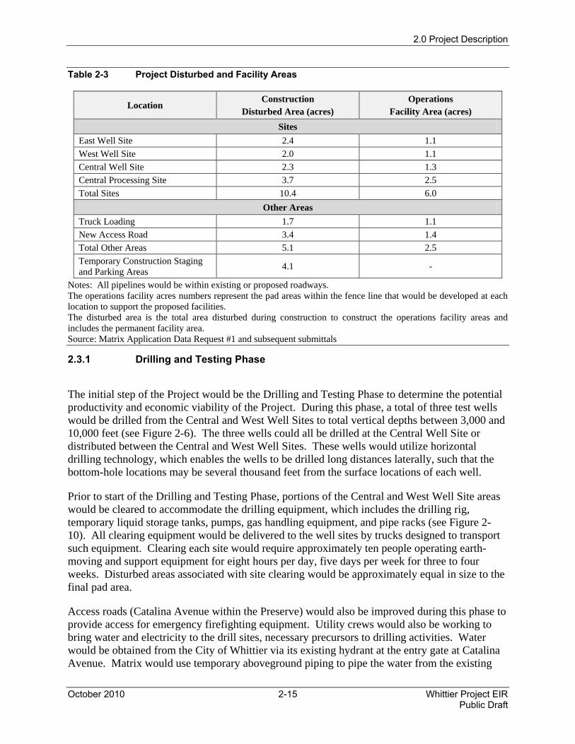
All three of the well sites would contain well cellars, well test stations, and liquid and gas separating equipment. In addition, the Central Site would house the oil processing facility and gas plant. The total pad area required for the oil and gas production and processing at the three sites is approximately 6.0 acres. An additional 4.4 acres may be temporarily disturbed for construction and grading the sites (see Table 2-3). Further, the County of Los Angeles Fire Department (LACoFD) may require a fuel modification zone (FMZ) around each pad area. An
2.0 Project Description
Whittier Project EIR 2-12 October 2010 Public Draft
FMZ is a strip of land where combustible native or ornamental vegetation is modified or partially or totally replaced with drought-tolerant, low-fuel-volume plants. The truck loading facility would occupy an additional 1.1 acres within the Preserve (see Figure 2-6). An additional 0.6 acres may be temporarily disturbed for constructing and grading the truck loading area (see Table 2-3).
In addition, roads, pipelines, and electrical conduit corridors, called the “backbone,” would be constructed to connect these site locations (see Figure 2-6). Oil, gas, and produced water pipelines and electrical conduits would be constructed below ground mostly within the road system. Electrical and pipeline interconnections would be made to the Southern California Edison (SCE) grid and the City of Whittier Sewer and Water District systems. The Project would utilize approximately 1.1 miles of existing roads within the Preserve and would construct 0.5 miles of new roadways within the Preserve to access the various sites.
Two methods for transporting the marketable crude oil are proposed by Matrix. One method would convey the oil via pipeline to the Truck Loading Facility directly east of the Central Well Site area, where the oil would be loaded onto oil tanker trucks and transported to a nearby receiving terminal (e.g., possibly in Santa Fe Springs) and then be transferred into the Crimson Pipeline System. This oil transportation method would be used during the testing phase of the Project until the oil pipeline is constructed and during rare periods when the pipeline system is shut down.
The second oil transportation method would transfer the marketable crude oil by pipeline from the Central Site to the existing Crimson Pipeline System via a new 2.8-mile pipeline connection to a tie-in at Leffingwell Road and La Mirada Boulevard. The Crimson Pipeline System would transport the crude to the ConocoPhillips Refinery in Wilmington. The connection line would be constructed at the same time and in the same trench as the natural gas sales line, which would follow the same route to tie into the SCGC line at the intersection of Colima and Lambert Roads. The connecting oil pipeline would then continue from that point to the Crimson Pipeline connection at the intersection of Leffingwell Road and La Mirada Boulevard. Oil transportation via pipeline would occur for the duration of the project except for brief and rare periods when the pipeline or refinery are temporarily shut down for maintenance, in which case oil would be temporarily transported via truck.
The proposed Project would involve three distinct development phases. The first phase, the Drilling and Testing Phase, would involve drilling three test wells at the Central Well and West Well Sites and assessing the quality and quantity of oil and gas produced. Assuming successful testing, the second phase, the Design and Construction Phase, would involve the installation of gas and oil processing and crude transportation facilities as well as the drilling of wells. The third phase, the Operations and Maintenance Phase, would involve drilling of the remaining wells at each of the three sites (a total of up to 60 wells), as well as the operation and maintenance of the gas and oil facility plants and the wells, which would involve well workovers and occasional well re-drilling. The following sections discuss each of these phases.
2.0 Project Description
October 2010 2-13 Whittier Project EIR Public Draft
Figure 2-5 Puente Hills Landfill Native Habitat Preserve
Source: RMP 2007
2.0 Project Description
Whittier Project EIR 2-14 October 2010 Public Draft
Figure 2-6 Proposed Project Sites
Source: Matrix Application 2009 and subsequent submittals
2.0 Project Description
October 2010 2-15 Whittier Project EIR Public Draft
Table 2-3 Project Disturbed and Facility Areas
Location Construction
Disturbed Area (acres) Operations
Facility Area (acres) Sites
East Well Site 2.4 1.1 West Well Site 2.0 1.1 Central Well Site 2.3 1.3 Central Processing Site 3.7 2.5 Total Sites 10.4 6.0
Other Areas Truck Loading 1.7 1.1 New Access Road 3.4 1.4 Total Other Areas 5.1 2.5 Temporary Construction Staging and Parking Areas 4.1 -
Notes: All pipelines would be within existing or proposed roadways. The operations facility acres numbers represent the pad areas within the fence line that would be developed at each location to support the proposed facilities. The disturbed area is the total area disturbed during construction to construct the operations facility areas and includes the permanent facility area. Source: Matrix Application Data Request #1 and subsequent submittals
2.3.1 Drilling and Testing Phase
The initial step of the Project would be the Drilling and Testing Phase to determine the potential productivity and economic viability of the Project. During this phase, a total of three test wells would be drilled from the Central and West Well Sites to total vertical depths between 3,000 and 10,000 feet (see Figure 2-6). The three wells could all be drilled at the Central Well Site or distributed between the Central and West Well Sites. These wells would utilize horizontal drilling technology, which enables the wells to be drilled long distances laterally, such that the bottom-hole locations may be several thousand feet from the surface locations of each well.
Prior to start of the Drilling and Testing Phase, portions of the Central and West Well Site areas would be cleared to accommodate the drilling equipment, which includes the drilling rig, temporary liquid storage tanks, pumps, gas handling equipment, and pipe racks (see Figure 2-10). All clearing equipment would be delivered to the well sites by trucks designed to transport such equipment. Clearing each site would require approximately ten people operating earth-moving and support equipment for eight hours per day, five days per week for three to four weeks. Disturbed areas associated with site clearing would be approximately equal in size to the final pad area.
Access roads (Catalina Avenue within the Preserve) would also be improved during this phase to provide access for emergency firefighting equipment. Utility crews would also be working to bring water and electricity to the drill sites, necessary precursors to drilling activities. Water would be obtained from the City of Whittier via its existing hydrant at the entry gate at Catalina Avenue. Matrix would use temporary aboveground piping to pipe the water from the existing
2.0 Project Description
Whittier Project EIR 2-16 October 2010 Public Draft
hydrant to the drill sites. During the Drilling and Testing Phase, SCE would provide a temporary service meter and poles would be installed to distribute power to the well sites as needed. Poles, approximately 30 feet high and spaced approximately every 200 feet, would connect to the SCE service at the north end of Ocean View Avenue (see Figure 2-6).
After the well pads are prepared, the drilling rig and associated equipment would be brought to the site and assembled. During set up, tear down and drilling operations, it is estimated that an average of 20 workers would be participating in the work. Each well is estimated to take 25 to 30 days to drill. Drilling would be conducted on a continuous schedule of 24 hours per day, seven days per week. While drilling is continuing, temporary oil, water and gas handling equipment, such as tanks, vessels, pumps, and compressors, would be installed on the well pad. The three test wells would be drilled one after another, utilizing the same rig and support equipment, which would remain on the property for approximately 90 days. When the third well is complete, the rig and associated equipment would be moved off of the property while monitoring and sampling of the test wells continues.
Continuous monitoring would be performed 24 hours per day, for up to 120 days. An average of two to five workers (e.g., pumpers, pipefitters, electricians), working eight-hour shifts, would be present during the testing. In addition, tanker trucks would transport the produced liquid (oil and water) offsite from three to six times per day during daylight hours only.
Drilling of the test wells would require a large drilling rig (approximately 144 feet tall) that would drill 24 hours per day until planned depths and bottom-hole locations are reached. It is anticipated that diesel-fueled generators would power the drilling rig and other necessary equipment. The surface equipment would be screened from view and appropriate temporary fencing and soundproofing would reduce noise.
Approximately 0.4 acre-feet (130,000 gallons) of water would be consumed while drilling each well. During the Drilling and Testing Phase, a temporary fire hydrant would be installed at each well site to provide water for fire protection. The temporary fire hydrants would connect to other pressurized hydrants with adequate pressure. However, some pressurized boosting may be required. As a byproduct of drilling operations, a liquid slurry of drilling “mud” would be collected onsite within bermed basins that are protected by impermeable membranes. Approximately 1,800 barrels of this mud would be collected for each well drilled. Most of the drilling mud would be reused and properly disposed offsite at an appropriate landfill after the third well is completed.
During the Drilling and Testing Phase, a 15-foot high noise blanket would be installed around the perimeter of the drill sites to minimize noise and shield views into the sites. Any additional wells drilled before construction is complete would also be shielded by perimeter noise blankets.
Once test well drilling is complete, the wells would be cased off, wellheads would be installed, and all the drilling equipment would be removed. A down-hole pump would be installed on each productive well for the purpose of pumping oil and water to the surface for testing. Volumes of liquids would be measured and samples taken to determine composition. These liquids would be temporarily stored in onsite tanks and then transported offsite by trucks. The gas produced would also be measured and tested and would be clean-burned or “flared” adjacent to the wells.
2.0 Project Description
October 2010 2-17 Whittier Project EIR Public Draft
The three initial test wells would be connected to a flare, either one flare if all the test wells are drilled at the Central Well Site or two flares if the test wells are drilled at both the Central and West Well Sites. The flare(s) would be installed after the initial test wells are drilled and would be removed after the permanent facilities are constructed and the gas is pipelined to the gas plant. Gas flaring would continue until the gas plant and gas pipeline are constructed as part of the Construction and Drilling Phase of the Project.
The information obtained from the test wells would provide valuable data that would enable Matrix to determine the economic viability of the Project. If deemed economic, the information would also be used to determine the quantity and depths of wells required to maximize oil and gas recovery and to optimize the capacity of oil processing, gas plant, and oil loading facilities.
If the Project delineation and exploratory phases do not produce the level of production that the applicant deems economically feasible, then decommissioning of the installed equipment would take place. Decommissioning would involve removal of the temporary test equipment and the drilling equipment, if not previously removed. The number of truck trips and associated level of effort would be approximately equal to those required to install the equipment. Decommissioning would include abandonment of wells as per DOGGR requirements. Matrix, under its lease with the City, is required to restore the site to its original condition, including filling sumps, remediation of contamination, regrading, and revegetation.
Section 2.2.5, Operations and Maintenance Phase, provides additional information regarding drilling practices.
2.3.1.1 Drilling and Testing Phase Personnel and Equipment Requirements
During test drilling, drilling equipment would be delivered to the site initially, would remain at the site until the end of drilling, and then be removed from the site. In addition, for the initial site clearing, three 70-foot flatbed trailers would deliver the site clearing equipment to the Central Well Site, which would be the staging area for construction. In addition, one 4,000-gallon water truck and two to four dump trucks would be driven to the site. All site clearing activities for both test sites (West Well and Central Well Sites) would be performed consecutively; therefore, this equipment would only be delivered and removed once.
Oil and water brought to the surface would be briefly stored in temporary tanks and then removed daily by 48-foot tanker trucks. Temporary tanks, approximately 12 feet tall by 40 feet long, would hold up to 500 barrels. Between three and six truck trips would be made per day for both crude oil and water; these truck trips would occur during daylight hours.
Approximately ten workers would drive to and from the site daily in conventional vehicles during the clearing phase. This includes survey crews driving standard survey pickup trucks.
During the drilling phase up to 20 workers would drive to the site daily in conventional vehicles. On average, two to five workers (e.g., pumpers, pipefitters, electricians), working 8-hour shifts, would be present during testing.
2.0 Project Description
Whittier Project EIR 2-18 October 2010 Public Draft
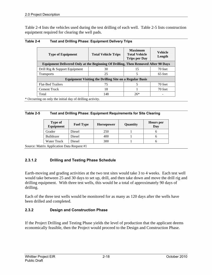
Table 2-4 lists the vehicles used during the test drilling of each well. Table 2-5 lists construction equipment required for clearing the well pads.
Table 2-4 Test and Drilling Phase: Equipment Delivery Trips
Type of Equipment Total Vehicle Trips Maximum
Total Vehicle Trips per Day
Vehicle Length
Equipment Delivered Only at the Beginning Of Drilling, Then Removed After 90 Days Drill Rig & Support Equipment 30 15 70 feet Transports 25 5 65 feet
Equipment Visiting the Drilling Site on a Regular Basis Flat-Bed Trailers 75 5 70 feet Cement Truck 18 1 70 feet Total 148 26* -
* Occurring on only the initial day of drilling activity.
Table 2-5 Test and Drilling Phase: Equipment Requirements for Site Clearing
Type of Equipment Fuel Type Horsepower Quantity Hours per
Day Grader Diesel 250 1 6 Bulldozer Diesel 400 1 6 Water Truck Diesel 300 1 6
Source: Matrix Application Data Request #1
2.3.1.2 Drilling and Testing Phase Schedule
Earth-moving and grading activities at the two test sites would take 3 to 4 weeks. Each test well would take between 25 and 30 days to set up, drill, and then take down and move the drill rig and drilling equipment. With three test wells, this would be a total of approximately 90 days of drilling.
Each of the three test wells would be monitored for as many as 120 days after the wells have been drilled and completed.
2.3.2 Design and Construction Phase
If the Project Drilling and Testing Phase yields the level of production that the applicant deems economically feasible, then the Project would proceed to the Design and Construction Phase.
2.0 Project Description
October 2010 2-19 Whittier Project EIR Public Draft
During the Design and Construction Phase, the following facilities would be constructed:
• A new access road;
• Oil and gas processing facilities;
• Truck loading facility;
• Backbone pipeline system;
• Gas and crude pipelines; and
• Well sites, cellars, and related vessels.
Section 2.2.5, Operations and Maintenance Phase, provides additional information regarding the drilling practices.
Matrix plans to provide sufficient well cellar and supporting oil and gas processing capacity to handle daily maximum production volumes of 10,000 barrels of crude oil and 6 million standard cubic feet per day (mmscfd) of natural gas.
2.3.2.1 New Access Road
A new access road would be constructed at the beginning of the Design and Construction Phase to accommodate construction equipment, heavy trucks, future drilling rigs and equipment, oil transport trucks, and to alleviate the need to send such traffic into the property via Mar Vista Avenue using the Catalina Avenue entrance.
The gated access road would only allow oilfield-related vehicles and emergency vehicles to access the area. All oilfield-related vehicles accessing the property, other than standards autos and pick-up trucks would use the new access road. Other oilfield-related vehicles, such as automobiles and pick-up trucks driven by employees, may use the Catalina Avenue access.
The new access road would be 0.5 miles long. It would require contouring and grading near Colima Road to allow it to utilize the new traffic signal installed as part of the Church project on the east side of Colima Road (see Appendix A).
Construction of the new access road would require grading the road area and importing road base and asphalt. Construction would take approximately 3 months. The grading equipment would be the same as the equipment used for the site grading. Grading cut would total an estimated 15,354 cubic yards and fill would total 14,300 cubic yards, for a total export amount of 1,054 cubic yards. The creek would be crossed by a reinforced concrete double-box culvert according to California Department of Transportation standards.
The onsite pipeline “backbone system” connecting the East Well Site to the Central Processing Site, as well as the crude oil and natural gas sales pipelines, would be buried under the new access road, except for a slight deviation and pipe bridge used to cross the creek (see Figure 2-6
2.0 Project Description
Whittier Project EIR 2-20 October 2010 Public Draft
and the detailed drawings in Appendix A). The backbone system includes water and electric utilities.
2.3.2.2 Sites Construction
The well pad sites would include the West Well Site, approximately 1.1 acres; the Central Site, approximately 3.8 acres (1.3 acres for the Central Well Site and 2.5 acres for the Central Site gas and oil processing area); and the East Well Site, approximately 1.1 acres (see Figure 2-6).
First, the drilling and productions sites would be leveled and the adjacent areas would be stabilized, after which the areas for the well cellars would be excavated and reinforced concrete would be poured. The total grading for the three drilling and production sites is estimated to be 52,670 cubic yards of cut and 30,500 cubic yards of fill.
During grading and earth-moving activities, a temporary 12,000-gallon elevated water tank would be provided and located onsite. This water would be used to moisten soil during compaction and for dust suppression. It is anticipated that earth-moving activities would last approximately 1 month at each site and that the water tank would be refilled from the temporary piped water connection up to five times during the month, for an average water use of 2,000 gallons per day (gpd).
After the earth-moving activities conclude, water would be used only for concrete curing, hydro testing of pipes, and general construction activities. During this period, it is anticipated that an average of 1,000 gallons of water would be used each month during the well pad and facilities construction.
Each Site would have one cellar, approximately 12 feet wide and 8 feet deep, with metal stairs at each end and covered with expanded metal grating for safety. The distance between wells would be approximately 8 feet; accordingly, the maximum number of wells accommodated would determine the length of each cellar. Matrix estimates they may require up to 20 wells per site. Drilling subsequent wells would involve the same activities as those during the Design and Testing Phase.
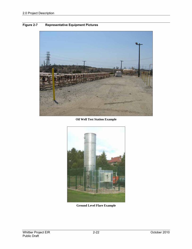
The liquid pumped to the surface would be an emulsion of oil, gas, and water. A well test station at each site would separate the emulsion and measure the respective quantities of oil and water produced by each well (see Figure 2-7). The well test station would be composed of one or more vessels, for handling liquids, along with piping and valves from each well, which would allow the production from each well to be routed separately through a vessel where individual well production data could be compiled. The liquids would then be pumped to the oil processing facility at the Central Site. Gas would be collected and piped to the gas plant, also constructed at the Central Site.
All wastewater generated during construction would be stored onsite within bermed basins, protected by an impermeable membrane. This would include water from washing down trucks, equipment, and concrete construction pads. These temporary basins would store all wastewater and vacuum trucks would periodically haul it away from the site.
2.0 Project Description
October 2010 2-21 Whittier Project EIR Public Draft
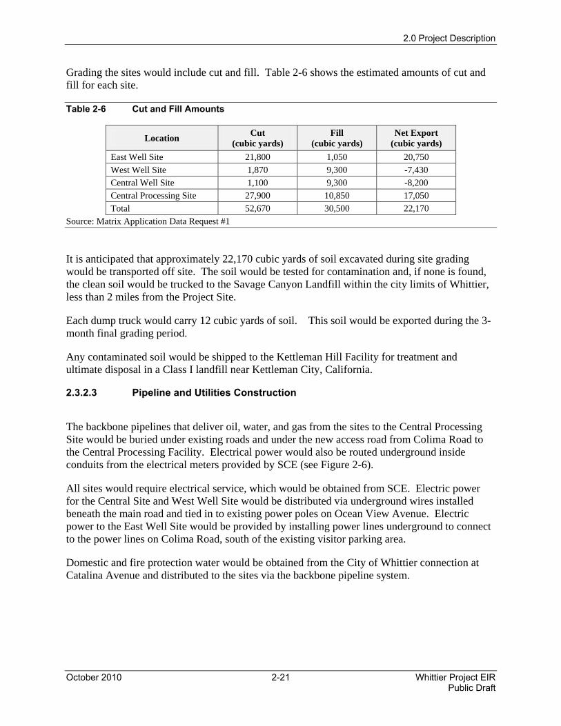
Grading the sites would include cut and fill. Table 2-6 shows the estimated amounts of cut and fill for each site.
Table 2-6 Cut and Fill Amounts
Location Cut (cubic yards)
Fill (cubic yards)
Net Export (cubic yards)
East Well Site 21,800 1,050 20,750 West Well Site 1,870 9,300 -7,430 Central Well Site 1,100 9,300 -8,200 Central Processing Site 27,900 10,850 17,050 Total 52,670 30,500 22,170
Source: Matrix Application Data Request #1
It is anticipated that approximately 22,170 cubic yards of soil excavated during site grading would be transported off site. The soil would be tested for contamination and, if none is found, the clean soil would be trucked to the Savage Canyon Landfill within the city limits of Whittier, less than 2 miles from the Project Site.
Each dump truck would carry 12 cubic yards of soil. This soil would be exported during the 3-month final grading period.
Any contaminated soil would be shipped to the Kettleman Hill Facility for treatment and ultimate disposal in a Class I landfill near Kettleman City, California.
2.3.2.3 Pipeline and Utilities Construction
The backbone pipelines that deliver oil, water, and gas from the sites to the Central Processing Site would be buried under existing roads and under the new access road from Colima Road to the Central Processing Facility. Electrical power would also be routed underground inside conduits from the electrical meters provided by SCE (see Figure 2-6).
All sites would require electrical service, which would be obtained from SCE. Electric power for the Central Site and West Well Site would be distributed via underground wires installed beneath the main road and tied in to existing power poles on Ocean View Avenue. Electric power to the East Well Site would be provided by installing power lines underground to connect to the power lines on Colima Road, south of the existing visitor parking area.
Domestic and fire protection water would be obtained from the City of Whittier connection at Catalina Avenue and distributed to the sites via the backbone pipeline system.
2.0 Project Description
Whittier Project EIR 2-22 October 2010 Public Draft
Figure 2-7 Representative Equipment Pictures
Oil Well Test Station Example
Ground Level Flare Example
2.0 Project Description
October 2010 2-23 Whittier Project EIR Public Draft
Matrix would construct a new 4-inch cast iron sewer pipeline from the new facility office adjacent to the central well pad to the sewer manhole on Catalina Avenue at the entrance to the Whittier Main Oil Field. The sewer pipeline would service restrooms at the Central Well Site offices. The office would be 30 by 80 feet and would contain two restrooms.
Each site would have a comprehensive fire protection system as required by the LACoFD. Automated alarm systems would also be included in each site’s design. Fire hydrants would be provided at each site as required by LACoFD. Preliminary designs by the Applicant include six fire hydrants along the new access road, two fire hydrants at the West Well Site, three fire hydrants at the Central Processing Site, two fire hydrants at the East Well Site, and eight fire hydrants at the Central Processing Site (see Appendix A).
Access roads and emergency site access would be designed in accordance with LACoFD requirements.
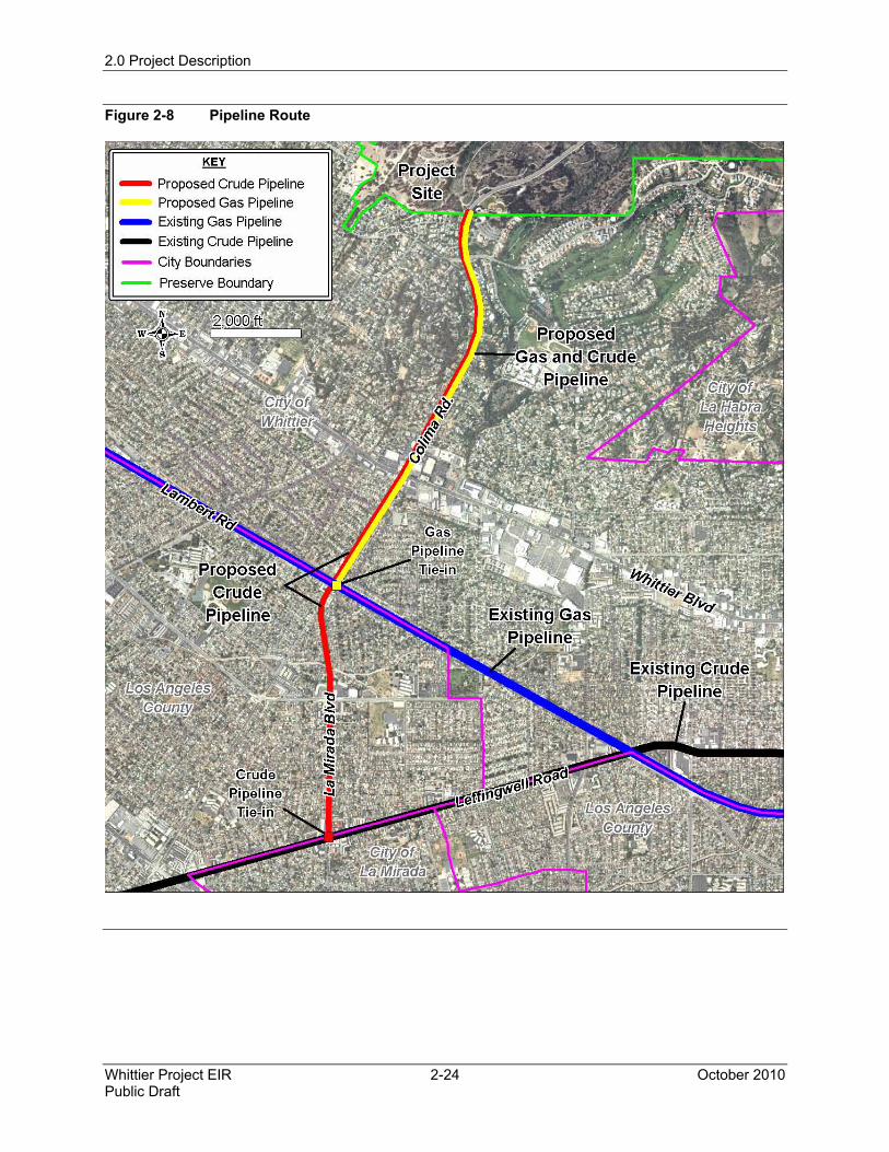
2.3.2.4 Gas and Crude Pipeline Construction
Gas and crude pipelines would be built to connect the proposed Project Site to the high-pressure natural gas pipeline that runs along Lambert Road and the crude pipeline that runs along Leffingwell Avenue. The pipelines would be installed together in the same trench along Colima Road south to Lambert Road. The crude pipeline would then continue south along Colima Road and La Mirada Boulevard to Leffingwell Avenue.
The entire gas pipeline route would be within the City of Whittier (the city boundary runs along Lambert Road) and entirely within existing streets (Colima Road) (see Figure 2-8).
The crude pipeline would cross into the unincorporated area of Los Angeles County, south of Lambert Road, between the City of Whittier and the City of La Mirada.
The proposed gas pipeline would be 6 inches in diameter and be approximately 1.8 miles in length. The crude pipeline would be 8 inches in diameter and approximately 2.8 miles in total length. Both pipelines would be manufactured in accordance with API specification 5L. The crude pipeline coating would be fusion-bond epoxy with polyethylene outer wrap tape covering the epoxy. The gas pipeline would be suitably coated as specified by SCGC. The pipelines would be cathodically protected and manual block valves would be installed at the ends.
Landowners and tenants adjacent to the rights-of-way would be notified in advance of construction in their area. A Traffic Plan would be prepared and construction would occur as approved by the local jurisdictional agency. Temporary alternative vehicle and pedestrian access would be established.
The use of a construction spread is anticipated to accomplish most aspects of construction along the alignment. A construction spread is a group of construction equipment that moves along the pipeline route, sequentially removing asphalt roadway, trenching, laying in pipe, filling, and re-paving and cleaning up. Figure 2-9 shows a typical construction spread.
2.0 Project Description
Whittier Project EIR 2-24 October 2010 Public Draft
Figure 2-8 Pipeline Route
2.0 Project Description
October 2010 2-25 Whittier Project EIR Public Draft
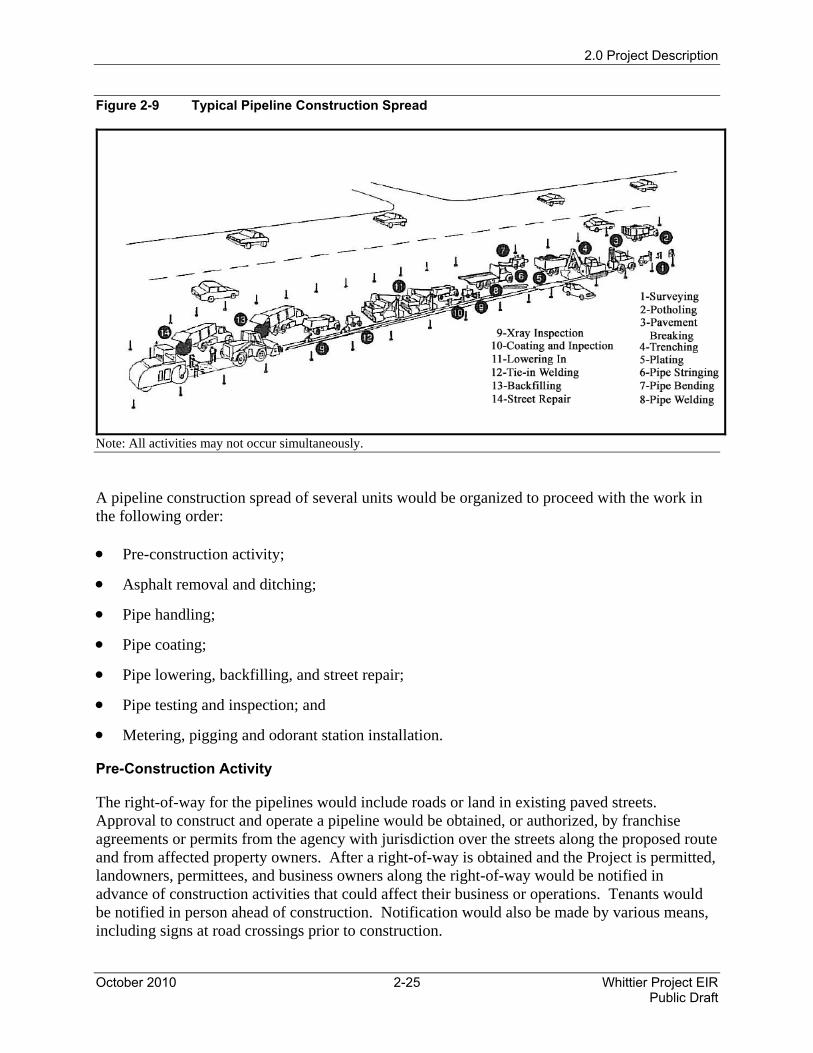
Figure 2-9 Typical Pipeline Construction Spread
Note: All activities may not occur simultaneously.
A pipeline construction spread of several units would be organized to proceed with the work in the following order:
• Pre-construction activity;
• Asphalt removal and ditching;
• Pipe handling;
• Pipe coating;
• Pipe lowering, backfilling, and street repair;
• Pipe testing and inspection; and
• Metering, pigging and odorant station installation.
Pre-Construction Activity
The right-of-way for the pipelines would include roads or land in existing paved streets. Approval to construct and operate a pipeline would be obtained, or authorized, by franchise agreements or permits from the agency with jurisdiction over the streets along the proposed route and from affected property owners. After a right-of-way is obtained and the Project is permitted, landowners, permittees, and business owners along the right-of-way would be notified in advance of construction activities that could affect their business or operations. Tenants would be notified in person ahead of construction. Notification would also be made by various means, including signs at road crossings prior to construction.
2.0 Project Description
Whittier Project EIR 2-26 October 2010 Public Draft
Emergency response providers near the proposed route would be notified prior to construction of construction locations, road closure schedules, and potential alternate routes. Directly affected businesses and residents would be given ample notice and information to plan alternative ingress and egress routes. Signage would be provided to direct motorists to alternate routes. Contractors would work with local police and traffic engineers to plan appropriate access alternatives for temporary street closures and traffic disruptions. Traffic control requirements from Caltrans, the County and the City would be followed.
Underground Service Alert would serve to notify service providers of construction to avoid conflicts with existing utilities and disruptions of service to utility customers. Since construction would occur almost exclusively within paved streets, extensive grading is not proposed. Preparation for in-street work would include breaking and removing pavement with concrete saws, pavement breakers, and jack hammers where necessary. Dump trucks would haul the broken debris to approved landfill sites or to a crusher plant.
Asphalt Removal and Ditching
Once traffic control measures are in place, ditching operations would begin. Typically, a 6-foot deep and 24-inch wide ditch (single pipe) or 36-inch wide ditch (double pipes) would be excavated (varying depths, depending on the conditions encountered). The total construction would be a maximum of 50 feet at a time. Backhoes and track hoes would excavate the ditch. However, hand digging would be necessary to locate buried utilities, such as other pipelines, cables, water mains, and sewers.
Fugitive dust emissions at the construction site during earthmoving operations would be controlled by water trucks equipped with fine spray nozzles. Approximately 10,000 gallons per day of water would be used for dust suppression.
Spoils from cuts, including cuts in streets, would be saved for backfill or would have to be removed and the ditch would have to be backfilled with slurry material as approved by the local jurisdictional agency. An effort would be made to minimize the amount of excess material. Materials unsuitable for backfill and not economically useful for other purposes would be disposed of in available landfills according to local and county guidelines.
When used for backfill, spoils from the trenches would be hauled to previously disturbed sites, determined by the construction contractor.
Pipe Handling
Pipe-stringing trucks would transport the pipe in 40- to 80-foot lengths from the shipment point or storage yards to the pipeline installation point. Where sufficient room exists, trucks would carry the pipe along the roadway and sideboom tractors would unload the joints of pipe from the stringing trucks and lay them end to end beside the ditch-line for future line-up and welding.
A portable bending machine would bend the pipe to fit the ditch contour both vertically and horizontally. Construction right-of-way conditions could occasionally require pipe bends that could not be accomplished in the field. In these cases, manufactured or shop-made bends would be used and pipe would be bent prior to the application of coating.
2.0 Project Description
October 2010 2-27 Whittier Project EIR Public Draft
While laying the pipe, line-up clamps would hold the pipe sections in position until 50 percent of the first welding pass is completed. Following the line-up crew, the welding crew would apply the remaining weld passes to bring the thickness of the weld to more than the thickness of the pipe by approximately 0.0625 inch. All pipeline welds would be inspected with x-rays.
Pipe Coating
Protecting the pipe from moisture and air helps prevent corrosion, thereby preventing cracks, breaks, and leaks in the pipe. The pipeline would be coated externally with fusion-bond epoxy and covered with polyethylene outer wrap tape. Pipeline coating would be applied at the mill before delivery to the construction site. However, field coating would be necessary on all field weld joints to provide a continuous coating along the pipeline. After the pipe has been welded and x-ray inspected, either heat shrink polyethylene sleeves or polyethylene tape and tape primer would be applied.
Pipe Lowering, Backfilling, and Street Repair
The pipe would be lifted and lowered into the ditch by two side-boom tractors spaced so that the weight of unsupported pipe would not cause mechanical damage. Cradles with rubber rollers or padded slings would allow the tractors to lower the pipe without damage as they travel along the ditch line. Additional welds could be required whenever the ditch line is obstructed by other utilities crossing the pipe ditch. These welds would typically be made in the ditch at the final elevation. In addition to normal welding and weld inspection, each weld would require pipe handling for line-up, cutting to exact length, coating, and backfilling.
Backfill material would be obtained from the ditch spoils or would be imported, as per local Agency requirement depending on soil properties. Spoils would be screened as the material is returned to the ditch using standard construction screening equipment. The sides of the pipe would be covered with a maximum of 6 inches of native fill, free of rocks, and then covered on top with a minimum of 12 inches of fill, free of rocks or a slurry would be used. This zone is referred to as the pipeline “padding and shading.” In certain areas where abrasive soils might damage the pipe coating, clean sand, earth backfill or slurry would pad the pipeline. Any required padding material would be obtained from local commercial sources. The backfill in the remainder of the trench above the padding would be native material excavated during trenching, or a slurry as required by local Agencies.
The area would be repaved if it was previously paved in existing streets. In areas where the pipeline would be in previously unpaved areas, the backfill would include topsoil preserved from the excavation for revegetation where needed. At the time of backfilling, a colored warning tape would be buried approximately 18 inches above the pipeline to indicate the presence of a buried pipeline to third-party excavators. The backfilled earth would be compacted using a roller or hydraulic tamper. The trench would be filled with slurry where required by local regulations. The slurry would be purchased from a local slurry plant and transported to the site. Steel plates would cover any open trench at the end of each workday.
2.0 Project Description
Whittier Project EIR 2-28 October 2010 Public Draft
Pipe Testing and Inspection
All field welding would be performed by qualified welders that meet the Applicant's specifications and in accordance with all applicable ordinances, rules, and regulations, including API 1104, the Standard for Welding Pipe Lines and Related Facilities, and the rules and regulations of the U.S. Department of Transportation found in the Code of Federal Regulations.
All welds would be visually and x-ray inspected. All rejected welds would be repaired or replaced as necessary and x-rayed again. The x-ray reports and a record of the location of welds would be maintained for the life of the pipeline.
In addition to standard mill testing of all pipe and fittings, hydrostatic testing would be performed after construction and prior to startup. Federal regulations mandate hydrostatic testing of new, cathodically protected pipelines prior to placing the line into operation. This test involves filling a test section of the pipe line with fresh water and increasing pressure to a predetermined level. Such tests are designed to prove that the pipe, fittings, and weld sections would maintain mechanical integrity under pressure without failure or leakage.
Cathodic protection controls the corrosion of a metal surface by making it work as a cathode of an electrochemical cell. This is achieved by placing the cell in contact with the metal surface and another more easily corroded metal to act as the anode of the electrochemical cell. The cathodic protection system consists of power sources called rectifiers, buried anodes, and test stations along the pipeline.
Metering and Pigging Station Installation
A gas-metering station would be required for the gas pipeline at a location where the pipeline enters Colima Road to measure and record gas volumes and provide custody transfer of the gas to SCGC. The metering station would require an approximate 30 by 20 foot building (see Figure 2-6 and Appendix A drawings). In addition, a pigging station would be installed to send and receive maintenance pigs into and from the pipelines to clean or inspect the pipeline.
2.3.2.5 Gas and Oil Processing Plants
The gas plant would be located at the Central Processing Site and would be approximately 200 by 300 feet (including the flare area). Diagrams with the detailed description of all facilities are included as Appendix A of this document. All well pad sites would send produced gas via pipeline to the gas plant for removal of liquids and impurities. The gas plant would have compressors, pumps, vessels, tanks, an odorizing system, a fire protection system, an automatic emergency shutdown system and an emergency flare. Sales quality gas would be sold directly to SCGC via a connecting pipeline from the site to the nearest The Gas Company connection on Colima Road.
The oil processing facility would also be located at the Central Processing Site and would be approximately 250 by 175 feet. This facility would include tanks and vessels for oil and water separation, air compressors for control purposes, pumps for moving oil and water, tanks for temporary storage of oil and water, and supporting vessels, controls and metering equipment.
2.0 Project Description
October 2010 2-29 Whittier Project EIR Public Draft
All vessels, tanks, and critical equipment would be surrounded by berms or containment walls to contain any spills. The oil processing facility would separate water and solids from the oil, then the oil would be temporarily stored in tanks prior to shipment. The separated water would be accumulated in tanks, filtered, and then pumped back into subsurface oil-producing sands with high-pressure injection pumps. The injection wells would be lined with steel casing until the well reaches the prescribed injection depth. Trucks would ship solids offsite to appropriate landfills.
Construction of the gas and oil processing facilities would involve the following activities:
• Grading;
• Cement pad construction;
• Vessel and tank erection; and
• Piping, electrical, and mechanical installation.
The subsequent sections discuss the details of the personnel and equipment requirements, along with the schedule. Table 2-3 lists the grading areas.
2.3.2.6 Construction and Drilling Waste
Both drilling and construction would generate waste; the following subsections describe the different types of waste that could be generated by the Project during the different phases and the planned disposal methods.
Construction Waste
During the grading process, branches and leaves that are encountered would be collected, shredded, and turned into mulch. If desired, the mulch material would be taken to a location within the Preserve designated by the Habitat Authority or otherwise would be disposed of offsite.
Wet concrete for pads, vaults, and foundations would be trucked to the site. Once the concrete is used, the truck shoots and concrete pumps would be washed down at the site. The concrete and water slurry would be collected in lined, bermed ponds for the water to evaporate. The residue concrete would periodically be collected and shipped offsite for proper disposal.
As part of the construction process, pallets, cardboard boxes, papers, plastics, banding materials, scrap steel, scrap aluminum, scrap wire, and rubbish would be collected. Recyclable waste would be recycled at an appropriate facility and other waste would be disposed in a landfill. Matrix estimates that up to 80 tons of this material would be recycled and disposed of during the 30-month construction phase.
Portable construction toilets would be provided for domestic waste.
2.0 Project Description
Whittier Project EIR 2-30 October 2010 Public Draft
Drilling Waste
Materials used in the drilling process would come packaged in paper bags, cardboard boxes, plastic containers, and on wooden pallets. Recyclable materials (e.g., empty containers, pallets, bags) would be taken to an offsite recycling center. Remaining trash would be stored in conventional trash bins and, when full, disposed of in a landfill. Matrix estimates that one 40- cubic yard container of such trash would be generated and disposed of for each well drilled.
Drill cuttings from each well would contain soil, sand, crushed rocks, gravel, and other materials. Matrix estimates that approximately 660 cubic yards of this material would be generated during drilling of each well. This material would be properly disposed of in an appropriate landfill.
2.3.2.7 Design and Construction Hazardous Materials
During the grading operations, earth-moving equipment would be refueled daily by service trucks carrying diesel fuel and lubricating oil. This service would be provided in the late afternoon while the equipment is idle.
During construction, service trucks would maintain and refuel machinery and equipment daily, delivering diesel fuel, gasoline, oils, and lubricants in the late afternoon. Welding and cutting gasses such as acetylene, oxygen, and argon would be stored in cylinders. Solvents would be stored in 55-gallon drums and paint would be stored in 5-gallon containers.
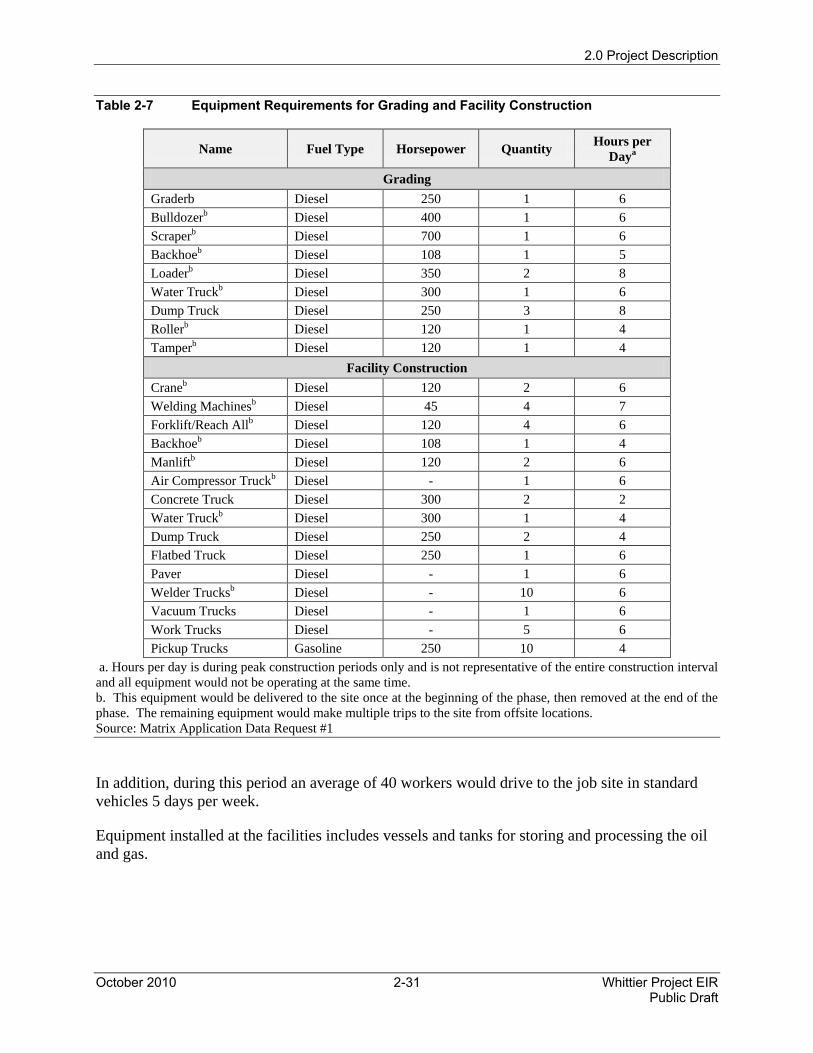
2.3.2.8 Design and Construction Phase Personnel and Equipment Requirements
Table 2-7 lists the equipment required for construction of well cellars, the truck loading facility, and the oil and gas processing facilities.
2.0 Project Description
October 2010 2-31 Whittier Project EIR Public Draft
Table 2-7 Equipment Requirements for Grading and Facility Construction
Name Fuel Type Horsepower Quantity Hours per Daya
Grading Graderb Diesel 250 1 6 Bulldozerb Diesel 400 1 6 Scraperb Diesel 700 1 6 Backhoeb Diesel 108 1 5 Loaderb Diesel 350 2 8 Water Truckb Diesel 300 1 6 Dump Truck Diesel 250 3 8 Rollerb Diesel 120 1 4 Tamperb Diesel 120 1 4
Facility Construction Craneb Diesel 120 2 6 Welding Machinesb Diesel 45 4 7 Forklift/Reach Allb Diesel 120 4 6 Backhoeb Diesel 108 1 4 Manliftb Diesel 120 2 6 Air Compressor Truckb Diesel - 1 6 Concrete Truck Diesel 300 2 2 Water Truckb Diesel 300 1 4 Dump Truck Diesel 250 2 4 Flatbed Truck Diesel 250 1 6 Paver Diesel - 1 6 Welder Trucksb Diesel - 10 6 Vacuum Trucks Diesel - 1 6 Work Trucks Diesel - 5 6 Pickup Trucks Gasoline 250 10 4
a. Hours per day is during peak construction periods only and is not representative of the entire construction interval and all equipment would not be operating at the same time. b. This equipment would be delivered to the site once at the beginning of the phase, then removed at the end of the phase. The remaining equipment would make multiple trips to the site from offsite locations. Source: Matrix Application Data Request #1
In addition, during this period an average of 40 workers would drive to the job site in standard vehicles 5 days per week.
Equipment installed at the facilities includes vessels and tanks for storing and processing the oil and gas.
2.0 Project Description
Whittier Project EIR 2-32 October 2010 Public Draft
Gas and Crude Oil Pipelines, Personnel, and Equipment Requirements
During the facility construction phase, the gas and crude pipelines would be built south along Colima Road to tie in to a SCGC transmission pipeline on Lambert Road and an existing crude oil pipeline along Leffingwell Road. A crew of approximately 15 equipment operators, pipe fitters, welders, laborers, and others would drive to the site each day. Two trenchers, two backhoes, two to four dump trucks, two 1-ton welding trucks, two pipe fitter trucks, and other trucks carrying materials would be used to construct the pipeline.
2.3.2.9 Design and Construction Phase Schedule
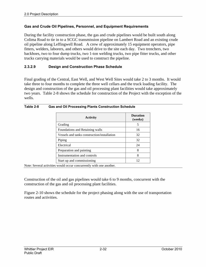
Final grading of the Central, East Well, and West Well Sites would take 2 to 3 months. It would take three to four months to complete the three well cellars and the truck loading facility. The design and construction of the gas and oil processing plant facilities would take approximately two years. Table 2-8 shows the schedule for construction of the Project with the exception of the wells.
Table 2-8 Gas and Oil Processing Plants Construction Schedule
Activity Duration (weeks)
Grading 5 Foundations and Retaining walls 16 Vessels and tanks construction/installation 32 Piping 32 Electrical 24 Preparation and painting 8 Instrumentation and controls 8 Start up and commissioning 12
Note: Several activities would occur concurrently with one another.
Construction of the oil and gas pipelines would take 6 to 9 months, concurrent with the construction of the gas and oil processing plant facilities.
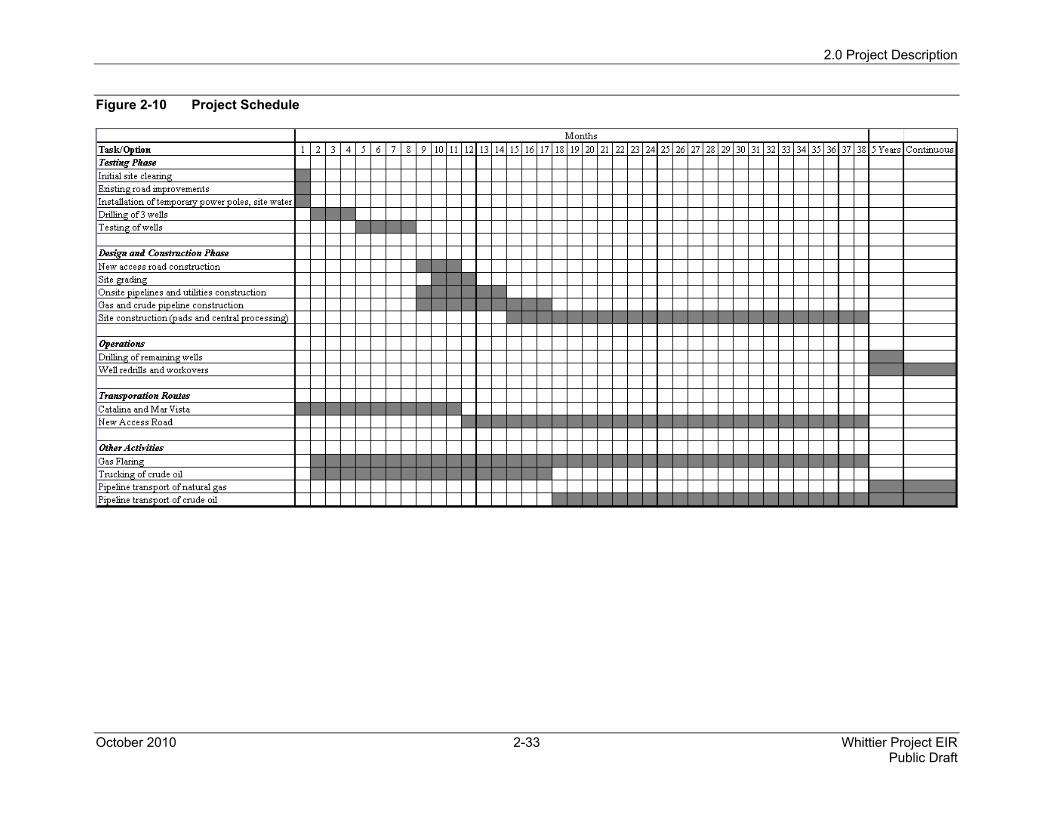
Figure 2-10 shows the schedule for the project phasing along with the use of transportation routes and activities.
2.0 Project Description
October 2010 2-33 Whittier Project EIR Public Draft
Figure 2-10 Project Schedule
2.0 Project Description
Whittier Project EIR 2-34 October 2010 Public Draft
2.3.3 Operations and Maintenance Phase
The Operations and Maintenance Phase of the Project would consist of drilling the remaining wells and operating and maintaining the oil processing, gas processing, and oil loading facilities. The facilities would be physically located at the three well sites within the Whittier Main Oil Field (see Figure 2-6).
2.3.3.1 Drilling Activities
Drilling up to 57 additional wells would take an average of 30 days per well, including drilling rig set-up, tear-down, and drilling operations. This would total up to 5 years of drilling spread evenly over the three well pad sites and would occur during only the Operations and Maintenance Phase.
Production wells would be drilled at all three well pad sites consecutively, with a single, large drilling rig. The production wells would use down-hole electric pumps to move the production fluids to the surface since the reservoir is not anticipated to produce enough pressure for sufficient free flow of fluids to the surface. Injection wells would inject the produced water back into the oil producing formations. As many as eight injection wells would also be drilled at the Central Well Site.
Drilling a well involves several distinct steps. Once the drilling derrick and structure are established, the drilling process begins. The first step is to drill a shallow, large-diameter hole and install a conductor pipe with a flange welded on top with diverter valves. The diverter valves allow any subsequent flow of fluids into the wellbore (well hole) to be diverted and controlled. Then a large diameter drill bit, slightly smaller than the conductor diameter, is placed into the conductor hole and drilling begins. Starting to drill the well is referred to as “spudding” a well.
In order to drill downwards through soil and rock, the drill bit requires downward force, which is provided by the weight of thick-walled pipe screwed on top of the drill bit. A single, 30-foot long drill pipe for a larger diameter drill bit weighs approximately 3 tons. As the drill bit drills deeper, more drill pipe is placed on top, thereby increasing the downward force to drill.
The drill bit turns clockwise as the weight of the drill pipe column forces it downward. The rotary table on the drill rig floor produces the turning; the table then grips the drill pipe with teeth and turns it, obtaining power from the drill motors.
As the drill bit turns, it generates rock cuttings. These must be removed from the wellbore by pumping fluids, or “mud”, down the hollow drill pipe, out of the holes at the bottom of the drill bit, and then back up the space between the wall of the hole and the drill pipe (the annulus). The mud equipment at the surface separates the mud from the cuttings and re-uses the mud. Cuttings are analyzed and then hauled offsite.
Once the wellbore is drilled to a predetermined depth, the drill pipe is pulled out of the hole and the hole is “cased.” The installation of wellbore casing is an integral part of drilling a well. Well
2.0 Project Description
October 2010 2-35 Whittier Project EIR Public Draft
casing is piping that is placed down a wellbore to stabilize the hole and prevent the entry of unwanted fluids, rock cuttings, or sand into the wellbore or the exit of mud and fluids out of the wellbore.
Once casing is placed in the hole to the given depth, cement is forced down the casing middle and out the bottom of the casing and back up the annulus until the annulus is full of cement. Right behind the cement is mud, separated by a rubber “plug,” which wipes the cement from the insides of the casing. When the plug reaches the bottom, it stops and allows the driller to know when the cement has reached the bottom of the wellbore. The cement is then allowed to dry to seal the outside of the casing to the wellbore sides.
At this point, a second, smaller diameter drill bit is placed into the wellbore and the well is drilled deeper. This process continues, with subsequently smaller drill bits and smaller diameter casing placed into the wellbore and cemented, until the target depth is reached. At this point, the casing is “perforated” with holes to allow production fluids to flow into the well and tubing is placed down the well and production fluids are pumped from the bottom of the well through the production tubing to the surface.
Matrix indicates that they would follow their currently used approach at the West Whittier field operation which includes methods of straight perforations of well casing into a oil/gas zone ("OG Zone") or the use of a slotted liner across an OG Zone to which a tube with slots/holes as a liner is used which allows fluids to enter from a selected formation or a method of perforation across a OG Zone with an injected resin or "Limited Entry Sand Control Method" which helps keep sand from flowing into a well.
A number of tests are performed at various stages during drilling, including pressure tests to ensure that the cement is solid and can hold pressure, and well logs and core samples are taken to understand the well design and drilling program.
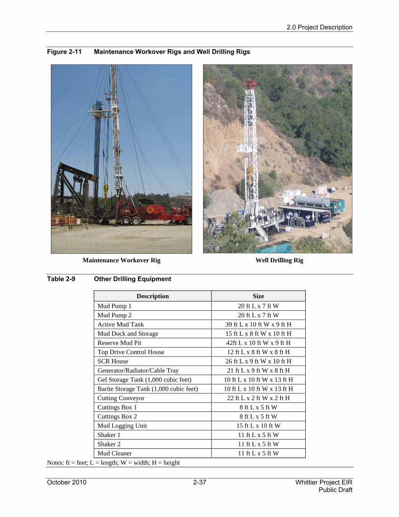
Figure 2-11 shows typical drilling rigs, used for well drilling, and workover rigs. The drilling rig would utilize diesel-powered electric generators, consuming 1,800 kilowatts (kW) during drilling operations.
Water consumption during drilling would be approximately 130,000 gallons of water per well drilled, for an average water use of 4,500 gpd over 30 days per well. A fire hydrant would be installed at each well pad site during the Design and Construction Phase (see Section 2.2.4.3).
During drilling operations, a liquid slurry of drilling “mud” would be collected onsite within bermed basins that are protected by an impermeable membrane. Much of the mud can be reused for the drilling of subsequent wells and the remainder would be collected and disposed offsite.
During the testing phase, a 15-foot tall noise blanket would be installed around the perimeter of the drill sites to minimize noise and to shield the sites during drilling operations. Additional wells, drilled before construction is complete, would also be shielded by perimeter noise blankets.
2.0 Project Description
Whittier Project EIR 2-36 October 2010 Public Draft
Table 2-9 lists additional equipment necessary during drilling. Note that the equipment shown is representative for a typical drilling operation of the type expected; the exact equipment list and layout may vary depending on the specific well.
Mud Handling Program
Two basic mud systems are anticipated for the proposed Project: a fresh water and clay-based system approved by the U.S. Environmental Protection Agency and a low-toxicity mineral oil system.
During drilling, cuttings and drilling fluid wastes would be processed by a chemically enhanced de-watering system and an onsite solidification process. The waste generated onsite would be transported in plastic lined bins (solidified solids) and vacuum trucks (liquid) and taken to an approved disposal site.
A mud handling program would be used for drilling the wells with the mineral-oil-based mud. Liquid oil, calcium chloride, water, and the associated additives would be combined at a mud mixing plant in Bakersfield, California. The mixed-oil-based drilling fluids would be pumped into vacuum trucks and transported to the drilling rig site. The drilling fluid would then be pumped from the vacuum trucks into the drilling rig pit system.
Prior to moving the oil-based fluid to the drilling rig, the pits would be emptied of water-based drilling fluids and cleaned. After the pits are cleaned, the fresh water used on the drilling rig would be disconnected. The pollution pan placed under the rig floor at the beginning of the drilling operation, and used throughout the water-based mud section of the well, would be inspected. The drill-pipe, mud-catch pans on the rig floor would also be inspected, as well as the mud buckets. This equipment would catch and collect any oil-based mud that may be on any of the equipment as it is pulled out of the well.
As required, additional oil-based mud would be made to specification and vacuum trucked to the well site. The mud would be pumped into the pits. When drilling is completed, the oil-based drilling mud would be pumped into vacuum trucks and transported back to Bakersfield for recycling. The rig and mud pits would be cleaned and the wash fluid hauled to an approved disposal site.
2.0 Project Description
October 2010 2-37 Whittier Project EIR Public Draft
Figure 2-11 Maintenance Workover Rigs and Well Drilling Rigs
Maintenance Workover Rig Well Drilling Rig
Table 2-9 Other Drilling Equipment
Description Size Mud Pump 1 20 ft L x 7 ft W Mud Pump 2 20 ft L x 7 ft W Active Mud Tank 39 ft L x 10 ft W x 9 ft H Mud Dock and Storage 15 ft L x 8 ft W x 10 ft H Reserve Mud Pit 42ft L x 10 ft W x 9 ft H Top Drive Control House 12 ft L x 8 ft W x 8 ft H SCR House 26 ft L x 9 ft W x 10 ft H Generator/Radiator/Cable Tray 21 ft L x 9 ft W x 8 ft H Gel Storage Tank (1,000 cubic feet) 10 ft L x 10 ft W x 13 ft H Barite Storage Tank (1,000 cubic feet) 10 ft L x 10 ft W x 13 ft H Cutting Conveyor 22 ft L x 2 ft W x 2 ft H Cuttings Box 1 8 ft L x 5 ft W Cuttings Box 2 8 ft L x 5 ft W Mud Logging Unit 15 ft L x 10 ft W Shaker 1 11 ft L x 5 ft W Shaker 2 11 ft L x 5 ft W Mud Cleaner 11 ft L x 5 ft W
Notes: ft = feet; L = length; W = width; H = height
2.0 Project Description
Whittier Project EIR 2-38 October 2010 Public Draft
Drilling Site Spill Containment
A pollution pan installed under the rig floor would catch any oil-based drilling mud that may spill on the rig floor. The catch pans installed under the drill pipe would catch any oil-based drilling mud left on the inside or outside of the drill pipe. The wash water would be disconnected once the oil-based drilling mud is in use and the rig floor would be cleaned with rubber squeegees. During routine drilling operations, some oil-based mud would be spilled on the rig floor. This would be captured and contained in the pollution pan and returned to the active mud pit. The drilling pad would be constructed to allow any fluids spilled directly around the rig to flow into the well cellar. In addition, an 18-inch berm would be placed around the entire drilling rig after the drilling rig is installed. In the event that a leak should occur in the mud handling system, it would be contained directly around the rig and flow into the cellar. A cellar pump would then pump the fluid out of the cellar and back into the active mud pit.
Rainwater and accumulated runoff within the bermed area around the rig would flow into the well cellar and be pumped into the active mud pit.
A spill trailer at the drilling site would be equipped with absorbent material, small spill booms to contain and direct flow, plastic sheets, personal protective equipment, and rakes, shovels, and hand tools. This equipment is designed for use in the event of an oil spill.
Blowout Prevention Equipment
A blowout occurs when unexpected high pressure and flow levels at the wellhead cause a release of oil and gas from the well. Blowout prevention (BOP) systems are safety systems used during drilling operations in oil and gas fields to prevent uncontrolled release of reservoir fluids and shut off the flow to prevent spills and releases of materials that could cause fires and explosions. BOP systems are composed of a stack, actuation systems, a choke manifold, stop systems, and other equipment. A BOP system would be placed on each wellhead during drilling and removed after the well was established. Wellhead pressures (pressure at the wellhead where the BOP is situated) would be a maximum of 2,500 pounds per square inch, gauge (psig).
Hydrogen Sulfide Contingency Planning
The status of the field in terms of hydrogen sulfide (H2S) in the gas and oil is unknown at this time, although it is expected that the composition of the gas would be similar to the adjacent reservoirs at Honolulu Terrace and Sycamore Canyon, which are both devoid of any significant levels of H2S. A contingency plan would be developed to address issues such as safety equipment, personnel responsibilities, first aid, and evacuation. This plan would address employee safety and issues in the event of H2S exposure.
Hydrogen sulfide is a colorless, toxic, flammable gas with a characteristic foul odor of rotten eggs. Gas that contains hydrogen sulfide is called “sour” gas. DOGGR publication M10 requires special precautions for well-drilling operations that could expect to encounter gas with hydrogen sulfide concentrations above 20 parts per million (ppm).
2.0 Project Description
October 2010 2-39 Whittier Project EIR Public Draft
Hydrogen sulfide can also be dissolved in the crude oil be liberated into the vapor space of storage tanks at significantly higher concentrations than the crude oil, according to DOGGR publication M10.
In the event that gas intended for production is found to be sour, or hydrogen sulfide levels in the gas are greater than 20 ppm or a crude hydrogen sulfide concentration, which could produce vapors above 100 ppm, the well would be shut in and either abandoned or the Project would be changed, including all necessary permits, to handle sour gas. Should gas containing low levels of H2S be encountered during drilling, no additional changes would be made to the drilling operations, since the drilling operations are already designed to protect against the release of production gases. Current plans indicate that permanent H2S gas detection is not proposed as part of the Project.
Temporary H2S detection equipment would be included as part of a contingency plan associated with drilling. H2S detection equipment would monitor the drilling rig environment during the drilling of the test wells, but it would be removed after the test wells are installed, assuming that the same formations would be penetrated. This temporary equipment would include H2S monitors on the drilling rig and breathing air packs at the rig and in the safety trailer.
Noise Abatement
Noise reducing mitigation efforts incorporated into the Project include using wood timbers and sleepers on pipe racks and at the pipe V-door ramp to minimize metal-to-metal contact. In addition, wood timbers would also be used on the rig floor and on the pipe racks to minimize metal-to-metal contact. The use of hydraulic tongs, as proposed by the Project, rather than chain or pneumatic tongs, would also minimize metal-to-metal contact. High sound levels from other equipment (e.g., pumps, compressors, generators, winches, auxiliary engines) would also be mitigated as necessary (e.g., enclosure, vibration reducing mounts, mufflers). The drilling area would be surrounded by a 15-foot tall sound barrier.
Diesel-powered electric generators would power the drilling rig and most of the associated drilling equipment. The crane and well-logging unit would operate approximately 20% of the time, both during the day and the night, depending on the drilling requirements. The well-logging unit, cementing equipment, coil-tubing unit, and slickline engines are truck-mounted and operate from the main truck engines. The well-logging unit contains the surface hardware necessary to make well measurements; the cementing equipment used to pump cement down the well; the coil-tubing unit used to run tubing down the well hole, and the slickline, a thin cable used to control and retrieve well-hole equipment.
Lighting and Shielding
The lighting for a mast and derrick generally consists of two light strings (i.e., two of the four corners of the mast have lights). Safety guidelines specify “luminance” for different safe working conditions.
2.0 Project Description
Whittier Project EIR 2-40 October 2010 Public Draft
For a rig, the guidelines include:
• Derrick: 30 foot candles;
• Rig Floor: 70 to 100 foot candles; and
• Pipe Racks: 50 foot candles.
Derrick light fixtures would typically be approximately 12 feet apart on the two corners of the mast holding the lights. The derrick light fixtures would be recessed and shielded to reduce glare.
The top of the derrick would have a red beacon light for airline identification. High intensity mercury arc lighting would be used on the rig floor and pointed at the specific work area. These lights would be inside the rig floor area.
Odor Abatement
Dust from cement, barite, and other mud chemicals would be controlled with dust filters and ventilation. Use of volatile materials onsite (e.g., paints, solvents) would be minimized. The Applicant indicates that water-based mud would have no appreciable odor and that the oil-based mud under consideration would have no appreciable odor beyond the drill site.
Drilling Materials
Table 2-10 lists the materials that would be used during drilling operations. The amounts listed are the estimated quantities consumed per well drilled. These materials are packaged by the manufacturer for shipping and would be delivered to the job site by conventional delivery or flatbed trucks. Only trained personnel would handle these materials.
Table 2-10 Drilling Materials Usage
Name Material Container Amount per Well
Gel Wyoming Bentonite 100-pound sack 525 sacks DMA Sodium Polyacrylate 50-pound sack 82 sacks Benex Anionic Acrylamide 2-pound sack 75 sacks GEOZan Xanthan Gum 25-pound sack 40 sacks Omniopol Sodium Polyacrylate Liquid 380 gallons CFR Fatty Acid Liquid 600 gallons Bicarb Sodium Bicarbonate 50-pound sack 40 sacks Citric Acid Citric Acid 50-pound sack 11 sacks Walnut Walnut Hulls 50-pound sack 48 sacks
All of the products listed in Table 2-10 are generically listed on the California Department of Health Services-approved Drilling Mud Additives List. In these concentrations, the drilling fluid is considered a non-hazardous material.
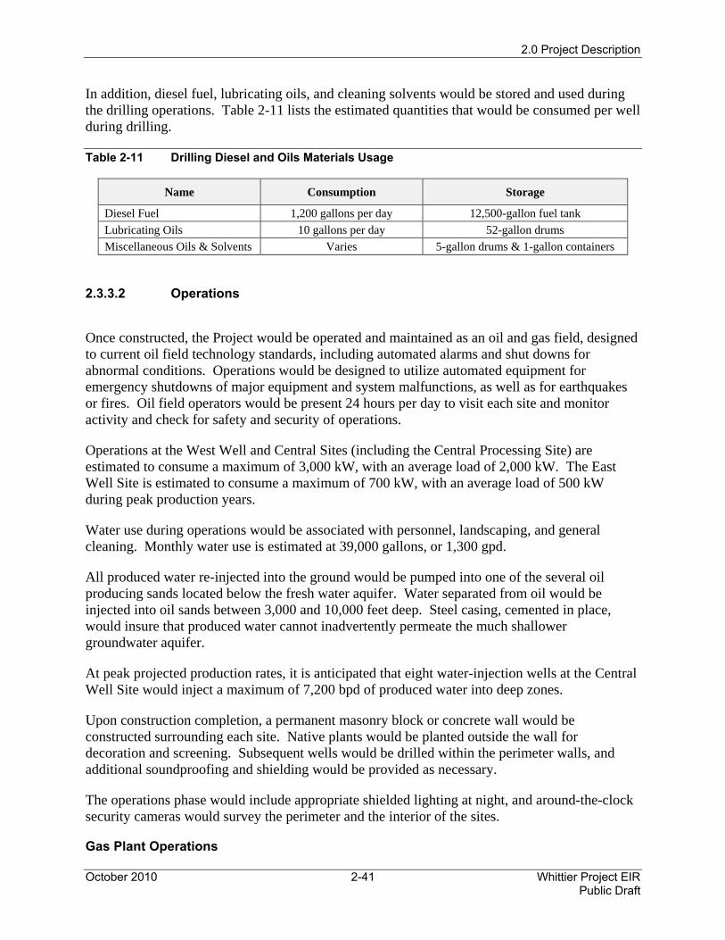
2.0 Project Description
October 2010 2-41 Whittier Project EIR Public Draft
In addition, diesel fuel, lubricating oils, and cleaning solvents would be stored and used during the drilling operations. Table 2-11 lists the estimated quantities that would be consumed per well during drilling.
Table 2-11 Drilling Diesel and Oils Materials Usage
Name Consumption Storage
Diesel Fuel 1,200 gallons per day 12,500-gallon fuel tank Lubricating Oils 10 gallons per day 52-gallon drums Miscellaneous Oils & Solvents Varies 5-gallon drums & 1-gallon containers
2.3.3.2 Operations
Once constructed, the Project would be operated and maintained as an oil and gas field, designed to current oil field technology standards, including automated alarms and shut downs for abnormal conditions. Operations would be designed to utilize automated equipment for emergency shutdowns of major equipment and system malfunctions, as well as for earthquakes or fires. Oil field operators would be present 24 hours per day to visit each site and monitor activity and check for safety and security of operations.
Operations at the West Well and Central Sites (including the Central Processing Site) are estimated to consume a maximum of 3,000 kW, with an average load of 2,000 kW. The East Well Site is estimated to consume a maximum of 700 kW, with an average load of 500 kW during peak production years.
Water use during operations would be associated with personnel, landscaping, and general cleaning. Monthly water use is estimated at 39,000 gallons, or 1,300 gpd.
All produced water re-injected into the ground would be pumped into one of the several oil producing sands located below the fresh water aquifer. Water separated from oil would be injected into oil sands between 3,000 and 10,000 feet deep. Steel casing, cemented in place, would insure that produced water cannot inadvertently permeate the much shallower groundwater aquifer.
At peak projected production rates, it is anticipated that eight water-injection wells at the Central Well Site would inject a maximum of 7,200 bpd of produced water into deep zones.
Upon construction completion, a permanent masonry block or concrete wall would be constructed surrounding each site. Native plants would be planted outside the wall for decoration and screening. Subsequent wells would be drilled within the perimeter walls, and additional soundproofing and shielding would be provided as necessary.
The operations phase would include appropriate shielded lighting at night, and around-the-clock security cameras would survey the perimeter and the interior of the sites.
Gas Plant Operations
2.0 Project Description
Whittier Project EIR 2-42 October 2010 Public Draft
Incoming gas from the well pad sites would be received at the gas plant via a pipeline that enters the plant. The maximum design flow rate would be 6 mmscfd. The incoming pressure of the gas would typically be approximately 55 psig. The gas would be received through a liquid slug catcher and intake scrubbers that capture any liquid condensate that may be present. See Figure 2-12 for a simplified process flow diagram of the proposed operations.
Downstream of the intake scrubbers, the gas would be compressed during first stage compression to approximately 150 psig prior to entering the gas sweetening plant, which removes any H2S from the gas stream, if necessary. Tests at nearby operating wells indicate that less than 1 ppm of hydrogen sulfide is in the gas. Small quantities of hydrogen sulfide encountered would be removed from the gas (see Table 2-1).
If small levels of H2S are encountered, the gas plant would be able to remove it to sweeten the gas to the levels required by SCGC. In the gas sweetening process, the gas would pass through a pair of heat exchangers and then flow through gas sweetening towers, which remove H2S compounds and residual sulfur elements. A pump would circulate the gas sweetening solution (Amine), which is the primary method for removing the sulfur compounds. The gas stream outgoing from the sweetening towers would be routed to a water wash tower, where the gas sweetening solution would be recovered, and the gas would then be directed through a filter and separator for final liquid separation.
At this point, the gas would be compressed again to approximately 500 psig in the second-stage compression system. The gas would then be ready for dehydration, or the removal of water vapors. A conventional glycol system would remove the water from the gas. Gas would be routed to a glycol contactor tower that would initially dehydrate the gas. Downstream of this gas tower, the gas would be routed through a glycol separator, and then through a heat exchanger that would provide for some cooling of the gas prior to entering the gas chiller and associated low temperature separator. The chiller would provide low temperature separation (LTS) of the gas stream, which would chill the incoming gas and remove natural gas liquids (NGL) from the gas stream. Propane would be the working refrigerant of the LTS plant.
After second stage compression, dehydration, and LTS, the gas would enter the pipeline for connection to the gas pipeline installed along Colima Avenue to connect to the existing natural gas pipeline along Lambert Avenue.
Vapor would be recovered throughout the plant in a near-atmospheric-pressure vapor header. The vapors would be compressed to 55 psig using a vapor recovery compressor. The gas would then be mixed with the gas coming from producing wells and would go to the gas plant with the produced gas.
The gas plant would separate NGL from the gas stream and mix these into the crude oil for transportation to the crude pipeline. At the maximum design rate of 10,000 barrels crude and 6 mmscfd of gas per day, the gas plant would yield between 50 to 70 bpd of NGL.
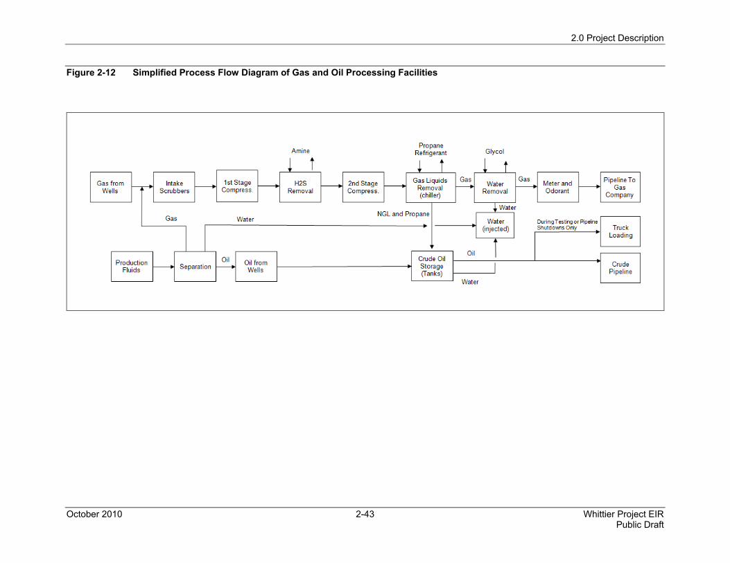
2.0 Project Description
October 2010 2-43 Whittier Project EIR Public Draft
Figure 2-12 Simplified Process Flow Diagram of Gas and Oil Processing Facilities
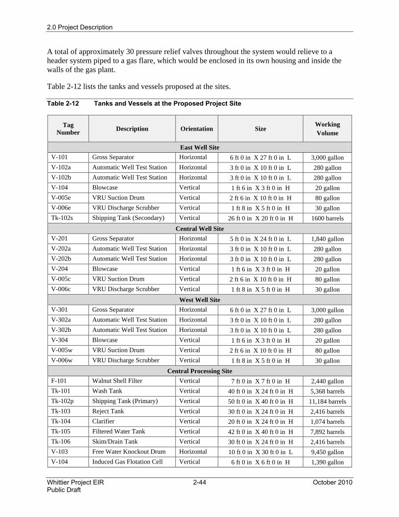
2.0 Project Description
Whittier Project EIR 2-44 October 2010 Public Draft
A total of approximately 30 pressure relief valves throughout the system would relieve to a header system piped to a gas flare, which would be enclosed in its own housing and inside the walls of the gas plant.
Table 2-12 lists the tanks and vessels proposed at the sites.
Table 2-12 Tanks and Vessels at the Proposed Project Site
Tag Number Description Orientation Size
Working Volume
East Well Site V-101 Gross Separator Horizontal 6 ft 0 in X 27 ft 0 in L 3,000 gallon V-102a Automatic Well Test Station Horizontal 3 ft 0 in X 10 ft 0 in L 280 gallon V-102b Automatic Well Test Station Horizontal 3 ft 0 in X 10 ft 0 in L 280 gallon V-104 Blowcase Vertical 1 ft 6 in X 3 ft 0 in H 20 gallon V-005e VRU Suction Drum Vertical 2 ft 6 in X 10 ft 0 in H 80 gallon V-006e VRU Discharge Scrubber Vertical 1 ft 8 in X 5 ft 0 in H 30 gallon Tk-102s Shipping Tank (Secondary) Vertical 26 ft 0 in X 20 ft 0 in H 1600 barrels
Central Well Site V-201 Gross Separator Horizontal 5 ft 0 in X 24 ft 0 in L 1,840 gallon V-202a Automatic Well Test Station Horizontal 3 ft 0 in X 10 ft 0 in L 280 gallon V-202b Automatic Well Test Station Horizontal 3 ft 0 in X 10 ft 0 in L 280 gallon V-204 Blowcase Vertical 1 ft 6 in X 3 ft 0 in H 20 gallon V-005c VRU Suction Drum Vertical 2 ft 6 in X 10 ft 0 in H 80 gallon V-006c VRU Discharge Scrubber Vertical 1 ft 8 in X 5 ft 0 in H 30 gallon
West Well Site V-301 Gross Separator Horizontal 6 ft 0 in X 27 ft 0 in L 3,000 gallon V-302a Automatic Well Test Station Horizontal 3 ft 0 in X 10 ft 0 in L 280 gallon V-302b Automatic Well Test Station Horizontal 3 ft 0 in X 10 ft 0 in L 280 gallon V-304 Blowcase Vertical 1 ft 6 in X 3 ft 0 in H 20 gallon V-005w VRU Suction Drum Vertical 2 ft 6 in X 10 ft 0 in H 80 gallon V-006w VRU Discharge Scrubber Vertical 1 ft 8 in X 5 ft 0 in H 30 gallon
Central Processing Site F-101 Walnut Shell Filter Vertical 7 ft 0 in X 7 ft 0 in H 2,440 gallon Tk-101 Wash Tank Vertical 40 ft 0 in X 24 ft 0 in H 5,368 barrels Tk-102p Shipping Tank (Primary) Vertical 50 ft 0 in X 40 ft 0 in H 11,184 barrels Tk-103 Reject Tank Vertical 30 ft 0 in X 24 ft 0 in H 2,416 barrels Tk-104 Clarifier Vertical 20 ft 0 in X 24 ft 0 in H 1,074 barrels Tk-105 Filtered Water Tank Vertical 42 ft 0 in X 40 ft 0 in H 7,892 barrels Tk-106 Skim/Drain Tank Vertical 30 ft 0 in X 24 ft 0 in H 2,416 barrels V-103 Free Water Knockout Drum Horizontal 10 ft 0 in X 30 ft 0 in L 9,450 gallon V-104 Induced Gas Flotation Cell Vertical 6 ft 0 in X 6 ft 0 in H 1,390 gallon
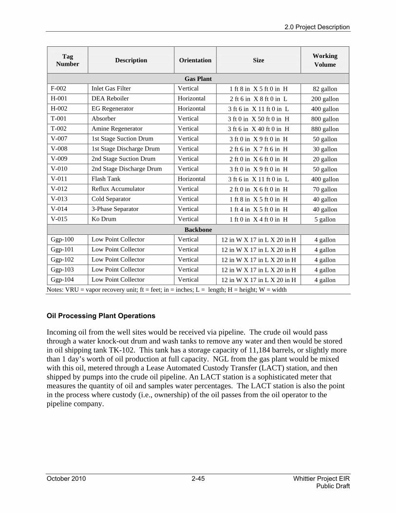
2.0 Project Description
October 2010 2-45 Whittier Project EIR Public Draft
Tag Number Description Orientation Size
Working Volume
Gas Plant F-002 Inlet Gas Filter Vertical 1 ft 8 in X 5 ft 0 in H 82 gallon H-001 DEA Reboiler Horizontal 2 ft 6 in X 8 ft 0 in L 200 gallon H-002 EG Regenerator Horizontal 3 ft 6 in X 11 ft 0 in L 400 gallon T-001 Absorber Vertical 3 ft 0 in X 50 ft 0 in H 800 gallon T-002 Amine Regenerator Vertical 3 ft 6 in X 40 ft 0 in H 880 gallon V-007 1st Stage Suction Drum Vertical 3 ft 0 in X 9 ft 0 in H 50 gallon V-008 1st Stage Discharge Drum Vertical 2 ft 6 in X 7 ft 6 in H 30 gallon V-009 2nd Stage Suction Drum Vertical 2 ft 0 in X 6 ft 0 in H 20 gallon V-010 2nd Stage Discharge Drum Vertical 3 ft 0 in X 9 ft 0 in H 50 gallon V-011 Flash Tank Horizontal 3 ft 6 in X 11 ft 0 in L 400 gallon V-012 Reflux Accumulator Vertical 2 ft 0 in X 6 ft 0 in H 70 gallon V-013 Cold Separator Vertical 1 ft 8 in X 5 ft 0 in H 40 gallon V-014 3-Phase Separator Vertical 1 ft 4 in X 5 ft 0 in H 40 gallon V-015 Ko Drum Vertical 1 ft 0 in X 4 ft 0 in H 5 gallon
Backbone Ggp-100 Low Point Collector Vertical 12 in W X 17 in L X 20 in H 4 gallon Ggp-101 Low Point Collector Vertical 12 in W X 17 in L X 20 in H 4 gallon Ggp-102 Low Point Collector Vertical 12 in W X 17 in L X 20 in H 4 gallon Ggp-103 Low Point Collector Vertical 12 in W X 17 in L X 20 in H 4 gallon Ggp-104 Low Point Collector Vertical 12 in W X 17 in L X 20 in H 4 gallon
Notes: VRU = vapor recovery unit; ft = feet; in = inches; L = length; H = height; W = width
Oil Processing Plant Operations
Incoming oil from the well sites would be received via pipeline. The crude oil would pass through a water knock-out drum and wash tanks to remove any water and then would be stored in oil shipping tank TK-102. This tank has a storage capacity of 11,184 barrels, or slightly more than 1 day’s worth of oil production at full capacity. NGL from the gas plant would be mixed with this oil, metered through a Lease Automated Custody Transfer (LACT) station, and then shipped by pumps into the crude oil pipeline. An LACT station is a sophisticated meter that measures the quantity of oil and samples water percentages. The LACT station is also the point in the process where custody (i.e., ownership) of the oil passes from the oil operator to the pipeline company.
2.0 Project Description
Whittier Project EIR 2-46 October 2010 Public Draft
Truck Loading Facility
The truck loading facility would be designed to load two trucks simultaneously at a maximum rate equal to the maximum daily crude production. Each truck would be able to load 150 barrels or more, depending on the crude properties. For the peak production, this would equate to approximately 69 trucks per day (for API-20 crude oil). The truck loading facility would only be utilized when the crude oil pipeline is not functioning. This is anticipated to happen infrequently.
Water Treatment and Injection
Water produced by the proposed Project would be cleaned of contaminants and injected back into the reservoirs at an estimated pressure of 1,000 psig. Produced water from the oil processing operations would pass through a clarifier and a skim tank and would then be gathered in a filtered water tank with a capacity of 7,892 barrels. The tank would operate at atmospheric pressure.
From the filtered water tank, the water would be pumped directly to injection. The injection pumps would be operated from an electric drive, with flow rate determined by the level in the filtered water tank. The discharge of the pumps would then go to the water injection wells. There would be as many as eight water injection wells located at the Central Well Site.
Gas Odorant and Metering Operations
Natural gas, used for heating and cooking in homes and as fuel for natural gas vehicles, is a colorless and odorless gas. The gas can be harmful if inhaled and can cause suffocation, fire, and explosion. Law requires that natural gas is odorized before entering the gas distribution system to allow for detection of gas leaks and prevention of hazardous consequences. Typically, the odorants used are sulfur compounds that have the classic “rotten egg” smell. The odorant tetrahydrothiophene would be used, which is similar to another commonly used natural gas odorant, methyl mercaptan.
The gas pipeline would require the delivery of odorant to the Central Processing Site gas plant to odorize the natural gas before introducing it into the natural gas pipeline. Based on 6 mmscfd and a 500-gallon odorant tank, there would be a total of two deliveries of odorant per year.
Well Maintenance, Workover, and Re-Drill Operations
Well maintenance and workover operations are periodically necessary to sustain production from the wells. A portable unit conducts routine maintenance, such as replacing gas lift valves or servicing sub-surface safety valves. A portable coiled tubing unit cleans out sand from the wells. A workover rig removes production tubing from a well to repair tubing or other leaks.
A workover rig is also used to set cement isolation plugs or bridge plugs in the wellbore to isolate non-productive intervals of the reservoir. A workover rig can be used to workover, recomplete, abandon, and sidetrack an existing well.
2.0 Project Description
October 2010 2-47 Whittier Project EIR Public Draft
Matrix estimates an average of one workover per year per well, or a maximum of 52 workovers per year. Depending upon the level of maintenance required, a workover of a well typically takes anywhere from 1 to 7 days. Workover rigs used for these operations typically operate 8 to 12 hours per day during weekdays. They do not operate at night or on weekends. Well workover rigs are generally truck mounted with up to a 90-foot tall mast (to service a 10,000 foot deep well) with a work platform near the top and an approximately 300-horsepower diesel power drive package.
Well re-drills involve similar operations as the initial drilling of the well with a similar sized drill rig and associated equipment and schedule (24 hours per day). Matrix estimates an average of three well re-drills annually for the life of the proposed Project once full field development is achieved.
Operational Waste
During operations, waste such as pallets, cardboard and paper boxes, paper, and plastics would be taken to an offsite recycling center. Scrap steel, scrap aluminum, and scrap wire would also be collected and recycled at an appropriate facility. Other trash and rubbish would be collected in waste bins and disposed of by a local waste hauler. On average, a 10-cubic yard bin would be disposed of each week.
The office sewer would be connected to the local sanitation district and portable construction toilets would be provided at strategic locations.
At some locations, sand and other solid particles are trapped in the oil and water emulsion that is brought to the surface by the deep well pumps. These solids would be separated from the oil and water and disposed of offsite at a hazardous waste landfill by a licensed contractor hired by Matrix. The quantities are unknown, but could range up to two trucks per month.
Periodically, a deep well pump would require repairs. When this occurs, the pump would be brought to the surface, accompanied by approximately 3 tons of soil and other solids. This material would be hauled to a landfill. It is unknown how often this would occur, but it is estimated as many as four times per year for the entire field.
2.3.3.3 Operation Phase Personnel and Equipment Requirements
As many as 15 to 20 operators and maintenance technicians would drive to the site each day in standard vehicles (not including drilling personnel). Periodically, 1- and 2-ton delivery trucks would bring parts to the facility site. Welding trucks, cranes, and other maintenance equipment and associated personnel would drive to the site as maintenance activities warrant. One 3,000-gallon vacuum truck would drive to and from the facility three to four times per week. Other equipment, such as well workover rigs and trucks, would drive to and from the job site periodically as maintenance activities require. Any heavy equipment would approach the Project Site via the new access road from Colima Road.
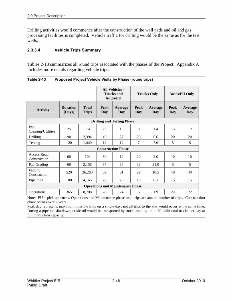
2.0 Project Description
Whittier Project EIR 2-48 October 2010 Public Draft
Drilling activities would commence after the construction of the well pads and oil and gas processing facilities is completed. Vehicle traffic for drilling would be the same as for the test wells.
2.3.3.4 Vehicle Trips Summary
Tables 2-13 summarizes all round trips associated with the phases of the Project. Appendix A includes more details regarding vehicle trips.
Table 2-13 Proposed Project Vehicle Visits by Phase (round trips)
All Vehicles - Trucks and Autos/PU
Trucks Only Autos/PU Only
Activity Duration(Days)
Total Trips
Peak Day
Average Day
Peak Day
Average Day
Peak Day
Average Day
Drilling and Testing Phase Pad Clearing/Utilities 25 334 23 13 8 1.4 15 12
Drilling 90 2,394 40 27 20 6.6 20 20 Testing 120 1,440 12 12 7 7.0 5 5
Construction Phase Access Road Construction 60 720 30 12 20 2.0 10 10
Pad Grading 60 2,158 37 36 32 31.0 5 5 Facility Construction 520 26,280 69 51 29 10.5 40 40
Pipelines 180 4,165 28 23 13 8.1 15 15 Operations and Maintenance Phase
Operations 365 8,708 28 24 6 1.9 22 22 Note: PU = pick up trucks. Operations and Maintenance phase total trips are annual number of trips. Construction phase occurs over 2 years. Peak day represents maximum possible trips on a single day; not all trips to the site would occur at the same time. During a pipeline shutdown, crude oil would be transported by truck, totaling up to 69 additional trucks per day at full production capacity.
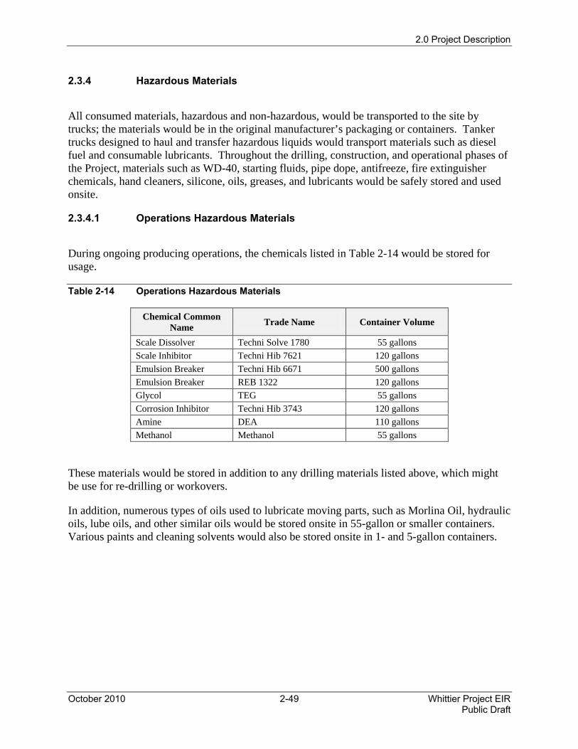
2.0 Project Description
October 2010 2-49 Whittier Project EIR Public Draft
2.3.4 Hazardous Materials
All consumed materials, hazardous and non-hazardous, would be transported to the site by trucks; the materials would be in the original manufacturer’s packaging or containers. Tanker trucks designed to haul and transfer hazardous liquids would transport materials such as diesel fuel and consumable lubricants. Throughout the drilling, construction, and operational phases of the Project, materials such as WD-40, starting fluids, pipe dope, antifreeze, fire extinguisher chemicals, hand cleaners, silicone, oils, greases, and lubricants would be safely stored and used onsite.
2.3.4.1 Operations Hazardous Materials
During ongoing producing operations, the chemicals listed in Table 2-14 would be stored for usage.
Table 2-14 Operations Hazardous Materials
Chemical Common Name Trade Name Container Volume
Scale Dissolver Techni Solve 1780 55 gallons Scale Inhibitor Techni Hib 7621 120 gallons Emulsion Breaker Techni Hib 6671 500 gallons Emulsion Breaker REB 1322 120 gallons Glycol TEG 55 gallons Corrosion Inhibitor Techni Hib 3743 120 gallons Amine DEA 110 gallons Methanol Methanol 55 gallons
These materials would be stored in addition to any drilling materials listed above, which might be use for re-drilling or workovers.
In addition, numerous types of oils used to lubricate moving parts, such as Morlina Oil, hydraulic oils, lube oils, and other similar oils would be stored onsite in 55-gallon or smaller containers. Various paints and cleaning solvents would also be stored onsite in 1- and 5-gallon containers.