Embed Size (px)
Citation preview
1
2008 International
ANSYS Conference
Development of a 3-D Blast Overpressure
Modeling Capability Utilizing Fluent
Daniel L. Cler - U.S. Army RDECOM/ARDEC/WSEC/Benet LabsMark Doxbeck - U.S. Army RDECOM/ARDEC/WSEC/Benet Labs
2
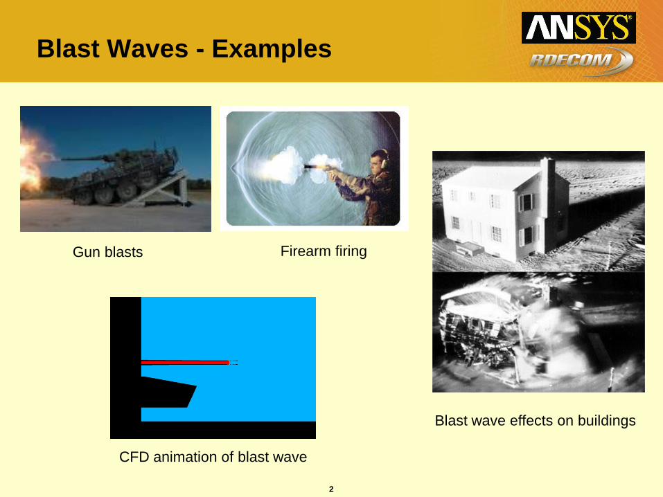
Blast Waves - Examples
Gun blasts Firearm firing
Blast wave effects on buildings
CFD animation of blast wave
3
Blast Waves
• A blast wave is the pressure and flow resulting from the
deposition of a large amount of energy in a small very localized
volume.
– Flow field can be approximated as a lead shock wave, followed by a 'self-
similar' subsonic flow field
• Shock waves cause a virtually instantaneous jump in pressure at
the shock front
• The combination of the pressure jump (called the overpressure)
and the dynamic pressure causes blast damage
• It is necessary to understand blast wave to
– Estimate the damage that will result from an explosion
– To devise mechanisms for mitigating the blast
4
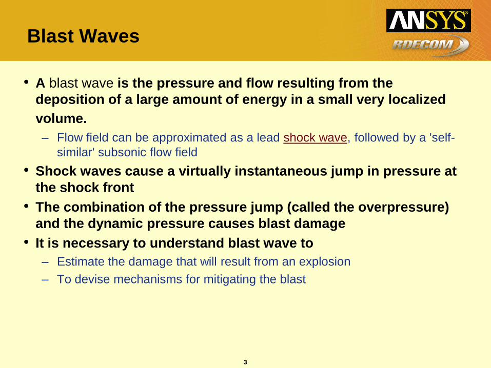
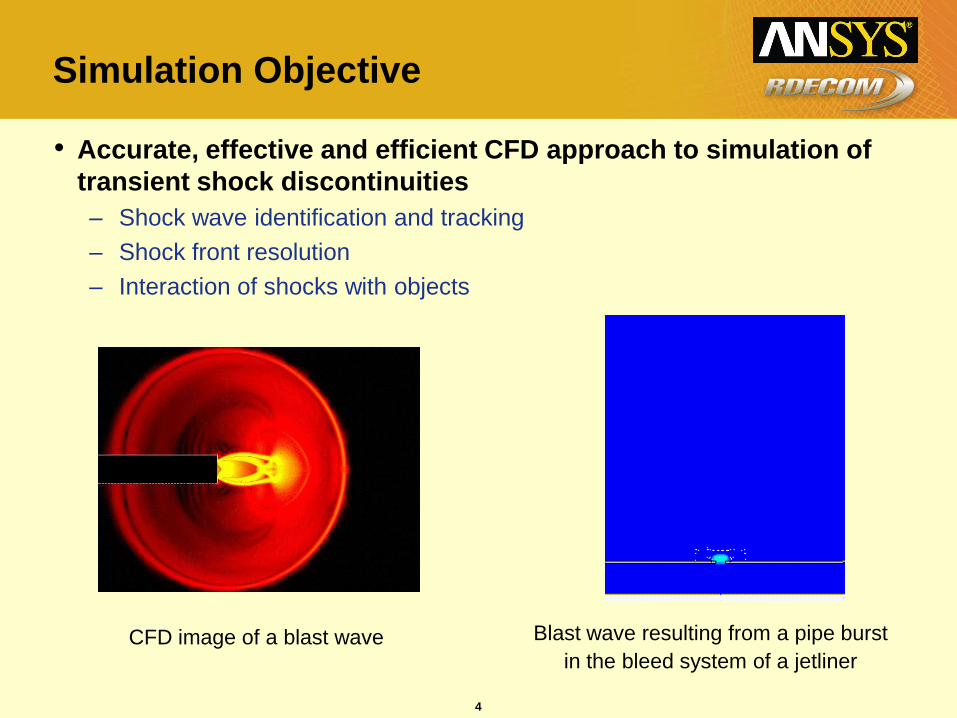
Simulation Objective
• Accurate, effective and efficient CFD approach to simulation of
transient shock discontinuities
– Shock wave identification and tracking
– Shock front resolution
– Interaction of shocks with objects
CFD image of a blast wave Blast wave resulting from a pipe burst
in the bleed system of a jetliner
5
Simulation Approach
• CFD finite-volume utilized rather than Lagrangian
– Lower computational overhead.
– Better flow prediction capabilities.
– Solution based grid adaption.
– Best in situations where blast does not cause structural deformation.
– Can be coupled to FEA solvers to determine deformations and loading of structural components
• Significant improvements to adaptation schemes are required to make CFD simulations feasible.
6
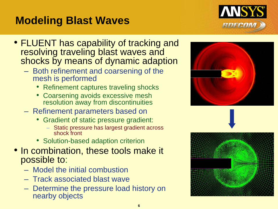
Modeling Blast Waves
• FLUENT has capability of tracking and resolving traveling blast waves and shocks by means of dynamic adaption– Both refinement and coarsening of the
mesh is performed• Refinement captures traveling shocks
• Coarsening avoids excessive mesh resolution away from discontinuities
– Refinement parameters based on• Gradient of static pressure gradient:
– Static pressure has largest gradient across shock front
• Solution-based adaption criterion
• In combination, these tools make it possible to:– Model the initial combustion
– Track associated blast wave
– Determine the pressure load history on nearby objects
7
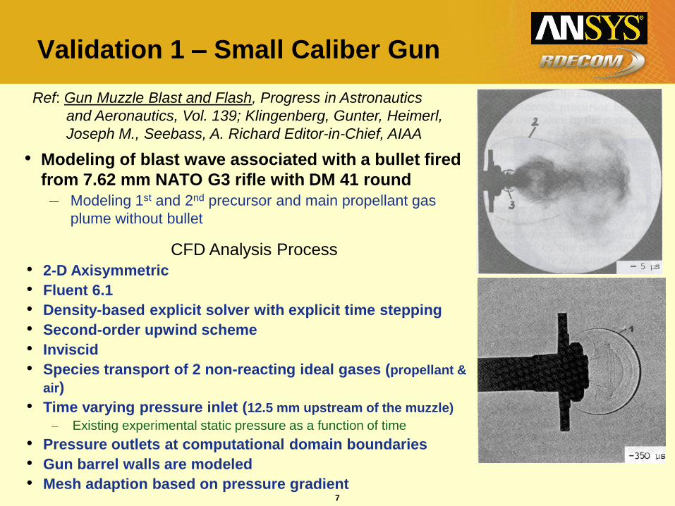
Validation 1 – Small Caliber Gun
• Modeling of blast wave associated with a bullet fired
from 7.62 mm NATO G3 rifle with DM 41 round
– Modeling 1st and 2nd precursor and main propellant gas
plume without bullet
Ref: Gun Muzzle Blast and Flash, Progress in Astronautics
and Aeronautics, Vol. 139; Klingenberg, Gunter, Heimerl,
Joseph M., Seebass, A. Richard Editor-in-Chief, AIAA
CFD Analysis Process
• 2-D Axisymmetric
• Fluent 6.1
• Density-based explicit solver with explicit time stepping
• Second-order upwind scheme
• Inviscid
• Species transport of 2 non-reacting ideal gases (propellant &
air)
• Time varying pressure inlet (12.5 mm upstream of the muzzle)
– Existing experimental static pressure as a function of time
• Pressure outlets at computational domain boundaries
• Gun barrel walls are modeled
• Mesh adaption based on pressure gradient
8
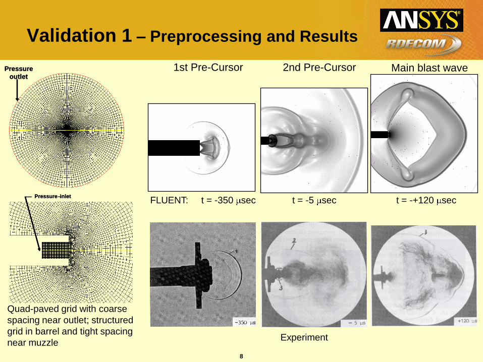
Validation 1 – Preprocessing and Results
1st Pre-Cursor
FLUENT: t = -350 sec t = -5 sec t = -+120 sec
2nd Pre-Cursor Main blast wave
Experiment
Quad-paved grid with coarse
spacing near outlet; structured
grid in barrel and tight spacing
near muzzle
Pressure
outlet
Pressure
outlet
Pressure-inletPressure-inlet
9
BWIP Development Rationale
• Standard Gradient Adaption Limitations
– Poor Coarsening after Wave Passes
– Loss of Adaption as Blast Wave Weakens
– Over-adaption in Uncritical Areas
– Unable to Utilize Advance Register Combinations to
Improve Performance
• Blast Wave Identification Parameter (BWIP)
– Track Primary and Reflected Waves
– Ignore Other Pressure Gradients
– Fine Control of Adaption Level on Shock Fronts
10
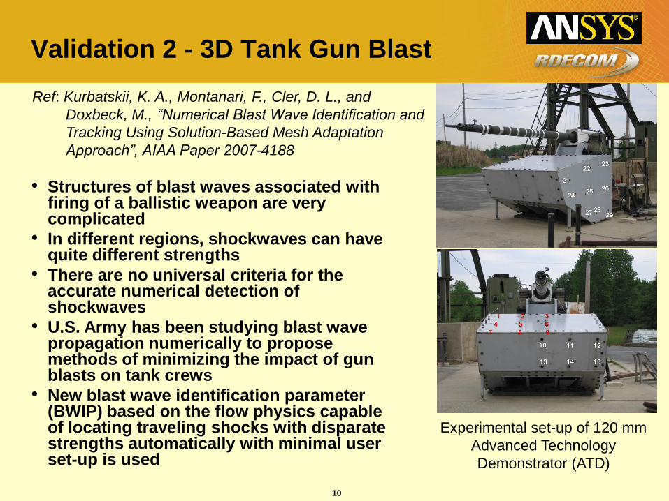
Validation 2 - 3D Tank Gun Blast
Experimental set-up of 120 mm
Advanced Technology
Demonstrator (ATD)
• Structures of blast waves associated with firing of a ballistic weapon are very complicated
• In different regions, shockwaves can have quite different strengths
• There are no universal criteria for the accurate numerical detection of shockwaves
• U.S. Army has been studying blast wave propagation numerically to propose methods of minimizing the impact of gun blasts on tank crews
• New blast wave identification parameter (BWIP) based on the flow physics capable of locating traveling shocks with disparate strengths automatically with minimal user set-up is used
Ref: Kurbatskii, K. A., Montanari, F., Cler, D. L., and
Doxbeck, M., “Numerical Blast Wave Identification and
Tracking Using Solution-Based Mesh Adaptation
Approach”, AIAA Paper 2007-4188
11
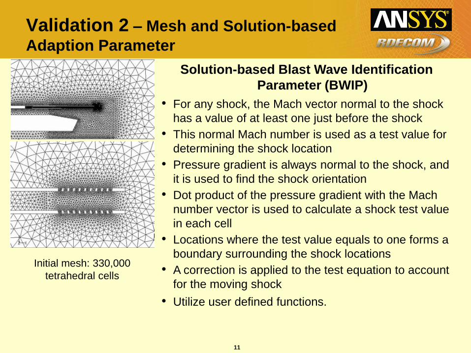
Validation 2 – Mesh and Solution-based
Adaption Parameter
Initial mesh: 330,000
tetrahedral cells
Solution-based Blast Wave Identification
Parameter (BWIP)
• For any shock, the Mach vector normal to the shock
has a value of at least one just before the shock
• This normal Mach number is used as a test value for
determining the shock location
• Pressure gradient is always normal to the shock, and
it is used to find the shock orientation
• Dot product of the pressure gradient with the Mach
number vector is used to calculate a shock test value
in each cell
• Locations where the test value equals to one forms a
boundary surrounding the shock locations
• A correction is applied to the test equation to account
for the moving shock
• Utilize user defined functions.
12
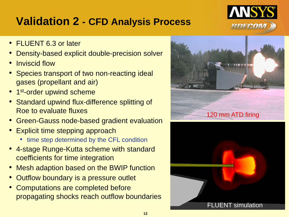
Validation 2 - CFD Analysis Process
• FLUENT 6.3 or later
• Density-based explicit double-precision solver
• Inviscid flow
• Species transport of two non-reacting ideal
gases (propellant and air)
• 1st-order upwind scheme
• Standard upwind flux-difference splitting of
Roe to evaluate fluxes
• Green-Gauss node-based gradient evaluation
• Explicit time stepping approach
• time step determined by the CFL condition
• 4-stage Runge-Kutta scheme with standard
coefficients for time integration
• Mesh adaption based on the BWIP function
• Outflow boundary is a pressure outlet
• Computations are completed before
propagating shocks reach outflow boundaries
120 mm ATD firing
FLUENT simulation
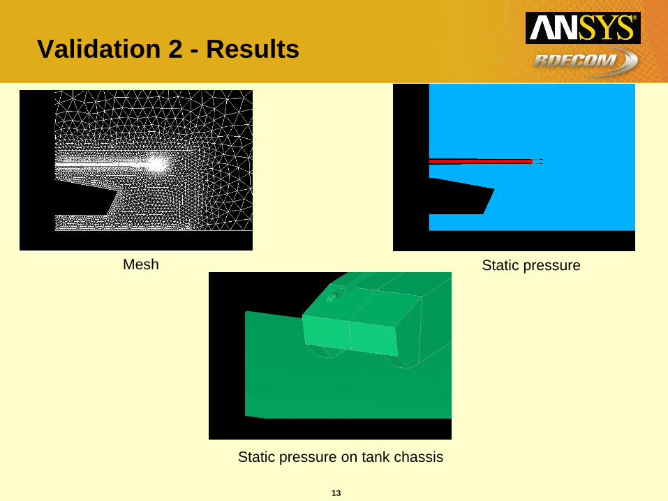
13
Validation 2 - Results
Mesh Static pressure
Static pressure on tank chassis
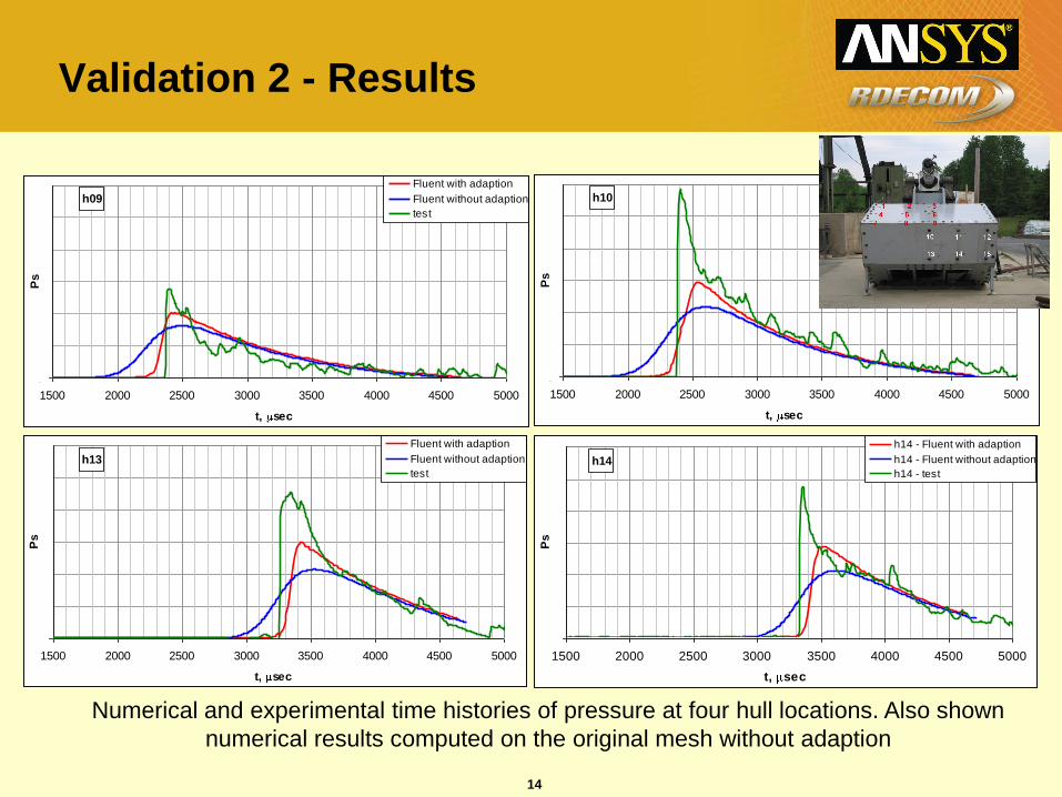
14
h09
0
1500 2000 2500 3000 3500 4000 4500 5000
t, sec
Ps
Fluent with adaption
Fluent without adaption
test
h10
0
1500 2000 2500 3000 3500 4000 4500 5000
t, sec
Ps
Fluent with adaption
Fluent without adaption
test
h13
0
1500 2000 2500 3000 3500 4000 4500 5000
t, sec
Ps
Fluent with adaption
Fluent without adaption
testh14
0
1500 2000 2500 3000 3500 4000 4500 5000
t, sec
Ps
h14 - Fluent with adaption
h14 - Fluent without adaption
h14 - test
Numerical and experimental time histories of pressure at four hull locations. Also shown
numerical results computed on the original mesh without adaption
Validation 2 - Results
15
Advanced BWIP Development
• Utilizes to determine shock location.
• Identifies shock center based on above.
• Marks cells a prescribed distance from shock center.
• Mark cells based on mass fraction of propellant.
• Combines registers.
• Creates a buffer zone in front of shock based on dot
product of vector defined by two cell centroids and a
velocity vector
• Grid adaption frequency controlled based on time for shock
to pass to edge of buffer zone.
• U.S. Patent Application # 60/944,612 Filed on 6/18/07
minVpmax
16
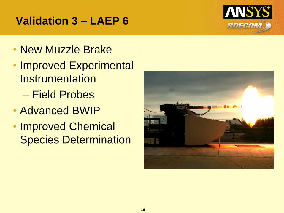
Validation 3 – LAEP 6
• New Muzzle Brake
• Improved Experimental
Instrumentation
– Field Probes
• Advanced BWIP
• Improved Chemical
Species Determination
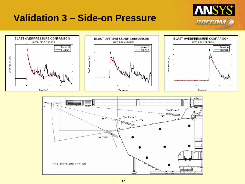
17
Validation 3 – Side-on Pressure
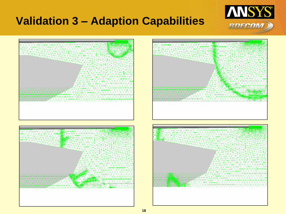
18
Validation 3 – Adaption Capabilities
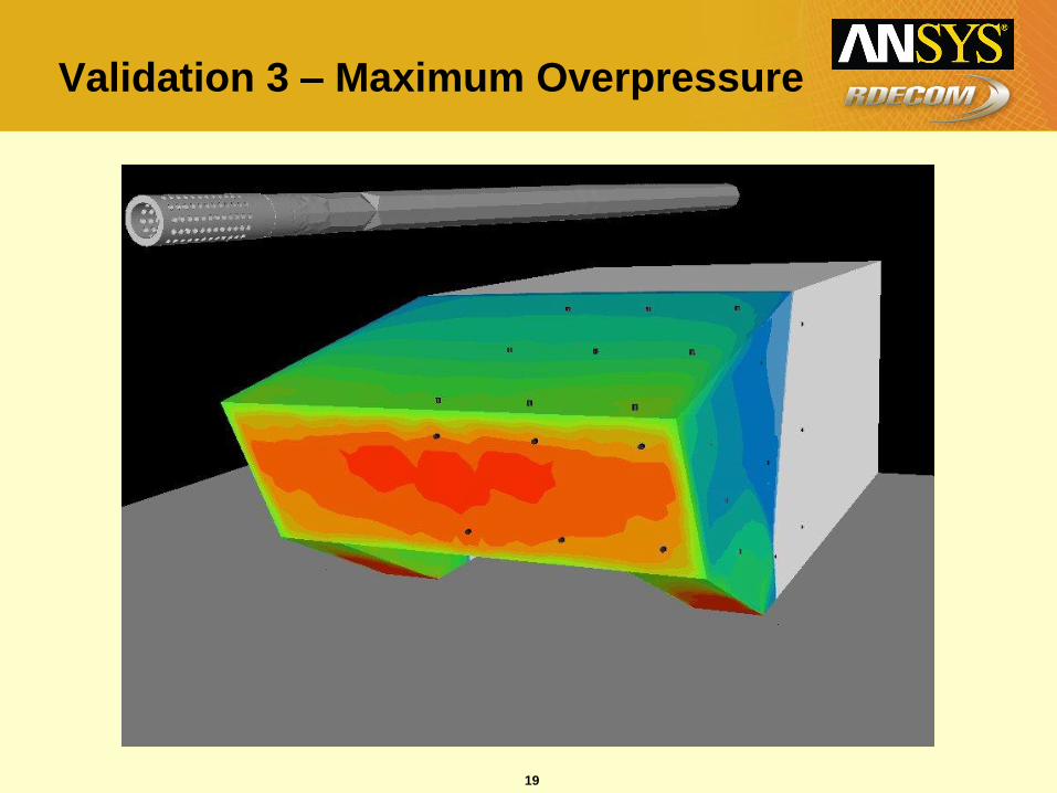
19
Validation 3 – Maximum Overpressure

20
Validation 3 – Animation 1
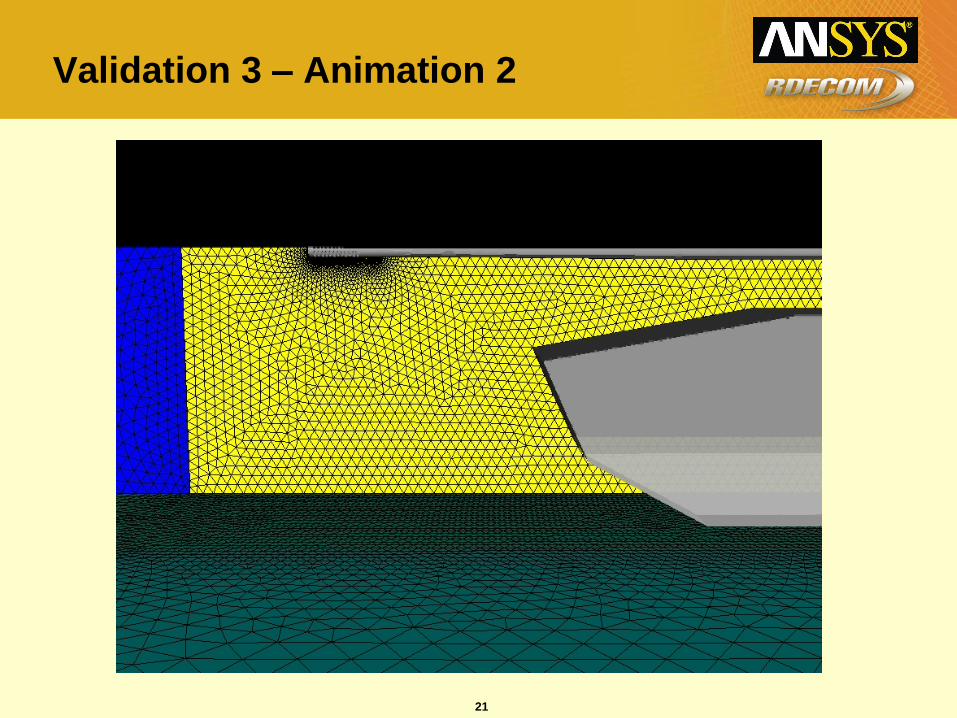
21
Validation 3 – Animation 2
22
Validation 3 – Animation 3
23
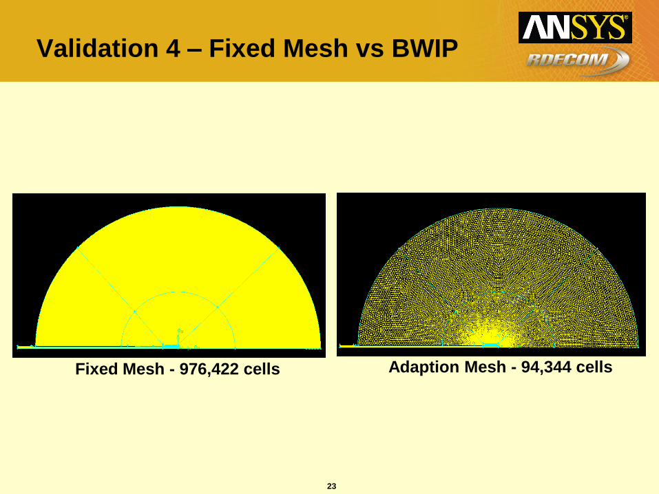
Validation 4 – Fixed Mesh vs BWIP
Fixed Mesh - 976,422 cells Adaption Mesh - 94,344 cells
24
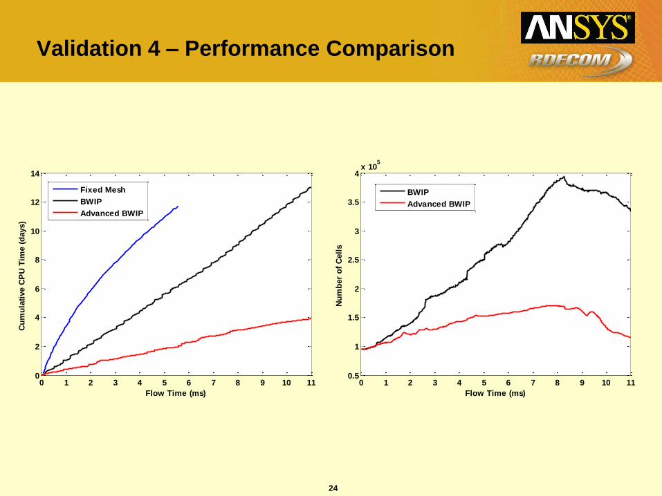
Validation 4 – Performance Comparison
0 1 2 3 4 5 6 7 8 9 10 110
2
4
6
8
10
12
14
Flow Time (ms)
Cu
mu
lati
ve C
PU
Tim
e (
days)
Fixed Mesh
BWIP
Advanced BWIP
0 1 2 3 4 5 6 7 8 9 10 110.5
1
1.5
2
2.5
3
3.5
4x 10
5
Flow Time (ms)
Nu
mb
er
of
Cell
s
BWIP
Advanced BWIP
25
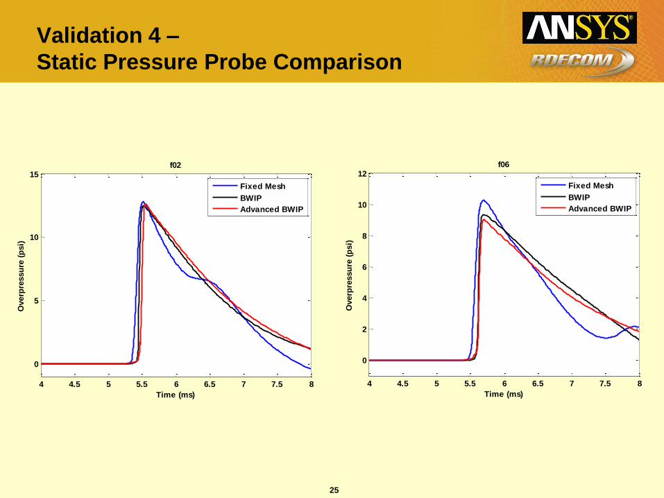
Validation 4 –
Static Pressure Probe Comparison
4 4.5 5 5.5 6 6.5 7 7.5 8
0
5
10
15
Time (ms)
Overp
ressu
re (
psi)
f02
Fixed Mesh
BWIP
Advanced BWIP
4 4.5 5 5.5 6 6.5 7 7.5 8
0
2
4
6
8
10
12
Time (ms)
Overp
ressu
re (
psi)
f06
Fixed Mesh
BWIP
Advanced BWIP
26
Validation 4 – Performance Comparison
• 2-D Comparison
– Advanced BWIP is 8 times faster.
– Slight reduction in quality at farfield locations.
• 3-D Comparison
– Advanced BWIP would be 2 orders of magnitude faster than fixed mesh based on 2-D performance comparison.
– Quality should only be slightly degraded.
– Advanced BWIP makes 3-D blast simulation feasible.
27
Conclusions
• High-quality 3-D blast analysis capability in
Fluent through Advanced BWIP user defined
function with very low computational overhead.
• Better solution accuracy and lower computational
cost than traditional Lagrangian blast simulation
methods.
• Validated against real world problems with good
prediction accuracy.
• Technology is licensable from RDECOM.