Embed Size (px)
Citation preview
FINAL REPORTDecember 2007
REPORT NO. 07-12
PROJECTILE, 155MM, XM982, EXCALIBUR,PACKED ONE (1) PER PA179 CONTAINER,
UNITIZED UP TO THREE (3) PER 40" x 48" WOODEN PALLET,MIL-STD-1660 TESTS
Distribution UnlimitedPrepared for:
Office of PM ExcaliburATTN: System Engineer, Laura WellsU.S. Army ARDEC, SFAE-AMO-CASS-EX, Bldg 171APicatinny, NJ 07806-5000
DEFENSE AMMUNITION CENTERVALIDATION ENGINEERING DIVISIONMCALESTER, OKLAHOMA 74501-9053
20080930139
AVAILABILTY NOTICE
A copy of this report will be furnished each attendee on automatic
distribution. Additional copies or authority for reprinting may be obtained by written
request from:
DirectorU.S. Army Defense Ammunition CenterATTN: SJMAC-DEV1 C Tree Road, Bldg. 35McAlester, OK 74501-9053
DISTRIBUTION INSTRUCTIONS
Destroy this report when no longer needed. Do not return.
Citation of trade names in this report does not constitute an official
endorsement.
The information contained herein will not be used for advertising purposes.
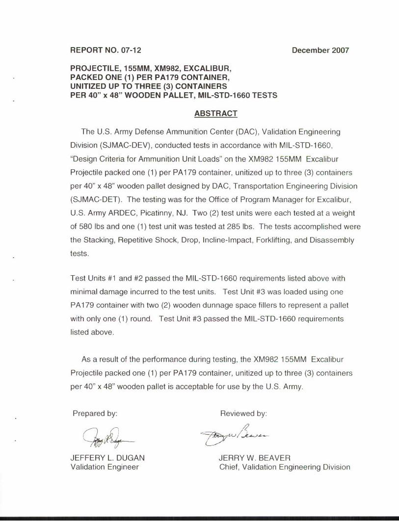
REPORT NO. 07-12 December 2007
PROJECTILE, 155MM, XM982, EXCALIBUR,PACKED ONE (1) PER PA179 CONTAINER,UNITIZED UP TO THREE (3) CONTAINERSPER 40" x 48" WOODEN PALLET, MIL-STD-1660 TESTS
ABSTRACT
The U.S. Army Defense Ammunition Center (DAC), Validation Engineering
Division (SJMAC-DEV), conducted tests in accordance with MIL-STD-1 660,
"Design Criteria for Ammunition Unit Loads" on the XM982 155MM Excalibur
Projectile packed one (1) per PA179 container, unitized up to three (3) containers
per 40" x 48" wooden pallet designed by DAC, Transportation Engineering Division
(SJMAC-DET). The testing was for the Office of Program Manager for Excalibur,
U.S. Army ARDEC, Picatinny, NJ. Two (2) test units were each tested at a weight
of 580 lbs and one (1) test unit was tested at 285 lbs. The tests accomplished were
the Stacking, Repetitive Shock, Drop, Incline-Impact, Forklifting, and Disassembly
tests.
Test Units #1 and #2 passed the MIL-STD-1660 requirements listed above with
minimal damage incurred to the test units. Test Unit #3 was loaded using one
PA1 79 container with two (2) wooden dunnage space fillers to represent a pallet
with only one (1) round. Test Unit #3 passed the MIL-STD-1660 requirements
listed above.
As a result of the performance during testing, the XM982 155MM Excalibur
Projectile packed one (1) per PA1 79 container, unitized up to three (3) containers
per 40" x 48" wooden pallet is acceptable for use by the U.S. Army.
Prepared by: Reviewed by:
JEFFERY L. DUGAN JERRY W. BEAVERValidation Engineer Chief, Validation Engineering Division
U.S. ARMY DEFENSE AMMUNITION CENTER
VALIDATION ENGINEERING DIVISIONMCALESTER, OK 74501-9053
REPORT NO. 07-12
PROJECTILE, 155MM, XM982, EXCALIBUR,PACKED ONE (1) PER PA1 79 CONTAINER,
UNITIZED UP TO THREE (3) CONTAINERS PER 40" x 48"WOODEN PALLET, MIL-STD-1 660 TESTS
TABLE OF CONTENTS
PART PAGE NO.
1. INTRODUCTION................................................................. 1-1
A. BACKGROUND ............................................................... 1-1
B. AUTHORITY................................................................... 1-1
C. OBJECTIVE .................................................................. 1-1
D. CONCLUSION................................................................ 1-1
2. ATTENDEES..................................................................... 2-1
3. TEST PROCEDURES ........................................................... 3-1
4. TEST EQUIPMENT.............................................................. 4-1
5. TEST RESULTS................................................................. 5-1
6. DRAWINGS....................................................................... 6-1
PART 1 - INTRODUCTION
A. BACKGROUND. The U.S. Army Defense Ammunition Center (DAC),
Validation Engineering Division (SJMAC-DEV), conducted tests in accordance
with MIL-STD-1 660, "Design Criteria for Ammunition Unit Loads" on the on the
XM982 155MM Excalibur Projectile packed one (1) per PA1 79 container,
unitized up to three (3) containers per 40" x 48" wooden pallet designed by DAC,
Transportation Engineering Division (SJMAC-DET). The testing was for the
Office of Program Manager for Excalibur, U.S. Army ARDEC, Picatinny, NJ. Two
(2) test units were each tested at a weight of 580 lbs and one (1) test unit was
tested at 285 lbs. The tests accomplished were the Stacking, Repetitive Shock,
Drop, Incline-Impact, Forklifting, and Disassembly tests.
B. AUTHORITY. This test was conducted lAW mission responsibilities
delegated by the U.S. Army Joint Munitions Command (JMC), Rock Island, IL.
Reference is made to the following:
1. AR 740-1, 15 June 2001, Storage and Supply Activity Operation
2. OSC-R, 10-23, Mission and Major Functions of the U.S. Army Defense
Ammunition Center (DAC) 21 Nov 2000.
C. OBJECTIVE. The objective of the tests was to determine if the on the
XM982 155MM Excalibur Projectile packed one (1) per PA179 container,
unitized up to three (3) containers per 40" x 48" wooden pallet met MIL-STD-
1660 test requirements prior to the acceptance of the unitization procedures by
the U.S. Army.
D. CONCLUSION. As a result of the performance during testing, the XM982
155MM Excalibur Projectile packed one (1) per PA179 Container, unitized up to
three (3) containers per 40" x 48" wooden pallet is acceptable for use by the U.S.
Army.
1-!
PART 2 - ATTENDEES
DATE PERFORMED: Test Unit #1- 22 October 2007
Test Unit #2- 24 October 2007
Test Unit #3- 1 November 2007
ATTENDEES MAILING ADDRESS
Jeffery L. Dugan DirectorGeneral Engineer U.S. Army Defense Ammunition CenterDSN 956-8090 ATTN: SJMAC-DEV(918) 420-8090 1 C Tree Road, Bldg. 35
McAlester, OK 74501-9053
Daryl Sieczkowski DirectorElectronic Technician U.S. Army Defense Ammunition CenterDSN 956-8988 ATTN: SJMAC-DEV(918) 420-8988 1 C Tree Road, Bldg. 35
McAlester, OK 74501-9053
2-1
PART 3 - TEST PROCEDURES
The test procedures outlined in this section were extracted from the MIL-STD-
1660. The tests are conducted on ammunition pallet units or unit loads and are
summarized as follows:
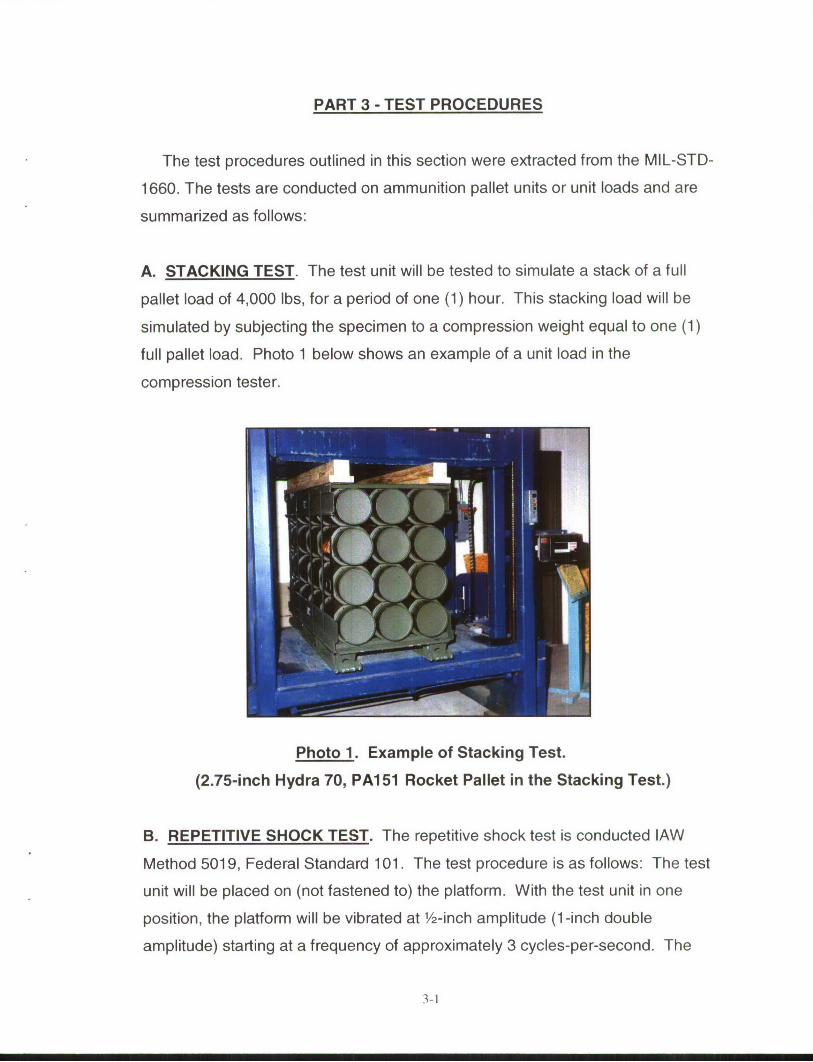
A. STACKING TEST. The test unit will be tested to simulate a stack of a full
pallet load of 4,000 Ibs, for a period of one (1) hour. This stacking load will be
simulated by subjecting the specimen to a compression weight equal to one (1)
full pallet load. Photo 1 below shows an example of a unit load in the
compression tester.
Photo 1. Example of Stacking Test.
(2.75-inch Hydra 70, PAI51 Rocket Pallet in the Stacking Test.)
B. REPETITIVE SHOCK TEST. The repetitive shock test is conducted lAW
Method 5019, Federal Standard 101. The test procedure is as follows: The test
unit will be placed on (not fastened to) the platform. With the test unit in one
position, the platform will be vibrated at 1/2-inch amplitude (1-inch double
amplitude) starting at a frequency of approximately 3 cycles-per-second. The
3-1
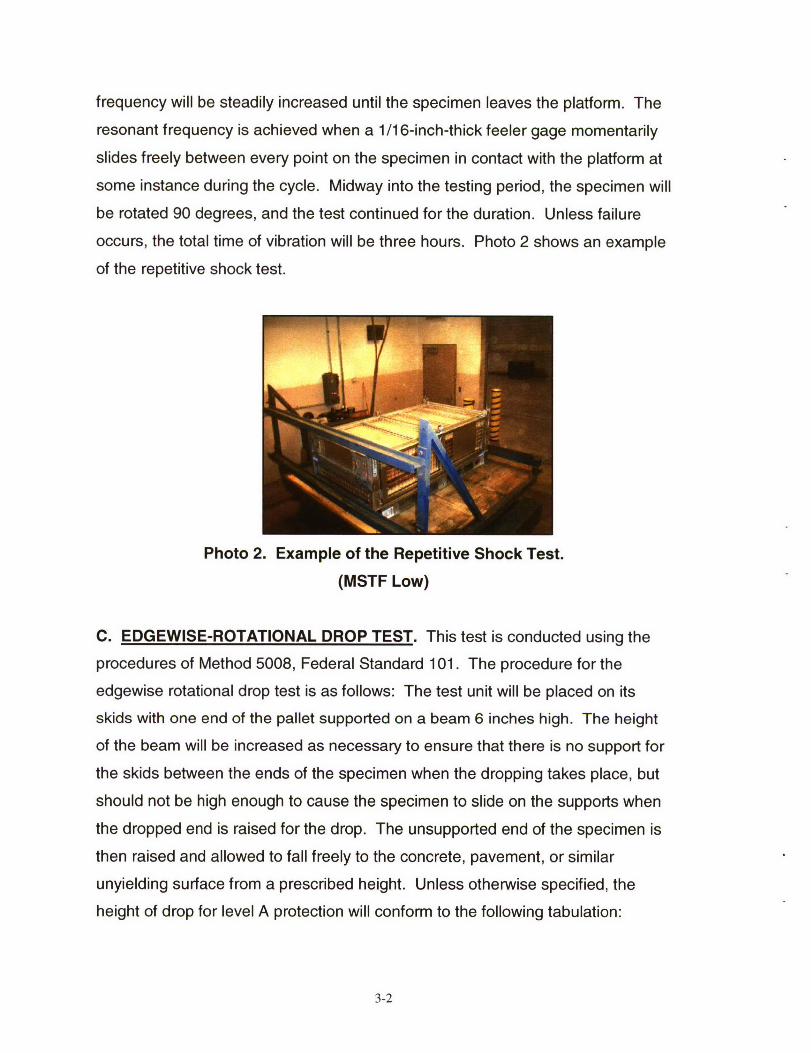
frequency will be steadily increased until the specimen leaves the platform. The
resonant frequency is achieved when a 1/16-inch-thick feeler gage momentarily
slides freely between every point on the specimen in contact with the platform at
some instance during the cycle. Midway into the testing period, the specimen will
be rotated 90 degrees, and the test continued for the duration. Unless failure
occurs, the total time of vibration will be three hours. Photo 2 shows an example
of the repetitive shock test.
Photo 2. Example of the Repetitive Shock Test.
(MSTF Low)
C. EDGEWISE-ROTATIONAL DROP TEST. This test is conducted using the
procedures of Method 5008, Federal Standard 101. The procedure for the
edgewise rotational drop test is as follows: The test unit will be placed on its
skids with one end of the pallet supported on a beam 6 inches high. The height
of the beam will be increased as necessary to ensure that there is no support for
the skids between the ends of the specimen when the dropping takes place, but
should not be high enough to cause the specimen to slide on the supports when
the dropped end is raised for the drop. The unsupported end of the specimen is
then raised and allowed to fall freely to the concrete, pavement, or similar
unyielding surface from a prescribed height. Unless otherwise specified, the
height of drop for level A protection will conform to the following tabulation:
3-2
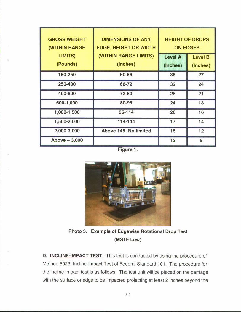
GROSS WEIGHT DIMENSIONS OF ANY HEIGHT OF DROPS
(WITHIN RANGE EDGE, HEIGHT OR WIDTH ON EDGES
LIMITS) (WITHIN RANGE LIMITS) Level A Level B
(Pounds) (Inches) (Inches) (Inches)
150-250 60-66 36 27
250-400 66-72 32 24
400-600 72-80 28 21
600-1,000 80-95 24 18
1,000-1,500 95-114 20 16
1,500-2,000 114-144 17 14
2,000-3,000 Above 145- No limited 15 12
Above - 3,000 12 9
Figure 1.
Photo 3. Example of Edgewise Rotational Drop Test
(MSTF Low)
D. INCLINE-IMPACT TEST. This test is conducted by using the procedure of
Method 5023, Incline-Impact Test of Federal Standard 101. The procedure for
the incline-impact test is as follows: The test unit will be placed on the carriage
with the surface or edge to be impacted projecting at least 2 inches beyond the
3-3
front end of the carriage. The carriage will be brought to a predetermined
position on the incline and released. If it were desired to concentrate the impact
on any particular position on the container, a 4- x 4-inch timber may be attached
to the bumper in the desired position before the test. The carriage will not strike
any part of the timber. The position of the specimen on the carriage and the
sequence in which surfaces and edges are subjected to impacts may be at the
option of the testing activity and dependent upon the objective of the test. When
the test is to determine satisfactory requirements for a container or pack, and,
unless otherwise specified, the specimen will be subjected to one impact on each
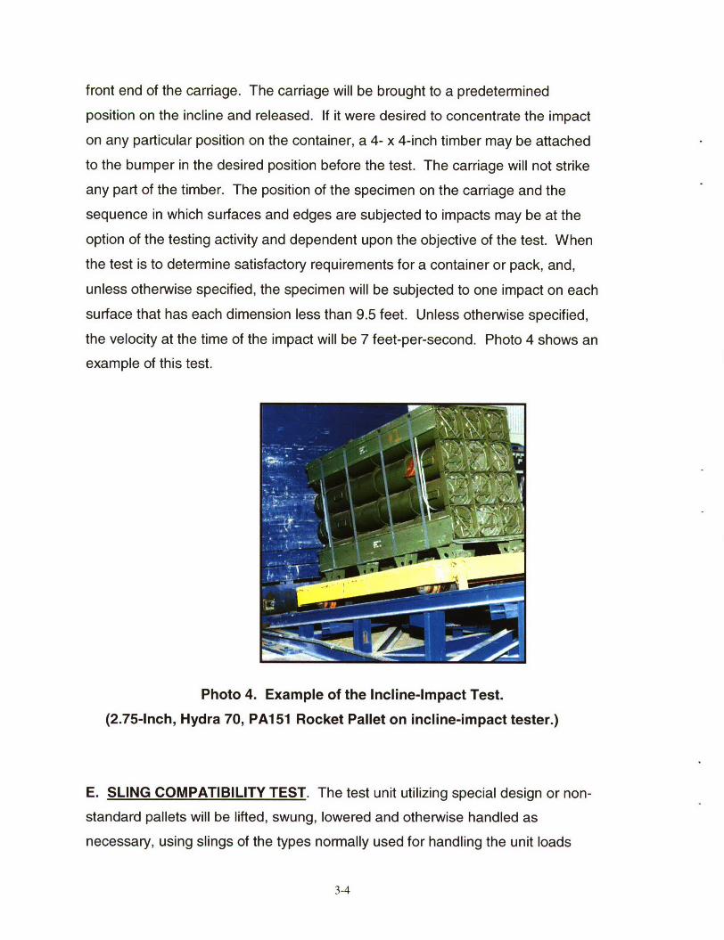
surface that has each dimension less than 9.5 feet. Unless otherwise specified,
the velocity at the time of the impact will be 7 feet-per-second. Photo 4 shows an
example of this test.
Photo 4. Example of the Incline-Impact Test.
(2.75-Inch, Hydra 70, PA151 Rocket Pallet on incline-impact tester.)
E. SLING COMPATIBILITY TEST. The test unit utilizing special design or non-
standard pallets will be lifted, swung, lowered and otherwise handled as
necessary, using slings of the types normally used for handling the unit loads
3-4
under consideration. Slings will be easily attached and removed. Danger of
slippage or disengagement when load is suspended will be cause for rejection of
the specimen.
F. FORKLIFTING TESTS. The test unit will be lifted clear of the ground by a
forklift from the end of the test unit and transported on the forks in the level or
back-tilt position. The forklift will pass over the Optional Rough Handling Course
for Forklift Trucks as outlined in MIL-STD-1 660. The course will consist of
parallel pairs of 1-inch boards spaced 54 inches apart and will be laid flat wise on
the pavement across the path of the forklift. One pair will be laid at an angle of
approximately 60 degrees to the path so that the left wheel strikes first. Another
pair will be laid securely across the path of the forklift so that the wheels strike
simultaneously. Another pair will be laid at an angle of approximately 75 degrees
to the path so that the right wheel strikes first. The test unit will be transported
over the Optional Rough Handling Course. The test unit shall be observed for
deflection and damage. The test unit will be rotated 90 degrees and the test unit
lifted from the side and the above steps repeated.
G. DISASSEMBLY TEST. Following all rough handling tests the test unit may
be squared up within 2 inches of its original shape and on a flat level surface.
The strapping will then be cut and removed from the palletized load. Assembly
of the test unit will be such that it retains its unity upon removal of the strapping.
3-5
PART 4 - TEST EQUIPMENT
A. COMPRESSION TESTER.
1. Nomenclature Compression Table
2. Manufacturer: Ormond Manufacturing
3. Platform: 60- by 60-inches
4. Compression Limit: 50,000 pounds
5. Tension Limit: 50,000 pounds
B. TRANSPORTATION (REPETITIVE SHOCK) SIMULATOR.
1. Nomenclature Repetitive Shock Simulator
2. Manufacturer: Gaynes Laboratory
3. Capacity: 6,000-pound payload
4. Displacement: 1/2-inch amplitude
5. Speed: 50 to 400 RPM
6. Platform: 5- by 8-foot
C. INCLINED PLANE.
1. Manufacturer: Conbur Incline
2. Type: Impact Tester
3. Grade: 10 percent incline
4. Length: 12-foot
4-1
PART 5 - TEST RESULTS
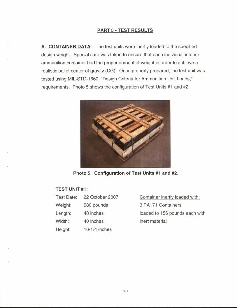
A. CONTAINER DATA. The test units were inertly loaded to the specified
design weight. Special care was taken to ensure that each individual interior
ammunition container had the proper amount of weight in order to achieve a
realistic pallet center of gravity (CG). Once properly prepared, the test unit was
tested using MIL-STD-1660, "Design Criteria for Ammunition Unit Loads,"
requirements. Photo 5 shows the configuration of Test Units #1 and #2.
Photo 5. Configuration of Test Units #1 and #2.
TEST UNIT #1:
Test Date: 22 October 2007 Container inertly loaded with:
Weight: 580 pounds 3 PA171 Containers
Length: 48 inches loaded to 156 pounds each with
Width: 40 inches inert material
Height: 16-1/4 inches
5-1
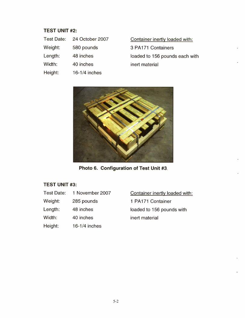
TEST UNIT #2:
Test Date: 24 October 2007 Container inertly loaded with:
Weight: 580 pounds 3 PA171 Containers
Length: 48 inches loaded to 156 pounds each with
Width: 40 inches inert material
Height: 16-1/4 inches
Photo 6. Configuration of Test Unit #3.
TEST UNIT #3:
Test Date: 1 November 2007 Container inertly loaded with:
Weight: 285 pounds 1 PA171 Container
Length: 48 inches loaded to 156 pounds with
Width: 40 inches inert material
Height: 16-1/4 inches
5-2
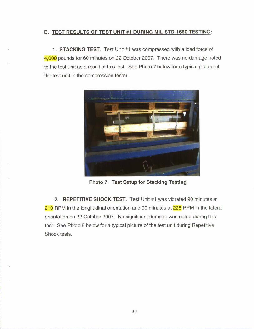
B. TEST RESULTS OF TEST UNIT #1 DURING MIL-STD-1 660 TESTING:
1. STACKING TEST. Test Unit #1 was compressed with a load force of
4,000 pounds for 60 minutes on 22 October 2007. There was no damage noted
to the test unit as a result of this test. See Photo 7 below for a typical picture of
the test unit in the compression tester.
Photo 7. Test Setup for Stacking Testing.
2. REPETITIVE SHOCK TEST. Test Unit #1 was vibrated 90 minutes at
210 RPM in the longitudinal orientation and 90 minutes at 225 RPM in the lateral
orientation on 22 October 2007. No significant damage was noted during this
test. See Photo 8 below for a typical picture of the test unit during Repetitive
Shock tests.
5-3
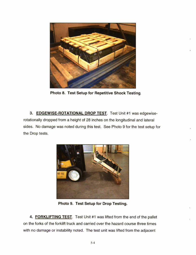
Photo 8. Test Setup for Repetitive Shock Testing.
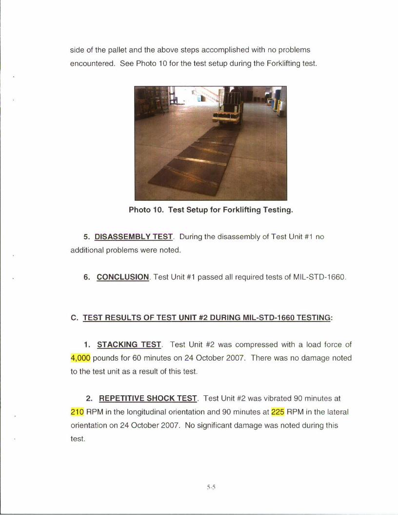
3. EDGEWISE-ROTATIONAL DROP TEST. Test Unit #1 was edgewise-
rotationally dropped from a height of 28 inches on the longitudinal and lateral
sides. No damage was noted during this test. See Photo 9 for the test setup for
the Drop tests.
Photo 9. Test Setup for Drop Testing.
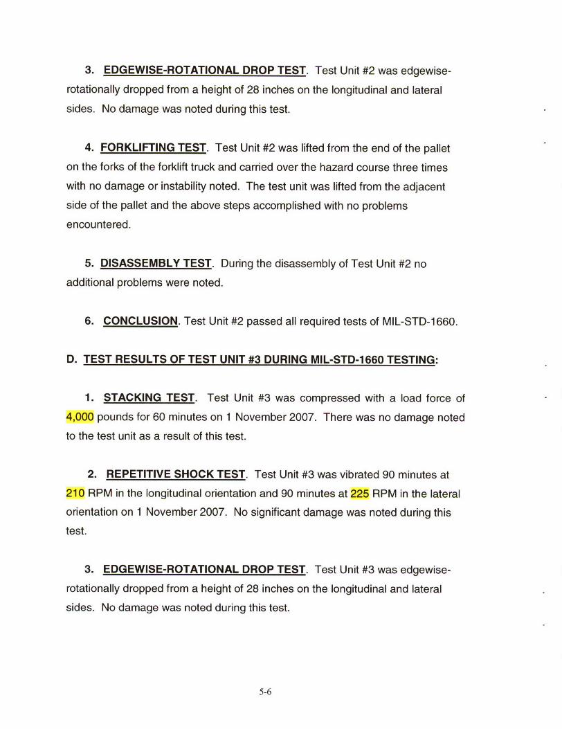
4. FORKLIFTING TEST. Test Unit #1 was lifted from the end of the pallet
on the forks of the forklift truck and carried over the hazard course three times
with no damage or instability noted. The test unit was lifted from the adjacent
5-4
side of the pallet and the above steps accomplished with no problems
encountered. See Photo 10 for the test setup during the Forklifting test.
Photo 10. Test Setup for Forklifting Testing.
5. DISASSEMBLY TEST. During the disassembly of Test Unit #1 no
additional problems were noted.
6. CONCLUSION. Test Unit #1 passed all required tests of MIL-STD-1660.
C. TEST RESULTS OF TEST UNIT #2 DURING MIL-STD-1 660 TESTING:
1. STACKING TEST. Test Unit #2 was compressed with a load force of
4,000 pounds for 60 minutes on 24 October 2007. There was no damage noted
to the test unit as a result of this test.
2. REPETITIVE SHOCK TEST. Test Unit #2 was vibrated 90 minutes at
210 RPM in the longitudinal orientation and 90 minutes at 225 RPM in the lateral
orientation on 24 October 2007. No significant damage was noted during this
test.
5-5
3. EDGEWISE-ROTATIONAL DROP TEST. Test Unit #2 was edgewise-
rotationally dropped from a height of 28 inches on the longitudinal and lateral
sides. No damage was noted during this test.
4. FORKLIFTING TEST. Test Unit #2 was lifted from the end of the pallet
on the forks of the forklift truck and carried over the hazard course three times
with no damage or instability noted. The test unit was lifted from the adjacent
side of the pallet and the above steps accomplished with no problems
encountered.
5. DISASSEMBLY TEST. During the disassembly of Test Unit #2 no
additional problems were noted.
6. CONCLUSION. Test Unit #2 passed all required tests of MIL-STD-1660.
D. TEST RESULTS OF TEST UNIT #3 DURING MIL-STD-1660 TESTING:
1. STACKING TEST. Test Unit #3 was compressed with a load force of
4,000 pounds for 60 minutes on 1 November 2007. There was no damage noted
to the test unit as a result of this test.
2. REPETITIVE SHOCK TEST. Test Unit #3 was vibrated 90 minutes at
210 RPM in the longitudinal orientation and 90 minutes at 225 RPM in the lateral
orientation on 1 November 2007. No significant damage was noted during this
test.
3. EDGEWISE-ROTATIONAL DROP TEST. Test Unit #3 was edgewise-
rotationally dropped from a height of 28 inches on the longitudinal and lateral
sides. No damage was noted during this test.
5-6
4. FORKLIFTING TEST. Test Unit #3 was lifted from the end of the pallet
on the forks of the forklift truck and carried over the Hazard Course three times
with no damage or instability noted. The test unit was lifted from the adjacent
side of the pallet and the above steps accomplished with no problems
encountered.
5. DISASSEMBLY TEST. During the disassembly of Test Unit #3 no
additional problems were noted.
6. CONCLUSION. Test Unit #3 passed all required tests of MIL-STD-1660.
5-7
PART 6- DRAWINGS
The following test sketches represent the load configuration that was subjected
to the test criteria.
6-1
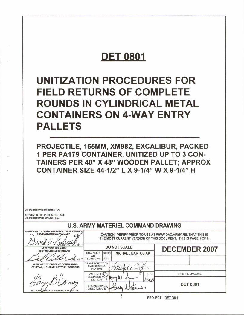
DET 0801
UNITIZATION PROCEDURES FORFIELD RETURNS OF COMPLETEROUNDS IN CYLINDRICAL METALCONTAINERS ON 4-WAY ENTRYPALLETS
PROJECTILE, 155MM, XM982, EXCALIBUR, PACKEDI PER PA179 CONTAINER, UNITIZED UP TO 3 CON-TAINERS PER 40" X 48" WOODEN PALLET; APPROXCONTAINER SIZE 44-112" L X 9-114" W X 9-1/4" H
DISTRIBUTION STATEMENT A
APPROVED FOR PUBLIC RELEASEDISTRIBUTION IS UNLIMITED.
U.S. ARMY MATERIEL COMMAND DRAWINGAPPROVED, U.S. ARMY RESEARCH, DEVELOPMENT)
AND ENGINEERING COMMAND CAUTION: VERIFY PRIOR TO USE AT WWW.DAC.ARMY.MIL THAT THIS ISTHE MOST CURRENT VERSION OF THIS DOCUMENT. THIS IS PAGE 1 OF 6.
AO, U.S. M DO NOT SCALE DECEMBER 2007NT MUTIONS COMMANDBASI MICHAE BARTOSIAK
ORTECHNICIAN I REV.
APPROVED BY ORDER OF COMMANDING TRANSPORTATIONGENERAL, U.S. ARMY MATERIEL COMMAND ENGINEERING
SPET D SPECIAL DRAWNG
USENGINEERING DET 0801
PROJECT DET 0801
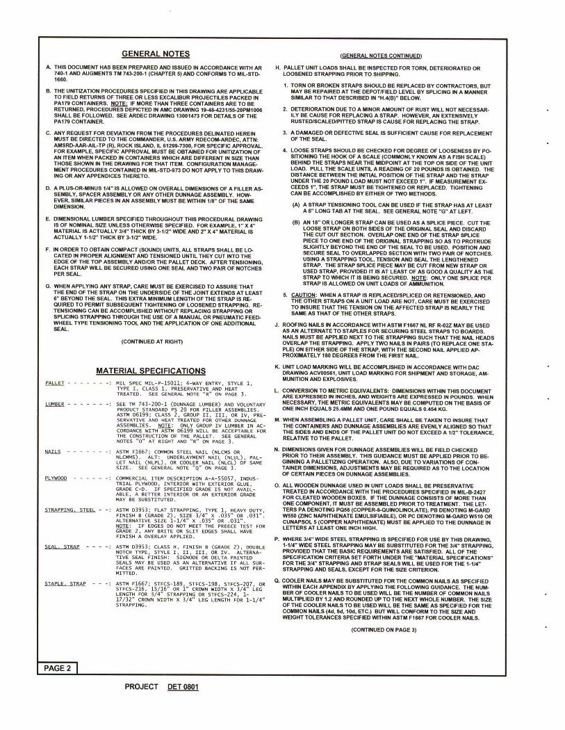
GENERAL NOTES (GENERAL NOTES CONTINUED)
A THIS DOCUMENT HAS BEEN PREPARED AND ISSUED IN ACCORDANCE WITH AR H. PALLET UNIT LOADS SHALL BE INSPECTED FOR TORN, DETERIORATED OR740-1 AND AUGMENTS TM 743-200-1 (CHAPTER 5) AND CONFORMS TO MIL-STD- LOOSENED STRAPPING PRIOR TO SHIPPING.1660.
1. TORN OR BROKEN STRAPS SHOULD BE REPLACED BY CONTRACTORS, BUTB. THE UNITIZATION PROCEDURES SPECIFIED IN THIS DRAWING ARE APPLICABLE MAY BE REPAIRED AT THE DEPOT/FIELD LEVEL BY SPLICING IN A MANNER
TO FIELD RETURNS OF THREE OR LESS EXCALIBUR PROJECTILES PACKED IN SIMILAR TO THAT DESCRIBED IN "H.4(B)" BELOW.PA179 CONTAINERS. NOTE: IF MORE THAN THREE CONTAINERS ARE TO BERETURNED, PROCEDURES DEPICTED IN AMC DRAWING 19-48-4231155-20PM1006 2. DETERIORATION DUE TO A MINOR AMOUNT OF RUST WILL NOT NECESSAR-SHALL BE FOLLOWED. SEE ARDEC DRAWING 13001473 FOR DETAILS OF THE ILY BE CAUSE FOR REPLACING A STRAP. HOWEVER, AN EXTENSIVELYPA179 CONTAINER. RUSTEDISCALED/PITED STRAP IS CAUSE FOR REPLACING THE STRAP.
C. ANY REQUEST FOR DEVIATION FROM THE PROCEDURES DELINATED HEREIN 3. A DAMAGED OR DEFECTIVE SEAL IS SUFFICIENT CAUSE FOR REPLACEMENTMUST BE DIRECTED TO THE COMMANDER, U.S. ARMY RDECOM-ARDEC, ATTN: OF THE SEAL.AMSRD-AAR-AIL-TP (R), ROCK ISLAND, IL 61299-7300, FOR SPECIFIC APPROVAL.FOR EXAMPLE, SPECIFIC APPROVAL MUST BE OBTAINED FOR UNITIZATION OF 4. LOOSE STRAPS SHOULD BE CHECKED FOR DEGREE OF LOOSENESS BY PO-AN ITEM WHEN PACKED IN CONTAINERS WHICH ARE DIFFERENT IN SIZE THAN SITIONING THE HOOK OF A SCALE (COMMONLY KNOWN AS A FISH SCALE)THOSE SHOWN IN THE DRAWING FOR THAT ITEM. CONFIGURATION MANAGE- BEHIND THE STRAPS NEAR THE MIDPOINT AT THE TOP OR SIDE OF THE UNITMENT PROCEDURES CONTAINED IN MIL-STD-973 DO NOT APPLY TO THIS DRAW- LOAD. PULL THE SCALE UNTIL A READING OF 20 POUNDS IS OBTAINED. THEING OR ANY APPENDICES THERETO. DISTANCE BETWEEN THE INITIAL POSITION OF THE STRAP AND THE STRAP
UNDER THE 20 POUND LOAD MUST NOT EXCEED 1". IF MEASUREMENT EX-D. A PLUS-OR-MINUS 114" IS ALLOWED ON OVERALL DIMENSIONS OF A FILLER AS- CEEDS 1", THE STRAP MUST BE TIGHTENED OR REPLACED. TIGHTENING
SEMBLY, SPACER ASSEMBLY OR ANY OTHER DUNNAGE ASSEMBLY. HOW- CAN BE ACCOMPLISHED BY EITHER OF TWO METHODS.EVER. SIMILAR PIECES IN AN ASSEMBLY MUST BE WITHIN 1/8" OF THE SAMEDIMENSION. (A) A STRAP TENSIONING TOOL CAN BE USED IF THE STRAP HAS AT LEAST
A S" LONG TAB AT THE SEAL. SEE GENERAL NOTE "G" AT LEFT.E. DIMENSIONAL LUMBER SPECIFIED THROUGHOUT THIS PROCEDURAL DRAWING (B) AN 18- DR LONGER STRAP CAN BE USED AS A SPLICE PIECE. CUT THE
IS OF NOMINAL SIZE UNLESS OTHERWISE SPECIFIED. FOR EXAMPLE, 1" X " LOOSE STRAP ON BOTH SIDES OF THE ORIGINAL SEAL AND DISCARDMATERIAL IS ACTUALLY 3/4" THICK BY 3-1/2" WIDE AND 2" X 4" MATERIAL IS THE CUT OUT SECTION. OVERLAP ONE END OF THE STRAP SPLICEACTUALLY 1-1/2" THICK BY 3-1/2" WIDE. PIECE TO ONE END OF THE ORIGINAL STRAPPING SO AS TO PROTRUDE
SLIGHTLY BEYOND THE END OF THE SEAL TO BE USED, POSITION ANDF. IN ORDER TO OBTAIN COMPACT (SOUND) UNITS, ALL STRAPS SHALL BE LO- SECURE SEAL TO OVERLAPPED SECTION WITH TWO PAIR OF NOTCHES.CATED IN PROPER ALIGNMENT AND TENSIONED UNTIL THEY CUT INTO THE USING A STRAPPING TOOL, TENSION AND SEAL THE LENGTHENEDEDGE OF THE TOP ASSEMBLY ANDIOR THE PALLET DECK. AFTER TENSIONING, STRAP. THE STRAP SPLICE PIECE MAY BE CUT FROM NEW STRAP OREACH STRAP WILL BE SECURED USING ONE SEAL AND TWO PAIR OF NOTCHES USED STRAP, PROVIDED IT IS AT LEAST OF AS GOOD A QUALITY AS THEPER SEAL. STRAP TO WHICH IT IS BEING SECURED. NOTE: ONLY ONE SPLICE PER
G. WHEN APPLYING ANY STRAP, CARE MUST BE EXERCISED TO ASSURE THAT STRAP IS ALLOWED ON UNIT LOADS OF AMMUNITION.THE END OF THE STRAP ON THE UNDERSIDE OF THE JOINT EXTENDS AT LEAST 5. CAUTION: WHEN A STRAP IS REPLACEDISPLICED OR RETENSIONED, AND6" BEYOND THE SEAL. THIS EXTRA MINIMUM LENGTH OF THE STRAP IS RE- THE OTHER STRAPS ON A UNIT LOAD ARE NOT, CARE MUST BE EXERCISEDQUIRED TO PERMIT SUBSEQUENT TIGHTENING OF LOOSENED STRAPPING. RE- TO INSURE THAT THE TENSION ON THE AFFECTED STRAP IS NEARLY THETENSIONING CAN BE ACCOMPLISHED WITHOUT REPLACING STRAPPING OR SAME AS THAT OF THE OTHER STRAPS.SPLICING STRAPPING THROUGH THE USE OF A MANUAL OR PNEUMATIC FEED-WHEEL TYPE TENSIONING TOOL AND THE APPLICATION OF ONE ADDITIONAL J. ROOFING HAILS IN ACCORDANCE WITH ASTM F1667 NL RF R-02Z MAY BE USEDSEAL. AS AN ALTERNATE TO STAPLES FOR SECURING STEEL STRAPS TO BOARDS.
NAILS MUST BE APPLIED NEXT TO THE STRAPPING SUCH THAT THE NAIL HEADS(CONTINUED AT RIGHT) OVERLAP THE STRAPPING. APPLY TWO NAILS IN PAIRS (TO REPLACE ONE STA-PLE) ON EITHER SIDE OF THE STRAP, WITH THE SECOND NAIL APPLIED AP-PROXIMATELY 180 DEGREES FROM THE FIRST NAIL.
K. UNIT LOAD MARKING WILL BE ACCOMPLISHED IN ACCORDANCE WITH DACMATERIAL SPECIFICATIONS DRAWING ACV00561, UNIT LOAD MARKING FOR SHIPMENT AND STORAGE, AM-MUNITION AND EXPLOSIVES.
PALLET - - ----- MIL SPEC MIL-P-1S011; 4-WAY ENTRY, STYLE 1,TYPE I, CLASS 1, PRESERVATIVE AND HEAT L. CONVERSION TO METRIC EQUIVALENTS: DIMENSIONS WITHIN THIS DOCUMENTTREATED. SEE GENERAL NOTE "R" ON PAGE 3. ARE EXPRESSED IN INCHES, AND WEIGHTS ARE EXPRESSED IN POUNDS. WHEN
LUMBER - : SEE TM 743-200-1 (DUNNAGE LUMBER) AND VOLUNTARY NECESSARY, THE METRIC EQUIVALENTS MAY BE COMPUTED ON THE BASIS OFPRODUCT STANDARD PS 20 FOR FILLER ASSEMBLIES. ONE INCH EQUALS 25.4MM AND ONE POUND EQUALS 0.454 KG.ASTM 06199; CLASS 2, GROUP II, III, OR IV, PRE-SERVATIVE AND HEAT TREATED FOR OTHER DUNNAGE M. WHEN ASSEMBLING A PALLET UNIT, CARE SHALL BE TAKEN TO INSURE THATASSEMBLIES. NMTE: ONLY GROUP IV LUMBER IN AC- THE CONTAINERS AND DUNNAGE ASSEMBLIES ARE EVENLY ALIGNED SO THATCORDANCE WITH ASTM 06199 WILL BE ACCEPTABLE FOR THE SIDES AND ENDS OF THE PALLET UNIT DO NOT EXCEED A 12" TOLERANCE,THE CONSTRUCTION OF THE PALLET. SEE GENERAL RELATIVE TO THE PALLET.NOTES "0" AT RIGHT AND "R" ON PAGE 3.
NAILS - - : ASTM F1667; COMMON STEEL NAIL (NLCMS OR N. DIMENSIONS GIVEN FOR DUNNAGE ASSEMBLIES WILL BE FIELD CHECKEDNLCMMS). ALT: UNDERLAYMENT NAIL (NLUL), PAL- PRIOR TO THEIR ASSEMBLY. THIS GUIDANCE MUST BE APPLIED PRIOR TO BE-LET NAIL (NLPL), OR COOLER NAIL (NLCL) OF SAME GINNING A PALLETIZING OPERATION. ALSO, DUE TO VARIATIONS OF CON-SIZE. SEE GENERAL NOTE "Q" ON PAGE 3. TAINER DIMENSIONS, ADJUSTMENTS MAY BE REQUIRED AS TO THE LOCATION
OF CERTAIN PIECES ON DUNNAGE ASSEMBLIES.PLO - .----- : COMMERCIAL ITEM DESCRIPTION A-A-55057, INDUS-
TRIAL PLYWOOD, INTERIOR WITH EXTERIOR GLUE, 0. ALL WOODEN DUNNAGE USED IN UNIT LOADS SHALL BE PRESERVATIVEGRADE C-D. IF SPECIFIED GRADE IS NOT AVAIL- TREATED IN ACCORDANCE WITH THE PROCEDURES SPECIFIED IN MIL-B-2427ABLE, A BETTER INTERIOR OR AN EXTERIOR GRADEMAY BE SUBSTITUTED. FOR CLEATED WOODEN BOXES. IF TE DUNNAGE CONSISTS OF MORE THAN
ONE COMPONENT, IT MUST BE ASSEMBLED PRIOR TO TREATMENT. THE LET-STRAPPING, STEEL - -: ASTM D3953; FLAT STRAPPING, TYPE 1, HEAVY DUTY, TERS PA DENOTING PQ56 (COPPER-B-QUINOUNOLATE), PB DENOTING M-GARD
FINISH B (GRADE 2), SIZE 3/4" X .035" OR .031". W550(ZINCNAPHTHENATEEMULSIFIABLE),ORPCDENOTINGM-GARDWS10ORALTERNATIVE SIZE 1-1/4" x .035" OR .031". CUNAPSOL 5 (COPPER NAPHTHENATE) MUST BE APPLIED TO THE DUNNAGE INNOTE: IF EDGES DO NOT MEET THE PREECE TEST FOR LETTERS AT LEAST ONE INCH HIGH.GRADE 2, ANY BRITE OR SLIT EDGES SHALL HAVEFINISH A OVERLAY APPLIED. P. WHERE 3/4" WIDE STEEL STRAPPING IS SPECIFIED FOR USE BY THIS DRAWING,
SEAL, SR A : ASTM 03953; CLASS H, FINISH B (GRADE 2), DOUBLE 1-1/4"WIDE STEEL STRAPPING MAY BE SUBSTITUTED FOR THE 3/4" STRAPPING,NOTCH TYPE, STYLE I, II, III, OR IV. ALTERNA- PROVIDED THAT THE BASIC REQUIREMENTS ARE SATISFIED. ALL OF THETIVE SEAL FINISH: SIGNODE OR DELTA PAINTED SPECIFICATION CRITERIA SET FORTH UNDER THE "MATERIAL SPECIFICATIONS"SEALS MAY BE USED AS AN ALTERNATIVE IF ALL SUR- FOR THE 314" STRAPPING AND STRAP SEALS WILL BE USED FOR THE 1-1/4"FACES ARE PAINTED. GRITTED BACKING IS NOT PER- STRAPPING AND SEALS, EXCEPT FOR THE SIZE CRITERION.MITTED.
STAPLE, STRAP ASTM F1667; STFCS-189, STFCS-198, STFCS-207, OR Q. COOLER NAILS MAY BE SUBSTITUTED FOR THE COMMON NAILS AS SPECIFIEDSTFCS-216, 1S/16 OR "1 CROWN WIDTH X 3/4 LEG WITHIN EACH APPENDIX BY APPLYING THE FOLLOWING GUIDANCE. THE NUM-
LENGTH FOR 3/4" STRAPPING OR STFCS-224, 1- BER OF COOLER NAILS TO BE USED WILL BE THE NUMBER OF COMMON NAILS17/32" CROWN WIDTH X 3/4" LEG LENGTH FOR 1-1/4" MULTIPLIED BY 1.2 AND ROUNDED UP TO THE NEXT WHOLE NUMBER. THE SIZESTRAPPING. OF THE COOLER NAILS TO BE USED WILL BE THE SAME AS SPECIFIED FOR THE
COMMON NAILS (4d, 6d, 10d, ETC.) BUT WILL CONFORM TO THE SIZE ANDWEIGHT TOLERANCES SPECIFIED WITHIN ASTM F1667 FOR COOLER NAILS.
(CONTINUED ON PAGE 3)
PAGE 2
PROJECT DET 0801
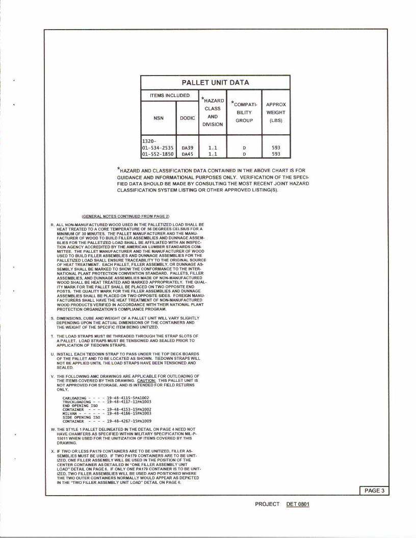
PALLET UNIT DATA
ITEMS INCLUDED HZD- HAZARD *COMPATI- APPROX
CLASSBILITY WEIGHT
NSN DODIC AND GROUP (LBS)DIVISION
1320-01-534-2535 DA39 1.1 D 59301-552-1850 DA45 1.1 D 593
*HAZARD AND CLASSIFICATION DATA CONTAINED IN THE ABOVE CHART IS FOR
GUIDANCE AND INFORMATIONAL PURPOSES ONLY. VERIFICATION OF THE SPECI-FIED DATA SHOULD BE MADE BY CONSULTING THE MOST RECENT JOINT HAZARDCLASSIFICATION SYSTEM LISTING OR OTHER APPROVED LISTING(S).
(GENERAL NOTES CONTINUED FROM PAGE 2(
R. ALL NON-MANUFACTURED WOOD USED IN THE PALLETIZED LOAD SHALL BEHEAT TREATED TO A CORE TEMPERATURE OF 56 DEGREES CELSIUS FOR AMINIMUM OF 30 MINUTES. THE PALLET MANUFACTURER AND THE MANU-FACTURER OF WOOD TO BUILD FILLER ASSEMBLIES AND DUNNAGE ASSEM-BLIES FOR THE PALLETIZED LOAD SHALL BE AFFILIATED WITH AN INSPEC-TION AGENCY ACCREDITED BY THE AMERICAN LUMBER STANDARDS COM-MITTEE. THE PALLET MANUFACTURER AND THE MANUFACTURER OF WOODUSED TO BUILD FILLER ASSEMBLIES AND DUNNAGE ASSEMBLIES FOR THEPALLETIZED LOAD SHALL ENSURE TRACEABILITY TO THE ORIGINAL SOURCEOF HEAT TREATMENT. EACH PALLET, FILLER ASSEMBLY, OR DUNNAGE AS-SEMBLY SHALL BE MARKED TO SHOW THE CONFORMANCE TO THE INTER-NATIONAL PLANT PROTECTION CONVENTION STANDARD. PALLETS, FILLERASSEMBLIES, AND DUNNAGE ASSEMBLIES MADE OF NON-MANUFACTUREDWOOD SHALL BE HEAT TREATED AND MARKED APPROPRIATELY. THE QUAL-ITY MARK FOR THE PALLET SHALL BE PLACED ON TWO OPPOSITE ENDPOSTS. THE QUALITY MARK FOR THE FILLER ASSEMBLIES AND DUNNAGEASSEMBLIES SHALL BE PLACED ON TWO OPPOSITE SIDES. FOREIGN MANU-FACTURERS SHALL HAVE THE HEAT TREATMENT OF NON-MANUFACTUREDWOOD PRODUCTS VERIFIED IN ACCORDANCE WITH THEIR NATIONAL PLANTPROTECTION ORGANIZATION'S COMPLIANCE PROGRAM.
S. DIMENSIONS, CUBE AND WEIGHT OF A PALLET UNIT WILL VARY SLIGHTLYDEPENDING UPON THE ACTUAL DIMENSIONS OF THE CONTAINERS ANDTHE WEIGHT OF THE SPECIFIC ITEM BEING UNITIZED.
T. THE LOAD STRAPS MUST BE THREADED THROUGH THE STRAP SLOTS OFA PALLET. LOAD STRAPS MUST BE TENSIONED AND SEALED PRIOR TOAPPLICATION OF TIEDOWN STRAPS.
U. INSTALL EACH TIEDOWN STRAP TO PASS UNDER THE TOP DECK BOARDSOF THE PALLET AND TO BE LOCATED AS SHOWN. TIEDOWN STRAPS WILLNOT BE APPLIED UNTIL THE LOAD STRAPS HAVE BEEN TENSIONED ANDSEALED.
V. THE FOLLOWING AMC DRAWINGS ARE APPLICABLE FOR OUTLOADING OFTHE ITEMS COVERED BY THIS DRAWING. CION: THIS PALLET UNIT ISNOT APPROVED FOR STORAGE, AND IS INTENDED FOR FIELD RETURNSONLY.
CARLOADING - - - - 19-48-4115-SPA1002TRUCKLOADING - - - 19-48-4117-11PA1003END OPENING ISOCONTAINER - - - - 19-48-4153-15PA1002NILVAN .-.-.-.-----19-48-4166-1SPA1003SIDE OPENING ISOCONTAINER - - - - 19-48-4267-1SPA1009
W. THE STYLE 1 PALLET DELINEATED IN THE DETAIL ON PAGE 4 NEED NOTHAVE CHAMFERS AS SPECIFIED WITHIN MILITARY SPECIFICATION MIL-P-15011 WHEN USED FOR THE UNITIZATION OF ITEMS COVERED BY THISDRAWING.
X. IF TWO OR LESS PAI 79 CONTAINERS ARE TO BE UNITIZED, FILLER AS-SEMBLIES MUST BE USED. IF TWO PA179 CONTAINERS ARE TO BE UNIT-IZED, ONE FILLER ASSEMBLY WILL BE USED IN THE POSITION OF THECENTER CONTAINER AS DETAILED IN "ONE FILLER ASSEMBLY UNITLOAD" DETAIL ON PAGE 6. IF ONLY ONE PA179 CONTAINER IS TO BE UNIT-IZED, TWO FILLER ASSEMBLIES WILL BE USED AND POSITIONED WHERETHE TWO OUTER CONTAINERS NORMALLY WOULD APPEAR AS DEPICTEDIN THE "TWO FILLER ASSEMBLY UNIT LOAD" DETAIL ON PAGE 6.
PAGE 3
PROJECT DET 0801
LOAD STRAP, 3/4' X .031" OR.035" X 10'-11" LONG STEEL TIEDOWN STRAP, 3/4" X .031"STRAPPING (2 REQD). SEE OR .035" X 9'-7 LONG STEEL
NOTE 'T' ON PAGE 3. STRAPPING (3 RECD). SEENOTE "U" ON PAGE 3.
TOP ASSEMBLY(1 REQD). SEE
DETAIL ONPAGE 5.
SEAL FOR 3/4" STRAPPING *(5 RECD, I PER STRAP).CRIMP AND SEAL WITH
WDE BY 3/4"LEG LENGTH(20 REQD, 4
PER LOADSTRAP AND4 PER TIE-
DOWN STRAP).SEE DETAIL A
AND B.
PALLET FILL ASSEMBLY48" (1 REQD). SEE DETAIL40" JON PAGE 5. TOENAIL
TO PALLET W/2-8dNAILS ON EACH SIDE.~40" X 48"
WOODPALLET
FOR BOTH LOAD ANDTIEDOWN STRAPS,TWO OF THE STAPLESPER STRAP ARE FOR BOTH LOAD AND TIEDOWNLOCATED ON OPPOSITE STRAPS, TWO OF THE STAPLESSIDES OF THE PALLET PER STRAP ARE LOCATEDFILL ASSEMBLY. ON THE TOP ASSEMBLY. ROM:
ENSURE STAPLES ARE POSITIONEDTO PENETRATE THE STRAPPINGDETAIL A DETAIL B BOARD IN THE TOP ASSEMBLY.
PALLET UNITSEE GENERAL NOTE "S" ON PAGE 3.
3 CONTAINERS OF PRO3ECTILES (1 PER CNTR) S 156 LBS - - 468 LBSDUNNAGE- - --------------------- 55 LBSPALLET ------------------------ 80 LBS
TOTAL WEIGHT- -- -- ---------- 603 LBS (APPROX)CUBE --------------- 18.1 CU FT (APPROX)
BILL OF MATERIAL
LL1BER LINEAR FEET BOARD FEET
1" x 4" 15 51" x 6" 17 92" X 4" 16 11
NAILS NO. REQO POUNDS
4d (1-1/2") 54 0.198d (2-1/2") 8 0.08
10d (3") 20 0.31
PALLET, 40" X 48" ------- 1 REQD ------ 80 LBSSTEEL STRAPPING, 3/4" - 50.59' REQD ----- 4.52 LBSSEAL FOR 3/4" STRAPPING - - - 5 REQP-- - - - - - -- NILSTAPLE7 15/16" x 3/4" - - - 20 REO NIL
PAGE 4
PROJECT DET 0801
STRAPPING BOARD1"x"'x 6-114" X
(3 REQD). NAIL TOBEARING ANDSUPPORT PIECESW13-d NAILS AT
211/4"1
131/22I- 2511/4"
BEARIN PICI914
SUPPORT PIECE 5112j
1" X 6" X 44-1/2"(2 REQD). SIDE VIEW
TOP ASSEMBLY
1>38" ±1/8"
/19 3/8" t118"
SIDE BUFFER2" X 4" X 48"
(2 REQD). NAILEND BUFFER TO THE END2' X 4"X 37" BUFFERS W/2-10d
(2 REQD). NAILS AT EACH END.
SIDE RESTRAINTPIECE, 2" X 4" X 4-3/8"(4 REQD). POSITIONAS SHOWN AND NAILTO END BUFFERSW/3-lOd NAILS.
PALLET FILL ASSEMBLY
r PAGE 5
PROJECT DET 0801
SUPPORT PIECE 2" X4" X 45".ONLY RECD FOR TWO FILLERASSEMBLY UNIT LOAD. SEE TWOFILLER ASSEMBLY UNIT LOAD DETAILBELOW. NAIL TO LONGITUDINALPIECE AND LATERAL PIECEW7-10d NAILS AS SHOWN INEND VIEW AT RIGHT.
LONGITUDINAL PIECE2" X 6" X 45" (2 REQD). LATERAL PECE
NAIL TO LATERAL 2" X 6" X 6-3/16"AT EACH JOINT. END VIEWPIECES W/2-1Id NAILS (5 REQD).
FILLER ASSEMBLY
/-FILLER ASSEMBLY(1 RECD). POSITIONAS SHOWN AND NAILTHRU PALLET FILL
7 IW AASSEMBLY INTO THE1711" APROXFILLER ASSEMBLY
IW/3-10d NAILS ONEACH SIDE
END VIEW
ISOMETRIC VIEWSEE THE DETAIL ON PAGE 4 FORADDITIONAL ASSEMBLY DETAILS.
ONE FILLER ASSEMBLY UNIT LOADSEE GENERAL NOTE ")C' ON PAGE 3
FILLER ASSEMBLY(2 REQD). POSITION
AS SHOWN WITHSUPPORT PIECE FACING
INWARD AND NAILTO PALLET FILL
ASSEMBLY W/3-110dNAILS ON EACH SIDE.
312"12" APPROX
APPROX I ,PO
SUPPORT PIECEOF FILLER ASSEMBLY.
SEE FILLER ASSEMBLYDETAIL ABOVE FOR
ISOMETRIC VIEW NAIUNG GUIDANCE. END VIEW
SEE THE DETAIL ON PAGE 4 FORADDITIONAL ASSEMBLY DETAILS.
TWO FILLER ASSEMBLY UNIT LOAD(SEE GENERAL NOTE "XC ON PAGE 3)
PAGE 6
PROJECT DET 0801