Embed Size (px)
Citation preview
2010 Chevrolet Cobalt Owner Manual M
In Brief . . . . . . . . . . . . . . . . . . . . . . . . . . . . . . . . . . . . . . . . . . . . 1-1Instrument Panel . . . . . . . . . . . . . . . . . . . . . . . . . . . . . . . . . 1-2Initial Drive Information . . . . . . . . . . . . . . . . . . . . . . . . . . . 1-4Vehicle Features . . . . . . . . . . . . . . . . . . . . . . . . . . . . . . . . 1-14Performance and Maintenance . . . . . . . . . . . . . . . . . . 1-18
Seats and Restraint System . . . . . . . . . . . . . . . . . . . . . . 2-1Front Seats . . . . . . . . . . . . . . . . . . . . . . . . . . . . . . . . . . . . . . . 2-2Rear Seats . . . . . . . . . . . . . . . . . . . . . . . . . . . . . . . . . . . . . . . 2-9Safety Belts . . . . . . . . . . . . . . . . . . . . . . . . . . . . . . . . . . . . . 2-10Child Restraints . . . . . . . . . . . . . . . . . . . . . . . . . . . . . . . . . 2-31Airbag System . . . . . . . . . . . . . . . . . . . . . . . . . . . . . . . . . . 2-53Restraint System Check . . . . . . . . . . . . . . . . . . . . . . . . . 2-74
Features and Controls . . . . . . . . . . . . . . . . . . . . . . . . . . . . 3-1Keys . . . . . . . . . . . . . . . . . . . . . . . . . . . . . . . . . . . . . . . . . . . . . 3-3Doors and Locks . . . . . . . . . . . . . . . . . . . . . . . . . . . . . . . . . 3-8Windows . . . . . . . . . . . . . . . . . . . . . . . . . . . . . . . . . . . . . . . . 3-14Theft-Deterrent Systems . . . . . . . . . . . . . . . . . . . . . . . . 3-16Starting and Operating Your Vehicle . . . . . . . . . . . . . 3-20Mirrors . . . . . . . . . . . . . . . . . . . . . . . . . . . . . . . . . . . . . . . . . . 3-37Storage Areas . . . . . . . . . . . . . . . . . . . . . . . . . . . . . . . . . . . 3-39Sunroof . . . . . . . . . . . . . . . . . . . . . . . . . . . . . . . . . . . . . . . . . 3-39
Instrument Panel . . . . . . . . . . . . . . . . . . . . . . . . . . . . . . . . . 4-1Instrument Panel Overview . . . . . . . . . . . . . . . . . . . . . . . 4-3Climate Controls . . . . . . . . . . . . . . . . . . . . . . . . . . . . . . . . 4-14Warning Lights, Gages, and Indicators . . . . . . . . . . 4-18Driver Information Center (DIC) . . . . . . . . . . . . . . . . . 4-37Audio System(s) . . . . . . . . . . . . . . . . . . . . . . . . . . . . . . . . 4-52
Driving Your Vehicle . . . . . . . . . . . . . . . . . . . . . . . . . . . . . . 5-1Your Driving, the Road, and the Vehicle . . . . . . . . . . 5-2Towing . . . . . . . . . . . . . . . . . . . . . . . . . . . . . . . . . . . . . . . . . . 5-30
Service and Appearance Care . . . . . . . . . . . . . . . . . . . 6-1Service . . . . . . . . . . . . . . . . . . . . . . . . . . . . . . . . . . . . . . . . . . . 6-4Fuel . . . . . . . . . . . . . . . . . . . . . . . . . . . . . . . . . . . . . . . . . . . . . . 6-6Checking Things Under the Hood . . . . . . . . . . . . . . . 6-12Headlamp Aiming . . . . . . . . . . . . . . . . . . . . . . . . . . . . . . . 6-44Bulb Replacement . . . . . . . . . . . . . . . . . . . . . . . . . . . . . . 6-47Windshield Wiper Blade Replacement . . . . . . . . . . . 6-53Tires . . . . . . . . . . . . . . . . . . . . . . . . . . . . . . . . . . . . . . . . . . . . 6-54Appearance Care . . . . . . . . . . . . . . . . . . . . . . . . . . . . . . 6-112Vehicle Identification . . . . . . . . . . . . . . . . . . . . . . . . . . . 6-120Electrical System . . . . . . . . . . . . . . . . . . . . . . . . . . . . . . 6-120Capacities and Specifications . . . . . . . . . . . . . . . . . . 6-128
2010 Chevrolet Cobalt Owner Manual M
Maintenance Schedule . . . . . . . . . . . . . . . . . . . . . . . . . . . 7-1Maintenance Schedule . . . . . . . . . . . . . . . . . . . . . . . . . . . 7-2
Customer Assistance Information . . . . . . . . . . . . . . . 8-1Customer Assistance and Information . . . . . . . . . . . . 8-2Reporting Safety Defects . . . . . . . . . . . . . . . . . . . . . . . . 8-15Vehicle Data Recording and Privacy . . . . . . . . . . . . . 8-17
Index . . . . . . . . . . . . . . . . . . . . . . . . . . . . . . . . . . . . i-1
GENERAL MOTORS, GM, the GM Emblem,CHEVROLET, the CHEVROLET Emblem, andthe name COBALT are registered trademarks ofGeneral Motors Corporation.
This manual describes features that may or may not beon your specific vehicle either because they are optionsthat you did not purchase or due to changessubsequent to the printing of this owner manual. Pleaserefer to the purchase documentation relating to yourspecific vehicle to confirm each of the features found onyour vehicle. For vehicles first sold in Canada,substitute the name “General Motors of CanadaLimited” for Chevrolet Motor Division wherever itappears in this manual.
Keep this manual in the vehicle for quick reference.
Canadian Owners
Propriétaires CanadiensA French language copy of this manual can be obtainedfrom your dealer/retailer or from:
On peut obtenir un exemplaire de ce guide en françaisauprès du concessionnaire ou à l'adresse suivante:
Helm, IncorporatedP.O. Box 07130Detroit, MI 48207
1-800-551-4123
Numéro de poste 6438 de langue française
www.helminc.com
IndexTo quickly locate information about the vehicle, use theindex in the back of the manual. It is an alphabetical listof what is in the manual and the page number where itcan be found.
iii
Litho in the U.S.A.Part No. 25895310 A First Printing ©2009 General Motors Corporation. All rights Reserved.
Safety Warnings and SymbolsWarning messages found on vehicle labels and in thismanual describe hazards and what to do to avoid orreduce them.
Danger indicates a hazard with a high level of riskwhich will result in serious injury or death.
Warning or Caution indicates a hazard that could resultin injury or death.
{ WARNING:
These mean there is something that could hurtyou or other people.
Notice: This means there is something that couldresult in property or vehicle damage. This would notbe covered by the vehicle's warranty.
A circle with a slashthrough it is a safetysymbol which means “DoNot,” “Do not do this,” or“Do not let this happen.”
Vehicle SymbolsThe vehicle has components and labels that usesymbols instead of text. Symbols are shown along withthe text describing the operation or information relatingto a specific component, control, message, gage,or indicator.
M : This symbol is shown when you need to see yourowner manual for additional instructions or information.
* : This symbol is shown when you need to see aservice manual for additional instructions or information.
iv
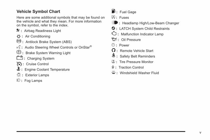
Vehicle Symbol ChartHere are some additional symbols that may be found onthe vehicle and what they mean. For more informationon the symbol, refer to the index.
9 : Airbag Readiness Light
# : Air Conditioning
! : Antilock Brake System (ABS)
g : Audio Steering Wheel Controls or OnStar®
$ : Brake System Warning Light
" : Charging System
I : Cruise Control
B : Engine Coolant Temperature
O : Exterior Lamps
# : Fog Lamps
. : Fuel Gage
+ : Fuses
i : Headlamp High/Low-Beam Changer
j : LATCH System Child Restraints
* : Malfunction Indicator Lamp
: : Oil Pressure
} : Power
/ : Remote Vehicle Start
> : Safety Belt Reminders
7 : Tire Pressure Monitor
F : Traction Control
M : Windshield Washer Fluid
v

2 NOTES
vi
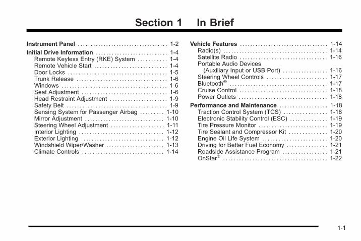
Section 1 In Brief
Instrument Panel . . . . . . . . . . . . . . . . . . . . . . . . . . . . . . . . . . . 1-2
Initial Drive Information . . . . . . . . . . . . . . . . . . . . . . . . . . . 1-4Remote Keyless Entry (RKE) System . . . . . . . . . . . 1-4Remote Vehicle Start . . . . . . . . . . . . . . . . . . . . . . . . . . . 1-4Door Locks . . . . . . . . . . . . . . . . . . . . . . . . . . . . . . . . . . . . . 1-5Trunk Release . . . . . . . . . . . . . . . . . . . . . . . . . . . . . . . . . . 1-6Windows . . . . . . . . . . . . . . . . . . . . . . . . . . . . . . . . . . . . . . . . 1-6Seat Adjustment . . . . . . . . . . . . . . . . . . . . . . . . . . . . . . . . 1-6Head Restraint Adjustment . . . . . . . . . . . . . . . . . . . . . . 1-9Safety Belt . . . . . . . . . . . . . . . . . . . . . . . . . . . . . . . . . . . . . . 1-9Sensing System for Passenger Airbag . . . . . . . . . 1-10Mirror Adjustment . . . . . . . . . . . . . . . . . . . . . . . . . . . . . . 1-10Steering Wheel Adjustment . . . . . . . . . . . . . . . . . . . . 1-11Interior Lighting . . . . . . . . . . . . . . . . . . . . . . . . . . . . . . . . 1-12Exterior Lighting . . . . . . . . . . . . . . . . . . . . . . . . . . . . . . . 1-12Windshield Wiper/Washer . . . . . . . . . . . . . . . . . . . . . . 1-13Climate Controls . . . . . . . . . . . . . . . . . . . . . . . . . . . . . . . 1-14
Vehicle Features . . . . . . . . . . . . . . . . . . . . . . . . . . . . . . . . . . 1-14Radio(s) . . . . . . . . . . . . . . . . . . . . . . . . . . . . . . . . . . . . . . . 1-14Satellite Radio . . . . . . . . . . . . . . . . . . . . . . . . . . . . . . . . . 1-16Portable Audio Devices(Auxiliary Input or USB Port) . . . . . . . . . . . . . . . . . 1-16
Steering Wheel Controls . . . . . . . . . . . . . . . . . . . . . . . 1-17Bluetooth® . . . . . . . . . . . . . . . . . . . . . . . . . . . . . . . . . . . . . 1-17Cruise Control . . . . . . . . . . . . . . . . . . . . . . . . . . . . . . . . . 1-18Power Outlets . . . . . . . . . . . . . . . . . . . . . . . . . . . . . . . . . 1-18
Performance and Maintenance . . . . . . . . . . . . . . . . . . 1-18Traction Control System (TCS) . . . . . . . . . . . . . . . . 1-18Electronic Stability Control (ESC) . . . . . . . . . . . . . . 1-19Tire Pressure Monitor . . . . . . . . . . . . . . . . . . . . . . . . . . 1-19Tire Sealant and Compressor Kit . . . . . . . . . . . . . . 1-20Engine Oil Life System . . . . . . . . . . . . . . . . . . . . . . . . 1-20Driving for Better Fuel Economy . . . . . . . . . . . . . . . 1-21Roadside Assistance Program . . . . . . . . . . . . . . . . . 1-21OnStar® . . . . . . . . . . . . . . . . . . . . . . . . . . . . . . . . . . . . . . . 1-22
1-1
Instrument Panel
1-2
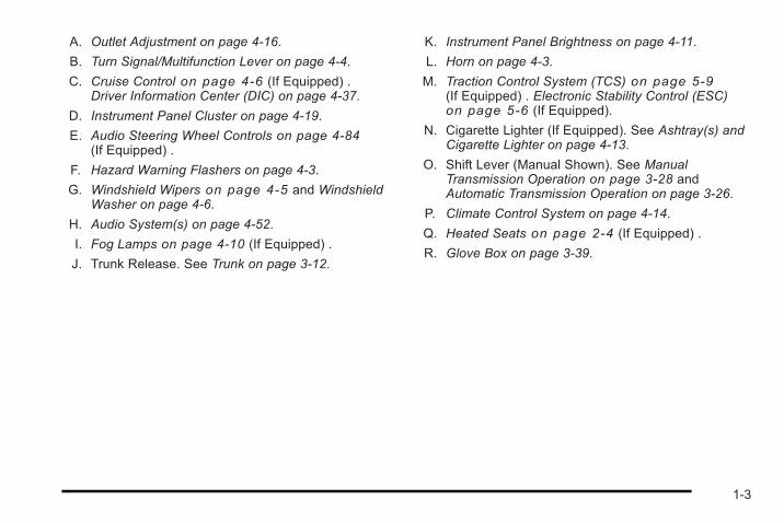
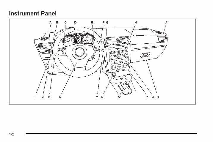
A. Outlet Adjustment on page 4‑16.
B. Turn Signal/Multifunction Lever on page 4‑4.
C. Cruise Control on page 4‑6 (If Equipped) .Driver Information Center (DIC) on page 4‑37.
D. Instrument Panel Cluster on page 4‑19.
E. Audio Steering Wheel Controls on page 4‑84(If Equipped) .
F. Hazard Warning Flashers on page 4‑3.
G. Windshield Wipers on page 4‑5 and WindshieldWasher on page 4‑6.
H. Audio System(s) on page 4‑52.
I. Fog Lamps on page 4‑10 (If Equipped) .
J. Trunk Release. See Trunk on page 3‑12.
K. Instrument Panel Brightness on page 4‑11.
L. Horn on page 4‑3.
M. Traction Control System (TCS) on page 5‑9(If Equipped) . Electronic Stability Control (ESC)on page 5‑6 (If Equipped).
N. Cigarette Lighter (If Equipped). See Ashtray(s) andCigarette Lighter on page 4‑13.
O. Shift Lever (Manual Shown). See ManualTransmission Operation on page 3‑28 andAutomatic Transmission Operation on page 3‑26.
P. Climate Control System on page 4‑14.
Q. Heated Seats on page 2‑4 (If Equipped) .
R. Glove Box on page 3‑39.
1-3
Initial Drive InformationThis section provides a brief overview about some ofthe important features that may or may not be on yourspecific vehicle.
For more detailed information, refer to each of thefeatures which can be found later in this owner manual.
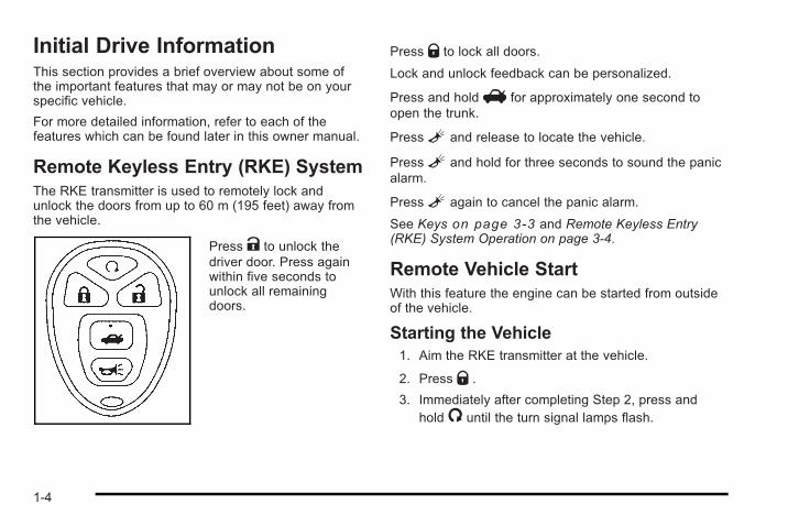
Remote Keyless Entry (RKE) SystemThe RKE transmitter is used to remotely lock andunlock the doors from up to 60 m (195 feet) away fromthe vehicle.
Press K to unlock thedriver door. Press againwithin five seconds tounlock all remainingdoors.
Press Q to lock all doors.
Lock and unlock feedback can be personalized.
Press and holdV for approximately one second toopen the trunk.
PressL and release to locate the vehicle.
PressL and hold for three seconds to sound the panicalarm.
PressL again to cancel the panic alarm.
See Keys on page 3‑3 and Remote Keyless Entry(RKE) System Operation on page 3‑4.
Remote Vehicle StartWith this feature the engine can be started from outsideof the vehicle.
Starting the Vehicle1. Aim the RKE transmitter at the vehicle.
2. Press Q .
3. Immediately after completing Step 2, press andhold/ until the turn signal lamps flash.
1-4
When the vehicle starts, the parking lamps will turn onand remain on as long as the engine is running. Thedoors will be locked and the climate control system maycome on.
The engine will continue to run for 10 minutes. Repeatthe steps for a 10-minute time extension. Remote startcan be extended only once.
Canceling a Remote StartTo cancel a remote start:. Aim the RKE transmitter at the vehicle and press
and hold/.. Turn on the hazard warning flashers.. Turn the ignition switch to ON/RUN and then
LOCK/OFF.
See Remote Vehicle Start on page 3‑6.
Door LocksTo lock the driver door from outside the vehicle, turn thekey clockwise. Turn it counterclockwise to unlock.
The Remote Keyless Entry (RKE) transmitter can alsobe used to lock or unlock the doors.
From the inside, use the manual lock knobs on eachdoor or use the power door locks.
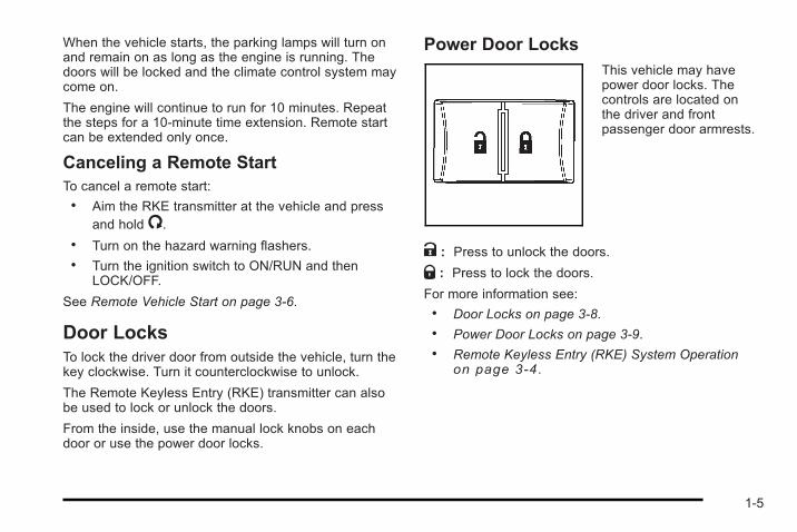
Power Door LocksThis vehicle may havepower door locks. Thecontrols are located onthe driver and frontpassenger door armrests.
K : Press to unlock the doors.
Q : Press to lock the doors.
For more information see:. Door Locks on page 3‑8.. Power Door Locks on page 3‑9.. Remote Keyless Entry (RKE) System Operation
on page 3‑4 .
1-5
Trunk ReleaseIn addition to the trunk release button on the RemoteKeyless Entry (RKE) transmitter, the trunk can beopened from inside the vehicle by pressing the remotetrunk release button. This button is located inside thedriver storage compartment, on the left side of theinstrument panel .
See Trunk on page 3‑12.
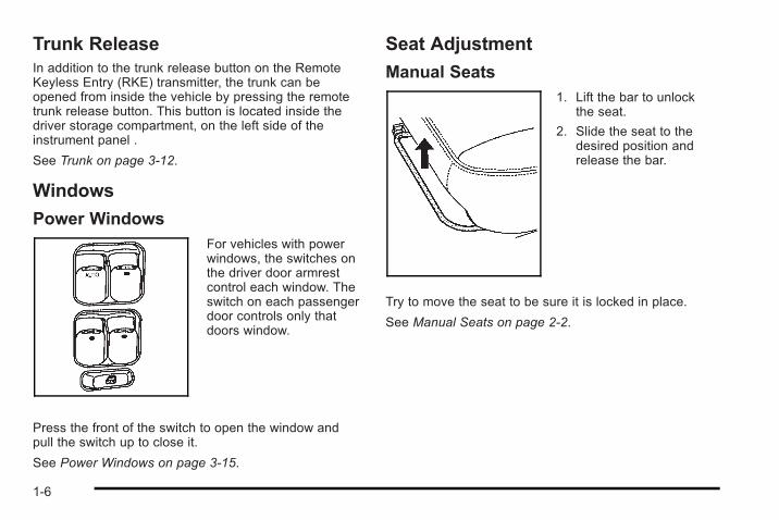
Windows
Power WindowsFor vehicles with powerwindows, the switches onthe driver door armrestcontrol each window. Theswitch on each passengerdoor controls only thatdoors window.
Press the front of the switch to open the window andpull the switch up to close it.
See Power Windows on page 3‑15.
Seat Adjustment
Manual Seats1. Lift the bar to unlock
the seat.
2. Slide the seat to thedesired position andrelease the bar.
Try to move the seat to be sure it is locked in place.
See Manual Seats on page 2‑2.
1-6
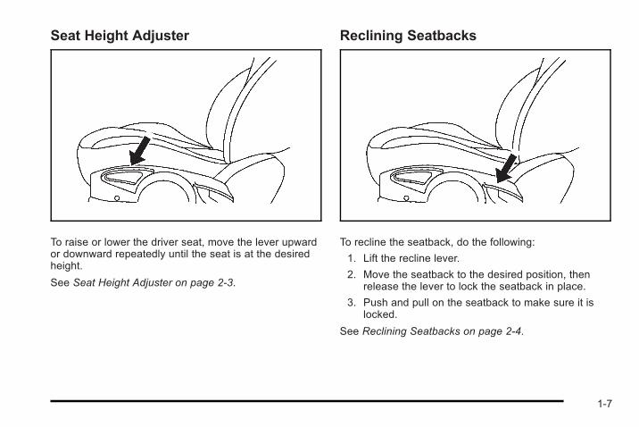
Seat Height Adjuster
To raise or lower the driver seat, move the lever upwardor downward repeatedly until the seat is at the desiredheight.
See Seat Height Adjuster on page 2‑3.
Reclining Seatbacks
To recline the seatback, do the following:
1. Lift the recline lever.
2. Move the seatback to the desired position, thenrelease the lever to lock the seatback in place.
3. Push and pull on the seatback to make sure it islocked.
See Reclining Seatbacks on page 2‑4.
1-7
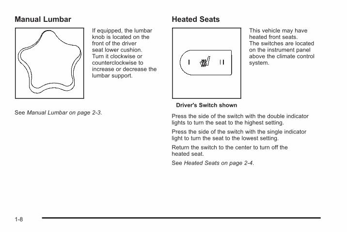
Manual LumbarIf equipped, the lumbarknob is located on thefront of the driverseat lower cushion.Turn it clockwise orcounterclockwise toincrease or decrease thelumbar support.
See Manual Lumbar on page 2‑3.
Heated Seats
Driver's Switch shown
This vehicle may haveheated front seats.The switches are locatedon the instrument panelabove the climate controlsystem.
Press the side of the switch with the double indicatorlights to turn the seat to the highest setting.
Press the side of the switch with the single indicatorlight to turn the seat to the lowest setting.
Return the switch to the center to turn off theheated seat.
See Heated Seats on page 2‑4.
1-8
Head Restraint AdjustmentDo not drive until the head restraints for all occupantsare installed and adjusted properly.
See Head Restraints on page 2‑7.
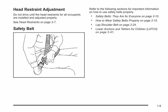
Safety Belt
Refer to the following sections for important informationon how to use safety belts properly.. Safety Belts: They Are for Everyone on page 2‑10.. How to Wear Safety Belts Properly on page 2‑15.. Lap-Shoulder Belt on page 2‑24.. Lower Anchors and Tethers for Children (LATCH)
on page 2‑41.
1-9
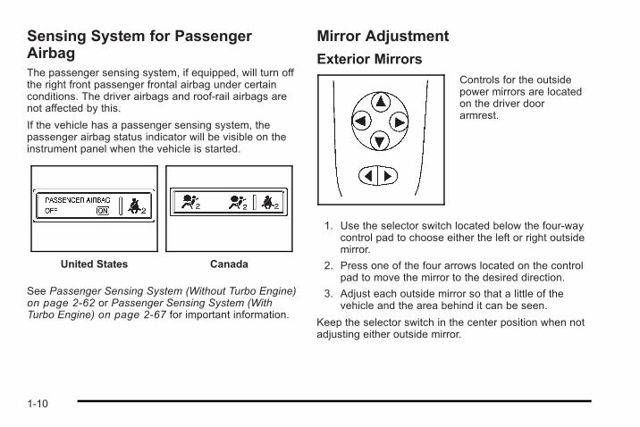
Sensing System for PassengerAirbagThe passenger sensing system, if equipped, will turn offthe right front passenger frontal airbag under certainconditions. The driver airbags and roof-rail airbags arenot affected by this.
If the vehicle has a passenger sensing system, thepassenger airbag status indicator will be visible on theinstrument panel when the vehicle is started.
United States Canada
See Passenger Sensing System (Without Turbo Engine)on page 2‑62 or Passenger Sensing System (WithTurbo Engine) on page 2‑67 for important information.
Mirror Adjustment
Exterior MirrorsControls for the outsidepower mirrors are locatedon the driver doorarmrest.
1. Use the selector switch located below the four-waycontrol pad to choose either the left or right outsidemirror.
2. Press one of the four arrows located on the controlpad to move the mirror to the desired direction.
3. Adjust each outside mirror so that a little of thevehicle and the area behind it can be seen.
Keep the selector switch in the center position when notadjusting either outside mirror.
1-10
Manually fold the mirrors inward to prevent damagewhen going through an automatic car wash. To fold, pullthe mirror toward the vehicle. Push the mirror outward,to return it to the original position.
Interior MirrorHold the inside rearview mirror in the center to move itfor a clearer view of behind the vehicle. Adjust themirror to reduce the glare of headlamps from behind.Push the tab forward for daytime use and pull it fornighttime use. See Manual Rearview Mirror onpage 3‑37.
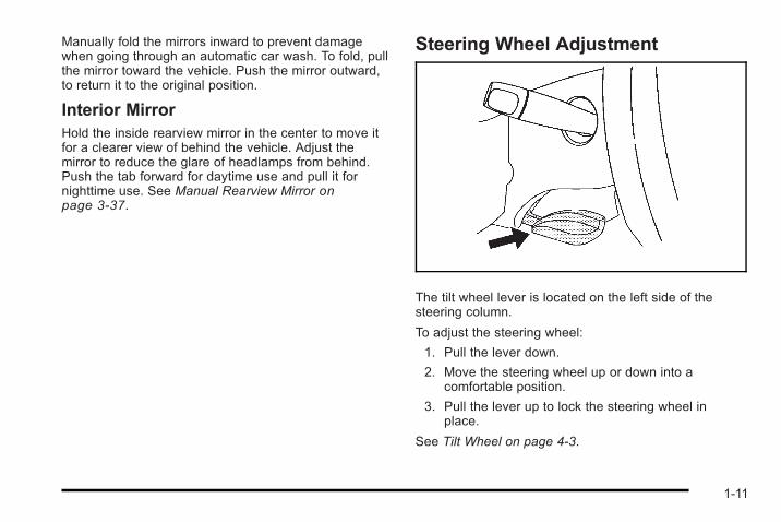
Steering Wheel Adjustment
The tilt wheel lever is located on the left side of thesteering column.
To adjust the steering wheel:
1. Pull the lever down.
2. Move the steering wheel up or down into acomfortable position.
3. Pull the lever up to lock the steering wheel inplace.
See Tilt Wheel on page 4‑3.
1-11
Interior Lighting
Dome LampThe vehicle may have a dome lamp.
Move the lever near the dome lamp to the followingpositions:
9 : Turns the lamp off, even when a door is opened.
1 : Turns the lamp on whenever a door is opened.
+ : Turns the dome lamp on.
Mirror Reading LampThe vehicle may have reading lamps on the rearviewmirror. Press the button near each lamp to turn thereading lamps on and off.
For more information on interior lighting, see:. Entry/Exit Lighting on page 4‑11.. Instrument Panel Brightness on page 4‑11.
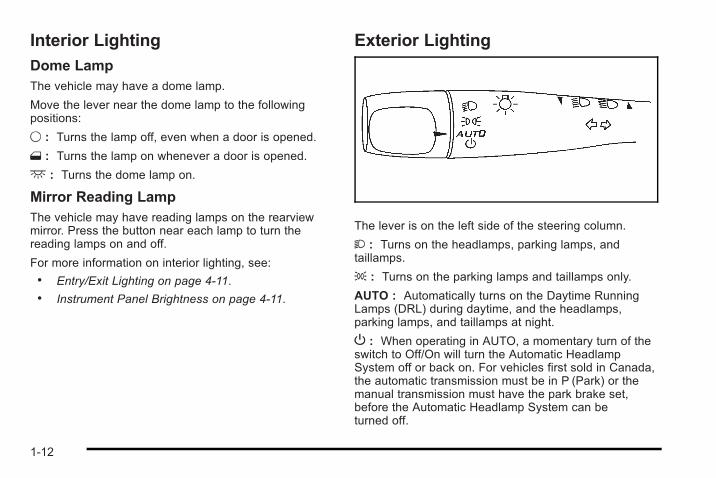
Exterior Lighting
The lever is on the left side of the steering column.
2 : Turns on the headlamps, parking lamps, andtaillamps.
; : Turns on the parking lamps and taillamps only.
AUTO : Automatically turns on the Daytime RunningLamps (DRL) during daytime, and the headlamps,parking lamps, and taillamps at night.
P : When operating in AUTO, a momentary turn of theswitch to Off/On will turn the Automatic HeadlampSystem off or back on. For vehicles first sold in Canada,the automatic transmission must be in P (Park) or themanual transmission must have the park brake set,before the Automatic Headlamp System can beturned off.
1-12
For more information, see:. Headlamps on page 4‑9.. Fog Lamps on page 4‑10.. Daytime Running Lamps (DRL) on page 4‑10.. Headlamps on Reminder on page 4‑10.. Wiper Activated Headlamps on page 4‑10.
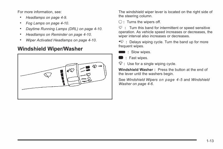
Windshield Wiper/Washer
The windshield wiper lever is located on the right side ofthe steering column.
9 : Turns the wipers off.
& : Turn this band for intermittent or speed sensitiveoperation. As vehicle speed increases or decreases, thewiper interval also increases or decreases.
x : Delays wiping cycle. Turn the band up for morefrequent wipes.
6 : Slow wipes.
1 : Fast wipes.
8 : Use for a single wiping cycle.
Windshield Washer : Press the button at the end ofthe lever until the washers begin.
See Windshield Wipers on page 4‑5 and WindshieldWasher on page 4‑6.
1-13
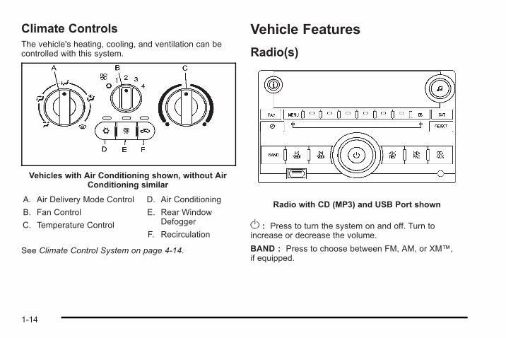
Climate ControlsThe vehicle's heating, cooling, and ventilation can becontrolled with this system.
Vehicles with Air Conditioning shown, without AirConditioning similar
A. Air Delivery Mode Control
B. Fan Control
C. Temperature Control
D. Air Conditioning
E. Rear WindowDefogger
F. Recirculation
See Climate Control System on page 4‑14.
Vehicle Features
Radio(s)
Radio with CD (MP3) and USB Port shown
O : Press to turn the system on and off. Turn toincrease or decrease the volume.
BAND : Press to choose between FM, AM, or XM™,if equipped.
1-14
f : Select radio stations.
©¨ : Seek or scan stations.
4 : Press 4 to display additional text information relatedto the current FM-RDS or XM station; or CD, MP3,WMA song. Song title information will be displayed onthe top line of the display while the artist information willbe displayed on the bottom line, it the information isavailable during XM, CD, MP3, or WMA playback.When information is not available, “No Info” displays.
For more information about these and other radiofeatures, see Radio(s) on page 4‑54.
Storing a Favorite StationDepending on which radio the vehicle has, radiostations are stored as either favorites or presets.
For radios with a FAV button, a maximum of 36 stationscan be stored as favorites using the six softkeys locatedbelow the radio station frequency tabs and by usingthe radio FAV button. Press FAV to go through up tosix pages of favorites, each having six favorite stationsavailable per page. Each page of favorites can containany combination of AM, FM, or XM stations.
For radios without a FAV button, up to 18 stations(six FM1, six FM2, and six AM), can be programmed onthe six numbered buttons.
For more information, see Radio(s) on page 4‑54.
Setting the ClockTo set the time and date for the Radio with CD (MP3)and USB port or the Radio with CD (MP3) player:
1. Turn the ignition key to ACC/ACCESSORY orON/RUN.
2. PressO to turn the radio on.
3. Press H and the HR, MIN, MM, DD, YYYY (hour,minute, month, day, and year) displays.
4. Press the softkey located below any one of thetabs that you want to change.
5. Increase or decrease the time or date by turning fclockwise or counterclockwise.
For detailed instructions on setting the clock for yourspecific audio system, see Setting the Clock onpage 4‑53.
1-15
Satellite RadioXM is a satellite radio service that is based in the48 contiguous United States and 10 Canadianprovinces. XM satellite radio has a wide variety ofprogramming and commercial-free music,coast-to-coast, and in digital-quality sound.
A fee is required to receive the XM service.
For more information, refer to:. www.xmradio.com or call 1-800-929-2100 (U.S.). www.xmradio.ca or call 1-877-438-9677 (Canada)
See “XM Satellite Radio Service” under Radio(s) onpage 4‑54.
Portable Audio Devices(Auxiliary Input or USB Port)This vehicle may have an auxiliary input jack and aUSB port, located on the audio faceplate. Externaldevices such as iPods®, laptop computers, MP3players, CD changers, USB storage devices, etc. canbe connected to the auxiliary input jack using a 3.5 mm(1/8 in) cable or the USB port depending on the audiosystem.
Press the CD/AUX button to play audio from theportable player.
See “Using the Auxiliary Input Jack” and “Using theUSB Port” under Radio(s) on page 4‑54.
1-16
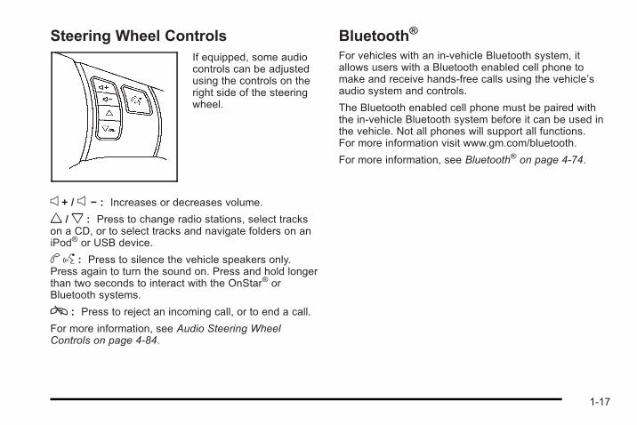
Steering Wheel ControlsIf equipped, some audiocontrols can be adjustedusing the controls on theright side of the steeringwheel.
e + / e − : Increases or decreases volume.
w /x : Press to change radio stations, select trackson a CD, or to select tracks and navigate folders on aniPod® or USB device.
bg : Press to silence the vehicle speakers only.Press again to turn the sound on. Press and hold longerthan two seconds to interact with the OnStar® orBluetooth systems.
c : Press to reject an incoming call, or to end a call.
For more information, see Audio Steering WheelControls on page 4‑84.
Bluetooth®
For vehicles with an in-vehicle Bluetooth system, itallows users with a Bluetooth enabled cell phone tomake and receive hands-free calls using the vehicle’saudio system and controls.
The Bluetooth enabled cell phone must be paired withthe in-vehicle Bluetooth system before it can be used inthe vehicle. Not all phones will support all functions.For more information visit www.gm.com/bluetooth.
For more information, see Bluetooth® on page 4‑74.
1-17
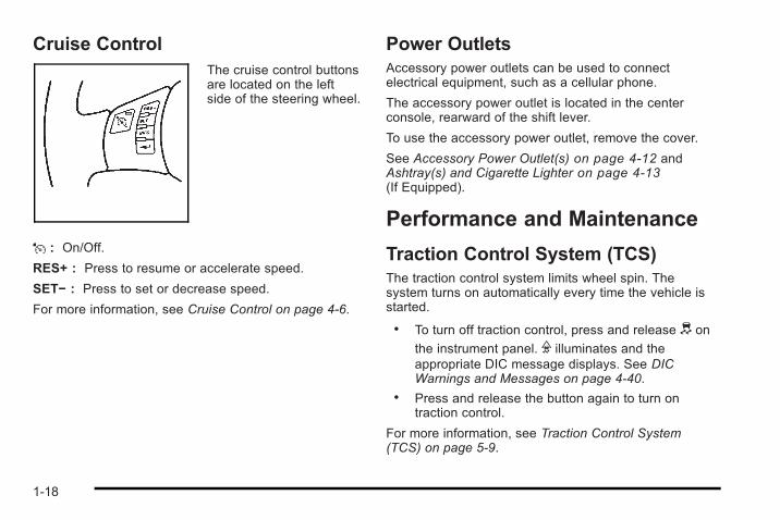
Cruise ControlThe cruise control buttonsare located on the leftside of the steering wheel.
J : On/Off.
RES+ : Press to resume or accelerate speed.
SET− : Press to set or decrease speed.
For more information, see Cruise Control on page 4‑6.
Power OutletsAccessory power outlets can be used to connectelectrical equipment, such as a cellular phone.
The accessory power outlet is located in the centerconsole, rearward of the shift lever.
To use the accessory power outlet, remove the cover.
See Accessory Power Outlet(s) on page 4‑12 andAshtray(s) and Cigarette Lighter on page 4‑13(If Equipped).
Performance and Maintenance
Traction Control System (TCS)The traction control system limits wheel spin. Thesystem turns on automatically every time the vehicle isstarted.
. To turn off traction control, press and release d on
the instrument panel. F illuminates and theappropriate DIC message displays. See DICWarnings and Messages on page 4‑40.
. Press and release the button again to turn ontraction control.
For more information, see Traction Control System(TCS) on page 5‑9.
1-18
Electronic Stability Control (ESC)The Electronic Stability Control system assists withdirectional control of the vehicle in difficult drivingconditions. The system turns on automatically everytime the vehicle is started.. To turn off both traction control and Electronic
Stability Control, press and hold d until Filluminates and the appropriate DIC messagedisplays. See DIC Warnings and Messages onpage 4‑40.
. Press and release the button again to turn on bothsystems.
For more information, see Electronic Stability Control(ESC) on page 5‑6.
Tire Pressure MonitorThis vehicle may have a Tire Pressure MonitorSystem (TPMS).
The Tire Pressure Monitoralerts you when asignificant reduction inpressure occurs in one ormore of the vehicle’s tiresby illuminating the low tirepressure warning light onthe instrument cluster.
The warning light will remain on until the tire pressure iscorrected. The proper tire pressures for your vehicle arelisted on the Tire and Loading Information label locatedon the driver side center pillar (B pillar). See Loadingthe Vehicle on page 5‑25.
1-19
You may notice during cooler conditions that the low tirepressure warning light will appear when the vehicle isfirst started and then turn off as you drive. This may bean early indicator that your tire pressures are gettinglow and the tires need to be inflated to the properpressure.
Note: The Tire Pressure Monitor can alert you aboutlow tire pressure, but it does not replace normal monthlytire maintenance. It is the driver’s responsibility tomaintain correct tire pressures.
See Tire Pressure Monitor System on page 6‑65 andTire Pressure Monitor Operation on page 6‑67.
Tire Sealant and Compressor KitThis vehicle may come with a jack and spare tire or atire sealant and compressor kit. The kit can be used toseal small punctures in the tread area of the tire.
See Tire Sealant and Compressor Kit on page 6‑81 forcomplete operating information.
Engine Oil Life SystemThe engine oil life system calculates engine oil lifebased on vehicle use and displays a DIC messagewhen it is necessary to change the engine oil and filter.The oil life system should be reset to 100% onlyfollowing an oil change.
Resetting the Oil Life System1. Turn the ignition to ON/RUN, with the engine off.
2. Press the DIC information and reset buttons at thesame time to enter the personalization menu.
3. Press the information button until the DIC displayshows OIL-LIFE RESET.
4. Press and hold the reset button until the DICdisplay shows ACKNOWLEDGED.
5. Turn the key to LOCK/OFF.
See Engine Oil Life System on page 6‑21.
1-20
Driving for Better Fuel EconomyDriving habits can affect fuel mileage. Here are somedriving tips to get the best fuel economy possible.. Avoid fast starts and accelerate smoothly.. Brake gradually and avoid abrupt stops.. Avoid idling the engine for long periods of time.. When road and weather conditions are
appropriate, use cruise control, if equipped.. Always follow posted speed limits or drive more
slowly when conditions require.. Keep vehicle tires properly inflated.. Combine several trips into a single trip.. Replace the vehicle's tires with the same TPC
Spec number molded into the tire's sidewall nearthe size.
. Follow recommended scheduled maintenance.
Roadside Assistance ProgramU.S.: 1-800-CHEV-USA (1-800-243-8872)
TTY Users: 1-888-889-2438
Canada: 1-800-268-6800
As the owner of a new Chevrolet, you are automaticallyenrolled in the Roadside Assistance program. Thisprogram provides technically trained advisors who areavailable 24 hours a day, 365 days a year, minor repairinformation or towing arrangements.
Roadside Assistance and OnStarIf you have a current OnStar subscription, press theOnStar button and the current GPS location will be sentto an OnStar Advisor who will assess your problem,contact Roadside Assistance, and relay exact locationto get you the help you need.
Online Owner CenterThe Online Owner Center is a complimentary servicethat includes online service reminders, vehiclemaintenance tips, online owner manual, specialprivileges and more.
Sign up today at: www.gmownercenter.com/chevrolet(U.S.) or www.gm.ca (Canada).
1-21
OnStar®
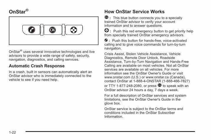
OnStar® uses several innovative technologies and liveadvisors to provide a wide range of safety, security,navigation, diagnostics, and calling services.
Automatic Crash ResponseIn a crash, built in sensors can automatically alert anOnStar advisor who is immediately connected to thevehicle to see if you need help.
How OnStar Service WorksQ : This blue button connects you to a speciallytrained OnStar advisor to verify your accountinformation and to answer questions.
] : Push this red emergency button to get priority helpfrom specially trained OnStar emergency advisors.
X : Push this button for hands-free, voice-activatedcalling and to give voice commands for turn-by-turnnavigation.
Crisis Assist, Stolen Vehicle Assistance, VehicleDiagnostics, Remote Door Unlock, RoadsideAssistance, Turn-by-Turn Navigation and Hands-FreeCalling are available on most vehicles. Not all OnStarservices are available on all vehicles. For moreinformation see the OnStar Owner's Guide or visitwww.onstar.com (U.S.) or www.onstar.ca (Canada),contact OnStar at 1-888-4-ONSTAR (1-888-466-7827)or TTY 1-877-248-2080, or pressQ to speak with anOnStar advisor 24 hours a day, 7 days a week.
For a full description of OnStar services and systemlimitations, see the OnStar Owner's Guide in theglove box.
OnStar service is subject to the OnStar terms andconditions included in the OnStar SubscriberInformation.
1-22
OnStar service cannot work unless the vehicle is in aplace where OnStar has an agreement with a wirelessservice provider for service in that area. OnStar servicealso cannot work unless the vehicle is in a place wherethe wireless service provider OnStar has hired for thatarea has coverage, network capacity and receptionwhen the service is needed, and technology that iscompatible with the OnStar service. Not all services areavailable everywhere, particularly in remote or enclosedareas, or at all times.
The OnStar system can record and transmit vehicleinformation. This information is automatically sent to anOnStar call center whenQ is pressed,] is pressed,or if the airbags or ACR system deploy. This informationusually includes the vehicle's GPS location and, in theevent of a crash, additional information regarding thecrash that the vehicle was involved in (e.g. the directionfrom which the vehicle was hit). When the virtualadvisor feature of OnStar hands-free calling is used, thevehicle also sends OnStar the vehicle's GPS locationso they can provide services where it is located.
Location information about the vehicle is only availableif the GPS satellite signals are unobstructed andavailable.
The vehicle must have a working electrical system,including adequate battery power, for the OnStarequipment to operate. There are other problems OnStarcannot control that may prevent OnStar from providing
OnStar service at any particular time or place. Someexamples are damage to important parts of the vehiclein a crash, hills, tall buildings, tunnels, weather orwireless phone network congestion.
OnStar Steering Wheel ControlsThis vehicle may have a Talk/Mute button that can beused to interact with OnStar hands-free calling. SeeAudio Steering Wheel Controls on page 4‑84 for moreinformation.
On some vehicles, the mute button can be used to dialnumbers into voice mail systems, or to dial phoneextensions. See the OnStar Owner's Guide for moreinformation.
Your ResponsibilityIncrease the volume of the radio if the OnStar advisorcannot be heard.
If the light next to the OnStar buttons is red, the systemmay not be functioning properly. PressQ and request avehicle diagnostic. If the light appears clear (no light isappearing), your OnStar subscription has expired andall services have been deactivated. PressQ to confirmthat the OnStar equipment is active.
1-23

2 NOTES
1-24
Section 2 Seats and Restraint System
Front Seats . . . . . . . . . . . . . . . . . . . . . . . . . . . . . . . . . . . . . . . . . 2-2Manual Seats . . . . . . . . . . . . . . . . . . . . . . . . . . . . . . . . . . . 2-2Seat Height Adjuster . . . . . . . . . . . . . . . . . . . . . . . . . . . . 2-3Manual Lumbar . . . . . . . . . . . . . . . . . . . . . . . . . . . . . . . . . 2-3Heated Seats . . . . . . . . . . . . . . . . . . . . . . . . . . . . . . . . . . . 2-4Reclining Seatbacks . . . . . . . . . . . . . . . . . . . . . . . . . . . . 2-4Head Restraints . . . . . . . . . . . . . . . . . . . . . . . . . . . . . . . . . 2-7Easy Entry Seat (Coupe) . . . . . . . . . . . . . . . . . . . . . . . . 2-8
Rear Seats . . . . . . . . . . . . . . . . . . . . . . . . . . . . . . . . . . . . . . . . . 2-9Split Folding Rear Seat . . . . . . . . . . . . . . . . . . . . . . . . . 2-9
Safety Belts . . . . . . . . . . . . . . . . . . . . . . . . . . . . . . . . . . . . . . . 2-10Safety Belts: They Are for Everyone . . . . . . . . . . . 2-10How to Wear Safety Belts Properly . . . . . . . . . . . . 2-15Lap-Shoulder Belt . . . . . . . . . . . . . . . . . . . . . . . . . . . . . 2-24Safety Belt Use During Pregnancy . . . . . . . . . . . . . 2-30Safety Belt Extender . . . . . . . . . . . . . . . . . . . . . . . . . . . 2-30
Child Restraints . . . . . . . . . . . . . . . . . . . . . . . . . . . . . . . . . . 2-31Older Children . . . . . . . . . . . . . . . . . . . . . . . . . . . . . . . . . 2-31Infants and Young Children . . . . . . . . . . . . . . . . . . . . 2-34Child Restraint Systems . . . . . . . . . . . . . . . . . . . . . . . 2-37Where to Put the Restraint . . . . . . . . . . . . . . . . . . . . . 2-39
Lower Anchors and Tethers for Children(LATCH) . . . . . . . . . . . . . . . . . . . . . . . . . . . . . . . . . . . . . 2-41
Securing a Child Restraint in a Rear SeatPosition . . . . . . . . . . . . . . . . . . . . . . . . . . . . . . . . . . . . . . 2-47
Securing a Child Restraint in the Right FrontSeat Position . . . . . . . . . . . . . . . . . . . . . . . . . . . . . . . . 2-50
Airbag System . . . . . . . . . . . . . . . . . . . . . . . . . . . . . . . . . . . . 2-53Where Are the Airbags? . . . . . . . . . . . . . . . . . . . . . . . 2-56When Should an Airbag Inflate? . . . . . . . . . . . . . . . 2-58What Makes an Airbag Inflate? . . . . . . . . . . . . . . . . 2-59How Does an Airbag Restrain? . . . . . . . . . . . . . . . . 2-59What Will You See After an Airbag Inflates? . . . 2-60Passenger Sensing System(Without Turbo Engine) . . . . . . . . . . . . . . . . . . . . . . 2-62
Passenger Sensing System(With Turbo Engine) . . . . . . . . . . . . . . . . . . . . . . . . . 2-67
Servicing Your Airbag-Equipped Vehicle . . . . . . . 2-72Adding Equipment to Your Airbag-EquippedVehicle . . . . . . . . . . . . . . . . . . . . . . . . . . . . . . . . . . . . . . 2-73
Restraint System Check . . . . . . . . . . . . . . . . . . . . . . . . . 2-74Checking the Restraint Systems . . . . . . . . . . . . . . . 2-74Replacing Restraint System Parts After aCrash . . . . . . . . . . . . . . . . . . . . . . . . . . . . . . . . . . . . . . . . 2-75
2-1
Front Seats
Manual Seats
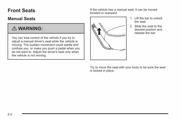
{ WARNING:
You can lose control of the vehicle if you try toadjust a manual driver's seat while the vehicle ismoving. The sudden movement could startle andconfuse you, or make you push a pedal when youdo not want to. Adjust the driver's seat only whenthe vehicle is not moving.
If the vehicle has a manual seat, it can be movedforward or rearward.
1. Lift the bar to unlockthe seat.
2. Slide the seat to thedesired position andrelease the bar.
Try to move the seat with your body to be sure the seatis locked in place.
2-2
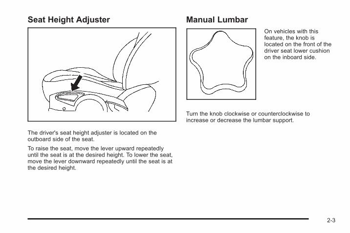
Seat Height Adjuster
The driver's seat height adjuster is located on theoutboard side of the seat.
To raise the seat, move the lever upward repeatedlyuntil the seat is at the desired height. To lower the seat,move the lever downward repeatedly until the seat is atthe desired height.
Manual LumbarOn vehicles with thisfeature, the knob islocated on the front of thedriver seat lower cushionon the inboard side.
Turn the knob clockwise or counterclockwise toincrease or decrease the lumbar support.
2-3
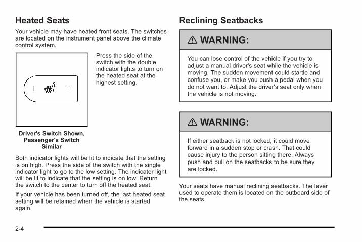
Heated SeatsYour vehicle may have heated front seats. The switchesare located on the instrument panel above the climatecontrol system.
Driver's Switch Shown,Passenger's Switch
Similar
Press the side of theswitch with the doubleindicator lights to turn onthe heated seat at thehighest setting.
Both indicator lights will be lit to indicate that the settingis on high. Press the side of the switch with the singleindicator light to go to the low setting. The indicator lightwill be lit to indicate that the setting is on low. Returnthe switch to the center to turn off the heated seat.
If your vehicle has been turned off, the last heated seatsetting will be retained when the vehicle is startedagain.
Reclining Seatbacks
{ WARNING:
You can lose control of the vehicle if you try toadjust a manual driver's seat while the vehicle ismoving. The sudden movement could startle andconfuse you, or make you push a pedal when youdo not want to. Adjust the driver's seat only whenthe vehicle is not moving.
{ WARNING:
If either seatback is not locked, it could moveforward in a sudden stop or crash. That couldcause injury to the person sitting there. Alwayspush and pull on the seatbacks to be sure theyare locked.
Your seats have manual reclining seatbacks. The leverused to operate them is located on the outboard side ofthe seats.
2-4
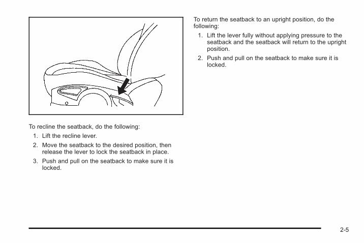
To recline the seatback, do the following:
1. Lift the recline lever.
2. Move the seatback to the desired position, thenrelease the lever to lock the seatback in place.
3. Push and pull on the seatback to make sure it islocked.
To return the seatback to an upright position, do thefollowing:
1. Lift the lever fully without applying pressure to theseatback and the seatback will return to the uprightposition.
2. Push and pull on the seatback to make sure it islocked.
2-5
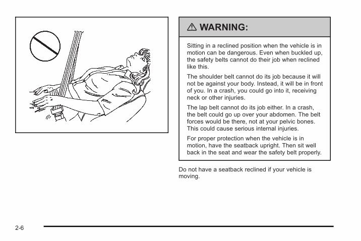
{ WARNING:
Sitting in a reclined position when the vehicle is inmotion can be dangerous. Even when buckled up,the safety belts cannot do their job when reclinedlike this.
The shoulder belt cannot do its job because it willnot be against your body. Instead, it will be in frontof you. In a crash, you could go into it, receivingneck or other injuries.
The lap belt cannot do its job either. In a crash,the belt could go up over your abdomen. The beltforces would be there, not at your pelvic bones.This could cause serious internal injuries.
For proper protection when the vehicle is inmotion, have the seatback upright. Then sit wellback in the seat and wear the safety belt properly.
Do not have a seatback reclined if your vehicle ismoving.
2-6
Head Restraints
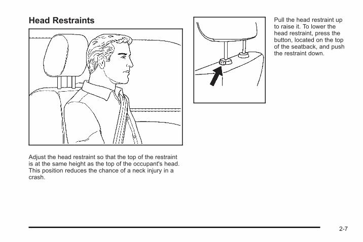
Adjust the head restraint so that the top of the restraintis at the same height as the top of the occupant's head.This position reduces the chance of a neck injury in acrash.
Pull the head restraint upto raise it. To lower thehead restraint, press thebutton, located on the topof the seatback, and pushthe restraint down.
2-7
Easy Entry Seat (Coupe)
{ WARNING:
If the easy entry right front seat is not locked, itcan move. In a sudden stop or crash, the personsitting there could be injured. After you have usedit, be sure to push rearward on an easy entry seatto be sure it is locked.
{ WARNING:
If either seatback is not locked, it could moveforward in a sudden stop or crash. That couldcause injury to the person sitting there. Alwayspush and pull on the seatbacks to be sure theyare locked.
The front passenger seat can be used to easily get inand out of the rear seat.
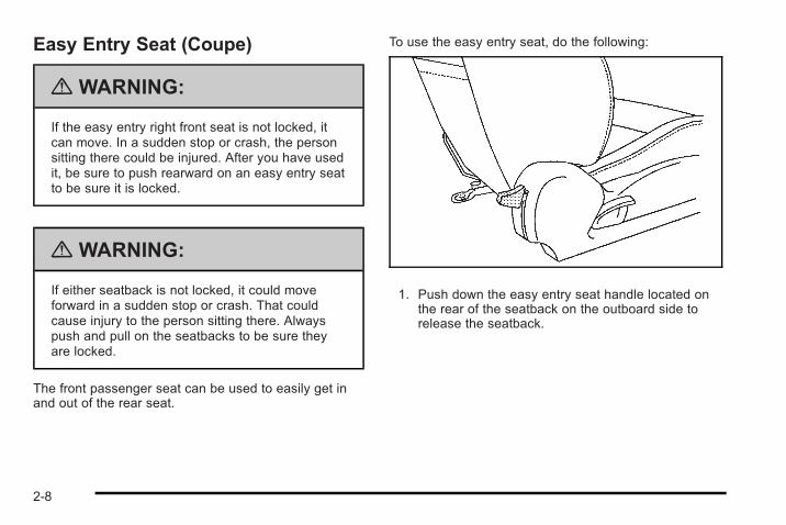
To use the easy entry seat, do the following:
1. Push down the easy entry seat handle located onthe rear of the seatback on the outboard side torelease the seatback.
2-8
2. Tilt the seatback forward completely while pushingthe seat forward.
3. Move the seat rearward until it locks into placeafter someone gets into the rear seat area.
4. Move the seatback to its original position andmake sure the seatback is locked.
Rear Seats
Split Folding Rear SeatYou can fold either side of the rear seatback down formore cargo space.
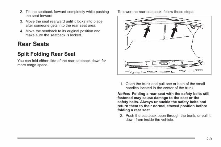
To lower the rear seatback, follow these steps:
1. Open the trunk and pull one or both of the smallhandles located in the center of the trunk.
Notice: Folding a rear seat with the safety belts stillfastened may cause damage to the seat or thesafety belts. Always unbuckle the safety belts andreturn them to their normal stowed position beforefolding a rear seat.
2. Push the seatback open through the trunk, or pull itdown from inside the vehicle.
2-9
To raise the rear seatback, lift it up and push rearwarduntil you hear a click. Push and pull on the seatback tobe sure it is locked into place.
{ WARNING:
If the seatback is not locked, it could moveforward in a sudden stop or crash. That couldcause injury to the person sitting there. Alwayspull forward on the top of the seatback at the areaof the latch to be sure it is locked.
{ WARNING:
A safety belt that is improperly routed, notproperly attached, or twisted will not provide theprotection needed in a crash. The person wearingthe belt could be seriously injured. After raisingthe rear seatback, always check to be sure thatthe safety belts are properly routed and attached,and are not twisted.
Safety Belts
Safety Belts: They Are for EveryoneThis section of the manual describes how to use safetybelts properly. It also describes some things not to dowith safety belts.
{ WARNING:
Do not let anyone ride where a safety belt cannotbe worn properly. In a crash, if you or yourpassenger(s) are not wearing safety belts, theinjuries can be much worse. You can hit thingsinside the vehicle harder or be ejected from thevehicle. You and your passenger(s) can beseriously injured or killed. In the same crash, youmight not be, if you are buckled up. Always fastenyour safety belt, and check that your passenger(s)are restrained properly too.
2-10
{ WARNING:
It is extremely dangerous to ride in a cargo area,inside or outside of a vehicle. In a collision,people riding in these areas are more likely to beseriously injured or killed. Do not allow people toride in any area of your vehicle that is notequipped with seats and safety belts. Be sureeveryone in your vehicle is in a seat and using asafety belt properly.
This vehicle has indicators as a reminder to buckle thesafety belts. See Safety Belt Reminders on page 4‑20for additional information.
In most states and in all Canadian provinces, the lawrequires wearing safety belts. Here is why:
You never know if you will be in a crash. If you do havea crash, you do not know if it will be a serious one.
A few crashes are mild, and some crashes can be soserious that even buckled up, a person would notsurvive. But most crashes are in between. In many ofthem, people who buckle up can survive and sometimeswalk away. Without safety belts, they could have beenbadly hurt or killed.
After more than 40 years of safety belts in vehicles,the facts are clear. In most crashes buckling up doesmatter ... a lot!
2-11
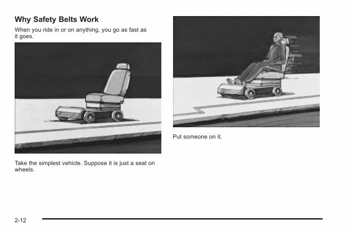
Why Safety Belts WorkWhen you ride in or on anything, you go as fast asit goes.
Take the simplest vehicle. Suppose it is just a seat onwheels.
Put someone on it.
2-12
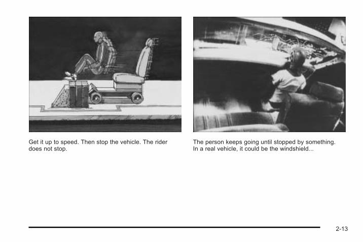
Get it up to speed. Then stop the vehicle. The riderdoes not stop.
The person keeps going until stopped by something.In a real vehicle, it could be the windshield...
2-13
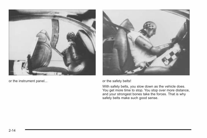
or the instrument panel... or the safety belts!
With safety belts, you slow down as the vehicle does.You get more time to stop. You stop over more distance,and your strongest bones take the forces. That is whysafety belts make such good sense.
2-14
Questions and Answers About SafetyBelts
Q: Will I be trapped in the vehicle after a crash if Iam wearing a safety belt?
A: You could be — whether you are wearing a safetybelt or not. But your chance of being consciousduring and after an accident, so you can unbuckleand get out, is much greater if you are belted.And you can unbuckle a safety belt, even if you areupside down.
Q: If my vehicle has airbags, why should I have towear safety belts?
A: Airbags are supplemental systems only; so theywork with safety belts — not instead of them.Whether or not an airbag is provided, all occupantsstill have to buckle up to get the most protection.That is true not only in frontal collisions, butespecially in side and other collisions.
Q: If I am a good driver, and I never drive far fromhome, why should I wear safety belts?
A: You may be an excellent driver, but if you are in acrash — even one that is not your fault — you andyour passenger(s) can be hurt. Being a good driverdoes not protect you from things beyond yourcontrol, such as bad drivers.
Most accidents occur within 25 miles (40 km) ofhome. And the greatest number of serious injuriesand deaths occur at speeds of less than 40 mph(65 km/h).
Safety belts are for everyone.
How to Wear Safety Belts ProperlyThis section is only for people of adult size.
Be aware that there are special things to know aboutsafety belts and children. And there are different rulesfor smaller children and infants. If a child will be riding inthe vehicle, see Older Children on page 2‑31 or Infantsand Young Children on page 2‑34. Follow those rulesfor everyone's protection.
It is very important for all occupants to buckle up.Statistics show that unbelted people are hurt more oftenin crashes than those who are wearing safety belts.
2-15
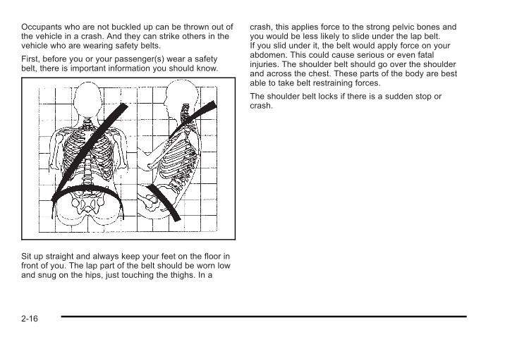
Occupants who are not buckled up can be thrown out ofthe vehicle in a crash. And they can strike others in thevehicle who are wearing safety belts.
First, before you or your passenger(s) wear a safetybelt, there is important information you should know.
Sit up straight and always keep your feet on the floor infront of you. The lap part of the belt should be worn lowand snug on the hips, just touching the thighs. In a
crash, this applies force to the strong pelvic bones andyou would be less likely to slide under the lap belt.If you slid under it, the belt would apply force on yourabdomen. This could cause serious or even fatalinjuries. The shoulder belt should go over the shoulderand across the chest. These parts of the body are bestable to take belt restraining forces.
The shoulder belt locks if there is a sudden stop orcrash.
2-16
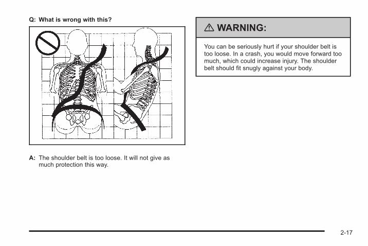
Q: What is wrong with this?
A: The shoulder belt is too loose. It will not give asmuch protection this way.
{ WARNING:
You can be seriously hurt if your shoulder belt istoo loose. In a crash, you would move forward toomuch, which could increase injury. The shoulderbelt should fit snugly against your body.
2-17
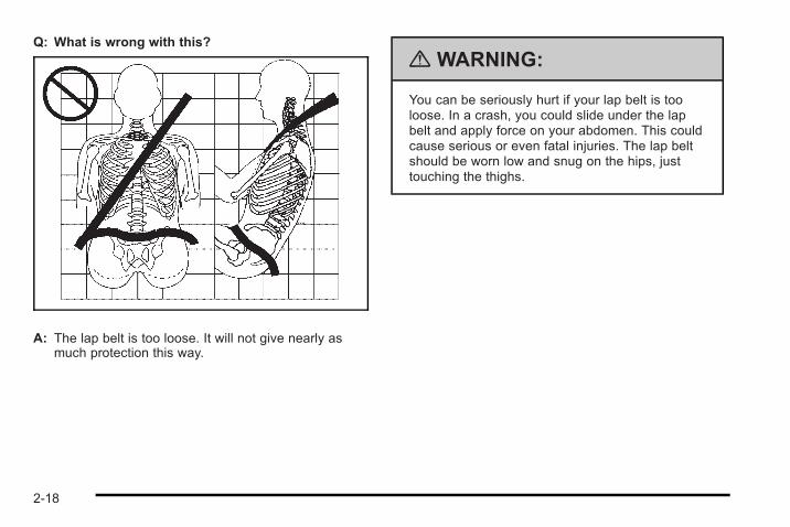
Q: What is wrong with this?
A: The lap belt is too loose. It will not give nearly asmuch protection this way.
{ WARNING:
You can be seriously hurt if your lap belt is tooloose. In a crash, you could slide under the lapbelt and apply force on your abdomen. This couldcause serious or even fatal injuries. The lap beltshould be worn low and snug on the hips, justtouching the thighs.
2-18
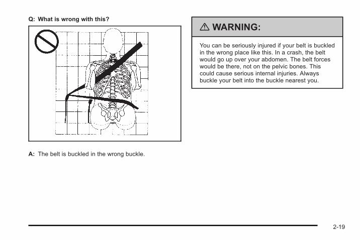
Q: What is wrong with this?
A: The belt is buckled in the wrong buckle.
{ WARNING:
You can be seriously injured if your belt is buckledin the wrong place like this. In a crash, the beltwould go up over your abdomen. The belt forceswould be there, not on the pelvic bones. Thiscould cause serious internal injuries. Alwaysbuckle your belt into the buckle nearest you.
2-19
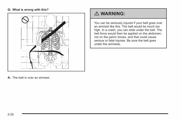
Q: What is wrong with this?
A: The belt is over an armrest.
{ WARNING:
You can be seriously injured if your belt goes overan armrest like this. The belt would be much toohigh. In a crash, you can slide under the belt. Thebelt force would then be applied on the abdomen,not on the pelvic bones, and that could causeserious or fatal injuries. Be sure the belt goesunder the armrests.
2-20
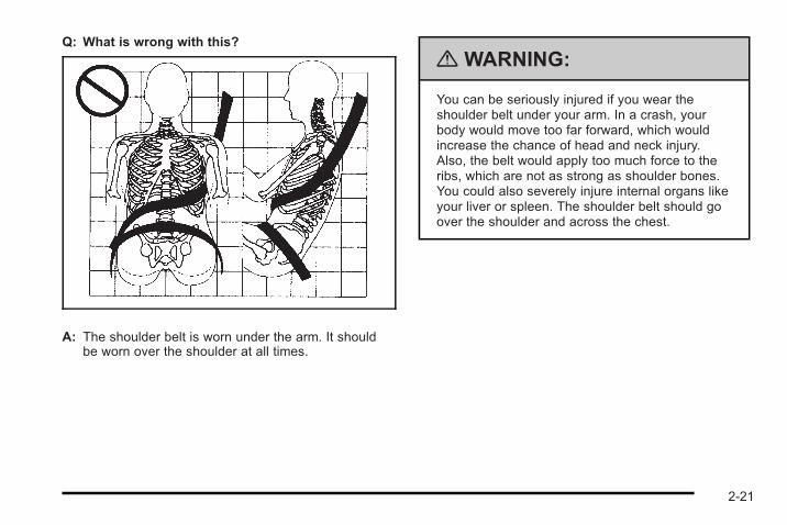
Q: What is wrong with this?
A: The shoulder belt is worn under the arm. It shouldbe worn over the shoulder at all times.
{ WARNING:
You can be seriously injured if you wear theshoulder belt under your arm. In a crash, yourbody would move too far forward, which wouldincrease the chance of head and neck injury.Also, the belt would apply too much force to theribs, which are not as strong as shoulder bones.You could also severely injure internal organs likeyour liver or spleen. The shoulder belt should goover the shoulder and across the chest.
2-21
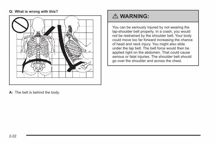
Q: What is wrong with this?
A: The belt is behind the body.
{ WARNING:
You can be seriously injured by not wearing thelap-shoulder belt properly. In a crash, you wouldnot be restrained by the shoulder belt. Your bodycould move too far forward increasing the chanceof head and neck injury. You might also slideunder the lap belt. The belt force would then beapplied right on the abdomen. That could causeserious or fatal injuries. The shoulder belt shouldgo over the shoulder and across the chest.
2-22
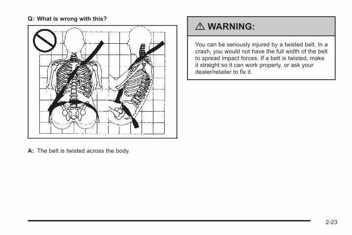
Q: What is wrong with this?
A: The belt is twisted across the body.
{ WARNING:
You can be seriously injured by a twisted belt. In acrash, you would not have the full width of the beltto spread impact forces. If a belt is twisted, makeit straight so it can work properly, or ask yourdealer/retailer to fix it.
2-23
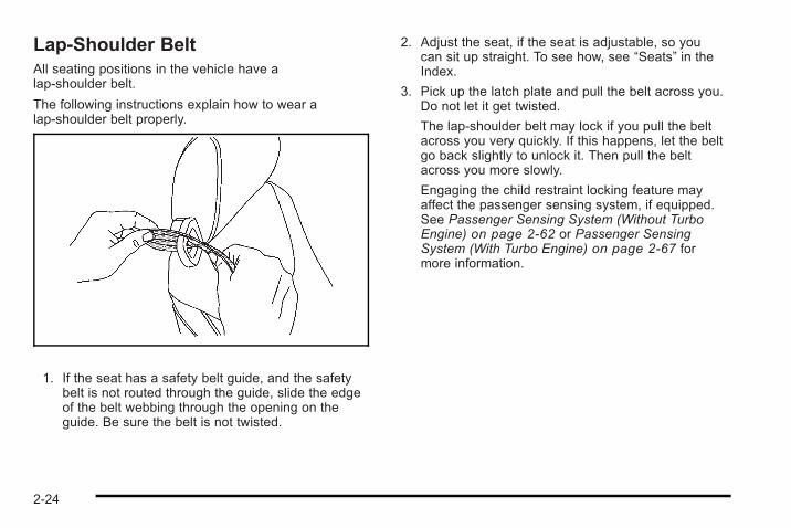
Lap-Shoulder BeltAll seating positions in the vehicle have alap-shoulder belt.
The following instructions explain how to wear alap-shoulder belt properly.
1. If the seat has a safety belt guide, and the safetybelt is not routed through the guide, slide the edgeof the belt webbing through the opening on theguide. Be sure the belt is not twisted.
2. Adjust the seat, if the seat is adjustable, so youcan sit up straight. To see how, see “Seats” in theIndex.
3. Pick up the latch plate and pull the belt across you.Do not let it get twisted.
The lap-shoulder belt may lock if you pull the beltacross you very quickly. If this happens, let the beltgo back slightly to unlock it. Then pull the beltacross you more slowly.
Engaging the child restraint locking feature mayaffect the passenger sensing system, if equipped.See Passenger Sensing System (Without TurboEngine) on page 2‑62 or Passenger SensingSystem (With Turbo Engine) on page 2‑67 formore information.
2-24
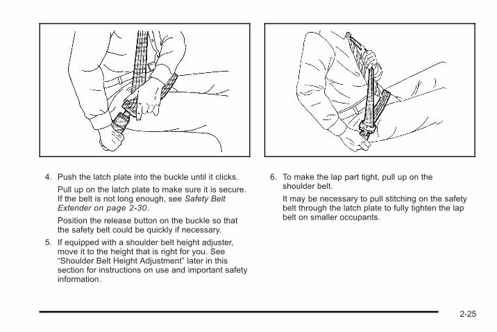
4. Push the latch plate into the buckle until it clicks.
Pull up on the latch plate to make sure it is secure.If the belt is not long enough, see Safety BeltExtender on page 2‑30.
Position the release button on the buckle so thatthe safety belt could be quickly if necessary.
5. If equipped with a shoulder belt height adjuster,move it to the height that is right for you. See“Shoulder Belt Height Adjustment” later in thissection for instructions on use and important safetyinformation.
6. To make the lap part tight, pull up on theshoulder belt.
It may be necessary to pull stitching on the safetybelt through the latch plate to fully tighten the lapbelt on smaller occupants.
2-25
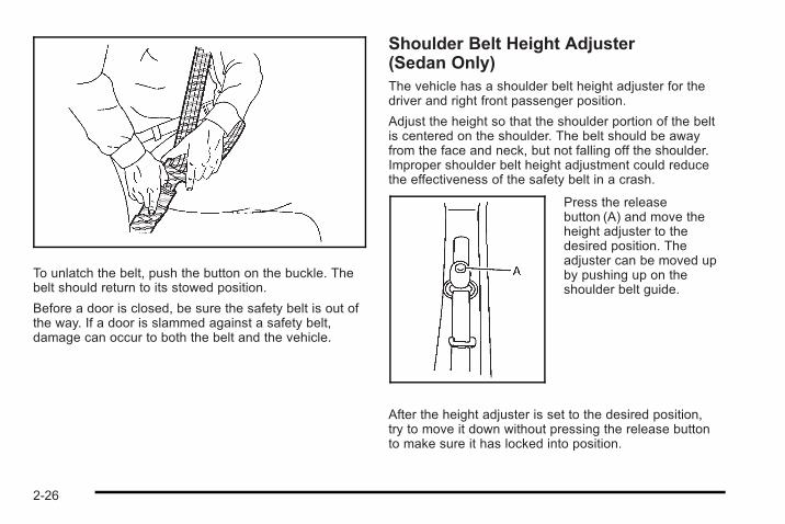
To unlatch the belt, push the button on the buckle. Thebelt should return to its stowed position.
Before a door is closed, be sure the safety belt is out ofthe way. If a door is slammed against a safety belt,damage can occur to both the belt and the vehicle.
Shoulder Belt Height Adjuster(Sedan Only)The vehicle has a shoulder belt height adjuster for thedriver and right front passenger position.
Adjust the height so that the shoulder portion of the beltis centered on the shoulder. The belt should be awayfrom the face and neck, but not falling off the shoulder.Improper shoulder belt height adjustment could reducethe effectiveness of the safety belt in a crash.
Press the releasebutton (A) and move theheight adjuster to thedesired position. Theadjuster can be moved upby pushing up on theshoulder belt guide.
After the height adjuster is set to the desired position,try to move it down without pressing the release buttonto make sure it has locked into position.
2-26
Safety Belt PretensionersThis vehicle has safety belt pretensioners for frontoutboard occupants. Although the safety beltpretensioners cannot be seen, they are part of thesafety belt assembly. They can help tighten the safetybelts during the early stages of a moderate to severefrontal or near frontal crash if the threshold conditionsfor pretensioner activation are met. And, if the vehiclehas side impact airbags, safety belt pretensioners canhelp tighten the safety belts in a side crash.
Pretensioners work only once. If the pretensionersactivate in a crash, they will need to be replaced, andprobably other new parts for the vehicle's safety beltsystem. See Replacing Restraint System Parts After aCrash on page 2‑75.
Rear Safety Belt Comfort GuidesThis vehicle may have rear shoulder belt comfortguides. If not, they are available through your dealer/retailer. The guides may provide added safety beltcomfort for older children who have outgrown boosterseats and for some adults. When installed and properlyadjusted, the comfort guide positions the belt away fromthe neck and head.
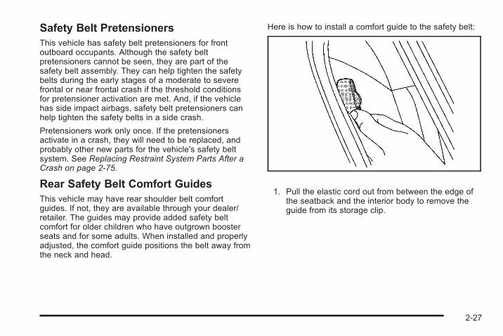
Here is how to install a comfort guide to the safety belt:
1. Pull the elastic cord out from between the edge ofthe seatback and the interior body to remove theguide from its storage clip.
2-27
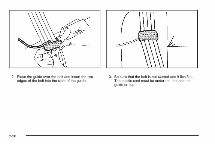
2. Place the guide over the belt and insert the twoedges of the belt into the slots of the guide.
3. Be sure that the belt is not twisted and it lies flat.The elastic cord must be under the belt and theguide on top.
2-28
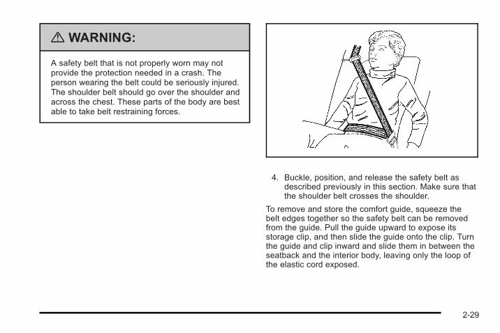
{ WARNING:
A safety belt that is not properly worn may notprovide the protection needed in a crash. Theperson wearing the belt could be seriously injured.The shoulder belt should go over the shoulder andacross the chest. These parts of the body are bestable to take belt restraining forces.
4. Buckle, position, and release the safety belt asdescribed previously in this section. Make sure thatthe shoulder belt crosses the shoulder.
To remove and store the comfort guide, squeeze thebelt edges together so the safety belt can be removedfrom the guide. Pull the guide upward to expose itsstorage clip, and then slide the guide onto the clip. Turnthe guide and clip inward and slide them in between theseatback and the interior body, leaving only the loop ofthe elastic cord exposed.
2-29
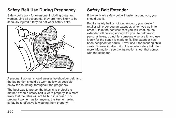
Safety Belt Use During PregnancySafety belts work for everyone, including pregnantwomen. Like all occupants, they are more likely to beseriously injured if they do not wear safety belts.
A pregnant woman should wear a lap-shoulder belt, andthe lap portion should be worn as low as possible,below the rounding, throughout the pregnancy.
The best way to protect the fetus is to protect themother. When a safety belt is worn properly, it is morelikely that the fetus will not be hurt in a crash. Forpregnant women, as for anyone, the key to makingsafety belts effective is wearing them properly.
Safety Belt ExtenderIf the vehicle's safety belt will fasten around you, youshould use it.
But if a safety belt is not long enough, your dealer/retailer will order you an extender. When you go in toorder it, take the heaviest coat you will wear, so theextender will be long enough for you. To help avoidpersonal injury, do not let someone else use it, and useit only for the seat it is made to fit. The extender hasbeen designed for adults. Never use it for securing childseats. To wear it, attach it to the regular safety belt. Formore information, see the instruction sheet that comeswith the extender.
2-30
Child Restraints
Older Children
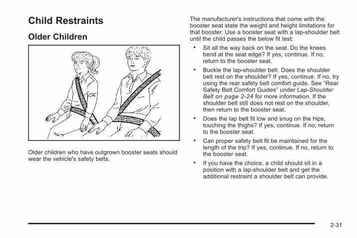
Older children who have outgrown booster seats shouldwear the vehicle's safety belts.
The manufacturer's instructions that come with thebooster seat state the weight and height limitations forthat booster. Use a booster seat with a lap-shoulder beltuntil the child passes the below fit test:. Sit all the way back on the seat. Do the knees
bend at the seat edge? If yes, continue. If no,return to the booster seat.
. Buckle the lap-shoulder belt. Does the shoulderbelt rest on the shoulder? If yes, continue. If no, tryusing the rear safety belt comfort guide. See “RearSafety Belt Comfort Guides” under Lap-ShoulderBelt on page 2‑24 for more information. If theshoulder belt still does not rest on the shoulder,then return to the booster seat.
. Does the lap belt fit low and snug on the hips,touching the thighs? If yes, continue. If no, returnto the booster seat.
. Can proper safety belt fit be maintained for thelength of the trip? If yes, continue. If no, return tothe booster seat.
. If you have the choice, a child should sit in aposition with a lap-shoulder belt and get theadditional restraint a shoulder belt can provide.
2-31
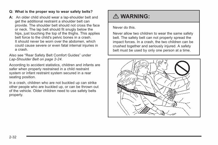
Q: What is the proper way to wear safety belts?
A: An older child should wear a lap-shoulder belt andget the additional restraint a shoulder belt canprovide. The shoulder belt should not cross the faceor neck. The lap belt should fit snugly below thehips, just touching the top of the thighs. This appliesbelt force to the child's pelvic bones in a crash.It should never be worn over the abdomen, whichcould cause severe or even fatal internal injuries ina crash.
Also see “Rear Safety Belt Comfort Guides” underLap-Shoulder Belt on page 2‑24.
According to accident statistics, children and infants aresafer when properly restrained in a child restraintsystem or infant restraint system secured in a rearseating position.
In a crash, children who are not buckled up can strikeother people who are buckled up, or can be thrown outof the vehicle. Older children need to use safety beltsproperly.
{ WARNING:
Never do this.
Never allow two children to wear the same safetybelt. The safety belt can not properly spread theimpact forces. In a crash, the two children can becrushed together and seriously injured. A safetybelt must be used by only one person at a time.
2-32
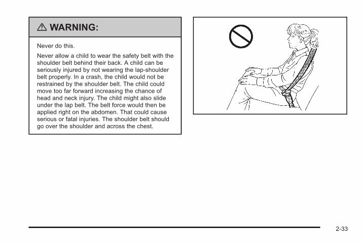
{ WARNING:
Never do this.
Never allow a child to wear the safety belt with theshoulder belt behind their back. A child can beseriously injured by not wearing the lap-shoulderbelt properly. In a crash, the child would not berestrained by the shoulder belt. The child couldmove too far forward increasing the chance ofhead and neck injury. The child might also slideunder the lap belt. The belt force would then beapplied right on the abdomen. That could causeserious or fatal injuries. The shoulder belt shouldgo over the shoulder and across the chest.
2-33
Infants and Young ChildrenEveryone in a vehicle needs protection! This includesinfants and all other children. Neither the distancetraveled nor the age and size of the traveler changesthe need, for everyone, to use safety restraints. In fact,the law in every state in the United States and in everyCanadian province says children up to some age mustbe restrained while in a vehicle.
{ WARNING:
Children can be seriously injured or strangled if ashoulder belt is wrapped around their neck andthe safety belt continues to tighten. Never leavechildren unattended in a vehicle and never allowchildren to play with the safety belts.
Airbags plus lap-shoulder belts offer protection foradults and older children, but not for young children andinfants. Neither the vehicle's safety belt system nor itsairbag system is designed for them. Every time infantsand young children ride in vehicles, they should havethe protection provided by appropriate child restraints.
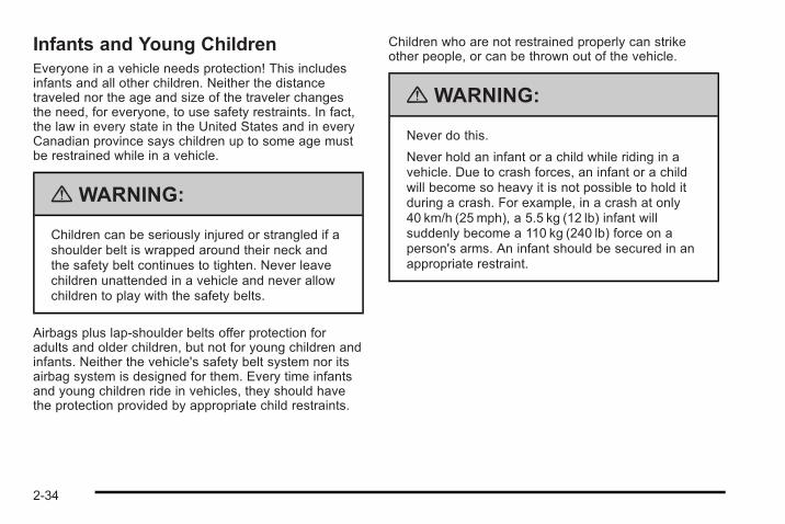
Children who are not restrained properly can strikeother people, or can be thrown out of the vehicle.
{ WARNING:
Never do this.
Never hold an infant or a child while riding in avehicle. Due to crash forces, an infant or a childwill become so heavy it is not possible to hold itduring a crash. For example, in a crash at only40 km/h (25 mph), a 5.5 kg (12 lb) infant willsuddenly become a 110 kg (240 lb) force on aperson's arms. An infant should be secured in anappropriate restraint.
2-34
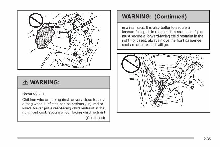
{ WARNING:
Never do this.
Children who are up against, or very close to, anyairbag when it inflates can be seriously injured orkilled. Never put a rear-facing child restraint in theright front seat. Secure a rear-facing child restraint
(Continued)
WARNING: (Continued)
in a rear seat. It is also better to secure aforward-facing child restraint in a rear seat. If youmust secure a forward-facing child restraint in theright front seat, always move the front passengerseat as far back as it will go.
2-35
Q: What are the different types of add-on childrestraints?
A: Add-on child restraints, which are purchased by thevehicle's owner, are available in four basic types.Selection of a particular restraint should take intoconsideration not only the child's weight, height, andage but also whether or not the restraint will becompatible with the motor vehicle in which it willbe used.
For most basic types of child restraints, there aremany different models available. When purchasing achild restraint, be sure it is designed to be used in amotor vehicle. If it is, the restraint will have a labelsaying that it meets federal motor vehicle safetystandards.
The restraint manufacturer's instructions that comewith the restraint state the weight and heightlimitations for a particular child restraint. In addition,there are many kinds of restraints available forchildren with special needs.
{ WARNING:
To reduce the risk of neck and head injury duringa crash, infants need complete support. This isbecause an infant's neck is not fully developedand its head weighs so much compared with therest of its body. In a crash, an infant in arear-facing child restraint settles into the restraint,so the crash forces can be distributed across thestrongest part of an infant's body, the back andshoulders. Infants should always be secured inrear-facing child restraints.
2-36
{ WARNING:
A young child's hip bones are still so small thatthe vehicle's regular safety belt may not remainlow on the hip bones, as it should. Instead, it maysettle up around the child's abdomen. In a crash,the belt would apply force on a body area that isunprotected by any bony structure. This alonecould cause serious or fatal injuries. To reduce therisk of serious or fatal injuries during a crash,young children should always be secured inappropriate child restraints.
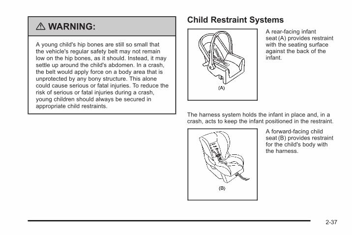
Child Restraint SystemsA rear-facing infantseat (A) provides restraintwith the seating surfaceagainst the back of theinfant.
The harness system holds the infant in place and, in acrash, acts to keep the infant positioned in the restraint.
A forward-facing childseat (B) provides restraintfor the child's body withthe harness.
2-37
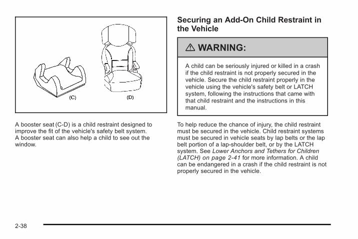
A booster seat (C-D) is a child restraint designed toimprove the fit of the vehicle's safety belt system.A booster seat can also help a child to see out thewindow.
Securing an Add-On Child Restraint inthe Vehicle
{ WARNING:
A child can be seriously injured or killed in a crashif the child restraint is not properly secured in thevehicle. Secure the child restraint properly in thevehicle using the vehicle's safety belt or LATCHsystem, following the instructions that came withthat child restraint and the instructions in thismanual.
To help reduce the chance of injury, the child restraintmust be secured in the vehicle. Child restraint systemsmust be secured in vehicle seats by lap belts or the lapbelt portion of a lap-shoulder belt, or by the LATCHsystem. See Lower Anchors and Tethers for Children(LATCH) on page 2‑41 for more information. A childcan be endangered in a crash if the child restraint is notproperly secured in the vehicle.
2-38
When securing an add-on child restraint, refer to theinstructions that come with the restraint which may beon the restraint itself or in a booklet, or both, and to thismanual. The child restraint instructions are important,so if they are not available, obtain a replacement copyfrom the manufacturer.
Keep in mind that an unsecured child restraint canmove around in a collision or sudden stop and injurepeople in the vehicle. Be sure to properly secure anychild restraint in the vehicle — even when no childis in it.
Securing the Child Within the ChildRestraint
{ WARNING:
A child can be seriously injured or killed in a crashif the child is not properly secured in the childrestraint. Secure the child properly following theinstructions that came with that child restraint.
Where to Put the RestraintAccording to accident statistics, children and infants aresafer when properly restrained in a child restraintsystem or infant restraint system secured in a rearseating position.
We recommend that children and child restraints besecured in a rear seat, including: an infant or a childriding in a rear-facing child restraint; a child riding in aforward-facing child seat; an older child riding in abooster seat; and children, who are large enough, usingsafety belts.
2-39
A label on the sun visor says, “Never put a rear-facingchild restraint in the front.” This is because the risk tothe rear-facing child is so great, if the airbag deploys.
{ WARNING:
A child in a rear-facing child restraint can beseriously injured or killed if the right frontpassenger airbag inflates. This is because theback of the rear-facing child restraint would bevery close to the inflating airbag. A child in aforward-facing child restraint can be seriouslyinjured or killed if the right front passenger airbaginflates and the passenger seat is in a forwardposition.
The vehicle may have a passenger sensingsystem which is designed to turn off the right frontpassenger frontal airbag under certain conditions.
(Continued)
WARNING: (Continued)
Even if the passenger sensing system,if equipped, has turned off the right frontpassenger frontal airbag, no system is fail-safe.No one can guarantee that an airbag will notdeploy under some unusual circumstance, eventhough it is turned off.
Secure rear-facing child restraints in a rear seat,even if the airbag is off. If you secure aforward-facing child restraint in the right front seat,always move the front passenger seat as far backas it will go. It is better to secure the child restraintin a rear seat.
See Passenger Sensing System (Without TurboEngine) on page 2‑62 or Passenger SensingSystem (With Turbo Engine) on page 2‑67 foradditional information.
When securing a child restraint in a rear seatingposition, study the instructions that came with the childrestraint to make sure it is compatible with this vehicle.
Wherever a child restraint is installed, be sure to securethe child restraint properly.
2-40
Keep in mind that an unsecured child restraint canmove around in a collision or sudden stop and injurepeople in the vehicle. Be sure to properly secure anychild restraint in the vehicle — even when no childis in it.
Lower Anchors and Tethers forChildren (LATCH)The LATCH system holds a child restraint during drivingor in a crash. This system is designed to makeinstallation of a child restraint easier. The LATCHsystem uses anchors in the vehicle and attachments onthe child restraint that are made for use with the LATCHsystem.
Make sure that a LATCH-compatible child restraint isproperly installed using the anchors, or use the vehicle'ssafety belts to secure the restraint, following theinstructions that came with that restraint, and also theinstructions in this manual. When installing a childrestraint with a top tether, you must also use either thelower anchors or the safety belts to properly secure thechild restraint. A child restraint must never be installedusing only the top tether and anchor.
In order to use the LATCH system in your vehicle, youneed a child restraint that has LATCH attachments.The child restraint manufacturer will provide you with
instructions on how to use the child restraint and itsattachments. The following explains how to attach achild restraint with these attachments in your vehicle.
Not all vehicle seating positions or child restraints havelower anchors and attachments or top tether anchorsand attachments.
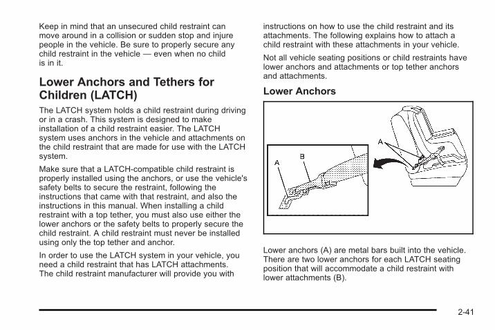
Lower Anchors
Lower anchors (A) are metal bars built into the vehicle.There are two lower anchors for each LATCH seatingposition that will accommodate a child restraint withlower attachments (B).
2-41
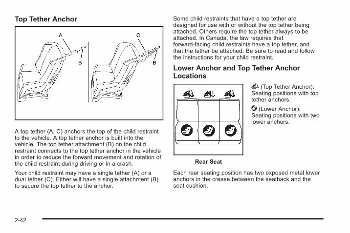
Top Tether Anchor
A top tether (A, C) anchors the top of the child restraintto the vehicle. A top tether anchor is built into thevehicle. The top tether attachment (B) on the childrestraint connects to the top tether anchor in the vehiclein order to reduce the forward movement and rotation ofthe child restraint during driving or in a crash.
Your child restraint may have a single tether (A) or adual tether (C). Either will have a single attachment (B)to secure the top tether to the anchor.
Some child restraints that have a top tether aredesigned for use with or without the top tether beingattached. Others require the top tether always to beattached. In Canada, the law requires thatforward-facing child restraints have a top tether, andthat the tether be attached. Be sure to read and followthe instructions for your child restraint.
Lower Anchor and Top Tether AnchorLocations
Rear Seat
i (Top Tether Anchor):Seating positions with toptether anchors.
j (Lower Anchor):Seating positions with twolower anchors.
Each rear seating position has two exposed metal loweranchors in the crease between the seatback and theseat cushion.
2-42
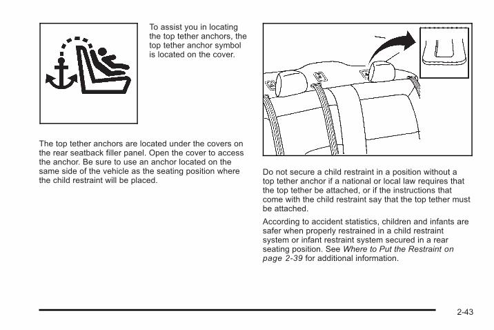
To assist you in locatingthe top tether anchors, thetop tether anchor symbolis located on the cover.
The top tether anchors are located under the covers onthe rear seatback filler panel. Open the cover to accessthe anchor. Be sure to use an anchor located on thesame side of the vehicle as the seating position wherethe child restraint will be placed.
Do not secure a child restraint in a position without atop tether anchor if a national or local law requires thatthe top tether be attached, or if the instructions thatcome with the child restraint say that the top tether mustbe attached.
According to accident statistics, children and infants aresafer when properly restrained in a child restraintsystem or infant restraint system secured in a rearseating position. See Where to Put the Restraint onpage 2‑39 for additional information.
2-43
Securing a Child Restraint Designed for theLATCH System
{ WARNING:
If a LATCH-type child restraint is not attached toanchors, the child restraint will not be able toprotect the child correctly. In a crash, the childcould be seriously injured or killed. Install aLATCH-type child restraint properly using theanchors, or use the vehicle's safety belts tosecure the restraint, following the instructions thatcame with the child restraint and the instructionsin this manual.
{ WARNING:
Do not attach more than one child restraint to asingle anchor. Attaching more than one childrestraint to a single anchor could cause theanchor or attachment to come loose or evenbreak during a crash. A child or others could beinjured. To reduce the risk of serious or fatalinjuries during a crash, attach only one childrestraint per anchor.
{ WARNING:
Children can be seriously injured or strangled if ashoulder belt is wrapped around their neck andthe safety belt continues to tighten. Buckle anyunused safety belts behind the child restraint sochildren cannot reach them. Pull the shoulder beltall the way out of the retractor to set the lock,if your vehicle has one, after the child restrainthas been installed.
2-44
Notice: Do not let the LATCH attachments rubagainst the vehicle’s safety belts. This may damagethese parts. If necessary, move buckled safety beltsto avoid rubbing the LATCH attachments.
Do not fold the empty rear seat with a safety beltbuckled. This could damage the safety belt or theseat. Unbuckle and return the safety belt to itsstowed position, before folding the seat.
1. Attach and tighten the lower attachments to thelower anchors. If the child restraint does not havelower attachments or the desired seating positiondoes not have lower anchors, secure the childrestraint with the top tether and the safety belts.Refer to your child restraint manufacturerinstructions and the instructions in this manual.
1.1. Find the lower anchors for the desiredseating position.
1.2. Put the child restraint on the seat.
1.3. Attach and tighten the lower attachments onthe child restraint to the lower anchors.
2. If the child restraint manufacturer recommends thatthe top tether be attached, attach and tighten thetop tether to the top tether anchor, if equipped.Refer to the child restraint instructions and thefollowing steps:
2.1. Find the top tether anchor.
2.2. Open the top tether anchor cover to exposethe anchor.
2.3. If you have an adjustable headrest or headrestraint, raise the headrest or head restraint.
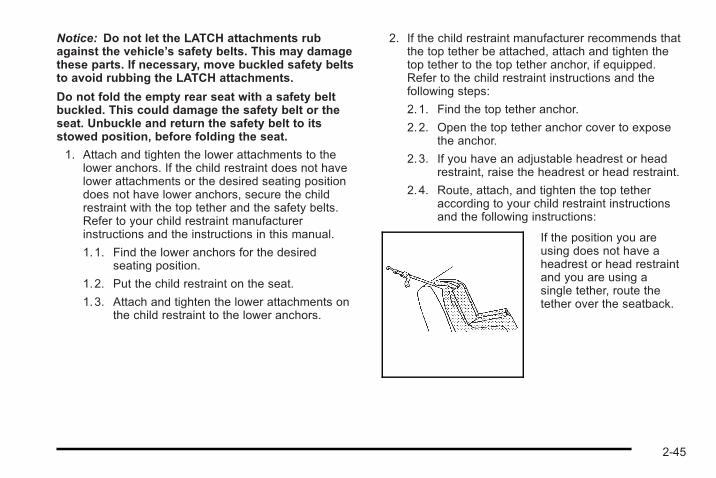
2.4. Route, attach, and tighten the top tetheraccording to your child restraint instructionsand the following instructions:
If the position you areusing does not have aheadrest or head restraintand you are using asingle tether, route thetether over the seatback.
2-45
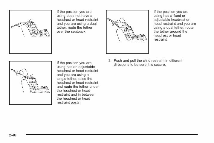
If the position you areusing does not have aheadrest or head restraintand you are using a dualtether, route the tetherover the seatback.
If the position you areusing has an adjustableheadrest or head restraintand you are using asingle tether, raise theheadrest or head restraintand route the tether underthe headrest or headrestraint and in betweenthe headrest or headrestraint posts.
If the position you areusing has a fixed oradjustable headrest orhead restraint and you areusing a dual tether, routethe tether around theheadrest or headrestraint.
3. Push and pull the child restraint in differentdirections to be sure it is secure.
2-46
Securing a Child Restraint in a RearSeat PositionWhen securing a child restraint in a rear seatingposition, study the instructions that came with your childrestraint to make sure it is compatible with this vehicle.
If your child restraint has the LATCH system, see LowerAnchors and Tethers for Children (LATCH) onpage 2‑41 for how to install your child restraint usingLATCH. If you secure a child restraint using a safetybelt and it uses a top tether, see Lower Anchors andTethers for Children (LATCH) on page 2‑41 for toptether anchor locations.
Do not secure a child restraint in a position without atop tether anchor if a national or local law requires thatthe top tether be anchored, or if the instructions thatcome with the child restraint say that the top strap mustbe anchored.
In Canada, the law requires that forward-facing childrestraints have a top tether, and that the tether beattached.
If your child restraint does not have the LATCH system,you will be using the safety belt to secure the childrestraint in this position. Be sure to follow theinstructions that came with the child restraint. Securethe child in the child restraint when and as theinstructions say.
If you need to install more than one child restraint in therear seat, be sure to read Where to Put the Restraint onpage 2‑39.
1. Put the child restraint on the seat.
2. Pick up the latch plate, and run the lap andshoulder portions of the vehicle's safety beltthrough or around the restraint. The child restraintinstructions will show you how.
2-47
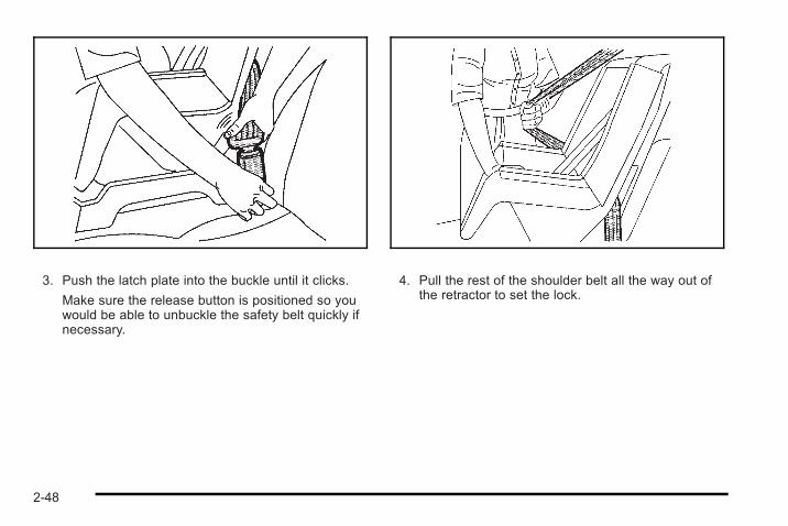
3. Push the latch plate into the buckle until it clicks.
Make sure the release button is positioned so youwould be able to unbuckle the safety belt quickly ifnecessary.
4. Pull the rest of the shoulder belt all the way out ofthe retractor to set the lock.
2-48
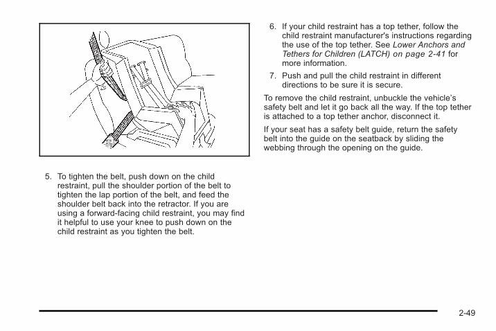
5. To tighten the belt, push down on the childrestraint, pull the shoulder portion of the belt totighten the lap portion of the belt, and feed theshoulder belt back into the retractor. If you areusing a forward-facing child restraint, you may findit helpful to use your knee to push down on thechild restraint as you tighten the belt.
6. If your child restraint has a top tether, follow thechild restraint manufacturer's instructions regardingthe use of the top tether. See Lower Anchors andTethers for Children (LATCH) on page 2‑41 formore information.
7. Push and pull the child restraint in differentdirections to be sure it is secure.
To remove the child restraint, unbuckle the vehicle’ssafety belt and let it go back all the way. If the top tetheris attached to a top tether anchor, disconnect it.
If your seat has a safety belt guide, return the safetybelt into the guide on the seatback by sliding thewebbing through the opening on the guide.
2-49
Securing a Child Restraint in theRight Front Seat PositionThe vehicle has airbags. A rear seat is a safer place tosecure a forward-facing child restraint. See Where toPut the Restraint .
In addition, the vehicle may have a passenger sensingsystem which is designed to turn off the right frontpassenger frontal airbag under certain conditions. SeePassenger Sensing System and Passenger AirbagStatus Indicator for more information on this, includingimportant safety information.
A label on your sun visor says, “Never put a rear-facingchild seat in the front.” This is because the risk to therear-facing child is so great, if the airbag deploys.
{ WARNING:
A child in a rear-facing child restraint can beseriously injured or killed if the right frontpassenger airbag inflates. This is because theback of the rear-facing child restraint would bevery close to the inflating airbag. A child in aforward-facing child restraint can be seriously
(Continued)
WARNING: (Continued)
injured or killed if the right front passenger airbaginflates and the passenger seat is in a forwardposition.
The vehicle may have a passenger sensingsystem which is designed to turn off the right frontpassenger frontal airbag under certain conditions.
Even if the passenger sensing system,if equipped, has turned off the right frontpassenger frontal airbag, no system is fail-safe.No one can guarantee that an airbag will notdeploy under some unusual circumstance, eventhough it is turned off.
Secure rear-facing child restraints in a rear seat,even if the airbag is off. If you secure aforward-facing child restraint in the right front seat,always move the front passenger seat as far backas it will go. It is better to secure the child restraintin a rear seat.
See Passenger Sensing System (Without TurboEngine) on page 2‑62 or Passenger SensingSystem (With Turbo Engine) on page 2‑67 foradditional information.
2-50
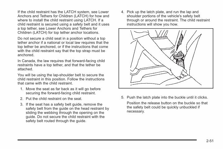
If the child restraint has the LATCH system, see LowerAnchors and Tethers for Children (LATCH) for how andwhere to install the child restraint using LATCH. If achild restraint is secured using a safety belt and it usesa top tether, see Lower Anchors and Tethers forChildren (LATCH) for top tether anchor locations.
Do not secure a child seat in a position without a toptether anchor if a national or local law requires that thetop tether be anchored, or if the instructions that comewith the child restraint say that the top strap must beanchored.
In Canada, the law requires that forward-facing childrestraints have a top tether, and that the tether beattached.
You will be using the lap-shoulder belt to secure thechild restraint in this position. Follow the instructionsthat came with the child restraint.
1. Move the seat as far back as it will go beforesecuring the forward-facing child restraint.
2. Put the child restraint on the seat.
3. If the seat has a safety belt guide, remove thesafety belt from the guide on the head restraint bysliding the webbing through the opening on theguide. Do not secure the child restraint with thesafety belt routed through the guide.
4. Pick up the latch plate, and run the lap andshoulder portions of the vehicle's safety beltthrough or around the restraint. The child restraintinstructions will show you how.
5. Push the latch plate into the buckle until it clicks.
Position the release button on the buckle so thatthe safety belt could be quickly unbuckled ifnecessary.
2-51
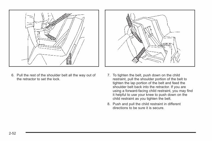
6. Pull the rest of the shoulder belt all the way out ofthe retractor to set the lock.
7. To tighten the belt, push down on the childrestraint, pull the shoulder portion of the belt totighten the lap portion of the belt and feed theshoulder belt back into the retractor. If you areusing a forward-facing child restraint, you may findit helpful to use your knee to push down on thechild restraint as you tighten the belt.
8. Push and pull the child restraint in differentdirections to be sure it is secure.
2-52
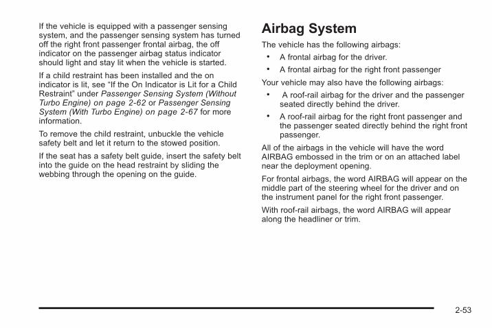
If the vehicle is equipped with a passenger sensingsystem, and the passenger sensing system has turnedoff the right front passenger frontal airbag, the offindicator on the passenger airbag status indicatorshould light and stay lit when the vehicle is started.
If a child restraint has been installed and the onindicator is lit, see “If the On Indicator is Lit for a ChildRestraint” under Passenger Sensing System (WithoutTurbo Engine) on page 2‑62 or Passenger SensingSystem (With Turbo Engine) on page 2‑67 for moreinformation.
To remove the child restraint, unbuckle the vehiclesafety belt and let it return to the stowed position.
If the seat has a safety belt guide, insert the safety beltinto the guide on the head restraint by sliding thewebbing through the opening on the guide.
Airbag SystemThe vehicle has the following airbags:. A frontal airbag for the driver.. A frontal airbag for the right front passenger
Your vehicle may also have the following airbags:. A roof-rail airbag for the driver and the passenger
seated directly behind the driver.. A roof-rail airbag for the right front passenger and
the passenger seated directly behind the right frontpassenger.
All of the airbags in the vehicle will have the wordAIRBAG embossed in the trim or on an attached labelnear the deployment opening.
For frontal airbags, the word AIRBAG will appear on themiddle part of the steering wheel for the driver and onthe instrument panel for the right front passenger.
With roof-rail airbags, the word AIRBAG will appearalong the headliner or trim.
2-53
Airbags are designed to supplement the protectionprovided by safety belts. Even though today's airbagsare also designed to help reduce the risk of injury fromthe force of an inflating bag, all airbags must inflate veryquickly to do their job.
Here are the most important things to know about theairbag system:
{ WARNING:
You can be severely injured or killed in a crash ifyou are not wearing your safety belt— even if youhave airbags. Airbags are designed to work withsafety belts, but do not replace them. Also,airbags are not designed to deploy in every crash.In some crashes safety belts are your onlyrestraint. See When Should an Airbag Inflate? onpage 2‑58.
Wearing your safety belt during a crash helpsreduce your chance of hitting things inside thevehicle or being ejected from it. Airbags are“supplemental restraints” to the safety belts.Everyone in your vehicle should wear a safety beltproperly—whether or not there is an airbag forthat person.
{ WARNING:
Airbags inflate with great force, faster than theblink of an eye. Anyone who is up against, or veryclose to, any airbag when it inflates can beseriously injured or killed. Do not sit unnecessarilyclose to the airbag, as you would be if you weresitting on the edge of your seat or leaning forward.Safety belts help keep you in position before andduring a crash. Always wear your safety belt,even with airbags. The driver should sit as farback as possible while still maintaining control ofthe vehicle.
Occupants should not lean on or sleep against thedoor or side windows in seating positions withroof-rail airbags.
2-54
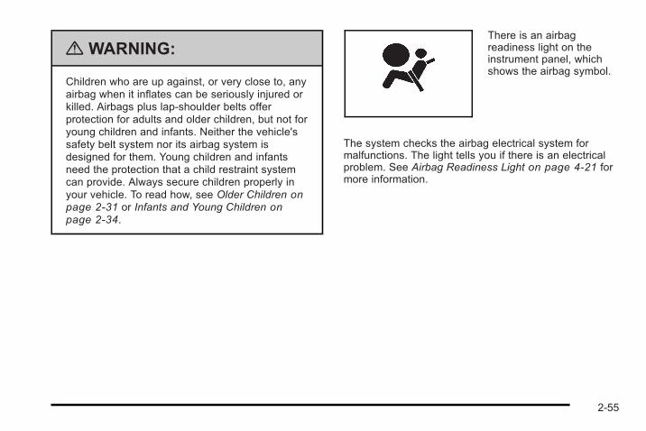
{ WARNING:
Children who are up against, or very close to, anyairbag when it inflates can be seriously injured orkilled. Airbags plus lap-shoulder belts offerprotection for adults and older children, but not foryoung children and infants. Neither the vehicle'ssafety belt system nor its airbag system isdesigned for them. Young children and infantsneed the protection that a child restraint systemcan provide. Always secure children properly inyour vehicle. To read how, see Older Children onpage 2‑31 or Infants and Young Children onpage 2‑34.
There is an airbagreadiness light on theinstrument panel, whichshows the airbag symbol.
The system checks the airbag electrical system formalfunctions. The light tells you if there is an electricalproblem. See Airbag Readiness Light on page 4‑21 formore information.
2-55
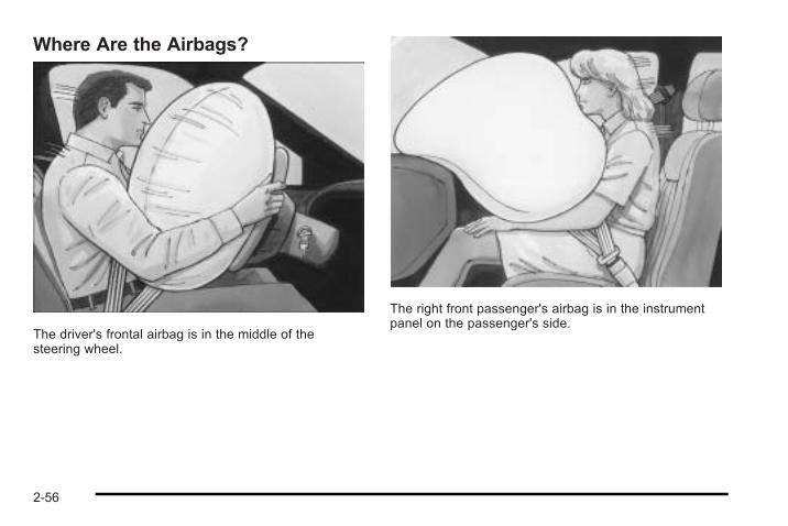
Where Are the Airbags?
The driver's frontal airbag is in the middle of thesteering wheel.
The right front passenger's airbag is in the instrumentpanel on the passenger's side.
2-56
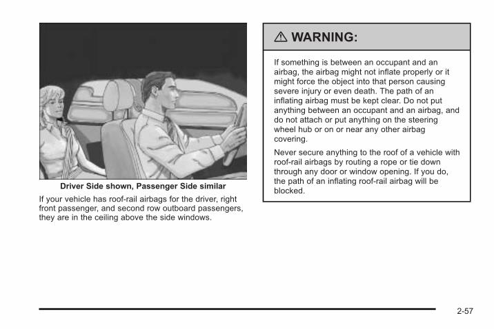
Driver Side shown, Passenger Side similar
If your vehicle has roof-rail airbags for the driver, rightfront passenger, and second row outboard passengers,they are in the ceiling above the side windows.
{ WARNING:
If something is between an occupant and anairbag, the airbag might not inflate properly or itmight force the object into that person causingsevere injury or even death. The path of aninflating airbag must be kept clear. Do not putanything between an occupant and an airbag, anddo not attach or put anything on the steeringwheel hub or on or near any other airbagcovering.
Never secure anything to the roof of a vehicle withroof-rail airbags by routing a rope or tie downthrough any door or window opening. If you do,the path of an inflating roof-rail airbag will beblocked.
2-57
When Should an Airbag Inflate?Frontal airbags are designed to inflate in moderate tosevere frontal or near-frontal crashes to help reduce thepotential for severe injuries mainly to the driver's or rightfront passenger's head and chest. However, they areonly designed to inflate if the impact exceeds apredetermined deployment threshold. Deploymentthresholds are used to predict how severe a crash islikely to be in time for the airbags to inflate and helprestrain the occupants.
Whether your frontal airbags will or should deploy is notbased on how fast your vehicle is traveling. It dependslargely on what you hit, the direction of the impact, andhow quickly your vehicle slows down.
Frontal airbags may inflate at different crash speeds.For example:. If the vehicle hits a stationary object, the airbags
could inflate at a different crash speed than if thevehicle hits a moving object.
. If the vehicle hits an object that deforms, theairbags could inflate at a different crash speedthan if the vehicle hits an object that does notdeform.
. If the vehicle hits a narrow object (like a pole), theairbags could inflate at a different crash speedthan if the vehicle hits a wide object (like a wall).
. If the vehicle goes into an object at an angle, theairbags could inflate at a different crash speedthan if the vehicle goes straight into the object.
Thresholds can also vary with specific vehicle design.
Frontal airbags are not intended to inflate during vehiclerollovers, rear impacts, or in many side impacts.
In addition, your vehicle has dual-stage frontal airbags.Dual-stage airbags adjust the restraint according tocrash severity. Your vehicle has an electronic frontalsensor, which helps the sensing system distinguishbetween a moderate frontal impact and a more severefrontal impact. For moderate frontal impacts, dual-stageairbags inflate at a level less than full deployment. Formore severe frontal impacts, full deployment occurs.
Your vehicle may have roof-rail airbags. See AirbagSystem on page 2‑53. Roof-rail airbags are intended toinflate in moderate to severe side crashes. Roof-railairbags will inflate if the crash severity is above thesystem's designed threshold level. The threshold levelcan vary with specific vehicle design.
2-58
Roof-rail airbags are not intended to inflate in frontalimpacts, near-frontal impacts, rollovers, or rear impacts.A roof-rail airbag is intended to deploy on the side of thevehicle that is struck.
In any particular crash, no one can say whether anairbag should have inflated simply because of thedamage to a vehicle or because of what the repair costswere. For frontal airbags, inflation is determined by whatthe vehicle hits, the angle of the impact, and howquickly the vehicle slows down. For roof-rail airbags,deployment is determined by the location and severityof the side impact.
What Makes an Airbag Inflate?In a deployment event, the sensing system sends anelectrical signal triggering a release of gas from theinflator. Gas from the inflator fills the airbag causing thebag to break out of the cover and deploy. The inflator,the airbag, and related hardware are all part of theairbag module.
Frontal airbag modules are located inside the steeringwheel and instrument panel. For vehicles with roof-railairbags, there are airbag modules in the ceiling of thevehicle, near the side windows that have occupantseating positions.
How Does an Airbag Restrain?In moderate to severe frontal or near frontal collisions,even belted occupants can contact the steering wheelor the instrument panel. In moderate to severe sidecollisions, even belted occupants can contact the insideof the vehicle.
Airbags supplement the protection provided by safetybelts. Frontal airbags distribute the force of the impactmore evenly over the occupant's upper body, stoppingthe occupant more gradually. Roof-rail airbags distributethe force of the impact more evenly over the occupant'supper body.
But airbags would not help in many types of collisions,primarily because the occupant's motion is not towardthose airbags. See When Should an Airbag Inflate? onpage 2‑58 for more information.
Airbags should never be regarded as anything morethan a supplement to safety belts.
2-59
What Will You See After an AirbagInflates?After the frontal airbags inflate, they quickly deflate, soquickly that some people may not even realize anairbag inflated. Roof-rail airbags may still be at leastpartially inflated for some time after they deploy. Somecomponents of the airbag module may be hot forseveral minutes. For location of the airbag modules, seeWhat Makes an Airbag Inflate? on page 2‑59.
The parts of the airbag that come into contact with youmay be warm, but not too hot to touch. There may besome smoke and dust coming from the vents in thedeflated airbags. Airbag inflation does not prevent thedriver from seeing out of the windshield or being able tosteer the vehicle, nor does it prevent people fromleaving the vehicle.
{ WARNING:
When an airbag inflates, there may be dust in theair. This dust could cause breathing problems forpeople with a history of asthma or other breathingtrouble. To avoid this, everyone in the vehicleshould get out as soon as it is safe to do so.If you have breathing problems but cannot get outof the vehicle after an airbag inflates, then getfresh air by opening a window or a door. If youexperience breathing problems following an airbagdeployment, you should seek medical attention.
The vehicle has a feature that may automatically unlockthe doors, turn on the interior lamps and hazard warningflashers, and shut off the fuel system after the airbagsinflate. You can lock the doors, turn off the interiorlamps and hazard warning flashers by using thecontrols for those features.
2-60
{ WARNING:
A crash severe enough to inflate the airbags mayhave also damaged important functions in thevehicle, such as the fuel system, brake andsteering systems, etc. Even if the vehicle appearsto be drivable after a moderate crash, there maybe concealed damage that could make it difficultto safely operate the vehicle.
Use caution if you should attempt to restart theengine after a crash has occurred.
In many crashes severe enough to inflate the airbag,windshields are broken by vehicle deformation.Additional windshield breakage may also occur from theright front passenger airbag.. Airbags are designed to inflate only once. After an
airbag inflates, you will need some new parts forthe airbag system. If you do not get them, theairbag system will not be there to help protect youin another crash. A new system will include airbagmodules and possibly other parts. The servicemanual for the vehicle covers the need to replaceother parts.
. The vehicle has a crash sensing and diagnosticmodule which records information after a crash.See Vehicle Data Recording and Privacy onpage 8‑17 and Event Data Recorders onpage 8‑18.
. Let only qualified technicians work on the airbagsystems. Improper service can mean that anairbag system will not work properly. See yourdealer/retailer for service.
2-61
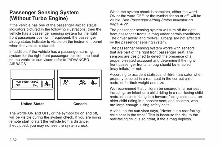
Passenger Sensing System(Without Turbo Engine)If the vehicle has one of the passenger airbag statusindicators pictured in the following illustrations, then thevehicle has a passenger sensing system for the rightfront passenger position. If equipped, the passengerairbag status indicator is visible on the instrument panelwhen the vehicle is started.
In addition, if the vehicle has a passenger sensingsystem for the right front passenger position, the labelon the vehicle's sun visors refer to “ADVANCEDAIRBAGS”.
United States Canada
The words ON and OFF, or the symbol for on and off,will be visible during the system check. If you are usingremote start to start the vehicle from a distance,if equipped, you may not see the system check.
When the system check is complete, either the wordON or the word OFF, or the symbol for on or off, will bevisible. See Passenger Airbag Status Indicator onpage 4‑22.
The passenger sensing system will turn off the rightfront passenger frontal airbag under certain conditions.The driver airbag and roof-rail airbags are not affectedby the passenger sensing system.
The passenger sensing system works with sensorsthat are part of the right front passenger seat. Thesensors are designed to detect the presence of aproperly-seated occupant and determine if the rightfront passenger frontal airbag should be enabled(may inflate) or not.
According to accident statistics, children are safer whenproperly secured in a rear seat in the correct childrestraint for their weight and size.
We recommend that children be secured in a rear seat,including: an infant or a child riding in a rear-facing childrestraint; a child riding in a forward-facing child seat; anolder child riding in a booster seat; and children, whoare large enough, using safety belts.
A label on the sun visor says, “Never put a rear-facingchild seat in the front.” This is because the risk to therear-facing child is so great, if the airbag deploys.
2-62
{ WARNING:
A child in a rear-facing child restraint can beseriously injured or killed if the right frontpassenger airbag inflates. This is because theback of the rear-facing child restraint would bevery close to the inflating airbag. A child in aforward-facing child restraint can be seriouslyinjured or killed if the right front passenger airbaginflates and the passenger seat is in a forwardposition.
Even if the passenger sensing system has turnedoff the right front passenger frontal airbag, nosystem is fail-safe. No one can guarantee that anairbag will not deploy under some unusualcircumstance, even though the airbag isturned off.
Secure rear-facing child restraints in a rear seat,even if the airbag is off. If you secure aforward-facing child restraint in the right front seat,always move the front passenger seat as far backas it will go. It is better to secure the child restraintin a rear seat.
The passenger sensing system is designed to turn offthe right front passenger frontal airbag if:. The right front passenger seat is unoccupied.. The system determines that an infant is present in
a child restraint.. A right front passenger takes his/her weight off of
the seat for a period of time.. Or, if there is a critical problem with the airbag
system or the passenger sensing system.
When the passenger sensing system has turned off theright front passenger frontal airbag, the off indicator willlight and stay lit to remind you that the airbag is off.See Passenger Airbag Status Indicator on page 4‑22.
The passenger sensing system is designed turn on(may inflate) the right front passenger frontal airbaganytime the system senses that a person of adult size issitting properly in the right front passenger seat. Whenthe passenger sensing system has allowed the airbagto be enabled, the on indicator will light and stay lit toremind you that the airbag is active.
2-63
For some children, including children in child restraints,and for very small adults, the passenger sensingsystem may or may not turn off the right front passengerfrontal airbag, depending upon the person's seatingposture and body build. Everyone in the vehicle whohas outgrown child restraints should wear a safety beltproperly — whether or not there is an airbag for thatperson.
{ WARNING:
If the airbag readiness light ever comes on andstays on, it means that something may be wrongwith the airbag system. To help avoid injury toyourself or others, have the vehicle serviced rightaway. See Airbag Readiness Light on page 4‑21for more information, including important safetyinformation.
If the On Indicator is Lit for a ChildRestraintIf a child restraint has been installed and the onindicator is lit:
1. Turn the vehicle off.
2. Remove the child restraint from the vehicle.
3. Remove any additional items from the seat such asblankets, cushions, seat covers, seat heaters,or seat massagers.
4. Reinstall the child restraint following the directionsprovided by the child restraint manufacturer andrefer to Securing a Child Restraint in the RightFront Seat Position on page 2‑50.
5. If, after reinstalling the child restraint and restartingthe vehicle, the on indicator is still lit, turn thevehicle off. Then slightly recline the vehicleseatback and adjust the seat cushion, if adjustable,to make sure that the vehicle seatback is notpushing the child restraint into the seat cushion.
Also make sure the child restraint is not trappedunder the vehicle head restraint. If this happens,adjust the head restraint. See Head Restraints onpage 2‑7 .
6. Restart the vehicle.
The passenger sensing system may or may notturn off the airbag for a child in a child restraintdepending upon the child's seating posture andbody build. It is better to secure the child restraintin a rear seat.
2-64

If the Off Indicator is Lit for anAdult-Size Occupant
If a person of adult-size is sitting in the right frontpassenger seat, but the off indicator is lit, it could bebecause that person is not sitting properly in the seat.
If this happens, use the following steps to allow thesystem to detect that person and enable the right frontpassenger frontal airbag:
1. Turn the vehicle off.
2. Remove any additional material from the seat,such as blankets, cushions, seat covers, seatheaters, or seat massagers.
3. Place the seatback in the fully upright position.
4. Have the person sit upright in the seat, centeredon the seat cushion, with legs comfortablyextended.
5. Restart the vehicle and have the person remain inthis position for two to three minutes after the onindicator is lit.
2-65
Additional Factors Affecting SystemOperationSafety belts help keep the passenger in position on theseat during vehicle maneuvers and braking, which helpsthe passenger sensing system maintain the passengerairbag status. See “Safety Belts” and “Child Restraints”in the Index for additional information about theimportance of proper restraint use.
A thick layer of additional material, such as a blanket orcushion, or aftermarket equipment such as seat covers,seat heaters, and seat massagers can affect how wellthe passenger sensing system operates. Werecommend that you not use seat covers or otheraftermarket equipment except when approved by GMfor your specific vehicle. See Adding Equipment to YourAirbag-Equipped Vehicle on page 2‑73 for moreinformation about modifications that can affect how thesystem operates.
A wet seat can affect the performance of the passengersensing system. Here is how:. The passenger sensing system may turn off the
passenger airbag when liquid is soaked into theseat. If this happens, the off indicator will be lit,and the airbag readiness light on the instrumentpanel will also be lit.
. Liquid pooled on the seat that has not soaked inmay make it more likely that the passengersensing system will enable (turn on) the passengerairbag while a child restraint or child occupant is onthe seat. If the passenger airbag is turned on, theon indicator will be lit.
If the passenger seat gets wet, dry the seatimmediately. If the airbag readiness light is lit, do notinstall a child restraint or allow anyone to occupy theseat. See Airbag Readiness Light on page 4‑21 forimportant safety information.
2-66
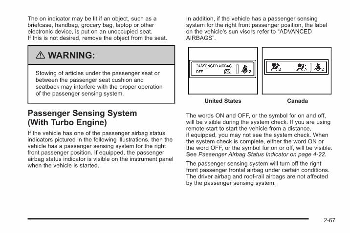
The on indicator may be lit if an object, such as abriefcase, handbag, grocery bag, laptop or otherelectronic device, is put on an unoccupied seat.If this is not desired, remove the object from the seat.
{ WARNING:
Stowing of articles under the passenger seat orbetween the passenger seat cushion andseatback may interfere with the proper operationof the passenger sensing system.
Passenger Sensing System(With Turbo Engine)If the vehicle has one of the passenger airbag statusindicators pictured in the following illustrations, then thevehicle has a passenger sensing system for the rightfront passenger position. If equipped, the passengerairbag status indicator is visible on the instrument panelwhen the vehicle is started.
In addition, if the vehicle has a passenger sensingsystem for the right front passenger position, the labelon the vehicle's sun visors refer to “ADVANCEDAIRBAGS”.
United States Canada
The words ON and OFF, or the symbol for on and off,will be visible during the system check. If you are usingremote start to start the vehicle from a distance,if equipped, you may not see the system check. Whenthe system check is complete, either the word ON orthe word OFF, or the symbol for on or off, will be visible.See Passenger Airbag Status Indicator on page 4‑22.
The passenger sensing system will turn off the rightfront passenger frontal airbag under certain conditions.The driver airbag and roof-rail airbags are not affectedby the passenger sensing system.
2-67
The passenger sensing system works with sensorsthat are part of the right front passenger seat.The sensors are designed to detect the presence of aproperly-seated occupant and determine if the rightfront passenger frontal airbag should be enabled(may inflate) or not.
According to accident statistics, children are safer whenproperly secured in a rear seat in the correct childrestraint for their weight and size.
We recommend that children be secured in a rear seat,including: an infant or a child riding in a rear-facing childrestraint; a child riding in a forward-facing child seat; anolder child riding in a booster seat; and children, whoare large enough, using safety belts.
A label on the sun visor says, “Never put a rear-facingchild seat in the front.” This is because the risk to therear-facing child is so great, if the airbag deploys.
{ WARNING:
A child in a rear-facing child restraint can beseriously injured or killed if the right frontpassenger airbag inflates. This is because theback of the rear-facing child restraint would bevery close to the inflating airbag. A child in aforward-facing child restraint can be seriouslyinjured or killed if the right front passenger airbaginflates and the passenger seat is in a forwardposition.
Even if the passenger sensing system has turnedoff the right front passenger frontal airbag, nosystem is fail-safe. No one can guarantee that anairbag will not deploy under some unusualcircumstance, even though the airbag isturned off.
Secure rear-facing child restraints in a rear seat,even if the airbag is off. If you secure aforward-facing child restraint in the right front seat,always move the front passenger seat as far backas it will go. It is better to secure the child restraintin a rear seat.
2-68
The passenger sensing system is designed to turn offthe right front passenger frontal airbag if:. The right front passenger seat is unoccupied.. The system determines that an infant is present in
a rear-facing infant seat.. The system determines that a small child is
present in a child restraint.. The system determines that a small child is
present in a booster seat.. A right front passenger takes his/her weight off of
the seat for a period of time.. The right front passenger seat is occupied by a
smaller person, such as a child who has outgrownchild restraints.
. Or, if there is a critical problem with the airbagsystem or the passenger sensing system.
When the passenger sensing system has turned off theright front passenger frontal airbag, the off indicator willlight and stay lit to remind you that the airbag is off.See Passenger Airbag Status Indicator on page 4‑22.
The passenger sensing system is designed to turn on(may inflate) the right front passenger frontal airbaganytime the system senses that a person of adult sizeis sitting properly in the right front passenger's seat.
When the passenger sensing system has allowed theairbag to be enabled, the on indicator will light and staylit to remind you that the airbag is active.
For some children who have outgrown child restraintsand for very small adults, the passenger sensingsystem may or may not turn off the right front passengerfrontal airbag, depending upon the person's seatingposture and body build. Everyone in the vehicle whohas outgrown child restraints should wear a safety beltproperly — whether or not there is an airbag for thatperson.
{ WARNING:
If the airbag readiness light ever comes on andstays on, it means that something may be wrongwith the airbag system. To help avoid injury toyourself or others, have the vehicle serviced rightaway. See Airbag Readiness Light on page 4‑21for more information, including important safetyinformation.
2-69
If the On Indicator is Lit for a ChildRestraintIf a child restraint has been installed and the onindicator is lit:
1. Turn the vehicle off.
2. Remove the child restraint from the vehicle.
3. Remove any additional items from the seat such asblankets, cushions, seat covers, seat heaters,or seat massagers.
4. Reinstall the child restraint following the directionsprovided by the child restraint manufacturer andrefer to Securing a Child Restraint in the RightFront Seat Position on page 2‑50.
5. If, after reinstalling the child restraint and restartingthe vehicle, the on indicator is still lit, turn thevehicle off. Then slightly recline the vehicleseatback and adjust the seat cushion, if adjustable,to make sure that the vehicle seatback is notpushing the child restraint into the seat cushion.
Also make sure the child restraint is not trappedunder the vehicle head restraint. If this happens,adjust the head restraint. See Head Restraints onpage 2‑7 .
6. Restart the vehicle.
If the on indicator is still lit, secure the childrestraint in a rear seat position in the vehicle, andcheck with your dealer/retailer.
2-70
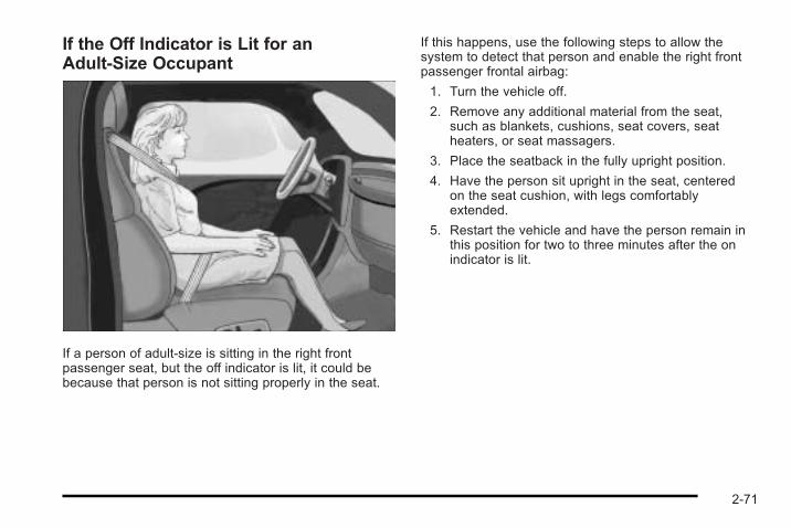
If the Off Indicator is Lit for anAdult-Size Occupant
If a person of adult-size is sitting in the right frontpassenger seat, but the off indicator is lit, it could bebecause that person is not sitting properly in the seat.
If this happens, use the following steps to allow thesystem to detect that person and enable the right frontpassenger frontal airbag:
1. Turn the vehicle off.
2. Remove any additional material from the seat,such as blankets, cushions, seat covers, seatheaters, or seat massagers.
3. Place the seatback in the fully upright position.
4. Have the person sit upright in the seat, centeredon the seat cushion, with legs comfortablyextended.
5. Restart the vehicle and have the person remain inthis position for two to three minutes after the onindicator is lit.
2-71
Additional Factors Affecting SystemOperationSafety belts help keep the passenger in position on theseat during vehicle maneuvers and braking, which helpsthe passenger sensing system maintain the passengerairbag status. See “Safety Belts” and “Child Restraints”in the Index for additional information about theimportance of proper restraint use.
A thick layer of additional material, such as a blanketor cushion, or aftermarket equipment such as seatcovers, seat heaters, and seat massagers can affecthow well the passenger sensing system operates.We recommend that you not use seat covers or otheraftermarket equipment except when approved by GMfor your specific vehicle. See Adding Equipment to YourAirbag-Equipped Vehicle on page 2‑73 for moreinformation about modifications that can affect how thesystem operates.
{ WARNING:
Stowing of articles under the passenger seat orbetween the passenger seat cushion andseatback may interfere with the proper operationof the passenger sensing system.
Servicing Your Airbag-EquippedVehicleAirbags affect how the vehicle should be serviced.There are parts of the airbag system in several placesaround the vehicle. Your dealer/retailer and the servicemanual have information about servicing the vehicleand the airbag system. To purchase a service manual,see Service Publications Ordering Information onpage 8‑16.
{ WARNING:
For up to 10 seconds after the ignition is turned offand the battery is disconnected, an airbag can stillinflate during improper service. You can be injuredif you are close to an airbag when it inflates. Avoidyellow connectors. They are probably part of theairbag system. Be sure to follow proper serviceprocedures, and make sure the person performingwork for you is qualified to do so.
2-72
Adding Equipment to YourAirbag-Equipped Vehicle
Q: Is there anything I might add to or change aboutthe vehicle that could keep the airbags fromworking properly?
A: Yes. If you add things that change the vehicle'sframe, bumper system, height, front end or sidesheet metal, they may keep the airbag system fromworking properly. Changing or moving any parts ofthe front seats, safety belts, the airbag sensing anddiagnostic module, steering wheel, instrument panel,roof-rail airbag modules, ceiling headliner or pillargarnish trim, front sensors, or airbag wiring canaffect the operation of the airbag system.
In addition, the vehicle may have a passengersensing system for the right front passengerposition, which includes sensors that are part of thepassenger's seat. The passenger sensing systemmay not operate properly if the original seat trim isreplaced with non-GM covers, upholstery or trim,or with GM covers, upholstery or trim designed for adifferent vehicle. Any object, such as an aftermarketseat heater or a comfort enhancing pad or device,installed under or on top of the seat fabric, couldalso interfere with the operation of the passengersensing system. This could either prevent properdeployment of the passenger airbag(s) or prevent
the passenger sensing system from properly turningoff the passenger airbag(s). See Passenger SensingSystem (Without Turbo Engine) on page 2‑62 orPassenger Sensing System (With Turbo Engine) onpage 2‑67.
If you have any questions, call CustomerAssistance. The phone numbers and addresses forCustomer Assistance are in Step Two of theCustomer Satisfaction Procedure in this manual.See Customer Satisfaction Procedure on page 8‑2.
Q: Because I have a disability, I have to get myvehicle modified. How can I find out whether thiswill affect my airbag system?
A: If you have questions, call Customer Assistance.The phone numbers and addresses for CustomerAssistance are in Step Two of the CustomerSatisfaction Procedure in this manual. SeeCustomer Satisfaction Procedure on page 8‑2.
In addition, your dealer/retailer and the service manualhave information about the location of the airbagsensors, sensing and diagnostic module and airbagwiring.
2-73
Restraint System Check
Checking the Restraint Systems
Safety BeltsNow and then, check that the safety belt reminder light,safety belts, buckles, latch plates, retractors, andanchorages are all working properly.
Look for any other loose or damaged safety belt systemparts that might keep a safety belt system from doing itsjob. See your dealer/retailer to have it repaired. Torn orfrayed safety belts may not protect you in a crash. Theycan rip apart under impact forces. If a belt is torn orfrayed, get a new one right away.
Make sure the safety belt reminder light is working. SeeSafety Belt Reminders on page 4‑20 for moreinformation.
Keep safety belts clean and dry. See Care of SafetyBelts on page 6‑116.
AirbagsThe airbag system does not need regularly scheduledmaintenance or replacement. Make sure the airbagreadiness light is working. See Airbag Readiness Lighton page 4‑21 for more information.
Notice: If an airbag covering is damaged, opened,or broken, the airbag may not work properly. Do notopen or break the airbag coverings. If there are anyopened or broken airbag covers, have the airbagcovering and/or airbag module replaced. For thelocation of the airbag modules, see What Makes anAirbag Inflate? on page 2‑59. See your dealer/retailer for service.
2-74
Replacing Restraint System PartsAfter a Crash
{ WARNING:
A crash can damage the restraint systems in yourvehicle. A damaged restraint system may notproperly protect the person using it, resulting inserious injury or even death in a crash. To helpmake sure your restraint systems are workingproperly after a crash, have them inspected andany necessary replacements made as soon aspossible.
If the vehicle has been in a crash, do you need newsafety belts or LATCH system (if equipped) parts?
After a very minor crash, nothing may be necessary. Butthe safety belt assemblies that were used during anycrash may have been stressed or damaged. See yourdealer/retailer to have the safety belt assembliesinspected or replaced.
If the vehicle has the LATCH system and it was beingused during a crash, you may need new LATCH systemparts.
New parts and repairs may be necessary even if thesafety belt or LATCH system (if equipped), was notbeing used at the time of the crash.
If an airbag inflates, you will need to replace airbagsystem parts. See the part on the airbag system earlierin this section.
Have the safety belt pretensioners checked if thevehicle has been in a crash, if the airbag readiness lightstays on after the vehicle is started, or while you aredriving. See Airbag Readiness Light on page 4‑21.
2-75

2 NOTES
2-76
Section 3 Features and Controls
Keys . . . . . . . . . . . . . . . . . . . . . . . . . . . . . . . . . . . . . . . . . . . . . . . . 3-3Remote Keyless Entry (RKE) System . . . . . . . . . . . 3-4Remote Keyless Entry (RKE) SystemOperation . . . . . . . . . . . . . . . . . . . . . . . . . . . . . . . . . . . . . 3-4
Remote Vehicle Start . . . . . . . . . . . . . . . . . . . . . . . . . . . 3-6
Doors and Locks . . . . . . . . . . . . . . . . . . . . . . . . . . . . . . . . . . 3-8Door Locks . . . . . . . . . . . . . . . . . . . . . . . . . . . . . . . . . . . . . 3-8Power Door Locks . . . . . . . . . . . . . . . . . . . . . . . . . . . . . . 3-9Delayed Locking . . . . . . . . . . . . . . . . . . . . . . . . . . . . . . . 3-10Automatic Door Lock . . . . . . . . . . . . . . . . . . . . . . . . . . 3-10Programmable Automatic Door Unlock . . . . . . . . 3-10Rear Door Security Locks (Sedan) . . . . . . . . . . . . . 3-11Lockout Protection . . . . . . . . . . . . . . . . . . . . . . . . . . . . . 3-11Trunk . . . . . . . . . . . . . . . . . . . . . . . . . . . . . . . . . . . . . . . . . . 3-12
Windows . . . . . . . . . . . . . . . . . . . . . . . . . . . . . . . . . . . . . . . . . . 3-14Manual Windows . . . . . . . . . . . . . . . . . . . . . . . . . . . . . . 3-14Power Windows . . . . . . . . . . . . . . . . . . . . . . . . . . . . . . . 3-15Sun Visors . . . . . . . . . . . . . . . . . . . . . . . . . . . . . . . . . . . . . 3-16
Theft-Deterrent Systems . . . . . . . . . . . . . . . . . . . . . . . . . 3-16Content Theft-Deterrent . . . . . . . . . . . . . . . . . . . . . . . . 3-16PASS-Key® III+ Electronic Immobilizer . . . . . . . . . 3-18PASS-Key® III+ Electronic ImmobilizerOperation . . . . . . . . . . . . . . . . . . . . . . . . . . . . . . . . . . . . 3-18
Starting and Operating Your Vehicle . . . . . . . . . . . . 3-20New Vehicle Break-In . . . . . . . . . . . . . . . . . . . . . . . . . . 3-20Ignition Positions . . . . . . . . . . . . . . . . . . . . . . . . . . . . . . 3-21Retained Accessory Power (RAP) . . . . . . . . . . . . . 3-23Starting the Engine . . . . . . . . . . . . . . . . . . . . . . . . . . . . 3-23Engine Coolant Heater . . . . . . . . . . . . . . . . . . . . . . . . . 3-25Automatic Transmission Operation . . . . . . . . . . . . . 3-26Manual Transmission Operation . . . . . . . . . . . . . . . 3-28Parking Brake . . . . . . . . . . . . . . . . . . . . . . . . . . . . . . . . . 3-31Shifting Into Park (Automatic Transmission) . . . 3-32Shifting Out of Park (AutomaticTransmission) . . . . . . . . . . . . . . . . . . . . . . . . . . . . . . . 3-33
Parking the Vehicle (Manual Transmission) . . . . 3-34Parking Over Things That Burn . . . . . . . . . . . . . . . . 3-34Engine Exhaust . . . . . . . . . . . . . . . . . . . . . . . . . . . . . . . . 3-35Running the Vehicle While Parked . . . . . . . . . . . . . 3-36
3-1
Section 3 Features and Controls
Mirrors . . . . . . . . . . . . . . . . . . . . . . . . . . . . . . . . . . . . . . . . . . . . 3-37Manual Rearview Mirror . . . . . . . . . . . . . . . . . . . . . . . . 3-37Outside Manual Mirror . . . . . . . . . . . . . . . . . . . . . . . . . 3-37Outside Remote Control Mirror . . . . . . . . . . . . . . . . . 3-37Outside Power Mirrors . . . . . . . . . . . . . . . . . . . . . . . . . 3-38Outside Convex Mirror . . . . . . . . . . . . . . . . . . . . . . . . . 3-38
Storage Areas . . . . . . . . . . . . . . . . . . . . . . . . . . . . . . . . . . . . 3-39Glove Box . . . . . . . . . . . . . . . . . . . . . . . . . . . . . . . . . . . . . 3-39Cupholders . . . . . . . . . . . . . . . . . . . . . . . . . . . . . . . . . . . . 3-39Center Console Storage . . . . . . . . . . . . . . . . . . . . . . 3-39Driver Storage Compartment . . . . . . . . . . . . . . . . . . 3-39Convenience Net . . . . . . . . . . . . . . . . . . . . . . . . . . . . . . 3-39
Sunroof . . . . . . . . . . . . . . . . . . . . . . . . . . . . . . . . . . . . . . . . . . . 3-39
3-2
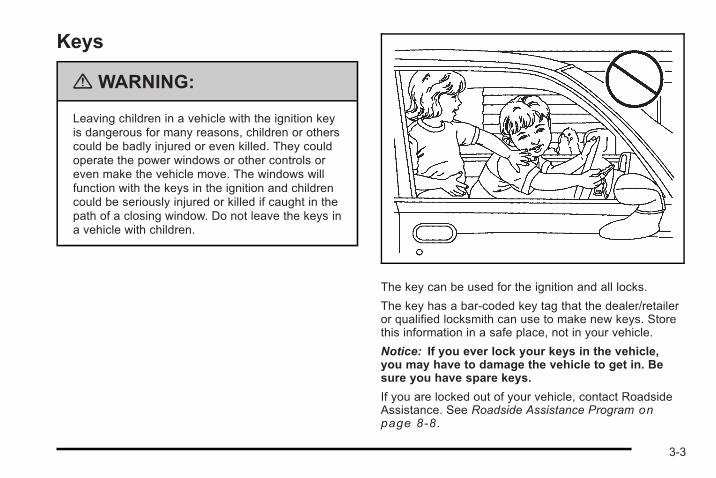
Keys
{ WARNING:
Leaving children in a vehicle with the ignition keyis dangerous for many reasons, children or otherscould be badly injured or even killed. They couldoperate the power windows or other controls oreven make the vehicle move. The windows willfunction with the keys in the ignition and childrencould be seriously injured or killed if caught in thepath of a closing window. Do not leave the keys ina vehicle with children.
The key can be used for the ignition and all locks.
The key has a bar-coded key tag that the dealer/retaileror qualified locksmith can use to make new keys. Storethis information in a safe place, not in your vehicle.
Notice: If you ever lock your keys in the vehicle,you may have to damage the vehicle to get in. Besure you have spare keys.
If you are locked out of your vehicle, contact RoadsideAssistance. See Roadside Assistance Program onpage 8‑8 .
3-3
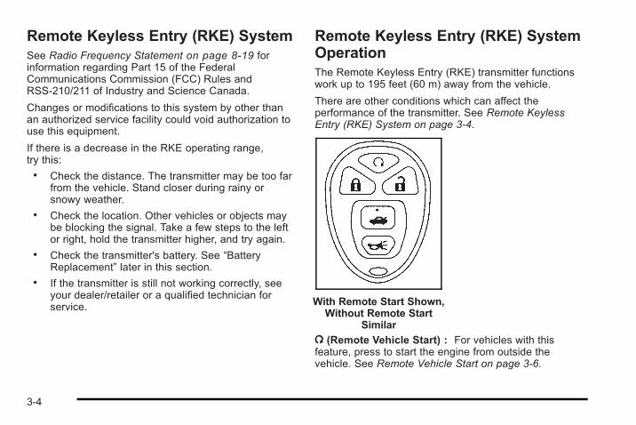
Remote Keyless Entry (RKE) SystemSee Radio Frequency Statement on page 8‑19 forinformation regarding Part 15 of the FederalCommunications Commission (FCC) Rules andRSS-210/211 of Industry and Science Canada.
Changes or modifications to this system by other thanan authorized service facility could void authorization touse this equipment.
If there is a decrease in the RKE operating range,try this:. Check the distance. The transmitter may be too far
from the vehicle. Stand closer during rainy orsnowy weather.
. Check the location. Other vehicles or objects maybe blocking the signal. Take a few steps to the leftor right, hold the transmitter higher, and try again.
. Check the transmitter's battery. See “BatteryReplacement” later in this section.
. If the transmitter is still not working correctly, seeyour dealer/retailer or a qualified technician forservice.
Remote Keyless Entry (RKE) SystemOperationThe Remote Keyless Entry (RKE) transmitter functionswork up to 195 feet (60 m) away from the vehicle.
There are other conditions which can affect theperformance of the transmitter. See Remote KeylessEntry (RKE) System on page 3‑4.
With Remote Start Shown,Without Remote Start
Similar
/ (Remote Vehicle Start) : For vehicles with thisfeature, press to start the engine from outside thevehicle. See Remote Vehicle Start on page 3‑6.
3-4
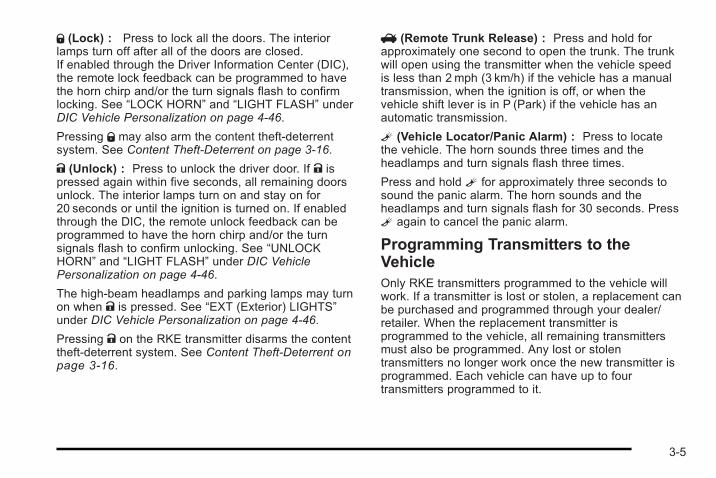
Q (Lock) : Press to lock all the doors. The interiorlamps turn off after all of the doors are closed.If enabled through the Driver Information Center (DIC),the remote lock feedback can be programmed to havethe horn chirp and/or the turn signals flash to confirmlocking. See “LOCK HORN” and “LIGHT FLASH” underDIC Vehicle Personalization on page 4‑46.
Pressing Q may also arm the content theft-deterrentsystem. See Content Theft-Deterrent on page 3‑16.
K (Unlock) : Press to unlock the driver door. If K ispressed again within five seconds, all remaining doorsunlock. The interior lamps turn on and stay on for20 seconds or until the ignition is turned on. If enabledthrough the DIC, the remote unlock feedback can beprogrammed to have the horn chirp and/or the turnsignals flash to confirm unlocking. See “UNLOCKHORN” and “LIGHT FLASH” under DIC VehiclePersonalization on page 4‑46.
The high-beam headlamps and parking lamps may turnon when K is pressed. See “EXT (Exterior) LIGHTS”under DIC Vehicle Personalization on page 4‑46.
Pressing K on the RKE transmitter disarms the contenttheft-deterrent system. See Content Theft-Deterrent onpage 3‑16.
V (Remote Trunk Release) : Press and hold forapproximately one second to open the trunk. The trunkwill open using the transmitter when the vehicle speedis less than 2 mph (3 km/h) if the vehicle has a manualtransmission, when the ignition is off, or when thevehicle shift lever is in P (Park) if the vehicle has anautomatic transmission.
L (Vehicle Locator/Panic Alarm) : Press to locatethe vehicle. The horn sounds three times and theheadlamps and turn signals flash three times.
Press and hold L for approximately three seconds tosound the panic alarm. The horn sounds and theheadlamps and turn signals flash for 30 seconds. PressL again to cancel the panic alarm.
Programming Transmitters to theVehicleOnly RKE transmitters programmed to the vehicle willwork. If a transmitter is lost or stolen, a replacement canbe purchased and programmed through your dealer/retailer. When the replacement transmitter isprogrammed to the vehicle, all remaining transmittersmust also be programmed. Any lost or stolentransmitters no longer work once the new transmitter isprogrammed. Each vehicle can have up to fourtransmitters programmed to it.
3-5
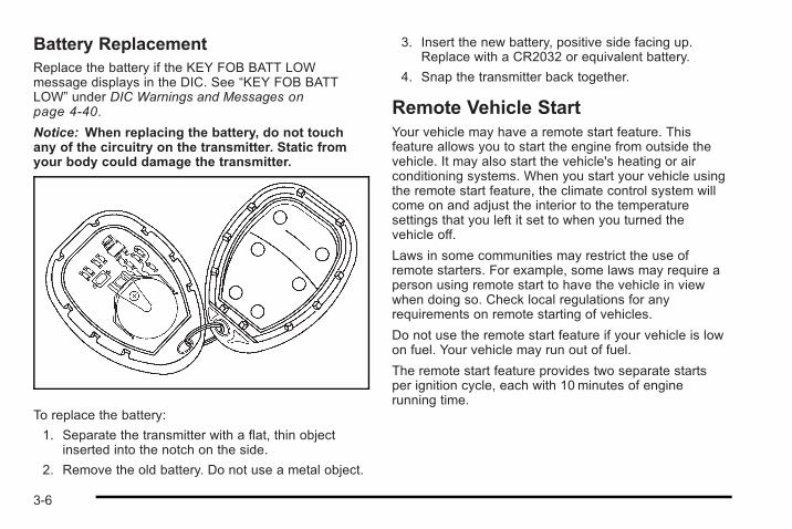
Battery ReplacementReplace the battery if the KEY FOB BATT LOWmessage displays in the DIC. See “KEY FOB BATTLOW” under DIC Warnings and Messages onpage 4‑40.
Notice: When replacing the battery, do not touchany of the circuitry on the transmitter. Static fromyour body could damage the transmitter.
To replace the battery:
1. Separate the transmitter with a flat, thin objectinserted into the notch on the side.
2. Remove the old battery. Do not use a metal object.
3. Insert the new battery, positive side facing up.Replace with a CR2032 or equivalent battery.
4. Snap the transmitter back together.
Remote Vehicle StartYour vehicle may have a remote start feature. Thisfeature allows you to start the engine from outside thevehicle. It may also start the vehicle's heating or airconditioning systems. When you start your vehicle usingthe remote start feature, the climate control system willcome on and adjust the interior to the temperaturesettings that you left it set to when you turned thevehicle off.
Laws in some communities may restrict the use ofremote starters. For example, some laws may require aperson using remote start to have the vehicle in viewwhen doing so. Check local regulations for anyrequirements on remote starting of vehicles.
Do not use the remote start feature if your vehicle is lowon fuel. Your vehicle may run out of fuel.
The remote start feature provides two separate startsper ignition cycle, each with 10 minutes of enginerunning time.
3-6
After your vehicle's engine has been started two timesusing the remote vehicle start button, the vehicle'signition switch must be turned to ON/RUN and thenback to LOCK/OFF using the key before the remotestart procedure can be used again. See IgnitionPositions on page 3‑21 for information regarding theignition positions on your vehicle.
If your vehicle has the remote start feature, the RKEtransmitter functions will have an increased range ofoperation. However, the range may be less while thevehicle is running.
There are other conditions which can affect theperformance of the transmitter, see Remote KeylessEntry (RKE) System on page 3‑4 for additionalinformation.
/ (Remote Start): This button will be on the RKEtransmitter if you have remote start.
To start the vehicle using the remote start feature, dothe following:
1. Aim the transmitter at the vehicle.
2. Press and release Q , then immediately press and
hold/ until the vehicle's turn signal lamps flash.
When the vehicle starts, the parking lamps will turnon and remain on while the engine is running. Thevehicle's doors will be locked.
3. If it is the first remote start since the vehicle hasbeen driven, repeat these steps, while the engineis running, to extend the time by 10 minutes for theengine to continue to run.
After entering the vehicle after a remote start, insert andturn the key to ON/RUN to drive the vehicle.
The engine will shut off automatically after 10 minutes,unless a time extension has been done or the vehicle'skey is inserted into the ignition switch and turned toON/RUN.
To manually shut off a remote start, do any of thefollowing. The parking lamps will turn off to indicate theengine is off.. Aim the RKE transmitter at the vehicle and press
and release the remote start button.. Turn on the hazard warning flashers.. Turn the ignition switch to ON/RUN and then
LOCK/OFF.
Your vehicle's engine can be started two times, perignition cycle, using the transmitter's remote startfeature.
If the remote start procedure is used again before thefirst 10 minute time frame has ended, the first10 minutes will immediately expire and the second10 minute time frame will start.
3-7
The remote vehicle start feature will not operate if anyof the follow occur:. The remote start system is disabled through
the DIC.. The vehicle's key is in the ignition.. The vehicle's hood is open.. The hazard warning flashers are on.. The check engine light is on. See Malfunction
Indicator Lamp on page 4‑27.. The engine coolant temperature is too high.. The oil pressure is low.. Two remote vehicle starts have already been
provided for that ignition cycle.
Vehicles that have the remote vehicle start feature areshipped from the factory with the remote start systemenabled. The system may be enabled or disabledthrough the DIC. See “REMOTE START” under DICVehicle Personalization on page 4‑46 for additionalinformation.
Doors and Locks
Door Locks
{ WARNING:
Unlocked doors can be dangerous.. Passengers, especially children, can easily
open the doors and fall out of a movingvehicle. When a door is locked, the handle willnot open it. The chance of being thrown out ofthe vehicle in a crash is increased if the doorsare not locked. So, all passengers shouldwear safety belts properly and the doorsshould be locked whenever the vehicle isdriven.
(Continued)
3-8
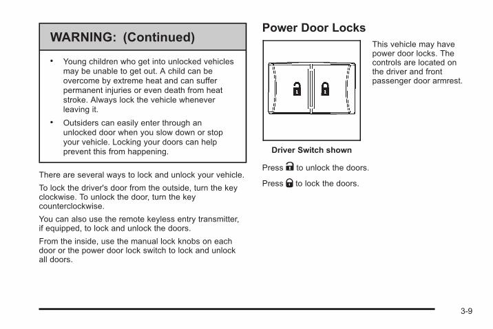
WARNING: (Continued)
. Young children who get into unlocked vehiclesmay be unable to get out. A child can beovercome by extreme heat and can sufferpermanent injuries or even death from heatstroke. Always lock the vehicle wheneverleaving it.
. Outsiders can easily enter through anunlocked door when you slow down or stopyour vehicle. Locking your doors can helpprevent this from happening.
There are several ways to lock and unlock your vehicle.
To lock the driver's door from the outside, turn the keyclockwise. To unlock the door, turn the keycounterclockwise.
You can also use the remote keyless entry transmitter,if equipped, to lock and unlock the doors.
From the inside, use the manual lock knobs on eachdoor or the power door lock switch to lock and unlockall doors.
Power Door Locks
Driver Switch shown
This vehicle may havepower door locks. Thecontrols are located onthe driver and frontpassenger door armrest.
Press K to unlock the doors.
Press Q to lock the doors.
3-9
Delayed LockingIf your vehicle has power locks, it will have the delayedlocking feature.
This feature will delay the actual locking of the doors forup to five seconds when the power door lock switch orremote keyless entry transmitter is used to lock thevehicle.
If any door is open when locking the vehicle, threechimes will sound signaling that the delayed lockingfeature is active. Five seconds after the last door isclosed, all of the doors will lock and the turn signallamps will flash. To cancel the delay and lock the doorsimmediately, press the lock button a second time.
This feature will not lock the doors if the key is in theignition .
You can disable this function through the DriverInformation Center (DIC). See DIC VehiclePersonalization on page 4‑46.
Automatic Door LockOn vehicles with power door locks, the doorsautomatically lock when the shift lever is moved outof (P) Park for a vehicle with an automatic transmission.For a vehicle with a manual transmission, the speedmust be greater than 5 mph (8 km/h).
The automatic door locking feature cannot be disabled.
Programmable Automatic DoorUnlockIf your vehicle has power locks, it has a programmableautomatic door unlock feature.
The doors can be programmed through the DriverInformation Center (DIC) to automatically unlock severalways. See DIC Vehicle Personalization on page 4‑46for more information.
3-10
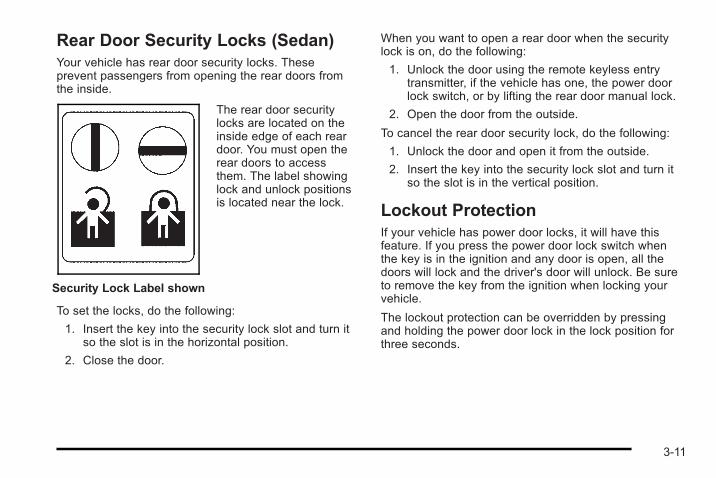
Rear Door Security Locks (Sedan)Your vehicle has rear door security locks. Theseprevent passengers from opening the rear doors fromthe inside.
Security Lock Label shown
The rear door securitylocks are located on theinside edge of each reardoor. You must open therear doors to accessthem. The label showinglock and unlock positionsis located near the lock.
To set the locks, do the following:
1. Insert the key into the security lock slot and turn itso the slot is in the horizontal position.
2. Close the door.
When you want to open a rear door when the securitylock is on, do the following:
1. Unlock the door using the remote keyless entrytransmitter, if the vehicle has one, the power doorlock switch, or by lifting the rear door manual lock.
2. Open the door from the outside.
To cancel the rear door security lock, do the following:
1. Unlock the door and open it from the outside.
2. Insert the key into the security lock slot and turn itso the slot is in the vertical position.
Lockout ProtectionIf your vehicle has power door locks, it will have thisfeature. If you press the power door lock switch whenthe key is in the ignition and any door is open, all thedoors will lock and the driver's door will unlock. Be sureto remove the key from the ignition when locking yourvehicle.
The lockout protection can be overridden by pressingand holding the power door lock in the lock position forthree seconds.
3-11
TrunkTo release the trunk lid from the outside, use the key orthe Remote Keyless Entry (RKE) transmitter,if equipped.
{ WARNING:
Exhaust gases can enter the vehicle if it is drivenwith the liftgate, trunk/hatch open, or with anyobjects that pass through the seal between thebody and the trunk/hatch or liftgate. Engineexhaust contains Carbon Monoxide (CO) whichcannot be seen or smelled. It can causeunconsciousness and even death.
(Continued)
WARNING: (Continued)
If the vehicle must be driven with the liftgate,or trunk/hatch open:
. Close all of the windows.
. Fully open the air outlets on or under theinstrument panel.
. Adjust the Climate Control system to a settingthat brings in only outside air and set the fanspeed to the highest setting. See ClimateControl System in the Index.
. If the vehicle is equipped with a power liftgate,disable the power liftgate function.
For more information about carbon monoxide, seeEngine Exhaust on page 3‑35.
3-12
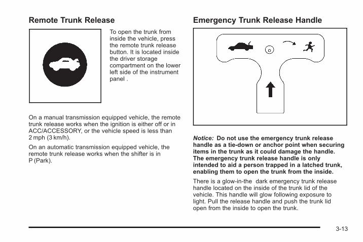
Remote Trunk ReleaseTo open the trunk frominside the vehicle, pressthe remote trunk releasebutton. It is located insidethe driver storagecompartment on the lowerleft side of the instrumentpanel .
On a manual transmission equipped vehicle, the remotetrunk release works when the ignition is either off or inACC/ACCESSORY, or the vehicle speed is less than2 mph (3 km/h).
On an automatic transmission equipped vehicle, theremote trunk release works when the shifter is inP (Park).
Emergency Trunk Release Handle
Notice: Do not use the emergency trunk releasehandle as a tie-down or anchor point when securingitems in the trunk as it could damage the handle.The emergency trunk release handle is onlyintended to aid a person trapped in a latched trunk,enabling them to open the trunk from the inside.
There is a glow-in-the dark emergency trunk releasehandle located on the inside of the trunk lid of thevehicle. This handle will glow following exposure tolight. Pull the release handle and push the trunk lidopen from the inside to open the trunk.
3-13
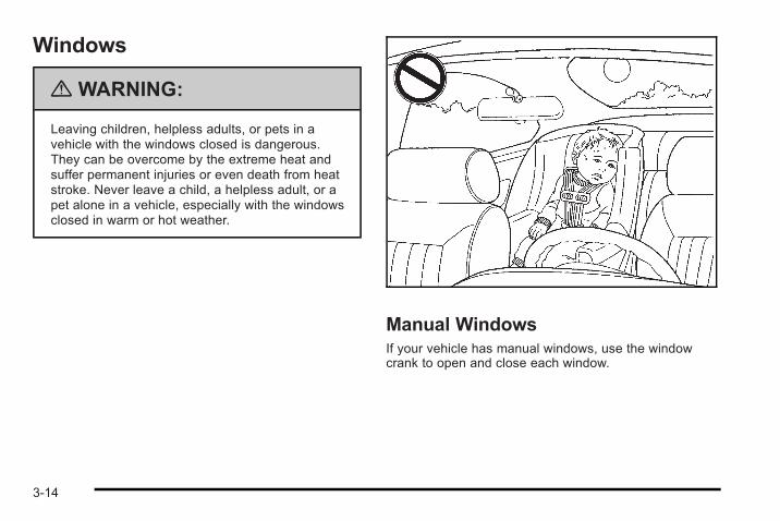
Windows
{ WARNING:
Leaving children, helpless adults, or pets in avehicle with the windows closed is dangerous.They can be overcome by the extreme heat andsuffer permanent injuries or even death from heatstroke. Never leave a child, a helpless adult, or apet alone in a vehicle, especially with the windowsclosed in warm or hot weather.
Manual WindowsIf your vehicle has manual windows, use the windowcrank to open and close each window.
3-14
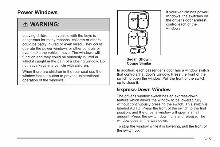
Power Windows
{ WARNING:
Leaving children in a vehicle with the keys isdangerous for many reasons, children or otherscould be badly injured or even killed. They couldoperate the power windows or other controls oreven make the vehicle move. The windows willfunction and they could be seriously injured orkilled if caught in the path of a closing window. Donot leave keys in a vehicle with children.
When there are children in the rear seat use thewindow lockout button to prevent unintentionaloperation of the windows.
Sedan Shown,Coupe Similar
If your vehicle has powerwindows, the switches onthe driver's door armrestcontrol each of thewindows.
In addition, each passenger's door has a window switchthat controls that door's window. Press the front of theswitch to open the window. Pull the front of the switchup to close it.
Express-Down WindowThe driver's window switch has an express-downfeature which allows the window to be lowered fullywithout continuously pressing the switch. This switch islabeled AUTO. Press the front of the switch to the firstposition, and the driver's window will open a smallamount. Press the switch down fully and release. Thewindow goes all the way down.
To stop the window while it is lowering, pull the front ofthe switch up.
3-15
Window Lockout (Sedan)o (Window Lockout) : The driver's window controlsalso include a lockout switch. Press the right side of theswitch to prevent the rear passengers from using theirwindow switches. The driver can still control all thewindows with the lockout on. Press the switch to the leftto return to normal window operation. A red bar on theright side of the switch indicates that the lockout featureis off.
Sun VisorsTo block out glare, swing down the visor(s). The visorscan also be detached from the center mount and swungto the side to cover the windows.
Visor Vanity MirrorYour vehicle may have a driver's side vanity mirror.Swing down the sun visor and lift the cover to exposethe mirror.
Theft-Deterrent SystemsVehicle theft is big business, especially in some cities.This vehicle has theft-deterrent features, however, theydo not make it impossible to steal.
Content Theft-DeterrentYour vehicle may have acontent theft-deterrentalarm system.
Arming the SystemWith the ignition off, you can arm the system bypressing the remote keyless entry transmitter lockbutton.
The system will arm after either of these things occur:. Thirty seconds after all the doors are closed.. Sixty seconds with any door open.
3-16
If you press the lock button on the transmitter a secondtime while all the doors are closed, the system will armimmediately. The system will still arm in 60 seconds if adoor is open. When the open door is closed, it will alsobecome armed.
The security light, located on the instrument panelcluster, will turn on to indicate that arming has beeninitiated. Once the system is armed, the security lightwill flash once every three seconds.
If the security light is flashing twice per second, thismeans that a door is open.
If you do not want to arm the system, you may lock thecar with the manual lock knobs, or the power door lockswitch, if equipped, on the doors.
Disarming the SystemYou can disarm the system by doing any one of thefollowing:. Press the remote keyless entry transmitter unlock
button.. Turn the ignition on.
If the system is armed and the trunk is opened usingthe trunk release button on the transmitter, the systemwill temporarily disarm itself and re-arm when the trunkhas been closed. This allows you to exit the vehicle,lock the doors using the transmitter, and open the trunkusing the transmitter without having to disarm andre-arm the system.
Once the system is disarmed, the security light will stopflashing.
How the System Alarm is ActivatedIf the system is armed, it can be activated by either:. Opening the driver's door or trunk. This will cause
a ten second pre-alarm chirp followed by a thirtysecond full alarm of horn and lights.
. Opening any other door. This will immediatelycause a full alarm of horn and lights for thirtyseconds.
When an alarm event has finished, the system willre-arm itself automatically.
3-17
How to Turn Off the System AlarmTo turn off the system alarm, do one of the following:. Press the lock button on the remote keyless entry
transmitter. The system will then re-arm itself.. Press the unlock button on the remote keyless
entry transmitter. This will also disarm the system.. Insert the key in the ignition and turn it on. This will
also disarm the system.
How to Detect a Tamper ConditionIf you hear three chirps when you press the unlock,lock, or trunk release buttons on the remote keylesstransmitter, it means that the content theft securitysystem alarm was previously activated.
PASS-Key® III+ ElectronicImmobilizerSee Radio Frequency Statement on page 8‑19 forinformation regarding Part 15 of the FederalCommunications Commission (FCC) Rules andRSS-210/211 of Industry and Science Canada.
PASS-Key® III+ ElectronicImmobilizer OperationYour vehicle has PASS-Key® III+ (PersonalizedAutomotive Security System) theft-deterrent system.PASS-Key® III+ is a passive theft-deterrent system.
The system is automatically armed when the key isremoved from the ignition.
You do not have to manually arm or disarm the system.
The security light will come on if there is a problem witharming or disarming the theft-deterrent system.
When the PASS-Key® III+ system senses that someoneis using the wrong key, it prevents the vehicle fromstarting. Anyone using a trial-and-error method to startthe vehicle will be discouraged because of the highnumber of electrical key codes.
When trying to start the vehicle if the engine does notstart and the security light comes on, there may be aproblem with your theft-deterrent system. Turn theignition off and try again.
3-18
If the engine still does not start, and the key appears tobe undamaged, try another ignition key. At this time,you may also want to check the fuse, see Fuses andCircuit Breakers on page 6‑121. If the engine still doesnot start with the other key, your vehicle needs service.If your vehicle does start, the first key may be faulty.See your dealer/retailer who can service thePASS-Key® III+ to have a new key made. In anemergency, contact Roadside Assistance. SeeRoadside Assistance Program on page 8‑8 , for moreinformation.
It may be possible for the PASS-Key® III+ decoder to“learn” the transponder value of a new or replacementkey. Up to 10 keys may be programmed for the vehicle.The following procedure is for programming additionalkeys only. If all the currently programmed keys are lostor do not operate, you must see your dealer/retailer or alocksmith who can service PASS-Key® III+ to have keysmade and programmed to the system.
See your dealer/retailer or a locksmith who can servicePASS-Key® III+ to get a new key blank that is cutexactly as the ignition key that operates the system.
To program the new key:
1. Verify that the new key has a 1 stamped on it.
2. Insert the already programmed key in the ignitionand start the engine. If the engine will not start, seeyour dealer/retailer for service.
3. After the engine has started, turn the key to LOCK/OFF, and remove the key.
4. Insert the key to be programmed and turn it to theON/RUN position within five seconds of the originalkey being turned to the LOCK/OFF position.
The security light will turn off once the key hasbeen programmed.
5. Repeat Steps 1 through 4 if additional keys are tobe programmed.
If you are ever driving and the security light comes onand stays on, you may be able to restart your engine ifyou turn it off. Your PASS-Key® III+ system, however, isnot working properly and must be serviced by yourdealer/retailer. Your vehicle is not protected by thePASS-Key® III+ system at this time.
If you lose or damage your PASS-Key® III+ key, seeyour dealer/retailer or a locksmith who can servicePASS-Key® III+ to have a new key made.
Do not leave the key or device that disarms ordeactivates the theft deterrent system in the vehicle.
3-19
Starting and Operating YourVehicle
New Vehicle Break-InNotice: The vehicle does not need an elaboratebreak-in. But it will perform better in the long run ifyou follow these guidelines:
. Do not drive at any one constant speed, fastor slow, for the first 500miles (805 km). Donot make full-throttle starts. Do not exceed5,000 engine rpm. Avoid downshifting tobrake or slow the vehicle.
. Avoid making hard stops for the first200miles (322 km) or so. During this timethe new brake linings are not yet broken in.Hard stops with new linings can meanpremature wear and earlier replacement.Follow this breaking-in guideline every timeyou get new brake linings.
. Do not tow a trailer during break-in. SeeTowing a Trailer (Automatic Transmission)on page 5‑33 or Towing a Trailer (ManualTransmission) on page 5‑39 for the trailertowing capabilities of your vehicle and moreinformation.
Following break-in, engine speed and load can begradually increased.
3-20
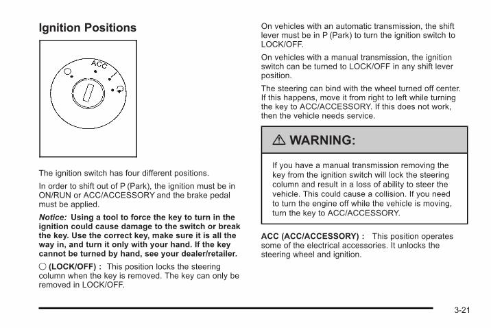
Ignition Positions
The ignition switch has four different positions.
In order to shift out of P (Park), the ignition must be inON/RUN or ACC/ACCESSORY and the brake pedalmust be applied.
Notice: Using a tool to force the key to turn in theignition could cause damage to the switch or breakthe key. Use the correct key, make sure it is all theway in, and turn it only with your hand. If the keycannot be turned by hand, see your dealer/retailer.
9 (LOCK/OFF) : This position locks the steeringcolumn when the key is removed. The key can only beremoved in LOCK/OFF.
On vehicles with an automatic transmission, the shiftlever must be in P (Park) to turn the ignition switch toLOCK/OFF.
On vehicles with a manual transmission, the ignitionswitch can be turned to LOCK/OFF in any shift leverposition.
The steering can bind with the wheel turned off center.If this happens, move it from right to left while turningthe key to ACC/ACCESSORY. If this does not work,then the vehicle needs service.
{ WARNING:
If you have a manual transmission removing thekey from the ignition switch will lock the steeringcolumn and result in a loss of ability to steer thevehicle. This could cause a collision. If you needto turn the engine off while the vehicle is moving,turn the key to ACC/ACCESSORY.
ACC (ACC/ACCESSORY) : This position operatessome of the electrical accessories. It unlocks thesteering wheel and ignition.
3-21
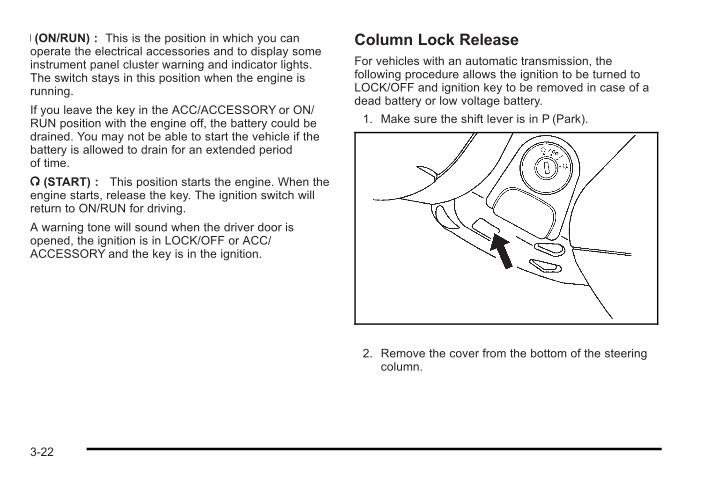
R (ON/RUN) : This is the position in which you canoperate the electrical accessories and to display someinstrument panel cluster warning and indicator lights.The switch stays in this position when the engine isrunning.
If you leave the key in the ACC/ACCESSORY or ON/RUN position with the engine off, the battery could bedrained. You may not be able to start the vehicle if thebattery is allowed to drain for an extended periodof time.
/ (START) : This position starts the engine. When theengine starts, release the key. The ignition switch willreturn to ON/RUN for driving.
A warning tone will sound when the driver door isopened, the ignition is in LOCK/OFF or ACC/ACCESSORY and the key is in the ignition.
Column Lock ReleaseFor vehicles with an automatic transmission, thefollowing procedure allows the ignition to be turned toLOCK/OFF and ignition key to be removed in case of adead battery or low voltage battery.
1. Make sure the shift lever is in P (Park).
2. Remove the cover from the bottom of the steeringcolumn.
3-22
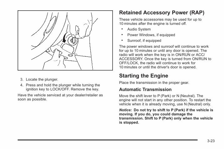
3. Locate the plunger.
4. Press and hold the plunger while turning theignition key to LOCK/OFF. Remove the key.
Have the vehicle serviced at your dealer/retailer assoon as possible.
Retained Accessory Power (RAP)These vehicle accessories may be used for up to10 minutes after the engine is turned off.. Audio System. Power Windows, if equipped. Sunroof, if equipped
The power windows and sunroof will continue to workfor up to 10 minutes or until any door is opened. Theradio will work when the key is in ON/RUN or ACC/ACCESSORY. Once the key is turned from ON/RUN toOFF/LOCK, the radio will continue to work for10 minutes or until the driver's door is opened.
Starting the EnginePlace the transmission in the proper gear.
Automatic TransmissionMove the shift lever to P (Park) or N (Neutral). Theengine will not start in any other position. To restart thevehicle when it is already moving, use N (Neutral) only.
Notice: Do not try to shift to P (Park) if the vehicle ismoving. If you do, you could damage thetransmission. Shift to P (Park) only when the vehicleis stopped.
3-23
Manual TransmissionThe shift lever should be in N (Neutral) and the parkingbrake engaged. Hold the clutch pedal down to the floorand start the engine. The vehicle will not start if theclutch pedal is not all the way down.
Starting Procedure1. With your foot off the accelerator pedal, turn the
ignition key to START. When the engine starts, letgo of the key. The idle speed will go down as theengine warms. Do not race the engine immediatelyafter starting it. Operate the engine andtransmission gently to allow the oil to warm up andlubricate all moving parts.
The vehicle has a Computer-Controlled CrankingSystem. This feature assists in starting the engineand protects components. If the ignition key isturned to the START position, and then releasedwhen the engine begins cranking, the engine willcontinue cranking for a few seconds or until thevehicle starts. If the engine does not start and thekey is held in START for many seconds, crankingwill be stopped after 15 seconds to preventcranking motor damage. To prevent gear damage,this system also prevents cranking if the engine isalready running. Engine cranking can be stoppedby turning the ignition switch to ACC/ACCESSORYor LOCK/OFF.
Notice: Cranking the engine for long periods oftime, by returning the key to the START positionimmediately after cranking has ended, can overheatand damage the cranking motor, and drain thebattery. Wait at least 15 seconds between each try,to let the cranking motor cool down.
2. If the engine does not start after 5-10 seconds,especially in very cold weather (below 0°For −18°C), it could be flooded with too muchgasoline. Push the accelerator pedal all the way tothe floor and holding it there as you hold the key inSTART for a maximum of 15 seconds. Wait at least15 seconds between each try, to allow the crankingmotor to cool. When the engine starts, let go of thekey and accelerator. If the vehicle starts briefly butthen stops again, repeat the procedure. This clearsthe extra gasoline from the engine. Do not race theengine immediately after starting it. Operate theengine and transmission gently until the oil warmsup and lubricates all moving parts.
Notice: The engine is designed to work with theelectronics in the vehicle. If you add electrical partsor accessories, you could change the way theengine operates. Before adding electricalequipment, check with your dealer/retailer. If you donot, the engine might not perform properly. Anyresulting damage would not be covered by thevehicle warranty.
3-24
Engine Coolant HeaterThe engine coolant heater can provide easier startingand better fuel economy during engine warm-up in coldweather condition at or below 0°F (−18°C). Vehicleswith am engine coolant heater should be plugged in atleast four hours before starting. An internal thermostatin the plug-end of the cord may exist which will preventengine coolant heater operation at temperatures above0°F (−18°C).
To Use the Engine Coolant Heater1. Turn off the engine.
2. Open the hood and unwrap the electrical cord. Theelectrical cord is located on the passenger side ofthe vehicle between the strut and the air cleaner/filter.
3. Plug it into a normal, grounded 110-volt AC outlet.
{ WARNING:
Plugging the cord into an ungrounded outlet couldcause an electrical shock. Also, the wrong kind ofextension cord could overheat and cause a fire.You could be seriously injured. Plug the cord intoa properly grounded three-prong 110-volt ACoutlet. If the cord will not reach, use a heavy-dutythree-prong extension cord rated for at least15 amps.
4. Before starting the engine, be sure to unplug andstore the cord as it was before to keep it away frommoving engine parts, and prevent damaged.
The length of time the heater should remain plugged independs on several factors. Ask a dealer/retailer in thearea where you will be parking the vehicle for the bestadvice on this.
3-25
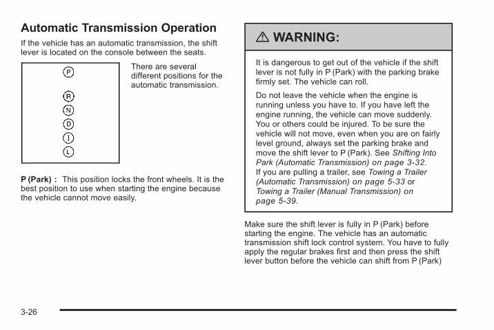
Automatic Transmission OperationIf the vehicle has an automatic transmission, the shiftlever is located on the console between the seats.
There are severaldifferent positions for theautomatic transmission.
P (Park) : This position locks the front wheels. It is thebest position to use when starting the engine becausethe vehicle cannot move easily.
{ WARNING:
It is dangerous to get out of the vehicle if the shiftlever is not fully in P (Park) with the parking brakefirmly set. The vehicle can roll.
Do not leave the vehicle when the engine isrunning unless you have to. If you have left theengine running, the vehicle can move suddenly.You or others could be injured. To be sure thevehicle will not move, even when you are on fairlylevel ground, always set the parking brake andmove the shift lever to P (Park). See Shifting IntoPark (Automatic Transmission) on page 3‑32.If you are pulling a trailer, see Towing a Trailer(Automatic Transmission) on page 5‑33 orTowing a Trailer (Manual Transmission) onpage 5‑39.
Make sure the shift lever is fully in P (Park) beforestarting the engine. The vehicle has an automatictransmission shift lock control system. You have to fullyapply the regular brakes first and then press the shiftlever button before the vehicle can shift from P (Park)
3-26
when the ignition key is in ON/RUN. If the vehiclecannot shift out of P (Park), ease pressure on the shiftlever and push the shift lever all the way into P (Park)as you maintain brake application. Then press the shiftlever button and then move the shift lever into anothergear. See Shifting Out of Park (Automatic Transmission)on page 3‑33.
Notice: Shifting to R (Reverse) while the vehicle ismoving forward could damage the transmission.The repairs would not be covered by the vehiclewarranty. Shift to R (Reverse) only after the vehicleis stopped.
R (Reverse) : Use this gear to back up.
To rock the vehicle back and forth to get out of snow,ice, or sand without damaging the transmission, see IfYour Vehicle is Stuck in Sand, Mud, Ice, or Snow onpage 5‑24.
N (Neutral) : In this position, the engine does notconnect with the wheels. To restart the engine when thevehicle is already moving, use N (Neutral) only. Also,use N (Neutral) when the vehicle is being towed.
{ WARNING:
Shifting into a drive gear while the engine isrunning at high speed is dangerous. Unless yourfoot is firmly on the brake pedal, the vehicle couldmove very rapidly. You could lose control and hitpeople or objects. Do not shift into a drive gearwhile the engine is running at high speed.
Notice: Shifting out of P (Park) or N (Neutral) withthe engine running at high speed may damage thetransmission. The repairs would not be covered bythe vehicle warranty. Be sure the engine is notrunning at high speed when shifting the vehicle.
D (Drive) : This position is for normal driving with theautomatic transmission. It provides the best fueleconomy. If you need more power for passing andyou are:. Going less than about 35 mph (55 km/h), push the
accelerator pedal about halfway down.. Going about 35 mph (55 km/h), push the
accelerator all the way down.
Downshifting the transmission in slippery roadconditions could result in skidding, see “Skidding” underLoss of Control on page 5‑16.
3-27
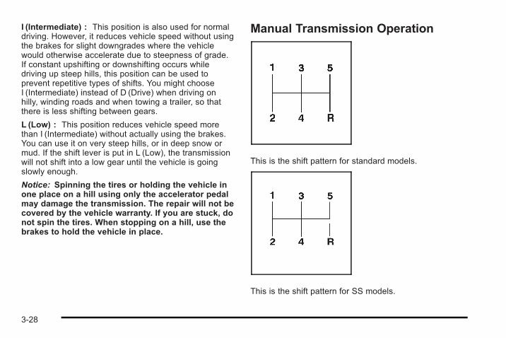
I (Intermediate) : This position is also used for normaldriving. However, it reduces vehicle speed without usingthe brakes for slight downgrades where the vehiclewould otherwise accelerate due to steepness of grade.If constant upshifting or downshifting occurs whiledriving up steep hills, this position can be used toprevent repetitive types of shifts. You might chooseI (Intermediate) instead of D (Drive) when driving onhilly, winding roads and when towing a trailer, so thatthere is less shifting between gears.
L (Low) : This position reduces vehicle speed morethan I (Intermediate) without actually using the brakes.You can use it on very steep hills, or in deep snow ormud. If the shift lever is put in L (Low), the transmissionwill not shift into a low gear until the vehicle is goingslowly enough.
Notice: Spinning the tires or holding the vehicle inone place on a hill using only the accelerator pedalmay damage the transmission. The repair will not becovered by the vehicle warranty. If you are stuck, donot spin the tires. When stopping on a hill, use thebrakes to hold the vehicle in place.
Manual Transmission Operation
This is the shift pattern for standard models.
This is the shift pattern for SS models.
3-28
Here is how to operate the manual transmission:
Notice: Do not rest your hand on the shift leverwhile driving. The pressure could cause prematurewear in the transmission. The repairs would not becovered by the vehicle warranty.
1 (First) : Press the clutch pedal and shift into 1 (First).Then, slowly let up on the clutch pedal as you press theaccelerator pedal.
You can shift into 1 (First) when the vehicle is travelingless than 20 mph (32 km/h). If you have come to acomplete stop and it is hard to shift into 1 (First), put theshift lever in N (Neutral) and let up on the clutch pedal.Press the clutch pedal back down. Then shift into1 (First).
2 (Second) : Press the clutch pedal as you let up onthe accelerator pedal and shift into 2 (Second). Then,slowly let up on the clutch pedal as you press theaccelerator pedal.
3 (Third), 4 (Fourth) and 5 (Fifth) : Shift into 3 (Third),4 (Fourth) and 5 (Fifth) the same way you do for2 (Second). Slowly let up on the clutch pedal as youpress the accelerator pedal down.
To stop, let up on the accelerator pedal and press thebrake pedal. Just before the vehicle stops, press theclutch pedal and the brake pedal, and shift toN (Neutral).
N (Neutral) : Use this position when you start or idlethe engine.
R (Reverse) : To back up, press down the clutch pedaland shift into R (Reverse).
For SS models, lift upwards on the ring located on theunderside of the shift knob to shift into R (Reverse).
Notice: Shifting to R (Reverse) while the vehicle ismoving forward could damage the transmission.The repairs would not be covered by the vehiclewarranty. Shift to R (Reverse) only after the vehicleis stopped.
Also, use R (Reverse), along with the parking brake, forparking the vehicle.
3-29
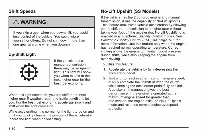
Shift Speeds
{ WARNING:
If you skip a gear when you downshift, you couldlose control of the vehicle. You could injureyourself or others. Do not shift down more thanone gear at a time when you downshift.
Up-Shift Light
If the vehicle has amanual transmission,there may be an up-shiftlight. This light will showyou when to shift to thenext higher gear for thebest fuel economy.
When this light comes on, you can shift to the nexthigher gear if weather, road, and traffic conditions letyou. For the best fuel economy, accelerate slowly andshift when the light comes on.
While accelerating, it is normal for the light to go on andoff if you quickly change the position of the accelerator.Ignore the light when downshifting.
No-Lift Upshift (SS Models)If the vehicle has the 2.0L turbo engine and manualtransmission, it has the capability of No-Lift Upshifts.This feature maximizes vehicle acceleration by allowingyou to shift the transmission to a higher gear withouttaking your foot off the accelerator. No-Lift Upshifting isenabled in all Electronic Stability Control modes. SeeElectronic Stability Control (ESC) on page 5‑6 formore information. Use this feature only when the enginehas reached normal operating temperature. Correctshifting allows the engine to maintain boost pressureduring shifts, while also keeping the engine fromover-revving.
To utilize this feature:
1. Accelerate the vehicle by fully depressing theaccelerator pedal.
2. Just prior to reaching the maximum engine speed,quickly complete the upshift utilizing the clutchwhile keeping the accelerator pedal fully applied.A quicker shift maneuver gives the bestperformance. If the engine is operated at themaximum engine speed for greater thanone second, the engine exits the No-Lift Upshiftmode and resumes normal engine overspeedprotection.
3-30
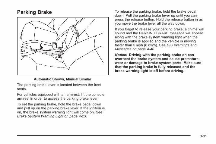
Parking Brake
Automatic Shown, Manual Similar
The parking brake lever is located between the frontseats.
For vehicles equipped with an armrest, lift the consolearmrest in order to access the parking brake lever.
To set the parking brake, hold the brake pedal downand pull up on the parking brake lever. If the ignition ison, the brake system warning light will come on. SeeBrake System Warning Light on page 4‑23.
To release the parking brake, hold the brake pedaldown. Pull the parking brake lever up until you canpress the release button. Hold the release button in asyou move the brake lever all the way down.
If you forget to release your parking brake, a chime willsound and the PARKING BRAKE message will appearalong with the brake system warning light when theparking brake is applied and the vehicle is movingfaster than 5 mph (8 km/h). See DIC Warnings andMessages on page 4‑40.
Notice: Driving with the parking brake on canoverheat the brake system and cause prematurewear or damage to brake system parts. Make surethat the parking brake is fully released and thebrake warning light is off before driving.
3-31
Shifting Into Park(Automatic Transmission)
{ WARNING:
It can be dangerous to get out of the vehicle if theshift lever is not fully in P (Park) with the parkingbrake firmly set. The vehicle can roll. If you haveleft the engine running, the vehicle can movesuddenly. You or others could be injured. To besure the vehicle will not move, even when you areon fairly level ground, use the steps that follow.If you are pulling a trailer, see Towing a Trailer(Automatic Transmission) on page 5‑33 orTowing a Trailer (Manual Transmission) onpage 5‑39.
To shift into P (Park):
1. Hold the brake pedal down and set the parkingbrake. See Parking Brake on page 3‑31 for moreinformation.
2. Move the shift lever into P (Park) by holding in thebutton on the shift lever and pushing the lever allthe way toward the front of the vehicle.
3. Turn the ignition key to LOCK/OFF.
Leaving the Vehicle With the EngineRunning (Automatic Transmission)
{ WARNING:
It can be dangerous to leave the vehicle with theengine running. The vehicle could move suddenlyif the shift lever is not fully in P (Park) with theparking brake firmly set. And, if you leave thevehicle with the engine running, it could overheatand even catch fire. You or others could beinjured. Do not leave the vehicle with the enginerunning.
If you have to leave an automatic transmission vehiclewith the engine running, be sure the vehicle is inP (Park) and the parking brake is firmly set before youleave it. After you have moved the shift lever intoP (Park), hold the brake pedal down. Then, see if youcan move the shift lever away from P (Park) without firstpushing the button. If you can, it means that the shiftlever was not fully locked into P (Park).
3-32
Torque Lock (Automatic Transmission)If you are parking on a hill and you do not shift intoP (Park) properly, the weight of the vehicle may put toomuch force on the parking pawl in the transmission. Youmay find it difficult to pull the shift lever out of P (Park).This is called “torque lock.” To prevent torque lock, setthe parking brake and then shift into P (Park) properlybefore you leave the driver seat. To find out how, seeShifting Into Park (Automatic Transmission) onpage 3‑32.
Move the shift lever out of P (Park) before you releasethe parking brake.
If torque lock does occur, you may need to haveanother vehicle push yours a little uphill to take some ofthe pressure from the parking pawl in the transmission,so you can pull the shift lever out of P (Park).
Shifting Out of Park(Automatic Transmission)This vehicle is equipped with an electronic shift lockrelease system. The shift lock release is designed to:. Prevent ignition key removal unless the shift lever
is in P (Park) with the shift lever button fullyreleased, and
. Prevent movement of the shift lever out of P (Park)unless the ignition is in ON/RUN or ACC/ACCESSORY and the regular brake pedal isapplied.
The shift lock release is always functional except in thecase of a an uncharged or low voltage (less than 9 volt)battery.
If the vehicle has an uncharged battery or a battery withlow voltage, try charging or jump starting the battery.See Jump Starting on page 6‑40 for more information.
To shift out of P (Park):
1. Apply the brake pedal.
2. Then press the shift lever button.
3. Move the shift lever to the desired position.
3-33
If you still are unable to shift out of P (Park):
1. Fully release the shift lever button.
2. While holding down the brake pedal, press the shiftlever button again.
3. Move the shift lever to the desired position.
If you still cannot move the shift lever from P (Park),consult your dealer/retailer or a professional towingservice.
Parking the Vehicle(Manual Transmission)Before leaving the vehicle, fully press the clutch pedaldown, move the shift lever into R (Reverse), and firmlyapply the parking brake. Once the shift lever has beenplaced in R (Reverse) with the clutch pedal presseddown, the ignition key can be turned to LOCK/OFF, thenremove the key and release the clutch pedal. SeeManual Transmission Operation on page 3‑28.
Parking Over Things That Burn
{ WARNING:
Things that can burn could touch hot exhaustparts under the vehicle and ignite. Do not parkover papers, leaves, dry grass, or other things thatcan burn.
3-34
Engine Exhaust
{ WARNING:
Engine exhaust contains Carbon Monoxide (CO)which cannot be seen or smelled. Exposure to COcan cause unconsciousness and even death.
Exhaust may enter the vehicle if:. The vehicle idles in areas with poor ventilation
(parking garages, tunnels, deep snow thatmay block underbody airflow or tail pipes).
. The exhaust smells or sounds strange ordifferent.
. The exhaust system leaks due to corrosion ordamage.
. The vehicle’s exhaust system has beenmodified, damaged or improperly repaired.
. There are holes or openings in the vehiclebody from damage or after-marketmodifications that are not completely sealed.
(Continued)
WARNING: (Continued)
If unusual fumes are detected or if it is suspectedthat exhaust is coming into the vehicle:. Drive it only with the windows
completely down.. Have the vehicle repaired immediately.
Never park the vehicle with the engine running inan enclosed area such as a garage or a buildingthat has no fresh air ventilation.
3-35
Running the Vehicle While ParkedIt is better not to park with the engine running. But if youever have to, here are some things to know.
{ WARNING:
Idling a vehicle in an enclosed area with poorventilation is dangerous. Engine exhaust mayenter the vehicle. Engine exhaust containsCarbon Monoxide (CO) which cannot be seen orsmelled. It can cause unconsciousness and evendeath. Never run the engine in an enclosed areathat has no fresh air ventilation. For moreinformation, see Engine Exhaust on page 3‑35.
{ WARNING:
It can be dangerous to get out of the vehicle if theautomatic transmission shift lever is not fully inP (Park) with the parking brake firmly set. Thevehicle can roll. Do not leave the vehicle when theengine is running unless you have to. If you haveleft the engine running, the vehicle can movesuddenly. You or others could be injured. To besure the vehicle will not move, even when you areon fairly level ground, always set the parkingbrake and move the shift lever to P (Park).
Follow the proper steps to be sure the vehicle will notmove. See Shifting Into Park (Automatic Transmission)on page 3‑32.
If parking on a hill and pulling a trailer, see Towing aTrailer (Automatic Transmission) on page 5‑33 orTowing a Trailer (Manual Transmission) on page 5‑39.
3-36
Mirrors
Manual Rearview MirrorHold the inside rearview mirror in the center to move itfor a clearer view of behind your vehicle. Adjust themirror to avoid glare from the headlamps behind you.Push the tab forward for daytime use and pull it fornighttime use.
Vehicles with OnStar® have three additional controlbuttons located at the bottom of the mirror. See yourdealer/retailer for more information on the system andhow to subscribe to OnStar®. See the OnStar® owner'sguide for more information about the services OnStar®
provides.
If the vehicle has map lamps, press the buttons locatedat the bottom of the mirror to turn them on or off.
Outside Manual MirrorAdjust the outside mirror just to see the side of yourvehicle and have a clear view of objects behind you.
Manually fold the mirrors inward to prevent damagewhen going through an automatic car wash. To fold, pullthe mirror toward the vehicle. Push the mirror outward,to return it to the original position.
Outside Remote Control MirrorAdjust the driver outside mirror with the control leverlocated on the driver door. Adjust the outside mirrors sothat the side of the vehicle can be seen.
Manually fold the mirrors inward to prevent damagewhen going through an automatic car wash. To fold, pullthe mirror toward the vehicle. Push the mirror outward,to return it to the original position.
3-37
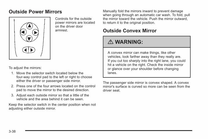
Outside Power MirrorsControls for the outsidepower mirrors are locatedon the driver doorarmrest.
To adjust the mirrors:
1. Move the selector switch located below thefour-way control pad to the left or right to chooseeither the driver or passenger side mirror.
2. Press one of the four arrows located on the controlpad to move the mirror to the desired direction.
3. Adjust each outside mirror so that a little of thevehicle and the area behind it can be seen.
Keep the selector switch in the center position when notadjusting either outside mirror.
Manually fold the mirrors inward to prevent damagewhen going through an automatic car wash. To fold, pullthe mirror toward the vehicle. Push the mirror outward,to return it to the original position.
Outside Convex Mirror
{ WARNING:
A convex mirror can make things, like othervehicles, look farther away than they really are.If you cut too sharply into the right lane, you couldhit a vehicle on the right. Check the inside mirroror glance over your shoulder before changinglanes.
The passenger side mirror is convex shaped. A convexmirror's surface is curved so more can be seen from thedriver seat.
3-38
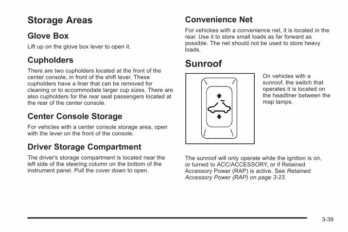
Storage Areas
Glove BoxLift up on the glove box lever to open it.
CupholdersThere are two cupholders located at the front of thecenter console, in front of the shift lever. Thesecupholders have a liner that can be removed forcleaning or to accommodate larger cup sizes. There arealso cupholders for the rear seat passengers located atthe rear of the center console.
Center Console StorageFor vehicles with a center console storage area, openwith the lever on the front of the console.
Driver Storage CompartmentThe driver's storage compartment is located near theleft side of the steering column on the bottom of theinstrument panel. Pull the cover down to open.
Convenience NetFor vehickes with a convenience net, it is located in therear. Use it to store small loads as far forward aspossible. The net should not be used to store heavyloads.
SunroofOn vehicles with asunroof, the switch thatoperates it is located onthe headliner between themap lamps.
The sunroof will only operate while the ignition is on,or turned to ACC/ACCESSORY, or if RetainedAccessory Power (RAP) is active. See RetainedAccessory Power (RAP) on page 3‑23.
3-39
Press the sunroof switch rearward to open the sunroofto the vent position. If the sunshade is closed, it mustbe opened manually in the vent position. Press andhold the switch rearward a second time to open thesunroof. If the sunshade is closed, it will openautomatically when the sunroof is opened.
To close the sunroof, press the switch forward and holdit until the sunroof is closed. The sunroof will stop if theswitch is released. Close the sunshade by hand.
Notice: Forcing the sunshade forward of the slidingglass panel may cause damage and the sunroofmay not operate properly. Always close the glasspanel before closing the sunshade.
The sunroof glass panel cannot be opened or closed ifthe vehicle has an electrical failure.
Do not keep the sunroof open for long periods of time.Debris may collect in the tracks and possibly damagethe sunroof and plug the water draining system.
3-40
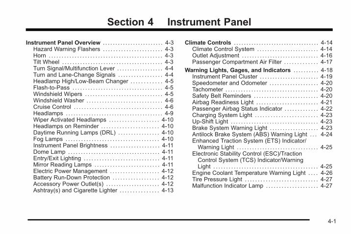
Section 4 Instrument Panel
Instrument Panel Overview . . . . . . . . . . . . . . . . . . . . . . . . 4-3Hazard Warning Flashers . . . . . . . . . . . . . . . . . . . . . . . 4-3Horn . . . . . . . . . . . . . . . . . . . . . . . . . . . . . . . . . . . . . . . . . . . . 4-3Tilt Wheel . . . . . . . . . . . . . . . . . . . . . . . . . . . . . . . . . . . . . . . 4-3Turn Signal/Multifunction Lever . . . . . . . . . . . . . . . . . . 4-4Turn and Lane-Change Signals . . . . . . . . . . . . . . . . . 4-4Headlamp High/Low-Beam Changer . . . . . . . . . . . . 4-5Flash-to-Pass . . . . . . . . . . . . . . . . . . . . . . . . . . . . . . . . . . . 4-5Windshield Wipers . . . . . . . . . . . . . . . . . . . . . . . . . . . . . . 4-5Windshield Washer . . . . . . . . . . . . . . . . . . . . . . . . . . . . . 4-6Cruise Control . . . . . . . . . . . . . . . . . . . . . . . . . . . . . . . . . . 4-6Headlamps . . . . . . . . . . . . . . . . . . . . . . . . . . . . . . . . . . . . . . 4-9Wiper Activated Headlamps . . . . . . . . . . . . . . . . . . . 4-10Headlamps on Reminder . . . . . . . . . . . . . . . . . . . . . . 4-10Daytime Running Lamps (DRL) . . . . . . . . . . . . . . . . 4-10Fog Lamps . . . . . . . . . . . . . . . . . . . . . . . . . . . . . . . . . . . . 4-10Instrument Panel Brightness . . . . . . . . . . . . . . . . . . . 4-11Dome Lamp . . . . . . . . . . . . . . . . . . . . . . . . . . . . . . . . . . . . 4-11Entry/Exit Lighting . . . . . . . . . . . . . . . . . . . . . . . . . . . . . 4-11Mirror Reading Lamps . . . . . . . . . . . . . . . . . . . . . . . . . 4-11Electric Power Management . . . . . . . . . . . . . . . . . . . 4-12Battery Run-Down Protection . . . . . . . . . . . . . . . . . . 4-12Accessory Power Outlet(s) . . . . . . . . . . . . . . . . . . . . . 4-12Ashtray(s) and Cigarette Lighter . . . . . . . . . . . . . . . 4-13
Climate Controls . . . . . . . . . . . . . . . . . . . . . . . . . . . . . . . . . . 4-14Climate Control System . . . . . . . . . . . . . . . . . . . . . . . . 4-14Outlet Adjustment . . . . . . . . . . . . . . . . . . . . . . . . . . . . . . 4-16Passenger Compartment Air Filter . . . . . . . . . . . . . 4-17
Warning Lights, Gages, and Indicators . . . . . . . . . . 4-18Instrument Panel Cluster . . . . . . . . . . . . . . . . . . . . . . . 4-19Speedometer and Odometer . . . . . . . . . . . . . . . . . . . 4-20Tachometer . . . . . . . . . . . . . . . . . . . . . . . . . . . . . . . . . . . . 4-20Safety Belt Reminders . . . . . . . . . . . . . . . . . . . . . . . . . 4-20Airbag Readiness Light . . . . . . . . . . . . . . . . . . . . . . . . 4-21Passenger Airbag Status Indicator . . . . . . . . . . . . . 4-22Charging System Light . . . . . . . . . . . . . . . . . . . . . . . . 4-23Up-Shift Light . . . . . . . . . . . . . . . . . . . . . . . . . . . . . . . . . . 4-23Brake System Warning Light . . . . . . . . . . . . . . . . . . . 4-23Antilock Brake System (ABS) Warning Light . . . 4-24Enhanced Traction System (ETS) Indicator/Warning Light . . . . . . . . . . . . . . . . . . . . . . . . . . . . . . . . 4-25
Electronic Stability Control (ESC)/TractionControl System (TCS) Indicator/WarningLight . . . . . . . . . . . . . . . . . . . . . . . . . . . . . . . . . . . . . . . . . 4-25
Engine Coolant Temperature Warning Light . . . . 4-26Tire Pressure Light . . . . . . . . . . . . . . . . . . . . . . . . . . . . 4-27Malfunction Indicator Lamp . . . . . . . . . . . . . . . . . . . . 4-27
4-1
Section 4 Instrument Panel
Oil Pressure Light . . . . . . . . . . . . . . . . . . . . . . . . . . . . . 4-30Security Light . . . . . . . . . . . . . . . . . . . . . . . . . . . . . . . . . . 4-30Fog Lamp Light . . . . . . . . . . . . . . . . . . . . . . . . . . . . . . . . 4-30Highbeam On Light . . . . . . . . . . . . . . . . . . . . . . . . . . . . 4-31Fuel Gage . . . . . . . . . . . . . . . . . . . . . . . . . . . . . . . . . . . . . 4-31Boost Gage . . . . . . . . . . . . . . . . . . . . . . . . . . . . . . . . . . . . 4-32Reconfigurable Performance Display (RPD) . . . 4-32
Driver Information Center (DIC) . . . . . . . . . . . . . . . . . . 4-37DIC Operation and Displays . . . . . . . . . . . . . . . . . . . 4-38DIC Warnings and Messages . . . . . . . . . . . . . . . . . . 4-40DIC Vehicle Personalization . . . . . . . . . . . . . . . . . . . 4-46
Audio System(s) . . . . . . . . . . . . . . . . . . . . . . . . . . . . . . . . . . 4-52Setting the Clock . . . . . . . . . . . . . . . . . . . . . . . . . . . . . . 4-53Radio(s) . . . . . . . . . . . . . . . . . . . . . . . . . . . . . . . . . . . . . . . 4-54Using an MP3 . . . . . . . . . . . . . . . . . . . . . . . . . . . . . . . . . 4-66XM Radio Messages . . . . . . . . . . . . . . . . . . . . . . . . . . . 4-72Bluetooth® . . . . . . . . . . . . . . . . . . . . . . . . . . . . . . . . . . . . . 4-74Theft-Deterrent Feature . . . . . . . . . . . . . . . . . . . . . . . . 4-84Audio Steering Wheel Controls . . . . . . . . . . . . . . . . 4-84Radio Reception . . . . . . . . . . . . . . . . . . . . . . . . . . . . . . . 4-85Fixed Mast Antenna . . . . . . . . . . . . . . . . . . . . . . . . . . . 4-86XM™ Satellite Radio Antenna System . . . . . . . . . 4-86
4-2
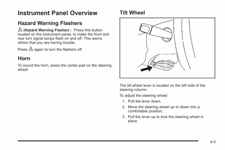
Instrument Panel Overview
Hazard Warning Flashers| (Hazard Warning Flasher) : Press this buttonlocated on the instrument panel, to make the front andrear turn signal lamps flash on and off. This warnsothers that you are having trouble.
Press| again to turn the flashers off.
HornTo sound the horn, press the center pad on the steeringwheel.
Tilt Wheel
The tilt wheel lever is located on the left side of thesteering column.
To adjust the steering wheel:
1. Pull the lever down.
2. Move the steering wheel up or down into acomfortable position.
3. Pull the lever up to lock the steering wheel inplace.
4-3
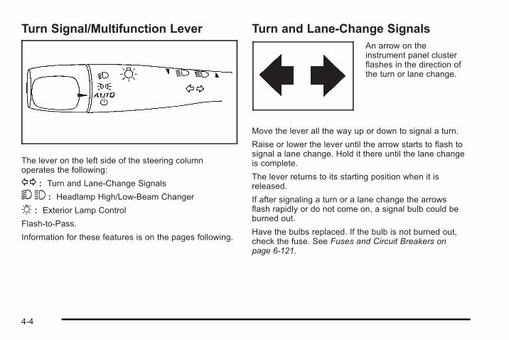
Turn Signal/Multifunction Lever
The lever on the left side of the steering columnoperates the following:
G : Turn and Lane-Change Signals
53 : Headlamp High/Low-Beam Changer
O : Exterior Lamp Control
Flash-to-Pass.
Information for these features is on the pages following.
Turn and Lane-Change SignalsAn arrow on theinstrument panel clusterflashes in the direction ofthe turn or lane change.
Move the lever all the way up or down to signal a turn.
Raise or lower the lever until the arrow starts to flash tosignal a lane change. Hold it there until the lane changeis complete.
The lever returns to its starting position when it isreleased.
If after signaling a turn or a lane change the arrowsflash rapidly or do not come on, a signal bulb could beburned out.
Have the bulbs replaced. If the bulb is not burned out,check the fuse. See Fuses and Circuit Breakers onpage 6‑121.
4-4
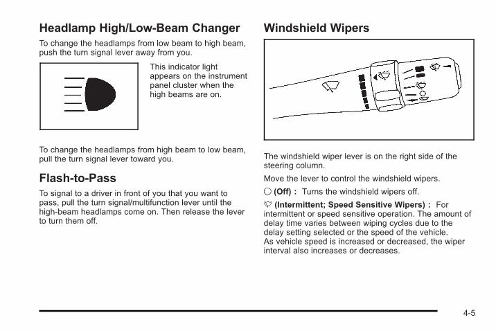
Headlamp High/Low-Beam ChangerTo change the headlamps from low beam to high beam,push the turn signal lever away from you.
This indicator lightappears on the instrumentpanel cluster when thehigh beams are on.
To change the headlamps from high beam to low beam,pull the turn signal lever toward you.
Flash-to-PassTo signal to a driver in front of you that you want topass, pull the turn signal/multifunction lever until thehigh-beam headlamps come on. Then release the leverto turn them off.
Windshield Wipers
The windshield wiper lever is on the right side of thesteering column.
Move the lever to control the windshield wipers.
9 (Off) : Turns the windshield wipers off.
& (Intermittent; Speed Sensitive Wipers) : Forintermittent or speed sensitive operation. The amount ofdelay time varies between wiping cycles due to thedelay setting selected or the speed of the vehicle.As vehicle speed is increased or decreased, the wiperinterval also increases or decreases.
4-5
x (Delay) : Move the lever to the& position, then
turn thex band up for more frequent wipes or downfor less frequent wipes.
6 (Low Speed) : Slow wipes.
1 (High Speed) : Fast wipes.
8 (Mist) : Single wipe, move the lever down, thenrelease it. Several wipes, hold the lever down.
Clear ice and snow from the wiper blades beforeusing them.
If frozen to the windshield, carefully loosen or thawthem. Damaged wiper blades should be replaced.
Heavy snow or ice can overload the wiper motor.A circuit breaker stops the motor until it cools. If themotor gets stuck, turn the wipers off, clear away thesnow or ice, and then turn the wipers back on.
As an added safety feature, if the wipers are on formore than 15 seconds, the vehicle's headlamps turn onautomatically. They turn off 15 seconds after the wipersare turned off.
Windshield WasherPress the button at the end of the windshield wiperlever until the washers begin.
{ WARNING:
In freezing weather, do not use your washer untilthe windshield is warmed. Otherwise the washerfluid can form ice on the windshield, blocking yourvision.
When the button is released, the washers stop, but thewipers continue to wipe about three times or resume theprevious speed.
Cruise ControlWith cruise control, a speed of about 40 km/h (25 mph)or more can be maintained without keeping your foot onthe accelerator. Cruise control does not work at speedsbelow 40 km/h (25 mph).
The brake must be applied at least one time, after thevehicle has been started, before cruise control willfunction.
4-6
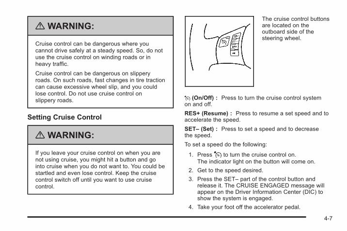
{ WARNING:
Cruise control can be dangerous where youcannot drive safely at a steady speed. So, do notuse the cruise control on winding roads or inheavy traffic.
Cruise control can be dangerous on slipperyroads. On such roads, fast changes in tire tractioncan cause excessive wheel slip, and you couldlose control. Do not use cruise control onslippery roads.
Setting Cruise Control
{ WARNING:
If you leave your cruise control on when you arenot using cruise, you might hit a button and gointo cruise when you do not want to. You could bestartled and even lose control. Keep the cruisecontrol switch off until you want to use cruisecontrol.
The cruise control buttonsare located on theoutboard side of thesteering wheel.
J (On/Off) : Press to turn the cruise control systemon and off.
RES+ (Resume) : Press to resume a set speed and toaccelerate the speed.
SET– (Set) : Press to set a speed and to decreasethe speed.
To set a speed do the following:
1. PressJ to turn the cruise control on.The indicator light on the button will come on.
2. Get to the speed desired.
3. Press the SET– part of the control button andrelease it. The CRUISE ENGAGED message willappear on the Driver Information Center (DIC) toshow the system is engaged.
4. Take your foot off the accelerator pedal.
4-7
Resuming a Set SpeedSuppose the cruise control is set at a desired speedand then the brake is applied. This disengages thecruise control. To return to the previously set speed,you do not need to go through the set process again.Once the vehicle is traveling at least 40 km/h (25 mph)or more, press the RES+ part of the button briefly.
The vehicle returns to the previously selected speedand stays there.
Increasing Speed While Using CruiseControlThere are two ways to go to a higher speed.
1. Disengage the cruise control by applying the brakepedal, but do not turn it off. Accelerate to a higherspeed and reset the cruise control.
2. If the cruise control system is already engaged,press the RES+ part of the button. Hold it thereuntil you get up to the speed desired, and thenrelease the button. To increase the vehicle speedin very small amounts, press the RES+ part of thebutton briefly and then release it. Each time this isdone, the vehicle goes about 1.6 km/h (1 mph)faster.
Reducing Speed While Using CruiseControlIf the cruise control system is already engaged,. Push and hold the SET– part of the button until the
lower speed desired is reached, then release it.. To slow down in very small amounts, push the
SET– part of the button briefly. Each time this isdone, the vehicle goes about 1.6 km/h (1 mph)slower.
Passing Another Vehicle While UsingCruise ControlUse the accelerator pedal to increase the vehicle'sspeed. When you take your foot off the pedal, thevehicle will slow down to the cruise control speed youset earlier.
Using Cruise Control on HillsHow well the cruise control will work on hills dependsupon the vehicle speed, load, and the steepness of thehills. When going up steep hills, you might have to stepon the accelerator pedal to maintain the vehicle'sspeed. When going downhill, you might have to brakeor shift to a lower gear to keep the vehicle's speeddown. Applying the brake will turn off the cruise control.
4-8
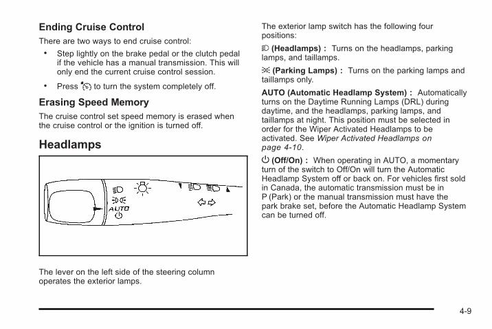
Ending Cruise ControlThere are two ways to end cruise control:. Step lightly on the brake pedal or the clutch pedal
if the vehicle has a manual transmission. This willonly end the current cruise control session.
. PressJ to turn the system completely off.
Erasing Speed MemoryThe cruise control set speed memory is erased whenthe cruise control or the ignition is turned off.
Headlamps
The lever on the left side of the steering columnoperates the exterior lamps.
The exterior lamp switch has the following fourpositions:
2 (Headlamps) : Turns on the headlamps, parkinglamps, and taillamps.
; (Parking Lamps) : Turns on the parking lamps andtaillamps only.
AUTO (Automatic Headlamp System) : Automaticallyturns on the Daytime Running Lamps (DRL) duringdaytime, and the headlamps, parking lamps, andtaillamps at night. This position must be selected inorder for the Wiper Activated Headlamps to beactivated. See Wiper Activated Headlamps onpage 4‑10.
P (Off/On) : When operating in AUTO, a momentaryturn of the switch to Off/On will turn the AutomaticHeadlamp System off or back on. For vehicles first soldin Canada, the automatic transmission must be inP (Park) or the manual transmission must have thepark brake set, before the Automatic Headlamp Systemcan be turned off.
4-9
Wiper Activated HeadlampsThe headlamps and parking lamps are activated15 seconds after the windshield wipers are turned on.For this feature to work, automatic lighting must beenabled. See Headlamps on page 4‑9 for additionalinformation.
When the ignition is turned off, the wiper-activatedheadlamps will immediately turn off. They also turn off15 seconds after the windshield wiper control isturned off.
Headlamps on ReminderIf the drivers door is opened with the ignition off and thelamps on, a warning chime will sound. This indicatesthat the headlamps are still on.
Daytime Running Lamps (DRL)Daytime Running Lamps (DRL) can make it easier forothers to see the front of your vehicle during the day.DRL can be helpful in many different driving conditions,but they can be especially helpful in the short periodsafter dawn and before sunset. Fully functional daytimerunning lamps are required on all vehicles first sold inCanada. The vehicle has a light sensor on top of theinstrument panel. Make sure it is not covered, or thehead lamps will be on when not needed.
The DRL system will make the headlamps come onwhen the following conditions are met:. The ignition is on.. The exterior lamps control is in AUTO or the
parking lamps only position.. The light sensor detects daytime light.. The parking brake is released.
When the DRL system is on, the taillamps, sidemarkerlamps, parking lamps, and instrument panel lights willnot be illuminated unless you have turned the exteriorlamps control to the parking lamp position.
As with any vehicle, you should turn on the regularheadlamp system when you need it.
Fog LampsFor vehicles with fog lamps, the button is located on theinstrument panel, to the left of the steering wheel.
The ignition must be on to use the fog lamps.
# : Press to turn the fog lamps on off. An indicatorlight on the button comes on when the fog lampsare on.
4-10
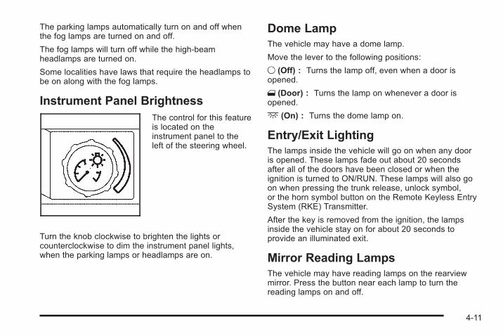
The parking lamps automatically turn on and off whenthe fog lamps are turned on and off.
The fog lamps will turn off while the high-beamheadlamps are turned on.
Some localities have laws that require the headlamps tobe on along with the fog lamps.
Instrument Panel BrightnessThe control for this featureis located on theinstrument panel to theleft of the steering wheel.
Turn the knob clockwise to brighten the lights orcounterclockwise to dim the instrument panel lights,when the parking lamps or headlamps are on.
Dome LampThe vehicle may have a dome lamp.
Move the lever to the following positions:
9 (Off) : Turns the lamp off, even when a door isopened.
1 (Door) : Turns the lamp on whenever a door isopened.
+ (On) : Turns the dome lamp on.
Entry/Exit LightingThe lamps inside the vehicle will go on when any dooris opened. These lamps fade out about 20 secondsafter all of the doors have been closed or when theignition is turned to ON/RUN. These lamps will also goon when pressing the trunk release, unlock symbol,or the horn symbol button on the Remote Keyless EntrySystem (RKE) Transmitter.
After the key is removed from the ignition, the lampsinside the vehicle stay on for about 20 seconds toprovide an illuminated exit.
Mirror Reading LampsThe vehicle may have reading lamps on the rearviewmirror. Press the button near each lamp to turn thereading lamps on and off.
4-11
Electric Power ManagementThis vehicle has Electric Power Management (EPM), anadvanced control system. It estimates the battery'stemperature and state of charge and then adjusts thevoltage for best performance and extended life of thebattery.
When the battery's state of charge is low, the voltage israised slightly to quickly put the charge back in. Whenthe state of charge is high, the voltage is loweredslightly to prevent overcharging. If the vehicle has avoltmeter gage or voltage display on the DriverInformation Center (DIC), you may see the voltagemove up or down. This is normal. If there is a problem,an alert will be displayed.
The battery can be discharged at idle if the electricalloads are very high. This is true for all vehicles. This isbecause the generator (alternator) may not be spinningfast enough at idle to produce all the power that isneeded for very high electrical loads.
A high electrical load occurs when several of thefollowing loads are on: headlamps, high beams, foglamps, rear window defogger, climate control fan at highspeed, heated seats, engine cooling fans, trailer loads,and loads plugged into accessory power outlets.
EPM works to prevent excessive discharge of thebattery. It does this by balancing the generator's outputand the vehicle's electrical needs. It can increase
engine idle speed to generate more power, wheneverneeded. It can temporarily reduce the power demandsof some accessories.
Normally, these actions occur in steps or levels, withoutbeing noticeable. In rare cases at the highest levels ofcorrective action, this action may be noticeable to thedriver.
Battery Run-Down ProtectionThe vehicle has a battery saver feature designed toprotect the vehicle's battery.
When any interior lamp is left on and the ignition isturned off, the battery rundown protection systemautomatically turns the lamp off after 20 minutes.This prevents draining of the battery.
Accessory Power Outlet(s)Accessory power outlets can be used to connectelectrical equipment, such as a cellular phone.
The accessory power outlet is located in the centerconsole, rearward of the shift lever.
To use the accessory power outlet, remove the cover.When not in use, always cover the accessory poweroutlet with the protective cap.
4-12
Notice: Leaving electrical equipment on forextended periods will drain the battery. Always turnoff electrical equipment when not in use and do notplug in equipment that exceeds the maximumamperage rating of 20 amperes.
Certain electrical accessories may not be compatiblewith the accessory power outlet and could result inblown vehicle or adapter fuses. If you experience aproblem, see your dealer/retailer for additionalinformation on the accessory power outlet.
Notice: Adding any electrical equipment to thevehicle can damage it or keep other componentsfrom working as they should. The repairs would notbe covered by the vehicle warranty. Do not useequipment exceeding maximum amperage rating of20 amperes. Check with your dealer/retailer beforeadding electrical equipment.
When adding electrical equipment, be sure to follow theinstallation instructions included with the equipment.
Notice: Improper use of the power outlet can causedamage not covered by the vehicle warranty. Do nothang any type of accessory or accessory bracketfrom the plug because the power outlets aredesigned for accessory power plugs only.
Ashtray(s) and Cigarette LighterThe vehicle may have an ashtray and cigarette lighter.To use the lighter, located on the instrument panelbelow the climate controls, push it in all the way andlet go. When it is ready, it will pop back out by itself.
Notice: Holding a cigarette lighter in while it isheating will not allow the lighter to back away fromthe heating element when it is hot. Damage fromoverheating may occur to the lighter or heatingelement, or a fuse could be blown. Do not hold acigarette lighter in while it is heating. Do not useequipment exceeding maximum amperage rating of15 amperes.
To clean the center console ashtray, remove the entireashtray and empty it.
Notice: If papers, pins, or other flammable items areput in the ashtray, hot cigarettes or other smokingmaterials could ignite them and possibly damagethe vehicle. Never put flammable items in theashtray.
4-13
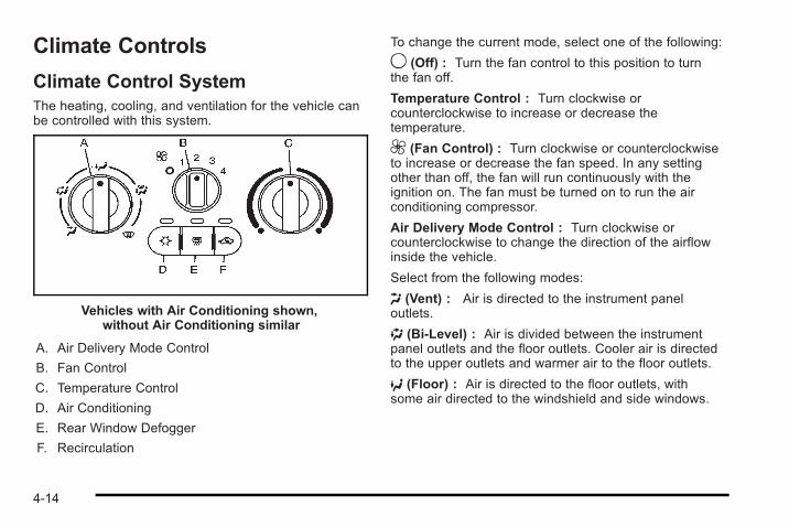
Climate Controls
Climate Control SystemThe heating, cooling, and ventilation for the vehicle canbe controlled with this system.
Vehicles with Air Conditioning shown,without Air Conditioning similar
A. Air Delivery Mode Control
B. Fan Control
C. Temperature Control
D. Air Conditioning
E. Rear Window Defogger
F. Recirculation
To change the current mode, select one of the following:
9 (Off) : Turn the fan control to this position to turnthe fan off.
Temperature Control : Turn clockwise orcounterclockwise to increase or decrease thetemperature.
9 (Fan Control) : Turn clockwise or counterclockwiseto increase or decrease the fan speed. In any settingother than off, the fan will run continuously with theignition on. The fan must be turned on to run the airconditioning compressor.
Air Delivery Mode Control : Turn clockwise orcounterclockwise to change the direction of the airflowinside the vehicle.
Select from the following modes:
H (Vent) : Air is directed to the instrument paneloutlets.
) (Bi-Level) : Air is divided between the instrumentpanel outlets and the floor outlets. Cooler air is directedto the upper outlets and warmer air to the floor outlets.
6 (Floor) : Air is directed to the floor outlets, withsome air directed to the windshield and side windows.
4-14
- (Defog) : This mode clears the windows of fog ormoisture. Air is directed to the windshield, side window,and floor outlets. To defog the windows faster, turn thetemperature control knob clockwise to the warmestsetting. In this mode, the system runs the airconditioning compressor.
0 (Defrost) : This mode removes fog or frost from thewindshield more quickly. Air is directed to thewindshield, with some air directed to the side windowoutlets and the floor outlets. To defrost the windowsfaster, turn the temperature control knob clockwise tothe warmest setting. In this mode, the system runs theair conditioning compressor.
For best results, clear all snow and ice from thewindshield before defrosting.
# (Air Conditioning) : For vehicles with airconditioning, press this button to turn the airconditioning system on or off. An indicator light comeson to show that the air conditioning is on.
On hot days, open the windows to let hot inside airescape; then close them. This helps to reduce the timeit takes for the vehicle to cool down. It also helps thesystem to operate more efficiently.
For quick cool down on hot days:
1. Select theH mode.
2. Select theh mode.
3. Select# .
4. Select the coolest temperature.
5. Select the highest fan speed.
Using these settings together for long periods of timemay cause the air inside of the vehicle to become toodry. To prevent this from happening, after the air in thevehicle has cooled, turn off the recirculation by pressingthe button again.
The air conditioning system removes moisture from theair, so a small amount of water might drip under thevehicle while idling or after turning off the engine.This is normal.
The air conditioning compressor cannot be turned onwhen the fan is off.
h (Recirculation) : Press to turn the recirculationmode on. An indicator light comes on to show thatrecirculation is on.
This mode recirculates and helps to quickly cool the airinside the vehicle. It can be used to help preventoutside air and odors from entering the vehicle.
4-15
The air conditioning compressor also comes on.Recirculation is not available for floor, defog and defrostmodes. If recirculation is selected in any of thesemodes, the recirculate indicator light flashes five timesand outside air will be delivered. Operation in this modeduring periods of high humidity and cool outsidetemperatures may result in increased window fogging.If window fogging is experienced, select thedefrost mode.
Outside Air : This mode allows outside air to circulatethrough the vehicle. This mode is automatically active ifrecirculate is not selected. There is no button foroutside air.
Rear Window DefoggerThe rear window defogger uses a warming grid toremove fog from the rear window.
The rear window defogger only works when the ignitionis in ON/RUN.
< (Rear) : Press to turn the rear window defogger onor off. Be sure to clear as much snow from the rearwindow as possible. An indicator light comes on toshow that the rear window defogger is on.
The rear window defogger turns off about 15 minutesafter the button is pressed. If turned on again, thedefogger only runs for about seven minutes before
turning off. If the vehicle is moving faster than 50 mph(80 kph), the rear defogger will stay on. The defoggercan also be turned off by turning off the engine.
Notice: Do not use anything sharp on the inside ofthe rear window. If you do, you could cut or damagethe warming grid, and the repairs would not becovered by the vehicle warranty. Do not attach atemporary vehicle license, tape, a decal or anythingsimilar to the defogger grid.
Outlet AdjustmentUse the thumbwheels located next to and below the airoutlets to change the direction of the airflow and toopen and close the outlets.
Operation Tips. Clear away any ice, snow or leaves from the air
inlets at the base of the windshield that may blockthe flow of air into the vehicle.
. Use of non-GM approved hood deflectors mayadversely affect the performance of the system.
. Keep the path under the front seats clear ofobjects to help circulate the air inside of the vehiclemore effectively.
4-16
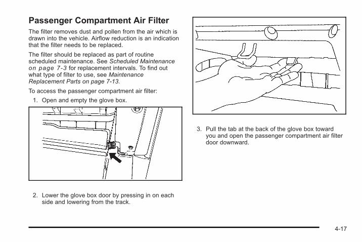
Passenger Compartment Air FilterThe filter removes dust and pollen from the air which isdrawn into the vehicle. Airflow reduction is an indicationthat the filter needs to be replaced.
The filter should be replaced as part of routinescheduled maintenance. See Scheduled Maintenanceon page 7‑3 for replacement intervals. To find outwhat type of filter to use, see MaintenanceReplacement Parts on page 7‑13.
To access the passenger compartment air filter:
1. Open and empty the glove box.
2. Lower the glove box door by pressing in on eachside and lowering from the track.
3. Pull the tab at the back of the glove box towardyou and open the passenger compartment air filterdoor downward.
4-17
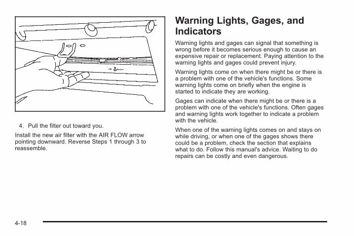
4. Pull the filter out toward you.
Install the new air filter with the AIR FLOW arrowpointing downward. Reverse Steps 1 through 3 toreassemble.
Warning Lights, Gages, andIndicatorsWarning lights and gages can signal that something iswrong before it becomes serious enough to cause anexpensive repair or replacement. Paying attention to thewarning lights and gages could prevent injury.
Warning lights come on when there might be or there isa problem with one of the vehicle's functions. Somewarning lights come on briefly when the engine isstarted to indicate they are working.
Gages can indicate when there might be or there is aproblem with one of the vehicle's functions. Often gagesand warning lights work together to indicate a problemwith the vehicle.
When one of the warning lights comes on and stays onwhile driving, or when one of the gages shows therecould be a problem, check the section that explainswhat to do. Follow this manual's advice. Waiting to dorepairs can be costly and even dangerous.
4-18
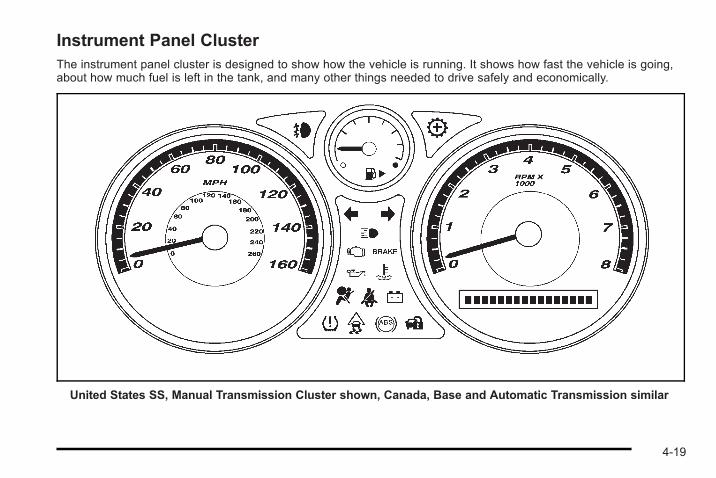
Instrument Panel ClusterThe instrument panel cluster is designed to show how the vehicle is running. It shows how fast the vehicle is going,about how much fuel is left in the tank, and many other things needed to drive safely and economically.
United States SS, Manual Transmission Cluster shown, Canada, Base and Automatic Transmission similar
4-19
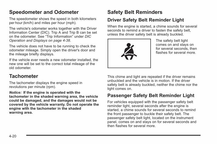
Speedometer and OdometerThe speedometer shows the speed in both kilometersper hour (km/h) and miles per hour (mph).
The vehicle's odometer works together with the DriverInformation Center (DIC). Trip A and Trip B can be seton the odometer. See “Trip Information” under DICOperation and Displays on page 4‑38.
The vehicle does not have to be running to check theodometer mileage. Simply open the driver's door andthe mileage briefly displays.
If the vehicle ever needs a new odometer installed, thenew one will be set to the correct total mileage of theold odometer.
TachometerThe tachometer displays the engine speed inrevolutions per minute (rpm).
Notice: If the engine is operated with thetachometer in the shaded warning area, the vehiclecould be damaged, and the damages would not becovered by the vehicle warranty. Do not operate theengine with the tachometer in the shadedwarning area.
Safety Belt Reminders
Driver Safety Belt Reminder LightWhen the engine is started, a chime sounds for severalseconds to remind a driver to fasten the safety belt,unless the driver safety belt is already buckled.
The safety belt lightcomes on and stays onfor several seconds, thenflashes for several more.
This chime and light are repeated if the driver remainsunbuckled and the vehicle is in motion. If the driversafety belt is already buckled, neither the chime nor thelight comes on.
Passenger Safety Belt Reminder LightFor vehicles equipped with the passenger safety beltreminder light, several seconds after the engine isstarted, a chime sounds for several seconds to remindthe front passenger to buckle their safety belt. Thepassenger safety belt light, located on the instrumentpanel, comes on and stays on for several seconds andthen flashes for several more.
4-20
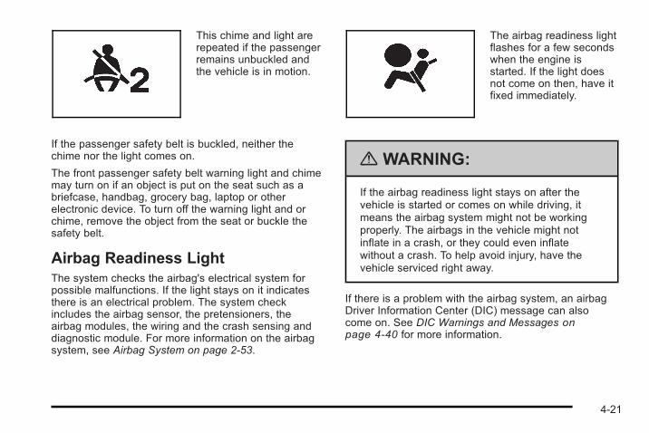
This chime and light arerepeated if the passengerremains unbuckled andthe vehicle is in motion.
If the passenger safety belt is buckled, neither thechime nor the light comes on.
The front passenger safety belt warning light and chimemay turn on if an object is put on the seat such as abriefcase, handbag, grocery bag, laptop or otherelectronic device. To turn off the warning light and orchime, remove the object from the seat or buckle thesafety belt.
Airbag Readiness LightThe system checks the airbag's electrical system forpossible malfunctions. If the light stays on it indicatesthere is an electrical problem. The system checkincludes the airbag sensor, the pretensioners, theairbag modules, the wiring and the crash sensing anddiagnostic module. For more information on the airbagsystem, see Airbag System on page 2‑53.
The airbag readiness lightflashes for a few secondswhen the engine isstarted. If the light doesnot come on then, have itfixed immediately.
{ WARNING:
If the airbag readiness light stays on after thevehicle is started or comes on while driving, itmeans the airbag system might not be workingproperly. The airbags in the vehicle might notinflate in a crash, or they could even inflatewithout a crash. To help avoid injury, have thevehicle serviced right away.
If there is a problem with the airbag system, an airbagDriver Information Center (DIC) message can alsocome on. See DIC Warnings and Messages onpage 4‑40 for more information.
4-21
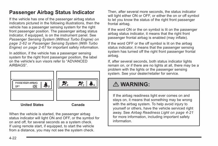
Passenger Airbag Status IndicatorIf the vehicle has one of the passenger airbag statusindicators pictured in the following illustrations, then thevehicle has a passenger sensing system for the rightfront passenger position. The passenger airbag statusindicator, if equipped, is on the instrument panel. SeePassenger Sensing System (Without Turbo Engine) onpage 2‑62 or Passenger Sensing System (With TurboEngine) on page 2‑67 for important safety information.
In addition, if the vehicle has a passenger sensingsystem for the right front passenger position, the labelon the vehicle's sun visors refer to “ADVANCEDAIRBAGS”.
United States Canada
When the vehicle is started, the passenger airbagstatus indicator will light ON and OFF, or the symbol foron and off, for several seconds as a system check.If using remote start, if equipped, to start the vehiclefrom a distance, you may not see the system check.
Then, after several more seconds, the status indicatorwill light either ON or OFF, or either the on or off symbolto let you know the status of the right front passengerfrontal airbag.
If the word ON or the on symbol is lit on the passengerairbag status indicator, it means that the right frontpassenger frontal airbag is enabled (may inflate).
If the word OFF or the off symbol is lit on the airbagstatus indicator, it means that the passenger sensingsystem has turned off the right front passenger frontalairbag.
If, after several seconds, both status indicator lightsremain on, or if there are no lights at all, there may be aproblem with the lights or the passenger sensingsystem. See your dealer/retailer for service.
{ WARNING:
If the airbag readiness light ever comes on andstays on, it means that something may be wrongwith the airbag system. To help avoid injury toyourself or others, have the vehicle serviced rightaway. See Airbag Readiness Light on page 4‑21for more information, including important safetyinformation.
4-22
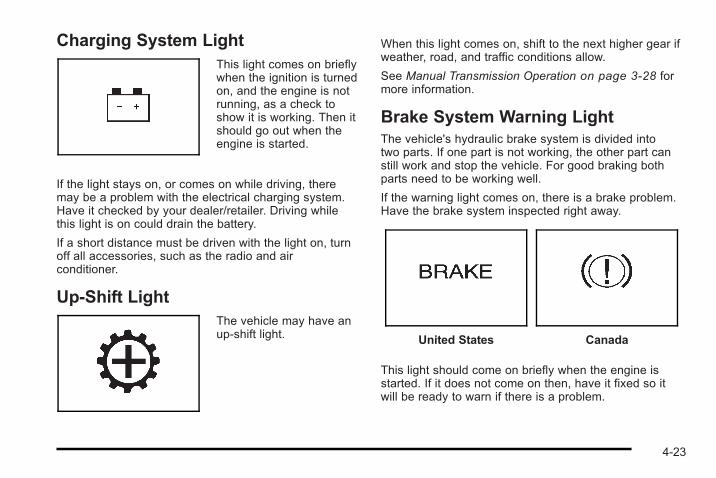
Charging System LightThis light comes on brieflywhen the ignition is turnedon, and the engine is notrunning, as a check toshow it is working. Then itshould go out when theengine is started.
If the light stays on, or comes on while driving, theremay be a problem with the electrical charging system.Have it checked by your dealer/retailer. Driving whilethis light is on could drain the battery.
If a short distance must be driven with the light on, turnoff all accessories, such as the radio and airconditioner.
Up-Shift LightThe vehicle may have anup-shift light.
When this light comes on, shift to the next higher gear ifweather, road, and traffic conditions allow.
See Manual Transmission Operation on page 3‑28 formore information.
Brake System Warning LightThe vehicle's hydraulic brake system is divided intotwo parts. If one part is not working, the other part canstill work and stop the vehicle. For good braking bothparts need to be working well.
If the warning light comes on, there is a brake problem.Have the brake system inspected right away.
United States Canada
This light should come on briefly when the engine isstarted. If it does not come on then, have it fixed so itwill be ready to warn if there is a problem.
4-23
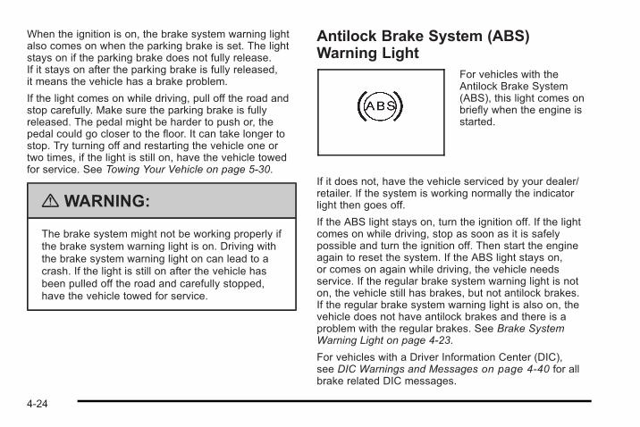
When the ignition is on, the brake system warning lightalso comes on when the parking brake is set. The lightstays on if the parking brake does not fully release.If it stays on after the parking brake is fully released,it means the vehicle has a brake problem.
If the light comes on while driving, pull off the road andstop carefully. Make sure the parking brake is fullyreleased. The pedal might be harder to push or, thepedal could go closer to the floor. It can take longer tostop. Try turning off and restarting the vehicle one ortwo times, if the light is still on, have the vehicle towedfor service. See Towing Your Vehicle on page 5‑30.
{ WARNING:
The brake system might not be working properly ifthe brake system warning light is on. Driving withthe brake system warning light on can lead to acrash. If the light is still on after the vehicle hasbeen pulled off the road and carefully stopped,have the vehicle towed for service.
Antilock Brake System (ABS)Warning Light
For vehicles with theAntilock Brake System(ABS), this light comes onbriefly when the engine isstarted.
If it does not, have the vehicle serviced by your dealer/retailer. If the system is working normally the indicatorlight then goes off.
If the ABS light stays on, turn the ignition off. If the lightcomes on while driving, stop as soon as it is safelypossible and turn the ignition off. Then start the engineagain to reset the system. If the ABS light stays on,or comes on again while driving, the vehicle needsservice. If the regular brake system warning light is noton, the vehicle still has brakes, but not antilock brakes.If the regular brake system warning light is also on, thevehicle does not have antilock brakes and there is aproblem with the regular brakes. See Brake SystemWarning Light on page 4‑23.
For vehicles with a Driver Information Center (DIC),see DIC Warnings and Messages on page 4‑40 for allbrake related DIC messages.
4-24
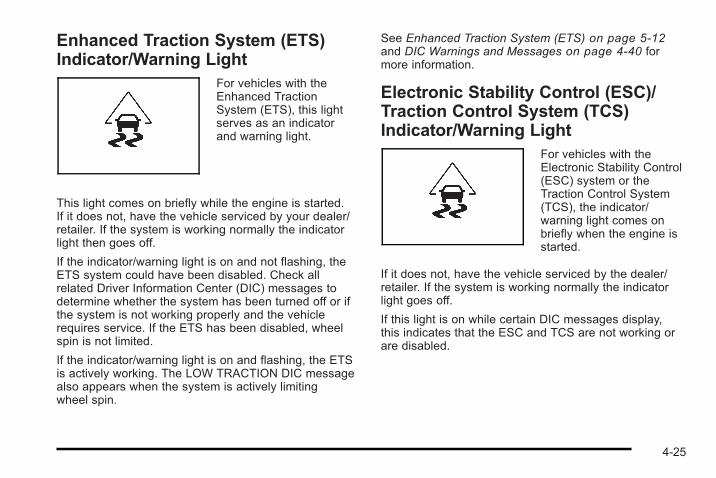
Enhanced Traction System (ETS)Indicator/Warning Light
For vehicles with theEnhanced TractionSystem (ETS), this lightserves as an indicatorand warning light.
This light comes on briefly while the engine is started.If it does not, have the vehicle serviced by your dealer/retailer. If the system is working normally the indicatorlight then goes off.
If the indicator/warning light is on and not flashing, theETS system could have been disabled. Check allrelated Driver Information Center (DIC) messages todetermine whether the system has been turned off or ifthe system is not working properly and the vehiclerequires service. If the ETS has been disabled, wheelspin is not limited.
If the indicator/warning light is on and flashing, the ETSis actively working. The LOW TRACTION DIC messagealso appears when the system is actively limitingwheel spin.
See Enhanced Traction System (ETS) on page 5‑12and DIC Warnings and Messages on page 4‑40 formore information.
Electronic Stability Control (ESC)/Traction Control System (TCS)Indicator/Warning Light
For vehicles with theElectronic Stability Control(ESC) system or theTraction Control System(TCS), the indicator/warning light comes onbriefly when the engine isstarted.
If it does not, have the vehicle serviced by the dealer/retailer. If the system is working normally the indicatorlight goes off.
If this light is on while certain DIC messages display,this indicates that the ESC and TCS are not working orare disabled.
4-25
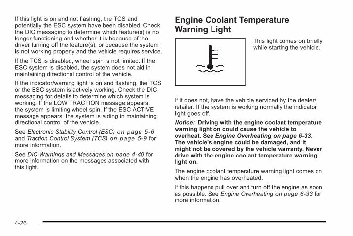
If this light is on and not flashing, the TCS andpotentially the ESC system have been disabled. Checkthe DIC messaging to determine which feature(s) is nolonger functioning and whether it is because of thedriver turning off the feature(s), or because the systemis not working properly and the vehicle requires service.
If the TCS is disabled, wheel spin is not limited. If theESC system is disabled, the system does not aid inmaintaining directional control of the vehicle.
If the indicator/warning light is on and flashing, the TCSor the ESC system is actively working. Check the DICmessaging for details to determine which system isworking. If the LOW TRACTION message appears,the system is limiting wheel spin. If the ESC ACTIVEmessage appears, the system is aiding in maintainingdirectional control of the vehicle.
See Electronic Stability Control (ESC) on page 5‑6and Traction Control System (TCS) on page 5‑9 formore information.
See DIC Warnings and Messages on page 4‑40 formore information on the messages associated withthis light.
Engine Coolant TemperatureWarning Light
This light comes on brieflywhile starting the vehicle.
If it does not, have the vehicle serviced by the dealer/retailer. If the system is working normally the indicatorlight goes off.
Notice: Driving with the engine coolant temperaturewarning light on could cause the vehicle tooverheat. See Engine Overheating on page 6‑33.The vehicle's engine could be damaged, and itmight not be covered by the vehicle warranty. Neverdrive with the engine coolant temperature warninglight on.
The engine coolant temperature warning light comes onwhen the engine has overheated.
If this happens pull over and turn off the engine as soonas possible. See Engine Overheating on page 6‑33 formore information.
4-26
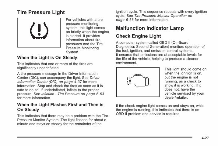
Tire Pressure LightFor vehicles with a tirepressure monitoringsystem, this light comeson briefly when the engineis started. It providesinformation about tirepressures and the TirePressure MonitoringSystem.
When the Light is On SteadyThis indicates that one or more of the tires aresignificantly underinflated.
A tire pressure message in the Driver InformationCenter (DIC), can accompany the light. See DriverInformation Center (DIC) on page 4‑37 for moreinformation. Stop and check the tires as soon as it issafe to do so. If underinflated, inflate to the properpressure. See Inflation - Tire Pressure on page 6‑63for more information.
When the Light Flashes First and Then isOn SteadyThis indicates that there may be a problem with the TirePressure Monitor System. The light flashes for about aminute and stays on steady for the remainder of the
ignition cycle. This sequence repeats with every ignitioncycle. See Tire Pressure Monitor Operation onpage 6‑66 for more information.
Malfunction Indicator Lamp
Check Engine LightA computer system called OBD II (On-BoardDiagnostics-Second Generation) monitors operation ofthe fuel, ignition, and emission control systems.It ensures that emissions are at acceptable levels forthe life of the vehicle, helping to produce a cleanerenvironment.
This light should come onwhen the ignition is on,but the engine is notrunning, as a check toshow it is working. If itdoes not, have thevehicle serviced by yourdealer/retailer.
If the check engine light comes on and stays on, whilethe engine is running, this indicates that there is anOBD II problem and service is required.
4-27
Malfunctions often are indicated by the system beforeany problem is apparent. Being aware of the light canprevent more serious damage to the vehicle. Thissystem assists the service technician in correctlydiagnosing any malfunction.
Notice: If the vehicle is continually driven with thislight on, after a while, the emission controls mightnot work as well, the vehicle's fuel economy mightnot be as good, and the engine might not run assmoothly. This could lead to costly repairs thatmight not be covered by the vehicle warranty.
Notice: Modifications made to the engine,transmission, exhaust, intake, or fuel system of thevehicle or the replacement of the original tires withother than those of the same Tire PerformanceCriteria (TPC) can affect the vehicle's emissioncontrols and can cause this light to come on.Modifications to these systems could lead tocostly repairs not covered by the vehicle warranty.This could also result in a failure to pass arequired Emission Inspection/Maintenance test.See Accessories and Modifications on page 6‑4.
This light comes on during a malfunction in one oftwo ways:
Light Flashing : A misfire condition has beendetected. A misfire increases vehicle emissions andcould damage the emission control system on thevehicle. Diagnosis and service might be required.
To prevent more serious damage to the vehicle:. Reduce vehicle speed.. Avoid hard accelerations.. Avoid steep uphill grades.. If towing a trailer, reduce the amount of cargo
being hauled as soon as it is possible.
If the light continues to flash, when it is safe to do so,stop the vehicle. Find a safe place to park the vehicle.Turn the key off, wait at least 10 seconds, and restartthe engine. If the light is still flashing, follow theprevious steps and see your dealer/retailer for serviceas soon as possible.
Light On Steady : An emission control systemmalfunction has been detected on the vehicle.Diagnosis and service might be required.
An emission system malfunction might be corrected bydoing the following:. Make sure the fuel cap is fully installed. See Filling
the Tank on page 6‑10. The diagnostic systemcan determine if the fuel cap has been left off orimproperly installed. A loose or missing fuel capallows fuel to evaporate into the atmosphere. A fewdriving trips with the cap properly installed shouldturn the light off.
4-28
. If the vehicle has been driven through a deeppuddle of water, the vehicle's electrical systemmight be wet. The condition is usually correctedwhen the electrical system dries out. A few drivingtrips should turn the light off.
. Make sure to fuel the vehicle with quality fuel.Poor fuel quality causes the engine not to run asefficiently as designed and can cause: stalling afterstart-up, stalling when the vehicle is changedinto gear, misfiring, hesitation on acceleration,or stumbling on acceleration. These conditionsmight go away once the engine is warmed up.
If one or more of these conditions occurs, changethe fuel brand used. It will require at least one fulltank of the proper fuel to turn the light off.
See Gasoline Octane on page 6‑7.
If none of the above have made the light turn off, yourdealer/retailer can check the vehicle. The dealer/retailerhas the proper test equipment and diagnostic tools to fixany mechanical or electrical problems that might havedeveloped.
Emissions Inspection and MaintenanceProgramsSome state/provincial and local governments have ormight begin programs to inspect the emission controlequipment on the vehicle. Failure to pass thisinspection could prevent getting a vehicle registration.
Here are some things to know to help the vehicle passan inspection:. The vehicle will not pass this inspection if the
check engine light is on with the engine running,or if the key is in ON/RUN and the light is not on.
. The vehicle will not pass this inspection if theOBD II (on-board diagnostic) system determinesthat critical emission control systems have notbeen completely diagnosed by the system.The vehicle would be considered not ready forinspection. This can happen if the battery hasrecently been replaced or if the battery has rundown. The diagnostic system is designed toevaluate critical emission control systems duringnormal driving. This can take several days ofroutine driving. If this has been done and thevehicle still does not pass the inspection for lack ofOBD II system readiness, your dealer/retailer canprepare the vehicle for inspection.
4-29
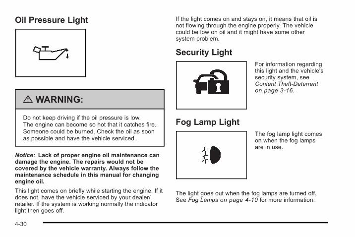
Oil Pressure Light
{ WARNING:
Do not keep driving if the oil pressure is low.The engine can become so hot that it catches fire.Someone could be burned. Check the oil as soonas possible and have the vehicle serviced.
Notice: Lack of proper engine oil maintenance candamage the engine. The repairs would not becovered by the vehicle warranty. Always follow themaintenance schedule in this manual for changingengine oil.
This light comes on briefly while starting the engine. If itdoes not, have the vehicle serviced by your dealer/retailer. If the system is working normally the indicatorlight then goes off.
If the light comes on and stays on, it means that oil isnot flowing through the engine properly. The vehiclecould be low on oil and it might have some othersystem problem.
Security LightFor information regardingthis light and the vehicle'ssecurity system, seeContent Theft-Deterrenton page 3‑16.
Fog Lamp LightThe fog lamp light comeson when the fog lampsare in use.
The light goes out when the fog lamps are turned off.See Fog Lamps on page 4‑10 for more information.
4-30
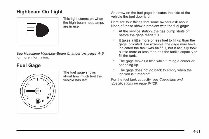
Highbeam On LightThis light comes on whenthe high-beam headlampsare in use.
See Headlamp High/Low-Beam Changer on page 4‑5for more information.
Fuel GageThe fuel gage showsabout how much fuel thevehicle has left.
An arrow on the fuel gage indicates the side of thevehicle the fuel door is on.
Here are four things that some owners ask about.None of these show a problem with the fuel gage:. At the service station, the gas pump shuts off
before the gage reads full.. It takes a little more or less fuel to fill up than the
gage indicated. For example, the gage may haveindicated the tank was half full, but it actually tooka little more or less than half the tank's capacity tofill the tank.
. The gage moves a little while turning a corner orspeeding up.
. The gage does not go back to empty when theignition is turned off.
For the fuel tank capacity, see Capacities andSpecifications on page 6‑128.
4-31
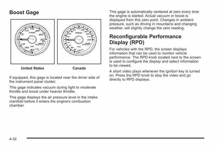
Boost Gage
United States Canada
If equipped, this gage is located near the driver side ofthe instrument panel cluster.
This gage indicates vacuum during light to moderatethrottle and boost under heavier throttle.
This gage displays the air pressure level in the intakemanifold before it enters the engine's combustionchamber.
This gage is automatically centered at zero every timethe engine is started. Actual vacuum or boost isdisplayed from this zero point. Changes in ambientpressure, such as driving in mountains and changingweather, will slightly change the zero reading.
Reconfigurable PerformanceDisplay (RPD)For vehicles with the RPD, the screen displaysinformation that can be used to monitor vehicleperformance. The RPD knob located next to the screenis used to configure the display and select informationto be viewed.
A short video plays whenever the ignition key is turnedon. Press the RPD knob to stop the video and godirectly to RPD displays.
4-32
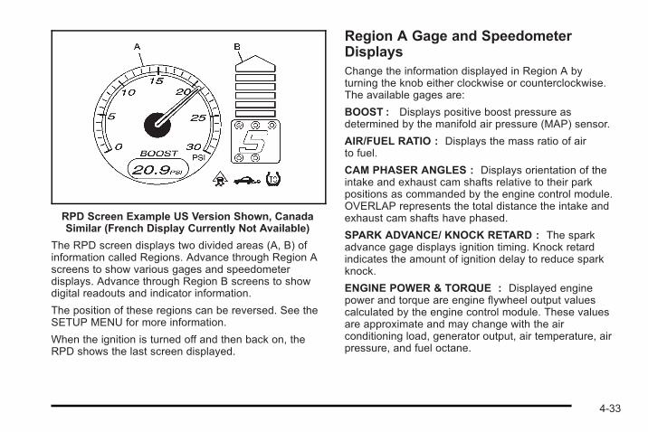
RPD Screen Example US Version Shown, CanadaSimilar (French Display Currently Not Available)
The RPD screen displays two divided areas (A, B) ofinformation called Regions. Advance through Region Ascreens to show various gages and speedometerdisplays. Advance through Region B screens to showdigital readouts and indicator information.
The position of these regions can be reversed. See theSETUP MENU for more information.
When the ignition is turned off and then back on, theRPD shows the last screen displayed.
Region A Gage and SpeedometerDisplaysChange the information displayed in Region A byturning the knob either clockwise or counterclockwise.The available gages are:
BOOST : Displays positive boost pressure asdetermined by the manifold air pressure (MAP) sensor.
AIR/FUEL RATIO : Displays the mass ratio of airto fuel.
CAM PHASER ANGLES : Displays orientation of theintake and exhaust cam shafts relative to their parkpositions as commanded by the engine control module.OVERLAP represents the total distance the intake andexhaust cam shafts have phased.
SPARK ADVANCE/ KNOCK RETARD : The sparkadvance gage displays ignition timing. Knock retardindicates the amount of ignition delay to reduce sparkknock.
ENGINE POWER & TORQUE : Displayed enginepower and torque are engine flywheel output valuescalculated by the engine control module. These valuesare approximate and may change with the airconditioning load, generator output, air temperature, airpressure, and fuel octane.
4-33
SPEEDOMETER & G FORCE : The G FORCE meterdisplays lateral acceleration. While turning right, Gforces are felt on the left, and vice versa. PEAK valuesare stored indefinitely, and can be reset with a pressand hold of the RPD knob while viewing the G FORCEmeter.
SETUP MENU : Press the RPD knob to enter thismenu. The vehicle should be stopped while configuringthe setup menu selections.
SCREEN OFF : Turns the screen off.
Region B Readout DisplaysPress the RPD knob to highlight Region B. Theinformation displayed can be changed by turning theRPD knob either clockwise or counterclockwise.Press the RPD knob again, to store the selection.The selection will also be stored after a few seconds ofno activity. Available modes are:
Readouts #1SHIFT LIGHTS/GEAR INDICATION : The shift lightsprovide visual identification of engine speed for atransmission gear. Shift light minimum and maximumRPM settings can be viewed and configured in theSETUP screen. The gear indication on manualtransmission vehicles is calculated by the enginecontrol module. The gear is only displayed whenenough torque is available to determine the selectedforward gear.
Readouts #2TIRE PRESSURES : Displays the last gage tirepressures recorded from each of the wheel mounted tirepressure sensors.
Readouts #3BAROMETER : Displays ambient air pressure asmeasured by the engine’s ambient pressure sensor.
OUTSIDE TEMPERATURE : Displays ambienttemperature as measured by an outside air temperaturesensor.
BATTERY VOLTAGE : Displays the vehicle’s batteryvoltage.
Readouts #4COOLANT TEMPERATURE : Displays engine coolanttemperature as measured by a coolant temperaturesensor.
INLET AIR TEMPERATURE : Displays theinstantaneous temperature of the air at the inlet to theinduction system.
FUEL PRESSURE : Displays fuel pressure asmeasured by a sensor on the output of thehigh-pressure fuel pump.
4-34
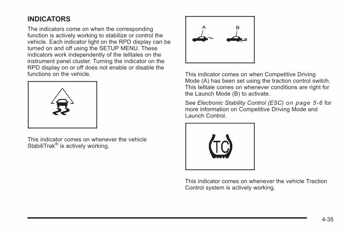
INDICATORSThe indicators come on when the correspondingfunction is actively working to stabilize or control thevehicle. Each indicator light on the RPD display can beturned on and off using the SETUP MENU. Theseindicators work independently of the telltales on theinstrument panel cluster. Turning the indicator on theRPD display on or off does not enable or disable thefunctions on the vehicle.
This indicator comes on whenever the vehicleStabiliTrak® is actively working.
This indicator comes on when Competitive DrivingMode (A) has been set using the traction control switch.This telltale comes on whenever conditions are right forthe Launch Mode (B) to activate.
See Electronic Stability Control (ESC) on page 5‑6 formore information on Competitive Driving Mode andLaunch Control.
This indicator comes on whenever the vehicle TractionControl system is actively working.
4-35
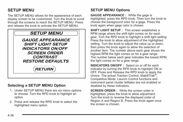
SETUP MENUThe SETUP MENU allows for the appearance of eachdisplay screen to be customized. Turn the knob to scrollthrough the screens to reach the SETUP MENU. Pressand release the knob to activate the SETUP MENU.
Selecting a SETUP MENU Option1. Under SETUP MENU there are six menu options
to choose. Turn the RPD knob to highlight anoption.
2. Press and release the RPD knob to select thehighlighted menu option.
SETUP MENU OptionsGAUGE APPEARANCE : While the gage ishighlighted, press the RPD knob. Then turn the knob tochoose the background color for a gage. Press theknob again when gage color is chosen.
SHIFT LIGHT SETUP : This screen establishes aRPM range where the shift light comes on for eachgear. Turn the RPD knob to highlight a shift light setting.Press the knob to allow adjustment of the highlightedsetting. Turn the knob to adjust the value up or down,then press the knob again to allow the selection ofanother item. The number above each gear shows thehighest RPM the light comes on for a gear range.The number below each gear indicates the lowest RPMthe light comes on for a gear range.
INDICATORS ON/OFF : Select on or off for eachindicator by turning the RPD knob to highlight ON orOFF. Press and Release the RPD knob to apply thechoice. The actual Traction Control, StabiliTrak®,Competitive Mode, Launch Control functions andinstrument panel cluster telltales are not enabled ordisabled by these indicators.
SCREEN ORDER : While the screen order ishighlighted, press the knob to allow adjustment.Turn the knob to reverse the displayed order ofRegion A and Region B. Press the knob again oncethe screen is chosen.
4-36
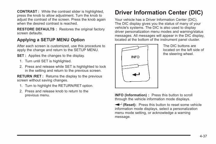
CONTRAST : While the contrast slider is highlighted,press the knob to allow adjustment. Turn the knob toadjust the contrast of the screen. Press the knob againwhen the desired contrast is reached.
RESTORE DEFAULTS : Restores the original factoryscreen defaults.
Applying a SETUP MENU OptionAfter each screen is customized, use this procedure toapply the change and return to the SETUP MENU.
SET : Applies the changes to the display.
1. Turn until SET is highlighted.
2. Press and release while SET is highlighted to lockin the setting and return to the previous screen.
RETURN /RET : Returns the display to the previousscreen without saving changes.
1. Turn to highlight the RETURN/RET option.
2. Press and release knob to return to theprevious menu.
Driver Information Center (DIC)Your vehicle has a Driver Information Center (DIC).The DIC display gives you the status of many of yourvehicle's systems. The DIC is also used to displaydriver personalization menu modes and warning/statusmessages. All messages will appear in the DIC display,located at the bottom of the instrument panel cluster.
The DIC buttons arelocated on the left side ofthe steering wheel.
INFO (Information) : Press this button to scrollthrough the vehicle information mode displays.
r (Reset): Press this button to reset some vehicleinformation mode displays, select a personalizationmenu mode setting, or acknowledge a warningmessage.
4-37
Press and hold the information and reset buttons at thesame time for one second, then release the buttons toenter the personalization menu. See DIC VehiclePersonalization on page 4‑46 for more information.
DIC Operation and DisplaysThe DIC comes on when the ignition is on. The DIC hasdifferent modes which can be accessed by pressing theDIC buttons. The button functions are detailed in thefollowing.
Information ModesINFO (Information) : Press this button to scrollthrough the following vehicle information modes:
Outside Air Temperature and OdometerPress the information button until the outside airtemperature and the odometer display. This modeshows the temperature outside of the vehicle in eitherdegrees Fahrenheit (°F) or degrees Celsius (°C) andthe total distance the vehicle has been driven ineither miles (mi) or kilometers (km). The outside airtemperature appears on the left side of the DIC displayand the odometer appears on the right side of thedisplay.
To change the DIC display to English or metric units,see “UNITS” under DIC Vehicle Personalization onpage 4‑46.
TRIPA or TRIP BPress the information button until TRIPA or TRIP Bdisplay. These modes show the current distancetraveled since the last reset for each trip odometer ineither miles (mi) or kilometers (km). Both odometers canbe used at the same time.
To reset the trip odometer to zero, press and hold thereset button for a few seconds while the desired tripodometer is displayed.
FUEL RANGEPress the information button until FUEL RANGEdisplays. This mode shows the remaining distance youcan drive without refueling in either miles (mi) orkilometers (km). It is based on fuel economy and thefuel remaining in the tank.
When the fuel level is low, FUEL RANGE LOWdisplays.
The fuel economy data used to determine fuel range isan average of recent driving conditions. As your drivingconditions change, this data is gradually updated.The FUEL RANGE mode cannot be reset.
4-38
MPG (L/100 KM) AVG (Average)Press the information button until MPG (L/100 KM) AVGdisplays. This mode shows how many miles per gallon(mpg) or liters per 100 kilometers (L/100 km) yourvehicle is getting based on current and past drivingconditions.
To reset the average fuel economy, press and hold thereset button while MPG (L/100 KM) AVG is displayed.Average fuel economy is then calculated starting fromthat point. If the average fuel economy is not reset, it iscontinually updated each time you drive.
MPG (L/100 KM) INST (Instantaneous)Press the information button until MPG (L/100 KM) INSTdisplays. This mode shows the current fuel economy ata particular moment and changes frequently as drivingconditions change. This mode shows the instantaneousfuel economy in miles per gallon (mpg) or liters per100 kilometers (L/100 km). Unlike average fueleconomy, this screen cannot be reset.
AV (Average) SPEEDPress the information button until AV SPEED displays.This mode shows the vehicle's average speed in milesper hour (mph) or kilometers per hour (km/h).
To reset the average vehicle speed, press and hold thereset button while AV SPEED is displayed.
OIL LIFEPress the information button until OIL LIFE displays.The engine oil life system shows an estimate of the oil'sremaining useful life. It shows 100% when the system isreset after an oil change. It alerts you to change the oilon a schedule consistent with your driving conditions.
In addition to the engine oil life system monitoring theoil life, additional maintenance is recommended in theMaintenance Schedule in this manual. See Engine Oilon page 6‑16 and Scheduled Maintenance onpage 7‑3 .
Always reset the engine oil life system after an oilchange. See “How to Reset the Engine Oil Life System”under Engine Oil Life System on page 6‑21.
4-39
COOLANTPress the information button until COOLANT displays.This mode shows the temperature of the enginecoolant in either degrees Fahrenheit (°F) or degreesCelsius (°C).
Tire PressureIf your vehicle is equipped with a Tire PressureMonitoring System (TPMS), the pressure for each tirecan be viewed in the DIC. The tire pressure is shown ineither pounds per square inch (psi) or kilopascals (kPa).Press the information button until LF ## PSI (kPa) ## RFdisplays for the front tires. Press the information buttonagain until LR ## PSI (kPa) ## RR displays for therear tires.
If a low tire pressure condition is detected by thesystem while driving, a message advising you tocheck the tire pressure appears in the display.See Inflation - Tire Pressure on page 6‑63 and DICWarnings and Messages on page 4‑40 for moreinformation.
DIC Warnings and MessagesThese messages appear if there is a problem detectedin one of your vehicle's systems.
A message clears when the vehicle's condition is nolonger present. To acknowledge a message and clear itfrom the display, press and hold any of the DIC buttons.If the condition is still present, the warning messagecomes back on the next time the vehicle is turned offand back on. With most messages, a warning chimesounds when the message displays. Your vehicle mayhave other warning messages.
AUTO (Automatic) LIGHTS OFFThis message displays if the automatic headlampsystem is disabled with the headlamp switch.
AUTO (Automatic) LIGHTS ONThis message displays if the automatic headlampsystem is enabled with the headlamp switch.
BRAKE FLUIDThis message displays, while the ignition is on, whenthe brake fluid level is low. The brake system warninglight on the instrument panel cluster also comes on.See Brake System Warning Light on page 4‑23 formore information. Have the brake system serviced byyour dealer/retailer as soon as possible.
4-40
CHANGE OIL SOONThis message displays when the life of the engine oilhas expired and it should be changed.
When this message is acknowledged and cleared fromthe display, the engine oil life system must still be resetseparately. See Engine Oil Life System on page 6‑21and Scheduled Maintenance on page 7‑3 for moreinformation.
CHECK GAS CAPThis message displays if the fuel cap has not been fullytightened. Recheck the fuel cap to make sure that it ison properly. A few driving trips with the cap properlyinstalled should turn the message off.
COMPETITIVE MODEIf your vehicle has this feature, this message displayswhen the Competitive Driving mode is selected.The Traction Control System (TCS) will not beoperating while in the Competitive Driving mode and theESC/TCS light on the instrument panel cluster will beon solid. Adjust your driving accordingly. See TractionControl System (TCS) on page 5‑9 , ElectronicStability Control (ESC) on page 5‑6 , and ElectronicStability Control (ESC)/Traction Control System (TCS)Indicator/Warning Light on page 4‑25 for moreinformation.
COOLING MODE ONThis message may display on some vehicles. Undersevere conditions, hot ambient temperatures, steepgrades, and towing, your vehicle may experience moretransmission shifting. This is temporary and normalunder these conditions. This does not require engine ortransmission service.
CRUISE ENGAGEDThis message displays when the cruise control systemis active. See Cruise Control on page 4‑6 for moreinformation.
DOOR AJARThis message displays if one or more of the vehicle'sdoors are open. Make sure that the door(s) are closedcompletely.
ENGINE DISABLEDThis message displays if the starting of the engineis disabled. Have your vehicle serviced by yourdealer/retailer immediately.
4-41
ENG (Engine) PWR (Power) REDUCEDThis message displays to inform you that the vehiclehas reduced engine power to avoid damaging theengine. Reduced engine power can affect the vehicle'sability to accelerate. If this message is on, but there isno reduction in performance, proceed to yourdestination. The performance may be reduced the nexttime the vehicle is driven. The vehicle may be drivenat a reduced speed while this message is on, butacceleration and speed may be reduced. Anytime thismessage stays on, the vehicle should be taken to yourdealer/retailer for service as soon as possible.
ESC (Electronic Stability Control) ACTIVEIf your vehicle has Electronic Stability Control (ESC),this message displays and the ESC/TCS light on theinstrument panel cluster flashes when ESC is assistingyou with directional control of the vehicle. You may feelor hear the system working and see this messagedisplayed in the DIC. Slippery road conditions mayexist when this message is displayed, so adjust yourdriving accordingly. This message may stay on for afew seconds after ESC stops assisting you withdirectional control of the vehicle. This is normal whenthe system is operating. See Electronic StabilityControl (ESC) on page 5‑6 and Electronic StabilityControl (ESC)/Traction Control System (TCS) Indicator/Warning Light on page 4‑25 for more information.
ESC (Electronic Stability Control) NOTREADYIf your vehicle has Electronic Stability Control (ESC),this message may display briefly after starting thevehicle if the system's sensors are not yet calibrated.The system is not functional until the message stopsdisplaying. Adjust your driving accordingly. When themessage is no longer displayed, the system isfunctional. See Electronic Stability Control (ESC) onpage 5‑6 for more information.
ESC (Electronic Stability Control) OFFIf your vehicle has Electronic Stability Control (ESC),this message displays and the ESC/TCS light on theinstrument panel cluster comes on solid when ESC isturned off. Adjust your driving accordingly. SeeElectronic Stability Control (ESC) on page 5‑6 andElectronic Stability Control (ESC)/Traction ControlSystem (TCS) Indicator/Warning Light on page 4‑25 formore information.
ICE POSSIBLEThis message displays when the outside airtemperature is cold enough to create icy roadconditions. Adjust your driving accordingly.
4-42
KEY FOB BATT (Battery) LOWThis message displays if the Remote Keyless Entry(RKE) transmitter battery is low. Replace the battery inthe transmitter. See “Battery Replacement” underRemote Keyless Entry (RKE) System Operation onpage 3‑4 .
LAUNCH CONTROLIf your vehicle has this feature, this message displaysafter the COMPETITIVE MODE message when thevehicle is stopped. Launch control is a form of tractioncontrol to control wheel spin while launching the vehicleduring closed track events and competitive drivingvenues. The system will exit to COMPETITIVE MODEafter the vehicle is launched. See “COMPETITIVEMODE” earlier in this section. See “Launch Control”under Electronic Stability Control (ESC) on page 5‑6for more information.
LEARN COMPLETEOn vehicles without the Remote Keyless Entry (RKE)system, this message displays when the Tire PressureMonitor System (TPMS) has completed the tire learningprocess. See Tire Pressure Monitor System onpage 6‑65 for more information.
LOW COOLANTIf your vehicle has a 2.0L engine, this message displayswhen there is a low level of engine coolant. Have thecooling system serviced by your dealer/retailer as soonas possible. See Engine Coolant on page 6‑28 formore information.
LOW FUELThis message displays when your vehicle is low on fuel.Refill the fuel tank as soon as possible. See Fuel Gageon page 4‑31, Fuel on page 6‑6 , and Filling the Tankon page 6‑10 for more information.
LOW TRACTIONIf your vehicle has the Enhanced Traction System(ETS) or Traction Control System (TCS), this messagedisplays and the ETS light or the ESC/TCS light on theinstrument panel cluster flashes when the system isactively limiting wheel spin. Slippery road conditionsmay exist if this message is displayed, so adjust yourdriving accordingly. This message stays on for a fewseconds after the system stops limiting wheel spin.See Enhanced Traction System (ETS) on page 5‑12 orTraction Control System (TCS) on page 5‑9 andEnhanced Traction System (ETS) Indicator/WarningLight on page 4‑25 or Electronic Stability Control(ESC)/Traction Control System (TCS) Indicator/WarningLight on page 4‑25 for more information.
4-43
PARKING BRAKEThis message displays if the parking brake is leftengaged. See Parking Brake on page 3‑31 for moreinformation.
POWER STEERINGThis message displays if a problem has been detectedwith the electric power steering. Have your vehicleserviced by your dealer/retailer immediately.
SERVICE AIR BAGThis message displays when there is a problem with theairbag system. Have your vehicle serviced by yourdealer/retailer immediately.
SERVICE ESC (ELECTRONIC STABILITYCONTROL)If your vehicle has Electronic Stability Control (ESC),this message displays and a chime sounds if there hasbeen a problem detected with ESC. The ESC/TCS lightalso appears on the instrument panel cluster. This lightstays on solid as long as the detected problem remainspresent. When this message displays, the system is notworking. Adjust your driving accordingly. See ElectronicStability Control (ESC) on page 5‑6 and ElectronicStability Control (ESC)/Traction Control System (TCS)Indicator/Warning Light on page 4‑25 for moreinformation.
If this message turns on while you are driving, pull offthe road as soon as possible and stop carefully. Tryresetting the system by turning the ignition off and thenback on. If this message still stays on or turns back onagain while you are driving, your vehicle needs service.Have the ESC inspected by your dealer/retailer as soonas possible.
SERVICE TRACTIONIf your vehicle has the Enhanced Traction System(ETS) or Traction Control System (TCS), this messagedisplays and a chime sounds when the system is notfunctioning properly. The ETS light or the ESC/TCS lightalso appears on the instrument panel cluster. This lightstays on solid as long as the detected problem remainspresent. When this message displays, the system is notworking. Adjust your driving accordingly. See EnhancedTraction System (ETS) on page 5‑12 or TractionControl System (TCS) on page 5‑9 and EnhancedTraction System (ETS) Indicator/Warning Light onpage 4‑25 or Electronic Stability Control (ESC)/TractionControl System (TCS) Indicator/Warning Light onpage 4‑25 for more information. Have the systemserviced by your dealer/retailer as soon as possible.
4-44
SVC (Service) BRAKE SYSTEMThis message may display if you have a turbochargedvehicle with Electronic Stability Control (ESC) and if thehydraulic brake boost is not working or is workingimproperly. Have the brake system serviced by yourdealer/retailer as soon as possible.
SVC (Service) TIRE MONITORIf your vehicle is equipped with a Tire PressureMonitoring System (TPMS), this message displays if apart on the TPMS is not working properly. The tirepressure light also flashes and then remains on duringthe same ignition cycle. See Tire Pressure Light onpage 4‑27. Several conditions may cause this messageto appear. See Tire Pressure Monitor Operation onpage 6‑66 for more information. If the warning comeson and stays on, there may be a problem with theTPMS. See your dealer/retailer.
TIRE LEARN ONIf your vehicle is equipped with a Tire PressureMonitoring System (TPMS) and does not have theRemote Keyless Entry (RKE) system, this messagedisplays when the TPMS is re-learning the tire positionson your vehicle. The tire positions must be re-learnedafter rotating the tires or after replacing a tire or sensor.See Tire Inspection and Rotation on page 6‑71,Tire Pressure Monitor System on page 6‑65, andInflation - Tire Pressure on page 6‑63 for moreinformation.
TIRE LOW ADD AIRIf your vehicle is equipped with a Tire PressureMonitoring System (TPMS), this message displayswhen the pressure in one or more of the vehicle's tiresis low. The low tire pressure warning light will also comeon. See Tire Pressure Light on page 4‑27. If a tirepressure message appears on the DIC, stop as soon asyou can. Have the tire pressures checked and set tothose shown on the Tire Loading Information label.See Tires on page 6‑54, Loading the Vehicle onpage 5‑25, and Inflation - Tire Pressure on page 6‑63.The DIC also shows the tire pressure values. See DICOperation and Displays on page 4‑38.
4-45
TRACTION OFFIf your vehicle has the Enhanced Traction System(ETS) or Traction Control System (TCS), this messagedisplays and the ETS light or the ESC/TCS light on theinstrument panel cluster comes on solid when thesystem is turned off. Adjust your driving accordingly.See Enhanced Traction System (ETS) on page 5‑12 orTraction Control System (TCS) on page 5‑9 andEnhanced Traction System (ETS) Indicator/WarningLight on page 4‑25 or Electronic Stability Control(ESC)/Traction Control System (TCS) Indicator/WarningLight on page 4‑25 for more information.
TRUNK AJARThis message displays when the trunk is not closedcompletely. Make sure that the trunk is closedcompletely. See Trunk on page 3‑12.
DIC Vehicle PersonalizationYour vehicle has personalization capabilities that allowyou to program certain features to a preferred setting.All of the features listed may not be available on yourvehicle. Only the features available will be displayed onthe DIC.
The default settings for the features were set when yourvehicle left the factory, but may have been changedfrom their default state since that time.
To change feature settings, use the following procedure:
Entering Personalization Menu1. Turn the ignition on while the vehicle is stopped.
To avoid excessive drain on the battery, it isrecommended that the headlamps are turned off.
2. Press and hold the information and reset buttons atthe same time for one second, then release toenter the personalization menu.
If the vehicle speed is greater than 3 km/h (2 mph),only the UNITS menu will be accessible.
3. Press the information button to scroll through theavailable personalization menu modes.
Press the reset button to scroll through theavailable settings for each mode.
If you do not make a selection within ten seconds,the display will go back to the previous informationdisplayed.
4-46
Personalization Menu Modes
OIL LIFE RESETWhen this feature is displayed, you can reset theengine oil life system. To reset the system, see EngineOil Life System on page 6‑21. See “OIL LIFE” underDIC Operation and Displays on page 4‑38 for moreinformation.
UNITSThis feature allows you to select the units ofmeasurement in which the DIC will display the vehicleinformation. When UNITS appears on the display, pressand hold the reset button for at least one second toscroll through the available settings:
ENGLISH (default in United States) : All informationwill be displayed in English units.
METRIC (default in Canada) : All information will bedisplayed in metric units.
To select a setting and move on to the next feature,press the information button while the desired setting isdisplayed on the DIC.
TIRE LEARN?If your vehicle is equipped with a Tire PressureMonitoring System (TPMS), this mode is available onvehicles without the Remote Keyless Entry (RKE)system. After rotating the tires or after replacing a tireor sensor, the TPMS must re-learn the tire positions.To re-learn the tire positions, see Tire Pressure MonitorSystem on page 6‑65. See Tire Inspection andRotation on page 6‑71 and DIC Warnings andMessages on page 4‑40 for more information.
REMOTE STARTIf your vehicle has remote start, this feature allowsremote start to be turned off or on. Remote start allowsyou to start the engine from outside of the vehicle usingyour Remote Keyless Entry (RKE) transmitter. WhenREMOTE START appears on the display, press andhold the reset button for at least one second to scrollthrough the available settings:
OFF : The remote start feature will be disabled.
ON (default) : The remote start feature will be enabled.
See Remote Vehicle Start on page 3‑6 for moreinformation.
To select a setting and move on to the next feature,press the information button while the desired setting isdisplayed on the DIC.
4-47
LOCK HORNIf your vehicle has Remote Keyless Entry (RKE), thisfeature, which allows the vehicle's horn to chirp everytime the lock button on the RKE transmitter is pressed,can be enabled or disabled. When LOCK HORNappears on the display, press and hold the reset buttonfor at least one second to scroll through the availablesettings:
OFF (default) : The horn will not chirp on the firstpress of the lock button on the RKE transmitter.The horn will still chirp on the second press.
ON : The horn will chirp on the first press of the lockbutton on the RKE transmitter.
See Remote Keyless Entry (RKE) System Operation onpage 3‑4 for more information.
To select a setting and move on to the next feature,press the information button while the desired setting isdisplayed on the DIC.
UNLOCK HORNIf your vehicle has Remote Keyless Entry (RKE), thisfeature, which allows the vehicle's horn to chirp on thefirst press of the unlock button on the RKE transmitter,can be enabled or disabled. When UNLOCK HORNappears on the display, press and hold the reset buttonfor at least one second to scroll through the availablesettings:
OFF (default) : The horn will not chirp when the unlockbutton on the RKE transmitter is pressed.
ON : The horn will chirp on the first press of the unlockbutton on the RKE transmitter.
See Remote Keyless Entry (RKE) System Operation onpage 3‑4 for more information.
To select a setting and move on to the next feature,press the information button while the desired setting isdisplayed on the DIC.
4-48
LIGHT FLASHIf your vehicle has Remote Keyless Entry (RKE), thisfeature, which allows the vehicle's exterior hazard/turnsignal lighting to flash every time the lock, unlock,or trunk release buttons on the RKE transmitter arepressed, can be enabled or disabled. When LIGHTFLASH appears on the display, press and hold the resetbutton for at least one second to scroll through theavailable settings:
OFF : The exterior hazard/turn signal lighting will notflash when the lock, unlock, or trunk release buttons onthe RKE transmitter are pressed.
ON (default) : The exterior hazard/turn signal lightingwill flash when the lock, unlock, or trunk release buttonson the RKE transmitter are pressed.
See Remote Keyless Entry (RKE) System Operation onpage 3‑4 for more information.
To select a setting and move on to the next feature,press the information button while the desired setting isdisplayed on the DIC.
DELAY LOCKThis feature, which delays the actual locking of thevehicle, can be enabled or disabled. When DELAYLOCK appears on the display, press and hold the resetbutton for at least one second to scroll through theavailable settings:
ON (default) : The doors will not lock until five secondsafter the last door is closed. You can temporarilyoverride delayed locking by pressing the power lockswitch or the lock button on the Remote Keyless Entry(RKE) transmitter a second time.
OFF : The doors will lock immediately when pressingthe power lock switch or the lock button on the RKEtransmitter.
See Power Door Locks on page 3‑9 , Delayed Lockingon page 3‑10, and Remote Keyless Entry (RKE)System Operation on page 3‑4 for more information.
To select a setting and move on to the next feature,press the information button while the desired setting isdisplayed on the DIC.
4-49
AUTO UNLK (Unlock)This feature, which allows the vehicle to automaticallyunlock certain doors, can be enabled or disabled. WhenAUTO UNLK appears on the display, press and hold thereset button for at least one second to scroll through theavailable settings:
ALL (default) : All of the doors will automaticallyunlock.
DRIVER : The driver's door will automatically unlock.
NONE : None of the doors will automatically unlock.You will need to manually unlock the doors.
If you have a manual transmission vehicle, the door(s)will automatically unlock when the ignition is turned off.
If you have an automatic transmission vehicle, you canselect when the automatic unlocking will occur. See“UNLK (Unlock) (Automatic Transmission Only)”following.
See Programmable Automatic Door Unlock onpage 3‑10 for more information.
To select a setting and move on to the next feature,press the information button while the desired setting isdisplayed on the DIC.
UNLK (Unlock) (AutomaticTransmission Only)This screen displays only if your vehicle has anautomatic transmission and DRIVER or ALL is selectedfor the AUTO UNLK feature. This feature determineswhen the automatic door unlocking will occur. WhenUNLK appears on the display, press and hold the resetbutton for at least one second to scroll through theavailable settings:
KEY OFF : The door(s) will unlock when the key isturned off.
SHIFT TO P (Park) (default) : The door(s) will unlockwhen the vehicle is shifted into P (Park).
See Programmable Automatic Door Unlock onpage 3‑10 for more information.
To select a setting and move on to the next feature,press the information button while the desired setting isdisplayed on the DIC.
4-50
EXT (Exterior) LIGHTSIf your vehicle has Remote Keyless Entry (RKE), thisfeature, which allows the vehicle's exterior perimeterlighting to turn on each time the unlock button on theRKE transmitter is pressed, can be enabled or disabled.When EXT LIGHTS appears on the display, press andhold the reset button for at least one second to scrollthrough the available settings:
OFF : The exterior perimeter lighting will not turn onwhen the unlock button on the RKE transmitter ispressed.
ON (default) : The exterior perimeter lighting will turnon when the unlock button on the RKE transmitter ispressed.
See Remote Keyless Entry (RKE) System Operation onpage 3‑4 for more information.
To select a setting and move on to the next feature,press the information button while the desired setting isdisplayed on the DIC.
LANGUAGEThis feature allows you to select the language in whichthe DIC will display. When LANGUAGE appears on thedisplay, press and hold the reset button for at leastone second to scroll through the available settings:
ENGLISH (default) : All messages will appear inEnglish.
FRENCH : All messages will appear in French.
SPANISH : All messages will appear in Spanish.
GERMAN : All messages will appear in German.
To select a setting and exit out of the personalizationmenu mode, press the information button while thedesired setting is displayed on the DIC.
Exiting Personalization MenuThe personalization menu will be exited when any ofthe following conditions occur:. A ten second time period has elapsed.. The ignition is turned off.. The end of the personalization menu list is
reached.
4-51
Audio System(s)Determine which radio the vehicle has and read thefollowing pages to become familiar with its features.
{ WARNING:
Taking your eyes off the road for extended periodscould cause a crash resulting in injury or death toyou or others. Do not give extended attention toentertainment tasks while driving.
This system provides access to many audio and nonaudio listings.
To minimize taking your eyes off the road while driving,do the following while the vehicle is parked:. Become familiar with the operation and controls of
the audio system.. Set up the tone, speaker adjustments, and preset
radio stations.
For more information, see Defensive Driving onpage 5‑2 .
Notice: Contact your dealer/retailer before addingany equipment.
Adding audio or communication equipment couldinterfere with the operation of the vehicle's engine,radio, or other systems, and could damage them.Follow federal rules covering mobile radio andtelephone equipment.
Notice: The chime signals related to safety belts,parking brake, and other functions of your vehicleoperate through the radio/entertainment system.If that equipment is replaced or additionalequipment is added to your vehicle, the chimes maynot work. Make sure that replacement or additionalequipment is compatible with your vehicle beforeinstalling it. See Accessories and Modifications onpage 6‑4.
The vehicle has Retained Accessory Power (RAP).With RAP, the audio system can be played even afterthe ignition is turned off. See Retained AccessoryPower (RAP) on page 3‑23 for more information.
4-52
Setting the Clock
Without Date Display
AM/FM Base Radio with a Single CD PlayerTo set the time:
1. Turn the ignition key to ACC/ACCESSORY orON/RUN. PressO to turn the radio on.
2. Press H until the hour begins flashing on the
display. Press H a second time and the minutebegins flashing on the display.
3. While either the hour or the minute numbers areflashing, turn f to increase or decrease the time.
4. Press H again until the clock display stops flashingto set the currently displayed time; otherwise, theflashing stops after five seconds and the currenttime displayed is automatically set.
To change the time default setting from 12 hour to24 hour, press the H button until 12H or 24H isdisplayed. Once 12H or 24H is displayed, turn thef knob to the desired option to select the setting.Press the H button again to apply the setting, or let thescreen time out.
With Date Display
Radio with CD (MP3) and USB Port, andRadio with Single CD (MP3) PlayerTo set the time and date:
1. Turn the ignition key to ACC/ACCESSORY orON/RUN. PressO to turn the radio on.
2. Press H and the HR, MIN, MM, DD, YYYY(hour, minute, month, day, and year) displays.
3. Press the softkey located below any one of thetabs that you want to change.
4. To increase the time or date do one of thefollowing:. Press the softkey located below the
selected tab.
. Press¨ SEEK, or\ FWD.
. Turn f clockwise.
5. To decrease the time or date do one of thefollowing:
. Press© SEEK ors REV.
. Turn f counterclockwise.
4-53
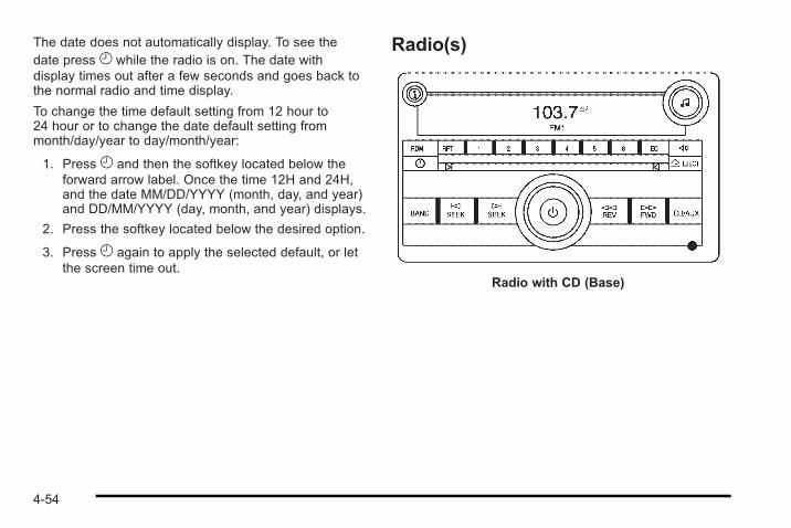
The date does not automatically display. To see thedate press H while the radio is on. The date withdisplay times out after a few seconds and goes back tothe normal radio and time display.
To change the time default setting from 12 hour to24 hour or to change the date default setting frommonth/day/year to day/month/year:
1. Press H and then the softkey located below theforward arrow label. Once the time 12H and 24H,and the date MM/DD/YYYY (month, day, and year)and DD/MM/YYYY (day, month, and year) displays.
2. Press the softkey located below the desired option.
3. Press H again to apply the selected default, or letthe screen time out.
Radio(s)
Radio with CD (Base)
4-54
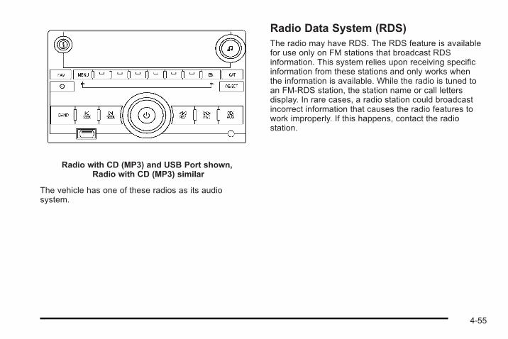
Radio with CD (MP3) and USB Port shown,Radio with CD (MP3) similar
The vehicle has one of these radios as its audiosystem.
Radio Data System (RDS)The radio may have RDS. The RDS feature is availablefor use only on FM stations that broadcast RDSinformation. This system relies upon receiving specificinformation from these stations and only works whenthe information is available. While the radio is tuned toan FM-RDS station, the station name or call lettersdisplay. In rare cases, a radio station could broadcastincorrect information that causes the radio features towork improperly. If this happens, contact the radiostation.
4-55
Playing the RadioO (Power/Volume) : Press to turn the system on andoff. Turn to increase or decrease the volume.
Speed Compensated Volume (SCV) : Radios withthe Speed Compensated Volume (SCV) featureautomatically adjust the radio volume to compensate forroad and wind noise as the vehicle speeds up or slowsdown, so that the volume level is consistent.
To activate SCV:
1. Set the radio volume to the desired level.
2. Press MENU to display the radio setup menu.
3. Press the softkey under the AUTO VOLUM tab onthe radio display.
4. Press the softkey under the desired SpeedCompensated Volume setting (OFF, Low, Med,or High) to select the level of radio volumecompensation. The display times out afterapproximately 10 seconds. Each higher settingallows for more radio volume compensation atfaster vehicle speeds.
Finding a StationBAND : Press to choose between FM1, FM2, AM,or XM™ (if equipped) on the Radio with CD (Base).Press to choose between FM, AM, XM (if equipped) onthe Radio with CD (MP3) and USB Port or the Radiowith CD (MP3).
f (Tune) : Turn to select radio stations.
© SEEK : Press to seek or scan stations with astrong signal in the selected band.
. To seek stations, press and release© SEEK togo to the previous station and stay there.
. To scan stations, press and hold© SEEK for afew seconds until the radio beeps once. The radiogoes to a station, plays for a few seconds, thengoes to the next station. Press© SEEK again tostop scanning.
. To scan preset stations in the selected band, pressand hold© SEEK for four seconds until a doublebeep sounds. The radio goes to a stored preset,plays for a few seconds, then goes to the nextstored preset. Press© SEEK again to stopscanning preset stations.
4-56
¨ SEEK : Press to seek or scan stations with astrong signal in the selected band.
. To seek stations, press and release¨ SEEK togo to the next station and stay there.
. To scan stations, press and hold¨ SEEK for afew seconds until the radio beeps once. The radiogoes to a station, plays for a few seconds, thengoes to the next station. Press¨ SEEK again tostop scanning.
. To scan preset stations in the selected band, pressand hold¨ SEEK for four seconds until a doublebeep sounds. The radio goes to a stored preset,plays for a few seconds, then goes to the nextstored preset. Press¨ SEEK again to stopscanning preset stations.
4 (Information) : For vehicles with the Radio with CD(Base), press to switch the display between the radiostation frequency and the time. While the ignition is off,press 4 to display the time.
For vehicles with XM, MP3, WMA, or RDS features,press 4 to display additional text information related tothe current FM-RDS or XM station; or CD, MP3, WMAsong. Song title information will be displayed on the top
line of the display while the artist information will bedisplayed on the bottom line, it the information isavailable during XM, CD, MP3, or WMA playback.When information is not available, “No Info” displays.
Storing Radio StationsDepending on which radio the vehicle has, radiostations are stored as either favorites or presets.
Storing a Radio Station as a FavoriteRadio that have a FAV button store radio stations asfavorites.
Drivers are encouraged to set up radio station favoriteswhile the vehicle is in P (Park). Tune to favorite stationsusing the softkeys, favorites button, and steering wheelcontrols. See Defensive Driving on page 5‑2.
FAV (Favorites) : A maximum of 36 stations can bestored as favorites using the six softkeys located belowthe radio station frequency tabs and by using the radiofavorites page button (FAV button). Press FAV to gothrough up to six pages of favorites, each having sixfavorite stations available per page. Each page offavorites can contain any combination of AM, FM, orXM stations. The current balance/fade and tone settingsare also stored with the favorite stations.
4-57
To store a station as a favorite:
1. Tune to the desired radio station and set thebalance/fade and tone settings to the desiredlevels.
2. Press FAV to display the page where to store thestation.
3. Press and hold one of the six softkeys until a beepsounds.
4. Repeat the steps for each radio station to bestored as a favorite.
To setup the number of favorites pages:
1. Press MENU to display the radio setup menu.
2. Press the softkey located below the FAV 1-6 tab.
3. Select the desired number of favorites pages bypressing the softkey located below the displayedpage numbers.
4. Press FAV, or let the menu time out, to return tothe original main radio screen showing the radiostation frequency tabs and to begin programmingfavorites.
Auto Text (Satellite Radio Service, CD, MP3, andWMA features) : If additional information is availablefor the current song being played, Auto Text willautomatically page/scroll the information everythree seconds above the FAV presets on the radiodisplay. By default, Auto Text is enabled.
To change the Auto Text setting:
1. Press MENU to display the radio setup menu.
2. Press the softkey under AUTO TXT tab on theradio display.
3. Press the softkey under the ON or OFF tab on theradio display.
If 4 is pressed and the song title or artist information islonger than what can be displayed, the extra informationwill page every three seconds when Auto Text isactivated.
4-58
Storing a Radio Station as a PresetRadios that have numbered pushbuttons store radiostations as presets.
Up to 18 stations (six FM1, six FM2, and six AM),can be programmed on the six numbered buttons.
To store preset stations:
1. Tune in the desired station.
2. Press and hold one of the six numbered buttonsfor three seconds until a beep sounds.
3. Repeat the Steps 1 and 2 for each numberedbutton.
Setting the Tone (Bass/Midrange/Treble)BASS/MID/TREB (Bass, Midrange, or Treble) : Theradio may display some or all tones such as BASS,MID, and TREB.
To adjust the tone settings on the Radio withCD (Base):
Press f until the tone control labels display,
then turn f to change the setting.
To adjust the tone settings on the Radio with CD (MP3)and USB Port or the Radio with CD (MP3):
1. Press f until the tone control tabs display.
2. Press the softkey below the desired tab to beadjusted.
3. To increase the level of the bass, midrange,or treble:
. Press¨ SEEK, or\ FWD.
. Turn f clockwise.
4. To decrease the level of the bass, midrange,or treble:
. Press© SEEK, ors REV.
. Turn f counterclockwise.
The radio may be capable of adjusting bass, midrange,or treble to the middle position by pressing the softkeybelow the BASS, MID, or TREB tab for more thantwo seconds. The radio beeps once and the leveladjusts to the middle position.
4-59
The radio may also be capable of adjusting all tone andspeaker controls to the middle position by pressing ffor more than two seconds until the radio beeps once.
If a station's frequency is weak, or has static, decreasethe treble.
EQ (Equalization) : Press this button to select presetequalization settings.
To return to the manual mode, press EQ until Manualdisplays or start to manually adjust the bass, midrange,or treble by pressing f .
Adjusting the Speakers (Balance/Fade)Depending on which radio the vehicle has, theBalance/Fade can be adjusted using f or` .
To adjust balance or fade using f :
1. Press f until the speaker control tabs display.
2. Press the softkey under the desired tab,or continue pressing f to highlight the desired tab.
3. Turn f to adjust the highlighted setting. Thehighlighted setting can also be adjusted bypressing either SEEK arrow.
On some radios,\ FWD ands REV can alsobe used to adjust the highlighted level.
To adjust balance or fade using` :
1. Press` until the speaker control labels display.
2. Continue pressing` until the desired speakercontrol label displays.
3. Turn f to adjust the setting. The settingcan also be adjusted by pressing eitherSEEK arrow,\ FWD, ors REV.
The radio may be capable of adjusting balance or fadeto the middle position by pressing the softkey below theBAL or FADE tab for more than two seconds. The radiobeeps once and the level adjusts to the middle position.
The radio may also be capable of adjusting all tone andspeaker controls to the middle position by pressing ffor more than two seconds until the radio beeps once.
4-60
Finding a Category (CAT) Station(XM Satellite Radio Service Only)CAT (Category) : The radio may have the CAT buttonfeature.
To select and find a desired category:
1. Press BAND until the XM frequency displays.
2. Press CAT to display the category tabs on theradio display. Continue pressing the CAT buttonuntil the desired category name displays.
3. Press either of the two softkeys below the desiredcategory tab to immediately tune to the first XMstation associated with that category.
4. To go to the previous or to the next XM stationwithin the selected category, do one of thefollowing:
. Turn f .
. Press the softkeys below the right or left arrowson the radio display.
. Press© SEEK or¨ SEEK.
5. To exit the category search mode, press the FAVbutton or BAND button to display the favoritesagain.
Undesired XM categories can be removed through thesetup menu. To remove an undesired category:
1. Press MENU to display the radio setup menu.
2. Press the softkey below the XM CAT tab.
3. Turn f to display the category to be removed.
4. Press the softkey below the Remove tab until thecategory name along with the word Removeddisplays.
5. Repeat the steps to remove additional categories.
Removed categories can be restored by pressing thesoftkey under the Add tab when a removed categorydisplays or by pressing the softkey below the RestoreAll tab.
Categories cannot be removed or added while thevehicle is moving faster than 5 mph (8 km/h).
4-61
Radio MessagesCalibration Error : Displays if the radio is no longercalibrated properly for the vehicle. The vehicle must bereturned to your dealer/retailer for service.
Loc or Locked : Displays when the THEFTLOCK®
system has activated. Take the vehicle to your dealer/retailer for service.
If any error occurs repeatedly or if an error cannot becorrected, contact your dealer/retailer.
XM Satellite Radio ServiceXM is a satellite radio service that is based in the48 contiguous United States and 10 Canadianprovinces. XM Satellite Radio has a wide varietyof programming and commercial-free music,coast-to-coast, and in digital-quality sound. A servicefee is required to receive the XM service. For moreinformation, contact XM at www.xmradio.com or call1-800-929-2100 in the U.S. and www.xmradio.caor call 1-877-438-9677 in Canada.
Radio Messages for XM OnlySee XM Radio Messages on page 4‑72 for moreinformation.
Loading a CDInsert a CD partway into the slot, label side up.The player pulls it in and the CD begins playing.
When the CD is inserted, the CD symbol displays.As each new track starts to play, the track numberdisplays.
The CD player can play the smaller 3 inch (8 cm) singleCDs with an adapter ring. Full-size CDs and the smallerCDs are loaded in the same manner.
Ejecting a CDZ EJECT : Press to eject the CD. If the CD is notremoved, after several seconds, the CD automaticallypulls back into the player.
Playing a CDIf the ignition or radio is turned off with a CD in theplayer it stays in the player. When the ignition or radio isturned on, the CD starts to play where it stopped, if itwas the last selected audio source.
f (Tune) : Turn to select tracks on the CD currentlyplaying.
4-62
© SEEK : Press to go to the start of the current track,if more than ten seconds have played. Press and holdor press multiple times to continue moving backwardthrough the tracks on the CD.
¨ SEEK : Press to go to the next track. Press andhold or press multiple times to continue moving forwardthrough the tracks on the CD.
s REV (Reverse) : Press and hold to reverseplayback quickly within a track. Sound is heard at areduced volume and the elapsed time of the trackdisplays. Release to resume playing the track.
\ FWD (Fast Forward) : Press and hold to advanceplayback quickly within a track. Sound is heard at areduced volume and the elapsed time of the trackdisplays. Release to resume playing the track.
RDM (Random) : Tracks can be listened to in random,rather than sequential order.
To use random:
1. Press the softkey below RDM tab until RandomCurrent Disc displays.
2. Press the softkey again to turn off random play.
BAND : Press to listen to the radio while a CD isplaying. The CD remains inside the radio for futurelistening.
CD/AUX (CD/Auxiliary) : Press to play a CD whilelistening to the radio. The CD icon and a messageshowing the track number displays when a CD is inthe player. Press this button again and the systemautomatically searches for an auxiliary input device,such as a portable audio player. If a portable audioplayer is not connected, No Aux Input Device Foundmay display.
Playing an MP3 CD-R or CD-RW DiscThe radio may have the ability to play an MP3 CD-R orCD-RW disc. See Using an MP3 on page 4‑66 formore information.
4-63
CD MessagesCHECK DISC : If an error message displays and/or theCD comes out, it could be for one of the followingreasons:. The CD player is very hot. When the temperature
returns to normal, the CD should play.. The road is very rough. When the road becomes
smoother, the CD should play.. The CD is dirty, scratched, wet, or upside down.. The air is very humid. If so, wait about an hour and
try again.. A problem may have occurred while burning
the CD.. The label could be caught in the CD player.
If the CD is not playing correctly, for any other reason,try a known good CD.
If any error occurs repeatedly or if an error cannot becorrected, contact your dealer/retailer. If the radiodisplays an error message, write it down and provide itto your dealer/retailer when reporting the problem.
Care of CDsStore CD(s) in their original cases or other protectivecases and away from direct sunlight and dust. The CDplayer scans the bottom of the disc. If the bottom of aCD is damaged it may not play properly or at all. Do nottouch the bottom of a CD while handling it. Pick up CDsby grasping the outer edges or the edge of the hole andthe outer edge.
If the surface of a CD is dirty, take a soft, lint free clothor dampen a clean, soft cloth in a mild, neutraldetergent solution mixed with water, and clean it.Make sure the wiping process starts from the center tothe edge.
Care of the CD PlayerDo not add labels to a CD, it could get caught in theCD player. Use a marking pen to write on the top of theCD if a description is needed.
Do not use CD lens cleaners, they could damage theCD player.
4-64
Notice: If a label is added to a CD, or more than oneCD is inserted into the slot at a time, or an attemptis made to play scratched or damaged CDs, the CDplayer could be damaged. While using the CDplayer, use only CDs in good condition without anylabel, load one CD at a time, and keep the CD playerand the loading slot free of foreign materials,liquids, and debris.
If an error displays, see “CD Messages” earlier in thissection.
Using the Auxiliary Input JackThe radio system may have an auxiliary input jacklocated on the lower right side of the faceplate. This isnot an audio output; do not plug the headphone set intothe front auxiliary input jack. An external audio devicesuch as an iPod®, laptop computer, MP3 player, CDchanger, etc. can be connected to the auxiliary inputjack for use as another audio source.
Drivers are encouraged to set up any auxiliary devicewhile the vehicle is in P (Park). See Defensive Drivingon page 5‑2 for more information on driver distraction.
To use a portable audio player, connect a 3.5 mm(1/8 in) cable to the radio's front auxiliary input jack.When a device is connected, press the radio CD/AUXbutton to begin playing audio from the device over thevehicle speakers.
O (Power/Volume) : Turn to adjust the volume.Additional volume adjustments may have to be madefrom the portable device if the volume is too quiet ornot loud.
BAND : Press to listen to the radio while a portableaudio device is connected to the auxiliary input.The portable audio device continues playing until it isstopped or turned off.
CD/AUX (CD/Auxiliary) : Press to play a CD while aportable audio device is connected to the auxiliaryinput. Press again and the system begins playing audiofrom the connected portable audio player. If a portableaudio player is not connected, No Aux Input Devicemay display.
4-65
Using the USB PortRadio's with a USB port can control a USB storagedevice or an iPod® using the radio buttons and knobs.See Using an MP3 on page 4‑66 for information abouthow to connect and control a USB storage device oran iPod.
USB SupportThe USB connector is located on the front of the radioand uses the USB 2.0 standard.
USB Supported Devices. USB Flash Drives. Portable USB Hard Drives. Fifth generation or later iPod. iPod nano. iPod touch. iPod classic
Not all iPods and USB Drives are compatible with theUSB port.
Make sure the iPod has the latest firmware fromApple® for proper operation. iPod firmware can beupdated using the latest iTunes® application.See www.apple.com/itunes.
For help with identifying your iPod, go towww.apple.com/support.
Using an MP3
FormatRadios that have the capability of playing MP3's canplay .mp3 or .wma files that were recorded onto a CD-Ror CD-RW disc. Radios that have a USB port canplay .mp3 and .wma files that are stored on a USBstorage device as well as AAC files that are stored onan iPod®.
Compressed AudioThe radio can play discs that contain bothuncompressed CD audio and MP3 files. If both formatsare on the disc, the radio reads all MP3 files first, thenthe uncompressed CD audio files.
CD-R or CD-RW Supported File and FolderStructureThe radio supports:. Up to 50 folders.. Up to 8 folders in depth.. Up to 50 playlists.. Up to 255 files.. Playlists with an .m3u or .wpl extension.. Files with an .mp3, .wma, or .cda file extension.
4-66
USB Supported File and Folder StructureThe radio supports:. Up to 700 folders.. Up to 8 folders in depth.. Up to 65,535 files.. Folder and file names up to 64 bytes.. Files with an .mp3 or .wma file extension.. AAC files stored on an iPod.. FAT16. FAT32
Root DirectoryThe root directory is treated as a folder. Files are storedin the root directory when the disc or storage devicedoes not contain folders. Files accessed from the rootdirectory of a CD display as F1 ROOT.
Empty FolderFolders that do not contain files are skipped, and theplayer advances to the next folder that contains files.
Order of PlayTracks are played in the following order:. Play begins from the first track in the first playlist
and continues sequentially through all tracks ineach playlist. When the last track of the last playlisthas played, play continues from the first track ofthe first playlist.
. Play begins from the first track in the first folderand continues sequentially through all tracks ineach folder. When the last track of the last folderhas played, play continues from the first track ofthe first folder.
When play enters a new folder, the display does notautomatically show the new folder name unless thefolder mode has been chosen as the default display.The new track name displays.
File System and NamingThe song name that displays is the song name that iscontained in the ID3 tag. If the song name is notpresent in the ID3 tag, then the radio displays the filename without the extension (such as .mp3) as thetrack name.
Track names longer than 32 characters or four pagesare shortened. The display does not show parts ofwords on the last page of text and the extension of thefilename is not displayed.
4-67
Preprogrammed PlaylistsCDs that have preprogrammed playlists that werecreated using WinAmp™, MusicMatch™, or RealJukebox™ software can be accessed, however, there isno playlist editing capability using the radio. Theseplaylists are treated as special folders containingcompressed audio song files.
Playlists that have an .m3u or .pls file extension and arestored on a USB device may be supported by the radiowith a USB port.
Playing a CD-R or CD-RW MP3f (Tune) : Turn to select MP3 files on the CD currentlyplaying.
© SEEK : Press to go to the start of the track, if morethan ten seconds have played. Press and hold or pressmultiple times to continue moving backward throughtracks.
¨ SEEK : Press to go to the next track. Press andhold or press multiple times to continue moving forwardthrough tracks.
s REV (Reverse) : Press and hold to reverseplayback quickly. Sound is heard at a reducedvolume and the elapsed time of the file displays.Releases REV to resume playing.
\ FWD (Fast Forward) : Press and hold toadvance playback quickly. Sound is heard at a reducedvolume and the elapsed time of the file displays.Release\ FWD to resume playing. The elapsed timeof the file displays.
Sc (Previous Folder) : Press the softkey belowSc to go to the first track in the previous folder.
c T (Next Folder) : Press the softkey belowc T togo to the first track in the next folder.
RDM (Random) : MP3 files can be listened to on a CDin random, rather than sequential order. To use random,press the softkey under the RDM tab until RandomCurrent Disc displays to play songs from the current CDin random order. Press the same softkey again to turnoff random play.
h (Music Navigator) : Press the softkey belowh to have the files played in order by artist or album.The player scans the disc to sort the files by artist andalbum ID3 tag information. It can take several minutesto scan the disc depending on the number of files onthe disc. The radio may begin playing while it isscanning in the background.
4-68
When the scan is finished, the disc begins playing filesin order by artist. The current artist playing is shown onthe second line of the display. Once all songs by thatartist are played, the player moves to the next artist inalphabetical order and begins playing files by that artist.
To listen to files by another artist, press the softkeylocated below either arrow tab. The disc goes to thenext or previous artist in alphabetical order. Continuepressing either softkey below the arrow tab until thedesired artist displays.
To change from playback by artist to playback byalbum:
1. Press the softkey located below the Sort By tab.
2. Press one of the softkeys below the album tabfrom the sort screen.
3. Press the softkey below the back tab to return tothe main music navigator screen.
The album name displays on the second line betweenthe arrows and songs from the current album begins toplay. Once all songs from that album have played, theplayer moves to the next album in alphabetical order onthe CD and begins playing MP3 files from that album.
To exit music navigator mode, press the softkey belowthe Back tab to return to normal MP3 playback.
Connecting a USB Storage Deviceor iPod®
The USB Port can be used to control an iPod or a USBstorage device.
To connect a USB storage device, connect the device tothe USB port located on the front of the radio.
To connect an iPod, connect one end of the USB cablethat came with the iPod to the iPod’s dock connectorand connect the other end to the USB port located onthe front of the radio. If the vehicle is on and the USBconnection works, “OK to disconnect” and a GM logomay appear on the iPod and iPod appears on theradio's display. The iPod music appears on the radio’sdisplay and begins playing.
The iPod charges while it is connected to the vehicle ifthe vehicle is in the ACC/ACCESSORY or ON/RUNposition. When the vehicle is turned off, the iPodautomatically powers off and will not charge or drawpower from the vehicle's battery.
If you have an older iPod model that is not supported, itcan still be used by connecting it to the Auxiliary InputJack using a standard 3.5 mm (1/8 in) stereo cable.See “Using the Auxiliary Input Jack” earlier for moreinformation.
4-69
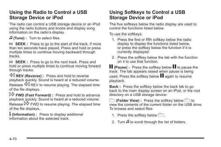
Using the Radio to Control a USBStorage Device or iPodThe radio can control a USB storage device or an iPodusing the radio buttons and knobs and display songinformation on the radio’s display.
f (Tune) : Turn to select files.
© SEEK : Press to go to the start of the track, if morethan ten seconds have played. Press and hold or pressmultiple times to continue moving backward throughtracks.
¨ SEEK : Press to go to the next track. Press andhold or press multiple times to continue moving forwardthrough tracks.
s REV (Reverse) : Press and hold to reverseplayback quickly. Sound is heard at a reduced volume.Releases REV to resume playing. The elapsed timeof the file displays.
\ FWD (Fast Forward) : Press and hold to advanceplayback quickly. Sound is heard at a reduced volume.Release\ FWD to resume playing. The elapsed timeof the file displays.
4 (Information) : Press to display additionalinformation about the selected track.
Using Softkeys to Control a USBStorage Device or iPodThe five softkeys below the radio display are used tocontrol the functions listed below.
To use the softkeys:
1. Press the first or fifth softkey below the radiodisplay to display the functions listed below,or press the softkey below the function if it iscurrently displayed.
2. Press the softkey below the tab with the functionon it to use that function.
j (Pause) : Press the softkey below j to pause thetrack. The tab appears raised when pause is beingused. Press the softkey below j again to resumeplayback.
Back : Press the softkey below the back tab to goback to the main display screen on an iPod, or the rootdirectory on a USB storage device.
c (Folder View) : Press the softkey belowc toview the contents of the current folder on the USB drive.To browse and select files:
1. Press the softkey belowc .
2. Turn f to scroll through the list of folders.
4-70
3. Press f to select the desired folder. If there ismore then one folder, repeat Steps 1 and 2 untilthe desired folder is reached.
4. Turn f to scroll through the files in the selectedfolder.
5. Press f to select the desired file to be played.
To skip through large lists, the five softkeys can be usedto navigate in the following order:. First softkey, first item in the list.. Second softkey, 1% through the list each time the
softkey is pressed.. Third softkey, 5% through the list each time the
softkey is pressed.. Fourth softkey, 10% through the list each time the
softkey is pressed.. Fifth softkey, end of the list.
h (Music Navigator : Press the softkey belowhto view and select a file on an iPod, using the iPod'smenu system. Files are sorted by:. Playlists. Artists. Albums
. Genres
. Songs
. Composers
To select files:
1. Press the softkey belowh .
2. Turn f to scroll through the list of menus.
3. Press f to select the desired menu.
4. Turn f to scroll through the folders or files in theselected menu.
5. Press f to select the desired file to be played.
To skip through large lists, the five softkeys can be usedto navigate in the following order:. First softkey, first item in the list.. Second softkey, 1% through the list each time the
softkey is pressed.. Third softkey, 5% through the list each time the
softkey is pressed.. Fourth softkey, 10% through the list each time the
softkey is pressed.. Fifth softkey, end of the list.
4-71
Repeat FunctionalityTo use Repeat:
Press the softkey below" or' to select betweenRepeat All and Repeat Track.
" (Repeat All) : Press the softkey below" to repeatall tracks. The tab appears lowered when Repeat All isbeing used. This is the default mode when a USBstorage device or iPod is first connected.
' (Repeat Track) : Press the softkey below' torepeat one track. The tab appears raised when RepeatTrack is being used.
Shuffle FunctionalityTo use Shuffle:
Press the softkey below>,2,< or= toselect between Shuffle Off, Shuffle All Songs/ShuffleSongs, Shuffle Album, or Shuffle Folder.
> (Shuffle Off) : Press the softkey below2 toturn shuffle off. This is the default mode when a USBstorage device or iPod is first connected.
2 (Shuffle All Songs / Shuffle Songs) : Press thesoftkey below= or< to shuffle all songs on theUSB storage device or iPod.
< (Shuffle Album) : Press the softkey below>to shuffle all songs in the current album on an iPod.
= (Shuffle Folder) : Press the softkey below> toshuffle all songs in the current folder on a USB storagedevice.
XM Radio MessagesXL (Explicit Language Channels) : These channels,or any others, can be blocked at a customer's request,by calling 1-800-852-XMXM (9696).
XM Updating : The encryption code in the receiver isbeing updated, and no action is required. This processshould take no longer than 30 seconds.
No XM Signal : The system is functioning correctly,but the vehicle is in a location that is blocking theXM™ signal. When the vehicle is moved into an openarea, the signal should return.
Loading XM : The audio system is acquiring andprocessing audio and text data. No action is needed.This message should disappear shortly.
Channel Off Air : This channel is not currently inservice. Tune in to another channel.
4-72
Channel Unauth : This channel is blocked or cannotbe received with your XM Subscription package.
Channel Unavail : This previously assigned channel isno longer assigned. Tune to another station. If thisstation was one of the presets, choose another stationfor that preset button.
No Artist Info : No artist information is available at thistime on this channel. The system is working properly.
No Title Info : No song title information is available atthis time on this channel. The system is workingproperly.
No CAT Info : No category information is available atthis time on this channel. The system is workingproperly.
No Information : No text or informational messagesare available at this time on this channel. The system isworking properly.
CAT Not Found : There are no channels available forthe selected category. The system is working properly.
XM Theftlocked : The XM receiver in the vehicle couldhave previously been in another vehicle. For securitypurposes, XM receivers cannot be swapped betweenvehicles. If this message is received after having thevehicle serviced, check with your dealer/retailer.
XM Radio ID : If tuned to channel 0, this messagealternates with the XM™ Radio 8 digit radio ID label.This label is needed to activate the service.
Unknown : If this message is received when tuned tochannel 0, there could be a receiver fault. Consult withyour dealer/retailer.
Check Antenna : If this message does not clear withina short period of time, the receiver or antenna couldhave a fault. Consult with your dealer/retailer.
Check XM Receivr : If this message does not clearwithin a short period of time, the receiver could have afault. Consult with your dealer/retailer.
XM Not Available : If this message does not clearwithin a short period of time, the receiver could have afault. Consult with your dealer/retailer.
4-73
Bluetooth®
Vehicles with a Bluetooth system can use a Bluetoothcapable cell phone with a Hands Free Profile to makeand receive phone calls. The system can be used whilethe key is in ON/RUN or ACC/ACCESSORY position.The range of the Bluetooth system can be up to 9.1 m(30 ft). Not all phones support all functions, and not allphones are guaranteed to work with the in-vehicleBluetooth system. See www.gm.com/bluetooth for moreinformation on compatible phones.
Voice RecognitionThe Bluetooth system uses voice recognition tointerpret voice commands to dial phone numbers andname tags.
Noise : Keep interior noise levels to a minimum.The system may not recognize voice commands if thereis too much background noise.
When to Speak : A short tone sounds after the systemresponds indicating when it is waiting for a voicecommand. Wait until the tone and then speak.
How to Speak : Speak clearly in a calm and naturalvoice.
Audio SystemWhen using the in-vehicle Bluetooth system, soundcomes through the vehicle's front audio systemspeakers and overrides the audio system. Use theaudio system volume knob, during a call, to change thevolume level. The adjusted volume level remains inmemory for later calls. To prevent missed calls, aminimum volume level is used if the volume is turneddown too low.
Bluetooth ControlsUse the buttons located on the steering wheel tooperate the in-vehicle Bluetooth system. See AudioSteering Wheel Controls on page 4‑84 for moreinformation.
bg (Push To Talk) : Press to answer incoming calls,to confirm system information, and to start speechrecognition.
cx (Phone On Hook) : Press to end a call, reject acall, or to cancel an operation.
4-74
PairingA Bluetooth enabled cell phone must be paired to thein-vehicle Bluetooth system first and then connected tothe vehicle before it can be used. See the cell phonemanufacturers user guide for Bluetooth functions beforepairing the cell phone. If a Bluetooth phone is notconnected, calls will be made using OnStar®
Hands-Free Calling, if available. Refer to the OnStarowner's guide for more information.
Pairing Information:. Up to five cell phones can be paired to the
in-vehicle Bluetooth system.. The pairing process is disabled when the vehicle is
moving.. The in-vehicle Bluetooth system automatically links
with the first available paired cell phone in theorder the phone was paired.
. Only one paired cell phone can be connected tothe in-vehicle Bluetooth system at a time.
. Pairing should only need to be completed once,unless changes to the pairing information havebeen made or the phone is deleted.
To link to a different paired phone, see Linking to aDifferent Phone later in this section.
Pairing a Phone
1. Press and hold bg for two seconds. The systemresponds with “Ready” followed by a tone.
2. Say “Bluetooth”. The system responds with“Bluetooth ready” followed by a tone.
3. Say “Pair”. The system responds with instructionsand a four digit PIN number. The PIN number willbe used in Step 4.
4. Start the Pairing process on the cell phone that willbe paired to the vehicle. Reference the cell phonemanufacturers user guide for information on thisprocess.
Locate the device named “General Motors” inthe list on the cellular phone and follow theinstructions on the cell phone to enter the four digitPIN number that was provided in Step 3.
5. The system prompts for a name for the phone. Usea name that best describes the phone. This namewill be used to indicate which phone is connected.The system then confirms the name provided.
6. The system responds with “<Phone name> hasbeen successfully paired” after the pairing processis complete.
7. Repeat Steps 1 through 7 for additional phones tobe paired.
4-75
Listing All Paired and Connected Phones
1. Press and hold bg for two seconds. The systemresponds with “Ready” followed by a tone.
2. Say “Bluetooth”. The system responds with“Bluetooth ready” followed by a tone.
3. Say “List”. The system lists all the paired Bluetoothdevices. If a phone is connected to the vehicle, thesystem will say “Is connected” after the connectedphone.
Deleting a Paired Phone
1. Press and hold bg for two seconds. The systemresponds with “Ready” followed by a tone.
2. Say “Bluetooth”. The system responds with“Bluetooth ready” followed by a tone.
3. Say “Delete”. The system asks which phone todelete followed by a tone.
4. Say the name of the phone to be deleted. If thephone name is unknown, use the “List” commandfor a list of all paired phones. The system respondswith “Would you like to delete <phone name>?Yes or No” followed by a tone.
5. Say “Yes” to delete the phone. The systemresponds with “OK, deleting <phone name>”.
Linking to a Different Phone
1. Press and hold bg for two seconds. The systemresponds with “Ready” followed by a tone.
2. Say “Bluetooth”. The system responds with“Bluetooth ready” followed by a tone.
3. Say “Change phone”. The system responds with“Please wait while I search for other phones”.. If another phone is found, the response will be
“<Phone name> is now connected”.. If another phone is not found, the original
phone remains connected.
Storing Name TagsThe system can store up to thirty phone numbers asname tags that are shared between the Bluetooth andOnStar systems.
The system uses the following commands to store andretrieve phone numbers:. Store. Digit Store. Directory
4-76
Using the Store CommandThe store command allows a phone number to bestored without entering the digits individually.
1. Press and hold bg for two seconds. The systemresponds with “Ready” followed by a tone.
2. Say “Store”. The system responds with “Store,number please” followed by a tone.
3. Say the complete phone number to be stored atonce with no pauses.. If the system recognizes the number it
responds with “OK, Storing” and repeats thephone number.
. If the system is unsure it recognizes the phonenumber, it responds with “Store” and repeatsthe number followed by “Please say yes or no”.If the number is correct, say “Yes”. If thenumber is not correct, say “No”. The system willask for the number to be re-entered.
4. After the system stores the phone number, itresponds with “Please say the name tag” followedby a tone.
5. Say a name tag for the phone number. The nametag is recorded and the system responds with“About to store <name tag>. Does thatsound OK?”.. If the name tag does not sound correct, say
“No” and repeat Step 5.. If the name tag sounds correct, say “Yes” and
the name tag is stored. After the number isstored the system returns to the main menu.
Using the Digit Store CommandThe digit store command allows a phone number to bestored by entering the digits individually.
1. Press and hold bg for two seconds. The systemresponds with “Ready” followed by a tone.
2. Say “Digit Store”. The system responds with“Please say the first digit to store” followed bya tone.
4-77
3. Say the first digit to be stored. The system willrepeat back the digit it heard followed by a tone.Continue entering digits until the number to bestored is complete.. If an unwanted number is recognized by the
system, say “Clear” at any time to clear thelast number.
. To hear all of the numbers recognized by thesystem, say “Verify” at any time and the systemwill repeat them.
4. After the complete number has been entered, say“Store”. The system responds with “Please say thename tag” followed by a tone.
5. Say a name tag for the phone number. The nametag is recorded and the system responds with“About to store <name tag>. Does thatsound OK?”.. If the name tag does not sound correct, say
“No” and repeat Step 5.. If the name tag sounds correct, say “Yes” and
the name tag is stored. After the number isstored the system returns to the main menu.
Using the Directory CommandThe directory command lists all of the name tags storedby the system. To use the directory command:
1. Press and hold bg for two seconds. The systemresponds with “Ready” followed by a tone.
2. Say “Directory”. The system responds with“Directory” and then plays back all of the storedname tags. When the list is complete, the systemreturns to the main menu.
Deleting Name TagsThe system uses the following commands to deletename tags:. Delete. Delete all name tags
Using the Delete CommandThe delete command allows specific name tags to bedeleted.
To use the delete command:
1. Press and hold bg for two seconds. The systemresponds with “Ready” followed by a tone.
2. Say “Delete”. The system responds with “Delete,please say the name tag” followed by a tone.
4-78
3. Say the name tag to be deleted. The systemresponds with “Would you like to delete, <nametag>? Please say yes or no”.. If the name tag is correct, say “Yes” to delete
the name tag. The system responds with “OK,deleting <name tag>, returning to themain menu.”
. If the name tag is incorrect, say “No”. Thesystem responds with “No. OK, let's try again,please say the name tag.”
Using the Delete All Name Tags CommandThe delete all name tags command deletes all storedphone book name tags and route name tags for OnStar,if present.
To use the delete all name tags command:
1. Press and hold bg for two seconds. The systemresponds with “Ready” followed by a tone.
2. Say “Delete all name tags”. The system respondswith “You are about to delete all name tags storedin your phone directory and your route destinationdirectory. Are you sure you want to do this? Pleasesay yes or no.”. Say “Yes” to delete all name tags.. Say “No” to cancel the function and return to
the main menu.
Making a CallCalls can be made using the following commands:. Dial. Digit Dial. Call. Re-dial
Using the Dial Command
1. Press and hold bg for two seconds. The systemresponds with “Ready” followed by a tone.
2. Say “Dial”. The system responds with “Dial using<phone name>. Number please” followed bya tone.
3. Say the entire number without pausing.. If the system recognizes the number, it
responds with “OK, Dialing” and dials thenumber.
. If the system does not recognize the number,it confirms the numbers followed by a tone.If the number is correct, say “Yes”. The systemresponds with “OK, Dialing” and dials thenumber. If the number is not correct, say “No”.The system will ask for the number to bere-entered.
4-79
Using the Digit Dial Command
1. Press and hold bg for two seconds. The systemresponds with “Ready” followed by a tone.
2. Say “Digit Dial”. The system responds with “Digitdial using <phone name>, please say the first digitto dial” followed by a tone.
3. Say the digit to be dialed one at a time. Followingeach digit, the system will repeat back the digit itheard followed by a tone.
4. Continue entering digits until the number to bedialed is complete. After the whole number hasbeen entered, say “Dial”. The system respondswith “OK, Dialing” and dials the number.. If an unwanted number is recognized by the
system, say “Clear” at any time to clear the lastnumber.
. To hear all of the numbers recognized by thesystem, say “Verify” at any time and the systemwill repeat them.
Using the Call Command
1. Press and hold bg for two seconds. The systemresponds with “Ready” followed by a tone.
2. Say “Call”. The system responds with “Call using<phone name>. Please say the name tag” followedby a tone.
3. Say the name tag of the person to call.. If the system clearly recognizes the name tag it
responds with “OK, calling, <name tag>” anddials the number.
. If the system is unsure it recognizes the rightname tag, it confirms the name tag followed bya tone. If the name tag is correct, say “Yes”.The system responds with “OK, calling, <nametag>” and dials the number. If the name tag isnot correct, say “No”. The system will ask forthe name tag to be re-entered.
Once connected, the person called will be heardthrough the audio speakers.
Using the Re-dial Command
1. Press and hold bg for two seconds. The systemresponds with “Ready” followed by a tone.
2. After the tone, say “Re-dial”. The system respondswith “Re-dial using <phone name>” and dials thelast number called from the connected Bluetoothphone.
Once connected, the person called will be heardthrough the audio speakers.
4-80
Receiving a CallWhen an incoming call is received, the audio systemmutes and a ring tone is heard in the vehicle.
. Press bg and begin speaking to answer the call.
. Presscx to ignore a call.
Call WaitingCall waiting must be supported on the Bluetooth phoneand enabled by the wireless service carrier to work.
. Press bg to answer an incoming call whenanother call is active. The original call is placedon hold.
. Press bg again to return to the original call.
. To ignore the incoming call, continue with theoriginal call with no action.
. Presscx to disconnect the current call andswitch to the call on hold.
Three-Way CallingThree-Way Calling must be supported on the Bluetoothphone and enabled by the wireless service carrierto work.
1. While on a call press bg . The system respondswith “Ready” followed by a tone.
2. Say “Three-way call”. The system responds with“Three-way call, please say dial or call”.
3. Use the dial or call command to dial the number ofthe third party to be called.
4. Once the call is connected, press bg to link allthe callers together.
Ending a Call
Presscx to end a call.
Muting a CallDuring a call, all sounds from inside the vehicle can bemuted so that the person on the other end of the callcannot hear them.
4-81
To Mute a call
1. Press bg . The system responds with “Ready”followed by a tone.
2. Say “Mute Call”. The system responds with“Call muted”.
To Cancel Mute
1. Press bg . The system responds with “Ready”followed by a tone.
2. After the tone, say “Mute Call”. The systemresponds with “Resuming call”.
Transferring a CallAudio can be transferred between the in-vehicleBluetooth system and the cell phone.
To Transfer Audio to the Cell PhoneDuring a call with the audio in the vehicle:
1. Press bg . The system responds with “Ready”followed by a tone.
2. Say “Transfer Call.” The system responds with“Transferring call” and the audio will switch fromthe vehicle to the cell phone.
To Transfer Audio to the In-VehicleBluetooth SystemThe cellular phone must be paired and connected withthe Bluetooth system before a call can be transferred.The connection process can take up to two minutesafter the key is turned to the ON/RUN or ACC/ACCESSORY position.
During a call with the audio on the cell phone,press bg for more than two seconds. The audioswitches from the cell phone to the vehicle.
Voice Pass-ThruVoice Pass-Thru allows access to the voice recognitioncommands on the cell phone. See the cell phonemanufacturers user guide to see if the cell phonesupports this feature. This feature can be used toverbally access contacts stored in the cell phone.
1. Press and hold bg for two seconds. The systemresponds with “Ready” followed by a tone.
2. Say “Bluetooth”. The system responds with“Bluetooth ready” followed by a tone.
3. Say “Voice”. The system responds with “OK,accessing <phone name>”.. The cell phone's normal prompt messages will
go through its cycle according to the phone'soperating instructions.
4-82
Dual Tone Multi-Frequency (DTMF)TonesThe in-vehicle Bluetooth system can send numbers andnumbers stored as name tags during a call. This is usedwhen calling a menu driven phone system. Accountnumbers can be programmed into the phonebook forretrieval during menu driven calls.
Sending a Number During a Call
1. Press bg . The system responds with “Ready”followed by a tone.
2. Say “Dial”. The system responds with “Say anumber to send tones” followed by a tone.
3. Say the number to send.. If the system clearly recognizes the number it
responds with “OK, Sending Number” and thedial tones are sent and the call continues.
. If the system is not sure it recognized thenumber properly, it responds “Dial Number,Please say yes or no?” followed by a tone.If the number is correct, say “Yes”. The systemresponds with “OK, Sending Number” and thedial tones are sent and the call continues.
Sending a Stored Name Tag During a Call
1. Press bg . The system responds with “Ready”followed by a tone.
2. Say “Send name tag.” The system responds with“Say a name tag to send tones” followed by a tone.
3. Say the name tag to send.. If the system clearly recognizes the name tag it
responds with “OK, Sending <name tag>” andthe dial tones are sent and the call continues.
. If the system is not sure it recognized the nametag properly, it responds “Dial <name tag>,Please say yes or no?” followed by a tone.If the name tag is correct, say “Yes”. Thesystem responds with “OK, Sending <nametag>” and the dial tones are sent and the callcontinues.
Clearing the SystemUnless information is deleted out of the in-vehicleBluetooth system, it will be retained indefinitely. Thisincludes all saved name tags in the phonebook andphone pairing information. For information on how todelete this information, see the above sections onDeleting a Paired Phone and Deleting Name Tags.
4-83
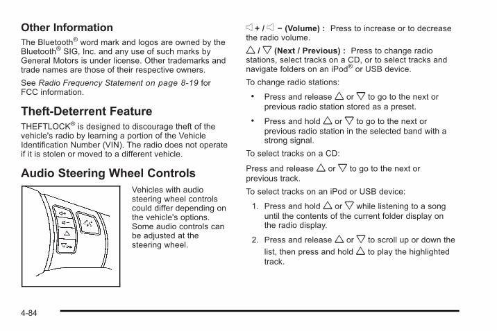
Other InformationThe Bluetooth® word mark and logos are owned by theBluetooth® SIG, Inc. and any use of such marks byGeneral Motors is under license. Other trademarks andtrade names are those of their respective owners.
See Radio Frequency Statement on page 8‑19 forFCC information.
Theft-Deterrent FeatureTHEFTLOCK® is designed to discourage theft of thevehicle's radio by learning a portion of the VehicleIdentification Number (VIN). The radio does not operateif it is stolen or moved to a different vehicle.
Audio Steering Wheel ControlsVehicles with audiosteering wheel controlscould differ depending onthe vehicle's options.Some audio controls canbe adjusted at thesteering wheel.
e + / e − (Volume) : Press to increase or to decreasethe radio volume.
w /x (Next / Previous) : Press to change radiostations, select tracks on a CD, or to select tracks andnavigate folders on an iPod® or USB device.
To change radio stations:
. Press and releasew orx to go to the next orprevious radio station stored as a preset.
. Press and holdw orx to go to the next orprevious radio station in the selected band with astrong signal.
To select tracks on a CD:
Press and releasew orx to go to the next orprevious track.
To select tracks on an iPod or USB device:
1. Press and holdw orx while listening to a songuntil the contents of the current folder display onthe radio display.
2. Press and releasew orx to scroll up or down the
list, then press and holdw to play the highlightedtrack.
4-84
To navigate folders on an iPod or USB device:
1. Press and holdw orx while listening to a songuntil the contents of the current folder display onthe radio display.
2. Press and holdx to go back to the previousfolder list.
3. Press and releasew orx to scroll up or downthe list.
. To select a folder, press and holdw when thefolder is highlighted.
. To go back further in the folder list, press andholdx .
c (End) : Press to reject an incoming call, or end acurrent call.
bg (Mute / Voice Recognition) : Press to silencethe vehicle speakers only. Press again to turn thesound on.
For vehicles with Bluetooth® or OnStar® systems pressand hold bg for longer than two seconds to interactwith those systems. See Bluetooth® on page 4‑74 andthe OnStar Owner's Guide for more information.
Radio ReceptionFrequency interference and static can occur duringnormal radio reception if items such as cell phonechargers, vehicle convenience accessories, andexternal electronic devices are plugged into theaccessory power outlet. If there is interference or static,unplug the item from the accessory power outlet.
AMThe range for most AM stations is greater than for FM,especially at night. The longer range can cause stationfrequencies to interfere with each other. For better radioreception, most AM radio stations boost the powerlevels during the day, and then reduce these levelsduring the night. Static can also occur when things likestorms and power lines interfere with radio reception.When this happens, try reducing the treble on the radio.
FM StereoFM signals only reach about 10 to 40 miles(16 to 65 km). Although the radio has a built-in electroniccircuit that automatically works to reduce interference,some static can occur, especially around tall buildingsor hills, causing the sound to fade in and out.
4-85
XM™ Satellite Radio ServiceXM Satellite Radio Service gives digital radio receptionfrom coast-to-coast in the 48 contiguous United States,and in Canada. Just as with FM, tall buildings or hillscan interfere with satellite radio signals, causing thesound to fade in and out. In addition, traveling orstanding under heavy foliage, bridges, garages,or tunnels may cause loss of the XM signal for aperiod of time.
Cellular Phone UsageCellular phone usage may cause interference with thevehicle's radio. This interference may occur whenmaking or receiving phone calls, charging thephone's battery, or simply having the phone on.This interference causes an increased level of staticwhile listening to the radio. If static is received whilelistening to the radio, unplug the cellular phone andturn it off.
Fixed Mast AntennaThe fixed mast antenna can withstand most car washeswithout being damaged as long as it is securelyattached to the base. If the mast becomes slightly bent,straighten it out by hand. If the mast is badly bent,replace it.
Occasionally check to make sure the antenna istightened to its base. If tightening is required,tighten by hand until fully seated plus one quarter turn.
XM™ Satellite Radio AntennaSystemThe XM Satellite Radio antenna is located on the roofor the rear of the vehicle. Keep the antenna clear ofobstructions for clear radio reception.
4-86
Section 5 Driving Your Vehicle
Your Driving, the Road, and the Vehicle . . . . . . . . . . 5-2Defensive Driving . . . . . . . . . . . . . . . . . . . . . . . . . . . . . . . 5-2Drunk Driving . . . . . . . . . . . . . . . . . . . . . . . . . . . . . . . . . . . 5-2Control of a Vehicle . . . . . . . . . . . . . . . . . . . . . . . . . . . . . 5-3Braking . . . . . . . . . . . . . . . . . . . . . . . . . . . . . . . . . . . . . . . . . 5-3Antilock Brake System (ABS) . . . . . . . . . . . . . . . . . . . 5-4Braking in Emergencies . . . . . . . . . . . . . . . . . . . . . . . . . 5-5Electronic Stability Control (ESC) . . . . . . . . . . . . . . . 5-6Traction Control System (TCS) . . . . . . . . . . . . . . . . . . 5-9Enhanced Traction System (ETS) . . . . . . . . . . . . . . 5-12Limited-Slip Differential . . . . . . . . . . . . . . . . . . . . . . . . 5-14Steering . . . . . . . . . . . . . . . . . . . . . . . . . . . . . . . . . . . . . . . 5-14Off-Road Recovery . . . . . . . . . . . . . . . . . . . . . . . . . . . . 5-16Passing . . . . . . . . . . . . . . . . . . . . . . . . . . . . . . . . . . . . . . . . 5-16Loss of Control . . . . . . . . . . . . . . . . . . . . . . . . . . . . . . . . 5-16Racing or Other Competitive Driving . . . . . . . . . . . 5-18
Driving at Night . . . . . . . . . . . . . . . . . . . . . . . . . . . . . . . . 5-18Driving in Rain and on Wet Roads . . . . . . . . . . . . . 5-18Before Leaving on a Long Trip . . . . . . . . . . . . . . . . . 5-20Highway Hypnosis . . . . . . . . . . . . . . . . . . . . . . . . . . . . . 5-20Hill and Mountain Roads . . . . . . . . . . . . . . . . . . . . . . . 5-20Winter Driving . . . . . . . . . . . . . . . . . . . . . . . . . . . . . . . . . 5-22If Your Vehicle is Stuck in Sand, Mud, Ice,or Snow . . . . . . . . . . . . . . . . . . . . . . . . . . . . . . . . . . . . . 5-24
Rocking Your Vehicle to Get It Out . . . . . . . . . . . . . 5-24Loading the Vehicle . . . . . . . . . . . . . . . . . . . . . . . . . . . . 5-25
Towing . . . . . . . . . . . . . . . . . . . . . . . . . . . . . . . . . . . . . . . . . . . . 5-30Towing Your Vehicle . . . . . . . . . . . . . . . . . . . . . . . . . . . 5-30Recreational Vehicle Towing . . . . . . . . . . . . . . . . . . . 5-30Towing a Trailer (Automatic Transmission) . . . . . 5-33Towing a Trailer (Manual Transmission) . . . . . . . . 5-39
5-1
Your Driving, the Road, and theVehicle
Defensive DrivingDefensive driving means “always expect theunexpected.” The first step in driving defensively is towear your safety belt — See Safety Belts: They Are forEveryone on page 2‑10.
{ WARNING:
Assume that other road users (pedestrians,bicyclists, and other drivers) are going to becareless and make mistakes. Anticipate what theymight do and be ready. In addition:. Allow enough following distance between you
and the driver in front of you.. Focus on the task of driving.
Driver distraction can cause collisions resulting ininjury or possible death. These simple defensivedriving techniques could save your life.
Drunk Driving
{ WARNING:
Drinking and then driving is very dangerous. Yourreflexes, perceptions, attentiveness, and judgmentcan be affected by even a small amount ofalcohol. You can have a serious — or evenfatal — collision if you drive after drinking. Do notdrink and drive or ride with a driver who has beendrinking. Ride home in a cab; or if you are with agroup, designate a driver who will not drink.
Death and injury associated with drinking and driving isa global tragedy.
Alcohol affects four things that anyone needs to drive avehicle: judgment, muscular coordination, vision, andattentiveness.
Police records show that almost 40 percent of all motorvehicle-related deaths involve alcohol. In most cases,these deaths are the result of someone who wasdrinking and driving. In recent years, more than17,000 annual motor vehicle-related deaths have beenassociated with the use of alcohol, with about250,000 people injured.
5-2
For persons under 21, it is against the law in everyU.S. state to drink alcohol. There are good medical,psychological, and developmental reasons forthese laws.
The obvious way to eliminate the leading highwaysafety problem is for people never to drink alcohol andthen drive.
Medical research shows that alcohol in a person'ssystem can make crash injuries worse, especiallyinjuries to the brain, spinal cord, or heart. This meansthat when anyone who has been drinking — driver orpassenger — is in a crash, that person's chance ofbeing killed or permanently disabled is higher than if theperson had not been drinking.
Control of a VehicleThe following three systems help to control the vehiclewhile driving — brakes, steering, and accelerator.At times, as when driving on snow or ice, it is easy toask more of those control systems than the tires androad can provide. Meaning, you can lose control of thevehicle. See Traction Control System (TCS) onpage 5‑9 , Enhanced Traction System (ETS) onpage 5‑12, and Electronic Stability Control (ESC) onpage 5‑6 .
Adding non-dealer/non-retailer accessories can affectvehicle performance. See Accessories andModifications on page 6‑4.
BrakingSee Brake System Warning Light on page 4‑23.
Braking action involves perception time and reactiontime. Deciding to push the brake pedal is perceptiontime. Actually doing it is reaction time.
Average reaction time is about three-fourths of asecond. But that is only an average. It might be lesswith one driver and as long as two or three seconds ormore with another. Age, physical condition, alertness,coordination, and eyesight all play a part. So do alcohol,drugs, and frustration. But even in three-fourths of asecond, a vehicle moving at 60 mph (100 km/h) travels66 feet (20 m). That could be a lot of distance in anemergency, so keeping enough space between thevehicle and others is important.
And, of course, actual stopping distances vary greatlywith the surface of the road, whether it is pavement orgravel; the condition of the road, whether it is wet, dry,or icy; tire tread; the condition of the brakes; the weightof the vehicle; and the amount of brake force applied.
5-3
Avoid needless heavy braking. Some people drive inspurts — heavy acceleration followed by heavybraking — rather than keeping pace with traffic. This isa mistake. The brakes might not have time to coolbetween hard stops. The brakes will wear out muchfaster with a lot of heavy braking. Keeping pace with thetraffic and allowing realistic following distanceseliminates a lot of unnecessary braking. That meansbetter braking and longer brake life.
If the engine ever stops while the vehicle is beingdriven, brake normally but do not pump the brakes.If the brakes are pumped, the pedal could get harder topush down. If the engine stops, there will still be somepower brake assist but it will be used when the brake isapplied. Once the power assist is used up, it can takelonger to stop and the brake pedal will be harderto push.
If the vehicle has Electronic Stability Control (ESC) andthe 2.0L turbocharged engine, it also has a hydraulicbrake boost feature which supplements the power brakesystem to maintain consistent brake performance underconditions of low brake booster vacuum. Low brakebooster vacuum conditions can include initial start upafter the vehicle has been parked for several hours,very frequent brake stops, or high altitude driving. Whenhydraulic brake boost is active, minor brake pulsation ormovement might be felt but this is normal. If brake pedal
feel changes or the brake pedal feels hard to push, thesystem might not be receiving the intended brake boostand the SVC BRAKE SYSTEM DIC message may bedisplayed.
Adding non-dealer/non-retailer accessories can affectvehicle performance. See Accessories andModifications on page 6‑4.
Antilock Brake System (ABS)The vehicle might have the Antilock Brake System(ABS), an advanced electronic braking system thathelps prevent a braking skid.
If the vehicle has ABS,this warning light on theinstrument panel comeson briefly when thevehicle is started.
When the engine is started, or when the vehicle beginsto drive away, ABS checks itself. A momentary motor orclicking noise might be heard while this test is going on,and it might even be noticed that the brake pedalmoves or pulses a little. This is normal.
5-4
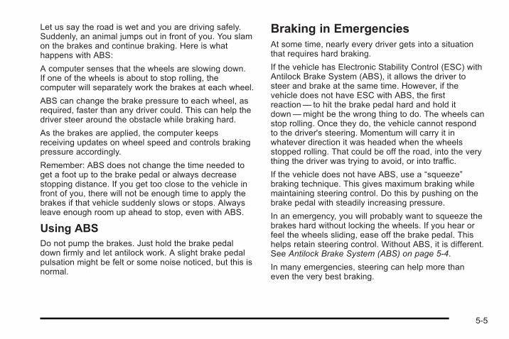
Let us say the road is wet and you are driving safely.Suddenly, an animal jumps out in front of you. You slamon the brakes and continue braking. Here is whathappens with ABS:
A computer senses that the wheels are slowing down.If one of the wheels is about to stop rolling, thecomputer will separately work the brakes at each wheel.
ABS can change the brake pressure to each wheel, asrequired, faster than any driver could. This can help thedriver steer around the obstacle while braking hard.
As the brakes are applied, the computer keepsreceiving updates on wheel speed and controls brakingpressure accordingly.
Remember: ABS does not change the time needed toget a foot up to the brake pedal or always decreasestopping distance. If you get too close to the vehicle infront of you, there will not be enough time to apply thebrakes if that vehicle suddenly slows or stops. Alwaysleave enough room up ahead to stop, even with ABS.
Using ABSDo not pump the brakes. Just hold the brake pedaldown firmly and let antilock work. A slight brake pedalpulsation might be felt or some noise noticed, but this isnormal.
Braking in EmergenciesAt some time, nearly every driver gets into a situationthat requires hard braking.
If the vehicle has Electronic Stability Control (ESC) withAntilock Brake System (ABS), it allows the driver tosteer and brake at the same time. However, if thevehicle does not have ESC with ABS, the firstreaction— to hit the brake pedal hard and hold itdown—might be the wrong thing to do. The wheels canstop rolling. Once they do, the vehicle cannot respondto the driver's steering. Momentum will carry it inwhatever direction it was headed when the wheelsstopped rolling. That could be off the road, into the verything the driver was trying to avoid, or into traffic.
If the vehicle does not have ABS, use a “squeeze”braking technique. This gives maximum braking whilemaintaining steering control. Do this by pushing on thebrake pedal with steadily increasing pressure.
In an emergency, you will probably want to squeeze thebrakes hard without locking the wheels. If you hear orfeel the wheels sliding, ease off the brake pedal. Thishelps retain steering control. Without ABS, it is different.See Antilock Brake System (ABS) on page 5‑4.
In many emergencies, steering can help more thaneven the very best braking.
5-5
Brake AssistIf this vehicle has ESC with ABS, it also has a BrakeAssist feature designed to assist the driver in stoppingor decreasing vehicle speed in emergency drivingconditions. This feature uses the stability systemhydraulic brake control module to supplement the powerbrake system under conditions where the driver hasquickly and forcefully applied the brake pedal in anattempt to quickly stop or slow down the vehicle.The stability system hydraulic brake control moduleincreases brake pressure at each corner of the vehicleuntil the ABS activates. Minor brake pedal pulsations orpedal movement during this time is normal and thedriver should continue to apply the brake pedal as thedriving situation dictates The Brake Assist feature willautomatically disengage when the brake pedal isreleased or brake pedal pressure is quickly decreased.
Electronic Stability Control (ESC)The vehicle may have an Electronic Stability Control(ESC) system which combines antilock brake, andtraction and stability control systems that help the drivermaintain directional control of the vehicle in most drivingconditions.
When the vehicle is started and begins to move, thesystem performs several diagnostic checks to ensurethere are no problems. The system may be heard or feltwhile it is working. This is normal and does not meanthere is a problem with the vehicle. The system shouldinitialize before the vehicle reaches 32 km/h (20 mph).
If the system fails to turn on or activate, the ESC/TCSlight comes on, and the ESC OFF and/or SERVICEESC message displays.
For more information, see Driver Information Center(DIC) on page 4‑37 and Electronic Stability Control(ESC)/Traction Control System (TCS) Indicator/WarningLight on page 4‑25.
5-6
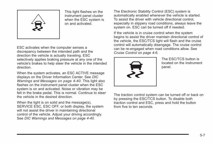
This light flashes on theinstrument panel clusterwhen the ESC system ison and activated.
ESC activates when the computer senses adiscrepancy between the intended path and thedirection the vehicle is actually traveling. ESCselectively applies braking pressure at any one of thevehicle's brakes to help steer the vehicle in the intendeddirection.
When the system activates, an ESC ACTIVE messagedisplays on the Driver Information Center. See DICWarnings and Messages on page 4‑40. This light alsoflashes on the instrument panel cluster when the ESCsystem is on and activated. Noise or vibration may befelt in the brake pedal. This is normal. Continue to steerthe vehicle in the desired direction.
When the light is on solid and the message(s),SERVICE ESC, ESC OFF, or both display, the systemwill not assist the driver in maintaining directionalcontrol of the vehicle. Adjust your driving accordingly.See DIC Warnings and Messages on page 4‑40.
The Electronic Stability Control (ESC) system isautomatically enabled whenever the vehicle is started.To assist the driver with vehicle directional control,especially in slippery road conditions, always leave thesystem on. ESC can be turned off if needed.
If the vehicle is in cruise control when the systembegins to assist the driver maintain directional control ofthe vehicle, the ESC/TCS light will flash and the cruisecontrol will automatically disengage. The cruise controlcan be re-engaged when road conditions allow. SeeCruise Control on page 4‑6.
The ESC/TCS button islocated on the instrumentpanel.
The traction control system can be turned off or back onby pressing the ESC/TCS button. To disable bothtraction control and ESC, press and hold the buttonfrom five to ten seconds.
5-7
When the ESC system is turned off, the TRACTIONOFF and ESC OFF messages appear, and theESC/TCS light comes on to warn the driver that bothtraction control and ESC are disabled.
It is recommended that the system remain on for normaldriving conditions, but it may be necessary to turn thesystem off if the vehicle is stuck in sand, mud, ice orsnow, and you want to “rock” your vehicle to attempt tofree it. It may also be necessary to turn off the systemwhen driving in extreme off-road conditions where highwheel spin is required. See If Your Vehicle is Stuck inSand, Mud, Ice, or Snow on page 5‑24.
ESC may also turn off automatically if it determines thata problem exists with the system. The ESC OFF andSERVICE ESC messages and the ESC/TCS lightcomes on to warn the driver that ESC is disabled andrequires service. If the problem does not clear afterrestarting the vehicle, see your dealer/retailer forservice. See DIC Warnings and Messages onpage 4‑40 for more information.
Adding non-dealer/non-retailer accessories can affectthe vehicle's performance. See Accessories andModifications on page 6‑4 for more information.
Competitive Driving Mode(SS Models Only)The driver can select this optional handling mode bypressing the ESC/TCS button on the console two timesquickly. COMPETITIVE MODE will be displayed in theDIC. See DIC Warnings and Messages on page 4‑40.
Competitive Driving Mode allows the driver to have fullcontrol of the front wheels while the ESC system helpsmaintain directional control of the vehicle by selectivebrake application. The ESC/TCS light will be on and thetraction control system will not be operating. Adjust yourdriving accordingly. This electronic stability controlmode is recommended only for use during closed trackevents and competitive driving venues.
When the ESC button is pressed again, or the vehicle isrestarted, the ESC and TCS will be turned back on.
Notice: When traction control is turned off,or Competitive Driving Mode is active, it is possibleto lose traction. If you attempt to shift with thefront wheels spinning with a loss of traction, it ispossible to cause damage to the transmission.Do not attempt to shift when the front wheels do nothave traction. Damage caused by misuse of thevehicle is not covered. See your warranty book foradditional information.
5-8
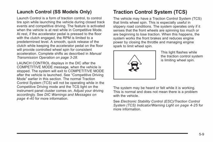
Launch Control (SS Models Only)Launch Control is a form of traction control, to controltire spin while launching the vehicle during closed trackevents and competitive driving. The feature is activatedwhen the vehicle is at rest while in Competitive Mode.At rest, if the accelerator pedal is pressed to the floorwith the clutch engaged, the RPM is limited to apredetermined level. A smooth, quick release of theclutch while keeping the accelerator pedal on the floorwill provide controlled wheel spin for consistentacceleration. Complete shifts as described in ManualTransmission Operation on page 3‑28.
LAUNCH CONTROL displays in the DIC after theCOMPETITIVE MODE message, when the vehicle isstopped. The system will exit to COMPETITIVE MODEafter the vehicle is launched. See “Competitive DrivingMode” earlier in this section. The normal TractionControl System (TCS) will not be operating while in theCompetitive Driving mode and the TCS light on theinstrument panel cluster comes on. Adjust your drivingaccordingly. See DIC Warnings and Messages onpage 4‑40 for more information.
Traction Control System (TCS)The vehicle may have a Traction Control System (TCS)that limits wheel spin. This is especially useful inslippery road conditions. The system operates only if itsenses that the front wheels are spinning too much orare beginning to lose traction. When this happens, thesystem works the front brakes and reduces enginepower by closing the throttle and managing enginespark to limit wheel spin.
This light flashes whilethe traction control systemis limiting wheel spin.
The system may be heard or felt while it is working.This is normal and does not mean there is a problemwith the vehicle.
See Electronic Stability Control (ESC)/Traction ControlSystem (TCS) Indicator/Warning Light on page 4‑25 formore information.
5-9
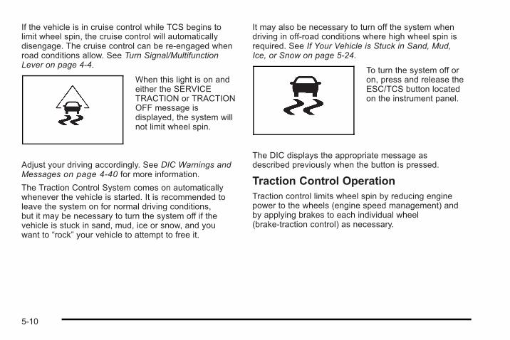
If the vehicle is in cruise control while TCS begins tolimit wheel spin, the cruise control will automaticallydisengage. The cruise control can be re-engaged whenroad conditions allow. See Turn Signal/MultifunctionLever on page 4‑4.
When this light is on andeither the SERVICETRACTION or TRACTIONOFF message isdisplayed, the system willnot limit wheel spin.
Adjust your driving accordingly. See DIC Warnings andMessages on page 4‑40 for more information.
The Traction Control System comes on automaticallywhenever the vehicle is started. It is recommended toleave the system on for normal driving conditions,but it may be necessary to turn the system off if thevehicle is stuck in sand, mud, ice or snow, and youwant to “rock” your vehicle to attempt to free it.
It may also be necessary to turn off the system whendriving in off-road conditions where high wheel spin isrequired. See If Your Vehicle is Stuck in Sand, Mud,Ice, or Snow on page 5‑24.
To turn the system off oron, press and release theESC/TCS button locatedon the instrument panel.
The DIC displays the appropriate message asdescribed previously when the button is pressed.
Traction Control OperationTraction control limits wheel spin by reducing enginepower to the wheels (engine speed management) andby applying brakes to each individual wheel(brake-traction control) as necessary.
5-10
The traction control system is enabled automaticallywhen the vehicle is started, and it will activate and flashthe ESC/TCS light and display the LOW TRACTIONmessage if it senses that either of the front wheels arespinning or beginning to lose traction while driving.For more information on the LOW TRACTION message,see Driver Information Center (DIC) on page 4‑37.
Notice: If the wheel(s) of one axle are allowed tospin excessively while the ESC/TCS, ABS andBrake warning lights and the SERVICE ESC and/orSERVICE TRACTION messages are displayed, thedifferential could be damaged. The repairs wouldnot be covered by the vehicle warranty. Reduceengine power and do not spin the wheel(s)excessively while these lights and this message aredisplayed.
Notice: When traction control is turned off,or Competitive Driving Mode is active, it is possibleto lose traction. If you attempt to shift with thedrive wheels spinning with a loss of traction, it ispossible to cause damage to the transmission.Do not attempt to shift when the drive wheels do nothave traction. Damage caused by misuse of thevehicle is not covered. See the warranty book foradditional information.
The traction control system may activate on dry orrough roads or under conditions such as heavyacceleration while turning or abrupt upshifts/downshiftsof the transmission. When this happens, a reduction inacceleration may be noticed or a noise or vibration maybe heard. This is normal.
If the vehicle is in cruise control while the systemactivates, the ESC/TCS light flashes and the cruisecontrol automatically disengages. The cruise controlcan be re-engaged when road conditions allow.See Cruise Control on page 4‑6.
Adding non-dealer/non-retailer accessories can affectthe vehicle's performance. See Accessories andModifications on page 6‑4 for more information.
5-11
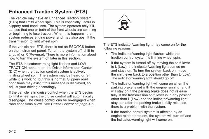
Enhanced Traction System (ETS)The vehicle may have an Enhanced Traction System(ETS) that limits wheel spin. This is especially useful inslippery road conditions. The system operates only if itsenses that one or both of the front wheels are spinningor beginning to lose traction. When this happens, thesystem reduces engine power and may also upshift thetransmission to limit wheel spin.
If the vehicle has ETS, there is not an ESC/TCS buttonon the instrument panel. To turn the system off, shift toL (Low) or R (Reverse). There is more information abouthow to turn the system off later in this section.
The ETS indicator/warning light flashes and LOWTRACTION appears on the Driver Information Center(DIC) when the traction control system is activelylimiting wheel spin. The system may be heard or feltwhile it is working, but this is normal. Slippery roadconditions may exist if this message is displayed, soadjust your driving accordingly.
If the vehicle is in cruise control when the ETS beginsto limit wheel spin, the cruise control will automaticallydisengage. The cruise control can be re-engaged whenroad conditions allow. See Cruise Control on page 4‑6.
The ETS indicator/warning light may come on for thefollowing reasons:. The indicator/warning light flashes while the
traction control system is limiting wheel spin.. If the system is turned off by moving the shift lever
to L (Low), the indicator/warning light comes onand stays on. To turn the system back on, movethe shift lever back to a position other than L (Low).The indicator/warning light should go off.
. The indicator/warning light will come on when theparking brake is set with the engine running, and itwill stay on if the parking brake does not releasefully. If the transmission shift lever is in any positionother than L (Low) and the indicator/warning lightstays on after the parking brake is fully released,there is a problem with the system.
. If the traction control system is affected by anengine related problem, the system will turn off andthe indicator/warning light will come on.
5-12
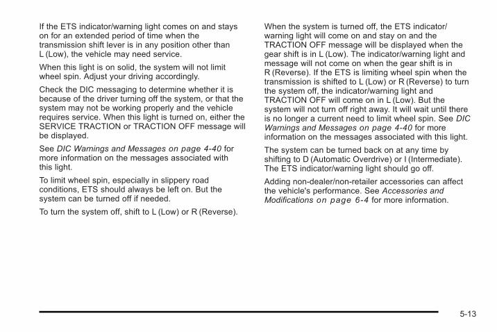
If the ETS indicator/warning light comes on and stayson for an extended period of time when thetransmission shift lever is in any position other thanL (Low), the vehicle may need service.
When this light is on solid, the system will not limitwheel spin. Adjust your driving accordingly.
Check the DIC messaging to determine whether it isbecause of the driver turning off the system, or that thesystem may not be working properly and the vehiclerequires service. When this light is turned on, either theSERVICE TRACTION or TRACTION OFF message willbe displayed.
See DIC Warnings and Messages on page 4‑40 formore information on the messages associated withthis light.
To limit wheel spin, especially in slippery roadconditions, ETS should always be left on. But thesystem can be turned off if needed.
To turn the system off, shift to L (Low) or R (Reverse).
When the system is turned off, the ETS indicator/warning light will come on and stay on and theTRACTION OFF message will be displayed when thegear shift is in L (Low). The indicator/warning light andmessage will not come on when the gear shift is inR (Reverse). If the ETS is limiting wheel spin when thetransmission is shifted to L (Low) or R (Reverse) to turnthe system off, the indicator/warning light andTRACTION OFF will come on in L (Low). But thesystem will not turn off right away. It will wait until thereis no longer a current need to limit wheel spin. See DICWarnings and Messages on page 4‑40 for moreinformation on the messages associated with this light.
The system can be turned back on at any time byshifting to D (Automatic Overdrive) or I (Intermediate).The ETS indicator/warning light should go off.
Adding non-dealer/non-retailer accessories can affectthe vehicle's performance. See Accessories andModifications on page 6‑4 for more information.
5-13
Limited-Slip DifferentialVehicles with a limited-slip differential can give moretraction on snow, mud, ice, sand or gravel. It works likea standard axle most of the time, but when traction islow, this feature allows the drive wheel with the mosttraction to move the vehicle. The limited slip design hasminimal impact to the steering feel, but boosts thetraction performance under all conditions.
Steering
Electric Power SteeringIf the engine stalls while driving, the power steeringassist system will continue to operate until you are ableto stop the vehicle. If power steering assist is lostbecause the electric power steering system is notfunctioning, the vehicle can be steered but it will takemore effort.
If you turn the steering wheel in either direction severaltimes until it stops, or hold the steering wheel in thestopped position for an extended amount of time, youmay notice a reduced amount of power steering assist.The normal amount of power steering assist shouldreturn shortly after a few normal steering movements.
The electric power steering system does not requireregular maintenance. If you suspect steering systemproblems and/or the POWER STEERING messagecomes on, contact your dealer/retailer for servicerepairs. See DIC Warnings and Messages onpage 4‑40.
Steering TipsIt is important to take curves at a reasonable speed.
Traction in a curve depends on the condition of the tiresand the road surface, the angle at which the curve isbanked, and vehicle speed. While in a curve, speed isthe one factor that can be controlled.
If there is a need to reduce speed, do it before enteringthe curve, while the front wheels are straight.
Try to adjust the speed so you can drive through thecurve. Maintain a reasonable, steady speed. Wait toaccelerate until out of the curve, and then accelerategently into the straightaway.
5-14
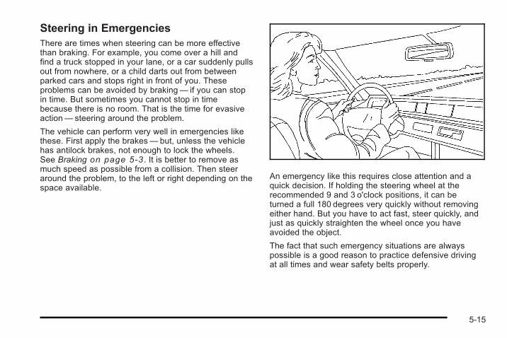
Steering in EmergenciesThere are times when steering can be more effectivethan braking. For example, you come over a hill andfind a truck stopped in your lane, or a car suddenly pullsout from nowhere, or a child darts out from betweenparked cars and stops right in front of you. Theseproblems can be avoided by braking— if you can stopin time. But sometimes you cannot stop in timebecause there is no room. That is the time for evasiveaction— steering around the problem.
The vehicle can perform very well in emergencies likethese. First apply the brakes— but, unless the vehiclehas antilock brakes, not enough to lock the wheels.See Braking on page 5‑3 . It is better to remove asmuch speed as possible from a collision. Then steeraround the problem, to the left or right depending on thespace available.
An emergency like this requires close attention and aquick decision. If holding the steering wheel at therecommended 9 and 3 o'clock positions, it can beturned a full 180 degrees very quickly without removingeither hand. But you have to act fast, steer quickly, andjust as quickly straighten the wheel once you haveavoided the object.
The fact that such emergency situations are alwayspossible is a good reason to practice defensive drivingat all times and wear safety belts properly.
5-15
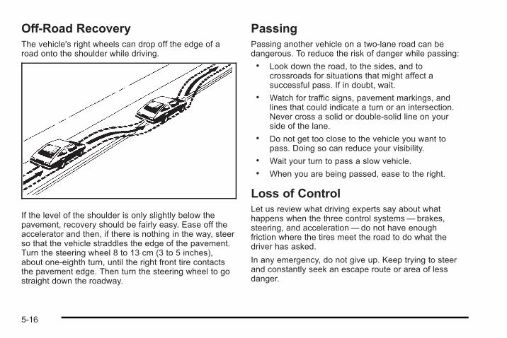
Off-Road RecoveryThe vehicle's right wheels can drop off the edge of aroad onto the shoulder while driving.
If the level of the shoulder is only slightly below thepavement, recovery should be fairly easy. Ease off theaccelerator and then, if there is nothing in the way, steerso that the vehicle straddles the edge of the pavement.Turn the steering wheel 8 to 13 cm (3 to 5 inches),about one-eighth turn, until the right front tire contactsthe pavement edge. Then turn the steering wheel to gostraight down the roadway.
PassingPassing another vehicle on a two-lane road can bedangerous. To reduce the risk of danger while passing:. Look down the road, to the sides, and to
crossroads for situations that might affect asuccessful pass. If in doubt, wait.
. Watch for traffic signs, pavement markings, andlines that could indicate a turn or an intersection.Never cross a solid or double-solid line on yourside of the lane.
. Do not get too close to the vehicle you want topass. Doing so can reduce your visibility.
. Wait your turn to pass a slow vehicle.
. When you are being passed, ease to the right.
Loss of ControlLet us review what driving experts say about whathappens when the three control systems— brakes,steering, and acceleration— do not have enoughfriction where the tires meet the road to do what thedriver has asked.
In any emergency, do not give up. Keep trying to steerand constantly seek an escape route or area of lessdanger.
5-16
SkiddingIn a skid, a driver can lose control of the vehicle.Defensive drivers avoid most skids by takingreasonable care suited to existing conditions, and bynot overdriving those conditions. But skids are alwayspossible.
The three types of skids correspond to the vehicle'sthree control systems. In the braking skid, the wheelsare not rolling. In the steering or cornering skid, toomuch speed or steering in a curve causes tires to slipand lose cornering force. And in the acceleration skid,too much throttle causes the driving wheels to spin.
If the vehicle has the Traction Control System (TCS) orthe Enhanced Traction System (ETS), remember: Ithelps to avoid only the acceleration skid. See TractionControl System (TCS) on page 5‑9 or EnhancedTraction System (ETS) on page 5‑12. If the vehicledoes not have TCS or ETS, or if the system is off, thenan acceleration skid is best handled by easing your footoff the accelerator pedal.
If the vehicle starts to slide, ease your foot off theaccelerator pedal and quickly steer the way you wantthe vehicle to go. If you start steering quickly enough,the vehicle may straighten out. Always be ready for asecond skid if it occurs.
If the vehicle has Electronic Stability Control (ESC), theESC might activate. See Electronic Stability Control(ESC) on page 5‑6.
Of course, traction is reduced when water, snow, ice,gravel, or other material is on the road. For safety, slowdown and adjust your driving to these conditions. It isimportant to slow down on slippery surfaces becausestopping distance will be longer and vehicle controlmore limited.
While driving on a surface with reduced traction, tryyour best to avoid sudden steering, acceleration,or braking, including reducing vehicle speed by shiftingto a lower gear. Any sudden changes could cause thetires to slide. You may not realize the surface is slipperyuntil the vehicle is skidding. Learn to recognize warningclues— such as enough water, ice, or packed snow onthe road to make a mirrored surface— and slow downwhen you have any doubt.
If the vehicle has the Antilock Brake System (ABS),remember: It helps avoid only the braking skid. If thevehicle does not have ABS, then in a braking skid,where the wheels are no longer rolling, release enoughpressure on the brakes to get the wheels rolling again.This restores steering control. Push the brake pedaldown steadily when you have to stop suddenly. As longas the wheels are rolling, you will have steering control.
5-17
Racing or Other Competitive DrivingSee your warranty book before using your vehicle forracing or other competitive driving. After reviewing yourwarranty book, please see the GM Performance Partswebsite or catalog and contact the race sanctioningbodies, for example Sports Car Club of America(SCCA) or Grand American, for parts and equipmentrequired for racing or other competitive driving.
Driving at NightNight driving is more dangerous than day drivingbecause some drivers are likely to be impaired — byalcohol or drugs, with night vision problems, or byfatigue.
Night driving tips include:. Drive defensively.. Do not drink and drive.. Reduce headlamp glare by adjusting the inside
rearview mirror.. Slow down and keep more space between you and
other vehicles because headlamps can only lightup so much road ahead.
. Watch for animals.
. When tired, pull off the road.
. Do not wear sunglasses.
. Avoid staring directly into approaching headlamps.
. Keep the windshield and all glass on your vehicleclean — inside and out.
. Keep your eyes moving, especially during turnsor curves.
No one can see as well at night as in the daytime.But, as we get older, these differences increase.A 50-year-old driver might need at least twice as muchlight to see the same thing at night as a 20-year-old.
Driving in Rain and on Wet RoadsRain and wet roads can reduce vehicle traction andaffect your ability to stop and accelerate. Always driveslower in these types of driving conditions and avoiddriving through large puddles and deep-standing orflowing water.
5-18
{ WARNING:
Wet brakes can cause crashes. They might notwork as well in a quick stop and could causepulling to one side. You could lose control of thevehicle.
After driving through a large puddle of water or acar/vehicle wash, lightly apply the brake pedaluntil the brakes work normally.
Flowing or rushing water creates strong forces.Driving through flowing water could cause yourvehicle to be carried away. If this happens, youand other vehicle occupants could drown. Do notignore police warnings and be very cautious abouttrying to drive through flowing water.
HydroplaningHydroplaning is dangerous. Water can build up underyour vehicle's tires so they actually ride on the water.This can happen if the road is wet enough and you aregoing fast enough. When your vehicle is hydroplaning,it has little or no contact with the road.
There is no hard and fast rule about hydroplaning.The best advice is to slow down when the road is wet.
Other Rainy Weather TipsBesides slowing down, other wet weather driving tipsinclude:. Allow extra following distance.. Pass with caution.. Keep windshield wiping equipment in good shape.. Keep the windshield washer fluid reservoir filled.. Have good tires with proper tread depth. See Tires
on page 6‑54.. Turn off cruise control.
5-19
Before Leaving on a Long TripTo prepare your vehicle for a long trip, consider havingit serviced by your dealer/retailer before departing.
Things to check on your own include:. Windshield Washer Fluid: Reservoir full?
Windows clean — inside and outside?. Wiper Blades: In good shape?. Fuel, Engine Oil, Other Fluids: All levels checked?. Lamps: Do they all work and are lenses clean?. Tires: Are treads good? Are tires inflated to
recommended pressure?. Weather and Maps: Safe to travel?
Have up-to-date maps?
Highway HypnosisAlways be alert and pay attention to your surroundingswhile driving. If you become tired or sleepy, find a safeplace to park your vehicle and rest.
Other driving tips include:. Keep the vehicle well ventilated.. Keep interior temperature cool.. Keep your eyes moving — scan the road ahead
and to the sides.. Check the rearview mirror and vehicle
instruments often.
Hill and Mountain RoadsDriving on steep hills or through mountains is differentthan driving on flat or rolling terrain. Tips for driving inthese conditions include:. Keep the vehicle serviced and in good shape.. Check all fluid levels and brakes, tires, cooling
system, and transmission.. Going down steep or long hills, shift to a
lower gear.
5-20
{ WARNING:
If you do not shift down, the brakes could get sohot that they would not work well. You would thenhave poor braking or even none going down a hill.You could crash. Shift down to let the engineassist the brakes on a steep downhill slope.
{ WARNING:
Coasting downhill in N (Neutral) or with theignition off is dangerous. The brakes will have todo all the work of slowing down and they couldget so hot that they would not work well.
(Continued)
WARNING: (Continued)
You would then have poor braking or even nonegoing down a hill. You could crash. Always havethe engine running and the vehicle in gear whengoing downhill.
. Stay in your own lane. Do not swing wide or cutacross the center of the road. Drive at speeds thatlet you stay in your own lane.
. Top of hills: Be alert — something could be in yourlane (stalled car, accident).
. Pay attention to special road signs (falling rocksarea, winding roads, long grades, passing orno-passing zones) and take appropriate action.
5-21
Winter Driving
Driving on Snow or IceDrive carefully when there is snow or ice between thetires and the road, creating less traction or grip. Wet icecan occur at about 32°F (0°C) when freezing rainbegins to fall, resulting in even less traction. Avoiddriving on wet ice or in freezing rain until roads can betreated with salt or sand.
Drive with caution, whatever the condition. Accelerategently so traction is not lost. Accelerating too quicklycauses the wheels to spin and makes the surface underthe tires slick, so there is even less traction.
Try not to break the fragile traction. If you accelerate toofast, the drive wheels will spin and polish the surfaceunder the tires even more.
If the vehicle has the Traction Control System (TCS) onpage 5‑9 or Enhanced Traction System (ETS) onpage 5‑12, it improves the ability to accelerate onslippery roads, but slow down and adjust your driving tothe road conditions. When driving through deep snow,turn off the ETS, if equipped, to help maintain vehiclemotion at lower speeds.
The Antilock Brake System (ABS) on page 5‑4improves vehicle stability during hard stops on aslippery roads, but whether the vehicle has ABS or not,apply the brakes sooner than when on dry pavement.
Without ABS, if the vehicle begins to slide, let up on thebrake pedal a little and apply steady pedal pressure toget the most traction. On vehicles without ABS, brakingso hard that the wheels stop rolling can cause thevehicle to slide — brake so the wheels always keeprolling so you can still steer.
Allow greater following distance on any slippery roadand watch for slippery spots. Icy patches can occur onotherwise clear roads in shaded areas. The surface of acurve or an overpass can remain icy when thesurrounding roads are clear. Avoid sudden steeringmaneuvers and braking while on ice.
Turn off cruise control, if equipped, on slippery surfaces.
Blizzard ConditionsBeing stuck in snow can be in a serious situation.Stay with the vehicle unless there is help nearby.If possible, use the Roadside Assistance Program onpage 8‑8 . To get help and keep everyone in thevehicle safe:. Turn on the Hazard Warning Flashers on
page 4‑3 .. Tie a red cloth to an outside mirror.
5-22
{ WARNING:
Snow can trap engine exhaust under the vehicle.This may cause exhaust gases to get inside.Engine exhaust contains carbon monoxide (CO)which cannot be seen or smelled. It can causeunconsciousness and even death.
If the vehicle is stuck in the snow:. Clear away snow from around the base of
your vehicle, especially any that is blockingthe exhaust pipe.
. Check again from time to time to be suresnow does not collect there.
. Open a window about 5 cm (two inches) onthe side of the vehicle that is away from thewind to bring in fresh air.
. Fully open the air outlets on or under theinstrument panel.
. Adjust the Climate Control system to a settingthat circulates the air inside the vehicle andset the fan speed to the highest setting.See Climate Control System in the Index.
(Continued)
WARNING: (Continued)
For more information about carbon monoxide, seeEngine Exhaust on page 3‑35.
Snow can trap exhaust gases under your vehicle.This can cause deadly CO (carbon monoxide) gasto get inside. CO could overcome you and kill you.You cannot see it or smell it, so you might notknow it is in your vehicle. Clear away snow fromaround the base of your vehicle, especially anythat is blocking the exhaust.
Run the engine for short periods only as needed tokeep warm, but be careful.
To save fuel, run the engine for only short periods asneeded to warm the vehicle and then shut the engineoff and close the window most of the way to save heat.Repeat this until help arrives but only when you feelreally uncomfortable from the cold. Moving about tokeep warm also helps.
If it takes some time for help to arrive, now and thenwhen you run the engine, push the accelerator pedalslightly so the engine runs faster than the idle speed.This keeps the battery charged to restart the vehicleand to signal for help with the headlamps. Do this aslittle as possible to save fuel.
5-23
If Your Vehicle is Stuck in Sand,Mud, Ice, or SnowSlowly and cautiously spin the wheels to free thevehicle when stuck in sand, mud, ice, or snow. SeeRocking Your Vehicle to Get It Out on page 5‑24.
If the vehicle has a traction system, it can often help tofree a stuck vehicle. Refer to the vehicle's tractionsystem in the Index. If stuck too severely for the tractionsystem to free the vehicle, turn the traction system offand use the rocking method.
{ WARNING:
If the vehicle's tires spin at high speed, they canexplode, and you or others could be injured.The vehicle can overheat, causing an enginecompartment fire or other damage. Spin thewheels as little as possible and avoid going above55 km/h (35 mph) as shown on the speedometer.
For information about using tire chains on the vehicle,see Tire Chains on page 6‑78.
Rocking Your Vehicle to Get It OutTurn the steering wheel left and right to clear the areaaround the front wheels. Turn off any traction system.Shift back and forth between R (Reverse) and a forwardgear, or with a manual transmission, between 1 (First) or2 (Second) and R (Reverse), spinning the wheels aslittle as possible. To prevent transmission wear, waituntil the wheels stop spinning before shifting gears.Release the accelerator pedal while shifting, and presslightly on the accelerator pedal when the transmission isin gear. Slowly spinning the wheels in the forward andreverse directions causes a rocking motion that couldfree the vehicle. If that does not get the vehicle out aftera few tries, it might need to be towed out. If the vehicledoes need to be towed out, see Towing Your Vehicle onpage 5‑30.
5-24
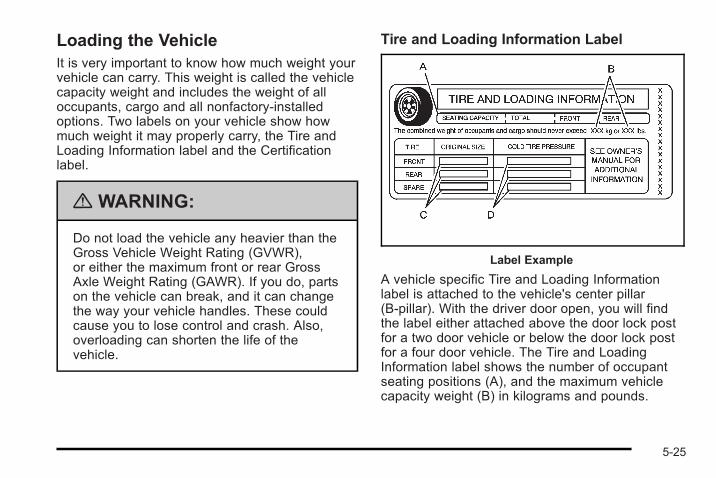
Loading the VehicleIt is very important to know how much weight yourvehicle can carry. This weight is called the vehiclecapacity weight and includes the weight of alloccupants, cargo and all nonfactory-installedoptions. Two labels on your vehicle show howmuch weight it may properly carry, the Tire andLoading Information label and the Certificationlabel.
{ WARNING:
Do not load the vehicle any heavier than theGross Vehicle Weight Rating (GVWR),or either the maximum front or rear GrossAxle Weight Rating (GAWR). If you do, partson the vehicle can break, and it can changethe way your vehicle handles. These couldcause you to lose control and crash. Also,overloading can shorten the life of thevehicle.
Tire and Loading Information Label
Label Example
A vehicle specific Tire and Loading Informationlabel is attached to the vehicle's center pillar(B-pillar). With the driver door open, you will findthe label either attached above the door lock postfor a two door vehicle or below the door lock postfor a four door vehicle. The Tire and LoadingInformation label shows the number of occupantseating positions (A), and the maximum vehiclecapacity weight (B) in kilograms and pounds.
5-25
The Tire and Loading Information label alsoshows the tire size of the original equipmenttires (C) and the recommended cold tire inflationpressures (D). For more information on tires andinflation see Tires on page 6‑54 and Inflation - TirePressure on page 6‑63 .
There is also important loading information on theCertification label. It tells you the Gross VehicleWeight Rating (GVWR) and the Gross AxleWeight Rating (GAWR) for the front and rear axle;see “Certification Label” later in this section.
Steps for Determining Correct Load Limit1. Locate the statement “The combined weight
of occupants and cargo should never exceedXXX kg or XXX lbs” on your vehicle's placard.
2. Determine the combined weight of the driverand passengers that will be riding in yourvehicle.
3. Subtract the combined weight of the driverand passengers from XXX kg or XXX lbs.
4. The resulting figure equals the availableamount of cargo and luggage load capacity.For example, if the “XXX” amount equals1400 lbs and there will be five 150 lbpassengers in your vehicle, the amount ofavailable cargo and luggage load capacity is650 lbs (1400 − 750 (5 x 150) = 650 lbs).
5. Determine the combined weight of luggageand cargo being loaded on the vehicle.That weight may not safely exceed theavailable cargo and luggage load capacitycalculated in Step 4.
6. If your vehicle will be towing a trailer, the loadfrom your trailer will be transferred to yourvehicle. Consult this manual to determinehow this reduces the available cargo andluggage load capacity of your vehicle.
If your vehicle can tow a trailer, see Towing aTrailer (Automatic Transmission) on page 5‑33or Towing a Trailer (Manual Transmission) onpage 5‑39 for important information ontowing a trailer, towing safety rules, andtrailering tips.
5-26
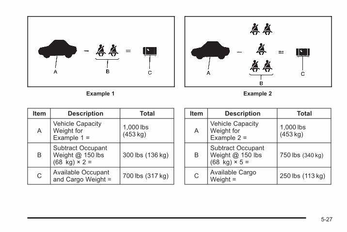
Example 1
Item Description Total
AVehicle CapacityWeight forExample 1 =
1,000 lbs(453 kg)
BSubtract OccupantWeight @ 150 lbs(68 kg) × 2 =
300 lbs (136 kg)
C Available Occupantand Cargo Weight =
700 lbs (317 kg)
Example 2
Item Description Total
AVehicle CapacityWeight forExample 2 =
1,000 lbs(453 kg)
BSubtract OccupantWeight @ 150 lbs(68 kg) × 5 =
750 lbs (340 kg)
C Available CargoWeight =
250 lbs (113 kg)
5-27
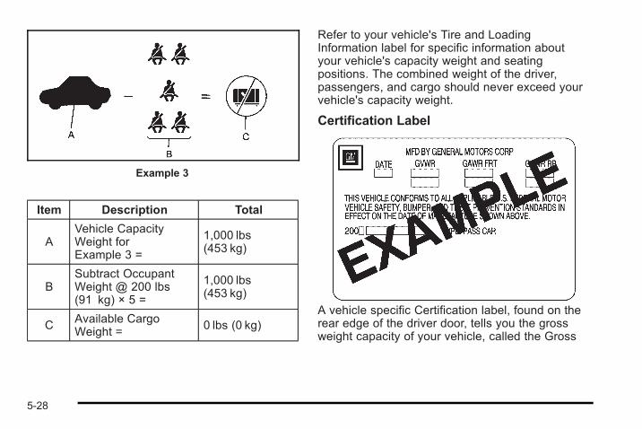
Example 3
Item Description Total
AVehicle CapacityWeight forExample 3 =
1,000 lbs(453 kg)
BSubtract OccupantWeight @ 200 lbs(91 kg) × 5 =
1,000 lbs(453 kg)
C Available CargoWeight =
0 lbs (0 kg)
Refer to your vehicle's Tire and LoadingInformation label for specific information aboutyour vehicle's capacity weight and seatingpositions. The combined weight of the driver,passengers, and cargo should never exceed yourvehicle's capacity weight.
Certification Label
A vehicle specific Certification label, found on therear edge of the driver door, tells you the grossweight capacity of your vehicle, called the Gross
5-28
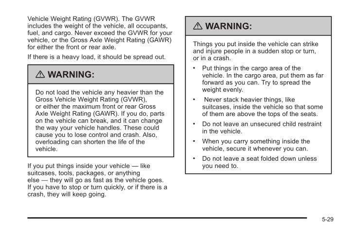
Vehicle Weight Rating (GVWR). The GVWRincludes the weight of the vehicle, all occupants,fuel, and cargo. Never exceed the GVWR for yourvehicle, or the Gross Axle Weight Rating (GAWR)for either the front or rear axle.
If there is a heavy load, it should be spread out.
{ WARNING:
Do not load the vehicle any heavier than theGross Vehicle Weight Rating (GVWR),or either the maximum front or rear GrossAxle Weight Rating (GAWR). If you do, partson the vehicle can break, and it can changethe way your vehicle handles. These couldcause you to lose control and crash. Also,overloading can shorten the life of thevehicle.
If you put things inside your vehicle — likesuitcases, tools, packages, or anythingelse — they will go as fast as the vehicle goes.If you have to stop or turn quickly, or if there is acrash, they will keep going.
{ WARNING:
Things you put inside the vehicle can strikeand injure people in a sudden stop or turn,or in a crash.. Put things in the cargo area of the
vehicle. In the cargo area, put them as farforward as you can. Try to spread theweight evenly.
. Never stack heavier things, likesuitcases, inside the vehicle so that someof them are above the tops of the seats.
. Do not leave an unsecured child restraintin the vehicle.
. When you carry something inside thevehicle, secure it whenever you can.
. Do not leave a seat folded down unlessyou need to.
5-29
Towing
Towing Your VehicleTo avoid damage, the disabled vehicle should be towedwith all four wheels off the ground. Consult your dealer/retailer or a professional towing service if the disabledvehicle must be towed. See Roadside AssistanceProgram on page 8‑8.
To tow the vehicle behind another vehicle forrecreational purposes, such as behind a motorhome,see “Recreational Vehicle Towing” following.
Recreational Vehicle TowingRecreational vehicle towing means towing the vehiclebehind another vehicle – such as behind a motorhome.The two most common types of recreational vehicletowing are known as dinghy towing and dolly towing.Dinghy towing is towing the vehicle with all four wheelson the ground. Dolly towing is towing the vehicle withtwo wheels on the ground and two wheels up on adevice known as a dolly.
Here are some important things to consider beforerecreational vehicle towing:. What is the towing capacity of the towing vehicle?
Be sure to read the tow vehicle manufacturer'srecommendations.
. What is the distance that will be travelled? Somevehicles have restrictions on how far and how longthey can tow.
. Is the proper towing equipment going to be used?See your dealer/retailer or trailering professionalfor additional advice and equipmentrecommendations.
. Is the vehicle ready to be towed? Just as preparingthe vehicle for a long trip, make sure the vehicle isprepared to be towed. See Before Leaving on aLong Trip on page 5‑20.
5-30
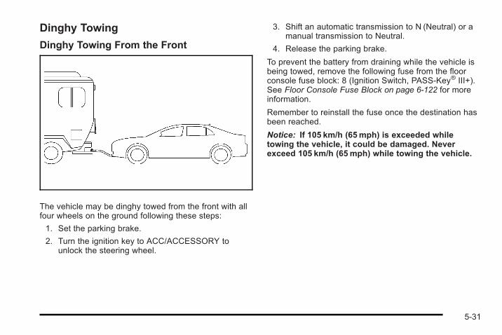
Dinghy Towing
Dinghy Towing From the Front
The vehicle may be dinghy towed from the front with allfour wheels on the ground following these steps:
1. Set the parking brake.
2. Turn the ignition key to ACC/ACCESSORY tounlock the steering wheel.
3. Shift an automatic transmission to N (Neutral) or amanual transmission to Neutral.
4. Release the parking brake.
To prevent the battery from draining while the vehicle isbeing towed, remove the following fuse from the floorconsole fuse block: 8 (Ignition Switch, PASS-Key® III+).See Floor Console Fuse Block on page 6‑122 for moreinformation.
Remember to reinstall the fuse once the destination hasbeen reached.
Notice: If 105 km/h (65mph) is exceeded whiletowing the vehicle, it could be damaged. Neverexceed 105 km/h (65mph) while towing the vehicle.
5-31
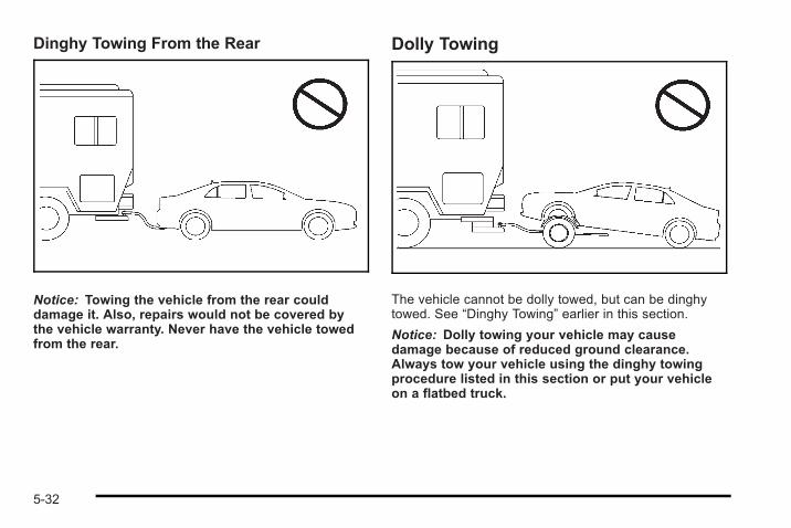
Dinghy Towing From the Rear
Notice: Towing the vehicle from the rear coulddamage it. Also, repairs would not be covered bythe vehicle warranty. Never have the vehicle towedfrom the rear.
Dolly Towing
The vehicle cannot be dolly towed, but can be dinghytowed. See “Dinghy Towing” earlier in this section.
Notice: Dolly towing your vehicle may causedamage because of reduced ground clearance.Always tow your vehicle using the dinghy towingprocedure listed in this section or put your vehicleon a flatbed truck.
5-32
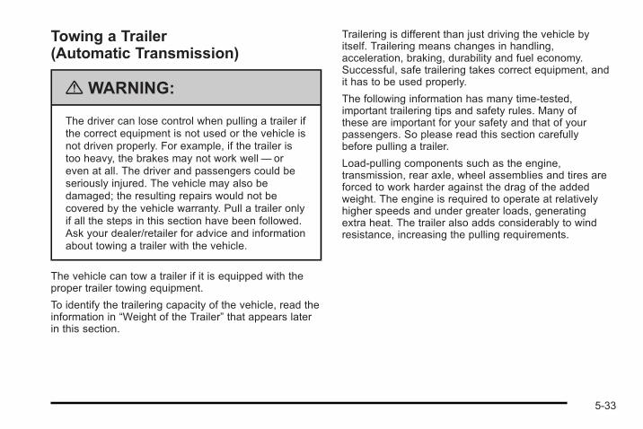
Towing a Trailer(Automatic Transmission)
{ WARNING:
The driver can lose control when pulling a trailer ifthe correct equipment is not used or the vehicle isnot driven properly. For example, if the trailer istoo heavy, the brakes may not work well— oreven at all. The driver and passengers could beseriously injured. The vehicle may also bedamaged; the resulting repairs would not becovered by the vehicle warranty. Pull a trailer onlyif all the steps in this section have been followed.Ask your dealer/retailer for advice and informationabout towing a trailer with the vehicle.
The vehicle can tow a trailer if it is equipped with theproper trailer towing equipment.
To identify the trailering capacity of the vehicle, read theinformation in “Weight of the Trailer” that appears laterin this section.
Trailering is different than just driving the vehicle byitself. Trailering means changes in handling,acceleration, braking, durability and fuel economy.Successful, safe trailering takes correct equipment, andit has to be used properly.
The following information has many time-tested,important trailering tips and safety rules. Many ofthese are important for your safety and that of yourpassengers. So please read this section carefullybefore pulling a trailer.
Load-pulling components such as the engine,transmission, rear axle, wheel assemblies and tires areforced to work harder against the drag of the addedweight. The engine is required to operate at relativelyhigher speeds and under greater loads, generatingextra heat. The trailer also adds considerably to windresistance, increasing the pulling requirements.
5-33
Pulling A TrailerIf you do, here are some important points:. There are many different laws, including speed
limit restrictions, having to do with trailering.Make sure the rig will be legal, not only where youlive but also where you will be driving. A goodsource for this information can be state orprovincial police.
. Do not tow a trailer at all during the first1,000 miles (1 600 km) the new vehicle is driven.The engine, transmission or other parts could bedamaged.
. Then, during the first 500 miles (800 km) that atrailer is towed, do not drive over 50 mph (80 km/h)and do not make starts at full throttle. This helpsthe engine and other parts of the vehicle wear in atthe heavier loads.
. Obey speed limit restrictions when towing a trailer.Do not drive faster than the maximum postedspeed for trailers, or no more than 55 mph(90 km/h), to save wear on the vehicle's parts.
. Do not tow when the outside air temperature isabove 100°F (38°C).
. Do not tow more than 1,000 miles (1 600 km)per year.
Three important considerations have to do with weight:. The weight of the trailer. The weight of the trailer tongue. The total weight on the vehicle's tires
Weight of the TrailerHow heavy can a trailer safely be?
It should never weigh more than 1,000 lbs (450 kg).But even that can be too heavy.
It depends on how the rig is used. For example, speed,altitude, road grades, outside temperature and howmuch the vehicle is used to pull a trailer are allimportant. It can depend on any special equipment onthe vehicle, and the amount of tongue weight thevehicle can carry. See “Weight of the Trailer Tongue”later in this section for more information.
Maximum trailer weight is calculated assuming only thedriver is in the tow vehicle and it has all the requiredtrailering equipment. The weight of additional optionalequipment, passengers and cargo in the tow vehiclemust be subtracted from the maximum trailer weight.
Ask your dealer/retailer for our trailering information oradvice, or write us at our Customer Assistance Offices.See Customer Assistance Offices on page 8‑6 formore information.
5-34
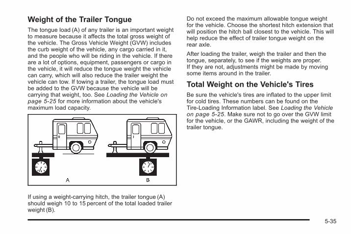
Weight of the Trailer TongueThe tongue load (A) of any trailer is an important weightto measure because it affects the total gross weight ofthe vehicle. The Gross Vehicle Weight (GVW) includesthe curb weight of the vehicle, any cargo carried in it,and the people who will be riding in the vehicle. If thereare a lot of options, equipment, passengers or cargo inthe vehicle, it will reduce the tongue weight the vehiclecan carry, which will also reduce the trailer weight thevehicle can tow. If towing a trailer, the tongue load mustbe added to the GVW because the vehicle will becarrying that weight, too. See Loading the Vehicle onpage 5‑25 for more information about the vehicle'smaximum load capacity.
If using a weight-carrying hitch, the trailer tongue (A)should weigh 10 to 15 percent of the total loaded trailerweight (B).
Do not exceed the maximum allowable tongue weightfor the vehicle. Choose the shortest hitch extension thatwill position the hitch ball closest to the vehicle. This willhelp reduce the effect of trailer tongue weight on therear axle.
After loading the trailer, weigh the trailer and then thetongue, separately, to see if the weights are proper.If they are not, adjustments might be made by movingsome items around in the trailer.
Total Weight on the Vehicle's TiresBe sure the vehicle's tires are inflated to the upper limitfor cold tires. These numbers can be found on theTire-Loading Information label. See Loading the Vehicleon page 5‑25. Make sure not to go over the GVW limitfor the vehicle, or the GAWR, including the weight of thetrailer tongue.
5-35
HitchesIt is important to have the correct hitch equipment.Crosswinds, large trucks going by and rough roads area few reasons why the right hitch is needed.. The rear bumper on the vehicle is not intended
for hitches. Do not attach rental hitches orother bumper-type hitches to it. Use only aframe-mounted hitch that does not attach to thebumper.
. Will there be any holes in the body of the vehicleafter installing a trailer hitch? If there are, then besure to seal the holes later when the hitch isremoved. If the holes are not sealed, deadlycarbon monoxide (CO) from exhaust can get intothe vehicle. See Engine Exhaust on page 3‑35.Dirt and water can also enter the vehicle.
Safety ChainsAlways attach chains between the vehicle and thetrailer. Cross the safety chains under the tongue of thetrailer to help prevent the tongue from contacting theroad if it becomes separated from the hitch. Alwaysleave just enough slack so the rig can turn. Never allowsafety chains to drag on the ground.
Trailer BrakesDoes the trailer have its own brakes? Be sure to readand follow the instructions for the trailer brakes so theyare installed, adjusted and maintained properly.
Driving with a TrailerTowing a trailer requires a certain amount ofexperience. Get to know the rig before setting out forthe open road. Get acquainted with the feel of handlingand braking with the added weight of the trailer. Andalways keep in mind that the vehicle you are driving isnow longer and not as responsive as the vehicle isby itself.
Before starting, check all trailer hitch parts andattachments, safety chains, electrical connectors,lamps, tires and mirror adjustments. If the trailer haselectric brakes, start the vehicle and trailer moving andthen apply the trailer brake controller by hand to be surethe brakes are working. This checks the electricalconnection at the same time.
During the trip, check occasionally to be sure that theload is secure, and that the lamps and any trailerbrakes are still working.
5-36
Following DistanceStay at least twice as far behind the vehicle ahead asyou would when driving the vehicle without a trailer.This can help to avoid situations that require heavybraking and sudden turns.
PassingMore passing distance is needed when towing a trailer.Because the rig is longer, it is necessary to go muchfarther beyond the passed vehicle before returning tothe lane.
Backing UpHold the bottom of the steering wheel with one hand.Then, to move the trailer to the left, move that hand tothe left. To move the trailer to the right, move your handto the right. Always back up slowly and, if possible,have someone guide you.
Making TurnsNotice: Making very sharp turns while traileringcould cause the trailer to come in contact withthe vehicle. The vehicle could be damaged.Avoid making very sharp turns while trailering.
When turning with a trailer, make wider turns thannormal. Do this so the trailer will not strike softshoulders, curbs, road signs, trees or other objects.Avoid jerky or sudden maneuvers. Signal well inadvance.
Turn Signals When Towing a TrailerThe arrows on the instrument panel flash wheneversignaling a turn or lane change. Properly hooked up,the trailer lamps also flash, telling other drivers thevehicle is turning, changing lanes or stopping.
When towing a trailer, the arrows on the instrumentpanel flash for turns even if the bulbs on the trailer areburned out. For this reason you may think other driversare seeing the signal when they are not. It is importantto check occasionally to be sure the trailer bulbs arestill working.
5-37
Driving on GradesNotice: Do not tow on steep continuous gradesexceeding 6 miles (9.6 km). Extended, higher thannormal engine and transmission temperatures mayresult and damage the vehicle. Frequent stops arevery important to allow the engine and transmissionto cool.
Reduce speed and shift to a lower gear before startingdown a long or steep downgrade. If the transmission isnot shifted down, the brakes might have to be used somuch that they would get hot and no longer work well.
Pay attention to the engine coolant gage. If the indicatoris in the red area, turn off the air conditioning to reduceengine load. See Engine Overheating on page 6‑33.
When towing under severe conditions such as hotambient temperatures or steep grades, the vehicle mayexperience more transmission shifting. A COOLINGMODE ON message may also appear in the DIC.This alerts the driver that the shifting mode is inprogress and is aiding engine cooling. See DICWarnings and Messages on page 4‑40 for moreinformation.
Parking on Hills
{ WARNING:
Parking the vehicle on a hill with the trailerattached can be dangerous. If something goeswrong, the rig could start to move. People can beinjured, and both the vehicle and the trailer can bedamaged. When possible, always park the rig ona flat surface.
If parking the rig on a hill:
1. Press the brake pedal, but do not shift into P (Park)yet. Turn the wheels into the curb if facing downhillor into traffic if facing uphill.
2. Have someone place chocks under the trailerwheels.
3. When the wheel chocks are in place, release thebrake pedal until the chocks absorb the load.
4. Reapply the brake pedal. Then apply the parkingbrake and shift into P (Park).
5. Release the brake pedal.
5-38
Leaving After Parking on a Hill1. Apply and hold the brake pedal while you:
. Start the engine.
. Shift into a gear.
. Release the parking brake.
2. Let up on the brake pedal.
3. Drive slowly until the trailer is clear of the chocks.
4. Stop and have someone pick up and store thechocks.
Maintenance When Trailer TowingThe vehicle needs service more often when pulling atrailer. See Scheduled Maintenance on page 7‑3 formore on this. Things that are especially important intrailer operation are automatic transmission fluid, engineoil, axle lubricant, belts, cooling system and brakesystem. It is a good idea to inspect these before andduring the trip.
Check periodically to see that all hitch nuts and boltsare tight.
Engine Cooling When Trailer TowingThe cooling system may temporarily overheat duringsevere operating conditions. See Engine Overheatingon page 6‑33.
Towing a Trailer(Manual Transmission)Do not tow a trailer if the vehicle is equipped with amanual transmission.
5-39

2 NOTES
5-40
Section 6 Service and Appearance Care
Service . . . . . . . . . . . . . . . . . . . . . . . . . . . . . . . . . . . . . . . . . . . . . 6-4Accessories and Modifications . . . . . . . . . . . . . . . . . . 6-4California Proposition 65 Warning . . . . . . . . . . . . . . . 6-5California Perchlorate MaterialsRequirements . . . . . . . . . . . . . . . . . . . . . . . . . . . . . . . . . 6-5
Doing Your Own Service Work . . . . . . . . . . . . . . . . . . 6-5Adding Equipment to the Outside of theVehicle . . . . . . . . . . . . . . . . . . . . . . . . . . . . . . . . . . . . . . . . 6-6
Fuel . . . . . . . . . . . . . . . . . . . . . . . . . . . . . . . . . . . . . . . . . . . . . . . . . 6-6Gasoline Octane . . . . . . . . . . . . . . . . . . . . . . . . . . . . . . . . 6-7Gasoline Specifications . . . . . . . . . . . . . . . . . . . . . . . . . 6-8California Fuel . . . . . . . . . . . . . . . . . . . . . . . . . . . . . . . . . . 6-8Additives . . . . . . . . . . . . . . . . . . . . . . . . . . . . . . . . . . . . . . . . 6-8Fuels in Foreign Countries . . . . . . . . . . . . . . . . . . . . . . 6-9Filling the Tank . . . . . . . . . . . . . . . . . . . . . . . . . . . . . . . . 6-10Filling a Portable Fuel Container . . . . . . . . . . . . . . . 6-12
Checking Things Under the Hood . . . . . . . . . . . . . . . 6-12Hood Release . . . . . . . . . . . . . . . . . . . . . . . . . . . . . . . . . 6-13Engine Compartment Overview . . . . . . . . . . . . . . . . 6-14Engine Oil . . . . . . . . . . . . . . . . . . . . . . . . . . . . . . . . . . . . . 6-17Engine Oil Life System . . . . . . . . . . . . . . . . . . . . . . . . 6-21Engine Air Cleaner/Filter
(2.0L Turbo Engine) . . . . . . . . . . . . . . . . . . . . . . . . . 6-23
Engine Air Cleaner/Filter (2.2L Engine) . . . . . . . . 6-25Automatic Transmission Fluid . . . . . . . . . . . . . . . . . . 6-27Manual Transmission Fluid . . . . . . . . . . . . . . . . . . . . 6-27Hydraulic Clutch . . . . . . . . . . . . . . . . . . . . . . . . . . . . . . . 6-27Cooling System . . . . . . . . . . . . . . . . . . . . . . . . . . . . . . . . 6-28Engine Coolant . . . . . . . . . . . . . . . . . . . . . . . . . . . . . . . . 6-29Engine Overheating . . . . . . . . . . . . . . . . . . . . . . . . . . . 6-34Windshield Washer Fluid . . . . . . . . . . . . . . . . . . . . . . 6-36Brakes . . . . . . . . . . . . . . . . . . . . . . . . . . . . . . . . . . . . . . . . . 6-37Battery . . . . . . . . . . . . . . . . . . . . . . . . . . . . . . . . . . . . . . . . . 6-40Jump Starting . . . . . . . . . . . . . . . . . . . . . . . . . . . . . . . . . . 6-41
Headlamp Aiming . . . . . . . . . . . . . . . . . . . . . . . . . . . . . . . . 6-45
Bulb Replacement . . . . . . . . . . . . . . . . . . . . . . . . . . . . . . . . 6-48Halogen Bulbs . . . . . . . . . . . . . . . . . . . . . . . . . . . . . . . . . 6-48Headlamps, Front Turn Signal, Sidemarker,and Parking Lamps . . . . . . . . . . . . . . . . . . . . . . . . . . 6-48
Center High-Mounted Stoplamp (CHMSL) . . . . . 6-50Taillamps and Turn Signal Lamps (Coupe) . . . . . 6-50Taillamps, Turn Signal, Stoplamps andBack-up Lamps (Sedan) . . . . . . . . . . . . . . . . . . . . . 6-51
Back-Up Lamps (Coupe) . . . . . . . . . . . . . . . . . . . . . . 6-52License Plate Lamp . . . . . . . . . . . . . . . . . . . . . . . . . . . . 6-53Replacement Bulbs . . . . . . . . . . . . . . . . . . . . . . . . . . . . 6-54
6-1
Section 6 Service and Appearance Care
Windshield Wiper Blade Replacement . . . . . . . . . . . 6-54
Tires . . . . . . . . . . . . . . . . . . . . . . . . . . . . . . . . . . . . . . . . . . . . . . . 6-55Winter Tires . . . . . . . . . . . . . . . . . . . . . . . . . . . . . . . . . . . . 6-56Tire Sidewall Labeling . . . . . . . . . . . . . . . . . . . . . . . . . 6-57Tire Terminology and Definitions . . . . . . . . . . . . . . . 6-61Inflation - Tire Pressure . . . . . . . . . . . . . . . . . . . . . . . . 6-64Tire Pressure Monitor System . . . . . . . . . . . . . . . . . 6-65Tire Pressure Monitor Operation . . . . . . . . . . . . . . . 6-67Tire Inspection and Rotation . . . . . . . . . . . . . . . . . . . 6-71When It Is Time for New Tires . . . . . . . . . . . . . . . . . 6-73Buying New Tires . . . . . . . . . . . . . . . . . . . . . . . . . . . . . . 6-73Different Size Tires and Wheels . . . . . . . . . . . . . . . 6-75Uniform Tire Quality Grading . . . . . . . . . . . . . . . . . . . 6-76Wheel Alignment and Tire Balance . . . . . . . . . . . . 6-77Wheel Replacement . . . . . . . . . . . . . . . . . . . . . . . . . . . 6-77Tire Chains . . . . . . . . . . . . . . . . . . . . . . . . . . . . . . . . . . . . 6-79If a Tire Goes Flat . . . . . . . . . . . . . . . . . . . . . . . . . . . . . 6-79Tire Sealant and Compressor Kit . . . . . . . . . . . . . . 6-81Tire Sealant and Compressor Kit Storage . . . . . . 6-88Changing a Flat Tire . . . . . . . . . . . . . . . . . . . . . . . . . . . 6-89Removing the Spare Tire and Tools . . . . . . . . . . . . 6-90Removing the Flat Tire and Installing the
Spare Tire (All Models Except SS) . . . . . . . . . . 6-95
Removing the Flat Tire and Installing theSpare Tire (SS Model) . . . . . . . . . . . . . . . . . . . . . 6-100
Storing a Flat or Spare Tire and Tools . . . . . . . . 6-109Compact Spare Tire . . . . . . . . . . . . . . . . . . . . . . . . . . 6-112
Appearance Care . . . . . . . . . . . . . . . . . . . . . . . . . . . . . . . . 6-113Interior Cleaning . . . . . . . . . . . . . . . . . . . . . . . . . . . . . 6-113Fabric/Carpet . . . . . . . . . . . . . . . . . . . . . . . . . . . . . . . . . 6-114Leather . . . . . . . . . . . . . . . . . . . . . . . . . . . . . . . . . . . . . . . 6-115Instrument Panel, Vinyl, and Other PlasticSurfaces . . . . . . . . . . . . . . . . . . . . . . . . . . . . . . . . . . . . 6-115
Care of Safety Belts . . . . . . . . . . . . . . . . . . . . . . . . . . 6-116Weatherstrips . . . . . . . . . . . . . . . . . . . . . . . . . . . . . . . . . 6-116Washing Your Vehicle . . . . . . . . . . . . . . . . . . . . . . . . 6-116Cleaning Exterior Lamps/Lenses . . . . . . . . . . . . . 6-117Finish Care . . . . . . . . . . . . . . . . . . . . . . . . . . . . . . . . . . . 6-117Windshield and Wiper Blades . . . . . . . . . . . . . . . . . 6-118Aluminum or Chrome-Plated Wheelsand Trim . . . . . . . . . . . . . . . . . . . . . . . . . . . . . . . . . . . . 6-118
Tires . . . . . . . . . . . . . . . . . . . . . . . . . . . . . . . . . . . . . . . . . . 6-119Sheet Metal Damage . . . . . . . . . . . . . . . . . . . . . . . . . 6-119Finish Damage . . . . . . . . . . . . . . . . . . . . . . . . . . . . . . . 6-119Underbody Maintenance . . . . . . . . . . . . . . . . . . . . . 6-120Chemical Paint Spotting . . . . . . . . . . . . . . . . . . . . . . 6-120
6-2
Section 6 Service and Appearance Care
Vehicle Identification . . . . . . . . . . . . . . . . . . . . . . . . . . . . 6-120Vehicle Identification Number (VIN) . . . . . . . . . . . 6-120Service Parts Identification Label . . . . . . . . . . . . . 6-121
Electrical System . . . . . . . . . . . . . . . . . . . . . . . . . . . . . . . . 6-121Add-On Electrical Equipment . . . . . . . . . . . . . . . . . 6-121Headlamp Wiring . . . . . . . . . . . . . . . . . . . . . . . . . . . . . 6-121Windshield Wiper Fuses . . . . . . . . . . . . . . . . . . . . . . 6-121
Power Windows and OtherPower Options . . . . . . . . . . . . . . . . . . . . . . . . . . . . . 6-121
Fuses and Circuit Breakers . . . . . . . . . . . . . . . . . . . 6-122Floor Console Fuse Block . . . . . . . . . . . . . . . . . . . . 6-122Engine Compartment Fuse Block . . . . . . . . . . . . . 6-124
Capacities and Specifications . . . . . . . . . . . . . . . . . . 6-128
6-3
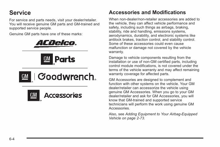
ServiceFor service and parts needs, visit your dealer/retailer.You will receive genuine GM parts and GM-trained andsupported service people.
Genuine GM parts have one of these marks:
Accessories and ModificationsWhen non-dealer/non-retailer accessories are added tothe vehicle, they can affect vehicle performance andsafety, including such things as airbags, braking,stability, ride and handling, emissions systems,aerodynamics, durability, and electronic systems likeantilock brakes, traction control, and stability control.Some of these accessories could even causemalfunction or damage not covered by the vehiclewarranty.
Damage to vehicle components resulting from theinstallation or use of non-GM certified parts, includingcontrol module modifications, is not covered under theterms of the vehicle warranty and may affect remainingwarranty coverage for affected parts.
GM Accessories are designed to complement andfunction with other systems on the vehicle. Your GMdealer/retailer can accessorize the vehicle usinggenuine GM Accessories. When you go to your GMdealer/retailer and ask for GM Accessories, you willknow that GM-trained and supported servicetechnicians will perform the work using genuine GMAccessories.
Also, see Adding Equipment to Your Airbag-EquippedVehicle on page 2‑73.
6-4
California Proposition 65 WarningMost motor vehicles, including this one, contain and/oremit chemicals known to the State of California tocause cancer and birth defects or other reproductiveharm. Engine exhaust, many parts and systems, manyfluids, and some component wear by-products containand/or emit these chemicals.
California Perchlorate MaterialsRequirementsCertain types of automotive applications, such as airbaginitiators, seat belt pretensioners, and lithium batteriescontained in remote keyless transmitters, may containperchlorate materials. Special handling may benecessary. For additional information, seewww.dtsc.ca.gov/hazardouswaste/perchlorate.
Doing Your Own Service Work
{ WARNING:
You can be injured and the vehicle could bedamaged if you try to do service work on a vehiclewithout knowing enough about it.
. Be sure you have sufficient knowledge,experience, the proper replacement parts, andtools before attempting any vehiclemaintenance task.
. Be sure to use the proper nuts, bolts, andother fasteners. English and metric fastenerscan be easily confused. If the wrong fastenersare used, parts can later break or fall off. Youcould be hurt.
If doing some of your own service work, use the properservice manual. It tells you much more about how toservice the vehicle than this manual can. To order theproper service manual, see Service PublicationsOrdering Information on page 8‑16.
6-5
This vehicle has an airbag system. Before attempting todo your own service work, see Servicing YourAirbag-Equipped Vehicle on page 2‑72.
Keep a record with all parts receipts and list themileage and the date of any service work performed.See Maintenance Record on page 7‑15.
Adding Equipment to the Outside ofthe VehicleThings added to the outside of the vehicle can affectthe airflow around it. This can cause wind noise andcan affect fuel economy and windshield washerperformance. Check with your dealer/retailer beforeadding equipment to the outside of the vehicle.
FuelUse of the recommended fuel is an important part of theproper maintenance of this vehicle. To help keep theengine clean and maintain optimum vehicleperformance, we recommend the use of gasolineadvertised as TOP TIER Detergent Gasoline.
Look for the TOP TIER label on the fuel pump to ensuregasoline meets enhanced detergency standardsdeveloped by auto companies. A list of marketersproviding TOP TIER Detergent Gasoline can be foundat www.toptiergas.com.
6-6
The 8th digit of the Vehicle Identification Number (VIN)shows the code letter or number that identifies thevehicle's engine. The VIN is at the top left of theinstrument panel. See Vehicle Identification Number(VIN) on page 6‑120.
Gasoline OctaneIf the vehicle has the 2.2L L4 engine (VIN Code 5), useregular unleaded gasoline with a posted octane rating of87 or higher. If the octane rating is less than 87, anaudible knocking noise, commonly referred to as sparkknock, might be heard when driving. If this occurs, usea gasoline rated at 87 octane or higher as soon aspossible. If heavy knocking is heard when usinggasoline rated at 87 octane or higher, the engine needsservice.
If the vehicle has the 2.0L L4 engine (VIN Code X), usepremium unleaded gasoline with a posted octane ratingof 91 or higher. You can also use regular unleadedgasoline rated at 87 octane or higher, but the vehicle'sacceleration could be slightly reduced, and a slightaudible knocking noise, commonly referred to as sparkknock, might be heard. If the octane is less than 87, youmight notice a heavy knocking noise when you drive.If this occurs, use a gasoline rated at 87 octane orhigher as soon as possible. Otherwise, you coulddamage the engine. If heavy knocking is heard whenusing gasoline rated at 87 octane or higher, the engineneeds service.
6-7
Gasoline SpecificationsAt a minimum, gasoline should meet ASTMspecification D 4814 in the United States orCAN/CGSB-3.5 or 3.511 in Canada. Some gasolinescontain an octane-enhancing additive calledmethylcyclopentadienyl manganese tricarbonyl (MMT).We recommend against the use of gasolines containingMMT. See Additives on page 6‑8 for additionalinformation.
California FuelIf the vehicle is certified to meet California EmissionsStandards, it is designed to operate on fuels that meetCalifornia specifications. See the underhood emissioncontrol label. If this fuel is not available in statesadopting California emissions standards, the vehiclewill operate satisfactorily on fuels meeting federalspecifications, but emission control system performancemight be affected. The malfunction indicator lamp couldturn on and the vehicle might fail a smog-check test.See Malfunction Indicator Lamp on page 4‑27. If thisoccurs, return to your authorized dealer/retailer fordiagnosis. If it is determined that the condition is causedby the type of fuel used, repairs might not be coveredby the vehicle warranty.
AdditivesTo provide cleaner air, all gasolines in the United Statesare now required to contain additives that help preventengine and fuel system deposits from forming, allowingthe emission control system to work properly. In mostcases, nothing should have to be added to the fuel.However, some gasolines contain only the minimumamount of additive required to meet U.S. EnvironmentalProtection Agency regulations. To help keep fuelinjectors and intake valves clean, or if the vehicleexperiences problems due to dirty injectors or valves,look for gasoline that is advertised as TOP TIERDetergent Gasoline.
For customers who do not use TOP TIER DetergentGasoline regularly, one bottle of GM Fuel SystemTreatment PLUS, added to the fuel tank at every engineoil change, can help clean deposits from fuel injectorsand intake valves. GM Fuel System Treatment PLUS isthe only gasoline additive recommended by GeneralMotors.
Also, your dealer/retailer has additives that will helpcorrect and prevent most deposit-related problems.
6-8
Gasolines containing oxygenates, such as ethers andethanol, and reformulated gasolines might be availablein your area. We recommend that you use thesegasolines, if they comply with the specificationsdescribed earlier. However, E85 (85% ethanol) andother fuels containing more than 10% ethanol must notbe used in vehicles that were not designed for thosefuels.
Notice: This vehicle was not designed for fuel thatcontains methanol. Do not use fuel containingmethanol. It can corrode metal parts in the fuelsystem and also damage plastic and rubber parts.That damage would not be covered under thevehicle warranty.
Some gasolines that are not reformulated for lowemissions can contain an octane-enhancing additivecalled methylcyclopentadienyl manganese tricarbonyl(MMT); ask the attendant where you buy gasolinewhether the fuel contains MMT. We recommend againstthe use of such gasolines. Fuels containing MMT canreduce the life of spark plugs and the performance ofthe emission control system could be affected. Themalfunction indicator lamp might turn on. If this occurs,return to your dealer/retailer for service.
Fuels in Foreign CountriesIf you plan on driving in another country outside theUnited States or Canada, the proper fuel might be hardto find. Never use leaded gasoline or any other fuel notrecommended in the previous text on fuel. Costlyrepairs caused by use of improper fuel would not becovered by the vehicle warranty.
To check the fuel availability, ask an auto club,or contact a major oil company that does business inthe country where you will be driving.
6-9
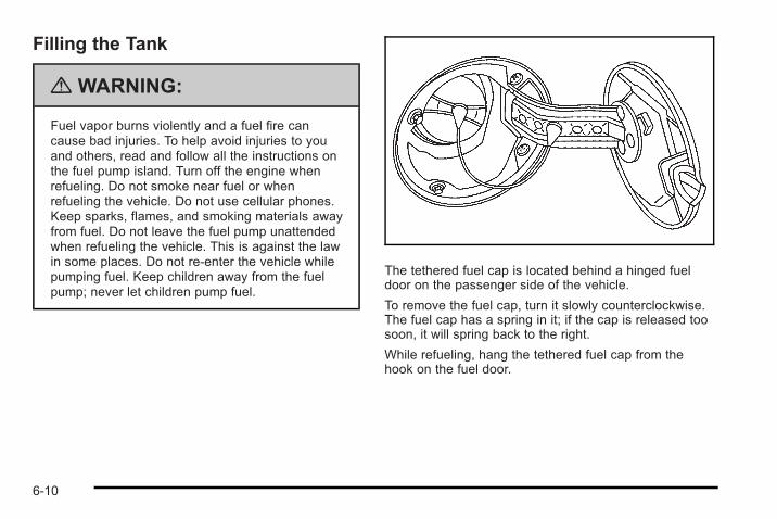
Filling the Tank
{ WARNING:
Fuel vapor burns violently and a fuel fire cancause bad injuries. To help avoid injuries to youand others, read and follow all the instructions onthe fuel pump island. Turn off the engine whenrefueling. Do not smoke near fuel or whenrefueling the vehicle. Do not use cellular phones.Keep sparks, flames, and smoking materials awayfrom fuel. Do not leave the fuel pump unattendedwhen refueling the vehicle. This is against the lawin some places. Do not re-enter the vehicle whilepumping fuel. Keep children away from the fuelpump; never let children pump fuel.
The tethered fuel cap is located behind a hinged fueldoor on the passenger side of the vehicle.
To remove the fuel cap, turn it slowly counterclockwise.The fuel cap has a spring in it; if the cap is released toosoon, it will spring back to the right.
While refueling, hang the tethered fuel cap from thehook on the fuel door.
6-10
{ WARNING:
Fuel can spray out on you if you open the fuel captoo quickly. If you spill fuel and then somethingignites it, you could be badly burned. This spraycan happen if the tank is nearly full, and is morelikely in hot weather. Open the fuel cap slowly andwait for any hiss noise to stop. Then unscrew thecap all the way.
Be careful not to spill fuel. Do not top off or overfill thetank and wait a few seconds after you have finishedpumping before removing the nozzle. Clean fuel frompainted surfaces as soon as possible. See WashingYour Vehicle on page 6‑116.
When replacing the fuel cap, turn it clockwise until itclicks. Make sure the cap is fully installed. Thediagnostic system can determine if the fuel cap hasbeen left off or improperly installed. This would allowfuel to evaporate into the atmosphere. See MalfunctionIndicator Lamp on page 4‑27.
The CHECK GAS CAP message displays on the DriverInformation Center (DIC) if the fuel cap is not properlyinstalled. See DIC Warnings and Messages onpage 4‑40 for more information.
{ WARNING:
If a fire starts while you are refueling, do notremove the nozzle. Shut off the flow of fuel byshutting off the pump or by notifying the stationattendant. Leave the area immediately.
Notice: If you need a new fuel cap, be sure to getthe right type. Your dealer/retailer can get one foryou. If you get the wrong type, it may not fitproperly. This may cause the malfunction indicatorlamp to light and may damage the fuel tank andemissions system. See Malfunction Indicator Lampon page 4‑27.
6-11
Filling a Portable Fuel Container
{ WARNING:
Never fill a portable fuel container while it is in thevehicle. Static electricity discharge from thecontainer can ignite the fuel vapor. You can bebadly burned and the vehicle damaged if thisoccurs. To help avoid injury to you and others:
. Dispense fuel only into approved containers.
. Do not fill a container while it is inside avehicle, in a vehicle's trunk, pickup bed, or onany surface other than the ground.
. Bring the fill nozzle in contact with the insideof the fill opening before operating the nozzle.Contact should be maintained until the filling iscomplete.
. Do not smoke while pumping fuel.
. Do not use a cellular phone whilepumping fuel.
Checking Things Underthe Hood
{ WARNING:
An electric fan under the hood can start up andinjure you even when the engine is not running.Keep hands, clothing, and tools away from anyunderhood electric fan.
{ WARNING:
Things that burn can get on hot engine parts andstart a fire. These include liquids like fuel, oil,coolant, brake fluid, windshield washer and otherfluids, and plastic or rubber. You or others couldbe burned. Be careful not to drop or spill thingsthat will burn onto a hot engine.
6-12
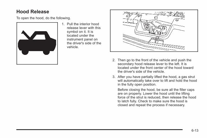
Hood ReleaseTo open the hood, do the following.
1. Pull the interior hoodrelease lever with thissymbol on it. It islocated under theinstrument panel onthe driver's side of thevehicle.
2. Then go to the front of the vehicle and push thesecondary hood release lever to the left. It islocated under the front center of the hood towardthe driver's side of the vehicle.
3. After you have partially lifted the hood, a gas strutwill automatically take over to lift and hold the hoodin the fully open position.
Before closing the hood, be sure all the filler capsare on properly. Lower the hood until the liftingforce of the strut is reduced, then release the hoodto latch fully. Check to make sure the hood isclosed and repeat the process if necessary.
6-13
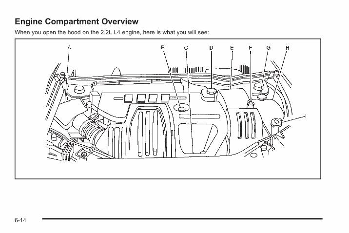
Engine Compartment OverviewWhen you open the hood on the 2.2L L4 engine, here is what you will see:
6-14
A. Engine Air Cleaner/Filter (2.0L Turbo Engine) onpage 6‑23 or Engine Air Cleaner/Filter(2.2L Engine) on page 6‑25.
B. Engine Oil Fill Cap. See “When to Add Engine Oil”under Engine Oil on page 6‑17.
C. Engine Oil Dipstick (Out of View). See “CheckingEngine Oil” under Engine Oil on page 6‑17.
D. Brake Master Cylinder Reservoir. See “BrakeFluid” under Brakes on page 6‑37 and HydraulicClutch on page 6‑27.
E. Engine Compartment Fuse Block on page 6‑124.
F. Remote Positive (+) Terminal. See Jump Startingon page 6‑41.
G. Remote Negative (-) Terminal. See Jump Startingon page 6‑41.
H. Engine Coolant Surge Tank. See Cooling Systemon page 6‑28.
I. Windshield Washer Fluid Reservoir. See “AddingWasher Fluid” under Windshield Washer Fluid onpage 6‑36.
6-15
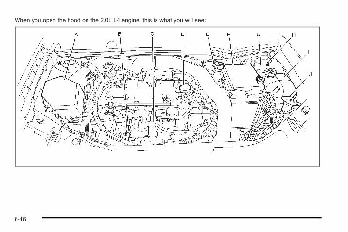
When you open the hood on the 2.0L L4 engine, this is what you will see:
6-16
A. Engine Air Cleaner/Filter (2.0L Turbo Engine) onpage 6‑23 or Engine Air Cleaner/Filter(2.2L Engine) on page 6‑25.
B. Engine Oil Dipstick. See “Checking Engine Oil”under Engine Oil on page 6‑17.
C. Engine Cooling Fan. See Cooling System onpage 6‑28.
D. Engine Oil Fill Cap. See “When to Add Engine Oil”under Engine Oil on page 6‑17.
E. Brake Master Cylinder Reservoir. See “BrakeFluid” under Brakes on page 6‑37 and HydraulicClutch on page 6‑27.
F. Engine Compartment Fuse Block on page 6‑124.
G. Remote Positive (+) Terminal. See Jump Startingon page 6‑41.
H. Remote Negative (-) Terminal. See Jump Startingon page 6‑41.
I. Engine Coolant Surge Tank. See Cooling Systemon page 6‑28.
J. Windshield Washer Fluid Reservoir. See “AddingWasher Fluid” under Windshield Washer Fluid onpage 6‑36.
Engine Oil
Checking Engine OilIt is a good idea to check the engine oil level at eachfuel fill. In order to get an accurate reading, the oil mustbe warm and the vehicle must be on level ground.
The engine oil dipstick handle is a yellow loop. SeeEngine Compartment Overview on page 6‑14 for thelocation of the engine oil dipstick.
1. Turn off the engine and give the oil several minutesto drain back into the oil pan. If this is not done, theoil dipstick might not show the actual level.
2. Pull out the dipstick and clean it with a paper towelor cloth, then push it back in all the way. Remove itagain, keeping the tip down, and check the level.
6-17
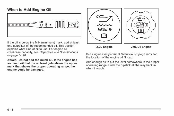
When to Add Engine Oil
If the oil is below the MIN (minimum) mark, add at leastone quart/liter of the recommended oil. This sectionexplains what kind of oil to use. For engine oilcrankcase capacity, see Capacities and Specificationson page 6‑128.
Notice: Do not add too much oil. If the engine hasso much oil that the oil level gets above the uppermark that shows the proper operating range, theengine could be damaged.
2.2L Engine 2.0L L4 Engine
See Engine Compartment Overview on page 6‑14 forthe location of the engine oil fill cap.
Add enough oil to put the level somewhere in the properoperating range. Push the dipstick all the way back inwhen through.
6-18
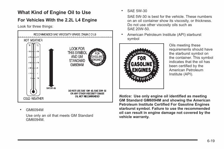
What Kind of Engine Oil to Use
For Vehicles With the 2.2L L4 EngineLook for three things:
. GM6094M
Use only an oil that meets GM StandardGM6094M.
. SAE 5W-30
SAE 5W-30 is best for the vehicle. These numberson an oil container show its viscosity, or thickness.Do not use other viscosity oils such asSAE 20W-50.
. American Petroleum Institute (API) starburstsymbol
Oils meeting theserequirements should havethe starburst symbol onthe container. This symbolindicates that the oil hasbeen certified by theAmerican PetroleumInstitute (API).
Notice: Use only engine oil identified as meetingGM Standard GM6094M and showing the AmericanPetroleum Institute Certified For Gasoline Enginesstarburst symbol. Failure to use the recommendedoil can result in engine damage not covered by thevehicle warranty.
6-19
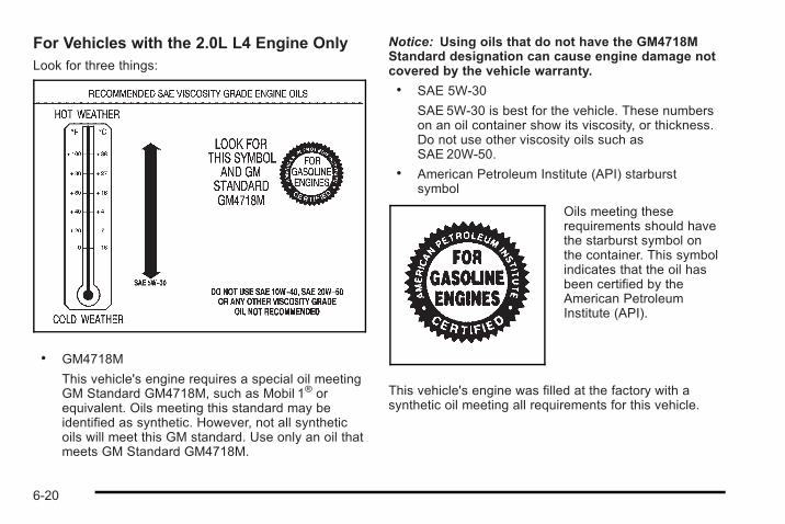
For Vehicles with the 2.0L L4 Engine OnlyLook for three things:
. GM4718M
This vehicle's engine requires a special oil meetingGM Standard GM4718M, such as Mobil 1® orequivalent. Oils meeting this standard may beidentified as synthetic. However, not all syntheticoils will meet this GM standard. Use only an oil thatmeets GM Standard GM4718M.
Notice: Using oils that do not have the GM4718MStandard designation can cause engine damage notcovered by the vehicle warranty.. SAE 5W-30
SAE 5W-30 is best for the vehicle. These numberson an oil container show its viscosity, or thickness.Do not use other viscosity oils such asSAE 20W-50.
. American Petroleum Institute (API) starburstsymbol
Oils meeting theserequirements should havethe starburst symbol onthe container. This symbolindicates that the oil hasbeen certified by theAmerican PetroleumInstitute (API).
This vehicle's engine was filled at the factory with asynthetic oil meeting all requirements for this vehicle.
6-20
Substitute Engine Oil: When adding oil to maintainengine oil level, oil meeting GM Standard GM4718Mmight not be available. You can add substitute oildesignated SAE 5W-30 with the starburst symbol at alltemperatures. Substitute oil not meeting GM StandardGM4718M should not be used for an oil change.
Cold Temperature Operation
For Vehicles With the 2.2L L4 EngineIf in an area of extreme cold, where the temperaturefalls below −20°F (−29°C), use either an SAE 5W-30synthetic oil or an SAE 0W-30 engine oil. Both provideeasier cold starting for the engine at extremely lowtemperatures. Always use an oil that meets the requiredspecification, GM6094M. See “What Kind of Engine Oilto Use” for more information.
Engine Oil Additives / Engine OilFlushesDo not add anything to the oil. The recommended oilswith the starburst symbol that meet GM standards areall that is needed for good performance and engineprotection.
Engine oil system flushes are not recommended andcould cause engine damage not covered by the vehiclewarranty.
Engine Oil Life System
When to Change Engine OilThis vehicle has the Engine Oil Life System, a computersystem that indicates when to change the engine oiland filter. This is based on engine revolutions andengine temperature, and not on mileage. Based ondriving conditions, the mileage at which an oil change isindicated can vary considerably. For the oil life systemto work properly, the system must be reset every timethe oil is changed.
6-21
When the system has calculated that oil life has beendiminished, it indicates that an oil change is necessary.A CHANGE OIL SOON message comes on. See DICWarnings and Messages on page 4‑40. Change theoil as soon as possible within the next 600 miles(1 000 km). It is possible that, if driving under the bestconditions, the oil life system might not indicate that anoil change is necessary for over a year. However, theengine oil and filter must be changed at least once ayear and at this time the system must be reset. Yourdealer/retailer has trained service people who willperform this work using genuine parts and reset thesystem. It is also important to check the oil regularlyand keep it at the proper level.
If the system is ever reset accidentally, the oil must bechanged at 3,000 miles (5 000 km) since the last oilchange. Remember to reset the oil life systemwhenever the oil is changed.
How to Reset the Engine Oil LifeSystemThe Engine Oil Life System calculates when to changeyour engine oil and filter based on vehicle use.Whenever the oil is changed, reset the system so it cancalculate when the next oil change is required. If asituation occurs where the oil is changed prior to aCHANGE OIL SOON message being turned on, resetthe system.
After changing the engine oil, the system must be reset:
1. Turn the ignition to ON/RUN, with the engine off.
2. Press the information and reset buttons on theDriver Information Center (DIC) at the same time toenter the personalization menu. See DIC VehiclePersonalization on page 4‑46.
3. Press the information button to scroll through theavailable personalization menu modes until theDIC display shows OIL-LIFE RESET.
6-22
4. Press and hold the reset button until the DICdisplay shows ACKNOWLEDGED. This will tell youthe system has been reset.
5. Turn the key to LOCK/OFF.
If the CHANGE OIL SOON message comes back onwhen the vehicle is started, the engine oil life systemhas not reset. Repeat the reset procedure.
What to Do with Used OilUsed engine oil contains certain elements that can beunhealthy for your skin and could even cause cancer.Do not let used oil stay on your skin for very long. Cleanyour skin and nails with soap and water, or a good handcleaner. Wash or properly dispose of clothing or ragscontaining used engine oil. See the manufacturer'swarnings about the use and disposal of oil products.
Used oil can be a threat to the environment. If youchange your own oil, be sure to drain all the oil from thefilter before disposal. Never dispose of oil by putting it inthe trash, pouring it on the ground, into sewers, or intostreams or bodies of water. Recycle it by taking it to aplace that collects used oil.
Engine Air Cleaner/Filter(2.0L Turbo Engine)See Engine Compartment Overview on page 6‑14Engine Compartment Overview for the location of theengine air cleaner/filter.
When to Inspect the Engine AirCleaner/FilterInspect the air cleaner/filter at the Maintenance IIintervals and replace it at the first oil change after each50,000 mile (80 000 km) interval. See ScheduledMaintenance on page 7‑3 Scheduled Maintenancefor more information. If you are driving in dusty/dirtyconditions, inspect the filter at each engine oil change.
6-23
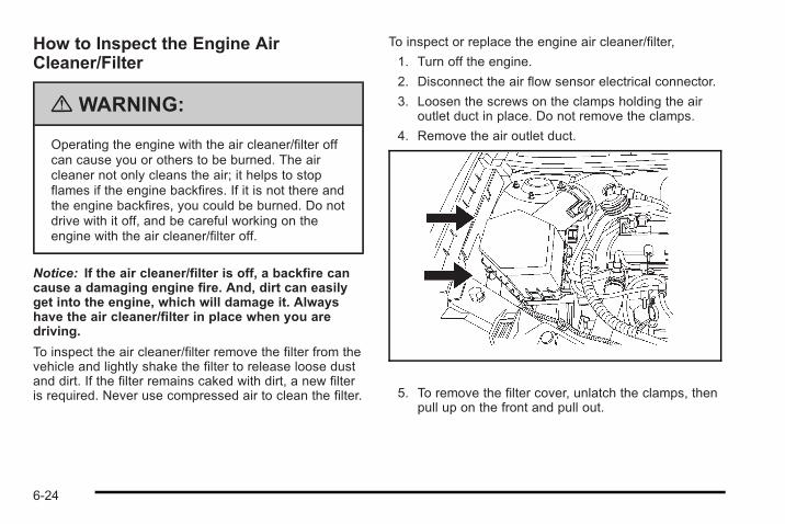
How to Inspect the Engine AirCleaner/Filter
{ WARNING:
Operating the engine with the air cleaner/filter offcan cause you or others to be burned. The aircleaner not only cleans the air; it helps to stopflames if the engine backfires. If it is not there andthe engine backfires, you could be burned. Do notdrive with it off, and be careful working on theengine with the air cleaner/filter off.
Notice: If the air cleaner/filter is off, a backfire cancause a damaging engine fire. And, dirt can easilyget into the engine, which will damage it. Alwayshave the air cleaner/filter in place when you aredriving.
To inspect the air cleaner/filter remove the filter from thevehicle and lightly shake the filter to release loose dustand dirt. If the filter remains caked with dirt, a new filteris required. Never use compressed air to clean the filter.
To inspect or replace the engine air cleaner/filter,
1. Turn off the engine.
2. Disconnect the air flow sensor electrical connector.
3. Loosen the screws on the clamps holding the airoutlet duct in place. Do not remove the clamps.
4. Remove the air outlet duct.
5. To remove the filter cover, unlatch the clamps, thenpull up on the front and pull out.
6-24
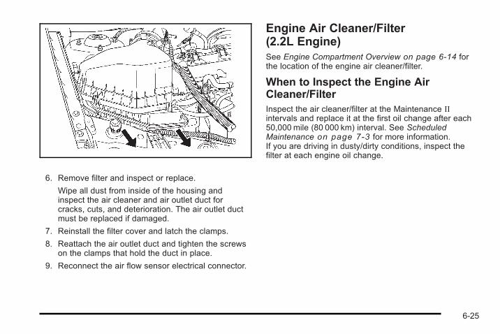
6. Remove filter and inspect or replace.
Wipe all dust from inside of the housing andinspect the air cleaner and air outlet duct forcracks, cuts, and deterioration. The air outlet ductmust be replaced if damaged.
7. Reinstall the filter cover and latch the clamps.
8. Reattach the air outlet duct and tighten the screwson the clamps that hold the duct in place.
9. Reconnect the air flow sensor electrical connector.
Engine Air Cleaner/Filter(2.2L Engine)See Engine Compartment Overview on page 6‑14 forthe location of the engine air cleaner/filter.
When to Inspect the Engine AirCleaner/FilterInspect the air cleaner/filter at the Maintenance IIintervals and replace it at the first oil change after each50,000 mile (80 000 km) interval. See ScheduledMaintenance on page 7‑3 for more information.If you are driving in dusty/dirty conditions, inspect thefilter at each engine oil change.
6-25
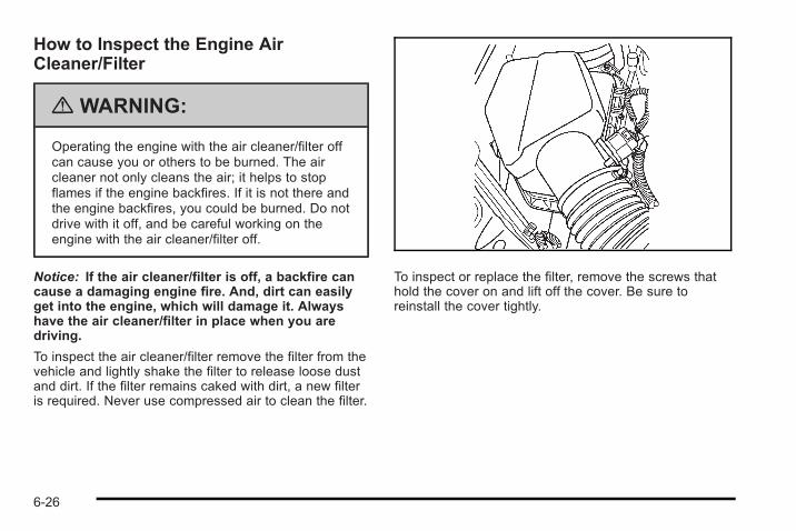
How to Inspect the Engine AirCleaner/Filter
{ WARNING:
Operating the engine with the air cleaner/filter offcan cause you or others to be burned. The aircleaner not only cleans the air; it helps to stopflames if the engine backfires. If it is not there andthe engine backfires, you could be burned. Do notdrive with it off, and be careful working on theengine with the air cleaner/filter off.
Notice: If the air cleaner/filter is off, a backfire cancause a damaging engine fire. And, dirt can easilyget into the engine, which will damage it. Alwayshave the air cleaner/filter in place when you aredriving.
To inspect the air cleaner/filter remove the filter from thevehicle and lightly shake the filter to release loose dustand dirt. If the filter remains caked with dirt, a new filteris required. Never use compressed air to clean the filter.
To inspect or replace the filter, remove the screws thathold the cover on and lift off the cover. Be sure toreinstall the cover tightly.
6-26
Automatic Transmission FluidIt is not necessary to check the transmission fluid level.A transmission fluid leak is the only reason for fluidloss. If a leak occurs, take your vehicle to a dealer/retailer and have it repaired as soon as possible.
Change the fluid and filter at the intervals listed in theMaintenance Schedule. See Scheduled Maintenanceon page 7‑3 . Be sure to use the transmission fluidlisted in Recommended Fluids and Lubricants onpage 7‑11.
Notice: Use of the incorrect automatic transmissionfluid may damage the vehicle, and the damages maynot be covered by the vehicle's warranty. Alwaysuse the automatic transmission fluid listed inRecommended Fluids and Lubricants on page 7‑11.
Manual Transmission FluidIt is not necessary to check the manual transmissionfluid level. A transmission fluid leak is the only reasonfor fluid loss. If a leak occurs, take the vehicle to adealer/retailer for service. Have it repaired as soon aspossible. You may also have the fluid level checked byyour dealer/retailer when the oil is changed. SeeRecommended Fluids and Lubricants on page 7‑11 forthe proper fluid to use.
Hydraulic ClutchThe hydraulic clutch linkage in your vehicle isself-adjusting. This system does not have its ownreservoir. It receives fluid from the brake master cylinderreservoir.
See Brakes on page 6‑37 for more information.
6-27
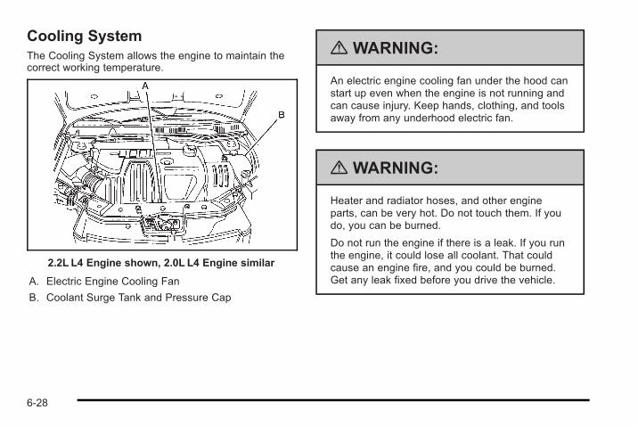
Cooling SystemThe Cooling System allows the engine to maintain thecorrect working temperature.
2.2L L4 Engine shown, 2.0L L4 Engine similar
A. Electric Engine Cooling Fan
B. Coolant Surge Tank and Pressure Cap
{ WARNING:
An electric engine cooling fan under the hood canstart up even when the engine is not running andcan cause injury. Keep hands, clothing, and toolsaway from any underhood electric fan.
{ WARNING:
Heater and radiator hoses, and other engineparts, can be very hot. Do not touch them. If youdo, you can be burned.
Do not run the engine if there is a leak. If you runthe engine, it could lose all coolant. That couldcause an engine fire, and you could be burned.Get any leak fixed before you drive the vehicle.
6-28
Notice: Using coolant other than DEX-COOL® cancause premature engine, heater core, or radiatorcorrosion. In addition, the engine coolant couldrequire changing sooner, at 50 000 km (30,000miles)or 24months, whichever occurs first. Any repairswould not be covered by the vehicle warranty.Always use DEX-COOL® (silicate-free) coolant in thevehicle.
Engine CoolantThe cooling system in the vehicle is filled withDEX-COOL® engine coolant. This coolant is designedto remain in the vehicle for five years or 150,000 miles(240 000 km), whichever occurs first.
The following explains the cooling system and how tocheck and add coolant when it is low. If there is aproblem with engine overheating, see EngineOverheating on page 6‑34
What to Use
{ WARNING:
Adding only plain water to the cooling system canbe dangerous. Plain water, or some other liquidsuch as alcohol, can boil before the propercoolant mixture will. The vehicle's coolant warningsystem is set for the proper coolant mixture. Withplain water or the wrong mixture, the engine couldget too hot but you would not get the overheatwarning. The engine could catch fire and you orothers could be burned. Use a 50/50 mixture ofclean, drinkable water and DEX-COOL® coolant.
Use a 50/50 mixture of clean, drinkable water andDEX-COOL® coolant. If using this mixture, nothing elseneeds to be added. This mixture:. Gives freezing protection down to −34°F (−37°C),
outside temperature.. Gives boiling protection up to 265°F (129°C),
engine temperature.
6-29
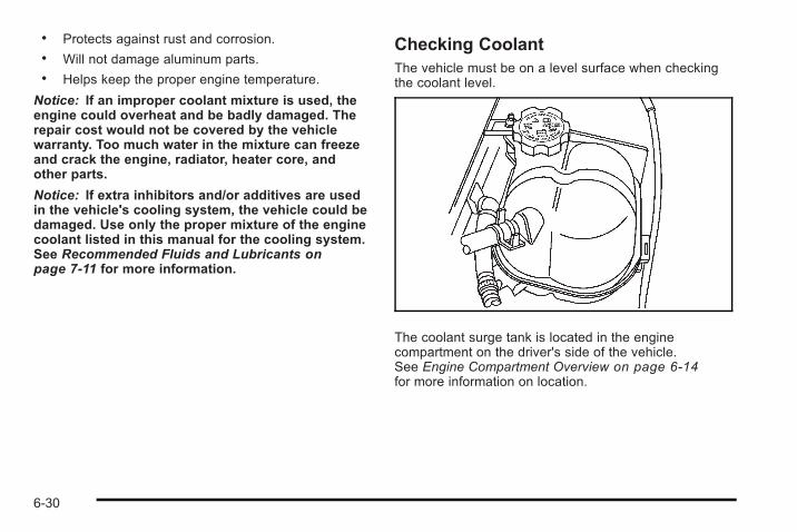
. Protects against rust and corrosion.
. Will not damage aluminum parts.
. Helps keep the proper engine temperature.
Notice: If an improper coolant mixture is used, theengine could overheat and be badly damaged. Therepair cost would not be covered by the vehiclewarranty. Too much water in the mixture can freezeand crack the engine, radiator, heater core, andother parts.
Notice: If extra inhibitors and/or additives are usedin the vehicle's cooling system, the vehicle could bedamaged. Use only the proper mixture of the enginecoolant listed in this manual for the cooling system.See Recommended Fluids and Lubricants onpage 7‑11 for more information.
Checking CoolantThe vehicle must be on a level surface when checkingthe coolant level.
The coolant surge tank is located in the enginecompartment on the driver's side of the vehicle.See Engine Compartment Overview on page 6‑14for more information on location.
6-30
Check to see if coolant is visible in the coolant surgetank. If the coolant inside the coolant surge tank isboiling, do not do anything else until it cools down.If coolant is visible but the coolant level is not at orabove the COLD FILL mark, add a 50/50 mixture ofclean, drinkable water and DEX-COOL® coolant at thecoolant surge tank, but be sure the cooling system iscool before this is done.
The coolant level should be at the COLD FILL line.If it is not, you may have a leak in the coolingsystem.
How to Add Coolant to the Surge Tank
{ WARNING:
You can be burned if you spill coolant on hotengine parts. Coolant contains ethylene glycoland it will burn if the engine parts are hot enough.Do not spill coolant on a hot engine.
Notice: This vehicle has a specific coolant fillprocedure. Failure to follow this procedure couldcause the engine to overheat and be severelydamaged.
{ WARNING:
An electric engine cooling fan under the hood canstart up even when the engine is not running andcan cause injury. Keep hands, clothing, and toolsaway from any underhood electric fan.
6-31
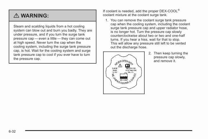
{ WARNING:
Steam and scalding liquids from a hot coolingsystem can blow out and burn you badly. They areunder pressure, and if you turn the surge tankpressure cap— even a little— they can come outat high speed. Never turn the cap when thecooling system, including the surge tank pressurecap, is hot. Wait for the cooling system and surgetank pressure cap to cool if you ever have to turnthe pressure cap.
If coolant is needed, add the proper DEX-COOL®
coolant mixture at the coolant surge tank.
1. You can remove the coolant surge tank pressurecap when the cooling system, including the coolantsurge tank pressure cap and upper radiator hose,is no longer hot. Turn the pressure cap slowlycounterclockwise about two or two and one-halfturns. If you hear a hiss, wait for that to stop.This will allow any pressure still left to be ventedout the discharge hose.
2. Then keep turning thepressure cap slowly,and remove it.
6-32
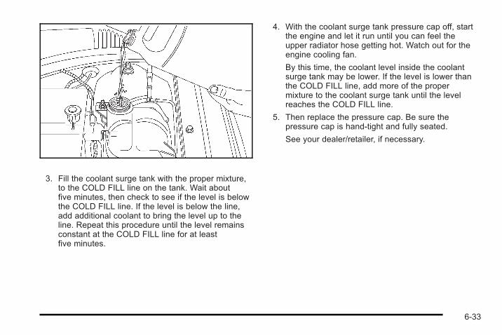
3. Fill the coolant surge tank with the proper mixture,to the COLD FILL line on the tank. Wait aboutfive minutes, then check to see if the level is belowthe COLD FILL line. If the level is below the line,add additional coolant to bring the level up to theline. Repeat this procedure until the level remainsconstant at the COLD FILL line for at leastfive minutes.
4. With the coolant surge tank pressure cap off, startthe engine and let it run until you can feel theupper radiator hose getting hot. Watch out for theengine cooling fan.
By this time, the coolant level inside the coolantsurge tank may be lower. If the level is lower thanthe COLD FILL line, add more of the propermixture to the coolant surge tank until the levelreaches the COLD FILL line.
5. Then replace the pressure cap. Be sure thepressure cap is hand-tight and fully seated.
See your dealer/retailer, if necessary.
6-33
Engine OverheatingThe vehicle has an indicator to warn of engineoverheating.
You will find an engine coolant temperature warninglight on your vehicle's instrument panel. See EngineCoolant Temperature Warning Light on page 4‑26 formore information.
You may decide not to lift the hood when this warningappears, but instead get service help right away.See Roadside Assistance Program on page 8‑8.
If you do decide to lift the hood , make sure the vehicleis parked on a level surface.
Then check to see if the engine cooling fans arerunning. If the engine is overheating, both fans shouldbe running. If they are not, do not continue to run theengine and have the vehicle serviced.
Notice: Engine damage from running the enginewithout coolant is not covered by the warranty.
Notice: If the engine catches fire because of beingdriven with no coolant, your vehicle can be badlydamaged. The costly repairs would not be coveredby the vehicle warranty.
If Steam Is Coming From The EngineCompartment
{ WARNING:
Steam from an overheated engine can burn youbadly, even if you just open the hood. Stay awayfrom the engine if you see or hear steam comingfrom it. Just turn it off and get everyone away fromthe vehicle until it cools down. Wait until there isno sign of steam or coolant before you openthe hood.
If you keep driving when your engine isoverheated, the liquids in it can catch fire. You orothers could be badly burned. Stop your engine ifit overheats, and get out of the vehicle until theengine is cool.
6-34
If No Steam Is Coming From TheEngine CompartmentIf an engine overheat warning is displayed but no steamcan be seen or heard, the problem may not be tooserious. Sometimes the engine can get a little too hotwhen the vehicle:. Climbs a long hill on a hot day.. Stops after high-speed driving.. Idles for long periods in traffic.. Tows a trailer.
If the overheat warning is displayed with no sign ofsteam:
1. Turn the air off.
2. Turn the heater on to the highest temperature andto the highest fan speed. Open the windows asnecessary.
3. In heavy traffic, let the engine idle in N (Neutral) forautomatic transmission or NEUTRAL for manualtransmission , while stopped. If it is safe to do so,pull off the road, shift to P (Park) or N (Neutral) andlet the engine idle.
If the temperature overheat gage is no longer in theoverheat zone or an overheat warning no longerdisplays, the vehicle can be driven. Continue to drivethe vehicle slow for about 10 minutes. Keep a safevehicle distance from the car in front of you. If thewarning does not come back on, continue to drivenormally.
If the warning continues, pull over, stop, and park thevehicle right away.
If there is no sign of steam, idle the engine forthree minutes while parked. If the warning is stilldisplayed, turn off the engine until it cools down.
6-35
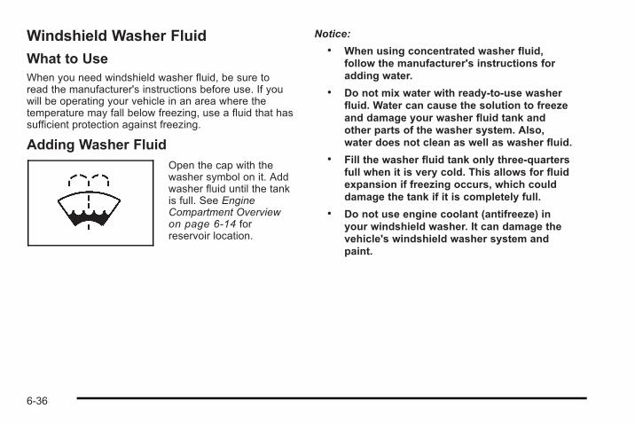
Windshield Washer Fluid
What to UseWhen you need windshield washer fluid, be sure toread the manufacturer's instructions before use. If youwill be operating your vehicle in an area where thetemperature may fall below freezing, use a fluid that hassufficient protection against freezing.
Adding Washer FluidOpen the cap with thewasher symbol on it. Addwasher fluid until the tankis full. See EngineCompartment Overviewon page 6‑14 forreservoir location.
Notice:. When using concentrated washer fluid,
follow the manufacturer's instructions foradding water.
. Do not mix water with ready-to-use washerfluid. Water can cause the solution to freezeand damage your washer fluid tank andother parts of the washer system. Also,water does not clean as well as washer fluid.
. Fill the washer fluid tank only three-quartersfull when it is very cold. This allows for fluidexpansion if freezing occurs, which coulddamage the tank if it is completely full.
. Do not use engine coolant (antifreeze) inyour windshield washer. It can damage thevehicle's windshield washer system andpaint.
6-36
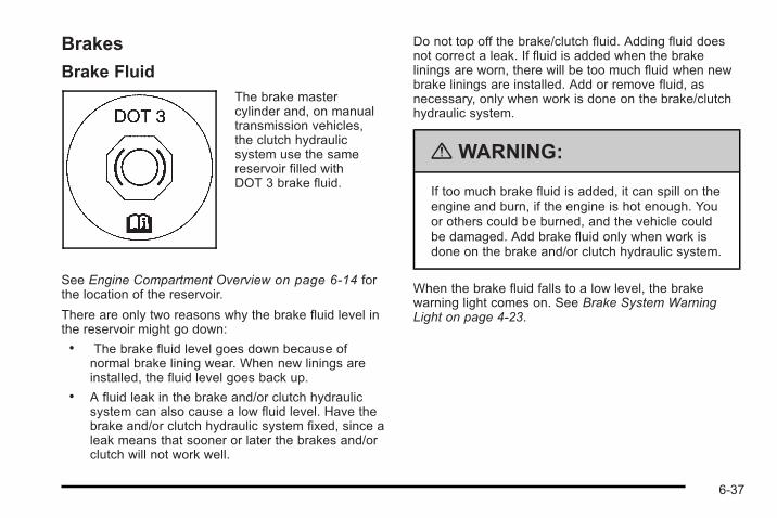
Brakes
Brake FluidThe brake mastercylinder and, on manualtransmission vehicles,the clutch hydraulicsystem use the samereservoir filled withDOT 3 brake fluid.
See Engine Compartment Overview on page 6‑14 forthe location of the reservoir.
There are only two reasons why the brake fluid level inthe reservoir might go down:. The brake fluid level goes down because of
normal brake lining wear. When new linings areinstalled, the fluid level goes back up.
. A fluid leak in the brake and/or clutch hydraulicsystem can also cause a low fluid level. Have thebrake and/or clutch hydraulic system fixed, since aleak means that sooner or later the brakes and/orclutch will not work well.
Do not top off the brake/clutch fluid. Adding fluid doesnot correct a leak. If fluid is added when the brakelinings are worn, there will be too much fluid when newbrake linings are installed. Add or remove fluid, asnecessary, only when work is done on the brake/clutchhydraulic system.
{ WARNING:
If too much brake fluid is added, it can spill on theengine and burn, if the engine is hot enough. Youor others could be burned, and the vehicle couldbe damaged. Add brake fluid only when work isdone on the brake and/or clutch hydraulic system.
When the brake fluid falls to a low level, the brakewarning light comes on. See Brake System WarningLight on page 4‑23.
6-37
What to AddUse only new DOT 3 brake fluid from a sealedcontainer. See Recommended Fluids and Lubricants onpage 7‑11.
Always clean the brake fluid reservoir cap and the areaaround the cap before removing it. This helps keep dirtfrom entering the reservoir.
{ WARNING:
With the wrong kind of fluid in the brake or clutchhydraulic system, the brakes or clutch might notwork well. This could cause a crash. Always usethe proper brake fluid.
Notice:. Using the wrong fluid can badly damage
brake or clutch hydraulic system parts. Forexample, just a few drops of mineral-basedoil, such as engine oil, in the brake or clutchhydraulic system can damage brake orclutch hydraulic system parts so badly thatthey will have to be replaced. Do not letsomeone put in the wrong kind of fluid.
. If brake fluid is spilled on the vehicle'spainted surfaces, the paint finish can bedamaged. Be careful not to spill brake fluidon the vehicle. If you do, wash it offimmediately. See Washing Your Vehicle onpage 6‑116.
Brake WearThis vehicle has front disc brakes and could have reardrum brakes or rear disc brakes.
Disc brake pads have built-in wear indicators that makea high-pitched warning sound when the brake pads areworn and new pads are needed. The sound can comeand go or be heard all the time the vehicle is moving,except when applying the brake pedal firmly.
6-38
{ WARNING:
The brake wear warning sound means that soonthe brakes will not work well. That could lead toan accident. When the brake wear warning soundis heard, have the vehicle serviced.
Notice: Continuing to drive with worn-out brakepads could result in costly brake repair.
Some driving conditions or climates can cause a brakesqueal when the brakes are first applied or lightlyapplied. This does not mean something is wrong withthe brakes.
Properly torqued wheel nuts are necessary to helpprevent brake pulsation. When tires are rotated, inspectbrake pads for wear and evenly tighten wheel nuts inthe proper sequence to torque specifications inCapacities and Specifications on page 6‑128.
If the vehicle has rear drum brakes, they do not havewear indicators, but if a rear brake rubbing noise isheard, have the rear brake linings inspectedimmediately. Rear brake drums should be removed andinspected each time the tires are removed for rotation orchanging. When the front brake pads are replaced,have the rear brakes inspected, too.
Brake linings should always be replaced as completeaxle sets.
Brake Pedal TravelSee your dealer/retailer if the brake pedal does notreturn to normal height, or if there is a rapid increase inpedal travel. This could be a sign that brake servicemight be required.
Brake AdjustmentEvery moderate brake stop, the disc brakes adjust forwear. If rarely making moderate or heavier brake stops,the brakes might not adjust correctly. Very carefullymaking a few moderate brake stops about every1,000 miles (1 600 km) will adjust the brakes properly.
If the vehicle has rear drum brakes and the brake pedalgoes down farther than normal, the rear drum brakesmight need adjustment. Adjust them by backing up andfirmly applying the brakes a few times.
6-39
Replacing Brake System PartsThe braking system on a vehicle is complex. Its manyparts have to be of top quality and work well together ifthe vehicle is to have really good braking. The vehiclewas designed and tested with top-quality brake parts.When parts of the braking system are replaced — forexample, when the brake linings wear down and newones are installed — be sure to get new approvedreplacement parts. If this is not done, the brakes mightnot work properly. For example, if someone puts inbrake linings that are wrong for the vehicle, the balancebetween the front and rear brakes can change — for theworse. The braking performance expected can changein many other ways if the wrong replacement brakeparts are installed.
BatteryRefer to the replacement number on the original batterylabel when a new battery is needed.
The battery is in the trunk. Access to the battery is notnecessary to jump start the vehicle. See Jump Startingon page 6‑41.
{ DANGER:
Battery posts, terminals, and related accessoriescontain lead and lead compounds, chemicalsknown to the State of California to cause cancerand reproductive harm. Wash hands afterhandling.
Vehicle Storage
{ WARNING:
Batteries have acid that can burn you and gasthat can explode. You can be badly hurt if you arenot careful. See Jump Starting on page 6‑41 fortips on working around a battery withoutgetting hurt.
Infrequent Usage: Remove the black, negative (−) cablefrom the battery to keep the battery from running down.
Extended Storage: Remove the black, negative (−)cable from the battery or use a battery trickle charger.
6-40
Jump StartingIf the vehicle's battery has run down, you may want touse another vehicle and some jumper cables to start thevehicle. Be sure to use the following steps to do itsafely.
{ WARNING:
Batteries can hurt you. They can be dangerousbecause:. They contain acid that can burn you.
. They contain gas that can explode or ignite.
. They contain enough electricity to burn you.
If you do not follow these steps exactly, some orall of these things can hurt you.
Notice: Ignoring these steps could result in costlydamage to the vehicle that would not be covered bythe warranty.
Trying to start the vehicle by pushing or pulling itwill not work, and it could damage the vehicle.
1. Check the other vehicle. It must have a 12-voltbattery with a negative ground system.
Notice: If the other vehicle's system is not a 12-voltsystem with a negative ground, both vehicles canbe damaged. Only use vehicles with 12-volt systemswith negative grounds to jump start your vehicle.
2. Get the vehicles close enough so the jumpercables can reach, but be sure the vehicles are nottouching each other. If they are, it could cause aground connection you do not want. You would notbe able to start the vehicle, and the bad groundingcould damage the electrical systems.
To avoid the possibility of the vehicles rolling, setthe parking brake firmly on both vehicles involvedin the jump start procedure. Put an automatictransmission in P (Park) or a manual transmissionin N (Neutral) before setting the parking brake.
Notice: If you leave the radio or other accessorieson during the jump starting procedure, they couldbe damaged. The repairs would not be covered bythe warranty. Always turn off the radio and otheraccessories when jump starting the vehicle.
3. Turn off the ignition on both vehicles. Unplugunnecessary accessories plugged into thecigarette lighter or the accessory power outlet.Turn off the radio and all lamps that are notneeded. This will avoid sparks and help save bothbatteries. And it could save the radio!
6-41
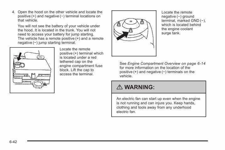
4. Open the hood on the other vehicle and locate thepositive (+) and negative (−) terminal locations onthat vehicle.
You will not see the battery of your vehicle underthe hood. It is located in the trunk. You will notneed to access your battery for jump starting.The vehicle has a remote positive (+) and a remotenegative (−) jump starting terminal.
Locate the remotepositive (+) terminal whichis located under a redtethered cap on theengine compartment fuseblock. Lift the cap toaccess the terminal.
Locate the remotenegative (−) groundterminal, marked GND (−),which is located behindthe engine coolantsurge tank.
See Engine Compartment Overview on page 6‑14for more information on the location of thepositive (+) and negative (−) terminals on thevehicle.
{ WARNING:
An electric fan can start up even when the engineis not running and can injure you. Keep hands,clothing and tools away from any underhoodelectric fan.
6-42
{ WARNING:
Using a match near a battery can cause batterygas to explode. People have been hurt doing this,and some have been blinded. Use a flashlight ifyou need more light.
Be sure the battery has enough water. You do notneed to add water to the battery installed in yournew vehicle. But if a battery has filler caps, besure the right amount of fluid is there. If it is low,add water to take care of that first. If you don't,explosive gas could be present.
Battery fluid contains acid that can burn you. Donot get it on you. If you accidentally get it in youreyes or on your skin, flush the place with waterand get medical help immediately.
{ WARNING:
Fans or other moving engine parts can injure youbadly. Keep your hands away from moving partsonce the engine is running.
5. Check that the jumper cables do not have loose ormissing insulation. If they do, you could get ashock. The vehicles could be damaged too.
Before you connect the cables, here are somebasic things you should know. Positive (+) will go topositive (+) or to a remote positive (+) terminal ifthe vehicle has one. Negative (−) will go to aheavy, unpainted metal engine part or to a remotenegative (−) terminal if the vehicle has one.
Do not connect positive (+) to negative (−) or youwill get a short that would damage the battery andmaybe other parts too. And do not connect thenegative (−) cable to the negative (−) terminal onthe dead battery because this can cause sparks.
6. Connect the red positive (+) cable to thepositive (+) terminal location on the vehicle with thedead battery. Use a remote positive (+) terminal ifthe vehicle has one.
6-43
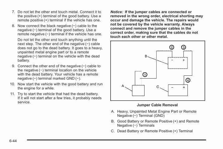
7. Do not let the other end touch metal. Connect it tothe positive (+) terminal of the good battery. Use aremote positive (+) terminal if the vehicle has one.
8. Now connect the black negative (−) cable to thenegative (−) terminal of the good battery. Use aremote negative (−) terminal if the vehicle has one.
Do not let the other end touch anything until thenext step. The other end of the negative (−) cabledoes not go to the dead battery. It goes to a heavy,unpainted metal engine part or to a remotenegative (−) terminal on the vehicle with the deadbattery.
9. Connect the other end of the negative (−) cable tothe negative (−) terminal location on the vehiclewith the dead battery. Your vehicle has a remotenegative (−) terminal marked GND (−).
10. Now start the vehicle with the good battery and runthe engine for a while.
11. Try to start the vehicle that had the dead battery.If it will not start after a few tries, it probably needsservice.
Notice: If the jumper cables are connected orremoved in the wrong order, electrical shorting mayoccur and damage the vehicle. The repairs wouldnot be covered by the vehicle warranty. Alwaysconnect and remove the jumper cables in thecorrect order, making sure that the cables do nottouch each other or other metal.
Jumper Cable Removal
A. Heavy, Unpainted Metal Engine Part or RemoteNegative (−) Terminal (GND)
B. Good Battery or Remote Positive (+) and RemoteNegative (−) Terminals
C. Dead Battery or Remote Positive (+) Terminal
6-44
To disconnect the jumper cables from both vehicles:
1. Disconnect the black negative (−) cable from thevehicle that had the dead battery.
2. Disconnect the black negative (−) cable from thevehicle with the good battery.
3. Disconnect the red positive (+) cable from thevehicle with the good battery.
4. Disconnect the red positive (+) cable from the othervehicle.
5. Return the positive (+) terminal cover to its originalposition.
Headlamp AimingThe optical headlamp aiming system has been preset atthe factory and should need no further adjustment
However, If the vehicle is damaged, the headlamp aimmay be affected and adjustment may be necessary.
If oncoming vehicles flash their high beams at you, thismay also mean the vertical aim needs to be adjusted.
It is recommended that the vehicle is taken to yourdealer/retailer for service if the headlamps need to bere-aimed. It is possible however, to re-aim theheadlamps as described.
The vehicle should be:. Placed so the headlamps are 25 ft. (7.6 m) from a
light colored wall.. On a perfectly level surface which is level all the
way to the wall.. Placed so it is at a right angle to the wall.. Clear of any snow, ice, or mud on it.. Fully assembled, with the tires properly inflated,
and all other work stopped while headlamp aimingis being done.
. Normally loaded with a full tank of fuel, with thespare tire in the proper location, and one person or160 lbs (75 kg) on the driver seat.
6-45
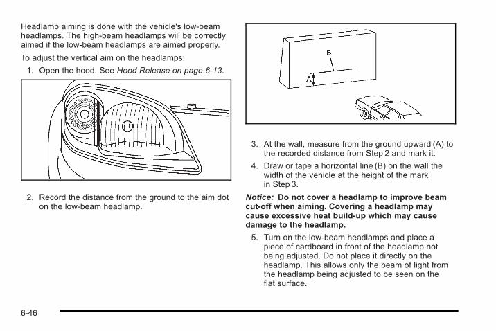
Headlamp aiming is done with the vehicle's low-beamheadlamps. The high-beam headlamps will be correctlyaimed if the low-beam headlamps are aimed properly.
To adjust the vertical aim on the headlamps:
1. Open the hood. See Hood Release on page 6‑13.
2. Record the distance from the ground to the aim doton the low-beam headlamp.
3. At the wall, measure from the ground upward (A) tothe recorded distance from Step 2 and mark it.
4. Draw or tape a horizontal line (B) on the wall thewidth of the vehicle at the height of the markin Step 3.
Notice: Do not cover a headlamp to improve beamcut-off when aiming. Covering a headlamp maycause excessive heat build-up which may causedamage to the headlamp.
5. Turn on the low-beam headlamps and place apiece of cardboard in front of the headlamp notbeing adjusted. Do not place it directly on theheadlamp. This allows only the beam of light fromthe headlamp being adjusted to be seen on theflat surface.
6-46
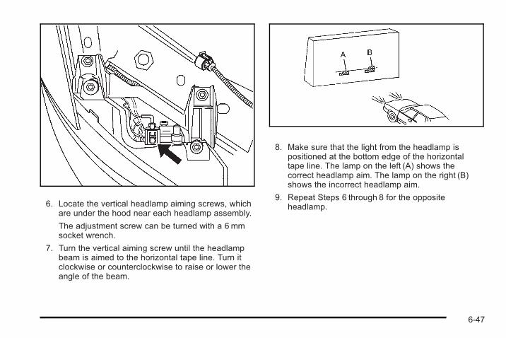
6. Locate the vertical headlamp aiming screws, whichare under the hood near each headlamp assembly.
The adjustment screw can be turned with a 6 mmsocket wrench.
7. Turn the vertical aiming screw until the headlampbeam is aimed to the horizontal tape line. Turn itclockwise or counterclockwise to raise or lower theangle of the beam.
8. Make sure that the light from the headlamp ispositioned at the bottom edge of the horizontaltape line. The lamp on the left (A) shows thecorrect headlamp aim. The lamp on the right (B)shows the incorrect headlamp aim.
9. Repeat Steps 6 through 8 for the oppositeheadlamp.
6-47
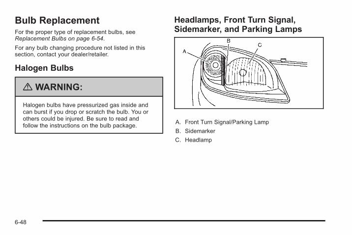
Bulb ReplacementFor the proper type of replacement bulbs, seeReplacement Bulbs on page 6‑54.
For any bulb changing procedure not listed in thissection, contact your dealer/retailer.
Halogen Bulbs
{ WARNING:
Halogen bulbs have pressurized gas inside andcan burst if you drop or scratch the bulb. You orothers could be injured. Be sure to read andfollow the instructions on the bulb package.
Headlamps, Front Turn Signal,Sidemarker, and Parking Lamps
A. Front Turn Signal/Parking Lamp
B. Sidemarker
C. Headlamp
6-48
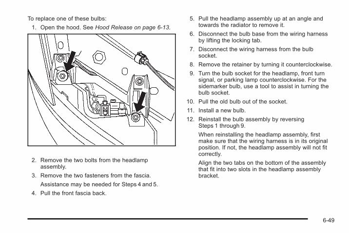
To replace one of these bulbs:
1. Open the hood. See Hood Release on page 6‑13.
2. Remove the two bolts from the headlampassembly.
3. Remove the two fasteners from the fascia.
Assistance may be needed for Steps 4 and 5.
4. Pull the front fascia back.
5. Pull the headlamp assembly up at an angle andtowards the radiator to remove it.
6. Disconnect the bulb base from the wiring harnessby lifting the locking tab.
7. Disconnect the wiring harness from the bulbsocket.
8. Remove the retainer by turning it counterclockwise.
9. Turn the bulb socket for the headlamp, front turnsignal, or parking lamp counterclockwise. For thesidemarker bulb, use a tool to assist in turning thebulb socket.
10. Pull the old bulb out of the socket.
11. Install a new bulb.
12. Reinstall the bulb assembly by reversingSteps 1 through 9.
When reinstalling the headlamp assembly, firstmake sure that the wiring harness is in its originalposition. If not, the headlamp assembly will not fitcorrectly.
Align the two tabs on the bottom of the assemblythat fit into two slots in the headlamp assemblybracket.
6-49
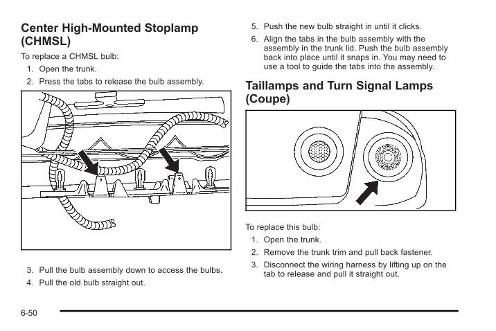
Center High-Mounted Stoplamp(CHMSL)To replace a CHMSL bulb:
1. Open the trunk.
2. Press the tabs to release the bulb assembly.
3. Pull the bulb assembly down to access the bulbs.
4. Pull the old bulb straight out.
5. Push the new bulb straight in until it clicks.
6. Align the tabs in the bulb assembly with theassembly in the trunk lid. Push the bulb assemblyback into place until it snaps in. You may need touse a tool to guide the tabs into the assembly.
Taillamps and Turn Signal Lamps(Coupe)
To replace this bulb:
1. Open the trunk.
2. Remove the trunk trim and pull back fastener.
3. Disconnect the wiring harness by lifting up on thetab to release and pull it straight out.
6-50
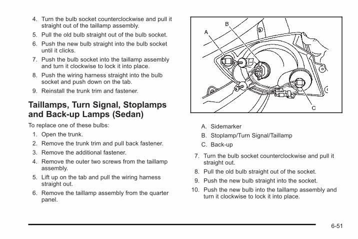
4. Turn the bulb socket counterclockwise and pull itstraight out of the taillamp assembly.
5. Pull the old bulb straight out of the bulb socket.
6. Push the new bulb straight into the bulb socketuntil it clicks.
7. Push the bulb socket into the taillamp assemblyand turn it clockwise to lock it into place.
8. Push the wiring harness straight into the bulbsocket and push down on the tab.
9. Reinstall the trunk trim and fastener.
Taillamps, Turn Signal, Stoplampsand Back-up Lamps (Sedan)To replace one of these bulbs:
1. Open the trunk.
2. Remove the trunk trim and pull back fastener.
3. Remove the additional fastener.
4. Remove the outer two screws from the taillampassembly.
5. Lift up on the tab and pull the wiring harnessstraight out.
6. Remove the taillamp assembly from the quarterpanel.
A. Sidemarker
B. Stoplamp/Turn Signal/Taillamp
C. Back-up
7. Turn the bulb socket counterclockwise and pull itstraight out.
8. Pull the old bulb straight out of the socket.
9. Push the new bulb straight into the socket.
10. Push the new bulb into the taillamp assembly andturn it clockwise to lock it into place.
6-51
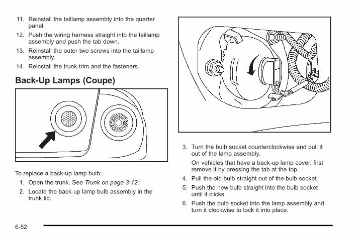
11. Reinstall the taillamp assembly into the quarterpanel.
12. Push the wiring harness straight into the taillampassembly and push the tab down.
13. Reinstall the outer two screws into the taillampassembly.
14. Reinstall the trunk trim and the fasteners.
Back-Up Lamps (Coupe)
To replace a back-up lamp bulb:
1. Open the trunk. See Trunk on page 3‑12.
2. Locate the back-up lamp bulb assembly in thetrunk lid.
3. Turn the bulb socket counterclockwise and pull itout of the lamp assembly.
On vehicles that have a back-up lamp cover, firstremove it by pressing the tab at the top.
4. Pull the old bulb straight out of the bulb socket.
5. Push the new bulb straight into the bulb socketuntil it clicks.
6. Push the bulb socket into the lamp assembly andturn it clockwise to lock it into place.
6-52
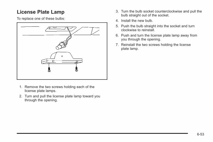
License Plate LampTo replace one of these bulbs:
1. Remove the two screws holding each of thelicense plate lamps.
2. Turn and pull the license plate lamp toward youthrough the opening.
3. Turn the bulb socket counterclockwise and pull thebulb straight out of the socket.
4. Install the new bulb.
5. Push the bulb straight into the socket and turnclockwise to reinstall.
6. Push and turn the license plate lamp away fromyou through the opening.
7. Reinstall the two screws holding the licenseplate lamp.
6-53
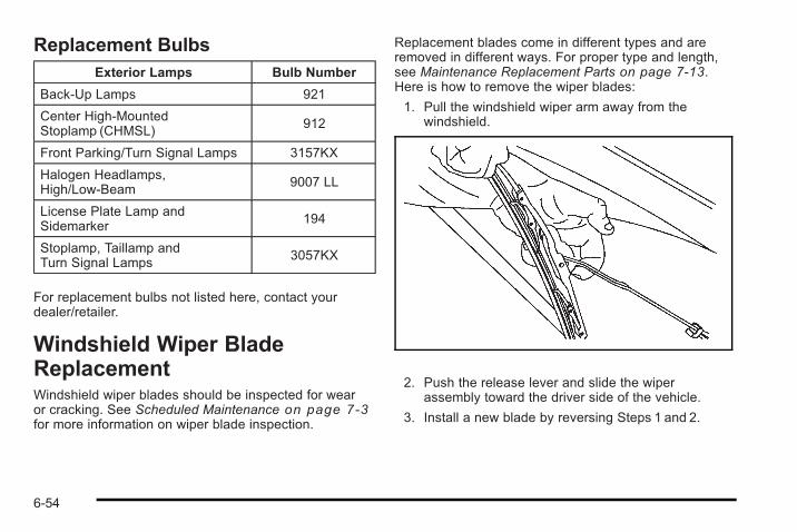
Replacement BulbsExterior Lamps Bulb Number
Back-Up Lamps 921
Center High-MountedStoplamp (CHMSL)
912
Front Parking/Turn Signal Lamps 3157KX
Halogen Headlamps,High/Low-Beam
9007 LL
License Plate Lamp andSidemarker
194
Stoplamp, Taillamp andTurn Signal Lamps
3057KX
For replacement bulbs not listed here, contact yourdealer/retailer.
Windshield Wiper BladeReplacementWindshield wiper blades should be inspected for wearor cracking. See Scheduled Maintenance on page 7‑3for more information on wiper blade inspection.
Replacement blades come in different types and areremoved in different ways. For proper type and length,see Maintenance Replacement Parts on page 7‑13.Here is how to remove the wiper blades:
1. Pull the windshield wiper arm away from thewindshield.
2. Push the release lever and slide the wiperassembly toward the driver side of the vehicle.
3. Install a new blade by reversing Steps 1 and 2.
6-54
TiresYour new vehicle comes with high-quality tiresmade by a leading tire manufacturer. If you everhave questions about the tire warranty and whereto obtain service, see the vehicle warranty bookletfor details. For additional information refer to thetire manufacturer.
{ WARNING:
Poorly maintained and improperly used tiresare dangerous.. Overloading your vehicle's tires can
cause overheating as a result of toomuch flexing. You could have an air-outand a serious accident. See Loading theVehicle on page 5‑25 .
. Underinflated tires pose the same dangeras overloaded tires. The resultingaccident could cause serious injury.Check all tires frequently to maintain therecommended pressure. Tire pressure
(Continued)
WARNING: (Continued)
should be checked when your vehicle'stires are cold. See Inflation - TirePressure on page 6‑64 .
. Overinflated tires are more likely to becut, punctured, or broken by a suddenimpact— such as when you hit a pothole.Keep tires at the recommended pressure.
. Worn, old tires can cause accidents.If the tire's tread is badly worn, or if yourvehicle's tires have been damaged,replace them.
6-55
Low-Profile Performance TireIf the vehicle has 225/40R18 size tires, they areclassified as low-profile performance tires. Thesetires are designed for very responsive driving onwet or dry pavement. You may also notice moreroad noise with low-profile performance tires andthat they tend to wear faster.
The 225/40R18 tire is a high performance tiredesigned for dry traction and handlingperformance which may result in reduced treadlife of 15,000 miles (24 140 km) or less dependingon individual driving behavior.
Notice: If the vehicle has low-profile tires, theyare more susceptible to damage from roadhazards or curb impact than standard profiletires. Tire and/or wheel assembly damage canoccur when coming into contact with roadhazards like, potholes, or sharp edged objects,or when sliding into a curb. The vehiclewarranty does not cover this type of damage.Keep tires set to the correct inflation pressureand, when possible avoid contact with curbs,potholes, and other road hazards.
Winter TiresIf the vehicle has 225/40R18 size tires, they areclassified as performance tires. These tires aredesigned for very responsive driving on wet or drypavement. If you expect to drive on snow or ice coveredroads often, you may want to get winter tires for thevehicle. All season tires provide good overallperformance on most surfaces but they may not offerthe traction you would like or the same level ofperformance as winter tires on snow or ice coveredroads.
Winter tires, in general, are designed for increasedtraction on snow and ice covered roads. With wintertires, there may be decreased dry road traction,increased road noise, and shorter tread life. Afterswitching to winter tires, be alert for changes in vehiclehandling and braking.
See your dealer/retailer for details regarding winter tireavailability and proper tire selection. Also, see BuyingNew Tires on page 6‑73.
6-56
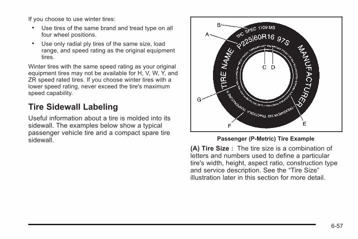
If you choose to use winter tires:. Use tires of the same brand and tread type on all
four wheel positions.. Use only radial ply tires of the same size, load
range, and speed rating as the original equipmenttires.
Winter tires with the same speed rating as your originalequipment tires may not be available for H, V, W, Y, andZR speed rated tires. If you choose winter tires with alower speed rating, never exceed the tire's maximumspeed capability.
Tire Sidewall LabelingUseful information about a tire is molded into itssidewall. The examples below show a typicalpassenger vehicle tire and a compact spare tiresidewall. Passenger (P-Metric) Tire Example
(A) Tire Size : The tire size is a combination ofletters and numbers used to define a particulartire's width, height, aspect ratio, construction typeand service description. See the “Tire Size”illustration later in this section for more detail.
6-57
(B) TPC Spec (Tire Performance CriteriaSpecification) : Original equipment tiresdesigned to GM's specific tire performance criteriahave a TPC specification code molded onto thesidewall. GM's TPC specifications meet or exceedall federal safety guidelines. If your vehicle has205/55R16 size tires, they meet the GM TPCSpec rating, but the TPC Spec code has not beenmolded onto the tire's sidewall.
(C) DOT (Department of Transportation) : TheDepartment of Transportation (DOT) codeindicates that the tire is in compliance with theU.S. Department of Transportation Motor VehicleSafety Standards.
(D) Tire Identification Number (TIN) : Theletters and numbers following DOT (Department ofTransportation) code is the Tire IdentificationNumber (TIN). The TIN shows the manufacturerand plant code, tire size, and date the tire wasmanufactured. The TIN is molded onto both sidesof the tire, although only one side may have thedate of manufacture.
(E) Tire Ply Material : The type of cord andnumber of plies in the sidewall and under thetread.
(F) Uniform Tire Quality Grading (UTQG) : Tiremanufacturers are required to grade tires basedon three performance factors: treadwear, tractionand temperature resistance. For more informationsee Uniform Tire Quality Grading on page 6‑76 .
(G) Maximum Cold Inflation Load Limit :Maximum load that can be carried and themaximum pressure needed to support that load.
6-58
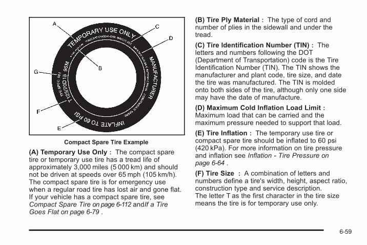
Compact Spare Tire Example
(A) Temporary Use Only : The compact sparetire or temporary use tire has a tread life ofapproximately 3,000 miles (5 000 km) and shouldnot be driven at speeds over 65 mph (105 km/h).The compact spare tire is for emergency usewhen a regular road tire has lost air and gone flat.If your vehicle has a compact spare tire, seeCompact Spare Tire on page 6‑112 andIf a TireGoes Flat on page 6‑79 .
(B) Tire Ply Material : The type of cord andnumber of plies in the sidewall and under thetread.
(C) Tire Identification Number (TIN) : Theletters and numbers following the DOT(Department of Transportation) code is the TireIdentification Number (TIN). The TIN shows themanufacturer and plant code, tire size, and datethe tire was manufactured. The TIN is moldedonto both sides of the tire, although only one sidemay have the date of manufacture.
(D) Maximum Cold Inflation Load Limit :Maximum load that can be carried and themaximum pressure needed to support that load.
(E) Tire Inflation : The temporary use tire orcompact spare tire should be inflated to 60 psi(420 kPa). For more information on tire pressureand inflation see Inflation - Tire Pressure onpage 6‑64 .
(F) Tire Size : A combination of letters andnumbers define a tire's width, height, aspect ratio,construction type and service description.The letter T as the first character in the tire sizemeans the tire is for temporary use only.
6-59
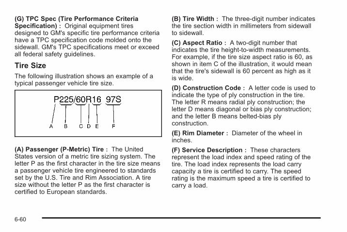
(G) TPC Spec (Tire Performance CriteriaSpecification) : Original equipment tiresdesigned to GM's specific tire performance criteriahave a TPC specification code molded onto thesidewall. GM's TPC specifications meet or exceedall federal safety guidelines.
Tire SizeThe following illustration shows an example of atypical passenger vehicle tire size.
(A) Passenger (P-Metric) Tire : The UnitedStates version of a metric tire sizing system. Theletter P as the first character in the tire size meansa passenger vehicle tire engineered to standardsset by the U.S. Tire and Rim Association. A tiresize without the letter P as the first character iscertified to European standards.
(B) Tire Width : The three-digit number indicatesthe tire section width in millimeters from sidewallto sidewall.
(C) Aspect Ratio : A two-digit number thatindicates the tire height-to-width measurements.For example, if the tire size aspect ratio is 60, asshown in item C of the illustration, it would meanthat the tire's sidewall is 60 percent as high as itis wide.
(D) Construction Code : A letter code is used toindicate the type of ply construction in the tire.The letter R means radial ply construction; theletter D means diagonal or bias ply construction;and the letter B means belted-bias plyconstruction.
(E) Rim Diameter : Diameter of the wheel ininches.
(F) Service Description : These charactersrepresent the load index and speed rating of thetire. The load index represents the load carrycapacity a tire is certified to carry. The speedrating is the maximum speed a tire is certified tocarry a load.
6-60
Tire Terminology and DefinitionsAir Pressure : The amount of air inside the tirepressing outward on each square inch of the tire.Air pressure is expressed in pounds per squareinch (psi) or kilopascal (kPa).
Accessory Weight : This means the combinedweight of optional accessories. Some examples ofoptional accessories are, automatic transmission,power steering, power brakes, power windows,power seats, and air conditioning.
Aspect Ratio : The relationship of a tire's heightto its width.
Belt : A rubber coated layer of cords that islocated between the plies and the tread. Cordsmay be made from steel or other reinforcingmaterials.
Bead : The tire bead contains steel wireswrapped by steel cords that hold the tire ontothe rim.
Bias Ply Tire : A pneumatic tire in which the pliesare laid at alternate angles less than 90 degreesto the centerline of the tread.
Cold Tire Pressure : The amount of air pressurein a tire, measured in pounds per square inch (psi)or kilopascals (kPa) before a tire has built up heatfrom driving. See Inflation - Tire Pressure onpage 6‑64 .
Curb Weight : The weight of a motor vehicle withstandard and optional equipment including themaximum capacity of fuel, oil, and coolant, butwithout passengers and cargo.
DOT Markings : A code molded into the sidewallof a tire signifying that the tire is in compliancewith the U.S. Department of Transportation (DOT)motor vehicle safety standards. The DOT codeincludes the Tire Identification Number (TIN), analphanumeric designator which can also identifythe tire manufacturer, production plant, brand, anddate of production.
GVWR : Gross Vehicle Weight Rating. SeeLoading the Vehicle on page 5‑25 .
GAWR FRT : Gross Axle Weight Rating for thefront axle. See Loading the Vehicle on page 5‑25 .
GAWR RR : Gross Axle Weight Rating for therear axle. See Loading the Vehicle on page 5‑25 .
6-61
Intended Outboard Sidewall : The side of anasymmetrical tire, that must always face outwardwhen mounted on a vehicle.
Kilopascal (kPa) : The metric unit for airpressure.
Light Truck (LT-Metric) Tire : A tire used on lightduty trucks and some multipurpose passengervehicles.
Load Index : An assigned number ranging from1 to 279 that corresponds to the load carryingcapacity of a tire.
Maximum Inflation Pressure : The maximumair pressure to which a cold tire can be inflated.The maximum air pressure is molded onto thesidewall.
Maximum Load Rating : The load rating for atire at the maximum permissible inflation pressurefor that tire.
Maximum Loaded Vehicle Weight : The sum ofcurb weight, accessory weight, vehicle capacityweight, and production options weight.
Normal Occupant Weight : The number ofoccupants a vehicle is designed to seat multipliedby 150 lbs (68 kg). See Loading the Vehicle onpage 5‑25 .
Occupant Distribution : Designated seatingpositions.
Outward Facing Sidewall : The side of anasymmetrical tire that has a particular side thatfaces outward when mounted on a vehicle.The side of the tire that contains a whitewall,bears white lettering, or bears manufacturer,brand, and/or model name molding that is higheror deeper than the same moldings on the othersidewall of the tire.
Passenger (P-Metric) Tire : A tire used onpassenger cars and some light duty trucks andmultipurpose vehicles.
Recommended Inflation Pressure : Vehiclemanufacturer's recommended tire inflationpressure as shown on the tire placard. SeeInflation - Tire Pressure on page 6‑64 and Loadingthe Vehicle on page 5‑25 .
6-62
Radial Ply Tire : A pneumatic tire in which theply cords that extend to the beads are laid at90 degrees to the centerline of the tread.
Rim : A metal support for a tire and upon whichthe tire beads are seated.
Sidewall : The portion of a tire between the treadand the bead.
Speed Rating : An alphanumeric code assignedto a tire indicating the maximum speed at which atire can operate.
Traction : The friction between the tire and theroad surface. The amount of grip provided.
Tread : The portion of a tire that comes intocontact with the road.
Treadwear Indicators : Narrow bands,sometimes called wear bars, that show across thetread of a tire when only 1/16 inch (1.6 mm) oftread remains. See When It Is Time for New Tireson page 6‑73 .
UTQGS (Uniform Tire Quality GradingStandards) : A tire information system thatprovides consumers with ratings for a tire'straction, temperature, and treadwear. Ratings aredetermined by tire manufacturers usinggovernment testing procedures. The ratings aremolded into the sidewall of the tire. See UniformTire Quality Grading on page 6‑76 .
Vehicle Capacity Weight : The number ofdesignated seating positions multiplied by 150 lbs(68 kg) plus the rated cargo load. See Loading theVehicle on page 5‑25 .
Vehicle Maximum Load on the Tire : Load onan individual tire due to curb weight, accessoryweight, occupant weight, and cargo weight.
Vehicle Placard : A label permanently attachedto a vehicle showing the vehicle's capacityweight and the original equipment tire size andrecommended inflation pressure. See “Tire andLoading Information Label” under Loading theVehicle on page 5‑25 .
6-63
Inflation - Tire PressureTires need the correct amount of air pressure tooperate effectively.
Notice: Do not let anyone tell you thatunder-inflation or over-inflation is all right. It isnot. If your tires do not have enough air(under-inflation), you can get the following:
. Too much flexing
. Too much heat
. Tire overloading
. Premature or irregular wear
. Poor handling
. Reduced fuel economy
If your tires have too much air (over-inflation),you can get the following:
. Unusual wear
. Poor handling
. Rough ride
. Needless damage from road hazards
A vehicle specific Tire and Loading Informationlabel is attached to your vehicle. This label showsyour vehicle's original equipment tires and thecorrect inflation pressures for your tires when theyare cold. The recommended cold tire inflationpressure, shown on the label, is the minimumamount of air pressure needed to support yourvehicle's maximum load carrying capacity.
For additional information regarding how muchweight your vehicle can carry, and an example ofthe Tire and Loading Information label, seeLoading the Vehicle on page 5‑25 . How you loadyour vehicle affects vehicle handling and ridecomfort. Never load your vehicle with more weightthan it was designed to carry.
6-64
When to CheckCheck your tires once a month or more. Do notforget to check the compact spare tire, if thevehicle has one. It should be at 60 psi (420 kPa).For additional information regarding the compactspare tire, seeCompact Spare Tire on page 6‑112 .
How to CheckUse a good quality pocket-type gage to check tirepressure. You cannot tell if your tires are properlyinflated simply by looking at them. Radial tiresmay look properly inflated even when they areunder-inflated. Check the tire's inflation pressurewhen the tires are cold. Cold means your vehiclehas been sitting for at least three hours or drivenno more than 1mile (1.6 km).
Remove the valve cap from the tire valve stem.Press the tire gage firmly onto the valve to get apressure measurement. If the cold tire inflationpressure matches the recommended pressure onthe Tire and Loading Information label, no furtheradjustment is necessary. If the inflation pressureis low, add air until you reach the recommendedamount.
If you overfill the tire, release air by pushing onthe metal stem in the center of the tire valve.Re-check the tire pressure with the tire gage.
Be sure to put the valve caps back on the valvestems. They help prevent leaks by keeping out dirtand moisture.
Tire Pressure Monitor SystemThe vehicle may have a Tire Pressure Monitor System(TPMS). This system uses radio and sensor technologyto check tire pressure levels. The TPMS sensorsmonitor the air pressure in your vehicle's tires andtransmit tire pressure readings to a receiver located inthe vehicle.
Each tire, including the spare (if provided), should bechecked monthly when cold and inflated to the inflationpressure recommended by the vehicle manufactureron the vehicle placard or tire inflation pressure label.(If your vehicle has tires of a different size than the sizeindicated on the vehicle placard or tire inflation pressurelabel, you should determine the proper tire inflationpressure for those tires.)
As an added safety feature, your vehicle has beenequipped with a tire pressure monitoring system(TPMS) that illuminates a low tire pressure telltale whenone or more of your tires is significantly under-inflated.
6-65
Accordingly, when the low tire pressure telltaleilluminates, you should stop and check your tires assoon as possible, and inflate them to the properpressure. Driving on a significantly under-inflated tirecauses the tire to overheat and can lead to tire failure.Under-inflation also reduces fuel efficiency and tiretread life, and may affect the vehicle's handling andstopping ability.
Please note that the TPMS is not a substitute for propertire maintenance, and it is the driver's responsibility tomaintain correct tire pressure, even if under-inflationhas not reached the level to trigger illumination of theTPMS low tire pressure telltale.
Your vehicle has also been equipped with a TPMSmalfunction indicator to indicate when the system is notoperating properly. The TPMS malfunction indicator iscombined with the low tire pressure telltale. When thesystem detects a malfunction, the telltale will flash forapproximately one minute and then remain continuouslyilluminated. This sequence will continue uponsubsequent vehicle start-ups as long as the malfunctionexists.
When the malfunction indicator is illuminated, thesystem may not be able to detect or signal low tirepressure as intended. TPMS malfunctions may occurfor a variety of reasons, including the installation ofreplacement or alternate tires or wheels on the vehiclethat prevent the TPMS from functioning properly.Always check the TPMS malfunction telltale afterreplacing one or more tires or wheels on your vehicle toensure that the replacement or alternate tires andwheels allow the TPMS to continue to function properly.
See Tire Pressure Monitor Operation on page 6‑67 foradditional information.
Federal Communications Commission(FCC) and Industry and Science CanadaSee Radio Frequency Statement on page 8‑19 forinformation regarding Part 15 of the FederalCommunications Commission (FCC) Rules andRSS-210/211 of Industry and Science Canada.
6-66
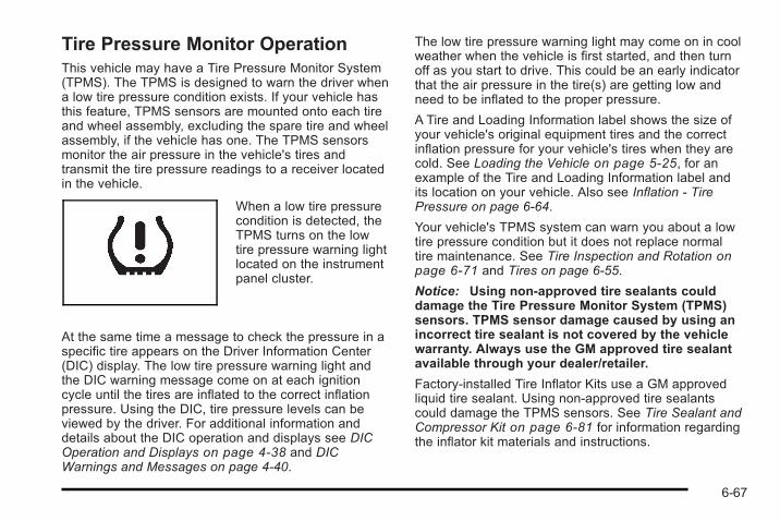
Tire Pressure Monitor OperationThis vehicle may have a Tire Pressure Monitor System(TPMS). The TPMS is designed to warn the driver whena low tire pressure condition exists. If your vehicle hasthis feature, TPMS sensors are mounted onto each tireand wheel assembly, excluding the spare tire and wheelassembly, if the vehicle has one. The TPMS sensorsmonitor the air pressure in the vehicle's tires andtransmit the tire pressure readings to a receiver locatedin the vehicle.
When a low tire pressurecondition is detected, theTPMS turns on the lowtire pressure warning lightlocated on the instrumentpanel cluster.
At the same time a message to check the pressure in aspecific tire appears on the Driver Information Center(DIC) display. The low tire pressure warning light andthe DIC warning message come on at each ignitioncycle until the tires are inflated to the correct inflationpressure. Using the DIC, tire pressure levels can beviewed by the driver. For additional information anddetails about the DIC operation and displays see DICOperation and Displays on page 4‑38 and DICWarnings and Messages on page 4‑40.
The low tire pressure warning light may come on in coolweather when the vehicle is first started, and then turnoff as you start to drive. This could be an early indicatorthat the air pressure in the tire(s) are getting low andneed to be inflated to the proper pressure.
A Tire and Loading Information label shows the size ofyour vehicle's original equipment tires and the correctinflation pressure for your vehicle's tires when they arecold. See Loading the Vehicle on page 5‑25, for anexample of the Tire and Loading Information label andits location on your vehicle. Also see Inflation - TirePressure on page 6‑64.
Your vehicle's TPMS system can warn you about a lowtire pressure condition but it does not replace normaltire maintenance. See Tire Inspection and Rotation onpage 6‑71 and Tires on page 6‑55.
Notice: Using non-approved tire sealants coulddamage the Tire Pressure Monitor System (TPMS)sensors. TPMS sensor damage caused by using anincorrect tire sealant is not covered by the vehiclewarranty. Always use the GM approved tire sealantavailable through your dealer/retailer.
Factory-installed Tire Inflator Kits use a GM approvedliquid tire sealant. Using non-approved tire sealantscould damage the TPMS sensors. See Tire Sealant andCompressor Kit on page 6‑81 for information regardingthe inflator kit materials and instructions.
6-67
TPMS Malfunction Light and MessageThe TPMS will not function properly if one or more ofthe TPMS sensors are missing or inoperable. When thesystem detects a malfunction, the low tire warning lightflashes for about one minute and then stays on for theremainder of the ignition cycle. A DIC warning messageis also displayed. The low tire warning light and DICwarning message come on at each ignition cycle untilthe problem is corrected. Some of the conditions thatcan cause the malfunction light and DIC message tocome on are:. One of the road tires has been replaced with the
spare tire, if the vehicle has one. The spare tiredoes not have a TPMS sensor. The TPMSmalfunction light and DIC message should go offonce you re-install the road tire containing theTPMS sensor.
. The TPMS sensor matching process was startedbut not completed or not completed successfullyafter rotating the vehicle's tires. The DIC messageand TPMS malfunction light should go off once theTPMS sensor matching process is performedsuccessfully. See “TPMS Sensor MatchingProcess” later in this section.
. One or more TPMS sensors are missing ordamaged. The DIC message and the TPMSmalfunction light should go off when the TPMS
sensors are installed and the sensor matchingprocess is performed successfully. See yourdealer/retailer for service.
. Replacement tires or wheels do not match yourvehicle's original equipment tires or wheels. Tiresand wheels other than those recommended foryour vehicle could prevent the TPMS fromfunctioning properly. See Buying New Tires onpage 6‑73.
. Operating electronic devices or being near facilitiesusing radio wave frequencies similar to the TPMScould cause the TPMS sensors to malfunction.
If the TPMS is not functioning it cannot detect or signala low tire condition. See your dealer/retailer for serviceif the TPMS malfunction light and DIC message comeson and stays on.
TPMS Sensor Matching ProcessEach TPMS sensor has a unique identification code.Any time you replace one or more of the TPMS sensorsor rotate the vehicle's tires, the identification codesneed to be matched to the new tire/wheel location.The sensors are matched, to the tire/wheel locations, inthe following order: driver side front tire, passenger sidefront tire, passenger side rear tire, and driver side reartire using a TPMS diagnostic tool. See your dealer/retailer for service.
6-68
The TPMS sensors can also be matched to each tire/wheel position by increasing or decreasing the tire's airpressure. When increasing the tire's pressure, do notexceed the maximum inflation pressure indicated on thetire's sidewall. To decrease the tire's air-pressure usethe pointed end of the valve cap, a pencil-style airpressure gage, or a key.
You have two minutes to match each tire and wheelposition. If it takes longer than two minutes to matchany tire and wheel position, the matching process stopsand you need to start over.
TPMS Matching Process for Vehicleswith Remote Keyless Entry (RKE)1. Set the parking brake.
2. Turn the ignition switch to ON/RUN with theengine off.
3. Press and hold the Remote Keyless Entry (RKE)transmitter's lock and unlock buttons, at the sametime, for about five seconds to start the TPMSlearn mode. The horn sounds twice indicating theTPMS receiver is ready and in learn mode.
4. Start with the driver side front tire. The driver sidefront turn signal also comes on to indicate thatcorner's sensor is ready to be learned.
5. Remove the valve cap from the tire's valve stem.Activate the TPMS sensor by increasing ordecreasing the tire's air pressure for abouteight seconds. The horn chirp, can take up to30 seconds to sound. It chirps one time and thenall the turn signals flash one time to confirm thesensor identification code has been matched to thetire/wheel position.
6. The passenger side front turn signal comes on toindicate that corner sensor is ready to be learned.Proceed to the passenger side front tire and repeatthe procedure in Step 5.
7. The passenger side rear turn signal comes on toindicate that corner sensor is ready to be learned.Proceed to the passenger side rear tire and repeatthe procedure in Step 5.
8. The driver side rear turn signal comes on toindicate that corner sensor is ready to be learned.Proceed to the driver side rear tire, and repeat theprocedure in Step 5.
6-69
9. After hearing the single horn chirp for the driverside rear tire, two additional horn chirps sound toindicate the tire learning process is done. Turn theignition switch to LOCK/OFF.
If no tires are learned after entering the TPMSlearn mode, or if communication with the receiverstops, or if the time limit has expired, turn theignition switch to LOCK/OFF and start overbeginning with Step 2.
10. Set all four tires to the recommended air pressurelevel as indicated on the Tire and LoadingInformation label.
11. Put the valve caps back on the valve stems.
TPMS Matching Process for Vehicleswithout Remote Keyless Entry (RKE)1. Set the parking brake.
2. Turn the ignition switch to ON/RUN with theengine off.
3. Using the Driver Information Center (DIC), pressthe INFO and Set/Reset buttons at the same timefor about one second. Then press and release theINFO button until the TIRE LEARN? messagedisplays.
4. Press and hold the Set/Reset DIC button forapproximately three seconds to start the TPMSlearn mode. The horn sounds twice to indicate theTPMS receiver is ready and the TIRE LEARN ONmessage displays. The driver side front turn signalalso comes on to indicate that corner sensor isready to be learned.
5. Start with the driver side front tire.
6. Remove the valve cap from the tire's valve stem.Activate the TPMS sensor by increasing ordecreasing the tire's air pressure for abouteight seconds. The horn chirp, can take up to30 seconds to sound. It chirps one time and thenall the turn signals flash one time to confirm thesensor identification code has been matched to thetire/wheel position.
7. The passenger side front turn signal comes on toindicate that corner sensor is ready to be learned.Proceed to the passenger side front tire and repeatthe procedure in Step 6.
8. The passenger side rear turn signal comes on toindicate that corner sensor is ready to be learned.Proceed to the passenger side rear tire and repeatthe procedure in Step 6.
6-70
9. The driver side rear turn signal comes on toindicate that corner sensor is ready to be learned.Proceed to the driver side rear tire, and repeat theprocedure in Step 6.
10. After hearing the single horn chirp for the driverside rear tire, two additional horn chirps sound toindicate the tire learning process is done. TheLEARN COMPLETE message displays if all fourtire positions are learned. Turn the ignition switchto LOCK/OFF.
If no tires are learned after entering the TPMSlearn mode, or if communication with the receiverstops, or if the time limit has expired, the TIRELEARN? message displays on the DIC. Turn theignition switch to LOCK/OFF and start overbeginning with Step 2.
11. Set all four tires to the recommended air pressurelevel as indicated on the Tire and LoadingInformation label.
12. Put the valve caps back on the valve stems.
Tire Inspection and RotationWe recommend that you regularly inspect thevehicle's tires, including the spare tire, if thevehicle has one, for signs of wear or damage.See When It Is Time for New Tires on page 6‑73for more information.
Tires should be rotated every 5,000 to 8,000 miles(8 000 to 13 000 km). See Scheduled Maintenanceon page 7‑3 .
If this vehicle has P225/40R18 size tires, theyshould be rotated every 3,000 miles (5 000 km).
The purpose of a regular tire rotation is to achievea uniform wear for all tires on the vehicle. This willensure that the vehicle continues to perform mostlike it did when the tires were new.
Any time you notice unusual wear, rotate the tiresas soon as possible and check wheel alignment.Also check for damaged tires or wheels. SeeWhen It Is Time for New Tires on page 6‑73 andWheel Replacement on page 6‑77 .
6-71
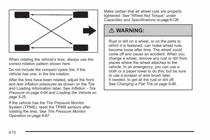
When rotating the vehicle's tires, always use thecorrect rotation pattern shown here.
Do not include the compact spare tire, if thevehicle has one, in the tire rotation.
After the tires have been rotated, adjust the frontand rear inflation pressures as shown on the Tireand Loading Information label. See Inflation - TirePressure on page 6‑64 and Loading the Vehicle onpage 5‑25 .
If the vehicle has the Tire Pressure MonitorSystem (TPMS), reset the TPMS sensors afterrotating the tires. See Tire Pressure MonitorOperation on page 6‑67 .
Make certain that all wheel nuts are properlytightened. See “Wheel Nut Torque” underCapacities and Specifications on page 6‑128 .
{ WARNING:
Rust or dirt on a wheel, or on the parts towhich it is fastened, can make wheel nutsbecome loose after time. The wheel couldcome off and cause an accident. When youchange a wheel, remove any rust or dirt fromplaces where the wheel attaches to thevehicle. In an emergency, you can use acloth or a paper towel to do this; but be sureto use a scraper or wire brush later,if needed, to get all the rust or dirt off.See Changing a Flat Tire on page 6‑89 .
6-72
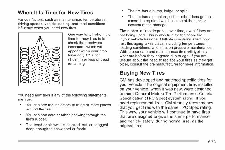
When It Is Time for New TiresVarious factors, such as maintenance, temperatures,driving speeds, vehicle loading, and road conditionsinfluence when you need new tires.
One way to tell when it istime for new tires is tocheck the treadwearindicators, which willappear when your tireshave only 1/16 inch(1.6 mm) or less of treadremaining.
You need new tires if any of the following statementsare true:. You can see the indicators at three or more places
around the tire.. You can see cord or fabric showing through the
tire's rubber.. The tread or sidewall is cracked, cut, or snagged
deep enough to show cord or fabric.
. The tire has a bump, bulge, or split.
. The tire has a puncture, cut, or other damage thatcannot be repaired well because of the size orlocation of the damage.
The rubber in tires degrades over time, even if they arenot being used. This is also true for the spare tire,if your vehicle has one. Multiple conditions affect howfast this aging takes place, including temperatures,loading conditions, and inflation pressure maintenance.With proper care and maintenance tires will typicallywear out before they degrade due to age. If you areunsure about the need to replace your tires as they getolder, consult the tire manufacturer for more information.
Buying New TiresGM has developed and matched specific tires foryour vehicle. The original equipment tires installedon your vehicle, when it was new, were designedto meet General Motors Tire Performance CriteriaSpecification (TPC Spec) system rating. If youneed replacement tires, GM strongly recommendsthat you get tires with the same TPC Spec rating.This way, your vehicle will continue to have tiresthat are designed to give the same performanceand vehicle safety, during normal use, as theoriginal tires.
6-73
GM's exclusive TPC Spec system considers overa dozen critical specifications that impact theoverall performance of your vehicle, includingbrake system performance, ride and handling,traction control, and tire pressure monitoringperformance. GM's TPC Spec number is moldedonto the tire's sidewall near the tire size. If thetires have an all-season tread design, the TPCSpec number will be followed by an MS for mudand snow. See Tire Sidewall Labeling onpage 6‑57 for additional information.
GM recommends replacing tires in sets of four.This is because uniform tread depth on all tireswill help keep your vehicle performing most like itdid when the tires were new. Replacing less thana full set of tires can affect the braking andhandling performance of your vehicle. See TireInspection and Rotation on page 6‑71 forinformation on proper tire rotation.
{ WARNING:
Mixing tires could cause you to lose controlwhile driving. If you mix tires of differentsizes, brands, or types (radial andbias-belted tires), the vehicle may not handleproperly, and you could have a crash. Usingtires of different sizes, brands, or types mayalso cause damage to your vehicle. Be sureto use the correct size, brand, and type oftires on all wheels. It is all right to drive withyour compact spare temporarily, as it wasdeveloped for use on your vehicle. SeeCompact Spare Tire on page 6‑112 .
{ WARNING:
If you use bias-ply tires on the vehicle, thewheel rim flanges could develop cracks aftermany miles of driving. A tire and/or wheelcould fail suddenly, causing a crash. Useonly radial-ply tires with the wheels on thevehicle.
6-74
If you must replace your vehicle's tires with thosethat do not have a TPC Spec number, make surethey are the same size, load range, speed rating,and construction type (radial and bias-belted tires)as your vehicle's original tires.
Vehicles that have a tire pressure monitoringsystem could give an inaccurate low-pressurewarning if non-TPC Spec rated tires are installedon your vehicle. Non-TPC Spec rated tires maygive a low-pressure warning that is higher or lowerthan the proper warning level you would get withTPC Spec rated tires. See Tire Pressure MonitorSystem on page 6‑65 .
Your vehicle's original equipment tires are listedon the Tire and Loading Information Label. SeeLoading the Vehicle on page 5‑25 , for moreinformation about the Tire and LoadingInformation Label and its location on your vehicle.
Different Size Tires and WheelsIf you add wheels or tires that are a different size thanyour original equipment wheels and tires, this mayaffect the way your vehicle performs, including itsbraking, ride and handling characteristics, stability, andresistance to rollover . Additionally, if your vehicle haselectronic systems such as, antilock brakes, tractioncontrol, and electronic stability control, the performanceof these systems can be affected.
{ WARNING:
If you add different sized wheels, your vehiclemay not provide an acceptable level ofperformance and safety if tires not recommendedfor those wheels are selected. You may increasethe chance that you will crash and suffer seriousinjury. Only use GM specific wheel and tiresystems developed for your vehicle, and havethem properly installed by a GM certifiedtechnician.
See Buying New Tires on page 6‑73 and Accessoriesand Modifications on page 6‑4 for additionalinformation.
6-75
Uniform Tire Quality GradingQuality grades can be found where applicable onthe tire sidewall between tread shoulder andmaximum section width. For example:
Treadwear 200 Traction AATemperature AThe following information relates to the systemdeveloped by the United States National HighwayTraffic Safety Administration (NHTSA), whichgrades tires by treadwear, traction, andtemperature performance. This applies only tovehicles sold in the United States. The grades aremolded on the sidewalls of most passenger cartires. The Uniform Tire Quality Grading (UTQG)system does not apply to deep tread, winter-typesnow tires, space-saver, or temporary use sparetires, tires with nominal rim diameters of10 to 12 inches (25 to 30 cm), or to somelimited-production tires.
While the tires available on General Motorspassenger cars and light trucks may vary withrespect to these grades, they must also conformto federal safety requirements and additionalGeneral Motors Tire Performance Criteria (TPC)standards.
TreadwearThe treadwear grade is a comparative ratingbased on the wear rate of the tire when testedunder controlled conditions on a specifiedgovernment test course. For example, a tiregraded 150 would wear one and a half (1.5) timesas well on the government course as a tire graded100. The relative performance of tires dependsupon the actual conditions of their use, however,and may depart significantly from the norm due tovariations in driving habits, service practices, anddifferences in road characteristics and climate.
Traction – AA, A, B, CThe traction grades, from highest to lowest, areAA, A, B, and C. Those grades represent the tire'sability to stop on wet pavement as measuredunder controlled conditions on specifiedgovernment test surfaces of asphalt and concrete.A tire marked C may have poor tractionperformance.
6-76
Temperature – A, B, CThe temperature grades are A (the highest), B,and C, representing the tire's resistance to thegeneration of heat and its ability to dissipate heatwhen tested under controlled conditions on aspecified indoor laboratory test wheel. Sustainedhigh temperature can cause the material of thetire to degenerate and reduce tire life, andexcessive temperature can lead to sudden tirefailure. The grade C corresponds to a level ofperformance which all passenger car tires mustmeet under the Federal Motor Vehicle SafetyStandard No. 109. Grades B and A representhigher levels of performance on the laboratory testwheel than the minimum required by law. It shouldbe noted that the temperature grade for this tire isestablished for a tire that is properly inflated andnot overloaded. Excessive speed, underinflation,or excessive loading, either separately or incombination, can cause heat buildup and possibletire failure.
Wheel Alignment and Tire BalanceThe tires and wheels on your vehicle were aligned andbalanced carefully at the factory to give you the longesttire life and best overall performance. Adjustments towheel alignment and tire balancing will not benecessary on a regular basis. However, if you noticeunusual tire wear or your vehicle pulling to one side orthe other, the alignment might need to be checked.If you notice your vehicle vibrating when driving on asmooth road, the tires and wheels might need to berebalanced. See your dealer/retailer for properdiagnosis.
Wheel ReplacementReplace any wheel that is bent, cracked, or badlyrusted or corroded. If wheel nuts keep coming loose,the wheel, wheel bolts, and wheel nuts should bereplaced. If the wheel leaks air, replace it (except somealuminum wheels, which can sometimes be repaired).See your dealer/retailer if any of these conditions exist.
Your dealer/retailer will know the kind of wheelyou need.
6-77
Each new wheel should have the same load-carryingcapacity, diameter, width, offset, and be mounted thesame way as the one it replaces.
If you need to replace any of your wheels, wheel bolts,wheel nuts, or Tire Pressure Monitor System (TPMS)sensors, replace them only with new GM originalequipment parts. This way, you will be sure to have theright wheel, wheel bolts, wheel nuts, and TPMS sensorsfor your vehicle.
{ WARNING:
Using the wrong replacement wheels, wheel bolts,or wheel nuts on your vehicle can be dangerous.It could affect the braking and handling of yourvehicle, make your tires lose air and make youlose control. You could have a collision in whichyou or others could be injured. Always use thecorrect wheel, wheel bolts, and wheel nuts forreplacement.
Notice: The wrong wheel can also cause problemswith bearing life, brake cooling, speedometer orodometer calibration, headlamp aim, bumper height,vehicle ground clearance, and tire or tire chainclearance to the body and chassis.
See Changing a Flat Tire on page 6‑89 for moreinformation.
Used Replacement Wheels
{ WARNING:
Putting a used wheel on the vehicle is dangerous.You cannot know how it has been used or how farit has been driven. It could fail suddenly andcause a crash. If you have to replace a wheel, usea new GM original equipment wheel.
6-78
Tire Chains
{ WARNING:
If your vehicle has P195/65R15, P205/55R16,P205/50R17, or 225/40R18 size tires, do not usetire chains. They can damage your vehiclebecause there is not enough clearance.
Tire chains used on a vehicle without the properamount of clearance can cause damage to thebrakes, suspension, or other vehicle parts. Thearea damaged by the tire chains could cause youto lose control of your vehicle and you or othersmay be injured in a crash.
Use another type of traction device only if itsmanufacturer recommends it for use on yourvehicle and tire size combination, and roadconditions. Follow that manufacturer'sinstructions. To help avoid damage to yourvehicle, drive slowly, readjust, or remove thedevice if it is contacting your vehicle, and do notspin your vehicle's wheels.
If you do find traction devices that will fit, installthem on the front tires.
Notice: If your vehicle has a tire size other thanP195/65R15, P205/55R16, P205/50R17 or 225/40R18size tires, use tire chains only where legal and onlywhen you must. Use only SAE Class S-type chainsthat are the proper size for your tires. Install themon the front tires and tighten them as tightly aspossible with the ends securely fastened. Driveslowly and follow the chain manufacturer'sinstructions. If you can hear the chains contactingyour vehicle, stop and retighten them. If the contactcontinues, slow down until it stops. Driving too fastor spinning the wheels with chains on will damageyour vehicle.
If a Tire Goes FlatIt is unusual for a tire to blowout while you are driving,especially if you maintain the tires properly. See Tireson page 6‑55. If air goes out of a tire, It is much morelikely to leak out slowly. But if you should ever have ablowout, here are a few tips about what to expect andwhat to do:
If a front tire fails, the flat tire will create a drag that pullsthe vehicle toward that side. Take your foot off theaccelerator pedal and grip the steering wheel firmly.Steer to maintain lane position, and then gently brake toa stop well out of the traffic lane.
6-79
A rear blowout, particularly on a curve, acts much like askid and may require the same correction you woulduse in a skid. In any rear blowout, remove your footfrom the accelerator pedal. Get the vehicle undercontrol by steering the way you want the vehicle to go.It may be very bumpy and noisy, but you can still steer.Gently brake to a stop, well off the road if possible.
If a tire goes flat, avoid further tire and wheel damageby driving slowly to a level place and stopping.
1. Turn on the hazard warning flashers. See HazardWarning Flashers on page 4‑3.
2. Park the vehicle. Set the parking brake firmly andput the shift lever in P (Park).
3. Turn off the engine.
4. Inspect the flat tire.
{ WARNING:
Lifting a vehicle and getting under it to domaintenance or repairs is dangerous without theappropriate safety equipment and training. If ajack is provided with the vehicle, it is designedonly for changing a flat tire. If it is used foranything else, you or others could be badlyinjured or killed if the vehicle slips off the jack. If ajack is provided with the vehicle, only use it forchanging a flat tire.
This vehicle may come with a jack and spare tire or atire sealant and compressor kit. To use the jack andspare tire, see Changing a Flat Tire on page 6‑89.To use the tire sealant and compressor kit, see TireSealant and Compressor Kit on page 6‑81.
6-80
Tire Sealant and Compressor Kit
{ WARNING:
Idling a vehicle in an enclosed area with poorventilation is dangerous. Engine exhaust mayenter the vehicle. Engine exhaust containsCarbon Monoxide (CO) which cannot be seen orsmelled. It can cause unconsciousness and evendeath. Never run the engine in an enclosed areathat has no fresh air ventilation. For moreinformation, see Engine Exhaust on page 3‑35.
{ WARNING:
Over-inflating a tire could cause the tire to ruptureand you or others could be injured. Be sure toread and follow the tire sealant and compressorkit instructions and inflate the tire to itsrecommended pressure. Do not exceed therecommended pressure.
{ WARNING:
Storing the tire sealant and compressor kit orother equipment in the passenger compartment ofthe vehicle could cause injury. In a sudden stop orcollision, loose equipment could strike someone.Store the tire sealant and compressor kit in itsoriginal location.
If this vehicle has a tire sealant and compressor kit,there may not be a spare tire, tire changing equipment,and on some vehicles there may not be a place tostore a tire.
The tire sealant and compressor can be used totemporarily seal punctures up to ¼ inch (6 mm) in thetread area of the tire. It can also be used to inflate anunder inflated tire.
If the tire has been separated from the wheel, hasdamaged sidewalls, or has a large puncture, the tire istoo severely damaged for the tire sealant andcompressor kit to be effective. See RoadsideAssistance Program on page 8‑8.
6-81
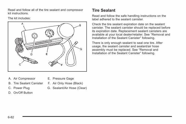
Read and follow all of the tire sealant and compressorkit instructions.
The kit includes:
A. Air Compressor
B. Tire Sealant Canister
C. Power Plug
D. On/Off Button
E. Pressure Gage
F. Air Only Hose (Black)
G. Sealant/Air Hose (Clear)
Tire SealantRead and follow the safe handling instructions on thelabel adhered to the sealant canister.
Check the tire sealant expiration date on the sealantcanister. The sealant canister should be replaced beforeits expiration date. Replacement sealant canisters areavailable at your local dealer/retailer. See “Removal andInstallation of the Sealant Canister” following.
There is only enough sealant to seal one tire. Afterusage, the sealant canister and sealant/air hoseassembly must be replaced. See “Removal andInstallation of the Sealant Canister” following.
6-82
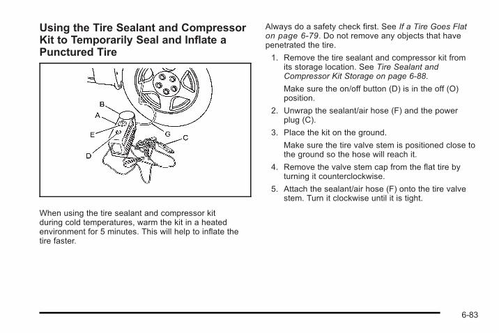
Using the Tire Sealant and CompressorKit to Temporarily Seal and Inflate aPunctured Tire
When using the tire sealant and compressor kitduring cold temperatures, warm the kit in a heatedenvironment for 5 minutes. This will help to inflate thetire faster.
Always do a safety check first. See If a Tire Goes Flaton page 6‑79. Do not remove any objects that havepenetrated the tire.
1. Remove the tire sealant and compressor kit fromits storage location. See Tire Sealant andCompressor Kit Storage on page 6‑88.
Make sure the on/off button (D) is in the off (O)position.
2. Unwrap the sealant/air hose (F) and the powerplug (C).
3. Place the kit on the ground.
Make sure the tire valve stem is positioned close tothe ground so the hose will reach it.
4. Remove the valve stem cap from the flat tire byturning it counterclockwise.
5. Attach the sealant/air hose (F) onto the tire valvestem. Turn it clockwise until it is tight.
6-83
6. Plug the power plug (C) into the accessory poweroutlet in the vehicle. Unplug all items from otheraccessory power outlets. See Accessory PowerOutlet(s) on page 4‑12.
If the vehicle has an accessory power outlet, donot use the cigarette lighter.
If the vehicle only has a cigarette lighter, use thecigarette lighter.
Do not pinch the power plug cord in the door orwindow.
7. Start the vehicle. The vehicle must be runningwhile using the air compressor.
8. Press the on/off (D) button to turn the tire sealantand compressor kit on.
The compressor will inject sealant and air intothe tire.
The pressure gage (E) will initially show a highpressure while the compressor pushes the sealantinto the tire. Once the sealant is completelydispersed into the tire, the pressure will quicklydrop and start to rise again as the tire inflates withair only.
9. Inflate the tire to the recommended inflationpressure using the pressure gage (E).The recommended inflation pressure can befound on the Tire and Loading Information label.See Inflation - Tire Pressure on page 6‑64.
The pressure gage (E) may read higher than theactual tire pressure while the compressor is on.Turn the compressor off to get an accuratepressure reading. The compressor may be turnedon/off until the correct pressure is reached.
Notice: If the recommended pressure cannot bereached after approximately 25 minutes, the vehicleshould not be driven farther. The tire is too severelydamaged and the tire sealant and compressor kitcannot inflate the tire. Remove the power plug fromthe accessory power outlet and unscrew theinflating hose from the tire valve. See RoadsideAssistance Program on page 8‑8.
10. Press the on/off button (D) to turn the tire sealantand compressor kit off.
The tire is not sealed and will continue toleak air until the vehicle is driven and thesealant is distributed in the tire, therefore,Steps 11 through 17 must be done immediatelyafter Step 10.
Be careful while handling the tire sealant andcompressor kit as it could be warm after usage.
6-84
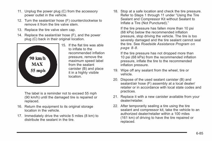
11. Unplug the power plug (C) from the accessorypower outlet in the vehicle.
12. Turn the sealant/air hose (F) counterclockwise toremove it from the tire valve stem.
13. Replace the tire valve stem cap.
14. Replace the sealant/air hose (F), and the powerplug (C) back in their original location.
15. If the flat tire was ableto inflate to therecommended inflationpressure, remove themaximum speed labelfrom the sealantcanister (B) and placeit in a highly visiblelocation.
The label is a reminder not to exceed 55 mph(90 km/h) until the damaged tire is repaired orreplaced.
16. Return the equipment to its original storagelocation in the vehicle.
17. Immediately drive the vehicle 5 miles (8 km) todistribute the sealant in the tire.
18. Stop at a safe location and check the tire pressure.Refer to Steps 1 through 11 under “Using the TireSealant and Compressor Kit without Sealant toInflate a Tire (Not Punctured).”
If the tire pressure has fallen more than 10 psi(68 kPa) below the recommended inflationpressure, stop driving the vehicle. The tire is tooseverely damaged and the tire sealant cannot sealthe tire. See Roadside Assistance Program onpage 8‑8 .
If the tire pressure has not dropped more than10 psi (68 kPa) from the recommended inflationpressure, inflate the tire to the recommendedinflation pressure.
19. Wipe off any sealant from the wheel, tire orvehicle.
20. Dispose of the used sealant canister (B) andsealant/air hose (F) assembly at a local dealer/retailer or in accordance with local state codes andpractices.
21. Replace it with a new canister available from yourdealer/retailer.
22. After temporarily sealing a tire using the tiresealant and compressor kit, take the vehicle to anauthorized dealer/retailer within a 100 miles(161 km) of driving to have the tire repaired orreplaced.
6-85
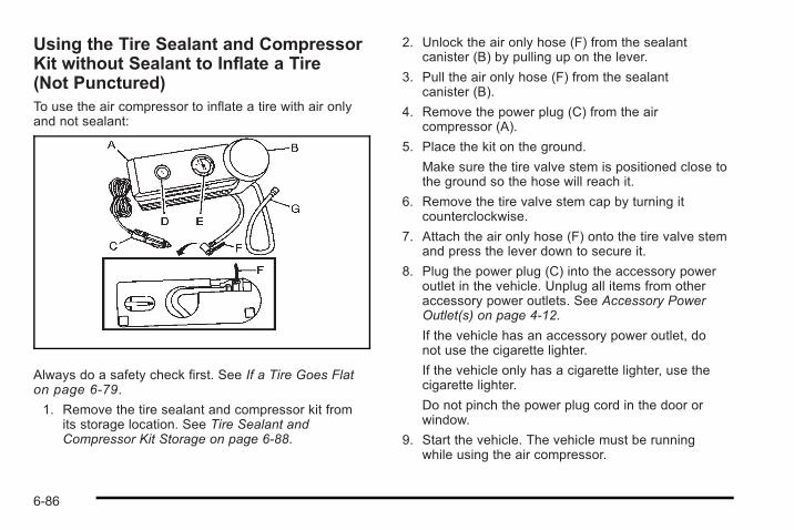
Using the Tire Sealant and CompressorKit without Sealant to Inflate a Tire(Not Punctured)To use the air compressor to inflate a tire with air onlyand not sealant:
Always do a safety check first. See If a Tire Goes Flaton page 6‑79.
1. Remove the tire sealant and compressor kit fromits storage location. See Tire Sealant andCompressor Kit Storage on page 6‑88.
2. Unlock the air only hose (F) from the sealantcanister (B) by pulling up on the lever.
3. Pull the air only hose (F) from the sealantcanister (B).
4. Remove the power plug (C) from the aircompressor (A).
5. Place the kit on the ground.
Make sure the tire valve stem is positioned close tothe ground so the hose will reach it.
6. Remove the tire valve stem cap by turning itcounterclockwise.
7. Attach the air only hose (F) onto the tire valve stemand press the lever down to secure it.
8. Plug the power plug (C) into the accessory poweroutlet in the vehicle. Unplug all items from otheraccessory power outlets. See Accessory PowerOutlet(s) on page 4‑12.
If the vehicle has an accessory power outlet, donot use the cigarette lighter.
If the vehicle only has a cigarette lighter, use thecigarette lighter.
Do not pinch the power plug cord in the door orwindow.
9. Start the vehicle. The vehicle must be runningwhile using the air compressor.
6-86
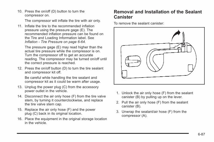
10. Press the on/off (D) button to turn thecompressor on.
The compressor will inflate the tire with air only.
11. Inflate the tire to the recommended inflationpressure using the pressure gage (E). Therecommended inflation pressure can be found onthe Tire and Loading Information label. SeeInflation - Tire Pressure on page 6‑64.
The pressure gage (E) may read higher than theactual tire pressure while the compressor is on.Turn the compressor off to get an accuratereading. The compressor may be turned on/off untilthe correct pressure is reached.
12. Press the on/off button (D) to turn the tire sealantand compressor kit off.
Be careful while handling the tire sealant andcompressor kit as it could be warm after usage.
13. Unplug the power plug (C) from the accessorypower outlet in the vehicle.
14. Disconnect the air only hose (F) from the tire valvestem, by turning it counterclockwise, and replacethe tire valve stem cap.
15. Replace the air only hose (F) and the powerplug (C) back in its original location.
16. Place the equipment in the original storage locationin the vehicle.
Removal and Installation of the SealantCanisterTo remove the sealant canister:
1. Unlock the air only hose (F) from the sealantcanister (B) by pulling up on the lever.
2. Pull the air only hose (F) from the sealantcanister (B).
3. Unwrap the sealant/air hose (F) from thecompressor (A).
6-87
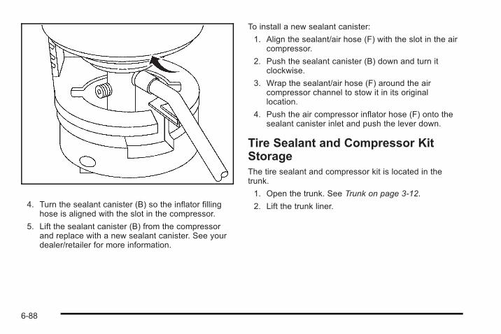
4. Turn the sealant canister (B) so the inflator fillinghose is aligned with the slot in the compressor.
5. Lift the sealant canister (B) from the compressorand replace with a new sealant canister. See yourdealer/retailer for more information.
To install a new sealant canister:
1. Align the sealant/air hose (F) with the slot in the aircompressor.
2. Push the sealant canister (B) down and turn itclockwise.
3. Wrap the sealant/air hose (F) around the aircompressor channel to stow it in its originallocation.
4. Push the air compressor inflator hose (F) onto thesealant canister inlet and push the lever down.
Tire Sealant and Compressor KitStorageThe tire sealant and compressor kit is located in thetrunk.
1. Open the trunk. See Trunk on page 3‑12.
2. Lift the trunk liner.
6-88
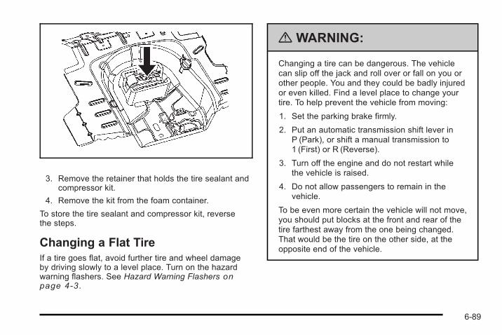
3. Remove the retainer that holds the tire sealant andcompressor kit.
4. Remove the kit from the foam container.
To store the tire sealant and compressor kit, reversethe steps.
Changing a Flat TireIf a tire goes flat, avoid further tire and wheel damageby driving slowly to a level place. Turn on the hazardwarning flashers. See Hazard Warning Flashers onpage 4‑3 .
{ WARNING:
Changing a tire can be dangerous. The vehiclecan slip off the jack and roll over or fall on you orother people. You and they could be badly injuredor even killed. Find a level place to change yourtire. To help prevent the vehicle from moving:
1. Set the parking brake firmly.
2. Put an automatic transmission shift lever inP (Park), or shift a manual transmission to1 (First) or R (Reverse).
3. Turn off the engine and do not restart whilethe vehicle is raised.
4. Do not allow passengers to remain in thevehicle.
To be even more certain the vehicle will not move,you should put blocks at the front and rear of thetire farthest away from the one being changed.That would be the tire on the other side, at theopposite end of the vehicle.
6-89
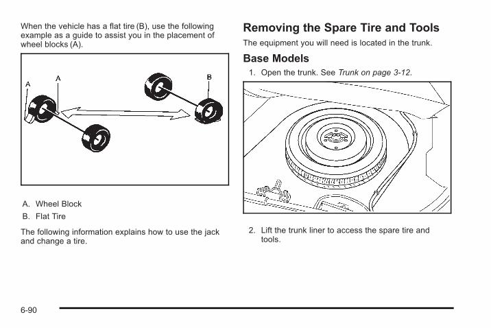
When the vehicle has a flat tire (B), use the followingexample as a guide to assist you in the placement ofwheel blocks (A).
A. Wheel Block
B. Flat Tire
The following information explains how to use the jackand change a tire.
Removing the Spare Tire and ToolsThe equipment you will need is located in the trunk.
Base Models1. Open the trunk. See Trunk on page 3‑12.
2. Lift the trunk liner to access the spare tire andtools.
6-90
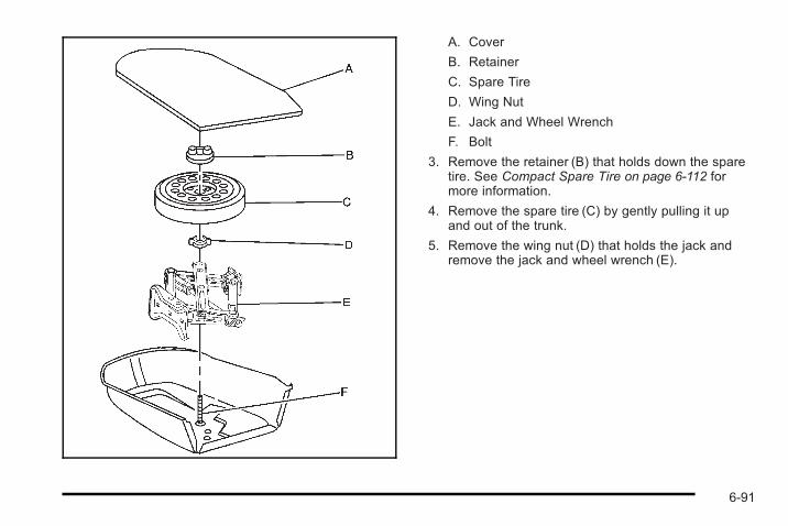
A. Cover
B. Retainer
C. Spare Tire
D. Wing Nut
E. Jack and Wheel Wrench
F. Bolt
3. Remove the retainer (B) that holds down the sparetire. See Compact Spare Tire on page 6‑112 formore information.
4. Remove the spare tire (C) by gently pulling it upand out of the trunk.
5. Remove the wing nut (D) that holds the jack andremove the jack and wheel wrench (E).
6-91
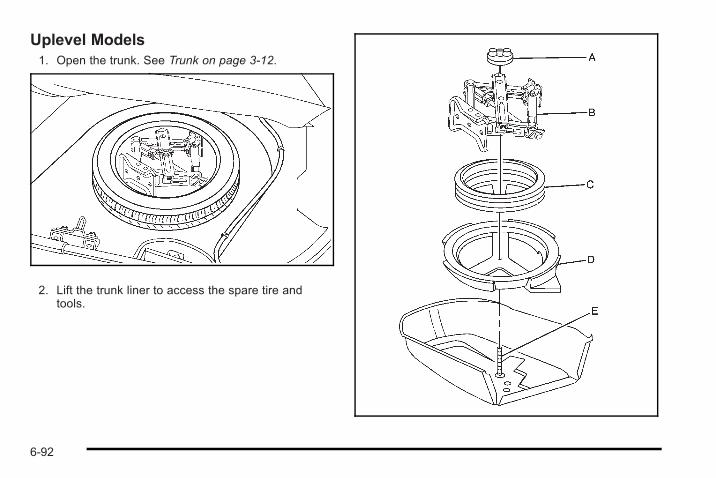
Uplevel Models1. Open the trunk. See Trunk on page 3‑12.
2. Lift the trunk liner to access the spare tire andtools.
6-92
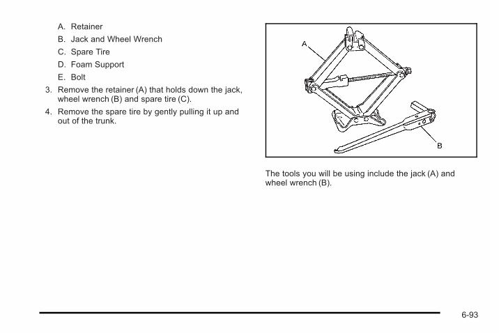
A. Retainer
B. Jack and Wheel Wrench
C. Spare Tire
D. Foam Support
E. Bolt
3. Remove the retainer (A) that holds down the jack,wheel wrench (B) and spare tire (C).
4. Remove the spare tire by gently pulling it up andout of the trunk.
The tools you will be using include the jack (A) andwheel wrench (B).
6-93
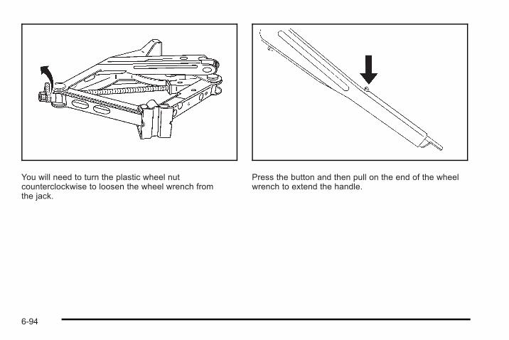
You will need to turn the plastic wheel nutcounterclockwise to loosen the wheel wrench fromthe jack.
Press the button and then pull on the end of the wheelwrench to extend the handle.
6-94
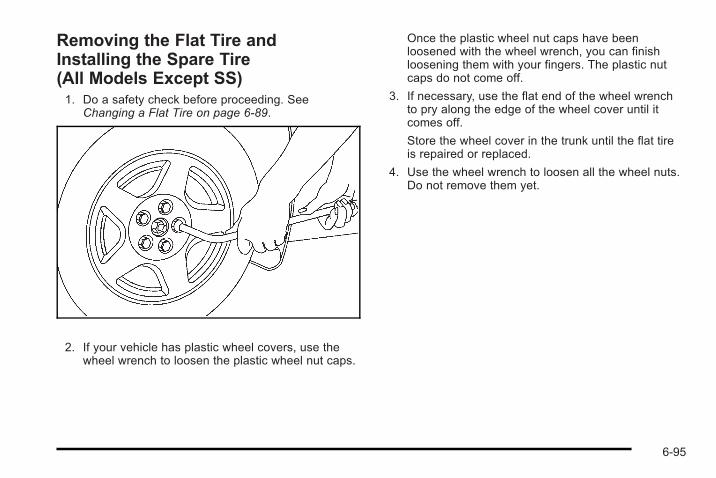
Removing the Flat Tire andInstalling the Spare Tire(All Models Except SS)1. Do a safety check before proceeding. See
Changing a Flat Tire on page 6‑89.
2. If your vehicle has plastic wheel covers, use thewheel wrench to loosen the plastic wheel nut caps.
Once the plastic wheel nut caps have beenloosened with the wheel wrench, you can finishloosening them with your fingers. The plastic nutcaps do not come off.
3. If necessary, use the flat end of the wheel wrenchto pry along the edge of the wheel cover until itcomes off.
Store the wheel cover in the trunk until the flat tireis repaired or replaced.
4. Use the wheel wrench to loosen all the wheel nuts.Do not remove them yet.
6-95
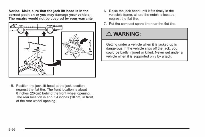
Notice: Make sure that the jack lift head is in thecorrect position or you may damage your vehicle.The repairs would not be covered by your warranty.
5. Position the jack lift head at the jack locationnearest the flat tire. The front location is about8 inches (20 cm) behind the front wheel opening.The rear location is about 4 inches (10 cm) in frontof the rear wheel opening.
6. Raise the jack head until it fits firmly in thevehicle's frame, where the notch is located,nearest the flat tire.
7. Put the compact spare tire near the flat tire.
{ WARNING:
Getting under a vehicle when it is jacked up isdangerous. If the vehicle slips off the jack, youcould be badly injured or killed. Never get under avehicle when it is supported only by a jack.
6-96
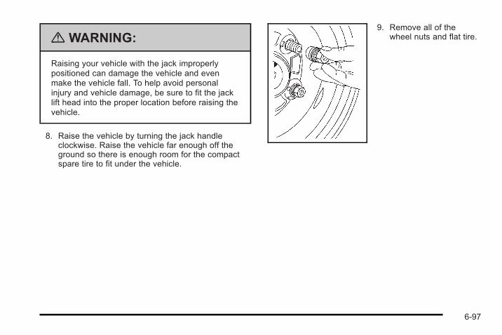
{ WARNING:
Raising your vehicle with the jack improperlypositioned can damage the vehicle and evenmake the vehicle fall. To help avoid personalinjury and vehicle damage, be sure to fit the jacklift head into the proper location before raising thevehicle.
8. Raise the vehicle by turning the jack handleclockwise. Raise the vehicle far enough off theground so there is enough room for the compactspare tire to fit under the vehicle.
9. Remove all of thewheel nuts and flat tire.
6-97
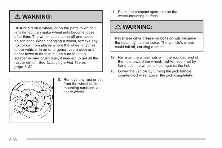
{ WARNING:
Rust or dirt on a wheel, or on the parts to which itis fastened, can make wheel nuts become looseafter time. The wheel could come off and causean accident. When changing a wheel, remove anyrust or dirt from places where the wheel attachesto the vehicle. In an emergency, use a cloth or apaper towel to do this; but be sure to use ascraper or wire brush later, if needed, to get all therust or dirt off. See Changing a Flat Tire onpage 6‑89.
10. Remove any rust or dirtfrom the wheel bolts,mounting surfaces, andspare wheel.
11. Place the compact spare tire on thewheel-mounting surface.
{ WARNING:
Never use oil or grease on bolts or nuts becausethe nuts might come loose. The vehicle's wheelcould fall off, causing a crash.
12. Reinstall the wheel nuts with the rounded end ofthe nuts toward the wheel. Tighten each nut byhand until the wheel is held against the hub.
13. Lower the vehicle by turning the jack handlecounterclockwise. Lower the jack completely.
6-98
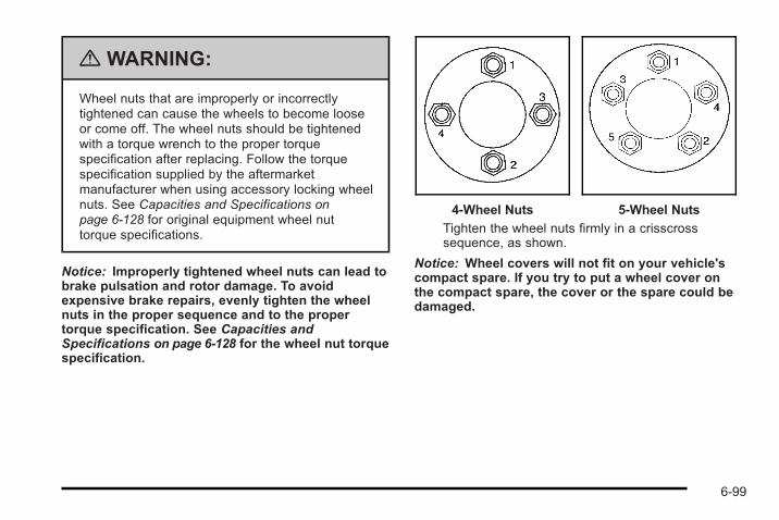
{ WARNING:
Wheel nuts that are improperly or incorrectlytightened can cause the wheels to become looseor come off. The wheel nuts should be tightenedwith a torque wrench to the proper torquespecification after replacing. Follow the torquespecification supplied by the aftermarketmanufacturer when using accessory locking wheelnuts. See Capacities and Specifications onpage 6‑128 for original equipment wheel nuttorque specifications.
Notice: Improperly tightened wheel nuts can lead tobrake pulsation and rotor damage. To avoidexpensive brake repairs, evenly tighten the wheelnuts in the proper sequence and to the propertorque specification. See Capacities andSpecifications on page 6‑128 for the wheel nut torquespecification.
4-Wheel Nuts 5-Wheel Nuts
Tighten the wheel nuts firmly in a crisscrosssequence, as shown.
Notice: Wheel covers will not fit on your vehicle'scompact spare. If you try to put a wheel cover onthe compact spare, the cover or the spare could bedamaged.
6-99
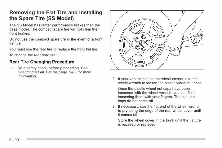
Removing the Flat Tire and Installingthe Spare Tire (SS Model)The SS Model has larger performance brakes than thebase model. The compact spare tire will not clear thefront brakes.
Do not use the compact spare tire in the event of a frontflat tire.
You must use the rear tire to replace the front flat tire.
To change the rear road tire:
Rear Tire Changing Procedure1. Do a safety check before proceeding. See
Changing a Flat Tire on page 6‑89 for moreinformation.
2. If your vehicle has plastic wheel covers, use thewheel wrench to loosen the plastic wheel nut caps.
Once the plastic wheel nut caps have beenloosened with the wheel wrench, you can finishloosening them with your fingers. The plastic nutcaps do not come off.
3. If necessary, use the flat end of the wheel wrenchto pry along the edge of the rear wheel cover untilit comes off.
Store the wheel cover in the trunk until the flat tireis repaired or replaced.
6-100
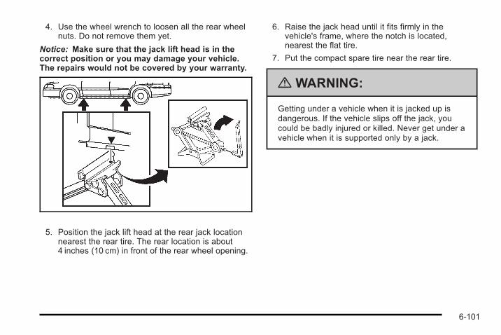
4. Use the wheel wrench to loosen all the rear wheelnuts. Do not remove them yet.
Notice: Make sure that the jack lift head is in thecorrect position or you may damage your vehicle.The repairs would not be covered by your warranty.
5. Position the jack lift head at the rear jack locationnearest the rear tire. The rear location is about4 inches (10 cm) in front of the rear wheel opening.
6. Raise the jack head until it fits firmly in thevehicle's frame, where the notch is located,nearest the flat tire.
7. Put the compact spare tire near the rear tire.
{ WARNING:
Getting under a vehicle when it is jacked up isdangerous. If the vehicle slips off the jack, youcould be badly injured or killed. Never get under avehicle when it is supported only by a jack.
6-101
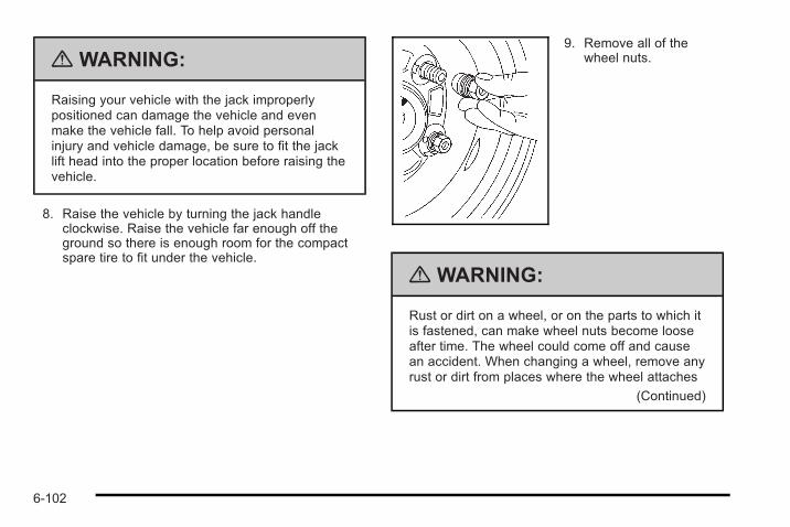
{ WARNING:
Raising your vehicle with the jack improperlypositioned can damage the vehicle and evenmake the vehicle fall. To help avoid personalinjury and vehicle damage, be sure to fit the jacklift head into the proper location before raising thevehicle.
8. Raise the vehicle by turning the jack handleclockwise. Raise the vehicle far enough off theground so there is enough room for the compactspare tire to fit under the vehicle.
9. Remove all of thewheel nuts.
{ WARNING:
Rust or dirt on a wheel, or on the parts to which itis fastened, can make wheel nuts become looseafter time. The wheel could come off and causean accident. When changing a wheel, remove anyrust or dirt from places where the wheel attaches
(Continued)
6-102
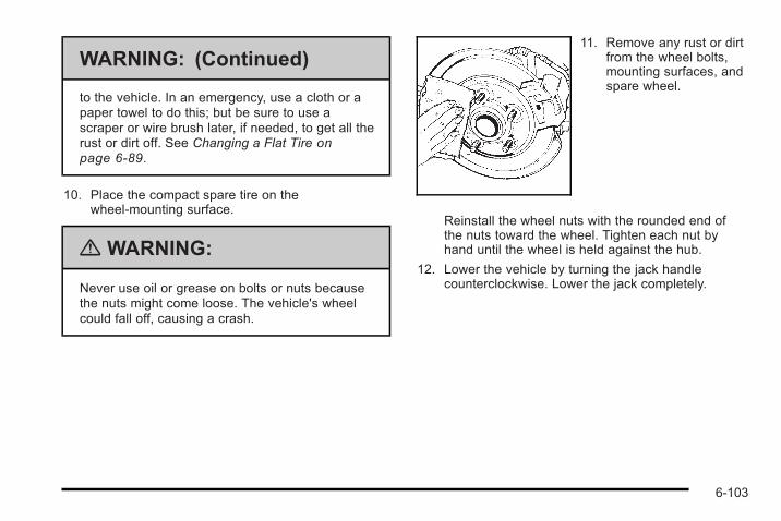
WARNING: (Continued)
to the vehicle. In an emergency, use a cloth or apaper towel to do this; but be sure to use ascraper or wire brush later, if needed, to get all therust or dirt off. See Changing a Flat Tire onpage 6‑89.
10. Place the compact spare tire on thewheel-mounting surface.
{ WARNING:
Never use oil or grease on bolts or nuts becausethe nuts might come loose. The vehicle's wheelcould fall off, causing a crash.
11. Remove any rust or dirtfrom the wheel bolts,mounting surfaces, andspare wheel.
Reinstall the wheel nuts with the rounded end ofthe nuts toward the wheel. Tighten each nut byhand until the wheel is held against the hub.
12. Lower the vehicle by turning the jack handlecounterclockwise. Lower the jack completely.
6-103
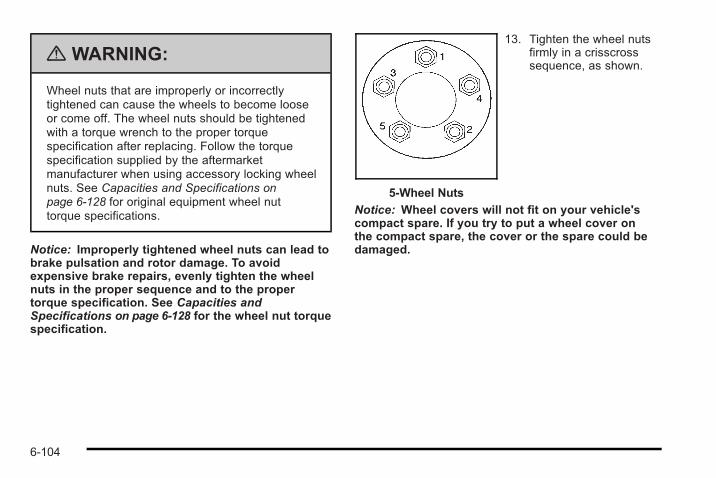
{ WARNING:
Wheel nuts that are improperly or incorrectlytightened can cause the wheels to become looseor come off. The wheel nuts should be tightenedwith a torque wrench to the proper torquespecification after replacing. Follow the torquespecification supplied by the aftermarketmanufacturer when using accessory locking wheelnuts. See Capacities and Specifications onpage 6‑128 for original equipment wheel nuttorque specifications.
Notice: Improperly tightened wheel nuts can lead tobrake pulsation and rotor damage. To avoidexpensive brake repairs, evenly tighten the wheelnuts in the proper sequence and to the propertorque specification. See Capacities andSpecifications on page 6‑128 for the wheel nut torquespecification.
5-Wheel Nuts
13. Tighten the wheel nutsfirmly in a crisscrosssequence, as shown.
Notice: Wheel covers will not fit on your vehicle'scompact spare. If you try to put a wheel cover onthe compact spare, the cover or the spare could bedamaged.
6-104
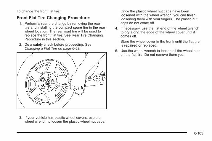
To change the front flat tire:
Front Flat Tire Changing Procedure:1. Perform a rear tire change by removing the rear
tire and installing the compact spare tire in the rearwheel location. The rear road tire will be used toreplace the front flat tire. See Rear Tire ChangingProcedure in this section.
2. Do a safety check before proceeding. SeeChanging a Flat Tire on page 6‑89.
3. If your vehicle has plastic wheel covers, use thewheel wrench to loosen the plastic wheel nut caps.
Once the plastic wheel nut caps have beenloosened with the wheel wrench, you can finishloosening them with your fingers. The plastic nutcaps do not come off.
4. If necessary, use the flat end of the wheel wrenchto pry along the edge of the wheel cover until itcomes off.
Store the wheel cover in the trunk until the flat tireis repaired or replaced.
5. Use the wheel wrench to loosen all the wheel nutson the flat tire. Do not remove them yet.
6-105
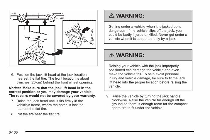
6. Position the jack lift head at the jack locationnearest the flat tire. The front location is about8 inches (20 cm) behind the front wheel opening.
Notice: Make sure that the jack lift head is in thecorrect position or you may damage your vehicle.The repairs would not be covered by your warranty.
7. Raise the jack head until it fits firmly in thevehicle's frame, where the notch is located,nearest the flat tire.
8. Put the tire near the flat tire.
{ WARNING:
Getting under a vehicle when it is jacked up isdangerous. If the vehicle slips off the jack, youcould be badly injured or killed. Never get under avehicle when it is supported only by a jack.
{ WARNING:
Raising your vehicle with the jack improperlypositioned can damage the vehicle and evenmake the vehicle fall. To help avoid personalinjury and vehicle damage, be sure to fit the jacklift head into the proper location before raising thevehicle.
9. Raise the vehicle by turning the jack handleclockwise. Raise the vehicle far enough off theground so there is enough room for the compactspare tire to fit under the vehicle.
6-106
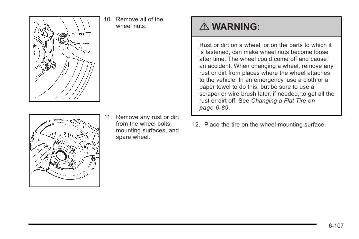
10. Remove all of thewheel nuts.
11. Remove any rust or dirtfrom the wheel bolts,mounting surfaces, andspare wheel.
{ WARNING:
Rust or dirt on a wheel, or on the parts to which itis fastened, can make wheel nuts become looseafter time. The wheel could come off and causean accident. When changing a wheel, remove anyrust or dirt from places where the wheel attachesto the vehicle. In an emergency, use a cloth or apaper towel to do this; but be sure to use ascraper or wire brush later, if needed, to get all therust or dirt off. See Changing a Flat Tire onpage 6‑89.
12. Place the tire on the wheel-mounting surface.
6-107
{ WARNING:
Never use oil or grease on bolts or nuts becausethe nuts might come loose. The vehicle's wheelcould fall off, causing a crash.
13. Reinstall the wheel nuts with the rounded end ofthe nuts toward the wheel. Tighten each nut byhand until the wheel is held against the hub.
14. Lower the vehicle by turning the jack handlecounterclockwise. Lower the jack completely.
{ WARNING:
Wheel nuts that are improperly or incorrectlytightened can cause the wheels to become looseor come off. The wheel nuts should be tightenedwith a torque wrench to the proper torquespecification after replacing. Follow the torquespecification supplied by the aftermarketmanufacturer when using accessory locking wheelnuts. See Capacities and Specifications onpage 6‑128 for original equipment wheel nuttorque specifications.
Notice: Improperly tightened wheel nuts can lead tobrake pulsation and rotor damage. To avoidexpensive brake repairs, evenly tighten the wheelnuts in the proper sequence and to the propertorque specification. See Capacities andSpecifications on page 6‑128 for the wheel nut torquespecification.
6-108
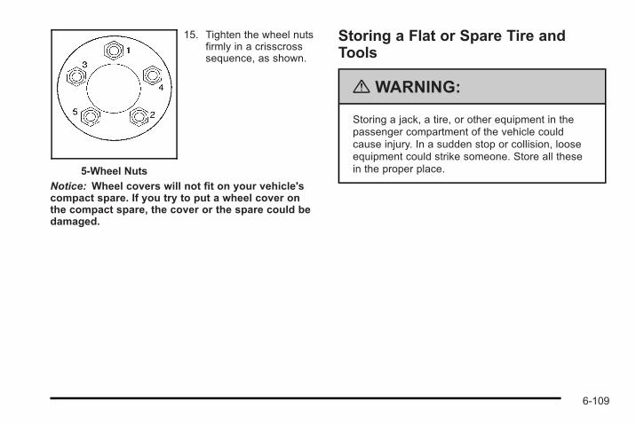
5-Wheel Nuts
15. Tighten the wheel nutsfirmly in a crisscrosssequence, as shown.
Notice: Wheel covers will not fit on your vehicle'scompact spare. If you try to put a wheel cover onthe compact spare, the cover or the spare could bedamaged.
Storing a Flat or Spare Tire andTools
{ WARNING:
Storing a jack, a tire, or other equipment in thepassenger compartment of the vehicle couldcause injury. In a sudden stop or collision, looseequipment could strike someone. Store all thesein the proper place.
6-109
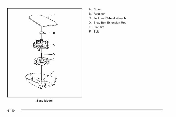
Base Model
A. Cover
B. Retainer
C. Jack and Wheel Wrench
D. Stow Bolt Extension Rod
E. Flat Tire
F. Bolt
6-110
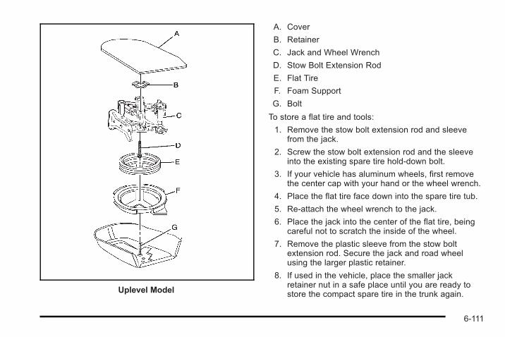
Uplevel Model
A. Cover
B. Retainer
C. Jack and Wheel Wrench
D. Stow Bolt Extension Rod
E. Flat Tire
F. Foam Support
G. Bolt
To store a flat tire and tools:
1. Remove the stow bolt extension rod and sleevefrom the jack.
2. Screw the stow bolt extension rod and the sleeveinto the existing spare tire hold-down bolt.
3. If your vehicle has aluminum wheels, first removethe center cap with your hand or the wheel wrench.
4. Place the flat tire face down into the spare tire tub.
5. Re-attach the wheel wrench to the jack.
6. Place the jack into the center of the flat tire, beingcareful not to scratch the inside of the wheel.
7. Remove the plastic sleeve from the stow boltextension rod. Secure the jack and road wheelusing the larger plastic retainer.
8. If used in the vehicle, place the smaller jackretainer nut in a safe place until you are ready tostore the compact spare tire in the trunk again.
6-111
To store the compact spare tire and tools, follow theprevious procedure without using the stow boltextension rod and see Removing the Spare Tire andTools on page 6‑90 and follow the removal procedure,in reverse, for the proper jack storage instructions forthis vehicle.
The compact spare tire is for temporary use only.Replace the compact spare with a full-size tire as soonas possible.
Compact Spare Tire
{ WARNING:
Driving with more than one compact spare tire ata time could result in loss of braking and handling.This could lead to a crash and you or others couldbe injured. Use only one compact spare tire ata time.
This vehicle may have a compact spare tire. Althoughthe compact spare tire was fully inflated when thevehicle was new, it can lose air after a time. Check theinflation pressure regularly. It should be 60 psi(420 kPa).
After installing the compact spare on the vehicle, if thevehicle has one, stop as soon as possible and makesure the spare tire is correctly inflated. The compactspare is made to perform well at speeds up to 65 mph(105 km/h) for distances up to 3,000 miles (5 000 km),so you can finish your trip and have the full-size tirerepaired or replaced at your convenience. Of course, itis best to replace the spare with a full-size tire as soonas possible. The spare tire will last longer and be ingood shape in case it is needed again.
Notice: When the compact spare is installed, do nottake the vehicle through an automatic car wash withguide rails. The compact spare can get caught onthe rails which can damage the tire, wheel and otherparts of the vehicle.
Do not use the compact spare on other vehicles.
And do not mix the compact spare tire or wheel withother wheels or tires. They will not fit. Keep the sparetire and its wheel together.
Notice: Tire chains will not fit the compact spare.Using them can damage the vehicle and candamage the chains too. Do not use tire chains onthe compact spare.
6-112
Appearance Care
Interior CleaningThe vehicle's interior will continue to look its best if it iscleaned often. Although not always visible, dust and dirtcan accumulate on the upholstery. Dirt can damagecarpet, fabric, leather, and plastic surfaces. Regularvacuuming is recommended to remove particles fromthe upholstery. It is important to keep the upholsteryfrom becoming and remaining heavily soiled. Soilsshould be removed as quickly as possible. Thevehicle's interior may experience extremes of heat thatcould cause stains to set rapidly.
Lighter colored interiors may require more frequentcleaning. Use care because newspapers and garmentsthat transfer color to home furnishings may also transfercolor to the vehicle's interior.
When cleaning the vehicle's interior, only use cleanersspecifically designed for the surfaces being cleaned.Permanent damage may result from using cleaners onsurfaces for which they were not intended. Use glasscleaner only on glass. Remove any accidentalover-spray from other surfaces immediately. To preventover-spray, apply cleaner directly to the cleaning cloth.
Notice: Using abrasive cleaners when cleaningglass surfaces on the vehicle, could scratch theglass and/or cause damage to the rear windowdefogger. When cleaning the glass on the vehicle,use only a soft cloth and glass cleaner.
Many cleaners contain solvents that may becomeconcentrated in the vehicle's breathing space.Before using cleaners, read and adhere to all safetyinstructions on the label. While cleaning the vehicle'sinterior, maintain adequate ventilation by opening thevehicle's doors and windows.
Dust may be removed from small buttons and knobsusing a small brush with soft bristles.
6-113
Products that remove odors from the vehicle'supholstery and clean the vehicle's glass can beobtained from your dealer/retailer.
Do not clean the vehicle using:. A knife or any other sharp object to remove a soil
from any interior surface.. A stiff brush. It can cause damage to the vehicle's
interior surfaces.. Heavy pressure or aggressive rubbing with a
cleaning cloth. Use of heavy pressure can damagethe interior and does not improve the effectivenessof soil removal.
. Laundry detergents or dishwashing soaps withdegreasers can leave residue that streaks andattracts dirt. For liquid cleaners, about 20 drops pergallon (3.78 L) of water is a good guide. Use onlymild, neutral-pH soaps.
. Too much cleaner that saturates the upholstery.
. Organic solvents such as naptha, alcohol, etc. thatcan damage the vehicle's interior.
Fabric/CarpetUse a vacuum cleaner with a soft brush attachmentfrequently to remove dust and loose dirt. A canistervacuum with a beater bar in the nozzle may only beused on floor carpet and carpeted floor mats. For anysoil, always try to remove it first with plain water or clubsoda. Before cleaning, gently remove as much of thesoil as possible using one of the following techniques:. For liquids: gently blot the remaining soil with a
paper towel. Allow the soil to absorb into the papertowel until no more can be removed.
. For solid dry soils: remove as much as possibleand then vacuum.
To clean:
1. Saturate a lint-free, clean white cloth with water orclub soda.
2. Wring the cloth to remove excess moisture.
3. Start on the outside edge of the soil and gently rubtoward the center. Continue cleaning, using a cleanarea of the cloth each time it becomes soiled.
4. Continue to gently rub the soiled area until thecleaning cloth remains clean.
5. If the soil is not completely removed, use a mildsoap solution and repeat the cleaning process thatwas used with plain water.
6-114
If any of the soil remains, a commercial fabric cleaner orspot lifter may be necessary. When a commercialupholstery cleaner or spot lifter is to be used, test asmall hidden area for colorfastness first. If the locallycleaned area gives any impression that a ring formationmay result, clean the entire surface.
After the cleaning process has been completed, a papertowel can be used to blot excess moisture from thefabric or carpet.
LeatherA soft cloth dampened with water can be used toremove dust. If a more thorough cleaning is necessary,a soft cloth dampened with a mild soap solution can beused. Allow the leather to dry naturally. Do not use heatto dry. Never use steam to clean leather. Never usespot lifters or spot removers on leather. Manycommercial leather cleaners and coatings that are soldto preserve and protect leather may permanentlychange the appearance and feel of the leather and arenot recommended. Do not use silicone or wax-basedproducts, or those containing organic solvents to cleanthe vehicle's interior because they can alter theappearance by increasing the gloss in a non-uniformmanner. Never use shoe polish on leather.
Instrument Panel, Vinyl, and OtherPlastic SurfacesA soft cloth dampened with water may be used toremove dust. If a more thorough cleaning is necessary,a clean soft cloth dampened with a mild soap solutioncan be used to gently remove dust and dirt. Never usespot lifters or removers on plastic surfaces. Manycommercial cleaners and coatings that are sold topreserve and protect soft plastic surfaces maypermanently change the appearance and feel of theinterior and are not recommended. Do not use siliconeor wax-based products, or those containing organicsolvents to clean the vehicle's interior because they canalter the appearance by increasing the gloss in anon-uniform manner.
Some commercial products may increase gloss on theinstrument panel. The increase in gloss may causeannoying reflections in the windshield and even make itdifficult to see through the windshield under certainconditions.
6-115
Care of Safety BeltsKeep belts clean and dry.
{ WARNING:
Do not bleach or dye safety belts. It may severelyweaken them. In a crash, they might not be ableto provide adequate protection. Clean safety beltsonly with mild soap and lukewarm water.
WeatherstripsSilicone grease on weatherstrips will make them lastlonger, seal better, and not stick or squeak. Applysilicone grease with a clean cloth. During very cold,damp weather frequent application may be required.See Recommended Fluids and Lubricants onpage 7‑11.
Washing Your VehicleThe best way to preserve the vehicle's finish is to keepit clean by washing it often.
Notice: Certain cleaners contain chemicals that candamage the emblems or nameplates on the vehicle.Check the cleaning product label. If it states that itshould not be used on plastic parts, do not use it onthe vehicle or damage may occur and it would notbe covered by the warranty.
Do not wash the vehicle in direct sunlight. Use a carwashing soap. Do not use cleaning agents that arepetroleum based or that contain acid or abrasives, asthey can damage the paint, metal or plastic on thevehicle. Approved cleaning products can be obtainedfrom your dealer/retailer. Follow all manufacturers'directions regarding correct product usage, necessarysafety precautions and appropriate disposal of anyvehicle care product.
Rinse the vehicle well, before washing and after toremove all cleaning agents completely. If they areallowed to dry on the surface, they could stain.
Dry the finish with a soft, clean chamois or an all-cottontowel to avoid surface scratches and water spotting.
High pressure car washes may cause water to enter thevehicle. Avoid using high pressure washes closer than12 inches (30 cm) to the surface of the vehicle. Use ofpower washers exceeding 1,200 psi (8 274 kPa) canresult in damage or removal of paint and decals.
6-116
Cleaning Exterior Lamps/LensesUse only lukewarm or cold water, a soft cloth and acar washing soap to clean exterior lamps and lenses.Follow instructions under Washing Your Vehicle onpage 6‑116.
Finish CareOccasional waxing or mild polishing of the vehicle byhand may be necessary to remove residue from thepaint finish. Approved cleaning products can beobtained from your dealer/retailer.
If the vehicle has a basecoat/clearcoat paint finish, theclearcoat gives more depth and gloss to the coloredbasecoat. Always use waxes and polishes that arenon-abrasive and made for a basecoat/clearcoat paintfinish.
Notice: Machine compounding or aggressivepolishing on a basecoat/clearcoat paint finish maydamage it. Use only non-abrasive waxes andpolishes that are made for a basecoat/clearcoatpaint finish on the vehicle.
Foreign materials such as calcium chloride and othersalts, ice melting agents, road oil and tar, tree sap, birddroppings, chemicals from industrial chimneys, etc., candamage the vehicle's finish if they remain on paintedsurfaces. Wash the vehicle as soon as possible.If necessary, use non-abrasive cleaners that aremarked safe for painted surfaces to remove foreignmatter.
Exterior painted surfaces are subject to aging, weatherand chemical fallout that can take their toll over a periodof years. To help keep the paint finish looking new, keepthe vehicle garaged or covered whenever possible.
Protecting Exterior Bright Metal PartsBright metal parts should be cleaned regularly to keeptheir luster. Washing with water is all that is usuallyneeded. However, chrome polish may be used onchrome or stainless steel trim, if necessary.
Use special care with aluminum trim. To avoiddamaging protective trim, never use auto or chromepolish, steam or caustic soap to clean aluminum.A coating of wax, rubbed to high polish, isrecommended for all bright metal parts.
6-117
Windshield and Wiper BladesClean the outside of the windshield with glass cleaner.
Clean the rubber blades using a lint free cloth or papertowel soaked with windshield washer fluid or a milddetergent. Wash the windshield thoroughly whencleaning the blades. Bugs, road grime, sap, and abuildup of vehicle wash/wax treatments may causewiper streaking. Replace the wiper blades if they areworn or damaged.
Wipers can be damaged by:. Extreme dusty conditions. Sand and salt. Heat and sun. Snow and ice, without proper removal
Aluminum or Chrome-Plated Wheelsand TrimThe vehicle may have either aluminum orchrome-plated wheels.
Keep the wheels clean using a soft clean cloth with mildsoap and water. Rinse with clean water. After rinsingthoroughly, dry with a soft clean towel. A wax may thenbe applied.
Notice: Chrome wheels and other chrome trim maybe damaged if the vehicle is not washed afterdriving on roads that have been sprayed withmagnesium, calcium or sodium chloride. Thesechlorides are used on roads for conditions such asice and dust. Always wash the vehicle's chromewith soap and water after exposure.
Notice: Using strong soaps, chemicals, abrasivepolishes, cleaners, brushes, or cleaners that containacid on aluminum or chrome-plated wheels, coulddamage the surface of the wheel(s). The repairswould not be covered by the vehicle warranty.Use only approved cleaners on aluminum orchrome-plated wheels.
The surface of these wheels is similar to the paintedsurface of the vehicle. Do not use strong soaps,chemicals, abrasive polishes, abrasive cleaners,cleaners with acid, or abrasive cleaning brushes onthem because they could damage the surface. Do notuse chrome polish on aluminum wheels.
Notice: Using chrome polish on aluminum wheelscould damage the wheels. The repairs would not becovered by the vehicle warranty. Use chrome polishon chrome wheels only.
6-118

Use chrome polish only on chrome-plated wheels, butavoid any painted surface of the wheel, and buff offimmediately after application.
Notice: Driving the vehicle through an automaticcar wash that has silicone carbide tire cleaningbrushes, could damage the aluminum orchrome-plated wheels. The repairs would not becovered by the vehicle warranty. Never drive avehicle that has aluminum or chrome-plated wheelsthrough an automatic car wash that uses siliconecarbide tire cleaning brushes.
TiresTo clean the tires, use a stiff brush with tire cleaner.
Notice: Using petroleum-based tire dressingproducts on the vehicle may damage the paint finishand/or tires. When applying a tire dressing, alwayswipe off any overspray from all painted surfaces onthe vehicle.
Sheet Metal DamageIf the vehicle is damaged and requires sheet metalrepair or replacement, make sure the body repair shopapplies anti-corrosion material to parts repaired orreplaced to restore corrosion protection.
Original manufacturer replacement parts will provide thecorrosion protection while maintaining the vehiclewarranty.
Finish DamageAny stone chips, fractures or deep scratches in thefinish should be repaired right away. Bare metal willcorrode quickly and may develop into major repairexpense.
Minor chips and scratches can be repaired withtouch-up materials available from your dealer/retailer.Larger areas of finish damage can be corrected in yourdealer's/retailer's body and paint shop.
6-119
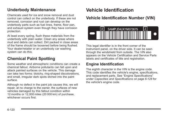
Underbody MaintenanceChemicals used for ice and snow removal and dustcontrol can collect on the underbody. If these are notremoved, corrosion and rust can develop on theunderbody parts such as fuel lines, frame, floor pan,and exhaust system even though they have corrosionprotection.
At least every spring, flush these materials from theunderbody with plain water. Clean any areas wheremud and debris can collect. Dirt packed in close areasof the frame should be loosened before being flushed.Your dealer/retailer or an underbody car washingsystem can do this.
Chemical Paint SpottingSome weather and atmospheric conditions can create achemical fallout. Airborne pollutants can fall upon andattack painted surfaces on the vehicle. This damagecan take two forms: blotchy, ring-shaped discolorations,and small, irregular dark spots etched into the paintsurface.
Although no defect in the paint job causes this, we willrepair, at no charge to the owner, the surfaces of newvehicles damaged by this fallout condition within12 months or 12,000 miles (20 000 km) of purchase,whichever occurs first.
Vehicle Identification
Vehicle Identification Number (VIN)
This legal identifier is in the front corner of theinstrument panel, on the driver side. It can be seenthrough the windshield from outside. The VIN alsoappears on the Vehicle Certification and Service Partslabels and certificates of title and registration.
Engine IdentificationThe eighth character in the VIN is the engine code.This code identifies the vehicle's engine, specifications,and replacement parts. See “Engine Specifications”under Capacities and Specifications on page 6‑128 forthe vehicle's engine code.
6-120
Service Parts Identification LabelThis label, in the trunk, on the driver side near the sparetire cover, has the following information:. Vehicle Identification Number (VIN). Model designation. Paint information. Production options and special equipment
Do not remove this label from the vehicle.
Electrical System
Add-On Electrical EquipmentNotice: Do not add anything electrical to the vehicleunless you check with your dealer/retailer first.Some electrical equipment can damage the vehicleand the damage would not be covered by thevehicle's warranty. Some add-on electricalequipment can keep other components fromworking as they should.
Add-on equipment can drain the vehicle battery, even ifthe vehicle is not operating.
The vehicle has an airbag system. Before attempting toadd anything electrical to the vehicle, see ServicingYour Airbag-Equipped Vehicle on page 2‑72 andAdding Equipment to Your Airbag-Equipped Vehicle onpage 2‑73.
Headlamp WiringThe headlamp wiring is protected by fuses. Should theheadlamps fail to function, have the headlamp systemchecked right away.
Windshield Wiper FusesThe windshield wiper motor is protected by a circuitbreaker and a fuse. If the motor overheats due to heavysnow, etc., the wiper will stop until the motor cools.If the overload is caused by some electrical problem,have it fixed.
Power Windows and Other PowerOptionsFuses in the fuse block protect the power windows.When the current load is too heavy, the fuse opensprotecting the circuit until the problem is fixed.
6-121
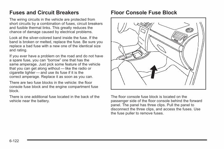
Fuses and Circuit BreakersThe wiring circuits in the vehicle are protected fromshort circuits by a combination of fuses, circuit breakersand fusible thermal links. This greatly reduces thechance of damage caused by electrical problems.
Look at the silver-colored band inside the fuse. If theband is broken or melted, replace the fuse. Be sure youreplace a bad fuse with a new one of the identical sizeand rating.
If you ever have a problem on the road and do not havea spare fuse, you can “borrow” one that has thesame amperage. Just pick some feature of the vehiclethat you can get along without— like the radio orcigarette lighter— and use its fuse if it is thecorrect amperage. Replace it as soon as you can.
There are two fuse blocks in the vehicle: the floorconsole fuse block and the engine compartment fuseblock.
There is one additional fuse located in the back of thevehicle near the battery.
Floor Console Fuse Block
The floor console fuse block is located on thepassenger side of the floor console behind the forwardpanel. The panel has three clips. Pull the panel todisconnect the three clips, and access the fuses. Usethe fuse puller to remove fuses.
6-122
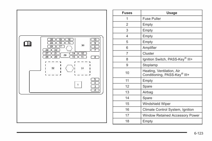
Fuses Usage
1 Fuse Puller
2 Empty
3 Empty
4 Empty
5 Empty
6 Amplifier
7 Cluster
8 Ignition Switch, PASS-Key® III+
9 Stoplamp
10Heating, Ventilation, AirConditioning, PASS-Key® III+
11 Empty
12 Spare
13 Airbag
14 Spare
15 Windshield Wiper
16 Climate Control System, Ignition
17 Window Retained Accessory Power
18 Empty
6-123
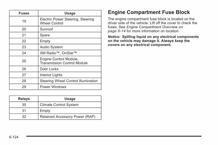
Fuses Usage
19 Electric Power Steering, SteeringWheel Control
20 Sunroof
21 Spare
22 Empty
23 Audio System
24 XM Radio™, OnStar™
25Engine Control Module,Transmission Control Module
26 Door Locks
27 Interior Lights
28 Steering Wheel Control Illumination
29 Power Windows
Relays Usage
30 Climate Control System
31 Empty
32 Retained Accessory Power (RAP)
Engine Compartment Fuse BlockThe engine compartment fuse block is located on thedriver side of the vehicle. Lift off the cover to check thefuses. See Engine Compartment Overview onpage 6‑14 for more information on location.
Notice: Spilling liquid on any electrical componentson the vehicle may damage it. Always keep thecovers on any electrical component.
6-124
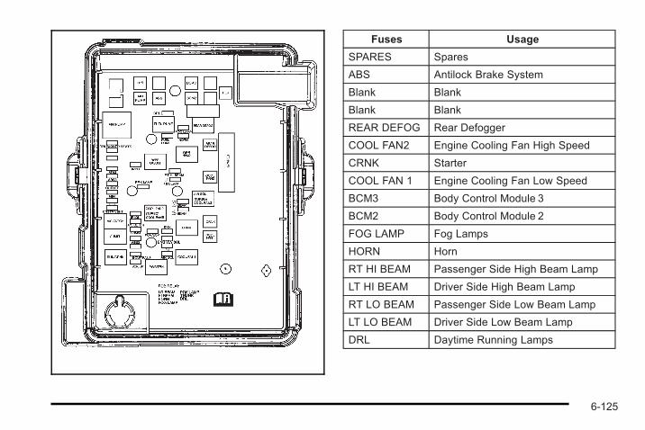
Fuses Usage
SPARES Spares
ABS Antilock Brake System
Blank Blank
Blank Blank
REAR DEFOG Rear Defogger
COOL FAN2 Engine Cooling Fan High Speed
CRNK Starter
COOL FAN 1 Engine Cooling Fan Low Speed
BCM3 Body Control Module 3
BCM2 Body Control Module 2
FOG LAMP Fog Lamps
HORN Horn
RT HI BEAM Passenger Side High Beam Lamp
LT HI BEAM Driver Side High Beam Lamp
RT LO BEAM Passenger Side Low Beam Lamp
LT LO BEAM Driver Side Low Beam Lamp
DRL Daytime Running Lamps
6-125
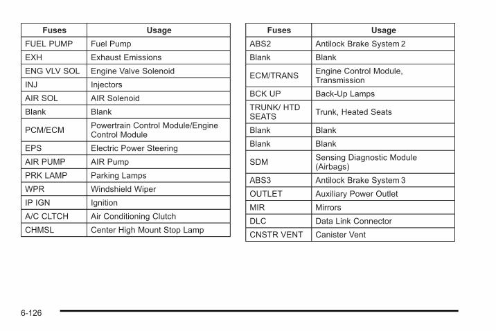
Fuses Usage
FUEL PUMP Fuel Pump
EXH Exhaust Emissions
ENG VLV SOL Engine Valve Solenoid
INJ Injectors
AIR SOL AIR Solenoid
Blank Blank
PCM/ECMPowertrain Control Module/EngineControl Module
EPS Electric Power Steering
AIR PUMP AIR Pump
PRK LAMP Parking Lamps
WPR Windshield Wiper
IP IGN Ignition
A/C CLTCH Air Conditioning Clutch
CHMSL Center High Mount Stop Lamp
Fuses Usage
ABS2 Antilock Brake System 2
Blank Blank
ECM/TRANSEngine Control Module,Transmission
BCK UP Back-Up Lamps
TRUNK/ HTDSEATS
Trunk, Heated Seats
Blank Blank
Blank Blank
SDMSensing Diagnostic Module(Airbags)
ABS3 Antilock Brake System 3
OUTLET Auxiliary Power Outlet
MIR Mirrors
DLC Data Link Connector
CNSTR VENT Canister Vent
6-126
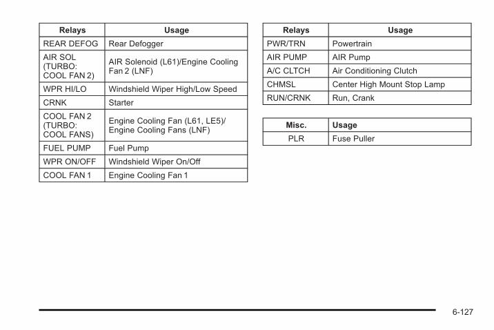
Relays Usage
REAR DEFOG Rear Defogger
AIR SOL(TURBO:COOL FAN 2)
AIR Solenoid (L61)/Engine CoolingFan 2 (LNF)
WPR HI/LO Windshield Wiper High/Low Speed
CRNK Starter
COOL FAN 2(TURBO:COOL FANS)
Engine Cooling Fan (L61, LE5)/Engine Cooling Fans (LNF)
FUEL PUMP Fuel Pump
WPR ON/OFF Windshield Wiper On/Off
COOL FAN 1 Engine Cooling Fan 1
Relays Usage
PWR/TRN Powertrain
AIR PUMP AIR Pump
A/C CLTCH Air Conditioning Clutch
CHMSL Center High Mount Stop Lamp
RUN/CRNK Run, Crank
Misc. Usage
PLR Fuse Puller
6-127
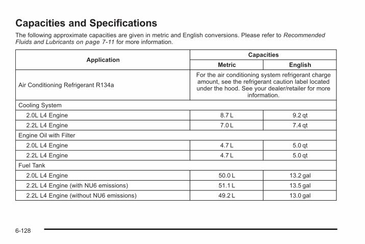
Capacities and SpecificationsThe following approximate capacities are given in metric and English conversions. Please refer to RecommendedFluids and Lubricants on page 7‑11 for more information.
ApplicationCapacities
Metric English
Air Conditioning Refrigerant R134a
For the air conditioning system refrigerant chargeamount, see the refrigerant caution label locatedunder the hood. See your dealer/retailer for more
information.
Cooling System
2.0L L4 Engine 8.7 L 9.2 qt
2.2L L4 Engine 7.0 L 7.4 qt
Engine Oil with Filter
2.0L L4 Engine 4.7 L 5.0 qt
2.2L L4 Engine 4.7 L 5.0 qt
Fuel Tank
2.0L L4 Engine 50.0 L 13.2 gal
2.2L L4 Engine (with NU6 emissions) 51.1 L 13.5 gal
2.2L L4 Engine (without NU6 emissions) 49.2 L 13.0 gal
6-128
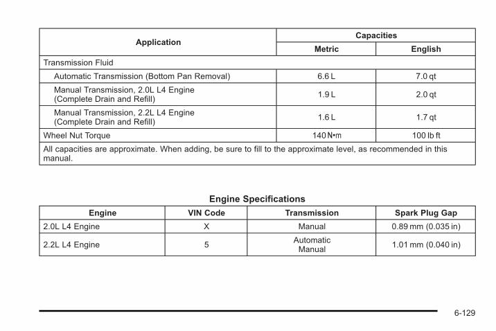
ApplicationCapacities
Metric English
Transmission Fluid
Automatic Transmission (Bottom Pan Removal) 6.6 L 7.0 qt
Manual Transmission, 2.0L L4 Engine(Complete Drain and Refill) 1.9 L 2.0 qt
Manual Transmission, 2.2L L4 Engine(Complete Drain and Refill)
1.6 L 1.7 qt
Wheel Nut Torque 140Y 100 lb ft
All capacities are approximate. When adding, be sure to fill to the approximate level, as recommended in thismanual.
Engine Specifications
Engine VIN Code Transmission Spark Plug Gap
2.0L L4 Engine X Manual 0.89 mm (0.035 in)
2.2L L4 Engine 5AutomaticManual
1.01 mm (0.040 in)
6-129

2 NOTES
6-130
Section 7 Maintenance Schedule
Maintenance Schedule . . . . . . . . . . . . . . . . . . . . . . . . . . . . 7-2Introduction . . . . . . . . . . . . . . . . . . . . . . . . . . . . . . . . . . . . . 7-2Scheduled Maintenance . . . . . . . . . . . . . . . . . . . . . . . . 7-3Owner Checks and Services . . . . . . . . . . . . . . . . . . . . 7-8
Recommended Fluids and Lubricants . . . . . . . . . . 7-11Maintenance Replacement Parts . . . . . . . . . . . . . . 7-13Engine Drive Belt Routing . . . . . . . . . . . . . . . . . . . . . 7-14Maintenance Record . . . . . . . . . . . . . . . . . . . . . . . . . . . 7-15
7-1
Maintenance Schedule
IntroductionNotice: Maintenance intervals, checks, inspections,recommended fluids, and lubricants are necessaryto keep this vehicle in good working condition.Damage caused by failure to follow scheduledmaintenance might not be covered by the vehiclewarranty.
Proper vehicle maintenance helps to keep the vehicle ingood working condition, improves fuel economy, andreduces vehicle emissions for better air quality.
Because of all the different ways people use vehicles,maintenance needs vary. The vehicle might need morefrequent checks and services. Please read theinformation under Scheduled Maintenance. To keep thevehicle in good condition, see your dealer/retailer.
The maintenance schedule is for vehicles that:. carry passengers and cargo within recommended
limits on the Tire and Loading Information label.See Loading the Vehicle on page 5‑25.
. are driven on reasonable road surfaces within legaldriving limits.
. use the recommended fuel. See Gasoline Octaneon page 6‑7 .
{ WARNING:
Performing maintenance work on a vehicle can bedangerous. In trying to do some jobs, you can beseriously injured. Do your own maintenance workonly if you have the required know-how and theproper tools and equipment for the job. If youhave any doubt, see your dealer/retailer to have aqualified technician do the work. See Doing YourOwn Service Work on page 6‑5.
At your General Motors dealer/retailer, you can becertain that you will receive the highest level of serviceavailable. Your dealer /retailer has specially trainedservice technicians, uses genuine GM replacementparts, as well as, up to date tools and equipment toensure fast and accurate diagnostics.
7-2
The proper replacement parts, fluids, and lubricants touse are listed in Recommended Fluids and Lubricantson page 7‑11 and Maintenance Replacement Parts onpage 7‑13. We recommend the use of genuine partsfrom your dealer/retailer.
Rotation of New TiresTo maintain ride, handling, and performance of thevehicle, it is important that the first rotation service fornew tires be performed when they have 8 000 to13 000 km (5,000 to 8,000 miles). See Tire Inspectionand Rotation on page 6‑71.
Scheduled Maintenance
When the Change Oil Soon MessageDisplaysChange engine oil and filter. See Engine Oil onpage 6‑16. An Emission Control Service.
When the Change Oil Soon message displays, serviceis required for the vehicle as soon as possible, withinthe next 1 000 km/600 miles. If driving under the bestconditions, the engine oil life system might not indicatethe need for vehicle service for more than a year. The
engine oil and filter must be changed at least once ayear and the oil life system must be reset. Your dealer/retailer has trained service technicians who will performthis work and reset the system. If the engine oil lifesystem is reset accidentally, service the vehicle within5 000 km/3,000 miles since the last service. Reset theoil life system whenever the oil is changed. See EngineOil Life System on page 6‑21.
When the Change Oil Soon message displays, certainservices, checks, and inspections are required. Theservices described for Maintenance I should beperformed at every engine oil change. The servicesdescribed for Maintenance II should beperformed when:. Maintenance I was performed the last time the
engine oil was changed.. It has been 10 months or more since the Change
Oil Soon message has displayed or since the lastservice.
7-3
Maintenance I. Change engine oil and filter. See Engine Oil on
page 6‑16. An Emission Control Service.. Engine coolant level check. See Engine Coolant
on page 6‑28.. Windshield washer fluid level check. See
Windshield Washer Fluid on page 6‑35.. Tire inflation check. See Inflation - Tire Pressure
on page 6‑63.. Tire wear inspection. See Tire Inspection and
Rotation on page 6‑71.. Rotate tires. See Tire Inspection and Rotation on
page 6‑71.. Fluids visual leak check (or every 12 months,
whichever occurs first). A leak in any system mustbe repaired and the fluid level checked.
. Engine air cleaner filter inspection (vehicles drivenin dusty conditions only). See Engine Air Cleaner/Filter (2.0L Turbo Engine) on page 6‑23 or EngineAir Cleaner/Filter (2.2L Engine) on page 6‑25.
. Brake system inspection (or every 12 months,whichever occurs first).
Maintenance II. Perform all services described in Maintenance I.. Steering and suspension inspection. Visual
inspection for damaged, loose, or missing parts orsigns of wear.
. Engine cooling system inspection. Visualinspection of hoses, pipes, fittings, and clamps andreplacement, if needed.
. Windshield wiper blade inspection for wear,cracking, or contamination and windshield andwiper blade cleaning, if contaminated. SeeWindshield and Wiper Blades on page 6‑117. Wornor damaged wiper blade replacement. SeeWindshield Wiper Blade Replacement onpage 6‑53.
. Body hinges and latches, key lock cylinders, andtrunk lid hinges and latches lubrication. SeeRecommended Fluids and Lubricants onpage 7‑11. More frequent lubrication may berequired when vehicle is exposed to a corrosiveenvironment. Applying silicone grease onweatherstrips with a clean cloth makes them lastlonger, seal better, and not stick or squeak.
. Restraint system component check. See Checkingthe Restraint Systems on page 2‑74.
7-4
. Automatic transmission fluid level check andadding fluid, if needed. See AutomaticTransmission Fluid on page 6‑26.
. Engine air cleaner filter inspection. See Engine AirCleaner/Filter (2.0L Turbo Engine) on page 6‑23or Engine Air Cleaner/Filter (2.2L Engine) onpage 6‑25.
. Passenger compartment air filter replacement(or every 12 months, whichever occurs first). Morefrequent replacement may be required if vehicle isdriven regularly under dusty conditions.
Additional Required Services
At Each Fuel Stop. Engine oil level check. See Engine Oil on
page 6‑16.. Engine coolant level check. See Engine Coolant
on page 6‑28.. Windshield washer fluid level check. See
Windshield Washer Fluid on page 6‑35.
Once a Month. Tire inflation check. See Inflation - Tire Pressure
on page 6‑63.. Tire wear inspection. See Tire Inspection and
Rotation on page 6‑71.
Once a Year. Starter switch check. See Owner Checks and
Services on page 7‑8.. Parking brake and automatic transmission P (Park)
mechanism check. See Owner Checks andServices on page 7‑8.
. Automatic transmission shiftlock control systemcheck. See Owner Checks and Services onpage 7‑8 .
. Ignition transmission lock check. See OwnerChecks and Services on page 7‑8.
. Engine cooling system and pressure cap pressurecheck. Radiator and air conditioning condenseroutside cleaning. See Cooling System onpage 6‑27.
. Exhaust system and nearby heat shieldsinspection for loose or damaged components.
. Throttle system inspection for interference, bindingor for damaged or missing parts. Replace parts asneeded. Replace any components that have higheffort or excessive wear. Do not lubricateaccelerator or cruise control cables.
. If the vehicle has a Tire Sealant and CompressorKit, check the sealant expiration date printed onthe instruction label of the kit. See Tire Sealant andCompressor Kit on page 6‑80.
7-5
First Engine Oil Change After Every40 000 km/25,000Miles. Fuel system inspection for damage or leaks.
First Engine Oil Change After Every80 000 km/50,000Miles. Engine air cleaner filter replacement. See Engine
Air Cleaner/Filter (2.0L Turbo Engine) onpage 6‑23 or Engine Air Cleaner/Filter(2.2L Engine) on page 6‑25.
. Automatic transmission fluid change (severeservice only) for vehicles mainly driven in heavycity traffic in hot weather, in hilly or mountainousterrain, when frequently towing a trailer, or used fortaxi, police, or delivery service. See AutomaticTransmission Fluid on page 6‑26.
First Engine Oil Change After Every160 000 km/100,000Miles. Spark plug replacement. An Emission Control
Service.
First Engine Oil Change After Every240 000 km/150,000Miles. Engine cooling system drain, flush, and refill,
cooling system and cap pressure check, andcleaning of outside of radiator and air conditioningcondenser (or every 5 years, whichever occursfirst). See Engine Coolant on page 6‑28. AnEmission Control Service.
. Engine accessory drive belt inspection for fraying,excessive cracks, or obvious damage andreplacement, if needed. An Emission ControlService.
7-6
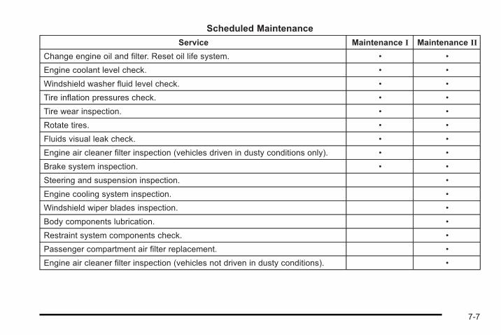
Scheduled Maintenance
Service Maintenance I Maintenance II
Change engine oil and filter. Reset oil life system. • •
Engine coolant level check. • •
Windshield washer fluid level check. • •
Tire inflation pressures check. • •
Tire wear inspection. • •
Rotate tires. • •
Fluids visual leak check. • •
Engine air cleaner filter inspection (vehicles driven in dusty conditions only). • •
Brake system inspection. • •
Steering and suspension inspection. •
Engine cooling system inspection. •
Windshield wiper blades inspection. •
Body components lubrication. •
Restraint system components check. •
Passenger compartment air filter replacement. •
Engine air cleaner filter inspection (vehicles not driven in dusty conditions). •
7-7
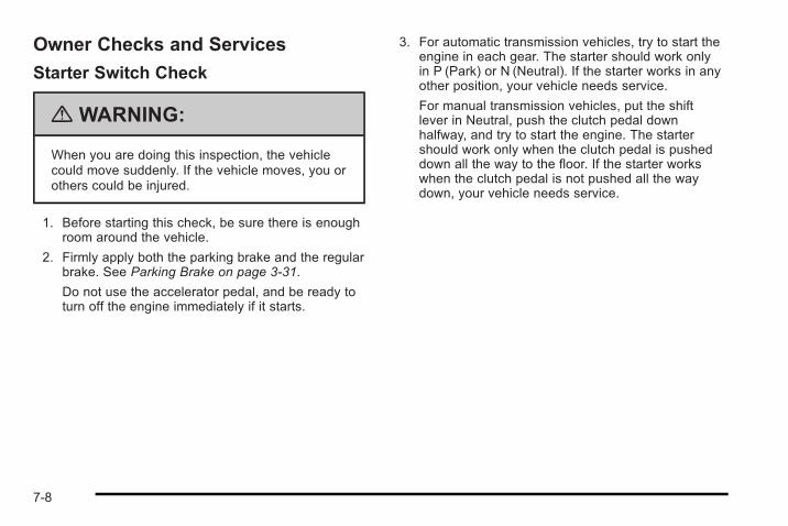
Owner Checks and Services
Starter Switch Check
{ WARNING:
When you are doing this inspection, the vehiclecould move suddenly. If the vehicle moves, you orothers could be injured.
1. Before starting this check, be sure there is enoughroom around the vehicle.
2. Firmly apply both the parking brake and the regularbrake. See Parking Brake on page 3‑31.
Do not use the accelerator pedal, and be ready toturn off the engine immediately if it starts.
3. For automatic transmission vehicles, try to start theengine in each gear. The starter should work onlyin P (Park) or N (Neutral). If the starter works in anyother position, your vehicle needs service.
For manual transmission vehicles, put the shiftlever in Neutral, push the clutch pedal downhalfway, and try to start the engine. The startershould work only when the clutch pedal is pusheddown all the way to the floor. If the starter workswhen the clutch pedal is not pushed all the waydown, your vehicle needs service.
7-8
Automatic Transmission Shift LockControl System Check
{ WARNING:
When you are doing this inspection, the vehiclecould move suddenly. If the vehicle moves, you orothers could be injured.
1. Before starting this check, be sure there is enoughroom around the vehicle. It should be parked on alevel surface.
2. Firmly apply the parking brake. See Parking Brakeon page 3‑31.
Be ready to apply the regular brake immediately ifthe vehicle begins to move.
3. With the engine off, turn the ignition to ON/RUN,but do not start the engine. Without applying theregular brake, try to move the shift lever out ofP (Park) with normal effort. If the shift lever movesout of P (Park), contact your dealer/retailer forservice.
Ignition Transmission Lock CheckWhile parked, and with the parking brake set, try to turnthe ignition to LOCK/OFF in each shift lever position.. For automatic transmission vehicles, the ignition
should turn to LOCK/OFF only when the shift leveris in P (Park). The ignition key should come outonly in LOCK/OFF.
. For manual transmission vehicles, the ignition keyshould come out only in LOCK/OFF.
Turn the steering wheel to the left and to the right.It should only lock when turned to the right.
Contact your dealer/retailer if service is required.
7-9
Parking Brake and AutomaticTransmission P (Park) MechanismCheck
{ WARNING:
When you are doing this check, the vehicle couldbegin to move. You or others could be injured andproperty could be damaged. Make sure there isroom in front of the vehicle in case it begins toroll. Be ready to apply the regular brake at onceshould the vehicle begin to move.
Park on a fairly steep hill, with the vehicle facingdownhill. Keeping your foot on the regular brake, set theparking brake.. To check the parking brake's holding ability: With
the engine running and the transmission inN (Neutral), slowly remove foot pressure from theregular brake pedal. Do this until the vehicle is heldby the parking brake only.
. To check the P (Park) mechanism's holding ability:With the engine running, shift to P (Park). Thenrelease the parking brake followed by the regularbrake.
Contact your dealer/retailer if service is required.
7-10
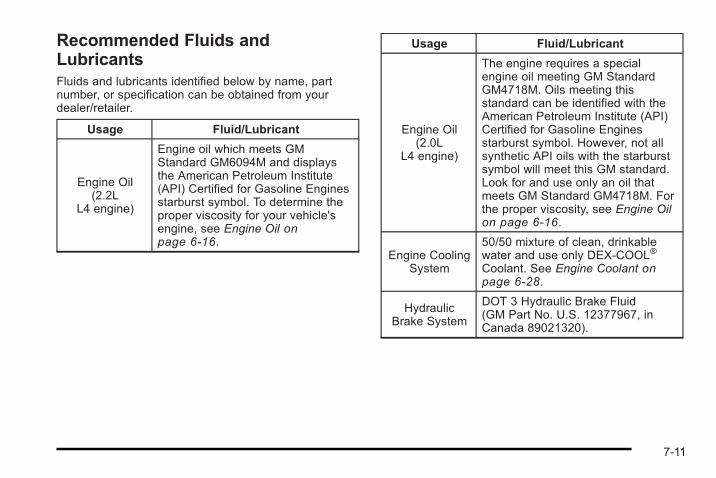
Recommended Fluids andLubricantsFluids and lubricants identified below by name, partnumber, or specification can be obtained from yourdealer/retailer.
Usage Fluid/Lubricant
Engine Oil(2.2L
L4 engine)
Engine oil which meets GMStandard GM6094M and displaysthe American Petroleum Institute(API) Certified for Gasoline Enginesstarburst symbol. To determine theproper viscosity for your vehicle'sengine, see Engine Oil onpage 6‑16.
Usage Fluid/Lubricant
Engine Oil(2.0L
L4 engine)
The engine requires a specialengine oil meeting GM StandardGM4718M. Oils meeting thisstandard can be identified with theAmerican Petroleum Institute (API)Certified for Gasoline Enginesstarburst symbol. However, not allsynthetic API oils with the starburstsymbol will meet this GM standard.Look for and use only an oil thatmeets GM Standard GM4718M. Forthe proper viscosity, see Engine Oilon page 6‑16.
Engine CoolingSystem
50/50 mixture of clean, drinkablewater and use only DEX-COOL®
Coolant. See Engine Coolant onpage 6‑28.
HydraulicBrake System
DOT 3 Hydraulic Brake Fluid(GM Part No. U.S. 12377967, inCanada 89021320).
7-11
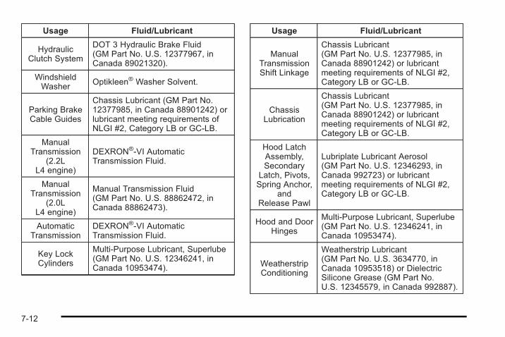
Usage Fluid/Lubricant
HydraulicClutch System
DOT 3 Hydraulic Brake Fluid(GM Part No. U.S. 12377967, inCanada 89021320).
WindshieldWasher Optikleen® Washer Solvent.
Parking BrakeCable Guides
Chassis Lubricant (GM Part No.12377985, in Canada 88901242) orlubricant meeting requirements ofNLGI #2, Category LB or GC-LB.
ManualTransmission
(2.2LL4 engine)
DEXRON®-VI AutomaticTransmission Fluid.
ManualTransmission
(2.0LL4 engine)
Manual Transmission Fluid(GM Part No. U.S. 88862472, inCanada 88862473).
AutomaticTransmission
DEXRON®-VI AutomaticTransmission Fluid.
Key LockCylinders
Multi-Purpose Lubricant, Superlube(GM Part No. U.S. 12346241, inCanada 10953474).
Usage Fluid/Lubricant
ManualTransmissionShift Linkage
Chassis Lubricant(GM Part No. U.S. 12377985, inCanada 88901242) or lubricantmeeting requirements of NLGI #2,Category LB or GC-LB.
ChassisLubrication
Chassis Lubricant(GM Part No. U.S. 12377985, inCanada 88901242) or lubricantmeeting requirements of NLGI #2,Category LB or GC-LB.
Hood LatchAssembly,Secondary
Latch, Pivots,Spring Anchor,
andRelease Pawl
Lubriplate Lubricant Aerosol(GM Part No. U.S. 12346293, inCanada 992723) or lubricantmeeting requirements of NLGI #2,Category LB or GC-LB.
Hood and DoorHinges
Multi-Purpose Lubricant, Superlube(GM Part No. U.S. 12346241, inCanada 10953474).
WeatherstripConditioning
Weatherstrip Lubricant(GM Part No. U.S. 3634770, inCanada 10953518) or DielectricSilicone Grease (GM Part No.U.S. 12345579, in Canada 992887).
7-12
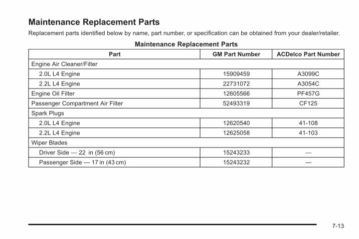
Maintenance Replacement PartsReplacement parts identified below by name, part number, or specification can be obtained from your dealer/retailer.
Maintenance Replacement Parts
Part GM Part Number ACDelco Part Number
Engine Air Cleaner/Filter
2.0L L4 Engine 15909459 A3099C
2.2L L4 Engine 22731072 A3054C
Engine Oil Filter 12605566 PF457G
Passenger Compartment Air Filter 52493319 CF125
Spark Plugs
2.0L L4 Engine 12620540 41-108
2.2L L4 Engine 12625058 41-103
Wiper Blades
Driver Side — 22 in (56 cm) 15243233 —
Passenger Side — 17 in (43 cm) 15243232 —
7-13
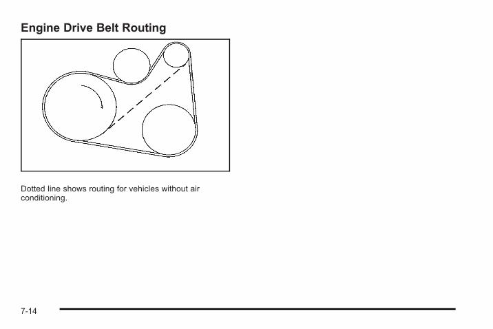
Engine Drive Belt Routing
Dotted line shows routing for vehicles without airconditioning.
7-14
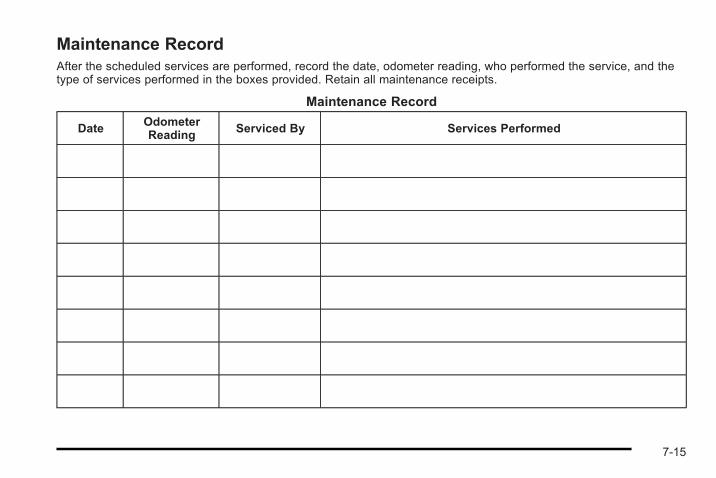
Maintenance RecordAfter the scheduled services are performed, record the date, odometer reading, who performed the service, and thetype of services performed in the boxes provided. Retain all maintenance receipts.
Maintenance Record
DateOdometerReading
Serviced By Services Performed
7-15
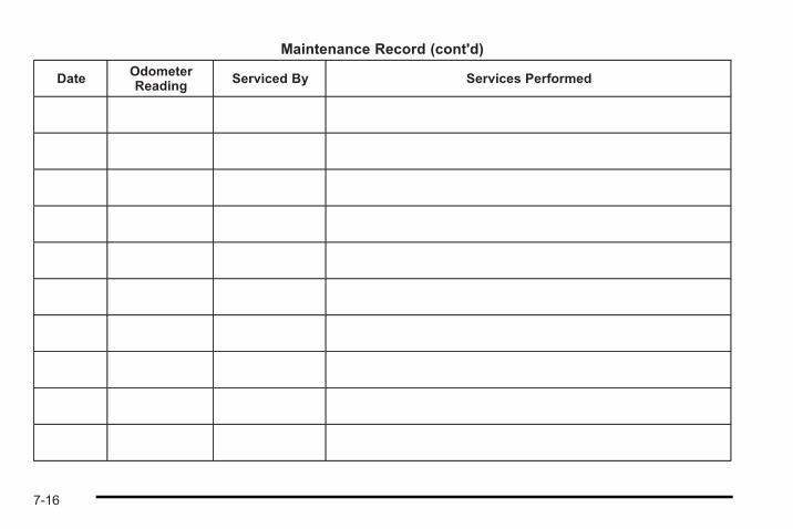
Maintenance Record (cont'd)
Date OdometerReading
Serviced By Services Performed
7-16
Maintenance Record (cont'd)
Date OdometerReading
Serviced By Services Performed
7-17

Maintenance Record (cont'd)
Date OdometerReading
Serviced By Services Performed
7-18
Section 8 Customer Assistance Information
Customer Assistance and Information . . . . . . . . . . . 8-2Customer Satisfaction Procedure . . . . . . . . . . . . . . . 8-2Online Owner Center . . . . . . . . . . . . . . . . . . . . . . . . . . . . 8-5Customer Assistance for Text Telephone(TTY) Users . . . . . . . . . . . . . . . . . . . . . . . . . . . . . . . . . . 8-6
Customer Assistance Offices . . . . . . . . . . . . . . . . . . . 8-6GM Mobility Reimbursement Program . . . . . . . . . . . 8-7Roadside Assistance Program . . . . . . . . . . . . . . . . . . 8-8Scheduling Service Appointments . . . . . . . . . . . . . 8-10Courtesy Transportation Program . . . . . . . . . . . . . . 8-10Collision Damage Repair . . . . . . . . . . . . . . . . . . . . . . 8-12
Reporting Safety Defects . . . . . . . . . . . . . . . . . . . . . . . . 8-15Reporting Safety Defects to the United StatesGovernment . . . . . . . . . . . . . . . . . . . . . . . . . . . . . . . . . 8-15
Reporting Safety Defects to theCanadian Government . . . . . . . . . . . . . . . . . . . . . . . 8-16
Reporting Safety Defects to General Motors . . . 8-16Service Publications Ordering Information . . . . . 8-16
Vehicle Data Recording and Privacy . . . . . . . . . . . . . 8-17Event Data Recorders . . . . . . . . . . . . . . . . . . . . . . . . . 8-18OnStar® . . . . . . . . . . . . . . . . . . . . . . . . . . . . . . . . . . . . . . . 8-18Navigation System . . . . . . . . . . . . . . . . . . . . . . . . . . . . . 8-19Radio Frequency Identification (RFID) . . . . . . . . . 8-19Radio Frequency Statement . . . . . . . . . . . . . . . . . . . 8-19
8-1
Customer Assistance andInformation
Customer Satisfaction ProcedureYour satisfaction and goodwill are important to yourdealer and to Chevrolet. Normally, any concerns withthe sales transaction or the operation of the vehicle willbe resolved by the dealer's sales or servicedepartments. Sometimes, however, despite the bestintentions of all concerned, misunderstandings canoccur. If your concern has not been resolved to yoursatisfaction, the following steps should be taken:
STEP ONE : Discuss your concern with a member ofdealership management. Normally, concerns can bequickly resolved at that level. If the matter has alreadybeen reviewed with the sales, service, or partsmanager, contact the owner of the dealership or thegeneral manager.
STEP TWO : If after contacting a member ofdealership management, it appears your concerncannot be resolved by the dealership without furtherhelp, in the U.S., call the Chevrolet CustomerAssistance Center at 1-800-222-1020. In Canada, callGeneral Motors of Canada Customer CommunicationCentre at 1-800-263-3777 (English), or 1-800-263-7854(French).
We encourage you to call the toll-free number in orderto give your inquiry prompt attention. Have the followinginformation available to give the Customer AssistanceRepresentative:. Vehicle Identification Number (VIN). This is
available from the vehicle registration or title, or theplate at the top left of the instrument panel andvisible through the windshield.
. Dealership name and location.
. Vehicle delivery date and present mileage.
When contacting Chevrolet, remember that yourconcern will likely be resolved at a dealer's facility. Thatis why we suggest following Step One first.
8-2
STEP THREE — U.S. Owners : Both General Motorsand your dealer are committed to making sure you arecompletely satisfied with your new vehicle. However,if you continue to remain unsatisfied after following theprocedure outlined in Steps One and Two, you can filewith the Better Business Bureau (BBB) Auto LineProgram to enforce your rights.
The BBB Auto Line Program is an out of court programadministered by the Council of Better Business Bureausto settle automotive disputes regarding vehicle repairsor the interpretation of the New Vehicle LimitedWarranty. Although you may be required to resort to thisinformal dispute resolution program prior to filing a courtaction, use of the program is free of charge and yourcase will generally be heard within 40 days. If you donot agree with the decision given in your case, you mayreject it and proceed with any other venue for reliefavailable to you.
You may contact the BBB Auto Line Program using thetoll-free telephone number or write them at the followingaddress:
BBB Auto Line ProgramCouncil of Better Business Bureaus, Inc.4200 Wilson BoulevardSuite 800Arlington, VA 22203-1838
Telephone: 1-800-955-5100dr.bbb.org/goauto
This program is available in all 50 states and the Districtof Columbia. Eligibility is limited by vehicle age,mileage, and other factors. General Motors reserves theright to change eligibility limitations and/or discontinueits participation in this program.
8-3
STEP THREE — Canadian Owners : In the event thatyou do not feel your concerns have been addressedafter following the procedure outlined in Steps 1 and 2,General Motors of Canada Limited wants you to beaware of its participation in a no-charge Mediation/Arbitration Program. General Motors of Canada Limitedhas committed to binding arbitration of owner disputesinvolving factory-related vehicle service claims. Theprogram provides for the review of the facts involved byan impartial third party arbiter, and may include aninformal hearing before the arbiter. The program isdesigned so that the entire dispute settlement process,from the time you file your complaint to the finaldecision, should be completed in about 70 days. Webelieve our impartial program offers advantages overcourts in most jurisdictions because it is informal, quick,and free of charge.
For further information concerning eligibility in theCanadian Motor Vehicle Arbitration Plan (CAMVAP), calltoll-free 1-800-207-0685, or call the General MotorsCustomer Communication Centre, 1-800-263-3777(English), 1-800-263-7854 (French), or write to:
The Mediation/Arbitration Programc/o Customer Communication CentreGeneral Motors of Canada LimitedMail Code: CA1-163-0051908 Colonel Sam DriveOshawa, Ontario L1H 8P7
Your inquiry should be accompanied by the VehicleIdentification Number (VIN).
8-4
Online Owner Center
Online Owner Center (U.S.) —www.gmownercenter.com/chevroletInformation and services customized for your specificvehicle — all in one convenient place.. Digital owner manual, warranty information,
and more. Online service and maintenance records. Find Chevrolet dealers for service nationwide. Exclusive privileges and offers. Recall notices for your specific vehicle. OnStar® and GM Cardmember Services Earnings
summaries
Other Helpful Links:Chevrolet — minus; www.chevrolet.com
Chevrolet Merchandise — www.chevymall.com
Help Center — www.chevrolet.com/helpcenter. FAQ. Contact Us
My GM Canada (Canada) — www.gm.caMy GM Canada is a password-protected section ofwww.gm.ca where you can save information on GMvehicles, get personalized offers, and use handy toolsand forms with greater ease.
Here are a few of the valuable tools and services youwill have access to:. My Showroom: Find and save information on
vehicles and current offers in your area.. My Dealers/Retailers: Save details such as
address and phone number for each of yourpreferred GM dealers/retailers.
. My Driveway: Access quick links to parts andservice estimates, check trade-in values,or schedule a service appointment by adding thevehicles you own to your driveway profile.
. My Preferences: Manage your profile and use toolsand forms with greater ease.
To sign up, visit the My GM Canada section withinwww.gm.ca.
8-5
Customer Assistance for TextTelephone (TTY) UsersTo assist customers who are deaf, hard of hearing,or speech-impaired and who use Text Telephones(TTYs), Chevrolet has TTY equipment available at itsCustomer Assistance Center. Any TTY user in theU.S. can communicate with Chevrolet by dialing:1-800-833-CHEV (2438). (TTY users in Canada can dial1-800-263-3830.)
Customer Assistance OfficesChevrolet encourages customers to call the toll-freenumber for assistance. However, if a customer wishesto write or e-mail Chevrolet, the letter should beaddressed to:
United States — Customer AssistanceChevrolet Motor DivisionChevrolet Customer Assistance CenterP.O. Box 33170Detroit, MI 48232-5170Chevrolet.com
1-800-222-10201-800-833-2438 (For Text Telephonedevices (TTYs))Roadside Assistance: 1-800-CHEV-USA (243-8872)
From Puerto Rico:
1-800-496-9992 (English)1-800-496-9993 (Spanish)
From U.S. Virgin Islands:
1-800-496-9994
Canada — Customer AssistanceGeneral Motors of Canada LimitedCustomer Communication Centre, CA1-163-0051908 Colonel Sam DriveOshawa, Ontario L1H 8P7gmcanada.com
1-800-263-3777 (English)1-800-263-7854 (French)1-800-263-3830 (For Text Telephonedevices (TTYs))Roadside Assistance: 1-800-268-6800
8-6
Overseas — Customer AssistancePlease contact the local General Motors Business Unit.
Mexico, Central America and CaribbeanIslands/Countries (Except Puerto Ricoand U.S. Virgin Islands) — CustomerAssistance
General Motors de Mexico, S. de R.L. de C.V.Customer Assistance CenterPaseo de la Reforma # 2740Col. Lomas de BezaresC.P. 11910, Mexico, D.F.
01-800-508-0000Long Distance: 011-52-53 29 0 800
GM Mobility ReimbursementProgram
This program, available to qualified applicants, canreimburse you up to $1,000 of the cost of eligibleaftermarket adaptive equipment required for yourvehicle, such as hand controls or a wheelchair/scooter lift.
The offer is available for a very limited period of timefrom the date of vehicle purchase/lease. For moredetails, or to determine your vehicle's eligibility, visitgmmobility.com or call the GM Mobility AssistanceCenter at 1-800-323-9935. Text telephone (TTY) users,call 1-800-833-9935.
General Motors of Canada also has a Mobility Program.Call 1-800-GM-DRIVE (463-7483) for details. TTY userscall 1-800-263-3830.
8-7
Roadside Assistance ProgramFor U.S. purchased vehicles, call 1-800-CHEV-USA(1-800-243-8872); (Text telephone (TTY):1-888-889-2438).
For Canadian purchased vehicles, call 1-800-268-6800.
Service is available 24 hours a day, 365 days a year.
Calling for AssistanceWhen calling Roadside Assistance, have the followinginformation ready:. Your name, home address, and home telephone
number. Telephone number of your location. Location of the vehicle. Model, year, color, and license plate number of the
vehicle. Odometer reading, Vehicle Identification Number
(VIN), and delivery date of the vehicle. Description of the problem
CoverageServices are provided up to 5 years/100,000 miles (160 000 km), whichever comes first.
In the U.S., anyone driving the vehicle is covered. InCanada, a person driving the vehicle without permissionfrom the owner is not covered.
Roadside Assistance is not a part of the New VehicleLimited Warranty. Chevrolet and General Motors ofCanada Limited reserve the right to make any changesor discontinue the Roadside Assistance program at anytime without notification.
Chevrolet and General Motors of Canada Limitedreserve the right to limit services or payment to anowner or driver if they decide the claims are made toooften, or the same type of claim is made many times.
8-8
Services Provided. Emergency Fuel Delivery: Delivery of enough
fuel for the vehicle to get to the nearest servicestation.
. Lock-Out Service: Service is provided to unlockthe vehicle if you are locked out. A remote unlockmay be available if you have OnStar®. For securityreasons, the driver must present identificationbefore this service is given.
. Emergency Tow From a Public Road orHighway: Tow to the nearest Chevrolet dealer forwarranty service, or if the vehicle was in a crashand cannot be driven. Assistance is also givenwhen the vehicle is stuck in the sand, mud,or snow.
. Flat Tire Change: Service is provided to change aflat tire with the spare tire. The spare tire,if equipped, must be in good condition andproperly inflated. It is the owner's responsibility forthe repair or replacement of the tire if it is notcovered by the warranty.
. Battery Jump Start: Service is provided to jumpstart a dead battery.
Services Not Included in RoadsideAssistance. Impound towing caused by violation of any laws.. Legal fines.. Mounting, dismounting or changing of snow tires,
chains, or other traction devices.. Towing or services for vehicles driven on a
non-public road or highway.
Services Specific to CanadianPurchased Vehicles. Fuel delivery: Reimbursement is approximately
$5 Canadian. Diesel fuel delivery may berestricted. Propane and other fuels are notprovided through this service.
. Lock-Out Service: Vehicle registration isrequired.
. Trip Routing Service: Detailed maps of NorthAmerica are provided when requested either withthe most direct route or the most scenic route.There is a limit of six requests per year. Additionaltravel information is also available. Allow threeweeks for delivery.
8-9
. Trip Interruption Benefits and Assistance: Mustbe over 250♦kilometres from where your trip wasstarted to qualify. General Motors of CanadaLimited requires pre-authorization, original detailedreceipts, and a copy of the repair orders. Onceauthorization has been received, the RoadsideAssistance advisor will help you makearrangements and explain how to receive payment.
. Alternative Service: If assistance cannot beprovided right away, the Roadside Assistanceadvisor may give you permission to get localemergency road service. You will receive payment,up to $100, after sending the original receipt toRoadside Assistance. Mechanical failures may becovered, however any cost for parts and labor forrepairs not covered by the warranty are the ownerresponsibility.
Scheduling Service AppointmentsWhen your vehicle requires warranty service, contactyour dealer/retailer and request an appointment. Byscheduling a service appointment and advising yourservice consultant of your transportation needs, yourdealer/retailer can help minimize your inconvenience.
If your vehicle cannot be scheduled into the servicedepartment immediately, keep driving it until it can bescheduled for service, unless, of course, the problem issafety-related. If it is, please call your dealership/retailer, let them know this, and ask for instructions.
If the dealer/retailer requests you to bring the vehicle forservice, you are urged to do so as early in the work dayas possible to allow for the same day repair.
Courtesy Transportation ProgramTo enhance your ownership experience, we and ourparticipating dealers are proud to offer CourtesyTransportation, a customer support program for vehicleswith the New Vehicle Limited Warranty (Base WarrantyCoverage period in Canada) and extended powertrain,and hybrid specific warranty in both the U.S. andCanada.
Several courtesy transportation options are available toassist in reducing your inconvenience when warrantyrepairs are required.
Courtesy Transportation is not a part of the New VehicleLimited Warranty. A separate booklet entitled “Warrantyand Owner Assistance Information” furnished with eachnew vehicle provides detailed warranty coverageinformation.
8-10
Transportation OptionsWarranty service can generally be completed while youwait. However, if you are unable to wait, GM helps tominimize your inconvenience by providing severaltransportation options. Depending on thecircumstances, your dealer can offer you one of thefollowing:
Shuttle ServiceShuttle service is the preferred means of offeringCourtesy Transportation. Dealers may provide you withshuttle service to get you to your destination withminimal interruption of your daily schedule. Thisincludes one-way or round trip shuttle service withinreasonable time and distance parameters of thedealer's area.
Public Transportation or FuelReimbursementIf your vehicle requires overnight warranty repairs, andpublic transportation is used instead of the dealer'sshuttle service, the expense must be supported byoriginal receipts and can only be up to the maximumamount allowed by GM for shuttle service. In addition,
for U.S. customers, should you arrange transportationthrough a friend or relative, limited reimbursement forreasonable fuel expenses may be available. Claimamounts should reflect actual costs and be supportedby original receipts. See your dealer for informationregarding the allowance amounts for reimbursement offuel or other transportation costs.
Courtesy Rental VehicleYour dealer may arrange to provide you with a courtesyrental vehicle or reimburse you for a rental vehicle thatyou obtain if your vehicle is kept for an overnightwarranty repair. Rental reimbursement will be limitedand must be supported by original receipts. Thisrequires that you sign and complete a rental agreementand meet state/provincial, local, and rental vehicleprovider requirements. Requirements vary and mayinclude minimum age requirements, insurancecoverage, credit card, etc. You are responsible for fuelusage charges and may also be responsible for taxes,levies, usage fees, excessive mileage, or rental usagebeyond the completion of the repair.
It may not be possible to provide a like-vehicle as acourtesy rental.
8-11
Additional Program InformationAll program options, such as shuttle service, may not beavailable at every dealer. Please contact your dealer forspecific information about availability. All CourtesyTransportation arrangements will be administered byappropriate dealer personnel.
General Motors reserves the right to unilaterally modify,change or discontinue Courtesy Transportation at anytime and to resolve all questions of claim eligibilitypursuant to the terms and conditions described hereinat its sole discretion.
Collision Damage RepairIf your vehicle is involved in a collision and it isdamaged, have the damage repaired by a qualifiedtechnician using the proper equipment and qualityreplacement parts. Poorly performed collision repairsdiminish your vehicle's resale value, and safetyperformance can be compromised in subsequentcollisions.
Collision PartsGenuine GM Collision parts are new parts made withthe same materials and construction methods as theparts with which your vehicle was originally built.Genuine GM Collision parts are your best choice toensure that your vehicle's designed appearance,
durability, and safety are preserved. The use ofGenuine GM parts can help maintain your GM NewVehicle Warranty.
Recycled original equipment parts may also be used forrepair. These parts are typically removed from vehiclesthat were total losses in prior crashes. In most cases,the parts being recycled are from undamaged sectionsof the vehicle. A recycled original equipment GM part,may be an acceptable choice to maintain your vehicle'soriginally designed appearance and safety performance,however, the history of these parts is not known. Suchparts are not covered by your GM New Vehicle LimitedWarranty, and any related failures are not covered bythat warranty.
Aftermarket collision parts are also available. These aremade by companies other than GM and may not havebeen tested for your vehicle. As a result, these partsmay fit poorly, exhibit premature durability/corrosionproblems, and may not perform properly in subsequentcollisions. Aftermarket parts are not covered by yourGM New Vehicle Limited Warranty, and any vehiclefailure related to such parts are not covered by thatwarranty.
8-12
Repair FacilityWe recommend that you choose a collision repairfacility that meets your needs before you ever needcollision repairs. Your dealer/retailer may have acollision repair center with GM-trained technicians andstate of the art equipment, or be able to recommend acollision repair center that has GM-trained techniciansand comparable equipment.
Insuring Your VehicleProtect your investment in your GM vehicle withcomprehensive and collision insurance coverage. Thereare significant differences in the quality of coverageafforded by various insurance policy terms. Manyinsurance policies provide reduced protection to yourGM vehicle by limiting compensation for damagerepairs by using aftermarket collision parts. Someinsurance companies will not specify aftermarketcollision parts. When purchasing insurance, werecommend that you assure your vehicle will berepaired with GM original equipment collision parts.If such insurance coverage is not available from yourcurrent insurance carrier, consider switching to anotherinsurance carrier.
If your vehicle is leased, the leasing company mayrequire you to have insurance that assures repairs withGenuine GM Original Equipment Manufacturer (OEM)parts or Genuine Manufacturer replacement parts. Readyour lease carefully, as you may be charged at the endof your lease for poor quality repairs.
If a Crash OccursHere is what to do if you are involved in a crash.. Check to make sure that you are all right. If you
are uninjured, make sure that no one else in yourvehicle, or the other vehicle, is injured.
. If there has been an injury, call emergencyservices for help. Do not leave the scene of acrash until all matters have been taken care of.Move your vehicle only if its position puts you indanger or you are instructed to move it by a policeofficer.
. Give only the necessary and requested informationto police and other parties involved in the crash.Do not discuss your personal condition, mentalframe of mind, or anything unrelated to the crash.This will help guard against post-crash legal action.
. If you need roadside assistance, call GM RoadsideAssistance. See Roadside Assistance Program onpage 8‑8 for more information.
8-13
. If your vehicle cannot be driven, know where thetowing service will be taking it. Get a card from thetow truck operator or write down the driver's name,the service's name, and the phone number.
. Remove any valuables from your vehicle before itis towed away. Make sure this includes yourinsurance information and registration if you keepthese items in your vehicle.
. Gather the important information you will need fromthe other driver. Things like name, address, phonenumber, driver's license number, vehicle licenseplate, vehicle make, model and model year,Vehicle Identification Number (VIN), insurancecompany and policy number, and a generaldescription of the damage to the other vehicle.
. If possible, call your insurance company from thescene of the crash. They will walk you through theinformation they will need. If they ask for a policereport, phone or go to the police departmentheadquarters the next day and you can get a copyof the report for a nominal fee. In some states/provinces with “no fault” insurance laws, a reportmay not be necessary. This is especially true ifthere are no injuries and both vehicles aredriveable.
. Choose a reputable collision repair facility for yourvehicle. Whether you select a dealer/retailer or aprivate collision repair facility to fix the damage,make sure you are comfortable with them.Remember, you will have to feel comfortable withtheir work for a long time.
. Once you have an estimate, read it carefully andmake sure you understand what work will beperformed on your vehicle. If you have a question,ask for an explanation. Reputable shops welcomethis opportunity.
Managing the Vehicle Damage RepairProcessIn the event that your vehicle requires damage repairs,GM recommends that you take an active role in itsrepair. If you have a pre-determined repair facility ofchoice, take your vehicle there, or have it towed there.Specify to the facility that any required replacementcollision parts be original equipment parts, either newGenuine GM parts or recycled original GM parts.Remember, recycled parts will not be covered by yourGM vehicle warranty.
8-14
Insurance pays the bill for the repair, but you must livewith the repair. Depending on your policy limits, yourinsurance company may initially value the repair usingaftermarket parts. Discuss this with your repairprofessional, and insist on Genuine GM parts.Remember if your vehicle is leased you may beobligated to have the vehicle repaired with Genuine GMparts, even if your insurance coverage does not pay thefull cost.
If another party's insurance company is paying for therepairs, you are not obligated to accept a repairvaluation based on that insurance company's collisionpolicy repair limits, as you have no contractual limitswith that company. In such cases, you can have controlof the repair and parts choices as long as cost stayswithin reasonable limits.
Reporting Safety Defects
Reporting Safety Defects to theUnited States GovernmentIf you believe that your vehicle has a defect whichcould cause a crash or could cause injury ordeath, you should immediately inform the NationalHighway Traffic Safety Administration (NHTSA) inaddition to notifying General Motors.
If NHTSA receives similar complaints, it may openan investigation, and if it finds that a safety defectexists in a group of vehicles, it may order a recalland remedy campaign. However, NHTSA cannotbecome involved in individual problems betweenyou, your dealer, or General Motors.
To contact NHTSA, you may call the VehicleSafety Hotline toll-free at 1-888-327-4236(TTY: 1-800-424-9153); go tohttp://www.safercar.gov; or write to:
Administrator, NHTSA1200 New Jersey Avenue, S.E.Washington, D.C. 20590
You can also obtain other information about motorvehicle safety from http://www.safercar.gov.
8-15
Reporting Safety Defects to theCanadian GovernmentIf you live in Canada, and you believe that your vehiclehas a safety defect, notify Transport Canadaimmediately, in addition to notifying General Motors ofCanada Limited. Call them at 1-800-333-0510 orwrite to:
Transport CanadaRoad Safety Branch2780 Sheffield RoadOttawa, Ontario K1B 3V9
Reporting Safety Defects to GeneralMotorsIn addition to notifying NHTSA (or Transport Canada) ina situation like this, please notify General Motors.
Call 1-800-222-1020, or write:
Chevrolet Motor DivisionChevrolet Customer Assistance CenterP.O. Box 33170Detroit, MI 48232-5170
In Canada, call 1-800-263-3777 (English) or1-800-263-7854 (French), or write:
General Motors of Canada LimitedCustomer Communication Centre, CA1-163-0051908 Colonel Sam DriveOshawa, Ontario L1H 8P7
Service Publications OrderingInformation
Service ManualsService Manuals have the diagnosis and repairinformation on engines, transmission, axle suspension,brakes, electrical, steering, body, etc.
Service BulletinsService Bulletins give additional technical serviceinformation needed to knowledgeably service GeneralMotors cars and trucks. Each bulletin containsinstructions to assist in the diagnosis and service ofyour vehicle.
8-16
Owner InformationOwner publications are written specifically for ownersand intended to provide basic operational informationabout the vehicle. The owner manual includes theMaintenance Schedule for all models.
In-Portfolio: Includes a Portfolio, Owner Manual, andWarranty Booklet.
RETAIL SELL PRICE: $35.00 (U.S.) plus processing fee
Without Portfolio: Owner Manual only.
RETAIL SELL PRICE: $25.00 (U.S.) plus processing fee
Current and Past Model Order FormsTechnical Service Bulletins and Manuals are availablefor current and past model GM vehicles. To request anorder form, specify year and model name of the vehicle.
ORDER TOLL FREE: 1-800-551-4123Monday-Friday 8:00 AM - 6:00 PMEastern TimeFor Credit Card Orders Only(VISA-MasterCard-Discover), visit Helm, Inc. on theWorld Wide Web at: helminc.com
Or you can write to:
Helm, IncorporatedP.O. Box 07130Detroit, MI 48207
Prices are subject to change without notice and withoutincurring obligation. Allow ample time for delivery.
Note to Canadian Customers: All listed prices arequoted in U.S. funds. Canadian residents are to makechecks payable in U.S. funds.
Vehicle Data Recording andPrivacyYour GM vehicle has a number of sophisticatedcomputers that record information about the vehicle’sperformance and how it is driven. For example, yourvehicle uses computer modules to monitor and controlengine and transmission performance, to monitor theconditions for airbag deployment and deploy airbags ina crash and, if so equipped, to provide antilock brakingto help the driver control the vehicle. These modulesmay store data to help your dealer/retailer technicianservice your vehicle. Some modules may also storedata about how you operate the vehicle, such as rate offuel consumption or average speed. These modulesmay also retain the owner’s personal preferences, suchas radio pre-sets, seat positions, and temperaturesettings.
8-17
Event Data RecordersThis vehicle has an Event Data Recorder (EDR). Themain purpose of an EDR is to record, in certain crash ornear crash-like situations, such as an airbagdeployment or hitting a road obstacle, data that willassist in understanding how a vehicle's systemsperformed. The EDR is designed to record data relatedto vehicle dynamics and safety systems for a shortperiod of time, typically 30 seconds or less. The EDR inthis vehicle is designed to record such data as:. How various systems in your vehicle were
operating. Whether or not the driver and passenger safety
belts were buckled/fastened. How far, if at all, the driver was pressing the
accelerator and/or brake pedal. How fast the vehicle was traveling
This data can help provide a better understanding of thecircumstances in which crashes and injuries occur.
Important: EDR data is recorded by your vehicle only ifa non-trivial crash situation occurs; no data is recordedby the EDR under normal driving conditions and nopersonal data (e.g., name, gender, age, and crashlocation) is recorded. However, other parties, such aslaw enforcement, could combine the EDR data with thetype of personally identifying data routinely acquiredduring a crash investigation.
To read data recorded by an EDR, special equipment isrequired, and access to the vehicle or the EDR isneeded. In addition to the vehicle manufacturer, otherparties, such as law enforcement, that have the specialequipment, can read the information if they have accessto the vehicle or the EDR.
GM will not access this data or share it with othersexcept: with the consent of the vehicle owner or, if thevehicle is leased, with the consent of the lessee; inresponse to an official request of police or similargovernment office; as part of GM's defense of litigationthrough the discovery process; or, as required by law.Data that GM collects or receives may also be used forGM research needs or may be made available to othersfor research purposes, where a need is shown and thedata is not tied to a specific vehicle or vehicle owner.
OnStar®
If the vehicle has OnStar and you subscribe to theOnStar services, please refer to the OnStar Terms andConditions for information on data collection and use.
8-18
Navigation SystemIf your vehicle has a navigation system, use of thesystem may result in the storage of destinations,addresses, telephone numbers, and other tripinformation. Refer to the navigation system operatingmanual for information on stored data and for deletioninstructions.
Radio FrequencyIdentification (RFID)RFID technology is used in some vehicles for functionssuch as tire pressure monitoring and ignition systemsecurity, as well as in connection with conveniencessuch as key fobs for remote door locking/unlocking andstarting, and in-vehicle transmitters for garage dooropeners. RFID technology in GM vehicles does not useor record personal information or link with any other GMsystem containing personal information.
Radio Frequency StatementThis vehicle has systems that operate on a radiofrequency that comply with Part 15 of the FederalCommunications Commission (FCC) Rules and withRSS-210/211 of Industry and Science Canada.
Operation is subject to the following two conditions:
1. The device may not cause interference.
2. The device must accept any interference received,including interference that may cause undesiredoperation of the device.
Changes or modifications to any of these systems byother than an authorized service facility could voidauthorization to use this equipment.
8-19

2 NOTES
8-20
AAccessories and Modifications . . . . . . . . . . . . . . . . . . . . . . .6-4Accessory Power . . . . . . . . . . . . . . . . . . . . . . . . . . . . . . . . . . 3-23Accessory Power Outlets . . . . . . . . . . . . . . . . . . . . . . . . . . 4-12Add-On Electrical Equipment . . . . . . . . . . . . . . . . . . . . . 6-121Additives, Fuel . . . . . . . . . . . . . . . . . . . . . . . . . . . . . . . . . . . . . . .6-8AdjustmentsHeadlamp Range . . . . . . . . . . . . . . . . . . . . . . . . . . . . . . . . . . 2-7
Air Cleaner/Filter, Engine . . . . . . . . . . . . . . . . . . . . 6-23, 6-25Air Conditioning . . . . . . . . . . . . . . . . . . . . . . . . . . . . . . . . . . . 4-14Air Filter, Passenger Compartment . . . . . . . . . . . . . . . . 4-17AirbagAdding Equipment to Your Airbag-EquippedVehicle . . . . . . . . . . . . . . . . . . . . . . . . . . . . . . . . . . . . . . . . . . 2-73
Airbag SystemHow Does an Airbag Restrain? . . . . . . . . . . . . . . . . . . . 2-59Passenger Sensing System . . . . . . . . . . . . . . . . 2-62, 2-67Servicing Your Airbag-Equipped Vehicle . . . . . . . . . . 2-72What Makes an Airbag Inflate? . . . . . . . . . . . . . . . . . . . 2-59What Will You See After an Airbag Inflates? . . . . . . 2-60When Should an Airbag Inflate? . . . . . . . . . . . . . . . . . . 2-58Where Are the Airbags? . . . . . . . . . . . . . . . . . . . . . . . . . . 2-56
AirbagsPassenger Status Indicator . . . . . . . . . . . . . . . . . . . . . . . 4-22Readiness Light . . . . . . . . . . . . . . . . . . . . . . . . . . . . . . . . . . 4-21System Check . . . . . . . . . . . . . . . . . . . . . . . . . . . . . . . . . . . . 2-53
AntennaFixed Mast . . . . . . . . . . . . . . . . . . . . . . . . . . . . . . . . . . . . . . . 4-86
Antenna, XM™ Satellite Radio Antenna System . . . 4-86Antilock Brake System (ABS) . . . . . . . . . . . . . . . . . . . . . . . .5-4Warning Light . . . . . . . . . . . . . . . . . . . . . . . . . . . . . . . . . . . . . 4-24
Appearance CareAluminum or Chrome-Plated Wheels . . . . . . . . . . . .6-118Care of Safety Belts . . . . . . . . . . . . . . . . . . . . . . . . . . . . .6-116Chemical Paint Spotting . . . . . . . . . . . . . . . . . . . . . . . . .6-120Cleaning Exterior Lamps/Lenses . . . . . . . . . . . . . . . .6-117Fabric/Carpet . . . . . . . . . . . . . . . . . . . . . . . . . . . . . . . . . . . .6-114Finish Care . . . . . . . . . . . . . . . . . . . . . . . . . . . . . . . . . . . . . .6-117Finish Damage . . . . . . . . . . . . . . . . . . . . . . . . . . . . . . . . . .6-119Instrument Panel, Vinyl, and Other PlasticSurfaces . . . . . . . . . . . . . . . . . . . . . . . . . . . . . . . . . . . . . . .6-115
Interior Cleaning . . . . . . . . . . . . . . . . . . . . . . . . . . . . . . . . .6-113Leather . . . . . . . . . . . . . . . . . . . . . . . . . . . . . . . . . . . . . . . . . .6-115Sheet Metal Damage . . . . . . . . . . . . . . . . . . . . . . . . . . . .6-119Tires . . . . . . . . . . . . . . . . . . . . . . . . . . . . . . . . . . . . . . . . . . . . .6-119Underbody Maintenance . . . . . . . . . . . . . . . . . . . . . . . . .6-120Washing Your Vehicle . . . . . . . . . . . . . . . . . . . . . . . . . . .6-116Weatherstrips . . . . . . . . . . . . . . . . . . . . . . . . . . . . . . . . . . . .6-116Windshield and Wiper Blades . . . . . . . . . . . . . . . . . . . .6-118
Ashtray . . . . . . . . . . . . . . . . . . . . . . . . . . . . . . . . . . . . . . . . . . . . 4-13Assistance Program, Roadside . . . . . . . . . . . . . . . . . . . . . .8-8
i - 1
Audio System . . . . . . . . . . . . . . . . . . . . . . . . . . . . . . . . . . . . . . 4-52Audio Steering Wheel Controls . . . . . . . . . . . . . . . . . . . 4-84Radio Reception . . . . . . . . . . . . . . . . . . . . . . . . . . . . . . . . . . 4-85Setting the Clock . . . . . . . . . . . . . . . . . . . . . . . . . . . . . . . . . 4-53Theft-Deterrent Feature . . . . . . . . . . . . . . . . . . . . . . . . . . . 4-84XM™ Satellite Radio Antenna System . . . . . . . . . . . . 4-86
Audio System(s) . . . . . . . . . . . . . . . . . . . . . . . . . . . . . . . . . . . 4-54Automatic Door Lock . . . . . . . . . . . . . . . . . . . . . . . . . . . . . . 3-10Automatic TransmissionFluid . . . . . . . . . . . . . . . . . . . . . . . . . . . . . . . . . . . . . . . . . . . . . . 6-27Operation . . . . . . . . . . . . . . . . . . . . . . . . . . . . . . . . . . . . . . . . . 3-26
BBack-Up Lamps - Ambulance BodyBulb Replacement . . . . . . . . . . . . . . . . . . . . . . . . . . . . . . . . 6-52
Battery . . . . . . . . . . . . . . . . . . . . . . . . . . . . . . . . . . . . . . . . . . . . 6-40Electric Power Management . . . . . . . . . . . . . . . . . . . . . . 4-12Run-Down Protection . . . . . . . . . . . . . . . . . . . . . . . . . . . . . 4-12
Belt Routing, Engine . . . . . . . . . . . . . . . . . . . . . . . . . . . . . . . 7-14Bluetooth® . . . . . . . . . . . . . . . . . . . . . . . . . . . . . . . . . . . . . . . . . 4-74Boost Gage . . . . . . . . . . . . . . . . . . . . . . . . . . . . . . . . . . . . . . . . 4-32BrakeEmergencies . . . . . . . . . . . . . . . . . . . . . . . . . . . . . . . . . . . . . . 5-5
Brakes . . . . . . . . . . . . . . . . . . . . . . . . . . . . . . . . . . . . . . . . . . . . . 6-37Antilock . . . . . . . . . . . . . . . . . . . . . . . . . . . . . . . . . . . . . . . . . . . . 5-4Parking . . . . . . . . . . . . . . . . . . . . . . . . . . . . . . . . . . . . . . . . . . . 3-31System Warning Light . . . . . . . . . . . . . . . . . . . . . . . . . . . . 4-23
Braking . . . . . . . . . . . . . . . . . . . . . . . . . . . . . . . . . . . . . . . . . . . . . .5-3Braking in Emergencies . . . . . . . . . . . . . . . . . . . . . . . . . . . . .5-5Break-In, New Vehicle . . . . . . . . . . . . . . . . . . . . . . . . . . . . . 3-20Bulb Replacement . . . . . . . . . . . . . . . . . . . . . . . . . . . . . . . . . 6-54Back-Up Lamps - Ambulance Body . . . . . . . . . . . . . . . 6-52Center High-Mounted Stoplamp (CHMSL) . . . . . . . . 6-50Fog Lamps . . . . . . . . . . . . . . . . . . . . . . . . . . . . . . . . . . . . . . . 4-10Halogen Bulbs . . . . . . . . . . . . . . . . . . . . . . . . . . . . . . . . . . . . 6-48Headlamp Aiming . . . . . . . . . . . . . . . . . . . . . . . . . . . . . . . . . 6-45Headlamps . . . . . . . . . . . . . . . . . . . . . . . . . . . . . . . . . . . . . . . 6-48Headlamps, Front Turn Signal, Sidemarker,and Parking Lamps . . . . . . . . . . . . . . . . . . . . . . . . . . . . . 6-48
License Plate Lamps . . . . . . . . . . . . . . . . . . . . . . . . . . . . . 6-53Taillamps and Turn Signal Lamps . . . . . . . . . . . . . . . . . 6-50Taillamps, Turn Signal, Stoplamps andBack-up Lamps . . . . . . . . . . . . . . . . . . . . . . . . . . . . . . . . . 6-51
Buying New Tires . . . . . . . . . . . . . . . . . . . . . . . . . . . . . . . . . . 6-73
CCaliforniaPerchlorate Materials Requirements . . . . . . . . . . . . . . . 6-5Warning . . . . . . . . . . . . . . . . . . . . . . . . . . . . . . . . . . . . . . . . . . . 6-5
California Fuel . . . . . . . . . . . . . . . . . . . . . . . . . . . . . . . . . . . . . . .6-8Canadian Owners . . . . . . . . . . . . . . . . . . . . . . . . . . . . . . . . . . . . iiiCapacities and Specifications . . . . . . . . . . . . . . . . . . . . . 6-128
i - 2
Carbon MonoxideEngine Exhaust . . . . . . . . . . . . . . . . . . . . . . . . . . . . . . . . . . . 3-35Trunk . . . . . . . . . . . . . . . . . . . . . . . . . . . . . . . . . . . . . . . . . . . . . 3-12Winter Driving . . . . . . . . . . . . . . . . . . . . . . . . . . . . . . . . . . . . 5-22
Care ofSafety Belts . . . . . . . . . . . . . . . . . . . . . . . . . . . . . . . . . . . . .6-116
CD, MP3 . . . . . . . . . . . . . . . . . . . . . . . . . . . . . . . . . . . . . . . . . . 4-66Center Console Storage . . . . . . . . . . . . . . . . . . . . . . . . . . . 3-39Center High-Mounted Stoplamp (CHMSL) . . . . . . . . . 6-50Chains, Tire . . . . . . . . . . . . . . . . . . . . . . . . . . . . . . . . . . . . . . . 6-79Charging System Light . . . . . . . . . . . . . . . . . . . . . . . . . . . . 4-23CheckEngine Lamp . . . . . . . . . . . . . . . . . . . . . . . . . . . . . . . . . . . . . 4-27
Checking Things Under the Hood . . . . . . . . . . . . . . . . . . 6-12Chemical Paint Spotting . . . . . . . . . . . . . . . . . . . . . . . . . . 6-120Child RestraintsInfants and Young Children . . . . . . . . . . . . . . . . . . . . . . . 2-34Lower Anchors and Tethers for Children . . . . . . . . . . 2-41Older Children . . . . . . . . . . . . . . . . . . . . . . . . . . . . . . . . . . . . 2-31Securing a Child Restraint in a Rear SeatPosition . . . . . . . . . . . . . . . . . . . . . . . . . . . . . . . . . . . . . . . . . 2-47
Securing a Child Restraint in the Right FrontSeat Position . . . . . . . . . . . . . . . . . . . . . . . . . . . . . . . . . . . . 2-50
Systems . . . . . . . . . . . . . . . . . . . . . . . . . . . . . . . . . . . . . . . . . . 2-37Where to Put the Restraint . . . . . . . . . . . . . . . . . . . . . . . 2-39
Cigarette Lighter . . . . . . . . . . . . . . . . . . . . . . . . . . . . . . . . . . . 4-13Circuit Breakers . . . . . . . . . . . . . . . . . . . . . . . . . . . . . . . . . . 6-122
CleaningAluminum or Chrome-Plated Wheels . . . . . . . . . . . .6-118Exterior Lamps/Lenses . . . . . . . . . . . . . . . . . . . . . . . . . .6-117Fabric/Carpet . . . . . . . . . . . . . . . . . . . . . . . . . . . . . . . . . . . .6-114Finish Care . . . . . . . . . . . . . . . . . . . . . . . . . . . . . . . . . . . . . .6-117Instrument Panel, Vinyl, and Other PlasticSurfaces . . . . . . . . . . . . . . . . . . . . . . . . . . . . . . . . . . . . . . .6-115
Interior . . . . . . . . . . . . . . . . . . . . . . . . . . . . . . . . . . . . . . . . . . .6-113Leather . . . . . . . . . . . . . . . . . . . . . . . . . . . . . . . . . . . . . . . . . .6-115Tires . . . . . . . . . . . . . . . . . . . . . . . . . . . . . . . . . . . . . . . . . . . . .6-119Underbody Maintenance . . . . . . . . . . . . . . . . . . . . . . . . .6-120Washing Your Vehicle . . . . . . . . . . . . . . . . . . . . . . . . . . .6-116Weatherstrips . . . . . . . . . . . . . . . . . . . . . . . . . . . . . . . . . . . .6-116Windshield and Wiper Blades . . . . . . . . . . . . . . . . . . . .6-118
Climate Control System . . . . . . . . . . . . . . . . . . . . . . . . . . . . 4-14Outlet Adjustment . . . . . . . . . . . . . . . . . . . . . . . . . . . . . . . . 4-16
Climate Controls . . . . . . . . . . . . . . . . . . . . . . . . . . . . . . . . . . . 1-14Clock, Setting . . . . . . . . . . . . . . . . . . . . . . . . . . . . . . . . . . . . . 4-53Clutch, Hydraulic . . . . . . . . . . . . . . . . . . . . . . . . . . . . . . . . . . 6-27Collision Damage Repair . . . . . . . . . . . . . . . . . . . . . . . . . . 8-12Compact Spare Tire . . . . . . . . . . . . . . . . . . . . . . . . . . . . . . 6-112Competitive Driving, Racing or Other . . . . . . . . . . . . . . 5-18Compressor Kit, Tire Sealant . . . . . . . . . . . . . . . . . . . . . . 6-81Content Theft-Deterrent . . . . . . . . . . . . . . . . . . . . . . . . . . . 3-16Control of a Vehicle . . . . . . . . . . . . . . . . . . . . . . . . . . . . . . . . . .5-3Convenience Net . . . . . . . . . . . . . . . . . . . . . . . . . . . . . . . . . . 3-39
i - 3
CoolantEngine . . . . . . . . . . . . . . . . . . . . . . . . . . . . . . . . . . . . . . . . . . . . 6-29Engine Temperature Warning Light . . . . . . . . . . . . . . . 4-26
Cooling System . . . . . . . . . . . . . . . . . . . . . . . . . . . . . . . . . . . . 6-28Courtesy Transportation Program . . . . . . . . . . . . . . . . . . 8-10Cruise Control . . . . . . . . . . . . . . . . . . . . . . . . . . . . . . . . . . . . . . .4-6Cupholders . . . . . . . . . . . . . . . . . . . . . . . . . . . . . . . . . . . . . . . . 3-39Customer Assistance . . . . . . . . . . . . . . . . . . . . . . . . . . . . . . . .8-6Offices . . . . . . . . . . . . . . . . . . . . . . . . . . . . . . . . . . . . . . . . . . . . . 8-6Text Telephone (TTY) Users . . . . . . . . . . . . . . . . . . . . . . . 8-6
Customer InformationService Publications Ordering Information . . . . . . . . 8-16
Customer Satisfaction Procedure . . . . . . . . . . . . . . . . . . . .8-2
DDamage Repair, Collision . . . . . . . . . . . . . . . . . . . . . . . . . . 8-12Data Recorders, Event . . . . . . . . . . . . . . . . . . . . . . . . . . . . 8-18Daytime Running Lamps (DRL) . . . . . . . . . . . . . . . . . . . . 4-10Defensive Driving . . . . . . . . . . . . . . . . . . . . . . . . . . . . . . . . . . . .5-2Delayed Locking . . . . . . . . . . . . . . . . . . . . . . . . . . . . . . . . . . . 3-10Differential, Limited-Slip . . . . . . . . . . . . . . . . . . . . . . . . . . . 5-14Disc, MP3 . . . . . . . . . . . . . . . . . . . . . . . . . . . . . . . . . . . . . . . . . 4-66DisplayReconfigurable Performance . . . . . . . . . . . . . . . . . . . . . 4-32
Doing Your Own Service Work . . . . . . . . . . . . . . . . . . . . . . .6-5Dome Lamp . . . . . . . . . . . . . . . . . . . . . . . . . . . . . . . . . . . . . . . 4-11
DoorAutomatic Door Lock . . . . . . . . . . . . . . . . . . . . . . . . . . . . . 3-10Delayed Locking . . . . . . . . . . . . . . . . . . . . . . . . . . . . . . . . . . 3-10Locks . . . . . . . . . . . . . . . . . . . . . . . . . . . . . . . . . . . . . . . . . . . . . . 3-8Power Locks . . . . . . . . . . . . . . . . . . . . . . . . . . . . . . . . . . . . . . . 3-9Programmable Automatic Door Unlock . . . . . . . . . . . 3-10Rear Door Security Locks . . . . . . . . . . . . . . . . . . . . . . . . 3-11
DriverSeat Height Adjuster . . . . . . . . . . . . . . . . . . . . . . . . . . . . . . . 2-3
Driver Information Center (DIC) . . . . . . . . . . . . . . . . . . . . 4-37DIC Operation and Displays . . . . . . . . . . . . . . . . . . . . . . 4-38DIC Vehicle Personalization . . . . . . . . . . . . . . . . . . . . . . 4-46DIC Warnings and Messages . . . . . . . . . . . . . . . . . . . . . 4-40
Driver Storage Compartment . . . . . . . . . . . . . . . . . . . . . . 3-39DrivingAt Night . . . . . . . . . . . . . . . . . . . . . . . . . . . . . . . . . . . . . . . . . . . 5-18Before a Long Trip . . . . . . . . . . . . . . . . . . . . . . . . . . . . . . . . 5-20Defensive . . . . . . . . . . . . . . . . . . . . . . . . . . . . . . . . . . . . . . . . . . 5-2Drunk . . . . . . . . . . . . . . . . . . . . . . . . . . . . . . . . . . . . . . . . . . . . . . 5-2Highway Hypnosis . . . . . . . . . . . . . . . . . . . . . . . . . . . . . . . . 5-20Hill and Mountain Roads . . . . . . . . . . . . . . . . . . . . . . . . . . 5-20In Rain and on Wet Roads . . . . . . . . . . . . . . . . . . . . . . . . 5-18Loss of Control . . . . . . . . . . . . . . . . . . . . . . . . . . . . . . . . . . . 5-16Off-Road Recovery . . . . . . . . . . . . . . . . . . . . . . . . . . . . . . . 5-16Rocking Your Vehicle to Get it Out . . . . . . . . . . . . . . . . 5-24Winter . . . . . . . . . . . . . . . . . . . . . . . . . . . . . . . . . . . . . . . . . . . . 5-22
Driving for Better Fuel Economy . . . . . . . . . . . . . . . . . . . 1-21
i - 4
EEasy Entry Seat . . . . . . . . . . . . . . . . . . . . . . . . . . . . . . . . . . . . .2-8EDR . . . . . . . . . . . . . . . . . . . . . . . . . . . . . . . . . . . . . . . . . . . . . . . 8-17Electrical Equipment, Add-On . . . . . . . . . . . . . . . . . . . . 6-121Electrical SystemEngine Compartment Fuse Block . . . . . . . . . . . . . . . .6-124Floor Console Fuse Block . . . . . . . . . . . . . . . . . . . . . . .6-122Fuses and Circuit Breakers . . . . . . . . . . . . . . . . . . . . . .6-122Headlamp Wiring . . . . . . . . . . . . . . . . . . . . . . . . . . . . . . . .6-121Power Windows and Other Power Options . . . . . .6-121Windshield Wiper Fuses . . . . . . . . . . . . . . . . . . . . . . . . .6-121
Electronic ImmobilizerPASS-Key® III+ . . . . . . . . . . . . . . . . . . . . . . . . . . . . . . . . . . . 3-18
Electronic Immobilizer OperationPASS-Key® III+ . . . . . . . . . . . . . . . . . . . . . . . . . . . . . . . . . . . 3-18
Electronic Stability Control . . . . . . . . . . . . . . . . . . . . . . . . . . .5-6Electronic Stability Control Indicator Light . . . . . . . . . . 4-25EngineAir Cleaner/Filter . . . . . . . . . . . . . . . . . . . . . . . . . . . 6-23, 6-25Check and Service Engine Soon Lamp . . . . . . . . . . . 4-27Compartment Overview . . . . . . . . . . . . . . . . . . . . . . . . . . . 6-14Coolant . . . . . . . . . . . . . . . . . . . . . . . . . . . . . . . . . . . . . . . . . . . 6-29Coolant Heater . . . . . . . . . . . . . . . . . . . . . . . . . . . . . . . . . . . 3-25Coolant Temperature Warning Light . . . . . . . . . . . . . . 4-26Cooling System . . . . . . . . . . . . . . . . . . . . . . . . . . . . . . . . . . . 6-28Drive Belt Routing . . . . . . . . . . . . . . . . . . . . . . . . . . . . . . . . 7-14Exhaust . . . . . . . . . . . . . . . . . . . . . . . . . . . . . . . . . . . . . . . . . . 3-35
Engine (cont.)Oil . . . . . . . . . . . . . . . . . . . . . . . . . . . . . . . . . . . . . . . . . . . . . . . . 6-17Overheating . . . . . . . . . . . . . . . . . . . . . . . . . . . . . . . . . . . . . . 6-34Starting . . . . . . . . . . . . . . . . . . . . . . . . . . . . . . . . . . . . . . . . . . . 3-23
Engine OilLife System . . . . . . . . . . . . . . . . . . . . . . . . . . . . . . . . . . . . . . . 6-21
Enhanced Traction System (ETS) Active Light . . . . . 5-12Enhanced Traction System (ETS)Indicator/Warning Light . . . . . . . . . . . . . . . . . . . . . . . . . . 4-25
Entry/Exit Lighting . . . . . . . . . . . . . . . . . . . . . . . . . . . . . . . . . 4-11Event Data Recorders . . . . . . . . . . . . . . . . . . . . . . . . . . . . . 8-18Extender, Safety Belt . . . . . . . . . . . . . . . . . . . . . . . . . . . . . . 2-30
FFilterEngine Air Cleaner . . . . . . . . . . . . . . . . . . . . . . . . . 6-23, 6-25
Finish Damage . . . . . . . . . . . . . . . . . . . . . . . . . . . . . . . . . . . 6-119Fixed Mast Antenna . . . . . . . . . . . . . . . . . . . . . . . . . . . . . . . 4-86Flash-to-Pass . . . . . . . . . . . . . . . . . . . . . . . . . . . . . . . . . . . . . . . .4-5Flashers, Hazard Warning . . . . . . . . . . . . . . . . . . . . . . . . . . .4-3Flat Tire . . . . . . . . . . . . . . . . . . . . . . . . . . . . . . . . . . . . . . . . . . . 6-79Flat Tire, Changing . . . . . . . . . . . . . . . . . . . . . . . . . . . . . . . . 6-89Flat Tire, Storing . . . . . . . . . . . . . . . . . . . . . . . . . . . . . . . . . . 6-109FluidAutomatic Transmission . . . . . . . . . . . . . . . . . . . . . . . . . . 6-27Windshield Washer . . . . . . . . . . . . . . . . . . . . . . . . . . . . . . . 6-36
i - 5
Fog LampsBulb Replacement . . . . . . . . . . . . . . . . . . . . . . . . . . . . . . . . 4-10Light . . . . . . . . . . . . . . . . . . . . . . . . . . . . . . . . . . . . . . . . . . . . . . 4-30
Folding Rear Seat . . . . . . . . . . . . . . . . . . . . . . . . . . . . . . . . . . .2-9Fuel . . . . . . . . . . . . . . . . . . . . . . . . . . . . . . . . . . . . . . . . . . . . . . . . .6-6Additives . . . . . . . . . . . . . . . . . . . . . . . . . . . . . . . . . . . . . . . . . . 6-8California Fuel . . . . . . . . . . . . . . . . . . . . . . . . . . . . . . . . . . . . . 6-8Filling a Portable Fuel Container . . . . . . . . . . . . . . . . . . 6-12Filling the Tank . . . . . . . . . . . . . . . . . . . . . . . . . . . . . . . . . . . 6-10Fuels in Foreign Countries . . . . . . . . . . . . . . . . . . . . . . . . . 6-9Gage . . . . . . . . . . . . . . . . . . . . . . . . . . . . . . . . . . . . . . . . . . . . . 4-31Gasoline Octane . . . . . . . . . . . . . . . . . . . . . . . . . . . . . . . . . . . 6-7Gasoline Specifications . . . . . . . . . . . . . . . . . . . . . . . . . . . . 6-8
Fuel EconomyDriving for Better . . . . . . . . . . . . . . . . . . . . . . . . . . . . . . . . . 1-21
FusesEngine Compartment Fuse Block . . . . . . . . . . . . . . . .6-124Floor Console Fuse Block . . . . . . . . . . . . . . . . . . . . . . .6-122Fuses and Circuit Breakers . . . . . . . . . . . . . . . . . . . . . .6-122Windshield Wiper . . . . . . . . . . . . . . . . . . . . . . . . . . . . . . . .6-121
GGagesBoost . . . . . . . . . . . . . . . . . . . . . . . . . . . . . . . . . . . . . . . . . . . . . 4-32Fuel . . . . . . . . . . . . . . . . . . . . . . . . . . . . . . . . . . . . . . . . . . . . . . 4-31Speedometer . . . . . . . . . . . . . . . . . . . . . . . . . . . . . . . . . . . . . 4-20Tachometer . . . . . . . . . . . . . . . . . . . . . . . . . . . . . . . . . . . . . . . 4-20
GasolineOctane . . . . . . . . . . . . . . . . . . . . . . . . . . . . . . . . . . . . . . . . . . . . 6-7Specifications . . . . . . . . . . . . . . . . . . . . . . . . . . . . . . . . . . . . . . 6-8
Glove Box . . . . . . . . . . . . . . . . . . . . . . . . . . . . . . . . . . . . . . . . . 3-39GM Mobility Reimbursement Program . . . . . . . . . . . . . . .8-7
HHalogen Bulbs . . . . . . . . . . . . . . . . . . . . . . . . . . . . . . . . . . . . . 6-48Hazard Warning Flashers . . . . . . . . . . . . . . . . . . . . . . . . . . . .4-3Head Restraints . . . . . . . . . . . . . . . . . . . . . . . . . . . . . . . . . . . . .2-7Headlamp Wiring . . . . . . . . . . . . . . . . . . . . . . . . . . . . . . . . . 6-121Headlamps . . . . . . . . . . . . . . . . . . . . . . . . . . . . . . . . . . . . . . . . . .4-9Aiming . . . . . . . . . . . . . . . . . . . . . . . . . . . . . . . . . . . . . . . . . . . . 6-45Bulb Replacement . . . . . . . . . . . . . . . . . . . . . . . . . . . . . . . . 6-48Daytime Running Lamps (DRL) . . . . . . . . . . . . . . . . . . . 4-10Flash-to-Pass . . . . . . . . . . . . . . . . . . . . . . . . . . . . . . . . . . . . . . 4-5Headlamps, Front Turn Signal, Sidemarker,and Parking Lamps . . . . . . . . . . . . . . . . . . . . . . . . . . . . . 6-48
High/Low Beam Changer . . . . . . . . . . . . . . . . . . . . . . . . . . 4-5On Reminder . . . . . . . . . . . . . . . . . . . . . . . . . . . . . . . . . . . . . 4-10Range Adjustment . . . . . . . . . . . . . . . . . . . . . . . . . . . . . . . . . 2-7Wiper Activated . . . . . . . . . . . . . . . . . . . . . . . . . . . . . . . . . . . 4-10
Heated Seats . . . . . . . . . . . . . . . . . . . . . . . . . . . . . . . . . . . . . . . .2-4Heater . . . . . . . . . . . . . . . . . . . . . . . . . . . . . . . . . . . . . . . . . . . . . 4-14Engine Coolant . . . . . . . . . . . . . . . . . . . . . . . . . . . . . . . . . . . 3-25
i - 6
Height Adjuster, Driver Seat . . . . . . . . . . . . . . . . . . . . . . . . .2-3Highbeam On Light . . . . . . . . . . . . . . . . . . . . . . . . . . . . . . . . 4-31Highway Hypnosis . . . . . . . . . . . . . . . . . . . . . . . . . . . . . . . . . 5-20Hill and Mountain Roads . . . . . . . . . . . . . . . . . . . . . . . . . . . 5-20HoodChecking Things Under . . . . . . . . . . . . . . . . . . . . . . . . . . . 6-12Release . . . . . . . . . . . . . . . . . . . . . . . . . . . . . . . . . . . . . . . . . . 6-13
Horn . . . . . . . . . . . . . . . . . . . . . . . . . . . . . . . . . . . . . . . . . . . . . . . . .4-3How to Wear Safety Belts Properly . . . . . . . . . . . . . . . . 2-15Hydraulic Clutch . . . . . . . . . . . . . . . . . . . . . . . . . . . . . . . . . . . 6-27
IIgnition Positions . . . . . . . . . . . . . . . . . . . . . . . . . . . . . . . . . . 3-21Indicator/Warning LIghtsEnhanced Traction System (ETS) . . . . . . . . . . . . . . . . 4-25
Infants and Young Children, Restraints . . . . . . . . . . . . 2-34Inflation - Tire Pressure . . . . . . . . . . . . . . . . . . . . . . . . . . . . 6-64Instrument PanelBrightness . . . . . . . . . . . . . . . . . . . . . . . . . . . . . . . . . . . . . . . . 4-11Cluster . . . . . . . . . . . . . . . . . . . . . . . . . . . . . . . . . . . . . . . . . . . 4-19
Introduction . . . . . . . . . . . . . . . . . . . . . . . . . . . . . . . . . . . . . . . . . .7-2
JJump Starting . . . . . . . . . . . . . . . . . . . . . . . . . . . . . . . . . . . . . . 6-41
KKeyless EntryRemote (RKE) System . . . . . . . . . . . . . . . . . . . . . . . . . . . . 3-4
Keyless Entry System . . . . . . . . . . . . . . . . . . . . . . . . . . . . . . .3-4Keys . . . . . . . . . . . . . . . . . . . . . . . . . . . . . . . . . . . . . . . . . . . . . . . . .3-3
LLabeling, Tire Sidewall . . . . . . . . . . . . . . . . . . . . . . . . . . . . . 6-57LampsBack-Up . . . . . . . . . . . . . . . . . . . . . . . . . . . . . . . . . . . . . . . . . . 6-52Daytime Running (DRL) . . . . . . . . . . . . . . . . . . . . . . . . . . 4-10Dome . . . . . . . . . . . . . . . . . . . . . . . . . . . . . . . . . . . . . . . . . . . . . 4-11License Plate . . . . . . . . . . . . . . . . . . . . . . . . . . . . . . . . . . . . . 6-53Malfunction Indicator . . . . . . . . . . . . . . . . . . . . . . . . . . . . . 4-27Mirror Reading . . . . . . . . . . . . . . . . . . . . . . . . . . . . . . . . . . . . 4-11Taillamps and Turn Signal . . . . . . . . . . . . . . . . . . . . . . . . 6-50
Lap-Shoulder Belt . . . . . . . . . . . . . . . . . . . . . . . . . . . . . . . . . 2-24LATCH System for Child Restraints . . . . . . . . . . . . . . . . 2-41LightingEntry/Exit . . . . . . . . . . . . . . . . . . . . . . . . . . . . . . . . . . . . . . . . . 4-11
Lights . . . . . . . . . . . . . . . . . . . . . . . . . . . . . . . . . . . . . . . . . . . . . . . .4-9Airbag Readiness . . . . . . . . . . . . . . . . . . . . . . . . . . . . . . . . . 4-21Antilock Brake System (ABS) Warning . . . . . . . . . . . . 4-24Brake System Warning . . . . . . . . . . . . . . . . . . . . . . . . . . . 4-23Charging System . . . . . . . . . . . . . . . . . . . . . . . . . . . . . . . . . 4-23Engine Coolant Temperature Warning . . . . . . . . . . . . 4-26Enhanced Traction System (ETS) Active . . . . . . . . . 5-12
i - 7
Lights (cont.)Flash-to-Pass . . . . . . . . . . . . . . . . . . . . . . . . . . . . . . . . . . . . . . 4-5Fog Lamps . . . . . . . . . . . . . . . . . . . . . . . . . . . . . . . . . . . . . . . 4-30High/Low Beam Changer . . . . . . . . . . . . . . . . . . . . . . . . . . 4-5Highbeam On . . . . . . . . . . . . . . . . . . . . . . . . . . . . . . . . . . . . . 4-31Oil Pressure . . . . . . . . . . . . . . . . . . . . . . . . . . . . . . . . . . . . . . 4-30On Reminder . . . . . . . . . . . . . . . . . . . . . . . . . . . . . . . . . . . . . 4-10Passenger Airbag Status Indicator . . . . . . . . . . . . . . . . 4-22Safety Belt Reminders . . . . . . . . . . . . . . . . . . . . . . . . . . . . 4-20Security . . . . . . . . . . . . . . . . . . . . . . . . . . . . . . . . . . . . . . . . . . 4-30Tire Pressure . . . . . . . . . . . . . . . . . . . . . . . . . . . . . . . . . . . . . 4-27Up-Shift . . . . . . . . . . . . . . . . . . . . . . . . . . . . . . . . . . . . . . . . . . 4-23
Limited-Slip Differential . . . . . . . . . . . . . . . . . . . . . . . . . . . . 5-14Loading Your Vehicle . . . . . . . . . . . . . . . . . . . . . . . . . . . . . . 5-25LocksAutomatic Door Lock . . . . . . . . . . . . . . . . . . . . . . . . . . . . . 3-10Delayed Locking . . . . . . . . . . . . . . . . . . . . . . . . . . . . . . . . . . 3-10Door . . . . . . . . . . . . . . . . . . . . . . . . . . . . . . . . . . . . . . . . . . . . . . . 3-8Lockout Protection . . . . . . . . . . . . . . . . . . . . . . . . . . . . . . . . 3-11Power Door . . . . . . . . . . . . . . . . . . . . . . . . . . . . . . . . . . . . . . . . 3-9Programmable Automatic Door Unlock . . . . . . . . . . . 3-10Rear Door Security Locks . . . . . . . . . . . . . . . . . . . . . . . . 3-11
Loss of Control . . . . . . . . . . . . . . . . . . . . . . . . . . . . . . . . . . . . 5-16Lower Anchors and Tethers for Children . . . . . . . . . . . 2-41LumbarManual Controls . . . . . . . . . . . . . . . . . . . . . . . . . . . . . . . . . . . 2-3
MMaintenance ScheduleMaintenance Record . . . . . . . . . . . . . . . . . . . . . . . . . . . . . 7-15Maintenance Replacement Parts . . . . . . . . . . . . . . . . . 7-13Owner Checks and Services . . . . . . . . . . . . . . . . . . . . . . . 7-8Recommended Fluids and Lubricants . . . . . . . . . . . . 7-11Scheduled Maintenance . . . . . . . . . . . . . . . . . . . . . . . . . . . 7-3
Malfunction Indicator Lamp . . . . . . . . . . . . . . . . . . . . . . . . 4-27Manual Lumbar Controls . . . . . . . . . . . . . . . . . . . . . . . . . . . . .2-3Manual Seats . . . . . . . . . . . . . . . . . . . . . . . . . . . . . . . . . . . . . . . .2-2Manual TransmissionFluid . . . . . . . . . . . . . . . . . . . . . . . . . . . . . . . . . . . . . . . . . . . . . . 6-27Operation . . . . . . . . . . . . . . . . . . . . . . . . . . . . . . . . . . . . . . . . . 3-28
Manual Windows . . . . . . . . . . . . . . . . . . . . . . . . . . . . . . . . . . 3-14MessageDIC Warnings and Messages . . . . . . . . . . . . . . . . . . . . . 4-40
Mirror Reading Lamps . . . . . . . . . . . . . . . . . . . . . . . . . . . . . 4-11MirrorsManual Rearview . . . . . . . . . . . . . . . . . . . . . . . . . . . . . . . . . 3-37Outside Convex Mirror . . . . . . . . . . . . . . . . . . . . . . . . . . . . 3-38Outside Manual Mirror . . . . . . . . . . . . . . . . . . . . . . . . . . . . 3-37Outside Power Mirrors . . . . . . . . . . . . . . . . . . . . . . . . . . . . 3-38Outside Remote Control Mirror . . . . . . . . . . . . . . . . . . . 3-37
MP3 . . . . . . . . . . . . . . . . . . . . . . . . . . . . . . . . . . . . . . . . . . . . . . . 4-66
i - 8
NNavigation System, Privacy . . . . . . . . . . . . . . . . . . . . . . . . 8-19Net, Convenience . . . . . . . . . . . . . . . . . . . . . . . . . . . . . . . . . 3-39New Vehicle Break-In . . . . . . . . . . . . . . . . . . . . . . . . . . . . . . 3-20
OOdometer . . . . . . . . . . . . . . . . . . . . . . . . . . . . . . . . . . . . . . . . . . 4-20Off-RoadRecovery . . . . . . . . . . . . . . . . . . . . . . . . . . . . . . . . . . . . . . . . . 5-16
OilEngine . . . . . . . . . . . . . . . . . . . . . . . . . . . . . . . . . . . . . . . . . . . . 6-17Engine Oil Life System . . . . . . . . . . . . . . . . . . . . . . . . . . . 6-21Pressure Light . . . . . . . . . . . . . . . . . . . . . . . . . . . . . . . . . . . . 4-30
Older Children, Restraints . . . . . . . . . . . . . . . . . . . . . . . . . 2-31Online Owner Center . . . . . . . . . . . . . . . . . . . . . . . . . . . . . . . .8-5OnStar, Privacy . . . . . . . . . . . . . . . . . . . . . . . . . . . . . . . . . . . . 8-18Outlet Adjustment . . . . . . . . . . . . . . . . . . . . . . . . . . . . . . . . . 4-16OutletsAccessory Power . . . . . . . . . . . . . . . . . . . . . . . . . . . . . . . . . 4-12
OutsideConvex Mirror . . . . . . . . . . . . . . . . . . . . . . . . . . . . . . . . . . . . 3-38Manual Mirror . . . . . . . . . . . . . . . . . . . . . . . . . . . . . . . . . . . . . 3-37Power Mirrors . . . . . . . . . . . . . . . . . . . . . . . . . . . . . . . . . . . . 3-38Remote Control Mirror . . . . . . . . . . . . . . . . . . . . . . . . . . . . 3-37
Owner Checks and Services . . . . . . . . . . . . . . . . . . . . . . . . .7-8Owners, Canadian . . . . . . . . . . . . . . . . . . . . . . . . . . . . . . . . . . . . iii
PPaint, Damage . . . . . . . . . . . . . . . . . . . . . . . . . . . . . . . . . . . . 6-119ParkShifting Into . . . . . . . . . . . . . . . . . . . . . . . . . . . . . . . . . . . . . . . 3-32Shifting Out of . . . . . . . . . . . . . . . . . . . . . . . . . . . . . . . . . . . . 3-33
ParkingBrake . . . . . . . . . . . . . . . . . . . . . . . . . . . . . . . . . . . . . . . . . . . . . 3-31Over Things That Burn . . . . . . . . . . . . . . . . . . . . . . . . . . . 3-34
Parking Your Vehicle . . . . . . . . . . . . . . . . . . . . . . . . . . . . . . 3-34PASS-Key® III+ Electronic Immobilizer . . . . . . . . . . . . . 3-18PASS-Key® III+ Electronic ImmobilizerOperation . . . . . . . . . . . . . . . . . . . . . . . . . . . . . . . . . . . . . . . . 3-18
Passenger Airbag Status Indicator . . . . . . . . . . . . . . . . . 4-22Passenger Compartment Air Filter . . . . . . . . . . . . . . . . . 4-17Passenger Sensing System . . . . . . . . . . . . . . . . . 2-62, 2-67Passing . . . . . . . . . . . . . . . . . . . . . . . . . . . . . . . . . . . . . . . . . . . . 5-16Perchlorate Materials Requirements, California . . . . . .6-5PhoneBluetooth® . . . . . . . . . . . . . . . . . . . . . . . . . . . . . . . . . . . . . . . . 4-74
PowerDoor Locks . . . . . . . . . . . . . . . . . . . . . . . . . . . . . . . . . . . . . . . . 3-9Electrical System . . . . . . . . . . . . . . . . . . . . . . . . . . . . . . . .6-121Retained Accessory (RAP) . . . . . . . . . . . . . . . . . . . . . . . 3-23Windows . . . . . . . . . . . . . . . . . . . . . . . . . . . . . . . . . . . . . . . . . 3-15
Pregnancy, Using Safety Belts . . . . . . . . . . . . . . . . . . . . . 2-30
i - 9
Privacy . . . . . . . . . . . . . . . . . . . . . . . . . . . . . . . . . . . . . . . . . . . . 8-17Navigation System . . . . . . . . . . . . . . . . . . . . . . . . . . . . . . . . 8-19OnStar . . . . . . . . . . . . . . . . . . . . . . . . . . . . . . . . . . . . . . . . . . . 8-18Radio Frequency Identification (RFID) . . . . . . . . . . . . 8-19
ProgramCourtesy Transportation . . . . . . . . . . . . . . . . . . . . . . . . . . 8-10
Programmable Automatic Door Unlock . . . . . . . . . . . . 3-10Proposition 65 Warning, California . . . . . . . . . . . . . . . . . . .6-5
RRacing or Other Competitive Driving . . . . . . . . . . . . . . . 5-18Radio FrequencyIdentification (RFID) . . . . . . . . . . . . . . . . . . . . . . . . . . . . . . 8-19Statement . . . . . . . . . . . . . . . . . . . . . . . . . . . . . . . . . . . . . . . . 8-19
Radio(s) . . . . . . . . . . . . . . . . . . . . . . . . . . . . . . . . . . . . . . . . . . . 4-54RadiosReception . . . . . . . . . . . . . . . . . . . . . . . . . . . . . . . . . . . . . . . . 4-85Setting the Clock . . . . . . . . . . . . . . . . . . . . . . . . . . . . . . . . . 4-53Theft-Deterrent . . . . . . . . . . . . . . . . . . . . . . . . . . . . . . . . . . . 4-84
Range Adjustment, Headlamps . . . . . . . . . . . . . . . . . . . . . .2-7Rear Door Security Locks . . . . . . . . . . . . . . . . . . . . . . . . . 3-11Rearview Mirrors . . . . . . . . . . . . . . . . . . . . . . . . . . . . . . . . . . 3-37Reclining Seatbacks . . . . . . . . . . . . . . . . . . . . . . . . . . . . . . . . .2-4Recommended Fluids and Lubricants . . . . . . . . . . . . . 7-11Reconfigurable Performance Display (RPD) . . . . . . . 4-32Recreational Vehicle Towing . . . . . . . . . . . . . . . . . . . . . . . 5-30
Reimbursement Program, GM Mobility . . . . . . . . . . . . . . .8-7Remote Keyless Entry (RKE) System . . . . . . . . . . . . . . . .3-4Remote Vehicle Start . . . . . . . . . . . . . . . . . . . . . . . . . . . . . . . .3-6Removing the Flat Tire and Installing theSpare Tire . . . . . . . . . . . . . . . . . . . . . . . . . . . . . . . . . 6-95, 6-100
Removing the Spare Tire and Tools . . . . . . . . . . . . . . . . 6-90Replacement Bulbs . . . . . . . . . . . . . . . . . . . . . . . . . . . . . . . . 6-54Replacement PartsMaintenance . . . . . . . . . . . . . . . . . . . . . . . . . . . . . . . . . . . . . . 7-13
Reporting Safety DefectsCanadian Government . . . . . . . . . . . . . . . . . . . . . . . . . . . . 8-16General Motors . . . . . . . . . . . . . . . . . . . . . . . . . . . . . . . . . . . 8-16U.S. Government . . . . . . . . . . . . . . . . . . . . . . . . . . . . . . . . . 8-15
Restraint System CheckChecking the Restraint Systems . . . . . . . . . . . . . . . . . . 2-74Replacing Restraint System Parts After aCrash . . . . . . . . . . . . . . . . . . . . . . . . . . . . . . . . . . . . . . . . . . . 2-75
Retained Accessory Power (RAP) . . . . . . . . . . . . . . . . . 3-23Ride Control Systems . . . . . . . . . . . . . . . . . . . . . . . . . . . . . . .5-6Electronic Stability (ESC) . . . . . . . . . . . . . . . . . . . . . . . . . . 5-6Enhanced Traction System (ETS) . . . . . . . . . . . . . . . . 5-14
Roadside Assistance Program . . . . . . . . . . . . . . . . . . . . . . .8-8Rocking Your Vehicle to Get it Out . . . . . . . . . . . . . . . . . 5-24RoofSunroof . . . . . . . . . . . . . . . . . . . . . . . . . . . . . . . . . . . . . . . . . . . 3-39
Running the Vehicle While Parked . . . . . . . . . . . . . . . . . 3-36
i - 10
SSafety BeltsCare of . . . . . . . . . . . . . . . . . . . . . . . . . . . . . . . . . . . . . . . . . .6-116Extender . . . . . . . . . . . . . . . . . . . . . . . . . . . . . . . . . . . . . . . . . . 2-30How to Wear Safety Belts Properly . . . . . . . . . . . . . . . 2-15Lap-Shoulder Belt . . . . . . . . . . . . . . . . . . . . . . . . . . . . . . . . 2-24Reminders . . . . . . . . . . . . . . . . . . . . . . . . . . . . . . . . . . . . . . . . 4-20Safety Belts Are for Everyone . . . . . . . . . . . . . . . . . . . . 2-10Use During Pregnancy . . . . . . . . . . . . . . . . . . . . . . . . . . . . 2-30
Safety Defects ReportingCanadian Government . . . . . . . . . . . . . . . . . . . . . . . . . . . . 8-16General Motors . . . . . . . . . . . . . . . . . . . . . . . . . . . . . . . . . . . 8-16U.S. Government . . . . . . . . . . . . . . . . . . . . . . . . . . . . . . . . . 8-15
Safety Warnings and Symbols . . . . . . . . . . . . . . . . . . . . . . . . ivScheduled Maintenance . . . . . . . . . . . . . . . . . . . . . . . . . . . . .7-3Scheduling Appointments . . . . . . . . . . . . . . . . . . . . . . . . . . 8-10Sealant Kit, Tire . . . . . . . . . . . . . . . . . . . . . . . . . . . . . . . . . . . 6-81SeatsDriver Seat Height Adjuster . . . . . . . . . . . . . . . . . . . . . . . . 2-3Easy Entry Seat . . . . . . . . . . . . . . . . . . . . . . . . . . . . . . . . . . . 2-8Heated Seats . . . . . . . . . . . . . . . . . . . . . . . . . . . . . . . . . . . . . . 2-4Manual Lumbar . . . . . . . . . . . . . . . . . . . . . . . . . . . . . . . . . . . . 2-3Reclining Seatbacks . . . . . . . . . . . . . . . . . . . . . . . . . . . . . . . 2-4Split Folding Rear Seat . . . . . . . . . . . . . . . . . . . . . . . . . . . . 2-9
Securing a Child RestraintRear Seat Position . . . . . . . . . . . . . . . . . . . . . . . . . . . . . . . 2-47Right Front Seat Position . . . . . . . . . . . . . . . . . . . . . . . . . 2-50
SecurityLight . . . . . . . . . . . . . . . . . . . . . . . . . . . . . . . . . . . . . . . . . . . . . . 4-30
Service . . . . . . . . . . . . . . . . . . . . . . . . . . . . . . . . . . . . . . . . . . . . . .6-4Accessories and Modifications . . . . . . . . . . . . . . . . . . . . . 6-4Adding Equipment to the Outside of the Vehicle . . . 6-6Doing Your Own Work . . . . . . . . . . . . . . . . . . . . . . . . . . . . . 6-5Engine Soon Lamp . . . . . . . . . . . . . . . . . . . . . . . . . . . . . . . 4-27Parts Identification Label . . . . . . . . . . . . . . . . . . . . . . . .6-121Publications Ordering Information . . . . . . . . . . . . . . . . . 8-16Scheduling Appointments . . . . . . . . . . . . . . . . . . . . . . . . . 8-10
Servicing Your Airbag-Equipped Vehicle . . . . . . . . . . . 2-72Setting the Clock . . . . . . . . . . . . . . . . . . . . . . . . . . . . . . . . . . 4-53Sheet Metal Damage . . . . . . . . . . . . . . . . . . . . . . . . . . . . . 6-119ShiftingOut of Park . . . . . . . . . . . . . . . . . . . . . . . . . . . . . . . . . . . . . . . 3-33
Shifting Into Park . . . . . . . . . . . . . . . . . . . . . . . . . . . . . . . . . . 3-32Signals, Turn and Lane-Change . . . . . . . . . . . . . . . . . . . . .4-4Spare TireCompact . . . . . . . . . . . . . . . . . . . . . . . . . . . . . . . . . . . . . . . . .6-112Installing . . . . . . . . . . . . . . . . . . . . . . . . . . . . . . . . . . .6-95, 6-100Removing . . . . . . . . . . . . . . . . . . . . . . . . . . . . . . . . . . . . . . . . 6-90Storing . . . . . . . . . . . . . . . . . . . . . . . . . . . . . . . . . . . . . . . . . .6-109
Specifications and Capacities . . . . . . . . . . . . . . . . . . . . . 6-128Speedometer . . . . . . . . . . . . . . . . . . . . . . . . . . . . . . . . . . . . . . 4-20Split Folding Rear Seat . . . . . . . . . . . . . . . . . . . . . . . . . . . . . .2-9Start Vehicle, Remote . . . . . . . . . . . . . . . . . . . . . . . . . . . . . . .3-6Starting the Engine . . . . . . . . . . . . . . . . . . . . . . . . . . . . . . . . 3-23Steering . . . . . . . . . . . . . . . . . . . . . . . . . . . . . . . . . . . . . . . . . . . 5-14
i - 11
Steering Wheel Controls, Audio . . . . . . . . . . . . . . . . . . . 4-84Steering Wheel, Tilt Wheel . . . . . . . . . . . . . . . . . . . . . . . . . .4-3Storage AreasCenter Console . . . . . . . . . . . . . . . . . . . . . . . . . . . . . . . . . . . 3-39Convenience Net . . . . . . . . . . . . . . . . . . . . . . . . . . . . . . . . . 3-39Cupholders . . . . . . . . . . . . . . . . . . . . . . . . . . . . . . . . . . . . . . . 3-39Driver Storage Compartment . . . . . . . . . . . . . . . . . . . . . 3-39Glove Box . . . . . . . . . . . . . . . . . . . . . . . . . . . . . . . . . . . . . . . . 3-39
Storing the Tire Sealant and Compressor Kit . . . . . . 6-88Stuck in Sand, Mud, Ice, or Snow . . . . . . . . . . . . . . . . . 5-24Sun Visors . . . . . . . . . . . . . . . . . . . . . . . . . . . . . . . . . . . . . . . . . 3-16Sunroof . . . . . . . . . . . . . . . . . . . . . . . . . . . . . . . . . . . . . . . . . . . . 3-39
TTachometer . . . . . . . . . . . . . . . . . . . . . . . . . . . . . . . . . . . . . . . . 4-20TaillampsTurn Signal Lamps . . . . . . . . . . . . . . . . . . . . . . . . . . . . . . . 6-50Turn Signal, Stoplamps and Back-up Lamps . . . . . . 6-51
Text Telephone (TTY) Users . . . . . . . . . . . . . . . . . . . . . . . . .8-6Theft-Deterrent Feature . . . . . . . . . . . . . . . . . . . . . . . . . . . . 4-84Theft-Deterrent Systems . . . . . . . . . . . . . . . . . . . . . . . . . . . 3-16Content Theft-Deterrent . . . . . . . . . . . . . . . . . . . . . . . . . . 3-16PASS-Key® III+ Electronic Immobilizer . . . . . . . . . . . . 3-18PASS-Key® III+ Electronic ImmobilizerOperation . . . . . . . . . . . . . . . . . . . . . . . . . . . . . . . . . . . . . . . 3-18
Tilt Wheel . . . . . . . . . . . . . . . . . . . . . . . . . . . . . . . . . . . . . . . . . . . .4-3Time, Setting . . . . . . . . . . . . . . . . . . . . . . . . . . . . . . . . . . . . . . 4-53
Tires . . . . . . . . . . . . . . . . . . . . . . . . . . . . . . . . . . . . . . . . . . . . . . . 6-55Aluminum or Chrome-Plated Wheels,Cleaning . . . . . . . . . . . . . . . . . . . . . . . . . . . . . . . . . . . . . . .6-118
Buying New Tires . . . . . . . . . . . . . . . . . . . . . . . . . . . . . . . . . 6-73Chains . . . . . . . . . . . . . . . . . . . . . . . . . . . . . . . . . . . . . . . . . . . . 6-79Changing a Flat Tire . . . . . . . . . . . . . . . . . . . . . . . . . . . . . . 6-89Cleaning . . . . . . . . . . . . . . . . . . . . . . . . . . . . . . . . . . . . . . . . .6-119Compact Spare . . . . . . . . . . . . . . . . . . . . . . . . . . . . . . . . . .6-112Different Size . . . . . . . . . . . . . . . . . . . . . . . . . . . . . . . . . . . . . 6-75If a Tire Goes Flat . . . . . . . . . . . . . . . . . . . . . . . . . . . . . . . . 6-79Inflation - Tire Pressure . . . . . . . . . . . . . . . . . . . . . . . . . . . 6-64Inspection and Rotation . . . . . . . . . . . . . . . . . . . . . . . . . . 6-71Installing the Spare Tire . . . . . . . . . . . . . . . . . . .6-95, 6-100Pressure Light . . . . . . . . . . . . . . . . . . . . . . . . . . . . . . . . . . . . 4-27Pressure Monitor Operation . . . . . . . . . . . . . . . . . . . . . . 6-67Pressure Monitor System . . . . . . . . . . . . . . . . . . . . . . . . . 6-65Removing the Flat Tire . . . . . . . . . . . . . . . . . . . .6-95, 6-100Removing the Spare Tire and Tools . . . . . . . . . . . . . . . 6-90Sealant and Compressor Kit . . . . . . . . . . . . . . . . 6-81, 6-88Sidewall Labeling . . . . . . . . . . . . . . . . . . . . . . . . . . . . . . . . . 6-57Storing a Flat or Spare Tire and Tools . . . . . . . . . . .6-109Terminology and Definitions . . . . . . . . . . . . . . . . . . . . . . 6-61Uniform Tire Quality Grading . . . . . . . . . . . . . . . . . . . . . 6-76Wheel Alignment and Tire Balance . . . . . . . . . . . . . . . 6-77Wheel Replacement . . . . . . . . . . . . . . . . . . . . . . . . . . . . . . 6-77When It Is Time for New Tires . . . . . . . . . . . . . . . . . . . . 6-73Winter . . . . . . . . . . . . . . . . . . . . . . . . . . . . . . . . . . . . . . . . . . . . 6-56
i - 12
TowingRecreational Vehicle . . . . . . . . . . . . . . . . . . . . . . . . . . . . . . 5-30Towing a Trailer . . . . . . . . . . . . . . . . . . . . . . . . . . . . 5-33, 5-39Your Vehicle . . . . . . . . . . . . . . . . . . . . . . . . . . . . . . . . . . . . . . 5-30
TractionControl System (TCS) . . . . . . . . . . . . . . . . . . . . . . . . . . . . . 5-9Limited-Slip Differential . . . . . . . . . . . . . . . . . . . . . . . . . . . 5-14
Traction SystemEnhanced . . . . . . . . . . . . . . . . . . . . . . . . . . . . . . . . . . . . . . . . 4-25
TransmissionFluid, Automatic . . . . . . . . . . . . . . . . . . . . . . . . . . . . . . . . . . 6-27Fluid, Manual . . . . . . . . . . . . . . . . . . . . . . . . . . . . . . . . . . . . . 6-27
Transmission Operation, Automatic . . . . . . . . . . . . . . . . 3-26Transmission Operation, Manual . . . . . . . . . . . . . . . . . . 3-28Transportation Program, Courtesy . . . . . . . . . . . . . . . . . 8-10Trunk . . . . . . . . . . . . . . . . . . . . . . . . . . . . . . . . . . . . . . . . . . . . . . 3-12Turn and Lane-Change Signals . . . . . . . . . . . . . . . . . . . . . .4-4Turn Signal/Multifunction Lever . . . . . . . . . . . . . . . . . . . . . .4-4
UUniform Tire Quality Grading . . . . . . . . . . . . . . . . . . . . . . 6-76Up-Shift Light . . . . . . . . . . . . . . . . . . . . . . . . . . . . . . . . . . . . . . 4-23
VVehicleControl . . . . . . . . . . . . . . . . . . . . . . . . . . . . . . . . . . . . . . . . . . . . 5-3Loading . . . . . . . . . . . . . . . . . . . . . . . . . . . . . . . . . . . . . . . . . . . 5-25Parking Your . . . . . . . . . . . . . . . . . . . . . . . . . . . . . . . . . . . . . . 3-34Remote Start . . . . . . . . . . . . . . . . . . . . . . . . . . . . . . . . . . . . . . 3-6Running While Parked . . . . . . . . . . . . . . . . . . . . . . . . . . . . 3-36Symbols . . . . . . . . . . . . . . . . . . . . . . . . . . . . . . . . . . . . . . . . . . . . . iv
Vehicle Data Recording and Privacy . . . . . . . . . . . . . . . 8-17Vehicle IdentificationNumber (VIN) . . . . . . . . . . . . . . . . . . . . . . . . . . . . . . . . . . . .6-120Service Parts Identification Label . . . . . . . . . . . . . . . .6-121
Vehicle PersonalizationDIC . . . . . . . . . . . . . . . . . . . . . . . . . . . . . . . . . . . . . . . . . . . . . . . 4-46
Ventilation Adjustment . . . . . . . . . . . . . . . . . . . . . . . . . . . . . 4-16Visors . . . . . . . . . . . . . . . . . . . . . . . . . . . . . . . . . . . . . . . . . . . . . 3-16
WWarning Lights, Gages, and Indicators . . . . . . . . . . . . 4-18WarningsDIC Warnings and Messages . . . . . . . . . . . . . . . . . . . . . 4-40Hazard Flashers . . . . . . . . . . . . . . . . . . . . . . . . . . . . . . . . . . . 4-3Safety and Symbols . . . . . . . . . . . . . . . . . . . . . . . . . . . . . . . . . iv
i - 13
WheelsAlignment and Tire Balance . . . . . . . . . . . . . . . . . . . . . . 6-77Different Size . . . . . . . . . . . . . . . . . . . . . . . . . . . . . . . . . . . . . 6-75Replacement . . . . . . . . . . . . . . . . . . . . . . . . . . . . . . . . . . . . . 6-77
When It Is Time for New Tires . . . . . . . . . . . . . . . . . . . . . 6-73Where to Put the Child Restraint . . . . . . . . . . . . . . . . . . . 2-39Windows . . . . . . . . . . . . . . . . . . . . . . . . . . . . . . . . . . . . . . . . . . 3-14Manual . . . . . . . . . . . . . . . . . . . . . . . . . . . . . . . . . . . . . . . . . . . 3-14Power . . . . . . . . . . . . . . . . . . . . . . . . . . . . . . . . . . . . . . . . . . . . 3-15
WindshieldWasher . . . . . . . . . . . . . . . . . . . . . . . . . . . . . . . . . . . . . . . . . . . . 4-6Washer Fluid . . . . . . . . . . . . . . . . . . . . . . . . . . . . . . . . . . . . . 6-36Wiper Blade Replacement . . . . . . . . . . . . . . . . . . . . . . . . 6-54Wiper Blades, Cleaning . . . . . . . . . . . . . . . . . . . . . . . . . .6-118Wiper Fuses . . . . . . . . . . . . . . . . . . . . . . . . . . . . . . . . . . . . .6-121Wipers . . . . . . . . . . . . . . . . . . . . . . . . . . . . . . . . . . . . . . . . . . . . . 4-5
Winter Driving . . . . . . . . . . . . . . . . . . . . . . . . . . . . . . . . . . . . . 5-22Winter Tires . . . . . . . . . . . . . . . . . . . . . . . . . . . . . . . . . . . . . . . 6-56Wiper Activated Headlamps . . . . . . . . . . . . . . . . . . . . . . . 4-10
XXM Radio Messages . . . . . . . . . . . . . . . . . . . . . . . . . . . . . . 4-72XM™ Satellite RadioAntenna . . . . . . . . . . . . . . . . . . . . . . . . . . . . . . . . . . . . . . . . . . 4-86
i - 14